HIGHWAY STANDARDS BRANCH DESIGN & CONTRACT STANDARDS OFFICE MARCH 2014 BIKEWAYS DESIGN MANUAL MINISTRY OF TRANSPORTATION

Welcome message from author
This document is posted to help you gain knowledge. Please leave a comment to let me know what you think about it! Share it to your friends and learn new things together.
Transcript

HIGHWAY STANDARDS BRANCH DESIGN & CONTRACT STANDARDS OFFICE
MARCH 2014
BIKEWAYS DESIGN MANUAL
MINISTRY OF TRANSPORTATION


March 2014: Table of Contents
TABLE OF CONTENTS
FOREWORD GLOSSARY G-1
1.0 INTRODUCTION
1.1 BACKGROUND AND POLICY 1-1
1.2 MANUAL PURPOSE AND LAYOUT 1-2
2.0 DESIGN CONTROLS 2.1 BICYCLE USER CHARACTERISTICS 2-1
2.2 BICYCLE OPERATIONAL REQUIREMENTS 2-5
2.3 TYPES OF CYCLING FACILITIES 2-7
2.4 CYCLING ROUTE SELECTION CRITERIA 2-15
3.0 CYCLING FACILITY TYPE SELECTION
3.1 FACILITY TYPES & THE BENEFITS OF SEPARATION 3-1
3.2 PROVINCIAL CYCLING FACILITY TYPE SELECTION TOOL 3-3
4.0 ON-ROAD CYCLING FACILITY DESIGN
4.1 SIGNED BIKE ROUTE 4-4
4.2 SIGNED BIKE ROUTE WITH A PAVED SHOULDER 4-11
4.3 BICYCLE (BIKE) LANE 4-23
4.4 SEPARATED BICYCLE LANE 4-29
4.5 RAISED CYCLE TRACK 4-36
4.6 INTERSECTIONS, INTERCHANGES AND CHANNELIZATIONS 4-42
4.7 OTHER ROADWAY DESIGN CONSIDERATIONS 4-72
4.8 CONSIDERATIONS FOR RETROFITTING CYCLING FACILITIES ON EXISTING PROVINCIAL HIGHWAY RIGHTS-OF-WAY 4-74

March 2014: Table of Contents
BIKEWAYS DESIGN MANUAL
Ministry of TRANSPORTATION
5.0 OFF-ROAD CYCLING FACILITY DESIGN
5.1 ACTIVE TRANSPORTATION PATH 5-3
5.2 OFF-ROAD MULTI-USE TRAIL 5-18
5.3 CROSSINGS AT ROADWAYS AND INTERCHANGE RAMPS 5-20
5.4 OTHER ROADWAY DESIGN CONSIDERATIONS 5-25
A. FACILITY TYPES MATRIX
FACILITY TYPES MATRIX A-1
B. THE TECHNICAL FOUNDATION OF THE FACILITY SELECTION TOOL
B.1 HOW THIS INFORMATION WAS DEVELOPED B-1
B.2 THE DESIGN CONTEXT B-2
B.3 THE DESIGNER’S FRAMEWORK B-3
FOREW
ORD
FOREWORD


March 2014: Foreword
FOREWORD
FOREWORD This Bikeways Design Manual is an update to the Ministry of Transportation’s Ontario Bikeways Planning and Design Guidelines which was published in 1996. The guidelines presented in this manual are to be applied to the design of on and off-road bicycle facilities located within provincial highway rights-of-way.
The information and design guidelines presented within this manual are based on best practices in both Canada and the United States, as well as relevant international research and is considered to reflect the state of knowledge with regard to bikeway network planning and cycling facility design at the time of publication. The guidelines in this manual have been developed to inform and provide guidance to designers regarding the design of cycling facilities within or crossing provincial highway rights-of-way. They are not intended to be restrictive and designers may consider and evaluate new design options as the knowledge base of bicycle facility design advances over time. This manual is intended to evolve as new research is completed and innovative Active Transportation (AT) design options are evaluated by the Ministry.
The information contained in this design manual has been carefully researched and is based on many of the latest available published standards for cycling facility design. However, no warranty, expressed or implied, is made as to the accuracy of the contents of the interpretations from reference publications; nor shall the fact of distribution constitute responsibility by the Ministry of Transportation of Ontario or any of the researchers or contributors, for omissions, errors or possible misrepresentations that may result from use or interpretation of the material contained herein. The manual should be used as an information and guideline resource and should not preclude sound engineering judgement.
Photographs contained within this manual
are used to illustrate best practices in
facility design and may not in all
instances illustrate signage or pavement
markings in accordance with the
recommended signage and pavement
marking guidelines for Ontario within this
design manual.

March 2014: Foreword
Ministry of TRANSPORTATION
FOREWORD
All figures that have been excerpted from the TAC publication: Bikeway Traffic Control Guidelines for Canada – Second Edition (2012) are reproduced with the express written authority of the Transportation Association of Canada (TAC).
Comments and suggestions on the content of this manual are welcome, and should be addressed to:
Design and Contract Standards Office Ministry of Transportation Ontario 301 St. Paul Street St. Catharines, ON, L2R 7R4 (905) 704-2293

GLO
SSARY
GLOSSARY


March 2014: Glossary G-1
GLOSSARY
GLOSSARY Active Transportation
Active transportation is any form of transportation that is “human-powered” such as cycling, walking, running, hiking, in-line skating, skateboarding etc.
Active Transportation (AT) Path (In-Boulevard Multi-Use Path)
An Active Transportation (AT) Path is an in-boulevard multi-use path facility intended for non-motorized travel modes and is typically located in place of, or adjacent to, a sidewalk in the boulevard of a road right-of-way. It is physically separated from motor vehicle traffic by a strip of grass (often referred to as a “boulevard” or “roadside ditch”) or an asphalt or concrete splash strip within the roadway or highway right-of-way. In urban areas, an active transportation path is often referred to as an “in-boulevard multi-use path” by municipalities.
Application Heuristics (Heuristics)
Application heuristics are knowledge based rules developed to aid designers. A set of 13 application heuristics have been developed to aid designers in Step 2 of the cycling facility type selection process outlined in Chapter 3. These heuristics link specific site conditions to appropriate facility types and supplementary design features.
Arterial Road, Rural [3]
Rural arterial roads are intended to move large volumes of traffic at high speeds. Rural arterial roads serve as the major routes in a network connecting the major economic regions and centres of a province such as large cities, industrial concentrations, agricultural areas and recreational facilities.
Arterial Road, Urban [3]
Urban arterial streets are intended to carry large volumes of all types of traffic moving at medium to high speeds. These streets serve the major traffic flows between the principal areas of traffic generation and also connect to arterials and collectors.
Average Daily Traffic (ADT) [3]
The total volume of traffic during a given time period (in whole days) greater than one day and less than one year divided by the number of days in that time period.

G-2 March 2014: Glossary
Ministry of TRANSPORTATION
BIKEWAYS DESIGN MANUAL
Average Annual Daily Traffic (AADT) [3]
The average daily 24 hour, two-way traffic for the period from January 1st to December 31st.
Bicycle
A bicycle having only two tandem wheels, propelled solely by human power, upon which typically one or two persons may travel. The Highway Traffic Act definition of a bicycle includes “a tricycle, a unicycle and a power-assisted bicycle but does not include a motor-assisted bicycle.”
Bicycle Detection [5]
Bicycle detection at actuated traffic signals is achieved through the use of inductive in-pavement loops, or a variety of other detector technologies including video, infrared, microwave and ultrasonic.
Bicycle Detector Loops
Bicycle detector loops are used to detect the presence of bicycles at actuated traffic signals. Bicycle detection is usually achieved through the use of in-pavement quadrupole or diagonal quadrupole inductive loops because they are bicycle-sensitive over their entire area. Pavement markings should be used to indicate to cyclists where they should position their bicycles in order to be detected.
Bicycle Lane (Conventional Bicycle Lane or Bike Lane) [1]
A Bicycle Lane is a portion of a roadway which has been designated by pavement markings and signage for exclusive use by cyclists.
Bicycle Signal Head [5]
A bicycle signal head is a traffic signal head specific for cyclists. The circular lenses with a red, amber and green bicycle outlined on a black background differentiate the bicycle signal head from the conventional signal head used before motorized vehicles.
Bidirectional Travel (Two-Way Travel)
Bidirectional means moving or operating in opposite directions. Cycle tracks, active transportation paths and off-road multi-use trails may all be designed for two-way travel by cyclists if space and site conditions allow for it.

March 2014: Glossary G-3
GLOSSARY
Bikeway or Cycling Route [1] & [3]
A generic term for any roadway, street, or path provided for bicycle travel either for the exclusive use of cyclists, or shared with other transportation modes. It is made up of one or more cycling facilities or multi-use lanes.
Boulevard
A boulevard is located beyond the travelled portion of a highway and may include a splash pad or landscaped strip used to physically separate a cycling facility from the roadway in an urban context.
Buffer
A spatial or physical separation.
Clearance, Horizontal
The horizontal clearance is the width required for safe passage of a cyclist as measured in a horizontal plane. The width is measured from the edge of the essential manoeuvring space to any fixed object capable of injuring or destabilizing a cyclist using the facility.
Clearance, Vertical
The vertical clearance is the height necessary for the safe passage of a cyclist as measured in a vertical plane.
Collector Road
A road for which vehicle movement and access are of equal importance. Direct access to adjacent properties may be permitted in some cases, typically in lower-density residential areas. Intersections are spaced at varying intervals and are typically only signalized where the collector road intersects an arterial road, or in some cases, another collector road.
Collision
An incident resulting in property damage, personal injury or death. It involves the loss of control or the striking of one or more vehicles with another vehicle, a person, an animal or an inanimate object.

G-4 March 2014: Glossary
Ministry of TRANSPORTATION
BIKEWAYS DESIGN MANUAL
Commuter Cyclist
A commuter cyclist is an individual who repetitively cycles over the same or a similar route, and uses a bicycle primarily for travel to and from work, school or shopping.
Conflict Zones (Motorist-Cyclist)
Motorist-cyclist conflict zones are areas where motorists and cyclists cross travel paths and therefore, the risk of motorist-cyclist collisions or conflicts is higher.
Context
Context is the circumstance that forms a specific situation. See Design Context for more information.
Cross Section
A cross section is a diagrammatic presentation of the right-of-way profile which is at right angles to the centre line at a given location.
Crossride
Any part of the roadway intended as a shared crossing for pedestrians and cyclists where cyclists are permitted to ride within the crossing, and indicated so by signs, pavement markings and a traffic signal (if the crossing is signalized).
Crosswalk [3]
Any part of the roadway specifically intended for pedestrian crossing, and indicated so by signs, lines or other markings.
Curb
A vertical or sloping construction element along the edge of a pavement or shoulder forming part of a gutter. It strengthens and protects the edge of the pavement, and clearly defines the edge to vehicle operators. The surface of the curb facing the general direction of the pavement is called the “face”.

March 2014: Glossary G-5
GLOSSARY
Cycling Facility
A cycling facility is a general term used to denote facilities designed for use by cyclists. Some examples of cycling facilities include signed only bike routes, signed bike routes with paved shoulders, bicycle lanes, separated bicycle lanes, cycle tracks, active transportation paths and off-road multi-use trails.
Cycling Network (Bikeway Network) [1]
[See Designated Cycling Route Network] Cyclist (Bicycle Driver)
A cyclist is a person who operates a muscular powered or motor assisted bicycle, tricycle or unicycle.
Cyclist Operating Space
Cyclist operating space is the space needed to maintain stability when operating a bicycle. The operating space is determined by examining typical bicycle dimensions, space requirements for manoeuvering, horizontal clearance and vertical height.
Delineation
One, or a combination of several types of devices (excluding Guide Signs) that regulate, warn or provide tracking information and guidance to motorists and cyclists.
Design Context
Site specific factors that are present create a design context that affects both design choices and key mitigation needs for a given situation. Context is very important in the design of cycling facilities and should be considered during all planning and design phases.
Design Speed [3]
A speed selected for purposes of design and correlation of the geometric features of a road and is a measure of the quality of design offered by the road.

G-6 March 2014: Glossary
Ministry of TRANSPORTATION
BIKEWAYS DESIGN MANUAL
Designated Cycling Route (Designated Bike Route) [1]
A designated cycling route is a segment of a bikeway network designated by the Ministry through signing. Generally, designated on-road cycling routes are signed using the green TAC Bike Route Marker (IB-23), however, it is still necessary for a designer to review and select the appropriate design treatment for a designated cycling route that responds to the location and roadway conditions.
Designated Cycling Route Network (Cycling Route Network or Cycling Network) [1]
A designated cycling route network is a system of routes which have been designated as cycling routes by the Ministry through signing.
Designer
A person actively engaged in a discipline, or profession. For the purposes of this manual, a designer refers to a planner or engineer engaged in the planning and design of cycling facilities.
Desired Value or Dimension
The desired value or dimension is what designers should strive to achieve in their designs.
Driver [7]
A person who drives a vehicle on a highway.
Experienced Cyclist
An experienced cyclist is a rider assumed to have the physical and judgmental skills needed to safely and comfortably manoeuvre a bicycle in a variety of traffic conditions.
Fitness and Sport Cyclist [1]
Fitness and sport cyclists ride their bicycles for exercise and skill training. Distances can be as long as 100 kilometres with cyclists often reaching speeds over 35 km/h.
Fitness and Sport Trips [1]
These types of recreational trips are often taken along low volume rural roadways with minimal traffic interruptions, and simulate race conditions in order to improve fitness and skill level.

March 2014: Glossary G-7
GLOSSARY
Freeway [3]
A fully controlled access highway limited to through traffic, with access through interchanges.
Functional Classification [3]
The functional classification system categorizes different roads on the basis of the service provided to the traffic mobility and land access; categorizes different roads according to required geometric design standards; and relates to major jurisdictional and road classification systems presently in use. The functional classification system has eight major divisions including: Rural Freeway, Rural Arterial, Rural Collector, Rural Local, Urban Freeway, Urban Arterial, Urban Collector, and Urban Local.
Grade Separation
Grade separation is the vertical isolation of traveled ways through the use of a structure so that traffic crosses without interruption.
Groove
A groove is a narrow longitudinal slot in the riding surface that could restrict steering of a bicycle wheel, such as a gap between two concrete slabs.
Highway [7]
A highway includes a common and public highway, street, avenue, parkway, driveway, square, place, bridge, viaduct or trestle, any part of which is intended for or used by the general public for the passage of vehicles and includes the area between the lateral property lines thereof.
Highway Traffic Act (HTA)
The Ontario Highway Traffic Act.
Human Factors
The consideration of human physical, perceptual and mental limitations in engineering design, so as to optimize the relationship between people and things. The objective is to reduce error and increase user comfort.
In-Boulevard Multi-use Path
See Active Transportation Path.

G-8 March 2014: Glossary
Ministry of TRANSPORTATION
BIKEWAYS DESIGN MANUAL
Inexperienced Adult Cyclist
A cyclist who may have the judgmental and physical maturity necessary to manoeuvre a bicycle in a variety of traffic conditions, but typically does not feel secure or comfortable riding in all traffic situations.
Interchange
A grade-separated intersection with one or more ramps that permit traffic to move from one roadway to another without crossing traffic streams.
Intersection [3]
The general area where two or more roads join or cross, within which are included the roadway and roadside facilities for traffic movements.
Intersection Approach
That part of an intersection leg used by traffic approaching the intersection.
King’s Highway [7]
A King’s Highway includes the secondary highways and tertiary roads designated as such under the Public Transportation and Highway Improvement Act.
Left-Turn Conflicts
Left-turn conflicts may occur when cyclists try to cross one or more lanes of opposing through-traffic in order to turn left using the same path as motorized vehicles.
Level of Cyclist Activity
The level of cyclist activity refers to the total number of cyclists observed in a given time period (typically one hour). For the purposes of this manual, cyclist activity has been divided into three categories: Low (< 10 cyclists per hour), Medium (10 to 50 cyclists per hour) and High (> 50 cyclists per hour).
Local Road
A road intended to provide access to development only.

March 2014: Glossary G-9
GLOSSARY
Maintenance
The upkeep of highways, traffic control devices, other transportation facilities, property and equipment.
Median Island
A zone or physical island constructed in the centre of a roadway to separate opposing directions of traffic. In the context of traffic calming, it may be used to reduce the overall width of the travel lanes.
Midblock
Segment of the roadway between two intersections.
Minor Road
The lesser of two roads at an intersection.
Minimum
See Suggested Minimum.
Motorist
A person who operates a motor vehicle on a highway.
Motor Vehicle [7]
Includes automobiles, motorcycles, motor-assisted bicycles (moped), and any other vehicle propelled or driven other than with muscular power unless otherwise indicated in the Ontario Highway Traffic Act. Does not include streetcars, or other vehicles designed to operate on rails, power assisted bicycles, motorized snow vehicles, traction engines, farm equipment or road-building machines.
Motor Vehicle Operating Speed (85th Percentile)
The 85th percentile motor vehicle operating speed is the speed which no more than 15% of traffic is exceeding. For the purposes of this design manual 85th percentile motor vehicle operating speed has been divided into three categories: Low Speed (30 to 50 km/h), Moderate Speed (50 to 70 km/h) and High Speed (> 70 km/h).

G-10 March 2014: Glossary
Ministry of TRANSPORTATION
BIKEWAYS DESIGN MANUAL
Off-Road Cycling Facility
An off-road cycling facility for the purposes of this manual includes any form of a cycling facility located outside the travelled portion of the roadway but may or may not be within the provincial highway right-of-way. It may consist of a shared facility for use by cyclists and other non-motorized users.
Off-Road Multi-Use Trail
An Off-Road Multi-Use Trail is a shared facility located outside the roadway right-of-way for use by cyclists, pedestrians and other non-motorized users. If permitted by municipal by-law, multi-use trails may also be used by recreational motorized vehicles.
One-Way Travel
See Unidirectional Travel.
On-Road Cycling Facility
An on-road cycling facility for the purposes of this manual includes any form of a cycling facility in a road right-of-way such as a signed bike route or any type of designated cycling facility on the traveled portion of a roadway as well as a shoulder bikeway or an active transportation path that is located beyond the shoulder and drainage ditch (if one is present), but located in the boulevard of a roadway.
On-Street Parking
The use of the roadway surface or the adjacent shoulder for vehicle parking.
Paved Path
A paved path is a path surfaced with a hard, durable surface such as asphalt or concrete.
Pavement Marking
Pavement markings are painted or durable lines or symbols applied on any paved bikeway or roadway surface for guiding vehicular, cyclist and pedestrian traffic.

March 2014: Glossary G-11
GLOSSARY
Pedestrian
A pedestrian is a person whose mode of transportation is by foot. It also includes a person in a non-motorized wheelchair, or person in a motorized wheelchair that cannot travel at over 10 km/h. A person pushing a bicycle or a motorized or non-motorized wheelchair is also considered a pedestrian. It does not include any person who is in or upon a vehicle, motorized or otherwise propelled.
Posted Speed [6]
The posted speed is the vehicular speed limit permitted on a roadway or highway and displayed on a regulatory sign. Railroad Crossing
A location where one or more railroad tracks cross a public highway, road, street or private roadway. This includes sidewalks and pathways at or associated with the crossing.
Rail Trail [1]
A rail trail is a shared use path, either paved or unpaved, built within the right-of-way of a former railroad.
Rail with Trail [1]
A rail with trail is a shared use path, either paved or unpaved, built within the right-of-way of an active railroad.
Raised Cycle Track
A Raised Cycle Track is a cycling facility adjacent to and often vertically separated from motor vehicular travel lanes. A raised cycle track may be designed for one-way or two-way travel and is designated for exclusive use by cyclists and is distinct from the sidewalk.
Ramp
An interconnecting roadway of a traffic interchange, or any connection between highways at different levels or between parallel highways, on which the vehicles may enter or leave a designated roadway.

G-12 March 2014: Glossary
Ministry of TRANSPORTATION
BIKEWAYS DESIGN MANUAL
Recreational Cyclist
A recreational cyclist is an individual who uses a bicycle for trip enjoyment, and usually takes relatively short trips at lower speeds. The ultimate destination is of secondary importance. Fitness and sport cyclists are one type of recreational cyclist (see Fitness and Sport Cyclist)
Recreational Trips [1]
Recreational trips are those where the primary objective for the cyclist is to enjoy the ride, the scenery and the company of other cyclists. These trips usually occur along off-road cycling facilities, on quiet neighbourhood streets and rural roadways.
Refuge Island
A refuge island is an island provided in a street for the safety of pedestrians, either as a median island on a wide street, where the width may not permit pedestrians to cross the street on a single Pedestrian Signal indication, or as a loading island for transit, such as streetcars.
Regulatory Sign
A traffic sign advising drivers of action they should or should not do, under a given set of circumstances. Disregard of a regulatory sign would usually constitute an offence.
Retrofit Roadway Improvement Project
A retrofit roadway improvement project redistributes space among different modes of transportation using the existing roadway platform. Retrofitting is often an appropriate and affordable solution for the implementation of cycling facilities.
Right-of-Way [3]
The area of land acquired for or devoted to the provision of a road.
Right-Turn Conflicts
Right-turn conflicts occur when a cyclist is proceeding straight through an intersection while a motorist is attempting to make a right turn, and to do so the motorist is required to cross over the on-road cycling facility.
Risk (Risk Exposure)
The probability of a situation involving exposure to danger.

March 2014: Glossary G-13
GLOSSARY
Road [3]
The entire right-of-way comprising a common or public thoroughfare, including a highway, street, bridge and any other structure incidental thereto.
Roadway [3] [7]
That part of the road that is improved, designed or ordinarily used for the passage of vehicular traffic, not including the shoulder. Where a highway includes two or more separate roadways, the term “roadway” refers to any one roadway separately and not to all of the roadways collectively.
Roundabout A raised circular island located in the centre of an intersection, which requires vehicles to travel through
the intersection in a counter‐clockwise direction around the island. Route Selection Criteria
Criteria used to aid designers in selecting bicycle routes that meet the needs of potential users to form a comprehensive bikeway network.
Rumble Strip [1] A rumble strip is a textured or grooved pavement treatment designed to create noise and vibration to alert motorists that they have entered the shoulder of a highway. Segregated Bicycle Lane
See Separated Bicycle Lane.
Separated Bicycle Lane (Segregated Bicycle Lane)
A Separated Bicycle Lane is a portion of a roadway which has been designated by special pavement markings and/or a physical barrier and signage for exclusive use by cyclists. This facility type provides additional spatial or physical separation between motorists and cyclists compared to a conventional bike lane.
Shared Lane Markings (SLM) [1]
A shared lane marking is a pavement marking symbol that indicates an appropriate position for a cyclist in a shared lane. See Sharrows for more information.

G-14 March 2014: Glossary
Ministry of TRANSPORTATION
BIKEWAYS DESIGN MANUAL
Sharrows [4]
“Sharrow” is the term used for shared roadway lane markings or shared lane arrows. A sharrow consists of two white chevron markings and a bicycle stencil. Sharrows are intended to guide cyclists where they should ride within a travel lane shared by both motorists and cyclists and are an optional treatment and context specific.
Shoulder [3]
Areas of pavement, gravel or hard surface placed adjacent to through or auxiliary lanes. They are intended for emergency stopping and travel by emergency vehicles. They also provide structural support for the pavement.
Sidewalk [3]
A travelled way intended for pedestrian use, following an alignment generally parallel to that of the adjacent roadway.
Sight Distance
The distance visible to the driver of a passenger vehicle or a bicycle, measured along the normal travel path of a roadway, to the roadway surface or to a specified height above the roadway, when the view is unobstructed by traffic.
Sightlines
A sightline is the ‘line of sight’ of a motorist or cyclist at any given time. Horizontal and vertical curves along the roadway as well as roadway width should be considered when providing adequate sightlines for road users. Regular maintenance of vegetation is also important in preserving sightlines.
Sign
A Traffic Control Device mounted on a fixed or portable support which conveys a specific message by means of symbols or words, and is officially erected for the purpose of regulating, warning or guiding traffic.
Signalized Intersection
An intersection where traffic approaching from all directions is regulated by a traffic control signal.

March 2014: Glossary G-15
GLOSSARY
Signed Bike Route [1]
A Signed Bike Route is a road designated as part of the cycling route network where both motorists and cyclists may share the same travel lane.
Signed Bike Route with a Paved Shoulder [1] [3]
A Signed Bike Route with a Paved Shoulder is a road with a rural cross section that is signed as a cycling route which also includes a paved shoulder. A paved shoulder is a portion of a roadway which is contiguous with the travelled way and accommodates stopped and emergency vehicles, pedestrians and cyclists. It also provides lateral support for the pavement structure. A paved shoulder on a designated cycling route may include a buffer zone to provide greater separation between motorists and cyclists.
Skew Angle
A skew angle is less than a right angle to a bikeway; generally an angle of 45 degrees or less.
Stopping Sight Distance
The distance required by a motorist or cyclist, travelling at a given speed, to bring the vehicle to a stop after an object on the roadway becomes visible. It includes the distance travelled during the Perception-reaction Time and the vehicle braking distance.
Suggested Minimum Value or Dimension
The suggested minimum value or dimension is the minimum that a designer should design to in constrained situations. Good engineering judgement should always be applied and consideration given to the location, context and roadway characteristics. Although consistency in design and signing is an important goal, a designer should never assume a “one solution fits all” approach.
Tab Sign
A sign smaller than the primary sign with which it is associated, and mounted below it. There are two types of tab signs:
1. Supplementary Tab Sign – contains additional, related information. 2. Educational Tab Sign – conveys the meaning of symbols during their introductory period.
Threshold
A threshold is a limit value.

G-16 March 2014: Glossary
Ministry of TRANSPORTATION
BIKEWAYS DESIGN MANUAL
Touring Cyclist
A touring cyclist is an individual who uses a bicycle for long distance travel, usually on multi-day trips and carrying baggage.
Touring Trips [1]
Touring trips are often undertaken over a longer period of time than utilitarian or recreational trips. Trips are generally between urban areas and points of interest. Touring trips require more planning since the route, destinations and accommodations are important factors for the cyclist.
Traffic
Traffic includes pedestrians, ridden or herded animals, vehicles, bicycles and other conveyances, either singly or together, while using a highway for purposes of travel.
Traffic Control Devices
Traffic control devices are signs, signals or other fixtures whether permanent or temporary, placed on or adjacent to a traveled way by authority of a public body having jurisdiction to regulate, warn or guide traffic.
Traffic Control Signal (Traffic Signal)
Any power-operated Traffic Control Device, whether manually, electrically or mechanically operated, by which traffic is alternately directed to stop and permitted to proceed. Traffic Signal:
1. When used in general discussion, a traffic signal is a complete installation including signal heads, wiring, controller, poles and other appurtenances.
2. When used specifically, the terms refer to the signal head which conveys a message to the observer.
3. That part of a traffic control signal system that consists of one set of no less than three coloured lenses, red, amber and green, mounted on a frame and commonly referred to as a signal head.
Traffic Volume
Traffic volume is the number of vehicles that pass a given point during a specified amount of time such as an hour, day or year.

March 2014: Glossary G-17
GLOSSARY
Travelled Way [3]
That part of a roadway intended for the vehicular use excluding shoulders. It may have a variety of surfaces but is most commonly hard surfaced with asphalt or concrete or gravel surfaced.
Two-Way Travel
See Bidirectional.
Unidirectional Travel (One-Way Travel)
Unidirectional means moving or operating in one direction. Most cycling facilities are designed for one-way travel by cyclists.
Unsignalized Intersection
An intersection where traffic approaching from all directions is regulated by any traffic control device that is not a traffic control signal.
Utilitarian Cyclist
A utilitarian cyclist is an individual who uses a bicycle primarily for travel to and from specific destinations such as work, school, shops or recreation centres.
Utilitarian (or Destination-Oriented) Trips [1]
Utilitarian trips are those for which the purpose is to reach a particular destination and are often repetitive. These include trips to places of employment or school, shopping, the bank as well as trips that are necessary as part of an individual’s daily activities.
Vehicle [7]
For the purpose of this manual, a wheeled vehicle is any device which is capable of moving itself and a person, or of being moved from place to place. This includes a motor vehicle, trailer, traction engine, farm tractor, road building machine, bicycle and any vehicle drawn, propelled or driven by any kind of power, including muscular power, but does not include a motorized snow vehicle or a street car.
Yield
To cede the right-of-way.
G-18 March 2014: Glossary
Ministry of TRANSPORTATION
BIKEWAYS DESIGN MANUAL
Youthful Cyclist
For the purpose of determining appropriate cycling facilities, any person under 13 years of age and usually operating a bicycle with wheels of a maximum diameter of 600 mm is considered a youthful cyclist.
Sources: [1] Guide for the Planning, Design and Operation of Bicycle Facilities (AASHTO, 2012) [2] Designing Walkable Urban Thoroughfares: A Context Sensitive Approach (ITE) [3] Geometric Design Standards for Ontario Highways (MTO, 1985) [4] Guidelines for the Design and Application of Bikeway Pavement Markings (TAC, August 2007) [5] Traffic Signal Guidelines for Bicycles (TAC, 2012) [6] TAC Geometric Design Guide for Canadian Roads (TAC, 1999) [7] Highway Traffic Act, R.S.O. 1990, Chapter H.8

CHAPTER 1.0IN
TROD
UCTIO
N
CHAPTER 1.0INTRODUCTION


March 2014: Chapter 1 – Introduction
CHAPTER TABLE OF CONTENTS CHAPTER
1.0
1.0 INTRODUCTION
1.1 BACKGROUND AND POLICY 1-1
1.2 MANUAL PURPOSE AND LAYOUT 1-2
1.2.1 HTA LEGISLATION SPECIFIC TO BICYCLES AND CYCLING 1-5
1.2.2 THE DESIGN DOMAIN CONCEPT 1-8
LIST OF TABLES Table 1-1 Summary of HTA Legislation Specific to Bicycles and Cycling 1-5


March 2014: Chapter 1 – Introduction 1-1
MANUAL PURPOSE AND OVERVIEW SECTION
1.1
1.0 INTRODUCTION 1.1 BACKGROUND AND POLICY
The Ministry of Transportation’s Ontario Bikeways Planning and Design Guidelines has served as an essential resource since its implementation in 1996. These guidelines outlined the planning and design principles to facilitate safer and more comfortable cycling opportunities based on research and best practices released before 1996. Since that time, numerous jurisdictions across Canada and around the world have developed design guidelines for bikeway facilities that have become more integrated into the transportation system.
There is an accepted movement towards the concept of a more balanced multi-modal transportation system with an increased emphasis on Active Transportation. Federal and Provincial policies including Ontario’s Places to Grow Act (2005), Ontario Professional Planner’s Institute Planning by Design: A Healthy Communities Handbook (2009), Metrolinx The Big Move (2008), the Provincial Policy Statement (2005), MTO’s Transit Supportive Guidelines (2012) and Transport Canada’s report titled “Strategies for Sustainable Transportation Planning: A Review of Practices and Options (2005)” have all played a role in supporting the integration of cycling within municipal and provincial transportation networks across Ontario.
In addition, other policies and design guidelines have been developed to guide and encourage the provision of transportation facilities which accommodate modes of travel other than the automobile by organizations such as the:
Ontario Traffic Council (OTC);
Transportation Association of Canada (TAC);
Institute of Traffic Engineers (ITE);
American Association of State Highway and Transportation Officials (AASHTO);
National Association of City Transportation Officials (NACTO); and
United States Department of Transportation Federal Highway Administration (FHWA).

1-2 March 2014: Chapter 1 – Introduction
Ministry of TRANSPORTATION
BIKEWAYS DESIGN MANUAL
The Ministry released in 2013 Ontario’s Cycling Strategy - #CycleON. It recognizes the increasing need to support the implementation of active transportation facilities on and/or crossing its provincial highway network. By developing and assembling a comprehensive set of bikeway planning and design standards into a new Bikeways Design Manual, the intention is that designers will have the tools and knowledge necessary for reviewing and implementing cycling facilities within provincial highway rights-of-way that are designed to minimize risk..
1.2 MANUAL PURPOSE AND LAYOUT
Well-designed, convenient and well-maintained facilities are essential to encourage cycling. The purpose of this manual is to provide information on how to accommodate bicycle travel and operations within provincial highway rights-of-way.
This manual is intended to present practical guidance on the planning, design, application and operations of cycling facilities for transportation designers, and to promote a uniform approach across Ontario, while respecting the role and function of the provincial highway system. Designers implementing cycling facilities on provincial highways should use this bikeways design manual as their primary reference. The Ontario Traffic Manual (OTM) Book 18: Cycling Facilities should be used for additional information. In the event of any inconsistency or conflict with OTM Book 18 on projects within provincial highway rights-of-way, the Bikeway Design Manual shall take precedence and govern.
This manual references various publications produced by the Ministry of Transportation and other agencies such as the Institute of Transportation Engineers (ITE), the Transportation Association of Canada (TAC) and the Ontario Traffic Council (OTC). In addition, the recommendations developed for this Bikeways Design Manual were informed by primary cycling references from the United States published by the National Association of City Transportation Officials (NACTO), the American Association of State Highway and Transportation Officials (AASHTO) and the United States Department of Transportation Federal Highway Administration (FHWA).

March 2014: Chapter 1 – Introduction 1-3
MANUAL PURPOSE AND OVERVIEW SECTION
1.2
This manual is divided into five (5) chapters:
Chapter 1 Introduction
Chapter 1 includes introductory information on the purpose of the manual, key highlights and provides an important background and policy information description of each of the sections found within the manual. The introduction outlines that the manual is meant to guide designers in the development of cycling facilities within or crossing the provincial highway rights-of-way.
Chapter 2 Design
Controls
Chapter 2 is intended to provide an overview of the bigger picture with respect to bikeway design controls. The section contains overarching concepts that should be understood in advance of laying the framework for a more detailed process of cycling facility selection and design. This chapter discusses basic information with respect to bicycle user characteristics, operational requirements, facility types and route selection criteria.
Chapter 3 Cycling Facility Type Selection
Chapter 3 connects the bikeway design controls and route selection process outlined in Chapter 2 to the details of cycling facility design discussed in Chapters 4 and 5. This information is critical in bridging the gap between route selection and infrastructure design. This chapter provides a detailed explanation of a 3-step cycling facility type selection process recommended for use by cycling facility designers. It covers recognizing user needs and separation; the technical foundation of the facility selection process; how to apply the cycling facility type selection tool; and suitable application environments. The chapter concludes with the application of the tool through worked examples.

1-4 March 2014: Chapter 1 – Introduction
Ministry of TRANSPORTATION
BIKEWAYS DESIGN MANUAL
Chapter 4 On-Road
Cycling Facility Design
Chapter 4 outlines the engineering design elements as well as design considerations for on-road cycling facilities. This design chapter is primarily organized by facility type for easy reference by designers. These include:
Signed Bike Route
Signed Bike Route with a Paved Shoulder
Bicycle (Bike) Lane
Separated Bicycle Lane
Raised Cycle Track Each facility type subsection includes a definition, general considerations and guidance on geometry, pavement structure, pavement markings, signage and typical applications. This manual is consistent with OTM Book 18: Cycling Facilities for signing and pavement markings for on-road cycling facility design. In addition, this chapter covers: intersections, interchanges and ramp crossings for on-road cycling facilities; drainage grates and utility covers; grade separations, fences, railings and barriers; and considerations for retrofitting on-road cycling facilities on existing provincial highways and rights-of-way.
Chapter 5 Off-Road
Cycling Facility Design
Chapter 5 outlines the engineering design elements and considerations for off-road cycling facilities. This chapter is primarily organized by facility type for easy reference by designers. These include:
Active Transportation Path (or In-Boulevard Multi-Use Path)
Off-Road Multi-Use Trail As in Chapter 4, each facility type subsection provides a definition, general considerations and guidance on geometry, pavement structure, pavement markings, signage and typical applications. Additional information is provided in the geometry section as off-road cycling facilities are located outside the travelled portion of the roadway and therefore require additional design consideration. This chapter also covers: crossings at roadways and interchange ramps for off-road facilities; drainage grates and utility covers; grade separations, fences, railings, and barriers; lighting and emergency access.

March 2014: Chapter 1 – Introduction 1-5
MANUAL PURPOSE AND OVERVIEW SECTION
1.2
1.2.1 HTA LEGISLATION SPECIFIC TO BICYCLES AND CYCLING
The Ontario Highway Traffic Act (HTA) defines the rules of the road and identifies the responsibilities and rights of motor vehicles, cyclists and pedestrians. Currently the HTA defines a bicycle (including electric assisted E-bikes) as a vehicle. Tricycles and unicycles are considered to be ‘bicycles’; those that are motor-assisted (mopeds) are excluded from this category. As such, cyclists are required to comply with the rules of the road in the same manner as a motorist.
Bicycles can be operated on most roadways in Ontario, with the exception of designated 400 series highways and other roadways where access has been restricted through municipal by-laws. Cyclists in Ontario are not required to have a driver’s license, and there are no age restrictions to operate a bicycle. Table 1-1 summarizes HTA legislation specific to bicycles and cycling, at the time this Bikeways Design Manual was published.
Table 1-1 – Summary of HTA Legislation Specific to Bicycles and Cycling
Situation HTA Clause HTA Section
Lights and reflectors on bicycles, etc.
“When on a highway at any time from one-half hour before sunset to one-half hour after sunrise and at any other time when, due to insufficient light or unfavourable atmospheric conditions, persons and vehicles on the highway are not clearly discernible at a distance of 150 metres or less, every motor-assisted bicycle and bicycle (other than a unicycle) shall carry a lighted lamp displaying a white or amber light on its front and a lighted lamp displaying a red light or a reflector approved by the Ministry on its rear, and in addition white reflective material shall be placed on its front forks, and red reflective material covering a surface of not less than 250 millimetres in length and 25 millimetres in width shall be place on its rear.”
62 (17)
Brakes on bicycle “No person shall ride a bicycle on a highway unless it is equipped with at least one brake system acting on the rear wheel that will enable the rider to make the braked wheel skid on dry, level and clean pavement.”
64 (3)
Alarm bell to be sounded “Every motor vehicle, motor assisted bicycle and bicycle shall be equipped with an alarm bell, gong or horn, which shall be kept in good working order and sounded whenever it is reasonably necessary to notify pedestrians or others of its approach.”
75 (5)
Bicyclists to wear helmet
“No person shall carry a passenger who is under sixteen years of age on a motorcycle on a highway unless the passenger is wearing a helmet that complies with the regulations and the chin strap of the helmet is securely fastened under the chin.” “Subject to subsection 103.1 (2), no person shall ride on or operate a bicycle on a highway unless the person is wearing a bicycle helmet that complies with the regulations and the chin strap of the helmet is securely fastened under the chin.”
104 (2)
104 (2.1)

1-6 March 2014: Chapter 1 – Introduction
Ministry of TRANSPORTATION
BIKEWAYS DESIGN MANUAL
Situation HTA Clause HTA Section
Riding in pedestrian Crossover “No person shall ride a bicycle across a roadway within a pedestrian crossover.” 140 (6)
Signal for left or right turn
“The driver or operator of a vehicle upon a highway before turning to the left or right at any intersection or into a private road or driveway or from one lane for traffic to another lane for traffic or to leave the roadway shall first see that the movement can be made in safety, and if the operation of any other vehicle may be affected by the movement shall give a signal plainly visible to the driver or operator of the other vehicle of the intention to make the movement.”
142 (1)
Mode of signalling turn “The signal required in subsections (1) and (2) shall be given either by means of the hand and arm in the manner herein specified or by a mechanical or electrical signal device as described in subsection (6).”
142 (3)
How to signal manually
“When the signal is given by means of the hand and arm, the driver or operator shall indicate his or her intention to turn,
(a) to the left, by extending the hand and arm horizontally and beyond the left side of the vehicle; or
(b) to the right, by extending the hand and arm upward and beyond the left side of the vehicle.
Despite clause (4) (b), a person on a bicycle may indicate the intention to turn to the right by extending the right hand and arm horizontally and beyond the right side of the bicycle.”
142 (4)
142 (5)
Signal for stop
“The driver or operator of a vehicle upon a highway before stopping or suddenly decreasing the speed of the vehicle, if the operation of any other vehicle may be affected by such stopping or decreasing of speed, shall give a signal plainly visible to the driver or operator of the other vehicle of the intention to stop or decrease speed,
manually (a) by means of the hand and arm extended downward beyond the left side of the vehicle; or
signalling device (b) by means of a stop lamp or lamps on the rear of the vehicle which shall emit a red or amber light and which shall be actuated upon application of the service or foot brake and which may or may not be incorporated with one or more rear lamps. R.S.O. 1990, c. H.8, s. 142 (8).”
142 (8)
Yielding to pedestrians “When under this section a driver is permitted to proceed, the driver shall yield the right of way to pedestrians lawfully within a crosswalk.” 144 (7)
Riding in crosswalks prohibited
“No person shall ride a bicycle across a roadway within or along a crosswalk at an intersection or at a location other than an intersection which location is controlled by a traffic control signal system.”
144 (29)
Vehicles meeting bicycles “Every person in charge of a vehicle on a highway meeting a person travelling on a bicycle shall allow the cyclist sufficient room on the roadway to pass.” 148 (4)

March 2014: Chapter 1 – Introduction 1-7
MANUAL PURPOSE AND OVERVIEW SECTION
1.2
Situation HTA Clause HTA Section
Bicycles overtaken “Every person on a bicycle or motor assisted bicycle who is overtaken by a vehicle or equestrian travelling at a greater speed shall turn out to the right and allow the vehicle or equestrian to pass and the vehicle or equestrian overtaking shall turn out to the left so far as may be necessary to avoid a collision.”
148 (6)
Towing of persons on bicycles, toboggans, etc., prohibited
“No driver of a vehicle or street car shall permit any person riding upon a bicycle, coaster, roller skates, skis, toboggan, sled or toy vehicle to attach the same, himself or herself to the vehicle or street car.”
160
Clinging to vehicles, bicycle passengers, etc. Bicycle riders, etc., clinging to vehicles
“A person riding upon a motor assisted bicycle, a bicycle, a coaster, roller skates, skis, a toboggan, a sled or a toy vehicle shall not attach it, them, himself or herself to a vehicle or street car on a roadway.”
178 (1)
Bicycle passengers “No person riding on a bicycle designed for carrying one person only shall carry any other person thereon.”
178 (2)
Persons clinging to vehicles “No person shall attach himself or herself to the outside of a vehicle or street car on a roadway for the purpose of being drawn along the roadway.”
178 (4)
Duties of pedestrian when walking along highway
Note: A dismounted cyclist is considered a pedestrian. “Where sidewalks are not provided on a highway, a pedestrian walking along the highway shall walk on the left side thereof facing oncoming traffic and, when walking along the roadway, shall walk as close to the left edge thereof as possible.” “Subsection (1) does not apply to a pedestrian walking a bicycle in circumstances where crossing to the left side of the highway would be unsafe.”
179 (1)
179 (2)
Regulating or prohibiting use of highway by pedestrians, etc.
“Bicycles are prohibited on designated freeways such as the 400 series, the QEW, Ottawa Queensway and on roads where “No Bicycle” signs are posted by regulation (i.e. Reg 630) or municipal by-law.”
185 (1)
Prohibiting motor assisted bicycles, etc., on municipal highways
“The council of a municipality may by by-law prohibit pedestrians or the use of motor assisted bicycles, bicycles, wheelchairs or animals on any highway or portion of a highway under its jurisdiction.”
185 (2)
Cyclist to identify self
“A police officer who finds any person contravening this Act or any municipal by-law regulating traffic while in charge of a bicycle may require that person to stop and to provide identification of himself or herself.” “Every person who is required to stop, by a police officer acting under subsection (1), shall stop and identify himself or herself to the police officer.”
218 (1)
218 (2)
To date, the HTA is silent on the topic of riding on sidewalks. Riding on sidewalks is generally discouraged, however, may be permitted through Municipal By-law consistent with HTA 185 (2).

1-8 March 2014: Chapter 1 – Introduction
Ministry of TRANSPORTATION
BIKEWAYS DESIGN MANUAL
1.2.2 THE DESIGN DOMAIN CONCEPT
The recommended practices presented in the subsequent chapters are based on the concept of the ‘design domain’. This was first introduced in the TAC Geometric Design Guide for Canadian Roads (1999) and can be viewed as a range of values that may be chosen for a particular design parameter. It provides the designer with some flexibility to design a cycling facility that is appropriate for the conditions, rather than to meet a rigid standard.
It is very important that a designer understands the process, including the development of rationale and justification for providing a particular treatment. Designers should refer to Chapters 2 and 3 for guidance on Design Controls and Cycling Facility Type Selection. The most appropriate value chosen for a design parameter should be based on several considerations, including but not limited to:
Facility function;
Available right-of-way;
Traffic volume;
Posted and 85th percentile motor vehicle operating speed;
Perceived user comfort and safety level;
Actual collision risk; and
Cost.
For the purposes of this design manual 85th percentile motor vehicle operating speed has been divided into three categories: Low Speed (30 to 50 km/h), Moderate Speed (> 50 to < 70 km/h) and High Speed (> 70 km/h).
Throughout this manual, the design domain is presented as a ‘desired width’ down to a ‘suggested minimum’ guideline. This design domain is intended to provide flexibility when designing cycling facilities. It is recommended that designers apply the desired width. However, it is recognized that in retrofit situations and along constrained corridors, this may not be consistently achievable. Based on their engineering judgement, designers may also choose values that are beyond the desired width guideline where sufficient right-of-way is available or traffic conditions justify this treatment.

March 2014: Chapter 1 – Introduction 1-9
MANUAL PURPOSE AND OVERVIEW SECTION
1.2
Designers should document their rationale, particularly where proposals deviate from the desired widths, which are considered optimal from a safety perspective.
Designers may refer to the TAC Geometric Design Guide for Canadian Roads (1999) Section 1.1.5 and Section 1.1.6 for further information on the concept of a design domain.


CHAPTER 2.0D
ESIGN
CON
TROLS
CHAPTER 2.0DESIGN CONTROLS


March 2014: Chapter 2 – Design Controls
CHAPTER TABLE OF CONTENTS CHAPTER
2.0
2.0 DESIGN CONTROLS
2.1 BICYCLE USER CHARACTERISTICS 2-1
2.1.1 AGE 2-1
2.1.2 SKILL AND COMFORT LEVEL 2-2
2.1.3 TRIP PURPOSE 2-3
2.1.4 OTHER POTENTIAL USERS 2-5
2.2 BICYCLE OPERATIONAL REQUIREMENTS 2-5
2.3 TYPES OF CYCLING FACILITIES 2-7
2.3.1 ON-ROAD CYCLING FACILITIES 2-8
2.3.1.1 Signed Bike Route 2-8
2.3.1.2 Signed Bike Route with a Paved Shoulder 2-9
2.3.1.3 Bicycle (Bike) Lane 2-10
2.3.1.4 Separated Bicycle Lane 2-11
2.3.1.5 Raised Cycle Track 2-12
2.3.2 OFF-ROAD CYCLING FACILITIES 2-13
2.3.2.1 Active Transportation Path 2-13
2.3.2.2 Off-Road Multi-Use Trail (crossing a provincial highway right-of-way) 2-14
2.4 CYCLING ROUTE SELECTION CRITERIA 2-15
2.4.1 ACCESS AND POTENTIAL USE 2-15
2.4.2 CONNECTIVITY AND DIRECTNESS 2-15
2.4.3 PHYSICAL BARRIERS / CONSTRAINTS 2-16
2.4.4 SCENIC AND ATTRACTIVE 2-16
2.4.5 RISK EXPOSURE 2-16
2.4.6 COST 2-17

March 2014: Chapter 2 – Design Controls
BIKEWAYS DESIGN MANUAL
Ministry of TRANSPORTATION
LIST OF FIGURES Figure 2.1 Cyclist Operating Space 2-6
Figure 2.2 Signed Bike Route (Urban Cross Section) 2-8
Figure 2.3 Signed Bike Route (Rural Cross Section) 2-8
Figure 2.4 Share the Road Signage (OTM Wc-19/ OTM Wc-19t) 2-8
Figure 2.5 Signed Bike Route with Paved Shoulder 2-9
Figure 2.6 Signed Bike Route with Buffered Paved Shoulder 2-9
Figure 2.7 Example of a Paved Shoulder 2-9
Figure 2.8 Example of a Buffered Shoulder 2-9
Figure 2.9 Bicycle Lane 2-10
Figure 2.10 Example of Bicycle Lane adjacent to on-street parking 2-10
Figure 2.11 Separated Bicycle Lane with Buffer 2-11
Figure 2.12 Example of a Separated Bicycle Lane with optional Flexible Delineators 2-11
Figure 2.13 One-Way Raised Cycle Track 2-12
Figure 2.14 Two-Way Raised Cycle Track 2-12
Figure 2.15 Shared Use Active Transportation Path 2-13
Figure 2.16 Example of a Shared Use AT Path, Stratford 2-13
Figure 2.17 Off-Road Multi-Use Trail 2-14
Figure 2.18 Example of an Off-Road Multi-use Trail 2-14
Figure 2.19 Connection between a Cycling Facility and Transit 2-15
Figure 2.20 Barrier/ Constraint to Bicycle Travel: Highway Structure 2-16
Figure 2.21 Scenic Multi-Use Trail: Welland Canal Trail 2-16
LIST OF TABLES Table 2-1 Common Characteristics of Utilitarian, Touring and Recreational Trips 2-4

March 2014: Chapter 2 – Design Controls 2-1
BICYCLE USER CHARACTERISTICS SECTION
2.1
2.0 DESIGN CONTROLS The information presented in this chapter is intended to provide guidance to designers with an understanding of the overarching planning concepts necessary when selecting and designing cycling facilities within provincial highway rights-of-way. In order to develop appropriate facilities for cyclists and their needs, it is important to understand the characteristics of bicycle transportation with respect to:
Bicycle User Characteristics;
Bicycle Operational Requirements;
Types of Cycling Facilities; and
Cycling Route Selection Criteria.
2.1 BICYCLE USER CHARACTERISTICS
A successful cycling network should provide a well-defined and comfortable environment for all its anticipated users. It is therefore important to identify the primary target groups for whom the facility is being designed. While there is a wide range of skill, age levels and considerable variation in typical trip length and purpose, from a planning perspective, users can generally be grouped according to age, skill and comfort level as well as trip purpose.
2.1.1 AGE
A high-quality cycling network should consider the needs of all users, young and old. As people age, their needs typically go full circle from recreational at a young age to utilitarian/fitness back to recreational.
Young cyclists may cycle for short distance trips, but are unlikely to go on longer trips without adult supervision. Their cycling distance range varies from 1 kilometre for young children to 5 kilometres for older children. They also are more likely to cycle for recreational purposes such as riding their bicycles to school, to the mall, to their friends or to a recreational facility within their neighbourhood. Therefore, they are likely to ride on residential/low volume streets and trails. Children are less visible to motorists because they are smaller in stature and ride smaller bicycles. Also, their riding skills and judgement (cognitive skills) are less developed than youth (11 years or older) and adult cyclists.
Adults may cycle for longer periods of time but distances vary greatly depending on the purpose of the trip. Many cycle for both utilitarian and recreational purposes and some adults may cycle as a

2-2 March 2014: Chapter 2 – Design Controls
Ministry of TRANSPORTATION
BIKEWAYS DESIGN MANUAL
preferred commuting option during different times of the year. The type of cycling facility on which adults select to ride on depends on their skill and comfort level (and the availability of such facilities).
2.1.2 SKILL AND COMFORT LEVEL
Planners and designers should consider cyclist skill and comfort level when deciding to implement a bicycle connection and choosing the appropriate cycling facility type. Cyclists can generally be categorized into one of the four following groups: “Strong and Fearless”, “Enthused and Confident”, “Interested but Concerned” and “No Way, No How”. This characterization emerged from Portland, Oregon, is commonly referenced by designers and cycling groups across North America and is becoming widely accepted.
Experienced riders tend to cycle more frequently than casual riders and will typically use a cycling network for both utilitarian and recreational purposes. They have higher-level cycling skills and are not afraid to ride alongside motor vehicle traffic. Therefore, experienced cyclists may be best served by designing roadways to accommodate shared use by cyclists and motorists. They are considered to be “Strong and Fearless” and are typically served by shared use roadways.
The “Enthused and Confident” cyclists are those who are comfortable sharing the roadway with vehicular traffic but prefer to do so within their own designated area marked by pavement markings and signage for the exclusive use by cyclists.
Inexperienced or casual cyclists ride infrequently and typically cycle recreationally around their immediate neighbourhood. They avoid cycling in areas with medium to high motor vehicle traffic. They become discouraged by high-speed traffic, adverse topographic conditions and inconsistent cycling facilities. Generally, inexperienced cyclists will best be accommodated by the implementation of cycling facilities on low speed roadways, or through in-boulevard or off-road cycling facilities which provide greater separation between cyclists and motorists. They are considered to be the “Interested but Concerned” cyclists.
Non-riders are considered to be the “No Way, No How” group. There is little or anything that can be done in terms of infrastructure or promotion that would encourage this group to use a bicycle for utilitarian or even recreational travel.

March 2014: Chapter 2 – Design Controls 2-3
BICYCLE USER CHARACTERISTICS SECTION
2.1
2.1.3 TRIP PURPOSE
Cycling trips can generally be divided into three categories: Utilitarian, Touring and Recreational.
Utilitarian (or destination-oriented) trips are those for which the purpose is to reach a particular destination and are often repetitive. These commonly include trips to places of employment/ school, shopping, the bank as well as any other trips that are necessary as part of an individual’s daily activities.
Commuting is a unique kind of destination trip. A commuter is someone who regularly travels the same route to their place of employment. Commuters are concerned with efficient travel in terms of time and distance. They generally use the most direct route with the least amount of stop lights or stop signs which may include major roadways.
Touring trips are often undertaken over a longer distance and period of time than utilitarian or recreational trips. Touring cyclists prefer to ride on rural roads or major trails with an abundant amount of scenery. Trips are generally between urban areas, towns, cities, villages and to points of interest. Touring trips require more planning since the route, destinations and accommodations are important factors for the cyclist. Family bicycle touring trips are becoming more popular as they provide parents and children an active alternative for travelling and experiencing the world.
Recreational trips are those where a primary objective for the cyclists is to enjoy the ride, the scenery, and the company of other cyclists. Cyclists that ride for leisure generally avoid higher volume rural arterials and collector roads and ride on off-road cycling facilities, quiet neighbourhood streets or rural local roadways.
Fitness and sport cyclists ride their bicycles for exercise and skill training. Distances can exceed 100 kilometres a day and sometimes reach speeds over 35 km/h. These types of recreational trips are often taken alone or in groups simulating race conditions in order to improve fitness and skill level. These cyclists prefer to ride on low to moderate volume rural roadways with minimal traffic interruptions.
Refer to Table 2-1 for a comparison of utilitarian, touring and recreational bicycle trips.

2-4 March 2014: Chapter 2 – Design Controls
Ministry of TRANSPORTATION
BIKEWAYS DESIGN MANUAL
Table 2-1 – Common Characteristics of Utilitarian, Touring and Recreational Trips
Utilitarian Trips Touring Trips Recreational Trips
Trip
Purp
ose
Destination-oriented trips such as commuting, shopping and running
errands
Touring trips generally between urban
areas and to points of interest
Recreational trips for fitness, sport
and fun
Dire
ctnes
s Direct route is very important
Direct route is somewhat important
Direct route is not as important
Dista
nce
1 km to 15 km
Varies but generally very long
distances for touring cyclists and somewhat shorter for touring families
1 km to 100 km
Cons
traint
s
Lack of cycling amenities at
destinations such as showers or bike racks;
Cycling routes are indirect or direct routes involving shared lanes with large volumes of high-speed traffic
Lack of cycling facilities between
urban areas
Cycling routes which are not
scenic or have high traffic volumes
Attra
ctive
ness
/S
cene
ry
More concerned about directness;
Flat topography is desired
Prefer to ride on routes with generally
interesting scenery; Varied topography may be desired
Primary concern is to enjoy the
ride and scenery; Varied topography may be desired
Safet
y and
Com
fort
May utilize major arterial and collector roads because they have the fewest
stops
Prefer to ride on scenic routes with
low motor vehicle volumes
Recreational cyclist’s choice of travel varies between local and collector roads. Prefer to avoid routes with high car and truck
volumes
Source: Based on information from AASHTO Guide for the Planning, Design, and Operation of Bicycle Facilities, 2012

March 2014: Chapter 2 – Design Controls 2-5
BICYCLE OPERATIONAL REQUIREMENTS SECTION
2.2
2.1.4 OTHER POTENTIAL USERS
This manual specifically focuses on designing facilities for cyclists and does not include design standards for most other users. However, consideration should be given to other potential users of cycling facilities when choosing facility types and designing a cycling linkage or network. Some of these users may include, but are not limited to, pedestrians, in-line skaters, skateboarders as well as those using a powered mobility aid or electric scooters.
2.2 BICYCLE OPERATIONAL REQUIREMENTS
Cyclist operating space is an important factor in cycling facility design. Cyclists need a certain amount of space to maintain stability when operating a bicycle. The operating space is determined by examining typical bicycle dimensions, space requirements for manoeuvring, horizontal clearance and vertical height. Operating characteristics vary considerably from cyclist to cyclist. Some of this variation is a result of the user (e.g. different types of bicycles and varying abilities among cyclists) or the surrounding environment (e.g. traffic volumes, mix and speed, geometric alignments and topographical conditions).
An operating width of 1.2 to 1.5 metres is sufficient to accommodate forward movement by most cyclists. This width is greater than the physical width momentarily occupied by a cyclist in order to accommodate natural side-to-side movement that varies with speed, wind, and cyclist proficiency. Cyclists do not travel in a straight line. Therefore, manoeuvring space is needed to allow for side-to-side movements during operation. The operating height of 2.5 metres can generally accommodate an average adult cyclist standing upright on the pedals of a bicycle. Figure 2.1 illustrates the Cyclist Operating Space. In addition to the minimum and preferred (desirable) operating widths illustrated in the figure, designers should provide a shy distance of 0.3 metres from parallel objects such as railings, walls, face of curbs or parked cars.
Cycling can be an efficient means of transportation but like any other mode in a transportation system, there are associated risks with operating a bicycle. Cyclists, similar to pedestrians, are considered a vulnerable roadway user as they are at greater risk to injury in a collision with a motor vehicle. Hence, it is important that cycling facility planners and designers consider the spatial needs of cyclists and motorists while following the accepted roadway safety and geometric design guidelines. In addition to having good cycling facilities, it is important to have supporting policies with regard to education, enforcement and cycling training programs. Please refer to Chapter 3 for more information regarding Cycling Facility Type Selection.

2-6 March 2014: Chapter 2 – Design Controls
Ministry of TRANSPORTATION
BIKEWAYS DESIGN MANUAL
Figure 2.1 – Cyclist Operating Space Source: Based on information from the AASHTO Guide for the Planning, Design and Operation of Bicycle Facilities, 2012

March 2014: Chapter 2 – Design Controls 2-7
TYPES OF CYCLING FACILITIES SECTION
2.3
2.3 TYPES OF CYCLING FACILITIES
A comprehensive cycling network typically consists of a variety of cycling facility types which accommodate different user characteristics and trip purposes. Each cycling facility type can be categorized into either ‘On-Road Cycling Facilities’ or ‘Off-Road Cycling Facilities’.
On-road cycling facilities are those within the travelled portion of the roadway. Off-road cycling facilities are those outside the travelled portion of the roadway but may or may not be within the provincial highway right-of-way.
This manual focuses on a range of on and off-road cycling facility types which may be applicable to provincial highways including:
On-Road Cycling Facilities: Signed Bike Route
Signed Bike Route with a Paved Shoulder
Bicycle (Bike) Lane
Separated Bicycle Lane
Raised Cycle Track
Off-Road Cycling Facilities: Active Transportation Path (or In-Boulevard Multi-Use Path)
Off-Road Multi-Use Trail Further details about each facility type are provided on the following pages. For more information refer to the Facility Types Matrix in Appendix A. For municipal roadways including crossings of provincial highways refer to OTM Book 18: Cycling Facilities.

2-8 March 2014: Chapter 2 – Design Controls
Ministry of TRANSPORTATION
BIKEWAYS DESIGN MANUAL
2.3.1 ON-ROAD CYCLING FACILITIES
2.3.1.1 Signed Bike Route
A Signed Bike Route is a road designated as part of the cycling route network where both motorists and cyclists may share the same travel lane.
A signed bike route is typically considered for local urban and suburban roads where traffic volumes and/or vehicle operating speeds are low to moderate. These roads often provide a comfortable bicycling environment for both experienced and casual cyclists for utilitarian and recreational purposes. As motor vehicle traffic volumes increase, consideration could be given to increasing the width of the shared travel lane. However, this may result in increased motor vehicle speeds and associated safety risks. A shared roadway that is intended to form part of the designated cycling route network should be identified as such by the green Bike Route Marker sign (TAC IB-23 or OTM M511). Depending on the roadway characteristics, the designated cycling route may be supplemented by Share the Road warning signs (TAC WC-19/ WC-19S or OTM Wc-19/ Wc-19t) or optional shared use lane markings (e.g. “sharrows”). Sharrows are typically only applied on an urban roadway cross section in an urban area designated as a cycling route. A roadway not designated as a cycling route but being used by cyclists may still have Share the Road signage to warn motorists of the presence of cyclists and their obligation to share the road. This is consistent with OTM Book 18: Cycling Facilities. Refer to Section 4.1 for more information.
Figure 2.3 – Signed Bike Route (Rural Cross Section)
Figure 2.2 – Signed Bike Route (Urban Cross Section)
Figure 2.4 – Share the Road Signage (OTM Wc-19/ OTM Wc-19t)

March 2014: Chapter 2 – Design Controls 2-9
TYPES OF CYCLING FACILITIES SECTION
2.3
2.3.1.2 Signed Bike Route with a Paved Shoulder
A Signed Bike Route with a Paved Shoulder is a road with a rural cross section that is signed as a cycling route which also includes a paved shoulder. A Paved Shoulder is a portion of a roadway which is contiguous with the travelled way and accommodates stopped and emergency vehicles, pedestrians and cyclists. It also provides lateral support for the pavement structure. A paved shoulder on a designated cycling route may include a buffer zone to provide greater separation between motorists and cyclists.
The paved shoulder is adjacent to the vehicular travel lane and provides cyclists with a riding space further away from motor vehicle traffic (travelling in the same direction). A signed bike route with buffered paved shoulder should be considered on high speed, high volume rural highways, arterials or collectors that have been identified as part of the designated cycling route network. The buffer can be made up of two edge lines with or without diagonal hatching or with a rumble strip in between. The buffer provides added separation between cyclists and motorists offering both user groups more comfort as they travel along the roadway. This facility type is typically used by more experienced cyclists for utilitarian and touring purposes. Refer to Section 4.2 for more information.
Figure 2.6 – Signed Bike Route with Buffered Paved Shoulder (hatching in the buffer is optional)
Figure 2.8 – Example of a Buffered Shoulder
Source: Pueblo Active Community Environments, 2008 (modified)
Figure 2.7 – Example of a Paved Shoulder
Figure 2.5 – Signed Bike Route with Paved Shoulder

2-10 March 2014: Chapter 2 – Design Controls
Ministry of TRANSPORTATION
BIKEWAYS DESIGN MANUAL
2.3.1.3 Bicycle (Bike) Lane
A Bicycle Lane is a portion of a roadway which has been designated by pavement markings and signage for exclusive use by cyclists.
A bicycle lane may be located on urban arterial or collector roadways that have higher traffic volumes, operating speeds and commercial vehicles compared to local urban roadways (e.g. residential streets). Bicycle lanes should be provided on both sides of two-way streets and in the direction of travel on one-way streets. If on-street parking is permitted, the bicycle lane is typically placed between the parking area and the travel lane. Sufficient space should be provided to mitigate conflict between cyclists and opening of car doors. The space reserved for the exclusive use of cyclists is defined by delineating lines and diamond symbol followed by a bicycle symbol indicating that the lane is reserved. Bicycle lanes are typically used by moderately to highly experienced cyclists for utilitarian purposes. Refer to Section 4.3 for more information.
Figure 2.10 – Example of Bicycle Lane adjacent to on-street parking
Figure 2.9 – Bicycle Lane

March 2014: Chapter 2 – Design Controls 2-11
TYPES OF CYCLING FACILITIES SECTION
2.3
2.3.1.4 Separated Bicycle Lane
A Separated Bicycle Lane is a portion of a roadway which has been designated by special pavement markings and/or a physical barrier and signage for exclusive use by cyclists. This facility type provides additional spatial or physical separation between motorists and cyclists. A separated bicycle lane, also sometimes referred to as a ‘segregated bicycle lane’ may be separated with pavement markings and/or with a physical barrier such as flexible delineators, medians or parked vehicles. Physical separation restricts and discourages the encroachment of motor vehicle traffic into the separated bicycle lane and is considered to create a more secure and comfortable environment for cyclists. Where a roadway allows on-street parking, the separated bicycle lane may be positioned between the parking lane and the curb. A separated bicycle lane is typically used by experienced or casual cyclists for utilitarian purposes. Refer to Section 4.4 for more information.
Figure 2.11 – Separated Bicycle Lane with Buffer
Figure 2.12 – Example of a Separated Bicycle Lane with optional Flexible Delineators
Source: City of Vancouver

2-12 March 2014: Chapter 2 – Design Controls
Ministry of TRANSPORTATION
BIKEWAYS DESIGN MANUAL
2.3.1.5 Raised Cycle Track
A Raised Cycle Track is a cycling facility adjacent to and often vertically separated from motor vehicular travel lanes. A raised cycle track is designed for one-way or two-way travel and is designated for exclusive use by cyclists and is distinct from the sidewalk.
A raised cycle track is typically implemented on high volume urban arterial or collector roadways, where there are also areas of high pedestrian and bicycle traffic. Raised cycle tracks are typically raised and curb separated either to the level of the adjacent sidewalk, or to an intermediate level between the roadway and sidewalk providing cyclists with space exclusively for their use. The cycle track may be designed for one-way or two-way travel, as illustrated in Figures 2.13 and 2.14, respectively. Cycle tracks are typically used by experienced and casual cyclists for utilitarian purposes. Refer to Section 4.5 for more information.
Figure 2.14 – Two-Way Raised Cycle Track
Figure 2.13 – One-Way Raised Cycle Track

March 2014: Chapter 2 – Design Controls 2-13
TYPES OF CYCLING FACILITIES SECTION
2.3
2.3.2 OFF-ROAD CYCLING FACILITIES
2.3.2.1 Active Transportation Path
An Active Transportation (AT) Path is an in-boulevard multi-use path facility intended for non-motorized travel modes and is typically located in place of, or adjacent to, a sidewalk in the boulevard of a road right-of-way. It is physically separated from motor vehicle traffic by a strip of grass (often referred to as a “boulevard” or “roadside ditch”) or an asphalt or concrete splash strip within the roadway or highway right-of-way. In urban areas, an active transportation path is often referred to as an “in-boulevard multi-use path” by municipalities.
Active transportation paths provide both recreational opportunities but may also be appropriate in providing a direct cycling commuter route in corridors not served directly by on-road cycling facilities. An active transportation path is appropriate for experienced and inexperienced cyclists and, if permitted, other active transportation users such as pedestrians, in-line skaters, skateboarders (depending on surface type) and wheelchair users. Motor vehicles are not permitted on an active transportation path, except when emergency or maintenance vehicles require access. Figure 2.15 illustrates a typical cross section for an active transportation path for use by both cyclists and pedestrians. Refer to Section 5.1 for more information. In some locations a two-way AT facility behind a barrier may be considered to provide separation between AT facility users and
motorists. Generally this type of treatment is considered on bridges/structures and/or in constrained corridors. Refer to Sections 4.7.2 to 4.7.4 for more information.
Figure 2.15 – Shared Use Active Transportation Path
Figure 2.16 – Example of a Shared Use AT Path, Stratford

2-14 March 2014: Chapter 2 – Design Controls
Ministry of TRANSPORTATION
BIKEWAYS DESIGN MANUAL
2.3.2.2 Off-Road Multi-Use Trail (crossing a provincial highway right-of-way)
An Off-Road Multi-use Trail is a shared facility located outside the roadway right-of-way for use by cyclists, pedestrians and other non-motorized users. If permitted by municipal by-law, multi-use trails may also be used by recreational motorized vehicles.
Off-road multi-use trails are generally used for recreational activities. However, major trails may serve as a direct cycling commuter route in corridors not served directly by on-road facilities. Off-road cycling routes are typically located along rivers, lake fronts, canals, abandoned utility rights-of-way, existing and former railway rights-of-way, parks and open spaces. If permitted, multi-use trails may be used by recreational motorized vehicles including snowmobiles and all-terrain vehicles (refer to the Highway Traffic Act (HTA) and local municipal by-laws for more information).
Section 5.2 provides some basic design information for crossing treatments of off-road multi-use trails. Designers may use this information in guiding them when a municipality seeks to develop a recreational trail across a provincial highway right-of-way.
Figure 2.17 – Off-Road Multi-Use Trail
Figure 2.18 – Example of an Off-Road Multi-Use Trail

March 2014: Chapter 2 – Design Controls 2-15
CYCLING ROUTE SELECTION CRITERIA SECTION
2.4
2.4 CYCLING ROUTE SELECTION CRITERIA
While all roadways should be accessible by bicycle, except where prohibited by law, some roadway corridors may be better than others for the implementation of cycling facilities. The planning process for developing a designated cycling route network consists of selecting routes that meet the needs of potential users. Often, a set of cycling route selection criteria is used to aid designers in this process. Common route selection criteria are described in this section which should, at a minimum, be considered when selecting routes for a designated cycling route network. Once designated, it is still necessary for the designer to review and select the appropriate design treatment. Chapter 3 provides a suggested technical process for the selection of an appropriate cycling facility type that best suits a given design situation.
2.4.1 ACCESS AND POTENTIAL USE
A designated cycling network is often developed by selecting routes that are located in proximity to the majority of users in order to maximize access and utilization. Cyclists are more inclined to use a cycling network if it is located in proximity to key origin and destination points in a community. Areas with high concentrations of residential, employment, commercial and retail land use, as well as educational institutions, community centres, recreational areas, transit terminals and mobility hubs should be considered as key origin and destination points that may generate cycling trips.
2.4.2 CONNECTIVITY AND DIRECTNESS
Routes that form part of a designated cycling network should provide connections to other modes of transportation (e.g. train stations and bus terminals) where possible and to areas of interest for cyclists. They should add to the completeness and to the comprehensiveness of the overall designated cycling route network by providing the most efficient and convenient connections between origin and destination points.
Figure 2.19 – Connection between a Cycling Facility and Transit (GO Transit)

2-16 March 2014: Chapter 2 – Design Controls
Ministry of TRANSPORTATION
BIKEWAYS DESIGN MANUAL
2.4.3 PHYSICAL BARRIERS / CONSTRAINTS
In some areas, there may be major physical barriers or constraints to bicycle travel caused by such things like topography, narrow bridges, freeways, railroad tracks or other impediments. When selecting cycling routes, consideration should be given to routes with no or few barriers so less experienced cyclists are not discouraged from using the route. If barriers or constraints are unavoidable, consideration should be given as to how such barriers will be overcome in order to improve connectivity and directness of the cycling route network.
2.4.4 SCENIC AND ATTRACTIVE
Scenery is an important consideration for any designated cycling network especially for touring and recreational routes. Cycling routes that are attractive and comfortable to use will improve overall user enjoyment and increase perception of safety. A high quality experience can be provided in a wide range of settings. Cycling facilities that serve as a primarily recreational purpose may be located beside river courses and ravines, or alternatively through hydro allowances and existing or former rail corridors to provide an interesting cycling experience. Both utilitarian and recreational cyclists tend to favour routes with adjacent land uses that are attractive.
2.4.5 RISK EXPOSURE
Consideration should be given to the safety and risk exposure of cyclists when selecting cycling routes. Some of the factors that affect safety and risk exposure on a bikeway include user conflicts (e.g. at intersections and interchanges), traffic volumes and speeds, truck and bus traffic volumes, the presence of on-street parking, surface quality, maintenance and human factors.
Figure 2.20 – Barrier/ Constraint to Bicycle Travel: Highway Structure
Figure 2.21 – Scenic Multi-Use Trail: Welland Canal Trail
Source: www.ibiketo.ca
March 2014: Chapter 2 – Design Controls 2-17
CYCLING ROUTE SELECTION CRITERIA SECTION
2.4
Surface quality and traffic volumes can dramatically affect a cyclist’s comfort level and safety, more so than that of a motorist. Cyclists prefer to ride on well maintained, smooth surfaces and therefore cycling facilities should only be located along routes that will be maintained by the responsible jurisdiction.
Cycling routes located on heavily travelled and/or high-speed roadways may be mostly used by experienced utilitarian cyclists as other casual or recreational cyclists may not be comfortable with that particular route. Therefore, consideration should be given to adding a cycling facility along an adjacent, parallel, less busy road or linear corridor as a secondary option. Cycling routes with less risk exposure should be considered first when planning a cycling network.
2.4.6 COST
The selection and location of cycling routes will normally involve a cost analysis of alternatives. This analysis should identify the major capital costs and annual maintenance costs for the cycling route network, as well as consideration should also be given to the constructability and feasibility of implementation. Funding availability can limit the alternatives; however, it is important that a lack of funds does not result in a poorly designed, constructed, or maintained facility.


CHAPTER 3.0CYCLIN
G FACILITY
TYPE SELECTION
CHAPTER 3.0CYCLING FACILITY
TYPE SELECTION


March 2014: Chapter 3 – Cycling Facility Type Selection
CHAPTER TABLE OF CONTENTS CHAPTER
3.0
3.0 CYCLING FACILITY TYPE SELECTION
3.1 FACILITY TYPES & THE BENEFITS OF SEPARATION 3-1
3.1.1 DEGREES OF SEPARATION 3-2
3.1.2 DIFFICULTIES IN QUANTIFYING CYCLING SAFETY 3-2
3.1.3 RECOGNIZING SPECIFIC USER NEEDS 3-3
3.2 PROVINCIAL CYCLING FACILITY TYPE SELECTION TOOL 3-3
3.2.1 HOW TO APPLY THE CYCLING FACILITY TYPE SELECTION TOOL 3-4
3.2.2 SUITABLE APPLICATION ENVIRONMENTS 3-5
3.2.3 CYCLING FACILITY TYPE REVIEW AND SELECTION PROCESS 3-6
Step 1: Pre-select the Cycling Facility Type(s) 3-7
Urban, Suburban, and Rural Cases 3-10
Step 2: A More Detailed Look 3-10
Application Heuristics for Cycling Facility Selection 3-11
Step 3: Developing the Rationale 3-19
LIST OF FIGURES Figure 3.1 An Overview of the Cycling Facility Type Selection Tool Process 3-5
Figure 3.2 Desirable Cycling Facility Pre-selection Nomograph 3-8
Figure 3.3(a) Model Worksheet for the Cycling Facility Type Selection Tool: Step 1 3-20
Figure 3.3(b) Model Worksheet for the Cycling Facility Type Selection Tool: Step 2 3-21
Figure 3.3(c) Model Worksheet for the Cycling Facility Type Selection Tool: Step 3 3-22

March 2014: Chapter 3 – Cycling Facility Type Selection
BIKEWAYS DESIGN MANUAL
Ministry of TRANSPORTATION
LIST OF TABLES Table 3-1 Summary of Application Heuristics 3-12
Table 3-2 Application Heuristics: 85th percentile Motor Vehicle Operating Speeds 3-13
Table 3-3 Application Heuristics: Motor Vehicle Volumes 3-13
Table 3-4 Application Heuristics: Function of Street/Road/Highway 3-14
Table 3-5 Application Heuristics: Vehicle Mix 3-14
Table 3-6 Application Heuristics: Collision History 3-14
Table 3-7 Application Heuristics: Sightlines and Available Space 3-15
Table 3-8 Application Heuristics: Costs 3-16
Table 3-9 Application Heuristics: Anticipated Users (Skill, Trip Purpose) 3-16
Table 3-10 Application Heuristics: Level of Bicycle Use 3-16
Table 3-11 Application Heuristics: Function of Route within Cycling Facility Network 3-17
Table 3-12 Application Heuristics: Type of Roadway Improvement Project 3-17
Table 3-13 Application Heuristics: On-Street Parking (for urban situations) 3-18
Table 3-14 Application Heuristics: Intersection / Access Density (for urban situations) 3-18
March 2014: Chapter 3 – Cycling Facility Type Selection 3-1
FACILITY TYPES & THE BENEFITS OF SEPARATION SECTION
3.1
3.0 CYCLING FACILITY TYPE SELECTION The purpose of this chapter is to set out a traceable process to select an appropriate cycling facility type that best suits a given design situation. The application of this process is intended to aid in the design of cycling facilities on provincial highways, as well as responses to municipal requests for bicycle and trail crossings of provincial highway rights-of-way. The process is not prescriptive. Rather, it takes the designer step-by-step through a review of the site and its proposed operating characteristics. The intention is to help the designer understand the physical and operating characteristics of the site in order to develop a design that is most appropriate given the context and best serves the specific needs of users of that facility.
To do this, the chapter provides designers with an understanding of the complexity of this challenge, as well as a range of factors that can influence the final design selection and the types of design responses that may be most appropriate for the circumstances. In many instances, there may be multiple design options that are suitable for a given situation, and the designer should clearly understand the technical foundation that underlies the decision making process in order to properly exercise the professional judgement needed to arrive at their final design. The following topics are discussed in this chapter:
Shared Roadways & the Benefits of Separation
The Technical Foundation (of the Cycling Facility Type Selection Tool)
The Provincial Cycling Facility Type Selection Tool
It is expected that when a designated cycling route is within a provincial highway, the typical outcome of the cycling facility review and selection process should be at a minimum, be one of the following:
Signed bike routes on very low volume rural and urban highways and roadways;
Paved shoulders or buffered paved shoulders on rural cross section highways; or
Exclusive bicycle lanes or physically separated cycling facilities (or cycle track) on urban cross section highways.
3.1 FACILITY TYPES & THE BENEFITS OF SEPARATION
One of the most effective measures for improving overall cyclist safety within a road network is increasing the number of cyclists using the system. Designers should provide additional cycling routes and facilities that encourage use by new or less experienced cyclists. An emerging option

3-2 March 2014: Chapter 3 – Cycling Facility Type Selection
Ministry of TRANSPORTATION
BIKEWAYS DESIGN MANUAL
that is becoming increasingly important in this respect is the appropriate deployment of a variety of cycling facility types whose distinguishing feature usually involves the presence of different degrees of separation of motorized and bicycle traffic (see Section 3.1.1). This is especially important of roadways that have moderate (e.g. 2,000 to 10,000 vpd) to high traffic volumes (e.g. > 10,000 vpd) and high 85th percentile motor vehicle operating speeds (e.g. > 70 km/h).
3.1.1 DEGREES OF SEPARATION
A variety of alternatives exist to separate cyclists from motor vehicle traffic. These range from shared travel lanes (no separation) on low volume roads to signed bike routes with paved shoulders, to bicycle lanes delineated by typical lane separator pavement markings, to similar facilities with varying widths of buffer zones, through to bicycle lanes that are separated from the motor vehicle lanes with a physical structure such as a raised curb or concrete barrier, or even active transportation paths and off-road cycling facilities that are completely separate from the motor vehicle travelled portion of the roadway.
Separation can be spatial or physical. Spatial separation can be achieved by providing wider shared lane roadways, paved shoulders, paved shoulders with buffer zones (may include a rumble strip in the buffer) or designated bicycle lanes with or without a buffer. Physical separation can be achieved by providing separated bicycle lanes (e.g. flexible delineators, etc.), cycle tracks, active transportation paths or multi-use trails outside off the road right-of-way.
3.1.2 DIFFICULTIES IN QUANTIFYING CYCLING SAFETY
Direct comparison of the relative safety of different types of cycling facilities is difficult. Separated bicycle lanes or cycle tracks are considered to be safer than conventional bicycle lanes but may still result in conflicts at intersection and driveway locations, especially if the facility is physically removed from the roadway in such a way that motorists (if not informed by appropriate signing and/or markings) may not expect cyclists at the intersection or driveway junction. Similarly, bicycle lanes and paved shoulders may result in more orderly and predictable behavior between motorists and cyclists, but they may lead to conflicts at intersections if bicycle lane traffic is required to re-integrate with motorized vehicles as they jointly traverse the intersection and its influence area. Much of the safety performance seems to depend on the design of cycling facilities, intersection treatments and the context of the road environment in which they are applied.
Based on these difficulties in quantifying bicycle safety, designers should exercise prudence and risk management during the design process. The basis for fundamental design decisions should be

March 2014: Chapter 3 – Cycling Facility Type Selection 3-3
PROVINCIAL CYCLING FACILITY TYPE SELECTION TOOL SECTION
3.2
made with an understanding of the context, the needs of cyclists and motorists, as well as a careful assessment of the sources of risk flowing from both cyclist and motorist interactions with each other and the nature of the cycling facilities.
3.1.3 RECOGNIZING SPECIFIC USER NEEDS
All cyclists do not perceive comfort uniformly, since different individual bicycle users generally possess different levels of skill, confidence, and experience. They may also have a different reason for making a bicycle trip that can change their perception of what is appropriate in a facility. This means that designers of cycling facilities need to consider cyclist comfort and the related issue of skill levels when choosing the appropriate cycling facility for a given application context (see Section 2.1.2). They may also need to look carefully at the trip purpose that will be primarily served by the facility (see Section 2.1.3).
3.2 PROVINCIAL CYCLING FACILITY TYPE SELECTION TOOL
In choosing the type of cycling facility design that might be deployed in any given situation, there are three basic realities that should be clearly understood:
1. Choice to separate is not simple: The choice to provide a separated versus non-separated facility is not a simple “yes” or “no” decision. The decision whether to separate or not needs to consider design criteria and apply good engineering judgement;
2. Design criteria need to recognize context: The criteria or thresholds used to select one cycling facility type over another need to be flexible to be able to accommodate each unique set of site characteristics that will exist for each design situation (context sensitive solutions including retrofitting existing roadways). Designers should use professional judgement when evaluating and selecting a facility type from this manual for a designated cycling route within the provincial right-of-way; and
3. Final decision requires professional judgement: The recommendation to separate or not to separate, and the choice of the specific facility type and combination of design features to be deployed, will be the responsibility of the designer. No quantitative algorithm, warrant, or other selection tool can substitute for the experience and judgement of a designer in such situations. To help designers to properly exercise their judgement, any facility type selection tool should also provide supplementary technical guidance appropriate to a full range of likely design situations. Designers should document their

3-4 March 2014: Chapter 3 – Cycling Facility Type Selection
Ministry of TRANSPORTATION
BIKEWAYS DESIGN MANUAL
decision making process and design criteria in the project file by following the process outlined in Section 3.2.1.
3.2.1 HOW TO APPLY THE CYCLING FACILITY TYPE SELECTION TOOL
The cycling facility type selection tool is a multi-step process that:
Helps address the merits of separated versus non-separated facilities in a given context;
Is technically reliable and founded on current knowledge and research;
Provides a consistent framework that is easy to apply and uses readily available data; and
Is not prescriptive, in order to allow flexibility during the decision process to account for differences in the physical and operational characteristics of the design context. This is especially true when there are constraints in retrofitting existing corridors and intersections.
The Cycling Facility Type Selection Tool has three steps: 1. An initial pre-selection step using a nomograph to guide the designer in selecting one or
more cycling facility types that may be appropriate for the operating environment. Refer to Figure 3.2 – Desirable Cycling Facility Pre-Selection Nomograph;
2. A process for reviewing key planning and design considerations in support of the nomograph and facility type identified that guides the designer through the decision making process at a more detailed level - essentially, determining if the pre-selected facility is compatible with the site characteristics and guiding the designer towards the selection of a specific type of cycling facility that includes the necessary design and risk mitigation features. Refer to Step 2: A More Detailed Look in Section 3.2.3 for application heuristics for considering design specific situations; and
3. A process for summarizing the decision and rationale behind selecting and designing a final facility type. Refer to Step 3: Developing the Rationale in Section 3.2.3 for more information.
An overview of the process recommended for applying the facility type selection tool is provided in Figure 3.1 and described in Section 3.2.3.

March 2014: Chapter 3 – Cycling Facility Type Selection 3-5
PROVINCIAL CYCLING FACILITY TYPE SELECTION TOOL SECTION
3.2
Figure 3.1 – An Overview of the Cycling Facility Type Selection Tool Process
3.2.2 SUITABLE APPLICATION ENVIRONMENTS
The principles for accommodating cyclists are similar for the rural and urban environments. However, designers are reminded that the individual site characteristics can be quite different. In urban areas there are typically more frequent conflict points (e.g. driveways, midblock crossings, intersections, sidewalks, on-street parking etc.) and therefore, need to be considered when assessing risk exposure in urban environments as they will influence the selection of suitable facility types. In rural areas, some design factors may prove to be less of a concern (e.g. on-street parking) where as other design factors require a more thorough examination. A rural road typically has the following characteristics: high (85th percentile) motor vehicle operating speeds (70 km/h or more); and drivers who may not be anticipating the presence of cyclists.
STEP 1:
Facility Pre-Selection (Use Nomograph – Figure 3.2)
STEP 2a: STEP 2b: STEP 2c:
Inventory Site-Specific Conditions
Review Key Design Considerations and Application Heuristics
(see Step 2 in Section 3.2.3)
Select Appropriate and Feasible Cycling Facility Type
STEP 3:
Justify and Document Decision and
Identify Design Enhancements

3-6 March 2014: Chapter 3 – Cycling Facility Type Selection
Ministry of TRANSPORTATION
BIKEWAYS DESIGN MANUAL
As a result, particular emphasis needs to be placed on providing adequate visibility, operating space, separation from motor vehicle traffic (where appropriate), and management of conflicts in the selection and design of cycling facilities. More operating space and separation is recommended as traffic volumes, speeds, proportions of heavy vehicles, and other risk factors increase. Planning efforts should also focus on identifying the most appropriate corridors for cycling routes in outlying areas.
Factors including but not limited to speed, volume, function of street/road/highway, vehicle mix and collision history play a critical role in classifying the risk environment on a given roadway. Recalling that the vast majority of highways that may be suitable for cycling will have a rural cross section, the most common decision to be made will be whether or not paved shoulders are appropriate. If after consideration of site-specific factors it is determined that paved shoulders are an appropriate solution, then the determination of an appropriate width and separation of paved shoulders should be influenced by the operating characteristics of the roadway and the risks they pose to cyclists.
3.2.3 CYCLING FACILITY TYPE REVIEW AND SELECTION PROCESS
In using the facility type selection tool, designers should note the following:
The tool has been developed to address two-lane, two-way roadways. However, the principles are still applicable to multi-lane roadways. For these situations, designers should consider the operating speed, total combined (two-way) traffic volume and traffic mix of the vehicles travelling in the lanes immediately adjacent to the cycling facility.
Along a given route the roadway characteristics may vary. As such, the route should be divided into homogenous sections. The tool can then be applied to each homogeneous section of the route. Notwithstanding this principle, if possible, the designer should strive to maintain a consistent facility type along a given route to better match the expectations of both cyclists and motorists.
The tool does not specifically address intersection locations but it does provide guidance with respect to the types of facilities to consider on the approaches to intersections. More specific information on designing for intersection environments can be found in Section 4.6 Intersections, Interchanges and Channelizations for On-Road Cycling Facilities.
The selection tool does not tell designers when and when not to provide a separated facility. Rather, it provides guidance on the use of a mixture of cycling facility types. Having a mix or pallet of facility types that can be deployed using a consistent methodology is necessary to

March 2014: Chapter 3 – Cycling Facility Type Selection 3-7
PROVINCIAL CYCLING FACILITY TYPE SELECTION TOOL SECTION
3.2
achieving both safe and comfortable cycling routes. Experience suggests that these two performance criteria – safety and comfort – are critical to building successful cycling networks.
Step 1: Pre-select the Cycling Facility Type(s)
The ‘Cycling Facility Pre-selection Nomograph’ (refer to Figure 3.2) was derived from international examples and is directly applicable to two lane roadways. However, the principles of the nomograph are still applicable to some multi-lane situations as well as one-ways streets. The motor vehicle operating speed and the total combined (two-way) traffic volume, as well as the traffic mix of the vehicles travelling in the curb lanes of a multi-lane roadway are considered to have the greatest effect on cyclists. Therefore, the characteristics of the travel lane closest to the proposed cycling facility should be considered during the pre-selection step.
The nomograph is the first step in the 3-step process and is intended to consider the safety risk environment of the roadway based on two key risk factors: vehicle speed and volume and preselect a facility type that may be suitable. The nomograph should NOT be used by itself as justification for cycling facility selection. In applying the nomograph the designer is required to have the following information:
Existing AADT,
Design Year AADT (normally ten years beyond Program Year for resurfacing and reconstruction projects), and
Motor vehicle operating speed (85th percentile speed in km/h).

3-8 March 2014: Chapter 3 – Cycling Facility Type Selection
Ministry of TRANSPORTATION
BIKEWAYS DESIGN MANUAL
NOTES: 1. Separated AT Pathway should be located beyond the applicable clear zone for the highway and/or separated from the highway by a barrier system. A. This nomograph is the first of a three step bicycle facility selection process, and should not be used by itself as the justification for facility selection (See Steps
2 and 3). B. This nomograph has been adapted for the North American context and is based on international examples and research for two lane highways. It is, however,
still applicable for low to moderate speed multi-lane highways. For these situations, designers should consider the operating speed, total combined traffic volume and traffic mix of the vehicles travelling in the lanes immediately adjacent to the cycling facilities.
C. For rural and suburban locations this nomograph assumes good sightlines are provided for all road users. In urban areas, there are typically more frequent conflict points at driveways, midblock crossings and intersections (especially on multi-lane highways), as well as on road segments with on-street parking. This needs to be considered when assessing risk exposure in urban environments since it will influence the selection of suitable facility type.
D. On four lane high speed highways with posted speed limits of 80 km/h or higher, paved shoulder cycling facilities are not recommended.
Figure 3.2 – Desirable Cycling Facility Pre-selection Nomograph

March 2014: Chapter 3 – Cycling Facility Type Selection 3-9
PROVINCIAL CYCLING FACILITY TYPE SELECTION TOOL SECTION
3.2
Based on the combination of motor vehicle volumes and operating speeds that are present along a given segment of roadway and using the nomograph shown in Figure 3.2, the designer identifies the following types of operating environments corresponding to the colour patterns in the nomograph:
1. Consider Shared Roadway – this operating environment involves low to moderate traffic volumes and low to moderate speeds; the types of cycling facilities that may be suitable include standard or wide curb lanes.
2. Consider Designated Cycling Operating Space – this operating environment involves moderate to high speeds and low traffic volumes or low speeds and moderate to high traffic volumes; the types of cycling facilities that may be suitable include paved shoulders and bicycle lanes.
3. Consider Alternate Road or Separated Facility – this operating environment involves moderate to high speeds and moderate to high traffic volumes; parallel corridors more conducive to cycling should be examined where possible. Otherwise the types of cycling facilities that may be suitable include separated bicycle lanes, cycle tracks, in-boulevard facilities, and off-road facilities.
4. Alternate Road or Separated Active Transportation Pathway – this operating environment involves high speeds and high traffic volumes. Where an alternate route more conducive to cycling is not available, the only suitable cycling facility within the highway right-of-way should be located beyond the applicable clear zone for the highway and/or separated from the highway by a barrier system.
The gradual transitions in color on the nomograph, from blue to white to red, represent the relative increase in risk to cyclists as speeds and volumes on a roadway increase. With the exception of the hatched area in the top right corner of the nomograph, there are no definite thresholds where one particular facility is preferred over another, however as one progresses into higher levels of risk, there is a preference to provide the types of cycling facilities that provide increasing degrees of separation. On four lane high speed highways with posted speed limits of 80 km/h or higher, paved shoulder cycling facilities are not recommended. Once an operating environment and potential facility type is identified, the designer proceeds to Step 2 to complete a more detailed assessment of site-specific conditions.

3-10 March 2014: Chapter 3 – Cycling Facility Type Selection
Ministry of TRANSPORTATION
BIKEWAYS DESIGN MANUAL
Urban, Suburban, and Rural Cases
Designers should not be surprised if specific categories of cycling facilities generated by the nomograph occur repeatedly when working within a specific settlement environment (e.g. rural, suburban, or urban). In particular, when the tool is applied to provincial highways (as well as many other rural facilities), the basic high speed and moderate to high volume character of these roads tend to drive the preliminary facility type generated by the nomograph towards greater separation between cycling facilities and motor vehicle traffic (e.g. paved shoulder or buffered paved shoulders).
In this case, it is important for the designer to remember that this initial selection is only the first step in the decision making process. Logically, given the typical high-speed and moderate to high traffic volume nature of such facilities and the effect of higher speeds and traffic volumes on cyclist comfort in particular, one should expect such an initial step outcome. The second step of the facility type selection process is critical to the designer in order identify physical and operational issues that define more critically a broader range of design options and mitigating measures that are available in such environments. However, it is possible that in some cases the outcome of both the first and second steps of the facility selection process may lead the designer to the conclusion that a given situation cannot practically be expected to accommodate cyclists. This is a logically foreseeable and an appropriate outcome.
Even in a challenging roadway environment, there may always be some cyclists who – because of their experience, expertise, and general comfort level - will wish to use a roadway even in the face of a challenging environment. Under the Highway Traffic Act (HTA), a bicycle is considered a “vehicle” and therefore permitted on any roadway (except where prohibited by law).
Step 2: A More Detailed Look
After pre-selecting a cycling facility type that appears appropriate to the operating environment of the roadway given the speed and volume conditions, the designer should now carry out a more detailed review of the site characteristics using the application heuristics described below for considering design specific situations.
Generally speaking, Step 2 is intended to prompt the designer to document the full range of operating conditions, risks, and design challenges present, to consider them collectively, and to select a particular type of cycling facility that best addresses the specific conditions. During this process, designers may refer to Appendix A: Cycling Facility Types Matrix for examples of

March 2014: Chapter 3 – Cycling Facility Type Selection 3-11
PROVINCIAL CYCLING FACILITY TYPE SELECTION TOOL SECTION
3.2
specific types of cycling facility designs, or may develop other design options specifically suited for a particular project if supported by good engineering judgment.
This step will confirm whether the one or two pre-selected cycling facility types are compatible with the site conditions. Three things can occur when this step is carried out:
Confirm the preselected facility type is compatible with site conditions; or
Assess if other facility type options could be considered for the site under review and whether additional design considerations are needed to suit the location and road segment conditions. This is especially true when retrofitting existing roadways or with constrained corridors; or
The pre-selected facility type(s) is not considered appropriate for the operating environment of the roadway, no other facility type options are considered appropriate and an alternate route should be investigated.
The majority of cycling routes along highways and roadways will be implemented as retrofit projects on existing rural arterial and collector roads. Narrow rights-of-way, roadway platforms and available shoulder widths will impact the feasibility of implementing some cycling facility types. However, in most cases, paved shoulders or buffered paved shoulders will be most appropriate for implementation on rural provincial highway right-of-ways.
Application Heuristics for Cycling Facility Selection
Through the use of a facility selection tool, a designer may identify a cycling facility type such as a paved shoulder, or bicycle lane, etc. However, actually implementing the results produced from a tool like a nomograph may not be possible in all situations due to such issues as physical constraints, environmental or neighbourhood impacts, significant costs or other issues and constraints. In making their final choice, designers should also consider site-specific characteristics such as lane widths, access density, motor vehicle traffic volumes, cycling volumes, etc. and how they relate to cycling safety and comfort. To help designers do this, the design factors summarized in Appendix B have been used to construct a set of application heuristics (knowledge-based rules) that link specific site conditions to appropriate facility types and supplementary design features.
In all, 13 categories of design heuristics were developed and related to the following context-specific characteristics of the site/corridor conditions being encountered. As outlined in Table 3-1, these include six primary determining criteria and seven secondary criteria that should also be

3-12 March 2014: Chapter 3 – Cycling Facility Type Selection
Ministry of TRANSPORTATION
BIKEWAYS DESIGN MANUAL
considered as any one of these factors could influence the final outcome of the facility selection process. Each of these application heuristics are discussed in more detail in tabular form below.
Table 3-1 – Summary of Application Heuristics
Primary Criteria
85th percentile motor vehicle operating speeds
Motor vehicle volumes
Function of street/road/highway
Vehicle mix
Collision history
Sightlines and available space
Secondary Criteria
Anticipated users (skill, trip purpose)
Level of bicycle use
Costs/funding
Function of route within cycling facility network
Type of roadway improvement project
On-street parking (for urban situations)
Intersection/access density (for urban situations)

March 2014: Chapter 3 – Cycling Facility Type Selection 3-13
PROVINCIAL CYCLING FACILITY TYPE SELECTION TOOL SECTION
3.2
Table 3-2 – Application Heuristics: 85th percentile Motor Vehicle Operating Speeds
85th Percentile Motor Vehicle Operating Speeds
Site Characteristics Application Heuristics (Design Considerations)
Low (30 to 50 km/h) Speed differential between bicycles and motor vehicles is within 30 km/h, suggesting integration of the two modes as mixed traffic (in standard or wide travelled lanes) may be appropriate.
Moderate (> 50 to < 70 km/h)
Exclusive operating space for both bicycles and motor vehicles, in the form of paved shoulders, wide curb lanes, bicycle lanes, or separated facilities is recommended. Traffic calming in urban areas plus speed enforcement may be an additional consideration to manage motor vehicle volume and speed.
High (> 70 km/h)
Speed differential between bicycles and motor vehicles exceeds 40 km/h, suggesting physical separation of the two modes should be considered (i.e. separated facilities such as buffered paved shoulders).
Speeds greater than 90 km/h are typical of rural highways (i.e. Trans Canada Highway), separated facilities at a minimum with a buffer between the roadway and the cycling facility or paved shoulder should be considered. Alternatively, a parallel cycling route should be explored.
Table 3-3 – Application Heuristics: Motor Vehicle Volumes
Motor Vehicle Volumes
Site Characteristics Application Heuristics (Design Considerations)
Very Low (two-way daily average volume less than 500 vpd) No facility type typically required.
Low (two-way daily average volume 500 to 2,000 vpd)
Mixed traffic may be appropriate if vehicle speeds and commercial vehicle volumes are low and good sight lines are available.
Moderate (two-way daily average volume 2,000 to 10,000 vpd)
Some level of formal cycling facility (signed bike routes with paved shoulders, or bicycle lanes) is recommended. Additional buffers may be considered.
High (two-way daily average volume greater than 10,000 vpd)
Spatial and/or Physical separation of motor vehicle and bicycle traffic should be considered.
Hourly one-way volume in the curb lane exceeds 250 vph Some level of cycling facility may be considered.

3-14 March 2014: Chapter 3 – Cycling Facility Type Selection
Ministry of TRANSPORTATION
BIKEWAYS DESIGN MANUAL
Table 3-4 – Application Heuristics: Function of Street/Road/Highway
Function of Street/Road/Highway Site Characteristics Application Heuristics (Design Considerations)
Access (local roads, residential streets) Mixed traffic may be appropriate if speeds and volumes are low.
Both access and mobility (many collectors, other roads and streets)
Some level of formal cycling facility (signed bike routes with paved shoulders, bicycle lanes or separated facility) should be considered.
Mobility (arterials, major collectors) Some level of formal cycling facility (bicycle lanes or separated facility) is appropriate.
Motor vehicle commuter route Some form of separated cycling facility should be considered.
Table 3-5 – Application Heuristics: Vehicle Mix
Vehicle Mix Site Characteristics Application Heuristics (Design Considerations)
More than 30 trucks and/or buses per hour are present in a single outside lane
Separated cycling facilities may be preferred by many cyclists. If paved shoulders, wide curb lanes or bicycle lanes are considered, additional width should be provided as a buffer. However, buffers are not required at lower speeds.
Bus stops are located frequently along the route
Facilities should clearly mark conflict areas between cyclists and buses/pedestrians at stop locations.
Table 3-6 – Application Heuristics: Collision History
Collision History Site Characteristics Application Heuristics (Design Considerations)
Bicycle collisions are relatively frequent along the route
A detailed safety study is recommended. Alternate routes should be considered. Separated facilities may be appropriate to address midblock conflicts. If on-road facilities are considered, the operating/buffer space provided to cyclists should be enhanced.
Bicycle collisions are relatively frequent at specific locations
Localized design improvements should be considered to address contributing factors at high-collision locations (often near intersection and driveway locations).
Noticeable trends emerge from bicycle collisions
Proposed facility and its design should attempt to address noticeable collision trends.

March 2014: Chapter 3 – Cycling Facility Type Selection 3-15
PROVINCIAL CYCLING FACILITY TYPE SELECTION TOOL SECTION
3.2
Collision History
Conflicts exist between cyclists and other modes (i.e. motor vehicles, pedestrians)
Facilities and crossings should be designed to minimize conflict between different types of users and the conflict area should be clearly marked.
Table 3-7 – Application Heuristics: Sightlines and Available Space
Sightlines and Available Space Site Characteristics Application Heuristics (Design Considerations)
Sufficient curb-to-curb width exists to adequately accommodate motorists and cyclists
Redistribute roadway space to accommodate bicycle lanes or wide curb lanes by narrowing or eliminating parking lanes, narrowing travel lanes, eliminating unnecessary turn lanes, etc.
Sufficient curb-to-curb width exists, but pinch points are created where turn lanes are developed at intersections
Cycle lanes may be discontinued (with appropriate positive guidance/warning measures) upstream of intersections to encourage cooperative merging of cyclists and motorists into a single traffic lane through intersections. Sharrow markings can be used to denote a desirable cyclist path through narrow intersections. Refer to Ontario Traffic Manual Book 18: Cycling Facilities for design recommendations.
Physical barriers are created by steep grades, rivers, freeways, railways, narrow bridges, etc.
Separated facilities should be considered to bypass or overcome barriers.
Curb-to-curb width is not adequate to provide sufficient operating space for both motorists and cyclists
Provide separated facilities adjacent to the roadway or within an independent right-of-way, provide paved shoulders, widen roadway platform to accommodate bicycle lanes or wide curb lanes, or examine alternate routes. If on-street parking is present, explore opportunities to eliminate or reduce parking.
Adequate sightlines for road users including both motorists and cyclists on rural roads given design and operating speeds
Horizontal and vertical curves along the roadway as well as roadway width should be considered when providing adequate sightlines for road users. Regular maintenance of vegetation is also important in preserving sightlines throughout the year.
Sight distance is limited at intersections, crossing locations or where cyclists and motor vehicles share limited road space
Improve sightlines by improving roadway geometry or removing/relocating roadside furniture and vegetation; provide adequate space for cyclists either on or off the roadway. Design intersection crossings to minimize and clearly mark conflicts, and restrict parking in close proximity to intersections.

3-16 March 2014: Chapter 3 – Cycling Facility Type Selection
Ministry of TRANSPORTATION
BIKEWAYS DESIGN MANUAL
Table 3-8 – Application Heuristics: Costs
Costs Site Characteristics Application Heuristics (Design Considerations)
More than one type of cycling facility appears appropriate
Benefit/cost analysis of alternatives should be conducted. Refer to NCHRP Report 552 - Guidelines for Analysis of Investments in Bicycle Facilities.
Capital is not available to provide preferred type of facility
Consider alternate routes or focus on cost-effective improvements to existing facilities such as improved maintenance, pavement/drainage rehabilitation, and removal of barriers. Poorly designed or constructed facilities may result in increased safety risks for cyclists and are unlikely to encourage additional use.
Table 3-9 – Application Heuristics: Anticipated Users (Skill, Trip Purpose)
Anticipated Users (Skill, Trip Purpose) Site Characteristics Application Heuristics (Design Considerations)
Experienced/advanced cyclists (commuters/utilitarian)
This group generally prefers direct, continuous facilities with minimal delay as is generally provided by the arterial road network. Wide curb lanes or preferably bike lanes should be considered.
Basic/novice cyclists (recreational)
This group generally prefers routes on residential streets with light traffic and low speeds. For other road classifications wide curb lanes, bicycle lanes, paved shoulders or buffered paved shoulders and separated facilities should be considered.
Child cyclists This group generally requires separated facilities free of conflicts with motor vehicle traffic. Separated facilities should be considered near schools, parks and neighbourhoods.
Table 3-10 – Application Heuristics: Level of Bicycle Use
Level of Bicycle Use Site Characteristics Application Heuristics (Design Considerations)
Presently low bicycle volumes
(< 10 per hour) Wide curb lanes may be adequate.
Presently high bicycle volumes
(> 50 per hour)
Paved shoulders or bicycle lanes may be appropriate. Provided width for urban cycling facilities should accommodate bicycle volumes during peak periods both midblock and at intersections.

March 2014: Chapter 3 – Cycling Facility Type Selection 3-17
PROVINCIAL CYCLING FACILITY TYPE SELECTION TOOL SECTION
3.2
Level of Bicycle Use
Significant bicycle traffic generators are nearby
Latent bicycle demand may exist if there are employment centres, neighborhoods, schools, parks, recreational and shopping facilities along the route. Bicycle lanes and separated facilities should be considered to accommodate the anticipated volumes of cyclists.
Table 3-11 – Application Heuristics: Function of Route within Cycling Facility Network
Function of Route within Cycling Facility Network Site Characteristics Application Heuristics (Design Considerations)
Parallel cycling routes already exist with cycling facilities present
Redundancy of cycling routes may provide an opportunity to provide different types of cycling facilities within the same travel corridor, providing options for cyclists with different skill levels and trip purposes.
New route provides a connection between adjacent existing facilities
Facility selection should provide continuity with adjacent cycling facilities to the extent possible.
New route provides access to a neighbourhood, suburb, etc.
Bicycle lanes and separated facilities should be considered to encourage cycling for all users.
Table 3-12 – Application Heuristics: Type of Roadway Improvement Project
Type of Roadway Improvement Project Site Characteristics Application Heuristics (Design Considerations)
New construction Appropriate cycling facilities should be planned and integrated with design and construction of new roads and communities.
Reconstruction Major roadway reconstruction provides an opportunity to improve provisions for cyclists through increased roadway width or off-road space with considerable cost savings.
Retrofit Affordable solutions may be limited to redistributing existing road space. Fully paved shoulders may be considered along rural arterials or collectors used by cyclists.

3-18 March 2014: Chapter 3 – Cycling Facility Type Selection
Ministry of TRANSPORTATION
BIKEWAYS DESIGN MANUAL
Table 3-13 – Application Heuristics: On-Street Parking (for urban situations)
On-Street Parking (for urban situations) Site Characteristics Application Heuristics (Design Considerations)
Parallel on-street parking is not permitted Opportunities to provide wide curb lanes or bicycle lanes, as well as their appropriateness should be explored.
Parallel on-street parking is permitted in localized areas along the route
Consistent bicycle lanes may prove difficult to provide since available roadway width is likely to change where parking is provided. Wide curb lanes may be an acceptable solution.
Parallel on-street parking is permitted but demand is low
Opportunities to remove, restrict or relocate parking in favour of providing bicycle lanes should be considered.
Parallel on-street parking is permitted but turnover is low
Bicycle lanes may be appropriate. Additional buffer space between bicycle and parking lanes should be provided.
Parallel on-street parking is permitted; turnover and demand is high
Separated cycling facilities or alternate routes may be most appropriate. Bicycle lanes are not desirable in this situation due to frequent conflicts with parking vehicles.
Perpendicular or diagonal parking is permitted
On-road facilities are not appropriate unless parking is reconfigured or removed. Alternate routes or opportunities to provide a separated facility should be explored.
Table 3-14 – Application Heuristics: Intersection / Access Density (for urban situations)
Intersection / Access Density (for urban situations) Site Characteristics Application Heuristics (Design Considerations)
Limited intersection and driveway crossings are present along the route
Separated facilities or bicycle lanes are well suited to routes with few driveways and intersections.
Numerous low volume driveways or unsignalized intersections are encountered
Wide curb lanes or bicycle lanes may be more appropriate than separated facilities since motorists are more likely to be aware of cyclists on the roadway than adjacent to the road.
Numerous high volume driveways or unsignalized intersections are present along the route
Separated facilities are generally not preferred in this situation; bicycle lanes or wide curb lanes may be more appropriate. Crossings should be designed to minimize conflicts; additional positive guidance or warning measures should be considered to warn cyclists and motorists of conflicts.

March 2014: Chapter 3 – Cycling Facility Type Selection 3-19
PROVINCIAL CYCLING FACILITY TYPE SELECTION TOOL SECTION
3.2
Intersection / Access Density (for urban situations)
Major intersections with high speed and traffic volumes are encountered
Consider provision of bicycle lanes, advance stop lines, and exclusive bicycle signal phases at major intersections; consider hook/indirect left turn treatments if there is significant bicycle left turn demand conflicting with through motor vehicle traffic. If a separated facility is being considered, crossings should have bicycle traffic signals with exclusive phases and conflicts should be clearly marked.
Step 3: Developing the Rationale
Once the range of site conditions have been inventoried and designers have documented the application principles and heuristics that apply to these conditions in Step 2, the designer reviews the guidance provided and determines the compatibility of the facility identified in Step 1 with the heuristics identified in Step 2. For example, if the result of Step 1 suggests a bicycle lane is a suitable facility type, the designer should review the guidance developed in Step 2 and determine if site conditions support bicycle lanes. If not, the designer should consider another facility type that may be more compatible with site conditions. After the designer has completed all the facility selection steps, it is possible to make a final decision regarding the appropriateness of the facility type for the specific roadway section being considered. At this point the designer should make note of design features such as buffers, intersection treatments, or other risk mitigation measures that should be carried forward in the design process. It is imperative that the designer document each decision made during the selection process. In this way, the tool provides a consistent means of documenting and defending those decisions as the need arises.
Once a preferred facility type has been selected, the design of that facility should be consistent with the design standards provided in Chapter 4 – On-Road Cycling Facility Design and Chapter 5 – Off-Road Cycling Facility Design. Figures 3.3a, b and c provide a model “worksheet” that designers can use to work through steps one, two and three of the facility selection process.

3-20 March 2014: Chapter 3 – Cycling Facility Type Selection
Ministry of TRANSPORTATION
BIKEWAYS DESIGN MANUAL
Figure 3.3a – Model Worksheet for the Cycling Facility Type Selection Tool: Step 1

March 2014: Chapter 3 – Cycling Facility Type Selection 3-21
PROVINCIAL CYCLING FACILITY TYPE SELECTION TOOL SECTION
3.2
Figure 3.3b – Model Worksheet for the Cycling Facility Type Selection Tool: Step 2
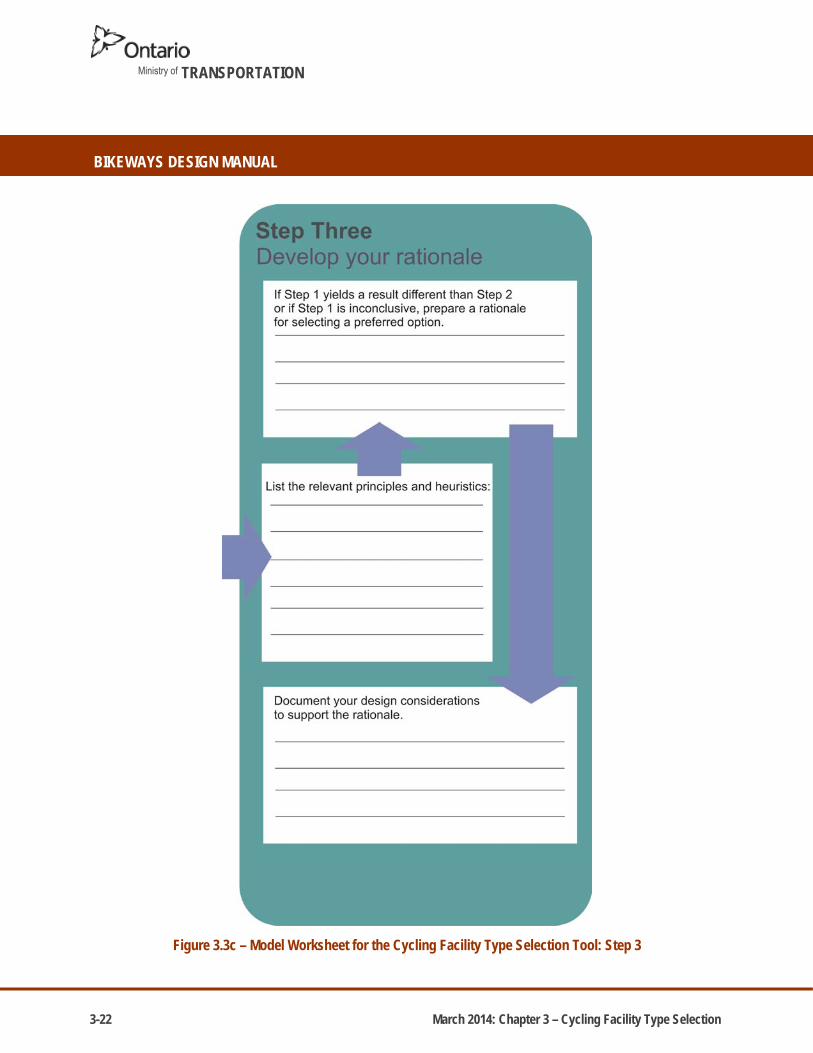
3-22 March 2014: Chapter 3 – Cycling Facility Type Selection
Ministry of TRANSPORTATION
BIKEWAYS DESIGN MANUAL
Figure 3.3c – Model Worksheet for the Cycling Facility Type Selection Tool: Step 3

CHAPTER 4.0O
N-RO
AD
CYCLING
FACILITY D
ESIGN
CHAPTER 4.0ON-ROAD CYCLING
FACILITY DESIGN


March 2014: Chapter 4 – On-Road Cycling Facility Design
ONTARIO BIKEWAY DESIGN MANUAL
CHAPTER TABLE OF CONTENTS CHAPTER
4.0
4.0 ON-ROAD CYCLING FACILITY DESIGN
4.1 SIGNED BIKE ROUTE 4-4
4.1.1 GENERAL CONSIDERATIONS 4-4
4.1.2 GEOMETRY 4-5
4.1.2.1 Width 4-5
4.1.3 PAVEMENT CONDITION AND TREATMENTS 4-6
4.1.4 PAVEMENT MARKINGS 4-7
4.1.5 SIGNAGE 4-9
4.1.6 TYPICAL APPLICATION CONSIDERATIONS FOR SIGNED BIKE ROUTES 4-10
4.2 SIGNED BIKE ROUTE WITH A PAVED SHOULDER 4-11
4.2.1 GENERAL CONSIDERATIONS 4-11
4.2.2 GEOMETRY 4-12
4.2.2.1 Width 4-13
4.2.3 PAVEMENT CONDITION AND TREATMENTS 4-16
4.2.3.1 Rumble Strip Design Considerations for Rural Roadways 4-16
4.2.4 PAVEMENT MARKINGS 4-20
4.2.5 SIGNAGE 4-20
4.2.6 TYPICAL APPLICATION CONSIDERATIONS FOR SIGNED BIKE ROUTES WITH PAVED
SHOULDERS 4-21
4.3 BICYCLE (BIKE) LANE 4-23
4.3.1 GENERAL CONSIDERATIONS 4-23
4.3.2 GEOMETRY 4-24
4.3.2.1 Width 4-24
4.3.3 PAVEMENT CONDITION AND TREATMENTS 4-25
4.3.4 PAVEMENT MARKINGS 4-26

March 2014: Chapter 4 – On-Road Cycling Facility Design
BIKEWAYS DESIGN MANUAL
Ministry of TRANSPORTATION
4.3.5 SIGNAGE 4-27
4.3.6 TYPICAL APPLICATION CONSIDERATIONS FOR BICYCLE LANES 4-28
4.4 SEPARATED BICYCLE LANE 4-29
4.4.1 GENERAL CONSIDERATIONS 4-29
4.4.1.1 Examples of Separated Bicycle Lanes 4-30
4.4.2 GEOMETRY 4-31
4.4.2.1 Width 4-31
4.4.3 PAVEMENT CONDITION AND TREATMENTS 4-32
4.4.4 PAVEMENT MARKINGS 4-33
4.4.5 SIGNAGE 4-34
4.4.6 TYPICAL APPLICATION CONSIDERATIONS FOR SEPARATED BICYCLE LANES 4-35
4.5 RAISED CYCLE TRACK 4-36
4.5.1 GENERAL CONSIDERATIONS 4-36
4.5.2 GEOMETRY 4-37
4.5.2.1 Width 4-37
4.5.3 PAVEMENT CONDITION AND TREATMENTS 4-38
4.5.4 PAVEMENT MARKINGS 4-39
4.5.5 SIGNAGE 4-40
4.5.6 TYPICAL APPLICATION CONSIDERATIONS FOR CYCLE TRACKS 4-41
4.6 INTERSECTIONS, INTERCHANGES AND CHANNELIZATIONS 4-42
4.6.1 INTERSECTIONS 4-42
4.6.1.1 Design Options for Mitigating Right Turn Conflicts 4-44
Bicycle Lane Adjacent to Combined Through/Right-Turn Lane 4-44
Combined Bicycle Lane / Right-Turn Vehicular Lane 4-46
Through Bicycle Lane with Dedicated Right-Turn Vehicular Lane 4-48

March 2014: Chapter 4 – On-Road Cycling Facility Design
ONTARIO BIKEWAY DESIGN MANUAL
CHAPTER TABLE OF CONTENTS CHAPTER
4.0
4.6.1.2 Design Options for Mitigating Left Turn Conflicts 4-50
4.6.1.3 Traffic Signals and Detector Loops 4-51
4.6.2 INTERCHANGES AND CHANNELIZATIONS 4-52
4.6.2.1 Implementing On-Road Cycling Facilities at Existing and New Interchanges..…4-52
Cycling Facility Crossing a Lower Speed Merging Ramp (less than 70km/h)
with Acceleration Lane 4-53
Cycling Facility Crossing a Lower Speed Merging Ramp (less than 70km/h)
without Acceleration Lane 4-54
Cycling Facility Crossing a High Speed Merging Ramp (greater than 70km/h) 4-55
Cycling Facility Crossing a Lower Speed Diverging Ramp (less than 70km/h) 4-56
Cycling Facility Crossing a Lower Speed Diverging Ramp (less than 70km/h)
with a Parallel Lane 4-57
Jug Handle Treatment at a High Speed Diverging Ramp (greater than 70km/h) 4-58
Cycling Facility Crossing at a High Speed Diverging Ramp (greater than 70km/h) 4-59
4.6.3 RAILWAY CROSSINGS 4-61
4.6.4 ROUNDABOUTS 4-63
4.7 OTHER ROADWAY DESIGN CONSIDERATIONS 4-72
4.7.1 DRAINAGE GRATES AND UTILITY COVERS 4-64
4.7.2 GRADE SEPARATIONS 4-68
4.7.3 FENCES, RAILINGS AND BARRIERS 4-69
4.7.4 LATERAL CLEARANCE TO OBSTRUCTIONS 4-69
4.7.5 LIGHTING 4-71
4.7.6 AERODYNAMIC EFFECT OF TRUCK PASSING 4-71
4.8 CONSIDERATIONS FOR RETROFITTING CYCLING FACILITIES ON
EXISTING PROVINCIAL HIGHWAY RIGHTS-OF-WAY 4-73
4.8.1 RETROFITTING BY WIDENING THE ROADWAY (RECONSTRUCTION) 4-73

March 2014: Chapter 4 – On-Road Cycling Facility Design
BIKEWAYS DESIGN MANUAL
Ministry of TRANSPORTATION
4.8.2 RETROFITTING WITHOUT ROADWAY WIDENING (REALLOCATION OF ROAD SPACE) 4-73
LIST OF FIGURES
Figure 4.1 Shared Use Lane Single File 4-4
Figure 4.2 Shared Roadway with Optional Sharrows 4-4
Figure 4.3 Shared Roadway with Wide Travel Lane 4-4
Figure 4.4 Narrow Signed Bike Route on a Rural Cross-Section 4-5
Figure 4.5 Wide Signed Bike Route / Shared Roadway with Optional Sharrows 4-5
Figure 4.6 Shared Roadway “Sharrow” Pavement Marking 4-7
Figure 4.7 Cyclist lateral positioning for side-by-side travel on a Shared Roadway 4-8
Figure 4.8 Cyclist lateral positioning for side-by-side travel on a Shared Roadway
with on-street parking 4-8
Figure 4.9 Signed Bike Route with Paved Shoulder, Sault St. Marie 4-11
Figure 4.10 Signed Bike Route with Buffered Paved Shoulder (Rumble Strip),
Sea to Sky Highway 4-11
Figure 4.11 Signed Bike Route with a Paved Shoulder < 2.0m wide 4-12
Figure 4.12 Signed Bike Route with a Buffered Paved Shoulder > 2.0m wide 4-12
Figure 4.13 Paved Shoulder Widths and Operational Buffer Zones on Rural Two-Lane
Highways with 85th Percentile Operating Speeds > 70 km/h and Designated
as a Cycling Route 4-15
Figure 4.14 Rumble Strip Design for 0.5 m Buffer Zone (as per MTOD 503.070) 4-18
Figure 4.15 Rumble Strip Design for 1.0 m Buffer Zone (as per MTOD 503.080) 4-19
Figure 4.16 Rumble Strip Design for 1.5 m Buffer Zone (as per MTOD 503.090) 4-20
Figure 4.17 Bicycle Lane beside Parking Lane 4-23
Figure 4.18 Conventional Bicycle Lane marked with a Diamond and Bicycle Symbol 4-23
Figure 4.19 Conventional Bicycle Lane 4-24
Figure 4.20 Typical Reserved Bicycle Lane Pavement Markings 4-26

March 2014: Chapter 4 – On-Road Cycling Facility Design
ONTARIO BIKEWAY DESIGN MANUAL
CHAPTER TABLE OF CONTENTS CHAPTER
4.0
Figure 4.21 Bicycle Lane and Vehicular Travel Lane separated by a painted buffer,
York Region 4-29
Figure 4.22 Examples of Separated Bicycle Lanes 4-30
Figure 4.23 Buffered Bicycle Lane 4-31
Figure 4.24 Buffered Bicycle Lane with Flexible Delineators 4-31
Figure 4.25 Separated Bicycle Lane 4-31
Figure 4.26 Typical Separated Bicycle Lane Pavement Markings 4-33
Figure 4.27 Raised Cycle Track, City of Guelph 4-36
Figure 4.28 One-Way Raised Cycle Track with Semi-mountable / Mountable Curb 4-37
Figure 4.29 Two-Way Raised Cycle Track with Barrier Curb 4-37
Figure 4.30 Asphalt Raised Cycle Track 4-38
Figure 4.31 Typical One-Way Raised Cycle Track Pavement Markings 4-39
Figure 4.32 Typical Bicycle and Motorized Vehicle Movements at an Intersection of
Multi-lane Roadways and associated Conflict Points 4-43
Figure 4.33 Longitudinal Pavement Markings for Bicycle Lanes (Line Delineations Details) 4-44
Figure 4.34 Bicycle Lane Adjacent to Combined Through / Right-Turn Lane
(with dashed white line approaching signalized intersection) 4-45
Figure 4.35 Bicycle Lane Adjacent to Combined Through / Right-Turn Lane (with solid white
line approaching signalized intersection and advance stop line) 4-45
Figure 4.36 Bicycle Lane Adjacent to Combined Right-Turn Lane 4-46
Figure 4.37 Combined Bicycle Lane / Right-Turn Vehicular Lane with On-Street Parking 4-47
Figure 4.38 Combined Bicycle Lane / Right-Turn Vehicular Lane without On-Street Parking 4-47
Figure 4.39 Through Bicycle Lane Adjacent to Introduced Right-Turn Lane 4-48
Figure 4.40 Through Bicycle Lane Adjacent to Curb Lane Transition 4-49
Figure 4.41 Two-Stage and Normal Left Turn Movements 4-50
Figure 4.42 Example of a Bicycle Signal Head 4-51
Figure 4.43 Bicycle Signal Head 4-51
Figure 4.44 Example Pavement Marking for Bicycle Actuation Location 4-51
Figure 4.45 Example of Cyclist Push Button 4-51

March 2014: Chapter 4 – On-Road Cycling Facility Design
BIKEWAYS DESIGN MANUAL
Ministry of TRANSPORTATION
Figure 4.46 Bicycle Lane Carried Straight across Lower Speed Merging Ramp
with Acceleration Lane 4-53
Figure 4.47 Bicycle Lane Carried Straight across Lower Speed Merging Ramp
without Acceleration Lane 4-54
Figure 4.48 Bicycle Lane Crossing at High Speed Merging Ramp 4-55
Figure 4.49 Bicycle Lane Carried Straight across Lower Speed Diverging Ramp 4-56
Figure 4.50 An Example of a Context Specific Design for a Bicycle Lane Carried Straight
Across a Lower Speed Diverging Ramp 4-56
Figure 4.51 Bicycle Lane Carried Straight across Lower Speed Diverging Ramp
with Parallel Lane 4-57
Figure 4.52 Example of a Bicycle Lane Jug Handle at High Speed Diverging Ramp 4-58
Figure 4.53 Bicycle Lane Crossing at a High Speed Diverging Ramp 4-59
Figure 4.54 Bicycle Lane Jug Handle at Skewed Railway Crossing with Gate Control 4-61
Figure 4.55 Bicycle Lane Jug Handle at Skewed Railway Crossing
with Unrestricted Right-of-Way Width and no Gate 4-62
Figure 4.56 Bicycle Lane at Skewed Railway Crossing with Gate Control 4-62
Figure 4.57 Bicycle Lane at Skewed Railway Crossing without Gate Control 4-62
Figure 4.58 Example of a Curb Inlet with Concrete Gutter 4-64
Figure 4.59 Example of a Drainage Grate with Herring Bone Openings and Concrete Gutter 4-64
Figure 4.60 MTC No. DD-713-A 4-65
Figure 4.61 MTC No. DD-713-B 4-65
Figure 4.62 Raised Curb Drainage Inlet as depicted in OPSD 400.082 4-66
Figure 4.63 Flat Drainage Grate with Herring Bone Openings as depicted in OPSD 400.020 4-67
Figure 4.64 Structure Cross-Sections on Designated Cycling Routes 4-70
Figure 4.65 The Aerodynamic Effect of Truck Passing 4-72
Figure 4.66 Example of a Bicycle Lane Implemented through a Road Diet,
Thorold Road, Welland 4-75

March 2014: Chapter 4 – On-Road Cycling Facility Design
ONTARIO BIKEWAY DESIGN MANUAL
CHAPTER TABLE OF CONTENTS CHAPTER
4.0
LIST OF TABLES Table 4-1 A Comparison of On-Road Cycling Facilities 4-2
Table 4-2 Desired and Suggested Minimum Lane Widths for Signed Bike Routes/
Shared Roadways 4-5
Table 4-3 Comparison of Roadway Surface Types (appropriate for On-Road
Cycling Facilities) 4-6
Table 4-4 Signage for Signed Bike Routes and Shared Roadways 4-10
Table 4-5 Desired and Suggested Minimum Widths for Paved Shoulders
along Signed Bike Routes 4-13
Table 4-6 Signage for Signed Bike Routes with Paved Shoulders 4-22
Table 4-7 Desired and Suggested Minimum Widths for Bicycle Lanes 4-25
Table 4-8 Signage for Bicycle Lanes 4-27
Table 4-9 Desired and Suggested Minimum Widths for Separated Bicycle Lanes 4-32
Table 4-10 Signage for Separated Bicycle Lanes 4-34
Table 4-11 Desired and Suggested Minimum Widths for Raised Cycle Tracks 4-38
Table 4-12 Signage for Raised Cycle Tracks 4-40
Table 4-13 Illumination Levels for On-Road Cycling Facilities 4-71


March 2014: Chapter 4 – On-Road Cycling Facility Design 4-1
SECTION
4.0 ON-ROAD CYCLING FACILITY DESIGN
4.0 ON-ROAD CYCLING FACILITY DESIGN Cyclists use the roadway system in Ontario for utilitarian, touring, recreational and fitness purposes. Therefore, on-road cycling facilities should be provided on highways designated as part of a cycling network. On-road cycling facilities generally follow the geometric alignments, profiles, and super-elevations of the roadway or road shoulder since roadway geometry typically exceeds minimum bikeway design requirements with respect to grade, curvature and sight distance for cycling when designed according to the Geometric Design Standards for Ontario Highways Manual. The Bikeways Design Manual focuses specifically on the design of on-road cycling facilities and should be considered in association with other provincial design guidelines and standards. Design considerations for the following on-road cycling facilities listed below are discussed in this section:
Signed Bike Route
Signed Bike Route with a Paved Shoulder
Bicycle (Bike) Lane
Separated (e.g. buffered) Bicycle Lane
Raised Cycle Track A Signed Bike Route with a Paved Shoulder (or buffered paved shoulder) may be the most appropriate facility type for provincial highway rights-of-way designated for cycling. Signed bike routes with paved shoulders provide a place for cyclists to ride on a highway with a rural cross section (no curbs) outside the motor vehicle travelled portion of the roadway. Pavement delineation lines as well as the addition of rumble strips and/or buffers can enhance the design of this facility type and may make it more appealing to a broader range of cyclists and therefore encourage more cyclists to use the facility. Some roadways identified as a potential cycling route may be constrained and may not be able to accommodate the suggested minimum paved shoulder width to designate the road as a cycling route. In these situations, the designer should consider paving as much of the shoulder as feasible based on sound engineering judgement. Although a road with a narrow paved shoulder would not typically be signed and promoted as a designated cycling route (except in low volume conidtions, see Figure 3.2 – Desirable Cycling Facility Pre-Selection Nomography), Share the Road signs (OTM Wc-19/ Wc-19t) could still be considered for the roadway. A Share the Road warning sign may be used to highlight a roadway condition that may pose a potential safety concern to cyclists and reinforces for both motorists and cyclists that both vehicles are to share the road. It is important to understand that a Share the Road sign does not indicate the roadway is part of the designated cycling route. The green Bicycle Route Marker or a regulatory sign such as the Reserved Bicycle Lane sign, do however. The application of Share

4-2 March 2014: Chapter 4 – On-Road Cycling Facility Design
BIKEWAYS DESIGN MANUAL
Ministry of TRANSPORTATION
the Road warning signs should be consistent with OTM Book 18: Cycling Facilities. Section 4.2 which provides more information for the design of Signed Bike Routes with Paved Shoulders.
Table 4-1 – A Comparison of On-Road Cycling Facilities
Signed Bike
Route1
Signed Bike Route with a Paved
Shoulder
Signed Bike Route with a Buffered Paved Shoulder
Bicycle Lane Separated Bicycle Lane
Raised Cycle Track
Exam
ple C
ross
Sec
tion
Example of Narrow Signed Bike Route on a
Rural Cross-Section
Example of a Signed Bike Route with a Paved
Shoulder
Example of a Signed Bike Route with a Paved
Shoulder including Buffer
Example of a Conventional Bicycle
Lane
Example of Buffered Bicycle Lane
Example of a One-Way Raised Cycle Track
Widt
h 4.0 – 4.5 m (Shared travel lane)
1.2 – 1.5 m (Paved Shoulder only)
2.0 – 3.0 m (Paved Shoulder with
0.5 – 1.5 m buffer)
1.5 – 1.8 m (Bicycle Lane & gutter)
1.5 – 2.0 m (Bicke Lane & gutter)
0.5 – 1.2 m (Separation width)
1.5 – 2.0 m (One-way Cycle Track)
3.0 – 4.0 m (Two-way Cycle Track)
Pave
ment
Marki
ngs
*Stencil Optional
N/A
* Hatching in the buffer is optional
Sign
age
Appli
catio
n2
Urban and suburban roads with low speed
and volume
Rural roads with moderate to high
speed and volume
Rural roads with moderate to high speed
and volume
Urban roads with low to moderate speed
and moderate volume
Urban roads with moderate to high
speed and volume
Urban roads with low to moderate speed and high volume
1Share the Road signs and Sharrow lane markings are optional 2For guidance on speed and volume thresholds, refer to Figure 3.2 - Cycling Facility Pre-selection Nomograph Source: TAC Bikeway Traffic Control Guidelines, 2012 and AASHTO Guide for the Planning Design and Operation of Bicycle Facilities, 2012

March 2014: Chapter 4 – On-Road Cycling Facility Design 4-3
SECTION
4.0 ON-ROAD CYCLING FACILITY DESIGN
Table 4-1 provides a brief comparison of the basic design elements for on-road cycling facilities. It also provides a summary of the typical application of the facility type which is based on a number of factors (e.g. operating speed and traffic volume). Designers should also refer to Chapter 3 to ensure that the appropriate facility type is selected for the designated bike route.
Design guideline thresholds presented in this manual include a desired value/dimension as well as a suggested minimum. The desired value is what designers should strive to achieve in their designs. Good engineering judgement should always be applied and consideration given to the location, context and roadway characteristics. Although consistency in design and signing is an important goal, a designer should never assume a “one solution fits all” approach.
The design guidelines presented in this Chapter are based on best practices both in Canada and the United States, and relevant national and international research. Throughout the decision-making process, designers are strongly encouraged to document their rationale. This is particularly important where proposals deviate from desired widths which are considered optimal from a safety perspective. This will assist the designer should they be required to defend any compromises they may have chosen for operational, cost or other reasons.

4-4 March 2014: Chapter 4 – On-Road Cycling Facility Design
BIKEWAYS DESIGN MANUAL
Ministry of TRANSPORTATION
4.1 SIGNED BIKE ROUTE
A Signed Bike Route is a road designated as part of the cycling route network where both motorists and cyclists share the same travel lane.
Figure 4.1 – Shared Use Lane Single File Source: valdodge.com, 2012
Figure 4.2 – Shared Roadway with Optional Sharrows Source: NRVBA, 2011
Figure 4.3 – Shared Roadway with Wide Travel Lane Source: Brigitte Schuster, 2011
4.1.1 GENERAL CONSIDERATIONS
Generally, all roadways are considered shared roadways unless bicycle travel is explicitly prohibited. Shared roadways with low volumes and low operating speeds often provide an enjoyable and comfortable bicycling experience for users without the need for implementing bicycle infrastructure beyond signing. A shared roadway that is intended to be a designated cycling route is identified as such by the Bike Route Marker. Signed bike routes can be considered on both urban and rural cross sections. Depending on the roadway characteristics, the designated cycling route may be supplemented by Share the Road warning signs (where recommended) or optional pavement markings. Also, a roadway not designated as a cycling route but being used by cyclists may still have Share the Road signage to warn motorists of the presence of cyclists and their obligation to share the road.
When improvements are made for cyclists, it often results in better conditions for all roadway users including motorists, pedestrians and other non-motorized vehicle users. Shared roadways can be improved by widening the curbside shared travel lane allowing motorists and cyclists to travel side-by-side or for motorists to safely pass a cyclist. Shared roadways with wide travel lanes are usually found along local urban roadways with low traffic volumes or low vehicular operating speeds; however, this may also be appropriate for rural roadways with low traffic volumes and low to moderate posted speed limits, depending on the location and context.

March 2014: Chapter 4 – On-Road Cycling Facility Design 4-5
SECTION
4.1 SIGNED BIKE ROUTE
4.1.2 GEOMETRY
Figure 4.4 – Narrow Signed
Bike Route on a Rural Cross-Section
Figure 4.5 – Wide Signed Bike Route / Shared Roadway with Optional Sharrows
4.1.2.1 Width
Table 4-2 – Desired and Suggested Minimum Lane Widths for Signed Bike Routes/ Shared Roadways
Classification Desired Width
Suggested Minimum Width in Constrained Corridors
Narrow Signed Bike Route / Shared Roadway3 4.00 m 3.25 m 1,4
Wide Signed Bike Route / Shared Roadway3 4.50 m 2 4.00 m 5
1Low volume, low speed conditions; cyclists take the lane 2Due to local variations in width, this may be up to 5.0 m in places. However, the lane width should not consistently exceed 4.5 m or motorists may attempt to overtake other motorists, causing a safety risk for cyclists. In these cases, provision of a designated bike lane should be considered 3Applies to curbside lane. Widths for the shared travel lane should be considered from the edge of the travelled way (for rural cross-sections), the face of the curb (for urban cross-sections without on-street parking), or the edge of the parking lane (for roads with on-street parking). 4It is recognized that travel lane widths may be less than 3.25 m – cyclists are still permitted as a vehicle under the HTA to use these roads 5Only suitable for lanes without sharrows or where the designer considers traffic volumes to be low and the speed differential between motor vehicles and bicycles to be minimal. Otherwise, a minimum lane width of 4.3 m is suggested Source: Based on information from AASHTO Guide for the Planning, Design and Operation of Bicycle Facilities, 2012

4-6 March 2014: Chapter 4 – On-Road Cycling Facility Design
BIKEWAYS DESIGN MANUAL
Ministry of TRANSPORTATION
It is recommended that designers provide the desired facility width in their designs. However, in constrained corridors, a designer may consider the suggested minimum if the context is appropriate. A shared roadway may have a narrow lane width where motor vehicles cannot pass the cyclist in the same space, or it may have a wider lane so that motorists can pass cyclists (when safe to do so) without leaving the lane. If space is available, travel lanes may be widened to accommodate side-by-side travel of motorists and cyclists. When side-by-side travel is to be provided for motorists and cyclists, a wide shared travel lane of a width of at least 4.0 m should be considered to a maximum of 4.5 m because travel lanes that exceed 4.5 m may encourage side-by-side travel between motorists.
4.1.3 PAVEMENT CONDITION AND TREATMENTS
Signed bike routes should use the same pavement structure and surface type as motor vehicles. Facilities incorporated into new roadways require no additional work or change in hot mix type or strength. When implementing signed bike routes, the roadway surface should be in good condition, offering cyclists a comfortable ride with minimal rutting, cracking, frost heaving and potholes. Table 4-3 outlines roadway surface types that may be considered for on-road cycling facilities.
Table 4-3 – Comparison of Roadway Surface Types (appropriate for On-Road Cycling Facilities)
Surface Type
Comfort of Ride
Skid Resistance
Will Lane Marking Adhere
Weather Resistance Costs Concerns
Asph
alt
Excellent Excellent Yes Excellent
Initial cost is high to medium for recycled Hot Mix; routing & sealing may be required every 3 to 5 years.
Should ensure cracks are routed & sealed properly which may be required every 3 to 5 years.
Surfa
ce
Trea
tmen
t/ Ch
ip Se
al
Fair Excellent Yes Good
Initial cost is low to medium (less expensive than asphalt) but annual maintenance may be required.
Life cycle of 1 to 3 years; Surface treatment will crack.
Conc
rete
Good Excellent Yes Excellent Initial cost is very high, however minimal maintenance is required.
Concrete joints can cause discomfort for riders.
Limes
tone
/Gra
nular
Su
rface
s
Fair Poor No Good Low cost and easy to maintain.
Recommended material for recreational bikeways and in natural settings where the terrain is flat.

March 2014: Chapter 4 – On-Road Cycling Facility Design 4-7
SECTION
4.1 SIGNED BIKE ROUTE
Figure 4.6 – Shared Roadway “Sharrow” Pavement Marking
Source: Based on information from TAC Bikeway Traffic Control Guidelines for Canada, 2012
4.1.4 PAVEMENT MARKINGS
Signed bike routes/ shared roadways in urban areas are sometimes marked with shared roadway lane markings, often referred to as “sharrows”. A sharrow consists of two white chevron markings, with a stroke width of 100 mm spaced at 100 mm apart above a white 1.0 m by 2.0 m bicycle marking. Refer to Figure 4.6 for a schematic of a “sharrow” pavement marking.
Sharrows are intended to guide both motorists and cyclists as to the suggested positioning of cyclists in the lane. They are an optional treatment for urban areas and context specific. They are particularly useful on shared roadways with wide travel lanes as motor vehicles and bicycles travel side-by-side and lane markings help to safely guide both user groups along these roadways.
Cyclists should ride so that they pass over the centre of the sharrow symbol in the same direction as traffic (as illustrated in Figure 4.7), with the edge of roadway, curb or on-street parking lane on the right and passing vehicular traffic on the left (as illustrated in Figure 4.8). On roadways with full time on-street parking, sharrows can be used to help cyclists with lateral positioning by identifying a suitable distance from parked vehicles for cyclists to ride in order to minimize the chances of them colliding with opening car doors. The centre of the sharrow should be placed 1.3 m from the edge of the parking lane.

4-8 March 2014: Chapter 4 – On-Road Cycling Facility Design
BIKEWAYS DESIGN MANUAL
Ministry of TRANSPORTATION
Figure 4.7 – Cyclist lateral positioning for side-by-side travel on a Shared Roadway Source: OTM Book 18: Cycling Facilities, 2013
Figure 4.8 – Cyclist lateral positioning for side-by-side travel on a Shared Roadway with on-street parking Source: OTM Book 18: Cycling Facilities, 2013

March 2014: Chapter 4 – On-Road Cycling Facility Design 4-9
SECTION
4.1 SIGNED BIKE ROUTE
4.1.5 SIGNAGE
Signs provide additional guidance to cyclists, motorists and other roadway users. Minimum sign sizes are dependent on whether both motorists and cyclists are required to interpret the sign or it is only for cyclists and other non-motorized users. Generally, signage used for on-road cycling facilities is meant for both motorists and cyclists.
A roadway that is intended to be part of a designated cycling route network should be signed using the green Bike Route Marker which contains a white bicycle symbol and the word “ROUTE” written underneath it (refer to column (a) in Table 4-4). Bike Route Marker signs should be placed 20 to 30 m in advance of, and following an intersection and other decision points, as well as at intervals along the route that are frequent enough to guide cyclists and inform them of any designated cycling route direction changes. Depending on the roadway characteristics, the signed bike route may be supplemented by Share the Road warning signs.
Unless cycling is specifically restricted, all roadways are considered to be shared roadways even if there is no signage present. Roadways with higher volumes of cyclist traffic should be marked using a yellow Share the Road warning sign and supplementary tab sign as shown in columns (b) and (c) of Table 4-4. The Share the Road sign is used to remind motorists that cyclists are permitted on the roadway and that motorists are required to provide adequate space for cyclists to ride. The supplementary tab sign should be used in conjunction with the Share the Road sign to convey the appropriate meaning. The sign assembly is particularly important where a roadway configuration changes, such as the discontinuation of a reserved bicycle lane. On shared roadways where the travel lane is too narrow for motorists to safely pass cyclists in a single lane, motorists and cyclists are encouraged to travel in single file and cyclists ‘take the lane’. See columns (d) and (e) for the Shared Use Lane Single File sign and supplementary tab sign.
Designers should refer to OTM Book 18: Cycling Facilities for current sign codes and dimension details for signed bike route and shared roadway signage.

4-10 March 2014: Chapter 4 – On-Road Cycling Facility Design
BIKEWAYS DESIGN MANUAL
Ministry of TRANSPORTATION
Table 4-4 – Signage for Signed Bike Routes and Shared Roadways
Bike Route Marker Share the Road Sign
Share the Road Tab Sign
Shared Use Lane Single File Sign
Single File Tab Sign
(a) (b) (c) (d) (e)
Sign
age
Sign
Co
de
TAC: IB-23 OTM: M511
TAC: WC-19 OTM: Wc-19
TAC: WC-19S OTM: Wc-19t
TAC: WC-20 OTM: (TBD)
TAC: WC-20S OTM: (TBD)
Dime
nsion
s
450 mm x 450 mm 600 mm x 600 mm 300 mm x 600 mm 600 mm x 600 mm 300 mm x 600 mm
Source: OTM Book 18: Cycling Facilities, 2013 and TAC Bikeway Traffic Control Guidelines for Canada, 2012
4.1.6 TYPICAL APPLICATION CONSIDERATIONS FOR SIGNED BIKE ROUTES
Signed Bike Routes may be implemented on local urban or suburban roadways with low volumes and low to moderate speeds (typically 40 to 60 km/h).
Signed Bike Routes may also be implemented on low volume rural highways where volumes are less than 500 vpd (no sharrows) or where paved shoulders are provided.
Optional ‘sharrow’ stencils may be applied along the route or at conflict points in urban areas.
Based on the above typical application considerations, it may seem at first glance that the most appropriate facility type in a given case is a signed bike route. However, it is still important to go through the step-by-step facility type selection process, as outlined in Chapter 3, in order to assess the location and context, select the appropriate facility type and document the selection process and rationale behind the decision.

March 2014: Chapter 4 – On-Road Cycling Facility Design 4-11
SECTION
4.2 SIGNED BIKE ROUTE WITH A PAVED SHOULDER
4.2 SIGNED BIKE ROUTE WITH A PAVED SHOULDER
A Signed Bike Route with a Paved Shoulder is a road with a rural road cross section that is signed
as a cycling route which also includes a paved shoulder. A Paved Shoulder is a portion of a
roadway which is contiguous with the travelled way and accommodates stopped and emergency
vehicles, pedestrians and cyclists. It also provides lateral support for the pavement structure. A
paved shoulder on a designated cycling route may include a buffer zone to provide greater
separation between motorists and cyclists.
Figure 4.9 – Signed Bike Route with Paved Shoulder, Sault St. Marie
Figure 4.10 – Signed Bike Route with Buffered Paved Shoulder (Rumble Strip), Sea to Sky Highway
4.2.1 GENERAL CONSIDERATIONS
In rural areas, paved shoulders are often used by cyclists for travel as they provide an area for
riding that is adjacent to vehicular travel lanes offering separation between bicycle traffic and
vehicular traffic. However, this separation is spatial as there is no physical barrier that restricts the
encroachment of motorized vehicles onto the paved shoulder. Bicycle traffic on a paved shoulder
is always one-way in the same direction as the adjacent right-most travel lane.
A Signed Bike Route with a Paved Shoulder (or buffered paved shoulder) may be the most
appropriate type of bicycle facility located within provincial highway right-of-ways. Signed bike
routes with paved shoulders provide a place for cyclists to ride on a highway with a rural cross
section outside the travelled portion of the roadway. Pavement delineation lines as well as the
addition of rumble strips and/or painted buffers may enhance the design of this facility type for
cyclists. Some roadways identified as a potential cycling route may be constrained and may not be

4-12 March 2014: Chapter 4 – On-Road Cycling Facility Design
BIKEWAYS DESIGN MANUAL
Ministry of TRANSPORTATION
able to accommodate the suggested minimum paved shoulder width to designate the roadway as a
cycling route. In these situations, the designer may consider paving as much of the shoulder as is
feasible based on sound engineering judgement. Although a roadway with a narrow paved
shoulder would not typically be signed and promoted as a designated bike route, Share the Road
warning signs may be considered at specific locations.
4.2.2 GEOMETRY
Figure 4.11 – Signed Bike Route with a Paved Shoulder < 2.0m wide
Figure 4.12 – Signed Bike Route with a Buffered Paved Shoulder > 2.0m wide
Adjacent motorized vehicle lanes should be 3.25 m minimum for lower speed urban routes excluding shared roadway and wide curb lane cycling facilities.
Note: the paved shoulder cross slope of a designated cycling route should be in accordance with
paved shoulder cross slope standards set out in the Geometric Design Standards for Ontario
Highways (GDSOH) Manual. A maximum 6% cross slope is acceptable for cycling. The
superelevation of paved shoulders on highways is not required for cycling due to curves being
relatively flat when compared to curves on Active Transportation Paths as presented in Section
5.1.2.4.

March 2014: Chapter 4 – On-Road Cycling Facility Design 4-13
SECTION
4.2 SIGNED BIKE ROUTE WITH A PAVED SHOULDER
4.2.2.1 Width
It is recommended that designers provide the desired facility width in their designs, however in constrained corridors a designer may consider the suggested minimum if context is appropriate.
Table 4-5 – Desired and Suggested Minimum Widths for Paved Shoulders along Signed Bike Routes
Classification Desired Width
Suggested Minimum Width in Constrained
Corridors
Paved Shoulder (< 2.0 m ) along a Signed Bike Route 1,3 1.5 m 1.2 m 2
Paved Shoulder (> 2.0 m ) along a Signed Bike Route 1,3 1.5 m bicycle operating space
& 1.5 m buffer 1.5 m bicycle operating space
& 0.5 m buffer 2
1Where a paved shoulder is 2.0 m wide, a 0.5 m buffer zone should be provided within the shoulder. A wider paved shoulder (2.5 m – 3.0 m) including a buffer (0.5 m – 1.5 m) should be provided on rural high speed high volume highways according to Figure 4.13. 2A 1.2 m wide paved shoulder may be considered in constrained corridors only. Any roadway with a paved shoulder of less than 1.2 m is considered a shared lane facility, though it may include a partially paved shoulder with a width of 0.5 m to 1.0 m. 3Refers to the lane adjacent to the curb or shoulder. Width is measured from the edge of the travelled way (for rural cross sections) and the face of the curb for urban cross sections
Source: Based on information AASHTO Guide for the Planning, Design and Operation of Bicycle Facilities, 2012
On signed bike routes on high speed rural highways with projected AADT greater than 4,000 or more than 30 trucks and/or buses per hour, paved shoulders with buffer zones are recommended according to Figure 4.13. In constrained corridors or at constrained sections within a signed bike route, designers may consider providing a minimum paved shoulder width of 1.2 m. Where barriers are present on constrained sections when paved shoulder widths of 1.2 m are provided on a signed bike route, a shy distance of 0.3 m minimum should be provided between edge of paved shoulder and the barrier.
The bicycle/rider dimension has changed since the predecessor to this manual was released in 1996. The new 2012 AASHTO Guide for the Planning, Design, and Operation of Bicycle Facilities gives the 95th percentile bicycle width as 0.75 m, compared to 0.6 m in the 1996 Bikeway Guidelines. This change may be attributable to the preponderance of mountain bikes being used today compared to the 1990s. In Section 2.3.1.4 of the 1996 Bikeway Guidelines, the manoeuvering space is given as 200 mm on each side of the bicycle. Using the new bicycle width of 0.75 m and adding 200 mm to each side gives a width of 1.15 m; this is rounded up to 1.2 m, the stated minimum paved shoulder width in constrained corridors. The recommended width of 1.2 m is driven by an increase in bicycle/rider operating space from the early 1990’s to 2012/13. An operating space of 1.2 m provides the minimum width to accommodate forward movement by most cyclists while recognizing that the natural side-to-side movement pedalling a bike can vary with speed, wind, and cyclist proficiency.

4-14 March 2014: Chapter 4 – On-Road Cycling Facility Design
BIKEWAYS DESIGN MANUAL
Ministry of TRANSPORTATION
Figure 4.13 provides guidance for the selection of paved shoulder widths and buffer zones for rural two lane highways with 85th percentile operating speeds of 70 km/h or more. For low speed roadways in built up areas, designers should refer to the nomograph in Chapter 3 for guidance on appropriate facility types. As noted in Figure 4.13, low volume highways with good sight lines do not normally require paved shoulders or may have partial paved shoulders less than 1.2 m. Any roadway with a paved shoulder width of less than 1.2 m is considered to be a shared lane facility. For more information on Signed Bike Routes (without paved shoulders) refer to Section 4.2. Designers should consider buffer zones on high speed roadways where there are more than 30 trucks and/or buses per hour. When noise sensitive areas including residences are located more than 100 m away from the buffered paved shoulder, shoulder rumble strips for bicycle buffer zones should be considered.
Figure 4.13 is intended as a tool to assist a designer on selecting appropriate shoulder widths on rural high speed two-lane highways for cycling. The initial step in selecting the appropriate shoulder width is Tables DA-1 and DA-2 from the Geometric Design Standards for Ontario Highways manual. Designers should then use Figure 4.13 to determine if the width of the selected shoulder should be increased to accommodate the paved shoulder width for a Signed Bike Route with a Paved Shoulder according to Figure 4.13. A designer still needs to follow the process set out to review the specific location and consider the heuristics presented in Chapter 3 of the Bikeways Design Manual and then ‘document’ the basis for the facility selection decision.
In situations where the facility type selection process has identified that the facility should include a paved shoulder but roadway or other constraints prevent the corridor from accommodating the suggested minimum paved shoulder width, the roadway should not be designated as a cycling route.

March 2014: Chapter 4 – On-Road Cycling Facility Design 4-15
SECTION
4.2 SIGNED BIKE ROUTE WITH A PAVED SHOULDER
NOTES:
A. In constrained corridors along the signed cycling route, designers may consider providing a minimum paved shoulder width of 1.2 m. Where barriers are
present on constrained corridors and paved shoulder widths of 1.2 m are provided, a shy distance of 0.3 m minimum should be provided between edge
of paved shoulder and the barrier.
B. Buffer zones should be considered on high speed roadways with more than 30 trucks and/or buses per hour per direction.
C. Paved shoulder width includes buffer.
D. This Figure is intended for Rural Two-Lane Highway Conditions with 85th percentile operating speeds ≥ 70 km/h. E. Some Secondary Highways may have lane widths less than 3.5 m, in which case traffic volume thresholds still apply.
Figure 4.13 – Paved Shoulder Widths and Operational Buffer Zones on Rural Two-Lane Highways with
85th Percentile Operating Speeds > 70 km/h and Designated as a Cycling Route

4-16 March 2014: Chapter 4 – On-Road Cycling Facility Design
BIKEWAYS DESIGN MANUAL
Ministry of TRANSPORTATION
4.2.3 PAVEMENT CONDITION AND TREATMENTS
It is recommended that during re-surfacing projects, the shoulder of roadways designated as cycling routes should be repaved at the same time as the roadway to ensure a seamless transition between the two. However, some roadways may have recently only had the travel portion of the roadway resurfaced and have since been identified as a potential designated cycling route. If it has been assessed that the facility should include a paved shoulder, the roadway should be designated as a cycling route when the paved shoulder has a surface that is an acceptable condition for cycling.
4.2.3.1 Rumble Strip Design Considerations for Rural Roadways
A shoulder rumble strip is a grooved pattern along the outer most edges of a roadway separating the travelled portion of the roadway from the shoulder. Shoulder rumble strips are intended for motorists and can be an effective safety measure used to reduce run-off-the-road collisions as they are designed to alert drivers with both an audible and tactile warning that the vehicle has partially or completely departed the travelled way of the highway onto the shoulder. It should be noted that shoulder rumble strips are not usually implemented in urban areas because the noise may affect local residents.
Shoulder rumble strips should be considered on signed bike routes on high speed rural highways where paved shoulders are 2.0 m wide or greater with buffer zones in accordance with Figure 4.13. The skip pattern in the shoulder rumble strip as detailed in the applicable MTODs allows cyclists to manoeuvre in and out of the paved shoulder to pass stopped cars, pedestrians, and other cyclists, as well as avoid debris in the shoulder.
Minimum 100 mm wide white edge lines should be placed on either side of the shoulder rumble strip as detailed in the applicable MTODs. The outside line closest to the cycling facility should follow the skip pattern in the shoulder rumble strips to provide cyclists with more guidance as to when there is a break in the shoulder rumble strips in the buffer zone.
The design of the shoulder rumble strips should be consistent with MTOD 503.070 for 0.5 m wide buffers, MTOD 503.080 for 1.0 m wide buffers and MTOD 503.090 for 1.5 m wide buffers. See Figures 4.14, 4.15 and 4.16, respectively. The minimum asphalt thickness on paved shoulders with rumble strips is 80 mm. For further application of rumble strips on provincial highways, reference PLNG-B-004 and HDB 2010-002.

March 2014: Chapter 4 – On-Road Cycling Facility Design 4-17
SECTION
4.2 SIGNED BIKE ROUTE WITH A PAVED SHOULDER
Figure 4.14 – Rumble Strips Design for 0.5 m Buffer Zone (as per MTOD 503.070)

4-18 March 2014: Chapter 4 – On-Road Cycling Facility Design
BIKEWAYS DESIGN MANUAL
Ministry of TRANSPORTATION
Figure 4.15 – Rumble Strips Design for 1.0 m Buffer Zone (as per MTOD 503.080)

March 2014: Chapter 4 – On-Road Cycling Facility Design 4-19
SECTION
4.2 SIGNED BIKE ROUTE WITH A PAVED SHOULDER
Figure 4.16 – Rumble Strips Design for 1.5 m Buffer Zone (as per MTOD 503.090)

4-20 March 2014: Chapter 4 – On-Road Cycling Facility Design
BIKEWAYS DESIGN MANUAL
Ministry of TRANSPORTATION
4.2.4 PAVEMENT MARKINGS
Signed bike routes with paved shoulders are generally delineated using a white 100 mm wide edge
line in order to visually separate the vehicular travel lane from the paved shoulder. Unlike bicycle
lanes, signed bike routes with paved shoulders do not generally have any other pavement
markings.
A signed bike route with buffered paved shoulder is designated with two delineating lines: a
100 mm solid white edge line, which defines the boundary between the buffer and the bicycle
operating space, and a 100 mm solid white edge line, which defines the boundary between the
buffer and the vehicular travel lane.
If diagonal hatched lines are applied within the buffer, the lines should be 100 mm wide, and
placed at an angle of 45 degrees in the direction of travel. The spacing between the diagonal lines
is generally a function of vehicular speed. Diagonal lines should be spaced 18 m apart on low to
moderate speed roadways and 36 m on high speed roadways. The frequency of hatching on the far
side or near side of the intersection should start at 3 m and increase to the 18 m for low to
moderate speed roadways and 36 m for high speed roadways.
If shoulder rumble strips with a skip pattern are applied within the buffer, then it is recommended
that the outside line closest to the paved shoulder follows the skip pattern to alert cyclists when
there is a break in the rumble strip.
4.2.5 SIGNAGE
If an engineering assessment indicates that the signed bike route should have a paved shoulder, it
should typically only be signed with a green Bike Route marker (refer to column (a) in Table 4-6)
if the suggested minimum paved shoulder width of 1.2 m is provided. Bike Route Marker signs
should be placed 20 to 30 m in advance of, and following an intersection and other decision points,
as well as at intervals along the route that are frequent enough to guide cyclists and inform them of
any designated cycling route direction changes. Depending on the roadway characteristics, the
signed bike route may be supplemented by Share the Road warning signs as shown in columns (b)
and (c) in Table 4-6. Share the Road warning signs may be considered if a particular roadway is
commonly used by cyclists and there are potential hazardous locations such as narrowing of
pavement, reduced sightlines, etc. The Share the Road warning sign is used to remind motorists
that cyclists are permitted on the roadway and that motorists are required to provide adequate
space for cyclists to ride.

March 2014: Chapter 4 – On-Road Cycling Facility Design 4-21
SECTION
4.2 SIGNED BIKE ROUTE WITH A PAVED SHOULDER
Table 4-6 summarizes the signs used for signed bicycle routes with paved shoulders. Designers
should refer to OTM Book 18: Cycling Facilities for current sign codes and dimension details for
signage for shared roadways and signed bicycle routes with paved shoulders.
Table 4-6 – Signage for Signed Bike Routes with Paved Shoulders
Bike Route Marker Share the Road
Sign Share the Road
Tab Sign
(a) (b) (c)
Sig
nage
Sig
n
Cod
e TAC: IB-23 OTM: M511
TAC: WC-19 OTM: Wc-19
TAC: WC-19S OTM: Wc-19t
Dim
ensi
ons
450 mm x 450 mm 600 mm x 600 mm 300 mm x 600 mm
Source: OTM Book 18: Cycling Facilities, 2013 and TAC Bikeway Traffic Control Guidelines for Canada, 2012
4.2.6 TYPICAL APPLICATION CONSIDERATIONS FOR SIGNED BIKE ROUTES
WITH PAVED SHOULDERS
Signed Bike Routes with Paved Shoulders may be implemented on provincial highways
with no curb or gutter.
Motor vehicle speeds and volumes vary. As volumes increase, designers should consider
wider paved shoulders and/or a buffered zone. A buffer provides additional separation
between cyclists and motorists offering both user groups more comfort as they travel.
On high speed provincial highways designated as a cycling route with medium to high
traffic volumes, the preferred shoulder width consists of a 1.5 m bicycle operating space
separated from the travelled lane with a buffer zone according to Figure 4.13 .

4-22 March 2014: Chapter 4 – On-Road Cycling Facility Design
BIKEWAYS DESIGN MANUAL
Ministry of TRANSPORTATION
In constrained corridors or sections along the cycling route, designers may consider
providing a minimum paved shoulder width of 1.2 m. Where barriers are present an
additional shy distance of 0.3 m should be provided between edge of paved shoulder and
the barrier.

March 2014: Chapter 4 – On-Road Cycling Facility Design 4-23
SECTION
4.3 BICYCLE (BIKE) LANE
4.3 BICYCLE (BIKE) LANE
A Bicycle Lane is a portion of a roadway which has been designated by pavement markings and signage for exclusive use by cyclists.
Figure 4.17 – Bicycle Lane beside Parking Lane Source: Jonathan Maus (BikePortland.org), 2010
Figure 4.18 – Conventional Bicycle Lane marked with a Diamond and Bicycle Symbol
Source: www.ibiketo.ca, 2007
4.3.1 GENERAL CONSIDERATIONS
Bicycle Lanes (sometimes referred to as Reserved Bicycle Lanes, Conventional Bicycle Lanes or Bike Lanes) delineate and separate motorized and bicycle traffic. As a result, they are perceived to provide a more comfortable riding environment for cyclists and better organize traffic flow for motorists. Bicycle lanes are typically located along urban roadways where traffic volumes and/or vehicular operating speeds are moderate. Bicycle lanes provide added comfort for cyclists because, unlike shared roadways and signed routes, bike lanes designate a portion of the roadway for the preferential or exclusive use of cyclists. However, a bicycle lane differs from a separated bicycle lane in that it has no spatial or physical barrier that limits or restricts the encroachment of motor vehicles into the bicycle lane.
The configuration of a bicycle lane requires thorough consideration of a number of design parameters including vehicular speed, traffic volume in the lane adjacent to the bicycle lane and the presence of on-street parking. The comfort level of cyclists using bicycle lanes is dependent on various geometric and operational factors as discussed in the following subsections.

4-24 March 2014: Chapter 4 – On-Road Cycling Facility Design
BIKEWAYS DESIGN MANUAL
Ministry of TRANSPORTATION
4.3.2 GEOMETRY
4.3.2.1 Width
A conventional bicycle lane should be at least 1.5 m wide (this includes 300 mm for the gutter). If space permits, a wider bicycle lane can be implemented with a width of 1.8 m (including a 300 mm gutter). Both options provide cyclists with preferential or exclusive use of a designated portion of the roadway. The added width provides greater comfort and safety for the cyclist by positioning cyclists further away from vehicular traffic. Table 4-7 provides a summary of desired and suggested minimum widths for bicycle lanes. It is recommended that designers provide the desired facility width in their design, however in constrained corridors a designer may consider reducing the width towards the suggested minimum if the context is appropriate.
Figure 4.19 – Conventional Bicycle Lane

March 2014: Chapter 4 – On-Road Cycling Facility Design 4-25
SECTION
4.3 BICYCLE (BIKE) LANE
Table 4-7 – Desired and Suggested Minimum Widths for Bicycle Lanes
1Includes bike lanes between through lanes and turn lanes on the approach to an intersection. Also applies to bike lanes between through lanes and merge lanes downstream of an intersection. 2Assumes a parking lane width of 2.5 m, although where possible the buffer width should be increased by reallocating road space from the parking lane. This is to encourage motorists to park closer to the curb, thus reducing the conflict zone between cyclists and car doors that may open without warning. In a low volume, low speed constrained corridor, a minimum 1.8 m wide bicycle lane may be provided without a buffer. However, there may be an increased risk of collisions between cyclists and opening car doors or alighting passengers. 3Includes bicycle lanes alongside continuous barriers such as guide rails and underpass walls.
Source: Based on information from AASHTO Guide for Planning, Design and Operation of Bicycle Facilities, 2012
4.3.3 PAVEMENT CONDITION AND TREATMENTS
On-road cycling facilities such as bicycle lanes typically use the same pavement type as motorized vehicles because roadway design requirements exceed minimum cycling facility design requirements. Therefore, bicycle lanes implemented on existing roadways use the existing base structure and surface type (asphalt or concrete); bicycle lanes incorporated into new roadway designs require no additional work or change in hot mix type or strength. Existing concrete roadways that are too narrow to accommodate a bicycle lane would not generally be widened with concrete as it is too expensive. An alternative would be to widen the roadway with asphalt, however this may result in differential settlement between the two types of pavement structures. Ideally, the desirable scenario is to have the bicycle lane included within the initial construction especially for a concrete roadway. Refer to Section 4.9 for more detailed information regarding implementing on-road cycling facilities on existing provincial highway rights-of-way. Refer back to Table 4-3 in Subsection 4.1.3 for information regarding some of the roadway pavement types that may be considered for on-road cycling facilities.
Classification Desired Width
Suggested Minimum Width in Constrained Corridors
Conventional Bicycle Lane 3 1.8 m 1.5 m
Conventional Bicycle Lane splitting two travel lanes 1 2.0 m 1.8 m
Conventional Bicycle Lane adjacent to on-street parking
2.5 m (1.5 m lane & 1.0 m buffer)
2.0 m (1.5 m lane & 0.5 m 2 buffer)

4-26 March 2014: Chapter 4 – On-Road Cycling Facility Design
BIKEWAYS DESIGN MANUAL
Ministry of TRANSPORTATION
Figure 4.20 – Typical Reserved Bicycle Lane Pavement Markings
Source: Based on information from TAC Bikeway Traffic Control Guidelines for Canada, 2012
4.3.4 PAVEMENT MARKINGS
An important component of bicycle lane design is pavement markings. Conventional bicycle lanes are generally separated from vehicular travel lanes by a 100 mm thick delineating line. They are further defined by a diamond symbol indicating that the lane is reserved for cyclists. This is followed by a bicycle symbol. The diamond symbol should be centred in the bicycle lane and have a stroke width of at least 75 mm.
An optional directional arrow may be used where the direction of travel is not clear or additional guidance is required. For example, the arrow may be used on contraflow bike lanes or at intersections where cyclists will take different trajectories at or on the approach to an intersection depending on the turning movement they are making. There are two sets of directional arrows that can be used: full-size motorist directional arrows where a motorist is required to see and interpret the symbol and reduced-size cyclist directional arrows where motorists do not need to see the symbol. Figure 4.20 illustrates the through-movement directional arrow and recommended pavement marking for a reserved bicycle lane.
Pavement markings for bicycle lanes are important because they:
Alert motorists and indicate the presence and orientation of cyclists;
Improve safety and comfort for cyclists by designating a portion of the roadway for the preferential or exclusive use of cyclists; and
Guide cyclists through high demand corridors by indicating the assigned travel path.
If space permits and conditions require greater separation, a painted buffer may be used to separate vehicular traffic from bicycle traffic. Refer to Section 4.4 for more information about Separated Bicycle Lanes.
Optional Arrow

March 2014: Chapter 4 – On-Road Cycling Facility Design 4-27
SECTION
4.3 BICYCLE (BIKE) LANE
4.3.5 SIGNAGE
Signage and wayfinding provide additional guidance to cyclists, motorists and other roadway users. Table 4-8 illustrates different types of TAC and OTM Reserved Bicycle Lane signs, as well as the OTM Begins and Ends tab signs. Bicycle lanes are generally marked using a Reserved Bicycle Lane sign indicating that the lane is reserved for exclusive use by bicycles. The sign is black and white in colour and contains a diamond and bicycle symbol similar to the pavement markings typical for a bicycle lane. Designers should refer to OTM Book 18: Cycling Facilities for current sign codes and dimension details for signage for bike lane facilities.
Table 4-8 – Signage for Bicycle Lanes
TAC Reserved Bicycle Lane
Overhead Sign
TAC Reserved Bicycle Lane
Ground-Mounted Sign
TAC Reserved Bicycle Lane Ends
Sign
(a) (b) (c)
Sign
age
Sign
Co
de
TAC: RB-90 TAC: RB-91 TAC: RB-92
Dime
nsion
s
600 mm x 750 mm 600 mm x 750 mm 600 mm x 750 mm
Source: OTM Book 18: Cycling Facilities, 2013 and TAC Bikeway Traffic Control Guidelines for Canada, 2012

4-28 March 2014: Chapter 4 – On-Road Cycling Facility Design
BIKEWAYS DESIGN MANUAL
Ministry of TRANSPORTATION
Table 4-8 – Signage for Bicycle Lanes (continued)
TAC Reserved Bicycle Lane
Overhead Sign
TAC Reserved Bicycle Lane
Ground-Mounted Sign
Reserved Bicycle Lane Begins Tab
Reserved Bicycle Lane Ends Tab
(d) (e) (f) (g)
Sign
age
Sign
Co
de
OTM: Rb-84 OTM: Rb-84a OTM: Rb-84t OTM: Rb-85t
Dime
nsion
s
600 mm x 600 mm 600 mm x 600 mm 200 mm x 600 mm 200 mm x 600 mm
Source: OTM Book 18: Cycling Facilities, 2013
4.3.6 TYPICAL APPLICATION CONSIDERATIONS FOR BICYCLE LANES
Bicycle lanes are typically implemented along major urban arterial or collector corridor that provides direct and convenient access to key destination points. These corridors are generally characterized as having moderate traffic volumes, operating speeds and percentage of commercial vehicles. Bicycle lanes should be provided on both sides of two-way streets. For roadways with higher traffic volumes and posted speed limits, as well as regular truck traffic, treatments with greater separation between cyclists and motorists may be considered such as Separated Bicycle Lanes discussed in Section 4.4 or Raised Cycle Tracks discussed in Section 4.5.

March 2014: Chapter 4 – On-Road Cycling Facility Design 4-29
SECTION
4.4 SEPARATED BICYCLE LANE
4.4 SEPARATED BICYCLE LANE
A Separated Bicycle Lane is a portion of a roadway which has been designated by
special pavement markings and/or a physical barrier and signage for exclusive use by
cyclists. This facility type provides additional spatial or physical separation between
motorists and cyclists.
Figure 4.21 – Bicycle Lane and Vehicular Travel Lane
separated by a painted buffer, York Region
4.4.1 GENERAL CONSIDERATIONS
The use of separated bicycle lanes is suggested for moderate to high speed roadways with higher
volumes of traffic. Separated bicycle lanes provide more comfort and may improve safety for
cyclists compared to conventional bicycle lanes because a wider spatial buffer or physical barrier
separates bicycles and motorized traffic. There are various types of physical barriers that are
available and can be used to create this separation but not all barrier types completely restrict the
encroachment of motor vehicles into the bicycle lane.
The barrier type and configuration of a separated bicycle lane requires thorough consideration of a
number of design parameters including vehicular speed, annual average daily traffic (AADT) and
truck volumes. The following subsections provide design guidance for separated bicycle lanes.

4-30 March 2014: Chapter 4 – On-Road Cycling Facility Design
BIKEWAYS DESIGN MANUAL
Ministry of TRANSPORTATION
4.4.1.1 Examples of Separated Bicycle Lanes
Figure 4.22 provides several North American examples of separated bicycle lanes with different
treatments.
Sherbourne Street, Toronto New York City, New York Source: Kyle Gradinger
North Bay, Ontario Portland, Oregon Source: Erica C. Barnett of SLOG News & Arts
Figure 4.22 - Examples of Separated Bicycle Lanes

4-31 March 2014: Chapter 4 – On-Road Cycling Facility Design
SECTION
4.4 SEPARATED BICYCLE LANE
4.4.2 GEOMETRY
4.4.2.1 Width
The lane widths of separated bicycle lanes vary depending on various factors including barrier type, vehicular speed, available space etc. Generally, separated bicycle lanes can range anywhere between 1.5 to 2.0 m wide. These lane widths may include the gutter (if one exists) but does not include the buffer and/or physical barrier width. Separated bicycle lanes are generally implemented on high speed roadways with higher volumes of traffic because they provide cyclists with additional space, as well as added comfort by separating motorists from cyclists with a wider spatial barrier or a physical barrier.
Table 4-9 lists desired and minimum lane and buffer widths for separated bicycle lanes. It is recommended that designers provide the desired facility width in their designs, however in constrained corridors a designer may consider the suggested minimum if the context is appropriate. Where designers are considering reducing the width of either the bicycle lane or the buffer to less than the desired width, they should give careful consideration to the effective unobstructed width available. The width requirement for a street sweeper vehicle is typically 2.0 m. As such, there are maintenance cost implications for narrower facilities as they require specialized or manual clearing
Figure 4.25 – Separated Bicycle Lane
Figure 4.23 – Buffered Bicycle Lane
Figure 4.24 – Buffered Bicycle Lane with Flexible Delineators

4-32 March 2014: Chapter 4 – On-Road Cycling Facility Design
BIKEWAYS DESIGN MANUAL
Ministry of TRANSPORTATION
methods. Projected cyclist volumes should also be considered, as a 2.0 m unobstructed width is typically required for cyclists to comfortably overtake one another.
Table 4-9 – Desired and Suggested Minimum Widths for Separated Bicycle Lanes
1 For bidirectional separated facilities, the same desired and minimum lane widths apply (per lane). Barrier widths are independent of the number of lanes. Where facilities are vertically separated, designers should refer to Table 4-15 – Desired and Suggested Minimum Widths for Raised Cycle Tracks 2 Designers should provide a minimum of 2.0 m effective width between the curb and the physical component of the barrier where high volumes of cyclists are anticipated. This will reduce the risk of cyclists clipping the physical buffer or curb while overtaking other cyclists. 3 Designers should provide the widest buffer possible to reduce the risk of a cyclist colliding with an opening car door, recognizing that the space available for avoiding debris or imperfections and overtaking is limited. 4 Maintenance procedures and costs should be considered since small street sweeper vehicles typically require 2.0 m of unobstructed running width. Designers should check the requirements for their municipality and factor in higher maintenance costs should their chosen facility widths require the use of specialized equipment or manual sweeping. 5 Based on OTM Book 18: Cycling Facilities, if a buffer zone is 1.2m or greater with a physical barrier, a sign may be placed on the barrier to improve visibility to motorists. Source: Based on information from AASHTO Guide for Planning, Design and Operation of Bicycle Facilities, 2012; NACTO Urban Bikeway Design Guide, 2011
4.4.3 PAVEMENT CONDITION AND TREATMENTS
On-road cycling facilities such as separated bicycle lanes implemented on existing roadways typically use the existing base structure and surface type. Facilities incorporated into new roadway designs use the same hot mix type and strength as the roadway design and require no additional work. Roadway subgrades and bases with well-maintained paved surfaces are considered to be adequate for all on-road cycling facilities including separated bicycle lanes.
Table 4-3 in Subsection 4.1.3 provides information regarding some of the roadway pavement types that may be considered for on-road cycling facilities.
Classification Desired Width
Suggested Minimum Width in Constrained
Corridors Buffered Bicycle Lane (pavement markings only) to the right of travel lane
1.8 m lane & 1.2 m buffer 5
1.5 m lane & 0.5 m buffer
Buffered Bicycle Lane with Flexible Delineators 2.0 m lane & 1.2 m buffer 5
1.5 m lane 2, 4 & 0.5 m buffer
Buffered Bicycle Lane to the right of a parking lane 1.8 m lane & 1.2 m buffer 5
1.5 m lane & 0.8 m buffer 3
Separated Bicycle Facility 2.0 m lane & 1.2 m buffer with barrier 5
1.8 m lane 2, 4 & 1.0 m buffer with barrier

4-33 March 2014: Chapter 4 – On-Road Cycling Facility Design
SECTION
4.4 SEPARATED BICYCLE LANE
Figure 4.26 – Typical Separated Bicycle Lane Pavement Markings
Source: Based on information from TAC Bikeway Traffic Control Guidelines for Canada, 2012
4.4.4 PAVEMENT MARKINGS
For a separated cycling facility, a designated buffer space separates the bicycle lane from the adjacent motor vehicle travel lane. Typically, the buffer consists of a solid white 100 mm edge line between the motor vehicle lane and the buffered zone and a second 100 mm edge line spaced at least 500 mm or more apart with diagonal hatching.
The diagonal hatch lines should be between 450 mm and 600 mm wide, and placed at an angle in the proportion of 2:1 in the direction of travel (e.g. 2 units along the direction of travel to 1 unit perpendicular to it). The spacing between the diagonal lines is typically in the range of 3 to 12 m and is generally a function of vehicular speed. On roadways with faster moving motor vehicles, the lines may be spaced farther apart; on roadways with slower moving vehicles, the hatched lines should occur more frequently.
In addition to the painted buffer, separated bicycle lanes should be marked with a bicycle symbol and a diamond symbol similar to conventional bicycle lanes. An optional directional arrow may also be used where the direction of travel is not clear or additional guidance is required. Figure 4.26 illustrates the recommended pavement markings for a separated cycling facility with appropriate dimension guidelines.
The main functions of pavement markings for separated bicycle lanes are to:
Alert motorists and indicate the presence and orientation of cyclists;
Mark a buffer zone in which physical barriers can be placed for added separation between motorists and cyclists;
Improve safety and comfort for cyclists by designating a portion of the roadway for the preferential or exclusive use of cyclists; and
Guide cyclists through high demand corridors by indicating the assigned travel path along the roadway.
Optional Arrow

4-34 March 2014: Chapter 4 – On-Road Cycling Facility Design
BIKEWAYS DESIGN MANUAL
Ministry of TRANSPORTATION
4.4.5 SIGNAGE
Separated bicycle lanes are marked using a Reserved Bicycle Lane sign. Designers can either use the TAC Reserved Bicycle Lane signs or the OTM Reserved Bicycle Lane signs and supplementary tab signs. The Reserved Bicycle Lane sign is black and white in colour and contains a diamond and bicycle symbol on it, similar to the pavement markings for bicycle lanes. In addition, the Turning Vehicles Yield to Bicycles sign should be implemented at intersections and other conflict zones where motorists are required to cross the separated cycling facility. See Table 4-10, which presents two different types of TAC and OTM Reserved Bicycle Lane signs, OTM Begins and Ends tab signs, plus the TAC Turning Vehicles Yield to Bicycles sign, all appropriate for signing separated bicycle lanes. Designers should refer to OTM Book 18: Cycling Facilities for current sign codes and dimension details for signage for separated bicycle lanes.
Table 4-10 – Signage for Separated Bicycle Lanes
TAC Reserved Bicycle Lane
Overhead Sign
TAC Reserved Bicycle Lane
Ground-Mounted Sign
TAC Reserved Bicycle Lane Ends
Sign
TAC Turning Vehicles Yield to
Bicycles Sign
(a) (b) (c) (d)
Sign
age
Sign
Co
de
TAC: RB-90 TAC: RB-91 TAC: RB-92 TAC: RB-37
Dime
nsion
s
600 mm x 750 mm 600 mm x 750 mm 600 mm x 750 mm 600 mm x 750 mm
Source: TAC Bikeway Traffic Control Guidelines for Canada, 2012

4-35 March 2014: Chapter 4 – On-Road Cycling Facility Design
SECTION
4.4 SEPARATED BICYCLE LANE
Table 4-10 – Signage for Separated Bicycle Lanes (continued)
TAC Reserved Bicycle Lane
Overhead Sign
TAC Reserved Bicycle Lane
Ground-Mounted Sign
Reserved Bicycle Lane Begins Tab
Reserved Bicycle Lane Ends Tab
(e) (f) (g) (h)
Sign
age
Sign
Co
de
OTM: Rb-84 OTM: Rb-84a OTM: Rb-84t OTM: Rb-85t
Dime
nsion
s
600 mm x 600 mm 600 mm x 600 mm 200 mm x 600 mm 200 mm x 600 mm
Source: OTM Book 18: Cycling Facilities, 2013
4.4.6 TYPICAL APPLICATION CONSIDERATIONS FOR SEPARATED BICYCLE LANES
Separated bicycle lanes may be implemented on moderate to high speed and high volume urban roadways or provincial highways with urban cross sections. They are generally suitable for major corridors that provide direct and convenient access to key destination points. Speed differentials between cyclists and motorized vehicles, traffic volume, and traffic mix are key factors in the decision to provide a separated bicycle lane.
Separated bicycle lanes are considered to provide more comfort and may improve safety for cyclists compared to conventional bicycle lanes because a wider spatial/physical barrier separates bicycle traffic from vehicular traffic.

4-36 March 2014: Chapter 4 – On-Road Cycling Facility Design
BIKEWAYS DESIGN MANUAL
Ministry of TRANSPORTATION
4.5 RAISED CYCLE TRACK
A Raised Cycle Track is a cycling facility adjacent to and often vertically separated from motor vehicular travel lanes. A raised cycle track is designated for exclusive use by cyclists and distinct from the sidewalk.
Figure 4.27 – Raised Cycle Track, City of Guelph
4.5.1 GENERAL CONSIDERATIONS
The use of raised cycle tracks is ideal for low to moderate speed corridors with high volumes of traffic. A raised cycle track is not suggested for high speed corridors. A raised cycle track is considered to provide cyclists with a more comfortable and safe riding environment than a conventional bicycle lane. It is an on-road cycling facility that is physically separated from vehicular traffic, typically raised above the roadway and curb separated. Raised cycle tracks can be designed for either one-way or two-way bicycle travel and are distinct from the sidewalk.
Similar to conventional and separated bicycle lanes, the implementation of cycle tracks requires thorough consideration of a number of design parameters including vehicular speed, annual average daily traffic (AADT) and truck traffic volumes. The following subsections provide design guidance for raised / curb separated cycle tracks.

March 2014: Chapter 4 – On-Road Cycling Facility Design 4-37
SECTION
4.5 RAISED CYCLE TRACK
4.5.2 GEOMETRY
Typically a semi-mountable or mountable curb is used next to a one-way raised cycle track where cyclists are travelling in the same direction as vehicular traffic. A barrier curb and boulevard setback is used next to a two-way raised cycle track where the cyclists closest to the roadway are travelling in the opposite direction of vehicular traffic.
4.5.2.1 Width
The width of a raised cycle track can vary depending on vehicular speed and volume in the area, as well as whether the facility to be implemented is a one-way or two-way cycle track. The desired widths given in Table 4-11 allow for adequate space for users with all skill levels to ride comfortably.
It is recommended that designers provide the desired facility width, however in constrained corridors a designer may consider the suggested minimum if the context is appropriate.
Figure 4.28 – One-Way Raised Cycle Track with Semi-mountable / Mountable Curb
Figure 4.29 – Two-Way Raised Cycle Track with Barrier Curb

4-38 March 2014: Chapter 4 – On-Road Cycling Facility Design
BIKEWAYS DESIGN MANUAL
Ministry of TRANSPORTATION
Table 4-11 – Desired and Suggested Minimum Widths for Raised Cycle Tracks
1Maintenance procedures and costs should be considered since small street sweeper vehicles typically require 2.0m of unobstructed running width. Designers should check the requirements for their municipality and factor in higher maintenance costs should their chosen facility widths require the use of specialized equipment or manual sweeping. Source: Based on information from AASHTO Guide for Planning, Design and Operation of Bicycle Facilities, 2012; NACTO Urban Bikeway Design Guide, 2011
Designers should refer to OTM Book 18: Cycling Facilities for guidance about raised cycle track design considerations at intersections.
4.5.3 PAVEMENT CONDITION AND TREATMENTS
On-road cycling facilities implemented on existing roadways typically use the existing base structure and surface type. Therefore, it is appropriate to use the same hot mix type and strength as the roadway design for cycling facilities incorporated into new roadways. Roadway subgrades and bases with well-maintained paved surfaces are completely adequate for all on-road cycling facilities including cycle tracks.
Table 4-3 in Subsection 4.1.3 provides information regarding some of the roadway pavement types that may be considered for on-road cycling facilities.
Classification Desired Width1
Suggested Minimum Width in Constrained
Corridors1
One-Way Raised Cycle Track 2.0 m 1.5 m 1
Two-Way Raised Cycle Track 4.0 m 3.0 m
Figure 4.30 – Asphalt Raised Cycle Track Source: Stephen Rees (Flickr), 2010

March 2014: Chapter 4 – On-Road Cycling Facility Design 4-39
SECTION
4.5 RAISED CYCLE TRACK
4.5.4 PAVEMENT MARKINGS
Since cycle tracks are raised and curb separated (or other form of separation) from the vehicular travel lane, a delineation line is generally not used between the two uses. However, pavement markings on raised cycle tracks are important in providing directional guidance to cyclists and separating bidirectional bicycle traffic for two-way raised cycle tracks.
A one-way raised cycle track should be marked with a directional arrow followed by a bicycle symbol to indicate the direction of travel which should be the same direction as vehicular traffic.
A two-way raised cycle track should be marked with a directional arrow followed by a bicycle symbol for both directions of travel. In addition, a painted delineation (yellow line) should be used to separate bidirectional travel. A continuous centre line should be provided along segments with reduced sightlines and visibility to prohibit passing and a broken centre line should be provided along segments where passing is permitted.
Refer to Figure 4.31 for recommended pavement markings and associated dimensions for a one-way raised cycle track. A two way raised cycle track typically contains the arrow and bicycle symbol in each direction separated by a broken yellow line.
The main functions of pavement markings for cycle tracks are to:
Improve safety and comfort for cyclists by designating a portion of the roadway for the preferential or exclusive use of cyclists;
Indicate the direction of travel whether it be uni-directional for a one-way raised cycle track or bi-directional for a two-way raised cycle track; and
Guide cyclists through high demand corridors by identifying the assigned travel path along the roadway.
Figure 4.31 – Typical One-Way Raised Cycle Track Pavement Markings
Source: Based on information from TAC Bikeway Traffic Control Guidelines for Canada, 2012
Optional Arrow

4-40 March 2014: Chapter 4 – On-Road Cycling Facility Design
BIKEWAYS DESIGN MANUAL
Ministry of TRANSPORTATION
4.5.5 SIGNAGE
Signage and wayfinding provide additional guidance to cyclists, motorists and other roadway users. Raised cycle tracks are designated using a Reserved Bicycle Lane sign. Designers can either use the TAC Reserved Bicycle Lane signs or the OTM Reserved Bicycle Lane signs and supplementary tab signs. The Reserved Bicycle Lane sign is black and white in colour and contains a diamond and bicycle symbol on it, similar to the pavement markings typical for conventional bicycle lanes. In addition, the Turning Vehicles Yield to Bicycles sign should be implemented at intersections and other conflict zones where motorists are required to cross a cycling facility. See Table 4-12, which presents different types of TAC and OTM Reserved Bicycle Lane signs, OTM Begins and Ends tab signs, plus the TAC Turning Vehicles Yield to Bicycles sign, all typically used for signing cycle tracks. Designers should refer to OTM Book 18: Cycling Facilities for current sign codes and dimension details for signage for separated bicycle lanes.
Table 4-12 – Signage for Raised Cycle Tracks
TAC Reserved Bicycle Lane
Overhead Sign
TAC Reserved Bicycle Lane
Ground-Mounted Sign
TAC Reserved Bicycle Lane Ends
Sign
TAC Turning Vehicles Yield to
Bicycles Sign
(a) (b) (c) (d)
Sign
age
Sign
Co
de
TAC: RB-90 TAC: RB-91 TAC: RB-92 TAC: RB-37
Dime
nsion
s
600 mm x 750 mm 600 mm x 750 mm 600 mm x 750 mm 600 mm x 750 mm
Source: TAC Bikeway Traffic Control Guidelines for Canada, 2012

March 2014: Chapter 4 – On-Road Cycling Facility Design 4-41
SECTION
4.5 RAISED CYCLE TRACK
Table 4-12 – Signage for Raised Cycle Tracks (continued)
TAC Reserved Bicycle Lane
Overhead Sign
TAC Reserved Bicycle Lane
Ground-Mounted Sign
Reserved Bicycle Lane Begins Tab
Reserved Bicycle Lane Ends Tab
(e) (f) (g) (h)
Sign
age
Sign
Co
de
OTM: Rb-84 OTM: Rb-84a OTM: Rb-84t OTM: Rb-85t
Dime
nsion
s
600 mm x 600 mm 600 mm x 600 mm 200 mm x 600 mm 200 mm x 600 mm
Source: OTM Book 18: Cycling Facilities, 2013
4.5.6 TYPICAL APPLICATION CONSIDERATIONS FOR RAISED CYCLE TRACKS
Raised cycle tracks are typically implemented in low to moderate speed urban arterial and collector corridors with high volumes of traffic.
North American cities have begun implementing cycling tracks in select north/south and east/west corridors that serve as a central spine of their cycling network.
Cycle tracks can be designed for either one-way or two-way bicycle travel and are distinct from the sidewalk.
Two-way cycle tracks should have a splash pad of at least 0.5 m wide separating the cycling facility from the roadway since bicycle traffic directly adjacent to vehicular traffic is travelling in the opposite direction.
Major corridors that provide direct and convenient access to key destination points (i.e. corridors with high cycling traffic).

4-42 March 2014: Chapter 4 – On-Road Cycling Facility Design
BIKEWAYS DESIGN MANUAL
Ministry of TRANSPORTATION
4.6 INTERSECTIONS, INTERCHANGES AND CHANNELIZATIONS
Intersections, interchanges and ramp crossings are among the most complex elements of the roadway network for cyclists. It is important to give these components careful consideration when integrating on-road cycling facilities at these areas whether it be a retrofit or a new build project. The following sections provide useful design guidelines which can significantly increase cyclist safety without delaying the movement of roadway users including cyclists, motorists and pedestrians. It is important to note that there are different design options depending on if the cycling facility is implemented on a low speed or high speed roadway. Some of the design options presented in this section are applicable to the context of a low speed urban roadway. The designer should carefully evaluate whether a design option is appropriate given the volume and speed of the roadway.
4.6.1 INTERSECTIONS
An intersection is where two or more roadways intersect at grade. It is a point where different modes of transportation and associated facilities cross paths, hence most conflicts between cyclists and motorists occur at intersections. The following design guidelines for intersections with on-road cycling facilities provide measures that decrease roadway user risk by:
Increasing visibility between cyclists, motorists and other roadway users;
Designating and clearly marking a travel path for all roadway and intersection users including cyclists, motorists and pedestrians;
Introducing designs that minimize the need for cyclists to perform complex manoeuvres;
Managing intersection access to mitigate conflict points;
Designing actuated signals to detect the presence of cyclists; and
Facilitating awareness and understanding between competing modes of transportation.
It is first important to understand typical bicycle and motor vehicle movements that generally occur at the intersection of multi-lane roadways. Figure 4.32 illustrates these movements and indicates potential conflict points between motorists and cyclists.

March 2014: Chapter 4 – On-Road Cycling Facility Design 4-43
SECTION
4.6 INTERSECTIONS, INTERCHANGES AND CHANNELIZATIONS
Figure 4.32 – Typical Bicycle and Motorized Vehicle Movements at an Intersection of Multi-lane Roadways and associated Conflict Points
Source: Based on TAC Geometric Design Guide for Canadian Roads, 1999 Conflicts between motor vehicles and bicycles are generally categorized as right-turn or left-turn conflicts. Right-turn conflicts may occur when a cyclist is trying to make a through movement while a motorist is trying to make a right turn and is required to cross over the on-road cycling facility to do so. Left-turn conflicts may occur when cyclists try to merge across one or more lanes of through vehicle traffic in order to turn left using the same path as motor vehicles. Both types of conflicts can be mitigated using innovative design options that incorporate elements such as: pavement markings and signage; pavement colour; designated holding areas for cyclists and medians. Where appropriate, bicycle traffic signals may be installed or the timings for existing traffic signals may be adjusted to accommodate cyclists.

4-44 March 2014: Chapter 4 – On-Road Cycling Facility Design
BIKEWAYS DESIGN MANUAL
Ministry of TRANSPORTATION
4.6.1.1 Design Options for Mitigating Right Turn Conflicts
The design of an intersection approach with vehicular turn lanes is very important in reducing right-turn conflicts between motorists and cyclists.
Bicycle Lane Adjacent to Combined Through/Right-Turn Lane
There are typically two treatments that can be considered for bicycle lanes adjacent to a combined through/right-turn lane approaching the intersection. A dashed white line may be provided approaching the intersection or, alternatively, the solid line may continue up to an optional advance stop bar for cyclists.
For bicycle lanes adjacent to a combined right-turn vehicle lane with a dashed line approaching the intersection, it is suggested that the dashed line begin a minimum of 15 m from the vehicle stop line. This indicates to motorists that they are permitted to cross into the bicycle lane (when safe to do so) to make a right hand turn. See Figure 4.34. Figure 4.33 details the dimensions for the longitudinal pavement markings for bicycle lanes. Refer to Section 4.3 for more specific design information for bicycle lanes.
The second approach is to provide the solid white line up to the stop bar to discourage motorists from entering the cycling facility when making a right turn movement. In this case, motorists are expected to turn from the motor vehicle lane without entering the bicycle lane on the approach to the intersection. An advance stop line may be provided for cyclists in order to position them ahead of motorists during the red signal indication. This makes cyclists more visible to right-turning motorists and to remind them that they are required to yield to cyclists on their right. In addition, the advance stop line gives cyclists a “head start” in crossing the intersection. See Figure 4.35.
Figure 4.33 – Longitudinal Pavement Markings for Bicycle Lanes (Line Delineation Details)
Source: TAC Bikeway Traffic Control Guidelines, 2012
Solid, White
Dashed, White

March 2014: Chapter 4 – On-Road Cycling Facility Design 4-45
SECTION
4.6 INTERSECTIONS, INTERCHANGES AND CHANNELIZATIONS
Figure 4.34 – Bicycle Lane Adjacent to Combined Through / Right-Turn Lane (with dashed white line approaching signalized intersection)
Source: TAC Bikeway Traffic Control Guidelines for Canada, 2012
Figure 4.35 – Bicycle Lane Adjacent to Combined Through / Right-Turn Lane (with solid white line approaching signalized intersection and advance stop line)
Source: OTM Book 18: Cycling Facilities, 2013

4-46 March 2014: Chapter 4 – On-Road Cycling Facility Design
BIKEWAYS DESIGN MANUAL
Ministry of TRANSPORTATION
Combined Bicycle Lane / Right-Turn Vehicular Lane
On low to moderate speed urban roadways with an exclusive right-turn vehicular lane, a combined bicycle lane / right-turn vehicular lane may be considered to direct right-turning motorists to the right side of cyclists. The combined bicycle lane / right-turn lane guides cyclists to the left side of the vehicular right-turn lane using sharrow lane markings. By managing the conflict in this way on the intersection approach, the likelihood of collisions may be significantly reduced. Cyclists and motorists are able to manoeuvre more comfortably and safely through the intersection and user movements are believed to be more predictable. Figure 4.37 illustrates a typical plan view of an intersection with a combined bicycle lane / right-turn vehicular lane and on-street parking present. Figure 4.38 illustrates an example of a combined bicycle lane / right turn vehicular lane without on-street parking.
Figure 4.36 – Bicycle Lane Adjacent to Combined Right-Turn Lane
Source: Richard Drdul (Flickr), 2010
The benefits of combined bicycle lane/right turn vehicular lane are:
Mitigates ‘right hook’ collisions since vehicles are positioned on the right side of through moving cyclists within the combined lane;
Positions the potential conflict point before the intersection making it more visible to motorists. Signage provides additional guidance;
Guides cyclists to ride in part of the right turn lane, where vehicular speed is generally slower than that of through traffic; and
Delineates the cycling travel path and positions cyclists appropriately in order to cross the intersection directly and safely.

March 2014: Chapter 4 – On-Road Cycling Facility Design 4-47
SECTION
4.6 INTERSECTIONS, INTERCHANGES AND CHANNELIZATIONS
Figure 4.37 – Combined Bicycle Lane / Right-Turn Vehicular Lane with On-Street Parking Source: OTM Book 18: Cycling Facilities, 2013
Figure 4.38 – Combined Bicycle Lane / Right-Turn Vehicular Lane without On-Street Parking Source: OTM Book 18: Cycling Facilities, 2013

4-48 March 2014: Chapter 4 – On-Road Cycling Facility Design
BIKEWAYS DESIGN MANUAL
Ministry of TRANSPORTATION
The benefits of a through bicycle lane distinct from a dedicated right-turn vehicular lane are:
Enables cyclists to position themselves appropriately to minimize conflict with vehicular traffic especially those motorists making a right turn;
Positions the potential conflict point before the intersection making it more visible to motorists;
Reduces conflicts between cyclists and right turning motorists; and
Delineates the cycling travel path and positions cyclists appropriately in order to cross the intersection directly and safely.
Through Bicycle Lane with Dedicated Right-Turn Vehicular Lane
Another design option for integrating cycling facilities on roadways with an exclusive right-turn lane is to provide a through bicycle lane that is distinct from the dedicated right-turn vehicular lane. Similar to the combined bicycle lane / right-turn lane, this design alternative positions cyclists on the left side of right-turning motor vehicles. A dashed line is used along the portion of the bicycle lane where motorists are permitted to cross into the dedicated right turn lane and a solid line is used to delineate the space that is exclusively reserved for cyclists. See Figure 4.39 for an illustration of a Through Bicycle Lane Adjacent to Introduced Right-Turn Lane. See Figure 4.40 for an example of a Through Bicycle Lane Adjacent to Curb Lane Transition, which is applicable to low speed urban roadways.
As previously stated, directing cyclists to the left of right-turning motorists is considered to significantly reduce right turn conflicts between the two user groups. User movements are believed to be more predictable making it more comfortable for those manoeuvring through the intersection.
Figure 4.39 – Through Bicycle Lane Adjacent to Introduced Right-Turn Lane Source: TAC Bikeway Traffic Control Guidelines for Canada, 2012

March 2014: Chapter 4 – On-Road Cycling Facility Design 4-49
SECTION
4.6 INTERSECTIONS, INTERCHANGES AND CHANNELIZATIONS
Figure 4.40 – Through Bicycle Lane Adjacent to Curb Lane Transition Source: TAC Bikeway Traffic Control Guidelines for Canada, 2012

4-50 March 2014: Chapter 4 – On-Road Cycling Facility Design
BIKEWAYS DESIGN MANUAL
Ministry of TRANSPORTATION
4.6.1.2 Design Options for Mitigating Left Turn Conflicts
There are three types of left turn movements which can be undertaken by a cyclist at an intersection: the two-stage movement, the vehicular left turn movement and the left turn using the crosswalk. In the latter case, cyclists are required to dismount making this the safest of the three options. For the two-stage movement, the cyclist rides through the intersection and waits until the signal turns green for the opposite direction. The cyclist then rides through the intersection again in a perpendicular direction (similar to the sequence taken by a pedestrian but not using the crosswalk). See the figure below (Figure 4.41). For other design options for mitigating left turn conflicts refer to OTM Book 18 – Cycling Facilities.
Figure 4.41 – Two-Stage and Normal Left Turn Movements Source: Information based on TAC Geometric Design Guide for Canadian Roads, 1999

March 2014: Chapter 4 – On-Road Cycling Facility Design 4-51
SECTION
4.6 INTERSECTIONS, INTERCHANGES AND CHANNELIZATIONS
4.6.1.3 Traffic Signals and Detector Loops
At intersections where cycling facilities are provided, cyclists should be considered in the timing of the traffic signal cycle and in the selection, sensitivity and placement of traffic detection devices.
Figures 4.42 and 4.43 show examples of a bicycle signal head approved by the Manual for Uniform Traffic Control Devices for Canada (MUTCDC). Designers should refer to OTM Book 12: Traffic Signals for design guidance on bicycle signal heads, signal timing and detector loops.
Where a bicycle signal is traffic responsive, bicycle presence should be conveyed to the signal by passive bicycle detectors such as in-pavement loops, microwave or infrared detectors (see Figure 4.44). Active detection, such as push buttons may also be used (see Figure 4.45). Designers should refer to OTM Book 18: Cycling Facilities for design guidance on the pavement markings and signs related to bicycle signal actuation.
Figure 4.44 – Example Pavement Marking for Bicycle
Actuation Location Figure 4.45 - Example of Cyclist Push Button
Source: NACTO Urban Bikeway Design Guide, 2011 – Portland, OR
Figure 4.42 – Example of a Bicycle Signal Head Source: Bicycle Federation of Wisconsin, 2010 – Bicycle Signal Head, NYC
Figure 4.43 –Bicycle Signal Head Source: MUTCDC - PENDING HTA APPROVAL

4-52 March 2014: Chapter 4 – On-Road Cycling Facility Design
BIKEWAYS DESIGN MANUAL
Ministry of TRANSPORTATION
4.6.2 INTERCHANGES AND CHANNELIZATIONS
The integration of cyclists at interchanges is often more complex than that for straight roadway segments. Interchanges possess unique characteristics and functions that present challenges when designing for the integration of cyclists especially when retrofitting cycling facilities on existing interchange structures. Cycling facilities may be able to be implemented for an existing interchange during an upgrade, as a retrofitting project or as part of a new interchange design.
The following section provides information on implementing active transportation facilities at existing interchanges and for new interchange designs as well as presenting a proposed process for identifying and assessing AT alternatives at interchanges.
4.6.2.1 Implementing On-Road Cycling Facilities at Existing and New Interchanges
The following section provides figures illustrating standard merging/diverging ramp and lane design alternatives for the inclusion of cycling facilities on crossroads with low to moderate operating speeds (< 70 km/h) on the ramp as well as on crossroads with higher operating speeds (> 70 km/h) on the ramp of the interchange.
For lower speed merging/diverging ramps, the bicycle lane should continue straight across the ramp using a white, dashed line pavement marking.
For high speed merging/diverging ramps, the bicycle lane should not be carried straight across the ramp. Instead, it is recommended that for diverging ramps, designers either place a crossing further up the ramp with indicating signage or implement a jug handle crossing.
Figures 4.46 and 4.47 illustrate how to integrate a bicycle lane at a low speed merging ramps with and without an acceleration lane, as well as at a high speed merging ramp respectively. Figure 4.48 relates to a high speed merging ramp.
Figures 4.49 through to 4.53 illustrate how to integrate a bicycle lane at low speed and high speed diverging ramps with and without a parallel lane, respectively.

March 2014: Chapter 4 – On-Road Cycling Facility Design 4-53
SECTION
4.6 INTERSECTIONS, INTERCHANGES AND CHANNELIZATIONS
Cycling Facility Crossing a Lower Speed Merging Ramp (less than 70 km/h) with Acceleration Lane
At a lower speed merging ramp with an acceleration lane, the bicycle lane should be carried straight across using two white dashed lines. A Bicycle Crossing Ahead warning sign and supplementary tab as well as a Reserved Bicycle Lane Ahead warning sign should be placed upstream of the acceleration lane on the ramp to warn motorists of the upcoming on-road cycling facility. A Reserved Bicycle Lane Sign should also be placed downstream of the acceleration lane at the end of the taper where the dedicated bicycle lane begins again. The distance between the warning sign and its corresponding condition is dependent on the posted speed of the roadway. Designers should refer to OTM Book 6: Warning Signs for guidance. See Figure 4.46 below.
Figure 4.46 – Bicycle Lane Carried Straight across Lower Speed Merging Ramp with Acceleration Lane Source: Based on TAC Bikeway Traffic Control Guidelines for Canada, 2012

4-54 March 2014: Chapter 4 – On-Road Cycling Facility Design
BIKEWAYS DESIGN MANUAL
Ministry of TRANSPORTATION
Cycling Facility Crossing a Lower Speed Merging Ramp (less than 70 km/h) without Acceleration Lane
At a lower speed merging ramp without an acceleration lane, the bicycle lane should be continued straight across using two white dashed lines and a Reserved Bicycle Lane Ahead warning sign and a yield sign should be placed prior to the conflict point to warn motorists of cyclists. A Reserved Bicycle Lane Sign should also be placed downstream of the ramp. The distance between the warning sign and its corresponding condition is dependent on the posted speed of the roadway. Designers should refer to OTM Book 6: Warning Signs for guidance. See Figure 4.47 below.
Figure 4.47 – Bicycle Lane Carried Straight across Lower Speed Merging Ramp without Acceleration Lane Source: TAC Bikeway Traffic Control Guidelines for Canada, 2012

March 2014: Chapter 4 – On-Road Cycling Facility Design 4-55
SECTION
4.6 INTERSECTIONS, INTERCHANGES AND CHANNELIZATIONS
Cycling Facility Crossing a High Speed Merging Ramp (greater than 70 km/h)
At a high speed merging ramp, the bicycle lane should be directed within the gore to create a shorter crossing distance. The designer should position the crossing so that it is more visible to motorist with improved sight lines for both cyclists and motorists. This design also suggests the implementation of a Bicycle Yield to High Speed Ramp Sign and the green Bike Route marker at the bull-nose and the Bicycle Crossing Ahead warning sign and supplementary tab on the ramp warning motorists of the bicycle crossing ahead. The distance between the warning sign and its corresponding condition is dependent on the posted speed of the roadway. Designers should refer to OTM Book 6: Warning Signs for guidance. See Figure 4.48 below.
Figure 4.48 – Bicycle Lane Crossing at High Speed Merging Ramp Source: Based on TAC Bikeway Traffic Control Guidelines for Canada, 2012

4-56 March 2014: Chapter 4 – On-Road Cycling Facility Design
BIKEWAYS DESIGN MANUAL
Ministry of TRANSPORTATION
Cycling Facility Crossing a Lower Speed Diverging Ramp (less than 70 km/h)
At a lower speed diverging ramp without a parallel lane, the bicycle lane should be continued across the throat of the ramp using a dashed white line beginning 30 m in advance of the ramp. See Figure 4.49 below.
Figure 4.49 - Bicycle Lane Carried Straight across Lower Speed Diverging Ramp Source: TAC Bikeway Traffic Control Guidelines for Canada, 2012 At a lower speed ramp in an urban area where there are high traffic volumes or sightline issues, a context specific design application may be considered. For example, within the conflict zone across the entrance to the ramp, the bicycle lane may be marked using a green surface treatment, as shown in Figure 4.50. Green surface treatment may be an option for any ramp configuration depending on the location, and this decision should be an outcome of the facility selection review process. It may also be included in an AT monitoring study if one is proposed.
Figure 4.50 – An Example of a Context Specific Design for a Bicycle Lane
Carried Straight across a Lower Speed Diverging Ramp Source: OTM Book 18: Cycling Facilities, 2013

March 2014: Chapter 4 – On-Road Cycling Facility Design 4-57
SECTION
4.6 INTERSECTIONS, INTERCHANGES AND CHANNELIZATIONS
Cycling Facility Crossing a Lower Speed Diverging Ramp (less than 70 km/h) with a Parallel Lane
At a lower speed diverging ramp with a parallel lane, the bicycle lane should be continued straight across the throat of the ramp using a dashed white line beginning 15 m in advance of the parallel lane. A Reserved Bicycle Lane Sign should also be placed at the beginning of the dashed line. See Figure 4.51 below.
Figure 4.51 – Bicycle Lane Carried Straight across Lower Speed Diverging Ramp with Parallel Lane Source: TAC Bikeway Traffic Control Guidelines for Canada, 2012

4-58 March 2014: Chapter 4 – On-Road Cycling Facility Design
BIKEWAYS DESIGN MANUAL
Ministry of TRANSPORTATION
Jug Handle Treatment at a High Speed Diverging Ramp (greater than 70 km/h)
The Jug Handle treatment is an extension of the bicycle lane on its own alignment and crosses as close to a right angle as possible at the ramp. Jug Handles should be marked using appropriate signage. A green Bike Route marker should be installed at two locations, one immediately before the vehicular acceleration lane and the other at the beginning of the jug handle along with a Bicycle Crossing Ahead sign and its supplementary tab. A yield sign should also be placed at the ramp crossing point. Figure 4.52 is an example application of the jug handle treatment at a high speed diverging ramp. The design of this application is context-specific, and is based on the ramp configuration and right-of-way constraints.
Figure 4.52 – Example of a Bicycle Lane Jug Handle at High Speed Diverging Ramp Source: Based on the TAC Bikeway Traffic Control Guidelines for Canada, 2012
The cycling facility can be signed using either the green bike route marker or reserved bicycle lane signage depending on facility type carried across the interchange.

March 2014: Chapter 4 – On-Road Cycling Facility Design 4-59
SECTION
4.6 INTERSECTIONS, INTERCHANGES AND CHANNELIZATIONS
Cycling Facility Crossing at a High Speed Diverging Ramp (greater than 70 km/h)
At a high speed diverging ramp, the cyclist crossing should be brought down the ramp to create a shorter crossing distance across the ramp. The designer should position the crossing so that it is more visible to motorist with improved sight lines for both cyclists and motorists. The Bicycle Crossing Ahead sign and supplementary tab along with the green Bike Route marker should be placed at the beginning of the ramp. The distance between the warning sign and its corresponding condition is dependent on the posted speed of the roadway. Designers should refer to OTM Book 6: Warning Signs for guidance. A sign advising bicycles to yield to traffic on the high speed ramp should be placed where the jug handle crosses the roadway. The green Bike Route marker should be installed with arrow signs, indicating to cyclists and motorists that the route deviates near the ramp. See Figure 4.53.
Figure 4.53 – Bicycle Lane Crossing at a High Speed Diverging Ramp Source: Based on the TAC Bikeway Traffic Control Guidelines for Canada, 2012
The cycling facility can be signed using either the green bike route marker or reserved bicycle lane signage depending on facility type carried across the interchange.

4-60 March 2014: Chapter 4 – On-Road Cycling Facility Design
BIKEWAYS DESIGN MANUAL
Ministry of TRANSPORTATION
When designing new interchanges there is an opportunity to consider which type of interchange should be implemented. Consideration should be given to balancing the needs of the various transportation modes including walking, cycling and motor vehicles. When considering the integration of AT users at an interchange, a new build, as opposed to a retrofit, gives designers the opportunity to choose an interchange configuration that not only meets the operational needs of the location (whether it is immediate or in the future) but is also conductive for the inclusion of AT facilities.
The interchange type and configuration can influence the number, complexity and frequency of conflict points between vehicles and pedestrians or cyclists. The configuration can also affect the level of driver, pedestrian and cyclist awareness of the conflict points and the workload affecting the ability of all roadway users to safely navigate the conflict points. The configurations that limit crossing distances reduce the exposure to conflicts. Interchanges that consolidate ramp movements to and from the cross street can limit the number and complexity of conflict points and increase driver awareness of pedestrian and cycling activity.
Active transportation alternatives for highway interchanges should be assessed on a site by site basis to determine the most appropriate design options for the conditions. An active transportation review should be undertaken if a designated cycling route is planned for an interchange. This assessment should first identify the need for an active transportation facility through the interchange, with consideration to existing or proposed active transportation facilities in the vicinity of the interchange. If an active transportation facility is identified for the interchange, the appropriate design options should be selected based on the traffic characteristics, operational concerns and physical constraints at each location. Designers should refer to the Integration of Cyclists and Pedestrians at Interchanges – Final Technical Report (Highway Design Bulletin 2012-004), which discusses the active transportation review process and provides a collection of ‘suggested minimum’ and ‘desirable’ design alternatives for a wide range of situations and interchange configurations.

March 2014: Chapter 4 – On-Road Cycling Facility Design 4-61
SECTION
4.6 INTERSECTIONS, INTERCHANGES AND CHANNELIZATIONS
4.6.3 RAILWAY CROSSINGS
Railway tracks crossing roadways can pose a hazard to cyclists for several reasons:
There may be difference in surface elevation between the roadway pavement, the at grade crossing and the rails;
There may be gaps on either side of the rail which can easily trap a bicycle wheel; and Rails can be slippery when wet.
Railway tracks may be more challenging to cross for some cyclists if the railway is not close to perpendicular to the cycling facility. Cycling facility crossings should be designed as close to a right angle (between 80 and 100 degrees) with the railway tracks as possible. Where the roadway intersects the railway at an angle between 80 and 100 degrees, the cycling facility may be located along the roadway alignment without any additional treatments.
If the angle of the railway crossing and the roadway intersection is less than 80 degrees or greater than 100 degrees, there are some design options to improve the crossing for cyclists. One option is widening the shoulder in advance of the crossing, thereby allowing cyclists to reduce their speed and position themselves for crossing at a right angle. If space permits, another option is to design a bicycle lane jug handle at the skewed railway crossing which allows for the bicycle path to be aligned perpendicular to the railway tracks. In both cases, an Automobiles and Motorcycles Prohibited sign should be used. Figures 4.54 and 4.55 illustrate bicycle lane jug handle a skewed railway crossing with and without gate control, respectively. Figure 4.56 and 4.57 illustrate bicycle lanes (with no jug handle) at a skewed railway crossing with and without gate control, respectively; in constrained corridors, this application may be used.
Figure 4.54 – Bicycle Lane Jug Handle at Skewed Railway Crossing with Gate Control Source: Based on the TAC Bikeway Traffic Control Guidelines for Canada, 2012

4-62 March 2014: Chapter 4 – On-Road Cycling Facility Design
BIKEWAYS DESIGN MANUAL
Ministry of TRANSPORTATION
Figure 4.55 – Bicycle Lane Jug Handle at Skewed Railway Crossing with Unrestricted Right-of-Way Width and no Gate Source: Based on the TAC Bikeway Traffic Control Guidelines for Canada, 2012
Figure 4.56 – Bicycle Lane at Skewed Railway Crossing with Gate Control Source: TAC Bikeway Traffic Control Guidelines for Canada, 2012
Figure 4.57 – Bicycle Lane at Skewed Railway Crossing without Gate Control Source: TAC Bikeway Traffic Control Guidelines for Canada, 2012

March 2014: Chapter 4 – On-Road Cycling Facility Design 4-63
SECTION
4.6 INTERSECTIONS, INTERCHANGES AND CHANNELIZATIONS
4.6.4 ROUNDABOUTS
A single-lane or multi-lane roundabout may be considered where applicable and designed in accordance with NCHRP Report 672 – Roundabouts: An Informational Guide Second Edition (December 2010) and Highway Design Bulletin 2011-004. Note that mini-roundabouts are not applicable on provincial highway rights-of-way.
In general, at single-lane roundabouts, cyclists are expected to ride with motorists. Cyclists are typically able to navigate single-lane roundabouts safely and comfortably (provided they can match the circulating vehicle speeds) as they are not required to change lanes to make left-turn movements, unlike at traditional intersections. They are also not required to change lanes or choose the appropriate lane of travel (as is the case at multi-lane roundabouts). The bike lane should be dashed approximately 30 – 45 m in advance of the termination of the bike lane to indicate that cyclists would merge into the adjacent lane.
At multi-lane roundabouts, cyclists should be given a choice as to whether they prefer to stay in mixed use traffic and ride with motorists or to use the sidewalk and cross the roadway as a pedestrian. Alternatively, if traffic volumes are high, a multi-use AT path may be built to allow cyclists to bypass the multi-lane roundabout. Bicycle ramps should be provided to allow access to the sidewalk or AT multi-use path and consideration should be given to providing a widened sidewalk or path where pedestrian and cyclist use is medium to high. Consideration should be given to adding a yield sign for cyclists at the approaches.
For more information refer to TAC Bikeway Traffic Control Guidelines for Canada, 2012 or OTM Book 18: Cycling Facilities.

4-64 March 2014: Chapter 4 – On-Road Cycling Facility Design
BIKEWAYS DESIGN MANUAL
Ministry of TRANSPORTATION
4.7 OTHER ROADWAY DESIGN CONSIDERATIONS
4.7.1 DRAINAGE GRATES AND UTILITY COVERS
Drainage is an important component of roadway design, and selection of the type of drainage grate depends on the hydraulic performance required. However, drainage grates, maintenance hole covers, and utility covers within a cyclist’s pathway can be a concern for the rider. A design option to consider for designated cycling route facilities adjacent to curb is the use of curb inlets in order to completely eliminate a cyclist’s exposure to drainage grate inlets as illustrated in Figure 4.58. The curb inlet should be consistent with OPSD 400.082 as illustrated in Figures 4.62, including concrete gutters with a minimum width of 0.3m. A drainage analysis should be conducted to determine whether curb inlets without drainage grates in front of the curb face will provide the required inlet capacity for drainage of the roadway surface in accordance with applicable MTO Drainage Design Standards.
If drainage grates are placed within a cyclist’s path, a flat grate with herring bone openings is recommended as illustrated in Figure 4.59. Flat herringbone grates should be consistent with OPSD 400.020 as illustrated in Figure 4.63, including concrete gutters with a minimum width of 0.3m.
On pavement rehabilitation projects where bicycle traffic is observed, existing drainage grates with openings parallel to the direction of bicycle travel similar to MTC No. DD-713-A or herringbone bone designs with a slot parallel to the curb face similar to MTC No. DD-713-B should be removed and replaced with new flat herringbone grates and frames according to OPSD 400.020 as part of the Adjusting and Rebuilding Manholes, Catch Basins and Ditch Inlet item in the Contract.
Figure 4.58 – Example of a Curb Inlet with Concrete Gutter
Figure 4.59 – Example of a Drainage Grate with Herring Bone Openings and Concrete Gutter

March 2014: Chapter 4 – On-Road Cycling Facility Design 4-65
SECTION
4.7 OTHER ROADWAY DESIGN CONSIDERATIONS
Details of existing drainage grates detailed in DD-713-A and DD-713-B are illustrated in Figures 4.60 and 4.61 respectively. A drainage analysis should be conducted to determine whether the inlet capacity of the new drainage grates will be sufficient for drainage of the roadway surface in accordance with applicable MTO Drainage Design Standards.
Figure 4.60 – MTC No. DD-713-A Figure 4.61 – MTC No. DD-713-B

4-66 March 2014: Chapter 4 – On-Road Cycling Facility Design
BIKEWAYS DESIGN MANUAL
Ministry of TRANSPORTATION
Figure 4.62 – Raised Curb Drainage Inlet as depicted in OPSD 400.082

March 2014: Chapter 4 – On-Road Cycling Facility Design 4-67
SECTION
4.7 OTHER ROADWAY DESIGN CONSIDERATIONS
Figure 4.63 – Flat Drainage Grate with Herring Bone Openings as depicted in OPSD 400.020

4-68 March 2014: Chapter 4 – On-Road Cycling Facility Design
BIKEWAYS DESIGN MANUAL
Ministry of TRANSPORTATION
Note: the paved shoulder cross slope of a designated cycling route should be in accordance with paved shoulder cross slope standards set out in the Geometric Design Standards of Ontario Highways (GDSOH) manual. A maximum 6% cross slope is acceptable.
4.7.2 GRADE SEPARATIONS
Cyclists may need to use a grade separation in order to cross major barriers or obstacles such as freeways, railways, and waterways. The most common bicycle facility types provided on bridges and in tunnels are shared lanes, bicycle lanes, and separated bicycle lanes in urban areas, and paved shoulders and separated bicycle lanes in rural areas. In general, on a designated bike route, bridges should be designed to match the geometric requirements of the roadway. The cross section elements of roadways on and under bridges should match those of the approach roadway, including bicycle facilities on designated bike routes.
New bridge structures or the modification of existing bridges on designated bike routes shall be designed in accordance with the MTO Structural Manual and Bridge Office Design Bulletins and/or Guidelines, and the Canadian Highway Bridge Design Code (CHBDC)(CAN/CSA-S6-06).
Existing structures on designated bike routes may need to be modified to safely integrate cyclists with other roadway users, or in the absence of an alternate route may require a separate bridge or tunnel for an AT path or multi-use trail adjacent to the existing structure in accordance with Section 5.5.2. Vehicular lane widths on provincial highways and at interchanges within provincial highway right-of-ways should be in accordance with the Geometric Design Standards for Ontario Highways (GDSOH) manual. On municipal road crossings of provincial highways without interchange ramps, lane widths should not be less than lane widths provided in Tables 2.2.2.1, 2.2.2.2 or 2.2.2.3 (September 1999) from the Transportation Association of Canada (TAC) Geometric Design Guide for Canadian Roads. Bicycle facility widths on designated bike routes should be in accordance with the guidelines in Sections 4.1 through 4.5 and illustrated in Figure 4.64. In constrained situations on a designated bike route through a grade separation with signed bicycle facilities where shared lanes are not recommended, a minimum 1.5 m bicycle lane or paved shoulder (e.g. 1.2 m minimum cyclists operating space width plus 0.3 m shy distance to face of curb or barrier) may be considered as an interim design option when barrier heights on structure are in accordance with CHBDC minimum barrier heights for bicycles.

March 2014: Chapter 4 – On-Road Cycling Facility Design 4-69
SECTION
4.7 OTHER ROADWAY DESIGN CONSIDERATIONS
4.7.3 FENCES, RAILINGS AND BARRIERS
As illustrated in Figure 4.64, on structures with signed bicycle facilities on designated bike routes, where the bicycle facility is not separated by a traffic barrier from motor vehicle traffic, a combination traffic/bicycle barrier should be provided at the edge(s) of the bridge and on top of adjacent retaining walls. Where the bicycle facility is not separated by a traffic barrier from motor vehicle traffic, and there is a pedestrian sidewalk located beyond the bicycle facility, a combination traffic/pedestrian barrier should be provided adjacent to the sidewalk at the edge(s) of the bridge and on top of adjacent retaining walls. Where a bicycle facility or Active Transportation (AT) path is separated by a traffic barrier from motor vehicle traffic, the AT side of the traffic barrier should have a smooth surface without snag points and a minimum height of 0.60 m measured from the surface of the AT side of barrier, and a combination pedestrian/bicycle barrier should be provided at the edge of the bridge and on top of adjacent retaining walls. Bicycle barriers and combination traffic/bicycle/pedestrian barriers on structures shall be designed in accordance with the MTO Structural Manual and Bridge Office Design Bulletins and/or Guidelines, and the Canadian Highway Bridge Design Code (CHBDC)(CAN/CSA-S6-06).
4.7.4 LATERAL CLEARANCE TO OBSTRUCTIONS
Generally, on designated bike routes a minimum 0.6 m wide lateral clearance from the edge of bicycle facilities clear of any vertical obstacles such as signs, luminaire poles or fire hydrants should be provided. Where barrier curbs are located adjacent to bicycle facilities, on designated bike routes the lateral clearance when measured from the face of the curb to signs should not be reduced to less than 0.3 m. The bike lane widths identified in Section 4.3.2.1 includes an allowance of 0.3 m for a gutter or clearance from the minimum cyclists operating space to the curb face, providing the desired operating space width of 1.5 m.
In constrained situations on a designated bike route with designated bicycle facilities adjacent to barriers including concrete barriers, steel beam guide rail, and cable guide rails, a minimum offset of 1.5 m from the travelled lane to the face of barrier should be provided to accommodate the bicycle facility (e.g. 1.2 m minimum cyclists operating space width plus 0.3 m shy distance to face of barrier).

4-70 March 2014: Chapter 4 – On-Road Cycling Facility Design
BIKEWAYS DESIGN MANUAL
Ministry of TRANSPORTATION
Notes: 1. Combination Traffic/Bicycle Barrier 2. Combination Traffic/Pedestrian Barrier 3. Traffic Barrier unless shoulder(s) are designated and signed for use by cyclists on structure, in which case
Combination Traffic/Bicycle Barrier 4. Traffic Barrier 5. Combination Pedestrian/Bicycle Barrier
Figure 4.64 – Structure Cross-Sections with Signed Bicycle Facilities on Designated Cycling Routes

March 2014: Chapter 4 – On-Road Cycling Facility Design 4-71
SECTION
4.7 OTHER ROADWAY DESIGN CONSIDERATIONS
4.7.5 LIGHTING
In most cases, roadway lighting for pedestrian areas is sufficient to light on-road cycling facilities
and improve cyclist visibility under dark conditions. Table 4-13 presents cycling facility
illumination levels for on-road cycling facilities. Designers should refer to the TAC Guide for the
Design of Roadway Lighting – Chapter 9: Roadways and Interchanges for further design
guidance.
Horizontal illumination is measured at pavement level and enables cyclists to see the direction of
the cycling facility, surface markings and any obstacles. Vertical illumination is measured 1.5 m
above the pavement and makes vertical surfaces visible (e.g. road signs or approaching cyclists).
Average illumination is the average lighting for all points on the roadway. Consistency in lighting,
which is measured using the uniformity ratio (the relationship between the average and minimum
illumination), is also important consideration in visibility. Designers should not exceed the
uniformity ratio in order to avoid sharp differences in brightness which could interfere with a
cyclist’s ability to adjust to variations in illumination intensity.
Table 4-13 – Illumination Levels for On-Road Cycling Facilities
Level of Cyclist Activity Maintained Average
Horizontal Illuminance (lux)
Maximum Horizontal Uniformity Ratio
Minimum Maintained Vertical Illuminance
(lux)
High (> 50 / hour) 20.0 4.0 : 1 10.0
Medium (10 to 50 / hour) 5.0 4.0 : 1 2.0
Low (< 10 / hour) 3.0 6.0 : 1 0.8
Source: Based on the TAC Guide for the Design of Roadway Lighting, 2006
4.7.6 AERODYNAMIC EFFECT OF TRUCK PASSING
The differential speed between cyclists and motor vehicles constitutes a risk factor. A cyclist’s
balance may be affected by the air displacement caused by heavy truck vehicles on high speed
roadways where the separation distance between the trucks and cyclists is small. Where truck
volumes and speeds are high a lateral separation between the cyclist and the motor vehicles is
desirable. The additional space reduces the aerodynamic interaction on cyclists caused by passing
trucks (exclusive of crosswinds) as shown in Figure 4.65.
Separation distance is defined as the distance between the assumed edge of the moving vehicle and
the edge of the minimum operating space for a cyclist. The maximum legal width of a tractor semi-

4-72 March 2014: Chapter 4 – On-Road Cycling Facility Design
BIKEWAYS DESIGN MANUAL
Ministry of TRANSPORTATION
trailer is 2.6 m, excluding mirrors. An operating space of 1.2 m provides sufficient width to
accommodate forward movement by most cyclists while recognizing that the natural side-to-side
movement pedalling a bike can vary with speed, wind, and cyclist proficiency. Refer to Section
4.2.2.1 for guidance on selecting widths for paved shoulders and buffer zones on signed bike
routes.
Figure 4.65 – The Aerodynamic Effect of Truck Passing Source: Based on Queensland Transport Guidelines, 2006
85th
Percentile Operating Speed

March 2014: Chapter 4 – On-Road Cycling Facility Design 4-73
SECTION
4.8 CONSIDERATIONS FOR RETROFITTING CYCLING FACILITIES
4.8 CONSIDERATIONS FOR RETROFITTING CYCLING FACILITIES ON EXISTING PROVINCIAL HIGHWAY RIGHTS-OF-WAY
For proposed new roadways that have been identified as part of the provincial cycling network, appropriate cycling facilities should be planned and integrated at the preliminary design stage. However, for existing roadways and highways that have been identified as part of the provincial cycling network, roadway widening, or the redistribution of existing space may be appropriate solutions for accommodating cycling facilities. The following two subsections provide some information regarding retrofitting by widening the roadway reconstruction or retrofitting without roadway widening by reallocating road space.
4.8.1 RETROFITTING BY WIDENING THE ROADWAY (RECONSTRUCTION)
Where sufficient right-of-way is available, roadway widening provides a significant opportunity to improve provisions for cyclists through increased roadway width. If the opportunity is available, roadway widening should be considered as it allows for the provision of facilities with a greater separation between motorists and cyclists.
Vehicular lane widths on provincial highways and at interchanges within provincial highway right-of-ways should be in accordance with the Geometric Design Standards for Ontario Highways (GDSOH) manual. Bicycle facility widths on designated bike routes should adhere to the guidelines in Sections 4.1 through 4.5. In constrained situations on a designated bike route, a minimum 1.5 m bicycle lane or paved shoulder (e.g. 1.2 m minimum cyclists operating space width plus 0.3 m shy distance to face of curb or barrier) may be considered as an interim design option.
Significant budgetary efficiencies may be available when roadway widening projects for the implementation of cycling facilities are completed in conjunction with repaving or reconstruction projects that are also planned along the roadway corridor. This also reduces the potential for uneven joints in the pavement and may reduce overall construction costs.
4.8.2 RETROFITTING WITHOUT ROADWAY WIDENING (REALLOCATION OF ROAD SPACE)
In many cases, roadways and highways identified as potential cycling routes may not be candidates for widening and/ or reconstruction due to budgetary or scheduling constraints. However, redistributing existing roadway space may prove to be an appropriate and affordable solution for the implementation of cycling facilities.

4-74 March 2014: Chapter 4 – On-Road Cycling Facility Design
BIKEWAYS DESIGN MANUAL
Ministry of TRANSPORTATION
Retrofitting existing roadways without roadway widening involves the reallocation of space for the implementation of cycling facilities. This may include:
Reducing the number of through vehicular travel lanes; or
Reconfiguring on-street parking or removing it on roadways with low demand.
For example, reducing the number of through vehicular travel lanes through a road diet on a multi-lane urban road to accommodate cycling facilities may be an appropriate solution without the need to widen. Figure 4.66 is an example of a road diet where an existing four lane highway was converted to a three lane highway (including a two-way centre left turn lane and bicycle lanes).
Vehicular lanes should not be narrowed to less than the minimum allowable width and cycling facilities should only be implemented if there is sufficient space. Cycling facility widths should be in accordance with the guidelines in Sections 4.1 through 4.5 and vehicular land widths should be in accordance with the Geometric Design Standards for Ontario Highways (GDSOH) manual.
Figure 4.66 – Example of a Bicycle Lane Implemented through a Road Diet, Thorold Road, Welland

CHAPTER 5.0O
FF-ROA
D CYCLIN
G
FACILITY DESIG
N
CHAPTER 5.0OFF-ROAD CYCLING
FACILITY DESIGN


March 2014: Chapter 5 – Off-Road Cycling Facility Design
CHAPTER TABLE OF CONTENTS CHAPTER
5.0
5.0 OFF-ROAD CYCLING FACILITY DESIGN
5.1 ACTIVE TRANSPORTATION PATH 5-3
5.1.1 GENERAL CONSIDERATIONS 5-3
5.1.2 GEOMETRY 5-4
5.1.2.1 Width 5-5
5.1.2.2 Design Speed 5-5
5.1.2.3 Grades 5-6
5.1.2.4 Radius of Horizontal Curve and Superelevation 5-7
5.1.2.5 Stopping Sight Distance 5-10
5.1.2.6 Lateral Clearance 5-11
5.1.2.7 Crest Vertical Curves 5-13
5.1.3 PAVEMENT CONDITION AND TREATMENTS 5-14
5.1.4 PAVEMENT MARKINGS 5-16
5.1.5 SIGNAGE 5-16
5.1.6 TYPICAL APPLICATION CONSIDERATIONS FOR AT PATHS 5-17
5.2 OFF-ROAD MULTI-USE TRAIL 5-18
5.2.1 GENERAL CONSIDERATIONS 5-18
5.2.2 GEOMETRY 5-18
5.2.2.1 Width 5-19
5.2.2.2 Trail Design Detail 5-19
5.3 CROSSINGS AT ROADWAYS AND INTERCHANGE RAMPS 5-20
5.3.1 CROSSINGS AT ROADWAYS 5-20
5.3.1.1 Conflicts with Side-roads and Driveways 5-20
5.3.1.2 Crossrides 5-22

March 2014: Chapter 5 – Off-Road Cycling Facility Design
Ministry of TRANSPORTATION
BIKEWAYS DESIGN MANUAL
5.3.2 CROSSINGS AT INTERCHANGE RAMPS 5-24
5.3.3 TRAFFIC SIGNALS 5-24
5.4 OTHER ROADWAY DESIGN CONSIDERATIONS 5-25
5.4.1 DRAINAGE GRATES AND UTILITY COVERS 5-25
5.4.2 GRADE SEPARATIONS 5-26
5.4.3 FENCES, RAILINGS AND BARRIERS 5-27
5.4.4 LIGHTING 5-28
5.4.5 EMERGENCY ACCESS 5-29

March 2014: Chapter 5 – Off-Road Cycling Facility Design
CHAPTER TABLE OF CONTENTS CHAPTER
5.0
LIST OF FIGURES Figure 5.1 Example of an Off-Road Multi-Use Trail 5-3
Figure 5.2 One-Way AT Path with Sidewalk 5-4
Figure 5.3 Two-Way AT Path with Sidewalk 5-4
Figure 5.4 Shared Use AT Path 5-4
Figure 5.5 Two-Way In-Boulevard AT Path Separated by a Roadside Ditch 5-4
Figure 5.6 Minimum Sight Stopping Distance for Various Speeds and Grades in Wet Conditions 5-10
Figure 5.7 Field of Vision for User on a Horizontal Curve 5-11
Figure 5.8 Lateral Clearance 5-12
Figure 5.9 Typical Pavement Markings for AT Paths (broken versus solid yellow centre line) 5-16
Figure 5.10 Off-Road Multi-Use Trail 5-18
Figure 5.11 Example of Hard Surfaced Multi-Use Trail alongside a river 5-18
Figure 5.12 Example Trail Design Detail – Hard Surface Trail, City of Mississauga 5-19
Figure 5.13 Example Trail Design Detail – Granular Trail Surface, City of Mississauga 5-20
Figure 5.14 Motorists on the cross-street may not expect cyclists travelling in the opposite direction 5-22
Figure 5.15 Motorists on the main street may not expect cyclists travelling in the opposite direction 5-22
Figure 5.16 Motorists on the main street may not expect cyclists travelling in the opposite direction 5-22
Figure 5.17 Stopped motor vehicles may block the path 5-22
Figure 5.18 AT Path or Multi-Use Trail Grade Separation 5-27
Figure 5.19 Bollards restrict unauthorized motor vehicles from accessing the off-road cycling facility, Orillia, Ontario 5-30

March 2014: Chapter 5 – Off-Road Cycling Facility Design
Ministry of TRANSPORTATION
CHAPTER TABLE OF CONTENTS CHAPTER
5.0
LIST OF TABLES Table 5-1 A Comparison of Off-Road Cycling Facilities 5-2
Table 5-2 Suggested Minimum and Desired Lane Widths for Active Transportation Paths 5-5
Table 5-3 Design Speed as a Function of Grade Steepness 5-6
Table 5-4 Extra AT Path Width Required on Grades as a Function of Grade Steepness and Length 5-6
Table 5-5 Minimum Radii for Horizontal Curves on Active Transportation Paths at a 20 Degree Lean Angle 5-8
Table 5-6 Minimum Horizontal Curve Radii for AT Path at a 2 per cent Superelevation 5-9
Table 5-7 Minimum Length of Crest Vertical Curve Based on Stopping Sight Distance 5-14
Table 5-8 Comparison of Surface Types Appropriate for AT Paths 5-15
Table 5-9 Signage for Active Transportation Paths 5-17
Table 5-10 Suggested Minimum and Desired Lane Widths for Off-Road Multi-Use Trails 5-19
Table 5-11 Off-Road Cycling Facility Illumination Levels 5-28

March 2014: Chapter 5 – Off-Road Bicycle Facility Design 5-1
OFF-ROAD CYCLING FACILITY DESIGN SECTION
5.0
5.0 OFF-ROAD CYCLING FACILITY DESIGN Cyclists use off-road cycling facilities primarily for recreational activities, however they may also be used for utilitarian purposes. These facilities are often preferred by less experienced cyclists and those that are less confident or comfortable riding on the roadway. Therefore, it is important to provide off-road cycling facilities that are safe, convenient and cater to a variety of users. The following section discusses design considerations specific to:
Active Transportation (AT) Paths and
Off-Road Multi-use Trails
AT paths are physically separated from vehicular traffic by a boulevard or splash strip between the path and the roadway; this lies within the highway right-of-way and is also known as a “verge” in a rural context. As such, in urban areas AT paths are sometimes referred to as “in-boulevard cycling facilities”. AT paths combine the user experience of an off-road path or trail with the on-road infrastructure of a conventional bicycle lane and are typically provided adjacent to roadways with high traffic volumes or speeds along key pedestrian and cycling corridors. An AT path can take on two forms: a bicycle path that is distinct from the sidewalk or a single path that is shared by cyclists and pedestrians. Other non-motorized users are also permitted on shared use AT paths.
Off-road multi-use trails may operate in the highway right-of-way or within its own independent right-of-way. Cyclists, pedestrians, and other active transportation users such as inline skaters and skateboarders may be permitted on multi-use trails depending on the surface type and local municipal bylaws. Though most motorized vehicles are prohibited from riding on off-road multi-use trails, recreational motorized vehicles such as snowmobiles and all-terrain vehicles (ATVs) may be permitted. The information presented in this chapter is intended to provide designers with a brief overview of off-road cycling facility design principles and how these facilities may be designed within or crossing provincial highway rights-of-way.
The following design standards are based on established practice, both in Canada and the United States, as well as relevant national and international research. Table 5-1 provides a brief comparison of the basic design elements for three different types of AT paths and off-road multi-use trails.

5-2 March 2014: Chapter 5 – Off-Road Cycling Facility Design
BIKEWAYS DESIGN MANUAL
Ministry of TRANSPORTATION
Table 5-1 – A Comparison of Off-Road Cycling Facilities
One-Way Active Transportation
Path with Sidewalk
Two-Way Active Transportation Path
with Sidewalk
Shared Use Active
Transportation Path
Two-Way In-Boulevard AT Path
Off-Road Multi-Use Trail
Exa
mple
Cros
s-Sec
tion
Example of One-Way AT Path
Example of Two-Way AT Path with Sidewalk
Example of Shared Use AT Path
Example of Two-Way In-Boulevard AT Path
Example of Multi-Use Trail
Lane
1.8 – 2.0 m (Bicycle Path Width Only)
3.0 – 4.0 m (Bicycle Path Width Only)
3.0 – 4.0 m (Shared Use Path Width)
3.0 – 4.0 m (Shared Use Path Width)
3.0 – 4.0 m (Trail Width)
Pave
ment
Marki
ngs
Plus typically a 100 mm yellow centre line
Plus typically a 100 mm yellow centre line
Plus typically a 100 mm yellow centre line
May include an optional 100 mm yellow centre line
Sign
age
Source: OTM Book 18: Cycling Facilities, 2013; TAC Bikeway Traffic Control Guidelines, 2012; and AASHTO Guide for the Planning Design and Operation of Bicycle Facilities, 2010

March 2014: Chapter 5 – Off-Road Facility Design 5-3
SECTION
5.1 ACTIVE TRANSPORTATION PATH
5.1 ACTIVE TRANSPORTATION PATH
An Active Transportation (AT) Path is a cycling facility physically separated from motor vehicle traffic by a strip of grass (often referred to as a “boulevard”) or an asphalt splash strip within the roadway or highway right-of-way. An active transportation path can take two forms, one where the bicycle path is distinct from the sidewalk and the other where a single path is shared by cyclists and pedestrians. In urban areas an active transportation path is often referred to as an “in-boulevard multi-use path” by municipalities.
GENERAL CONSIDERATIONS 5.1.1
Active Transportation (AT) paths are typically implemented adjacent to roadways with higher traffic volumes or speeds along key pedestrian and cycling corridors. Most often used to provide a recreational opportunity for users, an AT path may also be appropriate in providing cycling commuter routes in corridors not served directly by on-road cycling facilities, as long as the route is direct. Depending on the design, AT paths may be used by cyclists, as well as other active transportation users including pedestrians, rollerbladers, skateboarders and wheelchair users. Motorized vehicles are not permitted on an AT path.
Figure 5.1 – Example of an AT Path / In-Boulevard Multi-Use Path

5-4 March 2014: Chapter 5 – Off-Road Facility Design
BIKEWAYS DESIGN MANUAL
Ministry of TRANSPORTATION
GEOMETRY 5.1.2
Figure 5.2 – One-Way AT Path with Sidewalk
Figure 5.3 – Two-Way AT Path with Sidewalk
Figure 5.4 – Shared Use AT Path
Figure 5.5 – Two-Way In-Boulevard AT Path Separated by a Roadside Ditch

March 2014: Chapter 5 – Off-Road Facility Design 5-5
SECTION
5.1 ACTIVE TRANSPORTATION PATH
5.1.2.1 Width
The suggested minimum and desired bike path widths for one and two-way AT paths with sidewalks and shared use AT paths are summarized in Table 5-2. In general, the path width should be dependent on the volume and mix of users: the higher the volume of users, the wider the path that should be to minimize the risk of conflict.
Table 5-2 – Suggested Minimum and Desired Lane Widths for Active Transportation Paths
Classification Desired Width
Suggested Minimum Width in Constrained Corridors
One-way AT Path with Sidewalk (bicycle path width only) 2.0 m 1.8 m
Two-way AT Path with Sidewalk (bicycle path width only) 4.0 m 3.0 m
Two-way Shared Use AT Path 4.0 m 3.0 m 1
Two-way In-Boulevard AT Path Separated by a Roadside Ditch 4.0 m 3.0 m 1
1This suggested minimum can be reduced to 2.4 m in constrained corridors over short distances.
5.1.2.2 Source: Based on AASHTO Guide for Planning, Design and Operation of Bicycle Facilities, 2010Design Speed
The speed of a cyclist is dependent on several factors, including: the type and condition of the bicycle; the purpose of the trip; the surface condition of the path; the location, topography and user profile of the AT path; the speed and direction of the wind; and the physical condition of the cyclist. While there are potentially many different users of AT paths, these facilities should be designed for a speed that is at least as high as the preferred speed of faster cyclists.
For an adult cyclist travelling with no wind, on flat terrain and on asphalt pavement, the design speed should be 35 km/h. Most cyclists can maintain a riding speed of approximately 15 to 20 km/h on bike paths under such conditions, while some experienced cyclists can attain higher speeds. Where an AT path is located on a grade, a higher design speed should be considered in order to accommodate for cyclists’ increased velocity on descent. The speed of a cyclist will vary with the length and steepness of the grade as outlined in Table 5-3.

5-6 March 2014: Chapter 5 – Off-Road Facility Design
BIKEWAYS DESIGN MANUAL
Ministry of TRANSPORTATION
Table 5-3 – Design Speed as a Function of Grade Steepness
Grade (%) Length of Grade (m)
25 - 75 75 - 150 150+
3 – 5 35 km/h 40 km/h 45 km/h
6 - 8 40 km/h 50 km/h 55 km/h
9 + 45 km/h 55 km/h 60 km/h
Source: Based on Velo Quebec Planning and Design for Pedestrians and Cyclists – A Technical Guide, 2010
5.1.2.3 Grades
The grade of an AT path should generally match the grade of the adjacent roadway as it is located in the roadway right-of-way. Grades greater than 5 percent are undesirable because the ascents are difficult for many cyclists to climb and the descents cause some cyclists to exceed the speeds at which they are competent or comfortable to ride. If necessary, grades over 5 percent and less than 150 m long are acceptable if a higher design speed is used and additional path width is provided to accommodate for cyclist wobble on ascents and increased speeds on descents. Table 5-4 summarizes the extra width required depending on the steepness and length of the grade.
Table 5-4 – Extra AT Path Width Required on Grades as a Function of Grade Steepness and Length
Grade (%) Length of Grade (m)
25 - 75 75 - 150 150+
3 – 6 - 0.40 m 0.60 m
7 - 9 0.40 m 0.60 m 0.80 m
9 + 0.60 m 0.80 m 1.00 m
Source: Based on Velo Quebec Planning and Design for Pedestrians and Cyclists – A Technical Guide, 2010

March 2014: Chapter 5 – Off-Road Facility Design 5-7
SECTION
5.1 ACTIVE TRANSPORTATION PATH
5.1.2.4 Radius of Horizontal Curve and Superelevation
The user considered for the design of a horizontal curve for an AT path is the typical adult cyclist. There are two methods that may be used to calculate the minimum radius of horizontal curvature for cyclists. One method uses “lean angle”, and the second method uses superelevation and coefficient of friction. In general, the lean angle method should be used in design; however, there are situations where the superelevation method may be more appropriate. Both methods are described in the subsequent text.
Calculating Minimum Radius of Curvature with Lean Angle
Unlike an automobile, a cyclist typically leans while manoeuvring a turn or a curve to prevent a fall due to forces associated with turning movements. Most bicyclists usually do not lean drastically and 20 degrees from vertical is considered the typical maximum lean angle for most users. Assuming an operator who sits upright on the bicycle seat, the following equation can determine the minimum radius of curvature for any given lean angle and design speed:
0.0079tan
Where:
R = minimum radius of curvature (m),
V = design speed (km/h),
θ = lean angle from the vertical (degrees) (maximum 20 degrees).
In most cases, the lean angle formula should be used when determining the minimum radius of a horizontal curve, as it accounts for a cyclist’s lean while turning. For simplicity, minimum radii of curvature for a paved path at the maximum lean angle of 20 degrees may be selected from Table 5-5.

5-8 March 2014: Chapter 5 – Off-Road Facility Design
BIKEWAYS DESIGN MANUAL
Ministry of TRANSPORTATION
Table 5-5 – Minimum Radii for Horizontal Curves on Active Transportation Paths at a 20 Degree Lean Angle
Design Speed – V (km/h)
Minimum Radius – R (m)
20 10
25 15
30 20
35 30
40 35
45 45
50 55
55 70
60 80
Source: Based on AASHTO Guide for Planning, Design and Operation of Bicycle Facilities, 2010
Calculating Minimum Radius of Curvature with Superelevation
The second method of calculating minimum radius of curvature negotiable by a bicycle is a function of the design speed of the path, superelevation of the path surface, and the coefficient of friction between the bicycle tires and the path surface.
The minimum design radius of curvature can be derived from the following formula:
127
Where:
R = Minimum radius of curvature (m),
V = Design speed (km/h),
e = Rate of superelevation (m/m),
f = Coefficient of friction.

March 2014: Chapter 5 – Off-Road Facility Design 5-9
SECTION
5.1 ACTIVE TRANSPORTATION PATH
In most AT path applications, the superelevation rate will vary from a minimum of 2 percent (the minimum necessary to encourage adequate drainage) to a maximum of approximately 5 percent (beyond which manoeuvring may be difficult for slow cyclists). The minimum superelevation rate of 2 percent will be adequate for most conditions and will simplify construction.
The coefficient of friction depends upon speed, surface type and condition, tire type and condition, and whether the surface is wet or dry. Extrapolating from values used in highway design, friction factors for paved paths can be assumed to vary from 0.30 at 25 km/h to 0.22 at 50 km/h.
Calculating minimum radius based on superelevation may be useful on paved paths as it will yield a more conservative design in comparison to the lean method, and may be useful in calculating curves with higher design speeds and superelevation rates. Based on a superelevation rate of 2 percent, minimum radii of curvature may be selected from Table 5-6.
Table 5-6 – Minimum Horizontal Curve Radii for AT Paths at a 2 per cent Superelevation
Design Speed – V (km/h)
Friction Factor – f (Asphalt)
Minimum Radius - R (m)
25 0.30 15
30 0.28 25
35 0.26 35
40 0.25 45
50 0.22 80
60 0.18 140
Standard curve warning signs and supplemental pavement markings should be installed in accordance with the OTM Book 18: Cycling Facilities where substandard radius curves must be used on a path because of right-of-way, topographical, or other considerations. The negative effects of substandard curves can also be partially offset by providing an extra 1.0 m of pavement width through the curves.

5-10 March 2014: Chapter 5 – Off-Road Facility Design
BIKEWAYS DESIGN MANUAL
Ministry of TRANSPORTATION
5.1.2.5 Stopping Sight Distance
In order to provide cyclists with an opportunity to see and react to unexpected path conditions, an in-boulevard cycling facility should be designed with adequate stopping sight distances. The distance required to bring a bicycle to a full controlled stop is a function of the cyclist’s perception and brake reaction time, the initial speed of the bicycle, the grade of the path, the coefficient of friction between the tires and the pavement, and the braking ability of the bicycle. The total perception and brake reaction time is assumed to be 2.5 seconds. The coefficient of friction for a cyclist riding in typical conditions is 0.32, while a coefficient of 0.25 accounts for reduced braking system performance in wet conditions. Figure 5.6 indicates the minimum stopping sight distance for various design speeds and grades in wet conditions.
Figure 5.6 – Minimum Sight Stopping Distance for Various Speeds and Grades in Wet Conditions Source: Based on Velo Quebec Planning and Design for Pedestrians and Cyclists – A Technical Guide, 2010

March 2014: Chapter 5 – Off-Road Facility Design 5-11
SECTION
5.1 ACTIVE TRANSPORTATION PATH
Figure 5.7 – Field of Vision for User on a Horizontal Curve
Minimum stopping sight distance can be calculated with the following equation:
255
0.694
Where:
S = stopping sight distance (m)
V = design speed (km/h)
f = co-efficient of friction
G = grade (m/m) (rise/run)
If other active transportation users with lower coefficients of friction such as rollerbladers or recumbent cyclists are expected to make up a relatively large percentage of path users, stopping sight distances should be increased. To give cyclists and other AT path users appropriate stopping sight distance, designers must provide sufficient lateral clearance on the inside of horizontal curves and provide a minimum length for crest vertical curves.
5.1.2.6 Lateral Clearance
The amount of lateral clearance required on the inside of a horizontal curve is a function of the radius of curvature and the grade. The path’s grade affects both design speed and the sight stopping distance of a cyclist. The calculations for bidirectional paths are based on the parameters of the descending lane.
Figure 5.7 illustrates the parameters that are used to determine the amount of lateral clearance required on the inside of a horizontal curve. The centre line of the inside lane is used when measuring the length of the cyclist’s field of vision.

5-12 March 2014: Chapter 5 – Off-Road Facility Design
BIKEWAYS DESIGN MANUAL
Ministry of TRANSPORTATION
Figure 5.8 indicates the lateral clearance required for various radii of curvature as a function of stopping sight distance.
Figure 5.8 – Lateral Clearance Source: Based on Velo Quebec Planning and Design for Pedestrians and Cyclists – A Technical Guide, 2010
The following equation is used to determine the lateral clearance required (Note: this equation only applies when S is equal to or less than the length of the curve):
1 cos 28.65
Where:
S = stopping sight distance (m)
R = radius at the centre of the inside lane (m); and
M = lateral clearance, measured from the centre line of the inside lane (m).
(Note that the angle used in the equation is calculated in degrees)

March 2014: Chapter 5 – Off-Road Facility Design 5-13
SECTION
5.1 ACTIVE TRANSPORTATION PATH
Users may travel side-by-side in the same direction in the appropriate lane of an AT path, even when it is designated as a bidirectional path. On narrow paths, cyclists and users have a tendency to travel along the middle of the path. Therefore, on bidirectional AT paths, lateral clearances on horizontal curves should be calculated based on the sum of the stopping sight distances for path users travelling in the inside lane and outside lane of the horizontal curve, to reduce the risk of collisions between cyclists travelling in opposite directions.
Where providing this lateral clearance is not possible or feasible, consideration should be given to widening the AT path through the curve, or painting a yellow centre line between the lanes through the curve, installing turn or curve warning signs in accordance with the MUTCD, or a combination of these alternatives. Care must also be taken to ensure landscape trees and shrubs do not restrict stopping sight distances.
5.1.2.7 Crest Vertical Curves
In order to maintain adequate sight stopping distance on a crest vertical curve, the curve must be of a certain length. The minimum length required for a crest vertical curve is a function of the sight distance and the algebraic difference between the grades on either side of the crest. The following formulas are used to determine minimum curve length:
2 200
or
100 2 2
(when the minimum curve length (L) is less than the stopping sight distance (S));
(when the minimum curve length (L) is greater than the stopping sight distance (S))
where:
L = minimum vertical curve length (m);
S = minimum stopping sight distance (m);
A = algebraic difference in grade;
h1 = eye height of cyclist (1.40 m); and
h2 = height of object (0.0 m).

5-14 March 2014: Chapter 5 – Off-Road Facility Design
BIKEWAYS DESIGN MANUAL
Ministry of TRANSPORTATION
Table 5-7 summarizes the minimum length of crest vertical curves for various stopping sight distances as a function of the algebraic difference in grade.
Table 5-7 – Minimum Length of Crest Vertical Curve Based on Stopping Sight Distance
A (%)
Stopping Sight Distance (m) 10 20 30 40 50 60 70 80 90 100
2 20 40 60 3 7 27 47 67 87 107 4 10 30 50 70 91 116 143 5 4 24 44 64 88 114 145 179 6 13 33 54 77 105 137 174 214 7 20 40 63 90 123 160 203 250 8 5 25 46 71 103 140 183 231 286 9 9 29 51 80 116 158 206 260 321 10 12 32 57 89 129 175 229 289 357 11 15 35 63 98 141 193 251 318 393 12 17 39 69 107 154 210 274 347 429 13 18 42 74 116 167 228 297 376 464
14 20 45 80 125 180 245 320 405 500
15 1 21 48 86 134 193 263 343 434 536 16 3 23 51 91 143 206 280 366 463 571 17 4 24 55 97 152 219 298 389 492 607 18 4 26 58 103 161 231 315 411 521 643 19 5 27 61 109 170 244 333 434 550 679 20 6 29 64 114 179 257 350 457 579 714
*White Line indicates where stopping sight distance equals length of curve. Source: Based on AASHTO Guide for the Development of Bicycle Facilities, 2012
PAVEMENT CONDITION AND TREATMENTS 5.1.3
Designing and selecting pavement structures for AT paths is in many ways similar to designing and selecting highway pavement structures. A soils investigation should be conducted to determine the load carrying capabilities of the native soil and the need for any structural provisions. However, the differences in operating characteristics between bicycles and motor vehicles should be recognized. While loads on AT paths will be substantially less than highway loads, the pavement structure should be designed to sustain, without damage, wheel loads of occasional emergency, patrol, or maintenance, vehicles that are expected to use the cycling network.

March 2014: Chapter 5 – Off-Road Facility Design 5-15
SECTION
5.1 ACTIVE TRANSPORTATION PATH
The pavement elements of an AT path are the subgrade, the base, and the surface. The subgrade is the foundation of the path where the base is constructed. It is usually composed of the materials already present at the site. The base serves to distribute the surface load of the vehicles and active transportation users. Materials used to construct the base should be granular materials free of organic matter and meeting the desired gradation. The surface of the pavement is the operating area of a bicycle and should offer smooth riding facilities combined with good directional resistance to tire slipping. Shrubs and trees should be located away from the bike path in order to avoid the roots and bases from disturbing / breaking up the path surface. A graded area at the sides of the path can improve the long term performance of the path structure and provides a lateral clearance zone free of obstacles.
There are various pavement or surface treatment materials that may be considered for an AT path. The selection of an appropriate pavement or surface treatment is dependent on the expected user profile, intended use and local context of the path. Table 5-8 summarizes the material characteristics for AT path surface courses.
Table 5-8 – Comparison of Surface Types Appropriate for AT Paths
Comfort of Ride
Skid Resistance
Will Lane Marking Adhere
Weather Resistance Costs Concerns
Asph
alt
Excellent Excellent Yes Excellent Initial cost is high to medium for recycled Hot Mix; routing & sealing may be required every 3 to 5 years.
Must ensure cracks are routed & sealed properly which may be required every 3 to 5 years.
Surfa
ce T
reatm
ent /
Chip
Seal
Fair Excellent Yes Good
Initial cost is low to medium (less expensive than asphalt) but annual maintenance may be required.
Life cycle of 1 to 3 years; Surface treatment will be much more susceptible to frost action and overloading by maintenance vehicles.
Conc
rete
Good Excellent Yes Excellent Initial cost is very high, however minimal maintenance is required.
Concrete joints can cause discomfort for riders.
Gran
ular /
Lim
eston
e Du
st Fair Poor No Good Low cost and easy to maintain.
Recommended material for recreational cycling facilities and in natural settings where the terrain is flat.

5-16 March 2014: Chapter 5 – Off-Road Facility Design
BIKEWAYS DESIGN MANUAL
Ministry of TRANSPORTATION
PAVEMENT MARKINGS 5.1.4
Pavement markings may be used to delineate space for various users or directional travel on AT paths and are intended to reduce the risk of collisions on the pathway. A continuous yellow centre line should be provided on AT paths with bidirectional bicycle or active transportation traffic on curves that have reduced sightlines. A broken yellow 100 mm centre line may be used in areas where sightlines are good and passing is permitted. In addition, a bicycle symbol or a combination of a bicycle and pedestrian symbol may also be applied to the pavement along with arrows to indicate the appropriate direction of travel as illustrated in Figure 5.9.
Figure 5.9 – Typical Pavement Markings for AT Paths (broken versus solid yellow centre line)
SIGNAGE 5.1.5
All in-boulevard cycling facilities should be properly signed and marked with regulatory, warning and information signs.
On a multi-use boulevard active transportation path, a ‘Shared Pathway’ sign indicates to users that they are expected to share the space on the path. In cases where there is designation between the pedestrian and cyclist space, pathway organization signs should be used to communicate the pathway configuration to users.

March 2014: Chapter 5 – Off-Road Facility Design 5-17
SECTION
5.1 ACTIVE TRANSPORTATION PATH
Table 5-9 – Signage for Active Transportation Paths
Shared Pathway Sign Pathway Organization Sign
Pathway Organization Sign
Reserved Bicycle Lane Sign
(a) (b) (c) (d)
Sign
age
Sign
Cod
e
OTM: (TBD) TAC: RB-93
OTM: (TBD) TAC: RB-94L
OTM: (TBD) TAC: RB-94R
OTM: Rb-84a TAC: RB-91
Dime
nsion
s
300 mm x 450 mm 300 mm x 450 mm 300 mm x 450 mm 600 mm x 750 mm
Source: OTM Book 18: Cycling Facilities, 2013 Warning signs also need to be erected to inform cyclists of tight or substandard conditions and hazards. Where AT paths are primarily used for recreational or touring purposes, the provision of wayfinding and informational signage is recommended to inform users of nearby amenities and destinations, and to provide a high-quality experience. Designers should refer to OTM Book 18: Cycling Facilities for current sign codes and dimension details for signage for AT paths.
TYPICAL APPLICATION CONSIDERATIONS FOR AT PATHS 5.1.6
Major corridors with high motor vehicle volumes and speeds such that cyclists may be discouraged from riding on the roadway.
Along key pedestrian and cycling corridors with few or no driveways between controlled intersections.
A bicycle path that is distinct from the sidewalk, or
A single path is shared by cyclists and pedestrians. In addition to cyclists and pedestrians, other active transportation users such as rollerbladers and skateboarders are also permitted on shared use AT paths.

5-18 March 2014: Chapter 5 – Off-Road Facility Design
BIKEWAYS DESIGN MANUAL
Ministry of TRANSPORTATION
5.2 OFF-ROAD MULTI-USE TRAILS
An Off-Road Multi-Use Trail is a shared facility located outside the roadway right-of-way for use by cyclists and other non-motorized users. If permitted by municipal by-law, multi-use trails may also be used by recreational motorized vehicles.
GENERAL CONSIDERATIONS 5.2.1
Multi-use trails are generally used to provide a recreational opportunity for local residents and visitors. Multi-use trails are typically located along rivers, lake fronts, canals, rail corridors, and throughout parks. When designing off-road multi-use trails, designers should consider the characteristics and preferences of the various potential users. Users may include cyclists, pedestrians, rollerbladers, skateboarders and non-motorized scooter users which must all share the available space with one another. Recreational motorized vehicles including snowmobiles and all-terrain vehicles (ATVs) may also use a multi-use trail if permitted by the governing municipality. Typically, physical design criteria related to operating space, design speed, alignment and clear zones are governed by the needs of the fastest, most common user group on the majority of the trail system, in most cases, cyclists.
GEOMETRY 5.2.2
Figure 5.10 – Off-Road
Multi-Use Trail
Figure 5.11 – Example of a Hard Surfaced Multi-Use Trail alongside a river Credit: http://www.argentaartsdistrict.org/attractions/

March 2014: Chapter 5 – Off-Road Facility Design 5-19
SECTION
5.2 OFF-ROAD MULTI-USE TRAILS
5.2.2.1 Width
Table 5-10 – Suggested Minimum and Desired Lane Widths for Off-Road Multi-Use Trails
Classification Desired Width Suggested Minimum Width in Constrained Corridors
Off-Road Multi-Use Trail (trail width) 4.00 m 3.00 m
Source: Based on AASHTO Guide for Planning, Design and Operation of Bicycle Facilities, 2010
5.2.2.2 Trail Design Detail
The following figures (Figure 5.12 and Figure 5.13) provide two example trail design details: for a hard surfaced trail and for a granular surfaced trail, respectively. Designers should select a pavement material that meets current provincial standards. Granular surfacing is not typically desirable for trails where high cyclist volumes are expected. Hard surfaced trails provide a more comfortable and safe riding environment for cyclists and other AT users such as rollerbladers and skateboarders.
Figure 5.12 – Example Trail Design Detail – Hard Surface Trail

5-20 March 2014: Chapter 5 – Off-Road Facility Design
BIKEWAYS DESIGN MANUAL
Ministry of TRANSPORTATION
Figure 5.13 – Example Trail Design Detail – Granular Trail Surface
5.3 CROSSINGS AT ROADWAYS AND INTERCHANGE RAMPS
CROSSINGS AT ROADWAYS 5.3.1
AT paths and off-road multi-use trails are located outside the roadway right-of-way and therefore the design of crossings for facility types is particularly important. Drivers may not expect a cyclist to cross a roadway since an off-road cycling facility is removed from the travelled portion of the roadway and often not visible to the driver.
5.3.1.1 Conflicts with Side-roads and Driveways
Conflict points exist at roadway and driveway crossings, creating operational and safety problems for both cyclists and motorists using off-road cycling facilities. For example, a cyclist in a bidirectional facility may be travelling in the opposite direction to the adjacent lane of traffic, which is contrary to driver expectations. The following issues may arise when an AT path or multi-use trail cross a roadway or driveway:
March 2014: Chapter 5 – Off-Road Facility Design 5-21
SECTION
5.3 CROSSINGS AT ROADWAYS AND INTERCHANGE RAMPS
Motorists entering or crossing the roadway (i.e. Driver A) from a cross-street or driveway are looking for traffic coming from the left and may not notice cyclists approaching from the right. See Figure 5.14.
Motorists turning left from the main roadway onto the cross-street or driveway (i.e. Driver B) are looking for traffic ahead and may also fail to notice cyclists travelling in the opposite direction. See Figure 5.15.
Motorists turning right from the main roadway onto the cross-street or driveway (i.e. Driver C) may not expect a cyclist to be crossing since the cycling facility is removed from the travelled portion of the roadway and often not visible to the driver. See Figure 5.16.
Motorists stopped on as cross-street or driveway may block cyclists travelling along the AT path or multi-use trail. Therefore these facilities should not be implemented along routes where there are a large number of crossings and/or driveway entrance and exit points. See Figure 5.17.
At the end of a bi-directional AT path or multi-use trail, cyclists travelling in the opposite direction of adjacent motor vehicle traffic may continue travelling on the wrong side of the roadway or cyclists may travel on the wrong side of the roadway to access an AT path or multi-use trail entrance point.
Designers should consider the following mitigation measures:
Where no signal control is present for cycle track and in-boulevard crossings, signalized crossrides may be installed. These feature bicycle signals and phasing to accommodate two-way cyclist travel on one side of the roadway, whereas conventional traffic signals are sufficient for one-way operation. Crossrides should not be used for two-way separated bicycle lanes. Instead, a dedicated signal phase should be introduced within the intersection operation.
Improve sightlines by removing or relocating roadside furniture and vegetation. Provide adequate space for cyclists either on or off the roadway. Design intersection crossings to minimize and clearly mark conflicts, and restrict parking in close proximity to intersections.

5-22 March 2014: Chapter 5 – Off-Road Facility Design
BIKEWAYS DESIGN MANUAL
Ministry of TRANSPORTATION
Where the two-way facility crosses a driveway with high vehicle volumes, the Turning Vehicles Yield to Bikes sign (RB-33) may be installed at the designer’s discretion. The cycling facility shown on the sign should match the facility provided on the ground;
Where the designer believes that any of the turning movements shown in Figures 5.14 – 5.16 are particularly problematic, that turning movement may be restricted.
Where an active transportation facility crosses a roadway, designers should provide sufficient signage to guide cyclists and advise the direction of travel on the roadway.
5.3.1.2 Crossrides
Under the current regulations in the Highway Traffic Act (HTA), cyclists are not permitted to ride along or in a crosswalk. As such, at crosswalks cyclists are required to dismount and cross as a pedestrian by walking their bicycle. Where a crossride intended for cyclists and pedestrians is provided in place of a crosswalk, a cyclist can ride their bicycle within the crossing without dismounting. Three design options are available for crossrides – one design option is to have a separate crossing for cyclists and pedestrians adjacent to each other, the second design option is to have a combined crossing with a cyclist crossing area on either side of the pedestrian crossing, and the third design option is to have a mixed crossing where cyclists and pedestrians share the crossing area.
Separate Crossride – In this configuration, cyclists and pedestrians are provided with their own dedicated crossing space adjacent to each other. The “elephant’s feet” pavement markings define the space for the cyclist crossing and the “zebra” markings define the space for the pedestrian crossing.
Figure 5.14 – Motorists on the cross-street may not expect cyclists travelling in the opposite direction Source: AASHTO, 2012
Figure 5.17 – Stopped motor vehicles may block the path Source: AASHTO, 2012
Figure 5.15 – Motorists on the main street may not expect cyclists travelling in the opposite direction Source: AASHTO, 2012
Figure 5.16 – Motorists on the main street may not expect cyclists travelling in the opposite direction Source: AASHTO, 2012

March 2014: Chapter 5 – Off-Road Facility Design 5-23
SECTION
5.3 CROSSINGS AT ROADWAYS AND INTERCHANGE RAMPS
Combined Crossride – In this configuration “elephant’s feet” pavement markings are placed on either side of the pedestrian “zebra” markings permitting both cyclists and pedestrians to use the same space for crossing the intersection. Cyclists are permitted to ride within the combined crossride but are required to stay in between the “elephant’s feet” and the “zebra” markings.
Mixed Crossride – At low volume crossings, particularly at unsignalized locations where designers do not anticipate any queuing of pedestrians or cyclists, a mixed crossride may be considered. This configuration allows cyclists and pedestrians to mix, and for each to use the full width of the crossing. The result is space-saving efficiencies where cyclist and pedestrian volumes are sufficiently low that each user can safely negotiate across the roadway without impeding another user.
Crossrides may be considered on municipal roadways in an urban environment and are used to address context specific conditions. Each of these crossing configurations may be used at both signalized and unsignalized intersections, although the mixed crossing is more frequently applicable in the latter case. For more information on the application of crossrides refer to Section 5.8.1 of OTM Book 18: Cycling Facilities and refer to OTM Book 12A for details regarding bicycle signalization.

5-24 March 2014: Chapter 5 – Off-Road Facility Design
BIKEWAYS DESIGN MANUAL
Ministry of TRANSPORTATION
CROSSINGS AT INTERCHANGE RAMPS 5.3.2
The integration of cyclists at interchanges is often very complex, especially when an AT path or off-road multi-use trail crosses a highway ramp because motorists may be unaware of the presence of a cyclist due to the physical separation that exists between the two facilities.
When an AT path or off-road multi-use trail is to cross a 400 Series or similar high speed provincial highway in the vicinity of an interchange, designers should investigate providing a separate dedicated pedestrian/cyclist crossing/bridge up or downstream of the interchange to avoid any conflicts with the interchange ramps. This design alternative eliminates potential conflicts with motorists as cyclists remain within their own dedicated path or trail outside and independent of the travelled portion of the roadway.
Another design option may be to consider bringing the AT path or off-road multi-use trail up to the interchange area and have the path or trail cross the ramps and the interchange structure in place of a sidewalk. There should be sufficient space to accommodate the two-way, shared use facility and an appropriate buffer or “splash pad” width separating the shared use facility and the vehicular travelled portion of the roadway. If a sufficient buffer or “splash pad” width cannot be provided, designers may consider a barrier to provide separation of the two-way, shared use facility and the roadway.
Finally, in constrained situations, the AT path or off-road multi-use trail may be terminated at the closest controlled intersection upstream of the interchange and re-introduced at the closest controlled intersection downstream of the interchange. In this situation, pedestrians would continue to travel on the sidewalk within the roadway boulevard and cyclists would be brought onto the travelled portion of the roadway in advance of the interchange approach and proceed through the interchange on an on-road cycling facility such as a signed bike route, paved shoulder or bicycle lane. For more information about Implementing On-Road Cycling Facilities at Existing and New Interchanges refer to Section 4.6.2.1.
TRAFFIC SIGNALS 5.3.3
At intersections where on-road cycling facilities are provided, cyclists should be considered in the timing of the traffic signal cycle and in the selection, sensitivity and placement of traffic detection devices. However, at intersections where AT facilities are provided, it is more appropriate to provide a separate signal at the point at which the path crosses the roadway similar to a pedestrian crossing signal.

March 2014: Chapter 5 – Off-Road Facility Design 5-25
SECTION
5.4 OTHER ROADWAY DESIGN CONSIDERATIONS
Figures 4.42 and 4.43 show examples of a bicycle signal head approved by the Manual for Uniform Traffic Control Devices for Canada (MUTCDC). Designers should refer to OTM Book 12: Traffic Signals for design guidance on bicycle signal heads, signal timing and detector loops.
Where a bicycle signal is traffic responsive, bicycle presence should be conveyed to the signal by passive bicycle detectors such as in-pavement loops, microwave or infrared detectors. Active detection, such as push buttons may also be used. Designers should refer to OTM Book 18: Cycling Facilities for design guidance on the pavement markings and signs related to bicycle signal actuation.
For off-road multi-use trails, traffic signals are generally only required at midblock crossings. A midblock pedestrian signal allows dismounted cyclists and pedestrians to cross the roadway while motor vehicles are stopped. A midblock pedestrian / trail crossing of a multi-lane roadway should only be implemented at locations with adequate sight lines and only if the nearest controlled intersection is too far to expect users to travel to it.
5.4 OTHER ROADWAY DESIGN CONSIDERATIONS
DRAINAGE, GRATES, AND UTILITY COVERS 5.4.1
Drainage is an important component of design for AT paths and multi-use trails to minimize water ponding and erosion. On hard surfaced paths and trails, a desirable cross-fall of two percent should be provided to provide surface drainage, and at select locations may be reduced to no less than one percent or increased up to five percent. For granular surfaced paths, the cross-fall should not be greater than 10 percent.
AT paths and multi-use trails with a cross slope in the direction of the existing terrain will typically support the flow of surface run-off and avoids the need for channelizing flow in ditches, cross culverts, and storm sewer systems. Providing a crown on the path similar to a roadway is not necessary for drainage, and should simplify construction. Where a path or trail is constructed in low-lying areas or locations with considerable runoff, designers should consider provisions to address potential drainage concerns such as sub-drains, ditches or swales, cross-culverts or ditch inlets outletting into storm sewer systems. When the path is constructed into a slope with significant runoff, an interceptor ditch on the uphill side should be considered. Ditches should be rounded and have side slopes of 3H:1V or flatter to simplify establishment of suitable vegetative cover, minimize erosion, and minimize potential of injury to errant cyclists. The desirable offset from the edge of a hard surfaced path or trail to the breakpoint at top of ditch should be 1.5 m or greater, and in constrained areas 1.2 m minimum.

5-26 March 2014: Chapter 5 – Off-Road Facility Design
BIKEWAYS DESIGN MANUAL
Ministry of TRANSPORTATION
Where drainage grates are required within the path, a flat grate with herring bone openings is recommended consistent with OPSD 400.020 as illustrated in Figures 4.60 and 4.62.
GRADE SEPARATIONS 5.4.2
A bridge or a tunnel for AT paths and multi-use trails may be necessary on designated bike routes to overcome major barriers such as freeways, railways, and waterways, or adjacent to existing roadway bridges that are not wide enough to accommodate the path or trail. The surrounding topography around an AT path or multi-use trail is a major consideration when determining whether a bridge or a tunnel is appropriate. In general, bridges are preferred to tunnels (or large culverts) because they are perceived to be more secure to users and are less likely to have potential drainage issues. The geometry of the path or trail across the bridge or through the tunnel within a provincial highway right-of-way, including the approaches to the structure, should be designed in accordance with Sections 5.1.2 or 5.2.2. The clear width of the crossing measured between barriers (or walls in a tunnel or culvert) should include an additional 0.3 m lateral clearance on both sides of the desired or suggested path widths summarized in Tables 5-2 and 5-10 and illustrated in Figure 5.18. The additional lateral clearance provides for minimum shy distance to a barrier or vertical face of a structure, and provides additional room for cyclists to manoeuvre around other moving or stopped users on the path or trail.
The riding surface on a bridge or in a tunnel should be slip resistant for both cyclists and pedestrians during wet conditions. For decks surfaced with wood, the planks should be placed crosswise at a 45o or greater angle to the path of travel to minimize the potential of bicycle wheels getting caught in the gaps. For decks with metal riding surfaces, appropriate texturing and/or coatings are required to provide slip resistance during wet conditions.
New bridge structures or the modification of existing bridges within provincial highway right-of-ways shall be designed in accordance with the MTO Structural Manual and Bridge Office Design Bulletins and/or Guidelines, and the Canadian Highway Bridge Design Code (CHBDC)(CAN/CSA-S6-06). When the clear width of an AT path or multi-use trail on a bridge is wider than 3.0 m and access is provided for maintenance vehicles, the maintenance vehicle loads used for design shall be in accordance with applicable Bridge Office Design Bulletins.
Where an AT path or multi-use trail within provincial highway right-of-ways is provided within a culvert, the elevation of the path or trail shall be designed in accordance with the MTO Drainage Design Standards.

March 2014: Chapter 5 – Off-Road Facility Design 5-27
SECTION
5.4 OTHER ROADWAY DESIGN CONSIDERATIONS
GUARDS, FENCES, RAILINGS AND BARRIERS 5.4.3
For AT paths and multi-use trails on signed bicycle facilities on designated bike routes, bicycle barriers should be provided on the edge of bridges and on top of adjacent retaining walls where motor vehicle traffic is prohibited. Where the path or trail is located on the same structure as motor vehicle traffic that is not separated from the path or trail by a traffic barrier, combination traffic/bicycle/pedestrian barriers should be provided on the edge of the bridge and on top of adjacent retaining walls. Bicycle barriers and combination traffic/bicycle/pedestrian barriers on structures shall be designed in accordance with the MTO Structural Manual, Bridge Office Design Bulletins and/or Guidelines, and the Canadian Highway Bridge Design Code (CHBDC)(CAN/CSA-S6-06).
If an adjacent downward slope within 1.2 m of the edge of a hard surfaced AT path or off-road multi-use trail is steeper than 2H:1V, installation of a guard, pedestrian or bicycle barrier, fencing, or dense shrubbery should be considered. The minimum lateral offset from the edge of the path or trail to the face of a guard, pedestrian barrier, or fence should be at least 0.3 m. Dense shrubbery may be used as a physical barrier and should be offset at least 1.0 m from the edge of the path, and should not encroach within 0.6 m of the edge of the path.
Figure 5.18 – AT Path or Multi-Use Trail Grade Separation

5-28 March 2014: Chapter 5 – Off-Road Facility Design
BIKEWAYS DESIGN MANUAL
Ministry of TRANSPORTATION
LIGHTING 5.4.4
Lighting can improve visibility along AT paths and multi-use trails. Effective lighting is important for safe and secure travel at night or under other dark conditions. Provision of lighting should be considered where cycling at night is expected, such as along AT paths or multi-use trails serving students or commuters, or where paths cross barriers through underpasses or tunnels.
Pedestrian scale lighting is preferred as light is distributed from the source outward in horizontal and vertical rays. The levels of horizontal and vertical illumination are the main performance criteria determining the choice of light source. Horizontal illumination, measured at pavement level, enables cyclists to see the cycling route direction, surface markings and obstacles. Vertical illumination, measured 1.5 m above the pavement, makes vertical surfaces visible (e.g. cycling facility signage or approaching cyclists).
There are three parameters that should be considered to ensure adequate illumination is provided along the entire length and width, as well as on the perimeters of the path or trail. These include:
Average illumination, which is the average lighting level for all points on the AT path;
Minimum illumination, which is the lighting level at the darkest point on the AT path; and
Uniformity ratio of illumination, which is calculated by dividing the average illumination by the minimum illumination.
Table 5-11 outlines the illumination levels required for various locations along an off-road cycling facility. The uniformity ratio should not exceed 10:1 for guidance and 5.0:1 for security. Designers should refer to the TAC Guide for the Design of Roadway Lighting – Chapter 16: Off-Roadway Facilities for further design guidance.
Table 5-11 – Off-Road Cycling Facility Illumination Levels
Location Maintained Average Horizontal Illuminance (lux)
Maintained Average Vertical Illuminance (lux)
Along an AT Path or Multi-use Trail 5.0 5.0
In a tunnel 43 54 Source: Based on the TAC Guide for the Design of Roadway Lighting, 2006
At the intersection of an AT path or multi-use trail and an unlit street, the off-road cycling facility must be illuminated at the prescribed level for a distance of 25 m on either side of the intersection to ensure that cyclists are clearly visible to motorists. Transitional lighting is required on the

March 2014: Chapter 5 – Off-Road Facility Design 5-29
SECTION
5.4 OTHER ROADWAY DESIGN CONSIDERATIONS
street to enable motorists to adjust to the prescribed illumination level at the intersection. The length of this transition zone depends on the design speed of the street.
Where the AT path or multi-use trail crosses a lit street, the off-road cycling facility must be illuminated to the same level as the street for a distance of 25 m on either side of the intersection. The uniformity ratio for this section must be at least equal to that of the street.
EMERGENCY ACCESS 5.4.5
Emergency and maintenance vehicles may be required to use an AT path or multi-use trail to access a location otherwise inaccessible by a roadway. While these facility types often have some form of physical barrier to deny unauthorized vehicle access, provisions must be made to ensure that emergency and maintenance vehicles are able to access the path easily in order to complete the service requirement as efficiently as possible.
Bollards or posts used to restrict motor vehicle traffic must be easy for maintenance crews to remove. The posts must be clearly visible during the night and day as they represent a rigid hazard. Swing gates may be provided as an alternative to bollards; however, consideration should be given to the users of the pathway and how they would manoeuvre around a swing gate. In general, swing gates are not recommended as cyclists often have difficulty getting through without clipping their handle bars and, if possible, will often ride around the barrier to access the path.
Another approach for keeping motor vehicles off AT paths or multi-use trails while maintaining emergency access is to split the path entrance into two 1.5 m one-way entrance paths. Low bushes may be planted in between the paths to discourage motorists from entering. However, larger authorized vehicles may drive over the bushes in an emergency situation. Figure 5.21 shows an example of bollards being used to restrict unauthorized motorized vehicles from accessing the off-road cycling facility.

5-30 March 2014: Chapter 5 – Off-Road Facility Design
BIKEWAYS DESIGN MANUAL
Ministry of TRANSPORTATION
Figure 5.19 – Bollards restrict unauthorized motorized vehicles
from accessing the off-road cycling facility, Orillia, Ontario

APPENDIX A
CYCLING
FACILITY TYPES M
ATRIX
APPENDIX ACYCLING FACILITY
TYPES MATRIX


March 2014: Appendix A – Facility Types Matrix
APPENDIX TABLE OF CONTENTS APPENDIX
A
A. FACILITY TYPES MATRIX
FACILITY TYPES MATRIX A-1


Blvd
Varies 3.0 - 4.0 m
TravelLane Roadside Ditch
Placed 1.0m from curb
ROUTE
0.75 - 1.0 m
Travel Lane Blvd
Varies4.0 - 4.5 m
ROUTE
Minimum width: 1.2 m (shoulder); 0.5 m
For partially paved shoulders, the gravel portion should not be less than 0.5 m wide. If the gravel portion is less than 0.5 m wide then the entire shoulder should be paved.
OTM Book 18: Cycling Facilities
TAC Geometric Design Guide for the Design and Application of Bikeway Pavement Markings
AASHTO Guide for the Development of Bicycle Facilities
In constrained corridor, see Option 5.
Shoulder bikeways are appropriate bicycle facilities on rural roads with a large shoulder and where there is no curb and gutter.
facilities more accessible for less experienced and new riders.
The preferred minimum width is 2.0 m
Increase width based on speed and vehicle composition:o 2.5m wide shoulder (1.5m bicycle
posted speed > 80km/h and 9000 AADT
Travel Lane
BicycleOperating
SpaceBufferGranularShoulder
m 57.3 - 25.3m 57.3 - 25.3m 57.3 - 25.3m 57.3 - 25.3 3.25 - 3.75 m1.5 m - 2.0+ m
0.5 m - 1.5 m
0.5 m
Minimum width: 1.5 m
For partially paved shoulders, the gravel portion should not be less than 0.5 m wide. If the gravel portion is less than 0.5 m wide then the entire shoulder should be paved.
OTM Book 18: Cycling Facilities
TAC Geometric Design Guide for the Design and Application of Bikeway Pavement Markings
AASHTO Guide for the Development of Bicycle Facilities
If available width is less than 50% of the desirable bicycle lane width AASHTO allows striping the shoulder in lieu of bike lanes.
Shoulder bikeways are appropriate bicycle facilities on rural roads with a large shoulder and where there is no curb and gutter.
Facilities are typically used by experienced commuters rather than inexperienced riders.
The preferred minimum width is 1.5 m wide.
Increase width based on speed and vehicle composition:See option 6 if posted speed > 80 km/h at 3000 AADT
Travel Lane Paved ShoulderGranularShoulder
3.25 - 3.75 m 1.2 - 1.5 m 0.5 m
least separation more separation most separation
ROUTEROUTE
P
Typically Semi-mountable / Mountable Curb Separation - may include optional flex delineators
Barrier curbseparation
Travel lane widths (TAC Standards):Where travel lane less than 4.0 m and the posted speed limit is 50 km/h or less, the stencils should be placed in the centre of the
bicycle and vehicle operations.
OTM Book 18: Cycling Facilities
TAC Geometric Design Guide for the Design and Application of Bikeway Pavement Markings
AASHTO Guide for the Development of Bicycle Facilities
Encourage bicyclists to ride an appropriate distance away from the “door zone” on streets with parking.
These markings are often used on streets where dedicated bicycle lanes are desirable but are not possible due to physical or other constraints.
Travel lane widths (TAC Standards):o Minor arterial: 3.5 mo Collector (residential): 3.25 mo Collector (industrial/ commercial): 3.7 m.
Travel lane widths (TAC Standards):o Minor arterial: 3.7 m.o Collector (residential): 3.7 m.o Collector (industrial/ commercial): 3.7 m.
Should not be placed on roadways with a speed limit
applications.
“Shared Use Lane Single File” sign may be used in conjunction with Bike Route Sign when the travel lane is less than 4.0 m.
Markings should be placed 1.0 m from face of curb (or shoulder edge) on streets without on-street parking.
OTM Book 18: Cycling Facilities
TAC Geometric Design Guide for the Design and Application of Bikeway Pavement Markings
NACTO Urban Bikeway Design Guide
AASHTO Guide for the Development of Bicycle Facilities
Markings can be as little as 0.75 m from the curb on streets without on-street parking.
“Share the Road” signs can be added to increase driver awareness.
These markings are often used on streets where dedicated bicycle lanes are desirable but are not possible due to physical or other constraints.
Should not be placed on roadways with a speed limit over 60 km/h for side-by-side applications.
“Share The Road” signs should be provided.
OTM Book 18: Cycling Facilities
CROW Design Manual for Bicycle
NACTO Urban Bikeway Design Guide
Velo Quebec. (2003). Technical Handbook of Bikeway Design.
3.0 m minimum width to allow for passing
Striped centre line to separate
Parking should be banned on the side of the street with the cycle track to ensure adequate site distances for motorists crossing the path.
Desirable when there are more destinations on one side of a street or if the cycle track will connect to a shared-use path or bicycle facility on one side of the street.
4.0 m width
Innovative bicycle-friendly design needed at intersections to reduce
motorists and cyclists.
Pavement markings should indicate direction
OTM Book 18: Cycling Facilities
FHWA. Designing Sidewalks and Trails for Access.
AASHTO Guide for the Development of Bicycle Facilities
3.0 m is the minimum desired standard in most situations.
Should be separated from the
physical barrier
3.0 m is the minimum allowed for a two-way shared-use facility and is only recommended for
Ideal for families and recreational users.
Suggested when on-road improvements are not feasible along roadways, and when ample ROW is available.
4.0 m or greater - recommended for heavy use situations with high concentrations of multiple users.
3.0 m is the minimum desired standard in most situations.
3.0 m is the minimum allowed for a two-way shared-use facility and is only recommended for low
Ideal for families and recreational users.
Suggested when on-road improvements are not feasible along roadways, and when ample ROW is available.
OTM Book 18: Cycling Facilities
FHWA. Designing Sidewalks and Trails for Access.
AASHTO Guide for the Development of Bicycle Facilities
3.0 m is the minimum desired standard in most situations.
Should be separated from the
a physical barrier
3.0 m is the minimum allowed for a two-way shared-use facility and is only
situations.
Recommended for areas with high volumes of pedestrian
4.0 m or greater - recommended for heavy use situations with high concentrations of users.
Recommended width: 1.5 m
1.2 m acceptable where road width is limited; not suitable for roads with high ADT’s and commercial vehicles.
OTM Book 18: Cycling Facilities
TAC Geometric Design Guide for the Design and Application of Bikeway Pavement Markings
NACTO Urban Bikeway Design Guide
Most appropriate on urban arterial and collector streets
and speeds warrant user separation.
Increase width based on speed and vehicle composition: consider options 8-10 if:o Over 6000 AADT, or if trucks
o Speeds > 100 km/h
1.2 m bike lane is acceptable (in corridors where there is no gutter).
1.2 m bike lane is acceptable (in corridors where there is no gutter).
1.5 m bike lane is acceptable.
OTM Book 18: Cycling Facilities
CROW Design Manual for
NACTO Urban Bikeway Design Guide
1.5 m minimum width
width
Use along roadways with high motor vehicle volumes and/or speeds (>50 km/h).
Best on streets with parking lanes with a high occupancy rate
varies:o 80 cm (London and Brussels)o 50-75 cm (CROW Guide)o 183 cm (Portland, OR)
OTM Book 18: Cycling Facilities
CROW Design Manual for
NACTO Urban Bikeway Design Guide
Velo Quebec. (2003). Technical Handbook of Bikeway Design.
1.5 m minimum width
Change in level clearly
between bicyclists and pedestrians.
Use along roadways with high motor vehicle volumes and/or speeds (>50 km/h).
Where cyclists may enter/leave, or where motorists cross at a driveway, the curb should be rolled with a small 45 degree ramp
2.0 m width
Innovative bicycle-friendly design needed at intersections
turning motorists and cyclists.
OTM Book 18: Cycling Facilities
London Cycling Design Standards
NACTO Urban Bikeway Design Guide
Velo Quebec. (2003). Technical Handbook of Bikeway Design.
1.8 m minimum width to allow for passing
Shy distance of 5.0 cm suggested between cycle track and sidewalk
Change in level and planted
bicyclists and vehicles.
Use along roadways with high motor vehicle volumes and/or speeds
Where cyclists may enter/leave , or where motorists cross at a driveway, the curb should be mountable with a small 45 degree ramp
2.0 m width
Innovative bicycle-friendly design needed at intersections
turning motorists and cyclists.
OTM Book 18: Cycling Facilities
City of Portland, OR. (2010). Bicycle Master Plan for 2030 Bikeway Design Best Practices.
NACTO Urban Bikeway Design Guide
1.5 m minimum width
width
Designed to increase the space between the bicycle lanes and the travel lane or parked cars.
Appropriate where bike lanes are located on streets with high speeds (>50 km/h).
OTM Book 18: Cycling Facilities
City of Portland, OR. (2010). Bicycle Master Plan for 2030 Bikeway Design Best Practices.
NACTO Urban Bikeway Design Guide
1.5 m minimum width
width
varies:o 80 cm (London and Brussels)o 50-75 cm (CROW Guide)o 183 cm (Portland, OR)
varies:o 80 cm (London and Brussels)o 50-75 cm (CROW Guide)o 183 cm (Portland, OR)
Designed to increase the space between the bicycle lanes and the travel lane or parked cars.
Appropriate where bike lanes are located on streets with high speeds (>50 km/h).
OTM Book 18: Cycling Facilities
TAC Geometric Design Guide for Canadian Roads Chapter 3: Bicycles; Section 3.4.3.1. Widths are discussed in section 3.4.6.2.
Alert motorists to the presence of cyclists.
Travel lane minimum width: 3.0 m for low volume streets (less than 3,000 ADT) with
“Share the Road” signs are recommended
Travel lane widths:
o 4.0 mo greater than 3,000 ADT/laneo less than 60km/ho 6-12% trucks
Travel lane widths:
o 4.5 mo less than 3,000 ADT/laneo less than 60km/ho less than 6% trucks
OTM Book 18: Cycling Facilities
TAC Geometric Design Guide for Canadian Roads Chapter 3: Bicycles; Section 3.4.3.1. Widths are discussed in section 3.4.6.2.
NACTO Urban Bikeway Design Guide
4.0 - 4.5 m wide lanes
wide to allow motor vehicles to pass cyclists without encroaching on an adjacent travel lane.
PParking LaneTravel Lane
3.25 - 4.0 mTravel Lane
3.25 - 4.0 m
Travel Lane enaL levarTenaL levarT Travel Lane Travel Lane1.5 - 1.8 m
0.5 -1.2 m
0.5 -1.2 m
0.8 -1.2 m
1.5 - 2.0 m 1.5 - 1.8 m 1.5 - 2.0 m Shared Use Path
4.0 - 4.5 m
Blvd
Varies
Blvd
Varies
Blvd
Varies
Blvd
Varies
Blvd
Varies
Blvd
Varies Varies3.0 - 4.0 m
TravelLane
Curb &Blvd Blvd
Varies
1.5 - 1.8 m
includes0.3 m gutter
includes0.3 m gutter
includes0.3 m gutter
includes0.3 m gutter
Minimum Design Specifications
Preferred Design Specifications
Typical Criteria
References
In Constrained Corridors
Minimum Design Specifications
Preferred Design Specifications
Typical Criteria
References
In Constrained Corridors
This document is for information purposes only.
Cycling Facility Types Matrix
ROUTE ROUTE
Varies 1.5 m
Off-RoadMulti-Use Trail
17
Off-Road Multi-Use
Trail
Blvd
Blvd 3.0 - 4.0 m
OTM Book 18: Cycling Facilities
3.0 m is the minimum desired standard for bi-directional travel.
Should be separated from the
physical barrier
Typically incorporated into parkland and valley land. Cyclists may choose to remain in the roadway.
Ideal for families and recreational users.
Suggested when on-road improvements are not feasible along roadways, and when ample ROW is available.
4.0 m or greater- recommended for heavy use situations with high concentrations of multiple users.
Narrow Travel Lane: SLM
Signed Bike Route
Wide Travelled Lane: Signed
Wide Travelled Lane: SLM
1
ConventionalBicycle Lane
Buffered Bicycle Lane
Buffered Bicycle Lane with Flex
Delineators
Buffered Bicycle Lane withparking
Cycle Track:raised and
curb separated
7 8 9 10 12
Two WayCycle Track
11
Shared UseAT Path
1413 15
Two Way In-Boulevard AT Path
162 3 4
Signed Bike Route with
Paved Shoulder
BicycleLane
RaisedCycle Track
Active Transportation (AT) Path
Separated Bicycle Lane
One Way AT Path withsidewalk
6
Buffered PavedShoulder
5
PavedShoulder
Two Way AT Path withsidewalk
ClearZoneShared Use Path
3.0 - 4.0 m
Curb &Blvd
TravelLane
Varies
Blvd
Varies3.0 - 4.0 m
Curb &Blvd
TravelLane
Varies
Blvd
Varies3.25 - 3.75 m
Travel Lane 1.8 - 2.0 mBlvd
Varies
Blvd
Varies
ON-ROADCYCLING FACILITIES
OFF-ROADCYCLING FACILITIES
Signed Bike Route/ Shared Roadway
Signed Bike Route/ Shared Roadway with Wide Travelled Lane

APPENDIX BTHE TECHNICAL
FOUNDATION OF THE FACILITY SELECTION TOOL
APPENDIX B
FOU
NDATIO
N O
F THE
FACILITY SELECTION
TOO
L


March 2014: Appendix B – The Technical Foundation of the Facility Selection Tool
APPENDIX TABLE OF CONTENTS APPENDIX
B
B. THE TECHNICAL FOUNDATION OF THE FACILITY SELECTION TOOL
B.1 HOW THIS INFORMATION WAS DEVELOPED B-1
B.2 THE DESIGN CONTEXT B-2
B.3 THE DESIGNER’S FRAMEWORK B-3
B.3.1 MOTOR VEHICLE VOLUMES & FUNCTIONAL CLASSIFICATION B-3
B.3.2 MOTOR VEHICLE OPERATING SPEEDS B-4
B.3.3 SIGHTLINES B-5
B.3.4 CYCLIST VOLUMES B-6
B.3.5 TRUCK AND BUS USE OF ROADWAY B-7
B.3.6 PRESENCE OF ON-STREET PARKING (URBAN SITUATIONS) B-8
B.3.7 ANTICIPATED USER SKILLS AND TRIP TYPES B-8
B.3.8 PHYSICAL AND TOPOGRAPHICAL BARRIERS B-9
B.3.9 HISTORICAL COLLISION PATTERNS B-9
B.3.10 DIRECTNESS B-9
B.3.11 ACCESSIBILITY B-10
B.3.12 AESTHETICS B-10
B.3.13 PERSONAL SAFETY AND SECURITY B-11
B.3.14 DELAY B-11
B.3.15 CONFLICTS BETWEEN MODES B-12
B.3.16 MAINTENANCE B-13
B.3.17 SURFACE QUALITY B-13
B.3.18 INTERSECTION AND ACCESS CONDITIONS B-13
B.3.19 COST AND FUNDING B-14
B.3.20 LAWS AND REGULATIONS B-15

March 2014: Appendix B – The Technical Foundation of the Facility Selection Tool
APPENDIX
B
Ministry of TRANSPORTATION
BIKEWAYS DESIGN MANUAL
LIST OF TABLES Table B-1 Key Design Considerations with respect to Motor Vehicle Volumes & Functional Classification B-4
Table B-2 Key Design Considerations with respect to Motor Vehicle Operating Speeds B-5
Table B-3 Key Design Considerations with respect to Sightlines B-6
Table B-4 Key Design Considerations with respect to Cyclist Volumes B-7
Table B-5 Key Design Considerations with respect to Truck and Bus Use of Roadway B-7
Table B-6 Key Design Considerations with respect to On-Street Parking B-8
Table B-7 Key Design Considerations with respect to User Skills and Trip Types B-8
Table B-8 Key Design Considerations with respect to Barriers B-9
Table B-9 Key Design Considerations with respect to Collision Patterns B-9
Table B-10 Key Design Considerations with respect to Directness B-10
Table B-11 Key Design Considerations with respect to Accessibility B-10
Table B-12 Key Design Considerations with respect to Aesthetics B-11
Table B-13 Key Design Considerations with respect to Personal Safety and Security B-11
Table B-14 Key Design Considerations with respect to Delay B-12
Table B-15 Key Design Considerations with respect to Conflicts between Modes B-12
Table B-16 Key Design Considerations with respect to Maintenance B-13
Table B-17 Key Design Considerations with respect to Surface Quality B-13
Table B-18 Key Design Considerations with respect to Intersection Conditions B-14
Table B-19 Key Design Considerations with respect to Cost B-14
Table B-20 Key Design Considerations with respect to Provincial and Municipal Laws and Regulations B-15

March 2014: Appendix B – The Technical Foundation of the Facility Selection Tool B-1
THE TECHNICAL FOUNDATION OF THE FACILITY SELECTION TOOL
APPENDIX
B
B. THE TECHNICAL FOUNDATION OF THE FACILITY SELECTION TOOL
In Ontario, there are number of guidelines currently available for bicycle facility design. These include but are not limited to the existing 1996 Ontario Bikeways Planning and Design Guidelines (superseded by this updated manual), the TAC Bikeway Traffic Control Guidelines 2012, the TAC Geometric Design Guide for Canadian Roads 1999, the Ontario Traffic Manual (OTM) Book Series including the OTM Book 18: Cycling Facilities and the Velo Quebec Planning and Design for Pedestrians and Cyclists: A Technical Guide 2010. However, designers have found challenges in applying some of these references as they do not always provide a clear and traceable process for the selection of an appropriate bicycle facility type for a given design situation. This clearly demonstrated the need for the development of a bicycle facility selection tool. This section sets out the technical foundation underlying the analysis framework of this tool (this tool is also included in OTM Book 18: Cycling Facilities).
The design factors and key principles set out in this section relate not only to facility-type selection, but are also directly linked to the broader set of site-specific context considerations, which can be referred to as “application heuristics”. These application heuristics, some of which are discussed in Chapter 3, are simply knowledge-based rules that link the need for specific design elements or mitigating measures to the presence and characteristics of particular features or operational characteristics of the facility.
B.1 HOW THIS INFORMATION WAS DEVELOPED
First, a thorough review of existing guidelines commonly used in Ontario in the past by engineers and planners was completed. After reviewing existing Ontario and national guidelines, design factors and associated key considerations were extracted from the results of a comprehensive and carefully focused literature and research-in-progress review that examined the current Canadian and international state of practice with respect to physical bicycle facility separation. These design factors and associated key considerations are presented in Tables B-1 through to B-20.
Recent research on cycling safety and implementation guidance was reviewed from the following jurisdictions:

B-2 March 2014: Appendix B – The Technical Foundation of the Facility Selection Tool
BIKEWAYS DESIGN MANUAL APPENDIX
B
Ministry of TRANSPORTATION
Canada
New Zealand
Australia
Netherlands
United States
Denmark
United Kingdom
Germany
The results of this research generated a list of the factors that are thought to most directly influence, albeit to varying degrees, various design decisions that are made in the process of selecting bicycle facility types. Twenty design factors are presented. When considered as a whole, they give designers a set of key principles that provide a technical foundation for both general design decisions, and of course, the key decision on the facility type and degree of separation most appropriate for the application in question.
B.2 THE DESIGN CONTEXT
The range of factors influencing the design of bicycle facilities is extensive. As with all design situations, the factors that are present create a design context that affects both design choices and key mitigation needs for various physical and traffic situations. The group of design factors defined below provides a consistent reference framework for designers. It is intended to serve as a decision support tool for them and should help ensure that a consistent and full range of factors is considered when assessing design needs for a specific situation. Obviously, this list necessarily reflects the state of knowledge and the emerging nature of the science of bicycle facility design at the time of writing. As such, it will evolve and should be regarded as a guide whose structure and form will change as new science is added to what is already known. Building consistent design flexibility on this foundation knowledge should help support the successful design of bicycle facilities that respond to the needs of both cycling and motor vehicle users sharing a common roadway: whether the two modes interact continuously (on both road segments and intersections), or simply at selected locations along a route (typically, intersections and driveways). Section B.3 summarizes the following design factors and associated key considerations extracted from the literature review:
Motor vehicle volumes and functional classification;
Motor vehicle operating speeds;
Sightlines;
Cyclist volumes;
Truck and bus use of roadway;
Presence of on-street parking (urban situations);
Anticipated user skills and trip types;
Physical and topographical barriers;
The design factors create a context
that affects both design choices and
key mitigation needs for various
physical and traffic situations.

March 2014: Appendix B – The Technical Foundation of the Facility Selection Tool B-3
THE TECHNICAL FOUNDATION OF THE FACILITY SELECTION TOOL
APPENDIX
B
Historical collision patterns;
Directness;
Accessibility;
Aesthetics;
Personal safety;
Delay;
Conflicts between modes;
Maintenance;
Surface quality;
Bridges;
Intersection conditions;
Cost and funding; and Provincial/Municipal
laws and regulations.
B.3 THE DESIGNER’S FRAMEWORK
Each design factor is discussed separately in this section. The discussions have a uniform structure across the factors and for ease of reference are provided in tabular form. Each discussion covers three points: the name of the design factor; key design considerations linked to each of the factors and/or examples of current practices, as well as the source for each.
The key design considerations offered under each design factor are multi-faceted and do not stipulate single specific practices for each parameter being discussed. Rather, generalized principles used by various sources are cited, with the intention that such a discussion better recognizes the diverse international sources (and cycling/driving cultures) from which they are drawn, while still providing a consistent foundation of knowledge for the practitioner as they move forward in the design task.
The key design considerations for each design factor were used to inform and guide the development of the application heuristics identified in Step 2 of the Provincial Bicycle Facility Type Selection Tool and the Bikeways Design Manual in general. These design considerations are not necessarily object thresholds and may not be applied directly in all cases. Because of their inherent complexity (both operationally and physically) CONTEXT is everything in the design of bicycle facilities, and these principles are intended to inform and help the practitioner properly assess the context that is being dealt with. For example, when retrofitting existing roads and intersections, platform width and other existing constraints will play a role in selecting the appropriate bicycle facility type. Therefore consideration should be given to the type of roadway improvement project whether it is a new construction, a reconstruction (i.e. rehabilitation work) or a retrofit (i.e. minor modifications to shoulders but no alterations to the platform width).
B.3.1 MOTOR VEHICLE VOLUMES & FUNCTIONAL CLASSIFICATION
Motor vehicle volumes are expressed by various agencies using both vehicles per hour (vph) and vehicles per day (vpd) metrics. As motor vehicle volumes increase, the exposure of cyclists to the
The key design considerations for
each design factor were used to
inform and guide the development of
the Bikeways Design Manual.

B-4 March 2014: Appendix B – The Technical Foundation of the Facility Selection Tool
BIKEWAYS DESIGN MANUAL APPENDIX
B
Ministry of TRANSPORTATION
risk of interactions with that traffic also increases. As such, for planning purposes, the future year traffic volumes should be used when identifying appropriate bicycle facilities. The actual forecast year may vary by jurisdiction and will depend upon the type of planning study being undertaken. While generally reflected in motor vehicle volumes, the functional classification of a roadway also plays an important role in bicycle facility decisions.
Table B-1 - Key Design Considerations with respect to Motor Vehicle Volumes & Functional Classification
B.3.2 MOTOR VEHICLE OPERATING SPEEDS
Motor vehicles generally travel more quickly than cyclists. However, as motor vehicle speeds increase, the potential for collisions between cyclists and motor vehicles increases more rapidly and the likelihood for serious injury or fatal outcomes grows substantially higher. In addition, higher motor vehicle speeds negatively influence a cyclist’s ability to control their bicycle, and in general, reduce the comfort level felt by cyclists within the riding environment.
Key Design Considerations Source
Generally, mobility-oriented roads such as arterials require dedicated bicycle facilities Access-oriented roads such as local roads do not require dedicated bicycle facilities,
provided speeds are low.
Roads that serve both a mobility and access role generally require some form of bicycle facility. o For example some form of designated bicycle facility is recommended when
vehicular volumes exceed 500 vph.
CROW Traffic Engineering Design Manual for Bicycle Traffic (June 2007)
Provision of bicycle facilities is recommended on motor vehicle commuter routes, as this is often associated with aggressive traffic conditions.
Example from the Austroads Guide to Traffic Engineering Practice:
o Cyclists should be provided with adequate exclusive operating space when traffic volumes exceed 3,000 vpd or 200-250 vph in a single outside lane.
Austroads Guide to Traffic Engineering Practice Part 14 - Bicycles (1999)
For example in FHWA Selecting Roadway Design Treatments to Accommodate Bicycles Traffic volumes are categorized into three groups: o Less than 2,000 vpd (low) o 2,000 to 10,000 vpd (moderate) o Greater than 10,000 vpd (high)
FHWA Selecting Roadway Design Treatments to Accommodate Bicycles

March 2014: Appendix B – The Technical Foundation of the Facility Selection Tool B-5
THE TECHNICAL FOUNDATION OF THE FACILITY SELECTION TOOL
APPENDIX
B
Table B-2 - Key Design Considerations with respect to Motor Vehicle Operating Speeds
B.3.3 SIGHTLINES
Adequacy of sightlines, both at intersections and continuously along a roadway, is an important consideration that should influence the choice of a bicycle facility type. As such, designers should review the issue of sightlines based on the following:
High vehicle-cyclist speed differentials can create a high-risk environment for cyclists. Therefore in such environments sight distances beyond the minimum requirements for the operating speeds are required;
Key Design Considerations Source
Available roadway width needs to be considered in conjunction with traffic volumes and speed to determine the most appropriate type of facilities and preferred routes.
Bicycle commuters (generally advanced/experienced cyclists) frequently use arterial streets because they are direct, minimize delay, and provide continuity.
Basic/novice cyclists generally prefer more lightly travelled streets.
AASHTO Guide for the Development of Bicycle Facilities (1999/2012)
For example in CROW Traffic Engineering Design Manual for Bicycle Traffic:
o On high-speed (>80 km/h) rural roads, separated bicycle facilities or alternate routes are recommended. A boulevard buffer of 4.5 - 6.0 m between the roadway and the bicycle facility is desirable.
CROW Traffic Engineering Design Manual for Bicycle Traffic (June 2007)
Incremental clearance or buffer space is recommended between space occupied by
vehicles and the bicycle operating envelope as speeds increase (e.g. 1.0 m at 60 km/h, 1.5 m at 80 km/h, 2.0 m at 100 km/h).
` For example in Austroads Guide to Traffic Engineering Practice:
o Cited research (Godefrooji, 1992) states that where the difference between bicycle and motor vehicle speeds is less than 20 km/h, mixed traffic (i.e. shared roadway space in standard or wide curb lanes) may be acceptable. Separated bicycle facilities are most desirable when the speed differential exceeds 40 km/h. On this basis, wide curb lanes and bicycle lanes are avoided if possible when operating speeds exceed 70 km/h (assuming a typical bicycle operating speed of 30 km/h).
Austroads Guide to Traffic Engineering Practice Part 14 - Bicycles (1999)
Reducing traffic volumes and speeds may do more to improve cyclist safety than providing bicycle facilities, depending on the circumstances.
New Zealand Land Transport Authority Cycle Network and Route Planning Guide (2004)
For example in FHWA Selecting Roadway Design Treatments to Accommodate
Bicycles: o Operating speeds are categorized into four groups: 1) less than 50 km/h; 2) 50 to 65
km/h; 3) 65 to 80 km/h; and 4) greater than 80 km/h
FHWA Selecting Roadway Design Treatments to Accommodate Bicycles

B-6 March 2014: Appendix B – The Technical Foundation of the Facility Selection Tool
BIKEWAYS DESIGN MANUAL APPENDIX
B
Ministry of TRANSPORTATION
Driver expectancy - drivers may not expect to encounter cyclists in rural environments as they might in urban environments, and any design should consider a motorist’s ability to identify and react appropriately to the presence of cyclists.
Provisions for cyclists on high speed roads should include adequate space that is ideally separated from motor vehicle traffic. In addition sight distances beyond minimum requirements for the operating speeds are required - particularly at critical areas such as crest vertical curves, horizontal curves, and intersections. Regular maintenance of vegetation is also important in preserving sightlines throughout the year. It is desirable (though not always practical) that planning efforts explore opportunities to provide cycling routes and facilities in appropriate environments, rather than attempting to modify inherently incompatible roadways.
Table B-3 - Key Design Considerations with respect to Sightlines
B.3.4 CYCLIST VOLUMES
As with motor vehicle volumes, as cyclist volumes increase, the risk of interactions with motor vehicles also increases. In addition, using cyclist volume counts as the metric of demand for the use of a facility (and hence, potential total exposure) has been shown to result in frequent underestimation of the real demand for facility use. The need for risk mitigation through increased separation between motor vehicle traffic and cyclist traffic effectively increases as cyclist volume increases.
Key Design Considerations Source
Where comfortable and safe sharing of roads is not achievable some form of separation is needed such as paved shoulders or off-road paths. When creating links in a rural bicycle transport system to make riding an attractive and desirable transport option it may sometimes be more economical to build off-road connecting paths.
New South Wales Bicycle Guidelines (2005)

March 2014: Appendix B – The Technical Foundation of the Facility Selection Tool B-7
THE TECHNICAL FOUNDATION OF THE FACILITY SELECTION TOOL
APPENDIX
B
Table B-4 - Key Design Considerations with respect to Cyclist Volume
B.3.5 TRUCK AND BUS USE OF ROADWAY
Larger vehicles, such as transport trucks and buses have a greater influence on both cyclists and other vehicles in the traffic stream, than do simple passenger vehicles. As the volume of heavy vehicles increases, so too does the desirability of providing greater buffers and separation for cyclist traffic, since the difficulty of controlling a bicycle in the presence of large-vehicle buffeting requires both greater skill and more caution on the part of the cyclist. Buses and trucks stopped for loading and unloading purposes may also interfere with cyclist movements, create a need for lane changes on the part of cyclists (increasing the interaction with vehicular traffic), and at times may obstruct other drivers’ view of the cyclist on the road at inopportune moments.
Table B-5 - Key Design Considerations with respect to Truck and Bus Use of Roadway
Key Design Considerations Source
Cyclist volumes may be used as an indicator of level of use however may underestimate the potential bicycle demand.
Bicycle trip generators such as residential neighborhoods, employment centres, schools, parks, shopping centres, recreational facilities, colleges, etc. should also be considered to estimate latent bicycle demand and desire lines.
AASHTO Guide for the Development of Bicycle Facilities (1999/2012)
If a road section forms part of what might be termed a "spine" bicycle route (direct, primary routes between major destinations and areas of the city), preference is directed toward bicycle lanes or separated bicycle facilities.
For example in Austroads Guide to Traffic Engineering Practice: o Infrequent bicycle use, in the order of 10 users per hour or less, is considered low
bicycle demand. o Bicycle demand is considered to be high when there are 50 or so users per hour.
Austroads Guide to Traffic Engineering Practice Part 14 - Bicycles (1999)
Key Design Considerations Source
Conflicts with bus loading and unloading should be minimized in bicycle facility design. Greater separation may be required where cyclists share roadway space with trucks and
buses, particularly if operating speeds are high.
AASHTO Guide for the Development of Bicycle Facilities (1999/2012)
For example in Austroads Guide to Traffic Engineering Practice: o More than 30 heavy vehicles per hour warrants design consideration to minimize
conflict between bicycles and large vehicles
FHWA Selecting Roadway Design Treatments to Accommodate Bicycles

B-8 March 2014: Appendix B – The Technical Foundation of the Facility Selection Tool
BIKEWAYS DESIGN MANUAL APPENDIX
B
Ministry of TRANSPORTATION
B.3.6 PRESENCE OF ON-STREET PARKING (URBAN SITUATIONS)
The presence of on-street parking that can interact with cyclists has a considerable influence on both the safety and comfort of a bicycle facility. Of particular concern is the configuration of on-street parking, its degree of use or utilization, its turnover, and its separation from the operating space provided for cyclists.
Table B-6 - Key Design Considerations with respect to On-street Parking
B.3.7 ANTICIPATED USER SKILLS AND TRIP TYPES
In Section 2.1.2 and 2.1.3, the importance of recognizing different user skill levels and trip purposes as a consideration in the design of bicycle facilities was discussed. The more complex and high speed the facility, the greater the likelihood that novice or moderately skilled cyclists may avoid using the facility. The more basic the level of skill anticipated, the greater the need to consider mitigating measures – including separation – as one means of making the facility attractive to a broader base of cyclists.
Table B-7 - Key Design Considerations with respect to User Skills and Trip Types
Key Design Considerations Source
Turnover, density, and the configuration of on-street parking can affect cyclist safety. Locations with perpendicular and diagonal parking should be avoided.
AASHTO Guide for the Development of Bicycle Facilities (1999/2012)
If on-street parking demand is low and parking restrictions appear attainable, bicycle lanes are preferred over mixed traffic.
Austroads Guide to Traffic Engineering Practice Part 14 - Bicycles (1999)
Parking should be prohibited on streets with bicycle lanes if there is significant turnover. Where parking is permitted, a buffer should be provided between the bicycle lane and the parking lane.
Angle and perpendicular parking increases bicycle collision risk significantly.
Danish Road Directorate Collection of Cycle Concepts (2000)
Key Design Considerations Source Bicycle facilities near schools, parks, and residential neighborhoods are likely to attract
more basic/novice and child cyclists who typically prefer separated facilities.
AASHTO Guide for the Development of Bicycle Facilities (1999/2012)
Significant use by children or basic/novice cyclist typically warrants consideration of separated bicycle facilities.
Austroads Guide to Traffic Engineering Practice Part 14 - Bicycles (1999)

March 2014: Appendix B – The Technical Foundation of the Facility Selection Tool B-9
THE TECHNICAL FOUNDATION OF THE FACILITY SELECTION TOOL
APPENDIX
B
B.3.8 PHYSICAL AND TOPOGRAPHICAL BARRIERS
Significant physical and topographical barriers can result in both difficulties and increased risks for cyclists, particularly if such barriers can result in bicycle control challenges (steep uphill or downhill grades) or significant changes in motor vehicle operations (slowing or speeding of heavy vehicles). In some cases, depending on the alternatives available, such barriers may also result in unanticipated behaviour on the part of the cyclist faced with an unexpected challenge of this type.
Table B-8 - Key Design Considerations with respect to Barriers
B.3.9 HISTORICAL COLLISION PATTERNS
Where there is evidence of the involvement of cyclists in crashes, historical collision patterns can sometimes provide valuable indicators of the factors that are present that pose particular challenges for the accommodation of bicycle facilities, as well as the mitigating measures that can help resolve them.
Table B-9 - Key Design Considerations with respect to Collision Patterns
B.3.10 DIRECTNESS
The directness of routes between major commercial or commuter destinations can play a major influence in attracting new users to the cycling network. Recreational cycling on the other hand may not depend on this quality to such an extent. The provision of both types of facilities is obviously essential within any cycling network.
Key Design Considerations Source
Steep grades, waterways, railroads, freeways, and narrow bridges can impede bicycle movement.
Bicycle facilities should be designed to overcome these types of barriers.
AASHTO Guide for the Development of Bicycle Facilities (1999/2012)
Key Design Considerations Source
Plans for providing bicycle facilities should attempt to resolve existing collision patterns and collision/conflict frequency.
AASHTO Guide for the Development of Bicycle Facilities (1999/2012)

B-10 March 2014: Appendix B – The Technical Foundation of the Facility Selection Tool
BIKEWAYS DESIGN MANUAL APPENDIX
B
Ministry of TRANSPORTATION
Table B-10 - Key Design Considerations with respect to Directness
B.3.11 ACCESSIBILITY
Bicycle facilities – like all transportation infrastructure – depend on accessibility and connections between routes, major destinations, residential areas, and recreational services. Ease of access to and from such facilities should be a major planning and design consideration. The accessibility of a bicycle facility can be evaluated using several factors including the proximity of defined bicycle routes (i.e. are cyclists required to travel long distances to use a defined route?), continuity of a route (i.e. is there a consistent and continuous route for a cyclist to move from one location to another?), and legibility of a route (i.e. is it difficult for cyclists to follow the route and how well is the route signed and marked for wayfinding purposes?).
Table B-11 - Key Design Considerations with respect to Accessibility
B.3.12 AESTHETICS
In addition to providing the obvious pleasure that derives from pleasing views and landscape, aesthetics can contribute to an enhanced level of comfort for recreational cyclists, and motivation for new participants to join in this activity. Beyond physical beauty, aesthetics can include the amount of noise and the presence of other activities occurring within the rider’s immediate vicinity.
Key Design Considerations Source
Particularly for commuter/utilitarian bicycle trips, facilities should correspond with bicycle desire lines and provide a direct, convenient route.
AASHTO Guide for the Development of Bicycle Facilities (1999/2012)
Key Design Considerations Source
Frequent, convenient access to bicycle facilities should be provided, especially in residential areas and around bicycle traffic generators (schools, office buildings, shopping areas, parks, museums, etc.). Designs should also facilitate access for service, maintenance, and emergency vehicles.
AASHTO Guide for the Development of Bicycle Facilities (1999/2012)

March 2014: Appendix B – The Technical Foundation of the Facility Selection Tool B-11
THE TECHNICAL FOUNDATION OF THE FACILITY SELECTION TOOL
APPENDIX
B
Table B-12 - Key Design Considerations with respect to Aesthetics
B.3.13 PERSONAL SAFETY AND SECURITY
Basic principles of crime prevention through environmental design (CPTED) can be applied with particular purpose and success in both the planning and design of bicycle facilities in isolated areas. For example, if an off-road trail is contemplated, it may be preferable to provide it within the road right-of-way rather than on an independent alignment, such that users can benefit from the informal surveillance of passing motorists. In some situations, it may be desirable to provide illumination at night. Such measures improve the comfort of cyclists on such facilities, and enhance the attractiveness of such routes to a wider base of potential riders.
Table B-13 - Key Design Considerations with respect to Personal Safety and Security
B.3.14 DELAY
Wherever possible, it is desirable to plan and design bicycle facilities to provide for continuous movement of cyclists – bearing in mind their need to continue to comply with all traffic control devices. The use of designs that unnecessarily force riders to dismount, or that leave discontinuities in an otherwise uninterrupted path may not only discourage cyclists from using the facility, but may also lead to unpredictable behaviour. Unexpected behaviours on the part of cyclists can lead to higher levels of risk for both riders and motor vehicle drivers.
Key Design Considerations Source
Scenery is an important consideration for recreational users. Trees also provide shade and shelter from the elements.
AASHTO Guide for the Development of Bicycle Facilities (1999/2012)
Key Design Considerations Source
Potential for criminal acts against cyclists, particularly along isolated bicycle facilities needs to be considered.
AASHTO Guide for the Development of Bicycle Facilities (1999/2012)

B-12 March 2014: Appendix B – The Technical Foundation of the Facility Selection Tool
BIKEWAYS DESIGN MANUAL APPENDIX
B
Ministry of TRANSPORTATION
Table B-14 - Key Design Considerations with respect to Delay
Key Design Considerations Source
Cyclists have an inherent desire to maintain momentum and may avoid a route where
bicycle facilities are provided or disregard traffic control if delays are frequent or excessive.
AASHTO Guide for the Development of Bicycle Facilities (1999/2012)
B.3.15 CONFLICTS BETWEEN MODES
While not necessarily a good predictor of collision frequency, conflicts between modes often create a greater potential for collisions that may or may not be realized depending on a variety of factors (including the way in which “conflicts” are defined). Resolving, eliminating, or mitigating conflicts usually produces a reduced risk environment and an enhanced sense of comfort for users of the facility – whether they be cyclists, pedestrians, or drivers of motorized vehicles.
Table B-15 - Key Design Considerations with respect to Conflicts between Modes
Key Design Considerations Source
Potential conflicts between different types of users (cyclists/motorists, cyclists/pedestrians, etc.) should be identified and designs should aim to minimize and highlight the presence of conflicts. Intersections and driveways generally result in concentrations of conflicts.
AASHTO Guide for the Development of Bicycle Facilities (1999/2012)
When designing separated bicycle facilities, bicycle demand and pedestrian demand are both considered in determining the most appropriate configuration (i.e. exclusive to bicycles, mixed-use, or designating exclusive space for cyclists and pedestrians). Bicycle operating speeds are also considered. This is intended to minimize conflict between cyclists and pedestrians.
For example in Austroads Guide to Traffic Engineering Practice:
o Infrequent bicycle use, in the order of 10 users per hour or less, is considered low bicycle demand.
o Bicycle demand is considered to be high when there are 50 or so users per hour.
Austroads Guide to Traffic Engineering Practice Part 14 - Bicycles (1999)

March 2014: Appendix B – The Technical Foundation of the Facility Selection Tool B-13
THE TECHNICAL FOUNDATION OF THE FACILITY SELECTION TOOL
APPENDIX
B
B.3.16 MAINTENANCE
Good maintenance of all aspects of bicycle facilities is a substantial contributor to both the safety and comfort of such infrastructure. Designing facilities that support efficient maintenance is necessary.
Table B-16 - Key Design Considerations with respect to Maintenance
Key Design Considerations Source
Designs which facilitate and simplify maintenance activities improve the safety and use of the facility
AASHTO Guide for the Development of Bicycle Facilities (1999/2012)
B.3.17 SURFACE QUALITY
The condition of pavements and the riding surface of a facility (including ensuring the presence of traversable drainage features such as grates etc.) can be a substantive contributor to the safety performance of a bicycle facility. Poor surface quality usually results in reduced safety. Good surface quality results in both improved safety, and an increased likelihood of a bicycle facility’s use on a continuing basis.
Table B-17 – Key Design Considerations with respect to Surface Quality
Key Design Considerations Source
Pavements and other surfaces used for bicycle travel paths should be free of bumps, potholes, and other irregularities. Utility covers and drainage grates should be flush and traversable, preferably outside of the travel path.
AASHTO Guide for the Development of Bicycle Facilities (1999/2012)
B.3.18 INTERSECTION AND ACCESS CONDITIONS
Intersections and access points are a critical design element of bicycle facilities. Their prudent and appropriate design – from both a geometric and traffic operations point of view – is essential to the success of any bicycle facility. Recognizing the distinct needs of both cyclists and motorists, and clearly identifying both spatial and temporal allocations space reserved for both modes in a clear and unambiguous manner, is essential. Locations with increased access density or numerous high volume accesses require careful consideration. Refer to Section 4.7 - Intersections, Interchanges and Ramp Crossings for more information.
Table B-18 – Key Design Considerations with respect to Intersection Conditions

B-14 March 2014: Appendix B – The Technical Foundation of the Facility Selection Tool
BIKEWAYS DESIGN MANUAL APPENDIX
B
Ministry of TRANSPORTATION
Key Design Considerations Source
Bicycle collisions are often concentrated at intersections. The number and size of intersection crossings should be minimized to the extent possible and crossings should be designed to minimize and highlight conflicts. Exclusive bicycle signals should be considered at high-speed, high-volume intersections.
AASHTO Guide for the Development of Bicycle Facilities (1999/2012)
Bicycle symbols for traffic signals should be provided where separated facilities crossroads at signalized intersections that serve both pedestrians and cyclists.
Separated facilities that cross side streets at unsignalized intersections should do so adjacent to pedestrian crosswalks.
Proper signage and positive guidance are necessary to clearly indicate motorist/cyclist right-of-way expectations at intersection/driveway conflict areas.
Austroads Guide to Traffic Engineering Practice Part 14 - Bicycles (1999)
B.3.19 COST AND FUNDING
Provisions for cyclists on roadway projects will not only be influenced by both existing pavement width and available right-of-way but also by the availability of funding. Designers should seek to ensure that their solutions are cost-effective, meet project objectives and are appropriate for the intended users given the characteristics of the site. Cost is not the only consideration that should influence design decisions and does not eliminate the need for due diligence in providing safe and effective bicycle facilities that encourage use. Reduction in cost often comes at the expense of increased risk to users.
Table B-19 – Key Design Considerations with respect to Cost and Funding
Key Design Considerations Source
Funding availability can limit the feasible bicycle facility options for a particular location or limit the extent to which bicycle facilities can be provided.
A lack of funds should not result in poorly designed or the inappropriate implementation of bicycle facilities.
AASHTO Guide for the Development of Bicycle Facilities (1999/2012)

March 2014: Appendix B – The Technical Foundation of the Facility Selection Tool B-15
THE TECHNICAL FOUNDATION OF THE FACILITY SELECTION TOOL
APPENDIX
B
B.3.20 LAWS AND REGULATIONS
The provision and design of bicycle facilities is required to be consistent with laws and regulations that affect motorists and cyclists. In some cases, revisions to such codes may prove necessary to facilitate accepted design practices intended to promote safe and efficient use of transportation systems by all modes – for example bicycle traffic signals.
Table B-20 – Key Design Considerations with respect to Provincial and Municipal Laws and Regulations
Key Design Considerations Source
In Ontario a bicycle is classified as a vehicle and cyclists are required to comply with all rules and regulations that apply to the operator of a vehicle.
Highway Traffic Act of Ontario (1990)
Design of bicycle facilities should not encourage cyclists or motorists to operate in a manner that is inconsistent with established laws and expectations.
AASHTO Guide for the Development of Bicycle Facilities (1999/2012)
The tables presented in this section represent a very concise version of the information gathered in the course of the comprehensive literature search. The design factors and key considerations discussed above formed the basis on which the facility-type selection tool was developed and are directly linked to the broader set of site-specific context considerations (or application heuristics) discussed in Chapter 3. As previously mentioned, in some instances there may be multiple design options that are suitable for a given situation, and the practitioner should clearly understand the technical foundation that underlies the decision process in order to properly exercise the professional judgement needed to arrive at their final design.
The design factors and key considerations
discussed above formed the basis on
which the facility-type selection tool was
developed and are directly linked to the
…application heuristics discussed in the
following chapter.
Related Documents