Technical Evaluation Report TER 1907-01 Big Timber® CTX Construction Lag Screw Properties Western Builders Supply DBA Big Timber Product: CTX Construction Lag Screws Issue Date: September 3, 2019 Revision Date: November 14, 2019 Subject to Renewal: October 1, 2020

Welcome message from author
This document is posted to help you gain knowledge. Please leave a comment to let me know what you think about it! Share it to your friends and learn new things together.
Transcript
Technical Evaluation Report
TER 1907-01
Big Timber® CTX Construction Lag
Screw Properties
Western Builders Supply
DBA Big Timber
Product:
CTX Construction Lag Screws
Issue Date:
September 3, 2019
Revision Date:
November 14, 2019
Subject to Renewal:
October 1, 2020

TER 1907-01: BIG TIMBER® CTX CONSTRUCTION LAG SCREW PROPERTIES
© 2019 DRJ ENGINEERING, LLC PAGE 2 OF 12
COMPANY
INFORMATION:
Western Builders Supply DBA Big Timber
53 N 15th St, Ste 1 Billings, MT 59101-2501
406-252-6309
bigtimberfasteners.com
DIVISION: 06 00 00 - WOOD, PLASTICS AND COMPOSITES
SECTION: 06 05 23 - Wood, Plastic, and Composite Fastenings
1 PRODUCTS EVALUATED1
1.1 CTX Construction Lag Screws
2 APPLICABLE CODES AND STANDARDS2,3
2.1 Codes
2.1.1 IBC—12, 15, 18: International Building Code®
2.1.2 IRC—12, 15, 18: International Residential Code®
2.2 Standards and Referenced Documents
2.2.1 AISI S904: Standard Test Methods for Determining the Tensile and Shear Strength of Screws
2.2.2 ANSI / AWC NDS: National Design Specification (NDS) for Wood Construction
2.2.3 ASTM A153: Standard Specification for Zinc Coating (Hot-Dip) on Iron and Steel Hardware
2.2.4 ASTM A510: Standard Specification for General Requirements for Wire Rods and Coarse Round Wire,
Carbon Steel, and Alloy Steel
2.2.5 ASTM D1761: Standard Test Methods for Mechanical Fasteners in Wood
2.2.6 ASTM D2395: Standard Test Methods for Density and Specific Gravity (Relative Density) of Wood and Wood-
Based Materials
1 Building codes require data from valid research reports be obtained from approved sources. Agencies who are accredited through ISO/IEC 17065 have met the code requirements for
approval by the building official. DrJ is an ISO/IEC 17065 ANSI-Accredited Product Certification Body – Accreditation #1131.
Through ANSI accreditation and the IAF MLA, DrJ certification can be used to obtain product approval in any jurisdiction or country that has IAF MLA Members & Signatories to meet the Purpose of the MLA – “certified once, accepted everywhere.”
Building official approval of a licensed registered design professional (RDP) is performed by verifying the RDP and/or their business entity complies with all professional engineering laws of the relevant jurisdiction. Therefore, the work of licensed RDPs is accepted by building officials, except when plan (i.e. peer) review finds an error with respect to a specific section of the code. Where this TER is not approved, the building official responds in writing stating the reasons for disapproval.
For more information on any of these topics or our mission, product evaluation policies, product approval process, and engineering law, visit drjcertification.org or call us at 608-310-6748.
2 Unless otherwise noted, all references in this TER are from the 2018 version of the codes and the standards referenced therein (e.g., ASCE 7, NDS, ASTM). This material, design, or
method of construction also complies with the 2000-2015 versions of the referenced codes and the standards referenced therein.
3 All terms defined in the applicable building codes are italicized.

TER 1907-01: BIG TIMBER® CTX CONSTRUCTION LAG SCREW PROPERTIES
© 2019 DRJ ENGINEERING, LLC PAGE 3 OF 12
2.2.7 ASTM D2915: Standard Practice for Sampling and Data-Analysis for Structural Wood and Wood-Based
Products
2.2.8 ASTM D4442: Standard Test Methods for Direct Moisture Content Measurement of Wood and Wood-Based
Materials
2.2.9 ASTM F1575: Standard Test Method for Determining Bending Yield Moment of Nails
3 PERFORMANCE EVALUATION
3.1 Big Timber® CTX Construction Lag (CTX) Screws were tested and evaluated to determine their structural
resistance properties, which are used to develop reference design values for allowable stress design (ASD). The
following properties were evaluated:
3.1.1 Withdrawal strength in accordance with ASTM D1761.
3.1.2 Lateral shear in accordance with ASTM D1761.
3.1.3 Bending yield in accordance with ASTM F1575.
3.1.4 Tensile strength in accordance with AISI S904.
3.1.5 Shear strength in accordance with AISI S904.
3.1.6 Head pull-through in accordance with ASTM D1037.
3.1.7 Corrosion resistance of fasteners meeting or exceeding the protection afforded hot dipped galvanized
fasteners in accordance with ASTM A153, Class D.
3.2 Use of fasteners in locations exposed to saltwater or saltwater spray is outside the scope of this evaluation report.
3.3 Any code compliance issues not specifically addressed in this section are outside the scope of this TER.
3.4 Any engineering evaluation conducted for this TER was performed on the dates provided in this TER and within
DrJ’s professional scope of work.
4 PRODUCT DESCRIPTION AND MATERIALS
4.1 CTX screws have a round washer head with a star drive and are partially threaded. The product evaluated in this
TER is shown in Figure 1 and Figure 2.
FIGURE 1. BIG TIMBER® CTX CONSTRUCTION LAG SCREW
FIGURE 2. BIG TIMBER® CTX CONSTRUCTION LAG SCREW HEAD MARKINGS

TER 1907-01: BIG TIMBER® CTX CONSTRUCTION LAG SCREW PROPERTIES
© 2019 DRJ ENGINEERING, LLC PAGE 4 OF 12
4.2 CTX screws are manufactured using a standard cold-formed process followed by a heat-treating process.
4.3 CTX screws are coated with a proprietary coating, designated as Bronze Star, which exceeds the protections
provided by hot-dipped galvanized coatings conforming to ASTM A153.
4.4 Fasteners are approved for use in chemically treated or untreated lumber where ASTM A153, Class D coatings
are approved for use in accordance with IBC Section 2304.104 and IRC Section R317.3.
4.4.1 The proprietary coating has been tested and found to exceed the protection provided by code-approved hot-
dipped galvanized coatings meeting ASTM A153, Class D (IBC Section 2304.10.55 and IRC Section R317.3),
allowing for its use in pressure treated wood.
4.4.2 Fasteners are approved for use in fire-retardant-treated lumber, provided the conditions set forth by the fire-
retardant-treated lumber manufacturer are met, including appropriate strength reductions.
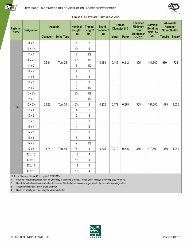
4.5 The fasteners evaluated in this TER are set forth in Table 1.
4 2012 IBC Section 2304.9
5 2012 IBC Section 2304.9.5
TER 1907-01: BIG TIMBER® CTX CONSTRUCTION LAG SCREW PROPERTIES
© 2019 DRJ ENGINEERING, LLC PAGE 5 OF 12
TABLE 1. FASTENER SPECIFICATIONS
Fastener Name
Designation Head (in) Nominal
Length1 (in)
Thread Length1
(in)
Shank Diameter2
(in)
Thread Diameter (in)
Specified Minimum
Core Hardness4
(HV 0.3)
Nominal Bending Yield, fyb
(psi)
Allowable Fastener
Strength (lbf)
Diameter Drive Type Minor Major Tensile Shear3
CTX
14 x 1
0.531 Torx 25
1 ¾
0.168 0.146 0.242 355 141,300 930 725
14 x 1½ 1½ 1
14 x 2 2 1½
14 x 2½ 2½ 1½
14 x 3 3 1½
14 x 4 4 2
14 x 5 5 3
14 x 6 6 3
15 x 2
0.620 Torx 30
2 1½
0.202 0.179 0.275 355 151,600 1,475 1,020
15 x 2½ 2½ 1½
15 x 3 3 1½
15 x 3½ 3½ 2
15 x 4 4 2
15 x 5 5 3
15 x 6 6 3
17 x 4
0.675 Torx 40
4 2
0.226 0.210 0.295 355 170,500 1,850 1,240
17 x 5 5 3
17 x 6 6 3
17 x 7 7 3½
17 x 8 8 4
17 x 10 10 4
17 x 12 12 4
17 x 14 14 4
17 x 16 16 4
SI: 1 in = 25.4 mm, 1 lb = 4.45 N, 1 psi = 0.00689 MPa
1. Fastener length is measured from the underside of the head to the tip. Thread length includes tapered tip (see Figure 1).
2. Shank diameter based on manufactured thickness. Finished dimensions are larger, due to the proprietary coatings added.
3. Shear determined at smooth shank diameter.
4. Based on a 300 gram load using the Vickers indenter.

TER 1907-01: BIG TIMBER® CTX CONSTRUCTION LAG SCREW PROPERTIES
© 2019 DRJ ENGINEERING, LLC PAGE 6 OF 12
5 APPLICATIONS
5.1 General
5.1.1 CTX screws are used to attach wood framing members in conventional light-frame construction and provide
resistance against withdrawal, head pull-through, axial, and shear loads. See Section 0 for installation
requirements.
5.1.2 CTX screws are installed without lead holes, as prescribed in NDS.
5.1.3 Where the application exceeds the limitations set forth herein, design shall be permitted in accordance with
accepted engineering procedures, experience, and technical judgment.
5.2 Design
5.2.1 Design of CTX screws is governed by the applicable code and the provisions for dowel-type fasteners in
NDS.
5.2.2 Unless otherwise noted, adjustment of the design stresses for duration of load shall be in accordance with the
applicable code.
5.3 CTX Reference Lateral Design Values (Z)
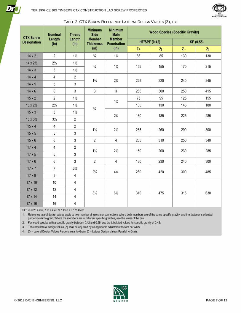
5.3.1 Reference lateral design values (lbf) for shear load parallel and perpendicular to grain for CTX screws are
specified in Table 2.
TER 1907-01: BIG TIMBER® CTX CONSTRUCTION LAG SCREW PROPERTIES
© 2019 DRJ ENGINEERING, LLC PAGE 7 OF 12
TABLE 2. CTX SCREW REFERENCE LATERAL DESIGN VALUES (Z), LBF
CTX Screw Designation
Nominal Length
(in)
Thread Length
(in)
Minimum Side
Member Thickness
(in)
Minimum Main
Member Penetration
(in)
Wood Species (Specific Gravity)
HF/SPF (0.42) SP (0.55)
Z┴ Z║ Z┴ Z║
14 x 2 2 1½ ¾ 1¼ 85 85 130 130
14 x 2½ 2½ 1½ ¾ 1¾ 155 155 170 215
14 x 3 3 1½
14 x 4 4 2 1¾ 2¼ 225 220 240 245
14 x 5 5 3
14 x 6 6 3 3 3 255 300 250 415
15 x 2 2 1½
¾
1¼ 75 95 125 155
15 x 2½ 2½ 1½ 105 130 145 180
15 x 3 3 1½ 2¼ 160 185 225 285
15 x 3½ 3½ 2
15 x 4 4 2 1½ 2½ 265 260 290 300
15 x 5 5 3
15 x 6 6 3 2 4 265 310 250 340
17 x 4 4 2 1½ 2½ 160 200 230 285
17 x 5 5 3
17 x 6 6 3 2 4 180 230 240 300
17 x 7 7 3½ 2¾ 4¼ 280 420 300 485
17 x 8 8 4
17 x 10 10 4
3½ 6½ 310 475 315 630 17 x 12 12 4
17 x 14 14 4
17 x 16 16 4
SI: 1 in = 25.4 mm, 1 lb = 4.45 N, 1 lb/in = 0.175 kN/m
1. Reference lateral design values apply to two-member single shear connections where both members are of the same specific gravity, and the fastener is oriented perpendicular to grain. Where the members are of different specific gravities, use the lower of the two.
2. For wood species with a specific gravity between 0.42 and 0.55, use the tabulated values for specific gravity of 0.42.
3. Tabulated lateral design values (Z) shall be adjusted by all applicable adjustment factors per NDS.
4. Z┴ = Lateral Design Values Perpendicular to Grain, Z║= Lateral Design Values Parallel to Grain.

TER 1907-01: BIG TIMBER® CTX CONSTRUCTION LAG SCREW PROPERTIES
© 2019 DRJ ENGINEERING, LLC PAGE 8 OF 12
5.4 CTX Reference Withdrawal Design Values (W) in Side Grain Applications
5.4.1 Reference withdrawal design values (lbf/in) for CTX screws are specified in Table 3.
TABLE 3. CTX SCREW REFERENCE WITHDRAWAL DESIGN VALUES (W) – SIDE GRAIN APPLICATIONS, LBF/IN
CTX Screw Designation Nominal Length
(in) Thread Length
(in)
Wood Species (Specific Gravity)
HF/SPF (0.42) SP (0.55)
14 x 1 1 ¾
120 210 14 x 1½ 1½ 1
14 x 2 2 1½
14 x 2½ 2½ 1½
195 215
14 x 3 3 1½
14 x 4 4 2
14 x 5 5 3
14 x 6 6 3
15 x 2 2 1½ 140 215
15 x 2½ 2½ 1½
15 x 3 3 1½ 165 215
15 x 3½ 3½ 2
175 230 15 x 4 4 2
15 x 5 5 3
15 x 6 6 3
17 x 4 4 2
150 235 17 x 5 5 3
17 x 6 6 3
17 x 7 7 3½
180 235
17 x 8 8 4
17 x 10 10 4
17 x 12 12 4
17 x 14 14 4
17 x 16 16 4
SI: 1 in = 25.4 mm, 1 lb = 4.45 N, 1 lb/in = 0.175 kN/m
1. Tabulated withdrawal values (W) shall be adjusted by all applicable adjustment factors per NDS, Table 11.3.1.
2. Fastener penetration is the threaded length embedded in the main member, including the tip.
3. For wood species with a specific gravity between 0.42 and 0.55, use the tabulated values for specific gravity of 0.42.
4. The full design withdrawal value is equal to the reference withdrawal value multiplied by the length of the threaded portion of the fastener embedded in the main member.
TER 1907-01: BIG TIMBER® CTX CONSTRUCTION LAG SCREW PROPERTIES
© 2019 DRJ ENGINEERING, LLC PAGE 9 OF 12
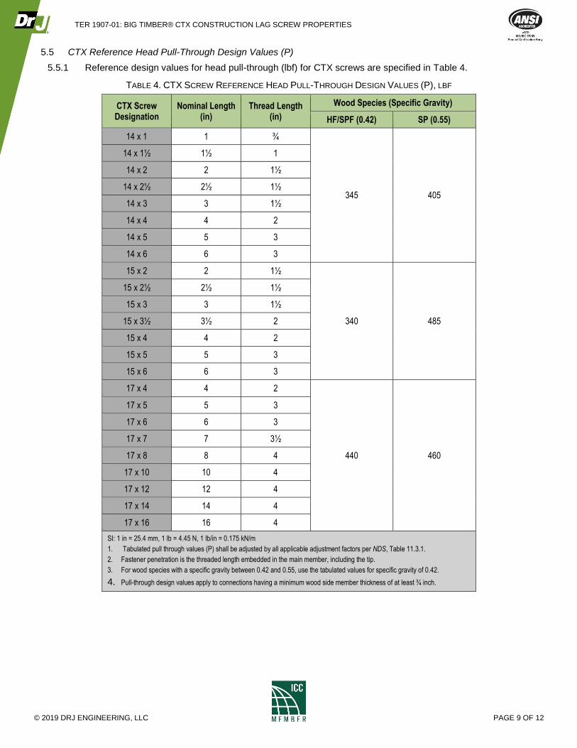
5.5 CTX Reference Head Pull-Through Design Values (P)
5.5.1 Reference design values for head pull-through (lbf) for CTX screws are specified in Table 4.
TABLE 4. CTX SCREW REFERENCE HEAD PULL-THROUGH DESIGN VALUES (P), LBF
CTX Screw Designation
Nominal Length (in)
Thread Length (in)
Wood Species (Specific Gravity)
HF/SPF (0.42) SP (0.55)
14 x 1 1 ¾
345 405
14 x 1½ 1½ 1
14 x 2 2 1½
14 x 2½ 2½ 1½
14 x 3 3 1½
14 x 4 4 2
14 x 5 5 3
14 x 6 6 3
15 x 2 2 1½
340 485
15 x 2½ 2½ 1½
15 x 3 3 1½
15 x 3½ 3½ 2
15 x 4 4 2
15 x 5 5 3
15 x 6 6 3
17 x 4 4 2
440 460
17 x 5 5 3
17 x 6 6 3
17 x 7 7 3½
17 x 8 8 4
17 x 10 10 4
17 x 12 12 4
17 x 14 14 4
17 x 16 16 4
SI: 1 in = 25.4 mm, 1 lb = 4.45 N, 1 lb/in = 0.175 kN/m
1. Tabulated pull through values (P) shall be adjusted by all applicable adjustment factors per NDS, Table 11.3.1.
2. Fastener penetration is the threaded length embedded in the main member, including the tip.
3. For wood species with a specific gravity between 0.42 and 0.55, use the tabulated values for specific gravity of 0.42.
4. Pull-through design values apply to connections having a minimum wood side member thickness of at least ¾ inch.

TER 1907-01: BIG TIMBER® CTX CONSTRUCTION LAG SCREW PROPERTIES
© 2019 DRJ ENGINEERING, LLC PAGE 10 OF 12
6 INSTALLATION
6.1 Installation shall comply with the manufacturer’s installation instructions and this TER. In the event of a conflict
between the manufacturer’s installation instructions and this TER, the more restrictive shall govern.
6.2 Minimum penetration is 1", unless otherwise stated in this TER. Install fasteners with head flush to the surface of
the wood member.
6.3 Lead holes are not required.
6.4 Screws shall be installed with the appropriate rotating powered driver.
6.5 Minimum requirements for screw spacing, edge distance, and end distance shall be in accordance with Table 5.
TABLE 5. CTX SCREW SPACING, EDGE DISTANCE, AND END DISTANCE REQUIREMENTS1, INCH
Connection Geometry CTX 14 CTX 15 CTX 17
Edge Distance – Load in any direction 1⅜ 1⅝ 1⅞
End Distance – Load parallel to grain, towards end 2½ 3 3⅜
End Distance – Load parallel to grain, away from end 1⅝ 2 2¼
End Distance – Load perpendicular to grain 1⅝ 2 2¼
Spacing between Fasteners in a Row – Parallel to grain 2½ 3 3⅜
Spacing between Fasteners in a Row – Perpendicular to grain 1⅝ 2 2¼
Spacing between Rows of Fasteners – In-line ⅞ 1 1⅛
Spacing between Rows of Fasteners – Staggered ½ ½ ⅝
SI: 1 in = 25.4 mm
1. Edge distances, end distances, and spacing of fasteners shall be sufficient to prevent splitting of the wood or as shown in this table, whichever is the more restrictive.
2. Values for “Spacing between Rows of Fasteners-Staggered” apply where the screws in adjacent rows are offset by one half of the “Spacing between Fasteners in a Row”
7 TEST ENGINEERING SUBSTANTIATING DATA
7.1 Testing for withdrawal by Element, in accordance with ASTM D1761.
7.2 Testing for lateral strength by Element, in accordance with ASTM D1761.
7.3 Testing for head pull-through by Element, in accordance with ASTM D1037.
7.4 Testing for bending yield by Element, in accordance with ASTM F1575.
7.5 Testing for tensile strength by Element, in accordance with AISI S904.
7.6 Testing for shear strength by Element, in accordance with AISI S904.
7.7 Testing for corrosion resistance by Element.
7.8 Some information contained herein is the result of testing and/or data analysis by other sources which conform to
IBC Section 1703 and relevant professional engineering law. DrJ relies on accurate data from these sources to
perform engineering analysis. DrJ has reviewed and found the data provided by other professional sources to be
credible.
7.9 Where appropriate, DrJ’s analysis is based on design values that have been codified into law through codes and
standards (e.g., IBC, IRC, NDS®, and SDPWS). This includes review of code provisions and any related test data
that aids in comparative analysis or provides support for equivalency to an intended end-use application. Where
the accuracy of design values provided herein is reliant upon the published properties of commodity materials
(e.g., lumber, steel, and concrete), DrJ relies upon the grade mark, stamp, and/or design values provided by raw
material suppliers to be accurate and conforming to the mechanical properties defined in the relevant material
standard.

TER 1907-01: BIG TIMBER® CTX CONSTRUCTION LAG SCREW PROPERTIES
© 2019 DRJ ENGINEERING, LLC PAGE 11 OF 12
8 FINDINGS
8.1 When used and installed in accordance with this TER and the manufacturer’s installation instructions, the
product(s) listed in Section 1.1 have the reference design value properties defined herein and are approved for
use in accordance with the applicable code.
8.2 IBC Section 104.11 (IRC Section R104.11 and IFC Section 104.9 are similar) states:
104.11 Alternative materials, design and methods of construction and equipment. The provisions of this code are not
intended to prevent the installation of any material or to prohibit any design or method of construction not specifically prescribed
by this code, provided that any such alternative has been approved. An alternative material, design or method of construction
shall be approved where the building official finds that the proposed design is satisfactory and complies with the intent of the
provisions of this code, and that the material, method or work offered is, for the purpose intended, not less than the equivalent
of that prescribed in this code…Where the alternative material, design or method of construction is not approved, the building
official shall respond in writing, stating the reasons the alternative was not approved.
8.3 This product has been evaluated in the context of the codes listed in Section 2 and is compliant with all known
state and local building codes. Where there are known variations in state or local codes applicable to this
evaluation, they are listed here.
8.3.1 No known variations
9 CONDITIONS OF USE
9.1 Wood main and side members must have a moisture content of less than 19 percent.
9.2 Use of fasteners in locations exposed to saltwater or saltwater spray is outside the scope of this evaluation report.
9.3 Where required by the building official, also known as the authority having jurisdiction (AHJ) in which the project is
to be constructed, this TER and the installation instructions shall be submitted at the time of permit application.
9.4 Any generally accepted engineering calculations needed to show compliance with this TER shall be submitted to
the AHJ for review and approval.
9.5 Design loads shall be determined in accordance with the building code adopted by the jurisdiction in which the
project is to be constructed and/or by the Building Designer (e.g., owner or registered design professional).
9.6 At a minimum, this product shall be installed per Section 0 of this TER.
9.7 This product is manufactured under a third-party quality control program in accordance with IBC Section 104.4
and 110.4 and IRC Section R104.4 and R109.2.
9.8 The actual design, suitability, and use of this TER, for any particular building, is the responsibility of the owner or
the owner's authorized agent. Therefore, the TER shall be reviewed for code compliance by the building official
for acceptance.
9.9 The use of this TER is dependent on the manufacturer’s in-plant QC, the ISO/IEC 17020 third-party quality
assurance program and procedures, proper installation per the manufacturer’s instructions, the building official’s
inspection, and any other code requirements that may apply to demonstrate and verify compliance with the
applicable building code.
10 IDENTIFICATION
10.1 The product(s) listed in Section 1.1 are identified by a label on the board or packaging material bearing the
manufacturer’s name, product name, TER number, and other information to confirm code compliance.
10.2 Additional technical information can be found at bigtimberfasteners.com.
TER 1907-01: BIG TIMBER® CTX CONSTRUCTION LAG SCREW PROPERTIES
© 2019 DRJ ENGINEERING, LLC PAGE 12 OF 12
11 REVIEW SCHEDULE
11.1 This TER is subject to periodic review and revision. For the most recent version of this TER, visit
drjcertification.org.
11.2 For information on the current status of this TER, contact DrJ Certification.
Related Documents