BIG-IP ® Local Traffic Manager ™ : Implementations Version 13.0

Welcome message from author
This document is posted to help you gain knowledge. Please leave a comment to let me know what you think about it! Share it to your friends and learn new things together.
Transcript

BIG-IP® Local Traffic Manager™:Implementations
Version 13.0


Table of Contents
Configuring a Simple Intranet..................................................................................................11Overview: A simple intranet configuration........................................................................11Task summary..................................................................................................................11
Creating a pool......................................................................................................12Creating a virtual server........................................................................................ 12
Configuring ISP Load Balancing.............................................................................................13Overview: ISP load balancing.......................................................................................... 13
Illustration of ISP load balancing...........................................................................13Task summary for ISP load balancing..............................................................................13
Creating a load balancing pool..............................................................................13Creating a virtual server for inbound content server traffic................................... 14Creating a virtual server for outbound traffic for routers........................................15Creating self IP addresses an external VLAN.......................................................15Enabling SNAT automap for internal and external VLANs.................................... 15
Routing Based on XML Content..............................................................................................17Overview: XML content-based routing............................................................................. 17Task summary..................................................................................................................17
Creating a custom XML profile..............................................................................18Writing XPath queries............................................................................................18Creating a pool to manage HTTP traffic................................................................19Creating an iRule...................................................................................................20Viewing statistics about XML content-based routing.............................................21
Configuring nPath Routing...................................................................................................... 23Overview: Layer 2 nPath routing...................................................................................... 23About Layer 2 nPath routing configuration....................................................................... 24Guidelines for UDP timeouts............................................................................................24Guidelines for TCP timeouts............................................................................................ 24Task summary..................................................................................................................24
Creating a Fast L4 profile...................................................................................... 25Creating a server pool for nPath routing................................................................25Creating a virtual server for Layer 2 nPath routing................................................25Configuring the virtual address on the server loopback interface......................... 26Setting the route for inbound traffic....................................................................... 26
Configuring Layer 3 nPath Routing.........................................................................................27Overview: Layer 3 nPath routing...................................................................................... 27Configuring Layer 3 nPath routing using tmsh................................................................. 27Configuring a Layer 3 nPath monitor using tmsh............................................................. 28Layer 3 nPath routing example.........................................................................................29
Creating a Basic Web Site and E-commerce Configuration................................................. 31Overview: Basic web site and eCommerce configuration................................................ 31
Illustration of basic web site and eCommerce configuration................................. 31
Table of Contents
3

Task summary..................................................................................................................31Creating a pool to process HTTP traffic................................................................ 32Creating a pool to manage HTTPS traffic............................................................. 32Creating a virtual server to manage HTTP traffic..................................................33Creating a virtual server to manage HTTPS traffic............................................... 33
Installing a BIG-IP System Without Changing the IP Network............................................. 35Overview: Installing a BIG-IP system without changing the IP network...........................35Task summary..................................................................................................................36
Removing the self IP addresses from the default VLANs..................................... 36Creating a VLAN group......................................................................................... 37Creating a self IP for a VLAN group...................................................................... 37Creating a pool of web servers..............................................................................37Creating a virtual server........................................................................................ 38
Enabling IP Address Intelligence............................................................................................ 39Overview: Enabling IP address intelligence..................................................................... 39
Downloading the IP address intelligence database...............................................39Creating an iRule to log IP address intelligence information.................................40Creating an iRule to reject requests with questionable IP addresses................... 40Checking the reputation of an IP address............................................................. 41Checking the status of the IP intelligence database..............................................42
IP address intelligence categories................................................................................... 42
Configuring Content Adaptation for HTTP Requests............................................................45Overview: Configuring HTTP Request Adaptation...........................................................45Task summary..................................................................................................................46
Creating a custom client-side ICAP profile............................................................46Creating a pool of ICAP servers............................................................................47Creating an internal virtual server for forwarding requests to an ICAP server...... 47Creating a custom Request Adapt profile..............................................................48Creating a custom HTTP profile............................................................................48Creating a pool to process HTTP traffic................................................................ 49Creating an HTTP virtual server for enabling request adaptation......................... 49
Implementation result.......................................................................................................50
Configuring Content Adaptation for HTTP Requests and Responses................................ 51Overview: Configuring HTTP Request and Response Adaptation ..................................51Task summary..................................................................................................................52
Creating a custom client-side ICAP profile............................................................52Creating a custom server-side ICAP profile.......................................................... 53Creating a pool of ICAP servers............................................................................54Creating an internal virtual server for forwarding requests to an ICAP server...... 54Creating an internal virtual server for forwarding responses to an ICAP server... 55Creating a custom Request Adapt profile..............................................................55Creating a custom Response Adapt profile...........................................................56Creating a custom HTTP profile............................................................................57Creating a pool to process HTTP traffic................................................................ 57Creating an HTTP virtual server for enabling request and response
adaptation........................................................................................................ 57Implementation result.......................................................................................................58
Configuring HTTP Load Balancing with Source Address Affinity Persistence.................. 59
Table of Contents
4
Overview: HTTP load balancing with source affinity persistence.....................................59Task summary..................................................................................................................59
Creating a pool to process HTTP traffic................................................................ 59Creating a virtual server for HTTP traffic...............................................................60
Configuring HTTP Load Balancing with Cookie Persistence............................................... 61Overview: HTTP load balancing with cookie persistence................................................ 61Task summary..................................................................................................................61
Creating a custom cookie persistence profile........................................................61Creating a pool to process HTTP traffic................................................................ 62Creating a virtual server for HTTP traffic...............................................................62
Compressing HTTP Responses.............................................................................................. 65Overview: Compressing HTTP responses....................................................................... 65Task summary..................................................................................................................65
Creating a customized HTTP compression profile................................................ 65Creating a virtual server for HTTP compression................................................... 66
Using Via Headers to Acquire Information About Intermediate Routers.............................67Overview: Using Via headers...........................................................................................67Task summary for identifying intermediate information with Via headers........................ 67
Identifying information about intermediate proxies with Via headers.................... 67Removing Via headers from requests and responses.......................................... 67
Configuring the BIG-IP System as a Reverse Proxy Server................................................. 69Overview: URI translation and HTML content modification..............................................69
About URI translation............................................................................................ 69Rules for matching requests to URI rules..............................................................70About URI Rules....................................................................................................71Introduction to HTML content modification............................................................71
Task summary..................................................................................................................71Creating a Rewrite profile to specify URI rules..................................................... 71Creating an HTML profile for tag removal............................................................. 72Creating pools for processing HTTP traffic........................................................... 73Creating a local traffic policy................................................................................. 73Creating a virtual server........................................................................................ 75
Implementation results.....................................................................................................75
Load Balancing Passive Mode FTP Traffic.............................................................................77Overview: FTP passive mode load balancing.................................................................. 77Task Summary for load balancing passive mode FTP traffic........................................... 77
Creating a custom FTP monitor............................................................................ 77Creating a pool to manage FTP traffic.................................................................. 78Creating a virtual server for FTP traffic................................................................. 79
Load Balancing Passive Mode FTP Traffic with Data Channel Optimization......................81Overview: FTP passive mode load balancing with data channel optimization.................81Task Summary for load balancing passive mode FTP traffic........................................... 81
Creating a custom FTP profile...............................................................................81Creating a custom FTP monitor............................................................................ 81Creating a pool to manage FTP traffic.................................................................. 83Creating a virtual server for FTP traffic................................................................. 83
Table of Contents
5

Implementation result.......................................................................................................84
Configuring the BIG-IP System as a DHCP Relay Agent...................................................... 85Overview: Managing IP addresses for DHCP clients.......................................................85
About the BIG-IP system as a DHCP relay agent................................................. 85Task summary..................................................................................................................86
Creating a pool of DHCP servers..........................................................................86Creating a DHCP type virtual server..................................................................... 87
Implementation result.......................................................................................................87
Configuring the BIG-IP System for DHCP Renewal...............................................................89Overview: Renewing IP addresses for DHCP clients.......................................................89
About DHCP renewal ........................................................................................... 89Creating a DHCP renewal virtual server.......................................................................... 90Implementation result.......................................................................................................90
Configuring a One-IP Network Topology................................................................................91Overview: Configuring a one-IP network topology...........................................................91
Illustration of a one-IP network topology for the BIG-IP system............................91Task summary for a one-IP network topology for the BIG-IP system...............................92
Creating a pool for processing HTTP connections with SNATs enabled...............92Creating a virtual server for HTTP traffic...............................................................92Defining a default route......................................................................................... 93Configuring a client SNAT..................................................................................... 93Configuring optional ephemeral port exhaustion...................................................94
Configuring the BIG-IP System to Auto-Populate Pools.......................................................95Overview: Using host names to identify pool members and nodes................................. 95
About modes of failure and related nodes or pool members.................................96Task summary..................................................................................................................96
Creating a default gateway pool............................................................................ 97Configuring the BIG-IP system to handle DNS lookups........................................97Creating nodes using host names.........................................................................97Creating a pool using host names.........................................................................98
About modifying nodes and pool members identified by host names.............................. 99Disabling a node....................................................................................................99Disabling a pool member.....................................................................................100
About pool member and node statistics.........................................................................100Viewing statistics for a specific node...................................................................100Viewing statistics for ephemeral pool members.................................................. 100
Implementing Health and Performance Monitoring.............................................................103Overview: Health and performance monitoring..............................................................103Task summary................................................................................................................103
Creating a custom monitor.................................................................................. 104Creating a load balancing pool............................................................................104Creating a virtual server...................................................................................... 105
Preventing TCP Connection Requests From Being Dropped.............................................107Overview: TCP request queuing.................................................................................... 107Preventing TCP connection requests from being dropped.............................................107Enabling TCP enhanced loss recovery.......................................................................... 108
Table of Contents
6
Setting Connection Limits..................................................................................................... 109Overview: About connection limits................................................................................. 109Limiting connections for a virtual server, pool member, or node....................................109Implementation results...................................................................................................109
Load Balancing to IPv6 Nodes.............................................................................................. 111Overview: Load balancing to iPv6 nodes....................................................................... 111Task summary................................................................................................................111
Creating a load balancing pool............................................................................111Creating a virtual server for IPv6 nodes..............................................................112
Mitigating Denial of Service Attacks.....................................................................................113Overview: Mitigating Denial of Service and other attacks..............................................113Denial of Service attacks and iRules............................................................................. 113
iRules for Code Red attacks................................................................................113iRules for Nimda attacks..................................................................................... 113
Common Denial of Service attacks................................................................................114Task summary................................................................................................................116
Configuring adaptive reaping.............................................................................. 116Setting the TCP and UDP connection timers...................................................... 117Applying a rate class to a virtual server.............................................................. 117Calculating connection limits on the main virtual server..................................... 117Setting connection limits on the main virtual server............................................ 117Adjusting the SYN Check threshold.................................................................... 118
Configuring Remote CRLDP Authentication........................................................................119Overview of remote authentication for application traffic................................................119Task Summary............................................................................................................... 119
Creating a CRLDP configuration object for authenticating application trafficremotely......................................................................................................... 119
Creating a custom CRLDP profile....................................................................... 120Modifying a virtual server for CRLDP authentication.......................................... 120
Configuring Remote LDAP Authentication...........................................................................121Overview of remote LDAP authentication for application traffic..................................... 121Task Summary............................................................................................................... 121
Creating an LDAP configuration object for authenticating application trafficremotely......................................................................................................... 121
Creating a custom LDAP profile.......................................................................... 122Modifying a virtual server for LDAP authentication............................................. 122
Configuring Remote RADIUS Authentication...................................................................... 123Overview of remote authentication for application traffic................................................123About RADIUS profiles...................................................................................................123Task summary for RADIUS authentication of application traffic.....................................123
Creating a RADIUS server object for authenticating application trafficremotely......................................................................................................... 123
Creating a RADIUS configuration object for authenticating application trafficremotely......................................................................................................... 124
Creating a custom RADIUS profile......................................................................124Modifying a virtual server for RADIUS authentication......................................... 125
Table of Contents
7

Configuring Remote SSL LDAP Authentication...................................................................127Overview of remote SSL LDAP authentication for application traffic............................. 127Task Summary............................................................................................................... 127
Creating an LDAP Client Certificate SSL configuration object............................ 127Creating a custom SSL Client Certificate LDAP profile.......................................128Modifying a virtual server for SSL Client Certificate LDAP authorization............128
Configuring Remote SSL OCSP Authentication.................................................................. 129Overview of remote authentication for application traffic................................................129Task Summary............................................................................................................... 129
Creating an SSL OCSP responder object for authenticating application trafficremotely......................................................................................................... 129
Creating an SSL OCSP configuration object for authenticating applicationtraffic remotely................................................................................................130
Creating a custom SSL OCSP profile................................................................. 130Modifying a virtual server for SSL OCSP authentication.....................................130
Configuring Remote TACACS+ Authentication....................................................................133Overview of remote authentication for application traffic................................................133Task Summary............................................................................................................... 133
Creating a TACACS+ configuration object...........................................................133Creating a custom TACACS+ profile................................................................... 134Modifying a virtual server for TACACS+ authentication.......................................134
Configuring the BIG-IP System for Electronic Trading....................................................... 137Overview: Configuring the BIG-IP system for electronic trading.................................... 137Task summary................................................................................................................137
Creating a data group list for a FIX profile...........................................................137Creating a FIX profile for electronic trading ........................................................138Creating a load balancing pool............................................................................138Creating a virtual server for secure electronic trading.........................................139Viewing FIX message statistics...........................................................................140
Implementation result.....................................................................................................140
Implementing Low-Latency Electronic Trading Functionality............................................ 141Overview: Configuring the BIG-IP system for low-latency electronic trading................. 141
About using low-latency electronic trading with HSRP or VRRP........................ 141Task summary................................................................................................................142
Licensing low-latency electronic trading functionality..........................................142Creating a custom Fast L4 profile for FIX............................................................142Creating a pool....................................................................................................142Creating a virtual server for low-latency electronic trading..................................143
Implementation result.....................................................................................................143
Implementing Low-Latency Electronic Trading with FIX load balancing.......................... 145Overview: Configuring low-latency electronic trading with FIX load balancing.............. 145Task summary................................................................................................................145
Licensing low-latency electronic trading functionality..........................................146Creating a custom Fast L4 profile for FIX............................................................146Creating a FIX profile for low-latency electronic trading......................................147Creating a pool....................................................................................................147
Table of Contents
8
Creating an iRule for load-balancing Layer-7 (FIX) traffic................................... 147Creating a virtual server for low-latency electronic trading..................................149
Implementation result.....................................................................................................150
Implementing Hardware-optimized FIX Low Latency (FIX LL) Electronic Trading........... 151About configuring BIG-IP systems for hardware-optimized FIX LL................................151
Task summary..................................................................................................... 151Implementation result..........................................................................................153
Implementing APM System Authentication..........................................................................155Overview: Configuring authentication for a remote system based on APM .................. 155
Creating a user authentication based on APM....................................................155Example access policy using APM LDAP authentication....................................156
Configuring an SSL Intercept Explicit Proxy Mode............................................................. 157About SSL intercept explicit proxy mode........................................................................157
The SplitSession Client profile type.....................................................................157The SplitSession Server profile type................................................................... 157
Task Summary............................................................................................................... 157Creating a SplitSession Client profile..................................................................158Creating a custom Client SSL profile.................................................................. 158Creating a pool to process HTTP traffic for an inspection device........................158Creating an ingress explicit proxy virtual server..................................................159Creating a SplitSession Server profile.................................................................160Creating a custom Server SSL profile.................................................................160Creating a pool to manage HTTPS traffic........................................................... 161Creating an egress explicit proxy virtual server...................................................161
Configuring an Explicit HTTP Proxy Chain.......................................................................... 163Overview: Configuring an explicit HTTP proxy chain..................................................... 163
About HTTP Proxy Connect profiles................................................................... 163Task Summary............................................................................................................... 163
Creating a custom HTTP Proxy Connect profile................................................. 163Creating a load balancing pool............................................................................164Creating a virtual server for explicit HTTP proxy connection...............................164
Manipulating HTTPS Traffic by Using a Third-Party Device............................................... 167Overview: Manipulating HTTPS traffic by using a third-party device............................. 167Task Summary............................................................................................................... 168
Creating a VLAN................................................................................................. 168Creating a custom Client SSL profile.................................................................. 169Creating a custom Server SSL profile.................................................................169Creating a VLAN group....................................................................................... 170Creating a virtual server to manage client-side HTTPS traffic............................ 170Creating a virtual server to manage server-side traffic....................................... 170
Legal Notices.......................................................................................................................... 173Legal notices..................................................................................................................173
Table of Contents
9

Table of Contents
10
Configuring a Simple Intranet
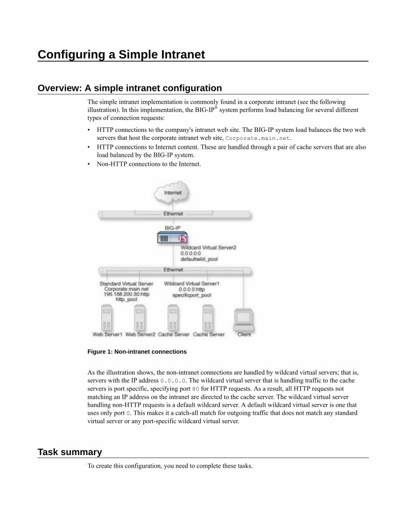
Overview: A simple intranet configurationThe simple intranet implementation is commonly found in a corporate intranet (see the followingillustration). In this implementation, the BIG-IP® system performs load balancing for several differenttypes of connection requests:
• HTTP connections to the company's intranet web site. The BIG-IP system load balances the two webservers that host the corporate intranet web site, Corporate.main.net.
• HTTP connections to Internet content. These are handled through a pair of cache servers that are alsoload balanced by the BIG-IP system.
• Non-HTTP connections to the Internet.
Figure 1: Non-intranet connections
As the illustration shows, the non-intranet connections are handled by wildcard virtual servers; that is,servers with the IP address 0.0.0.0. The wildcard virtual server that is handling traffic to the cacheservers is port specific, specifying port 80 for HTTP requests. As a result, all HTTP requests notmatching an IP address on the intranet are directed to the cache server. The wildcard virtual serverhandling non-HTTP requests is a default wildcard server. A default wildcard virtual server is one thatuses only port 0. This makes it a catch-all match for outgoing traffic that does not match any standardvirtual server or any port-specific wildcard virtual server.
Task summaryTo create this configuration, you need to complete these tasks.

Task listCreating a poolCreating a virtual server
Creating a pool
You can create pool of servers that you group together to receive and process traffic, to enable the BIG-IPsystem to efficiently distribute the load on servers.
1. On the Main tab, click Local Traffic > Pools.The Pool List screen opens.
2. Click Create.The New Pool screen opens.
3. In the Name field, type a unique name for the pool.4. In the Resources area of the screen, use the New Members setting to add the pool members. For
example, the pool members for http_pool are 192.168.100.10:80 and 192.168.100.11:80.The pool members for specificport_pool are 192.168.100.20:80 and 192.168.100.21:80.
5. Click Finished.
The load balancing pool appears in the Pools list.
Creating a virtual server
This task creates a destination IP address for application traffic. As part of this task, you must assign therelevant pool to the virtual server.
1. On the Main tab, click Local Traffic > Virtual Servers.The Virtual Server List screen opens.
2. Click the Create button.The New Virtual Server screen opens.
3. In the Name field, type a unique name for the virtual server.4. For a host, in the Destination Address field, type an IPv4 or IPv6 address in CIDR format to allow
all traffic to be translated.The supported format is address/prefix, where the prefix length is in bits. For example, an IPv4address/prefix is 0.0.0.0/0, and an IPv6 address/prefix is ::/0.
5. In the Service Port field, type 80, or select HTTP from the list.6. In the Configuration area of the screen, locate the Type setting and select either Standard or
Forwarding (IP).7. From the HTTP Profile list, select an HTTP profile.8. In the Resources area of the screen, from the Default Pool list, select the relevant pool name.9. Click Finished.
You now have a virtual server to use as a destination address for application traffic.
Configuring a Simple Intranet
12

Configuring ISP Load Balancing
Overview: ISP load balancingYou might find that as your network grows, or network traffic increases, you require an additionalconnection to the Internet. You can use this configuration to add an Internet connection to your existingnetwork. The following illustration shows a network configured with two Internet connections.
Illustration of ISP load balancing
Figure 2: ISP load balancing
Task summary for ISP load balancingThere are number of tasks you must perform to implement load balancing for ISPs.
Task listCreating a load balancing poolCreating a virtual server for inbound content server trafficCreating a virtual server for outbound traffic for routersCreating self IP addresses an external VLANEnabling SNAT automap for internal and external VLANs
Creating a load balancing pool
You can a create load balancing pool, which is a logical set of devices, such as web servers, that yougroup together to receive and process traffic, to efficiently distribute the load on your resources. Usingthis procedure, create one pool that load balances the content servers, and one pool to load balance therouters.
1. On the Main tab, click Local Traffic > Pools.
The Pool List screen opens.2. Click Create.
The New Pool screen opens.3. In the Name field, type a unique name for the pool.4. For the Health Monitors setting, in the Available list, select a monitor type, and click << to move the
monitor to the Active list.
Tip: Hold the Shift or Ctrl key to select more than one monitor at a time.
5. From the Load Balancing Method list, select how the system distributes traffic to members of thispool.The default is Round Robin.
6. For the Priority Group Activation setting, specify how to handle priority groups:
• Select Disabled to disable priority groups. This is the default option.• Select Less than, and in the Available Members field type the minimum number of members that
must remain available in each priority group in order for traffic to remain confined to that group.7. Using the New Members setting, add each resource that you want to include in the pool:
a) (Optional) In the Node Name field, type a name for the node portion of the pool member.b) In the Address field, type an IP address.c) In the Service Port field, type a port number, or select a service name from the list.d) (Optional) In the Priority field, type a priority number.e) Click Add.
8. Click Repeat and create another pool.9. Click Finished.
The load balancing pools appear in the Pools list.
Creating a virtual server for inbound content server traffic
You must create a virtual server to load balance inbound connections. The default pool that you assign asa resource in this procedure is the pool of internal servers.
1. On the Main tab, click Local Traffic > Virtual Servers.The Virtual Server List screen opens.
2. Click the Create button.The New Virtual Server screen opens.
3. In the Name field, type a unique name for the virtual server.4. In the Destination Address field, type the IP address in CIDR format.
The supported format is address/prefix, where the prefix length is in bits. For example, an IPv4address/prefix is 10.0.0.1 or 10.0.0.0/24, and an IPv6 address/prefix is ffe1::0020/64 or2001:ed8:77b5:2:10:10:100:42/64. When you use an IPv4 address without specifying a prefix,the BIG-IP® system automatically uses a /32 prefix.
Note: The IP address you type must be available and not in the loopback network.
5. In the Service Port field, type a port number or select a service name from the Service Port list.6. If the traffic to be load balanced is of a certain type, select the profile type that matches the
connection type.To load balance HTTP traffic, locate the HTTP Profile setting and select http.
7. In the Resources area of the screen, from the Default Pool list, select the relevant pool name.8. Click Finished.
The virtual server is configured to load balance inbound connections to the servers.
Configuring ISP Load Balancing
14
Creating a virtual server for outbound traffic for routers
You must create a virtual server to load balance outbound connections. The default pool that you assignas a resource in this procedure is the pool of routers.
1. On the Main tab, click Local Traffic > Virtual Servers.The Virtual Server List screen opens.
2. Click the Create button.The New Virtual Server screen opens.
3. In the Name field, type a unique name for the virtual server.4. In the Destination Address field, type the IP address in CIDR format.
The supported format is address/prefix, where the prefix length is in bits. For example, an IPv4address/prefix is 10.0.0.1 or 10.0.0.0/24, and an IPv6 address/prefix is ffe1::0020/64 or2001:ed8:77b5:2:10:10:100:42/64. When you use an IPv4 address without specifying a prefix,the BIG-IP® system automatically uses a /32 prefix.
Note: The IP address you type must be available and not in the loopback network.
5. In the Resources area of the screen, from the Default Pool list, select the relevant pool name.6. Click Finished.
The virtual server is configured to load balance outbound connections to the routers.
Creating self IP addresses an external VLAN
You must assign two self IP addresses to the external VLAN.
1. On the Main tab, click Network > Self IPs.2. Click Create.
The New Self IP screen opens.3. In the IP Address field, type an IP address.
This IP address should represent the network of the router.The system accepts IPv4 and IPv6 addresses.
4. In the Netmask field, type the network mask for the specified IP address.
For example, you can type 255.255.255.0.5. Select External from the VLAN list.6. Click Repeat.7. In the IP Address field, type an IPv4 or IPv6 address.
This IP address should represent the address space of the VLAN that you specify with the VLAN/Tunnel setting.
8. Click Finished.The screen refreshes, and displays the new self IP address.
The self IP address is assigned to the external VLAN.
Enabling SNAT automap for internal and external VLANs
You can configure SNAT automapping on the BIG-IP system for internal and external VLANs.
1. On the Main tab, click Local Traffic > Address Translation.The SNAT List screen displays a list of existing SNATs.
2. Click Create.
BIG-IP Local Traffic Manager: Implementations
15

3. Name the new SNAT.4. From the Translation list, select Automap.5. For the VLAN / Tunnel List setting, in the Available list, select external and internal, and using the
Move button, transfer the VLANs to the Selected list.6. Click the Finished button.
SNAT automapping on the BIG-IP system is configured for internal and external VLANs.
Configuring ISP Load Balancing
16

Routing Based on XML Content
Overview: XML content-based routingYou can use the BIG-IP® system to perform XML content-based routing whereby the system routesrequests to an appropriate pool, pool member, or virtual server based on specific content in an XMLdocument. For example, if your company transfers information in XML format, you could use thisfeature to examine the XML content with the intent to route the information to the appropriatedepartment.
You configure content-based routing by creating an XML profile and associating it with a virtual server.In the XML profile, define the matching content to look for in the XML document. Next, specify how toroute the traffic to a pool by writing simple iRules®. When the system discovers a match, it triggers aniRule event, and then you can configure the system to route traffic to a virtual server, a pool, or a node.You can allow multiple query matches, if needed.
This example shows a simple XML document that the system could use to perform content-basedrouting. It includes an element called FinanceObject used in this implementation.
<soapenv:Envelope xmlns:xsi="http://www.w3.org/2001/XMLSchema-instance"xmlns:xsd="http://www.w3.org/2001/XMLSchema"xmlns:soapenv="http://schemas.xmlsoap.org/soap/envelope/"xmlns:eai="http://192.168.149.250/eai_enu/"xmlns:soapenc="http://schemas.xmlsoap.org/soap/encoding/"> <soapenv:Header/> <soapenv:Body> <eai:SiebelEmployeeDeletesoapenv:encodingStyle="http://schemas.xmlsoap.org/soap/encoding/"> <FinanceObject xsi:type="xsd:string">Route to Financing</FinanceObject> <SiebelMessage xsi:type="ns:ListOfEmployeeInterfaceTopElmt"xmlns:ns="http://www.siebel.com/xml"> <ListOfEmployeeInterface xsi:type="ns:ListOfEmployeeInterface"> <SecretKey>123456789</SecretKey> <Employee>John</Employee> <Title>CEO</Title> </ListOfEmployeeInterface> </SiebelMessage> </eai:SiebelEmployeeDelete> </soapenv:Body></soapenv:Envelope>
Task summaryYou can perform tasks to enable XML content-based routing whereby the system routes requests to anappropriate pool, pool member, or virtual server based on specific content in an XML document.
Task listCreating a custom XML profileWriting XPath queriesCreating a pool to manage HTTP trafficCreating an iRuleViewing statistics about XML content-based routing

Creating a custom XML profile
To implement content-based routing, you first need to create an XML profile. XML profiles specify thecontent to look for in XML documents. In the XML profile, you define XPath queries to locate items inan XML document.
1. On the Main tab, click Local Traffic > Profiles > Services > XML.The XML screen opens.
2. Click Create.The New XML screen opens.
3. In the Name field, type a unique name for the XML profile, such as cbr_xml_profile.4. In the Settings area, select the Custom check box at right.
The settings become available.5. If you want to reference XML elements with namespaces in XPath queries, from Namespace
Mappings, select Specify.The screen displays the Namespace Mappings List settings.
6. Add namespaces to the list to specify how to map XML namespaces (as defined by the xmlnsattribute) for the system to use when routing XML traffic to the correct pool, pool member, or virtualserver:a) In the Prefix field, type the namespace prefix.b) In the Namespace field, type the URL that the prefix maps to.c) Click Add to add the namespace to the Namespace Mappings List.
7. To define the matching criteria in the XML document, from XPath Queries, select Specify.The screen displays the XPath Queries settings.
8. Add XPath queries to the list to define matching criteria in XML payloads so the system can route thetraffic to the correct pool, pool member, or virtual server:a) In the XPath field, type an XPath expression.
For example, to look for an element called FinanceObject, type //FinanceObject.b) Click Add to add the XPath expression to the XPath Queries list.
You can define up to three XPath queries.The expression is added to the list.
9. To allow each query to have multiple matches, select Multiple Query Matches.10. Click Finished.
The system creates an XML profile.
You can use the XML profile to route XML traffic. Note that XML profiles do not support use of theExpect header field. This is because the header of a transaction could direct it to one pool, and thepayload could invoke an iRule to direct the transaction to a different pool.
Writing XPath queries
You can write up to three XPath queries to define the content that you are looking for in XMLdocuments. When writing XPath queries, you use a subset of the XPath syntax described in the XMLPath Language (XPath) standard at http://www.w3.org/TR/xpath.
These are the rules for writing XPath queries for XML content-based routing.
1. Express the queries in abbreviated form.2. Map all prefixes to namespaces.3. Use only ASCII characters in queries.4. Write queries to match elements and attributes.
Routing Based on XML Content
18
5. Use wildcards as needed for elements and namespaces; for example, //emp:employee/*.6. Do not use predicates in queries.
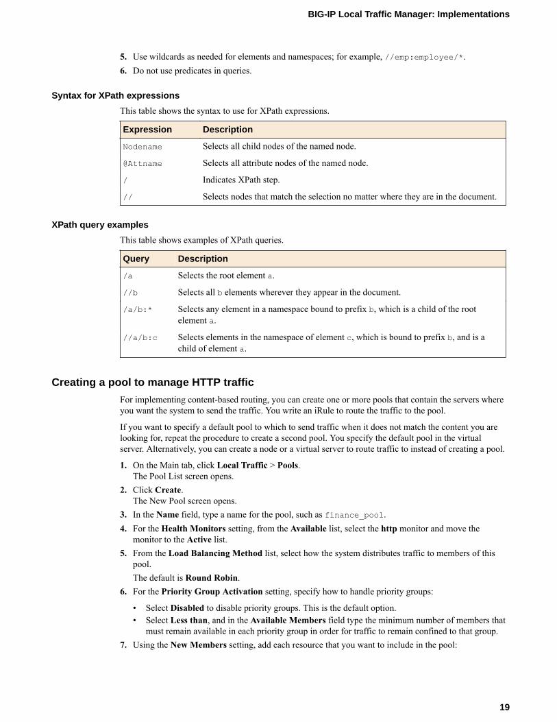
Syntax for XPath expressions
This table shows the syntax to use for XPath expressions.
Expression Description
Nodename Selects all child nodes of the named node.
@Attname Selects all attribute nodes of the named node.
/ Indicates XPath step.
// Selects nodes that match the selection no matter where they are in the document.
XPath query examples
This table shows examples of XPath queries.
Query Description
/a Selects the root element a.
//b Selects all b elements wherever they appear in the document.
/a/b:* Selects any element in a namespace bound to prefix b, which is a child of the rootelement a.
//a/b:c Selects elements in the namespace of element c, which is bound to prefix b, and is achild of element a.
Creating a pool to manage HTTP traffic
For implementing content-based routing, you can create one or more pools that contain the servers whereyou want the system to send the traffic. You write an iRule to route the traffic to the pool.
If you want to specify a default pool to which to send traffic when it does not match the content you arelooking for, repeat the procedure to create a second pool. You specify the default pool in the virtualserver. Alternatively, you can create a node or a virtual server to route traffic to instead of creating a pool.
1. On the Main tab, click Local Traffic > Pools.The Pool List screen opens.
2. Click Create.The New Pool screen opens.
3. In the Name field, type a name for the pool, such as finance_pool.4. For the Health Monitors setting, from the Available list, select the http monitor and move the
monitor to the Active list.5. From the Load Balancing Method list, select how the system distributes traffic to members of this
pool.The default is Round Robin.
6. For the Priority Group Activation setting, specify how to handle priority groups:
• Select Disabled to disable priority groups. This is the default option.• Select Less than, and in the Available Members field type the minimum number of members that
must remain available in each priority group in order for traffic to remain confined to that group.7. Using the New Members setting, add each resource that you want to include in the pool:
BIG-IP Local Traffic Manager: Implementations
19

a) Type an IP address in the Address field.b) Type 80 in the Service Port field, or select HTTP from the list.c) (Optional) Type a priority number in the Priority field.d) Click Add.
8. Click Finished.
The new pool appears in the Pools list.
Creating an iRule
You create iRules® to automate traffic forwarding for XML content-based routing. When a match occurs,an iRule event is triggered, and the iRule directs the individual request to a pool, a node, or virtual server.This implementation targets a pool.
1. On the Main tab, click Local Traffic > iRules.
2. Click Create.3. In the Name field, type a name, such as XML_CBR_iRule.
The full path name of the iRule cannot exceed 255 characters.4. In the Definition field, type the syntax for the iRule using Tool Command Language (Tcl) syntax.
For complete and detailed information iRules syntax, see the F5 Networks DevCentral web sitehttp://devcentral.f5.com.
5. Click Finished.
Examples of iRules for XML content-based routing
This example shows an iRule that queries for an element called FinanceObject in XML content and ifa match is found, an iRule event is triggered. The system populates the values of the Tcl variables($XML_count, $XML_queries, and $XML_values). Then the system routes traffic to a pool calledfinance_pool.
when XML_CONTENT_BASED_ROUTING{ for {set i 0} { $i < $XML_count } {incr i} { log local0. $XML_queries($i) log local0. $XML_values($i) if {($XML_queries($i) contains "FinanceObject")} { pool finance_pool } }}
This is another example of XML content-based routing. It shows routing by bank name and by price.
when XML_CONTENT_BASED_ROUTING{ for {set i 0} { $i < $XML_count } {incr i} { # routing by BANK_NAME if {($XML_queries($i) contains "BANK_NAME")} { if {($XML_values($i) contains "InternationalBank")} { pool pool1 } elseif {($XML_values($i) contains "Hapoalim")} { pool pool2 } else { pool pool3 } } # routing by PRICE
Routing Based on XML Content
20

if {($XML_queries($i) contains "PRICE")} { if {($XML_values($i) > 50)} { pool pool1 } else { pool pool2 } } # end for } }
Note: The XML_CONTENT_BASED_ROUTING event does not trigger when the client's headers contain"Expect: 100-continue" regardless of whether the server sends a 100-continue response. In thiscase, the request is routed to the default pool.
Tcl variables in iRules for XML routing
This table lists and describes the Tcl variables in the sample iRule.
Tcl variable Description
$XML_count Shows the number of matching queries.
$XML_queries Contains an array of the matching query names.
$XML_values Holds the values of the matching elements.
Viewing statistics about XML content-based routing
You can view statistics about XML content-based routing to make sure that the routing is working.
Note: The system first checks for a match, then checks for malformedness of XML content. So if thesystem detects a match, it stops checking, and might not detect any subsequent parts of the document thatare malformed.
1. On the Main tab, click Statistics > Module Statistics > Local Traffic.The Local Traffic statistics screen opens.
2. From the Statistics Type list, select Profiles Summary.3. In the Global Profile Statistics area, for the Profile Type XML, click View in the Details.
The system displays information about the number of XML documents that were inspected, thenumber of documents that had zero to three matches, and the number of XML documents that werefound to be malformed.
BIG-IP Local Traffic Manager: Implementations
21

Routing Based on XML Content
22

Configuring nPath Routing
Overview: Layer 2 nPath routingWith the Layer 2 nPath routing configuration, you can route outgoing server traffic around the BIG-IP®
system directly to an outbound router. This method of traffic management increases outbound throughputbecause packets do not need to be transmitted to the BIG-IP system for translation and then forwarded tothe next hop.
Figure 3: Layer 2 nPath routing
Note: The type of virtual server that processes the incoming traffic must be a transparent, non-translating type of virtual server.
In bypassing the BIG-IP system on the return path, Layer 2 nPath routing departs significantly from atypical load-balancing configuration. In a typical load-balancing configuration, the destination address ofthe incoming packet is translated from that of the virtual server to that of the server being load balancedto, which then becomes the source address of the returning packet. A default route set to the BIG-IPsystem then sees to it that packets returning to the originating client return through the BIG-IP system,which translates the source address back to that of the virtual server.
Note: Do not attempt to use nPath routing for Layer 7 traffic. Certain traffic features do not workproperly if Layer 7 traffic bypasses the BIG-IP system on the return path.

About Layer 2 nPath routing configurationThe Layer 2 nPath routing configuration differs from the typical BIG-IP® load balancing configuration inthe following ways:
• The default route on the content servers must be set to the router's internal address (10.1.1.1 in theillustration) rather than to the BIG-IP system's floating self IP address (10.1.1.10). This causes thereturn packet to bypass the BIG-IP system.
• If you plan to use an nPath configuration for TCP traffic, you must create a Fast L4 profile with thefollowing custom settings:
• Enable the Loose Close setting. When you enable this setting, the TCP protocol flow expires morequickly, after a TCP FIN packet is seen. (A FIN packet indicates the tearing down of a previousconnection.)
• Set the TCP Close Timeout setting to the same value as the profile idle timeout if you expect halfcloses. If not, you can set this value to 5 seconds.
• Because address translation and port translation have been disabled, when the incoming packet arrivesat the pool member it is load balanced to the virtual server address (176.16.1.1 in the illustration), notto the address of the server. For the server to respond to that address, that address must be configuredon the loopback interface of the server and configured for use with the server software.
Guidelines for UDP timeoutsWhen you configure nPath for UDP traffic, the BIG-IP® system tracks packets sent between the samesource and destination address to the same destination port as a connection. This is necessary to ensurethe client requests that are part of a session always go to the same server. Therefore, a UDP connection isreally a form of persistence, because UDP is a connectionless protocol.
To calculate the timeout for UDP, estimate the maximum amount of time that a server transmits UDPpackets before a packet is sent by the client. In some cases, the server might transmit hundreds of packetsover several minutes before ending the session or waiting for a client response.
Guidelines for TCP timeoutsWhen you configure nPath for TCP traffic, the BIG-IP® system recognizes only the client side of theconnection. For example, in the TCP three-way handshake, the BIG-IP system sees the SYN from theclient to the server, and does not see the SYN acknowledgment from the server to the client, but does seethe acknowledgment of the acknowledgment from the client to the server. The timeout for the connectionshould match the combined TCP retransmission timeout (RTO) of the client and the node as closely aspossible to ensure that all connections are successful.
The maximum initial RTO observed on most UNIX and Windows® systems is approximately 25 seconds.Therefore, a timeout of 51 seconds should adequately cover the worst case. When a TCP session isestablished, an adaptive timeout is used. In most cases, this results in a faster timeout on the client andnode. Only in the event that your clients are on slow, lossy networks would you ever require a higherTCP timeout for established connections.
Task summaryThere are several tasks you perform to create a Layer 2 nPath routing configuration.
Configuring nPath Routing
24
Task listCreating a Fast L4 profileCreating a server pool for nPath routingCreating a virtual server for Layer 2 nPath routingConfiguring the virtual address on the server loopback interfaceSetting the route for inbound traffic
Creating a Fast L4 profile
You can create a custom Fast L4 profile to manage Layer 4 traffic more efficiently.
1. On the Main tab, click Local Traffic > Profiles > Protocol > Fast L4.The Fast L4 screen opens.
2. Click Create.The New Fast L4 profile screen opens.
3. In the Name field, type a unique name for the profile.4. Select the Custom check box.5. Select the Loose Close check box only for a one-arm virtual server configuration.6. Set the TCP Close Timeout setting, according to the type of traffic that the virtual server will
process.7. Click Finished.
The custom Fast L4 profile appears in the list of Fast L4 profiles.
Creating a server pool for nPath routing
After you create a custom Fast L4 profile, you need to create a server pool.
1. On the Main tab, click Local Traffic > Pools.The Pool List screen opens.
2. Click Create.The New Pool screen opens.
3. In the Name field, type a unique name for the pool.4. For the Health Monitors setting, in the Available list, select a monitor type, and click << to move the
monitor to the Active list.
Tip: Hold the Shift or Ctrl key to select more than one monitor at a time.
5. Using the New Members setting, add each resource that you want to include in the pool:a) (Optional) In the Node Name field, type a name for the node portion of the pool member.b) In the Address field, type an IP address.c) In the Service Port field, type a port number, or select a service name from the list.d) (Optional) In the Priority field, type a priority number.e) Click Add.
6. Click Finished.
Creating a virtual server for Layer 2 nPath routing
After you create a server pool, you need to create a virtual server that references the profile and pool youcreated.
1. On the Main tab, click Local Traffic > Virtual Servers.The Virtual Server List screen opens.
BIG-IP Local Traffic Manager: Implementations
25
2. Click the Create button.The New Virtual Server screen opens.
3. In the Name field, type a unique name for the virtual server.4. In the Destination Address field, type the IP address in CIDR format.
The supported format is address/prefix, where the prefix length is in bits. For example, an IPv4address/prefix is 10.0.0.1 or 10.0.0.0/24, and an IPv6 address/prefix is ffe1::0020/64 or2001:ed8:77b5:2:10:10:100:42/64. When you use an IPv4 address without specifying a prefix,the BIG-IP® system automatically uses a /32 prefix.
Note: The IP address you type must be available and not in the loopback network.
5. From the Configuration list, select Advanced.6. From the Type list, select Performance (Layer 4).7. From the Protocol list, select one of the following:
• UDP• TCP• *All Protocols
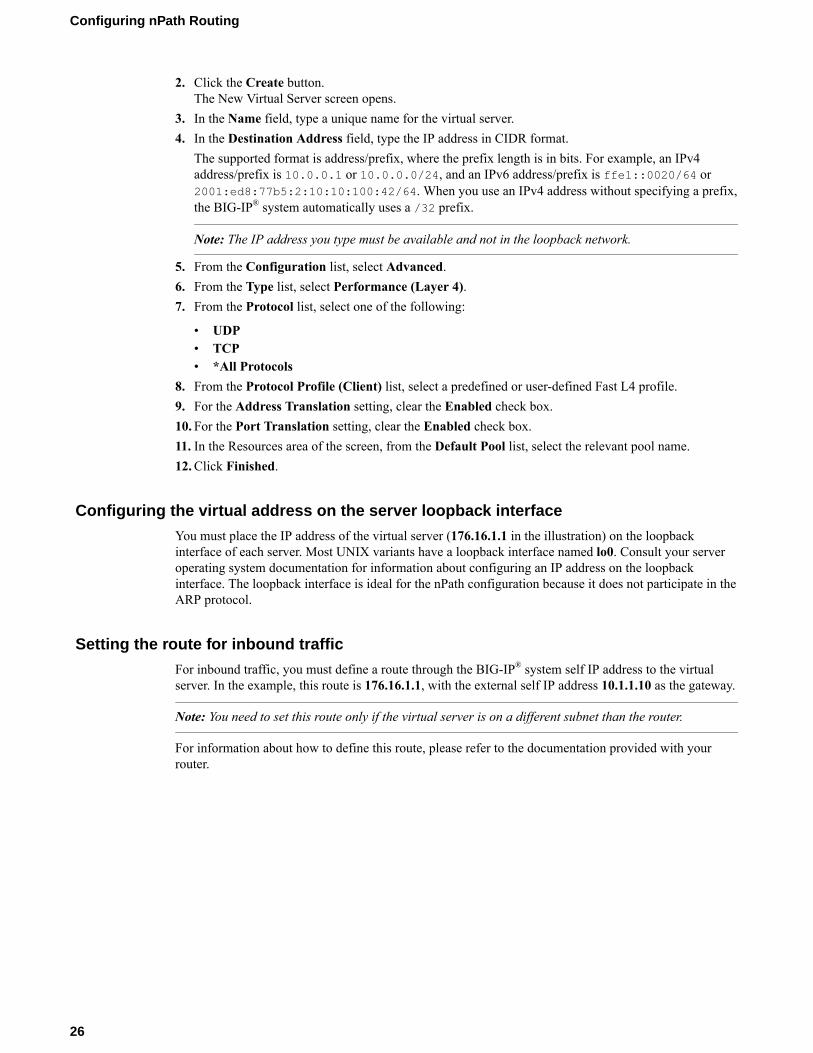
8. From the Protocol Profile (Client) list, select a predefined or user-defined Fast L4 profile.9. For the Address Translation setting, clear the Enabled check box.10. For the Port Translation setting, clear the Enabled check box.11. In the Resources area of the screen, from the Default Pool list, select the relevant pool name.12. Click Finished.
Configuring the virtual address on the server loopback interface
You must place the IP address of the virtual server (176.16.1.1 in the illustration) on the loopbackinterface of each server. Most UNIX variants have a loopback interface named lo0. Consult your serveroperating system documentation for information about configuring an IP address on the loopbackinterface. The loopback interface is ideal for the nPath configuration because it does not participate in theARP protocol.
Setting the route for inbound traffic
For inbound traffic, you must define a route through the BIG-IP® system self IP address to the virtualserver. In the example, this route is 176.16.1.1, with the external self IP address 10.1.1.10 as the gateway.
Note: You need to set this route only if the virtual server is on a different subnet than the router.
For information about how to define this route, please refer to the documentation provided with yourrouter.
Configuring nPath Routing
26

Configuring Layer 3 nPath Routing
Overview: Layer 3 nPath routingUsing Layer 3 nPath routing, you can load balance traffic over a routed topology in your data center. Inthis deployment, the server sends its responses directly back to the client, even when the servers, and anyintermediate routers, are on different networks. This routing method uses IP encapsulation to create a uni-directional outbound tunnel from the server pool to the server.
You can also override the encapsulation for a specified pool member, and either remove that poolmember from any encapsulation or specify a different encapsulation protocol. The availableencapsulation protocols are IPIP and GRE.
Figure 4: Example of a Layer 3 routing configuration
This illustration shows the path of a packet in a deployment that uses Layer 3 nPath routing through atunnel.
1. The client sends traffic to a Fast L4 virtual server.2. The pool encapsulates the packet and sends it through a tunnel to the server.3. The server removes the encapsulation header and returns the packet to the network.4. The target application receives the original packet, processes it, and responds directly to the client.
Configuring Layer 3 nPath routing using tmshBefore performing this procedure, determine the IP address of the loopback interface for each server inthe server pool.
Use Layer 3 nPath routing to provide direct server return for traffic in a routed topology in your datacenter.

1. On the BIG-IP® system, start a console session.2. Create a server pool with an encapsulation profile.
tmsh create ltm pool npath_ipip_pool profiles add { ipip } members add { 10.7.1.7:any 10.7.1.8:any 10.7.1.9:any }
This command creates the pool npath_ipip_pool, which has three members that specify allservices: 10.7.1.7:any, 10.7.1.8:any, and 10.7.1.9:any, and applies IPIP encapsulation tooutbound traffic.
3. Create a profile that disables hardware acceleration.
tmsh create ltm profile fastl4 fastl4_npath pva-acceleration none
This command disables the Packet Velocity® ASIC acceleration mode in the new Fast L4 profilenamed fastl4_npath.
4. Create a virtual server that has address translation disabled, and includes the pool with theencapsulation profile.
tmsh create ltm virtual npath_udp destination 176.16.1.1:anypool npath_ipip_pool profiles add { fastl4_npath } translate-addressdisabled ip-protocol udp
This command creates a virtual server named npath_udp that intercepts all UDP traffic, does not useaddress translation, and does not use hardware acceleration. The destination address 176.16.1.1matches the IP address of the loopback interface on each server.
These implementation steps configure only the BIG-IP device in a deployment example. To configureother devices in your network for L3 nPath routing, consult the device manufacturer's documentation forsetting up direct server return (DSR) for each device.
Configuring a Layer 3 nPath monitor using tmshBefore you begin this task, configure a server pool with an encapsulation profile, such asnpath_ipip_pool.
You can create a custom monitor to provide server health checks of encapsulated tunnel traffic. Setting avariable in the db component causes the monitor traffic to be encapsulated.
1. Start at the Traffic Management Shell (tmsh).2. Create a transparent health monitor with the destination IP address of the virtual server that includes
the pool with the encapsulation profile.
tmsh create ltm monitor udp npath_udp_monitor transparent enabled destination 176.16.1.1:*
This command creates a transparent monitor for UDP traffic with the destination IP address176.16.1.1, and the port supplied by the pool member.
3. Associate the health monitor with the pool that has the encapsulation profile.
tmsh modify pool npath_ipip_pool monitor npath_udp_monitor
This command specifies that the BIG-IP® system monitors UDP traffic to the poolnpath_ipip_pool.
4. Enable the variable in the db component that causes the monitor traffic to be encapsulated.
tmsh modify sys db tm.monitorencap value enable
Configuring Layer 3 nPath Routing
28

This command specifies that the monitor traffic is encapsulated.
Layer 3 nPath routing exampleThe following illustration shows one example of an L3 nPath routing configuration in a network.
Figure 5: Example of a Layer 3 routing configuration
The following examples show the configuration code that supports the illustration.
Client configuration:
# ifconfig eth0 inet 10.102.45.10 netmask 255.255.255.0 up# route add –net 10.0.0.0 netmask 255.0.0.0 gw 10.102.45.1
BIG-IP® device configuration:
# - create node pointing to server's ethernet address# ltm node 10.102.4.10 {# address 10.102.4.10# }# - create transparent monitor# ltm monitor tcp t.ipip {# defaults-from tcp# destination 10.102.3.202:http# interval 5# time-until-up 0# timeout 16# transparent enabled# }# - create pool with ipip profile# ltm pool ipip.pool {# members {# 10.102.4.10:any { - real server's ip address# address 10.102.4.10# }# }# monitor t.ipip - transparent monitor# profiles {
BIG-IP Local Traffic Manager: Implementations
29
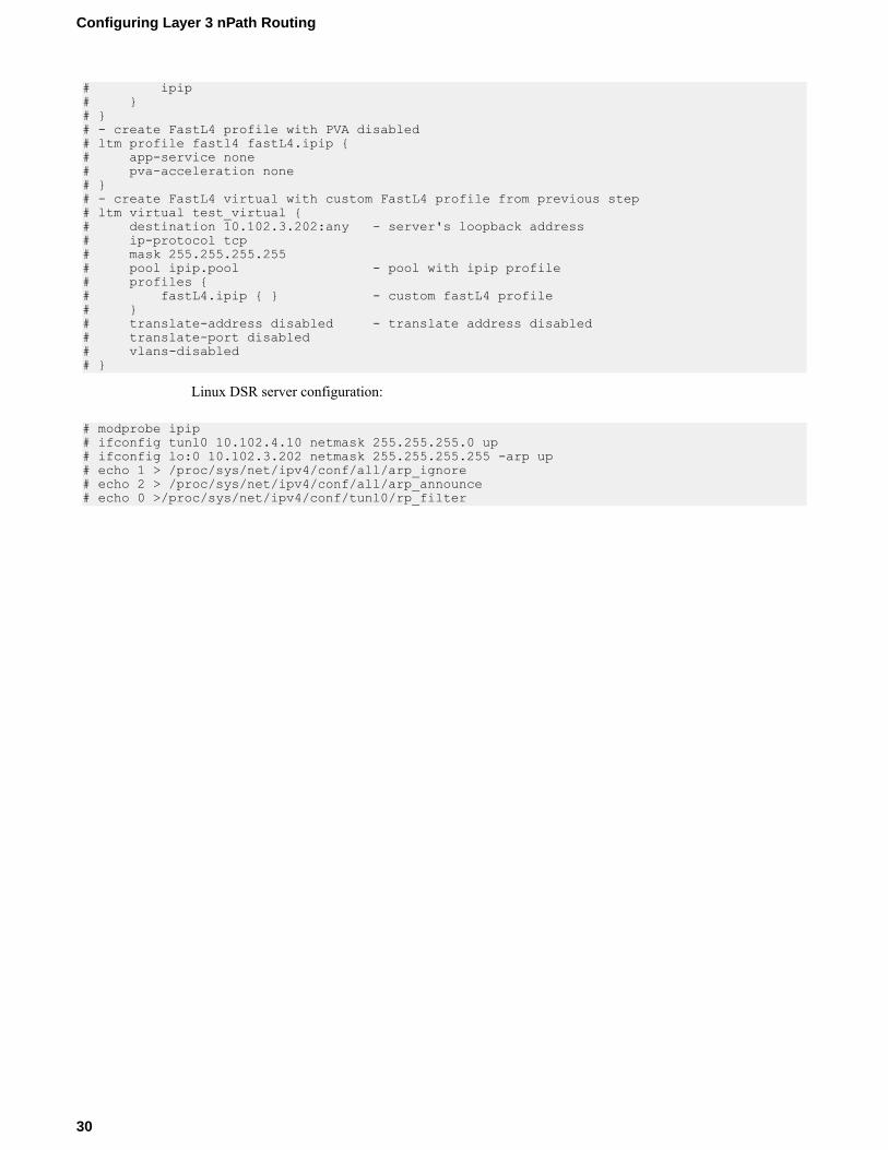
# ipip# }# }# - create FastL4 profile with PVA disabled# ltm profile fastl4 fastL4.ipip {# app-service none# pva-acceleration none# }# - create FastL4 virtual with custom FastL4 profile from previous step# ltm virtual test_virtual {# destination 10.102.3.202:any - server's loopback address# ip-protocol tcp# mask 255.255.255.255# pool ipip.pool - pool with ipip profile# profiles {# fastL4.ipip { } - custom fastL4 profile# }# translate-address disabled - translate address disabled# translate-port disabled# vlans-disabled# }
Linux DSR server configuration:
# modprobe ipip# ifconfig tunl0 10.102.4.10 netmask 255.255.255.0 up# ifconfig lo:0 10.102.3.202 netmask 255.255.255.255 -arp up# echo 1 > /proc/sys/net/ipv4/conf/all/arp_ignore# echo 2 > /proc/sys/net/ipv4/conf/all/arp_announce# echo 0 >/proc/sys/net/ipv4/conf/tunl0/rp_filter
Configuring Layer 3 nPath Routing
30

Creating a Basic Web Site and E-commerce Configuration
Overview: Basic web site and eCommerce configurationThe most common use for the BIG-IP® system is distributing traffic across an array of web servers thathost standard web traffic, including eCommerce traffic. The following illustration shows a configurationwhere a BIG-IP system load balances two sites: www.siterequest.com andstore.siterequest.com. The www.siterequest.com site provides standard web content, and thestore.siterequest.com site is the e-commerce site that sells items to www.siterequest.comcustomers.
Illustration of basic web site and eCommerce configuration
Figure 6: Basic web site and eCommerce configuration
Task summaryYou can implement a basic configuration for load balancing application traffic to a web site, as well asload balancing secure traffic to an eCommerce site.
Before you use this implementation:
• Verify that you have created two VLANs on the BIG-IP® system. One VLAN should reside on theexternal network and another on the internal network.
• Verify that you have created a self IP address for each VLAN.
Task listCreating a pool to process HTTP trafficCreating a pool to manage HTTPS trafficCreating a virtual server to manage HTTP trafficCreating a virtual server to manage HTTPS traffic
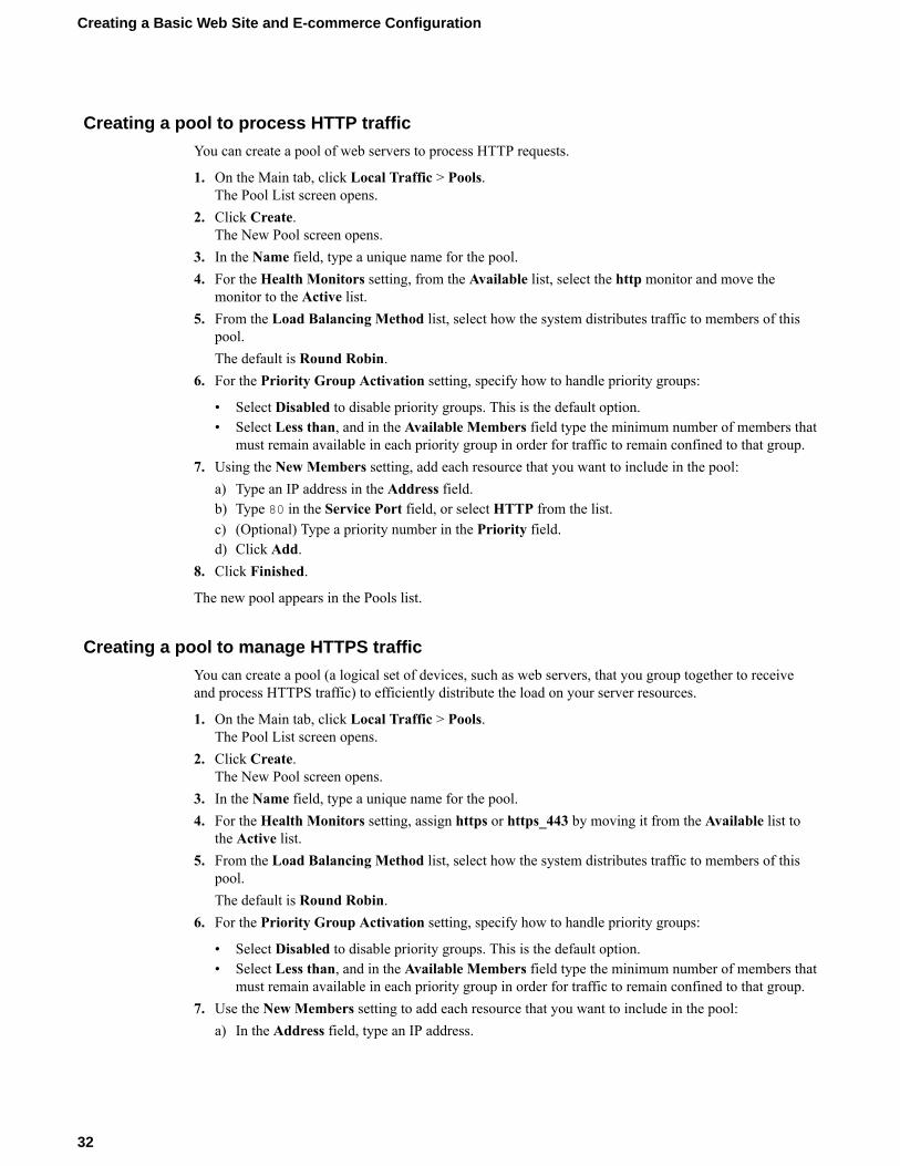
Creating a pool to process HTTP traffic
You can create a pool of web servers to process HTTP requests.
1. On the Main tab, click Local Traffic > Pools.The Pool List screen opens.
2. Click Create.The New Pool screen opens.
3. In the Name field, type a unique name for the pool.4. For the Health Monitors setting, from the Available list, select the http monitor and move the
monitor to the Active list.5. From the Load Balancing Method list, select how the system distributes traffic to members of this
pool.The default is Round Robin.
6. For the Priority Group Activation setting, specify how to handle priority groups:
• Select Disabled to disable priority groups. This is the default option.• Select Less than, and in the Available Members field type the minimum number of members that
must remain available in each priority group in order for traffic to remain confined to that group.7. Using the New Members setting, add each resource that you want to include in the pool:
a) Type an IP address in the Address field.b) Type 80 in the Service Port field, or select HTTP from the list.c) (Optional) Type a priority number in the Priority field.d) Click Add.
8. Click Finished.
The new pool appears in the Pools list.
Creating a pool to manage HTTPS traffic
You can create a pool (a logical set of devices, such as web servers, that you group together to receiveand process HTTPS traffic) to efficiently distribute the load on your server resources.
1. On the Main tab, click Local Traffic > Pools.The Pool List screen opens.
2. Click Create.The New Pool screen opens.
3. In the Name field, type a unique name for the pool.4. For the Health Monitors setting, assign https or https_443 by moving it from the Available list to
the Active list.5. From the Load Balancing Method list, select how the system distributes traffic to members of this
pool.The default is Round Robin.
6. For the Priority Group Activation setting, specify how to handle priority groups:
• Select Disabled to disable priority groups. This is the default option.• Select Less than, and in the Available Members field type the minimum number of members that
must remain available in each priority group in order for traffic to remain confined to that group.7. Use the New Members setting to add each resource that you want to include in the pool:
a) In the Address field, type an IP address.
Creating a Basic Web Site and E-commerce Configuration
32

b) In the Service Port field type 443 , or select HTTPS from the list.c) (Optional) Type a priority number in the Priority field.d) Click Add.
8. Click Finished.
The HTTPS load balancing pool appears in the Pool List screen.
Creating a virtual server to manage HTTP traffic
You can create a virtual server to manage HTTP traffic as either a host virtual server or a network virtualserver.
1. On the Main tab, click Local Traffic > Virtual Servers.The Virtual Server List screen opens.
2. Click the Create button.The New Virtual Server screen opens.
3. In the Name field, type a unique name for the virtual server.4. In the Destination Address field, type the IP address in CIDR format.
The supported format is address/prefix, where the prefix length is in bits. For example, an IPv4address/prefix is 10.0.0.1 or 10.0.0.0/24, and an IPv6 address/prefix is ffe1::0020/64 or2001:ed8:77b5:2:10:10:100:42/64. When you use an IPv4 address without specifying a prefix,the BIG-IP® system automatically uses a /32 prefix.
Note: The IP address you type must be available and not in the loopback network.
5. In the Service Port field, type 80, or select HTTP from the list.6. From the HTTP Profile list, select http.7. In the Resources area of the screen, from the Default Pool list, select the relevant pool name.8. Click Finished.
The HTTP virtual server appears in the list of existing virtual servers on the Virtual Server List screen.
Creating a virtual server to manage HTTPS traffic
You can specify a virtual server to be either a host virtual server or a network virtual server to manageHTTPS traffic.
1. On the Main tab, click Local Traffic > Virtual Servers.The Virtual Server List screen opens.
2. Click the Create button.The New Virtual Server screen opens.
3. In the Name field, type a unique name for the virtual server.4. In the Destination Address field, type the IP address in CIDR format.
The supported format is address/prefix, where the prefix length is in bits. For example, an IPv4address/prefix is 10.0.0.1 or 10.0.0.0/24, and an IPv6 address/prefix is ffe1::0020/64 or2001:ed8:77b5:2:10:10:100:42/64. When you use an IPv4 address without specifying a prefix,the BIG-IP® system automatically uses a /32 prefix.
Note: The IP address you type must be available and not in the loopback network.
5. Type 443 in the Service Port field, or select HTTPS in the list.6. Select http in the HTTP Profile list.7. From the HTTP Compression Profile list, select one of the following profiles:
BIG-IP Local Traffic Manager: Implementations
33

• httpcompression• wan-optimized-compression• A customized profile
8. From the Web Acceleration Profile list, select one of the following profiles:
• optimized-acceleration• optimized-caching• webacceleration• A customized profile
9. For the SSL Profile (Client) setting, from the Available list, select clientssl, and using the Movebutton, move the name to the Selected list.
10. Click Finished.
The HTTPS virtual server appears in the Virtual Server List screen.
Creating a Basic Web Site and E-commerce Configuration
34

Installing a BIG-IP System Without Changing the IPNetwork
Overview: Installing a BIG-IP system without changing the IP networkA combination of several features of the BIG-IP®system makes it possible for you to place a BIG-IPsystem in a network without changing the existing IP network. The following illustration shows the datacenter topology before you add the BIG-IP system. The data center has one LAN, with one IP network,10.0.0.0. The data center has one router to the Internet, two web servers, and a back-end mail server.
Figure 7: Data center example before adding a BIG-IP system
The existing data center structure does not support load balancing or high availability. The followingillustration shows an example of the data center topology after you add the BIG-IP system.

Figure 8: Data center example after adding a BIG-IP system
Task summaryTo configure the BIG-IP® system for this implementation, you must perform a few key tasks. Theexample shown in the illustration is based on the use of the default internal and external VLANconfiguration with self IP addresses on each of the VLANs that are on the same IP network on which youare installing the BIG-IP system.
Important: The default route on each content server should be set to the IP address of the router. In thisexample, you set the default route to 10.0.0.2.
Task listRemoving the self IP addresses from the default VLANsCreating a VLAN groupCreating a self IP for a VLAN groupCreating a pool of web serversCreating a virtual server
Removing the self IP addresses from the default VLANs
Remove the self IP addresses from the individual VLANs. After you create the VLAN group, you willcreate another self IP address for the VLAN group for routing purposes. The individual VLANs nolonger need their own self IP addresses.
1. On the Main tab, click Network > Self IPs.2. Select the check box for each IP address and VLAN that you want to delete.3. Click Delete.4. Click Delete.
The self IP address is removed from the Self IP list.
Installing a BIG-IP System Without Changing the IP Network
36

Creating a VLAN group
VLAN groups consolidate Layer 2 traffic from two or more separate VLANs.
1. On the Main tab, click Network > VLANs > VLAN Groups.The VLAN Groups list screen opens.
2. From the VLAN Groups menu, choose List.3. Click Create.
The New VLAN Group screen opens.4. In the General Properties area, in the VLAN Group field, type a unique name for the VLAN group.5. For the VLANs setting, from the Available field select the internal and external VLAN names, and
click << to move the VLAN names to the Members field.6. Click Finished.
Creating a self IP for a VLAN group
Before you create a self IP address, ensure that you have created at least one VLAN or VLAN group.
A self IP address enables the BIG-IP® system and other devices on the network to route applicationtraffic through the associated VLAN or VLAN group.
1. On the Main tab, click Network > Self IPs.2. Click Create.
The New Self IP screen opens.3. In the IP Address field, type a self IP address for the VLAN group. In the example shown, this IP
address is 10.0.0.6.4. In the Netmask field, type the network mask for the specified IP address.
For example, you can type 255.255.255.0.5. From the VLAN/Tunnel list, select the name of the VLAN group you previously created.6. From the Port Lockdown list, select Allow Default.7. Click Finished.
The screen refreshes, and displays the new self IP address.
The BIG-IP system can send and receive traffic through the specified VLAN or VLAN group.
Creating a pool of web servers
You can a create pool of web servers that you group together to receive and process traffic, to efficientlydistribute the load on your server resources.
1. On the Main tab, click Local Traffic > Pools.The Pool List screen opens.
2. Click Create.The New Pool screen opens.
3. In the Name field, type a unique name for the pool.4. In the Resources area of the screen, use the New Members setting to add the pool members. In our
example, pool members are 10.0.0.3:80 and 10.0.0.4:80.5. Click Finished.
The load balancing pool appears in the Pools list.
BIG-IP Local Traffic Manager: Implementations
37

Creating a virtual server
A virtual server represents a destination IP address for application traffic.
1. On the Main tab, click Local Traffic > Virtual Servers.The Virtual Server List screen opens.
2. Click the Create button.The New Virtual Server screen opens.
3. In the Name field, type a unique name for the virtual server.4. In the Destination Address field, type the IP address in CIDR format.
The supported format is address/prefix, where the prefix length is in bits. For example, an IPv4address/prefix is 10.0.0.1 or 10.0.0.0/24, and an IPv6 address/prefix is ffe1::0020/64 or2001:ed8:77b5:2:10:10:100:42/64. When you use an IPv4 address without specifying a prefix,the BIG-IP® system automatically uses a /32 prefix.
Note: The IP address for this field needs to be on the same subnet as the external self-IP address.
5. From the Service Port list, select *All Ports.6. In the Resources area of the screen, from the Default Pool list, select the relevant pool name.
You now have a destination IP address on the BIG-IP® system for application traffic.
Installing a BIG-IP System Without Changing the IP Network
38
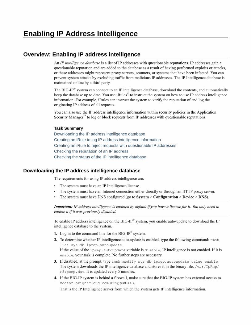
Enabling IP Address Intelligence
Overview: Enabling IP address intelligenceAn IP intelligence database is a list of IP addresses with questionable reputations. IP addresses gain aquestionable reputation and are added to the database as a result of having performed exploits or attacks,or these addresses might represent proxy servers, scanners, or systems that have been infected. You canprevent system attacks by excluding traffic from malicious IP addresses. The IP Intelligence database ismaintained online by a third party.
The BIG-IP® system can connect to an IP intelligence database, download the contents, and automaticallykeep the database up to date. You use iRules® to instruct the system on how to use IP address intelligenceinformation. For example, iRules can instruct the system to verify the reputation of and log theoriginating IP address of all requests.
You can also use the IP address intelligence information within security policies in the ApplicationSecurity Manager™ to log or block requests from IP addresses with questionable reputations.
Task SummaryDownloading the IP address intelligence databaseCreating an iRule to log IP address intelligence informationCreating an iRule to reject requests with questionable IP addressesChecking the reputation of an IP addressChecking the status of the IP intelligence database
Downloading the IP address intelligence database
The requirements for using IP address intelligence are:
• The system must have an IP Intelligence license.• The system must have an Internet connection either directly or through an HTTP proxy server.• The system must have DNS configured (go to System > Configuration > Device > DNS).
Important: IP address intelligence is enabled by default if you have a license for it. You only need toenable it if it was previously disabled.
To enable IP address intelligence on the BIG-IP® system, you enable auto-update to download the IPintelligence database to the system.
1. Log in to the command line for the BIG-IP® system.2. To determine whether IP intelligence auto-update is enabled, type the following command: tmsh
list sys db iprep.autoupdateIf the value of the iprep.autoupdate variable is disable, IP intelligence is not enabled. If it isenable, your task is complete. No further steps are necessary.
3. If disabled, at the prompt, type tmsh modify sys db iprep.autoupdate value enableThe system downloads the IP intelligence database and stores it in the binary file, /var/IpRep/F5IpRep.dat. It is updated every 5 minutes.
4. If the BIG-IP system is behind a firewall, make sure that the BIG-IP system has external access tovector.brightcloud.com using port 443.That is the IP Intelligence server from which the system gets IP Intelligence information.
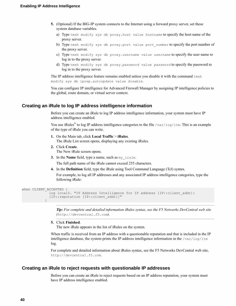
5. (Optional) If the BIG-IP system connects to the Internet using a forward proxy server, set thesesystem database variables.a) Type tmsh modify sys db proxy.host value hostname to specify the host name of the
proxy server.b) Type tmsh modify sys db proxy.port value port_number to specify the port number of
the proxy server.c) Type tmsh modify sys db proxy.username value username to specify the user name to
log in to the proxy server.d) Type tmsh modify sys db proxy.password value password to specify the password to
log in to the proxy server.
The IP address intelligence feature remains enabled unless you disable it with the command tmshmodify sys db iprep.autoupdate value disable.
You can configure IP intelligence for Advanced Firewall Manager by assigning IP intelligence policies tothe global, route domain, or virtual server context.
Creating an iRule to log IP address intelligence information
Before you can create an iRule to log IP address intelligence information, your system must have IPaddress intelligence enabled.
You use iRules® to log IP address intelligence categories to the file /var/log/ltm. This is an exampleof the type of iRule you can write.
1. On the Main tab, click Local Traffic > iRules.The iRule List screen opens, displaying any existing iRules.
2. Click Create.The New iRule screen opens.
3. In the Name field, type a name, such as my_irule.The full path name of the iRule cannot exceed 255 characters.
4. In the Definition field, type the iRule using Tool Command Language (Tcl) syntax.For example, to log all IP addresses and any associated IP address intelligence categories, type thefollowing iRule:
when CLIENT_ACCEPTED { log local0. "IP Address Intelligence for IP address [IP::client_addr]: [IP::reputation [IP::client_addr]]" }
Tip: For complete and detailed information iRules syntax, see the F5 Networks DevCentral web site(http://devcentral.f5.com).
5. Click Finished.The new iRule appears in the list of iRules on the system.
When traffic is received from an IP address with a questionable reputation and that is included in the IPintelligence database, the system prints the IP address intelligence information in the /var/log/ltmlog.
For complete and detailed information about iRules syntax, see the F5 Networks DevCentral web site,http://devcentral.f5.com.
Creating an iRule to reject requests with questionable IP addresses
Before you can create an iRule to reject requests based on an IP address reputation, your system musthave IP address intelligence enabled.
Enabling IP Address Intelligence
40
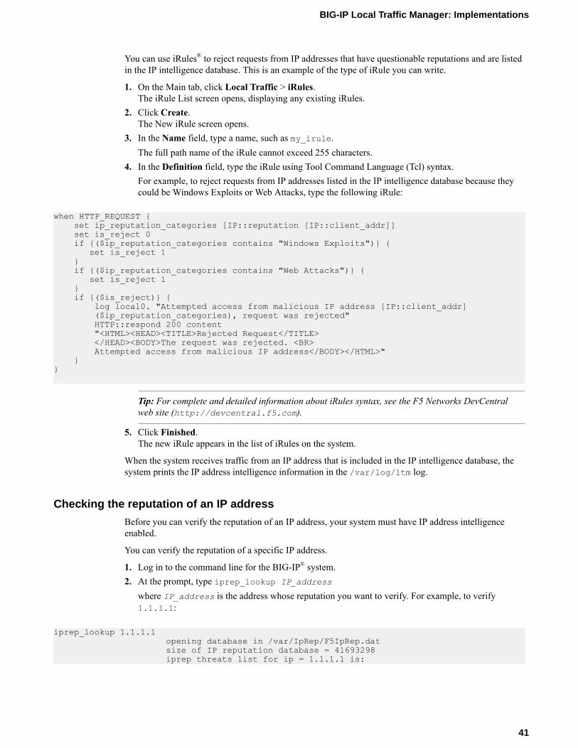
You can use iRules® to reject requests from IP addresses that have questionable reputations and are listedin the IP intelligence database. This is an example of the type of iRule you can write.
1. On the Main tab, click Local Traffic > iRules.The iRule List screen opens, displaying any existing iRules.
2. Click Create.The New iRule screen opens.
3. In the Name field, type a name, such as my_irule.The full path name of the iRule cannot exceed 255 characters.
4. In the Definition field, type the iRule using Tool Command Language (Tcl) syntax.For example, to reject requests from IP addresses listed in the IP intelligence database because theycould be Windows Exploits or Web Attacks, type the following iRule:
when HTTP_REQUEST { set ip_reputation_categories [IP::reputation [IP::client_addr]] set is_reject 0 if {($ip_reputation_categories contains "Windows Exploits")} { set is_reject 1 } if {($ip_reputation_categories contains "Web Attacks")} { set is_reject 1 } if {($is_reject)} { log local0. "Attempted access from malicious IP address [IP::client_addr] ($ip_reputation_categories), request was rejected" HTTP::respond 200 content "<HTML><HEAD><TITLE>Rejected Request</TITLE> </HEAD><BODY>The request was rejected. <BR> Attempted access from malicious IP address</BODY></HTML>" }}
Tip: For complete and detailed information about iRules syntax, see the F5 Networks DevCentralweb site (http://devcentral.f5.com).
5. Click Finished.The new iRule appears in the list of iRules on the system.
When the system receives traffic from an IP address that is included in the IP intelligence database, thesystem prints the IP address intelligence information in the /var/log/ltm log.
Checking the reputation of an IP address
Before you can verify the reputation of an IP address, your system must have IP address intelligenceenabled.
You can verify the reputation of a specific IP address.
1. Log in to the command line for the BIG-IP® system.2. At the prompt, type iprep_lookup IP_address
where IP_address is the address whose reputation you want to verify. For example, to verify1.1.1.1:
iprep_lookup 1.1.1.1 opening database in /var/IpRep/F5IpRep.dat size of IP reputation database = 41693298 iprep threats list for ip = 1.1.1.1 is:
BIG-IP Local Traffic Manager: Implementations
41

bit 4 - Scanners bit 5 - Denial of Service
The system looks up the IP address, and if it is in the database, the command output displays the IPaddress intelligence categories that show the reason. In this case, 1.1.1.1 is a source of potentialport or network scans and DoS attacks. If the IP address is not found in the IP intelligence database,the system returns the message iprep_lookup not found for ip = <ip_address>.
Checking the status of the IP intelligence database
You can display the status of the IP Intelligence database to learn when it was last updated and thenumber of questionable IP addresses it contains.
1. Log in to the command line for the BIG-IP® system.2. To display IP intelligence database status, type tmsh show sys iprep-status.
The system displays the status. For example:
-----------------------------------------------------------------------Sys::IP Reputation Database Status-----------------------------------------------------------------------Last time the server was contacted for updates 04/21/2012 09:33:31Last time an update was received 04/21/2012 09:33:31Total number of IP Addresses in the database 5516336Number of IP Addresses received in the last update 136
IP address intelligence categoriesAlong with the IP address, the IP intelligence database stores the category that explains the reason thatthe IP address is considered untrustworthy.
Category Name Description
Additional IP addresses that are added from additional categories not more explicitly defined.
Application Denialof Service
IP addresses involved in application DoS Attacks, or anomalous traffic detection.
Botnets IP addresses of computers that are infected with malicious software (BotnetCommand and Control channels, and infected zombie machines) and arecontrolled as a group by a Bot master, and are now part of a botnet. Hackers canexploit botnets to send spam messages, launch various attacks, or cause targetsystems to behave in other unpredictable ways.
Cloud StorageProviders
IP addresses and networks that belong to cloud providers, which offer serviceshosted on their servers via the Internet.
Denial-of-Service IP addresses that have launched denial-of-service (DoS) attacks, distributeddenial-of-service (DDoS) attacks, anomalous SYN flood attacks, or anomaloustraffic detection. These attacks are usually requests for legitimate services, butoccur at such a fast rate that targeted systems cannot respond quickly enough andbecome bogged down or unable to service legitimate clients.
Illegal Websites IP addresses that contain criminally obscene or potentially criminal internetcopyright and intellectual property violations.
Note: This category has been deprecated by Webroot BrightCloud.
Enabling IP Address Intelligence
42

Category Name Description
Infected Sources Active IP addresses that issue HTTP requests with a low reputation index score, orthat are known malicious web sites offering or distributing malware, shell code,rootkits, worms, or viruses.
Phishing Proxies IP addresses that host phishing sites, and other kinds of fraud activities, such as adclick fraud or gaming fraud.
Proxy IP addresses that are associated with web proxies that shield the originator's IPaddress (such as proxy and anonymization services). This category also includesTOR anonymizer addresses.
Scanners IP addresses that are involved in reconnaissance, such as probes, host scan,domain scan, and password brute force, typically to identify vulnerabilities forlater exploits.
Spam Sources IP addresses tunneling spam messages through proxy, anomalous SMTP activitiesand forum spam activities.
Web Attacks IP addresses involved in cross site scripting, iFrame injection, SQL injection, crossdomain injection, or domain password brute force.
Windows Exploits Active IP addresses that have exercised various exploits against Windowsresources by offering or distributing malware, shell code, rootkits, worms, orviruses using browsers, programs, downloaded files, scripts, or operating systemvulnerabilities.
BIG-IP Local Traffic Manager: Implementations
43

Enabling IP Address Intelligence
44

Configuring Content Adaptation for HTTP Requests
Overview: Configuring HTTP Request AdaptationThis implementation describes how to configure the BIG-IP® content adaptation feature for adaptingHTTP requests. With this feature, a BIG-IP virtual server can conditionally forward HTTP requests to apool of Internet Content Adaptation Protocol (ICAP) servers for modification, before sending the requestto a web server.
In this implementation, you create a standard HTTP virtual server and pool of web servers for processingclient requests. The HTTP virtual server accepts each client request in the normal way, but before loadbalancing the request to the pool of web servers, the virtual server forwards the HTTP request to a specialinternal virtual server.
The internal virtual server receives the HTTP request from the standard virtual server, and load balancesthe request to a pool of ICAP servers for modification. After the ICAP server modifies the request, theBIG-IP system sends the request to the appropriate web server for processing.
Figure 9: Content adaptation configuration for modifying HTTP requests
The internal virtual server references the pool of content adaptation servers, including the load balancingmethod to use for those servers. The internal virtual server also references an ICAP profile, whichincludes specific instructions for how the BIG-IP system should wrap the HTTP request in an ICAPmessage for adaptation.
Optionally, the internal virtual server can reference:
• Any persistence method that you would like the BIG-IP system to use when load balancing traffic tothe ICAP pool.
• Any health or performance monitor that you would like the BIG-IP system to use when loadbalancing traffic to the ICAP pool.
• Any iRules® related to the content adaptation.

Task summaryComplete the tasks in this implementation to create a BIG-IP® configuration that performs contentadaptation for HTTP requests.
Task ListCreating a custom client-side ICAP profileCreating a pool of ICAP serversCreating an internal virtual server for forwarding requests to an ICAP serverCreating a custom Request Adapt profileCreating a custom HTTP profileCreating a pool to process HTTP trafficCreating an HTTP virtual server for enabling request adaptation
Creating a custom client-side ICAP profile
You create this ICAP profile when you want to use an ICAP server to wrap an HTTP request in an ICAPmessage before the BIG-IP® system sends the request to a pool of web servers. The profile specifies theHTTP request-header values that the ICAP server uses for the ICAP message.
Important: You can use macro expansion for all ICAP header values. For example, if an ICAP headervalue contains ${SERVER_IP}, the BIG-IP system replaces the macro with the IP address of the ICAPserver selected from the pool assigned to the internal virtual server. If an ICAP header value contains ${SERVER_PORT}, the BIG-IP system replaces the macro with the port of the ICAP server selected fromthe pool assigned to the internal virtual server. For example, you can set the URI value in an ICAPprofile to icap://${SERVER_IP}:${SERVER_PORT}/virusScan.
1. On the Main tab, click Local Traffic > Profiles > Services > ICAP.2. Click Create.3. In the Name field, type a unique name for the profile.4. For the Parent Profile setting, retain the default value, icap.5. On the right side of the screen, select the Custom check box.6. In the URI field, type a URI in this format: icap://hostname:port/path.
For example, using macro expansion, you can set the URI value to:
icap://${SERVER_IP}:${SERVER_PORT}/virusScan
.7. In the Preview Length field, type a length or retain the default value 0.
This value defines the amount of the HTTP request or response that the BIG-IP system offers to theICAP server when sending the request or response to the server for adaptation. This value should notexceed the length of the preview that the ICAP server has indicated it will accept.
8. In the Header From field, type a value for the From: ICAP header.9. In the Host field, type a value for the Host: ICAP header.10. In the Referer field, type a value for the Referer: ICAP header.11. In the User Agent field, type a value for the User-Agent: ICAP header.12. Click Finished.
Configuring Content Adaptation for HTTP Requests
46

After you create the ICAP profile, you can assign it to an internal virtual server so that the HTTP requestthat the BIG-IP system sends to an ICAP server is wrapped in an ICAP message, according to the settingsyou specified in the ICAP profile.
Creating a pool of ICAP servers
You perform this task to create a pool of ICAP servers that perform content adaptation on HTTP requests.
1. On the Main tab, click Local Traffic > Pools.The Pool List screen opens.
2. Click Create.The New Pool screen opens.
3. In the Name field, type a unique name for the pool.4. For the Health Monitors setting, from the Available list, select the http monitor and move the
monitor to the Active list.5. From the Load Balancing Method list, select how the system distributes traffic to members of this
pool.The default is Round Robin.
6. For the Priority Group Activation setting, specify how to handle priority groups:
• Select Disabled to disable priority groups. This is the default option.• Select Less than, and in the Available Members field type the minimum number of members that
must remain available in each priority group in order for traffic to remain confined to that group.7. Using the New Members setting, add each resource that you want to include in the pool:
a) (Optional) In the Node Name field, type a name for the node portion of the pool member.b) In the Address field, type an IP address.c) In the Service Port field, type a port number, or select a service name from the list.d) (Optional) In the Priority field, type a priority number.e) Click Add.
8. Click Finished.
The pool of ICAP load balancing servers appears in the Pools list.
Creating an internal virtual server for forwarding requests to an ICAP server
A virtual server of type internal provides a destination that a standard type of virtual server can usewhen forwarding HTTP requests slated for ICAP-based content adaptation.
1. On the Main tab, click Local Traffic > Virtual Servers.The Virtual Server List screen opens.
2. Click the Create button.The New Virtual Server screen opens.
3. In the Name field, type a unique name for the virtual server.4. In the Description field, type a description of the virtual server.
For example: This virtual server ensures HTTP request modification through theuse of the service_name ICAP service..
5. From the Type list, select Internal.6. For the State setting, verify that the value is set to Enabled.7. From the Configuration list, select Advanced.8. From the ICAP Profile list, select the ICAP profile that you previously created for handling HTTP
requests.9. From the Default Pool list, select the pool of ICAP servers that you previously created.
BIG-IP Local Traffic Manager: Implementations
47
10. Click Finished.
After you perform this task, a standard type of virtual server can forward HTTP requests to an internaltype of virtual server. The internal virtual server then sends the request to a pool of ICAP servers, beforesending the request back to the standard virtual server for forwarding to the pool of web servers.
Creating a custom Request Adapt profile
You create a Request Adapt type of profile when you want a standard HTTP virtual server to forwardHTTP requests to an internal virtual server that references a pool of ICAP servers. A Request Adapt typeof profile instructs the HTTP virtual server to send an HTTP request to a named internal virtual server forpossible request modification.
1. On the Main tab, click Local Traffic > Profiles > Services > Request Adapt.2. Click Create.3. In the Name field, type a unique name for the profile.4. For the Parent Profile setting, retain the default value, requestadapt.5. On the right-side of the screen, clear the Custom check box.6. For the Enabled setting, retain the default value, Enabled.
When you set this value to Enabled, the BIG-IP system forwards HTTP requests to the specifiedinternal virtual server for adaptation.
7. From the Internal Virtual Name list, select the name of the internal virtual server that youpreviously created for forwarding HTTP requests to the pool of iCAP servers.
8. In the Preview Size field, type a numeric value.This specifies the maximum size of the preview buffer. This buffer holds a copy of the HTTP requestheader and the data sent to the internal virtual server, in case the adaptation server reports that noadaptation is needed. Setting the preview size to 0 disables buffering of the request and should onlybe done if the adaptation server always returns a modified HTTP request or the original HTTPrequest.
9. In the Timeout field, type a numeric value, in seconds.If the internal virtual server does not return a result within the specified time, a timeout error occurs.To disable the timeout, use the value 0.
10. From the Service Down Action list, select an action for the BIG-IP system to take if the internalvirtual server returns an error:
• Select Ignore to instruct the BIG-IP system to ignore the error and send the unmodified HTTPrequest to an HTTP server in the HTTP server pool.
• Select Drop to instruct the BIG-IP system to drop the connection.• Select Reset to instruct the BIG-IP system to reset the connection.
11. Click Finished.
After you perform this task, the BIG-IP® system contains a Request Adapt profile that a standard HTTPvirtual server can use to forward an HTTP request to an internal virtual server for ICAP traffic.
Creating a custom HTTP profile
An HTTP profile defines the way that you want the BIG-IP®system to manage HTTP traffic.
1. On the Main tab, click Local Traffic > Profiles > Services > HTTP.The HTTP profile list screen opens.
2. Click Create.The New HTTP Profile screen opens.
3. In the Name field, type a unique name for the profile.
Configuring Content Adaptation for HTTP Requests
48

4. From the Parent Profile list, select http.5. Select the Custom check box.6. Modify the settings, as required.7. Click Finished.
The custom HTTP profile now appears in the HTTP profile list screen.
Creating a pool to process HTTP traffic
You can create a pool of web servers to process HTTP requests.
1. On the Main tab, click Local Traffic > Pools.The Pool List screen opens.
2. Click Create.The New Pool screen opens.
3. In the Name field, type a unique name for the pool.4. For the Health Monitors setting, from the Available list, select the http monitor and move the
monitor to the Active list.5. From the Load Balancing Method list, select how the system distributes traffic to members of this
pool.The default is Round Robin.
6. For the Priority Group Activation setting, specify how to handle priority groups:
• Select Disabled to disable priority groups. This is the default option.• Select Less than, and in the Available Members field type the minimum number of members that
must remain available in each priority group in order for traffic to remain confined to that group.7. Using the New Members setting, add each resource that you want to include in the pool:
a) Type an IP address in the Address field.b) Type 80 in the Service Port field, or select HTTP from the list.c) (Optional) Type a priority number in the Priority field.d) Click Add.
8. Click Finished.
The new pool appears in the Pools list.
Creating an HTTP virtual server for enabling request adaptation
You perform this task to create a standard virtual server that can forward an HTTP request to an internalvirtual server. The internal virtual server then sends the request to a pool of ICAP servers before the BIG-IP® system sends the request to the web server.
1. On the Main tab, click Local Traffic > Virtual Servers.The Virtual Server List screen opens.
2. Click the Create button.The New Virtual Server screen opens.
3. In the Name field, type a unique name for the virtual server.4. In the Destination Address field, type the IP address that you want to use as a destination for client
traffic destined for a pool of HTTP web servers.The supported format is address/prefix, where the prefix length is in bits. For example, an IPv4address/prefix is 10.0.0.1 or 10.0.0.0/24, and an IPv6 address/prefix is ffe1::0020/64 or2001:ed8:77b5:2:10:10:100:42/64. When you use an IPv4 address without specifying a prefix,the BIG-IP® system automatically uses a /32 prefix.
BIG-IP Local Traffic Manager: Implementations
49
Note: The IP address you type must be available and not in the loopback network.
5. In the Service Port field, type 443 or select HTTPS from the list.
Note: If traffic is on a secure internal network, you can use 80/HTTP.
6. From the Configuration list, select Advanced.7. From the HTTP Profile list, select the name of the HTTP profile that you created previously.8. From the Request Adapt Profile list, select the name of the Request Adapt profile that you
previously created.9. From the Source Address Translation list, select Auto Map.10. From the Default Pool list, select the name of the HTTP server pool that you previously created.11. Click Finished.
After you create the virtual server, the BIG-IP® system can forward an HTTP request to a pool of ICAPservers before sending the request to the web server.
Implementation resultAfter you complete the tasks in this implementation, the BIG-IP® system can perform content adaptationon HTTP requests as they pass through the BIG-IP system during normal HTTP processing. The newobjects that this implementation creates are:
• A custom ICAP profile• A pool of ICAP content adaptation servers• An internal virtual server that load balances HTTP requests to the ICAP pool• A custom Request Adapt profile that references the internal virtual server• A custom HTTP profile• A standard HTTP pool of web servers• A standard HTTP virtual server that sends HTTP requests to an internal virtual server for content
adaptation and load balances HTTP requests to the web pool
Configuring Content Adaptation for HTTP Requests
50
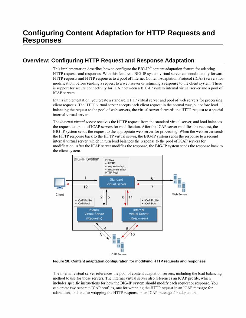
Configuring Content Adaptation for HTTP Requests andResponses
Overview: Configuring HTTP Request and Response AdaptationThis implementation describes how to configure the BIG-IP® content adaptation feature for adaptingHTTP requests and responses. With this feature, a BIG-IP system virtual server can conditionally forwardHTTP requests and HTTP responses to a pool of Internet Content Adaptation Protocol (ICAP) servers formodification, before sending a request to a web server or returning a response to the client system. Thereis support for secure connectivity for ICAP between a BIG-IP system internal virtual server and a pool ofICAP servers.
In this implementation, you create a standard HTTP virtual server and pool of web servers for processingclient requests. The HTTP virtual server accepts each client request in the normal way, but before loadbalancing the request to the pool of web servers, the virtual server forwards the HTTP request to a specialinternal virtual server.
The internal virtual server receives the HTTP request from the standard virtual server, and load balancesthe request to a pool of ICAP servers for modification. After the ICAP server modifies the request, theBIG-IP system sends the request to the appropriate web server for processing. When the web server sendsthe HTTP response back to the HTTP virtual server, the BIG-IP system sends the response to a secondinternal virtual server, which in turn load balances the response to the pool of ICAP servers formodification. After the ICAP server modifies the response, the BIG-IP system sends the response back tothe client system.
Figure 10: Content adaptation configuration for modifying HTTP requests and responses
The internal virtual server references the pool of content adaptation servers, including the load balancingmethod to use for those servers. The internal virtual server also references an ICAP profile, whichincludes specific instructions for how the BIG-IP system should modify each request or response. Youcan create two separate ICAP profiles, one for wrapping the HTTP request in an ICAP message foradaptation, and one for wrapping the HTTP response in an ICAP message for adaptation.
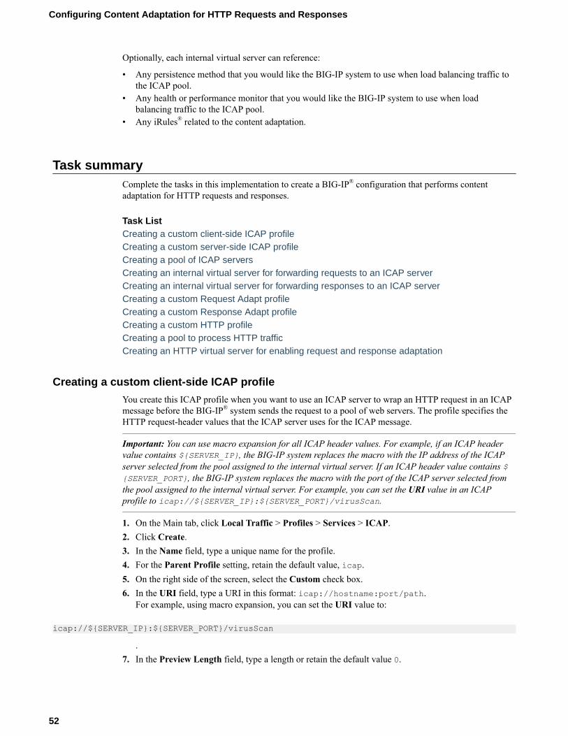
Optionally, each internal virtual server can reference:
• Any persistence method that you would like the BIG-IP system to use when load balancing traffic tothe ICAP pool.
• Any health or performance monitor that you would like the BIG-IP system to use when loadbalancing traffic to the ICAP pool.
• Any iRules® related to the content adaptation.
Task summaryComplete the tasks in this implementation to create a BIG-IP® configuration that performs contentadaptation for HTTP requests and responses.
Task ListCreating a custom client-side ICAP profileCreating a custom server-side ICAP profileCreating a pool of ICAP serversCreating an internal virtual server for forwarding requests to an ICAP serverCreating an internal virtual server for forwarding responses to an ICAP serverCreating a custom Request Adapt profileCreating a custom Response Adapt profileCreating a custom HTTP profileCreating a pool to process HTTP trafficCreating an HTTP virtual server for enabling request and response adaptation
Creating a custom client-side ICAP profile
You create this ICAP profile when you want to use an ICAP server to wrap an HTTP request in an ICAPmessage before the BIG-IP® system sends the request to a pool of web servers. The profile specifies theHTTP request-header values that the ICAP server uses for the ICAP message.
Important: You can use macro expansion for all ICAP header values. For example, if an ICAP headervalue contains ${SERVER_IP}, the BIG-IP system replaces the macro with the IP address of the ICAPserver selected from the pool assigned to the internal virtual server. If an ICAP header value contains ${SERVER_PORT}, the BIG-IP system replaces the macro with the port of the ICAP server selected fromthe pool assigned to the internal virtual server. For example, you can set the URI value in an ICAPprofile to icap://${SERVER_IP}:${SERVER_PORT}/virusScan.
1. On the Main tab, click Local Traffic > Profiles > Services > ICAP.2. Click Create.3. In the Name field, type a unique name for the profile.4. For the Parent Profile setting, retain the default value, icap.5. On the right side of the screen, select the Custom check box.6. In the URI field, type a URI in this format: icap://hostname:port/path.
For example, using macro expansion, you can set the URI value to:
icap://${SERVER_IP}:${SERVER_PORT}/virusScan
.7. In the Preview Length field, type a length or retain the default value 0.
Configuring Content Adaptation for HTTP Requests and Responses
52

This value defines the amount of the HTTP request or response that the BIG-IP system offers to theICAP server when sending the request or response to the server for adaptation. This value should notexceed the length of the preview that the ICAP server has indicated it will accept.
8. In the Header From field, type a value for the From: ICAP header.9. In the Host field, type a value for the Host: ICAP header.10. In the Referer field, type a value for the Referer: ICAP header.11. In the User Agent field, type a value for the User-Agent: ICAP header.12. Click Finished.
After you create the ICAP profile, you can assign it to an internal virtual server so that the HTTP requestthat the BIG-IP system sends to an ICAP server is wrapped in an ICAP message, according to the settingsyou specified in the ICAP profile.
Creating a custom server-side ICAP profile
You create this ICAP profile when you want to use an ICAP server to wrap an HTTP response in anICAP message before the BIG-IP® system sends the response back to the client. The profile specifies theHTTP response-header values that the ICAP server uses for the ICAP message.
Important: Optionally, you can use macro expansion for all ICAP header values. For example, if anICAP header value contains ${SERVER_IP}, the BIG-IP system replaces the macro with the IP addressof the ICAP server selected from the pool assigned to the internal virtual server. If an ICAP header valuecontains ${SERVER_PORT}, the BIG-IP system replaces the macro with the port of the ICAP serverselected from the pool assigned to the internal virtual server. For example, you can set the URI value inan ICAP profile to icap://${SERVER_IP}:${SERVER_PORT}/videoOptimization.
1. On the Main tab, click Local Traffic > Profiles > Services > ICAP.2. Click Create.3. In the Name field, type a unique name for the profile.4. For the Parent Profile setting, retain the default value, icap.5. On the right side of the screen, select the Custom check box.6. In the URI field, type a URI in this format: icap://hostname:port/path.
For example, using macro expansion, you can set the URI value to:
icap://${SERVER_IP}:${SERVER_PORT}/videoOptimization7. In the Preview Length field, type a length or retain the default value 0.
This value defines the amount of the HTTP request or response that the BIG-IP system offers to theICAP server when sending the request or response to the server for adaptation. This value should notexceed the length of the preview that the ICAP server has indicated it will accept.
8. In the Header From field, type a value for the From: ICAP header.9. In the Host field, type a value for the Host: ICAP header.10. In the Referer field, type a value for the Referer: ICAP header.11. In the User Agent field, type a value for the User-Agent: ICAP header.12. Click Finished.
After you create the ICAP profile, you can assign it to an internal virtual server so that the HTTPresponse that the BIG-IP system sends to an ICAP server is wrapped in an ICAP message, according tothe settings you specified in the ICAP profile.
BIG-IP Local Traffic Manager: Implementations
53
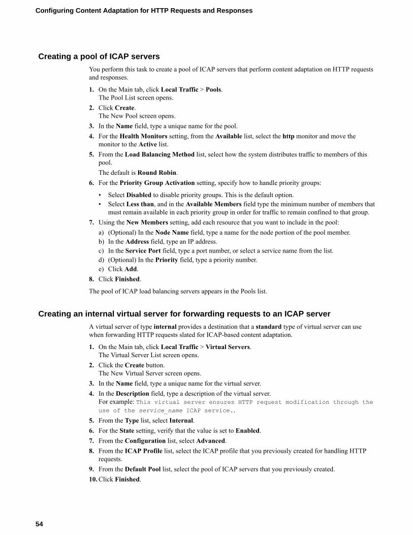
Creating a pool of ICAP servers
You perform this task to create a pool of ICAP servers that perform content adaptation on HTTP requestsand responses.
1. On the Main tab, click Local Traffic > Pools.The Pool List screen opens.
2. Click Create.The New Pool screen opens.
3. In the Name field, type a unique name for the pool.4. For the Health Monitors setting, from the Available list, select the http monitor and move the
monitor to the Active list.5. From the Load Balancing Method list, select how the system distributes traffic to members of this
pool.The default is Round Robin.
6. For the Priority Group Activation setting, specify how to handle priority groups:
• Select Disabled to disable priority groups. This is the default option.• Select Less than, and in the Available Members field type the minimum number of members that
must remain available in each priority group in order for traffic to remain confined to that group.7. Using the New Members setting, add each resource that you want to include in the pool:
a) (Optional) In the Node Name field, type a name for the node portion of the pool member.b) In the Address field, type an IP address.c) In the Service Port field, type a port number, or select a service name from the list.d) (Optional) In the Priority field, type a priority number.e) Click Add.
8. Click Finished.
The pool of ICAP load balancing servers appears in the Pools list.
Creating an internal virtual server for forwarding requests to an ICAP server
A virtual server of type internal provides a destination that a standard type of virtual server can usewhen forwarding HTTP requests slated for ICAP-based content adaptation.
1. On the Main tab, click Local Traffic > Virtual Servers.The Virtual Server List screen opens.
2. Click the Create button.The New Virtual Server screen opens.
3. In the Name field, type a unique name for the virtual server.4. In the Description field, type a description of the virtual server.
For example: This virtual server ensures HTTP request modification through theuse of the service_name ICAP service..
5. From the Type list, select Internal.6. For the State setting, verify that the value is set to Enabled.7. From the Configuration list, select Advanced.8. From the ICAP Profile list, select the ICAP profile that you previously created for handling HTTP
requests.9. From the Default Pool list, select the pool of ICAP servers that you previously created.10. Click Finished.
Configuring Content Adaptation for HTTP Requests and Responses
54

After you perform this task, a standard type of virtual server can forward HTTP requests to an internaltype of virtual server. The internal virtual server then sends the request to a pool of ICAP servers, beforesending the request back to the standard virtual server for forwarding to the pool of web servers.
Creating an internal virtual server for forwarding responses to an ICAP server
A virtual server of type internal provides a destination that a standard type of virtual server can usewhen forwarding HTTP responses slated for ICAP-based content adaptation.
1. On the Main tab, click Local Traffic > Virtual Servers.The Virtual Server List screen opens.
2. Click the Create button.The New Virtual Server screen opens.
3. In the Name field, type a unique name for the virtual server.4. In the Description field, type a description of the virtual server.
For example: This virtual server ensures HTTP response modification throughthe use of the service_name ICAP service..
5. From the Type list, select Internal.6. For the State setting, verify that the value is set to Enabled.7. From the Configuration list, select Advanced.8. From the ICAP Profile list, select the ICAP profile that you previously created for handling HTTP
responses.9. From the Default Pool list, select the pool of ICAP servers that you previously created.10. Click Finished.
After you perform this task, a standard type of virtual server can forward an HTTP response to an internaltype of virtual server. The internal virtual server then sends the response to a pool of ICAP servers beforesending the response back to the standard virtual server for forwarding to the client system.
Creating a custom Request Adapt profile
You create a Request Adapt type of profile when you want a standard HTTP virtual server to forwardHTTP requests to an internal virtual server that references a pool of ICAP servers. A Request Adapt typeof profile instructs the HTTP virtual server to send an HTTP request to a named internal virtual server forpossible request modification.
1. On the Main tab, click Local Traffic > Profiles > Services > Request Adapt.2. Click Create.3. In the Name field, type a unique name for the profile.4. For the Parent Profile setting, retain the default value, requestadapt.5. On the right-side of the screen, clear the Custom check box.6. For the Enabled setting, retain the default value, Enabled.
When you set this value to Enabled, the BIG-IP system forwards HTTP requests to the specifiedinternal virtual server for adaptation.
7. From the Internal Virtual Name list, select the name of the internal virtual server that youpreviously created for forwarding HTTP requests to the pool of iCAP servers.
8. In the Preview Size field, type a numeric value.This specifies the maximum size of the preview buffer. This buffer holds a copy of the HTTP requestheader and the data sent to the internal virtual server, in case the adaptation server reports that noadaptation is needed. Setting the preview size to 0 disables buffering of the request and should onlybe done if the adaptation server always returns a modified HTTP request or the original HTTPrequest.
BIG-IP Local Traffic Manager: Implementations
55

9. In the Timeout field, type a numeric value, in seconds.If the internal virtual server does not return a result within the specified time, a timeout error occurs.To disable the timeout, use the value 0.
10. From the Service Down Action list, select an action for the BIG-IP system to take if the internalvirtual server returns an error:
• Select Ignore to instruct the BIG-IP system to ignore the error and send the unmodified HTTPrequest to an HTTP server in the HTTP server pool.
• Select Drop to instruct the BIG-IP system to drop the connection.• Select Reset to instruct the BIG-IP system to reset the connection.
11. Click Finished.
After you perform this task, the BIG-IP® system contains a Request Adapt profile that a standard HTTPvirtual server can use to forward an HTTP request to an internal virtual server for ICAP traffic.
Creating a custom Response Adapt profile
You create a Response Adapt type of profile when you want a standard HTTP virtual server to forwardHTTP responses to an internal virtual server that references a pool of ICAP servers. A Response Adapttype of profile instructs the HTTP virtual server to send an HTTP response to a named internal virtualserver for possible response modification.
1. On the Main tab, click Local Traffic > Profiles > Services > Response Adapt.2. Click Create.3. In the Name field, type a unique name for the profile.4. For the Parent Profile setting, retain the default value, responseadapt.5. On the right-side of the screen, select the Custom check box.6. For the Enabled setting, retain the default value, Enabled.
When you set this value to Enabled, the BIG-IP system forwards HTTP responses to the specifiedinternal virtual server for adaptation.
7. From the Internal Virtual Name list, select the name of the internal virtual server that youpreviously created for forwarding HTTP responses to the pool of iCAP servers.
8. In the Preview Size field, type a numeric value.This specifies the maximum size of the preview buffer. This buffer holds a copy of the HTTPresponse header and the data sent to the internal virtual server, in case the adaptation server reportsthat no adaptation is needed. Setting the preview size to 0 disables buffering of the response andshould only be done if the adaptation server always returns a modified HTTP response or the originalHTTP response.
9. In the Timeout field, type a numeric value.If the internal virtual server does not return a result within the specified time, a timeout error occurs.To disable the timeout, use the value 0.
10. From the Service Down Action list, select an action for the BIG-IP system to take if the internalvirtual server returns an error:
• Select Ignore to instruct the BIG-IP system to ignore the error and send the unmodified HTTPresponse to an HTTP server in the HTTP server pool.
• Select Drop to instruct the BIG-IP system to drop the connection.• Select Reset to instruct the BIG-IP system to reset the connection.
11. Click Finished.
After you perform this task, the BIG-IP® system contains a Response Adapt profile that a standard HTTPvirtual server can use to forward an HTTP response to an internal virtual server for ICAP traffic.
Configuring Content Adaptation for HTTP Requests and Responses
56
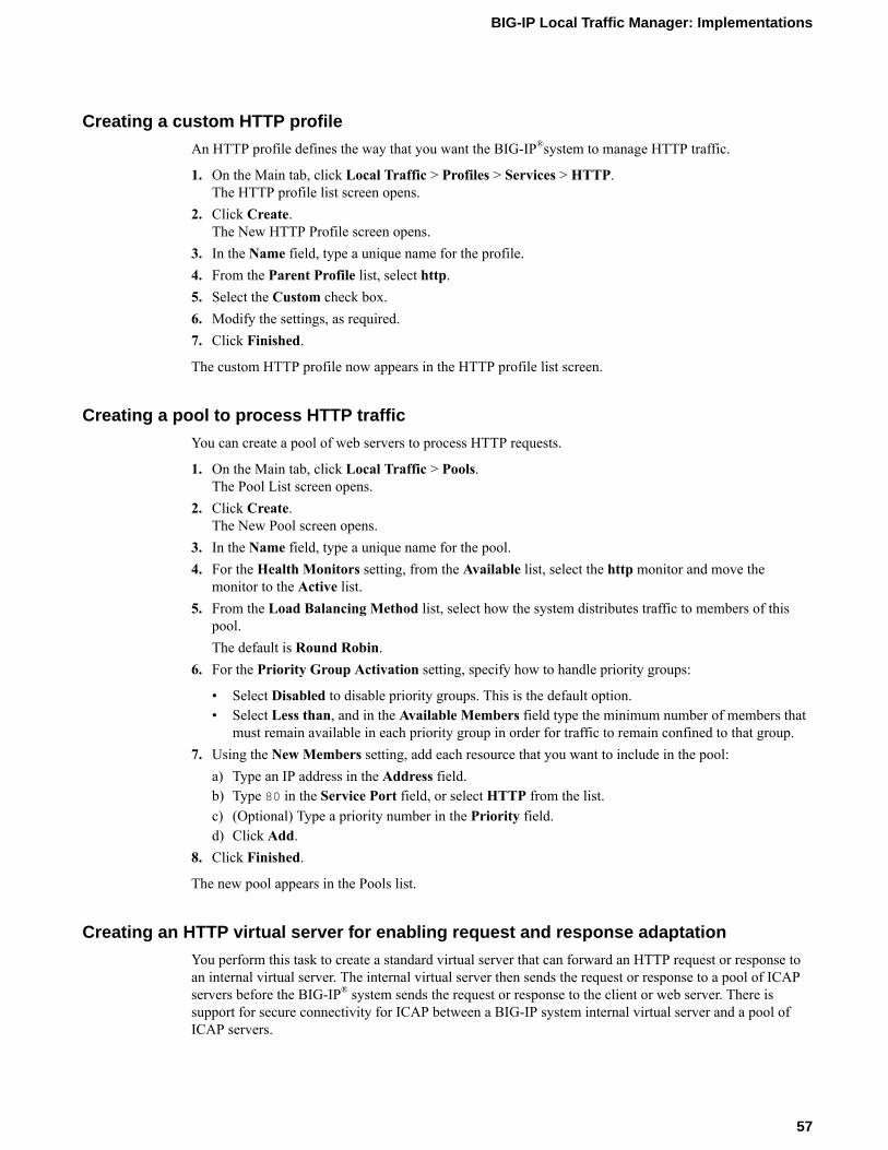
Creating a custom HTTP profile
An HTTP profile defines the way that you want the BIG-IP®system to manage HTTP traffic.
1. On the Main tab, click Local Traffic > Profiles > Services > HTTP.The HTTP profile list screen opens.
2. Click Create.The New HTTP Profile screen opens.
3. In the Name field, type a unique name for the profile.4. From the Parent Profile list, select http.5. Select the Custom check box.6. Modify the settings, as required.7. Click Finished.
The custom HTTP profile now appears in the HTTP profile list screen.
Creating a pool to process HTTP traffic
You can create a pool of web servers to process HTTP requests.
1. On the Main tab, click Local Traffic > Pools.The Pool List screen opens.
2. Click Create.The New Pool screen opens.
3. In the Name field, type a unique name for the pool.4. For the Health Monitors setting, from the Available list, select the http monitor and move the
monitor to the Active list.5. From the Load Balancing Method list, select how the system distributes traffic to members of this
pool.The default is Round Robin.
6. For the Priority Group Activation setting, specify how to handle priority groups:
• Select Disabled to disable priority groups. This is the default option.• Select Less than, and in the Available Members field type the minimum number of members that
must remain available in each priority group in order for traffic to remain confined to that group.7. Using the New Members setting, add each resource that you want to include in the pool:
a) Type an IP address in the Address field.b) Type 80 in the Service Port field, or select HTTP from the list.c) (Optional) Type a priority number in the Priority field.d) Click Add.
8. Click Finished.
The new pool appears in the Pools list.
Creating an HTTP virtual server for enabling request and response adaptation
You perform this task to create a standard virtual server that can forward an HTTP request or response toan internal virtual server. The internal virtual server then sends the request or response to a pool of ICAPservers before the BIG-IP® system sends the request or response to the client or web server. There issupport for secure connectivity for ICAP between a BIG-IP system internal virtual server and a pool ofICAP servers.
BIG-IP Local Traffic Manager: Implementations
57

1. On the Main tab, click Local Traffic > Virtual Servers.The Virtual Server List screen opens.
2. Click the Create button.The New Virtual Server screen opens.
3. In the Name field, type a unique name for the virtual server.4. In the Destination Address field, type the IP address that you want to use as a destination for client
traffic destined for a pool of HTTP web servers.The supported format is address/prefix, where the prefix length is in bits. For example, an IPv4address/prefix is 10.0.0.1 or 10.0.0.0/24, and an IPv6 address/prefix is ffe1::0020/64 or2001:ed8:77b5:2:10:10:100:42/64. When you use an IPv4 address without specifying a prefix,the BIG-IP® system automatically uses a /32 prefix.
Note: The IP address you type must be available and not in the loopback network.
5. In the Service Port field, type 80, or select HTTP from the list.6. From the Configuration list, select Advanced.7. From the HTTP Profile list, select the name of the HTTP profile that you created previously.8. From the Request Adapt Profile list, select the name of the Request Adapt profile that you
previously created.9. From the Response Adapt Profile list, select the name of the Response Adapt profile that you
previously created.10. From the Source Address Translation list, select Auto Map.11. From the Default Pool list, select the name of the HTTP server pool that you previously created.12. Click Finished.
After you create the virtual server, the BIG-IP® system can forward an HTTP request or response to apool of ICAP servers before sending the request or response to the client or web server, respectively.
Implementation resultAfter performing the tasks in this implementation, the BIG-IP® can perform content adaptation on HTTPrequests and responses as they pass through the BIG-IP system during normal HTTP processing. Thenew objects that this implementation creates are:
• Two custom ICAP profiles (for requests and responses)• One pool of ICAP content adaptation servers• Two separate internal virtual servers. One internal virtual server load balances HTTP requests to the
ICAP pool , while the other load balances responses to the ICAP pool.• Two custom adaptation profiles (a Request Adapt profile and a Response Adapt profile) that each
reference a separate internal virtual server (for requests and responses, respectively)• A custom HTTP profile• A standard HTTP pool of web servers• A standard HTTP virtual server that sends HTTP requests and responses to an internal virtual server
for content adaptation, load balances HTTP requests to the web pool, and forwards HTTP responsesto the relevant client
Configuring Content Adaptation for HTTP Requests and Responses
58

Configuring HTTP Load Balancing with Source AddressAffinity Persistence
Overview: HTTP load balancing with source affinity persistenceMany computing environments want to use a BIG-IP® system to intelligently manage their HTTP traffic.You can easily control your HTTP traffic by implementing a BIG-IP system feature known as an HTTPprofile. An HTTP profile is a group of settings that affect the behavior of HTTP traffic. An HTTP profiledefines the way that you want the BIG-IP system to manage HTTP traffic.
You can use the default HTTP profile, with all of its default values, or you can create a custom HTTPprofile. This particular implementation uses the default HTTP profile.
When you configure the BIG-IP system to manage HTTP traffic, you can also implement simple sessionpersistence, also known as source address affinity persistence. Source address affinity persistence directssession requests to the same server based solely on the source IP address of a packet. To implementsource address affinity persistence, the BIG-IP system offers a default persistence profile that you canimplement. Just as for HTTP, you can use the default profile, or you can create a custom simplepersistence profile.
Task summaryThis implementation describes how to set up a basic HTTP load balancing scenario and source addressaffinity persistence, using the default HTTP and source address affinity persistence profiles.
Because this implementation configures HTTP load balancing and session persistence using the defaultHTTP and persistence profiles, you do not need to specifically configure these profiles. Instead, yousimply configure some settings on the virtual server when you create it.
Task listCreating a pool to process HTTP trafficCreating a virtual server for HTTP traffic
Creating a pool to process HTTP traffic
You can create a pool of web servers to process HTTP requests.
1. On the Main tab, click Local Traffic > Pools.The Pool List screen opens.
2. Click Create.The New Pool screen opens.
3. In the Name field, type a unique name for the pool.4. For the Health Monitors setting, from the Available list, select the http monitor and move the
monitor to the Active list.5. From the Load Balancing Method list, select how the system distributes traffic to members of this
pool.The default is Round Robin.
6. For the Priority Group Activation setting, specify how to handle priority groups:
• Select Disabled to disable priority groups. This is the default option.• Select Less than, and in the Available Members field type the minimum number of members that
must remain available in each priority group in order for traffic to remain confined to that group.7. Using the New Members setting, add each resource that you want to include in the pool:
a) Type an IP address in the Address field.b) Type 80 in the Service Port field, or select HTTP from the list.c) (Optional) Type a priority number in the Priority field.d) Click Add.
8. Click Finished.
The new pool appears in the Pools list.
Creating a virtual server for HTTP traffic
This task creates a destination IP address for application traffic. As part of this task, you must assign therelevant pool to the virtual server.
1. On the Main tab, click Local Traffic > Virtual Servers.The Virtual Server List screen opens.
2. Click the Create button.The New Virtual Server screen opens.
3. In the Name field, type a unique name for the virtual server.4. In the Destination Address field, type the IP address in CIDR format.
The supported format is address/prefix, where the prefix length is in bits. For example, an IPv4address/prefix is 10.0.0.1 or 10.0.0.0/24, and an IPv6 address/prefix is ffe1::0020/64 or2001:ed8:77b5:2:10:10:100:42/64. When you use an IPv4 address without specifying a prefix,the BIG-IP® system automatically uses a /32 prefix.
Note: The IP address you type must be available and not in the loopback network.
5. In the Service Port field, type 80, or select HTTP from the list.6. From the HTTP Profile list, select http.7. In the Resources area of the screen, from the Default Pool list, select the relevant pool name.8. From the Default Persistence Profile list, select source_addr.
This implements simple persistence, using the default source address affinity profile.9. Click Finished.
You now have a virtual server to use as a destination address for application traffic.
Configuring HTTP Load Balancing with Source Address Affinity Persistence
60

Configuring HTTP Load Balancing with CookiePersistence
Overview: HTTP load balancing with cookie persistenceMany computing environments want to use a BIG-IP® system to intelligently manage their HTTP traffic.You can easily control your HTTP traffic by implementing a BIG-IP system feature known as an HTTPprofile. An HTTP profile is a group of settings that affects the behavior of HTTP traffic. An HTTPprofile defines the way that you want the system to manage HTTP traffic.
You can use the default HTTP profile, with all of its default values, or you can create a custom HTTPprofile. When you create a custom HTTP profile, you not only modify the setting values, but you canenable more advanced features such as data compression of server responses.
When you configure the BIG-IP system to manage HTTP traffic, you can also implement cookie-basedsession persistence. Cookie persistence directs session requests to the same server based on HTTPcookies that the BIG-IP system stores in the client’s browser.
Task summaryThis implementation describes how to set up a basic HTTP load balancing scenario and cookiepersistence, using the default HTTP profile.
Because this implementation configures HTTP load balancing and session persistence using the defaultHTTP, you do not need to specifically configure this profile. Instead, you simply configure some settingson the virtual server when you create it.
Task listCreating a custom cookie persistence profileCreating a pool to process HTTP trafficCreating a virtual server for HTTP traffic
Creating a custom cookie persistence profile
A good way to implement cookie persistence is to create a custom cookie persistence profile.
1. From the Main tab, click Local Traffic > Profiles > Persistence.2. Click Create.3. In the Name field, type a name for the profile.4. From the Persistence Type list, select Cookie.5. From the Parent Profile list, select cookie.6. On the right side of the screen, select the Custom check box.7. From the Cookie Method list, select HTTP Cookie Insert.8. If you want the BIG-IP system to encrypt the pool name specified in the BigIPServer default cookie,
select the Default Cookie Encrypt Pool Name check box.9. Retain or change all other profile settings.10. Click FInished.
The custom cookie persistence profile appears in the Persistence list.

Creating a pool to process HTTP traffic
You can create a pool of web servers to process HTTP requests.
1. On the Main tab, click Local Traffic > Pools.The Pool List screen opens.
2. Click Create.The New Pool screen opens.
3. In the Name field, type a unique name for the pool.4. For the Health Monitors setting, from the Available list, select the http monitor and move the
monitor to the Active list.5. From the Load Balancing Method list, select how the system distributes traffic to members of this
pool.The default is Round Robin.
6. For the Priority Group Activation setting, specify how to handle priority groups:
• Select Disabled to disable priority groups. This is the default option.• Select Less than, and in the Available Members field type the minimum number of members that
must remain available in each priority group in order for traffic to remain confined to that group.7. Using the New Members setting, add each resource that you want to include in the pool:
a) Type an IP address in the Address field.b) Type 80 in the Service Port field, or select HTTP from the list.c) (Optional) Type a priority number in the Priority field.d) Click Add.
8. Click Finished.
The new pool appears in the Pools list.
Creating a virtual server for HTTP traffic
This task creates a destination IP address for application traffic. As part of this task, you must assign therelevant pool to the virtual server.
Note: You can also use HTTP Cookie Insert persistence with a Performance (HTTP) type of virtualserver.
1. On the Main tab, click Local Traffic > Virtual Servers.The Virtual Server List screen opens.
2. Click the Create button.The New Virtual Server screen opens.
3. In the Name field, type a unique name for the virtual server.4. In the Destination Address field, type the IP address in CIDR format.
The supported format is address/prefix, where the prefix length is in bits. For example, an IPv4address/prefix is 10.0.0.1 or 10.0.0.0/24, and an IPv6 address/prefix is ffe1::0020/64 or2001:ed8:77b5:2:10:10:100:42/64. When you use an IPv4 address without specifying a prefix,the BIG-IP® system automatically uses a /32 prefix.
Note: The IP address you type must be available and not in the loopback network.
5. In the Service Port field, type 80, or select HTTP from the list.6. From the HTTP Profile list, select http.
Configuring HTTP Load Balancing with Cookie Persistence
62

7. In the Resources area of the screen, from the Default Pool list, select the relevant pool name.8. From the Default Persistence Profile list, select the name of the custom cookie profile you created
earlier, such as mycookie_profile.This implements cookie persistence, using a custom cookie persistence profile.
9. Click Finished.
You now have a virtual server to use as a destination address for application traffic.
BIG-IP Local Traffic Manager: Implementations
63

Configuring HTTP Load Balancing with Cookie Persistence
64

Compressing HTTP Responses
Overview: Compressing HTTP responsesAn optional feature of the BIG-IP® system is the system’s ability to off-load HTTP compression tasksfrom the target server. All of the tasks that you need to configure HTTP compression, as well as thecompression software itself, are centralized on the BIG-IP system. The primary way to enable HTTPcompression is by configuring an HTTP Compression type of profile and then assigning the profile to avirtual server. This causes the system to compress HTTP content for any responses matching the valuesthat you specify in the Request-URI or Content-Type settings of the HTTP Compression profile.
Tip: If you want to enable HTTP compression for specific connections, you can write an iRule thatspecifies the HTTP:compress enable command. Using the BIG-IP system HTTP compression feature, youcan include or exclude certain types of URIs or files that you specify. This is useful because some URI orfile types might already be compressed. F5 Networks does not recommend using CPU resources tocompress already-compressed data because the cost of compressing the data usually outweighs thebenefits. Examples of regular expressions that you might want to specify for exclusion are .*\.pdf, .*\.gif, or .*\.html.
Task summaryTo configure HTTP data compression, you need to create an HTTP compression type of profile, as wellas a virtual server.
Task listCreating a customized HTTP compression profileCreating a virtual server for HTTP compression
Creating a customized HTTP compression profile
If you need to adjust the compression settings to optimize compression for your environment, you canmodify a custom HTTP compression profile.
1. On the Main tab, click Acceleration > Profiles > HTTP Compression.The HTTP Compression profile list screen opens.
2. Click Create.The New HTTP Compression profile screen opens.
3. In the Name field, type a unique name for the profile.4. From the Parent Profile list, select one of the following profiles:
• httpcompression.• wan-optimized-compression.
5. Select the Custom check box.6. Modify the settings, as required.7. Click Finished.
The modified HTTP compression profile is available in the HTTP Compression list screen.

Creating a virtual server for HTTP compression
You can create a virtual server that uses an HTTP profile with an HTTP compression profile to compressHTTP responses.
1. On the Main tab, click Local Traffic > Virtual Servers.The Virtual Server List screen opens.
2. Click the Create button.The New Virtual Server screen opens.
3. In the Name field, type a unique name for the virtual server.4. In the Destination Address field, type the IP address in CIDR format.
The supported format is address/prefix, where the prefix length is in bits. For example, an IPv4address/prefix is 10.0.0.1 or 10.0.0.0/24, and an IPv6 address/prefix is ffe1::0020/64 or2001:ed8:77b5:2:10:10:100:42/64. When you use an IPv4 address without specifying a prefix,the BIG-IP® system automatically uses a /32 prefix.
Note: The IP address you type must be available and not in the loopback network.
5. In the Service Port field, type 80, or select HTTP from the list.6. Select http in the HTTP Profile list.7. From the HTTP Compression Profile list, select one of the following profiles:
• httpcompression• wan-optimized-compression• A customized profile
8. In the Resources area of the screen, from the Default Pool list, select the relevant pool name.9. Click Finished.
The virtual server with an HTTP profile configured with an HTTP compression profile appears in theVirtual Server list.
After you have created a custom HTTP Compression profile and a virtual server, you can test theconfiguration by attempting to pass HTTP traffic through the virtual server. Check to see that the BIG-IPsystem includes and excludes the responses that you specified in the custom profile, and that the systemcompresses the data as specified.
Compressing HTTP Responses
66
Using Via Headers to Acquire Information AboutIntermediate Routers
Overview: Using Via headersVia headers provide useful information about intermediate routers that can be used in network analysisand troubleshooting.
Task summary for identifying intermediate information with Via headersPerform these tasks to identify intermediate information with Via headers.
Task listIdentifying information about intermediate proxies with Via headersRemoving Via headers from requests and responses
Identifying information about intermediate proxies with Via headers
The BIG-IP® system can include Via headers (configured in an HTTP profile) in a request, a response, orboth, to identify information, such as protocols and names, for intermediate proxies that forwardmessages.
1. On the Main tab, click Local Traffic > Profiles > Services > HTTP.The HTTP profile list screen opens.
2. Click the name of a user-defined profile.3. Select the Custom check box.4. In the Send Proxy Via Header In Request list, do one of the following:
• Select the Preserve option to include the Via header in the client request to the origin web server.• Select the Append option, and then type a string in the Send Proxy Via Header Host Name
field, which is appended as a comment when sending a Via header in a request to an origin webserver.
5. In the Send Proxy Via Header In Response list, do one of the following:
• Select the Preserve option to include the Via header in the client response to the client.• Select the Append option, and then type a string in the Send Proxy Via Header Host Name
field, which is appended as a comment when sending a Via header in a response to a client.6. Click Finished.
The BIG-IP system is configured to use Via headers to identify protocols and intermediate proxies thatforward messages.
Removing Via headers from requests and responses
Via headers are configured in an HTTP profile for requests or responses.
You can remove Via headers from requests and responses if you no longer require them to identifyinformation about intermediate proxies.
1. On the Main tab, click Local Traffic > Profiles > Services > HTTP.

The HTTP profile list screen opens.2. Click the name of a user-defined profile.3. Select the Custom check box.4. In the Send Proxy Via Header In Request list, select Remove.5. In the Send Proxy Via Header In Response list, select Remove.6. Click Finished.
The BIG-IP® system removes Via headers, as configured, for requests and responses.
Using Via Headers to Acquire Information About Intermediate Routers
68

Configuring the BIG-IP System as a Reverse Proxy Server
Overview: URI translation and HTML content modificationFor environments that use web servers, you might want your websites to appear differently on theexternal network than on the internal network. For example, you might want the BIG-IP® system to sendtraffic destined for http://www.siterequest.com/ to the internal server http://appserver1.siterequest.com/ instead. Normally, this translation could cause some issues, such asthe web server expecting to see a certain host name (such as for name-based virtual hosting) or the webserver using the internal host name and/or path when sending a redirect to client systems. Fortunately,you can configure the BIG-IP system to solve these problems.
You can also configure the BIG-IP system to modify HTML content as needed after the system hasperformed the URI translation.
This implementation describes an example of URI translation and HTML content modification and thenprovides the tasks to implement this example.
About URI translation
You can configure the BIG-IP® system to perform URI translation on HTTP requests. Suppose that acompany named Siterequest has a website www.siterequest.com, which has a public IP addressand a registered DNS entry, and therefore can be accessed from anywhere on the Internet.
Furthermore, suppose that Siterequest has two application servers with private IP addresses andunregistered DNS entries, inside the company's firewall. The application servers are visible within theinternal network as appserver1.siterequest.com and appserver2.siterequest.com.
Because these servers have no public DNS entries, any client system that tries to access one of theseservers from outside the company network receives a no such host error.
As the illustration shows, you can prevent this problem by configuring the BIG-IP system to act as areverse proxy server:

Figure 11: The BIG-IP system as a reverse proxy server for URI translation
In the example, the company Siterequest has decided to enable Web access to the internal applicationservers, without exposing them to the Internet directly. Instead, the company has integrated the serverswith the web server siterequest.com so that http://www.siterequest.com/sales is mappedinternally to http://appserver1.siterequest.com/sales, and http://siterequest.com/marketing is mapped internally to http://appserver2.example.com/marketing. This is atypical reverse-proxy configuration.
To configure the BIG-IP system to perform this translation, you create a Rewrite profile and configureone or more URI rules. A URI rule specifies the particular URI translation that you want the BIG-IPsystem to perform. Specifically, a URI rule translates the scheme, host, port, or path of any client URI,server URI, or both. A URI rule also translates any domain and path information in the Set-Cookieheader of the response when that header information matches the information in the URI rule.
Note: The Rewrite profile supports HTML and CSS content types only. To specify MIME types for HTMLcontent, you can either create an HTML profile or accept the default values that the Rewrite profile uses,text/html and text/xhtml. For CSS content, only the text/css MIME type is supported.
Rules for matching requests to URI rules
The BIG-IP® system follows these rules when attempting to match a request to a URI rule:
• A request does not need to match any entry. That is, if no entries match and there is no catch-all entry,then the Rewrite profile has no effect.
• Each request matches one entry only, which is the entry with the most specific host and path.• If multiple entries match, then the BIG-IP system uses the entry with the deepest path name on the
left side of the specified mapping.• The BIG-IP system matches those requests that contain host names in URIs before matching requests
that do not contain host names in URIs.
Configuring the BIG-IP System as a Reverse Proxy Server
70

• The BIG-IP system processes the specified entries in the mapping from most-specific to least-specific, regardless of the order specified in the actual Rewrite profile.
About URI Rules
When creating a URI rule, you must specify the client and server URIs in these ways:
• When the URI is a path prefix only, the path must be preceded by and followed by a /, for example, /sales/.
• When the URI contains more than the path prefix (such as, a host), the URI must also contain ascheme and must be followed by a /, for example, http://www.siterequest/sales/.
Introduction to HTML content modification
When you configure an HTML profile on the BIG-IP® system, the system can modify HTML contentthat passes through the system, according to your specifications. For example, if you want the BIG-IPsystem to detect all content of type text/html and then remove all instances of the HTML img tag withthe src attribute, you can configure an HTML profile accordingly, and assign it to the virtual server. TheHTML profile ensures that the BIG-IP system removes those instances of the tag from any HTMLcontent that passes through the virtual server.
Or, you can configure an HTML profile to match on a certain tag and attribute in HTML content when aparticular iRule event is triggered, and then create an iRule that includes a command to replace the valueof the matched attribute with a different attribute. The BIG-IP system includes several iRule commandsthat you can use when the Raise Event on Comment or Raise Event on Tag events are triggered.For more information on iRule commands related to HTML content modification, see the F5 Networksweb site http://devcentral.f5.com.
HTML tag removal and replacement are just two of several HTML rules that you can configure tomanipulate HTML content. An HTML rule defines the specific actions that you want the BIG-IP systemto perform on a specified type HTML content.
Task summaryThe first step to configuring the BIG-IP® system to act as a reverse proxy server is to create a Rewritetype of profile on the BIG-IP system and associate it with a virtual server. Note that each virtual servermust have an HTTP profile. The Rewrite profile is designed for HTTP sites, as well as HTTPS siteswhere SSL is terminated on the BIG-IP system (that is, the virtual server references a Client SSL profile).
Task ListCreating a Rewrite profile to specify URI rulesCreating an HTML profile for tag removalCreating pools for processing HTTP trafficCreating a local traffic policyCreating a virtual server
Creating a Rewrite profile to specify URI rules
To configure the BIG-IP® system to perform URI translation, you create a Rewrite profile, specifying oneor more URI rules that associate a client-side path with a server-side URI. You also specify whether youwant the URI translation to pertain to HTTP requests, responses, or both.
BIG-IP Local Traffic Manager: Implementations
71

Note: The Rewrite profile supports HTML and CSS content types only. To specify MIME types for HTMLcontent, you can either create an HTML profile or accept the default values that the Rewrite profile uses,text/html and text/xhtml. For CSS content, only the text/css MIME type is supported.
1. On the Main tab, click Local Traffic > Profiles > Services > Rewrite.The Rewrite profile list appears.
2. Click Create New Profile.The Create New Profile Rewrite pop-up screen opens.
3. In the Profile Name field, type a name, such as my_rewrite_profile.4. From the Parent Profile list, select rewrite.5. From the Rewrite Mode list, select URI Translation.6. On the left pane, click URI Rules.
An empty text box appears for displaying client-server URI mappings that you specify.7. Click Add.8. From the Rule Type list, select Both.9. In the Client URI box, type a client path, such as /sales/.10. In the Server URI box, type a server URI, such as http://appserver1.siterequest.com/
sales/.You must include a scheme in the server URI that you specify.An example of a scheme is http.
11. Click OK.This displays a mapping of the specified client path to the associated server scheme, host, and path.
12. Click Add again.13. From the Rule Type list, select Both.14. In the Client URI field, type a client path, such as /marketing/.15. In the Server URI field, type a server URI, such as http://appserver2.siterequest.com/
marketing/.You must include a scheme in the server URI that you specify.An example of a scheme is http.
16. Click OK.This displays a mapping of the specified client path to the associated server scheme, host, and path.
17. Click OK.
The BIG-IP system now includes two URI rules for performing URI translation on both requests andresponses. For example, the host name in a request destined for http://www.siterequest.com/sales/ will be translated to http://appserver1.siterequest.com/sales/, and the host name ina request destined for https://www.siterequest.com/marketing/ will be translated to http://appserver2.siterequest.com/marketing/. A reverse translation occurs on any response.
Creating an HTML profile for tag removal
You create an HTML profile when you want the BIG-IP® system to act on certain types of HTMLcontent.
1. On the Main tab, click Local Traffic > Profiles > Content > HTML.2. Click the Create New Profile button.3. In the Profile Name field, type a name, such as my_html_profile.4. From the Parent Profile list, select /Common/html.5. On the left pane, click HTML Rules.
Configuring the BIG-IP System as a Reverse Proxy Server
72

6. On the Create New button, click the right arrow.7. Select Remove Tag.
The Create New Remove Tag Rule box appears.8. In the Rule Name field, type a name, such as my_remove_img_tag_rule.9. Optionally, in the Description field, type a description of the rule, such as Removes the img tag
with the src attribute.10. On the left pane, click Match Settings.11. In the Match Tag Name field, type the name of the tag that you want to remove from the HTML
content.An example of a tag to specify is the HTML img tag.
12. In the Match Attribute Name field, type the name of the attribute associated with the tag that youspecified for removal.An example of an attribute to specify is the src attribute for the img tag.
13. Click OK.14. In the Available Rules list, locate the HTML rule that you want to enable, and select the adjacent
check box.15. Using the Move button, move the selected HTML rule to the Selected Rules list.16. Click OK.
After creating this HTML profile, you can implement the HTML content modification by assigning theprofile to the virtual server that is processing the associated HTTP traffic.
Creating pools for processing HTTP traffic
You can create two load balancing pools, and then create a policy that forwards certain HTTP traffic toone pool, and other HTTP traffic to another pool.
1. On the Main tab, click Local Traffic > Pools.The Pool List screen opens.
2. Click Create.The New Pool screen opens.
3. In the Name field, type a unique name for the pool.4. Using the New Members setting, add each resource that you want to include in the pool:
a) (Optional) In the Node Name field, type a name for the node portion of the pool member.b) In the Address field, type an IP address.c) In the Service Port field, type a port number, or select a service name from the list.d) (Optional) In the Priority field, type a priority number.e) Click Add.
5. Click Finished.6. Repeat this task to create a second pool.
The new pools appear in the Pools list.
Creating a local traffic policy
You perform this task to create a local traffic policy that forwards traffic to one or more non-defaultpools, based on some condition. For example, for a condition such as an HTTP request whose host nameequals siterequest.com and URI starts with /sales/, the BIG-IP® system can forward that requestto pool_app1.
1. On the Main tab, click Local Traffic > Policies > Policy List.The Policy List Page screen opens.
BIG-IP Local Traffic Manager: Implementations
73
2. Click Create.The New Policy screen opens.
3. In the Name field, type a unique name for the policy.4. From the Strategy list, select a matching strategy.5. For the Requires setting, select http from the Available list, and move the entry to the Selected list
using the Move button.6. For the Controls setting, select forwarding from the Available list, and move the entry to the
Selected list using the Move button.7. Click Add.
The New Rule screen opens.8. In the Rule field, type a unique name for the rule.9. From the Operand list, select http-host.10. Using the options for the Conditions setting, configure a rule where the condition equals the criteria
specified:a) From the Condition list, select equals.b) (Optional) Select the case sensitive check box to apply case sensitivity to the condition.c) In the Values field, type the text for the applicable value and click Add.
An example of a value is siterequest.com.The specified condition appears in the Values list box.
d) At the lower left, click Add.The configured condition appears in the Conditions list.
11. From the Operand list, select http-uri.12. Using the options for the Conditions setting, configure a rule where the condition starts with the
criteria specified:a) From the Condition list, select starts with.b) (Optional) Select the case sensitive check box to apply case sensitivity to the condition.c) In the Values field, type the text for the applicable value and click Add.
An example of a value is /app1/.The specified condition appears in the Values list box.
d) At the lower left click Add.The configured condition appears in the Condition list.
13. Using the Actions setting, configure the applicable options:a) From the Target list, select forward.b) From the Event list, select an event.c) From the Action list, select pool.d) From the Parameters list, select the pool name to which you want the BIG-IP system to forward
the traffic.e) To the right of the input field, click Add.
The configured parameter appears in the Parameters list box.f) At the lower left click Add.
The configured settings for the action appear in the Actions list.14. Repeat steps 11 through 13, specifying a second http-uri condition value, such as /marketing,
and specifying a different non-default pool name.15. Click Finished.
For each matching condition specified in the policy, the virtual server to which you assign the policyforwards the packet to the non-default pool that you specified in the policy. For example, you can createone policy that forwards traffic with a URI starting with /sales/ to pool_sales and another policythat forwards traffic with a URI starting with /marketing/ to pool_marketing.
Configuring the BIG-IP System as a Reverse Proxy Server
74

Creating a virtual server
You can create a virtual server that translates a URI in a request or response and modifies HTML content.When you create the virtual server, you can also configure it to forward certain HTTP traffic to one pool,while forwarding other HTTP traffic to a different pool..
1. On the Main tab, click Local Traffic > Virtual Servers.The Virtual Server List screen opens.
2. Click the Create button.The New Virtual Server screen opens.
3. In the Name field, type a unique name for the virtual server.4. In the Destination Address field, type the IP address in CIDR format.
The supported format is address/prefix, where the prefix length is in bits. For example, an IPv4address/prefix is 10.0.0.1 or 10.0.0.0/24, and an IPv6 address/prefix is ffe1::0020/64 or2001:ed8:77b5:2:10:10:100:42/64. When you use an IPv4 address without specifying a prefix,the BIG-IP® system automatically uses a /32 prefix.
Note: The IP address you type must be available and not in the loopback network.
5. In the Service Port field, type 80, or select HTTP from the list.6. For the HTTP Profile setting, verify that the default HTTP profile, http, is selected.7. In the Content Rewrite area, from the Rewrite Profile list, select the relevant Rewrite profile that you
created.8. From the HTML Profile list, select the relevant HTML profile that you created.9. For the Policies setting, select the local traffic policy you created from the Available list and move it
to the Enabled list.10. Click Finished.
The HTTP virtual server appears in the list of existing virtual servers on the Virtual Server List screen.This virtual server can translate URIs in requests and responses, modify HTML content, and forward thetraffic to two different non-default load balancing pools.
Implementation resultsAfter you perform the tasks in this implementation, the BIG-IP® system can:
• Translate URIs according to the URI rules specified in the Rewrite profile.• Modify specified HTML content according to the HTML rule specified in the HTML profile.• Forward HTTP traffic to two different non-default pools according to a local traffic policy.
BIG-IP Local Traffic Manager: Implementations
75

Configuring the BIG-IP System as a Reverse Proxy Server
76
Load Balancing Passive Mode FTP Traffic
Overview: FTP passive mode load balancingYou can set up the BIG-IP system to load balance passive mode FTP traffic. You do this by using thedefault FTP profile. An FTP profile determines the way that the BIG-IP system processes FTP traffic.
Additionally, you can create an iRule to apply to the FTP data channel. You apply the iRule to the datachannel by assigning the iRule to the virtual server that you create.
Task Summary for load balancing passive mode FTP trafficYou can perform these tasks to configure FTP passive mode load balancing.
Task listCreating a custom FTP monitorCreating a pool to manage FTP trafficCreating a virtual server for FTP traffic
Creating a custom FTP monitor
An FTP monitor requires a user name and password, and the full path to the file to be downloaded.
Note: The BIG-IP® system does not save the downloaded file.
Note: The BIG-IP® system does not save the downloaded file.
1. Click Create.The New Monitor screen opens.
2. Type a name for the monitor in the Name field.3. From the Type list, select FTP.
The screen refreshes, and displays the configuration options for the FTP monitor type.4. From the Import Monitor list, select an existing monitor.
The new monitor inherits initial configuration values from the existing monitor.5. Type a number in the Interval field that indicates, in seconds, how frequently the system issues the
monitor check. The default is 10 seconds.6. Type a number in the Timeout field that indicates, in seconds, how much time the target has to
respond to the monitor check. The default is 31 seconds.If the target responds within the allotted time period, it is considered up. If the target does not respondwithin the time period, it is considered down.
7. Type a name in the User Name field.8. Type a password in the Password field.9. Type the full path and file name of the file that the system attempts to download in the Path/
Filename field.The health check is successful if the system can download the file.
10. For the Mode setting, select one of the following data transfer process (DTP) modes.

Option Description
Passive The monitor sends a data transfer request to the FTP server. When the FTP server receivesthe request, the FTP server initiates and establishes the data connection.
Port The monitor initiates and establishes the data connection with the FTP server.
11. From the Configuration list, select Advanced.This selection makes it possible for you to modify additional default settings.
12. For the Alias Address setting, do one of the following:
• Accept the *All Addresses default option.• Type an alias IP address for the monitor to verify, on behalf of the pools or pool members with
which the monitor is associated.
If the health check for the alias address is successful, the system marks all associated objects up. If thehealth check for the alias address is not successful, then the system marks all associated objects down.
13. For the Alias Service Port setting, do one of the following:
• Accept the *All Ports default option.• Select an alias port or service for the monitor to check, on behalf of the pools or pool members
with which the monitor is associated.
If the health check for the alias port or service is successful, the system marks all associated objectsup. If the health check for the alias port or service is not successful, then the system marks allassociated objects down.
14. For the Debug setting, specify whether you want the system to collect and publish additionalinformation and error messages for this monitor.You can use the log information to help diagnose and troubleshoot unsuccessful health checks. Toview the log entries, see the System > Logs screens.
Option Description
Yes The system redirects error messages and other information to a log file created specificallyfor this monitor.
No The system does not collect additional information or error messages related to thismonitor. This is the default setting.
15. Click Finished.
Creating a pool to manage FTP traffic
To load balance passive mode FTP traffic, you create a load balancing pool. When you create the pool,you assign the custom FTP monitor that you created in the previous task.
1. On the Main tab, click Local Traffic > Pools.The Pool List screen opens.
2. Click Create.The New Pool screen opens.
3. In the Name field, type a unique name for the pool.4. For the Health Monitors setting, in the Available list, select a monitor type, and click << to move the
monitor to the Active list.
Tip: Hold the Shift or Ctrl key to select more than one monitor at a time.
5. From the Priority Group Activation list, select Disabled.6. Add each resource that you want to include in the pool using the New Members setting:
Load Balancing Passive Mode FTP Traffic
78

a) Type an IP address in the Address field.b) Type 21 in the Service Port field, or select FTP from the list.c) (Optional) Type a priority number in the Priority field.d) Click Add.
7. Click Finished.
The pool to manage FTP traffic appears in the Pools list.
Creating a virtual server for FTP traffic
You can define a virtual server that references the FTP profile and the FTP pool.
1. On the Main tab, click Local Traffic > Virtual Servers.The Virtual Server List screen opens.
2. Click the Create button.The New Virtual Server screen opens.
3. In the Name field, type a unique name for the virtual server.4. In the Destination Address field, type the IP address in CIDR format.
The supported format is address/prefix, where the prefix length is in bits. For example, an IPv4address/prefix is 10.0.0.1 or 10.0.0.0/24, and an IPv6 address/prefix is ffe1::0020/64 or2001:ed8:77b5:2:10:10:100:42/64. When you use an IPv4 address without specifying a prefix,the BIG-IP® system automatically uses a /32 prefix.
Note: The IP address you type must be available and not in the loopback network.
5. In the Service Port field, type 21 or select FTP from the list.6. For the FTP Profile setting, select the default profile, ftp.7. Locate the Resources area of the screen; for the Related iRules setting, from the Available list, select
the name of the iRule that you want to assign and move the name to the Enabled list.This setting applies to virtual servers that reference a profile for a data channel protocol, such as FTPor RTSP.
8. In the Resources area of the screen, from the Default Pool list, select the relevant pool name.9. Click Finished.
The custom FTP virtual server appears in the Virtual Servers list.
BIG-IP Local Traffic Manager: Implementations
79

Load Balancing Passive Mode FTP Traffic
80

Load Balancing Passive Mode FTP Traffic with DataChannel Optimization
Overview: FTP passive mode load balancing with data channeloptimization
You can set up the BIG-IP system to load balance passive mode FTP traffic, with optimization of both theFTP control channel and the data channel.
By default, the BIG-IP system optimizes FTP traffic for the control channel, according to theconfiguration settings in the default client and server TCP profiles assigned to the virtual server. Whenyou use this particular implementation, you also configure the system to take advantage of those sameTCP profile settings for the FTP data channel. This provides useful optimization of the data channelpayload.
Task Summary for load balancing passive mode FTP trafficYou can perform these tasks to configure FTP passive mode load balancing that optimizes traffic on boththe control channel and data channel.
Task listCreating a custom FTP profileCreating a custom FTP monitorCreating a pool to manage FTP trafficCreating a virtual server for FTP traffic
Creating a custom FTP profile
You create a custom FTP profile when you want to fine-tune the way that the BIG-IP®system managesFTP traffic. This procedure creates an FTP profile and optimizes the way that the BIG-IP systemmanages traffic for the FTP data channel.
1. On the Main tab, click Local Traffic > Profiles > Services > FTP.The FTP profile list screen opens.
2. Click Create.The New FTP Profile screen opens.
3. In the Name field, type a unique name for the profile.4. From the Parent Profile list, select the default ftp profile.5. Select the Custom check box.6. For the Inherit Parent Profile setting, select the check box.
This optimizes data channel traffic.7. Click Finished.
The custom FTP profile now appears in the FTP profile list screen.
Creating a custom FTP monitor
An FTP monitor requires a user name and password, and the full path to the file to be downloaded.

Create a custom FTP monitor to verify passive mode File Transfer Protocol (FTP) traffic. The monitorattempts to download a specified file to the /var/tmp directory. If the file is retrieved, the check issuccessful.
Note: The BIG-IP® system does not save the downloaded file.
1. Click Create.The New Monitor screen opens.
2. Type a name for the monitor in the Name field.3. From the Type list, select FTP.
The screen refreshes, and displays the configuration options for the FTP monitor type.4. From the Import Monitor list, select an existing monitor.
The new monitor inherits initial configuration values from the existing monitor.5. Type a number in the Interval field that indicates, in seconds, how frequently the system issues the
monitor check. The default is 10 seconds.6. Type a number in the Timeout field that indicates, in seconds, how much time the target has to
respond to the monitor check. The default is 31 seconds.If the target responds within the allotted time period, it is considered up. If the target does not respondwithin the time period, it is considered down.
7. Type a name in the User Name field.8. Type a password in the Password field.9. Type the full path and file name of the file that the system attempts to download in the Path/
Filename field.The health check is successful if the system can download the file.
10. For the Mode setting, select one of the following data transfer process (DTP) modes.Option Description
Passive The monitor sends a data transfer request to the FTP server. When the FTP server receivesthe request, the FTP server initiates and establishes the data connection.
Port The monitor initiates and establishes the data connection with the FTP server.
11. From the Configuration list, select Advanced.This selection makes it possible for you to modify additional default settings.
12. For the Alias Address setting, do one of the following:
• Accept the *All Addresses default option.• Type an alias IP address for the monitor to verify, on behalf of the pools or pool members with
which the monitor is associated.
If the health check for the alias address is successful, the system marks all associated objects up. If thehealth check for the alias address is not successful, then the system marks all associated objects down.
13. For the Alias Service Port setting, do one of the following:
• Accept the *All Ports default option.• Select an alias port or service for the monitor to check, on behalf of the pools or pool members
with which the monitor is associated.
If the health check for the alias port or service is successful, the system marks all associated objectsup. If the health check for the alias port or service is not successful, then the system marks allassociated objects down.
14. For the Debug setting, specify whether you want the system to collect and publish additionalinformation and error messages for this monitor.
Load Balancing Passive Mode FTP Traffic with Data Channel Optimization
82

You can use the log information to help diagnose and troubleshoot unsuccessful health checks. Toview the log entries, see the System > Logs screens.
Option Description
Yes The system redirects error messages and other information to a log file created specificallyfor this monitor.
No The system does not collect additional information or error messages related to thismonitor. This is the default setting.
15. Click Finished.
You can associate the new custom monitor with the pool that contains the FTP resources.
Creating a pool to manage FTP traffic
To load balance passive mode FTP traffic, you create a load balancing pool. When you create the pool,you assign the custom FTP monitor that you created in the previous task.
1. On the Main tab, click Local Traffic > Pools.The Pool List screen opens.
2. Click Create.The New Pool screen opens.
3. In the Name field, type a unique name for the pool.4. For the Health Monitors setting, in the Available list, select a monitor type, and click << to move the
monitor to the Active list.
Tip: Hold the Shift or Ctrl key to select more than one monitor at a time.
5. From the Priority Group Activation list, select Disabled.6. Add each resource that you want to include in the pool using the New Members setting:
a) Type an IP address in the Address field.b) Type 21 in the Service Port field, or select FTP from the list.c) (Optional) Type a priority number in the Priority field.d) Click Add.
7. Click Finished.
The pool to manage FTP traffic appears in the Pools list.
Creating a virtual server for FTP traffic
You can define a virtual server that references the FTP profile and the FTP pool.
1. On the Main tab, click Local Traffic > Virtual Servers.The Virtual Server List screen opens.
2. Click the Create button.The New Virtual Server screen opens.
3. In the Name field, type a unique name for the virtual server.4. In the Destination Address field, type the IP address in CIDR format.
The supported format is address/prefix, where the prefix length is in bits. For example, an IPv4address/prefix is 10.0.0.1 or 10.0.0.0/24, and an IPv6 address/prefix is ffe1::0020/64 or2001:ed8:77b5:2:10:10:100:42/64. When you use an IPv4 address without specifying a prefix,the BIG-IP® system automatically uses a /32 prefix.
Note: The IP address you type must be available and not in the loopback network.
BIG-IP Local Traffic Manager: Implementations
83

5. In the Service Port field, type 21 or select FTP from the list.6. From the FTP Profile list, select the custom profile that you created earlier.7. Locate the Resources area of the screen; for the Related iRules setting, from the Available list, select
the name of the iRule that you want to assign and move the name to the Enabled list.This setting applies to virtual servers that reference a profile for a data channel protocol, such as FTPor RTSP.
8. In the Resources area of the screen, from the Default Pool list, select the relevant pool name.9. Click Finished.
The custom FTP virtual server appears in the Virtual Servers list.
Implementation resultA BIG-IP system with this configuration can process FTP traffic in passive mode, in a way that optimizesthe traffic on both the control channel and the data channel. This optimization is based on the settings ofthe default client-side and server-side TCP profiles.
Load Balancing Passive Mode FTP Traffic with Data Channel Optimization
84

Configuring the BIG-IP System as a DHCP Relay Agent
Overview: Managing IP addresses for DHCP clientsWhen you want to manage Dynamic Host Configuration Protocol (DHCP) client IP addresses, you canconfigure the BIG-IP® system to act as a DHCP relay agent. A common reason to configure the BIG-IPsystem as a DHCP relay agent is when the DHCP clients reside on a different subnet than the subnet ofthe DHCP servers.
Before configuring the BIG-IP system to act as a DHCP relay agent, it is helpful to understand someBIG-IP system terminology:
BIG-IP object type Definition
BIG-IP pool member A DHCP relay target (such as a DHCP server or BOOTPserver). This is the dynamic address server to which the BIG-IP system forwards unicast requests.
BIG-IP virtual server A BIG-IP system address on the listening VLAN
BIG-IP VLAN assigned to a virtualserver
A listening VLAN, controlled on a per-virtual server basis
About the BIG-IP system as a DHCP relay agent
A BIG-IP® virtual server, configured as a Dynamic Host Configuration Protocol (DHCP) type, providesyou with the ability to relay DHCP client requests for an IP address to one or more DHCP servers,available as pool members in a DHCP pool, on different +virtual local area networks (VLANs). TheDHCP client request is relayed to all pool members, and the replies from all pool members are relayedback to the client.
Figure 12: A sample DHCP relay agent configuration
For example, a DHCP client sends a broadcast message to the destination IP address255.255.255.255, which is the destination address configured on the virtual server. A DHCP typevirtual server automatically uses port 67 for an IPv4 broadcast message or port 547 for an IPv6 broadcastmessage. The BIG-IP virtual server receives this message on the VLAN with self IP address 10.20.0.1and relays the DHCP request to all DHCP servers: 10.10.0.3 and 10.10.0.7.

All DHCP servers provide a DHCP response with available IP addresses to the BIG-IP virtual server,which then relays all responses to the client. The client accepts and uses only one of the IP addressesreceived.
Note: In this example, there is no hop between the DHCP client and the BIG-IP relay agent. However, acommon topology is one that includes this hop, which is often another BIG-IP system.
Alternate configuration
If the DHCP client subnet includes a BIG-IP system that serves as a hop to the BIG-IP relay agent, youmust perform two additional configuration tasks:
• You must configure the BIG-IP relay agent to relay the client DHCP requests to the DHCP serverswithout losing the originating subnet (source) IP address. This originating source IP address istypically a self IP address of the BIG-IP system that resides on the client subnet. You configure theBIG-IP relay agent to preserve the originating source IP address by creating a SNAT that specifies theoriginating self IP address as both the origin address and the translation address. A SNAT configuredin this way prevents the BIG-IP relay agent, before sending the DHCP broadcast message to theDHCP servers, from translating the source IP address of the incoming DHCP request to a differentaddress.
• You must add a route (to the BIG-IP relay agent) that specifies the originating source IP address as thedestination for DHCP responses. The DHCP servers use this route to send their responses backthrough the BIG-IP relay agent to the clients.
Task summaryYou configure the BIG-IP system to act as a Dynamic Host Configuration Protocol (DHCP) relay agentby creating a pool of DHCP servers and then creating a virtual server to manage DHCP client broadcastmessages.
Task listCreating a pool of DHCP serversCreating a DHCP type virtual server
Creating a pool of DHCP servers
You must create a pool that includes Dynamic Host Configuration Protocol (DHCP) servers as poolmembers before you create a DHCP type of virtual server.
Important: Never add more than 20 pool members to a pool of DHCP servers. Although the BIG-IP®
system does not prevent you from adding more than 20 members to a pool, only 20 members or fewer willreceive the client DHCP DISCOVER request.
1. On the Main tab, click Local Traffic > Pools.The Pool List screen opens.
2. Click Create.The New Pool screen opens.
3. In the Name field, type a unique name for the pool.4. (Optional) Type a description for the pool.5. (Optional) For the Health Monitors setting, in the Available list, select UDP, and click << to move
the monitor to the Active list.6. From the Load Balancing Method list, select a method.
Configuring the BIG-IP System as a DHCP Relay Agent
86

Note: A DHCP pool requires a load balancing method, although actual load balancing across DHCPpool members is ignored and DHCP requests are sent to all DHCP pool members.
7. For the Priority Group Activation setting, select Disabled.8. Add each resource that you want to include in the pool using the New Members setting:
a) (Optional) Type a name in the Node Name field, or select a node address from the Node List.
a) Type an IP address in the Address field, or select a node address from the Node List.b) Type 67 (IPv4) or 547 (IPv6) in the Service Port field.c) Click Add.
9. Clicked Finished.
A pool that includes DHCP servers as pool members is created.
Creating a DHCP type virtual server
A DHCP type of BIG-IP® virtual server provides you with the ability to relay DHCP client requests foran IP address to one or more DHCP servers, and provide DHCP server responses with an available IPaddress for the client.
1. On the Main tab, click Local Traffic > Virtual Servers.The Virtual Server List screen opens.
2. Click the Create button.The New Virtual Server screen opens.
3. In the Name field, type a unique name for the virtual server.4. (Optional) Type a description for the virtual server.5. From the Type list, select DHCP.6. Select one of the following to configure a Destination Address type.
Destination Steps to configure
255.255.255.255 (IPv4 Default) None.
ff02::1:2 (IPv6 Default) None.
Other For a host or network, in the Destination Address field, type anIPv4 address/prefix or an IPv6 address/prefix.
7. From the State list, select Enabled.8. In the Configuration area for the VLAN and Tunnel Traffic setting, select the VLANs on the same
network as the DHCP clients to ensure that the BIG-IP system can accept the broadcast traffic fromthe client.
9. From the Default Pool list, select the pool that is configured for DHCP servers.10. Click Finished.
A DHCP type of virtual server is configured to provide the ability to relay DHCP client requests for an IPaddress to one or more DHCP servers, and provide DHCP server responses with an available IP addressfor the client.
Implementation resultThe BIG-IP® system is configured to manage Dynamic Host Configuration Protocol (DHCP) client IPaddresses, using a DHCP type of virtual server to manage DHCP client broadcast messages.
BIG-IP Local Traffic Manager: Implementations
87

Configuring the BIG-IP System as a DHCP Relay Agent
88

Configuring the BIG-IP System for DHCP Renewal
Overview: Renewing IP addresses for DHCP clientsYou can configure the BIG-IP® system to manage DHCP renewal requests and responses.
Before configuring the BIG-IP system to manage DHCP renewal requests and responses, it is helpful tounderstand some BIG-IP system terminology:
BIG-IP object type Definition
BIG-IP pool member A DHCP relay target (such as a DHCP server or BOOTPserver). This is the dynamic address server to which the BIG-IP system forwards unicast requests.
BIG-IP virtual server A BIG-IP system address on the listening VLAN
BIG-IP VLAN assigned to a virtualserver
A listening VLAN, controlled on a per-virtual server basis
About DHCP renewal
You can configure the BIG-IP system to act as a DHCP renewal system. A common reason to configurethe BIG-IP system as a renewal system is when the DHCP servers reside on a different subnet than thatof the client systems, and the BIG-IP system is also configured as a DHCP relay agent. As a DHCPrenewal system, the BIG-IP system manages the renewal of client IP addresses by DHCP servers beforethe addresses expire.
During the renewal process, a DHCP client sends a renewal request, which is passed through a BIG-IPForwarding IP type of virtual server directly to the specific DHCP server that issued the initial client IPaddress. The DHCP server then sends a response to renew the lease for the client's IP address.
In the example shown in the illustration, a DHCP client sends a renewal message to the same BIG-IPsystem that initially acted as the DHCP relay agent. This renewal request is forwarded through a BIG-IPrenewal virtual server directly to DHCP server 1. DHCP server 1 then provides a response to renew thelease for the client's IP address.
Figure 13: A sample DHCP renewal system configuration

Creating a DHCP renewal virtual serverA Dynamic Host Configuration Protocol (DHCP) renewal virtual server forwards a DHCP requestmessage from a DHCP client directly to a DHCP server, to automatically renew an IP address before itexpires.
1. On the Main tab, click Local Traffic > Virtual Servers.The Virtual Server List screen opens.
2. Click the Create button.The New Virtual Server screen opens.
3. In the Name field, type a unique name for the virtual server.4. (Optional) Type a description for the virtual server.5. From the Type list, select Forwarding (IP).6. For a host, in the Destination Address field, type an IPv4 or IPv6 address in CIDR format to allow
all traffic to be translated.The supported format is address/prefix, where the prefix length is in bits. For example, an IPv4address/prefix is 0.0.0.0/0, and an IPv6 address/prefix is ::/0.
7. In the Service Port field, type 67 (IPv4) or 547 (IPv6).8. From the Protocol list, select UDP.9. From the VLAN and Tunnel Traffic list, select the VLANs on the same network as the DHCP
clients.10. Click Finished.
The BIG-IP system is now configured with a virtual server that can forward DHCP renewal requestsdirectly to the appropriate DHCP server.
Implementation resultThe BIG-IP® system is configured to forward DHCP client renewal requests to appropriate DHCP serversthat reside on a different subnet than the client systems. The BIG-IP also forwards the DHCP serverresponses back to the client systems, therefore ensuring that client IP addresses do not expire.
Configuring the BIG-IP System for DHCP Renewal
90
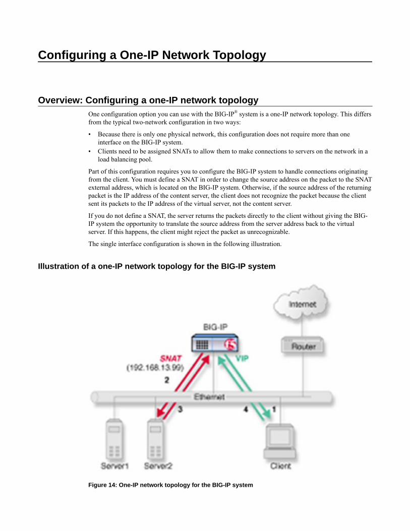
Configuring a One-IP Network Topology
Overview: Configuring a one-IP network topologyOne configuration option you can use with the BIG-IP® system is a one-IP network topology. This differsfrom the typical two-network configuration in two ways:
• Because there is only one physical network, this configuration does not require more than oneinterface on the BIG-IP system.
• Clients need to be assigned SNATs to allow them to make connections to servers on the network in aload balancing pool.
Part of this configuration requires you to configure the BIG-IP system to handle connections originatingfrom the client. You must define a SNAT in order to change the source address on the packet to the SNATexternal address, which is located on the BIG-IP system. Otherwise, if the source address of the returningpacket is the IP address of the content server, the client does not recognize the packet because the clientsent its packets to the IP address of the virtual server, not the content server.
If you do not define a SNAT, the server returns the packets directly to the client without giving the BIG-IP system the opportunity to translate the source address from the server address back to the virtualserver. If this happens, the client might reject the packet as unrecognizable.
The single interface configuration is shown in the following illustration.
Illustration of a one-IP network topology for the BIG-IP system
Figure 14: One-IP network topology for the BIG-IP system
Task summary for a one-IP network topology for the BIG-IP systemYou can perform these tasks to configure a one-IP network topology.
Task listCreating a pool for processing HTTP connections with SNATs enabledCreating a virtual server for HTTP trafficDefining a default routeConfiguring a client SNATConfiguring optional ephemeral port exhaustion
Creating a pool for processing HTTP connections with SNATs enabled
Verify that all content servers for the pool are in the network of VLAN external.
For a basic configuration, you need to create a pool to manage HTTP connections. This pool enablesSNATs for any connections destined for a member of the pool.
1. On the Main tab, click Local Traffic > Pools.The Pool List screen opens.
2. Click Create.The New Pool screen opens.
3. In the Name field, type a unique name for the pool.4. For the Health Monitors setting, from the Available list, select the http monitor and move the
monitor to the Active list.5. For the Allow SNAT setting, verify that the value is Yes.6. In the Resources area of the screen, use the default values for the Load Balancing Method and
Priority Group Activation settings.7. Using the New Members setting, add each resource that you want to include in the pool:
a) Type an IP address in the Address field.b) Type 80 in the Service Port field, or select HTTP from the list.c) (Optional) Type a priority number in the Priority field.d) Click Add.
8. Click Finished.
The new pool appears in the Pools list.
Creating a virtual server for HTTP traffic
This task creates a destination IP address for application traffic. As part of this task, you must assign therelevant pool to the virtual server.
1. On the Main tab, click Local Traffic > Virtual Servers.The Virtual Server List screen opens.
2. Click the Create button.The New Virtual Server screen opens.
3. In the Name field, type a unique name for the virtual server.4. In the Destination Address field, type the IP address in CIDR format.
Configuring a One-IP Network Topology
92

The supported format is address/prefix, where the prefix length is in bits. For example, an IPv4address/prefix is 10.0.0.1 or 10.0.0.0/24, and an IPv6 address/prefix is ffe1::0020/64 or2001:ed8:77b5:2:10:10:100:42/64. When you use an IPv4 address without specifying a prefix,the BIG-IP® system automatically uses a /32 prefix.
Note: The IP address you type must be available and not in the loopback network.
5. In the Service Port field, type 80, or select HTTP from the list.6. From the HTTP Profile list, select http.7. In the Resources area of the screen, from the Default Pool list, select the relevant pool name.8. Click Finished.
You now have a virtual server to use as a destination address for application traffic.
Defining a default route
Another task that you must perform to implement one-IP network load balancing is to define a defaultroute for the VLAN external.
1. On the Main tab, click Network > Routes.2. Click Add.
The New Route screen opens.3. In the Name field, type Default Gateway Route.4. In the Destination field, type the IP address 0.0.0.0.
An IP address of 0.0.0.0 in this field indicates that the destination is a default route.5. From the Resource list, select Use VLAN/Tunnel.
A VLAN represents the VLAN through which the packets flow to reach the specified destination.6. Select external from the VLAN/Tunnel list.7. Click Finished.
The default route for VLAN external is defined.
Configuring a client SNAT
To configure the BIG-IP® system to handle connections originating from the client, you can define aSNAT to change the source address on the packet to the SNAT external address located on the BIG-IPsystem.
1. On the Main tab, click Local Traffic > Address Translation.The SNAT List screen displays a list of existing SNATs.
2. Click Create.3. Name the new SNAT.4. In the Translation field, type the IP address that you want to use as a translation IP address.5. From the Origin list, select Address List.6. For each client to which you want to assign a translation address, do the following:
a) In the Address field., type a client IP address.b) Click Add.
7. From the VLAN/Tunnel Traffic list, select Enabled on.8. For the VLAN List setting, in the Available field, select external, and using the Move button, move
the VLAN name to the Selected field.9. Click the Finished button.
The BIG-IP system is configured to handle connections originating from the client
BIG-IP Local Traffic Manager: Implementations
93

Configuring optional ephemeral port exhaustion
You must configure a client SNAT before you can configure ephemeral port exhaustion functionality forthat SNAT.
You can configure the BIG-IP® system to accumulate real-time ephemeral-port statistics, and when usageexceeds a specified threshold level, to log an error and provide a Simple Network Management Protocol(SNMP) alert notification. Thus you can assess an approaching exhaustion of ephemeral ports, andrespond accordingly.
1. Log on to the command line of the system using the root account.2. Type tmsh to access the Traffic Management Shell.3. Type the following command to enable ephemeral port-exhaustion threshold warning functionality.
The default value is enabled.modify ltm global-settings traffic-control port-find-threshold-warning[enabled_or_disabled]
4. Type the following command to specify the number of random attempts to find an unused outboundport for a connection. Values can range from 1 through 12. The default value is 8.modify ltm global-settings traffic-control port-find-threshold-trigger[threshold_level]
5. Type the following command to specify the timeout period, in seconds, from one threshold triggeruntil a subsequent threshold trigger, which if exceeded, resets and causes the threshold warning toexpire. Values can range from 0 through 300 seconds. The default value is 30.modify ltm global-settings traffic-control port-find-threshold-timeout[timeout_period]
The BIG-IP system is configured to accumulate real-time ephemeral-port statistics, and to provide atrigger when usage exceeds a specified threshold level.
You need to configure logging functionality, for example, high-speed remote logging, to log any errormessages. Additionally, you will want to manage any alert notifications by using SNMP.
Configuring a One-IP Network Topology
94

Configuring the BIG-IP System to Auto-Populate Pools
Overview: Using host names to identify pool members and nodesYou create nodes on the BIG-IP® system to represent the backend servers on your network. In turn, youcreate pool members to represent the backend servers on your network when you create a pool and wantto load balance traffic to multiple backend servers.
You can configure a BIG-IP system with nodes and pool members that are identified with fully-qualifieddomain names (FQDNs). When you configure pool members with FQDN, addresses will dynamicallyfollow DNS changes. Fully dynamic DNS-managed pools may even be created. In the followingillustration, the BIG-IP Local Traffic Manager™ creates an ephemeral pool member for each IP addressreturned in the DNS response.
Figure 15: BIG-IP system auto-populating a pool and routing traffic to the pool members
This next illustration shows another option. With this configuration, the system sends a DNS query forthe FQDN, and then creates only one ephemeral node or pool member using the first IP address returnedin the DNS response. An advantage to this configuration is that you can change the IP addresses of thebackend servers that host the domain without reconfiguring the BIG-IP system. However, if your DNSservers are configured to round robin DNS responses, this feature is not recommended.
Figure 16: BIG-IP system routing traffic to a node identified by a host name

About modes of failure and related nodes or pool members
If a node or pool member that is identified by a fully-qualified domain name (FQDN) is down for aspecified amount of time, the BIG-IP® system marks the node or pool member down. Failure to resolve aFQDN will not cause the marking down of nodes or pool members currently in service. While the statusof the FQDN node or pool member for DNS is reflected in the status of the FQDN node, since the FQDNnode or pool member does not itself monitor any servers, its status does not contribute to the status of thepool in any way.
Failure of a monitored ephemeral to respond to monitor probes results in the marking down of a specificnode. Niether the FQDN or any of the related ephemeals are directly affected. Because ephemeral objectsmonitor servers, the status of the epemeral node or pool member affects the pool status in the same wayas any other pool member or node.
Task summaryPerform these tasks to configure the BIG-IP® system to auto-populate pools.Creating a default gateway poolConfiguring the BIG-IP system to handle DNS lookupsCreating nodes using host namesCreating a pool using host names
Configuring the BIG-IP System to Auto-Populate Pools
96

Creating a default gateway pool
Create a default gateway pool for the system to use to forward traffic.
1. On the Main tab, click Local Traffic > Pools.The Pool List screen opens.
2. Click Create.The New Pool screen opens.
3. In the Name field, type a unique name for the pool.4. For the Health Monitors setting, from the Available list, select the gateway_icmp monitor and move
the monitor to the Active list.5. Using the New Members setting, add each router that you want to include in the default gateway
pool:a) Type the IP address of a router in the Address field.b) Type an asterisk (*) in the Service Port field, or select *All Services from the list.c) Click Add.
6. Click Finished.
Configuring the BIG-IP system to handle DNS lookups
Configure how the BIG-IP® system handles DNS lookups when you want to use fully-qualified domainnames (FQDNs) to identify nodes and pool members.
1. On the Main tab, click System > Configuration > Device > DNS.The DNS Device configuration screen opens.
2. In the DNS Lookup Server List area, in the Address field, type the IP address of the DNS server(s)you want to add.The system uses these DNS servers to validate DNS lookups and resolve host names. Then, clickAdd.
Note: If you did not disable DHCP before the first boot of the system, and if the DHCP serverprovides the information about your local DNS servers, then this field is automatically populated.
3. Click Update.
Creating nodes using host names
Determine the fully-qualified domain name (FQDN) that you want to use to identify a node.
You can create nodes identified by FQDNs and then create a pool and add pool members from a list ofnodes.
1. On the Main tab, expand Local Traffic, and click Nodes.The Node List screen opens.
2. Click the Create button.The New Node screen opens.
3. In the Name field, type a descriptive label for the node.Names are case-sensitive.
4. For the Address setting, select FQDN, and then type the host name in the field.5. In the Configuration area, from the Health Monitors list, select the way that you want the system to
apply monitors to the node.
BIG-IP Local Traffic Manager: Implementations
97
The default setting is Node Default.
Option Description
Node Default Specifies that the system uses the defined default monitors for nodes. The defaultmonitors are defined on the Default Monitors screen of the BIG-IP Configurationutility.
Node Specific Specifies that the system monitors this node with the monitors that you configure inthe Select Monitors setting.
Note: When you select the Node Specific option, the screen refreshes to display theSelect Monitors setting.
None Specifies that the system does not monitor this node.
6. In the Ratio field, type a number for the ratio weight of the node.7. In the Connection Limit field, type a number for the maximum established connection limit for the
node.8. In the Connection Rate Limit field, type a number that specifies the number of new connections
accepted per second for the node.9. From the Address Type list, select whether the node resolves to an IPv4 or IPv6 address. The default
is IPv4.10. From the Auto Populate list, select Enabled. The options are:
Option Description
Enabled The system automatically creates ephemeral nodes using the IP addresses returned by theresolution of a DNS query for the FQDN, that is, for each DNS entry of the resolvedFQDN.
Disabled The system automatically creates a node that corresponds to the IP address of only thefirst DNS entry of the resolved FQDN.
11. In the Interval field, type the number of seconds before the system creates new ephemeral nodes ordeletes expired ephemeral nodes based on the IP addresses returned in response to a DNS query forthe FQDN of the node. The default is the TTL of the IP address in the DNS response.
12. In the Down Interval field, type the number of seconds the system waits to mark an FQDN nodedown following a DNS query failure.
13. Click Finished.The screen refreshes, and the new node appears in the node list.
Creating a pool using host names
Before creating a pool, determine the servers that you want to add to the pool using a fully-qualifieddomain name (FQDN).
Ensure that your DNS servers are not configured for round robin DNS resolutions; instead, ensure thatyour DNS servers return all available IP addresses in a DNS resolution.
When you want the BIG-IP® system to automatically update pool members as you make changes to theIP addresses of servers in your network, you can create a pool of servers that are identified by FQDNs.
1. On the Main tab, click Local Traffic > Pools.The Pool List screen opens.
2. Click Create.The New Pool screen opens.
3. In the Name field, type a unique name for the pool.
Configuring the BIG-IP System to Auto-Populate Pools
98

4. For the Health Monitors setting, from the Available list, select a monitor and move the monitor tothe Active list.
Note: A pool containing nodes represented by FQDNs cannot be monitored by inband or saspmonitors.
5. From the Load Balancing Method list, select how the system distributes traffic to members of thispool.The default is Round Robin.
6. In the New Members setting, add at least one node with a static IP address. This node serves as afallback if a DNS query returns no records for the nodes identified by FQDNs.a) Select Node List.b) From the Address list, select a node identified by a static IP address.c) From the Service Port list, make a selection.d) Click Add.
7. In the New Members setting, add the members that you want to include in the pool using FQDNs.a) Select FQDN Node List.b) From the Address list, select a node identified by an FQDN.c) Make a selection from the Service Port list.
8. In the New Members setting, select Enabled. The options are:Option Description
Enabled The system generates an ephemeral node for each IP address returned in response to aDNS query for the FQDN of the node. Additionally, when a DNS response indicates theIP address of an ephemeral node no longer exists, the system deletes the ephemeral node.
Disabled The system selects the first address and generates an ephemeral for that address.
9. Click Add.10. Repeat steps 7-9 to add additional members to the pool.11. Click Finished.
The screen refreshes, and you see the new pool in the Pool list.
About modifying nodes and pool members identified by host namesWhen you change the configuration of a fully-qualified domain name (FQDN) pool member or node, anyephemeral pool members or nodes that the BIG-IP® system created based on the IP addresses returned ina DNS response for that FQDN are automatically modified, as well. For example, if you change themonitor on an FQDN node, the system automatically changes the monitor assigned to the ephemeralnodes associated with that node.
When you want to modify an FQDN pool member or node, but you want persistent and activeconnections to be completed before the BIG-IP system marks the pool member or node as down, disablethe pool member or node first, and then make modifications.
Task summaryDisabling a nodeDisabling a pool member
Disabling a node
Determine the node that you want to disable.
BIG-IP Local Traffic Manager: Implementations
99

You can disable a node when you want to make changes to your network, but you want persistent andactive connections to be completed before the BIG-IP® system marks the node as down.
1. On the Main tab, click Local Traffic > Nodes.The Node List screen opens.
2. In the Name column, click a node name.3. In the State area, click Disabled (Only persistent or active connections allowed).
Note: You can only disable the parent FQDN node or pool member. After disabling, the ephemeraldependents are then disabled, but you cannot directly disable an ephemeral node.
4. Click Update.The screen refreshes, and the status in the Availability area changes.
Disabling a pool member
Determine the pool member that you want to disable. You can only disable a parent fully-qualifieddomain name (FQDN) node or pool member. The ephemeral dependents are then disabled. You cannotdirectly disable the ephemerals.
Disable a pool member when you want to make changes to your network, but you want persistent andactive connections to be completed before the BIG-IP® system marks the pool member as down.
1. On the Main tab, click Local Traffic > Pools.The Pool List screen opens.
2. Click a pool name in the Pool List.3. On the menu bar, click Members.4. In the Member list, select the relevant pool member.5. In the State area, click Disabled (Only persistent or active connections allowed).6. Click Update.
The screen refreshes, and the status in the Availability area changes.
About pool member and node statisticsYou can view statistics about pool members and nodes identified by host names.
Task summaryViewing statistics for a specific nodeViewing statistics for ephemeral pool members
Viewing statistics for a specific node
Ensure that at least one LTM® node exists on the BIG-IP® system.
You can view statistics for an LTM node when you want to analyze BIG-IP system traffic.
1. On the Main tab, click Statistics > Module Statistics > Local Traffic.The Local Traffic statistics screen opens.
2. From the Statistics Type list, select Nodes.Information displays about the node.
Viewing statistics for ephemeral pool members
Ensure that at least one LTM® node exists on the BIG-IP® system.
Configuring the BIG-IP System to Auto-Populate Pools
100

When you want to analyze how the BIG-IP system is handling traffic, you can view statistics for poolsand pool members, including the ephemeral pools created when the pool member is identified by a fully-qualified domain name (FQDN) and Auto Populate is enabled for the pool member.
1. On the Main tab, click Statistics > Module Statistics > Local Traffic.The Local Traffic statistics screen opens.
2. From the Statistics Type list, select Pools.Information displays about the pools configured on the BIG-IP system. The ephemeral pool membersare shown indented below their parent pool member and with two dashes preceding the pool membername.
BIG-IP Local Traffic Manager: Implementations
101

Configuring the BIG-IP System to Auto-Populate Pools
102

Implementing Health and Performance Monitoring
Overview: Health and performance monitoringYou can set up the BIG-IP® system to monitor the health or performance of certain nodes or servers thatare members of a load balancing pool. Monitors verify connections on pool members and nodes. Amonitor can be either a health monitor or a performance monitor, designed to check the status of a pool,pool member, or node on an ongoing basis, at a set interval. If a pool member or node being checkeddoes not respond within a specified timeout period, or the status of a pool member or node indicates thatperformance is degraded, the BIG-IP system can redirect the traffic to another pool member or node.
Some monitors are included as part of the BIG-IP system, while other monitors are user-created.Monitors that the BIG-IP system provides are called pre-configured monitors. User-created monitors arecalled custom monitors.
Before configuring and using monitors, it is helpful to understand some basic concepts regarding monitortypes, monitor settings, and monitor implementation.
Monitor typesEvery monitor, whether pre-configured or custom, is a certain type of monitor. Each type of monitorchecks the status of a particular protocol, service, or application. For example, one type of monitor isHTTP. An HTTP type of monitor allows you to monitor the availability of the HTTP service on apool, pool member, or node. A WMI type of monitor allows you to monitor the performance of apool, pool member, or node that is running the Windows Management Instrumentation (WMI)software. An ICMP type of monitor simply determines whether the status of a node is up or down.
Monitor settingsEvery monitor consists of settings with values. The settings and their values differ depending on thetype of monitor. In some cases, the BIG-IP system assigns default values. For example, the followingshows the settings and default values of an ICMP-type monitor.
Name my_icmp Type ICMP Interval 5 Timeout 16 Transparent No Alias Address * All Addresses
Note: If you want to monitor the performance of a RealNetworks® RealServer server or a Windows®-based server equipped with Windows Management Instrumentation (WMI), you must first download aspecial plug-in file onto the BIG-IP system.
Task summaryTo implement a health or performance monitor, you perform these tasks.
Task listCreating a custom monitorCreating a load balancing poolCreating a virtual server

Creating a custom monitor
Before creating a custom monitor, you must decide on a monitor type.
You can create a custom monitor when the values defined in a pre-configured monitor do not meet yourneeds, or no pre-configured monitor exists for the type of monitor you are creating.
Important: When defining values for custom monitors, make sure you avoid using any values that are onthe list of reserved keywords.
1. Click Create.The New Monitor screen opens.
2. Type a name for the monitor in the Name field.3. From the Type list, select the type of monitor.
The screen refreshes, and displays the configuration options for the monitor type.4. From the Import Monitor list, select an existing monitor.
The new monitor inherits initial configuration values from the existing monitor.5. From the Configuration list, select Advanced.
This selection makes it possible for you to modify additional default settings.6. Configure all settings shown.7. Click Finished.
Creating a load balancing pool
You can create a load balancing pool (a logical set of devices such as web servers that you group togetherto receive and process traffic) to efficiently distribute the load on your server resources.
Note: You must create the pool before you create the corresponding virtual server.
1. On the Main tab, click Local Traffic > Pools.The Pool List screen opens.
2. Click Create.The New Pool screen opens.
3. In the Name field, type a unique name for the pool.4. For the Health Monitors setting, in the Available list, select a monitor type, and click << to move the
monitor to the Active list.
Tip: Hold the Shift or Ctrl key to select more than one monitor at a time.
5. From the Load Balancing Method list, select how the system distributes traffic to members of thispool.The default is Round Robin.
6. For the Priority Group Activation setting, specify how to handle priority groups:
• Select Disabled to disable priority groups. This is the default option.• Select Less than, and in the Available Members field type the minimum number of members that
must remain available in each priority group in order for traffic to remain confined to that group.7. Using the New Members setting, add each resource that you want to include in the pool:
a) (Optional) In the Node Name field, type a name for the node portion of the pool member.b) In the Address field, type an IP address.
Implementing Health and Performance Monitoring
104

c) In the Service Port field, type a port number, or select a service name from the list.d) (Optional) In the Priority field, type a priority number.e) Click Add.
8. Click Finished.
The load balancing pool appears in the Pools list.
Creating a virtual server
A virtual server represents a destination IP address for application traffic.
1. On the Main tab, click Local Traffic > Virtual Servers.The Virtual Server List screen opens.
2. Click the Create button.The New Virtual Server screen opens.
3. In the Name field, type a unique name for the virtual server.4. In the Destination Address field, type the IP address in CIDR format.
The supported format is address/prefix, where the prefix length is in bits. For example, an IPv4address/prefix is 10.0.0.1 or 10.0.0.0/24, and an IPv6 address/prefix is ffe1::0020/64 or2001:ed8:77b5:2:10:10:100:42/64. When you use an IPv4 address without specifying a prefix,the BIG-IP® system automatically uses a /32 prefix.
Note: The IP address you type must be available and not in the loopback network.
5. In the Service Port field, type a port number or select a service name from the Service Port list.6. In the Resources area of the screen, from the Default Pool list, select the relevant pool name.
BIG-IP Local Traffic Manager: Implementations
105

Implementing Health and Performance Monitoring
106

Preventing TCP Connection Requests From BeingDropped
Overview: TCP request queuingTCP request queuing provides the ability to queue connection requests that exceed the capacity ofconnections for a pool, pool member, or node, as determined by the connection limit. Consequently,instead of dropping connection requests that exceed the capacity of a pool, pool member, or node, TCPrequest queuing makes it possible for those connection requests to reside within a queue in accordancewith defined conditions until capacity becomes available.
When using session persistence, a request becomes queued when the pool member connection limit isreached.
Without session persistence, when all pool members have a specified connection limit, a request becomesqueued when the total number of connection limits for all pool members is reached.
Conditions for queuing connection requests include:
• The maximum number of connection requests within the queue, which equates to the maximumnumber of connections within the pool, pool member, or node. Specifically, the maximum number ofconnection requests within the queue cannot exceed the cumulative total number of connections foreach pool member or node. Any connection requests that exceed the capacity of the request queue aredropped.
• The availability of server connections for reuse. When a server connection becomes available forreuse, the next available connection request in the queue becomes dequeued, thus allowing additionalconnection requests to be queued.
• The expiration rate of connection requests within the queue. As queue entries expire, they areremoved from the queue, thus allowing additional connection requests to be queued.
Connection requests within the queue become dequeued when:
• The connection limit of the pool is increased.• A pool member's slow ramp time limit permits a new connection to be made.• The number of concurrent connections to the virtual server falls to less than the connection limit.• The connection request within the queue expires.
Preventing TCP connection requests from being droppedWhen you enable TCP request queuing, connection requests become queued when they exceed the totalnumber of available server connections.
1. On the Main tab, click Local Traffic > Pools.The Pool List screen opens.
2. Click a pool name in the Pool List.3. From the Configuration list, select Advanced.4. In the Enable Request Queuing list, select Yes.5. In the Request Queue Depth field, type the maximum number of connections allowed in the queue.
Note: If you type zero (0) or leave the field blank, the maximum number of queued connections isunlimited, constrained only by available memory.

6. In the Request Queue Timeout field, type the maximum number of milliseconds that a connectioncan remain queued.
Note: If you type zero (0) or leave the field blank, the maximum number of milliseconds is unlimited.
7. Click Update.
Connection requests become queued when they exceed the total number of available server connections.
Enabling TCP enhanced loss recoveryAlthough this feature is disabled by default, you can enable Enhanced Loss Recovery using TCP profiles.This will increase the TCP performance for networks with low RTT and high packet loss. Enhanced lossrecovery retransmits lost segments multiple times during a loss recovery period to prevent a timeoutrecovery.
Important: This feature can be used only when the Selective ACKs feature is enabled for the TCPconnection.
1. On the Main tab, click Local Traffic > Profiles > Protocol > TCP.2. Click an existing profile or click Create.3. Scroll down to the Loss Detection and Recovery area, and select the Custom check box at the right.4. For the Enhanced Loss Recovery setting, select the check box.
Preventing TCP Connection Requests From Being Dropped
108

Setting Connection Limits
Overview: About connection limitsYou can configure a virtual server, pool member, or node to prevent an excessive number of connectionrequests during events such as a Denial of Service (DoS) attack or a planned, high-demand traffic event.To ensure the availability of a virtual server, pool member, or node, you can use the BIG-IP® LocalTraffic Manager™ to manage the total number of connections and the rate at which connections are made.
When you specify a connection limit, the system prevents the total number of concurrent connections tothe virtual server, pool member, or node from exceeding the specified number.
When you specify a connection rate limit, the system controls the number of allowed new connectionsper second, thus providing a manageable increase in connections without compromising availability.
Limiting connections for a virtual server, pool member, or nodeYou can improve the availability of a virtual server, pool member, or node by using the BIG-IP® LocalTraffic Manager™ to specify a connection limit and a connection rate limit.
1. On the Main tab, expand Local Traffic, and then click Virtual Servers, Pools, or Nodes.2. Click the name of the virtual server, pool, or node you want to modify.3. For virtual servers only, from the Configuration list, select Advanced.4. In the Connection Limit field, type a number that specifies the maximum number of concurrent open
connections.5. In the Connection Rate Limit field, type a number that specifies the number of new connections
accepted per second for the virtual server.6. Click Update to save the changes.
After configuring connection and connection rate limits on a virtual server, or after configuring theselimits on a pool member or node associated with a virtual server, the system controls the total number ofconcurrent connections and the rate of new connections to the virtual server, pool member, or node.
Implementation resultsConfiguring a connection limit or a connection rate limit for a virtual server, pool member, or nodeprevents an excessive number of connection requests during events such as a Denial of Service (DoS)attack or a planned, high-demand traffic event. In this way, you can manage the total number ofconnections to a virtual server, pool member, or node, as well as the rate at which connections are made.When you specify a connection rate limit, the system controls the number of allowed new connectionsper second, thus providing a manageable increase in connections without compromising availability.

Setting Connection Limits
110

Load Balancing to IPv6 Nodes
Overview: Load balancing to iPv6 nodesTo set up the BIG-IP® system to function as an IPv4-to-IPv6 gateway, you create a load balancing poolconsisting of members that represent IPv6 nodes. You also create a virtual server that load balancestraffic to those pool members.
As an option, you can use the tmsh command line interface to configure the BIG-IP system to send outICMPv6 routing advisory messages, and to respond to ICMPv6 route solicitation messages. When youperform this task, the BIG-IP system begins to support auto-configuration of downstream nodes. Also,the downstream nodes automatically discover that the BIG-IP system is their router.
Task summaryWhen you configure IPv4-to-IPv6 load balancing, you must create a pool for load balancing traffic toIPv6 nodes, and then create an IPv4 virtual server that processes application traffic.
Task listCreating a load balancing poolCreating a virtual server for IPv6 nodes
Creating a load balancing pool
The first task in configuring IPv4-to-IPv6 load balancing is to create a pool to load balance connectionsto IPv6 nodes. Use the Configuration utility to create this pool.
1. On the Main tab, click Local Traffic > Pools.The Pool List screen opens.
2. Click Create.The New Pool screen opens.
3. In the Name field, type a unique name for the pool.4. For the Health Monitors setting, in the Available list, select a monitor type, and click << to move the
monitor to the Active list.
Tip: Hold the Shift or Ctrl key to select more than one monitor at a time.
5. From the Load Balancing Method list, select how the system distributes traffic to members of thispool.The default is Round Robin.
6. For the Priority Group Activation setting, specify how to handle priority groups:
• Select Disabled to disable priority groups. This is the default option.• Select Less than, and in the Available Members field type the minimum number of members that
must remain available in each priority group in order for traffic to remain confined to that group.7. Using the New Members setting, add each resource that you want to include in the pool:
a) (Optional) In the Node Name field, type a name for the node portion of the pool member.b) In the Address field, type an IP address.
c) In the Service Port field, type a port number, or select a service name from the list.d) (Optional) In the Priority field, type a priority number.e) Click Add.
8. Click Finished.
The load balancing pool appears in the Pools list.
Creating a virtual server for IPv6 nodes
You can define a virtual server that references the pool of IPv6 nodes.
1. On the Main tab, click Local Traffic > Virtual Servers.The Virtual Server List screen opens.
2. Click the Create button.The New Virtual Server screen opens.
3. In the Name field, type a unique name for the virtual server.4. In the Destination Address field, type the IPv6 address in CIDR format.
The supported format is address/prefix, where the prefix length is in bits. For example, an IPv6address/prefix is 64:ff9b::/64 or 2001:ed8:77b5:2::/64.
5. In the Service Port field, type a port number or select a service name from the Service Port list.6. In the Resources area of the screen, from the Default Pool list, select the name of the pool that
contains the IPv6 servers.7. Click Finished.
The virtual server that references the pool of IPv6 nodes appears in the Virtual Servers list.
Load Balancing to IPv6 Nodes
112

Mitigating Denial of Service Attacks
Overview: Mitigating Denial of Service and other attacksThe BIG-IP® system contains several features that provide you with the ability to create a configurationthat contributes to the security of your network. In particular, the BIG-IP system is in a unique position tomitigate some types of Denial of Service (DoS) attacks that try to consume system resources in order todeny service to the intended recipients.
The following features of the BIG-IP system help it resist many types of DoS attacks:
• The BIG-IP kernel has a mechanism built in to protect against SYN Flood attacks by limitingsimultaneous connections, and tearing down connections that have unacknowledged SYN/ACKpackets after some time period as passed. (A SYN/ACK packet is a packet that is sent as part of theTCP three-way handshake).
• BIG-IP system can handle tens of thousands of Layer 4 (L4) connections per second. It would take avery determined attack to affect either the BIG-IP system itself, or the site, if sufficient serverresources and bandwidth are available.
• SYN floods, or Denial of Service (DoS) attacks, can consume all available memory. The BIG-IPsystem supports a large amount of memory to help it resist DoS attacks.
Denial of Service attacks and iRulesYou can create BIG-IP® iRules® to filter out malicious DoS attacks. After you identify a particular attack,you can write an iRule that discards packets containing the elements that identify the packet as malicious.
iRules for Code Red attacks
The BIG-IP® system is able to filter out the Code Red attack by using an iRule to send the HTTP requestto a dummy pool.
when HTTP_REQUEST { if {string tolower [HTTP::uri] contains "default.ida" } { discard } else { pool RealServerPool}
iRules for Nimda attacks
The Nimda worm is designed to attack systems and applications based on the Microsoft® Windows®
operating system.
when HTTP_REQUEST { set uri [string tolower [HTTP::uri]] if { ($uri contains "cmd.exe") or ($uri contains "root.exe") or ($uri contains "admin.dll") } { discard } else { pool ServerPool }

}
Common Denial of Service attacksYou might want to know how the BIG-IP® system reacts to certain common attacks that are designed todeny service by breaking the service or the network devices. The following information lists the mostcommon attacks, along with how the BIG-IP system functionality handles the attack.
Attacktype
Description Mitigation
SYN flood A SYN flood is an attack against a system for the purpose ofexhausting that system's resources. An attacker launching aSYN flood against a target system attempts to occupy allavailable resources used to establish TCP connections bysending multiple SYN segments containing incorrect IPaddresses. Note that the term SYN refers to a type ofconnection state that occurs during establishment of a TCP/IPconnection. More specifically, a SYN flood is designed to fillup a SYN queue. A SYN queue is a set of connections storedin the connection table in the SYN-RECEIVED state, as partof the standard three-way TCP handshake. A SYN queue canhold a specified maximum number of connections in the SYN-RECEIVED state. Connections in the SYN-RECEIVED stateare considered to be half-open and waiting for anacknowledgment from the client. When a SYN flood causesthe maximum number of allowed connections in the SYN-RECEIVED state to be reached, the SYN queue is said to befull, thus preventing the target system from establishing otherlegitimate connections. A full SYN queue therefore results inpartially-open TCP connections to IP addresses that either donot exist or are unreachable. In these cases, the connectionsmust reach their timeout before the server can continuefulfilling other requests.
The BIG-IP system includes a featuredesigned to alleviate SYN flooding. Knownas SYN Check™, this feature sendsinformation about the flow, in the form ofcookies, to the requesting client, so that thesystem does not need to keep the SYN-RECEIVED state that is normally stored inthe connection table for the initiated session.Because the SYN-RECEIVED state is notkept for a connection, the SYN queue cannotbe exhausted, and normal TCPcommunication can continue. The SYNCheck feature complements the existingadaptive reaper feature in the BIG-IP system.While the adaptive reaper handlesestablished connection flooding, SYN Checkprevents connection flooding altogether.That is, while the adaptive reaper must workovertime to flush connections, the SYNCheck feature prevents the SYN queue frombecoming full, thus allowing the targetsystem to continue to establish TCPconnections.
ICMPflood(Smurf)
The ICMP flood, sometimes referred to as a Smurf attack, is anattack based on a method of making a remote network sendICMP Echo replies to a single host. In this attack, a singlepacket from the attacker goes to an unprotected network'sbroadcast address. Typically, this causes every machine on thatnetwork to answer with a packet sent to the target. The BIG-IPsystem is hardened against these attacks because it answersonly a limited number of ICMP requests per second, and thendrops the rest. On the network inside the BIG-IP system, theBIG-IP system ignores directed subnet broadcasts, and doesnot respond to the broadcast ICMP Echo that a Smurf attackeruses to initiate an attack.
You do not need to make any changes to theBIG-IP system configuration for this type ofattack.
UDP flood The UDP flood attack is most commonly a distributed Denialof Service attack (DDoS), where multiple remote systems aresending a large flood of UDP packets to the target. The BIG-IPsystem handles these attacks similarly to the way it handles aSYN flood. If the port is not listening, the BIG-IP systemdrops the packets. If the port is listening, the reaper removesthe false connections.
Setting the UDP idle session timeout tobetween 5 and 10 seconds reaps theseconnections quickly without impacting userswith slow connections. However, with UDPthis might still leave too many openconnections, and your situation might requirea setting of between 2 and 5 seconds.
Mitigating Denial of Service Attacks
114
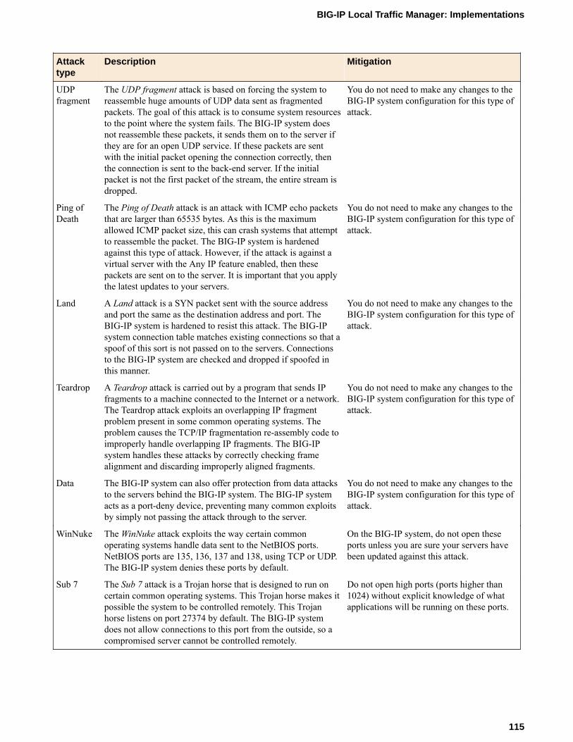
Attacktype
Description Mitigation
UDPfragment
The UDP fragment attack is based on forcing the system toreassemble huge amounts of UDP data sent as fragmentedpackets. The goal of this attack is to consume system resourcesto the point where the system fails. The BIG-IP system doesnot reassemble these packets, it sends them on to the server ifthey are for an open UDP service. If these packets are sentwith the initial packet opening the connection correctly, thenthe connection is sent to the back-end server. If the initialpacket is not the first packet of the stream, the entire stream isdropped.
You do not need to make any changes to theBIG-IP system configuration for this type ofattack.
Ping ofDeath
The Ping of Death attack is an attack with ICMP echo packetsthat are larger than 65535 bytes. As this is the maximumallowed ICMP packet size, this can crash systems that attemptto reassemble the packet. The BIG-IP system is hardenedagainst this type of attack. However, if the attack is against avirtual server with the Any IP feature enabled, then thesepackets are sent on to the server. It is important that you applythe latest updates to your servers.
You do not need to make any changes to theBIG-IP system configuration for this type ofattack.
Land A Land attack is a SYN packet sent with the source addressand port the same as the destination address and port. TheBIG-IP system is hardened to resist this attack. The BIG-IPsystem connection table matches existing connections so that aspoof of this sort is not passed on to the servers. Connectionsto the BIG-IP system are checked and dropped if spoofed inthis manner.
You do not need to make any changes to theBIG-IP system configuration for this type ofattack.
Teardrop A Teardrop attack is carried out by a program that sends IPfragments to a machine connected to the Internet or a network.The Teardrop attack exploits an overlapping IP fragmentproblem present in some common operating systems. Theproblem causes the TCP/IP fragmentation re-assembly code toimproperly handle overlapping IP fragments. The BIG-IPsystem handles these attacks by correctly checking framealignment and discarding improperly aligned fragments.
You do not need to make any changes to theBIG-IP system configuration for this type ofattack.
Data The BIG-IP system can also offer protection from data attacksto the servers behind the BIG-IP system. The BIG-IP systemacts as a port-deny device, preventing many common exploitsby simply not passing the attack through to the server.
You do not need to make any changes to theBIG-IP system configuration for this type ofattack.
WinNuke The WinNuke attack exploits the way certain commonoperating systems handle data sent to the NetBIOS ports.NetBIOS ports are 135, 136, 137 and 138, using TCP or UDP.The BIG-IP system denies these ports by default.
On the BIG-IP system, do not open theseports unless you are sure your servers havebeen updated against this attack.
Sub 7 The Sub 7 attack is a Trojan horse that is designed to run oncertain common operating systems. This Trojan horse makes itpossible the system to be controlled remotely. This Trojanhorse listens on port 27374 by default. The BIG-IP systemdoes not allow connections to this port from the outside, so acompromised server cannot be controlled remotely.
Do not open high ports (ports higher than1024) without explicit knowledge of whatapplications will be running on these ports.
BIG-IP Local Traffic Manager: Implementations
115

Attacktype
Description Mitigation
BackOrifice
A Back Orifice attack is a Trojan horse that is designed to runon certain common operating systems. This Trojan horsemakes it possible the system to be controlled remotely. ThisTrojan horse listens on UDP port 31337 by default. The BIG-IP system does not allow connections to this port from theoutside, so a compromised server cannot be controlledremotely.
Do not open high ports (ports higher than1024) without explicit knowledge of whatwill be running on these ports
Task summaryThere are several tasks you can perform to mitigate Denial of Service attacks.
Task listConfiguring adaptive reapingSetting the TCP and UDP connection timersApplying a rate class to a virtual serverCalculating connection limits on the main virtual serverSetting connection limits on the main virtual serverAdjusting the SYN Check threshold
Configuring adaptive reaping
This procedure configures adaptive reaping. The adaptive connection reaper closes idle connectionswhen memory usage on the BIG-IP system increases. This feature makes it possible for the BIG-IPsystem to aggressively reap connections when the system memory utilization reaches the low-watermark, and to stop establishing new connections when the system memory utilization reaches the high-water mark percentage.
If the BIG-IP platform includes an LCD panel, an adaptive reaping event causes the BIG-IP system todisplay the following message on the LCD panel:
Blocking DoS attack
Warning: The adaptive reaper settings do not apply to SSL connections. However, you can set TCP andUDP connection timeouts that reap idle SSL connections.
1. On the Main tab, click System > Configuration.The General screen opens.
2. From the Local Traffic menu, choose General.3. In the Properties area of the screen, set the Reaper High-water Mark property to 95.4. Set the Reaper Low-water Mark property to 85.5. Click Update.
When aggressive mode is activated on the BIG-IP system, the event is marked in the /var/log/ltm filewith messages similar to these examples:
tmm tmm[PID]: 011e0002:4: sweeper_update: aggressive mode activated. (117504/138240 pages)
tmm tmm[PID]: 011e0002:4: sweeper_update: aggressive mode deactivated. (117503/138240 pages)
Mitigating Denial of Service Attacks
116
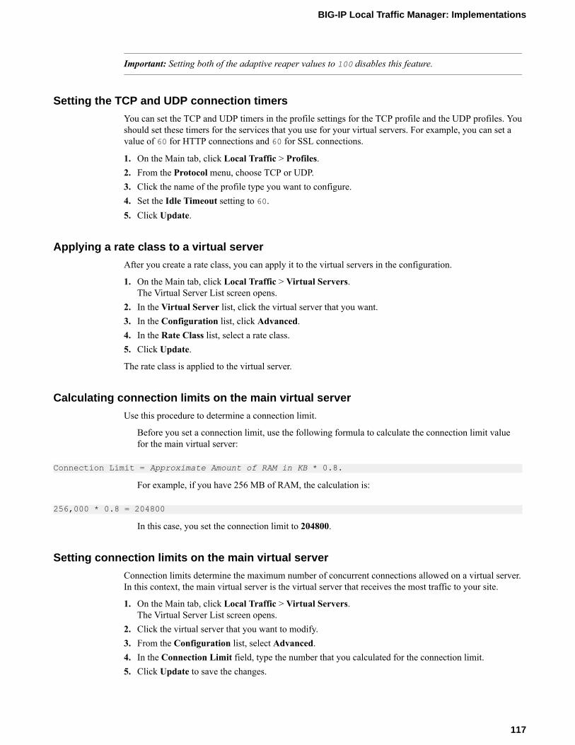
Important: Setting both of the adaptive reaper values to 100 disables this feature.
Setting the TCP and UDP connection timers
You can set the TCP and UDP timers in the profile settings for the TCP profile and the UDP profiles. Youshould set these timers for the services that you use for your virtual servers. For example, you can set avalue of 60 for HTTP connections and 60 for SSL connections.
1. On the Main tab, click Local Traffic > Profiles.2. From the Protocol menu, choose TCP or UDP.3. Click the name of the profile type you want to configure.4. Set the Idle Timeout setting to 60.5. Click Update.
Applying a rate class to a virtual server
After you create a rate class, you can apply it to the virtual servers in the configuration.
1. On the Main tab, click Local Traffic > Virtual Servers.The Virtual Server List screen opens.
2. In the Virtual Server list, click the virtual server that you want.3. In the Configuration list, click Advanced.4. In the Rate Class list, select a rate class.5. Click Update.
The rate class is applied to the virtual server.
Calculating connection limits on the main virtual server
Use this procedure to determine a connection limit.
Before you set a connection limit, use the following formula to calculate the connection limit valuefor the main virtual server:
Connection Limit = Approximate Amount of RAM in KB * 0.8.
For example, if you have 256 MB of RAM, the calculation is:
256,000 * 0.8 = 204800
In this case, you set the connection limit to 204800.
Setting connection limits on the main virtual server
Connection limits determine the maximum number of concurrent connections allowed on a virtual server.In this context, the main virtual server is the virtual server that receives the most traffic to your site.
1. On the Main tab, click Local Traffic > Virtual Servers.The Virtual Server List screen opens.
2. Click the virtual server that you want to modify.3. From the Configuration list, select Advanced.4. In the Connection Limit field, type the number that you calculated for the connection limit.5. Click Update to save the changes.
BIG-IP Local Traffic Manager: Implementations
117

The virtual server is configured for the specified maximum number of concurrent connections.
Adjusting the SYN Check threshold
You can configure the SYN Check™ feature to prevent the BIG-IP SYN queue from becoming full duringa SYN flood attack. The SYN Check Activation Threshold setting indicates the number of new oruntrusted TCP connections that can be established before the BIG-IP activates the SYN Cookiesauthentication method for subsequent TCP connections.
1. On the Main tab, click System > Configuration.2. From the Local Traffic menu, choose General.3. In the SYN Check Activation Threshold field, type the number of connections that you want to
define for the threshold.4. Click Update.
If SYN flooding occurs, the BIG-IP system now protects the BIG-IP SYN queue from becoming full.
Mitigating Denial of Service Attacks
118
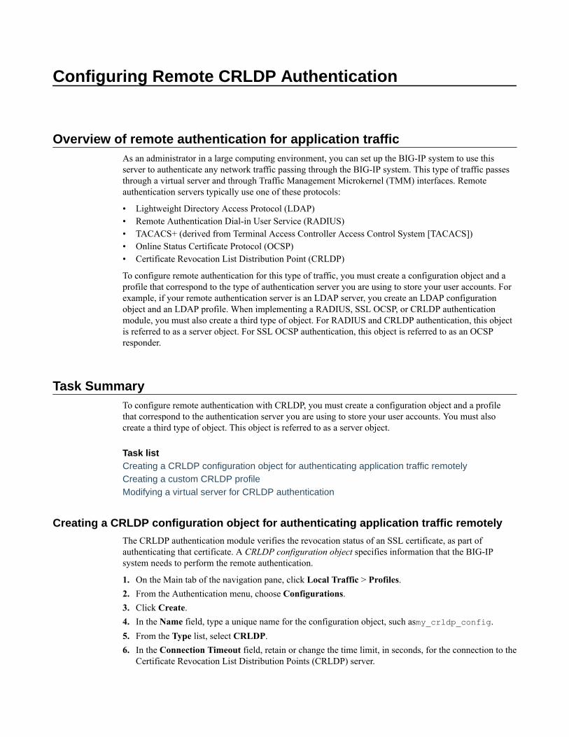
Configuring Remote CRLDP Authentication
Overview of remote authentication for application trafficAs an administrator in a large computing environment, you can set up the BIG-IP system to use thisserver to authenticate any network traffic passing through the BIG-IP system. This type of traffic passesthrough a virtual server and through Traffic Management Microkernel (TMM) interfaces. Remoteauthentication servers typically use one of these protocols:
• Lightweight Directory Access Protocol (LDAP)• Remote Authentication Dial-in User Service (RADIUS)• TACACS+ (derived from Terminal Access Controller Access Control System [TACACS])• Online Status Certificate Protocol (OCSP)• Certificate Revocation List Distribution Point (CRLDP)
To configure remote authentication for this type of traffic, you must create a configuration object and aprofile that correspond to the type of authentication server you are using to store your user accounts. Forexample, if your remote authentication server is an LDAP server, you create an LDAP configurationobject and an LDAP profile. When implementing a RADIUS, SSL OCSP, or CRLDP authenticationmodule, you must also create a third type of object. For RADIUS and CRLDP authentication, this objectis referred to as a server object. For SSL OCSP authentication, this object is referred to as an OCSPresponder.
Task SummaryTo configure remote authentication with CRLDP, you must create a configuration object and a profilethat correspond to the authentication server you are using to store your user accounts. You must alsocreate a third type of object. This object is referred to as a server object.
Task listCreating a CRLDP configuration object for authenticating application traffic remotelyCreating a custom CRLDP profileModifying a virtual server for CRLDP authentication
Creating a CRLDP configuration object for authenticating application traffic remotely
The CRLDP authentication module verifies the revocation status of an SSL certificate, as part ofauthenticating that certificate. A CRLDP configuration object specifies information that the BIG-IPsystem needs to perform the remote authentication.
1. On the Main tab of the navigation pane, click Local Traffic > Profiles.2. From the Authentication menu, choose Configurations.3. Click Create.4. In the Name field, type a unique name for the configuration object, such asmy_crldp_config.5. From the Type list, select CRLDP.6. In the Connection Timeout field, retain or change the time limit, in seconds, for the connection to the
Certificate Revocation List Distribution Points (CRLDP) server.
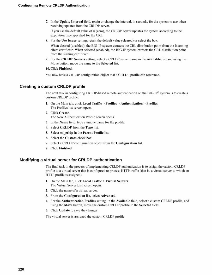
7. In the Update Interval field, retain or change the interval, in seconds, for the system to use whenreceiving updates from the CRLDP server.If you use the default value of 0 (zero), the CRLDP server updates the system according to theexpiration time specified for the CRL.
8. For the Use Issuer setting, retain the default value (cleared) or select the box.When cleared (disabled), the BIG-IP system extracts the CRL distribution point from the incomingclient certificate. When selected (enabled), the BIG-IP system extracts the CRL distribution pointfrom the signing certificate.
9. For the CRLDP Servers setting, select a CRLDP server name in the Available list, and using theMove button, move the name to the Selected list.
10. Click Finished.
You now have a CRLDP configuration object that a CRLDP profile can reference.
Creating a custom CRLDP profile
The next task in configuring CRLDP-based remote authentication on the BIG-IP® system is to create acustom CRLDP profile.
1. On the Main tab, click Local Traffic > Profiles > Authentication > Profiles.The Profiles list screen opens.
2. Click Create.The New Authentication Profile screen opens.
3. In the Name field, type a unique name for the profile.4. Select CRLDP from the Type list.5. Select ssl_crldp in the Parent Profile list.6. Select the Custom check box.7. Select a CRLDP configuration object from the Configuration list.8. Click Finished.
Modifying a virtual server for CRLDP authentication
The final task in the process of implementing CRLDP authentication is to assign the custom CRLDPprofile to a virtual server that is configured to process HTTP traffic (that is, a virtual server to which anHTTP profile is assigned).
1. On the Main tab, click Local Traffic > Virtual Servers.The Virtual Server List screen opens.
2. Click the name of a virtual server.3. From the Configuration list, select Advanced.4. For the Authentication Profiles setting, in the Available field, select a custom CRLDP profile, and
using the Move button, move the custom CRLDP profile to the Selected field.5. Click Update to save the changes.
The virtual server is assigned the custom CRLDP profile.
Configuring Remote CRLDP Authentication
120

Configuring Remote LDAP Authentication
Overview of remote LDAP authentication for application trafficAs an administrator in a large computing environment, you can set up the BIG-IP system to use thisserver to authenticate any network traffic passing through the BIG-IP system. This type of traffic passesthrough a virtual server and through Traffic Management Microkernel (TMM) interfaces. Remoteauthentication servers typically use one of these protocols:
• Lightweight Directory Access Protocol (LDAP)• Remote Authentication Dial-in User Service (RADIUS)• TACACS+ (derived from Terminal Access Controller Access Control System [TACACS])• Online Status Certificate Protocol (OCSP)• Certificate Revocation List Distribution Point (CRLDP)
To configure remote authentication for this type of traffic, you must create a configuration object and aprofile that correspond to the type of authentication server you are using to store your user accounts. Forexample, if your remote authentication server is an LDAP server, you create an LDAP configurationobject and an LDAP profile. When implementing a RADIUS, SSL OCSP, or CRLDP authenticationmodule, you must also create a third type of object. For RADIUS and CRLDP authentication, this objectis referred to as a server object. For SSL OCSP authentication, this object is referred to as an OCSPresponder.
Task SummaryTo configure remote authentication for LDAP traffic, you must create a configuration object and a profilethat correspond to the LDAP authentication server you are using to store your user accounts. You mustalso modify the relevant virtual server.
Task listCreating an LDAP configuration object for authenticating application traffic remotelyCreating a custom LDAP profileModifying a virtual server for LDAP authentication
Creating an LDAP configuration object for authenticating application traffic remotely
An LDAP configuration object specifies information that the BIG-IP system needs to perform the remoteauthentication. For example, the configuration object specifies the remote LDAP tree that the system usesas the source location for the authentication data.
1. On the Main tab of the navigation pane, click Local Traffic > Profiles.2. From the Authentication menu, choose Configurations.3. Click Create.4. In the Name field, type a unique name for the configuration object, such asmy_ldap_config.5. From the Type list, select LDAP.6. In the Remote LDAP Tree field, type the file location (tree) of the user authentication database on
the LDAP or Active Directory server.

At a minimum, you must specify a domain component (that is, dc=value).7. In the Hosts field, type the IP address of the remote LDAP or Active Directory server.8. Click Add.
The IP address of the remote LDAP or Active Directory server appears in the Hosts area.9. Retain or change the Service Port value.10. Retain or change the LDAP Version value.11. Click Finished.
You now have an LDAP configuration object that the LDAP authentication profile can reference.
Creating a custom LDAP profile
The next task in configuring LDAP-based or Active Directory-based remote authentication on the BIG-IP® system is to create a custom LDAP profile.
1. On the Main tab, click Local Traffic > Profiles > Authentication > Profiles.The Profiles list screen opens.
2. Click Create.The New Authentication Profile screen opens.
3. In the Name field, type a unique name for the profile.4. Select LDAP from the Type list.5. Select ldap in the Parent Profile list.6. Select the LDAP configuration object that you created from the Configuration list.7. Click Finished.
The custom LDAP profile appears in the Profiles list.
Modifying a virtual server for LDAP authentication
The final task in the process of implementing authentication using a remote LDAP server is to assign thecustom LDAP profile and a default LDAP authentication iRule to a virtual server that is configured toprocess HTTP traffic (that is, a virtual server to which an HTTP profile is assigned).
1. On the Main tab, click Local Traffic > Virtual Servers.The Virtual Server List screen opens.
2. Click the name of a Standard type of virtual server to which an HTTP profile is assigned.3. From the Configuration list, select Advanced.4. For the Authentication Profiles setting, in the Available field, select a custom LDAP profile, and
using the Move button, move the custom LDAP profile to the Selected field.5. Click Update to save the changes.
The virtual server is assigned the custom LDAP profile.
Configuring Remote LDAP Authentication
122

Configuring Remote RADIUS Authentication
Overview of remote authentication for application trafficAs an administrator in a large computing environment, you can set up the BIG-IP® system to use thisserver to authenticate any network traffic passing through the BIG-IP system. This type of traffic passesthrough a virtual server and through Traffic Management Microkernel (TMM) interfaces. Remoteauthentication servers typically use one of these protocols:
• Lightweight Directory Access Protocol (LDAP)• Remote Authentication Dial-in User Service (RADIUS)• TACACS+ (derived from Terminal Access Controller Access Control System [TACACS])• Online Status Certificate Protocol (OCSP)• Certificate Revocation List Distribution Point (CRLDP)
To configure remote authentication for this type of traffic, you must create a configuration object and aprofile that correspond to the type of authentication server you are using to store your user accounts. Forexample, if your remote authentication server is an LDAP server, you create an LDAP configurationobject and an LDAP profile. When implementing a RADIUS, SSL OCSP, or CRLDP authenticationmodule, you must also create a third type of object. For RADIUS and CRLDP authentication, this objectis referred to as a server object. For SSL OCSP authentication, this object is referred to as an OCSPresponder.
About RADIUS profilesThe BIG-IP® system includes a profile type that you can use to load balance Remote Authentication Dial-In User Service (RADIUS) traffic.
When you configure a RADIUS type of profile, the BIG-IP system can send client-initiated RADIUSmessages to load balancing servers. The BIG-IP system can also ensure that those messages are persistedon the servers.
Task summary for RADIUS authentication of application trafficTo configure remote authentication for RADIUS traffic, you must create a configuration object and aprofile that correspond to the RADIUS authentication server you are using to store your user accounts.You must also create a third type of object. This object is referred to as a server object.
Task listCreating a RADIUS server object for authenticating application traffic remotelyCreating a RADIUS configuration object for authenticating application traffic remotelyCreating a custom RADIUS profileModifying a virtual server for RADIUS authentication
Creating a RADIUS server object for authenticating application traffic remotely
A RADIUS server object represents the remote RADIUS server that the BIG-IP system uses to accessauthentication data.
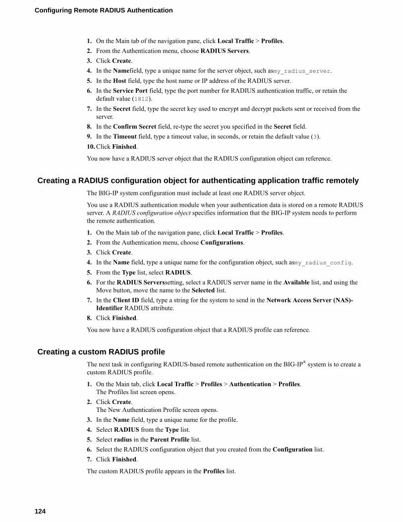
1. On the Main tab of the navigation pane, click Local Traffic > Profiles.2. From the Authentication menu, choose RADIUS Servers.3. Click Create.4. In the Namefield, type a unique name for the server object, such asmy_radius_server.5. In the Host field, type the host name or IP address of the RADIUS server.6. In the Service Port field, type the port number for RADIUS authentication traffic, or retain the
default value (1812).7. In the Secret field, type the secret key used to encrypt and decrypt packets sent or received from the
server.8. In the Confirm Secret field, re-type the secret you specified in the Secret field.9. In the Timeout field, type a timeout value, in seconds, or retain the default value (3).10. Click Finished.
You now have a RADIUS server object that the RADIUS configuration object can reference.
Creating a RADIUS configuration object for authenticating application traffic remotely
The BIG-IP system configuration must include at least one RADIUS server object.
You use a RADIUS authentication module when your authentication data is stored on a remote RADIUSserver. A RADIUS configuration object specifies information that the BIG-IP system needs to performthe remote authentication.
1. On the Main tab of the navigation pane, click Local Traffic > Profiles.2. From the Authentication menu, choose Configurations.3. Click Create.4. In the Name field, type a unique name for the configuration object, such asmy_radius_config.5. From the Type list, select RADIUS.6. For the RADIUS Serverssetting, select a RADIUS server name in the Available list, and using the
Move button, move the name to the Selected list.7. In the Client ID field, type a string for the system to send in the Network Access Server (NAS)-
Identifier RADIUS attribute.8. Click Finished.
You now have a RADIUS configuration object that a RADIUS profile can reference.
Creating a custom RADIUS profile
The next task in configuring RADIUS-based remote authentication on the BIG-IP® system is to create acustom RADIUS profile.
1. On the Main tab, click Local Traffic > Profiles > Authentication > Profiles.The Profiles list screen opens.
2. Click Create.The New Authentication Profile screen opens.
3. In the Name field, type a unique name for the profile.4. Select RADIUS from the Type list.5. Select radius in the Parent Profile list.6. Select the RADIUS configuration object that you created from the Configuration list.7. Click Finished.
The custom RADIUS profile appears in the Profiles list.
Configuring Remote RADIUS Authentication
124

Modifying a virtual server for RADIUS authentication
The final task in the process of implementing authentication using a remote RADIUS server is to assignthe custom RADIUS profile to a virtual server that is configured to process HTTP traffic (that is, a virtualserver to which an HTTP profile is assigned).
1. On the Main tab, click Local Traffic > Virtual Servers.The Virtual Server List screen opens.
2. Click the name of a virtual server.3. From the Configuration list, select Advanced.4. For the Authentication Profiles setting, in the Available field, select a custom RADIUS profile, and
using the Move button, move the custom RADIUS profile to the Selected field.5. Click Update to save the changes.
The virtual server is assigned the custom RADIUS profile.
BIG-IP Local Traffic Manager: Implementations
125

Configuring Remote RADIUS Authentication
126

Configuring Remote SSL LDAP Authentication
Overview of remote SSL LDAP authentication for application trafficAs an administrator in a large computing environment, you can set up the BIG-IP system to use thisserver to authenticate any network traffic passing through the BIG-IP system. This type of traffic passesthrough a virtual server and through Traffic Management Microkernel (TMM) interfaces. Remoteauthentication servers typically use one of these protocols:
• Lightweight Directory Access Protocol (LDAP)• Remote Authentication Dial-in User Service (RADIUS)• TACACS+ (derived from Terminal Access Controller Access Control System [TACACS])• Online Status Certificate Protocol (OCSP)• Certificate Revocation List Distribution Point (CRLDP)
To configure remote authentication for this type of traffic, you must create a configuration object and aprofile that correspond to the type of authentication server you are using to store your user accounts. Forexample, if your remote authentication server is an LDAP server, you create an LDAP configurationobject and an LDAP profile. When implementing a RADIUS, SSL OCSP, or CRLDP authenticationmodule, you must also create a third type of object. For RADIUS and CRLDP authentication, this objectis referred to as a server object. For SSL OCSP authentication, this object is referred to as an OCSPresponder.
Task SummaryTo configure remote authentication for SSL LDAP traffic, you must create a configuration object and aprofile that correspond to the type of authentication server you are using to store your user accounts.
Task listCreating an LDAP Client Certificate SSL configuration objectCreating a custom SSL Client Certificate LDAP profileModifying a virtual server for SSL Client Certificate LDAP authorization
Creating an LDAP Client Certificate SSL configuration object
An SSL Client Certificate LDAP configuration object specifies information that the BIG-IP system needsto perform the remote authentication. This configuration object is one of the required objects you need toimpose certificate-based access control on application traffic.
1. On the Main tab of the navigation pane, click Local Traffic > Profiles.2. From the Authentication menu, choose Configurations.3. Click Create.4. In the Name field, type a unique name for the configuration object, such asmy_ssl_ldap_config.5. From the Type list, select SSL Client Certificate LDAP.6. In the Hostsfield, type an IP address for the remote LDAP authentication server storing the
authentication data, and click Add.The IP address appears in the Hosts area of the screen.

7. Repeat the previous step for each LDAP server you want to use.8. From the Search Type list, select one of the following:
Option Description
User Choose this option if you want the system to extract a user name from the clientcertificate and search for that user name in the remote LDAP database.
Certificate Map Choose this option if you want the system to search for an existing user-certificatemapping in the remote LDAP database.
Certificate Choose this option if you want the system to search for a certificate stored in theuser's profile in the remote LDAP database.
9. Click Finished.
You now have a configuration object that an SSL Client Certificate LDAP profile can reference.
Creating a custom SSL Client Certificate LDAP profile
The next task in configuring LDAP-based remote authentication on the BIG-IP®system is to create acustom SSL Client Certificate LDAP profile.
1. On the Main tab, click Local Traffic > Profiles > Authentication > Profiles.The Profiles list screen opens.
2. Click Create.The New Authentication Profile screen opens.
3. In the Name field, type a unique name for the profile.4. Select the Custom check box.5. Select SSL Client Certificate LDAP from the Type list.6. Select ssl_cc_ldap in the Parent Profile list.7. Select the name of a LDAP configuration object from the Configuration list.8. Click Finished.
The custom SSL Client Certificate LDAP profile appears in the Profiles list.
Modifying a virtual server for SSL Client Certificate LDAP authorization
The final task in the process of implementing authorization using a remote LDAP server is to assign thecustom SSL Client Certificate LDAP profile and a default LDAP authentication iRule to a virtual serverthat is configured to process HTTP traffic (that is, a virtual server to which an HTTP profile is assigned).
1. On the Main tab, click Local Traffic > Virtual Servers.The Virtual Server List screen opens.
2. Click the name of a Standard-type virtual server to which an HTTP server profile is assigned.3. From the Configuration list, select Advanced.4. For the Authentication Profiles setting, in the Available field, select a custom SSL Client Certificate
LDAP profile, and using the Move button, move the custom SSL Client Certificate LDAP profile tothe Selected field.
5. Click Update to save the changes.
The virtual server is assigned the custom SSL Client Certificate LDAP profile.
Configuring Remote SSL LDAP Authentication
128
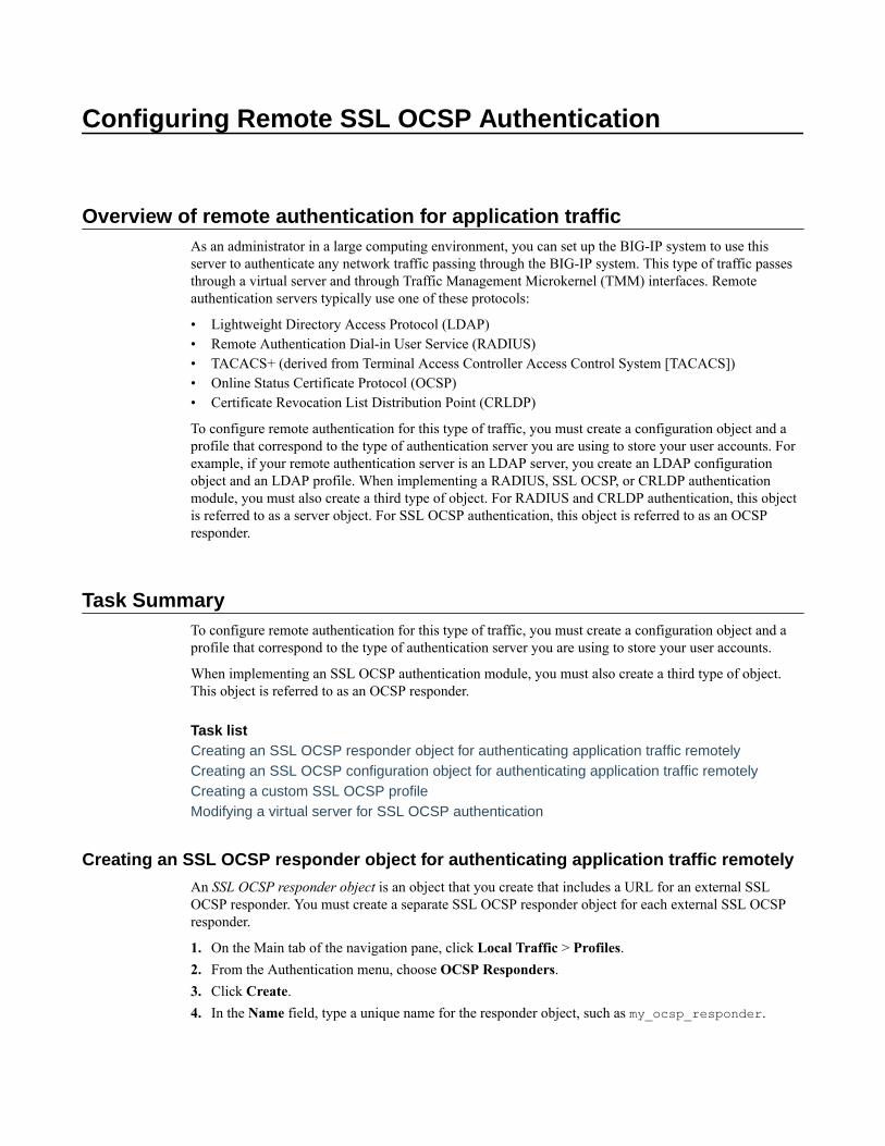
Configuring Remote SSL OCSP Authentication
Overview of remote authentication for application trafficAs an administrator in a large computing environment, you can set up the BIG-IP system to use thisserver to authenticate any network traffic passing through the BIG-IP system. This type of traffic passesthrough a virtual server and through Traffic Management Microkernel (TMM) interfaces. Remoteauthentication servers typically use one of these protocols:
• Lightweight Directory Access Protocol (LDAP)• Remote Authentication Dial-in User Service (RADIUS)• TACACS+ (derived from Terminal Access Controller Access Control System [TACACS])• Online Status Certificate Protocol (OCSP)• Certificate Revocation List Distribution Point (CRLDP)
To configure remote authentication for this type of traffic, you must create a configuration object and aprofile that correspond to the type of authentication server you are using to store your user accounts. Forexample, if your remote authentication server is an LDAP server, you create an LDAP configurationobject and an LDAP profile. When implementing a RADIUS, SSL OCSP, or CRLDP authenticationmodule, you must also create a third type of object. For RADIUS and CRLDP authentication, this objectis referred to as a server object. For SSL OCSP authentication, this object is referred to as an OCSPresponder.
Task SummaryTo configure remote authentication for this type of traffic, you must create a configuration object and aprofile that correspond to the type of authentication server you are using to store your user accounts.
When implementing an SSL OCSP authentication module, you must also create a third type of object.This object is referred to as an OCSP responder.
Task listCreating an SSL OCSP responder object for authenticating application traffic remotelyCreating an SSL OCSP configuration object for authenticating application traffic remotelyCreating a custom SSL OCSP profileModifying a virtual server for SSL OCSP authentication
Creating an SSL OCSP responder object for authenticating application traffic remotely
An SSL OCSP responder object is an object that you create that includes a URL for an external SSLOCSP responder. You must create a separate SSL OCSP responder object for each external SSL OCSPresponder.
1. On the Main tab of the navigation pane, click Local Traffic > Profiles.2. From the Authentication menu, choose OCSP Responders.3. Click Create.4. In the Name field, type a unique name for the responder object, such as my_ocsp_responder.
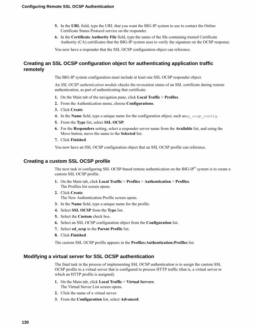
5. In the URL field, type the URL that you want the BIG-IP system to use to contact the OnlineCertificate Status Protocol service on the responder.
6. In the Certificate Authority File field, type the name of the file containing trusted CertificateAuthority (CA) certificates that the BIG-IP system uses to verify the signature on the OCSP response.
You now have a responder that the SSL OCSP configuration object can reference.
Creating an SSL OCSP configuration object for authenticating application trafficremotely
The BIG-IP system configuration must include at least one SSL OCSP responder object.
An SSL OCSP authentication module checks the revocation status of an SSL certificate during remoteauthentication, as part of authenticating that certificate.
1. On the Main tab of the navigation pane, click Local Traffic > Profiles.2. From the Authentication menu, choose Configurations.3. Click Create.4. In the Name field, type a unique name for the configuration object, such asmy_ocsp_config.5. From the Type list, select SSL OCSP.6. For the Responders setting, select a responder server name from the Available list, and using the
Move button, move the name to the Selected list.7. Click Finished.
You now have an SSL OCSP configuration object that an SSL OCSP profile can reference.
Creating a custom SSL OCSP profile
The next task in configuring SSL OCSP-based remote authentication on the BIG-IP® system is to create acustom SSL OCSP profile.
1. On the Main tab, click Local Traffic > Profiles > Authentication > Profiles.The Profiles list screen opens.
2. Click Create.The New Authentication Profile screen opens.
3. In the Name field, type a unique name for the profile.4. Select SSL OCSP from the Type list.5. Select the Custom check box.6. Select an SSL OCSP configuration object from the Configuration list.7. Select ssl_ocsp in the Parent Profile list.8. Click Finished.
The custom SSL OCSP profile appears in the Profiles:Authentication:Profiles list.
Modifying a virtual server for SSL OCSP authentication
The final task in the process of implementing SSL OCSP authentication is to assign the custom SSLOCSP profile to a virtual server that is configured to process HTTP traffic (that is, a virtual server towhich an HTTP profile is assigned).
1. On the Main tab, click Local Traffic > Virtual Servers.The Virtual Server List screen opens.
2. Click the name of a virtual server.3. From the Configuration list, select Advanced.
Configuring Remote SSL OCSP Authentication
130

4. For the Authentication Profiles setting, in the Available field, select a custom SSL OCSP profile.Then, using the Move button, move the custom SSL OCSP profile to the Selected field.
5. Click Update to save the changes.
The virtual server is assigned the custom SSL OCSP profile.
BIG-IP Local Traffic Manager: Implementations
131

Configuring Remote SSL OCSP Authentication
132

Configuring Remote TACACS+ Authentication
Overview of remote authentication for application trafficAs an administrator in a large computing environment, you can set up the BIG-IP® system to use thisserver to authenticate any network traffic passing through the BIG-IP system. This type of traffic passesthrough a virtual server and through Traffic Management Microkernel (TMM) interfaces. Remoteauthentication servers typically use one of these protocols:
• Lightweight Directory Access Protocol (LDAP)• Remote Authentication Dial-in User Service (RADIUS)• TACACS+ (derived from Terminal Access Controller Access Control System [TACACS])• Online Status Certificate Protocol (OCSP)• Certificate Revocation List Distribution Point (CRLDP)
To configure remote authentication for this type of traffic, you must create a configuration object and aprofile that correspond to the type of authentication server you are using to store your user accounts. Forexample, if your remote authentication server is an LDAP server, you create an LDAP configurationobject and an LDAP profile. When implementing a RADIUS, SSL OCSP, or CRLDP authenticationmodule, you must also create a third type of object. For RADIUS and CRLDP authentication, this objectis referred to as a server object. For SSL OCSP authentication, this object is referred to as an OCSPresponder.
Task SummaryTo configure remote authentication for this type of traffic, you must create a configuration object and aprofile that correspond to the type of authentication server you are using to store your user accounts.
Task listCreating a TACACS+ configuration objectCreating a custom TACACS+ profileModifying a virtual server for TACACS+ authentication
Creating a TACACS+ configuration object
A TACACS+ configuration object specifies information that the BIG-IP system needs to perform theremote authentication. For example, the configuration object specifies the IP address of the remoteTACACS+ server.
1. On the Main tab of the navigation pane, click Local Traffic > Profiles.2. From the Authentication menu, choose Configurations.3. Click Create.4. In the Name field, type a unique name for the configuration object, such asmy_tacacs_config.5. From the Type list, select TACACS+.6. For the Servers setting, select a server name in the Available list, and using the Move button, move
the name to the Selected list.
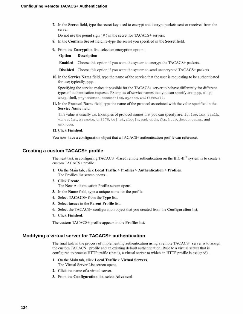
7. In the Secret field, type the secret key used to encrypt and decrypt packets sent or received from theserver.Do not use the pound sign ( # ) in the secret for TACACS+ servers.
8. In the Confirm Secret field, re-type the secret you specified in the Secret field.
9. From the Encryption list, select an encryption option:Option Description
Enabled Choose this option if you want the system to encrypt the TACACS+ packets.
Disabled Choose this option if you want the system to send unencrypted TACACS+ packets.
10. In the Service Name field, type the name of the service that the user is requesting to be authenticatedfor use; typically, ppp.Specifying the service makes it possible for the TACACS+ server to behave differently for differenttypes of authentication requests. Examples of service names that you can specify are: ppp, slip,arap, shell, tty-daemon, connection, system, and firewall.
11. In the Protocol Name field, type the name of the protocol associated with the value specified in theService Name field.This value is usually ip. Examples of protocol names that you can specify are: ip, lcp, ipx, stalk,vines, lat, xremote, tn3270, telnet, rlogin, pad, vpdn, ftp, http, deccp, osicp, andunknown.
12. Click Finished.
You now have a configuration object that a TACACS+ authentication profile can reference.
Creating a custom TACACS+ profile
The next task in configuring TACACS+-based remote authentication on the BIG-IP® system is to create acustom TACACS+ profile.
1. On the Main tab, click Local Traffic > Profiles > Authentication > Profiles.The Profiles list screen opens.
2. Click Create.The New Authentication Profile screen opens.
3. In the Name field, type a unique name for the profile.4. Select TACACS+ from the Type list.5. Select tacacs in the Parent Profile list.6. Select the TACACS+ configuration object that you created from the Configuration list.7. Click Finished.
The custom TACACS+ profile appears in the Profiles list.
Modifying a virtual server for TACACS+ authentication
The final task in the process of implementing authentication using a remote TACACS+ server is to assignthe custom TACACS+ profile and an existing default authentication iRule to a virtual server that isconfigured to process HTTP traffic (that is, a virtual server to which an HTTP profile is assigned).
1. On the Main tab, click Local Traffic > Virtual Servers.The Virtual Server List screen opens.
2. Click the name of a virtual server.3. From the Configuration list, select Advanced.
Configuring Remote TACACS+ Authentication
134

4. For the Authentication Profiles setting, in the Available field, select a custom TACACS+ profile,and using the Move button, move the custom TACACS+ profile to the Selected field.
5. Click Update to save the changes.
The virtual server is assigned the custom TACACS+ profile.
BIG-IP Local Traffic Manager: Implementations
135

Configuring Remote TACACS+ Authentication
136
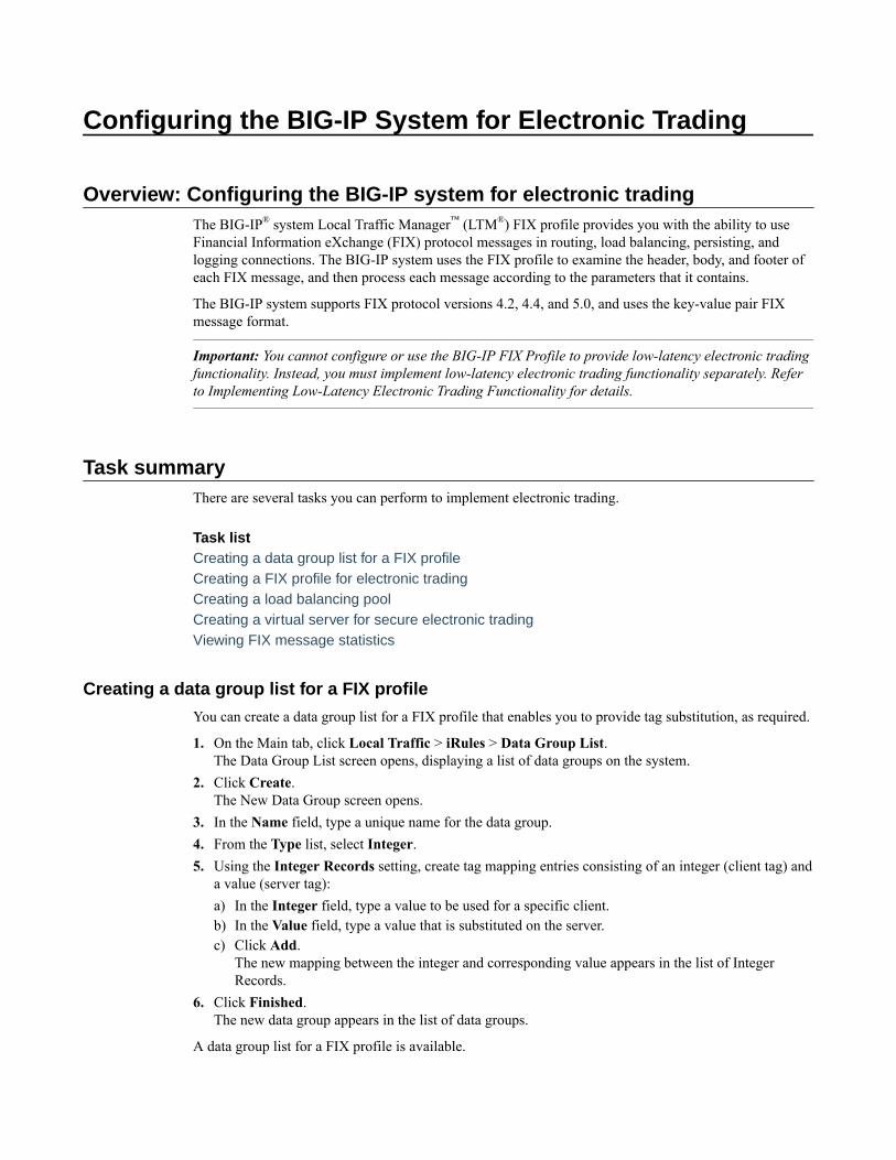
Configuring the BIG-IP System for Electronic Trading
Overview: Configuring the BIG-IP system for electronic tradingThe BIG-IP® system Local Traffic Manager™ (LTM®) FIX profile provides you with the ability to useFinancial Information eXchange (FIX) protocol messages in routing, load balancing, persisting, andlogging connections. The BIG-IP system uses the FIX profile to examine the header, body, and footer ofeach FIX message, and then process each message according to the parameters that it contains.
The BIG-IP system supports FIX protocol versions 4.2, 4.4, and 5.0, and uses the key-value pair FIXmessage format.
Important: You cannot configure or use the BIG-IP FIX Profile to provide low-latency electronic tradingfunctionality. Instead, you must implement low-latency electronic trading functionality separately. Referto Implementing Low-Latency Electronic Trading Functionality for details.
Task summaryThere are several tasks you can perform to implement electronic trading.
Task listCreating a data group list for a FIX profileCreating a FIX profile for electronic tradingCreating a load balancing poolCreating a virtual server for secure electronic tradingViewing FIX message statistics
Creating a data group list for a FIX profile
You can create a data group list for a FIX profile that enables you to provide tag substitution, as required.
1. On the Main tab, click Local Traffic > iRules > Data Group List.The Data Group List screen opens, displaying a list of data groups on the system.
2. Click Create.The New Data Group screen opens.
3. In the Name field, type a unique name for the data group.4. From the Type list, select Integer.5. Using the Integer Records setting, create tag mapping entries consisting of an integer (client tag) and
a value (server tag):a) In the Integer field, type a value to be used for a specific client.b) In the Value field, type a value that is substituted on the server.c) Click Add.
The new mapping between the integer and corresponding value appears in the list of IntegerRecords.
6. Click Finished.The new data group appears in the list of data groups.
A data group list for a FIX profile is available.

Creating a FIX profile for electronic trading
You can create a FIX profile for electronic trading, and steer traffic in accordance with specifiedparameters.
1. On the Main tab, click Local Traffic > Profiles > Services > FIX.The FIX profile list screen opens.
2. Click Create.The New FIX Profile screen opens.
3. In the Name field, type a unique name for the profile.4. From the Parent Profile list, select a parent profile.5. Select the Custom check box.6. (Optional) From the Report Log Publisher list, select the publisher for error messages and status
reports.7. (Optional) From the Message Log Publisher list, select the publisher for message logging.8. In the Rate Sample Interval field, type the sample interval, in seconds, for the message rate.9. From the Error Action list, select one of the following settings.
• Don't Forward (default) to drop a message with errors and not forward it.• Drop Connection to disconnect the connection.
10. Select the Quick Parsing check box to parse the basic standard fields, and validate the messagelength and checksum.
11. Select the Response Parsing check box to parse the messages from the FIX server, applying the sameparser configuration and error handling for the server as for the client.
12. Select the Fully Parse Logon Message check box to fully parse the logon message, instead of usingquick parsing.
13. From the Sender and Tag Substitution Data Group Mapping list, select one of the followingsettings.Setting Description
Not Configured(default)
Disables the tag substitution map between sender ID and tag substitution datagroup.
Specify Provides the Mapping List settings for you to configure as required.
1. In the Sender field, type a sender ID that represents the identity of the firmsending the message.
Example: client12. In the Data Group field, type a tag substitution data group.
Example: FIX_tag_map3. Click Add.
14. Click Finished.
The FIX profile is configured for electronic trading.
Creating a load balancing pool
You can create a load balancing pool (a logical set of devices such as web servers that you group togetherto receive and process traffic) to efficiently distribute the load on your server resources.
Note: You must create the pool before you create the corresponding virtual server.
Configuring the BIG-IP System for Electronic Trading
138
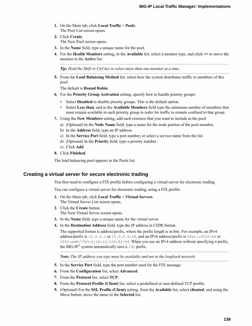
1. On the Main tab, click Local Traffic > Pools.The Pool List screen opens.
2. Click Create.The New Pool screen opens.
3. In the Name field, type a unique name for the pool.4. For the Health Monitors setting, in the Available list, select a monitor type, and click << to move the
monitor to the Active list.
Tip: Hold the Shift or Ctrl key to select more than one monitor at a time.
5. From the Load Balancing Method list, select how the system distributes traffic to members of thispool.The default is Round Robin.
6. For the Priority Group Activation setting, specify how to handle priority groups:
• Select Disabled to disable priority groups. This is the default option.• Select Less than, and in the Available Members field type the minimum number of members that
must remain available in each priority group in order for traffic to remain confined to that group.7. Using the New Members setting, add each resource that you want to include in the pool:
a) (Optional) In the Node Name field, type a name for the node portion of the pool member.b) In the Address field, type an IP address.c) In the Service Port field, type a port number, or select a service name from the list.d) (Optional) In the Priority field, type a priority number.e) Click Add.
8. Click Finished.
The load balancing pool appears in the Pools list.
Creating a virtual server for secure electronic trading
You first need to configure a FIX profile before configuring a virtual server for electronic trading.
You can configure a virtual server for electronic trading, using a FIX profile.
1. On the Main tab, click Local Traffic > Virtual Servers.The Virtual Server List screen opens.
2. Click the Create button.The New Virtual Server screen opens.
3. In the Name field, type a unique name for the virtual server.4. In the Destination Address field, type the IP address in CIDR format.
The supported format is address/prefix, where the prefix length is in bits. For example, an IPv4address/prefix is 10.0.0.1 or 10.0.0.0/24, and an IPv6 address/prefix is ffe1::0020/64 or2001:ed8:77b5:2:10:10:100:42/64. When you use an IPv4 address without specifying a prefix,the BIG-IP® system automatically uses a /32 prefix.
Note: The IP address you type must be available and not in the loopback network.
5. In the Service Port field, type the port number used for the FIX message.6. From the Configuration list, select Advanced.7. From the Protocol list, select TCP.8. From the Protocol Profile (Client) list, select a predefined or user-defined TCP profile.9. (Optional) For the SSL Profile (Client) setting, from the Available list, select clientssl, and using the
Move button, move the name to the Selected list.
BIG-IP Local Traffic Manager: Implementations
139

10. (Optional) For the SSL Profile (Server) setting, from the Available list, select serverssl, and usingthe Move button, move the name to the Selected list.
11. From the FIX Profile list, select the FIX profile you want to assign to the virtual server.12. In the Resources area of the screen, from the Default Pool list, select the relevant pool name.13. Click Finished.
A virtual server is configured for electronic trading, using a FIX profile.
Viewing FIX message statistics
You can view various statistics specific to FIX profile traffic.
1. On the Main tab, click Local Traffic > Virtual Servers > Statistics.The Virtual Servers statistics screen opens.
2. From the Statistics Type list, select Profiles Summary.3. In the Global Profile Statistics area, for the Profile Type FIX, click View in the Details.
The system displays information about the number of current connections, the number of messages,the total message size, and the number of messages in the last sample interval.
The FIX profile statistics are available.
Implementation resultThis implementation configures a BIG-IP® system to manage electronic trading functionality, providesyou with the ability to use Financial Information eXchange (FIX) protocol messages.
Configuring the BIG-IP System for Electronic Trading
140
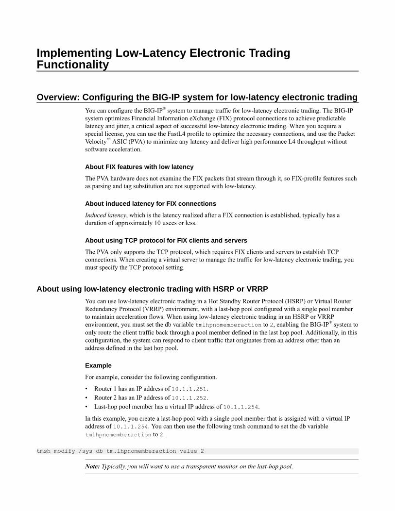
Implementing Low-Latency Electronic TradingFunctionality
Overview: Configuring the BIG-IP system for low-latency electronic tradingYou can configure the BIG-IP® system to manage traffic for low-latency electronic trading. The BIG-IPsystem optimizes Financial Information eXchange (FIX) protocol connections to achieve predictablelatency and jitter, a critical aspect of successful low-latency electronic trading. When you acquire aspecial license, you can use the FastL4 profile to optimize the necessary connections, and use the PacketVelocity™ ASIC (PVA) to minimize any latency and deliver high performance L4 throughput withoutsoftware acceleration.
About FIX features with low latency
The PVA hardware does not examine the FIX packets that stream through it, so FIX-profile features suchas parsing and tag substitution are not supported with low-latency.
About induced latency for FIX connections
Induced latency, which is the latency realized after a FIX connection is established, typically has aduration of approximately 10 µsecs or less.
About using TCP protocol for FIX clients and servers
The PVA only supports the TCP protocol, which requires FIX clients and servers to establish TCPconnections. When creating a virtual server to manage the traffic for low-latency electronic trading, youmust specify the TCP protocol setting.
About using low-latency electronic trading with HSRP or VRRP
You can use low-latency electronic trading in a Hot Standby Router Protocol (HSRP) or Virtual RouterRedundancy Protocol (VRRP) environment, with a last-hop pool configured with a single pool memberto maintain acceleration flows. When using low-latency electronic trading in an HSRP or VRRPenvironment, you must set the db variable tmlhpnomemberaction to 2, enabling the BIG-IP® system toonly route the client traffic back through a pool member defined in the last hop pool. Additionally, in thisconfiguration, the system can respond to client traffic that originates from an address other than anaddress defined in the last hop pool.
Example
For example, consider the following configuration.
• Router 1 has an IP address of 10.1.1.251.• Router 2 has an IP address of 10.1.1.252.• Last-hop pool member has a virtual IP address of 10.1.1.254.
In this example, you create a last-hop pool with a single pool member that is assigned with a virtual IPaddress of 10.1.1.254. You can then use the following tmsh command to set the db variabletmlhpnomemberaction to 2.
tmsh modify /sys db tm.lhpnomemberaction value 2
Note: Typically, you will want to use a transparent monitor on the last-hop pool.
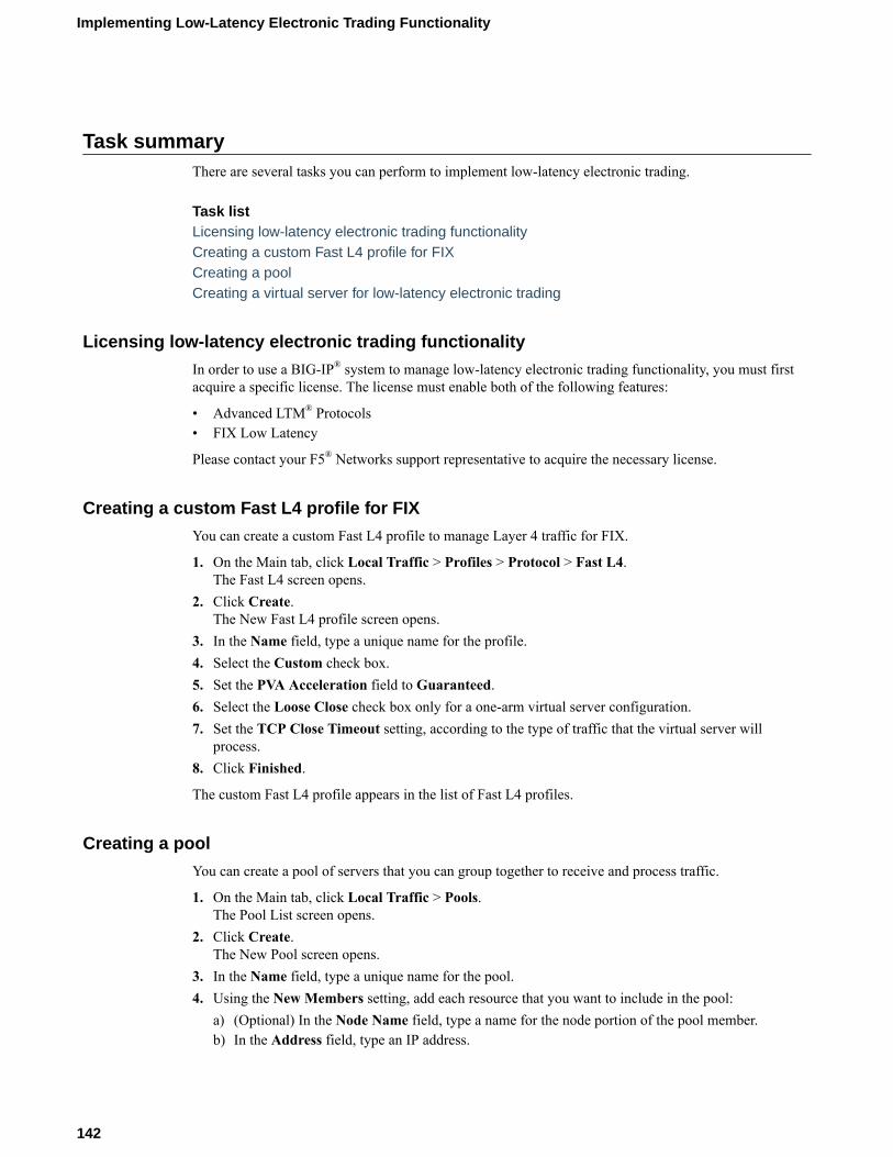
Task summaryThere are several tasks you can perform to implement low-latency electronic trading.
Task listLicensing low-latency electronic trading functionalityCreating a custom Fast L4 profile for FIXCreating a poolCreating a virtual server for low-latency electronic trading
Licensing low-latency electronic trading functionality
In order to use a BIG-IP® system to manage low-latency electronic trading functionality, you must firstacquire a specific license. The license must enable both of the following features:
• Advanced LTM® Protocols• FIX Low Latency
Please contact your F5® Networks support representative to acquire the necessary license.
Creating a custom Fast L4 profile for FIX
You can create a custom Fast L4 profile to manage Layer 4 traffic for FIX.
1. On the Main tab, click Local Traffic > Profiles > Protocol > Fast L4.The Fast L4 screen opens.
2. Click Create.The New Fast L4 profile screen opens.
3. In the Name field, type a unique name for the profile.4. Select the Custom check box.5. Set the PVA Acceleration field to Guaranteed.6. Select the Loose Close check box only for a one-arm virtual server configuration.7. Set the TCP Close Timeout setting, according to the type of traffic that the virtual server will
process.8. Click Finished.
The custom Fast L4 profile appears in the list of Fast L4 profiles.
Creating a pool
You can create a pool of servers that you can group together to receive and process traffic.
1. On the Main tab, click Local Traffic > Pools.The Pool List screen opens.
2. Click Create.The New Pool screen opens.
3. In the Name field, type a unique name for the pool.4. Using the New Members setting, add each resource that you want to include in the pool:
a) (Optional) In the Node Name field, type a name for the node portion of the pool member.b) In the Address field, type an IP address.
Implementing Low-Latency Electronic Trading Functionality
142
c) In the Service Port field, type a port number, or select a service name from the list.d) (Optional) In the Priority field, type a priority number.e) Click Add.
5. Click Finished.6. Repeat these steps for each pool you want to create.
The new pool appears in the Pools list.
Creating a virtual server for low-latency electronic trading
After you create a server pool, you need to create a virtual server that references the profile and pool youcreated.
1. On the Main tab, click Local Traffic > Virtual Servers.The Virtual Server List screen opens.
2. Click the Create button.The New Virtual Server screen opens.
3. In the Name field, type a unique name for the virtual server.4. From the Type list, select Performance (Layer 4).5. In the Destination Address field, type the IP address in CIDR format.
The supported format is address/prefix, where the prefix length is in bits. For example, an IPv4address/prefix is 10.0.0.1 or 10.0.0.0/24, and an IPv6 address/prefix is ffe1::0020/64 or2001:ed8:77b5:2:10:10:100:42/64. When you use an IPv4 address without specifying a prefix,the BIG-IP® system automatically uses a /32 prefix.
Note: The IP address you type must be available and not in the loopback network.
6. From the Configuration list, select Advanced.7. From the Protocol list, select TCP.8. From the Protocol Profile (Client) list, select the custom Fast L4 profile you defined for low-latency
FIX trading.9. (Optional) For the Address Translation setting, clear the Enabled check box to implement direct
server return (DSR) functionality.10. (Optional) For the Port Translation setting, clear the Enabled check box.
Important: Clearing the Enabled check box disables network address translation (NAT) functionality.If you require NAT, you must select the Enabled check box.
11. In the Resources area of the screen, from the Default Pool list, select the relevant pool name.12. Click Finished.
The virtual server is configured to use the specified Fast L4 profile and pool. If a client initiates a FIXconnection with this virtual server, the connection uses the Fast L4 (ePVA) hardware.
Implementation resultThis implementation configures a BIG-IP® system to manage low-latency electronic trading functionality,optimizing the system for predictable latency and jitter. Clients who send FIX packets to the virtualserver's Destination address all receive this low-latency service.
BIG-IP Local Traffic Manager: Implementations
143

Implementing Low-Latency Electronic Trading Functionality
144

Implementing Low-Latency Electronic Trading with FIXload balancing
Overview: Configuring low-latency electronic trading with FIX loadbalancing
You can configure the BIG-IP® system to manage electronic trading traffic for both low-latency andintelligent load balancing. The BIG-IP system supports Financial Information eXchange (FIX) protocolconnections for electronic trading between financial institutions. When you acquire a special license, youcan use the FastL4 profile to optimize the FIX connections, and use the embedded Packet Velocity®
ASIC (ePVA) to minimize the latency. You can then use an iRule to implement intelligent load balancing:you do this by enabling the Late Binding feature in the FastL4 profile, then creating an iRule that parseseach FIX header to choose a back-end server pool.
About Late Binding
With the Late Binding feature enabled, an iRule can examine the FIX logon packet, the one thatestablishes the connection, and choose a server pool based on the packet's contents. The iRule finishes bysending the connection down to the ePVA hardware, which processes the stream at high speed.
The only TCP options available to the client and server are MSS, accept Selective ACK, and TimeStamp. The BIG-IP system ignores all other options because it must enable SYN cookies on the client-side interface, and because the ePVA hardware does not slow down for any of those options. Forexample, the BIG-IP system ignores the Window Scaling option as soon as the flow has been released tothe ePVA hardware.
Note: Secure Sockets Layer (SSL) is not supported by a virtual server that uses Late Binding.
About FIX features with low latency
After the iRule selects a server, the ePVA hardware manages the FIX stream for the rest of its existence.The ePVA does not examine the individual FIX packets that pass through it, so FIX-profile features suchas tag substitution are not supported.
About induced latency for FIX connections
Induced latency, which is the latency realized after a FIX connection is established, typically has aduration of approximately 10 µsecs or less.
About using TCP protocol for FIX clients and servers
The ePVA only supports the TCP protocol, which requires FIX clients and servers to establish TCPconnections. When creating a virtual server to manage the traffic for low-latency electronic trading, youmust specify the TCP protocol setting.
Task summaryThere are several tasks you perform to implement low-latency electronic trading.
Task listLicensing low-latency electronic trading functionality

Creating a custom Fast L4 profile for FIXCreating a FIX profile for low-latency electronic tradingCreating a poolCreating an iRule for load-balancing Layer-7 (FIX) trafficCreating a virtual server for low-latency electronic trading
Licensing low-latency electronic trading functionality
In order to use a BIG-IP® system to manage low-latency electronic trading functionality, you must firstacquire a specific license. The license must enable both of the following features:
• Advanced LTM® Protocols• FIX Low Latency
Please contact your F5® Networks support representative to acquire the necessary license.
Creating a custom Fast L4 profile for FIX
You can create a custom Fast L4 profile to manage Layer-4 traffic for FIX.
1. On the Main tab, click Local Traffic > Profiles > Protocol > Fast L4.The Fast L4 screen opens.
2. Click Create.The New Fast L4 profile screen opens.
3. In the Name field, type a unique name for the profile.4. Select the Custom check box.5. Set the PVA Acceleration field to Guaranteed.6. If you plan to use Late Binding and either of the Loose Initiation and Loose Close check boxes are
enabled, clear them both.The Late Binding feature examines the first few packets in the FIX stream, and the Loose Initiationfeature makes it possible to skip those packets without any examination.
7. Set the TCP Close Timeout setting, according to the type of traffic that the virtual server willprocess.
8. Disable the Hardware SYN Cookie Protection feature by clearing the check box.9. Enable the Software SYN Cookie Protection feature by selecting the check box.10. The Late Binding feature makes it possible to choose a server pool based on data in the FIX header.
An iRule in the virtual server parses the FIX header and selects the server pool. Select the check boxto enable Late Binding.a) You can allow the iRule to explicitly determine when the flow is released from Layer 7 down to
Layer 4. The iRule code can then perform additional computation before binding the connection toLayer 4. Enable this by selecting the Explicit Flow Migration check box. When this feature isenabled, the flow is not released to Layer 4 until the iRule invokes the BIGTCP::release_flowcommand.By default, this is disabled and the flow drops down to Layer 4 immediately after the connectionto the server is established.
b) Use the Client Timeout field to determine how much time to allow for any client to send the first2144 bytes of Layer 7information. In normal cases, this amount of data arrives immediately.
c) From the Timeout Recovery list, select an action that the profile should take in case of timeout.Select Disconnect to drop the connection summarily, or select Fallback to process the packetwithout parsing the Layer 7 fields. The fallback option sends any timed-out connection to theVirtual Server's default pool.
11. Click Finished.
Implementing Low-Latency Electronic Trading with FIX load balancing
146
The custom Fast L4 profile appears in the list of Fast L4 profiles.
Creating a FIX profile for low-latency electronic trading
A virtual server with Late Binding enabled can choose a server pool based on the contents of the FIXconnection's initial packet. The Late Binding feature makes it possible to combine this load balancingwith low latency.
Note: This is a simplified FIX profile. The low-latency path goes through the ePVA hardware, which doesnot examine the contents of each FIX packet. The only packet that the BIG-IP software examines is thelogon packet, which the BIG-IP® system uses to choose a server pool. Therefore, most of the features inthe FIX-profile screen (such as tag substitution) are ignored for low-latency trading.
1. On the Main tab, click Local Traffic > Profiles > Services > FIX.The FIX profile list screen opens.
2. Click Create.The New FIX Profile screen opens.
3. In the Name field, type a unique name for the profile.4. From the Parent Profile list, select a parent profile.5. Select the Custom check box.6. (Optional) From the Report Log Publisher list, select the publisher for error messages and status
reports.7. (Optional) From the Message Log Publisher list, select the publisher for message logging.8. Click Finished.
The FIX profile is configured for low-latency electronic trading with FIX load balancing.
Creating a pool
You can create a pool of servers that you can group together to receive and process traffic.
1. On the Main tab, click Local Traffic > Pools.The Pool List screen opens.
2. Click Create.The New Pool screen opens.
3. In the Name field, type a unique name for the pool.4. Using the New Members setting, add each resource that you want to include in the pool:
a) (Optional) In the Node Name field, type a name for the node portion of the pool member.b) In the Address field, type an IP address.c) In the Service Port field, type a port number, or select a service name from the list.d) (Optional) In the Priority field, type a priority number.e) Click Add.
5. Click Finished.6. Repeat these steps for each pool you want to create.
The new pool appears in the Pools list.
Creating an iRule for load-balancing Layer-7 (FIX) traffic
Creating an iRule for load-balancing Layer-7 (FIX) traffic requires that the Late Binding feature isenabled in the Fast L4 profile. A virtual server with Late Binding enabled can choose a server pool basedon the contents of the FIX connection's initial logon packet(s).
BIG-IP Local Traffic Manager: Implementations
147
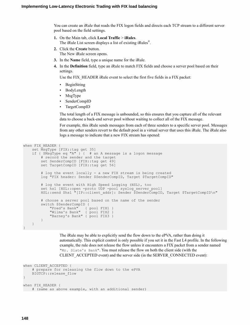
You can create an iRule that reads the FIX logon fields and directs each TCP stream to a different serverpool based on the field settings.
1. On the Main tab, click Local Traffic > iRules.The iRule List screen displays a list of existing iRules®.
2. Click the Create button.The New iRule screen opens.
3. In the Name field, type a unique name for the iRule.4. In the Definition field, type an iRule to match FIX fields and choose a server pool based on their
settings.Use the FIX_HEADER iRule event to select the first five fields in a FIX packet:
• BeginString• BodyLength• MsgType• SenderCompID• TargetCompID
The total length of a FIX message is unbounded, so this ensures that you capture all of the relevantdata to choose a back-end server pool without waiting to collect all of the FIX message.For example, this iRule sends messages from each of three senders to a specific server pool. Messagesfrom any other senders revert to the default pool in a virtual server that uses this iRule. The iRule alsologs a message to indicate that a new FIX stream has opened:
when FIX_HEADER { set MsgType [FIX::tag get 35] if { $MsgType eq "A" } { # an A message is a logon message # record the sender and the target set SenderCompID [FIX::tag get 49] set TargetCompID [FIX::tag get 56] # log the event locally - a new FIX stream is being created log "FIX header: Sender $SenderCompID, Target $TargetCompID" # log the event with High Speed Logging (HSL), too set hsl [HSL::open -proto UDP -pool syslog_server_pool] HSL::send $hsl "[IP::client_addr]: Sender $SenderCompID, Target $TargetCompID\n" # choose a server pool based on the name of the sender switch $SenderCompID { "Fred's Bank" { pool FIX1 } "Wilma's Bank" { pool FIX2 } "Barney's Bank" { pool FIX3 } } }}
The iRule may be able to explicitly send the flow down to the ePVA, rather than doing itautomatically. This explicit control is only possible if you set it in the Fast L4 profile. In the followingexample, the rule does not release the flow unless it encounters a FIX packet from a sender named"Mr. Slate's Bank". You must release the flow on both the client side (with theCLIENT_ACCEPTED event) and the server side (in the SERVER_CONNECTED event):
when CLIENT_ACCEPTED { # prepare for releasing the flow down to the ePVA BIGTCP::release_flow}
when FIX_HEADER { # (same as above example, with an additional sender)
Implementing Low-Latency Electronic Trading with FIX load balancing
148

set MsgType [FIX::tag get 35] if { $MsgType eq "A" } { # an A message is a logon message # record the sender and the target set SenderCompID [FIX::tag get 49] set TargetCompID [FIX::tag get 56] # log the event - a new FIX stream is being created log "FIX header: Sender $SenderCompID, Target $TargetCompID" # choose a server pool based on the name of the sender switch $SenderCompID { "Fred's Bank" { pool FIX1 } "Wilma's Bank" { pool FIX2 } "Barney's Bank" { pool FIX3 } "Mr. Slate's Bank" { pool FIX4 } } }}
when SERVER_CONNECTED { if {$SenderCompID eq "Mr. Slate's Bank"}{ # Mr. Slate's Bank sent this, so lower the latency log local0. "Detected $SenderCompID - releasing flow to ePVA" BIGTCP::release_flow }}
The previous code sends all FIX streams through standard FIX-profile processing except the one(s)from "Mr. Slate's Bank", which goes through the ePVA.
5. Click Finished.
The iRule is now available. You can use this iRule in a virtual server that also offers a FIX profile and thelow latency of Fast L4.
Creating a virtual server for low-latency electronic trading
After you create a server pool, profile(s), and (optionally) iRule, you need to create a virtual server thatreferences those components.
1. On the Main tab, click Local Traffic > Virtual Servers.The Virtual Server List screen opens.
2. Click the Create button.The New Virtual Server screen opens.
3. In the Name field, type a unique name for the virtual server.4. From the Type list, select Performance (Layer 4).5. In the Destination Address field, type the IP address in CIDR format. This is the address to which
the FIX clients send their FIX transmissions.The supported format is address/prefix, where the prefix length is in bits. For example, an IPv4address/prefix is 10.0.0.1 or 10.0.0.0/24, and an IPv6 address/prefix is ffe1::0020/64 or2001:ed8:77b5:2:10:10:100:42/64. When you use an IPv4 address without specifying a prefix,the BIG-IP® system automatically uses a /32 prefix.
Note: The IP address you type must be available and not in the loopback network.
6. From the Configuration list, select Advanced.7. From the Protocol list, select TCP.8. From the Protocol Profile (Client) list, select the custom Fast L4 profile you defined for low-latency
FIX trading.9. Go to the FIX Profile list and select the custom FIX profile you defined for low-latency trading.
BIG-IP Local Traffic Manager: Implementations
149

10. (Optional) For the Address Translation setting, clear the Enabled check box to implement directserver return (DSR) functionality.
11. (Optional) For the Port Translation setting, clear the Enabled check box.
Important: Clearing the Enabled check box disables network address translation (NAT) functionality.If you require NAT, you must select the Enabled check box.
12. In the Resources area of the screen, from the Default Pool list, select the pool name for FIX streams.This pool is for streams that do not match your iRule(s).
13. For the iRules setting, from the Available list, select the name of the iRule that you created for theLate Binding feature and move it to the Enabled list.The iRule enables load balancing based on the Layer-7 (FIX) fields at the head of each stream.
14. Click Finished.
The virtual server is configured to use the specified Fast L4 profile and pool. If a client initiates a FIXconnection with this virtual server, the connection uses the Fast L4 (ePVA) hardware.
Implementation resultThis implementation configures a BIG-IP® system to manage low-latency electronic trading functionality,optimizing the system for predictable latency and jitter. Clients who send FIX streams to the virtualserver's Destination address all receive this low-latency service. The virtual server intelligently distributesthe streams to different server pools based on information in each stream's FIX logon packet.
Implementing Low-Latency Electronic Trading with FIX load balancing
150

Implementing Hardware-optimized FIX Low Latency (FIXLL) Electronic Trading
About configuring BIG-IP systems for hardware-optimized FIX LLYou can configure BIG-IP® 10000 and 12000 Series systems that are running BIG-IP software version12.1.0 to use a customized firmware to manage traffic for hardware-optimized, low-latency electronictrading. This FIX low latency (FIX LL) solution provides enhanced collision handling.
Important: The FIX LL firmware does not support hardware SYN cookies. Be sure to enable softwareSYN cookie protection.
Task summary
There are several tasks you can perform to implement hardware-optimized FIX low-latency electronictrading.
Task list
Licensing low-latency electronic trading functionality
In order to use a BIG-IP® system to manage low-latency electronic trading functionality, you must firstacquire a specific license. The license must enable both of the following features:
• Advanced LTM® Protocols• FIX Low Latency
Please contact your F5® Networks support representative to acquire the necessary license.
Selecting a firmware to use for hardware-optimized FIX LL
You can use the TMOS Shell (tmsh) to choose whether to use the FIX low latency (FIX LL) firmware.
1. Connect to the system using the serial console.2. Log in to the command-line interface of the system using the root account.3. Open the TMOS Shell (tmsh).
tmsh4. Enable the FIX LL firmware.
modify sys db pva.fix.lowlatency value enable5. Reboot the system to update the FPGA.
reboot
Important: If you are switching to the FIX LL firmware for the first time, the system performs an HSBupdate to load the new firmware. Do not interrupt the progress of the firmware update. When thefirmware update completes, the system reboots, and then you will be able to use the FIX LL firmware.
6. (Optional) To switch back to the default firmware:a) Disable the FIX LL firmware.
modify sys db pva.fix.lowlatency value disableb) Reboot the system to update the FPGA.
reboot

Creating a custom Fast L4 profile for hardware-optimized FIX LL
You can create a custom Fast L4 profile to manage Layer 4 traffic for FIX low latency (FIX LL).
1. On the Main tab, click Local Traffic > Profiles > Protocol > Fast L4.The Fast L4 screen opens.
2. Click Create.The New Fast L4 profile screen opens.
3. In the Name field, type a unique name for the profile.4. Select the Custom check box.5. From the PVA Acceleration list, select Dedicated.6. Select the PVA Flow Aging and PVA Flow Evict check boxes.7. For the PVA Offload Dynamic setting, retain the default value (Enabled).8. For the PVA Dynamic Client Packets setting, retain the default value (1).9. For the PVA Dynamic Server Packets setting, retain the default value (0).10. Select the Loose Close check box only for a one-arm virtual server configuration.11. Set the TCP Close Timeout setting, according to the type of traffic that the virtual server will
process.12. Select the Software SYN Cookie Protection check box.13. Click Finished.
The custom Fast L4 profile appears in the list of Fast L4 profiles.
Creating a pool
You can create a pool of servers that you can group together to receive and process traffic.
1. On the Main tab, click Local Traffic > Pools.The Pool List screen opens.
2. Click Create.The New Pool screen opens.
3. In the Name field, type a unique name for the pool.4. Using the New Members setting, add each resource that you want to include in the pool:
a) (Optional) In the Node Name field, type a name for the node portion of the pool member.b) In the Address field, type an IP address.c) In the Service Port field, type a port number, or select a service name from the list.d) (Optional) In the Priority field, type a priority number.e) Click Add.
5. Click Finished.6. Repeat these steps for each pool you want to create.
The new pool appears in the Pools list.
Creating a virtual server for low-latency electronic trading
After you create a server pool, you need to create a virtual server that references the profile and pool youcreated.
1. On the Main tab, click Local Traffic > Virtual Servers.The Virtual Server List screen opens.
2. Click the Create button.The New Virtual Server screen opens.
Implementing Hardware-optimized FIX Low Latency (FIX LL) Electronic Trading
152

3. In the Name field, type a unique name for the virtual server.4. From the Type list, select Performance (Layer 4).5. In the Destination Address field, type the IP address in CIDR format.
The supported format is address/prefix, where the prefix length is in bits. For example, an IPv4address/prefix is 10.0.0.1 or 10.0.0.0/24, and an IPv6 address/prefix is ffe1::0020/64 or2001:ed8:77b5:2:10:10:100:42/64. When you use an IPv4 address without specifying a prefix,the BIG-IP® system automatically uses a /32 prefix.
Note: The IP address you type must be available and not in the loopback network.
6. From the Configuration list, select Advanced.7. From the Protocol list, select TCP.8. From the Protocol Profile (Client) list, select the custom Fast L4 profile you defined for low-latency
FIX trading.9. (Optional) For the Address Translation setting, clear the Enabled check box to implement direct
server return (DSR) functionality.10. (Optional) For the Port Translation setting, clear the Enabled check box.
Important: Clearing the Enabled check box disables network address translation (NAT) functionality.If you require NAT, you must select the Enabled check box.
11. In the Resources area of the screen, from the Default Pool list, select the relevant pool name.12. Click Finished.
The virtual server is configured to use the specified Fast L4 profile and pool. If a client initiates a FIXconnection with this virtual server, the connection uses the Fast L4 (ePVA) hardware.
Implementation result
This implementation configures a BIG-IP® system to manage low-latency electronic trading functionality,optimizing the system for predictable latency and jitter. Clients who send FIX packets to the virtualserver's Destination address all receive this low-latency service.
BIG-IP Local Traffic Manager: Implementations
153

Implementing Hardware-optimized FIX Low Latency (FIX LL) Electronic Trading
154

Implementing APM System Authentication
Overview: Configuring authentication for a remote system based on APMAs an administrator in a large computing environment, you might prefer to store user accounts remotely,on a dedicated authentication server. When you want to use a remote server to authenticate traffic thatmanages a BIG-IP® system, you can store BIG-IP system administrative accounts on an AAA server.BIG-IP APM® supports AAA servers such as HTTP, LDAP, RADIUS, Active Directory, and TACACS+.To complete the authentication process, you must add the newly configured AAA action to an accesspolicy. You can find more information about AAA authentication and access policies in BIG-IP AccessPolicy Manager: Authentication and Single Sign-On and BIG-IP Access Policy Manager: Visual PolicyEditor.
Important: System authentication using APM methods will not work if the user name and passwordcontains Unicode characters (for example, Chinese characters) or the symbols ampersand (&), colon (:),less than (<), and apostrophe (').
Creating a user authentication based on APM
Before you begin:
• Verify that the BIG-IP® system user accounts have been created on the remote authentication server.• Verify that the appropriate user groups, if any, are defined on the remote authentication server.
You can configure the BIG-IP® system to use an APM® server for authenticating BIG-IP® system useraccounts, that is, traffic that passes through the management interface (MGMT).
1. On the Main tab, click System > Users.2. On the menu bar, click Authentication.3. Click Change.4. From the User Directory list, select Remote - APM Based.5. For the Access Profile setting, click the + button.
The screen refreshes to show general properties.6. In the Name field, type a name for the access profile.
Note: An access profile name must be unique among all access profile and any per-request policynames.
7. From the Default Language list, select a language.The default is English (en).
8. From the Authentication Type list, select the type of authentication for the APM based remote userauthentication.The screen refreshes to show areas and settings specific to the authentication type.
9. Fill in the fields.10. Click Finished.
You can now authenticate administrative traffic for user accounts that are stored on a remote APM server.If you have no need to configure group-based user authorization, your configuration tasks are complete.

Example access policy using APM LDAP authentication
This is an example of an access policy with all the associated elements that are needed to authenticateand authorize your users with LDAP authentication.
Figure 17: Example of an access policy for LDAP Auth
Implementing APM System Authentication
156

Configuring an SSL Intercept Explicit Proxy Mode
About SSL intercept explicit proxy modeA typical SSL intercept explicity proxy mode configuration includes two BIG-IP devices, one configuredto manage half-proxy client traffic and one configured to manage half-proxy server traffic. When theingress BIG-IP system receives a client request, SSL decrypts the request. The ingress BIG-IP systemthen sends metadata to the egress BIG-IP system by means of the out-of-band TCP connection and sendsthe request data to the inspection device. When the egress BIG-IP system receives the metadata throughthe out-of-band connection and the request from the inspection device, it uses the information in themetadata, re-encrypts the request, and forwards it to the destination server.
The following illustration depicts an example configuration.
Figure 18: An example SSL intercept explicity proxy mode configuration
The SplitSession Client profile type
The SplitSession Client profile defines the client parameters in an SSL intercept explicit proxy modeconfiguration. This profile enables you to configure a Peer Port, which specifies the port for theSplitSession peer that is connected to the out-of-band connection, and the Peer IP address, whichspecifies the IP address for the SplitSession peer that is connected to the out-of-band connection.
The SplitSession Server profile type
The SplitSession Server profile defines the server parameters in an SSL intercept explicit proxy modeconfiguration. This profile enables you to configure a Listen Port, which specifies the port that theSplitSession server listens on for the out-of-band connection, and the Listen IP address, which specifiesthe IP address that the SplitSession server listens on for the out-of-band connection.
Task SummaryComplete these tasks to configure an SSL intercept explicit proxy configuration.Creating a SplitSession Client profile

Creating a custom Client SSL profileCreating a pool to process HTTP traffic for an inspection deviceCreating an ingress explicit proxy virtual serverCreating a SplitSession Server profileCreating a custom Server SSL profileCreating a pool to manage HTTPS trafficCreating an egress explicit proxy virtual server
Creating a SplitSession Client profile
You can create a SplitSession Client profile to define the client parameters in an SSL intercept explicitproxy mode configuration.
1. On the Main tab, click Local Traffic > Profiles > Other > SplitSession Client.The SplitSession Client profile list screen opens.
2. Click Create.The New SplitSession Client Profile screen opens.
3. In the Name field, type a unique name for the profile.4. From the Parent Profile list, retain the default value or select another existing profile of the same
type.5. In the Peer Port field, type a value for the the port of the SplitSession peer assigned to the out-of-
band connection.6. In the Peer IP field, type the IP address of the SplitSession peer assigned to the out-of-band
connection.7. Click Finished.
A SplitSession Client profile to define the client parameters in an SSL intercept explicit proxy modeconfiguration is available to assign to a virtual server.
Creating a custom Client SSL profile
You perform this task to create a Client SSL profile that makes it possible for direct client-serverauthentication while still allowing the BIG-IP system to perform data optimization, such as decryptionand encryption. This profile applies to client-side SSL traffic only.
1. On the Main tab, click Local Traffic > Profiles > SSL > Client.The Client SSL profile list screen opens.
2. Click Create.The New Client SSL Profile screen opens.
3. In the Name field, type a unique name for the profile.4. Select clientssl in the Parent Profile list.5. For the Proxy SSL setting, select the check box.6. From the Configuration list, select Advanced.
7. Modify all other settings, as required.8. Click Finished.
The custom Client SSL profile appears in the Client SSL profile list screen.
Creating a pool to process HTTP traffic for an inspection device
You can create a pool that includes an inspection device to process HTTP requests.
Configuring an SSL Intercept Explicit Proxy Mode
158

1. On the Main tab, click Local Traffic > Pools.The Pool List screen opens.
2. Click Create.The New Pool screen opens.
3. In the Name field, type a unique name for the pool.4. Using the New Members setting, add each resource that you want to include in the pool:
a) Type an IP address in the Address field.b) Type 80 in the Service Port field, or select HTTP from the list.c) (Optional) Type a priority number in the Priority field.d) Click Add.
5. Click Finished.
The new pool appears in the Pools list.
Creating an ingress explicit proxy virtual server
Before you configure an ingress explicit proxy virtual server, you need to configure a SplitSession Clientprofile and pool to assign to the virtual server.
You can configure an ingress explicit proxy virtual server to manage the client split-session half-proxytraffic from a client to the inspection device.
1. On the Main tab, click Local Traffic > Virtual Servers.The Virtual Server List screen opens.
2. Click the Create button.The New Virtual Server screen opens.
3. In the Name field, type a unique name for the virtual server.4. In the Description field, type a description of the virtual server.5. In the Source Address field, type 0.0.0.0/0 for the source address and prefix length.6. In the Destination Address field, type an IP address in CIDR format.
The supported format is address/prefix, where the prefix length is in bits. For example, to select all IPaddresses, an IPv4 address/prefix is 0.0.0.0/0, and an IPv6 address/prefix is ::/0. To specify anetwork, an IPv4 address/prefix is 10.07.0.0 or 10.07.0.0/24, and an IPv6 address/prefix isffe1::/64 or 2001:ed8:77b5::/64. When you use an IPv4 address without specifying a prefix,the BIG-IP® system automatically uses a /32 prefix.
Note: For best results, F5® recommends that you enter the subnet that matches your destinationserver network.
7. In the Service Port field, type 443 or select HTTPS from the list.8. From the HTTP Profile list, select http.9. For the SSL Profile (Client) setting, select a client SSL profile.10. From the Protocol list, select TCP.11. From the SplitSession Client Profile list, select splitsessionclient or a custom SplitSession Client
profile.12. From the Default Pool list, select the name of the HTTP server pool that you previously created.13. Click Finished.
An ingress explicit proxy virtual server is configured to manage the client split-session half-proxy trafficfrom a client to the inspection device.
BIG-IP Local Traffic Manager: Implementations
159

Creating a SplitSession Server profile
You can create a SplitSession Server profile to define the server parameters in an SSL intercept explicitproxy mode configuration.
1. On the Main tab, click Local Traffic > Profiles > Other > SplitSession Server.The SplitSession Server profile list screen opens.
2. Click Create.The New SplitSession Server Profile screen opens.
3. In the Name field, type a unique name for the profile.4. From the Parent Profile list, retain the default value or select another existing profile of the same
type.5. In the Listen Port field, type a value for the the port of the SplitSession server listens on for the out-
of-band connection.6. In the Listen IP field, type the IP address of the SplitSession server listens on for the out-of-band
connection.7. Click Finished.
A SplitSession Server profile to define the server parameters in an SSL intercept explicit proxy modeconfiguration is available to assign to a virtual server.
Creating a custom Server SSL profile
You perform this task to create a Server SSL profile that makes it possible for direct client-serverauthentication while still allowing the BIG-IP® system to perform data optimization, such as decryptionand encryption. This profile applies to server-side SSL traffic only.
Important: The certificate and key that you specify in this profile must match the certificate/key pair thatyou expect the back-end server to offer. If the back-end server has two or more certificates to offer, youmust create a separate Server SSL profile for each certificate and then assign all of the Server SSLprofiles to a single virtual server.
1. On the Main tab, click Local Traffic > Profiles > SSL > Server.The Server SSL profile list screen opens.
2. Click Create.The New Server SSL Profile screen opens.
3. In the Name field, type a unique name for the profile.4. Select serverssl in the Parent Profile list.5. From the Certificate list, select a relevant certificate name.6. From the Key list, select a relevant key name.7. For the Proxy SSL setting, select the check box.8. From the Configuration list, select Advanced.
9. Modify all other settings, as required.10. Choose one of the following actions:
• If you need to create another Server SSL profile, click Repeat.• If you do not need to create another Server SSL profile, click Finished.
All relevant Server SSL profiles now appear on the SSL Server profile list screen.
Configuring an SSL Intercept Explicit Proxy Mode
160

Creating a pool to manage HTTPS traffic
You can create a pool (a logical set of devices, such as web servers, that you group together to receiveand process HTTPS traffic) to efficiently distribute the load on your server resources.
1. On the Main tab, click Local Traffic > Pools.The Pool List screen opens.
2. Click Create.The New Pool screen opens.
3. In the Name field, type a unique name for the pool.4. For the Health Monitors setting, assign https or https_443 by moving it from the Available list to
the Active list.5. From the Load Balancing Method list, select how the system distributes traffic to members of this
pool.The default is Round Robin.
6. For the Priority Group Activation setting, specify how to handle priority groups:
• Select Disabled to disable priority groups. This is the default option.• Select Less than, and in the Available Members field type the minimum number of members that
must remain available in each priority group in order for traffic to remain confined to that group.7. Use the New Members setting to add each resource that you want to include in the pool:
a) In the Address field, type an IP address.b) In the Service Port field type 443 , or select HTTPS from the list.c) (Optional) Type a priority number in the Priority field.d) Click Add.
8. Click Finished.
The HTTPS load balancing pool appears in the Pool List screen.
Creating an egress explicit proxy virtual server
Before you configure an egress explicit proxy virtual server, you need to configure a SplitSession Serverprofile and pool to assign to the virtual server.
You can configure an egress explicit proxy virtual server to manage the server split-session half-proxytraffic from an inspection device to a server.
1. On the Main tab, click Local Traffic > Virtual Servers.The Virtual Server List screen opens.
2. Click the Create button.The New Virtual Server screen opens.
3. In the Name field, type a unique name for the virtual server.4. In the Description field, type a description of the virtual server.5. In the Source Address field, type 0.0.0.0/0 for the source address and prefix length.6. In the Destination Address field, type an IP address in CIDR format.
The supported format is address/prefix, where the prefix length is in bits. For example, to select all IPaddresses, an IPv4 address/prefix is 0.0.0.0/0, and an IPv6 address/prefix is ::/0. To specify anetwork, an IPv4 address/prefix is 10.07.0.0 or 10.07.0.0/24, and an IPv6 address/prefix isffe1::/64 or 2001:ed8:77b5::/64. When you use an IPv4 address without specifying a prefix,the BIG-IP® system automatically uses a /32 prefix.
BIG-IP Local Traffic Manager: Implementations
161

Note: For best results, F5® recommends that you enter the subnet that matches your destinationserver network.
7. In the Service Port field, type 443 or select HTTPS from the list.8. For the SSL Profile (Server) setting, select a server SSL profile.9. From the Protocol list, select TCP.10. From the SplitSession Server Profile list, select splitsessionserver or a custom SplitSession Server
profile.11. From the Default Pool list, select the name of the HTTP server pool that you previously created.12. Click Finished.
An egress explicit proxy virtual server is configured to manage the server split-session half-proxy trafficfrom an inspection device to a server.
Configuring an SSL Intercept Explicit Proxy Mode
162

Configuring an Explicit HTTP Proxy Chain
Overview: Configuring an explicit HTTP proxy chainAn explicit HTTP proxy chain configuration enables you to load balance traffic from a BIG-IP® devicethrough a pool of proxy devices. When establishing an explicit HTTP proxy chain, the BIG-IP explicitproxy device sends an HTTP request to a remote proxy device, which connects to the requested host andport. Once the connection succeeds between the BIG-IP explicit proxy device and the remote proxydevice, a tunnel is opened between the BIG-IP explicit proxy device and the remote proxy device, whichallows other protocols to pass unimpeded through the tunnel.
The following illustration depicts a typical explicit HTTP proxy chain configuration.
Figure 19: A typical explicit HTTP proxy chain configuration
About HTTP Proxy Connect profiles
The HTTP Proxy Connect profile enables a BIG-IP® device to connect to a remote, down-stream proxydevice. A client connects to the BIG-IP device, which selects a remote proxy device from a pool of proxydevices. An HTTP CONNECT handshake tells the selected remote proxy device where to connect. Whenthe connection is established, it becomes an opaque tunnel. Any protocol can use the tunnel between theBIG-IP device and the remote proxy.
When an HTTP profile is assigned to the virtual server, the HTTP CONNECT handshake isautomatically configured. If an HTTP profile not assigned to the virtual server, for example, when youhave opaque SSL traffic, you can use HTTP::proxy chain iRule commands to configure thedestination to which the remote proxy device routes traffic.
Task SummaryComplete these tasks to configure an explicit HTTP proxy chain configuration.Creating a custom HTTP Proxy Connect profileCreating a load balancing poolCreating a virtual server for explicit HTTP proxy connection
Creating a custom HTTP Proxy Connect profile
You can create a custom HTTP Proxy Connect profile and assign it to a virtual server to load balanceHTTP traffic through a pool of proxy devices.
1. On the Main tab, click Local Traffic > Profiles > Other > HTTP Proxy Connect.The HTTP Proxy Connect profile list screen opens.
2. Click Create.The New HTTP Proxy Connect Profile screen opens.
3. In the Name field, type a unique name for the profile.

4. From the Parent Profile list, retain the default value or select another existing profile of the sametype.
5. Select the Custom check box.6. Select the Default State check box.7. Click Finished.
The custom HTTP Proxy Connect profile is available to assign to a virtual server.
Creating a load balancing pool
You can create a load balancing pool (a logical set of proxy devices that you group together to receiveand process traffic) to efficiently distribute the load on your resources.
Note: You must create the pool before you create the corresponding virtual server.
1. On the Main tab, click Local Traffic > Pools.The Pool List screen opens.
2. Click Create.The New Pool screen opens.
3. In the Name field, type a unique name for the pool.4. For the Health Monitors setting, in the Available list, select a monitor type, and click << to move the
monitor to the Active list.
Tip: Hold the Shift or Ctrl key to select more than one monitor at a time.
5. From the Load Balancing Method list, select how the system distributes traffic to members of thispool.The default is Round Robin.
6. For the Priority Group Activation setting, specify how to handle priority groups:
• Select Disabled to disable priority groups. This is the default option.• Select Less than, and in the Available Members field type the minimum number of members that
must remain available in each priority group in order for traffic to remain confined to that group.7. Using the New Members setting, add each resource that you want to include in the pool:
a) (Optional) In the Node Name field, type a name for the node portion of the pool member.b) In the Address field, type an IP address.c) In the Service Port field, type a port number, or select a service name from the list.d) (Optional) In the Priority field, type a priority number.e) Click Add.
8. Click Finished.
The load balancing pool appears in the Pools list.
Creating a virtual server for explicit HTTP proxy connection
You can create a virtual server to load balance HTTP traffic through a pool of remote proxy devices.
1. On the Main tab, click Local Traffic > Virtual Servers.The Virtual Server List screen opens.
2. Click the Create button.The New Virtual Server screen opens.
3. In the Name field, type a unique name for the virtual server.4. In the Destination Address field, type the IP address in CIDR format.
Configuring an Explicit HTTP Proxy Chain
164
The supported format is address/prefix, where the prefix length is in bits. For example, an IPv4address/prefix is 10.0.0.1 or 10.0.0.0/24, and an IPv6 address/prefix is ffe1::0020/64 or2001:ed8:77b5:2:10:10:100:42/64. When you use an IPv4 address without specifying a prefix,the BIG-IP® system automatically uses a /32 prefix.
Note: The IP address you type must be available and not in the loopback network.
5. In the Service Port field, type a port number or select a service name from the Service Port list.6. From the HTTP Proxy Connect Profile list, select a profile.7. In the Resources area of the screen, from the Default Pool list, select the relevant pool name.
A virtual server is available to load balance HTTP traffic through a pool of remote proxy devices
BIG-IP Local Traffic Manager: Implementations
165

Configuring an Explicit HTTP Proxy Chain
166

Manipulating HTTPS Traffic by Using a Third-Party Device
Overview: Manipulating HTTPS traffic by using a third-party deviceYou can configure a BIG-IP® device to manage HTTPS traffic by using a third-party device that canintercept and modify the traffic, as necessary. This configuration provides SSL decryption, manipulation,and re-encryption while appearing relatively transparent at layer 2.
When you configure a virtual server to use the Transparent Nexthop control, traffic matching the virtualserver is sent to the specified interface and the layer 2 addressing on the ingress packet is preserved.Configuring the Transparent Nexthop to specify the VLAN that is configured with the inspection deviceeliminates the need to configure a pool, NAT, SNAT, or other load balancing functionality to theinspection device.
Important: Transparent Nexthop functionality requires a license that supports that functionality. If theTransparent Nexthop control does not appear on the New Virtual Server screen, contact your F5®
Networks support representative to acquire the necessary license.
The basic process used in this configuration is as follows:
1. A client sends an HTTPS request to a server by means of the BIG-IP device.2. The BIG-IP device intercepts the request, decrypts it, and forwards the request as cleartext to the
inspection device.3. The inspection device receives and, as necessary, modifies the cleartext request.4. The inspection device forwards the cleartext request to the server by means of the BIG-IP device.5. The BIG-IP device re-encrypts the cleartext request and sends the ciphertext request to the server.6. The server sends a response to the client by means of the BIG-IP device.7. The BIG-IP device receives the response, decrypts it, and forwards the response as cleartext to the
inspection device.8. The inspection device receives and, as necessary, modifies the cleartext response.9. The inspection device forwards the cleartext response to the client by means of the BIG-IP device.10. The BIG-IP device re-encrypts the cleartext response and sends the ciphertext response to the client.
The following illustration shows an example of a BIG-IP device that manages HTTPS traffic modified bya third-party device.
Figure 20: An example configuration of a BIG-IP device managing HTTPS traffic modified by athird-party device.

Task SummaryComplete these tasks to configure a BIG-IP® device to manage HTTPS traffic by using a third-partydevice that can intercept and modify the traffic, as necessary.
Creating a VLAN
When you create a VLAN, each of the specified interfaces can process traffic destined for that VLAN.You can create a VLAN for use with an inspection device, as necessary.
1. On the Main tab, click Network > VLANs.The VLAN List screen opens.
2. Click Create.The New VLAN screen opens.
3. In the Name field, type a unique name for the VLAN.4. In the Tag field, type a numeric tag, between 1-4094, for the VLAN, or leave the field blank if you
want the BIG-IP system to automatically assign a VLAN tag.The VLAN tag identifies the traffic from hosts in the associated VLAN.
5. For the Interfaces setting:a) From the Interface list, select an interface number.b) From the Tagging list, select Tagged.c) Click Add.
6. If you want the system to verify that the return route to an initial packet is the same VLAN fromwhich the packet originated, select the Source Check check box.
7. In the MTU field, retain the default number of bytes (1500).8. From the Configuration list, select Advanced.9. For the Hardware SYN Cookie setting, select or clear the check box.
When you enable this setting, the BIG-IP system triggers hardware SYN cookie protection for thisVLAN.Enabling this setting causes additional settings to appear. These settings appear on specific BIG-IPplatforms only.
10. For the Syncache Threshold setting, retain the default value or change it to suit your needs.The Syncache Threshold value represents the number of outstanding SYN flood packets on theVLAN that will trigger the hardware SYN cookie protection feature.
When the Hardware SYN Cookie setting is enabled, the BIG-IP system triggers SYN cookieprotection in either of these cases, whichever occurs first:
• The number of TCP half-open connections defined in the LTM® setting Global SYN CheckThreshold is reached.
• The number of SYN flood packets defined in this Syncache Threshold setting is reached.11. For the SYN Flood Rate Limit setting, retain the default value or change it to suit your needs.
The SYN Flood Rate Limit value represents the maximum number of SYN flood packets per secondreceived on this VLAN before the BIG-IP system triggers hardware SYN cookie protection for theVLAN.
12. Click Finished.The screen refreshes, and displays the new VLAN in the list.
Manipulating HTTPS Traffic by Using a Third-Party Device
168
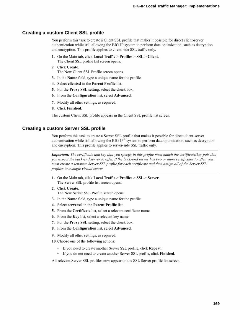
Creating a custom Client SSL profile
You perform this task to create a Client SSL profile that makes it possible for direct client-serverauthentication while still allowing the BIG-IP system to perform data optimization, such as decryptionand encryption. This profile applies to client-side SSL traffic only.
1. On the Main tab, click Local Traffic > Profiles > SSL > Client.The Client SSL profile list screen opens.
2. Click Create.The New Client SSL Profile screen opens.
3. In the Name field, type a unique name for the profile.4. Select clientssl in the Parent Profile list.5. For the Proxy SSL setting, select the check box.6. From the Configuration list, select Advanced.
7. Modify all other settings, as required.8. Click Finished.
The custom Client SSL profile appears in the Client SSL profile list screen.
Creating a custom Server SSL profile
You perform this task to create a Server SSL profile that makes it possible for direct client-serverauthentication while still allowing the BIG-IP® system to perform data optimization, such as decryptionand encryption. This profile applies to server-side SSL traffic only.
Important: The certificate and key that you specify in this profile must match the certificate/key pair thatyou expect the back-end server to offer. If the back-end server has two or more certificates to offer, youmust create a separate Server SSL profile for each certificate and then assign all of the Server SSLprofiles to a single virtual server.
1. On the Main tab, click Local Traffic > Profiles > SSL > Server.The Server SSL profile list screen opens.
2. Click Create.The New Server SSL Profile screen opens.
3. In the Name field, type a unique name for the profile.4. Select serverssl in the Parent Profile list.5. From the Certificate list, select a relevant certificate name.6. From the Key list, select a relevant key name.7. For the Proxy SSL setting, select the check box.8. From the Configuration list, select Advanced.
9. Modify all other settings, as required.10. Choose one of the following actions:
• If you need to create another Server SSL profile, click Repeat.• If you do not need to create another Server SSL profile, click Finished.
All relevant Server SSL profiles now appear on the SSL Server profile list screen.
BIG-IP Local Traffic Manager: Implementations
169
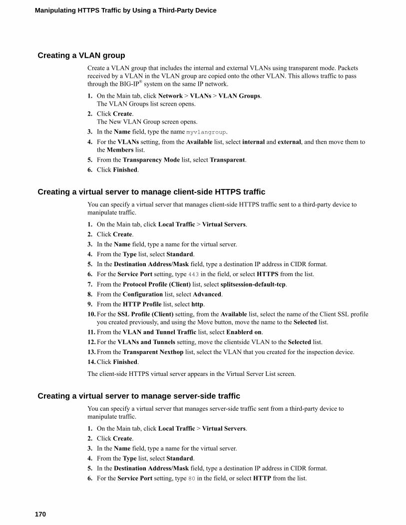
Creating a VLAN group
Create a VLAN group that includes the internal and external VLANs using transparent mode. Packetsreceived by a VLAN in the VLAN group are copied onto the other VLAN. This allows traffic to passthrough the BIG-IP® system on the same IP network.
1. On the Main tab, click Network > VLANs > VLAN Groups.The VLAN Groups list screen opens.
2. Click Create.The New VLAN Group screen opens.
3. In the Name field, type the name myvlangroup.4. For the VLANs setting, from the Available list, select internal and external, and then move them to
the Members list.5. From the Transparency Mode list, select Transparent.6. Click Finished.
Creating a virtual server to manage client-side HTTPS traffic
You can specify a virtual server that manages client-side HTTPS traffic sent to a third-party device tomanipulate traffic.
1. On the Main tab, click Local Traffic > Virtual Servers.2. Click Create.3. In the Name field, type a name for the virtual server.4. From the Type list, select Standard.5. In the Destination Address/Mask field, type a destination IP address in CIDR format.6. For the Service Port setting, type 443 in the field, or select HTTPS from the list.7. From the Protocol Profile (Client) list, select splitsession-default-tcp.8. From the Configuration list, select Advanced.9. From the HTTP Profile list, select http.10. For the SSL Profile (Client) setting, from the Available list, select the name of the Client SSL profile
you created previously, and using the Move button, move the name to the Selected list.11. From the VLAN and Tunnel Traffic list, select Enablerd on.12. For the VLANs and Tunnels setting, move the clientside VLAN to the Selected list.13. From the Transparent Nexthop list, select the VLAN that you created for the inspection device.14. Click Finished.
The client-side HTTPS virtual server appears in the Virtual Server List screen.
Creating a virtual server to manage server-side traffic
You can specify a virtual server that manages server-side traffic sent from a third-party device tomanipulate traffic.
1. On the Main tab, click Local Traffic > Virtual Servers.2. Click Create.3. In the Name field, type a name for the virtual server.4. From the Type list, select Standard.5. In the Destination Address/Mask field, type a destination IP address in CIDR format.6. For the Service Port setting, type 80 in the field, or select HTTP from the list.
Manipulating HTTPS Traffic by Using a Third-Party Device
170

7. From the Configuration list, select Advanced.8. From the Protocol Profile (Server) list, select splitsession-default-tcp.9. From the HTTP Profile list, select http.10. For the SSL Profile (Server) setting, from the Available list, the name of the Server SSL profile you
created previously, and using the Move button, move the name to the Selected list.11. From the VLAN and Tunnel Traffic list, select Enabled on.12. For the VLANs and Tunnels setting, move the VLAN that you created for the inspection device to
the Selected list.13. From the Transparent Nexthop list, select the serverside VLAN.14. Click Finished.
The server-side HTTPS virtual server appears in the Virtual Server List screen.
BIG-IP Local Traffic Manager: Implementations
171

Manipulating HTTPS Traffic by Using a Third-Party Device
172

Legal Notices
Legal notices
Publication Date
This document was published on March 4, 2019.
Publication Number
MAN-0293-14
Copyright
Copyright © 2019, F5 Networks, Inc. All rights reserved.
F5 Networks, Inc. (F5) believes the information it furnishes to be accurate and reliable. However, F5assumes no responsibility for the use of this information, nor any infringement of patents or other rightsof third parties which may result from its use. No license is granted by implication or otherwise underany patent, copyright, or other intellectual property right of F5 except as specifically described byapplicable user licenses. F5 reserves the right to change specifications at any time without notice.
Trademarks
For a current list of F5 trademarks and service marks, see http://www.f5.com/about/guidelines-policies/trademarks.
All other product and company names herein may be trademarks of their respective owners.
Patents
This product may be protected by one or more patents indicated at: https://f5.com/about-us/policies/patents.
Export Regulation Notice
This product may include cryptographic software. Under the Export Administration Act, the UnitedStates government may consider it a criminal offense to export this product from the United States.
RF Interference Warning
This is a Class A product. In a domestic environment this product may cause radio interference, in whichcase the user may be required to take adequate measures.
FCC Compliance
This equipment has been tested and found to comply with the limits for a Class A digital device pursuantto Part 15 of FCC rules. These limits are designed to provide reasonable protection against harmfulinterference when the equipment is operated in a commercial environment. This unit generates, uses, andcan radiate radio frequency energy and, if not installed and used in accordance with the instructionmanual, may cause harmful interference to radio communications. Operation of this equipment in aresidential area is likely to cause harmful interference, in which case the user, at his own expense, will berequired to take whatever measures may be required to correct the interference.

Any modifications to this device, unless expressly approved by the manufacturer, can void the user'sauthority to operate this equipment under part 15 of the FCC rules.
Canadian Regulatory Compliance
This Class A digital apparatus complies with Canadian ICES-003.
Standards Compliance
This product conforms to the IEC, European Union, ANSI/UL and Canadian CSA standards applicable toInformation Technology products at the time of manufacture.
Legal Notices
174

Index
A
adaptive connection reapingconfiguring 116
APM LDAP Auth default rulesexample 156
attacksmitigating 113
authenticationwith CRLDP 119
authorization default rulesexample for APM LDAP 156
B
BIG-IP systeminstalling on same network 35
BIND serverconfiguring on BIG-IP 97
C
Client SSL profilescreating 158, 169
Code Red attackspreventing with iRules 113
compression profilesconfiguring 65
connection limitscalculating 117to ensure system availability 109
connection rate limitsabout 109and configuration results 109creating for virtual servers 109
connection reapingconfiguring 116
connection requests 109connection thresholds 118connection timers
setting 117connections
creating pools for 32, 49, 57, 59, 62limiting 109queuing TCP connection requests 107
contentdefining with queries 18
content adaptation 45, 46, 51, 52content adaptation configuration objects 50, 58content-based routing
about 17creating profile 18viewing statistics 21
control channel optimization 84cookie persistence
about 61cookie profiles
creating 61
CRLDP authenticationconfiguring 119
CRLDP configuration objectscreating 119
custom FTP monitorsand FTP load balancing 77, 81creating 77, 81
custom monitorscreating 104
D
data center topologyexample of 35
data channel optimization 84default gateway pools
creating 97default route
for Layer 2 nPath configuration 24setting 36
Denial of Service attacksfiltering 113mitigating 113preventing 109tasks for 116types of 114
destination IP addressescreating for HTTP traffic 60
DHCP lease expiration 90DHCP relay agents
and the BIG-IP system 85, 86and virtual servers 87
DHCP virtual serversimplementation results 87, 90overview of 89overview of managing 85tasks for 86
DNS lookupsand the BIG-IP system 97
DNS nameserverconfiguring on BIG-IP 97
DoS attack prevention 113DoS attacks, See Denial of Service attacksdownstream nodes
auto-configuring 111
E
eCommerce trafficload balancing 31
electronic tradingabout configuring FIX profile 137creating virtual server for 139implementing with FIX profile 138viewing FIX message statistics 140
enhanced loss recoveryenabling on TCP 108
ephemeral pool members
Index
175

ephemeral pool members (continued)and viewing statistics 100
explicit HTTP proxy chainconfiguring 163
F
failureabout modes of 96
Fast L4 profilescreating for L2 nPath routing 142
FIX LL, See hardware-optimized FIX low-latency electronictrading.FIX profile
about configuring for electronic trading 137creating virtual server for trading 139implementing for low-latency trading and FIX loadbalancing 147implementing for trading 138viewing message statistics 140
FIX protocolsupported versions 137
FIX protocol connectionsabout optimization 141about optimization with FIX load balancing 145using HSRP 141using VRRP 141
FTP configurationtasks for 77, 81
FTP load balancingand custom FTP monitors 77, 81
FTP passive mode 77, 81FTP profiles
creating 81defined 77
FTP traffic optimization 84
H
hardware-optimized FIX low latencytask summary 151
hardware-optimized FIX low-latency electronic tradingoverview 151selecting which firmware to use 151
header valuesfor HTTP requests 46, 52for HTTP responses 53
health monitoringdescribed 103
health monitorsassigning to pools 47, 54, 104, 138, 164described 103
high-water mark thresholds 116host names
and nodes 95and pool members 95
HTML contentand virtual servers 75modifying 71modifying/deleting 72
HTML tag attributesmodifying 71
HTTP compressionconfiguring 65enabling 65
HTTP compression tasksoff-loading from server 65
HTTP content adaptation 45, 46, 51, 52HTTP profiles
creating 48, 57HTTP proxy connect profile
about 163HTTP Proxy Connect profile
creating 163HTTP request-header values 46, 52HTTP requests
adapting content for 46, 52HTTP response-header values 53HTTP responses
adapting content for 52compressing 65
HTTP trafficusing cookie persistence 61using source address persistence 59
HTTPS trafficcreating a pool to manage 32, 161overview, manipulating by using a third-party device 167
I
ICAP configuration objects 50, 58ICAP content adaptation 45, 51ICAP profiles
assigning 47, 54, 55inbound connections
configuring SNAT ephemeral port exhaustion 94inspection device
creating pools for 158internal virtual server type
defined 45, 51internal virtual servers
creating 47, 54, 55intranet configuration 11IP address expiration 90IP address intelligence
categories 42checking database status 42checking IP reputation 41downloading the database 39enabling 39logging information 40overview 39rejecting bad requests 40
IP addresseschecking IP reputation 41
IP intelligence database 39, 42IP reputation
overview 39iprep_lookup command 41iprep-status command 42iprep.autoupdate command 39IPv4-to-IPv6 gateways
configuring 111IPv6 addresses
Index
176

IPv6 addresses (continued)load balancing to 111
IPv6 routing and solicitation messages 111iRule events 20iRule queries 20iRules
and XML routing 20for attack prevention 113for HTML content replacement 71
L
LDAP Auth default rulesfor APM, example 156
LDAP protocol 121, 127load balancing
and monitors 103local traffic policy
creating 73logging
of IP address intelligence information 40loopback interface
for nPath routing 26low-latency electronic trading
creating virtual server for 143, 152hardware-optimized FIX low latency 151implementation overview 141implementing 142, 146, 151implementing with FIX profile and load balancing 147results 140, 143, 150, 153tasks for 137, 142, 145using HSRP 141using VRRP 141
low-latency electronic trading and load balancingcreating virtual server for 149
low-latency electronic trading with FIX load balancingimplementation overview 145
low-water mark thresholds 116LTM nodes
viewing statistics 100
M
matching criteriadefining 18
memory utilizationand connection thresholds 116
monitor types 103monitors
assigning to pools 47, 54, 104, 138, 164for health checking 103for L3 nPath routing 28for performance 103
N
namespacesadding 18
network securityprotecting 113
network topologyfor one-IP configuration 91
Nimda worm attackpreventing with iRules 113
nodesabout modifying 99about statistics 100and automatic updates 95and connection rate limits 109creating using host names 97disabling 99for local traffic pools 97
nPath routingand inbound traffic 26and server pools 25configuring for L3 27configuring monitors for L3 28defined for L2 23defined for L3 27example 29for TCP and UDP traffic 24
O
OCSP protocol 129, 130OCSP responders
creating 129one-IP network topology
illustration of 91outgoing traffic
and L2 nPath routing 23and L3 nPath routing 27
P
packetsdiscarding 113
performance monitorsassigning to pools 47, 54, 104, 138, 164described 103
pooland viewing statistics 100
pool memberand persistent connections 100disabling 100
pool membersabout and related nodes 96about automatic update 95about modifying 99about statistics 100and connection rate limits 109and viewing statistics 100creating with host names 98
poolscreating 47, 54, 73, 104, 138, 142, 147, 152, 164creating for DHCP servers 86creating for FTP traffic 78, 83creating for HTTP 19creating for HTTP traffic 32, 49, 57, 59, 62creating for HTTPS traffic 32, 161creating for inspection device 158creating load balancing 12, 13, 111creating members with host names 98for HTTP traffic 92
Index
177

pools (continued)for L2 nPath routing 25for L3 nPath routing 27
profilescreating CRLDP 120creating custom Fast L4 142, 146creating custom Fast L4 for hardware-optimized FIX LL152creating custom SSL OCSP 130creating Fast L4 25creating for client-side SSL 158, 169creating for FTP 81creating for HTTP 48, 57creating for server-side SSL 160, 169creating LDAP 122creating RADIUS 124creating SSL Client Certificate LDAP 128creating TACACS+ 134creating XML 18for cookie persistence 61for FTP traffic 77, 81for IPIP encapsulation 27for L3 nPath routing 27
Proxy SSL featureand Server SSL profiles 160, 169
R
RADIUS messagessending 123
RADIUS profilespurpose of 123
RADIUS protocol 124RADIUS server objects
creating 123rate limits 109remote CRLDP configuration
tasks for 119remote LDAP configuration
tasks for 121remote RADIUS configuration
tasks for 123remote server authentication
and CRLDP protocol 119and LDAP protocol 121and OCSP protocol 129and RADIUS protocol 123and SSL LDAP protocol 127and TACACS+ protocol 133
remote SSL LDAP configurationtasks for 127
remote SSL OCSP configurationtasks for 129
remote system authenticationfor APM 155for LTM 155
remote TACACS+ configurationtasks for 133
remote traffic authenticationwith CRLDP 119
request-header values 46, 52requests, excessive 109
resource consumption 113responders
creating for OCSP 129response-header values 53reverse proxy servers 69Rewrite profile
creating 71Rewrite profiles
rules for URI matching 70route domains
and IPv6 addressing 111routes
defining default 93setting for inbound traffic 26
routingand XML content 17based on XML content 18
routing advisory messages 111routing statistics
for XML content 21routing XML content 21
S
securityof network 113
self IP addressesand VLAN groups 37creating 37removing from VLANs 36
server poolsfor L2 nPath routing 25
Server SSL profilescreating 160, 169
SNATsconfiguring client 93configuring ephemeral port exhaustion 94
source address persistenceabout 59
SplitSession Client profileabout 157creating 158
SplitSession Server profileabout 157creating 160
SSL interceptabout explicit proxy mode 157
SSL OCSP authentication 129, 130statistics
for XML routing 21viewing per LTM node 100viewing per pool or pool member 100
SYN Check thresholdactivating 118
SYN flood attacks 113
T
TACACS+ protocol 133Tcl variables 21TCP
enabling enhanced loss recovery 108
Index
178

TCP connection timerssetting 117
TCP requestsqueuing overview 107
TCP trafficand nPath routing 24
timerssetting 117
traffic distribution 31traffic forwarding
automating 20translation rules
for URIs 71
U
UDP connection timerssetting 117
UDP trafficand nPath routing 24
URI rulesrequirements for specifying 71
URI translationand virtual servers 75example of 69
URI translation rulescreating 71
user authenticationcreating for APM 155
V
Via headerdisabling 67identifying intermediate protocols 67identifying intermediate proxies 67overview 67task summary 67
virtual addressesand loopback interface 26
virtual servercreating for low-latency electronic trading 143, 152creating for low-latency electronic trading and FIX loadbalancing 149
virtual serversand connection limits 117and connection rate limits 109and cookie persistence 62and HTML content 75and internal type 45, 51and URI translation 75applying a rate class 117creating 12, 47, 54, 55, 105, 112creating an iRule for FIX headers 147creating connection rate limits for 109creating DHCP type 87creating egress 161creating for explicit HTTP proxy connection 164creating for FTP traffic 79, 83creating for HTTP compression 66creating for HTTP traffic 33, 60, 170creating for HTTPS traffic 33, 170
virtual servers (continued)creating for one-IP network 38creating for web hosting 49, 57, 92creating ingress 159DHCP relay type overview 85DHCP renewal 89for DHCP renewal 90for inbound traffic 14for L2 nPath routing 23, 25for L3 nPath routing 27for outbound traffic 15modifying for CRLDP authentication 120modifying for LDAP authentication 122modifying for RADIUS authentication 125modifying for SSL Client Certificate LDAP authorization128modifying for SSL OCSP authentication 130modifying for TACACS+ authentication 134setting connection limits on 117
VLAN externalcreating self IP addresses for 15
VLAN groupsand self IP addresses 37creating 37, 170
VLANscreating 168enabling SNAT automap 15for eCommerce traffic 31removing self IP addresses 36
W
web serversload balancing to 37
X
XML contentrouting 17
XML content-based routingand traffic forwarding 20
XML profilescreating 18
XML routingexample of 20
XPath expressionssamples of syntax 19
XPath queriescreating 18rules for writing 18
XPath queryexamples 19
Index
179

Index
180
Related Documents


