Taunton, MA Wastewater Treatment Facility Phase I Improvements CWSRF 4605 Addendum No. 3 July 30, 2021 This Addendum No. 3 forms a part of the Contract Documents and modifies the Bidding Documents dated July 2nd, 2021 as noted below. Acknowledge receipt of this Addendum in the space provided in the Bid Form. Failure to do so may subject the Bidder to disqualification. Item 1: Changes to Specification Language Specification 13321 - Instrumentation and Controls ● Paragraph 1.3.A – Replace “Contractor” with “Instrumentation/Controls Contractor”. ● Paragraph 1.3.B – Replace “a single instrument manufacturer” with “Instrumentation/Controls Contractor”. ● Paragraph 1.3.C – Replace “system supplier” with “Instrumentation/Controls Contractor”. ● Paragraph 1.3.C – Replace “Contractor” with “General Contractor”. ● Paragraph 1.3.D – Replace “system supplier” with “Instrumentation/Controls Contractor”. ● Paragraph 1.3.E – Replace “instrumentation and control system supplier” with “Instrumentation/Controls Contractor”. ● Paragraph 1.3.F – Add “Instrumentation/Controls Contractor’s” prior to the words “factory-trained service engineer”. ● Paragraph 1.3.F – Replace “Contractor” with “General Contractor”. ● Paragraph 1.3.G – Replace “Contractor” with “General Contractor”. Specification 15500 HVAC ● Paragraph 2.20.C.1 – Replace the entire paragraph with the following: 1. Unit shall be capable of providing up to 100% of nominal capacity in heating at 17 deg F and 60% of nominal capacity in heating at 0 deg F. Unit shall be Bid Addendum #3 CWSRF 4605 Page 1 of 13

Welcome message from author
This document is posted to help you gain knowledge. Please leave a comment to let me know what you think about it! Share it to your friends and learn new things together.
Transcript
Taunton, MAWastewater Treatment Facility
Phase I ImprovementsCWSRF 4605
Addendum No. 3July 30, 2021
This Addendum No. 3 forms a part of the Contract Documents and modifies the BiddingDocuments dated July 2nd, 2021 as noted below. Acknowledge receipt of this Addendum in thespace provided in the Bid Form. Failure to do so may subject the Bidder to disqualification.
Item 1: Changes to Specification Language
Specification 13321 - Instrumentation and Controls
● Paragraph 1.3.A – Replace “Contractor” with “Instrumentation/Controls Contractor”.
● Paragraph 1.3.B – Replace “a single instrument manufacturer” with“Instrumentation/Controls Contractor”.
● Paragraph 1.3.C – Replace “system supplier” with “Instrumentation/ControlsContractor”.
● Paragraph 1.3.C – Replace “Contractor” with “General Contractor”.
● Paragraph 1.3.D – Replace “system supplier” with “Instrumentation/ControlsContractor”.
● Paragraph 1.3.E – Replace “instrumentation and control system supplier” with“Instrumentation/Controls Contractor”.
● Paragraph 1.3.F – Add “Instrumentation/Controls Contractor’s” prior to the words“factory-trained service engineer”.
● Paragraph 1.3.F – Replace “Contractor” with “General Contractor”.
● Paragraph 1.3.G – Replace “Contractor” with “General Contractor”.
Specification 15500 HVAC
● Paragraph 2.20.C.1 – Replace the entire paragraph with the following:
1. Unit shall be capable of providing up to 100% of nominal capacity in heating at17 deg F and 60% of nominal capacity in heating at 0 deg F. Unit shall be
Bid Addendum #3CWSRF 4605
Page 1 of 13
capable of providing heating at outdoor temperatures as low as -13 deg F.
Specification 16000 Basic Electrical Requirements
● Paragraph 1.5.B – Replace the entire paragraph with the following:
1. All Concrete work, including the furnish and installation of concrete electricalduct encasement, transformer pads, equipment mounting pads, concretehandholes, light pole bases, is included under DIVISION 3 - CONCRETE ofthese Specifications.
Specification 16085 Miscellaneous Equipment
● Paragraph 1.2.A - add the following:
“17. Electrical Cabinet Enclosures”
● Add the following Part
“2.18 ELECTRICAL ENCLOSURE CABINET
A. Provide a free standing heavy-duty NEMA 4X stainless steel weather-tight andcorrosion resistant custom fabricated electrical cabinet enclosures with sealedneoprene gasketing around all edges of the door. Cabinet enclosures shall bemade of 14 gauge steel. The enclosure shall have the minimum dimensions asshown on the drawings. Actual sizes of the enclosures and lengths of theenclosures may be larger to incorporate all of the required equipment. TheContractor is responsible to properly size the control cabinet required at noadditional cost to the Owner. Submit cabinet layout drawing with all dimensionsshown for all installed devices.
B. Control Cabinet shall have a natural mill finish.
C. Enclosures shall have a sidewall mounted ventilation louvers with filters on theopposite sidewall. Doors shall have vault type operating handles with three pointcatch. Doors shall be fully gasketed with opening of sufficient size to permit readyremoval of any of the equipment installed in the compartments. Doors shall haveprovisions for pad locking.
D. Heavy duty padlock with six sets of keys for each lock shall be furnished. Padlocksshall have forged brass case with brass shackle. Shackle shall be 5/16 inch diameterwith 2½ inch clearance. Locks shall be No. 3841 as manufactured by Yale, or equalby Corbin.
E. Pedestal roof shall slant to the rear of the enclosure. Drip shield shall extend overdoor opening. All exposed hardware shall be Type 316 stainless steel.
Bid Addendum #3CWSRF 4605
Page 2 of 13
F. Cabinet enclosures shall be bolted to a concrete pad on stainless steel oraluminum feet using Type 316 stainless steel hardware.”
Specification 16130 - Raceways and Fittings
● Paragraph 1.4.C – Add “and Headworks Building” after the words “wet wells”.
Item 2: Changes to Drawings and Plans Language
Drawing H-1.2
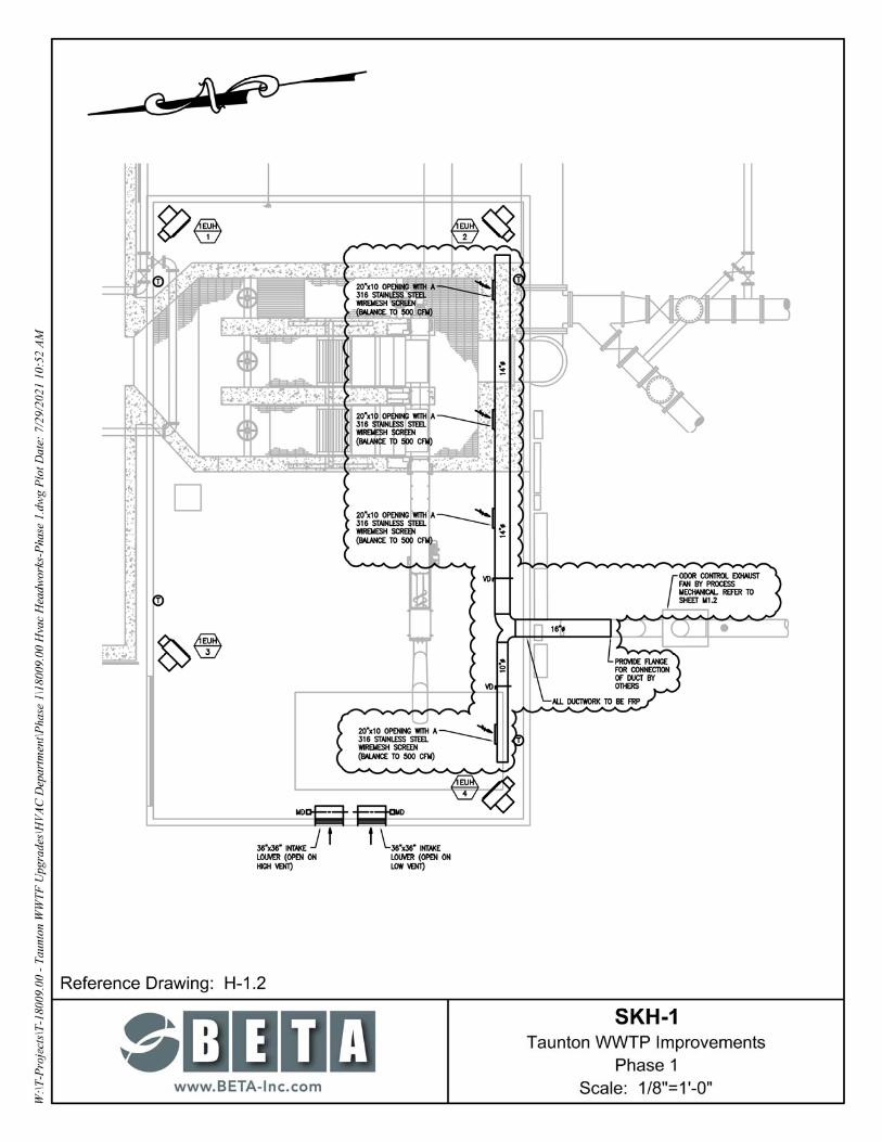
● See sketch SKH-1 on sheet. Added under Item 3, below.
Drawing H-0.3
● VRF (INDOOR UNIT) SCHEDULE – In REMARKS column, add the following note foreach HP unit: “Set unit speed at low.”
Drawing E-0.4
● On Operation Building One Line Diagram - Demolition add Demolition hatch marks overPanel “PGLP-1” and its associated connection.
Drawing E-0.8
● Change reference of “60”x60”x18” to the electrical enclosure to “72”x60”x26””
Drawing E-0.16
● Add the following light fixture to the light fixture schedule
“R1 Wet listed recess LED 6” lensed downlight LithoniaWF6E-LED-30K-90CR1-MW”
Drawing E-0.19
● Add “& PRIMARY GALLERY” after the word “BASEMENT LEVEL” on the OperationBuilding portion of the riser diagram.
Drawing E-0.20
● Replace the reference to “SLUDGE PUMP STATION #1” fiber path panel in lower middleportion of drawing to “EXISTING BLOWER/STORAGE BUILDING”
● At the RTU-3 control panel remove the control panels CP-3600, CP-6000, CP-6101,CP-6201, CP-6301, & CP-6401 and all associated TD1 connections.
Bid Addendum #3CWSRF 4605
Page 3 of 13
Drawing E-1.2
● Add a 36” wide 12” deep control panel labeled “CP-1300” to the West end of theelectrical cabinets.
Drawing E-2.4
● Add a weatherproof receptacle to Primary Clarifier #4 with identical configuration asshown for Primary Clarifier #1, #2 and #3.
Drawing E-2.5
● Add a “F7” light fixture with weatherproof switch to Primary Clarifier #4 with identicalconfiguration as shown for Primary Clarifier #1, #2 and #3.
Drawing E-7.5
● Add (2) 60” wide 124” deep control panels labeled “CP-7301” and “CP-7302” to centerarea of the electrical room where 7DP1 is located.
Drawing E-9.4
● Add workstation screen reference similar to Work Station #1 to the Southwest corner ofthe control room with call out labeled “WORK STATION #1A”.
● Add call out “SCADA DATA OUTELT” 2D data outlet in the Southwest corner of thecontrol room.
Item 3: Changes to Drawings and Plans
DELETE Primary Clarifier Plans and Elevations S-2.1 and ADD the attached PrimaryClarifier Plans and Elevations S-2.1 Re-Issued Per Addendum
ADD the attached Taunton WWTP Improvements Phase I SKH-1
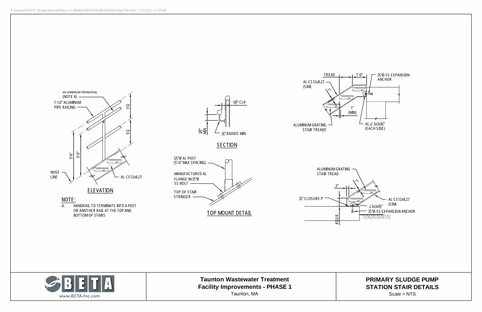
ADD the attached Primary Sludge Pump Station Stair Details
Item 4: Requests for Information and Clarification: The following questions were receivedregarding the bidding documents and subsequent addendums. Responses are in red.
1. Who is responsible to furnish and set in place the utility transformerpad, utility handholes and light pole pales? Refer to thisaddendum, Item 1
2. Could you please confirm the Electrical subcontractor is to furnish andinstall all VFD's and motor starters that are not factory installed on theequipment? Refer to specification 16000 paragraphs 1.1.B.5 & 1.1.B.6.
Bid Addendum #3CWSRF 4605
Page 4 of 13

3. Could you please provide specifications for the Stainless-Steel ElectricalCabinets noted on Drawing E-0.8? Please include the dimensions, DrawingE-1.2 and E-0.8 show different sizes. Refer to this addendum, Item 2.
4. Drawing E-1.2 shows a Gas Detection System furnished by Division 17. IsDivision 16 responsible to install and wire it? If yes, could you pleaseprovide wiring diagrams? Refer to drawing E-0.17.
5. Who is responsible for the removal/disposal of the existing Generators,pad-mount transformer, Motor Control Centers and miscellaneouselectrical equipment shown as being demolished? Refer to specification16000 paragraph 1.1.B.14 and Drawing E-0.1.
6. Could you please provide the Manufacturer and Catalogue Number for thelight fixture with the designation "Rl" shown on drawing E-9.6? It is not onthe fixture schedule. Refer to this addendum.
7. Could you please provide the locations for Power Panels "2DP1" and"PGLP1"? I cannot locate them on the drawings. Refer to Drawing E-2.4 for2DP1 and Refer to this addendum, Item 2, for PGLP1
8. Could you please provide the location for Screening Control Panel "CP-1300"?Refer to this addendum.
9. Please provide drawings on the BFA piping. It appears to be in theHVAC scope of work (per M-1.2) but no drawings/routing wereprovided. See Sketch SKH-1 attached.
10. Does Phase 1 Improvements include Blowers and appurtenant piping in thenew Blower building? If so, please provide a specification for these blowers andappurtenant piping. No. blowers and piping are part of a later contract.
11. Spec section 11601 indicates weirs and baffles to be installed in the finalclarifiers, is this work expected to be performed under this phase? If so, pleaseprovide a drawing indicating the work involved. No - final clarifiers are part of alater contract
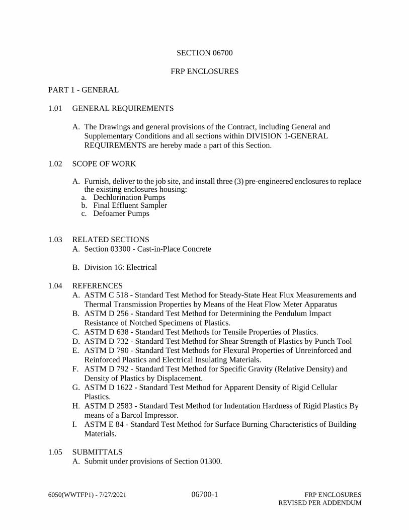
12. Please provide a specification for the FRP huts indicated on DWG M-5.2 Spec06700 attached
13. Drawing M-5.2 shows three existing pieces of equipment, FRP DechlorinationAnalyzer Hut, FRP Final Effluent Sampler Hut, and FRP Defoamer Hutw/Secondary Containment. These equipment huts are all indicated to have tobe relocated and kept on-line during construction based on drawing M-5.1 andthen relocated to their permanent locations. Please provide more informationabout the equipment in these structures and what type of piping, sizes,insulation, or other mechanical work is required to complete the intendedscope. Also, please confirm any temporary or permanent electrical workassociated with this equipment is to be the responsibility of the EC. None ofthe equipment in any of these huts is to be moved or replaced. Only the hutsare being replaced.
Bid Addendum #3CWSRF 4605
Page 5 of 13
14. Specification 01810 does not address the plant water system. Part of theproject scope is to replace the plant water pumps and associated piping in theChemical Handling Building. Note that the new plant water pumps are locatedin the same location as the existing plant water pumps. The new pumpingsystem is a pre-assembled skid. Please confirm the plant water system can beshut down for a sustained period to perform the plant water pump and pipingreplacement, and that no temporary plant water is required. The plant watersystem cannot be shut down for a sustained period. Contractor should carrythe cost for relocating existing pumps for temporary plant water service.
15. On plans S-2.3 to S-2.5, (2) exterior staircase replacements are shown. Pleaseprovide fabrication details for the replacement metal stairs. Detail has beenprovided.
16. Specification Section 01665-Part 3 – B – Please confirm that all of the numbersin the table associated with the Supervision of Installation, EquipmentCheckout, Field Acceptance Tests, Pre-Startup Operator Training, and PostStart-Up Services are manhours only for the Manufacturers field servicerepresentative and not number of trips. Is it mandatory for bidders to carrythese Manufacturer manhours? Startup services under this specification arethe responsibility of the manufacturer, not the GC. If the manufacturer issubcontracted to GC, they should carry typical manhours for startup services.
17. Specification Section 02080 – Are there any available Hazardous Soils andGroundwater Test Reports for this project or previous contracts that thecontractor may review? Have previous contracts or plant staff encounteredcontaminated soils at the site? There is no known contamination at the site,the spec is a contingency plan if any is encountered.
18. Specification Section 02082-1.8C – Please provide the referenced Asbestosdocuments. Asbestos test results attached
19. Specification Section 13321-1.3 – Please clarify if the term Contractor used inthis section is the I/C Contractor or the General Contractor. Refer to thisaddendum, Item 1.
20. Specification Section 02080 – Please consider providing individual unit priceitems for Suspect Soils and Contaminated Soils that will be removed from thesite that would capture the requirements of this specification section. Notintended to be a bid item. Costs will be reimbursed as incurred.
21. Specification Section 02080-1.07-A – Please provide Appendix C. Seeattached revised section 02080 - precharacterization has not been done.
22. Specification Section – 02080-3.06 – At the 600 West Water Street are thereany site improvements and permits that must be performed and acquired by theGeneral Contractor prior to stockpiling potentially contaminated soils? Has thislocation been used by previous contracts for this purpose? See revised section02080
23. Sheet S-1.4 Proposed Foundation Layout noted the footings to be 15” thick.Section 10/S-1.4 states the footing to be 2’-0” thick. Please confirm the correctthickness. The section view is correct - the footing is 2'-0" thick.
24. Sheet S-2.4 please confirm if the existing stairs are concrete or metal. Please
Bid Addendum #3CWSRF 4605
Page 6 of 13
supply any attachment details of the stairs to the existing walls. Stairs aremetal, see attached architectural details (Item 3)
25. Sheet S-6.2 Detail 20/S-6.4 notes a 10” x 12” shear key. Is this a continuousshear key? If not,please supply the spacing of this shear key along the footing.Please confirm the key size. Shear key is continuous, but is 10"Wx2"H, NOT12"H.
26. Sheet S-6.6 Typical sections for Walls Type A & B notes a 10” x 6” shearkey. Is this a continuous shear key? If not, please supply the spacing of thisshear key along the footing. Please confirm the key size. Shear key iscontinuous, and is 10"Wx6"H
27. Sheet S-6.2 Foundation plan notes a 2’-6” wide step footing, and detail 19/S6.2notes a 21” wide step footing. Please advise. Step is 2'-6" deep, with a 21"overlap as shown in detail 19
28. Sheet S-6.6 Please provide rebar details for type A & B footings, andprecast curbing Rebar is as shown (no rebar required in curbing)
29. Bid Item 3 – Concrete Spalling Repair of Existing Concrete Tanks andStructures = 350 SF contains both shallow depth repairs and partial depthrepairs as detailed on SG-3. The scope and unit cost of the two repairs arevery different, and the Contractor has no way to properly bid this item. Werequest two separate unit price bid items be used for these two concreterepairs. No changes will be made to the unit price bid for Bid Item #3
30. SG-3 Partial Depth Repair detail call for 5,000 PSI, 3/8”, 660 cement concrete.Specification 03930-3.06 call for 4,000 PSI concrete. Please advise. 4,000 psiconcrete as specified will be sufficient.
31. S-6.4 Please confirm the bottom of roof SIP form is 8” under the top of concreteslab EL. 42.04 as shown in Detail 21 (At Steel Beam). Confirmed.
32. S-5.2 Sections 37 & 38, and Sheet S-5.2 section 39: Please supplyelevations and limits for concrete fill at the Chlorine Contact Tank channels.See Sheet M-5.2. Con- crete fill pitches from El. 7.80 at upstream end to 7.50where it meets existing.
33. Drawing M-5.6. Please provide a specification for the pipe insulation at the 1”PVC Tank Discharge line. See Specification Section 11961, Part 2.16
34. Section 16721 3.1 F, says fire alarm raceways and boxes shall be paintedred. Who is responsible for this painting – Division 16 electrical or 09003Painting? Electrical Contractor is responsible with the intent of factorypainted conduit and box covers.
35. There is no lighting detail for the new fourth primary clarifier on drawing E-2.5.Refer to this addendum, Item 2
36. Drawing E-0.20 indicates <TD1> runs between RTU-3 and CP-3600 orCP-6000. Are these N.I.C. for this phase? Same question for the runsbetween CP-6000 and Blower control panels CP-6101, -6201, -6301 and-6401? Refer to this addendum, Item 2
37. What are the physical locations for this equipment mentioned ondrawing E-0.20: Centrifuge #1 control panel CP-7301 @ SolidsHandling Building Refer to this addendum Item 2
Bid Addendum #3CWSRF 4605
Page 7 of 13
Centrifuge #2 control panel CP-7302 @ Solids Handling Building Refer tothis addendum.
Screenings control panel CP-1300 @ Headworks Building Refer to thisaddendum.
SCADA Workstation #1A @ Operations Building Refer to this addendum.
38. Drawing E-0.20 shows a 2nd SCADA fiber optic patch panel for Sludge
PS #1 – is this intended for the existing (old) Blower building asindicated? Refer to this addendum, Item 2
39. The riser drawing E-0.19 does not show the new fire alarm devices withinthe Primary Sludge PS as indicated on Drawing E-2.6. Refer to thisaddendum, Item 2
40. Section 16000 1.5, says “RELATED WORK NOT INCLUDED” and listsexcavation and backfill, etc as well as concrete work. Why is this beingchanged by Q&A in Addenda#2. Please formally address thesescope/spec discrepancies. Refer to this addendum, Item 2
41. General note 1 on Drawing E-0.1 says the general contractor is providingconcrete pads. Please clarify who is responsible for concrete pads. Generalcontractor as per the note.
42. Who is responsible for providing the handholes on drawing E-0.2 Refer tothis addendum, Item 2
43. Are the fiber optic communications cables for I&C and/or fire alarm intendedto enter and pass through the same handholes as the power on E-0.2? Yes.
44. Please clarify MBE/WBE goal percentages on the project for the generalcontractor scope. Specification sections 00100, 01010 and 01067 havedifferent requirements. The goals are 4.9% and 4.6%
45. Please clarify who is responsible for paying for permits including but notlimited to building, NPDES, electrical, plumbing and mechanical? Thespecification has conflicting information. The City will waive fees on allcity-issued permits. Municipalities are fee exempt from NPDES permit.
46. Clarify the responsibility for routine maintenance on new equipment andmaterials in the one year from acceptance? The specification01800-Maintenance is unclear. Veolia will be responsible for routinemaintenance after startup.
47. Vibration monitoring is specified as the engineer’s responsibility in02160-Excavation Support and the contractor’s responsibility in 02399 –Geotechnical Instrumentation Preconstruction Survey PreconstructionVibration Monitoring. Please clarify. No vibration monitoring is needed.
48. Please define the scope for repointing masonry and EFIS repair on existingbuildings. Please provide estimated quantity. Notes on architectural drawingsrequire this “as necessary”. previously answered
49. Who is responsible for first fill of chemicals for hypo and lime systems outsideof what is required for startup under specification 01710-Startup. Theoperator (Veolia)
Bid Addendum #3CWSRF 4605
Page 8 of 13
50. Is the entire existing roofing system including rock ballasts consideredAsbestos Containing Materials and to be abated per 02082-AsbestosAbatement? No - only materials identified are considered ACMs
51. 02160-Excavation Support - Clarify how to quantify an unforeseen sitecondition (boulders/rock) in areas requiring temporary excavation support?MGL states the following “if, during the progress of the work, the contractor orthe awarding authority discovers that the actual subsurface or latent physicalconditions encountered at the site differ substantially or materially from thoseshown on the plans or indicated in the contract documents either thecontractor or the contracting authority may request an equitable adjustment inthe contract price of the contract applying to work affected by the differing siteconditions.” This will be established with the successful bidder beforeawarding the contract.Contractor should not carry additional costs forunforeseen site conditions.
52. Per specification 11320-Primary Clarifier Equipment, it states the primaryclarifier influent is to be designed to accommodate 2.6 MGD with a max of 6.3MGD. Please confirm this is correct. This is correct - 2.6 MGD per clarifier ismax day (for solids removal), 6.3 mgd is max hour (for hydraulics)
53. Is the lime piping scheduled to be painted in the field? Buried lime piping, andpiping within the silo enclosure does not need to be painted. If PVC pipe isused, and it is exposed and above grade, it must be painted or otherwiseprotected from UV.
54. Please clarify where the rotary screw compressor will be installed in relation tothe lime system? It is intended to be installed on the lime silo foundation nextto the silo.
55. Provide detail for patching to concrete/masonry openings for old/abandonedutility penetrations. (HVAC/Plumb/Process/Electrical) Generally, penetrationsare intended to be cut and capped.
56. Please clarify what that the general contractor’s or electrical contractor’sscope of responsibility is with respect Bid package #3-I&C/SCADA?a. Whomis responsible for mounting/ installing devices, conduit, wiring/ect, mountingpanels, housekeeping pads, etc.? Refer to electrical drawing E-0.1 forhousekeeping pads and and specification 16000 paragraph 1.1.
57. In walkthrough a junction box/pad and conduit was identified in the yardnorth-west corner of CCT. It appears to be in footprint of new CCT extension.Please clarify if this needs to be relocated. To be determined in the field withsuccessful bidder and handled as a change if needed.
58. Please provide a detail for the mounting of aluminum railings on roof slated forroofing replacement. Replacement is to be in-kind. Match existing.
59. Please clarify scope for new aluminum railings on the solids handling buildingroof. Railing is only required adjacent to the hatch as shown on Sheet A-7.1
60. Please provide detail of new stair and railings in the operations building lowerlevel? Reference drawing A-9.2 Lower Level Plan. There are no new stairs.Stairs are existing.
61. Please provide detail on metal staircases from primary sludge pipe gallery roofto ground. Reference drawing S-2.5. Refer to this addendum, Item 3
62. Clarify mounting of aluminum hand rails on the curbing of the primary piping
Bid Addendum #3CWSRF 4605
Page 9 of 13
gallery roof? Railing shown on M-2.2 on North and East face of galleryappear to be on a curb.
a. Does the flashing need to be removed/abated/replaced, as this roofingis not shown to be replaced? Replace in kind. Flashing does not need tobe removed if replacement does not dam- age it.
63. Can you provide details on the primary clarifier #4 Walkway (Walkway BridgePan – Dwg S-2.8) that is depicted as a 5-foot cantilevered extension to thevendor’s bridge? Are steps to be provided form walkway down to roof deck?Sheet S-2.8 has a typo - the roof curb elevation is 33.71, not 31.71 as shown.No step is required.
64. Metal roof deck shown on drawing S-6.3 is neither sized nor specified. Pleaseclarify. Clarify finish the finish for the roof beams shown on S-6.3. There is nometal roof deck. S- 6.3 shows a framing plan for the concrete roof deck andinsulation shown on S-6.4
65. There is a discrepancy between railing scope in headworks on mechanicaland structural drawings. Please clarify which is correct. Mechanical drawingsshow the correct scope of railings.
66. Does the Chlorine manhole get railings on the entire perimeter? Yes67. Are the new refrigerators (2) to be furnished and installed by Contractor? If so,
can you provide details on the proposed product? The lab refrigerator is to besupplied as spec'd in Sec- tion 11500. The break room refrigerator is not partof this contract.
68. Is the infill of the louvers/equipment demolished in primary gallery, chemicalbuilding and solids handling building included in the project? If so, pleaseprovide details for infill. Infill is to match existing (i.e. CMU/brick).
69. Please identify equipment/piping/etc. to be demolished and removed in thefirst floor mechanical room of operations building. (Room 918) All equipmentand piping in room to be removed. This includes AC-1 and all associatedductwork and piping. EF-1 and associated ductwork and controls. Unit heaterUH-1 and associated piping. And Roof exhaust hood EA-1 and ductwork andcontrols.
70. Drawing M-7.2 depicts a new Scum Concentrator to be installed in the SolidsHandling Building but no spec. was provided. Previously answered addendum#2
71. As it appears that the roofing system for the Primary Pipe Gallery is not slatedto be replaced, what will be required for roofing repairs with any work (newHVAC units and Plumbing roof drains) that impacts this roofing? Penetrationsto be made water tight, disturbed areas re- paired.
72. Is it the intent to replace the underslab plumbing piping in the basement(DwgP-9.3) and 1st Floor Bathrooms(Dwg P-9.5), as no floor demo/repairs arecalled out or depicted? Yes the underslab piping is to be removed. Contractorshall demo existing slab as needed for pipe demolition and new pipeinstallation and provide new slab to replace what was demolished withstandard building basement slab depth and rebar configuration.
73. Are there any restrictions to the reconstruction of the Administration area suchas providing temporary facilities (lab areas, bathrooms, lockers, office space,control room space, ect.)? Coordinate with owner on expectations on
Bid Addendum #3CWSRF 4605Page 10 of 13
sequencing for temporary labs and bathrooms – determination to be added tofront ends
74. With reference to the pipe schedule on Dwg M-0.1 and Restrained Joint/ThrustBlock Table on Dwg CD-2:
a. Under the various piping systems the joint type is called outas DI – Mechanical Joints, while spec. section 02622 notes tosupply the piping as specified and allows for the Contractor tosupply push-on or MJ piping. Please clarify what will beallowed for each DI piping system.
b. Is there a requirement for supplying restrained joints/thrust forany of the process piping systems, as the requirement forrestraining piping or providing thrust blocks appears to only belisted on Dwg CD-2 for water and sewer force mains.
There is no spec section 02622, DI pipe is in 02618. Follow pipeschedule on M-0.1 for joint type. Thrust blocks are covered in Section11961, part 2.15 (D).
75. On M-1.5 are the plant water and lime slurry to be run under the silofoundation and turn up into the silo or are they run on top of the foundation (itappears they are) are they to be heat traced and insulated? Due to the depthof the silo foundation they are shown on top of the foundation. They do notneed heat tracing or insulation.
76. Dwg G-2.1 provides summary table of the plant design flow conditions only. Asthere is no bypass or maintenance of flow spec. section, what are the flows tobe considered for bypassing around each section of the plant? Due toavailable redundancies (grit chambers, primary clari- fiers), bypass is notanticipated. However, the main lift pump station is capable of pumping 22MGD, so if bypass is needed then that would be the maximum flow.
77. There are no unit priced items to cover unsuitable excavation below grade,rock or boulders, or new gravel or stone supply on this project? This will beestablished with the successful bidder before awarding the contract.Contractorshould not carry additional costs for unforeseen site conditions.
78. As this GC bid is to provide (2) separate prices: Bid Package 1(GC only) &BidPackage 1+2(GC with electrical):
a. For Package 1 – Whom is to figure on supplying all of thetemporary electrical work to maintain operations (MCCs,equipment) that is required on this project? Refer to specification16000 paragraphs 1.12 & 1.13.
1. Headworks Building is slated for building demo, whileequipment in the building is to be maintained. Whom isresponsible for providing temp. power for this equipmentduring reconstruction? Electrical contractor to providetemporary support with plywood backboard mounted to
Bid Addendum #3CWSRF 4605Page 11 of 13
partially buried support legs. Switchovers are to be phased,existing service to remain active until the building is poweredfrom the new service.
2. Other buildings appear to be slated for electrical replacement,therefore temp. power will be required. Temporary power isindicated on the electrical one line diagrams.
3. With a new service being provided, temporary powerneeds to be provided during switchovers.Switchovers are to be phased, existing services toremain active until all the buildings are powered fromthe new service.
b. For Package 1 - Whom is responsible for furnishing/installing transformerpad? Refer to this Addendum.
79. Dwg G-1.4 - Per Freshwater Wetland Note 6 – All excess soil must bestockpiled outsideBuffer and Resource areas. Where will be allowed to stockpile material slatedfor reuse on-site? The staging area shown on Sheet C-1.16, and/orcoordinate with Veolia operations staff
80. Dwg C.16 – calls for the Lime Silo and related foundation to be demo’d:a. Will VNA empty and cleanout remaining lime prior to demo?No, GC will be responsible for for cleanout. Veolia will attempt to drawdown existing lime
81. Pipe schedule on Dwg M-0.1 lists the Sodium Bisulfite (SB) to be heat tracedand insulated. As we are required to re-route this piping underground aroundCC Tank addition only, is this insulation/heat tracing required for thisunderground portion? Yes, the rerouting is shown on C- 1.15. Yes, the entirepipe must be insulated and heat traced, including buried pipe.
a. Nothing is called out on the drawings for insulation or heat tracing.82. Section “09003 – Resilient Floors – General” refers to section 09650 for details
which is not included in specifications There is no resilient flooring - disregard.83. Drawing P-2.1 and P2.2 shows new waste and vent piping which appears to
be under slab. Are we required to remove existing concrete, excavate, demothe piping, backfill and recast slab in these locations? If so, please providestructural detail Yes the underslab piping is to be removed. Contractor shall demoexisting slab as needed for pipe demolition and new pipe installation and providenew slab to replace what was demolished with standard building basement slab
depth and rebar configuration.84. Drawing P-5.1 and P5.3 shows demolition and installation of floor drain and
waste piping, Are we required to remove existing concrete, excavate, demothe piping, backfill and recast slab in these locations? If so, please providestructural detail Yes the underslab piping is to be removed. Contractor shall demoexisting slab as needed for pipe demolition and new pipe installation and providenew slab to replace what was demolished with standard building basement slabdepth and rebar configuration.
85. Drawing P-9.1 and P9.3 shows demolition and installation of floor drain and
Bid Addendum #3CWSRF 4605Page 12 of 13
waste piping, Are we required to remove existing concrete, excavate, demothe piping, backfill and recast slab in these locations? If so, please providestructural detail. Yes the underslab piping is to be removed. Contractor shall demoexisting slab as needed for pipe demolition and new pipe installation and providenew slab to replace what was demolished with standard building basement slab
depth and rebar configuration86. The finish schedule on A-0.1, shows new ACT ceiling in multiple areas of the
Operations Building, are there existing ceilings that need to be demolished?Yes, majority of ceilings are being replaced
87. The finish schedule on A-0.1, shows new Flooring in multiple areas of theOperations Building, is there existing flooring in these locations that need tobe demolished? Floor finish demo will be required in the following rooms: VCT in911 & 915 and ceramic tile in 903, 904, 913, 930 & 931
88. In the basement of the operations building, currently at the location of theshowers in Room 904, there is a wood structure with lockers and furnitureinside, are we to demolish this structure? Please provide further detail.
89. Are we required to provide any temporary provisions to accommodate theOperations Building Staff while we are renovating? Yes, Coordinate with Veoliaon expectations on sequencing for temporary offices, labs and bathrooms
90. Are there any restrictions or existing services requirements to consider whilerenovating the Operations Building? This questions is not clear
91. Drawing P-9.4 in admin. Building first floor shows a sink labeled “LS-1” in thechemical analysis lab. What is the brand name and specification for this sinkand fixtures? Refer to A-9.1 and A-9.2 for Lab Sink requirements.
92. Drawing P-9.4 in admin. Building first floor shows a sink labeled “DW-1” in thechemical analysis lab. What is the brand name and specification for this sinkand fixtures? Refer to A-9.1 and A-9.2 for Lab Sink requirements.
93. Dwg S-2.1 depict flowable fill to be provided between the PS Tank 4 – southwall and the existing PS-3 tank wall. How is this formwork to be installed andstripped with only 12-inches of spacing? Flowable fill does not require forms,the intent is just to backfill the space, and soil backfill is impractical at thatlocation.
94. Is there existing sheeting left in place around the chlorine contact tank? If so,where is it located and at what elevation was it left at? There is no existingsheeting indicated on the exist- ing record drawings, so it is unlikely that thereis any left in place.
95. Section 07002 Paragraph 1.01A states cover work under the following Section03350, could you please provide this section it in not listed in the spec book.Previously answered.
END OF DOCUMENT
Bid Addendum #3CWSRF 4605Page 13 of 13

S-2.1 Revised

UNLESS OTHERWISE NOTED OR CHANGED BY REPRODUCTION
SHEET NO.
SCALE
DATE
DESIGNED BY:
CHECKED BY:
BETA JOB NO.:
ISSUE DATE:
DRAWN BY:
REVISIONSNO.
TITLE
PROJECT
SUBCONSULTANT
PREPARED BY
AS SHOWN
REGISTERED PROFESSIONAL
7/2
2/2
02
1 4
:0
0 P
MN
:\6
00
0S
\6
05
0 - T
AU
NT
ON
W
WT
F\D
RA
WIN
G F
IL
ES
\P
LA
NS
ET
\P
HA
SE
1
_R
EV
1\6
05
0_
SR
2.1
- P
1_
RE
V1
.D
WG
(B
ET
A S
TB
B
W.S
TB
)
Taunton Wastewater
Treatment Facility
Improvements
Phase 1
BN
BN
TMW
7/2/2021
6050
Primary Clarifier Plans and
Elevations
S-2.1
TAUNTON, MA
1 CONCRETE PIPE ENCASEMENT 07/21
1
1
AutoCAD SHX Text
SCALE: " = 1'-0"18" = 1'-0"
AutoCAD SHX Text
GENERAL PLAN
AutoCAD SHX Text
1'-6" WALL THICKNESS (TYP.)
AutoCAD SHX Text
1'-6" WALL THICKNESS (TYP.)
AutoCAD SHX Text
FOOTING (TYP.)
AutoCAD SHX Text
OUTSIDE OF WALL
AutoCAD SHX Text
INSIDE OF WALL
AutoCAD SHX Text
[P-2.3]
AutoCAD SHX Text
[P-2.2]
AutoCAD SHX Text
S-2.2
AutoCAD SHX Text
18
AutoCAD SHX Text
S-2.1
AutoCAD SHX Text
15
AutoCAD SHX Text
EXIST. PRIMARY CLARIFIER NO. 3
AutoCAD SHX Text
W.P. #1
AutoCAD SHX Text
W.P. #2
AutoCAD SHX Text
W.P. #3
AutoCAD SHX Text
W.P. #4
AutoCAD SHX Text
CONST. JT
AutoCAD SHX Text
41'-0"
AutoCAD SHX Text
SCUM WELL (SEE SHEET S-2.7 S-2.7 FOR DETAILS)
AutoCAD SHX Text
CLARIFIER WALKWAY (SEE SHEET S-2.8 S-2.8 FOR DETAILS)
AutoCAD SHX Text
S-2.1
AutoCAD SHX Text
16
AutoCAD SHX Text
PRIMARY CLARIFIER NO. 4
AutoCAD SHX Text
CONST. JT (TYP.)
AutoCAD SHX Text
CONST. JT.
AutoCAD SHX Text
CONST. JT.
AutoCAD SHX Text
CONST. JT.
AutoCAD SHX Text
CONST. JT.
AutoCAD SHX Text
24" DI (SEE ENCASEMENT DETAIL THIS SHEET) (TYP)
AutoCAD SHX Text
EFFLUENT TROUGH (TYP.)
AutoCAD SHX Text
STEP @ TOP OF CLARIFIER WALL
AutoCAD SHX Text
8" DI (SEE ENCASEMENT DETAIL THIS SHEET) (TYP)
AutoCAD SHX Text
NOTES:
AutoCAD SHX Text
1.SEE MECHANICAL SHEETS SEE MECHANICAL SHEETS FOR EQUIPMENT DETAILS
AutoCAD SHX Text
SCALE: " = 1'-0"18" = 1'-0"
AutoCAD SHX Text
FOOTING PLAN
AutoCAD SHX Text
SLOPED TO CENTER (TYP.)
AutoCAD SHX Text
#6 @ 12" E.W. T&B (TYP. THROUGHOUT)
AutoCAD SHX Text
W.P. #1
AutoCAD SHX Text
W.P. #2
AutoCAD SHX Text
W.P. #3
AutoCAD SHX Text
W.P. #4
AutoCAD SHX Text
SLOPED TO CENTER (TYP.)
AutoCAD SHX Text
SLOPED TO CENTER (TYP.)
AutoCAD SHX Text
EL. 22.92
AutoCAD SHX Text
CONST. JT (TYP.)
AutoCAD SHX Text
CONST. JT.
AutoCAD SHX Text
S-2.2
AutoCAD SHX Text
20
AutoCAD SHX Text
S-2.2
AutoCAD SHX Text
19
AutoCAD SHX Text
SLOPED TO CENTER (TYP.)
AutoCAD SHX Text
SLUDGE COLLECTION POCKET
AutoCAD SHX Text
EL. 22.92
AutoCAD SHX Text
PRIMARY CLARIFIER NO. 4
AutoCAD SHX Text
EL. 33.50
AutoCAD SHX Text
20" WALL PIPE [P-2.3] EL. 30.33 (SEE MECHANICAL SHEETS FOR DETAILS)
AutoCAD SHX Text
4" WALL SLEEVE [P-2.2] EL. 28.50 (SEE MECHANICAL SHEETS FOR DETAILS]
AutoCAD SHX Text
24" WALL PIPE [P-2.1] EL. 18.25 (SEE MECHANICAL SHEETS FOR DETAILS)
AutoCAD SHX Text
FINISH GRADE EL. 25.80
AutoCAD SHX Text
CONC. FOOTING (TYP.)
AutoCAD SHX Text
17
AutoCAD SHX Text
S-2.2
AutoCAD SHX Text
15
AutoCAD SHX Text
S-2.1
AutoCAD SHX Text
SCALE: " = 1'-0"38" = 1'-0"
AutoCAD SHX Text
SECTION
AutoCAD SHX Text
12" PREFORMED JOINT FILLER
AutoCAD SHX Text
EXIST. PRIMARY CLARIFIER NO. 3
AutoCAD SHX Text
EXIST. SUB-FOOTING TO REMAIN
AutoCAD SHX Text
PRIMARY CLARIFIER NO. 3
AutoCAD SHX Text
NORTHING
AutoCAD SHX Text
W.P. #1
AutoCAD SHX Text
W.P. #2
AutoCAD SHX Text
W.P. #3
AutoCAD SHX Text
W.P. #4
AutoCAD SHX Text
33353424.08
AutoCAD SHX Text
EASTING
AutoCAD SHX Text
9189159.93
AutoCAD SHX Text
33352725.18
AutoCAD SHX Text
9189046.79
AutoCAD SHX Text
33352838.31
AutoCAD SHX Text
9188347.89
AutoCAD SHX Text
33353537.22
AutoCAD SHX Text
9188461.03
AutoCAD SHX Text
STEP @ TOP OF CLARIFIER
AutoCAD SHX Text
EL. 33.50
AutoCAD SHX Text
EL. 33.76
AutoCAD SHX Text
16
AutoCAD SHX Text
S-2.1
AutoCAD SHX Text
SCALE: " = 1'-0"38" = 1'-0"
AutoCAD SHX Text
SECTION
AutoCAD SHX Text
CORNER OF TANK
AutoCAD SHX Text
CONST. JT. OPTIONAL
AutoCAD SHX Text
TOP OF SLAB
AutoCAD SHX Text
STEEL REINF. (SEE SHEET S-2.2 FOR DETAILS) (TYP.)
AutoCAD SHX Text
D.I. PIPE
AutoCAD SHX Text
CONST. JT. (RAKE FINISH)
AutoCAD SHX Text
SCALE: "=1'-0"38"=1'-0"
AutoCAD SHX Text
PIPE ENCASEMENT DETAIL
AutoCAD SHX Text
NOTE:
AutoCAD SHX Text
1.24" D.I. PIPE SHOWN, 8" D.I. PIPE SIMILAR.24" D.I. PIPE SHOWN, 8" D.I. PIPE SIMILAR.
Mike Andrus
Typewriter
AS RE-ISSUED PER ADDENDUM

SKH-1

Primary Sludge Pump Station Stair Detail
AL CS12x8.27
EQEQ
3'-6"
NOSELINE
1-1/2" ALUMINUMPIPE RAILING
ELEVATION
3'-0"
ALUMINUM HANDRAIL(NOTE A)
NOTE:A. HANDRAIL TO TERMINATE INTO A POST
OR ANOTHER RAIL AT THE TOP ANDBOTTOM OF STAIRS
112"Ø AL POST
(5'-0" MAX SPACING)
MANUFACTURED ALFLANGE W/ 1
2"ØSS BOLT
TOP OF STAIRSTRINGER
TOP MOUNT DETAIL
21 2"MI
N
112" CLR
18" RADIUS MIN
SECTION
34"Ø SS EXPANSION ANCHOR
AL CS12x8.27(SIM)∠3x3x3
8"
ALUMINUM GRATINGSTAIR TREAD
2"
1"
14" CLOSURE P
RISE
R
ALUMINUM GRATINGSTAIR TREADS
1"
AL CS12x8.27(SIM)
TREAD
1"(MIN)
1'-0"
AL 3x3x38"
(EACH SIDE)
34"Ø SS EXPANSION
ANCHOR
PRIMARY SLUDGE PUMPSTATION STAIR DETAILS
Scale = NTS
Taunton Wastewater TreatmentFacility Improvements - PHASE 1
Taunton, MA
J:\Taunton\WWTF Design\Autocad\Misc\111-86884-AMOD-STAIR-DETAILS.dwg Plot Date: 7/27/2021 11:19 AM

Section 06700 FRP Enclosures
6050(WWTFP1) - 7/27/2021 06700-1 FRP ENCLOSURESREVISED PER ADDENDUM
SECTION 06700
FRP ENCLOSURES
PART 1 - GENERAL
1.01 GENERAL REQUIREMENTS
A. The Drawings and general provisions of the Contract, including General andSupplementary Conditions and all sections within DIVISION 1-GENERALREQUIREMENTS are hereby made a part of this Section.
1.02 SCOPE OF WORK
A. Furnish, deliver to the job site, and install three (3) pre-engineered enclosures to replacethe existing enclosures housing:
a. Dechlorination Pumpsb. Final Effluent Samplerc. Defoamer Pumps
1.03 RELATED SECTIONSA. Section 03300 - Cast-in-Place Concrete
B. Division 16: Electrical
1.04 REFERENCESA. ASTM C 518 - Standard Test Method for Steady-State Heat Flux Measurements and
Thermal Transmission Properties by Means of the Heat Flow Meter ApparatusB. ASTM D 256 - Standard Test Method for Determining the Pendulum Impact
Resistance of Notched Specimens of Plastics.C. ASTM D 638 - Standard Test Methods for Tensile Properties of Plastics.D. ASTM D 732 - Standard Test Method for Shear Strength of Plastics by Punch ToolE. ASTM D 790 - Standard Test Methods for Flexural Properties of Unreinforced and
Reinforced Plastics and Electrical Insulating Materials.F. ASTM D 792 - Standard Test Method for Specific Gravity (Relative Density) and
Density of Plastics by Displacement.G. ASTM D 1622 - Standard Test Method for Apparent Density of Rigid Cellular
Plastics.H. ASTM D 2583 - Standard Test Method for Indentation Hardness of Rigid Plastics By
means of a Barcol Impressor.I. ASTM E 84 - Standard Test Method for Surface Burning Characteristics of Building
Materials.
1.05 SUBMITTALSA. Submit under provisions of Section 01300.
FRP ENCLOSURES 06700-2 6050(WWTFP1)-7/27/2021REVISED PER ADDENDUM
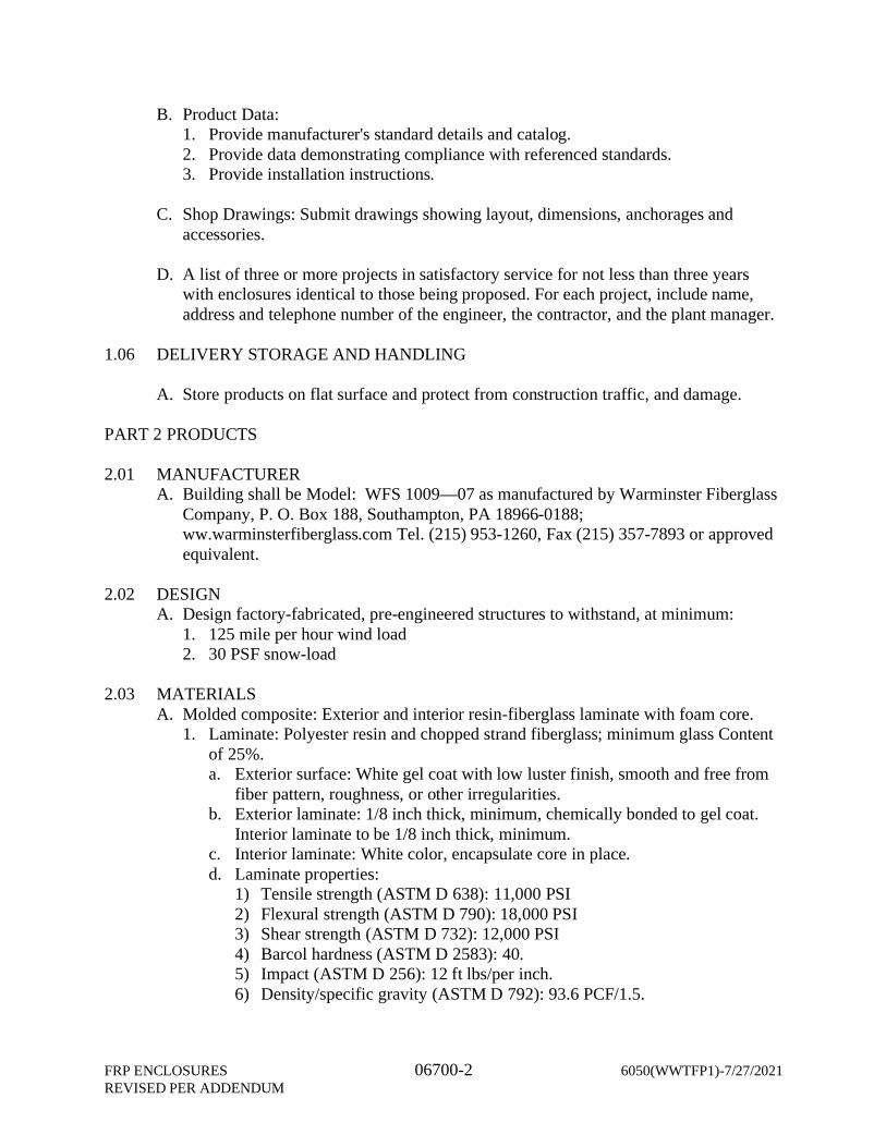
B. Product Data:1. Provide manufacturer's standard details and catalog.2. Provide data demonstrating compliance with referenced standards.3. Provide installation instructions.
C. Shop Drawings: Submit drawings showing layout, dimensions, anchorages andaccessories.
D. A list of three or more projects in satisfactory service for not less than three yearswith enclosures identical to those being proposed. For each project, include name,address and telephone number of the engineer, the contractor, and the plant manager.
1.06 DELIVERY STORAGE AND HANDLING
A. Store products on flat surface and protect from construction traffic, and damage.
PART 2 PRODUCTS
2.01 MANUFACTURERA. Building shall be Model: WFS 1009—07 as manufactured by Warminster Fiberglass
Company, P. O. Box 188, Southampton, PA 18966-0188;ww.warminsterfiberglass.com Tel. (215) 953-1260, Fax (215) 357-7893 or approvedequivalent.
2.02 DESIGNA. Design factory-fabricated, pre-engineered structures to withstand, at minimum:
1. 125 mile per hour wind load2. 30 PSF snow-load
2.03 MATERIALSA. Molded composite: Exterior and interior resin-fiberglass laminate with foam core.
1. Laminate: Polyester resin and chopped strand fiberglass; minimum glass Contentof 25%.a. Exterior surface: White gel coat with low luster finish, smooth and free from
fiber pattern, roughness, or other irregularities.b. Exterior laminate: 1/8 inch thick, minimum, chemically bonded to gel coat.
Interior laminate to be 1/8 inch thick, minimum.c. Interior laminate: White color, encapsulate core in place.d. Laminate properties:
1) Tensile strength (ASTM D 638): 11,000 PSI2) Flexural strength (ASTM D 790): 18,000 PSI3) Shear strength (ASTM D 732): 12,000 PSI4) Barcol hardness (ASTM D 2583): 40.5) Impact (ASTM D 256): 12 ft lbs/per inch.6) Density/specific gravity (ASTM D 792): 93.6 PCF/1.5.
6050(WWTFP1) - 7/27/2021 06700-3 FRP ENCLOSURESREVISED PER ADDENDUM
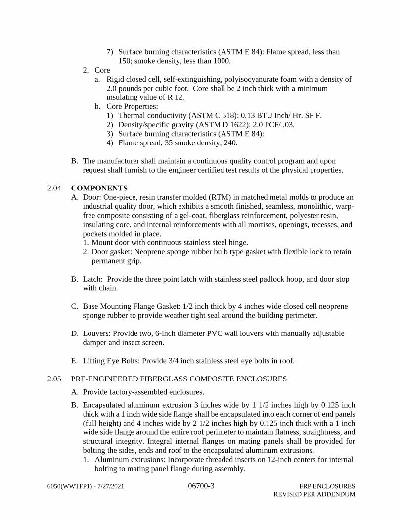
7) Surface burning characteristics (ASTM E 84): Flame spread, less than150; smoke density, less than 1000.
2. Corea. Rigid closed cell, self-extinguishing, polyisocyanurate foam with a density of
2.0 pounds per cubic foot. Core shall be 2 inch thick with a minimuminsulating value of R 12.
b. Core Properties:1) Thermal conductivity (ASTM C 518): 0.13 BTU Inch/ Hr. SF F.2) Density/specific gravity (ASTM D 1622): 2.0 PCF/ .03.3) Surface burning characteristics (ASTM E 84):4) Flame spread, 35 smoke density, 240.
B. The manufacturer shall maintain a continuous quality control program and uponrequest shall furnish to the engineer certified test results of the physical properties.
2.04 COMPONENTSA. Door: One-piece, resin transfer molded (RTM) in matched metal molds to produce an
industrial quality door, which exhibits a smooth finished, seamless, monolithic, warp-free composite consisting of a gel-coat, fiberglass reinforcement, polyester resin,insulating core, and internal reinforcements with all mortises, openings, recesses, andpockets molded in place.1. Mount door with continuous stainless steel hinge.2. Door gasket: Neoprene sponge rubber bulb type gasket with flexible lock to retain
permanent grip.
B. Latch: Provide the three point latch with stainless steel padlock hoop, and door stopwith chain.
C. Base Mounting Flange Gasket: 1/2 inch thick by 4 inches wide closed cell neoprenesponge rubber to provide weather tight seal around the building perimeter.
D. Louvers: Provide two, 6-inch diameter PVC wall louvers with manually adjustabledamper and insect screen.
E. Lifting Eye Bolts: Provide 3/4 inch stainless steel eye bolts in roof.
2.05 PRE-ENGINEERED FIBERGLASS COMPOSITE ENCLOSURES
A. Provide factory-assembled enclosures.B. Encapsulated aluminum extrusion 3 inches wide by 1 1/2 inches high by 0.125 inch
thick with a 1 inch wide side flange shall be encapsulated into each corner of end panels(full height) and 4 inches wide by 2 1/2 inches high by 0.125 inch thick with a 1 inchwide side flange around the entire roof perimeter to maintain flatness, straightness, andstructural integrity. Integral internal flanges on mating panels shall be provided forbolting the sides, ends and roof to the encapsulated aluminum extrusions.1. Aluminum extrusions: Incorporate threaded inserts on 12-inch centers for internal
bolting to mating panel flange during assembly.
FRP ENCLOSURES 06700-4 6050(WWTFP1)-7/27/2021REVISED PER ADDENDUM
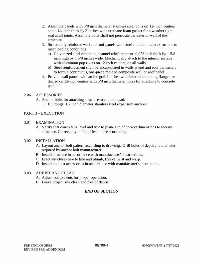
2. Assemble panels with 3/8 inch diameter stainless steel bolts on 12- inch centersand a 1/4 inch thick by 3 inches wide urethane foam gasket for a weather tightseal at all joints. Assembly bolts shall not penetrate the exterior wall of thestructure.
3. Structurally reinforce wall and roof panels with steel and aluminum extrusions tomeet loading conditions.a) Galvanized steel mounting channel reinforcement: 0.078 inch thick by 1 5/8
inch high by 1 5/8 inches wide. Mechanically attach to the interior surfacewith aluminum pop rivets on 12-inch centers, on all walls.
b) Steel reinforcement shall be encapsulated in walls at end and roof perimeter,to form a continuous, one-piece molded composite wall or roof panel
4. Provide wall panels with an integral 4 inches wide internal mounting flange pre-drilled on 12-inch centers with 5/8 inch diameter holes for attaching to concretepad.
2.06 ACCESSORIESA. Anchor bolts for attaching structure to concrete pad:
1. Buildings: 1/2 inch diameter stainless steel expansion anchors.
PART 3 – EXECUTION
3.01 EXAMINATIONA. Verify that concrete is level and true to plane and of correct dimensions to receive
structure. Correct any deficiencies before proceeding.
3.02 INSTALLATIONA. Layout anchor bolt pattern according to drawings. Drill holes of depth and diameter
required by anchor bolt manufacturer.B. Install structure in accordance with manufacturer's instructions.C. Erect structures true to line and plumb, free of twist and warp.D. Install and test accessories in accordance with manufacturer's instructions.
3.03 ADJUST AND CLEANA. Adjust components for proper operation.B. Leave project site clean and free of debris.
END OF SECTION

Section 02082 Appendix - Asbestos Results
EMSL Analytical, Inc.440 Washington Street, Suite 2 Weymouth, MA 02188
Tel/Fax: (781) 682-2206 / (781) 682-2207
http://www.EMSL.com / [email protected]
642000944EMSL Order:
Customer ID: BETA25
Customer PO: 6050
Project ID:
Attention: Phone:Matthew Alger (401) 333-2382
Fax:Beta Group
Received Date:701 George Washington Highway 06/08/2020 8:50 AM
Analysis Date:Lincoln, RI 02865 06/17/2020
Collected Date:
Project: 6050 / WWTF / Taunton, MA
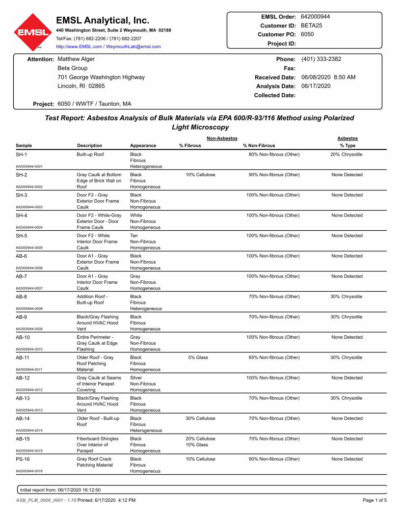
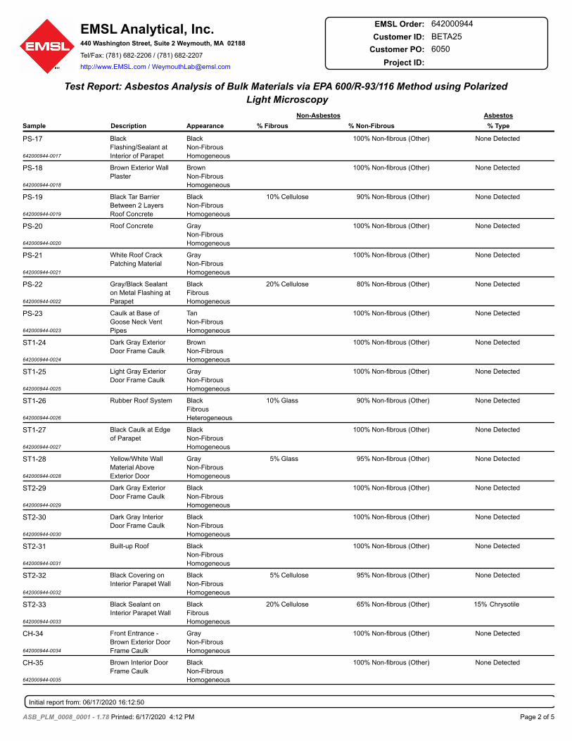
Test Report: Asbestos Analysis of Bulk Materials via EPA 600/R-93/116 Method using Polarized
Light Microscopy
Sample Description Appearance % Fibrous % Non-Fibrous
Non-Asbestos Asbestos
% Type
SH-1
642000944-0001
20% ChrysotileNon-fibrous (Other)80%Black
Fibrous
Heterogeneous
Built-up Roof
SH-2
642000944-0002
None DetectedNon-fibrous (Other)90%Cellulose10%Black
Fibrous
Homogeneous
Gray Caulk at Bottom
Edge of Brick Wall on
Roof
SH-3
642000944-0003
None DetectedNon-fibrous (Other)100%Black
Non-Fibrous
Homogeneous
Door F2 - Gray
Exterior Door Frame
Caulk
SH-4
642000944-0004
None DetectedNon-fibrous (Other)100%White
Non-Fibrous
Homogeneous
Door F2 - White-Gray
Exterior Door - Door
Frame Caulk
SH-5
642000944-0005
None DetectedNon-fibrous (Other)100%Tan
Non-Fibrous
Homogeneous
Door F2 - White
Interior Door Frame
Caulk
AB-6
642000944-0006
None DetectedNon-fibrous (Other)100%Black
Non-Fibrous
Homogeneous
Door A1 - Gray
Exterior Door Frame
Caulk
AB-7
642000944-0007
None DetectedNon-fibrous (Other)100%Gray
Non-Fibrous
Homogeneous
Door A1 - Gray
Interior Door Frame
Caulk
AB-8
642000944-0008
30% ChrysotileNon-fibrous (Other)70%Black
Fibrous
Heterogeneous
Addition Roof -
Built-up Roof
AB-9
642000944-0009
30% ChrysotileNon-fibrous (Other)70%Black
Fibrous
Homogeneous
Black/Gray Flashing
Around HVAC Hood
Vent
AB-10
642000944-0010
None DetectedNon-fibrous (Other)100%Gray
Non-Fibrous
Homogeneous
Entire Perimeter -
Gray Caulk at Edge
Flashing
AB-11
642000944-0011
30% ChrysotileNon-fibrous (Other)65%Glass5%Black
Fibrous
Homogeneous
Older Roof - Gray
Roof Patching
Material
AB-12
642000944-0012
None DetectedNon-fibrous (Other)100%Silver
Non-Fibrous
Homogeneous
Gray Caulk at Seams
of Interior Parapet
Covering
AB-13
642000944-0013
30% ChrysotileNon-fibrous (Other)70%Black
Fibrous
Homogeneous
Black/Gray Flashing
Around HVAC Hood
Vent
AB-14
642000944-0014
None DetectedNon-fibrous (Other)70%Cellulose30%Black
Fibrous
Heterogeneous
Older Roof - Built-up
Roof
AB-15
642000944-0015
None DetectedNon-fibrous (Other)70%Cellulose
Glass
20%
10%
Black
Fibrous
Homogeneous
Fiberboard Shingles
Over Interior of
Parapet
PS-16
642000944-0016
None DetectedNon-fibrous (Other)90%Cellulose10%Black
Fibrous
Homogeneous
Gray Roof Crack
Patching Material
Initial report from: 06/17/2020 16:12:50
Page 1 of 5ASB_PLM_0008_0001 - 1.78 Printed: 6/17/2020 4:12 PM
EMSL Analytical, Inc.440 Washington Street, Suite 2 Weymouth, MA 02188
Tel/Fax: (781) 682-2206 / (781) 682-2207
http://www.EMSL.com / [email protected]
642000944EMSL Order:
Customer ID: BETA25
Customer PO: 6050
Project ID:
Test Report: Asbestos Analysis of Bulk Materials via EPA 600/R-93/116 Method using Polarized
Light Microscopy
Sample Description Appearance % Fibrous % Non-Fibrous
Non-Asbestos Asbestos
% Type
PS-17
642000944-0017
None DetectedNon-fibrous (Other)100%Black
Non-Fibrous
Homogeneous
Black
Flashing/Sealant at
Interior of Parapet
PS-18
642000944-0018
None DetectedNon-fibrous (Other)100%Brown
Non-Fibrous
Homogeneous
Brown Exterior Wall
Plaster
PS-19
642000944-0019
None DetectedNon-fibrous (Other)90%Cellulose10%Black
Non-Fibrous
Homogeneous
Black Tar Barrier
Between 2 Layers
Roof Concrete
PS-20
642000944-0020
None DetectedNon-fibrous (Other)100%Gray
Non-Fibrous
Homogeneous
Roof Concrete
PS-21
642000944-0021
None DetectedNon-fibrous (Other)100%Gray
Non-Fibrous
Homogeneous
White Roof Crack
Patching Material
PS-22
642000944-0022
None DetectedNon-fibrous (Other)80%Cellulose20%Black
Fibrous
Homogeneous
Gray/Black Sealant
on Metal Flashing at
Parapet
PS-23
642000944-0023
None DetectedNon-fibrous (Other)100%Tan
Non-Fibrous
Homogeneous
Caulk at Base of
Goose Neck Vent
Pipes
ST1-24
642000944-0024
None DetectedNon-fibrous (Other)100%Brown
Non-Fibrous
Homogeneous
Dark Gray Exterior
Door Frame Caulk
ST1-25
642000944-0025
None DetectedNon-fibrous (Other)100%Gray
Non-Fibrous
Homogeneous
Light Gray Exterior
Door Frame Caulk
ST1-26
642000944-0026
None DetectedNon-fibrous (Other)90%Glass10%Black
Fibrous
Heterogeneous
Rubber Roof System
ST1-27
642000944-0027
None DetectedNon-fibrous (Other)100%Black
Non-Fibrous
Homogeneous
Black Caulk at Edge
of Parapet
ST1-28
642000944-0028
None DetectedNon-fibrous (Other)95%Glass5%Gray
Non-Fibrous
Homogeneous
Yellow/White Wall
Material Above
Exterior Door
ST2-29
642000944-0029
None DetectedNon-fibrous (Other)100%Black
Non-Fibrous
Homogeneous
Dark Gray Exterior
Door Frame Caulk
ST2-30
642000944-0030
None DetectedNon-fibrous (Other)100%Black
Non-Fibrous
Homogeneous
Dark Gray Interior
Door Frame Caulk
ST2-31
642000944-0031
None DetectedNon-fibrous (Other)100%Black
Non-Fibrous
Homogeneous
Built-up Roof
ST2-32
642000944-0032
None DetectedNon-fibrous (Other)95%Cellulose5%Black
Non-Fibrous
Homogeneous
Black Covering on
Interior Parapet Wall
ST2-33
642000944-0033
15% ChrysotileNon-fibrous (Other)65%Cellulose20%Black
Fibrous
Homogeneous
Black Sealant on
Interior Parapet Wall
CH-34
642000944-0034
None DetectedNon-fibrous (Other)100%Gray
Non-Fibrous
Homogeneous
Front Entrance -
Brown Exterior Door
Frame Caulk
CH-35
642000944-0035
None DetectedNon-fibrous (Other)100%Black
Non-Fibrous
Homogeneous
Brown Interior Door
Frame Caulk
Initial report from: 06/17/2020 16:12:50
Page 2 of 5ASB_PLM_0008_0001 - 1.78 Printed: 6/17/2020 4:12 PM
EMSL Analytical, Inc.440 Washington Street, Suite 2 Weymouth, MA 02188
Tel/Fax: (781) 682-2206 / (781) 682-2207
http://www.EMSL.com / [email protected]
642000944EMSL Order:
Customer ID: BETA25
Customer PO: 6050
Project ID:
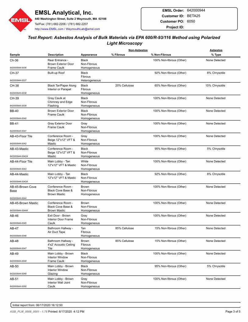
Test Report: Asbestos Analysis of Bulk Materials via EPA 600/R-93/116 Method using Polarized
Light Microscopy
Sample Description Appearance % Fibrous % Non-Fibrous
Non-Asbestos Asbestos
% Type
Ch-36
642000944-0036
None DetectedNon-fibrous (Other)100%Black
Non-Fibrous
Homogeneous
Rear Entrance -
Brown Exterior Door
Frame Caulk
CH-37
642000944-0037
8% ChrysotileNon-fibrous (Other)92%Black
Fibrous
Heterogeneous
Built-up Roof
CH-38
642000944-0038
15% ChrysotileNon-fibrous (Other)65%Cellulose20%Black
Fibrous
Homogeneous
Black Tar/Paper Along
Interior or Parapet
CH-39
642000944-0039
None DetectedNon-fibrous (Other)100%Black
Non-Fibrous
Homogeneous
Gray Caulk at
Chimney and Edge
Flashing
BB-40
642000944-0040
None DetectedNon-fibrous (Other)100%Black
Non-Fibrous
Homogeneous
Brown Exterior Door
Frame Caulk
BB-41
642000944-0041
None DetectedNon-fibrous (Other)100%Gray
Non-Fibrous
Homogeneous
Gray Exterior Door
Frame Caulk
AB-43-Floor Tile
642000944-0042
None DetectedNon-fibrous (Other)100%Gray
Non-Fibrous
Homogeneous
Conference Room -
Beige 12"x12" VFT &
Mastic
AB-43-Mastic
642000944-0042A
5% ChrysotileNon-fibrous (Other)95%Black
Non-Fibrous
Homogeneous
Conference Room -
Beige 12"x12" VFT &
Mastic
AB-44-Floor Tile
642000944-0043
None DetectedNon-fibrous (Other)100%White
Non-Fibrous
Homogeneous
Main Lobby - Tan
12"x12" VFT & Mastic
AB-44-Mastic
642000944-0043A
8% ChrysotileNon-fibrous (Other)92%Black
Non-Fibrous
Homogeneous
Main Lobby - Tan
12"x12" VFT & Mastic
AB-45-Brown Cove
Base
642000944-0044
None DetectedNon-fibrous (Other)100%Brown
Non-Fibrous
Homogeneous
Conference Room -
Black Cove Base &
Brown Mastic
AB-45-Brown Mastic
642000944-0044A
None DetectedNon-fibrous (Other)100%Brown
Non-Fibrous
Homogeneous
Conference Room -
Black Cove Base &
Brown Mastic
AB-46
642000944-0045
None DetectedNon-fibrous (Other)100%Gray
Non-Fibrous
Homogeneous
Exit Door - Brown
Interior Door Frame
Caulk
AB-47
642000944-0046
None DetectedNon-fibrous (Other)15%Cellulose85%Tan
Fibrous
Homogeneous
Bathroom Hallway -
Air Duct Tape
AB-48
642000944-0047
None DetectedNon-fibrous (Other)15%Cellulose85%Brown
Fibrous
Homogeneous
Bathroom Hallway -
4'x2' Acoustic Ceiling
Tile
AB-49
642000944-0048
None DetectedNon-fibrous (Other)100%Black
Non-Fibrous
Homogeneous
Main Lobby - Brown
Interior Window
Frame Caulk
AB-50
642000944-0049
5% ChrysotileNon-fibrous (Other)95%Black
Non-Fibrous
Homogeneous
Main Lobby - Brown
Interior Window
Glazing
AB-51
642000944-0050
None DetectedNon-fibrous (Other)100%Gray
Non-Fibrous
Homogeneous
Main Lobby - Brown
Interior Wall Joint
Caulk
Initial report from: 06/17/2020 16:12:50
Page 3 of 5ASB_PLM_0008_0001 - 1.78 Printed: 6/17/2020 4:12 PM
EMSL Analytical, Inc.440 Washington Street, Suite 2 Weymouth, MA 02188
Tel/Fax: (781) 682-2206 / (781) 682-2207
http://www.EMSL.com / [email protected]
642000944EMSL Order:
Customer ID: BETA25
Customer PO: 6050
Project ID:
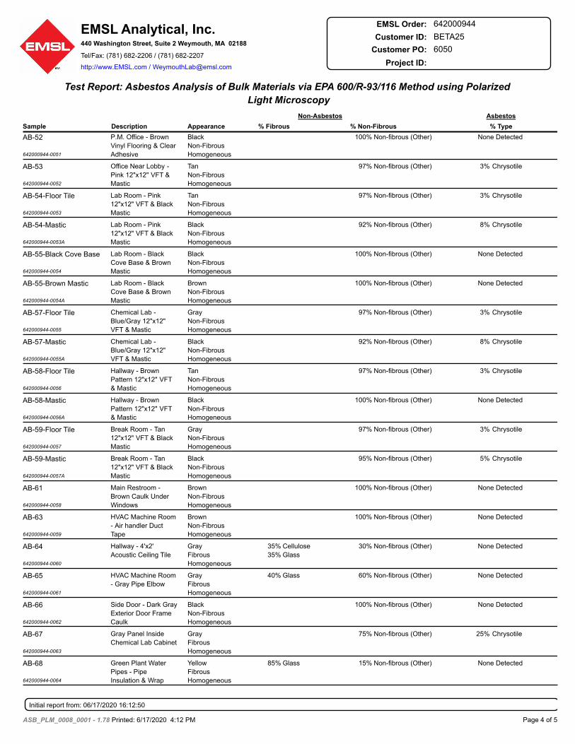
Test Report: Asbestos Analysis of Bulk Materials via EPA 600/R-93/116 Method using Polarized
Light Microscopy
Sample Description Appearance % Fibrous % Non-Fibrous
Non-Asbestos Asbestos
% Type
AB-52
642000944-0051
None DetectedNon-fibrous (Other)100%Black
Non-Fibrous
Homogeneous
P.M. Office - Brown
Vinyl Flooring & Clear
Adhesive
AB-53
642000944-0052
3% ChrysotileNon-fibrous (Other)97%Tan
Non-Fibrous
Homogeneous
Office Near Lobby -
Pink 12"x12" VFT &
Mastic
AB-54-Floor Tile
642000944-0053
3% ChrysotileNon-fibrous (Other)97%Tan
Non-Fibrous
Homogeneous
Lab Room - Pink
12"x12" VFT & Black
Mastic
AB-54-Mastic
642000944-0053A
8% ChrysotileNon-fibrous (Other)92%Black
Non-Fibrous
Homogeneous
Lab Room - Pink
12"x12" VFT & Black
Mastic
AB-55-Black Cove Base
642000944-0054
None DetectedNon-fibrous (Other)100%Black
Non-Fibrous
Homogeneous
Lab Room - Black
Cove Base & Brown
Mastic
AB-55-Brown Mastic
642000944-0054A
None DetectedNon-fibrous (Other)100%Brown
Non-Fibrous
Homogeneous
Lab Room - Black
Cove Base & Brown
Mastic
AB-57-Floor Tile
642000944-0055
3% ChrysotileNon-fibrous (Other)97%Gray
Non-Fibrous
Homogeneous
Chemical Lab -
Blue/Gray 12"x12"
VFT & Mastic
AB-57-Mastic
642000944-0055A
8% ChrysotileNon-fibrous (Other)92%Black
Non-Fibrous
Homogeneous
Chemical Lab -
Blue/Gray 12"x12"
VFT & Mastic
AB-58-Floor Tile
642000944-0056
3% ChrysotileNon-fibrous (Other)97%Tan
Non-Fibrous
Homogeneous
Hallway - Brown
Pattern 12"x12" VFT
& Mastic
AB-58-Mastic
642000944-0056A
None DetectedNon-fibrous (Other)100%Black
Non-Fibrous
Homogeneous
Hallway - Brown
Pattern 12"x12" VFT
& Mastic
AB-59-Floor Tile
642000944-0057
3% ChrysotileNon-fibrous (Other)97%Gray
Non-Fibrous
Homogeneous
Break Room - Tan
12"x12" VFT & Black
Mastic
AB-59-Mastic
642000944-0057A
5% ChrysotileNon-fibrous (Other)95%Black
Non-Fibrous
Homogeneous
Break Room - Tan
12"x12" VFT & Black
Mastic
AB-61
642000944-0058
None DetectedNon-fibrous (Other)100%Brown
Non-Fibrous
Homogeneous
Main Restroom -
Brown Caulk Under
Windows
AB-63
642000944-0059
None DetectedNon-fibrous (Other)100%Brown
Non-Fibrous
Homogeneous
HVAC Machine Room
- Air handler Duct
Tape
AB-64
642000944-0060
None DetectedNon-fibrous (Other)30%Cellulose
Glass
35%
35%
Gray
Fibrous
Homogeneous
Hallway - 4'x2'
Acoustic Ceiling Tile
AB-65
642000944-0061
None DetectedNon-fibrous (Other)60%Glass40%Gray
Fibrous
Homogeneous
HVAC Machine Room
- Gray Pipe Elbow
AB-66
642000944-0062
None DetectedNon-fibrous (Other)100%Black
Non-Fibrous
Homogeneous
Side Door - Dark Gray
Exterior Door Frame
Caulk
AB-67
642000944-0063
25% ChrysotileNon-fibrous (Other)75%Gray
Fibrous
Homogeneous
Gray Panel Inside
Chemical Lab Cabinet
AB-68
642000944-0064
None DetectedNon-fibrous (Other)15%Glass85%Yellow
Fibrous
Homogeneous
Green Plant Water
Pipes - Pipe
Insulation & Wrap
Initial report from: 06/17/2020 16:12:50
Page 4 of 5ASB_PLM_0008_0001 - 1.78 Printed: 6/17/2020 4:12 PM
EMSL Analytical, Inc.440 Washington Street, Suite 2 Weymouth, MA 02188
Tel/Fax: (781) 682-2206 / (781) 682-2207
http://www.EMSL.com / [email protected]
642000944EMSL Order:
Customer ID: BETA25
Customer PO: 6050
Project ID:
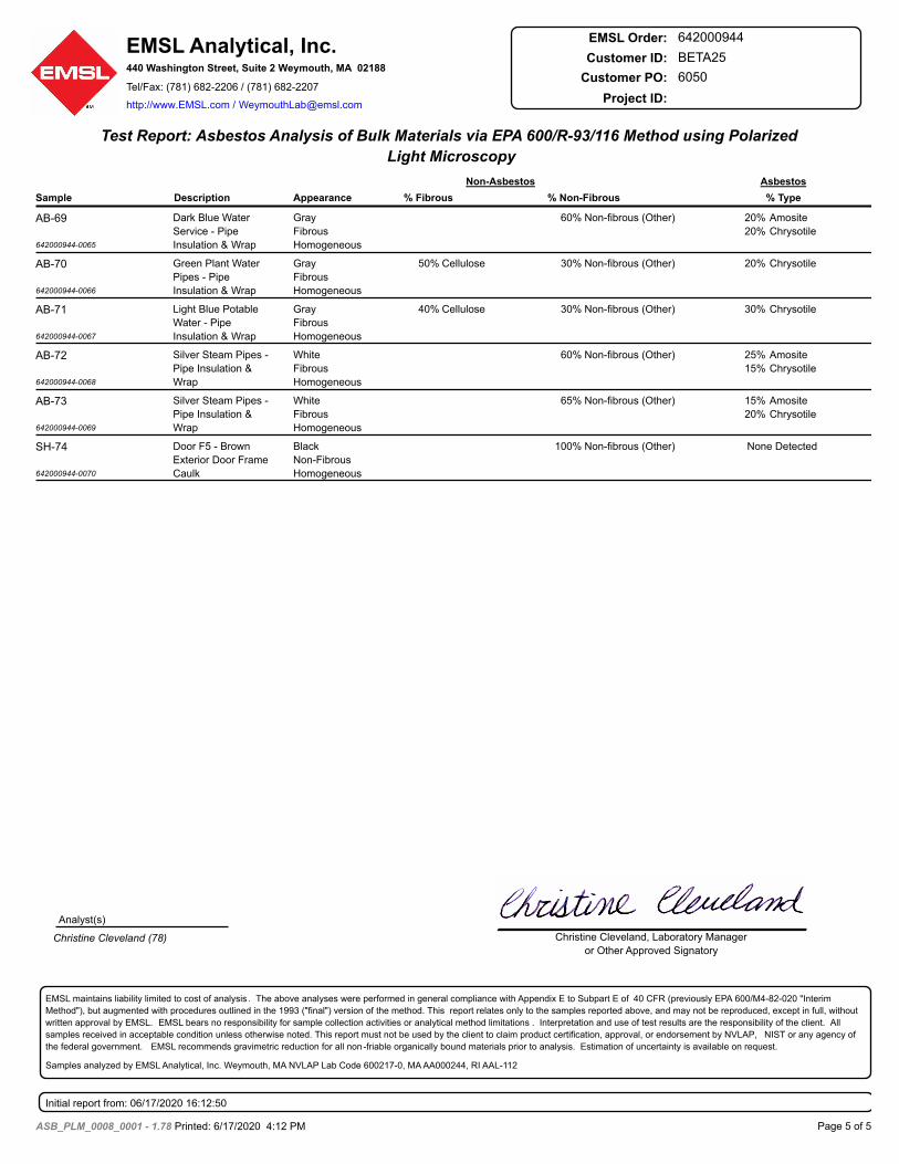
Test Report: Asbestos Analysis of Bulk Materials via EPA 600/R-93/116 Method using Polarized
Light Microscopy
Sample Description Appearance % Fibrous % Non-Fibrous
Non-Asbestos Asbestos
% Type
AB-69
642000944-0065
20%
20%
Amosite
Chrysotile
Non-fibrous (Other)60%Gray
Fibrous
Homogeneous
Dark Blue Water
Service - Pipe
Insulation & Wrap
AB-70
642000944-0066
20% ChrysotileNon-fibrous (Other)30%Cellulose50%Gray
Fibrous
Homogeneous
Green Plant Water
Pipes - Pipe
Insulation & Wrap
AB-71
642000944-0067
30% ChrysotileNon-fibrous (Other)30%Cellulose40%Gray
Fibrous
Homogeneous
Light Blue Potable
Water - Pipe
Insulation & Wrap
AB-72
642000944-0068
25%
15%
Amosite
Chrysotile
Non-fibrous (Other)60%White
Fibrous
Homogeneous
Silver Steam Pipes -
Pipe Insulation &
Wrap
AB-73
642000944-0069
15%
20%
Amosite
Chrysotile
Non-fibrous (Other)65%White
Fibrous
Homogeneous
Silver Steam Pipes -
Pipe Insulation &
Wrap
SH-74
642000944-0070
None DetectedNon-fibrous (Other)100%Black
Non-Fibrous
Homogeneous
Door F5 - Brown
Exterior Door Frame
Caulk
Analyst(s)
Christine Cleveland (78) Christine Cleveland, Laboratory Manager
or Other Approved Signatory
EMSL maintains liability limited to cost of analysis . The above analyses were performed in general compliance with Appendix E to Subpart E of 40 CFR (previously EPA 600/M4-82-020 "Interim
Method"), but augmented with procedures outlined in the 1993 ("final") version of the method. This report relates only to the samples reported above, and may not be reproduced, except in full, without
written approval by EMSL. EMSL bears no responsibility for sample collection activities or analytical method limitations . Interpretation and use of test results are the responsibility of the client. All
samples received in acceptable condition unless otherwise noted. This report must not be used by the client to claim product certification, approval, or endorsement by NVLAP, NIST or any agency of
the federal government. EMSL recommends gravimetric reduction for all non -friable organically bound materials prior to analysis. Estimation of uncertainty is available on request.
Samples analyzed by EMSL Analytical, Inc. Weymouth, MA NVLAP Lab Code 600217-0, MA AA000244, RI AAL-112
Initial report from: 06/17/2020 16:12:50
Page 5 of 5ASB_PLM_0008_0001 - 1.78 Printed: 6/17/2020 4:12 PM

Section 02080MANAGEMENT OF CONTAMINATED MATERIALS Revised
6050(WWTFP1)-7/26/2021 02080-1 MGMT. OF SUSPECT SOIL &REVISED PER ADDENDUM DISPOSAL OF CONTAMINATED SOIL
SECTION 02080
MANAGEMENT OF CONTAMINATED MATERIALS
PART 1 GENERAL
1.01 SUMMARYA. Section Includes
1. Requirements for disposal of surplus materials generated from excavation duringconstruction at the Taunton Wastewater Treatment Facility.
2. Requirements for identifying, handling, stockpiling, and disposal of contaminatedsoil.
B. Related Sections1. Section 01025 – Measurement and Payment2. Section 01300 – Submittals3. Section 02140 – Dewatering
1.02 WORK INCLUDED AND DEFINITIONSA. In general, Work under this Section shall include all labor, materials, equipment,
supervision and supplies necessary for the loading, handling, transportation, and off-site disposal of Impacted and Contaminated soil as directed by the ENGINEER.
1. “Natural” soils are those believed by the ENGINEER (but not yet confirmed bylaboratory testing) to contain concentrations of oil or hazardous materials below thelevels listed in “Table 1: MADEP Identified Background Levels in Soil”. Thedesignation of “Natural” soil will be made by the ENGINEER based on field screening,visual observation, and/or olfactory indicators.
2. “Impacted” soil shall be defined as those containing concentrations of contaminantsabove MassDEP’s level for “Natural” soils but still meet the acceptance criteria for abeneficial use facilities’ acceptance criterion based on the ENGINEER’s laboratoryanalytical results.
3. “Contaminated” soil shall be defined as those containing concentrations ofcontaminants above those for a beneficial use facilities’ acceptance criterion but belowCOMM97 acceptance criterion based on the ENGINEER’s laboratory analyticalresults.
B. Soil generated from excavation activities, shall be managed as follows:
1. Securing all permits and licenses, as necessary, including notification of localemergency personnel and notification/reporting requirements, with respect tounforeseen conditions;
2. Mobilization and demobilization of all personnel, equipment, materials and suppliesrequired to perform the Work;
MGMT. OF SUSPECT SOIL & 02080-2 6050(WWTFP1)-7/26/2021DISPOSAL OF CONTAMINATED SOIL REVISED PER ADDENDUM
3. Assisting ENGINEER in obtaining environmental samples;4. Upon determination by the ENGINEER (based on laboratory sample results) that
the soil qualifies as Impacted soil, or Contaminated soil, the CONTRACTOR shallcoordinate off-site disposal of the soil at an appropriate disposal facility. Asstipulated in Section 01025, the CONTRACTOR is responsible for the disposal ofexcess soil “Natural” as defined above at no additional cost to the OWNER;
5. Segregating boulders and other large rocks for off-site management, as directed bythe ENGINEER;
6. To the extent practical, removing and segregating asphalt from the soil; and,7. General site cleanup.
1.03 SAMPLINGA. The Contractor will provide all equipment, manpower, and machinery required to
conduct test pits for collection of representative soil samples. The Contractor willbackfill and restore each test pit to match existing grades.
B. The ENGINEER will be responsible for sampling and analyses as may be required bythe receiving disposal facility(ies) for off-site disposal of Contaminated soil. Any suchsampling services shall be identified by Contractor as quickly as possible, and Engineerwill respond as expeditiously as possible. Contractor shall schedule his/her activitiesto allow for sampling to be performed, analytical results to be compiled andmanagement decisions to be made. No claim shall be made for reasonable delaysassociated with such supplemental sampling, analytical services and decision making.In most cases, Engineer will provide any necessary sampling services and analyticalresults within fourteen (14) days after formal request by Contractor. To accommodatea time critical project activity, and upon Contractor’s request, Engineer will acceleratethe supplemental sampling and analytical results to the extent reasonably possible.
C. Any samples collected and/or tested by the CONTRACTOR shall be for his ownconvenience only, and shall not be the basis for classification, determination of limits,or payment.
1.04 LICENSED SITE PROFESSIONAL (LSP) SERVICESA. All Licensed Site Professional (LSP) services for the work shall be provided by the
ENGINEER, including all Massachusetts Department of Environmental Protection(MassDEP) response actions. The ENGINEER will be responsible for preparing allMassachusetts Contingency Plan (MCP) related filings including but not limited toUtility-related Abatement Measure (URAM) Plans, Release Abatement Measure(RAM) plans, Material Shipping Records, and Bills of Lading.
1.05 APPLICABLE LAWS AND REGULATIONSA. The CONTRACTOR is advised that Work under this Section may need to be performed
under the requirements of 310 CMR 40.0000 et seq., also known as the MassachusettsContingency Plan (MCP).
6050(WWTFP1)-7/26/2021 02080-3 MGMT. OF SUSPECT SOIL &REVISED PER ADDENDUM DISPOSAL OF CONTAMINATED SOIL
B. Work under this Section shall be performed in strict compliance with all applicableFederal, State and local laws, rules, regulations related to the handling and off-sitemanagement of contaminated wastes and regulated soil.
C. Pertinent Federal and State Authorities having jurisdiction over this project include:
1. Occupational Safety and Health Administration (OSHA)2. U.S. Environmental Protection Agency (EPA)
3. Massachusetts Department of Environmental Protection (MassDEP)D. The following OSHA regulations will apply:
1. Occupational Safety and Health Standards, Hazardous Waste Operations andEmergency Response - 29 CFR 1910.120.
2. Safety and Health Regulations for Construction - 29 CFR 1926.1.06 SUBMITTALS
A. Submittals shall be made in compliance with the requirements of Section 01300 exceptas provided for herein.
B. No Work will be permitted to proceed until the required submittals have been receivedand approved by the ENGINEER. In the event the ENGINEER requests additionalinformation, it shall be the CONTRACTOR’s responsibility to provide such additionalinformation in a complete and timely manner, so that construction can proceed by thedate stipulated in the Notice to Proceed.
C. Impacted and/or Contaminated soil may be encountered during the work. Prior to thecommencement of work, the CONTRACTOR shall submit the following to theENGINEER for approval:
1. Submittal of all required certifications demonstrating that personnel are properlytrained and qualified to perform the Work in accordance with applicable OSHAregulations and all laws governing the Work.
2. Names and qualifications of all proposed subcontractors, if any, identifying thetasks to be performed by each proposed Subcontractor.
3. If Impacted or Contaminated Soil is encountered, the CONTRACTOR shallprepare a Soil Management Plan that includes a description of the proposedequipment and decontamination procedures, identification of any staging areas forthe loading of the Impacted/Contaminated soil (as directed by the Engineer),proposed disposal facility(ies), and project schedule.
D. The CONTRACTOR’s Site-Specific Health & Safety Plan pursuant to OSHA1910.120 requirements.
E. Approval of submittals by the ENGINEER shall not impose any liability upon theENGINEER, nor shall any such approval relieve the CONTRACTOR of his/her
MGMT. OF SUSPECT SOIL & 02080-4 6050(WWTFP1)-7/26/2021DISPOSAL OF CONTAMINATED SOIL REVISED PER ADDENDUM
responsibilities to meet all of the requirements and comply with all applicable laws,regulations and other applicable requirements under this Contract.
1.07 EXISTING ENVIRONMENTAL CONDITIONSA. The CONTRACTOR shall satisfy himself/herself as to the conditions existing at the
Site, the type of equipment required to perform this Work, and the quality and quantityof the materials to be removed.
B. Failure of the CONTRACTOR to become fully acquainted with the availableinformation will not relieve him/her of the responsibility to completely and properlyperform the work in full compliance with the Contract Documents. The ENGINEERassumes no responsibility for any conclusion or interpretation made by theCONTRACTOR on the basis of information made available by the Owner orENGINEER.
PART 2 PRODUCTS [NOT USED]
PART 3 EXECUTION
3.01 GENERALA. The CONTRACTOR will provide adequate barriers and demarcation of excavations
and exclusion zones to warn site visitors and the public of potential hazards.
B. The CONTRACTOR will take appropriate means to prevent a release or the spread ofhazardous wastes or contaminated materials as a result of the CONTRACTOR’soperations.
C. The CONTRACTOR will assist the ENGINEER with collection of soil and/orgroundwater samples for laboratory analyses, as requested.
D. The ENGINEER will be responsible for collection of all samples, and the determinationof the limits of contamination
3.02 SITE HEALTH & SAFETYA. The CONTRACTOR is solely responsible for controlling Site health and safety,
including the provision of a Site Health and Safety Officer. In the performance of itsWork, the CONTRACTOR shall provide for the safety of all CONTRACTORpersonnel, other CONTRACTOR’s personnel, regulatory agency personnel, and thepublic for the duration of the Contract.
B. The CONTRACTOR is solely responsible for his/her construction means and methods.
C. The ENGINEER will be responsible for the health and safety of its personnel only.
D. The CONTRACTOR shall provide a Health and Safety Plan (HASP) which addressesidentified contaminants of concern for the Work under this Contract. Such plan shall
6050(WWTFP1)-7/26/2021 02080-5 MGMT. OF SUSPECT SOIL &REVISED PER ADDENDUM DISPOSAL OF CONTAMINATED SOIL
conform to the requirements of OSHA 1910.120 and all other applicable federal, state,and local laws, regulations, ordinances, and procedures. The HASP shall be developedand implemented by the CONTRACTOR’s Safety Officer experienced with the healthand safety requirements of OSHA 1910.120. The HASP shall be revised, as needed,whenever new information about site hazards is obtained.
E. All personnel performing Work in contaminated or hazardous areas shall be fullytrained in accordance with the OSHA 1910.120 and the HASP and shall be thoroughlybriefed on anticipated hazards, safety equipment to be employed, safety practices to befollowed, and emergency procedures and communications. The CONTRACTOR shallhave a medical monitoring surveillance program in place for all personnel inaccordance with all applicable laws and regulations.
3.03 MISCELLANEOUS PROVISIONSA. CONTRACTOR must have a valid EPA identification number and any other permits
or licenses required by federal, state, and local laws, regulations, ordinances, andprocedures for the transportation of hazardous wastes.
B. The CONTRACTOR shall be responsible for securing all necessary and applicablepermits, certificates, licenses, and approvals required for the performance of this Workand shall be responsible for the payment of all associated fees.
C. The CONTRACTOR shall comply with all required reporting and record keepingrequirements in accordance with the provisions of this Contract and all applicablefederal, state, and local laws, regulations, ordinances, and procedures.
D. The CONTRACTOR shall be responsible for all notifications required by federal, state,and local laws, regulations, ordinances, and procedures. All notifications shall becoordinated with the ENGINEER.
E. Material Shipping Records and/or Bills of Lading, as appropriate, will be provided andcoordinated by the ENGINEER. The Owner will be responsible for signing all wastemanifests and bills of lading. In order for CONTRACTOR’s operations to proceedwithout interruption, complete and accurate information shall be provided by theCONTRACTOR during the Submittals process. CONTRACTOR shall be responsiblefor preparing applications to disposal facilities.
3.04 DUST MONITORING & CONTROL MEASURESA. The CONTRACTOR is responsible for monitoring the Work for evidence of airborne
particulates (dusts) emanating from the Work area. It shall be the CONTRACTOR’sresponsibility to continuously monitor the work area for dust levels.
B. The CONTRACTOR shall take appropriate measures to substantially eliminate thegeneration of dusts within the Work Area, including use of water provided by theCONTRACTOR and covering all stockpiled wastes and/or soil, except in theimmediate vicinity of the excavation, where water may be required to control dustemissions.
MGMT. OF SUSPECT SOIL & 02080-6 6050(WWTFP1)-7/26/2021DISPOSAL OF CONTAMINATED SOIL REVISED PER ADDENDUM
C. The ENGINEER will also be monitoring the site for elevated levels of dusts. In theevent that visible emissions are observed, the ENGINEER may direct the contractor totake appropriate measures to mitigate the condition. Failure of the CONTRACTOR toimplement measures that reduce dust levels may be cause for suspension of the Work,until otherwise directed by the ENGINEER.
3.05 EXCAVATON OF SOILA. Soil will be classified based on soil sampling results from test pits or observation wells
performed by the Contractor. Classified soil can be live loaded for removal from thesite.
B. Soil identified as “Natural” that is generated from excavation activities associated withthe Taunton WWTF will become property of the Contractor. As stipulated in Section01025, the CONTRACTOR is responsible for the disposal of excess “Natural” soil asdefined above at no additional cost to the OWNER.
C. Soil identified as “Impacted” that is generated from excavation activities associatedwith the Taunton WWTF will be transported off site to an facility approved by theEngineer. A Material Shipping Record is required for shipment of all “Impacted” soil.
D. Soil identified as “Contaminated” that is generated from excavation activitiesassociated with the Taunton WWTF will be transported off site to an facility approvedby the Engineer. A Material Shipping Record or Bill of Lading is required for shipmentof all “Contaminated” soil.
E. The CONTRACTOR shall minimize the spread and loss of “Impacted” orContaminated Soil during excavation activities as follows:
1. The CONTRACTOR shall segregate boulders, asphalt, construction debris and otherdeleterious materials from excavated Soil to the extent practicable and as directedby the ENGINEER. This segregation shall occur at the point of excavation, prior tothe transport of soil.
3.06 TEMPORARY SOIL STOCKPILINGA. The ENGINEER anticipates the need for temporary stockpiling of soil. However, the
work areas do not allow for stockpiling at the site of generation of the soil. Therefore,soil shall be transported to and stockpiled at the Owner’s property at 600 West WaterStreet in Taunton, Massachusetts (or another site designated by the Owner). Thefollowing provisions shall apply to the stockpiling:
1. Due to space limitations at 600 West Water Street a maximum of 500 cubic yardstotal of soil can be stored at one time.
2. Natural soil, soil that is not pre-characterized, Impacted soil, and Contaminated soilstockpiles shall be maintained separately and delineated with jersey barriers.
3. Straw wattles shall be provided on the downgradient side of all stockpiles.
6050(WWTFP1)-7/26/2021 02080-7 MGMT. OF SUSPECT SOIL &REVISED PER ADDENDUM DISPOSAL OF CONTAMINATED SOIL
4. As directed by the ENGINEER, Impacted soil and Contaminated soil shall bestockpiled out of the immediate work area and in a location designated by Owner (at600 West Water Street), on 6-mil polyethylene sheeting. All stockpiled Impactedsoil and Contaminated soil shall be covered with 6-mil polyethylene sheeting at theend of every working day. Sheeting shall be properly secured such that it remainsfully intact during inclement weather conditions.
5. As directed by the ENGINEER, soil that is not pre-characterized shall be stockpiledout of the immediate work area and in a location designated by Owner (at 600 WestWater Street), on 6-mil polyethylene sheeting. All stockpiled soil that is not pre-characterized shall be covered with 6-mil polyethylene sheeting at the end of everyworking day. Sheeting shall be properly secured such that it remains fully intactduring inclement weather conditions.
6. As directed by the ENGINEER, the CONTRACTOR shall segregate the soil intoseparate stockpile areas (physically separated by excavation site and labeled) tofacilitate separate characterization by ENGINEER, and subsequent off-sitemanagement. No individual stockpile may exceed 250 cubic yards.
7. All stockpiled soil shall be transported from 600 West Water Street as soon aspossible. In no case shall excavated soil remain stockpiled for more than 120 daysfrom its excavation.
3.07 OFF-SITE MANAGEMENT OF IMPACTED SOILA. The CONTRACTOR shall be responsible for the off-site transportation and disposal of
Impacted soil.
B. The CONTRACTOR shall be responsible for coordination of all transporter andreceiving facility activities. Transporter vehicles used for the transportation ofImpacted soil shall be covered, substance compatible, licensed, insured, and permittedpursuant to federal, state, and local laws, regulations, ordinances, and procedures.
C. Vehicles departing the site shall be properly logged to show the vehicle identification,driver’s name, time of departure, destination, and approximate volume and content ofmaterial carried.
D. Impacted soil shall not leave the site until the designated receiving facility has agreedin writing to accept the type and quantity of waste/soil to be shipped.
E. The CONTRACTOR shall complete required facility applications and other pertinentforms for proper transportation and disposal. The ENGINEER shall review and the Citywill sign the applications. Signatures from the receiving location of materialstransported off-site are required. The CONTRACTOR shall be held accountable forensuring that requirements of the transporter and receiving disposal facility(ies) andfederal, state, and local laws, regulations, ordinances, and procedures are complied withand properly documented.
MGMT. OF SUSPECT SOIL & 02080-8 6050(WWTFP1)-7/26/2021DISPOSAL OF CONTAMINATED SOIL REVISED PER ADDENDUM
F. Documentation shall be maintained indicating that applicable laws have been satisfiedand that Impacted and Contaminated soil has been successfully transported andreceived at the disposal facility(ies).
G. Actual quantities and measurements in the field shall be tabulated by theCONTRACTOR on a daily basis. The CONTRACTOR will not be reimbursed for unitrate work performed without the prior approval.
3.08 OFF-SITE MANAGEMENT OF CONTAMINATED SOILA. The CONTRACTOR shall be responsible for the off-site transportation and disposal of
Contaminated soil designated by the ENGINEER for off-site disposal at an appropriatedisposal facility.
B. The Contractor will be responsible for additional sampling and analyses as may berequired by the receiving disposal facility(ies) for off-site disposal of Contaminatedsoil.
C. Vehicles used for transportation of Contaminated soil shall be properly labeled andplacarded, as required for off-site transportation for conformance with federal, state,and local laws, regulations, ordinances, and procedures.
D. The CONTRACTOR shall be responsible for coordination of all transporter andreceiving facility activities. Transporter vehicles used for the transportation ofContaminated soil shall be covered, substance compatible, licensed, insured, andpermitted pursuant to federal, state, and local laws, regulations, ordinances, andprocedures.
E. Vehicles departing the site shall be properly logged to show the vehicle identification,driver’s name, time of departure, destination, and approximate volume and content ofmaterial carried.
F. No Contaminated soil shall leave the site until the designated receiving facility hasagreed in writing to accept the type and quantity of waste/soil to be shipped.
G. The CONTRACTOR shall complete required facility applications and other pertinentforms for proper transportation and disposal. The ENGINEER shall review and the Citywill sign the applications. Signatures from the receiving location of materialstransported off-site are required. The CONTRACTOR shall be held accountable forensuring that requirements of the transporter and receiving disposal facility(ies) andfederal, state, and local laws, regulations, ordinances, and procedures are complied withand properly documented.
H. Documentation shall be maintained indicating that applicable laws have been satisfiedand that Contaminated soil has been successfully transported and received at thedisposal facility(ies).
6050(WWTFP1)-7/26/2021 02080-9 MGMT. OF SUSPECT SOIL &REVISED PER ADDENDUM DISPOSAL OF CONTAMINATED SOIL
I. Actual quantities and measurements in the field shall be tabulated by theCONTRACTOR and verified by ENGINEER on a daily basis. The CONTRACTORwill not be reimbursed for unit rate work performed without the prior approval ofquantities by ENGINEER.
3.09 SITE CLEANUPA. During the course of the Work, the CONTRACTOR shall keep the Site and his
operations clean and neat at all times. The CONTRACTOR shall dispose of all residueresulting from the site operations; and at the conclusion for the day's Work, he shallremove and haul away surplus materials, lumber, equipment, temporary structures, andany other refuse remaining from the site operations and shall leave the site in a neatand orderly condition.
3.10 DOCUMENTATIONA. Within 21 days after substantial completion of the Work, the CONTRACTOR shall
submit to the ENGINEER one (1) original copy of all manifests, certified weigh slips(tons), bills-of-lading, and records of final waste disposition from the acceptingdisposal facility(ies), and all other pertinent documentation, including a summary ofdates and quantities relating to the off-site management of Contaminated soil.
END OF SECTION

Section 11320PRIMARY CLARIFIER EQUIPMENT
Revised
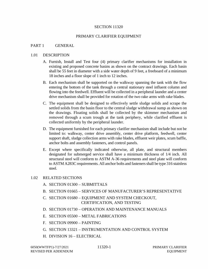
6050(WWTFP1)-7/27/2021 11320-1 PRIMARY CLARIFIERREVISED PER ADDENDUM EQUIPMENT
SECTION 11320
PRIMARY CLARIFIER EQUIPMENT
PART 1 GENERAL
1.01 DESCRIPTIONA. Furnish, Install and Test four (4) primary clarifier mechanisms for installation in
existing and proposed concrete basins as shown on the contract drawings. Each basinshall be 55 feet in diameter with a side water depth of 9 feet, a freeboard of a minimum18 inches and a floor slope of 1 inch to 12 inches.
B. Each mechanism shall be supported on the walkway spanning the tank with the flowentering the bottom of the tank through a central stationary steel influent column andflowing into the feedwell. Effluent will be collected in a peripheral launder and a centerdrive mechanism shall be provided for rotation of the two rake arms with rake blades.
C. The equipment shall be designed to effectively settle sludge solids and scrape thesettled solids from the basin floor to the central sludge withdrawal sump as shown onthe drawings. Floating solids shall be collected by the skimmer mechanism andremoved through a scum trough at the tank periphery, while clarified effluent iscollected uniformly by the peripheral launder.
D. The equipment furnished for each primary clarifier mechanism shall include but not belimited to: walkway, center drive assembly, center drive platform, feedwell, centersupport shaft, sludge collection arms with rake blades, effluent weir plates, scum baffle,anchor bolts and assembly fasteners, and control panels.
E. Except where specifically indicated otherwise, all plate, and structural membersdesignated for submerged service shall have a minimum thickness of 1/4 inch. Allstructural steel will conform to ASTM A-36 requirements and steel plate will conformto ASTM A283C requirements. All anchor bolts and fasteners shall be type 316 stainlesssteel.
1.02 RELATED SECTIONSA. SECTION 01300 – SUBMITTALS
B. SECTION 01665 – SERVICES OF MANUFACTURER’S REPRESENTATIVEC. SECTION 01680 – EQUIPMENT AND SYSTEM CHECKOUT,
CERTIFICATION, AND TESTINGD. SECTION 01730 – OPERATION AND MAINTENANCE MANUALS
E. SECTION 05500 – METAL FABRICATIONSF. SECTION 09900 – PAINTING
G. SECTION 13321 – INSTRUMENTATION AND CONTROL SYSTEMH. DIVISION 16 – ELECTRICAL
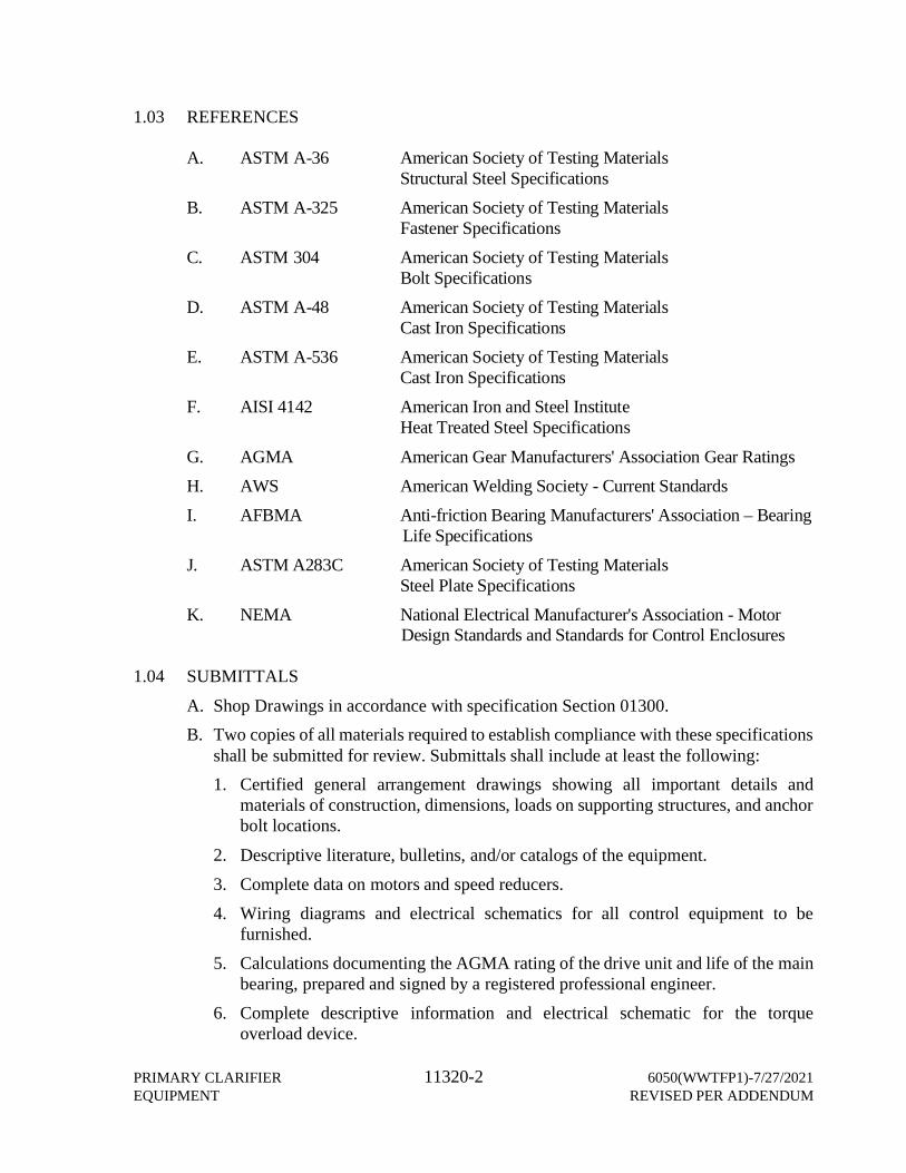
PRIMARY CLARIFIER 11320-2 6050(WWTFP1)-7/27/2021EQUIPMENT REVISED PER ADDENDUM
1.03 REFERENCES
A. ASTM A-36 American Society of Testing MaterialsStructural Steel Specifications
B. ASTM A-325 American Society of Testing MaterialsFastener Specifications
C. ASTM 304 American Society of Testing MaterialsBolt Specifications
D. ASTM A-48 American Society of Testing MaterialsCast Iron Specifications
E. ASTM A-536 American Society of Testing MaterialsCast Iron Specifications
F. AISI 4142 American Iron and Steel InstituteHeat Treated Steel Specifications
G. AGMA American Gear Manufacturers' Association Gear RatingsH. AWS American Welding Society - Current StandardsI. AFBMA Anti-friction Bearing Manufacturers' Association – Bearing Life SpecificationsJ. ASTM A283C American Society of Testing Materials
Steel Plate Specifications K. NEMA National Electrical Manufacturer's Association - Motor Design Standards and Standards for Control Enclosures
1.04 SUBMITTALS
A. Shop Drawings in accordance with specification Section 01300.B. Two copies of all materials required to establish compliance with these specifications
shall be submitted for review. Submittals shall include at least the following:1. Certified general arrangement drawings showing all important details and
materials of construction, dimensions, loads on supporting structures, and anchorbolt locations.
2. Descriptive literature, bulletins, and/or catalogs of the equipment.3. Complete data on motors and speed reducers.4. Wiring diagrams and electrical schematics for all control equipment to be
furnished.5. Calculations documenting the AGMA rating of the drive unit and life of the main
bearing, prepared and signed by a registered professional engineer.6. Complete descriptive information and electrical schematic for the torque
overload device.

6050(WWTFP1)-7/27/2021 11320-3 PRIMARY CLARIFIERREVISED PER ADDENDUM EQUIPMENT
7. Complete sludge transport calculations substantiating the rake blade design, raketip speed, and floor slope.
8. Complete process calculations substantiating the sizing of the center column andports, EDI and outlets, and outer feedwell. These calculations shall be based onparameters from the manufacturers operating experience. These parameters shallbe verified by data presented from successful operating installations. Side by sidecomparison testing of EDI and feedwell design from existing operating clarifiersthat have spiral rake blades and are products of the manufacturer shall bepresented with the calculations.
C. The submittal shall include data from a minimum of five (5) successfully operatinginstallations that verify the experience of the manufacturer. Data shall includeperformance verification of influent flow rate (Q), hydraulic loading (OFR), andeffluent suspended solids (ESS). Operation and Maintenance Manual in accordancewith specification Section 01730.
1.05 MARKING, DELIVERY, STORAGE, AND HANDLINGA. Fabricated assemblies shall be shipped in the largest sections permitted by carrier
regulations, properly match-marked for ease of field erection.B. All components shall be erected immediately upon receipt from the primary clarifier
equipment manufacturer or stored in strict conformance with storage recommendationsprovided by the equipment manufacturer in the operations and maintenance manual.
C. The mechanism shall be lubricated in strict accordance with the instructions of theprimary clarifier mechanism manufacturer's field service representative. The contractorshall provide the required lubricants.
1.06 QUALITY ASSURANCE.A. The primary clarifier equipment manufacturer shall modify his standard equipment to
meet the minimum values specified for dimensions, design, and the intent of thisspecification.
B. Manufacturers regularly engaged in the manufacture of the clarifier equipment asspecified herein and who can demonstrate equipment of this specified design, in actualservice for a period of not less than 10 years will be considered as acceptablemanufacturers.
C. Manufacturers shall show evidence of quality assurance in manufacturing andsupplying equipment essential in details to the equipment herein specified. Thisassurance will be met by certification to the quality system requirement of ISO 9001 orequivalent standard as accepted by the engineer.
D. The equipment specified herein shall be factory assembled as far as practical to verifythat all mating parts can be field assembled. The manufacturer shall submit certificationof shop trial assembly and photographs of assembly before shipment.

PRIMARY CLARIFIER 11320-4 6050(WWTFP1)-7/27/2021EQUIPMENT REVISED PER ADDENDUM
E. Shop inspection shall be performed by a qualified inspector and certified by themanufacturer. The inspection shall be documented and all deficiencies noted,corrected, re-inspected and final completion formally authorized. Final shipmentauthorization shall be by the manufacturer to ensure completion of all fabrication,assembly, and inspection requirements. Inspection records and evidence of inspectorqualification shall be submitted to the owner upon request.
1.06 OPERATION AND MAINTENANCE MANUALSA. The equipment manufacturer shall furnish an electronic copy and printed copies of
the operation and maintenance manual at least two weeks prior to shipment of allmajor equipment components, which will be retained at the installation site to assistplant operators.
B. Each manual shall be a bound, indexed binder with drawings and parts lists preparedspecifically for this project rather than general instructions that are not designed for thisproject.
C. As a minimum, the manual shall contain:
1. Certified as built drawings - General arrangement2. Certified as built drawings - General arrangement details
3. Erection drawings.4. A complete bill of materials for the equipment including the weights of all structural
steel components.5. Installation and maintenance instructions for the specific equipment including the
erection sequence, maintenance and trouble-shooting check points, and completelubrication procedures with recommended grades of lubricants.
6. Cut sheets for all equipment items purchased from sub-vendors.7. A list of the primary clarifier equipment manufacturer's recommended spare parts
specifically denoting wear items, long delivery items, and all items convenient forstocking as optional replacement items.
PART 2 PRODUCTS
2.01 MANUFACTURERS
A. Amwell, A Division of McNish Corp., Aurora, ILB. WesTech Engineering Inc., Salt Lake City, UTC. Approved equal.
2.02 DESIGNA. The Primary Clarifier Mechanism shall be designed as follows:
6050(WWTFP1)-7/27/2021 11320-5 PRIMARY CLARIFIERREVISED PER ADDENDUM EQUIPMENT
Influent Flow Rate Per Clarifier (MGD)– Design: 2.6 MGD– Maximum: 6.3 MGD– Solids Loading Design: 4,500 lbs/day– Solids Loading Maximum: 5,500 lbs/dayTank Dimensions (ft): 55x55Side Water Depth (ft): 9’-1”Freeboard (ft): 1.5 (min.)Bottom Slope (in/ft): 1/1Center Support Outside Diameter (in): 24Feedwell– Diameter (ft): 8– Depth (ft): 3Collector Tip Speed (ft/min): 10Motor HP: 1Torque (ft-lbs)– Design Running: 14,700– Momentary Peak: 29,400
2.03 MATERIALSA. All structural steel shall conform to AISC – Steel Construction Manual latest edition.
All steel plates shall conform to ASTM A36. All structural steel shape series of M,MT, S, ST, C, MC, L shall conform to ASTM A36. Structural steel shapes W, WT,HP shall conform to ASTM A992/A572. All pipe shall be ASTM A53, Grade B. Allsquare and rectangular tubing shall be ASTM A500, Grade B, unless otherwise noted.Steel members in contact with liquids, either continuously or intermittently, shallhave a minimum thickness of 1/4 inch unless otherwise noted. All aluminum shall betype 5052, 6061, 6063, or 2014 alloy unless noted. All stainless steel shall be type304/304L unless noted.
2.04 CENTER DRIVE ASSEMBLYA. Fabricated or Cast Drives will be permitted.
FABRICATED DRIVEB. Design Parameters
1. The drive unit shall be designed and manufactured by the equipment supplier toensure unit responsibility. The drive unit shall be designed for the torque valuespreviously listed. It shall turn the mechanism at the design collector tip speed.The drive main bearing shall be designed for the total rotating mechanism loadswith a minimum L-10 life of 50 years or 438,000 hours. The drive unit shall be
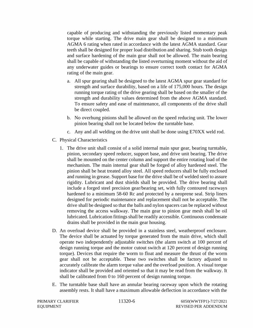
PRIMARY CLARIFIER 11320-6 6050(WWTFP1)-7/27/2021EQUIPMENT REVISED PER ADDENDUM
capable of producing and withstanding the previously listed momentary peaktorque while starting. The drive main gear shall be designed to a minimumAGMA 6 rating when rated in accordance with the latest AGMA standard. Gearteeth shall be designed for proper load distribution and sharing. Stub tooth designand surface hardening of the main gear shall not be allowed. The main bearingshall be capable of withstanding the listed overturning moment without the aid ofany underwater guides or bearings to ensure correct tooth contact for AGMArating of the main gear.a. All spur gearing shall be designed to the latest AGMA spur gear standard for
strength and surface durability, based on a life of 175,000 hours. The designrunning torque rating of the drive gearing shall be based on the smaller of thestrength and durability values determined from the above AGMA standard.To ensure safety and ease of maintenance, all components of the drive shallbe direct coupled.
b. No overhung pinions shall be allowed on the speed reducing unit. The lowerpinion bearing shall not be located below the turntable base.
c. Any and all welding on the drive unit shall be done using E70XX weld rod.C. Physical Characteristics
1. The drive unit shall consist of a solid internal main spur gear, bearing turntable,pinion, secondary speed reducer, support base, and drive unit bearing. The driveshall be mounted on the center column and support the entire rotating load of themechanism. The main internal gear shall be forged of alloy hardened steel. Thepinion shall be heat treated alloy steel. All speed reducers shall be fully enclosedand running in grease. Support base for the drive shall be of welded steel to assurerigidity. Lubricant and dust shields shall be provided. The drive bearing shallinclude a forged steel precision gear/bearing set, with fully contoured racewayshardened to a minimum 58-60 Rc and protected by a neoprene seal. Strip linersdesigned for periodic maintenance and replacement shall not be acceptable. Thedrive shall be designed so that the balls and nylon spacers can be replaced withoutremoving the access walkway. The main gear to pinion gear mesh shall be oillubricated. Lubrication fittings shall be readily accessible. Continuous condensatedrains shall be provided in the main gear housing.
D. An overload device shall be provided in a stainless steel, weatherproof enclosure.The device shall be actuated by torque generated from the main drive, which shalloperate two independently adjustable switches (the alarm switch at 100 percent ofdesign running torque and the motor cutout switch at 120 percent of design runningtorque). Devices that require the worm to float and measure the thrust of the wormgear shall not be acceptable. These two switches shall be factory adjusted toaccurately calibrate the alarm torque value and the overload position. A visual torqueindicator shall be provided and oriented so that it may be read from the walkway. Itshall be calibrated from 0 to 160 percent of design running torque.
E. The turntable base shall have an annular bearing raceway upon which the rotatingassembly rests. It shall have a maximum allowable deflection in accordance with the
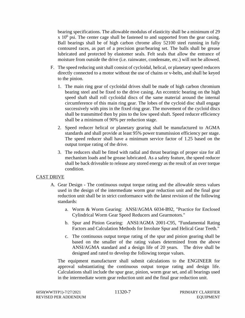
6050(WWTFP1)-7/27/2021 11320-7 PRIMARY CLARIFIERREVISED PER ADDENDUM EQUIPMENT
bearing specifications. The allowable modulus of elasticity shall be a minimum of 29x 106 psi. The center cage shall be fastened to and supported from the gear casing.Ball bearings shall be of high carbon chrome alloy 52100 steel running in fullycontoured races, as part of a precision gear/bearing set. The balls shall be greaselubricated and protected by elastomer seals. Felt seals that allow the entrance ofmoisture from outside the drive (i.e. rainwater, condensate, etc.) will not be allowed.
F. The speed reducing unit shall consist of cycloidal, helical, or planetary speed reducersdirectly connected to a motor without the use of chains or v-belts, and shall be keyedto the pinion.1. The main ring gear of cycloidal drives shall be made of high carbon chromium
bearing steel and be fixed to the drive casing. An eccentric bearing on the highspeed shaft shall roll cycloidal discs of the same material around the internalcircumference of this main ring gear. The lobes of the cycloid disc shall engagesuccessively with pins in the fixed ring gear. The movement of the cycloid discsshall be transmitted then by pins to the low speed shaft. Speed reducer efficiencyshall be a minimum of 90% per reduction stage.
2. Speed reducer helical or planetary gearing shall be manufactured to AGMAstandards and shall provide at least 95% power transmission efficiency per stage.The speed reducer shall have a minimum service factor of 1.25 based on theoutput torque rating of the drive.
3. The reducers shall be fitted with radial and thrust bearings of proper size for allmechanism loads and be grease lubricated. As a safety feature, the speed reducershall be back driveable to release any stored energy as the result of an over torquecondition.
CAST DRIVEA. Gear Design - The continuous output torque rating and the allowable stress values
used in the design of the intermediate worm gear reduction unit and the final gearreduction unit shall be in strict conformance with the latest revision of the followingstandards:
a. Worm & Worm Gearing: ANSI/AGMA 6034-B92, "Practice for EnclosedCylindrical Worm Gear Speed Reducers and Gearmotors."
b. Spur and Pinion Gearing: ANSI/AGMA 2001-C95, "Fundamental RatingFactors and Calculation Methods for Involute Spur and Helical Gear Teeth."
c. The continuous output torque rating of the spur and pinion gearing shall bebased on the smaller of the rating values determined from the aboveANSI/AGMA standard and a design life of 20 years. The drive shall bedesigned and rated to develop the following torque values.
The equipment manufacturer shall submit calculations to the ENGINEER forapproval substantiating the continuous output torque rating and design life.Calculations shall include the spur gear, pinion, worm gear set, and all bearings usedin the intermediate worm gear reduction unit and the final gear reduction unit.

PRIMARY CLARIFIER 11320-8 6050(WWTFP1)-7/27/2021EQUIPMENT REVISED PER ADDENDUM
The spur gear and pinion calculations shall clearly specify the values used for thefollowing design parameters for surface durability and strength ratings:
d. Number of Pinions Pinion Pitch Diametere. Actual Face Width Tooth Diametrical Pitch
f. Tooth Geometry Factors (I and J Factors) Hardness Ratio Factorg. Load Distribution Factor Elastic Coefficient
h. Aspect Ratio Life Factori. Allowable Contact Stress Application Factor
j. Allowable Bending Stress Rim Thickness FactorLoad distribution factors (Cm and Km) used in the calculations shall not exceed 1.28.For parameters which are material dependent, such as allowable contact stress, thecalculations shall include a full description of the materials, quality grade, and heattreatment used. Momentary peak torque calculations shall use a maximum of 75%of yield strength.
B. Primary Gear Reduction Unit - The primary gear reduction unit shall consist of atotally enclosed, horizontal type gearmotor or gear reducer with C-face mounteddrive motor, mounted on top of the intermediate worm gear housing. The primarygear reducer shall be a heavy-duty parallel shaft helical type, conforming toANSI/AGMA 6019-B89, and shall have a service factor of 1.4, based upon thespecified continuous running torque.
All gearbox bearings shall be of the anti-friction type and running in oil in a cast ironor steel housing. The totally enclosed primary reduction unit shall operate on 3 phase,60 hertz, 230/460 volt power source, and shall be at least 1.0 HP. The motor shallconform to NEMA specifications for AC motors and be designed for continuousoperating in humid outdoor condition.
C. Chain Drive - Power transmission between the primary gear reduction unit and theintermediate worm gear reduction unit shall be through a steel roller chain and steelsprocket assembly. The chain drive shall be enclosed with a steel chain guardmeeting OSHA requirements. The shear pin overload shall be easily accessible byremoval of the chain guard.
D. Intermediate Worm Gear Reduction Unit - The intermediate worm gear reductionunit shall consist of a worm gear driven by an integral straddle mounted worm andshaft, supported by heavy duty anti-friction bearings running in an oil bath, andhousing. Plain or sleeve type bearings will not be acceptable. All bearings shall havea minimum L10 life of 20 years, based on the continuous torque rating.
The integral worm and shaft shall be single piece and made from AISI 8620H alloysteel carburized, hardened and ground and shall have a case hardness of 55-60 RC.
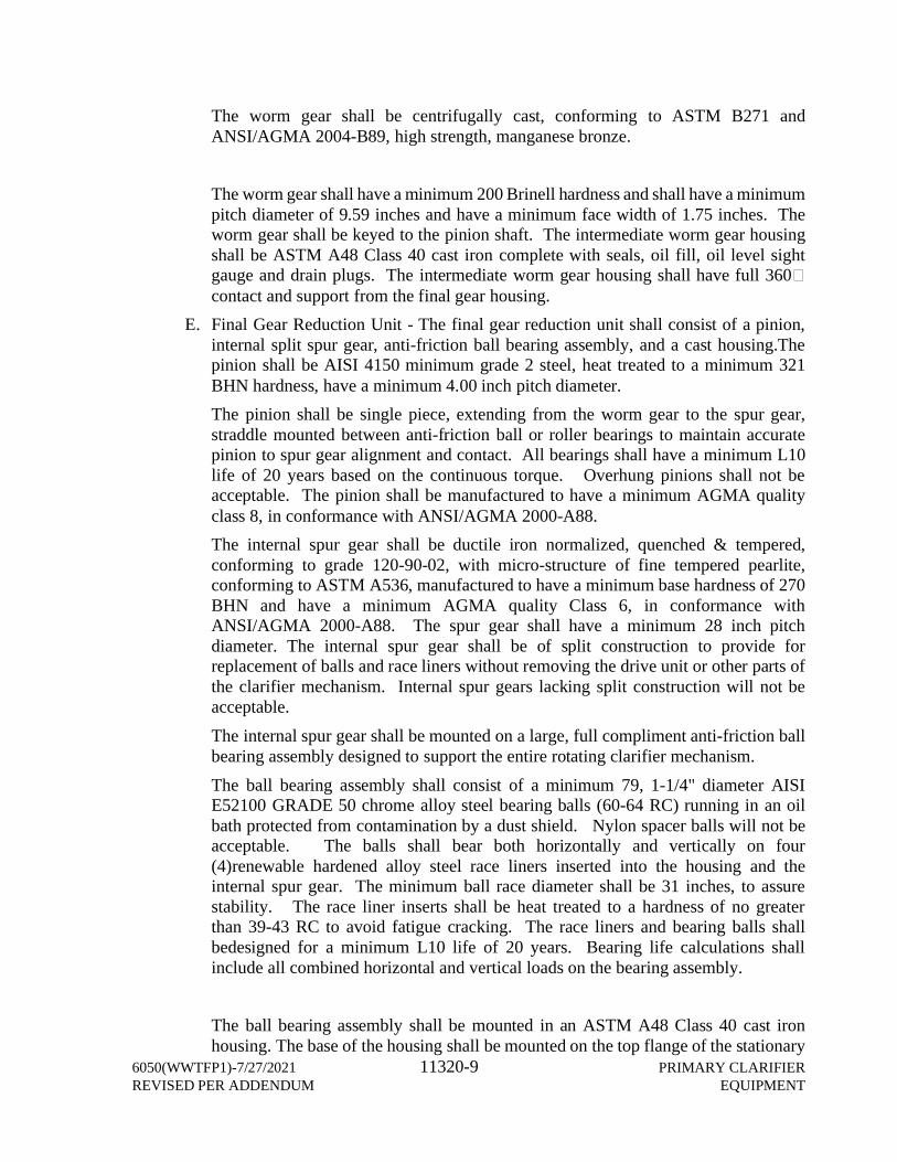
6050(WWTFP1)-7/27/2021 11320-9 PRIMARY CLARIFIERREVISED PER ADDENDUM EQUIPMENT
The worm gear shall be centrifugally cast, conforming to ASTM B271 andANSI/AGMA 2004-B89, high strength, manganese bronze.
The worm gear shall have a minimum 200 Brinell hardness and shall have a minimumpitch diameter of 9.59 inches and have a minimum face width of 1.75 inches. Theworm gear shall be keyed to the pinion shaft. The intermediate worm gear housingshall be ASTM A48 Class 40 cast iron complete with seals, oil fill, oil level sightgauge and drain plugs. The intermediate worm gear housing shall have full 360�contact and support from the final gear housing.
E. Final Gear Reduction Unit - The final gear reduction unit shall consist of a pinion,internal split spur gear, anti-friction ball bearing assembly, and a cast housing.Thepinion shall be AISI 4150 minimum grade 2 steel, heat treated to a minimum 321BHN hardness, have a minimum 4.00 inch pitch diameter.The pinion shall be single piece, extending from the worm gear to the spur gear,straddle mounted between anti-friction ball or roller bearings to maintain accuratepinion to spur gear alignment and contact. All bearings shall have a minimum L10life of 20 years based on the continuous torque. Overhung pinions shall not beacceptable. The pinion shall be manufactured to have a minimum AGMA qualityclass 8, in conformance with ANSI/AGMA 2000-A88.The internal spur gear shall be ductile iron normalized, quenched & tempered,conforming to grade 120-90-02, with micro-structure of fine tempered pearlite,conforming to ASTM A536, manufactured to have a minimum base hardness of 270BHN and have a minimum AGMA quality Class 6, in conformance withANSI/AGMA 2000-A88. The spur gear shall have a minimum 28 inch pitchdiameter. The internal spur gear shall be of split construction to provide forreplacement of balls and race liners without removing the drive unit or other parts ofthe clarifier mechanism. Internal spur gears lacking split construction will not beacceptable.The internal spur gear shall be mounted on a large, full compliment anti-friction ballbearing assembly designed to support the entire rotating clarifier mechanism.The ball bearing assembly shall consist of a minimum 79, 1-1/4" diameter AISIE52100 GRADE 50 chrome alloy steel bearing balls (60-64 RC) running in an oilbath protected from contamination by a dust shield. Nylon spacer balls will not beacceptable. The balls shall bear both horizontally and vertically on four(4)renewable hardened alloy steel race liners inserted into the housing and theinternal spur gear. The minimum ball race diameter shall be 31 inches, to assurestability. The race liner inserts shall be heat treated to a hardness of no greaterthan 39-43 RC to avoid fatigue cracking. The race liners and bearing balls shallbedesigned for a minimum L10 life of 20 years. Bearing life calculations shallinclude all combined horizontal and vertical loads on the bearing assembly.
The ball bearing assembly shall be mounted in an ASTM A48 Class 40 cast ironhousing. The base of the housing shall be mounted on the top flange of the stationary
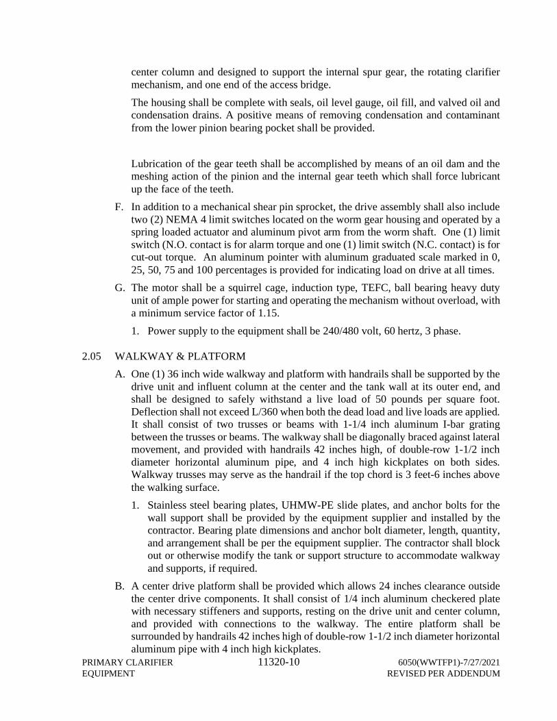
PRIMARY CLARIFIER 11320-10 6050(WWTFP1)-7/27/2021EQUIPMENT REVISED PER ADDENDUM
center column and designed to support the internal spur gear, the rotating clarifiermechanism, and one end of the access bridge.The housing shall be complete with seals, oil level gauge, oil fill, and valved oil andcondensation drains. A positive means of removing condensation and contaminantfrom the lower pinion bearing pocket shall be provided.
Lubrication of the gear teeth shall be accomplished by means of an oil dam and themeshing action of the pinion and the internal gear teeth which shall force lubricantup the face of the teeth.
F. In addition to a mechanical shear pin sprocket, the drive assembly shall also includetwo (2) NEMA 4 limit switches located on the worm gear housing and operated by aspring loaded actuator and aluminum pivot arm from the worm shaft. One (1) limitswitch (N.O. contact is for alarm torque and one (1) limit switch (N.C. contact) is forcut-out torque. An aluminum pointer with aluminum graduated scale marked in 0,25, 50, 75 and 100 percentages is provided for indicating load on drive at all times.
G. The motor shall be a squirrel cage, induction type, TEFC, ball bearing heavy dutyunit of ample power for starting and operating the mechanism without overload, witha minimum service factor of 1.15.1. Power supply to the equipment shall be 240/480 volt, 60 hertz, 3 phase.
2.05 WALKWAY & PLATFORMA. One (1) 36 inch wide walkway and platform with handrails shall be supported by the
drive unit and influent column at the center and the tank wall at its outer end, andshall be designed to safely withstand a live load of 50 pounds per square foot.Deflection shall not exceed L/360 when both the dead load and live loads are applied.It shall consist of two trusses or beams with 1-1/4 inch aluminum I-bar gratingbetween the trusses or beams. The walkway shall be diagonally braced against lateralmovement, and provided with handrails 42 inches high, of double-row 1-1/2 inchdiameter horizontal aluminum pipe, and 4 inch high kickplates on both sides.Walkway trusses may serve as the handrail if the top chord is 3 feet-6 inches abovethe walking surface.1. Stainless steel bearing plates, UHMW-PE slide plates, and anchor bolts for the
wall support shall be provided by the equipment supplier and installed by thecontractor. Bearing plate dimensions and anchor bolt diameter, length, quantity,and arrangement shall be per the equipment supplier. The contractor shall blockout or otherwise modify the tank or support structure to accommodate walkwayand supports, if required.
B. A center drive platform shall be provided which allows 24 inches clearance outsidethe center drive components. It shall consist of 1/4 inch aluminum checkered platewith necessary stiffeners and supports, resting on the drive unit and center column,and provided with connections to the walkway. The entire platform shall besurrounded by handrails 42 inches high of double-row 1-1/2 inch diameter horizontalaluminum pipe with 4 inch high kickplates.
6050(WWTFP1)-7/27/2021 11320-11 PRIMARY CLARIFIERREVISED PER ADDENDUM EQUIPMENT
2.06 INFLUENT & SLUDGE REMOVALA. The influent well shall be supported from the drive cage and designed to diffuse the
flow into the tank. The influent well shall be made of 3/16" thick steel plate withnecessary stiffening members and shall be provided with baffled port openings at thewater surface to direct any floating material out of the well and to the surfaceskimmer. The influent well diameter shall be 8'-0" and shall project at least 3'-1"beneath the surface.1. Prior to the center column being grouted in place, the drive unit shall be installed,
positioned, and leveled.B. The center cage shall be of steel box truss construction. It shall be provided with
connections for the two sludge rake arms and feedwell supports if required. The cagetop shall be bolted to the main gear which shall rotate the cage with the attached armsand feedwell. The cage and each arm shall be designed to withstand 150 percent ofthe design running torque of the drive without over stressing the members. Loadingto develop the torque shall be considered as uniform loads applied to each armindividually.
C. The mechanism shall include two long sludge rake arms of steel truss constructionwith spiral-shaped or segmented steel scraper blades and adjustable stainless steelsqueegees. Squeegees shall be fastened to the rake blades with stainless steelfasteners.1. Scraper blades shall be designed for sufficient sludge transport capacity to handle
the design solids loading rate, with the depth of the blade varying from aminimum at the tank periphery to a maximum at the tank center.
2. Blades shall properly convey settled sludge to the sludge withdrawal point.Blades which move sludge away from the center column to the withdrawal pointring shall also be provided.
3. The arms shall be adjustable at the cage to assure an even grout thickness overthe tank bottom.
4. The rake speed shall be sufficient to transport the necessary volume of sludge tothe sludge outlet, but shall not re-suspend settled sludge.
D. Each sludge collector arm shall include a counter weighted type radially extendingcorner sweep assembly. The corner sweep assembly shall consist of two (2) triangulartruss support arms attached to a sludge scraper blade. The supports arm shall befabricated from minimum 2" diameter steel pipe or tubing. The sludge scraper bladeshall be fabricated from a minimum 2" x 8" x 3/16" thick steel tubing. A minimum20-gauge brass squeegee shall be attached to the scraper blade. Each corner sweepsupport arm shall attach to the top and bottom of the rake arm utilizing a pivotassembly. Each support arm pivot assembly shall consist of two (2) fabricated steelpillow block bearings and minimum 1 1/2" diameter steel pivot shafts. Each cornersweep support arm shall attach to the scraper blade utilizing a pivot assembly. Thescraper blade pivot assembly shall consist of a steel pillow block bearing and
PRIMARY CLARIFIER 11320-12 6050(WWTFP1)-7/27/2021EQUIPMENT REVISED PER ADDENDUM
minimum 1 1/2" diameter steel pivot shaft. A heavy-duty fabricated steel bracketshall bolt to the end of the scraper blade and shall support a minimum 10" OD x 31/2" wide UHMW polyethylene wheel.
E. The counter weight assembly shall consist of a steel counter weight wheel, chain,steel guide chain sheave, and counter weight. The counter weight wheel shall beattached to the support arm pivot shaft above the top of the rake arm. The counterweight wheel and guide chain sheave shall be aligned so that a consistent load isapplied to the corner sweep assembly at all times.
F. The counter weight chain shall travel in a straight line throughout its range of travel.The guide chain sheave shall be grooved and shall be a minimum 10" in diameter.The counter weight wheel segment shall be grooved.
G. The corner sweep assembly shall be balanced by using two (2) counter weightassemblies. The support arms for the counter weights shall be located above the rakearm and shall be fabricated from minimum 1/4" thick steel members
2.07 SCUM REMOVALA. The clarifier manufacturer shall furnish two (2) skimming devices as part of each
clarifier mechanism. Each skimming mechanism shall be arranged to sweep thesurface of the sedimentation compartment, automatically removing scum and floatingmaterial to a scum box at the periphery of the tank.
B. The rotating scum skimmer shall include a horizontal steel plate skimmer bladesupported by vertical steel members extending up from the rake arms. The blade shallextend from a point 6 inches away from the influent feedwell to the hinged scumskimmer assembly at the tank periphery.
C. A hinged scum skimmer assembly shall be mounted on the outer end of the skimmerblade. The hinged scum skimmer assembly shall be designed to form a pocket fortrapping the scum. The hinged arrangement shall insure continual contact and properalignment between wiper blade, scum baffle, and ramp as the blade travels up thescum box ramp. The wiper blade shall have a wearing strip on its outer end whichcontacts the scum baffle and a neoprene strip on its lower and inner edge. Theneoprene wipers shall be a minimum 1/4 inch thickness. The scum is trapped as thewiper blade meets the ramp and is raised up the ramp to be deposited into the scumtrough for disposal.
D. The scum box shall be of the size specified, supported from the tank wall andconnected to the scum withdrawal piping. It shall be made of ¼ inch thick weldedsteel plate. The box shall have a scum trough, vertical steel sides, and a slopingapproach ramp that extends from 1-1/2 inches above water level to 5-1/2 inchesbelow. A similar ramp shall be provided at the opposite end to allow the skimmerblade to lower back to the operating position. A flexible connector shall be providedfor connection to the contractor supplied scum withdrawal piping in the tank wall.
E. A scum flushing valve shall be attached to the scum box which automatically opensand allows clarified liquid into the scum box to flush out solids. The valve shallactuate at every pass of the scum skimmer over the scum box, allowing sufficient
6050(WWTFP1)-7/27/2021 11320-13 PRIMARY CLARIFIERREVISED PER ADDENDUM EQUIPMENT
delay after deposit of the solids before flushing begins. Delay and flush duration shallbe adjustable. The opening and closing of the scum flushing valve shall be onesmooth continuous movement. The valve shall provide 2 to 5 gallons of flush waterper each pass of the skimmer assembly.
F. The scum baffle shall consist of 1/4 inch thick x 12 inches deep fiberglass sections.In the area of the scum box the scum baffle shall extend to 24 inches startingapproximately 6 feet before and ending 2 feet after the scum box. The baffle sectionsshall be curved and fastened to the launder wall with adjustable FRP support brackets,stainless steel fasteners, and anchor bolts.
2.08 EFFLUENT REMOVALA. A rectangular effluent launder shall be provided around the perimeter of the tank.
The launder shall be formed as part of the concrete wall. A drop-out box shall beprovided in the bottom of the launder at one point for collection and discharge of theclarified effluent.
B. An adjustable weir shall be provided around the periphery of the tank at the watersurface for removal of clarified effluent.1. The weir shall consist of 1/4 inch thick x 9 inches deep fiberglass sections with 2-
1/2 inch deep 90 degree v-notches at 6 inch intervals. The weir sections shall becurved and fastened to the launder wall with special large washers, anchor bolts,and hex nuts to allow vertical adjustment.
2.09 ANCHORAGE & FASTENERSA. All anchor bolts shall be a minimum of 1/2 inch diameter and made of type 304
stainless steel. The equipment supplier shall furnish all anchor bolts, nuts, andwashers required for the equipment.
B. All structural fasteners shall be a minimum of 1/2 inch diameter and made of type304 stainless steel. The equipment supplier shall furnish all fasteners required forthe assembly of the equipment.
2.10 CONTROLSA. Refer to Instrumentation and Control Drawings and Specifications.
2.11 PAINTING/FINISHING
A. Provide in accordance with Specification Section 09900 - Painting.B. Sharp projections of cut or sheared edges of ferrous metals shall be ground to a radius
by multiple passes of a power grinder as required to ensure satisfactory coatingadhesion.
C. All iron and steel surfaces, except the drive unit, shall be field cleaned and paintedby the contractor to ensure paint compatibility and assign unit responsibility for thecoating system. The drive unit shall be coated with the manufacturer’s standardenamel paint system.
PRIMARY CLARIFIER 11320-14 6050(WWTFP1)-7/27/2021EQUIPMENT REVISED PER ADDENDUM
PART 3 EXECUTION
3.01 INSTALLATIONA. The equipment shall be installed in strict accordance with the manufacturer's written
instructions. The equipment shall be installed properly to provide a complete workingsystem.
3.03 SERVICEA. Provide the services of a manufacturer’s representative in accordance with Section
01735. The representative shall inspect and approve the installation, certify that thetorque settings of the drive overload protection device are correct, perform the torquetest and instruct the owner's personnel on maintenance and operation. If additionalservice is required due to the mechanisms not being fully operational, at the time ofservice requested by the contractor, the additional service days will be at the contractor'sexpense.
3.02 TESTINGA. Torque Tests:
1. The entire sludge collector mechanism shall be statically load tested by loadingthe rake arm with 150 percent of the specified design running torque. The testshall verify the torque overload control device settings for alarm and motorcutout. One truss arm shall be anchored and the load measured to demonstrate therake arms’, cage’s, and drive unit’s ability to withstand the specified torque.Sketches and calculations shall be submitted illustrating how the torque will beapplied prior to the test taking place.
B. Operation Tests:1. The contractor shall operate the mechanism in a dry tank for a minimum of 4
continuous hours before flow is allowed to enter the system. There shall be nobinding, jerky, or unusual motion exhibited during this run in period. Motoramperage shall be checked at least hourly for any unusual or higher than normalfigures. After the unit has successfully passed this initial test, flow shall beintroduced into the tank and the same 4 hour observation test run. If the unitshould fail under any of these conditions, the test shall be halted and the problemcorrected. If, after several attempts, the unit does not successfully pass the fieldtest, the faulty portion of the equipment shall be repaired or replaced and the testre-run.
3.03 STARTUP
A. Provide startup services in accordance with Specification Section 01665

6050(WWTFP1)-7/27/2021 11320-15 PRIMARY CLARIFIERREVISED PER ADDENDUM EQUIPMENT
B. The equipment supplier shall provide the service of a qualified representative for onetrip and one day per mechanism to inspect the mechanism installation and assist instartup.
3.04 SPARE PARTSA. The intent of this specification is to provide uninterrupted operation for a minimum
period of two (2) years. To meet this objective the clarifier manufacturer shall supplyany spare parts, excluding lubricants that are required to meet this time frame.
END OF SECTION

Section 02140 Dewatering
6050(WWTFP1)-07/26/21 02140-1 DEWATERINGREVISED PER ADDENDUM
SECTION 02140
DEWATERING
PART 1 GENERAL
1.01 SUMMARY
A. Dewatering specified in this section is applicable to all utilities and structures under the work.
B. Section Includes
1. Requirements for designing, furnishing, installing, maintaining, operating and removal oftemporary dewatering systems required to lower and control water levels and hydrostaticpressures during construction.
2. Requirements for disposing of pumped water.
C. Related Sections
1. Section 02160 – Excavation Support.
2. Section 02200 – Earth Excavation, Backfill, Fill, and Grading.
1.02 DEFINITIONS
A. Dewatering: Lowering the zone of saturation and intercepting groundwater seepagewhich would otherwise emerge from the slopes or bottom of the excavations. The purposes ofdewatering are to increase the stability of excavated slopes; prevent loss of material frombeneath the slopes or bottom of the excavation; improve the excavating and haulingcharacteristics of on-site soil; prevent rupture or heaving of the bottom of an excavation; anddispose of pumped water. In addition, dewatering is required to place and compact structuralfill.
1.03 DESIGN REQUIREMENTS
A. The Contractor is responsible for the adequacy of the dewatering system.
B. Design dewatering systems to:
1. Effectively reduce the hydrostatic pressure and lower the groundwater levels to a minimumof 2 feet below bottom of excavation in sandy soil; and lower the groundwater levels to aminimum of four (4) feet below bottom of excavation in silty soil;
2. Design and install the dewatering system such that the excavation bottom remains stablethrough construction and so that groundwater does not seep out of open cut slopes therebyreducing the slope stability. Pumping from the bottom of the excavation as the sole meansof dewatering will not be permitted.
3. Develop a substantially dry and stable subgrade for the protection of subsequentoperations;
DEWATERING 02140-2 6050(WWTFP1)-07/26/21REVISED PER ADDENDUM
4 Result in no damage to adjacent buildings, structures, utilities and other work, included inthis contract.
C. Dewatering shall be completed in accordance with the Contractor’s chosen method capable ofmeeting the requirements of this specification.
D. Monitoring wells shall be provided inside and outside of each excavation to demonstrate thatthe dewatering system is functioning as designed prior to the start of excavation (four for eachexcavation). The monitor well locations, depths, and descriptions, both inside and outside ofthe excavation, will be provided to the Contractor by the Engineer after review of theContractor’s Dewatering and Excavation Support submittals. The Contractor shall coordinateand work with the Engineer to implement the dewatering system monitoring requirements.
E. The Contractor shall provide proposed structure buoyancy calculations (annotated)with any necessary drawings and sketches to support when the construction dewateringsystem can be safely turned-off and removed/abandoned without damage to the Work.
F. During monitor well construction, the Contractor shall take a minimum of three (3) soilsamples (minimum 8 oz jar size, larger preferred) during the installation of eachmonitoring well at the depth locations indicated by the Engineer, with one sample atmid slot/screen section level, for submission to the Engineer
G. Methods may include sump pumping, single or multiple stage well point or jet eductor wellpoint systems, deep wells, or combinations thereof.
H. Locate dewatering facilities where they will not interfere with existing utilities, facilities and/orconstruction work to be done under this Contract.
I. Contractor is responsible to obtain all necessary permits from state and local authorities,including Veolia, regarding the operation and discharge of the dewatering system, and toconduct all necessary sampling and testing that may be required by those authorities. TheContractor is responsible for all associated costs.
J. Dewatering system performance shall be assessed by a program of groundwater wellinstallations and well monitoring per this specification, and as approved by the Engineer.
K. Design the dewatering system to provide adequate settling, and filtering facilities so that thedischarge does not contain suspended soil particles. Design the discharge so that the dischargelocation is not damaged or eroded. The Contractor shall design their sediment removal systemto meet the effluent requirements of the NPDES Construction General Permit.
L. Coordinate the dewatering system design with excavation support system requirements.
M. Design, provide, install, operate, maintain and remove a temporary surface water controlprogram, which will divert surface water away from excavations, trenches, utilities, and allother work areas.
6050(WWTFP1)-07/26/21 02140-3 DEWATERINGREVISED PER ADDENDUM
N. Design shall include provisions to prevent freezing including but not limited to heat trace,insulation, low temperature alarms, and appurtenances required to insure continuous operationof the dewatering system.
1.04 SUBMITTALS
A. Shop Drawings
1. Design of the excavation support and dewatering systems shall be coordinated and shall besubmitted in the same transmittal.
2. In accordance with Section 01300 submit the following prior to dewatering systeminstallation:
a. Proposed system components.b. Operational plan to include locations and depth of components.c. Method of disposal of pumped water, including method of insuring proper sediment
removal should upset in dewatering system occur.
B. Quality Assurance/Control Submittals
1. In accordance with Section 01300 submit the following:
a. Dewatering systems to be designed under the direct supervision of a ProfessionalEngineer registered in the State of Massachusetts.
b. Complete Certificate of Design at the end of this section.c. Provide documentation demonstrating ability and experience of installing contractor
for the type of conditions under this contract.d. Names, addresses and telephone numbers of supervisory personnel actively involved
in at least five successful projects requiring dewatering.
1.05 PROJECT/SITE CONDITIONS
A. Subsurface Data
1. A Geotechnical Report including test borings and laboratory soil testing data, has beencompleted and are including in Appendix A to the Specification.
2. The data shown is for general bidding information. Bidders are expected to examine the site,review the provided reports, exploration logs and samples to evaluate the character ofsubsurface conditions. No warranty, express or implied, is made concerning the accuracy ofthe subsurface data.
3. The Contractor shall notify the Engineer immediately if subsurface conditions encounteredduring construction are different from those encountered in the explorations.
4. Upon notification to the Owner, bidders will be allowed to perform additional subsurfaceexplorations to satisfy themselves of the existing subsurface conditions at no additional costto the Owner.
DEWATERING 02140-4 6050(WWTFP1)-07/26/21REVISED PER ADDENDUM
B. Environmental Requirements
1. Dispose of pumped water in accordance with Notice of Intent and the associated Order ofConditions.
C. Existing Facilities
1. Discharge of dewatering effluent to the City of Taunton drainage system or directly toWaters of the United States is not permitted.
D. Existing Conditions
1. Groundwater Measurements have been made previously and are noted in Appendix A.
2. Groundwater surface is subject to seasonal fluctuations, tidal influences and fluctuationduring periods of heavy precipitation
PART 2 PRODUCTS
NOT USED
PART 3 EXECUTION
3.01 GENERAL
A. Operation and Performance: Once started, operate the dewatering system continuously, 24hours per day, 7 days per week, until such time as construction work below existinggroundwater levels is complete, and/or as directed by the Engineer.
1. Measure and record the performance of the dewatering system at the same time each dayusing a flow measurement device and the groundwater monitoring well(s) installed tomonitor dewatering system performance.
B. Coordinate the dewatering Work schedule with the General Contractor, and othersubcontractors performing related work.
C. The Contractor shall coordinate a Pre-Construction Meeting with the Engineer to discussContractor means, methods, procedures and schedule for dewatering systems construction,operation and removal/abandonment when no longer needed.
D. Complete installation of the dewatering system in accordance with the submittal designapproved by the Engineer. Provide all labor, materials, equipment, and supervisory personnelrequired to perform the Work.
E. Store materials at the designated locations in an organized fashion in order to execute the Workin an expeditious manner and to permit on-going existing pump station operations.
F. Layout the Work in the field and mobilize labor, materials, equipment, and supervisorypersonnel necessary for the performance of dewatering work.
G. The Contractor shall adapt and modify the dewatering and sedimentation treatment systems asrequired throughout the course of the Work to meet applicable requirements.
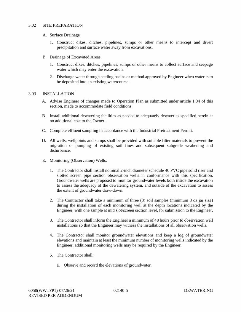
6050(WWTFP1)-07/26/21 02140-5 DEWATERINGREVISED PER ADDENDUM
3.02 SITE PREPARATION
A. Surface Drainage
1. Construct dikes, ditches, pipelines, sumps or other means to intercept and divertprecipitation and surface water away from excavations.
B. Drainage of Excavated Areas
1. Construct dikes, ditches, pipelines, sumps or other means to collect surface and seepagewater which may enter the excavation.
2. Discharge water through settling basins or method approved by Engineer when water is tobe deposited into an existing watercourse.
3.03 INSTALLATION
A. Advise Engineer of changes made to Operation Plan as submitted under article 1.04 of thissection, made to accommodate field conditions
B. Install additional dewatering facilities as needed to adequately dewater as specified herein atno additional cost to the Owner.
C. Complete effluent sampling in accordance with the Industrial Pretreatment Permit.
D. All wells, wellpoints and sumps shall be provided with suitable filter materials to prevent themigration or pumping of existing soil fines and subsequent subgrade weakening anddisturbance.
E. Monitoring (Observation) Wells:
1. The Contractor shall install nominal 2-inch diameter schedule 40 PVC pipe solid riser andslotted screen pipe section observation wells in conformance with this specification.Groundwater wells are proposed to monitor groundwater levels both inside the excavationto assess the adequacy of the dewatering system, and outside of the excavation to assessthe extent of groundwater draw-down.
2. The Contractor shall take a minimum of three (3) soil samples (minimum 8 oz jar size)during the installation of each monitoring well at the depth locations indicated by theEngineer, with one sample at mid slot/screen section level, for submission to the Engineer.
3. The Contractor shall inform the Engineer a minimum of 48 hours prior to observation wellinstallations so that the Engineer may witness the installations of all observation wells.
4. The Contractor shall monitor groundwater elevations and keep a log of groundwaterelevations and maintain at least the minimum number of monitoring wells indicated by theEngineer; additional monitoring wells may be required by the Engineer.
5. The Contractor shall:
a. Observe and record the elevations of groundwater.
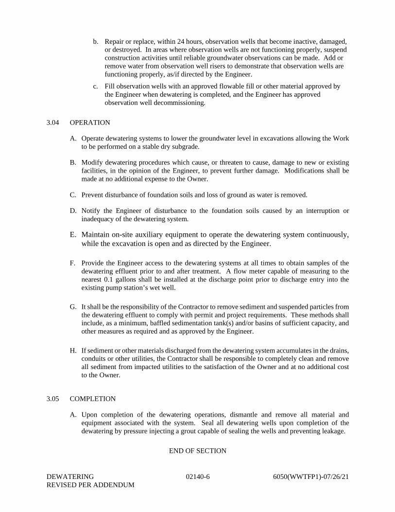
DEWATERING 02140-6 6050(WWTFP1)-07/26/21REVISED PER ADDENDUM
b. Repair or replace, within 24 hours, observation wells that become inactive, damaged,or destroyed. In areas where observation wells are not functioning properly, suspendconstruction activities until reliable groundwater observations can be made. Add orremove water from observation well risers to demonstrate that observation wells arefunctioning properly, as/if directed by the Engineer.
c. Fill observation wells with an approved flowable fill or other material approved bythe Engineer when dewatering is completed, and the Engineer has approvedobservation well decommissioning.
3.04 OPERATION
A. Operate dewatering systems to lower the groundwater level in excavations allowing the Workto be performed on a stable dry subgrade.
B. Modify dewatering procedures which cause, or threaten to cause, damage to new or existingfacilities, in the opinion of the Engineer, to prevent further damage. Modifications shall bemade at no additional expense to the Owner.
C. Prevent disturbance of foundation soils and loss of ground as water is removed.
D. Notify the Engineer of disturbance to the foundation soils caused by an interruption orinadequacy of the dewatering system.
E. Maintain on-site auxiliary equipment to operate the dewatering system continuously,while the excavation is open and as directed by the Engineer.
F. Provide the Engineer access to the dewatering systems at all times to obtain samples of thedewatering effluent prior to and after treatment. A flow meter capable of measuring to thenearest 0.1 gallons shall be installed at the discharge point prior to discharge entry into theexisting pump station’s wet well.
G. It shall be the responsibility of the Contractor to remove sediment and suspended particles fromthe dewatering effluent to comply with permit and project requirements. These methods shallinclude, as a minimum, baffled sedimentation tank(s) and/or basins of sufficient capacity, andother measures as required and as approved by the Engineer.
H. If sediment or other materials discharged from the dewatering system accumulates in the drains,conduits or other utilities, the Contractor shall be responsible to completely clean and removeall sediment from impacted utilities to the satisfaction of the Owner and at no additional costto the Owner.
3.05 COMPLETION
A. Upon completion of the dewatering operations, dismantle and remove all material andequipment associated with the system. Seal all dewatering wells upon completion of thedewatering by pressure injecting a grout capable of sealing the wells and preventing leakage.
END OF SECTION
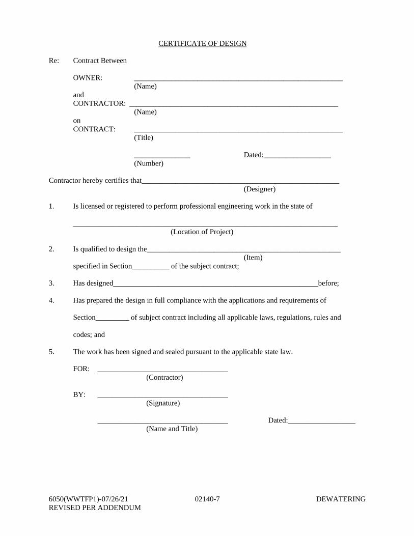
6050(WWTFP1)-07/26/21 02140-7 DEWATERINGREVISED PER ADDENDUM
CERTIFICATE OF DESIGN
Re: Contract Between
OWNER: ________________________________________________________(Name)
andCONTRACTOR: ________________________________________________________
(Name)onCONTRACT: ________________________________________________________
(Title)
_______________ Dated:__________________(Number)
Contractor hereby certifies that_____________________________________________________(Designer)
1. Is licensed or registered to perform professional engineering work in the state of
_______________________________________________________________________(Location of Project)
2. Is qualified to design the____________________________________________________(Item)
specified in Section__________ of the subject contract;
3. Has designed_______________________________________________________before;
4. Has prepared the design in full compliance with the applications and requirements of
Section_________ of subject contract including all applicable laws, regulations, rules and
codes; and
5. The work has been signed and sealed pursuant to the applicable state law.
FOR: ___________________________________ (Contractor)
BY: ___________________________________ (Signature)
___________________________________ Dated:__________________ (Name and Title)
Related Documents