1 Bicycle-Powered AC Generator by Andrew Austin Senior Project ELECTRICAL ENGINEERING DEPARTMENT California Polytechnic State University San Luis Obispo June 2011

Welcome message from author
This document is posted to help you gain knowledge. Please leave a comment to let me know what you think about it! Share it to your friends and learn new things together.
Transcript

1
Bicycle-Powered AC Generator
by
Andrew Austin
Senior Project
ELECTRICAL ENGINEERING DEPARTMENT
California Polytechnic State University
San Luis Obispo
June 2011

2
Abstract
The purpose of this senior project is to design, build, and be able to present a
mechanism that will produce AC power using the mechanical energy produced by a
person pedaling a standard bicycle. Also, I would like to be able to show the user and
the audience the advantage of using compact fluorescent bulbs, and in doing so, make
them more conscience of energy-saving products. To do this, I must present a stand that
can support a bicycle with a rider, a way to convert the wheel’s motion to DC power, to
convert that DC power to usable AC power, and lastly to be able to show the power
usage of incandescent and compact fluorescent light bulbs. The crucial part of this
project is being able to take the variable DC voltage that is produced by the variable
pedaling speed and converting it to a stable 12V DC output that can be converted to AC
power through an inverter. This report will document the progress that has been made
towards completion, and if any actions must be taken to complete this project.
3
Table of Contents
I. Abstract…………………………………………………………………………………………………………………… i
II. List of Figures…………………………………………………………………………………………………………. 2
III. List of Tables and Graphs……………………………………………………………………………………… 3
IV. Introduction…..…………………………………………………………………………………………………….. 4
V. Design…………............................................................................................................ 5
VI. Analysis……………………………………………………………………………………………………………….. 15
VII. Conclusion…………………………………………………………………………………………………………. 20
VIII. Acknowledgement……………………………………………………………………………………………. 22
IX. Bibliography…………..…………………………………………………………………………………………… 23
X. Appendix….…………….…………………………………………………………………………………………… 24
4
List of Figures
Figure 1: Project Diagram…………………………………………………………………………………………………….. 5
Figure 2: Indoor Roller Trainer……………………………………………………………………………………………… 6
Figure 3: Bike Trainer…………………………………………………………………………………………………………… 7
Figure 4: Initial Placement of the Generator……………………………………………………………………….. 7
Figure 5: Representation of Resistance-Generator Connection…………………………………………… 8
Figure 6: Final Placement of the Generator……………………………………………………….………………… 9
Figure 7: 300 W Generator……………………………………………………………………………….…………………. 9
Figure 8: Basic Topology of a Buck-Boost Converter………………………………………………….………... 10
Figure 9: Pin Configuration for LGA Packaged LTM4605………………………………………….………….. 11
Figure 10: Typical Application and Demoboard of the LTM4605…………………………….…………… 12
Figure 11: 500 Watt Power Inverter……………………………………………………………………….…………… 13
Figure 12: Killawatt Device………………………………………………………………………………….……………… 14
Figure 13: Light Fixture………………………………………………………………………………………….…….……… 14
Figure 14: Output Voltage When Input Voltage = 15V………………………………………………………... 17
Figure 15: Output Voltage When Input Voltage = 4.5V……………………………………………………….. 17
Figure 16: Efficiency Graph of LTM4605……………………………………………………………………………… 19
5
List of Tables and Graphs
Graph 1: Voltage Output Based on Wheel Speed…………………………………………………………………. 13
Table 1: RPMs at Different Voltages…………………………………………………………………………………….. 13
Graph 2: Current Based on Voltage from the Generator………………………………………………………. 14
Table 2: Current Based on Voltage………………………………………………………….………………………….… 15
Table 1: Projected and Actual Amount of Money Spent………………………….………………………….… 21

6
Introduction
This project is meant to allow anybody to interact with a power-producing machine, and
ultimately to allow them to see how simple steps can be taken to lower our carbon footprint as
a society and to help lower their personal energy bills. This project will be used by Cal Poly’s
Green Campus Program at their booth during events such as Open House and Wow Weeks’
Club Showcase. I approached them with interest in the program and my contribution to their
program will be this project. At the end of the project, they hope to be able to give people the
chance to have a hands-on opportunity to generate power and to understand how simple
utilities can help make a difference in the world.
The availability of sustainable and efficient products is on the market, yet we as
individuals often assume that other people will change their everyday way of living. However, a
global effort has to be made to make a difference, and fortunately this program is trying to
accelerate this way of thinking. I have recently been more aware of these steps, so I hope that
with this project, that more people can take simple measures to help create a healthier living
environment while also saving them some cash. I will take this passion for sustainable energy
with my knowledge in the field of electrical engineering to create an efficient and working
product that can be used for years to come.
The design below illustrates the
bicycle to produce AC voltage to the light bulbs.
To allow the rear tire to be spun without moving, it must be suspended above the ground.
initial idea was to use conduit tubing to construct my own bike stand. The stand would have a
triangular shape like most stands to, and would be able to keep the bike’s read tire lifted off of
the ground. However, the part of the design that would hold
wheel to continue spinning was a task that wouldn’t have been safe, or economically
responsible. The part that holds the axle in the air is not built or sold independently without the
complete stand, so my initial design was
that acted like rolling pins that the wheel would spin on. This way, the wheel wouldn’t have to
be suspended off the ground, and the rolling pins could easily be connected to the generator to
Design
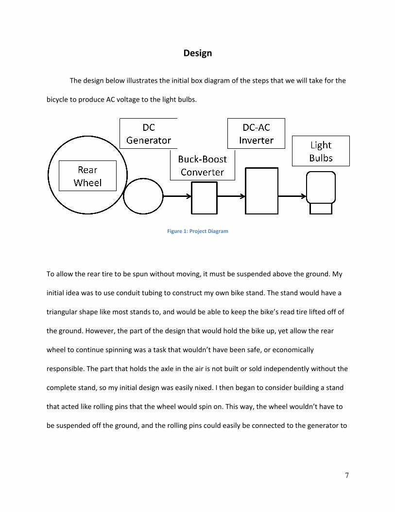
below illustrates the initial box diagram of the steps that we will take
bicycle to produce AC voltage to the light bulbs.
Figure 1: Project Diagram
To allow the rear tire to be spun without moving, it must be suspended above the ground.
initial idea was to use conduit tubing to construct my own bike stand. The stand would have a
triangular shape like most stands to, and would be able to keep the bike’s read tire lifted off of
the ground. However, the part of the design that would hold the bike up, yet allow the rear
wheel to continue spinning was a task that wouldn’t have been safe, or economically
responsible. The part that holds the axle in the air is not built or sold independently without the
complete stand, so my initial design was easily nixed. I then began to consider building a stand
that acted like rolling pins that the wheel would spin on. This way, the wheel wouldn’t have to
be suspended off the ground, and the rolling pins could easily be connected to the generator to
7
initial box diagram of the steps that we will take for the
To allow the rear tire to be spun without moving, it must be suspended above the ground. My
initial idea was to use conduit tubing to construct my own bike stand. The stand would have a
triangular shape like most stands to, and would be able to keep the bike’s read tire lifted off of
the bike up, yet allow the rear
wheel to continue spinning was a task that wouldn’t have been safe, or economically
responsible. The part that holds the axle in the air is not built or sold independently without the
easily nixed. I then began to consider building a stand
that acted like rolling pins that the wheel would spin on. This way, the wheel wouldn’t have to
be suspended off the ground, and the rolling pins could easily be connected to the generator to
8
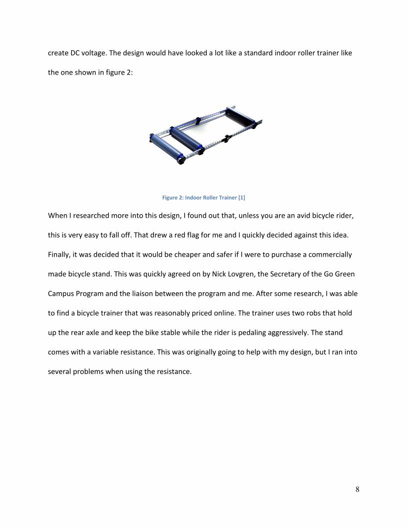
create DC voltage. The design would have looked a lot like a standard indoor roller trainer like
the one shown in figure 2:
Figure 2: Indoor Roller Trainer [1]
When I researched more into this design, I found out that, unless you are an avid bicycle rider,
this is very easy to fall off. That drew a red flag for me and I quickly decided against this idea.
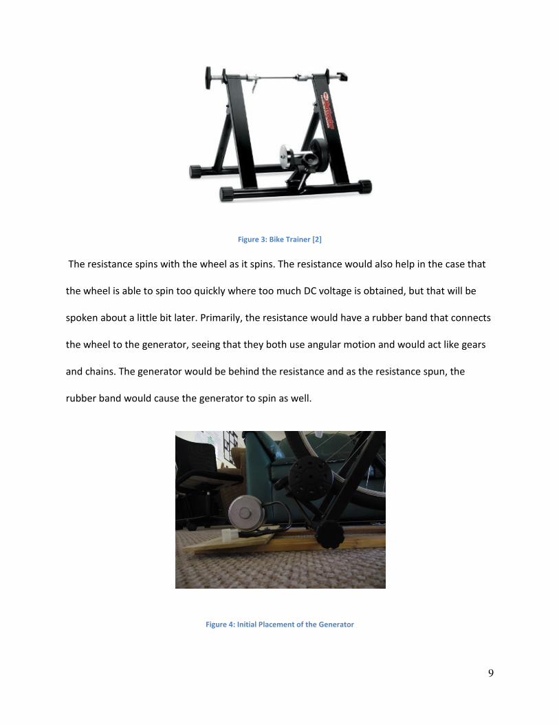
Finally, it was decided that it would be cheaper and safer if I were to purchase a commercially
made bicycle stand. This was quickly agreed on by Nick Lovgren, the Secretary of the Go Green
Campus Program and the liaison between the program and me. After some research, I was able
to find a bicycle trainer that was reasonably priced online. The trainer uses two robs that hold
up the rear axle and keep the bike stable while the rider is pedaling aggressively. The stand
comes with a variable resistance. This was originally going to help with my design, but I ran into
several problems when using the resistance.
9
Figure 3: Bike Trainer [2]
The resistance spins with the wheel as it spins. The resistance would also help in the case that
the wheel is able to spin too quickly where too much DC voltage is obtained, but that will be
spoken about a little bit later. Primarily, the resistance would have a rubber band that connects
the wheel to the generator, seeing that they both use angular motion and would act like gears
and chains. The generator would be behind the resistance and as the resistance spun, the
rubber band would cause the generator to spin as well.
Figure 4: Initial Placement of the Generator
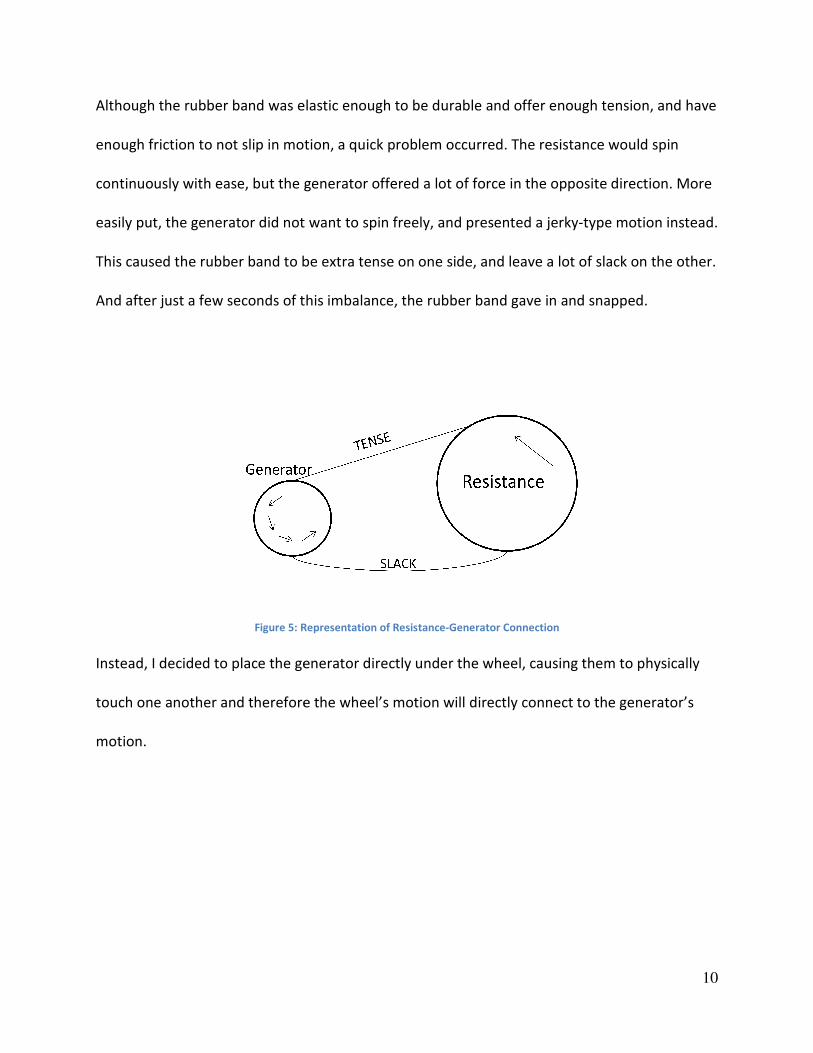
Although the rubber band was elastic enough to be durable and offer enough tension, and have
enough friction to not slip in motion, a quick
continuously with ease, but the generator offered a lot of force in the opposite direction. More
easily put, the generator did not want to spin freely, and presented a jerky
This caused the rubber band to be extra tense on one side, and leave a lot of slack on the other.
And after just a few seconds of this imbalance, the rubber band gave in and snapped.
Figure 5: Representation of Resistance
Instead, I decided to place the generator directly under the wheel, causing them to physically
touch one another and therefore the wheel’s motion will directly connect to the generator’s
motion.
Although the rubber band was elastic enough to be durable and offer enough tension, and have
enough friction to not slip in motion, a quick problem occurred. The resistance would spin
continuously with ease, but the generator offered a lot of force in the opposite direction. More
easily put, the generator did not want to spin freely, and presented a jerky-type motion instead.
ubber band to be extra tense on one side, and leave a lot of slack on the other.
And after just a few seconds of this imbalance, the rubber band gave in and snapped.
: Representation of Resistance-Generator Connection
Instead, I decided to place the generator directly under the wheel, causing them to physically
touch one another and therefore the wheel’s motion will directly connect to the generator’s
10
Although the rubber band was elastic enough to be durable and offer enough tension, and have
problem occurred. The resistance would spin
continuously with ease, but the generator offered a lot of force in the opposite direction. More
type motion instead.
ubber band to be extra tense on one side, and leave a lot of slack on the other.
And after just a few seconds of this imbalance, the rubber band gave in and snapped.
Instead, I decided to place the generator directly under the wheel, causing them to physically
touch one another and therefore the wheel’s motion will directly connect to the generator’s
11
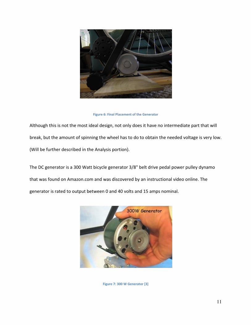
Figure 6: Final Placement of the Generator
Although this is not the most ideal design, not only does it have no intermediate part that will
break, but the amount of spinning the wheel has to do to obtain the needed voltage is very low.
(Will be further described in the Analysis portion).
The DC generator is a 300 Watt bicycle generator 3/8" belt drive pedal power pulley dynamo
that was found on Amazon.com and was discovered by an instructional video online. The
generator is rated to output between 0 and 40 volts and 15 amps nominal.
Figure 7: 300 W Generator [3]
12
The generator had to be bolted down onto a piece of wood so that it does not move from the
force of the bike tire. Also, when the rubber band was going to be used, the elasticity was
enough to pull the generator up. I initially had a 1” piece of wood to bolt it down to, but the
bolts that it came with weren’t long enough. The bolts that were offered at Home Depot were
long enough, but unfortunately turned out to not match the treads that were on the generator.
After several angry trips, I decided to use a thinner piece of wood (1/2”) and use the bolts that
came with it. After testing, I saw that the half-inch wood was enough to hold the generator in
place. The generator comes with the positive and negative leads that are connected to a buck-
boost converter.
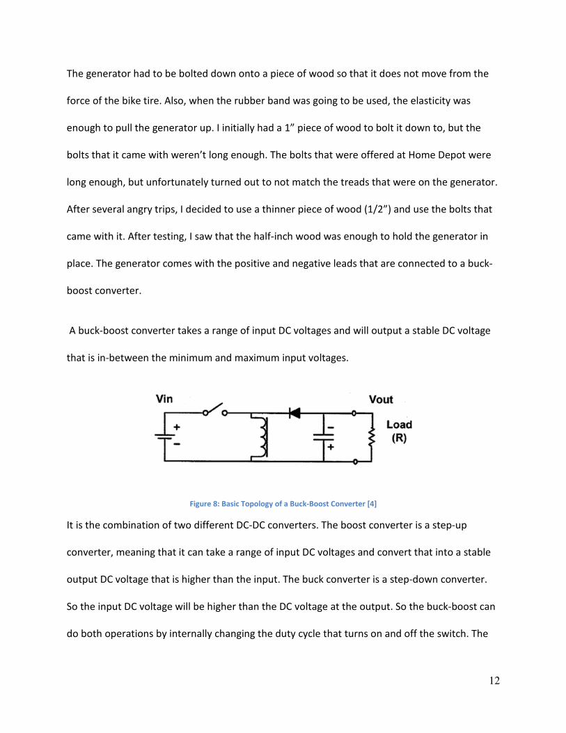
A buck-boost converter takes a range of input DC voltages and will output a stable DC voltage
that is in-between the minimum and maximum input voltages.
Figure 8: Basic Topology of a Buck-Boost Converter [4]
It is the combination of two different DC-DC converters. The boost converter is a step-up
converter, meaning that it can take a range of input DC voltages and convert that into a stable
output DC voltage that is higher than the input. The buck converter is a step-down converter.
So the input DC voltage will be higher than the DC voltage at the output. So the buck-boost can
do both operations by internally changing the duty cycle that turns on and off the switch. The

13
one that will be implemented in my project is a high efficiency buck-boost DC/DC μModule
Regulator from Linear Technology [5]. The chip is an LTM4605 and can handle an input voltage
between 4.5 to 20 volts DC and will output 12 volts DC. When I first ordered the free sample
from Linear Technology, the plan was to design the layout and solder together the board
myself. When the chips did come in, they were in LGA packaging style.
Figure 9: Pin Configuration for LGA Packaged LTM4605
After contacting Linear Technology, the conclusion came that there was no easy way of putting
soldering the board and the circuitry together, and it would need special equipment, a special
type of PCB, and hours and hours of labor. After weighing out the options of time, money, and
efficiency, I decided to choose the demoboard over building my own board. The demoboard
was only $65, and if I were to get at least two of each component (in case I overheated the first
one), and ordered a special board, the savings from making my own board were minimal (less
than $15) so the decision was made after getting permission from my advisor and Nick Lovgren.
Unfortunately I ran into another problem; the chip could not handle the current that the DC
generator could supply. This meant that a current divider or bypass would have to be included
into the design so that the chip and the components do not burn out and fail. For my design, I

14
simply added a 1k Ω load to the output of the generator. This greatly decreased the current
since the generator is ultimately supplying power, so the voltage that it outputs will remain the
same, but the current will decrease by a factor of 1000 in comparison to no load settings. After
the current problem was solved, I was able to successfully pedal the bike and as long as the
output voltage was between 4.5 and 20 volts, the LTM4605 outputted a stable 12 volts. It is
important that no more than 20 volts in injected into the board. So this means that whoever is
attending to the rider of the bike needs to regulate their speed so that they do not go too fast.
Figure 10: Typical Application and Demoboard of the LTM4605
The next step is to take the stable, steady 12 volt output from the buck-boost to the DC-AC
inverter. The inverter’s job is simple; to take the DC voltage input and output AC voltage. The
reason I added this to my project is because this will allow the user to use the generator as if it
was from a wall outlet. The inverter that I will be using is the Black & Decker 500 W Power
Inverter and was found at Home Depot. It supplies 500 watts of continuous power and 115V.

15
Figure 11: 500 Watt Power Inverter6
The inverter works by putting offset on a DC voltage in a way that it looks like an AC voltage
waveform. It has a total harmonic distortion of 36% and maximum single harmonic of 28% at
100% rated load. The modified sine wave acts as the AC voltage. This inverter was chosen
above the others for several reasons. First off, it had to produce enough power to illuminate 3
incandescent (60 watts) and 3 compact fluorescent (15 watts) light bulbs. I also preferred to
have two AC plugs be separated so that two “killawatt” devices can be attached to show the
difference in power consumption for each group of lights. This was important for my design
because that was the original plan for this project. The Go Green Campus Program wanted this
project to directly and easily show people how simple steps can be made to help our
environment. The “killawatt” devices will show the user that the same amount of lights can be
powered with a quarter of the energy with the CFL’s.
16
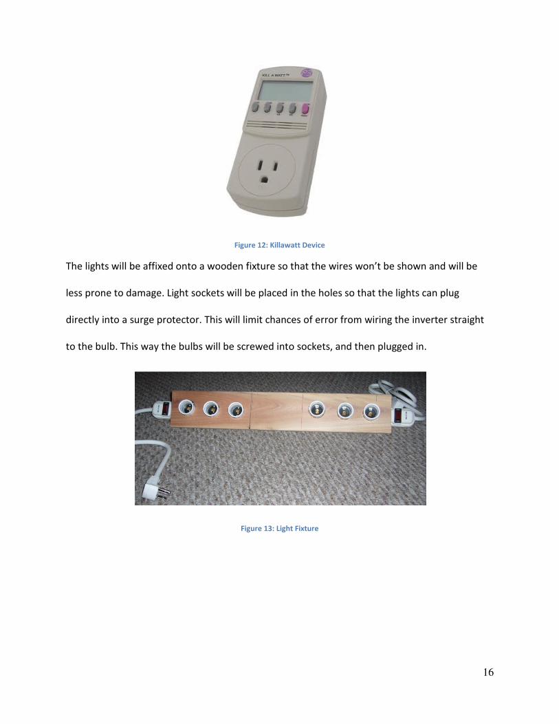
Figure 12: Killawatt Device
The lights will be affixed onto a wooden fixture so that the wires won’t be shown and will be
less prone to damage. Light sockets will be placed in the holes so that the lights can plug
directly into a surge protector. This will limit chances of error from wiring the inverter straight
to the bulb. This way the bulbs will be screwed into sockets, and then plugged in.
Figure 13: Light Fixture
17
Analysis
Bike-Generator Connection:
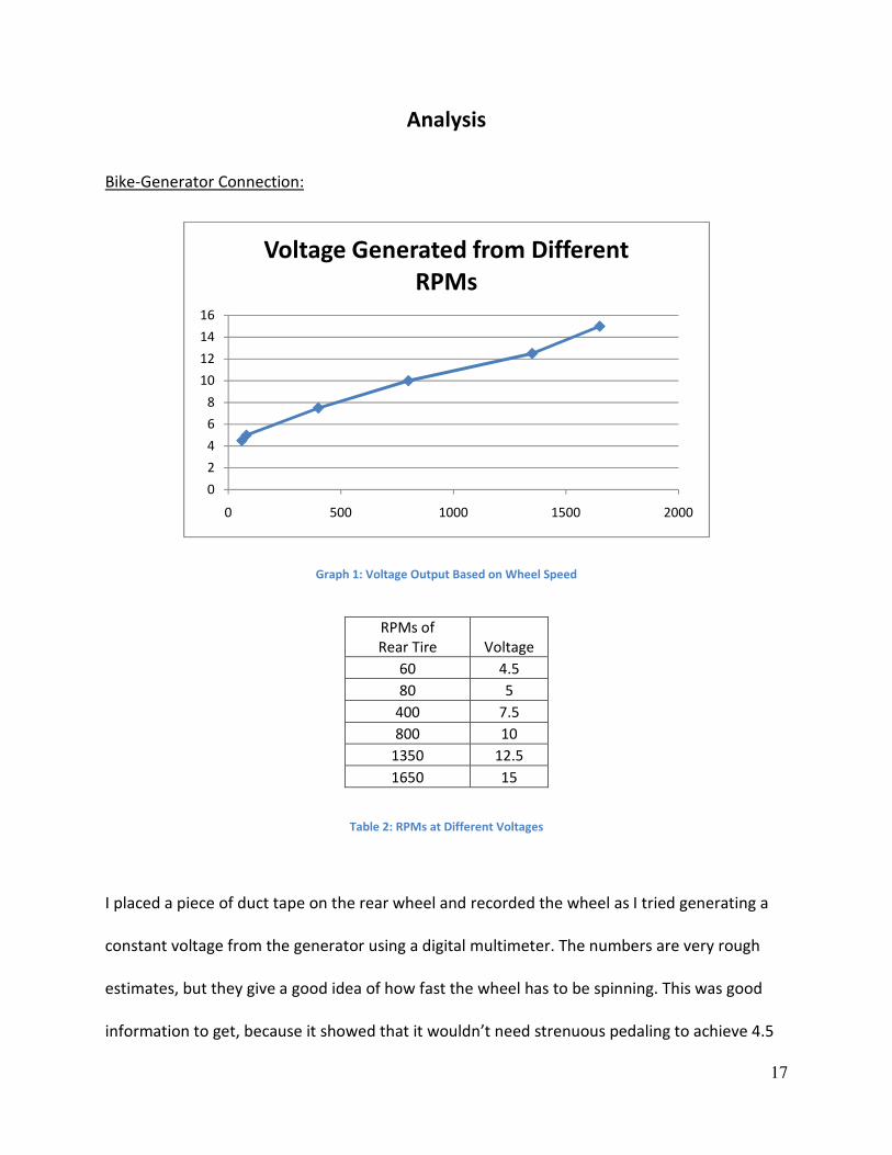
Graph 1: Voltage Output Based on Wheel Speed
RPMs of
Rear Tire Voltage
60 4.5
80 5
400 7.5
800 10
1350 12.5
1650 15
Table 2: RPMs at Different Voltages
I placed a piece of duct tape on the rear wheel and recorded the wheel as I tried generating a
constant voltage from the generator using a digital multimeter. The numbers are very rough
estimates, but they give a good idea of how fast the wheel has to be spinning. This was good
information to get, because it showed that it wouldn’t need strenuous pedaling to achieve 4.5
0
2
4
6
8
10
12
14
16
0 500 1000 1500 2000
Voltage Generated from Different
RPMs

18
volts, and it would be very difficult to go over 20 volts. This allows the user to have a large
margin of error when it comes to pedaling the bike. The rear tire of the bike has a diameter of
25 ½ inches across, giving it a circumference of 80.07 inches around. The generator’s axis has a
2 inch diameter, giving that a 6.28 inch circumference. Using that ratio of rear tire/generator, it
says that with 1 turn of the bike tire that you will get almost 13 turns of the generator,
assuming you get perfect connection.
Next was the test with the current, since that was one of my fears when it came to overloading
the demoboard and frying all of the components. For this test, I used two multimeters to see
how much current I was drawing from the generator at different voltages.
Graph 2: Current Based on Voltage from the Generator
0
200
400
600
800
1000
1200
1400
1600
0 2 4 6 8 10 12 14 16
Cu
rre
nt
(mA
)
Voltage (V)
Current Based on the Voltage
19
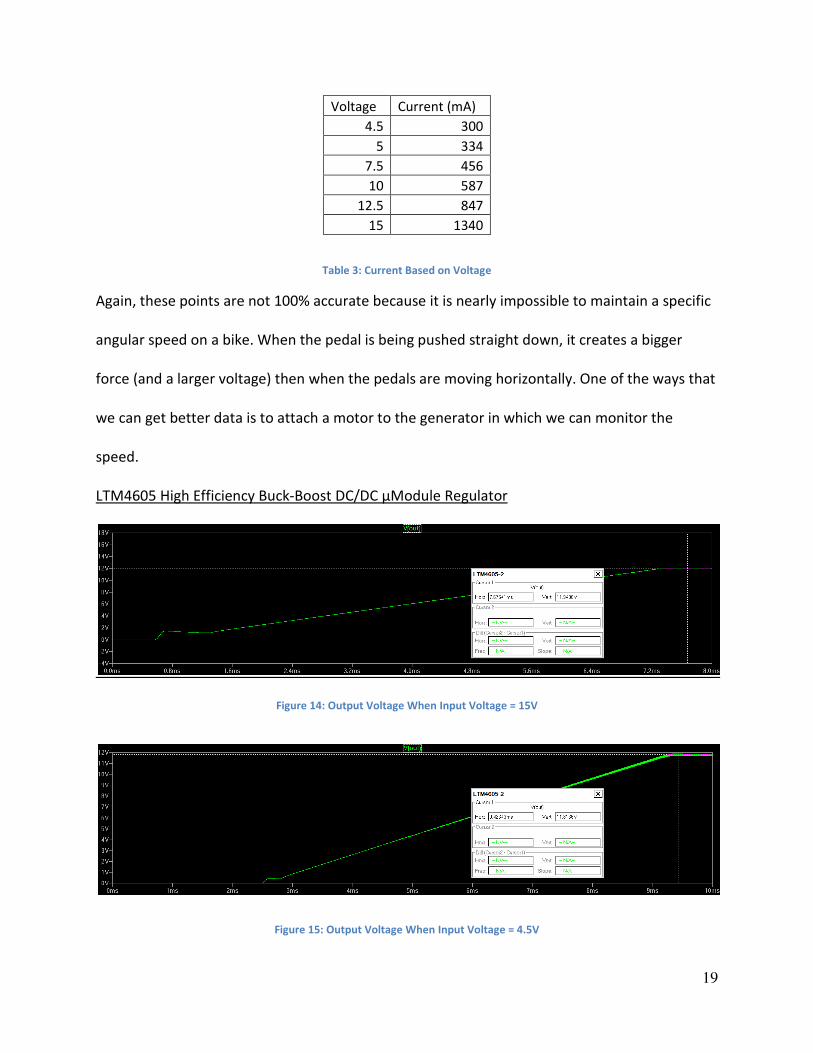
Voltage Current (mA)
4.5 300
5 334
7.5 456
10 587
12.5 847
15 1340
Table 3: Current Based on Voltage
Again, these points are not 100% accurate because it is nearly impossible to maintain a specific
angular speed on a bike. When the pedal is being pushed straight down, it creates a bigger
force (and a larger voltage) then when the pedals are moving horizontally. One of the ways that
we can get better data is to attach a motor to the generator in which we can monitor the
speed.
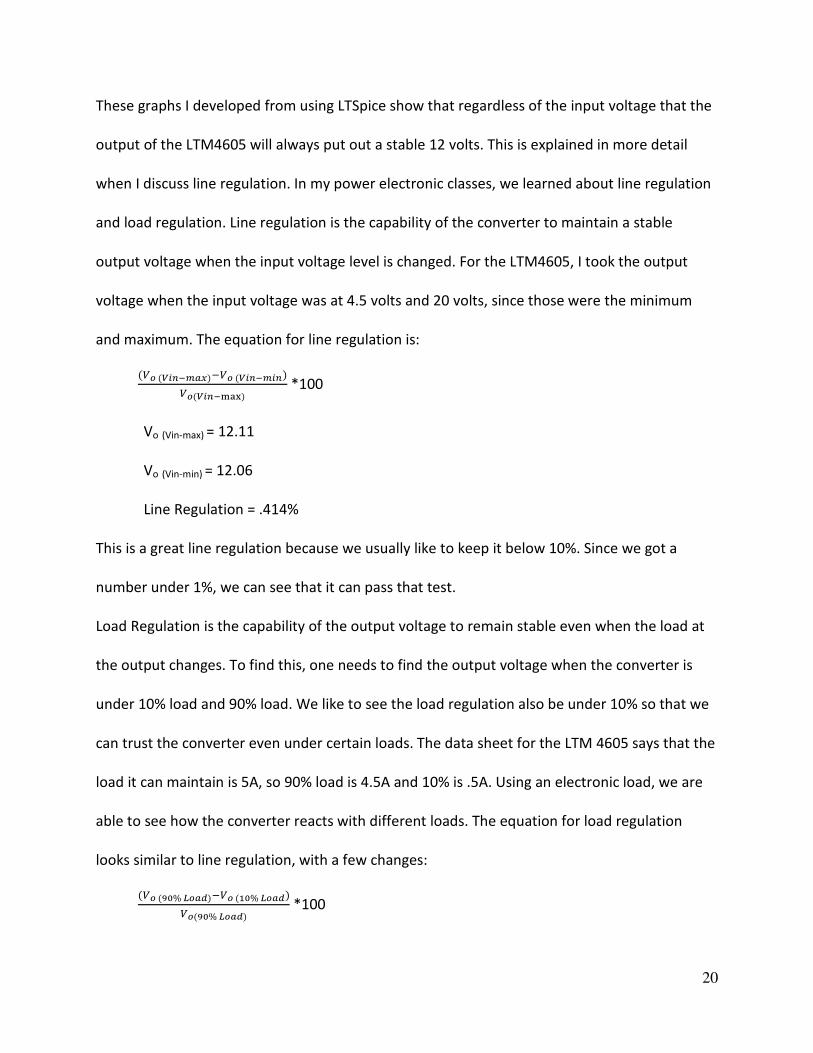
LTM4605 High Efficiency Buck-Boost DC/DC μModule Regulator
Figure 14: Output Voltage When Input Voltage = 15V
Figure 15: Output Voltage When Input Voltage = 4.5V
20
These graphs I developed from using LTSpice show that regardless of the input voltage that the
output of the LTM4605 will always put out a stable 12 volts. This is explained in more detail
when I discuss line regulation. In my power electronic classes, we learned about line regulation
and load regulation. Line regulation is the capability of the converter to maintain a stable
output voltage when the input voltage level is changed. For the LTM4605, I took the output
voltage when the input voltage was at 4.5 volts and 20 volts, since those were the minimum
and maximum. The equation for line regulation is:
*100
Vo (Vin-max) = 12.11
Vo (Vin-min) = 12.06
Line Regulation = .414%
This is a great line regulation because we usually like to keep it below 10%. Since we got a
number under 1%, we can see that it can pass that test.
Load Regulation is the capability of the output voltage to remain stable even when the load at
the output changes. To find this, one needs to find the output voltage when the converter is
under 10% load and 90% load. We like to see the load regulation also be under 10% so that we
can trust the converter even under certain loads. The data sheet for the LTM 4605 says that the
load it can maintain is 5A, so 90% load is 4.5A and 10% is .5A. Using an electronic load, we are
able to see how the converter reacts with different loads. The equation for load regulation
looks similar to line regulation, with a few changes:
% %
% *100

21
Vo (90% Load) = 12.12 V
Vo (10% Load) = 12.05V
Load Regulation: .577%
Again, the converter passed the test and proves to be a dependable converter no matter what
the load is.
The efficiency of the converter came with the data sheet. It shows that the converter is most
efficient when it is dropping from a higher voltage down to about 11.5 volts. This shows that as
the converter is in buck mode and the input is falling so that the input voltage equals the
output voltage, that that is when it is most efficient. However, when the input voltage starts
low, the converter becomes inefficient quickly after achieving 4.5 volts and starts to ascend
again when the converter switches to buck mode.
Figure16: Efficiency Graph of LTM4605 [5]
22
Conclusion
Working on this project helped me understand the steps that are involved with
brainstorming, designing, planning, and executing a project. These are skills that aren’t stressed
in many of our electrical engineering classes and I’m fortunate that I was able to have this
senior project to call my own and to work on my organization. I’m very happy with the almost
finished product. I say that it is almost finished because I know that there are several
improvements that can be made on this project. I personally don’t like how the generator and
bicycle tire are physically touching and would like to place a battery in between the DC-DC
converter and the inverter so that the power inputted into the inverter remains constant,
therefore having a constant output power. However, I feel like I was able to put the best
product forward for the Cal Poly Go Green Campus Program and feel safe that they will treat
this project with care and within the next couple years, improve on it so that they can get their
message represented to the people who are able to see it.
I understand that there are still several qualities that I need to improve on. There were
several times in the past several months that I lost communication with both my advisor and
with Nick. I know that communication stopped because of uncertainty on my part, and
understand know that stopping our collaboration only added to the problem. I would have liked
to have more stable conversations with both, and will take that thinking into any projects or
employments that I may have in the future. Another thing I could have done better was to plan
my time and my money better. There were little things here and there that I bought and ended
up not using. That’s extremely inefficient and for a person who is usually stingy with money, is
something that I know I should’ve done better.

23
According to the schedule that I set out for myself, I fell behind slightly before the end
of Winter quarter due to finals and class projects, but was able to make up for it during Spring
Break. That was when I did most of my building and purchasing of materials. After the research
I did during Winter quarter plus the work I put in during Spring Break helped me achieve my
finished project just 2 weeks behind the deadline I set for myself which was April 12th. That
deadline was meant to be early on so that if I did run into problems or delays that I could finish
by 5th week of Spring quarter. I also had set a projected budget on this report to be $250.
Proposed Actual
Inverter $40.00 $34.99
DC-DC
Converter $25.00 $65.00
DC Generator $50.00 $200.00
Light Bulbs $20.00 $0.00
Stand $30.00 $60.00
Bike $60.00 $0.00
Overhead
(10%) $22.50 $36.00
Total $247.50 $395.99
Table 4: Projected and Actual Amount of Money Spent
It’s obvious that I spent more than anticipated, but I don’t think that it is because I was
irresponsible with the money. I feel that we got the best deals that we could find for the
project, but I made the mistake of not accurately researching the prices before I set the
estimation. The generators that I originally thought of using were not going to be durable
enough, so the more expensive one was our best option. We are able to save money by having
a plethora of light bulbs in the Go Green Campus’ possession, and the bike can be interchanged
so anyone with a bike can supply that and it did not have to be purchased.

24
Acknowledgement
I’d like to give a thank you to Dr. Shaban and Nick Lovgren for helping me with this
Senior Project. In the end, I’m glad that I had an interesting and enjoyable project to work on. I
can breathe a little easier knowing that I’ve spent the past several years studying something
that I like to do, and that this project was the last piece of my college puzzle. I hope that I was
able to spend the past 5 years with no regrets and that the classes and the experiences I went
through will guide me to a happy and successful future.
25
Bibliography
1. “What Is A Bicycle Roller Trainer?” <http://www.bicycle-and-bikes.com/bicycle-roller-
trainer.html > April 14, 2011.
2. “Bell Motivator Mag Indoor Bicycle Trainer.” Amazon.
<http://www.amazon.com/gp/product/B000AAYBWS?ie=UTF8&tag=freewaresharew01
&linkCode=as2&camp=1789&creative=390957&creativeASIN=B000AAYBWS > February
11th, 2011
3. “300 Watt Bicycle Generator 3/8" Belt Drive Pedal Power Pulley Dynamo.” Amazon.
<http://www.amazon.com/gp/product/B001WB3TZ4?ie=UTF8&tag=freewaresharew01
&linkCode=as2&camp=1789&creative=390957&creativeASIN=B001WB3TZ4 > February
11th, 2011
4. Taufik. “Introduction to Magnetic Design.” 2nd Revision, 2011. “Buck-Boost Convert”
Page 81. April 25th, 2011.
5. “LTM4605 – High Efficiency Buck-Boost DC/DC μModule.” Linear Technology.
<http://www.linear.com/product/LTM4605> February 18th, 2011.
6. “Vehicle Power System 500 Watt Power Inverter with USB Charging Port Instruction
Manual.” Black & Decker. Revised August 2010. April 25th, 2011.

26
Appendix
Parts List/Specification:
- Generator:
300 Watt Air Cooled DC Generator
0V to 40V Output
Nominal 15A Current
Peak 20A Current
Max RPM: 2600
-DC/DC Converter
VIN range: 4.5V to 20V
Typical 5A Current
Up to 98% Efficiency
Current Mode Control
Good Output Signal
Phase-Lockable Fixed Frequency: 200 kHz to 400 kHz
Complete Data Sheet Attached
-DC-AC Inverter
Maximum Continuous Power: 500W

27
Surge/Peak Power: 1000W
Input: 12.8V
Output: 115V/60Hz
Fuse: 30A*2, 10A*1
Modified Sine Wave Output
Up to 4.35A
Related Documents