Bicycle Hardware‐in‐the‐Loop Simulator for Braking Dynamics Assistance System IPG Apply & Innovate 2016 Conference Session: Off‐Highway Cornelius Bott, Martin Pfeiffer, Oliver Maier, Jürgen Wrede 21.09.2016

Welcome message from author
This document is posted to help you gain knowledge. Please leave a comment to let me know what you think about it! Share it to your friends and learn new things together.
Transcript
Bicycle Hardware‐in‐the‐Loop Simulatorfor Braking Dynamics Assistance System
IPG Apply & Innovate 2016 ConferenceSession: Off‐Highway
Cornelius Bott, Martin Pfeiffer, Oliver Maier, Jürgen Wrede21.09.2016

Outline
Introduction to BikeSafeMotivationVision
MethodologyHIL Testbench
Structure and ComponentsUsage in Development
ResultsConclusion
2
Motivation for Active Safety Systems on Bicycles
3
• Low wheel moment of inertia
• Risk of overbraking
• Mainly on roads with low
friction coefficient & in curves
Front wheel lockup
• High centre of gravity
• Emergency or shock braking
• Mainly on roads with high
friction coefficient & downhill
Nose over(falling over the handlebars)
• Properly adjusted:
always very powerful
• Modern hydraulic technology:
stronger and more robust
• High risk of falling due to
users’ mistakes
Bicycle braking systems
• Availability of electric energy
• Favourable mass & cost ratio
Electrifiedbicycles
Sources:Gustav Magenwirth GmbH, Robert Bosch GmbH

Vision Functional Prototype
• Purpose: algorithm development
• Rapid‐control‐prototyping system
• Purpose: brake pressure modulation
• Hydraulic unit of motorcycle ABS
• Measurands: 1) longitudinal and vertical accelerations
2) pitch rate
• Micromechanical sensor unit
4
Control unit
Actuator
• Measurand: front wheel speed
• Active sensor based on Hall Effect
Sensors
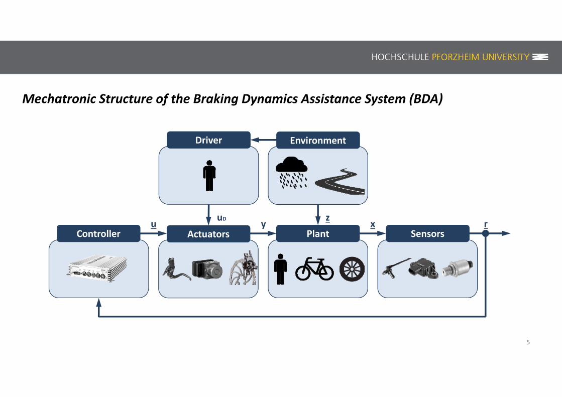
Mechatronic Structure of the Braking Dynamics Assistance System (BDA)
5
Environment
PlantActuatorsController
Driver
Sensorsu y x rzuD

6
Methodology of Development
Proof of Concept
Functional model evaluation
System integrationand testing
④
Requirements Profile
Accident research and respective applications
①
Requirements identification and quantification
②
⑤
System design and implementation
③
Validation
Validation
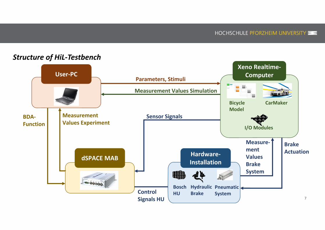
Structure of HiL‐Testbench
User‐PC
dSPACE MAB
Sensor Signals
BrakeActuation
Parameters, Stimuli
Measurement Values Simulation
BDA‐Function
Measure‐mentValuesBrakeSystem
ControlSignals HU
MeasurementValues Experiment
Hardware‐Installation
BoschHU
HydraulicBrake
PneumaticSystem
Xeno Realtime‐Computer
CarMaker
I/O Modules
BicycleModel
7
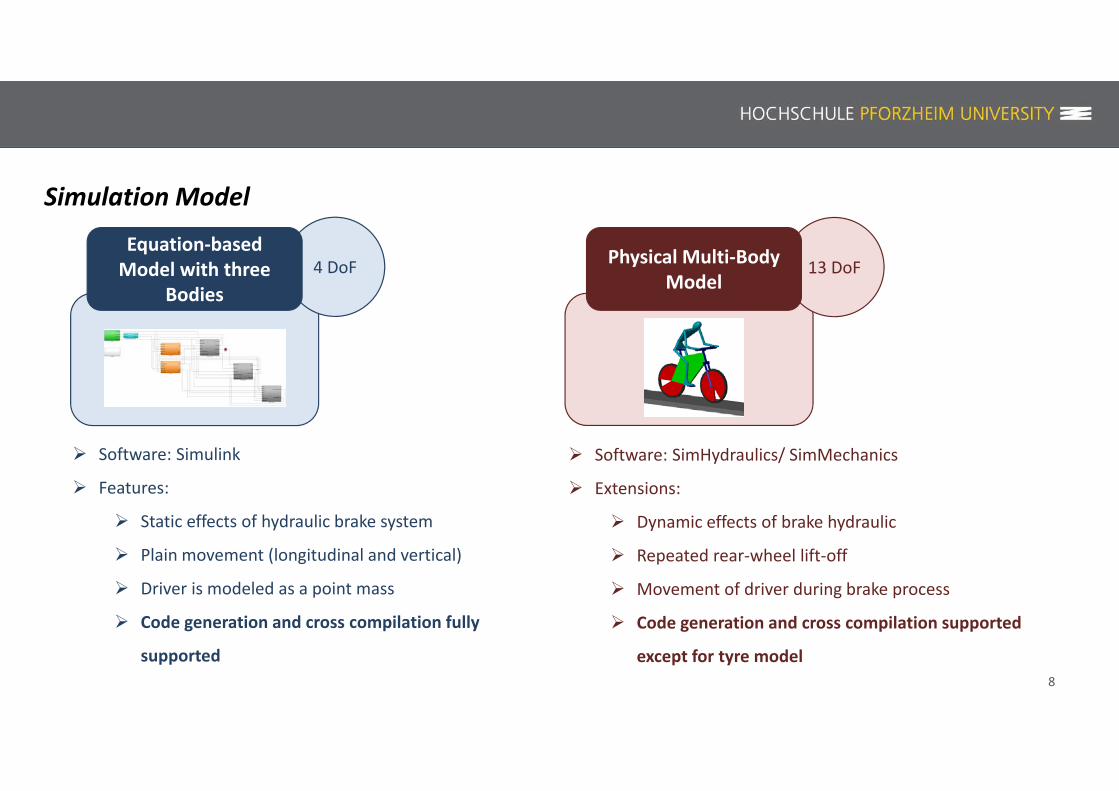
Simulation Model
8
Software: SimHydraulics/ SimMechanics
Extensions:
Dynamic effects of brake hydraulic
Repeated rear‐wheel lift‐off
Movement of driver during brake process
Code generation and cross compilation supported
except for tyre model
Software: Simulink
Features:
Static effects of hydraulic brake system
Plain movement (longitudinal and vertical)
Driver is modeled as a point mass
Code generation and cross compilation fully
supported
13 DoFPhysical Multi‐Body Model
4 DoFEquation‐basedModel with three
Bodies

9
Real‐Time Computer & M‐Modules
M400WheelSpeed
M62NAnalog Outputs
M36N00Analog Inputs
M514x CAN
Front‐ and
Rear‐Wheel
60 Teeths
Measurement
Trigger
Lift‐Off Sensor
Brake force
Measurement
Brake lever Sensor
Pressure sensors
Acceleration sensors

HiL‐Testbench
Real time computer RCP System
Brake force sensorCharge amplifier
Brake lever
Battery
10
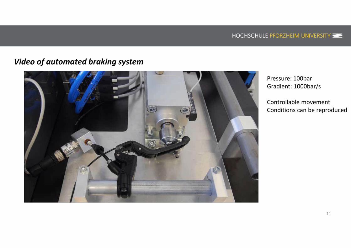
Video of automated braking system
Pressure: 100barGradient: 1000bar/s
Controllable movementConditions can be reproduced
11

Usage in Development
MiL HiL Real Experiment
• Wheel Speed Signal Analysis
under real conditions
• Investigation of hydraulic brake
system (especially HU)
• Cover a wider parameter space
• Reproducibility
12

13
Results – BDA‐Function not engaged
14
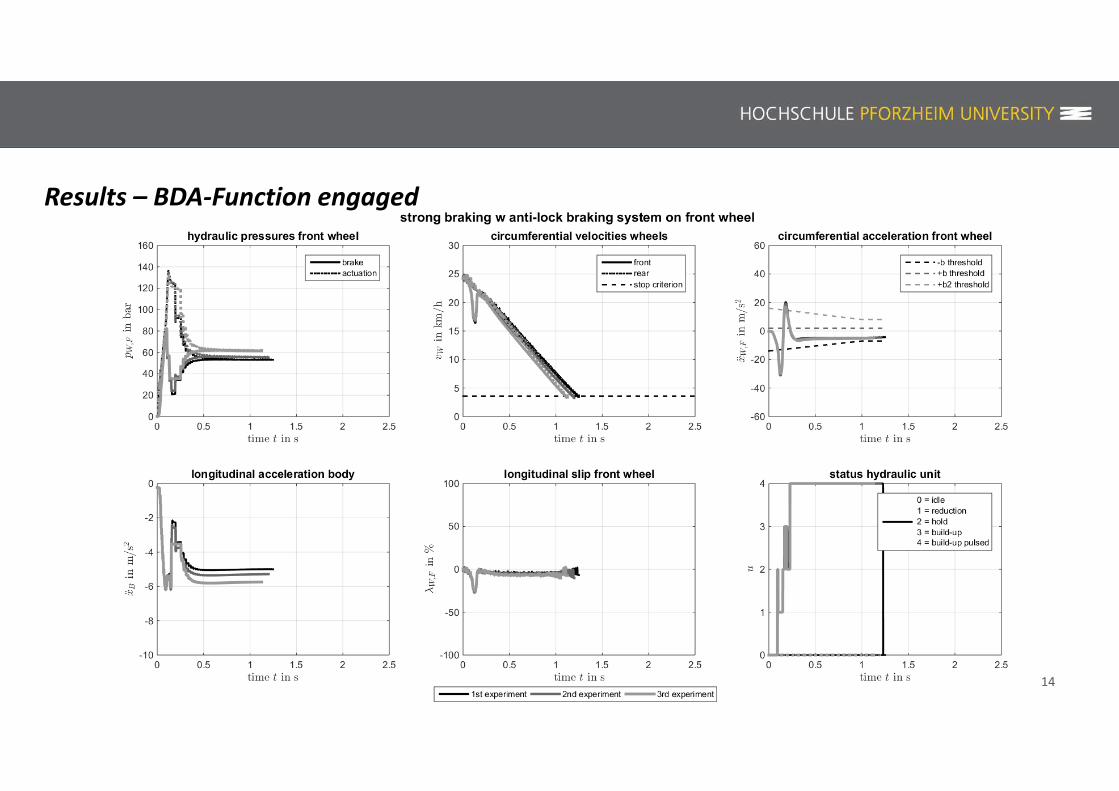
Results – BDA‐Function engaged

Conclusion – Usage of HIL for development of a BDA function
15
Requirements for BikeSafe function development were met
Very useful for investigation of Brake System and HU
Good validation of BDA function before real experiments
Limitations of BDA function could be accessed
Transfer of known method to a new domain
16
Thank you for your attention!
Related Documents