US 20140253271A1 (19) United States (12) Patent Application Publication (10) Pub. No.: US 2014/0253271 A1 Heins (43) Pub. Date: Sep. 11, 2014 (54) BI-TOROIDAL TOPOLOGY TRANSFORMER (52) US. Cl. CPC .................................... .. H01F27/24 (2013.01) (71) Applicant: Thane C - Heins,A1m0nte (CA) USPC ............................................. .. 336/5; 336/220 (72) Inventor: Thane C. Heins, Almonte (CA) (57) ABSTRACT (21) Appl. No.: 14/199,541 (22) Filed. Man 6 2014 The present invention relates to electrical transformers and, in a particular, to improvements to ef?ciency in energy conver Related US. Application Data sion in electrical transformers. The improved transformer has (60) Provisional application NO 61/773 877 ?led on Mar a bi-toroidal circuit topology in Which the magnetic ?ux 7 2013 ' ’ ’ ' passing through the primary and secondary coils are different. ’ ' The turns ratio displays an “effective magni?cation” like an Publication Classi?cation impedance transformed by a feedback loop. The result is a transformer Which displays virtually no primary input current (51) Int. Cl. increase from no-load to on-load and an on-load power factor H01F 27/24 (2006.01) of zero for a purely resistive load. Secstwtt-arryitlciii #1 Gemmtary' Earl 22' Bi-Toroid Transformer (BiTT) Variations

Welcome message from author
This document is posted to help you gain knowledge. Please leave a comment to let me know what you think about it! Share it to your friends and learn new things together.
Transcript
US 20140253271A1
(19) United States (12) Patent Application Publication (10) Pub. No.: US 2014/0253271 A1
Heins (43) Pub. Date: Sep. 11, 2014
(54) BI-TOROIDAL TOPOLOGY TRANSFORMER (52) US. Cl. CPC .................................... .. H01F27/24 (2013.01)
(71) Applicant: Thane C - Heins,A1m0nte (CA) USPC ............................................. .. 336/5; 336/220
(72) Inventor: Thane C. Heins, Almonte (CA) (57) ABSTRACT
(21) Appl. No.: 14/199,541 (22) Filed. Man 6 2014 The present invention relates to electrical transformers and, in
a particular, to improvements to ef?ciency in energy conver Related US. Application Data sion in electrical transformers. The improved transformer has
(60) Provisional application NO 61/773 877 ?led on Mar a bi-toroidal circuit topology in Which the magnetic ?ux 7 2013 ' ’ ’ ' passing through the primary and secondary coils are different.
’ ' The turns ratio displays an “effective magni?cation” like an
Publication Classi?cation impedance transformed by a feedback loop. The result is a transformer Which displays virtually no primary input current
(51) Int. Cl. increase from no-load to on-load and an on-load power factor H01F 27/24 (2006.01) of zero for a purely resistive load.
Secstwtt-arryitlciii #1 Gemmtary' Earl 22'
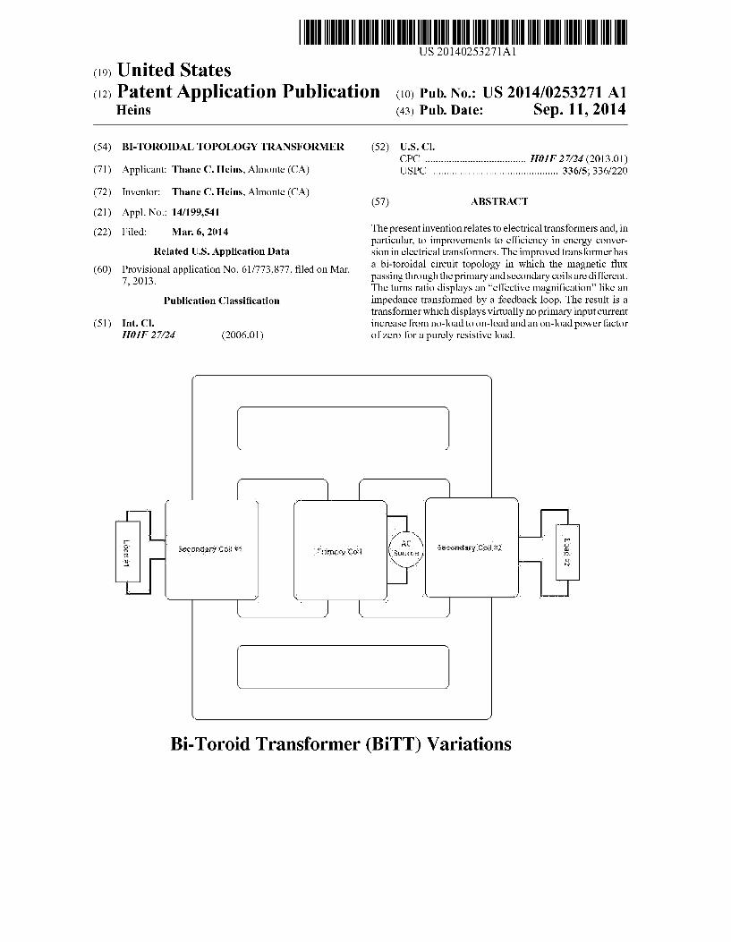
Bi-Toroid Transformer (BiTT) Variations
US 2014/0253271 A1 Sep. 11, 2014 Sheet 1 0f 17 Patent Application Publication
Fig. 1A
Fig. 1B
Fig. 1C
Patent Application Publication Sep. 11, 2014 Sheet 2 of 17 US 2014/0253271 A1
/ -
k)?“ Gemxmlar; can:
Fig 2A. Bi-Toroid Transformer (BiTT) Variations
1100
Primary Flux
I {—1
—Cl
1101 1102 (No Load)
1' In: = MIN ‘ — - - - - - _ _ _ I
zp= MAX
Primary Voltage i
{<1 Secondary Voltage i | PrimaryI Currant i I
if i L =—
‘ I '/ ‘ V | | r “a ,1” | | _ a
|
| “180” Primary Power=VxlxR B=° =13vx.25A:D
= 0 Watts
Fig 11. No-Load Flux Diagram for Conventional Transformer
Patent Application Publication Sep. 11, 2014 Sheet 3 0f 17 US 2014/0253271 A1
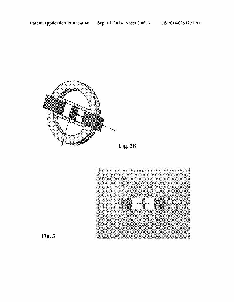
Fig. 2B
Fig. 3 , M M,
Patent Application Publication Sep. 11, 2014 Sheet 4 0f 17 US 2014/0253271 A1
Fig. 4
aw 42:3 5
K, i
Patent Application Publication Sep. 11, 2014 Sheet 5 0f 17 US 2014/0253271 A1
Fig. 5
US 2014/0253271 A1 Sep. 11, 2014 Sheet 6 0f 17 Patent Application Publication
. ‘ cs $6.6 . . 4.2 . . .
Fig. 6
7 Fig
Patent Application Publication Sep. 11, 2014 Sheet 7 0f 17 US 2014/0253271 A1
Fig. 9
Patent Application Publication Sep. 11, 2014 Sheet 8 0f 17 US 2014/0253271 A1
Fig 10
Fig 12
Patent Application Publication Sep. 11, 2014 Sheet 9 0f 17 US 2014/0253271 A1
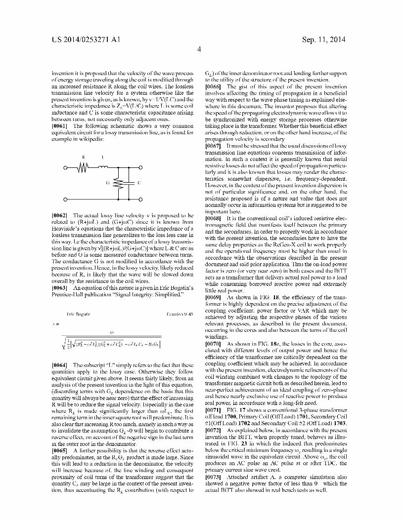
Fig. 13
Fig. 15
Patent Application Publication Sep. 11, 2014 Sheet 10 0f 17 US 2014/0253271 A1
1400
Primary Flu: (D;
; T 1 . | : : I | I I I
l I | I
1401 1403 g: 1402 l I | I | I I |
| I | I
| I I |
l T L I i k , r k _ ________ ________ _ _ ,
Load Voltage
Primary Voltage Load Current
PrimarJ,l Current
Fig. 14A On-Load Secondary Induced Flux
Patent Application Publication Sep. 11, 2014 Sheet 11 of 17 US 2014/0253271 A1
Load
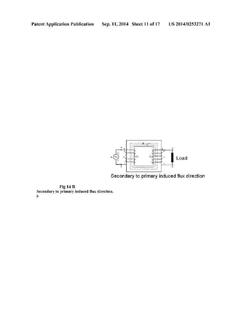
Secondary to primary induced ?ux direction
Fig 14 B Secondary to primary induced ?ux direction. 6
Patent Application Publication Sep. 11, 2014 Sheet 12 0f 17 US 2014/0253271 A1
Fig. 16
Fig. 18
Fig. 19
Patent Application Publication Sep. 11, 2014 Sheet 13 0f 17 US 2014/0253271 A1
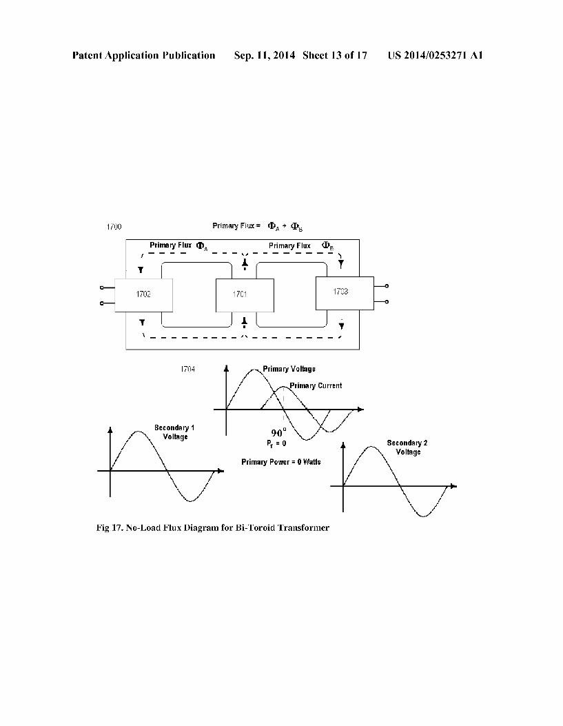
1mg Primary Fiu: 1= “IDA + EDS
Primary Flu: (DA Primary Flu: CD5 : - - - - - - - H - - - — - — — - x
1 T ' I i ' i i D— —o
1r02 1m W3 D— _O
1r l J + L J 1 \ _ _ _ _ _ _ _ _ _ I\ _ _ _ _ _ _ _ _ I
1TU4
Secundaryi Voltage
SecundaryZ Voltage
Primal},r Power = 1] Watts
I V; I V‘ Fig 17. No-Load Flux Diagram for Bi-Toroicl Transformer
Patent Application Publication Sep. 11, 2014 Sheet 14 0f 17 US 2014/0253271 A1
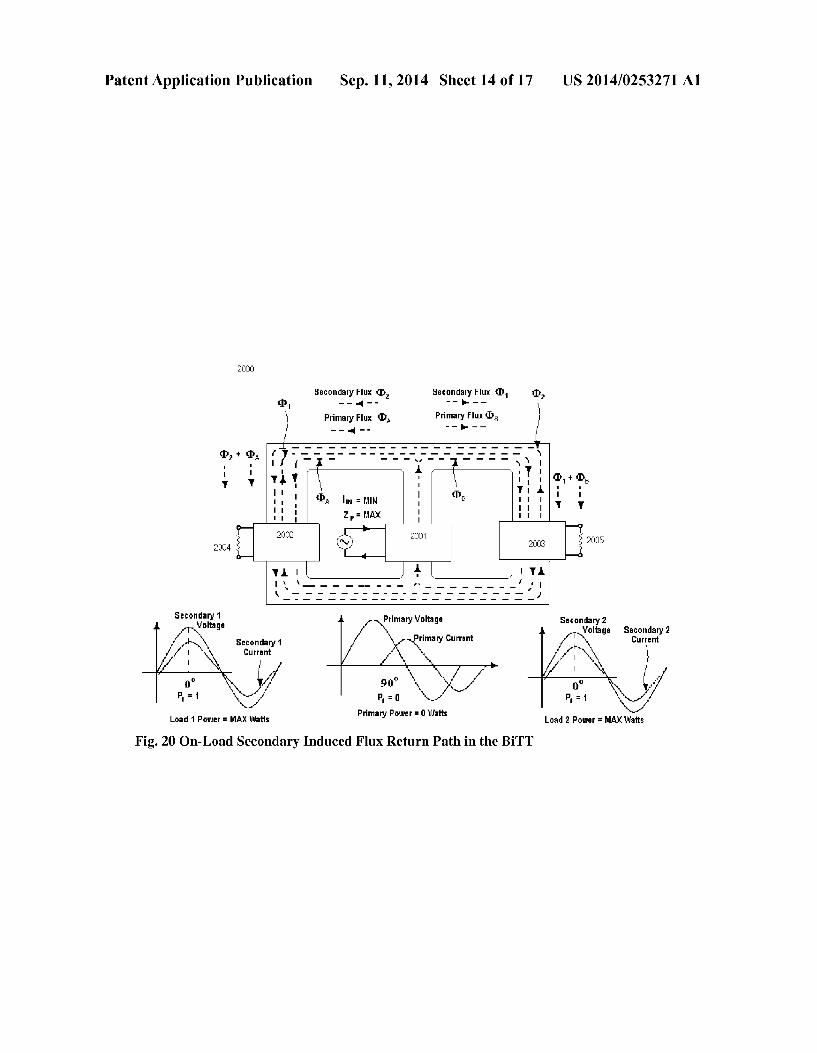
2000
5"""586' FlllX (D2 Secondarg,r Flux (I11 (1)2 <I>1 - - -r - - - - a _ _
Primary Flux (DA Primary Flux (DB
(132 + (DA
Seeondary1 Voltage Secondary2
Voltage Secondary2 Secondary1 current Cu rre nl
Load 1 Power = MAX Watls Primary power = 0 watts Load 2 Power = MAX Watts
Fig. 20 On-Load Secondary Induced Flux Return Path in the BiTT
Patent Application Publication Sep. 11, 2014 Sheet 15 0f 17 US 2014/0253271 A1
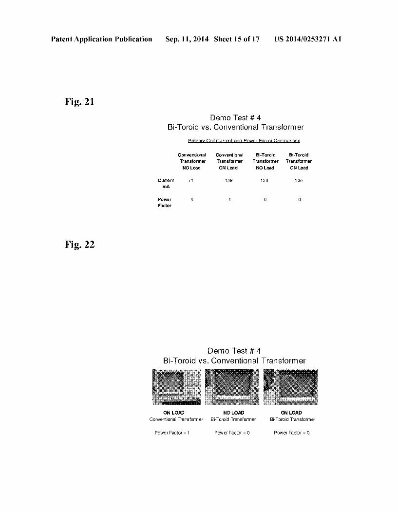
Fig. 21 Demo Test # 4
Bi-Toroid vs. Conventional Transform er
Prim il rrn varF rm rin
Conventional Conventional Bi-Toroid Bi-Toroid Transformer Transformer Transformer Transformer NO Load ON Load NO Load ON Load
Current 71 139 130 130 mA
Power 0 i O 0 Factor
Fig. 22
Demo Test # 4 Bi-Toroid vs. Conventional Transform er
ON LOAD NO LOAD ON LOAD Conventional Transformer Bi-Toroid Transformer Bi~Toroid Transformer
Power Factor = 1 Power Factor = 0 Power Factor = 0
US 2014/0253271 A1 Sep. 11, 2014 Sheet 16 0f 17 Patent Application Publication
US 2014/0253271 A1 Sep. 11, 2014 Sheet 17 0f 17 Patent Application Publication
....M......~...Hn... .. ....
... i ‘
Aw. . .1.” ".xz..w.f..... ........x.u . a. 1.3..“
.. a“ . u
US 2014/0253271A1
BI-TOROIDAL TOPOLOGY TRANSFORMER
[0001] Copending application Ser. No. 14/059,775 is herein incorporated by reference in its entirety for essential subject matter.
BACKGROUND OF THE INVENTION
[0002] In a transformer, the instantaneous voltage induced across the secondary coil is given from Faraday’s Law by:
where Ns is the number of turns in the coil and (I) is the magnetic ?ux. (integral of magnetic ?eld over the cross sectional area of the coil) If the coil axis is perpendicular to the magnetic ?eld lines, (normally the case by choice in transformers) total ?ux reduces to a product of the ?ux den sity B and the (constant) areaA through which it cuts. B varies with time according to the excitation of the primary. By Gauss’s law for magnetism the same magnetic ?ux passes through both the primary and secondary coils so in an ideal transformer the instantaneous voltage across the primary winding is:
VPJVquJ/dl
Therefore the voltages, turns ratios and currents in the two coils can be related by:
V/VPINS/NPII/IS Many applications of prior art transformers follow these equations, as illustrated in FIG. 1.
SUMMARY OF THE INVENTION
[0003] The transformer of the present invention, sometimes referred to herein as ‘Bi-Toroid Transformer’ or “BiTT” does not behave according to the transformer equation as given above and thus overcomes the problems with the prior art. The BiTT’s circuit topology has been changed so that it is no longer true that the same magnetic ?ux passes through both the primary and secondary coils. The turns ratio displays an “effective magni?cation” like an impedance transformed by a feedback loop. The result is a transformer which displays virtually no primary input current increase from no-load to on-load and an on-load power factor of zero with as long as it has a purely resistive load. [0004] As will be described in greater detail below, under such conditions, as compared with the prior art, the BiTT consumes mostly reactive power in the primary while deliv ering real power to the loads. Such a transformer could be used in a wide variety of applications and especially, owing to its increased ef?ciency and therefore reduced production of heat, could be installed for the distribution of AC electrical power throughout the residential and industrial grid having reduced cooling systems including ?uids containing harmful chemicals.
DESCRIPTION OF DRAWINGS
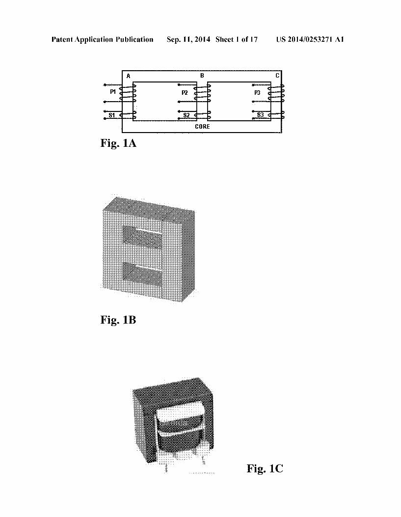
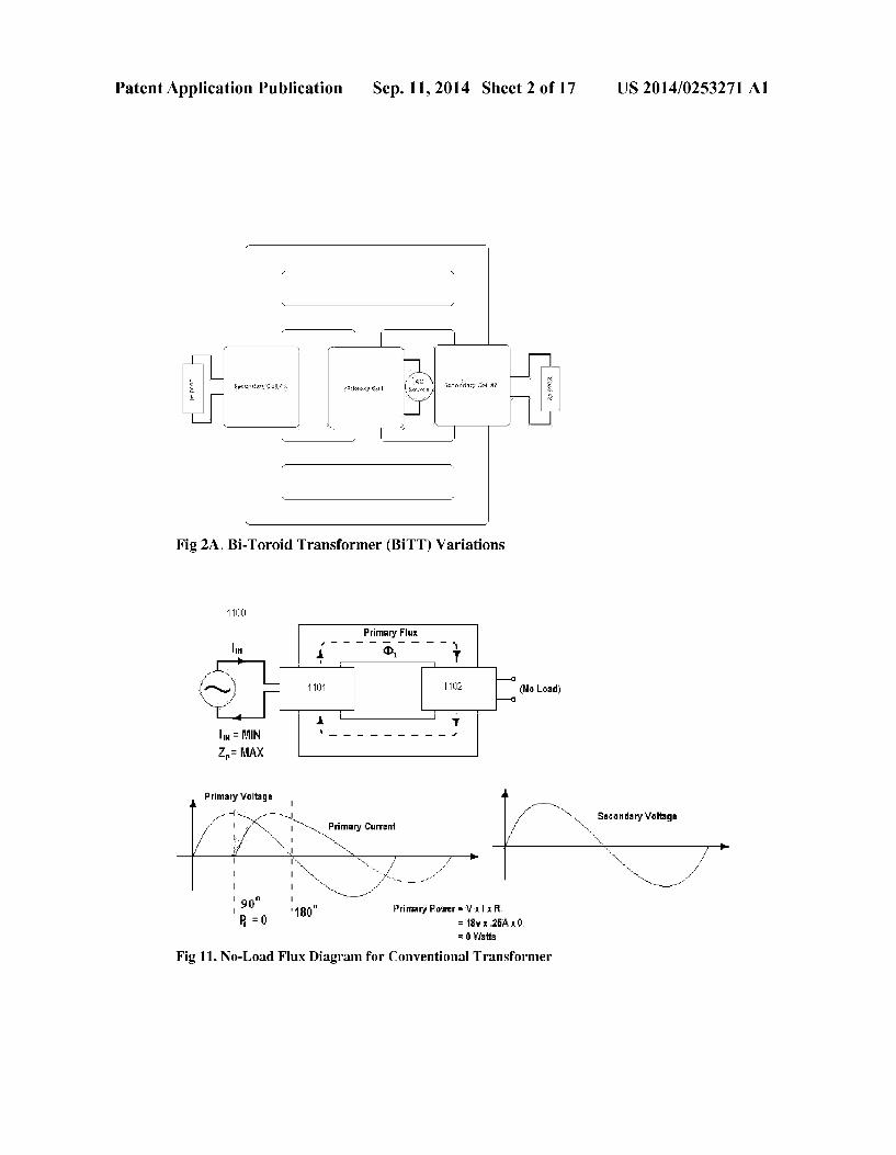
[0005] FIGS. 1A, B & C shows Prior Artia three-phase transformer, in which the ideal transformer equations can be applied relatively straightforwardly. [0006] FIGS. 2A and 2B illustrate the Bi-Toroid Trans former (BiTT) which is adapted from the topology of FIG. 1 in which the primary is placed on the central leg and two secondaries (or a ‘split secondary’) are wound around the two side legs.
Sep. 11,2014
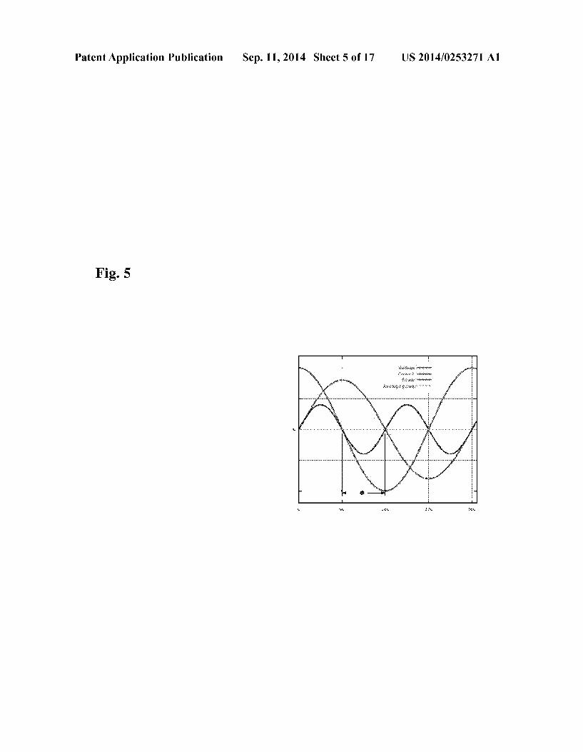
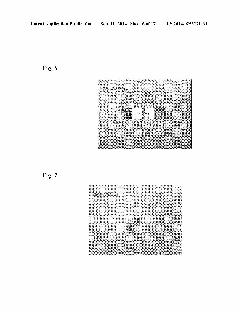
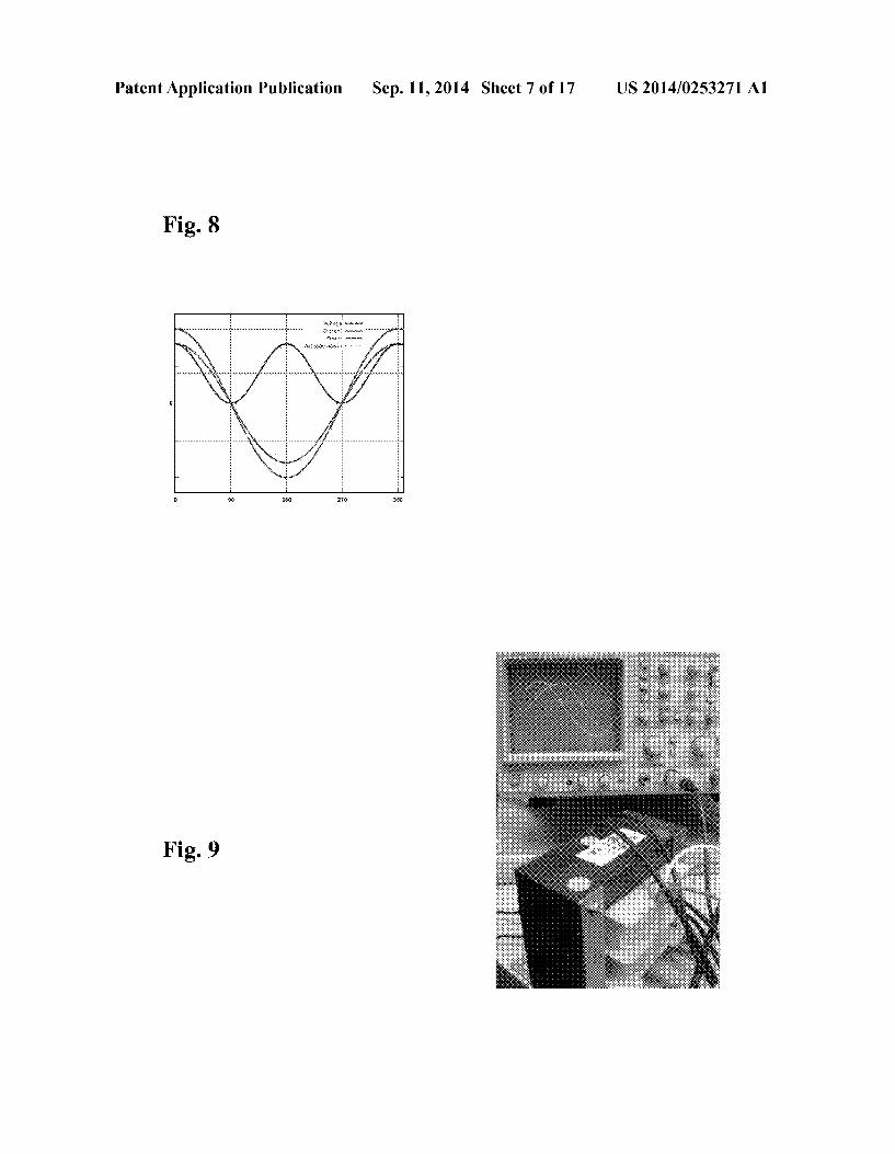
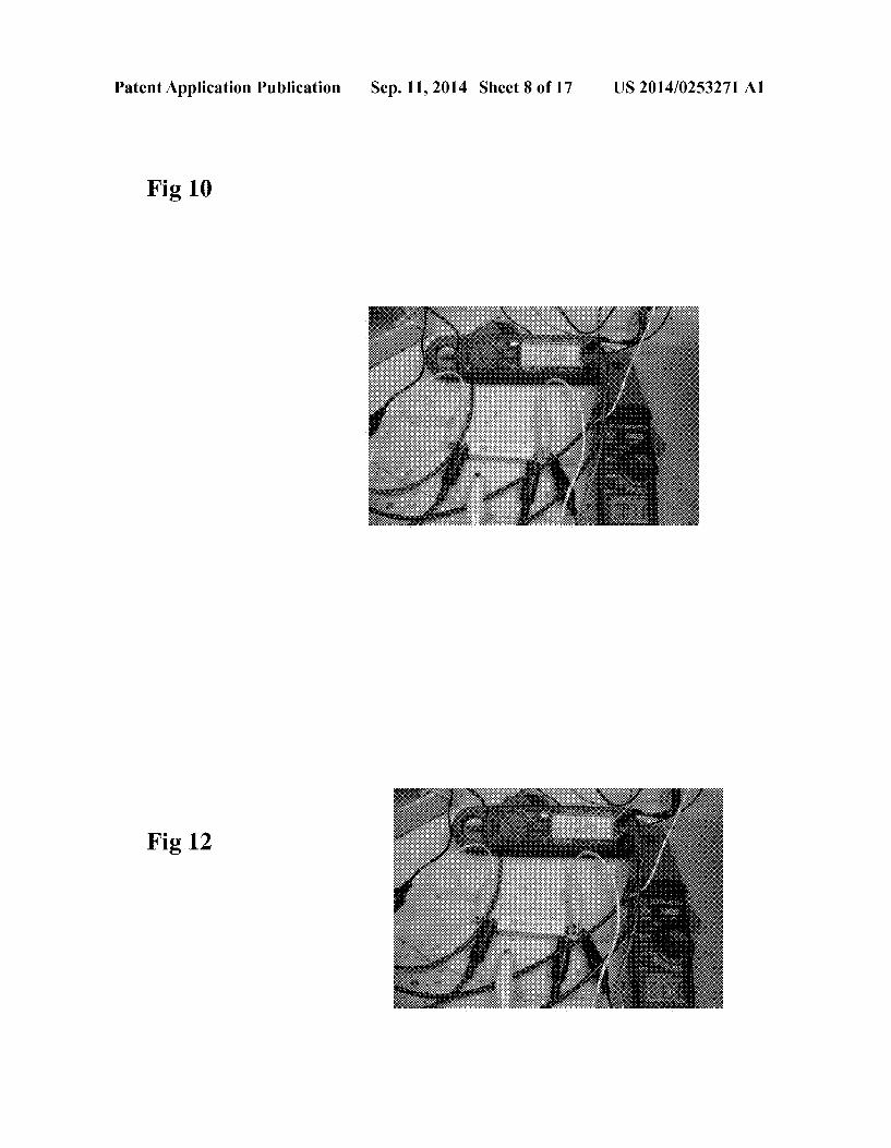
[0007] FIG. 3 shows the ?ux delivered by the BiTT primary is evenly distributed between the two secondary coils and no-load voltages are induced in each secondary coil accord ing to Faraday’s Law of Induction. [0008] FIG. 4 shows how the cross sectional area of a ferromagnetic core plays an important role in dictating the core’ s reluctance and how much magnetic ?ux can ?ow at any given time. [0009] FIG. 5 shows the various sine waves with a Zero Power Factor (PfIO). [0010] FIG. 6 shows the idealized isolated ?ux paths when the BiTT is placed on-load and current ?ows in the secondary coils, [0011] FIG. 7 shows the BiTT Secondary On-Load B-H Curve. [0012] FIG. 8 shows the various Sine waves with a Power Factor of 1 (Pf:1). [0013] FIG. 9 shows a conventional transformer on no load. [0014] FIG. 10 shows the input current and the output volt age across a load for a conventional transformer when on
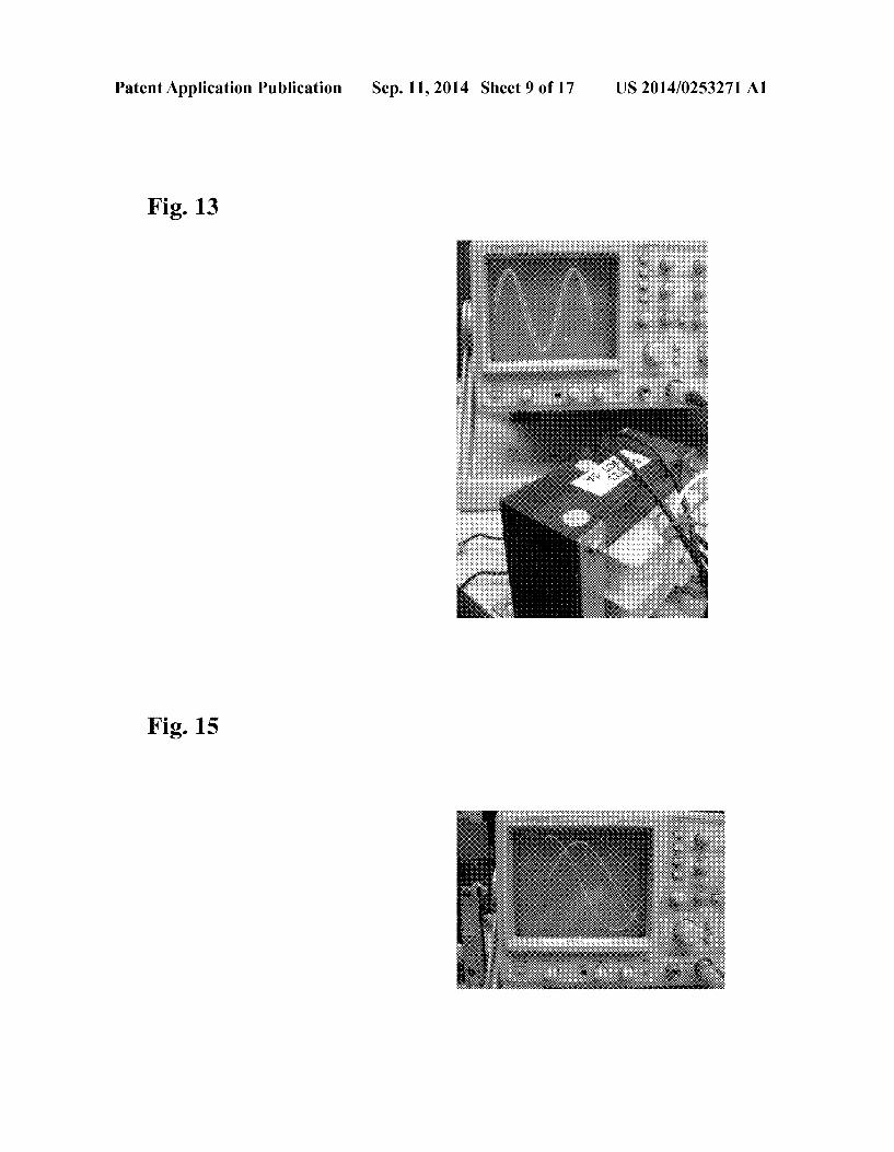
no-load. The input current is 0.071 Amps. [0015] FIG. 11 shows how the primary coil delivers mag netic ?ux to the secondary coil in a conventional transformer and how a voltage is induced in the secondary coil. [0016] FIG. 12 shows the same transformer output when it is collected across the load the primary current increases to almost double the no-load current at 0.133 Amps. [0017] FIG. 13 shows the on load voltage and current sine waves for the conventional transformer with a purely resistive load which has a power factor of 1.
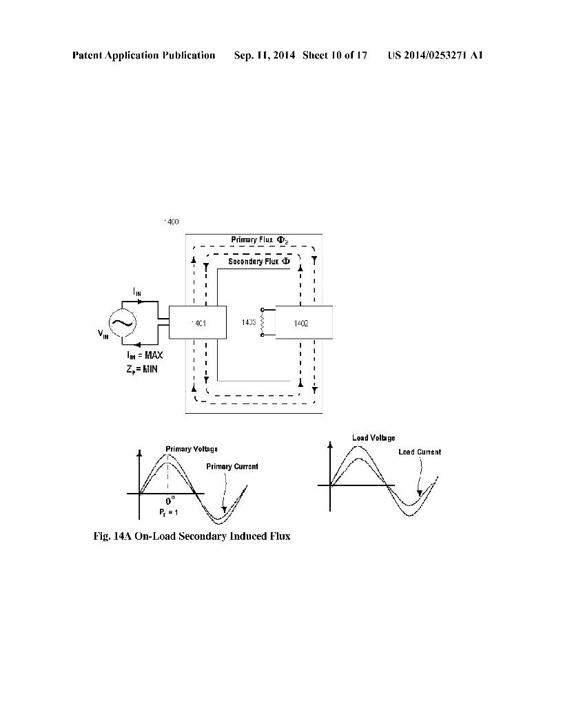
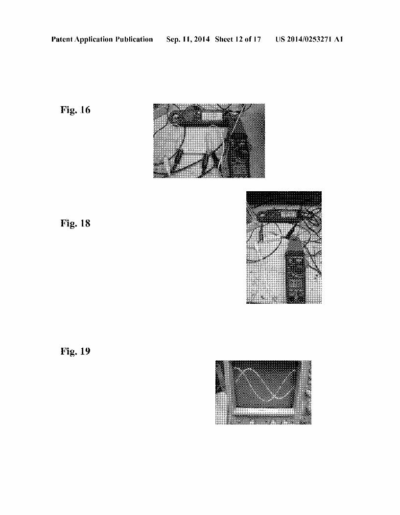
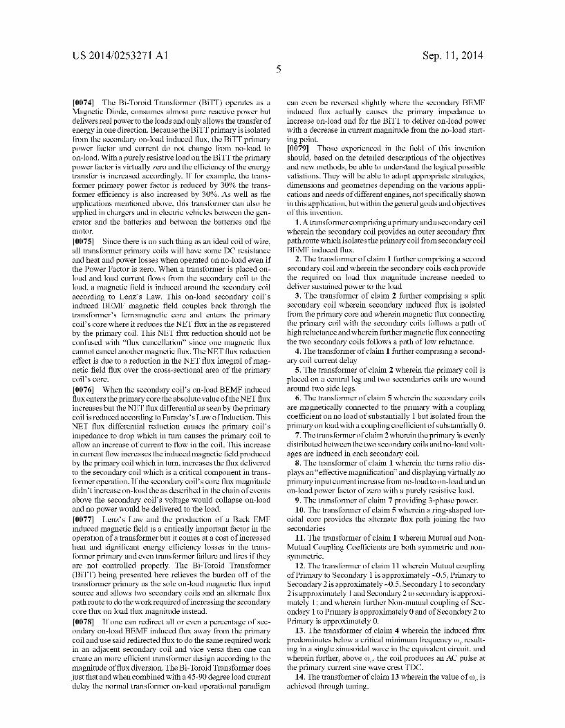
[0018] FIG. 14A illustrates how the primary coil’s mag netic ?ux is delivered to the secondary coil through the fer romagnetic core, in a conventional transformer. [0019] FIG. 14B illustrates secondary to primary induced ?ux direction, in a conventional transformer. [0020] FIG. 15. Shows the no-Load Bi-Toroid Transformer Voltage and Current Sine Waves [0021] FIG. 16. Shows the no-load Bi-Toroid Transformer Input and Output [0022] FIG. 17 Illustrates how the BITT, when properly tuned, behaves in which the induced ?ux predominates below the critical minimum frequency 006 [0023] FIG. 18. Shows the on-Load Bi-Toroid Transformer Input and Output and how the ef?ciency of the transformer is highly dependent on the precise adjustment of the coupling coef?cient [0024] FIG. 19 Shows the on-Load B-Toroid Transformer Voltage and Current Sine Waves [0025] FIG. 20 Shows ?ux compared with current in a parallel resistor circuit [0026] FIG. 22 Shows a performance comparison between a BiTT and a conventional transformer
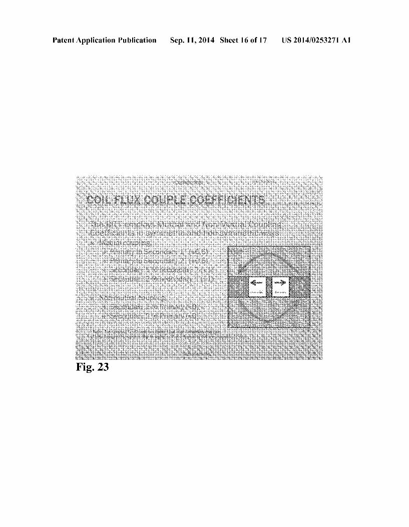
[0027] FIG. 23 Shows on-load sine wave comparisons between a conventional transformer and a BiTT
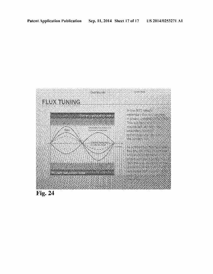
[0028] FIG. 24 Shows BiTT primary sine wave compari sons on No-Load and On-Load.
DETAILED DESCRIPTION
[0029] Physically the BiTT as shown in FIG. 2 differs from a conventional transformer in that the BiTT has a ‘split sec ondary’ coil, or two secondary coils and an alternate ?ux path
US 2014/0253271A1
route for secondary BEMF induced ?ux. The BiTT is speci? cally designed to keep secondary induced ?ux away from the primary core.
[0030] As illustrated in FIGS. 2A and 2B, the BiTT ring shaped toroidal core provides the alternate ?ux path joining the two secondaries. The outer secondary ?ux path isolates the primary from secondary induced BEMF as described further in the text. Shown is an inner three legged transformer with outer secondary Toroid ?ux path route which isolates primary from secondary BEMF induced ?ux.
[0031] As shown in FIG. 4 the secondaries uses a smaller region of the B-H curve (operate further from saturation). This is intentional since magnetic ?ux always follows the path of least reluctance and since core reluctance increases with ?ux magnitude, the secondary core region is designed to always be much lower than the primary core, encouraging ?ux to stay in the outer ?ux path and avoid the primary core ?ux path. As the ?ux magnitude in the core increases in tandem with primary current, so too does the core’s reluc tance. The core’ s reluctance peaks when the input current sine wave peaks (at 90 and 270 degrees) as shown in FIG. 5 and is minimum when the current passes through the zero point on theYAXis (at 0, 180 and 360 degrees). The BiTT uses this fact in conjunction with the secondary coil current delay to help ensure that the majority of secondary induced BEMF ?ux does not couple back through the primary but stays in the outer toroid ring.
[0032] With reference to FIG. 5, the voltage and current sine waves are 90 degrees out of phase. The power sine wave is evenly distributed and all power is Reactive Power with zero net real power consumption.
[0033] As shown in FIG. 6 the primary uses a physically smaller core and utilizes larger region of the B-H curve (oper ates closer to saturation). Saturation is not completely ben e?cial for the BiTT, but operating near saturation keeps the primary reluctance in its optimal range. Back EMF induced magnetic ?ux is created according to LenZ’s Law. The induced magnetic ?ux follows the lowest reluctance ?ux path from one secondary coil into the other secondary coil and avoids the higher reluctance primary core route. The second ary induced ?ux maintains the ?ux magnitudes required for the secondary coil’s to deliver power to the load without requiring a primary current or power increase.
[0034] Referring to FIG. 7, typically in any conventional transformer design, the secondary induced on-load ?ux couples directly back through the primary core and it causes the primary impedance to decrease which in turn causes the primary current to increase (and primary losses to increase and overall ef?ciency to decrease) while the load power factor is re?ected back onto the primary such that, if the load power factor is 1 the on-load power factor of the transformer primary will also be 1 as shown in FIG. 8, which shows the sine wave relationships for a transformer primary where a power factor of 1 is exhibited. A power factor of 1 denotes that the current and voltage are in phase with each other and that real power is being consumed in the transformer primary coil.
[0035] No-load power factor in an ideal coil is 0 as dis played in FIG. 5, with pure Reactive Power being consumed and no real power consumption in the coil. FIG. 8 shows the various Sine waves with a Power Factor of 1 (Pf:1 ). All power is Real Power with 100% power consumption.
Sep. 11,2014
[0036] Comparison Between Conventional Transformer Performance Vs BiTT Performance
[0037] As shown in FIG. 9, the current lags the voltage by 90 degrees. The current that ?ows in the primary coil when 90 degrees out of phase with the voltage is called Reactive Cur rent. Reactive Current ?ows into the primary coil on one half of the sine wave and back to the source on the other half of the sine wave. The Power factor for an ideal transformer on no-load is zero and the Net power consumption is also zero.
Pin I VinxL-nxPower Factor
Because the PF is zero the primary consumes only Reactive Power (ie zero Real Power). [0038] FIG. 11 shows a Conventional Transformer 1100, a Primary Coil (Off Load) 1101, a Secondary Coil (Off Load) 1102 and R, Load, Pf:1 1103 [0039] FIG. 12 illustrates the case of a conventional trans former placed on on-load, with current ?owing in the second ary coil to the load. This current produces induced BEMF magnetic ?ux which couples back through the transformer core and through the primary coil. The secondary induced ?ux reduces the primary coil’ s impedance which allows addi tional current to ?ow in the primary windings. The increased current ?ow in the primary coil increases the primary coil’s induced ?ux which is delivered to the secondary coil which is required to maintain the secondary coil’ s ?ux magnitude and sustain the power to the load.
[0040] In a conventional transformer, as shown in FIG. 13, the primary and secondary coils are magnetically linked with a coupling coef?cient of 1 and the load power factor dictates the secondary coil power factor which in turn dictates the primary power factor. As a comparison the BiTT secondary coils are magnetically connected to the primary on no load with a coupling coef?cient of 1 but isolated from the primary on load with a coupling coef?cient of 0.
[0041] Without the primary current and ?ux increase the secondary voltage would collapse on-load and no sustained power would be delivered by the transformer when placed on load. The primary coil’s input current increase is a function of LenZ’s Law and a performance requirement but it comes at a penalty with increased primary heat and a corresponding loss in energy conversion ef?ciency.
[0042] The BiTT design eliminates the need for a primary coil current increase when the BiTT is placed on load because the secondary coil’s each provide the required on load ?ux magnitude increase needed to deliver sustained power to the load. This allows the BiTT primary coil to operate with the same low no load input current level same no load power factor and minimal heat, power loss and power consumption while delivering real power and operating on load.
[0043] FIG. 14A shows a conventional 3-phase Trans former 1400, Primary Coil (On Load) 1401, Secondary Coil (On Load) 1402 and R, Load, Pf:1 1403. [0044] With reference to FIGS. 14A and B, the secondary coil is placed on load and current ?ows in the secondary coil which gives rise to a BEMF induced ?ux which couples back to the primary, causing primary current, heat and losses to increase as well as altering the primary coil’s power factor.
[0045] Flux ?ow can be compared with current in a parallel resistor circuit as shown in FIG. 20. Reluctance behaves much like resistance, in that the induced magnetic ?eld will follow the path of least reluctance:
Related Documents