BHARAT HEAVY ELECTRICALS LIMITED TRANSMISSION BUSINESS ENGINEERING MANAGEMENT NOIDA COPYRIGHT & CONFIDENTIAL The information in this document is the property of BHARAT HEAVY ELECTRICALS LIMITED. This must not be used directly or indirectly in anyway detrimental to the interest of the company. DOCUMENT NO. TB-TBCB-KHAVADA-KPS3 Rev 00 Prepared Checked Approved TYPE OF DOC. TECHNICAL SPECIFICATION NAME Vyom JK SKS TITLE 420kV GAS INSULATED SWITCHGEAR (GIS) SIGN DATE GROUP TBEM WO No. CUSTOMER Power Grid Corporation of India Ltd. PROJECT Pre Bid Tie up for 400kV GIS Substation Package SS02 for 400kV GIS at KPS-3 S/S including 400kV class Bus Reactor associated with Transmission scheme for Establishment of Khavda Pooling Station-3 (KPS3) Contents Section No. Description No of Pages Section-1.1 Part A : Scope Matrix for GIS 15 Section-1.2 Part B Khavda-3 06 Section-1.3 Annexure Section-Project-KPS3 06 Section-1.4 Annexure IV -420KV GIS Description 06 Section-1.5 Annexure BOQ 05 Section-2 GIS – General Technical Requirement 95 Section-3 Standard Technical Specification of GIS 96 Section-4 Annexure A and Annexure B 02 Remarks: Bidder to note that data and details of Guaranteed Technical Particulars shall not be reviewed during Technical Evaluation/ Review, hence compliance of Guaranteed Technical Particulars in line with Technical Specification has to be ensured by the bidder. Rev.No. Date Altered Checked Approved Distribution To Copies

Welcome message from author
This document is posted to help you gain knowledge. Please leave a comment to let me know what you think about it! Share it to your friends and learn new things together.
Transcript
BHARAT HEAVY ELECTRICALS LIMITED TRANSMISSION BUSINESS ENGINEERING MANAGEMENT
NOIDA
CO
PY
RIG
HT
& C
ON
FID
EN
TIA
L T
he in
form
atio
n in
this
doc
umen
t is
the
prop
erty
of B
HA
RA
T H
EA
VY
ELE
CT
RIC
ALS
LIM
ITE
D.
Thi
s m
ust n
ot b
e us
ed
dire
ctly
or
indi
rect
ly in
any
way
det
rim
enta
l to
the
inte
rest
of t
he c
ompa
ny.
DOCUMENT NO. TB-TBCB-KHAVADA-KPS3 Rev 00 Prepared Checked Approved
TYPE OF DOC. TECHNICAL SPECIFICATION NAME Vyom JK SKS
TITLE 420kV GAS INSULATED SWITCHGEAR (GIS)
SIGN
DATE
GROUP TBEM
WO No.
CUSTOMER Power Grid Corporation of India Ltd.
PROJECT
Pre Bid Tie up for 400kV GIS Substation Package SS02 for 400kV GIS at KPS-3 S/S including 400kV class Bus Reactor associated with Transmission scheme for Establishment of Khavda Pooling Station-3 (KPS3)
Contents
Section No. Description No of Pages
Section-1.1 Part A : Scope Matrix for GIS 15
Section-1.2 Part B Khavda-3 06
Section-1.3 Annexure Section-Project-KPS3 06
Section-1.4 Annexure IV -420KV GIS Description 06
Section-1.5 Annexure BOQ 05
Section-2 GIS – General Technical Requirement 95
Section-3 Standard Technical Specification of GIS 96
Section-4 Annexure A and Annexure B 02
Remarks: Bidder to note that data and details of Guaranteed Technical Particulars shall not be reviewed during Technical Evaluation/ Review, hence compliance of Guaranteed Technical Particulars in line with Technical Specification has to be ensured by the bidder.
Rev.No. Date Altered Checked Approved
Distribution
To Copies
Bharat Heavy Electricals Limited Section-1 (Part-A) Standard Scope Matrix for Gas Insulated Switchgear
Standard Scope Matrix for GIS, Rev.0 Page 1 of 15
CONTENTS
1. SCOPE
2. SPECIFIC TECHNICAL REQUIREMENTS
3. NOTES FOR BILL OF QUANTITY
4. NOTES FOR MODE OF MEASUREMENT
5. STRUCTURAL STEEL
6. EARTHING OF GIS
7. SCOPE FOR CABLES
8. OTHER GENERAL REQUIREMENTS
9. DRAWINGS / DOCUMENTS REQUIRED FOR ENGINEERING MANUFACTURING
CLEARANCE
10. TYPE TESTING
11. QUALITY PLAN
12. SITE SERVICES
a. SUPERVISION AT SITE
b. TESTING & COMMISSIONING
13. TESTING KITS, TOOLS & TACKLES
14. SPARES
15. PACKING AND DISPATCH
16. EXCLUSION FROM BIDDER'S SCOPE

Bharat Heavy Electricals Limited Section-1 (Part-A) Standard Scope Matrix for Gas Insulated Switchgear
Standard Scope Matrix for GIS, Rev.0 Page 2 of 15
This document covers broader guideline for bidder’s scope of supply & services. The
same shall be prevailing on all other section of technical specification.
1. SCOPE
This technical specification covers the requirements of (1.) design, type testing,
engineering, fabrication, manufacturing, shop assembly, inspection and testing at
manufacturer’s works, proper packing, supply and delivery to project site, (2.)
supervision of material reconciliation, installation / erection, (3.) execution of site
testing & commissioning along with necessary kits, tools & equipment , putting GIS
with LCC & its Accessories into successful operation complete with all materials,
support structures, anchoring bolts, chemical anchor, accessories, commissioning
spares & maintenance spares, special spanners, special tools & tackles, any specific
required ancillary services, SF6 gas for first filling & spare etc. including design
studies, training of BHEL / Customer personnel for offered GIS & its Accessories
complete in all respects for efficient & trouble-free operation mentioned under this
specification.
This section covers bidder’s scope for GIS with LCC & its Accessories. The offered GIS
with LCC & its Accessories shall comply with the Section-1, 2 & 3 of technical
specification.
The complete technical specification comprises of following sections:
Section-1 : Scope, Project Specific Technical Requirements & Bill of
Quantities including scope matrix
Section-2 : Equipment Specification under scope of Supplies
Section-3 : Project Details & General Technical Requirements (For All
Equipment under the Project)
Section-4 : Annexures
Annexure A- Compliance Certificate
Annexure B- Schedule of Technical Deviations
The following order of priority shall be followed. In case of conflict between

Bharat Heavy Electricals Limited Section-1 (Part-A) Standard Scope Matrix for Gas Insulated Switchgear
Standard Scope Matrix for GIS, Rev.0 Page 3 of 15
requirements specified in various documents, the more stringent one shall be
followed. BHEL/Customer concurrence shall, however, be obtained before taking a
final decision in such matters.
1. Statutory Regulations
2. Section-1(PART-A) Standard Scope Matrix
3. Section-1(PART-B)
4. Section-2
5. Section-3
Bidder shall furnish list of conflicts/ ambiguities/ deviations, if any, along with their
technical offer and also furnish the basis that is considered for submitting technical
offer. BHEL will address the bidder’s listed conflicts prior to award. In case of
ambiguity, bidder shall inform BHEL of their interpretation. In case bidder fails to
convey the same prior to award, BHEL decision on interpretation shall be considered
final if need arises during the execution. No additional cost or extra time on account
of conflicts/ ambiguities/ deviations shall be admissible.
In general, no deviation from the requirements specified in various clauses of this
specification shall be allowed and hence, a certificate to this effect shall have to be
furnished along with the offer (Annexure-A), however bidder shall furnish list of
conflicts/ ambiguities/ deviations (Annexure-B), if any.
Please note, any deviation not specifically brought out in Annexure-B (Schedule of
Technical Deviations) shall not be admissible for any time and commercial
implication at later stage. Except to the technical deviations listed in this schedule,
bidder’s offer shall be considered in full compliance to the tender specifications
irrespective of any such deviation indicated / taken elsewhere in the submitted offer.
Any conflicts/ ambiguities/ deviations mentioned elsewhere in technical offer shall not
be reviewed.
The scope of supplies shall be as per commercial terms and conditions enclosed
separately with the notice inviting tender/ enquiry.

Bharat Heavy Electricals Limited Section-1 (Part-A) Standard Scope Matrix for Gas Insulated Switchgear
Standard Scope Matrix for GIS, Rev.0 Page 4 of 15
2. SPECIFIC TECHNICAL REQUIREMENTS
Please refer Section-1(PART-B) of technical specification.
3. NOTE FOR BILL OF QUANTITIES
1. SF6 gas for initial installation of complete GIS System, including wastage during
installation, testing and successful commissioning shall be deemed included in the
bidder’s scope.
2. The offered GIS with LCC & its Accessories shall be complete in all respect in
compliance to technical specification and relevant IS / IEC / IEEE standards as
applicable. Any other equipment/material required to complete the specified GIS
scope of work are inclusive of bidder’s scope of supply & services.
3. All essential and desirable accessories are deemed inclusive of offer i.e. and not
limited to Gas Monitoring Devices, Pressure Switches, PD sensors, Pressure relief
device, insulator, expansion joint/ flexible, bellows/ compensators like lateral
mounting units, Axial compensators, Parallel compensators, tolerance
compensators and vibration compensators etc. complete in all respect.
4. Total contract value may vary up to ±30% at contract stage.
5. Any Item not quoted mentioned “Not Applicable” in bid price schedule and found
applicable as per technical specification and system requirement shall be supplied
free of cost by bidder without any time / cost implication to BHEL / Customer.
6. Length & route of GIB is purely indicative and same shall be finalized during
detailed engineering stage.
7. BHEL reserve rights to amend Bay sequence during contract stage, no separate
claim shall be admissible in this regards.
8. Supply scope of Testing & Maintenance Equipment – Scope of supply of following
Equipments shall be applicable only if covered in BOQ / BPS.
a. SF6 Gas leakage detector
b. Gas filling and evacuating plant: (Gas Processing unit)
c. SF6 gas analyser
d. Portable Partial Discharge(PD) monitoring system
e. Online Partial Discharge Monitoring System
Bharat Heavy Electricals Limited Section-1 (Part-A) Standard Scope Matrix for Gas Insulated Switchgear
Standard Scope Matrix for GIS, Rev.0 Page 5 of 15
Remark: BPS: Bid Price Schedule
4. NOTES ON MODE OF MEASUREMENT
1. The price of Bus-duct inside the GIS hall (inner wall face of GIS Hall) shall be
integral part of the respective bay module and it will not be paid separately.
However, the payment of bus-duct for outside the GIS hall along with support
structure shall be paid as per running meters in line with provision of Technical
Specification & Bid Price schedule.
2. In the case of outdoor type GIS, Gas Insulated Bus Duct (GIB) length of 1-phase
bus duct outside the GIS BAY MODULE shall be considered for mode of
measurement from the end of Bay equipment (VT, LA etc.) to end equipment
(SF6 to air bushing / SF6 to oil bushing/ Cable connection module etc.).
3. Any change in bay pitch (distance between bays): In a case where shifting of GIS
bays shall be called by BHEL (during contract stage) due to revision / change in
civil architectural requirement or due to expansion joint requirement in the GIS
building, Bidder to incorporate the same with full compliance of technical
requirement. Payment equivalent of BPS / BOQ item under head “Gas Insulated
Bus Duct” shall be operated for additional length of Main Bus, subject to such
shifting is not attributed to bidder.
5. STRUCTURAL STEEL
Structural Steel required for installation of complete GIS system with LCC & its
Accessories is deemed inclusive in bidder’s scope of supply. All steel structure
members shall be hot-dip galvanized after fabrication (excluding floor embedded
items for which standard practice is to be followed). Unless otherwise specified in
other section of technical specification, minimum mass of zinc coating for Galvanizing
shall be 610 gm/square meter. All field assembly joints shall be bolted. Field welding
shall generally not be acceptable. Noncorrosive metal or plated steel shall be used for
bolts and nuts throughout the work.
1. Lattice / Pipe structure Materials for support of GIS, Bus Ducts, SF6 to oil bushing/
SF6 to cable connection and SF6 to air bushing/ connection including Anchor

Bharat Heavy Electricals Limited Section-1 (Part-A) Standard Scope Matrix for Gas Insulated Switchgear
Standard Scope Matrix for GIS, Rev.0 Page 6 of 15
Fastener Bolts, Foundation Bolts, Base Plate / Channel / Metallic / Structural
Member for seating of GIS system, all floor and wall Embedded Items, wall
crossing arrangements, Rails and/ or other items structural items as required.
Manufacturer shall provide suitable foundation channels and anchor bolts to
support the switchgear assemblies. All mounting bolts, Anchor Fasteners,
foundation bolts, nuts and washers, equipment fixing hardware shall be provided
to fasten the switchgear base frames to the foundation channels as applicable
2. The GIS Equipment shall be complete with all necessary supports, ladders,
galleries, staircases, catwalks, movable platforms or walkways (for accessing the
equipment above two meters for maintenance and operation), mechanism
cabinets, internal cable raceways etc. for each bay and it shall be of modular
construction and extendable design.
3. Structural steel for complete GIS system with LCC & its Accessories is deemed
inclusive in bidder’s scope of supply.
6. EARTHING OF GIS
Bidder to submit detailed calculations and layout drawings for earthing system during
detailed engineering stage based on technical specification, bidder’s design
philosophy, IS/IEC/IEEE requirement as applicable. Bidder to provide the bill of
quantity of entire GIS system with LCC & its Accessories
1. Supply of 40 mm MS ROD, 75X12 mm GI Flat, 50X06 mm GI Flat is not in
bidder’s scope of supply.
2. All other earthing materials including complete Hardwares, nut, bolts washers, lug
etc. required, as per earthing design shall be in bidder’s scope of supply.
3. Installation / Erection of earthing will be done by BHEL team under the
supervision of bidder/manufacturer, as per manufacturer’s design.
7. SCOPE FOR CABLES
1. Power, control & instrumentation cables for Cabling (1.) within GIS, (2.) GIS to
LCC, (3.) LCC to LCC shall be deemed inclusive in bidder’s scope of supply.
2. Scope includes for completeness for GIS system with LCC & its Accessories
Bharat Heavy Electricals Limited Section-1 (Part-A) Standard Scope Matrix for Gas Insulated Switchgear
Standard Scope Matrix for GIS, Rev.0 Page 7 of 15
3. Cabling between LCC to LCC shall be applicable if required in bidder’s design
philosophy.
4. Cables required for bidder supplied GIS sub-system i.e. condition monitoring
system (Gas monitoring system, PD monitoring system etc) are to be supplied by
bidder as complete system.
5. Necessary Cable Lug, Glands & shroud etc. required for installation of bidder’s
supplied cable are deemed inclusive in bidder’s scope.
6. Bidder to provide detailed “Bill of Quantity” during detailed engineering stage.
Cabling & termination schedule for the same shall be provided by successful
bidder along with AS BUILT drawing during contract stage.
7. Power Cable TB’s (for both AC & DC incoming feeder cables) shall be suitable for
termination of requisite cable.
8. OTHER GENERAL REQUIREMENTS
Other general requirements GIS with LCC & its Accessories shall be as follows,
1. Guaranteed Technical Particulars: Bidder to submit detailed GTP in line with
technical specification during contract stage for review and approval. GTP &
drawings submitted with technical bid shall only be reviewed during contract stage
only. Bidder to please note, deviations / conflict if any please be mentioned in
schedule of technical deviations only.
2. The positioning of the circuit breaker in the GIS shall be such that it shall be
possible to access the circuit breaker of any feeder from the front side for routine
inspection, maintenance and repair without interfering with the operation of the
adjacent feeders.
3. The physical layout shall ensure free movement of the SF6 Gas Cart and easy
access to all components of the GIS for operation and maintenance purposes.
4. Bidder shall submit list of consumables with shelf life of less than six months and
same shall be dispatched before commencement of erection or after clearance
from BHEL/Customer whichever is earlier. No separate dispatch clearance shall be
required for consumables. Cost of the same deemed inclusive.
5. Bidder shall offer their latest type tested model to accommodate the specified &
allocated space as per attached layout drawing of GIS.
6. Bidder shall conduct insulation co-ordination studies in line with IEC for
Bharat Heavy Electricals Limited Section-1 (Part-A) Standard Scope Matrix for Gas Insulated Switchgear
Standard Scope Matrix for GIS, Rev.0 Page 8 of 15
establishing surge arrester rating, quantity and any other requirement for
successful operation of GIS.
7. Bidder to submit Study report of VFTO generated for 400kV GIS installation.
8. Bidder shall check and ensure adequacy of system protection for successful
operation of GIS. After checking of system by bidder, GIS shall be installed and if
any failure, malfunction of any part occurs after/ during commissioning, same
shall be replaced immediately without any extra cost.
9. Final documentation shall be submitted in hard copy (Four prints) and soft (Three
CDs/DVDs)
10. In the case if CSD is specifically called in BPS / BOQ / Section-1(PART-B) of
technical specifications, the same should have display facility at the front for the
display of settings and measured values. In case where CSD does not have
complete display facility for settings and measured values, bidder to supply one
number laptop PC with pre-installed, licensed software for each site. Special cable
required for integration is deemed inclusive in bidder’s scope.
11. Bidder to submit all supporting documents in English. If document submitted by
bidder is other than English language, self-attested English translated document
should also be submitted.
9. DRAWINGS / DOCUMENTS FOR MANUFACTURING CLEARANCE
The drawings/ documents, as follows shall be used for providing technical clearance
for manufacturing of GIS and furthermore, it shall be used for delay analysis, if any,
from bidder. The first drawing submission will be counted from the date of submitting
reasonably correct drawings.
Sl. No. Overall Drawings approval required in Cat I /Cat II
LOT-1
1 GIS- Gas Schematics with Single Line Diagram (Including CT VT
Parameters)
2 GIS- Guaranteed Technical Particulars (Including all GIS equipment)
3 GIS- Layout Plan & Section
4 GIS- Interfacing Drawings for Cable Connection Module / SF6 to Air
Bushing / SF6 to Oil Module (as applicable under scope) with Guaranteed
Technical Particulars
Bharat Heavy Electricals Limited Section-1 (Part-A) Standard Scope Matrix for Gas Insulated Switchgear
Standard Scope Matrix for GIS, Rev.0 Page 9 of 15
5 GIS- Equipment Layout with Earthing philosophy
6 GIS- Type Test Reports (Including all GIS equipment)
7 GIS- Quality Assurance Plan & Inspection Test Schedule
LOT-2
8 GIS- Earthing Design, philosophy, Layout
9 GIS- Secondary Engineering Base Design
10 GIS- Control Schematics for GIS and Local Control Cabinet
11 GIS- Maintenance Equipment Catalogue with Guaranteed Technical
Particulars, test reports
12 GIS- Quantification for main Items, Spares, Consumables
13 GIS- Civil Design Specification with Foundation Loading Diagram (Including
interfacing details)
14 Other documents as per Technical Specification / BPS / BOQ shall be
finalized during detailed engineering stage.
OTHER
15 GIS- 3D OGA Drawing (3D-Model with complete editable data base)
compatible with Autocad & Primtech for complete GIS & its accessories.
16 Manuals on unloading, safe storage, transportation, installation, testing,
commissioning, routine check, preventive maintenance
10. TYPE TEST
Please refer Section-1(PART-B) and Section-2 of technical specification for the details
of type test requirement. All equipment being supplied shall conform to type tests as
per technical specification and shall be subject to routine & acceptance tests in
accordance with requirements stipulated under respective sections of technical
specification.
11. QUALITY PLAN
Bidder to follow valid customer approved (1.) Manufacturing Quality Pan, (2.) factory
acceptance test (FAT) procedure & (3.) Site acceptance test (SAT) procedures, as per
Customer procedure. In case the bidder doesn’t have Customer approved Quality
Bharat Heavy Electricals Limited Section-1 (Part-A) Standard Scope Matrix for Gas Insulated Switchgear
Standard Scope Matrix for GIS, Rev.0 Page 10 of 15
Plan, it will be the bidder’s responsibility to get its Quality Plan approved from the
ultimate Customer within 30 days from the date of issue of after award of LOI / PO
whichever is earlier.
All materials shall be procured, manufactured, inspected and tested by vendor/ sub-
vendor as per approved quality plan. The supplier shall perform all tests necessary to
ensure that the material and workmanship conform to the relevant standards and
comply with the requirements of the specification.
GIS and its associated materials shall be subject to inspection by BHEL/ Customer /
authorized representative at bidder / manufacturing works. Hence, Bidder shall
furnish all necessary information concerning the supply to BHEL. During fabrication,
the equipment shall be subject to inspection by BHEL/ Customer or by an agency
authorized by BHEL/ Customer to assess the progress of work as well as to ascertain
that only quality raw material is used.
12. SITE SERVICES
Site service activities shall be carried out at in stages as per requirement or front
availability at site, and hence multiple visits for completion of work are envisaged as
per site requirements hence any claim in this regards shall not be admissible on
account of multiple mobilization or idling during project execution stage.
12.1. SUPERVISION AT SITE
1. Supervision of complete installation / erection of GIS with LCC & its Accessories
are in the scope of bidder.
2. Scope also includes verification of materials for proper storage with due
instructions/ training to site persons for long storage.
3. Standard storage instruction manual specifically specifying the item detailed with
details of type of storage.
4. Supervision for reconciliation and spares / accessories and handing over to
customer.
Bharat Heavy Electricals Limited Section-1 (Part-A) Standard Scope Matrix for Gas Insulated Switchgear
Standard Scope Matrix for GIS, Rev.0 Page 11 of 15
5. Final documentation
12.2. TESTING & COMMISSIONING
1. The complete GIS System shall be subjected to the site tests as per technical
specifications, IEC-62271-203. Bidder to submit site acceptance testing (SAT)
procedures and get the same approved from BHEL / Customer before carrying out
the site testing at site.
2. Carrying out successful HV/ Power Frequency Testing of GIS as per IEC shall be in
scope of bidder, which includes HV test kit with operator, accessories & tools
required for completion of HV testing. Bays may be commissioned separately.
3. BHEL shall provide free support at site for HV Test Kit i.e. it’s unloading,
assembling of HV test kit, dismantling & loading back on carrier.
4. Complete Field testing and commissioning of GIS system with LCC & its
Accessories are under the scope of Bidder.
5. Bidder supplied special equipment, T&P if required OEM supervision, the same is
to be arranged by bidder, cost of the same shall be deemed inclusive of respective
item.
6. Bidder/ OEM shall coordinate with manufacturers of other equipment wherever
required and shall freely and readily supply all technical information for this
purpose as and when called for.
7. ETC work schedule for all the GIS may vary according to readiness of site.
Respective dates for the commencement of erection, testing and commissioning
activities of GIS shall be communicated to manufacturers from time to time as per
the readiness of site.
13. TESTING KITS, TOOLS & TACKLES
1. All the Instruments/ Testing kits including HV Test Kit, SF6 Gas handling
Equipments required for successful installation, testing, commissioning,
maintenance of offered GIS are to be arranged by bidder on returnable basis.
Cost of the same shall be deemed inclusive in the offer.
2. Special tools & tackles for installation, maintenance, testing & commissioning of
GIS shall be in bidder's scope, it shall be brought at site on returnable basis only.

Bharat Heavy Electricals Limited Section-1 (Part-A) Standard Scope Matrix for Gas Insulated Switchgear
Standard Scope Matrix for GIS, Rev.0 Page 12 of 15
3. The general Tools and Tackles shall be provided by BHEL, list of the requirement
i.e. general tools-tackle, spanners, gauges, slings and other lifting devices, crane,
welding machines, drills, general instruments and appliances necessary for the
installation of GIS is to be submit by bidder along the technical bid. In case bidder
fails to convey the same along with technical bid, BHEL decision on interpretation
of general tools tackle shall be considered final and any tools & tackles required
shall be brought at site by bidder without any claim.
4. Bidder to furnish detailed BOQ for non-returnable special Tools and Tackles, if
applicable along with unit prices to be handed over to ultimate customer. The
prices for the same shall be considered during evaluation.
14. SPARES
1. Any equipment which is not supplied as main equipment or part of main
equipment, mandatory spare for that is not applicable.
2. In case contractor offers circuit breaker, dis-connector, current transformer,
SF6/Air Bushing etc. under main equipment of higher rating than equipment
rating specified in the specifications, the mandatory spare of same higher rating
offered by contractor identical to main equipment offered in the package shall be
required to be supplied against spares without any cost implication.
3. The Mandatory Spares shall be included in the bid proposal by the bidder. The
prices of these spares shall be given by the Bidder in the relevant schedule of Bid
Price Schedule and shall be considered for evaluation of bid. It shall not be binding
on the Employer to procure all of these mandatory spares.
4. The bidder is clarified that no mandatory spares shall generally be used during the
commissioning of the equipment.
5. Start-up & Commissioning spares are included in bidder’s scope of supply and
shall be included in the base price. Adequate stock of start-up & commissioning
spares shall be made available at the site such that the start-up and
commissioning of the equipment /systems, performance testing and handing over
the equipment/ systems to the Purchaser can be carried out without any
hindrance or delays. The unutilized Start-up & Commissioning spares brought for
commissioning purpose by bidder shall be taken back by the bidder.
6. Wherever spares in BPS / BOQ/Technical Specification have been specified as
Bharat Heavy Electricals Limited Section-1 (Part-A) Standard Scope Matrix for Gas Insulated Switchgear
Standard Scope Matrix for GIS, Rev.0 Page 13 of 15
“each type/each rating/each type & rating”: If the offered spare/spares is
sufficient to replace the respective main equipment of all types/ratings, then such
offered spare/spares shall be acceptable. It implies that common spare/spare set
fulfilling the spare requirement of all types/ratings shall also be acceptable,
provided it is configurable at site itself without special assistance of OEM.
7. Mandatory Spares, wherever mentioned, are envisaged for the equipment/items
being supplied under the main equipment heads under present scope meeting the
requirements of Technical Specifications. The component/sub-component of an
equipment/item specified in BPS / BOQ under Mandatory Spare, which is not
applicable as per the offered design of respective main equipment, shall not be
referred to.
8. Bidder to submit price break-up of spares during tender stage. It shall not be
binding on the BHEL to procure all of these mandatory spares.
9. Bidder/ vendor shall ensure the availability of spare parts and maintenance
support services for the offered equipment at least for 15 years from the date of
supply. Bidder shall give a notice of at least one year to the Customer & BHEL
(both) before phasing out the products/spares to enable the owner for placement
of order for spares and services.
15. PACKING AND DISPATCH
1. The equipment shall be carefully packed for transport by sea, rail and road in such
a manner that it is protected against the climatic conditions and for any damage
during transportation, transit and storage. Packing of the equipment shall be
suitable for long storage (minimum 1 year).
2. The GIS transport units shall be shipped in the largest factory assembled units
within transport and loading limitations and considering handling facilities on site
to reduce the erection and installation work on site to a minimum. Where possible
all items of equipment or factory assembled units shall be boxed in substantial
crates or containers to facilitate handling in a safe and secure manner.
3. Each individual piece to be shipped, whether crate, container or large unit, shall
be marked special notations such as ‘Fragile’, ‘This side up’, ‘Centre of gravity’,
‘Weight’, ’Owner's particulars’, ’PO no.’ etc., and other details as per purchase
order & technical specification.
4. The equipment may be stored outdoors for long periods before installation. The
packing shall be completely suitable for outdoor storage in areas with heavy rains
Bharat Heavy Electricals Limited Section-1 (Part-A) Standard Scope Matrix for Gas Insulated Switchgear
Standard Scope Matrix for GIS, Rev.0 Page 14 of 15
and high ambient temperature.
5. Special precautions shall be taken to protect any parts containing electrical
insulation against the ingress of moisture. This applies particularly to the
equipment of which each gas section shall be sealed and pressurized prior to
shipping. Dry nitrogen/air or dry SF6 gas (in full compliance to technical
requirement) shall be used and the pressure shall be such as to ensure that,
allowing for reasonable leakage, it will always be greater than the atmospheric
pressure for all variations in ambient temperature and the atmospheric pressure
encountered during shipment to site and calculating the pressure to which the
sections shall be filled to ensure positive pressure at all times during shipment.
6. All blanking plates, caps, seals, etc., necessary for sealing the gas sections during
shipment to site shall be provided. Any seals, gaskets, `0' rings, etc. that will be
used as part of the arrangement for sealing off gas sections for shipment of site,
shall not be used in the final installation of the equipment at site. Vendor to
provide quantity of components accordingly considering permanent installation
and commissioning.
16. SPECIFIC- EXCLUSIONS (NOT IN BIDDER’S SCOPE)
The following items are specifically excluded from the bidder’s scope of supply &
services, irrespective of the same if covered under any section of technical
specification other than Section-1 (PART-B). If specific requirement mentioned in the
Section-1(PART-B) of technical specification shall overrule this specific exclusion.
1. Any scope of supply / services mentioned in Section-2 or Section-3 of technical
specification but not having any relationship with GIS, LCC & its Accessories and
not covered in Section-1(PART-B) or BPS / BOQ shall be deemed excluded from
bidder’s scope.
2. Installation / Erection of GIS with LCC & its Accessories except supervision work.
3. Cable laying & terminations, however supervision work & termination of special
cables shall be in bidder’s scope.
4. Open & Closed stores at site. (Bidder to provide space requirement in tech bid)
5. Local transportation/ conveyance for bidder’s engineers shall be arranged by BHEL
between local stay and site.
6. Office assistance shall be provided BHEL including sitting facility etc.

Bharat Heavy Electricals Limited Section-1 (Part-A) Standard Scope Matrix for Gas Insulated Switchgear
Standard Scope Matrix for GIS, Rev.0 Page 15 of 15
7. Receipt & unloading of material at site except supervision work
8. Terminal connector for SF6 to Air Bushing to conductor or any other interfacing
equipment.
9. Watch & Ward of GIS material at BHEL Store
10. Civil Works i.e. GIS Hall, civil works requirement for GIS System. (Please refer
clause “Structure-Steel” for bidder’s scope of supply)
11. EOT crane, Air Conditioning & Ventilation System, Illumination System & Fire
detection & alarm system, however complete input shall be provided for EOT and
other system
12. Control Relay & Protection Panels, Numerical Relays, Bus Bar Protection Panel,
SAS & ECS system, ACDB, DCDB, Battery & Charger
13. Earthing material i.e. 40 mm MS Rod, 50X6 GI Flat & 75X12 GI Flat for earthing
14. Outdoor AIS Equipments
15. Power & Control cable beyond LCC
16. BHEL / Customer / BHEL appointed 3rd party inspector travel, lodging & boarding
charges during testing / inspection.
Rev Number Date Initiated by Reviewed by Approved by
Rev.0 19 Feb 2022 JAIK SKS AG
Bharat Heavy Electricals Limited SECTION 1 (Part-B) Doc No. TB-TBCB-KHAVADA-KPS3 Technical Specification 400KV Gas Insulated Switchgear
Page 1 of 6
This technical specification is required for Pre-bid tie-up before participation in
the following tender:
Name of the Customer Power Grid Corporation of India Ltd.
Name of Main Contractor Bharat Heavy Electricals Limited
Name of the Project/
Tender
400kV GIS Substation Package SS02 for 400kV
GIS at KPS-3 S/S including 400kV class Bus
Reactor associated with Transmission scheme for
Establishment of Khavda Pooling Station-3 (KPS3)
Location KHAVDA, GUJARAT, INDIA
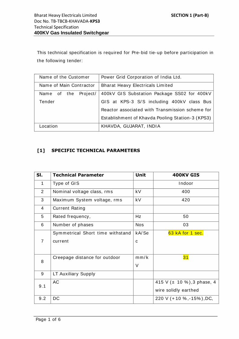
[1] SPECIFIC TECHNICAL PARAMETERS
Sl. Technical Parameter Unit 400KV GIS
1 Type of GIS Indoor
2 Nominal voltage class, rms kV 400
3 Maximum System voltage, rms kV 420
4 Current Rating
5 Rated frequency, Hz 50
6 Number of phases Nos 03
7
Symmetrical Short time withstand
current
kA/Se
c
63 kA for 1 sec.
8 Creepage distance for outdoor mm/k
V
31
9 LT Auxiliary Supply
9.1 AC 415 V (± 10 %),3 phase, 4
wire solidly earthed
9.2 DC 220 V (+10 %,-15%),DC,

Bharat Heavy Electricals Limited SECTION 1 (Part-B) Doc No. TB-TBCB-KHAVADA-KPS3 Technical Specification 400KV Gas Insulated Switchgear
Page 2 of 6
2 wire, unearthed
10 Meteorological data
10.1 Design ambient temperature 0C Min. 0 °C / Max. 50 °C
10.2
Altitude Less than 1000 meter
above mean sea level
(MSL)
10.3 Snow fall Nil
10.4 Seismic Zone As per IS 1893 (Part 1)
10.5 Wind Zone NBC 2016
10.6 Design relative humidity % 100
10.7 Coastal Consideration Area YES
[2] BILL OF QUANTITIES:
1. Please refer following Annexures for Bill of quantities:
ANNEXURE_BOQ_KHAVADA_KPS3
2. During tender stage No of bays of 400kV GIS may vary. No of bays of
400kV GIS shall be finalized after receipt of Notification of award (NOA)
from POWERGRID.
[3] SPECIFIC TECHNICAL REQUIREMENTS
3. Please follow Project specific requirement, as per document
SECTION-1, ANNEXURE SECTION-PROJECT
4. Please follow description of 400kV GIS modules/Equipment as per
document SECTION-1, ANNEXURE-IV
5. All technical details of GIS are as per SECTION-2.
6. KPS3 (GIS) substation is situated in coastal area. Hence, all the
specifications defined for coastal area in various sections of Technical
Specifications shall be applicable for KPS3 (GIS) substation.
7. For 400kV GIS Line feeder bay module (with PIR) and 400kV GIS Tie Bay
module (with PIR) as mentioned in BPS, Controlled Switching Device (CSD)
in place of PIR shall also be acceptable provided it meets the functional
requirements equivalent to PIR to limit line switching over voltage. Further,
it is clarified that no cost compensation shall be considered on account of

Bharat Heavy Electricals Limited SECTION 1 (Part-B) Doc No. TB-TBCB-KHAVADA-KPS3 Technical Specification 400KV Gas Insulated Switchgear
Page 3 of 6
above viz. provision of CSD in place of PIR.
[3] OTHER TECHNICAL REQUIREMENTS for GIS & OTHER
ASSOCIATED EQUIPMENTS:
1. Factor of safety for design of equipment structures and foundations shall
be as below:
a. Factor of safety for design of equipment structures shall be 1.5
under normal condition and 1.2 under short-circuit condition.
b. Factor of safety for design of equipment foundation shall be 1.5 in
both normal and short circuit condition as per IS 456.
c. Factor of safety for stability of equipment foundation like
overturning shall be 2 (without wind or seismic), 1.5 (with wind or
seismic) for normal and short circuit condition as per IS 1904.”
2. All switchgear/equipment, bushings etc. shall be designed for minimum
Creepage distance of 31mm/kV. Minimum Creepage for polymer housing
bushing shall be 31mm/kV in line with IEC 60815-3. Further, minimum
weight of zinc coating for hot dip galvanization shall be as per clause no.
12.2 of Section-3 considering coastal area.
[4] SPECIFIC TECHNICAL REQUIREMENTS FOR CSD
1. CSD shall be deployed for optimization of switching behavior of bidder
supplied GIS Breaker.
2. The limit for inrush current for switching of Transformer by CSD shall be
1.0 p.u. of rated current of transformer after fine tuning of CSD settings
during pre-commissioning checks. For site acceptance of CSD, during
online CSD test after fine tuning inrush current should be less than 1.0
P.U. of rated current in five consecutive operations.
3. All 400kV Circuit Breaker control schematics shall be finalized in such a
way, that it may operate with or without CSD by using a suitable selector
switch irrespective of whether circuit breakers to be supplied are envisaged
along with CSD or not as per bid price schedules.
Bharat Heavy Electricals Limited SECTION 1 (Part-B) Doc No. TB-TBCB-KHAVADA-KPS3 Technical Specification 400KV Gas Insulated Switchgear
Page 4 of 6
4. Complete interfacing with GIS and CSD shall be in bidder’s scope. Any
additional item like transducer, contact multiplication relay, switches,
special/screened cables, modification hardwired, modification in
schematics (if any) required for interfacing and for complying to the
technical specification requirement shall be in bidder’s scope and shall be
included in quoted price. No price implication for the same shall be
entertained during detailed engineering.
5. All wiring necessary for interface of GIS/ CRP with bidder supplied CSD is
also deemed to be included in the scope of bidder. Cables, lugs, ties etc
required for connection of CSD in existing relay panel is deemed to be
included in bidder’s scope.
6. Supervision of Erection only and testing & Commissioning of CSD shall be
in bidder’s scope.
7. The CSD should have display facility at the front for the display of settings
and measured values. In case where CSD does not have complete display
facility for settings and measured values, bidder to supply one number
laptop PC with pre-installed, licensed software for each site. Cost of the
same shall be deemed included in offer.
8. Special cables (i.e., screened/ FO cable) other than 1100V LT Power &
Control Cables required for CB / CSD / Relay Panel interfacing shall be in
bidder’s scope. Mode of measurement for special cable shall be cable-
trench running length from GIS to CSD/ Relay panel. Total requirement of
special cable qty. is to be estimated & supplied by bidder based on no. of
runs etc.
[5] TECHNICAL QUALIFYING REQUIREMENTS:
Please refer following attached document for qualification criteria:
1. Technical Qualifying Requirement for KPS3 Annexure-A (BDS)
Bharat Heavy Electricals Limited SECTION 1 (Part-B) Doc No. TB-TBCB-KHAVADA-KPS3 Technical Specification 400KV Gas Insulated Switchgear
Page 5 of 6
Bidder to submit complete supporting documents required for technical
qualifying requirement along with the bid.
[6] TYPE TESTING, INSPECTION, TESTING & INSPECTION
CERTIFICATE
Please refer Section-2 and Section-3 of technical specification for the
details of type test requirement.
All equipment being supplied shall conform to type tests as per technical
specification and shall be subject to routine tests in accordance with
requirements stipulated under respective sections.
The reports for all type tests as per technical specification shall be
furnished by the bidder along with equipment / material drawings.
However, type test reports of similar equipments / material already
accepted in POWERGRID (in the projects similar to present project) shall
be applicable for all projects with similar requirement. The type tests
conducted earlier should have either been conducted in accredited
laboratory (accredited based on ISO / IEC Guide 25 / 17025 or EN 45001
by the national accreditation body of the country where laboratory is
located) or witnessed by POWERGRID or representative authorized by
POWERGRID or Utility or representative of accredited test lab.
Unless otherwise specified elsewhere, the type test reports submitted shall
be of the tests conducted within last 10 (ten) years from the originally
scheduled date of bid opening of tender of POWERGRID i.e. 04th March
2022. In case the test reports are of the test conducted earlier than 10
(ten) years from the original date of technical bid opening of tender
(Tender of Powergrid), the contractor shall repeat these test(s) at no extra
cost to BHEL / Powergrid.
Bharat Heavy Electricals Limited SECTION 1 (Part-B) Doc No. TB-TBCB-KHAVADA-KPS3 Technical Specification 400KV Gas Insulated Switchgear
Page 6 of 6
Further, in the event of any discrepancy in the test reports i.e. any test
report not acceptable due to any design/manufacturing changes or due to
non-compliance with the requirement stipulated in the Technical
Specification or any/all type tests not carried out, same shall be carried
out without any additional cost and delivery implication to BHEL/Powergrid.
The Bidder shall intimate BHEL with the detailed program about the type
tests at least two (2) weeks in advance in case of domestic supplies & six
(6) weeks in advance in case of foreign supplies.
Note – Type test report shall be reviewed for approval in detailed
engineering stage only. However, for evaluation purpose, the test reports
are to be submitted along with the technical bid.
[7] ENCLOSED DOCUMENTS WITH SECTION-1
1. SECTION-1, ANNEXURE-A
2. SECTION-1, ANNEXURE-IV
3. ANNEXURE_BOQ_KHAVADA_KPS3
4. Technical Qualifying Requirement for KPS3 Annexure-A (BDS)
------------xxxxx-----------
Technical Specification, Section Project Rev-0 400kV GIS Substation Package-SS02 associated with “Establishment of Khavda Pooling Station-3 (KPS3) in Khavda RE Park” under TBCB route
Page 2 of 17
SECTION-PROJECT
1.0 GENERAL Power Grid Corporation of India Ltd. (POWERGRID), a Govt. of India Enterprise is
responsible for bulk Power transmission of electrical energy from various Central Govt.
Power Projects to various utilities/beneficiaries and interconnecting regional grids, operating
and maintaining the National electrical grid of India. It is established with mandate of "We
will become a Global Transmission Company with Dominant Leadership in Emerging Power
Markets with World Class Capabilities by:
� World Class: Setting superior standards in capital project management and operations
for the industry and ourselves.
� Global: Leveraging capabilities to consistently generate maximum value for all
stakeholders in India and in emerging and growing economies.
� Inspiring, nurturing and empowering the next generation of professionals.
� Achieving continuous improvements through innovation and state of the art
technology.
� Committing to highest standards in health, safety, security and environment.” as its
mission.
1.1 Govt. of India (MoP) has identified the execution of “Establishment of Khavda Pooling
Station-3 (KPS3) in Khavda RE Park” through Tariff Based Competitive Bidding (TBCB)
route for which POWERGRID is intending to participate in the bidding process. Further,
POWERGRID is intending to arrange for pre-bid tie-up for the scope envisaged.
1.2 Following Transmission System is envisaged under “Establishment of Khavda Pooling
Station-3 (KPS3) in Khavda RE Park” through TBCB route:
A. Transmission lines: i) KPS3 – KPS2 765kV D/C transmission line (20km approx.)
B. Substations: i) Establishment of 3x1500 MVA, 765/400kV KPS3 (GIS) substation with 1x330
MVAR, 765kV Bus Reactor and 1x125 MVAR, 420kV Bus Reactor (and with
provisions for future 220kV).
ii) 2 no. of 765kV line bays at KPS2 (GIS) substation for termination of KPS3-KPS2
765kV D/C transmission line.
2.0 SCOPE OF WORK
2.1 The scope of this specification covers the following:
I. Construction of 400kV GIS at 765/400/220kV KPS3 (GIS) substation with following bays/elements:
SECTION-1 Khavda Station-3 (KPS3)
ANNEXURE
Technical Specification, Section Project Rev-0 400kV GIS Substation Package-SS02 associated with “Establishment of Khavda Pooling Station-3 (KPS3) in Khavda RE Park” under TBCB route
Page 3 of 17
A. 400kV
i) ICT bay: 3 nos.
ii) Bus Reactor: 1×125 MVAR, 420kV
iii) Bus Reactor bay: 1 no.
iv) Line bay: 3 nos.
v) Line with switched Reactor bay: 1 no.
vi) Space for future line bay: 9 nos.
vii) Space for future 765/400 kV ICT bay: 5 nos.
viii) Space for future 400/220kV ICT along with associated bay: 2 nos.
ix) Space for future 400kV Bus Sectionalizer bay: 2 nos. (1 no. for each Main Bus)
Construction of 765/400kV KPS3 New GIS substation and supply, erection, testing &
commissioning of 765/400/33kV Transformer & 765kV Reactors are covered under separate
package(s). However, following associated works are covered under the scope of this
package:
i. All erection hardware items, structure, BPI etc. of 400kV class required for switching
arrangement with spare 1-Ph unit of 765/400kV Autotransformer along with overhead
connection of 400kV bushings of 765/400kV Autotransformers to substation equipment
including all associated terminal connectors.
ii. HVWS system & Hydrant System for 400kV class Reactor.
2.2 Four (4) nos. of complete 400kV GIS diameters have been envisaged under present scope at
KPS3 GIS substation as mentioned below:
i. Two (2) nos. of 400kV GIS diameters of Line-Tie-ICT (765/400kV) configuration
ii. One (1) no. of 400kV GIS diameter of Bus Reactor-Tie-ICT (765/400kV) configuration
iii. One (1) no. of 400kV GIS diameter of Line-Tie-Line with switched Reactor
configuration. The 400kV GIS bay for line with switched Reactor shall be utilized in
future for which the 400kV GIS bus ducts shall be brought outside of the GIS hall and
provided with extension module suitably under present scope for future connections.
2.3 It is the intent of this specification to describe primary features, materials, and design &
performance requirements and to establish minimum standards for the work. The
specification is not intended to specify the complete details of various practices of
manufactures/ bidders, but to specify the requirements with regard to performance, durability
and satisfactory operation under the specified site conditions.
2.4 The detailed scope of works is brought out in subsequent clauses of this section.
2.4.1 Construction of 400kV GIS at KPS3 (GIS) substation 2.4.1.1 Design, engineering, manufacture, testing, supply including transportation & insurance,
unloading, storage, erection, testing and commissioning at site of following equipment and
items complete in all respect:
A) 400kV Gas Insulated Switchgear
The SF6 gas insulated switch gear (50 Hz) shall be of the indoor metal-enclosed type.
h extension module
Technical Specification, Section Project Rev-0 400kV GIS Substation Package-SS02 associated with “Establishment of Khavda Pooling Station-3 (KPS3) in Khavda RE Park” under TBCB route
Page 4 of 17
400kV SF6 gas insulated switch gear shall have one and a half breaker bus bar arrangement.
The Switchgear shall be complete with all necessary terminal boxes, SF6 gas filling,
interconnecting power and control wiring, grounding connections, gas monitoring equipment
& piping and support structures along with necessary base plate & foundation bolts. In
addition, all necessary platforms, supports, ladders and catwalks etc. as required for operation
& maintenance work shall also be provided.
a) 420kV GIS modules/Equipment as per BPS and description given in Annexure-IV.
b) Testing and Maintenance equipment as per BPS.
c) EOT crane for GIS hall under present scope.
d) Ventilation system and Fire detection & alarm system (conventional type) for GIS hall.
e) Air conditioning system and Fire detection & alarm system (conventional type) for
relay panel room.
f) Any other equipment/material required to complete the specified GIS scope of work.
B) Air insulated switchgear (AIS) and Other Main Equipment
a) 1x125 MVAR, 420kV, 3-Phase Bus Reactor alongwith all fittings & accessories.
b) 400kV Class Bus Post Insulators, Wave Traps, Surge Arresters and CVT.
c) KPS3 (GIS) substation is being equipped with Substation Automation System (SAS)
based on IEC-61850 under separate package (make of SAS shall be provided during
detailed engineering). Augmentation of SAS by providing associated equipment for
bays under present scope shall be carried out by the contractor. Under present scope,
contractor shall include BCUs required for bays including all necessary
hardware and software to integrate with the substation automation system.
The scope of work shall include but not limited to integration of IEDs under present
scope of augmentation with substation automation (which is based on IEC-61850) and
capability enhancement of same as required including up-dating of system database,
displays, development additional displays and reports as per requirement.
The necessary interface equipment and integration work for transferring data to RLDC
(RSCC) /NLDC/Remote control Centre through optical fiber based SDH
communication link is also under present scope. The Contractor scope does not include
any modification at the Remote control centers.
d) Complete control, relay and protection system as per Section–Control and Relay panels.
Decentralized (distributed) type of bus bar protection system shall be provided for
Technical Specification, Section Project Rev-0 400kV GIS Substation Package-SS02 associated with “Establishment of Khavda Pooling Station-3 (KPS3) in Khavda RE Park” under TBCB route
Page 11 of 17
Location of the Substation - The location of substation is indicated below:
Sl. no. Name of Substation Name of State Nearest Rail Head 1. KPS3 (GIS) Gujarat Bhuj
For design purposes, meteorological data shall be considered as mentioned below:
Altitude Less than 1000 meter above mean sea level (MSL)
Snow fall NIL
Seismic Zone NBC 2016
Wind Zone NBC 2016
Min./Max. Ambient Temperature
0 / 50 degree centigrade
Coastal Area Consideration
Yes (For KPS3 and KPS2 both)
Fault level shall be as mentioned below:
Sl. no. Name of substation Voltage level Fault Level 1. KPS3 (GIS) 400kV 63kA for 1 sec.
5.0 SCHEDULE OF QUANTITIES
The requirement of various items/equipments and civil works are indicated in Bid price
Schedules.
All equipments/items, Structures and civil works for which quantities has been given in the
BPS shall be payable on unit rate basis. During actual execution, any variation in such
quantities shall be paid based on the unit rate under each item incorporated in Letter of award.
Wherever the quantities of items/works are indicated in Set/LOT/LS, the bidder is required to
estimate the quantity required for entire execution and completion of works and incorporate
their price in respective Bid price schedules. For erection hardware items, Bidders shall
estimate the total requirement of the works and indicate module-wise lump sum price bay
wise and include the same in relevant Bid price schedules. Any material/works for the
modules not specifically mentioned in the description in BPS, as may be required shall be
deemed to be included in the module itself.
No cost compensation shall be considered on account of “Set/LOT/LS” items in any case if
number of bays specified in section project remains unchanged.
Bidder should include all such items in the bid proposal sheets, which are not specifically
mentioned but are essential for the execution of the contract. Item which explicitly may not
appear in various schedules and required for successful commissioning of substation shall be
included in the bid price and shall be provided at no extra cost to Employer.
4.0 PHYSICAL AND OTHER PARAMETERS
Technical Specification, Section Project Rev-0 400kV GIS Substation Package-SS02 associated with “Establishment of Khavda Pooling Station-3 (KPS3) in Khavda RE Park” under TBCB route
Page 12 of 17
6.0 BASIC REFERENCE DRAWINGS
a) The bus switching schemes shall be as mentioned below:
Name of substation
Bus switching scheme 765kV (covered under
separate package) 400kV 220kV
(Future) KPS3 (GIS) One & half breaker
scheme
One & half breaker
scheme
Double Main
b) Plot plan and coordinates of substation land shall be provided to the successful bidder
during detailed engineering.
c) The reference drawings, which form a part of the specifications, are given at Annexure-I.
The bidder shall maintain the phase to earth clearance, phase to phase clearance and
sectional clearances, clearances between buses, bus heights but may alter the locations of
equipment to obtain the statutory electrical clearances required for the substation.
The enclosed drawings give the basic scheme, layout of substation, substation buildings,
associated services etc. In case of any discrepancy between the drawings and text of
specification, the requirements of text shall prevail in general. However, the Bidder is
advised to get these clarified from Employer.
7.0 DIFFERENT SECTIONS OF TECHNICAL SPECIFICATION
For the purpose of present scope of work, technical specification (Vol. II) shall consist of
following sections and they should be read in conjunction with each other.
Sl. No. Description Revision 1. Section – Project 00
2. Section - General Technical Requirement 15
3. Section - Gas Insulated Switchgear (GIS) 05A
4. Section - Switchgear – INST 11
5. Section - Switchgear – SA 12
6. Section - Lighting System 07
7. Section - Fire Protection System 06
8. Section - Power & Control Cable 06
9. Section - Air Conditioning System 04
10. Section - Switchyard Erection 10
11. Section – Structure 06
12. Section - Civil Works 11A with correction slip
13. Section - Control & Relay Panel 09
14. Section - Substation Automation System 04
15. Section – PMU 00
Technical Specification, Section Project Rev-0 400kV GIS Substation Package-SS02 associated with “Establishment of Khavda Pooling Station-3 (KPS3) in Khavda RE Park” under TBCB route
Page 13 of 17
16. Section – PLCC 05
17. Section - Shunt Reactor upto 400kV, Neutral Grounding Reactor and Surge Arrester
11
In case of any discrepancy between Section-PROJECT, Section-GTR and other technical
specifications on scope of works, Section-PROJECT shall prevail over all other sections.
In case of any discrepancy between Section-GTR and individual sections for various
equipments, requirement of individual equipment section shall prevail.
In case of any discrepancy between Main body of Section-Project and Annexure(s) of
Section-Project, provisions specified in Main body of Section-Project shall prevail.
8.0 MANDATORY SPARES
The Mandatory Spares shall be included in the bid proposal by the bidder. The prices of these
spares shall be given by the Bidder in the relevant schedule of BPS and shall be considered
for evaluation of bid. It shall not be binding on the Employer to procure all of these
mandatory spares.
The bidder is clarified that no mandatory spares shall generally be used during the
commissioning of the equipment. Any spares required for commissioning purpose shall be
arranged by the Contractor. The unutilized spares if any brought for commissioning purpose
shall be taken back by the contractor.
Wherever spares in BPS/Technical Specification have been specified as “each type/each
rating/each type & rating”: If the offered spare/spares is sufficient to replace the respective
main equipment of all types/ratings, then such offered spare/spares shall be acceptable. It
implies that common spare/spare set fulfilling the spare requirement of all types/ratings shall
also be acceptable, provided it is configurable at site itself without special assistance of OEM.
Mandatory Spares, wherever mentioned, are envisaged for the equipment/items being
supplied under the main equipment heads under present scope meeting the requirements of
Technical Specifications. The component/sub-component of an equipment/item specified in
BPS under Mandatory Spare, which is not applicable as per the offered design of respective
main equipment, shall not be referred to.
Detailed break-up of Mandatory spares shall be as per Annexure-II.
9.0 SPECIFIC REQUIREMENTS
9.1 Relevant/applicable clauses of Specific Requirements as mentioned at C/ENGG/SPEC/SEC-
PROJECT/SPECIFIC REQUIREMENT Rev. no. 06 (attached as Annexure-III) shall also be
referred for specified scope of work.
9.2 The substation shall be designed considering current ratings as indicated below:
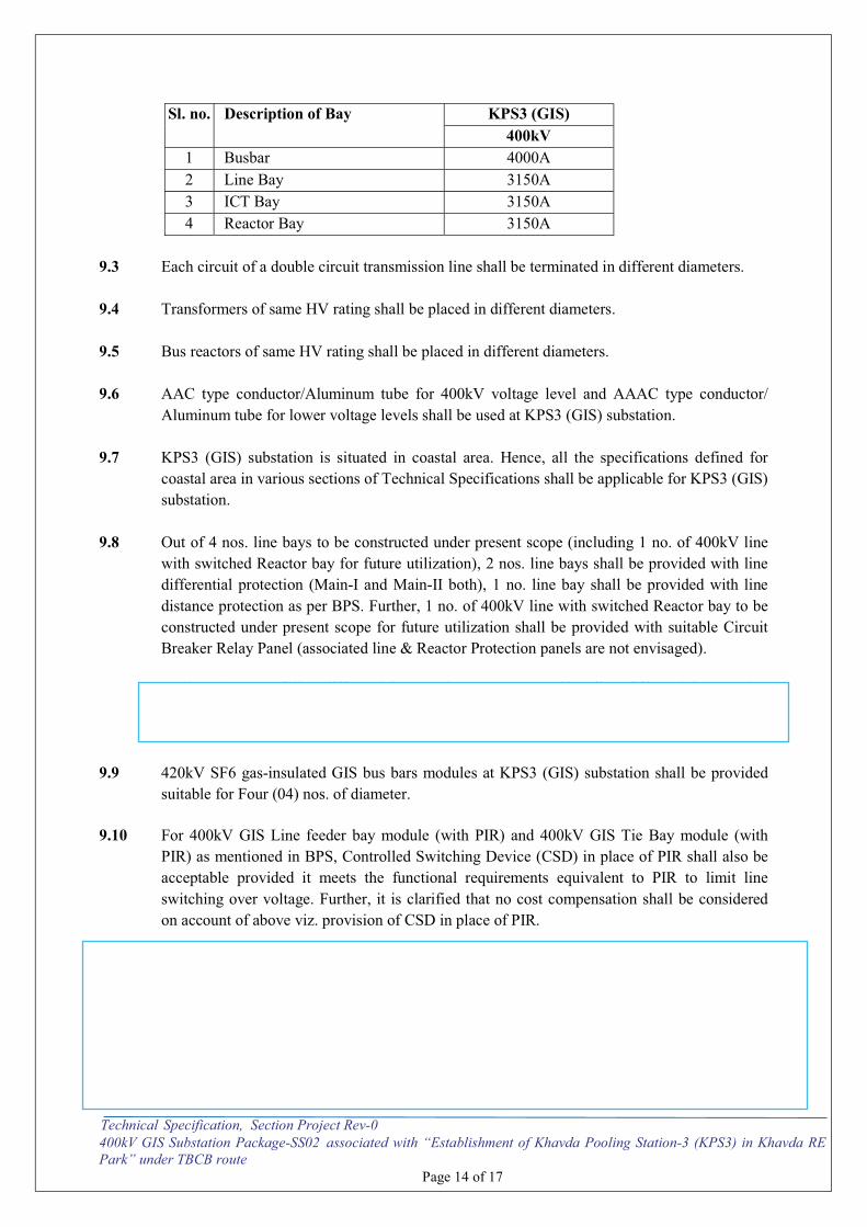
Technical Specification, Section Project Rev-0 400kV GIS Substation Package-SS02 associated with “Establishment of Khavda Pooling Station-3 (KPS3) in Khavda RE Park” under TBCB route
Page 14 of 17
Sl. no. Description of Bay KPS3 (GIS) 400kV
1 Busbar 4000A
2 Line Bay 3150A
3 ICT Bay 3150A
4 Reactor Bay 3150A
9.3 Each circuit of a double circuit transmission line shall be terminated in different diameters.
9.4 Transformers of same HV rating shall be placed in different diameters.
9.5 Bus reactors of same HV rating shall be placed in different diameters.
9.6 AAC type conductor/Aluminum tube for 400kV voltage level and AAAC type conductor/
Aluminum tube for lower voltage levels shall be used at KPS3 (GIS) substation.
9.7 KPS3 (GIS) substation is situated in coastal area. Hence, all the specifications defined for
coastal area in various sections of Technical Specifications shall be applicable for KPS3 (GIS)
substation.
9.8 Out of 4 nos. line bays to be constructed under present scope (including 1 no. of 400kV line
with switched Reactor bay for future utilization), 2 nos. line bays shall be provided with line
differential protection (Main-I and Main-II both), 1 no. line bay shall be provided with line
distance protection as per BPS. Further, 1 no. of 400kV line with switched Reactor bay to be
constructed under present scope for future utilization shall be provided with suitable Circuit
Breaker Relay Panel (associated line & Reactor Protection panels are not envisaged).
Further, in case of line differential protection system, matching line differential protection
relay (as loose item without panel) at remote end substation shall also deemed to be included
under present scope including necessary support for its commissioning at remote end.
9.9 420kV SF6 gas-insulated GIS bus bars modules at KPS3 (GIS) substation shall be provided
suitable for Four (04) nos. of diameter.
9.10 For 400kV GIS Line feeder bay module (with PIR) and 400kV GIS Tie Bay module (with
PIR) as mentioned in BPS, Controlled Switching Device (CSD) in place of PIR shall also be
acceptable provided it meets the functional requirements equivalent to PIR to limit line
switching over voltage. Further, it is clarified that no cost compensation shall be considered
on account of above viz. provision of CSD in place of PIR.
9.11 All Circuit Breaker Relay Panel Shall be provided with Auto-reclose function. However,
during execution stage Auto-reclose function shall be enabled/disabled based on application.
9.12 Sl. nos. (i), (iv) and (v) of Reference Drawings mentioned at Annexure-D of Section- Shunt
Reactor upto 400kV, Neutral Grounding Reactor and Surge Arrester Rev-11 stands deleted.
9.13 Clause No 24.1 of Section GTR Rev 15 is amended as below:
Annexure-IV
Description of 420kV GIS modules/Equipment
Page 1 of 5
A. 420kV GIS modules/Equipment: 420kV GIS modules/equipment shall be provided as per BPS and as per description given below:
a) Isolated phase, 420kV SF6 gas-insulated metal enclosed bus bar module
comprising of following:
i. Three (3) numbers of 4000A individual bus bars enclosures running across the length of the switchgear to interconnect each of the circuit breaker bay modules in one and a half breaker bus system.
ii. One (1) number 3-phase, single pole group operated safety grounding switches,
complete with manual and motor driven operating mechanisms. iii. Three (3) numbers 1-phase Potential Transformers complete with manual
operated isolating Switch/device. iv. Gas monitoring devices, barriers, pressure switches, UHF PD Sensors, support
structure etc. as required. v. End Piece (Interface) module with the test link for future extension of Bus bar
module. The end piece module shall be designed in such a way so that future GIS module may be tested without extending voltage to existing bus by removing the test link. End piece interface module for both the buses shall be in one alignment.
vi. Local Control Cubicle (if required separately).
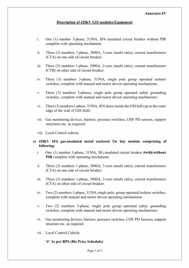
b) 420kV SF6 gas-insulated metal enclosed Line feeder bay module comprising of
following:
i. One (1) number 3-phase, 3150A, SF6 insulated circuit breaker #with/without PIR complete with operating mechanism.
ii. Three (3) numbers 1-phase, 3000A, 3-core (multi ratio), current transformers
(CTA) on one side of circuit breaker.
iii. Three (3) numbers 1-phase, 3000A, 2-core (multi ratio), current transformers (CTB) on other side of circuit breaker.
iv. Three (3) numbers 3-phase, 3150A, single pole group operated isolator
switches, complete with manual and motor driven operating mechanisms. v. Two (2) numbers 3-phase, single pole group operated safety grounding
switches, complete with manual and motor driven operating mechanisms. vi. One (1) number 3-phase, single pole high speed grounding switch, complete
with group operated manual and motor driven operating mechanisms.
vii. Three (3) numbers 1-phase, 3150A, SF6 ducts inside GIS hall (up to the outer edge of the wall of GIS Hall)
JAIK
Text Box
Section-1, Annexure-IV
Annexure-IV
Description of 420kV GIS modules/Equipment
Page 2 of 5
viii. Gas monitoring devices, barriers, pressure switches, UHF PD Sensors, support structure etc. as required.
ix. Local Control Cubicle.
‘#’ As per BPS (Bis Price Schedule)
c) 420kV SF6 gas-insulated metal enclosed ICT bay module (for 400kV side of
765/400kV ICT) comprising of following:
i. One (1) number 3-phase, 3150A, SF6 insulated circuit breaker without PIR complete with operating mechanism.
ii. Three (3) numbers 1-phase, 3000A, 3-core (multi ratio), current transformers
(CTA) on one side of circuit breaker.
iii. Three (3) numbers 1-phase, 3000A, 2-core (multi ratio), current transformers (CTB) on other side of circuit breaker.
iv. Two (2) numbers 3-phase, 3150A, single pole, group operated isolator switches,
complete with manual and motor driven operating mechanisms.
v. Two (2) numbers 3-phase, single pole, group operated safety grounding switches, complete with manual and motor driven operating mechanisms.
vi. Three (3) numbers 1-phase, 3150A, single pole, individual pole operated
isolator switches, complete with manual and motor driven operating mechanisms.
vii. Three (3) numbers 1-phase, single pole, individual pole operated safety
grounding switches, complete with manual and motor driven operating mechanisms.
viii. Three Nos. 1-phase, 3150A, individual pole operated isolator switches,
complete with manual and motor driven operating mechanisms for switching of spare Transformer through 400kV auxiliary bus. The isolator must meet the operational requirement in terms of Phase-Phase insulation withstand capability.
ix. Three (3) numbers 1-phase, 3150A, SF6 ducts inside GIS hall (upto the outer
edge of the wall of GIS Hall)
x. Gas monitoring devices, barriers, pressure switches, UHF PD Sensors, support structure etc. as required.
xi. Local Control Cubicle.
d) 420kV SF6 gas insulated metal enclosed Bus reactor module comprising of
following:
Annexure-IV
Description of 420kV GIS modules/Equipment
Page 3 of 5
i. One (1) number 3-phase, 3150A, SF6 insulated circuit breaker without PIR
complete with operating mechanism.
ii. Three (3) numbers 1-phase, 3000A, 3-core (multi ratio), current transformers (CTA) on one side of circuit breaker.
iii. Three (3) numbers 1-phase, 3000A, 2-core (multi ratio), current transformers (CTB) on other side of circuit breaker.
iv. Three (3) numbers 3-phase, 3150A, single pole group operated isolator switches, complete with manual and motor driven operating mechanisms
v. Three (3) numbers 3-phases, single pole group operated safety grounding
switches, complete with manual and motor driven operating mechanisms.
vi. Three (3) numbers1-phase, 3150A, SF6 ducts inside the GIS hall (up to the outer edge of the wall of GIS Hall)
vii. Gas monitoring devices, barriers, pressure switches, UHF PD sensors, support
structures etc. as required.
viii. Local Control cubicle.
e) 420kV SF6 gas-insulated metal enclosed Tie bay module comprising of following:
i. One (1) number 3-phase, 3150A, SF6 insulated circuit breaker #with/without
PIR complete with operating mechanism.
ii. Three (3) numbers 1-phase, 3000A, 3-core (multi ratio), current transformers (CTA) on one side of circuit breaker.
iii. Three (3) numbers 1-phase, 3000A, 3-core (multi ratio), current transformers (CTA) on other side of circuit breaker.
iv. Two (2) numbers 3-phase, 3150A single pole, group operated isolator switches,
complete with manual and motor driven operating mechanisms.
v. Two (2) numbers 3-phase, single pole group operated safety grounding switches, complete with manual and motor driven operating mechanisms.
vi. Gas monitoring devices, barriers, pressure switches, UHF PD Sensors, support structure etc. as required.
vii. Local Control Cubicle.
‘#’ As per BPS (Bis Price Schedule)
Annexure-IV
Description of 420kV GIS modules/Equipment
Page 4 of 5
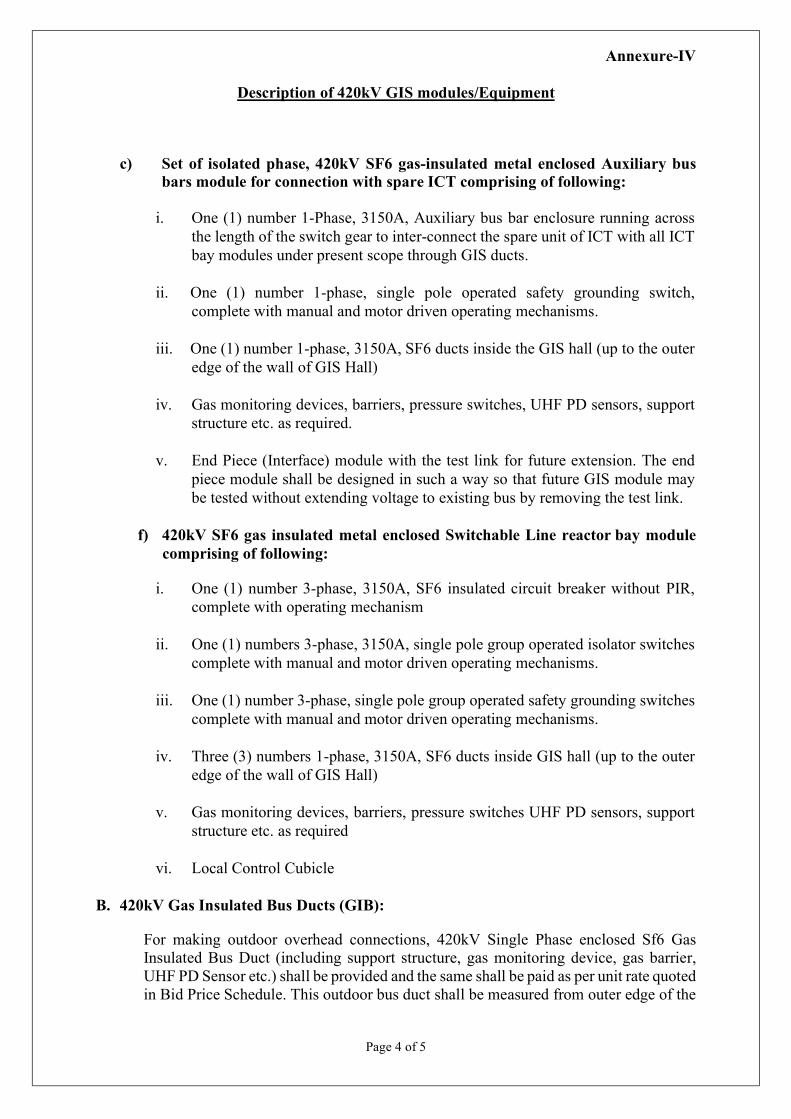
c) Set of isolated phase, 420kV SF6 gas-insulated metal enclosed Auxiliary bus
bars module for connection with spare ICT comprising of following:
i. One (1) number 1-Phase, 3150A, Auxiliary bus bar enclosure running across the length of the switch gear to inter-connect the spare unit of ICT with all ICT bay modules under present scope through GIS ducts.
ii. One (1) number 1-phase, single pole operated safety grounding switch, complete with manual and motor driven operating mechanisms.
iii. One (1) number 1-phase, 3150A, SF6 ducts inside the GIS hall (up to the outer edge of the wall of GIS Hall)
iv. Gas monitoring devices, barriers, pressure switches, UHF PD sensors, support structure etc. as required.
v. End Piece (Interface) module with the test link for future extension. The end piece module shall be designed in such a way so that future GIS module may be tested without extending voltage to existing bus by removing the test link.
f) 420kV SF6 gas insulated metal enclosed Switchable Line reactor bay module comprising of following:
i. One (1) number 3-phase, 3150A, SF6 insulated circuit breaker without PIR,
complete with operating mechanism
ii. One (1) numbers 3-phase, 3150A, single pole group operated isolator switches complete with manual and motor driven operating mechanisms.
iii. One (1) number 3-phase, single pole group operated safety grounding switches complete with manual and motor driven operating mechanisms.
iv. Three (3) numbers 1-phase, 3150A, SF6 ducts inside GIS hall (up to the outer edge of the wall of GIS Hall)
v. Gas monitoring devices, barriers, pressure switches UHF PD sensors, support structure etc. as required
vi. Local Control Cubicle
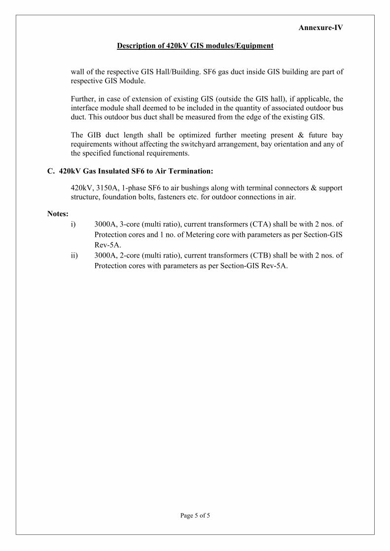
B. 420kV Gas Insulated Bus Ducts (GIB):
For making outdoor overhead connections, 420kV Single Phase enclosed Sf6 Gas Insulated Bus Duct (including support structure, gas monitoring device, gas barrier, UHF PD Sensor etc.) shall be provided and the same shall be paid as per unit rate quoted in Bid Price Schedule. This outdoor bus duct shall be measured from outer edge of the
Annexure-IV
Description of 420kV GIS modules/Equipment
Page 5 of 5
wall of the respective GIS Hall/Building. SF6 gas duct inside GIS building are part of respective GIS Module. Further, in case of extension of existing GIS (outside the GIS hall), if applicable, the interface module shall deemed to be included in the quantity of associated outdoor bus duct. This outdoor bus duct shall be measured from the edge of the existing GIS. The GIB duct length shall be optimized further meeting present & future bay requirements without affecting the switchyard arrangement, bay orientation and any of the specified functional requirements.
C. 420kV Gas Insulated SF6 to Air Termination:
420kV, 3150A, 1-phase SF6 to air bushings along with terminal connectors & support structure, foundation bolts, fasteners etc. for outdoor connections in air.
Notes: i) 3000A, 3-core (multi ratio), current transformers (CTA) shall be with 2 nos. of
Protection cores and 1 no. of Metering core with parameters as per Section-GIS Rev-5A.
ii) 3000A, 2-core (multi ratio), current transformers (CTB) shall be with 2 nos. of Protection cores with parameters as per Section-GIS Rev-5A.
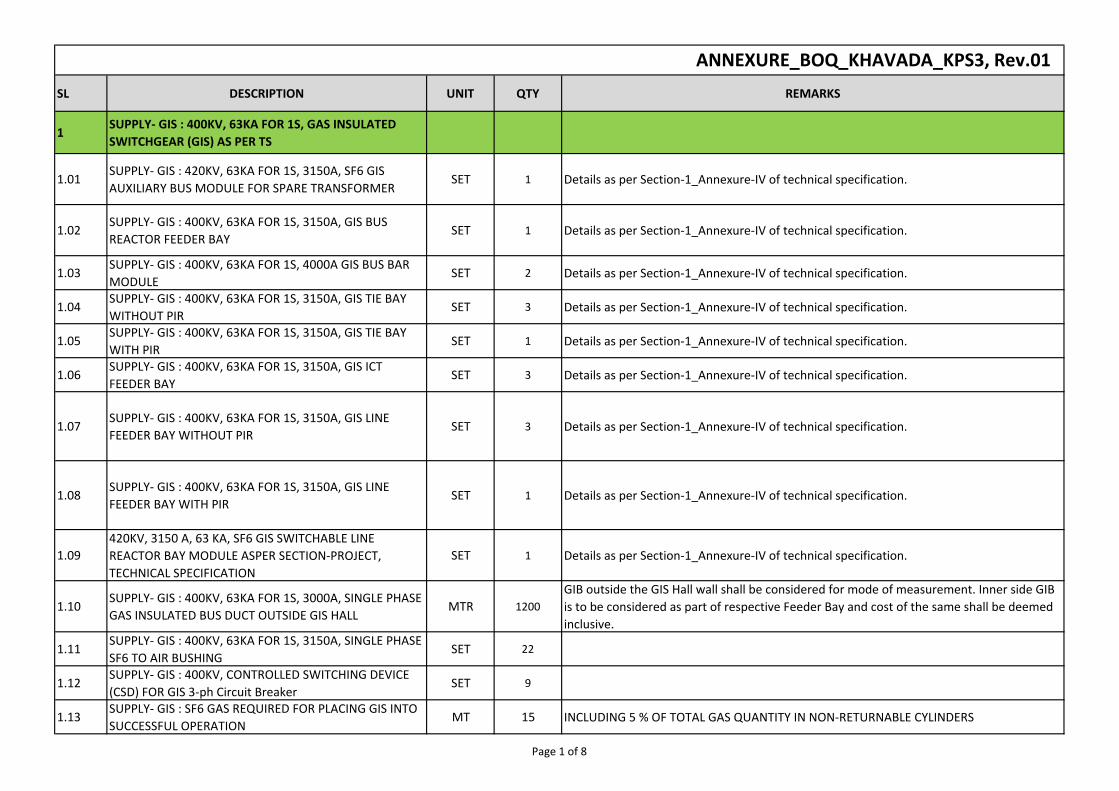
SL DESCRIPTION UNIT QTY REMARKS
1SUPPLY- GIS : 400KV, 63KA FOR 1S, GAS INSULATED
SWITCHGEAR (GIS) AS PER TS
1.01SUPPLY- GIS : 420KV, 63KA FOR 1S, 3150A, SF6 GIS
AUXILIARY BUS MODULE FOR SPARE TRANSFORMERSET 1 Details as per Section-1_Annexure-IV of technical specification.
1.02SUPPLY- GIS : 400KV, 63KA FOR 1S, 3150A, GIS BUS
REACTOR FEEDER BAYSET 1 Details as per Section-1_Annexure-IV of technical specification.
1.03SUPPLY- GIS : 400KV, 63KA FOR 1S, 4000A GIS BUS BAR
MODULESET 2 Details as per Section-1_Annexure-IV of technical specification.
1.04SUPPLY- GIS : 400KV, 63KA FOR 1S, 3150A, GIS TIE BAY
WITHOUT PIRSET 3 Details as per Section-1_Annexure-IV of technical specification.
1.05SUPPLY- GIS : 400KV, 63KA FOR 1S, 3150A, GIS TIE BAY
WITH PIRSET 1 Details as per Section-1_Annexure-IV of technical specification.
1.06SUPPLY- GIS : 400KV, 63KA FOR 1S, 3150A, GIS ICT
FEEDER BAYSET 3 Details as per Section-1_Annexure-IV of technical specification.
1.07SUPPLY- GIS : 400KV, 63KA FOR 1S, 3150A, GIS LINE
FEEDER BAY WITHOUT PIRSET 3 Details as per Section-1_Annexure-IV of technical specification.
1.08SUPPLY- GIS : 400KV, 63KA FOR 1S, 3150A, GIS LINE
FEEDER BAY WITH PIRSET 1 Details as per Section-1_Annexure-IV of technical specification.
1.09
420KV, 3150 A, 63 KA, SF6 GIS SWITCHABLE LINE
REACTOR BAY MODULE ASPER SECTION-PROJECT,
TECHNICAL SPECIFICATION
SET 1 Details as per Section-1_Annexure-IV of technical specification.
1.10SUPPLY- GIS : 400KV, 63KA FOR 1S, 3000A, SINGLE PHASE
GAS INSULATED BUS DUCT OUTSIDE GIS HALLMTR 1200
GIB outside the GIS Hall wall shall be considered for mode of measurement. Inner side GIB
is to be considered as part of respective Feeder Bay and cost of the same shall be deemed
inclusive.
1.11SUPPLY- GIS : 400KV, 63KA FOR 1S, 3150A, SINGLE PHASE
SF6 TO AIR BUSHINGSET 22
1.12SUPPLY- GIS : 400KV, CONTROLLED SWITCHING DEVICE
(CSD) FOR GIS 3-ph Circuit BreakerSET 9
1.13SUPPLY- GIS : SF6 GAS REQUIRED FOR PLACING GIS INTO
SUCCESSFUL OPERATIONMT 15 INCLUDING 5 % OF TOTAL GAS QUANTITY IN NON-RETURNABLE CYLINDERS
ANNEXURE_BOQ_KHAVADA_KPS3, Rev.01
Page 1 of 8
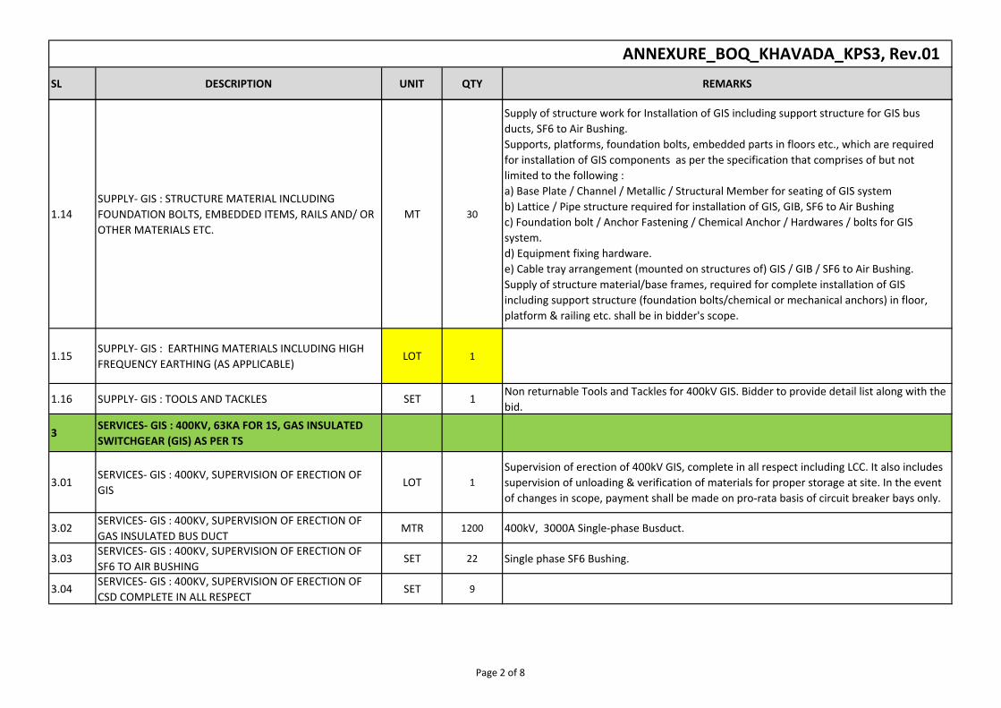
SL DESCRIPTION UNIT QTY REMARKS
ANNEXURE_BOQ_KHAVADA_KPS3, Rev.01
1.14
SUPPLY- GIS : STRUCTURE MATERIAL INCLUDING
FOUNDATION BOLTS, EMBEDDED ITEMS, RAILS AND/ OR
OTHER MATERIALS ETC.
MT 30
Supply of structure work for Installation of GIS including support structure for GIS bus
ducts, SF6 to Air Bushing.
Supports, platforms, foundation bolts, embedded parts in floors etc., which are required
for installation of GIS components as per the specification that comprises of but not
limited to the following :
a) Base Plate / Channel / Metallic / Structural Member for seating of GIS system
b) Lattice / Pipe structure required for installation of GIS, GIB, SF6 to Air Bushing
c) Foundation bolt / Anchor Fastening / Chemical Anchor / Hardwares / bolts for GIS
system.
d) Equipment fixing hardware.
e) Cable tray arrangement (mounted on structures of) GIS / GIB / SF6 to Air Bushing.
Supply of structure material/base frames, required for complete installation of GIS
including support structure (foundation bolts/chemical or mechanical anchors) in floor,
platform & railing etc. shall be in bidder's scope.
1.15SUPPLY- GIS : EARTHING MATERIALS INCLUDING HIGH
FREQUENCY EARTHING (AS APPLICABLE)LOT 1
1.16 SUPPLY- GIS : TOOLS AND TACKLES SET 1Non returnable Tools and Tackles for 400kV GIS. Bidder to provide detail list along with the
bid.
3SERVICES- GIS : 400KV, 63KA FOR 1S, GAS INSULATED
SWITCHGEAR (GIS) AS PER TS
3.01SERVICES- GIS : 400KV, SUPERVISION OF ERECTION OF
GISLOT 1
Supervision of erection of 400kV GIS, complete in all respect including LCC. It also includes
supervision of unloading & verification of materials for proper storage at site. In the event
of changes in scope, payment shall be made on pro-rata basis of circuit breaker bays only.
3.02SERVICES- GIS : 400KV, SUPERVISION OF ERECTION OF
GAS INSULATED BUS DUCTMTR 1200 400kV, 3000A Single-phase Busduct.
3.03SERVICES- GIS : 400KV, SUPERVISION OF ERECTION OF
SF6 TO AIR BUSHINGSET 22 Single phase SF6 Bushing.
3.04SERVICES- GIS : 400KV, SUPERVISION OF ERECTION OF
CSD COMPLETE IN ALL RESPECTSET 9
Page 2 of 8
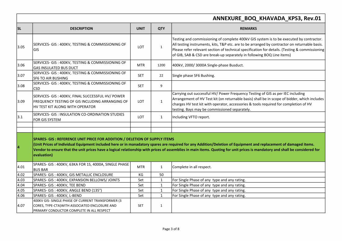
SL DESCRIPTION UNIT QTY REMARKS
ANNEXURE_BOQ_KHAVADA_KPS3, Rev.01
3.05SERVICES- GIS : 400KV, TESTING & COMMISSIONING OF
GISLOT 1
Testing and commissioning of complete 400kV GIS system is to be executed by contractor.
All testing instruments, kits, T&P etc. are to be arranged by contractor on returnable basis.
Please refer relevant section of technical specification for details. (Testing & commissioning
of GIB, SAB & CSD are break-up separately in following BOQ Line items)
3.06SERVICES- GIS : 400KV, TESTING & COMMISSIONING OF
GAS INSULATED BUS DUCTMTR 1200 400kV, 2000/ 3000A Single-phase Busduct.
3.07SERVICES- GIS : 400KV, TESTING & COMMISSIONING OF
SF6 TO AIR BUSHINGSET 22 Single phase SF6 Bushing.
3.08SERVICES- GIS : 400KV, TESTING & COMMISSIONING OF
CSDSET 9
3.09
SERVICES- GIS : 400KV, FINAL SUCCESSFUL HV/ POWER
FREQUENCY TESTING OF GIS INCLUDING ARRANGING OF
HV TEST KIT ALONG WITH OPERATOR
LOT 1
Carrying out successful HV/ Power Frequency Testing of GIS as per IEC including
Arrangement of HV Test kit (on returnable basis) shall be in scope of bidder, which includes
charges HV test kit with operator, accessories & tools required for completion of HV
testing. Bays may be commissioned separately.
3.1SERVICES- GIS : INSULATION CO-ORDINATION STUDIES
FOR GIS SYSTEMLOT 1 Including VFTO report.
4
4.01SPARES- GIS : 400KV, 63KA FOR 1S, 4000A, SINGLE PHASE
BUS BARMTR 1 Complete in all respect.
4.02 SPARES- GIS : 400KV, GIS METALLIC ENCLOSURE KG 50
4.03 SPARES- GIS : 400KV, EXPANSION BELLOWS/ JOINTS Set 1 For Single Phase of any type and any rating.
4.04 SPARES- GIS : 400KV, TEE BEND Set 1 For Single Phase of any type and any rating.
4.05 SPARES- GIS : 400KV, ANGLE BEND (135°) Set 1 For Single Phase of any type and any rating.
4.06 SPARES- GIS : 400KV, L-BEND Set 1 For Single Phase of any type and any rating.
4.07400KV GIS- SINGLE PHASE OF CURRENT TRANSFORMER (3
CORES, TYPE-CTA)WITH ASSOCIATED ENCLOSURE AND
PRIMARY CONDUCTOR COMPLETE IN ALL RESPECT
SET 1
SPARES- GIS : REFERENCE UNIT PRICE FOR ADDITION / DELETION OF SUPPLY ITEMS
(Unit Prices of Individual Equipment included here or in manadatory spares are required for any Addition/Deletion of Equipment and replacement of damaged items.
Vendor to ensure that the unit prices have a logical relationship with prices of assemblies in main items. Quoting for unit prices is mandatory and shall be considered for
evaluation)
Page 3 of 8
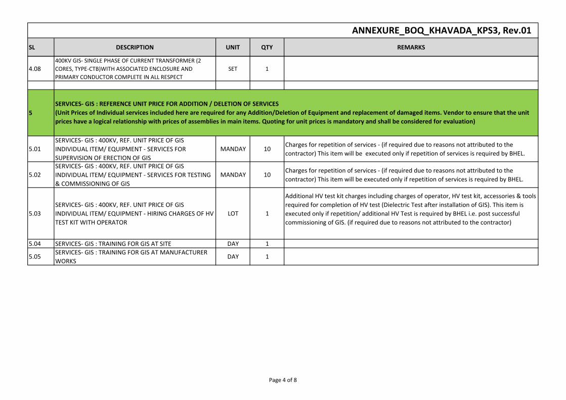
SL DESCRIPTION UNIT QTY REMARKS
ANNEXURE_BOQ_KHAVADA_KPS3, Rev.01
4.08400KV GIS- SINGLE PHASE OF CURRENT TRANSFORMER (2
CORES, TYPE-CTB)WITH ASSOCIATED ENCLOSURE AND
PRIMARY CONDUCTOR COMPLETE IN ALL RESPECT
SET 1
5
5.01
SERVICES- GIS : 400KV, REF. UNIT PRICE OF GIS
INDIVIDUAL ITEM/ EQUIPMENT - SERVICES FOR
SUPERVISION OF ERECTION OF GIS
MANDAY 10Charges for repetition of services - (if required due to reasons not attributed to the
contractor) This item will be executed only if repetition of services is required by BHEL.
5.02
SERVICES- GIS : 400KV, REF. UNIT PRICE OF GIS
INDIVIDUAL ITEM/ EQUIPMENT - SERVICES FOR TESTING
& COMMISSIONING OF GIS
MANDAY 10Charges for repetition of services - (if required due to reasons not attributed to the
contractor) This item will be executed only if repetition of services is required by BHEL.
5.03
SERVICES- GIS : 400KV, REF. UNIT PRICE OF GIS
INDIVIDUAL ITEM/ EQUIPMENT - HIRING CHARGES OF HV
TEST KIT WITH OPERATOR
LOT 1
Additional HV test kit charges including charges of operator, HV test kit, accessories & tools
required for completion of HV test (Dielectric Test after installation of GIS). This item is
executed only if repetition/ additional HV Test is required by BHEL i.e. post successful
commissioning of GIS. (if required due to reasons not attributed to the contractor)
5.04 SERVICES- GIS : TRAINING FOR GIS AT SITE DAY 1
5.05SERVICES- GIS : TRAINING FOR GIS AT MANUFACTURER
WORKSDAY 1
SERVICES- GIS : REFERENCE UNIT PRICE FOR ADDITION / DELETION OF SERVICES
(Unit Prices of Individual services included here are required for any Addition/Deletion of Equipment and replacement of damaged items. Vendor to ensure that the unit
prices have a logical relationship with prices of assemblies in main items. Quoting for unit prices is mandatory and shall be considered for evaluation)
Page 4 of 8
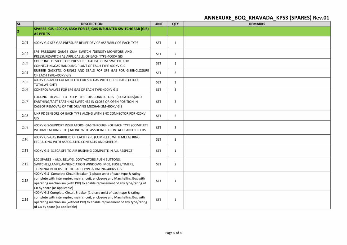
SL DESCRIPTION UNIT QTY REMARKS
2SPARES- GIS : 400KV, 63KA FOR 1S, GAS INSULATED SWITCHGEAR (GIS)
AS PER TS
2.01 400KV GIS-SF6 GAS PRESSURE RELIEF DEVICE ASSEMBLY OF EACH TYPE SET 1
2.02SF6 PRESSURE GAUGE CUM SWITCH /DENSITY MONITORS AND
PRESSURESWITCH AS APPLICABLE, OF EACH TYPE-400KV GISSET 2
2.03COUPLING DEVICE FOR PRESSURE GAUGE CUM SWITCH FOR
CONNECTINGGAS HANDLING PLANT OF EACH TYPE-400KV GISSET 1
2.04RUBBER GASKETS, O-RINGS AND SEALS FOR SF6 GAS FOR GISENCLOSURE
OF EACH TYPE-400KV GISSET 3
2.05400KV GIS-MOLECULAR FILTER FOR SF6 GAS WITH FILTER BAGS (3 % OF
TOTALWEIGHT)SET 1
2.06 CONTROL VALVES FOR SF6 GAS OF EACH TYPE-400KV GIS SET 3
2.07
LOCKING DEVICE TO KEEP THE DIS-CONNECTORS (ISOLATORS)AND
EARTHING/FAST EARTHING SWITCHES IN CLOSE OR OPEN POSITION IN
CASEOF REMOVAL OF THE DRIVING MECHANISM-400KV GIS
SET 3
2.08UHF PD SENSORS OF EACH TYPE ALONG WITH BNC CONNECTOR FOR 420KV
GISSET 5
2.09400KV GIS-SUPPORT INSULATORS (GAS THROUGH) OF EACH TYPE (COMPLETE
WITHMETAL RING ETC.) ALONG WITH ASSOCIATED CONTACTS AND SHIELDSSET 3
2.10400KV GIS-GAS BARRIERS OF EACH TYPE (COMPLETE WITH METAL RING
ETC.)ALONG WITH ASSOCIATED CONTACTS AND SHIELDSSET 3
2.11 400KV GIS- 3150A SF6 TO AIR BUSHING COMPLETE IN ALL RESPECT SET 1
2.12
LCC SPARES - AUX. RELAYS, CONTACTORS,PUSH BUTTONS,
SWITCHES,LAMPS,ANNUNCIATION WINDOWS, MCB, FUSES,TIMERS,
TERMINAL BLOCKS ETC. OF EACH TYPE & RATING-400kV GIS
SET 2
2.13
400KV GIS- Complete Circuit Breaker (1 phase unit) of each type & rating
complete with interrupter, main circuit, enclosure and Marshalling Box with
operating mechanism (with PIR) to enable replacement of any type/rating of
CB by spare (as applicable)
SET 1
2.14
400KV GIS-Complete Circuit Breaker (1 phase unit) of each type & rating
complete with interrupter, main circuit, enclosure and Marshalling Box with
operating mechanism (without PIR) to enable replacement of any type/rating
of CB by spare (as applicable)
SET 1
ANNEXURE_BOQ_KHAVADA_KPS3 (SPARES) Rev.01
Page 5 of 8
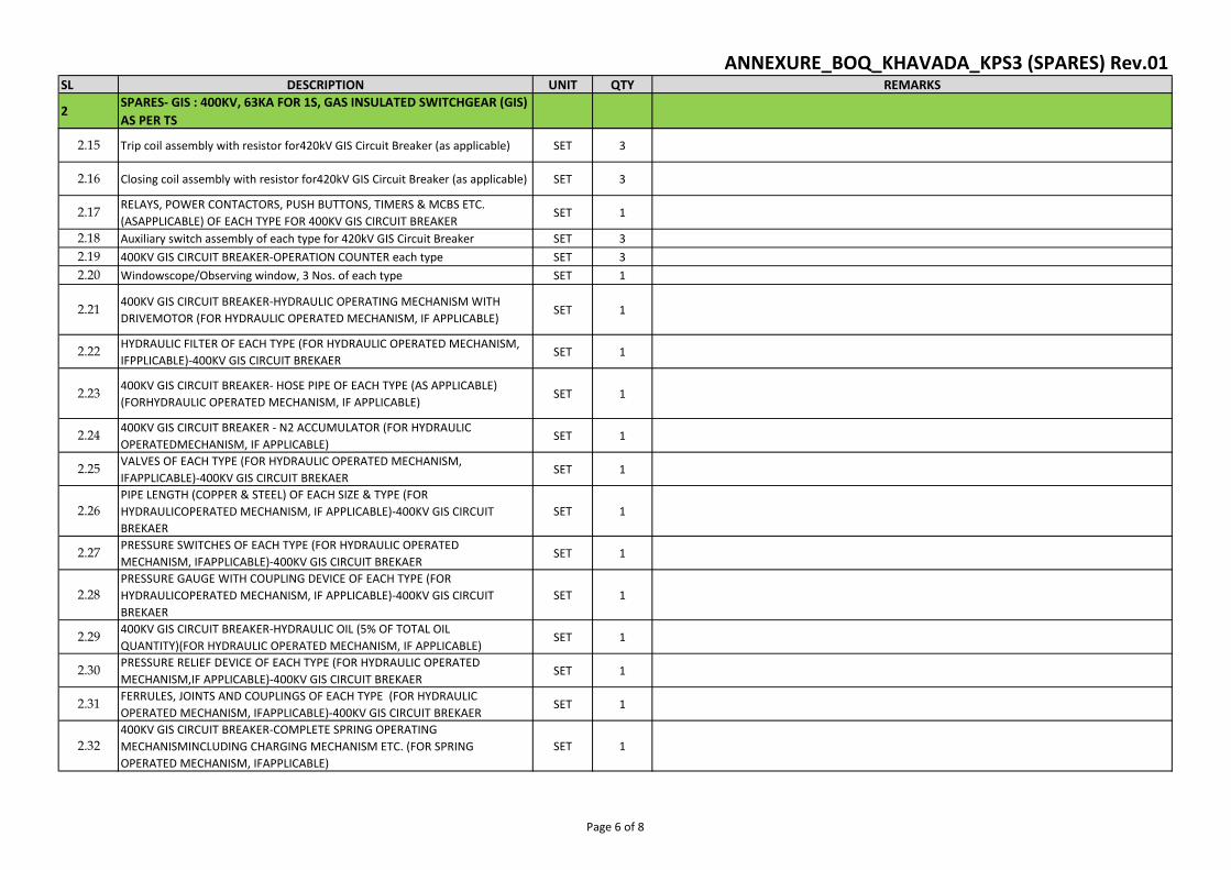
SL DESCRIPTION UNIT QTY REMARKS
2SPARES- GIS : 400KV, 63KA FOR 1S, GAS INSULATED SWITCHGEAR (GIS)
AS PER TS
ANNEXURE_BOQ_KHAVADA_KPS3 (SPARES) Rev.01
2.15 Trip coil assembly with resistor for420kV GIS Circuit Breaker (as applicable) SET 3
2.16 Closing coil assembly with resistor for420kV GIS Circuit Breaker (as applicable) SET 3
2.17RELAYS, POWER CONTACTORS, PUSH BUTTONS, TIMERS & MCBS ETC.
(ASAPPLICABLE) OF EACH TYPE FOR 400KV GIS CIRCUIT BREAKERSET 1
2.18 Auxiliary switch assembly of each type for 420kV GIS Circuit Breaker SET 3
2.19 400KV GIS CIRCUIT BREAKER-OPERATION COUNTER each type SET 3
2.20 Windowscope/Observing window, 3 Nos. of each type SET 1
2.21400KV GIS CIRCUIT BREAKER-HYDRAULIC OPERATING MECHANISM WITH
DRIVEMOTOR (FOR HYDRAULIC OPERATED MECHANISM, IF APPLICABLE)SET 1
2.22HYDRAULIC FILTER OF EACH TYPE (FOR HYDRAULIC OPERATED MECHANISM,
IFPPLICABLE)-400KV GIS CIRCUIT BREKAERSET 1
2.23400KV GIS CIRCUIT BREAKER- HOSE PIPE OF EACH TYPE (AS APPLICABLE)
(FORHYDRAULIC OPERATED MECHANISM, IF APPLICABLE)SET 1
2.24400KV GIS CIRCUIT BREAKER - N2 ACCUMULATOR (FOR HYDRAULIC
OPERATEDMECHANISM, IF APPLICABLE)SET 1
2.25VALVES OF EACH TYPE (FOR HYDRAULIC OPERATED MECHANISM,
IFAPPLICABLE)-400KV GIS CIRCUIT BREKAERSET 1
2.26
PIPE LENGTH (COPPER & STEEL) OF EACH SIZE & TYPE (FOR
HYDRAULICOPERATED MECHANISM, IF APPLICABLE)-400KV GIS CIRCUIT
BREKAER
SET 1
2.27PRESSURE SWITCHES OF EACH TYPE (FOR HYDRAULIC OPERATED
MECHANISM, IFAPPLICABLE)-400KV GIS CIRCUIT BREKAERSET 1
2.28
PRESSURE GAUGE WITH COUPLING DEVICE OF EACH TYPE (FOR
HYDRAULICOPERATED MECHANISM, IF APPLICABLE)-400KV GIS CIRCUIT
BREKAER
SET 1
2.29400KV GIS CIRCUIT BREAKER-HYDRAULIC OIL (5% OF TOTAL OIL
QUANTITY)(FOR HYDRAULIC OPERATED MECHANISM, IF APPLICABLE)SET 1
2.30PRESSURE RELIEF DEVICE OF EACH TYPE (FOR HYDRAULIC OPERATED
MECHANISM,IF APPLICABLE)-400KV GIS CIRCUIT BREKAERSET 1
2.31FERRULES, JOINTS AND COUPLINGS OF EACH TYPE (FOR HYDRAULIC
OPERATED MECHANISM, IFAPPLICABLE)-400KV GIS CIRCUIT BREKAERSET 1
2.32
400KV GIS CIRCUIT BREAKER-COMPLETE SPRING OPERATING
MECHANISMINCLUDING CHARGING MECHANISM ETC. (FOR SPRING
OPERATED MECHANISM, IFAPPLICABLE)
SET 1
Page 6 of 8
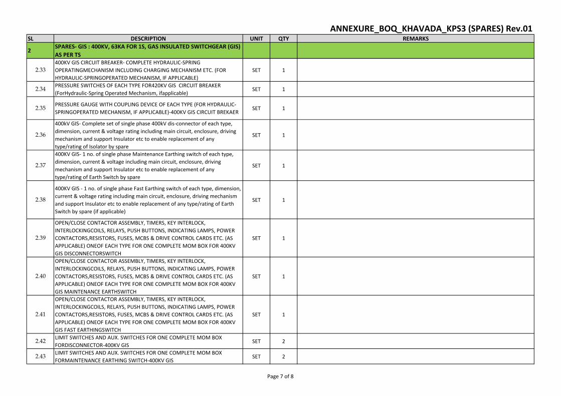
SL DESCRIPTION UNIT QTY REMARKS
2SPARES- GIS : 400KV, 63KA FOR 1S, GAS INSULATED SWITCHGEAR (GIS)
AS PER TS
ANNEXURE_BOQ_KHAVADA_KPS3 (SPARES) Rev.01
2.33
400KV GIS CIRCUIT BREAKER- COMPLETE HYDRAULIC-SPRING
OPERATINGMECHANISM INCLUDING CHARGING MECHANISM ETC. (FOR
HYDRAULIC-SPRINGOPERATED MECHANISM, IF APPLICABLE)
SET 1
2.34PRESSURE SWITCHES OF EACH TYPE FOR420KV GIS CIRCUIT BREAKER
(ForHydraulic-Spring Operated Mechanism, ifapplicable)SET 1
2.35PRESSURE GAUGE WITH COUPLING DEVICE OF EACH TYPE (FOR HYDRAULIC-
SPRINGOPERATED MECHANISM, IF APPLICABLE)-400KV GIS CIRCUIT BREKAERSET 1
2.36
400kV GIS- Complete set of single phase 400kV dis-connector of each type,
dimension, current & voltage rating including main circuit, enclosure, driving
mechanism and support Insulator etc to enable replacement of any
type/rating of Isolator by spare
SET 1
2.37
400KV GIS- 1 no. of single phase Maintenance Earthing switch of each type,
dimension, current & voltage including main circuit, enclosure, driving
mechanism and support Insulator etc to enable replacement of any
type/rating of Earth Switch by spare
SET 1
2.38
400KV GIS - 1 no. of single phase Fast Earthing switch of each type, dimension,
current & voltage rating including main circuit, enclosure, driving mechanism
and support Insulator etc to enable replacement of any type/rating of Earth
Switch by spare (if applicable)
SET 1
2.39
OPEN/CLOSE CONTACTOR ASSEMBLY, TIMERS, KEY INTERLOCK,
INTERLOCKINGCOILS, RELAYS, PUSH BUTTONS, INDICATING LAMPS, POWER
CONTACTORS,RESISTORS, FUSES, MCBS & DRIVE CONTROL CARDS ETC. (AS
APPLICABLE) ONEOF EACH TYPE FOR ONE COMPLETE MOM BOX FOR 400KV
GIS DISCONNECTORSWITCH
SET 1
2.40
OPEN/CLOSE CONTACTOR ASSEMBLY, TIMERS, KEY INTERLOCK,
INTERLOCKINGCOILS, RELAYS, PUSH BUTTONS, INDICATING LAMPS, POWER
CONTACTORS,RESISTORS, FUSES, MCBS & DRIVE CONTROL CARDS ETC. (AS
APPLICABLE) ONEOF EACH TYPE FOR ONE COMPLETE MOM BOX FOR 400KV
GIS MAINTENANCE EARTHSWITCH
SET 1
2.41
OPEN/CLOSE CONTACTOR ASSEMBLY, TIMERS, KEY INTERLOCK,
INTERLOCKINGCOILS, RELAYS, PUSH BUTTONS, INDICATING LAMPS, POWER
CONTACTORS,RESISTORS, FUSES, MCBS & DRIVE CONTROL CARDS ETC. (AS
APPLICABLE) ONEOF EACH TYPE FOR ONE COMPLETE MOM BOX FOR 400KV
GIS FAST EARTHINGSWITCH
SET 1
2.42LIMIT SWITCHES AND AUX. SWITCHES FOR ONE COMPLETE MOM BOX
FORDISCONNECTOR-400KV GISSET 2
2.43LIMIT SWITCHES AND AUX. SWITCHES FOR ONE COMPLETE MOM BOX
FORMAINTENANCE EARTHING SWITCH-400KV GISSET 2
Page 7 of 8
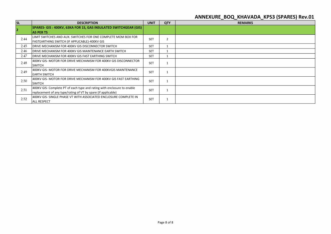
SL DESCRIPTION UNIT QTY REMARKS
2SPARES- GIS : 400KV, 63KA FOR 1S, GAS INSULATED SWITCHGEAR (GIS)
AS PER TS
ANNEXURE_BOQ_KHAVADA_KPS3 (SPARES) Rev.01
2.44LIMIT SWITCHES AND AUX. SWITCHES FOR ONE COMPLETE MOM BOX FOR
FASTEARTHING SWITCH (IF APPLICABLE)-400KV GISSET 2
2.45 DRIVE MECHANISM FOR 400KV GIS DISCONNECTOR SWITCH SET 1
2.46 DRIVE MECHANISM FOR 400KV GIS MAINTENANCE EARTH SWITCH SET 1
2.47 DRIVE MECHANISM FOR 400KV GIS FAST EARTHING SWITCH SET 1
2.48400KV GIS- MOTOR FOR DRIVE MECHANISM FOR 400KV GIS DISCONNECTOR
SWITCHSET 1
2.49400KV GIS- MOTOR FOR DRIVE MECHANISM FOR 400KVGIS MAINTENANCE
EARTH SWITCHSET 1
2.50400KV GIS- MOTOR FOR DRIVE MECHANISM FOR 400KV GIS FAST EARTHING
SWITCHSET 1
2.51400KV GIS- Complete PT of each type and rating with enclosure to enable
replacement of any type/rating of VT by spare (if applicable)SET 1
2.52400KV GIS- SINGLE PHASE VT WITH ASSOCIATED ENCLOSURE COMPLETE IN
ALL RESPECTSET 1
Page 8 of 8
TECHNICAL SPECIFICATION
SECTION-GAS INSULATED SWITCHGEAR
Document No.: C/ENGG/SPEC/GIS (Rev.05A) FEBRUARY’ 2019
पावर ��ड कापरेशन आफ इि�डया �ल�मटेड
(भारत सरकार का उयम)
Power Grid Corporation of India Limited (A Government of India Enterprises)
1653024
Text Box
REMARK - PLEASE READ TERMINOLOGY OF SECTION-2 OF TECH SPECIFICATION AS FOLLWOS 1. Read "GTR" as "Section-3 of technical specification" 2. Read "Powergrid" as "BHEL/Powergrid". 3. Read "Employer" as "Powergrid". 4. Read "Contractor" as bidder
1653024
Text Box
Section -2 of Technical Specification

INDEX
S.No. Description Page No
1. GENERAL 1
2. GENERAL CHARACTERISTICS 1
3. REFERENCE STANDARDS 1
4. DEFINITIONS 2
5. GENERAL DESIGN AND SAFETY REQUIREMENT 3
6. CIRCUIT BREAKERS 15
7. DISCONNECTORS (ISOLATORS) 23
8. SAFETY GROUNDING SWITCHES 25
9. HIGH SPEED MAKE PROOF GROUNDING SWITCHES 26
10. INSTRUMENT TRANSFORMERS 28
11. SURGE ARRESTORS 31
12. OUTDOOR SF6/Air BUSHINGS 34
13. GIS TO CABLE TERMINATION (If applicable) 35
14. TRANSFORMER / REACTOR TERMINATION 35
15. LOCAL CONTROL CUBICLE (LCC) 36
16. GIS BUILDING 39
17. ELECTRIC OVERHEAD CRANE 40
18. SEISMIC DESIGN CRITERIA 41
19. DESIGN REVIEW 41
20. TYPE TESTS 43
21. MISCLLENOUS 44
22. TRANSPORT OF EQUIPMENT TO SITE 44
23. PACKING, STORAGE AND UNPACKING 45
24. INSTALLATION OF GIS 46
25. ON SITE TESTING 48
26. MANDATORY SPARE 48
27. TESTING & MAINTENACE EQUIPMENT 49
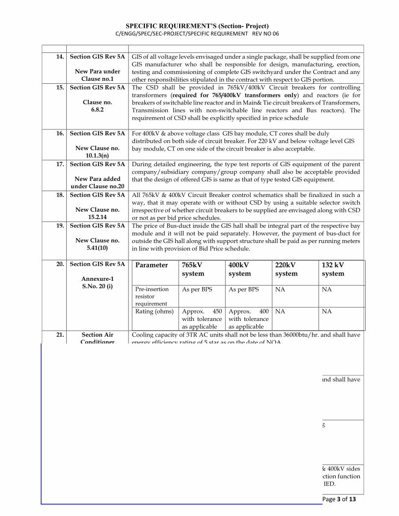
SPECIFIC REQUIREMENT’S (Section- Project) C/ENGG/SPEC/SEC-PROJECT/SPECIFIC REQUIREMENT REV NO 06
Page 3 of 13
14. Section GIS Rev 5A
New Para under
Clause no.1
GIS of all voltage levels envisaged under a single package, shall be supplied from one GIS manufacturer who shall be responsible for design, manufacturing, erection, testing and commissioning of complete GIS switchyard under the Contract and any other responsibilities stipulated in the contract with respect to GIS portion.
15. Section GIS Rev 5A
Clause no. 6.8.2
The CSD shall be provided in 765kV/400kV Circuit breakers for controlling transformers (required for 765/400kV transformers only) and reactors (ie for breakers of switchable line reactor and in Main& Tie circuit breakers of Transformers, Transmission lines with non-switchable line reactors and Bus reactors). The requirement of CSD shall be explicitly specified in price schedule
16. Section GIS Rev 5A
New Clause no. 10.1.3(n)
For 400kV & above voltage class GIS bay module, CT cores shall be duly distributed on both side of circuit breaker. For 220 kV and below voltage level GIS bay module, CT on one side of the circuit breaker is also acceptable.
17. Section GIS Rev 5A
New Para added under Clause no.20
During detailed engineering, the type test reports of GIS equipment of the parent company/subsidiary company/group company shall also be acceptable provided that the design of offered GIS is same as that of type tested GIS equipment.
18. Section GIS Rev 5A
New Clause no. 15.2.14
All 765kV & 400kV Circuit Breaker control schematics shall be finalized in such a way, that it may operate with or without CSD by using a suitable selector switch irrespective of whether circuit breakers to be supplied are envisaged along with CSD or not as per bid price schedules.
19. Section GIS Rev 5A
New Clause no. 5.41(10)
The price of Bus-duct inside the GIS hall shall be integral part of the respective bay module and it will not be paid separately. However, the payment of bus-duct for outside the GIS hall along with support structure shall be paid as per running meters in line with provision of Bid Price schedule.
20. Section GIS Rev 5A
Annexure-1 S.No. 20 (i)
Parameter
765kV system
400kV system
220kV system
132 kV system
Pre-insertion resistor requirement
As per BPS As per BPS NA NA
Rating (ohms) Approx. 450 with tolerance as applicable
Approx. 400 with tolerance as applicable
NA NA
21. Section Air Conditioner
Rev 04
Clause No. 2.3.2.3
Cooling capacity of 3TR AC units shall not be less than 36000btu/hr. and shall have energy efficiency rating of 5 star as on the date of NOA.
22. Section Air Conditioner
Rev 04
Clause No. 2.3.3.4
Cooling capacity of 2TR AC units shall not be less than 22000btu/hr. and shall have energy efficiency rating of 5 star as on the date of NOA
23. Section Air Conditioner
Rev 04
New Annexure-S3
Annexure S3 – Air Conditioning & Ventilation System for GIS Building
24. Section CRP Rev 09
New Clause No. 21.8
Back-up Impedance protection function shall be provided for 765kV & 400kV sides of 765/400/33kV ICT and for 400kV side of 400kV class ICT. This protection function and Differential Protection function shall not be combined in the same IED.
JAIK
Text Box
JAIK
Text Box
Note: This SPECIFIC REQUIREMENTS (SECTION-PROJECT) shall prevail over Technical Specification Gas Insulated Switchgear Rev 05A (February 2019)C/ENGG/SPEC/GIS (Rev.05A)
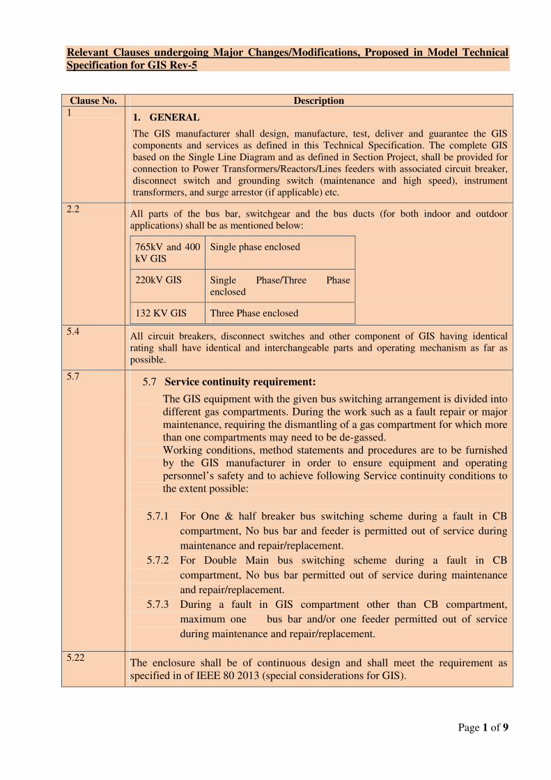
Relevant Clauses undergoing Major Changes/Modifications, Proposed in Model Technical
Specification for GIS Rev-5
Page 1 of 9
Clause No. Description
1 1. GENERAL
The GIS manufacturer shall design, manufacture, test, deliver and guarantee the GIS
components and services as defined in this Technical Specification. The complete GIS
based on the Single Line Diagram and as defined in Section Project, shall be provided for
connection to Power Transformers/Reactors/Lines feeders with associated circuit breaker,
disconnect switch and grounding switch (maintenance and high speed), instrument
transformers, and surge arrestor (if applicable) etc.
2.2 All parts of the bus bar, switchgear and the bus ducts (for both indoor and outdoor
applications) shall be as mentioned below:
765kV and 400
kV GIS
Single phase enclosed
220kV GIS Single Phase/Three Phase
enclosed
132 KV GIS Three Phase enclosed
5.4 All circuit breakers, disconnect switches and other component of GIS having identical
rating shall have identical and interchangeable parts and operating mechanism as far as
possible.
5.7 5.7 Service continuity requirement:
The GIS equipment with the given bus switching arrangement is divided into
different gas compartments. During the work such as a fault repair or major
maintenance, requiring the dismantling of a gas compartment for which more
than one compartments may need to be de-gassed.
Working conditions, method statements and procedures are to be furnished
by the GIS manufacturer in order to ensure equipment and operating
personnel’s safety and to achieve following Service continuity conditions to
the extent possible:
5.7.1 For One & half breaker bus switching scheme during a fault in CB
compartment, No bus bar and feeder is permitted out of service during
maintenance and repair/replacement.
5.7.2 For Double Main bus switching scheme during a fault in CB
compartment, No bus bar permitted out of service during maintenance
and repair/replacement.
5.7.3 During a fault in GIS compartment other than CB compartment,
maximum one bus bar and/or one feeder permitted out of service
during maintenance and repair/replacement.
5.22 The enclosure shall be of continuous design and shall meet the requirement as
specified in of IEEE 80 2013 (special considerations for GIS).
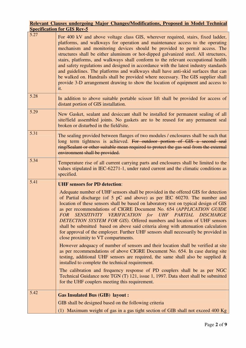
Relevant Clauses undergoing Major Changes/Modifications, Proposed in Model Technical
Specification for GIS Rev-5
Page 2 of 9
5.27 For 400 kV and above voltage class GIS, wherever required, stairs, fixed ladder,
platforms, and walkways for operation and maintenance access to the operating
mechanism and monitoring devices should be provided to permit access. The
structures shall be either aluminum or hot-dipped galvanized steel. All structures,
stairs, platforms, and walkways shall conform to the relevant occupational health
and safety regulations and designed in accordance with the latest industry standards
and guidelines. The platforms and walkways shall have anti-skid surfaces that can
be walked on. Handrails shall be provided where necessary. The GIS supplier shall
provide 3-D arrangement drawing to show the location of equipment and access to
it.
5.28 In addition to above suitable portable scissor lift shall be provided for access of
distant portion of GIS installation.
5.29 New Gasket, sealant and desiccant shall be installed for permanent sealing of all
site/field assembled joints. No gaskets are to be reused for any permanent seal
broken or disturbed in the field/site.
5.31 The sealing provided between flanges of two modules / enclosures shall be such that
long term tightness is achieved. For outdoor portion of GIS a second seal
ring/Sealant or other suitable mean required to protect the gas seal from the external
environment shall be provided.
5.34 Temperature rise of all current carrying parts and enclosures shall be limited to the
values stipulated in IEC-62271-1, under rated current and the climatic conditions as
specified.
5.41 UHF sensors for PD detection:
Adequate number of UHF sensors shall be provided in the offered GIS for detection
of Partial discharge (of 5 pC and above) as per IEC 60270. The number and
location of these sensors shall be based on laboratory test on typical design of GIS
as per recommendations of CIGRE Document No. 654 (APPLICATION GUIDE
FOR SENSITIVITY VERIFICATION for UHF PARTIAL DISCHARGE
DETECTION SYSTEM FOR GIS). Offered numbers and location of UHF sensors
shall be submitted based on above said criteria along with attenuation calculation
for approval of the employer. Further UHF sensors shall necessarily be provided in
close proximity to VT compartments.
However adequacy of number of sensors and their location shall be verified at site
as per recommendations of above CIGRE Document No. 654. In case during site
testing, additional UHF sensors are required, the same shall also be supplied &
installed to complete the technical requirement.
The calibration and frequency response of PD couplers shall be as per NGC
Technical Guidance note TGN (T) 121, issue 1, 1997. Data sheet shall be submitted
for the UHF couplers meeting this requirement.
5.42 Gas Insulated Bus (GIB) layout :
GIB shall be designed based on the following criteria
(1) Maximum weight of gas in a gas tight section of GIB shall not exceed 400 Kg
Relevant Clauses undergoing Major Changes/Modifications, Proposed in Model Technical
Specification for GIS Rev-5
Page 3 of 9
(for 765 kV & 400 kV)/ 250 Kg (for 220 kV & 132 kV).
(2) GIB shall be generally in horizontal layer. However in exceptional
circumstance GIB in vertical layers can be provided with the approval of
employer.
(3) The minimum vertical ground clearance of GIB at road crossing shall be 5.5
meters
(4) The horizontal clearance between GIB and GIS building /any other building
wall shall be preferably three (3) meters.
(5) The GIB route inside the GIS Hall shall not obstruct easy access to GIS and
control room buildings and shall not obstruct movement of crane, equipment
including HV test equipment for maintenance works.
(6) The GIB clear height outside the GIS hall in switchyard area shall be minimum
3.5 meter, so as not to obstruct easy access to GIB, movement of crane for
maintenance work.
(7) Optimization of outdoor GIB length using overhead AIS connection with Bus
Post Insulator of respective voltage class is generally acceptable subject to
meeting the electrical clearances as stipulated.
(8) For the maintenance of GIB of one circuit, only that circuit shall be isolated.
Adequate clearance between bus ducts of two circuit shall be ensured by the
contractor during layout finalization.
(9) GIS manufacturer as per their design shall preferably use maximum three
standard straight horizontal outdoor bus duct lengths for entire GIS installation
to optimize the spare requirement.
5.45 Documentation
The contractor shall prepare and submit to the employer, drawings, details that
show the GIS design in order for the employer to verify the equipment conform
to the specifications. The Design Document to be submitted for review and
approval are as follows:
i.Design Review Document as per clause no. 20 of this specification
ii. Single Line Diagram
iii. Gas Schematic Diagram
iv. GTP-Guaranteed Technical Particulars
v. GIS layout (Plan and Section) including 3D drawing
vi. GIS Component Drawings
vii. Interface modules drawing for GIS extension
viii. Rating and Name Plate Drawing
ix. GIS/LCC Schematics Drawing
x. Foundation loading plan and detail
xi. GIS Support Structure Drawing
xii. GIS platforms and Walkway Drawing
xiii. GIS grounding plan and details along with design calculation for GIS
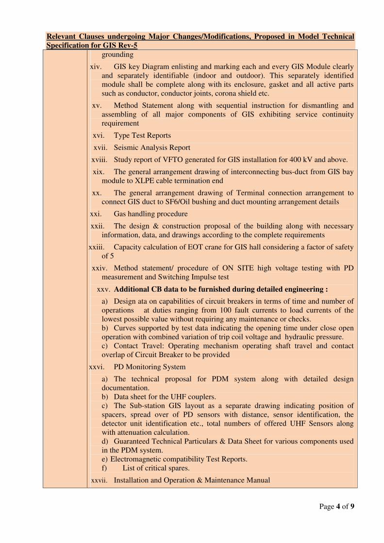
Relevant Clauses undergoing Major Changes/Modifications, Proposed in Model Technical
Specification for GIS Rev-5
Page 4 of 9
grounding
xiv. GIS key Diagram enlisting and marking each and every GIS Module clearly
and separately identifiable (indoor and outdoor). This separately identified
module shall be complete along with its enclosure, gasket and all active parts
such as conductor, conductor joints, corona shield etc.
xv. Method Statement along with sequential instruction for dismantling and
assembling of all major components of GIS exhibiting service continuity
requirement
xvi. Type Test Reports
xvii. Seismic Analysis Report
xviii. Study report of VFTO generated for GIS installation for 400 kV and above.
xix. The general arrangement drawing of interconnecting bus-duct from GIS bay
module to XLPE cable termination end
xx. The general arrangement drawing of Terminal connection arrangement to
connect GIS duct to SF6/Oil bushing and duct mounting arrangement details
xxi. Gas handling procedure
xxii. The design & construction proposal of the building along with necessary
information, data, and drawings according to the complete requirements
xxiii. Capacity calculation of EOT crane for GIS hall considering a factor of safety
of 5
xxiv. Method statement/ procedure of ON SITE high voltage testing with PD
measurement and Switching Impulse test
xxv. Additional CB data to be furnished during detailed engineering :
a) Design ata on capabilities of circuit breakers in terms of time and number of
operations at duties ranging from 100 fault currents to load currents of the
lowest possible value without requiring any maintenance or checks.
b) Curves supported by test data indicating the opening time under close open
operation with combined variation of trip coil voltage and hydraulic pressure.
c) Contact Travel: Operating mechanism operating shaft travel and contact
overlap of Circuit Breaker to be provided
xxvi. PD Monitoring System
a) The technical proposal for PDM system along with detailed design
documentation.
b) Data sheet for the UHF couplers.
c) The Sub-station GIS layout as a separate drawing indicating position of
spacers, spread over of PD sensors with distance, sensor identification, the
detector unit identification etc., total numbers of offered UHF Sensors along
with attenuation calculation.
d) Guaranteed Technical Particulars & Data Sheet for various components used
in the PDM system.
e) Electromagnetic compatibility Test Reports.
f) List of critical spares.
xxvii. Installation and Operation & Maintenance Manual
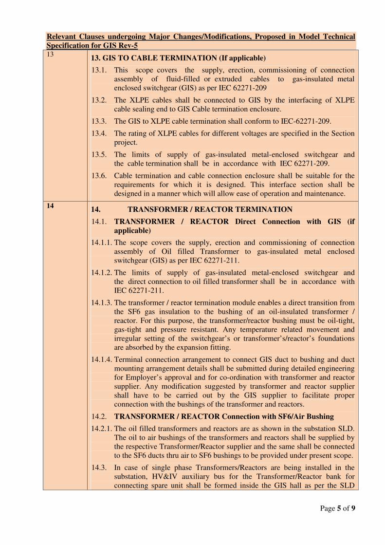
Relevant Clauses undergoing Major Changes/Modifications, Proposed in Model Technical
Specification for GIS Rev-5
Page 5 of 9
13 13. GIS TO CABLE TERMINATION (If applicable)
13.1. This scope covers the supply, erection, commissioning of connection
assembly of fluid-filled or extruded cables to gas-insulated metal
enclosed switchgear (GIS) as per IEC 62271-209
13.2. The XLPE cables shall be connected to GIS by the interfacing of XLPE
cable sealing end to GIS Cable termination enclosure.
13.3. The GIS to XLPE cable termination shall conform to IEC-62271-209.
13.4. The rating of XLPE cables for different voltages are specified in the Section
project.
13.5. The limits of supply of gas-insulated metal-enclosed switchgear and
the cable termination shall be in accordance with IEC 62271-209.
13.6. Cable termination and cable connection enclosure shall be suitable for the
requirements for which it is designed. This interface section shall be
designed in a manner which will allow ease of operation and maintenance.
14 14. TRANSFORMER / REACTOR TERMINATION
14.1. TRANSFORMER / REACTOR Direct Connection with GIS (if
applicable)
14.1.1. The scope covers the supply, erection and commissioning of connection
assembly of Oil filled Transformer to gas-insulated metal enclosed
switchgear (GIS) as per IEC 62271-211.
14.1.2. The limits of supply of gas-insulated metal-enclosed switchgear and
the direct connection to oil filled transformer shall be in accordance with
IEC 62271-211.
14.1.3. The transformer / reactor termination module enables a direct transition from
the SF6 gas insulation to the bushing of an oil-insulated transformer /
reactor. For this purpose, the transformer/reactor bushing must be oil-tight,
gas-tight and pressure resistant. Any temperature related movement and
irregular setting of the switchgear’s or transformer’s/reactor’s foundations
are absorbed by the expansion fitting.
14.1.4. Terminal connection arrangement to connect GIS duct to bushing and duct
mounting arrangement details shall be submitted during detailed engineering
for Employer’s approval and for co-ordination with transformer and reactor
supplier. Any modification suggested by transformer and reactor supplier
shall have to be carried out by the GIS supplier to facilitate proper
connection with the bushings of the transformer and reactors.
14.2. TRANSFORMER / REACTOR Connection with SF6/Air Bushing
14.2.1. The oil filled transformers and reactors are as shown in the substation SLD.
The oil to air bushings of the transformers and reactors shall be supplied by
the respective Transformer/Reactor supplier and the same shall be connected
to the SF6 ducts thru air to SF6 bushings to be provided under present scope.
14.3. In case of single phase Transformers/Reactors are being installed in the
substation, HV&IV auxiliary bus for the Transformer/Reactor bank for
connecting spare unit shall be formed inside the GIS hall as per the SLD
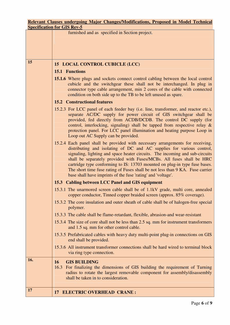
Relevant Clauses undergoing Major Changes/Modifications, Proposed in Model Technical
Specification for GIS Rev-5
Page 6 of 9
furnished and as specified in Section project.
15 15 LOCAL CONTROL CUBICLE (LCC)
15.1 Functions
15.1.6 Where plugs and sockets connect control cabling between the local control
cubicle and the switchgear these shall not be interchanged. In plug in
connector type cable arrangement, min 2 cores of the cable with connected
condition on both side up to the TB to be left unused as spare.
15.2 Constructional features
15.2.3 For LCC panel of each feeder bay (i.e. line, transformer, and reactor etc.),
separate AC/DC supply for power circuit of GIS switchgear shall be
provided, fed directly from ACDB/DCDB. The control DC supply (for
control, interlocking, signaling) shall be tapped from respective relay &
protection panel. For LCC panel illumination and heating purpose Loop in
Loop out AC Supply can be provided.
15.2.4 Each panel shall be provided with necessary arrangements for receiving,
distributing and isolating of DC and AC supplies for various control,
signaling, lighting and space heater circuits. The incoming and sub-circuits
shall be separately provided with Fuses/MCBs. All fuses shall be HRC
cartridge type conforming to IS: 13703 mounted on plug-in type fuse bases.
The short time fuse rating of Fuses shall be not less than 9 KA. Fuse carrier
base shall have imprints of the fuse 'rating' and 'voltage'.
15.3 Cabling between LCC Panel and GIS equipment
15.3.1 The unarmored screen cable shall be of 1.1kV grade, multi core, annealed
copper conductor, Tinned copper braided screen (approx. 85% coverage).
15.3.2 The core insulation and outer sheath of cable shall be of halogen-free special
polymer.
15.3.3 The cable shall be flame-retardant, flexible, abrasion-and wear-resistant
15.3.4 The size of core shall not be less than 2.5 sq. mm for instrument transformers
and 1.5 sq. mm for other control cable.
15.3.5 Prefabricated cables with heavy duty multi-point plug-in connections on GIS
end shall be provided.
15.3.6 All instrument transformer connections shall be hard wired to terminal block
via ring type connection.
16. 16 GIS BUILDING
16.3 For finalizing the dimensions of GIS building the requirement of Turning
radius to rotate the largest removable component for assembly/disassembly
shall be taken in to consideration.
17 17 ELECTRIC OVERHEAD CRANE :
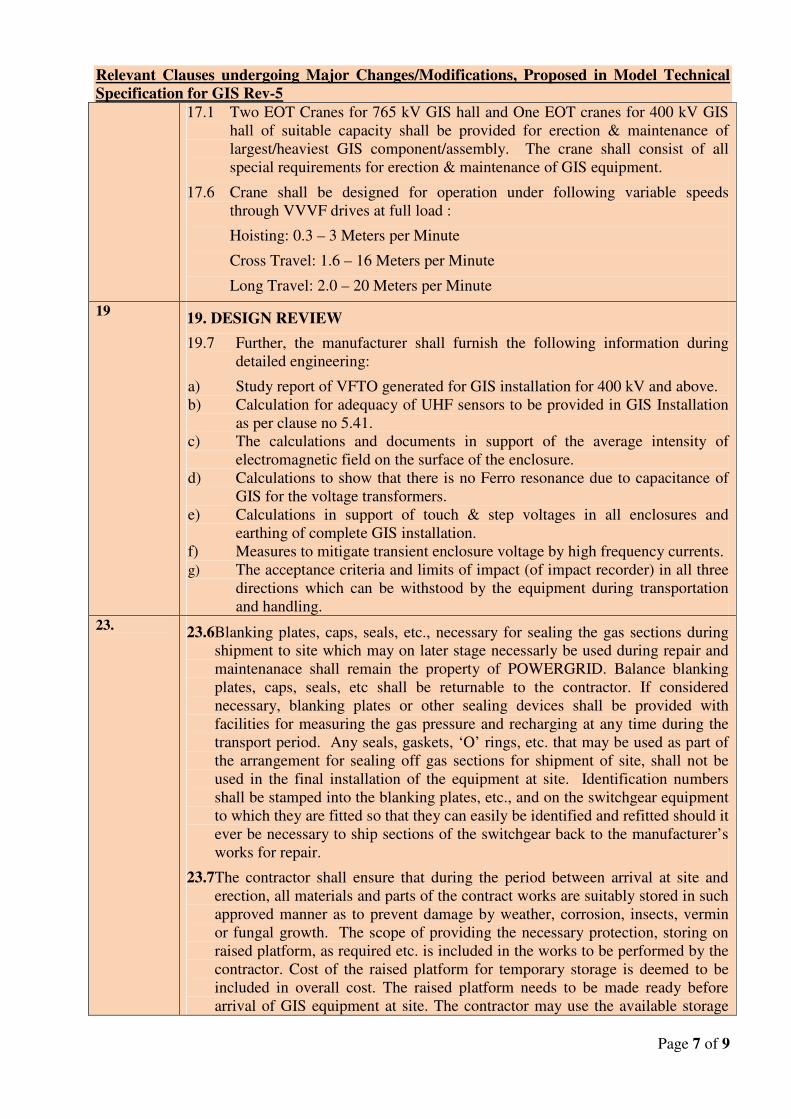
Relevant Clauses undergoing Major Changes/Modifications, Proposed in Model Technical
Specification for GIS Rev-5
Page 7 of 9
17.1 Two EOT Cranes for 765 kV GIS hall and One EOT cranes for 400 kV GIS
hall of suitable capacity shall be provided for erection & maintenance of
largest/heaviest GIS component/assembly. The crane shall consist of all
special requirements for erection & maintenance of GIS equipment.
17.6 Crane shall be designed for operation under following variable speeds
through VVVF drives at full load :
Hoisting: 0.3 – 3 Meters per Minute
Cross Travel: 1.6 – 16 Meters per Minute
Long Travel: 2.0 – 20 Meters per Minute
19 19. DESIGN REVIEW
19.7 Further, the manufacturer shall furnish the following information during
detailed engineering:
a) Study report of VFTO generated for GIS installation for 400 kV and above.
b) Calculation for adequacy of UHF sensors to be provided in GIS Installation
as per clause no 5.41.
c) The calculations and documents in support of the average intensity of
electromagnetic field on the surface of the enclosure.
d) Calculations to show that there is no Ferro resonance due to capacitance of
GIS for the voltage transformers.
e) Calculations in support of touch & step voltages in all enclosures and
earthing of complete GIS installation.
f) Measures to mitigate transient enclosure voltage by high frequency currents.
g) The acceptance criteria and limits of impact (of impact recorder) in all three
directions which can be withstood by the equipment during transportation
and handling.
23. 23.6Blanking plates, caps, seals, etc., necessary for sealing the gas sections during
shipment to site which may on later stage necessarly be used during repair and
maintenanace shall remain the property of POWERGRID. Balance blanking
plates, caps, seals, etc shall be returnable to the contractor. If considered
necessary, blanking plates or other sealing devices shall be provided with
facilities for measuring the gas pressure and recharging at any time during the
transport period. Any seals, gaskets, ‘O’ rings, etc. that may be used as part of
the arrangement for sealing off gas sections for shipment of site, shall not be
used in the final installation of the equipment at site. Identification numbers
shall be stamped into the blanking plates, etc., and on the switchgear equipment
to which they are fitted so that they can easily be identified and refitted should it
ever be necessary to ship sections of the switchgear back to the manufacturer’s
works for repair.
23.7The contractor shall ensure that during the period between arrival at site and
erection, all materials and parts of the contract works are suitably stored in such
approved manner as to prevent damage by weather, corrosion, insects, vermin
or fungal growth. The scope of providing the necessary protection, storing on
raised platform, as required etc. is included in the works to be performed by the
contractor. Cost of the raised platform for temporary storage is deemed to be
included in overall cost. The raised platform needs to be made ready before
arrival of GIS equipment at site. The contractor may use the available storage
Relevant Clauses undergoing Major Changes/Modifications, Proposed in Model Technical
Specification for GIS Rev-5
Page 8 of 9
areas at site with permission of site in charge.
23.11 For the purpose of release of payment linked to receipt and physical
verification in case of GIS equipment it shall mean random opening and
physical verification of one number of packing unit of each type of main
equipment (i.e. GIS CB/ISO/ES/PT/LA etc.) for each voltage level.
Thereafter proper re-packing of the GIS unit shall be ensured as per
manufacturer recommendation.
24 24 INSTALLATION OF GIS
24.1Civil works of GIS Hall shall be completed in all respects before taking up the
installation and it shall be ensured that Ventilation System is operational and all
dust and dirt in the hall are removed. The GIS hall needs to be in positive
pressure before starting Installation.
24.3Un-packaging of GIS modules shall be done outside the GIS hall and in no case
module to be taken inside GIS hall with packing.
24.7 GIS hall door shall have automatic close facility after entry of personnel to
avoid dust and moisture entry. Walls and ceiling shall be in a condition so that
neither dirt nor plaster might fall or rub off and formation of condensation water
in ceiling shall be prevented under any circumstances.
24.12 Maintenance room (as a part of LCR room) shall be constructed for carrying
out repair works/ small part assembly All excess material (not required for
immediate installation works) test equipment and tools and tackles to be stored
separately from GIS hall in this room for rework.
24.13 Erection agency shall submit method statement and make available formats
for checking during each stage of hall preparation, assembly process and final
checks to be approved by POWERGRID site before start of erection. Shock
recorder down loaded data and analysis shall be submitted preferably before
commencement of erection work. In case of violation of shock limits, expert
form manufacturer shall visit and do the joint internal inspection and shall
submit analysis report before giving clearance for erection. If required the
module shall be taken back to factory for further analysis and testing.
25 25. ON SITE TESTING
After the GIS Switchgear has been fully installed at site and SF6 gas filled at
rated filling density, the complete assembly shall be subjected to the site tests
as per IEC-62271-203 and POWERGRID Asset Management Controlled
Document No: D-3-01-09-01-01. After the above, Special Dielectric test
(Switching Impulse test) shall be conducted for 765 kV GIS with the test
voltages specified below:-
25.1. Application of Power Frequency voltage test for duration of 1 minute with
the value 760 kV (r.m.s.) as per IEC 62271-203.
25.2. Directly after the above test at 25.1 Switching impulse test with three
impulses of each polarity and with the value 1240 kVp(80 % of the rated
switching Impulse withstand level) as per IEC 62271-203.
25.3. In case of a disruptive discharge in the gas as outlined in clause no: C.6.2.2
Relevant Clauses undergoing Major Changes/Modifications, Proposed in Model Technical
Specification for GIS Rev-5
Page 9 of 9
Procedure b), Annexure-C of IEC 62271-203 during the AC voltage test and
a repeat test is performed due to this failure, then the repeat test shall be
carried out at Specified voltage.
25.4. In case of a disruptive discharge in the gas as outlined in clause no: C.6.2.2
Procedure b) Annexure-C of IEC 62271-203 during Oscillating Switching
Impulse Test and a repeat test is performed due to this failure then the repeat
test shall be carried out at a value equal to 90 % of the rated switching
Impulse withstand level.
25.5. Method statement/ procedure of ON SITE high voltage testing, PD
measurement and Switching Impulse test shall be submitted by contractor in
advance.
26 MANDATORY SPARE
Design, engineering, manufacture, testing, supply on FOR destination site basis including transportation & insurance, storage at site of Mandatory spares for the GIS(As specified in BPS). Standard list of Mandatory Spares is as per Annexure-10
27 27.2Gas filling and evacuating plant : (Gas Processing unit)
The minimum capacity parameters of evacuation plant will be as under :
Oil Free Suction (Recovery) Pump: 30 M3/Hour
Compressor (Two Stage): 15 M3/Hour
Oil Free Vacuum Pump: 100 M3/Hour
27 27.5 Online Partial Discharge Monitoring System (Applicable for 765kV& 400
kV GIS)
The scope shall cover Engineering, supply, installation, testing and commissioning
of partial discharge continuous monitoring system, with all necessary auxiliaries and
accessories to make a complete system as per technical specification, including site
demonstration of successful operation. Any items/accessories necessary to make the
system fully functional for the trouble free online PD monitoring of complete GIS
installation shall be considered as included in the scope.
The PDM system shall be provided with all its hardware and software, with readily
interfacing to the UHF PD couplers installed in the GIS of present bays and future
bays as shown in SLD plus 20% additional as extra. Details of this shall be
submitted during engineering stage for approval.
The integration of UHF PD coupler in future GIS bays shall be done in respective
package. The number of UHF PD coupler for future bays shall be decided based on
GIS layout finalized under present scope (considering present GIS equipment with
future provision).
1653024
Line
1653024
Line
Technical Specification Gas Insulated Switchgear Page 1 of 79
Rev 05A (February 2019)
1. GENERAL
The GIS manufacturer shall design, manufacture, test, deliver and guarantee the GIS
components and services as defined in this Technical Specification. The complete GIS
based on the Single Line Diagram and as defined in Section Project, shall be provided for
connection to Power Transformers/Reactors/Lines feeders with associated circuit breaker,
disconnect switch and grounding switch (maintenance and high speed), instrument
transformers, and surge arrestor (if applicable) etc.
2. GENERAL CHARACTERISTICS
2.1. The SF6 gas insulated metal enclosed switchgear shall be totally safe against inadvertent
touch of any of it's constituent parts. It should be designed for indoor application with
meteorological conditions as specified.
2.2. All parts of the bus bar, switchgear and the bus ducts (for both indoor and outdoor
applications) shall be as mentioned below:
765kV and 400 kV GIS Single phase enclosed
220kV GIS Single Phase/Three Phase enclosed
132 KV GIS Three Phase enclosed
2.3. The design should be such that all parts subjected to wear and tear are easily accessible for
maintenance purposes. The equipment offered shall be protected against all types of voltage
surges and any equipment necessary to satisfy this requirement shall deemed to be included.
3. REFERENCE STANDARDS
The GIS offered shall confirm to IEC 62271-203 and other relevant IEC standard except to
the extent explicitly modified in the specification and shall be in accordance with
requirement specified in GTR.
The metal-enclosed gas-insulated switchgear, including the operating devices, accessories
and auxiliary equipment forming integral part thereof, shall be designed, manufactured,
assembled and tested in accordance with the following International Electro-technical
Commission (IEC) Publications including their parts and supplements as amended or
revised as on date of bid opening:
IEC 62271-203 Gas Insulated metal-enclosed switchgear for rated voltages above
52 KV
IEC 62271-207 Seismic qualification for gas-insulated switchgear assemblies for rated
Technical Specification Gas Insulated Switchgear Page 2 of 79
Rev 05A (February 2019)
voltages above 52 kV
IEC 60376 New sulphur hexafluoride
IEC 62271- 100 High voltage alternating current Circuit breakers
IEC 62271-1 Common clauses for high voltage Switchgear and control-gear
Standards
IEC 62271-102 Alternating current Disconnect Switch(isolators) and earthing switches
IEC 61869 General Requirements Instrument Transformers
IEC 60137 Bushings for alternating voltages above 1000 V
IEC 62271-209 Cable connections for gas-insulated switchgear
IEC 60480 Guide to checking of sulphur hexafluoride taken from
electrical equipment
IEC 60099 -1/4 Non-linear resistor type arresters for AC systems
IEC 60439 Factory-built assemblies of low-voltage switchgear and control
Gear.
IEEE 80 2013 IEEE Guide for Safety in AC Substation grounding.
CIGRE-44 Earthing of GIS- an application guide. (Electra no.151,Dec’93).
IEC 62271-211 Direct connection between Power Transformers and gas
insulated metal enclosed switchgear for rated voltage 72.5 kV
and above.
The components and devices which are not covered by the above standards shall conform
to, and comply with, the applicable standards, rules, codes and regulations of the
internationally recognized standardizing bodies and professional societies as may be
approved by the Employer and the manufacturer shall list all such applicable standards,
codes etc.
In case the requirements laid down herein differ from those given in above standard in any
aspect the switchgear shall comply with the requirements indicated herein in regard thereto.
4. DEFINITIONS
4.1. Assembly: Assembly refers to the entire completed GIS equipment furnished under
contract.
4.2. Bay: Bay refers to the area occupied by one Circuit Breaker and associated equipment.
4.3. Compartment: When used in conjunction with GIS equipment, compartment refers to a gas
tight volume bounded by enclosure walls and gas tight isolating barriers.
4.4. Enclosure: When used in conjunction with GIS equipment, enclosure refers to the grounded
metal housing or shell which contains and protects internal Power system equipment
(breaker, disconnecting switch, grounding switch, voltage transformer, current transformer,
surge arresters, interconnecting bus etc.)
4.5. Manual Operation: Manual operation means operation by hand without using any other
source of power.
Technical Specification Gas Insulated Switchgear Page 3 of 79
Rev 05A (February 2019)
4.6. Module: When used in conjunction with GIS equipment, module refers to a portion of that
equipment. Each module includes its own enclosure. A module can contain more than one
piece of equipment, for example, a module can contain a disconnecting switch and a
grounding switch.
4.7. Reservoir: When used in conjunction with GIS equipment reservoir refers to a larger gas-
tight volume.
5. GENERAL DESIGN AND SAFETY REQUIREMENT
5.1. The GIS shall be designed, manufactured and tested in accordance with the best
international engineering practices under strict quality control to meet the requirement
stipulated in the technical specification. Adequate safety margin with respect to thermal,
mechanical, dielectric stress and insulation coordination etc. shall be maintained during
design, selection of raw material, manufacturing process etc. so that the GIS provides long
life with least maintenance.
The workmanship shall be of the highest quality and shall conform to the latest modern
practices for the manufacture of high technology machinery and electrical switchgear.
5.2. The GIS assembly shall consist of separate modular compartments e.g. Circuit Breaker
compartment, Bus bar compartment filled with SF6 Gas and separated by gas tight partitions
so as to minimize risk to human life, allow ease of maintenance and limit the effects of gas
leaks failures & internal arcs etc. These compartments shall be such that maintenance on one
feeder may be performed without de-energising the adjacent feeders. These compartments
shall be designed to minimize the risk of damage to adjacent sections and protection of
personnel in the event of a failure occurring within the compartments. Rupture diaphragms
with suitable deflectors shall be provided to prevent uncontrolled bursting pressures
developing within the enclosures under worst operating conditions, thus providing
controlled pressure relief in the affected compartment.
5.3. The switchgear, which shall be of modular design, shall have complete phase isolation. The
conductors and the live parts shall be mounted on high graded epoxy resin insulators. These
insulators shall be designed to have high structural strength and electrical dielectric
properties and shall be free of any voids and free of partial discharge at a voltage which is at
least 5% greater than the rated voltage. These shall be designed to have high structural and
dielectric strength properties and shall be shaped so as to provide uniform field distribution
and to minimize the effects of particle deposition either from migration of foreign particles
within the enclosures or from the by-products of SF6 breakdown under arcing conditions.
5.4. All circuit breakers, disconnect switches and other component of GIS having identical rating
shall have identical and interchangeable parts and operating mechanism as far as possible.
5.5. Gas barrier insulators shall be provided so as to divide the GIS into separate compartments.
These shall be suitably located in order to minimize disturbance in case of leakage or
dismantling. They shall be designed to withstand any internal fault thereby keeping an
internal arc inside the faulty compartment. Further, it is prohibited to work adjacent to a gas
Technical Specification Gas Insulated Switchgear Page 4 of 79
Rev 05A (February 2019)
compartment while it is fully pressurized on the other side. For such cases, the gas pressure
in the adjacent compartments needs to be reduced.
5.6. The switchgear shall be of the free standing, self-supporting with easy accessibility to all
the parts during installation & maintenance with all high-voltage equipment installed inside
gas-insulated metallic and earthed enclosures. GIS should be suitably sub-divided into
individual arc and gas-proof compartments preferably for:
1) Bus bars
2) Intermediate compartment
3) Circuit breakers
4) Feeder Disconnect Switch
5) Voltage Transformers
6) Gas Insulated bus duct section between GIS and XLPE cable/Overhead
Conductor.
7) Gas Insulated bus section between GIS & Oil filled Transformer/ Reactor (if
applicable)
Typical drawings indicating gas tight compartments are enclosed at Annexure-A. This is an
indicative drawing only, however GIS manufacturer shall ensure the service continuity
requirement as mentioned above.
5.7. Service continuity requirement:
The GIS equipment with the given bus switching arrangement is divided into different gas
compartments. During the work such as a fault repair or major maintenance, requiring the
dismantling of a gas compartment for which more than one compartments may need to be
de-gassed.
Working conditions, method statements and procedures are to be furnished by the GIS
manufacturer in order to ensure equipment and operating personnel’s safety and to achieve
following Service continuity conditions to the extent possible:
5.7.1. For One & half breaker bus switching scheme during a fault in CB compartment, No bus bar
and feeder is permitted out of service during maintenance and repair/replacement.
5.7.2. For Double Main bus switching scheme during a fault in CB compartment, No bus bar
permitted out of service during maintenance and repair/replacement.
5.7.3. During a fault in GIS compartment other than CB compartment, maximum one bus bar
and/or one feeder permitted out of service during maintenance and repair/replacement.
5.8. The material and thickness of the enclosures shall be such as to withstand an internal flash
over without burns through for a period of 300 ms at rated short time withstand current. The
material shall be such that it has no effect of environment as well as from the by-products of
SF6 breakdown under arcing condition. This shall be validated with Type Test.
5.9. Each section shall have plug- in or easily removable connection pieces to allow for easy
replacement of any component with the minimum of disturbance to the remainder of the
Technical Specification Gas Insulated Switchgear Page 5 of 79
Rev 05A (February 2019)
equipment. Inspection windows (View Ports) shall be provided for Disconnect Switch and
both type of earth switches i.e. Maintenance and fast operating.
5.10. The material used for manufacturing the switchgear equipment shall be of the type,
composition and have physical properties best suited to their particular purposes and in
accordance with the latest engineering practices. All the conductors shall be fabricated of
aluminum/ copper tubes of cross sectional area suitable to meet the normal and short circuit
current rating requirements. The finish of the conductors shall be smooth so as to prevent
any electrical discharge. The conductor ends shall be silver plated and fitted into finger
contacts or tulip contacts. The contacts shall be of sliding type to allow the conductors to
expand or contract axially due to temperature variation without imposing any mechanical
stress on supporting insulators.
5.11. Each pressure filled enclosure shall be designed and fabricated to comply with the
requirements of the applicable pressure vessel codes and based on the design temperature
and design pressures as defined in IEC-62271-203.
5.12. The maximum SF6 gas leakage shall not exceed 0.5% (half percent) per year for the whole
equipment and for any individual gas compartment separately. The SF6 gas leakage should
not exceed 0.5% per year and the leakage rate shall be guaranteed for at least 10 years. In
case the leakage under the specified conditions is found to be greater than 0.5% after one
year of commissioning, the manufacturer will have to supply free of cost, the total gas
requirement for subsequent ten (10) years, based on actual leakage observed during the first
year of operation after commissioning.
5.13. Each gas-filled compartment shall be equipped with static filters, density switches, filling
valve and safety diaphragm. The filters shall be capable of absorbing any water vapor
which may penetrate into the enclosures as well as the by-products of SF6 during
interruption. Each gas compartment shall be fitted with non-return valve connectors for
evacuating & filling the gas and checking the gas pressure etc.
5.14. The switchgear when installed and operating under the ambient conditions shall perform
satisfactorily and safely under all normal and fault conditions. Even repeated operations up
to the permissible servicing intervals under 100% rated and fault conditions, shall not
diminish the performance or significantly shorten the useful life of the switchgear. Any
fault caused by external/internal reasons shall be positively confined to the originating
compartment and shall not spread to other parts of the switchgear.
5.15. The thermal rating of all current carrying parts shall be minimum for one sec. for the rated
symmetrical short-circuit current.
5.16. The arrangement of the individual switchgear bays shall be such so as to achieve optimum
space-saving, neat and logical arrangement and adequate accessibility to all external
components.
5.17. The layout of the substation equipment, bus bars and switchgear bays shall preferably be
based on the principle of “phase grouping”. Switchgear layout based on the “mixed phases”
principle shall not be accepted without mutual agreement between supplier and employer.

Technical Specification Gas Insulated Switchgear Page 6 of 79
Rev 05A (February 2019)
The arrangement of the equipment offered must provide adequate access for operation,
testing, Repair and maintenance.
5.18. All the elements shall be accessible without removing support structures for routine
inspections. The removal of individual enclosure parts or entire breaker bays shall be
possible without disturbing the enclosures of neighboring bays and LCC panels.
5.19. It should not be possible to unwillingly touch live parts of the switchgear or to perform
operations that lead to arcing faults without the use of tools or brute force. All interlocks that
prevent potentially dangerous mal-operations, shall be constructed such that they cannot be
operated easily, i.e. the operator must use tools or brute force to over-ride them.
5.20. In general the contours of energized metal parts of the GIS and any other accessory shall be
such, so as to eliminate areas or points of high electrostatic flux concentrations. The
surfaces shall be smooth with no projection or irregularities which may cause visible corona.
No corona shall be visible in complete darkness which the equipment is subjected to
specified test voltage. There shall be no radio interference from the energized switchgear at
rated voltage.
5.21. The GIS shall be designed, so as to take care of the VFT over voltages generated as a result
of pre-strikes and re-strikes during isolator operation. Maximum VFT over voltages peak
shall not be higher than rated lightning impulse withstand voltage (LIWV) of the equipment.
Necessary measures shall be under taken by GIS manufacture to restrict maximum VFT
over voltages lower than the LIWV. Manufacturer shall submit the study report of VFTO
generated for GIS installation for 400 kV and above.
5.22. The enclosure shall be of continuous design and shall meet the requirement as specified in
of IEEE 80 2013 (special considerations for GIS).
The enclosure shall be sized for carrying induced current equal to the rated current of the
Bus. The conductor and the enclosure shall form the concentric pair with effective shielding
of the field internal to the enclosure.
5.23. The fabricated metal enclosure shall be of Aluminium alloy having high resistance to
corrosion, low electrical losses and negligible magnetic losses. However, 765kV CB
Enclosure made of other proven material /alloy as per manufacturer’s standard practice shall
also be acceptable. The manufacturer shall clearly indicate the material used for different
GIS enclosures in the GTP/design document during approval. All joint surfaces shall be
machined and all castings shall be spot faced for all bolt heads or nuts and washers. All
screws, bolts, studs and nuts shall confirm to metric system.”The elbows, bends, cross and
T-sections of interconnections shall include the insulators bearing the conductor when the
direction changes take place in order to ensure that live parts remain perfectly centered and
the electrical field is not increased at such points.
5.24. The enclosure shall be designed to practically eliminate the external electromagnetic field
and thereby electro-dynamic stresses even under short circuit conditions. The average
intensity of electromagnetic field shall not be more than 50 micro Tesla on the surface of the
enclosure.
Technical Specification Gas Insulated Switchgear Page 7 of 79
Rev 05A (February 2019)
5.25. The switchgear shall have provision for connection with ground mat risers through copper
connections. This provision shall consist of grounding pads to be connected to the ground
mat riser in the vicinity of the equipment.
5.26. For 400 kV and above voltage class GIS, wherever required, stairs, fixed ladder, platforms,
and walkways for operation and maintenance access to the operating mechanism and
monitoring devices should be provided to permit access. The structures shall be either
aluminum or hot-dipped galvanized steel. All structures, stairs, platforms, and walkways
shall conform to the relevant occupational health and safety regulations and designed in
accordance with the latest industry standards and guidelines. The platforms and walkways
shall have anti-skid surfaces that can be walked on. Handrails shall be provided where
necessary. The GIS supplier shall provide 3-D arrangement drawing to show the location of
equipment and access to it.
5.27. In addition to above suitable portable scissor lift shall be provided for access of distant
portion of GIS installation.
5.28. New Gasket, sealant and desiccant shall be installed for permanent sealing of all site/field
assembled joints. No gaskets are to be reused for any permanent seal broken or disturbed in
the field/site.
5.29. The enclosure & support structure shall be designed such that person of 1780 mm in height
and 80 Kg in weight is able to climb on the equipment for maintenance.
5.30. The sealing provided between flanges of two modules / enclosures shall be such that long
term tightness is achieved.
5.31. Alarm circuit shall not respond to faults for momentary conditions. The following
indications including those required elsewhere in the specifications shall be generally
provided in the alarm and indication circuits.
Gas Insulating System:
i) Loss of Gas Density
ii) Any other alarm necessary to indicate deterioration of the gas insulating system.
Operating System:
i) Low operating pressure
ii) Loss of Heater power
iii) Loss of operating power
iv) Loss of control supply
v) Pole Discordance.
5.32. The equipment will be operated under the following ambient conditions (or as defined in the
section project):
a) The ambient temperature varies between 0 degree-C and 50 degree-C. However, for
design purposes, ambient temperature should be considered as 50 degree-C.
b) The humidity will be about 95% (indoors)
c) The elevation is less than 1000 meters
Technical Specification Gas Insulated Switchgear Page 8 of 79
Rev 05A (February 2019)
5.33. Temperature rise of all current carrying parts and enclosures shall be limited to the values
stipulated in IEC-62271-1, under rated current and the climatic conditions as specified.
5.34. All cabinet heaters shall be rated for 240V AC (1-phase) supply and shall be complete with
thermostat, control switches and fuses, connected as a balanced 3-phase 4-wire load. The
heaters shall be so arranged and protected as to create no hazard to adjacent equipment from
the heat produced.
5.35. Bellows or Compensating Units:- Adequate provision shall be made to allow for the
thermal expansion of the conductors & enclosures and for differential thermal expansion
between the conductors and the enclosures. The bellows metallic( preferably stainless steel)
with suitable provision for permitting the movement during expansion and contraction may
be provided and shall be of following types:.
1. Lateral / Vertical mounting units: These shall be inserted, as required, between
sections of busbars, on transformer, shunt reactor and XLPE cable etc. Lateral
mounting shall be made possible by a sliding section of enclosure and tubular
conductors.
2. Axial compensators: These shall be provided to accommodate changes in length of
busbars due to temperature variations.
3. Parallel compensators: These shall be provided to accommodate large linear
expansions and angle tolerances.
4. Tolerance compensators: These shall be provided for taking up manufacturing, site
assembly and foundation tolerances.
5. Vibration compensators: These bellow compensators shall be provided for absorbing
vibrations caused by the transformers and shunt reactors when connected to SF6
switchgear by oil- SF6 bushings.
The electrical connections across the bellows or compensating units shall be made by means
of suitable connectors. For sliding type compensators, markers/pointers shall be provided to
observe expansion or contraction during climatic conditions.
5.36. Indication and verification of switch positions: Indicators shall be provided on all circuit
breakers, isolators and earth-switches, which shall clearly show whether the switches are
open or closed. The indicators shall be mechanically coupled directly to the main contact
operating drive rod or linkages and shall be mounted in a position where they are clearly
visible from the floor or the platform in the vicinity of the equipment.
Inspection windows shall also be provided with all isolators and earth switches so that the
switch contact positions can be verified by direct visual inspection.
5.37. Pressure relief device : Pressure relief devices shall be provided in the gas sections to
protect the gas enclosures from damage or distortion during the occurrence of abnormal
pressure increase or shock waves generated by internal electrical fault arcs (preferably in
downward direction).
Technical Specification Gas Insulated Switchgear Page 9 of 79
Rev 05A (February 2019)
Pressure relief shall be achieved either by means of diaphragms or plugs venting directly
into the atmosphere in a controlled direction.
If the pressure relief devices vent directly into the atmosphere, suitable guards and
deflectors shall be provided.
5.38. Pressure vessel requirements: The enclosure shall be designed for the mechanical and
thermal loads to which it is subjected in service. The enclosure shall be manufactured and
tested according to the Pressure Vessel Code (ASME/CENELEC code for pressure Vessel.)
The bursting strength of Aluminum castings has to be at least 5 times the design pressure. A
bursting pressure test shall be carried out at 5 times the design pressure as a type test on
each type of enclosure.
Each enclosure has to be tested as a routine test at 1.5 times the design pressure for one
minute.
5.39. Grounding:
5.39.1. The grounding system shall be designed and provided as per IEEE-80-2013 and CIGRE-44
to protect operating staff against any hazardous touch voltages and electro-magnetic
interferences.
5.39.2. The GIS supplier shall define clearly what constitutes the main grounding bus of the GIS.
The contractor shall supply the entire material for grounding bus of GIS viz conductor,
clamps, joints, operating and safety platforms etc. The contractor is also required to supply
all the earthing conductors and associated hardware material for connecting all GIS
equipment, bus ducts, enclosures, control cabinets, supporting structure, GIS surge arrestor
etc. to the ground bus of GIS.
5.39.3. The enclosure of the GIS may be grounded at several points so that there shall be grounded
cage around all the live parts. A minimum of two nos. of grounding connections should be
provided for each of circuit breaker, cable terminals, surge arrestors, earth switches and at
each end of the bus bars. The grounding continuity between each enclosure shall be
effectively interconnected either internally or externally with Copper/Aluminum bonds of
suitable size to bridge the flanges. Subassembly to subassembly bonding shall be provided
to bridge the gap & safe voltage gradients between all intentionally grounded parts of the
GIS assembly & between those parts and the main grounding bus of the GIS.
5.39.4. Each marshaling box, local control panel, power and control cable sheaths and other non-
current carrying metallic structures shall be connected to the grounding system of GIS via
connections that are separated from GIS enclosures.
5.39.5. The grounding connector shall be of sufficient mechanical strength to withstand
electromagnetic forces as well as capable of carrying the anticipated maximum fault current
without overheating. At least two grounding paths shall be provided to connect each point to
the main grounding bus. Necessary precautions should be under taken to prevent excessive
currents from being induced into adjacent frames, structures of reinforcing steel and to avoid
establishment of current loops via other station equipment.
Technical Specification Gas Insulated Switchgear Page 10 of 79
Rev 05A (February 2019)
5.39.6. All flexible bonding leads shall be tinned copper. All connectors, for attaching flexible
bonding leads to grounding conductors and grounding conductors to support structures shall
be tinned bronze with stainless steel or tinned bronze hardware.
5.39.7. The contractor shall provide suitable measure to mitigate transient enclosure voltage caused
by high frequency currents due to by lightning strikes, operation of surge arrestor, phase to
earth fault and discharges between contacts during switching operation. The grounding
system shall ensure safe touch & step voltages in all the enclosures.
5.40. UHF sensors for PD detection:
Adequate number of UHF sensors shall be provided in the offered GIS for detection of
Partial discharge (of 5 pC and above) as per IEC 60270. The number and location of these
sensors shall be based on laboratory test on typical design of GIS as per recommendations
of CIGRE Document No. 654 (APPLICATION GUIDE FOR SENSITIVITY VERIFICATION
for UHF PARTIAL DISCHARGE DETECTION SYSTEM FOR GIS). Offered numbers and
location of UHF sensors shall be submitted based on above said criteria along with
attenuation calculation for approval of the employer. Further UHF sensors shall necessarily
be provided in close proximity to VT compartments.
However adequacy of number of sensors and their location shall be verified at site as per
recommendations of above CIGRE Document No. 654. In case during site testing,
additional UHF sensors are required, the same shall also be supplied & installed to complete
the technical requirement.
The calibration and frequency response of PD couplers shall be as per NGC Technical
Guidance note TGN (T) 121, issue 1, 1997. Data sheet shall be submitted for the UHF
couplers meeting this requirement.
5.41. Gas Insulated Bus (GIB) layout :
GIB shall be designed based on the following criteria
(1) Maximum weight of gas in a gas tight section of GIB shall not exceed 400 Kg (for
765 kV & 400 kV)/ 250 Kg (for 220 kV & 132 kV).
(2) GIB shall be generally in horizontal layer. However in exceptional circumstance GIB
in vertical layers can be provided with the approval of employer.
(3) The minimum vertical ground clearance of GIB at road crossing shall be 5.5 meters
(4) The horizontal clearance between GIB and GIS building /any other building wall
shall be preferably three (3) meters.
(5) The GIB route inside the GIS Hall shall not obstruct easy access to GIS and control
room buildings and shall not obstruct movement of crane, equipment including HV
test equipment for maintenance works.

Technical Specification Gas Insulated Switchgear Page 11 of 79
Rev 05A (February 2019)
(6) The GIB clear height outside the GIS hall in switchyard area shall be minimum 3.5
meter, so as not to obstruct easy access to GIB, movement of crane for maintenance
work.
(7) Optimization of outdoor GIB length using overhead AIS connection with Bus Post
Insulator of respective voltage class is generally acceptable subject to meeting the
electrical clearances as stipulated.
(8) For the maintenance of GIB of one circuit, only that circuit shall be isolated.
Adequate clearance between bus ducts of two circuit shall be ensured by the
contractor during layout finalization.
(9) GIS manufacturer as per their design shall preferably use maximum three standard
straight horizontal outdoor bus duct lengths for entire GIS installation to optimize
the spare requirement.
5.42. Extension of GIS
5.42.1. The arrangement of gas sections or compartments shall be such as to facilitate future
extension of any make without any drilling, cutting or welding on the existing equipment.
To add equipment, it shall not be necessary to move or dislocate the existing switchgear
bays.
5.42.2. As the GIS is likely to be extended in future, during detailed engineering stage, the
contractor shall make available the complete design detail of interface module such as
cross section, enclosure material, enclosure dimensions (inner & outer), Flange diameter
(inner & outer), conductor cross-section & connection arrangement, bolt spacing &
dimension, rated gas pressure, Gasket detail etc. Further GIS manufacturer supplying GIS
under present scope shall furnish all the required details in addition to mentioned above
necessary for design and successful implementation of an interface module during later
stage while extending GIS by any other GIS manufacturer, without any help of GIS
manufacturer who has supplied the GIS equipment in present scope.
5.42.3. The Interface module shall be designed to provide Isolating link with access hole on
enclosure. The Isolating link shall be provided in such a way so that HV test can be
performed on either side of the interface module separately, keeping other side of GIS
remained isolated. Interface Module drawing with necessary detail shall be submitted for
approval. Conceptual Interface Module Drawing is attached as Annexure-9
5.42.4. Further the contractor who is extending the existing GIS installation, it shall be his
responsibility to provide interface module matching with the existing GIS interface module.
The drawing of existing GIS interface/end piece module shall be provided by the employer.
However it shall be the responsibility of contractor to verify the existing details during site
visit.
The Contractor shall optimally utilize the space inside the GIS hall (including the extension
portion) for accommodating the interface module being supplied under the contract.
5.43. SF6 GAS
Technical Specification Gas Insulated Switchgear Page 12 of 79
Rev 05A (February 2019)
The SF6 gas insulated metal-clad switchgear shall be designed for use with SF6 gas
complying with the recommendations of IEC 60376, 60376A & 60376B, at the time of the
first charging with gas. All SF6 gas supplied as part of the contract shall comply with the
requirements of IEC & should be suitable in all respects for use in the switchgear under all
operating conditions. Necessary statutory clearances from concerned authorities for import
of the Gas and for storage of the Gas shall be obtained.
The high pressure cylinders in which SF6 gas is supplied & stored at site shall comply with
the requirements of following standards & regulations :
IS : 4379 Identification of the contents of industrial gas cylinders.
IS : 7311 Seamless high carbon steel cylinders for permanent & high pressure
liquefiable gases. The cylinders shall also meet latest Gas Cylinder
Rules (PESO)
SF6 gas shall be tested for purity, dew point, air, hydrolysable fluorides and water contents
as per IEC:60376, 60376A & 60376B and test certificates shall be furnished to the
Employer indicating all test results as per IEC standards for each lot of SF6 gas. Further site
tests for dew point and purity shall be done during commissioning of GIS. Gas bottles
should be tested for leakage during receipt at site.
The contractor shall indicate diagnostic test methods for checking the quality of gas in the
various sections of GIS during service. The method proposed shall have as a minimum
check the moisture content & the percentage of purity of the gas on annual basis.
The contractor shall also submit clearly the precise procedure to be adopted by maintenance
personnel for handling equipment that are exposed to the products of arcing in SF6 Gas so
as to ensure that they are not affected by possible irritants of the skin and respiratory system.
Recommendations shall be submitted for suitable protective clothing, method of disposal of
cleaning utensils and other relevant matters.
The contractor shall also indicate the details and type of filters used in various gas sections,
and should also submit the operating experience with such filters.
5.43.1. SF6 gas monitoring devices and alarm circuits: Dial type temperature compensated gas
density monitoring devices with associated pressure gauge will be provided. The devices
shall provide continuous & automatic monitoring of gas density. A separate device shall be
provided for each gas tight compartment so that it can be monitored simultaneously as
follows:-
Compar
tment/
Sl. No.
Compartments except CB Circuit Breaker compartments
1 “Gas Refill level: This will be used to
annunciate the need for the gas
refilling. The contractor shall provide a
'Gas Refill' level :This will be used to
annunciate the need for gas refilling.
The contractor shall provide a contact
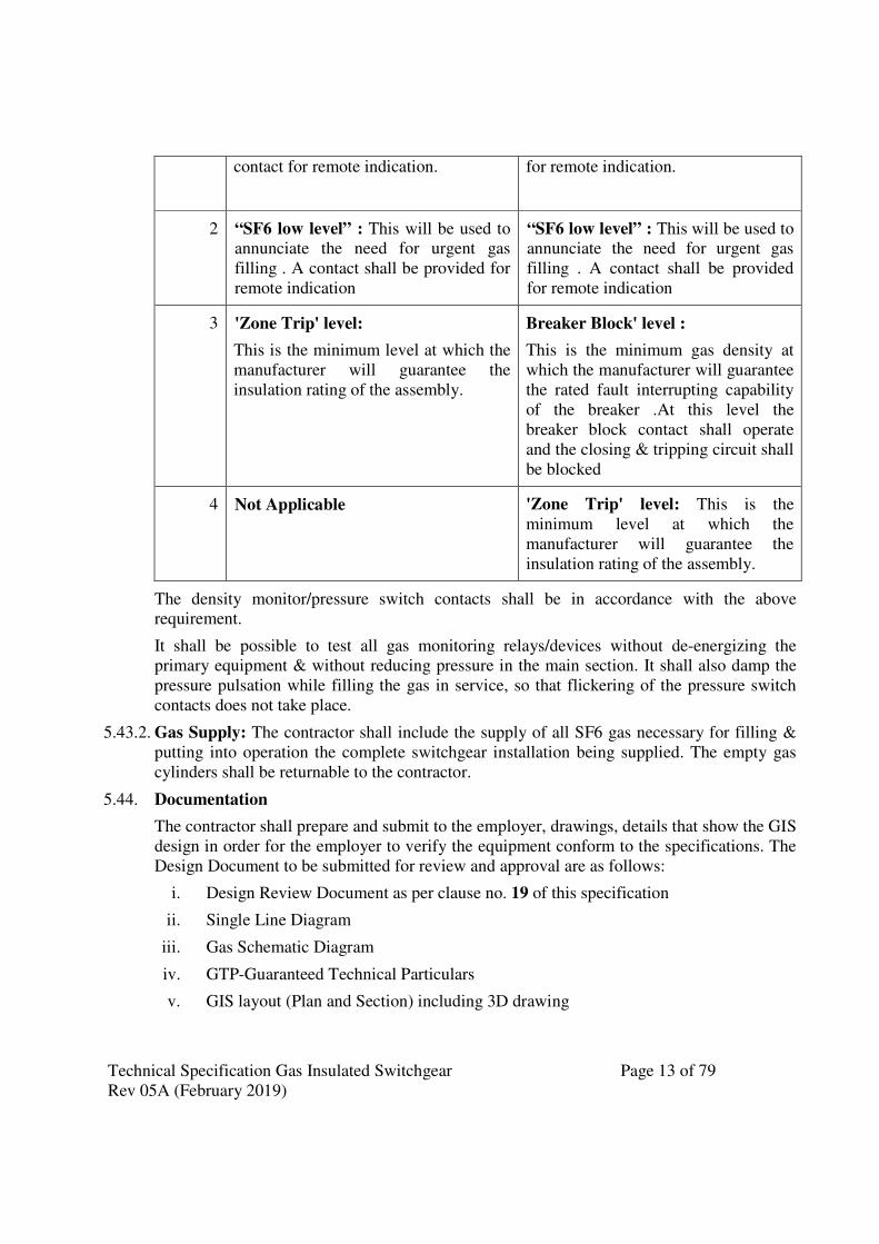
Technical Specification Gas Insulated Switchgear Page 13 of 79
Rev 05A (February 2019)
contact for remote indication.
for remote indication.
2 “SF6 low level” : This will be used to
annunciate the need for urgent gas
filling . A contact shall be provided for
remote indication
“SF6 low level” : This will be used to
annunciate the need for urgent gas
filling . A contact shall be provided
for remote indication
3 'Zone Trip' level:
This is the minimum level at which the
manufacturer will guarantee the
insulation rating of the assembly.
Breaker Block' level :
This is the minimum gas density at
which the manufacturer will guarantee
the rated fault interrupting capability
of the breaker .At this level the
breaker block contact shall operate
and the closing & tripping circuit shall
be blocked
4 Not Applicable 'Zone Trip' level: This is the
minimum level at which the
manufacturer will guarantee the
insulation rating of the assembly.
The density monitor/pressure switch contacts shall be in accordance with the above
requirement.
It shall be possible to test all gas monitoring relays/devices without de-energizing the
primary equipment & without reducing pressure in the main section. It shall also damp the
pressure pulsation while filling the gas in service, so that flickering of the pressure switch
contacts does not take place.
5.43.2. Gas Supply: The contractor shall include the supply of all SF6 gas necessary for filling &
putting into operation the complete switchgear installation being supplied. The empty gas
cylinders shall be returnable to the contractor.
5.44. Documentation
The contractor shall prepare and submit to the employer, drawings, details that show the GIS
design in order for the employer to verify the equipment conform to the specifications. The
Design Document to be submitted for review and approval are as follows:
i. Design Review Document as per clause no. 19 of this specification
ii. Single Line Diagram
iii. Gas Schematic Diagram
iv. GTP-Guaranteed Technical Particulars
v. GIS layout (Plan and Section) including 3D drawing
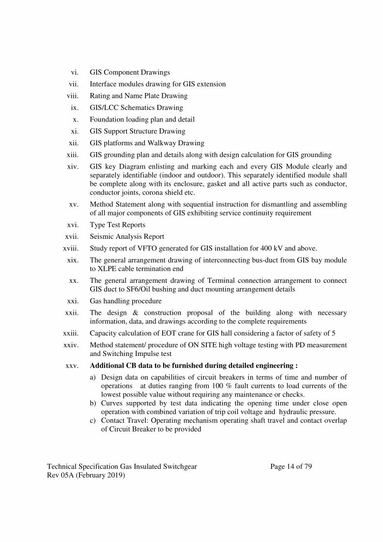
Technical Specification Gas Insulated Switchgear Page 14 of 79
Rev 05A (February 2019)
vi. GIS Component Drawings
vii. Interface modules drawing for GIS extension
viii. Rating and Name Plate Drawing
ix. GIS/LCC Schematics Drawing
x. Foundation loading plan and detail
xi. GIS Support Structure Drawing
xii. GIS platforms and Walkway Drawing
xiii. GIS grounding plan and details along with design calculation for GIS grounding
xiv. GIS key Diagram enlisting and marking each and every GIS Module clearly and
separately identifiable (indoor and outdoor). This separately identified module shall
be complete along with its enclosure, gasket and all active parts such as conductor,
conductor joints, corona shield etc.
xv. Method Statement along with sequential instruction for dismantling and assembling
of all major components of GIS exhibiting service continuity requirement
xvi. Type Test Reports
xvii. Seismic Analysis Report
xviii. Study report of VFTO generated for GIS installation for 400 kV and above.
xix. The general arrangement drawing of interconnecting bus-duct from GIS bay module
to XLPE cable termination end
xx. The general arrangement drawing of Terminal connection arrangement to connect
GIS duct to SF6/Oil bushing and duct mounting arrangement details
xxi. Gas handling procedure
xxii. The design & construction proposal of the building along with necessary
information, data, and drawings according to the complete requirements
xxiii. Capacity calculation of EOT crane for GIS hall considering a factor of safety of 5
xxiv. Method statement/ procedure of ON SITE high voltage testing with PD measurement
and Switching Impulse test
xxv. Additional CB data to be furnished during detailed engineering :
a) Design data on capabilities of circuit breakers in terms of time and number of
operations at duties ranging from 100 % fault currents to load currents of the
lowest possible value without requiring any maintenance or checks.
b) Curves supported by test data indicating the opening time under close open
operation with combined variation of trip coil voltage and hydraulic pressure.
c) Contact Travel: Operating mechanism operating shaft travel and contact overlap
of Circuit Breaker to be provided

Technical Specification Gas Insulated Switchgear Page 15 of 79
Rev 05A (February 2019)
xxvi. PD Monitoring System
a) The technical proposal for PDM system along with detailed design
documentation.
b) Data sheet for the UHF couplers.
c) The Sub-station GIS layout as a separate drawing indicating position of spacers,
spread over of PD sensors with distance, sensor identification, the detector unit
identification etc., total numbers of offered UHF Sensors along with attenuation
calculation.
d) Guaranteed Technical Particulars & Data Sheet for various components used in
the PDM system.
e) Electromagnetic compatibility Test Reports.
f) List of critical spares.
xxvii. Installation and Operation & Maintenance Manual
6. CIRCUIT BREAKERS
6.1. General : SF6 gas insulated metal enclosed circuit breakers and accessories shall conform
to IEC: 62271-100, IEC: 62271-1 and other relevant IEC standards except to the extent
explicitly modified in the specification and shall also be in accordance with requirements
specified in Section-GTR.
Circuit breakers shall be equipped with the operating mechanism. Circuit breakers shall be
of single pressure type. Complete circuit breaker with all necessary items for successful
operation shall be supplied. The circuit breakers shall be designed for high speed single and
three phase reclosing (as applicable) with an operating sequence and timing as specified.
6.2. Duty Requirements: Circuit breaker shall be C2 - M2 class as per IEC 62271-100.
Circuit breaker shall meet the duty requirements for any type of fault or fault location also
for line charging and dropping when used on effectively grounded system and perform
make and break operations as per the stipulated duty cycles satisfactorily.
6.3. Pre insertion resister: 765kV/400 kV circuit breakers for line bay (as per the provisions of bid
proposal sheet) shall be provided with single step pre insertion closing resistors (wherever the
requirement of PIR is explicitly specified so ) to limit the switching surges to a value of less
than1.9 p.u for 765kV and 2.3 p.u for 400kV. PIR contacts should open immediately after
closing of main contacts or At least 5 ms prior to opening of main contacts at rated air/gas
pressure where the PIR contacts remain closed. The resistor shall have thermal rating for the
following duties :
a. Terminal fault : Close.... 1 Min........ Open...... Close Open 2 min........ Close .......
1 Min........ Open Close Open.
b. Reclosing against trapped charges : Duty same as under (a.) above. The first, third
and fourth closures are to be on de-energised line while second closing is to be
made with lines against trapped charge of 1.2 p.u. of opposite polarity.
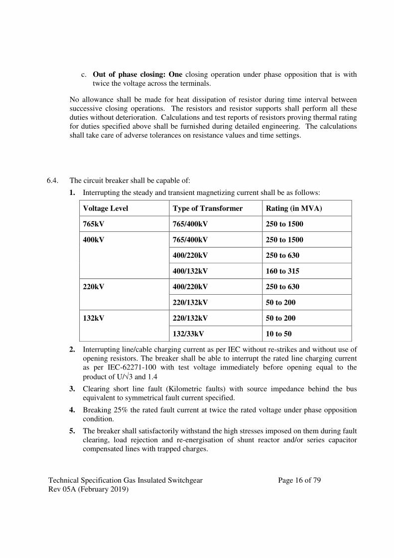
Technical Specification Gas Insulated Switchgear Page 16 of 79
Rev 05A (February 2019)
c. Out of phase closing: One closing operation under phase opposition that is with
twice the voltage across the terminals.
No allowance shall be made for heat dissipation of resistor during time interval between
successive closing operations. The resistors and resistor supports shall perform all these
duties without deterioration. Calculations and test reports of resistors proving thermal rating
for duties specified above shall be furnished during detailed engineering. The calculations
shall take care of adverse tolerances on resistance values and time settings.
6.4. The circuit breaker shall be capable of:
1. Interrupting the steady and transient magnetizing current shall be as follows:
Voltage Level Type of Transformer Rating (in MVA)
765kV 765/400kV 250 to 1500
400kV 765/400kV 250 to 1500
400/220kV 250 to 630
400/132kV 160 to 315
220kV 400/220kV 250 to 630
220/132kV 50 to 200
132kV 220/132kV 50 to 200
132/33kV 10 to 50
2. Interrupting line/cable charging current as per IEC without re-strikes and without use of
opening resistors. The breaker shall be able to interrupt the rated line charging current
as per IEC-62271-100 with test voltage immediately before opening equal to the
product of U/√3 and 1.4
3. Clearing short line fault (Kilometric faults) with source impedance behind the bus
equivalent to symmetrical fault current specified.
4. Breaking 25% the rated fault current at twice the rated voltage under phase opposition
condition.
5. The breaker shall satisfactorily withstand the high stresses imposed on them during fault
clearing, load rejection and re-energisation of shunt reactor and/or series capacitor
compensated lines with trapped charges.
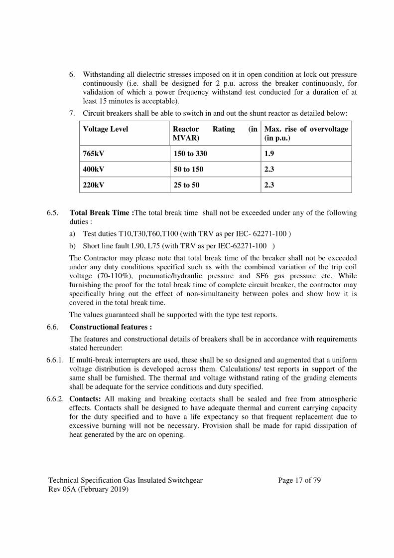
Technical Specification Gas Insulated Switchgear Page 17 of 79
Rev 05A (February 2019)
6. Withstanding all dielectric stresses imposed on it in open condition at lock out pressure
continuously (i.e. shall be designed for 2 p.u. across the breaker continuously, for
validation of which a power frequency withstand test conducted for a duration of at
least 15 minutes is acceptable).
7. Circuit breakers shall be able to switch in and out the shunt reactor as detailed below:
Voltage Level Reactor Rating (in
MVAR)
Max. rise of overvoltage
(in p.u.)
765kV 150 to 330 1.9
400kV 50 to 150 2.3
220kV 25 to 50 2.3
6.5. Total Break Time :The total break time shall not be exceeded under any of the following
duties :
a) Test duties T10,T30,T60,T100 (with TRV as per IEC- 62271-100 )
b) Short line fault L90, L75 (with TRV as per IEC-62271-100 )
The Contractor may please note that total break time of the breaker shall not be exceeded
under any duty conditions specified such as with the combined variation of the trip coil
voltage (70-110%), pneumatic/hydraulic pressure and SF6 gas pressure etc. While
furnishing the proof for the total break time of complete circuit breaker, the contractor may
specifically bring out the effect of non-simultaneity between poles and show how it is
covered in the total break time.
The values guaranteed shall be supported with the type test reports.
6.6. Constructional features :
The features and constructional details of breakers shall be in accordance with requirements
stated hereunder:
6.6.1. If multi-break interrupters are used, these shall be so designed and augmented that a uniform
voltage distribution is developed across them. Calculations/ test reports in support of the
same shall be furnished. The thermal and voltage withstand rating of the grading elements
shall be adequate for the service conditions and duty specified.
6.6.2. Contacts: All making and breaking contacts shall be sealed and free from atmospheric
effects. Contacts shall be designed to have adequate thermal and current carrying capacity
for the duty specified and to have a life expectancy so that frequent replacement due to
excessive burning will not be necessary. Provision shall be made for rapid dissipation of
heat generated by the arc on opening.
Technical Specification Gas Insulated Switchgear Page 18 of 79
Rev 05A (February 2019)
6.6.3. Any device provided for voltage grading to damp oscillations or, to prevent re-strike prior to
the complete interruption of the circuit or to limit over voltage on closing, shall have a life
expectancy comparable of that of the breaker as a whole.
6.6.4. Breakers shall be so designed that when operated within their specified rating, the
temperature of each part will be limited to values consistent with a long life for the material
used. The temperature rise shall not exceed that indicated in IEC-62271-100 under specified
ambient conditions.
6.6.5. The breaker should be able to withstand all dielectric stresses imposed on it in open
condition at lockout pressure continuously (i.e. 2 p.u. power frequency voltage across the
breaker continuously)
6.6.6. In the interrupter assembly there shall be an adsorbing product box to minimize the effect of
SF6 decomposition products and moisture. The material used in the construction of the
circuit breakers shall be such as to be fully compatible with SF6 gas decomposition
products.
6.6.7. Provisions shall be made for attaching an operational analyzer to record travel, speed and
making measurement of operating timings etc. after installation at site. The contractor shall
supply three set of transducer for each substation covered under the scope.
6.6.8. Circuit Breaker shall be supplied with auxiliary switch having additional 8 NO (normally
open) and 8 NC ( normally closed) contacts for future use over and above those required for
switchgear interlocking and other control and protection function. These spare NO and NC
contacts shall be wired upto the local control cubicle.
6.6.9. The CO (Close-open) operation and its timing shall be such as to ensure complete
travel/insertion of the contact during closing operation and then follow the opening
operation
6.7. Operating mechanism
6.7.1. General Requirements :
a) Circuit breaker shall be operated by spring charged mechanism or electro hydraulic
mechanism or a combination of these. The mechanism shall be housed in a dust proof
cabinet and shall have IP: 42 degree of protection.
b) The operating mechanism box shall be strong, rigid, rebound free and shall be readily
accessible for maintenance.
c) The operating mechanism shall be suitable for high speed reclosing and other duties
specified. During reclosing the breaker contacts shall close fully and then open. The
mechanism shall be anti-pumping and trip free (as per IEC definition) under every
method of closing.
d) The mechanism shall be such that the failure of any auxiliary spring will not prevent
tripping and will not cause unwanted trip or closing operation of the Circuit Breaker.
Technical Specification Gas Insulated Switchgear Page 19 of 79
Rev 05A (February 2019)
e) A mechanical indicator shall be provided to show open and close position of the
breaker. It shall be located in a position where it will be visible to a man standing on the
ground level with the mechanism housing closed. An operation counter shall also be
provided.
f) Working parts of the mechanism shall be of corrosion resisting material, bearings which
require grease shall be equipped with pressure type grease fittings. Bearing pin, bolts,
nuts and other parts shall be adequately pinned or locked to prevent loosening or
changing adjustment with repeated operation of the breaker.
g) The contractor shall furnish detailed operation and maintenance manual of the
mechanism along with the operation manual for the circuit breaker.
6.7.2. Control
a) The close and trip circuits shall be designed to permit use of momentary-contact
switches and push buttons.
b) Each breaker pole shall be provided with two (2) independent tripping circuits and trip
coils which may be connected to a different set of protective relays.
c) The breaker shall normally be operated by remote electrical control. Electrical tripping
shall be performed by shunt trip coils. However, provisions shall be made for local
electrical control. For this purpose a local/remote selector switch and close and trip
control switch/push buttons shall be provided in the breaker control cabinet.
d) The trip coil shall be suitable for trip circuit supervision during both open and close
position of breaker.
e) Closing coil and associated circuits shall operate correctly at all values of voltage
between 85% and 110% of the rated voltage. Shunt trip and associated circuits shall
operate correctly under all operating conditions of the circuit breaker upto the rated
breaking capacity of the circuit breaker and at all values of supply voltage between 70%
and 110% of rated voltage.
f) Density meter contacts and pressure switch contacts shall be suitable for direct use as
permissive in closing and tripping circuits. Separate contacts have to be used for each of
tripping and closing circuits. If contacts are not suitably rated and multiplying relays are
used then fail safe logic/schemes are to be employed. DC supplies shall be monitored
for remote annunciations and operation lockout in case of dc failures.
g) The auxiliary switch of the breaker shall be positively driven by the breaker operating
rod.
6.7.3. Spring operated Mechanism
a) Spring operated mechanism shall be complete with motor as per manufacturer practice.
Opening spring and closing spring with limit switch for automatic charging and other
necessary accessories to make the mechanism a complete operating unit shall also be
provided.
Technical Specification Gas Insulated Switchgear Page 20 of 79
Rev 05A (February 2019)
b) As long as power is available to the motor, a continuous sequence of the closing and
opening operations shall be possible. The motor shall have adequate thermal rating for
this duty.
c) After failure of power supply to the motor one close open operation shall be possible
with the energy contained in the operating mechanism.
d) Breaker operation shall be independent of the motor which shall be used solely for
compressing the closing spring. Facility for manual charging of the closing spring shall
also be provided. The motor rating shall be such that it required preferably not more than
90 seconds for full charging of the closing spring.
e) Closing action of circuit breaker shall compress the opening spring ready for tripping.
f) When closing springs are discharged after closing a breaker, closing springs shall
automatically be charged for the next operation and an indication of this shall be
provided in the local control cabinet & SAS .
g) Provisions shall be made to prevent a closing operation of the breaker when the spring is
in the partial charged condition.
h) Mechanical interlocks shall be provided in the operating mechanism to prevent
discharging of closing springs when the breaker is in the closed position.
i) The spring operating mechanism shall have adequate energy stored in the operating
spring to close and latch the circuit breaker against the rated making current and also to
provide the required energy for the tripping mechanism in case the tripping energy is
derived from the operating mechanism.
j) The spring charging failure alarm shall be provided with a time delay relay having
setting range from 0-3 minutes.
k) Separate MCBs shall be provided for each spring charging motor and the rating of
MCBs shall be suitably selected to match the starting, running and stalling time.
l) An overload relay shall be provided for protection of the spring charging motor.
6.7.4. Hydraulically Operated Mechanism :
a) Hydraulically operated mechanism shall comprise of operating unit with power cylinder,
control valves, high and low pressure reservoir, motor etc.
b) The hydraulic oil used shall be fully compatible for the temperature range to be
encountered during operation.
c) The oil pressure switch controlling the oil pump and pressure in the high pressure
reservoir shall have adequate no. of spare contacts, for continuous monitoring of low
pressure, high pressure etc. at switchyard control room.
Technical Specification Gas Insulated Switchgear Page 21 of 79
Rev 05A (February 2019)
d) The mechanism shall be suitable for at-least two close open operations after failure of
AC supply to the motor starting at pressure equal to the lowest pressure of auto reclose
duty plus pressure drop for one close open operation.
e) The mechanism shall be capable of operating the circuit breaker correctly and
performing the duty cycle specified under all conditions with the pressure of hydraulic
operated fluid in the operating mechanism at the lowest permissible pressure before
make up.
f) Trip lockout shall be provided to prevent operations of the circuit breaker below the
minimum specified hydraulic pressure. Alarm contacts for loss of Nitrogen shall also be
provided.
g) All hydraulic joints shall have no oil leakage under the site conditions and joints shall be
tested at factory against oil leakage.
6.8. Controlled Switching Device(CSD):
6.8.1. 765kV & 400KV Circuit Breaker shall be equipped with controlled switching device with
consequent optimization of switching behavior, when used in:
1. Switching of transformer(from 765kV and 400kV side circuit breakers only)
2. Switching of shunt reactor
6.8.2. The CSD shall be provided in 765kV/400kV Circuit breakers for controlling transformers
and reactors (ie for breakers of switchable line reactor and in Main& Tie circuit breakers of
Transformers, Transmission lines with non-switchable line reactors and Bus reactors). The
requirement of CSD shall be explicitly specified in price schedule
6.8.3. Technical Requirement for Controlled switching device:
a) The CSD shall be designed to operate correctly and satisfactorily with the excursion
of auxiliary A/C & DC voltages and frequency as specified in section - GTR.
b) The CSD shall meet the requirements of IEC-61000-4 16 class IV regarding HF
disturbance test and fast transient test shall be as per IEC-61000 – 4-4 level IV and
insulation test as per 60255 – 5.
c) The CSD shall have functions for switching ON & OFF the circuit breakers.
d) The CSD shall get command to operate the breakers manually or through auto re-
close relay at random. The controller shall be able to analyze the current and voltage
waves available through the signals from secondaries of CTs & CVTs for the
purpose of calculation of optimum moment of the switching the circuit breaker and
issue command to circuit breaker to operate.
e) The CSD shall have an adaptive control feature to consider the next operating time
of the breaker in calculation of optimum time of issuing the switching command. In
calculation of net operating time of the breaker the controller must consider all
factors that may affect the operating time of the breaker such as, but not limited to,
ambient temperature, control voltage variation, SF6 gas density variations etc.
Schematic drawing for this purpose shall be provided by the contractor. The
Technical Specification Gas Insulated Switchgear Page 22 of 79
Rev 05A (February 2019)
accuracy of the operating time estimation by the controller shall be better than + 0.5
ms.
f) The CSD shall have communication port to facilitate online communication of the
control switching device with SCADA directly on 61850 or through gateway which
shall be under present scope.
g) The CSD shall be PC compatible for the setting of various parameters and down
loading of the settings and measured values date time of switching etc. Window
based software for this purpose shall be supplied by the contractor to be used on the
owner’s PC.
h) The CSD shall be suitable for current input of 1 amp from the secondary of the CTs.
and 110 V (Ph to Ph) from the CVTs. The controller shall withstand transient and
dynamic state values of the current from the secondary of the CTs and CVTs.
i) The CSD shall have time setting resolution of 0.1 ms or better.
j) The CSD shall have sufficient number of output/input potential free contacts for
connecting the monitoring equipment and annunciation system available in the
control room. Necessary details shall be worked out during engineering the scheme.
k) The CSD shall also record and monitor the switching operations and make
adjustments to the switching instants to optimize the switching behavior as
necessary. It shall provide self-diagnostic facilities, signaling of alarms and enable
downloading of data captured from the switching events.
l) The provision for bypassing the Controlled switching device shall be provided
through BCU and SCADA both so that whenever, the CSD is not healthy due to any
reason (including auxiliary supply failure), uncontrolled trip/close command can be
extended to the circuit Breaker. Alternatively, in case of any non-operation of the
CSD after receiving a close/trip command after a pre-determined time delay, the
CSD should automatically be bypassed so as to ensure that the trip and close
commands are extended to the Trip/Close coils through subsequent command.
m) The CSD shall be provided with a communication port to facilitate online
communication of the CSD with Substation automation system directly on IEC
61850 protocols. If the CSD does not meet the protocols of IEC 61850, suitable
gateway shall be provided to enable the communication of CSD as per IEC 61850.
6.9. The technical parameters of Circuit breakers are as per Annexure –1
6.10. Tests :
6.10.1. Type Tests:
i. In accordance with the requirements stipulated under Section GTR the circuit breaker
along with its operating mechanism shall conform to the type tests as per IEC-62271-
100.
ii. The type test report of Electromagnetic Compatibility Test (EMC) of CSD shall be
submitted for approval
Technical Specification Gas Insulated Switchgear Page 23 of 79
Rev 05A (February 2019)
iii. Circuit breakers meant for controlled switching shall conform to requirements of
IEC/TR-62271–302. The contractor shall submit test reports to demonstrate that the
offered CB conforms to the requirements of performance verification tests and
parameter definition tests as per IEC/TR 62271-302. The contractor shall also furnish
the report for the re-ignition free arcing window for switching 3-phase shunt reactor as
demonstrated in the shunt reactor switching test.
6.10.2. Routine Tests:
Routine tests as per IEC: 62271-100 shall be performed on all circuit breakers.
In addition to the mechanical and electrical tests specified by IEC, the following shall also
be performed.
i. Speed curves for each breaker shall be obtained with the help of a suitable operation
analyzer to determine the breaker contact movement during opening, closing, auto
reclosing and trip free operation under normal as well as limiting operating control
voltage conditions. The tests shall show the speed of contacts directly at various stages
of operation, travel of contacts, opening time, closing time, shortest time between
separation and meeting of contacts at break make operation etc. This test shall also be
performed at site for which the necessary operation analyzer along with necessary
transducers, cables, console etc. shall be arranged by the contractor at his own cost.
After completion of site pre-commissioning test, 03 nos. travel transducer shall be
handed over to POWERGRID.
ii. During testing of CB, dynamic contact resistance measurement (DCRM) shall be
carried out for close-open (CO) operations with delay of 300ms between close and trip
operations. Minimum 100A current shall be injected for DCRM test. Travel
characteristics, injected current, trip/close coil current shall also be recorded along with
DCRM test.
iii. Routine tests on Circuit breakers with Controlled switching device as per IEC/TR
62271-302.
7. DISCONNECTORS (ISOLATORS)
7.1. Disconnectors shall be three-pole group operated or Single-pole individual operated (as per
single line diagram of the substation) and shall be installed in the switchgear to provide
electrical isolation. The disconnectors shall conform to IEC- 62271-102 and shall have the
ratings as specified in BPS.
7.2. Construction & Design.
7.2.1. The disconnectors shall be operated by electric motor suitable for use on DC system and
shall be equipped with a manual operating mechanism for emergency use. The motor shall
be protected against over current and short circuit.
7.2.2. Disconnectors shall be suitable to switch the bus charging currents during their opening and
closing and shall confirm to all three test duties viz TD1,TD2 and TD3 as per Annexure –F

Technical Specification Gas Insulated Switchgear Page 24 of 79
Rev 05A (February 2019)
of IEC: 62271- 102.They shall also be able to make and break rated bus transfer current at
rated bus transfer voltage which appears during transfer between bus bars in accordance
with Annexure –B of IEC: 62271-102. The contact shielding shall also be designed to
prevent restrikes and high local stresses caused by transient recovery voltages when these
currents are interrupted.
7.2.3. The disconnect switches shall be arranged in such a way that all the three phases operate
simultaneously. All the parts of the operating mechanism shall be able to withstand starting
torque of the motor mechanism without damage until the motor overload protection
operates.
7.2.4. It shall be possible to operate the disconnect switches manually by cranks or hand wheels.
7.2.5. For motor-operated disconnect switches, the control should be electrically and/or
mechanically uncoupled from the drive shaft when the switch is operated manually to
prevent coincident power operation of the switch and the drive mechanism(s).
7.2.6. The operating mechanisms shall be complete with all necessary linkages, clamps, couplings,
operating rods, support brackets and grounding devices. All the bearings shall be
permanently lubricated or shall be of such a type that no lubrication or maintenance is
required.
7.2.7. The opening and closing of the disconnectors shall be achieved by either local or remote
control. The local operation shall be by means of a two-position control switch located in
the Local Control Cabinet (LCC).
7.2.8. Remote control of the disconnectors from the control room/SAS shall be made by means of
remote/ local transfer switch.
7.2.9. The disconnector operations shall be inter-locked electrically with the associated circuit
breakers in such a way that the disconnector control is inoperative if the circuit breaker is
closed.
7.2.10. Each disconnector shall be supplied with auxiliary switch having additional 8 NO (Normally
Open) and 8 NC (Normally Closed) contacts for future use over and above those required
for switchgear interlocking and automation purposes. These spare NO and NC contacts shall
be wired up to the local control cabinet.
7.2.11. The signaling of the closed position of the disconnector shall not take place unless it is
certain that the movable contacts will reach a position in which the rated normal current,
peak withstand current and short-time withstand current can be carried safely.
7.2.12. The signaling of the open position of the disconnector shall not take place unless the
movable contacts have reached such a position that the clearance between the contacts is at
least 80 percent of the rated isolating distance.
7.2.13. The disconnectors and safety grounding switches shall have mechanical/electrical inter-
locks to prevent closing of the grounding switches when isolator switches are in the closed
position and to prevent closing of the disconnectors when the grounding switch is in the
Technical Specification Gas Insulated Switchgear Page 25 of 79
Rev 05A (February 2019)
closed position. Integrally mounted lock when provided shall be equipped with a unique key
for such three phase group. Master key is not permitted.
7.2.14. The local control of the Isolator and high-speed grounding switches from the Local Control
Cabinet (LCC) should be achieved from the individual control switches with the
remote/local transfer switch set to local.
7.2.15. All electrical sequence interlocks will apply in both remote and local control modes.
7.2.16. Each disconnector shall have a clearly identifiable local, positively driven mechanical
position indicator, together with position indicator on the local control cubicle (LCC) and
provisions for taking the signals to the control room. The details of the inscriptions and
colouring for the indicator are given as under :
INSCRIPTION COLOUR
Open position OPEN GREEN
Closed position CLOSED RED
7.2.17. All the disconnecting switches shall have arrangement allowing easy visual inspection of the
travel of the switch contacts in both open and close positions, from the outside of the
enclosure.
7.2.18. The disconnecting switches shall be provided with rating plates and shall be easily
accessible.
7.2.19. The mechanical endurance class shall be M2 as per IEC for 765kV, 400kV 220 kV and
132kV disconnectors.
7.2.20. Mechanical position indication shall be provided locally at each disconnector and Electrical
indication at each Local Control Cabinet (LCC) / SAS.
7.3. The technical parameters of disconnectors are as per Annexure-2
8. SAFETY GROUNDING SWITCHES
8.1. Safety grounding switches shall be three-pole group operated or single-pole individual
operated (as per single line diagram of the substation). It shall be operated by DC electric
motor and shall be equipped with a manual operating mechanism for emergency use. The
motor shall be protected against over-current and short circuit.
8.2. Each safety grounding switch shall be electrically interlocked with its associated
disconnectors and circuit breaker such that it can only be closed if both the circuit breaker
and disconnectors are in open position. Safety grounding switch shall also be mechanically
key interlocked with its associated disconnectors.
8.3. Each safety grounding switch shall have clearly identifiable local positive driven
mechanical indicator together with position indicator on the Local Control Cabinet (LCC)
and provision for taking the signal to Control room.
Technical Specification Gas Insulated Switchgear Page 26 of 79
Rev 05A (February 2019)
8.4. The details of the inscription and colouring for the indicator are given as under :
INSCRIPTION COLOUR
Open position OPEN GREEN
Closed position CLOSED RED
8.5. Interlocks shall be provided so that manual operation of the switches or insertion of the
manual operating device will disable the electrical control circuits.
8.6. Each ground switch shall be fitted with auxiliary switches having 4 NO (Normally Open)
and 4 NC (Normally Closed) contacts for use by others over and above those required for
local interlocking and position indication purposes.
8.7. Provision shall be made for padlocking / suitable locking arrangement for the ground
switches in either the open or closed position.
8.8. All portions of the grounding switch and operating mechanism required for grounding shall
be connected together utilizing flexible copper conductors having a minimum cross-
sectional area of 100 sq. mm.
8.9. The main grounding connections on each grounding switch shall be rated to carry the full
short circuit current for 1 sec. and shall be equipped with a silver-plated terminal connector
suitable for steel strap of adequate rating for connection to the grounding grid.
8.10. The safety grounding switches shall conform to the requirements of IEC- 62271- 102 and
shall have electrical endurance class: E0 & shall have mechanical endurance class M2 for
765/400 kV & M1 for 220/132 kV voltage level.
8.11. The grounding switch shall be provided with test provision (insulated link) to permit test
voltage up to 10 kV and up to 200 A to be applied to the main conductor without removing
SF6 gas from the enclosure and without disassembling the enclosure except for ground
shunt leads.
8.12. Combined Disconnectors & Safety grounding switch arrangement shall also be acceptable.
8.13. Mechanical position indication shall be provided locally at each switch and Electrical
indication at each Local Control Cabinet (LCC) / SAS.
9. HIGH SPEED MAKE PROOF GROUNDING SWITCHES:
9.1. Grounding switches located at the beginning of the line feeder bay modules shall be of the
high speed, make proof type and will be used to discharge the respective charging currents,
trapped charge in addition to their safety grounding function. These grounding switches
shall be capable of interrupting the inductive and capacitive currents and to withstand the
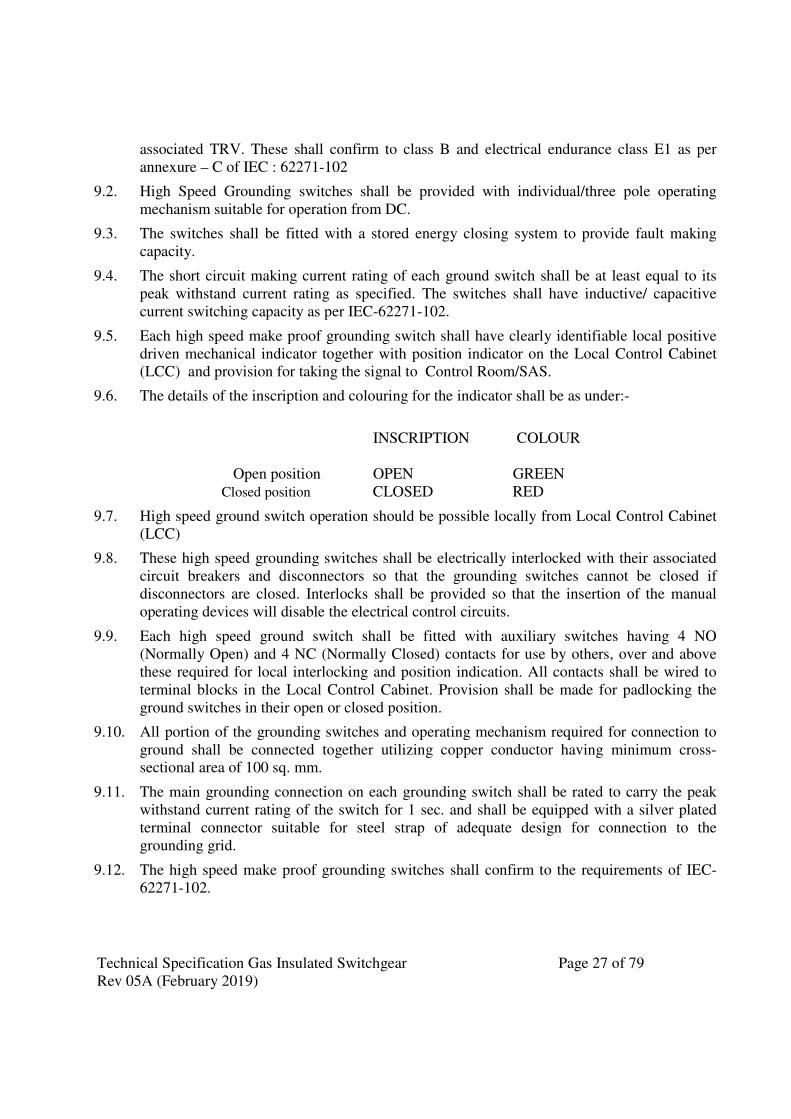
Technical Specification Gas Insulated Switchgear Page 27 of 79
Rev 05A (February 2019)
associated TRV. These shall confirm to class B and electrical endurance class E1 as per
annexure – C of IEC : 62271-102
9.2. High Speed Grounding switches shall be provided with individual/three pole operating
mechanism suitable for operation from DC.
9.3. The switches shall be fitted with a stored energy closing system to provide fault making
capacity.
9.4. The short circuit making current rating of each ground switch shall be at least equal to its
peak withstand current rating as specified. The switches shall have inductive/ capacitive
current switching capacity as per IEC-62271-102.
9.5. Each high speed make proof grounding switch shall have clearly identifiable local positive
driven mechanical indicator together with position indicator on the Local Control Cabinet
(LCC) and provision for taking the signal to Control Room/SAS.
9.6. The details of the inscription and colouring for the indicator shall be as under:-
INSCRIPTION COLOUR
Open position OPEN GREEN
Closed position CLOSED RED
9.7. High speed ground switch operation should be possible locally from Local Control Cabinet
(LCC)
9.8. These high speed grounding switches shall be electrically interlocked with their associated
circuit breakers and disconnectors so that the grounding switches cannot be closed if
disconnectors are closed. Interlocks shall be provided so that the insertion of the manual
operating devices will disable the electrical control circuits.
9.9. Each high speed ground switch shall be fitted with auxiliary switches having 4 NO
(Normally Open) and 4 NC (Normally Closed) contacts for use by others, over and above
these required for local interlocking and position indication. All contacts shall be wired to
terminal blocks in the Local Control Cabinet. Provision shall be made for padlocking the
ground switches in their open or closed position.
9.10. All portion of the grounding switches and operating mechanism required for connection to
ground shall be connected together utilizing copper conductor having minimum cross-
sectional area of 100 sq. mm.
9.11. The main grounding connection on each grounding switch shall be rated to carry the peak
withstand current rating of the switch for 1 sec. and shall be equipped with a silver plated
terminal connector suitable for steel strap of adequate design for connection to the
grounding grid.
9.12. The high speed make proof grounding switches shall confirm to the requirements of IEC-
62271-102.
Technical Specification Gas Insulated Switchgear Page 28 of 79
Rev 05A (February 2019)
9.13. The grounding switch shall be provided with test provision (insulated link) to permit test
voltage up to 10 kV and up to 200 A to be applied to the main conductor without removing
SF6 gas from the enclosure and without disassembling the enclosure except for ground
shunt leads.
10. INSTRUMENT TRANSFORMERS
10.1. Current Transformers
The current transformers and accessories shall conform to IEC: 61869 and other relevant
standards except to the extent explicitly modified in the specification.
10.1.1. Ratios and Characteristics: The CT core distribution for various voltage levels shall be as
per Table 3A, 3B, 3C 3D & 3E. Further the numbers of cores, rating, ratios, accuracy class,
etc. for the individual current transformers secondary cores shall be in accordance with
above table attached at Annexure-3.
Where multi-ratio current transformers are required the various ratios shall be obtained by
changing the effective number of turns on the secondary winding.
10.1.2. Rating and Diagram Plates: Rating and diagram plates shall be as specified in the IEC
specification incorporating the year of manufacture. The rated current & extended current
rating in case of current transformers and rated voltage, voltage factor & intermediate
voltage in case of voltage transformers shall be clearly indicated on the name plate.
The diagram plates shall show the terminal markings and the relative physical arrangement
of the current transformer cores with respect to the primary terminals (P1 & P2).
The position of each primary terminal in the current transformer SF6 gas section shall be
clearly marked by two plates fixed to the enclosure at each end of the current transformer.
10.1.3. Constructional Details:
a) The current transformers incorporated into the GIS will be used for protective relaying
and metering purposes and shall be of metal- enclosed type.
b) Each current transformer shall be equipped with a secondary terminal box with terminals
for the secondary circuits, which are connected to the Local Control Cubicle. The star/
delta configuration and the inter connection to the line protection panels will be done at
the CT terminal block located in the local control cubicle.
c) Current transformers guaranteed burdens and accuracy class are to be intended as
simultaneous for all cores.
d) The rated extended currents for 800 kV and 420 kV class Current transformers shall be
as given below:
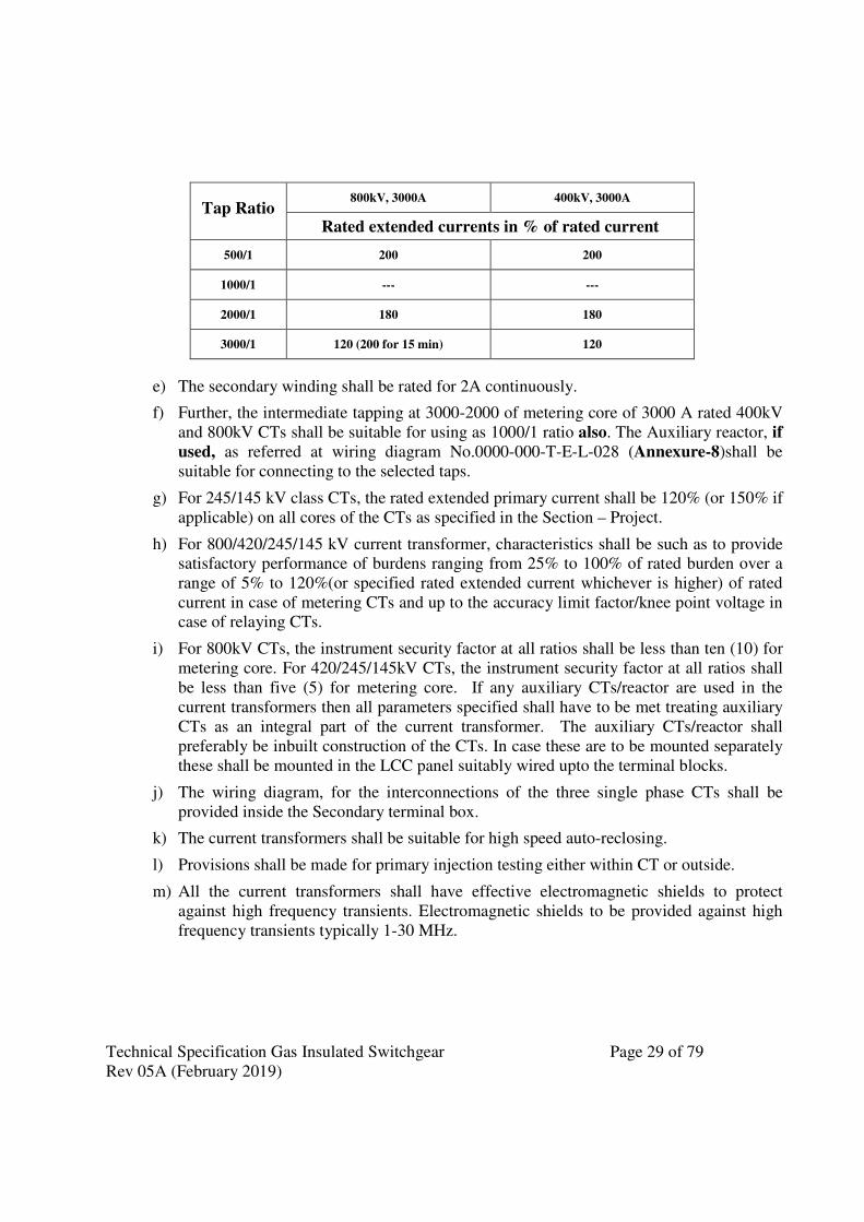
Technical Specification Gas Insulated Switchgear Page 29 of 79
Rev 05A (February 2019)
e) The secondary winding shall be rated for 2A continuously.
f) Further, the intermediate tapping at 3000-2000 of metering core of 3000 A rated 400kV
and 800kV CTs shall be suitable for using as 1000/1 ratio also. The Auxiliary reactor, if
used, as referred at wiring diagram No.0000-000-T-E-L-028 (Annexure-8)shall be
suitable for connecting to the selected taps.
g) For 245/145 kV class CTs, the rated extended primary current shall be 120% (or 150% if
applicable) on all cores of the CTs as specified in the Section – Project.
h) For 800/420/245/145 kV current transformer, characteristics shall be such as to provide
satisfactory performance of burdens ranging from 25% to 100% of rated burden over a
range of 5% to 120%(or specified rated extended current whichever is higher) of rated
current in case of metering CTs and up to the accuracy limit factor/knee point voltage in
case of relaying CTs.
i) For 800kV CTs, the instrument security factor at all ratios shall be less than ten (10) for
metering core. For 420/245/145kV CTs, the instrument security factor at all ratios shall
be less than five (5) for metering core. If any auxiliary CTs/reactor are used in the
current transformers then all parameters specified shall have to be met treating auxiliary
CTs as an integral part of the current transformer. The auxiliary CTs/reactor shall
preferably be inbuilt construction of the CTs. In case these are to be mounted separately
these shall be mounted in the LCC panel suitably wired upto the terminal blocks.
j) The wiring diagram, for the interconnections of the three single phase CTs shall be
provided inside the Secondary terminal box.
k) The current transformers shall be suitable for high speed auto-reclosing.
l) Provisions shall be made for primary injection testing either within CT or outside.
m) All the current transformers shall have effective electromagnetic shields to protect
against high frequency transients. Electromagnetic shields to be provided against high
frequency transients typically 1-30 MHz.
Tap Ratio 800kV, 3000A 400kV, 3000A
Rated extended currents in % of rated current
500/1 200 200
1000/1 --- ---
2000/1 180 180
3000/1 120 (200 for 15 min) 120
Technical Specification Gas Insulated Switchgear Page 30 of 79
Rev 05A (February 2019)
10.2. VOLTAGE TRANSFORMERS
The voltage transformers shall conform to IEC- 61869 and other relevant standards except
to the extent explicitly modified in the specification.
Voltage transformers shall be of the electromagnetic type with SF6 gas insulation. The earth
end of the high voltage winding and the ends of the secondary winding shall be brought out
in the terminal box.
10.2.1. Ratios and Characteristics: The rating, ratio, accuracy class, connection etc. for the
voltage transformers shall be in accordance with Annexure 4 & Table 4A.
10.2.2. Rating and diagram plates :Rating and diagram plate shall be provided complying with
the requirements of the IEC specification incorporating the year of manufacture and
including turns ratio, voltage ratio, burden, connection diagram etc.
10.2.3. Secondary Terminals, Earthing
The beginning and end of each secondary winding shall be wired to suitable terminals
accommodated in a terminal box mounted directly on the voltage transformer section of the
SF6 switchgear.
All terminals shall be stamped or otherwise marked to correspond with the marking on the
diagram plate. Provision shall be made for earthing of the secondary windings inside the
terminal box.
10.2.4. The transformer shall be able to sustain full line to line voltage without saturation of
transformer.
10.2.5. Constructional Details of Voltage Transformers :
a) The voltage transformers shall be located as a separate bay module and will be
connected phase to ground and shall be used for protection, metering and
synchronization.
b) The voltage transformers shall be of inductive type, nonresistant and shall be contained
in their own-SF6 compartment, separated from other parts of installation. The voltage
transformers shall be effectively shielded against high frequency electromagnetic
transients. The supplier shall ensure that there is no risk of Ferro resonance due to the
capacitance of the GIS.
c) The voltage transformers shall have three secondary windings.
d) Voltage transformers secondary shall be protected by Miniature Circuit breakers
(MCBs) with monitoring contacts for all the windings. The secondary terminals of the
VT’s shall be terminated to preferably stud type non-disconnecting terminal blocks in
the secondary boxes via the fuse.
Technical Specification Gas Insulated Switchgear Page 31 of 79
Rev 05A (February 2019)
e) The voltage transformer should be thermally and dielectrically safe when the secondary
terminals are loaded with the guaranteed thermal burdens.
f) The accuracy of 0.2 on secondary III should be maintained throughout the entire burden
range up to 50 VA on all the three windings without any adjustments during operation.
g) The diagram for the interconnection of the VTs shall be provided inside secondary
terminal box.
h) It should be ensured that access to secondary terminals is without any danger of access
to high voltage circuit.
10.3. Tests:
10.3.1. In accordance with the requirements in Section-GTR, Current Transformer and Voltage
Transformer should have been type tested and shall be subjected to routine tests in
accordance with relevant IEC.
10.3.2. The test reports of type tests, as applicable, as per IEC-61869-2 for CT, and IEC-61869-3
for IVT and following additional tests shall be submitted for the Employer’s review. The
type tests for which the procedure is under consideration as per above said IEC is not
required to be considered.
a) Current Transformers (CT): Transmitted over voltage test for 145kV and above
voltage rating
b) Inductive Voltage Transformers (IVT): Transmitted over voltage test for 145kV
and above voltage rating
11. SURGE ARRESTORS
11.1. The surge arrestors shall confirm in general to latest IEC –60099-4.
11.2. Insulation co-ordination and selection of surge arrestor: The contractor shall be fully
responsible for complete insulation co-ordination of switchyard including GIS. Contractor
shall carry out detailed studies and design calculations to evolve the required parameters
locations, energy capability etc. of surge arrestors such that adequate protective margin is
available between peak impulse, surge and power frequency discharge voltages and BIL of
the protected requirement. The locations of surge arrestors shown in single line diagram is
indicative only. If the contractor feels that at some more locations the surge arrestors are
required to be provided the same should also be deemed included in the offer.
The contractor shall perform all necessary studies and the report shall detail the limits of all
equipment parameters which could affect the insulation co-ordination. The report shall also
detail the characteristics of the surge arrestor and shall demonstrate that the selected
arrestor’s protective and withstand levels, discharge and coordinating currents and arrestor
ratings and comply with the requirement of this specification.
Technical Specification Gas Insulated Switchgear Page 32 of 79
Rev 05A (February 2019)
The contractor shall also consider in the studies the open circuit breaker condition, fast
transients generated by slow operation of disconnecting switches. The study report and
design calculations shall be submitted for Owner’s approval.
11.3. Duty requirements of GIS Surge Arrestor
11.3.1. The surge arrestor shall be SF6 gas insulated metal oxide and gapless type. The metal
housing of the arrestor shall be connected to the metal enclosure of the GIS with flange,
bolted and gasketed joint so that the arrestor housing is grounded through GIS enclosure.
11.3.2. Surge arrestor shall be disconnect-link type and be attached to the gas-insulated system in
such a manner that they can be readily disconnected from the system while the system is
being dielectrically tested.
11.3.3. The surge arrester shall be of heavy duty station class and gapless (Metal oxide) type
without any series or shunt gaps.
11.3.4. The surge arresters shall be capable of discharging over-voltages occurring during switching
of unloaded transformers, reactors and long lines.
11.3.5. Surge arresters for the 765 kV network shall be capable of discharging of severe re-
energisation switching surges on a 765kV line with surge impedance of 270hms and
capacitance of 13 nF/Km.
765 kV class arrester shall be capable of discharging energy equivalent to class 5 of IEC for
a 765 kV system on two successive operation followed immediately by 50 HZ energisation
with a sequential voltage profile as specified below:
1000 kVp for 3 peaks
910 kVp for 0.1 Sec.
885 kVp for 1 Sec.
866 kVp for 10 Secs.
11.3.6. Surge arresters for the 400 kV network shall be capable of discharging of severe re-
energisation switching surges on a 400 kV, 450 Km long line with surge impedance of 300
ohms and capacitance of 12 nF/Km and over voltage factor of 2.3 p.u at the arrestor
terminals.
400 kV class arrester shall be capable of discharging energy equivalent to class 4 of IEC for
a 400 kV system on two successive operation followed immediately by 50 HZ energisation
with a sequential voltage profile as specified below:
650 kVp for 3 peaks
575 kVp for 0.1 Sec.
550 kVp for 1 Sec.
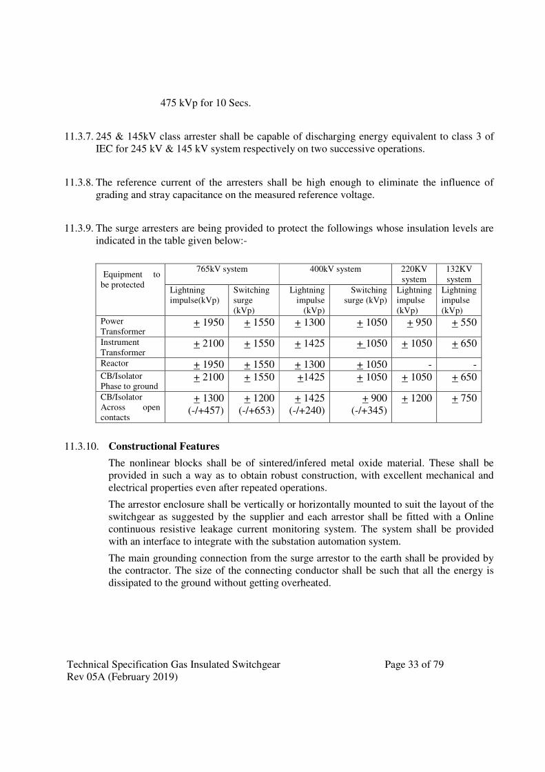
Technical Specification Gas Insulated Switchgear Page 33 of 79
Rev 05A (February 2019)
475 kVp for 10 Secs.
11.3.7. 245 & 145kV class arrester shall be capable of discharging energy equivalent to class 3 of
IEC for 245 kV & 145 kV system respectively on two successive operations.
11.3.8. The reference current of the arresters shall be high enough to eliminate the influence of
grading and stray capacitance on the measured reference voltage.
11.3.9. The surge arresters are being provided to protect the followings whose insulation levels are
indicated in the table given below:-
Equipment to
be protected
765kV system 400kV system 220KV
system
132KV
system
Lightning
impulse(kVp)
Switching
surge
(kVp)
Lightning
impulse
(kVp)
Switching
surge (kVp) Lightning
impulse
(kVp)
Lightning
impulse
(kVp)
Power
Transformer + 1950 + 1550 + 1300 + 1050 + 950 + 550
Instrument
Transformer + 2100 + 1550 + 1425 + 1050 + 1050 + 650
Reactor + 1950 + 1550 + 1300 + 1050 - - CB/Isolator
Phase to ground + 2100 + 1550 +1425 + 1050 + 1050 + 650
CB/Isolator
Across open
contacts
+ 1300
(-/+457)
+ 1200
(-/+653)
+ 1425
(-/+240)
+ 900
(-/+345)
+ 1200 + 750
11.3.10. Constructional Features
The nonlinear blocks shall be of sintered/infered metal oxide material. These shall be
provided in such a way as to obtain robust construction, with excellent mechanical and
electrical properties even after repeated operations.
The arrestor enclosure shall be vertically or horizontally mounted to suit the layout of the
switchgear as suggested by the supplier and each arrestor shall be fitted with a Online
continuous resistive leakage current monitoring system. The system shall be provided
with an interface to integrate with the substation automation system.
The main grounding connection from the surge arrestor to the earth shall be provided by
the contractor. The size of the connecting conductor shall be such that all the energy is
dissipated to the ground without getting overheated.
Technical Specification Gas Insulated Switchgear Page 34 of 79
Rev 05A (February 2019)
11.4. Tests
11.4.1. In accordance with the requirements stipulated, the surge arrestors shall conform to type
tests and shall be subjected to routine and acceptance tests in accordance with IEC
document.
11.4.2. Each metal oxide block shall be tested for the guaranteed specific energy capability in
addition to the routine/acceptance test as per IEC-60099.
11.4.3. Test on Surge Monitors: The Surge monitors shall also be connected in series with the test
specimens during residual voltage and current impulse withstand tests to verify efficacy of
the same. Additional routine/functional tests with one 100A and 10 kA current impulse,
(8/20 micro sec.) shall also be performed on the surge monitor.
11.5. Technical Parameters: Technical parameters are as per Annexure 5.
12. OUTDOOR SF6/Air BUSHINGS :
Outdoor bushings, for the connection of conventional external conductors to the SF6 metal
enclosed switchgear, shall be provided where specified and shall conform to the requirements
given in GTR.
The dimensional and clearance requirements for the metal enclosure will be the responsibility of
the manufacturer and their dimensions must be coordinated with the switchgear.
Bushings shall generally be in accordance with the requirements of IEC -60137.
12.1. Insulation levels and Creepage distances: All bushings shall have an impulse and power
frequency withstand level that is greater than or equal to the levels specified for GIS.
The creepage distance over the external surface of outdoor bushings shall not be less than 25
mm/kV and in highly polluted area it shall not be less than 31mm/kV (as per section- Project).
12.2. Bushing types and fitting: The details of bushing shall be as follows
SF6 to air Bushing shall be of Polymer / composite type and shall be robust and designed
for adequate cantilever strength to meet the requirement of seismic condition, substation
layout. The electrical and mechanical characteristics of bushings shall be in accordance with
IEC: 60137. All details of the bushing shall be submitted for approval and design review.
Polymer / composite insulator shall be seamless sheath of a silicone rubber compound. The
housing & weather sheds should have silicon content of minimum 30% by weight. It should
protect the bushing against environmental influences, external pollution and humidity. The
hollow silicone composite insulators shall comply with the requirements of the IEC
publications IEC 61462 and the relevant parts of IEC 62217. The design of the composite
insulators shall be tested and verified according to IEC 61462.

Technical Specification Gas Insulated Switchgear Page 35 of 79
Rev 05A (February 2019)
12.3. Mechanical forces on bushing terminals: Outdoor bushings must be capable of
withstanding cantilever forces due to weight of bus duct (GIB) on one side & AIS
conductor/Al tube on the other side and short circuit forces.
12.4. Type test reports as per applicable IEC including radio interference voltage (RIV) test shall
be submitted in line with the requirement as specified in section GTR for approval.
12.5. The technical parameters of Bushing are as per Annexure-6
13. GIS TO CABLE TERMINATION (If applicable)
13.1. This scope covers the supply, erection, commissioning of connection assembly of fluid-
filled or extruded cables to gas-insulated metal enclosed switchgear (GIS) as per IEC
62271-209
13.2. The XLPE cables shall be connected to GIS by the interfacing of XLPE cable sealing end to
GIS Cable termination enclosure.
13.3. The GIS to XLPE cable termination shall conform to IEC-62271-209.
13.4. The rating of XLPE cables for different voltages is specified in the Section project.
13.5. The limits of supply of gas-insulated metal-enclosed switchgear and the cable
termination shall be in accordance with IEC 62271-209.
13.6. Cable termination and cable connection enclosure shall be suitable for the requirements for
which it is designed. This interface section shall be designed in a manner which will allow
ease of operation and maintenance.
13.7. The SF6 cable end unit and connection support structure should be equipped with provisions
for isolating the cable sheath or pipe to permit cathodic protection of cable system.(see
IEC62271-209)
13.8. The provision shall be made for a removable link. The gap created when the link is removed
should have sufficient electric strength to withstand the switchgear high voltage site tests.
The contractor may suggest alternative arrangements to meet these requirements. The
corona rings/stress shields for the control of electrical field in the vicinity of the isolation
gap shall be provided by the GIS manufacturer.
13.9. All supporting structures for the SF6 bus-duct connections between the XLPE cable sealing
ends and the GIS shall be the scope of the contract. The supplier may specify alternative
connecting & supporting arrangements for approval of the Employer.
13.10. The opening for access shall be provided in each phase terminal enclosures as necessary to
permit removal of connectors to isolate the XLPE cables to allow carrying out the insulation
tests. The general arrangement drawing of interconnecting bus-duct from GIS bay module to
XLPE cable termination end shall also be submitted.
14. TRANSFORMER / REACTOR TERMINATION
Technical Specification Gas Insulated Switchgear Page 36 of 79
Rev 05A (February 2019)
14.1. TRANSFORMER / REACTOR Direct Connection with GIS (if applicable)
14.1.1. The scope covers the supply, erection and commissioning of connection assembly of Oil
filled Transformer to gas-insulated metal enclosed switchgear (GIS) as per IEC 62271-211.
14.1.2. The limits of supply of gas-insulated metal-enclosed switchgear and the direct
connection to oil filled transformer shall be in accordance with IEC 62271-211.
14.1.3. The transformer / reactor termination module enables a direct transition from the SF6 gas
insulation to the bushing of an oil-insulated transformer / reactor. For this purpose, the
transformer/reactor bushing must be oil-tight, gas-tight and pressure resistant. Any
temperature related movement and irregular setting of the switchgear’s or
transformer’s/reactor’s foundations are absorbed by the expansion fitting.
14.1.4. Terminal connection arrangement to connect GIS duct to bushing and duct mounting
arrangement details shall be submitted during detailed engineering for Employer’s approval
and for co-ordination with transformer and reactor supplier. Any modification suggested by
transformer and reactor supplier shall have to be carried out by the GIS supplier to facilitate
proper connection with the bushings of the transformer and reactors.
14.2. TRANSFORMER / REACTOR Connection with SF6/Air Bushing
14.2.1. The oil filled transformers and reactors are as shown in the substation SLD. The oil to air
bushings of the transformers and reactors shall be supplied by the respective
Transformer/Reactor supplier and the same shall be connected to the SF6 ducts thru air to
SF6 bushings to be provided under present scope.
14.3. In case of single phase Transformers/Reactors are being installed in the substation, HV&IV
auxiliary bus for the Transformer/Reactor bank for connecting spare unit shall be formed
inside the GIS hall as per the SLD furnished and as specified in Section project.
15. LOCAL CONTROL CUBICLE (LCC)
15.1. Functions
15.1.1. Each circuit-breaker bay shall be provided with a local control cubicle containing local
control switches and a mimic diagram for the operation and semaphore/indicating lamp for
status indication of the circuit-breaker and all associated isolators and earth switches
together with selector switches to prevent local and remote and supervisory controls being
in operation simultaneously.
15.1.2. Status indications in the LCC shall be semaphore type or LED type.
15.1.3. Closing of the circuit- breaker from the local control unit shall only be available when the
breaker is isolated for maintenance purposes. Circuit-breaker control position selector,
operating control switch and electrical emergency trip push button shall be installed in the
Local Control Cubicle. Circuit-breaker control from this position will be used under
Technical Specification Gas Insulated Switchgear Page 37 of 79
Rev 05A (February 2019)
maintenance and emergency conditions only. The emergency trip push buttons shall be
properly shrouded.
15.1.4. If Disconnector or earth switch is not in the fully open or closed position a "Control Circuit
Faulty" alarm shall be initiated, and electrical operation shall be blocked.
15.1.5. 20% spare terminals shall be provided in each LCC apart from terminals provided for the
termination and interconnection of all cabling associated with remote and supervisory
control, alarms, indications, protection and main power supply etc .
15.1.6. Where plugs and sockets connect control cabling between the local control cubicle and the
switchgear these shall not be interchanged. In plug in connector type cable arrangement,
min 2 cores of the cable with connected condition on both side up to the TB to be left
unused as spare.
15.1.7. Hydraulic/pneumatic and SF6 auxiliary equipment necessary for the correct functioning of
the circuit breaker, isolators and earth switches shall be located in a separate cubicle
compartment.
15.1.8. LCC shall be suitable for remote operation from substation automation system (SAS). Each
gas tight compartment shall be monitored individually per phase basis through SAS
15.2. Constructional features
15.2.1. Local Control cubicle shall be either mounted on the GIS with front access or free standing,
floor mounting type. It shall comprise structural frames completely enclosed with specially
selected smooth finished, cold rolled sheet steel of thickness not less than 3 mm for weight
bearing members of the panels such as base frame, front sheet and door frames, and 2.0mm
for sides, door, top and bottom portions. There shall be sufficient reinforcement to provide
level transportation and installation. Alternatively folded sheet panels of adequate thickness
and strength is also acceptable.
15.2.2. Access to all compartments shall be provided by doors. All fastenings shall be integral with
the panel or door and provision made for locking. Cubicles shall be well ventilated through
vermin-proof louvers(if required) having anti insect screen. All doors shall be gasketed all
around with suitably profiled Neoprene/EPDM/PU gaskets conforming to the provision of
IS 11149. However, XLPE gaskets can also be used for fixing protective glass doors.
15.2.3. For LCC panel of each feeder bay (i.e. line, transformer, and reactor etc.), Bus Coupler bay
and Bus Sectionalizer bay, separate AC/DC supply for power circuit of GIS switchgear shall
be provided, fed directly from ACDB/DCDB. The control DC supply (for control,
interlocking, signaling) shall be tapped from respective relay & protection panel. For LCC
panel illumination and heating purpose Loop in Loop out AC Supply can be provided.
15.2.4. Each panel shall be provided with necessary arrangements for receiving, distributing and
isolating of DC and AC supplies for various control, signaling, lighting and space heater
circuits. The incoming and sub-circuits shall be separately provided with Fuses/MCBs. All
fuses shall be HRC cartridge type conforming to IS: 13703 mounted on plug-in type fuse

Technical Specification Gas Insulated Switchgear Page 38 of 79
Rev 05A (February 2019)
bases. The short time fuse rating of Fuses shall be not less than 9 KA. Fuse carrier base
shall have imprints of the fuse 'rating' and 'voltage'.
15.2.5. Each LCC Panel shall be provided with the following
1. Plug Point: 240V, Single phase 50Hz, AC socket with switch suitable to accept 5/15
Amps pin round standard Indian plug, shall be provided in the interior of each cubicle
with ON-OFF switch.
2. Interior Lighting: Each panel shall be provided with a door-operated LED lighting
fixture rated for 240 Volts, single phase, 50 Hz supply for the interior illumination of
the panel controlled by the respective panel door switch.
3. Space Heater: Each panel shall be provided with a thermostatically connected space
heater rated for 240V, single phase, 50 Hz AC supply for the internal heating of the
panel to prevent condensation of moisture. The fittings shall be complete with switch
unit.
15.2.6. Operating mechanisms, auxiliary switches and associated relays, control switches, control
cable terminations, and other ancillary equipment shall be accommodated in sheet steel
vermin proof cubicles.
15.2.7. The arrangement of equipment within cubicles shall be such that access for maintenance or
removal of any item shall be possible with the minimum disturbance of associated
apparatus. All the control switches shall be internal i.e. installed behind a lockable glass
door, that allows a complete view of the annunciator and mimic diagram when the LCC
door is closed. Necessary protection shall be provided to avoid inadvertent operation of
control switches.
15.2.8. An interlocking scheme shall be provided that takes into account the following basic
requirements.
• To safeguard maintenance personnel who may be working on one section of the
equipment with other sections live.
• prevent incorrect switching sequences that could lead to a hazardous situation to
plant, equipment and personnel.
15.2.9. Electrical bolt interlocks shall be energized only when the operating handle of the
mechanism is brought to the working position. Visible indication shall be provided to
show whether the mechanism is locked or free. Means, normally padlocked/handle lock,
shall be provided whereby the bolt can be operated in the emergency of a failure of
interlock supplies.
15.2.10. Where key interlocking is employed tripping of the circuit breaker shall not occur if any
attempt is made to remove the trapped key from the mechanism. Any local emergency-
tripping device shall be kept separate and distinct from the key interlocking.
15.2.11. Disconnecting switches shall be so interlocked that they cannot be operated unless the
associated circuit-breaker is open except that where double bus bar arrangements are
specified, on-load transfer of feeder circuits from one bus bar to another shall be made
Technical Specification Gas Insulated Switchgear Page 39 of 79
Rev 05A (February 2019)
possible by interlocks which ensure that the associated bus coupler and its isolators are
closed.
15.2.12. Bus coupler circuit breaker shall be interlocked so that it shall not be possible to open a
bus coupler circuit breaker while on load change over on that side of the breaker is in
progress.-
15.2.13. All isolating devices shall be interlocked with associated circuit-breakers and isolators in
the same station so that it shall not be possible to make or break current on an isolating
device unless a parallel circuit in that station is already closed.
15.3. Cabling between LCC Panel and GIS equipment
15.3.1. The unarmored screen cable shall be of 1.1kV grade, multi core, annealed copper conductor,
Tinned copper braided screen (approx. 85% coverage).
15.3.2. The core insulation and outer sheath of cable shall be of halogen-free special polymer.
15.3.3. The cable shall be flame-retardant, flexible, abrasion-and wear-resistant.
15.3.4. The size of core shall not be less than 2.5 sq. mm for instrument transformers and 1.5 sq.
mm for other control cable.
15.3.5. Prefabricated cables with heavy duty multi-point plug-in connections on GIS end shall be
provided.
15.3.6. All instrument transformer connections shall be hard wired to terminal block via ring type
connection.
16. GIS BUILDING
16.1. The buildings shall house each voltage class Gas Insulated Switchgear (GIS) and other
associated equipment inside each of the GIS buildings. GIS building(s) shall be
constructed for the specified number of bays/diameters as per section project.
16.2. For finalizing the dimensions of GIS building the requirement of Turning radius to rotate
the largest removable component for assembly/disassembly shall be taken in to
consideration.
16.3. Wherever GIS Building of already exists, then the existing GIS Building(s) for respective
voltage class shall be suitably extended keeping the width of the building same to
accommodate the number of bays/diameters as specified in the Section Project/BPS.
16.4. The contractor shall submit the design & construction proposal of the building along with
necessary information, data, and drawings during the detailed engineering according to
the complete requirements.
16.5. The area for GIS Building(s) is indicated in the BPS. The area given is for reference only
and may vary according to the requirement of the equipment to be installed inside. The
Technical Specification Gas Insulated Switchgear Page 40 of 79
Rev 05A (February 2019)
contractor shall finalize the dimensions according to the equipment offered by them
providing enough space & access for erection, operation and maintenance.
16.6. The contractor shall place their panels i.e. Bay level units, bay mimic, relay and
protection panels, RTCC panels, Communication panels etc. in a separate Relay Panel
Room in the GIS building. The size of the room shall be such that all the panels for the
bays/ diameters as per clause 16.1 shall be accommodated in the above room. The panel
room shall be air-conditioned. Further, the temperature of the room shall be monitored
through substation automation system by providing necessary temperature transducers.
17. ELECTRIC OVERHEAD CRANE :
17.1. Two EOT Cranes for 765 kV GIS hall and One EOT cranes for 400 kV GIS hall of
suitable capacity shall be provided for erection & maintenance of largest/heaviest GIS
component/assembly. The crane shall consist of all special requirements for erection &
maintenance of GIS equipment.
17.2. The capacity of the crane shall be sized to lift the heaviest GIS switchgear component.
17.3. The Crane shall be used for the erection and maintenance of the GIS switchgear
components installed in the GIS switchgear room. On completion of erection of the
switchgear, the Contractor shall completely service the crane before the Taking Over
Certificate is issued.
17.4. Crane hook approaches shall be of the minimum possible dimensions to ensure maximum
coverage of the GIS building area.
17.5. The crane(s) shall be capable of lifting and accurately positioning all loads ranging from
full crane rated capacity to at least 10% rated capacity.
17.6. Crane shall be designed for operation under following variable speeds through VVVF
drives at full load :
Hoisting: 0.3 – 3 Meters per Minute
Cross Travel: 1.6 – 16 Meters per Minute
Long Travel: 2.0 – 20 Meters per Minute
17.7. The electric overhead cranes shall be provided with walkways, platforms. shall be
provided along the bridge rails and on the crab of EOT crane to facilitate
cleaning/maintenance of the crane and to give access to the GIS room high bay lighting
and ventilation duct and grilles.
17.8. The platform and walkways shall be designed to support any weight to be imposed upon
them during crane overhaul.
17.9. An access platform shall be provided together with a guarded ladder to allow access to
the bridge rails.
17.10. The crane shall be provided with pendant control and RF control.
Technical Specification Gas Insulated Switchgear Page 41 of 79
Rev 05A (February 2019)
17.11. Contractor shall submit the capacity calculation of crane for GIS hall considering a factor
of safety of rope as at least 5.
17.12. The Capacity of Cranes to be provided for GIS Hall shall confirm following.
a) The crane for 765kV GIS hall shall have capacity of minimum 12.5T safe working load
& minimum hook height of crane has shall be 10.0 meters or as per actual requirement
whichever is higher.
b) The crane for 400kV GIS hall shall have capacity of minimum 6T safe working load &
minimum hook height of crane have shall be 9.0 meters or as per actual requirement
whichever is higher.
c) The crane for 220kV GIS/132kV GIS shall have capacity of minimum 5T safe working
load & minimum hook height of crane have shall be 8.0 meters or as per actual
requirement whichever is higher.
17.13. In case the GIS hall is to be extended, the scope of work also involves extension of EOT
crane girders and all necessary Electrical & Mechanical accessories to facilitate
movement of existing EOT crane in the extended portion of GIS hall. Cost of the same
shall be deemed to be covered in the building cost.
17.14. The following tests shall be carried out on EOT Crane.
1. The crane shall be tested at manufacturer work under full load and 25 percent
overload of hoisting and cross transverse motions as a routine test.
2. Further the following tests may be done at site after installation of the crane at site
a. Check all the accessories for proper function
b. No load test
c. Load test as per site conditions
18. SEISMIC DESIGN CRITERIA:
18.1. The equipment shall be designed for operation in seismic zone for earthquake resistance.
The seismic loads are due to the horizontal and vertical acceleration which may be assumed
to act on concurrently. Seismic Qualification requirements shall be as per IEC 62271-207
for the design of equipment. The equipment along with its parts shall be strong enough and
sufficiently well connected to resist total operating stresses resulting from the forces in
normal operation, but in case of abnormal condition shall also resist with forces
superimposed due to earthquakes. Test Report/Analysis Report should be furnished.
19. DESIGN REVIEW
19.1. Design reviews shall be conducted by Employer; however the entire responsibility of design
shall be with the supplier.
19.2. Employer may also visit to the supplier’s works to inspect design, manufacturing and test
facilities.

Technical Specification Gas Insulated Switchgear Page 42 of 79
Rev 05A (February 2019)
19.3. The design review will commence after placement of award with the successful contractor
and shall be finalized before commencement of manufacturing activity. These design
reviews shall be carried out in detail to the specific design with reference of the GIS under
the scope of this specification. Employer reserve the right to waive off the design review
during detailed engineering.
19.4. The design review shall be conducted generally following the, “User Guide for the
application of Gas Insulator Switchgear (GIS) rated voltage of 72.5kV and above” – CIGRE
report No. 125 prepared by CIGRE Working Group 23.10.
19.5. The manufacturer will be required to demonstrate the use of adequate safety margins for
thermal, mechanical, dielectric, insulation coordination and vibration etc. design to take into
the account the uncertainties of his design and manufacturing processes.
19.6. The scope of such a design review shall at least include the following:
1. Dielectric Stress of Solid Insulation like Gas Barrier, support
insulator etc.
2. Dielectric stress of SF6 Gas Volume.
3. Mechanical strength of enclosure, expansion joints etc.
4. Criteria for providing expansion joint.
5. Sealing system
6. Insulation coordination
7. Thermal stress and resulting increase in gas pressure during short
circuit condition.
8. Earthing of enclosure w.r.t circulating current.
9. Seismic design, as per IEC 62271-207
10. Circuit Breaker.
11. Isolator and Earth switch.
12. Voltage transformer.
13. Current Transformer.
14. Surge Arrester.
15. Bushing.
16. Ducting.
17. Corrosion protection.
18. Electrical and physical Interfaces with substation.
19. Testing capabilities.
20. Inspection and test plan.
21. Transport and storage.
22. Maintainability.
23. Site Test.
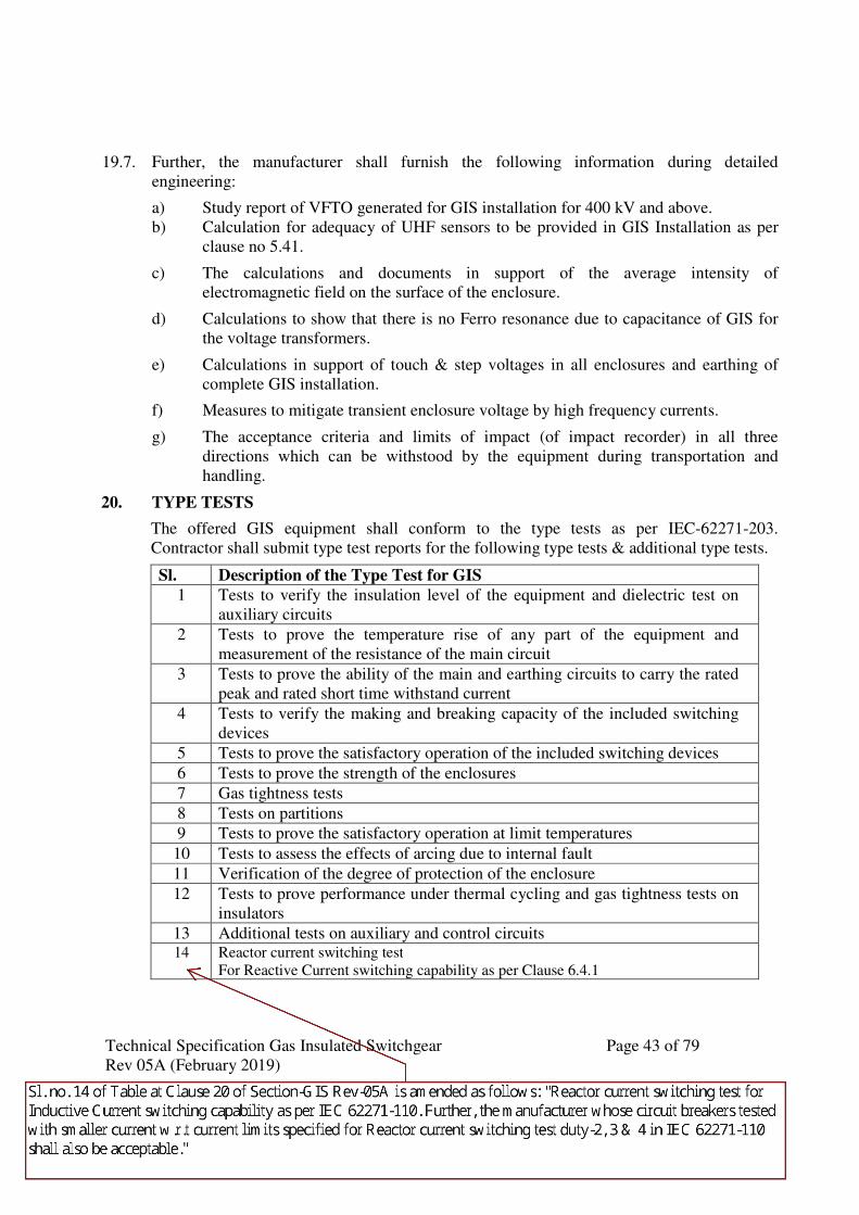
Technical Specification Gas Insulated Switchgear Page 43 of 79
Rev 05A (February 2019)
19.7. Further, the manufacturer shall furnish the following information during detailed
engineering:
a) Study report of VFTO generated for GIS installation for 400 kV and above.
b) Calculation for adequacy of UHF sensors to be provided in GIS Installation as per
clause no 5.41.
c) The calculations and documents in support of the average intensity of
electromagnetic field on the surface of the enclosure.
d) Calculations to show that there is no Ferro resonance due to capacitance of GIS for
the voltage transformers.
e) Calculations in support of touch & step voltages in all enclosures and earthing of
complete GIS installation.
f) Measures to mitigate transient enclosure voltage by high frequency currents.
g) The acceptance criteria and limits of impact (of impact recorder) in all three
directions which can be withstood by the equipment during transportation and
handling.
20. TYPE TESTS
The offered GIS equipment shall conform to the type tests as per IEC-62271-203.
Contractor shall submit type test reports for the following type tests & additional type tests.
Sl. Description of the Type Test for GIS
1 Tests to verify the insulation level of the equipment and dielectric test on
auxiliary circuits
2 Tests to prove the temperature rise of any part of the equipment and
measurement of the resistance of the main circuit
3 Tests to prove the ability of the main and earthing circuits to carry the rated
peak and rated short time withstand current
4 Tests to verify the making and breaking capacity of the included switching
devices
5 Tests to prove the satisfactory operation of the included switching devices
6 Tests to prove the strength of the enclosures
7 Gas tightness tests
8 Tests on partitions
9 Tests to prove the satisfactory operation at limit temperatures
10 Tests to assess the effects of arcing due to internal fault
11 Verification of the degree of protection of the enclosure
12 Tests to prove performance under thermal cycling and gas tightness tests on
insulators
13 Additional tests on auxiliary and control circuits 14 Reactor current switching test
For Reactive Current switching capability as per Clause 6.4.1
JAIK
Callout
Sl. no. 14 of Table at Clause 20 of Section-GIS Rev-05A is amended as follows: "Reactor current switching test for Inductive Current switching capability as per IEC 62271-110. Further, the manufacturer whose circuit breakers tested with smaller current w.r.t current limits specified for Reactor current switching test duty-2, 3 & 4 in IEC 62271-110 shall also be acceptable."
Technical Specification Gas Insulated Switchgear Page 44 of 79
Rev 05A (February 2019)
15 Test to demonstrate the Power frequency withstand capability of breaker in open
condition at lock out pressure.
16 Electromagnetic compatibility tests (if applicable)
17 Radio inference voltage tests
The test reports of the above type tests for GIS (including type test report on Circuit breaker,
Disconnect Switch, Grounding switches, Current and Voltage transformers as per relevant
IEC and type tests of SF6/Air & Oil bushing as per IEC 60137 shall be submitted for
approval as per Section- GTR, Technical Specification.
21. MISCLLENOUS
21.1. Painting of enclosure: All enclosures shall be painted externally as per manufacturer’s
painting procedure.
21.2. Heaters: Wherever required, heaters shall be provided to prevent moisture condensation
inside various Marshaling boxes.
21.3. Identification & rating plate
Each bay shall have a nameplate showing
a) Each module will have its own Identification & rating plate. The rating plate marking
for each individual equipment like Circuit breaker, Disconnect Switch Grounding
switches, Current transformer, Voltage transformers, Surge arrester etc shall be as
per their relevant IEC.
b) A schematic diagram indicating their relative locations.
22. TRANSPORT OF EQUIPMENT TO SITE
The contractor shall be responsible for the loading, transport, handling and offloading of all
equipment and materials from the place of manufacture or supply to site. The contractor
shall be responsible to select and verify the route, mode of transportation and make all
necessary arrangement with the appropriate authorities as well as determining any transport
restrictions and regulations imposed by the government and other local authorities. All
transport packages containing critical units viz Circuit breakers and Voltage transformers
shall be provided with sufficient number of impact recorders (on returnable basis) during
transportation to measure the magnitude and duration of the impact in all three directions.
In case of electronic impact recorder, the recording shall commence in the factory and must
continue till the units reach site. The data of electronic impact recorders shall be
downloaded at site and a soft copy of it shall be handed over to Engineer – in –charge.
Further, contractor shall communicate the interpretation of the data within three weeks.
Technical Specification Gas Insulated Switchgear Page 45 of 79
Rev 05A (February 2019)
23. PACKING, STORAGE AND UNPACKING
23.1. All the equipment shall be carefully packed for transport by sea, rail and road in such a
manner that it is protected against the climatic conditions and the variations in such
conditions that will be encountered enroute from the manufacturer’s works to the site.
23.2. The SF6 metal clad equipment shall be shipped in the largest factory assembled units that
the transport and loading limitations and handling facilities on site will allow to reduce the
erection and installation work on site to a minimum.
23.3. Where possible all items of equipment or factory assembled units shall be boxed in
substantial crates or containers to facilitate handling in a safe and secure manner. Should
the units be considered too large for packing in crates, they shall be suitably lagged and
protected to prevent damage to any part, particularly small projections, during transport and
handling. Special lugs or protective supports shall be provided for lifting to prevent slings
and other lifting equipment from causing damage. Each crate, container or shipping unit
shall be marked clearly on the outside to show where the weight is bearing and the correct
position for the slings.
23.4. Each individual piece to be shipped, whether crate, container or large unit, shall be marked
with a notation of the part or parts contained therein.
23.5. Special precautions shall be taken to protect any parts containing electrical insulation
against the ingress of moisture. This applies particularly to the metal clad equipment of
which each gas section shall be sealed and pressurized prior to shipping. Either dry
nitrogen/air or dry SF6 gas shall be used and the pressure shall be such as to ensure that,
allowing for reasonable leakage, it will always be greater than the atmospheric pressure for
all variations in ambient temperature and the atmospheric pressure encountered during
shipment to site and calculating the pressure to which the sections shall be filled to ensure
positive pressure at all times during shipment.
23.6. Blanking plates, caps, seals, etc., necessary for sealing the gas sections during shipment to
site which may on later stage necessarly be used during repair and maintenanace shall
remain the property of POWERGRID. Balance blanking plates, caps, seals, etc shall be
returnable to the contractor. If considered necessary, blanking plates or other sealing devices
shall be provided with facilities for measuring the gas pressure and recharging at any time
during the transport period. Any seals, gaskets, ‘O’ rings, etc. that may be used as part of
the arrangement for sealing off gas sections for shipment of site, shall not be used in the
final installation of the equipment at site. Identification numbers shall be stamped into the
blanking plates, etc., and on the switchgear equipment to which they are fitted so that they
can easily be identified and refitted should it ever be necessary to ship sections of the
switchgear back to the manufacturer’s works for repair.
23.7. Valves and other gas couplings associated with the switchgear gas systems shall be
adequately protected against damage from any bumps or physical blows. They shall also be
capped to prevent ingress of dirt or moisture or damage to any coupling, pipes, threads or
special fittings. Any explosion vents and other pressure relief devices, shall be suitably
Technical Specification Gas Insulated Switchgear Page 46 of 79
Rev 05A (February 2019)
sealed and protected to prevent accidental exposure of the sealed sections during shipment
to site.
23.8. For bus ducts involving male and female joints of the current carrying conductor, the same
shall be transported in disassembled condition to avoid any damage during transit. All bright
parts liable to rust shall receive a coat of anti rusting composition and shall be suitably
protected.
23.9. The contractor shall ensure that during the period between arrival at site and erection, all
materials and parts of the contract works are suitably stored in such approved manner as to
prevent damage by weather, corrosion, insects, vermin or fungal growth. The scope of
providing the necessary protection, storing on raised platform, as required etc. is included in
the works to be performed by the contractor. Cost of the raised platform for temporary
storage is deemed to be included in overall cost. The raised platform needs to be made ready
before arrival of GIS equipment at site. The contractor may use the available storage areas at
site with permission of site in charge.
23.10. The equipment shall be unpacked immediately before Installation. They shall not be left
lying unnecessarily in open crates or containers. Special precautions shall be taken when
gas sections which have been sealed and pressurized for shipping are opened up to reduce
the ingress of dirt and atmospheric moisture to a minimum. Whenever possible this shall
only be done immediately prior to installation and if any section is to be left outside for any
length of time after being opened, it shall be resealed and pressurized with either dry
nitrogen or SF6 gas until required.
23.11. For the purpose of release of payment linked to receipt and physical verification in case of
GIS equipment it shall mean random opening and physical verification of one number of
packing unit of each type of main equipment (i.e. GIS CB/ISO/ES/PT/LA etc.) for each
voltage level. Thereafter proper re-packing of the GIS unit shall be ensured as per
manufacturer recommendation.
24. INSTALLATION OF GIS
24.1. Civil works of GIS Hall shall be completed in all respects before taking up the installation
and it shall be ensured that Ventilation System is operational and all dust and dirt in the hall
are removed. The GIS hall needs to be in positive pressure before starting Installation.
24.2. The installation area shall be secured against entry of unauthorized personnel. Only certified
manufacturer’s engineer and supervisor shall undertake the erection works. Engineers and
supervisors of the manufacturer shall submit authorization and competency certificate to
POWERGRID.
24.3. Un-packaging of GIS modules shall be done outside the GIS hall and in no case module to
be taken inside GIS hall with packing.
24.4. All assembly work shall be done by qualified personnel only who are to be identified and
list submitted to POWERGRID site before starting of erection work.

Technical Specification Gas Insulated Switchgear Page 47 of 79
Rev 05A (February 2019)
24.5. Assembly drawing for GIS erection for the section under progress shall be available and
displayed in GIS hall at the time of erection work.
24.6. Working personnel shall clean their shoes or apply covers on shoes before entering the
immediate working area. The working clothes of authorized personnel shall be made of non-
fluffy material.
24.7. GIS hall door shall have automatic close facility after entry of personnel to avoid dust and
moisture entry. Walls and ceiling shall be in a condition so that neither dirt nor plaster might
fall or rub off and formation of condensation water in ceiling shall be prevented under any
circumstances.
24.8. Floor in the installation area shall have a firm surface and shall be kept dust free with a
vacuum cleaner. Vacuum cleaning to be done on regular basis.
24.9. Only T&P and consumables required for GIS erection shall be kept in GIS during erection.
24.10. In case of outdoor installation of GIS or of GIS components open gas compartments shall be
protected from dust and moisture ingress (by tarpaulin covers/protective enclosure/chamber
etc)
24.11. Bus duct exits in the GIS hall’s wall shall be kept covered by suitable means until
permanent cover is provided after installation of bus ducts.
24.12. Maintenance room (as a part of LCR room) shall be constructed for carrying out repair
works/ small part assembly. All excess material (not required for immediate installation
works) test equipment and tools and tackles to be stored separately from GIS hall in this
room for rework.
24.13. Erection agency shall submit method statement and make available formats for checking
during each stage of hall preparation, assembly process and final checks to be approved by
POWERGRID site before start of erection. Shock recorder down loaded data and analysis
shall be submitted preferably before commencement of erection work. In case of violation
of shock limits, expert form manufacturer shall visit and do the joint internal inspection and
shall submit analysis report before giving clearance for erection. If required the module shall
be taken back to factory for further analysis and testing.
24.14. Cleaning is of utmost importance and hence before assembly, all the loose metal parts,
subassemblies and all contact & sealing surfaces shall be cleaned before installation.
Cleaning shall be carried out with specified cleaning agents of the manufacturer, in no
condition water is to be used except for external surfaces. Further, prior to opening of gas
compartment, the same shall be thoroughly cleaned externally. The vacuum cleaning of the
installation area shall also be done specially the immediate vicinity of the flanges to be
connected.
24.15. All Civil Work inside building including internal cable trench shall be completed before
GIS installation.
Technical Specification Gas Insulated Switchgear Page 48 of 79
Rev 05A (February 2019)
24.16. Installation of flanges shall be done immediately after removal of transport covers.
Transport covers, O-rings and other packing material of GIS shall be taken out immediately
after removal.
24.17. O Rings shall be properly stored and taken out only before installation. O Rings are also to
be cleaned before use with manufacturer authorized cleaning agent.
24.18. At all points of time during installation authorized personnel shall use suitable gloves to
avoid contamination.
24.19. Cable termination work shall commence only after completion of GIS equipment erection,
as during GIS installation period laying and termination of cables interferes with the GIS
erection work and affects cleanliness.
24.20. Approved Field Quality Plan shall be followed during site work.
25. ON SITE TESTING
After the GIS Switchgear has been fully installed at site and SF6 gas filled at rated filling
density, the complete assembly shall be subjected to the site tests as per IEC-62271-203 and
POWERGRID Asset Management Controlled Document No: D-3-01-09-01-01. After the
above, Special Dielectric test (Switching Impulse test) shall be conducted for 765 kV GIS
with the test voltages specified below:-
25.1. Application of Power Frequency voltage test for duration of 1 minute with the value 760 kV
(r.m.s.) as per IEC 62271-203.
25.2. Directly after the above test at 25.1, Switching impulse test with three impulses of each
polarity and with the value 1240 kVp(80 % of the rated switching Impulse withstand level)
as per IEC 62271-203.
25.3. In case of a disruptive discharge in the gas as outlined in clause no: C.6.2.2 Procedure b),
Annexure-C of IEC 62271-203 during the AC voltage test and a repeat test is performed
due to this failure, then the repeat test shall be carried out at Specified voltage.
25.4. In case of a disruptive discharge in the gas as outlined in clause no: C.6.2.2 Procedure b)
Annexure-C of IEC 62271-203 during Oscillating Switching Impulse Test and a repeat test
is performed due to this failure then the repeat test shall be carried out at a value equal to 90
% of the rated switching Impulse withstand level.
25.5. Method statement/ procedure of ON SITE high voltage testing, PD measurement and
Switching Impulse test shall be submitted by contractor in advance.
26. MANDATORY SPARE
Design, engineering, manufacture, testing, supply on FOR destination site basis including transportation & insurance, storage at site of Mandatory spares for the GIS(As specified in BPS). Standard list of Mandatory Spares is as per Annexure-10
1653024
Text Box
Technical Specification Gas Insulated Switchgear Page 49 of 79
Rev 05A (February 2019)
27. TESTING & MAINTENACE EQUIPMENT
Testing & Maintenance equipment shall be offered, as per relevant schedule of BPS.
27.1. SF6 Gas leakage detector.
The detector shall be portable, battery operated, hand held type and having a minimum SF6
gas leakage sensitivity of 5gm/year. The sensor shall be connected through a flexible wand
for easy accessibility to joints, seals and couplings in GIS equipment and provided with a
protection filter. The equipment shall have on/off switch & suitable indicating lamps/LEDs,
variable pitch audible signal for leakage indication. The equipment shall have automatic
zeroing of background signals suitable for detecting SF6 gas leakage in charged switchyard.
The test kit shall be compatible for EMI/EMC environment as per IEC 1000.
27.2. Gas filling and evacuating plant : (Gas Processing unit)
• The plant necessary for filling and evacuating the SF6 gas in the switchgear shall be
supplied to enable any maintenance work to be carried out. This shall include all the
necessary gas cylinders for temporarily storing the evacuated SF6 gas. The capacity of the
temporary storage facilities shall at least be sufficient for storing the maximum quantity of
gas that could be removed from at least one phase of one complete bay (switchgear and
associated equipment).
• Where any item of the filling and evacuating plant is of such a weight that it cannot easily be
carried by maintenance personnel, it shall be provided with lifting hooks for lifting and
moving with the overhead cranes.
• The minimum capacity parameters of evacuation plant will be as under :
Oil Free Suction (Recovery) Pump: 30 M3/Hour
Compressor (Two Stage): 15 M3/Hour
Oil Free Vacuum Pump: 100 M3/Hour
• The evacuation equipment shall be provided with all the necessary pipes, couplings, flexible
tubes and valves for coupling up to the switchgear for filling or evacuating all the gases.
Details of the filling and evacuating plant that will be supplied, as well as the description of
the filling and evacuating procedures shall be furnished
27.3. SF6 gas analyzer:
The SF6 gas analyser should be of portable type and instruments shall have following
features:
a. In-built calibration facility.
b. Sensitivity of the equipment shall not be affected by any atmospheric conditions like dust,
humidity, heat, wind etc.
Technical Specification Gas Insulated Switchgear Page 50 of 79
Rev 05A (February 2019)
c. Equipment shall work on zero gas loss principle i.e. gas should be pumped back to the
compartment after measurement without any exposure to the atmosphere.
d. Equipment shall be supplied with suitable regulator which can be used to connect SF6
cylinder if required.
e. Following acidic/impurities products should be detected as per IEC 60480 and IEC 60376
i) SF6 purity – Range: 0-100 % & Accuracy: +/- 2 deg
ii) Dew point - Range : -60 to +20 deg C & Accuracy: +/- 4 deg C
iii) SO2 - Range : 0-150 ppm & Accuracy : +/- 2 %
iv) HF - Range : 0-10ppm & Accuracy : +/- 10 %
f. Instrument should work on AC source as well as on rechargeable battery
g. Input pressure: upto 10 bar
h. It should be housed in a robust IP67 case with wheels
27.4. Portable Partial Discharge(PD) monitoring system (Shall generally applicable for
220kV&132 kV)
• The equipment shall be used for detecting different types of defects in Gas Insulated
Stations (GIS) such as Particles, Loose shields and Partial Discharges as well as for
detection of Partial discharges in other types of equipment such as Cable Joints, CTs and
PTs.
• It shall be capable for measuring PD in charged GIS environment as EHV which shall have
bandwidth in order of 100 MHz–2GHz with possibility to select a wide range of
intermediate bandwidths for best measurement results. The principle of operation shall be
based on UHF principle of detection. The instrument should also be able to detect partial
discharges in cable joints and terminations.
• Detection and measurement of PD and bouncing particles shall be displayed on built in large
LCD display and the measurement shall be stored in the instrument and further
downloadable to a PC for further analysis to locate actual source of PD such as free
conducting particles, floating components, voids in spacers, particle on spacer surfaces etc.
Software for display and diagnosis of PD signals and an expert software system for accurate
interpretation of cause of PD shall also be supplied and installed by the contractor.
• The equipment shall meet the following requirements
1. Measurement shall be possible in noisy environment.
2. Stable reading shall be possible in presence of vibrations within complex GIS
assemblies, which can produce signals similar to PD.
3. Equipment should have necessary synchronizing circuits to obtain PD correlation
with power cycle and power frequency.
4. The equipment shall be battery operated with built-in-battery charger. It shall also
be suitable for 230V AC/50 Hz input.
Technical Specification Gas Insulated Switchgear Page 51 of 79
Rev 05A (February 2019)
5. Measurement shall be possible in the charged switchyard in the presence of
EMI/EMC. Supplier should have supplied similar detector for GIS application to
other utilities. Performance certificate and the list of users shall be supplied along
with the offer.
6. Instrument shall be supplied with standard accessories i.e., re-locatable sensors with
mounting arrangements, connecting cables (duly screened) to sensors, Lap-top PC,
diagnostic and expert interpretation software, carrying case, rechargeable battery
pack with charger suitable for 230V AC, 50Hz supply connecting cables (duly
screened) to view in storage.
7. The function of software shall be covering the following:
a) Data recording, storage and retrieval in computer
b) Data base analysis
c) Template analysis for easy location of fault inside the GIS
d) Evaluation of PD measurement i.e, Amplitude, Phase Synchronization etc.
e) Evaluation of bouncing/loose particles with flight time and estimation on size of
particle.
f) Expert software system for accurate interpretation of cause of PD.
g) Report generation.
8. To prove the suitability in charged switchyard condition, practical demonstration
shall be conducted before acceptance.
9. Supplier shall have “Adequate after sales service” facility in India and shall provide
the document in support of this.
10. Necessary training may be accorded to personnel to make use of the kit for locating
PD sources inside the GIS
11. Instrument shall be robust and conform to relevant standard.
• Calibration: The UHF Couplers have to be first calibrated as per CIGRE Document No.
654 as part of factory acceptance tests to guarantee detection sensitivity of 5pC or better.
The GIS of same design shall be used as test specimen during the coupler calibration.
The pulse injection level determined through above factory calibration tests shall only be
used as reference for site sensitivity checks during commissioning of PDM system. The
data sheet/frequency response characteristics shall be submitted for reference.
• Pulse generator, same type as that of used during factory testing for UHF sensor
sensitivity test shall be supplied as a standard accessory.
27.5. Online Partial Discharge Monitoring System (Applicable for 765kV& 400 kV GIS)
• GIS equipment shall be designed so as to minimize partial discharge or other electrical
discharge. A state-of-the art Partial Discharge Monitoring system shall be provided to
monitor the entire GIS installation.
Technical Specification Gas Insulated Switchgear Page 52 of 79
Rev 05A (February 2019)
• An on-line continuous Partial Discharge Monitoring (PDM) system shall be designed to
provide an automatic facility for the simultaneous collection of PD data at multiple points
on the GIS & its associated GIB ducts and Voltage Transformers adopting UHF
technique. The data stored shall provide a historical record of the progress of PD sources
and shall identify the areas of maximum activity.
• On-line continuous Partial Discharge Monitoring (PDM) system shall be capable for
measuring PD in charged GIS environment as EHV which shall have bandwidth in order
of 100 MHz–2GHz with possibility to select a wide range of intermediate bandwidths for
best measurement results. The principle of operation shall be based on UHF principle of
detection.
• The scope shall cover Engineering, supply, installation, testing and commissioning of
partial discharge continuous monitoring system, with all necessary auxiliaries and
accessories to make a complete system as per technical specification, including site
demonstration of successful operation. Any items/accessories necessary to make the
system fully functional for the trouble free online PD monitoring of complete GIS
installation shall be considered as included in the scope.
The PDM system shall be provided with all its hardware and software, with readily
interfacing to the UHF PD couplers installed in the GIS of present bays and future bays
as shown in SLD plus 20% additional as extra. Details of this shall be submitted during
engineering stage for approval.
The integration of UHF PD coupler in future GIS bays shall be done in respective
package. The number of UHF PD coupler for future bays shall be decided based on GIS
layout finalized under present scope (considering present GIS equipment with future
provision).
The PD Monitoring PC Work Station shall be housed in a lockable cabinet with duplicate
keys and shall be located in the control room of the GIS substation. Workstation PCs
shall be pre-loaded with all necessary Hardware & Software. The PCs shall have each
Combo drive & Retrievable disk drive (1 TB), Ethernet port 100Mbps, printer. The
workstation PC shall be powered by suitable dedicated UPS and same is included in the
present scope.
• Design of on-line PDM System
1. The technical proposal for PDM system along with detailed design documentation
shall be submitted for EMPLOYER’S approval during engineering stage.
2. To guarantee that sufficient coverage is available for complete GIS installation to
monitor PD activity all design details shall be submitted as part of the above for
review.
3. The sensitivity of the offered system shall be in accordance with CIGRE Document
No. 654 that will be verified as part of site sensitivity tests.
Technical Specification Gas Insulated Switchgear Page 53 of 79
Rev 05A (February 2019)
4. UHF attenuation data of GIS shall be submitted for the switching devices, spacers,
bends etc.
5. The signal attenuation level of co-axial cable per meter length and justification for
the length of cable connection between the couplers and detector units shall be
furnished.
6. The overall sensitivity of PD detection system shall take into account the spacing
between couplers and the associated cabling, filters, amplifiers, etc.
7. The Sub-station GIS layout as a separate drawing indicating position of spacers,
spread over of PD sensors with distance, sensor identification, the detector unit
identification etc. shall be submitted during engineering stage for approval.
8. The PD sensors shall be identified / coordinated with the corresponding detector unit
etc. with proper identification labeling and indicated in the substation PDM SLD.
9. Internal arrangement/wiring diagram is to be submitted for detector units/control
cabinet etc. All internal items are to be identified / labeled to facilitate
troubleshooting.
10. Supply requirement (AC & DC) to be specified for the complete monitoring system.
11. Power supply to PDM PC shall have protection against surges, overload and short
circuit. A dedicated on-line UPS system shall also be provided as a backup during
supply interruption, to ensure trouble-free & reliable running of the PDM System for
a minimum of 15 minutes duration. Ratings of UPS shall be proposed for the
approval of EMPLOYER’S. The UPS shall have enough capacity to initiate a ‘safe’
shut down of the PDM PC and the peripherals after this 15-minute period if normal
supply fails to resume. The PDM PCs shall restart automatically on resumption of
normal supply. The UPS shall not generate spikes during changeover of supply. UPS
shall automatically give indication / alarm when it requires battery replacement.
Potential Free Contacts shall be generated to signal these events. These contacts shall
be wired out to Annunciation / Monitoring systems. Alternately, inverter of suitable
capacity is also acceptable. Critical Process and Status alarms of the PDM system
shall be displayed.
12. PDM System shall be provided with a user security for accessing the system with a
log-on and password entry procedure. The user levels shall be defined as a Master
User and other users for the modification of system, update, and entry of parameters
or manual operation. System shall be able to generate 3D point on wave pattern
whenever any PD activity detected by the system. System shall be able to give online
3D point on wave pattern, online PRPD (phase resolved PD) and online short time
trend etc. System shall be able to generate the all the logs related to system fault,
system access, PD event, and any changes in system setting etc.
13. Method of electrical isolation/protection provided between PD sensor and detector
circuitry in case of flashover/high potential stress inside GIS should be furnished.
14. The selected mode of propagation of PD signal (electromagnetic wave) inside GIS
for the design of sensors shall be furnished.
15. The protection available for electronics against transient over voltages caused by
switching operations shall be furnished.
Technical Specification Gas Insulated Switchgear Page 54 of 79
Rev 05A (February 2019)
16. The capacity of each detector unit to be specified to accommodate as many numbers
of PD sensors signal.
17. The applicable standards to meet IEC & IEEE requirements for electromagnetic
compatibility shall be specified. The offered system should have been tested for the
same for working in a 400kV & above substation environment. The necessary
documentation has to be submitted in this regard.
18. Guaranteed technical particulars & data sheet for various components used in the
system shall be submitted.
• Calibration: The UHF Couplers have to be first calibrated as per CIGRE procedure TF
15/330305 as part of factory acceptance tests to guarantee detection sensitivity of 5pC or
better. The GIS of same design shall be used as test specimen during the coupler
calibration. The pulse injection level determined through above factory calibration tests
shall only be used as reference for site sensitivity checks during commissioning of PDM
system. The data sheet/frequency response characteristics shall be submitted for
reference.
• Every Day Use & Maintenance : The system shall be designed suitable for an
unmanned s/s and operate automatically. The system shall generate alarms if suspected
partial discharge activity is noticed or the system itself is in failure, thereby eliminating
the necessity of periodic system access by the user and one such alarm shall be connected
to Substation automation system (SAS). The alarms shall be configured coupler wise.
• Computers and Peripherals: The PC operating system shall be the latest version of MS
Windows. It should be suitable for continuous process application and should have been
tested for the same. The hardware configuration of PC should be the latest available in
the market of industrial type subject to EMPLOYER’S / Engineer approval. For storing
the historical PD database, sufficient storage facility in the form of hard disc and
retrievable hard disk drive of 1TB as specified shall be available in the substation. The
PC monitor shall be 21” LCD type of reputed make.
• Filtering Facility: The filtering facility has to be provided in order to distinguish real PD
from internal/external noise such as switching operations, self-test signal, radio,
communication signal etc. The PDM system itself shall be able to discriminate the noise
from real PD. The exposed gas barriers of the GIS shall be shielded effectively against
noise interference & tested. The gas barrier shields/belts shall be suitable for outdoor use
also & able to withstand high ambient temperature. Site measurements have to be
performed after installation of the PDM system in order to identify the various sources of
external noise to incorporate the same in the filtering facility. This filtering will
preferably be through software by band pass, which can be manually activated (as an
option) to filter out noise signals in the trend plot display. If hardware filtering is
employed then adequate measures have to be taken to avoid masking of other signals,
which may lie in the same frequency range. The method adopted for the above shall be
specified taking into account the sensitivity requirement of PDM system as per CIGRE
document. The noise filters shall be selectable individually coupler-wise.
Technical Specification Gas Insulated Switchgear Page 55 of 79
Rev 05A (February 2019)
• Self-Test (Diagnostic) Facility: Built-in self-checking facility shall be incorporated in
the control system which will continuously verify the correct operation of the whole
monitoring system with the simulated PD signal viz. checking of the sensitivity of
individual detector units, response of PD sensors in addition to the checking of the
system functioning. The periodicity of such self-check operation shall be specified. In
case of system failure this shall trigger an alarm for communication to SAS. External
check facility: Propose the arrangement/device available for externally checking the
healthiness of PD sensors by pulse injection in addition to built-in monitoring facility.
• Detector Units: The sensitivity of each detector unit shall be furnished. The sensitivity level
of individual detector units shall be selectable depending on the site background noise
level.
• Trend Plot: The trend plot facility shall be available with the update period of
hourly/daily/weekly/monthly/yearly. It shall be possible to view the historical trends for
the complete archived data accumulated over several years.
• PD Monitoring modes: There shall be two different modes of system operation viz. a
dedicated Continuous PD Monitoring mode for the normal day today operation of the
system & a dedicated HV commissioning test mode which is exclusively for PD
monitoring during HV commissioning test. The HV commissioning mode shall also
operate as an independent feature.
In the HV Commissioning mode the real time display shall be possible for a minimum of
two complete bays with associated bus bars and at with one second update period. The
HV test software shall automatically record the HV voltage information along with PD so
as to check PD inception & extinction voltages precisely. The complete HV & PD data
recorded during HV test shall be possible to be reviewed in replay mode after the HV
test.
• Alarm Facility: The PDM system shall generate alarm when action is required; viz. a) PD
alarm (abnormal PD activity indicating a risk of failure) & b) PD system fail alarm to be
connected to SAS.
• Real Time Display: The PDM system should have the facility of Real Time display, which
will give an instant indication of PD activity coupler wise, with one-second-update
period. The PDM system shall be able to capture the PD data triggered by associated
switching operations of CBs & isolators.
• Schematics: The PDM system should have GIS schemes bay-wise incorporating PD sensor
identification and location along with spacer location. The sectional view of typical bay
arrangement of GIS showing active parts shall also be included as part of the PDM
software.
• Print Option/Facility: PDM system should have the option/facility of printing all trend
plots/reports/POW patterns/displays, etc. Laser Colour printer shall be provided for this
purpose at substation.
Technical Specification Gas Insulated Switchgear Page 56 of 79
Rev 05A (February 2019)
• Data Archives: This is to provide access to historical data and file storage with date and
time stamp. Sufficient storage facility shall be available to review historical data updated
for the lifetime of switchgear. The substation & headquarters PCs shall have a backup
device in the form of a retrievable disk drive of 1TB capacity for this purpose.
• PD Fault Identification & Location/Pattern Recognition/Predictive Maintenance
Diagnostic Software: In order to interpret various types of PD defects, intelligent
diagnostics software (expert system) shall be built- in as part of the PDM software
capability. This is mainly to reduce the dependence on PD specialist. The bidder shall
also make available typical point-on-wave patters as library pictures to train the user.
Software Updates: It shall be possible to upgrade / update the system software throughout
the lifetime of the system with the ongoing development / refinement in PD technology.
• Fault investigation : In case of any indication of suspected PD activity by the on line system,
further investigation has to be carried out by the contractor for the PD defect
identification and location during the warranty period
• Special Tools / equipment, Spare Parts, software packages
Special Tools: Special tools for cutting and crimping of coaxial cable with ‘N
Connectors’ shall be supplied.
Spare parts: The contractor has to supply critical spares with replacement procedure for
the trouble free operation of the system during its expected lifetime as part of the
contract. A detailed list shall be included in the tender and also submitted for
EMPLOYER’S approval during the detailed engineering stage.
Software Packages: The complete software package shall be supplied as part of a back-up
facility in the form of DVD/CDs viz. Windows operating system with end user license,
PDM Software including HV Test, Drivers for modems etc., software for remote access,
printer etc. The list shall be submitted for reference.
Pulse generator for UHF sensor sensitivity test shall also be supplied as a standard
accessory.
• Operation & Maintenance Manual :A complete O&M manual covering all aspects of trouble
shooting of PDM system in six sets in original shall be provided & also in CD’s. For diagram
references colour pictures shall be provided. A step-by-step procedure for spare parts
replacement shall also be included.
• Factory / Site Test Formats: The factory & site tests format to be submitted for approval. The
format shall cover all possible tests to confirm healthiness of the system and to record the test
values.
• List of References: The bidder shall provide a reference list of PD monitoring system,
which is supplied by them and in successful operation worldwide in a power utility.
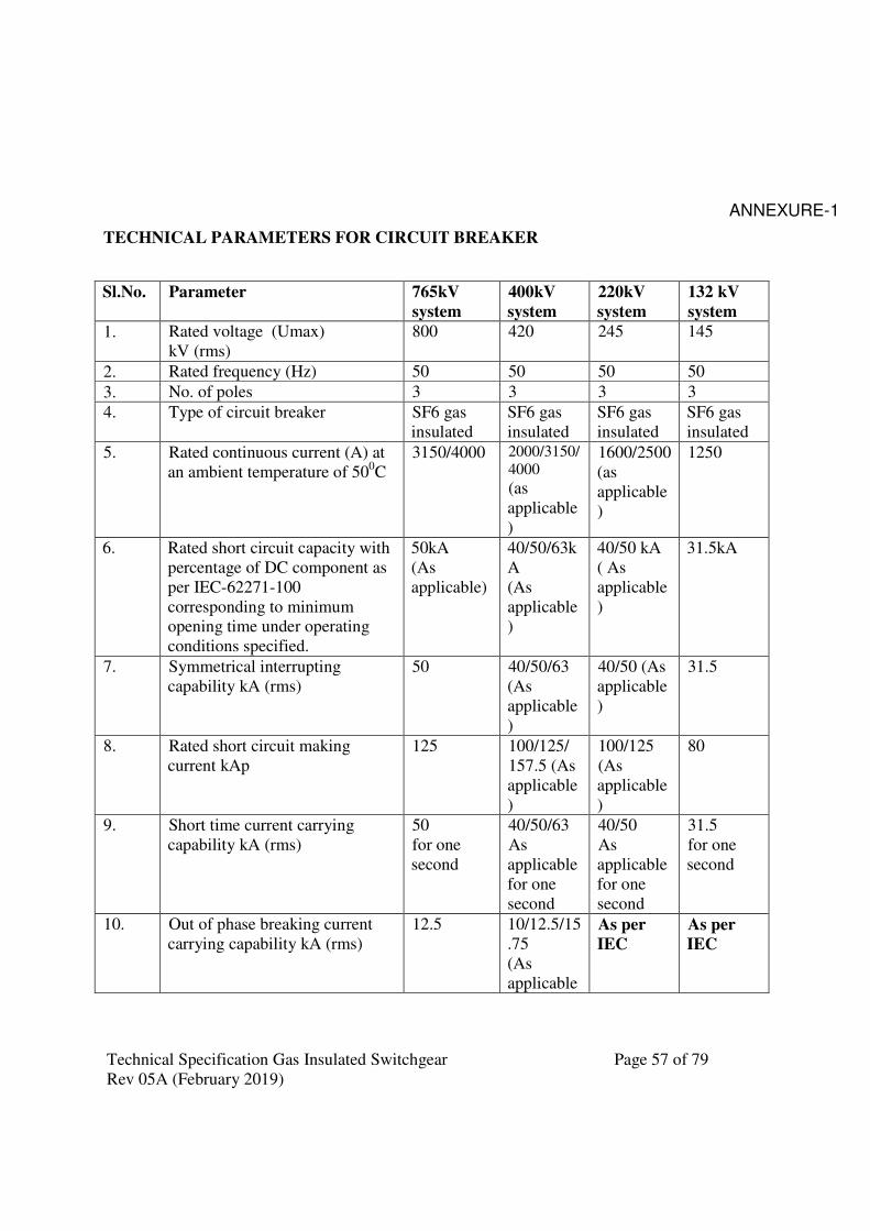
Technical Specification Gas Insulated Switchgear Page 57 of 79
Rev 05A (February 2019)
ANNEXURE-1
TECHNICAL PARAMETERS FOR CIRCUIT BREAKER
Sl.No. Parameter 765kV
system
400kV
system
220kV
system
132 kV
system
1. Rated voltage (Umax)
kV (rms)
800 420 245 145
2. Rated frequency (Hz) 50 50 50 50
3. No. of poles 3 3 3 3
4. Type of circuit breaker SF6 gas
insulated
SF6 gas
insulated
SF6 gas
insulated
SF6 gas
insulated
5. Rated continuous current (A) at
an ambient temperature of 500C
3150/4000 2000/3150/
4000
(as
applicable
)
1600/2500
(as
applicable
)
1250
6. Rated short circuit capacity with
percentage of DC component as
per IEC-62271-100
corresponding to minimum
opening time under operating
conditions specified.
50kA
(As
applicable)
40/50/63k
A
(As
applicable
)
40/50 kA
( As
applicable
)
31.5kA
7. Symmetrical interrupting
capability kA (rms)
50 40/50/63
(As
applicable
)
40/50 (As
applicable
)
31.5
8. Rated short circuit making
current kAp
125 100/125/
157.5 (As
applicable
)
100/125
(As
applicable
)
80
9. Short time current carrying
capability kA (rms)
50
for one
second
40/50/63
As
applicable
for one
second
40/50
As
applicable
for one
second
31.5
for one
second
10. Out of phase breaking current
carrying capability kA (rms)
12.5
10/12.5/15
.75
(As
applicable
As per
IEC
As per
IEC
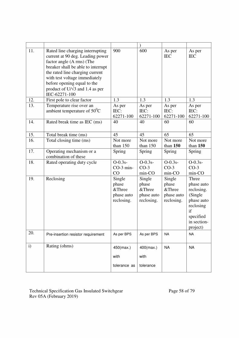
Technical Specification Gas Insulated Switchgear Page 58 of 79
Rev 05A (February 2019)
)
11. Rated line charging interrupting
current at 90 deg. Leading power
factor angle (A rms) (The
breaker shall be able to interrupt
the rated line charging current
with test voltage immediately
before opening equal to the
product of U/√3 and 1.4 as per
IEC-62271-100
900 600 As per
IEC
As per
IEC
12. First pole to clear factor 1.3 1.3 1.3 1.3
13. Temperature rise over an
ambient temperature of 500C
As per
IEC:
62271-100
As per
IEC:
62271-100
As per
IEC:
62271-100
As per
IEC:
62271-100
14. Rated break time as IEC (ms) 40 40 60 60
15. Total break time (ms) 45 45 65 65
16. Total closing time (ms) Not more
than 150
Not more
than 150
Not more
than 150
Not more
than 150
17. Operating mechanism or a
combination of these
Spring Spring Spring Spring
18. Rated operating duty cycle O-0.3s-
CO-3 min-
CO
O-0.3s-
CO-3
min-CO
O-0.3s-
CO-3
min-CO
O-0.3s-
CO-3
min-CO
19. Reclosing Single
phase
&Three
phase auto
reclosing.
Single
phase
&Three
phase auto
reclosing.
Single
phase
&Three
phase auto
reclosing.
Three
phase auto
reclosing.
(Single
phase auto
reclosing
if
specified
in section-
project)
20. Pre-insertion resistor requirement As per BPS As per BPS NA NA
i) Rating (ohms) 450(max.)
with
tolerance as
400(max.)
with
tolerance
NA NA
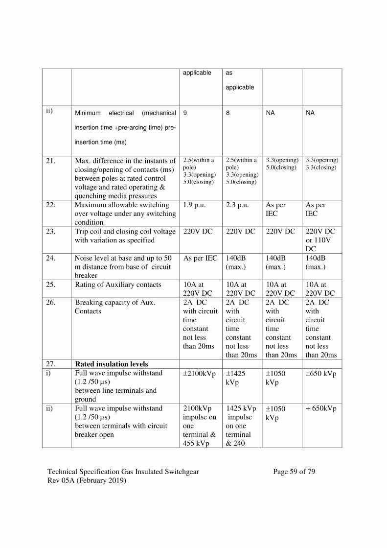
Technical Specification Gas Insulated Switchgear Page 59 of 79
Rev 05A (February 2019)
applicable as
applicable
ii) Minimum electrical (mechanical
insertion time +pre-arcing time) pre-
insertion time (ms)
9 8 NA NA
21. Max. difference in the instants of
closing/opening of contacts (ms)
between poles at rated control
voltage and rated operating &
quenching media pressures
2.5(within a
pole)
3.3(opening)
5.0(closing)
2.5(within a
pole)
3.3(opening)
5.0(closing)
3.3(opening)
5.0(closing)
3.3(opening)
3.3(closing)
22. Maximum allowable switching
over voltage under any switching
condition
1.9 p.u. 2.3 p.u. As per
IEC
As per
IEC
23. Trip coil and closing coil voltage
with variation as specified
220V DC 220V DC 220V DC 220V DC
or 110V
DC
24. Noise level at base and up to 50
m distance from base of circuit
breaker
As per IEC 140dB
(max.)
140dB
(max.)
140dB
(max.)
25. Rating of Auxiliary contacts 10A at
220V DC
10A at
220V DC
10A at
220V DC
10A at
220V DC
26. Breaking capacity of Aux.
Contacts
2A DC
with circuit
time
constant
not less
than 20ms
2A DC
with
circuit
time
constant
not less
than 20ms
2A DC
with
circuit
time
constant
not less
than 20ms
2A DC
with
circuit
time
constant
not less
than 20ms
27. Rated insulation levels
i) Full wave impulse withstand
(1.2 /50 µs)
between line terminals and
ground
±2100kVp
±1425
kVp
±1050
kVp
±650 kVp
ii) Full wave impulse withstand
(1.2 /50 µs)
between terminals with circuit
breaker open
2100kVp
impulse on
one
terminal &
455 kVp
1425 kVp
impulse
on one
terminal
& 240
±1050
kVp
+ 650kVp

Technical Specification Gas Insulated Switchgear Page 60 of 79
Rev 05A (February 2019)
power
frequency
voltage of
opposite
polarity on
the other
terminal
kVp
power
frequency
voltage of
opposite
polarity
on the
other
terminal
iii) Rated switching impulse
withstand voltage
(250/2500 µs) Dry & wet
between line terminals and
ground
+ 1550kVp
+1050
kVp
.
NA NA
iv) Rated switching impulse
withstand voltage
(250/2500 µs) Dry &wet
Between terminals with circuit
breaker open
1175kVp
impulse on
one
terminal &
650 kVp
power
frequency
voltage of
opposite
polarity on
the other
terminal
900 kVp
impulse
on one
terminal
& 345
kVp
power
frequency
voltage of
opposite
polarity
on the
other
terminal
NA NA
v) One minute power frequency dry
withstand voltage between line
terminals and ground
830kV rms 520 kV
rms.
460 kV
rms.
275 kV
rms
vi) One minute power frequency dry
withstand voltage between
terminals with circuit breaker
open
1150kV
rms
610 kV
rms.
460 kV
rms.
275 kV
rms
28. Minimum corona extinction
voltage with CB in all positions
508 kV
rms
320kV
rms
156 kV
rms
92 kV rms
29. Max. radio interference voltage
for frequency between 0.5 MHz
and 2 MHz (Micro volts)
2500 µV
(at 508kV
rms)
1000 µV
(at 266kV
rms)
1000 µV
(at 156kV
rms)
500µV
(at 92kV
rms)
30. System neutral earthing Effectively earthed
31. Auxiliary contacts Besides requirement of technical specification, the

Technical Specification Gas Insulated Switchgear Page 61 of 79
Rev 05A (February 2019)
manufacturer/contractor shall wire up 10 NO +
10 NC contacts exclusively for purchaser’s use
and wired up to common marshalling box.
32. No. of terminals All contacts & control circuits to be wired out up
to common marshalling box + minimum 24
terminals exclusively for purchaser’s future use
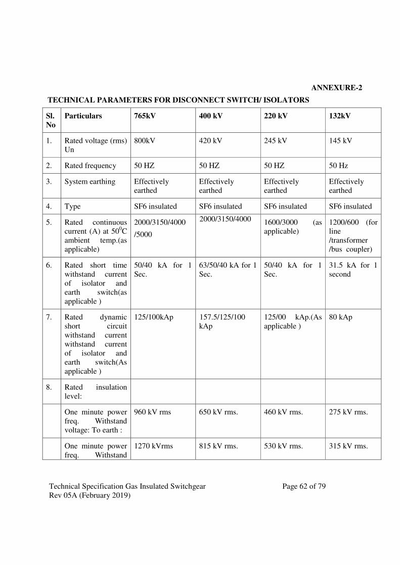
Technical Specification Gas Insulated Switchgear Page 62 of 79
Rev 05A (February 2019)
ANNEXURE-2
TECHNICAL PARAMETERS FOR DISCONNECT SWITCH/ ISOLATORS
Sl.
No
Particulars 765kV 400 kV 220 kV 132kV
1. Rated voltage (rms)
Un
800kV 420 kV 245 kV 145 kV
2. Rated frequency 50 HZ 50 HZ 50 HZ 50 Hz
3. System earthing Effectively earthed
Effectively earthed
Effectively earthed
Effectively earthed
4. Type SF6 insulated SF6 insulated SF6 insulated SF6 insulated
5. Rated continuous
current (A) at 500C
ambient temp.(as
applicable)
2000/3150/4000
/5000
2000/3150/4000 1600/3000 (as
applicable)
1200/600 (for
line
/transformer
/bus coupler)
6. Rated short time
withstand current
of isolator and
earth switch(as
applicable )
50/40 kA for 1
Sec.
63/50/40 kA for 1
Sec.
50/40 kA for 1
Sec.
31.5 kA for 1
second
7. Rated dynamic
short circuit
withstand current
withstand current
of isolator and
earth switch(As
applicable )
125/100kAp
157.5/125/100
kAp
125/00 kAp.(As
applicable )
80 kAp
8. Rated insulation
level:
One minute power
freq. Withstand
voltage: To earth :
960 kV rms
650 kV rms. 460 kV rms. 275 kV rms.
One minute power
freq. Withstand
1270 kVrms 815 kV rms. 530 kV rms. 315 kV rms.
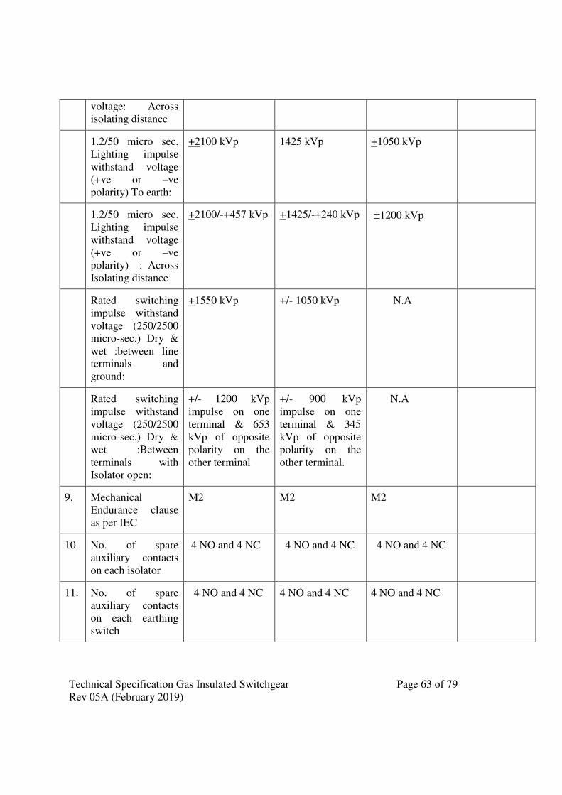
Technical Specification Gas Insulated Switchgear Page 63 of 79
Rev 05A (February 2019)
voltage: Across
isolating distance
1.2/50 micro sec.
Lighting impulse
withstand voltage
(+ve or –ve
polarity) To earth:
+2100 kVp 1425 kVp +1050 kVp
1.2/50 micro sec.
Lighting impulse
withstand voltage
(+ve or –ve
polarity) : Across
Isolating distance
+2100/-+457 kVp +1425/-+240 kVp ±1200 kVp
Rated switching
impulse withstand
voltage (250/2500
micro-sec.) Dry &
wet :between line
terminals and
ground:
+1550 kVp +/- 1050 kVp N.A
Rated switching
impulse withstand
voltage (250/2500
micro-sec.) Dry &
wet :Between
terminals with
Isolator open:
+/- 1200 kVp
impulse on one
terminal & 653
kVp of opposite
polarity on the
other terminal
+/- 900 kVp
impulse on one
terminal & 345
kVp of opposite
polarity on the
other terminal.
N.A
9. Mechanical
Endurance clause
as per IEC
M2 M2 M2
10. No. of spare
auxiliary contacts
on each isolator
4 NO and 4 NC 4 NO and 4 NC 4 NO and 4 NC
11. No. of spare
auxiliary contacts
on each earthing
switch
4 NO and 4 NC 4 NO and 4 NC 4 NO and 4 NC
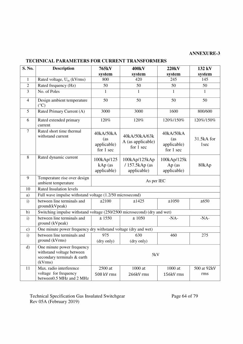
Technical Specification Gas Insulated Switchgear Page 64 of 79
Rev 05A (February 2019)
ANNEXURE-3
TECHNICAL PARAMETERS FOR CURRENT TRANSFORMERS
S. No. Description 765kV
system
400kV
system
220kV
system
132 kV
system 1 Rated voltage, Um (kVrms) 800 420 245 145
2 Rated frequency (Hz) 50 50 50 50
3 No. of Poles 1 1 1 1
4 Design ambient temperature
(°C)
50 50 50 50
5 Rated Primary Current (A) 3000 3000 1600 800/600
6 Rated extended primary
current
120% 120% 120%/150% 120%/150%
7 Rated short time thermal
withstand current 40kA/50kA
(as
applicable)
for 1 sec
40kA/50kA/63k
A (as applicable)
for 1 sec
40kA/50kA
(as
applicable)
for 1 sec
31.5kA for
1sec
8 Rated dynamic current 100kAp/125
kAp (as
applicable)
100kAp/125kAp
/ 157.5kAp (as
applicable)
100kAp/125k
Ap (as
applicable)
80kAp
9 Temperature rise over design
ambient temperature As per IEC
10 Rated Insulation levels
a) Full wave impulse withstand voltage (1.2/50 microsecond)
i) between line terminals and
ground(kVpeak)
±2100 ±1425 ±1050 ±650
b) Switching impulse withstand voltage (250/2500 microsecond) (dry and wet)
i) between line terminals and
ground (kVpeak)
± 1550 ± 1050 -NA- -NA-
c) One minute power frequency dry withstand voltage (dry and wet)
i) between line terminals and
ground (kVrms)
975
(dry only)
630
(dry only)
460 275
d) One minute power frequency
withstand voltage between
secondary terminals & earth
(kVrms)
5kV
11 Max. radio interference
voltage for frequency
between0.5 MHz and 2 MHz
2500 at
508 kV rms
1000 at
266kV rms
1000 at
156kV rms
500 at 92kV
rms

Technical Specification Gas Insulated Switchgear Page 65 of 79
Rev 05A (February 2019)
S. No. Description 765kV
system
400kV
system
220kV
system
132 kV
system at (microvolts)
12 Minimum Corona
extinction voltage
(kVrms)
508 320 -NA- -NA-
13 Seismic acceleration
(Horizontal)
0.3g 0.3g 0.3g 0.3g
14 Partial Discharge As per IEC As per IEC As per IEC As per IEC
15 Number of terminals All terminals of control circuits are to be wired up to marshaling
box plus 20% spare terminals evenly distributed on all TBs. 17 System neutral earthing Effectively Earthed
For other parameters, refer respective Table for the applicable voltage class of CTs.
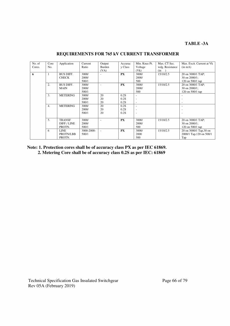
Technical Specification Gas Insulated Switchgear Page 66 of 79
Rev 05A (February 2019)
TABLE -3A
REQUIREMENTS FOR 765 kV CURRENT TRANSFORMER
No. of
Cores.
Core
No.
Application Current
Ratio
Output
Burden
(VA)
Accurac
y Class
Min. Knee Pt.
Voltage
(Vk)
Max. CT Sec.
wdg. Resistance
(in � )
Max. Excit. Current at Vk
(in mA)
6 1 BUS DIFF.
CHECK
3000/
2000/
500/1
- PX 3000/
2000/
500
15/10/2.5 20 on 3000/1 TAP;
30 on 2000/1;
120 on 500/1 tap
2. BUS DIFF.
MAIN
3000/
2000/
500/1
- PX 3000/
2000/
500
15/10/2.5 20 on 3000/1 TAP;
30 on 2000/1;
120 on 500/1 tap
3. METERING 3000/
2000/
500/1
20
20
20
0.2S
0.2S
0.2S
-
-
-
-
-
-
4. METERING 3000/
2000/
500/1
20
20
20
0.2S
0.2S
0.2S
-
-
-
-
-
-
5. TRANSF
DIFF./ LINE
PROTN.
3000/
2000/
500/1
- PX 3000/
2000/
500
15/10/2.5 20 on 3000/1 TAP;
30 on 2000/1;
120 on 500/1 tap
6 LINE
PROTN/LBB
PROTN.
3000-2000-
500/1
- PX 3000/
2000
500
15/10/2.5 20 on 3000/1 Tap,30 on
2000/1 Tap,120 on 500/1
Tap
Note: 1. Protection cores shall be of accuracy class PX as per IEC 61869.
2. Metering Core shall be of accuracy class 0.2S as per IEC: 61869
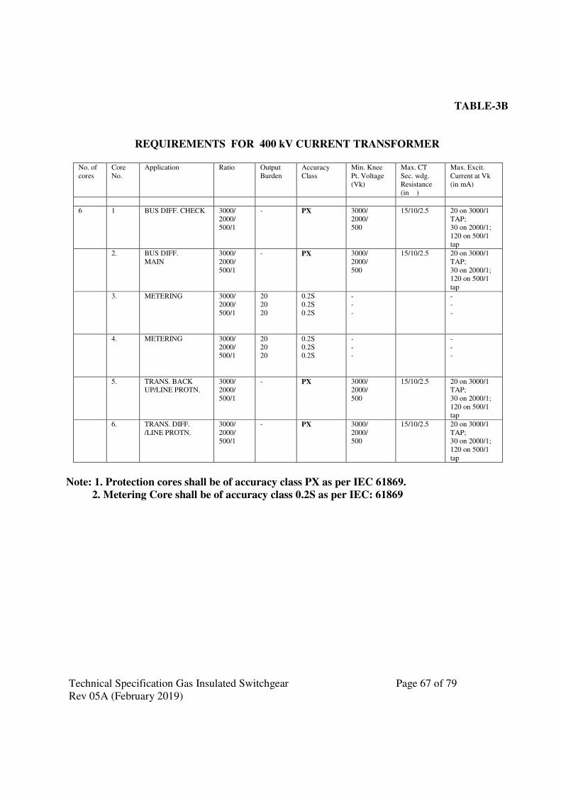
Technical Specification Gas Insulated Switchgear Page 67 of 79
Rev 05A (February 2019)
TABLE-3B
REQUIREMENTS FOR 400 kV CURRENT TRANSFORMER
No. of
cores
Core
No.
Application Ratio Output
Burden
Accuracy
Class
Min. Knee
Pt. Voltage
(Vk)
Max. CT
Sec. wdg.
Resistance
(in �)
Max. Excit.
Current at Vk
(in mA)
6 1 BUS DIFF. CHECK 3000/
2000/
500/1
- PX 3000/
2000/
500
15/10/2.5 20 on 3000/1
TAP;
30 on 2000/1;
120 on 500/1
tap
2. BUS DIFF.
MAIN
3000/
2000/
500/1
- PX 3000/
2000/
500
15/10/2.5 20 on 3000/1
TAP;
30 on 2000/1;
120 on 500/1
tap
3. METERING 3000/
2000/
500/1
20
20
20
0.2S
0.2S
0.2S
-
-
-
-
-
-
4. METERING 3000/
2000/
500/1
20
20
20
0.2S
0.2S
0.2S
-
-
-
-
-
-
5. TRANS. BACK
UP/LINE PROTN.
3000/
2000/
500/1
- PX 3000/
2000/
500
15/10/2.5 20 on 3000/1
TAP;
30 on 2000/1;
120 on 500/1
tap
6. TRANS. DIFF.
/LINE PROTN.
3000/
2000/
500/1
- PX 3000/
2000/
500
15/10/2.5 20 on 3000/1
TAP;
30 on 2000/1;
120 on 500/1
tap
Note: 1. Protection cores shall be of accuracy class PX as per IEC 61869.
2. Metering Core shall be of accuracy class 0.2S as per IEC: 61869

Technical Specification Gas Insulated Switchgear Page 68 of 79
Rev 05A (February 2019)
TABLE-3C
REQUIREMENTS FOR 220 kV CURRENT TRANSFORMER
No.of Core Appli- Current Output Accuracy Min. knee Max. CT Max. Excit-
Cores No. cation ratio burden class pt.volt- sec.wdg. ation cur-
(VA) age (Vk) resist- rent at Vk
ance(ohms) (in mA)
5 1 BUS DIFF 1600- - PX 1600/ 8/4 25 on
CHECK 800/1 800 1600/1
Tap; 50 on
800/1 Tap
2 BUS DIFF 1600- - PX 1600/ 8/4 25 on
MAIN 800/1 800 1600/1
Tap;
50 on
800/1
Tap
3 METERING 1600- 20 0.2S - - -
800/1
4 TRANS. 1600- - PX 1600/ 8/4 25 on
BACK 800/1 800 1600/1
UP/LINE Tap;
PROTN. 50 on
800/1
Tap
5 TRANS. 1600- - PX 1600/ 8/4 25 on
DIFF/LINE 800/1 800 1600/1
PROTN Tap;
50 on
800/1
Tap
Note: 1. Protection cores shall be of accuracy class PX as per IEC 61869.
2. Metering Core shall be of accuracy class 0.2S as per IEC: 61869
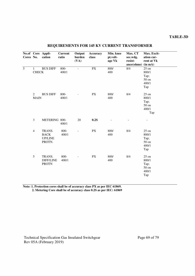
Technical Specification Gas Insulated Switchgear Page 69 of 79
Rev 05A (February 2019)
TABLE-3D
REQUIREMENTS FOR 145 KV CURRENT TRANSFORMER
No.of Core Appli- Current Output Accuracy Min. knee Max. CT Max. Excit-
Cores No. cation ratio burden class pt.volt- sec.wdg. ation cur-
(VA) age Vk resist- rent at Vk
ance(ohms) (in mA)
5 1 BUS DIFF 800- - PX 800/ 8/4 25 on
CHECK 400/1 400 800/1
Tap;
50 on
400/1
Tap
2 BUS DIFF 800- - PX 800/ 8/4 25 on
MAIN 400/1 400 800/1
Tap;
50 on
400/1
Tap
3 METERING 800- 20 0.2S - - -
400/1
4 TRANS. 800- - PX 800/ 8/4 25 on
BACK 400/1 400 800/1
UP/LINE Tap;
PROTN. 50 on
400/1
Tap
5 TRANS. 800- - PX 800/ 8/4 25 on
DIFF/LINE 400/1 400 800/1
PROTN Tap;
50 on
400/1
Tap
Note: 1. Protection cores shall be of accuracy class PX as per IEC 61869.
2. Metering Core shall be of accuracy class 0.2S as per IEC: 61869
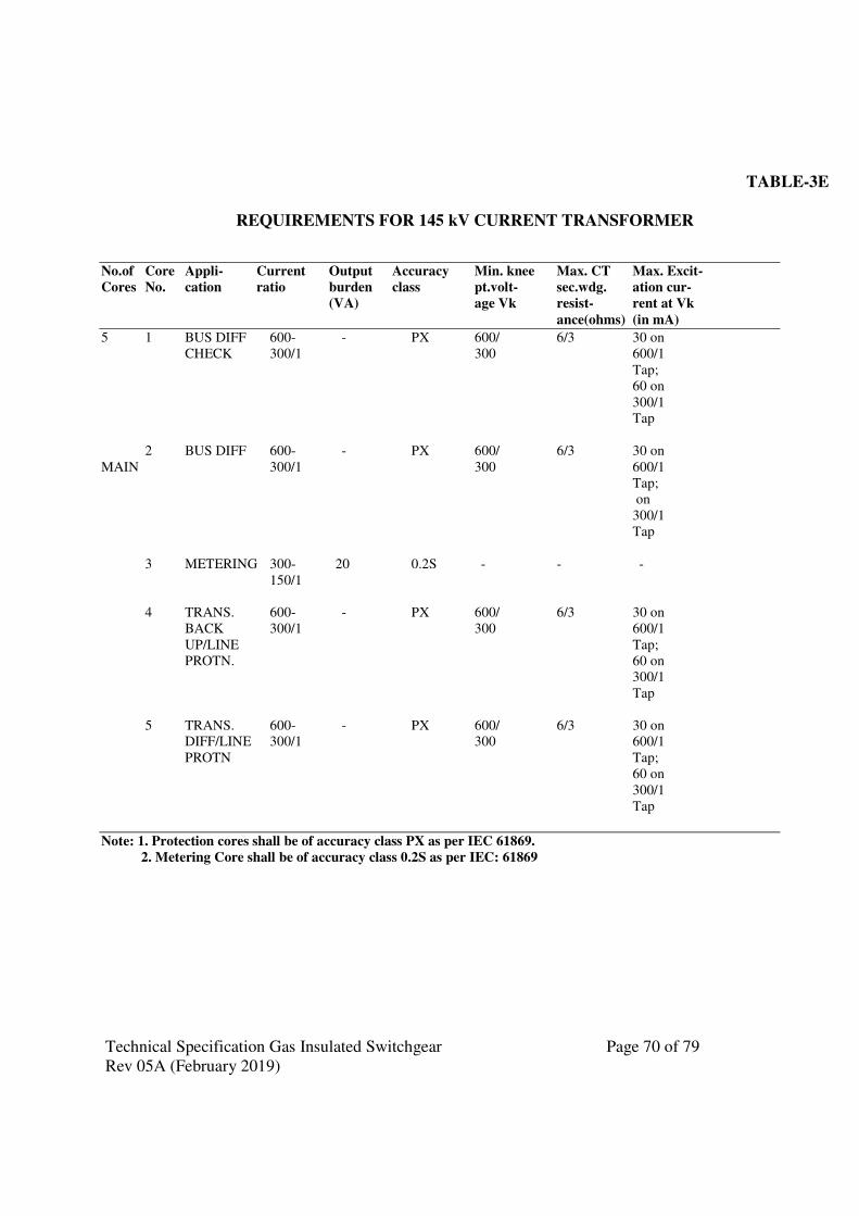
Technical Specification Gas Insulated Switchgear Page 70 of 79
Rev 05A (February 2019)
TABLE-3E
REQUIREMENTS FOR 145 kV CURRENT TRANSFORMER
No.of Core Appli- Current Output Accuracy Min. knee Max. CT Max. Excit-
Cores No. cation ratio burden class pt.volt- sec.wdg. ation cur-
(VA) age Vk resist- rent at Vk
ance(ohms) (in mA)
5 1 BUS DIFF 600- - PX 600/ 6/3 30 on
CHECK 300/1 300 600/1
Tap;
60 on
300/1
Tap
2 BUS DIFF 600- - PX 600/ 6/3 30 on
MAIN 300/1 300 600/1
Tap;
on
300/1
Tap
3 METERING 300- 20 0.2S - - -
150/1
4 TRANS. 600- - PX 600/ 6/3 30 on
BACK 300/1 300 600/1
UP/LINE Tap;
PROTN. 60 on
300/1
Tap
5 TRANS. 600- - PX 600/ 6/3 30 on
DIFF/LINE 300/1 300 600/1
PROTN Tap;
60 on
300/1
Tap
Note: 1. Protection cores shall be of accuracy class PX as per IEC 61869.
2. Metering Core shall be of accuracy class 0.2S as per IEC: 61869
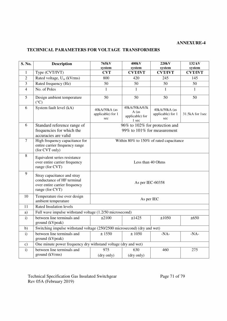
Technical Specification Gas Insulated Switchgear Page 71 of 79
Rev 05A (February 2019)
ANNEXURE-4
TECHNICAL PARAMETERS FOR VOLTAGE TRANSFORMERS
S. No. Description 765kV
system
400kV
system
220kV
system
132 kV
system
1 Type (CVT/IVT) CVT CVT/IVT CVT/IVT CVT/IVT
2 Rated voltage, Um (kVrms) 800 420 245 145
3 Rated frequency (Hz) 50 50 50 50
4 No. of Poles 1 1 1 1
5 Design ambient temperature
(°C)
50 50 50 50
6 System fault level (kA) 40kA/50kA (as
applicable) for 1
sec
40kA/50kA/63k
A (as
applicable) for
1 sec
40kA/50kA (as
applicable) for 1
sec
31.5kA for 1sec
6 Standard reference range of
frequencies for which the
accuracies are valid
96% to 102% for protection and
99% to 101% for measurement
7 High frequency capacitance for
entire carrier frequency range
(for CVT only)
Within 80% to 150% of rated capacitance
8 Equivalent series resistance
over entire carrier frequency
range (for CVT)
Less than 40 Ohms
9 Stray capacitance and stray
conductance of HF terminal
over entire carrier frequency
range (for CVT)
As per IEC-60358
10 Temperature rise over design
ambient temperature As per IEC
11 Rated Insulation levels
a) Full wave impulse withstand voltage (1.2/50 microsecond)
i) between line terminals and
ground (kVpeak)
±2100 ±1425 ±1050 ±650
b) Switching impulse withstand voltage (250/2500 microsecond) (dry and wet)
i) between line terminals and
ground (kVpeak)
± 1550 ± 1050 -NA- -NA-
c) One minute power frequency dry withstand voltage (dry and wet)
i) between line terminals and
ground (kVrms)
975
(dry only)
630
(dry only)
460 275
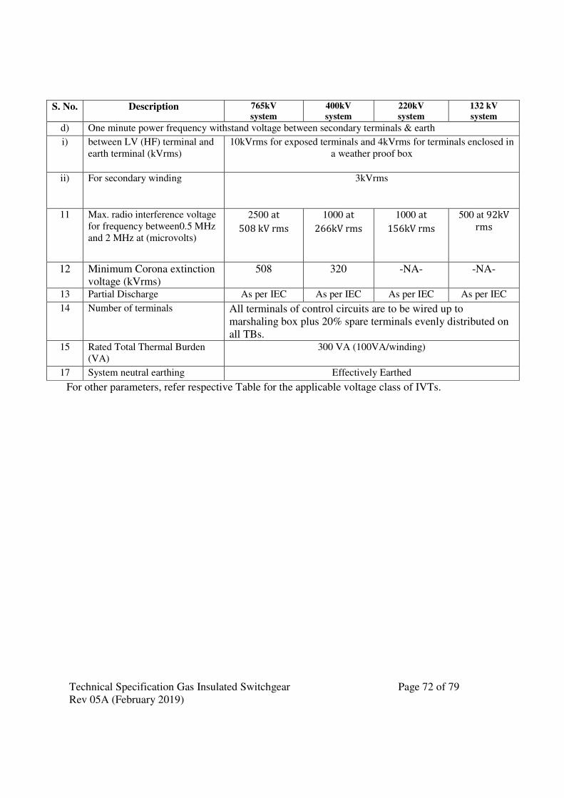
Technical Specification Gas Insulated Switchgear Page 72 of 79
Rev 05A (February 2019)
S. No. Description 765kV
system
400kV
system
220kV
system
132 kV
system
d) One minute power frequency withstand voltage between secondary terminals & earth
i) between LV (HF) terminal and
earth terminal (kVrms)
10kVrms for exposed terminals and 4kVrms for terminals enclosed in
a weather proof box
ii) For secondary winding 3kVrms
11 Max. radio interference voltage
for frequency between0.5 MHz
and 2 MHz at (microvolts)
2500 at
508 kV rms
1000 at
266kV rms
1000 at
156kV rms
500 at 92kV
rms
12 Minimum Corona extinction
voltage (kVrms)
508 320 -NA- -NA-
13 Partial Discharge As per IEC As per IEC As per IEC As per IEC
14 Number of terminals All terminals of control circuits are to be wired up to
marshaling box plus 20% spare terminals evenly distributed on
all TBs. 15 Rated Total Thermal Burden
(VA)
300 VA (100VA/winding)
17 System neutral earthing Effectively Earthed
For other parameters, refer respective Table for the applicable voltage class of IVTs.
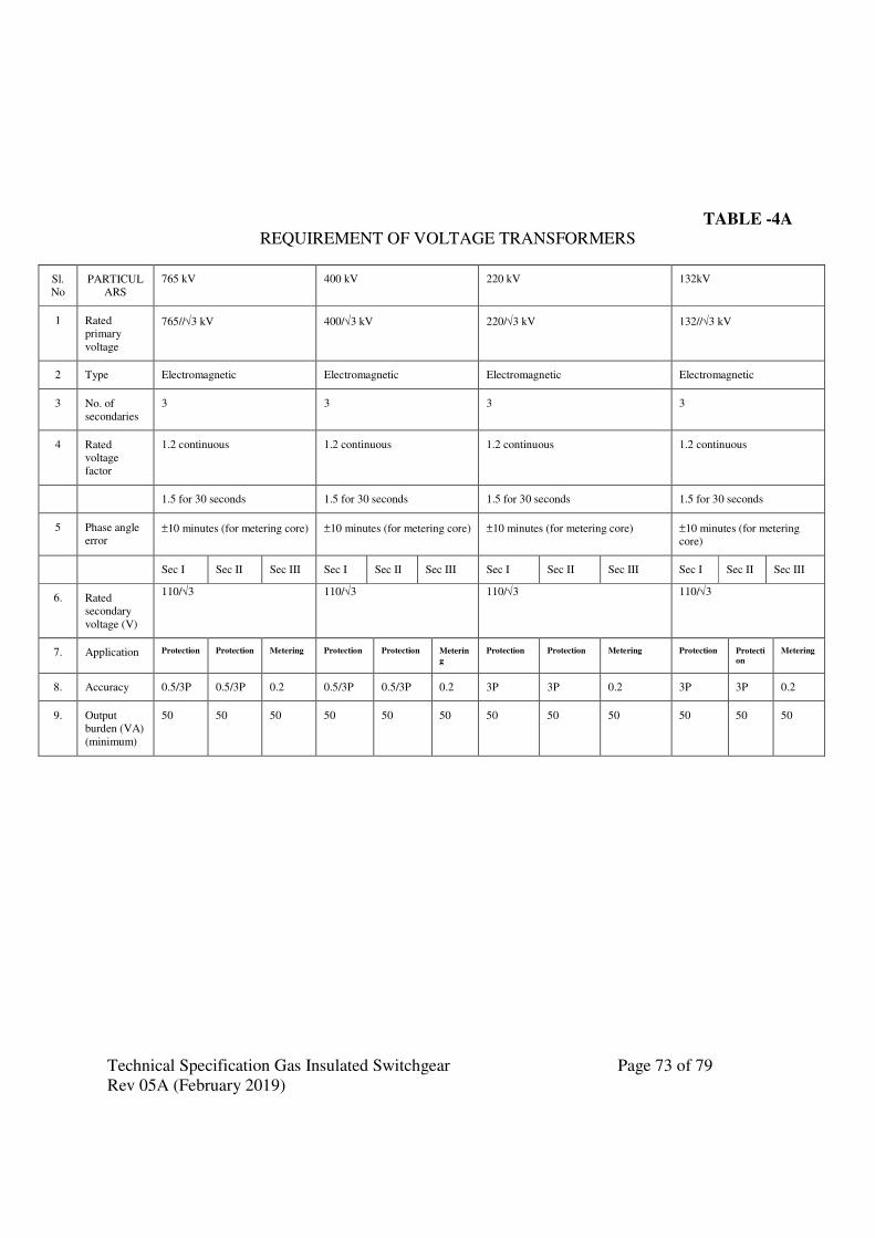
Technical Specification Gas Insulated Switchgear Page 73 of 79
Rev 05A (February 2019)
TABLE -4A
REQUIREMENT OF VOLTAGE TRANSFORMERS
Sl.
No
PARTICUL
ARS
765 kV 400 kV 220 kV 132kV
1 Rated
primary
voltage
765//√3 kV 400/√3 kV 220/√3 kV 132//√3 kV
2 Type Electromagnetic Electromagnetic Electromagnetic Electromagnetic
3 No. of
secondaries
3 3 3 3
4 Rated
voltage
factor
1.2 continuous 1.2 continuous 1.2 continuous 1.2 continuous
1.5 for 30 seconds 1.5 for 30 seconds 1.5 for 30 seconds 1.5 for 30 seconds
5 Phase angle
error ±10 minutes (for metering core) ±10 minutes (for metering core) ±10 minutes (for metering core) ±10 minutes (for metering
core)
Sec I Sec II Sec III Sec I Sec II Sec III Sec I Sec II Sec III Sec I Sec II Sec III
6. Rated
secondary
voltage (V)
110/√3 110/√3 110/√3 110/√3
7. Application Protection Protection Metering Protection Protection Meterin
g
Protection Protection Metering Protection Protecti
on
Metering
8. Accuracy 0.5/3P 0.5/3P 0.2 0.5/3P 0.5/3P 0.2 3P 3P 0.2 3P 3P 0.2
9. Output
burden (VA)
(minimum)
50 50 50 50 50 50 50 50 50 50 50 50

Technical Specification Gas Insulated Switchgear Page 74 of 79
Rev 05A (February 2019)
ANNEXURE-5
TECHNICAL PARAMETERS OF GIS SURGE ARRESTOR
Sl. No.
Description Unit 800kV SA 420kV SA 245kV SA 145kV SA
1 Nominal System Operating voltage
kV, rms 765 400 220 132
2 Rated frequency Hz 50 50 50 50
3 No. of Poles No. 1 1 1 1
4 Design ambient temperature
°C 50 50 50 50
5 Rated arrester voltage
kV 624 336 216 120
6 Continuous operating voltage at 50 deg.C
kV 490 267 168 102
7 Nominal discharge current
20 kA of 8/20 microsecond
wave
20 kA of 8/20 microsecond
wave
10 kA of 8/20 microsecond
wave
10 kA of 8/20 microsecond
wave
8 Discharge current at which insulation co-ordination will be done
20 kA of 8/20 microsecond
wave
20 kA of 8/20 microsecond
wave
10 kA of 8/20 microsecond
wave
10 kA of 8/20 microsecond
wave
9 Minimum discharge capability (referred to rated arrester Voltage) or corresponding to minimum discharge voltage as per clause-2.0 (d) whichever is higher
kJ/kV 13kJ/kV 12kJ/kV 5kJ/kV 5kJ/kV
10 Max. switching surge residual voltage
kVp 1180 (at 1kA)
1220 (at 2kA)
670(at 2kA)
650 (at 500A)
500 (at 1kA) 280 (at 1kA)
11 Max. residual voltage at
i) 5kA kVp - - 560 310
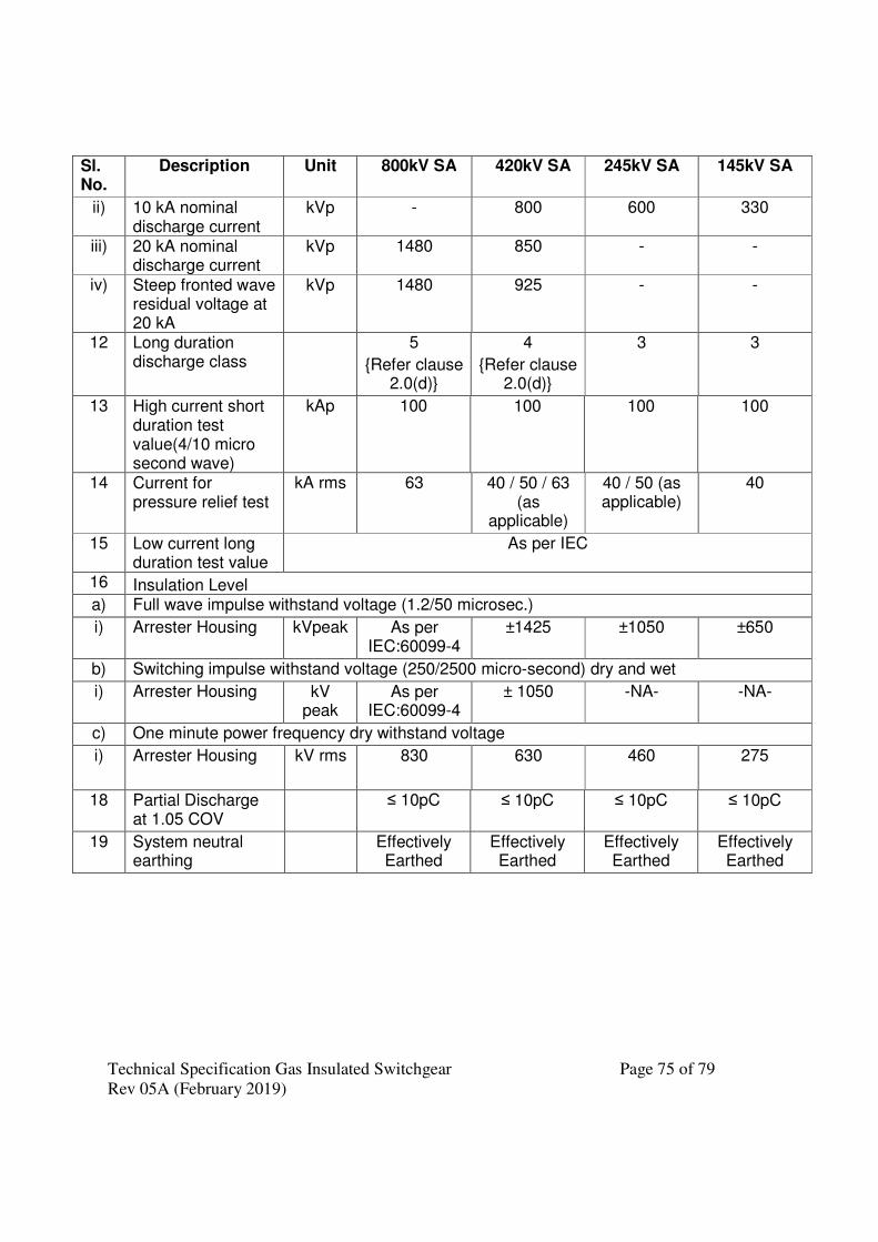
Technical Specification Gas Insulated Switchgear Page 75 of 79
Rev 05A (February 2019)
Sl. No.
Description Unit 800kV SA 420kV SA 245kV SA 145kV SA
ii) 10 kA nominal discharge current
kVp - 800 600 330
iii) 20 kA nominal discharge current
kVp 1480 850 - -
iv) Steep fronted wave residual voltage at 20 kA
kVp 1480 925 - -
12 Long duration discharge class
5
{Refer clause 2.0(d)}
4
{Refer clause 2.0(d)}
3 3
13 High current short duration test value(4/10 micro second wave)
kAp 100 100 100 100
14 Current for pressure relief test
kA rms 63 40 / 50 / 63 (as
applicable)
40 / 50 (as applicable)
40
15 Low current long duration test value
As per IEC
16 Insulation Level a) Full wave impulse withstand voltage (1.2/50 microsec.)
i) Arrester Housing kVpeak As per IEC:60099-4
±1425 ±1050 ±650
b) Switching impulse withstand voltage (250/2500 micro-second) dry and wet
i) Arrester Housing kV peak
As per IEC:60099-4
± 1050 -NA- -NA-
c) One minute power frequency dry withstand voltage
i) Arrester Housing kV rms 830 630
460
275
18 Partial Discharge at 1.05 COV
≤ 10pC ≤ 10pC ≤ 10pC ≤ 10pC
19 System neutral earthing
Effectively Earthed
Effectively Earthed
Effectively Earthed
Effectively Earthed
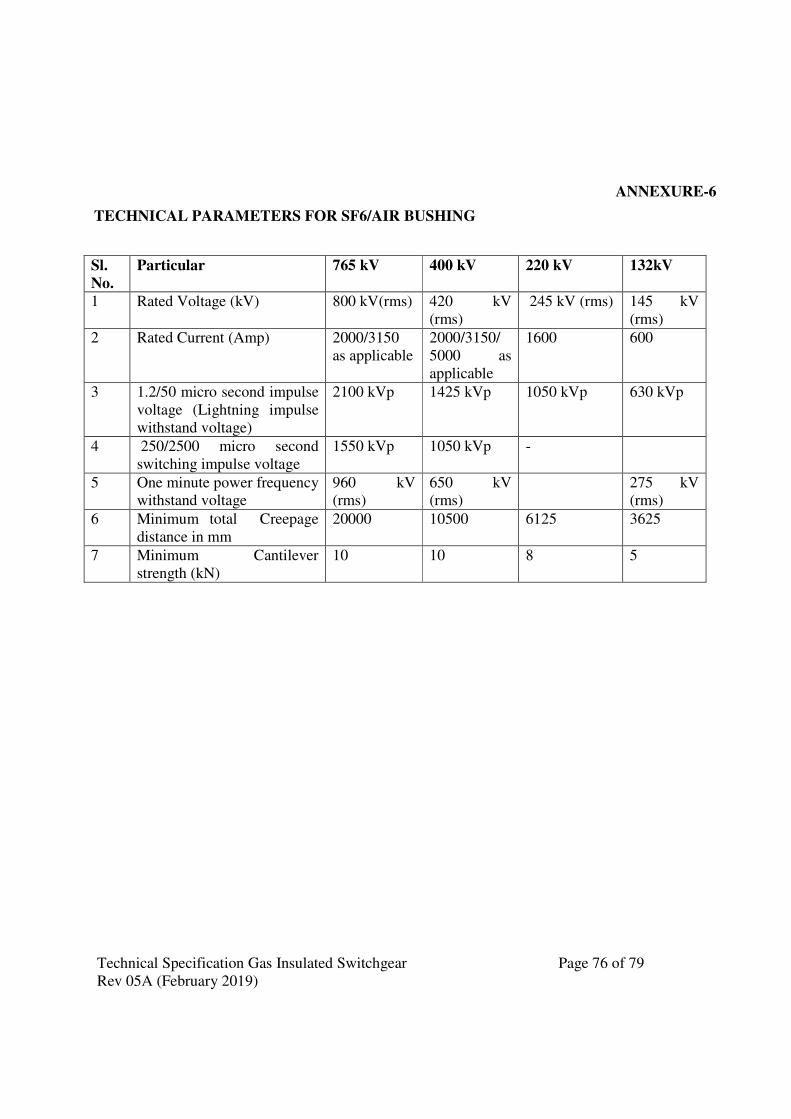
Technical Specification Gas Insulated Switchgear Page 76 of 79
Rev 05A (February 2019)
ANNEXURE-6
TECHNICAL PARAMETERS FOR SF6/AIR BUSHING
Sl.
No.
Particular 765 kV 400 kV 220 kV 132kV
1 Rated Voltage (kV) 800 kV(rms) 420 kV
(rms)
245 kV (rms) 145 kV
(rms)
2 Rated Current (Amp) 2000/3150
as applicable
2000/3150/
5000 as
applicable
1600 600
3 1.2/50 micro second impulse
voltage (Lightning impulse
withstand voltage)
2100 kVp 1425 kVp 1050 kVp 630 kVp
4 250/2500 micro second
switching impulse voltage
1550 kVp 1050 kVp -
5 One minute power frequency
withstand voltage
960 kV
(rms)
650 kV
(rms)
275 kV
(rms)
6 Minimum total � Creepage
distance in mm
20000 10500 6125 3625
7 Minimum Cantilever
strength (kN)
10 10 8 5

Technical Specification Gas Insulated Switchgear Page 77 of 79
Rev 05A (February 2019)
Annexure-7
Wiring Diagram of VT
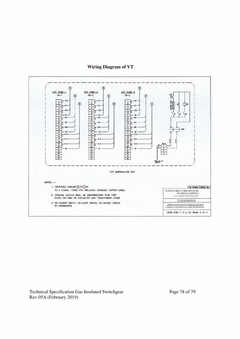
Technical Specification Gas Insulated Switchgear Page 78 of 79
Rev 05A (February 2019)
Wiring Diagram of VT
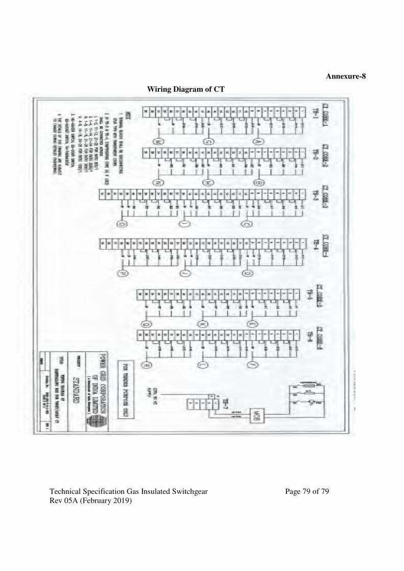
Technical Specification Gas Insulated Switchgear Page 79 of 79
Rev 05A (February 2019)
Annexure-8
Wiring Diagram of CT
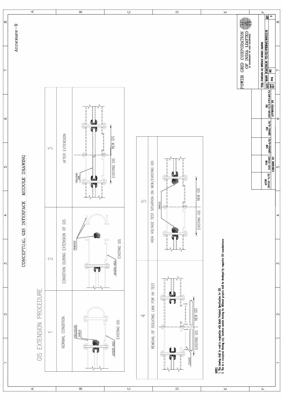
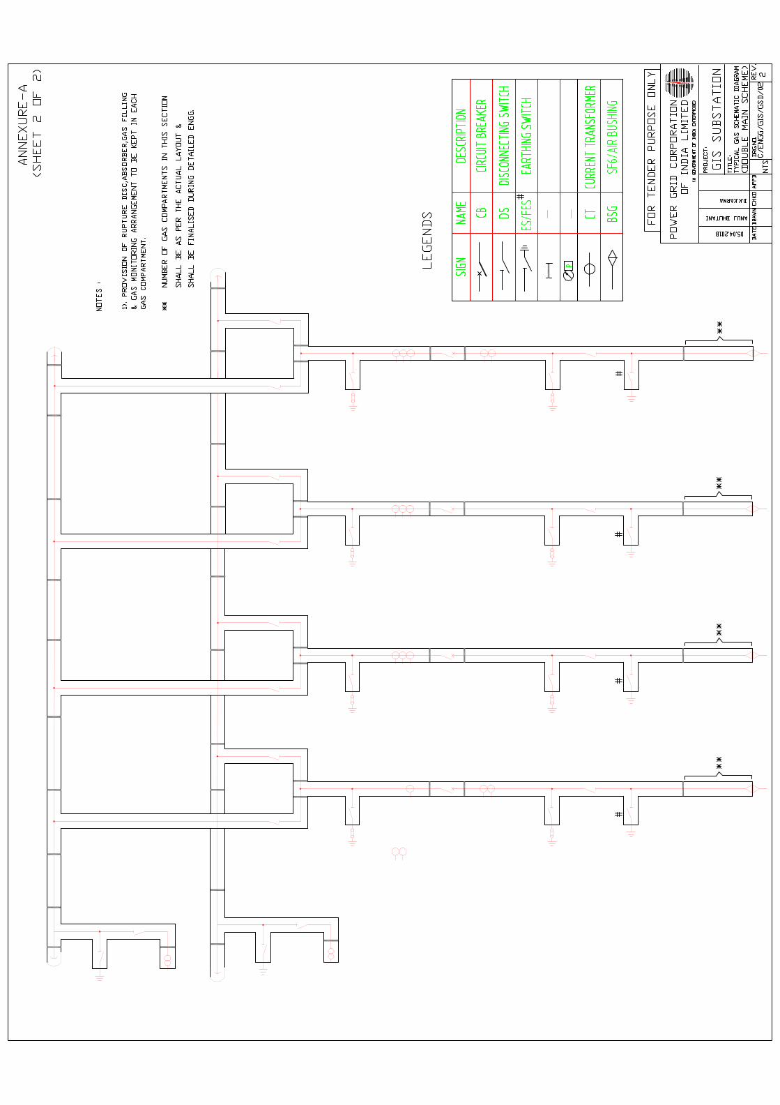
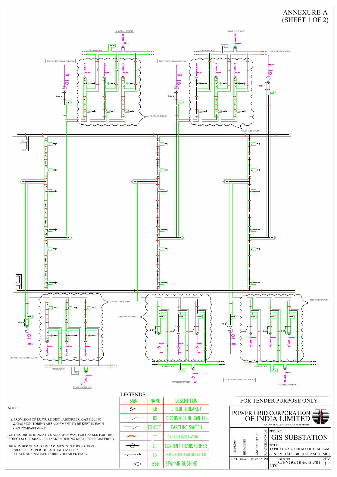
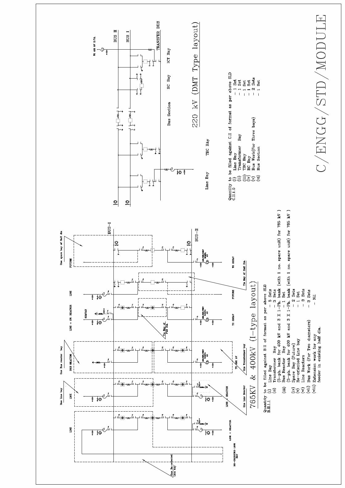
TECHNICAL SPECIFICATION SECTION-GENERAL TECHNICAL REQUIREMENTS
( ) Power Grid Corporation of India Limited (A Government of India Enterprises)
Document No.: C/ENGG/SPEC/GTR (Rev.15) December 2020
STANDARD TECHNICAL SPECIFICATION FOR GIS Doc No. TB-419-316-100, Rev.0 SECTION-3
REMARK - PLEASE READ TERMINOLOGY OF SECTION-2 OF TECH SPECIFICATION AS FOLLWOS 1. Read "GTR" as "Section-3 of technical specification" 2. Read "Powergrid" as "BHEL/Powergrid". 3. Read "Employer" as "Powergrid". 4. Read "Contractor" as bidder
Page 1 of 93
STANDARD TECHNICAL SPECIFICATION FOR GIS Doc No. TB-419-316-101, Rev.0 SECTION-3
STANDARD TECHNICAL SPECIFICATION FOR GIS Doc No. TB-419-316-101, Rev.0 SECTION-3
JAIK
Text Box
SECTION-3
JAIK
Text Box
STANDARD TECHNICAL SPECIFICATION FOR GIS

SECTION-GENERAL TECHNICAL REQUIREMENTS (GTR)
____________________________________________________________________________ Technical Specification: GTR Page 1 of 42
C/ENGG/SPEC/GTR (Rev. No.:-15, Dec 2020)
Contents 1.0 FOREWORD .................................................................................................................................................. 2 2.0 GENERAL REQUIREMENT ......................................................................................................................... 2 3.0 STANDARDS ................................................................................................................................................. 3 4.0 SERVICES TO BE PERFORMED BY THE EQUIPMENT BEING FURNISHED ..................................... 3 5.0 ENGINEERING DATA AND DRAWINGS .................................................................................................. 6 6.0 MATERIAL/ WORKMANSHIP .................................................................................................................... 8 7.0 DESIGN IMPROVEMENTS / COORDINATION ...................................................................................... 11 8.0 QUALITY ASSURANCE PROGRAMME .................................................................................................. 11 9.0 TYPE TESTING & CLEARANCE CERTIFICATE .................................................................................... 17 10.0 TESTS ........................................................................................................................................................... 18 11.0 PACKAGING & PROTECTION .................................................................................................................. 19 12.0 FINISHING OF METAL SURFACES ......................................................................................................... 20 12.3 PAINTING .................................................................................................................................................... 20 13.0 HANDLING, STORING AND INSTALLATION ....................................................................................... 22 14.0 TOOLS .......................................................................................................................................................... 23 15.0 AUXILIARY SUPPLY ................................................................................................................................. 24 16.0 SUPPORT STRUCTURE ............................................................................................................................. 24 17.0 CLAMPS AND CONNECTORS INCLUDING TERMINAL CONNECTORS .......................................... 25 18.0 CONTROL CABINETS, JUNCTION BOXES, TERMINAL BOXES MARSHALLING BOXES .......... 26 FOR OUTDOOR EQUIPMENT ................................................................................................................... 26 19.0 DISPOSAL OF PACKING MATERIAL & WASTE FROM CONSTRUCTION SITE .............................. 27 20.0 TERMINAL BLOCKS AND WIRING ........................................................................................................ 27 21.0 LAMPS & SOCKETS ................................................................................................................................... 28 22.0 BUSHINGS, HOLLOW COLUMN INSULATORS, SUPPORT INSULATORS: ...................................... 29 23.0 MOTORS ...................................................................................................................................................... 30 24.0 TECHNICAL REQUIREMENT OF EQUIPMENTS ................................................................................... 31
Annexure- C1 Corona and Radio Interference Voltage (RIV) Test - 2 SHEET
Page 2 of 93
SECTION-GENERAL TECHNICAL REQUIREMENTS (GTR)
____________________________________________________________________________ Technical Specification: GTR Page 2 of 42
C/ENGG/SPEC/GTR (Rev. No.:-15, Dec 2020)
FOREWORD
GENERAL REQUIREMENT
Page 3 of 93
SECTION-GENERAL TECHNICAL REQUIREMENTS (GTR)
____________________________________________________________________________ Technical Specification: GTR Page 3 of 42
C/ENGG/SPEC/GTR (Rev. No.:-15, Dec 2020)
3.0 STANDARDS
4.0 SERVICES TO BE PERFORMED BY THE EQUIPMENT BEING FURNISHED
Page 4 of 93
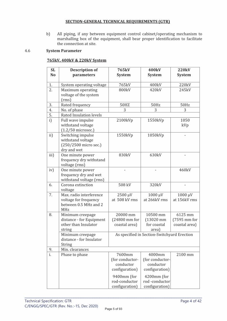
SECTION-GENERAL TECHNICAL REQUIREMENTS (GTR)
____________________________________________________________________________ Technical Specification: GTR Page 4 of 42
C/ENGG/SPEC/GTR (Rev. No.:-15, Dec 2020)
System Parameter
765kV, 400kV & 220kV System
SL No
Description of parameters
765kV System
400kV System
220kV System
Page 5 of 93
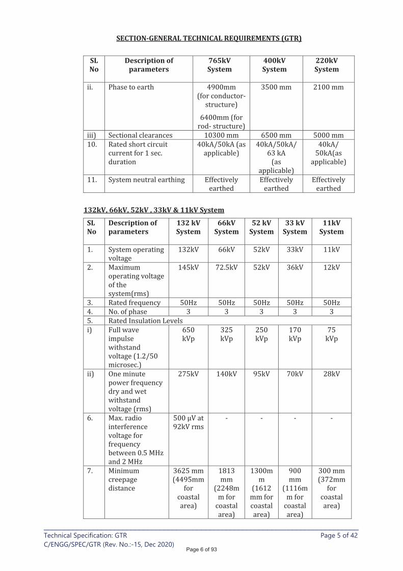
SECTION-GENERAL TECHNICAL REQUIREMENTS (GTR)
____________________________________________________________________________ Technical Specification: GTR Page 5 of 42
C/ENGG/SPEC/GTR (Rev. No.:-15, Dec 2020)
SL No
Description of parameters
765kV System
400kV System
220kV System
132kV, 66kV, 52kV , 33kV & 11kV System
SL No
Description of parameters
132 kV System
66kV System
52 kV System
33 kV System
11kV System
Page 6 of 93
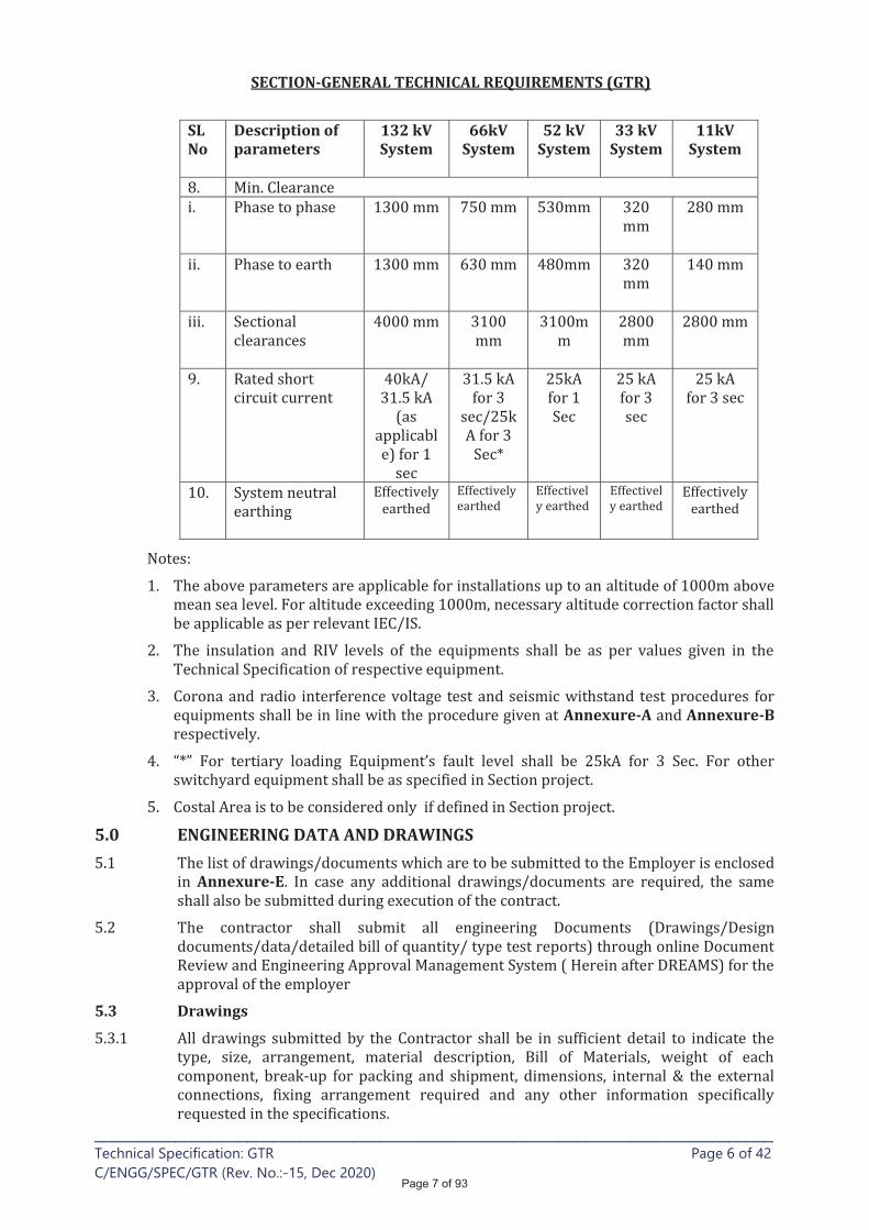
SECTION-GENERAL TECHNICAL REQUIREMENTS (GTR)
____________________________________________________________________________ Technical Specification: GTR Page 6 of 42
C/ENGG/SPEC/GTR (Rev. No.:-15, Dec 2020)
SL No
Description of parameters
132 kV System
66kV System
52 kV System
33 kV System
11kV System
Annexure-A Annexure-B
5.0 ENGINEERING DATA AND DRAWINGS
Annexure-E
5.3 Drawings
Page 7 of 93

SECTION-GENERAL TECHNICAL REQUIREMENTS (GTR)
____________________________________________________________________________ Technical Specification: GTR Page 7 of 42
C/ENGG/SPEC/GTR (Rev. No.:-15, Dec 2020)
5.7 Approval Procedure
Page 8 of 93
Two
SECTION-GENERAL TECHNICAL REQUIREMENTS (GTR)
____________________________________________________________________________ Technical Specification: GTR Page 8 of 42
C/ENGG/SPEC/GTR (Rev. No.:-15, Dec 2020)
NOTE :
Annexure–D
6.0 MATERIAL/ WORKMANSHIP 6.1 General Requirement
Page 9 of 93
SECTION-GENERAL TECHNICAL REQUIREMENTS (GTR)
____________________________________________________________________________ Technical Specification: GTR Page 9 of 42
C/ENGG/SPEC/GTR (Rev. No.:-15, Dec 2020)
6.2 Provisions For Exposure to Hot and Humid climate
Page 10 of 93
SECTION-GENERAL TECHNICAL REQUIREMENTS (GTR)
____________________________________________________________________________ Technical Specification: GTR Page 10 of 42
C/ENGG/SPEC/GTR (Rev. No.:-15, Dec 2020)
6.2.1 Space Heaters
6.2.2 FUNGI STATIC VARNISH
6.2.3 Ventilation opening
6.2.4 Degree of Protection
6.3 RATING PLATES, NAME PLATES AND LABELS
Page 11 of 93

SECTION-GENERAL TECHNICAL REQUIREMENTS (GTR)
____________________________________________________________________________ Technical Specification: GTR Page 11 of 42
C/ENGG/SPEC/GTR (Rev. No.:-15, Dec 2020)
6.4 FIRST FILL OF CONSUMABLES, OIL AND LUBRICANTS
7.0 DESIGN IMPROVEMENTS / COORDINATION
8.0 QUALITY ASSURANCE PROGRAMME
Page 12 of 93

SECTION-GENERAL TECHNICAL REQUIREMENTS (GTR)
____________________________________________________________________________ Technical Specification: GTR Page 12 of 42
C/ENGG/SPEC/GTR (Rev. No.:-15, Dec 2020)
Quality Assurance Documents
i)
ii)
Page 13 of 93
SECTION-GENERAL TECHNICAL REQUIREMENTS (GTR)
____________________________________________________________________________ Technical Specification: GTR Page 13 of 42
C/ENGG/SPEC/GTR (Rev. No.:-15, Dec 2020)
8.3 INSPECTION, TESTING & INSPECTION CERTIFICATE
Annexure-F
Annexure-G
Levels
Level –I
Level – II
Page 14 of 93
SECTION-GENERAL TECHNICAL REQUIREMENTS (GTR)
____________________________________________________________________________ Technical Specification: GTR Page 14 of 42
C/ENGG/SPEC/GTR (Rev. No.:-15, Dec 2020)
Level - III
Level – IV
Page 15 of 93

SECTION-GENERAL TECHNICAL REQUIREMENTS (GTR)
____________________________________________________________________________ Technical Specification: GTR Page 15 of 42
C/ENGG/SPEC/GTR (Rev. No.:-15, Dec 2020)
Page 16 of 93
SECTION-GENERAL TECHNICAL REQUIREMENTS (GTR)
____________________________________________________________________________ Technical Specification: GTR Page 16 of 42
C/ENGG/SPEC/GTR (Rev. No.:-15, Dec 2020)
8.3.22 For EHV transformers/reactors
Page 17 of 93

SECTION-GENERAL TECHNICAL REQUIREMENTS (GTR)
____________________________________________________________________________ Technical Specification: GTR Page 17 of 42
C/ENGG/SPEC/GTR (Rev. No.:-15, Dec 2020)
9.0 TYPE TESTING & CLEARANCE CERTIFICATE
Page 18 of 93
SECTION-GENERAL TECHNICAL REQUIREMENTS (GTR)
____________________________________________________________________________ Technical Specification: GTR Page 18 of 42
C/ENGG/SPEC/GTR (Rev. No.:-15, Dec 2020)
10.0 TESTS 10.1 Pre-commissioning Tests
10.2 Commissioning Tests
Page 19 of 93

SECTION-GENERAL TECHNICAL REQUIREMENTS (GTR)
____________________________________________________________________________ Technical Specification: GTR Page 19 of 42
C/ENGG/SPEC/GTR (Rev. No.:-15, Dec 2020)
PRECOMMISSIONING, COMMISSIONING, TRIAL-RUN & COMPLETION
11.0 PACKAGING & PROTECTION
Page 20 of 93

SECTION-GENERAL TECHNICAL REQUIREMENTS (GTR)
____________________________________________________________________________ Technical Specification: GTR Page 20 of 42
C/ENGG/SPEC/GTR (Rev. No.:-15, Dec 2020)
12.0 FINISHING OF METAL SURFACES
12.2 HOT DIP GALVANISING
and 900 gm/sq.m for coastal area (if defined in Section Project)
and 900 gm/sq.m for coastal area (if specified in Section-Project).
12.3 PAINTING
Page 21 of 93
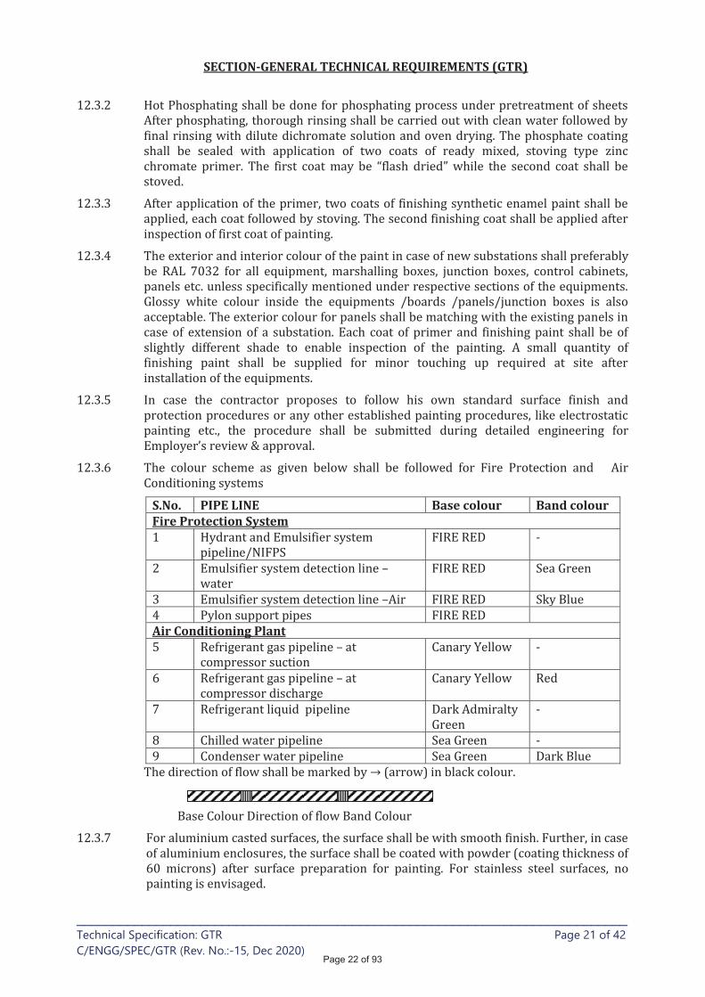
SECTION-GENERAL TECHNICAL REQUIREMENTS (GTR)
____________________________________________________________________________ Technical Specification: GTR Page 21 of 42
C/ENGG/SPEC/GTR (Rev. No.:-15, Dec 2020)
S.No. PIPE LINE Base colour Band colour Fire Protection System
Air Conditioning Plant
Page 22 of 93
SECTION-GENERAL TECHNICAL REQUIREMENTS (GTR)
____________________________________________________________________________ Technical Specification: GTR Page 22 of 42
C/ENGG/SPEC/GTR (Rev. No.:-15, Dec 2020)
.
13.0 HANDLING, STORING AND INSTALLATION
Page 23 of 93
SECTION-GENERAL TECHNICAL REQUIREMENTS (GTR)
____________________________________________________________________________ Technical Specification: GTR Page 23 of 42
C/ENGG/SPEC/GTR (Rev. No.:-15, Dec 2020)
13.13 Equipment Bases
.
14.0 TOOLS 14.1 TOOLS & PLANTS (T&P)
14.2 SPECIAL TOOLS AND TACKLES
Page 24 of 93
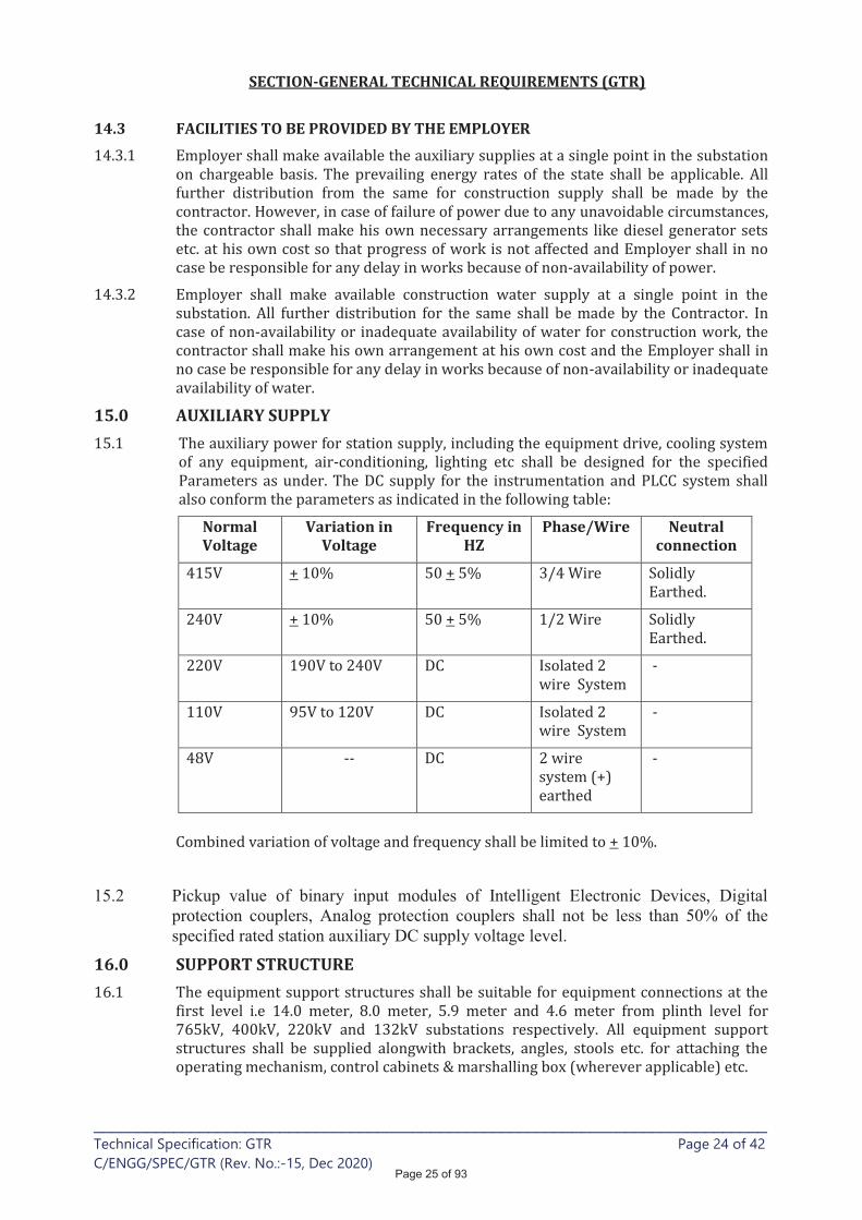
SECTION-GENERAL TECHNICAL REQUIREMENTS (GTR)
____________________________________________________________________________ Technical Specification: GTR Page 24 of 42
C/ENGG/SPEC/GTR (Rev. No.:-15, Dec 2020)
14.3 FACILITIES TO BE PROVIDED BY THE EMPLOYER
15.0 AUXILIARY SUPPLY
Normal Voltage
Variation in Voltage
Frequency in HZ
Phase/Wire Neutral connection
15.2 Pickup value of binary input modules of Intelligent Electronic Devices, Digital
protection couplers, Analog protection couplers shall not be less than 50% of the
specified rated station auxiliary DC supply voltage level.
16.0 SUPPORT STRUCTURE
Page 25 of 93
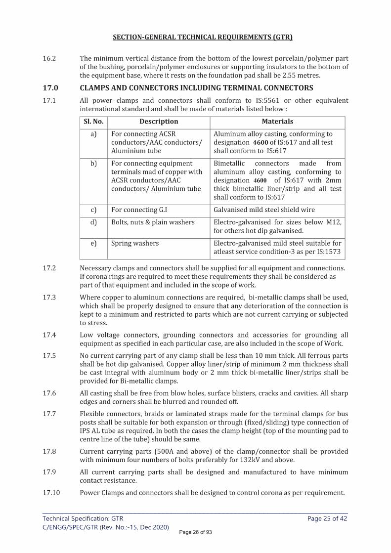
SECTION-GENERAL TECHNICAL REQUIREMENTS (GTR)
____________________________________________________________________________ Technical Specification: GTR Page 25 of 42
C/ENGG/SPEC/GTR (Rev. No.:-15, Dec 2020)
17.0 CLAMPS AND CONNECTORS INCLUDING TERMINAL CONNECTORS
Sl. No. Description Materials
4600
4600
Page 26 of 93
SECTION-GENERAL TECHNICAL REQUIREMENTS (GTR)
____________________________________________________________________________ Technical Specification: GTR Page 26 of 42
C/ENGG/SPEC/GTR (Rev. No.:-15, Dec 2020)
17.11 Tests
18.0 CONTROL CABINETS, JUNCTION BOXES, TERMINAL BOXES MARSHALLING BOXES FOR OUTDOOR EQUIPMENT
Page 27 of 93
SECTION-GENERAL TECHNICAL REQUIREMENTS (GTR)
____________________________________________________________________________ Technical Specification: GTR Page 27 of 42
C/ENGG/SPEC/GTR (Rev. No.:-15, Dec 2020)
19.0 DISPOSAL OF PACKING MATERIAL & WASTE FROM CONSTRUCTION SITE
20.0 TERMINAL BLOCKS AND WIRING
Page 28 of 93
SECTION-GENERAL TECHNICAL REQUIREMENTS (GTR)
____________________________________________________________________________ Technical Specification: GTR Page 28 of 42
C/ENGG/SPEC/GTR (Rev. No.:-15, Dec 2020)
21.0 LAMPS & SOCKETS 21.1 Lamps & Sockets
Page 29 of 93
SECTION-GENERAL TECHNICAL REQUIREMENTS (GTR)
____________________________________________________________________________ Technical Specification: GTR Page 29 of 42
C/ENGG/SPEC/GTR (Rev. No.:-15, Dec 2020)
21.2 Hand Lamp:
21.3 Switches and Fuses:
/
22.0 BUSHINGS, HOLLOW COLUMN INSULATORS, SUPPORT INSULATORS:
Page 30 of 93
SECTION-GENERAL TECHNICAL REQUIREMENTS (GTR)
____________________________________________________________________________ Technical Specification: GTR Page 30 of 42
C/ENGG/SPEC/GTR (Rev. No.:-15, Dec 2020)
RTV Coating on porcelain insulators (for coastal area)
Annexure-H. 22.10
23.0 MOTORS
23.1 Enclosures
23.2 Operational Features
23.3 Starting Requirements:
Page 31 of 93
SECTION-GENERAL TECHNICAL REQUIREMENTS (GTR)
____________________________________________________________________________ Technical Specification: GTR Page 31 of 42
C/ENGG/SPEC/GTR (Rev. No.:-15, Dec 2020)
23.4 Running Requirements:
23.5 TESTING AND COMMISSIONING
24. TECHNICAL REQUIREMENT OF EQUIPMENTS Indian Manufacturing facilities
Legend:
Page 32 of 93
SECTION-GENERAL TECHNICAL REQUIREMENTS (GTR)
____________________________________________________________________________ Technical Specification: GTR Page 32 of 42
C/ENGG/SPEC/GTR (Rev. No.:-15, Dec 2020)
satisfactory operation
Circuit Breaker Bay
24.1 Technical requirements for 765/400/220/132/110kV* Air Insulated Switchgear (AIS) Equipment* (i.e Circuit Breaker, Isolator, Current Transformer, Capacitive Voltage transformer, Inductive Voltage transformer, Surge Arrester and Wave Trap)
a)
b)
24.2 Technical Requirement for 765kV class Transformer
Page 33 of 93
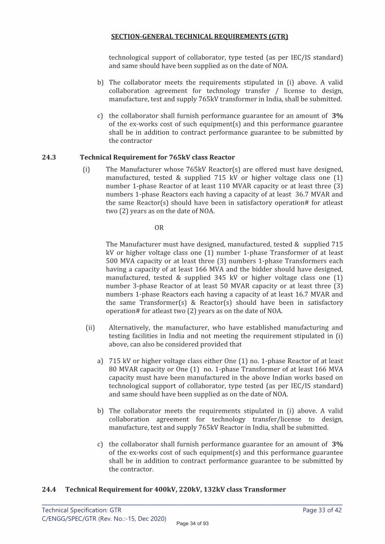
SECTION-GENERAL TECHNICAL REQUIREMENTS (GTR)
____________________________________________________________________________ Technical Specification: GTR Page 33 of 42
C/ENGG/SPEC/GTR (Rev. No.:-15, Dec 2020)
3%
24.3 Technical Requirement for 765kV class Reactor
3%
24.4 Technical Requirement for 400kV, 220kV, 132kV class Transformer
Page 34 of 93
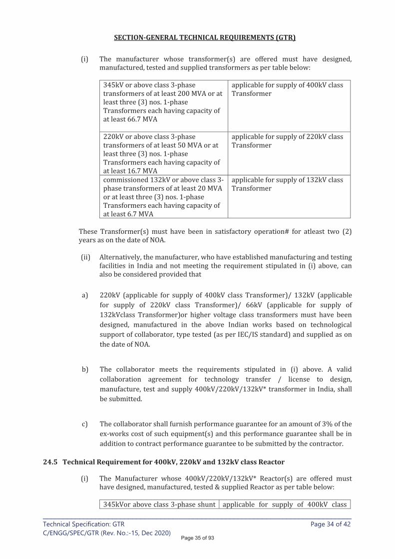
SECTION-GENERAL TECHNICAL REQUIREMENTS (GTR)
____________________________________________________________________________ Technical Specification: GTR Page 34 of 42
C/ENGG/SPEC/GTR (Rev. No.:-15, Dec 2020)
24.5 Technical Requirement for 400kV, 220kV and 132kV class Reactor
Page 35 of 93
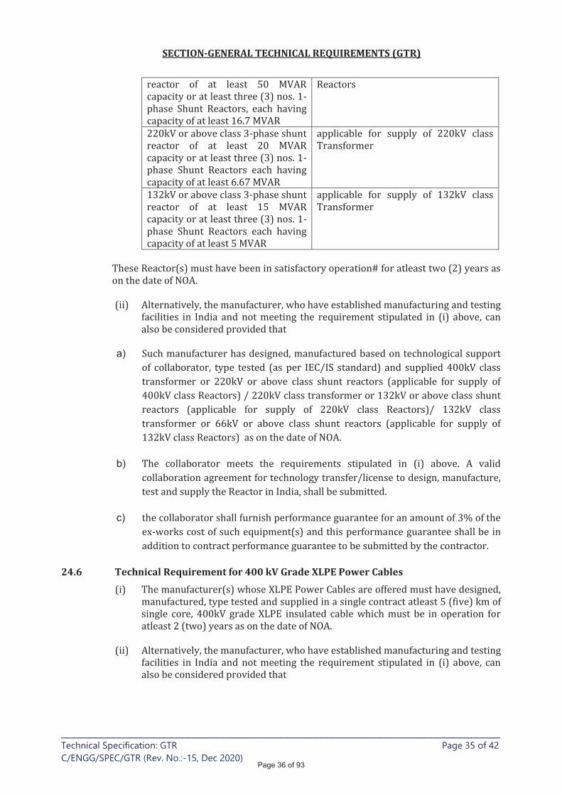
SECTION-GENERAL TECHNICAL REQUIREMENTS (GTR)
____________________________________________________________________________ Technical Specification: GTR Page 35 of 42
C/ENGG/SPEC/GTR (Rev. No.:-15, Dec 2020)
a)
b)
c)
24.6 Technical Requirement for 400 kV Grade XLPE Power Cables
Page 36 of 93
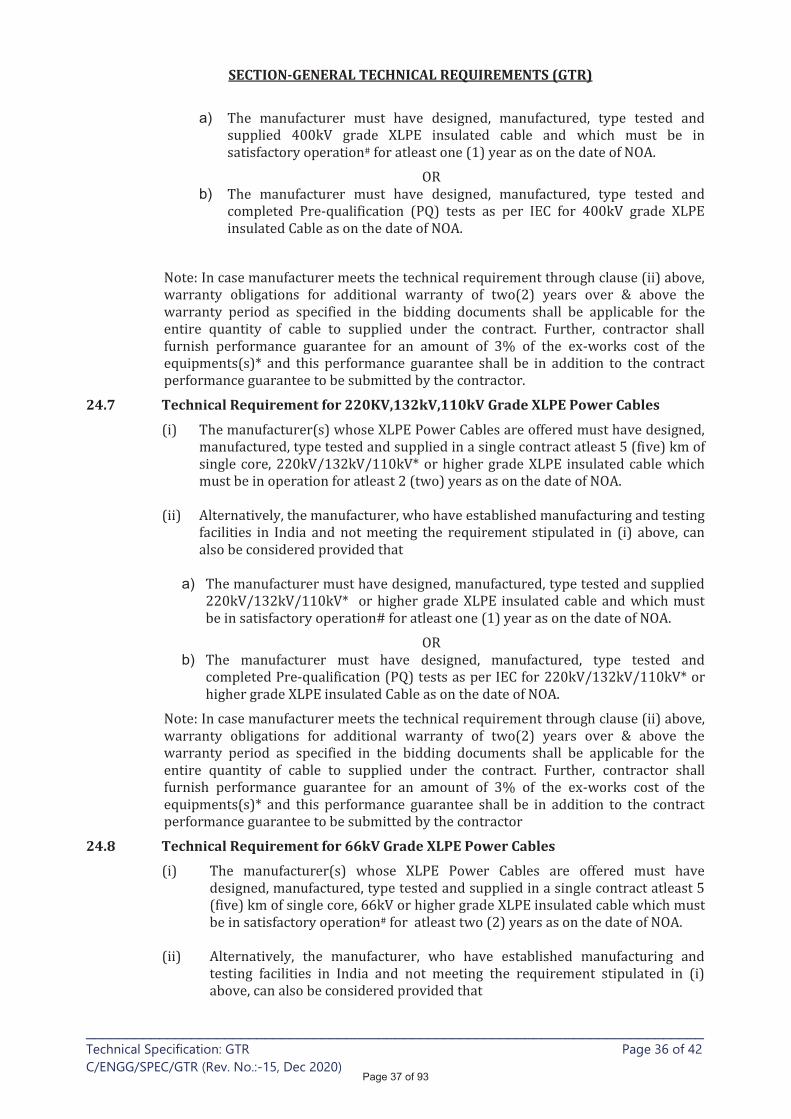
SECTION-GENERAL TECHNICAL REQUIREMENTS (GTR)
____________________________________________________________________________ Technical Specification: GTR Page 36 of 42
C/ENGG/SPEC/GTR (Rev. No.:-15, Dec 2020)
a)
b)
24.7 Technical Requirement for 220KV,132kV,110kV Grade XLPE Power Cables
a)
b)
24.8 Technical Requirement for 66kV Grade XLPE Power Cables
Page 37 of 93
SECTION-GENERAL TECHNICAL REQUIREMENTS (GTR)
____________________________________________________________________________ Technical Specification: GTR Page 37 of 42
C/ENGG/SPEC/GTR (Rev. No.:-15, Dec 2020)
a)
24.9 Technical Requirement for 1.1 KV Grade PVC Control Cable
24.10 Technical Requirement for 1.1 KV Grade PVC Power Cable
24.11 Technical Requirement for 1.1 KV Grade XLPE Power Cables
24.12 Technical Requirement for LT Switchgear
24.13 Technical Requirements for Battery
24.14 Technical Requirements for Battery Charger
24.15 Technical Requirements for LT Transformer
Page 38 of 93
SECTION-GENERAL TECHNICAL REQUIREMENTS (GTR)
____________________________________________________________________________ Technical Specification: GTR Page 38 of 42
C/ENGG/SPEC/GTR (Rev. No.:-15, Dec 2020)
24.16 Technical Requirements for Composite Long Rod Polymer Insulator (765kV & 400kV)
a)
b)
Technical Requirements for Control, Relay & Protection System and Sub-station Automation System
Page 39 of 93
SECTION-GENERAL TECHNICAL REQUIREMENTS (GTR)
____________________________________________________________________________ Technical Specification: GTR Page 39 of 42
C/ENGG/SPEC/GTR (Rev. No.:-15, Dec 2020)
24.18 Technical Requirements for analog and digital PLCC panels (765kV, 400kV, 220kV & 132kV)
a)
b)
c)
24.19 Technical Requirement of Communication Equipment
“Local Supplier”
24.20 Technical Requirement for 400kV GIS Equipment
Page 40 of 93

SECTION-GENERAL TECHNICAL REQUIREMENTS (GTR)
____________________________________________________________________________ Technical Specification: GTR Page 40 of 42
C/ENGG/SPEC/GTR (Rev. No.:-15, Dec 2020)
c)
25.0 Technical Requirement of Sub-contractors:
OR
OR
Note:
Page 41 of 93
SECTION-GENERAL TECHNICAL REQUIREMENTS (GTR)
____________________________________________________________________________ Technical Specification: GTR Page 41 of 42
C/ENGG/SPEC/GTR (Rev. No.:-15, Dec 2020)
Technical Requirement of Sub-contractors of GIS Packages
Note:
1.
Page 42 of 93

SECTION-GENERAL TECHNICAL REQUIREMENTS (GTR)
____________________________________________________________________________ Technical Specification: GTR Page 42 of 42
C/ENGG/SPEC/GTR (Rev. No.:-15, Dec 2020)
Page 43 of 93
SECTION-GENERAL TECHNICAL REQUIREMENTS (GTR)
____________________________________________________________________________ Technical Specification: GTR Page 1 of 2
C/ENGG/SPEC/GTR (Rev. No.:-15, Dec 2020)
CORONA AND RADIO INTERFERENCE VOLTAGE (RIV) TEST
1. General
2. Test Levels:
3. Test Methods for RIV:
4. Test Methods for Visible Corona
Page 44 of 93
SECTION-GENERAL TECHNICAL REQUIREMENTS (GTR)
____________________________________________________________________________ Technical Specification: GTR Page 2 of 2
C/ENGG/SPEC/GTR (Rev. No.:-15, Dec 2020)
.
5. Test Records:
Page 45 of 93

SECTION-GENERAL TECHNICAL REQUIREMENTS (GTR)
____________________________________________________________________________________________
Technical Specification: GTR Page 1 of 1 (Annexure-B)
C/ENGG/SPEC/GTR (Rev. No.:-15, Dec 2020)
SEISMIC WITHSTAND TEST PROCEDURE
Seismic Calculations certified by NABL Labs shall also be acceptable
Page 46 of 93
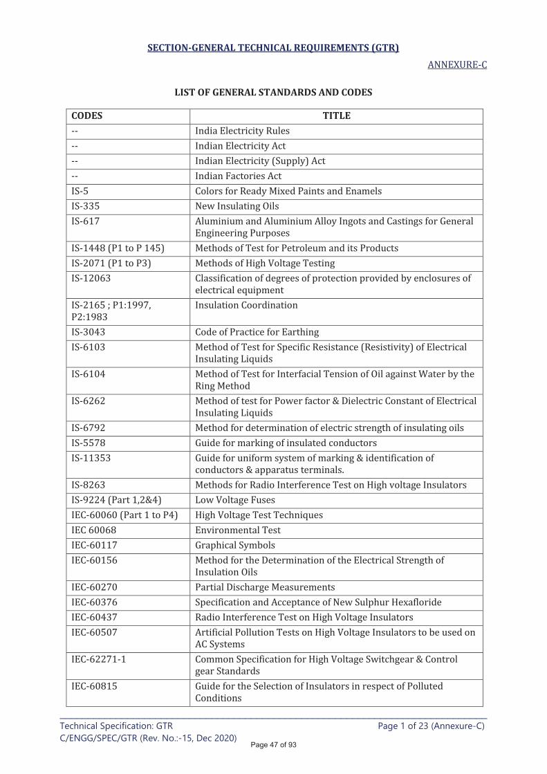
SECTION-GENERAL TECHNICAL REQUIREMENTS (GTR)
____________________________________________________________________________ Technical Specification: GTR Page 1 of 23 (Annexure-C)
C/ENGG/SPEC/GTR (Rev. No.:-15, Dec 2020)
LIST OF GENERAL STANDARDS AND CODES
CODES TITLE
Page 47 of 93
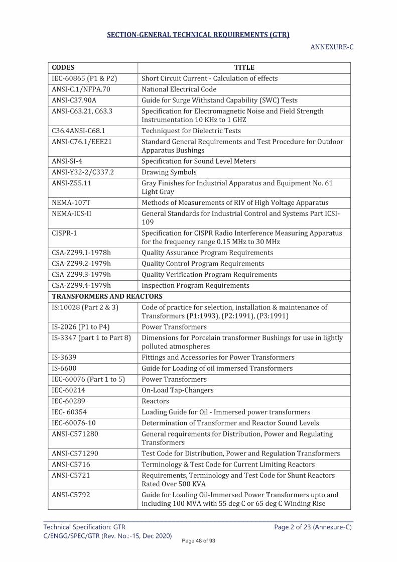
SECTION-GENERAL TECHNICAL REQUIREMENTS (GTR)
____________________________________________________________________________ Technical Specification: GTR Page 2 of 23 (Annexure-C)
C/ENGG/SPEC/GTR (Rev. No.:-15, Dec 2020)
CODES TITLE
TRANSFORMERS AND REACTORS
Page 48 of 93

SECTION-GENERAL TECHNICAL REQUIREMENTS (GTR)
____________________________________________________________________________ Technical Specification: GTR Page 3 of 23 (Annexure-C)
C/ENGG/SPEC/GTR (Rev. No.:-15, Dec 2020)
CODES TITLE
Page 49 of 93

SECTION-GENERAL TECHNICAL REQUIREMENTS (GTR)
____________________________________________________________________________ Technical Specification: GTR Page 4 of 23 (Annexure-C)
C/ENGG/SPEC/GTR (Rev. No.:-15, Dec 2020)
CODES TITLE
Page 50 of 93
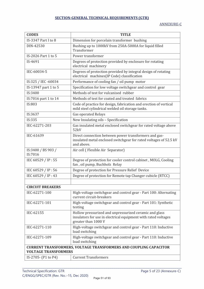
SECTION-GENERAL TECHNICAL REQUIREMENTS (GTR)
____________________________________________________________________________ Technical Specification: GTR Page 5 of 23 (Annexure-C)
C/ENGG/SPEC/GTR (Rev. No.:-15, Dec 2020)
CODES TITLE
CIRCUIT BREAKERS
CURRENT TRANSFORMERS, VOLTAGE TRANSFORMERS AND COUPLING CAPACITOR VOLTAGE TRANSFORMERS
Page 51 of 93
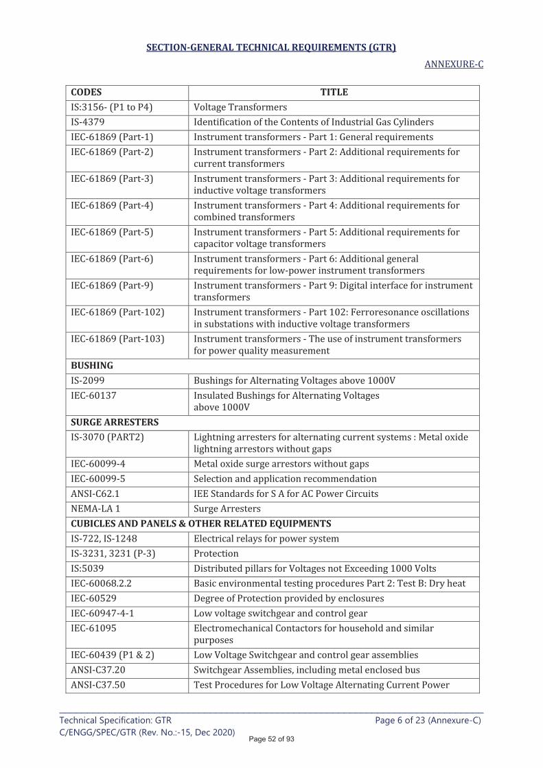
SECTION-GENERAL TECHNICAL REQUIREMENTS (GTR)
____________________________________________________________________________ Technical Specification: GTR Page 6 of 23 (Annexure-C)
C/ENGG/SPEC/GTR (Rev. No.:-15, Dec 2020)
CODES TITLE
BUSHING
SURGE ARRESTERS
CUBICLES AND PANELS & OTHER RELATED EQUIPMENTS
Page 52 of 93

SECTION-GENERAL TECHNICAL REQUIREMENTS (GTR)
____________________________________________________________________________ Technical Specification: GTR Page 7 of 23 (Annexure-C)
C/ENGG/SPEC/GTR (Rev. No.:-15, Dec 2020)
CODES TITLE
Disconnecting switches
PLCC and line traps
Protection and control equipment
Page 53 of 93
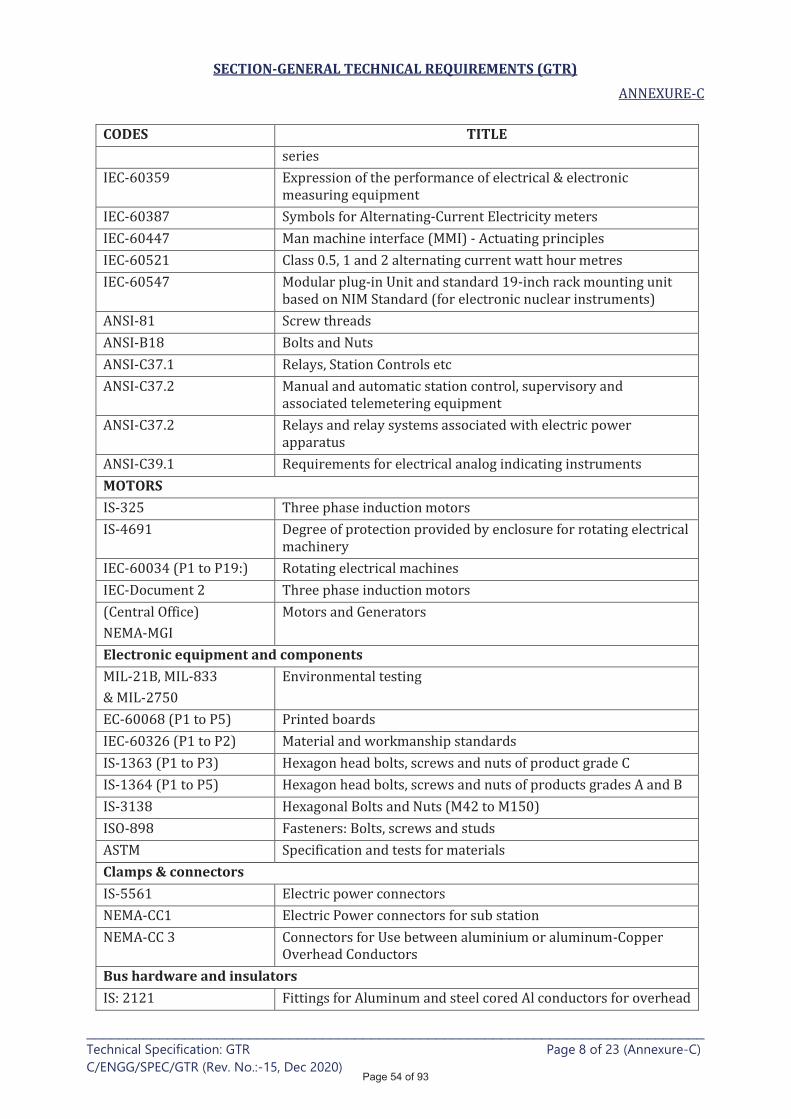
SECTION-GENERAL TECHNICAL REQUIREMENTS (GTR)
____________________________________________________________________________ Technical Specification: GTR Page 8 of 23 (Annexure-C)
C/ENGG/SPEC/GTR (Rev. No.:-15, Dec 2020)
CODES TITLE
MOTORS
Electronic equipment and components
Clamps & connectors
Bus hardware and insulators
Page 54 of 93
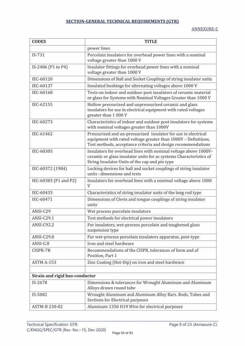
SECTION-GENERAL TECHNICAL REQUIREMENTS (GTR)
____________________________________________________________________________ Technical Specification: GTR Page 9 of 23 (Annexure-C)
C/ENGG/SPEC/GTR (Rev. No.:-15, Dec 2020)
CODES TITLE
Strain and rigid bus-conductor
Page 55 of 93
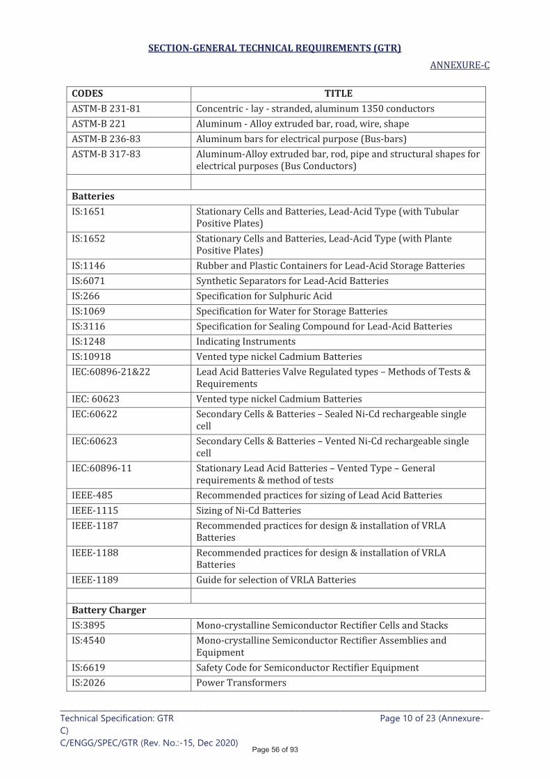
SECTION-GENERAL TECHNICAL REQUIREMENTS (GTR)
____________________________________________________________________________ Technical Specification: GTR Page 10 of 23 (Annexure-
C)
C/ENGG/SPEC/GTR (Rev. No.:-15, Dec 2020)
CODES TITLE
Batteries
Battery Charger
Page 56 of 93
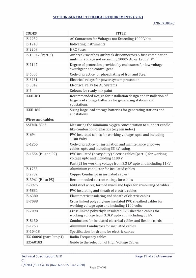
SECTION-GENERAL TECHNICAL REQUIREMENTS (GTR)
____________________________________________________________________________ Technical Specification: GTR Page 11 of 23 (Annexure-
C)
C/ENGG/SPEC/GTR (Rev. No.:-15, Dec 2020)
CODES TITLE
Wires and cables
Page 57 of 93
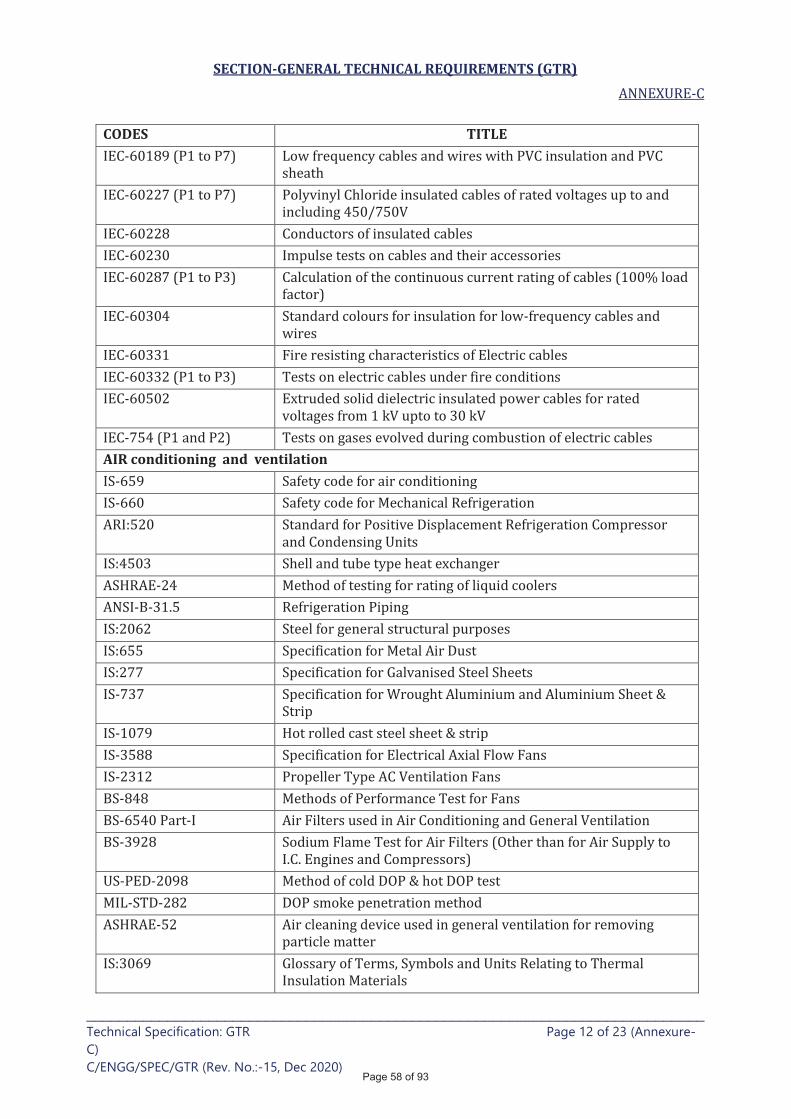
SECTION-GENERAL TECHNICAL REQUIREMENTS (GTR)
____________________________________________________________________________ Technical Specification: GTR Page 12 of 23 (Annexure-
C)
C/ENGG/SPEC/GTR (Rev. No.:-15, Dec 2020)
CODES TITLE
AIR conditioning and ventilation
Page 58 of 93

SECTION-GENERAL TECHNICAL REQUIREMENTS (GTR)
____________________________________________________________________________ Technical Specification: GTR Page 13 of 23 (Annexure-
C)
C/ENGG/SPEC/GTR (Rev. No.:-15, Dec 2020)
CODES TITLE
Galvanizing
Painting
Fire protection system
HORIZONTAL CENTRIFUGAL PUMPS
Page 59 of 93
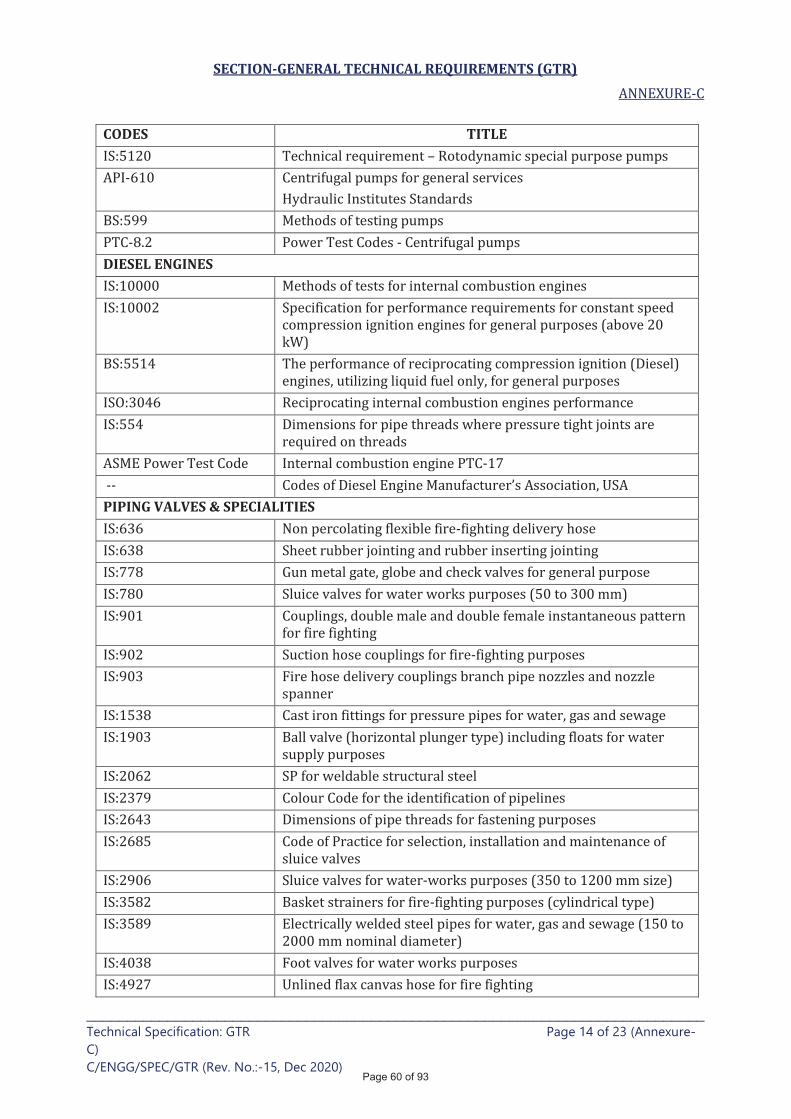
SECTION-GENERAL TECHNICAL REQUIREMENTS (GTR)
____________________________________________________________________________ Technical Specification: GTR Page 14 of 23 (Annexure-
C)
C/ENGG/SPEC/GTR (Rev. No.:-15, Dec 2020)
CODES TITLE
DIESEL ENGINES
PIPING VALVES & SPECIALITIES
Page 60 of 93
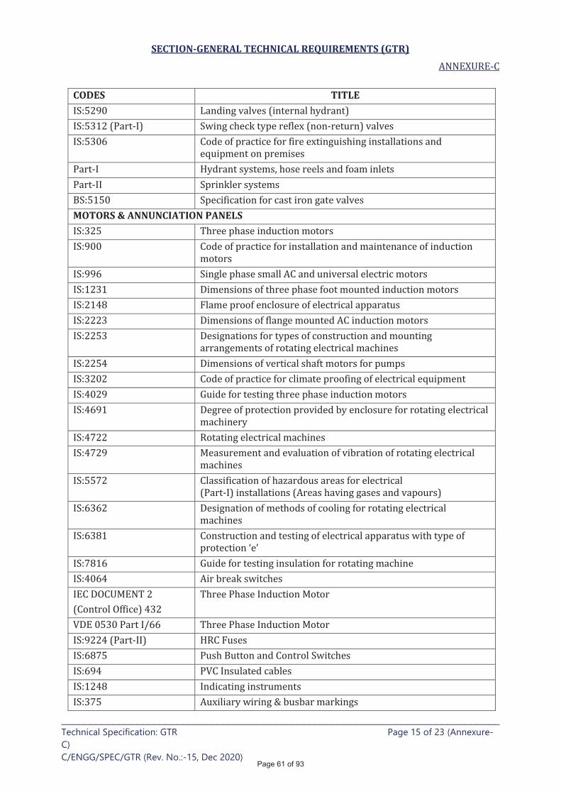
SECTION-GENERAL TECHNICAL REQUIREMENTS (GTR)
____________________________________________________________________________ Technical Specification: GTR Page 15 of 23 (Annexure-
C)
C/ENGG/SPEC/GTR (Rev. No.:-15, Dec 2020)
CODES TITLE
MOTORS & ANNUNCIATION PANELS
Page 61 of 93
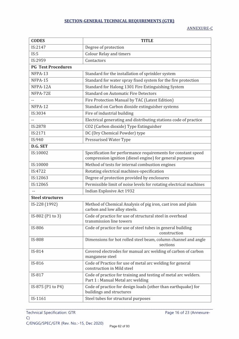
SECTION-GENERAL TECHNICAL REQUIREMENTS (GTR)
____________________________________________________________________________ Technical Specification: GTR Page 16 of 23 (Annexure-
C)
C/ENGG/SPEC/GTR (Rev. No.:-15, Dec 2020)
CODES TITLE
PG Test Procedures
D.G. SET
Steel structures
Page 62 of 93
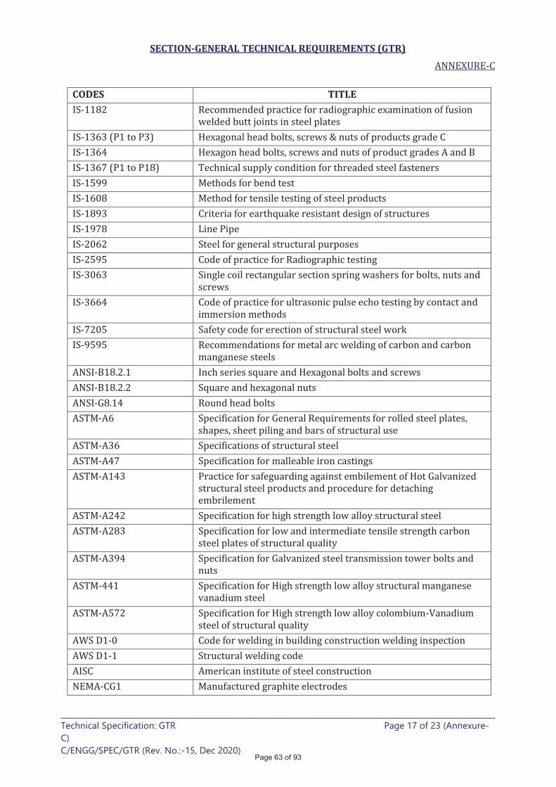
SECTION-GENERAL TECHNICAL REQUIREMENTS (GTR)
____________________________________________________________________________ Technical Specification: GTR Page 17 of 23 (Annexure-
C)
C/ENGG/SPEC/GTR (Rev. No.:-15, Dec 2020)
CODES TITLE
Page 63 of 93
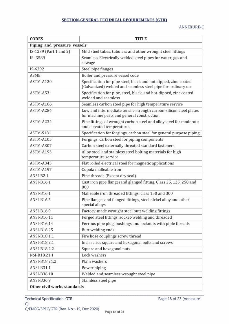
SECTION-GENERAL TECHNICAL REQUIREMENTS (GTR)
____________________________________________________________________________ Technical Specification: GTR Page 18 of 23 (Annexure-
C)
C/ENGG/SPEC/GTR (Rev. No.:-15, Dec 2020)
CODES TITLE Piping and pressure vessels
Other civil works standards
Page 64 of 93

SECTION-GENERAL TECHNICAL REQUIREMENTS (GTR)
____________________________________________________________________________ Technical Specification: GTR Page 19 of 23 (Annexure-
C)
C/ENGG/SPEC/GTR (Rev. No.:-15, Dec 2020)
CODES TITLE
National building code of India 1970
Page 65 of 93
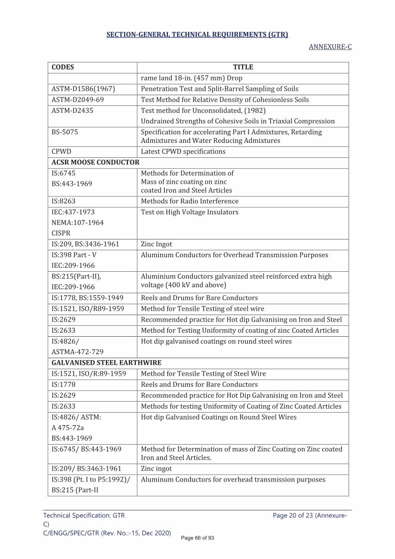
SECTION-GENERAL TECHNICAL REQUIREMENTS (GTR)
____________________________________________________________________________ Technical Specification: GTR Page 20 of 23 (Annexure-
C)
C/ENGG/SPEC/GTR (Rev. No.:-15, Dec 2020)
CODES TITLE
ACSR MOOSE CONDUCTOR
GALVANISED STEEL EARTHWIRE
Page 66 of 93
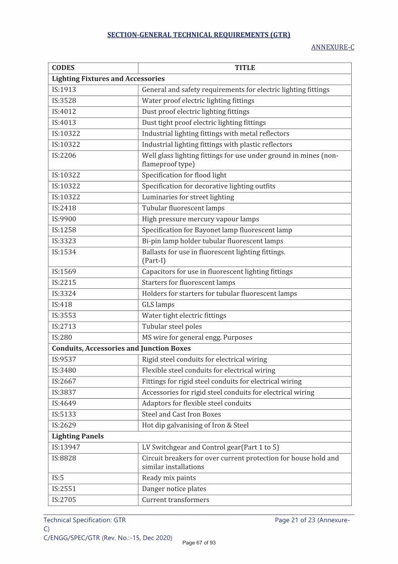
SECTION-GENERAL TECHNICAL REQUIREMENTS (GTR)
____________________________________________________________________________ Technical Specification: GTR Page 21 of 23 (Annexure-
C)
C/ENGG/SPEC/GTR (Rev. No.:-15, Dec 2020)
CODES TITLE Lighting Fixtures and Accessories
Conduits, Accessories and Junction Boxes
Lighting Panels
Page 67 of 93
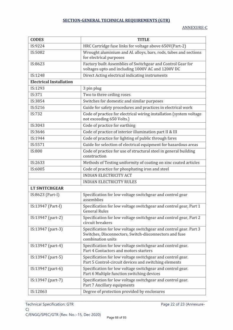
SECTION-GENERAL TECHNICAL REQUIREMENTS (GTR)
____________________________________________________________________________ Technical Specification: GTR Page 22 of 23 (Annexure-
C)
C/ENGG/SPEC/GTR (Rev. No.:-15, Dec 2020)
CODES TITLE
Electrical Installation
LT SWITCHGEAR
Page 68 of 93
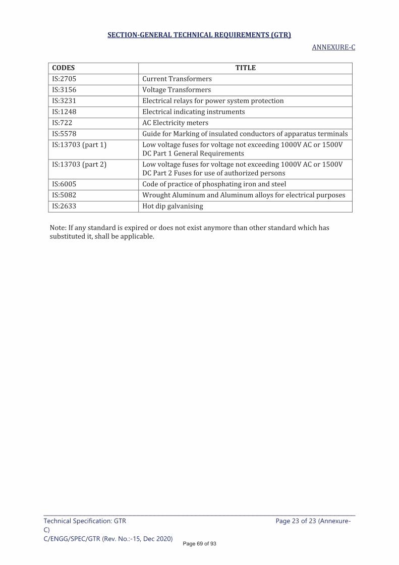
SECTION-GENERAL TECHNICAL REQUIREMENTS (GTR)
____________________________________________________________________________ Technical Specification: GTR Page 23 of 23 (Annexure-
C)
C/ENGG/SPEC/GTR (Rev. No.:-15, Dec 2020)
CODES TITLE
Page 69 of 93
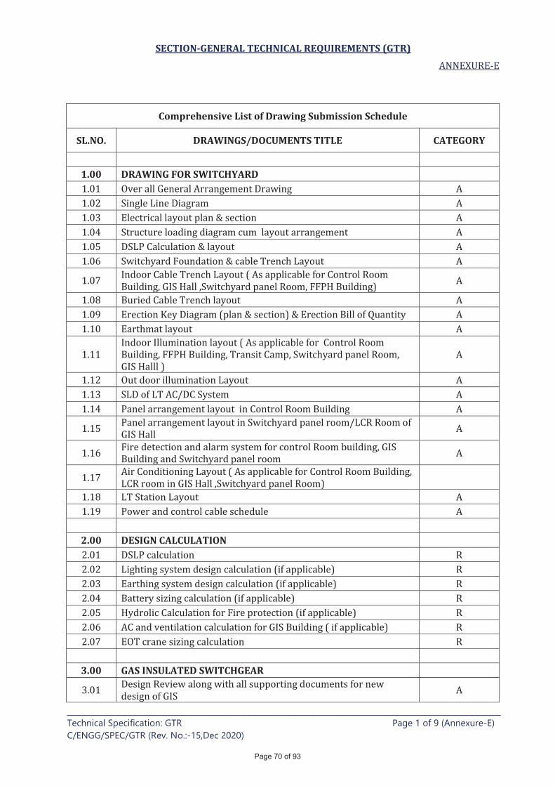
SECTION-GENERAL TECHNICAL REQUIREMENTS (GTR)
____________________________________________________________________________ Technical Specification: GTR Page 1 of 9 (Annexure-E)
C/ENGG/SPEC/GTR (Rev. No.:-15,Dec 2020)
Comprehensive List of Drawing Submission Schedule
SL.NO. DRAWINGS/DOCUMENTS TITLE CATEGORY
1.00 DRAWING FOR SWITCHYARD
2.00 DESIGN CALCULATION
3.00 GAS INSULATED SWITCHGEAR
Page 70 of 93

SECTION-GENERAL TECHNICAL REQUIREMENTS (GTR)
____________________________________________________________________________ Technical Specification: GTR Page 2 of 9 (Annexure-E)
C/ENGG/SPEC/GTR (Rev. No.:-15,Dec 2020)
Comprehensive List of Drawing Submission Schedule
4.00 AUTOTRANSFORMER
Page 71 of 93
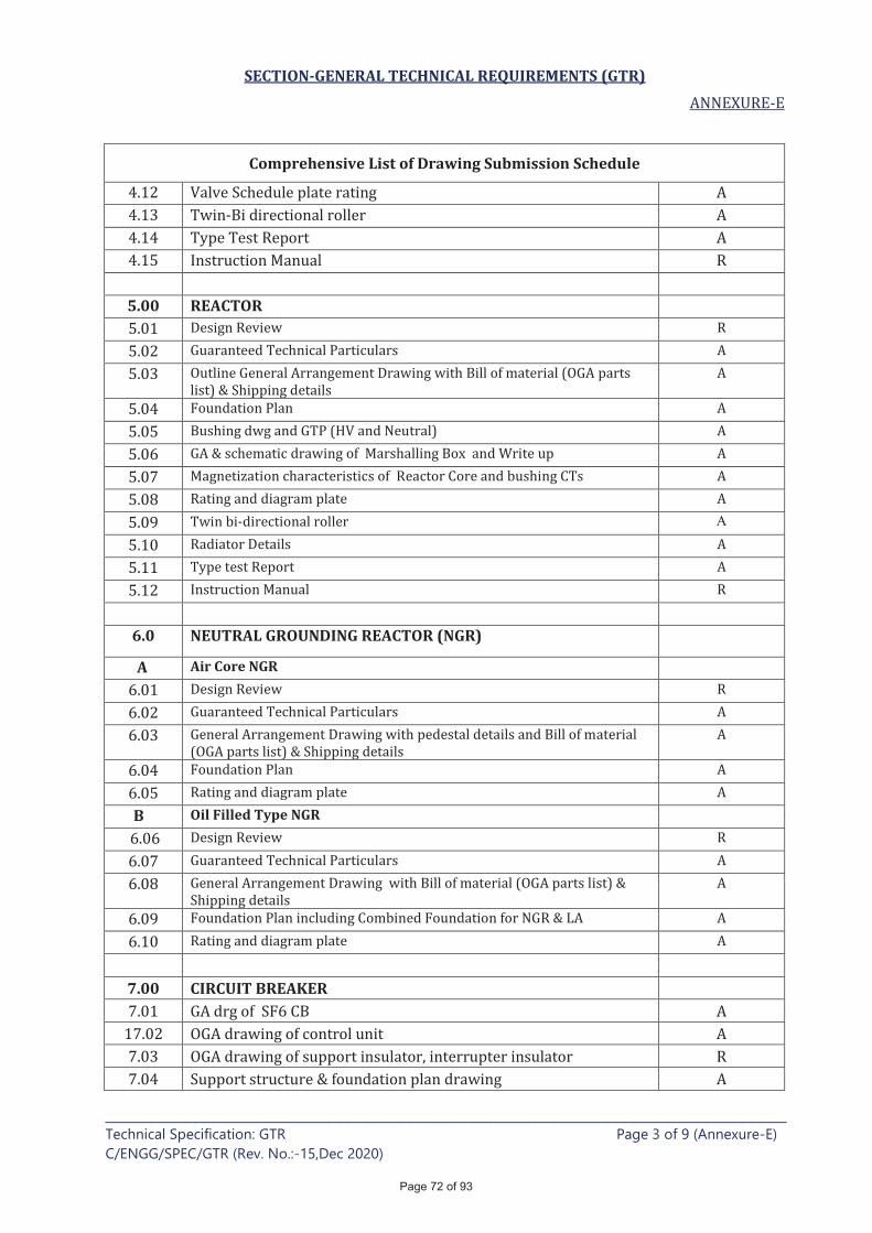
SECTION-GENERAL TECHNICAL REQUIREMENTS (GTR)
____________________________________________________________________________ Technical Specification: GTR Page 3 of 9 (Annexure-E)
C/ENGG/SPEC/GTR (Rev. No.:-15,Dec 2020)
Comprehensive List of Drawing Submission Schedule
5.00 REACTOR
A
6.0 NEUTRAL GROUNDING REACTOR (NGR)
A Air Core NGR
B Oil Filled Type NGR
7.00 CIRCUIT BREAKER
Page 72 of 93
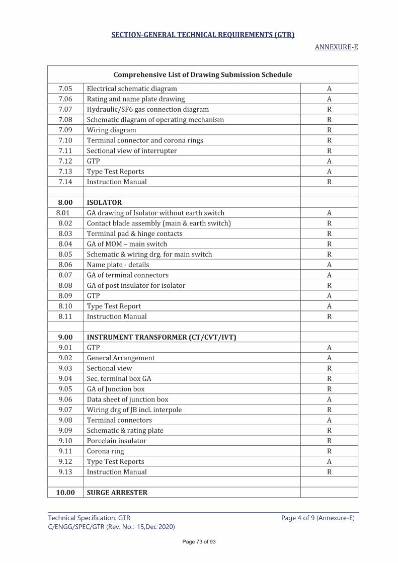
SECTION-GENERAL TECHNICAL REQUIREMENTS (GTR)
____________________________________________________________________________ Technical Specification: GTR Page 4 of 9 (Annexure-E)
C/ENGG/SPEC/GTR (Rev. No.:-15,Dec 2020)
Comprehensive List of Drawing Submission Schedule
8.00 ISOLATOR
9.00 INSTRUMENT TRANSFORMER (CT/CVT/IVT)
10.00 SURGE ARRESTER
Page 73 of 93
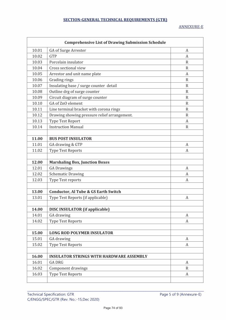
SECTION-GENERAL TECHNICAL REQUIREMENTS (GTR)
____________________________________________________________________________ Technical Specification: GTR Page 5 of 9 (Annexure-E)
C/ENGG/SPEC/GTR (Rev. No.:-15,Dec 2020)
Comprehensive List of Drawing Submission Schedule
11.00 BUS POST INSULATOR
12.00 Marshaling Box, Junction Boxes
13.00 Conductor, Al Tube & GS Earth Switch
14.00 DISC INSULATOR (if applicable)
15.00 LONG ROD POLYMER INSULATOR
16.00 INSULATOR STRINGS WITH HARDWARE ASSEMBLY
Page 74 of 93
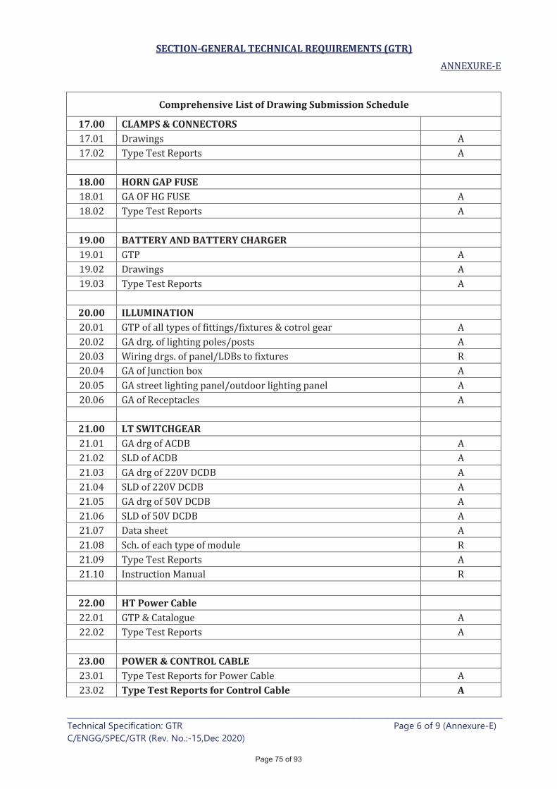
SECTION-GENERAL TECHNICAL REQUIREMENTS (GTR)
____________________________________________________________________________ Technical Specification: GTR Page 6 of 9 (Annexure-E)
C/ENGG/SPEC/GTR (Rev. No.:-15,Dec 2020)
Comprehensive List of Drawing Submission Schedule
17.00 CLAMPS & CONNECTORS
18.00 HORN GAP FUSE
19.00 BATTERY AND BATTERY CHARGER
20.00 ILLUMINATION
21.00 LT SWITCHGEAR
22.00 HT Power Cable
23.00 POWER & CONTROL CABLE
Type Test Reports for Control Cable A
Page 75 of 93
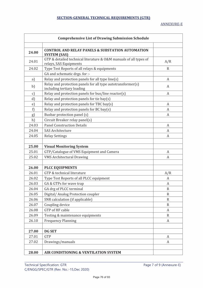
SECTION-GENERAL TECHNICAL REQUIREMENTS (GTR)
____________________________________________________________________________ Technical Specification: GTR Page 7 of 9 (Annexure-E)
C/ENGG/SPEC/GTR (Rev. No.:-15,Dec 2020)
Comprehensive List of Drawing Submission Schedule
24.00 CONTROL AND RELAY PANELS & SUBSTATION AUTOMATION SYSTEM (SAS)
25.00 Visual Monitoring System
26.00 PLCC EQUIPMENTS
27.00 DG SET
28.00 AIR CONDITIONING & VENTILATION SYSTEM
Page 76 of 93
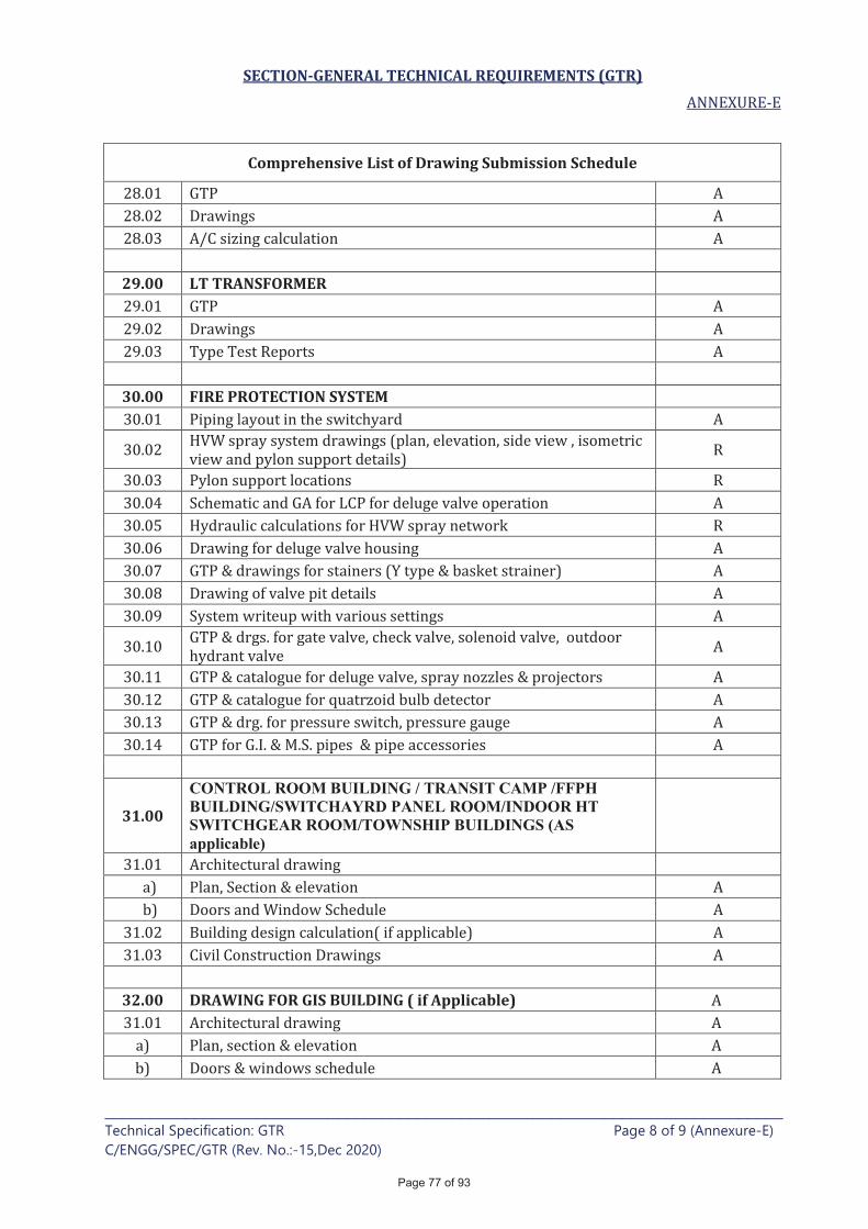
SECTION-GENERAL TECHNICAL REQUIREMENTS (GTR)
____________________________________________________________________________ Technical Specification: GTR Page 8 of 9 (Annexure-E)
C/ENGG/SPEC/GTR (Rev. No.:-15,Dec 2020)
Comprehensive List of Drawing Submission Schedule
29.00 LT TRANSFORMER
30.00 FIRE PROTECTION SYSTEM
31.00
CONTROL ROOM BUILDING / TRANSIT CAMP /FFPH BUILDING/SWITCHAYRD PANEL ROOM/INDOOR HT SWITCHGEAR ROOM/TOWNSHIP BUILDINGS (AS applicable)
32.00 DRAWING FOR GIS BUILDING ( if Applicable)
Page 77 of 93
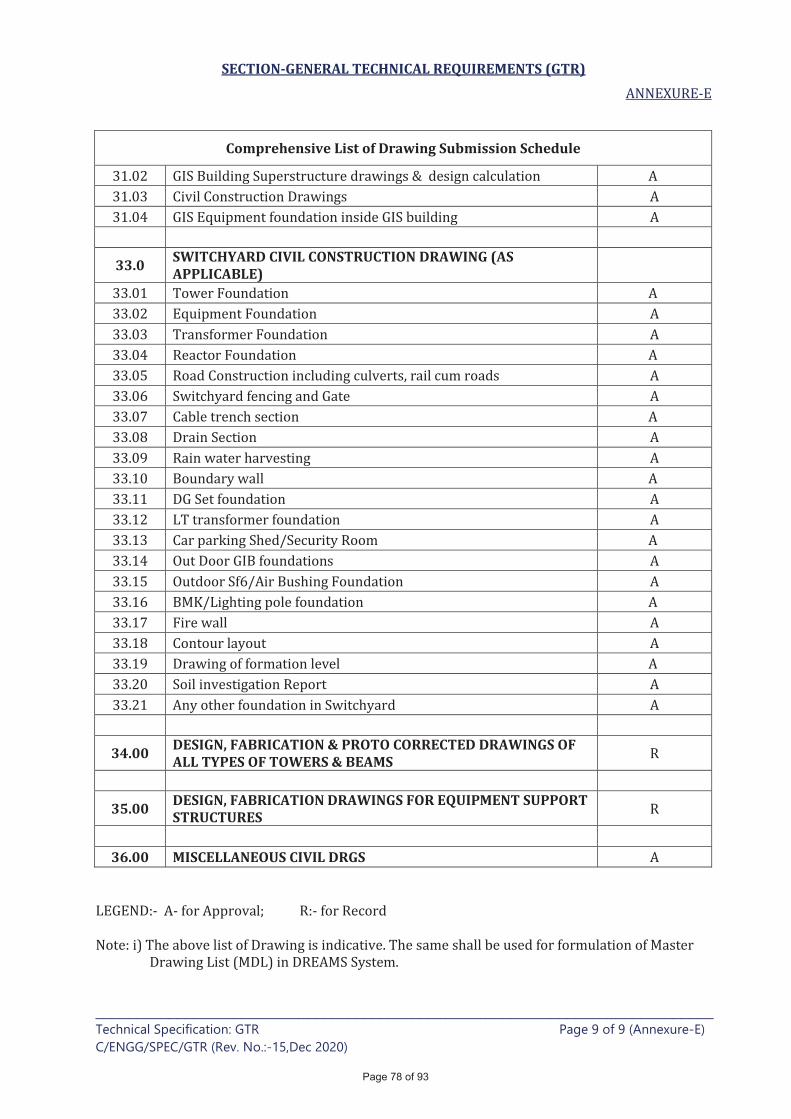
SECTION-GENERAL TECHNICAL REQUIREMENTS (GTR)
____________________________________________________________________________ Technical Specification: GTR Page 9 of 9 (Annexure-E)
C/ENGG/SPEC/GTR (Rev. No.:-15,Dec 2020)
Comprehensive List of Drawing Submission Schedule
33.0 SWITCHYARD CIVIL CONSTRUCTION DRAWING (AS APPLICABLE)
34.00 DESIGN, FABRICATION & PROTO CORRECTED DRAWINGS OF ALL TYPES OF TOWERS & BEAMS
35.00 DESIGN, FABRICATION DRAWINGS FOR EQUIPMENT SUPPORT STRUCTURES
36.00 MISCELLANEOUS CIVIL DRGS
Page 78 of 93
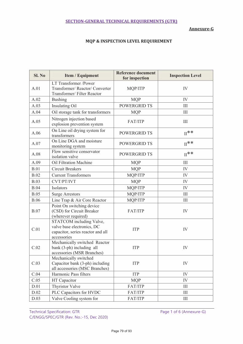
SECTION-GENERAL TECHNICAL REQUIREMENTS (GTR)
Annexure-G
__________________________________________________________________________ Technical Specification: GTR Page 1 of 6 (Annexure-G)
C/ENGG/SPEC/GTR (Rev. No.:-15, Dec 2020)
MQP & INSPECTION LEVEL REQUIREMENT
Sl. No Item / Equipment Reference document for inspection Inspection Level
A.01
LT Transformer /Power
Transformer/ Reactor/ Converter
Transformer/ Filter Reactor
MQP/ITP IV
A.02 Bushing MQP IV
A.03 Insulating Oil POWERGRID TS III
A.04 Oil storage tank for transformers MQP III
A.05 Nitrogen injection based
explosion prevention system FAT/ITP III
A.06 On Line oil drying system for
transformers POWERGRID TS II**
A.07 On Line DGA and moisture
monitoring system POWERGRID TS II**
A.08 Flow sensitive conservator
isolation valve POWERGRID TS II**
A.09 Oil Filtration Machine MQP III
B.01 Circuit Breakers MQP IV
B.02 Current Transformers MQP/ITP IV
B.03 CVT/PT/IVT MQP IV
B.04 Isolators MQP/ITP IV
B.05 Surge Arrestors MQP/ITP III
B.06 Line Trap & Air Core Reactor MQP/ITP III
B.07
Point On switching device
(CSD) for Circuit Breaker
(wherever required)
FAT/ITP IV
C.01
STATCOM including Valve,
valve base electronics, DC
capacitor, series reactor and all
accessories
ITP IV
C.02
Mechanically switched Reactor
bank (3-ph) including all
accessories (MSR Branches)
ITP IV
C.03
Mechanically switched
Capacitor bank (3-ph) including
all accessories (MSC Branches)
ITP IV
C.04 Harmonic Pass filters ITP IV
C.05 HT Capacitor MQP IV
D.01 Thyristor Valve FAT/ITP III
D.02 PLC Capacitors for HVDC FAT/ITP III
D.03 Valve Cooling system for FAT/ITP III
Page 79 of 93

SECTION-GENERAL TECHNICAL REQUIREMENTS (GTR)
Annexure-G
__________________________________________________________________________ Technical Specification: GTR Page 2 of 6 (Annexure-G)
C/ENGG/SPEC/GTR (Rev. No.:-15, Dec 2020)
Sl. No Item / Equipment Reference document for inspection Inspection Level
HVDC
D.04 AC/DC Filter Resistors ITP III
D.05 DC Current and Voltage
measuring device for HVDC FAT/ITP III
D.06 Maintenance platform for valve
hall POWERGRID TS II
D.07 Optical signal column for FSC FAT/ITP II
E.01 GIS including spares MQP/ITP IV
E.02 Dew Point Meter for GIS POWERGRID TS I*
E.03 Portable Partial Discharge
monitoring system for GIS POWERGRID TS I*
E.04 Partial Discharge Monitoring System (Online) for GIS ITP III
E.05 PEB Structure and Puf Panels MQP III
F.01 Substation Automation system FAT/MQP III
F.02 Event Logger POWERGRID TS III
F.03
PLCC equipment Viz PLCC
Terminal ,Carrier equipment,
Protection Coupler , Coupling
Device but excluding EPAX /
HF Cable
MQP III
F.04 Control & Relay Panels MQP III
G.01 EHV Cables MQP/ITP III
G.02 Power Cables & Control Cables MQP III
G.03 Cable Joints (11 kV and above) POWERGRID TS II
G.04 Cable Lugs & Glands /
Clamps/Terminations POWERGRID TS I
H.01 LT Switchgear &
ACDB/DCDB/MLDB/ELDB MQP III
H.02 Battery POWERGRID TS II
H.03 Battery Charger MQP III
H.04 UPS & Voltage Stablizer MQP/FAT III
H.05 D. G. Set FAT/ITP III
H.06 Lighting Panel POWERGRID TS II
H.07 Lighting Poles POWERGRID TS II
H.08.1
Lighting Fixtures, Lighting
Earthwire, Switches / sockets,
Conduits, Lamps & fans
including exhaust fans
POWERGRID TS I
H.8.2
Solar based LEDs System
including street light/pole solar
panel, Inverter controller/LED
fixture
FAT III
H.09 MS/GI /PVC Pipes for cable POWERGRID TS I
Page 80 of 93
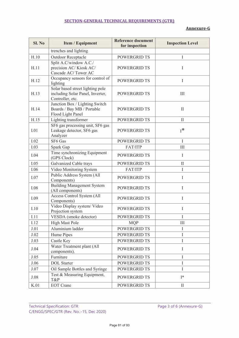
SECTION-GENERAL TECHNICAL REQUIREMENTS (GTR)
Annexure-G
__________________________________________________________________________ Technical Specification: GTR Page 3 of 6 (Annexure-G)
C/ENGG/SPEC/GTR (Rev. No.:-15, Dec 2020)
Sl. No Item / Equipment Reference document for inspection Inspection Level
trenches and lighting
H.10 Outdoor Receptacle POWERGRID TS I
H.11
Split A.C/window A.C./
precision AC/ Kiosk AC/
Cascade AC/ Tower AC
POWERGRID TS I
H.12 Occupancy sensors for control of
lighting POWERGRID TS I
H.13
Solar based street lighting pole
including Solar Panel, Inverter,
Controller, etc.
POWERGRID TS III
H.14
Junction Box / Lighting Switch
Boards / Bay MB / Portable
Flood Light Panel
POWERGRID TS II
H.15 Lighting transformer POWERGRID TS II
I.01
SF6 gas processing unit, SF6 gas
Leakage detector, SF6 gas
Analyzer
POWERGRID TS I*
I.02 SF6 Gas POWERGRID TS I
I.03 Spark Gap FAT/ITP III
I.04 Time synchronizing Equipment
(GPS Clock) POWERGRID TS I
I.05 Galvanized Cable trays POWERGRID TS II
I.06 Video Monitoring System FAT/ITP I
I.07 Public Address System (All
Components) POWERGRID TS I
I.08 Building Management System
(All components) POWERGRID TS I
I.09 Access Control System (All
Components) POWERGRID TS I
I.10 Video Display system/ Video
Projection system POWERGRID TS I
I.11 VESDA (smoke detector) POWERGRID TS I
I.12 High Mast Pole MQP III
J.01 Aluminium ladder POWERGRID TS I
J.02 Hume Pipes POWERGRID TS I
J.03 Castle Key POWERGRID TS I
J.04 Water Treatment plant (All
components). POWERGRID TS I
J.05 Furniture POWERGRID TS I
J.06 DOL Starter POWERGRID TS I
J.07 Oil Sample Bottles and Syringe POWERGRID TS I
J.08 Test & Measuring Equipment,
T&P POWERGRID TS I*
K.01 EOT Crane POWERGRID TS II
Page 81 of 93
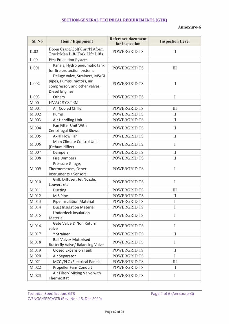
SECTION-GENERAL TECHNICAL REQUIREMENTS (GTR)
Annexure-G
__________________________________________________________________________ Technical Specification: GTR Page 4 of 6 (Annexure-G)
C/ENGG/SPEC/GTR (Rev. No.:-15, Dec 2020)
Sl. No Item / Equipment Reference document for inspection Inspection Level
K.02 Boom Crane/Golf Cart/Platform
Truck/Man Lift/ Fork Lift/ Lifts POWERGRID TS II
L.00 Fire Protection System
L.001 Panels, Hydro pneumatic tank
for fire protection system. POWERGRID TS III
L.002
Deluge valve, Strainers, MS/GI pipes, Pumps, motors, air compressor, and other valves, Diesel Engines
POWERGRID TS II
L.003 Others POWERGRID TS I
M.00 HVAC SYSTEM
M.001 Air Cooled Chiller POWERGRID TS III
M.002 Pump POWERGRID TS II
M.003 Air Handling Unit POWERGRID TS II
M.004 Fan Filter Unit With
Centrifugal Blower POWERGRID TS II
M.005 Axial Flow Fan POWERGRID TS II
M.006 Main Climate Control Unit
(Dehumidifier) POWERGRID TS I
M.007 Dampers POWERGRID TS II
M.008 Fire Dampers POWERGRID TS II
M.009
Pressure Gauge, Thermometers, Other Instruments / Sensors
POWERGRID TS I
M.010 Grill, Diffuser, Jet Nozzle,
Louvers etc POWERGRID TS I
M.011 Ducting POWERGRID TS III
M.012 M S Pipe POWERGRID TS II
M.013 Pipe Insulation Material POWERGRID TS I
M.014 Duct Insulation Material POWERGRID TS I
M.015 Underdeck Insulation
Material POWERGRID TS I
M.016 Gate Valve & Non Return
valve POWERGRID TS I
M.017 Y Strainer POWERGRID TS II
M.018 Ball Valve/ Motorised
Butterfly Valve/ Balancing Valve POWERGRID TS I
M.019 Closed Expansion Tank POWERGRID TS II
M.020 Air Separator POWERGRID TS I
M.021 MCC /PLC /Electrical Panels POWERGRID TS III
M.022 Propeller Fan/ Conduit POWERGRID TS II
M.023 Air Filter/ Mixing Valve with
Thermostat POWERGRID TS I
Page 82 of 93
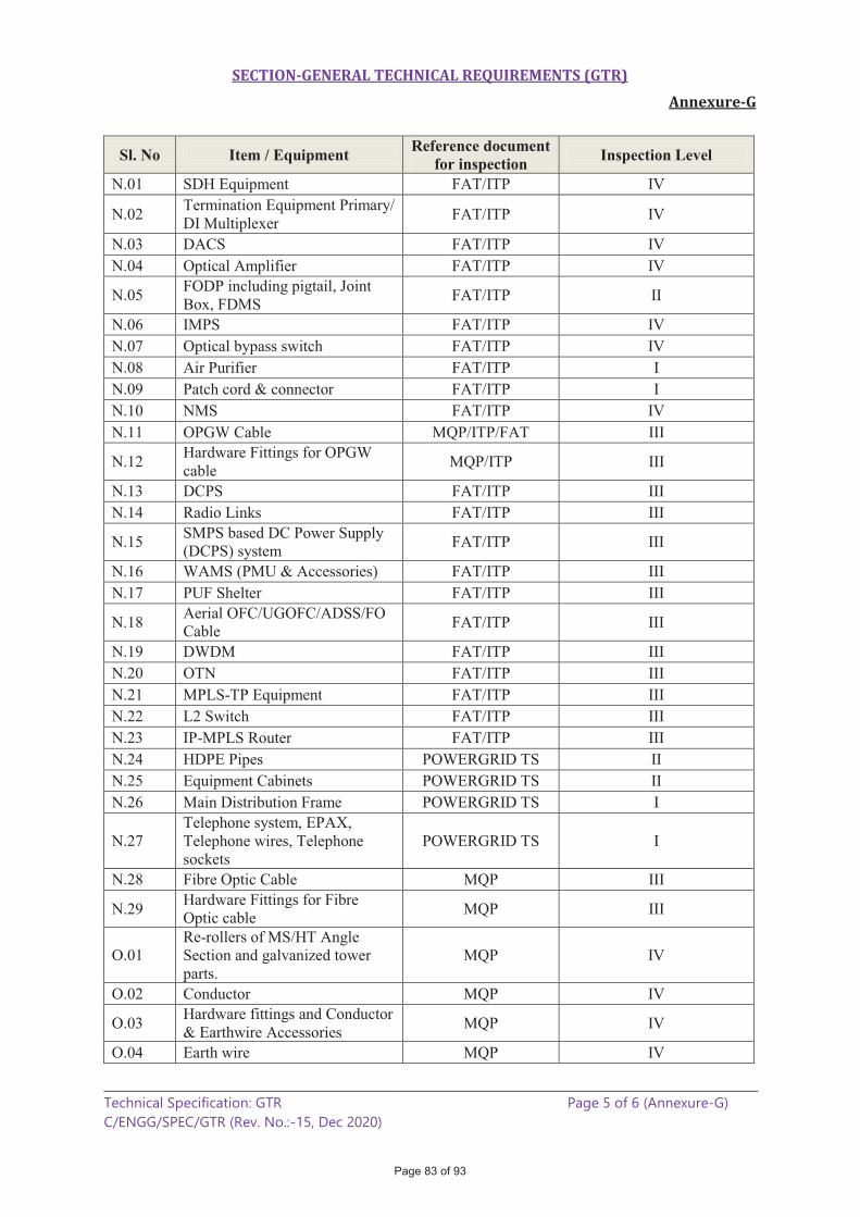
SECTION-GENERAL TECHNICAL REQUIREMENTS (GTR)
Annexure-G
__________________________________________________________________________ Technical Specification: GTR Page 5 of 6 (Annexure-G)
C/ENGG/SPEC/GTR (Rev. No.:-15, Dec 2020)
Sl. No Item / Equipment Reference document for inspection Inspection Level
N.01 SDH Equipment FAT/ITP IV
N.02 Termination Equipment Primary/
DI Multiplexer FAT/ITP IV
N.03 DACS FAT/ITP IV
N.04 Optical Amplifier FAT/ITP IV
N.05 FODP including pigtail, Joint
Box, FDMS FAT/ITP II
N.06 IMPS FAT/ITP IV
N.07 Optical bypass switch FAT/ITP IV
N.08 Air Purifier FAT/ITP I
N.09 Patch cord & connector FAT/ITP I
N.10 NMS FAT/ITP IV
N.11 OPGW Cable MQP/ITP/FAT III
N.12 Hardware Fittings for OPGW
cable MQP/ITP III
N.13 DCPS FAT/ITP III
N.14 Radio Links FAT/ITP III
N.15 SMPS based DC Power Supply
(DCPS) system FAT/ITP III
N.16 WAMS (PMU & Accessories) FAT/ITP III
N.17 PUF Shelter FAT/ITP III
N.18 Aerial OFC/UGOFC/ADSS/FO
Cable FAT/ITP III
N.19 DWDM FAT/ITP III
N.20 OTN FAT/ITP III
N.21 MPLS-TP Equipment FAT/ITP III
N.22 L2 Switch FAT/ITP III
N.23 IP-MPLS Router FAT/ITP III
N.24 HDPE Pipes POWERGRID TS II
N.25 Equipment Cabinets POWERGRID TS II
N.26 Main Distribution Frame POWERGRID TS I
N.27
Telephone system, EPAX,
Telephone wires, Telephone
sockets
POWERGRID TS I
N.28 Fibre Optic Cable MQP III
N.29 Hardware Fittings for Fibre
Optic cable MQP III
O.01
Re-rollers of MS/HT Angle
Section and galvanized tower
parts.
MQP IV
O.02 Conductor MQP IV
O.03 Hardware fittings and Conductor
& Earthwire Accessories MQP IV
O.04 Earth wire MQP IV
Page 83 of 93

SECTION-GENERAL TECHNICAL REQUIREMENTS (GTR)
Annexure-G
__________________________________________________________________________ Technical Specification: GTR Page 6 of 6 (Annexure-G)
C/ENGG/SPEC/GTR (Rev. No.:-15, Dec 2020)
Sl. No Item / Equipment Reference document for inspection Inspection Level
O.05 Insulator MQP IV
O.06 Bolts & Nuts of Gr 8.8 / 8 MQP IV
O.07 Mono Pole MQP IV
O.08 Foundation Bolts & Anchor
Bolts POWERGRID TS III
O.09 D-shackle/ Hanger / Links and
associated Special bolt/nuts MQP III
O.10 Span Marker, Obstruction lights
and Wind Measuring Equipment POWERGRID TS III
O.11 MS ROD rolled by Approved
Re-roller of POWERGRID MQP III
O.12 MS ROD rolled by Approved
steel producers of POWERGRID POWERGRID TS I
O.13 Spring Washers & Pack washers POWERGRID TS II
O.14 Bolts & Nuts Gr up to 5.6/5 POWERGRID TS II
O.15 ACD & Barbed wire for
ACD/Bird guard POWERGRID TS II
O.16 Danger Plate /Phase Plate /
Number Plate / Circuit plate POWERGRID TS I
O.17 Sub Station Structure
(lattice/pipe type) MQP III
O.18 Clamps & Connecters (including
equipment connectors) MQP III
O.19 MS/ GI Flat, rod type, pipe type
and other earthing material. POWERGRID TS II
O.20 Aluminium Tube & Busbar
materials POWERGRID TS II
O.21 Pipe Type & Counter Poise
Earthing POWERGRID TS II
O.22 DTS System POWERGRID TS II
For Equipment where requirement of MQP is envisaged, ITP/FAT will be followed If sourced from off shore. For items required in S/S or T/L or TELECOM/LD&C , same inspection level as specified shall be followed for all the cases.
*MICC for test and measuring equipment (inspection level I or II) shall be issued only after actual verification/ demonstration of satisfactory performance at site.
** Though level-2 items, CIP/MICC can be issued also on review of TCs and visual inspection of these item.
Page 84 of 93
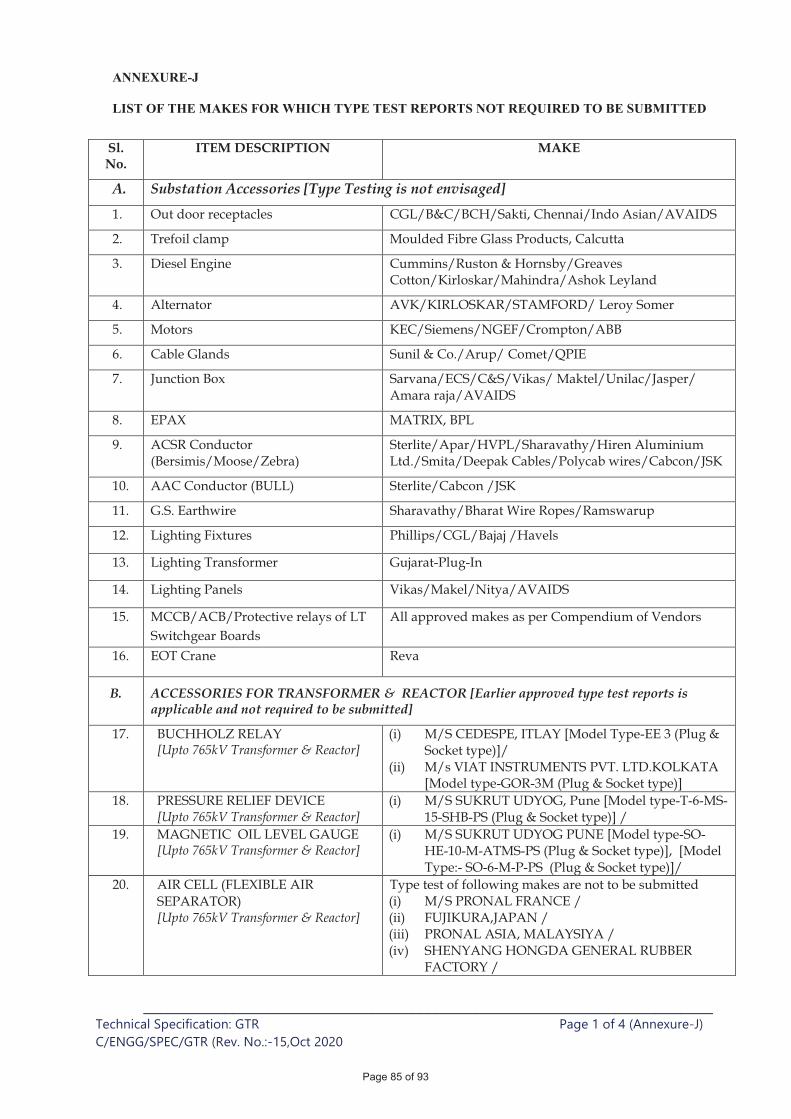
ANNEXURE-J
LIST OF THE MAKES FOR WHICH TYPE TEST REPORTS NOT REQUIRED TO BE SUBMITTED
______________________________________________________________________ Technical Specification: GTR Page 1 of 4 (Annexure-J)
C/ENGG/SPEC/GTR (Rev. No.:-15,Oct 2020
Sl. No.
ITEM DESCRIPTION MAKE
A. Substation Accessories [Type Testing is not envisaged] 1. Out door receptacles CGL/B&C/BCH/Sakti, Chennai/Indo Asian/AVAIDS
2. Trefoil clamp Moulded Fibre Glass Products, Calcutta
3. Diesel Engine Cummins/Ruston & Hornsby/Greaves Cotton/Kirloskar/Mahindra/Ashok Leyland
4. Alternator AVK/KIRLOSKAR/STAMFORD/ Leroy Somer
5. Motors KEC/Siemens/NGEF/Crompton/ABB
6. Cable Glands Sunil & Co./Arup/ Comet/QPIE
7. Junction Box Sarvana/ECS/C&S/Vikas/ Maktel/Unilac/Jasper/ Amara raja/AVAIDS
8. EPAX MATRIX, BPL
9. ACSR Conductor (Bersimis/Moose/Zebra)
Sterlite/Apar/HVPL/Sharavathy/Hiren Aluminium Ltd./Smita/Deepak Cables/Polycab wires/Cabcon/JSK
10. AAC Conductor (BULL) Sterlite/Cabcon /JSK
11. G.S. Earthwire Sharavathy/Bharat Wire Ropes/Ramswarup
12. Lighting Fixtures Phillips/CGL/Bajaj /Havels
13. Lighting Transformer Gujarat-Plug-In
14. Lighting Panels Vikas/Makel/Nitya/AVAIDS
15. MCCB/ACB/Protective relays of LT Switchgear Boards
All approved makes as per Compendium of Vendors
16. EOT Crane Reva
B. ACCESSORIES FOR TRANSFORMER & REACTOR [Earlier approved type test reports is applicable and not required to be submitted]
17. BUCHHOLZ RELAY [Upto 765kV Transformer & Reactor]
(i) M/S CEDESPE, ITLAY [Model Type-EE 3 (Plug & Socket type)]/
(ii) M/s VIAT INSTRUMENTS PVT. LTD.KOLKATA [Model type-GOR-3M (Plug & Socket type)]
18. PRESSURE RELIEF DEVICE [Upto 765kV Transformer & Reactor]
(i) M/S SUKRUT UDYOG, Pune [Model type-T-6-MS-15-SHB-PS (Plug & Socket type)] /
19. MAGNETIC OIL LEVEL GAUGE [Upto 765kV Transformer & Reactor]
(i) M/S SUKRUT UDYOG PUNE [Model type-SO-HE-10-M-ATMS-PS (Plug & Socket type)], [Model Type:- SO-6-M-P-PS (Plug & Socket type)]/
20. AIR CELL (FLEXIBLE AIR SEPARATOR) [Upto 765kV Transformer & Reactor]
Type test of following makes are not to be submitted (i) M/S PRONAL FRANCE / (ii) FUJIKURA,JAPAN / (iii) PRONAL ASIA, MALAYSIYA / (iv) SHENYANG HONGDA GENERAL RUBBER
FACTORY /
Page 85 of 93
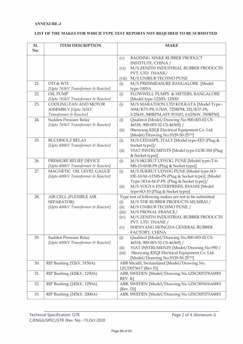
ANNEXURE-J
LIST OF THE MAKES FOR WHICH TYPE TEST REPORTS NOT REQUIRED TO BE SUBMITTED
______________________________________________________________________ Technical Specification: GTR Page 2 of 4 (Annexure-J)
C/ENGG/SPEC/GTR (Rev. No.:-15,Oct 2020
Sl. No.
ITEM DESCRIPTION MAKE
(v) BAODING XINKE RUBBER PRODUCT INSTITUTE, CHINA /
(vi) M/S ZENITH INDUSTRIAL RUBBER PRODUCTS PVT. LTD. THANE/
(vii) M/S UNIRUB TECHNO PUNE 21. OTI & WTI
[Upto 765kV Transformer & Reactor] (i) M/S PRESIMEASURE BANGALORE [Model
type-1005A 22. OIL PUMP
[Upto 765kV Transformer & Reactor] (i) FLOWWELL PUMPS & METERS, BANGALORE
[Model type-1220D, 1250D 23. COOLING FAN AND MOTOR
ASSEMBLY [Upto 765kV Transformer & Reactor]
(i) M/S MARATHON LTD KOLKATA [Model Type:-36M/K75-P8, 0.7kW, 725RPM, 22J/K37-P6, 0.25kW, 940RPM,AFF 915103, 0.625kW, 550RPM]
24. Sudden Pressure Relay [Upto 765kV Transformer & Reactor]
(i) Qualitrol [Model/Drawing No.900-003-02 CS-46518, 900-003-32 CS-46369] /
(ii) Shenyang KEQI Electrical Equipment Co. Ltd. [Model/Drawing No.SYJ9-50-25TH]
25. BUCHHOLZ RELAY [Upto 400kV Transformer & Reactor]
(i) M/S CEDASPE, ITALY [Model type-EE3 (Plug & Socket type)]/
(ii) VIAT INSTRUMENTS [Model type-GOR-3M (Plug & Socket type)]
26. PRESSURE RELIEF DEVICE [Upto 400kV Transformer & Reactor]
(i) M/S SKURUT UDYOG, PUNE [Model type-T-6-MS-15-SHB-PS (Plug & Socket type)]
27. MAGNETIC OIL LEVEL GAUGE [Upto 400kV Transformer & Reactor]
(i) M/S SUKRUT UDYOG PUNE [Model type-SO-HE-10-M-ATMS-PS (Plug & Socket type)], [Model Type: SO-6-M-P-PS (Plug & Socket type)]/
(ii) M/S YOGYA ENTERPRISES, JHANSI [Model type-SO-10 (Plug & Socket type)]
28. AIR CELL (FLEXIBLE AIR SEPARATOR) [Upto 400kV Transformer & Reactor]
Type test of following makes are not to be submitted (i) M/S THE RUBBER PRODUCTS MUMBAI / (ii) M/S UNIRUB TECHNO PUNE / (iii) M/S PRONAL FRANCE/ (iv) M/S ZENITH INDUSTRIAL RUBBER PRODUCTS
PVT. LTD. THANE / (v) SHENYANG HONGDA GENERAL RUBBER
FACTORY, CHINA 29. Sudden Pressure Relay
[Upto 400kV Transformer & Reactor] (i) Qualitrol [Model/Drawing No.900-003-02 CS-
46518, 900-003-32 CS-46369] / (ii) VIAT INSTRUMENTS [Model/Drawing No.950 / (iii) Shenyang KEQI Electrical Equipment Co. Ltd.
[Model/Drawing No.SYJ9-50-25TH] 30. RIP Bushing (52kV, 3150A) ABB Micafil, Switzerland [Model/Drawing No.
1ZCD073617 (Rev F)] 31. RIP Bushing (420kV, 1250A) ABB, SWEDEN [Model/Drawing No.1ZSC005378A0001
REV. K] 32. RIP Bushing (245kV, 1250A) ABB, SWEDEN [Model/Drawing No.1ZSC005416A0001
(Rev. D)] 33. RIP Bushing (245kV, 2000A) ABB, SWEDEN [Model/Drawing No.1ZSC005373A0001
Page 86 of 93

ANNEXURE-J
LIST OF THE MAKES FOR WHICH TYPE TEST REPORTS NOT REQUIRED TO BE SUBMITTED
______________________________________________________________________ Technical Specification: GTR Page 3 of 4 (Annexure-J)
C/ENGG/SPEC/GTR (Rev. No.:-15,Oct 2020
Sl. No.
ITEM DESCRIPTION MAKE
(Rev. C)] 34. RIP Bushing (420kV, 1250A) HSP Germany [Model/Drawing No.327470]
35. RIP Bushing (245kV, 2000A) HSP Germany [Model/Drawing No.329260]
36. RIP Bushing (52kV, 3150A) HSP Germany [Model/Drawing No.329280]
37. RIP Bushing (420kV, 1250A) Izolyator, Russia [Model/Drawing No.686354.603]
38. RIP Bushing (245kV, 2000A) Izolyator, Russia [Model/Drawing No.686353.602]
39. RIP Bushing (52kV, 3150A) Izolyator, Russia [Model/Drawing No.686351.601]
40. RIP Bushing (145kV, 1250A) Izolyator, Russia [Model/Drawing No.686352.604]
41. RIP Bushing (420kV, 1250A) TRENCH, CHINA [Model/Drawing No.ECT 707 (C2)]
42. RIP Bushing (245kV, 2000A) TRENCH, CHINA [Model/Drawing No.ECT 617 (C3)]
43. RIP Bushing (245kV, 1250A) TRENCH, CHINA [Model/Drawing No.ECT 616 (C3)]
44. RIP Bushing (145kV, 1250A) TRENCH, CHINA [Model/Drawing No.ECT 516 (C3)]
45. RIP Bushing (52kV, 1250A) TRENCH, CHINA [Model/Drawing No.ECT 415 (C3)]
46. RIP Bushing (52kV, 3150A) TRENCH, CHINA [Model/Drawing No.ECT 419 (C3)]
47. RIP Bushing (420kV, 1250A) Xian China [Model/Drawing No.75706 (Rev 09)]
48. RIP Bushing (245kV,2000A) Xian China [Model/Drawing No.75618 (Rev 09)]
49. RIP Bushing (52kV, 3150A) Xian China [Model/Drawing No.75366 (Rev 03)]
50. RIP Bushing (52kV, 3150A) Xian China [Model/Drawing No.75332 (Rev 08)]
51. OIP Bushing (800kV, 2500A) ABB, SWEDEN [Model / Drawing No. GOE-2550-1600-2500-0.6-B, 1ZSC026186-AAM REV. H]
52. OIP Bushing (420kV, 2500A) ABB, SWEDEN [Model / Drawing No.GOE-1425-1150-2500-0.6, 1ZSC026186-AAL REV. F]
53. OIP Bushing (800kV, 2500A) TBEA, CHINA [Model / Drawing No.TBEA-500-765T-A0035-01, REV. 02]
54. OIP Bushing (420kV, 2500A) TBEA, CHINA [Model / Drawing No.TBEA-500-765T-A0035-02, REV. 02]
55. OIP Bushing (420kV, 2500A) TRENCH, CHINA [Model / Drawing No.OT-738-1 (C 5)]
56. OLTC (500MVA, 765kV ICT) MR Germany [Model/Drawing No. MI 1503 72.5/RC- 12231WR]
57. OLTC (500MVA, 400kV ICT) Easun MR, Chennai [Model/Drawing No. 3 x MI 1200 300/D 10.19.3W]
58. OLTC (220kV & below rating transformer)
BHEL, Bhopal [Model/Drawing No.MIII 600 110/C 10.19.3W]
C. TESTING EQUIPMENT FOR TRANSFORMER & REACTOR
59. Oil BDV Test Kit Baur [Model/Drawing No.DTA 100C]
60. Oil BDV Test Kit Megger [Model/Drawing No.OTS 100AF]
Page 87 of 93
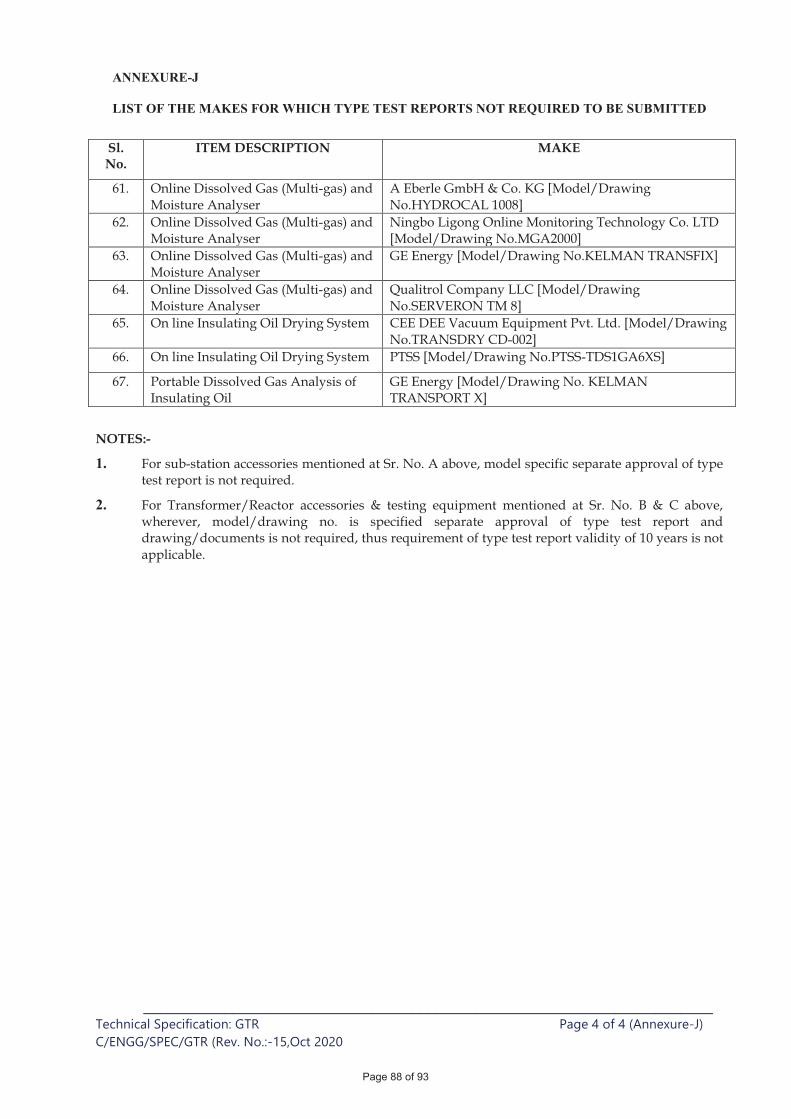
ANNEXURE-J
LIST OF THE MAKES FOR WHICH TYPE TEST REPORTS NOT REQUIRED TO BE SUBMITTED
______________________________________________________________________ Technical Specification: GTR Page 4 of 4 (Annexure-J)
C/ENGG/SPEC/GTR (Rev. No.:-15,Oct 2020
Sl. No.
ITEM DESCRIPTION MAKE
61. Online Dissolved Gas (Multi-gas) and Moisture Analyser
A Eberle GmbH & Co. KG [Model/Drawing No.HYDROCAL 1008]
62. Online Dissolved Gas (Multi-gas) and Moisture Analyser
Ningbo Ligong Online Monitoring Technology Co. LTD [Model/Drawing No.MGA2000]
63. Online Dissolved Gas (Multi-gas) and Moisture Analyser
GE Energy [Model/Drawing No.KELMAN TRANSFIX]
64. Online Dissolved Gas (Multi-gas) and Moisture Analyser
Qualitrol Company LLC [Model/Drawing No.SERVERON TM 8]
65. On line Insulating Oil Drying System CEE DEE Vacuum Equipment Pvt. Ltd. [Model/Drawing No.TRANSDRY CD-002]
66. On line Insulating Oil Drying System PTSS [Model/Drawing No.PTSS-TDS1GA6XS]
67. Portable Dissolved Gas Analysis of Insulating Oil
GE Energy [Model/Drawing No. KELMAN TRANSPORT X]
NOTES:-
1. For sub-station accessories mentioned at Sr. No. A above, model specific separate approval of type test report is not required.
2. For Transformer/Reactor accessories & testing equipment mentioned at Sr. No. B & C above, wherever, model/drawing no. is specified separate approval of type test report and drawing/documents is not required, thus requirement of type test report validity of 10 years is not applicable.
Page 88 of 93
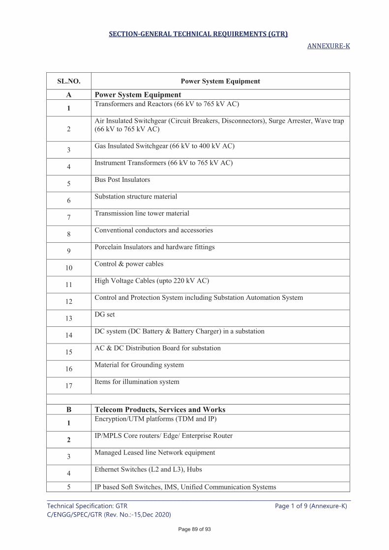
SECTION-GENERAL TECHNICAL REQUIREMENTS (GTR)
____________________________________________________________________________ Technical Specification: GTR Page 1 of 9 (Annexure-K)
C/ENGG/SPEC/GTR (Rev. No.:-15,Dec 2020)
SL.NO. Power System Equipment
A Power System Equipment
1 Transformers and Reactors (66 kV to 765 kV AC)
2
Air Insulated Switchgear (Circuit Breakers, Disconnectors), Surge Arrester, Wave trap
(66 kV to 765 kV AC)
3 Gas Insulated Switchgear (66 kV to 400 kV AC)
4 Instrument Transformers (66 kV to 765 kV AC)
5 Bus Post Insulators
6 Substation structure material
7 Transmission line tower material
8 Conventional conductors and accessories
9 Porcelain Insulators and hardware fittings
10 Control & power cables
11 High Voltage Cables (upto 220 kV AC)
12 Control and Protection System including Substation Automation System
13 DG set
14 DC system (DC Battery & Battery Charger) in a substation
15 AC & DC Distribution Board for substation
16 Material for Grounding system
17 Items for illumination system
B Telecom Products, Services and Works
1 Encryption/UTM platforms (TDM and IP)
2 IP/MPLS Core routers/ Edge/ Enterprise Router
3 Managed Leased line Network equipment
4 Ethernet Switches (L2 and L3), Hubs
5 IP based Soft Switches, IMS, Unified Communication Systems
Page 89 of 93
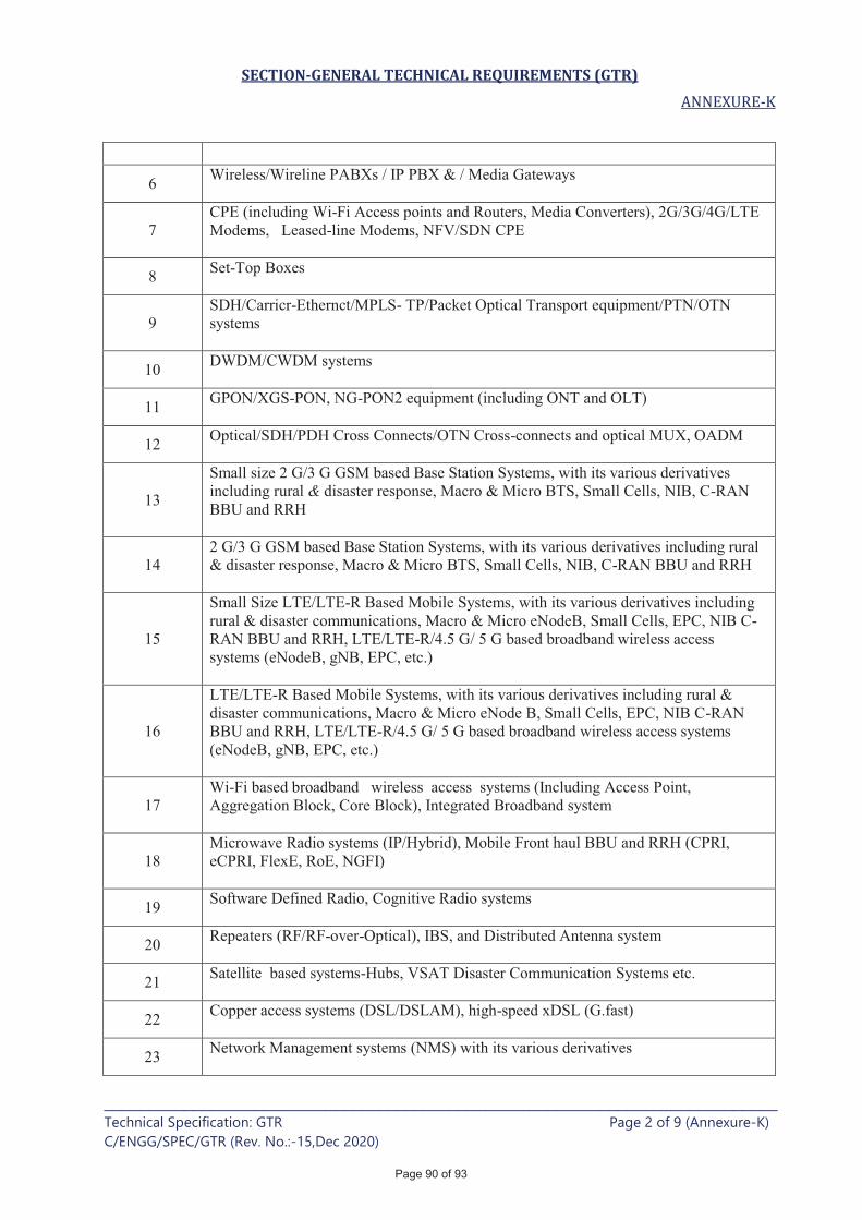
SECTION-GENERAL TECHNICAL REQUIREMENTS (GTR)
____________________________________________________________________________ Technical Specification: GTR Page 2 of 9 (Annexure-K)
C/ENGG/SPEC/GTR (Rev. No.:-15,Dec 2020)
6 Wireless/Wireline PABXs / IP PBX & / Media Gateways
7
CPE (including Wi-Fi Access points and Routers, Media Converters), 2G/3G/4G/LTE
Modems, Leased-line Modems, NFV/SDN CPE
8 Set-Top Boxes
9
SDH/Carricr-Ethernct/MPLS- TP/Packet Optical Transport equipment/PTN/OTN
systems
10 DWDM/CWDM systems
11 GPON/XGS-PON, NG-PON2 equipment (including ONT and OLT)
12 Optical/SDH/PDH Cross Connects/OTN Cross-connects and optical MUX, OADM
13
Small size 2 G/3 G GSM based Base Station Systems, with its various derivatives
including rural & disaster response, Macro & Micro BTS, Small Cells, NIB, C-RAN
BBU and RRH
14
2 G/3 G GSM based Base Station Systems, with its various derivatives including rural
& disaster response, Macro & Micro BTS, Small Cells, NIB, C-RAN BBU and RRH
15
Small Size LTE/LTE-R Based Mobile Systems, with its various derivatives including
rural & disaster communications, Macro & Micro eNodeB, Small Cells, EPC, NIB C-
RAN BBU and RRH, LTE/LTE-R/4.5 G/ 5 G based broadband wireless access
systems (eNodeB, gNB, EPC, etc.)
16
LTE/LTE-R Based Mobile Systems, with its various derivatives including rural &
disaster communications, Macro & Micro eNode B, Small Cells, EPC, NIB C-RAN
BBU and RRH, LTE/LTE-R/4.5 G/ 5 G based broadband wireless access systems
(eNodeB, gNB, EPC, etc.)
17
Wi-Fi based broadband wireless access systems (Including Access Point,
Aggregation Block, Core Block), Integrated Broadband system
18
Microwave Radio systems (IP/Hybrid), Mobile Front haul BBU and RRH (CPRI,
eCPRI, FlexE, RoE, NGFI)
19 Software Defined Radio, Cognitive Radio systems
20 Repeaters (RF/RF-over-Optical), IBS, and Distributed Antenna system
21 Satellite based systems-Hubs, VSAT Disaster Communication Systems etc.
22 Copper access systems (DSL/DSLAM), high-speed xDSL (G.fast)
23 Network Management systems (NMS) with its various derivatives
Page 90 of 93
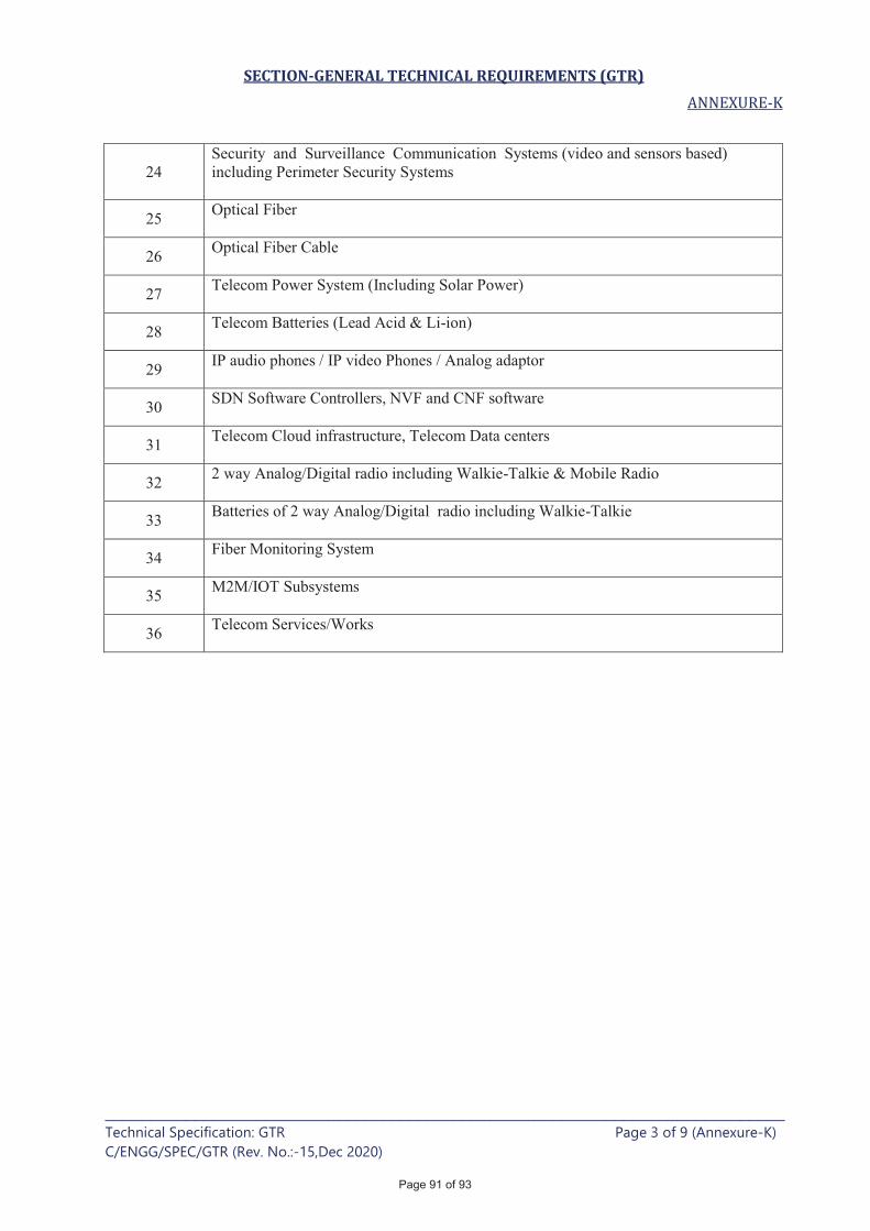
SECTION-GENERAL TECHNICAL REQUIREMENTS (GTR)
____________________________________________________________________________ Technical Specification: GTR Page 3 of 9 (Annexure-K)
C/ENGG/SPEC/GTR (Rev. No.:-15,Dec 2020)
24
Security and Surveillance Communication Systems (video and sensors based)
including Perimeter Security Systems
25 Optical Fiber
26 Optical Fiber Cable
27 Telecom Power System (Including Solar Power)
28 Telecom Batteries (Lead Acid & Li-ion)
29 IP audio phones / IP video Phones / Analog adaptor
30 SDN Software Controllers, NVF and CNF software
31 Telecom Cloud infrastructure, Telecom Data centers
32 2 way Analog/Digital radio including Walkie-Talkie & Mobile Radio
33 Batteries of 2 way Analog/Digital radio including Walkie-Talkie
34 Fiber Monitoring System
35 M2M/IOT Subsystems
36 Telecom Services/Works
Page 91 of 93

������������ ����������������
��������������������������������� �!�""���#$�%��&&%� ��%����'(���)*���+,)-�
�����./����
�������������������0������'�1��&����'������)( &���+���
� ����������� ���� ��������������� ����� ������� � ������� ������������������������ ��������������������������������������������������� �������������������������� �� ������� � ��������������������� �������������������������������������������������� �� ����������������������!"�
2( ��3�1�4��3��
� #�� ���������� ������� ���������������������������������� ������������� �� ��������������� ������������������������������������� � �� ��"�
5( ��3�6����73��+��'��
$"%� ��������������������������� ����������� ���� ��� �������������� �����&��� ��'*��� ��� ��� ��� �� ������������ �*�&+�!� +��� �� ��� %,'%�%..$!� +��� '%"� #�������� ��� � ��� � ����� ����������� ��� ����� �� ���������� � � %/:� ��� /";� <=� ������� �������� ��� �� �� ���������/";�<>=� ��?�<>=�������������� �������� ��������������� �����������"�#����������������� ��� �������"�
$"?� @����� ���������������������� �������������� �BD<@���������+��� �� ���B�"�%/F'%.,G������������ ����������� �"�
$"$�� ��� ����������� ���� ����� ��������� ��� ����� �������� ������� � ��� ��� ���� ������� ���"� ��������������������������� �������� � ������� ��� ���� ��������� ���� � �� ��� ����� ���� �� � ���� ��� ��� �� ������ ���� ��� ����� �� �� ������ ������ ���� ���������� ��� ����� � � ��� ��$";������������� ����"�
$"G�� @�� ��� �� ��� ����� ��� ��������� ������� ���� ����� ���� ��� ��� ��� ���� �� ��������� ���� ����� ��� � ��� ����� ����� ��� �����"� ��� ��� � ��� ���������� �� ��������� ��� �� ��� ������ � ��� ����� ��� �� ���� �� �����������"� ���� ������� ����� ������������ �� ������ ������� ������� ��� �������� ��� J;:�� %//:� ���� %%/:� ��� ������ � ��� ���� ��� ������� ���� ���� ��� ����� ������� ���� ��� ���� � ��"� � #������ � ��� ���� ��� ������� ���� F,;K��� G//K��� ??/K�� �� � ���� �� �� ��� �������� � �� ���������� ���� �������� �� �������������� ��� �������"�
$";�� #�� ���� ��� ��������� ����� ��� ��� ���� *�&+�� ���������� ��� ��� ��� ��������� �������������� ����������������������� ������� ��"�
$",�� #������������������������������ ����� �������"�@���� ��� ������������������������������� ���� ������������������������������� ������ ���������������� ������������ ����������������������� ��������"�
"( ��3�6����73��+'�3�8����+���9�������8����+"**:'��7�8�4�;�
� #������������� ����� ��������� �������������� �� ��������������������������������� ��"� #�� ��� ����� ��� ���� ��� ��� �� �� ����� ������� ��� ���� �������� ����������� �������� �������������������������������� ������� ������ ���� �� ������ ��� ���� ����� ��� ����� ����� �� ����� ���� �� �� ��� ������������������������ ���� ����������������������� ���� ������ ���������"�#���������������������� ������%%/:������������������������ �� ������������� ���� ����"� ��� ����� ������� ���� ��� ����� ��� �K�� ������ �� %%/:�� ��� ����� ��������������� ��� �������������� ��������� ���������� ��� ������������������������� ������� � ������������ ��������"�#�����������������������������������G�
+@LD�F/
Section-3
ANNEX C1
Page 92 of 93

������������ ����������������
��������������������������������� �!�"#���#$�%��&&%� ��%����'(���)*���+,)-�
����� �������� ���� ��������� �� ����������������������� ��"�#����������� �� ������������������������������� � �������� ������ ������� � �� ��������������������������������������� ��� � ���������������� ��������� �������� �!�� ��������"�+��������� ����������� �������������K��������������K������������ ���� ����� �� ���� ������� ����� "�"� J;:�� %//:�� ���� %%/:"� @�� �����������������������K������������ ���� ��������� �� ����������"�@���������� ���� ����� ��� ���������� �� ���� ����� �� ��� +������� �� � ��� � � ��� @&@����� ���� ������G//�� �������������������� ��������������������������M;",������� �����"� #�� ������� �� �������� ����� ��� ���� �� �� ��� ���� ��� ������ ���� ����� ��� ���� ������ ���� � � ���� ���� ��� ����� ���� ����� � ���� ������� ��"�+���������������� �K������������������������ �� ������������������������ ������ ������� ��� ��� ���� ��������� ���� ���� ����� ��� ����� ���� ���������"� #�������������������������������������O�������� ������� ������������� ������'���"�
� ��� ����� ������� ���� ��� ����� ��� �K�� ������ �� %%/:�� ������� ����� ��� ��� ���������������������������� �� ���������������������� �������������"�
G"%� #�� ��� ����� ��� ��������� ��� ���� �������"� @�� ����� �������� ����� ����K���������������������� ���� �� ������������������ ������ �����������O�������� � ������� �������������� ����������������� ���� �����"�
G"?� ��� ��� ��� �� ��������� ��� �� ��� ��O��� ����������� ����� ��������� ����� ����K��� ��� �� �������� ��� ��������� ��� ��� ���� ��� ��� ���� ��� ���� �� ������ ��������������O���"�#���������������������������K��������������� ����������� ������� ������� �� ��� ����������� �� ���� �� �������� ����� ���� � ���"�Q��� ���� ��� �� ���������� ���� ��� ��� ��� ���� ���� ����� ��� ���� ���� �� �� �������������� ��������������"�#������ ������� ���������������������������������+�������U�� ��������� ����� ����� � ��� �� ���� ������� ���� ���� ��� � �������� �� �����������O��������������� ��������� ��������"�
G"$� #����� ������� ������ � ������������� �� ������������������������� ������� ������������� ����������� �������������"�
G"G� >�������������������������� ������� ������������������������ � ��� ������� ��� ������� ���� ��� ���� ���"� B�� ��� � �� ��� ��� ������� ��� �� �������������� ���� � ��� ��� �������"� & ���������� ���� ���� � � ���� ������� �� �� ������������ �������������� �������� ���� ������+�������U�� �������� ��� �� ���� � ���� �� ���������O�� ���������"�
#( ��3�����+73��� ������ ��� �� �� ������ ������� ��������� ��������������� ����������� � ���
�������*�&+�����BD<@�%/F'%.,G��������� ��������������� �������� ����������W�� �!����� Y��K��������� ���������������������"�� �!����� Q�� ��������������������� �� ���������������"�� �!����� <����������������������������������� ��� ��������������������"�� �!��� ������� ���� ������� ���� � � ������� �� ���� ��� ���� ���� ��� �����������
������������������������"���������������������� �!����� #��� ������� ����� ��� ��������� ���� ��������� ���� ������� ����� %//�
� �������� ������� ��� ��"�� �!����� Z���������� �� ������� �������������������������������������� ���������
�����������"�
+@LD�F%
Section-3ANNEX C1
Page 93 of 93

Bharat Heavy Electricals Limited Gas Insulated Switchgear Section-4 Annexure - A
_____________________________________________________________________________________________________ Section 4: Annexure Page 1 of 1
ANNEXURE-A
COMPLIANCE CERTIFICATE OF TECHNICAL SPECIFICATION
The bidder shall confirm compliance to the following by signing/ stamping this compliance certificate and furnishing same with the offer.
1. The scope of supply, technical details, construction features, design parameters etc. shall be as per technical specification & there are no exclusion/ deviation with regard to same.
2. There are no deviation(s) with respect to specification other than those furnished in the ‘schedule of technical deviations’.
3. Only those technical submittals which are specifically asked for in NIT to be submitted at tender
stage shall be considered as part of offer. Any other submission, even if made, shall not be considered as part of offer.
4. Any comments/ clarifications on technical/ inspection requirements furnished as part of bidder’s
covering letter shall not be considered by BHEL, and bidder’s offer shall be construed to be in conformance with the specification.
5. Any changes made by the bidder in the price schedule with respect to the description/ quantities
from those given in ‘BOQ’ of the specification shall not be considered (i.e., technical description & quantities as per the specification shall prevail).
Date: Bidder’s Stamp & Signature
JAIK
Rectangle
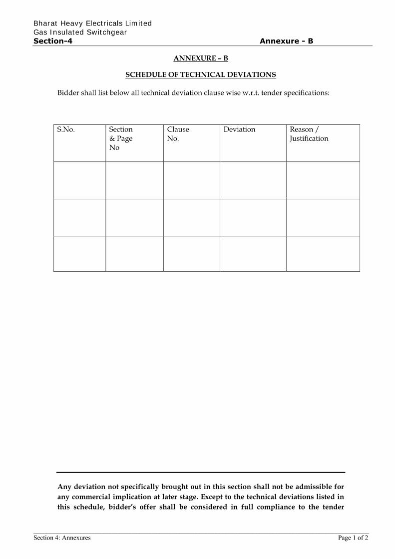
Bharat Heavy Electricals Limited Gas Insulated Switchgear Section-4 Annexure - B
_____________________________________________________________________________________________________ Section 4: Annexures Page 1 of 2
ANNEXURE – B
SCHEDULE OF TECHNICAL DEVIATIONS Bidder shall list below all technical deviation clause wise w.r.t. tender specifications:
S.No. Section & Page No
Clause No.
Deviation Reason / Justification
Any deviation not specifically brought out in this section shall not be admissible for
any commercial implication at later stage. Except to the technical deviations listed in
this schedule, bidder’s offer shall be considered in full compliance to the tender
JAIK
Rectangle
Bharat Heavy Electricals Limited Gas Insulated Switchgear Section-4 Annexure - B
_____________________________________________________________________________________________________ Section 4: Annexures Page 2 of 2
specifications irrespective of any such deviation indicated / taken elsewhere in the
submitted offer.
Date: Tenderer’s Stamp & Signature
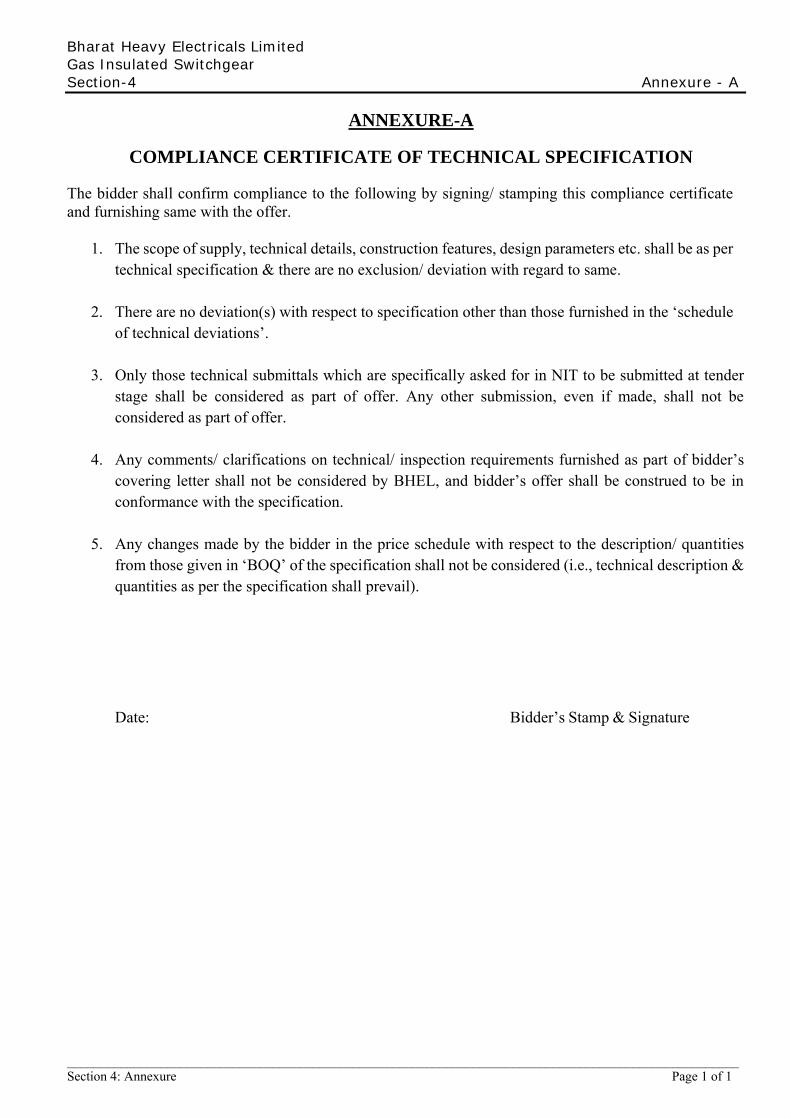
Bharat Heavy Electricals Limited Gas Insulated Switchgear Section-4 Annexure - A
_____________________________________________________________________________________________________ Section 4: Annexure Page 1 of 1
ANNEXURE-A
COMPLIANCE CERTIFICATE OF TECHNICAL SPECIFICATION
The bidder shall confirm compliance to the following by signing/ stamping this compliance certificate and furnishing same with the offer.
1. The scope of supply, technical details, construction features, design parameters etc. shall be as per technical specification & there are no exclusion/ deviation with regard to same.
2. There are no deviation(s) with respect to specification other than those furnished in the ‘schedule of technical deviations’.
3. Only those technical submittals which are specifically asked for in NIT to be submitted at tender
stage shall be considered as part of offer. Any other submission, even if made, shall not be considered as part of offer.
4. Any comments/ clarifications on technical/ inspection requirements furnished as part of bidder’s
covering letter shall not be considered by BHEL, and bidder’s offer shall be construed to be in conformance with the specification.
5. Any changes made by the bidder in the price schedule with respect to the description/ quantities
from those given in ‘BOQ’ of the specification shall not be considered (i.e., technical description & quantities as per the specification shall prevail).
Date: Bidder’s Stamp & Signature
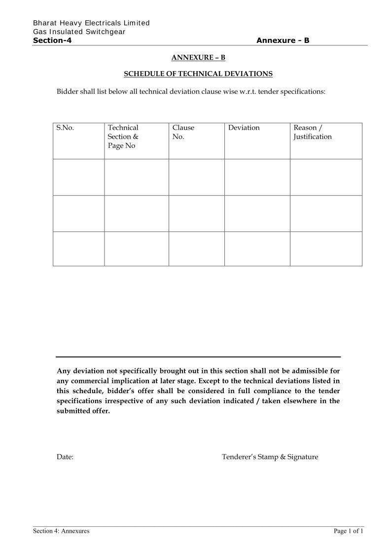
Bharat Heavy Electricals Limited Gas Insulated Switchgear Section-4 Annexure - B
_____________________________________________________________________________________________________ Section 4: Annexures Page 1 of 1
ANNEXURE – B
SCHEDULE OF TECHNICAL DEVIATIONS Bidder shall list below all technical deviation clause wise w.r.t. tender specifications:
S.No. Technical Section & Page No
Clause No.
Deviation Reason / Justification
Any deviation not specifically brought out in this section shall not be admissible for
any commercial implication at later stage. Except to the technical deviations listed in
this schedule, bidder’s offer shall be considered in full compliance to the tender
specifications irrespective of any such deviation indicated / taken elsewhere in the
submitted offer.
Date: Tenderer’s Stamp & Signature
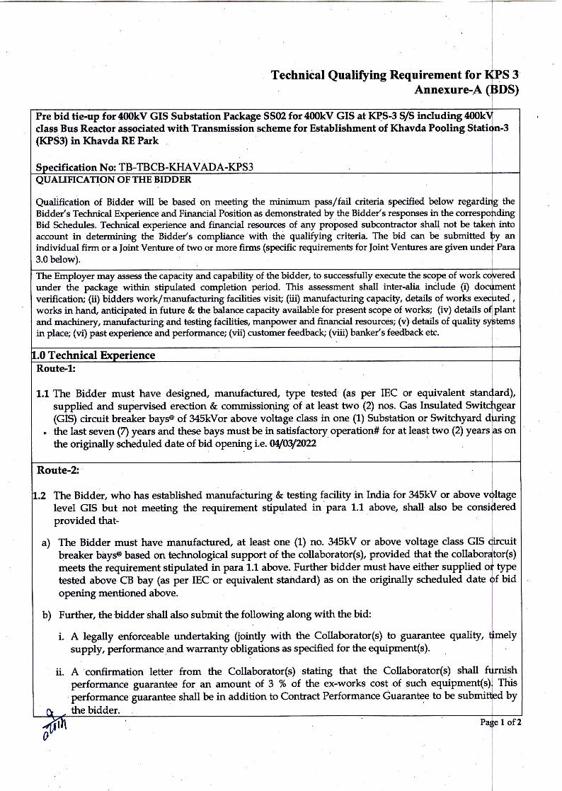
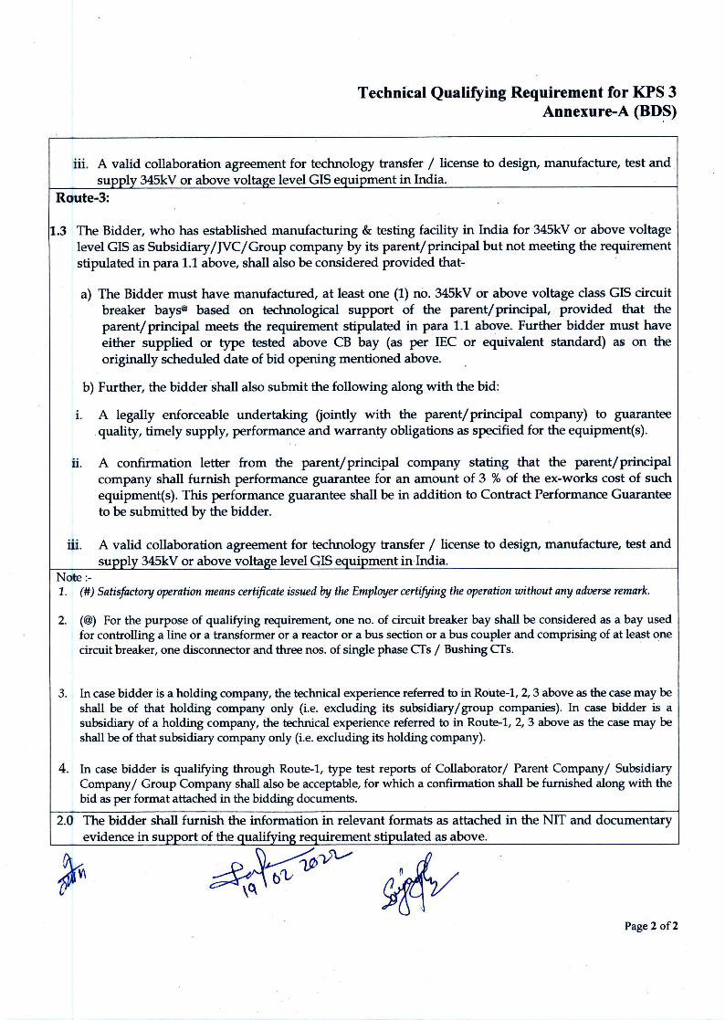
Related Documents