Welcome message from author
This document is posted to help you gain knowledge. Please leave a comment to let me know what you think about it! Share it to your friends and learn new things together.
Transcript

BFM
™ Specifications
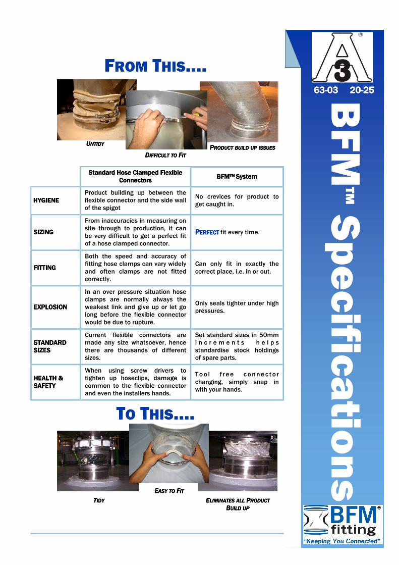
UUUUNTIDYNTIDYNTIDYNTIDY PPPPRODUCTRODUCTRODUCTRODUCT BUILDBUILDBUILDBUILD UPUPUPUP ISSUESISSUESISSUESISSUES
Standard Hose Clamped Flexible Standard Hose Clamped Flexible Standard Hose Clamped Flexible Standard Hose Clamped Flexible
ConnectorsConnectorsConnectorsConnectors BFM™BFM™BFM™BFM™ SystemSystemSystemSystem
HYGIENEHYGIENEHYGIENEHYGIENE Product building up between the flexible connector and the side wall of the spigot
No crevices for product to get caught in.
SIZINGSIZINGSIZINGSIZING
From inaccuracies in measuring on site through to production, it can be very difficult to get a perfect fit of a hose clamped connector.
PPPPERFECTERFECTERFECTERFECT fit every time.
FITTINGFITTINGFITTINGFITTING
Both the speed and accuracy of fitting hose clamps can vary widely and often clamps are not fitted correctly.
Can only fit in exactly the correct place, i.e. in or out.
EXPLOSIONEXPLOSIONEXPLOSIONEXPLOSION
In an over pressure situation hose clamps are normally always the weakest link and give up or let go long before the flexible connector would be due to rupture.
Only seals tighter under high pressures.
STANDARDSTANDARDSTANDARDSTANDARD SIZESSIZESSIZESSIZES
Current flexible connectors are made any size whatsoever, hence there are thousands of different sizes.
Set standard sizes in 50mm i n c r e m e n t s h e l p s standardise stock holdings of spare parts.
HEALTH &HEALTH &HEALTH &HEALTH & SAFETYSAFETYSAFETYSAFETY
When using screw drivers to tighten up hoseclips, damage is common to the flexible connector and even the installers hands.
Too l f r ee connec to r changing, simply snap in with your hands.
TO THIS….
TTTTIDYIDYIDYIDY EEEELIMINATESLIMINATESLIMINATESLIMINATES ALLALLALLALL PPPPRODUCTRODUCTRODUCTRODUCT
BBBBUILDUILDUILDUILD UPUPUPUP
FROM THIS….
DDDDIFFICULTIFFICULTIFFICULTIFFICULT TOTOTOTO FFFFITITITIT
EEEEASYASYASYASY TOTOTOTO FFFFITITITIT
R
63636363----03 2003 2003 2003 20----25252525

When welding the BFM™ Fittings to your equipment the Application Length must be accurately measured.
BFM™ Specifications
BFM™ SPIGOTS Patents and Registered Designs Applied For © 2006
All rights reserved
Ø (Diameter)
100
150
200
250
300
350
400
450
500
550
600
650
Oscillating equipment
IG = CL — 40mm (Minimum)
Off Set equipment
IG = CL — 20mm (Minimum)
In-line static equipment
IG = CL — 10mm (Minimum)
CL = Connector Length (See BFM™ Flexible Connector Sheet)
Note: 1. The stainless steel spigots (flanges) have a tail 52mm (2”) long. These can be easily cut down or cut on an angle to suit your existing pipework, see installation instructions for more information.
2. It is important to weld the spigots onto your pipework with the length
of the flexible connector in mind. Standard length flexible connectors will be stocked and hence will be more readily available, and less expensive than non standard lengths.
3. For applications where there is a possibility for static build up, e.g.
wood dust, flour, milk powder etc., we recommend using a static dissipative wire (strip), connecting the two BFM™Spigots together.
R
63636363----03030303

BFM Global Limited
Ph: +64 9 483 8158 Email: [email protected]
Web site: http://www.BFMfitting.com
BFM™ FLEXIBLE CONNECTOR Patents and Registered Designs Applied For © 2006
All rights reserved
Read this sheet in conjunction with the BFM™ Spigots page
Contact BFM Global Ltd for full range of Fabrics available
Ø (Diameter)
100
150
200
250
300
350
400
450
500
550
600
650
Length (CL)
150
150
200
200
200
200
200
200
200
200
200
200
Illustrated BFM™ Connector manufactured using 040 Seeflex material (Clear Urethane)
BFM™ Specifications
R
20202020----25252525
Related Documents