Floating ball valve BF 2000

Welcome message from author
This document is posted to help you gain knowledge. Please leave a comment to let me know what you think about it! Share it to your friends and learn new things together.
Transcript

Floating ball valve
BF 2000
FLOATING BALL VALVE
Technical Documentation - FLOATING BALL VALVE –Rev : 2 Page 2 of 28
SRi is
PREAMBLE
This technical document contains proprietary information belonging to SRi and cannot be copied, reproduced,divulged, transfered or edited in any form whatever, including electronically or in any format for transmission orpublic diffusion without the prior written agreement of SRi.
This document is for information only regarding the actual technical evolution of the product and as such it issubject to change without prior notice. It cannot be considered as contractual or binding. SRi declines allresponsibility or obligation for errors or oversights which may appear in this document.
Case history :
Date Document Number of revision 15/10/00 DTB2000A 1-Floating ball valve.
Technical Documentation - English -Version 1
PARIS
41-43 Rue des Chantiers 78000 Versailles - FRANCETel 33 (0) 139 502 920Fax 33 (0) 139 027 191
E-mail : [email protected]

FLOATING BALL VALVE
Technical Documentation - FLOATING BALL VALVE –Rev : 2 Page 3 of 28
SUMMARY
PREAMBLE................................................................................................................................................................ 2
DESIGN BF 2000 ........................................................................................................................................................ 4
TECHNICAL CHARACTERISTICS ....................................................................................................................... 4
CAST OR STAMPED CONSTRUCTION ............................................................................................................... 4
DIMENSIONAL RANGE .......................................................................................................................................... 5
FULL BORE ............................................................................................................................................................... 5REDUCED BORE........................................................................................................................................................ 5
EQUIPMENT.............................................................................................................................................................. 5
OPEN/CLOSE LOCKING DEVICE: ............................................................................................................................... 5STEM EXTENSIONS: .................................................................................................................................................. 5GEARBOXES ............................................................................................................................................................. 5LIMIT SWITCHES ....................................................................................................................................................... 5ACTUATION.............................................................................................................................................................. 5
FIRE SAFE.................................................................................................................................................................. 5
MATERIALS .............................................................................................................................................................. 6
TOP WORKS ............................................................................................................................................................ 18
PRESSURE TEMPERATURE RATING ............................................................................................................. 19
TORQUES AND OPERATING............................................................................................................................... 21
OPENING TORQUE: ................................................................................................................................................. 21MAXIMUM ALLOWABLE STEM TORQUE.................................................................................................................. 22
HYDRAULIC CHARACTERISTICS..................................................................................................................... 23
FLOW COFFICIENT CV........................................................................................................................................ 24
FULL BORE VALVES............................................................................................................................................... 24REDUCED BORE VALVES ........................................................................................................................................ 25
ACCESSORIES......................................................................................................................................................... 26
INSULATING EXTENSION......................................................................................................................................... 26LOCKING DEVICES ................................................................................................................................................. 27
BF 2000 PRODUCTS................................................................................................................................................ 28

FLOATING BALL VALVE
Technical Documentation - FLOATING BALL VALVE –Rev : 2 Page 4 of 28
DESIGN BF 2000SRi Taking advantage of its experience in high andvery high pressure technology, SRI offers a completerange of floating ball valves.
A modern approach to dimensioning and to conceptreliability in conjunction with proven technicalsolutions assure :- Complete conformitywith norms, codes andspecifications - Quality inconformance with thecriteria of ISO 9001.BF 2000 valves aremade to withstand thefull differential pressure of each pressure class in everyNominal Diameter.
TECHNICAL CHARACTERISTICS
Split body in two blocks bolted together. Double bodystatic sealing, primary joint in elastomer or polymerand a secondary firesafe gasket. Bolts threaded blindholes with anti-corrosion protection.Solid stainless steel ball.Anti-blowout stem profiled to minimize stresses (nogrooves or threads)Dynanic Stem Sealing with standard body housingavailable in 3 versions :
1-fixed composition with O-ring and fire safegraphite gasket2-adjustable arrangement with graphite gasketsonly3-adjustable arrangement with PTFE gasketsfor use in very corrosive applications
Polymer seats assure the sealing and the bracing in theblock position using a controlled pre-charge..
ISO interface for simple and rapid connections ofgearboxes and other automatic controls.
Positive antistatic device through physical contactbetween the different parts.
Strict conformity to the Pressure/Temperaturerelations per ISO PN for each pressure class, within thecapacity limits of the composants. This requirementis superior to that imposed by BS 5351 Norm.
CAST OR STAMPED CONSTRUCTION
The basic model is made from cast parts (carbon orstainless steel) for the body and forged metal for theother parts.
Alternatively the pressure containing parts are madefrom stamped roughs up to ND 2 inch and in forgedroughs for larger sizes especially for noble alloys(Duplex Steel, Inconel, etc.).
In both cases all the elements are completelyinterchangeable between all versions.
AUTOMATIC LIMITATION OFOVERPRESSURE IN THE BODY CAVITY
Seat conception and placement in the line sealing mechanism
assure automatic decompression in the body cavity with theupstream connector. This pressure equalization is effectiveat a very low level (lowest to 5 bars) necessary to equilibratethe pre-loading of the seats.
Seat volumreduced
Conical rear face forself-positionningRelief seat
grooves
Solid seatpreloaded
All sealing arrangements are independentof the stem to facilitate maintenance andadjustment.
Fire safe lip
FLOATING BALL VALVE
Technical Documentation - FLOATING BALL VALVE –Rev : 2 Page 5 of 28
TORQUE AND OPERATING
Particular attention is paid to reliability and consistencein operating by optimizing the dimensions of thecomposants and the friction between surfaces.
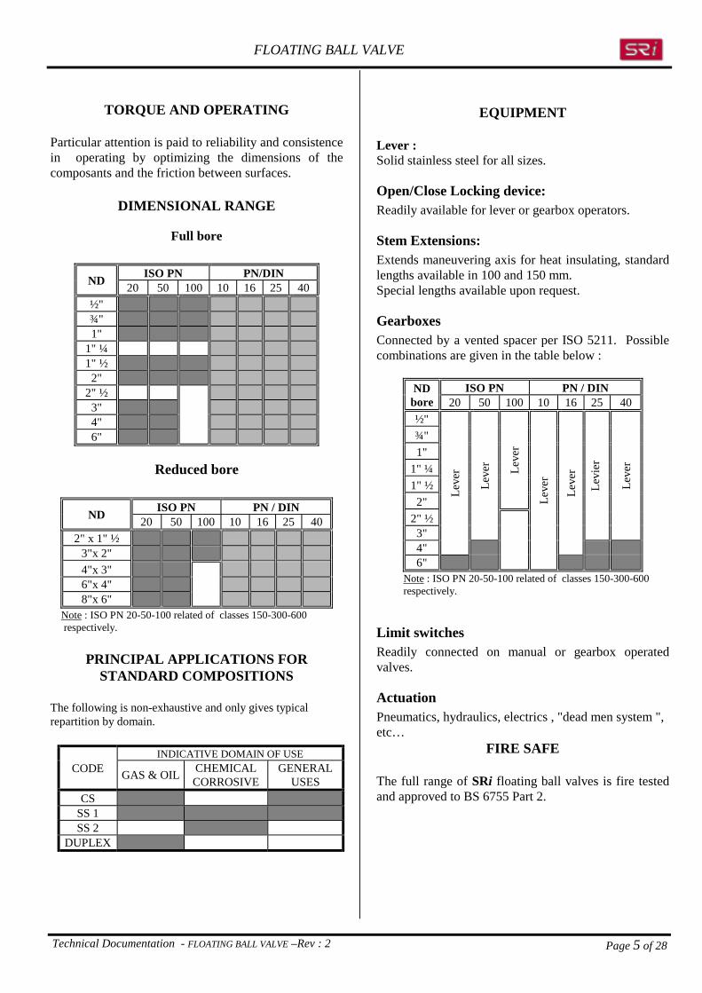
DIMENSIONAL RANGE
Full bore
ISO PN PN/DINND 20 50 100 10 16 25 40½"¾"1"
1" ¼1" ½
2"2" ½
3"4"6"
Reduced bore
ISO PN PN / DINND 20 50 100 10 16 25 402" x 1" ½
3"x 2"4"x 3"6"x 4"8"x 6"
Note : ISO PN 20-50-100 related of classes 150-300-600 respectively.
PRINCIPAL APPLICATIONS FORSTANDARD COMPOSITIONS
The following is non-exhaustive and only gives typicalrepartition by domain.
INDICATIVE DOMAIN OF USECODE GAS & OIL CHEMICAL
CORROSIVEGENERAL
USESCS
SS 1SS 2
DUPLEX
EQUIPMENT
Lever :Solid stainless steel for all sizes.
Open/Close Locking device:Readily available for lever or gearbox operators.
Stem Extensions:Extends maneuvering axis for heat insulating, standardlengths available in 100 and 150 mm.Special lengths available upon request.
GearboxesConnected by a vented spacer per ISO 5211. Possiblecombinations are given in the table below :
ISO PN PN / DINNDbore 20 50 100 10 16 25 40½"¾"1"
1" ¼1" ½2"
Leve
r2" ½3"
Leve
r
Levi
er
Leve
r
4"
Leve
r
Leve
r6"
Leve
r
Note : ISO PN 20-50-100 related of classes 150-300-600 respectively.
Limit switchesReadily connected on manual or gearbox operatedvalves.
ActuationPneumatics, hydraulics, electrics , "dead men system ",etc…
FIRE SAFE
The full range of SRi floating ball valves is fire testedand approved to BS 6755 Part 2.

FLOATING BALL VALVE
Technical Documentation - FLOATING BALL VALVE –Rev : 2 Page 6 of 28
MATERIALS
Materials indicated represent the standard manufactured compositions.Other metals can be used. Consult your sales person.
STANDARD MATERIALRep Part name CS SS 1 SS 2 DUPLEX1 BODY A216WCB(1) A351CF8M(2) A351CF8M(2) A182F512 FLANGE A216WCB(1) A351CF8M(2) A351CF8M(2) A182F514 BALL A182F316 A182F316 A182F316 A182F515 SEAT PTFE (3) PTFE (3) PTFE (3) PTFE (3)
6 STEM + Anti-static A182F316 A182F316 A182F316 A182F518 PACKING GLAND A182F316 A182F316 A182F316 A182F316
10 STUD A193 B7 A193 B8M A193 B8M A193 B8M11 NUT A194 2H A194 Gr 8 A194 Gr 8 A194 Gr 817 PACKING GLAND BEARING PTFE PTFE PTFE PTFE21 FIRE-SAFE STEM GASKET GRAPHIT GRAPHIT NA GRAPHIT22 FIRE-SAFE BODY GASKET GRAPHIT GRAPHIT GRAPHIT GRAPHIT25 STOP SCREW AISI 316 AISI 316 AISI 316 AISI 31626 STOP PLATE AISI 316L AISI 316L AISI 316L AISI 316L32 FLANGE SEAL FKM (4) PTFE+304 PTFE+304 FKM (4)
38A-B STEM SEAL FKM (4) FKM (4) NA FKM (4)
69 TRUST BEARING STEM PTFE+304 PTFE+304 PTFE+304 PTFE+30480 PACKING GLAND WASHER A182F316 A182F316 A182F316 A182F316
141 SEAL STEM SUPPORT A182F316 A182F316 NA A182F316142-143 CHEVRON RING NA NA PTFE NA
Notes : 1- Possible manufacture in A350 LF2 – Stamped for ND <= 2" 2- Possible manufacture in A182F316 – Stamped for ND<=2" 3- PTFE +25% glass filler & PTFE +15% graphite in ISO PN 100 (600 lbs) only Other quality (Devlon V, Peek, etc.) upon request 4-FKM=Fluoroelastomer Various elastomers are available depending on service conditions.
"Bicone" system SS2
Graphit systemCS-SS1-DUPLEX
O RING SYSTEMCS-SS1-DUPLEX
FLOATING BALL VALVE
Technical Documentation - FLOATING BALL VALVE –Rev : 2 Page 7 of 28
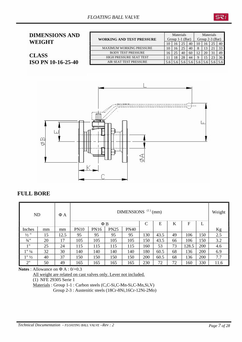
MaterialsGroup 1-1 (Bar)
MaterialsGroup 2-3 (Bar)WORKING AND TEST PRESSURE
10 16 25 40 10 16 25 40MAXIMUM WORKING PRESSURE 10 16 25 40 8 13 21 33
BODY TEST PRESSURE 16 25 40 60 12 20 31 49HIGH PRESSURE SEAT TEST 11 18 28 44 9 15 23 36AIR SEAT TEST PRESSURE 5.6 5.6 5.6 5.6 5.6 5.6 5.6 5.6
DIMENSIONS ANDWEIGHT
CLASSISO PN 10-16-25-40
FULL BORE
DIMENSIONS (1 ) (mm)ND Φ A
Φ B C E K F L
Weight
Inches mm mm PN10 PN16 PN25 PN40 Kg½ " 15 12.5 95 95 95 95 130 43.5 49 106 150 2.5¾" 20 17 105 105 105 105 150 43.5 66 106 150 3.21" 25 24 115 115 115 115 160 53 73 128.5 200 4.6
1" ¼ 32 30 140 140 140 140 180 60.5 68 136 200 6.91" ½ 40 37 150 150 150 150 200 60.5 68 136 200 7.7
2" 50 49 165 165 165 165 230 72 72 160 330 11.6 Notes : Allowance on Φ A : 0/+0.3 All weight are related on cast valves only. Lever not included.
(1) NFE 29305 Serie 1 Materials : Group 1-1 : Carbon steels (C,C-Si,C-Mn-Si,C-Mn,Si,V) Group 2-3 : Austenitic steels (18Cr-8Ni,16Cr-12Ni-2Mo)

FLOATING BALL VALVE
Technical Documentation - FLOATING BALL VALVE –Rev : 2 Page 8 of 28
FULL BORE
DIMENSIONS (1 ) (mm) WeightND Φ A
Φ B C E K F LInches mm mm PN10 PN16 Kg2" ½ 65 64 185 185 290 90.5 82 178.5 330 16.53" 80 75 200 200 310 90.5 82 178.5 330 21.64" 100 100 220 220 350 118.5 100 221 450 396" 150 150 285 285 480 166 150 274 500 83
Notes : Allowance on Φ A : 0/+0.3 All weight are related on cast valves only. Lever not included. 1-NFE 29305 Serie 1
Materials : Group 1-1 : Carbon steels (C,C-Si,C-Mn-Si,C-Mn,Si,V) Group 2-3 : Austenitic steels (18Cr-8Ni,16Cr-12Ni-2Mo)
MaterialsGroup 1-1 (Bar)
MaterialsGroup 2-3 (Bar)WORKING AND TEST PRESSURE
10 16 10 16MAXIMUM WORKING PRESSURE 10 16 8 13
BODY TEST PRESSURE 16 25 12 20HIGH PRESSURE SEAT TEST 11 18 9 15AIR SEAT TEST PRESSURE 5.6 5.6 5.6 5.6
DIMENSIONS ANDWEIGHT
CLASSISO PN 10-16

FLOATING BALL VALVE
Technical Documentation - FLOATING BALL VALVE –Rev : 2 Page 9 of 28
FULL BORE
DIMENSIONS (1 ) (mm)ND Φ A
Φ B C E K F L
Weight
Inches mm mm PN25 PN40 Kg2" ½ 65 64 185 185 290 104.5 115 207 450 17.63" 80 75 200 200 310 104.5 115 207 450 32.54" 100 100 235 235 350 136 130 244 500 61.66" 150 150 300 300 480 185 180 Not applicable 96
Notes : Allowance on Φ A : 0/+0.3 All weight are related on cast valves only. Lever not included. 1-NFE 29305 Serie 1
Materials : Group 1-1 : Carbon steels (C,C-Si,C-Mn-Si,C-Mn,Si,V) Group 2-3 : Austenitic steels (18Cr-8Ni,16Cr-12Ni-2Mo)
MaterialsGroup 1-1 (Bar)
MaterialsGroup 2-3 (Bar)WORKING AND TEST PRESSURE
25 40 25 40MAXIMUM WORKING PRESSURE 25 40 21 33
BODY TEST PRESSURE 40 60 31 49HIGH PRESSURE SEAT TEST 28 44 23 36AIR SEAT TEST PRESSURE 5.6 5.6 5.6 5.6
DIMENSIONS ANDWEIGHT
CLASSISO PN 25-40

FLOATING BALL VALVE
Technical Documentation - FLOATING BALL VALVE –Rev : 2 Page 10 of 28
FULL BORE
ND Φ A Norm 1 DIMENSIONS (1 ) (mm) Weight
Inches mm C B E K F L Kg½ " 15 12.5 B16-10 108 89 43.5 44 106 150 2.3¾" 20 17 B16-10 117.3 99 43.5 49 106 150 2.91" 25 24 B16-10 127 108 53 53 128.5 200 4.2
1" ½ 40 37 B16-10 165.1 127 60.5 68 136 200 7B16-10 177.8 152 72 72 160 330 10.52" 50 49 BS2080 203 152 72 72 160 330 11.2B16-10 203.2 190 90.5 82 178.5 330 183" 80 75 BS2080 241 190 90.5 82 178.5 330 19.1B16-10 228.6 229 118.5 100 221 450 32.54" 100 100 BS2080 305 229 118.5 100 221 450 34
6" 150 150 B16-10 393.72 279 166 150 274 500 80 Notes : Allowance on Φ A : 0/+0.3 All weight are related on cast valves only. Lever not included. 1-NFE 29305 Serie 1
Materials : Group 1-1 : Carbon steels (C,C-Si,C-Mn-Si,C-Mn,Si,V) Group 2-3 : Austenitic steels (18Cr-8Ni,16Cr-12Ni-2Mo)
1 End to end ANSIB16-10 or BS 2080 Table 1 Raised face2 Long pattern
MaterialsGroup 1-1
MaterialsGroup 2-3WORKING AND TEST PRESSURE
Bar Psi Bars PsiMAXIMUM WORKING PRESSURE 20 285 16 230
BODY TEST PRESSURE 30 425 24 345HIGH PRESSURE SEAT TEST 22 300 18 360AIR SEAT TEST PRESSURE 5.6 80 5.6 80
DIMENSIONS ANDWEIGHT
CLASS ISO PN 20ANSI 150 lbs

FLOATING BALL VALVE
Technical Documentation - FLOATING BALL VALVE –Rev : 2 Page 11 of 28
FULL BORE
ND DIMENSIONS (1 ) (mm)
Inches mmΦ A
C B E K F L
Weight
Kg½ " 15 12.5 139.7 95 43.5 49 106 150 3.2¾" 20 17 152.4 117 43.5 66 106 150 4.31" 25 24 165.1 124 53 73 128.5 200 5.8
1" ½ 40 37 190.5 156 60.5 68 136 200 9.82" 50 49 215.9 165 72 72 160 330 11.23" 80 75 282.5 210 104.5 115 207 450 30.74" 100 100 304.8 254 136 130 244 500 58.76" 150 150 403.4 318 185 180 Not applicable 128
Notes : Allowance on Φ A : 0/+0.3 All weight are related on cast valves only. Lever not included. 1-NFE 29305 Serie 1
Materials : Group 1-1 : Carbon steels (C,C-Si,C-Mn-Si,C-Mn,Si,V) Group 2-3 : Austenitic steels (18Cr-8Ni,16Cr-12Ni-2Mo)
MaterialsGroup 1-1
MaterialsGroup 2-3WORKING AND TEST PRESSURE
Bar Psi Bars PsiMAXIMUM WORKING PRESSURE 51 740 41 600
BODY TEST PRESSURE 78 1100 63 900HIGH PRESSURE SEAT TEST 57 800 46 660AIR SEAT TEST PRESSURE 5.6 80 5.6 80
DIMENSIONS ANDWEIGHT
CLASS ISO PN 50ANSI 300 lbs
FLOATING BALL VALVE
Technical Documentation - FLOATING BALL VALVE –Rev : 2 Page 12 of 28
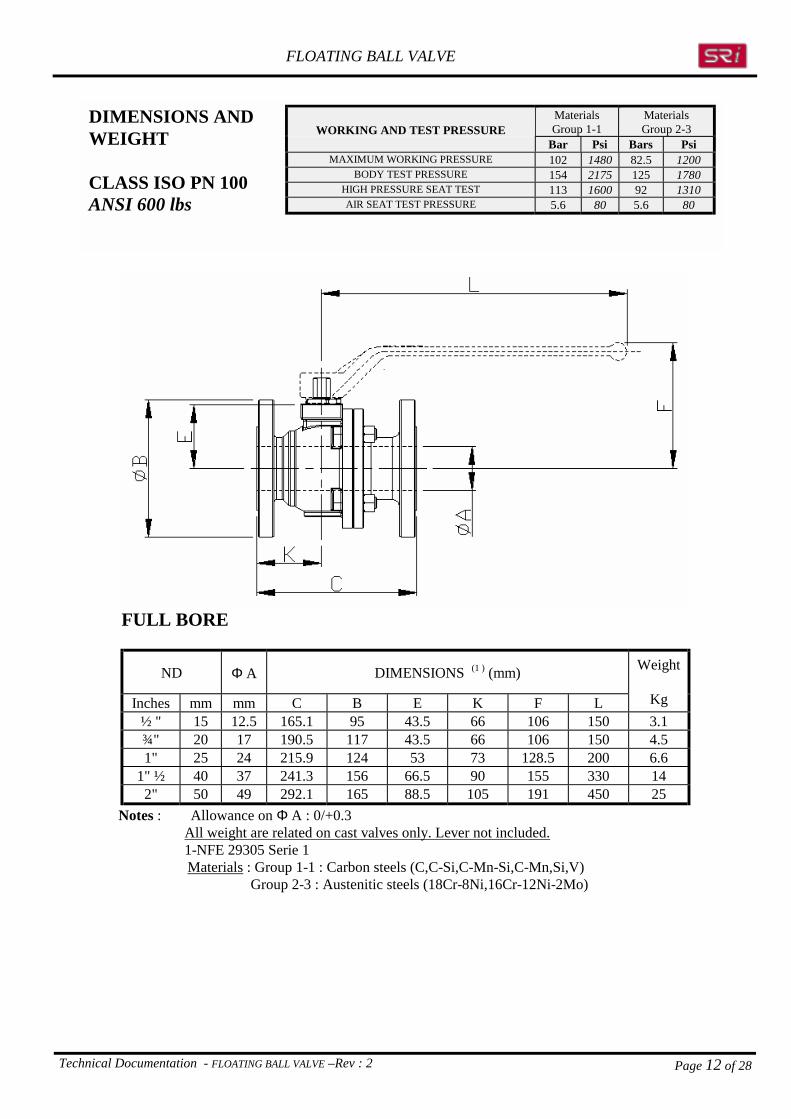
FULL BORE
ND Φ A DIMENSIONS (1 ) (mm)
Inches mm mm C B E K F L
Weight
Kg½ " 15 12.5 165.1 95 43.5 66 106 150 3.1¾" 20 17 190.5 117 43.5 66 106 150 4.51" 25 24 215.9 124 53 73 128.5 200 6.6
1" ½ 40 37 241.3 156 66.5 90 155 330 142" 50 49 292.1 165 88.5 105 191 450 25
Notes : Allowance on Φ A : 0/+0.3 All weight are related on cast valves only. Lever not included. 1-NFE 29305 Serie 1
Materials : Group 1-1 : Carbon steels (C,C-Si,C-Mn-Si,C-Mn,Si,V) Group 2-3 : Austenitic steels (18Cr-8Ni,16Cr-12Ni-2Mo)
MaterialsGroup 1-1
MaterialsGroup 2-3WORKING AND TEST PRESSURE
Bar Psi Bars PsiMAXIMUM WORKING PRESSURE 102 1480 82.5 1200
BODY TEST PRESSURE 154 2175 125 1780HIGH PRESSURE SEAT TEST 113 1600 92 1310AIR SEAT TEST PRESSURE 5.6 80 5.6 80
DIMENSIONS ANDWEIGHT
CLASS ISO PN 100ANSI 600 lbs

FLOATING BALL VALVE
Technical Documentation - FLOATING BALL VALVE –Rev : 2 Page 13 of 28
REDUCED BORE
DIMENSIONS (1 ) (mm)Weight
ND Φ A Φ A0
Φ B C E K F LInches mm mm mm PN10 PN16 Kg
2"x 1" ½ 50x40 49 37 165 165 230 60.5 72 136 200 11.43"x 2" 80x50 75 49 200 200 310 72 90 160 330 20.24"x 3" 100x80 100 75 220 220 350 90.5 100 178.5 330 266"x 4" 150x100 150 100 285 285 480 118.5 135 221 450 48.58"x 6" 200x150 200 150 340 340 600 166 170 274 500 98 3
Notes : Allowance on Φ A : 0/+0.3 All weight are related on cast valves only. Lever not included. 1-NFE 29305 Serie 1
Materials : Group 1-1 : Carbon steels (C,C-Si,C-Mn-Si,C-Mn,Si,V) Group 2-3 : Austenitic steels (18Cr-8Ni,16Cr-12Ni-2Mo)
3 Weight is valid for PN10 and PN16
MaterialsGroup 1-1 (Bar)
MaterialsGroup 2-3 (Bar)WORKING AND TEST PRESSURE
PN 10 PN 16 PN 10 PN 16MAXIMUM WORKING PRESSURE 10 16 8 13
BODY TEST PRESSURE 16 25 12 20HIGH PRESSURE SEAT TEST 11 18 9 15AIR SEAT TEST PRESSURE 5.6 5.6 5.6 5.6
DIMENSIONS ANDWEIGHT
CLASSISO PN 10-16

FLOATING BALL VALVE
Technical Documentation - FLOATING BALL VALVE –Rev : 2 Page 14 of 28
REDUCED BORE
DIMENSIONS (1 ) (mm)ND Φ A Φ A0
Φ B C E K F L
Weight
Inches mm mm mm PN25 PN40 Kg2" x 1" ½ 50x40 49 37 165 165 230 60.5 72 136 200 11.4
3"x 2" 80x50 75 49 200 200 310 72 90 160 330 20.24"x 3" 100x80 100 75 235 235 350 104.5 130 207 450 366"x 4" 150x100 150 100 300 300 480 136 165 244 500 738"x 6" 200x150 200 150 360 375 600 185 210 Not applicable 1214 1285
Notes : Allowance on Φ A : 0/+0.3 All weight are related on cast valves only. Lever not included. 1-NFE 29305 Serie 1
Materials : Group 1-1 : Carbon steels (C,C-Si,C-Mn-Si,C-Mn,Si,V) Group 2-3 : Austenitic steels (18Cr-8Ni,16Cr-12Ni-2Mo)
4 Weight ISO PN 255 Weight ISO PN 40
MaterialsGroup 1-1 (Bar)
MaterialsGroup 2-3 (Bar)WORKING AND TEST PRESSURE
PN 25 PN 40 PN 25 PN 40MAXIMUM WORKING PRESSURE 25 40 21 33
BODY TEST PRESSURE 40 60 31 49HIGH PRESSURE SEAT TEST 28 44 23 36AIR SEAT TEST PRESSURE 5.6 5.6 5.6 5.6
DIMENSIONS ANDWEIGHT
CLASSISO PN 25-40

FLOATING BALL VALVE
Technical Documentation - FLOATING BALL VALVE –Rev : 2 Page 15 of 28
REDUCED BORE
ND Form Φ A Φ A0 DIMENSIONS (1 ) (mm) Weight
Inches mm mm mm C B E K F L Kg2" x 1" ½ 50x40 49 37 177.8 152 60.5 72 136 200 9.2
3" x 2" 80x50 75 49 203.2 190 72 90 160 330 17.24"x 3" 100x80 100 75 228.6 229 90.5 100 178.5 330 256"x 4" 150x100 LP 150 100 393.7 279 118.5 135 221 450 488"x 6" 200x150 LP 200 150 457.2 343 166 170 274 500 96.2
Notes : Allowance on Φ A : 0/+0.3 All weight are related on cast valves only. Lever not included. 1-NFE 29305 Serie 1
Materials : Group 1-1 : Carbon steels (C,C-Si,C-Mn-Si,C-Mn,Si,V) Group 2-3 : Austenitic steels (18Cr-8Ni,16Cr-12Ni-2Mo) LP = Long pattern
MaterialsGroup 1-1
MaterialsGroup 2-3WORKING AND TEST PRESSURE
Bar Psi Bars PsiMAXIMUM WORKING PRESSURE 20 285 16 230
BODY TEST PRESSURE 30 425 24 345HIGH PRESSURE SEAT TEST 22 300 18 360AIR SEAT TEST PRESSURE 5.6 80 5.6 80
DIMENSIONS ANDWEIGHT
CLASS ISO PN 20ANSI 150 lbs

FLOATING BALL VALVE
Technical Documentation - FLOATING BALL VALVE –Rev : 2 Page 16 of 28
REDUCED BORE
ND Form Φ A Φ A0 DIMENSIONS (1 ) (mm) Weight
Inches mm mm mm C B E K F L Kg2" x 1" ½ 50x40 49 37 215.9 165 60.5 72 136 200 12
3" x 2" 80x50 75 49 282.4 210 72 90 160 330 234"x 3" 100x80 100 75 304.8 254 104.5 130 207 450 42.56"x 4" 150x100 150 100 403.4 318 136 165 244 500 818"x 6" 200x150 LP 200 150 501.6 381 185 210 NA 143.5
Notes : Allowance on Φ A : 0/+0.3 All weight are related on cast valves only. Lever not included. 1-NFE 29305 Serie 1
Materials : Group 1-1 : Carbon steels (C,C-Si,C-Mn-Si,C-Mn,Si,V) Group 2-3 : Austenitic steels (18Cr-8Ni,16Cr-12Ni-2Mo) LP = Long pattern
MaterialsGroup 1-1
MaterialsGroup 2-3WORKING AND TEST PRESSURE
Bar Psi Bars PsiMAXIMUM WORKING PRESSURE 51 740 41 600
BODY TEST PRESSURE 78 1100 63 900HIGH PRESSURE SEAT TEST 57 800 46 660AIR SEAT TEST PRESSURE 5.6 80 5.6 80
DIMENSIONS ANDWEIGHT
CLASS ISO PN 50ANSI 300 lbs

FLOATING BALL VALVE
Technical Documentation - FLOATING BALL VALVE –Rev : 2 Page 17 of 28
REDUCED BORE
ND Φ A Φ A0 DIMENSIONS (1 ) (mm) Weight
Inches mm mm mm C B E K F L Kg2"x1" ½ 50x40 49 37 292.1 165 66.5 105 155 330 163" x 2" 80x50 75 49 355.6 210 88.5 130 191 450 33
Notes : Allowance on Φ A : 0/+0.3 All weight are related on cast valves only. Lever not included. 1-NFE 29305 Serie 1
Materials : Group 1-1 : Carbon steels (C,C-Si,C-Mn-Si,C-Mn,Si,V) Group 2-3 : Austenitic steels (18Cr-8Ni,16Cr-12Ni-2Mo)
MaterialsGroup 1-1
MaterialsGroup 2-3WORKING AND TEST PRESSURE
Bar Psi Bars PsiMAXIMUM WORKING PRESSURE 102 1480 82.5 1200
BODY TEST PRESSURE 154 2175 125 1780HIGH PRESSURE SEAT TEST 113 1600 92 1310AIR SEAT TEST PRESSURE 5.6 80 5.6 80
DIMENSIONS ANDWEIGHT
CLASS ISO PN 100ANSI 600 lbs

FLOATING BALL VALVE
Technical Documentation - FLOATING BALL VALVE –Rev : 2 Page 18 of 28
TOP WORKS
NA= Not applicable
ND Inches Dimensions (mm)Full Reduced Classes Type
ISO A B C F G H J C L N P150 PN10-16300 PN25-40½" NA600 PN100
F03 14.5 10 4.5 25 9 11 4 M6 36 M4 8
150 PN10-16300 PN25-40¾" NA600 PN100
F03 14.5 10 4.5 25 9 11 4 M6 36 M4 8
150 PN10-16300 PN25-401" NA600 PN100
F04 19 12 7 30 11 14 4 M6 42 M5 8
PN10-161" ¼ NA PN25-40 F04 19 12 7 30 11 14 4 M6 42 M5 8
150 PN10-16300 PN25-40 F04 19 12 7 30 11 14 4 M6 42 M5 81" ½ 2"x 1" ½600 PN100 F05 26 19 7 35 16 19 4 M6 50 M6 12150 PN10-16300 PN25-40 F05 26 19 7 35 16 19 4 M6 50 M6 122" 3"x 2"600 PN100 F10 42.5 29 13.5 70 22 29 4 M10 102 M8 12
PN10-16 F05 26 19 7 35 16 19 4 M6 50 M6 122" ½ NA PN25-40 F10 42.5 29 13.5 70 22 29 4 M10 102 M8 12150 PN10-16 F05 26 19 7 35 16 19 4 M6 50 M6 123" 4"x 3" 300 PN25-40 F10 42.5 29 13.5 70 22 29 4 M10 102 M8 12150 PN10-16 F10 42.5 29 13.5 70 22 29 4 M10 102 M8 124" 6"x 4" 300 PN25-40 F12 55 39 16 85 32 39 4 M12 125 M10 15150 PN10-16 F12 55 39 16 85 32 39 4 M12 125 M10 156" 8"x 6" 300 PN25-40 F16 70 50 20 130 44 54 4 M20 165 M10 15
ISO 5211 standardWarning !
Connecting devices for actuators should notexert any axial or radial loads on the valvestem
FLOATING BALL VALVE
Technical Documentation - FLOATING BALL VALVE –Rev : 2 Page 19 of 28
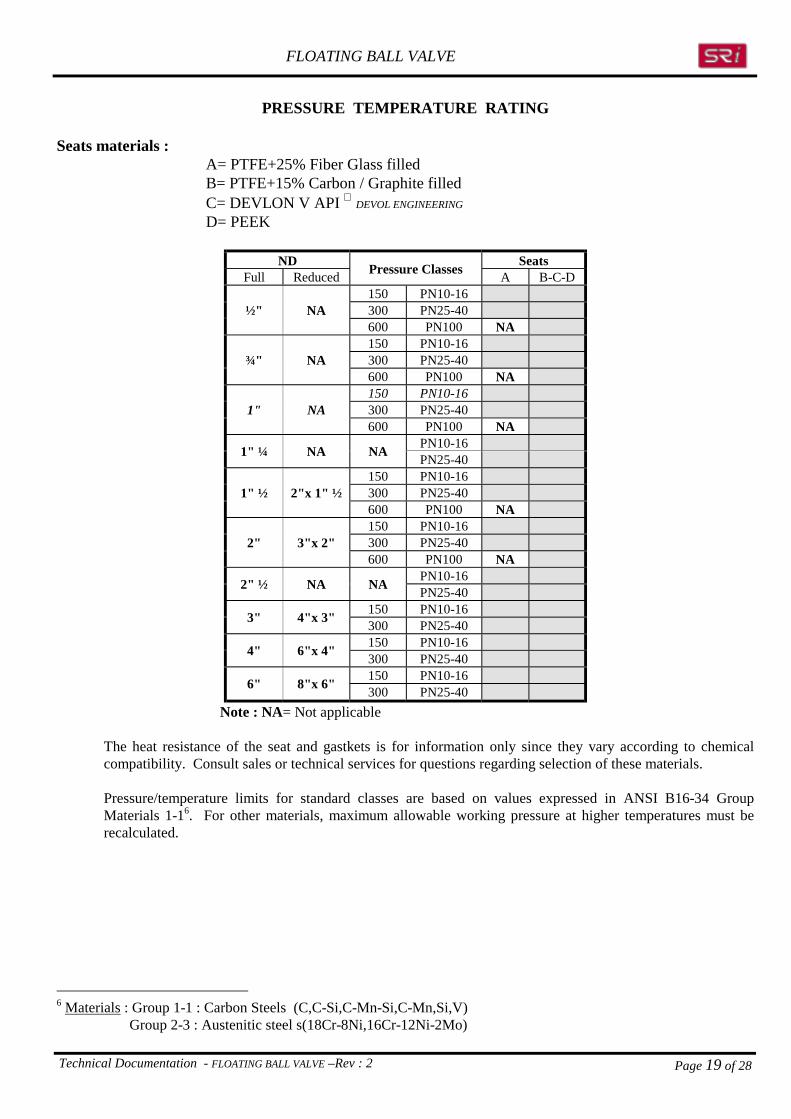
PRESSURE TEMPERATURE RATING
Seats materials : A= PTFE+25% Fiber Glass filled B= PTFE+15% Carbon / Graphite filled C= DEVLON V API DEVOL ENGINEERING
D= PEEK
ND SeatsFull Reduced Pressure Classes A B-C-D
150 PN10-16300 PN25-40½" NA600 PN100 NA150 PN10-16300 PN25-40¾" NA600 PN100 NA150 PN10-16300 PN25-401" NA600 PN100 NA
PN10-161" ¼ NA NA PN25-40150 PN10-16300 PN25-401" ½ 2"x 1" ½600 PN100 NA150 PN10-16300 PN25-402" 3"x 2"600 PN100 NA
PN10-162" ½ NA NA PN25-40150 PN10-163" 4"x 3" 300 PN25-40150 PN10-164" 6"x 4" 300 PN25-40150 PN10-166" 8"x 6" 300 PN25-40
Note : NA= Not applicable
The heat resistance of the seat and gastkets is for information only since they vary according to chemicalcompatibility. Consult sales or technical services for questions regarding selection of these materials.
Pressure/temperature limits for standard classes are based on values expressed in ANSI B16-34 GroupMaterials 1-16. For other materials, maximum allowable working pressure at higher temperatures must berecalculated.
6 Materials : Group 1-1 : Carbon Steels (C,C-Si,C-Mn-Si,C-Mn,Si,V)
Group 2-3 : Austenitic steel s(18Cr-8Ni,16Cr-12Ni-2Mo)
FLOATING BALL VALVE
Technical Documentation - FLOATING BALL VALVE –Rev : 2 Page 20 of 28
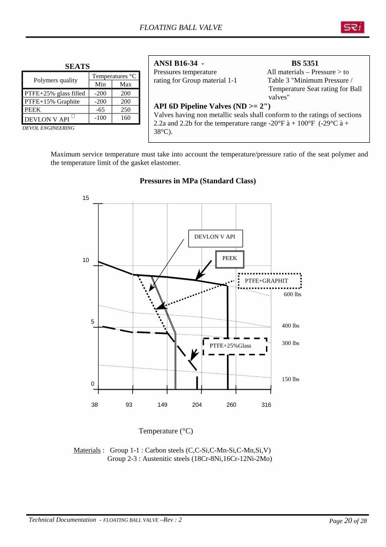
ANSI B16-34 - BS 5351Pressures temperature All materials – Pressure > torating for Group material 1-1 Table 3 "Minimum Pressure /
Temperature Seat rating for Ballvalves"
API 6D Pipeline Valves (ND >= 2")Valves having non metallic seals shall conform to the ratings of sections2.2a and 2.2b for the temperature range -20°F à + 100°F (-29°C à +38°C).
Maximum service temperature must take into account the temperature/pressure ratio of the seat polymer andthe temperature limit of the gasket elastomer.
Pressures in MPa (Standard Class)
0
5
10
15
38 93 149 204 260 316
Temperature (°C)
600 lbs
400 lbs
300 lbs
150 lbs
DEVLON V API
PEEK
PTFE+25%Glass
PTFE+GRAPHIT
Materials : Group 1-1 : Carbon steels (C,C-Si,C-Mn-Si,C-Mn,Si,V) Group 2-3 : Austenitic steels (18Cr-8Ni,16Cr-12Ni-2Mo)
SEATSTemperatures °CPolymers quality Min Max
PTFE+25% glass filled -200 200PTFE+15% Graphite -200 200PEEK -65 250DEVLON V API -100 160
DEVOL ENGINEERING
FLOATING BALL VALVE
Technical Documentation - FLOATING BALL VALVE –Rev : 2 Page 21 of 28
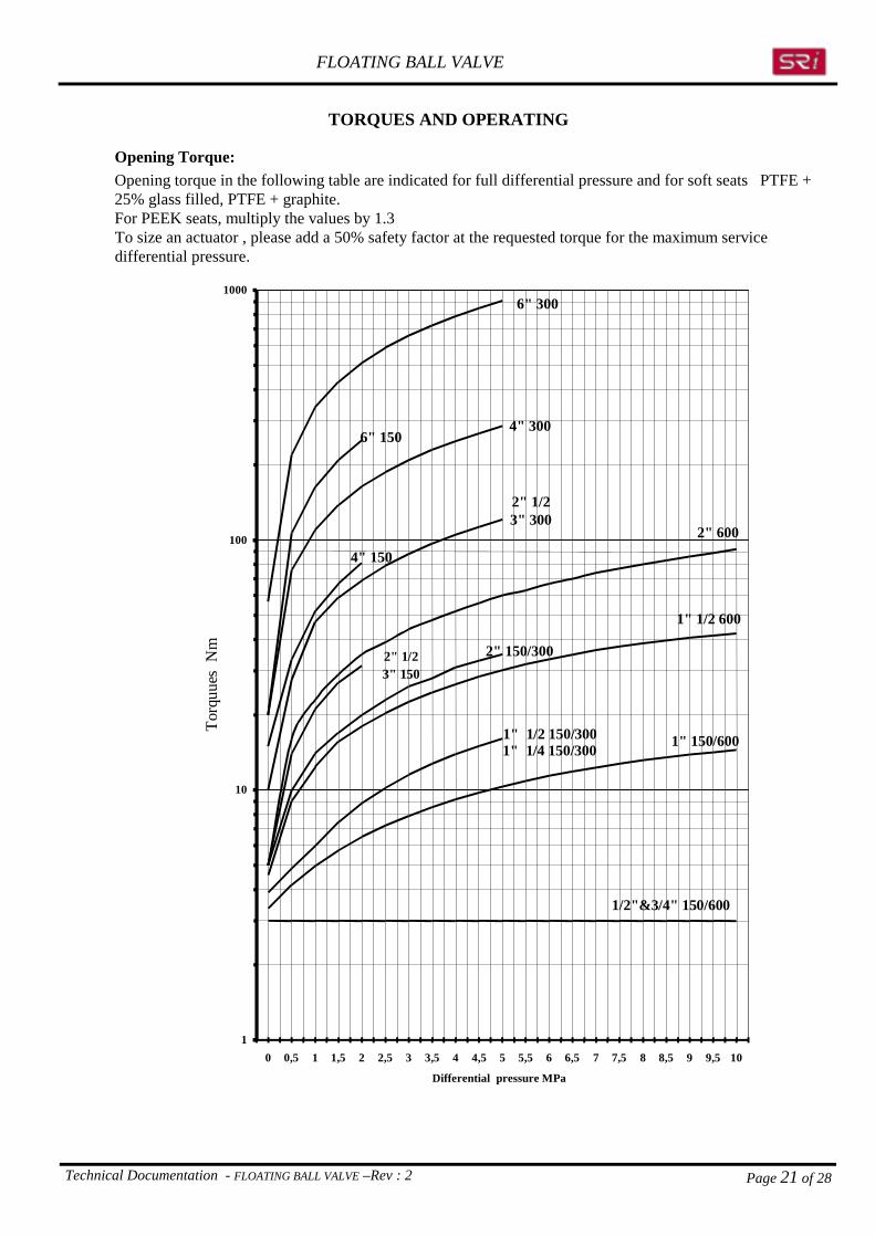
TORQUES AND OPERATING
Opening Torque:Opening torque in the following table are indicated for full differential pressure and for soft seats PTFE +25% glass filled, PTFE + graphite.For PEEK seats, multiply the values by 1.3To size an actuator , please add a 50% safety factor at the requested torque for the maximum servicedifferential pressure.
1
10
100
1000
0 0,5 1 1,5 2 2,5 3 3,5 4 4,5 5 5,5 6 6,5 7 7,5 8 8,5 9 9,5 10
Differential pressure MPa
1/2"&3/4" 150/600
1" 150/6001" 1/2 150/300
1" 1/2 600
2" 150/3002" 1/23" 150
2" 1/23" 300
4" 150
4" 3006" 150
6" 300
2" 600
1" 1/4 150/300
Torq
uues
Nm

FLOATING BALL VALVE
Technical Documentation - FLOATING BALL VALVE –Rev : 2 Page 22 of 28
Maximum allowable Stem Torque
The following table indicates the maximum admissible torque before reaching the conventional yield strengthlimit of the material at the most critical point of stem.
This value should never be surpassed in any case since excess force can lead to irreversible damage to thestem and other moving parts.
Caution must be used when connecting hydraulic, pneumatic, or electric operators to insure that the maximumforce or pressure of the operator does not generate an excessive torque on the stem.
Shear torque values in NmStem dimensions on page 18
ND (bore) & Class Stem materials – TorqueISO PN20 ISO PN50 ISO PN100
Stemdimensions 316 410 F51 17-4PH
(PN 10-16) (PN 25-40) (PN 100)
ISO N°
ΦH G Sy=207 Sy=500 Sy=450 Sy=724½ " ¾" F03 12 9 28 67 60 154
1" - 1" ¼ - 1" ½ 1" F04 15 12 52 126 113 1822"- 2" ½ - 3" 2" 1" ½ F05 20 16 144 347 312 798
4" 2" ½ 3" 2" F10 30 22 416 1004 904 23106" 4" F12 40 32 1149 2774 2497 6381
6" F16 54 44 2470 5966 5369 8639ISO PN 20 – 50 -100 related to 150 – 300 - 600 class respectively.
Notes :Sy =Min yield strength (determining by the 0.2% offset) in MPaΦH =Outside stem diameter in mmG =On flat stem dimension in mmCodification materials UNS (Unified Numbering System)
316 : UNS S31600410: UNS S41000F51 : UNS S31803 (Ferritic Austenitic)17-4PH :UNS S17400 Quenched and tempered H1150

FLOATING BALL VALVE
Technical Documentation - FLOATING BALL VALVE –Rev : 2 Page 23 of 28
HYDRAULIC CHARACTERISTICS
SRi can recommend the size of valve to be installed or evaluate pressure loss caused by a given valve uponreceipt of the service conditions.
Flow coefficient calculations are taken from the following references :-NF EN 60534-2-2 June 1993 C 46-504-NF E 29 312 December 1984
LIQUID
Cv = Flow coefficient q = Volumic flow (m3/h) W = Mass flow (ton / h) at flowing
temperature∆P = Pressure drop (bar)Gf = Liquid density related to water
(1 à 15,6°C)
Volum flow
C qG
Pvf= × ×116.
∆Mass flow
C WG Pv
f
= ××
116.∆
GAS
Q = Volumic flow (Nm3/h) W = Mass flow (ton/h) G = Gas density at 15,6°C and 1013 mbar
related air (= 1) Gf = Gas density at flowing temperature
condition and 1013 mbar related 'air
(=1) T
G 75.288×=
Cv = Flow coefficient∆P = Pressure drop (bar)T = Absolute temperature of gas (°K)P1 =Upstream pressure (bar abs.)P2 =Downstream pressure (bar abs.)
Volumic flow
C Q G TP P Pv = × ×
× +295 1 2∆ ( )
Mass flow
( )C W
P P P Gv
f
= ×× + ×47 2
1 2
.∆
STEAM
Cv = Flow coefficient W = Mass flow (ton/h) ∆P = Pressure drop (bar)Tsh = SuperHeated temperature related to saturated temperature (°C)P1 = Upstream pressure (bar abs.)P2 = Downstream pressure (bar abs.)
Mass flow Saturated steam
( )C W
P P Pv = ×
× +72 4
1 2
.∆
Mass flow SuperHeated steam( )
( )C
T WP P P
vsh=
× + × ×
× +
72 4 1 0 00126
1 2
. .∆

FLOATING BALL VALVE
Documentation technique Rev :2-FLOATING BALL VALVE Page 24 of 28
FLOW COFFICIENT CV
Flow coefficients Cv and Kv :
Cv = Water flow in US Gallons (3,78 liters) by minute for 1 psi constant pressure drop.Kv = Water flow in m3 by hour for 1 bar constant pressure drop.
16.1
CvKv = and KvCv ×= 16.1
Full Bore Valves
Indicated flow coefficients are identical in both flow directions
ND Pressure ClassInches mm 150 300 600 PN10 PN16 PN25 PN40
½" 15 25 22 20 22 22 22 22¾" 20 51 45 40 45 45 45 451" 25 116 102 89 103 103 103 103
1" ¼ 32 NA 170 170 170 1701" ½" 40 301 280 249 273 273 273 273
2" 50 585 531 456 514 514 514 5142" ½ 65 NA 893 893 893 893
3" 80 1585 1344 1198 1283 1283 1283 12834" 100 2917 2526 2122 2357 2357 2357 2357
6" LP 150 6230 6154 5229 5642 5642 5642 5642 Note :
Classes 150-300-600 related to class ISOPN 20-50-100 respectively.

FLOATING BALL VALVE
Documentation technique Rev :2-FLOATING BALL VALVE Page 25 of 28
Reduced bore Valves
IMPORTANT :
Due to the asymetry of a reduced passage valve, the flow coefficient varies according to the flow direction
FLOW direction 1
ND Pressure ClassInches mm 150 300 600 PN10 PN16 PN25 PN40
2"x1" ½ 50 x 40 108 116 102 101 101 106 1063"x 2" 80 x 50 157 172 315 148 148 166 1664"x 3" 100 x 80 446 481 746 761
6"x 4" LP 150 x 100 1011 955 1097 11598"x 6" SP 200 x 150 NA 2175 NA 21758"x 6" LP 200 x150 2663 2679
NA
2851 2907 NA= Not applicable
Classes 150-300-600 related to class ISOPN 20-50-100 respectively.
FLOW direction 2
ND Pressure ClassInches mm 150 300 600 PN10 PN16 PN25 PN40
2"x 1" ½ 50 x 40 108 110 98 101 101 102 1023"x 2" 80 x 50 157 158 240 148 148 150 1504"x 3" 100 x 80 446 454 722 599
6"x 4" LP 150 x 100 703 955 702 9678"x 6" SP 200 x 150 NA 2180 NA 21808"x 6" LP 200 x150 2532 2247
NA
2486 2230 NA= Not applicable
Classes 150-300-600 related to class ISOPN 20-50-100 respectively.
12

FLOATING BALL VALVE
Documentation technique Rev :2-FLOATING BALL VALVE Page 26 of 28
ACCESSORIES
Insulating Extension
MATERIALSRep Part name Carbon steel Stainless steel150 UPPER SEAL Nitrile (NBR) Nitrile (NBR)148 STEM A182F316 or UNS17400 A182F316 or UNS17400149 EXTENSION A216WCB -A350GrLF2 A351CF8M -A182F31637 BOLTING A193 B8- A4/70 A193 B8- A4/70
ND (bore) & ClassISO PN20 ISO PN50 ISO PN100
Length Hc(mm)
(PN 10-16) (PN 25-40) (PN 100)
ISO N°
Hc½ " ¾" F03 100
1" - 1" ¼ - 1" ½ 1" F04 1002"- 2" ½ - 3" 2" 1" ½ F05 100
4" 2" ½ 3" 2" F10 1006" 4" F12 100
6" F16 120Class 150-300-600 related to class ISOPN 20-50-100 respectively.

FLOATING BALL VALVE
Documentation technique Rev :2-FLOATING BALL VALVE Page 27 of 28
Locking Devices
The locking device has been designed to lock open or closed without any further change in the valve.Once the locking device is installed it cannot be removed.All parts of the locking device are in stainless steel 316.
The locking device is available for five ISO sizes. The maximum pin sizes for padlocks (not supplied) are indicated in the following table
ND (bore) & ClassesISO PN20 ISO PN50 ISO PN100
Padlockpin
diameter
(PN 10-16) (PN 25-40) (PN 100)
ISO N°
mm½ " ¾" F03 4
1" - 1" ¼ - 1" ½ 1" F04 42"- 2" ½ - 3" 2" 1" ½ F05 6
4" 2" ½ 3" 2" F10 66" 4" F12 6
Classes 150-300-600 related to class ISOPN 20-50-100 respectively.
Locking stem
Locking KeyOpen or Close
FLOATING BALL VALVE
Documentation technique Rev :2-FLOATING BALL VALVE Page 28 of 28
BF 2000 PRODUCTS
Metal /Metal Floating Ball Valves
Size range ½" to 6" full and reduced bore, ISO PN 20-50-100 PN 10-16-25-40.Seats and ball with tungsten carbide coating.
Manual and motorized operations.
Low Temperature and Cryogenic Floating Ball Valves
Size range ½" to 6" full and reduced bore, ISO PN 20-50-100 PN 10-16-25-40.Standard cryogenic extension designed for fluids down to –196°C.
Manual and motorized operations.
High Temperature Floating Ball Valves
Size range ½" to 6" full and reduced bore, ISO PN 20-50-100 PN 10-16-25-40.Designed for fluid up to 450°C.
Metal/metal seated and expanded graphit" sealsTop stem temperature stabilized at 150°C max
Manual and motorized operations.
Multi-way floating ball valves ( 3 ways "L" type") .
Size range ½" to 6" full and reduced bore, ISO PN 20-50-100 PN 10-16-25-40.Soft Seats or metal seats with Tungsten carbide coating.
2 seats ball valves , non transflow .Manual and motorized operations.
SUD ROBINETTERIE industriePost Box 316
13309 MARSEILLE CEDEX 14 -FRANCE
Tel 33 (0) 495 055 050Fax 33 (0) 495 055 070
Email : [email protected] : http://www.sri.fr