Products Solutions Services BA00111D/06/EN/13.14 71261899 Valid as of version V 1.01.00 (Device software) Operating Instructions Proline t-mass 65 Thermal mass flowmeter 6

Welcome message from author
This document is posted to help you gain knowledge. Please leave a comment to let me know what you think about it! Share it to your friends and learn new things together.
Transcript
Products Solutions ServicesBA00111D/06/EN/13.1471261899
Valid as of versionV 1.01.00 (Device software)
Operating InstructionsProline t-mass 65Thermal mass flowmeter
6
Proline t-mass 65
2 Endress+Hauser
Table of contents
1 Document information . . . . . . . . . . . . . . 31.1 Document conventions . . . . . . . . . . . . . . . . . . . . . . . 3
2 Safety instructions . . . . . . . . . . . . . . . . . 52.1 Designated use . . . . . . . . . . . . . . . . . . . . . . . . . . . . . 52.2 Installation, commissioning and operation . . . . . . 52.3 Operational safety . . . . . . . . . . . . . . . . . . . . . . . . . . . 62.4 Return . . . . . . . . . . . . . . . . . . . . . . . . . . . . . . . . . . . . . 62.5 Product safety . . . . . . . . . . . . . . . . . . . . . . . . . . . . . . 6
3 Identification . . . . . . . . . . . . . . . . . . . . . . 73.1 Device designation . . . . . . . . . . . . . . . . . . . . . . . . . . 73.2 Certificates and approvals . . . . . . . . . . . . . . . . . . 103.3 Registered trademarks . . . . . . . . . . . . . . . . . . . . . 10
4 Installation . . . . . . . . . . . . . . . . . . . . . . . 114.1 Incoming acceptance, transport and storage . . . 114.2 Installation conditions . . . . . . . . . . . . . . . . . . . . . 124.3 Installation . . . . . . . . . . . . . . . . . . . . . . . . . . . . . . . 194.4 Post-installation check . . . . . . . . . . . . . . . . . . . . . 27
5 Electrical connection. . . . . . . . . . . . . . . 285.1 Connecting the remote version . . . . . . . . . . . . . . 285.2 Connecting the measuring unit . . . . . . . . . . . . . . 305.3 Degree of protection . . . . . . . . . . . . . . . . . . . . . . . 335.4 Post-connection check . . . . . . . . . . . . . . . . . . . . . 34
6 Operation . . . . . . . . . . . . . . . . . . . . . . . . 356.1 Display and operating elements . . . . . . . . . . . . . 356.2 Brief operating instructions for the function matrix
366.3 Error messages . . . . . . . . . . . . . . . . . . . . . . . . . . . 386.4 Communication . . . . . . . . . . . . . . . . . . . . . . . . . . . 39
7 Commissioning . . . . . . . . . . . . . . . . . . . 507.1 Function check . . . . . . . . . . . . . . . . . . . . . . . . . . . 507.2 Switching on the measuring device . . . . . . . . . . 507.3 Quick Setup . . . . . . . . . . . . . . . . . . . . . . . . . . . . . . 507.4 Configuration . . . . . . . . . . . . . . . . . . . . . . . . . . . . . 617.5 Adjustment . . . . . . . . . . . . . . . . . . . . . . . . . . . . . . 657.6 Data storage device (HistoROM) . . . . . . . . . . . . . 66
8 Maintenance . . . . . . . . . . . . . . . . . . . . . 678.1 External cleaning . . . . . . . . . . . . . . . . . . . . . . . . . 678.2 Pipe cleaning . . . . . . . . . . . . . . . . . . . . . . . . . . . . . 678.3 Sensor cleaning . . . . . . . . . . . . . . . . . . . . . . . . . . . 678.4 Replacing seals . . . . . . . . . . . . . . . . . . . . . . . . . . . 688.5 In-situ calibration . . . . . . . . . . . . . . . . . . . . . . . . . 688.6 Recalibration . . . . . . . . . . . . . . . . . . . . . . . . . . . . . 68
9 Accessories . . . . . . . . . . . . . . . . . . . . . . .699.1 Device-specific accessories . . . . . . . . . . . . . . . . . . 699.2 Communication-specific accessories . . . . . . . . . . 699.3 Service-specific accessories . . . . . . . . . . . . . . . . . . 70
10 Trouble-shooting . . . . . . . . . . . . . . . . . .7110.1 Trouble-shooting instructions . . . . . . . . . . . . . . . 7110.2 System error messages . . . . . . . . . . . . . . . . . . . . . 7210.3 Process error messages . . . . . . . . . . . . . . . . . . . . . 7610.4 Process errors without messages . . . . . . . . . . . . . 7610.5 Response of outputs to errors . . . . . . . . . . . . . . . . 7810.6 Spare parts . . . . . . . . . . . . . . . . . . . . . . . . . . . . . . . . 7910.7 Return . . . . . . . . . . . . . . . . . . . . . . . . . . . . . . . . . . . 8610.8 Disposal . . . . . . . . . . . . . . . . . . . . . . . . . . . . . . . . . . 8610.9 Software history . . . . . . . . . . . . . . . . . . . . . . . . . . . 87
11 Technical data. . . . . . . . . . . . . . . . . . . . .8811.1 Applications . . . . . . . . . . . . . . . . . . . . . . . . . . . . . . 8811.2 Function and system design . . . . . . . . . . . . . . . . . 8811.3 Input . . . . . . . . . . . . . . . . . . . . . . . . . . . . . . . . . . . . . 8811.4 Output . . . . . . . . . . . . . . . . . . . . . . . . . . . . . . . . . . . 8911.5 Power supply . . . . . . . . . . . . . . . . . . . . . . . . . . . . . . 9011.6 Performance characteristics . . . . . . . . . . . . . . . . . 9011.7 Installation . . . . . . . . . . . . . . . . . . . . . . . . . . . . . . . 9211.8 Environment . . . . . . . . . . . . . . . . . . . . . . . . . . . . . . 9211.9 Process . . . . . . . . . . . . . . . . . . . . . . . . . . . . . . . . . . . 9311.10 Mechanical construction . . . . . . . . . . . . . . . . . . . . 9511.11 Operability . . . . . . . . . . . . . . . . . . . . . . . . . . . . . . . . 9711.12 Certificates and approvals . . . . . . . . . . . . . . . . . . . 9711.13 Ordering information . . . . . . . . . . . . . . . . . . . . . . . 9911.14 Accessories . . . . . . . . . . . . . . . . . . . . . . . . . . . . . . . 9911.15 Documentation . . . . . . . . . . . . . . . . . . . . . . . . . . . . 99
Index. . . . . . . . . . . . . . . . . . . . . . . . . . . 100

Proline t-mass 65 Document information
Endress+Hauser 3
1 Document information
1.1 Document conventions
1.1.1 Safety symbols
1.1.2 Electrical symbols
Symbol Device particularities and document content
" Caution!
“Caution” indicates an action or procedure which, if not performed correctly, can result in incorrect operation or destruction of the device. Comply strictly with the instructions.
# Warning!
"Warning" indicates an action or procedure which, if not performed correctly, can result in injury or a safety hazard. Comply strictly with the instructions and proceed with care.
! Note!
"Note" indicates an action or procedure which, if not performed correctly, can have an indirect effect on operation or trigger an unexpected response on the part of the device.
Symbol Meaning
A0011197
Direct currentA terminal at which DC voltage is present or through which direct current flows.
A0011198
Alternating currentA terminal at which alternating voltage (sinusoidal) is present or through which alternating current flows.
A0011200
Ground connectionA grounded terminal which, as far as the operator is concerned, is grounded via a grounding system.
A0011199
Protective ground connectionA terminal which must be connected to ground prior to establishing any other connections.
A0011201
Equipotential connectionA connection that must be connected to the plant grounding system: This may be a potential equalization line or a star grounding system depending on national or company codes of practice.
Document information Proline t-mass 65
4 Endress+Hauser
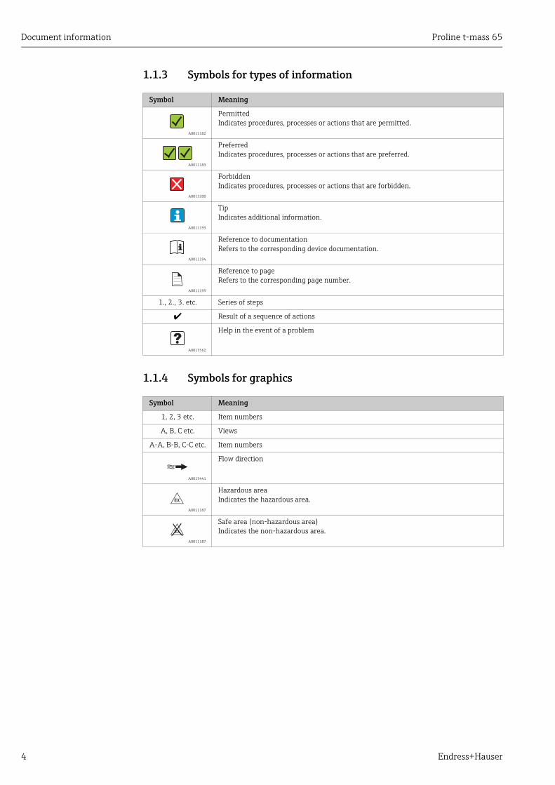
1.1.3 Symbols for types of information
1.1.4 Symbols for graphics
Symbol Meaning
A0011182
PermittedIndicates procedures, processes or actions that are permitted.
A0011183
PreferredIndicates procedures, processes or actions that are preferred.
A0011200
ForbiddenIndicates procedures, processes or actions that are forbidden.
A0011193
TipIndicates additional information.
A0011194
Reference to documentationRefers to the corresponding device documentation.
A0011195
Reference to pageRefers to the corresponding page number.
1., 2., 3. etc. Series of steps
à Result of a sequence of actions
A0013562
Help in the event of a problem
Symbol Meaning
1, 2, 3 etc. Item numbers
A, B, C etc. Views
A-A, B-B, C-C etc. Item numbers
A0013441
Flow direction
A0011187
Hazardous areaIndicates the hazardous area.
A0011187
Safe area (non-hazardous area)Indicates the non-hazardous area.
-
.

Proline t-mass 65 Safety instructions
Endress+Hauser 5
2 Safety instructions
2.1 Designated useThe measuring device described in these Operating Instructions is to be used only for measuring the mass flow rate of gases (e. g. kg, Nm3 Sft3). At the same time, it also measures gas temperature. The measuring device can be configured to measure a standard range of pure gases or gas mixtures.
Examples:• Air• Oxygen• Nitrogen• Carbon Dioxide• Argon, etc.
The use with corrosive, saturated or unclean gases should be treated with caution In such cases, please contact your Endress+Hauser sales center for clarification. The use with unstable gases or gases not deemed to be suitable by Endress+Hauser must be avoided. The measuring device is not designed to be used with liquids or fluids in the liquid phase.
Resulting from incorrect use or from use other than that designated, the operational safety of the measuring devices can be jeopardized. The manufacturer accepts no liability for damages being produced from this.
2.2 Installation, commissioning and operationNote the following points:• Installation, connection to the electricity supply, commissioning, operation and
maintenance of the measuring device must be carried out by trained, qualified specialists authorized to perform such work by the facility's owner operator. The specialist must have read and understood these Operating Instructions and must follow the instructions they contain.
• Endress+Hauser is willing to assist in clarifying the chemical resistance properties of parts wetted by special fluids, including fluids used for cleaning. However small changes in temperature, concentration or the degree of contamination in the process can result in changes of the chemical resistance properties. Therefore, Endress+Hauser can not guarantee or accept liability for the chemical resistance properties of the fluid wetted materials in a specific application. The operator is responsible for the choice of fluid wetted materials in regards to their in-process resistance to corrosion.
• If carrying out welding work on the piping, the welding unit should not be grounded by means of the measuring device.
• The installer must ensure that the measuring device is correctly wired in accordance with the wiring diagrams. The transmitter must be grounded unless special protection measures have been taken e.g. galvanically isolated power supply SELV or PELV! (SELV = Safe Extra Low Voltage; PELV = Protective Extra Low Voltage)
• Invariably, local regulations governing the opening and repair of electrical devices apply.

Safety instructions Proline t-mass 65
6 Endress+Hauser
2.3 Operational safetyNote the following points:• Measuring devices for use in hazardous environments are accompanied by separate
"Ex documentation", which is an integral part of these Operating Instructions. Strict compliance with the installation instructions and ratings as stated in this supplementary documentation is mandatory. The symbol on the front of this supplementary Ex documentation indicates the approval and the certification body (e.g. 0 Europe, 2 USA, 1 Canada).
• Burn hazard! When hot fluid passes through the measuring tube, the surface temperature of the housing increases. In the case of the sensor, in particular, users should expect temperatures that can be close to the fluid temperature. If the temperature of the fluid is high, implement sufficient measures to prevent burning or scalding.
• The measuring device complies with the general safety requirements in accordance with EN 61010-1, the EMC requirements of IEC/EN 61326, and NAMUR recommendation NE 21, NE 43 and NE 53.
• The separate document on the Pressure Equipment Directive must be observed for measuring devices used in Category II or III installations in accordance with the Pressure Equipment Directive.
• The manufacturer reserves the right to modify technical data without prior notice. Your Endress+Hauser sales center will supply you with current information and updates to these Operating Instructions.
2.4 Return• Do not return a measuring device if it is not absolutely certain that it has been fully cleaned
of all traces of hazardous substances, e.g. substances which have penetrated crevices or diffused through plastic.
• Costs incurred for waste disposal and injury (burns, etc.) due to inadequate cleaning of the measuring device will be charged to the owner-operator.
• Refer to the measures on → 86.
2.5 Product safetyThis measuring device is designed in accordance with good engineering practice to meet state-of-the-art safety requirements, has been tested, and left the factory in a condition in which it is safe to operate. It complies with the applicable standards and regulations in accordance with EN 61010-1 "Safety requirements for electrical equipment for measurement, control and laboratory use". It can, however, be a source of danger if used incorrectly or for other than the designated use.

Proline t-mass 65 Identification
Endress+Hauser 7
3 Identification
3.1 Device designationThe "t-mass 65" measuring device consists of the following components:• t-mass 65 transmitter• t-mass F, t-mass I sensors
Two versions are available:• Compact version: transmitter and sensor form a single mechanical unit.• Remote version: transmitter and sensor are installed separately.
3.1.1 Nameplate of the transmitter
A0005101
Fig. 1: Nameplate specifications for the "t-mass 65" transmitter (example)
1 Order code, serial number: See the specifications on the order confirmation for the meanings of the individual letters and digits.
2 Power supply, frequency, power consumption3 Available inputs/outputs:4 Reserved for information on special products5 Please refer to operating instructions / documentation6 Reserved for certificates, approvals and for additional information on device version7 Ambient temperature range8 Degree of protection
Order Code:Ser.No.:TAG No.:
20-55VAC/16-62VDC50-60Hz 14VA/8W
IP67/NEMA/Type4X65F25-XXXXXXXXXXXX12345678901ABCDEFGHJKLMNPQRST
–20°C (–4°F) < Tamb < +60°C (+140°F)
I-OUT ( HART), f-OUT
Proline t-mass 65
RELAY, RELAY
i
1
2
3
4
7 8
5
6
N12895
Identification Proline t-mass 65
8 Endress+Hauser
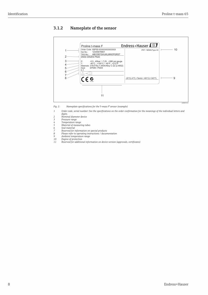
3.1.2 Nameplate of the sensor
A0005512
Fig. 2: Nameplate specifications for the "t-mass F" sensor (example)
1 Order code, serial number: See the specifications on the order confirmation for the meanings of the individual letters and digits.
2 Nominal diameter device3 Pressure range4 Temperature range5 Material of measuring tubes6 Seal material7 Reserved for information on special products8 Please refer to operating instructions / documentation9 Ambient temperature range10 Degree of protection11 Reserved for additional information on device version (approvals, certificates)
1
2
4567
9
11
10
3
Proline t-mass F
ABCDEFGHIJKLMNOPQRSTTAG-No.:Ser.No.: 12345678901Order Code: IP67 / NEMA/Type 4X65F50-XXXXXXXXXXXX
P:T:Materials:Seal:3.1
-0.5...40bar / -7.25...+580 psi gauge
EPDM / PEEK316/316L/1.4404/Alloy C 22- (2.4602)-40°C...+100°C / -40°F...+212°F
-20°C(-4°F) <Tamb< +60°C(+140°F)
i
DN50 DIN/EN PN40
N12895
8

Proline t-mass 65 Identification
Endress+Hauser 9
3.1.3 Nameplate for connections
a0013819
Fig. 3: Nameplate specifications for transmitter connections (example)
1 Serial number2 Possible configuration of current output3 Possible configuration of relay contacts4 Terminal assignment, cable for power supply: 85 to 260 V AC, 20 to 55 V AC, 16 to 62 V DC
Terminal No. 1: L1 for AC, L+ for DCTerminal No. 2: N for AC, L– for DC
5 Signals present at inputs and outputs, possible configuration and terminal assignment (20 to 27), see also "Electrical values of inputs/outputs", → 88
6 Version of device software currently installed7 Installed communication type, e.g.: HART, PROFIBUS DP, etc.8 Information on current communication software (Device Revision and Device Description),
e.g.: Dev. 01 / DD 01 for HART9 Date of manufacture10 Current updates to data specified in points 6 to 9
Active: 0/4...20mA, RL max. = 700 Ohm
Passive: 4...20mA, max. 30VDC, Ri < 150 Ohm
Passive: 30VDC, 250mA
(HART: RL.min. = 250 OHM)
fmax = 1kHz
3...30VDC, Ri = 5kOhm
f-OUT
I-OUT (HART)A
P
STATUS-IN X
f-OUTPassive: 30VDC, 250mA
fmax = 1kHzP
Communication:
Drivers:
Device SW: XX.XX.XX
XXXXXXXXXXXXXXXX
Date: 01. MAI 2009
Ex-works / ab-Werk / réglages usine
26
(+)
/2
7(-
)
NC:
Versorgung /
Tension d'alimentation
Observer manuel d'instruction
See operating manualBetriebsanleitung beachten
XXXXXXXXXXXSer.No.:
Supply /
24
(+)
/2
5(-
)
22
(+)
/2
3(-
)
20
(+)
/2
1(-
)
N/L-
PE
A:
NO:P:
L1/L+
1 2
319475-00XX
activepassivenormally open contactnormally closed contact
Update 1 Update 2
2
3
1
4
5
6789
10

Identification Proline t-mass 65
10 Endress+Hauser
3.2 Certificates and approvalsThis measuring device is designed in accordance with good engineering practice to meet state-of-the-art safety requirements, has been tested, and left the factory in a condition in which it is safe to operate. The measuring device complies with the applicable standards and regulations in accordance with EN 61010-1 "Safety requirements for electrical equipment for measurement, control and laboratory use" and with the EMC requirements of IEC/EN 61326. The measuring device described in these Operating Instructions thus complies with the statutory requirements of the EC Directives. Endress+Hauser confirms successful testing of the measuring device by affixing to it the CE mark.The measuring device meets the EMC requirements of the Australian Communications and Media Authority (ACMA).
3.3 Registered trademarksKALREZ® and VITON®
Registered trademarks of DuPont Performance Elastomers L.L.C., Wilmington, USA
AMS™ Registered trademark of Emmerson Process Management, St. Louis, USA
HART® Registered trademark of HART Communication Foundation, Austin, USA
HistoROM™, S-DAT®, T-DAT™, F-CHIP®, FieldCare®, Field XpertTM, FieldCheck®, Applicator®, t-mass®
Registered or registration-pending trademarks of businesses in the Endress+Hauser Group

Proline t-mass 65 Installation
Endress+Hauser 11
4 Installation
4.1 Incoming acceptance, transport and storage
4.1.1 Incoming acceptanceOn receipt of the goods, check the following points:• Is the packaging or content undamaged?• Is the delivery complete and do the delivered goods match your order?
4.1.2 TransportObserve the following instructions when unpacking and transporting the device to its final location:• Transport the measuring device in the container in which it is delivered.• The covers or caps fitted to the process connections prevent mechanical damage to the
sealing surfaces and contamination in the measuring tube when the unit is being transported or in storage. Do not remove these covers or caps until immediately before installation.
• Do not lift measuring devices of nominal diameters > DN 40 (1½") by the transmitter housing or the connection housing in the case of the remote version → 4. For transportation purposes, use webbing slings slung round the two process connections. Do not use chains, as they could damage the housing.
# Warning! Risk of injury if the measuring device slips. The center of gravity of the assembled measuring device might be higher than the points around which the slings are slung.When transporting, make sure that the measuring device does not unexpectedly turn around its axis or slip.
A0004294
Fig. 4: Instructions for transporting sensors with > DN 40 (> 1½")
4.1.3 StorageNote the following points:• Pack the measuring device in such a way as to protect it reliably against impact for storage
(and transportation). The original packaging provides optimum protection.• The permissible storage temperature is: –40 to +80 °C (–40 to +176 °F),
preferably +20 °C (+68 °F).• Do not remove the protective covers or caps on the process connections until you are ready
to install the device.• The measuring device must be protected against direct sunlight during storage in order to
avoid unacceptably high surface temperatures.• Devices delivered with special sealing or bagging for oxygen service must remain sealed or
bagged until ready for installation.
Installation Proline t-mass 65
12 Endress+Hauser
4.2 Installation conditionsNote the following points:• The thermal dispersion principle is very sensitive to disturbed flow conditions.• Observe the recommended inlet and outlet requirements.• Good engineering practice is necessary for the associated pipe work and installation.• Ensure correct alignment and orientation of the sensor.• Take measures to reduce or avoid condensation (e.g. install a condensation trap, thermal
insulation, etc.).• The maximum permitted ambient temperatures → 92 and the medium temperature
range → 93 must be observed.• Install the transmitter in a shaded location or use a protective sun shield.• For mechanical reasons, and in order to protect the pipe, it is advisable to support heavy
sensors.
4.2.1 DimensionsThe dimensions and installation lengths of the sensor and transmitter can be found in the "Technical Information" for the device in question. This document can be downloaded as a PDF file from www.endress.com. A list of the "Technical Information" documents available can be found in the "Documentation" section on → 99.
4.2.2 System pressure and pulsating flow Reciprocating pumps and some compressor systems can create strong changes in process pressure that can induce spurious internal flow patterns and therefore cause additional measurement error. These pressure pulses must be reduced by the appropriate measures:
• Use of expansion tanks• Use of inlet expanders• Relocate the flowmeter further downstream
In compressed air systems, it is recommended to mount the flowmeter after the filter, dryer and buffer devices to avoid pulsations and oil/dirt contamination.Do not mount the flowmeter directly after the compressor outlet.

Proline t-mass 65 Installation
Endress+Hauser 13
4.2.3 Pipework requirementsGood engineering practice should be followed at all times:
• Correct preparation, welding and finishing techniques• Correctly sized gaskets• Correctly aligned flanges and gaskets• Connecting pipe work should match the internal diameter of the flowmeter. Maximum
pipe diameter mismatch should not exceed:– 1 mm (0.04 in) for diameters < DN 200 (8")– 3 mm (0.12 in) for diameters DN 200 (8")
Further information is provided in ISO Standard 14511.
" Caution! New installations should be free of metallic and abrasive particles to prevent damage to the sensing elements on start-up.
A0005103
Correctly aligned flanges and gaskets
A0005104 A0005105 A0005106
Pipe diameter one is not equal pipe diameter two
Incorrectly sized gaskets Incorrectly aligned flanges and gaskets

Installation Proline t-mass 65
14 Endress+Hauser
4.2.4 OrientationMake sure that the direction arrow on the sensor matches the direction of flow through the pipe.
Flanged sensor Insertion sensor
Vertical orientation
A0013785
compact
m
remote
m
compact
m, n
remote
m
Horizontal orientation, transmitter head up
A0013786
compact/remote
n
Horizontal orientation, transmitter head down
A0013787
compact/remote
o
Inclined orientation, transmitter head down
A0009897
compact/remote
p
= Recommended orientation = Orientation recommended in certain situations
m In the case of saturated or unclean gases, upward flow in a vertical pipe section is preferred to minimize condensation/contamination.n Not recommended if the vibrations are too high or if the installation is unstable.o Only suitable for clean/dry gases. Do not mount the sensor from the bottom, on horizontal pipes, if build-up or condensate are likely to be present. Mount the sensor in a position as indicated below p If the gas is very wet or saturated with water (e. g. biogas, undried compressed air), mount in inclined orientation (approx. 135° ±10°).
Proline t-mass 65 Installation
Endress+Hauser 15
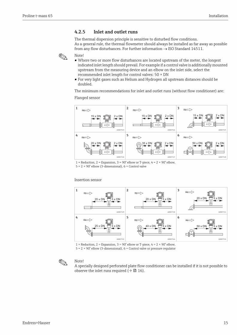
4.2.5 Inlet and outlet runsThe thermal dispersion principle is sensitive to disturbed flow conditions. As a general rule, the thermal flowmeter should always be installed as far away as possible from any flow disturbances. For further information ISO Standard 14511.
! Note! • Where two or more flow disturbances are located upstream of the meter, the longest
indicated inlet length should prevail. For example if a control valve is additionally mounted upstream from the measuring device and an elbow on the inlet side, select the recommended inlet length for control valves: 50 × DN
• For very light gases such as Helium and Hydrogen all upstream distances should be doubled.
The minimum recommendations for inlet and outlet runs (without flow conditioner) are:
Flanged sensor
Insertion sensor
! Note! A specially designed perforated plate flow conditioner can be installed if it is not possible to observe the inlet runs required (→ 16).
1
A0007523
2
A0007524
3
A0007525
4
A0007526
5
A0007527
6
A0007528
1 = Reduction, 2 = Expansion, 3 = 90° elbow or T-piece, 4 = 2 × 90° elbow, 5 = 2 × 90° elbow (3-dimensional), 6 = Control valve
1
A0007529
2
A0007530
3
A0007531
4
A0007532
5
A0007564
6
A0007534
1 = Reduction, 2 = Expansion, 3 = 90° elbow or T-piece, 4 = 2 × 90° elbow, 5 = 2 × 90° elbow (3-dimensional), 6 = Control valve or pressure regulator
15 x DN 2 x DN 15 x DN 2 x DN 15 x DN 2 x DN
20 x DN 2 x DN 35 x DN 2 x DN 50 x DN 2 x DN
20 x DN 5 x DN 20 x DN 5 x DN 20 x DN 5 x DN
25 x DN 5 x DN 40 x DN 5 x DN 50 x DN 5 x DN

Installation Proline t-mass 65
16 Endress+Hauser
Outlet runs with pressure measuring points
The pressure measuring point should be installed downstream of the measuring device, so that there is no potential influence of the pressure transmitter process connection on the flow entering the measuring point.
A0005114
Fig. 5: Installing a pressure measuring point (PT = pressure transmitter)
Perforated plate flow conditioner
It is recommended to install a perforated plate flow conditioner if the recommended inlet runs are not available.
A0005115
Fig. 6: The figure above illustrates the minimum recommended inlet and outlet runs expressed in multiples of the pipe diameter using a flow conditioner.
1 = Flow conditioner with the flanged sensor, 2 = Flow conditioner with the insertion sensor
Flow conditioner for use with insertion sensors 65I → 69
The well known "Mitsubishi" design is recommended for this application DN 80 mm to DN 300 mm (3" to 12"). The flow conditioner must be installed at a distance of 8 × DN upstream of the sensor. A further 5 pipe diameters minimum inlet run is required upstream of the actual conditioner itself.Measured errors can occur depending on disturbances in the inlet run. Therefore it is advisable to choose inlet runs that are as long as possible.
! Note! In the case of insertion devices, the inlet run selected downstream of the conditioner should be as long as possible.
PT
2...5 x DN
2 × DN5 - 10 × DN >8 × DN 5 × DN5 - 10 × DN
21

Proline t-mass 65 Installation
Endress+Hauser 17
Perforated plate flow conditioners (19 hole) for use with flanged sensor 65F → 69
This is a special Endress+Hauser version designed especially for use with the t-mass F sensor (sizes DN 25 to 100 / 1" to 4"). The mounting hole patterns and sizing are of a multi-variant design which means that one plate will fit different flange pressure classes e.g. Cl. 150 and Cl. 300.
The flow conditioner and gaskets are fitted between the pipe flange and the measuring device → 7. Use only standard bolts which match the flange bolt hole to guarantee that the flow conditioner is centered correctly.The alignment notch must also be pointing in the same plane as the transmitter. Incorrect installation of the flow conditioner will have a small effect on the measurement accuracy.
A0005116
Fig. 7: Flow conditioner mounting arrangement (example)
1 = perforated plate flow conditioner, 2 = seal/gasket, 3 = alignment notch, 4 = alignment in the same plane as the transmitter
Note• Order the t-mass F sensor and the flow conditioner together to ensure that they are
calibrated together. Joint calibration guarantees optimum performance. Ordering the flow conditioner separately and using it with the measuring device will further increase measurement uncertainty.
• The use of conditioners from other suppliers will affect the flow profile and pressure drop and will have an adverse effect on performance.
• Bolts, nuts, seals, etc. are not included in the scope of supply and must be supplied by the customer.
12
2
3
4
1
1
1

Installation Proline t-mass 65
18 Endress+Hauser
4.2.6 HeatingSome applications require suitable measures to avoid heat loss (condensation). Heating can be electric, e. g. with heated elements, or by means of copper pipes carrying hot water or steam.
" Caution! Risk of electronics overheating! Consequently, make sure that the adapter between sensor and transmitter and the connection housing of the remote version always remain free of insulating material.
4.2.7 Thermal insulation
If the gas is very wet or saturated with water (e.g. biogas), the piping and sensor housing should be insulated to prevent water droplets from condensing on the transducer.
A0005122
Fig. 8: Maximum thermal insulation for t-mass 65F and 65I
a Maximum insulation height for the flanged sensorb Maximum insulation height for the insertion sensor
4.2.8 Vibrations
" Caution! Excessive vibration can result in mechanical damage to the measuring device and its mounting. Observe the vibration specification in the technical data section → 93
a a
b b

Proline t-mass 65 Installation
Endress+Hauser 19
4.3 Installation
4.3.1 Mounting the insertion sensorThe sensor can be mounted into a welding boss or a retractable mounting set. If a retractable mounting set is being used, then refer to the supplementary documentation delivered with the mounting set.
Mounting the welding boss
This instruction describes mounting of the Endress+Hauser welding boss. If a welding boss is already available or a customer-specific one is being used, then go to the next section "Insertion depth calculation and adjustment."
! Note! • Take the orientation and inlet and outlet runs into account before mounting the welding
socket → 14 ff.• The welding boss is made of stainless steel 1.4404 (316/316L). Use appropriate welding
technique.
" Caution! • When mounting the fitting to a thin wall duct, use a suitable support bracket for the sensor
and weld the welding boss to a base plate to spread the load. Otherwise, the mounting may be unstable and the duct wall can be damaged.
# Warning! • These instructions are only applicable to installation in an un-pressurized line, without gas
present and at safe temperatures.
1. Drill or a cut hole of Ø 31.0 mm ± 0.5 mm (1.22 ± 0.019") in the pipe.
2. Deburr the hole.
3. Fit the edge of the welding boss into the hole, align it vertically and weld it on → 9.
A0010098
Fig. 9: Positioning the welding socket on the pipe (or duct)
Insertion depth calculation and adjustment
To ensure optimum measurement performance, the insertion sensor must be installed in the correct position in the pipe or duct (30% of the internal diameter).A millimeter and inch scale is provided along the entire length of the sensor tube. This makes it possible to align the sensor at the right depth.
4. Calculate the insertion depth:– with the help of the Quick Setup "Sensor" → 53 or– using the following dimensions and formulae
90°90°
Installation Proline t-mass 65
20 Endress+Hauser
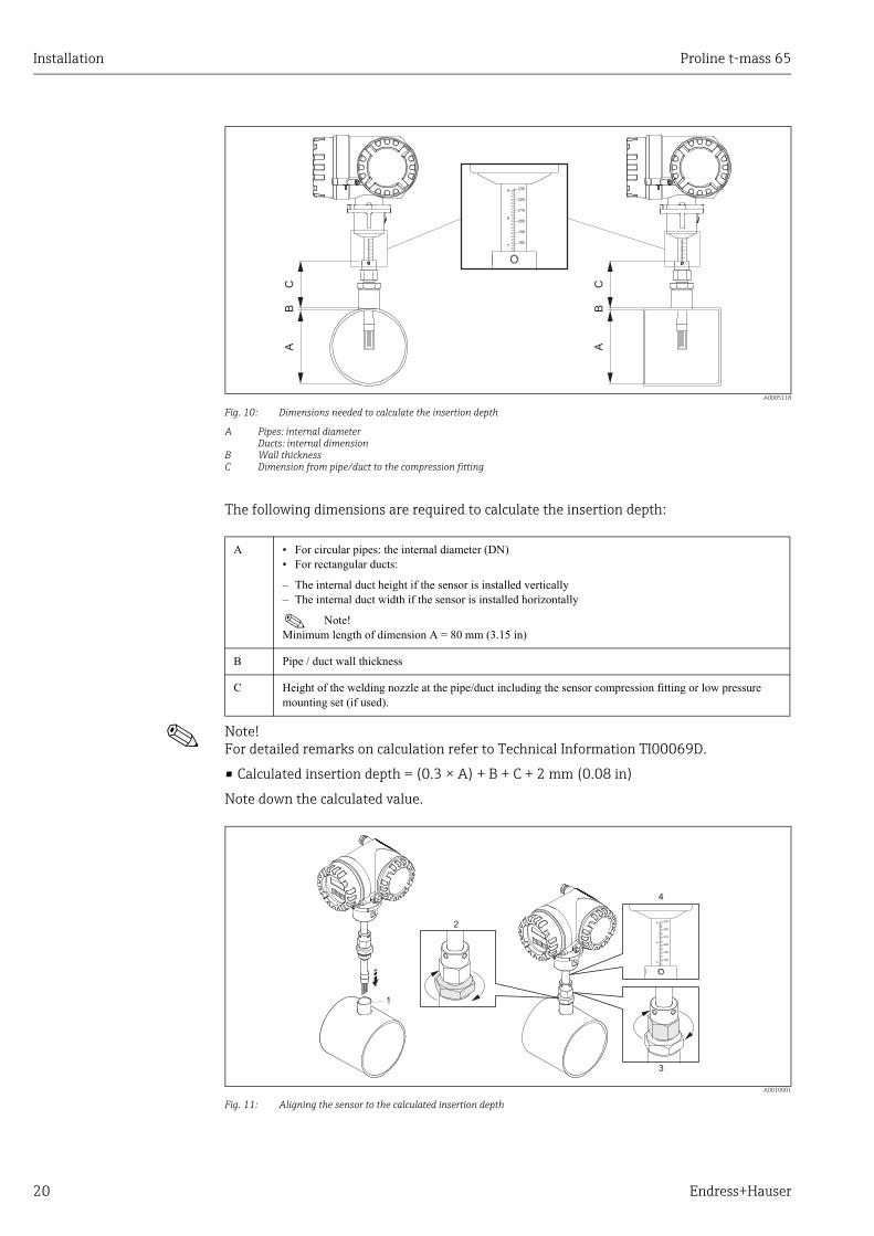
A0005118
Fig. 10: Dimensions needed to calculate the insertion depth
A Pipes: internal diameterDucts: internal dimension
B Wall thicknessC Dimension from pipe/duct to the compression fitting
The following dimensions are required to calculate the insertion depth:
! Note! For detailed remarks on calculation refer to Technical Information TI00069D.
• Calculated insertion depth = (0.3 × A) + B + C + 2 mm (0.08 in)
Note down the calculated value.
A0010001
Fig. 11: Aligning the sensor to the calculated insertion depth
AB
C
AB
C
230
220
210
200
190
180
9
8
7
230
220
210
200
190
180
9
8
7
230
220
210
200
190
180
9
8
7
A • For circular pipes: the internal diameter (DN)• For rectangular ducts:
– The internal duct height if the sensor is installed vertically– The internal duct width if the sensor is installed horizontally
! Note! Minimum length of dimension A = 80 mm (3.15 in)
B Pipe / duct wall thickness
C Height of the welding nozzle at the pipe/duct including the sensor compression fitting or low pressure mounting set (if used).
1
3
4
2 230
220
210
200
190
180
9
8
7
Proline t-mass 65 Installation
Endress+Hauser 21
5. Insert the sensor in the nozzle (1) and tighten the lower nut of the compression fitting (2) finger-tight.
" Caution! – NPT thread: use a thread sealing tape or paste– G 1 A thread: the sealing ring supplied must be installed
6. Tighten the upper nut of compression fitting (3) such that the sensor can still be adjusted.
7. Read off the calculated insertion depth from the scale and adjust the sensor so that the value aligns with the upper end of the compression fitting (4).
8. Tighten the lower nut of the compression fitting 1¼ revolutions using a wrench (42 mm).
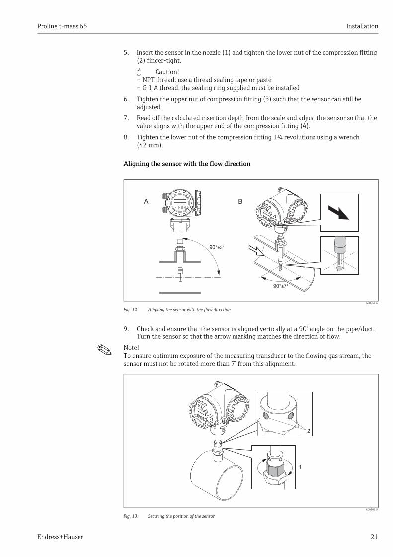
Aligning the sensor with the flow direction
A0005117
Fig. 12: Aligning the sensor with the flow direction
9. Check and ensure that the sensor is aligned vertically at a 90° angle on the pipe/duct. Turn the sensor so that the arrow marking matches the direction of flow.
! Note! To ensure optimum exposure of the measuring transducer to the flowing gas stream, the sensor must not be rotated more than 7° from this alignment.
A0010114
Fig. 13: Securing the position of the sensor
90°±7°
90°±3°
BA
1
2

Installation Proline t-mass 65
22 Endress+Hauser
10. Tighten the compression fitting (1) by hand to secure the position of the sensor. Then, using an open-ended wrench, tighten another 1¼ revolutions in a clockwise direction.
11. Fix the two securing screws (2) (Allen key 3 mm; (1/8")).
# Warning! Observe torque: 4 Nm (2.95 lbf ft)
12. Check that the sensor and transmitter do not turn.
13. Check the measuring point for leaks at the maximum operating pressure.
Proline t-mass 65 Installation
Endress+Hauser 23
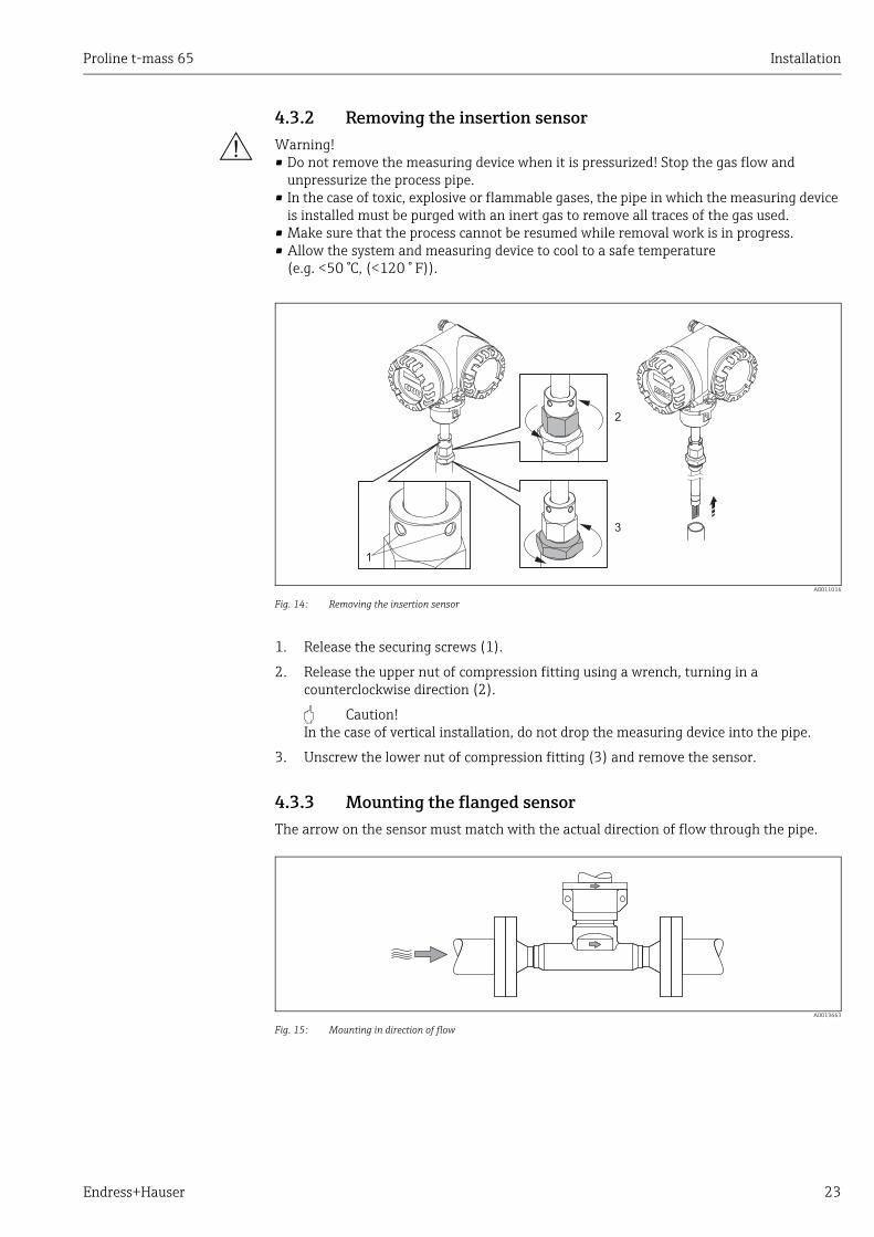
4.3.2 Removing the insertion sensor
# Warning! • Do not remove the measuring device when it is pressurized! Stop the gas flow and
unpressurize the process pipe.• In the case of toxic, explosive or flammable gases, the pipe in which the measuring device
is installed must be purged with an inert gas to remove all traces of the gas used.• Make sure that the process cannot be resumed while removal work is in progress.• Allow the system and measuring device to cool to a safe temperature
(e.g. <50 °C, (<120 ° F)).
A0011016
Fig. 14: Removing the insertion sensor
1. Release the securing screws (1).
2. Release the upper nut of compression fitting using a wrench, turning in a counterclockwise direction (2).
" Caution! In the case of vertical installation, do not drop the measuring device into the pipe.
3. Unscrew the lower nut of compression fitting (3) and remove the sensor.
4.3.3 Mounting the flanged sensor The arrow on the sensor must match with the actual direction of flow through the pipe.
A0013663
Fig. 15: Mounting in direction of flow
1
2
3

Installation Proline t-mass 65
24 Endress+Hauser
4.3.4 Turning the transmitter housing
Turning the aluminum field housing
# Warning! The rotating mechanism for measuring devices for hazardous areas Zone 1 (ATEX/IEC Ex) or Class I Div. 1 (FM/CSA) is different to that described here. The procedure for turning these housings is described in the Ex-specific documentation → 99.
1. Loosen the two securing screws.
" Caution! Special screw! Do not loosen screw completely or replace with another screw.Use only original Endress+Hauser parts.
1. Turn the bayonet catch as far as it will go.
2. Carefully lift the transmitter housing as far as it will go.
3. Turn the transmitter housing to the desired position (max. 2 × 90° in either direction).
4. Lower the housing into position and re-engage the bayonet catch.
5. Retighten the two securing screws.
A0004302
Fig. 16: Turning the transmitter housing (aluminum field housing)
4.3.5 Turning the local display1. Unscrew cover of the electronics compartment from the transmitter housing.
2. Press the side latches on the display module and remove the module from the electronics compartment cover plate.
3. Rotate the display to the desired position (4 × 45 ° in both directions), and reset it onto the electronics compartment cover plate.
4. Screw the cover of the electronics compartment firmly back onto the transmitter housing.
A0003236
Fig. 17: Turning the local display (field housing)
3
5
61
2 4
4 x 45°

Proline t-mass 65 Installation
Endress+Hauser 25
4.3.6 Installing the wall-mount transmitter housingThere are various ways of installing the wall-mount transmitter housing:
• Mounted directly on the wall• Installation in control panel → 26 (separate mounting set, accessories) → 69• Pipe mounting → 26 (separate mounting set, accessories → 69)
" Caution! • The ambient temperature may not exceed the permissible range of –20 to +60 °C
(-4 to +140 °F), optionally –40 to +60 °C (–40 to +140 °F), at the mounting location.• Install the device in a shady location. Avoid direct sunlight on the display.• Always install the wall-mount housing in such a way that the cable entries are pointing
down.
Mounted directly on the wall
1. Drill the holes as illustrated in the diagram.
2. Remove the cover of the connection compartment (a).
3. Push the two securing screws (b) through the appropriate bores (c) in the housing.– Securing screws (M6): max. Ø 6.5 mm (0.26 inch)– Screw head: max. Ø 10.5 mm (0.41 inch)
4. Secure the transmitter housing to the wall as indicated.
5. Screw the cover of the connection compartment (a) firmly onto the housing.
A0001130
Fig. 18: Engineering unit mm (in)
a
bc
90 (3.54)
35 (1.38)
192 (7.56)
81
.5 (
3.2
)

Installation Proline t-mass 65
26 Endress+Hauser
Installation in control panel
1. Prepare the opening in the panel as illustrated in the diagram.
2. Slide the housing into the opening in the panel from the front.
3. Screw the fasteners onto the wall-mount housing.
4. Screw threaded rods into holders and tighten until the housing is solidly seated on the panel wall. Afterwards, tighten the locking nuts. Additional support is not necessary.
A0001131
Fig. 19: Engineering unit mm (in)
Pipe mounting
The assembly should be performed by following the instructions in the diagram.
" Caution! If a warm pipe is used for installation, make sure that the housing temperature does not exceed the max. permitted value of +60 °C (+140 °F).
A0001132
Fig. 20: Engineering unit mm (in)
245 (9.65)
~110 (~4.33)
210 (8.27)
+0.5 (+0.019)–0.5 (–0.019)
+0.5 (+0.019)–0.5 (–0.019)
Ø 20…70
(Ø 0.79…2.75)
~ ~ 6.1)155 (

Proline t-mass 65 Installation
Endress+Hauser 27
4.4 Post-installation checkPerform the following checks after installing the measuring device in the pipe:
Device condition and specifications Notes
Is the measuring device undamaged (visual inspection)? –
Does the device correspond to specifications at the measurement point, including process temperature and pressure, ambient temperature, measuring range, etc.?Check the name plate.
→ 7
Installation Notes
Correct alignment of pipe/gasket/flowmeter body? → 13
Professional installation, e.g. correct pipe internal diameter, correctly sized gaskets? → 13
Is the position chosen for the sensor correct, in other words suitable for sensor type, fluid properties and fluid temperature?
→ 14
Is there sufficient upstream and downstream pipe sensor? → 15
Correct installation of flow conditioner (if fitted)? → 16
Does the arrow on the sensor match the direction of flow through the pipe? → 14
Correct sensor depth (insertion sensor only)? → 19
Process environment/process conditions Notes
Is the measuring device protected against moisture and direct sunlight? –
Is the measuring device protected against overheating? → 18
Is the measuring device protected against excessive vibration? → 18, → 93
Check gas conditions (e. g. purity, dryness, cleanliness) Select suitable orientation → 14
Electrical connection Proline t-mass 65
28 Endress+Hauser
5 Electrical connection
# Warning! When connecting Ex-certified measuring devices, see the notes and diagrams in the Ex-specific supplement to these Operating Instructions. Please do not hesitate to contact your Endress+Hauser sales center if you have any questions.
! Note! The measuring device does not have an internal power isolation switch. Therefore provide an isolation switch or circuit breaker which can be used to disconnect the power supply to the measuring device.
5.1 Connecting the remote version
! Note! A cable is not supplied for the remote version.
5.1.1 Connecting the connecting cable for sensor/transmitter
# Warning! • After removing the electronics cover, there is a risk of electric shock as shock protection is
removed! Switch off the measuring device before removing internal covers.• Risk of electric shock. Connect the protective earth to the ground terminal on the housing
before the power is supplied.
1. Remove the connection compartment cover by loosening the fixing screws on the transmitter and sensor housing.
2. Feed the connecting cable through the appropriate cable entry.
3. Establish the connections between sensor and transmitter in accordance with the wiring diagram (→ 21 or see wiring diagram in screw cap; wire cross-section: max. 2.5 mm² (14 AWG)).
4. Screw the connection compartment cover back onto the sensor or transmitter housing.
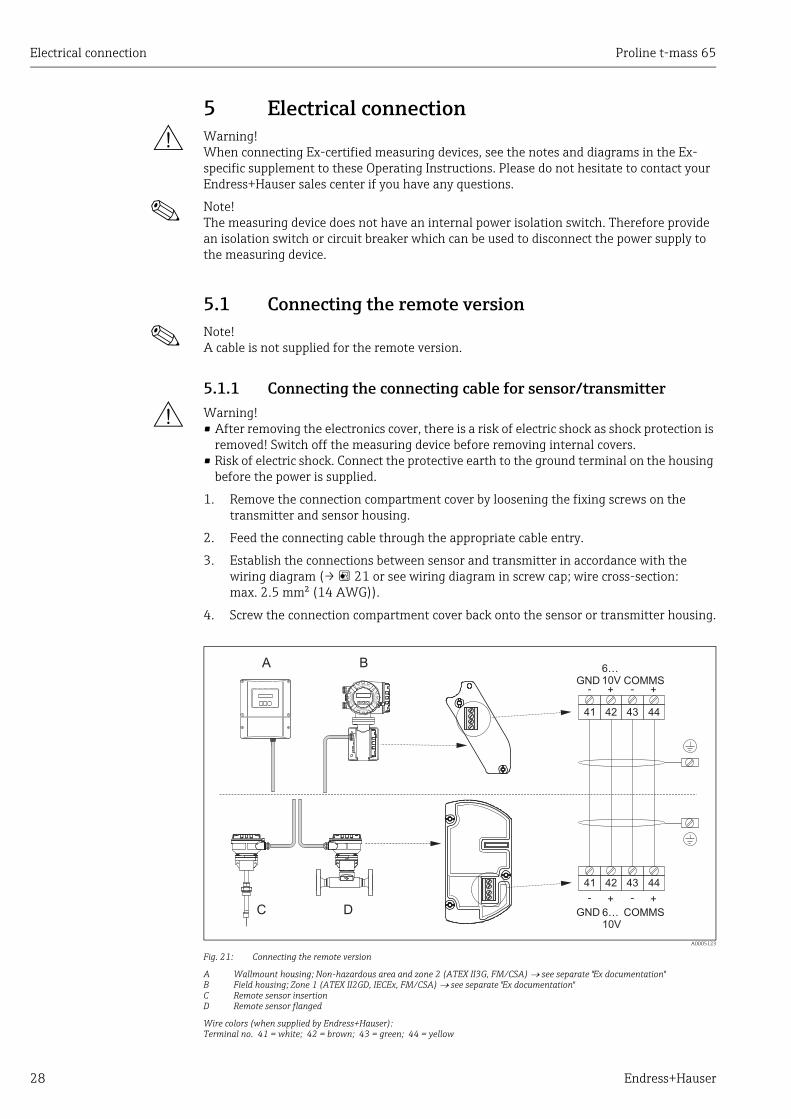
A0005123
Fig. 21: Connecting the remote version
A Wallmount housing; Non-hazardous area and zone 2 (ATEX II3G, FM/CSA) see separate "Ex documentation"B Field housing; Zone 1 (ATEX II2GD, IECEx, FM/CSA) see separate "Ex documentation"C Remote sensor insertionD Remote sensor flanged
Wire colors (when supplied by Endress+Hauser):Terminal no. 41 = white; 42 = brown; 43 = green; 44 = yellow
Nicht unter Spannungöffnen
Keep
cover
tightw
hile
circ
uits
are
aliv
e
Nepasouvrirl’appareil soustension
Keep
cove
rtightw
hile
circ
uits
are
aliv
e
A B
C D
41 42 43 44
GND6…10V COMMS+- +-
GND COMMS
- -+ +
41 42 43 44
6…10V

Proline t-mass 65 Electrical connection
Endress+Hauser 29
5.1.2 Cable specification, connecting cableA cable with the following specifications must be used for the remote version:
• 2 × 2 × 0.5 mm² (AWG 20) PVC cable with common shield (2 twisted pairs)• Conductor resistance: 40 /km ( 131.2 /1000 ft)• Operating voltage: 250 V• Temperature range: –40 to +105 °C (–40 to +221 °F)• Overall nominal diameter: 8.5 mm (0.335")• Maximum cable length: 100 m (328 feet)
! Note! • The cable must be installed securely to prevent movement• The cable should be of sufficient diameter to provide adequate sealing of the compression
fitting → 90.

Electrical connection Proline t-mass 65
30 Endress+Hauser
5.2 Connecting the measuring unit
5.2.1 Terminal assignment
Electrical values for inputs
→ 88
Electrical values for outputs
→ 89
Terminal No. (inputs/outputs)
Order variant 20 (+) / 21 (–) 22 (+) / 23 (–) 24 (+) / 25 (–) 26 (+) / 27 (–)
Fixed communication boards (permanent assignment)
65F**-***********A65I-*************A - - Frequency output Current output
HART
65F**-***********B65I-*************B
Relay output Relay output Frequency output Current outputHART
65F**-***********R65I-*************R - - Current output 2
Ex i, activeCurrent output 1,Ex i, active, HART
65F**-***********S65I-*************S
- - Frequency outputEx i, passive
Current output, Ex i,active, HART
65F**-***********T65I-*************T - -
Frequency outputEx i, passive
Current output, Ex i,passive, HART
65F**-***********U65I-*************U - - Current output 2
Ex i, passiveCurrent output 1,
Ex i, passive, HART
Flexible communication boards
65F**-***********C65I-*************C Relay output 2 Relay output 1 Frequency output Current output, HART
65F**-***********D65I-*************D
Status input Relay output Frequency output Current output, HART
65F**-***********E65I-*************E Status input Relay output Current output 2
Current output 1, HART
65F**-***********L65I-*************L Status input Relay output 2 Relay output 1 Current output, HART
65F**-***********265I-*************2
Relay output Current output 2 Frequency output Current output 1, HART
65F**-***********465I-*************4 Current input Relay output Frequency output Current output, HART
65F**-***********565I-*************5 Status input Current input Frequency output Current output, HART
65F**-***********665I-*************6
Status input Current input Current output 2 Current output, HART
65F**-***********865I-*************8 Status input Frequency output Current output 2 Current output, HART

Proline t-mass 65 Electrical connection
Endress+Hauser 31
5.2.2 Transmitter connection
# Warning! • Risk of electric shock. Switch off the power supply before opening the measuring device.
Never mount or wire the measuring device while it is connected to the power supply. Failure to comply with this precaution can result in irreparable damage to the electronics.
• Risk of electric shock. Connect the protective earth to the ground terminal on the housing before the power supply is applied unless special protection measures have been taken (e.g. galvanically isolated power supply SELV or PELV).
• Compare the specifications on the nameplate with the local supply voltage and frequency. The national regulations governing the installation of electrical equipment also apply.
1. Unscrew the connection compartment cover (f) from the transmitter housing.
2. Feed the power supply cable (a) and the signal cable (b) through the appropriate cable entries.
3. Perform wiring:– Wiring diagram (aluminum housing) → 22– Wiring diagram (wall-mount housing) → 23– Terminal assignment → 30
4. Screw the cover of the connection compartment (f) back onto the transmitter housing.
Connecting the aluminum field housing
A0004582
Fig. 22: Connecting the transmitter (aluminum field housing). Wire cross-section: max. 2.5 mm²(14 AWG)
a Cable for power supply: 85 to 260 V AC, 20 to 55 V AC, 16 to 62 V DCTerminal No. 1: L1 for AC, L+ for DCTerminal No. 2: N for AC, L– for DC
b Signal cable: Terminals Nos. 20-27 → 30c Ground terminal for protective earthd Ground terminal for signal cable shielde Service adapter for connecting service interface FXA193 (FieldCheck, FieldCare)f Cover of the connection compartmentg Securing clamp
b
b
c
d
a
a
21
– 27
– 25
– 23
– 21
+ 26
+ 24
+ 22
+ 20
L1 (L+)N (L-)
g
f
e
Electrical connection Proline t-mass 65
32 Endress+Hauser
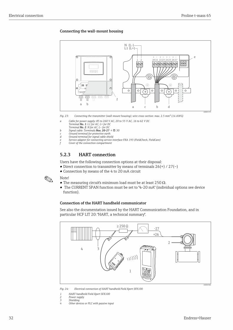
Connecting the wall-mount housing
A0001135
Fig. 23: Connecting the transmitter (wall-mount housing); wire cross-section: max. 2.5 mm² (14 AWG)
a Cable for power supply: 85 to 260 V AC, 20 to 55 V AC, 16 to 62 V DCTerminal No. 1: L1 for AC, L+ for DCTerminal No. 2: N for AC, L– for DC
b Signal cable: Terminals Nos. 20-27 → 30c Ground terminal for protective earthd Ground terminal for signal cable shielde Service adapter for connecting service interface FXA 193 (FieldCheck, FieldCare)f Cover of the connection compartment
5.2.3 HART connectionUsers have the following connection options at their disposal:• Direct connection to transmitter by means of terminals 26(+) / 27(–)• Connection by means of the 4 to 20 mA circuit
! Note! • The measuring circuit's minimum load must be at least 250 .• The CURRENT SPAN function must be set to "4-20 mA" (individual options see device
function).
Connection of the HART handheld communicator
See also the documentation issued by the HART Communication Foundation, and in particular HCF LIT 20: "HART, a technical summary".
A0004586
Fig. 24: Electrical connection of HART handheld Field Xpert SFX100
1 HART handheld Field Xpert SFX1002 Power supply3 Shielding4 Other devices or PLC with passive input
1 2
c d
e
aa
bb
f
+
22
–
23
+
20
–
21
+
24
–
25
+
26–
27
L1 (L+)N (L-)
+26
-27
4
2
� 250 Ω
1
3
Proline t-mass 65 Electrical connection
Endress+Hauser 33
Connection of a PC with an operating software
In order to connect a PC with operating software (e.g. FieldCare), a HART modem is needed.
A0004592
Fig. 25: Electrical connection of a PC with operating software
1 PC with operating software2 Power supply3 Shielding4 Other devices or PLC with passive input5 HART modem
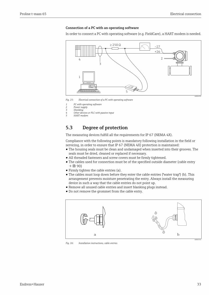
5.3 Degree of protectionThe measuring devices fulfill all the requirements for IP 67 (NEMA 4X).
Compliance with the following points is mandatory following installation in the field or servicing, in order to ensure that IP 67 (NEMA 4X) protection is maintained:• The housing seals must be clean and undamaged when inserted into their grooves. The
seals must be dried, cleaned or replaced if necessary.• All threaded fasteners and screw covers must be firmly tightened.• The cables used for connection must be of the specified outside diameter (cable entry → 90)
• Firmly tighten the cable entries (a).• The cables must loop down before they enter the cable entries ("water trap") (b). This
arrangement prevents moisture penetrating the entry. Always install the measuring device in such a way that the cable entries do not point up.
• Remove all unused cable entries and insert blanking plugs instead.• Do not remove the grommet from the cable entry.
A0001914
Fig. 26: Installation instructions, cable entries
+26
–27
1
2
3
5
4
� 250 Ω
a b
Electrical connection Proline t-mass 65
34 Endress+Hauser
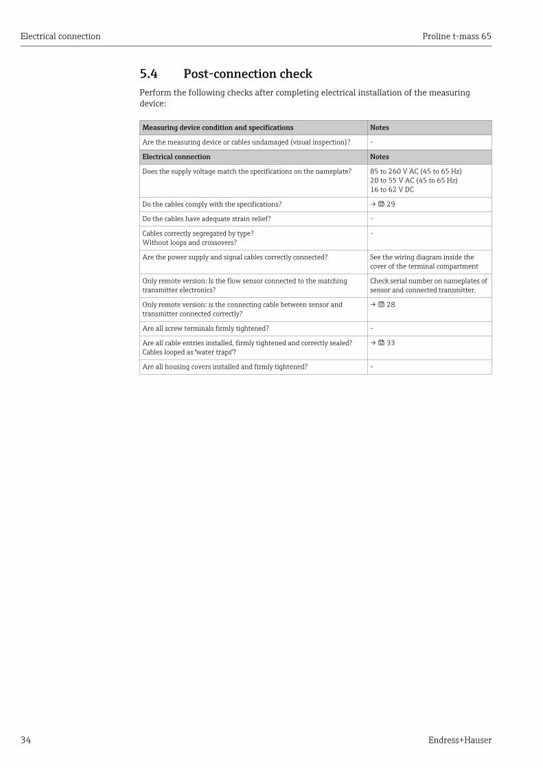
5.4 Post-connection checkPerform the following checks after completing electrical installation of the measuring device:
Measuring device condition and specifications Notes
Are the measuring device or cables undamaged (visual inspection)? -
Electrical connection Notes
Does the supply voltage match the specifications on the nameplate? 85 to 260 V AC (45 to 65 Hz)20 to 55 V AC (45 to 65 Hz)16 to 62 V DC
Do the cables comply with the specifications? → 29
Do the cables have adequate strain relief? -
Cables correctly segregated by type?Without loops and crossovers?
-
Are the power supply and signal cables correctly connected? See the wiring diagram inside the cover of the terminal compartment
Only remote version: Is the flow sensor connected to the matching transmitter electronics?
Check serial number on nameplates of sensor and connected transmitter.
Only remote version: is the connecting cable between sensor and transmitter connected correctly?
→ 28
Are all screw terminals firmly tightened? -
Are all cable entries installed, firmly tightened and correctly sealed?Cables looped as "water traps"?
→ 33
Are all housing covers installed and firmly tightened? -
Proline t-mass 65 Operation
Endress+Hauser 35
6 Operation
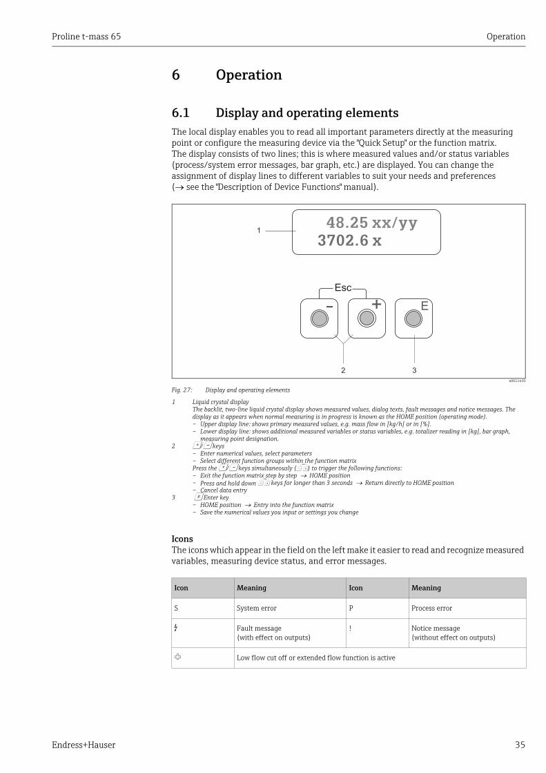
6.1 Display and operating elementsThe local display enables you to read all important parameters directly at the measuring point or configure the measuring device via the "Quick Setup" or the function matrix.The display consists of two lines; this is where measured values and/or status variables (process/system error messages, bar graph, etc.) are displayed. You can change the assignment of display lines to different variables to suit your needs and preferences ( see the "Description of Device Functions" manual).
a0011430
Fig. 27: Display and operating elements
1 Liquid crystal displayThe backlit, two-line liquid crystal display shows measured values, dialog texts, fault messages and notice messages. The display as it appears when normal measuring is in progress is known as the HOME position (operating mode).– Upper display line: shows primary measured values, e.g. mass flow in [kg/h] or in [%].– Lower display line: shows additional measured variables or status variables, e.g. totalizer reading in [kg], bar graph,
measuring point designation.2 O/S keys
– Enter numerical values, select parameters– Select different function groups within the function matrixPress the O/S keys simultaneously (X) to trigger the following functions:– Exit the function matrix step by step HOME position– Press and hold down X keys for longer than 3 seconds Return directly to HOME position– Cancel data entry
3 F Enter key– HOME position Entry into the function matrix– Save the numerical values you input or settings you change
IconsThe icons which appear in the field on the left make it easier to read and recognize measured variables, measuring device status, and error messages.
Esc
E+-
1
32
48.25 xx/yy3702.6 x
Icon Meaning Icon Meaning
S System error P Process error
$ Fault message(with effect on outputs)
! Notice message(without effect on outputs)
Low flow cut off or extended flow function is active

Operation Proline t-mass 65
36 Endress+Hauser
6.2 Brief operating instructions for the function matrix
! Note! • See the general notes → 37• Function descriptions see the "Description of Device Functions" manual
1. HOME position F Entry into the function matrix
2. Select a function group (e.g. CURRENT OUTPUT 1)
3. Select a function (e.g. TIME CONSTANT)Change parameter / enter numerical values:OS Select or enter enable code, parameters, numerical valuesF Save your entries
4. Exit the function matrix:– Press and hold down Esc key (X) for longer than 3 seconds HOME position– Repeatedly press Esc key (X) Return step by step to HOME position
A0001142
Fig. 28: Selecting functions and configuring parameters (function matrix)
>3s
- + E
Esc
E
E
E
E
E E E E E
–
+
+
Esc
–+
Esc
–
+
Esc
–
Em
n
o
p

Proline t-mass 65 Operation
Endress+Hauser 37
6.2.1 General notesThe Quick Setup menu contains the default settings that are adequate for commissioning.Complex measuring operations on the other hand necessitate additional functions that you can configure as necessary and customize to suit your process parameters. The function matrix, therefore, comprises a multiplicity of additional functions which, for the sake of clarity, are arranged in a number of function groups.
Comply with the following instructions when configuring functions:• You select functions as described already → 36.• You can switch off certain functions (OFF). If you do so, related functions in other function
groups will no longer be displayed.• Certain functions prompt you to confirm your data entries. Press P to select "SURE ( YES )"
and press F to confirm. This saves your setting or starts a function.• Return to the HOME position is automatic if no key is pressed for 5 minutes.• Programming mode is disabled automatically if you do not press a key within 60 seconds
following automatic return to the HOME position.
" Caution! All functions are described in detail, as is the function matrix itself, in the "Description of Device Functions" manual, which is a separate part of these Operating Instructions.
! Note! • The transmitter continues to measure while data entry is in progress, i.e. the current
measured values are output via the signal outputs in the normal way.• If the power supply fails, all preset and parameterized values remain safely stored in the
EEPROM.
6.2.2 Enabling the programming modeThe function matrix can be disabled. Disabling the function matrix rules out the possibility of inadvertent changes to device functions, numerical values or factory settings. A numerical code (factory setting = 65) has to be entered before settings can be changed.If you use a code number of your choice, you exclude the possibility of unauthorized persons accessing data ( see the “Description of Device Functions” manual).
Comply with the following instructions when entering codes:• If programming is disabled and the P operating elements are pressed in any function, a
prompt for the code automatically appears on the display.• If “0” is specified as the customer's code, programming is always enabled.• Your Endress+Hauser sales center can be of assistance if you mislay your private code.
" Caution! Changing certain parameters, such as all sensor characteristics, for example, influences numerous functions of the entire measuring system, particularly measuring accuracy.There is no need to change these parameters under normal circumstances and, consequently, they are protected by a special code known only to the Endress+Hauser sales center. Please contact Endress+Hauser first if you have any questions.

Operation Proline t-mass 65
38 Endress+Hauser
6.2.3 Disabling the programming modeProgramming mode is disabled if an operating element is not pressed within 60 seconds following automatic return to the HOME position.Programming can also be disabled by entering any number in the "ACCESS CODE" function (other than the customer's code).
6.3 Error messages
6.3.1 Type of errorErrors that occur during commissioning or measuring are displayed immediately. If two or more system or process errors occur, the error with the highest priority is the one shown on the display.
The measuring device distinguishes between two types of error:• System error: This group includes all device errors, e.g. communication errors, hardware
errors etc. → 72• Process error: This group includes all application errors, e.g. flow limit etc. → 76
A0000991
Fig. 29: Error messages on the display (example)
1 Error type: P = process error, S = system error2 Error message type: $ = fault message, ! = notice message, definition 3 Error designation: e.g. FLOW LIMIT = maximum flow limit exceeded4 Error number: e.g. #4225 Duration of most recent error occurrence (in hours, minutes and seconds)
6.3.2 Error message typeUsers have the option of weighting system and process errors differently, by defining them as Fault messages or Notice messages. This is specified via the function matrix (see the "Description of Device Functions" manual).Serious system errors, e.g. module defects, are always identified and classified as "fault messages" by the measuring device.
Notice message (!)• The error in question has no effect on the current operation and on the outputs of the
measuring device.• Displayed as Exclamation mark (!), error designation (S: system error, P: process error).
Fault message ($ )• The error in question interrupts or stops the current operation and has a direct effect on
the outputs. The response of the outputs (failsafe mode) can be defined by means of functions in the function matrix.→ 78
• Displayed as Lightning flash ( $), error designation (S: system error, P: process error).
! Note! For safety reasons, error messages should be outputted via the status output.
1
2 4 5 3
XXXXXXXXXX
#000 00:00:05
P

Proline t-mass 65 Operation
Endress+Hauser 39
6.4 CommunicationIn addition to local operation, the measuring device can be configured and measured values can be obtained by means of the HART protocol. Digital communication takes place using the 4-20 mA current output HART. → 32The HART protocol allows the transfer of measuring and device data between the HART master and the field devices for configuration and diagnostics purposes. The HART master, e.g. a handheld terminal or PC-based operating programs (such as FieldCare), require device description (DD) files which are used to access all the information in a HART device. Information is exclusively transferred using so-called "commands".
There are three different command groups:• Universal Commands
Universal commands are supported and used by all HART devices. These are associated with the following functionalities for example: – Recognizing HART devices– Reading digital measured values (mass flow, totalizer, etc.)
• Common practice commands:Common practice commands offer functions which are supported or can be executed by most but not all field devices.
• Device-specific commands:These commands allow access to device-specific functions which are not HART standard. Such commands access individual field device information, amongst other things, such as empty/full pipe calibration values, low flow cut off settings etc.
! Note! The measuring device has access to all three command classes. List of all ''Universal Commands" and "Common Practice Commands": → 41
6.4.1 Operating optionsFor the complete operation of the measuring device, including device-specific commands, device description (DD) files are available to the user for the following operating aids and programs:
! Note! The HART protocol requires the "4 to 20 mA HART" setting (individual options see device function) in the CURRENT SPAN function (current output 1).
Field Xpert HART Communicator
Selecting device functions with a HART Communicator is a process involving a number of menu levels and a special HART function matrix.The HART manual in the carrying case of the HART Communicator contains more detailed information on the device.
Operating program "FieldCare"
FDT-based plant asset management tool from Endress+Hauser. It can configure all intelligent field devices in your plant and supports you in managing them. By using status information, it also provides a simple but effective means of checking their health. The Proline flow measuring devices are accessed via a service interface or via the service interface FXA193.
Operating program "SIMATIC PDM" (Siemens)
SIMATIC PDM is a standardized, manufacturer-independent tool for the operation, configuration, maintenance and diagnosis of intelligent field devices.
Operation Proline t-mass 65
40 Endress+Hauser
Operating program "AMS" device manager (Emerson Process Management)
AMS (Asset Management Solutions): program for operating and configuring measuring devices.
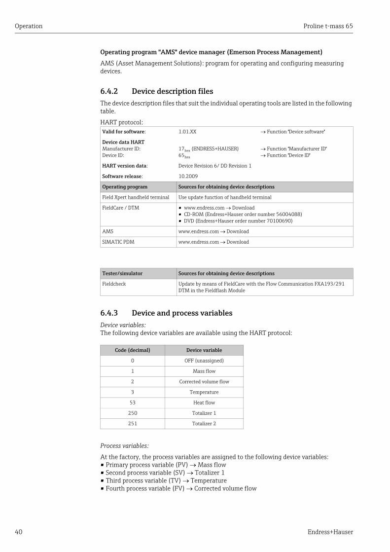
6.4.2 Device description filesThe device description files that suit the individual operating tools are listed in the following table.
HART protocol:
6.4.3 Device and process variablesDevice variables:The following device variables are available using the HART protocol:
Process variables:
At the factory, the process variables are assigned to the following device variables:• Primary process variable (PV) Mass flow• Second process variable (SV) Totalizer 1• Third process variable (TV) Temperature• Fourth process variable (FV) Corrected volume flow
Valid for software: 1.01.XX Function "Device software"
Device data HARTManufacturer ID:Device ID:
17hex (ENDRESS+HAUSER)65hex
Function "Manufacturer ID" Function "Device ID"
HART version data: Device Revision 6/ DD Revision 1
Software release: 10.2009
Operating program Sources for obtaining device descriptions
Field Xpert handheld terminal Use update function of handheld terminal
FieldCare / DTM • www.endress.com Download• CD-ROM (Endress+Hauser order number 56004088)• DVD (Endress+Hauser order number 70100690)
AMS www.endress.com Download
SIMATIC PDM www.endress.com Download
Tester/simulator Sources for obtaining device descriptions
Fieldcheck Update by means of FieldCare with the Flow Communication FXA193/291 DTM in the Fieldflash Module
Code (decimal) Device variable
0 OFF (unassigned)
1 Mass flow
2 Corrected volume flow
3 Temperature
53 Heat flow
250 Totalizer 1
251 Totalizer 2

Proline t-mass 65 Operation
Endress+Hauser 41
! Note! You can set or change the assignment of device variables to process variables using Command 51. → 41
6.4.4 Universal / Common practice HART commandsThe following table contains all the universal commands supported by the measuring device.
Command No.HART command / Access type
Command data(numeric data in decimal form)
Response data(numeric data in decimal form)
Universal Commands
0 Read unique device identifierAccess type = read
none Device identification delivers information on the measuring device and the manufacturer. It cannot be changed.
The response consists of a 12-byte device ID:– Byte 0: fixed value 254– Byte 1: Manufacturer ID, 17 = Endress+Hauser– Byte 2: Device type ID, e.g. 65 = t-mass 65– Byte 3: Number of preambles– Byte 4: Universal commands rev. no.– Byte 5: Device-specific commands rev. no.– Byte 6: Software revision– Byte 7: Hardware revision– Byte 8: Additional device information– Byte 9-11: Device identification
1 Read primary process variableAccess type = read
none – Byte 0: HART unit code of the primary process variable
– Bytes 1-4: Primary process variable
Factory setting:Primary process variable = Mass flow
! Note! • You can set the assignment of device variables to
process variables using Command 51.• Manufacturer-specific units are represented using
the HART unit code "240".
2 Read the primary process variable as current in mA and percentage of the set measuring rangeAccess type = read
none – Bytes 0-3: Actual current of the primary process variable in mA
– Bytes 4-7: Percentage of the set measuring range
Factory setting:Primary process variable = Mass flow
! Note! You can set the assignment of device variables to process variables using Command 51.

Operation Proline t-mass 65
42 Endress+Hauser
3 Read the primary process variable as current in mA and four (preset using Command 51) dynamic process variablesAccess type = read
none 24 bytes are sent as a response:– Bytes 0-3: Primary process variable current in mA– Byte 4: HART unit code of the primary process
variable– Bytes 5-8: Primary process variable– Byte 9: HART unit code of the second process
variable– Bytes 10-13: Second process variable– Byte 14: HART unit code of the third process
variable– Bytes 15-18: Third process variable– Byte 19: HART unit code of the fourth process
variable– Bytes 20-23: Fourth process variable
Factory setting:• Primary process variable = Mass flow• Second process variable = Totalizer 1• Third process variable = Temperature• Fourth process variable = Corrected volume flow
! Note! • You can set the assignment of device variables to
process variables using Command 51.• Manufacturer-specific units are represented using
the HART unit code "240".
6 Set HART shortform addressAccess type = write
Byte 0: desired address (0 to 15)
Factory setting:0
! Note! With an address >0 (multidrop mode), the current output of the primary process variable is set to 4 mA.
Byte 0: active address
11 Read unique device identification using the TAG (measuring point designation)Access type = read
Bytes 0-5: TAG Device identification delivers information on the measuring device and the manufacturer. It cannot be changed.
The response consists of a 12-byte device ID if the given TAG agrees with the one saved in the measuring device:– Byte 0: fixed value 254– Byte 1: Manufacturer ID, 17 = Endress+Hauser– Byte 2: Device type ID, 65 = t-mass 65– Byte 3: Number of preambles– Byte 4: Universal commands rev. no.– Byte 5: Device-specific commands rev. no.– Byte 6: Software revision– Byte 7: Hardware revision– Byte 8: Additional device information– Byte 9-11: Device identification
12 Read user messageAccess type = read
none Bytes 0-24: User message
! Note! You can write the user message using Command 17.
13 Read TAG, descriptor and dateAccess type = read
none – Bytes 0-5: TAG– Bytes 6-17: Descriptor– Byte 18-20: Date
! Note! You can write the TAG, descriptor and date using Command 18.
Command No.HART command / Access type
Command data(numeric data in decimal form)
Response data(numeric data in decimal form)
Proline t-mass 65 Operation
Endress+Hauser 43
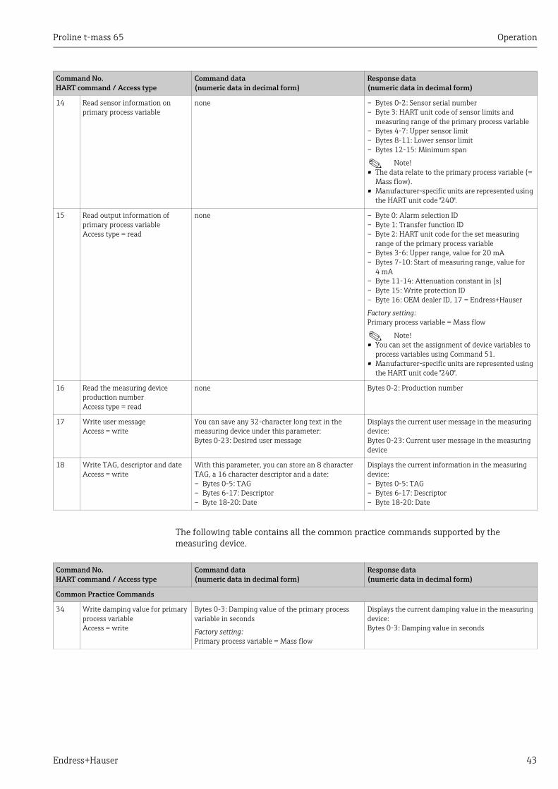
The following table contains all the common practice commands supported by the measuring device.
14 Read sensor information on primary process variable
none – Bytes 0-2: Sensor serial number– Byte 3: HART unit code of sensor limits and
measuring range of the primary process variable– Bytes 4-7: Upper sensor limit– Bytes 8-11: Lower sensor limit– Bytes 12-15: Minimum span
! Note! • The data relate to the primary process variable (=
Mass flow).• Manufacturer-specific units are represented using
the HART unit code "240".
15 Read output information of primary process variableAccess type = read
none – Byte 0: Alarm selection ID– Byte 1: Transfer function ID– Byte 2: HART unit code for the set measuring
range of the primary process variable– Bytes 3-6: Upper range, value for 20 mA– Bytes 7-10: Start of measuring range, value for
4 mA– Byte 11-14: Attenuation constant in [s]– Byte 15: Write protection ID– Byte 16: OEM dealer ID, 17 = Endress+Hauser
Factory setting:Primary process variable = Mass flow
! Note! • You can set the assignment of device variables to
process variables using Command 51.• Manufacturer-specific units are represented using
the HART unit code "240".
16 Read the measuring device production numberAccess type = read
none Bytes 0-2: Production number
17 Write user messageAccess = write
You can save any 32-character long text in the measuring device under this parameter:Bytes 0-23: Desired user message
Displays the current user message in the measuring device:Bytes 0-23: Current user message in the measuring device
18 Write TAG, descriptor and dateAccess = write
With this parameter, you can store an 8 character TAG, a 16 character descriptor and a date:– Bytes 0-5: TAG– Bytes 6-17: Descriptor– Byte 18-20: Date
Displays the current information in the measuring device:– Bytes 0-5: TAG– Bytes 6-17: Descriptor– Byte 18-20: Date
Command No.HART command / Access type
Command data(numeric data in decimal form)
Response data(numeric data in decimal form)
Command No.HART command / Access type
Command data(numeric data in decimal form)
Response data(numeric data in decimal form)
Common Practice Commands
34 Write damping value for primary process variableAccess = write
Bytes 0-3: Damping value of the primary process variable in seconds
Factory setting:Primary process variable = Mass flow
Displays the current damping value in the measuring device:Bytes 0-3: Damping value in seconds

Operation Proline t-mass 65
44 Endress+Hauser
35 Write measuring range of primary process variableAccess = write
Write the desired measuring range:– Byte 0: HART unit code of the primary process
variable– Bytes 1-4: Upper range, value for 20 mA– Bytes 5-8: Start of measuring range, value for
4 mA
Factory setting:Primary process variable = Mass flow
! Note! • You can set the assignment of device variables to
process variables using Command 51.• If the HART unit code is not the correct one for the
process variable, the measuring device will continue with the last valid unit.
The currently set measuring range is displayed as a response:– Byte 0: HART unit code for the set measuring
range of the primary process variable– Bytes 1-4: Upper range, value for 20 mA– Bytes 5-8: Start of measuring range, value for
4 mA
! Note! Manufacturer-specific units are represented using the HART unit code "240".
38 Device status reset (Configuration changed)Access = write
none none
40 Simulate output current of primary process variableAccess = write
Simulation of the desired output current of the primary process variable.
An entry value of 0 exits the simulation mode:Byte 0-3: Output current in mA
Factory setting:Primary process variable = Mass flow
! Note! You can set the assignment of device variables to process variables with Command 51.
The momentary output current of the primary process variable is displayed as a response:Byte 0-3: Output current in mA
42 Perform master resetAccess = write
none none
44 Write unit of primary process variableAccess = write
Set unit of primary process variable.
Only units which are suitable for the process variable are transferred to the measuring device:Byte 0: HART unit code
Factory setting:Primary process variable = Mass flow
! Note! • If the written HART unit code is not the correct
one for the process variable, the measuring device will continue with the last valid unit.
• If you change the unit of the primary process variable, this has no impact on the system units.
The current unit code of the primary process variable is displayed as a response:Byte 0: HART unit code
! Note! Manufacturer-specific units are represented using the HART unit code "240".
48 Read additional device statusAccess = read
none The device status is displayed in extended form as the response:Coding: see table → 46
Command No.HART command / Access type
Command data(numeric data in decimal form)
Response data(numeric data in decimal form)
Proline t-mass 65 Operation
Endress+Hauser 45
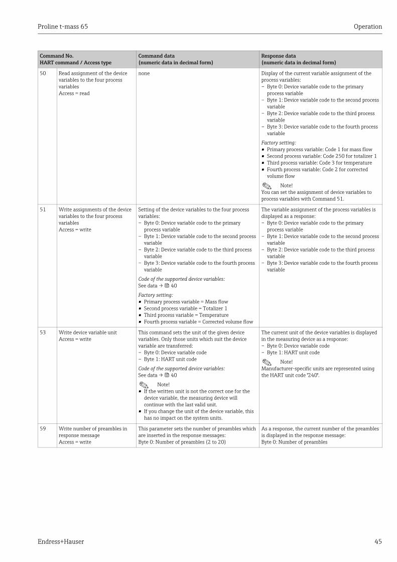
50 Read assignment of the device variables to the four process variablesAccess = read
none Display of the current variable assignment of the process variables:– Byte 0: Device variable code to the primary
process variable– Byte 1: Device variable code to the second process
variable– Byte 2: Device variable code to the third process
variable– Byte 3: Device variable code to the fourth process
variable
Factory setting:• Primary process variable: Code 1 for mass flow• Second process variable: Code 250 for totalizer 1• Third process variable: Code 3 for temperature• Fourth process variable: Code 2 for corrected
volume flow
! Note! You can set the assignment of device variables to process variables with Command 51.
51 Write assignments of the device variables to the four process variablesAccess = write
Setting of the device variables to the four process variables:– Byte 0: Device variable code to the primary
process variable– Byte 1: Device variable code to the second process
variable– Byte 2: Device variable code to the third process
variable– Byte 3: Device variable code to the fourth process
variable
Code of the supported device variables:See data → 40
Factory setting:• Primary process variable = Mass flow• Second process variable = Totalizer 1• Third process variable = Temperature• Fourth process variable = Corrected volume flow
The variable assignment of the process variables is displayed as a response:– Byte 0: Device variable code to the primary
process variable– Byte 1: Device variable code to the second process
variable– Byte 2: Device variable code to the third process
variable– Byte 3: Device variable code to the fourth process
variable
53 Write device variable unitAccess = write
This command sets the unit of the given device variables. Only those units which suit the device variable are transferred:– Byte 0: Device variable code– Byte 1: HART unit code
Code of the supported device variables:See data → 40
! Note! • If the written unit is not the correct one for the
device variable, the measuring device will continue with the last valid unit.
• If you change the unit of the device variable, this has no impact on the system units.
The current unit of the device variables is displayed in the measuring device as a response:– Byte 0: Device variable code– Byte 1: HART unit code
! Note! Manufacturer-specific units are represented using the HART unit code "240".
59 Write number of preambles in response messageAccess = write
This parameter sets the number of preambles which are inserted in the response messages:Byte 0: Number of preambles (2 to 20)
As a response, the current number of the preambles is displayed in the response message:Byte 0: Number of preambles
Command No.HART command / Access type
Command data(numeric data in decimal form)
Response data(numeric data in decimal form)
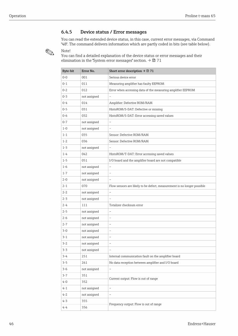
Operation Proline t-mass 65
46 Endress+Hauser
6.4.5 Device status / Error messagesYou can read the extended device status, in this case, current error messages, via Command "48". The command delivers information which are partly coded in bits (see table below).
! Note! You can find a detailed explanation of the device status or error messages and their elimination in the "System error messages" section. → 71
Byte-bit Error No. Short error description → 71
0-0 001 Serious device error
0-1 011 Measuring amplifier has faulty EEPROM
0-2 012 Error when accessing data of the measuring amplifier EEPROM
0-3 not assigned –
0-4 014 Amplifier: Defective ROM/RAM
0-5 031 HistoROM/S-DAT: Defective or missing
0-6 032 HistoROM/S-DAT: Error accessing saved values
0-7 not assigned –
1-0 not assigned –
1-1 035 Sensor: Defective ROM/RAM
1-2 036 Sensor: Defective ROM/RAM
1-3 not assigned –
1-4 042 HistoROM/T-DAT: Error accessing saved values
1-5 051 I/O board and the amplifier board are not compatible
1-6 not assigned –
1-7 not assigned –
2-0 not assigned –
2-1 070 Flow sensors are likely to be defect, measurement is no longer possible
2-2 not assigned –
2-3 not assigned –
2-4 111 Totalizer checksum error
2-5 not assigned –
2-6 not assigned –
2-7 not assigned –
3-0 not assigned –
3-1 not assigned –
3-2 not assigned –
3-3 not assigned –
3-4 251 Internal communication fault on the amplifier board
3-5 261 No data reception between amplifier and I/O board
3-6 not assigned –
3-7 351Current output: Flow is out of range
4-0 352
4-1 not assigned –
4-2 not assigned –
4-3 355Frequency output: Flow is out of range
4-4 356

Proline t-mass 65 Operation
Endress+Hauser 47
4-5 not assigned –
4-6 not assigned –
4-7 359 Pulse output: Pulse output frequency is out of range5-0 360
5-1 not assigned –
5-2 not assigned –
5-3 363 Current input: The actual value for the current input is outside the set range
5-4 not assigned –
5-5 not assigned –
5-6 not assigned –
5-7 not assigned –
6-0 372 The measured sensor differential temperature is below limit value
6-1 not assigned –
6-2 not assigned –
6-3 not assigned –
6-4 not assigned –
6-5 not assigned –
6-6 not assigned –
6-7 381 The minimum fluid temperature limit for the transducer has been undershot
7-0 382 The maximum fluid temperature limit for the transducer has been exceeded
7-1 422 The flow has exceeded the maximum measuring limit
7-2 not assigned –
7-3 not assigned –
7-4 not assigned –
7-5 not assigned –
7-6 not assigned –
7-7 451 The saved zero point is inaccurate possibly due to unstable process or flow conditions
8-0 501 New amplifier or communication (I/O module) software version is being loaded. Currently no other functions are possible
8-1 502 Up- or downloading the device data via configuration program. Currently no other functions are possible
8-2 561 Zero point adjustment function is active
8-3 601 Positive zero return active
8-4 611 Simulation current output active
8-5 612 Simulation current output active
8-6 not assigned –
8-7 not assigned –
9-0 621 Simulation frequency output active
9-1 622 Simulation frequency output active
9-2 not assigned –
9-3 not assigned –
9-4 631 Simulation pulse output active
9-5 632 Simulation pulse output active
Byte-bit Error No. Short error description → 71

Operation Proline t-mass 65
48 Endress+Hauser
9-6 not assigned –
9-7 not assigned –
10-0 641 Simulation status output active
10-1 642 Simulation status output active
10-2 not assigned –
10-3 not assigned –
10-4 651 Simulation relay output active
10-5 652 Simulation relay output active
10-6 not assigned –
10-7 not assigned –
11-0 661 Simulation current input active
11-1 not assigned –
11-2 not assigned –
11-3 not assigned –
11-4 671 Simulation status input active
11-5 672 Simulation status input active
11-6 not assigned –
11-7 not assigned –
12-0 691 Simulation of response to error (outputs) active
12-1 692 Simulation of measuring variables (e.g. mass flow)
12-2 698 The measuring device is being checked on-site via the test and simulation device (FieldCheck)
12-3 not assigned –
12-4 not assigned –
12-5 not assigned –
12-6 not assigned –
12-7 not assigned –
Byte-bit Error No. Short error description → 71

Proline t-mass 65 Operation
Endress+Hauser 49
6.4.6 Switching HART write protection on and offA jumper on the I/O board provides the means of switching HART write protection on or off.
! Note! Write protection is not available for the fixed I/O boards → 30.
# Warning! Risk of electric shock. Exposed components carry dangerous voltages. Switch off the power supply before you remove the cover of the electronics compartment.
1. Switch off the power supply.
2. Remove the I/O board → 80.
3. Switch HART write protection on or off, as applicable, by means of the jumper (→ 30).
4. Installation of the I/O board is the reverse of the removal procedure.
A0001212
Fig. 30: Switching HART write protection on and off
1 Write protection OFF (default), that is: HART protocol unlocked2 Write protection ON, that is: HART protocol locked
1
2IN
PUT/OUTPUT 4
INPUT/O
UTPUT 3
INPUT/O
UTPUT 2
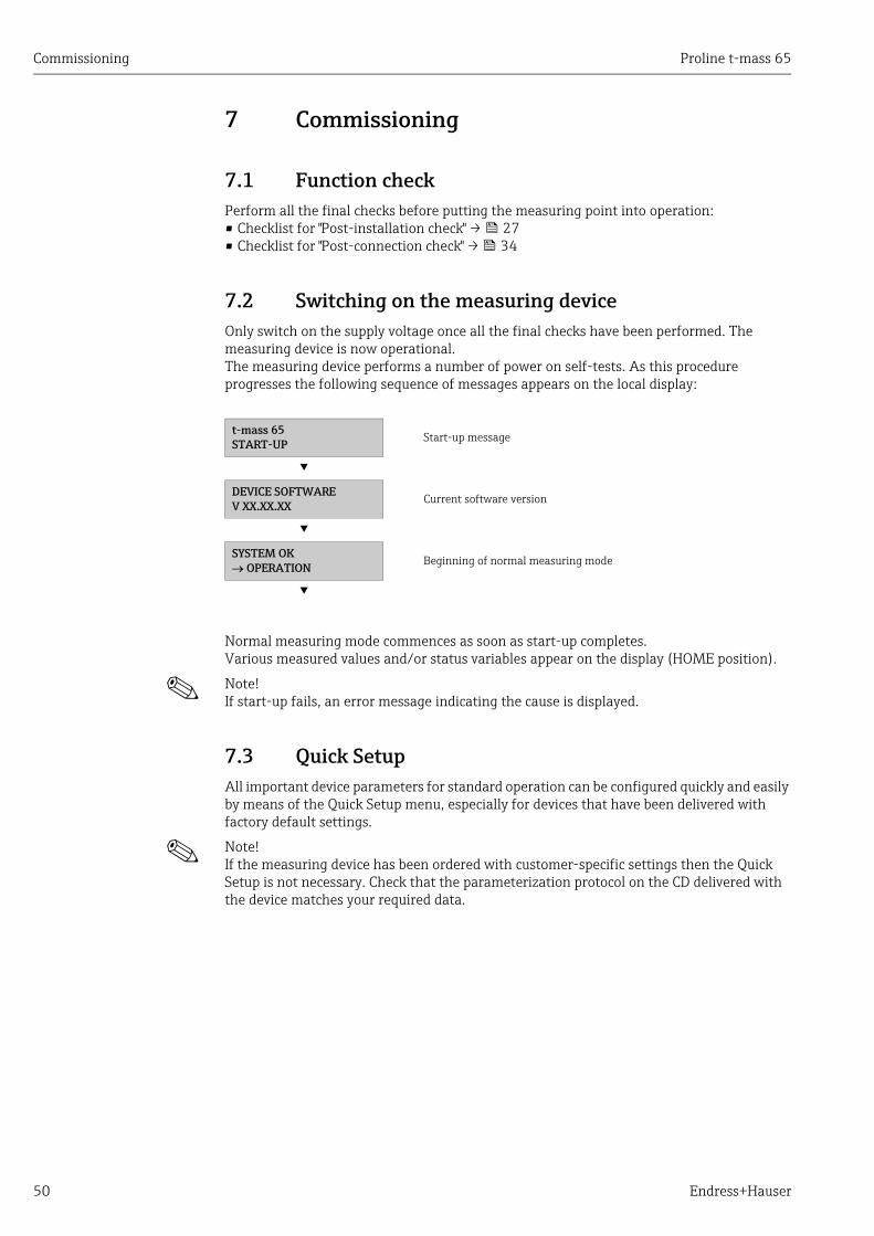
Commissioning Proline t-mass 65
50 Endress+Hauser
7 Commissioning
7.1 Function checkPerform all the final checks before putting the measuring point into operation:• Checklist for "Post-installation check" → 27• Checklist for "Post-connection check" → 34
7.2 Switching on the measuring deviceOnly switch on the supply voltage once all the final checks have been performed. The measuring device is now operational.The measuring device performs a number of power on self-tests. As this procedure progresses the following sequence of messages appears on the local display:
Normal measuring mode commences as soon as start-up completes. Various measured values and/or status variables appear on the display (HOME position).
! Note! If start-up fails, an error message indicating the cause is displayed.
7.3 Quick SetupAll important device parameters for standard operation can be configured quickly and easily by means of the Quick Setup menu, especially for devices that have been delivered with factory default settings.
! Note! If the measuring device has been ordered with customer-specific settings then the Quick Setup is not necessary. Check that the parameterization protocol on the CD delivered with the device matches your required data.
t-mass 65 START-UP Start-up message
▾ DEVICE SOFTWARE V XX.XX.XX
Current software version
▾ SYSTEM OK OPERATION
Beginning of normal measuring mode
▾
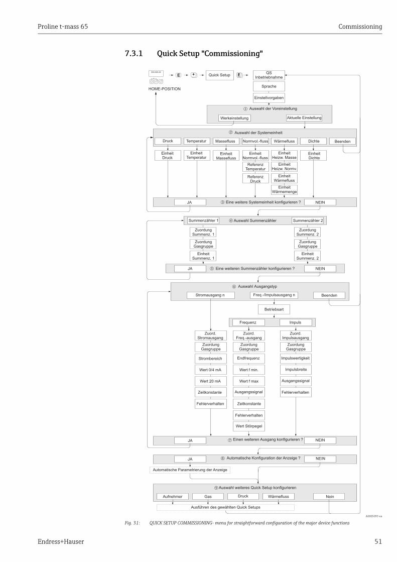
Proline t-mass 65 Commissioning
Endress+Hauser 51
7.3.1 Quick Setup "Commissioning"
A0005093-en
Fig. 31: QUICK SETUP COMMISSIONING- menu for straightforward configuration of the major device functions
++E +E
n
o
t
Esc
E+-
XXX.XXX.XX
p
s
m
r
q
u
JA
JA
JA
NEIN
NEIN
NEIN
Eine weitere Systemeinheit konfigurieren ?
Stromausgang n Freq.-/Impulsausgang n
Auswahl Summenzähler
Automatische Konfiguration der Anzeige ?
Beenden
Zuord.Stromausgang
Strombereich
Wert 0/4 mA
Wert 20 mA
Zeitkonstante
ZeitkonstanteFehlerverhalten
Fehlerverhalten
Fehlerverhalten
Zuord.Freq.-ausgang
Endfrequenz
Wert f min.
Wert f max
Ausgangssignal
Zuord.Impulsausgang
Impulswertigkeit
Impulsbreite
Ausgangssignal
Betriebsart
Frequenz Impuls
Automatische Parametrierung der Anzeige
Normvol.-flussMassefluss Dichte
Auswahl der Systemeinheit
Temperatur Beenden
EinheitNormvol.-fluss
EinheitMassefluss
EinheitDichte
EinheitTemperatur
Sprache
Einstellvorgaben
Quick Setup
HOME-POSITION
QSInbetriebnahme
Einen weiteren Ausgang konfigurieren ?
ReferenzTemperatur
ReferenzDruck
EinheitSummenz. 2
ZuordungSummenz. 2
ZuordungGasgruppe
Auswahl Ausgangstyp
Auswahl der Voreinstellung
Werkeinstellung Aktuelle Einstellung
Wert Störpegel
Druck
EinheitDruck
Summenzähler 1 Summenzähler 2
JA NEINEine weiteren konfigurieren ?Summenzähler
EinheitSummenz. 1
ZuordungSummenz. 1
ZuordungGasgruppe
ZuordungGasgruppe
ZuordungGasgruppe
ZuordungGasgruppe
Nein
Auswahl weiteres Quick Setup konfigurieren
Aufnehmer Gas Druck Wärmefluss
Wärmefluss
EinheitWärmefluss
EinheitWärmemenge
Ausführen des gewählten Quick Setups
EinheitHeizw. Masse
EinheitHeizw. Normv.
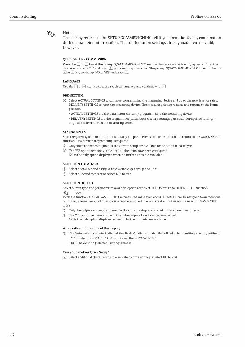
Commissioning Proline t-mass 65
52 Endress+Hauser
! Note! The display returns to the SETUP COMMISSIONING cell if you press the Q key combination during parameter interrogation. The configuration settings already made remain valid, however.
QUICK SETUP - COMMISSIONPress the O or S key at the prompt "QS-COMMISSION NO" and the device access code entry appears. Enter the device access code "65" and press F; programming is enabled. The prompt "QS-COMMISSION NO" appears. Use the O or S key to change NO to YES and press F.
LANGUAGEUse the O or S key to select the required language and continue with F.
PRE-SETTING.
m Select ACTUAL SETTINGS to continue programming the measuring device and go to the next level or select DELIVERY SETTINGS to reset the measuring device. The measuring device restarts and returns to the Home position.- ACTUAL SETTINGS are the parameters currently programmed in the measuring device- DELIVERY SETTINGS are the programmed parameters (factory settings plus customer-specific settings) originally delivered with the measuring device
SYSTEM UNITS.Select required system unit function and carry out parameterization or select QUIT to return to the QUICK SETUP function if no further programming is required.
n Only units not yet configured in the current setup are available for selection in each cycle.
o The YES option remains visible until all the units have been configured.NO is the only option displayed when no further units are available.
SELECTION TOTALIZER.
p Select a totalizer and assign a flow variable, gas group and unit.
q Select a second totalizer or select "NO" to exit.
SELECTION OUTPUT.Select output type and parameterize available options or select QUIT to return to QUICK SETUP function.
! Note! With the function ASSIGN GAS GROUP, the measured value from each GAS GROUP can be assigned to an individual output or, alternatively, both gas groups can be assigned to one current output using the selection GAS GROUP 1 & 2.
r Only the outputs not yet configured in the current setup are offered for selection in each cycle.
s The YES option remains visible until all the outputs have been parameterized.NO is the only option displayed when no further outputs are available.
Automatic configuration of the display
t The "automatic parameterization of the display" option contains the following basic settings/factory settings:- YES: main line = MASS FLOW, additional line = TOTALIZER 1- NO: The existing (selected) settings remain.
Carry out another Quick Setup?
u Select additional Quick Setups to complete commissioning or select NO to exit.
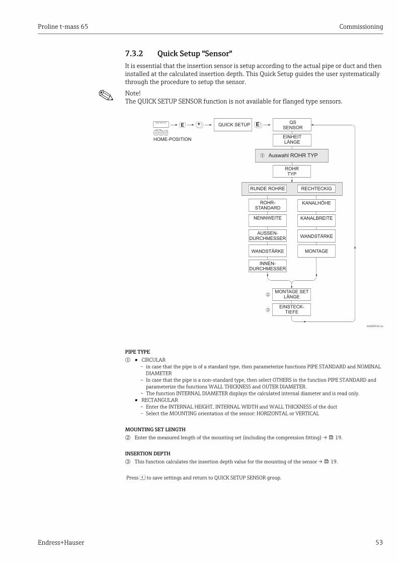
Proline t-mass 65 Commissioning
Endress+Hauser 53
7.3.2 Quick Setup "Sensor"It is essential that the insertion sensor is setup according to the actual pipe or duct and then installed at the calculated insertion depth. This Quick Setup guides the user systematically through the procedure to setup the sensor.
! Note! The QUICK SETUP SENSOR function is not available for flanged type sensors.
A0009910-en
PIPE TYPE
m • CIRCULAR – in case that the pipe is of a standard type, then parameterize functions PIPE STANDARD and NOMINAL
DIAMETER– In case that the pipe is a non-standard type, then select OTHERS in the function PIPE STANDARD and
parameterize the functions WALL THICKNESS and OUTER DIAMETER.– The function INTERNAL DIAMETER displays the calculated internal diameter and is read only.
• RECTANGULAR – Enter the INTERNAL HEIGHT, INTERNAL WIDTH and WALL THICKNESS of the duct– Select the MOUNTING orientation of the sensor: HORIZONTAL or VERTICAL
MOUNTING SET LENGTH
n Enter the measured length of the mounting set (including the compression fitting) → 19.
INSERTION DEPTH
o This function calculates the insertion depth value for the mounting of the sensor → 19.
Press F to save settings and return to QUICK SETUP SENSOR group.
++EEsc
E+-
XXX.XXX.XX
HOME-POSITION
+E
m
n
o
QUICK SETUP QSSENSOR
ROHR-STANDARD
KANALHÖHE
NENNWEITE KANALBREITE
EINHEITLÄNGE
WANDSTÄRKE
WANDSTÄRKE
MONTAGE
RECHTECKIGRUNDE ROHRE
AUSSEN-DURCHMESSER
INNEN-DURCHMESSER
MONTAGE SETLÄNGE
EINSTECK-TIEFE
ROHRTYP
Auswahl ROHR TYP
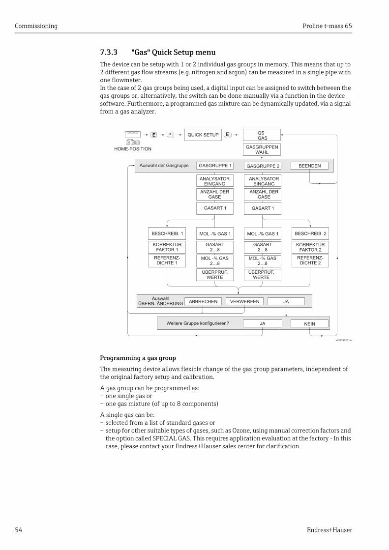
Commissioning Proline t-mass 65
54 Endress+Hauser
7.3.3 "Gas" Quick Setup menuThe device can be setup with 1 or 2 individual gas groups in memory. This means that up to 2 different gas flow streams (e.g. nitrogen and argon) can be measured in a single pipe with one flowmeter.In the case of 2 gas groups being used, a digital input can be assigned to switch between the gas groups or, alternatively, the switch can be done manually via a function in the device software. Furthermore, a programmed gas mixture can be dynamically updated, via a signal from a gas analyzer.
A0009907-en
Programming a gas group
The measuring device allows flexible change of the gas group parameters, independent of the original factory setup and calibration.
A gas group can be programmed as:– one single gas or– one gas mixture (of up to 8 components)
A single gas can be:– selected from a list of standard gases or– setup for other suitable types of gases, such as Ozone, using manual correction factors and
the option called SPECIAL GAS. This requires application evaluation at the factory - In this case, please contact your Endress+Hauser sales center for clarification.
++EEsc
E+-
XXX.XXX.XX
HOME-POSITION
+EQUICK SETUP QSGAS
BESCHREIB. 1
KORREKTURFAKTOR 1
REFERENZ-DICHTE 1
GASGRUPPENWAHL
GASGRUPPE 1
ANZAHL DERGASE
GASART2…8
MOL -% GAS2…8
ÜBERPRÜF.WERTE
AuswahlÜBERN. ÄNDERUNG ABBRECHEN
JA NEIN
Auswahl der Gasgruppe
Weitere Gruppe konfigurieren?
MOL -% GAS 1MOL -% GAS 1
BEENDENGASGRUPPE 2
ANZAHL DERGASE
GASART 1 GASART 1
GASART2…8
MOL -% GAS2…8
JAVERWERFEN
BESCHREIB. 2
ÜBERPRÜF.WERTE
REFERENZ-DICHTE 2
KORREKTURFAKTOR 2
ANALYSATOREINGANG
ANALYSATOREINGANG

Proline t-mass 65 Commissioning
Endress+Hauser 55
Setting or viewing the active gas group
The active measuring group can be set via 2 methods:
1. Digital input: the status input can be configured to switch between the two groups. Select option GAS GROUP (see "Description of Device Functions" manual BA00112D/06/…).
2. Manual switch: go to the function SELECT GROUP and simply select 1 or 2 and then exit using ESC (+/- keys simultaneously). No save function is necessary.
! Note! The Quick Setup Gas function is not available if an in-situ calibration function has been performed on the measuring device as the in-situ calibration curve refers to the sensor power at each recorded flow point.Therefore, the programmed gas settings become redundant → 68.
Performing the Quick Setup
1. GAS GROUPUse the O or S key to select the required GAS GROUP and continue with F. – Set the ANALYZER INPUT to ON if a gas compensation input is being used → 60– Select the NUMBER OF GASES in the group from 1 to 8.– Select the GAS TYPE from the choose list.– Enter the MOLE % for each GAS TYPE (only if NUMBER OF GASES is 2 and more).– The error message CHECK VALUES appears if the total mixture % does not equal
100%. Go back and check the mixture settings.
2. SAVE CHANGES?– Select YES to save the settings in GAS GROUP 1 or 2 and activate the last gas group
selected. Press F to continue or– Select CANCEL to save the entered settings in buffer memory but not activate them
for measurement. If this function is selected, then it will be necessary to come back to this gas group and save it at a later stage.
– Select DISCARD to clear the last changes and return to CONFIGURE GROUP to make new settings.
3. ANOTHER GAS GROUP? – Select YES to continue to the CONFIGURE GROUP function. Use the + or - key to
select the desired GAS GROUP and proceed as per the above instructions.– Select NO to exit to the Quick Setup.
! Note! More detailed information on the GAS GROUP programming can be found in the separate "Description of Device Functions" manual (BA112D/06/… see chapter GAS).
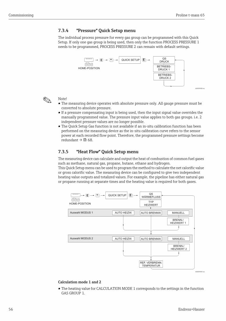
Commissioning Proline t-mass 65
56 Endress+Hauser
7.3.4 "Pressure" Quick Setup menuThe individual process pressure for every gas group can be programmed with this Quick Setup. If only one gas group is being used, then only the function PROCESS PRESSURE 1 needs to be programmed, PROCESS PRESSURE 2 can remain with default settings.
A0009908-en
! Note! • The measuring device operates with absolute pressure only. All gauge pressure must be
converted to absolute pressure.• If a pressure compensating input is being used, then the input signal value overrides the
manually programmed value. The pressure input value applies to both gas groups. i.e. 2 independent pressure values are no longer possible.
• The Quick Setup Gas function is not available if an in-situ calibration function has been performed on the measuring device as the in-situ calibration curve refers to the sensor power at each recorded flow point. Therefore, the programmed pressure settings become redundant → 68.
7.3.5 "Heat Flow" Quick Setup menuThe measuring device can calculate and output the heat of combustion of common fuel gases such as methane, natural gas, propane, butane, ethane and hydrogen. This Quick Setup menu can be used to program the method to calculate the net calorific value or gross calorific value. The measuring device can be configured to give two independent heating value outputs and totalized values. For example, the pipeline has either natural gas or propane running at separate times and the heating value is required for both gases.
A0009909-en
Calculation mode 1 and 2
• The heating value for CALCULATION MODE 1 corresponds to the settings in the function GAS GROUP 1.
++EEsc
E+-
XXX.XXX.XX
HOME-POSITION
+EQUICK SETUP QSDRUCK
BETRIEBS-DRUCK 2
BETRIEBS-DRUCK 1
++EEsc
E+-
XXX.XXX.XX
HOME-POSITION
+EQUICK SETUP QSWÄRMEFLUSS
AUTO HEIZW.Auswahl MODUS 1 MANUELLAUTO BRENNW.
Auswahl MODUS 2 AUTO HEIZW. MANUELLAUTO BRENNW.
BRENN-/HEIZWERT 2
BRENN-/HEIZWERT 1
TYPHEIZWERT
REF. VERBRENN.TEMPERATUR
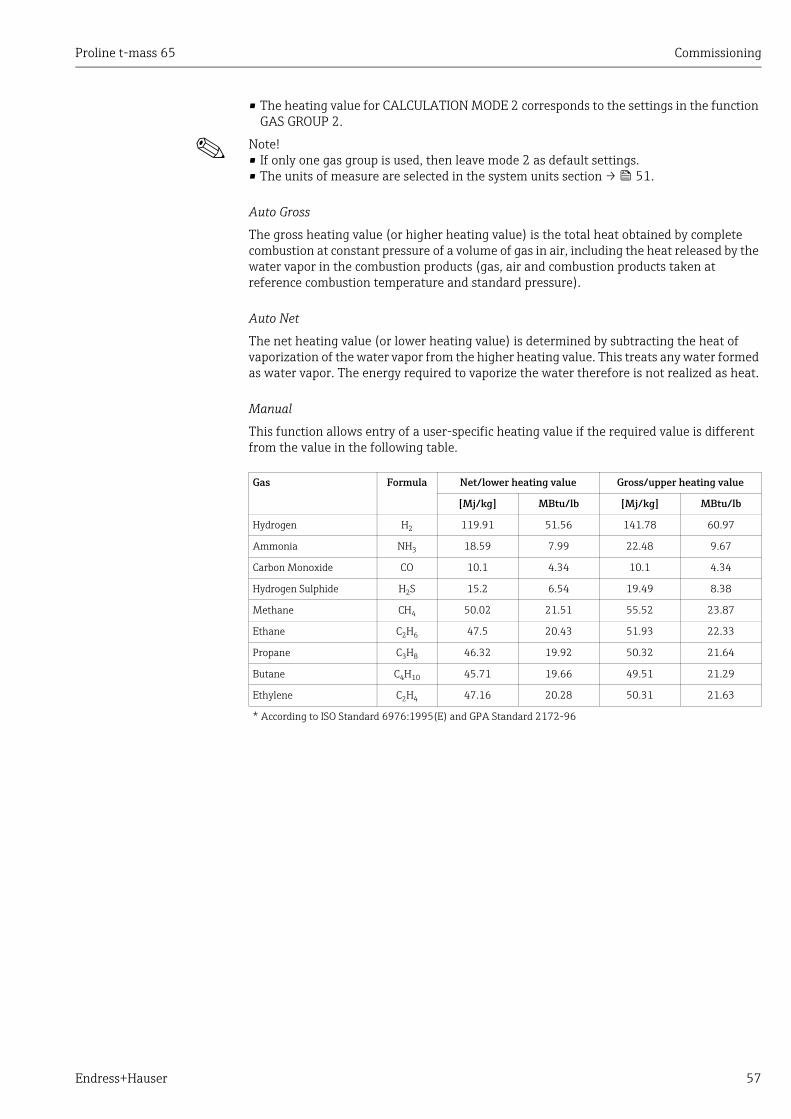
Proline t-mass 65 Commissioning
Endress+Hauser 57
• The heating value for CALCULATION MODE 2 corresponds to the settings in the function GAS GROUP 2.
! Note! • If only one gas group is used, then leave mode 2 as default settings.• The units of measure are selected in the system units section → 51.
Auto Gross
The gross heating value (or higher heating value) is the total heat obtained by complete combustion at constant pressure of a volume of gas in air, including the heat released by the water vapor in the combustion products (gas, air and combustion products taken at reference combustion temperature and standard pressure).
Auto Net
The net heating value (or lower heating value) is determined by subtracting the heat of vaporization of the water vapor from the higher heating value. This treats any water formed as water vapor. The energy required to vaporize the water therefore is not realized as heat.
Manual
This function allows entry of a user-specific heating value if the required value is different from the value in the following table.
Gas Formula Net/lower heating value Gross/upper heating value
[Mj/kg] MBtu/lb [Mj/kg] MBtu/lb
Hydrogen H2 119.91 51.56 141.78 60.97
Ammonia NH3 18.59 7.99 22.48 9.67
Carbon Monoxide CO 10.1 4.34 10.1 4.34
Hydrogen Sulphide H2S 15.2 6.54 19.49 8.38
Methane CH4 50.02 21.51 55.52 23.87
Ethane C2H6 47.5 20.43 51.93 22.33
Propane C3H8 46.32 19.92 50.32 21.64
Butane C4H10 45.71 19.66 49.51 21.29
Ethylene C2H4 47.16 20.28 50.31 21.63
* According to ISO Standard 6976:1995(E) and GPA Standard 2172-96

Commissioning Proline t-mass 65
58 Endress+Hauser
Reference combustion temperature
The following reference temperatures are used:
7.3.6 Data backup/transmissionUsing the T-DAT SAVE/LOAD function, you can transfer data (device parameters and settings) between the T-DAT (exchangeable memory) and the EEPROM (device storage unit).
This is required in the following instances:• Creating a backup: current data are transferred from an EEPROM to the T-DAT.• Replacing a transmitter: current data are copied from an EEPROM to the T-DAT and then
transferred to the EEPROM of the new transmitter.• Duplicating data: current data are copied from an EEPROM to the T-DAT and then
transferred to EEPROMs of identical measuring points.
! Note! For information on installing and removing the T-DAT → 79
A0001221-en
Fig. 32: Data backup/transmission with T-DAT SAVE/LOAD function
Country reference combustion temperature
Austria, Belgium, Denmark, Germany, Italy, Luxembourg, The Netherlands, Poland, Russia, Sweden, Switzerland
25 °C
Brazil, China 20 °C
France, Japan 0 °C
Australia, Canada, Czech Republic, Hungary, India, Ireland, Malaysia, Mexico, South Africa, Great Britain 15 °C
Slovakia 25 °C
USA, Venezuela 60 °F
Esc
E+-
XXX.XXX.XX
� �
�
�
� � � �
�
��
��
��
��
T-DAT
VERWALTEN
Quick Setup
HOME
POSITION
LADEN
JA NEIN
ABBRECHENSICHERN
JA NEIN
Neustart des
Messgerätes
Eingabe
gespeichert
Proline t-mass 65 Commissioning
Endress+Hauser 59
Information on the LOAD and SAVE options available
LOAD:Data are transferred from the T-DAT to the EEPROM.
! Note! • Any settings already saved on the EEPROM are deleted.• This option is only available, if the T-DAT contains valid data.• This option can only be executed if the software version of the T-DAT is the same or newer
than that of the EEPROM. Otherwise, the error message "TRANSM. SW-DAT" appears after restarting and the LOAD function is then no longer available.
SAVE:Data are transferred from the EEPROM to the T-DAT
7.3.7 External pressure compensation input1. Install the pressure transmitter downstream of the flowmeter according to the pipe
work requirements → 13. Use only an absolute range pressure cell.
2. Connect the signal circuit, noting the following:– Input signal information → 88– Configure the active/passive mode on the flexible I/O board → 61– The t-mass transmitter can power the current loop (active mode) or a separate
24 VDC power supply can be used (passive mode)– Refer to the terminal assignments and grounding for the current input → 29.– Use only a screened signal cable.
3. Turn on the power to the flowmeter and signal circuit.
4. Go to the function CURRENT INPUT ASSIGN CURRENT INPUT in the software matrix and assign the option PRESSURE to the input. Parameterize the remaining functions as required.
5. In the function CURRENT INPUT ACTUAL CURRENT INPUT, check whether a 4-20 mA input signal is present.
! Note! See Description of Device Functions BA00112D/06 manual for details.
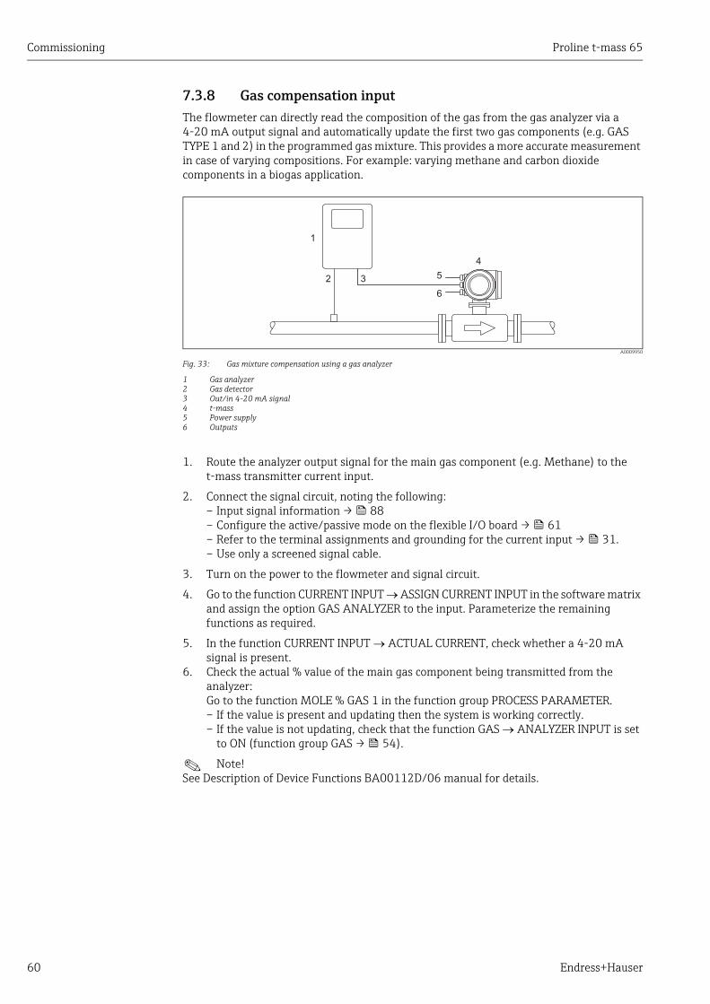
Commissioning Proline t-mass 65
60 Endress+Hauser
7.3.8 Gas compensation inputThe flowmeter can directly read the composition of the gas from the gas analyzer via a 4-20 mA output signal and automatically update the first two gas components (e.g. GAS TYPE 1 and 2) in the programmed gas mixture. This provides a more accurate measurement in case of varying compositions. For example: varying methane and carbon dioxide components in a biogas application.
A0009950
Fig. 33: Gas mixture compensation using a gas analyzer
1 Gas analyzer2 Gas detector3 Out/in 4-20 mA signal4 t-mass5 Power supply6 Outputs
1. Route the analyzer output signal for the main gas component (e.g. Methane) to the t-mass transmitter current input.
2. Connect the signal circuit, noting the following:– Input signal information → 88– Configure the active/passive mode on the flexible I/O board → 61– Refer to the terminal assignments and grounding for the current input → 31.– Use only a screened signal cable.
3. Turn on the power to the flowmeter and signal circuit.
4. Go to the function CURRENT INPUT ASSIGN CURRENT INPUT in the software matrix and assign the option GAS ANALYZER to the input. Parameterize the remaining functions as required.
5. In the function CURRENT INPUT ACTUAL CURRENT, check whether a 4-20 mA signal is present.
6. Check the actual % value of the main gas component being transmitted from the analyzer:Go to the function MOLE % GAS 1 in the function group PROCESS PARAMETER.– If the value is present and updating then the system is working correctly.– If the value is not updating, check that the function GAS ANALYZER INPUT is set
to ON (function group GAS → 54).
! Note! See Description of Device Functions BA00112D/06 manual for details.
4
5
6
32
1
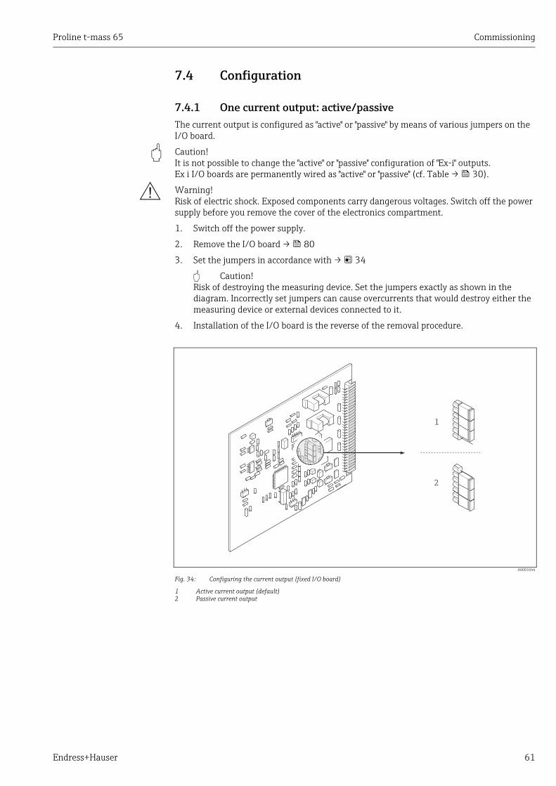
Proline t-mass 65 Commissioning
Endress+Hauser 61
7.4 Configuration
7.4.1 One current output: active/passiveThe current output is configured as "active" or "passive" by means of various jumpers on the I/O board.
" Caution! It is not possible to change the "active" or "passive" configuration of "Ex-i" outputs. Ex i I/O boards are permanently wired as "active" or "passive" (cf. Table → 30).
# Warning! Risk of electric shock. Exposed components carry dangerous voltages. Switch off the power supply before you remove the cover of the electronics compartment.
1. Switch off the power supply.
2. Remove the I/O board → 80
3. Set the jumpers in accordance with → 34
" Caution! Risk of destroying the measuring device. Set the jumpers exactly as shown in the diagram. Incorrectly set jumpers can cause overcurrents that would destroy either the measuring device or external devices connected to it.
4. Installation of the I/O board is the reverse of the removal procedure.
A0001044
Fig. 34: Configuring the current output (fixed I/O board)
1 Active current output (default)2 Passive current output
1
2

Commissioning Proline t-mass 65
62 Endress+Hauser
7.4.2 Two current outputs: active/passiveThe current outputs are configured as "active" or "passive" by means of various jumpers on the I/O board or current submodule.
" Caution! It is not possible to change the "active" or "passive" configuration of "Ex-i" outputs. Ex i I/O boards are permanently wired as "active" or "passive" (cf. Table → 30).
# Warning! Risk of electric shock. Exposed components carry dangerous voltages. Switch off the power supply before you remove the cover of the electronics compartment.
1. Switch off the power supply.
2. Remove the I/O board → 80
3. Set the jumpers in accordance with → 35
" Caution! Risk of destroying the measuring device. Set the jumpers exactly as shown in the diagram. Incorrectly set jumpers can cause overcurrents that would destroy either the measuring device or external devices connected to it.
4. Installation of the I/O board is the reverse of the removal procedure.
A0001214
Fig. 35: Configuring current outputs with the aid of jumpers (flexible I/O board)
1 Current output 1 with HART1.1 Active current output (default)1.2 Passive current output2 Current output 2 (optional, plug-in module)2.1 Active current output (default)2.2 Passive current output
INPUT/O
UTPUT 4
2
1
2.1
1.1
2.2
1.2
+
+
INPUT/O
UTPUT 3
INPUT/O
UTPUT 2

Proline t-mass 65 Commissioning
Endress+Hauser 63
7.4.3 Current input: active/passiveThe current inputs are configured as "active" or "passive" by means of various jumpers on the current input submodule.
# Warning! Risk of electric shock. Exposed components carry dangerous voltages. Switch off the power supply before you remove the cover of the electronics compartment.
1. Switch off the power supply.
2. Remove the I/O board → 80
3. Set the jumpers in accordance with → 36
" Caution! – Risk of destroying the measuring device. Set the jumpers exactly as shown in the
diagram. Incorrectly set jumpers can cause overcurrents that would destroy either the measuring device or external devices connected to it.
– Note that the position of the current submodule on the I/O board can vary, depending on the version ordered, and that the terminal assignment in the connection compartment of the transmitter varies accordingly → 30.
4. Installation of the I/O board is the reverse of the removal procedure.
A0005124
Fig. 36: Configuring current inputs with the aid of jumpers (flexible I/O board)
Current input 1 (optional, plug-in module)1 Active current input (default)2 Passive current input
INPUT/O
UTPUT 4
1
2 +
+
INPUT/O
UTPUT 3
INPUT/O
UTPUT 2

Commissioning Proline t-mass 65
64 Endress+Hauser
7.4.4 Relay contacts: Normally closed/Normally openThe relay contact can be configured as normally open (NO or make) or normally closed (NC or break) contacts by means of two jumpers on the I/O board or on the pluggable submodule. This configuration can be called up at any time with the ACTUAL STATUS RELAY function.
# Warning! Risk of electric shock. Exposed components carry dangerous voltages. Switch off the power supply before you remove the cover of the electronics compartment.
1. Switch off the power supply.
2. Remove the I/O board → 80
3. Set the jumpers → 37 or → 38
" Caution! – If you change the setting you must always change the positions of both jumpers!
Note precisely the specified positions of the jumpers.– Note that the position of the relay submodule on the I/O board can vary, depending
on the version ordered, and that the terminal assignment in the connection compartment of the transmitter varies accordingly → 30.
4. Installation of the I/O board is the reverse of the removal procedure.
A0001215
Fig. 37: Configuring relay contacts (NC / NO) on the flexible I/O board (submodule)
1 Configured as NO contact (default, relay 1)2 Configured as NC contact (default, relay 2, if installed)
A0001216
Fig. 38: Configuring relay contacts (NC / NO) on the fixed I/O board.A = relay 1; B = relay 2
1 Configured as NO contact (default, relay 1)2 Configured as NC contact (default, relay 2)
INPUT/O
UTPUT 4
INPUT/O
UTPUT 3
+
+1
2
INPUT/O
UTPUT 2
+1
+2B
+1
A+2
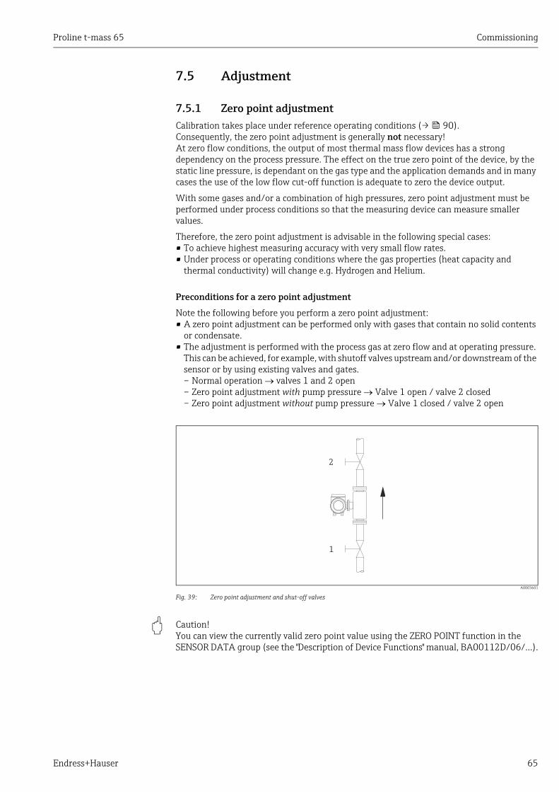
Proline t-mass 65 Commissioning
Endress+Hauser 65
7.5 Adjustment
7.5.1 Zero point adjustmentCalibration takes place under reference operating conditions (→ 90). Consequently, the zero point adjustment is generally not necessary!At zero flow conditions, the output of most thermal mass flow devices has a strong dependency on the process pressure. The effect on the true zero point of the device, by the static line pressure, is dependant on the gas type and the application demands and in many cases the use of the low flow cut-off function is adequate to zero the device output.
With some gases and/or a combination of high pressures, zero point adjustment must be performed under process conditions so that the measuring device can measure smaller values.
Therefore, the zero point adjustment is advisable in the following special cases:• To achieve highest measuring accuracy with very small flow rates.• Under process or operating conditions where the gas properties (heat capacity and
thermal conductivity) will change e.g. Hydrogen and Helium.
Preconditions for a zero point adjustment
Note the following before you perform a zero point adjustment:• A zero point adjustment can be performed only with gases that contain no solid contents
or condensate.• The adjustment is performed with the process gas at zero flow and at operating pressure.
This can be achieved, for example, with shutoff valves upstream and/or downstream of the sensor or by using existing valves and gates.– Normal operation valves 1 and 2 open– Zero point adjustment with pump pressure Valve 1 open / valve 2 closed– Zero point adjustment without pump pressure Valve 1 closed / valve 2 open
A0003601
Fig. 39: Zero point adjustment and shut-off valves
" Caution! You can view the currently valid zero point value using the ZERO POINT function in the SENSOR DATA group (see the "Description of Device Functions" manual, BA00112D/06/…).
1
2

Commissioning Proline t-mass 65
66 Endress+Hauser
Performing a zero point adjustment
1. Operate the system until operating conditions have settled.
2. Stop the flow (v = 0 m/s).
3. Check the shut-off valves for leaks.
4. Check that operating pressure is correct.
5. Using the local display/operating program, select the ZEROPOINT ADJUSTMENT function in the function matrix:PROCESS PARAMETER ZEROPOINT ADJUSTMENT
6. When you press O or S you are automatically prompted to enter the access code if the function matrix is still disabled. Enter the code (factory setting = 65).
7. Use O or S to select START and press F to confirm. The zero point adjustment now starts and is completed within a few seconds.
! Note! If the flow in the pipe is unstable, the following error message may appear on the display "ZERO ADJUST FAIL". The zero point adjustment has failed. The preconditions need to be stabilized before attempting a new adjustment.
8. Back to the HOME position:– Press and hold down Esc key (X) for longer than three seconds or– Repeatedly press and release the Esc key (X).
Resetting a zero point adjustment
The currently stored zero point can be reset to the original factory value by using the RESET option within ZERO POINT ADJUST.Use O or S to select RESET and press F to confirm. The zero point adjustment is now reset.
7.6 Data storage device (HistoROM)At Endress+Hauser, the term HistoROM refers to various types of data storage modules on which process and measuring device data are stored. By plugging and unplugging such modules, device configurations can be duplicated onto other measuring devices to cite just one example.
7.6.1 HistoROM/S-DAT (sensor-DAT)The S-DAT is an exchangeable data storage device in which all sensor-relevant parameters are stored, e.g. pipe type, nominal diameter, serial number, flow conditioner, zero point.
7.6.2 HistoROM/T-DAT (transmitter-DAT)The HistoROM/T-DAT is an exchangeable data storage device in which all transmitter parameters and settings are stored. Storing of specific parameter settings from the EEPROM to the HistoROM/T-DAT and vice versa has to be carried out by the user (= manual save function). For detailed information → 58.
Proline t-mass 65 Maintenance
Endress+Hauser 67
8 MaintenanceGenerally, the flowmeter requires no special maintenance work, particularly if the gas is clean and dry.
# Warning! Hazardous area approvals may demand that the device be returned to an Endress+Hauser sales center (→ 6) for service or that work can only be carried out by a qualified Endress+Hauser service person. Please contact your Endress+Hauser sales center if you have any questions.
8.1 External cleaning When cleaning the exterior of measuring devices, always use cleaning agents that do not attack the surface of the housing and the seals.
8.2 Pipe cleaningThe sensor is capable of withstanding clean in place (CIP) processes using heated liquids or steam (SIP), within the maximum specified temperature limits. However the sensor measurement will be adversely affected during the cleaning cycle and a settling down period will be required after the cycle to allow the process and sensor temperatures to re-stabilize.
! Note! The POSITIVE ZERO RETURN function maybe activated to set the current output to zero flow during such cycles. See "Description of Device Functions" manual for more information.
" Caution! Do not use a pipe cleaning pig.
8.3 Sensor cleaningFor gases that do carry impurities, it is recommended that the sensor be routinely inspected and cleaned to minimize any potential measuring errors due to contamination or build-ups. The frequency of inspection and cleaning will depend upon the application and expected measurement performance. Cleaning is performed by applying a non-filming or oil-free type cleaning fluid to a soft brush or cloth and gently wiping over the surface until all build-ups and contaminants are removed.
" Caution! • Use care not to bend the sensing elements of the transducer during cleaning.• Do not use abrasive materials or fluids corrosive to the sensor materials and seals.
Sensor-specific information:• t-mass F:
Removal of the transducer requires specialist knowledge, tools and parts. The process seal also may need to be tested and re-qualified. This procedure must be carried out by an Endress+Hauser sales center.
• t-mass I:Follow the safety instructions in the "Installation" section when removing the sensor (→ 19).
Maintenance Proline t-mass 65
68 Endress+Hauser
8.4 Replacing sealsUnder normal circumstances, fluid wetted seals of the sensor do not require replacement. Replacement is necessary only in special circumstances, for example if aggressive or corrosive fluids are incompatible with the seal material.Only Endress+Hauser seals may be used.
Sensor-specific information:• t-mass F:
The sensor contains o-rings seals and a bushing. In case of failure, the device must be returned to an Endress+Hauser sales center for inspection and repair (→ 6).
• t-mass I:The transducer is welded to the insertion tube and has no exchangeable seals. The compression fitting contains wetted seals (ferrules) and a bonded seal is used on the G 1 A thread version.
" Caution! Do not reuse seals once they have been removed.Only Endress+Hauser spare parts may be used. The compression fitting and the bonded seal are available as spare parts. The bonded seal can be easily exchanged on-site.
8.5 In-situ calibration The t-mass flowmeters are designed to support in-situ calibration using a reference meter signal, thus saving time and cost by reducing the need for factory re-calibration.Pre-requirements for in-situ calibration with adjustment:
1. Stable gas composition (operation with one gas group only; without gas analyzer input)
2. Stable pressure and temperature (without pressure compensation input)
3. Mass flow reference
a. mass flow reference meter, mounted in the measurement or bypass pipe, providing a mA signal to t-mass or
b. manual entry of known mass flow reference values. For example, the display value from the reference meter or a derived value from a pump curve)
4. Ability to control the flow range over a minimum of 5 control points
This function can only be activated with a special Endress+Hauser service code.For specific applications, contact your Endress+Hauser sales center.
8.6 RecalibrationFor thermal meters, the interval between calibrations is dependent on the application since calibration drift is predominantly caused by contamination of the sensor surface.If the gas is not clean (i.e. contains particulates), then gentle cleaning of the sensor elements can be effective at regular intervals. The cleaning interval will depend upon the nature and extent of the contamination.
Determination of recalibration intervals: • If the measurement is critical, then a calibration audit should be undertaken by performing
recalibration checks once per year for a period of 2 years. Increase that period to twice per year if the application gas is not clean and dry.Depending on the results of the audit, the next recalibration check interval can be increased or decreased accordingly.
• For non-critical applications and or where the gas is clean and dry, a recalibration interval of every 2 to 3 years is recommended.

Proline t-mass 65 Accessories
Endress+Hauser 69
9 AccessoriesVarious accessories, which can be ordered separately from Endress+Hauser, are available for the transmitter and the sensor. Your Endress +Hauser sales center can provide detailed information on the specific order code.
9.1 Device-specific accessories
9.2 Communication-specific accessories
Accessories Description Order codeMounting boss Mounting boss for the t-mass insertion version DK6MB - *Cable remote version Connecting cable for the remote version DK6CA - *Mounting set for transmitter
Mounting set for remote version. Suitable for:– Wall mounting– Pipe mounting– Installation in control panel
Mounting set for aluminum field housing:Suitable for pipe mounting (¾" to 3")
DK6WM - *
Hot tap, process pressure
Low-pressure version:Mounting kit with process connection, ball valve, safety chain and sensor connection. Insertion or extraction of sensor under process pressure (max. 4 barg (65 psig)).
DK6HT-***
Medium-pressure version:Mounting kit with process connection, ball valve, sensor connection and extractor assembly. Insertion or extraction of sensor under process pressure (max. 16 barg (235 psig)).
Cold tap, atmospheric pressure
Mounting kit with sensor connection, ball valve and weld socket. Insertion or extraction of sensor in unpressurized pipes (atmospheric pressure). In the absence of a measuring device, the mounting kit enables pipe resealing in order to resume the process.
DK6ML-***
Flow conditioner • t-mass F: DN25 to 100 (1 to 4")• t-mass I: DN 80 to 300 (3 to 12")
DK6ST-***DK7ST-***
Graphic data manager Memograph M
The graphic data manager Memograph M provides information on all the relevant process variables. Measured values are recorded correctly, limit values are monitored and measuring points analyzed. The data are stored in the 256 MB internal memory and also on an SD card or USB stick. The mathematics channels which are optionally available facilitate continuous monitoring, e.g. of specific energy consumption, boiler efficiency and other parameters which are necessary for efficient energy management.
RSG40 - ************
Accessory Description Order code
HART Communicator Field Xpert SFX 100
Handheld terminal for remote configuration and for obtaining measured values via the 4 to 20 mA HART current output. Further information is available from your Endress+Hauser sales center.
SFX100 – *******
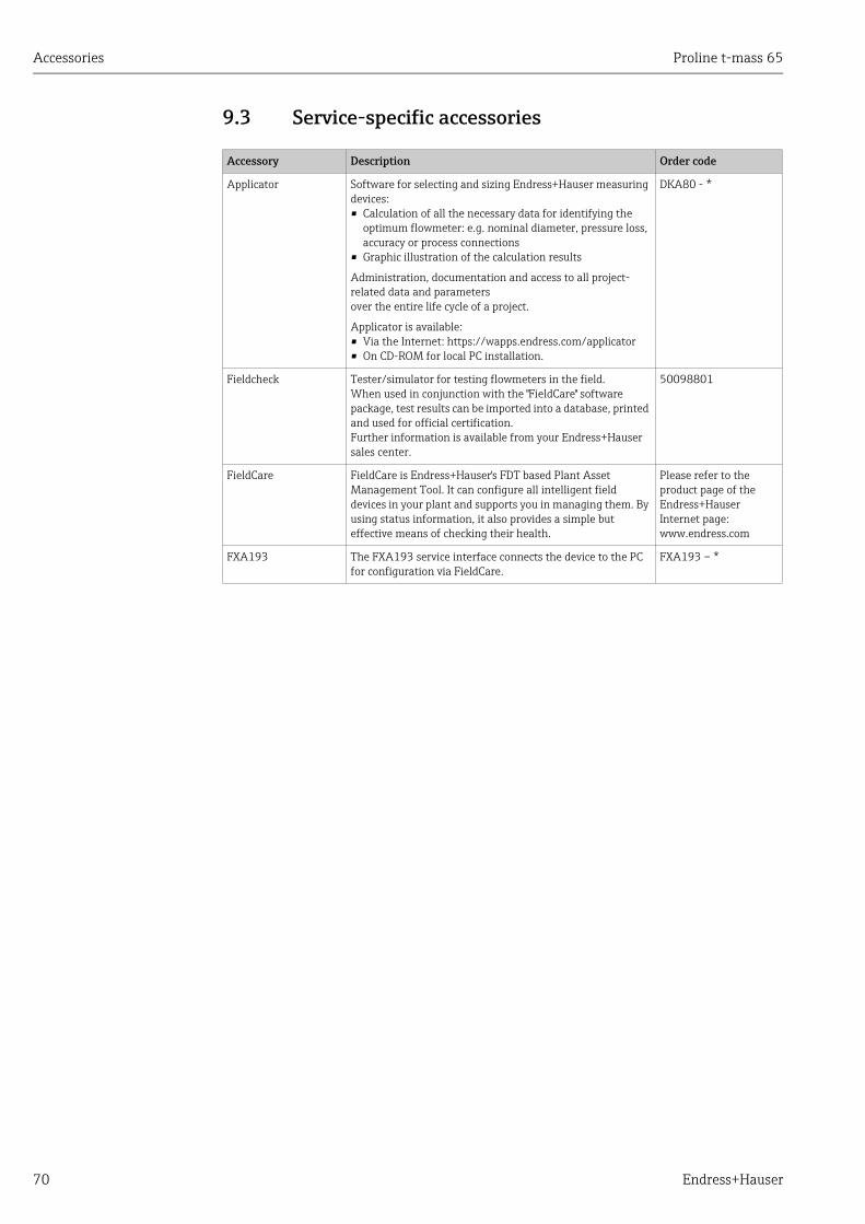
Accessories Proline t-mass 65
70 Endress+Hauser
9.3 Service-specific accessories
Accessory Description Order code
Applicator Software for selecting and sizing Endress+Hauser measuring devices:• Calculation of all the necessary data for identifying the
optimum flowmeter: e.g. nominal diameter, pressure loss, accuracy or process connections
• Graphic illustration of the calculation results
Administration, documentation and access to all project-related data and parametersover the entire life cycle of a project.
Applicator is available:• Via the Internet: https://wapps.endress.com/applicator• On CD-ROM for local PC installation.
DKA80 - *
Fieldcheck Tester/simulator for testing flowmeters in the field.When used in conjunction with the "FieldCare" software package, test results can be imported into a database, printed and used for official certification.Further information is available from your Endress+Hauser sales center.
50098801
FieldCare FieldCare is Endress+Hauser's FDT based Plant Asset Management Tool. It can configure all intelligent field devices in your plant and supports you in managing them. By using status information, it also provides a simple but effective means of checking their health.
Please refer to the product page of the Endress+Hauser Internet page:www.endress.com
FXA193 The FXA193 service interface connects the device to the PC for configuration via FieldCare.
FXA193 – *

Proline t-mass 65 Trouble-shooting
Endress+Hauser 71
10 Trouble-shooting
10.1 Trouble-shooting instructionsAlways start troubleshooting with the following checklist if faults occur after commissioning or during operation. The routine takes you directly to the cause of the problem and the appropriate remedial measures.
Check the display
No display visible and no output signals present.
1. Check the supply voltage Terminals 1, 2
2. Check device fuse → 8585 to 260 V AC: 0.8 A slow-blow / 250 V20 to 55 V AC and 16 to 62 V DC: 2 A slow-blow / 250 V
3. Measuring electronics defective order spare parts → 79
No display visible, but output signals are present.
1. Check whether the ribbon cable connector of the display module is correctly plugged into the amplifier board → 80.
2. Display module defective order spare parts → 80
3. Measuring electronics defective order spare parts → 80
Display texts are in a foreign language.
Switch off the power supply. Press and hold down both the P keys and switch on the measuring device. The display text will appear in English (default) and is displayed at maximum contrast.
Measured value indicated, but no signal at the current or pulse output
Measuring electronics defective order spare parts → 80
▾Error messages on display
Errors that occur during commissioning or measuring are displayed immediately. Error messages consist of a variety of icons. The meanings of these icons are as follows (example):
– Type of error: S = System error, P = Process error– Error message type: $ = Fault message, ! = Notice message– FLOW LIMIT = Error designation, e.g. measured flow has exceeded the maximum limit.– 03:00:05 = Duration of error occurrence (in hours, minutes and seconds)– #422 = Error number
" Caution! • See the information on → 38.• The measuring device interprets simulations and positive zero return as system errors, but displays them as a
notice message only.
System error (device error) has occurred → 72
Process error (application error) has occurred → 76
▾Other error (without error message)
Some other error has occurred.
Diagnosis and rectification → 76

Trouble-shooting Proline t-mass 65
72 Endress+Hauser
10.2 System error messagesSerious system errors are always recognized by the flowmeter as "Fault message", and are shown as a lightning flash ($) on the display! Fault messages immediately affect the inputs and outputs. Simulations and positive zero return, on the other hand, are classed and displayed as "Notice messages".
" Caution! In the event of a serious fault, a flowmeter might have to be returned to the manufacturer for repair. Important procedures must be carried out before you return a flowmeter to Endress+Hauser. → 6Always enclose a duly completed "Declaration of contamination" form with the measuring device. You will find a preprinted blank of this form at the back of this manual.
! Note! • The listed error message types below correspond to the factory setting.• Also observe the information on the following pages: → 38
No. Error message / Type Cause Remedy / spare part → 79
S = System error$ = Fault message (with an effect on the inputs and outputs)! = Notice message (without an effect on the inputs and outputs)
No. # 0xx Hardware error
001 S: CRITICAL FAIL. $: # 001
Serious device error Replace the amplifier board.
011 S: AMP HW EEPROM $: # 011
Amplifier: Defective EEPROM Replace the amplifier board.
012 S: AMP SW EEPROM $: # 012
Measuring amplifier: Error when accessing data of the EEPROM
The EEPROM data blocks in which an error has occurred are displayed in the "TROUBLESHOOTING" function.Press Enter to acknowledge the errors in question; default values are automatically inserted instead of the errored parameter values.
! Note! The measuring device has to be restarted if an error has occurred in a totalizer block (see error No. 111 / CHECKSUM TOTAL).
014 S: AMP SW-ROM/RAM $: # 014
Amplifier: Defective ROM/RAM Replace the amplifier board.
031 S: SENSOR HW DAT $: # 031
1. HistoROM/S-DAT is not plugged into the amplifier board or is missing.
2. HistoROM/S-DAT is defective.
1. Check whether the HistoROM/S-DAT is correctly plugged into the amplifier board.
2. Replace the S-DAT if it is defective.
Before replacing the DAT, check that the new, replacement DAT is compatible with the measuring electronics.Check the:Spare part set numberHardware revision code
3. Replace measuring electronics boards if necessary.
4. Plug the S-DAT into the amplifier board.
032 S: SENSOR SW DAT $: # 032
Sensor DAT:Error accessing the calibration values stored in the HistoROM/S-DAT.
035 S: SEN HW-ROM/RAM $: # 035
Sensor: Defective ROM/RAM Replace the amplifier board.
036 S: SEN SW-ROM/RAM $: # 036

Proline t-mass 65 Trouble-shooting
Endress+Hauser 73
042 S: TRANSM. SW DAT $: # 042
Sensor DAT:Error accessing the calibration values stored in the HistoROM/T-DAT.
1. Check whether the HistoROM/T-DAT is correctly plugged into the amplifier board.
2. Replace the T-DAT if it is defective.
Before replacing the DAT, check that the new, replacement DAT is compatible with the measuring electronics.Check the:Spare part set numberHardware revision code
3. Replace measuring electronics boards if necessary.
4. Plug the T-DAT into the amplifier board.
051 S: A / C COMPATIB. $: # 051
The I/O board and the amplifier board are not compatible.
Use only compatible modules and boards.Check the compatibility of the modules used.
Check the:– Spare part set number– Hardware revision code
070 S: SENSOR DEFECT$: # 070
Flow sensors are likely to be defect, measurement is no longer possible.
1. Visual check of the sensors for damage.
2. The resistance of the sensors must be measured.
Contact your Endress+Hauser sales center for clarification.
No. # 1xx Software error
111 S: CHECKSUM TOTAL $: # 111
Totalizer checksum error 1. Restart the measuring device
2. Replace the amplifier board if necessary.
121 S: A/C SW COMPATI !: # 121
Due to different software versions, I/O board and amplifier board are only partially compatible (possibly restricted functionality).
! Note! – This message is only listed in the error history.– Nothing is displayed on the display.
Module with lower software version has either to be actualized by FieldCare with the required software version or the module has to be replaced.
No. # 2xx Error in DAT / no communication
205 S: LOAD T-DAT !: # 205
Transmitter DATData backup (downloading) to HistoROM/T-DAT failed, or error when accessing (uploading) the calibration values stored in the HistoROM/T-DAT.
1. Check whether the HistoROM/T-DAT is correctly plugged into the amplifier board.
2. Replace the T-DAT if it is defective.Before replacing the DAT, check that the new, replacement DAT is compatible with the measuring electronics. Check the:– Spare part set number– Hardware revision code
3. Replace measuring electronics boards if necessary.
206 S: SAVE T-DAT !: # 206
211 S: S-DAT NO HW$: # 211
HistoROM/S-DAT is not fitted to amplifier board. Check whether the HistoROM/S-DAT is correctly plugged into the amplifier board.
251 S: COMMUNIC. SENS$: # 251
Internal microprocessor communication fault on the amplifier board.
Remove the amplifier board.
261 S: COMMUNIC. I/O $: # 261
No data reception between amplifier and I/O board or faulty internal data transfer.
Check the BUS contacts
No. # 3xx System limits exceeded
351…352
S: RANGE CUR.OUTn !: # 351…352
Current output:The actual value for the flow lies outside the set limits.
1. Change lower-range or upper-range values entered.
2. Reduce flow.
355…356
S: RANGE FREQ.OUTn !: # 355…356
Frequency output:The actual value for the flow lies outside the set limits.
1. Change lower-range or upper-range values entered.
2. Reduce flow.
No. Error message / Type Cause Remedy / spare part → 79

Trouble-shooting Proline t-mass 65
74 Endress+Hauser
359… 360
S: RANGE PULSEn !: # 359…360
Pulse output:Pulse output frequency is outside the set range.
1. Increase pulse value
2. When selecting the pulse width, choose a value that can still be processed by a connected counter (e.g. mechanical counter, PLC etc.).Determine the pulse width:– Variant 1: Enter the minimum duration that a pulse
must be present at the connected counter to ensure its registration.
– Variant 2: Enter the maximum (pulse) frequency as the half "reciprocal value" that a pulse must be present at the connected counter to ensure its registration.
Example:The maximum input frequency of the connected counter is 10 Hz. The pulse width to be entered is:
A0004437
3. Reduce flow.
363 S: RANGE CUR.IN1 !: # 363
Current input:The actual value for the current input is outside the set range.
1. Change set lower-range or upper-range value.
2. Check settings of the external current source.
372 S: DIFF TEMP LO $: # 372
The measured sensor differential temperature is below limit value.
Reduce the flow rate.
381 S: FLUIDTEMP.MIN !: # 381
The minimum fluid temperature limit for the transducer has been exceeded.
Increase the process gas temperature.
" Caution! In case of severe temperature exposure, the transducer may be damaged.
382 S: FLUIDTEMP.MAX !: # 382
The minimum fluid temperature limit for the transducer has been exceeded.
Reduce the process gas temperature.
" Caution! In case of severe temperature exposure, the transducer may be damaged.
No. # 5xx Application error
501 S: SW.-UPDATE ACT !: # 501
New amplifier or communication (I/O module) software version is loaded. Currently no other functions are possible.
Wait until process is finished. The device will restart automatically.
502 S: UP-/DOWNL. ACT !: # 502
Up- or downloading the device data via configuration program. Currently no other functions are possible.
Wait until process is finished.
No. # 6xx Simulation mode active
601 S: POS.ZERO-RET. !: # 601
Positive zero return active.
" Caution! This message has the highest display priority.
Switch off positive zero return.
611…612
S: SIM. CURR.OUT. n !: # 611…612
Simulation current output active Switch off simulation
621…622
S: SIM. FREQ.OUT. n !: # 621…622
Simulation frequency output active Switch off simulation
631…632
S: SIM. PULSE n !: # 631…632
Simulation pulse output active Switch off simulation
641…642
S: SIM. STAT.OUT n !: # 641…642
Simulation status output active Switch off simulation
651…652
S: SIM.REL.OUT n !: # 651…652
Simulation relay output active Switch off simulation
No. Error message / Type Cause Remedy / spare part → 79
1
2.10 Hz= 50 ms

Proline t-mass 65 Trouble-shooting
Endress+Hauser 75
661 S: SIM.CURR. IN 1 !: # 661
Simulation current input active Switch off simulation
671…672
S: SIM.STATUS IN n!: # 671…672
Simulation status input active Switch off simulation
691 S: SIM. FAILSAFE !: # 691
Simulation of response to error (outputs) active Switch off simulation
692 S: SIM. MEASURAND !: # 692
Simulation of measuring variables (e.g. mass flow) Switch off simulation
698 S: DEV. TEST ACT. !: # 698
The measuring device is being checked on-site via the test and simulation device (FieldCheck).
No. Error message / Type Cause Remedy / spare part → 79

Trouble-shooting Proline t-mass 65
76 Endress+Hauser
10.3 Process error messagesProcess errors can be defined as either "Fault" or "Notice" messages and can thereby be weighted differently. This is specified via the function matrix (® "Description of Device Functions" manual).
! Note! • The error message types listed below correspond to the factory setting.• Also observe the information on the following pages: → 38
10.4 Process errors without messages
No. Error message / Type Cause Remedy / spare part → 79
S = System error$ = Fault message (with an effect on the inputs and outputs)! = Notice message (without an effect on the inputs and outputs)
422 P: FLOW LIMIT $: # 422
The measured flow has exceeded the maximum limit.
Reduce the flow rate.
! Note! Error can be configured as a fault or notice message.
731 P: ADJ. ZERO FAIL $: # 731
The saved zero point is inaccurate possibly due to unstable process or flow conditions.
Make sure that zero point adjustment is carried out at "zero flow" only (v = 0 m/s) → 65.
Symptoms Rectification
! Note! You may have to change or correct certain settings of the function matrix in order to rectify faults. The functions outlined below, such as DISPLAY DAMPING, for example, are described in detail in the "Description of Device Functions" manual.
Displayed measured value fluctuates even though flow is steady.
1. Increase value of the TIME CONSTANT setting CURRENT OUTPUT function group.
2. Increase value of the DISPLAY DAMPING setting USER INTERFACE function group.
3. The inlet and outlet lengths must be observed. See installation conditions → 15
4. Consider the use of a flow conditioner. See installation conditions → 16
5. Relocate the meter to a point where there is less flow disturbance
Measuring device displays flow with no actual flow present.
1. The low flow cut off value is programmed too low. Increase value of the ON VALUE LOW FLOW CUT OFF setting PROCESS PARAMETERS function group (Factory setting = 1% of 20mA value).
2. Check for leaks in the pipe line downstream of the sensor.
3. Reduce or eliminate pressure pulsations in the line.
Measuring device displays flow with no actual flow present - but with high static line pressure and thermally conductive gases present (e.g. hydrogen, helium, etc.). Line pressure is typically > 5 bar / 75 psi
Start the ZERO POINT ADJUST function PROCESS PARAMETERS function group.See Zero Point Adjust function → 65
! Note! Process preconditions are required before starting this function.
Measuring device displays zero flow but flow is present.
1. The INSTALLATION FACTOR may have a wrong setting = 0 ® PROCESS PARAMETERS function group (factory setting = 1.0).
2. The LOW FLOW CUT OFF setting may be too high. Adjust the function ON VALUE LOW FLOW CUT OFF to a lower value PROCESS PARAMETERS function group (factory setting 1% of calibrated 20mA value).
3. The ZERO POINT ADJUST function may have been incorrectly carried out with flow present. RESET the zero point adjustment if necessary PROCESS PARAMETERS function group.

Proline t-mass 65 Trouble-shooting
Endress+Hauser 77
Measuring device displays incorrect flow values.
1. Check the basic parameters of the device → 50Especially:– Gas– Process pressure– Reference pressure and reference temperature– Flow units– Output assignment
2. Check the installation conditions (Post-installation check → 27)a. The inlet and outlet lengths must be observed → 15.
b. Consider the use of a flow conditioner if the necessary inlet requirements cannot be met → 16.
c. t-mass F: Check for diameter mismatch between the flanges and check the gasket alignment → 13.t-mass I: Check the sensor orientation and insertion depth. → 19.
d. If the measures above cannot rectify the problem, the INSTALLATION FACTOR PROCESS PARAMETER function group (factory setting = 1.0) must be configured in such a way that the flow rate displayed matches the anticipated flow rate.
3. The flow rate maybe too high (i.e. above sensor calibration range)1. Check the measuring range that the Endress+Hauser Applicator program uses.
2. Check if the inverted plus sign "+" is shown on the display? If yes, reduce the velocity if possible.
4. The flow rate maybe too low1. Check the measuring range that the Endress+Hauser Applicator program uses.
2. Increase the velocity if possible.
5. Check the condition of the transducer1. Are the measuring elements bent? If yes, replacement is necessary.
2. Are build-ups present? If yes, clean the sensors (transducer cleaning Sensor cleaning → 67).
3. Has corrosion occurred? If yes, replacement is necessary.
6. Check if the gas is wet? Is condensate present on the sensors?If so:
1. For horizontal pipes: Mount the sensor at 135° → 14
2. Install a condensate trap or filter upstream of the flowmeter
7. Check if heating devices are used upstream of the flowmeter causing possible temperature profile effects ?If so:
1. Relocate the flowmeter further downstream or
2. Install a flow conditioner upstream of the flowmeter
The fault cannot be rectified or some other fault not described above has occurred.In such cases, your Endress+Hauser sales center can help.
The following options are available for tackling problems of this nature:
Request the services of an Endress+Hauser service technicianIf our service representative is contacted to have a service technician sent out, please be ready with the following information:– Brief description of the fault– Nameplate specifications : Order code and serial number → 7
Returning measuring devices to Endress+HauserThe procedures on → 6 must be carried out before you return a flowmeter requiring repair or calibration to Endress+Hauser.Always enclose a duly completed "Declaration of contamination" form with the flowmeter. You will find a preprinted "Declaration of contamination" at the back of this manual.
Replace transmitter electronicsComponents in the measuring electronics defective order replacement → 79
Symptoms Rectification

Trouble-shooting Proline t-mass 65
78 Endress+Hauser
10.5 Response of outputs to errors
! Note! The failsafe mode of totalizers, current, pulse, frequency, status and relay outputs can be customized by means of various functions in the function matrix. You will find detailed information on these procedures in the "Description of Device Functions" manual.
You can use positive zero return to set the signals of the current, pulse and status outputs to their fallback value, for example when measuring has to be interrupted while a pipe is being cleaned This function takes priority over all other device functions. Simulations, for example, are suppressed.
Failsafe mode of outputs and totalizers
Process/system error is present Positive zero return is activated
" Caution! System or process errors defined as "Notice messages" have no effect whatsoever on the inputs and outputs. See the information on → 38
Current output 1, 2 MINIMUM CURRENTThe current output will be set to the lower value of the signal on alarm level depending on the setting selected in the CURRENT SPAN (see the "Description of Device Functions" manual).
MAXIMUM CURRENTThe current output will be set to the higher value of the signal on alarm level depending on the setting selected in the CURRENT SPAN (see the "Description of Device Functions" manual).
HOLD VALUEMeasured value display on the basis of the last saved value preceding occurrence of the fault.
ACTUAL VALUEMeasured value display on the basis of the current flow measurement. The fault is ignored.
Output signal corresponds to "zero flow"
Pulse output FALLBACK VALUESignal output no pulses
ACTUAL VALUEFault is ignored, i.e. normal measured value output on the basis of ongoing flow measurement.
Output signal corresponds to "zero flow"
Frequency output FALLBACK VALUESignal output 0 Hz
FAILSAFE LEVELOutput of the frequency specified in the FAILSAFE VALUE function.
HOLD VALUELast valid value (preceding occurrence of the fault) is output.
ACTUAL VALUEFault is ignored, i.e. normal measured value output on the basis of ongoing flow measurement.
Output signal corresponds to "zero flow"
Totalizer 1, 2 STOPThe totalizers are paused until the error is rectified.
ACTUAL VALUEThe fault is ignored. The totalizer continues to count in accordance with the current flow value.
HOLD VALUEThe totalizers continue to count the flow in accordance with the last valid flow value (before the error occurred).
Totalizer stops
Status output Status output non-conductive in the event of fault or power supply failure No effect on status output
Relay output 1, 2 In event of fault or power supply failure: relay de-energized
The "Description of Device Functions" manual contains detailed information on relay switching response for various configurations such as error message, flow limit, temperature limit, etc.
No effect on the relay output

Proline t-mass 65 Trouble-shooting
Endress+Hauser 79
10.6 Spare partsThe previous sections contain a detailed trouble-shooting guide. → 71The measuring device, moreover, provides additional support in the form of continuous self-diagnosis and error messages.Fault rectification can entail replacing defective components with tested spare parts. The illustration below shows the available scope of spare parts.
! Note! You can order spare parts directly from your Endress+Hauser sales center by providing the serial number printed on the transmitter's nameplate. → 7
Spare parts are shipped as sets comprising the following parts:• Spare part• Additional parts, small items (threaded fasteners, etc.)• Installation instructions• Packaging
A0005125
Fig. 40: Spare parts for transmitter 65 (field and wall-mount housings)
1 Power unit board (85 to 260 V AC, 20 to 55 V AC, 16 to 62 V DC)2 Amplifier board3 I/O board (COM module), flexible assignment4 Pluggable input/output submodules; ordering structure → 695 I/O board (COM module), permanent assignment6 HistoROM/S-DAT (sensor data memory)7 HistoROM/T-DAT (transmitter data memory)8 Display module
1
2
3
4
6
7IN
PUT/OUTPUT
2
INPUT/O
UTPUT3
INPUT/O
UTPUT4
5
8
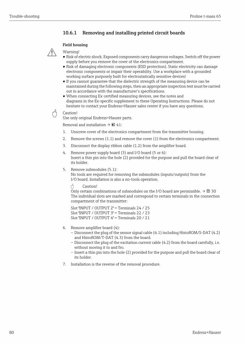
Trouble-shooting Proline t-mass 65
80 Endress+Hauser
10.6.1 Removing and installing printed circuit boards
Field housing
# Warning! • Risk of electric shock. Exposed components carry dangerous voltages. Switch off the power
supply before you remove the cover of the electronics compartment.• Risk of damaging electronic components (ESD protection). Static electricity can damage
electronic components or impair their operability. Use a workplace with a grounded working surface purposely built for electrostatically sensitive devices!
• If you cannot guarantee that the dielectric strength of the measuring device can be maintained during the following steps, then an appropriate inspection test must be carried out in accordance with the manufacturer’s specifications.
• When connecting Ex-certified measuring devices, see the notes anddiagrams in the Ex-specific supplement to these Operating Instructions. Please do not hesitate to contact your Endress+Hauser sales center if you have any questions.
" Caution! Use only original Endress+Hauser parts.
Removal and installation → 41:
1. Unscrew cover of the electronics compartment from the transmitter housing.
2. Remove the screws (1.1) and remove the cover (1) from the electronics compartment.
3. Disconnect the display ribbon cable (1.2) from the amplifier board.
4. Remove power supply board (3) and I/O board (5 or 6):Insert a thin pin into the hole (2) provided for the purpose and pull the board clear of its holder.
5. Remove submodules (5.1):No tools are required for removing the submodules (inputs/outputs) from the I/O board. Installation is also a no-tools operation.
" Caution! Only certain combinations of submodules on the I/O board are permissible. → 30The individual slots are marked and correspond to certain terminals in the connection compartment of the transmitter:
Slot "INPUT / OUTPUT 2" = Terminals 24 / 25Slot "INPUT / OUTPUT 3" = Terminals 22 / 23Slot "INPUT / OUTPUT 4" = Terminals 20 / 21
6. Remove amplifier board (4):– Disconnect the plug of the sensor signal cable (4.1) including HistoROM/S-DAT (4.2)
and HistoROM/T-DAT (4.3) from the board.– Disconnect the plug of the excitation current cable (4.2) from the board carefully, i.e.
without moving it to and fro.– Insert a thin pin into the hole (2) provided for the purpose and pull the board clear of
its holder.
7. Installation is the reverse of the removal procedure.

Proline t-mass 65 Trouble-shooting
Endress+Hauser 81
A0005126
Fig. 41: Field housing: removing and installing printed circuit boards
1 Electronics compartment cover with local display1.1 Screws of electronics compartment cover1.2 Ribbon cable (display module)2 Aperture for installing/removing boards3 Power unit board4 Amplifier board4.1 Signal cable (sensor)4.2 HistoROM/S-DAT (sensor data memory)4.3 HistoROM/T-DAT (transmitter data memory)5 I/O board (flexible assignment)5.1 Pluggable submodules (status input and current input, current output, frequency output and relay output)6 I/O board (permanent assignment)
3
4
5
5.1
2
2
4.1
4.3
4.2IN
PUT/OUTPUT
2
INPUT/O
UTPUT3
INPUT/O
UTPUT4
6
1.1
1
1.2
2

Trouble-shooting Proline t-mass 65
82 Endress+Hauser
Wall-mount housing
# Warning! • Risk of electric shock. Exposed components carry dangerous voltages. Switch off the power
supply before you remove the cover of the electronics compartment.• Risk of damaging electronic components (ESD protection). Static electricity can damage
electronic components or impair their operability. Use a workplace with a grounded working surface purposely built for electrostatically sensitive devices!
• If you cannot guarantee that the dielectric strength of the measuring device can be maintained during the following steps, then an appropriate inspection test must be carried out in accordance with the manufacturer’s specifications.
• When connecting Ex-certified measuring devices, see the notes and diagrams in the Ex-specific supplement to these Operating Instructions. Please do not hesitate to contact your Endress+Hauser sales center if you have any questions.
" Caution! Use only original Endress+Hauser parts.
Removal and installation → 42:
1. Remove the screws and open the hinged cover (1) of the housing.
2. Loosen the screws securing the electronics module (2). Then push up electronics module and pull it as far as possible out of the wall-mount housing.
3. Disconnect the sensor signal cable plug (7.1) including HistoROM/S-DAT (7.2) and HistoROM/T-DAT (7.3) from amplifier board (7).
4. Remove the cover (4) from the electronics compartment by removing the screws.
5. Disconnect the ribbon cable plug (3) of the display module from amplifier board (7).
6. Remove the boards (6, 7, 8, 9):Insert a thin pin into the hole (5) provided for the purpose and pull the board clear of its holder.
7. Remove submodules (8.1):No tools are required for removing the submodules (inputs/outputs) from the I/O board. Installation is also a no-tools operation.
" Caution! Only certain combinations of submodules on the I/O board are permissible. → 30The individual slots are marked and correspond to certain terminals in the connection compartment of the transmitter:
Slot "INPUT / OUTPUT 2" = Terminals 24 / 25Slot "INPUT / OUTPUT 3" = Terminals 22 / 23Slot "INPUT / OUTPUT 4" = Terminals 20 / 21
8. Installation is the reverse of the removal procedure.
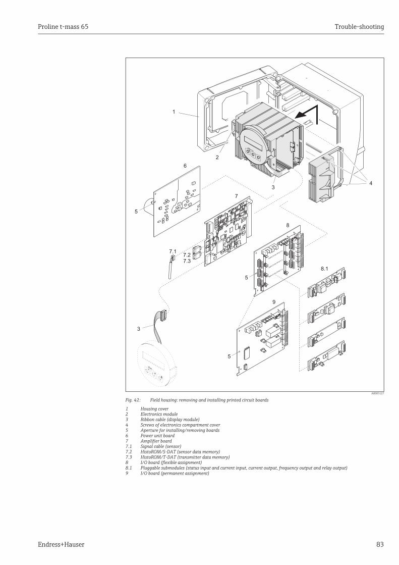
Proline t-mass 65 Trouble-shooting
Endress+Hauser 83
A0005127
Fig. 42: Field housing: removing and installing printed circuit boards
1 Housing cover2 Electronics module3 Ribbon cable (display module)4 Screws of electronics compartment cover5 Aperture for installing/removing boards6 Power unit board7 Amplifier board7.1 Signal cable (sensor)7.2 HistoROM/S-DAT (sensor data memory)7.3 HistoROM/T-DAT (transmitter data memory)8 I/O board (flexible assignment)8.1 Pluggable submodules (status input and current input, current output, frequency output and relay output)9 I/O board (permanent assignment)
34
1
2
6
7
8
8.1
9
5
7.1
7.37.2
INPUT/O
UTPUT2
INPUT/O
UTPUT3
INPUT/O
UTPUT4
5
5
3

Trouble-shooting Proline t-mass 65
84 Endress+Hauser
Electronics housing sensor remote version
# Warning! • Risk of damaging electronic components (ESD protection). Static electricity can damage
electronic components or impair their operability. Use a workplace with a grounded working surface purposely built for electrostatically sensitive devices!
• If you cannot guarantee that the dielectric strength of the measuring device can be maintained during the following steps, then an appropriate inspection test must be carried out in accordance with the manufacturer’s specifications.
• When connecting Ex-certified measuring devices, see the notes and diagrams in the Ex-specific supplement to these Operating Instructions. Please do not hesitate to contact your Endress+Hauser sales center if you have any questions.
" Caution! Use only original Endress+Hauser parts.
Removal and installation → 43:
1. Remove the safety screw (1) and remove the cover (2) from the electronics compartment.
2. Disconnect the sensor cable plug (3).
3. Disconnect the remote cable from the terminal block (4).
4. Remove the two screws (5) from the printed circuit board
5. Remove printed circuit board (6)
6. Installation is the reverse of the removal procedure.
A0005131
Fig. 43: Electronics compartment of the sensor housing remote version: removing and installing printed circuit board
Wire colors (when supplied by Endress+Hauser):Terminal no. 41 = white; 42 = brown; 43 = green; 44 = yellow
1
2
3
4
5
6
5
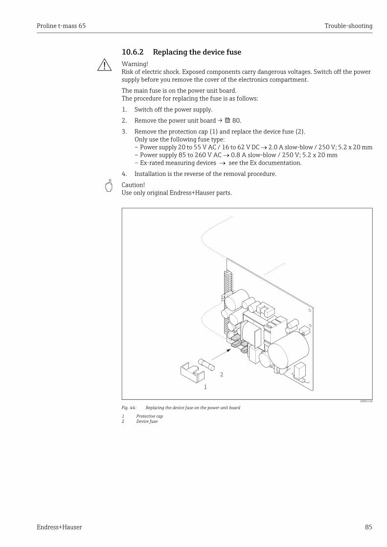
Proline t-mass 65 Trouble-shooting
Endress+Hauser 85
10.6.2 Replacing the device fuse
# Warning! Risk of electric shock. Exposed components carry dangerous voltages. Switch off the power supply before you remove the cover of the electronics compartment.
The main fuse is on the power unit board.The procedure for replacing the fuse is as follows:
1. Switch off the power supply.
2. Remove the power unit board → 80.
3. Remove the protection cap (1) and replace the device fuse (2).Only use the following fuse type:– Power supply 20 to 55 V AC / 16 to 62 V DC 2.0 A slow-blow / 250 V; 5.2 x 20 mm– Power supply 85 to 260 V AC 0.8 A slow-blow / 250 V; 5.2 x 20 mm– Ex-rated measuring devices see the Ex documentation.
4. Installation is the reverse of the removal procedure.
" Caution! Use only original Endress+Hauser parts.
A0001148
Fig. 44: Replacing the device fuse on the power unit board
1 Protective cap2 Device fuse
1
2
Trouble-shooting Proline t-mass 65
86 Endress+Hauser
10.7 Return
The measuring device must be returned if it is in need of repair or a factory calibration, or if the wrong measuring device has been delivered or ordered. According to legal regulations Endress+Hauser, as an ISO-certified company, is required to follow certain procedures when handling returned products that are in contact with the medium.To ensure swift, safe and professional device returns, please read the return procedures and conditions on the Endress+Hauser website at www.services.endress.com/return-material
10.8 Disposal
10.8.1 Disassembling the measuring device1. Switch off the device.
2. WARNING! Danger to persons from process conditions! Beware of hazardous process conditions such as pressure in the measuring device, high temperatures or aggressive fluids.
Carry out the mounting and connection procedure described in the "Mounting the measuring device" and "Connecting the measuring device" sections in the logically reverse order. Observe the safety instructions.
10.8.2 Disposing of the measuring device
# Warning! Hazardous fluids present a risk to humans and the environment!• Ensure that the measuring device and all cavities are free of fluid residues that are
hazardous to health or the environment, e.g. substances that have permeated into crevices or diffused through plastic.
Note the following when disposing of the device:• Observe applicable national regulations.• Separate and recycle the device components based on the materials.

Proline t-mass 65 Trouble-shooting
Endress+Hauser 87
10.9 Software history
! Note! Uploading or downloading a software version normally requires a special service software.
Date Software version Changes to software Documentation
10.2009
1.01.XX Software expansion:– second gas group in memory– gas heat flow and heat quantity– variable gas fraction input– revised diagnostics– Fieldcheck compatibility
New functionalities:– Quick Setups for gas, pressure, heat flow and
sensor– additional pressure units– system units for calorific value, heat flow and
quantity heat – process pressure for gas group 1 + 2– status input assignment for gas group– current input assignment for variable gas fraction– assignment of heat flow to display, totalizer and
outputs– totalizer units for quantity heat flow– assignment of gas groups to outputs and totalizer– on/off delay for relay outputs – selection special gas with correction factors and
reference density– insertion depth calculator– time stamping for process and system errors
71115126/06.10
11.2005
1.00.XX 71009069/12.05

Technical data Proline t-mass 65
88 Endress+Hauser
11 Technical data
11.1 Applications→ 5
11.2 Function and system design
Measuring principle Mass flow measurement by the thermal dispersion principle.
Measuring system The "t-mass 65" measuring device consists of the following components:• t-mass 65 transmitter• t-mass F, t-mass I sensor
Two versions are available:• Compact version: transmitter and sensor form a single mechanical unit.• Remote version: transmitter and sensor are installed separately.
11.3 Input
Measured variable • Mass flow• Gas temperature• Gas heat flow
Measuring range The measuring range is dependent upon:• Gas• Pressure• Temperature• Cross-sectional area of pipe or duct• Use of flow conditioner (t-mass F sensor)
Please refer to Applicator, the Endress+Hauser sizing and selection software, for calculation of the measuring range.
Special applications
High gas velocities (>70 m/s)In the event of high gas velocities, it is advisable to read in the process pressure dynamically or to enter the pressure very precisely as a velocity-dependent correction is performed.
Light gases
• Due to the very high thermal conductivity of hydrogen (H) (9 times that of air) and the fact that hydrogen is the lightest of all gases, it can prove very difficult to reliably measure this gas. Depending on the application, the flow rates of hydrogen are often particularly slow and the flow profiles are not sufficiently developed. It is not unusual for the flows to be in the laminar range, whereas a turbulent flow regime would be required for optimum measurement.
• Despite loss of accuracy and linearity in hydrogen applications with low flow rates, the t-mass 65 measures with good repeatability and is therefore suitable for monitoring flow conditions (e.g. leak detection).
• A linear, reliable measured value is difficult to obtain in applications with light gases with a Reynolds number below RE 4000. While this can be improved by making a special adjustment in the lower flow range, a loss of accuracy and linearity should be expected. It is advisable to contact your Endress+Hauser sales center if your application involves media with Reynolds numbers below RE 4000.

Proline t-mass 65 Technical data
Endress+Hauser 89
• When mounting, please note that the recommended upstream distances should be doubled for very light gases such as helium and hydrogen. → 15
Input signal Status input (auxiliary input)
U = 3 to 30 V DC, Ri = 5 k, galvanically isolated. Switch level ±3 to ±30 V DC.Configurable for: gas group, totalizer reset, positive zero return
11.4 Output
Output signal Current output
Active/passive selectable, galvanically isolated, time constant selectable (0.0 to 100.0 s), full scale value selectable, temperature coefficient: typically 0.005% o.r./°C, resolution: 0.5 μA• Active: 0/4 to 20 mA, RL < 700 (for HART: RL 250 )• Passive: 4 to 20 mA; supply voltage VS 18 to 30 V DC; Ri 150
Pulse / frequency output
Active/passive selectable, galvanically isolated
• Active: 24 V DC, 25 mA (max. 250 mA during 20 ms), RL 100 (flexible I/O boards only, see terminal assignment → 30)
• Passive: open collector, 30 V DC, 250 mA• Frequency output: full scale frequency 2 to 1000 Hz (fmax = 1250 Hz), on/off ratio 1:1,
pulse width max. 2 s, time constant selectable (0.0 to 100.0 s)• Pulse output: pulse value and pulse polarity selectable, pulse width adjustable
(0.5 to 2000 ms; factory setting = 20 ms)
Signal on alarm Current output:Failsafe mode selectable (for example, according to NAMUR recommendation NE 43)
Pulse/frequency output:Failsafe mode selectable
Status output:"Non-conductive" in the event of fault or power supply failure.
Relay output:"De-energized" in the event of fault or power supply failure
Current input:Failsafe mode selectable
Load See "Output signal"
Low flow cut off Switch points for low flow cut off are programmable.Factory settings = 1% of calibrated full scale value.
Galvanic isolation All circuits for inputs, outputs and power supply are galvanically isolated from each other.
Switching output Relay output: Normally closed (NC) or normally open (NO) contacts available (factory setting: relay 1 = NO, relay 2 = NC), max. 30 V / 0.5 A AC; 60 V / 0.1 A DC, galvanically isolated.Configurable for: error messages, limit valuesFactory setting: closed

Technical data Proline t-mass 65
90 Endress+Hauser
11.5 Power supply
Electrical connections → 28
Supply voltage 85 to 260 V AC, 45 to 65 Hz20 to 55 V AC, 45 to 65 Hz16 to 62 V DC
Power consumption • AC: 85 to 260 V = 18.2 VA; 20 to 55 V = 14 VA ; (including sensor)• DC: 8 W (including sensor)
Switch-on current:• Max. 8 A (<5 ms) at 24 V DC• Max. 4 A (<5 ms) at 260 V AC
Power supply failure Lasting min. 1 power cycle:• EEPROM/HistoROM/T-DAT saves measuring system data if the power supply fails.• HistoROM S-DAT is an exchangeable data storage chip with sensor specific data: (pipe
type, nominal diameter, serial number, flow conditioner, zero point, etc).• Totalizer stops at the last value determined
Potential equalization No measures necessary.For measuring devices in hazardous areas please refer to the additional Ex documentation.
Cable entry Power supply and signal cables (inputs/outputs):• Cable entry M20 × 1.5 (8 to 12 mm (0.31 to 0.47 in))• Threads for cable entries, ½" NPT, G ½"
Connecting cable for remote version:• Cable entry M20 × 1.5 (8 to 12 mm (0.31 to 0.47 in))• Threads for cable entries, ½" NPT, G ½"
Cable specifications (remote version)
→ 29
11.6 Performance characteristics
Reference conditions • Traceable to National Standards• Accredited according to ISO/IEC 17025• Air-controlled to 24 °C ± 0.5 °C (75.2 °F ± 0.9 °F) at atmospheric pressure• Humidity-controlled < 40% RH
Maximum measured error t-mass 65F and t-mass 65I±1.5 % of reading for 100 % to 10 % of range (at reference conditions)±0.15 % of full scale for 10 % to 1 % of range (at reference conditions)
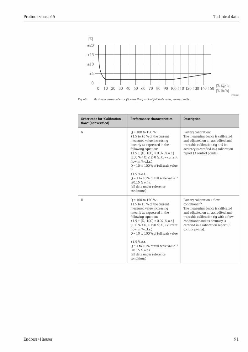
Proline t-mass 65 Technical data
Endress+Hauser 91
A0021682
Fig. 45: Maximum measured error (% mass flow) as % of full scale value, see next table
0 10[% kg/h]
±10
0
50 80
[%]
90 100
±5
±15
20 30 40 60 70
±20
110 120 130 140 150[% lb/h]
Order code for "Calibration flow" (not verified)
Performance characteristics Description
G Q = 100 to 150 %:±1.5 to ±5 % of the current measured value increasing linearly as expressed in the following equation:±1.5 ± (Xn-100) × 0.07[% o.r.](100 % < Xn ≤ 150 %; Xn = current flow in % o.f.s.)Q = 10 to 100 % of full scale value
±1.5 % o.r.Q = 1 to 10 % of full scale value
±0.15 % o.f.s. (all data under reference conditions)
Factory calibration:The measuring device is calibrated and adjusted on an accredited and traceable calibration rig and its accuracy is certified in a calibration report (3 control points).
H Q = 100 to 150 %:±1.5 to ±5 % of the current measured value increasing linearly as expressed in the following equation:±1.5 ± (Xn-100) × 0.07[% o.r.](100 % < Xn ≤ 150 %; Xn = current flow in % o.f.s.)Q = 10 to 100 % of full scale value
±1.5 % o.r.Q = 1 to 10 % of full scale value
±0.15 % o.f.s. (all data under reference conditions)
Factory calibration + flow conditioner:The measuring device is calibrated and adjusted on an accredited and traceable calibration rig with a flow conditioner and its accuracy is certified in a calibration report (3 control points).

Technical data Proline t-mass 65
92 Endress+Hauser
1. The full scale value depends on the nominal diameter of the device and the maximum flow capacity of the calibration rig. The full scale values are listed in the following section.
2. A flow conditioner is also supplied.
Repeatability ±0.5 % of reading for velocities above 1.0 m/s (0.3 ft/s)
Response time Typically less than 2 seconds for 63 % of a given step change (in either direction).
Influence of medium pressure(Pressure co-efficient)
Air: 0.35 % per bar (0.02% per psi) of process pressure change
11.7 InstallationInstallation section → 11
11.8 Environment
Ambient temperature range
Standard: –20 to +60 °C (–4 to +140 °F) Optional: –40 to +60 °C (–40 to +140 °F)
K Q = 100 to 150 %:±1.5 to ±5 % of the current measured value increasing linearly as expressed in the following equation:±1.5 ± (Xn-100) × 0.07[% o.r.](100 % < Xn ≤ 150 %; Xn = current flow in % o.f.s.)Q = 10 to 100 % of full scale value
±1.5 % o.r.Q = 1 to 10 % of full scale value
±0.15 % o.f.s. (all data under reference conditions)
5-point, traceable ISO/IEC17025:The measuring device is calibrated and adjusted on an accredited and traceable calibration rig and its accuracy is certified in a Swiss Calibration Services (SCS) calibration report (5 control points), which confirms traceability to the national calibration standard.
L Q = 100 to 150 %:±1.5 to ±5 % of the current measured value increasing linearly as expressed in the following equation:±1.5 ± (Xn-100) × 0.07[% o.r.](100 % < Xn ≤ 150 %; Xn = current flow in % o.f.s.)Q = 10 to 100 % of full scale value
±1.5 % o.r.Q = 1 to 10 % of full scale value
±0.15 % o.f.s. (all data under reference conditions)
5-point, traceable ISO/IEC17025 + flow conditioner:The measuring device is calibrated and adjusted on an accredited and traceable calibration rig with a flow conditioner and its accuracy is certified in a Swiss Calibration Services (SCS) calibration report (5 control points), which confirms traceability to the national calibration standard.
Order code for "Calibration flow" (not verified)
Performance characteristics Description

Proline t-mass 65 Technical data
Endress+Hauser 93
! Note! • Install the device in a shady location. Avoid direct sunlight, particularly in warm climatic
regions. (A protective sun cover is available on request)• At ambient temperatures below –20 °C (–4 °F) the readability of the display may be
impaired.
Storage temperature –40 to +80 °C (–40 to +176 °F), recommended +20 °C (+68 °F)
Degree of protection Standard: IP 67 (NEMA 4X) for transmitter and sensor
Shock resistance According to IEC 60068-2-31
Vibration resistance Acceleration up to 1 g, 10 to 150 Hz, following IEC 60068-2-6
Electromagnetic compatibility (EMC)
To IEC/EN 61326 and NAMUR recommendation NE 21
11.9 Process
Medium temperature range
Sensor
t-mass F:–40 to +100 °C (–40 to +212 °F)
t-mass I:–40 to +130 °C (–40 to +266 °F)
Seals t-mass F
O-rings:Viton FKM –20 to +100 °C (–4 to +212 °F)Kalrez –20 to +100 °C (–4 to +212 °F)EPDM –40 to +100 °C (–40 to +212 °F)
Bushing:PEEK –40 to +100 °C (–40 to +212 °F)
Seals t-mass I
Bonded seals:Kalrez –20 to +130 °C (–4 to +266 °F)EPDM –40 to +130 °C (–40 to +266 °F)Nitrile –35 to +130 °C (–31 to +266 °F)
Ferrule:PEEK, PVDF –40 to +130 °C (–40 to +266 °F)
NoteWe recommend special materials (Alloy and PVDF) for aggressive media (e.g. chlorine or ozone). Please contact your Endress+Hauser sales center for clarification.
Media The following media and media mixtures can be measured. A mixture can consist of up to 8 components from the following list.
AIRAMMONIAARGONBUTANECARBON DIOXIDECARBON MONOXIDECHLORINE
ETHANEETHYLENEHELIUM 4HYDROGEN NORMALHYDROGEN CHLORIDEHYDROGEN SULFIDEKRYPTON
METHANENEONNITROGENOXYGENPROPANEXENON

Technical data Proline t-mass 65
94 Endress+Hauser
NoteOther media (e.g. ozone) available on request. Contact your Endress+Hauser sales center for clarification.
Pressure-temperature ratings
! Note! An overview of the pressure-temperature ratings for the process connections is provided in the Technical Information
Flow limit See "Measuring range" section → 88.The velocity in the measuring tube should not exceed 130 m/s (427 ft/s), (in air).
Pressure loss Negligible (without flow conditioner).Refer to Applicator for the precise calculation → 70
Medium pressure range (nominal pressure)
t-mass F:–0.5 to 40 bar gauge (–7.25 to 580 psi gauge)
t-mass I:–0.5 to 20 bar gauge (–7.25 to 290 psi gauge)
Limiting medium pressure range (nominal pressure)
The material load diagrams (pressure-temperature ratings) for the process connections are provided in the separate "Technical Information" document for the particular measuring device. This can be downloaded as a PDF file at www.endress.com.A list of the "Technical Information" documents: → 99
Hot tap, process pressure The Hot tap for mounting and removal at process pressure may only be used with non-toxic, innocuous gases classified as "Group II" in accordance with European Directive 67/548/EEC Art. 2.
Medium pressure versionMax. process pressure: 20 barg (290 psig)Max. extraction press: 16 barg (230 psig)Max. extraction temperature: +50 °C (+122 °F)Min. sensor length: 435 mm (17 in)
Low pressure versionMax. process pressure: 20 barg (290 psig)Max. extraction press: 4.5 barg (65 psig)Max. extraction temperature: +50 °C (+122 °F)Min. sensor length: 335 mm (13 in)
Cold tap, atmospheric pressure
Cold tap for mounting and removal at atmospheric pressureMax. process pressure: 20 barg (290 psig)Max. extraction pressure: 1 bar(a) (14.5 psia)Max. extraction temperature: +50 °C (+122 °F)Min. sensor length: 335 mm (13 in)
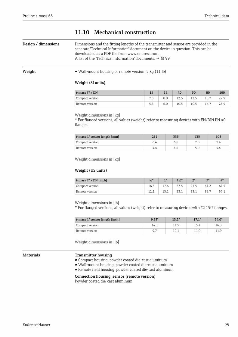
Proline t-mass 65 Technical data
Endress+Hauser 95
11.10 Mechanical construction
Design / dimensions Dimensions and the fitting lengths of the transmitter and sensor are provided in the separate "Technical Information" document on the device in question. This can be downloaded as a PDF file from www.endress.com.A list of the "Technical Information" documents: → 99
Weight • Wall-mount housing of remote version: 5 kg (11 lb)
Weight (SI units)
Weight dimensions in [kg]* For flanged versions, all values (weight) refer to measuring devices with EN/DIN PN 40 flanges.
Weight dimensions in [kg]
Weight (US units)
Weight dimensions in [lb]* For flanged versions, all values (weight) refer to measuring devices with "Cl 150" flanges.
Weight dimensions in [lb]
Materials Transmitter housing• Compact housing: powder coated die-cast aluminum• Wall-mount housing: powder coated die-cast aluminum• Remote field housing: powder coated die-cast aluminum
Connection housing, sensor (remote version)Powder coated die-cast aluminum
t-mass F* / DN 15 25 40 50 80 100
Compact version 7.5 8.0 12.5 12.5 18.7 27.9
Remote version 5.5 6.0 10.5 10.5 16.7 25.9
t-mass I / sensor length [mm] 235 335 435 608
Compact version 6.4 6.6 7.0 7.4
Remote version 4.4 4.6 5.0 5.4
t-mass F* / DN [inch] ½" 1" 1½" 2" 3" 4"
Compact version 16.5 17.6 27.5 27.5 41.2 61.5
Remote version 12.1 13.2 23.1 23.1 36.7 57.1
t-mass I / sensor length [inch] 9.25" 13.2" 17.1" 24.0"
Compact version 14.1 14.5 15.4 16.3
Remote version 9.7 10.1 11.0 11.9
Technical data Proline t-mass 65
96 Endress+Hauser
t-mass F sensor
Measuring tube:• In contact with medium:
- DN 15 to 25 (½ to 1"): stainless cast steel CF3M-A351- DN 40 to 100 (1 ½ to 4"): 1.4404 (316/316L)
• Not in contact with medium:- 1.4301 (304)
Flanges (process connections): Stainless steel 1.4404 (316L/316)
Transducer:• 1.4404 (316L)• Alloy C22, 2.4602 (N06022)
Transducer elements:• 1.4404 (316L) or• 1.4404 (316L)• Alloy C22, 2.4602 (N06022)
Bushing:PEEK GF30, PVDF
O-rings:EPDM, Kalrez 6375, Viton FKM
t-mass I sensor
Insertion tube:• Sensor length 235 (9"), 335 (13"), 435 (17"), 608 (24")• 1.4404 (316/316L)• Special lengths and full Alloy C22 versions on request
Transducer:• 1.4404 (316L)• Alloy C22, 2.4602 (N06022)
Protection guard:1.4404 (316L)
Compression fitting:1.4404 (316/316L)
Ferrule:PEEK 450G, PVDF (on request)
Bonded seals:EPDM, Kalrez 6375, Nitrile and 316/316L (outer ring)
Hot tap, process pressure
Lower tube section:1.4404 (316/316L)
Upper tube section:1.4404 (316/316L)
Ball valve:CF3M and CF8M
Seal:PTFE
Proline t-mass 65 Technical data
Endress+Hauser 97
Cold tap, atmospheric pressure
Lower tube section:1.4404 to EN 10272 and 316/316L to A479
Upper tube section:1.4404 to EN 10216-5 and 316/316L to A312
Ball valve:CF3M and CF8M
Seal:PTFE
Process connections For both the flanged and insertion meters it is possible to have wetted parts degreased for oxygen service. Further information is available from your Endress+Hauser sales center.
t-mass F:Flanges according EN 1092-1, JIS B2220 and ASME B16.5
t-mass I:G 1A or 1" MNPT thread
11.11 Operability
Display elements • Liquid crystal display: illuminated, two lines with 16 characters per line• Selectable display of different measured values and status variables• At ambient temperatures below –20 °C (–4 °F) the readability of the display may be
impaired.
Operating elements • Local operation with three keys (S, O, F)• Quick Setup menus for straight forward commissioning
Languages English, German, French, Spanish, Italian, Dutch, Norwegian, Finnish, Swedish, Portuguese, Polish, Czech
11.12 Certificates and approvals
CE mark The measuring system is in conformity with the statutory requirements of the applicable EC Directives. These are listed in the corresponding EC Declaration of Conformity along with the standards applied.Endress+Hauser confirms successful testing of the device by affixing to it the CE mark.
C-Tick mark The measuring system meets the EMC requirements of the Australian Communications and Media Authority (ACMA).
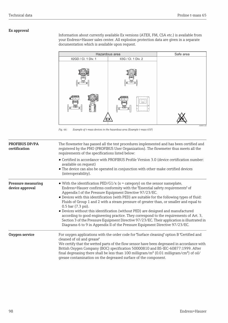
Technical data Proline t-mass 65
98 Endress+Hauser
Ex approvalInformation about currently available Ex versions (ATEX, FM, CSA etc.) is available from your Endress+Hauser sales center. All explosion protection data are given in a separate documentation which is available upon request.
A0005128
Fig. 46: Example of t-mass devices in the hazardous area (Example t-mass 65F)
PROFIBUS DP/PA certification
The flowmeter has passed all the test procedures implemented and has been certified and registered by the PNO (PROFIBUS User Organization). The flowmeter thus meets all the requirements of the specifications listed below:
• Certified in accordance with PROFIBUS Profile Version 3.0 (device certification number: available on request)
• The device can also be operated in conjunction with other-make certified devices (interoperability).
Pressure measuring device approval
• With the identification PED/G1/x (x = category) on the sensor nameplate, Endress+Hauser confirms conformity with the "Essential safety requirements" of Appendix I of the Pressure Equipment Directive 97/23/EC.
• Devices with this identification (with PED) are suitable for the following types of fluid:Fluids of Group 1 and 2 with a steam pressure of greater than, or smaller and equal to 0.5 bar (7.3 psi).
• Devices without this identification (without PED) are designed and manufactured according to good engineering practice. They correspond to the requirements of Art. 3, Section 3 of the Pressure Equipment Directive 97/23/EC. Their application is illustrated in Diagrams 6 to 9 in Appendix II of the Pressure Equipment Directive 97/23/EC.
Oxygen service For oxygen applications with the order code for "Surface cleaning" option B "Certified and cleaned of oil and grease"We certify that the wetted parts of the flow sensor have been degreased in accordance with British Oxygen Company (BOC) specification 50000810 and BS-IEC-60877:1999. After final degreasing there shall be less than 100 milligram/m² (0.01 milligram/cm²) of oil/grease contamination on the degreased surface of the component.
Nicht unter Spannungöffnen
Keep
cover
tightw
hile
circ
uits
are
aliv
e
Nepasouvrirl’appareil soustension
Keep
cove
rtightw
hile
circ
uits
are
aliv
e
Nicht unter Spannungöffnen
Keep
cover
tightw
hile
circ
uits
are
aliv
e
Nepasouvrirl’appareil soustension
Keep
cove
rtightw
hile
circ
uits
are
aliv
e
II2GD / Cl. 1 Div. 1 II3G / Cl. 1 Div. 2
Esc
E- +
EX EX
Hazardous area Safe area
Proline t-mass 65 Technical data
Endress+Hauser 99
Other standards and guidelines
• BS IEC 60877:1999Procedures for ensuring the cleanliness of industrial-process measurement and control equipment in oxygen service.
• EN 60529Degrees of protection by housing (IP code)
• EN 61010-1Safety requirements for electrical equipment for measurement, control and laboratory use.
• IEC/EN 61326 "Emission in accordance with requirements for Class A". Electromagnetic compatibility (EMC- requirements).
• EN 91/155/EECSafety Data Sheets Directive.
• ISO/IEC 17025General requirements for the competence of testing and calibration laboratories.
• ISO 14511Measurement of fluid flow in closed conduits - Thermal mass flowmeters.
• NAMUR NE 21Electromagnetic compatibility (EMC) of industrial process and laboratory control equipment.
• NAMUR NE 43Standardization of the signal level for the breakdown information of digital transmitters with analogue output signal.
• NAMUR NE 53Software of field devices and signal-processing devices with digital electronics
11.13 Ordering informationThe Endress +Hauser sales center can provide detailed ordering information and information on the extended order code.
11.14 AccessoriesVarious accessories, which can be ordered separately from Endress+Hauser, are available for the transmitter and the sensor → 69
11.15 Documentation‣ Technical Information t-mass 65F, 65I (TI00069D/06)
‣ Description of Device Functions t-mass 65 (BA00114D/06)
‣ Supplementary documentation on Ex-ratings: ATEX, FM, CSA, IECEx, NEPSI
‣ Flow measuring technology (FA00005D/06/)
Proline t-mass 65
100 Endress+Hauser
Index
AAccessories . . . . . . . . . . . . . . . . . . . . . . . . . . . . . . . . . . . . . 69Ambient temperature . . . . . . . . . . . . . . . . . . . . . . . . . . . . 92Applications . . . . . . . . . . . . . . . . . . . . . . . . . . . . . . . . . . . . . . 5Applicator (selection and sizing software). . . . . . . . . . . 70Approvals . . . . . . . . . . . . . . . . . . . . . . . . . . . . . . . . . . . 10, 97
CCable entry
Degree of protection . . . . . . . . . . . . . . . . . . . . . . . . . . 33Technical data . . . . . . . . . . . . . . . . . . . . . . . . . . . . . . . 90
Cable specification, connecting cable . . . . . . . . . . . . . . . 29Cable specifications (remote version) . . . . . . . . . . . . . . . 29Calibration
In-situ . . . . . . . . . . . . . . . . . . . . . . . . . . . . . . . . . . . . . . 68Reference conditions . . . . . . . . . . . . . . . . . . . . . . . . . . 90
CE mark. . . . . . . . . . . . . . . . . . . . . . . . . . . . . . . . . . . . . . . . 97CE mark (declaration of conformity). . . . . . . . . . . . . . . . 10Certificates . . . . . . . . . . . . . . . . . . . . . . . . . . . . . . . . . . 10, 97Certificates and approvals . . . . . . . . . . . . . . . . . . . . . . . . 10Cleaning
External cleaning . . . . . . . . . . . . . . . . . . . . . . . . . . . . . 67Pipe cleaning . . . . . . . . . . . . . . . . . . . . . . . . . . . . . . . . 67Transducer cleaning . . . . . . . . . . . . . . . . . . . . . . . . . . 67
Code entry (function matrix) . . . . . . . . . . . . . . . . . . . . . . 37Commissioning . . . . . . . . . . . . . . . . . . . . . . . . . . . . . . . . . 51
One current output . . . . . . . . . . . . . . . . . . . . . . . . . . . 61Two current outputs . . . . . . . . . . . . . . . . . . . . . . . . . . 62
Commubox FXA 191 (electrical connection) . . . . . . . . . 33Communication . . . . . . . . . . . . . . . . . . . . . . . . . . . . . . . . . 39Connecting the measuring unit . . . . . . . . . . . . . . . . . . . . 30Connecting the remote version . . . . . . . . . . . . . . . . . . . . 28Connection
See Electrical connectionC-Tick mark . . . . . . . . . . . . . . . . . . . . . . . . . . . . . . . . . 10, 97Current input
Configuration active/passive . . . . . . . . . . . . . . . . . . . 63Current output
Technical data . . . . . . . . . . . . . . . . . . . . . . . . . . . . . . . 89Current output, one
Configuration active/passive . . . . . . . . . . . . . . . . . . . 61Current outputs, two
Configuration active/passive . . . . . . . . . . . . . . . . . . . 62
DData back-up (of device data with T-DAT). . . . . . . . . . . 58Data storage device (HistoROM) . . . . . . . . . . . . . . . . . . . 66Declaration of conformity (CE mark) . . . . . . . . . . . . . . . 10Degree of protection . . . . . . . . . . . . . . . . . . . . . . . . . . 33, 93Designated use. . . . . . . . . . . . . . . . . . . . . . . . . . . . . . . . . . . . 5Device description files . . . . . . . . . . . . . . . . . . . . . . . . . . . 40Device designation. . . . . . . . . . . . . . . . . . . . . . . . . . . . . 7, 88Device functions
See "Description of Device Functions" manualDisplay
Turning the display . . . . . . . . . . . . . . . . . . . . . . . . . . . 24
Documentation . . . . . . . . . . . . . . . . . . . . . . . . . . . . . . . . . . 99
EElectrical connection
Cable specifications (remote version) . . . . . . . . . . . . . 29Commubox FXA 191. . . . . . . . . . . . . . . . . . . . . . . . . . . 33Degree of protection . . . . . . . . . . . . . . . . . . . . . . . . . . . 33HART handheld terminal . . . . . . . . . . . . . . . . . . . . . . . 32Remote version . . . . . . . . . . . . . . . . . . . . . . . . . . . . . . . 28
Error messagesConfirming error messages . . . . . . . . . . . . . . . . . . . . . 38System error (device error) . . . . . . . . . . . . . . . . . . . . . 72
Error response (inputs/outputs) . . . . . . . . . . . . . . . . . . . . 78Error types (system and process errors). . . . . . . . . . . . . . 38Ex approval . . . . . . . . . . . . . . . . . . . . . . . . . . . . . . . . . . . . . 98
FField Xpert SFX100 . . . . . . . . . . . . . . . . . . . . . . . . . . . 32, 39FieldCare . . . . . . . . . . . . . . . . . . . . . . . . . . . . . . . . . . . . . . . 39Fieldcheck (tester and simulator) . . . . . . . . . . . . . . . . . . . 70Flow conditioner . . . . . . . . . . . . . . . . . . . . . . . . . . . . . . . . . 16Function check. . . . . . . . . . . . . . . . . . . . . . . . . . . . . . . . . . . 50Function description
See "Description of Device Functions" manualFunction matrix
(Brief operating instructions) . . . . . . . . . . . . . . . . . . . 36Fuse, replacing. . . . . . . . . . . . . . . . . . . . . . . . . . . . . . . . . . . 85
GGalvanic isolation . . . . . . . . . . . . . . . . . . . . . . . . . . . . . . . . 89Gas analyzer. . . . . . . . . . . . . . . . . . . . . . . . . . . . . . . . . . . . . 60Gas mixture . . . . . . . . . . . . . . . . . . . . . . . . . . . . . . . . . . . . . . 5Gas pressure. . . . . . . . . . . . . . . . . . . . . . . . . . . . . . . . . . . . . 56Gas programming . . . . . . . . . . . . . . . . . . . . . . . . . . . . . . . . 54Gas properties . . . . . . . . . . . . . . . . . . . . . . . . . . . . . . . . . . . . 5
HHART
Command classes . . . . . . . . . . . . . . . . . . . . . . . . . . . . . 39Command No. . . . . . . . . . . . . . . . . . . . . . . . . . . . . . . . . 41Device status, error messages . . . . . . . . . . . . . . . . . . . 46Electrical connection . . . . . . . . . . . . . . . . . . . . . . . . . . . 32Error messages . . . . . . . . . . . . . . . . . . . . . . . . . . . . . . . 41Handheld terminal . . . . . . . . . . . . . . . . . . . . . . . . . . . . 39
HART connection . . . . . . . . . . . . . . . . . . . . . . . . . . . . . . . . 32Heat flow . . . . . . . . . . . . . . . . . . . . . . . . . . . . . . . . . . . . . . . 56Heat quantity . . . . . . . . . . . . . . . . . . . . . . . . . . . . . . . . . . . . 56HistoROM
S-DAT (sensor DAT) . . . . . . . . . . . . . . . . . . . . . . . . . . . 66T-DAT (transmitter DAT). . . . . . . . . . . . . . . . . . . . . . . 66
HOME position (operating mode). . . . . . . . . . . . . . . . . . . 35
IIdentification . . . . . . . . . . . . . . . . . . . . . . . . . . . . . . . . . . . . . 7Incoming acceptance. . . . . . . . . . . . . . . . . . . . . . . . . . . . . . 11Inlet and outlet runs . . . . . . . . . . . . . . . . . . . . . . . . . . . . . . 15Input signal . . . . . . . . . . . . . . . . . . . . . . . . . . . . . . . . . . . . . 89
Proline t-mass 65
Endress+Hauser 101
Insertion depth. . . . . . . . . . . . . . . . . . . . . . . . . . . . . . . . . . 19Insertion sensor
Insertion depth. . . . . . . . . . . . . . . . . . . . . . . . . . . . . . . 19Installation . . . . . . . . . . . . . . . . . . . . . . . . . . . . . . . . . . 19
Installation . . . . . . . . . . . . . . . . . . . . . . . . . . . . . . . . . . . . . 11Insertion sensor . . . . . . . . . . . . . . . . . . . . . . . . . . . . . . 19See Installation conditionsWelding boss . . . . . . . . . . . . . . . . . . . . . . . . . . . . . . . . 19
Installation conditions . . . . . . . . . . . . . . . . . . . . . . . . . . . 12Dimensions . . . . . . . . . . . . . . . . . . . . . . . . . . . . . . . . . . 12
Installation, commissioning and operation . . . . . . . . . . . . 5Installing the wall-mount transmitter housing . . . . . . . 25
LLanguages. . . . . . . . . . . . . . . . . . . . . . . . . . . . . . . . . . . . . . 97Limiting flow
See Measuring rangeLoad. . . . . . . . . . . . . . . . . . . . . . . . . . . . . . . . . . . . . . . . . . . 89Low flow cut off . . . . . . . . . . . . . . . . . . . . . . . . . . . . . . . . . 89Low pressure mounting set . . . . . . . . . . . . . . . . . . . . . . . 23
MMaintenance . . . . . . . . . . . . . . . . . . . . . . . . . . . . . . . . . . . 67Material . . . . . . . . . . . . . . . . . . . . . . . . . . . . . . . . . . . . . . . 95Materials. . . . . . . . . . . . . . . . . . . . . . . . . . . . . . . . . . . . . . . 95Maximum measured error . . . . . . . . . . . . . . . . . . . . . . . . 90Measured variable . . . . . . . . . . . . . . . . . . . . . . . . . . . . . . . 88Measuring principle . . . . . . . . . . . . . . . . . . . . . . . . . . . . . 88Measuring range . . . . . . . . . . . . . . . . . . . . . . . . . . . . . . . . 88Measuring system . . . . . . . . . . . . . . . . . . . . . . . . . . . . . 7, 88Medium pressure (Influence). . . . . . . . . . . . . . . . . . . . . . 92Medium pressure range . . . . . . . . . . . . . . . . . . . . . . . . . . 94Medium temperature range . . . . . . . . . . . . . . . . . . . . . . . 93
NNameplate
Connections . . . . . . . . . . . . . . . . . . . . . . . . . . . . . . . . . . . 9Sensor . . . . . . . . . . . . . . . . . . . . . . . . . . . . . . . . . . . . . . . . 8Transmitter. . . . . . . . . . . . . . . . . . . . . . . . . . . . . . . . . . . . 7
Net/gross calorific value . . . . . . . . . . . . . . . . . . . . . . . . . . 56
OOperating conditions. . . . . . . . . . . . . . . . . . . . . . . . . . . . . 92Operating options . . . . . . . . . . . . . . . . . . . . . . . . . . . . . . . 39Operation . . . . . . . . . . . . . . . . . . . . . . . . . . . . . . . . . . . . . . 35
Device description files . . . . . . . . . . . . . . . . . . . . . . . . 40Field Xpert HART handheld terminal . . . . . . . . . . . . 39FieldCare . . . . . . . . . . . . . . . . . . . . . . . . . . . . . . . . . . . . 39Function matrix . . . . . . . . . . . . . . . . . . . . . . . . . . . . . . 36
Operational safety . . . . . . . . . . . . . . . . . . . . . . . . . . . . . . . . . 6Order code
Accessories . . . . . . . . . . . . . . . . . . . . . . . . . . . . . . . . . . 69Sensor . . . . . . . . . . . . . . . . . . . . . . . . . . . . . . . . . . . . . . . . 9Transmitter. . . . . . . . . . . . . . . . . . . . . . . . . . . . . . . . . 7–8
Ordering information . . . . . . . . . . . . . . . . . . . . . . . . . . . . 99Orientation . . . . . . . . . . . . . . . . . . . . . . . . . . . . . . . . . . . . . 14Outlet runs with pressure measuring points . . . . . . . . . 16Output signal . . . . . . . . . . . . . . . . . . . . . . . . . . . . . . . . . . . 89Oxygen service . . . . . . . . . . . . . . . . . . . . . . . . . . . . . . . . . . 98
PPipe cleaning . . . . . . . . . . . . . . . . . . . . . . . . . . . . . . . . . . . . 67Pipework requirements . . . . . . . . . . . . . . . . . . . . . . . . . . . 13Post-connection check . . . . . . . . . . . . . . . . . . . . . . . . . . . . 34Post-installation check . . . . . . . . . . . . . . . . . . . . . . . . . . . . 27Post-installation check (checklist) . . . . . . . . . . . . . . . . . . 27Power consumption . . . . . . . . . . . . . . . . . . . . . . . . . . . . . . 90Power supply (supply voltage). . . . . . . . . . . . . . . . . . . . . . 90Power supply failure . . . . . . . . . . . . . . . . . . . . . . . . . . . . . . 90Pressure
Limiting medium pressure range . . . . . . . . . . . . . . . . 94Medium pressure (Influence). . . . . . . . . . . . . . . . . . . . 92Medium pressure range . . . . . . . . . . . . . . . . . . . . . . . . 94Process pressure . . . . . . . . . . . . . . . . . . . . . . . . . . . . . . 56Quick Setup . . . . . . . . . . . . . . . . . . . . . . . . . . . . . . . . . . 56System pressure. . . . . . . . . . . . . . . . . . . . . . . . . . . . . . . 12
Pressure co-efficient . . . . . . . . . . . . . . . . . . . . . . . . . . . . . . 92Pressure compensation input . . . . . . . . . . . . . . . . . . . . . . 59Pressure loss (formulas, pressure loss diagrams) . . . . . . 94Pressure measuring device approval. . . . . . . . . . . . . . . . . 98Pressure measuring points. . . . . . . . . . . . . . . . . . . . . . . . . 16Printed circuit boards (installation/removal)
Field housing . . . . . . . . . . . . . . . . . . . . . . . . . . . . . 80, 84Wall-mount housing. . . . . . . . . . . . . . . . . . . . . . . . . . . 82
Process errorDefinition . . . . . . . . . . . . . . . . . . . . . . . . . . . . . . . . . . . . 38
Process error messages . . . . . . . . . . . . . . . . . . . . . . . . . . . 76Process errors without messages . . . . . . . . . . . . . . . . . . . 76Process pressure, programming . . . . . . . . . . . . . . . . . . . . 56Product safety . . . . . . . . . . . . . . . . . . . . . . . . . . . . . . . . . . . . 6Programming mode
Enabling . . . . . . . . . . . . . . . . . . . . . . . . . . . . . . . . . 37–38Pulsating flow . . . . . . . . . . . . . . . . . . . . . . . . . . . . . . . . . . . 12
QQuick Setup
Commissioning . . . . . . . . . . . . . . . . . . . . . . . . . . . . . . . 51Gas programming . . . . . . . . . . . . . . . . . . . . . . . . . . . . . 54Heat flow . . . . . . . . . . . . . . . . . . . . . . . . . . . . . . . . . . . . 56Pressure . . . . . . . . . . . . . . . . . . . . . . . . . . . . . . . . . . . . . 56Sensor . . . . . . . . . . . . . . . . . . . . . . . . . . . . . . . . . . . . . . . 53
RRecalibration . . . . . . . . . . . . . . . . . . . . . . . . . . . . . . . . . . . . 68Registered trademarks . . . . . . . . . . . . . . . . . . . . . . . . . . . . 10Removal . . . . . . . . . . . . . . . . . . . . . . . . . . . . . . . . . . . . . . . . 23Repeatability . . . . . . . . . . . . . . . . . . . . . . . . . . . . . . . . . . . . 92Replacement
Printed circuit boards (installation/removal) 80, 82, 84Replacing
Seals . . . . . . . . . . . . . . . . . . . . . . . . . . . . . . . . . . . . . . . . 68Response of outputs to errors . . . . . . . . . . . . . . . . . . . . . . 78Response time . . . . . . . . . . . . . . . . . . . . . . . . . . . . . . . 88, 92
SSafety icons . . . . . . . . . . . . . . . . . . . . . . . . . . . . . . . . . . . . . . 6Safety instructions. . . . . . . . . . . . . . . . . . . . . . . . . . . . . . . . . 6S-DAT (sensor DAT) . . . . . . . . . . . . . . . . . . . . . . . . . . . . . . 66Seals

Proline t-mass 65
102 Endress+Hauser
Materials . . . . . . . . . . . . . . . . . . . . . . . . . . . . . . . . . . . . 95Medium temperature range . . . . . . . . . . . . . . . . . . . . 93Replacing, replacement seals . . . . . . . . . . . . . . . . . . . 68
Sensor heating . . . . . . . . . . . . . . . . . . . . . . . . . . . . . . . . . . 18Sensor installation
See Installation conditionsSensor setup . . . . . . . . . . . . . . . . . . . . . . . . . . . . . . . . . . . . 53Serial number . . . . . . . . . . . . . . . . . . . . . . . . . . . . . . . . . . 7–9Shock resistance . . . . . . . . . . . . . . . . . . . . . . . . . . . . . . . . . 93Signal on alarm . . . . . . . . . . . . . . . . . . . . . . . . . . . . . . . . . . 89Software
Amplifier display. . . . . . . . . . . . . . . . . . . . . . . . . . . . . . 50Versions (history) . . . . . . . . . . . . . . . . . . . . . . . . . . . . . 87
Spare parts. . . . . . . . . . . . . . . . . . . . . . . . . . . . . . . . . . . . . . 79Status input
Technical data . . . . . . . . . . . . . . . . . . . . . . . . . . . . . . . . 89Status output . . . . . . . . . . . . . . . . . . . . . . . . . . . . . . . . . . . . 89Storage . . . . . . . . . . . . . . . . . . . . . . . . . . . . . . . . . . . . . . . . . 11Storage temperature. . . . . . . . . . . . . . . . . . . . . . . . . . . . . . 93Supplementary Ex documentation . . . . . . . . . . . . . . . . . . . 6Supply voltage (power supply) . . . . . . . . . . . . . . . . . . . . . 90Switching on the measuring device . . . . . . . . . . . . . . . . . 50Switching output. . . . . . . . . . . . . . . . . . . . . . . . . . . . . . . . . 89System error
Definition . . . . . . . . . . . . . . . . . . . . . . . . . . . . . . . . . . . . 38System error messages. . . . . . . . . . . . . . . . . . . . . . . . . . . . 72System pressure . . . . . . . . . . . . . . . . . . . . . . . . . . . . . 12, 94
TT-DAT (HistoROM)
Save/load (data back-up, e.g. for replacing devices) 58T-DAT (transmitter DAT) . . . . . . . . . . . . . . . . . . . . . . . . . 66Technical data . . . . . . . . . . . . . . . . . . . . . . . . . . . . . . . . . . . 88Temperature range
Ambient temperature range . . . . . . . . . . . . . . . . . . . . 92Environment . . . . . . . . . . . . . . . . . . . . . . . . . . . . . . . . . 92Medium . . . . . . . . . . . . . . . . . . . . . . . . . . . . . . . . . . . . . 93Medium temperature range . . . . . . . . . . . . . . . . . . . . 93Storage . . . . . . . . . . . . . . . . . . . . . . . . . . . . . . . . . . . . . . 93Storage temperature. . . . . . . . . . . . . . . . . . . . . . . . . . . 93
Terminal assignment . . . . . . . . . . . . . . . . . . . . . . . . . . . . . 30Thermal insulation . . . . . . . . . . . . . . . . . . . . . . . . . . . . . . . 18Transducer cleaning . . . . . . . . . . . . . . . . . . . . . . . . . . . . . . 67Transmitter
Electrical connection. . . . . . . . . . . . . . . . . . . . . . . . . . . 31Installing the wall-mount transmitter housing. . . . . 25Turning the field housing (aluminum). . . . . . . . . . . . 24
Transmitter connection . . . . . . . . . . . . . . . . . . . . . . . . . . . 31Transport . . . . . . . . . . . . . . . . . . . . . . . . . . . . . . . . . . . . . . . 11Transporting the sensor. . . . . . . . . . . . . . . . . . . . . . . . . . . 11Trouble-shooting . . . . . . . . . . . . . . . . . . . . . . . . . . . . . . . . 71Trouble-shooting and remedy. . . . . . . . . . . . . . . . . . . . . . 71Trouble-shooting instructions. . . . . . . . . . . . . . . . . . . . . . 71Turning the local display . . . . . . . . . . . . . . . . . . . . . . . . . . 24Turning the transmitter housing . . . . . . . . . . . . . . . . . . . 24
UUniversal / Common practice HART commands. . . . . . . 41
VVibration resistance . . . . . . . . . . . . . . . . . . . . . . . . . . . . . . 93
See "Vibration resistance"Vibrations. . . . . . . . . . . . . . . . . . . . . . . . . . . . . . . . . . . 18, 93
WWall-mount housing, installing . . . . . . . . . . . . . . . . . . . . 25Weight . . . . . . . . . . . . . . . . . . . . . . . . . . . . . . . . . . . . . . . . . 95Welding boss . . . . . . . . . . . . . . . . . . . . . . . . . . . . . . . . . . . . 19Wiring. . . . . . . . . . . . . . . . . . . . . . . . . . . . . . . . . . . . . . . . . . 28
ZZero point adjustment . . . . . . . . . . . . . . . . . . . . . . . . 65–66

www.addresses.endress.com
Related Documents


