Betavoltaic device in por-SiC/Si C-Nuclear Energy Converter Alina Akimchenko 1, , Victor Chepurnov 1, , Mikhail Dolgopolov 1,2, , Albina Gurskaya 1, , Oleg Kuznetsov 1, † , Alikhan Mashnin 3, ‡ , Vitaliy Radenko 4, § , Alexander Radenko 4, ¶ , and Oleg Surnin 5, ‖ & George Zanin 6, ** 1 Samara University, Academician Pavlov 1, 443011 Samara, Russia 2 STP «Aviatechnocon», Moscow highway 34, 3b, 443086 Samara, Russia 3 Scientific production Association information technologies LlC, 142620 Moscow region, Russia 4 MEC Quasar Ltd., Mechnikova 3, 443030 Samara, Russia 5 LLC open {code;}, Samara, Russia 6 BetaVoltaics LLC., Samara, Russia Abstract. The miniature and low-power devices with long service life in hard operating conditions like the Carbon-14 beta-decay energy converters indeed as eternal resource for integrated MEMS and NEMS are considered. Authors discuss how to create the power supply for MEMS/NEMS devices, based on porous SiC/Si structure, which are tested to be used as the beta-decay energy converters of radioactive C-14 into electrical energy. This is based on the silicon carbide obtaining by self-organizing mono 3C-SiC endotaxy on the Si substrate. The new idea is the C-14 atoms including in molecules in the silicon carbide porous structure by this technology, which will increase the efficiency of the converter due to the greater intensity of electron-hole pairs generation rate in the space charge region. The synthesis of C-14 can be also performed by using the electronically controlled magneto-optic chamber. 1 Introduction The development of energy-saving technologies, the functioning of the MEMS devices, the reliability of their operation for a long time in offline conditions led to the search of appropriate means of generating energy for them. Especially in the trends of microelectronics on the benchmark 30 micron size active microprocessor board that hosts all the necessary devices. e-mail: [email protected] e-mail: [email protected] e-mail: [email protected] e-mail: [email protected] † e-mail: [email protected] ‡ e-mail: [email protected] § e-mail: [email protected] ¶ e-mail: [email protected] ‖ e-mail: [email protected] ** e-mail: [email protected] © The Authors, published by EDP Sciences. This is an open access article distributed under the terms of the Creative Commons Attribution License 4.0 (http://creativecommons.org/licenses/by/4.0/). EPJ Web of Conferences 158, 06004 (2017) DOI: 10.1051/epjconf/201715806004 QFTHEP 2017

Welcome message from author
This document is posted to help you gain knowledge. Please leave a comment to let me know what you think about it! Share it to your friends and learn new things together.
Transcript

Betavoltaic device in por-SiC/Si
C-Nuclear Energy Converter
Alina Akimchenko1,�, Victor Chepurnov1,��, Mikhail Dolgopolov1,2,���, Albina Gurskaya1,����,Oleg Kuznetsov1,†, Alikhan Mashnin3,‡, Vitaliy Radenko4,§, Alexander Radenko4,¶, andOleg Surnin5,‖ & George Zanin6,∗∗
1Samara University, Academician Pavlov 1, 443011 Samara, Russia2STP «Aviatechnocon», Moscow highway 34, 3b, 443086 Samara, Russia3Scientific production Association information technologies LlC, 142620 Moscow region, Russia4MEC Quasar Ltd., Mechnikova 3, 443030 Samara, Russia5LLC open {code;}, Samara, Russia6BetaVoltaics LLC., Samara, Russia
Abstract. The miniature and low-power devices with long service life in hard operatingconditions like the Carbon-14 beta-decay energy converters indeed as eternal resource forintegrated MEMS and NEMS are considered. Authors discuss how to create the powersupply for MEMS/NEMS devices, based on porous SiC/Si structure, which are testedto be used as the beta-decay energy converters of radioactive C-14 into electrical energy.This is based on the silicon carbide obtaining by self-organizing mono 3C-SiC endotaxyon the Si substrate. The new idea is the C-14 atoms including in molecules in the siliconcarbide porous structure by this technology, which will increase the efficiency of theconverter due to the greater intensity of electron-hole pairs generation rate in the spacecharge region. The synthesis of C-14 can be also performed by using the electronicallycontrolled magneto-optic chamber.
1 Introduction
The development of energy-saving technologies, the functioning of the MEMS devices, the reliabilityof their operation for a long time in offline conditions led to the search of appropriate means ofgenerating energy for them. Especially in the trends of microelectronics on the benchmark 30 micronsize active microprocessor board that hosts all the necessary devices.
�e-mail: [email protected]��e-mail: [email protected]���e-mail: [email protected]����e-mail: [email protected]
†e-mail: [email protected]‡e-mail: [email protected]§e-mail: [email protected]¶e-mail: [email protected]‖e-mail: [email protected]∗∗e-mail: [email protected]
© The Authors, published by EDP Sciences. This is an open access article distributed under the terms of the Creative Commons Attribution License 4.0 (http://creativecommons.org/licenses/by/4.0/).
EPJ Web of Conferences 158, 06004 (2017) DOI: 10.1051/epjconf/201715806004QFTHEP 2017

Betavoltaic devices, also known as betavoltaic cells, are generators of electric current, in effect isthe form of battery, which uses the energy from radionuclides emitting beta particles (electrons) [1].A common source used is the hydrogen isotope, tritium, or Nickel-63.
From history it is well known that nuclear battery technology began in 1913, when Henry Moseleyfirst demonstrated the beta cell [2]. And today the global market for active medical implants in 2016amounted to 24.8 billions US dollars, and the capacity of the potential market of batteries in 2020is estimated at $ 40 billions. The annual demand of Russian patients in pacemakers is about 60thousands [3–5].
In this paper authors will discuss how to create the power source for MEMS/NEMS devices basedon por-SiC/Si porous structure, which is tested to be used as the beta-decay energy converter ofradioactive Carbon-14 into electrical energy [6–9]. This involves silicon carbide obtaining by self-organizing mono 3C-SiC endotaxy way on the Si substrate [10, 11]. The key interest in the presentaspect has the systematic optimization of main parameters that affect the operational efficiency of thebetavoltaic current source [12].
Energy converters of beta radiation are based on isotopes transformations reactions with half-livesof more than 100 years. Energy converters are designed to secure operational performance, allowingreinstallation on the objects with the corresponding lifetime. Analogues were brought out to thelaboratory samples level for two years. The groundwork of this project is on the part of semiconductortechnology: mastered growing por-SiC/Si heterostructures. The groundwork for the development ofan energy source not specified. But there is information of methods and businesses with similaractivities [12–17]. The use of the product will effectively solve the following problems: the provisionof energy for autonomous systems and devices, MEMS devices, sensors in oil capital constructions asexample, information systems systems, including biosensors of medical direction and equipment.
1.1 Betavoltaics power source for pacemaker
There are a number of ways to use betavoltaics power sources in heart pacemakers [5]. The firstway is to replace the lithium-ion battery in the pacemaker to betavoltaic source. The advantage ofthis method is compact because betavoltaic source is small in size and easy to fit into the pacemakerwithout changing the design. However, this method has some difficulties: modern betavoltaic sourcescan not provide sufficient power and stable DC current for simultaneous charging of the capacitor andthe power drive circuit of the pacemaker.
The second method is the simultaneous use of a lithium-ion battery and betavoltaic source. Li-ion battery will power the control circuit and to charge the capacitors in the pulse generator, andbetavoltaic source will be connected to the lithium-ion battery through the charge controller, and shallprovide drip recharging the battery. Drip – charging a small current to compensate for self-dischargeor discharging at low external load. Typically, this method of charging is used for lead-acid batteriesto extend their lifespan, but can be used for lithium-ion batteries also. Because lithium-ion batteriesare sensitive to overcharging, you need to implement drip charging through the charge controller. Thepacemaker is a constant drip rechargeable lithium-ion battery will greatly increase its life cycle. Theadvantage of this method is the lack of necessary changes in the design of the pacemaker - you onlyneed to slightly increase the body to fit two batteries and a charge controller. The downside is theincrease in the size of a pacemaker, which may complicate implantation. However, given the sizebetavoltaic power supplies and charge controller, increasing the hull will be negligible. It is onlynecessary to make a small charge controller.
2
EPJ Web of Conferences 158, 06004 (2017) DOI: 10.1051/epjconf/201715806004QFTHEP 2017
Betavoltaic devices, also known as betavoltaic cells, are generators of electric current, in effect isthe form of battery, which uses the energy from radionuclides emitting beta particles (electrons) [1].A common source used is the hydrogen isotope, tritium, or Nickel-63.
From history it is well known that nuclear battery technology began in 1913, when Henry Moseleyfirst demonstrated the beta cell [2]. And today the global market for active medical implants in 2016amounted to 24.8 billions US dollars, and the capacity of the potential market of batteries in 2020is estimated at $ 40 billions. The annual demand of Russian patients in pacemakers is about 60thousands [3–5].
In this paper authors will discuss how to create the power source for MEMS/NEMS devices basedon por-SiC/Si porous structure, which is tested to be used as the beta-decay energy converter ofradioactive Carbon-14 into electrical energy [6–9]. This involves silicon carbide obtaining by self-organizing mono 3C-SiC endotaxy way on the Si substrate [10, 11]. The key interest in the presentaspect has the systematic optimization of main parameters that affect the operational efficiency of thebetavoltaic current source [12].
Energy converters of beta radiation are based on isotopes transformations reactions with half-livesof more than 100 years. Energy converters are designed to secure operational performance, allowingreinstallation on the objects with the corresponding lifetime. Analogues were brought out to thelaboratory samples level for two years. The groundwork of this project is on the part of semiconductortechnology: mastered growing por-SiC/Si heterostructures. The groundwork for the development ofan energy source not specified. But there is information of methods and businesses with similaractivities [12–17]. The use of the product will effectively solve the following problems: the provisionof energy for autonomous systems and devices, MEMS devices, sensors in oil capital constructions asexample, information systems systems, including biosensors of medical direction and equipment.
1.1 Betavoltaics power source for pacemaker
There are a number of ways to use betavoltaics power sources in heart pacemakers [5]. The firstway is to replace the lithium-ion battery in the pacemaker to betavoltaic source. The advantage ofthis method is compact because betavoltaic source is small in size and easy to fit into the pacemakerwithout changing the design. However, this method has some difficulties: modern betavoltaic sourcescan not provide sufficient power and stable DC current for simultaneous charging of the capacitor andthe power drive circuit of the pacemaker.
The second method is the simultaneous use of a lithium-ion battery and betavoltaic source. Li-ion battery will power the control circuit and to charge the capacitors in the pulse generator, andbetavoltaic source will be connected to the lithium-ion battery through the charge controller, and shallprovide drip recharging the battery. Drip – charging a small current to compensate for self-dischargeor discharging at low external load. Typically, this method of charging is used for lead-acid batteriesto extend their lifespan, but can be used for lithium-ion batteries also. Because lithium-ion batteriesare sensitive to overcharging, you need to implement drip charging through the charge controller. Thepacemaker is a constant drip rechargeable lithium-ion battery will greatly increase its life cycle. Theadvantage of this method is the lack of necessary changes in the design of the pacemaker - you onlyneed to slightly increase the body to fit two batteries and a charge controller. The downside is theincrease in the size of a pacemaker, which may complicate implantation. However, given the sizebetavoltaic power supplies and charge controller, increasing the hull will be negligible. It is onlynecessary to make a small charge controller.
2 Model of the semiconductor betavoltaic Energy Converter device
Unlike most nuclear power sources, which use nuclear radiation to generate heat, which then is used togenerate electricity (thermoelectric and thermionic sources), betavoltaics uses the non-thermal conver-sion process, converting electron-hole pairs produced by the ionization trail of beta particles traversingthe semiconductor [12, 13, 18].
There are two competitive directions of the betavoltaic converters development: the accumula-tion of charges in the reactions of transformation of elements using supercapacitors; the charge sep-aration in p-n junction of the solar battery analogue [13]; the combination of the two directions.In all cases, the main competitive advantage over other energy sources is the long life cycle of beta-converter. The disadvantage is due to low capacity and low efficiency, which is overcome technologi-cal way (the higher degree of enrichment of isotope using the developed nanoporous surfaces, reduc-ing the leakage current of super capacitor and p-n junction, using a combination of several sourcesof beta-radiation flux; the system microcontroller, which controls the flow of the charge). The ratio’price/performance’ is determined by several factors: semiconductors heterostructures provide a pricelevel conventional semiconductor discrete diodes or transistors, high power, the technology of nuclearfusion, the working fluid used in the operation of medical devices provide a level of price acceptableto the consumer, when there is no alternative. Planning design parameters and performances are fol-lowing: Voltage range ∼ 2 mV, Size of the device ∼ 10 × 10 × 0.3 ÷ 0.5 mm, Mass of each structuralelement ≈ 0.17 g, Working current range 0.1 µA, Working temperature range −50 ÷ 3500C.
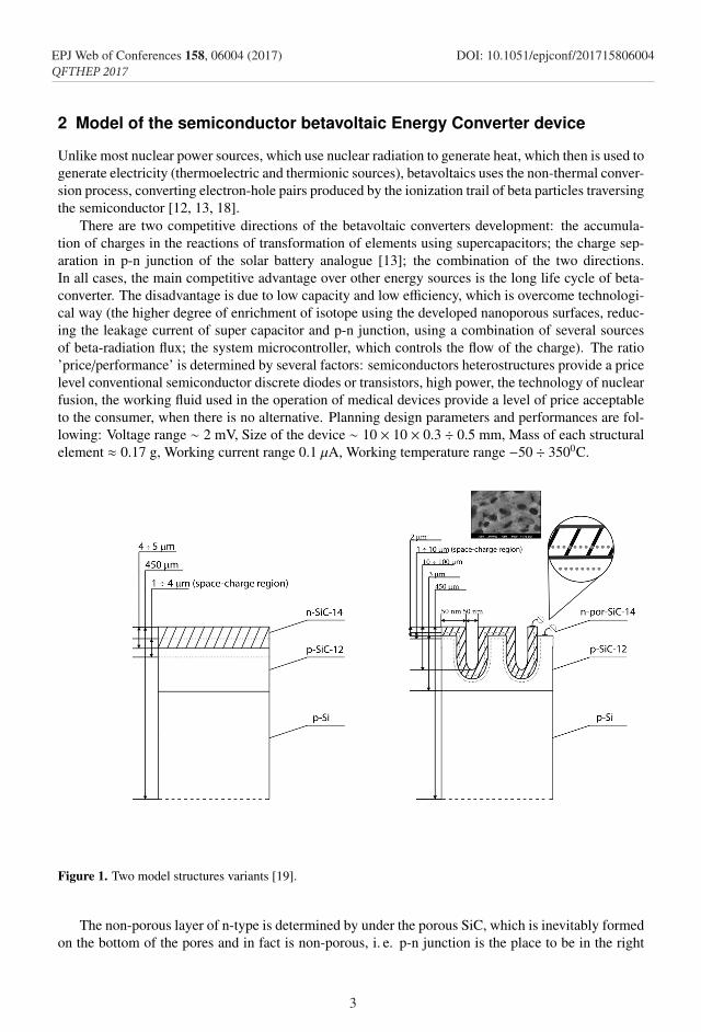
Figure 1. Two model structures variants [19].
The non-porous layer of n-type is determined by under the porous SiC, which is inevitably formedon the bottom of the pores and in fact is non-porous, i. e. p-n junction is the place to be in the right
3
EPJ Web of Conferences 158, 06004 (2017) DOI: 10.1051/epjconf/201715806004QFTHEP 2017
picture in Fig. 1 is still not in the porous layer. and indirectly associated with it and the space-chargeregion (SCR), between non-porous layers.
3 Carbon-14 choice of as the fuel
The data yield a conclusion on the promise of a new betavoltaic power supply source, namely, the nu-clear battery based on Carbon-14, as the active substance would be more useful and less expen-sive [20]. Additional advantages of such power supply sources can be obtained in a silicon carbidestructure based on the technology we developed [19]. Below let us consider the following compari-son [20] with a technology that uses Nickel-63.
1. The production of C-14 in the dense ion plasma flow is much cheaper than the production ofNi-63 in Nickel target, due to the low cost of N-14.
2. Ion-plasma implantation C-14 on SiC substrate allows to reduce the crystal process and realizewide production on semiconductor converters on C-14.
3. At the same time, the production of Ni-63 by this technology is also possible, and the costwill be much reduced compared to traditional methods. Because of the greater mass of the ions, theequipment for ion-plasma sputtering with a seal of the flow of Nickel ions will be several times moreexpensive because of increased working installation area. At this stage, it is more sophisticated toproduce C-14.
4. Specific activity of C-14 is different from the Ni-63 about in 10 times per unit volume, due tothe huge difference in half-life times.
5. Self-absorption of Ni-63 is larger by approximately three times, which leads to the maximumlimit optimal thickness of the layer to 4 microns, and for C-14 this thickness may be up to 60 micronswhich is better suited. The total quantity of the isotope C-14 may be an order of magnitude greater,therefore, guaranteed more power for the same size of power converters.
6. The specific power of Ni-63 per gram of the substance 5 times (due to more activity) exceedsthe power density of C -14. But the maximum and average energies of electrons in the C-14 decay isin 2, and even 3, times more than in the Ni-63 decay.
7. The production cost of 12 mg C-14 will take approximately 8 hours, taking into account equip-ment depreciation, will cost about 170$.
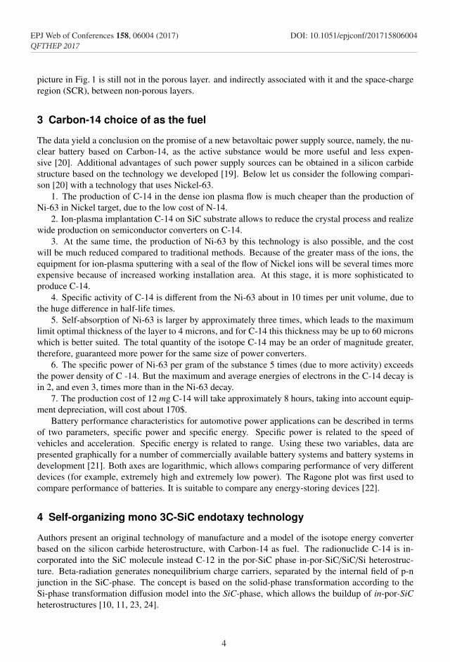
Battery performance characteristics for automotive power applications can be described in termsof two parameters, specific power and specific energy. Specific power is related to the speed ofvehicles and acceleration. Specific energy is related to range. Using these two variables, data arepresented graphically for a number of commercially available battery systems and battery systems indevelopment [21]. Both axes are logarithmic, which allows comparing performance of very differentdevices (for example, extremely high and extremely low power). The Ragone plot was first used tocompare performance of batteries. It is suitable to compare any energy-storing devices [22].
4 Self-organizing mono 3C-SiC endotaxy technology
Authors present an original technology of manufacture and a model of the isotope energy converterbased on the silicon carbide heterostructure, with Carbon-14 as fuel. The radionuclide C-14 is in-corporated into the SiC molecule instead C-12 in the por-SiC phase in-por-SiC/SiC/Si heterostruc-ture. Beta-radiation generates nonequilibrium charge carriers, separated by the internal field of p-njunction in the SiC-phase. The concept is based on the solid-phase transformation according to theSi-phase transformation diffusion model into the SiC-phase, which allows the buildup of in-por-SiCheterostructures [10, 11, 23, 24].
4
EPJ Web of Conferences 158, 06004 (2017) DOI: 10.1051/epjconf/201715806004QFTHEP 2017
picture in Fig. 1 is still not in the porous layer. and indirectly associated with it and the space-chargeregion (SCR), between non-porous layers.
3 Carbon-14 choice of as the fuel
The data yield a conclusion on the promise of a new betavoltaic power supply source, namely, the nu-clear battery based on Carbon-14, as the active substance would be more useful and less expen-sive [20]. Additional advantages of such power supply sources can be obtained in a silicon carbidestructure based on the technology we developed [19]. Below let us consider the following compari-son [20] with a technology that uses Nickel-63.
1. The production of C-14 in the dense ion plasma flow is much cheaper than the production ofNi-63 in Nickel target, due to the low cost of N-14.
2. Ion-plasma implantation C-14 on SiC substrate allows to reduce the crystal process and realizewide production on semiconductor converters on C-14.
3. At the same time, the production of Ni-63 by this technology is also possible, and the costwill be much reduced compared to traditional methods. Because of the greater mass of the ions, theequipment for ion-plasma sputtering with a seal of the flow of Nickel ions will be several times moreexpensive because of increased working installation area. At this stage, it is more sophisticated toproduce C-14.
4. Specific activity of C-14 is different from the Ni-63 about in 10 times per unit volume, due tothe huge difference in half-life times.
5. Self-absorption of Ni-63 is larger by approximately three times, which leads to the maximumlimit optimal thickness of the layer to 4 microns, and for C-14 this thickness may be up to 60 micronswhich is better suited. The total quantity of the isotope C-14 may be an order of magnitude greater,therefore, guaranteed more power for the same size of power converters.
6. The specific power of Ni-63 per gram of the substance 5 times (due to more activity) exceedsthe power density of C -14. But the maximum and average energies of electrons in the C-14 decay isin 2, and even 3, times more than in the Ni-63 decay.
7. The production cost of 12 mg C-14 will take approximately 8 hours, taking into account equip-ment depreciation, will cost about 170$.
Battery performance characteristics for automotive power applications can be described in termsof two parameters, specific power and specific energy. Specific power is related to the speed ofvehicles and acceleration. Specific energy is related to range. Using these two variables, data arepresented graphically for a number of commercially available battery systems and battery systems indevelopment [21]. Both axes are logarithmic, which allows comparing performance of very differentdevices (for example, extremely high and extremely low power). The Ragone plot was first used tocompare performance of batteries. It is suitable to compare any energy-storing devices [22].
4 Self-organizing mono 3C-SiC endotaxy technology
Authors present an original technology of manufacture and a model of the isotope energy converterbased on the silicon carbide heterostructure, with Carbon-14 as fuel. The radionuclide C-14 is in-corporated into the SiC molecule instead C-12 in the por-SiC phase in-por-SiC/SiC/Si heterostruc-ture. Beta-radiation generates nonequilibrium charge carriers, separated by the internal field of p-njunction in the SiC-phase. The concept is based on the solid-phase transformation according to theSi-phase transformation diffusion model into the SiC-phase, which allows the buildup of in-por-SiCheterostructures [10, 11, 23, 24].
Figure 2. Ragone Diagram.
This is also possible to achieve by ion implantation of Carbon-14 into the silicon carbidephase [25–27]. The latter approach to the direct conversion can increase the effectiveness of beta-voltaic energy converters.
To analyze concentration of Carbon atoms in SiC heterostructure, SIMS method was used.We provide one example (for the left picture case in Fig.1) to illustrate the generation of in SiC/Siheterostructure phase [28].
The method of secondary ion mass spectrometry (SIMS) [29–31] is used to analyze the com-position of solid surfaces and thin substrates. The essence of the method is to irradiate the samplesurface by a focused beam of ions (primary ions). When hitting the sample, the primary ions undergomultiple collisions, which are emitted from the sample atoms and clusters of atoms in the processof collisions, the latter spontaneously ionized (forming secondary ions). These secondary ions arecollected in the secondary beam and analyzed.
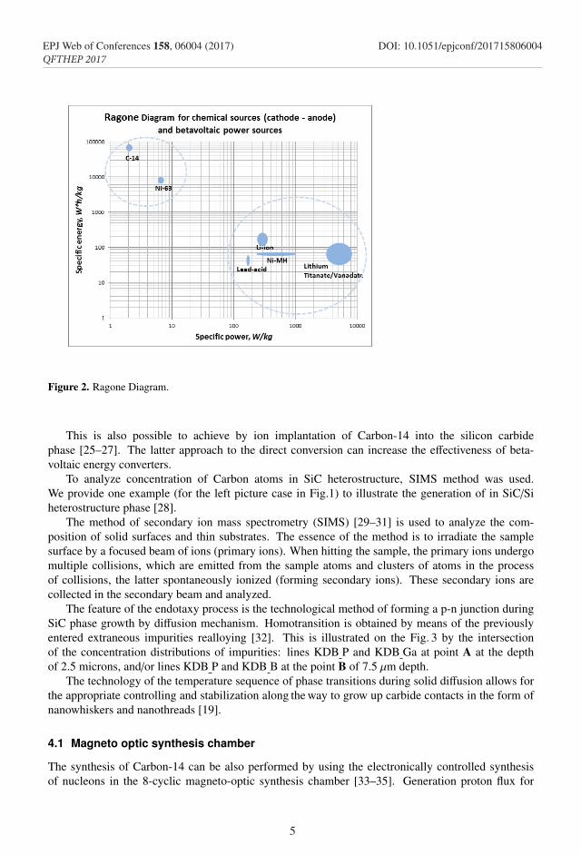
The feature of the endotaxy process is the technological method of forming a p-n junction duringSiC phase growth by diffusion mechanism. Homotransition is obtained by means of the previouslyentered extraneous impurities realloying [32]. This is illustrated on the Fig. 3 by the intersectionof the concentration distributions of impurities: lines KDB P and KDB Ga at point A at the depthof 2.5 microns, and/or lines KDB P and KDB B at the point B of 7.5 µm depth.
The technology of the temperature sequence of phase transitions during solid diffusion allows forthe appropriate controlling and stabilization along the way to grow up carbide contacts in the form ofnanowhiskers and nanothreads [19].
4.1 Magneto optic synthesis chamber
The synthesis of Carbon-14 can be also performed by using the electronically controlled synthesisof nucleons in the 8-cyclic magneto-optic synthesis chamber [33–35]. Generation proton flux for
5
EPJ Web of Conferences 158, 06004 (2017) DOI: 10.1051/epjconf/201715806004QFTHEP 2017
Figure 3. Diagram of concentrations dependencies on depth. The analyzed depth ranges from 5.3 × 10⁻⁸ to24.3 × 10−6 m. The concentration of C-12 atoms (KDB C curve), depending on the analyzed depth, ranges from8.4 × 1019 to 3.2 × 10¹⁶ [20, 28].
the synthesis of neutrons by lithium ion target as a result of compaction of the primary flux of protonsand sampling of parameters specify the density and average energy of the flow. Electronically con-trollable streams are formed in parameters repetition period Tsl and frequency discrete streams ωsl.Generation dense proton flux for the synthesis of neutrons by lithium ion targets:
D + Li6 → Be7 + n0, D + Li7 → 2He4 + n0. (1)
The synthesis reaction at the target dense nitrogen ions:
D + Li7 → C4 + p+. (2)
The Device (see Fig. 4) consists of electronically controlled ion sources with magneto optic fluxconcentration with the ion energy of up to 50 keV, electronically controlled pulsed accelerator sec-tions that form discrete ion flux with the ion energy from 200 to 600 keV, combined with an 8-cyclicmagneto optic synthesis chamber and a controlled magneto-dynamic trap for generating dense neu-tron fluxes. The synthesis of C-14 by neutrons goes in a 4-cycle magneto optic chamber on the denseion target. At the final stage, C-14 from the magneto optic storage is deposited on the SiC substrate.Multilayer formation of C-14 on the SiC substrate or on substrates from other materials is also possi-ble.
The total energy of the incident particle and the target is above the Coulomb repulsion energy.Density ni impinging stream for pulsed operation is equal to or above 1022 cm−3. Retention time in
6
EPJ Web of Conferences 158, 06004 (2017) DOI: 10.1051/epjconf/201715806004QFTHEP 2017
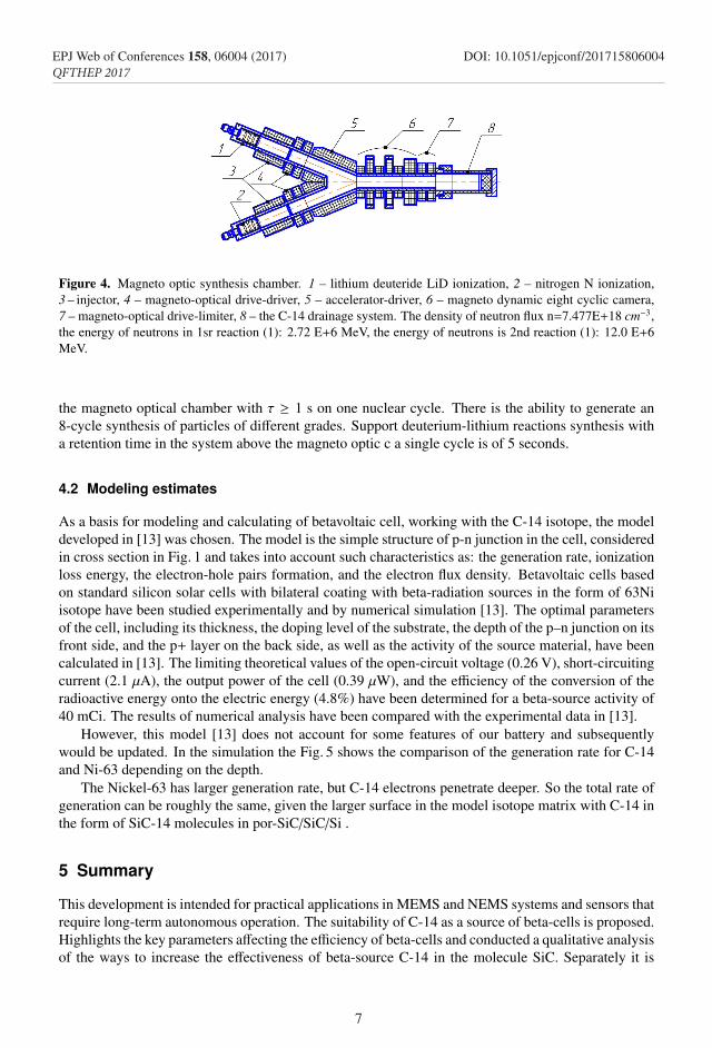
Figure 3. Diagram of concentrations dependencies on depth. The analyzed depth ranges from 5.3 × 10⁻⁸ to24.3 × 10−6 m. The concentration of C-12 atoms (KDB C curve), depending on the analyzed depth, ranges from8.4 × 1019 to 3.2 × 10¹⁶ [20, 28].
the synthesis of neutrons by lithium ion target as a result of compaction of the primary flux of protonsand sampling of parameters specify the density and average energy of the flow. Electronically con-trollable streams are formed in parameters repetition period Tsl and frequency discrete streams ωsl.Generation dense proton flux for the synthesis of neutrons by lithium ion targets:
D + Li6 → Be7 + n0, D + Li7 → 2He4 + n0. (1)
The synthesis reaction at the target dense nitrogen ions:
D + Li7 → C4 + p+. (2)
The Device (see Fig. 4) consists of electronically controlled ion sources with magneto optic fluxconcentration with the ion energy of up to 50 keV, electronically controlled pulsed accelerator sec-tions that form discrete ion flux with the ion energy from 200 to 600 keV, combined with an 8-cyclicmagneto optic synthesis chamber and a controlled magneto-dynamic trap for generating dense neu-tron fluxes. The synthesis of C-14 by neutrons goes in a 4-cycle magneto optic chamber on the denseion target. At the final stage, C-14 from the magneto optic storage is deposited on the SiC substrate.Multilayer formation of C-14 on the SiC substrate or on substrates from other materials is also possi-ble.
The total energy of the incident particle and the target is above the Coulomb repulsion energy.Density ni impinging stream for pulsed operation is equal to or above 1022 cm−3. Retention time in
Figure 4. Magneto optic synthesis chamber. 1 – lithium deuteride LiD ionization, 2 – nitrogen N ionization,3 – injector, 4 – magneto-optical drive-driver, 5 – accelerator-driver, 6 – magneto dynamic eight cyclic camera,7 – magneto-optical drive-limiter, 8 – the C-14 drainage system. The density of neutron flux n=7.477E+18 cm−3,the energy of neutrons in 1sr reaction (1): 2.72 E+6 MeV, the energy of neutrons is 2nd reaction (1): 12.0 E+6MeV.
the magneto optical chamber with τ ≥ 1 s on one nuclear cycle. There is the ability to generate an8-cycle synthesis of particles of different grades. Support deuterium-lithium reactions synthesis witha retention time in the system above the magneto optic c a single cycle is of 5 seconds.
4.2 Modeling estimates
As a basis for modeling and calculating of betavoltaic cell, working with the C-14 isotope, the modeldeveloped in [13] was chosen. The model is the simple structure of p-n junction in the cell, consideredin cross section in Fig. 1 and takes into account such characteristics as: the generation rate, ionizationloss energy, the electron-hole pairs formation, and the electron flux density. Betavoltaic cells basedon standard silicon solar cells with bilateral coating with beta-radiation sources in the form of 63Niisotope have been studied experimentally and by numerical simulation [13]. The optimal parametersof the cell, including its thickness, the doping level of the substrate, the depth of the p–n junction on itsfront side, and the p+ layer on the back side, as well as the activity of the source material, have beencalculated in [13]. The limiting theoretical values of the open-circuit voltage (0.26 V), short-circuitingcurrent (2.1 µA), the output power of the cell (0.39 µW), and the efficiency of the conversion of theradioactive energy onto the electric energy (4.8%) have been determined for a beta-source activity of40 mCi. The results of numerical analysis have been compared with the experimental data in [13].
However, this model [13] does not account for some features of our battery and subsequentlywould be updated. In the simulation the Fig. 5 shows the comparison of the generation rate for C-14and Ni-63 depending on the depth.
The Nickel-63 has larger generation rate, but C-14 electrons penetrate deeper. So the total rate ofgeneration can be roughly the same, given the larger surface in the model isotope matrix with C-14 inthe form of SiC-14 molecules in por-SiC/SiC/Si .
5 Summary
This development is intended for practical applications in MEMS and NEMS systems and sensors thatrequire long-term autonomous operation. The suitability of C-14 as a source of beta-cells is proposed.Highlights the key parameters affecting the efficiency of beta-cells and conducted a qualitative analysisof the ways to increase the effectiveness of beta-source C-14 in the molecule SiC. Separately it is
7
EPJ Web of Conferences 158, 06004 (2017) DOI: 10.1051/epjconf/201715806004QFTHEP 2017

Figure 5. Generation rate comparison for C-14 and Ni-63. Notations for C-14 – solid red curve, Ni-63 – dot bluecurve. Parameters: C-14 Specific activity 1.648 × 10¹¹ Becquerel/gram. The energy at the one electron-hole pairof is 3.6 eV. The area of 4 cm2 (as in [13]).
necessary to solve the problem of isotope enrichment C-14. We need to develop and conduct a seriesof experiments to verify the theoretical calculations and hypotheses.
The production of Carbon-14 at a cost lower than traditional production. The source of the neutronfluxes for the synthesis of radioactive isotopes for medical purposes. Modification device to vacuumion-plasma deposition of Carbon-14 on the SiC substrate is developing still.
A method of implantation C-14 in molecule por-SiC is in step preparation heterostructures ofp-n-transition. Technology has been developed and a mathematical model of the converter manufac-turing: technological (route maps, physical parameters, tools) and design (assembly devices, housing,terminals, electrical insulation, recycling methods) documentation.
Acknowledgements. M. D. is grateful to Workshop organizers for the attention, creative discussion andthe opportunity to present results of research project, also thanks V. Tarala for debates and discussion of experi-ments. Authors are grateful to collaboration in principle detailed analysis with Bazhanov A.Ya. and Romanov A.(Angstrem) & V. Zinchenko and G. Shestakov (Aviatechnocon).
References
[1] Rappaport P. The electron-voltaic effect in p-n junctions induced by beta particle bombardment /Phys. Rev. 1953. Vol. 93. P. 246-247.
[2] H. G. J. Moseley, Phil. Mag., 1913, 26, 1025–1034.[3] YOLE DEVELOPPEMENT Status of the MEMS Industry 2016//i-micronews.com URL:
https://www.i-micronews.com/category-listing/product/status-of-the-mems-industry-2016.html[4] Dolgopolov Mikhail V., Anisimova Valeriya Yu., Akimchenko Alina A., Kuznetsov Oleg V.,
Zanin George G. Analysis and assessment of the betavoltaics power supply market. P. 452-473.In Economics and management in conditions of nonlinear dynamics / under the editorship of Dr.Econ. Sciences, Professor A. V. Babkin. – SPb. : Publishing house of Polytechnical Institute. Uni-versity, 2017. – 773 p.
[5] Katz D., Akiyama T. Pacemaker longevity: The World’s Longest-Lasting VVI Pacemaker. Annalsof Noninvasive Electrocardiology, Volume 12, Issue 3, pages 223-226. 2017.
8
EPJ Web of Conferences 158, 06004 (2017) DOI: 10.1051/epjconf/201715806004QFTHEP 2017
Figure 5. Generation rate comparison for C-14 and Ni-63. Notations for C-14 – solid red curve, Ni-63 – dot bluecurve. Parameters: C-14 Specific activity 1.648 × 10¹¹ Becquerel/gram. The energy at the one electron-hole pairof is 3.6 eV. The area of 4 cm2 (as in [13]).
necessary to solve the problem of isotope enrichment C-14. We need to develop and conduct a seriesof experiments to verify the theoretical calculations and hypotheses.
The production of Carbon-14 at a cost lower than traditional production. The source of the neutronfluxes for the synthesis of radioactive isotopes for medical purposes. Modification device to vacuumion-plasma deposition of Carbon-14 on the SiC substrate is developing still.
A method of implantation C-14 in molecule por-SiC is in step preparation heterostructures ofp-n-transition. Technology has been developed and a mathematical model of the converter manufac-turing: technological (route maps, physical parameters, tools) and design (assembly devices, housing,terminals, electrical insulation, recycling methods) documentation.
Acknowledgements. M. D. is grateful to Workshop organizers for the attention, creative discussion andthe opportunity to present results of research project, also thanks V. Tarala for debates and discussion of experi-ments. Authors are grateful to collaboration in principle detailed analysis with Bazhanov A.Ya. and Romanov A.(Angstrem) & V. Zinchenko and G. Shestakov (Aviatechnocon).
References
[1] Rappaport P. The electron-voltaic effect in p-n junctions induced by beta particle bombardment /Phys. Rev. 1953. Vol. 93. P. 246-247.
[2] H. G. J. Moseley, Phil. Mag., 1913, 26, 1025–1034.[3] YOLE DEVELOPPEMENT Status of the MEMS Industry 2016//i-micronews.com URL:
https://www.i-micronews.com/category-listing/product/status-of-the-mems-industry-2016.html[4] Dolgopolov Mikhail V., Anisimova Valeriya Yu., Akimchenko Alina A., Kuznetsov Oleg V.,
Zanin George G. Analysis and assessment of the betavoltaics power supply market. P. 452-473.In Economics and management in conditions of nonlinear dynamics / under the editorship of Dr.Econ. Sciences, Professor A. V. Babkin. – SPb. : Publishing house of Polytechnical Institute. Uni-versity, 2017. – 773 p.
[5] Katz D., Akiyama T. Pacemaker longevity: The World’s Longest-Lasting VVI Pacemaker. Annalsof Noninvasive Electrocardiology, Volume 12, Issue 3, pages 223-226. 2017.
[6] V.I.Chepurnov, M.V.Dolgopolov, A.V.Gurskaya, S.N.Podgornov, A.N.Scherbakov, InternationalConference "Electronics-2015" , 13 (2015)
[7] A.V.Gurskaya, M.V.Dolgopolov, V.I.Chepurnov, 22 All-Russian Scientific Conference of physicsstudents and young scientists, 183 (2016)
[8] S.P.Zavodov, V.I.Chepurnov, A.A.Kirpichev, Modern problems of physics and technologies.MEPhI., 189-191 (2016)
[9] The Patent Application 2016129598, 19.07.2016.[10] The Patent of The RUSSIAN FEDERATION 02370851 C2 Method of self-organizing mono
3c-SiC endotaxi on Si substrate / V.I.Chepurnov, since 15.12.2005.[11] ROSRID, R & D report, with references to the literature, V.I.Chepurnov, etc. AAAA-B16-
216122220098-7.[12] Tariq R.Alam, Mark A. Pierson. Principles of Betavoltaic Battery Design // J. Energy Power
Sources. Vol. 3, No. 1, 2016, pp. 11-41.[13] Gorbatsevich A.A., Korneev V.I., Danilin A.B., Magomedbekov E.P., Molin A.A. Analysis
(Simulation) of Ni-63 beta-voltaic cells based on silicon solar cells. Technical Physics. The RussianJournal of Applied Physics. 2016. T. 61. N 7. P. 1053-1059.
[14] M.A. Polikarpov, E.B. Yakimov Investigation of properties of semiconductor converter based onsilicon for beta-voltaic elements. SEMICONDUCTORS. 2015, T. 49, V. 6. P. 763-766.
[15] Abanin I.E. Selection of Active Layers for a Power Supply Device with p-n Junction Excited byβ-Radiation. NANO- AND MICROSYSTEMS TECHNOLOGY. N 10 (183). 2015. P. 4-10.
[16] Bulyarskiy S.V., Lakalin A.V., Abanin I.E., Amelichev V.V., Svetuhin V.V. Optimization of theparameters of power sources excited by β-radiation. Semiconductors. 2017. T. 51. N 1. P. 66-72.
[17] Saurov A.N., Bulyarskiy S.V., Risovanniy V.D., Pavlov A.A., Abanin I.E., Kitsyuk E.P.,Shamanaev A.A., Lebedev E.A. Nanostructured Current Sources Excited by β-Radiation Basedon Carbon Nanotubes. Izvestiya vysshikh uchednykh zavedenii. Elektronika. T 20. N 5. 2015.P. 474-480.
[18] A 25-Year Battery: Long-lived nuclear batteries powered by hydrogen isotopes are in testing formilitary applications, Katherine Bourzac, Technology Review, MIT, 17 Nov 2009.
[19] A. V. Gurskaya, M. V. Dolgopolov, V. I. Chepurnov. C-14 Beta Converter. Physics of Particlesand Nuclei, 2017, Vol. 48, No. 6, pp. 941–944.
[20] V.I.Chepurnov, M.V.Dolgopolov, A.V.Gurskaya, A. A. Akimchenko, O. V. Kuznetsov, A. V.Radenko, V. V. Radenko, A. S. Mashnin. C-BETAVOLTAIC ENERGYCONVERTER IN POR-SIC/SI //MATERIALS SCIENCE. NON-EQUILIBRIUM PHASE TRANSFORMATIONS. 2017.Issue 3. PP. 119-120
[21] Ragone, D., Review of Battery Systems for Electrically Powered Vehicles, SAE Technical Paper680453, 1968. 8 p.
[22] Christen, Thomas; Carlen, Martin W. (2000). Theory of Ragone plots. Journal of Power Sources.91 (2). pp. 210–216.
[23] V.I.Chepurnov, M.V.Dolgopolov, A.V.Gurskaya, Sorokov A.S., Oil. Gas. Novatsiya. Volume 1280-82 (2016).
[24] Pavlikov A.V., Timoshenko V.Y., Latukhina N.V., Chepurnov V.I. Structural and optical proper-ties of silicon-carbide nanowires produced by the high-temperature carbonization of silicon nanos-tructures // Semiconductors. 2017. T. 51. N 3. P. 402-406.
[25] Vavilov V.S., Guseva M.I., Konorova E.A., Krasnopevtsev V.V., Sergienko V.F., TutovV.V. Semi-conducting diamonds produced by ion bombardment // Soviet Phys.-Solid St. 8. 1966. pp.1560-1561.
9
EPJ Web of Conferences 158, 06004 (2017) DOI: 10.1051/epjconf/201715806004QFTHEP 2017

[26] Vavilov V.S., Guseva M.I., Konorova E.A., Sergienko V.F. Investigation during isochronous mul-tistage annealing of the electrical conductivity of semiconducting n- and p-type diamonds preparedby the ion implantation method // Soviet Phys. Semiconductors 4. 1970. P. 6-11.
[27] Gusev V.M., Titov V.V. Kinetics of thermal annealing of radiation defects in silicon doped bythe ion implantation method // Sov. Phys.-Semicond. 3, 1-6. 1969.
[28] Bazhanov A.Ya., Chepurnov V.I., Romanov A. 2017. In preparation.[29] Thomson J.J. Rays of positive electricity // Phil. Mag. 20: 752-767. 1910.[30] Herzog R.F.K., Viehboeck F. Ion source for mass spectrography // Phys. Rev. 76 (6): 855-856.
1949.[31] Honig R.E.. Sputtering of surfaces by positive ion beams of low energy // J. Appl. Phys. 29:
549-555. 1958.[32] V. I. Chepurnov, Associates of dot defects of various nature in SiCSiC-phase of semiconductor
heterostructure of SiC//SiSiC//Si, received by endotaksiya method, Vestnik Samarskogo Gosu-darstvennogo Universiteta. Estestvenno-Nauchnaya Seriya, 2014, no. 7(118), 145-162
[33] Physics and Technology of Ion Sources, 2nd, Revised and Extended Edition. Ian G. Brown(Editor). 396 pages. October 2004.
[34] Mesyats Gennady A. Pulsed power. Springer. 2005. 568 p.[35] A. T. Forrester Large Ion Beams: Fundamentals of Generation and Propagation. Wiley-VCH;
1 edition (April 1988). 325 p.
10
EPJ Web of Conferences 158, 06004 (2017) DOI: 10.1051/epjconf/201715806004QFTHEP 2017
Related Documents