Guidelines & Recommended Practices Selection of Artificial Lift Systems for Deliquifying Gas Wells Prepared by Artificial Lift R&D Council Status The text of this document written and edited. There are a few more sections to be added. Chair Bill Lane, [email protected] Team: David Hill, Shauna Noonan, Ken Saveth, Laurent Seince , TIm Soltys, Rick Webb, Larry Harms Comments: Bill Lane will work with Larry Harms to update for use with gas wells. 3.3 Progressing Cavity Pumping This section presents the operating principals, operating limits, and system requirements for progressing cavity pump systems. Recommended practices, operating considerations, and costs are discussed. This discussion will be limited to conventional and insertable PC pumps used for gas well deliquification. The emphasis will be on CBM/CSG wells and shallow gas applications since production from PC pump systems becomes limited for deeper applications. 2.4b.1 System Description The surface and subsurface equipment for a typical electric drive system are shown below:

Welcome message from author
This document is posted to help you gain knowledge. Please leave a comment to let me know what you think about it! Share it to your friends and learn new things together.
Transcript

Guidelines & Recommended PracticesSelection of Artificial Lift Systems
for Deliquifying Gas WellsPrepared by Artificial Lift R&D Council
Status The text of this document written and edited. There are a few more sec-
tions to be added. Chair Bill Lane, [email protected] Team: David Hill, Shauna Noonan, Ken Saveth, Laurent Seince , TIm
Soltys, Rick Webb, Larry Harms Comments: Bill Lane will work with Larry Harms to update for use
with gas wells.
3.3 Progressing Cavity Pumping
This section presents the operating principals, operating limits, and system requirements for progressing cavity pump systems. Recommended prac-tices, operating considerations, and costs are discussed. This discussion will be limited to conventional and insertable PC pumps used for gas well deliquification. The emphasis will be on CBM/CSG wells and shallow gas applications since production from PC pump systems becomes limited for deeper applications.
2.4b.1 System Description
The surface and subsurface equipment for a typical electric drive system are shown below:

Selection of Artificial Lift Systems for Deliquifying Gas Wells Page 2
Belts & Sheaves
Surface Drive
Stuffing Box
Pumping Tee
Electric Motor
Polished Rod
Sucker Rodsw/ Couplings
Surface Equipment
Belts & Sheaves
Surface Drive
Stuffing Box
Pumping Tee
Electric Motor
Polished Rod
Sucker Rodsw/ Couplings
Surface Equipment

Selection of Artificial Lift Systems for Deliquifying Gas Wells Page 3
Downhole Equipment
PC Pump Stator
PC Pump Rotor
No-Turn Tool
Tubing String
Tagbar
Sucker Rodsw/ Couplings
(Illustrations courtesy of Weatherford International)
Surface drives are typically electrically driven. Gas engine driven generators can be used to supply electricity where line power is not available. Hydraulic transmissions consisting of an engine driven pump driving a hydraulic motor on the surface drive are also common.
Most surface drives have belt and sheave reductions to provide additional speed adjustment. Geared systems and inline electric or hydraulic systems are also available. All surface drive systems must have adequate backspin control and the ability to absorb the stored energy of the rod string torsion plus the full column of fluid.

Selection of Artificial Lift Systems for Deliquifying Gas Wells Page 4
The stuffing box includes a seal to keep pressurized well fluids from escap-ing. Stuffing boxes for PC pump systems are specifically designed to seal against rotating polished rods. Stuffing boxes designed for reciprocating rod applications should not be used for PC pump systems unless they are quali -fied by the manufacturer for use with rotating rods or PC pump systems.
Below the stuffing box the pumping tee provides a flow connection to the production tubing. Special “composite” pumping tees for PC pump systems clamp on the polished rod to support the rod string and seal against the pol-ished rod to isolate well fluids. This allows the stuffing box and surface drive to be serviced or removed safely without pulling the rod string.
The stators for conventional PC pumps are run as part of the production tub-ing string. The rotor is run into the well on the end of the rod string which consists of either jointed sucker rod or continuous rod.
The downhole assembly includes a tagbar to allow the rotor to be positively located relative to the stator. Installation procedures include running the ro-tor to the tagbar and then spacing back to align the rotor into the stator. The rotor space-out is unique to the pump geometry, well operating conditions, and rod string configuration.
Tubing insertable systems are available in which the stator and rotor are run as one assembly with the rod string inside of the tubing. This simplifies run-ning and retrieval, so insertable pumps are usually preferred over conven-tional pumps. The use of insertable pumps is limited by the tubing size.
Large systems may require a no-turn device to prevent the torque in the pump from loosening the tubing connections. Smaller systems with properly torqued tubing typically do not require no-turn devices although no-turn de-vices are often included as a precaution.

Selection of Artificial Lift Systems for Deliquifying Gas Wells Page 5
Insertable PC Pump Downhole Assembly(Illustration courtesy of Weatherford International)
2.4b.2 Operating Principals
PC pumps consist of a rotor turning inside of a stator whereby the rotor is the only moving component. The rotor is helical and typically has a round cross section (single lobe). The stator cavity is also helical, but the stator pitch is twice the pitch of the rotor. The stator cavity cross-sectional shape has one more lobe than the rotor. For a single lobe rotor, the stator cavity cross-sec-tion is like a rectangle with rounded ends (2 lobes) similar to a race track. The resulting assembly creates sealed cavities between the rotor and stator which “progress” from the pump inlet to the outlet as the rotor turns (a pro-gressing cavity pump). The cavities are sealed so the pump is a positive dis-placement device. Therefore a PC pump will hold a column of fluid when the pump rotation stops.
No-Turn Tool
Tag B
Pull R
Seating Man-
PC P
Extension Tube
Pump Seating Nipple
Tub-i
Seal line

Selection of Artificial Lift Systems for Deliquifying Gas Wells Page 6
3rd cavity
2nd cavity
1st cavity
(Figures courtesy of Weatherford International)
The lift capacity (depth rating) of the pump is dependent on the number of stages and the fit of the rotor to the stator. The volume capacity (production rate) of the pump is dependent upon the cavity size and the pump rate of ro-tation. The cavity size is determined by the rotor eccentricity and pitch. Long pitches and high eccentricity result in high displacement (high produc-tion volume) per rotor revolution. Short pitch pumps reduce the fluid velocity through the pump which reduces abrasive wear on the pump from fluids that contain particulate matter. Relatively long pitches relative to eccentricity are used for less viscous liquids such as water, while relatively short pitches rel-ative to eccentricity are used for more viscous liquids such as heavy oil.
Single Lobe Multi-lobe

Selection of Artificial Lift Systems for Deliquifying Gas Wells Page 7
Figures courtesy of Weatherford International
2.4b.3 Operating Limits
The PC pump rotary motion and positive displacement combined with direct mechanical drive from the surface result in the highest system efficiency of any lift system. The volumetric efficiency of the pump is directly related to the stator-to-rotor interference fit. Tighter fits allow less slippage and result in higher volumetric efficiency. Looser fits provide increased cooling and lu-brication resulting in longer life for the pump. Therefore, efficiency is often a trade-off for operating life.
PC pump systems are relatively tolerant of sand and particulate matter com-pared to most common lift technologies. The elastomer in the stator deforms to accommodate particulate matter pressed against the stator ID by the rotor lobes. The particles are then released back into the flow stream after the ro-tor lobe passes by.
Because of high efficiency and tolerance to particulate matter, PC pump sys-tems are ideal for use in many CBM/CSG wells. In deep CBM/CSG wells (typically > 6000’ TVD) and where local PC pump service expertise is limited rod pump systems tend to be more competitive. In shallow CBM/CSG wells (less than 1500’ TVD) lower cost small ESP systems can be competitive.

Selection of Artificial Lift Systems for Deliquifying Gas Wells Page 8
PC pumps have no valves or centrifugal stages so they will not gas lock al-though they will have reduced efficiency in the presence of gas. Excessive GLR through the pump for extended periods of time can damage the elas-tomer due to elastomer hysteresis heating in the absence of liquid cooling.
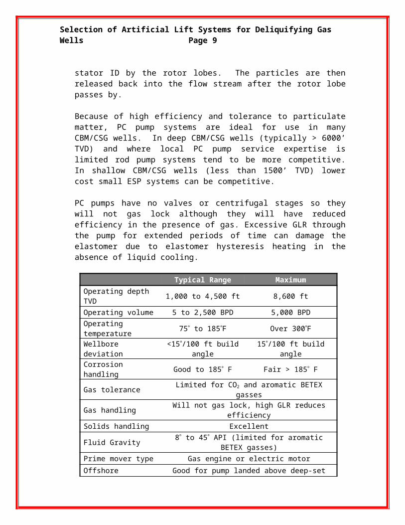
Typical Range MaximumOperating depth TVD 1,000 to 4,500 ft 8,600 ft
Operating volume 5 to 2,500 BPD 5,000 BPD
Operating temperature 75 to 185F Over 300F
Wellbore deviation <15/100 ft build angle 15/100 ft build angle
Corrosion handling Good to 185 F Fair > 185 F
Gas tolerance Limited for CO2 and aromatic BETEX gasses
Gas handling Will not gas lock, high GLR reduces efficiency
Solids handling Excellent
Fluid Gravity 8 to 45 API (limited for aromatic BETEX gasses)
Prime mover type Gas engine or electric motor
Offshore application Good for pump landed above deep-set SSSV
System efficiency 55% to 70% Figure courtesy of Weatherford International
Typical operating speeds are between 150 and 400 rpm. Speeds slower than 150 rpm can result in stick-slip behavior due to system fluid properties and friction elements (rod friction within the tubing, rotor/stator interference fit). Speeds over 500 rpm can result in excessive rod whirl which can dam-age the rotor and tubing.
Rotors are sized for a specific interference fit with the stator elastomer in or-der to allow a designed amount of slippage (fluid leakage) between stages to provide pump lubrication and cooling. Most systems are designed for volu-metric efficiencies of 60% to 85%. Depending on the application conditions higher efficiencies may compromise pump run life, and lower efficiencies will increase operating costs.
2.4b.4 Operating Requirements
PC pump systems can run off of the electric grid, or they can use natural gas powered engines or local power generation.
PC pump technology may be the most efficient lift technology, especially for abrasive fluids, but it is also the most easily misapplied technology. PC pump systems should be designed on a well-by-well basis according to the depth, fluid properties, production rates, etc. of individual wells. Systems
Selection of Artificial Lift Systems for Deliquifying Gas Wells Page 9
should be designed by experienced PC pump applications personnel. Trained PC pump service personnel are required to install, commission, and maintain PC pump systems.
System monitoring is required in order to optimize pump operation relative to changing well conditions and to prevent pump-off conditions. Variable speed controllers with automatic PC pump pump-off controls are important. Telemetry and remote monitoring is recommended.
2.4b.5 Life Expectancy
Life expectancy in CBM/CSG wells has averaged around 18 months globally and typically ranges from 12 to 36 months. Although solids and coal fines can be detrimental to any pump, PC pump system failures in CBM/CSG have more often been related to rod-tubing wear and continuous gas produc-tion through the pump. The rod-tubing wear is related to the well geometry and the resulting water-wet side loads between the sucker rod couplings and the tubing ID. Water is not a good lubricant and can be especially abrasive when solids are present. In some areas high concentration of CO2 in the produced water can cause Explosive Decompression (ED) of the stator elas-tomer. Special elastomers have been developed to mitigate the damage caused by ED.
Pump failures can be minimized by close attention to avoiding pump-off con-ditions and by minimizing the amount of gas through the pump. Landing the pump below the gas entry interval, the use of subsurface gauges and VFDs (variable frequency drives) with pump-off logic all help extend pump operat-ing life.
Tubing and rod damage can be minimized by using continuous rod systems to eliminate the couplings and the corresponding concentrated side contact forces. Continuous rod will have 75% less side load pressure than conven-tional sucker rod couplings in PC pump applications because the side load is spread along the length of the rod. If conventional sucker rod is used, tubing rotators and repositioning of the rod string can extend the life of tubing.
In Canada and similar areas with significant PC pump manufacturing infra-structure it is common to re-use rotors as the stators wear and are replaced. Rotors for these applications have extra-chrome or similar hard coatings to provide extended life. Typically, three stators will be replaced for each rotor replaced. In locations where PC pump manufacturing infrastructure is less developed the rotor hard coating thickness may be reduced in order to mini-mize costs since the rotors will not be reused. In these applications the ro-tors are designed to last as long as the stators.

Selection of Artificial Lift Systems for Deliquifying Gas Wells Page 10
2.4b.6 Costs
While costs will be dependent upon system features, complexity and local operational costs some general rules-of-thumb apply: In low to medium vol-ume CBM/CSG applications procurement costs (CAPEX) tend to be split ¼ for the subsurface pump assembly and components, ¼ for the rod string, ¼ for the surface drive, and ¼ for the surface VFD controls.
Operating costs (OPEX) vary greatly depending on the local cost of power or fuel and must include maintenance and service costs since PC pump sys-tems require periodic attention. In general, OPEX will be less than compara-ble other lift technologies due to high operating efficiency and low failure rates. Only lift technologies such as plunger lift and gas lift that leverage for-mation energy will have lower operating costs per barrel lifted.
Although PC pumps are the most energy efficient form of lift, skilled PC pump service personnel will be required to keep the systems in optimum op-erating condition. In the absence of skilled service personnel reliability and associated costs will be compromised.
2.4b.7 Recommended Practices
Specific installation, operation, and maintenance guidelines are provided by suppliers for systems and components. The following suggested guidelines represent best practices for PC pump systems.
Design for Free GasFree gas occupies space in the pump cavity. This reduces liquid displace-ment and reduces pump lubrication and cooling. In gas wells attempts should be made to reduce the amount of free gas that enters the PCP. The following practices should be considered when free gas is present:
Land the PCP below the perforations.
If the pump is landed above the perforations a tail-joint assembly should extend below the pump to effectively place the intake below the perforations.
Use a downhole gas separator.
Use a charge “tandem” PC pump configuration in which a higher volume capacity lower lift pump compresses well fluids prior to the in-take of the primary lift pump. Tandem pumps must be sized to allow the rotor of the lower pump to pass through the stator of the upper pump during run-in and retrieval (See illustration, below)

Selection of Artificial Lift Systems for Deliquifying Gas Wells Page 11
(Illustration courtesy of Weatherford International)
Design for Highly Deviated WellsContinuous sucker rod is recommended for any PC pump system installed in deviated wells. The continuous rod will greatly reduce side loads and tubing wear without the reliability issues associated with sucker rod guides.
Biased intake separators are available to reduce gas ingestion in deviated wells. The separators draw in liquids from the low side of the tubing while al -lowing gas to pass along the high side of the tubing.
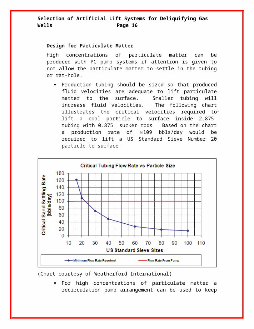
Design for Particulate MatterHigh concentrations of particulate matter can be produced with PC pump systems if attention is given to not allow the particulate matter to settle in the tubing or rat-hole.
Production tubing should be sized so that produced fluid velocities are adequate to lift particulate matter to the surface. Smaller tubing will increase fluid velocities. The following chart illustrates the critical ve-

Selection of Artificial Lift Systems for Deliquifying Gas Wells Page 12
locities required to lift a coal particle to surface inside 2.875” tubing with 0.875” sucker rods. Based on the chart a production rate of 109 bbls/day would be required to lift a US Standard Sieve Number 20 particle to surface.
(Chart courtesy of Weatherford International)
For high concentrations of particulate matter a recirculation pump ar-rangement can be used to keep particulate matter in suspension prior to pumping. This is similar to the charge pump arrangement described above except a perforated nipple is located between the tandem pumps to allow fluid to recirculate from the discharge of the lower pump back to its intake.
Design for Water and Thermal Elastomer SwellThe amount of fluid and thermal elastomer swell is unique to the elastomer compound and fluid conditions. At elevated temperatures >60°C the amount of fluid swell is significant with some elastomers. Therefore it is common for the manufacturer to perform a fluid compatibility test using the produced fluid under simulated operating conditions. The fluid compatibility testing accom-plishes two purposes.
1. Identifies the best elastomer for the application.
2. Provides the ability to model and select rotor dimensions that will provide an optimized and balanced rotor/stator interference fit across
Selection of Artificial Lift Systems for Deliquifying Gas Wells Page 13
the stator cavity profile. Incorrect rotor/stator fit can result in poor per-formance and run life.
2.4b.8 Trouble-shooting
Possible causes
Observed problems
Suggested solutionsNo
prod
uctio
n
Pro
duct
ion
drop
s of
f
Inte
rmitt
ent p
rodu
ctio
n
Pum
p w
ill n
ot s
tart
Mot
or s
talls
at p
ump-
up
Mot
or o
verh
eats
Exc
essi
ve p
ower
Exc
essi
ve n
oise
and
vib
ratio
n
Wea
r on
pum
p co
mpo
nent
s
Exc
essi
ve p
acki
ng g
land
wea
r
Pac
king
gla
nd le
akag
e
Pum
p lo
cks
up
Percentage abrasion above maximum recom-mended X X Select correct rotor fit, decrease
pump speedSucker rods parted X X Fish parted rod and replaceTubing parted X X X Tighten new tubing adequatelyInadequate fluid (reservoir or completion re-lated) X X X X Reduce pump speed/put well on
timerHole in tubing or collar X X X Replace tubing or collarMotor supply or wiring X X X Check electrical supply and wiringPump intake blocked X X X X Pull up rotor, circulate wellFluid viscosity above design point X X X X X X X Decrease pump speedFluid temperature above / below design point X X X Select correct rotor fitFluid viscosity below design point X Increase pump speed
Discharge pressure above design point X X X X X X X Check flow line for blockage/closed valve
Packing gland too tight X X X X X X Adjust packing glandPacking gland not tight enough X Adjust packing gland
Excessive free gas at pump intake X X X Install gas anchor, reduce speed or lower pump
Pump speed above design point X X X X X X Decrease pump speedPump speed too slow X X Increase pump speedDrive belts slipping X X X X Check belt tensionIncorrect rotor setting X X X X X Check and adjust rotor spacingDrive mounting insecure X Check/tighten all mounting hardwareDrive head bearing wear / failure X X X X X X Replace or overhaul surface driveWorn pump (rotor / stator) X Replace worn componentsLow voltage X X X Check voltage / wiring sizesAbrasives in the packing gland area X X X Check packing type and conditionFailure of drive arrangement X X X X X Check failed drive componentsIncompatible treating chemicals X X X X X X Re-check chemical compatibilityPump discharge blocked/valve closed X X X X X X X X X Relieve pressure. Clear blockagesStator worn / damaged X X X X X X Replace worn partsPacking glands destroy packing X X X Check polished rod for wearMotor is too small X X X Check and re-calculate motor sizeIncorrect rotor spacing X X X X X Re-space rotorStator elastomer swollen X X X X X Re-evaluate elastomer selectionPump sanded in X X X X Perform flush by or pull pump
(Table courtesy of PCM)

Selection of Artificial Lift Systems for Deliquifying Gas Wells Page 14
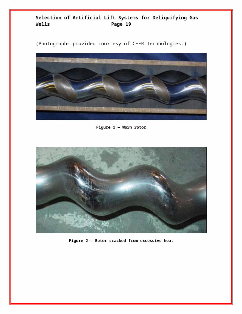
Examples of damaged rotors
Figures 1 to 3 show examples of different types of rotor damage.(Photographs provided courtesy of CFER Technologies.)
Figure 1 — Worn rotor
Figure 2 — Rotor cracked from excessive heat

Selection of Artificial Lift Systems for Deliquifying Gas Wells Page 15
Figure 3 — Pitted rotor
Examples of damaged stators
Figures 4 to 11 show examples of different types of stator damage.(Photographs provided courtesy of CFER Technologies.)
Figure 4 — Blistered stator, possibly from decomprerssion of absorbed gasses
Selection of Artificial Lift Systems for Deliquifying Gas Wells Page 16
Figure 5 — Burned/overheated stator
Figure 6 — Eroded/pressure washed stator
Figure 7 — De-bonded stator

Selection of Artificial Lift Systems for Deliquifying Gas Wells Page 17
Figure 8 — Scratched/grooved stator
Figure 9 — Torn/chunked stator
Figure 10 — Stators contaminated with foreign material (two examples)

Selection of Artificial Lift Systems for Deliquifying Gas Wells Page 18
Figure 11 — Worn stator
Copyright
Rights to this information are owned by the Artificial Lift Research and Develop-ment Council (ALRDC). This material may be used by any member of ALRDC in any way they see fit as long as they refer to the ALRDC Artificial Lift Selection document where it is presented.
Disclaimer
The Artificial Lift Research and Development Council (ALRDC) and its officers and trustees, (here in after referred to as the Sponsoring Organization), and the author(s) of this Information and their company(ies), provide this informa-tion "as is" without any warranty of any kind, express or implied, as to the ac-curacy of the information or the products or services referred to in the infor-mation (in so far as such warranties may be excluded under any relevant law) and these members and their companies will not be liable for unlawful actions and any losses or damage that may result from use of any information as a consequence of any inaccuracies in, or any omission from, the informa-tion which therein may be contained.
The views, opinions, and conclusions expressed in this information are those of the author(s) and not necessarily those of the Sponsoring Organization. The author(s) are solely responsible for the content of the materials.The Sponsoring Organization cannot and does not warrant the accuracy of these documents beyond the source documents, although we do make every attempt to work from authoritative sources. The Sponsoring Organization pro-vides this information as a service. The Sponsoring Organization make no representations or warranties, express or implied, with respect to the informa-tion, or any part thereof, including any warrantees of title, non infringement of
Selection of Artificial Lift Systems for Deliquifying Gas Wells Page 19
copyright or patent rights of others, merchantability, or fitness or suitability for any purpose.
Related Documents