Beta Draft Confidential NavisCore IP Navigator Configuration Guide For B-STDX 6.5.2.x, CBX 3.5.2.x, and GX 1.5.2.x Product Code: 80114 Revision 03 January 2002

Welcome message from author
This document is posted to help you gain knowledge. Please leave a comment to let me know what you think about it! Share it to your friends and learn new things together.
Transcript

Beta Draft Confidential
NavisCore IP Navigator Configuration Guide
For B-STDX 6.5.2.x, CBX 3.5.2.x, and GX 1.5.2.x
Product Code: 80114Revision 03
January 2002

ii1/14/02 NavisCore IP Navigator Configuration Guide
Beta Draft Confidential
Copyright© 1999-2002 Lucent Technologies. All Rights Reserved.
This material is protected by the copyright laws of the United States and othercountries. It may not be reproduced, distributed, or altered in any fashion by any entity(either internal or external to Lucent Technologies), except in accordance withapplicable agreements, contracts or licensing, without the express written consent ofLucent Technologies.
For permission to reproduce or distribute, please contact: Technical Publications,InterNetworking Systems/Core Switching Division at 978-692-2600.
Notice. Every effort was made to ensure that the information in this document wascomplete and accurate at the time of printing. However, information is subject tochange.
Trademarks. Cascade, IP Navigator, Navis, NavisXtend, NavisCore, PriorityFrame, Rapid Upgrade, and WebXtend are trademarks of Lucent Technologies. Othertrademarks and trade names mentioned in this document belong to their respectiveowners.
Limited Warranty. Lucent Technologies provides a limited warranty to thisproduct. For more information, see the software license agreement in this document.
Ordering Information. To order copies of this document, contact your LucentTechnologies account representative.
Support Telephone Numbers. For technical support and other services, see thecustomer support contact information in the “About This Guide” section of thisdocument.

Beta Draft Confidential
LUCENT TECHNOLOGIES END-USER LICENSE AGREEMENT
LUCENT TECHNOLOGIES IS WILLING TO LICENSE THE ENCLOSED SOFTWAREAND ACCOMPANYING USER DOCUMENTATION (COLLECTIVELY, THE“PROGRAM”) TO YOU ONLY UPON THE CONDITION THAT YOU ACCEPT ALL OFTHE TERMS AND CONDITIONS OF THIS LICENSE AGREEMENT. PLEASE READTHE TERMS AND CONDITIONS OF THIS LICENSE AGREEMENT CAREFULLYBEFORE OPENING THE PACKAGE(S) OR USING THE LUCENT SWITCH(ES)CONTAINING THE SOFTWARE, AND BEFORE USING THE ACCOMPANYING USERDOCUMENTATION. OPENING THE PACKAGE(S) OR USING THE LUCENTSWITCH(ES) CONTAINING THE PROGRAM WILL INDICATE YOUR ACCEPTANCEOF THE TERMS OF THIS LICENSE AGREEMENT. IF YOU ARE NOT WILLING TO BEBOUND BY THE TERMS OF THIS LICENSE AGREEMENT, LUCENT IS UNWILLINGTO LICENSE THE PROGRAM TO YOU, IN WHICH EVENT YOU SHOULD RETURNTHE PROGRAM WITHIN TEN (10) DAYS FROM SHIPMENT TO THE PLACE FROMWHICH IT WAS ACQUIRED, AND YOUR LICENSE FEE WILL BE REFUNDED. THISLICENSE AGREEMENT REPRESENTS THE ENTIRE AGREEMENT CONCERNINGTHE PROGRAM BETWEEN YOU AND LUCENT, AND IT SUPERSEDES ANY PRIORPROPOSAL, REPRESENTATION OR UNDERSTANDING BETWEEN THE PARTIES.
1. License Grant. Lucent hereby grants to you, and you accept, a non-exclusive,non-transferable license to use the computer software, including all patches, errorcorrections, updates and revisions thereto in machine-readable, object code form only(the “Software”), and the accompanying User Documentation, only as authorized inthis License Agreement. The Software may be used only on a single computer owned,leased, or otherwise controlled by you; or in the event of inoperability of thatcomputer, on a backup computer selected by you. You agree that you will not pledge,lease, rent, or share your rights under this License Agreement, and that you will not,without Lucent’s prior written consent, assign or transfer your rights hereunder. Youagree that you may not modify, reverse assemble, reverse compile, or otherwisetranslate the Software or permit a third party to do so. You may make one copy of theSoftware and User Documentation for backup purposes. Any such copies of theSoftware or the User Documentation shall include Lucent’s copyright and otherproprietary notices. Except as authorized under this paragraph, no copies of theProgram or any portions thereof may be made by you or any person under yourauthority or control.
2. Lucent’s Rights. You agree that the Software and the User Documentation areproprietary, confidential products of Lucent or Lucent's licensor protected under UScopyright law and you will use your best efforts to maintain their confidentiality. Youfurther acknowledge and agree that all right, title and interest in and to the Program,including associated intellectual property rights, are and shall remain with Lucent orLucent's licensor. This License Agreement does not convey to you an interest in or tothe Program, but only a limited right of use revocable in accordance with the terms ofthis License Agreement.
NavisCore IP Navigator Configuration Guide 1/14/02iii
Beta Draft Confidential
3. License Fees. The license fees paid by you are paid in consideration of the licensegranted under this License Agreement.
4. Term. This License Agreement is effective upon your opening of the package(s) oruse of the switch(es) containing Software and shall continue until terminated. Youmay terminate this License Agreement at any time by returning the Program and allcopies or portions thereof to Lucent. Lucent may terminate this License Agreementupon the breach by you of any term hereof. Upon such termination by Lucent, youagree to return to Lucent the Program and all copies or portions thereof. Terminationof this License Agreement shall not prejudice Lucent's rights to damages or any otheravailable remedy.
5. Limited Warranty. Lucent warrants, for your benefit alone, for a period of 90days from the date of shipment of the Program by Lucent (the “Warranty Period”) thatthe program diskettes in which the Software is contained are free from defects inmaterial and workmanship. Lucent further warrants, for your benefit alone, that duringthe Warranty Period the Program shall operate substantially in accordance with theUser Documentation. If during the Warranty Period, a defect in the Program appears,you may return the Program to the party from which the Program was acquired foreither replacement or, if so elected by such party, refund of amounts paid by you underthis License Agreement. You agree that the foregoing constitutes your sole andexclusive remedy for breach by Lucent of any warranties made under this Agreement.EXCEPT FOR THE WARRANTIES SET FORTH ABOVE, THE PROGRAM IS LICENSED“AS IS”, AND LUCENT DISCLAIMS ANY AND ALL OTHER WARRANTIES,WHETHER EXPRESS, IMPLIED OR STATUTORY, INCLUDING, WITHOUTLIMITATION, ANY IMPLIED WARRANTIES OF MERCHANTABILITY OR FITNESSFOR A PARTICULAR PURPOSE AND ANY WARRANTIES OF NONINFRINGEMENT.
6. Limitation of Liability. Lucent’s cumulative liability to you or any other partyfor any loss or damages resulting from any claims, demands, or actions arising out ofor relating to this License Agreement shall not exceed the greater of: (i) ten thousandUS dollars ($10,000) or (ii) the total license fee paid to Lucent for the use of theProgram. In no event shall Lucent be liable for any indirect, incidental, consequential,special, punitive or exemplary damages or lost profits, even if Lucent has been advisedof the possibility of such damages.
iv1/14/02 NavisCore IP Navigator Configuration Guide

Beta Draft Confidential
7. Proprietary Rights Indemnification. Lucent shall at its expense defend youagainst and, subject to the limitations set forth elsewhere herein, pay all costs anddamages made in settlement or awarded against you resulting from a claim that theProgram as supplied by Lucent infringes a United States copyright or a United Statespatent, or misappropriates a United States trade secret, provided that you: (a) provideprompt written notice of any such claim, (b) allow Lucent to direct the defense andsettlement of the claim, and (c) provide Lucent with the authority, information, andassistance that Lucent deems reasonably necessary for the defense and settlement ofthe claim. You shall not consent to any judgment or decree or do any other act incompromise of any such claim without first obtaining Lucent’s written consent. In anyaction based on such a claim, Lucent may, at its sole option, either: (1) obtain for youthe right to continue using the Program, (2) replace or modify the Program to avoidthe claim, or (3) if neither (1) nor (2) can reasonably be effected by Lucent, terminatethe license granted hereunder and give you a prorata refund of the license fee paid forsuch Program, calculated on the basis of straight-line depreciation over a five-yearuseful life. Notwithstanding the preceding sentence, Lucent will have no liability forany infringement or misappropriation claim of any kind if such claim is based on: (i)the use of other than the current unaltered release of the Program and Lucent hasprovided or offers to provide such release to you for its then current license fee, or (ii)use or combination of the Program with programs or data not supplied or approved byLucent to the extent such use or combination caused the claim.
8. Export Control. You agree not to export or disclose to anyone except a UnitedStates national any portion of the Program supplied by Lucent without first obtainingthe required permits or licenses to do so from the US Office of Export Administration,and any other appropriate government agency.
9. Governing Law. This License Agreement shall be construed and governed inaccordance with the laws and under the jurisdiction of the Commonwealth ofMassachusetts, USA. Any dispute arising out of this Agreement shall be referred to anarbitration proceeding in Boston, Massachusetts, USA by the American ArbitrationAssociation.
10. Miscellaneous. If any action is brought by either party to this LicenseAgreement against the other party regarding the subject matter hereof, the prevailingparty shall be entitled to recover, in addition to any other relief granted, reasonableattorneys’ fees and expenses of arbitration. Should any term of this LicenseAgreement be declared void or unenforceable by any court of competent jurisdiction,such declaration shall have no effect on the remaining terms hereof. The failure ofeither party to enforce any rights granted hereunder or to take action against the otherparty in the event of any breach hereunder shall not be deemed a waiver by that partyas to subsequent enforcement of rights or subsequent actions in the event of futurebreaches.
NavisCore IP Navigator Configuration Guide 1/14/02v

Beta Draft Confidential
vi1/14/02 NavisCore IP Navigator Configuration Guide
Beta Draft Confidential
Contents
About This GuideWhat You Need to Know......................................................................................... xxixReading Path ............................................................................................................. xxx
NMS Documentation.......................................................................................... xxxSwitch Software Documentation....................................................................... xxxi
How to Use This Guide...........................................................................................xxxiiWhat’s New in This Release? ................................................................................ xxxivConventions ..........................................................................................................xxxviiRelated Documents ..............................................................................................xxxviiiCustomer Comments.............................................................................................. xxxixTechnical Support .................................................................................................. xxxixAcronyms..................................................................................................................... xl
Chapter 1 OverviewAbout IP Switching....................................................................................................1-1Lucent’s Implementation of IP Switching .................................................................1-1
IP Forwarding......................................................................................................1-2Routing Protocols ................................................................................................1-3
Interior Gateway Protocols ...........................................................................1-3Exterior Gateway Protocols ..........................................................................1-3Internet and Transport Protocols...................................................................1-4Multicast Protocols .......................................................................................1-4
Exchanging Routing Table Information..............................................................1-5Mapping Routes to Virtual Circuits ....................................................................1-5Label Switched Paths ..........................................................................................1-6Absolute QoS ......................................................................................................1-7Policy-Based Forwarding ....................................................................................1-8IP Virtual Private Networks ................................................................................1-8
Configuration and Management ................................................................................1-9Logical Port Configuration................................................................................1-10
Terminology.............................................................................................................1-11
NavisCore IP Navigator Configuration Guide rvii
Contents
Beta Draft Confidential
Chapter 2 Configuring Ethernet Logical PortsPrerequisites...............................................................................................................2-1Accessing the Logical Port Functions........................................................................2-2About the Set All Logical Ports in PPort Dialog Box ...............................................2-5
The Set Attributes Options Menu........................................................................2-7Administrative Attributes .............................................................................2-7Trap Control Attributes.................................................................................2-8Ethernet Attributes........................................................................................2-9
Chapter 3 Configuring IP Logical Ports and IP ServersPrerequisites...............................................................................................................3-3About IP Addresses....................................................................................................3-4
Address Resolution Protocol ...............................................................................3-4Configuring IP Logical Ports .....................................................................................3-5
Accessing Logical Port Parameters.....................................................................3-6Accessing the Set IP Parameters Dialog Box from the NavisCore Menu ....3-6Accessing the Set IP Parameters Dialog Box from the Set AllLogical Ports Dialog Box .............................................................................3-8
Adding an IP Logical Port.................................................................................3-10Setting the IP Interface Address........................................................................3-14Setting the DLCI for Frame Relay Logical Ports..............................................3-18Setting the VPI/VCI for ATM Logical Ports ....................................................3-21Binding an IP Interface......................................................................................3-24
About IP Server Logical Ports on the CBX 500 ......................................................3-25Forwarding Engines on IP Server Cards ...........................................................3-25IP Server Logical Ports......................................................................................3-26Bandwidth Allocation........................................................................................3-27
Configuring IP Server Logical Ports........................................................................3-28Creating an IP Server Logical Port....................................................................3-29
IP Server PVCs on the CBX 500 .............................................................................3-33Creating an IP Server PVC................................................................................3-33
Chapter 4 Configuring IP Packet FiltersAbout Packet Filters...................................................................................................4-1
IP Header.............................................................................................................4-2UDP/TCP Header ................................................................................................4-2
Configuring IP Packet Filters.....................................................................................4-3Defining an IP Packet Filter ...............................................................................4-4
Packet Filter Configuration Example .........................................................4-11Assigning IP Packet Filters to Logical Ports.....................................................4-13Assigning IP Filters to the Host (Switch)..........................................................4-15Assigning IP Packet Filters to Circuits..............................................................4-18Viewing an IP Packet Filter’s Configuration ....................................................4-21
Chapter 5 Configuring Policy-Based ForwardingAbout Forwarding Policies ........................................................................................5-1About Policy PVCs ....................................................................................................5-3
viii1/14/02 NavisCore IP Navigator Configuration Guide

Contents
Beta Draft Confidential
Policy-Based Forwarding Tutorial.............................................................................5-4How Do I Configure Policy-Based Forwarding? ................................................5-5
Step 1: Plan the Policy PVCs........................................................................5-5Step 2: Create the Policy PVCs ....................................................................5-5Step 3: Create the Forwarding Policies.........................................................5-6Step 4: Assign the Forwarding Policies to IP Logical Ports.........................5-6Step 5: Enable Policy-Based Forwarding .....................................................5-6Policy-Based Forwarding Configuration Flowchart.....................................5-7
How Do I Verify that Policy-Based Forwarding is Working?............................5-8What Happens When a Policy PVC Goes Down? ..............................................5-8How Can I Set Up PVCs that are Redundant and Share Traffic Load?..............5-9When Should I Not Use Switch/FE-to-Switch/FE Policy PVCs?.....................5-10When Should I Use Switch/FE-to-Switch/FE Policy PVCs?............................5-10Can I Use Policy PVCs for QoS Bandwidth Reservation? ...............................5-11
Configuring a Policy PVC .......................................................................................5-12Defining a Forwarding Policy..................................................................................5-28Assigning a Forwarding Policy to a Logical Port ....................................................5-33Enabling Policy-Based Forwarding .........................................................................5-34Configuring the Recipient Switch or Router ...........................................................5-35
Chapter 6 Configuring Static ARP EntriesAddress Resolution Protocol......................................................................................6-1Defining a Static ARP Entry......................................................................................6-2
Chapter 7 Configuring RIPConfiguring RIP at the Logical Port ..........................................................................7-1Configuring ECMP Routing for RIP .........................................................................7-6
Chapter 8 Configuring BGP ParametersAbout BGP.................................................................................................................8-2
BGP Peers and Route Updates ............................................................................8-2BGP Peer Groups ................................................................................................8-3Configuring IBGP ...............................................................................................8-4
Full Mesh IBGP ............................................................................................8-4Route Reflection ...........................................................................................8-5BGP Confederation.......................................................................................8-7
BGP Aggregates ..................................................................................................8-9BGP Route Dampening .......................................................................................8-9
Configuring BGP Switch Parameters ......................................................................8-10Configuring BGP Neighbors and Assigning Route Maps .......................................8-14Configuring BGP Aggregates ..................................................................................8-21Configuring BGP Peer Groups ................................................................................8-23
Assigning BGP Neighbors to Peer Groups .......................................................8-28Configuring BGP Route Dampening .......................................................................8-29Configuring IP Loopback Addresses .......................................................................8-31
NavisCore IP Navigator Configuration Guide ix

Contents
Beta Draft Confidential
Chapter 9 Configuring IP OSPF and VNN OSPFAbout OSPF ...............................................................................................................9-2
OSPF Link-State Database..................................................................................9-2Designated Routers and OSPF Relationships .....................................................9-3OSPF Flooding Controls .....................................................................................9-3OSPF Areas .........................................................................................................9-4OSPF Routing and Router Classifications ..........................................................9-6OSPF Area Aggregates .......................................................................................9-8OSPF Summary LSAs.........................................................................................9-8OSPF Virtual Links .............................................................................................9-9About Clustering ...............................................................................................9-10
VNN and IP Navigator Overview............................................................................9-11VNN ..................................................................................................................9-11IP Navigator ......................................................................................................9-11How VNN OSPF and IP OSPF View the Network...........................................9-12
Planning Separate OSPF Network Views................................................................9-16Considering Network Size and Types of Network Traffic................................9-16Planning Trunk Configuration...........................................................................9-17Planning VNN OSPF and IP OSPF Loopback Addresses,Area Aggregates, and Virtual Links..................................................................9-19Planning Router IDs ..........................................................................................9-22Planning Route Maps ........................................................................................9-23Important Upgrade Considerations ...................................................................9-24
IP OSPF Router IDs....................................................................................9-24Virtual Links ...............................................................................................9-24Performance ................................................................................................9-24Viewing Routing Information.....................................................................9-24
Configuring Trunks for IP OSPF and VNN OSPF..................................................9-25Configuring IP OSPF...............................................................................................9-29
Configuring IP OSPF on the IP Logical Port ....................................................9-30Configuring IP OSPF Neighbors.......................................................................9-34Configuring IP OSPF Area Aggregates ............................................................9-36Configuring IP OSPF Virtual Links..................................................................9-38Configuring IP OSPF Route Maps....................................................................9-41Configuring IP OSPF Router IDs......................................................................9-42Configuring Multiple IP OSPF Authentication Keys........................................9-43
About Multiple Authentication Keys..........................................................9-43Configuring Authentication Keys...............................................................9-45
About Equal-cost Multipath Routing for IP OSPF ...........................................9-48Configuring VNN OSPF..........................................................................................9-49
Configuring VNN Loopback Addresses ...........................................................9-49Configuring VNN Area Aggregates..................................................................9-50Configuring VNN Virtual Links .......................................................................9-52
Configuring Multiple IP OSPF and VNN OSPF Areas...........................................9-54Steps for Configuring Multiple OSPF Areas ....................................................9-54
Prerequisites for Multiple OSPF Areas ......................................................9-54Configuration Recommendations ...............................................................9-54IP OSPF Area Configuration ......................................................................9-55
x1/14/02 NavisCore IP Navigator Configuration Guide

Contents
Beta Draft Confidential
VNN OSPF Area Configuration .................................................................9-55Virtual Link Configuration .........................................................................9-56Address Aggregation ..................................................................................9-56
Configuring Route Maps for IP OSPF and VNN OSPF..........................................9-57
Chapter 10 Configuring Static RoutesAbout Static Routes .................................................................................................10-1Configuring a Static Route.......................................................................................10-2
Chapter 11 Configuring Route PoliciesAbout Network Filters .............................................................................................11-2About Access Lists ..................................................................................................11-2About Route Maps ...................................................................................................11-3
Route Map From and To Choices .....................................................................11-4Determining if a Route Map is for Import or Export ........................................11-5
Route Map Guidelines .............................................................................................11-6When are Route Maps Not Used? .....................................................................11-6What Happens if You Do Not Use a Route Map? ............................................11-8
Protocol Pairs That Do Not Require Route Maps.......................................11-8Protocol Pairs That Require Route Maps ...................................................11-9
Steps For Configuring a Route Map ......................................................................11-11Adding a Network Filter ........................................................................................11-13Adding a Network Access List ..............................................................................11-15Adding Route Maps ...............................................................................................11-18Using Regular Expressions ....................................................................................11-64
Chapter 12 Configuring Label Switched PathsWhat Are Label Switched Paths? ............................................................................12-2
Multipoint-to-Point (MPT) LSPs ......................................................................12-3MPT LSP Initialization...............................................................................12-4MPT LSP Requirements .............................................................................12-4
Point-to-Point LSPs...........................................................................................12-5Multicast LSPs ..................................................................................................12-7
Multicast LSP Initialization ........................................................................12-8Processing LSPs.......................................................................................................12-9LSPs and Switch Domains.....................................................................................12-10LSPs and VNN OSPF Areas..................................................................................12-11Enabling MPT LSPs and Multicast LSPs ..............................................................12-11Configuring Point-to-Point LSP Connections .......................................................12-13
Verifying Network-Wide Traffic Descriptors .................................................12-13Configuring the Connections...........................................................................12-14Defining a Point-to-Point Connection Path.....................................................12-18
Displaying Operational Status of Point-to-Point Paths..........................................12-20Configuring LSPs Over OPTimum Cell Trunks....................................................12-21
OPTimum Cell Trunk VPI Restrictions ..........................................................12-21MPT LSP Traffic Forwarding Across OPTimum Cell Trunks .......................12-23Configuring an ATM OPTimum Cell Trunk for LSP Traffic.........................12-24
NavisCore IP Navigator Configuration Guide xi
Contents
Beta Draft Confidential
Chapter 13 About Next Hop Resolution ProtocolOverview of NHRP..................................................................................................13-1
NHRP Components ...........................................................................................13-3NHS Component.........................................................................................13-4NHC Component ........................................................................................13-4NHS and NHC Support on Lucent Switches ..............................................13-4
Creating Shortcuts .............................................................................................13-5NHRP Protocol..................................................................................................13-6
NHRP Registration Request/Reply.............................................................13-6NHRP Resolution Request/Reply...............................................................13-7NHRP Purge Request................................................................................13-10NHRP Error Indication .............................................................................13-10
NHRP Extensions............................................................................................13-11Responder Address Extension ..................................................................13-11Route Record Extension ...........................................................................13-11
NHRP Feature Summary.................................................................................13-12Lucent NHRP Implementation ..............................................................................13-13
Configuration and Management Notes............................................................13-13NHRP and IP VPNs..................................................................................13-13SVC Node Prefixes...................................................................................13-13NHRP Logical Ports .................................................................................13-13Addressing ................................................................................................13-14MPT Aggregation Technology For Connecting Ingress andEgress Switches ........................................................................................13-14NHRP Packet Exchange Between CBX 500 Switches.............................13-15Proxy Clients and Packet Forwarding ......................................................13-15Placement of NHS-capable Switches and the Proxy Client .....................13-16Multiple NHSs in a LIS ............................................................................13-20Enabling/Disabling NHRP Requests ........................................................13-21Connection Requirements for Ingress Logical Ports ................................13-21SVC Connection and Termination............................................................13-21No Resolution Cache Match .....................................................................13-22Frame Relay UNI and PPP Logical Ports .................................................13-22Extensions.................................................................................................13-24Domino Effect...........................................................................................13-24Queuing of NHRP Packets .......................................................................13-24Backward Feedback..................................................................................13-24No Support for Non-authoritative Requests .............................................13-24
Guaranteeing QoS for IP Traffic Flows ..........................................................13-25Serving NHS.............................................................................................13-27Ingress Transiting NHS ............................................................................13-28Egress Transiting NHS .............................................................................13-29Proxy Client ..............................................................................................13-29Configuring Flow Profiles and Associated QoS Parameters ....................13-32
Interaction Between NHRP Shortcuts and Policy PVCs.................................13-33Preventing Persistent Routing Loops ..............................................................13-34
xii1/14/02 NavisCore IP Navigator Configuration Guide
Contents
Beta Draft Confidential
Chapter 14 Configuring Next Hop Resolution ProtocolBefore You Begin ....................................................................................................14-1
Planning Your NHRP Network Configuration .................................................14-3About NBMA Addressing.................................................................................14-4
ATM End System Address Formats ...........................................................14-5Native E.164 Address Format.....................................................................14-8Designing an Address Format Plan ............................................................14-8
About NHRP and IP VPNs ...............................................................................14-9Configuring SVC Node Prefixes .............................................................................14-9Adding and Deleting NHRP Logical Ports ............................................................14-10
Adding an NHRP Logical Port........................................................................14-10Deleting an NHRP Logical Port ......................................................................14-11
Configuring Node Parameters................................................................................14-12Configuring Flow Profiles .....................................................................................14-19
About Wildcards..............................................................................................14-20Creating IP Flow Profiles ................................................................................14-21
Adjusting Onset and Abatement Parameters ............................................14-30Modifying IP Flow Profiles.............................................................................14-30Deleting IP Flow Profiles ................................................................................14-31
Configuring Servers ...............................................................................................14-32About the Default Server.................................................................................14-32Adding a Server...............................................................................................14-33Modifying a Server..........................................................................................14-38Deleting a Server .............................................................................................14-38Adding Server Cache Entries ..........................................................................14-39Modifying a Server Cache Entry.....................................................................14-45Deleting a Server Cache Entry ........................................................................14-46
Configuring the Proxy Client.................................................................................14-47Configuring Proxy Client Parameters .............................................................14-47Modifying Proxy Client Parameters................................................................14-52Adding Proxy Client Cache Entries ................................................................14-52Modifying a Proxy Client Cache Entry...........................................................14-58Deleting a Proxy Client Cache Entry ..............................................................14-58
Configuring NHRP Logical Port Parameters.........................................................14-59Configuring NHRP Logical Port FP/TD Associations ..........................................14-64
Before You Begin............................................................................................14-65Associating a Flow Profile ..............................................................................14-66Modifying a Flow Profile Association ............................................................14-72Replacing a Flow Profile Association .............................................................14-73Deleting a Flow Profile Association ...............................................................14-74
Deleting All Flow Profile Associations ....................................................14-74Deleting a Single Flow Profile Association..............................................14-74
Configuring Log Parameters..................................................................................14-75
Chapter 15 Configuring IP Multicast RoutingOverview of IP Multicast Routing...........................................................................15-1IP Multicast Routing Protocols................................................................................15-3
NavisCore IP Navigator Configuration Guide xiii
Contents
Beta Draft Confidential
Distance Vector Multicast Routing Protocol.....................................................15-4Broadcast Phase ..........................................................................................15-4Pruning Phase .............................................................................................15-6
Multicast Open Shortest Path First..................................................................15-10Tunneling.........................................................................................................15-12
Lucent Implementation of IP Multicast Routing ...................................................15-13IGMP Implementation.....................................................................................15-13DVMRP and MOSPF Implementation............................................................15-15
Planning IP Multicast Routing...............................................................................15-17Verifying Basic IP Connectivity .....................................................................15-17Planning Your IGMP Configuration ...............................................................15-17Planning Your DVMRP Configuration...........................................................15-18
Identifying Physical Interfaces and Tunnels.............................................15-18Identifying Scoped Boundaries.................................................................15-22
Planning Your MOSPF Configuration ............................................................15-24Verify IP OSPF Router IDs ......................................................................15-24Identifying OSPF Interfaces .....................................................................15-24Verifying That Multicast LSPs are Enabled .............................................15-26Planning DVMRP Interoperability ...........................................................15-26
Configuring IGMP .................................................................................................15-28Configuring DVMRP VIFs....................................................................................15-32
Configuring DVMRP VIFs for Fast Ethernet and PPP Logical Ports ............15-32Configuring Scoped Boundaries for Ethernet and PPP Ports ...................15-37
Configuring VIFs for Tunnels.........................................................................15-38Configuring Scoped Boundaries for Tunnels ...........................................15-41
Configuring MOSPF..............................................................................................15-43Configuring Multicast Traffic Forwarding......................................................15-43Exporting MOSPF Routes to DVMRP ...........................................................15-44Enabling Multicast LSPs .................................................................................15-44
Chapter 16 Configuring IP Virtual Private NetworksUnderstanding an IP VPN........................................................................................16-2
How IP VPN Traffic Accesses the Lucent Network.........................................16-4How IP VPN Traffic is Routed Through the Lucent Network..........................16-6
Routing and Forwarding .............................................................................16-9How IP VPNs Differ From VNN VPNs................................................................16-11About the Public IP VPN.......................................................................................16-11Planning an IP VPN...............................................................................................16-12
Divide IP VPN Network Management Tasks .................................................16-12Determine a Unique Name and Password.......................................................16-13Identify Ingress Ports, DLCIs, and VPI/VCIs.................................................16-13Identify Ingress IP Interfaces ..........................................................................16-18Identify IP VPN Cloud IP Interfaces...............................................................16-19Identify Point-to-Point LSPs ...........................................................................16-21Verify MOSPF Support...................................................................................16-21Verify RIP/OSPF Support ...............................................................................16-21Identify IP OSPF Router ID and Loopback Address Requirements ...............16-21Determine IP VPN Resource Limits ...............................................................16-23
xiv1/14/02 NavisCore IP Navigator Configuration Guide

Contents
Beta Draft Confidential
Identify IP VPN Memory Requirements.........................................................16-24VPN Network Design Recommendations.......................................................16-24
Meshed Point-to-Point LSP Solution........................................................16-25Virtual Router Gateway Solution .............................................................16-25
P VPN Configuration Flowchart............................................................................16-27Adding an IP VPN .................................................................................................16-28Modifying an IP VPN ............................................................................................16-31Deleting an IP VPN ...............................................................................................16-31Selecting the IP VPN .............................................................................................16-33
Selecting the IP VPN from the Administer Menu...........................................16-33Selecting the IP VPN Using the Select IP VPN Button ..................................16-34
Setting IP VPN Cloud IP Interfaces.......................................................................16-35Configuring Ingress IP Interfaces for IP VPNs .....................................................16-40
Assigning an Ethernet or PPP IP Logical Port to an IP VPN..........................16-41Assigning IP Logical Port DLCIs or VPI/VCIs to IP VPNs...........................16-42Assigning IP Server Logical Port VPI/VCIs to IP VPNs................................16-46
Assigning VPI/VCIs through the Set IP Server LPorts Selection ............16-47Assigning VPI/VCIs through the Set IP Server PVCs Selection..............16-51
Binding an IP Interface to a DLCI or a VPI/VCI............................................16-53Managing IP VPN Ingress IP Interfaces .........................................................16-56
Assigning Point-to-Point LSPs to an IP VPN........................................................16-57Assigning Additional Network Resources to an IP VPN ......................................16-57Telneting Into an IP VPN ......................................................................................16-61Logging in to an IP VPN at the Switch Console ...................................................16-62
Appendix A PRAM UploadUsing the Upload PRAM Command ........................................................................A-1Using Upload PRAM After Configuring IP Objects ................................................A-2
Appendix B Troubleshooting IP Navigator ProblemsIdentifying IP Navigator Problems ........................................................................... B-1Isolating IP Navigator Problems............................................................................... B-2Verifying IP Navigator Problems ............................................................................. B-2IP Navigator Limitations........................................................................................... B-2TCP/IP Programs ...................................................................................................... B-3
ping Program ...................................................................................................... B-3IP Source Address Selection in a public VPN............................................. B-3IP Source Address Selection in a private VPN............................................ B-4ping Extended Options ............................................................................... B-4
traceroute Program ............................................................................................. B-6traceroute IP Address Selection ............................................................. B-6
IP Navigator Diagnostic Utilities.............................................................................. B-7IP Trace Utility................................................................................................... B-7
Creating a Trace Profile ............................................................................... B-8Starting a Trace.......................................................................................... B-11Using the IP Trace Commands With IP VPNs .......................................... B-13Sample Trace Output ................................................................................. B-14IP Trace Command Syntax ........................................................................ B-15
NavisCore IP Navigator Configuration Guide xv
Contents
Beta Draft Confidential
LSP Trace Utility.............................................................................................. B-15ctr Command Syntax ................................................................................. B-16tr Command Syntax ................................................................................... B-17Sample LSP Trace Output ......................................................................... B-17
Label Switched Paths.............................................................................................. B-19Overview .......................................................................................................... B-19LSP Call Signalling .......................................................................................... B-20LSP Call Forwarding........................................................................................ B-21MPT LSP Information and Restrictions........................................................... B-21
MPT LSP Configuration Prerequisites ...................................................... B-21VNN OSPF Domains................................................................................. B-22Switch Domains......................................................................................... B-22OPTimum Trunks ...................................................................................... B-22Parallel Paths.............................................................................................. B-23Traffic Descriptors..................................................................................... B-23Disabling MPT LSP................................................................................... B-23
Point-to-Point LSP Information and Restrictions ............................................ B-24VNN OSPF Domains................................................................................. B-24Switch Domains......................................................................................... B-24OPTimum Trunks ...................................................................................... B-24
Multicast LSP Information and Restrictions .................................................... B-24VNN OSPF Domains................................................................................. B-24Switch Domains......................................................................................... B-24
LSP Terms........................................................................................................ B-25Examining a LSP Data Path.................................................................................... B-27
Examine the Data Path of an MPT LSP ........................................................... B-27Step 1: Verify MPT LSPs are Operational ................................................ B-30Step 2: Identify the Ingress Switch ............................................................ B-31Step 3: Identify the Ingress Card at the Ingress Switch............................. B-31Step 4: Identify the Ingress Circuit on the Ingress Cardat the Ingress Switch .................................................................................. B-31Step 5: Identify the Root Switch of the Ingress Circuit ............................. B-32Step 6: Identify the Egress Circuit (OVc) from the Ingress Cardto the Egress Card on the Ingress Switch .................................................. B-33Step 7: Identify the Egress Card from the Ingress Switchto the Transit Switch .................................................................................. B-34Step 8: Identify the Ingress Circuit (RVc) from theEgress Card on the Ingress Switch to the Ingress Cardon the Transit Switch ................................................................................. B-35Step 9: Identify the Egress Circuit (OVc) from the Ingress Cardto the Egress Card on the Transit Switch................................................... B-35Step 10: Identify the Ingress Circuit (RVc) from the Egress Cardat the Transit Switch to the Ingress Card at the Egress Switch ................. B-37Step 11: Identify the Egress Circuit and the FE at the Root Switch.......... B-37Step 12: Send IP Traffic Through the LSP Data Pathto Validate Forwarding .............................................................................. B-38
LSP Connection Failure Reasons............................................................................ B-39LSP Path Failure Reasons....................................................................................... B-43
xvi1/14/02 NavisCore IP Navigator Configuration Guide

Contents
Beta Draft Confidential
LSP Flag Characteristics......................................................................................... B-44LSP Console Commands ........................................................................................ B-46
show mpt all ..................................................................................................... B-46show mpt ckt .................................................................................................... B-47show mpt dpath ................................................................................................ B-49show mpt error.................................................................................................. B-50show mpt rootnodes.......................................................................................... B-55show mpt signal................................................................................................ B-56show mpt spath................................................................................................. B-58show mpt vcarray ............................................................................................. B-59show mpt svcarray and show mpt rsvcarray .................................................... B-62
IP Forwarding ......................................................................................................... B-64Routing Tables ................................................................................................. B-64How an IP Packet is Forwarded ....................................................................... B-64Route Protocol Priority..................................................................................... B-65IP Forwarding Console Commands ................................................................. B-66
show ip forward statistics .......................................................................... B-66TCP/IP Statistics ..................................................................................................... B-79UDP Statistics ......................................................................................................... B-83
Index
NavisCore IP Navigator Configuration Guide xvii

Contents
Beta Draft Confidential
List of Figures
Figure 2-1. Switch Back Panel (CBX) Dialog Box............................................2-2Figure 2-2. Set Physical Port Attributes Dialog Box .........................................2-3Figure 2-3. Set All Logical Ports in PPort Dialog Box ......................................2-4Figure 2-4. Add Logical Port Type Dialog Box.................................................2-6Figure 2-5. Add Logical Port Dialog Box ..........................................................2-6Figure 2-6. Administrative Attributes for Ethernet Logical Ports......................2-7Figure 2-7. Trap Control Attributes for Ethernet Logical Ports .........................2-8Figure 2-8. Ethernet Frame Attributes................................................................2-9Figure 2-9. Ethernet II Frame Type....................................................................2-9Figure 2-10. IEEE SNAP Frame Type .................................................................2-9Figure 3-1. IP Logical Port Configuration Process ............................................3-5Figure 3-2. Set All IP LPorts Dialog Box ..........................................................3-6Figure 3-3. Set IP Parameters Dialog Box (No IP LPort) ..................................3-7Figure 3-4. Set All Logical Ports in PPort..........................................................3-9Figure 3-5. Set IP Parameters Dialog Box (IP LPort Already Added) ............3-10Figure 3-6. Set IP Interface Addresses Dialog Box .........................................3-14Figure 3-7. Set IP Interface Address Dialog Box.............................................3-16Figure 3-8. Set All IP Interface Data Link IDs Dialog Box (FR LPorts).........3-18Figure 3-9. Add Protocol Connection ID Dialog Box (FR LPorts) .................3-19Figure 3-10. Set All IP Interface Data Link IDs Dialog Box (ATM LPorts).....3-21Figure 3-11. Add Protocol Connection ID Dialog Box (ATM LPorts) .............3-22Figure 3-12. Bind IP Interface Address to Protocol ID Dialog Box (DLCI) .....3-24Figure 3-13. VPI Parameters for IP Server Cards with Two FEs ......................3-26Figure 3-14. Configuring IP Server Logical Ports on the CBX 500 ..................3-28Figure 3-15. Show IP Servers Dialog Box .........................................................3-29Figure 3-16. Set All Logical Ports in IP Server PPort........................................3-30Figure 3-17. Add Logical Port Type ..................................................................3-31Figure 3-18. Add Logical Port Administrative Attributes Dialog Box ..............3-32Figure 3-19. Set All IP Server PVCs on Map Dialog Box.................................3-34Figure 3-20. Select End Logical Ports................................................................3-35Figure 4-1. Set All Packet Filters Dialog Box....................................................4-4Figure 4-2. Set Filter Dialog Box .......................................................................4-5Figure 4-3. Set Filter Dialog Box (Sample Packet Filter Settings) ..................4-12Figure 4-4. Set All Logical Port Filters Dialog Box ........................................4-13Figure 4-5. Assign Logical Port IP Filter Dialog Box......................................4-13Figure 4-6. Set All Host filters Dialog Box......................................................4-15Figure 4-7. Associate Host Filters Dialog Box ................................................4-16Figure 4-8. Set All IP Circuit Filters Dialog Box.............................................4-18Figure 4-9. Associate IP Circuit Filter List Dialog Box...................................4-19Figure 4-10. Set All Packet Filters Dialog Box..................................................4-21Figure 4-11. Logical ports using the Packet Filter Dialog Box..........................4-22Figure 4-12. Packet Filter Error Message Dialog Box .......................................4-22Figure 5-1. Source-Based Routing Example ......................................................5-4Figure 5-2. Policy-Based Forwarding Configuration Flowchart........................5-7
xviii1/14/02 NavisCore IP Navigator Configuration Guide

Contents
Beta Draft Confidential
Figure 5-3. Redundant PVCs..............................................................................5-9Figure 5-4. Switch-to-Switch Policy PVC Configuration................................5-11Figure 5-5. Set All Policy PVCs On Map Dialog Box.....................................5-13Figure 5-6. Select End Logical Ports Dialog Box ............................................5-15Figure 5-7. Add PVC Dialog Box (Administrative Attributes) .......................5-17Figure 5-8. Add PVC Dialog Box (Traffic Type Attributes) ...........................5-20Figure 5-9. Add PVC Dialog Box (User Preference Attributes)......................5-25Figure 5-10. Set All Forwarding Policies Dialog Box .......................................5-28Figure 5-11. Add Forwarding Policy Dialog Box ..............................................5-29Figure 5-12. Set All Logical Port Forwarding Policies Dialog Box ..................5-33Figure 5-13. Associate LPort Forwarding Policy Dialog Box ...........................5-33Figure 5-14. Set IP Parameters Dialog Box (With Forwarding
Policy Enabled)............................................................................5-35Figure 5-15. Configuring a Receiving Switch/Router........................................5-36Figure 6-1. Set All Static ARP Entries List Dialog Box ....................................6-2Figure 6-2. Set Static ARP Dialog Box..............................................................6-3Figure 7-1. Add RIP Interface Dialog Box ........................................................7-2Figure 7-2. Set RIP Parameters Dialog Box.......................................................7-6Figure 8-1. Autonomous System Examples .......................................................8-2Figure 8-2. Full Mesh Interior Border Gateway Protocol Example...................8-4Figure 8-3. Route Reflection Example...............................................................8-5Figure 8-4. BGP Confederation Example ..........................................................8-8Figure 8-5. Set BGP Dialog Box......................................................................8-10Figure 8-6. Set All BGP Neighbors Dialog Box ..............................................8-14Figure 8-7. BGP Neighbor Error Message .......................................................8-15Figure 8-8. Add BGP Neighbor Dialog Box ....................................................8-16Figure 8-9. Set All BGP Aggregates Dialog Box.............................................8-21Figure 8-10. Add BGP Aggregate Dialog Box ..................................................8-22Figure 8-11. Set All BGP Peer Groups Dialog Box...........................................8-24Figure 8-12. Add BGP Peer Group Dialog Box.................................................8-25Figure 8-13. Set BGP Route Dampening Dialog Box........................................8-29Figure 8-14. Set All IP Loopback Addresses Dialog Box..................................8-31Figure 8-15. Add IP Loopback Address Dialog Box .........................................8-31Figure 9-1. OSPF Areas .....................................................................................9-5Figure 9-2. Router Classifications......................................................................9-7Figure 9-3. OSPF Area Configuration Example ................................................9-9Figure 9-4. Common OSPF Network View Through a Single
OSPF Instance ...............................................................................9-13Figure 9-5. Different OSPF Network Views....................................................9-14Figure 9-6. Different Area Configurations for VNN OSPF and IP OSPF .......9-15Figure 9-7. Trunk VNN OSPF and IP OSPF Area Membership .....................9-17Figure 9-8. Virtual Links for VNN OSPF Network View ...............................9-20Figure 9-9. Virtual Link for IP OSPF Network View......................................9-21Figure 9-10. IP OSPF Router ID Requirements.................................................9-23Figure 9-11. Add Trunk Dialog Box ..................................................................9-26Figure 9-12. Trunk Configured for IP Routing ..................................................9-27Figure 9-13. Modify Trunk Dialog Box .............................................................9-28Figure 9-14. Add OSPF Interface Dialog Box ...................................................9-30
NavisCore IP Navigator Configuration Guide 1/14/02xix
Contents
Beta Draft Confidential
Figure 9-15. Set All OSPF Neighbors Dialog Box ............................................9-34Figure 9-16. Add OSPF Neighbor Dialog Box ..................................................9-35Figure 9-17. Set All OSPF Area Aggregates Dialog Box ..................................9-36Figure 9-18. Add OSPF Area Aggregate Dialog Box........................................9-36Figure 9-19. Set All OSPF Virtual Links Dialog Box........................................9-38Figure 9-20. Add OSPF Virtual Link Dialog Box .............................................9-38Figure 9-21. Set All OSPF Route Maps .............................................................9-41Figure 9-22. Set OSPF Router ID Dialog Box ...................................................9-42Figure 9-23. Multiple Authentication Keys for an IP OSPF Interface...............9-44Figure 9-24. Modify OSPF Interface Dialog Box ..............................................9-45Figure 9-25. Set OSPF Authentication Entries Dialog Box ...............................9-46Figure 9-26. Add OSPF Authentication Entry Dialog Box................................9-47Figure 9-27. Set All VNN Loopback Addresses Dialog Box ............................9-49Figure 9-28. Add VNN Loopback Address Dialog Box ....................................9-49Figure 9-29. Set All VNN Area Aggregates Dialog Box...................................9-50Figure 9-30. Add VNN Area Aggregate Dialog Box.........................................9-50Figure 9-31. Set All VNN Virtual Links Dialog Box ........................................9-52Figure 9-32. Add VNN Virtual Link Dialog Box ..............................................9-52Figure 10-1. Set All Static Routes Dialog Box ..................................................10-2Figure 10-2. Set Static Route Dialog Box ..........................................................10-3Figure 11-1. Using Route Maps to Filter Routes ...............................................11-5Figure 11-2. Flow of Routing Information Through the Switch ........................11-7Figure 11-3. Using the Arrow Buttons to Sequence Route Maps ....................11-12Figure 11-4. Set All Network Filters Dialog Box ............................................11-13Figure 11-5. Add Network Filter Dialog Box ..................................................11-14Figure 11-6. Set All Network Access Lists Dialog Box ..................................11-15Figure 11-7. Add Network Access List Dialog Box ........................................11-16Figure 11-8. Set All Route Maps Dialog Box ..................................................11-18Figure 11-9. Add Route Map Dialog Box ........................................................11-20Figure 11-10. Second Add Route Map Dialog Box ...........................................11-22Figure 11-11. Origin, Transit, and Last AS Paths ..............................................11-27Figure 12-1. Ingress, Transit, and Egress Switches in an LSP...........................12-2Figure 12-2. MPT Label Switched Path .............................................................12-3Figure 12-3. MPT LSP Network ........................................................................12-4Figure 12-4. Point-to-Point LSP Connections....................................................12-5Figure 12-5. IP VPN Traffic over Point-to-Point LSP Connections ..................12-7Figure 12-6. Sample Multicast LSP ...................................................................12-8Figure 12-7. LSP Leaf Occurrences in the CBX 500 and
B-STDX 8000/9000 ......................................................................12-9Figure 12-8. Set IP Parameters Dialog Box .....................................................12-12Figure 12-9. Set All Point-to-Point LSP Connections Dialog Box ..................12-14Figure 12-10. Add Point-to-Point LSP Connection Dialog Box........................12-17Figure 12-11. Set Point-to-Point LSP Define Path Dialog Box .........................12-18Figure 12-12. Displaying the Operational Status ...............................................12-20Figure 12-13. Add Logical Port – Opt Trunk VPI Range Dialog Box...............12-24Figure 13-1. Sample Logical NBMA Network ..................................................13-2Figure 13-2. Sample NHCs and NHSs ...............................................................13-3Figure 13-3. Shortcut Between Two NHCs .......................................................13-5
xx1/14/02 NavisCore IP Navigator Configuration Guide

Contents
Beta Draft Confidential
Figure 13-4. NHRP Registration Process...........................................................13-7Figure 13-5. NHRP Resolution Request for NHC B’s NBMA Address............13-8Figure 13-6. NHRP Resolution Reply with NHC B’s NBMA Address.............13-9Figure 13-7. Sample MPT LSPs.......................................................................13-15Figure 13-8. First Example of NHS-capable Switches ....................................13-17Figure 13-9. Second Example of NHS-capable Switches ................................13-18Figure 13-10. Sample Placement of Proxy Client for Uni-directional
IP Traffic Flow ............................................................................13-19Figure 13-11. Sample Placement of Proxy Clients for Bi-directional
IP Traffic Flows...........................................................................13-20Figure 13-12. SVC Terminated at Frame Relay or PPP Logical Port................13-23Figure 13-13. IP Traffic Flows...........................................................................13-25Figure 13-14. Serving NHS................................................................................13-27Figure 13-15. Ingress NHS Responsibilities ......................................................13-28Figure 13-16. NHRP Resolution Reply Received from NHS Outside
the Lucent Network .....................................................................13-29Figure 13-17. Proxy Client Role ........................................................................13-30Figure 14-1. NHRP Configuration Tasks...........................................................14-2Figure 14-2. AESA Address Formats.................................................................14-7Figure 14-3. Set IP Parameters Dialog Box (With Add NHRP LPort Button) 14-10Figure 14-4. Set All NHRP Node Parameters Dialog Box (With Default
Values) .........................................................................................14-12Figure 14-5. Set NHRP Node Parameters Dialog Box.....................................14-13Figure 14-6. Set All NHRP Node Flow Profiles Dialog Box...........................14-21Figure 14-7. Add NHRP Node Flow Profiles Dialog Box...............................14-22Figure 14-8. Set All NHRP Server Parameters Dialog Box.............................14-33Figure 14-9. Set NHRP Server Dialog Box......................................................14-34Figure 14-10. Set All NHRP Cache Entries Dialog Box (Server) .....................14-40Figure 14-11. Add Static Cache Entry Dialog Box (Server)..............................14-41Figure 14-12. Set All NHRP Client Parameters Dialog Box .............................14-47Figure 14-13. Set NHRP Client Parameters Dialog Box ...................................14-48Figure 14-14. Set All NHRP Cache Entries Dialog Box (Proxy Client)............14-53Figure 14-15. Add Static Cache Entry Dialog Box (Proxy Client) ....................14-54Figure 14-16. Set All NHRP LPort Parameters Dialog Box (Display Mode)....14-60Figure 14-17. Set NHRP LPort Parameters Dialog Box ....................................14-61Figure 14-18. Set All NHRP LPort Flow Profiles Dialog Box ..........................14-66Figure 14-19. Set NHRP LPort Flow Profile/TD Associations Dialog Box
(No Profiles Added).....................................................................14-68Figure 14-20. Set NHRP Flow Profile/TD Associations Dialog Box
(One Profile) ................................................................................14-69Figure 14-21. Set All ATM Traffic Descriptors Dialog Box .............................14-70Figure 14-22. Add Traffic Descriptor Dialog Box.............................................14-70Figure 14-23. Set All NHRP Log Parameters Dialog Box.................................14-75Figure 14-24. Set NHRP Log Parameters Dialog Box.......................................14-76Figure 15-1. Multicast Transmission..................................................................15-2Figure 15-2. Constructing a DVMRP Multicast Spanning Tree ........................15-7Figure 15-3. Constructed DVMRP Multicast Spanning Tree ............................15-9Figure 15-4. Constructing an MOSPF Tree .....................................................15-11
NavisCore IP Navigator Configuration Guide 1/14/02xxi

Contents
Beta Draft Confidential
Figure 15-5. Tunneling.....................................................................................15-12Figure 15-6. IGMP Message Exchange............................................................15-14Figure 15-7. Mixed DVMRP/MOSPF Network Environment.........................15-16Figure 15-8. IGMP Configuration Requirements for Ethernet Logical Ports ..15-17Figure 15-9. Sample VIFs and a Non-VIF .......................................................15-19Figure 15-10. Sample IP Address and CIDR Mask for Ethernet Logical Ports.15-20Figure 15-11. Sample IP Addresses for VIFs Associated with Tunnels ............15-21Figure 15-12. Sample Scoped Boundary............................................................15-23Figure 15-13. IP Logical Ports That Require OSPF Interfaces ..........................15-25Figure 15-14. IP Loopback Address Requirements ...........................................15-27Figure 15-15. Set IP Parameters Dialog Box (With IGMP Selected) ................15-28Figure 15-16. Set IGMP Dialog Box..................................................................15-29Figure 15-17. Set IP Parameters Dialog Box (With DVMRP Selected)............15-32Figure 15-18. Set DVMRP Interface Dialog Box ..............................................15-33Figure 15-19. IP Multicast Scoped Boundary Table
Dialog Box (Ethernet/PPP)..........................................................15-37Figure 15-20. Add IP Multicast Scoped Boundary Address
Dialog Box (Ethernet/PPP)..........................................................15-37Figure 15-21. DVMRP Virtual Interface Parameters Dialog Box .....................15-38Figure 15-22. Add DVMRP Tunnel Dialog Box ...............................................15-39Figure 15-23. IP Mcast Scoped Boundary Table Dialog Box (Tunnels) ...........15-41Figure 15-24. Add IP Mcast Boundary Interface Dialog Box (Tunnels) ...........15-42Figure 15-25. Add OSPF Interface Dialog Box (With Multicast Selected).......15-43Figure 16-1. Traditional IP Enterprise Network.................................................16-2Figure 16-2. Multiple IP VPNs ..........................................................................16-3Figure 16-3. Virtual Routers...............................................................................16-5Figure 16-4. IP VPN Cloud IP Interfaces...........................................................16-7Figure 16-5. Multicast Addresses Assigned to Virtual Routers .........................16-8Figure 16-6. LSPs Transporting IP VPN Traffic..............................................16-10Figure 16-7. Ethernet/VPN Relationship .........................................................16-14Figure 16-8. PPP/VPN Relationship ................................................................16-14Figure 16-9. IP VPN/DLCI Relationship .........................................................16-15Figure 16-10. IP VPN/VPI/VCI Relationship (ATM/IP Ports on
the B-STDX)................................................................................16-16Figure 16-11. VPN/VPI/VCI Relationship (IP Server Logical Ports) ...............16-17Figure 16-12. DLCIs Bound to Ingress IP Interfaces.........................................16-18Figure 16-13. Identifying VPN Cloud IP Interfaces ..........................................16-20Figure 16-14. IP OSPF Router ID and IP Loopback Address Requirements ....16-22Figure 16-15. IP VPN Limits Per Switch...........................................................16-24Figure 16-16. Meshed Point-to-Point LSP Solution...........................................16-25Figure 16-17. Virtual Router Gateway Solution ................................................16-26Figure 16-18. IP VPN Configuration Flowchart ................................................16-27Figure 16-19. Set All IP Virtual Private Networks Dialog Box.........................16-28Figure 16-20. Add IP Virtual Private Network Dialog Box...............................16-29Figure 16-21. Select IP VPN Dialog Box ..........................................................16-33Figure 16-22. Set All IP LPorts Dialog Box (With Select IP VPN Button) ......16-34Figure 16-23. Set All IP LPorts Dialog Box (with VPN Cloud LPort)..............16-36Figure 16-24. Set Cloud IP Interface Addresses Dialog Box.............................16-37
xxii1/14/02 NavisCore IP Navigator Configuration Guide
Contents
Beta Draft Confidential
Figure 16-25. Set Cloud IP Interface Address Dialog Box ................................16-38Figure 16-26. Set IP Parameters Dialog Box (PPP Port) ...................................16-41Figure 16-27. Set IP Parameters Dialog Box (DLCI) ........................................16-43Figure 16-28. Set IP Parameters Dialog Box (VPI/VCI) ...................................16-43Figure 16-29. Set All IP Interface Data Link IDs Dialog Box (DLCI) ..............16-44Figure 16-30. Set All IP Interface Data Link IDs Dialog Box (VPI/VCI).........16-44Figure 16-31. Add Protocol Connection ID Dialog Box (DLCI).......................16-45Figure 16-32. Add Protocol Connection ID Dialog Box (VPI/VCI)..................16-45Figure 16-33. Show IP Servers Dialog Box .......................................................16-47Figure 16-34. Set All Logical Ports in IP Server PPort Dialog Box ..................16-48Figure 16-35. Set IP Parameters Dialog Box (IP Server VPI/VCI) ...................16-49Figure 16-36. Set All IP Interface Data Link IDs Dialog Box
(IP Server VPI/VCI) ....................................................................16-49Figure 16-37. Modify Protocol Connection ID Dialog Box
(IP Server VPI/VCI) ....................................................................16-50Figure 16-38. Set All IP Server PVCs Dialog Box ............................................16-51Figure 16-39. Bind IP Interface Address to Protocol ID Dialog Box (DLCI) ...16-53Figure 16-40. Set IP Interface Address Dialog Box...........................................16-54Figure 16-41. Sample Set All Route Maps Dialog Box .....................................16-58Figure 16-42. Sample Set All Static ARP Entries Dialog Box ..........................16-59Figure 16-43. Sample Set All Static Routes Dialog Box ...................................16-59Figure B-1. MPT LSP Data Path Network....................................................... B-27
NavisCore IP Navigator Configuration Guide 1/14/02xxiii
Contents
Beta Draft Confidential
List of Tables
Table 1-1. Logical Ports That Support IP Routingon the B-STDX 8000/9000........................................................... 1-10
Table 1-2. Logical Ports Supporting IP Routing on the CBX 500................. 1-11Table 1-3. Terminology Changes................................................................... 1-11Table 2-1. Set All Logical Ports in PPort Command Buttons.......................... 2-5Table 2-2. Administrative Attributes (Ethernet Ports) Fields .......................... 2-7Table 2-3. Set Trap Control Attributes (Ethernet Ports) Fields ....................... 2-8Table 2-4. Set Ethernet Frame Attributes (Ethernet Ports) Fields ................... 2-9Table 3-1. Logical Ports that Support IP Routing............................................ 3-2Table 3-2. Set IP Parameters Buttons ............................................................ 3-11Table 3-3. IP Parameter Fields....................................................................... 3-12Table 3-4. Set IP Interface Addresses Buttons............................................... 3-15Table 3-5. IP Interface Address Fields........................................................... 3-16Table 3-6. Set All IP Interface Data Link ID Buttons.................................... 3-19Table 3-7. Add Protocol Connection ID Fields ............................................. 3-20Table 3-8. IP Protocol Connection ID Buttons .............................................. 3-22Table 3-9. IP Protocol Connection ID For ATM LPorts Fields..................... 3-23Table 3-10. Show IP Servers Buttons .............................................................. 3-29Table 3-11. Information Displayed for Endpoints 1 and 2 .............................. 3-36Table 4-1. Set All Packet Filters Buttons......................................................... 4-5Table 4-2. Set Filter Fields............................................................................... 4-6Table 4-3. Assign Logical Port IP Filter Fields ............................................. 4-14Table 4-4. Assign Logical Port IP Filter Buttons........................................... 4-14Table 4-5. Associate Host Filters Fields ........................................................ 4-16Table 4-6. Associate Host Filters Buttons...................................................... 4-17Table 4-7. Associate IP Circuit Filter List Fields .......................................... 4-19Table 4-8. Associate IP Circuit Filter List Buttons........................................ 4-20Table 5-1. Set All Policy PVCs on Map Dialog Box: Buttons ...................... 5-14Table 5-2. Select End Logical Ports Dialog Box: Fields ............................... 5-16Table 5-3. Set Administrative Attributes Fields ............................................ 5-18Table 5-4. Set Traffic Type Attributes Fields (Frame Relay Endpoints)....... 5-21Table 5-5. Set Traffic Type Attributes Fields (ATM Endpoints) .................. 5-22Table 5-6. QoS Class Traffic Descriptors ...................................................... 5-24Table 5-7. User Preference Attributes............................................................ 5-26Table 5-8. Set All Forwarding Policies Dialog Box: Buttons........................ 5-29Table 5-9. Add Forwarding Policy Dialog Box: Fields ................................. 5-30Table 5-10. Associate LPort Forwarding Policy Dialog Box: Fields .............. 5-34Table 6-1. Set All Static ARP Entries Buttons ................................................ 6-3Table 6-2. Static ARP Fields............................................................................ 6-4Table 7-1. RIP Interface Fields ........................................................................ 7-3Table 8-1. Set BGP Buttons ........................................................................... 8-11Table 8-2. BGP Parameter Fields................................................................... 8-11Table 8-3. Set All BGP Neighbors Buttons ................................................... 8-15Table 8-4. BGP Neighbor Fields.................................................................... 8-16
xxiv1/14/02 NavisCore IP Navigator Configuration Guide

Contents
Beta Draft Confidential
Table 8-5. Set All BGP Aggregates Buttons.................................................. 8-21Table 8-6. BGP Aggregate Fields .................................................................. 8-22Table 8-7. Set All BGP Peer Groups Dialog Box Buttons ............................ 8-24Table 8-8. Add BGP Peer Group Dialog Box Buttons .................................. 8-25Table 8-9. Add BGP Peer Group Fields......................................................... 8-26Table 8-10. Set BGP Route Dampening Fields ............................................... 8-30Table 9-1. Cluster ID and IP Addresses Example.......................................... 9-10Table 9-2. Add OSPF Interface Buttons ........................................................ 9-30Table 9-3. Add OSPF Interface Fields........................................................... 9-31Table 9-4. Add OSPF Neighbor Fields .......................................................... 9-35Table 9-5. Add OSPF Area Aggregate Fields................................................ 9-37Table 9-6. OSPF Virtual Link Fields ............................................................ 9-39Table 9-7. Set OSPF Authentication Entries Buttons .................................... 9-46Table 9-8. Add OSPF Authentication Entry Fields ....................................... 9-47Table 9-9. Add VNN OSPF Area Aggregate Fields ...................................... 9-51Table 9-10. VNN OSPF Virtual Link Fields ................................................... 9-53Table 10-1. Set All Static Routes Buttons ....................................................... 10-2Table 10-2. Static Route Fields........................................................................ 10-4Table 11-1. Route Map From and To Choices................................................. 11-4Table 11-2. Protocol Pair Route Map Requirements ....................................... 11-9Table 11-3. Set All Network Filters Buttons ................................................. 11-13Table 11-4. Network Filter Fields.................................................................. 11-14Table 11-5. Set All Network Access List Buttons ......................................... 11-15Table 11-6. Network Access List Fields ........................................................ 11-17Table 11-7. Set All Route Maps Buttons ....................................................... 11-19Table 11-8. Set All Route Maps Common Values......................................... 11-20Table 11-9. Route Map Descriptions ............................................................. 11-21Table 11-10. Add Route Map Fields................................................................ 11-23Table 11-11. Match and Set Parameter Descriptions....................................... 11-23Table 11-12. BGP to BGP Match and Set Parameters.................................... 11-25Table 11-13. BGP to OSPF Match and Set Parameters ................................... 11-28Table 11-14. BGP to RIP Match and Set Parameters ...................................... 11-30Table 11-15. BGP to Routing Table Match and Set Parameters...................... 11-32Table 11-16. BGP to VNN Match and Set Parameters.................................... 11-34Table 11-17. OSPF to BGP Match and Set Parameters ................................... 11-36Table 11-18. OSPF to RIP Match and Set Parameters..................................... 11-38Table 11-19. OSPF to VNN Match and Set Parameters .................................. 11-39Table 11-20. RIP to RIP Match and Set Parameters........................................ 11-40Table 11-21. RIP to BGP Match and Set Parameters ...................................... 11-41Table 11-22. RIP to OSPF Match and Set Parameters..................................... 11-43Table 11-23. RIP to Routing Table Match and Set Parameters ....................... 11-44Table 11-24. RIP to VNN Match and Set Parameters ..................................... 11-45Table 11-25. Static to BGP Match and Set Parameters ................................... 11-46Table 11-26. Static to OSPF Match and Set Parameters.................................. 11-47Table 11-27. Static to RIP Match and Set Parameters ..................................... 11-48Table 11-28. Static to VNN Match and Set Parameters................................... 11-49Table 11-29. Any or Direct to BGP Match and Set Parameters ...................... 11-50Table 11-30. Any or Direct to OSPF Match and Set Parameters..................... 11-52
NavisCore IP Navigator Configuration Guide 1/14/02xxv
Contents
Beta Draft Confidential
Table 11-31. Any or Direct to RIP Match and Set Parameters........................ 11-53Table 11-32. Any or Direct to VNN Match and Set Parameters ..................... 11-54Table 11-33. Aggregate to BGP Match and Set Parameters............................ 11-55Table 11-34. Aggregate to VNN Match and Set Parameters ........................... 11-56Table 11-35. VNN to BGP Match and Set Parameters.................................... 11-57Table 11-36. VNN to OSPF Match and Set Parameters .................................. 11-59Table 11-37. VNN to RIP Match and Set Parameters ..................................... 11-60Table 11-38. MOSPF to Routing Table Match and Set Parameters ................ 11-61Table 11-39. MOSPF to DVMRP Match and Set Parameters ......................... 11-62Table 11-40. DVMRP to Routing Table Match and Set Parameters ............... 11-62Table 11-41. DVMRP to DVMRP Match and Set Parameters........................ 11-63Table 11-42. Commonly Used Regular Expression Operators........................ 11-64Table 11-43. Regular Expression Examples .................................................... 11-65Table 12-1. Set IP Parameters Dialog Box: Field Descriptions..................... 12-12Table 12-2. Set All Point-to-Point LSP Connections Dialog Box: Buttons .. 12-15Table 12-3. Set All Point-to-Point LSP Connections Dialog Box: Fields ..... 12-15Table 12-4. Set Point-to-Point LSP Defined Path Dialog Box: Fields .......... 12-19Table 12-5. MPT LSP Traffic Forwarding Across OPTimum Cell Trunks .. 12-23Table 12-6. Opt Trunk VPI Range Attributes Fields ..................................... 12-25Table 13-1. Fail Reasons................................................................................ 13-31Table 14-1. AFI Default Values....................................................................... 14-5Table 14-2. IDI Default Values........................................................................ 14-6Table 14-3. HO-DSP Default Values............................................................... 14-6Table 14-4. NHRP Node Parameters ............................................................. 14-13Table 14-5. Logging Detail ............................................................................ 14-16Table 14-6. NHRP IP Flow Profile Parameters ............................................. 14-23Table 14-7. NHRP Server Parameters ........................................................... 14-35Table 14-8. NHRP Server Cache Entry Parameters....................................... 14-42Table 14-9. NHRP Client Parameters ............................................................ 14-49Table 14-10. NHRP Proxy Client Cache Entry Parameters............................. 14-55Table 14-11. NHRP Logical Port Parameters .................................................. 14-61Table 14-12. NHRP Log Parameters ............................................................... 14-76Table 15-1. Sample Local and Remote IP Addresses .................................... 15-21Table 15-2. IGMP Configuration Parameters ................................................ 15-29Table 15-3. Set DVMRP Interface Dialog Box Buttons................................ 15-34Table 15-4. DVMRP Interface Configuration Parameters............................. 15-34Table 15-5. DVMRP Virtual Interface Parameters Dialog Box Buttons....... 15-39Table 15-6. DVMRP Interface Configuration Parameters............................. 15-40Table 16-1. IP VPN Management Responsibilities ....................................... 16-12Table 16-2. Set All IP Virtual Private Networks Dialog Box: Buttons ......... 16-28Table 16-3. Add IP Virtual Private Network Dialog Box: Fields.................. 16-29Table 16-4. IP VPN Cloud IP Interface Address Fields ................................ 16-38Table 16-5. Ingress IP Interface Assignment Rules....................................... 16-40Table 16-6. Set All IP Interface Data Link IDs Dialog Box Buttons ............ 16-44Table 16-7. Set All IP Interface Data Link IDs Dialog Box
(For VPI/VCI) Buttons 16-50Table 16-8. Ingress IP Interface Address Fields ............................................ 16-54Table 16-9. Private IP VPN Resource Management and References ............ 16-60
xxvi1/14/02 NavisCore IP Navigator Configuration Guide

Contents
Beta Draft Confidential
Table B-1. Terminology Changes.................................................................. B-19Table B-2. LSP Terms/Acronyms ................................................................ B-25Table B-3. LSP Connection Failure Reasons ................................................ B-39Table B-4. LSP Path Failure Reasons............................................................ B-43Table B-5. LSP Flags..................................................................................... B-44Table B-6. show mpt all Command Fields ................................................... B-47Table B-7. show mpt ckt Command Fields ................................................... B-48Table B-8. show mpt error Command Fields ................................................ B-52Table B-9. show mpt signal Command Fields............................................... B-57Table B-10. show mpt vcarray Command Fields ............................................ B-61Table B-11. show mpt svcarray and show mpt rsvcarray Command Fields ... B-62Table B-12. Route Protocol Priority ................................................................ B-65Table B-13. Logical Ports That Support IP Routing
on the B-STDX 8000/9000.......................................................... B-66Table B-14. Logical Ports Supporting IP Routing on the CBX 500................ B-67Table B-15. Card Types with Forwarding Engine........................................... B-68Table B-16. show ip forward Command Fields............................................... B-71Table B-17. show tcp Command Fields........................................................... B-80Table B-18. show udp Command Fields ......................................................... B-83
NavisCore IP Navigator Configuration Guide 1/14/02xxvii

Contents
Beta Draft Confidential
xxviii1/14/02 NavisCore IP Navigator Configuration Guide
Beta Draft Confidential
About This Guide
The NavisCore IP Navigator Configuration Guide is a task-oriented guide thatdescribes, step-by-step, the process for configuring an IP interface. This guide isintended for users who will be accessing the NavisCore NMS to configure IPinterfaces in a network.
This guide supports the following Network Management Station (NMS) and switchsoftware releases:
• NavisCore, Release 05.01.00.00
• B-STDX, Release 06.05.02.00
• CBX 500, Release 03.05.02.00
What You Need to Know
As a reader of this guide, you should be familiar with UNIX and HP OpenView. Youshould also know about relational databases to properly maintain Sybase, which isused by NavisCore.
This guide assumes that you have already installed the Lucent switch hardware andthe NMS and switch software. See the “Related Documents” section for a list ofdocuments that describe these and other tasks.
Be sure to read the Software Release Notice (SRN) that accompanies each product.The SRN contains the most current feature information and requirements.
NavisCore IP Navigator Configuration Guide xxix

Beta Draft ConfidentialAbout This Guide
Reading Path
This section describes all of the documents that support the NavisCore NMS andswitch software.
NMS Documentation
Read the following documents to install and operate NavisCore Release 5.0.
This guide describes prerequisite tasks, hardware and softwarerequirements, and instructions for installing Solaris, HPOpenView, and NavisCore on the NMS.
This guide describes how to configure and manage NavisCore,network maps, and Lucent switches. It also describes how toadd third-party objects to the map and access them throughNavisCore.
NetworkManagementStation InstallationGuide
NavisCore NMSGetting StartedGuide
xxx1/14/02 NavisCore IP Navigator Configuration Guide
Beta Draft Confidential About This Guide
Switch Software Documentation
Read the following documents to configure switch software forB-STDX Release 06.05.xx.xx, CBX Release 03.05.xx.xx, and GX Release01.05.xx.xx.
These guides describe how to configure WAN services onthe B-STDX, CBX, and GX switch platforms:
• NavisCore Frame Relay Configuration Guide
• NavisCore ATM Configuration Guide
• NavisCore IP Navigator Configuration Guide
This guide describes how to monitor and diagnose problemsin your NavisCore switch network.
This reference lists and describes the NavisCore switchconsole commands.
NavisCoreConfigurationGuides
NavisCoreDiagnostic Guide
Console CommandReference
NavisCore PhysicalInterfaceConfigurationGuide
This guide describes the processor and I/O modules on eachswitch platform, and how to configure physical ports, timing,and other attributes through NavisCore.
NavisCore IP Navigator Configuration Guide 1/14/02xxxi
Beta Draft ConfidentialAbout This Guide
How to Use This Guide
This guide contains the following information:
Read To Learn About
Chapter 1 An overview of the product.
Chapter 2 How to configure logical ports on the following cards:
• 4-Port Ethernet Card on the CBX 500 switch
• 2-Port Ethernet Card on the B-STDX 8000/9000 switch
Chapter 3 How to configure:
• IP logical ports on B-STDX 8000/9000 and CBX 500 switches. IPlogical ports are ports that support IP routing.
• IP server logical ports on the CBX 500 switch. IP server logical portsprovide a method of accepting or transmitting IP traffic on acell-based card.
Chapter 4 How to configure and assign IP packet filters.
Chapter 5 How to provision IP policy-based forwarding.
Chapter 6 How to define static ARP entries.
Chapter 7 How to configure Routing Information Protocol (RIP) parameters on anIP logical port and how to configure equal-cost multipath routing forRIP.
Chapter 8 How to configure Border Gateway Protocol (BGP) parameters including:
• BGP switch parameters
• BGP neighbors
• BGP aggregates
• BGP peer groups
• BGP route dampening
This chapter also describes how to configure IP loopback addresses.
Chapter 9 How to configure Open Shortest Path First (OSPF) parameters for IPNavigator and Virtual Network Navigator (VNN).
Chapter 10 How to configure static routes.
Chapter 11 How to create a route map. The purpose of a route map is to control andmodify routing information and to define the parameters that yoursystem uses to redistribute routes between routing domains.
xxxii1/14/02 NavisCore IP Navigator Configuration Guide

Beta Draft Confidential About This Guide
Chapter 12 How IP Navigator uses label switched paths (LSPs) as a means offorwarding IP traffic over switched paths through the Lucent network.
Chapter 13 An overview of the Next Hop Resolution Protocol (NHRP), whichLucent uses to implement absolute QoS.
Chapter 14 How to configure NHRP to implement absolute QoS.
Chapter 15 How to configure IP multicast routing protocols, including:
• Internet Group Management Protocol (IGMP)
• Distance Vector Multicast Routing Protocol (DVMRP)
• Multicast Open Shortest Path First (MOSPF)
Chapter 16 How to configure IP virtual private networks (VPNs).
Appendix A How to use the Upload PRAM function.
Appendix B How to troubleshoot IP Navigator problems on Lucent switches.
Read To Learn About
NavisCore IP Navigator Configuration Guide 1/14/02xxxiii

Beta Draft ConfidentialAbout This Guide
What’s New in This Release?
This guide describes the following new product features:
Featureor
Enhancement
Enables You To See
New Features in This Release
Absolute QoS Set up an SVC “shortcut” to a destination using theNon-Broadcast Multiple Access (NBMA) address of thenext hop toward a destination. These shortcuts provideQoS guarantees for traffic that passes over them. AbsoluteQoS is implemented through the Next Hop ResolutionProtocol (NHRP).
Chapter 13 andChapter 14
IP Virtual PrivateNetworks (VPNs)
Reserve IP network resources for use by private networks,such as corporate intranets and extranets. Examples of thekinds of resources you can reserve for an IP VPN includeARP entries, static routes, route maps, and point-to-pointlabel switched paths (LSPs).
Chapter 16
Equal-Cost MultipathRouting
Load balance IP traffic across multiple routes of equalcost. These routes can be learned through BGP, OSPF,and RIP. These routes can also be manually configuredstatic routes.
Chapter 7, Chapter 8,Chapter 9, andChapter 10
Policy-BasedForwarding
Configure policy-based forwarding, which is a techniquefor forwarding IP packets based on criteria defined inforwarding policies. Policy-based forwarding allowsswitches to forward packets based on policies rather thanon destination IP addresses.
Chapter 5
IP Multicast RoutingProtocols
Configure the Internet Group Management Protocol(IGMP), Distance Vector Multicast Routing Protocol(DVMRP), and Multicast Open Shortest Path First(MOSPF) on switches that run IP Navigator.
Chapter 15
Separate Instances ofOSPF
Configure separate instances of OSPF on B-STDX8000/9000, CBX 500, and GX 550 switches. Whereas inprior releases Virtual Network Navigator (VNN) and IPNavigator shared a common OSPF component, VNN andIP Navigator now have their own OSPF components orinstances: the VNN instance of OSPF and the IP instanceof OSPF. This feature reduces the number of OSPF routesthat non-switch equipment such as routers must track, andallows network managers to conceal network resourcesfrom nodes outside the Lucent network.
Chapter 9
xxxiv1/14/02 NavisCore IP Navigator Configuration Guide

Beta Draft Confidential About This Guide
Multiple IP OSPFAuthentication Keys
Configure multiple authentication keys for an IP OSPFinterface. You can then activate these keys at differenttimes, making it extremely difficult for network intrudersto compromise your security.
Chapter 9
IP OSPF MD5Authentication
Configure MD5 authentication for IP OSPF interfaces. Chapter 9
QoS Guarantees forPoint-to-Point LSPs
Assign QoS classes and traffic descriptors topoint-to-point LSPs, which are circuits used to forward IPtraffic through a Lucent network in both directions.
Note: LSPs were formerly known as MPTs.
Chapter 12
VBR TrafficDescriptor Support forPoint-to-Point LSPs
Assign VBR traffic descriptors for point-to-point LSPconnections.
Chapter 12
Point-to-Point LSPSupport for IP VPNs
Configure one point-to-point LSP connection betweentwo switches per private IP VPN. For example, supposethat you have three IP VPNs that require point-to-pointLSP connections between the same two switches. You canconfigure one point-to-point LSP connection for eachVPN. See the NavisCore IP Navigator ConfigurationGuide (Product Code 80114) for details.
Chapter 12
Multicast LSPs Configure multicast LSPs, which are point-to-multipointcircuits used to forward IP multicast traffic through aLucent network.
Chapter 12
Multiple Roots forMPT LSPs at AreaBorder Routers
Support multiple roots at an area border router (theboundary between OSPF areas) for a multipoint-to-pointlabel switched path (MPT LSP). This feature eliminatesthe 2048-leaf limit for the aggregate of spanned areas.
Note: MPT LSPs were formerly referred to as“reverse MPTs.”
Chapter 12
BGP RouteDampening
Configure BGP route dampening, which suppressesroutes that have become unstable. Route dampeningreduces bandwidth utilization by reducing the amount ofBGP UPDATE and WITHDRAWN messages that aretransmitted as a result of route flapping. Routes that flapfrequently are suppressed (that is, are not advertised) untila user-defined parameter expires.
Chapter 8
BGP Peer Groups Configure BGP peer groups, which are groups of BGPneighbors that share the same route maps. Peer groupsprovide simplified route map management and efficientroute map updates.
Chapter 8
Featureor
Enhancement
Enables You To See
NavisCore IP Navigator Configuration Guide 1/14/02xxxv

Beta Draft ConfidentialAbout This Guide
BGP MD5Authentication
Configure a BGP peer to protect its BGP sessions, usingMD5 authentication, against the introduction of spoofedTCP segments into a TCP connection stream.
Chapter 8
BGP RegularExpressions
Define UNIX-style regular expressions in route maps forfiltering BGP traffic.
Chapter 11
IP Server PVCsthrough an ATMNetwork
Create an IP server PVC between two IP Server switchendpoints. In effect, you can create an IP Server PVCbetween two CBX 500 switches separated by anintermediate ATM network. You can use this type of PVCas an alternative to ATM OPTimum trunks.
Chapter 3
Additional QoSSupport for IP ServerPVCs
Assign traffic descriptors other than UBR to IP ServerPVCs, as well as traffic policing and traffic shaping.
Chapter 3
DTE Automatic DLCIRecognition
Configure the automatic recognition of DLCIs by DTEs.For Frame Relay UNI DTE logical ports that areconfigured as IP logical ports, IP Navigator willautomatically recognize DLCIs received from the DCE inlink management interface (LMI) status messages. Thereceived DLCIs become the equivalent of pre-configuredDLCIs. This eliminates the need to pre-configure DLCIs.
Chapter 3
New Route MapSources
Configure route map sources for the VNN instance ofOSPF, DVMRP, and MOSPF.
Chapter 11
B-STDX 1-PortChannelized DS3/1/0
Configure IP logical ports on the B-STDX 1-portchannelized DS3/1/0 module.
Chapter 1 and Chapter 3
General Enhancements
Documentationreferences
Updated documentation references as needed. Chapter 14 andChapter 15
Featureor
Enhancement
Enables You To See
xxxvi1/14/02 NavisCore IP Navigator Configuration Guide
Beta Draft Confidential About This Guide
Conventions
This guide uses the following conventions, when applicable:
Convention Indicates Example
Courier Regular System messages and output,prompts, pathnames,filenames, and commandnames.
Please wait...
Courier Italics Variable text for which yousupply a value.
cdrompath/docs/atmcfg.pdf
Courier Bold User input. > show mpt all
Menu => Option A selection from a menu. NavisCore => Logon
Italics Book titles, new terms, andemphasized text.
Network ManagementStation Installation Guide
Boxes around text Notes, warnings, cautions. See examples below.
Notes provide additional information or helpful suggestions that may apply tothe subject text.
!Cautions notify the reader to proceed carefully to avoid possible equipmentdamage or data loss.
Warnings notify the reader to proceed carefully to avoid possible personal injury.
NavisCore IP Navigator Configuration Guide 1/14/02xxxvii
Beta Draft ConfidentialAbout This Guide
Related Documents
This section lists the related Lucent documentation that may be helpful to read.
• B-STDX 8000/9000 Hardware Installation Guide (Product Code: 80005)
• CBX 500 Hardware Installation Guide (Product Code: 80011)
• GX 550 Multiservice WAN Switch Hardware Installation Guide (Product Code:80077)
• Network Management Station Installation Guide (Product Code: 80097)
• Network Management Station Upgrade Guide (P/N 104-00099-00)
• NavisCore NMS Getting Started Guide (Product Code: 80106)
• NavisCore Physical Interface Configuration Guide (Product Code: 80099)
• NavisCore Frame Relay Configuration Guide (Product Code: 80100)
• NavisCore ATM Configuration Guide (Product Code: 80101)
• NavisCore Diagnostics Guide (Product Code: 80105)
• NavisCore Troubleshooting Guide (Product Code: 80104)
• Console Command Reference (for B-STDX 6.5.2.x, CBX 3.5.2.x, and GX 1.5.2.x)(Product Code: 80125)
All manuals for Core Systems and the Master Glossary are available on the CoreSystems Documentation Library CD-ROM (Product Code: 80025).
xxxviii1/14/02 NavisCore IP Navigator Configuration Guide

Beta Draft Confidential About This Guide
Customer Comments
Customer comments are welcome. Please respond in one of the following ways:
• Fill out the Customer Comment Form located at the back of this guide and returnit to us.
• E-mail your comments to [email protected]
• FAX your comments to 978-692-1510, attention Technical Publications.
Technical Support
The Lucent Technical Assistance Center (TAC) is available to assist you with anyproblems encountered while using this Lucent product. Log on to our CustomerSupport web site to obtain telephone numbers for the Lucent TAC in your region:
http://www.lucent.com/support
NavisCore IP Navigator Configuration Guide 1/14/02xxxix

Beta Draft ConfidentialAbout This Guide
Acronyms
This guide uses the following acronyms:
Acronym Description
ABR area border router
ABS area border switch
AESA ATM End System Address
AFI authority and format identifier
ARP Address Resolution Protocol
AS autonomous system
ATM Asynchronous Transfer Mode
BGP Border Gateway Protocol
CBT Core Based Trees
CDV cell delay variation
CIDR classless inter-domain routing
CIE client information element
CLR cell loss ratio
CTD cell transfer delay
DCC data country code
DVMRP Distance Vector Multicast Routing Protocol
ECMP equal-cost multipath
ESI end system identifier
FTP File Transfer Protocol
HO-DSP high-order domain specific part
IANA Internet Assigned Numbers Authority
ICD international country designator
ICMP Internet Control Message Protocol
IDI initial domain identifier
IDP initial domain part
xl1/14/02 NavisCore IP Navigator Configuration Guide
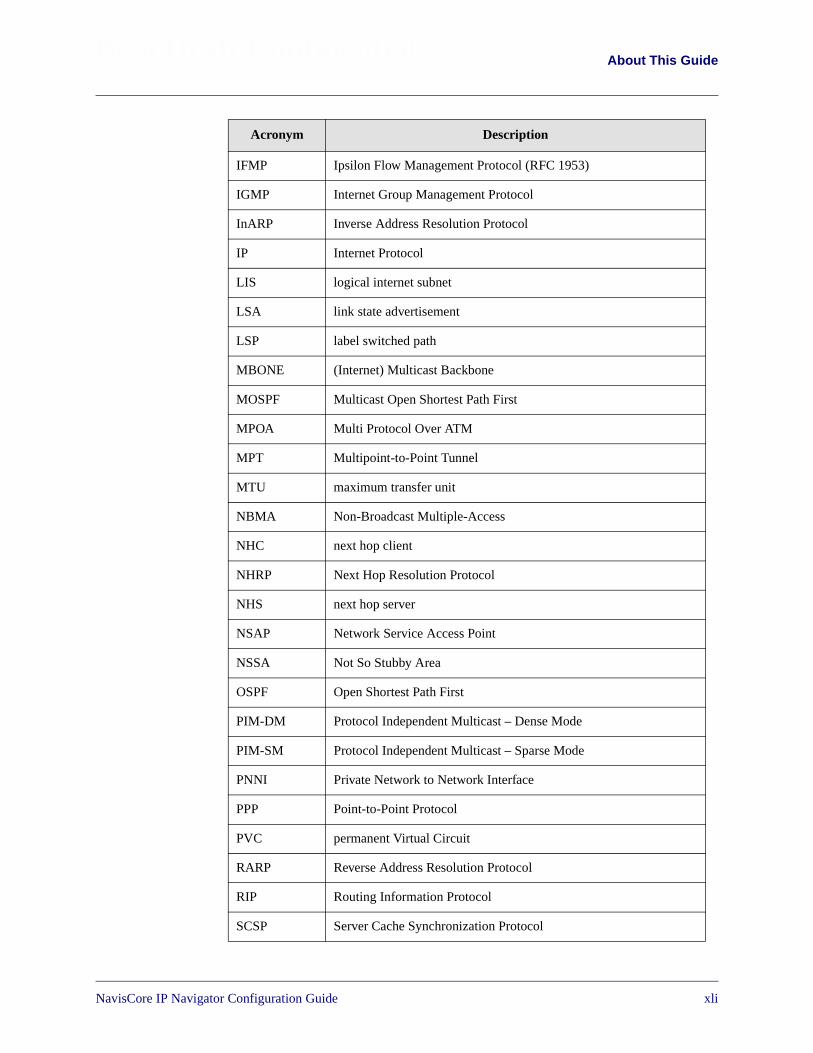
Beta Draft Confidential About This Guide
IFMP Ipsilon Flow Management Protocol (RFC 1953)
IGMP Internet Group Management Protocol
InARP Inverse Address Resolution Protocol
IP Internet Protocol
LIS logical internet subnet
LSA link state advertisement
LSP label switched path
MBONE (Internet) Multicast Backbone
MOSPF Multicast Open Shortest Path First
MPOA Multi Protocol Over ATM
MPT Multipoint-to-Point Tunnel
MTU maximum transfer unit
NBMA Non-Broadcast Multiple-Access
NHC next hop client
NHRP Next Hop Resolution Protocol
NHS next hop server
NSAP Network Service Access Point
NSSA Not So Stubby Area
OSPF Open Shortest Path First
PIM-DM Protocol Independent Multicast – Dense Mode
PIM-SM Protocol Independent Multicast – Sparse Mode
PNNI Private Network to Network Interface
PPP Point-to-Point Protocol
PVC permanent Virtual Circuit
RARP Reverse Address Resolution Protocol
RIP Routing Information Protocol
SCSP Server Cache Synchronization Protocol
Acronym Description
NavisCore IP Navigator Configuration Guide 1/14/02xli
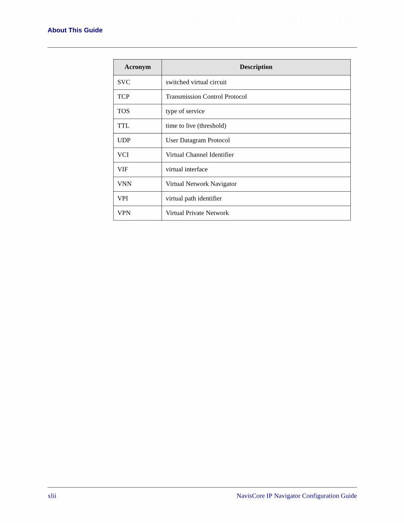
Beta Draft ConfidentialAbout This Guide
SVC switched virtual circuit
TCP Transmission Control Protocol
TOS type of service
TTL time to live (threshold)
UDP User Datagram Protocol
VCI Virtual Channel Identifier
VIF virtual interface
VNN Virtual Network Navigator
VPI virtual path identifier
VPN Virtual Private Network
Acronym Description
xlii1/14/02 NavisCore IP Navigator Configuration Guide
NavisCore IP Navigator Configuration Guide
Beta Draft Confidential
1
Overview
This chapter provides an overview of Lucent’s IP switching technology for coreswitches, called IP Navigator™, and describes how Lucent uses IP Navigator toimplement the TCP/IP protocol suite into its multiservice core switching platforms.
About IP Switching
Internet Protocol (IP) switching technology allows Lucent’s multiservice coreswitching platforms to assume the characteristics and role of an IP router. The maindifference between Lucent’s IP switching and traditional IP routing is that in the coreof the Lucent network, IP packets are switched instead of routed. In other words,instead of examining IP headers at each hop, Lucent switches examine the IP headeronly at the ingress and egress ports to the Lucent network. In the core of the network,the switches function as IP hardware forwarding engines. The advantages toimplementing IP switching technology over traditional routing include lower-layerpacket handling, improved traffic management and throughput, increasedperformance, and end-to-end Quality of Service (QoS).
In existing Internet Service Provider (ISP) networks, the addition of IP switchingallows service providers to optimize data traffic flow by eliminating the need for alldata packets to flow through the core router. IP switching also eases the managementand control duties of the core routers by reducing the number of routing sessions,eliminating IP table lookups, and in some cases, removing the need for the core routercompletely.
Lucent’s Implementation of IP Switching
Lucent adds its IP Navigator software to existing multiservice WAN platformsenabling service providers to offer standard or enhanced IP services based onend-to-end Quality of Service (QoS). IP Navigator is a software upgrade to the NMSfor Lucent’s multiservice switch platforms. (For specific hardware and softwarerequirements, refer to the software release notes that accompany your IP Navigatorsoftware package.)
1-1
Beta Draft ConfidentialOverviewLucent’s Implementation of IP Switching
IP Navigator enables a B-STDX and/or CBX switch on the edge of a WAN to runstandard IP routing protocols. CBX and/or B-STDX switches are on the edge of theLucent cloud, forwarding packets based on the IP address of the frames. Frame relay,ATM, and Ethernet interfaces are supported. Inside the cloud, a CBX 500 can be usedto provide a high-speed ATM backbone, whereby packets are switched overautomatically established virtual paths.
IP Forwarding
IP forwarding decisions are based on routes that are learned via standard routingprotocols running on the switch. Inside the autonomous system (AS), the OpenShortest Path First (OSPF) protocol is the Interior Gateway Protocol (IGP). TheBorder Gateway Protocol (BGP) is the Exterior Gateway Protocol (EGP). BGP learnsthe routes to networks in other autonomous systems. On links to CPE routers, RoutingInformation Protocol (RIP), OSPF, or static routing can be used to learn routes tonetworks that are reached through these routers.
1-2 NavisCore IP Navigator Configuration Guide

Beta Draft ConfidentialOverview
Lucent’s Implementation of IP Switching
Routing Protocols
IP Navigator supports a variety of IP routing protocols that are required tocommunicate with traditional routers. IP Navigator includes all the necessaryprotocols a service provider needs to offer Internet and Intranet services. Theseprotocols include:
• IGPs
• BGP-4 (used as the EGP)
• Internet and transport protocols
• Multicast protocols
Interior Gateway Protocols
RIP, RIP-2, and OSPF are interior gateway protocols (IGP). An IGP is used to developthe routing tables within a network that is administered by one company ororganization. RIP is still widely used in smaller IP networks.
OSPF is the routing protocol that is typically used in new or large IP networks. Anexpanded version of OSPF is part of the Virtual Network Navigator (VNN), theconnection-oriented routing technology used in Lucent switches.
Exterior Gateway Protocols
BGP is an EGP that exchanges routing information between autonomous systems. AnAS is a set of routers that has a single routing policy running under a single technicaladministration. BGP advertises routes between external BGP neighbors or peers,unlike IGPs such as OSPF and RIP, which advertise routes within the same AS. Whenyou configure a list of BGP neighbors and networks, you enable these peers andnetworks to exchange routing information with the BGP-configured switch. SeeFigure 8-1 for an example of AS relationships.
The Internet is a collection of autonomous systems. Interconnections amongautonomous systems typically do not use IGPs; instead, they use protocols that areclassified as EGPs, such as BGP.
There are two instances of OSPF: one for IP Navigator and one for VirtualNetwork Navigator (VNN). See Chapter 9, “Configuring IP OSPF and VNNOSPF,” for details.
Lucent supports BGP-4.
NavisCore IP Navigator Configuration Guide 1/14/021-3

Beta Draft ConfidentialOverviewLucent’s Implementation of IP Switching
Internet and Transport Protocols
IP Navigator supports the following Internet and transport protocols:
• Address Resolution Protocol (ARP)
• File Transfer Protocol (FTP)
• Internet Control Message Protocol (ICMP)
• Internet Protocol (IP)
• Inverse Address Resolution Protocol (InARP)
• Next Hop Resolution Protocol (NHRP)
• Simple Network Management Protocol (SNMP)
• Telnet Protocol (Telnet)
• Transmission Control Protocol (TCP)
• User Datagram Protocol (UDP)
Multicast Protocols
Multicasting allows a single packet of information to be sent to multiple destinations.Audio and videoconferencing are natural applications for this type of connection. IPNavigator supports Internet Group Management Protocol (IGMP), Multicast OSPF(MOSPF), and Distance Vector Multicast Routing Protocol (DVMRP).
1-4 NavisCore IP Navigator Configuration Guide

Beta Draft ConfidentialOverview
Lucent’s Implementation of IP Switching
Exchanging Routing Table Information
In any routed network, routers learn about the topology of the network by exchangingrouting information. In an IP Navigator network, the same information must beexchanged so that every router-enabled switch shares the same network view.
Each switch running IP Navigator in the Lucent network communicates with everyother switch running IP Navigator. Routing tables are maintained in each switch and amaster table is maintained in the switch’s control processor (CP) for B-STDX8000/9000 switches and in the switch processor (SP) for CBX 500 switches. Each I/Oprocessor (IOP) module stores routing table information, eliminating a single point offailure in the switch.
Mapping Routes to Virtual Circuits
The process of establishing and mapping routes to virtual circuits is the role of theVirtual Network Navigator (VNN). VNN establishes virtual circuits between entryand exit points in the network. The virtual circuits are then mapped to routes based onthe egress node. The process of establishing the virtual circuits is automatic. Topologychanges, such as the addition of a new switch, trigger a recalculation of all virtualcircuits. More importantly, VNN continually monitors the performance of each virtualcircuit, recalculating a new path if a better one exists. The monitoring process is astandard function of VNN, and its functions are expanded to include IP Navigator.
NavisCore IP Navigator Configuration Guide 1/14/021-5
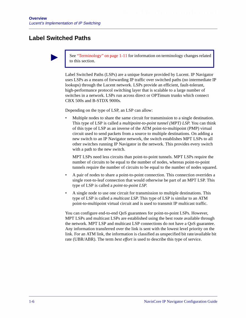
Beta Draft ConfidentialOverviewLucent’s Implementation of IP Switching
Label Switched Paths
Label Switched Paths (LSPs) are a unique feature provided by Lucent. IP Navigatoruses LSPs as a means of forwarding IP traffic over switched paths (no intermediate IPlookups) through the Lucent network. LSPs provide an efficient, fault-tolerant,high-performance protocol switching layer that is scalable to a large number ofswitches in a network. LSPs run across direct or OPTimum trunks which connectCBX 500s and B-STDX 9000s.
Depending on the type of LSP, an LSP can allow:
• Multiple nodes to share the same circuit for transmission to a single destination.This type of LSP is called a multipoint-to-point tunnel (MPT) LSP. You can thinkof this type of LSP as an inverse of the ATM point-to-multipoint (PMP) virtualcircuit used to send packets from a source to multiple destinations. On adding anew switch to an IP Navigator network, the switch establishes MPT LSPs to allother switches running IP Navigator in the network. This provides every switchwith a path to the new switch.
MPT LSPs need less circuits than point-to-point tunnels. MPT LSPs require thenumber of circuits to be equal to the number of nodes, whereas point-to-pointtunnels require the number of circuits to be equal to the number of nodes squared.
• A pair of nodes to share a point-to-point connection. This connection overrides asingle root-to-leaf connection that would otherwise be part of an MPT LSP. Thistype of LSP is called a point-to-point LSP.
• A single node to use one circuit for transmission to multiple destinations. Thistype of LSP is called a multicast LSP. This type of LSP is similar to an ATMpoint-to-multipoint virtual circuit and is used to transmit IP multicast traffic.
You can configure end-to-end QoS guarantees for point-to-point LSPs. However,MPT LSPs and multicast LSPs are established using the best route available throughthe network. MPT LSP and multicast LSP connections do not have a QoS guarantee.Any information transferred over the link is sent with the lowest level priority on thelink. For an ATM link, the information is classified as unspecified bit rate/available bitrate (UBR/ABR). The term best effort is used to describe this type of service.
See “Terminology” on page 1-11 for information on terminology changes relatedto this section.
1-6 NavisCore IP Navigator Configuration Guide
Beta Draft ConfidentialOverview
Lucent’s Implementation of IP Switching
Switches in an IP Navigator network automatically establish LSP circuits uponstartup. However, you must enable LSPs on switches. For more information on this,see “Enabling MPT LSPs and Multicast LSPs” on page 12-11. VNN calculates thebest path from each node to the new switch using its own extended version of OSPF.These paths are used to form the LSP. Major network changes cause VNN torecalculate the LSPs. If configured to do so, VNN will continually monitor the LSPsand recalculate them based on performance. VNN treats the LSPs the same way ittreats any other circuit connection. No special configuration is required for LSPmonitoring.
See Chapter 12, “Configuring Label Switched Paths,” for more information on LSPs.
Absolute QoS
The absolute QoS feature allows IP Navigator to provide an on demand ATM SVC toa destination. IP Navigator uses fields within the IP packet such as source ordestination address, IP protocol number, source and destination protocol ports, and thetype of service field to map critical IP traffic on to a dynamically established ATMSVC. This feature is especially useful for applications that require a high degree ofQoS, such as voice over IP.
The absolute QoS feature is implemented through NHRP, which is the protocol usedto establish on demand ATM SVCs. See Chapter 13, “About Next Hop ResolutionProtocol” and Chapter 14, “Configuring Next Hop Resolution Protocol” for moreinformation on configuring NHRP.
NavisCore IP Navigator Configuration Guide 1/14/021-7
Beta Draft ConfidentialOverviewLucent’s Implementation of IP Switching
Policy-Based Forwarding
Policy-based forwarding is a technique for forwarding IP packets based on criteriadefined in forwarding policies. Policy-based forwarding allows switches to forwardpackets based on policies rather than on destination IP addresses.
You associate forwarding policies with one or more ingress IP logical ports on aswitch. If an IP packet received at IP logical port XYZ matches the criteria of aforwarding policy associated with that port, IP Navigator forwards the packet over aspecified policy PVC. Otherwise, IP Navigator routes the packet on a best-effort basisaccording to the packet’s destination IP address.
You associate IP forwarding policies with existing policy PVCs, which you set upwith Quality of Service attributes (QoS class, traffic descriptors such as PCR, SCR).
See Chapter 5, “Configuring Policy-Based Forwarding,” for more information onpolicy-based forwarding.
IP Virtual Private Networks
An IP Virtual Private Network (VPN) is a collection of IP network resources that apublic carrier or service provider reserves for private use.
In a traditional IP enterprise network, all resources are owned and controlled by asingle organization. To users within the organization, the network appears as aseparate routing domain. However, when a public carrier or service provider reservesresources for IP VPNs, each IP VPN has its own view — that is, users of the IP VPNsee only the resources reserved for them. Although multiple VPNs may share the samephysical topology, each VPN appears to its users as if it were a separate routingdomain.
To a network manager, a IP VPN also appears as a separate network. NavisCoreallows the network manager to select a specific VPN to be managed. This allows thenetwork manager to see only certain resources configured for the VPN (routes, routemaps, and so on).
See Chapter 16, “Configuring IP Virtual Private Networks,” for more information onIP VPNs.
See “Terminology” on page 1-11 for information on terminology changes relatedto this section.
1-8 NavisCore IP Navigator Configuration Guide

Beta Draft ConfidentialOverview
Configuration and Management
Configuration and Management
With the addition of IP Navigator, NavisCore and associated network managementserver products provide the required support for all IP switching features.Theprotocols required to configure IP switching include: IP, OSPF, RIP, and BGP. Inaddition, IP Navigator adds new monitoring functions to enable networkadministrators to monitor their IP traffic parameters and routing-table contents.
IP Navigator supports the following standard MIBs:
• MIB II
• OSPF v2 MIB
• BGP-4 MIB
• Routing Table MIB
• RIP v2 MIB
In addition, IP Navigator supports the following Internet Engineering Task Force(IETF) draft MIBs:
• RFC Draft IGMP MIB
• RFC Draft DVMRP MIB
• RFC Draft Multicast MIB
• RFC Draft NHRP MIB
NavisCore IP Navigator Configuration Guide 1/14/021-9

Beta Draft ConfidentialOverviewConfiguration and Management
Logical Port Configuration
You can configure the following types of logical ports for IP routing:
• IP logical ports on B-STDX 8000/9000 and CBX 500 switches. IP logical portsare ports that support IP routing.
• IP Server logical ports on the CBX 500. IP Server logical ports provide a methodof accepting or transmitting IP traffic to or from a cell-based logical port.
Table 1-1 lists the logical ports and card types that support IP routing on the B-STDX8000/9000. Table 1-2 lists the logical ports and examples of card types that support IProuting on the CBX 500. Contact your Lucent representative or see your softwarerelease notice for an exact list of supported card types.
See Chapter 3, “Configuring IP Logical Ports and IP Servers,” and Chapter 16,“Configuring IP Virtual Private Networks,” for further details about logical portconfiguration.
a Frame Card Examples = UIO, 4-T1, 4-E1, DSX-10, HSSI, Ch DS3, Ch DS 3/1/0, 12-E1b ATM Card Examples = ATM CS, ATM DS3, ATM E3, ATM OC3
NHRP logical ports are supported on B-STDX 8000/9000 and CBX 500switches. NHRP logical ports support NHRP communications over IP logicalports. You add NHRP logical ports to IP logical ports.
Table 1-1. Logical Ports That Support IP Routing on the B-STDX 8000/9000
Logical Port Card Types Encapsulation Address Resolution
FR UNI-DCE
FR UNI-DTE
FR NNI
Frame cardsa RFC1490 InARP (RFC1293)ARP (RFC1490)
PPP Frame cardsa PPP N/A
ATM UNI DTE
ATM UNI DCE
Frame cardsa RFC 1483 InATMARP
ATM UNI DTE
ATM UNI DCE
ATM cardsb RFC 1483 InATMARP
Ethernet 2-portEthernet card
IEEE SNAPEthernet II
ARP
IP VPN Cloud N/A N/A ARP
1-10 NavisCore IP Navigator Configuration Guide
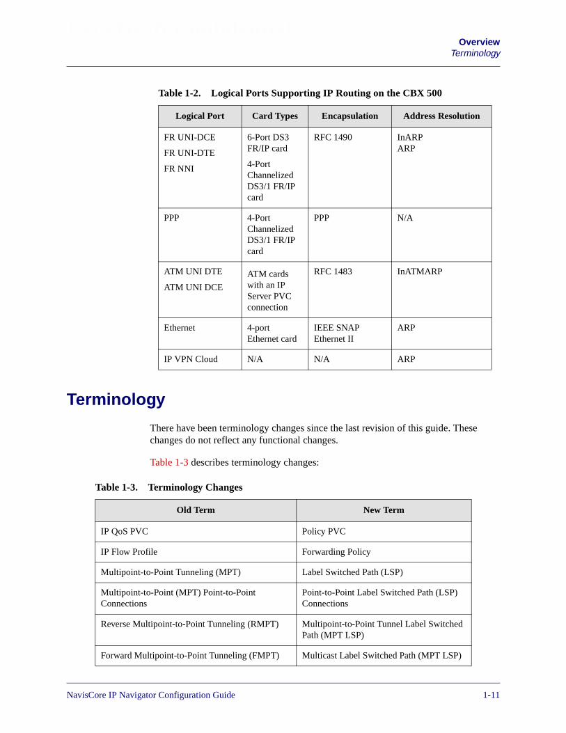
Beta Draft ConfidentialOverview
Terminology
Terminology
There have been terminology changes since the last revision of this guide. Thesechanges do not reflect any functional changes.
Table 1-3 describes terminology changes:
Table 1-2. Logical Ports Supporting IP Routing on the CBX 500
Logical Port Card Types Encapsulation Address Resolution
FR UNI-DCE
FR UNI-DTE
FR NNI
6-Port DS3FR/IP card
4-PortChannelizedDS3/1 FR/IPcard
RFC 1490 InARPARP
PPP 4-PortChannelizedDS3/1 FR/IPcard
PPP N/A
ATM UNI DTE
ATM UNI DCE
ATM cardswith an IPServer PVCconnection
RFC 1483 InATMARP
Ethernet 4-portEthernet card
IEEE SNAPEthernet II
ARP
IP VPN Cloud N/A N/A ARP
Table 1-3. Terminology Changes
Old Term New Term
IP QoS PVC Policy PVC
IP Flow Profile Forwarding Policy
Multipoint-to-Point Tunneling (MPT) Label Switched Path (LSP)
Multipoint-to-Point (MPT) Point-to-PointConnections
Point-to-Point Label Switched Path (LSP)Connections
Reverse Multipoint-to-Point Tunneling (RMPT) Multipoint-to-Point Tunnel Label SwitchedPath (MPT LSP)
Forward Multipoint-to-Point Tunneling (FMPT) Multicast Label Switched Path (MPT LSP)
NavisCore IP Navigator Configuration Guide 1/14/021-11

Beta Draft ConfidentialOverviewTerminology
1-12 NavisCore IP Navigator Configuration Guide
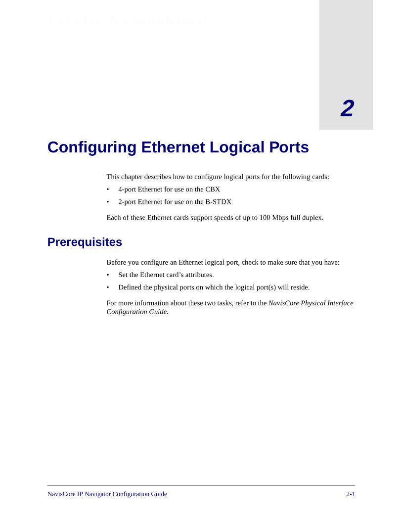
NavisCore IP Navigator Configuration Guide
Beta Draft Confidential
2
Configuring Ethernet Logical Ports
This chapter describes how to configure logical ports for the following cards:
• 4-port Ethernet for use on the CBX
• 2-port Ethernet for use on the B-STDX
Each of these Ethernet cards support speeds of up to 100 Mbps full duplex.
Prerequisites
Before you configure an Ethernet logical port, check to make sure that you have:
• Set the Ethernet card’s attributes.
• Defined the physical ports on which the logical port(s) will reside.
For more information about these two tasks, refer to the NavisCore Physical InterfaceConfiguration Guide.
2-1

Beta Draft ConfidentialConfiguring Ethernet Logical PortsAccessing the Logical Port Functions
Accessing the Logical Port Functions
To access the Logical Port functions in NavisCore:
1. Select the switch to which you want to add a logical port.
2. Log in to NavisCore using either a provisioning or operator password.
3. From the Administer menu, select Lucent Parameters� Set Parameters.
The Switch Back Panel dialog box appears. Figure 2-1 illustrates the Switch BackPanel dialog box for a CBX 500.
Figure 2-1. Switch Back Panel (CBX) Dialog Box
4. Select the physical port you want to configure. Choose the Attrs button. The SetPhysical Port Attributes dialog box appears (see Figure 2-2).
Select the physicalport and chooseAttrs.
2-2 NavisCore IP Navigator Configuration Guide
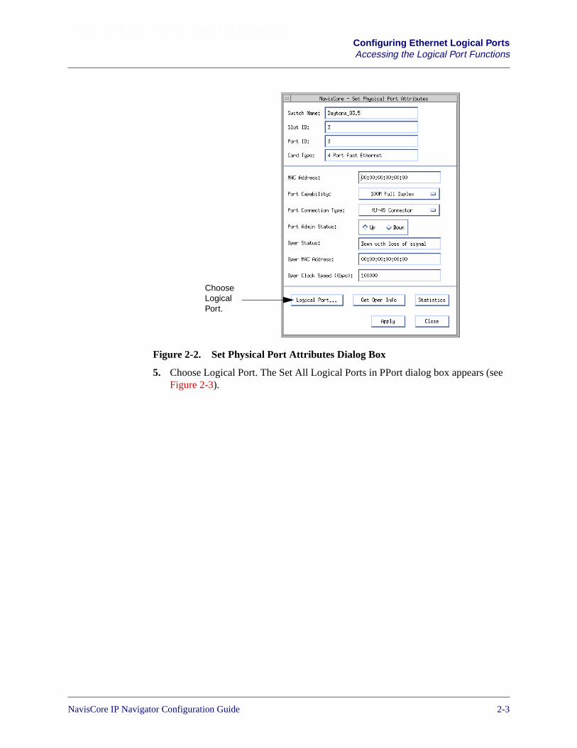
Beta Draft ConfidentialConfiguring Ethernet Logical PortsAccessing the Logical Port Functions
Figure 2-2. Set Physical Port Attributes Dialog Box
5. Choose Logical Port. The Set All Logical Ports in PPort dialog box appears (seeFigure 2-3).
ChooseLogicalPort.
NavisCore IP Navigator Configuration Guide 1/14/022-3
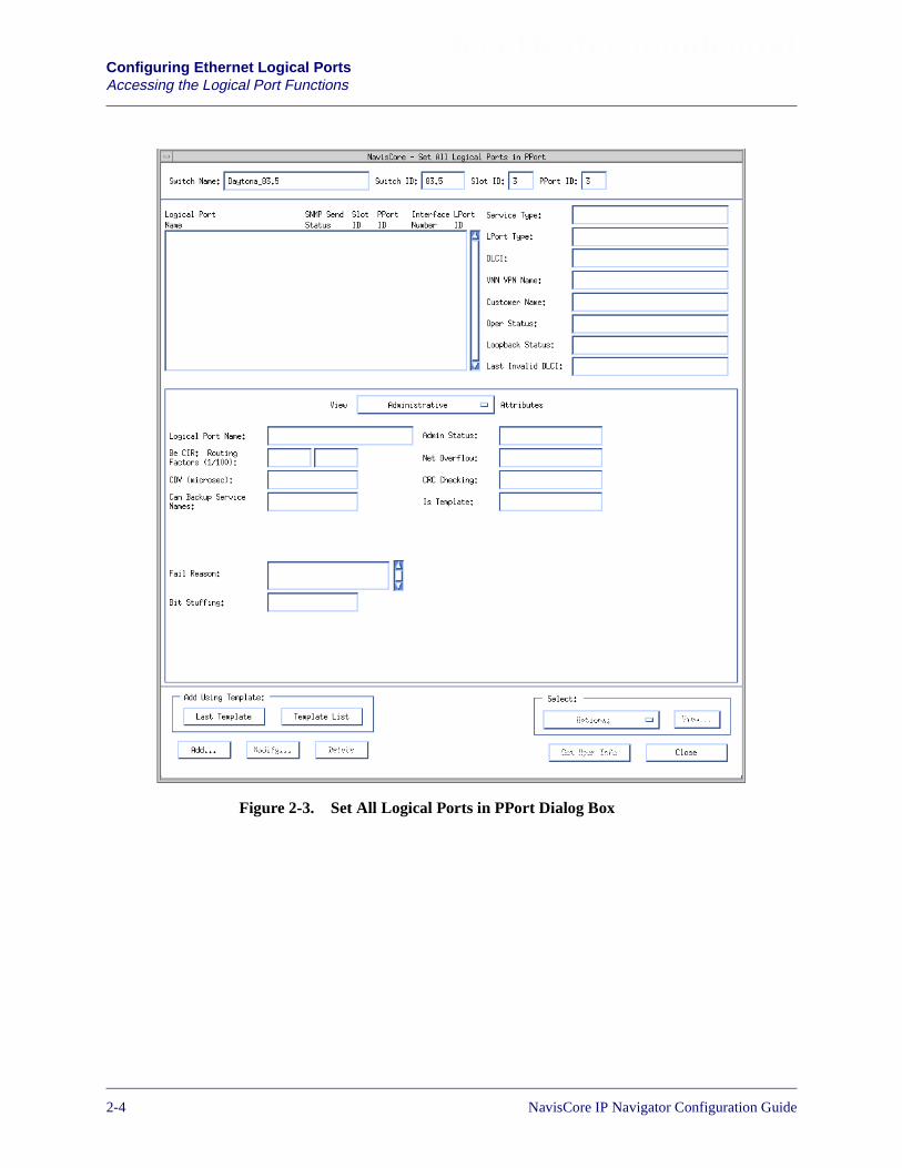
Beta Draft ConfidentialConfiguring Ethernet Logical PortsAccessing the Logical Port Functions
Figure 2-3. Set All Logical Ports in PPort Dialog Box
2-4 NavisCore IP Navigator Configuration Guide
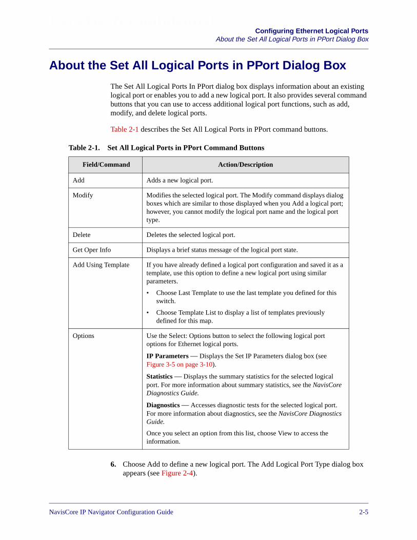
Beta Draft ConfidentialConfiguring Ethernet Logical Ports
About the Set All Logical Ports in PPort Dialog Box
About the Set All Logical Ports in PPort Dialog Box
The Set All Logical Ports In PPort dialog box displays information about an existinglogical port or enables you to add a new logical port. It also provides several commandbuttons that you can use to access additional logical port functions, such as add,modify, and delete logical ports.
Table 2-1 describes the Set All Logical Ports in PPort command buttons.
6. Choose Add to define a new logical port. The Add Logical Port Type dialog boxappears (see Figure 2-4).
Table 2-1. Set All Logical Ports in PPort Command Buttons
Field/Command Action/Description
Add Adds a new logical port.
Modify Modifies the selected logical port. The Modify command displays dialogboxes which are similar to those displayed when you Add a logical port;however, you cannot modify the logical port name and the logical porttype.
Delete Deletes the selected logical port.
Get Oper Info Displays a brief status message of the logical port state.
Add Using Template If you have already defined a logical port configuration and saved it as atemplate, use this option to define a new logical port using similarparameters.
• Choose Last Template to use the last template you defined for thisswitch.
• Choose Template List to display a list of templates previouslydefined for this map.
Options Use the Select: Options button to select the following logical portoptions for Ethernet logical ports.
IP Parameters — Displays the Set IP Parameters dialog box (seeFigure 3-5 on page 3-10).
Statistics — Displays the summary statistics for the selected logicalport. For more information about summary statistics, see the NavisCoreDiagnostics Guide.
Diagnostics — Accesses diagnostic tests for the selected logical port.For more information about diagnostics, see the NavisCore DiagnosticsGuide.
Once you select an option from this list, choose View to access theinformation.
NavisCore IP Navigator Configuration Guide 1/14/022-5
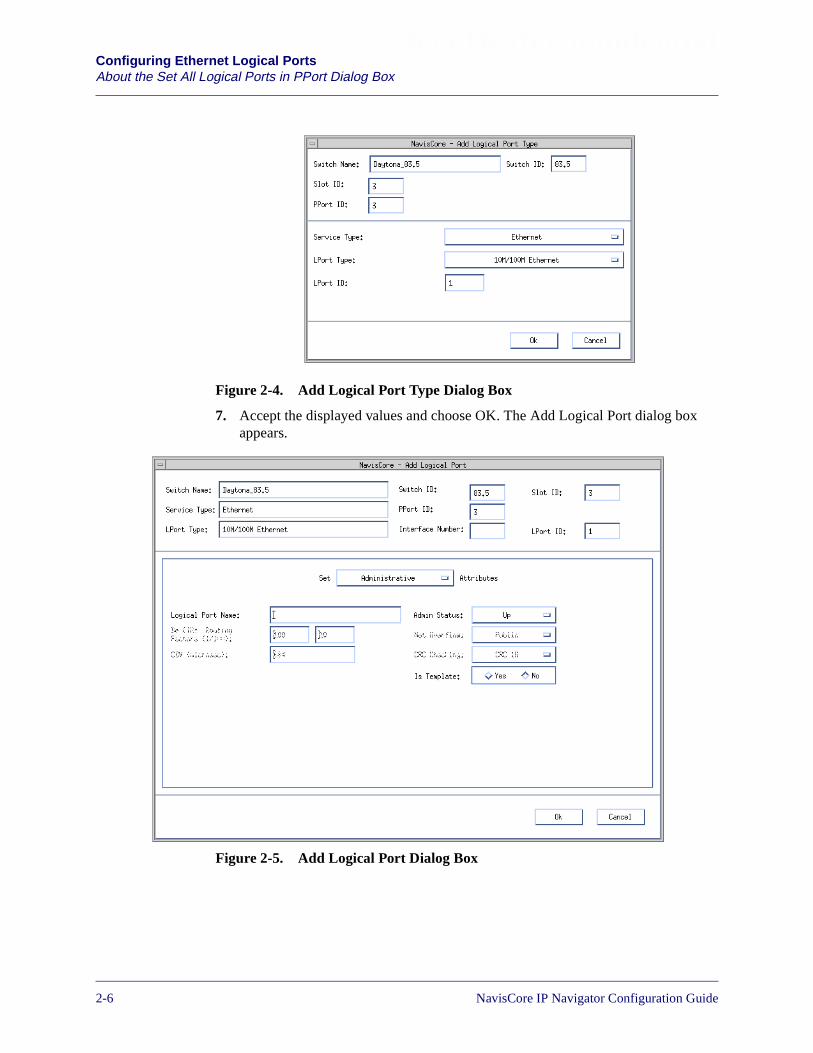
Beta Draft ConfidentialConfiguring Ethernet Logical PortsAbout the Set All Logical Ports in PPort Dialog Box
Figure 2-4. Add Logical Port Type Dialog Box
7. Accept the displayed values and choose OK. The Add Logical Port dialog boxappears.
Figure 2-5. Add Logical Port Dialog Box
2-6 NavisCore IP Navigator Configuration Guide
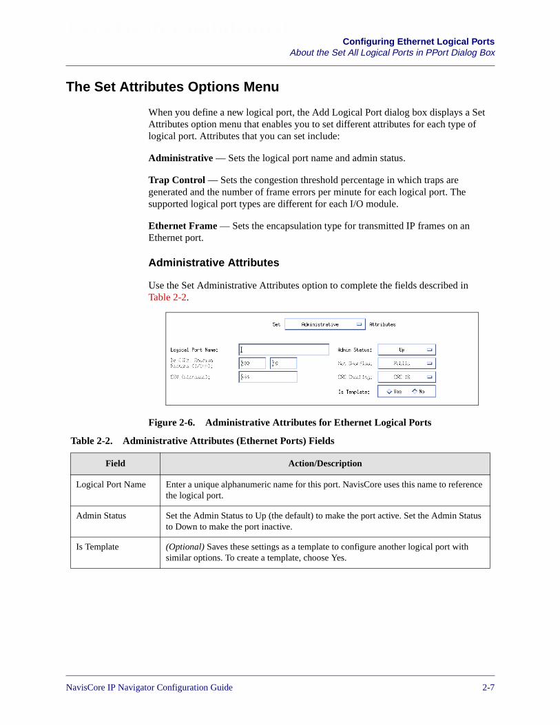
Beta Draft ConfidentialConfiguring Ethernet Logical Ports
About the Set All Logical Ports in PPort Dialog Box
The Set Attributes Options Menu
When you define a new logical port, the Add Logical Port dialog box displays a SetAttributes option menu that enables you to set different attributes for each type oflogical port. Attributes that you can set include:
Administrative — Sets the logical port name and admin status.
Trap Control — Sets the congestion threshold percentage in which traps aregenerated and the number of frame errors per minute for each logical port. Thesupported logical port types are different for each I/O module.
Ethernet Frame — Sets the encapsulation type for transmitted IP frames on anEthernet port.
Administrative Attributes
Use the Set Administrative Attributes option to complete the fields described inTable 2-2.
Figure 2-6. Administrative Attributes for Ethernet Logical Ports
Table 2-2. Administrative Attributes (Ethernet Ports) Fields
Field Action/Description
Logical Port Name Enter a unique alphanumeric name for this port. NavisCore uses this name to referencethe logical port.
Admin Status Set the Admin Status to Up (the default) to make the port active. Set the Admin Statusto Down to make the port inactive.
Is Template (Optional) Saves these settings as a template to configure another logical port withsimilar options. To create a template, choose Yes.
NavisCore IP Navigator Configuration Guide 1/14/022-7
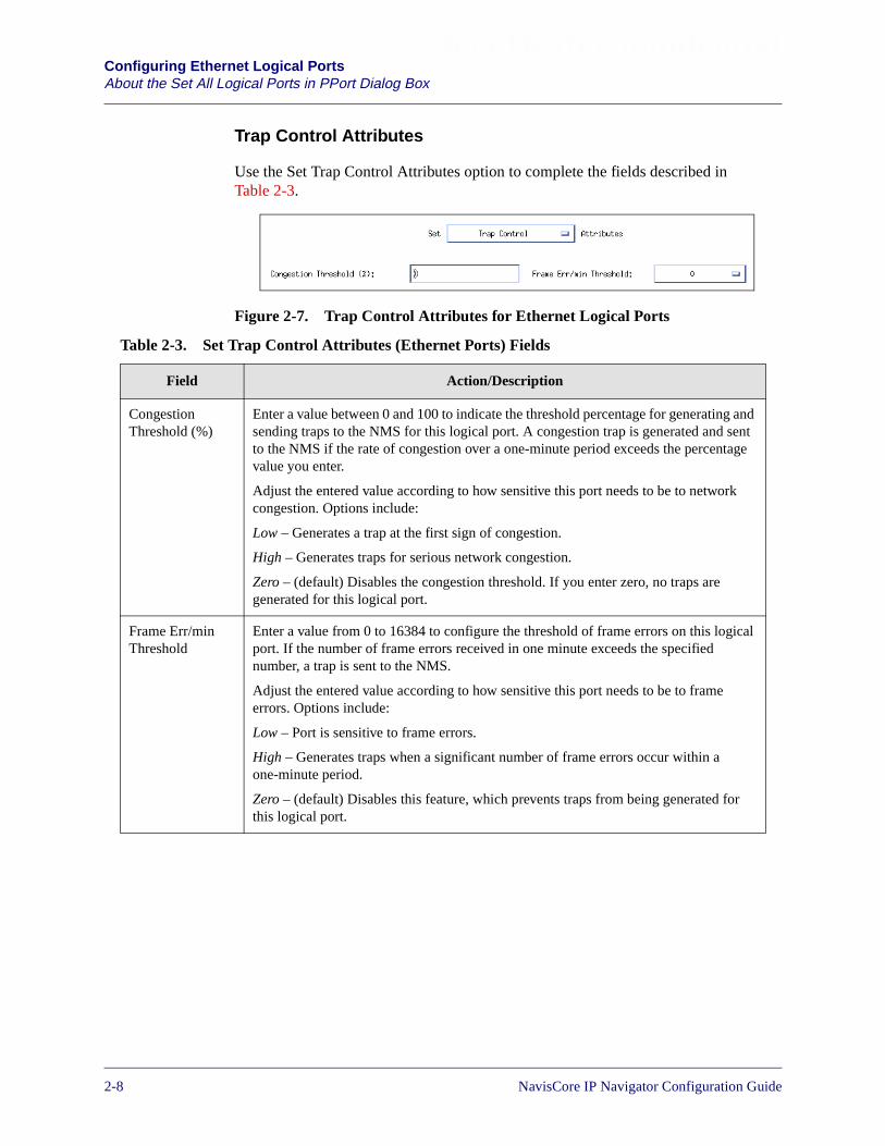
Beta Draft ConfidentialConfiguring Ethernet Logical PortsAbout the Set All Logical Ports in PPort Dialog Box
Trap Control Attributes
Use the Set Trap Control Attributes option to complete the fields described inTable 2-3.
Figure 2-7. Trap Control Attributes for Ethernet Logical Ports
Table 2-3. Set Trap Control Attributes (Ethernet Ports) Fields
Field Action/Description
CongestionThreshold (%)
Enter a value between 0 and 100 to indicate the threshold percentage for generating andsending traps to the NMS for this logical port. A congestion trap is generated and sentto the NMS if the rate of congestion over a one-minute period exceeds the percentagevalue you enter.
Adjust the entered value according to how sensitive this port needs to be to networkcongestion. Options include:
Low – Generates a trap at the first sign of congestion.
High – Generates traps for serious network congestion.
Zero – (default) Disables the congestion threshold. If you enter zero, no traps aregenerated for this logical port.
Frame Err/minThreshold
Enter a value from 0 to 16384 to configure the threshold of frame errors on this logicalport. If the number of frame errors received in one minute exceeds the specifiednumber, a trap is sent to the NMS.
Adjust the entered value according to how sensitive this port needs to be to frameerrors. Options include:
Low – Port is sensitive to frame errors.
High – Generates traps when a significant number of frame errors occur within aone-minute period.
Zero – (default) Disables this feature, which prevents traps from being generated forthis logical port.
2-8 NavisCore IP Navigator Configuration Guide
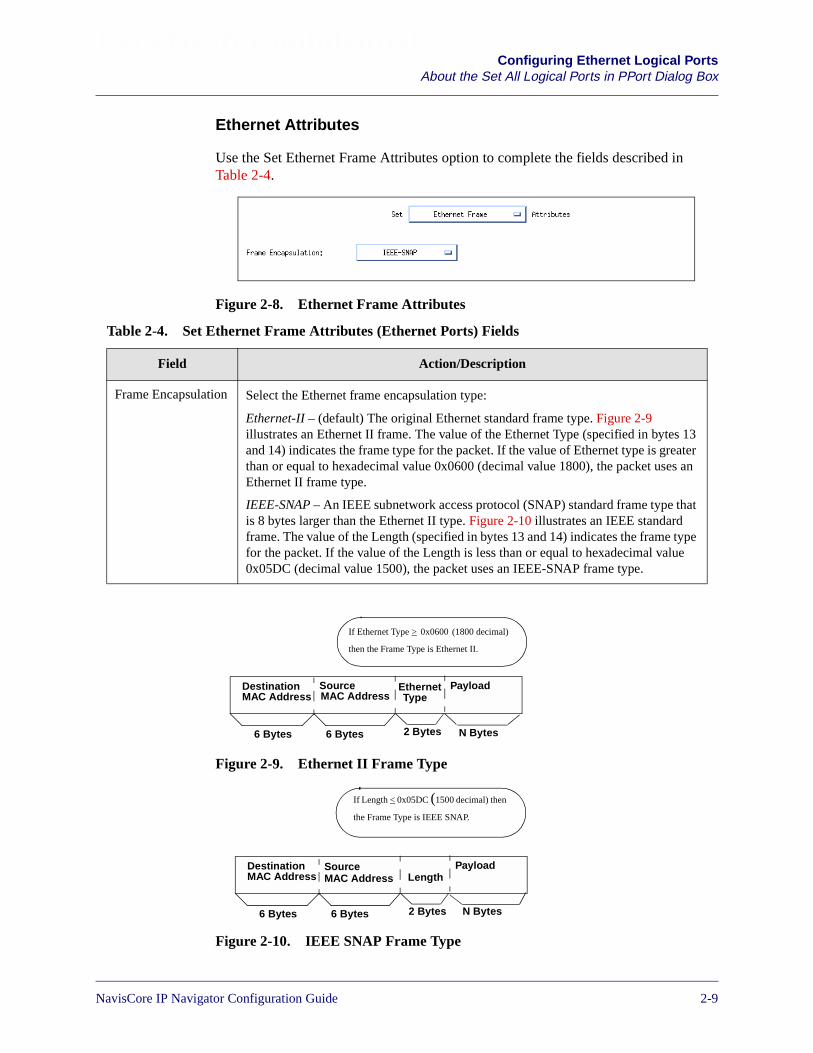
Beta Draft ConfidentialConfiguring Ethernet Logical Ports
About the Set All Logical Ports in PPort Dialog Box
Ethernet Attributes
Use the Set Ethernet Frame Attributes option to complete the fields described inTable 2-4.
Figure 2-8. Ethernet Frame Attributes
Figure 2-9. Ethernet II Frame Type
Figure 2-10. IEEE SNAP Frame Type
Table 2-4. Set Ethernet Frame Attributes (Ethernet Ports) Fields
Field Action/Description
Frame Encapsulation Select the Ethernet frame encapsulation type:
Ethernet-II – (default) The original Ethernet standard frame type. Figure 2-9illustrates an Ethernet II frame. The value of the Ethernet Type (specified in bytes 13and 14) indicates the frame type for the packet. If the value of Ethernet type is greaterthan or equal to hexadecimal value 0x0600 (decimal value 1800), the packet uses anEthernet II frame type.
IEEE-SNAP – An IEEE subnetwork access protocol (SNAP) standard frame type thatis 8 bytes larger than the Ethernet II type. Figure 2-10 illustrates an IEEE standardframe. The value of the Length (specified in bytes 13 and 14) indicates the frame typefor the packet. If the value of the Length is less than or equal to hexadecimal value0x05DC (decimal value 1500), the packet uses an IEEE-SNAP frame type.
DestinationMAC Address
SourceMAC Address
6 Bytes 6 Bytes
EthernetType
2 Bytes
Payload
N Bytes
If Ethernet Type > 0x0600 (1800 decimal)
then the Frame Type is Ethernet II.
DestinationMAC Address
SourceMAC Address
6 Bytes 6 Bytes
Length
2 Bytes
Payload
N Bytes
If Length < 0x05DC (1500 decimal) then
the Frame Type is IEEE SNAP.
NavisCore IP Navigator Configuration Guide 1/14/022-9

Beta Draft ConfidentialConfiguring Ethernet Logical PortsAbout the Set All Logical Ports in PPort Dialog Box
2-10 NavisCore IP Navigator Configuration Guide
NavisCore IP Navigator Configuration Guide
Beta Draft Confidential
3
Configuring IP Logical Ports and IPServers
This chapter describes how to configure:
• IP logical ports on B-STDX 8000/9000 and CBX 500 switches. IP logical portsare ports that support IP routing. See Figure 3-1 on page 3-5 for a summary of theIP logical port configuration process.
• IP server logical ports on the CBX 500 switch. IP server logical ports provide amethod of accepting or transmitting IP traffic on a cell-based card. SeeFigure 3-14 on page 3-28 for a summary of the IP server logical portconfiguration process.
This chapter does not discuss managing IP logical ports and IP server logicalports for private IP virtual private networks (IP VPNs). For more information onIP VPN management, see Chapter 16, “Configuring IP Virtual PrivateNetworks.”
3-1

Beta Draft ConfidentialConfiguring IP Logical Ports and IP Servers
Table 3-1 lists the logical ports that support IP routing. Contact your Lucentrepresentative or see your software release notice for an exact list of supported cardtypes.
a Frame Card Examples = UIO, 4-T1, 4-E1, DSX-10, HSSI, Ch DS3, Ch DS 3/1/0, 12-E1b ATM Card Examples = ATM CS, ATM DS3, ATM E3, ATM OC3
Table 3-1. Logical Ports that Support IP Routing
Switch Logical Port Card Types
B-STDX 8000/9000 FR UNI-DCE
FR UNI-DTE
FR NNI
Frame cardsa
PPP Frame cardsa
ATM UNI DTE
ATM UNI DCE
Frame cardsa
ATM UNI DTE
ATM UNI DCE
ATM cardsb
Ethernet 2-port Ethernet cards
CBX 500 Frame Relay 4-port channelizedDS3/1 FR/IP card
Frame Relay 6-port DS3 FR/IP card
PPP 4-port channelizedDS3/1 FR/IP card
Ethernet 4-port Ethernet card
ATM UNI DTE
ATM UNI DCE
ATM cards with an IPserver PVC connection
3-2 NavisCore IP Navigator Configuration Guide
Beta Draft ConfidentialConfiguring IP Logical Ports and IP Servers
Prerequisites
Prerequisites
Prior to configuring IP services, verify that the following tasks are complete.
• Create a network map.
• Configure the switch parameters. If you are configuring an IP logical port on aCBX 500, you must install and configure a 6-port DS3 FR/IP card, a 4-portChannelized DS3/1 FR/IP card, or a 4-port Ethernet card.
• Configure the physical port parameters.
• If you are configuring an IP logical port on a B-STDX 8000/9000, configure thelogical port for Frame Relay, ATM, or Ethernet service.
For more details about these tasks, see Chapter 2, “Configuring Ethernet LogicalPorts” and the following guides:
• NavisCore Frame Relay Configuration Guide for information about configuringlogical ports for frame relay service.
• NavisCore ATM Configuration Guide for information about configuring logicalports for ATM service.
• NavisCore Physical Interface Configuration Guide for information aboutconfiguring cards and physical ports.
NavisCore IP Navigator Configuration Guide 1/14/023-3
Beta Draft ConfidentialConfiguring IP Logical Ports and IP ServersAbout IP Addresses
About IP Addresses
When you specify the IP address, you must specify the type of IP forwarding thelogical port will use. The following two types of IP forwarding are automaticallyenabled by default:
Unicast — Enables IP forwarding from this logical port to a unicast address.
Broadcast — Enables IP forwarding from this logical port to a broadcast address.
Address Resolution Protocol
A node requires the following information to communicate with another node:
• IP address of the destination node
• Hardware address of the destination node (DLCI for Frame Relay and VPI/VCIfor ATM)
IP Navigator uses one of the following protocols to resolve an unknown hardware orIP address:
Address Resolution Protocol (ARP) — Used for Frame Relay, Ethernet, and IP VPNcloud interface configurations when an IP address of a given destination is known, butthe destination hardware address (e.g., MAC address or DLCI) is not.
Inverse Address Resolution Protocol (InARP) — Used for Frame Relay and ATMconfigurations when the destination hardware address (DLCI or VPI/VCI) is known,but the destination IP address is not.
The ARP table resides in the CP/SP memory. An ARP entry is stored for 25 minutes(the same amount of time as a BSD IP stack). All statically configured ARP entries arestored in PRAM. If there is a change in the ARP table, it is sent to the IOP.
3-4 NavisCore IP Navigator Configuration Guide

Beta Draft ConfidentialConfiguring IP Logical Ports and IP Servers
Configuring IP Logical Ports
Configuring IP Logical Ports
Figure 3-1 illustrates the steps for configuring an IP logical port on a B-STDX8000/9000 switch or on a CBX 500 switch.
Figure 3-1. IP Logical Port Configuration Process
Specify the IP Interface Address. See “Setting theIP Interface Address” on page 3-14.
Use the Set All IP LPort function to add an IPLogical Port. See “Adding an IP Logical Port” onpage 3-10.
Specify DLCI Parameters and bind DLCI to aninterface (Frame Relay LPorts only). See “Settingthe DLCI for Frame Relay Logical Ports” onpage 3-18 and “Binding an IP Interface” onpage 3-24.
Enable RIP on this logical port(Chapter 7).
Enable OSPF on this logical port(Chapter 9).
Configure Packet Filters on thisinterface (Chapter 4).
Configure policy-based forwardingon this logical port (Chapter 5).
OR
OR
Configure NHRP on this logicalport (Chapter 14).
Configure multicast on this logicalport (Chapter 15).
Configure IP VPN resources onthis logical port (Chapter 16).
Specify the VPI/VCI Parameters and bindVPI/VCI to an interface (ATM LPorts only). See“Setting the VPI/VCI for ATM Logical Ports” onpage 3-21 and “Binding an IP Interface” onpage 3-24.
NavisCore IP Navigator Configuration Guide 1/14/023-5
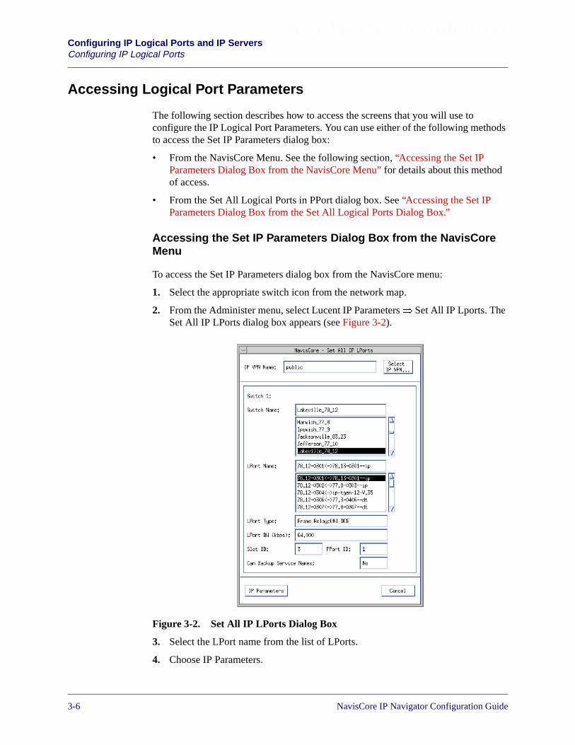
Beta Draft ConfidentialConfiguring IP Logical Ports and IP ServersConfiguring IP Logical Ports
Accessing Logical Port Parameters
The following section describes how to access the screens that you will use toconfigure the IP Logical Port Parameters. You can use either of the following methodsto access the Set IP Parameters dialog box:
• From the NavisCore Menu. See the following section, “Accessing the Set IPParameters Dialog Box from the NavisCore Menu” for details about this methodof access.
• From the Set All Logical Ports in PPort dialog box. See “Accessing the Set IPParameters Dialog Box from the Set All Logical Ports Dialog Box.”
Accessing the Set IP Parameters Dialog Box from the NavisCoreMenu
To access the Set IP Parameters dialog box from the NavisCore menu:
1. Select the appropriate switch icon from the network map.
2. From the Administer menu, select Lucent IP Parameters� Set All IP Lports. TheSet All IP LPorts dialog box appears (see Figure 3-2).
Figure 3-2. Set All IP LPorts Dialog Box
3. Select the LPort name from the list of LPorts.
4. Choose IP Parameters.
3-6 NavisCore IP Navigator Configuration Guide

Beta Draft ConfidentialConfiguring IP Logical Ports and IP Servers
Configuring IP Logical Ports
If an IP logical port has not defined for the logical port, the Set IP Parametersdialog box appears with the Add IP LPort button displayed (see Figure 3-3).
If an IP logical port has been previously defined for the logical port, the Set IPParameters dialog box appears without the Add IP LPort button displayed (seeFigure 3-5 on page 3-10).
Figure 3-3. Set IP Parameters Dialog Box (No IP LPort)
See “Adding an IP Logical Port” on page 3-10 for instructions on adding an IPLPort from the Set IP Parameters dialog box.
NavisCore IP Navigator Configuration Guide 1/14/023-7

Beta Draft ConfidentialConfiguring IP Logical Ports and IP ServersConfiguring IP Logical Ports
Accessing the Set IP Parameters Dialog Box from the Set AllLogical Ports Dialog Box
To access the Set IP Parameters dialog box from the Set All Logical Ports in PPortdialog box:
1. From the network map select the appropriate switch icon.
2. From the Administer menu select Lucent Parameters� Set Parameters. TheSwitch Back Panel dialog box appears.
3. Select the physical port and choose Attrs. The Set Physical Port Attributes dialogbox appears.
4. Perform one of the following actions:
a. For unchannelized physical ports, choose Logical Port. The Set All LogicalPorts in PPort dialog box appears (see Figure 3-4).
b. For physical ports on channelized DS 3/1/0 modules on B-STDX switches,double click on the channel. The Set Channel Attributes dialog box appears.Choose Logical Port. The Set All Logical Ports in PPort dialog box appears(see Figure 3-4).
c. For channelized physical ports other than channelized DS 3/1/0 ports onB-STDX switches, select a channel and choose Logical Port. The Set AllLogical Ports in PPort dialog box appears (see Figure 3-4).
3-8 NavisCore IP Navigator Configuration Guide

Beta Draft ConfidentialConfiguring IP Logical Ports and IP Servers
Configuring IP Logical Ports
Figure 3-4. Set All Logical Ports in PPort
5. Select the logical port name from the list.
6. Select IP Parameters from the Options pull-down menu.
7. Choose Set. The Set IP Parameters dialog box appears (see Figure 3-3 onpage 3-7).
Select IPParametersfrom theOptionspull-downmenu.
NavisCore IP Navigator Configuration Guide 1/14/023-9
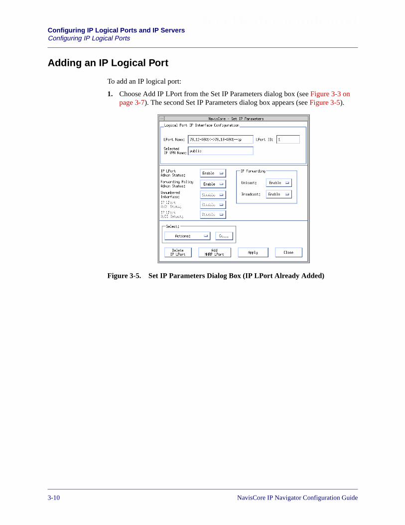
Beta Draft ConfidentialConfiguring IP Logical Ports and IP ServersConfiguring IP Logical Ports
Adding an IP Logical Port
To add an IP logical port:
1. Choose Add IP LPort from the Set IP Parameters dialog box (see Figure 3-3 onpage 3-7). The second Set IP Parameters dialog box appears (see Figure 3-5).
Figure 3-5. Set IP Parameters Dialog Box (IP LPort Already Added)
3-10 NavisCore IP Navigator Configuration Guide
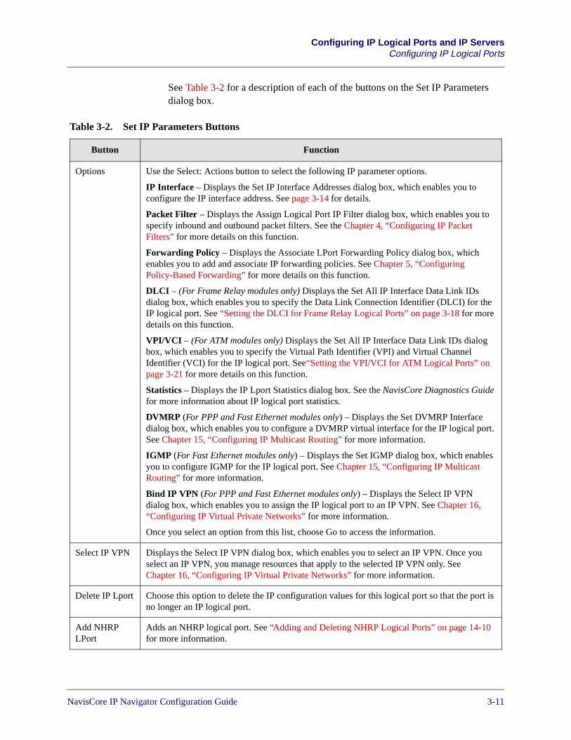
Beta Draft ConfidentialConfiguring IP Logical Ports and IP Servers
Configuring IP Logical Ports
See Table 3-2 for a description of each of the buttons on the Set IP Parametersdialog box.
Table 3-2. Set IP Parameters Buttons
Button Function
Options Use the Select: Actions button to select the following IP parameter options.
IP Interface – Displays the Set IP Interface Addresses dialog box, which enables you toconfigure the IP interface address. See page 3-14 for details.
Packet Filter – Displays the Assign Logical Port IP Filter dialog box, which enables you tospecify inbound and outbound packet filters. See the Chapter 4, “Configuring IP PacketFilters” for more details on this function.
Forwarding Policy – Displays the Associate LPort Forwarding Policy dialog box, whichenables you to add and associate IP forwarding policies. See Chapter 5, “ConfiguringPolicy-Based Forwarding” for more details on this function.
DLCI – (For Frame Relay modules only) Displays the Set All IP Interface Data Link IDsdialog box, which enables you to specify the Data Link Connection Identifier (DLCI) for theIP logical port. See “Setting the DLCI for Frame Relay Logical Ports” on page 3-18 for moredetails on this function.
VPI/VCI – (For ATM modules only) Displays the Set All IP Interface Data Link IDs dialogbox, which enables you to specify the Virtual Path Identifier (VPI) and Virtual ChannelIdentifier (VCI) for the IP logical port. See“Setting the VPI/VCI for ATM Logical Ports” onpage 3-21 for more details on this function.
Statistics – Displays the IP Lport Statistics dialog box. See the NavisCore Diagnostics Guidefor more information about IP logical port statistics.
DVMRP (For PPP and Fast Ethernet modules only) – Displays the Set DVMRP Interfacedialog box, which enables you to configure a DVMRP virtual interface for the IP logical port.See Chapter 15, “Configuring IP Multicast Routing” for more information.
IGMP (For Fast Ethernet modules only) – Displays the Set IGMP dialog box, which enablesyou to configure IGMP for the IP logical port. See Chapter 15, “Configuring IP MulticastRouting” for more information.
Bind IP VPN (For PPP and Fast Ethernet modules only) – Displays the Select IP VPNdialog box, which enables you to assign the IP logical port to an IP VPN. See Chapter 16,“Configuring IP Virtual Private Networks” for more information.
Once you select an option from this list, choose Go to access the information.
Select IP VPN Displays the Select IP VPN dialog box, which enables you to select an IP VPN. Once youselect an IP VPN, you manage resources that apply to the selected IP VPN only. SeeChapter 16, “Configuring IP Virtual Private Networks” for more information.
Delete IP Lport Choose this option to delete the IP configuration values for this logical port so that the port isno longer an IP logical port.
Add NHRPLPort
Adds an NHRP logical port. See “Adding and Deleting NHRP Logical Ports” on page 14-10for more information.
NavisCore IP Navigator Configuration Guide 1/14/023-11
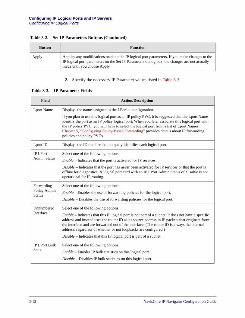
Beta Draft ConfidentialConfiguring IP Logical Ports and IP ServersConfiguring IP Logical Ports
2. Specify the necessary IP Parameter values listed in Table 3-3.
Apply Applies any modifications made to the IP logical port parameters. If you make changes to theIP logical port parameters on the Set IP Parameters dialog box, the changes are not actuallymade until you choose Apply.
Table 3-2. Set IP Parameters Buttons (Continued)
Button Function
Table 3-3. IP Parameter Fields
Field Action/Description
Lport Name Displays the name assigned to the LPort at configuration.
If you plan to use this logical port as an IP policy PVC, it is suggested that the Lport Nameidentify the port as an IP policy logical port. When you later associate this logical port withthe IP policy PVC, you will have to select the logical port from a list of Lport Names.Chapter 5, “Configuring Policy-Based Forwarding” provides details about IP forwardingpolicies and policy PVCs.
Lport ID Displays the ID number that uniquely identifies each logical port.
IP LPortAdmin Status
Select one of the following options:
Enable – Indicates that the port is activated for IP services.
Disable – Indicates that the port has never been activated for IP services or that the port isoffline for diagnostics. A logical port card with an IP LPort Admin Status of Disable is notoperational for IP routing.
ForwardingPolicy AdminStatus
Select one of the following options:
Enable – Enables the use of forwarding policies for the logical port.
Disable – Disables the use of forwarding policies for the logical port.
UnnumberedInterface
Select one of the following options:
Enable – Indicates that this IP logical port is not part of a subnet. It does not have a specificaddress and instead uses the router ID as its source address in IP packets that originate fromthe interface and are forwarded out of the interface. (The router ID is always the internaladdress, regardless of whether or not loopbacks are configured.)
Disable – Indicates that this IP logical port is part of a subnet.
IP LPort BulkStats
Select one of the following options:
Enable – Enables IP bulk statistics on this logical port.
Disable – Disables IP bulk statistics on this logical port.
3-12 NavisCore IP Navigator Configuration Guide
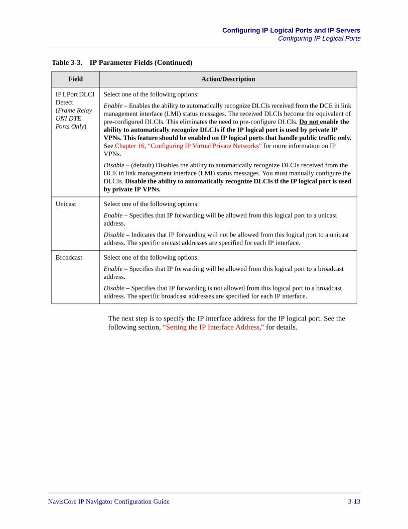
Beta Draft ConfidentialConfiguring IP Logical Ports and IP Servers
Configuring IP Logical Ports
The next step is to specify the IP interface address for the IP logical port. See thefollowing section, “Setting the IP Interface Address,” for details.
IP LPort DLCIDetect(Frame RelayUNI DTEPorts Only)
Select one of the following options:
Enable – Enables the ability to automatically recognize DLCIs received from the DCE in linkmanagement interface (LMI) status messages. The received DLCIs become the equivalent ofpre-configured DLCIs. This eliminates the need to pre-configure DLCIs. Do not enable theability to automatically recognize DLCIs if the IP logical port is used by private IPVPNs. This feature should be enabled on IP logical ports that handle public traffic only.See Chapter 16, “Configuring IP Virtual Private Networks” for more information on IPVPNs.
Disable – (default) Disables the ability to automatically recognize DLCIs received from theDCE in link management interface (LMI) status messages. You must manually configure theDLCIs. Disable the ability to automatically recognize DLCIs if the IP logical port is usedby private IP VPNs.
Unicast Select one of the following options:
Enable – Specifies that IP forwarding will be allowed from this logical port to a unicastaddress.
Disable – Indicates that IP forwarding will not be allowed from this logical port to a unicastaddress. The specific unicast addresses are specified for each IP interface.
Broadcast Select one of the following options:
Enable – Specifies that IP forwarding will be allowed from this logical port to a broadcastaddress.
Disable – Specifies that IP forwarding is not allowed from this logical port to a broadcastaddress. The specific broadcast addresses are specified for each IP interface.
Table 3-3. IP Parameter Fields (Continued)
Field Action/Description
NavisCore IP Navigator Configuration Guide 1/14/023-13
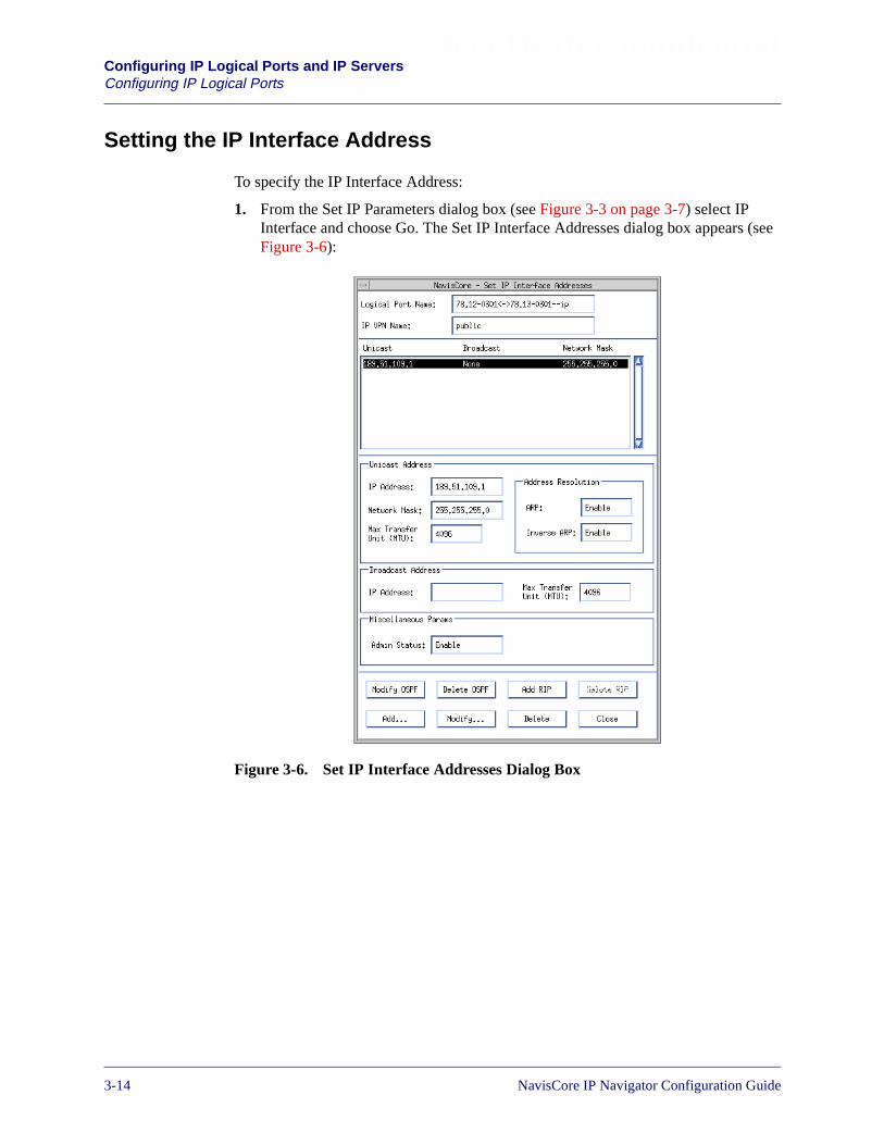
Beta Draft ConfidentialConfiguring IP Logical Ports and IP ServersConfiguring IP Logical Ports
Setting the IP Interface Address
To specify the IP Interface Address:
1. From the Set IP Parameters dialog box (see Figure 3-3 on page 3-7) select IPInterface and choose Go. The Set IP Interface Addresses dialog box appears (seeFigure 3-6):
Figure 3-6. Set IP Interface Addresses Dialog Box
3-14 NavisCore IP Navigator Configuration Guide

Beta Draft ConfidentialConfiguring IP Logical Ports and IP Servers
Configuring IP Logical Ports
Table 3-4 describes the buttons on the Set IP Interface Addresses dialog box.
Table 3-4. Set IP Interface Addresses Buttons
Button Function
Add OSPF Displays the Add OSPF Interface dialog box, which enables you to specify theOSPF parameters for the logical port. This button appears only if you have not yetspecified any OSPF parameters for the logical port.
Add RIP Displays the Add RIP Interface dialog box, which enables you to specify the RIPparameters for the logical port. This button does not appear if you have alreadyconfigured RIP parameters for the logical port.
Modify OSPF Displays the Modify OSPF Interface dialog box, which enables you to modify theOSPF parameters for the logical port. This button appears only if you have alreadyspecified the OSPF parameters for the logical port.
Modify RIP Displays the Modify RIP Interface dialog box, which enables you to modify theRIP parameters for the logical port. This button appears only if you have alreadyspecified the RIP parameters for the logical port.
Delete OSPF Displays the Delete OSPF Interface dialog box, which enables you to delete theOSPF parameters for the logical port. This button appears only if you have alreadyspecified the OSPF parameters for the logical port.
Delete RIP Displays the Delete RIP Interface dialog box, which enables you to delete the RIPparameters for the logical port. This button appears only if you have alreadyspecified the RIP parameters for the logical port.
Add Displays the Add Interface Address dialog box.
Modify Displays the Modify Interface Address dialog box.
Delete Displays the Delete Interface Address dialog box.
NavisCore IP Navigator Configuration Guide 1/14/023-15
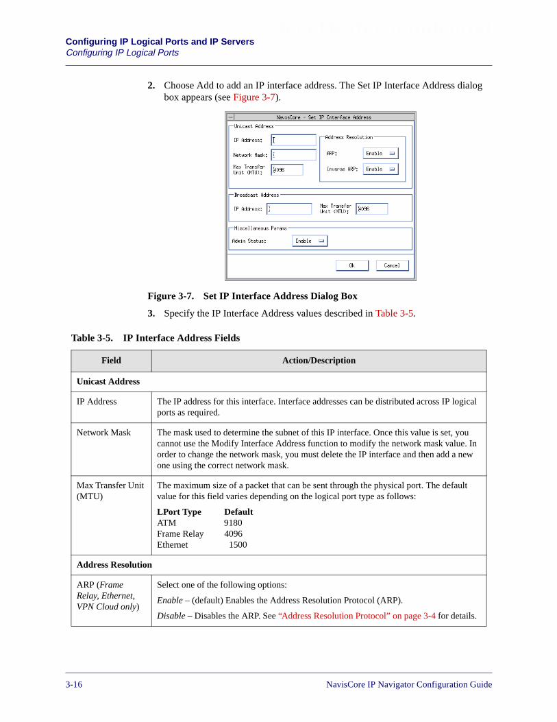
Beta Draft ConfidentialConfiguring IP Logical Ports and IP ServersConfiguring IP Logical Ports
2. Choose Add to add an IP interface address. The Set IP Interface Address dialogbox appears (see Figure 3-7).
Figure 3-7. Set IP Interface Address Dialog Box
3. Specify the IP Interface Address values described in Table 3-5.
Table 3-5. IP Interface Address Fields
Field Action/Description
Unicast Address
IP Address The IP address for this interface. Interface addresses can be distributed across IP logicalports as required.
Network Mask The mask used to determine the subnet of this IP interface. Once this value is set, youcannot use the Modify Interface Address function to modify the network mask value. Inorder to change the network mask, you must delete the IP interface and then add a newone using the correct network mask.
Max Transfer Unit(MTU)
The maximum size of a packet that can be sent through the physical port. The defaultvalue for this field varies depending on the logical port type as follows:
LPort Type DefaultATM 9180Frame Relay 4096Ethernet 1500
Address Resolution
ARP (FrameRelay, Ethernet,VPN Cloud only)
Select one of the following options:
Enable – (default) Enables the Address Resolution Protocol (ARP).
Disable – Disables the ARP. See “Address Resolution Protocol” on page 3-4 for details.
3-16 NavisCore IP Navigator Configuration Guide

Beta Draft ConfidentialConfiguring IP Logical Ports and IP Servers
Configuring IP Logical Ports
4. Choose OK.
After you assign the IP interface address you can then specify the DLCI (forFrame Relay logical ports) or the VPI/VCI (for ATM logical ports). See thefollowing sections for more information on these tasks:
• “Setting the DLCI for Frame Relay Logical Ports” on page 3-18
• “Setting the VPI/VCI for ATM Logical Ports” on page 3-21
Inverse ARP(Frame Relay andATM Only)
Select one of the following options:
Enable – (default) Enables the Inverse Address Resolution Protocol (InARP).
Disable – Disables the InARP. See “Address Resolution Protocol” on page 3-4 fordetails.
Broadcast Address
IP Address The address used by this interface for subnet broadcasting.
Max Transfer Unit(MTU)
The maximum size of a packet that can be sent through the physical port. The defaultvalue for this field varies depending on the logical port type as follows:
LPort Type DefaultATM 9180Frame Relay 4096Ethernet 1500
Miscellaneous Params
Admin Status Enable – (default) Enables IP interface address status.
Disable – Disables IP interface address status.
Table 3-5. IP Interface Address Fields (Continued)
Field Action/Description
NavisCore IP Navigator Configuration Guide 1/14/023-17
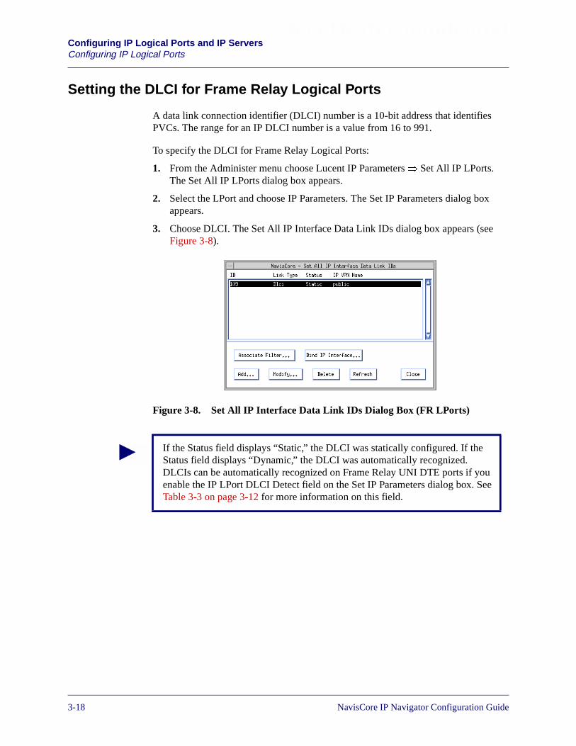
Beta Draft ConfidentialConfiguring IP Logical Ports and IP ServersConfiguring IP Logical Ports
Setting the DLCI for Frame Relay Logical Ports
A data link connection identifier (DLCI) number is a 10-bit address that identifiesPVCs. The range for an IP DLCI number is a value from 16 to 991.
To specify the DLCI for Frame Relay Logical Ports:
1. From the Administer menu choose Lucent IP Parameters� Set All IP LPorts.The Set All IP LPorts dialog box appears.
2. Select the LPort and choose IP Parameters. The Set IP Parameters dialog boxappears.
3. Choose DLCI. The Set All IP Interface Data Link IDs dialog box appears (seeFigure 3-8).
Figure 3-8. Set All IP Interface Data Link IDs Dialog Box (FR LPorts)
If the Status field displays “Static,” the DLCI was statically configured. If theStatus field displays “Dynamic,” the DLCI was automatically recognized.DLCIs can be automatically recognized on Frame Relay UNI DTE ports if youenable the IP LPort DLCI Detect field on the Set IP Parameters dialog box. SeeTable 3-3 on page 3-12 for more information on this field.
3-18 NavisCore IP Navigator Configuration Guide

Beta Draft ConfidentialConfiguring IP Logical Ports and IP Servers
Configuring IP Logical Ports
The Set All IP Interface Data Link IDs dialog box provides the following buttons:
4. Choose Add. The Add Protocol Connection ID dialog box appears (seeFigure 3-9).
Figure 3-9. Add Protocol Connection ID Dialog Box (FR LPorts)
Table 3-6. Set All IP Interface Data Link ID Buttons
Button Function
Associate Filter Displays the Associate IP Circuit Filter List dialog box toenable you to associate a filter with a specific DLCI address.See “Assigning IP Packet Filters to Circuits” on page 4-18 formore information.
Bind IP Interface See “Binding an IP Interface” on page 3-24 for moreinformation.
Add Displays the Set IP Protocol Connection ID dialog box toenable you to add a DLCI number.
Modify Displays the Set IP Protocol Connection ID dialog box toenable you to modify a DLCI number.
Delete Deletes a selected DLCI number.
Refresh Refreshes the Status field.
NavisCore IP Navigator Configuration Guide 1/14/023-19

Beta Draft ConfidentialConfiguring IP Logical Ports and IP ServersConfiguring IP Logical Ports
Specify the field values as described in Table 3-7.
5. Bind an IP interface to the DLCI. See “Binding an IP Interface” on page 3-24 formore information.
Table 3-7. Add Protocol Connection ID Fields
Field Action/Description
Lport Name Displays the name assigned to the LPort at the time of configuration. The LPort ID uniquelyidentifies each logical port within the physical port.
Lport ID Displays the ID number that uniquely identifies each logical port.
DLCI The DLCI value for this IP interface. The range for an IP DLCI number is a value from16-991. This range of DLCI numbers is available for most link management types. If linkmanagement is LMI-1, the maximum value is 1007.
Note that DLCI numbers that range from 0 to 15 are reserved.
Choose IPVPN
Select the IP VPN to which you are assigning this DLCI. By default, the DLCI is a publicnetwork resource (that is, it is assigned to the public IP VPN). See “Configuring Ingress IPInterfaces for IP VPNs” on page 16-40 for more information.
3-20 NavisCore IP Navigator Configuration Guide
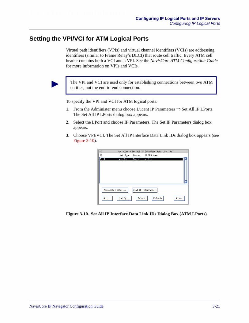
Beta Draft ConfidentialConfiguring IP Logical Ports and IP Servers
Configuring IP Logical Ports
Setting the VPI/VCI for ATM Logical Ports
Virtual path identifiers (VPIs) and virtual channel identifiers (VCIs) are addressingidentifiers (similar to Frame Relay’s DLCI) that route cell traffic. Every ATM cellheader contains both a VCI and a VPI. See the NavisCore ATM Configuration Guidefor more information on VPIs and VCIs.
To specify the VPI and VCI for ATM logical ports:
1. From the Administer menu choose Lucent IP Parameters� Set All IP LPorts.The Set All IP LPorts dialog box appears.
2. Select the LPort and choose IP Parameters. The Set IP Parameters dialog boxappears.
3. Choose VPI/VCI. The Set All IP Interface Data Link IDs dialog box appears (seeFigure 3-10).
Figure 3-10. Set All IP Interface Data Link IDs Dialog Box (ATM LPorts)
The VPI and VCI are used only for establishing connections between two ATMentities, not the end-to-end connection.
NavisCore IP Navigator Configuration Guide 1/14/023-21
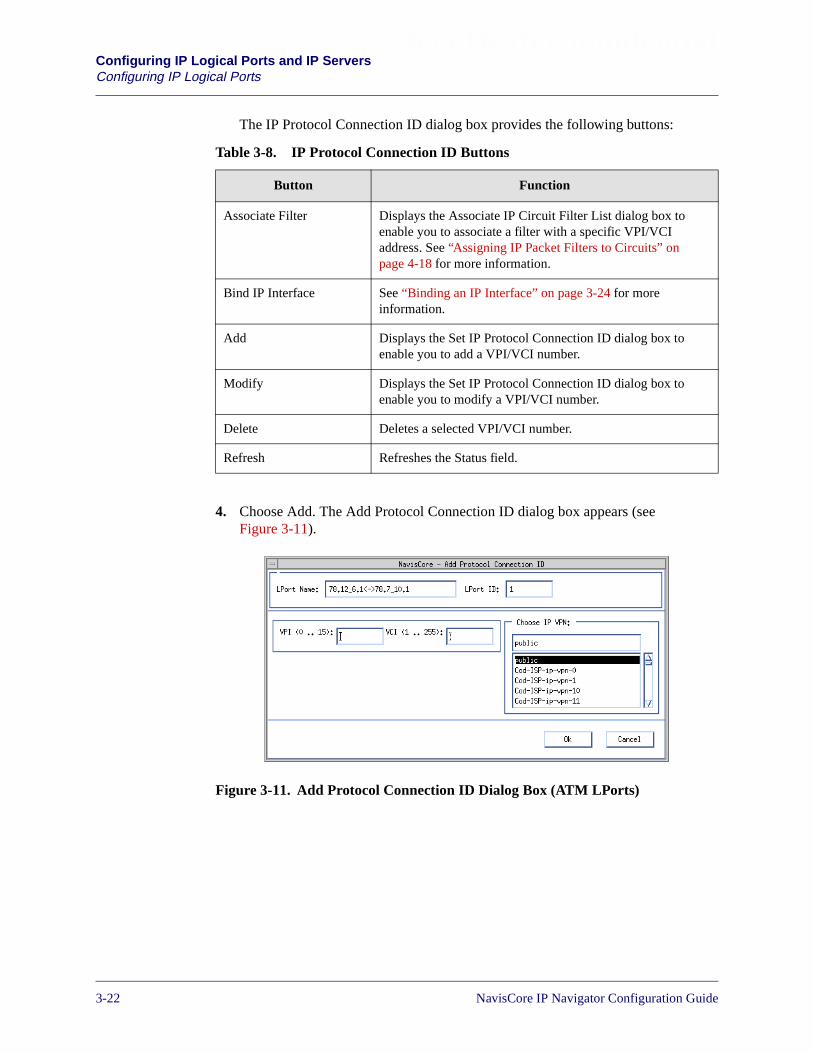
Beta Draft ConfidentialConfiguring IP Logical Ports and IP ServersConfiguring IP Logical Ports
The IP Protocol Connection ID dialog box provides the following buttons:
4. Choose Add. The Add Protocol Connection ID dialog box appears (seeFigure 3-11).
Figure 3-11. Add Protocol Connection ID Dialog Box (ATM LPorts)
Table 3-8. IP Protocol Connection ID Buttons
Button Function
Associate Filter Displays the Associate IP Circuit Filter List dialog box toenable you to associate a filter with a specific VPI/VCIaddress. See “Assigning IP Packet Filters to Circuits” onpage 4-18 for more information.
Bind IP Interface See “Binding an IP Interface” on page 3-24 for moreinformation.
Add Displays the Set IP Protocol Connection ID dialog box toenable you to add a VPI/VCI number.
Modify Displays the Set IP Protocol Connection ID dialog box toenable you to modify a VPI/VCI number.
Delete Deletes a selected VPI/VCI number.
Refresh Refreshes the Status field.
3-22 NavisCore IP Navigator Configuration Guide

Beta Draft ConfidentialConfiguring IP Logical Ports and IP Servers
Configuring IP Logical Ports
5. Specify the field values as described in Table 3-9.
6. Bind an IP interface to the VPI/VCI. See “Binding an IP Interface” on page 3-24for more information.
Table 3-9. IP Protocol Connection ID For ATM LPorts Fields
Field Action/Description
LPort Name Displays the name assigned to the LPort at configuration. The LPort ID identifies the selectedlogical port.
LPort ID Displays the unique ID number assigned to the selected logical port.
VPI The virtual path identifier (VPI). A virtual path (VP) is a group of virtual channels (VCs) carriedbetween two points. VPs provide a way to bundle traffic headed in the same direction. The VPIis an addressing identifier that routes cell traffic. Switching equipment checks the VPI portionof the header to route traffic over certain trunks.
This field displays a range of valid values based on the number of valid bits that are configuredfor this logical port. If the number of valid bits is set to 4, the valid range for the VPI value canbe from 0 to 15. If VPI/VCIs already exist on the selected logical port, you can change thenumber of valid bits; however, the new values must be large enough to support the largest PVCconfigured for this ATM port.
See the NavisCore ATM Configuration Guide for a complete description of the valid values forVPI. See “Forwarding Engines on IP Server Cards” on page 3-25 for specific information aboutVPI values for IP server logical ports.
VCI The virtual channel identifier (VCI). A virtual channel (VC) is a connection between twocommunicating ATM entities.
This field displays a range of valid values based on the number of valid bits that are configuredfor this logical port. If the number of valid bits is set to 8, the VCI value can be from 32 to 255(VCI 0 - 31 are reserved and cannot be used per ATM Forum standards). If VPI/VCIs alreadyexist on the selected logical port, you can change the number of valid bits; however, the newvalues must be large enough to support the largest PVC configured for this ATM port.
See the NavisCore ATM Configuration Guide for a complete description of the valid values forVPI. See the “Forwarding Engines on IP Server Cards” on page 3-25 for specific informationabout VCI values for IP server logical ports.
Choose IPVPN
Select the IP VPN to which you are assigning this VPI/VCI. By default, the VPI/VCI is a publicnetwork resource (that is, it is assigned to the public IP VPN). See “Configuring Ingress IPInterfaces for IP VPNs” on page 16-40 for more information.
NavisCore IP Navigator Configuration Guide 1/14/023-23

Beta Draft ConfidentialConfiguring IP Logical Ports and IP ServersConfiguring IP Logical Ports
Binding an IP Interface
You must bind an IP interface to each DLCI or VPI/VCI. You can bind and create IPinterfaces during the same process. The task of binding IP interfaces with DLCIs andVPI/VCIs is required due to Lucent’s support of IP VPNs. See Chapter 16,“Configuring IP Virtual Private Networks” for more information.
To bind an IP interface to a DLCI or VPI/VCI:
1. At the Set All IP Interface Data Link IDs dialog box (see Figure 3-8 on page 3-18or Figure 3-10 on page 3-21), select the DLCI or VPI/VCI to which you want tobind an IP interface.
2. Choose Bind IP Interface. The Bind IP Interface Address to Protocol ID dialogbox appears (see Figure 3-12). Note that, although the dialog box in Figure 3-12 isfor a DLCI, the dialog box for a VPI/VCI is almost identical. The only differenceis that the dialog box for a VPI/VCI displays the VPI and VCI instead of theDLCI.
Figure 3-12. Bind IP Interface Address to Protocol ID Dialog Box (DLCI)
3. Select the IP interface you want to bind to the DLCI or VPI/VCI in the AvailableIP Interfaces column. Keep in mind that you can also create an IP interface at thistime by choosing the Add IP Interface button. See “Setting the IP InterfaceAddress” on page 3-14 for more information.
4. Choose Assign. The address moves to the Assigned IP Interfaces column.
5. Choose OK.
At any time, you can delete the IP interface binding by selecting the IP interfacefrom the list of assigned IP interfaces and choosing Unassign. Choose OK afteryou have deleted the binding.
3-24 NavisCore IP Navigator Configuration Guide
Beta Draft ConfidentialConfiguring IP Logical Ports and IP ServersAbout IP Server Logical Ports on the CBX 500
About IP Server Logical Ports on the CBX 500
You can configure logical ports as IP server logical ports on either of the followingCBX 500 cards:
• 6-port DS3 FR/IP Card
• 4-port Channelized DS3/1 FR/IP Card
• 4-port Ethernet Card
The purpose of an IP server logical port is to provide a method of accepting ortransmitting IP traffic from or to a cell-based port. All IP traffic entering and exiting aCBX 500 ATM cell card must be transmitted through an IP server logical port that isconfigured on either a 6-port DS3 FR/IP card, 4-port DS3/1 FR/IP card, or on a 4-portEthernet card.
The number of IP server cards is only limited by the number of slots in the switch.
Forwarding Engines on IP Server Cards
There are two forwarding engines (FEs) on a 6-port DS3 FR/IP card and on a 4-portEthernet card. There is one FE on a 4-port Channelized DS3/1 FR/IP card. FEsreassemble cells and perform IP lookups. The NMS identifies the two FEs on an IPserver card as Server 1 and Server 2 (or as just Server 1 for a 4-port ChannelizedDS3/1 FR/IP card).
Each FE has hard-coded values for the VPI and VCI bit parameters. The value for theVPI bits parameter is permanently set to 6. For this reason, the maximum number ofIP logical ports that you can create for each IP server card is 64 (0-63). Therefore,on 6-port DS3 FR/IP cards and 4-port Ethernet cards, if you define 64 IP logical portson the first FE of the card (which is identified in the NMS as Server 1), you cannotdefine any IP logical ports on the second FE (Server 2). You can create any number ofIP logical ports (up to a maximum of 64) between the two FEs.
On 4-port Channelized DS3/1 FR/IP cards, you have only one FE; therefore, youcreate all 64 IP logical ports on that FE.
The value for the VCI bits parameter is permanently set to 8. For this reason, you cancreate up to 225 (28 - 31) PVCs for each IP logical port.
NavisCore IP Navigator Configuration Guide 1/14/023-25

Beta Draft ConfidentialConfiguring IP Logical Ports and IP ServersAbout IP Server Logical Ports on the CBX 500
Figure 3-13. VPI Parameters for IP Server Cards with Two FEs
IP Server Logical Ports
IP server logical ports on IP server cards are virtual ports. For this reason, physicalport numbers on 6-port DS3 FR/IP cards start at 7 and physical port numbers on 4-portEthernet cards and 4-port Channelized DS3/1 FR/IP cards start at 5.
You use the Set IP Server function on the Administer menu to configure IP serverlogical ports on a CBX 500. You can create multiple IP interfaces for each IP serverlogical port. See “Creating an IP Server Logical Port” on page 3-29 for moreinformation.
012xxx
63
IP Server Card
FE
FE
If IP Server 1 has threePVCs configured with VPI 0,1, and 2, any PVCs createdon IP Server 2 must use aVPI from 3 through 63.
IP Server PVCs
ATM UNI LPortsIP Server 2
IP Server 1
3-26 NavisCore IP Navigator Configuration Guide
Beta Draft ConfidentialConfiguring IP Logical Ports and IP ServersAbout IP Server Logical Ports on the CBX 500
Bandwidth Allocation
Multiple PVCs can be defined for an IP server logical port.
Logical port bandwidth on an IP server logical port must be sufficient to support all ofthe PVCs traversing the port. For this reason, before you configure IP server logicalports, you must plan for the total amount of bandwidth that will be required forall of the PVCs that are associated with the IP server logical port. If you assign allof the bandwidth to the first IP server logical port, there will be no bandwidthavailable for PVCs that are configured for subsequent IP server logical ports.
If you want to create multiple IP server logical ports on an IP server card, youmust be aware of the following requirements:
• All of the logical port bandwidth cannot be allocated to the first IP serverlogical port that you define (a Direct UNI-DCE LPort).
• For subsequent IP logical ports, a VPI start/stop range must be defined.There cannot be any overlap between logical ports. For example, if the firstvirtual IP server logical port is configured with a VPI start/stop range of 1and 4, the second virtual IP server logical port cannot use a VPI start/stoprange that includes any VPIs already defined.
NavisCore IP Navigator Configuration Guide 1/14/023-27

Beta Draft ConfidentialConfiguring IP Logical Ports and IP ServersConfiguring IP Server Logical Ports
Configuring IP Server Logical Ports
Figure 3-14 illustrates the steps for configuring an IP server logical port on a CBX 500switch.
Figure 3-14. Configuring IP Server Logical Ports on the CBX 500
Use the Set IP Server LPortfunction to add an IP serverlogical port. See “Creating an IPServer Logical Port” onpage 3-29.
Specify the IP Interface Address.See “Setting the IP InterfaceAddress” on page 3-14.
Enable RIP on this logical port(Chapter 7).
Enable OSPF on this logical port(Chapter 9).
Configure Packet Filters on thisinterface (Chapter 4).
Establish IP server PVCs. See“Creating an IP Server PVC” onpage 3-33.
Configure NHRP on this logicalport (Chapter 14).
Configure multicast on this logicalport (Chapter 15).
Configure IP VPN resources onthis logical port (Chapter 16).
Bind IP server PVC’s VPI/VCI toIP interface. See “Binding an IPInterface” on page 3-24.
OR
Configure policy-based forwardingon this logical port (Chapter 5).
3-28 NavisCore IP Navigator Configuration Guide
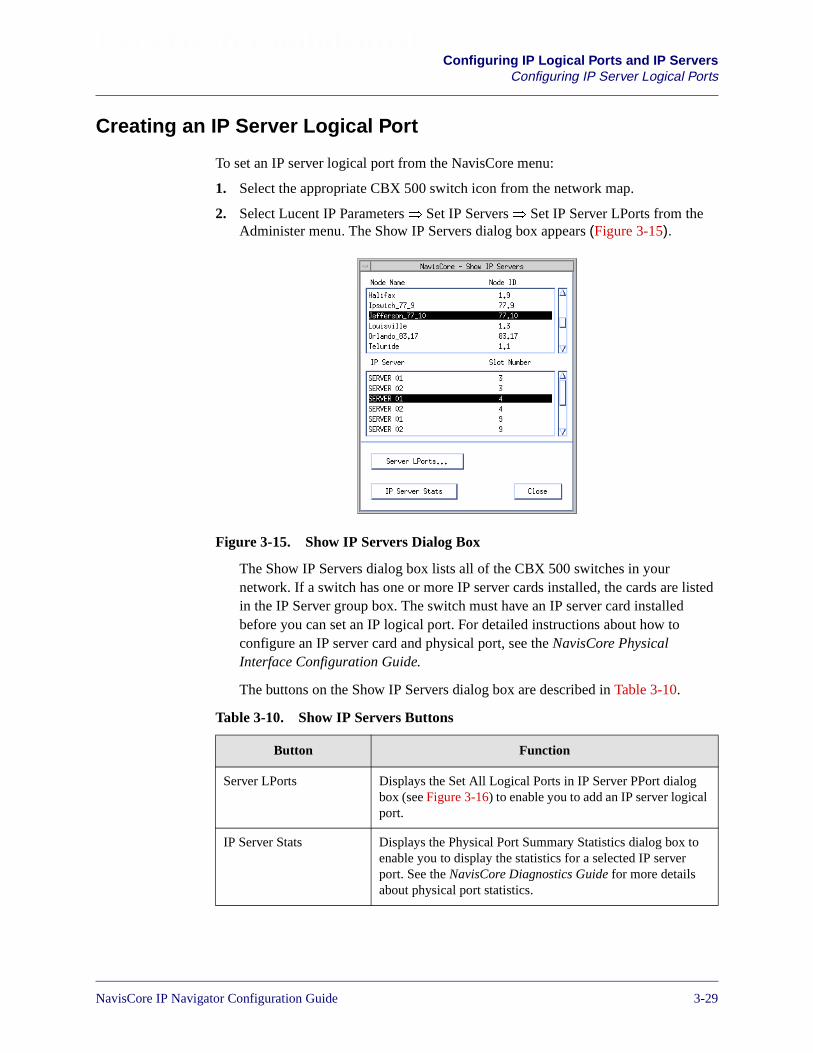
Beta Draft ConfidentialConfiguring IP Logical Ports and IP Servers
Configuring IP Server Logical Ports
Creating an IP Server Logical Port
To set an IP server logical port from the NavisCore menu:
1. Select the appropriate CBX 500 switch icon from the network map.
2. Select Lucent IP Parameters� Set IP Servers� Set IP Server LPorts from theAdminister menu. The Show IP Servers dialog box appears (Figure 3-15).
Figure 3-15. Show IP Servers Dialog Box
The Show IP Servers dialog box lists all of the CBX 500 switches in yournetwork. If a switch has one or more IP server cards installed, the cards are listedin the IP Server group box. The switch must have an IP server card installedbefore you can set an IP logical port. For detailed instructions about how toconfigure an IP server card and physical port, see the NavisCore PhysicalInterface Configuration Guide.
The buttons on the Show IP Servers dialog box are described in Table 3-10.
Table 3-10. Show IP Servers Buttons
Button Function
Server LPorts Displays the Set All Logical Ports in IP Server PPort dialogbox (see Figure 3-16) to enable you to add an IP server logicalport.
IP Server Stats Displays the Physical Port Summary Statistics dialog box toenable you to display the statistics for a selected IP serverport. See the NavisCore Diagnostics Guide for more detailsabout physical port statistics.
NavisCore IP Navigator Configuration Guide 1/14/023-29
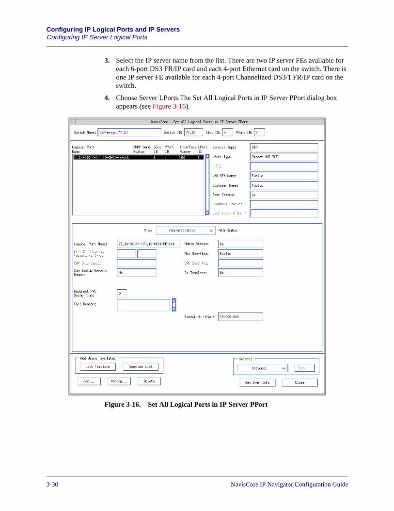
Beta Draft ConfidentialConfiguring IP Logical Ports and IP ServersConfiguring IP Server Logical Ports
3. Select the IP server name from the list. There are two IP server FEs available foreach 6-port DS3 FR/IP card and each 4-port Ethernet card on the switch. There isone IP server FE available for each 4-port Channelized DS3/1 FR/IP card on theswitch.
4. Choose Server LPorts.The Set All Logical Ports in IP Server PPort dialog boxappears (see Figure 3-16).
Figure 3-16. Set All Logical Ports in IP Server PPort
3-30 NavisCore IP Navigator Configuration Guide
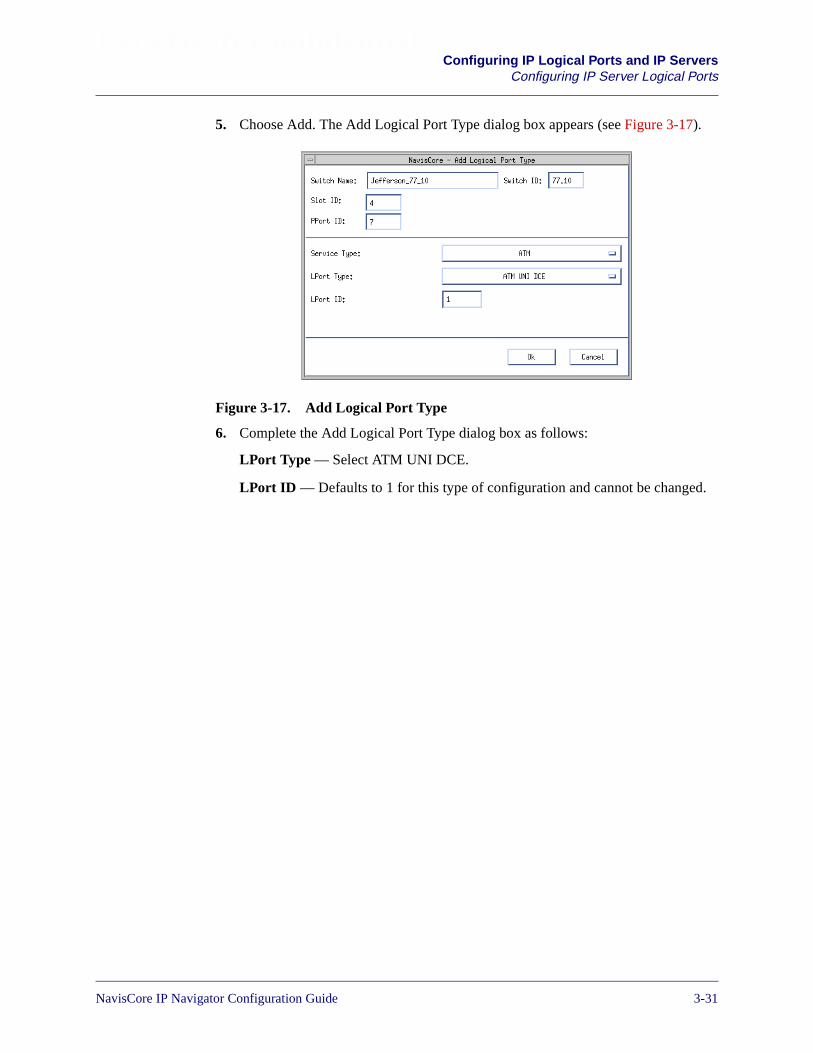
Beta Draft ConfidentialConfiguring IP Logical Ports and IP Servers
Configuring IP Server Logical Ports
5. Choose Add. The Add Logical Port Type dialog box appears (see Figure 3-17).
Figure 3-17. Add Logical Port Type
6. Complete the Add Logical Port Type dialog box as follows:
LPort Type — Select ATM UNI DCE.
LPort ID — Defaults to 1 for this type of configuration and cannot be changed.
NavisCore IP Navigator Configuration Guide 1/14/023-31
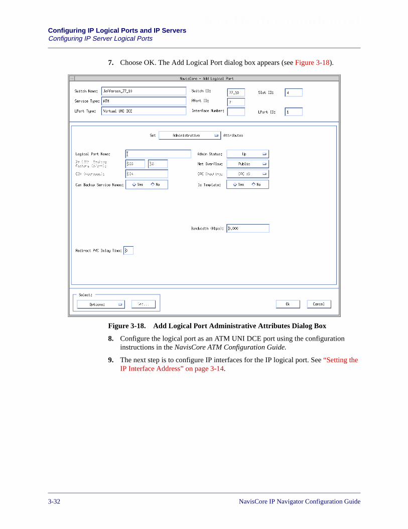
Beta Draft ConfidentialConfiguring IP Logical Ports and IP ServersConfiguring IP Server Logical Ports
7. Choose OK. The Add Logical Port dialog box appears (see Figure 3-18).
Figure 3-18. Add Logical Port Administrative Attributes Dialog Box
8. Configure the logical port as an ATM UNI DCE port using the configurationinstructions in the NavisCore ATM Configuration Guide.
9. The next step is to configure IP interfaces for the IP logical port. See “Setting theIP Interface Address” on page 3-14.
3-32 NavisCore IP Navigator Configuration Guide

Beta Draft ConfidentialConfiguring IP Logical Ports and IP Servers
IP Server PVCs on the CBX 500
IP Server PVCs on the CBX 500
For each IP-enabled ATM logical port, you need a working PVC from an ATM logicalport to an IP server logical port.
You can also create an IP server PVC between IP server endpoints on the sameCBX 500 switch or two different CBX 500 switches. The CBX 500 switches may beseparated by an intermediate ATM network. You can use this feature as an alternativeto ATM OPTimum trunks.
Creating an IP Server PVC
To create an IP server PVC from the NavisCore menu:
1. Select the appropriate CBX 500 switch icon from the network map.
2. Select Lucent IP Parameters� Set IP Servers� Set IP Server PVCs from theAdminister menu. The Set All IP Server PVCs on Map dialog box appears (seeFigure 3-19).
The Set All IP Server PVCs on Map dialog box initially displays no definedcircuit names. To display all of the defined circuit names, position the cursor inthe Search by Name field and press Enter. This search may take several minutesdepending on your configuration.
For a partial search, enter the selected search criteria in the Search by Name field.To use a wildcard search to find a specific circuit name, you can:
• Use an * to match any number of characters
• Use a ? to match a single character
• Use a \* to match the * character
• Use a \? to match the ? character
• Use a \\ to match the \ character
NavisCore IP Navigator Configuration Guide 1/14/023-33
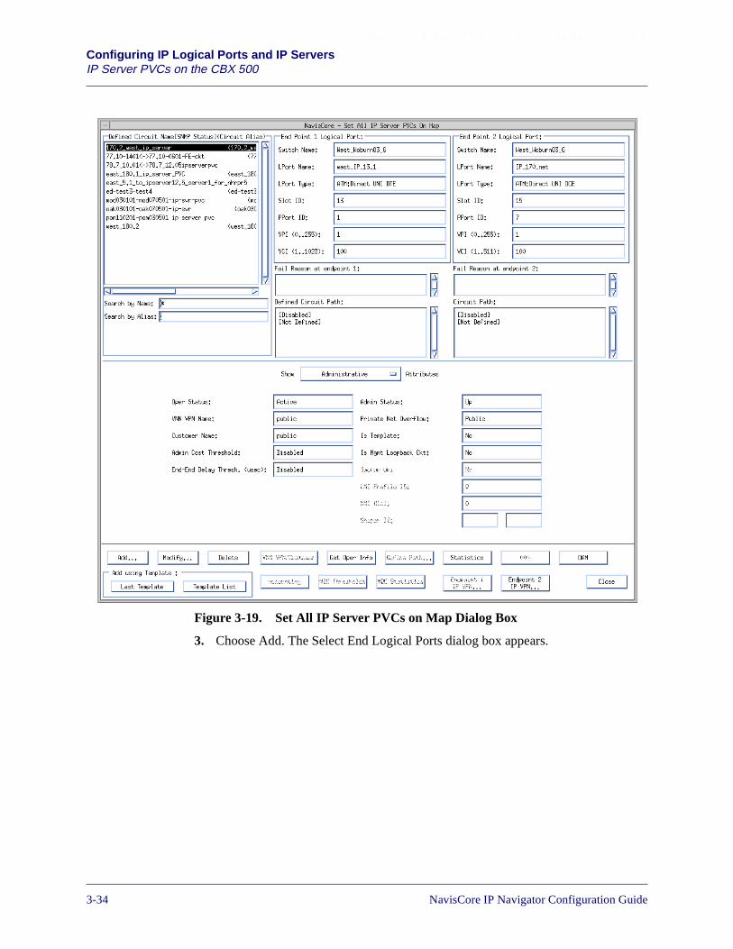
Beta Draft ConfidentialConfiguring IP Logical Ports and IP ServersIP Server PVCs on the CBX 500
Figure 3-19. Set All IP Server PVCs on Map Dialog Box
3. Choose Add. The Select End Logical Ports dialog box appears.
3-34 NavisCore IP Navigator Configuration Guide
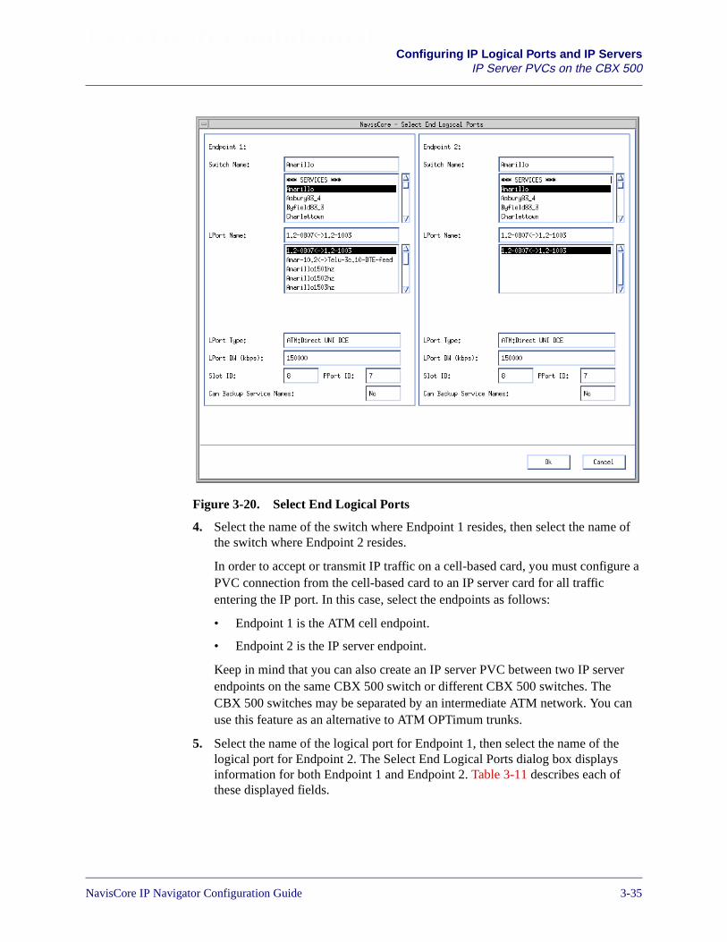
Beta Draft ConfidentialConfiguring IP Logical Ports and IP Servers
IP Server PVCs on the CBX 500
Figure 3-20. Select End Logical Ports
4. Select the name of the switch where Endpoint 1 resides, then select the name ofthe switch where Endpoint 2 resides.
In order to accept or transmit IP traffic on a cell-based card, you must configure aPVC connection from the cell-based card to an IP server card for all trafficentering the IP port. In this case, select the endpoints as follows:
• Endpoint 1 is the ATM cell endpoint.
• Endpoint 2 is the IP server endpoint.
Keep in mind that you can also create an IP server PVC between two IP serverendpoints on the same CBX 500 switch or different CBX 500 switches. TheCBX 500 switches may be separated by an intermediate ATM network. You canuse this feature as an alternative to ATM OPTimum trunks.
5. Select the name of the logical port for Endpoint 1, then select the name of thelogical port for Endpoint 2. The Select End Logical Ports dialog box displaysinformation for both Endpoint 1 and Endpoint 2. Table 3-11 describes each ofthese displayed fields.
NavisCore IP Navigator Configuration Guide 1/14/023-35

Beta Draft ConfidentialConfiguring IP Logical Ports and IP ServersIP Server PVCs on the CBX 500
6. Choose OK from the Select End Logical Ports dialog box. The Add PVC dialogbox appears.
7. See the NavisCore ATM Configuration Guide to define the following attributes foreach PVC:
• Administrative
• Traffic Type
• User Preference
• Frame Discard
Table 3-11. Information Displayed for Endpoints 1 and 2
Field Action/Description
Primary SwitchName
Displays the name of the switch on which the primary (active) logicalport resides.
Primary LPortName
Displays the name of the primary (active) logical port endpoint.
LPort Type Displays the logical port type for the selected logical ports.
LPort Bandwidth Displays the logical port bandwidth for the selected logical ports. Ateach endpoint, logical ports may have a different bandwidth.
Slot ID Displays the I/O slot (number) where the IOMs for the selected logicalports reside.
PPort ID Displays the port ID numbers for the selected logical ports.
Can BackupService Names
Displays either Yes or No to specify whether or not this logical portcan be backed up to a service name binding.
You can now configure traffic descriptors that are better than UBR (for example,VBRnrt) for IP server PVCs. Traffic shaping and policing is also supported forIP Server PVCs.
3-36 NavisCore IP Navigator Configuration Guide

NavisCore IP Navigator Configuration Guide
Beta Draft Confidential
4
Configuring IP Packet Filters
This chapter describes the following tasks:
• Configuring IP packet filters
• Assigning IP packet filters to a logical port
• Assigning IP packet filters to the host
• Assigning IP packet filters to a circuit
• Viewing an IP packet filter configuration
About Packet Filters
Packet filtering enables a switch to accept or reject inbound or outbound packets bycomparing a packet’s IP upper-layer header information (see below for the IP headerfields) to configured parameters called filters, which you define in NavisCore.
You define packet filters based on the following fields in the IP packet header:
• IP Header
• UDP/TCP Header
The following sections describe each of these fields.
4-1
Beta Draft ConfidentialConfiguring IP Packet FiltersAbout Packet Filters
IP Header
Source Address — The source address field contains the IP address that sends thepacket.
Destination Address — The destination address field contains the IP address thatreceives the packet.
Type of Service (TOS) — The TOS field indicates the packet’s priority.
Protocol — The transport field specifies the protocol (TCP or UDP) that enables thepacket to be delivered to the correct destination protocol.
UDP/TCP Header
Source Port — This field contains the 16-bit protocol port number used todemultiplex datagrams among processes waiting to receive them. The source port isoptional. When used, it specifies the port to which replies should be sent. If not used,the field should be left blank.
Destination Port — This field contains the 16-bit protocol port number used todemultiplex datagrams among processes waiting to receive them.
For inbound filters, when a packet is received, the forwarding code checks the packetagainst the interface’s list of filters. If the packet matches a filter in the filter list, thepacket is accepted or rejected and further filtering is terminated. The packet goesthrough a similar process for outbound filters, however, the process occurs only afterthe packet is received and routed to an interface.
4-2 NavisCore IP Navigator Configuration Guide

Beta Draft ConfidentialConfiguring IP Packet Filters
Configuring IP Packet Filters
Configuring IP Packet Filters
When you define an IP packet filter, you specify parameters that control theprocessing of inbound and/or outbound packets. After you define the filter, you canassign it to IP logical ports, the switch itself (host), or PVCs.
This section describes how to:
• Define an IP packet filter
• Assign an IP packet filter to a logical port
• Assign an IP packet filter to a host (switch)
• Assign an IP packet filter to a circuit
• View an IP packet filter’s configuration and its associated logical port and/orcircuit
You can create a maximum of 1024 packet filters per switch.
You can define 128 logical port/circuit filter bindings per IOP.
You can assign a maximum of 32 inbound and 32 outbound filters per logicalport.
You can assign a maximum of 32 inbound and 32 outbound filters per circuit.
NavisCore IP Navigator Configuration Guide 1/14/024-3
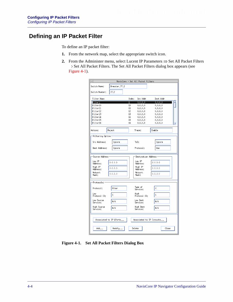
Beta Draft ConfidentialConfiguring IP Packet FiltersConfiguring IP Packet Filters
Defining an IP Packet Filter
To define an IP packet filter:
1. From the network map, select the appropriate switch icon.
2. From the Administer menu, select Lucent IP Parameters� Set All Packet Filters� Set All Packet Filters. The Set All Packet Filters dialog box appears (seeFigure 4-1).
Figure 4-1. Set All Packet Filters Dialog Box
4-4 NavisCore IP Navigator Configuration Guide
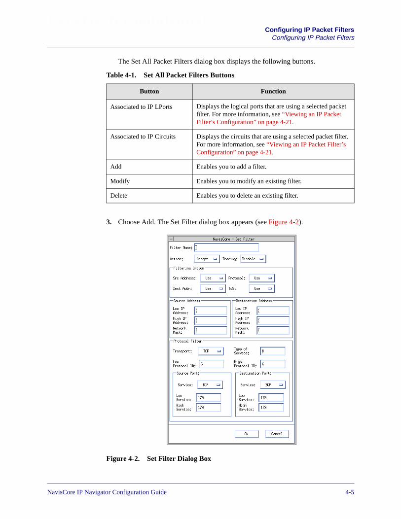
Beta Draft ConfidentialConfiguring IP Packet Filters
Configuring IP Packet Filters
The Set All Packet Filters dialog box displays the following buttons.
3. Choose Add. The Set Filter dialog box appears (see Figure 4-2).
Figure 4-2. Set Filter Dialog Box
Table 4-1. Set All Packet Filters Buttons
Button Function
Associated to IP LPorts Displays the logical ports that are using a selected packetfilter. For more information, see “Viewing an IP PacketFilter’s Configuration” on page 4-21.
Associated to IP Circuits Displays the circuits that are using a selected packet filter.For more information, see “Viewing an IP Packet Filter’sConfiguration” on page 4-21.
Add Enables you to add a filter.
Modify Enables you to modify an existing filter.
Delete Enables you to delete an existing filter.
NavisCore IP Navigator Configuration Guide 1/14/024-5

Beta Draft ConfidentialConfiguring IP Packet FiltersConfiguring IP Packet Filters
4. Complete the fields as described in Table 4-2.
Table 4-2. Set Filter Fields
Field Action/Description
Filter Name Enter a filter name to identify the filter.
Action Select one of the following options:
Accept – This parameter instructs the switch to accept packets thatmatch the filtering criteria.
Reject – This parameter instructs the switch to reject packets thatmatch the filtering criteria.
Tracing Select one of the following options:
Enable – This parameter instructs the switch to pass matchedpackets to the trace manager.
Disable – This parameter instructs the switch not to pass matchedpackets to the trace manager.
Filtering Option
Src Address Select one of the following options:
Use – To filter packets based on the source address field in the IPpacket header.
Ignore – To ignore filtering based on the source address field in theIP packet header. If you choose Ignore, the source address fields aregrayed out and cannot be defined.
Protocol Select one of the following options:
Use – To filter packets based on the source address field in the IPpacket header.
Ignore – To ignore filtering based on the source address field in theIP packet header. If you choose Ignore, the protocol fields aregrayed out and cannot be defined.
Dest Addr Select one of the following options:
Use – To filter packets based on the destination address field in theIP packet header.
Ignore – To ignore filtering based on the destination address field inthe IP packet header. If you choose Ignore, the Destination Addressfields are grayed out and cannot be defined.
4-6 NavisCore IP Navigator Configuration Guide
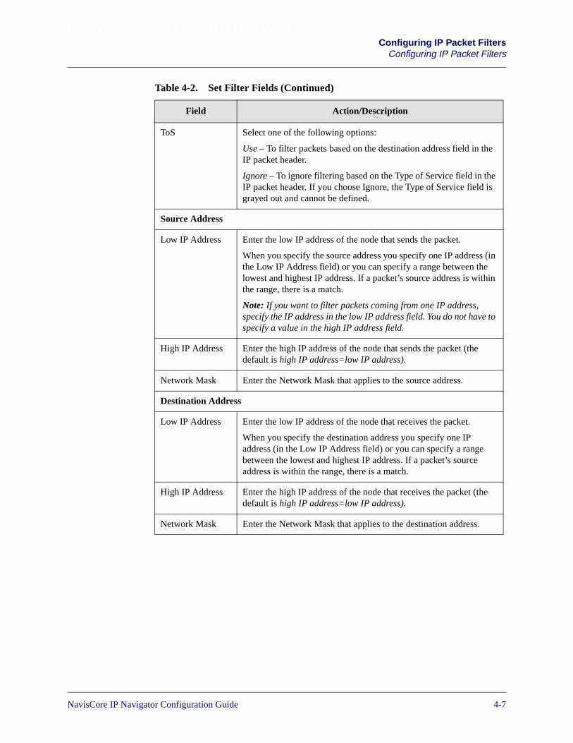
Beta Draft ConfidentialConfiguring IP Packet Filters
Configuring IP Packet Filters
ToS Select one of the following options:
Use – To filter packets based on the destination address field in theIP packet header.
Ignore – To ignore filtering based on the Type of Service field in theIP packet header. If you choose Ignore, the Type of Service field isgrayed out and cannot be defined.
Source Address
Low IP Address Enter the low IP address of the node that sends the packet.
When you specify the source address you specify one IP address (inthe Low IP Address field) or you can specify a range between thelowest and highest IP address. If a packet’s source address is withinthe range, there is a match.
Note: If you want to filter packets coming from one IP address,specify the IP address in the low IP address field. You do not have tospecify a value in the high IP address field.
High IP Address Enter the high IP address of the node that sends the packet (thedefault is high IP address=low IP address).
Network Mask Enter the Network Mask that applies to the source address.
Destination Address
Low IP Address Enter the low IP address of the node that receives the packet.
When you specify the destination address you specify one IPaddress (in the Low IP Address field) or you can specify a rangebetween the lowest and highest IP address. If a packet’s sourceaddress is within the range, there is a match.
High IP Address Enter the high IP address of the node that receives the packet (thedefault is high IP address=low IP address).
Network Mask Enter the Network Mask that applies to the destination address.
Table 4-2. Set Filter Fields (Continued)
Field Action/Description
NavisCore IP Navigator Configuration Guide 1/14/024-7

Beta Draft ConfidentialConfiguring IP Packet FiltersConfiguring IP Packet Filters
Protocol Filter
Transport Select the packet’s transport protocol type:
TCP – Transmission Control Protocol.
UDP – User Datagram Protocol
Others – You must specify protocol IDs in the low and high protocolID fields.
Transport refers to the protocol (TCP, UDP, or Others) that enablesthe packet to be delivered to the correct destination protocol.
Note: When you select TCP or UDP, the low and high protocolfields are automatically filled in with the protocol’s correspondingprotocol ID.
In addition, if you select TCP or UDP, you must specify the sourceand destination port fields. However, if you select Others, the sourceand destination port sections are grayed out and cannot be defined.
Type of Service Enter a value between 0 and 254.
Protocols use the type of service value to specify the packet’spriority.
Low Protocol ID If you selected Others in the Transport field, enter the low protocolID. See RFC 1700 for protocol ID numbers. You can either specifyone value (in this field) or you can enter a range between this valueand the high protocol ID. If the packet’s protocol ID is between thelow and high protocol ID, there is a match.
High Protocol ID If you selected Others in the Transport field, enter the high protocolID. See RFC 1700 for protocol ID numbers.
When you enter this value, you enter a range between the lowprotocol ID and this value. If the packet’s protocol ID is between thelow and high protocol ID, there is a match.
Table 4-2. Set Filter Fields (Continued)
Field Action/Description
4-8 NavisCore IP Navigator Configuration Guide
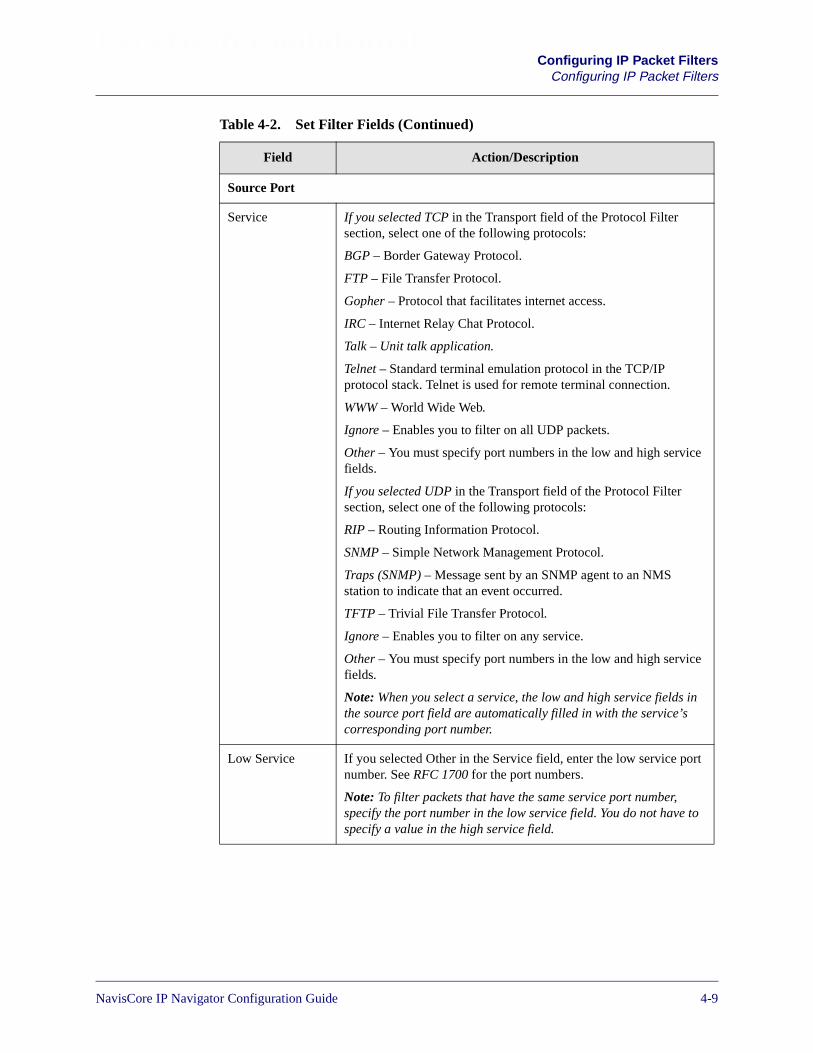
Beta Draft ConfidentialConfiguring IP Packet Filters
Configuring IP Packet Filters
Source Port
Service If you selected TCP in the Transport field of the Protocol Filtersection, select one of the following protocols:
BGP – Border Gateway Protocol.
FTP – File Transfer Protocol.
Gopher – Protocol that facilitates internet access.
IRC – Internet Relay Chat Protocol.
Talk – Unit talk application.
Telnet – Standard terminal emulation protocol in the TCP/IPprotocol stack. Telnet is used for remote terminal connection.
WWW – World Wide Web.
Ignore – Enables you to filter on all UDP packets.
Other – You must specify port numbers in the low and high servicefields.
If you selected UDP in the Transport field of the Protocol Filtersection, select one of the following protocols:
RIP – Routing Information Protocol.
SNMP – Simple Network Management Protocol.
Traps (SNMP) – Message sent by an SNMP agent to an NMSstation to indicate that an event occurred.
TFTP – Trivial File Transfer Protocol.
Ignore – Enables you to filter on any service.
Other – You must specify port numbers in the low and high servicefields.
Note: When you select a service, the low and high service fields inthe source port field are automatically filled in with the service’scorresponding port number.
Low Service If you selected Other in the Service field, enter the low service portnumber. See RFC 1700 for the port numbers.
Note: To filter packets that have the same service port number,specify the port number in the low service field. You do not have tospecify a value in the high service field.
Table 4-2. Set Filter Fields (Continued)
Field Action/Description
NavisCore IP Navigator Configuration Guide 1/14/024-9
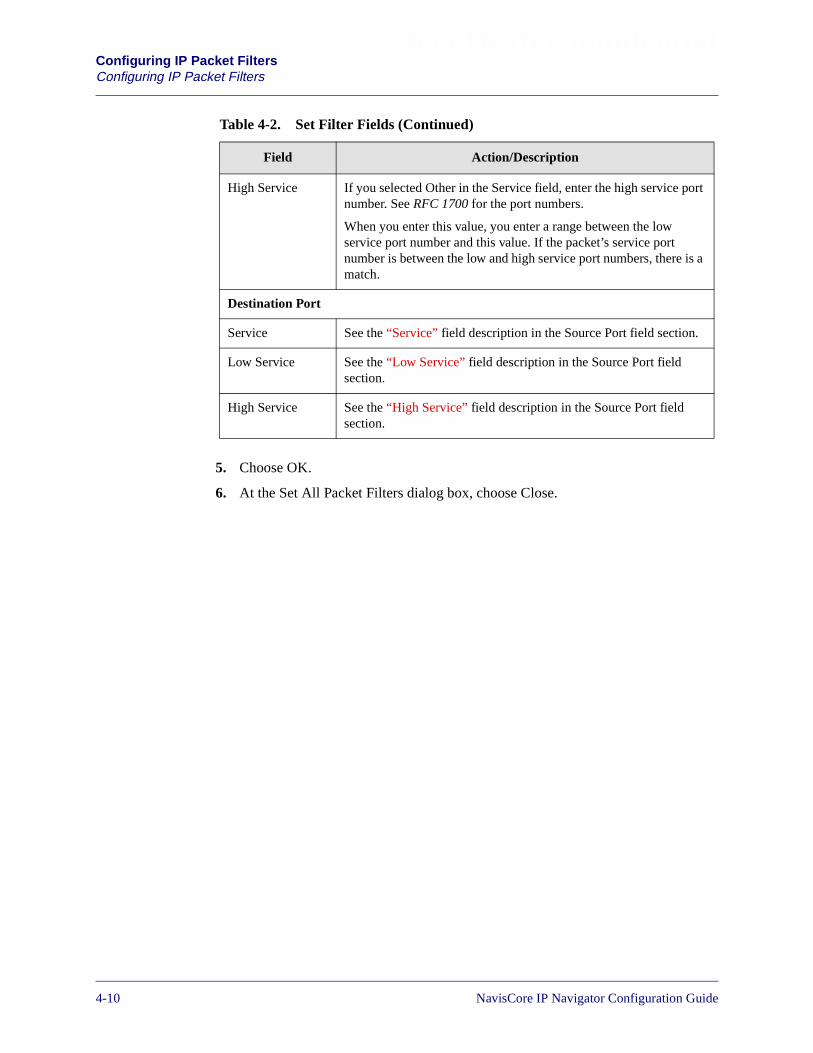
Beta Draft ConfidentialConfiguring IP Packet FiltersConfiguring IP Packet Filters
5. Choose OK.
6. At the Set All Packet Filters dialog box, choose Close.
High Service If you selected Other in the Service field, enter the high service portnumber. See RFC 1700 for the port numbers.
When you enter this value, you enter a range between the lowservice port number and this value. If the packet’s service portnumber is between the low and high service port numbers, there is amatch.
Destination Port
Service See the “Service” field description in the Source Port field section.
Low Service See the “Low Service” field description in the Source Port fieldsection.
High Service See the “High Service” field description in the Source Port fieldsection.
Table 4-2. Set Filter Fields (Continued)
Field Action/Description
4-10 NavisCore IP Navigator Configuration Guide

Beta Draft ConfidentialConfiguring IP Packet Filters
Configuring IP Packet Filters
Packet Filter Configuration Example
The following configuration is an example of a filter that restricts packets comingfrom a specified source IP address.
1. From the network map, select the appropriate switch icon.
2. From the Administer menu, select Lucent IP Parameters� Set All Packet Filters� Set All Packet Filters. The Set All Packet Filters dialog box appears(see Figure 4-1).
3. Choose Add. The Set Filter dialog box appears (see Figure 4-2).
4. In the Filter Name field, enter:
reject152.148.51.118
5. In the Action field, select Reject.
6. In the Tracing field, select Disable to disable the trace manager.
7. In the Filtering Option fields;
– Select Use in the Src Address field.
– Select Ignore in the Dest Addr, Protocol, and ToS fields.
8. In the Low IP Address field in the Source Address section, enter:
152.148.51.118
9. In the Network Mask field, enter:
255.255.255.255
When you select Ignore in these fields, the fields in the Protocol Filter, SourcePort, and Destination Port sections are grayed out. These fields are disabled andare not used to filter packets.
You do not have to specify the high IP address for the source address becauseyou are restricting packets coming from one IP address. However, if you want torestrict packets coming from a range of IP addresses, specify both the low andhigh IP addresses.
NavisCore IP Navigator Configuration Guide 1/14/024-11

Beta Draft ConfidentialConfiguring IP Packet FiltersConfiguring IP Packet Filters
Figure 4-3 displays the specified fields.
Figure 4-3. Set Filter Dialog Box (Sample Packet Filter Settings)
10. Choose OK.
When you assign this filter to a specific logical port or host, all packets comingfrom 152.148.51.118 are not allowed to pass through.
The fields in the ProtocolFilter, Source Port, andDestination Port sectionsare grayed out because youselected Ignore in theFiltering Option fields.
Specify 152.148.51.118 inthe Low IP Address fieldand 255.255.255.255 in theNetwork Mask field.
4-12 NavisCore IP Navigator Configuration Guide
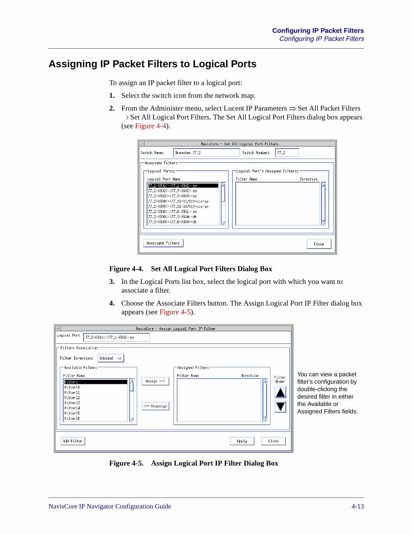
Beta Draft ConfidentialConfiguring IP Packet Filters
Configuring IP Packet Filters
Assigning IP Packet Filters to Logical Ports
To assign an IP packet filter to a logical port:
1. Select the switch icon from the network map.
2. From the Administer menu, select Lucent IP Parameters� Set All Packet Filters� Set All Logical Port Filters. The Set All Logical Port Filters dialog box appears(see Figure 4-4).
Figure 4-4. Set All Logical Port Filters Dialog Box
3. In the Logical Ports list box, select the logical port with which you want toassociate a filter.
4. Choose the Associate Filters button. The Assign Logical Port IP Filter dialog boxappears (see Figure 4-5).
Figure 4-5. Assign Logical Port IP Filter Dialog Box
You can view a packetfilter’s configuration bydouble-clicking thedesired filter in eitherthe Available orAssigned Filters fields.
NavisCore IP Navigator Configuration Guide 1/14/024-13

Beta Draft ConfidentialConfiguring IP Packet FiltersConfiguring IP Packet Filters
Table 4-3 describes the fields on the Assign Logical Port IP Filter dialog box.
The Assign Logical Port IP Filter buttons are described in Table 4-4.
You can view a packet filter’s configuration by double-clicking the desired filterin either the Available or Assigned Filters fields. The Show IP FilterConfiguration dialog box appears with the filter’s configuration.
Table 4-3. Assign Logical Port IP Filter Fields
Field Description
Logical Port Displays the name of the logical port.
Filter Direction Enables you to indicate the direction (inbound oroutbound) in which you want the packets filtered throughthis logical port.
Available Filters
Filter Name The name that identifies the filter.
Assigned Filters
Filter Name The name that identifies the filter.
Direction The direction (inbound or outbound) in which you wantthe packets filtered.
Table 4-4. Assign Logical Port IP Filter Buttons
Button Function
Assign Enables you to assign an IP packet filter to this logical port.
Unassign Enables you to remove an IP packet filter from this logicalport.
Filter Order Enables you to specify the order in which the defined packetfilters are applied. When a match occurs, the filtering processends.
Add Filter Enables you to configure an additional IP packet filter.
Apply Applies any of the changes that you have made on this dialogbox.
4-14 NavisCore IP Navigator Configuration Guide
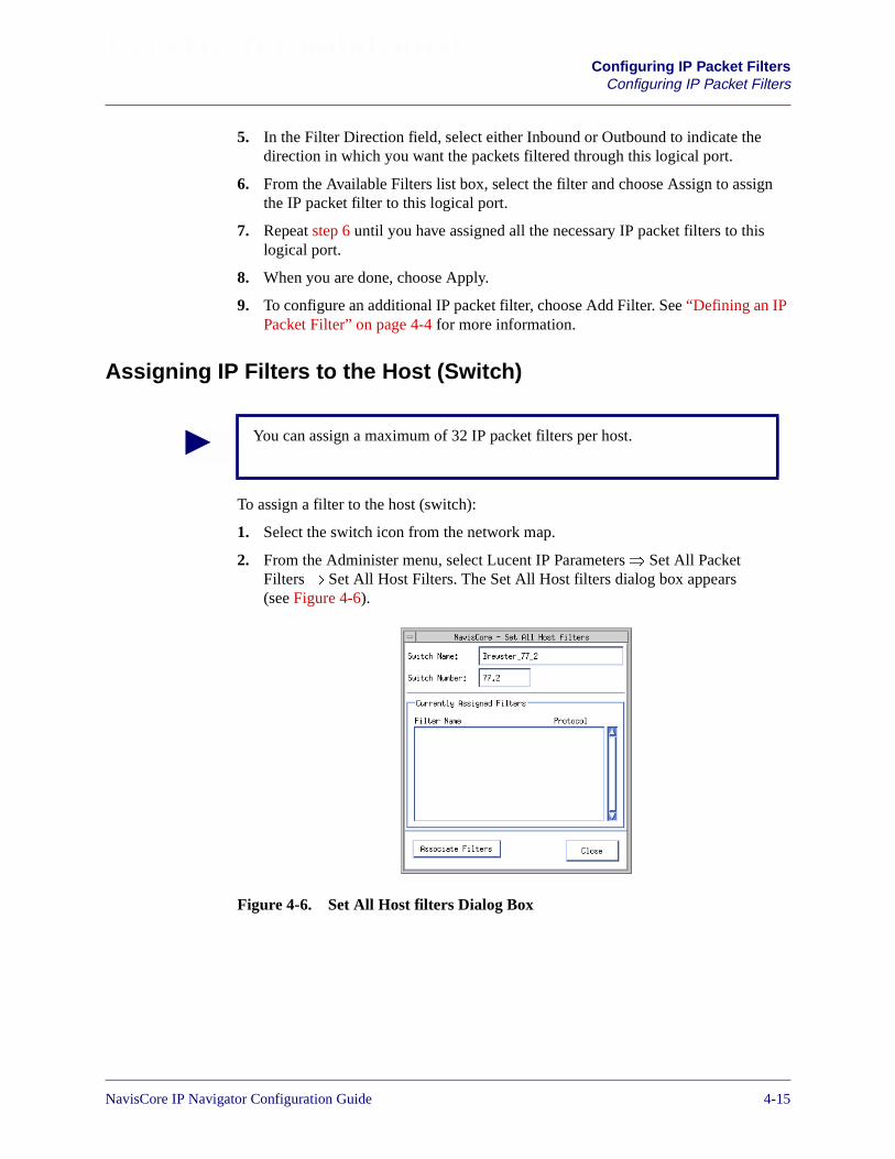
Beta Draft ConfidentialConfiguring IP Packet Filters
Configuring IP Packet Filters
5. In the Filter Direction field, select either Inbound or Outbound to indicate thedirection in which you want the packets filtered through this logical port.
6. From the Available Filters list box, select the filter and choose Assign to assignthe IP packet filter to this logical port.
7. Repeat step 6 until you have assigned all the necessary IP packet filters to thislogical port.
8. When you are done, choose Apply.
9. To configure an additional IP packet filter, choose Add Filter. See “Defining an IPPacket Filter” on page 4-4 for more information.
Assigning IP Filters to the Host (Switch)
To assign a filter to the host (switch):
1. Select the switch icon from the network map.
2. From the Administer menu, select Lucent IP Parameters� Set All PacketFilters� Set All Host Filters. The Set All Host filters dialog box appears(see Figure 4-6).
Figure 4-6. Set All Host filters Dialog Box
You can assign a maximum of 32 IP packet filters per host.
NavisCore IP Navigator Configuration Guide 1/14/024-15

Beta Draft ConfidentialConfiguring IP Packet FiltersConfiguring IP Packet Filters
3. Choose Associate Filters. The Associate Host Filters dialog box appears (seeFigure 4-7).
Figure 4-7. Associate Host Filters Dialog Box
Table 4-5 describes the fields on the Associate Host Filters dialog box.
The Filter Orderbuttons enableyou to changethe order inwhich filters areapplied.
You can view a packet filter’s configuration by double-clicking on the desiredfilter in either the Available or Assigned Filters fields. The Show IP FilterConfiguration dialog box appears with the filter’s configuration.
Table 4-5. Associate Host Filters Fields
Field Description
Switch Name Displays the name of the switch.
Switch ID Displays the switch ID.
Available Filters
Filter Name The name that identifies each of the defined filters.
Protocol Displays TCP, UDP, or Others to indicate the filter’s transport protocol. SeeTable 4-2 for a description of each of these protocol types.
Assigned Filters
Filter Name The name that identifies each of the defined filters that are assigned to theswitch.
Protocol Displays TCP, UDP, or Others to indicate the filter’s transport protocol. SeeTable 4-2 for a description of each of these protocol types.
4-16 NavisCore IP Navigator Configuration Guide
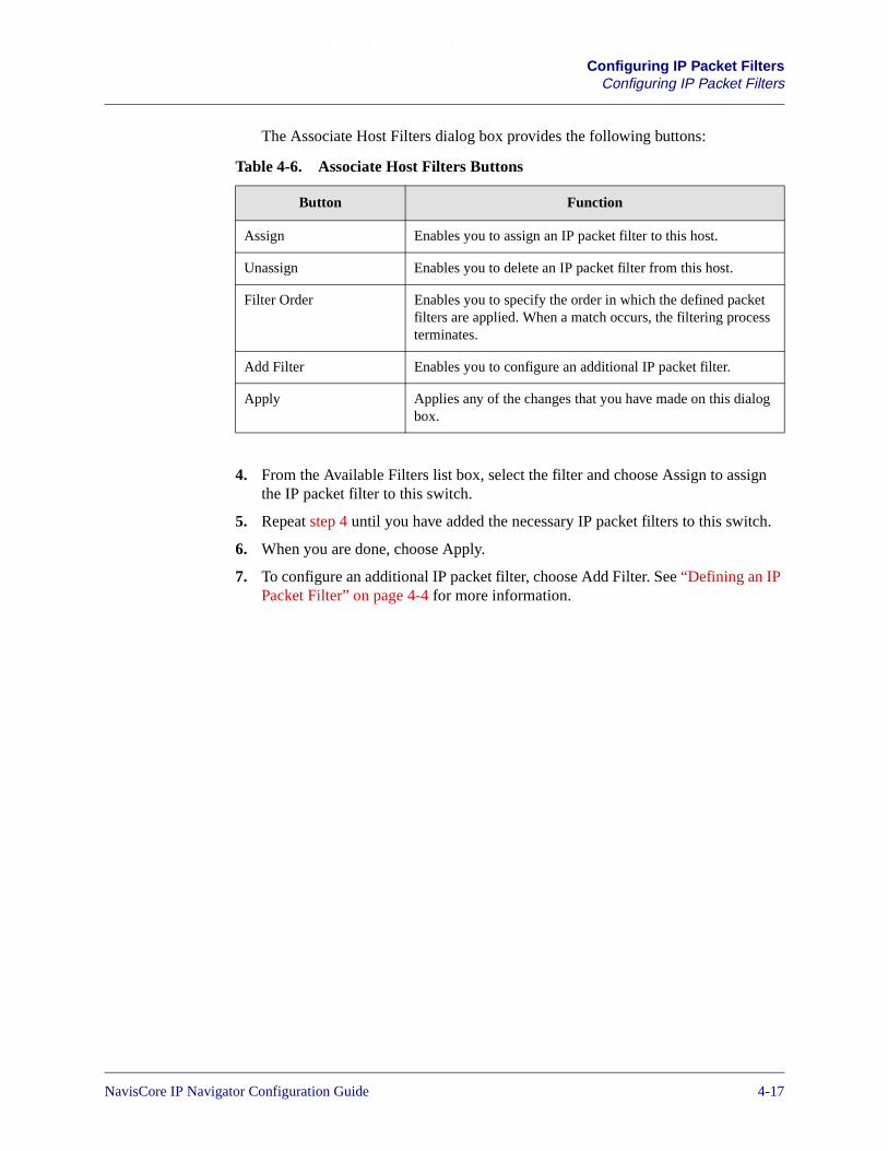
Beta Draft ConfidentialConfiguring IP Packet Filters
Configuring IP Packet Filters
The Associate Host Filters dialog box provides the following buttons:
4. From the Available Filters list box, select the filter and choose Assign to assignthe IP packet filter to this switch.
5. Repeat step 4 until you have added the necessary IP packet filters to this switch.
6. When you are done, choose Apply.
7. To configure an additional IP packet filter, choose Add Filter. See “Defining an IPPacket Filter” on page 4-4 for more information.
Table 4-6. Associate Host Filters Buttons
Button Function
Assign Enables you to assign an IP packet filter to this host.
Unassign Enables you to delete an IP packet filter from this host.
Filter Order Enables you to specify the order in which the defined packetfilters are applied. When a match occurs, the filtering processterminates.
Add Filter Enables you to configure an additional IP packet filter.
Apply Applies any of the changes that you have made on this dialogbox.
NavisCore IP Navigator Configuration Guide 1/14/024-17
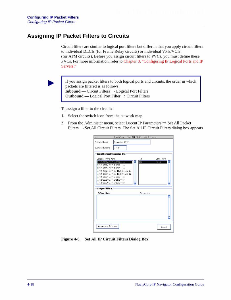
Beta Draft ConfidentialConfiguring IP Packet FiltersConfiguring IP Packet Filters
Assigning IP Packet Filters to Circuits
Circuit filters are similar to logical port filters but differ in that you apply circuit filtersto individual DLCIs (for Frame Relay circuits) or individual VPIs/VCIs(for ATM circuits). Before you assign circuit filters to PVCs, you must define thesePVCs. For more information, refer to Chapter 3, “Configuring IP Logical Ports and IPServers.”
To assign a filter to the circuit:
1. Select the switch icon from the network map.
2. From the Administer menu, select Lucent IP Parameters� Set All PacketFilters� Set All Circuit Filters. The Set All IP Circuit Filters dialog box appears.
Figure 4-8. Set All IP Circuit Filters Dialog Box
If you assign packet filters to both logical ports and circuits, the order in whichpackets are filtered is as follows:Inbound — Circuit Filters� Logical Port FiltersOutbound — Logical Port Filter� Circuit Filters
4-18 NavisCore IP Navigator Configuration Guide

Beta Draft ConfidentialConfiguring IP Packet Filters
Configuring IP Packet Filters
3. Choose Associate Filters. The Associate IP Circuit Filter List dialog box appears(see Figure 4-9).
Figure 4-9. Associate IP Circuit Filter List Dialog Box
Table 4-7 describes the Associate IP Circuit Filter List dialog box fields.
You can view a packet filter’s configuration by double-clicking the desired filterin either the Available or Assigned Filters fields. The Show IP FilterConfiguration dialog box appears with the filter’s configuration.
Table 4-7. Associate IP Circuit Filter List Fields
Field Description
Logical Port Displays the circuit name.
VPI/VCI (for ATM logical ports) Displays the circuit’s VPI/VCI.
DLCI (for Frame Relay logical ports) Displays the circuit’s DLCI.
Filter Direction Enables you to indicate the direction (inbound or outbound) in whichyou want the packets filtered through this circuit.
Available Filters
Filter Name The name that identifies the filters available to this circuit.
Assigned Filters
Filter Name The name that identifies the filter(s) assigned to this circuit.
Direction Indicates the direction (inbound or outbound) in which you want thepackets filtered.
NavisCore IP Navigator Configuration Guide 1/14/024-19
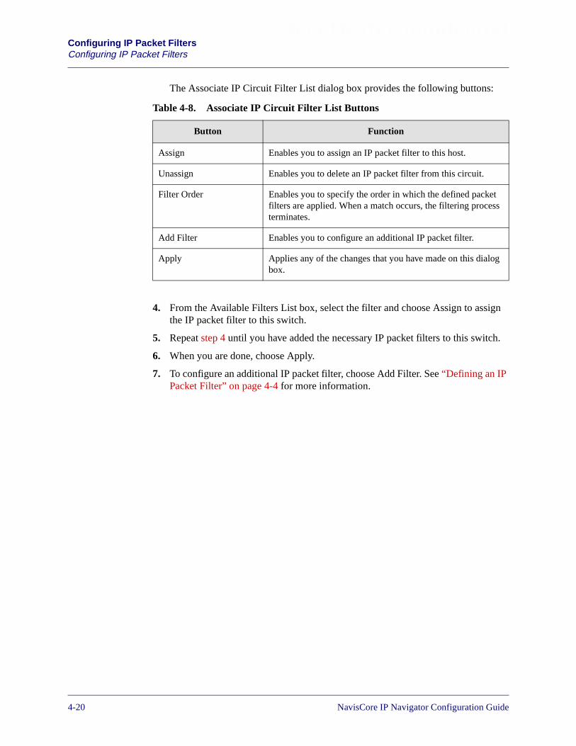
Beta Draft ConfidentialConfiguring IP Packet FiltersConfiguring IP Packet Filters
The Associate IP Circuit Filter List dialog box provides the following buttons:
4. From the Available Filters List box, select the filter and choose Assign to assignthe IP packet filter to this switch.
5. Repeat step 4 until you have added the necessary IP packet filters to this switch.
6. When you are done, choose Apply.
7. To configure an additional IP packet filter, choose Add Filter. See “Defining an IPPacket Filter” on page 4-4 for more information.
Table 4-8. Associate IP Circuit Filter List Buttons
Button Function
Assign Enables you to assign an IP packet filter to this host.
Unassign Enables you to delete an IP packet filter from this circuit.
Filter Order Enables you to specify the order in which the defined packetfilters are applied. When a match occurs, the filtering processterminates.
Add Filter Enables you to configure an additional IP packet filter.
Apply Applies any of the changes that you have made on this dialogbox.
4-20 NavisCore IP Navigator Configuration Guide

Beta Draft ConfidentialConfiguring IP Packet Filters
Configuring IP Packet Filters
Viewing an IP Packet Filter’s Configuration
Once you define an IP packet filter and associate it, you can view its configuration andassociated logical port or circuit. Use the following steps to view an IP packet filterconfiguration for a logical port:
1. From the network map, select the appropriate switch icon.
2. From the Administer menu, select Lucent IP Parameters� Set All PacketFilters� Set All Packet Filters. The Set All Packet Filters dialog box appears (seeFigure 4-10).
Figure 4-10. Set All Packet Filters Dialog Box
First select a filter in theFilter Name field.
Then choose theAssociated to IP LPortsbutton to view the IPlogical port(s) associatedwith the IP packet filter.
NavisCore IP Navigator Configuration Guide 1/14/024-21

Beta Draft ConfidentialConfiguring IP Packet FiltersConfiguring IP Packet Filters
3. Do the following:
a. Select a filter in the filter field.
b. Choose the Associated to IP LPorts button. The Logical ports using the PacketFilter dialog box appears (see Figure 4-11).
Figure 4-11. Logical ports using the Packet Filter Dialog Box
If you selected a packet filter that is not assigned to an IP logical port, thefollowing message appears:
Figure 4-12. Packet Filter Error Message Dialog Box
4. Choose Close.
5. To view a packet filter that is assigned to a circuit, perform step 1 through step 3,except choose the Associated to IP Circuits button instead of the Associated to IPLPorts button.
4-22 NavisCore IP Navigator Configuration Guide
NavisCore IP Navigator Configuration Guide
Beta Draft Confidential
5
Configuring Policy-Based Forwarding
This chapter provides an overview of policy-based forwarding and describes thefollowing tasks:
• Configuring a policy PVC
• Defining a forwarding policy
• Assigning a forwarding policy to a logical port
• Enabling policy-based forwarding
About Forwarding Policies
Policy-based forwarding is a technique for forwarding IP packets based on criteriadefined in forwarding policies. Policy-based forwarding allows switches to forwardpackets based on criteria other than destination IP addresses. For example, you canuse policy-based forwarding to route packets based on source address, source ordestination port number, Type of Service (ToS), protocol type, or otheruser-configurable criteria.
You associate forwarding policies with one or more ingress IP logical ports on aswitch. If an IP packet received at an ingress IP logical port matches the criteria of aforwarding policy associated with that port, IP Navigator forwards the packet over aspecified policy PVC. Otherwise, IP Navigator routes the packet on a best-effort basisaccording to the packet’s destination IP address.
When you define a forwarding policy, you specify:
• Forwarding criteria, including source and destination IP addresses and masks, anIP protocol, a Type of Service (ToS), source and destination TCP/UDP ports, anda Virtual Private Network (VPN) ID.
• Policy PVCs and associated Quality of Service (QoS) attributes, including a QoSclass and traffic descriptors such as peak cell rate (PCR) and sustainable cell rate(SCR).
5-1
Beta Draft ConfidentialConfiguring Policy-Based ForwardingAbout Forwarding Policies
You can associate more than one forwarding policy with an ingress IP logical port. IPNavigator enforces the policies on any IP packets received at that port. If multiplepolicies are associated with one IP logical port, incoming IP packets are processedaccording to the first matching policy found. You can specify the sequence in whichforwarding policies are applied to an IP logical port.
Remember the following important facts about IP policy PVCs and forwardingpolicies:
• Policy-based forwarding replaces IP QoS PVCs completely. However, because IPQoS is a subset of policy-based forwarding, you can convert any existingapplications to policy-based forwarding. This means that you can convert IP QoSflow profiles to forwarding policies, and convert IP QoS PVCs to policy PVCs.
• One policy PVC may be shared by multiple forwarding policies.
• One forwarding policy may be shared by multiple logical ports on a switch(B-STDX 8000/9000) or on a Frame Engine (CBX 500). Forwarding PVCscannot be shared by two Frame Engines (FEs) on one CBX 500 card or by FEs ondifferent cards.
• You can assign as many as 100 forwarding policies to one ingress logical port.
• A switch (B-STDX 8000/9000) or Frame Engine (CBX 500) may have as many as1500 forwarding policies.
• You can have as many as 3,736 logical ports per switch (B-STDX 8000/9000) orFrame Engine (CBX 500) that have associated forwarding policies.
• You can modify an IP address in a forwarding policy with a ClasslessInterDomain Routing (CIDR) mask. For example, if the address field is set to1.2.3.4 with a mask of 255.255.255.0, an address of 1.2.3.n causes a match for anyvalue of n.
• You can specify the order in which forwarding policies are applied to incomingpackets.
• The switch processor (CP/SP) maintains the forwarding policy and policy PVCinformation, but then distributes the information to the appropriate IOMs/IOPs sothat the switch processor is not required for proper forwarding policy operation.This step eliminates a single point of failure.
• IP Navigator checks packet filters before it checks forwarding policies. Becausepacket filtering occurs first, a packet could be dropped before policy-basedforwarding ever checks it.
• IP Navigator checks NHRP flow profiles before it checks forwarding policies.Because NHRP flow detection occurs first, a packet could get forwarded over anNHRP SVC shortcut before policy-based forwarding ever checks it.
• You are responsible for assuring that the bandwidth allocated for a policy PVCsupports the amount of traffic travelling over the policy PVC.
5-2 NavisCore IP Navigator Configuration Guide

Beta Draft ConfidentialConfiguring Policy-Based Forwarding
About Policy PVCs
About Policy PVCs
A policy PVC is like an ordinary PVC, with some exceptions. This section describesthe exceptions.
A policy PVC between two B-STDX 8000/9000 switches is either a switch-to-switchPVC or a switch-to-logical-port PVC (not logical port-to-logical port). IP packetsmust enter a policy PVC at the switch, and exit the PVC at either another switch (inwhich case they are routed based on a routing table lookup) or a specific egress logicalport.
A policy PVC between two CBX 500 switches is either a FE-to-FE PVC or aFE-to-logical-port PVC (not logical port-to-logical port). IP packets must enter apolicy PVC on a CBX 500 at the FE, and exit the PVC at either another FE (in whichcase they are routed based on a routing table lookup) or a specific egress logical port.
When a policy PVC exits the Lucent network at a switch or FE, the policy PVC isbi-directional. When a policy PVC exits the Lucent network at a logical port, thepolicy PVC is uni-directional. To handle traffic in the opposite direction, you can:
• Create a policy PVC in the opposite direction.
• Route traffic in the opposite direction to an IP logical port. In this case, traffic willbe routed using routing table lookups.
The following types of user logical ports may act as egress ports for policy PVCs:
• IP logical port
• ATM UNI logical port
• Frame Relay UNI logical port
• PPP logical port
• Ethernet logical port
On the B-STDX 8000/9000 switch, some or all of the IP logical ports can share thesame policy PVC. On the CBX 500 switch, some or all of the IP logical ports on oneFE can share the same policy PVC. A policy PVC cannot be shared by logical ports onmore than one FE.
NavisCore IP Navigator Configuration Guide 1/14/025-3

Beta Draft ConfidentialConfiguring Policy-Based ForwardingPolicy-Based Forwarding Tutorial
Policy-Based Forwarding Tutorial
This section provides a tutorial on policy-based forwarding. As an example, thissection presents a common use of policy-based forwarding called source-basedrouting. Source-based routing is a scheme for forwarding IP packets based on theirsource IP address instead of their destination IP address.
In this tutorial, traffic intended for host Boston must be forwarded through differentInternet Service Providers (ISPs) according to the source address of the traffic:
• IP packets that have a source IP address of 152.148.10.x must be forwardedthrough ISP 1 to host Boston.
• IP packets that have a source IP address of 152.148.20.x must be forwardedthrough ISP 2 to host Boston.
Figure 5-1 illustrates the source-based routing example.
Figure 5-1. Source-Based Routing Example
90
00
90
00
LucentNetwork
ISP 2
ISP 1LogicalPort A
(Ingress)
LogicalPort B
(Egress)
LogicalPort C
(Egress)
MAX TNT
Boston
5-4 NavisCore IP Navigator Configuration Guide

Beta Draft ConfidentialConfiguring Policy-Based Forwarding
Policy-Based Forwarding Tutorial
How Do I Configure Policy-Based Forwarding?
This section describes the five general steps for configuring policy-based forwarding:
1. Plan the policy PVCs.
2. Create the policy PVCs.
3. Create the forwarding policies.
4. Assign the forwarding policies to IP logical ports.
5. If necessary, enable policy-based forwarding.
Step 1: Plan the Policy PVCs
When you plan a policy PVC, identify the problem that you want the policy PVC tosolve. For example, in Figure 5-1 on page 5-4, the policy PVC must provide asource-based routing solution.
Step 2: Create the Policy PVCs
In Figure 5-1 on page 5-4, you want to create two policy PVCs:
POL-PVC10 — IP packets enter this policy PVC at the ingress switch and exit thepolicy PVC at Logical Port B in the egress switch. You use this policy PVC to forwardIP packets with a source address of 152.148.10.x over Logical Port B to ISP 1. ISP 1will then be responsible for delivering the packets to host Boston.
POL-PVC20 — IP packets enter this policy PVC at the ingress switch and exit thePVC at Logical Port C in the egress switch. You use this policy PVC to forwardpackets with a source address of 152.148.20.x over Logical Port C to ISP 2. ISP 2 willthen be responsible for delivering the packets to host Boston.
See “Configuring a Policy PVC” on page 5-12 for instructions on creating a policyPVC. When you create a policy PVC, keep the following in mind:
• The ingress side of a policy PVC is always a switch (on a B-STDX 8000/9000) orFrame Engine (on a CBX 500).
• The egress side of a policy PVC may be a B-STDX switch or CBX 500 FE (thatis, the “dummy” logical port that represents a switch or FE), or it may be a logicalport on a switch.
NavisCore IP Navigator Configuration Guide 1/14/025-5

Beta Draft ConfidentialConfiguring Policy-Based ForwardingPolicy-Based Forwarding Tutorial
Step 3: Create the Forwarding Policies
To set up the forwarding policies illustrated in Figure 5-1 on page 5-4, you would:
• Create a forwarding policy for POL-PVC10 with:
– The Source IP Address field set to 152.148.10.0
– The Network Mask field set to 255.255.255.0
– The Policy PVC field set to POL-PVC10
• Create a forwarding policy for POL-PVC20 with:
– The Source IP address field set to 152.148.20.0
– The Network Mask field set to 255.255.255.0
– The Policy PVC field set to POL-PVC20
See “Defining a Forwarding Policy” on page 5-28 for more information on creatingforwarding policies.
Step 4: Assign the Forwarding Policies to IP Logical Ports
Assign the forwarding policies to the appropriate ingress logical port (for example,Logical Port A in Figure 5-1). See “Assigning a Forwarding Policy to a Logical Port”on page 5-33 for detailed instructions. Choose the appropriate logical port and assignthe policies to that port.
Use the following switch console command to verify that the assignment was madeproperly:
show ip policy forwarding attributes <interface #>
This command shows all forwarding policies assigned to the specified port. Theinterface # is the logical port’s interface ID (that is, the LPort ID).
Step 5: Enable Policy-Based Forwarding
Enable policy-based forwarding on the appropriate ingress port (logical port A inFigure 5-1). See “Enabling Policy-Based Forwarding” on page 5-34 for detailedinstructions.
Use the following switch console command to verify that policy-based forwarding isenabled for the specified port:
show ip policy forwarding state <interface #>
This command shows whether policy-based forwarding is enabled for the specifiedlogical port. The interface # is the logical port’s interface ID (that is, the LPort ID).
5-6 NavisCore IP Navigator Configuration Guide
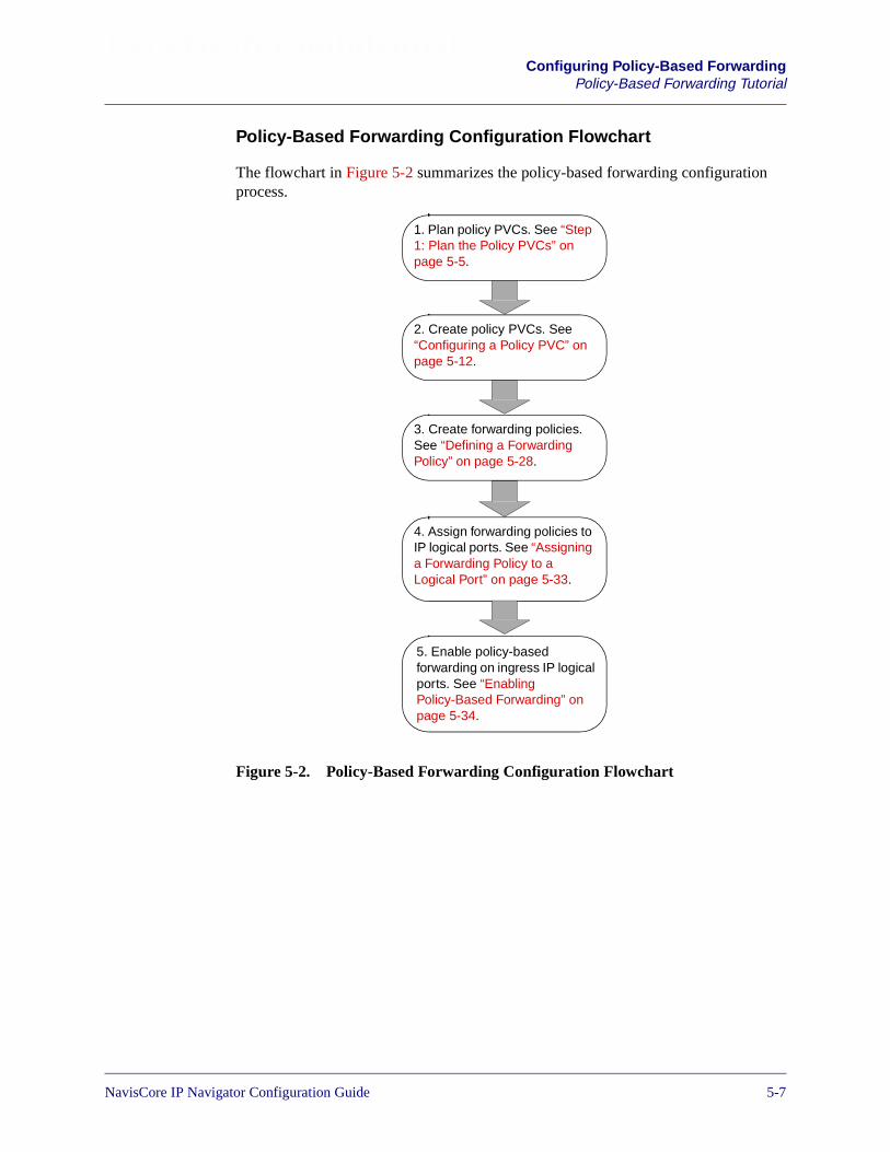
Beta Draft ConfidentialConfiguring Policy-Based Forwarding
Policy-Based Forwarding Tutorial
Policy-Based Forwarding Configuration Flowchart
The flowchart in Figure 5-2 summarizes the policy-based forwarding configurationprocess.
Figure 5-2. Policy-Based Forwarding Configuration Flowchart
2. Create policy PVCs. See“Configuring a Policy PVC” onpage 5-12.
3. Create forwarding policies.See “Defining a ForwardingPolicy” on page 5-28.
4. Assign forwarding policies toIP logical ports. See “Assigninga Forwarding Policy to aLogical Port” on page 5-33.
5. Enable policy-basedforwarding on ingress IP logicalports. See “EnablingPolicy-Based Forwarding” onpage 5-34.
1. Plan policy PVCs. See “Step1: Plan the Policy PVCs” onpage 5-5.
NavisCore IP Navigator Configuration Guide 1/14/025-7

Beta Draft ConfidentialConfiguring Policy-Based ForwardingPolicy-Based Forwarding Tutorial
How Do I Verify that Policy-Based Forwarding is Working?
After policy PVCs are active and forwarding policies are associated with ingresslogical ports, you can verify that policy-based forwarding is working in three ways:
• Use the following switch console command to view forwarding statistics:
show ip policy forwarding statistics <interface #>
This command shows a count of received IP packets that matched a forwardingpolicy associated with the specified logical port, and, as a result, were forwardedover the associated policy PVC. Note that if a received packet matches a policy,but the associated PVC is not active, the counter is not incremented. The packet isonly counted if it is forwarded over the PVC. A separate counter is kept for eachforwarding policy associated with the specified logical port.
• Use the following Monitor menu selection to view forwarding statistics: Lucent IPObjects� Show All Forwarding Policies� Show All Logical Port ForwardingPolicies.
• Use the following switch console command to verify that a policy PVC is active:
show ip policy forwarding pvc
This command identifies those policy PVCs that originate on the switch or FEwhere the command is issued (that is, the ingress side of the policy PVC).
What Happens When a Policy PVC Goes Down?
If a logical port receives an IP packet that matches an associated forwarding policy,but the policy PVC specified in the forwarding policy is not active, then the packet isrouted on a best-effort basis according to its destination IP address.
For example, in Figure 5-1 on page 5-4, best-effort routing could forward the packet toeither ISP 1 or ISP 2, depending upon routing table information. If you assume thatbest-effort routing is not acceptable, you can assign packet filters to egress logicalports B and C to eliminate the possibility of the wrong packet being sent to the wrongISP. The filters would cause the unwanted packets to be dropped. Specifically, thefilters would dictate that any packets with a source IP address of 152.148.20.x wouldnot be forwarded out logical port B, and any packets with source IP address of152.148.10.x would not be forwarded out logical port C.
Another way to solve the problem of inactive policy PVCs is to create a backup policyPVC. See “How Can I Set Up PVCs that are Redundant and Share Traffic Load?” onpage 5-9 for details.
5-8 NavisCore IP Navigator Configuration Guide

Beta Draft ConfidentialConfiguring Policy-Based Forwarding
Policy-Based Forwarding Tutorial
How Can I Set Up PVCs that are Redundant and Share TrafficLoad?
Assuming the existence of two logical ports between the egress switch and one of theISPs in Figure 5-1 on page 5-4, you could then create two policy PVCs that start in theingress switch, and terminate at their respective egress switch logical ports. You couldthen create two forwarding policies, which would be identical except that they usedifferent policy PVCs.
Figure 5-3 illustrates the new configuration. In this figure, two redundant policy PVCsare created for ISP 1. Each PVC is associated with a different egress IP logical port(B1 and B2). Two forwarding policies are created and associated with the ingress IPlogical port.
Figure 5-3. Redundant PVCs
The following sequence of events will occur when a packet is received by the ingressswitch logical port:
1. The packet matches the first of the two forwarding policies, but the PVC specifiedby that policy is down.
2. The second forwarding policy is checked for a match, and the packet matches thatpolicy.
3. The packet is successfully forwarded over the policy PVC specified by the secondforwarding policy, since the second policy PVC is up.
You can specify the sequence in which forwarding policies are applied to packetscoming in over a logical port. Therefore, you can determine which PVC/egress portcombination should be used as the primary path and which should be used as thesecondary path.
90
00
90
00
LucentNetwork
ISP 2
ISP 1LogicalPort A
(Ingress)
LogicalPort C
(Egress)
MAX TNT
Boston
LogicalPorts B1and B2
(Egress)
Create two forwardingpolicies and associatethem with this ingress IPlogical port. Eachforwarding policy uses adifferent policy PVC.
NavisCore IP Navigator Configuration Guide 1/14/025-9
Beta Draft ConfidentialConfiguring Policy-Based ForwardingPolicy-Based Forwarding Tutorial
Now, assume that you want to associate eight logical ports in the ingress switch or FEwith the same forwarding policies. For four of the logical ports, you can specify:
• Forwarding policy A (which specifies policy PVC A) will be applied first
• Forwarding policy B (which specifies policy PVC B) will be applied if policyPVC A is not functioning
For the remaining four ports, you can reverse the policy order — forwarding policy Bwill be applied first, and forwarding policy A will be applied if policy PVC A is notfunctioning. In this way, both PVC/egress port combinations are used. If either policyPVC fails, the other policy PVC can support the traffic from all eight ingress ports.
The fault-tolerant UNI PVC feature allows the logical port side of a PVC to have twoports associated with it — a primary logical port and a secondary (backup) logicalport. This may be considered as an alternative to the method previously described inthis section. However, fault tolerant PVCs have a limitation: the PVC stays downtemporarily while the switchover from primary logical port to backup logical porttakes place. Packets are lost during that time. See the NavisCore Frame RelayConfiguration Guide or the NavisCore ATM Configuration Guide for moreinformation on fault-tolerant PVCs.
When Should I Not Use Switch/FE-to-Switch/FE Policy PVCs?
When a policy PVC terminates at a switch or FE instead of a logical port, packetsarriving over the PVC at the egress switch are routed based on the routing tables inthat egress switch. This type of policy PVC would not work in the example inFigure 5-1 on page 5-4. If the policy PVC terminated at the switch instead of at alogical port, packets would be sent to either ISP 1 or ISP 2 according to the currentinformation in the routing table rather than according to the PVC policy.
When Should I Use Switch/FE-to-Switch/FE Policy PVCs?
Use of a switch-to-switch or FE-to-FE policy PVC could make sense in anotherconfiguration. Suppose that two egress switches are available, one connected to ISP 1and the other to ISP 2. In each switch, multiple logical ports for reaching each ISPexist. Figure 5-4 illustrates this configuration.
5-10 NavisCore IP Navigator Configuration Guide
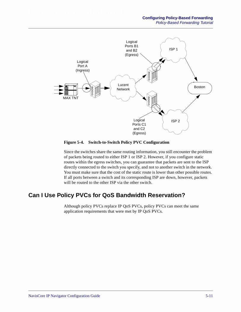
Beta Draft ConfidentialConfiguring Policy-Based Forwarding
Policy-Based Forwarding Tutorial
Figure 5-4. Switch-to-Switch Policy PVC Configuration
Since the switches share the same routing information, you still encounter the problemof packets being routed to either ISP 1 or ISP 2. However, if you configure staticroutes within the egress switches, you can guarantee that packets are sent to the ISPdirectly connected to the switch you specify, and not to another switch in the network.You must make sure that the cost of the static route is lower than other possible routes.If all ports between a switch and its corresponding ISP are down, however, packetswill be routed to the other ISP via the other switch.
Can I Use Policy PVCs for QoS Bandwidth Reservation?
Although policy PVCs replace IP QoS PVCs, policy PVCs can meet the sameapplication requirements that were met by IP QoS PVCs.
90
00
90
00
90
00
LucentNetwork
ISP 2
ISP 1
LogicalPort A
(Ingress)
MAX TNT
Boston
LogicalPorts B1and B2
(Egress)
LogicalPorts C1and C2(Egress)
NavisCore IP Navigator Configuration Guide 1/14/025-11
Beta Draft ConfidentialConfiguring Policy-Based ForwardingConfiguring a Policy PVC
Configuring a Policy PVC
To configure a policy PVC, you first create the circuit endpoints, then define andname the circuit connection. You also assign administrative, user preference, and otherattributes to the circuit.
To configure a policy PVC:
1. From the Administer menu, select Lucent IP Parameters� Set Policy PVCs. TheSet All Policy PVCs on Map dialog box appears (see Figure 5-5).
A number of seconds may pass between the time a policy PVC is created and thetime it is active. A policy PVC is active when no “Fail Reason at endpoint x”messages appear on the Set All Policy PVCs On Map dialog box (seeFigure 5-5). You can also use the show ip policy forwarding pvccommand to verify that a PVC is active. See “How Do I Verify that Policy-BasedForwarding is Working?” on page 5-8 for more information.
5-12 NavisCore IP Navigator Configuration Guide

Beta Draft ConfidentialConfiguring Policy-Based Forwarding
Configuring a Policy PVC
Figure 5-5. Set All Policy PVCs On Map Dialog Box
The Set All Policy PVCs on Map dialog box is blank initially. To display the completelist of defined circuit names, position the cursor in the Search by Name field and pressEnter. This search may take several minutes depending on your configuration.
To display a filtered list of defined circuit names, enter the selected search criteria inthe Search by Name field. To use a wildcard search to find a specific circuit name, youcan:
• Use an * to match any number of characters.
• Use a ? to match a single character.
• Use a \* to match the * character.
• Use a \? to match the ? character.
• Use a \\ to match the \ character.
NavisCore IP Navigator Configuration Guide 1/14/025-13

Beta Draft ConfidentialConfiguring Policy-Based ForwardingConfiguring a Policy PVC
Table 5-1 describes the buttons on the Set All Policy PVCs on Map dialog box.
2. Choose Add. The Select End Logical Ports dialog box appears (see Figure 5-6).
Table 5-1. Set All Policy PVCs on Map Dialog Box: Buttons
Button Function
Add/Modify/Delete Enables you to add a new circuit or modify or delete an existing circuit.
Note: If the PVC loopback status field does not display NONE, do not attemptto modify or delete the selected circuit.
VPN/Customer Displays the virtual private network customer’s name.
Get Oper Info Displays a status message in the Oper Status field about the selected circuit. Formore information, see the NavisCore Diagnostics Guide.
Define Path Enables you to define a circuit path manually.
Statistics Displays the summary statistics for the selected circuit. For information, see theNavisCore Diagnostics Guide.
QoS Displays the Quality of Service (QoS) values for the selected circuit.
OAM Alarms (ATM CS andIWU modules only)
Displays the OAM alarms, which indicate whether the circuit is up or down.These alarms send a signal to the logical port whenever the circuit goes down orcomes back up.
Add using Template If you have already defined a circuit configuration and saved it as a template,use this option to define a new circuit.
Choose Last Template to use the last template you defined for this switch.
Choose Template List to display a list of templates previously defined for thismap.
Accounting Accesses the accounting functions for a PVC. For more information, see theNavisXtend Accounting Server Administrator’s Guide.
NDC Thresholds (CBX 500only)
Displays the configured network data collection (NDC) thresholds for theselected circuit.
NDC Statistic (CBX 500only)
Displays the NDC statistics for the selected circuit.
Close Exits the dialog box and returns you to the network map.
5-14 NavisCore IP Navigator Configuration Guide

Beta Draft ConfidentialConfiguring Policy-Based Forwarding
Configuring a Policy PVC
Figure 5-6. Select End Logical Ports Dialog Box
The Select End Logical Ports dialog box displays information based onconfiguration selections you made. Table 5-2 describes each field.
Select logicalports
NavisCore IP Navigator Configuration Guide 1/14/025-15
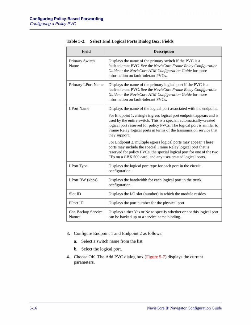
Beta Draft ConfidentialConfiguring Policy-Based ForwardingConfiguring a Policy PVC
3. Configure Endpoint 1 and Endpoint 2 as follows:
a. Select a switch name from the list.
b. Select the logical port.
4. Choose OK. The Add PVC dialog box (Figure 5-7) displays the currentparameters.
Table 5-2. Select End Logical Ports Dialog Box: Fields
Field Description
Primary SwitchName
Displays the name of the primary switch if the PVC is afault-tolerant PVC. See the NavisCore Frame Relay ConfigurationGuide or the NavisCore ATM Configuration Guide for moreinformation on fault-tolerant PVCs.
Primary LPort Name Displays the name of the primary logical port if the PVC is afault-tolerant PVC. See the NavisCore Frame Relay ConfigurationGuide or the NavisCore ATM Configuration Guide for moreinformation on fault-tolerant PVCs.
LPort Name Displays the name of the logical port associated with the endpoint.
For Endpoint 1, a single ingress logical port endpoint appears and isused by the entire switch. This is a special, automatically-createdlogical port reserved for policy PVCs. The logical port is similar toFrame Relay logical ports in terms of the transmission service thatthey support.
For Endpoint 2, multiple egress logical ports may appear. Theseports may include the special Frame Relay logical port that isreserved for policy PVCs, the special logical port for one of the twoFEs on a CBX 500 card, and any user-created logical ports.
LPort Type Displays the logical port type for each port in the circuitconfiguration.
LPort BW (kbps) Displays the bandwidth for each logical port in the trunkconfiguration.
Slot ID Displays the I/O slot (number) in which the module resides.
PPort ID Displays the port number for the physical port.
Can Backup ServiceNames
Displays either Yes or No to specify whether or not this logical portcan be backed up to a service name binding.
5-16 NavisCore IP Navigator Configuration Guide

Beta Draft ConfidentialConfiguring Policy-Based Forwarding
Configuring a Policy PVC
Figure 5-7. Add PVC Dialog Box (Administrative Attributes)
5. Access the Set Attributes option menu and complete the circuit attributes asdescribed in the following sections.
6. After you complete the circuit attributes, choose OK to accept the circuitparameters and send the configuration file to the switch (provided the switch iscommunicating with the NMS). The Set All PVCs on Map dialog box reappears.
SetAttributesOptionMenu
NavisCore IP Navigator Configuration Guide 1/14/025-17
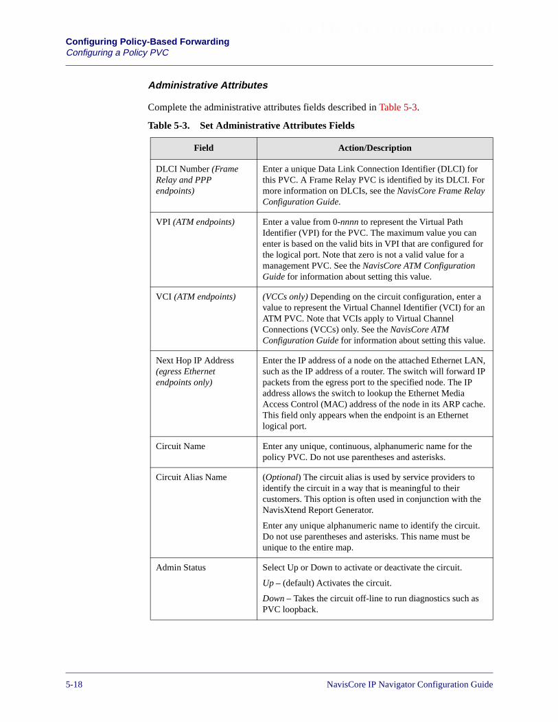
Beta Draft ConfidentialConfiguring Policy-Based ForwardingConfiguring a Policy PVC
Administrative Attributes
Complete the administrative attributes fields described in Table 5-3.
Table 5-3. Set Administrative Attributes Fields
Field Action/Description
DLCI Number (FrameRelay and PPPendpoints)
Enter a unique Data Link Connection Identifier (DLCI) forthis PVC. A Frame Relay PVC is identified by its DLCI. Formore information on DLCIs, see the NavisCore Frame RelayConfiguration Guide.
VPI (ATM endpoints) Enter a value from 0-nnnn to represent the Virtual PathIdentifier (VPI) for the PVC. The maximum value you canenter is based on the valid bits in VPI that are configured forthe logical port. Note that zero is not a valid value for amanagement PVC. See the NavisCore ATM ConfigurationGuide for information about setting this value.
VCI (ATM endpoints) (VCCs only) Depending on the circuit configuration, enter avalue to represent the Virtual Channel Identifier (VCI) for anATM PVC. Note that VCIs apply to Virtual ChannelConnections (VCCs) only. See the NavisCore ATMConfiguration Guide for information about setting this value.
Next Hop IP Address(egress Ethernetendpoints only)
Enter the IP address of a node on the attached Ethernet LAN,such as the IP address of a router. The switch will forward IPpackets from the egress port to the specified node. The IPaddress allows the switch to lookup the Ethernet MediaAccess Control (MAC) address of the node in its ARP cache.This field only appears when the endpoint is an Ethernetlogical port.
Circuit Name Enter any unique, continuous, alphanumeric name for thepolicy PVC. Do not use parentheses and asterisks.
Circuit Alias Name (Optional) The circuit alias is used by service providers toidentify the circuit in a way that is meaningful to theircustomers. This option is often used in conjunction with theNavisXtend Report Generator.
Enter any unique alphanumeric name to identify the circuit.Do not use parentheses and asterisks. This name must beunique to the entire map.
Admin Status Select Up or Down to activate or deactivate the circuit.
Up – (default) Activates the circuit.
Down – Takes the circuit off-line to run diagnostics such asPVC loopback.
5-18 NavisCore IP Navigator Configuration Guide

Beta Draft ConfidentialConfiguring Policy-Based Forwarding
Configuring a Policy PVC
Private Net Overflow (For VNN Virtual Private Networks) Set the Private NetOverflow parameters, which determine whether circuitsoriginating from an LPort will be restricted to trunks of theirown VNN VPN or use public (shared) trunks during overflowconditions. Options include:
Public – (default) Enables the circuit to use public trunksduring traffic overflow or trunk failure conditions.
Restrict – Restricts trunks to their own virtual privatenetwork.
Template (Optional) Save these settings as a template to use whenconfiguring another circuit with the same options. To create atemplate, choose Yes in the Is Template field.
Mgmt Loopback Ckt Choose Yes to include this PVC configuration in the NMSinitialization script file. This file contains all the SNMP setrequests necessary to replicate the entire switchconfiguration. Once you download this file to the switch, thisPVC can be used to establish NMS-to-switch connectivity.This option is especially useful in some management DLCIconfigurations. The default value is No. (For moreinformation about management DLCIs, see the NavisCoreFrame Relay Configuration Guide.)
Admin Cost Threshold If you enable this option, the PVC will not be routed over apath whose total administrative cost exceeds the enteredvalue. This means that if you enable this field and enter avalue of 1000, the PVC will not be routed over a path whosetotal administrative cost exceeds 1000. The totaladministrative cost for a path is calculated by summing theadministrative cost for each trunk in the path. The valid rangeof values for this field is 1 - 65534. (Do not enable this optionif you use End-End Delay routing.)
End-End Delay Threshold If you enable this option, the PVC will not be routed over apath whose total end-to-end delay exceeds the entered value.This means that if you enable this field and enter a value of500 µsec., the PVC will not be routed over a path whose totalend-to-end delay exceeds 500 µsec. The total end-to-enddelay for a path is calculated by summing end-to-end delayfor each trunk in the path. The valid range for this field is 0 -167777214 µsec.
Note: The value you enter should reflect your networktopology. If a PVC will typically traverse high speed trunks,set the delay rate lower; increase the delay if the PVC mustuse low-speed trunks.
Table 5-3. Set Administrative Attributes Fields (Continued)
Field Action/Description
NavisCore IP Navigator Configuration Guide 1/14/025-19

Beta Draft ConfidentialConfiguring Policy-Based ForwardingConfiguring a Policy PVC
Traffic Type Attributes
1. Select Traffic Type from the Set Attributes option menu. The traffic type fieldsappear (see Figure 5-8).
Figure 5-8. Add PVC Dialog Box (Traffic Type Attributes)
2. Complete the fields described in Table 5-4 (for Frame Relay logical ports) and inTable 5-5 (for ATM logical ports). Keep in mind that the fields on the dialog boxwill vary, depending on whether the logical port endpoints support Frame Relayor ATM.
ChooseTraffic Type
The left column beneath the Forward (−>) arrow represents the logical port forthe circuit that connects Endpoint 1 to Endpoint 2. The right column beneath theReverse (<−) arrow represents the logical port for the circuit that connectsEndpoint 2 to Endpoint 1. Enter values in both columns.
5-20 NavisCore IP Navigator Configuration Guide

Beta Draft ConfidentialConfiguring Policy-Based Forwarding
Configuring a Policy PVC
Table 5-4. Set Traffic Type Attributes Fields (Frame Relay Endpoints)
Field Action/Description
QoS Class (Fwd/Rev) Select one of the following Quality of Service (QoS) classes:
VFR (Real-Time) – Variable Frame Rate (VFR). Used for special delay-sensitiveapplications that require low delay variation between endpoints.
VFR (Non-Real Time) – Handles transfer of long, bursty data streams over apre-established connection. This service provides low data loss but no delayguarantee. Also used for short, bursty data, such as LAN traffic. CPE protocolsadjust for any delay or loss incurred through the use of VFR-NRT.
UFR – Unspecified Frame Rate (UFR). Used for LAN traffic, primarily. The CPEshould compensate for any delay or frame loss.
Priority (Fwd/Rev) Select 1, 2, or 3 to configure the priority of data being transmitted on this circuit.Circuit priority determines the data’s forwarding priority. The highest priority is 1(do not discard data); the lowest is 3 (discards data). The forward and reversecircuit priority values do not have to match.
CIR (Kbps) (CommittedInformation Rate)
Enter the rate in Kbps at which the network transfers data under normalconditions. Normal conditions refer to a properly designed network with amplebandwidth and switch capacity. The rate is averaged over a minimum incrementof the committed rate measurement interval (Tc). The value on each PVC isasymmetric (you can set a different CIR in each direction), which provides moreefficient use of bandwidth.
Bc (Kbits) (CommittedBurst Size)
Enter the maximum amount of data, in Kbits, that the network attempts to transferdata under normal conditions during a specified time interval, Tc. Tc is calculatedas Bc/CIR. This value must be greater than zero and is typically set to the samevalue as CIR.
Be (Kbits) (Excess BurstSize)
Enter the maximum amount of uncommitted data, in Kbits, the network willattempt to deliver during a specified time interval, Tc. Tc is calculated as Bc/CIR.The network treats this data as discard eligible (DE) data.
Rate Enf Scheme Select Simple (default) or Jump. The configurable rate enforcement schemeprovides more flexibility, increased rate enforcement accuracy, and improvedswitch performance.
Note: If you select the Simple scheme, the “bad” PVC detection feature isdisabled.
NavisCore IP Navigator Configuration Guide 1/14/025-21
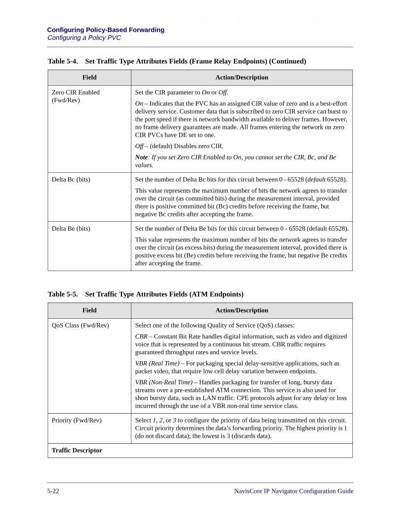
Beta Draft ConfidentialConfiguring Policy-Based ForwardingConfiguring a Policy PVC
Zero CIR Enabled(Fwd/Rev)
Set the CIR parameter to On or Off.
On – Indicates that the PVC has an assigned CIR value of zero and is a best-effortdelivery service. Customer data that is subscribed to zero CIR service can burst tothe port speed if there is network bandwidth available to deliver frames. However,no frame delivery guarantees are made. All frames entering the network on zeroCIR PVCs have DE set to one.
Off – (default) Disables zero CIR.
Note: If you set Zero CIR Enabled to On, you cannot set the CIR, Bc, and Bevalues.
Delta Bc (bits) Set the number of Delta Bc bits for this circuit between 0 - 65528 (default 65528).
This value represents the maximum number of bits the network agrees to transferover the circuit (as committed bits) during the measurement interval, providedthere is positive committed bit (Bc) credits before receiving the frame, butnegative Bc credits after accepting the frame.
Delta Be (bits) Set the number of Delta Be bits for this circuit between 0 - 65528 (default 65528).
This value represents the maximum number of bits the network agrees to transferover the circuit (as excess bits) during the measurement interval, provided there ispositive excess bit (Be) credits before receiving the frame, but negative Be creditsafter accepting the frame.
Table 5-4. Set Traffic Type Attributes Fields (Frame Relay Endpoints) (Continued)
Field Action/Description
Table 5-5. Set Traffic Type Attributes Fields (ATM Endpoints)
Field Action/Description
QoS Class (Fwd/Rev) Select one of the following Quality of Service (QoS) classes:
CBR – Constant Bit Rate handles digital information, such as video and digitizedvoice that is represented by a continuous bit stream. CBR traffic requiresguaranteed throughput rates and service levels.
VBR (Real Time) – For packaging special delay-sensitive applications, such aspacket video, that require low cell delay variation between endpoints.
VBR (Non-Real Time) – Handles packaging for transfer of long, bursty datastreams over a pre-established ATM connection. This service is also used forshort bursty data, such as LAN traffic. CPE protocols adjust for any delay or lossincurred through the use of a VBR non-real time service class.
Priority (Fwd/Rev) Select 1, 2, or 3 to configure the priority of data being transmitted on this circuit.Circuit priority determines the data’s forwarding priority. The highest priority is 1(do not discard data); the lowest is 3 (discards data).
Traffic Descriptor
5-22 NavisCore IP Navigator Configuration Guide

Beta Draft ConfidentialConfiguring Policy-Based Forwarding
Configuring a Policy PVC
Type The type of traffic descriptor you can specify depends on your choice of QoSclass (see Table 5-6 on page 5-24).
PCR Peak Cell Rate (PCR) is the maximum allowed cell transmission rate (expressedin cells per second). It defines the shortest time period between cells and providesthe highest guarantee that network performance objectives (based on cell lossratio) will be met.
SCR Sustained Cell Rate (SCR) is the maximum average cell transmission rate that isallowed over a given period of time on a given circuit. It allows the network toallocate sufficient resources (but fewer resources than would be allocated basedon PCR) for guaranteeing that network performance objectives are met. Thisparameter applies only to VBR traffic; it does not apply to CBR or UBR/ABRtraffic.
MBS Maximum Burst Size (MBS) is the maximum number of cells that can be receivedat the Peak Cell Rate. This allows a burst of cells to arrive at a rate higher than theSCR. If the burst is larger than anticipated, the additional cells are either tagged ordropped. This parameter applies only to VBR traffic; it does not apply to the CBRor UBR traffic.
MCR Minimum Cell Rate (MCR) is the rate at which the source switch is alwaysallowed to send data. This parameter only applies to ABR traffic. For moreinformation about Flow Control Processor features, see the NavisCore ATMConfiguration Guide.
Table 5-5. Set Traffic Type Attributes Fields (ATM Endpoints) (Continued)
Field Action/Description
NavisCore IP Navigator Configuration Guide 1/14/025-23

Beta Draft ConfidentialConfiguring Policy-Based ForwardingConfiguring a Policy PVC
Table 5-6. QoS Class Traffic Descriptors
QoS Class Traffic Descriptor Description
Constant BitRate (CBR)(specified/unspecified)
PCR CLP=0,PCR CLP=0+1,tagging
Traffic conformance is based on the Peak Cell Rate (PCR) of boththe CLP=0 and CLP=0+1 cell streams with tagging enabled.
PCR CLP=0,PCR CLP=0+1,no tagging
Traffic conformance is based on the PCR of both the CLP=0 andCLP=0+1 cell streams with no tagging.
PCR CLP=0+1 Traffic conformance is based only on the PCR of the CLP=0+1aggregate cell stream with no best effort.
VBR-RT/VBR-NRT(specified/unspecified)
PCR CLP=0+1,SCR CLP=0,MBS CLP=0,tagging
Traffic conformance is based on the PCR of the CLP=0+1 aggregatecell stream, as well as the Sustained Cell Rate (SCR) and maximumburst size (MBS) of the CLP=0 cell stream with tagging enabled.
PCR CLP=0+1,SCR CLP=0,MBS CLP=0,no tagging
Traffic conformance is based on the PCR of the CLP=0+1 aggregatecell stream, as well as the SCR and MBS of the CLP=0 cell streamwith no tagging.
PCR CLP=0+1,SCR CLP=0+1,MBS CLP=0+1
Traffic conformance is based on the PCR, SCR, and MBS of theCLP=0+1 cell stream with no tagging.
UBR PCR CLP=0+1 Traffic conformance is based only on the PCR of the CLP=0+1aggregate cell stream with no best effort.
Best Effort No traffic conformance is applied to this cell steam. A “best effort”attempt is made to deliver all traffic, but there is no guarantee theswitch will not drop cells due to congestion.
Best Effort,Tagging
Traffic conformance is only applied to tag all cells as CLP1. A “besteffort” attempt is made to deliver all traffic, but there is no guaranteethe switch will not drop cells due to congestion.
ABR PCR CLP=0,MCR CLP=0
Traffic conformance is based on the PCR of the CLP=0 cell stream,as well as the MCR of the CLP=0 cell stream with no tagging.
5-24 NavisCore IP Navigator Configuration Guide
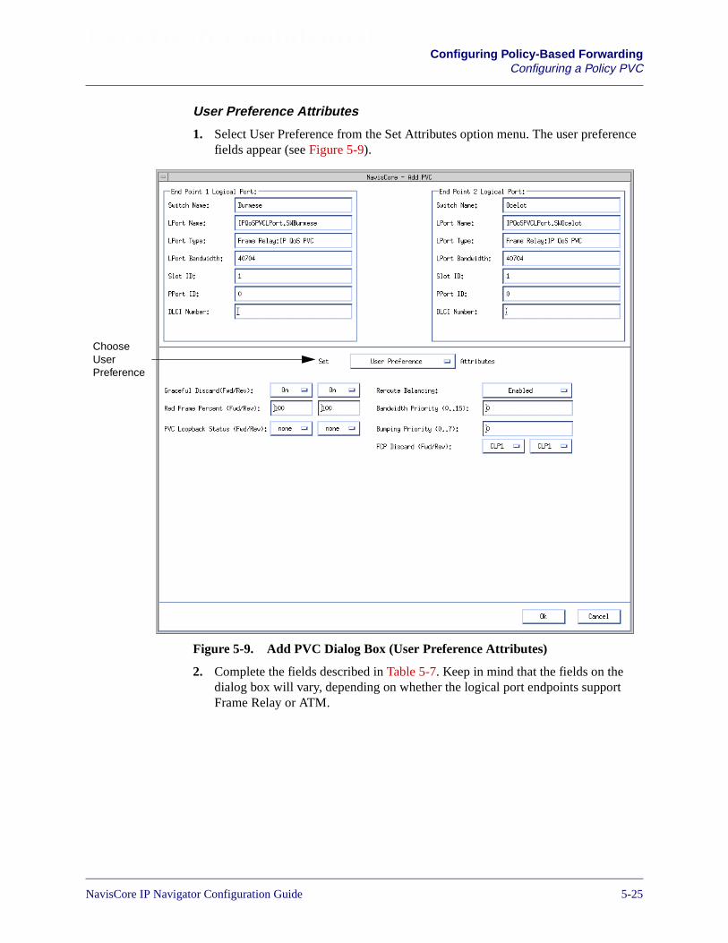
Beta Draft ConfidentialConfiguring Policy-Based Forwarding
Configuring a Policy PVC
User Preference Attributes
1. Select User Preference from the Set Attributes option menu. The user preferencefields appear (see Figure 5-9).
Figure 5-9. Add PVC Dialog Box (User Preference Attributes)
2. Complete the fields described in Table 5-7. Keep in mind that the fields on thedialog box will vary, depending on whether the logical port endpoints supportFrame Relay or ATM.
ChooseUserPreference
NavisCore IP Navigator Configuration Guide 1/14/025-25
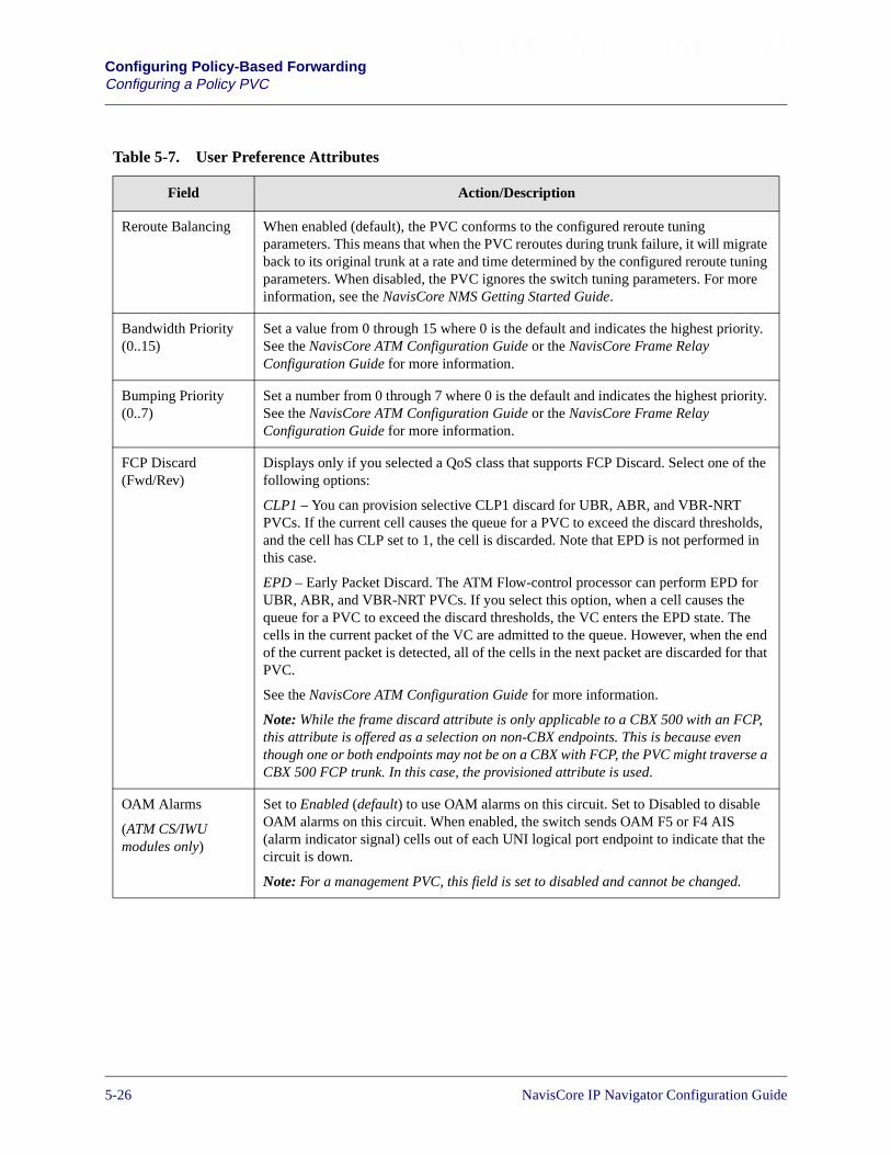
Beta Draft ConfidentialConfiguring Policy-Based ForwardingConfiguring a Policy PVC
Table 5-7. User Preference Attributes
Field Action/Description
Reroute Balancing When enabled (default), the PVC conforms to the configured reroute tuningparameters. This means that when the PVC reroutes during trunk failure, it will migrateback to its original trunk at a rate and time determined by the configured reroute tuningparameters. When disabled, the PVC ignores the switch tuning parameters. For moreinformation, see the NavisCore NMS Getting Started Guide.
Bandwidth Priority(0..15)
Set a value from 0 through 15 where 0 is the default and indicates the highest priority.See the NavisCore ATM Configuration Guide or the NavisCore Frame RelayConfiguration Guide for more information.
Bumping Priority(0..7)
Set a number from 0 through 7 where 0 is the default and indicates the highest priority.See the NavisCore ATM Configuration Guide or the NavisCore Frame RelayConfiguration Guide for more information.
FCP Discard(Fwd/Rev)
Displays only if you selected a QoS class that supports FCP Discard. Select one of thefollowing options:
CLP1 – You can provision selective CLP1 discard for UBR, ABR, and VBR-NRTPVCs. If the current cell causes the queue for a PVC to exceed the discard thresholds,and the cell has CLP set to 1, the cell is discarded. Note that EPD is not performed inthis case.
EPD – Early Packet Discard. The ATM Flow-control processor can perform EPD forUBR, ABR, and VBR-NRT PVCs. If you select this option, when a cell causes thequeue for a PVC to exceed the discard thresholds, the VC enters the EPD state. Thecells in the current packet of the VC are admitted to the queue. However, when the endof the current packet is detected, all of the cells in the next packet are discarded for thatPVC.
See the NavisCore ATM Configuration Guide for more information.
Note: While the frame discard attribute is only applicable to a CBX 500 with an FCP,this attribute is offered as a selection on non-CBX endpoints. This is because eventhough one or both endpoints may not be on a CBX with FCP, the PVC might traverse aCBX 500 FCP trunk. In this case, the provisioned attribute is used.
OAM Alarms
(ATM CS/IWUmodules only)
Set to Enabled (default) to use OAM alarms on this circuit. Set to Disabled to disableOAM alarms on this circuit. When enabled, the switch sends OAM F5 or F4 AIS(alarm indicator signal) cells out of each UNI logical port endpoint to indicate that thecircuit is down.
Note: For a management PVC, this field is set to disabled and cannot be changed.
5-26 NavisCore IP Navigator Configuration Guide

Beta Draft ConfidentialConfiguring Policy-Based Forwarding
Configuring a Policy PVC
UPC Function
(CBX 500 only)
Enables (default) or disables the usage parameter control (UPC) function. When youenable UPC, the circuit tags or drops cells as they come into the port that do notconform to the configured traffic descriptors. When you disable UPC, the circuit allowsall traffic, including non-conforming traffic, into the port. As a result, when you disableUPC, quality of service is no longer guaranteed for circuits in the network due to thepotential for increasing the cell loss ratio because of port congestion. For this reason,you should enable the UPC function on all circuits.
Note: To use the UPC function for individual circuits, verify that the UPC function isenabled for both logical port endpoints on which you will define the circuit. EnablingUPC at the circuit level has no effect if you did not enable UPC at the logical portlevel. UPC is enabled by default for both logical ports and circuits.
Note: If both endpoints are configured as ATM CE endpoints, the UPC Function is notavailable.
CDV Tolerance
(CBX 500 only)
Configure the cell delay variation (CDV) tolerance. The UPC uses this value to policethe requested traffic descriptor. Valid values are between 1–65535 microseconds. Thedefault is 600 microseconds.
Graceful Discard(Fwd/Rev)
(ATM UNI endpointon frame-basedcard)
Select On (default) or Off to define how this circuit handles “red” packets. Red packetsare designated as those bits received during the current time interval that exceed thecommitted burst size (Bc) and excess burst size (Be) thresholds, including the currentframe. The Discard Eligible (DE) bit for a red packet is set to 1, meaning the networkcan discard this packet unless Graceful Discard is set to On.
On – Forwards some red packets if there is no congestion.
Off – Immediately discards red packets.
Note: For the ATM UNI DS3/E3, if you set this value for shaping purposes, the switchcode ignores the PCR, SCR, and MBS values calculated from Set Traffic DescriptorAttributes; the switch instead picks the highest PCR queue available and sets the SCRto that PCR.
Red Frame Percent(Fwd/Rev)
(ATM UNI endpointon frame-basedcard)
Set this value only if Graceful Discard is set to On. See the NavisCore ATMConfiguration Guide for more information. The Red Frame Percent limits the numberof red frames the network is responsible to deliver.
PVC LoopbackStatus (Fwd/Rev)
(ATM UNI endpointon frame-basedcard)
Displays the current loopback state. If None is not displayed in the PVC LoopbackStatus field, do not attempt to modify or delete the selected circuit. See the NavisCoreDiagnostics Guide for more information about loopback testing.
Table 5-7. User Preference Attributes (Continued)
Field Action/Description
NavisCore IP Navigator Configuration Guide 1/14/025-27
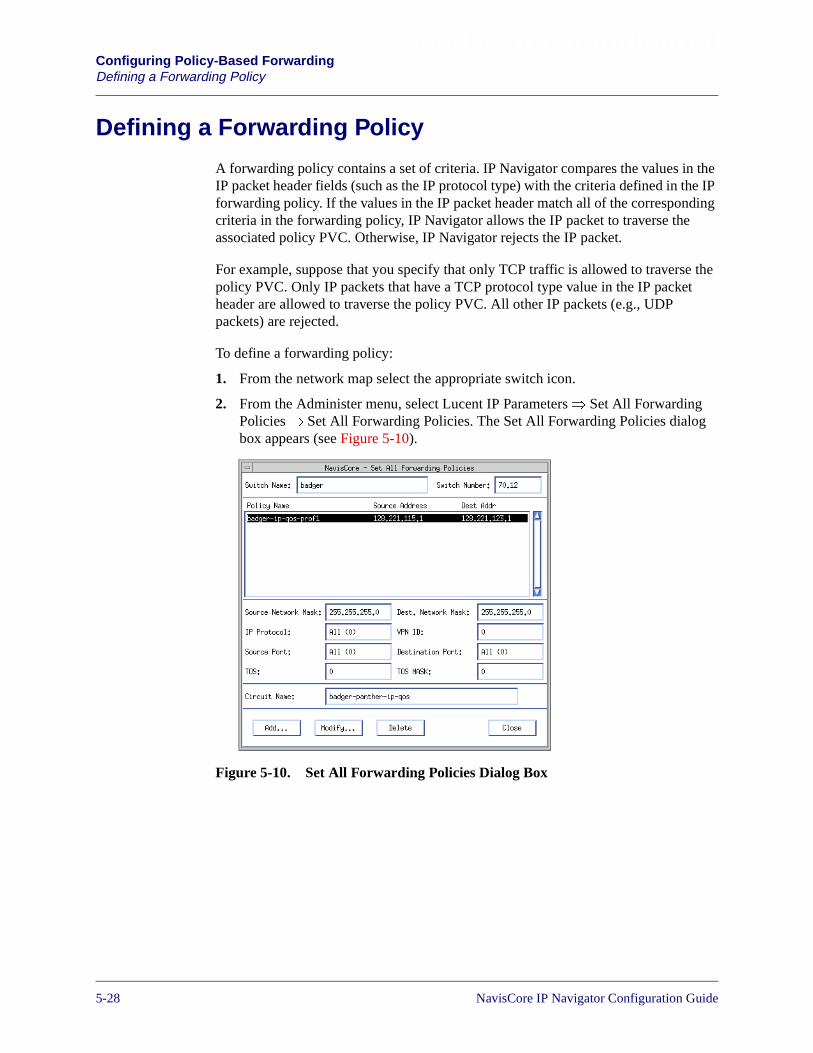
Beta Draft ConfidentialConfiguring Policy-Based ForwardingDefining a Forwarding Policy
Defining a Forwarding Policy
A forwarding policy contains a set of criteria. IP Navigator compares the values in theIP packet header fields (such as the IP protocol type) with the criteria defined in the IPforwarding policy. If the values in the IP packet header match all of the correspondingcriteria in the forwarding policy, IP Navigator allows the IP packet to traverse theassociated policy PVC. Otherwise, IP Navigator rejects the IP packet.
For example, suppose that you specify that only TCP traffic is allowed to traverse thepolicy PVC. Only IP packets that have a TCP protocol type value in the IP packetheader are allowed to traverse the policy PVC. All other IP packets (e.g., UDPpackets) are rejected.
To define a forwarding policy:
1. From the network map select the appropriate switch icon.
2. From the Administer menu, select Lucent IP Parameters� Set All ForwardingPolicies� Set All Forwarding Policies. The Set All Forwarding Policies dialogbox appears (see Figure 5-10).
Figure 5-10. Set All Forwarding Policies Dialog Box
5-28 NavisCore IP Navigator Configuration Guide

Beta Draft ConfidentialConfiguring Policy-Based Forwarding
Defining a Forwarding Policy
The following table describes the buttons on the Set All Forwarding Policiesdialog box.
3. Choose the Add button. The Add Forwarding Policy dialog box appears (seeFigure 5-11).
Figure 5-11. Add Forwarding Policy Dialog Box
Table 5-8. Set All Forwarding Policies Dialog Box: Buttons
Button Function
Add Enables you to add a forwarding policy.
Modify Enables you to modify a forwarding policy.
Delete Enables you to delete a forwarding policy.
To allow all IP packets to traverse the associated policy PVC, accept the defaultswhen you define a forwarding policy. However, keep in mind that the defaultVPN ID (0) means that only public IP traffic (that is, IP packets that are notowned by a specific VPN customer) will traverse the associated policy PVC.
For example, if you enter a specific IP VPN ID (for example, 3) but retain theother default values, all IP packets belonging to the VPN customer who isassigned IP VPN ID 3 would traverse the policy PVC. Public IP packets and IPpackets from other IP VPN customers would not traverse the policy PVC.
NavisCore IP Navigator Configuration Guide 1/14/025-29
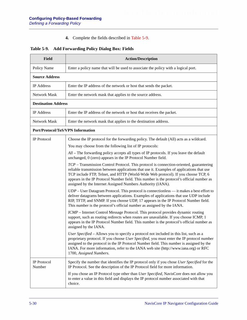
Beta Draft ConfidentialConfiguring Policy-Based ForwardingDefining a Forwarding Policy
4. Complete the fields described in Table 5-9.
Table 5-9. Add Forwarding Policy Dialog Box: Fields
Field Action/Description
Policy Name Enter a policy name that will be used to associate the policy with a logical port.
Source Address
IP Address Enter the IP address of the network or host that sends the packet.
Network Mask Enter the network mask that applies to the source address.
Destination Address
IP Address Enter the IP address of the network or host that receives the packet.
Network Mask Enter the network mask that applies to the destination address.
Port/Protocol/ToS/VPN Information
IP Protocol Choose the IP protocol for the forwarding policy. The default (All) acts as a wildcard.
You may choose from the following list of IP protocols:
All – The forwarding policy accepts all types of IP protocols. If you leave the defaultunchanged, 0 (zero) appears in the IP Protocol Number field.
TCP – Transmission Control Protocol. This protocol is connection-oriented, guaranteeingreliable transmission between applications that use it. Examples of applications that useTCP include FTP, Telnet, and HTTP (World-Wide Web protocol). If you choose TCP, 6appears in the IP Protocol Number field. This number is the protocol’s official number asassigned by the Internet Assigned Numbers Authority (IANA).
UDP – User Datagram Protocol. This protocol is connectionless — it makes a best effort todeliver datagrams between applications. Examples of applications that use UDP includeRIP, TFTP, and SNMP. If you choose UDP, 17 appears in the IP Protocol Number field.This number is the protocol’s official number as assigned by the IANA.
ICMP – Internet Control Message Protocol. This protocol provides dynamic routingsupport, such as routing redirects when routes are unavailable. If you choose ICMP, 1appears in the IP Protocol Number field. This number is the protocol’s official number asassigned by the IANA.
User Specified – Allows you to specify a protocol not included in this list, such as aproprietary protocol. If you choose User Specified, you must enter the IP protocol numberassigned to the protocol in the IP Protocol Number field. This number is assigned by theIANA. For more information, refer to the IANA web site (http://www.iana.org) or RFC1700, Assigned Numbers.
IP ProtocolNumber
Specify the number that identifies the IP protocol only if you chose User Specified for theIP Protocol. See the description of the IP Protocol field for more information.
If you chose an IP Protocol type other than User Specified, NavisCore does not allow youto enter a value in this field and displays the IP protocol number associated with thatchoice.
5-30 NavisCore IP Navigator Configuration Guide

Beta Draft ConfidentialConfiguring Policy-Based Forwarding
Defining a Forwarding Policy
Source Port
(Meaningful onlyif TCP or UDP isselected for IPProtocol)
Choose the source application for the forwarding policy. Choose one of the following:
All – (default) The forwarding policy applies to all application traffic from source todestination.
BGP – BGP traffic.
FTP Data – FTP data traffic.
FTP Control – FTP control traffic.
Gopher – Gopher traffic.
IRC – IRC traffic.
Talk – Talk traffic.
Telnet – Telnet traffic.
WWW – HTTP traffic.
RIP – RIP traffic.
SNMP – SNMP traffic.
SNMP Traps – SNMP traps traffic.
TFTP – TFTP traffic.
Ambiguous – The traffic flows are tracked based on discrete source application values(1024 is used for the port value).
User Specified – Allows you to specify an application that is not in the list (such as athird-party vendor application), and requires you to enter a port number that the applicationuses in the Source Port Number field. You can obtain this port number from the applicationdeveloper. For more information on port numbers, refer to the IANA web site(http://www.iana.org) or RFC 1700, Assigned Numbers. You can find a listing of many portnumbers at the following URL:http://www.isi.edu/in-notes/iana/assignments/port-numbers.
Source PortNumber
Specify the port number used by the source application only if you chose User Specifiedfor the Source Application. You can obtain this port number from the applicationdeveloper. For more information on port numbers, refer to the IANA web site(http://www.iana.org) or RFC 1700, Assigned Numbers. You can find a listing of many portnumbers at the following URL:http://www.isi.edu/in-notes/iana/assignments/port-numbers.
If you chose a source port other than User Specified, NavisCore does not allow you to entera value in this field and displays the port number associated with that choice. See thedescription of the Source Port field for more information.
Dest. Port(Meaningful onlyif TCP or UDP isselected for IPProtocol)
Choose the destination application for the forwarding policy. In most cases, your choicesof source and destination application will be the same, since communication betweendifferent types of applications is rare. See the description of the Source Port field forinformation on the choices available to you.
Table 5-9. Add Forwarding Policy Dialog Box: Fields (Continued)
Field Action/Description
NavisCore IP Navigator Configuration Guide 1/14/025-31
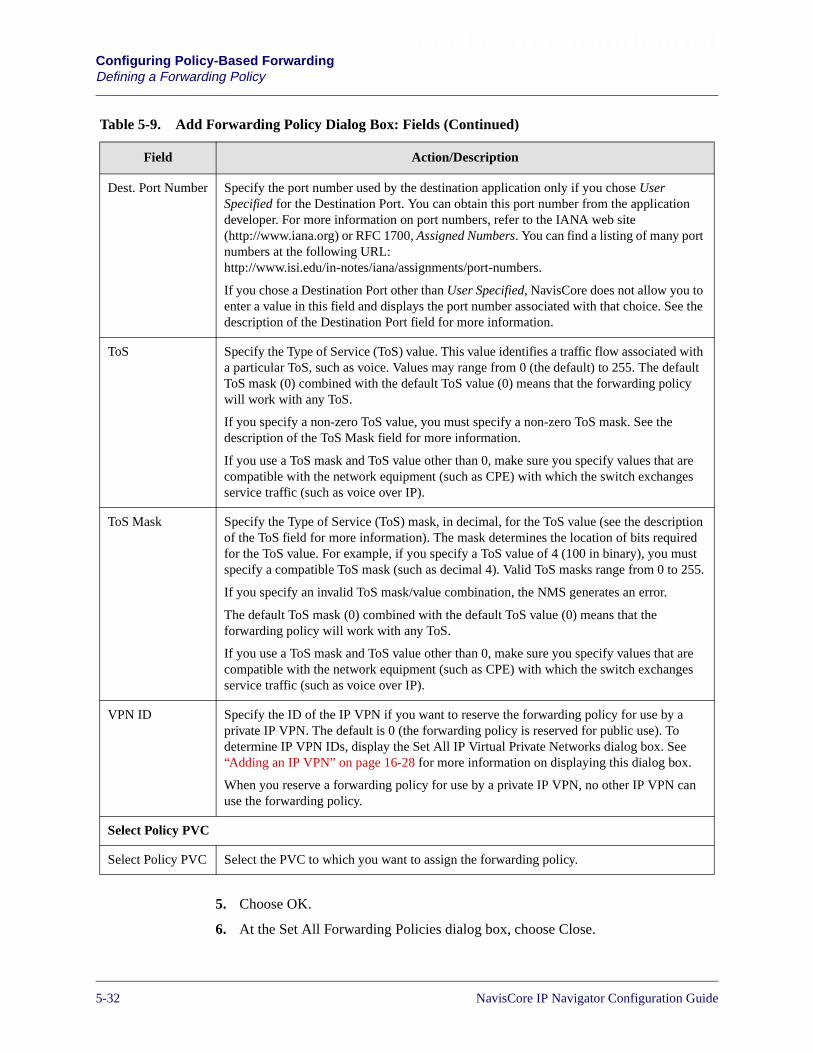
Beta Draft ConfidentialConfiguring Policy-Based ForwardingDefining a Forwarding Policy
5. Choose OK.
6. At the Set All Forwarding Policies dialog box, choose Close.
Dest. Port Number Specify the port number used by the destination application only if you chose UserSpecified for the Destination Port. You can obtain this port number from the applicationdeveloper. For more information on port numbers, refer to the IANA web site(http://www.iana.org) or RFC 1700, Assigned Numbers. You can find a listing of many portnumbers at the following URL:http://www.isi.edu/in-notes/iana/assignments/port-numbers.
If you chose a Destination Port other than User Specified, NavisCore does not allow you toenter a value in this field and displays the port number associated with that choice. See thedescription of the Destination Port field for more information.
ToS Specify the Type of Service (ToS) value. This value identifies a traffic flow associated witha particular ToS, such as voice. Values may range from 0 (the default) to 255. The defaultToS mask (0) combined with the default ToS value (0) means that the forwarding policywill work with any ToS.
If you specify a non-zero ToS value, you must specify a non-zero ToS mask. See thedescription of the ToS Mask field for more information.
If you use a ToS mask and ToS value other than 0, make sure you specify values that arecompatible with the network equipment (such as CPE) with which the switch exchangesservice traffic (such as voice over IP).
ToS Mask Specify the Type of Service (ToS) mask, in decimal, for the ToS value (see the descriptionof the ToS field for more information). The mask determines the location of bits requiredfor the ToS value. For example, if you specify a ToS value of 4 (100 in binary), you mustspecify a compatible ToS mask (such as decimal 4). Valid ToS masks range from 0 to 255.
If you specify an invalid ToS mask/value combination, the NMS generates an error.
The default ToS mask (0) combined with the default ToS value (0) means that theforwarding policy will work with any ToS.
If you use a ToS mask and ToS value other than 0, make sure you specify values that arecompatible with the network equipment (such as CPE) with which the switch exchangesservice traffic (such as voice over IP).
VPN ID Specify the ID of the IP VPN if you want to reserve the forwarding policy for use by aprivate IP VPN. The default is 0 (the forwarding policy is reserved for public use). Todetermine IP VPN IDs, display the Set All IP Virtual Private Networks dialog box. See“Adding an IP VPN” on page 16-28 for more information on displaying this dialog box.
When you reserve a forwarding policy for use by a private IP VPN, no other IP VPN canuse the forwarding policy.
Select Policy PVC
Select Policy PVC Select the PVC to which you want to assign the forwarding policy.
Table 5-9. Add Forwarding Policy Dialog Box: Fields (Continued)
Field Action/Description
5-32 NavisCore IP Navigator Configuration Guide
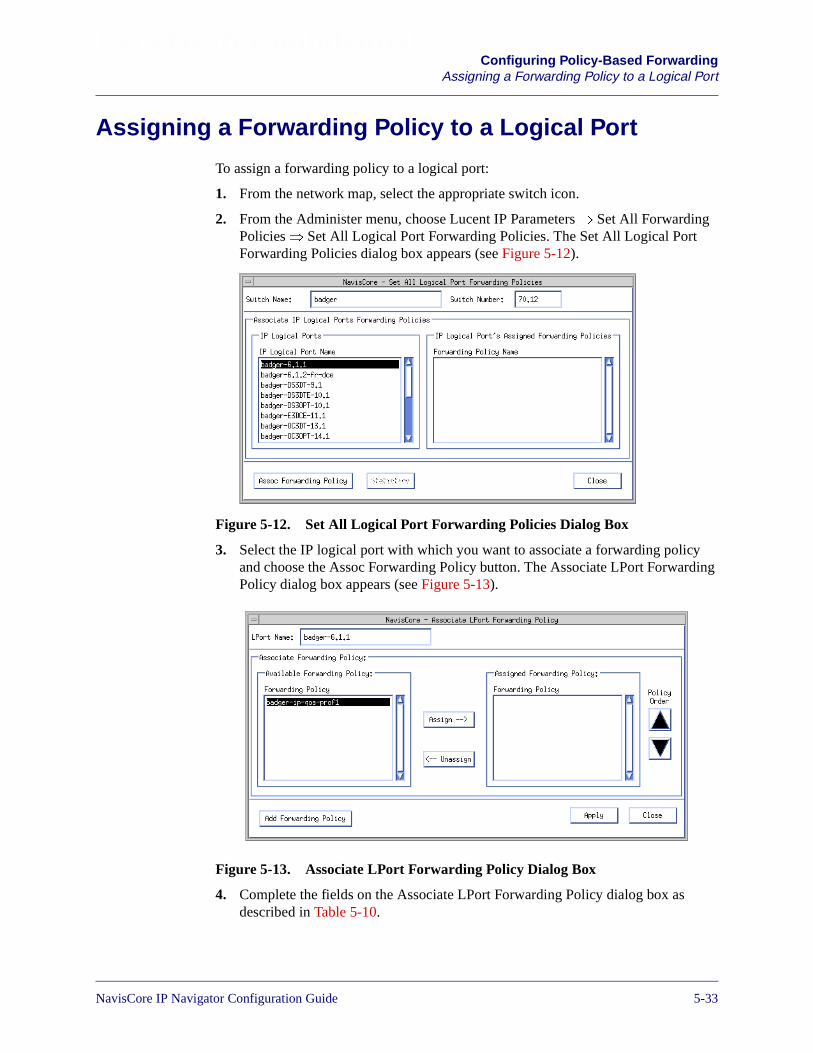
Beta Draft ConfidentialConfiguring Policy-Based Forwarding
Assigning a Forwarding Policy to a Logical Port
Assigning a Forwarding Policy to a Logical Port
To assign a forwarding policy to a logical port:
1. From the network map, select the appropriate switch icon.
2. From the Administer menu, choose Lucent IP Parameters� Set All ForwardingPolicies� Set All Logical Port Forwarding Policies. The Set All Logical PortForwarding Policies dialog box appears (see Figure 5-12).
Figure 5-12. Set All Logical Port Forwarding Policies Dialog Box
3. Select the IP logical port with which you want to associate a forwarding policyand choose the Assoc Forwarding Policy button. The Associate LPort ForwardingPolicy dialog box appears (see Figure 5-13).
Figure 5-13. Associate LPort Forwarding Policy Dialog Box
4. Complete the fields on the Associate LPort Forwarding Policy dialog box asdescribed in Table 5-10.
NavisCore IP Navigator Configuration Guide 1/14/025-33
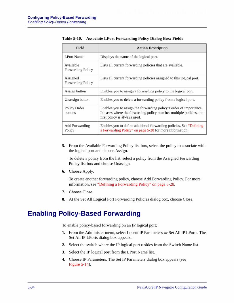
Beta Draft ConfidentialConfiguring Policy-Based ForwardingEnabling Policy-Based Forwarding
5. From the Available Forwarding Policy list box, select the policy to associate withthe logical port and choose Assign.
To delete a policy from the list, select a policy from the Assigned ForwardingPolicy list box and choose Unassign.
6. Choose Apply.
To create another forwarding policy, choose Add Forwarding Policy. For moreinformation, see “Defining a Forwarding Policy” on page 5-28.
7. Choose Close.
8. At the Set All Logical Port Forwarding Policies dialog box, choose Close.
Enabling Policy-Based Forwarding
To enable policy-based forwarding on an IP logical port:
1. From the Administer menu, select Lucent IP Parameters� Set All IP LPorts. TheSet All IP LPorts dialog box appears.
2. Select the switch where the IP logical port resides from the Switch Name list.
3. Select the IP logical port from the LPort Name list.
4. Choose IP Parameters. The Set IP Parameters dialog box appears (seeFigure 5-14).
Table 5-10. Associate LPort Forwarding Policy Dialog Box: Fields
Field Action Description
LPort Name Displays the name of the logical port.
AvailableForwarding Policy
Lists all current forwarding policies that are available.
AssignedForwarding Policy
Lists all current forwarding policies assigned to this logical port.
Assign button Enables you to assign a forwarding policy to the logical port.
Unassign button Enables you to delete a forwarding policy from a logical port.
Policy Orderbuttons
Enables you to assign the forwarding policy’s order of importance.In cases where the forwarding policy matches multiple policies, thefirst policy is always used.
Add ForwardingPolicy
Enables you to define additional forwarding policies. See “Defininga Forwarding Policy” on page 5-28 for more information.
5-34 NavisCore IP Navigator Configuration Guide

Beta Draft ConfidentialConfiguring Policy-Based Forwarding
Configuring the Recipient Switch or Router
Figure 5-14. Set IP Parameters Dialog Box (With ForwardingPolicy Enabled)
5. Specify Enable in the Forwarding Policy Admin Status field.
6. Choose Apply.
Configuring the Recipient Switch or Router
When a policy PVC terminates on a Frame Relay or ATM logical port, the circuit IDof that logical port (DLCI or VPI/VCI) is used in the frames or cells sent over thatpolicy PVC port instead of the circuit ID associated with the lport’s IP address. Youmust configure the switch/router that receives datagrams from the policy PVC toaccept frames or cells that use the circuit ID of the policy PVC or the recipientswitch/router will ignore them.
For example, Figure 5-15 illustrates a policy PVC between two switches. The policyPVC is assigned a DLCI of 432, meaning that frames sent over the policy PVC have aDLCI of 432. However, the IP logical port on the egress switch has a DLCI of 123associated with its IP address, meaning that frames sent out that port on a hop-by-hopbasis have a DLCI of 123.
NavisCore IP Navigator Configuration Guide 1/14/025-35

Beta Draft ConfidentialConfiguring Policy-Based ForwardingConfiguring the Recipient Switch or Router
Figure 5-15. Configuring a Receiving Switch/Router
Because ARP/LMI does not distribute policy PVC circuit information automatically,you must configure the switch or router receiving the frames or cells to accept thepolicy PVC circuit ID or the receiving switch/router will discard frames/cells withunrecognized DLCI values.
The procedure for defining the policy PVC circuit ID in a receiving switch or routerdepends on the type of device. For example, if the device receiving the frames was aCisco router, you would use the following port configuration parameters:
frame-relay interface-dlci 432 (Frame Relay)atm pvc 2 4 32 aal5snap inarp 5 (ATM)
90
00
90
00
LucentNetwork
PolicyPVC
Ingress
Policy PVCEgress
DLCI=432
LPortDLCI=123
ReceivingSwitch or
Router
5-36 NavisCore IP Navigator Configuration Guide
NavisCore IP Navigator Configuration Guide
Beta Draft Confidential
6
Configuring Static ARP Entries
This chapter describes how to define Static ARP Entries. When you define Static ARPentries, you create a table that matches IP addresses to specific hardware addresses(MAC, DLCI, VPI/VCI) or internal switch number addresses. The hardware address(or internal switch number) you define depends on the link type.
Address Resolution Protocol
A switch requires the following information in order to communicate with anothernode over Frame Relay, ATM, or Ethernet:
• IP address of the destination node
• Hardware address of the destination node (DLCI for Frame Relay, VPI/VCI forATM, or MAC address for Ethernet)
To communicate with another switch over an IP VPN cloud interface, a switchrequires:
• IP address of the destination switch’s IP VPN cloud interface (see Chapter 16,“Configuring IP Virtual Private Networks” for more information on IP VPN cloudinterfaces)
• Internal switch number of the destination switch
When an interface is configured for Ethernet, the IP addresses of the destination nodesare known (the hardware addresses are not known). When an interface is configuredfor Frame Relay, the hardware addresses of the destination nodes are known. IPservices use ARP and InARP to resolve the lack of a hardware or IP address.
6-1
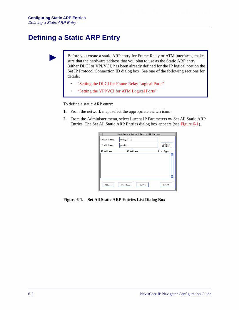
Beta Draft ConfidentialConfiguring Static ARP EntriesDefining a Static ARP Entry
Defining a Static ARP Entry
To define a static ARP entry:
1. From the network map, select the appropriate switch icon.
2. From the Administer menu, select Lucent IP Parameters� Set All Static ARPEntries. The Set All Static ARP Entries dialog box appears (see Figure 6-1).
Figure 6-1. Set All Static ARP Entries List Dialog Box
Before you create a static ARP entry for Frame Relay or ATM interfaces, makesure that the hardware address that you plan to use as the Static ARP entry(either DLCI or VPI/VCI) has been already defined for the IP logical port on theSet IP Protocol Connection ID dialog box. See one of the following sections fordetails:
• “Setting the DLCI for Frame Relay Logical Ports”
• “Setting the VPI/VCI for ATM Logical Ports”
6-2 NavisCore IP Navigator Configuration Guide

Beta Draft ConfidentialConfiguring Static ARP Entries
Defining a Static ARP Entry
The Set All Static ARP Entries dialog box displays the following buttons.
3. Choose the Add button. The Set Static ARP dialog box appears (see Figure 6-2).
Figure 6-2. Set Static ARP Dialog Box
Table 6-1. Set All Static ARP Entries Buttons
Button Function
Select IP VPN Displays the Select IP VPN dialog box, allowing you to selectan IP VPN. Once you select the IP VPN, all of the static ARPentries you define are for the selected IP VPN only. The nameof the selected IP VPN appears in the IP VPN Name field. See“Selecting the IP VPN” on page 16-33 for more information.
Add Enables you to add a static ARP entry.
Modify Enables you to modify a static ARP entry.
Delete Enables you to delete a static ARP entry.
If you are creating an ARP entry for an IP VPN, make sure you are in the contextof that IP VPN. For example, if you are adding an IP VPN cloud ARP entry foran IP VPN called “IPVPN1,” make sure you are in the context of IPVPN1. Toenter the context of an IP VPN, choose the Select IP VPN button and select theappropriate IP VPN.
NavisCore IP Navigator Configuration Guide 1/14/026-3
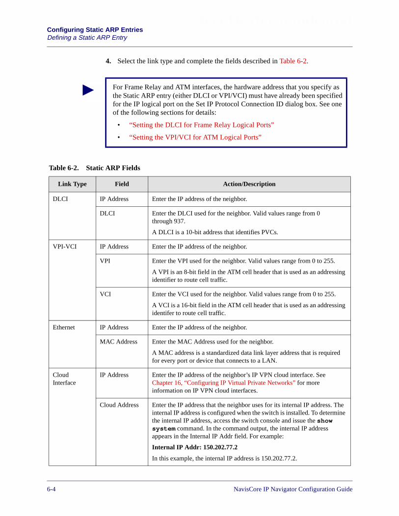
Beta Draft ConfidentialConfiguring Static ARP EntriesDefining a Static ARP Entry
4. Select the link type and complete the fields described in Table 6-2.
For Frame Relay and ATM interfaces, the hardware address that you specify asthe Static ARP entry (either DLCI or VPI/VCI) must have already been specifiedfor the IP logical port on the Set IP Protocol Connection ID dialog box. See oneof the following sections for details:
• “Setting the DLCI for Frame Relay Logical Ports”
• “Setting the VPI/VCI for ATM Logical Ports”
Table 6-2. Static ARP Fields
Link Type Field Action/Description
DLCI IP Address Enter the IP address of the neighbor.
DLCI Enter the DLCI used for the neighbor. Valid values range from 0through 937.
A DLCI is a 10-bit address that identifies PVCs.
VPI-VCI IP Address Enter the IP address of the neighbor.
VPI Enter the VPI used for the neighbor. Valid values range from 0 to 255.
A VPI is an 8-bit field in the ATM cell header that is used as an addressingidentifier to route cell traffic.
VCI Enter the VCI used for the neighbor. Valid values range from 0 to 255.
A VCI is a 16-bit field in the ATM cell header that is used as an addressingidentifer to route cell traffic.
Ethernet IP Address Enter the IP address of the neighbor.
MAC Address Enter the MAC Address used for the neighbor.
A MAC address is a standardized data link layer address that is requiredfor every port or device that connects to a LAN.
CloudInterface
IP Address Enter the IP address of the neighbor’s IP VPN cloud interface. SeeChapter 16, “Configuring IP Virtual Private Networks” for moreinformation on IP VPN cloud interfaces.
Cloud Address Enter the IP address that the neighbor uses for its internal IP address. Theinternal IP address is configured when the switch is installed. To determinethe internal IP address, access the switch console and issue the showsystem command. In the command output, the internal IP addressappears in the Internal IP Addr field. For example:
Internal IP Addr: 150.202.77.2
In this example, the internal IP address is 150.202.77.2.
6-4 NavisCore IP Navigator Configuration Guide

Beta Draft ConfidentialConfiguring Static ARP Entries
Defining a Static ARP Entry
5. Choose OK. The ARP table entry is created for these addresses.
6. At the Set IP ARP List dialog box, choose Close.
NavisCore IP Navigator Configuration Guide 1/14/026-5

Beta Draft ConfidentialConfiguring Static ARP EntriesDefining a Static ARP Entry
6-6 NavisCore IP Navigator Configuration Guide

NavisCore IP Navigator Configuration Guide
Beta Draft Confidential
7
Configuring RIP
This chapter describes how to configure Routing Information Protocol (RIP)parameters on an IP logical port and how to configure equal-cost multipath (ECMP)routing support for RIP. RIP is a distance vector protocol, which bases all routingdecisions on the distance to the destination.
Configuring RIP at the Logical Port
To configure RIP at the logical port:
1. Add an IP logical port and interface. For more details on these procedures, see“Adding an IP Logical Port” on page 3-10.
2. Choose Add RIP from the Set IP Interface Addresses dialog box. The Add RIPInterface dialog box appears (see Figure 7-1).
This chapter does not discuss configuring RIP for IP virtual private networks (IPVPNs). For more information on IP VPN management, see Chapter 16,“Configuring IP Virtual Private Networks.”
7-1
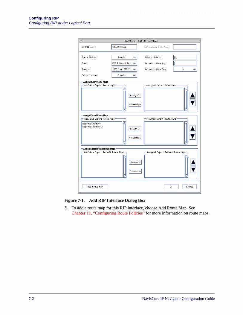
Beta Draft ConfidentialConfiguring RIPConfiguring RIP at the Logical Port
Figure 7-1. Add RIP Interface Dialog Box
3. To add a route map for this RIP interface, choose Add Route Map. SeeChapter 11, “Configuring Route Policies” for more information on route maps.
7-2 NavisCore IP Navigator Configuration Guide

Beta Draft ConfidentialConfiguring RIP
Configuring RIP at the Logical Port
4. To define the RIP interface, specify the field values as described in Table 7-1.
Table 7-1. RIP Interface Fields
Field Action/Description
IP Address The IP address for this interface.
Admin Status Select one of the following options:
Enable – Indicates that the port is activated for RIP and RIP packets can be exchangedover this logical port.
Disable – Indicates that the port has not been activated for RIP or that the port is offlinefor diagnostics. An IP interface with an Admin Status of Disable cannot exchange RIPpackets.
Send Possible values are: Disable, RIP 1, RIP 1 Compatible, or RIP 2. RIP 1 Compatible is thedefault value.
Receive Possible values are: RIP 1, RIP2, RIP 1 or RIP 2, or Disable. RIP1 or RIP 2 is the defaultvalue.
Split Horizon Split horizon is a method for avoiding common situations that require counting toinfinity.
Specify one of the following options:
Disable – Indicates that split horizon will not be used.
Simple – Indicates that split horizon will be used. The simple form of split horizonspecifies that if a router learns of a route from an update received on the link, it does notadvertise that route on updates that it transmits to the link.
Poison Reverse – Is a stronger form of split horizon. In this form, routers do not omitdestinations learned from an interface. Instead, they include these destinations, butadvertise an infinite cost to reach them. This option increases the size of routing updates.In addition, it provides a positive indication that a specific location is not reachablethrough a router.
Default Metric A variable that specifies the metric that is used for the default route entry in RIP updatesthat originate on this interface. A value of zero indicates that no default route should beoriginated.
Authentication Key Do not specify this value if you specified a value of No as the authentication type.
If you specified a value of Simple or MD5 as the authentication type, you must specifythe authentication password in this field.
NavisCore IP Navigator Configuration Guide 1/14/027-3

Beta Draft ConfidentialConfiguring RIPConfiguring RIP at the Logical Port
Authentication Type This value specifies the type of authentication that RIP uses as a security measure toensure that this logical port and router are exchanging information with proper neighbors.Possible values are No, Simple, or MD5.
No – Specifies that no authentication will be performed.
Simple – Specifies a simple password authentication method that enables you todesignate a password that is part of all RIP messages on an interface-by-interface basis.
When a router receives a message on an interface that is using simple passwordauthentication, it checks the incoming RIP message to ensure that the proper password isincluded in the message. If the password is correct, the message is processed normally. Ifthe password is not part of the incoming message or an incorrect password is used, themessage is ignored and dropped.
MD5 – Specifies the Message Digest Algorithm Version 5 (MD5) authentication. Thismethod is similar to the simple password method, however, the password is nevertransmitted. Instead, the router uses the MD5 algorithm to create a message digest of thepassword. The message digest is sent instead of the password. This method prevents thepassword from being read during transmission.
Available ImportRoute Maps
The import route maps that are available for assignment to this RIP interface. Use theAssign button to move a route map from the Available to the Assigned list. Use theUnassign button to move a route map from the Assigned to the Available list. For moreinformation about creating route maps, see Chapter 11, “Configuring Route Policies.”
To display the parameters for any listed route map, double-click on the map.
Assigned ImportRoute Maps
The import route maps that are assigned to this RIP interface. All incoming routes on thisRIP interface are filtered using the assigned route maps in the listed sequence.
Use the Assign button to move a route map from the Available to the Assigned list. Usethe Unassign button to move a route map from the Assigned to the Available list. Use theup and down arrows to change the sequence of the route maps in the Assigned list. IPNavigator executes the route maps in the sequence that they are ordered in this list. Routemaps should be ordered from most specific to least specific.
To display the parameters for any listed route map, double-click on the map.
Available ExportRoute Maps
The export route maps that are available for assignment to this RIP interface. Use theAssign button to move a route map from the Available to the Assigned list. Use theUnassign button to move a route map from the Assigned to the Available list. For moreinformation about creating route maps, see Chapter 11, “Configuring Route Policies.”
To display the parameters for any listed route map, double-click on the map.
Table 7-1. RIP Interface Fields (Continued)
Field Action/Description
7-4 NavisCore IP Navigator Configuration Guide
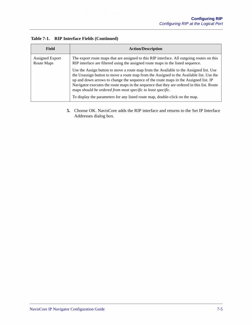
Beta Draft ConfidentialConfiguring RIP
Configuring RIP at the Logical Port
5. Choose OK. NavisCore adds the RIP interface and returns to the Set IP InterfaceAddresses dialog box.
Assigned ExportRoute Maps
The export route maps that are assigned to this RIP interface. All outgoing routes on thisRIP interface are filtered using the assigned route maps in the listed sequence.
Use the Assign button to move a route map from the Available to the Assigned list. Usethe Unassign button to move a route map from the Assigned to the Available list. Use theup and down arrows to change the sequence of the route maps in the Assigned list. IPNavigator executes the route maps in the sequence that they are ordered in this list. Routemaps should be ordered from most specific to least specific.
To display the parameters for any listed route map, double-click on the map.
Table 7-1. RIP Interface Fields (Continued)
Field Action/Description
NavisCore IP Navigator Configuration Guide 1/14/027-5

Beta Draft ConfidentialConfiguring RIPConfiguring ECMP Routing for RIP
Configuring ECMP Routing for RIP
This release supports equal-cost multipath (ECMP) routing, which load balances IPtraffic over multiple routes of equal cost to the same destination. This feature appliesto routes learned through BGP, RIP, OSPF, and manually configured static routes.
If multiple gateways of equal cost (that is, multiple equal-cost paths) can be used toreach the same destination, RIP will add up to four ECMP routes. If multipleequal-cost paths from a switch to the same destination are available, you can configureRIP on that switch to use them. Otherwise, RIP uses only one path. By takingadvantage of multiple paths to a destination, you can load-balance network traffic.
By default, equal-cost multipath (ECMP) routing is disabled for RIP. Before youenable ECMP for RIP, note the following:
• If multiple neighbor gateways report the same cost for reaching the samedestination, equal-cost routes are created.
• The maximum number of equal-cost paths to the same destination is four.
• Routing updates update the RIP equal-cost routes.
• Each route is aged independently.
To configure RIP to use multiple equal-cost paths:
1. From the network map, select the appropriate switch icon.
2. From the Administer menu, select Ascend IP Parameters� Set RIP Parameters.The Set RIP Parameters dialog box appears (see Figure 7-2).
Figure 7-2. Set RIP Parameters Dialog Box
3. Specify Enable (use multiple paths of equal cost) in the Equal Cost Multipathfield. The default is Disable (do not use multiple paths of equal cost).
4. Choose Apply.
7-6 NavisCore IP Navigator Configuration Guide

NavisCore IP Navigator Configuration Guide
Beta Draft Confidential
8
Configuring BGP Parameters
This chapter provides an overview of the Border Gateway Protocol (BGP) anddescribes how to perform the following tasks:
• Configuring BGP neighbors
• Configuring BGP aggregates
• Configuring BGP peer groups
• Configuring BGP route dampening
• Configuring IP loopback addresses
8-1
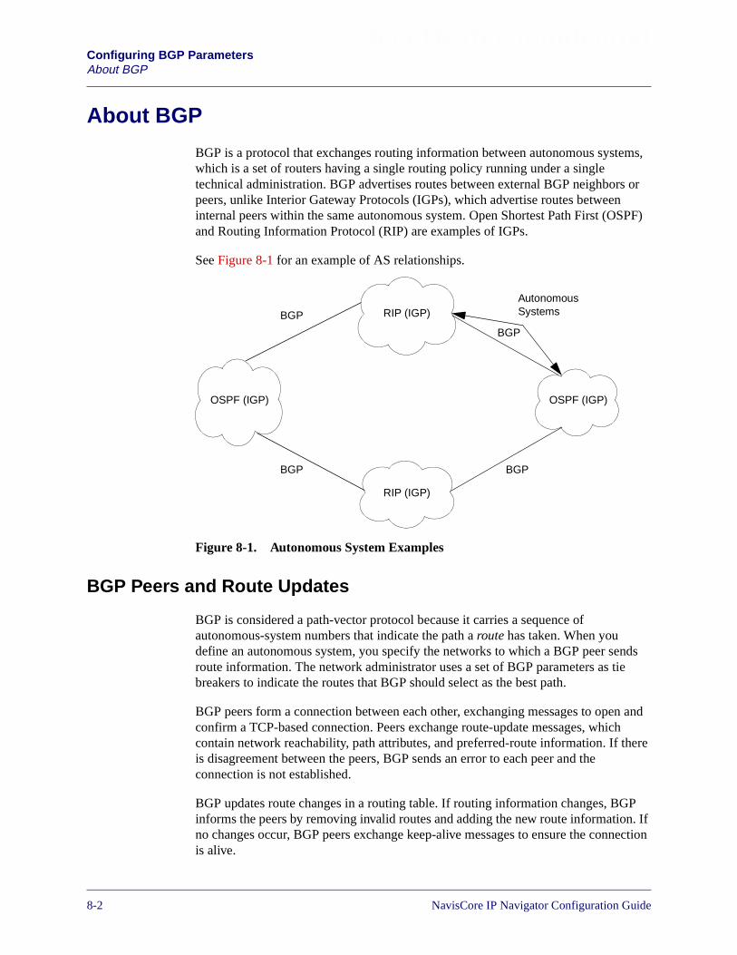
Beta Draft ConfidentialConfiguring BGP ParametersAbout BGP
About BGP
BGP is a protocol that exchanges routing information between autonomous systems,which is a set of routers having a single routing policy running under a singletechnical administration. BGP advertises routes between external BGP neighbors orpeers, unlike Interior Gateway Protocols (IGPs), which advertise routes betweeninternal peers within the same autonomous system. Open Shortest Path First (OSPF)and Routing Information Protocol (RIP) are examples of IGPs.
See Figure 8-1 for an example of AS relationships.
Figure 8-1. Autonomous System Examples
BGP Peers and Route Updates
BGP is considered a path-vector protocol because it carries a sequence ofautonomous-system numbers that indicate the path a route has taken. When youdefine an autonomous system, you specify the networks to which a BGP peer sendsroute information. The network administrator uses a set of BGP parameters as tiebreakers to indicate the routes that BGP should select as the best path.
BGP peers form a connection between each other, exchanging messages to open andconfirm a TCP-based connection. Peers exchange route-update messages, whichcontain network reachability, path attributes, and preferred-route information. If thereis disagreement between the peers, BGP sends an error to each peer and theconnection is not established.
BGP updates route changes in a routing table. If routing information changes, BGPinforms the peers by removing invalid routes and adding the new route information. Ifno changes occur, BGP peers exchange keep-alive messages to ensure the connectionis alive.
BGP
BGP BGP
BGP
AutonomousSystems
OSPF (IGP)
RIP (IGP)
RIP (IGP)
OSPF (IGP)
8-2 NavisCore IP Navigator Configuration Guide

Beta Draft ConfidentialConfiguring BGP Parameters
About BGP
BGP Peer Groups
A BGP peer group is a group of BGP neighbors that share the same route maps.Because you probably set the same routing policies for most BGP peers, the majorityof your BGP neighbors are probably eligible for peer group membership.
Peer groups provide the following benefits:
Simplified Route Map Management — Peer groups simplify route mapmanagement. Instead of defining the same route maps for each neighbor, you candefine one set of route maps and assign them to a peer group. Neighbors that aremembers of a peer group inherit all of the route map configuration options of the peergroup. If a route map is applied to a BGP neighbor, and that neighbor is a member of apeer group, the individual route map is executed first, followed by the peer grouppolicies.
Efficient Route Map Updates — Peer groups make the route map update processefficient. If you set up peer groups, IP Navigator no longer must parse route mapssequentially for each neighbor. Based on the route maps in the peer group, IPNavigator formulates the route map update once, and then floods the same route mapupdate to all the group members.
NavisCore IP Navigator Configuration Guide 1/14/028-3
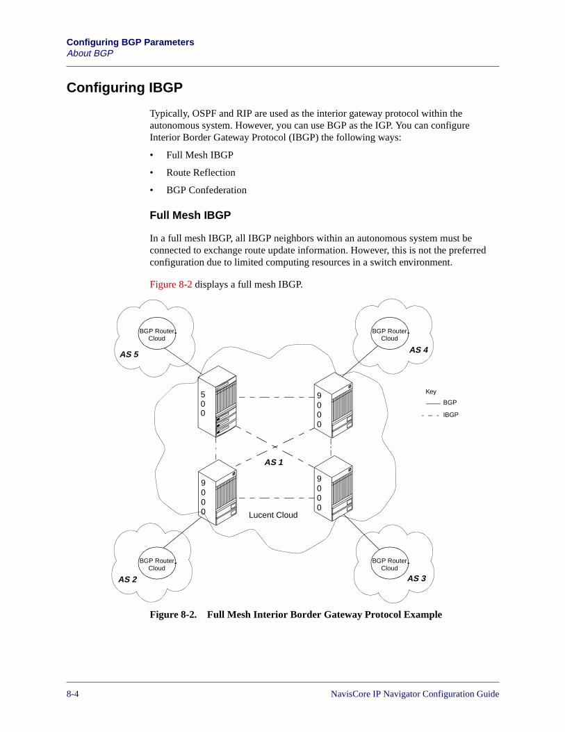
Beta Draft ConfidentialConfiguring BGP ParametersAbout BGP
Configuring IBGP
Typically, OSPF and RIP are used as the interior gateway protocol within theautonomous system. However, you can use BGP as the IGP. You can configureInterior Border Gateway Protocol (IBGP) the following ways:
• Full Mesh IBGP
• Route Reflection
• BGP Confederation
Full Mesh IBGP
In a full mesh IBGP, all IBGP neighbors within an autonomous system must beconnected to exchange route update information. However, this is not the preferredconfiguration due to limited computing resources in a switch environment.
Figure 8-2 displays a full mesh IBGP.
Figure 8-2. Full Mesh Interior Border Gateway Protocol Example
9000
9000
9000
500
AS 5
AS 1
AS 2 AS 3
AS 4
Lucent Cloud
BGP RouterCloud
BGP RouterCloud
BGP RouterCloud
BGP RouterCloud
Key
BGP
IBGP
8-4 NavisCore IP Navigator Configuration Guide
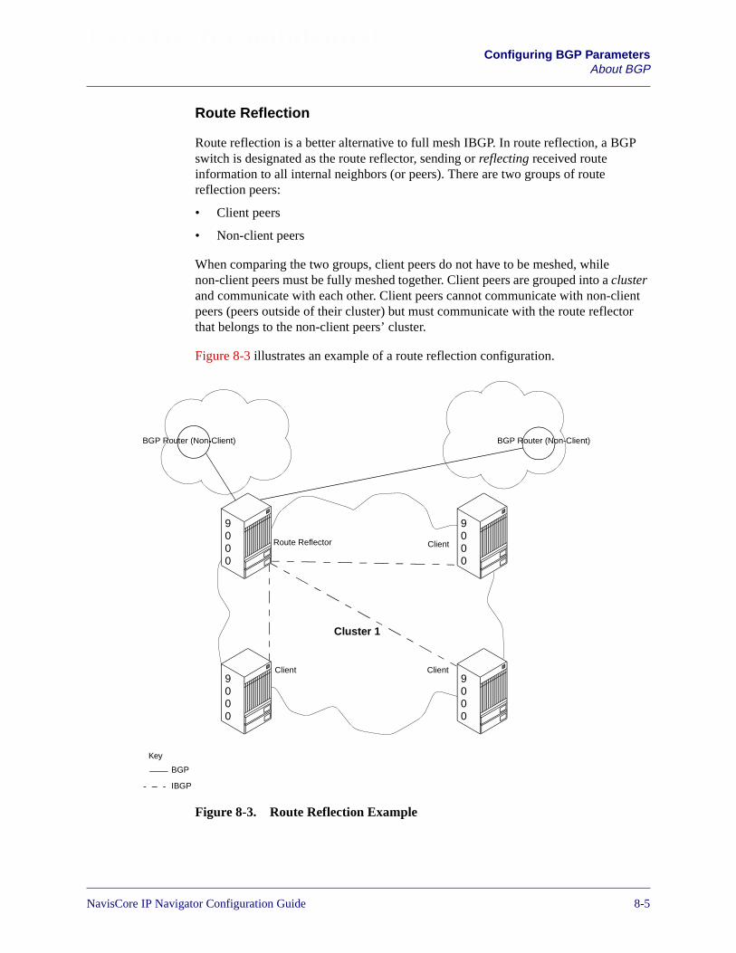
Beta Draft ConfidentialConfiguring BGP Parameters
About BGP
Route Reflection
Route reflection is a better alternative to full mesh IBGP. In route reflection, a BGPswitch is designated as the route reflector, sending or reflecting received routeinformation to all internal neighbors (or peers). There are two groups of routereflection peers:
• Client peers
• Non-client peers
When comparing the two groups, client peers do not have to be meshed, whilenon-client peers must be fully meshed together. Client peers are grouped into a clusterand communicate with each other. Client peers cannot communicate with non-clientpeers (peers outside of their cluster) but must communicate with the route reflectorthat belongs to the non-client peers’ cluster.
Figure 8-3 illustrates an example of a route reflection configuration.
Figure 8-3. Route Reflection Example
9000
9000
9000
9000
Key
BGP
IBGP
BGP Router (Non-Client) BGP Router (Non-Client)
Route Reflector
Client Client
Client
Cluster 1
NavisCore IP Navigator Configuration Guide 1/14/028-5

Beta Draft ConfidentialConfiguring BGP ParametersAbout BGP
For every route update received from an advertiser peer, the route reflector does one ofthe following (provided the best path selection is applied first):
• If the advertiser peer is a non-client, then the route reflector reflects the route to allnon-clients.
• If the advertiser peer is a client peer, then the route reflector reflects the route toall non-client peers and all client peers other than the original advertiser.
• If the advertiser peer is an external BGP peer, then the route reflector reflects theroute to all clients and non-clients (normal BGP operation).
Route reflection defines the following attributes for detection and avoidance of pathloops:
ORIGINATOR_ID — This attribute is the router ID of the route originator in thelocal AS.
CLUSTER_LIST — This attribute is a sequence of cluster ID values that representthe reflection path the route passed.
Autonomous systems may have multiple route reflectors. Route reflectorscommunicating with each other are considered non-client peers and should be fullymeshed.
8-6 NavisCore IP Navigator Configuration Guide
Beta Draft ConfidentialConfiguring BGP Parameters
About BGP
BGP Confederation
Configuring IBGP to support BGP confederation provides an extension to BGP. Thisextension enables you to create a confederation of autonomous systems (AS), whichare represented as a single autonomous system to BGP peers outside theconfederation.
By subdividing an AS into smaller domains (called sub AS), you can control routingpolicy using information contained in the BGP AS_PATH attribute. The rules of IBGPapply inside each subAS. This means that within a subAS, all BGP routers must befully meshed. Since each subAS uses a different AS number, the group of subASs thatmake up a confederation is using external BGP (EBGP). Even though EBGP runsbetween the subASs, routing within the confederation uses the same rules as IBGProuting within a single AS.
Subdividing a large AS provides a significant reduction in the total number ofintra-domain BGP connections, since the connectivity requirements simplify to themodel used for inter-domain connections. However, remember that dividing a largeAS may unnecessarily lengthen the sequence portions of the AS_PATH attribute.Dividing an AS into separate systems may adversely affect the network’s ability toroute packets through the Internet.
You configure a BGP confederation using the following attributes:
AS Confederation — A collection of autonomous systems advertised as a single ASnumber to BGP speakers that are not members of the confederation.
AS Confederation Identifier — An externally visible autonomous system numberthat identifies the confederation as a whole.
Member-AS — An autonomous system that is contained in a given AS confederation.
The BGP confederation members use their confederation identifier in all transactionswith peers outside the confederation. This confederation identifier is considered to bean “externally visible” AS number and this number is used in the AS_PATH attribute.
A member of a BGP confederation uses its routing domain identifier (the internallyvisible AS number) in all transactions with peers that belong to the sameconfederation as the given switch.
NavisCore IP Navigator Configuration Guide 1/14/028-7
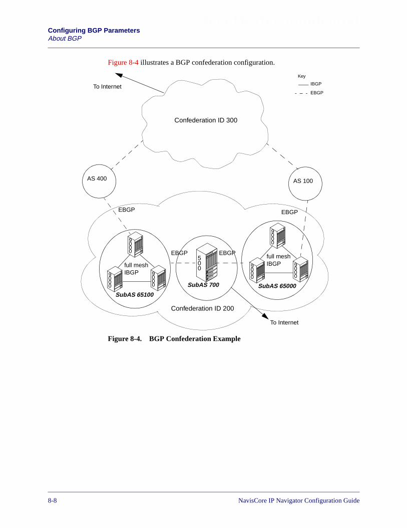
Beta Draft ConfidentialConfiguring BGP ParametersAbout BGP
Figure 8-4 illustrates a BGP confederation configuration.
Figure 8-4. BGP Confederation Example
9000
9000
9000
full meshIBGP
9000
9000
9000
full meshIBGP
500
EBGP EBGP
Confederation ID 200
AS 400 AS 100
EBGP EBGP
To Internet
To Internet
Key
IBGP
EBGP
Confederation ID 300
SubAS 65100SubAS 65000SubAS 700
8-8 NavisCore IP Navigator Configuration Guide

Beta Draft ConfidentialConfiguring BGP Parameters
About BGP
BGP Aggregates
An aggregate is formed by combining specific network addresses to less specific ones,thereby reducing the size of the routing table. Aggregates do the following:
• Reduce the size of the BGP routing table
• Provide better network control over network instability
• Provide a better mechanism to maintain route updates across areas
Aggregate networks use Classless Interdomain Routing (CIDR) addressing and areconfigured with a network prefix and mask. During the route update process, BGPscans the entire routing table for networks that are part of the configured aggregatenetwork. If matches are found, BGP forms the aggregate networks and advertisesaggregate routes to peers.
BGP Route Dampening
Because of hardware failures, software failures, system upgrades, insufficient networkand system resources, and countless other problems, unstable routes are oftenintroduced into routing tables across the network.
The intermittent appearance and disappearance of a route is the primary symptom ofrouting instability — a condition known as flapping. This condition causes therepeated propagation of BGP UPDATE messages (notifying the network of theappearance of a route) and WITHDRAWN messages (notifying the network of theroute’s disappearance) on the network. The large amount of routing traffic canconsume significant network bandwidth and increase the CPU utilization of routers.
The establishment and maintenance of stable routes — both within networks andamong networks — is a crucial goal for insuring reliable network connectivity. Toachieve this goal, IP Navigator implements a mechanism called route dampening. Thepurpose of route dampening is to suppress routes that have become unstable. Routedampening reduces bandwidth utilization by reducing the amount of BGP UPDATEand WITHDRAWN messages that are transmitted as a result of route flapping. Routesthat flap frequently are suppressed (that is, are not advertised) until a user-definedparameter expires.
To configure route dampening, network managers specify criteria to identify poorlybehaved routes (routes that are announced and then withdrawn at a rapid rate).Depending on their degree of instability, flapping routes are penalized and preventedfrom being advertised to the network. If a route flaps at a low rate, the route issuppressed for a brief period of time or not at all.
Route suppression is dynamic, adapting to the frequency and duration with whichparticular routes appear to be flapping. The more a route flaps during a period of time,the longer it is suppressed based on several configurable parameters. See “ConfiguringBGP Route Dampening” on page 8-29 for more information on configuring theseparameters.
NavisCore IP Navigator Configuration Guide 1/14/028-9
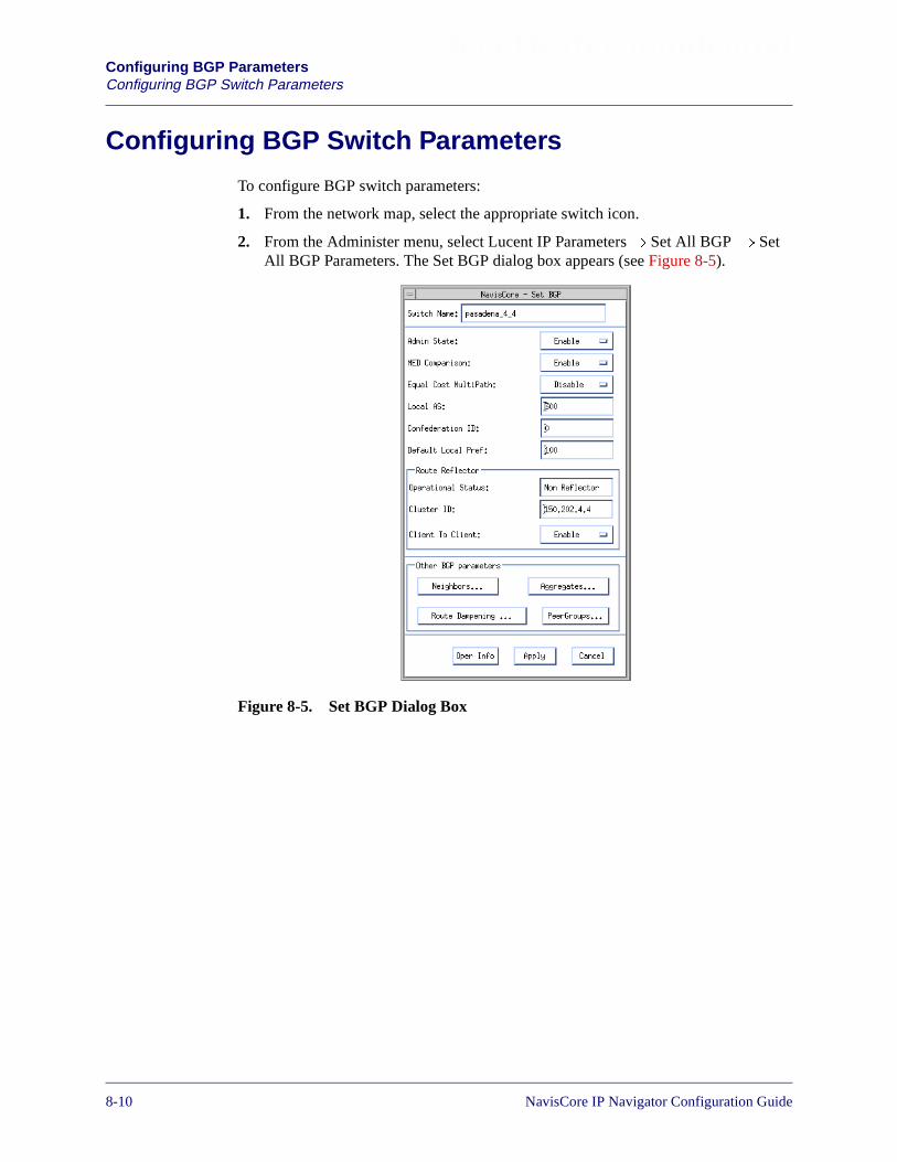
Beta Draft ConfidentialConfiguring BGP ParametersConfiguring BGP Switch Parameters
Configuring BGP Switch Parameters
To configure BGP switch parameters:
1. From the network map, select the appropriate switch icon.
2. From the Administer menu, select Lucent IP Parameters� Set All BGP � SetAll BGP Parameters. The Set BGP dialog box appears (see Figure 8-5).
Figure 8-5. Set BGP Dialog Box
8-10 NavisCore IP Navigator Configuration Guide

Beta Draft ConfidentialConfiguring BGP Parameters
Configuring BGP Switch Parameters
The Set BGP dialog box provides the following buttons:
3. Complete the fields described in Table 8-2.
Table 8-1. Set BGP Buttons
Button Function
Neighbors... Choose this button to define BGP neighbor parameters. For more information, see“Configuring BGP Neighbors and Assigning Route Maps” on page 8-14.
Aggregates... Choose this button to define BGP aggregate parameters. For more information, see“Configuring BGP Aggregates” on page 8-21.
RouteDampening
Choose this button to configure BGP route dampening. For more information, see“Configuring BGP Route Dampening” on page 8-29.
Peer Groups Choose this button to configure BGP peer groups. For more information, see “ConfiguringBGP Peer Groups” on page 8-23.
Oper Info Choose this button to update the Operational Status field.
Apply Choose this button to put your changes into effect.
Table 8-2. BGP Parameter Fields
Field Action/Description
Admin State Select one of the following options:
Enable – Allows the selected switch to exchange route updates using BGP.
Disable – (default) Prevents the selected switch from exchanging route updates using BGP.
MEDComparison
Select one of the following options:
Enable – (default) Allows you to use a multi-exit discriminator (MED) in the route selectionprocess. MED allows BGP to communicate preferred path information to external neighborswhen the autonomous system has multiple exits to another autonomous system.
Disable – Prevents the use of MED in the route selection process.
NavisCore IP Navigator Configuration Guide 1/14/028-11

Beta Draft ConfidentialConfiguring BGP ParametersConfiguring BGP Switch Parameters
Equal CostMultipath
Select one of the following options:
Enable – Enables equal-cost multipath (ECMP) routing for BGP.
Disable – (default) Disables ECMP routing for BGP.
If multiple, equal-cost AS paths from a switch to the same destination are available, you canconfigure BGP on that switch to use them. Otherwise, BGP uses only one path. By takingadvantage of multiple paths to a destination, you can load-balance network traffic.
By default, ECMP routing is disabled for BGP. Before you enable ECMP for BGP, note thefollowing:
• BGP can add up to four equal-cost paths for each item of Network Layer ReachabilityInformation (NLRI). An NLRI is part of a route definition, consisting of an IP address anda prefix. Thus, BGP can add up to four equal-cost paths to the destination specified by theIP address/prefix combination in the NLRI.
• When using multiple equal-cost paths to the same destination, BGP does not use therouter ID to break the tie.
• For NLRIs that have an ECMP route, the BGP update message for the NLRI specifies anaggregated AS_PATH of all the constituents of the ECMP route.
• Both EBGP and IBGP routes are ECMP candidates.
• Routes learned through both direct BGP peers and indirect BGP peers are ECMPcandidates.
• BGP peering to a loopback address is not an ECMP requirement.
Local AS Enter a value between 1 and 65535. This parameter is the switch’s Autonomous System (AS)number. The default is 0 (no AS number assigned).
ConfederationID
An externally visible Autonomous System number that identifies the confederation as awhole.
If you are using BGP confederation, enter a value to specify a unique confederation identifier.The ID may be any unique number within the range of 1 to 65535. A value of 0 disables BGPconfederation features.
Default LocalPref
Enter a value between 1 and 4294967295 (the default is 100). This value is exchangedbetween IBGP peers in the same AS.
A local preference allows you to rank a route according to its importance. The localpreference is compared to other routes that have the same destination. A higher localpreference indicates the route is preferred. For example, a route with a local preference of 200is preferred over a route with a local preference of 100.
Table 8-2. BGP Parameter Fields (Continued)
Field Action/Description
8-12 NavisCore IP Navigator Configuration Guide

Beta Draft ConfidentialConfiguring BGP Parameters
Configuring BGP Switch Parameters
4. Choose Apply.
Route Reflector
OperationalStatus (READONLY)
This parameter identifies whether or not this peer is a route reflector. If it is, the peer forwardsroute information to all clients.
The route reflector is implicitly defined when you define any of its peers to be a routereflector client.
Cluster ID Enter the internal IP address of the selected switch if the switch is a route reflector in acluster, which contains more than one route reflector. The default is the internal IP address ofthe switch.
A cluster is a group of client peers that communicate with a BGP route reflector. A cluster IDspecifies the cluster.
Client To Client(For RouteReflector peersonly)
Select one of the following options:
Enable – (default) If you enable this parameter, any routes that are received by the selectedswitch from a client will be sent to all other clients. Enable is the default.
Disable – If you disable this parameter, any routes that are received by the selected switchfrom a client will not be sent to all other clients.
Note: Disable this parameter if all clients are fully meshed.
Table 8-2. BGP Parameter Fields (Continued)
Field Action/Description
NavisCore IP Navigator Configuration Guide 1/14/028-13
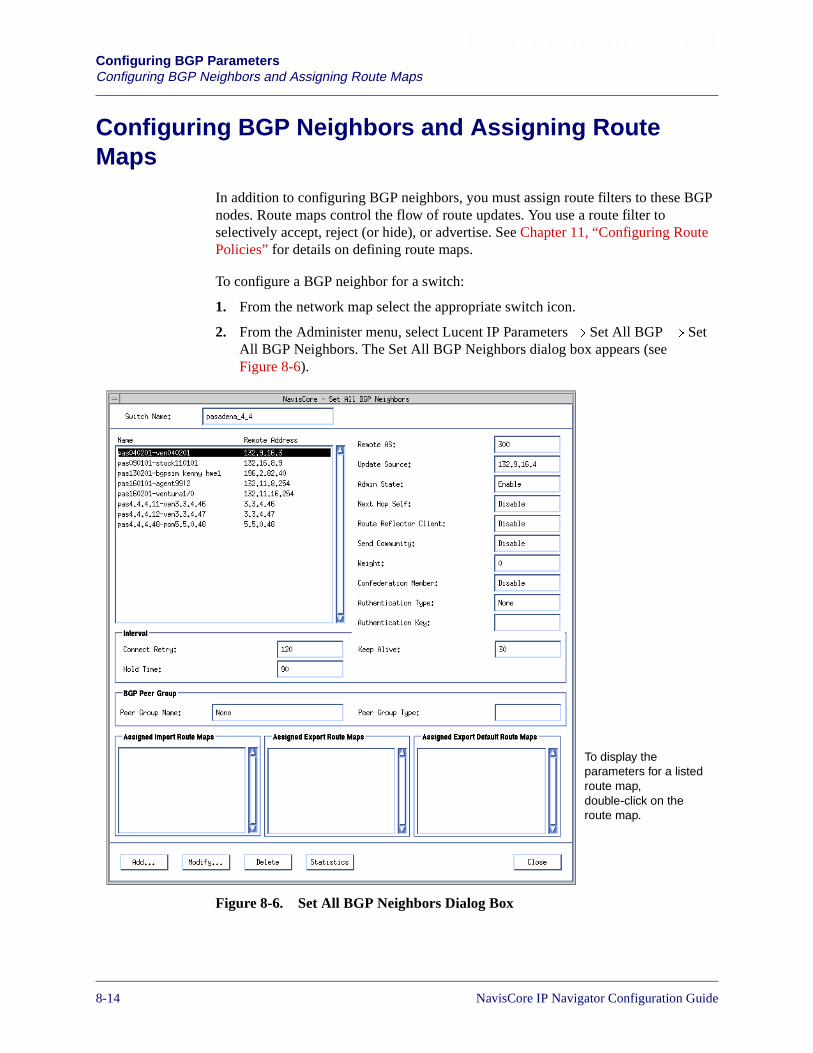
Beta Draft ConfidentialConfiguring BGP ParametersConfiguring BGP Neighbors and Assigning Route Maps
Configuring BGP Neighbors and Assigning RouteMaps
In addition to configuring BGP neighbors, you must assign route filters to these BGPnodes. Route maps control the flow of route updates. You use a route filter toselectively accept, reject (or hide), or advertise. See Chapter 11, “Configuring RoutePolicies” for details on defining route maps.
To configure a BGP neighbor for a switch:
1. From the network map select the appropriate switch icon.
2. From the Administer menu, select Lucent IP Parameters� Set All BGP � SetAll BGP Neighbors. The Set All BGP Neighbors dialog box appears (seeFigure 8-6).
Figure 8-6. Set All BGP Neighbors Dialog Box
To display theparameters for a listedroute map,double-click on theroute map.
8-14 NavisCore IP Navigator Configuration Guide
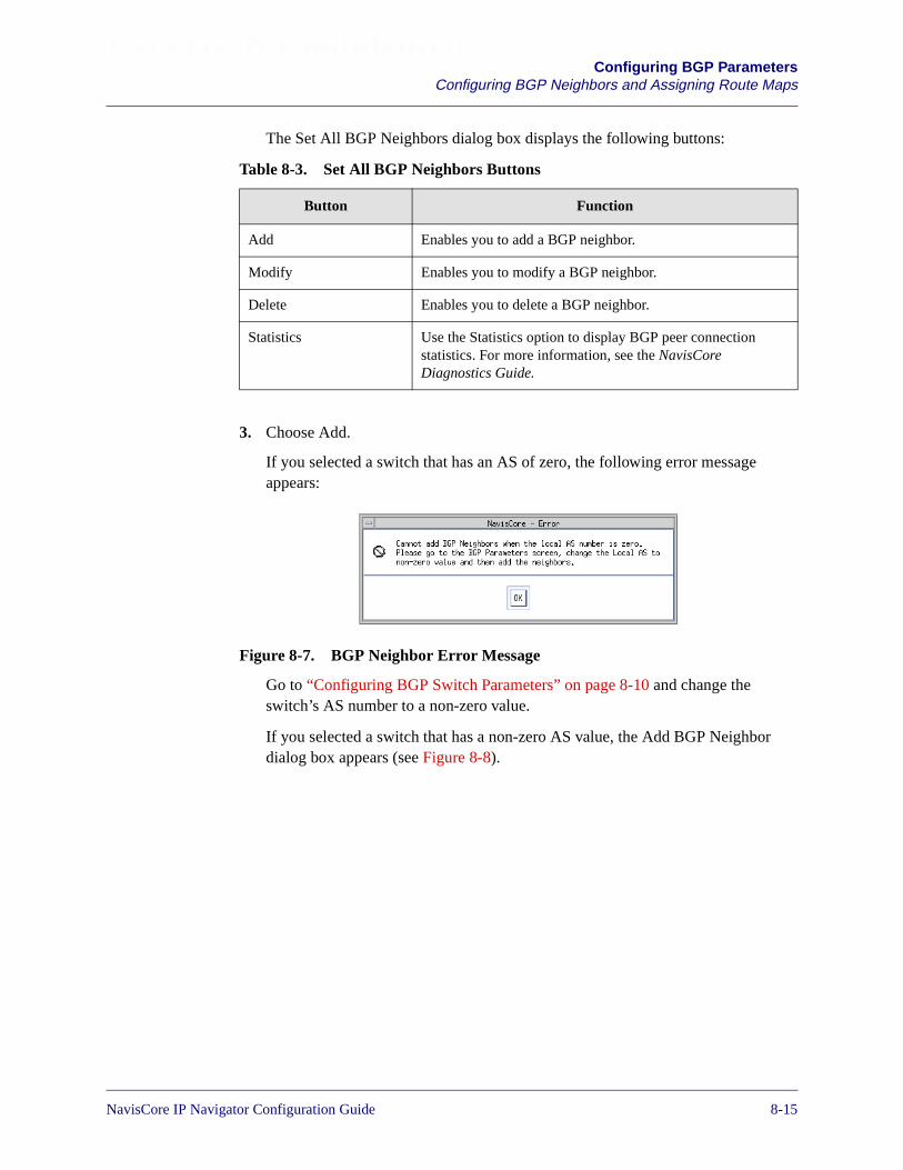
Beta Draft ConfidentialConfiguring BGP Parameters
Configuring BGP Neighbors and Assigning Route Maps
The Set All BGP Neighbors dialog box displays the following buttons:
3. Choose Add.
If you selected a switch that has an AS of zero, the following error messageappears:
Figure 8-7. BGP Neighbor Error Message
Go to “Configuring BGP Switch Parameters” on page 8-10 and change theswitch’s AS number to a non-zero value.
If you selected a switch that has a non-zero AS value, the Add BGP Neighbordialog box appears (see Figure 8-8).
Table 8-3. Set All BGP Neighbors Buttons
Button Function
Add Enables you to add a BGP neighbor.
Modify Enables you to modify a BGP neighbor.
Delete Enables you to delete a BGP neighbor.
Statistics Use the Statistics option to display BGP peer connectionstatistics. For more information, see the NavisCoreDiagnostics Guide.
NavisCore IP Navigator Configuration Guide 1/14/028-15

Beta Draft ConfidentialConfiguring BGP ParametersConfiguring BGP Neighbors and Assigning Route Maps
Figure 8-8. Add BGP Neighbor Dialog Box
4. Specify the values as listed in Table 8-4.
Use the arrow buttonsto specify the sequencethat IP Navigator usesto filter routinginformation.
Table 8-4. BGP Neighbor Fields
Field Action/Description
Name Enter the name of the BGP neighbor.
Remote Address Enter the IP address of the BGP neighbor.
Admin State Select one of the following options:
Enable – (default) Activates the connection between the selected switch and this BGPneighbor.
Disable – Deactivates the connection between the selected switch and this BGP neighbor.
8-16 NavisCore IP Navigator Configuration Guide
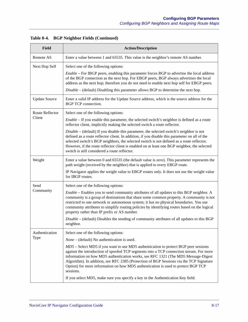
Beta Draft ConfidentialConfiguring BGP Parameters
Configuring BGP Neighbors and Assigning Route Maps
Remote AS Enter a value between 1 and 65535. This value is the neighbor’s remote AS number.
Next Hop Self Select one of the following options:
Enable – For IBGP peers, enabling this parameter forces BGP to advertise the local addressof the BGP connection as the next hop. For EBGP peers, BGP always advertises the localaddress as the next hop; therefore you do not need to enable next hop self for EBGP peers.
Disable – (default) Disabling this parameter allows BGP to determine the next hop.
Update Source Enter a valid IP address for the Update Source address, which is the source address for theBGP TCP connection.
Route ReflectorClient
Select one of the following options:
Enable – If you enable this parameter, the selected switch’s neighbor is defined as a routereflector client, implicitly making the selected switch a route reflector.
Disable – (default) If you disable this parameter, the selected switch’s neighbor is notdefined as a route reflector client. In addition, if you disable this parameter on all of theselected switch’s BGP neighbors, the selected switch is not defined as a route reflector.However, if the route reflector client is enabled on at least one BGP neighbor, the selectedswitch is still considered a route reflector.
Weight Enter a value between 0 and 65535 (the default value is zero). This parameter represents thepath weight (received by the neighbor) that is applied to every EBGP route.
IP Navigator applies the weight value to EBGP routes only. It does not use the weight valuefor IBGP routes.
SendCommunity
Select one of the following options:
Enable – Enables you to send community attributes of all updates to this BGP neighbor. Acommunity is a group of destinations that share some common property. A community is notrestricted to one network or autonomous system; it has no physical boundaries. You usecommunity attributes to simplify routing policies by identifying routes based on the logicalproperty rather than IP prefix or AS number.
Disable – (default) Disables the sending of community attributes of all updates to this BGPneighbor.
AuthenticationType
Select one of the following options:
None – (default) No authentication is used.
MD5 – Select MD5 if you want to use MD5 authentication to protect BGP peer sessionsagainst the introduction of spoofed TCP segments into a TCP connection stream. For moreinformation on how MD5 authentication works, see RFC 1321 (The MD5 Message-DigestAlgorithm). In addition, see RFC 2385 (Protection of BGP Sessions via the TCP SignatureOption) for more information on how MD5 authentication is used to protect BGP TCPsessions.
If you select MD5, make sure you specify a key in the Authentication Key field.
Table 8-4. BGP Neighbor Fields (Continued)
Field Action/Description
NavisCore IP Navigator Configuration Guide 1/14/028-17
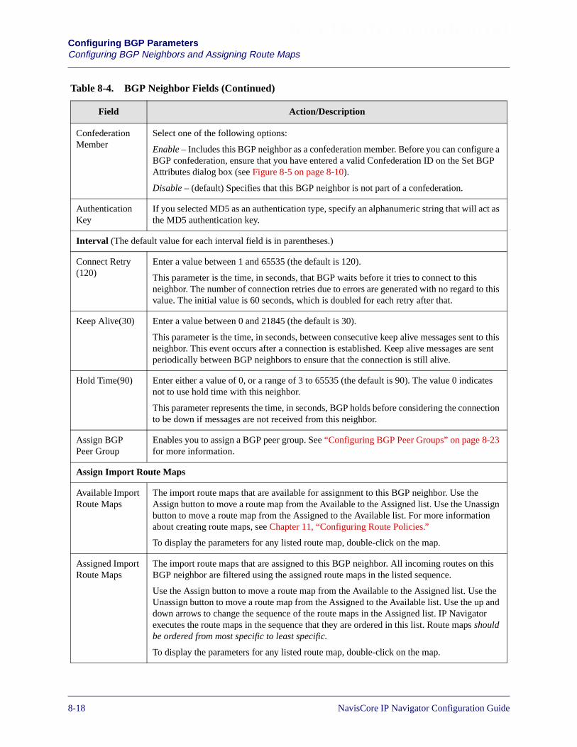
Beta Draft ConfidentialConfiguring BGP ParametersConfiguring BGP Neighbors and Assigning Route Maps
ConfederationMember
Select one of the following options:
Enable – Includes this BGP neighbor as a confederation member. Before you can configure aBGP confederation, ensure that you have entered a valid Confederation ID on the Set BGPAttributes dialog box (see Figure 8-5 on page 8-10).
Disable – (default) Specifies that this BGP neighbor is not part of a confederation.
AuthenticationKey
If you selected MD5 as an authentication type, specify an alphanumeric string that will act asthe MD5 authentication key.
Interval (The default value for each interval field is in parentheses.)
Connect Retry(120)
Enter a value between 1 and 65535 (the default is 120).
This parameter is the time, in seconds, that BGP waits before it tries to connect to thisneighbor. The number of connection retries due to errors are generated with no regard to thisvalue. The initial value is 60 seconds, which is doubled for each retry after that.
Keep Alive(30) Enter a value between 0 and 21845 (the default is 30).
This parameter is the time, in seconds, between consecutive keep alive messages sent to thisneighbor. This event occurs after a connection is established. Keep alive messages are sentperiodically between BGP neighbors to ensure that the connection is still alive.
Hold Time(90) Enter either a value of 0, or a range of 3 to 65535 (the default is 90). The value 0 indicatesnot to use hold time with this neighbor.
This parameter represents the time, in seconds, BGP holds before considering the connectionto be down if messages are not received from this neighbor.
Assign BGPPeer Group
Enables you to assign a BGP peer group. See “Configuring BGP Peer Groups” on page 8-23for more information.
Assign Import Route Maps
Available ImportRoute Maps
The import route maps that are available for assignment to this BGP neighbor. Use theAssign button to move a route map from the Available to the Assigned list. Use the Unassignbutton to move a route map from the Assigned to the Available list. For more informationabout creating route maps, see Chapter 11, “Configuring Route Policies.”
To display the parameters for any listed route map, double-click on the map.
Assigned ImportRoute Maps
The import route maps that are assigned to this BGP neighbor. All incoming routes on thisBGP neighbor are filtered using the assigned route maps in the listed sequence.
Use the Assign button to move a route map from the Available to the Assigned list. Use theUnassign button to move a route map from the Assigned to the Available list. Use the up anddown arrows to change the sequence of the route maps in the Assigned list. IP Navigatorexecutes the route maps in the sequence that they are ordered in this list. Route maps shouldbe ordered from most specific to least specific.
To display the parameters for any listed route map, double-click on the map.
Table 8-4. BGP Neighbor Fields (Continued)
Field Action/Description
8-18 NavisCore IP Navigator Configuration Guide

Beta Draft ConfidentialConfiguring BGP Parameters
Configuring BGP Neighbors and Assigning Route Maps
5. In the Available Import Route Maps List box, specify the import route map andchoose assign.
To remove an import route map from the list, select the import route map from theAssigned Import Route Maps List box and choose Unassign.
6. In the Available Export Route Maps List box, specify the export route map andchoose assign.
To remove an export route map from the list, select the export route map from theAssigned Export Route Maps List box and choose Unassign.
Assign Export Route Map
Available ExportRoute Maps
The export route maps that are available for assignment to this BGP neighbor.
Use the Assign button to move a route map from the Available to the Assigned list. Use theUnassign button to move a route map from the Assigned to the Available list. For moreinformation about creating route maps, see Chapter 11, “Configuring Route Policies.”
To display the parameters for any listed route map, double-click on the map.
Assigned ExportRoute Maps
The export route maps that are assigned to this BGP neighbor. All outgoing routes on thisBGP neighbor are filtered using the assigned route maps in the listed sequence.
Use the Assign button to move a route map from the Available to the Assigned list. Use theUnassign button to move a route map from the Assigned to the Available list. Use the up anddown arrows to change the sequence of the route maps in the Assigned list. IP Navigatorexecutes the route maps in the sequence that they are ordered in this list. Route maps shouldbe ordered from most specific to least specific.
To display the parameters for any listed route map, double-click on the map.
Assign Export Default Route Maps
Available ExportDefault RouteMaps
The export default route maps that are available for assignment to this BGP neighbor.
Use the Assign button to move a route map from the Available to the Assigned list. Use theUnassign button to move a route map from the Assigned to the Available list. For moreinformation about creating route maps, see Chapter 11, “Configuring Route Policies.”
To display the parameters for any listed route map, double-click on the map.
Assigned ExportDefault RouteMaps
The export default route maps that are assigned to this BGP neighbor. All outgoing routes onthis BGP neighbor are filtered using the assigned route maps in the listed sequence.
Use the Assign button to move a route map from the Available to the Assigned list. Use theUnassign button to move a route map from the Assigned to the Available list. Use the up anddown arrows to change the sequence of the route maps in the Assigned list. IP Navigatorexecutes the route maps in the sequence that they are ordered in this list. Route maps shouldbe ordered from most specific to least specific.
To display the parameters for any listed route map, double-click on the map.
Table 8-4. BGP Neighbor Fields (Continued)
Field Action/Description
NavisCore IP Navigator Configuration Guide 1/14/028-19

Beta Draft ConfidentialConfiguring BGP ParametersConfiguring BGP Neighbors and Assigning Route Maps
7. In the Available Export Default Route Maps List box, specify the export defaultroute map and choose assign.
To remove an export default route map from the list, select the export default routemap from the Assigned Export Default Route Maps list box and choose Unassign.
8. Choose OK.
9. To add an additional network access list, choose Add Route Map. See “AddingRoute Maps” on page 11-18 for more information.
To add a BGP peer group, choose Add Bgp Peer Group. See “Configuring BGPPeer Groups” on page 8-23 for more information.
10. In the Set All BGP Neighbors dialog box, choose Close.
8-20 NavisCore IP Navigator Configuration Guide

Beta Draft ConfidentialConfiguring BGP Parameters
Configuring BGP Aggregates
Configuring BGP Aggregates
To configure BGP aggregates:
1. From the network map, select the appropriate switch icon.
2. From the Administer menu, choose Lucent IP Parameters� Set All BGP � SetAll BGP Aggregates. The Set All BGP Aggregates dialog box appears (seeFigure 8-9).
Figure 8-9. Set All BGP Aggregates Dialog Box
The Set All BGP Aggregates dialog box displays the following buttons.
Table 8-5. Set All BGP Aggregates Buttons
Button Function
Add Aggregate RouteMap
Enables you to add an Aggregate Route Map. For moreinformation, see Table 11-33 on page 11-55.
Add Enables you to add a BGP aggregate.
Modify Enables you to modify a BGP aggregate.
Delete Enables you to delete a BGP aggregate.
NavisCore IP Navigator Configuration Guide 1/14/028-21

Beta Draft ConfidentialConfiguring BGP ParametersConfiguring BGP Aggregates
3. At the Set All BGP Aggregates dialog box, choose Add. The Add BGPAggregates dialog box appears (see Figure 8-10).
Figure 8-10. Add BGP Aggregate Dialog Box
4. Specify the values described in Table 8-6.
5. Choose OK.
6. At the Set All BGP Aggregates dialog box, choose Close.
Table 8-6. BGP Aggregate Fields
Field Action/Description
Network Address This parameter is the aggregate network IP address.
Network Mask This parameter is the aggregate network mask.
Adver. Contributor Select one of the following options:
Enable – Enabling this parameter allows you to advertisecomponents of the aggregate network.
Disable – Disabling this parameter enables you to stopadvertising components of the aggregate network.
8-22 NavisCore IP Navigator Configuration Guide
Beta Draft ConfidentialConfiguring BGP ParametersConfiguring BGP Peer Groups
Configuring BGP Peer Groups
This section provides instructions on how to configure peer groups. Before youconfigure peer groups, note the following:
• The peer group configuration process involves associating a group of BGPneighbors with one or more route maps. See “Configuring BGP Neighbors andAssigning Route Maps” on page 8-14 for more information on configuring BGPneighbors. See Chapter 11, “Configuring Route Policies” for more information onconfiguring route maps.
• All members of the same peer group must be the same BGP node type (EBGP,IBGP client, or IBGP non-client).
• Route maps in a peer group can be sequenced. This is no different than sequencingthe route maps that you assign directly to a BGP neighbor.
• Some neighbors in a peer group may have slightly different route maprequirements than other neighbors. You can add additional route maps to theneighbor that complements the set of route maps already assigned to the peergroup.
• For each neighbor in the peer group, IP Navigator evaluates the route mapsdefined specifically for that neighbor first, then it evaluates the peer group routemaps.
• A switch can support a maximum of 10 different peer groups and a maximum of50 associations between peer groups and route maps.
To configure BGP peer groups:
1. From the network map, select the appropriate switch icon.
2. From the Administer menu, select Ascend IP Parameters� Set All BGP� SetAll BGP Peer Groups. The Set All BGP Peer Groups dialog box appears (seeFigure 8-11).
NavisCore IP Navigator Configuration Guide 1/14/028-23
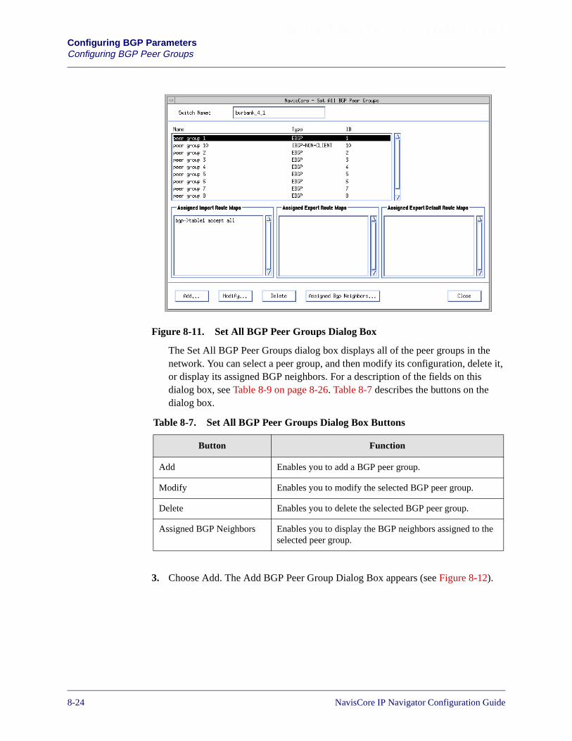
Beta Draft ConfidentialConfiguring BGP ParametersConfiguring BGP Peer Groups
Figure 8-11. Set All BGP Peer Groups Dialog Box
The Set All BGP Peer Groups dialog box displays all of the peer groups in thenetwork. You can select a peer group, and then modify its configuration, delete it,or display its assigned BGP neighbors. For a description of the fields on thisdialog box, see Table 8-9 on page 8-26. Table 8-7 describes the buttons on thedialog box.
3. Choose Add. The Add BGP Peer Group Dialog Box appears (see Figure 8-12).
Table 8-7. Set All BGP Peer Groups Dialog Box Buttons
Button Function
Add Enables you to add a BGP peer group.
Modify Enables you to modify the selected BGP peer group.
Delete Enables you to delete the selected BGP peer group.
Assigned BGP Neighbors Enables you to display the BGP neighbors assigned to theselected peer group.
8-24 NavisCore IP Navigator Configuration Guide
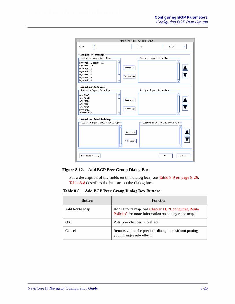
Beta Draft ConfidentialConfiguring BGP ParametersConfiguring BGP Peer Groups
Figure 8-12. Add BGP Peer Group Dialog Box
For a description of the fields on this dialog box, see Table 8-9 on page 8-26.Table 8-8 describes the buttons on the dialog box.
Table 8-8. Add BGP Peer Group Dialog Box Buttons
Button Function
Add Route Map Adds a route map. See Chapter 11, “Configuring RoutePolicies” for more information on adding route maps.
OK Puts your changes into effect.
Cancel Returns you to the previous dialog box without puttingyour changes into effect.
NavisCore IP Navigator Configuration Guide 1/14/028-25

Beta Draft ConfidentialConfiguring BGP ParametersConfiguring BGP Peer Groups
4. Complete the fields described in Table 8-9.
Table 8-9. Add BGP Peer Group Fields
Field Action/Description
Name Specify a unique alphanumeric name for the peer group.
Type Specify one of the following BGP neighbor types:
EBGP – (default) BGP neighbors that are members of this peer group must all be ExteriorBorder Gateway Protocol (EBGP) peers.
IBGP-CLIENT – BGP neighbors that are members of this peer group must all be InteriorBorder Gateway Protocol (IBGP) clients in the same AS. They must also be configured aspeers of a route reflector and part of its cluster.
IBGP-NON-CLIENT – BGP neighbors that are members of this peer group must all beIBGP non-clients in the same AS. They must also be configured as peers of a routereflector, but not part of its cluster.
Assign Import Route Maps
Available ImportRoute Maps
The import route maps that are available for assignment to this BGP peer group. Use theAssign button to move a route map from the Available to the Assigned list. Use theUnassign button to move a route map from the Assigned to the Available list. For moreinformation about creating route maps, see Chapter 11, “Configuring Route Policies.”
To display the parameters for any listed route map, double-click on the map.
Assigned ImportRoute Maps
The import route maps that are assigned to this BGP peer group. All incoming routes onthe members of the BGP peer group are filtered using the assigned route maps in the listedsequence.
Use the Assign button to move a route map from the Available to the Assigned list. Use theUnassign button to move a route map from the Assigned to the Available list. Use the upand down arrows to change the sequence of the route maps in the Assigned list. IPNavigator executes the route maps in the sequence that they are ordered in this list. Routemaps should be ordered from most specific to least specific.
To display the parameters for any listed route map, double-click on the map.
8-26 NavisCore IP Navigator Configuration Guide
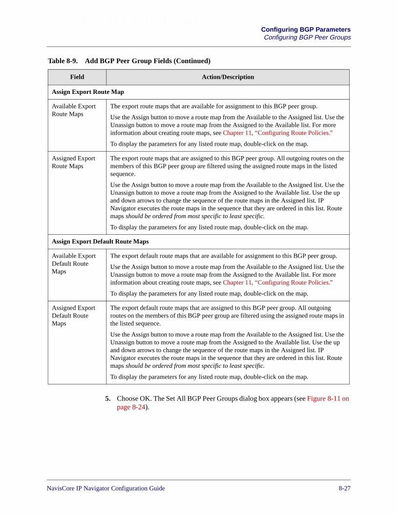
Beta Draft ConfidentialConfiguring BGP ParametersConfiguring BGP Peer Groups
5. Choose OK. The Set All BGP Peer Groups dialog box appears (see Figure 8-11 onpage 8-24).
Assign Export Route Map
Available ExportRoute Maps
The export route maps that are available for assignment to this BGP peer group.
Use the Assign button to move a route map from the Available to the Assigned list. Use theUnassign button to move a route map from the Assigned to the Available list. For moreinformation about creating route maps, see Chapter 11, “Configuring Route Policies.”
To display the parameters for any listed route map, double-click on the map.
Assigned ExportRoute Maps
The export route maps that are assigned to this BGP peer group. All outgoing routes on themembers of this BGP peer group are filtered using the assigned route maps in the listedsequence.
Use the Assign button to move a route map from the Available to the Assigned list. Use theUnassign button to move a route map from the Assigned to the Available list. Use the upand down arrows to change the sequence of the route maps in the Assigned list. IPNavigator executes the route maps in the sequence that they are ordered in this list. Routemaps should be ordered from most specific to least specific.
To display the parameters for any listed route map, double-click on the map.
Assign Export Default Route Maps
Available ExportDefault RouteMaps
The export default route maps that are available for assignment to this BGP peer group.
Use the Assign button to move a route map from the Available to the Assigned list. Use theUnassign button to move a route map from the Assigned to the Available list. For moreinformation about creating route maps, see Chapter 11, “Configuring Route Policies.”
To display the parameters for any listed route map, double-click on the map.
Assigned ExportDefault RouteMaps
The export default route maps that are assigned to this BGP peer group. All outgoingroutes on the members of this BGP peer group are filtered using the assigned route maps inthe listed sequence.
Use the Assign button to move a route map from the Available to the Assigned list. Use theUnassign button to move a route map from the Assigned to the Available list. Use the upand down arrows to change the sequence of the route maps in the Assigned list. IPNavigator executes the route maps in the sequence that they are ordered in this list. Routemaps should be ordered from most specific to least specific.
To display the parameters for any listed route map, double-click on the map.
Table 8-9. Add BGP Peer Group Fields (Continued)
Field Action/Description
NavisCore IP Navigator Configuration Guide 1/14/028-27

Beta Draft ConfidentialConfiguring BGP ParametersConfiguring BGP Peer Groups
Assigning BGP Neighbors to Peer Groups
You can assign a BGP neighbor to a peer group when you add or modify the neighbor.To assign a BGP neighbor to a peer group:
1. From the network map, select the appropriate switch icon.
2. From the Administer menu, select Ascend IP Parameters� Set All BGP� SetAll BGP Neighbors. The Set All BGP Neighbors dialog box appears (seeFigure 8-6 on page 8-14).
3. The action you perform at this point depends on whether you want to add a BGPneighbor or modify an existing neighbor:
• To add a new BGP neighbor, choose Add. The Add BGP Neighbor dialog boxappears (see Figure 8-8 on page 8-16).
• To modify a BGP neighbor, select a BGP neighbor from the list of neighborsand choose Modify. The Modify BGP Neighbor dialog box appears. Thisdialog box is similar to the Add BGP Neighbor dialog box (see Figure 8-8 onpage 8-16).
4. Select the peer group to which you are assigning the BGP neighbor. NavisCoredisplays an error message if you select a peer group that is incompatible with theneighbor. For example, if the peer group type is configured as EBGP, but theneighbor you want to assign is an IBGP client, NavisCore will display an error.
If no peer groups are defined, choose Add Bgp Peer Group to add a peer group.The Add BGP Peer Group dialog box appears (see Figure 8-12 on page 8-25).After you complete the fields on this dialog box, you can return to the Add BGPNeighbor dialog box to assign the neighbor to a peer group. See “ConfiguringBGP Peer Groups” on page 8-23 for more information on adding peer groups.
5. Complete the other fields on the Add BGP Neighbor dialog box if you are addinga new peer group. See “Configuring BGP Neighbors and Assigning Route Maps”on page 8-14 for more information.
6. Choose OK.
8-28 NavisCore IP Navigator Configuration Guide

Beta Draft ConfidentialConfiguring BGP Parameters
Configuring BGP Route Dampening
Configuring BGP Route Dampening
You configure IP Navigator to suppress propagation of unstable BGP routes between adestination (D) and an EBGP peer (P). For each route, IP Navigator maintains aninstability metric, which provides a way to measure the degree of a route’s instability.Whenever P deletes or changes its route to D, IP Navigator increments the associatedinstability metric. In other words, the more frequently a route changes, the route’sdegree of instability increases and, therefore, the instability metric increases.
The instability metric decays exponentially over time based on a configurable half-lifetime. You configure the decay rates differently when D is reachable or unreachable.
When a route’s instability metric exceeds a specified upper threshold, IP Navigatorsuppresses advertisement of the route even if the route is up. A route’s instabilitymetric continues to increase even after the route is suppressed. However, the metricwill not exceed a configurable ceiling, which effectively limits the time it takes toreadvertise the route regardless of the route’s prior history. IP Navigator reuses theroute only when the instability metric goes below the configurable lower threshold.
To configure BGP route dampening:
1. From the network map, select the appropriate switch icon.
2. From the Administer menu, select Ascend IP Parameters� Set All BGP� SetAll BGP Parameters. The Set BGP dialog box appears (see Figure 8-5 onpage 8-10).
3. Choose Route Dampening. The Set BGP Route Dampening dialog box appears(see Figure 8-13).
Figure 8-13. Set BGP Route Dampening Dialog Box
IP Navigator does not apply route dampening to routes that it learns throughIBGP. This restriction prevents the creation of forwarding loops, and preventsIBGP peers from enforcing a higher penalty for routes that are external to the ASthan for routes that are internal to the AS.
NavisCore IP Navigator Configuration Guide 1/14/028-29
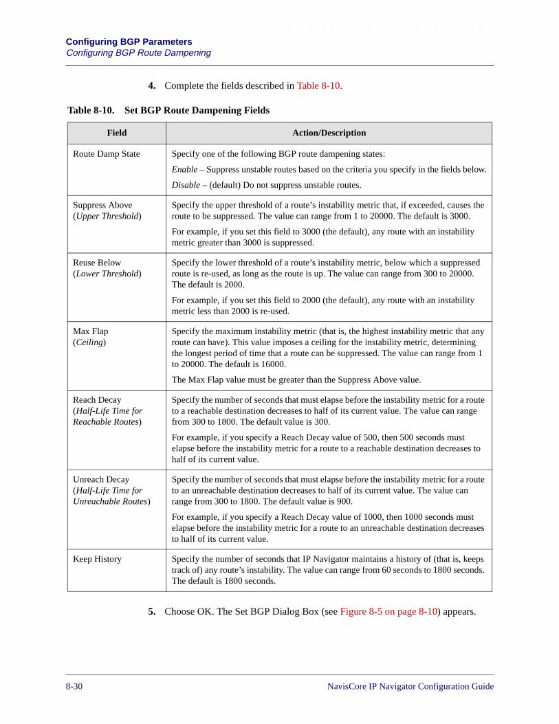
Beta Draft ConfidentialConfiguring BGP ParametersConfiguring BGP Route Dampening
4. Complete the fields described in Table 8-10.
5. Choose OK. The Set BGP Dialog Box (see Figure 8-5 on page 8-10) appears.
Table 8-10. Set BGP Route Dampening Fields
Field Action/Description
Route Damp State Specify one of the following BGP route dampening states:
Enable – Suppress unstable routes based on the criteria you specify in the fields below.
Disable – (default) Do not suppress unstable routes.
Suppress Above(Upper Threshold)
Specify the upper threshold of a route’s instability metric that, if exceeded, causes theroute to be suppressed. The value can range from 1 to 20000. The default is 3000.
For example, if you set this field to 3000 (the default), any route with an instabilitymetric greater than 3000 is suppressed.
Reuse Below(Lower Threshold)
Specify the lower threshold of a route’s instability metric, below which a suppressedroute is re-used, as long as the route is up. The value can range from 300 to 20000.The default is 2000.
For example, if you set this field to 2000 (the default), any route with an instabilitymetric less than 2000 is re-used.
Max Flap(Ceiling)
Specify the maximum instability metric (that is, the highest instability metric that anyroute can have). This value imposes a ceiling for the instability metric, determiningthe longest period of time that a route can be suppressed. The value can range from 1to 20000. The default is 16000.
The Max Flap value must be greater than the Suppress Above value.
Reach Decay(Half-Life Time forReachable Routes)
Specify the number of seconds that must elapse before the instability metric for a routeto a reachable destination decreases to half of its current value. The value can rangefrom 300 to 1800. The default value is 300.
For example, if you specify a Reach Decay value of 500, then 500 seconds mustelapse before the instability metric for a route to a reachable destination decreases tohalf of its current value.
Unreach Decay(Half-Life Time forUnreachable Routes)
Specify the number of seconds that must elapse before the instability metric for a routeto an unreachable destination decreases to half of its current value. The value canrange from 300 to 1800. The default value is 900.
For example, if you specify a Reach Decay value of 1000, then 1000 seconds mustelapse before the instability metric for a route to an unreachable destination decreasesto half of its current value.
Keep History Specify the number of seconds that IP Navigator maintains a history of (that is, keepstrack of) any route’s instability. The value can range from 60 seconds to 1800 seconds.The default is 1800 seconds.
8-30 NavisCore IP Navigator Configuration Guide

Beta Draft ConfidentialConfiguring BGP Parameters
Configuring IP Loopback Addresses
Configuring IP Loopback Addresses
The Set IP Loopback Address function enables you to establish an IP loopbackaddress that is not associated with any physical port. Because the loopback address isindependent of a physical interface, the status of the physical link does not affect theIP loopback address. If you use an IP loopback address as a BGP neighbor address,you ensure that the BGP connection will not go down.
To set an IP loopback address:
1. From the network map, select the appropriate switch icon.
2. From the Administer menu, choose Lucent IP Parameters� Set All IP LoopbackAddresses. The Set All IP Loopback Addresses dialog box appears (seeFigure 8-14).
Figure 8-14. Set All IP Loopback Addresses Dialog Box
3. Choose Add. The Add IP Loopback Address dialog box appears (seeFigure 8-15).
Figure 8-15. Add IP Loopback Address Dialog Box
4. Enter the IP address.
5. Enter the Area ID.
6. Choose OK. The Set All IP Loopback Addresses dialog box reappears and thenew IP loopback address is included in the list.
NavisCore IP Navigator Configuration Guide 1/14/028-31

Beta Draft ConfidentialConfiguring BGP ParametersConfiguring IP Loopback Addresses
8-32 NavisCore IP Navigator Configuration Guide
NavisCore IP Navigator Configuration Guide
Beta Draft Confidential
9
Configuring IP OSPF and VNN OSPF
Lucent switches can perform routing tasks using IP Navigator and Virtual NetworkNavigator (VNN) routing software. Both IP Navigator and VNN support the OpenShortest Path First (OSPF) routing protocol. In previous releases of Lucent switchsoftware, VNN and IP Navigator shared the same OSPF software component toperform their OSPF routing tasks. However, in this release, VNN and IP Navigatorhave their own OSPF software components, or instances. These instances are calledVNN OSPF and IP OSPF.
Because VNN and IP Navigator now have their own OSPF instances, you canconfigure Lucent switches so that VNN and IP Navigator have separate OSPF viewsof the network. For example, you can configure separate areas for VNN OSPF and IPOSPF, and you can configure the network so that some trunks are hidden from IPOSPF but visible to VNN OSPF.
This chapter discusses:
• An overview of OSPF, IP Navigator, and VNN
• Planning separate IP OSPF and VNN OSPF network views
• Configuring IP OSPF area IDs and VNN OSPF area IDs for trunks
• Configuring IP OSPF
• Configuring VNN OSPF
• Configuring multiple IP OSPF areas and VNN OSPF areas
• Configuring route maps using IP OSPF and VNN OSPF as route map sources anddestinations.
Although IP Navigator is not supported on GX 550 switches, GX 550 switchesthat run switch software version 01.05.xx.xx support separate instances of OSPFfor IP and VNN. With the exception of the information that applies toconfiguring IP OSPF on IP logical ports, the information in this chapter appliesto GX 550 switches. IP logical ports are not supported on GX 550 switches.
9-1
Beta Draft ConfidentialConfiguring IP OSPF and VNN OSPFAbout OSPF
About OSPF
OSPF is a link-state routing protocol that works within an Autonomous System (AS).Within an AS, each OSPF router maintains an identical link-state database thatdescribes the network topology. This link-state database allows a router to calculate arouting table by constructing a shortest-path tree. Both IP Navigator and VNN supportthe OSPF Version 2 protocol, as described in RFC 2328.
The OSPF protocol has the following advantages over the Routing InformationProtocol (RIP):
Authentication — Provides security. Only an authorized router can generate routeupdates to other routers.
Type of Service (TOS) — Enables your network to make routing decisions based onthe quality of service required by a host application.
Areas — Restricts flooding to configured areas, thereby reducing the database size.
OSPF Link-State Database
OSPF uses a link-state database to describe the networks and gateways within anAutonomous System. OSPF uses a flooding mechanism to distribute and synchronizethe link-state database between routers. When a network’s topology changes, eachrouter receives one or more link-state advertisements (LSAs), which contain topologyinformation. Each router stores LSAs in its link-state database.
Link-state databases include:
• Known router addresses
• Known links and their associated costs
• Known network addresses
Routers use the link-state database and Dijkstra’s algorithm (algorithm used tocalculate best routes) to determine the best route.
9-2 NavisCore IP Navigator Configuration Guide

Beta Draft ConfidentialConfiguring IP OSPF and VNN OSPF
About OSPF
Designated Routers and OSPF Relationships
Designated Routers are responsible for sending copies of the link-state database torouters in the network. When new routers send Hello packets to the DesignatedRouter, the Designated Router responds with an acknowledgment message. The newrouter then sends a database description packet requesting a copy of the link-statedatabase. The Designated Router responds by sending a database description packetthat contains a copy of the link-state database to the new router and updates othernodes in the network about the new router/switch.
In addition, Designated Routers:
• Monitor the health of adjacent routers
• Establish adjacencies with non-designated routers
A Backup Designated Router is typically defined in case the Designated Router goesdown. The Backup Designated Router keeps track of the same information as theDesignated Router, but keeps silent. If the backup detects a failure of the DesignatedRouter, it immediately becomes active.
OSPF Flooding Controls
Flooding is a reliable way to send link-state advertisements (LSAs) to ensure that allrouters in an area have identical link-state databases. Multiple copies of the messagetravel through the network, ensuring that one message will arrive safely at each node.However, flooding causes significant network traffic. To reduce network traffic, OSPFimplements the following flooding controls:
• The Designated Router is the only router that can generate link-state updates. Thiscontrol reduces the number of copies created.
• Before forwarding OSPF link-state updates, the Designated Router checks its ownlink-state database to see if the update was received. If it was, the copy isdiscarded.
• OSPF supports areas where flooding is restricted. Smaller areas mean fewercopies of a message and less traffic.
• Each node acknowledges each LSA update that it receives from the DesignatedRouter.
NavisCore IP Navigator Configuration Guide 1/14/029-3
Beta Draft ConfidentialConfiguring IP OSPF and VNN OSPFAbout OSPF
OSPF Areas
Link-state database size increases in proportion to network size. This can limit thescalability of the network for the following reasons:
• Increased memory space is consumed
• Route table generation becomes more processor-intensive
• It takes longer to:
– Calculate link costs for more links
– Calculate the spanning tree for a large network
– Generate large routing tables required by large networks
To address large link-state databases, OSPF uses areas. An area is a group of OSPFrouters that exchanges topology information. Designated Routers only send LSAs torouters that are part of the same area. If an Autonomous System (AS) has one area, allrouters in the Autonomous System receive LSAs. However, if the AutonomousSystem is divided into many areas, LSAs only go to the appropriate areas, therebyminimizing traffic and the link-state database size. The Autonomous System workslike a collection of smaller networks.
Because of flooding controls, the topology of one area is unknown by routers inanother area. This means a router knows nothing of network topology outside its ownarea. Each area has a unique link-state database, and all routers in the given areashould have the same database.
If an Autonomous System consists of more than one area, a backbone area (Area 0)must be created for OSPF to distribute consistent routing information throughout theAutonomous System. The backbone area allows information from one area to beadvertised in other areas.
9-4 NavisCore IP Navigator Configuration Guide

Beta Draft ConfidentialConfiguring IP OSPF and VNN OSPF
About OSPF
Figure 9-1 illustrates the concept of areas.
Figure 9-1. OSPF Areas
In Figure 9-1, the Autonomous System is divided into five areas. Each area representssmaller networks within the Autonomous System, and maintains separate link-statedatabases. Area 0 is the backbone, connecting all areas within the AutonomousSystem.
OSPF requires the backbone to be contiguous to all areas in the Autonomous System.All non-backbone areas (that is, areas other than area 0) must connect to the backbonearea directly or through a virtual link.
Packets are forwarded between areas, from the source area, through the backbone, andthen into the destination area. Lucent’s OSPF area implementation assigns each trunkto a specific area. This provides maximum flexibility in setting area boundaries andchanging area boundaries in the future.
Autonomous System
Area 0
Router
Area 3 Area 4
Area 1 Area 2
Area BorderRouter
NavisCore IP Navigator Configuration Guide 1/14/029-5
Beta Draft ConfidentialConfiguring IP OSPF and VNN OSPFAbout OSPF
OSPF Routing and Router Classifications
There are three types of routing:
• Intra-area routing — Routing within an area
• Inter-area routing — Routing between areas
• AS-external routing — Routing between the OSPF Autonomous System and otherAutonomous Systems
These types of routing are performed by different classifications of routers, including:
Internal routers — Routers that are directly connected and belong to the same area.In addition, routers with interfaces connected only to the backbone are classified asinternal routers.
Area border routers (ABRs) — Routers with links to more than one area. ABRsmaintain separate link-state databases of each area to which they belong.
Backbone routers — Routers with an interface to the backbone. A backbone is eitheran area border router or an internal router.
AS boundary routers — Routers that connect an OSPF Autonomous System to aregion that uses a different routing protocol. AS boundary routers may be internalrouters, area border routers, or backbone routers.
Figure 9-2 shows an example of OSPF routing and router classifications.
9-6 NavisCore IP Navigator Configuration Guide

Beta Draft ConfidentialConfiguring IP OSPF and VNN OSPF
About OSPF
Figure 9-2. Router Classifications
RIP Network
Area 0
Area 2Area 1
OSPF AutonomousSystem
Area Border Router
Internal Router
AS Boundary Router
Intra-Area Route
Inter-Area Route
AS-ExternalRoute
NavisCore IP Navigator Configuration Guide 1/14/029-7
Beta Draft ConfidentialConfiguring IP OSPF and VNN OSPFAbout OSPF
OSPF Area Aggregates
Area aggregates consolidate multiple routes (or IP addresses) within an area (or areas)into one single LSA. This consolidation enables one advertisement representing arange of IP addresses within an area (or areas) to be broadcast.
Area aggregates:
• Reduce the size of the OSPF routing table
• Provide better control over network instabilities
• Provide a better mechanism to summarize route updates across areas
• Reduce memory requirements for link-state databases
• Reduce the cost of route calculation
• Have a maximum area size of 400 switches and routers, or 1,000 interfaces
Although address aggregation is not required, it results in fewer summary LSAs.Fewer summary LSAs reduce the size of the routing table and OSPF link-statedatabases. See “OSPF Summary LSAs” for more information on summary LSAs.
OSPF Summary LSAs
IP addressing information is advertised across area boundaries in OSPF summaryLSAs. Each summary LSA advertises a single range of IP addresses. The IP addressranges are configured in the ABRs. See “OSPF Routing and Router Classifications”on page 9-6 for more information on ABRs.
For example, Area 1 is assigned a subnet of 107.109.220.0/24. The number 24specifies a subnet mask of 24, so all IP addresses in the range 107.109.220.1-254 aresent as a single OSPF summary LSA.
9-8 NavisCore IP Navigator Configuration Guide

Beta Draft ConfidentialConfiguring IP OSPF and VNN OSPF
About OSPF
OSPF Virtual Links
OSPF requires that all OSPF areas be connected to the OSPF backbone area. Inaddition to direct connections, you can use virtual links to logically connect physicallyseparate portions of a network to the backbone. OSPF uses virtual links for thefollowing purposes:
• To connect areas that are not physically connected to the backbone.
• To preserve the continuity of the OSPF backbone.
The two endpoints of a virtual link are ABRs. Figure 9-3 illustrates a network thatconnects Area 0.0.0.4 to the backbone through Area 0.0.0.3 by using a virtual linkfrom Switch 7 to Switch 4.
Figure 9-3. OSPF Area Configuration Example
Switch 1107.109.110.1
Area 0.0.0.2
Area 0.0.0.1
Switch 2107.109.110.2
107.109.50.33107.109.50.34
Switch 5107.109.220.23
Switch 3107.109.50.1
Switch 6107.109.220.2
Switch 4107.109.221.201
107.109.221.21
Area 0.0.0.3
Area 0.0.0.0Backbone
Area 0.0.0.4
VirtualLink
Switch 7107.109.221.250
NavisCore IP Navigator Configuration Guide 1/14/029-9

Beta Draft ConfidentialConfiguring IP OSPF and VNN OSPFAbout OSPF
Figure 9-3 shows a single OSPF backbone area with an Area ID of 0.0.0.0. All threenon-backbone areas (0.0.0.1, 0.0.0.2, and 0.0.0.3) are directly connected to the OSPF0.0.0.0 backbone area. Area 0.0.0.4 is connected to the backbone through the virtuallink that is configured in Area 0.0.0.3.
About Clustering
Clustering is a way of grouping VNN OSPF areas into subareas (the IP instance ofOSPF does not support clustering). Clustering enables you to use set increments (a setof three bits of the internal IP address to assign a cluster address between 000 and 111,or 0 and 7) of the host ID address in different VNN OSPF areas, while performingroute aggregation at the Area Border Router. A cluster forms a subset of an OSPFarea. A cluster enables additional address aggregation at the ABR and reduces the sizeof the IP routing table, link-state database, and the number of summary LSAs.
Use clustering only if you deploy new nodes with the same subnet addresses intomultiple VNN OSPF areas (for example, due to a lack of IP addresses).
Version 2.3 and later NMS versions allow you to define an IP address subnet as part ofa cluster, define a cluster ID, and designate a switch as part of a cluster at switchdeployment.
You assign a cluster ID to the IP address to be clustered. The cluster ID specifies theupper three bits of the host ID. As you add switches in that cluster ID, the switchnumber/host ID in the IP address increments according to the cluster ID. Table 9-1shows the cluster ID IP-address range using 107.109.50.x as the default IP address.
Do not configure clustering if you implement OSPF areas using B-STDX switchsoftware versions prior to version 5.0.
Table 9-1. Cluster ID and IP Addresses Example
Cluster ID IP Address Range
0 107.109.50.1 - 107.109.50.30
1 107.109.50.33 - 107.109.50.62
2 107.109.50.65 - 107.109.50.94
3 107.109.50.97 - 107.109.50.126
4 107.109.50.129 - 107.109.50.158
5 107.109.50.161 - 107.109.50.190
6 107.109.50.193 - 107.109.50.222
7 107.109.50.225 - 107.109.50.254
9-10 NavisCore IP Navigator Configuration Guide

Beta Draft ConfidentialConfiguring IP OSPF and VNN OSPF
VNN and IP Navigator Overview
VNN and IP Navigator Overview
Before you can start to configure separate network views for VNN OSPF and IPOSPF, it is helpful to review how each routing method works separately, andunderstand how both routing methods work together.
VNN
VNN performs the following functions:
• Routes ATM and Frame Relay PVC and SVC traffic to other Lucent switchesthrough the Lucent network. To route ATM and Frame Relay between Lucentswitches, VNN uses OSPF with some proprietary extensions.
• Routes SMDS datagrams.
• Routes switch management traffic (e.g., SNMP) through the Lucent network.Management connections such as management DLCIs and managementVPI/VCIs are handled by VNN.
• Sets up Multipoint-to-Point Tunnel (MPT) label switched paths (LSPs) for use byIP Navigator and selects the paths that they use. VNN determines when to addnew leaves to each MPT LSP and the path that each MPT LSP uses.
• Distributes topological data and other data from the switch processor (CP or SP)to the Input/Output Processors (IOPs) so that the IOPs can perform VCcalculations.
IP Navigator
IP Navigator performs the following functions:
• Determines whether IP packets are routed at Layer 3 (IP) or switched at Layer 2(using MPT LSPs). When the IP path is through an IP logical port, IP Navigatorroutes the packet. When the IP path traverses trunks, IP Navigator forwards thepacket via an MPT LSP (which is set up by VNN).
• Maintains the IP routing table using IP OSPF, RIP, BGP, and static routing. Notethat IP OSPF is based on the OSPF standard while VNN OSPF implements someproprietary extensions to standard OSPF.
• Distributes IP routing information between other routing protocols. For BGP, IPNavigator distributes information on IBGP next hops.
NavisCore IP Navigator Configuration Guide 1/14/029-11

Beta Draft ConfidentialConfiguring IP OSPF and VNN OSPFVNN and IP Navigator Overview
How VNN OSPF and IP OSPF View the Network
Separate instances of OSPF for VNN and IP Navigator have the following benefits:
Create a simplified topological view for IP routers from other vendors — IProuters from other vendors cannot support OSPF areas as large as the areas that Lucentswitches can support. By supporting separate topological views for VNN OSPF and IPOSPF, you can configure large areas for VNN OSPF, thereby optimizing virtual circuitpaths, and create smaller OSPF areas for IP OSPF to accommodate IP routers fromother vendors.
Hide management addresses from IP routers — By configuring different networkviews for VNN OSPF and IP OSPF, you can prevent the management IP addresses ofswitches from being advertised to IP routers. Unless you explicitly allow themanagement addresses to be advertised to IP routers (through a route map),management addresses are advertised by VNN OSPF only.
Separate OSPF views provide you with a flexible way to configure the network. Forexample, you can divide the network into three areas for IP OSPF, but have only onearea for VNN OSPF. This approach would have the following benefits:
• Allow VNN to use optimal paths for virtual circuits.
• Reduce the size of IP areas, thereby reducing the size of the OSPF databases on IProuters that forward packets through the Lucent network.
• Hide management addresses from the IP routers.
When you initially upgrade a Lucent switch to this release of IP Navigator, VNNOSPF and IP OSPF have identical OSPF network views. You have the option tocontinue with this configuration, or create different views for VNN OSPF and IPOSPF.
Figure 9-4 shows a Lucent network in which all switches are running a release ofLucent switch software prior to this release. The Lucent network is a single-area AS.Notice that, on Switch1, VNN and IP Navigator have a common OSPF network viewof the Lucent network through a common OSPF instance.
9-12 NavisCore IP Navigator Configuration Guide

Beta Draft ConfidentialConfiguring IP OSPF and VNN OSPF
VNN and IP Navigator Overview
Figure 9-4. Common OSPF Network View Through a Single OSPF Instance
In Figure 9-5, all the switches in the network are upgraded to this release of Lucentswitch software, creating separate instances of OSPF (VNN OSPF and IP OSPF). Inboth the VNN OSPF and IP OSPF network views, the Lucent network remains asingle-area AS. However, in the IP OSPF view in Figure 9-5, the network manager hashidden part of the Lucent network (the trunks indicated by dashed lines) from therouter connected to Switch1. The hidden trunks are part of the VNN OSPF view only.
VNN
IPOSPF
500
500
500
500
Router
Router
Router Router
Router
Router
Switch1
Switch2
Switch3
Switch4
Switch5
Switch6
Switch8
Switch7
Switch1’s view of the Lucentnetwork. VNN and IP on Switch1have a common view of thenetwork through a single OSPFinstance.
Area 0
Area 0
Area 0Area 0
Area 0Area 0
Area 0
Area 0
Router
90
00
90
00
90
00
90
00
NavisCore IP Navigator Configuration Guide 1/14/029-13

Beta Draft ConfidentialConfiguring IP OSPF and VNN OSPFVNN and IP Navigator Overview
Figure 9-5. Different OSPF Network Views
If required, the network manager could have configured multiple areas for either VNNOSPF, IP OSPF, or both. Figure 9-6 shows a Lucent network in which VNN OSPF hasonly one area, but IP OSPF has three areas.
VNN
OSPF
500
500
500
500
Router
Router
Router Router
Router
Switch1
Switch2
Switch3
Switch4
Switch5
Switch6
Switch8
Switch7
IPOSPF
Switch1’s view of the Lucentnetwork. VNN OSPF and IPOSPF on Switch1 have a differentview of the network. VNN OSPFsees the entire network, while partof the network is hidden from IPOSPF.
VNN Area 0IP Area 0
VNN Area 0IP Area 0
VNN Area 0
VNN Area 0IP Area 0
VNN Area 0IP Area 0
VNN Area 0IP Area 0
VNN Area 0
VNN Area 0IP Area 0
Router
Router90
00
90
00
90
00
90
00
You can configure an IP OSPF router ID on any switch connected to a trunk thatis a member of an IP OSPF area. See “Planning Router IDs” on page 9-22 formore information.
9-14 NavisCore IP Navigator Configuration Guide
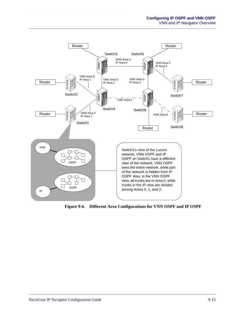
Beta Draft ConfidentialConfiguring IP OSPF and VNN OSPF
VNN and IP Navigator Overview
Figure 9-6. Different Area Configurations for VNN OSPF and IP OSPF
500
500
500
500
Router
Router
Router Router
Router
Switch1
Switch2
Switch3
Switch4
Switch5
Switch6
Switch8
Switch7
VNN Area 0IP Area 1
VNN Area 0IP Area 1
VNN Area 0
VNN Area 0IP Area 0
VNN Area 0IP Area 2
VNN Area 0IP Area 1
VNN Area 0
VNN Area 0IP Area 2
Router
Router
VNN
OSPF
IPOSPF
Switch1’s view of the Lucentnetwork. VNN OSPF and IPOSPF on Switch1 have a differentview of the network. VNN OSPFsees the entire network, while partof the network is hidden from IPOSPF. Also, in the VNN OSPFview, all trunks are in Area 0, whiletrunks in the IP view are dividedamong Areas 0, 1, and 2.
90
00
90
00
90
00
90
00
NavisCore IP Navigator Configuration Guide 1/14/029-15

Beta Draft ConfidentialConfiguring IP OSPF and VNN OSPFPlanning Separate OSPF Network Views
Planning Separate OSPF Network Views
Before you start to configure separate network views for VNN OSPF and IP OSPF,perform the following tasks:
• Consider network size and types of network traffic
• Plan your trunk configuration
• Plan for configuring VNN OSPF loopbacks, area aggregates, and virtual links
• Plan for configuring router IDs for IP OSPF
• Plan route maps
Considering Network Size and Types of Network Traffic
To develop an overall strategy for configuring separate network views for VNN OSPFand IP OSPF, you need to take into account:
• Types of network traffic
• Network size
• Topology
IP Navigator handles IP traffic while VNN handles non-IP traffic, which includesmanagement traffic and ATM and Frame Relay PVC and SVC traffic.
If your network is large and handles a mix of IP, management, ATM, and Frame Relaytraffic, consider configuring one or two large areas for VNN OSPF and severalsmaller areas for IP OSPF. The benefits of this approach are:
• Large OSPF areas enable VNN to create optimal paths for ATM and Frame Relayvirtual circuits. In addition, you can include management trunks in the VNN areasonly, hiding them from third-party IP routers outside the Lucent network.
• Small OSPF areas enable IP Navigator to accommodate third-party routerlimitations.
9-16 NavisCore IP Navigator Configuration Guide

Beta Draft ConfidentialConfiguring IP OSPF and VNN OSPF
Planning Separate OSPF Network Views
Planning Trunk Configuration
Your trunk configuration determines:
• VNN OSPF areas
• IP OSPF areas
All trunks are in VNN OSPF areas. In order to add a trunk, you must configure a VNNOSPF area ID for the trunk.
Optionally, you can enable IP and configure an IP OSPF area ID for a trunk so that atrunk can belong to:
• Both a VNN OSPF area and an IP OSPF area
• A VNN OSPF area only
A trunk cannot belong to an IP OSPF area only.
Figure 9-7 shows a Lucent network in which some trunks belong to both VNN OSPFareas and IP OSPF areas (trunks 1-6), and other trunks belong to VNN OSPF areasonly (trunks 7 and 8). Note that trunks 7 and 8 (shown by the dashed lines) are bestsuited for carrying management traffic because they are the most secure (that is, theycannot be seen by third-party IP routers outside the Lucent network).
Figure 9-7. Trunk VNN OSPF and IP OSPF Area Membership
500
500
VNN Area ID = 0Trunk IP Routing = EnabledTrunk IP Area ID = 0
500
500
500
500
500
500
VNN Area ID = 0Trunk IP Routing = EnabledTrunk IP Area ID = 1
VNN Area ID = 0Trunk IP Routing = EnabledTrunk IP Area ID = 1
VNN Area ID = 0Trunk IP Routing = DisabledTrunk IP Area ID = N/A
VNN Area ID = 0Trunk IP Routing = DisabledTrunk IP Area ID = N/A
VNN Area ID = 0Trunk IP Routing = EnabledTrunk IP Area ID = 2
VNN Area ID = 0Trunk IP Routing = EnabledTrunk IP Area ID = 2
VNN Area ID = 0Trunk IP Routing = EnabledTrunk IP Area ID = 1
1
2
3
4 5
7 8
6
NavisCore IP Navigator Configuration Guide 1/14/029-17

Beta Draft ConfidentialConfiguring IP OSPF and VNN OSPFPlanning Separate OSPF Network Views
Configuration parameters on the Add Trunk and Modify Trunk dialog boxes allowyou to enable IP routing and configure VNN OSPF and IP OSPF area IDs on trunks.When you enable IP routing for a trunk, NavisCore automatically configures the IPOSPF interface for each trunk.
NavisCore uses the following trunk configuration parameters to configure the IPOSPF interface for each trunk endpoint:
Trunk IP Area ID — NavisCore sets the OSPF Area ID to the value of the Trunk IPArea ID field.
TOS Zero Metric (End 1) — NavisCore sets the TOS 0 metric of the first trunkendpoint’s IP OSPF interface to the value in this field.
TOS Zero Metric (End 2) — NavisCore sets the TOS 0 metric of the second trunkendpoint’s IP OSPF interface to the value in this field.
For more information on configuring trunks for separate OSPF network views, see“Configuring Trunks for IP OSPF and VNN OSPF” on page 9-25.
9-18 NavisCore IP Navigator Configuration Guide

Beta Draft ConfidentialConfiguring IP OSPF and VNN OSPF
Planning Separate OSPF Network Views
Planning VNN OSPF and IP OSPF Loopback Addresses,Area Aggregates, and Virtual Links
Because VNN OSPF and IP OSPF have separate network views, you must configurethe following parameters separately if the network supports multiple IP OSPF areas ormultiple VNN OSPF areas:
Loopback Addresses — Loopback addresses act as endpoint addresses for virtuallinks. A loopback address is not associated with any physical port.
Area Aggregates — Aggregation is the process of advertising a range of IP addressesby advertising only a single IP address prefix, which is specified by an IP address/IPnetwork mask pair. Addresses can be aggregated at area borders. This practiceimproves route scaling by reducing the size of the topology database and the routingtable. You configure aggregates in the Area Border Router (ABR).
Virtual Links — OSPF requires that all areas be attached to the backbone area.However, areas do not have to be physically attached to the backbone. Instead, youcan configure virtual links to logically attach an area to the backbone. Before you canconfigure a virtual link you must know:
• The non-backbone transit area for the virtual link.
• The router IDs for the two endpoint switches. For VNN OSPF, the router ID is thesame value as the switch ID. IP OSPF has its own router ID. The endpointswitches are the ABRs that border on the transit area.
In addition, you must ensure that both switches have OSPF interfaces in the transitarea.
See “Configuring Multiple IP OSPF and VNN OSPF Areas” on page 9-54 for moreinformation on configuration considerations for multiple OSPF areas. For moreconceptual information on loopback addresses, area aggregates, and virtual links, see“About OSPF” on page 9-2.
Figure 9-8 and Figure 9-9 show the same physical network, but from different OSPFperspectives. Figure 9-8 shows the VNN OSPF view of the network and Figure 9-9shows the IP OSPF view of the network. In Figure 9-8, two VNN OSPF virtual linksare configured, but in Figure 9-9 only one IP OSPF virtual link is configured becauseIP OSPF has a different view of the network.
This section applies only if you configure multiple VNN OSPF areas or IP OSPFareas.
NavisCore IP Navigator Configuration Guide 1/14/029-19
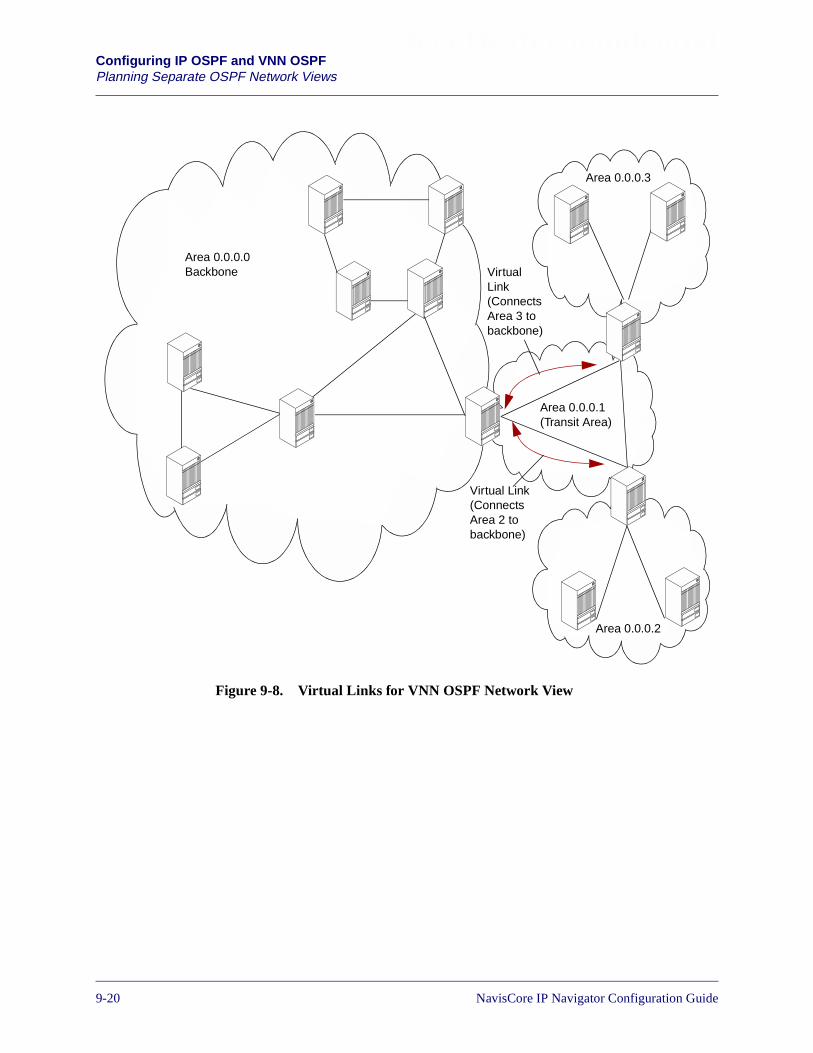
Beta Draft ConfidentialConfiguring IP OSPF and VNN OSPFPlanning Separate OSPF Network Views
Figure 9-8. Virtual Links for VNN OSPF Network View
Area 0.0.0.1(Transit Area)
Area 0.0.0.0Backbone
Area 0.0.0.2
Area 0.0.0.3
VirtualLink(ConnectsArea 3 tobackbone)
Virtual Link(ConnectsArea 2 tobackbone)
9-20 NavisCore IP Navigator Configuration Guide

Beta Draft ConfidentialConfiguring IP OSPF and VNN OSPF
Planning Separate OSPF Network Views
Figure 9-9. Virtual Link for IP OSPF Network View
Area 0.0.0.2
Area 0.0.0.1
1
Area 0.0.0.0Backbone
Area 0.0.0.4
Area 0.0.0.1
Crossed out ofIP OSPFnetwork view.
Virtual Link(ConnectsArea 4 tobackbone)
Area 0.0.0.3(Transit Area)
NavisCore IP Navigator Configuration Guide 1/14/029-21
Beta Draft ConfidentialConfiguring IP OSPF and VNN OSPFPlanning Separate OSPF Network Views
Planning Router IDs
Switches have two OSPF router IDs: one for VNN OSPF and one for IP OSPF.Whereas VNN OSPF uses the internal switch ID as the router ID, IP OSPF has its ownrouter ID.
Switch IDs are configured when the switch is installed. In prior releases of IPNavigator, both VNN and IP Navigator used the switch ID as the router ID. Once youupgrade to this release of IP Navigator, only VNN OSPF continues to use the switchID as the router ID.
For example, in Figure 9-10, all switches, with one exception, have an IP logical portconfigured. Each of these switches does not require you to configure an IP OSPFrouter ID. The single exception is Switch4, which requires an IP OSPF router IDbecause it is connected to IP OSPF trunks (and therefore has to route IP traffic), butdoes not have an IP logical port or IP Server logical port. You would configure an IPOSPF router ID for Switch4 in the context of the public IP VPN.
You do not have to configure an IP OSPF router ID on switches that have IPlogical ports or IP Server logical ports (and associated IP interfaces and IP OSPFinterfaces) configured. These switches automatically choose the IP address ofone of their IP interfaces to be the IP OSPF router ID. If a switch has multiple IPinterfaces, the switch chooses the highest IP address to be the IP OSPF router ID.
The automatically chosen IP OSPF router ID applies to the public IP VPN only.You must have an IP OSPF router ID for the public IP VPN in order for IP trafficto be forwarded properly. If necessary, you may manually override theautomatically chosen IP OSPF router ID by configuring an IP OSPF router ID ofyour own choosing for the public IP VPN. You can configure IP OSPF routerIDs for private IP VPNs, but this is not required. See Chapter 16, “ConfiguringIP Virtual Private Networks” for more information on IP VPNs.
For an IP OSPF router ID to be selected automatically, it is not sufficient toconfigure just IP logical ports (or IP Server logical ports) and IP interfaces. Youmust also configure at least one IP OSPF interface.
You must manually configure an IP OSPF router ID on each switch (within thecontext of the public IP VPN) that meets the following conditions:
• No IP logical port or IP Server logical port (and associated IP interfaces)configured on the switch
• Forwards IP traffic on IP trunk interfaces (that is, trunks assigned IP OSPFarea IDs)
Switches that meet these conditions cannot automatically choose an IP OSPFrouter ID. You must configure one manually.
9-22 NavisCore IP Navigator Configuration Guide
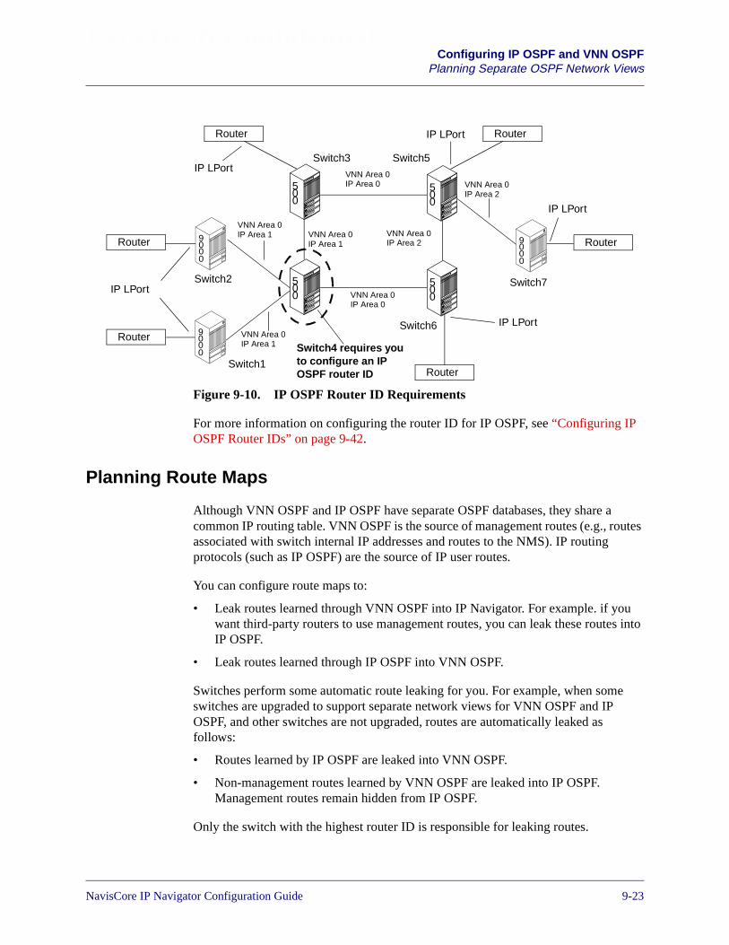
Beta Draft ConfidentialConfiguring IP OSPF and VNN OSPF
Planning Separate OSPF Network Views
Figure 9-10. IP OSPF Router ID Requirements
For more information on configuring the router ID for IP OSPF, see “Configuring IPOSPF Router IDs” on page 9-42.
Planning Route Maps
Although VNN OSPF and IP OSPF have separate OSPF databases, they share acommon IP routing table. VNN OSPF is the source of management routes (e.g., routesassociated with switch internal IP addresses and routes to the NMS). IP routingprotocols (such as IP OSPF) are the source of IP user routes.
You can configure route maps to:
• Leak routes learned through VNN OSPF into IP Navigator. For example. if youwant third-party routers to use management routes, you can leak these routes intoIP OSPF.
• Leak routes learned through IP OSPF into VNN OSPF.
Switches perform some automatic route leaking for you. For example, when someswitches are upgraded to support separate network views for VNN OSPF and IPOSPF, and other switches are not upgraded, routes are automatically leaked asfollows:
• Routes learned by IP OSPF are leaked into VNN OSPF.
• Non-management routes learned by VNN OSPF are leaked into IP OSPF.Management routes remain hidden from IP OSPF.
Only the switch with the highest router ID is responsible for leaking routes.
500
500
500
500
Router
Router
Router Router
Switch1
Switch2
Switch3 Switch5
Switch6
Switch7
VNN Area 0IP Area 1
VNN Area 0IP Area 1
VNN Area 0IP Area 0
VNN Area 0IP Area 2
VNN Area 0IP Area 1
VNN Area 0IP Area 2
Router
Router90
00
90
00
90
00
Switch4 requires youto configure an IPOSPF router ID
IP LPort
IP LPort
IP LPort
IP LPort
IP LPort
VNN Area 0IP Area 0
NavisCore IP Navigator Configuration Guide 1/14/029-23
Beta Draft ConfidentialConfiguring IP OSPF and VNN OSPFPlanning Separate OSPF Network Views
Important Upgrade Considerations
This section lists some important considerations you should take into account beforeyou upgrade a switch to this release of IP Navigator.
IP OSPF Router IDs
After you upgrade any switch to this release, make sure you configure a router ID forIP OSPF on the switch if the switch meets the following criteria:
• The switch does not have an IP logical port or IP Server logical port (andassociated IP interfaces) configured
• The switch is required to route IP traffic over IP trunk interfaces
See “Planning Router IDs” on page 9-22 and “Configuring IP OSPF Router IDs” onpage 9-42 for more information.
Virtual Links
When you upgrade a switch to this release, virtual links that you configured inprevious releases become VNN OSPF virtual links. They do not become IP OSPFvirtual links. If you want IP OSPF virtual links, you must configure them.
Performance
As you upgrade switches to this release of IP Navigator, network routing may not beoptimal. Optimal routing performance returns as soon as the whole network isupgraded or a routing policy is configured. See “Planning Route Maps” on page 9-23for more information on this process.
Viewing Routing Information
Following upgrade, VNN OSPF routing information is labeled “VNN” in the routingtable. IP OSPF routing information is labeled “OSPF.”
9-24 NavisCore IP Navigator Configuration Guide
Beta Draft ConfidentialConfiguring IP OSPF and VNN OSPF
Configuring Trunks for IP OSPF and VNN OSPF
Configuring Trunks for IP OSPF and VNN OSPF
When you add or modify a trunk, you can enable or disable IP routing for the trunkand assign the trunk to different areas (one for VNN OSPF and one for IP OSPF).
To add a new trunk or modify an existing trunk to support different network views forVNN OSPF and IP OSPF:
1. Follow the instructions for adding or modifying trunks in the NavisCore ATMConfiguration Guide or the NavisCore Frame Relay Configuration Guide.
2. At the Add Trunk dialog box (see Figure 9-11) or Modify Trunk dialog box(which is similar to the Add Trunk dialog box), perform the following actions toconfigure separate network views for VNN OSPF and IP OSPF:
– Enter the VNN OSPF Area ID in the Area ID field.
– Optionally, enter the IP OSPF Area ID in the Trunk Ip Area ID field.
– By default, IP routing is enabled for the trunk. To disable IP routing, specifyDisable in the Trunk IP routing field. For example, you would specify Disableif the trunk handles management traffic and you want to hide the trunk fromthird-party routers outside the Lucent network.
– Configure the values for Admin Cost and TOS 0 Metric, where Admin Cost isused by VNN OSPF and TOS 0 Metric is used by IP OSPF.
3. Complete all the procedures for adding or modifying a trunk described in theNavisCore ATM Configuration Guide or the NavisCore Frame RelayConfiguration Guide.
NavisCore IP Navigator Configuration Guide 1/14/029-25
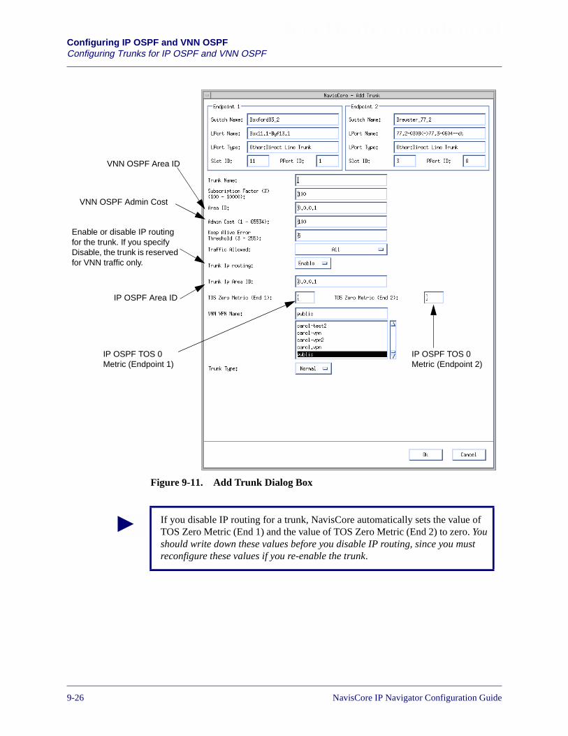
Beta Draft ConfidentialConfiguring IP OSPF and VNN OSPFConfiguring Trunks for IP OSPF and VNN OSPF
Figure 9-11. Add Trunk Dialog Box
VNN OSPF Area ID
IP OSPF Area ID
Enable or disable IP routingfor the trunk. If you specifyDisable, the trunk is reservedfor VNN traffic only.
VNN OSPF Admin Cost
IP OSPF TOS 0Metric (Endpoint 1)
IP OSPF TOS 0Metric (Endpoint 2)
If you disable IP routing for a trunk, NavisCore automatically sets the value ofTOS Zero Metric (End 1) and the value of TOS Zero Metric (End 2) to zero. Youshould write down these values before you disable IP routing, since you mustreconfigure these values if you re-enable the trunk.
9-26 NavisCore IP Navigator Configuration Guide
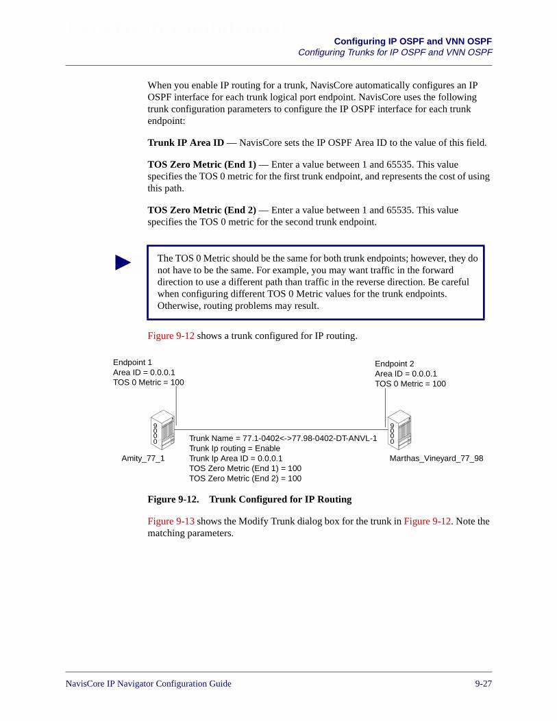
Beta Draft ConfidentialConfiguring IP OSPF and VNN OSPF
Configuring Trunks for IP OSPF and VNN OSPF
When you enable IP routing for a trunk, NavisCore automatically configures an IPOSPF interface for each trunk logical port endpoint. NavisCore uses the followingtrunk configuration parameters to configure the IP OSPF interface for each trunkendpoint:
Trunk IP Area ID — NavisCore sets the IP OSPF Area ID to the value of this field.
TOS Zero Metric (End 1) — Enter a value between 1 and 65535. This valuespecifies the TOS 0 metric for the first trunk endpoint, and represents the cost of usingthis path.
TOS Zero Metric (End 2) — Enter a value between 1 and 65535. This valuespecifies the TOS 0 metric for the second trunk endpoint.
Figure 9-12 shows a trunk configured for IP routing.
Figure 9-12. Trunk Configured for IP Routing
Figure 9-13 shows the Modify Trunk dialog box for the trunk in Figure 9-12. Note thematching parameters.
The TOS 0 Metric should be the same for both trunk endpoints; however, they donot have to be the same. For example, you may want traffic in the forwarddirection to use a different path than traffic in the reverse direction. Be carefulwhen configuring different TOS 0 Metric values for the trunk endpoints.Otherwise, routing problems may result.
Trunk Name = 77.1-0402<->77.98-0402-DT-ANVL-1Trunk Ip routing = EnableTrunk Ip Area ID = 0.0.0.1TOS Zero Metric (End 1) = 100TOS Zero Metric (End 2) = 100
Endpoint 1Area ID = 0.0.0.1TOS 0 Metric = 100
Endpoint 2Area ID = 0.0.0.1TOS 0 Metric = 100
Amity_77_1 Marthas_Vineyard_77_98
90
00
90
00
NavisCore IP Navigator Configuration Guide 1/14/029-27

Beta Draft ConfidentialConfiguring IP OSPF and VNN OSPFConfiguring Trunks for IP OSPF and VNN OSPF
Figure 9-13. Modify Trunk Dialog Box
9-28 NavisCore IP Navigator Configuration Guide

Beta Draft ConfidentialConfiguring IP OSPF and VNN OSPF
Configuring IP OSPF
Configuring IP OSPF
This section describes how to set IP OSPF parameters and includes the followingtasks:
• Configuring IP OSPF parameters on the logical port
• Configuring IP OSPF neighbors
• Configuring IP OSPF area aggregates
• Configuring IP OSPF virtual links
• Configuring IP OSPF route maps
• Configuring IP OSPF router IDs
• Configuring multiple IP OSPF authentication keys
In addition, this section also discusses equal-cost multipath (ECMP) routing for IPOSPF.
NavisCore IP Navigator Configuration Guide 1/14/029-29

Beta Draft ConfidentialConfiguring IP OSPF and VNN OSPFConfiguring IP OSPF
Configuring IP OSPF on the IP Logical Port
To configure IP OSPF on the IP logical port:
1. Enable the logical port for IP services as described in “Configuring IP LogicalPorts” on page 3-5.
2. Choose Add OSPF from the Set IP Interface Addresses dialog box (see Figure 3-6on page 3-14). The Add OSPF Interface dialog box appears (see Figure 9-14).
Figure 9-14. Add OSPF Interface Dialog Box
The Add OSPF Interface dialog box displays the following buttons:
Table 9-2. Add OSPF Interface Buttons
Button Function
Authentication Entries Enables you to add multiple authentication keys for the OSPFinterface. See “Configuring Multiple IP OSPF AuthenticationKeys” on page 9-43 for more information.
OK Enables you to put your changes into effect.
Cancel Enables you to exit the dialog box without putting yourchanges into effect.
9-30 NavisCore IP Navigator Configuration Guide
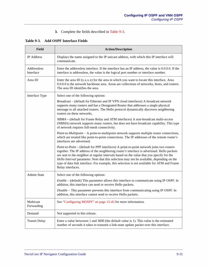
Beta Draft ConfidentialConfiguring IP OSPF and VNN OSPF
Configuring IP OSPF
3. Complete the fields described in Table 9-3.
Table 9-3. Add OSPF Interface Fields
Field Action/Description
IP Address Displays the name assigned to the IP unicast address, with which this IP interface willcommunicate.
AddresslessInterface
Enter the addressless interface. If the interface has an IP address, the value is 0.0.0.0. If theinterface is addressless, the value is the logical port number or interface number.
Area ID Enter the area ID (x.x.x.x) for the area in which you want to locate this interface. Area0.0.0.0 is the network backbone area. Areas are collections of networks, hosts, and routers.The area ID identifies the area.
Interface Type Select one of the following options:
Broadcast – (default for Ethernet and IP VPN cloud interfaces) A broadcast networksupports many routers and has a Designated Router that addresses a single physicalmessage to all attached routers. The Hello protocol dynamically discovers neighboringrouters on these networks.
NBMA – (default for Frame Relay and ATM interfaces) A non-broadcast multi-access(NBMA) network supports many routers, but does not have broadcast capability. This typeof network requires full-mesh connectivity.
Point-to-Multipoint – A point-to-multipoint network supports multiple router connections,which are treated like point-to-point connections. The IP addresses of the remote router’sinterfaces are advertised.
Point-to-Point – (default for PPP interfaces) A point-to-point network joins two routerstogether. The IP address of the neighboring router’s interface is advertised. Hello packetsare sent to the neighbor at regular intervals based on the value that you specify for theHello Interval parameter. Note that this selection may not be available, depending on thetype of data link interface. For example, this selection is not available for ATM and FrameRelay interfaces.
Admin State Select one of the following options:
Enable – (default) This parameter allows this interface to communicate using IP OSPF. Inaddition, this interface can send or receive Hello packets.
Disable – This parameter prevents this interface from communicating using IP OSPF. Inaddition, this interface cannot send or receive Hello packets.
MulticastForwarding
See “Configuring MOSPF” on page 15-43 for more information.
Demand Not supported in this release.
Transit Delay Enter a value betweeen 1 and 3600 (the default value is 1). This value is the estimatednumber of seconds it takes to transmit a link-state update packet over this interface.
NavisCore IP Navigator Configuration Guide 1/14/029-31
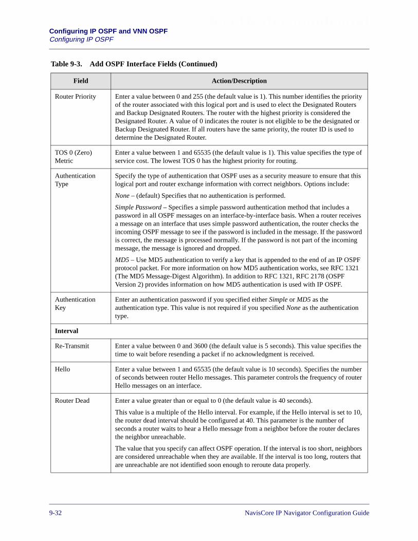
Beta Draft ConfidentialConfiguring IP OSPF and VNN OSPFConfiguring IP OSPF
Router Priority Enter a value between 0 and 255 (the default value is 1). This number identifies the priorityof the router associated with this logical port and is used to elect the Designated Routersand Backup Designated Routers. The router with the highest priority is considered theDesignated Router. A value of 0 indicates the router is not eligible to be the designated orBackup Designated Router. If all routers have the same priority, the router ID is used todetermine the Designated Router.
TOS 0 (Zero)Metric
Enter a value between 1 and 65535 (the default value is 1). This value specifies the type ofservice cost. The lowest TOS 0 has the highest priority for routing.
AuthenticationType
Specify the type of authentication that OSPF uses as a security measure to ensure that thislogical port and router exchange information with correct neighbors. Options include:
None – (default) Specifies that no authentication is performed.
Simple Password – Specifies a simple password authentication method that includes apassword in all OSPF messages on an interface-by-interface basis. When a router receivesa message on an interface that uses simple password authentication, the router checks theincoming OSPF message to see if the password is included in the message. If the passwordis correct, the message is processed normally. If the password is not part of the incomingmessage, the message is ignored and dropped.
MD5 – Use MD5 authentication to verify a key that is appended to the end of an IP OSPFprotocol packet. For more information on how MD5 authentication works, see RFC 1321(The MD5 Message-Digest Algorithm). In addition to RFC 1321, RFC 2178 (OSPFVersion 2) provides information on how MD5 authentication is used with IP OSPF.
AuthenticationKey
Enter an authentication password if you specified either Simple or MD5 as theauthentication type. This value is not required if you specified None as the authenticationtype.
Interval
Re-Transmit Enter a value between 0 and 3600 (the default value is 5 seconds). This value specifies thetime to wait before resending a packet if no acknowledgment is received.
Hello Enter a value between 1 and 65535 (the default value is 10 seconds). Specifies the numberof seconds between router Hello messages. This parameter controls the frequency of routerHello messages on an interface.
Router Dead Enter a value greater than or equal to 0 (the default value is 40 seconds).
This value is a multiple of the Hello interval. For example, if the Hello interval is set to 10,the router dead interval should be configured at 40. This parameter is the number ofseconds a router waits to hear a Hello message from a neighbor before the router declaresthe neighbor unreachable.
The value that you specify can affect OSPF operation. If the interval is too short, neighborsare considered unreachable when they are available. If the interval is too long, routers thatare unreachable are not identified soon enough to reroute data properly.
Table 9-3. Add OSPF Interface Fields (Continued)
Field Action/Description
9-32 NavisCore IP Navigator Configuration Guide
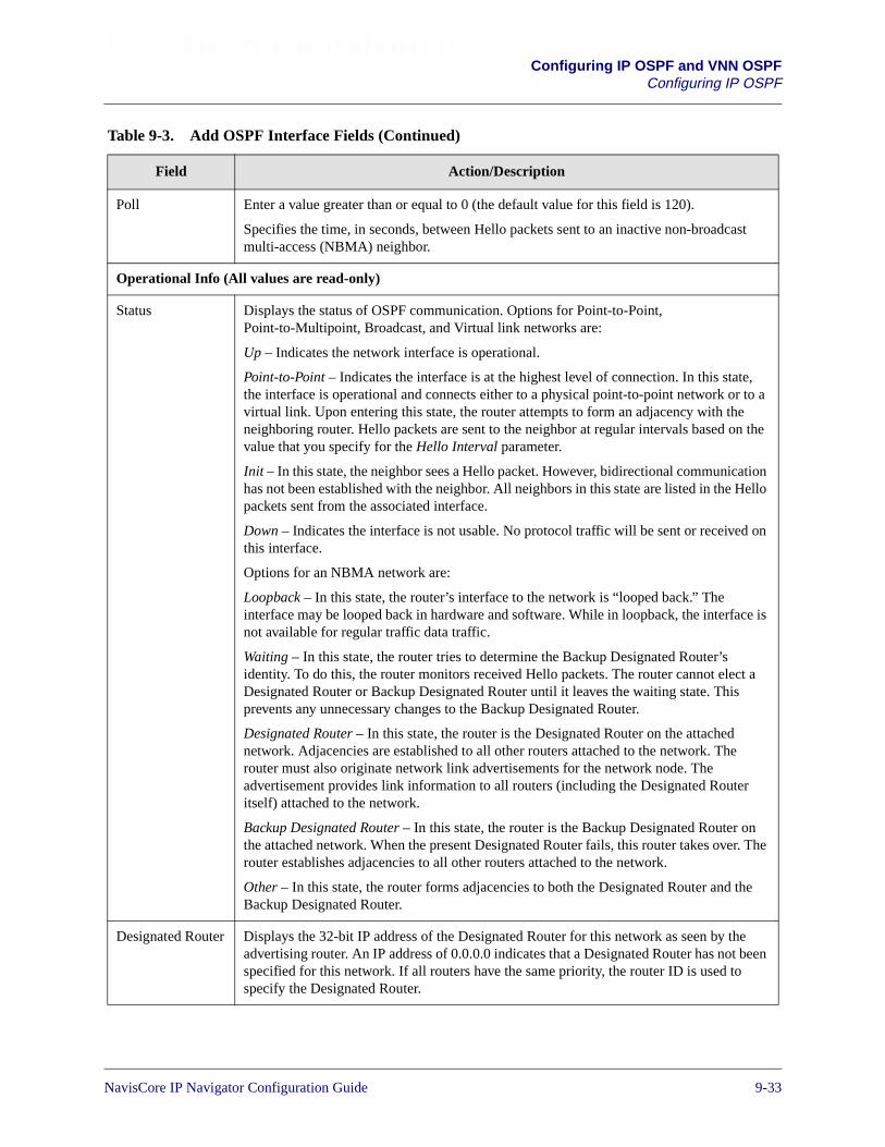
Beta Draft ConfidentialConfiguring IP OSPF and VNN OSPF
Configuring IP OSPF
Poll Enter a value greater than or equal to 0 (the default value for this field is 120).
Specifies the time, in seconds, between Hello packets sent to an inactive non-broadcastmulti-access (NBMA) neighbor.
Operational Info (All values are read-only)
Status Displays the status of OSPF communication. Options for Point-to-Point,Point-to-Multipoint, Broadcast, and Virtual link networks are:
Up – Indicates the network interface is operational.
Point-to-Point – Indicates the interface is at the highest level of connection. In this state,the interface is operational and connects either to a physical point-to-point network or to avirtual link. Upon entering this state, the router attempts to form an adjacency with theneighboring router. Hello packets are sent to the neighbor at regular intervals based on thevalue that you specify for the Hello Interval parameter.
Init – In this state, the neighbor sees a Hello packet. However, bidirectional communicationhas not been established with the neighbor. All neighbors in this state are listed in the Hellopackets sent from the associated interface.
Down – Indicates the interface is not usable. No protocol traffic will be sent or received onthis interface.
Options for an NBMA network are:
Loopback – In this state, the router’s interface to the network is “looped back.” Theinterface may be looped back in hardware and software. While in loopback, the interface isnot available for regular traffic data traffic.
Waiting – In this state, the router tries to determine the Backup Designated Router’sidentity. To do this, the router monitors received Hello packets. The router cannot elect aDesignated Router or Backup Designated Router until it leaves the waiting state. Thisprevents any unnecessary changes to the Backup Designated Router.
Designated Router – In this state, the router is the Designated Router on the attachednetwork. Adjacencies are established to all other routers attached to the network. Therouter must also originate network link advertisements for the network node. Theadvertisement provides link information to all routers (including the Designated Routeritself) attached to the network.
Backup Designated Router – In this state, the router is the Backup Designated Router onthe attached network. When the present Designated Router fails, this router takes over. Therouter establishes adjacencies to all other routers attached to the network.
Other – In this state, the router forms adjacencies to both the Designated Router and theBackup Designated Router.
Designated Router Displays the 32-bit IP address of the Designated Router for this network as seen by theadvertising router. An IP address of 0.0.0.0 indicates that a Designated Router has not beenspecified for this network. If all routers have the same priority, the router ID is used tospecify the Designated Router.
Table 9-3. Add OSPF Interface Fields (Continued)
Field Action/Description
NavisCore IP Navigator Configuration Guide 1/14/029-33

Beta Draft ConfidentialConfiguring IP OSPF and VNN OSPFConfiguring IP OSPF
4. When you are done setting parameters, choose OK.
Configuring IP OSPF Neighbors
To define an IP OSPF neighbor:
1. From the network map, select the appropriate switch icon.
2. From the Administer menu, select Lucent IP Parameters� Set All OSPF � SetAll OSPF Neighbors. The Set All OSPF Neighbors dialog box appears(see Figure 9-15).
Figure 9-15. Set All OSPF Neighbors Dialog Box
BackupDesignated Rtr
Displays the 32-bit IP address of the Backup Designated Router for this network as seen bythe advertising router. An IP address of 0.0.0.0 indicates that a Backup Designated Routerhas not been specified for this network.
Events Displays the number of times this OSPF interface changed its state, or the number of timesan error occurred.
Table 9-3. Add OSPF Interface Fields (Continued)
Field Action/Description
You do not have to define IP OSPF neighbors that are reached on IP OSPFinterfaces. OSPF automatically discovers its neighbors through Hello packets.
If you manually define IP OSPF neighbors for an IP OSPF interface configuredwith an NBMA interface type where IARP is disabled, only those neighbors arein effect. Dynamic discovery is disabled on that interface.
9-34 NavisCore IP Navigator Configuration Guide
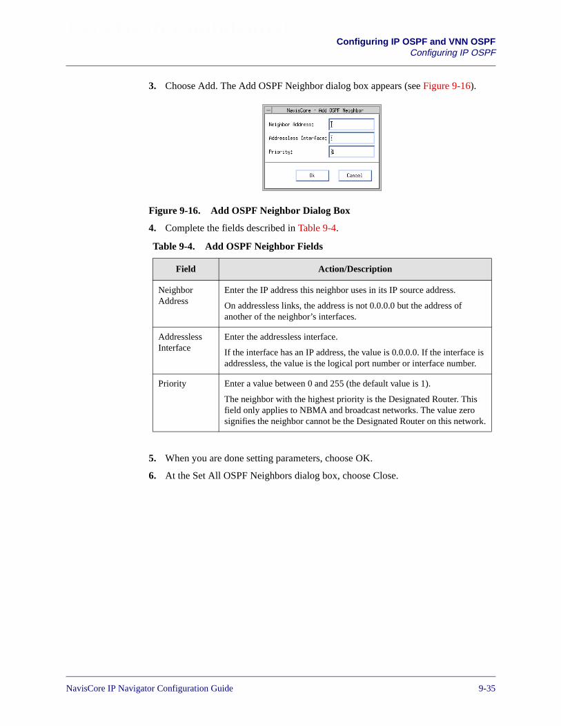
Beta Draft ConfidentialConfiguring IP OSPF and VNN OSPF
Configuring IP OSPF
3. Choose Add. The Add OSPF Neighbor dialog box appears (see Figure 9-16).
Figure 9-16. Add OSPF Neighbor Dialog Box
4. Complete the fields described in Table 9-4.
5. When you are done setting parameters, choose OK.
6. At the Set All OSPF Neighbors dialog box, choose Close.
Table 9-4. Add OSPF Neighbor Fields
Field Action/Description
NeighborAddress
Enter the IP address this neighbor uses in its IP source address.
On addressless links, the address is not 0.0.0.0 but the address ofanother of the neighbor’s interfaces.
AddresslessInterface
Enter the addressless interface.
If the interface has an IP address, the value is 0.0.0.0. If the interface isaddressless, the value is the logical port number or interface number.
Priority Enter a value between 0 and 255 (the default value is 1).
The neighbor with the highest priority is the Designated Router. Thisfield only applies to NBMA and broadcast networks. The value zerosignifies the neighbor cannot be the Designated Router on this network.
NavisCore IP Navigator Configuration Guide 1/14/029-35
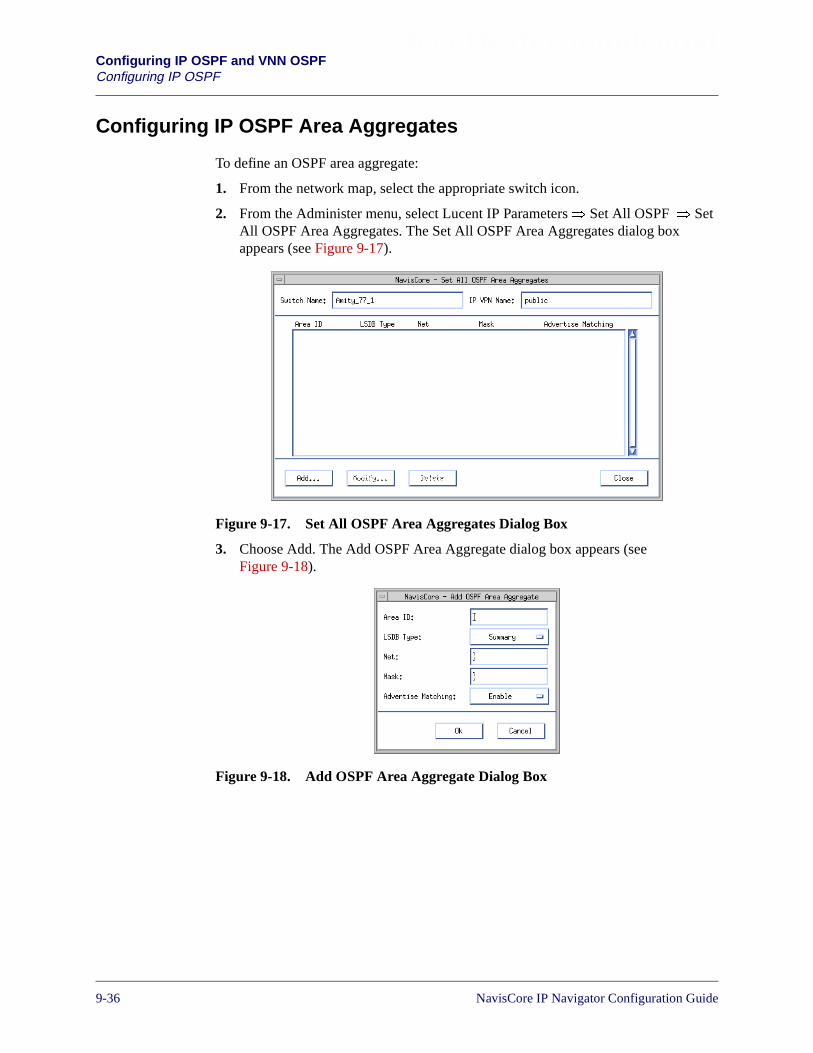
Beta Draft ConfidentialConfiguring IP OSPF and VNN OSPFConfiguring IP OSPF
Configuring IP OSPF Area Aggregates
To define an OSPF area aggregate:
1. From the network map, select the appropriate switch icon.
2. From the Administer menu, select Lucent IP Parameters� Set All OSPF � SetAll OSPF Area Aggregates. The Set All OSPF Area Aggregates dialog boxappears (see Figure 9-17).
Figure 9-17. Set All OSPF Area Aggregates Dialog Box
3. Choose Add. The Add OSPF Area Aggregate dialog box appears (seeFigure 9-18).
Figure 9-18. Add OSPF Area Aggregate Dialog Box
9-36 NavisCore IP Navigator Configuration Guide

Beta Draft ConfidentialConfiguring IP OSPF and VNN OSPF
Configuring IP OSPF
4. Complete the fields described in Table 9-5.
5. When you are done setting parameters, choose OK.
6. At the Set All OSPF Area Aggregates dialog box, choose Close.
Table 9-5. Add OSPF Area Aggregate Fields
Field Action/Description
Area ID Enter the area ID (x.x.x.x) in which you want to locate the node.Area 0.0.0.0 is the network backbone.
Areas are collections of networks, hosts, and routers. The area IDidentifies the area.
LSDB Type Specify the link state database type to which this addressaggregate applies.
Options include:
Summary – (default) Area border routers generate summary linkadvertisements, which describe inter-area routes (routes betweenareas) to networks.
NSSA External – Not So Stubby Area external (NSSA) linkadvertisements allow an AS border router within a stub area andthe routers within that area to learn about the external networksaccessible through the AS border router in the area.
Net Enter the IP address of the net or subnet, indicated by the range.
Mask Enter the subnet mask that pertains to the net or subnet.
Advertise Matching Select one of the following options:
Enable – (default) If you enable this parameter, you “leak” thenet/mask you specified for the given area.
Disable – If you disable this parameter, you hide the net/maskyou specified for the given area.
NavisCore IP Navigator Configuration Guide 1/14/029-37

Beta Draft ConfidentialConfiguring IP OSPF and VNN OSPFConfiguring IP OSPF
Configuring IP OSPF Virtual Links
To define an OSPF virtual link:
1. From the network map, select the appropriate switch icon.
2. From the Administer menu, select Lucent IP Parameters� Set All OSPF � SetAll OSPF Virtual Links. The Set All OSPF Virtual Links dialog box appears (seeFigure 9-19).
Figure 9-19. Set All OSPF Virtual Links Dialog Box
3. Choose Add. The Add OSPF Virtual Link dialog box appears (see Figure 9-20).
Figure 9-20. Add OSPF Virtual Link Dialog Box
9-38 NavisCore IP Navigator Configuration Guide

Beta Draft ConfidentialConfiguring IP OSPF and VNN OSPF
Configuring IP OSPF
4. Complete the fields described in Table 9-6.
Table 9-6. OSPF Virtual Link Fields
Field Action/Description
Area ID Enter the area ID (x.x.x.x) of the transit area, which is the non-backbone area that thevirtual link traverses to connect to the backbone area. This ID cannot be 0.0.0.0 (the AreaID of the backbone area).
Areas are collections of networks, hosts, and routers. The area ID identifies the area.
Neighbor(Router ID)
Enter the Router ID (internal IP address) of the switch (that is, the neighbor) on the otherend of the virtual link. The router ID is configured when the switch is installed. Todetermine the internal IP address, access the switch console and issue the show ipospf statistics command. In the command output, the internal IP addressappears in the OSPF Router ID field. For example:
OSPF Router ID: 150.202.77.2
Transit Delay Enter a value between 0 and 3600 (the default value is 1).
This field specifies the estimated number of seconds it takes to transmit a link-stateupdate packet over this interface.
Authentication Key Enter an authentication password in this field if you specify either Simple or MD5 as theauthentication type. This value is not required if you specify None as the authenticationtype.
AuthenticationType
Specify the type of authentication that OSPF uses as a security measure to ensure thatthis logical port and router exchange information with correct neighbors. Optionsinclude:
None – (default) Specifies that no authentication is performed.
Simple Password – Specifies a simple password authentication method that includes apassword in all OSPF messages on an interface-by-interface basis. When a routerreceives a message on an interface that uses simple password authentication, the routerchecks the incoming OSPF message to see if the password is included in the message. Ifthe password is correct, the message is processed normally. If the password is not part ofthe incoming message, the message is ignored and dropped.
MD5 – Use MD5 authentication to verify a key that is appended to the end of an IPOSPF protocol packet. For more information on how MD5 authentication works, seeRFC 1321 (The MD5 Message-Digest Algorithm). In addition to RFC 1321, RFC 2178(OSPF Version 2) provides information on how MD5 authentication is used with IPOSPF.
Interval
Retransmission Enter a value between 0 and 3600 (the default value is 5 seconds) This field specifies thetime to wait before resending a packet if no acknowledgment is received.
NavisCore IP Navigator Configuration Guide 1/14/029-39
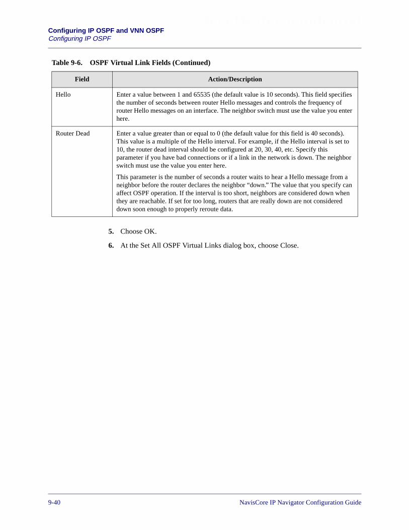
Beta Draft ConfidentialConfiguring IP OSPF and VNN OSPFConfiguring IP OSPF
5. Choose OK.
6. At the Set All OSPF Virtual Links dialog box, choose Close.
Hello Enter a value between 1 and 65535 (the default value is 10 seconds). This field specifiesthe number of seconds between router Hello messages and controls the frequency ofrouter Hello messages on an interface. The neighbor switch must use the value you enterhere.
Router Dead Enter a value greater than or equal to 0 (the default value for this field is 40 seconds).This value is a multiple of the Hello interval. For example, if the Hello interval is set to10, the router dead interval should be configured at 20, 30, 40, etc. Specify thisparameter if you have bad connections or if a link in the network is down. The neighborswitch must use the value you enter here.
This parameter is the number of seconds a router waits to hear a Hello message from aneighbor before the router declares the neighbor “down.” The value that you specify canaffect OSPF operation. If the interval is too short, neighbors are considered down whenthey are reachable. If set for too long, routers that are really down are not considereddown soon enough to properly reroute data.
Table 9-6. OSPF Virtual Link Fields (Continued)
Field Action/Description
9-40 NavisCore IP Navigator Configuration Guide
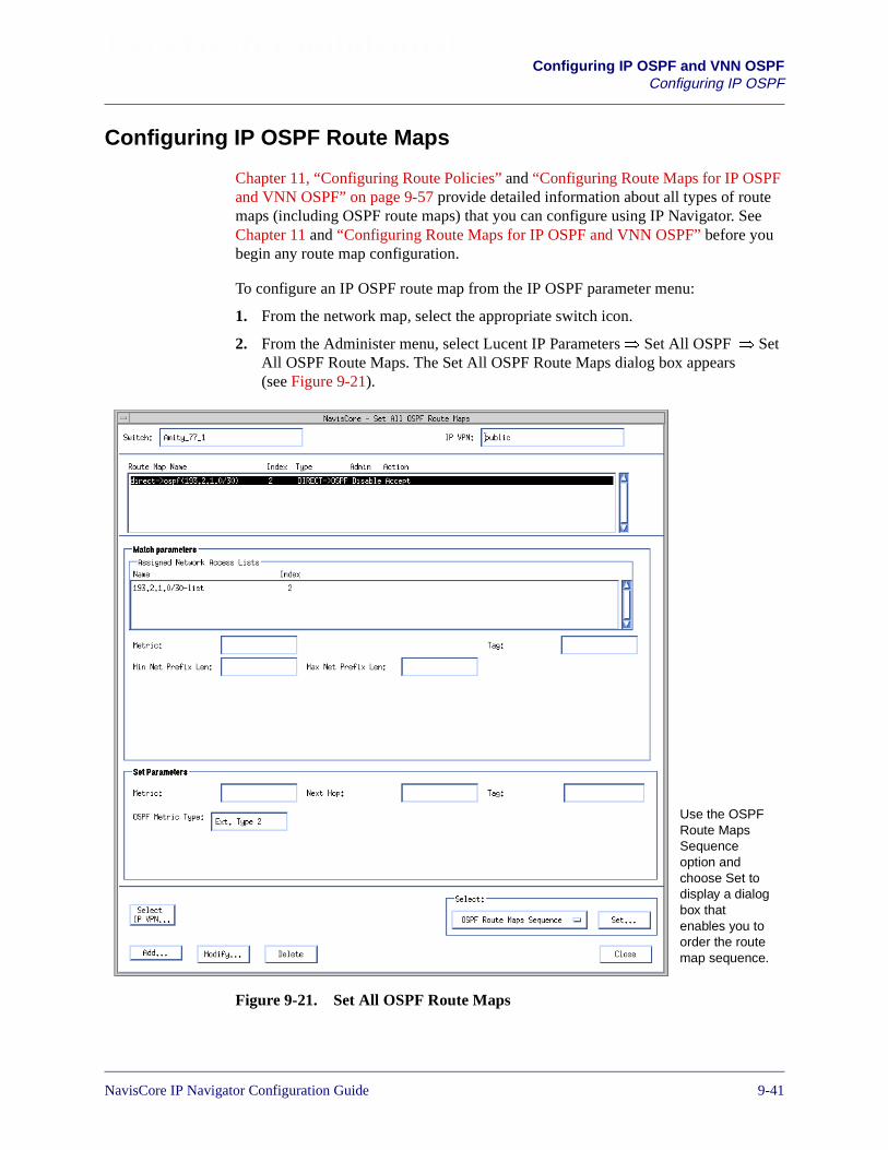
Beta Draft ConfidentialConfiguring IP OSPF and VNN OSPF
Configuring IP OSPF
Configuring IP OSPF Route Maps
Chapter 11, “Configuring Route Policies” and “Configuring Route Maps for IP OSPFand VNN OSPF” on page 9-57 provide detailed information about all types of routemaps (including OSPF route maps) that you can configure using IP Navigator. SeeChapter 11 and “Configuring Route Maps for IP OSPF and VNN OSPF” before youbegin any route map configuration.
To configure an IP OSPF route map from the IP OSPF parameter menu:
1. From the network map, select the appropriate switch icon.
2. From the Administer menu, select Lucent IP Parameters� Set All OSPF � SetAll OSPF Route Maps. The Set All OSPF Route Maps dialog box appears(see Figure 9-21).
Figure 9-21. Set All OSPF Route Maps
Use the OSPFRoute MapsSequenceoption andchoose Set todisplay a dialogbox thatenables you toorder the routemap sequence.
NavisCore IP Navigator Configuration Guide 1/14/029-41

Beta Draft ConfidentialConfiguring IP OSPF and VNN OSPFConfiguring IP OSPF
Configuring IP OSPF Router IDs
To configure the router ID for IP OSPF:
1. From the Administer menu, select Lucent IP Parameters� Set All OSPF� SetOSPF Router ID. The Set OSPF Router ID dialog box (see Figure 9-22) appears.
Figure 9-22. Set OSPF Router ID Dialog Box
2. Complete the following fields:
Admin State — Specify Enable (the default) to enable the router ID. SpecifyDisable to disable the router ID. If you specify Disable, IP Navigator will notfunction properly on the switch.
Router ID — Enter the router ID for the switch. This ID is a 32-bit IP address (forexample, 155.10.10.10) that uniquely identifies the switch within the AutonomousSystem (AS). The router ID can be the same as an IP address assigned to any ofthe switch’s IP interfaces. Consider using the smallest IP interface address as therouter ID.
3. Choose Apply when you are done.
Note that you can configure an IP OSPF router ID on an IP VPN-by-IP VPN basis.You can choose the Select IP VPN button to access a specific IP VPN. See Chapter 16,“Configuring IP Virtual Private Networks” for more information on managing IPVPNs.
Before you configure IP OSPF router IDs, make sure you read the section“Planning Router IDs” on page 9-22.
9-42 NavisCore IP Navigator Configuration Guide

Beta Draft ConfidentialConfiguring IP OSPF and VNN OSPF
Configuring IP OSPF
Configuring Multiple IP OSPF Authentication Keys
You can configure multiple authentication keys for an IP OSPF interface. You canthen activate these keys at different times, making it extremely difficult for networkintruders to compromise your security.
About Multiple Authentication Keys
Each authentication key has four time constants:
Start Accept — The date and time when the IP OSPF interface starts acceptingpackets with the given key.
Stop Accept — The date and time when the IP OSPF interface stops acceptingpackets with the given key.
Start Generate — The date and time when the IP OSPF interface starts to use the keyto generate packets.
Stop Generate — The date and time when the IP OSPF interface stops using the keyto generate packets.
For a given authentication key, the time constants should be synchronized as follows:
• The Start Accept date and time should be less than the Start Generate date andtime. This guarantees that the IP OSPF interface is ready to accept packets withthe given authentication key before they are generated.
• The Stop Generate date and time should be less than the Stop Accept date andtime. This guarantees that the generation of packets with the given authenticationkey stops before the IP OSPF interface is ready to reject them.
Make sure that the same time constant values are configured on all network nodes fora given authentication key. The Start Accept day and time you configure on one nodeshould be the same as the Start Accept day and time you configure on another node,and so on.
When a new authentication key replaces an old one, the Start Generate day and timefor the new key must be less than or equal to the Stop Generate day and time of the oldkey. This helps to avoid the creation of a window of time during which network trafficis interrupted. The interruption results from the following:
• Packets with the old key are not generated
• Packets with the new key are generated but not accepted
Figure 9-23 shows two authentication keys and their respective time constants thatspan a one-year period.
NavisCore IP Navigator Configuration Guide 1/14/029-43
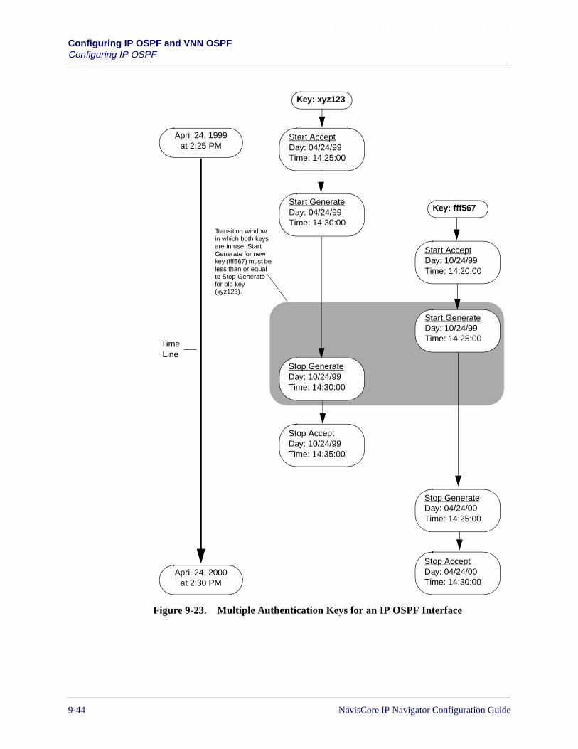
Beta Draft ConfidentialConfiguring IP OSPF and VNN OSPFConfiguring IP OSPF
Figure 9-23. Multiple Authentication Keys for an IP OSPF Interface
Start AcceptDay: 10/24/99Time: 14:20:00
Stop GenerateDay: 04/24/00Time: 14:25:00
April 24, 1999at 2:25 PM
April 24, 2000at 2:30 PM
Key: fff567
Stop AcceptDay: 10/24/99Time: 14:35:00
Start AcceptDay: 04/24/99Time: 14:25:00
Start GenerateDay: 04/24/99Time: 14:30:00
Stop AcceptDay: 04/24/00Time: 14:30:00
Key: xyz123
Stop GenerateDay: 10/24/99Time: 14:30:00
Start GenerateDay: 10/24/99Time: 14:25:00
TimeLine
Transition windowin which both keysare in use. StartGenerate for newkey (fff567) must beless than or equalto Stop Generatefor old key(xyz123).
9-44 NavisCore IP Navigator Configuration Guide

Beta Draft ConfidentialConfiguring IP OSPF and VNN OSPF
Configuring IP OSPF
Configuring Authentication Keys
Before you attempt to configure multiple authentication keys, make sure that you haveadded an OSPF interface and specified an Authentication Type of MD5 or SimplePassword.
To configure an authentication key:
1. From the network map, select the appropriate switch icon.
2. From the Administer menu, select Lucent IP Parameters� Set All IP LPorts. TheSet All IP LPorts dialog box appears (see Figure 3-2 on page 3-6).
3. Select the IP logical port associated with the OSPF interface for which you wantto configure MD5 authentication or simple password authentication.
4. Choose IP Parameters. The Set IP Parameters dialog box appears (see Figure 3-3on page 3-7).
5. Select IP Interface.
6. Choose Go. The Set IP Interface Addresses dialog box appears (see Figure 3-6 onpage 3-14).
7. Choose Modify OSPF. The Modify OSPF Interface dialog box appears (seeFigure 9-24).
Figure 9-24. Modify OSPF Interface Dialog Box
8. Choose Authentication Entries. The Set OSPF Authentication Entries dialog boxappears (see Figure 9-25).
NavisCore IP Navigator Configuration Guide 1/14/029-45

Beta Draft ConfidentialConfiguring IP OSPF and VNN OSPFConfiguring IP OSPF
Figure 9-25. Set OSPF Authentication Entries Dialog Box
The Set OSPF Authentication Entries dialog box displays all of the authenticationkeys you have configured for the OSPF interface, and their associated timeconstants. The fields on the dialog box are described in Table 9-8.
The buttons on the dialog box are described in Table 9-7.
9. Choose Add. The Add OSPF Authentication Entry dialog box appears (seeFigure 9-26).
Table 9-7. Set OSPF Authentication Entries Buttons
Button Function
Add Adds an authentication key entry.
Modify Modifies a selected authentication key.
Delete Deletes a selected authentication key.
9-46 NavisCore IP Navigator Configuration Guide

Beta Draft ConfidentialConfiguring IP OSPF and VNN OSPF
Configuring IP OSPF
Figure 9-26. Add OSPF Authentication Entry Dialog Box
10. Complete the fields in Table 9-8.
Table 9-8. Add OSPF Authentication Entry Fields
Field Action/Description
Authentication Key ID Specify a numeric authentication key ID, from 0 to 255. Each authenticationkey is identified by a unique ID. The default is 0.
Authentication Key Specify an alphanumeric string that will act as the authentication key. The stingcan be up to 16 characters long.
Authentication Key StartAccept Date
Specify the date and time that the OSPF interface accepts packets with thespecified key. The Start Accept date and time should be less than the StartGenerate date and time. This guarantees that the OSPF interface is ready toaccept packets with the given authentication key before they are generated.
Specify date and time as follows:
• Specify the day in the DD field. The default is 1 (the first day of the month).
• Specify the year in the YYYY field. You must specify all 4 digits of the year(for example, 2000). The default is 1970.
• Specify the hour, minute, and second on the specified date in the HH, MM,and SS fields respectively using military-style time (for example, 2:05 PM is14:05:00). The default for all of these fields in 0. If you leave these fieldsunchanged, the key goes into effect at midnight on the specified date.
NavisCore IP Navigator Configuration Guide 1/14/029-47
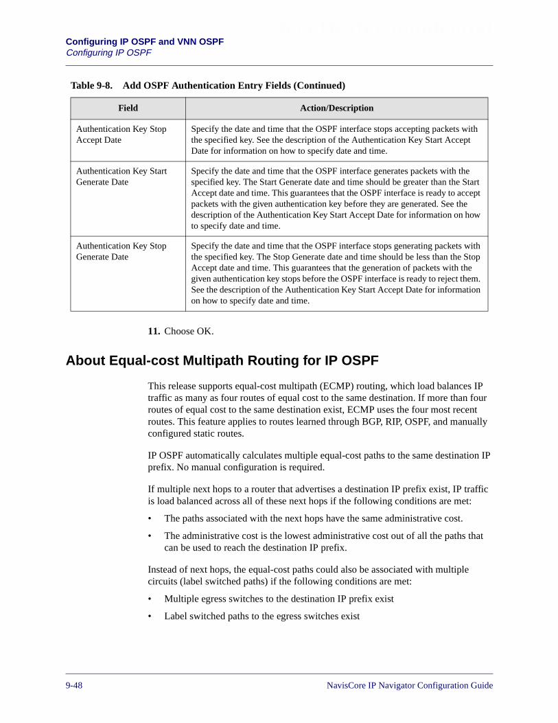
Beta Draft ConfidentialConfiguring IP OSPF and VNN OSPFConfiguring IP OSPF
11. Choose OK.
About Equal-cost Multipath Routing for IP OSPF
This release supports equal-cost multipath (ECMP) routing, which load balances IPtraffic as many as four routes of equal cost to the same destination. If more than fourroutes of equal cost to the same destination exist, ECMP uses the four most recentroutes. This feature applies to routes learned through BGP, RIP, OSPF, and manuallyconfigured static routes.
IP OSPF automatically calculates multiple equal-cost paths to the same destination IPprefix. No manual configuration is required.
If multiple next hops to a router that advertises a destination IP prefix exist, IP trafficis load balanced across all of these next hops if the following conditions are met:
• The paths associated with the next hops have the same administrative cost.
• The administrative cost is the lowest administrative cost out of all the paths thatcan be used to reach the destination IP prefix.
Instead of next hops, the equal-cost paths could also be associated with multiplecircuits (label switched paths) if the following conditions are met:
• Multiple egress switches to the destination IP prefix exist
• Label switched paths to the egress switches exist
Authentication Key StopAccept Date
Specify the date and time that the OSPF interface stops accepting packets withthe specified key. See the description of the Authentication Key Start AcceptDate for information on how to specify date and time.
Authentication Key StartGenerate Date
Specify the date and time that the OSPF interface generates packets with thespecified key. The Start Generate date and time should be greater than the StartAccept date and time. This guarantees that the OSPF interface is ready to acceptpackets with the given authentication key before they are generated. See thedescription of the Authentication Key Start Accept Date for information on howto specify date and time.
Authentication Key StopGenerate Date
Specify the date and time that the OSPF interface stops generating packets withthe specified key. The Stop Generate date and time should be less than the StopAccept date and time. This guarantees that the generation of packets with thegiven authentication key stops before the OSPF interface is ready to reject them.See the description of the Authentication Key Start Accept Date for informationon how to specify date and time.
Table 9-8. Add OSPF Authentication Entry Fields (Continued)
Field Action/Description
9-48 NavisCore IP Navigator Configuration Guide

Beta Draft ConfidentialConfiguring IP OSPF and VNN OSPF
Configuring VNN OSPF
Configuring VNN OSPF
This section describes how to configure loopback addresses, area aggregates, andvirtual links for VNN OSPF.
Configuring VNN Loopback Addresses
To configure loopback addresses for VNN:
1. From the Administer menu, select Lucent Parameters� Set All VNN� Set AllVNN Loopbacks. The Set All VNN Loopback Addresses dialog box (seeFigure 9-27) appears.
Figure 9-27. Set All VNN Loopback Addresses Dialog Box
2. Choose Add. The Add VNN Loopback Address dialog box (see Figure 9-28)appears.
Figure 9-28. Add VNN Loopback Address Dialog Box
3. Enter the loopback IP address (for example, 152.148.30.5).
4. Enter the Area ID (for example, 0.0.0.2).
5. Choose OK. The Set All VNN Loopback Addresses dialog box appears,displaying the new loopback address.
NavisCore IP Navigator Configuration Guide 1/14/029-49

Beta Draft ConfidentialConfiguring IP OSPF and VNN OSPFConfiguring VNN OSPF
Configuring VNN Area Aggregates
To configure area aggregates for VNN:
1. From the Administer menu, select Lucent Parameters� Set All VNN� Set AllVNN Area Aggregates. The Set All VNN Area Aggregates dialog box (seeFigure 9-29) appears.
Figure 9-29. Set All VNN Area Aggregates Dialog Box
2. Choose Add. The Add VNN Area Aggregate dialog box (see Figure 9-30)appears.
Figure 9-30. Add VNN Area Aggregate Dialog Box
9-50 NavisCore IP Navigator Configuration Guide
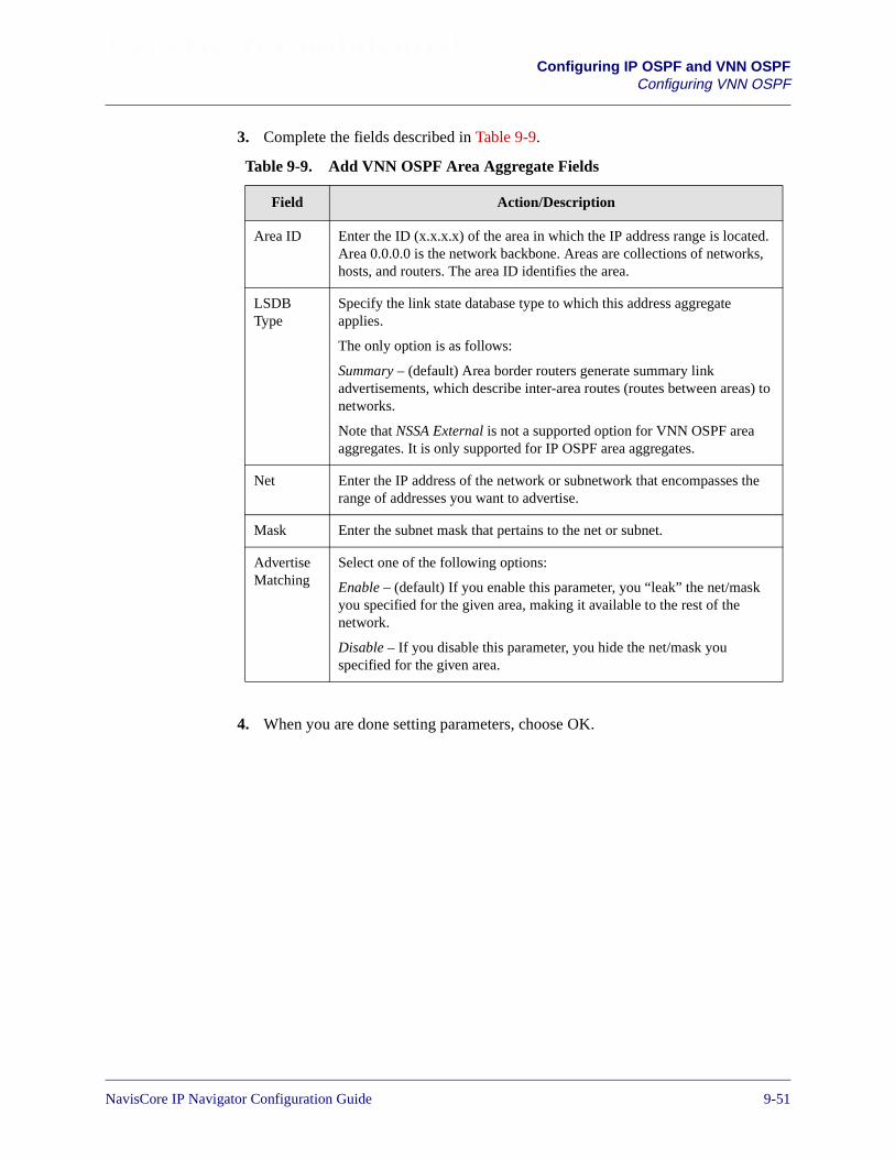
Beta Draft ConfidentialConfiguring IP OSPF and VNN OSPF
Configuring VNN OSPF
3. Complete the fields described in Table 9-9.
4. When you are done setting parameters, choose OK.
Table 9-9. Add VNN OSPF Area Aggregate Fields
Field Action/Description
Area ID Enter the ID (x.x.x.x) of the area in which the IP address range is located.Area 0.0.0.0 is the network backbone. Areas are collections of networks,hosts, and routers. The area ID identifies the area.
LSDBType
Specify the link state database type to which this address aggregateapplies.
The only option is as follows:
Summary – (default) Area border routers generate summary linkadvertisements, which describe inter-area routes (routes between areas) tonetworks.
Note that NSSA External is not a supported option for VNN OSPF areaaggregates. It is only supported for IP OSPF area aggregates.
Net Enter the IP address of the network or subnetwork that encompasses therange of addresses you want to advertise.
Mask Enter the subnet mask that pertains to the net or subnet.
AdvertiseMatching
Select one of the following options:
Enable – (default) If you enable this parameter, you “leak” the net/maskyou specified for the given area, making it available to the rest of thenetwork.
Disable – If you disable this parameter, you hide the net/mask youspecified for the given area.
NavisCore IP Navigator Configuration Guide 1/14/029-51

Beta Draft ConfidentialConfiguring IP OSPF and VNN OSPFConfiguring VNN OSPF
Configuring VNN Virtual Links
To configure virtual links for VNN:
1. From the Administer menu, select Lucent Parameters� Set All VNN� Set AllVNN Virtual Links. The Set All VNN Virtual Links dialog box (see Figure 9-31)appears.
Figure 9-31. Set All VNN Virtual Links Dialog Box
2. Choose Add. The Add VNN Virtual Link dialog box appears (see Figure 9-32).
Figure 9-32. Add VNN Virtual Link Dialog Box
9-52 NavisCore IP Navigator Configuration Guide
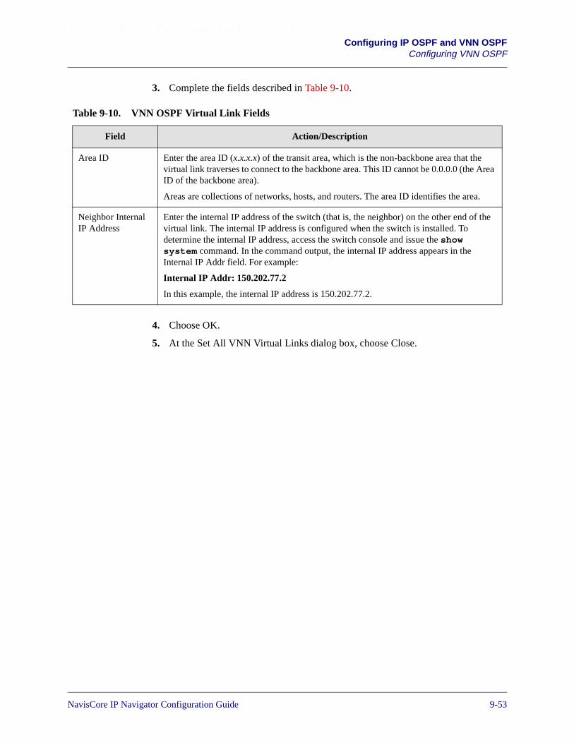
Beta Draft ConfidentialConfiguring IP OSPF and VNN OSPF
Configuring VNN OSPF
3. Complete the fields described in Table 9-10.
4. Choose OK.
5. At the Set All VNN Virtual Links dialog box, choose Close.
Table 9-10. VNN OSPF Virtual Link Fields
Field Action/Description
Area ID Enter the area ID (x.x.x.x) of the transit area, which is the non-backbone area that thevirtual link traverses to connect to the backbone area. This ID cannot be 0.0.0.0 (the AreaID of the backbone area).
Areas are collections of networks, hosts, and routers. The area ID identifies the area.
Neighbor InternalIP Address
Enter the internal IP address of the switch (that is, the neighbor) on the other end of thevirtual link. The internal IP address is configured when the switch is installed. Todetermine the internal IP address, access the switch console and issue the showsystem command. In the command output, the internal IP address appears in theInternal IP Addr field. For example:
Internal IP Addr: 150.202.77.2
In this example, the internal IP address is 150.202.77.2.
NavisCore IP Navigator Configuration Guide 1/14/029-53

Beta Draft ConfidentialConfiguring IP OSPF and VNN OSPFConfiguring Multiple IP OSPF and VNN OSPF Areas
Configuring Multiple IP OSPF and VNN OSPF Areas
Configuring multiple IP OSPF areas and VNN OSPF areas consists of the followingprocedures:
• OSPF Area Configuration
• Virtual Link Configuration
• Address Aggregation
See “Steps for Configuring Multiple OSPF Areas” on page 9-54 for more informationabout each of these procedures.
Steps for Configuring Multiple OSPF Areas
The following sections outline each of the steps for OSPF Area configuration.
Prerequisites for Multiple OSPF Areas
To configure multiple IP OSPF areas, the IP logical ports and associated IP interfacesmust be defined. See “Configuring IP Logical Ports” on page 3-5 for details. Toconfigure multiple VNN OSPF areas, no special prerequisites must be met.
Configuration Recommendations
Be aware of the following recommendations when configuring multiple IP OSPFareas or multiple VNN OSPF areas:
• Do not make areas too small.
– Area boundaries may be difficult to configure, and can cause sub-optimalrouting for both IP and circuits.
– If every switch is an area border router, there will be no improvements to theroute scaling.
• Plan ahead when assigning areas. Modification of the trunk Area ID is aservice-affecting procedure that causes the trunk to bounce.
• Do not unnecessarily aggregate IP addresses. Modifying switch IP addresses istime-consuming and should not be done for the sole purpose of aggregation.
Area 0 is the OSPF backbone area. Areas do not have to be physically attachedto the backbone. Instead, virtual links can be configured to logically attach anarea to the backbone.
Every area border router must be connected to the backbone area. You use area 0trunks or configured virtual links to connect each area border router to thebackbone area.
9-54 NavisCore IP Navigator Configuration Guide
Beta Draft ConfidentialConfiguring IP OSPF and VNN OSPF
Configuring Multiple IP OSPF and VNN OSPF Areas
IP OSPF Area Configuration
To configure multiple IP OSPF areas:
1. Set the IP OSPF Area ID of all trunks. From the Administer menu, select LucentParameters� Set All Trunks. The NMS displays the NavisCore Set All Trunksdialog box. See “Configuring Trunks for IP OSPF and VNN OSPF” on page 9-25for more information.
2. Set the Area ID of the IP logical ports:
a. From the Administer menu, select Lucent IP Parameters� Set All IP LPorts.The Set All IP LPorts dialog box appears.
b. Choose IP Parameters. The Set IP Parameters dialog box appears.
c. Choose IP Interface. The Set IP Interface Addresses dialog box appears.
d. Choose Add OSPF. The Add OSPF Interface dialog box appears. See“Configuring IP OSPF on the IP Logical Port” on page 9-30 for moreinformation about how to complete this dialog box.
3. Set the Area ID of the loopback addresses. From the Administer menu, selectLucent IP Parameters� Set All IP Loopback Addresses. The Set All IPLoopback Addresses dialog box appears. See “Configuring IP LoopbackAddresses” on page 8-31 for more information.
VNN OSPF Area Configuration
To configure multiple VNN OSPF areas:
1. Set the VNN OSPF Area ID of all trunks. From the Administer menu, selectLucent Parameters� Set All Trunks. The NMS displays the NavisCore Set AllTrunks dialog box. See “Configuring Trunks for IP OSPF and VNN OSPF” onpage 9-25 for more information.
2. Set the Area ID of the Network Service Access Points (NSAPs). From theAdminister menu, select Lucent Parameters� Set All SVC Parameters� Set AllNode Prefixes. The Set All Node Prefixes dialog box appears. See the NavisCoreFrame Relay Configuration Guide or the NavisCore ATM Configuration Guidefor more information.
3. Set the Area ID of the loopback addresses. From the Administer menu, selectLucent Parameters� Set All VNN� Set All VNN Loopbacks. See “ConfiguringVNN Loopback Addresses” on page 9-49 for more information.
The Area ID of the switch IP address is set automatically to one of the following:
– Area 1, if it exists.
– If Area 1 does not exist, the Area ID is set to the ID of the switch with thelowest Area ID.
NavisCore IP Navigator Configuration Guide 1/14/029-55
Beta Draft ConfidentialConfiguring IP OSPF and VNN OSPFConfiguring Multiple IP OSPF and VNN OSPF Areas
Virtual Link Configuration
Areas do not have to be physically attached to the backbone. Instead, you canconfigure virtual links to logically attach an area to the backbone. Before you canconfigure a virtual link, you must know:
• The non-backbone transit area for the virtual link.
• The router IDs for the two endpoint switches. (The router ID of each switchendpoint is the same value as the switch ID).
In addition, you must ensure that both switches have IP addresses in the transit area.Add loopback addresses if necessary.
To add virtual links for IP OSPF and VNN OSPF, see the following sections:
• “Configuring IP OSPF Virtual Links” on page 9-38
• “Configuring VNN Virtual Links” on page 9-52
Address Aggregation
Aggregation is the process of advertising a single address prefix (rather thanadvertising multiple, more specific prefixes). Addresses can be aggregated at areaborders. This practice further improves route scaling by reducing the size of thelink-state database and the routing table.
You configure aggregates in the area border router.
VNN OSPF Address Aggregation
You can configure VNN OSPF area aggregates. See “Configuring VNN AreaAggregates” on page 9-50 for more information.
You can also configure an aggregate for an NSAP. From the Administer menu, selectLucent Parameters� Set All SVC Parameters� Set All Node Prefixes. The Set AllNode Prefixes dialog box appears. See the NavisCore Frame Relay ConfigurationGuide and the NavisCore ATM Configuration Guide for more information.
IP OSPF Address Aggregation
You can configure IP OSPF area aggregates. See “Configuring IP OSPF AreaAggregates” on page 9-36 for more information.
9-56 NavisCore IP Navigator Configuration Guide

Beta Draft ConfidentialConfiguring IP OSPF and VNN OSPF
Configuring Route Maps for IP OSPF and VNN OSPF
Configuring Route Maps for IP OSPF and VNN OSPF
Because of the separation of VNN OSPF and IP OSPF, you can now use VNN OSPFas a route map source and destination. For example, you can configure a route map toadvertise management routes (which are learned through VNN OSPF) to BGP, RIP, orIP OSPF.
As a source, VNN OSPF can be used in the following combinations:
• VNN� BGP
• VNN� RIP
• VNN� OSPF
As a destination, VNN OSPF can be used in the following combinations:
• BGP� VNN
• RIP� VNN
• OSPF� VNN
• Static� VNN
• Direct� VNN
• Any� VNN
• Aggregate� VNN
For more information on configuring route maps, see Chapter 11, “Configuring RoutePolicies.”
VNN OSPF is identified as “VNN” in the route map dialog boxes, and IP OSPFis identified as “OSPF.”
NavisCore IP Navigator Configuration Guide 1/14/029-57

Beta Draft ConfidentialConfiguring IP OSPF and VNN OSPFConfiguring Route Maps for IP OSPF and VNN OSPF
9-58 NavisCore IP Navigator Configuration Guide

NavisCore IP Navigator Configuration Guide
Beta Draft Confidential
10
Configuring Static Routes
This chapter describes how to configure static routes.
About Static Routes
You configure static routes manually only if they are reachable. Static routes do notdisappear from the IP routing table and will always be advertised. However, staticroutes do not respond to network topology changes. The only way a static route canchange is if the network administrator changes them. In addition, static routes provideredundancy if a primary connection fails.
10-1
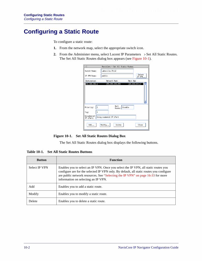
Beta Draft ConfidentialConfiguring Static RoutesConfiguring a Static Route
Configuring a Static Route
To configure a static route:
1. From the network map, select the appropriate switch icon.
2. From the Administer menu, select Lucent IP Parameters� Set All Static Routes.The Set All Static Routes dialog box appears (see Figure 10-1).
Figure 10-1. Set All Static Routes Dialog Box
The Set All Static Routes dialog box displays the following buttons.
Table 10-1. Set All Static Routes Buttons
Button Function
Select IP VPN Enables you to select an IP VPN. Once you select the IP VPN, all static routes youconfigure are for the selected IP VPN only. By default, all static routes you configureare public network resources. See “Selecting the IP VPN” on page 16-33 for moreinformation on selecting an IP VPN.
Add Enables you to add a static route.
Modify Enables you to modify a static route.
Delete Enables you to delete a static route.
10-2 NavisCore IP Navigator Configuration Guide
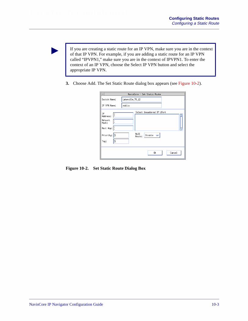
Beta Draft ConfidentialConfiguring Static Routes
Configuring a Static Route
3. Choose Add. The Set Static Route dialog box appears (see Figure 10-2).
Figure 10-2. Set Static Route Dialog Box
If you are creating a static route for an IP VPN, make sure you are in the contextof that IP VPN. For example, if you are adding a static route for an IP VPNcalled “IPVPN1,” make sure you are in the context of IPVPN1. To enter thecontext of an IP VPN, choose the Select IP VPN button and select theappropriate IP VPN.
NavisCore IP Navigator Configuration Guide 1/14/0210-3

Beta Draft ConfidentialConfiguring Static RoutesConfiguring a Static Route
4. Complete the fields described in Table 10-2.
5. Choose OK.
6. At the Static Route dialog box, choose Close.
Table 10-2. Static Route Fields
Field Description
IP Address Enter the IP address of the destination network.
Network Mask Enter the network mask.
Next Hop Enter the IP address of the next hop.
The next hop field is disabled if you:
– Selected an unnumbered IP logical port (see “Select Unnumbered IPLPort”), or
– Enabled null route (see “Null Route”)
Priority Enter a value from 1 to 20 to specify the static route priority. The highestnumber is the preferred priority. The priority of the static route is in relationto other route protocols.
If you assign equal priority to multiple static routes to the same destination,IP traffic is load balanced across those routes. (This is called equal-costmultipath routing.) Keep in mind that routes with a higher priority will stilltake precedence over routes with a lower priority. If you want to always loadbalance traffic across multiple static routes to a given destination, do thefollowing:
– Assign these routes the same priority.
– Make sure that routes with a higher priority do not exist.
Tag Enter the tag value, which you use to group multiple static route entriestogether.
Null Route Select one of the following:
Enable – If you enable this parameter, packets destined for this network willbe discarded. In addition, the next hop is disabled.
Disable – If you disable this parameter, packets destined for this network willbe forwarded.
Select Unnumbered IP LPort Select an unnumbered IP logical port to set up a static route to an IP interfacethat is not part of a subnet and does not have a specific address. Instead, theunnumbered IP logical port uses the router ID as its address.
10-4 NavisCore IP Navigator Configuration Guide

NavisCore IP Navigator Configuration Guide
Beta Draft Confidential
11
Configuring Route Policies
This chapter describes the following configuration tasks:
• Adding a Network Filter
• Adding a Network Access List
• Adding a Route Map
You perform these tasks in order to set route policies for your network. These policiescontrol the flow of routing information.
The route map provides the primary mechanism for setting route policies. Thepurpose of a route map is to control and modify routing information and to define theparameters that your system uses to redistribute routes between routing domains.Route maps are used to alter route parameters that are then stored in the routing table,or sent via routing updates to other routers.
You can optionally define the following components for use in a route map:
• Network filters
• Network access lists
After you define the route map, you must assign it to a neighbor (in the case of BGP orRIP). If you have multiple route maps for the same neighbor, you can specify the orderin which IP Navigator uses these maps.
The following sections define the concepts for using network filters, network accesslists, and route maps. In addition, these sections describe how to use route maps toredistribute routes between routing domains.
11-1
Beta Draft ConfidentialConfiguring Route PoliciesAbout Network Filters
About Network Filters
Network filters control the flow of route distribution. You can use a network filter toselect routes that will be accepted or rejected by route maps. The specified filters mustbe used in a network access list and then applied to route maps.
When you create a network filter, you specify the following information:
• A network address
• A network mask value
• Coverage (inclusive or exact)
The network address and network mask value identify the route. The coveragespecifies the type of access. Inclusive filters allow access to all networks that matchthe specified network address (including addresses that may be more specific such asa subnetwork address). Exact filters allow access only to the network that is specifiedin the network address.
About Access Lists
A network filter access list is an object that contains a set of unique network filters. Upto 300 network filters can be included in an access list.
You can create an empty network access list and later add defined network filters tothe list. You use network access lists to logically group network filters.
A network filter is an optional component of a route map; however, if you wantto use one or more network filters, you must include the filter in an access listand then include the access list in a route map. The route map must then beassigned to the appropriate neighbor or interface. A network filter by itselfcannot be applied to a route map, neighbor, or interface.
A network access list is an optional component of a route map; however, if youwant to use one or more network access lists, you must include the list in a routemap and then assign the map to the appropriate neighbor or interface. A networkaccess list by itself cannot be applied to a neighbor or interface.
11-2 NavisCore IP Navigator Configuration Guide

Beta Draft ConfidentialConfiguring Route Policies
About Route Maps
About Route Maps
Route maps enable you to specify the direction of route traffic based on the source ofthe traffic or a combination of both the traffic source and destination. You can enableor disable a route map as required by setting the Admin Status value for the route map.
When you create a route map, you specify two routing protocols: a From Protocol anda To Protocol. The route map specifies how routes are redistributed from one routingprotocol to another. This is done between two different protocols as well as within thesame protocol (for example, from BGP to BGP). The route maps are also used toselectively accept routes from a particular routing protocol into the router’s mainrouting table.
In addition, you can optionally specify the following values as route map match or setparameters:
• Metric value
• Tag value
• Next hop address
• Autonomous System path values (BGP only)
• Community values (BGP only)
• OSPF route type
NavisCore IP Navigator Configuration Guide 1/14/0211-3
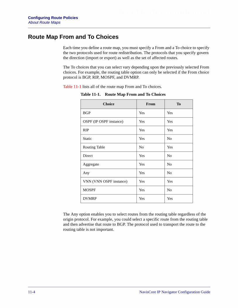
Beta Draft ConfidentialConfiguring Route PoliciesAbout Route Maps
Route Map From and To Choices
Each time you define a route map, you must specify a From and a To choice to specifythe two protocols used for route redistribution. The protocols that you specify governthe direction (import or export) as well as the set of affected routes.
The To choices that you can select vary depending upon the previously selected Fromchoices. For example, the routing table option can only be selected if the From choiceprotocol is BGP, RIP, MOSPF, and DVMRP.
Table 11-1 lists all of the route map From and To choices.
The Any option enables you to select routes from the routing table regardless of theorigin protocol. For example, you could select a specific route from the routing tableand then advertise that route to BGP. The protocol used to transport the route to therouting table is not important.
Table 11-1. Route Map From and To Choices
Choice From To
BGP Yes Yes
OSPF (IP OSPF instance) Yes Yes
RIP Yes Yes
Static Yes No
Routing Table No Yes
Direct Yes No
Aggregate Yes No
Any Yes No
VNN (VNN OSPF instance) Yes Yes
MOSPF Yes No
DVMRP Yes Yes
11-4 NavisCore IP Navigator Configuration Guide

Beta Draft ConfidentialConfiguring Route Policies
About Route Maps
Determining if a Route Map is for Import or Export
The protocol that you select for the To choice specifies whether a map is an import orexport map as follows:
• Route maps that use a To choice of BGP, OSPF, or RIP are automatically createdas export route maps.
• Route maps that use a To choice of Routing Table are created as import routemaps.
• All route selections for a route map that uses a To choice of “Routing Table” areperformed before IP Navigator adds the routes to the routing table.
Figure 11-1. Using Route Maps to Filter Routes
9000 Switch
Route maps are applied toa neighbor or interfaceand can filter routescoming into or out of therouting table.
Neighbor
RoutingTable
Neighbor
MA
P
NavisCore IP Navigator Configuration Guide 1/14/0211-5
Beta Draft ConfidentialConfiguring Route PoliciesRoute Map Guidelines
Route Map Guidelines
Route maps are required if you want to accomplish any of the following tasks:
• Route filtering
• Route redistribution
• Altering route parameters such as metric, next hop, tag, and BGP path attributes.
See Figure 11-2 and the sections that follow for a description of the guidelines forroute map use.
When are Route Maps Not Used?
You cannot use a route map to specify a routing policy for the following pairs:
OSPF to Routing Table — IP Navigator always adds IP OSPF routes to therouting table. For this reason, you cannot use a route map to determine theacceptance or rejection of specific routes between IP OSPF and the routing table.
VNN to Routing Table — IP Navigator always adds VNN OSPF routes to therouting table. For this reason, you cannot use a route map to determine theacceptance or rejection of specific routes between VNN OSPF and the routingtable.
OSPF to OSPF — IP Navigator always advertises IP OSPF routes to the IP OSPFrouting domain. Link state protocols assume that all routes share the sameinformation. For this reason, you cannot use a route map to determine theacceptance or rejection of specific routes being sent to an IP OSPF neighbor.
VNN to VNN — IP Navigator always advertises VNN OSPF routes to the VNNOSPF routing domain. Link state protocols assume that all routes share the sameinformation. For this reason, you cannot use a route map to determine theacceptance or rejection of specific routes being sent to a VNN OSPF neighbor.
11-6 NavisCore IP Navigator Configuration Guide
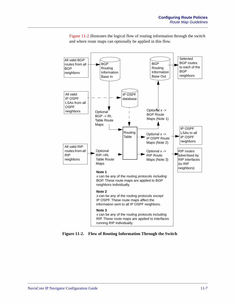
Beta Draft ConfidentialConfiguring Route Policies
Route Map Guidelines
Figure 11-2 illustrates the logical flow of routing information through the switchand where route maps can optionally be applied in this flow.
Figure 11-2. Flow of Routing Information Through the Switch
Optional x ->BGP RouteMaps (Note 1)
Note 1x can be any of the routing protocols includingBGP. These route maps are applied to BGPneighbors individually.
Note 2x can be any of the routing protocols exceptIP OSPF. These route maps affect theinformation sent to all IP OSPF neighbors.
Note 3x can be any of the routing protocols includingRIP. These route maps are applied to interfacesrunning RIP individually.
SelectedBGP routesto each of theBGPneighbors
All valid BGProutes from allBGPneighbors
All validIP OSPFLSAs from allOSPFneighbors
IP OSPFLSAs to allIP OSPFneighbors
RIP routesadvertised byRIP interfaces(to RIPneighbors)
All valid RIProutes from allRIPneighbors
OptionalRIP->Rt.Table RouteMaps
Optional x ->RIP RouteMaps (Note 3)
Optional x ->IP OSPF RouteMaps (Note 2)
BGPRoutingInformationBase Out
BGPRoutingInformationBase In
OptionalBGP -> Rt.Table RouteMaps
IP OSPFdatabase
RoutingTable
NavisCore IP Navigator Configuration Guide 1/14/0211-7
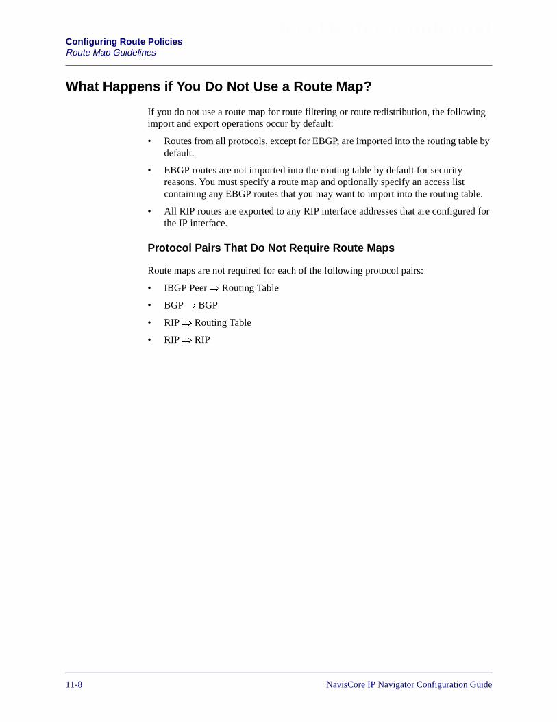
Beta Draft ConfidentialConfiguring Route PoliciesRoute Map Guidelines
What Happens if You Do Not Use a Route Map?
If you do not use a route map for route filtering or route redistribution, the followingimport and export operations occur by default:
• Routes from all protocols, except for EBGP, are imported into the routing table bydefault.
• EBGP routes are not imported into the routing table by default for securityreasons. You must specify a route map and optionally specify an access listcontaining any EBGP routes that you may want to import into the routing table.
• All RIP routes are exported to any RIP interface addresses that are configured forthe IP interface.
Protocol Pairs That Do Not Require Route Maps
Route maps are not required for each of the following protocol pairs:
• IBGP Peer� Routing Table
• BGP� BGP
• RIP� Routing Table
• RIP� RIP
11-8 NavisCore IP Navigator Configuration Guide

Beta Draft ConfidentialConfiguring Route Policies
Route Map Guidelines
Protocol Pairs That Require Route Maps
Route maps are required for each of the following protocol pairs:
Table 11-2. Protocol Pair Route Map Requirements
Protocol Pair Description
Static� OSPFDirect� OSPFBGP� OSPFRIP� OSPFVNN� OSPF
Route maps are required to advertise any Static, Direct, BGP, RIP, and VNNOSPF routes into the IP OSPF routing domain. By default, IP Navigator doesnot advertise Static, direct, BGP, RIP, or VNN OSPF routes into the IP OSPFrouting domain.
Note: Switches perform some automatic route leaking for you between VNNOSPF and IP OSPF. For example, in a Lucent network, when some switches areupgraded to support separate OSPF network views for VNN and IP Navigator,and other switches are not upgraded, routes are automatically leaked as follows:
• Routes learned by IP OSPF are leaked into VNN OSPF.
• Non-management routes learned by VNN OSPF are leaked into IP OSPF.Management routes remain hidden from IP OSPF.
Static� VNNDirect� VNNBGP� VNNRIP� VNNOSPF� VNN
Route maps are required in order to advertise any Static, Direct, BGP, RIP, andIP OSPF routes into the VNN OSPF routing domain. By default, IP Navigatordoes not advertise Static, direct, BGP, RIP, or IP OSPF routes into the VNNOSPF routing domain.
Note: Switches perform some automatic route leaking for you between VNNOSPF and IP OSPF. For example, in a Lucent network, when some switches areupgraded to support separate OSPF network views for VNN and IP Navigator,and other switches are not upgraded, routes are automatically leaked as follows:
• Routes learned by IP OSPF are leaked into VNN OSPF.
• Non-management routes learned by VNN OSPF are leaked into IP OSPF.Management routes remain hidden from IP OSPF.
Static� RIPDirect� RIPBGP� RIPOSPF� RIPVNN� RIP
Route maps are required to advertise any Static, Direct, BGP, VNN OSPF, andIP OSPF routes into the RIP routing domain. By default, IP Navigator does notadvertise Static, Direct, BGP, VNN OSPF, and IP OSPF routes into the RIProuting domain.
Static� BGPDirect� BGPOSPF� BGPRIP� BGPVNN� BGP
Route maps are required to advertise any Static, Direct, BGP, RIP, and OSPFroutes into the BGP routing domain. By default, IP Navigator does not advertiseStatic, Direct, BGP, RIP, VNN OSPF, and IP OSPF routes into the BGP routingdomain.
MOSPF� DVMRP Route maps are required to export any routes learned by MOSPF into theDVMRP routing domain.
NavisCore IP Navigator Configuration Guide 1/14/0211-9
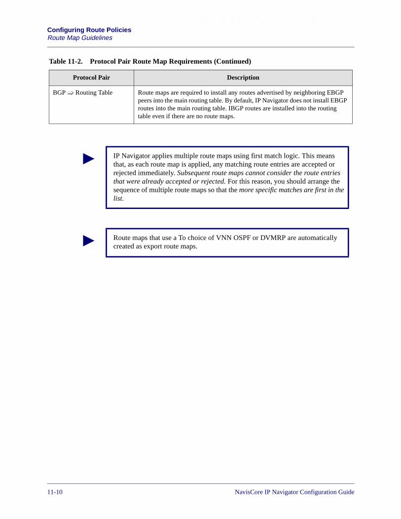
Beta Draft ConfidentialConfiguring Route PoliciesRoute Map Guidelines
BGP� Routing Table Route maps are required to install any routes advertised by neighboring EBGPpeers into the main routing table. By default, IP Navigator does not install EBGProutes into the main routing table. IBGP routes are installed into the routingtable even if there are no route maps.
Table 11-2. Protocol Pair Route Map Requirements (Continued)
Protocol Pair Description
IP Navigator applies multiple route maps using first match logic. This meansthat, as each route map is applied, any matching route entries are accepted orrejected immediately. Subsequent route maps cannot consider the route entriesthat were already accepted or rejected. For this reason, you should arrange thesequence of multiple route maps so that the more specific matches are first in thelist.
Route maps that use a To choice of VNN OSPF or DVMRP are automaticallycreated as export route maps.
11-10 NavisCore IP Navigator Configuration Guide

Beta Draft ConfidentialConfiguring Route Policies
Steps For Configuring a Route Map
Steps For Configuring a Route Map
To configure a route map, use the following steps:
1. (Optional) Define the network filters depending on your system’s needs. See“Adding a Network Filter” on page 11-13 for more information.
2. (Optional) Use the defined network filters to create the network access lists. See“Adding a Network Access List” on page 11-15 for more information.
3. Specify the routing policies that define the match parameters to be used to filterroutes and the set parameters for all selected routes. See “Adding Route Maps” onpage 11-18 for more information.
4. Assign the route map to a BGP neighbor or a RIP interface. You assign route mapsto BGP interfaces using the Add BGP Neighbor dialog box or the Modify BGPNeighbor dialog box. See Chapter 8, “Configuring BGP Parameters” for moreinformation about accessing the BGP functions. You assign route maps to RIPinterfaces using the Add RIP Interface dialog box or the Modify RIP Interfacedialog box. See Chapter 7, “Configuring RIP” for more information aboutaccessing the RIP functions.
5. If you have multiple route maps, use the arrow buttons (see Figure 11-3) on theAdd/Modify BGP Neighbor and Add/Modify RIP Interface dialog boxes tospecify the order in which IP Navigator uses the assigned route maps. Route mapsfilter routes on the interface in the order in which they are specified on thesedialog boxes. Route maps should be ordered from most specific to least specific.
Route maps that have a To protocol of OSPF are global and for this reason do notneed to be assigned to an OSPF interface. IP Navigator uses this type of routemap as soon as you create the map.
NavisCore IP Navigator Configuration Guide 1/14/0211-11
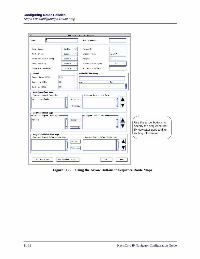
Beta Draft ConfidentialConfiguring Route PoliciesSteps For Configuring a Route Map
Figure 11-3. Using the Arrow Buttons to Sequence Route Maps
Use the arrow buttons tospecify the sequence thatIP Navigator uses to filterrouting information.
11-12 NavisCore IP Navigator Configuration Guide
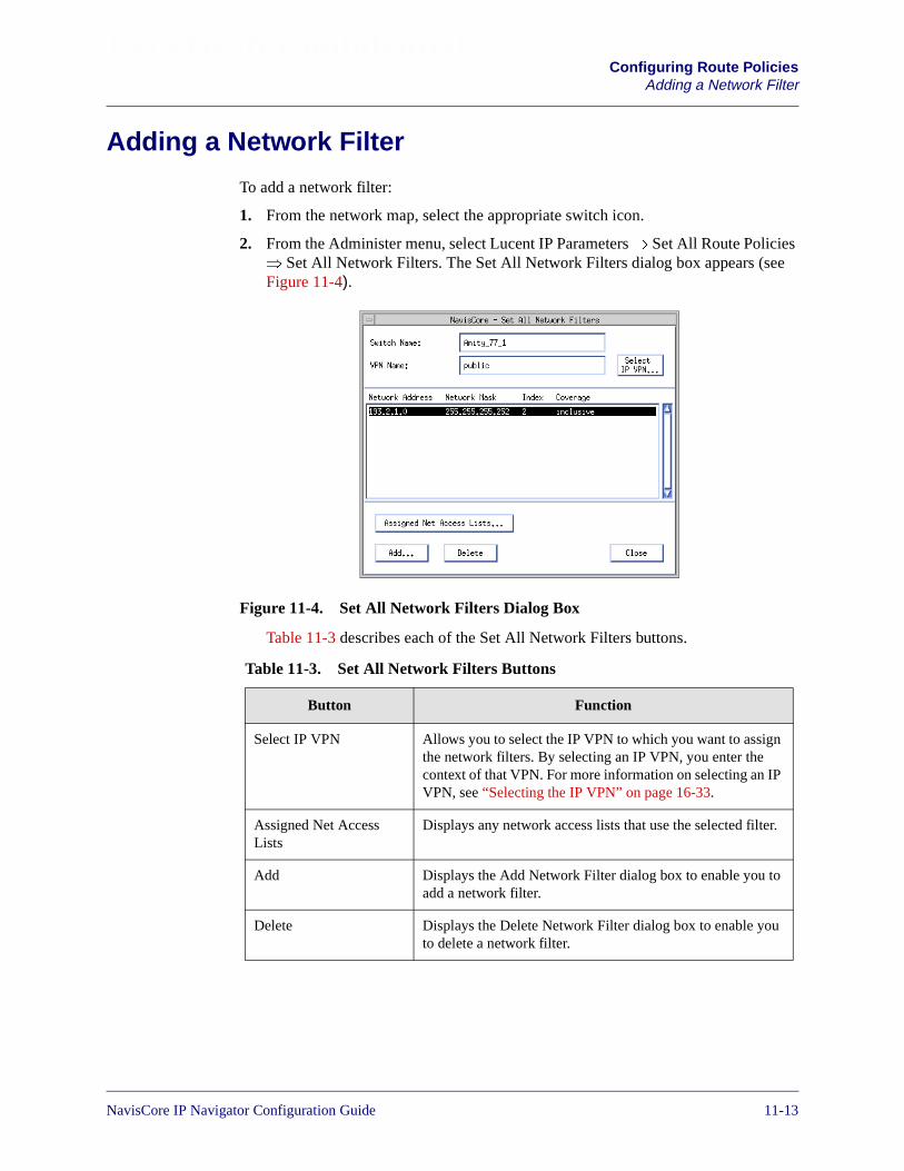
Beta Draft ConfidentialConfiguring Route Policies
Adding a Network Filter
Adding a Network Filter
To add a network filter:
1. From the network map, select the appropriate switch icon.
2. From the Administer menu, select Lucent IP Parameters� Set All Route Policies � Set All Network Filters. The Set All Network Filters dialog box appears (seeFigure 11-4).
Figure 11-4. Set All Network Filters Dialog Box
Table 11-3 describes each of the Set All Network Filters buttons.
Table 11-3. Set All Network Filters Buttons
Button Function
Select IP VPN Allows you to select the IP VPN to which you want to assignthe network filters. By selecting an IP VPN, you enter thecontext of that VPN. For more information on selecting an IPVPN, see “Selecting the IP VPN” on page 16-33.
Assigned Net AccessLists
Displays any network access lists that use the selected filter.
Add Displays the Add Network Filter dialog box to enable you toadd a network filter.
Delete Displays the Delete Network Filter dialog box to enable youto delete a network filter.
NavisCore IP Navigator Configuration Guide 1/14/0211-13
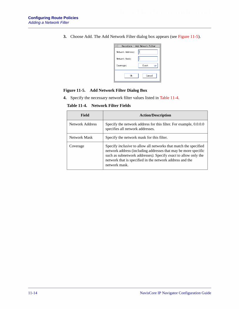
Beta Draft ConfidentialConfiguring Route PoliciesAdding a Network Filter
3. Choose Add. The Add Network Filter dialog box appears (see Figure 11-5).
Figure 11-5. Add Network Filter Dialog Box
4. Specify the necessary network filter values listed in Table 11-4.
Table 11-4. Network Filter Fields
Field Action/Description
Network Address Specify the network address for this filter. For example, 0.0.0.0specifies all network addresses.
Network Mask Specify the network mask for this filter.
Coverage Specify inclusive to allow all networks that match the specifiednetwork address (including addresses that may be more specificsuch as subnetwork addresses). Specify exact to allow only thenetwork that is specified in the network address and thenetwork mask.
11-14 NavisCore IP Navigator Configuration Guide

Beta Draft ConfidentialConfiguring Route Policies
Adding a Network Access List
Adding a Network Access ListA network access list enables you to logically group a set of network filters. To add anetwork access list:
1. From the network map, select the appropriate switch icon.
2. From the Administer menu, select Lucent IP Parameters� Set All Route Policies � Set All Network Access Lists. The Set All Network Access Lists dialog boxappears (see Figure 11-6).
Figure 11-6. Set All Network Access Lists Dialog Box
Table 11-5 describes each of the Set All Network Access Lists buttons.
Table 11-5. Set All Network Access List Buttons
Button Function
Select IP VPN Allows you to select the IP VPN to which you want to assignthe network access list. By selecting an IP VPN, you enterthe context of that VPN. For more information on selectingan IP VPN, see “Selecting the IP VPN” on page 16-33.
Add Displays the Add Network Access List dialog box to enableyou to add a network access list.
Modify Displays the Modify Network Access List dialog box toenable you to modify a selected network access list.
Delete Displays the Delete Network Access List dialog box toenable you to delete a selected network access list.
Assigned Route Maps Displays route maps that use a selected network access list.
NavisCore IP Navigator Configuration Guide 1/14/0211-15

Beta Draft ConfidentialConfiguring Route PoliciesAdding a Network Access List
3. Choose Add. The Add Network Access List dialog box appears (see Figure 11-7).
Figure 11-7. Add Network Access List Dialog Box
4. Specify a unique network access list name.
5. Use the Assign and Unassign buttons to specify the network filters that you wantto include in the network access list. See Table 11-6 on page 11-17 for adescription of each of the fields on the Add Network Access List dialog box.
6. To add a filter to the list of Available Network Filters, choose Add Network Filterto display the Add Network Filter dialog box shown in Figure 11-5 on page 11-14.Any filters that you add are included in either the list of available network filtersor the list of assigned network filters.
7. Choose OK after the Assigned Network Filters list includes all of the filters thatyou want to use in the network access list. One network access list can include upto 300 network filters.
11-16 NavisCore IP Navigator Configuration Guide
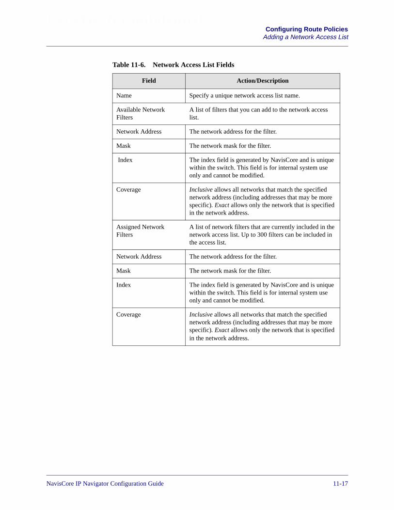
Beta Draft ConfidentialConfiguring Route Policies
Adding a Network Access List
Table 11-6. Network Access List Fields
Field Action/Description
Name Specify a unique network access list name.
Available NetworkFilters
A list of filters that you can add to the network accesslist.
Network Address The network address for the filter.
Mask The network mask for the filter.
Index The index field is generated by NavisCore and is uniquewithin the switch. This field is for internal system useonly and cannot be modified.
Coverage Inclusive allows all networks that match the specifiednetwork address (including addresses that may be morespecific). Exact allows only the network that is specifiedin the network address.
Assigned NetworkFilters
A list of network filters that are currently included in thenetwork access list. Up to 300 filters can be included inthe access list.
Network Address The network address for the filter.
Mask The network mask for the filter.
Index The index field is generated by NavisCore and is uniquewithin the switch. This field is for internal system useonly and cannot be modified.
Coverage Inclusive allows all networks that match the specifiednetwork address (including addresses that may be morespecific). Exact allows only the network that is specifiedin the network address.
NavisCore IP Navigator Configuration Guide 1/14/0211-17

Beta Draft ConfidentialConfiguring Route PoliciesAdding Route Maps
Adding Route Maps
To add a route map:
1. From the network map, select the appropriate switch icon.
2. From the Administer menu, select Lucent IP Parameters� Set All Route Policies � Set All Route Maps. The Set All Route Maps dialog box appears (seeFigure 11-8).
Figure 11-8. Set All Route Maps Dialog Box
11-18 NavisCore IP Navigator Configuration Guide

Beta Draft ConfidentialConfiguring Route Policies
Adding Route Maps
Table 11-7 describes each of the Set All Route Maps buttons. Table 11-8 onpage 11-20 describes the fields at the top of the Set All Route Maps dialog box.
The Match Parameters and Set Parameters on the Set All Route Map dialog boxvary depending on the type of route map that you are defining. See Table 11-11 onpage 11-23 for a reference to the section of this chapter that describes the Matchand Set parameters for each route map type.
Table 11-7. Set All Route Maps Buttons
Button Function
Select IP VPN Allows you to select the IP VPN to which you want to assign thenetwork access list. By selecting an IP VPN, you enter the context ofthat VPN. For more information on selecting an IP VPN, see“Selecting the IP VPN” on page 16-33.
Add Displays the Add Route Map dialog box to enable you to add a routepolicy.
Modify Displays the Modify Route Map dialog box to enable you to modify aroute policy.
Delete Displays the Delete Route Map dialog box to enable you to delete aroute policy.
Options Use the Select: Options button to select one of the following options.
Assigned BGP Neighbors — Lists all BGP neighbors that use aselected route map.
Assigned BGP Peer Groups – Displays the assigned BGP peergroups.
Assigned RIP Interfaces — Lists all RIP interfaces that use a selectedroute map.
BGP Neighbors — Displays the Set All BGP Neighbors dialog box toenable you to assign a route map to a BGP neighbor.
OSPF Route Maps Sequence — Displays the Change the Order ofOSPF Route Maps dialog box to enable you to change the sequence ofassigned route maps.
Show Bgp Route Dampening – Displays the BGP route dampeningconfiguration.
NavisCore IP Navigator Configuration Guide 1/14/0211-19

Beta Draft ConfidentialConfiguring Route PoliciesAdding Route Maps
3. Choose Add. The Add Route Map dialog box appears (see Figure 11-9).
Figure 11-9. Add Route Map Dialog Box
Table 11-8. Set All Route Maps Common Values
Field Action/Description
Switch Name Displays the name of the currently selected switch.
Route Map Name A name that uniquely identifies the route map.
Index The index field is generated by NavisCore and is unique within the switch. This field isfor internal system use only and cannot be modified.
Type Displays the From protocol and To protocol that identify the route distribution type. SeeTable 11-11 on page 11-23 for a list of route distribution types and a reference to thesection of this chapter that describes how to redistribute routes between various routingprotocols.
Admin Specify Enable or Disable. Enable indicates that the route map is administrativelyenabled and can be used. Disable indicates that the route map is administrativelydisabled and cannot be used.
Action Specify Accept, Deny, or Originate Default.
Accept – indicates that all routes that match the specified Match parameters areaccepted.
Deny – indicates that all routes that match the specified Match parameters are denied.
Originate Default – indicates that you can specify the match parameters that definewhere to send a default route heading. This option is used for the following types ofroute maps: BGP to BGP, ANY to BGP, or RIP to RIP.
11-20 NavisCore IP Navigator Configuration Guide
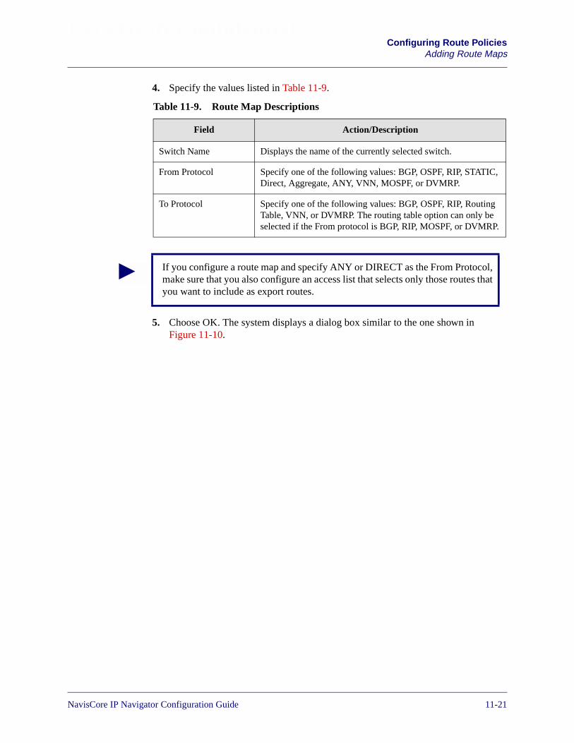
Beta Draft ConfidentialConfiguring Route Policies
Adding Route Maps
4. Specify the values listed in Table 11-9.
5. Choose OK. The system displays a dialog box similar to the one shown inFigure 11-10.
Table 11-9. Route Map Descriptions
Field Action/Description
Switch Name Displays the name of the currently selected switch.
From Protocol Specify one of the following values: BGP, OSPF, RIP, STATIC,Direct, Aggregate, ANY, VNN, MOSPF, or DVMRP.
To Protocol Specify one of the following values: BGP, OSPF, RIP, RoutingTable, VNN, or DVMRP. The routing table option can only beselected if the From protocol is BGP, RIP, MOSPF, or DVMRP.
If you configure a route map and specify ANY or DIRECT as the From Protocol,make sure that you also configure an access list that selects only those routes thatyou want to include as export routes.
NavisCore IP Navigator Configuration Guide 1/14/0211-21

Beta Draft ConfidentialConfiguring Route PoliciesAdding Route Maps
Figure 11-10. Second Add Route Map Dialog Box
6. Specify the Route Map Name, Admin Status, and Action values as described inTable 11-10.
7. Specify the necessary match and set parameters for this route map. If you need toadd an access list to the route map, choose Add Access Lists. Instructions foradding access lists start on page 11-15.
The Match parameters and Set parameters on the Add Route Map dialog box varydepending on the type of route map that you are defining. See Table 11-11 for areference to the section of this chapter that describes the Match and Setparameters for each route map type.
All of the Match and Set Parameter fields described in Table 11-12 throughTable 11-31 are optional. You can specify a routing policy that uses no matchand no set values.
11-22 NavisCore IP Navigator Configuration Guide

Beta Draft ConfidentialConfiguring Route Policies
Adding Route Maps
Table 11-10. Add Route Map Fields
Field Action/Description
Route Map Name Specify a unique name to identify the route map.
Admin Status Specify Enable or Disable. Enable indicates that the route map is administrativelyenabled and can be used. Disable indicates that the route map is administrativelydisabled and cannot be used.
Action Specify Accept, Deny, or Originate Default.
Accept – Indicates that all routes that match the specified Match parameters areaccepted.
Deny – Indicates that all routes that match the specified Match parameters are denied.
Originate Default – Indicates that you can specify the match parameters that definewhere to send a default route heading. This option is used for the following types ofroute maps: BGP to BGP, ANY to BGP, or RIP to RIP.
Table 11-11. Match and Set Parameter Descriptions
Route Map Type See...
BGP to BGP Table 11-12 on page 11-25
BGP to OSPF Table 11-13 on page 11-28
BGP to RIP Table 11-14 on page 11-30
BGP to Routing Table Table 11-15 on page 11-32
BGP to VNN Table 11-16 on page 11-34
OSPF to BGP Table 11-17 on page 11-36
OSPF to RIP Table 11-18 on page 11-38
OSPF to VNN Table 11-19 on page 11-39
RIP to RIP Table 11-20 on page 11-40
RIP to BGP Table 11-21 on page 11-41
RIP to OSPF Table 11-22 on page 11-43
RIP to Routing Table Table 11-23 on page 11-44
RIP to VNN Table 11-24 on page 11-45
Static to BGP Table 11-25 on page 11-46
NavisCore IP Navigator Configuration Guide 1/14/0211-23
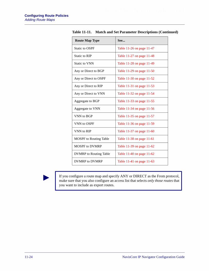
Beta Draft ConfidentialConfiguring Route PoliciesAdding Route Maps
Static to OSPF Table 11-26 on page 11-47
Static to RIP Table 11-27 on page 11-48
Static to VNN Table 11-28 on page 11-49
Any or Direct to BGP Table 11-29 on page 11-50
Any or Direct to OSPF Table 11-30 on page 11-52
Any or Direct to RIP Table 11-31 on page 11-53
Any or Direct to VNN Table 11-32 on page 11-54
Aggregate to BGP Table 11-33 on page 11-55
Aggregate to VNN Table 11-34 on page 11-56
VNN to BGP Table 11-35 on page 11-57
VNN to OSPF Table 11-36 on page 11-59
VNN to RIP Table 11-37 on page 11-60
MOSPF to Routing Table Table 11-38 on page 11-61
MOSPF to DVMRP Table 11-39 on page 11-62
DVMRP to Routing Table Table 11-40 on page 11-62
DVMRP to DVMRP Table 11-41 on page 11-63
Table 11-11. Match and Set Parameter Descriptions (Continued)
Route Map Type See...
If you configure a route map and specify ANY or DIRECT as the From protocol,make sure that you also configure an access list that selects only those routes thatyou want to include as export routes.
11-24 NavisCore IP Navigator Configuration Guide
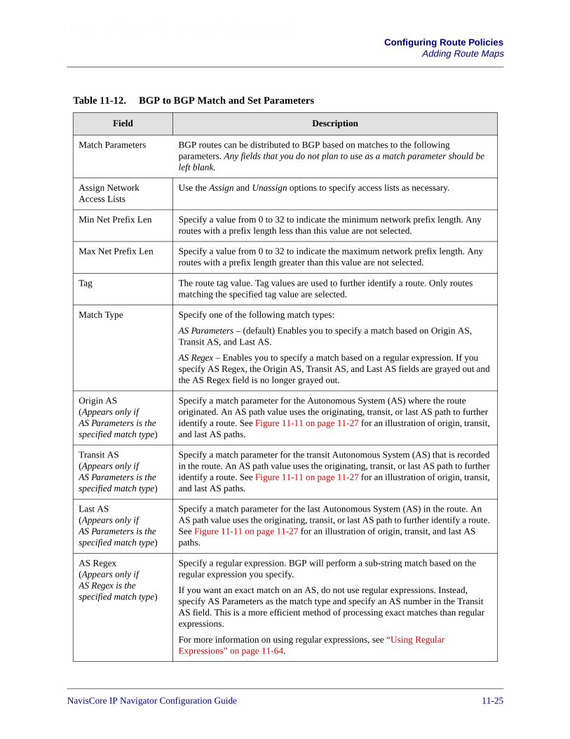
Beta Draft ConfidentialConfiguring Route Policies
Adding Route Maps
Table 11-12. BGP to BGP Match and Set Parameters
Field Description
Match Parameters BGP routes can be distributed to BGP based on matches to the followingparameters. Any fields that you do not plan to use as a match parameter should beleft blank.
Assign NetworkAccess Lists
Use the Assign and Unassign options to specify access lists as necessary.
Min Net Prefix Len Specify a value from 0 to 32 to indicate the minimum network prefix length. Anyroutes with a prefix length less than this value are not selected.
Max Net Prefix Len Specify a value from 0 to 32 to indicate the maximum network prefix length. Anyroutes with a prefix length greater than this value are not selected.
Tag The route tag value. Tag values are used to further identify a route. Only routesmatching the specified tag value are selected.
Match Type Specify one of the following match types:
AS Parameters – (default) Enables you to specify a match based on Origin AS,Transit AS, and Last AS.
AS Regex – Enables you to specify a match based on a regular expression. If youspecify AS Regex, the Origin AS, Transit AS, and Last AS fields are grayed out andthe AS Regex field is no longer grayed out.
Origin AS(Appears only ifAS Parameters is thespecified match type)
Specify a match parameter for the Autonomous System (AS) where the routeoriginated. An AS path value uses the originating, transit, or last AS path to furtheridentify a route. See Figure 11-11 on page 11-27 for an illustration of origin, transit,and last AS paths.
Transit AS(Appears only ifAS Parameters is thespecified match type)
Specify a match parameter for the transit Autonomous System (AS) that is recordedin the route. An AS path value uses the originating, transit, or last AS path to furtheridentify a route. See Figure 11-11 on page 11-27 for an illustration of origin, transit,and last AS paths.
Last AS(Appears only ifAS Parameters is thespecified match type)
Specify a match parameter for the last Autonomous System (AS) in the route. AnAS path value uses the originating, transit, or last AS path to further identify a route.See Figure 11-11 on page 11-27 for an illustration of origin, transit, and last ASpaths.
AS Regex(Appears only ifAS Regex is thespecified match type)
Specify a regular expression. BGP will perform a sub-string match based on theregular expression you specify.
If you want an exact match on an AS, do not use regular expressions. Instead,specify AS Parameters as the match type and specify an AS number in the TransitAS field. This is a more efficient method of processing exact matches than regularexpressions.
For more information on using regular expressions, see “Using RegularExpressions” on page 11-64.
NavisCore IP Navigator Configuration Guide 1/14/0211-25

Beta Draft ConfidentialConfiguring Route PoliciesAdding Route Maps
Origin Specify one of the following values to indicate the BGP origin code for use as amatch parameter: IGP, EGP, Incomplete, None.
Community Specify one of the following values to identify the community:
Define – Indicates that you will specify a user-defined community in theCommunity Value field.
Well Known – Indicates that you will specify one of the following three reservedcommunity values in the Community Value field: No Export, No Advertise, or LocalAS.
None – Indicates that no community value will be specified.
Community Value If you chose Define for the Community field, specify the new community numberthat will be used as a match parameter.
If you chose Well Known for the Community field, specify one of the followingthree reserved community values: No Export, No Advertise, or Local AS.
If you chose None for the Community field, this field is grayed out to indicate that itis not used.
Set Parameters The following parameters are set on all selected routes. Routes are selected if theymatch the specified match parameters. Any fields that you do not plan to use as setparameters should be left blank. No default is used if the field is left blank.
Origin Specify one of the following values to indicate the BGP origin code for use as amatch parameter: IGP, EGP, Incomplete, None.
Atomic Aggregate Specify Enable or Disable to indicate whether or not the atomic aggregate attributeshould be set as an indication of information loss.
Multi-Exit-Discr The multi-exit-discriminator (MED) value. This value indicates the preferred pathinto an AS that has multiple entry points. Lower MED values indicate the preferredpath. For example, a route with a MED value of 120 would be preferred over a routewith a MED value of 200.
Next Hop Specify the IP address that identifies the next hop to reach a network.
AS Repeat Count A multiple number of the local AS number prepended to the existing segment. Thisnumber is the total number of times that IP Navigator adds the local AS to the ASpath.
Community Type Specify one of the following values to identify the community type:
Replacement – Assigns a new community number to replace the old value.
Additive – Adds a community to an existing community.
None – No community modification will occur.
Table 11-12. BGP to BGP Match and Set Parameters (Continued)
Field Description
11-26 NavisCore IP Navigator Configuration Guide

Beta Draft ConfidentialConfiguring Route Policies
Adding Route Maps
Figure 11-11. Origin, Transit, and Last AS Paths
Community Specify one of the following values to identify the community:
Define – Indicates that you will specify a user-defined community in theCommunity Value field.
Well Known –Indicates that you will specify one of the following three reservedcommunity values in the Community Value field: No Export, No Advertise, or LocalAS.
None – Indicates that no community value will be specified.
Community Value If you chose Define for the Community field, specify the new community numberthat will be assigned to selected routes.
If you chose Well Known for the Community field, specify one of the followingthree reserved community values: No Export, No Advertise, or Local AS.
If you chose None for the Community field, this field is grayed out to indicate that itis not used.
Table 11-12. BGP to BGP Match and Set Parameters (Continued)
Field Description
Origin AS pathis the first in thesegment
Last AS path isthe last in thesegment
A transit AS path occursanywhere between thefirst and last endpointsof a segment.
NavisCore IP Navigator Configuration Guide 1/14/0211-27
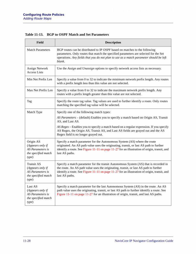
Beta Draft ConfidentialConfiguring Route PoliciesAdding Route Maps
Table 11-13. BGP to OSPF Match and Set Parameters
Field Description
Match Parameters BGP routes can be distributed to IP OSPF based on matches to the followingparameters. Only routes that match the specified parameters are selected for the Setoperations. Any fields that you do not plan to use as a match parameter should be leftblank.
Assign NetworkAccess Lists
Use the Assign and Unassign options to specify network access lists as necessary.
Min Net Prefix Len Specify a value from 0 to 32 to indicate the minimum network prefix length. Any routeswith a prefix length less than this value are not selected.
Max Net Prefix Len Specify a value from 0 to 32 to indicate the maximum network prefix length. Anyroutes with a prefix length greater than this value are not selected.
Tag Specify the route tag value. Tag values are used to further identify a route. Only routesmatching the specified tag value will be selected.
Match Type Specify one of the following match types:
AS Parameters – (default) Enables you to specify a match based on Origin AS, TransitAS, and Last AS.
AS Regex – Enables you to specify a match based on a regular expression. If you specifyAS Regex, the Origin AS, Transit AS, and Last AS fields are grayed out and the ASRegex field is no longer grayed out.
Origin AS(Appears only ifAS Parameters isthe specified matchtype)
Specify a match parameter for the Autonomous System (AS) where the routeoriginated. An AS path value uses the originating, transit, or last AS path to furtheridentify a route. See Figure 11-11 on page 11-27 for an illustration of origin, transit, andlast AS paths.
Transit AS(Appears only ifAS Parameters isthe specified matchtype)
Specify a match parameter for the transit Autonomous System (AS) that is recorded inthe route. An AS path value uses the originating, transit, or last AS path to furtheridentify a route. See Figure 11-11 on page 11-27 for an illustration of origin, transit, andlast AS paths.
Last AS(Appears only ifAS Parameters isthe specified matchtype)
Specify a match parameter for the last Autonomous System (AS) in the route. An ASpath value uses the originating, transit, or last AS path to further identify a route. SeeFigure 11-11 on page 11-27 for an illustration of origin, transit, and last AS paths.
11-28 NavisCore IP Navigator Configuration Guide

Beta Draft ConfidentialConfiguring Route Policies
Adding Route Maps
AS Regex(Appears only ifAS Regex is thespecified matchtype)
Specify a regular expression. BGP will perform a sub-string match based on the regularexpression you specify.
If you want an exact match on an AS, do not use regular expressions. Instead, specifyAS Parameters as the match type and specify an AS number in the Transit AS field.This is a more efficient method of processing exact matches than regular expressions.
For more information on using regular expressions, see “Using Regular Expressions”on page 11-64.
Origin Specify one of the following values to indicate the BGP origin code: IGP, EGP,Incomplete, or None.
Community Specify one of the following values to identify the community:
Define – Indicates that you will specify a user-defined community in the CommunityValue field.
Well Known – Indicates that you will specify one of the following three reservedcommunity values in the Community Value field: No Export, No Advertise, or LocalAS.
None – Indicates that no community value will be specified.
Community Value If you chose Define for the Community field, specify the new community number thatwill be used as a match parameter.
If you chose Well Known for the Community field, specify one of the following threereserved community values: No Export, No Advertise, or Local AS.
If you chose None for the Community field, this field is grayed out to indicate that it isnot used.
Table 11-13. BGP to OSPF Match and Set Parameters (Continued)
Field Description
NavisCore IP Navigator Configuration Guide 1/14/0211-29

Beta Draft ConfidentialConfiguring Route PoliciesAdding Route Maps
Set Parameters The following parameters are set on all selected routes. Routes are selected if theymatch the specified match parameters. If you leave any of the following parametersblank, the system uses a default value.
Metric Sets the IP OSPF route metric to the specified metric value. If you leave this field blank,a default metric from the routing table is used.
Tag Sets the IP OSPF route tag value to the specified value. If you leave this field blank, adefault tag from the routing table is used.
OSPF Metric Type Specify External-type-1 or External-type-2. If you leave this field blank,External-type-2 is used as the default.
Next Hop The IP address that identifies the next hop to reach a network. If you leave this fieldblank, a default of 0 is used.
Table 11-13. BGP to OSPF Match and Set Parameters (Continued)
Field Description
Table 11-14. BGP to RIP Match and Set Parameters
Field Description
Match Parameters The redistribution of routes from BGP to RIP are based on matches to the followingobjects. Any fields that you do not plan to use as a match parameter should be leftblank.
Network Access Lists Use the Assign and Unassign options to specify network access lists as necessary.
Min Net Prefix Len Specify a value from 0 to 32 to indicate the minimum network prefix length. Any routeswith a prefix length less than this value are not selected.
Max Net Prefix Len Specify a value from 0 to 32 to indicate the maximum network prefix length. Anyroutes with a prefix length greater than this value are not selected.
Tag Specify the tag value to be used as the match parameter. Tag values are used to furtheridentify a route. Only routes matching this value are selected.
Match Type Specify one of the following match types:
AS Parameters – (default) Enables you to specify a match based on Origin AS, TransitAS, and Last AS.
AS Regex – Enables you to specify a match based on a regular expression. If youspecify AS Regex, the Origin AS, Transit AS, and Last AS fields are grayed out and theAS Regex field is no longer grayed out.
Origin AS(Appears only ifAS Parameters is thespecified match type)
Specify a match parameter for the Autonomous System (AS) where the routeoriginated. An AS path value uses the originating, transit, or last AS path to furtheridentify a route. See Figure 11-11 on page 11-27 for an illustration of origin, transit,and last AS paths.
11-30 NavisCore IP Navigator Configuration Guide

Beta Draft ConfidentialConfiguring Route Policies
Adding Route Maps
Transit AS(Appears only ifAS Parameters is thespecified match type)
Specify a match parameter for the transit Autonomous System (AS) that is recorded inthe route. An AS path value uses the originating, transit, or last AS path to furtheridentify a route. See Figure 11-11 on page 11-27 for an illustration of origin, transit,and last AS paths.
Last AS(Appears only ifAS Parameters is thespecified match type)
Specify a match parameter for the last Autonomous System (AS) in the route. An ASpath value uses the originating, transit, or last AS path to further identify a route. SeeFigure 11-11 on page 11-27 for an illustration of origin, transit, and last AS paths.
AS Regex(Appears only ifAS Regex is thespecified match type)
Specify a regular expression. BGP will perform a sub-string match based on the regularexpression you specify.
If you want an exact match on an AS, do not use regular expressions. Instead, specifyAS Parameters as the match type and specify an AS number in the Transit AS field.This is a more efficient method of processing exact matches than regular expressions.
For more information on using regular expressions, see “Using Regular Expressions”on page 11-64.
Origin Specify one of the following values to indicate the BGP origin code: IGP, EGP,Incomplete, or None.
Community Specify one of the following values to identify the community:
Define – Indicates that you will specify a user-defined community in the CommunityValue field.
Well Known – Indicates that you will specify one of the following three reservedcommunity values in the Community Value field: No Export, No Advertise, or LocalAS.
None – Indicates that no community value will be specified.
Community Value If you chose Define for the Community field, specify the new community number thatwill be used as a match parameter.
If you chose Well Known for the Community field, specify one of the following threereserved community values: No Export, No Advertise, or Local AS.
If you chose None for the Community field, this field is grayed out to indicate that it isnot used.
Set Parameters The following parameters are set on all selected routes. Routes are selected if theymatch the specified match parameters. If you leave any of the following parametersblank, the system uses a default value.
Metric Sets the RIP route metric to the specified metric value. If you leave this field blank, adefault metric from the routing table is used.
Tag Sets the route tag field for the route. If you leave this field blank, a default tag from therouting table is used.
Table 11-14. BGP to RIP Match and Set Parameters (Continued)
Field Description
NavisCore IP Navigator Configuration Guide 1/14/0211-31
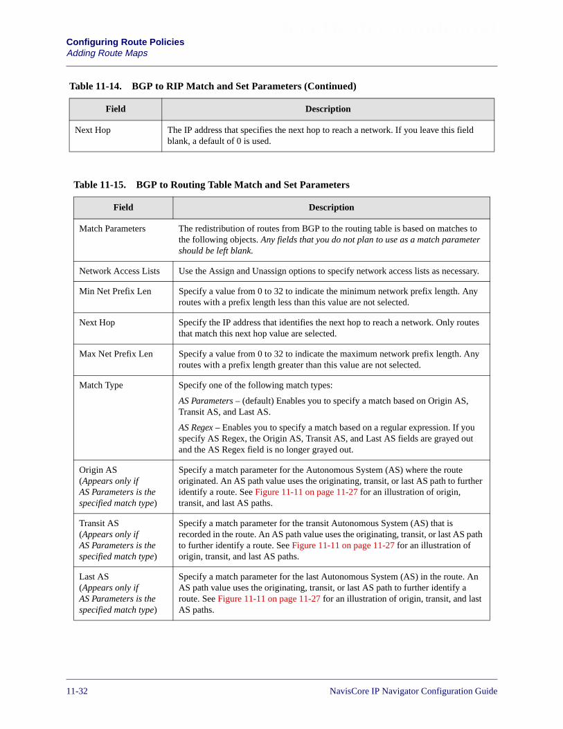
Beta Draft ConfidentialConfiguring Route PoliciesAdding Route Maps
Next Hop The IP address that specifies the next hop to reach a network. If you leave this fieldblank, a default of 0 is used.
Table 11-14. BGP to RIP Match and Set Parameters (Continued)
Field Description
Table 11-15. BGP to Routing Table Match and Set Parameters
Field Description
Match Parameters The redistribution of routes from BGP to the routing table is based on matches tothe following objects. Any fields that you do not plan to use as a match parametershould be left blank.
Network Access Lists Use the Assign and Unassign options to specify network access lists as necessary.
Min Net Prefix Len Specify a value from 0 to 32 to indicate the minimum network prefix length. Anyroutes with a prefix length less than this value are not selected.
Next Hop Specify the IP address that identifies the next hop to reach a network. Only routesthat match this next hop value are selected.
Max Net Prefix Len Specify a value from 0 to 32 to indicate the maximum network prefix length. Anyroutes with a prefix length greater than this value are not selected.
Match Type Specify one of the following match types:
AS Parameters – (default) Enables you to specify a match based on Origin AS,Transit AS, and Last AS.
AS Regex – Enables you to specify a match based on a regular expression. If youspecify AS Regex, the Origin AS, Transit AS, and Last AS fields are grayed outand the AS Regex field is no longer grayed out.
Origin AS(Appears only ifAS Parameters is thespecified match type)
Specify a match parameter for the Autonomous System (AS) where the routeoriginated. An AS path value uses the originating, transit, or last AS path to furtheridentify a route. See Figure 11-11 on page 11-27 for an illustration of origin,transit, and last AS paths.
Transit AS(Appears only ifAS Parameters is thespecified match type)
Specify a match parameter for the transit Autonomous System (AS) that isrecorded in the route. An AS path value uses the originating, transit, or last AS pathto further identify a route. See Figure 11-11 on page 11-27 for an illustration oforigin, transit, and last AS paths.
Last AS(Appears only ifAS Parameters is thespecified match type)
Specify a match parameter for the last Autonomous System (AS) in the route. AnAS path value uses the originating, transit, or last AS path to further identify aroute. See Figure 11-11 on page 11-27 for an illustration of origin, transit, and lastAS paths.
11-32 NavisCore IP Navigator Configuration Guide

Beta Draft ConfidentialConfiguring Route Policies
Adding Route Maps
AS Regex(Appears only ifAS Regex is thespecified match type)
Specify a regular expression. BGP will perform a sub-string match based on theregular expression you specify.
If you want an exact match on an AS, do not use regular expressions. Instead,specify AS Parameters as the match type and specify an AS number in the TransitAS field. This is a more efficient method of processing exact matches than regularexpressions.
For more information on using regular expressions, see “Using RegularExpressions” on page 11-64.
Origin Specify one of the following values to indicate the BGP origin code: IGP, EGP,Incomplete, or None.
Community Specify one of the following values to identify the community:
Define – Indicates that you will specify a user-defined community in theCommunity Value field.
Well Known – Indicates that you will specify one of the following three reservedcommunity values in the Community Value field: No Export, No Advertise, orLocal AS.
None – Indicates that no community value will be specified.
Community Value If you chose Define for the Community field, specify the new community numberthat will be assigned to selected routes.
If you chose Well Known for the Community field, specify one of the followingthree reserved community values: No Export, No Advertise, or Local AS.
If you chose None for the Community field, this field is grayed out to indicate thatit is not used.
Set Parameters The following parameters are set on all selected routes. Routes are selected if theymatch the specified match parameters. Any fields that you do not plan to use as setparameters should be left blank. No default is used if the field is left blank.
Local Preference The value that you specify is used as the local preference value for all selectedroutes. Local preference indicates a degree of preference given to a route tocompare it with other routes for the same destination. A higher local preferencevalue indicates a preferred route. This value is local to the AS and is exchangedbetween IBGP peers only. It is not passed to EBGP peers.
Tag Sets the route tag field for the route.
Weight A weight value that is assigned to a route. This value is used only for routes fromEBGP peers. The weight value is not used for routes from IBGP peers.
Multi-Exit-Discr The multi-exit-discriminator (MED) value. This value indicates the preferred pathinto an AS that has multiple entry points. Lower MED values indicate the preferredpath. For example, a route with a MED value of 120 would be preferred over aroute with a MED value of 200.
Table 11-15. BGP to Routing Table Match and Set Parameters (Continued)
Field Description
NavisCore IP Navigator Configuration Guide 1/14/0211-33

Beta Draft ConfidentialConfiguring Route PoliciesAdding Route Maps
Next Hop Specify the IP address that identifies the next hop to reach a network.
Community Type Specify one of the following values.
Replacement – Assigns a new community number to replace the old value.
Additive – Adds a community to an existing community.
None – No community modification occurs.
Community Specify one of the following values to identify the community:
Define – Indicates that you will specify a user-defined community in theCommunity Value field.
Well Known – Indicates that you will specify one of the following three reservedcommunity values in the Community Value field: No Export, No Advertise, orLocal AS.
None – Indicates that no community value will be specified.
Community Value If you chose Define for the Community field, specify the new community numberthat will be assigned to selected routes.
If you chose Well Known for the Community field, specify one of the followingthree reserved community values: No Export, No Advertise, or Local AS.
If you chose None for the Community field, this field is grayed out to indicate thatit is not used.
Table 11-15. BGP to Routing Table Match and Set Parameters (Continued)
Field Description
Table 11-16. BGP to VNN Match and Set Parameters
Field Description
Match Parameters BGP routes can be distributed to VNN OSPF based on matches to the followingparameters. Only routes that match the specified parameters are selected for the Setoperations. Any fields that you do not plan to use as a match parameter should be leftblank.
Assign NetworkAccess Lists
Use the Assign and Unassign options to specify network access lists as necessary.
Min Net Prefix Len Specify a value from 0 to 32 to indicate the minimum network prefix length. Any routeswith a prefix length less than this value are not selected.
Max Net Prefix Len Specify a value from 0 to 32 to indicate the maximum network prefix length. Any routeswith a prefix length greater than this value are not selected.
Tag Specify the route tag value. Tag values are used to further identify a route. Only routesmatching the specified tag value will be selected.
11-34 NavisCore IP Navigator Configuration Guide

Beta Draft ConfidentialConfiguring Route Policies
Adding Route Maps
Match Type Specify one of the following match types:
AS Parameters – (default) Enables you to specify a match based on Origin AS, TransitAS, and Last AS.
AS Regex – Enables you to specify a match based on a regular expression. If you specifyAS Regex, the Origin AS, Transit AS, and Last AS fields are grayed out and the ASRegex field is no longer grayed out.
Origin AS(Appears only ifAS Parameters isthe specified matchtype)
Specify a match parameter for the Autonomous System (AS) where the route originated.An AS path value uses the originating, transit, or last AS path to further identify a route.See Figure 11-11 on page 11-27 for an illustration of origin, transit, and last AS paths.
Transit AS(Appears only ifAS Parameters isthe specified matchtype)
Specify a match parameter for the transit Autonomous System (AS) that is recorded in theroute. An AS path value uses the originating, transit, or last AS path to further identify aroute. See Figure 11-11 on page 11-27 for an illustration of origin, transit, and last ASpaths.
Last AS(Appears only ifAS Parameters isthe specified matchtype)
Specify a match parameter for the last Autonomous System (AS) in the route. An AS pathvalue uses the originating, transit, or last AS path to further identify a route. SeeFigure 11-11 on page 11-27 for an illustration of origin, transit, and last AS paths.
AS Regex(Appears only ifAS Regex is thespecified matchtype)
Specify a regular expression. BGP will perform a sub-string match based on the regularexpression you specify.
If you want an exact match on an AS, do not use regular expressions. Instead, specify ASParameters as the match type and specify an AS number in the Transit AS field. This is amore efficient method of processing exact matches than regular expressions.
For more information on using regular expressions, see “Using Regular Expressions” onpage 11-64.
Origin Specify one of the following values to indicate the BGP origin code: IGP, EGP,Incomplete, or None.
Community Specify one of the following values to identify the community:
Define – Indicates that you will specify a user-defined community in the CommunityValue field.
Well Known – Indicates that you will specify one of the following three reservedcommunity values in the Community Value field: No Export, No Advertise, or Local AS.
None – Indicates that no community value will be specified.
Table 11-16. BGP to VNN Match and Set Parameters (Continued)
Field Description
NavisCore IP Navigator Configuration Guide 1/14/0211-35

Beta Draft ConfidentialConfiguring Route PoliciesAdding Route Maps
Community Value If you chose Define for the Community field, specify the new community number thatwill be used as a match parameter.
If you chose Well Known for the Community field, specify one of the following threereserved community values: No Export, No Advertise, or Local AS.
If you chose None for the Community field, the field is grayed out to indicate that it is notused.
Set Parameters The following parameters are set on all selected routes. Routes are selected if they matchthe specified match parameters. If you leave any of the following parameters blank, thesystem uses a default value.
Metric Sets the VNN OSPF route metric to the specified metric value. If you leave this fieldblank, a default metric from the routing table is used.
Tag Sets the VNN OSPF route tag value to the specified value. If you leave this field blank, adefault tag from the routing table is used.
VNN Metric Type Specify External-type-1 or External-type-2. If you leave this field blank, External-type-2is used as the default.
Next Hop The IP address that identifies the next hop to reach a network. If you leave this field blank,a default of 0 is used.
Table 11-16. BGP to VNN Match and Set Parameters (Continued)
Field Description
Table 11-17. OSPF to BGP Match and Set Parameters
Field Description
Match Parameters The redistribution of routes from an IP OSPF domain into BGP is based onmatching the following objects. Any fields that you do not plan to use as a matchparameter should be left blank.
Network Access Lists Use the Assign and Unassign options to specify access lists as necessary.
Metric The IP OSPF cost. If you leave this field blank, a default value from the routingtable is used.
Min Net Prefix Len Specify a value from 0 to 32 to indicate the minimum network prefix length. Anyroutes with a prefix length less than this value are not selected.
Max Net Prefix Len Specify a value from 0 to 32 to indicate the maximum network prefix length. Anyroutes with a prefix length greater than this value are not selected.
Tag Specify the IP OSPF route tag value to be used as the match parameter. Onlyroutes matching this value are selected.
OSPF Route Type Specify one of the following OSPF Metric Type values: Intra, Internal,External-1, External-2, or None.
11-36 NavisCore IP Navigator Configuration Guide

Beta Draft ConfidentialConfiguring Route Policies
Adding Route Maps
Set Parameters The following parameters are set on all selected routes. Routes are selected if theymatch the specified match parameters. Any fields that you do not plan to use as setparameters should be left blank. No default is used if the field is left blank.
Local Preference The value that you specify is used as the local preference value for all selectedroutes. Local preference indicates a degree of preference given to a route tocompare it with other routes for the same destination. A higher local preferencevalue indicates a preferred route. This value is local to the AS and is exchangedbetween IBGP peers only. It is not passed to EBGP peers.
Origin Specify one of the following values to indicate the BGP origin code: IGP, EGP,Incomplete, Do not set.
Atomic Aggregate Specify Enable or Disable to indicate whether or not the atomic aggregateattribute is set as an indication of information loss.
Multi-Exit-Discr The multi-exit-discriminator (MED) value. This value indicates the preferred pathinto an AS that has multiple entry points. Lower MED values indicate thepreferred path. For example, a route with a MED value of 120 would be preferredover a route with a MED value of 200.
Next Hop Specify the IP address that identifies the next hop to reach a network.
AS Repeat Count A multiple number of the local AS number prepended to the existing segment.This number is the total number of times that IP Navigator adds the local AS to theAS path.
Community Type Specify one of the following values.
Replacement – Assigns a new community number to replace the old value.
Additive – Adds a community to an existing community.
None – No community modification occurs.
Community Specify one of the following values to identify the community:
Define – Indicates that you will specify a user-defined community in theCommunity Value field.
Well Known – Indicates that you will specify one of the following three reservedcommunity values in the Community Value field: No Export, No Advertise, orLocal AS.
None – Indicates that no community value will be specified.
Community Value If you chose Define for the Community field, specify the new community numberthat will be assigned to selected routes.
If you chose Well Known for the Community field, specify one of the followingthree reserved community values: No Export, No Advertise, or Local AS.
If you chose None for the Community field, this field is grayed out to indicate thatit is not used.
Table 11-17. OSPF to BGP Match and Set Parameters (Continued)
Field Description
NavisCore IP Navigator Configuration Guide 1/14/0211-37
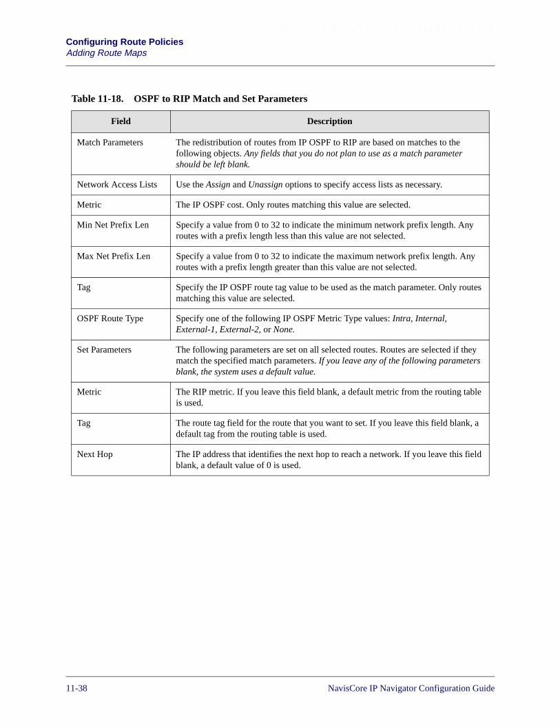
Beta Draft ConfidentialConfiguring Route PoliciesAdding Route Maps
Table 11-18. OSPF to RIP Match and Set Parameters
Field Description
Match Parameters The redistribution of routes from IP OSPF to RIP are based on matches to thefollowing objects. Any fields that you do not plan to use as a match parametershould be left blank.
Network Access Lists Use the Assign and Unassign options to specify access lists as necessary.
Metric The IP OSPF cost. Only routes matching this value are selected.
Min Net Prefix Len Specify a value from 0 to 32 to indicate the minimum network prefix length. Anyroutes with a prefix length less than this value are not selected.
Max Net Prefix Len Specify a value from 0 to 32 to indicate the maximum network prefix length. Anyroutes with a prefix length greater than this value are not selected.
Tag Specify the IP OSPF route tag value to be used as the match parameter. Only routesmatching this value are selected.
OSPF Route Type Specify one of the following IP OSPF Metric Type values: Intra, Internal,External-1, External-2, or None.
Set Parameters The following parameters are set on all selected routes. Routes are selected if theymatch the specified match parameters. If you leave any of the following parametersblank, the system uses a default value.
Metric The RIP metric. If you leave this field blank, a default metric from the routing tableis used.
Tag The route tag field for the route that you want to set. If you leave this field blank, adefault tag from the routing table is used.
Next Hop The IP address that identifies the next hop to reach a network. If you leave this fieldblank, a default value of 0 is used.
11-38 NavisCore IP Navigator Configuration Guide

Beta Draft ConfidentialConfiguring Route Policies
Adding Route Maps
Table 11-19. OSPF to VNN Match and Set Parameters
Field Description
Match Parameters The redistribution of routes from an IP OSPF domain into VNN OSPF is based onmatching the following objects. Any fields that you do not plan to use as a matchparameter should be left blank.
Network Access Lists Use the Assign and Unassign options to specify access lists as necessary.
Metric The IP OSPF cost. If you leave this field blank, a default value from the routingtable is used.
Min Net Prefix Len Specify a value from 0 to 32 to indicate the minimum network prefix length. Anyroutes with a prefix length less than this value are not selected.
Max Net Prefix Len Specify a value from 0 to 32 to indicate the maximum network prefix length. Anyroutes with a prefix length greater than this value are not selected.
Tag Specify the IP OSPF route tag value to be used as the match parameter. Onlyroutes matching this value are selected.
OSPF Route Type Specify one of the following IP OSPF Route Type values: Intra, Internal,External-1, External-2, or None.
Set Parameters The following parameters are set on all selected routes. Routes are selected if theymatch the specified match parameters. Any fields that you do not plan to use as setparameters should be left blank. No default is used if the field is left blank.
Metric The VNN OSPF cost. If you leave this field blank, a default value from the routingtable is used.
Tag The tag to be set in the redistributed routes to VNN OSPF. If you leave this fieldblank, a default tag from the routing table is used.
VNN Metric Type Specify one of the following values: External Type 1 or External Type 2. If youleave this field blank, a value of External Type 2 is used.
Next Hop The IP address that identifies the next hop to reach a network. If you leave thisfield blank, a default value of 0 is used.
NavisCore IP Navigator Configuration Guide 1/14/0211-39

Beta Draft ConfidentialConfiguring Route PoliciesAdding Route Maps
Table 11-20. RIP to RIP Match and Set Parameters
Field Description
Match Parameters The redistribution of routes from RIP or RIP version 2 to RIP or RIP version 2 arebased on matches to the following objects. Any fields that you do not plan to use asa match parameter should be left blank.
Network Access Lists Use the Assign and Unassign options to specify access lists as necessary.
Metric The RIP metric value that is used as a match parameter. Only routes matching thisvalue are selected.
Min Net Prefix Len Specify a value from 0 to 32 to indicate the minimum network prefix length. Anyroutes with a prefix length less than this value are not selected.
Max Net Prefix Len Specify a value from 0 to 32 to indicate the maximum network prefix length. Anyroutes with a prefix length greater than this value are not selected.
Tag Specify the route tag value to be used as the match parameter. Tag values are used tofurther identify a route. Only routes matching this value are selected.
Set Parameters The following parameters are set on all selected routes. Routes are selected if theymatch the specified match parameters. If you leave any of the following parametersblank, the system uses a default value.
Metric The RIP metric. If you leave this field blank, a default metric from the routing tableis used.
Tag The route tag field for the route that you want to set. If you leave this field blank, adefault tag from the routing table is used.
Next Hop An IP address that identifies the next hop to reach a network. If you leave this fieldblank, a default value of 0 is used.
11-40 NavisCore IP Navigator Configuration Guide

Beta Draft ConfidentialConfiguring Route Policies
Adding Route Maps
Table 11-21. RIP to BGP Match and Set Parameters
Field Description
Match Parameters Routes from RIP and RIP version 2 can be redistributed into a BGP domain basedon matches to one or more of the following objects. Any fields that you do not planto use as a match parameter should be left blank.
Network Access Lists Use the Assign and Unassign options to specify access lists as necessary.
Metric The RIP metric value that is used as a match parameter. Only routes matching thisvalue are selected.
Min Net Prefix Len Specify a value from 0 to 32 to indicate the minimum network prefix length. Anyroutes with a prefix length less than this value are not selected.
Max Net Prefix Len Specify a value from 0 to 32 to indicate the minimum network prefix length. Anyroutes with a prefix length less than this value are not selected.
Tag Specify the route tag value to be used as the match parameter. Tag values are usedto further identify a route. Only routes matching this value are selected.
Set Parameters The following parameters are set on all selected routes. Routes are selected if theymatch the specified match parameters. Any fields that you do not plan to use as setparameters should be left blank. No default is used if the field is left blank.
Local Preference The value that you specify is used as the local preference value for all selectedroutes. Local preference indicates a degree of preference given to a route tocompare it with other routes for the same destination. A higher local preferencevalue indicates a preferred route. This value is local to the AS and is exchangedbetween IBGP peers only. It is not passed to EBGP peers.
Origin Specify one of the following values to indicate the origin of the route: IGP, EGP,Incomplete, or None.
Atomic Aggregate Specify Enable or Disable to indicate whether or not the atomic aggregate attributeis set as an indication of information loss.
Multi-Exit-Discr The multi-exit-discriminator (MED) value. This value indicates the preferred pathinto an AS that has multiple entry points. Lower MED values indicate the preferredpath. For example a route with a MED value of 120 would be preferred over aroute with a MED value of 200.
Next Hop Specify the IP address that identifies the next hop to reach a network.
AS Repeat Count A multiple number of the local AS number prepended to the existing segment. Thisnumber is the total number of times that IP Navigator adds the local AS to the ASpath.
NavisCore IP Navigator Configuration Guide 1/14/0211-41

Beta Draft ConfidentialConfiguring Route PoliciesAdding Route Maps
Community Type Specify one of the following values.
Replacement – Assigns a new community number to replace the old value.
Additive – Adds a community to an existing community.
None – No community modification occurs.
Community Specify one of the following values to identify the community:
Define – Indicates that you will specify a user-defined community in theCommunity Value field.
Well Known – Indicates that you will specify one of the following three reservedcommunity values in the Community Value field: No Export, No Advertise, orLocal AS.
None – Indicates that no community value will be specified.
Community Value If you chose Define for the Community field, specify the new community numberthat will be assigned to selected routes.
If you chose Well Known for the Community field, specify one of the followingthree reserved community values: No Export, No Advertise, or Local AS.
If you chose None for the Community field, this field is grayed out to indicate thatit is not used.
Table 11-21. RIP to BGP Match and Set Parameters (Continued)
Field Description
11-42 NavisCore IP Navigator Configuration Guide

Beta Draft ConfidentialConfiguring Route Policies
Adding Route Maps
Table 11-22. RIP to OSPF Match and Set Parameters
Field Description
Match Parameters Routes from RIP and RIP version 2 can be redistributed into an IP OSPF domainbased on matches to one or more of the following objects. Any fields that you do notplan to use as a match parameter should be left blank.
Network Access Lists Use the Assign and Unassign options to specify access lists as necessary.
Metric The RIP metric value that is used as a match parameter. Only routes matching thisvalue are selected.
Min Net Prefix Len Specify a value from 0 to 32 to indicate the minimum network prefix length. Anyroutes with a prefix length less than this value are not selected.
Max Net Prefix Len Specify a value from 0 to 32 to indicate the maximum network prefix length. Anyroutes with a prefix length greater than this value are not selected.
Tag Specify the route tag value to be used as the match parameter. Tag values are used tofurther identify a route. Only routes matching this value are selected.
Set Parameters The following parameters are set on all selected routes. Routes are selected if theymatch the specified match parameters. If you leave any of the following parametersblank, the system uses a default value.
Metric The IP OSPF cost. If you leave this field blank, a default value from the routingtable is used.
Tag The tag to be set in the redistributed routes to IP OSPF. If you leave this field blank,a default tag from the routing table is used.
OSPF Metric Type Specify one of the following values: External Type 1 or External Type 2. If youleave this field blank, a value of External Type 2 is used.
Next Hop The IP address that identifies the next hop to reach a network. If you leave this fieldblank, a default value of 0 is used.
NavisCore IP Navigator Configuration Guide 1/14/0211-43
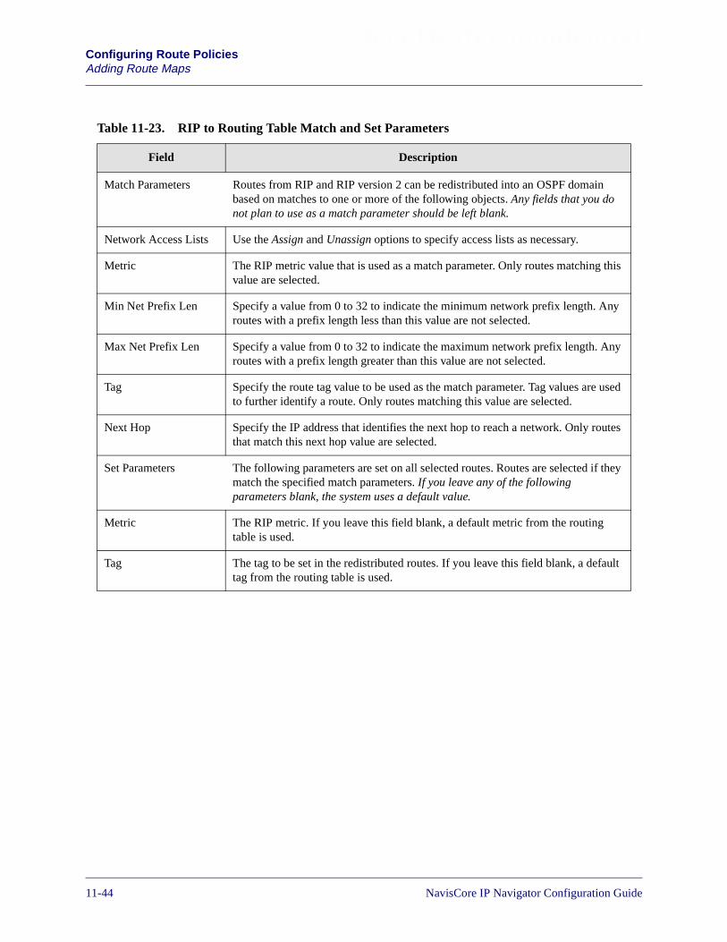
Beta Draft ConfidentialConfiguring Route PoliciesAdding Route Maps
Table 11-23. RIP to Routing Table Match and Set Parameters
Field Description
Match Parameters Routes from RIP and RIP version 2 can be redistributed into an OSPF domainbased on matches to one or more of the following objects. Any fields that you donot plan to use as a match parameter should be left blank.
Network Access Lists Use the Assign and Unassign options to specify access lists as necessary.
Metric The RIP metric value that is used as a match parameter. Only routes matching thisvalue are selected.
Min Net Prefix Len Specify a value from 0 to 32 to indicate the minimum network prefix length. Anyroutes with a prefix length less than this value are not selected.
Max Net Prefix Len Specify a value from 0 to 32 to indicate the maximum network prefix length. Anyroutes with a prefix length greater than this value are not selected.
Tag Specify the route tag value to be used as the match parameter. Tag values are usedto further identify a route. Only routes matching this value are selected.
Next Hop Specify the IP address that identifies the next hop to reach a network. Only routesthat match this next hop value are selected.
Set Parameters The following parameters are set on all selected routes. Routes are selected if theymatch the specified match parameters. If you leave any of the followingparameters blank, the system uses a default value.
Metric The RIP metric. If you leave this field blank, a default metric from the routingtable is used.
Tag The tag to be set in the redistributed routes. If you leave this field blank, a defaulttag from the routing table is used.
11-44 NavisCore IP Navigator Configuration Guide

Beta Draft ConfidentialConfiguring Route Policies
Adding Route Maps
Table 11-24. RIP to VNN Match and Set Parameters
Field Description
Match Parameters Routes from RIP and RIP version 2 can be redistributed into a VNN OSPF domainbased on matches to one or more of the following objects. Any fields that you do notplan to use as a match parameter should be left blank.
Network Access Lists Use the Assign and Unassign options to specify access lists as necessary.
Metric The RIP metric value that is used as a match parameter. Only routes matching thisvalue are selected.
Min Net Prefix Len Specify a value from 0 to 32 to indicate the minimum network prefix length. Anyroutes with a prefix length less than this value are not selected.
Max Net Prefix Len Specify a value from 0 to 32 to indicate the maximum network prefix length. Anyroutes with a prefix length greater than this value are not selected.
Tag Specify the route tag value to be used as the match parameter. Tag values are used tofurther identify a route. Only routes matching this value are selected.
Set Parameters The following parameters are set on all selected routes. Routes are selected if theymatch the specified match parameters. If you leave any of the following parametersblank, the system uses a default value.
Metric The VNN OSPF cost. If you leave this field blank, a default value from the routingtable is used.
Tag The tag to be set in the redistributed routes to VNN OSPF. If you leave this fieldblank, a default tag from the routing table is used.
VNN Metric Type Specify one of the following values: External Type 1 or External Type 2. If youleave this field blank, a value of External Type 2 is used.
Next Hop The IP address that identifies the next hop to reach a network. If you leave this fieldblank, a default value of 0 is used.
NavisCore IP Navigator Configuration Guide 1/14/0211-45
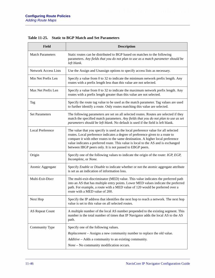
Beta Draft ConfidentialConfiguring Route PoliciesAdding Route Maps
Table 11-25. Static to BGP Match and Set Parameters
Field Description
Match Parameters Static routes can be distributed to BGP based on matches to the followingparameters. Any fields that you do not plan to use as a match parameter should beleft blank.
Network Access Lists Use the Assign and Unassign options to specify access lists as necessary.
Min Net Prefix Len Specify a value from 0 to 32 to indicate the minimum network prefix length. Anyroutes with a prefix length less than this value are not selected.
Max Net Prefix Len Specify a value from 0 to 32 to indicate the maximum network prefix length. Anyroutes with a prefix length greater than this value are not selected.
Tag Specify the route tag value to be used as the match parameter. Tag values are usedto further identify a route. Only routes matching this value are selected.
Set Parameters The following parameters are set on all selected routes. Routes are selected if theymatch the specified match parameters. Any fields that you do not plan to use as setparameters should be left blank. No default is used if the field is left blank.
Local Preference The value that you specify is used as the local preference value for all selectedroutes. Local preference indicates a degree of preference given to a route tocompare it with other routes to the same destination. A higher local preferencevalue indicates a preferred route. This value is local to the AS and is exchangedbetween IBGP peers only. It is not passed to EBGP peers.
Origin Specify one of the following values to indicate the origin of the route: IGP, EGP,Incomplete, or None.
Atomic Aggregate Specify Enable or Disable to indicate whether or not the atomic aggregate attributeis set as an indication of information loss.
Multi-Exit-Discr The multi-exit-discriminator (MED) value. This value indicates the preferred pathinto an AS that has multiple entry points. Lower MED values indicate the preferredpath. For example, a route with a MED value of 120 would be preferred over aroute with a MED value of 200.
Next Hop Specify the IP address that identifies the next hop to reach a network. The next hopvalue is set to this value on all selected routes.
AS Repeat Count A multiple number of the local AS number prepended to the existing segment. Thisnumber is the total number of times that IP Navigator adds the local AS to the ASpath.
Community Type Specify one of the following values.
Replacement – Assigns a new community number to replace the old value.
Additive – Adds a community to an existing community.
None – No community modification occurs.
11-46 NavisCore IP Navigator Configuration Guide

Beta Draft ConfidentialConfiguring Route Policies
Adding Route Maps
Community Specify one of the following values to identify the community:
Define – Indicates that you will specify a user-defined community in theCommunity Value field.
Well Known – Indicates that you will specify one of the following three reservedcommunity values in the Community Value field: No Export, No Advertise, orLocal AS.
None – Indicates that no community value will be specified.
Community Value If you chose Define for the Community field, specify the new community numberthat will be assigned to selected routes.
If you chose Well Known for the Community field, specify one of the followingthree reserved community values: No Export, No Advertise, or Local AS.
If you chose None for the Community field, this field is grayed out to indicate that itis not used.
Table 11-25. Static to BGP Match and Set Parameters (Continued)
Field Description
Table 11-26. Static to OSPF Match and Set Parameters
Field Description
Match Parameters Static routes can be distributed to IP OSPF based on matches to the following lists.Any fields that you do not plan to use as a match parameter should be left blank.
Network Access Lists Use the Assign and Unassign options to specify access lists as necessary.
Min Net Prefix Len Specify a value from 0 to 32 to indicate the minimum network prefix length. Anyroutes with a prefix length less than this value are not selected.
Max Net Prefix Len Specify a value from 0 to 32 to indicate the maximum network prefix length. Anyroutes with a prefix length greater than this value are not selected.
Tag Specify the route tag value to be used as the match parameter. Tag values are usedto further identify a route. Only routes matching this value are selected.
Set Parameters The following parameters are set on all selected routes. Routes are selected if theymatch the specified match parameters. If you leave any of the following parametersblank, the system uses a default value.
Metric The IP OSPF cost. If no IP OSPF metric is specified, a default metric value fromthe routing table is used.
Tag The tag to be set in the redistributed routes to IP OSPF. If none is specified, then adefault tag value from the routing table is used.
OSPF Metric Type Specify one of the following values: External Type 1 or External Type 2.
NavisCore IP Navigator Configuration Guide 1/14/0211-47

Beta Draft ConfidentialConfiguring Route PoliciesAdding Route Maps
Next Hop The IP address that identifies the next hop to reach a network. If you leave this fieldblank, a default value of 0 is used.
Table 11-26. Static to OSPF Match and Set Parameters (Continued)
Field Description
Table 11-27. Static to RIP Match and Set Parameters
Field Description
Match Parameters Static routes can be distributed to RIP based on matches to the following lists. Anyfields that you do not plan to use as a match parameter should be left blank.
Network Access Lists Use the Assign and Unassign options to specify access lists as necessary.
Min Net Prefix Len Specify a value from 0 to 32 to indicate the minimum network prefix length. Anyroutes with a prefix length less than this value are not selected.
Max Net Prefix Len Specify a value from 0 to 32 to indicate the maximum network prefix length. Anyroutes with a prefix length greater than this value are not selected.
Tag Specify the route tag value to be used as the match parameter. Tag values are usedto further identify a route. Only routes matching this value are selected.
Set Parameters The following parameters are set on all selected routes. Routes are selected if theymatch the specified match parameters. If you leave any of the following parametersblank, the system uses a default value.
Metric Sets the metric value on all selected routes to the specified metric value. If youleave this field blank, a default metric value from the routing table is used.
Tag Sets the tag value on all selected routes to the specified tag value. If you leave thisfield blank, a default tag value from the routing table is used.
Next Hop An IP address that identifies the next hop to reach a network. If you leave this fieldblank, a default value of 0 is used.
11-48 NavisCore IP Navigator Configuration Guide

Beta Draft ConfidentialConfiguring Route Policies
Adding Route Maps
Table 11-28. Static to VNN Match and Set Parameters
Field Description
Match Parameters Static routes can be distributed to VNN OSPF based on matches to the followinglists. Any fields that you do not plan to use as a match parameter should be leftblank.
Network Access Lists Use the Assign and Unassign options to specify access lists as necessary.
Min Net Prefix Len Specify a value from 0 to 32 to indicate the minimum network prefix length. Anyroutes with a prefix length less than this value are not selected.
Max Net Prefix Len Specify a value from 0 to 32 to indicate the maximum network prefix length. Anyroutes with a prefix length greater than this value are not selected.
Tag Specify the route tag value to be used as the match parameter. Tag values are usedto further identify a route. Only routes matching this value are selected.
Set Parameters The following parameters are set on all selected routes. Routes are selected if theymatch the specified match parameters. If you leave any of the following parametersblank, the system uses a default value.
Metric The VNN OSPF cost. If no VNN OSPF metric is specified, a default metric valuefrom the routing table is used.
Tag The tag to be set in the redistributed routes to VNN OSPF. If none is specified, thena default tag value from the routing table is used.
VNN Metric Type Specify one of the following values: External Type 1 or External Type 2.
Next Hop The IP address that identifies the next hop to reach a network. If you leave this fieldblank, a default value of 0 is used.
NavisCore IP Navigator Configuration Guide 1/14/0211-49

Beta Draft ConfidentialConfiguring Route PoliciesAdding Route Maps
Table 11-29. Any or Direct to BGP Match and Set Parameters
Field Description
Match Parameters The redistribution of routes from a Direct or Any domain into BGP is based onmatching the following objects. Any fields that you do not plan to use as a matchparameter should be left blank.
Network Access Lists Use the Assign and Unassign options to specify access lists as necessary.
Metric The OSPF cost. Only routes matching this value are selected. This parameter is notused for Direct to BGP route maps.
Min Net Prefix Len Specify a value from 0 to 32 to indicate the minimum network prefix length. Anyroutes with a prefix length less than this value are not selected.
Max Net Prefix Len Specify a value from 0 to 32 to indicate the maximum network prefix length. Anyroutes with a prefix length greater than this value are not selected.
Tag Specify the OSPF route tag value to be used as the match parameter. Only routesmatching this value are selected. This parameter is not used for Direct to BGProute maps.
Set Parameters The following parameters are set on all selected routes. Routes are selected if theymatch the specified match parameters. Any fields that you do not plan to use as aset parameter should be left blank. No default is used if the field is left blank.
Local Preference The value that you specify is used as the local preference value for all selectedroutes. Local preference indicates a degree of preference given to a route tocompare it with other routes to the same destination. A higher local preferencevalue indicates a preferred route. This value is local to the AS and is exchangedbetween IBGP peers only. It is not passed to EBGP peers.
Origin Specify one of the following values to indicate the BGP origin code: IGP, EGP,Incomplete, Do not set.
Atomic Aggregate Specify Enable or Disable to indicate whether or not the atomic aggregate attributeis set as an indication of information loss.
Multi-Exit-Discr The multi-exit-discriminator (MED) value. This value indicates the preferred pathinto an AS that has multiple entry points. Lower MED values indicate the preferredpath. For example, a route with a MED value of 120 would be preferred over aroute with a MED value of 200.
Next Hop An IP address that identifies the next hop to reach a network. If you leave this fieldblank, a default value of 0 is used.
AS Repeat Count A multiple number of the local AS number prepended to the existing segment. Thisnumber is the total number of times that IP Navigator adds the local AS to the ASpath.
11-50 NavisCore IP Navigator Configuration Guide
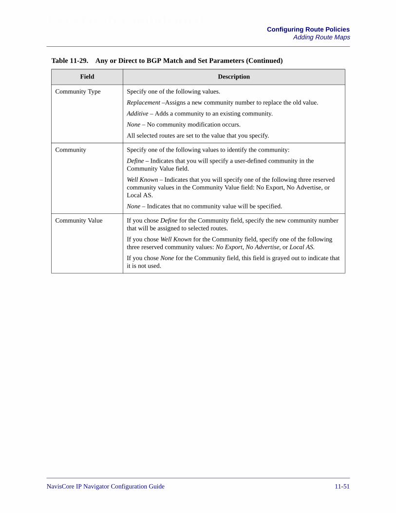
Beta Draft ConfidentialConfiguring Route Policies
Adding Route Maps
Community Type Specify one of the following values.
Replacement –Assigns a new community number to replace the old value.
Additive – Adds a community to an existing community.
None – No community modification occurs.
All selected routes are set to the value that you specify.
Community Specify one of the following values to identify the community:
Define – Indicates that you will specify a user-defined community in theCommunity Value field.
Well Known – Indicates that you will specify one of the following three reservedcommunity values in the Community Value field: No Export, No Advertise, orLocal AS.
None – Indicates that no community value will be specified.
Community Value If you chose Define for the Community field, specify the new community numberthat will be assigned to selected routes.
If you chose Well Known for the Community field, specify one of the followingthree reserved community values: No Export, No Advertise, or Local AS.
If you chose None for the Community field, this field is grayed out to indicate thatit is not used.
Table 11-29. Any or Direct to BGP Match and Set Parameters (Continued)
Field Description
NavisCore IP Navigator Configuration Guide 1/14/0211-51
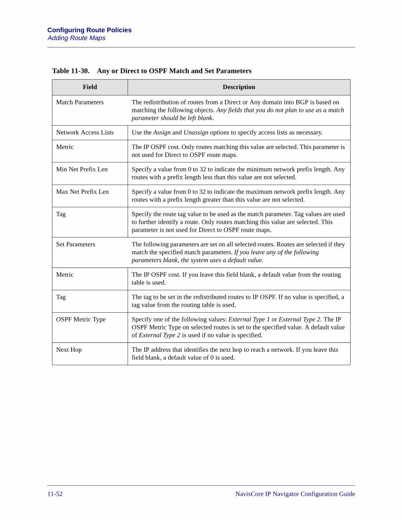
Beta Draft ConfidentialConfiguring Route PoliciesAdding Route Maps
Table 11-30. Any or Direct to OSPF Match and Set Parameters
Field Description
Match Parameters The redistribution of routes from a Direct or Any domain into BGP is based onmatching the following objects. Any fields that you do not plan to use as a matchparameter should be left blank.
Network Access Lists Use the Assign and Unassign options to specify access lists as necessary.
Metric The IP OSPF cost. Only routes matching this value are selected. This parameter isnot used for Direct to OSPF route maps.
Min Net Prefix Len Specify a value from 0 to 32 to indicate the minimum network prefix length. Anyroutes with a prefix length less than this value are not selected.
Max Net Prefix Len Specify a value from 0 to 32 to indicate the maximum network prefix length. Anyroutes with a prefix length greater than this value are not selected.
Tag Specify the route tag value to be used as the match parameter. Tag values are usedto further identify a route. Only routes matching this value are selected. Thisparameter is not used for Direct to OSPF route maps.
Set Parameters The following parameters are set on all selected routes. Routes are selected if theymatch the specified match parameters. If you leave any of the followingparameters blank, the system uses a default value.
Metric The IP OSPF cost. If you leave this field blank, a default value from the routingtable is used.
Tag The tag to be set in the redistributed routes to IP OSPF. If no value is specified, atag value from the routing table is used.
OSPF Metric Type Specify one of the following values: External Type 1 or External Type 2. The IPOSPF Metric Type on selected routes is set to the specified value. A default valueof External Type 2 is used if no value is specified.
Next Hop The IP address that identifies the next hop to reach a network. If you leave thisfield blank, a default value of 0 is used.
11-52 NavisCore IP Navigator Configuration Guide

Beta Draft ConfidentialConfiguring Route Policies
Adding Route Maps
Table 11-31. Any or Direct to RIP Match and Set Parameters
Field Description
Match Parameters The redistribution of routes from a Direct or Any domain into RIP is based onmatching the following objects. Any fields that you do not plan to use as a matchparameter should be left blank.
Network Access Lists Use the Assign and Unassign options to specify access lists as necessary.
Metric The metric value that is used as a match parameter. Only routes matching thisvalue are selected. This parameter is not used for Direct to RIP route maps.
Min Net Prefix Len Specify a value from 0 to 32 to indicate the minimum network prefix length. Anyroutes with a prefix length less than this value are not selected.
Max Net Prefix Len Specify a value from 0 to 32 to indicate the maximum network prefix length. Anyroutes with a prefix length greater than this value are not selected.
Tag Specify the route tag value to be used as the match parameter. Tag values are usedto further identify a route. Only routes matching this value are selected. Thisparameter is not used for Direct to RIP route maps.
Set Parameters The following parameters are set on all selected routes. Routes are selected if theymatch the specified match parameters. If you leave any of the following parametersblank, the system uses a default value.
Metric The RIP metric. If no RIP metric is specified, the value in the routing table is used.
Tag The tag to be set in the redistributed routes to RIP. If no value is specified, a tagvalue from the routing table is used.
Next Hop The IP address that identifies the next hop to reach a network. If you leave thisfield blank, a default value of 0 is used.
NavisCore IP Navigator Configuration Guide 1/14/0211-53
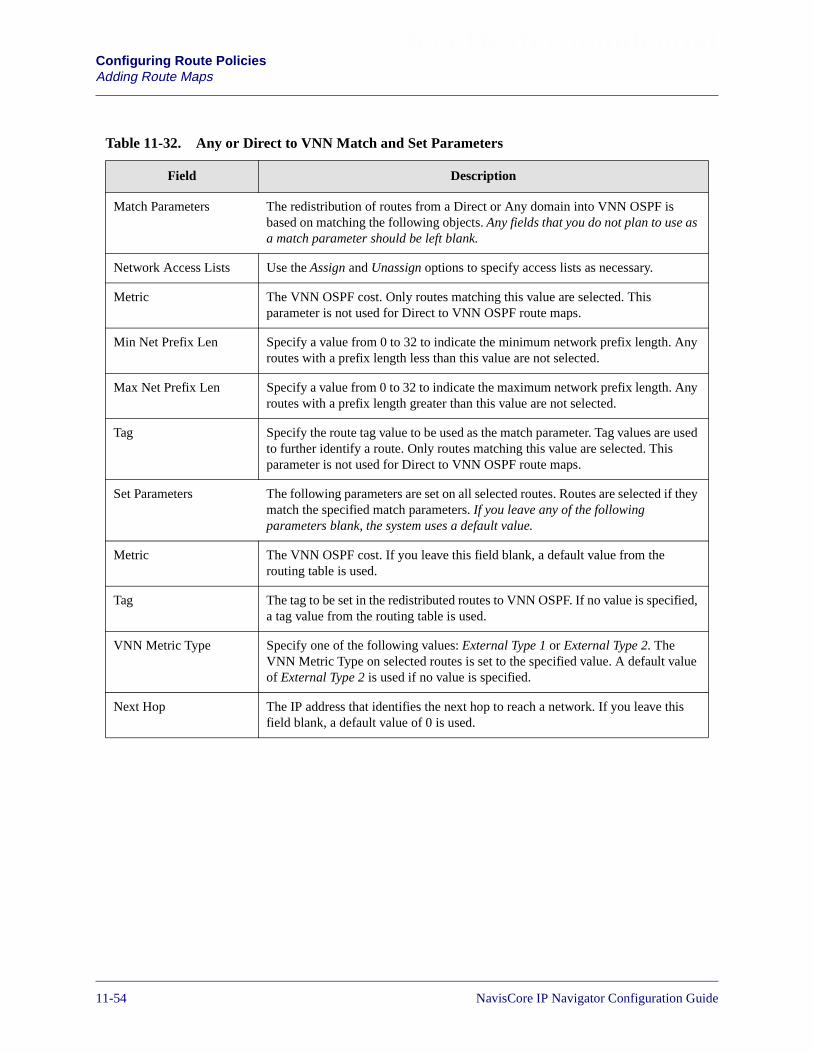
Beta Draft ConfidentialConfiguring Route PoliciesAdding Route Maps
Table 11-32. Any or Direct to VNN Match and Set Parameters
Field Description
Match Parameters The redistribution of routes from a Direct or Any domain into VNN OSPF isbased on matching the following objects. Any fields that you do not plan to use asa match parameter should be left blank.
Network Access Lists Use the Assign and Unassign options to specify access lists as necessary.
Metric The VNN OSPF cost. Only routes matching this value are selected. Thisparameter is not used for Direct to VNN OSPF route maps.
Min Net Prefix Len Specify a value from 0 to 32 to indicate the minimum network prefix length. Anyroutes with a prefix length less than this value are not selected.
Max Net Prefix Len Specify a value from 0 to 32 to indicate the maximum network prefix length. Anyroutes with a prefix length greater than this value are not selected.
Tag Specify the route tag value to be used as the match parameter. Tag values are usedto further identify a route. Only routes matching this value are selected. Thisparameter is not used for Direct to VNN OSPF route maps.
Set Parameters The following parameters are set on all selected routes. Routes are selected if theymatch the specified match parameters. If you leave any of the followingparameters blank, the system uses a default value.
Metric The VNN OSPF cost. If you leave this field blank, a default value from therouting table is used.
Tag The tag to be set in the redistributed routes to VNN OSPF. If no value is specified,a tag value from the routing table is used.
VNN Metric Type Specify one of the following values: External Type 1 or External Type 2. TheVNN Metric Type on selected routes is set to the specified value. A default valueof External Type 2 is used if no value is specified.
Next Hop The IP address that identifies the next hop to reach a network. If you leave thisfield blank, a default value of 0 is used.
11-54 NavisCore IP Navigator Configuration Guide
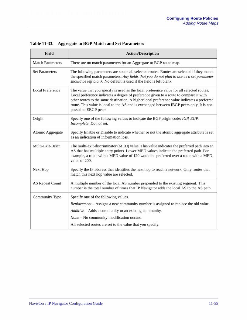
Beta Draft ConfidentialConfiguring Route Policies
Adding Route Maps
Table 11-33. Aggregate to BGP Match and Set Parameters
Field Action/Description
Match Parameters There are no match parameters for an Aggregate to BGP route map.
Set Parameters The following parameters are set on all selected routes. Routes are selected if they matchthe specified match parameters. Any fields that you do not plan to use as a set parametershould be left blank. No default is used if the field is left blank.
Local Preference The value that you specify is used as the local preference value for all selected routes.Local preference indicates a degree of preference given to a route to compare it withother routes to the same destination. A higher local preference value indicates a preferredroute. This value is local to the AS and is exchanged between IBGP peers only. It is notpassed to EBGP peers.
Origin Specify one of the following values to indicate the BGP origin code: IGP, EGP,Incomplete, Do not set.
Atomic Aggregate Specify Enable or Disable to indicate whether or not the atomic aggregate attribute is setas an indication of information loss.
Multi-Exit-Discr The multi-exit-discriminator (MED) value. This value indicates the preferred path into anAS that has multiple entry points. Lower MED values indicate the preferred path. Forexample, a route with a MED value of 120 would be preferred over a route with a MEDvalue of 200.
Next Hop Specify the IP address that identifies the next hop to reach a network. Only routes thatmatch this next hop value are selected.
AS Repeat Count A multiple number of the local AS number prepended to the existing segment. Thisnumber is the total number of times that IP Navigator adds the local AS to the AS path.
Community Type Specify one of the following values.
Replacement – Assigns a new community number is assigned to replace the old value.
Additive – Adds a community to an existing community.
None – No community modification occurs.
All selected routes are set to the value that you specify.
NavisCore IP Navigator Configuration Guide 1/14/0211-55

Beta Draft ConfidentialConfiguring Route PoliciesAdding Route Maps
Community Specify one of the following values to identify the community:
Define – Indicates that you will specify a user-defined community in the CommunityValue field.
Well Known – Indicates that you will specify one of the following three reservedcommunity values in the Community Value field: No Export, No Advertise, or Local AS.
None – Indicates that no community value will be specified.
Community Value If you chose Define for the Community field, specify the new community number thatwill be assigned to selected routes.
If you chose Well Known for the Community field, specify one of the following threereserved community values: No Export, No Advertise, or Local AS.
If you chose None for the Community field, this field is grayed out to indicate that it isnot used.
Table 11-33. Aggregate to BGP Match and Set Parameters (Continued)
Field Action/Description
Table 11-34. Aggregate to VNN Match and Set Parameters
Field Description
Match Parameters There are no match parameters for an Aggregate to VNN route map.
Set Parameters The following parameters are set on all selected routes. Routes are selected if they matchthe specified match parameters. Any fields that you do not plan to use as a set parametershould be left blank. No default is used if the field is left blank.
Metric The VNN OSPF cost. If no OSPF metric is specified, a default metric value from therouting table is used.
Tag The tag to be set in the redistributed routes to VNN OSPF. If none is specified, then adefault tag value from the routing table is used.
VNN Metric Type Specify one of the following values: External Type 1 or External Type 2.
Next Hop The IP address that identifies the next hop to reach a network. If you leave this fieldblank, a default value of 0 is used.
11-56 NavisCore IP Navigator Configuration Guide
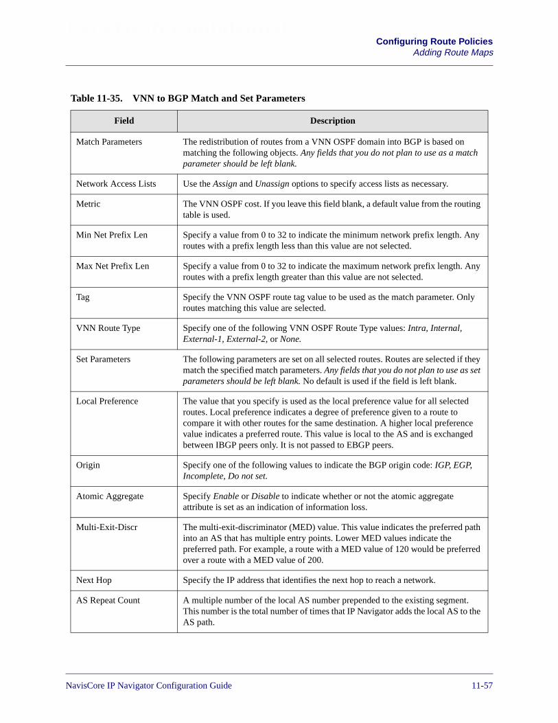
Beta Draft ConfidentialConfiguring Route Policies
Adding Route Maps
Table 11-35. VNN to BGP Match and Set Parameters
Field Description
Match Parameters The redistribution of routes from a VNN OSPF domain into BGP is based onmatching the following objects. Any fields that you do not plan to use as a matchparameter should be left blank.
Network Access Lists Use the Assign and Unassign options to specify access lists as necessary.
Metric The VNN OSPF cost. If you leave this field blank, a default value from the routingtable is used.
Min Net Prefix Len Specify a value from 0 to 32 to indicate the minimum network prefix length. Anyroutes with a prefix length less than this value are not selected.
Max Net Prefix Len Specify a value from 0 to 32 to indicate the maximum network prefix length. Anyroutes with a prefix length greater than this value are not selected.
Tag Specify the VNN OSPF route tag value to be used as the match parameter. Onlyroutes matching this value are selected.
VNN Route Type Specify one of the following VNN OSPF Route Type values: Intra, Internal,External-1, External-2, or None.
Set Parameters The following parameters are set on all selected routes. Routes are selected if theymatch the specified match parameters. Any fields that you do not plan to use as setparameters should be left blank. No default is used if the field is left blank.
Local Preference The value that you specify is used as the local preference value for all selectedroutes. Local preference indicates a degree of preference given to a route tocompare it with other routes for the same destination. A higher local preferencevalue indicates a preferred route. This value is local to the AS and is exchangedbetween IBGP peers only. It is not passed to EBGP peers.
Origin Specify one of the following values to indicate the BGP origin code: IGP, EGP,Incomplete, Do not set.
Atomic Aggregate Specify Enable or Disable to indicate whether or not the atomic aggregateattribute is set as an indication of information loss.
Multi-Exit-Discr The multi-exit-discriminator (MED) value. This value indicates the preferred pathinto an AS that has multiple entry points. Lower MED values indicate thepreferred path. For example, a route with a MED value of 120 would be preferredover a route with a MED value of 200.
Next Hop Specify the IP address that identifies the next hop to reach a network.
AS Repeat Count A multiple number of the local AS number prepended to the existing segment.This number is the total number of times that IP Navigator adds the local AS to theAS path.
NavisCore IP Navigator Configuration Guide 1/14/0211-57
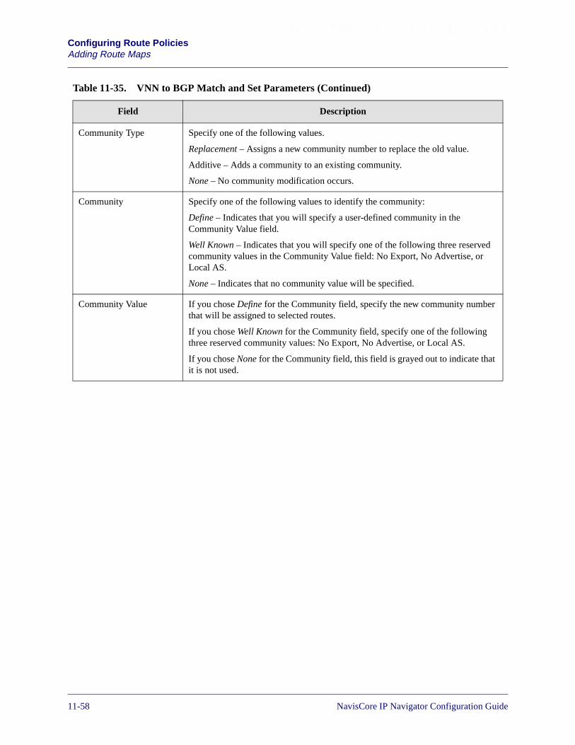
Beta Draft ConfidentialConfiguring Route PoliciesAdding Route Maps
Community Type Specify one of the following values.
Replacement – Assigns a new community number to replace the old value.
Additive – Adds a community to an existing community.
None – No community modification occurs.
Community Specify one of the following values to identify the community:
Define – Indicates that you will specify a user-defined community in theCommunity Value field.
Well Known – Indicates that you will specify one of the following three reservedcommunity values in the Community Value field: No Export, No Advertise, orLocal AS.
None – Indicates that no community value will be specified.
Community Value If you chose Define for the Community field, specify the new community numberthat will be assigned to selected routes.
If you chose Well Known for the Community field, specify one of the followingthree reserved community values: No Export, No Advertise, or Local AS.
If you chose None for the Community field, this field is grayed out to indicate thatit is not used.
Table 11-35. VNN to BGP Match and Set Parameters (Continued)
Field Description
11-58 NavisCore IP Navigator Configuration Guide

Beta Draft ConfidentialConfiguring Route Policies
Adding Route Maps
Table 11-36. VNN to OSPF Match and Set Parameters
Field Description
Match Parameters The redistribution of routes from VNN OSPF to IP OSPF are based on matches tothe following objects. Any fields that you do not plan to use as a match parametershould be left blank.
Network Access Lists Use the Assign and Unassign options to specify access lists as necessary.
Metric The VNN OSPF cost. Only routes matching this value are selected.
Min Net Prefix Len Specify a value from 0 to 32 to indicate the minimum network prefix length. Anyroutes with a prefix length less than this value are not selected.
Max Net Prefix Len Specify a value from 0 to 32 to indicate the maximum network prefix length. Anyroutes with a prefix length greater than this value are not selected.
Tag Specify the VNN OSPF route tag value to be used as the match parameter. Onlyroutes matching this value are selected.
VNN Route Type Specify one of the following VNN Route Type values: Intra, Internal, External-1,External-2, or None.
Set Parameters The following parameters are set on all selected routes. Routes are selected if theymatch the specified match parameters. If you leave any of the following parametersblank, the system uses a default value.
Metric The IP OSPF cost. If you leave this field blank, a default value from the routingtable is used.
Tag The tag to be set in the redistributed routes to IP OSPF. If you leave this field blank,a default tag from the routing table is used.
OSPF Metric Type Specify one of the following values: External Type 1 or External Type 2. If youleave this field blank, a value of External Type 2 is used.
Next Hop The IP address that identifies the next hop to reach a network. If you leave this fieldblank, a default value of 0 is used.
NavisCore IP Navigator Configuration Guide 1/14/0211-59
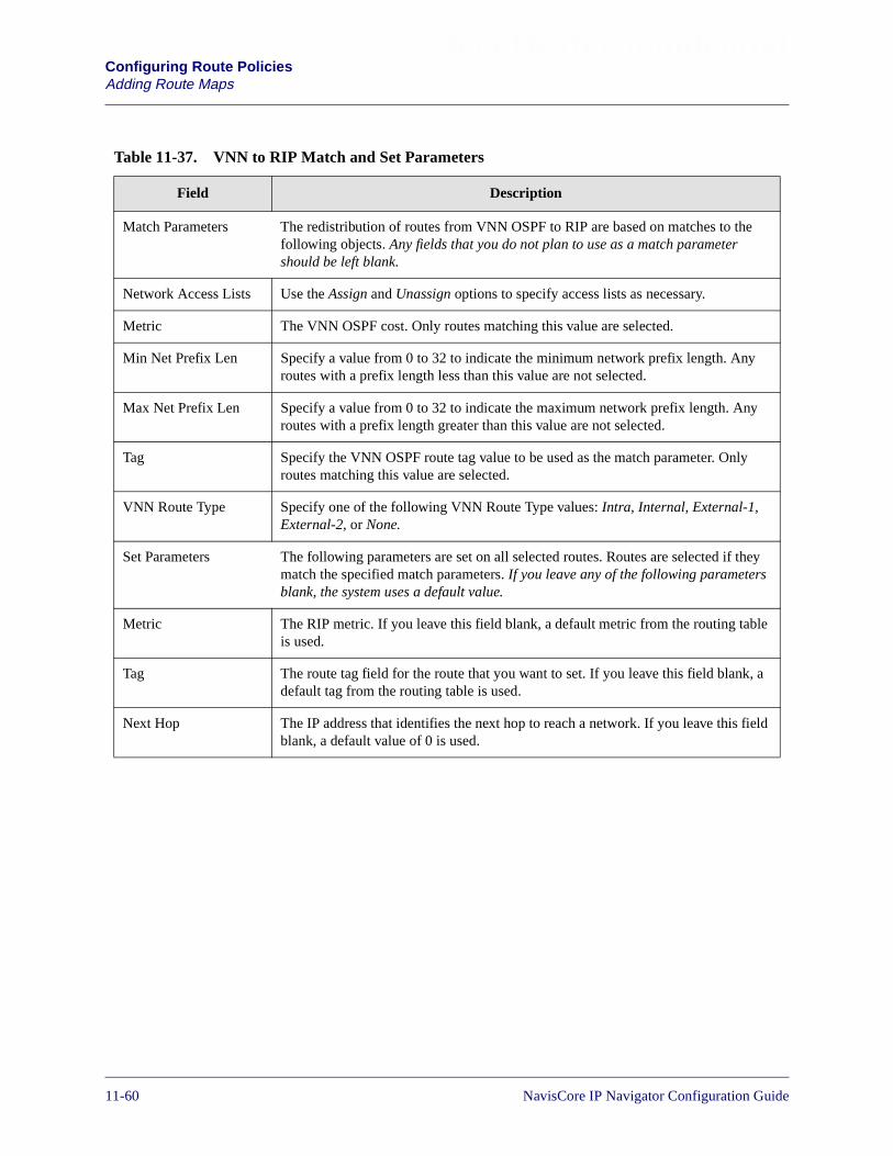
Beta Draft ConfidentialConfiguring Route PoliciesAdding Route Maps
Table 11-37. VNN to RIP Match and Set Parameters
Field Description
Match Parameters The redistribution of routes from VNN OSPF to RIP are based on matches to thefollowing objects. Any fields that you do not plan to use as a match parametershould be left blank.
Network Access Lists Use the Assign and Unassign options to specify access lists as necessary.
Metric The VNN OSPF cost. Only routes matching this value are selected.
Min Net Prefix Len Specify a value from 0 to 32 to indicate the minimum network prefix length. Anyroutes with a prefix length less than this value are not selected.
Max Net Prefix Len Specify a value from 0 to 32 to indicate the maximum network prefix length. Anyroutes with a prefix length greater than this value are not selected.
Tag Specify the VNN OSPF route tag value to be used as the match parameter. Onlyroutes matching this value are selected.
VNN Route Type Specify one of the following VNN Route Type values: Intra, Internal, External-1,External-2, or None.
Set Parameters The following parameters are set on all selected routes. Routes are selected if theymatch the specified match parameters. If you leave any of the following parametersblank, the system uses a default value.
Metric The RIP metric. If you leave this field blank, a default metric from the routing tableis used.
Tag The route tag field for the route that you want to set. If you leave this field blank, adefault tag from the routing table is used.
Next Hop The IP address that identifies the next hop to reach a network. If you leave this fieldblank, a default value of 0 is used.
11-60 NavisCore IP Navigator Configuration Guide

Beta Draft ConfidentialConfiguring Route Policies
Adding Route Maps
Table 11-38. MOSPF to Routing Table Match and Set Parameters
Field Description
Match Parameters Routes from an MOSPF multicast network can be redistributed into a routing tablebased on matches to one or more of the following objects. Any fields that you donot plan to use as a match parameter should be left blank.
Network Access Lists Use the Assign and Unassign options to specify access lists as necessary.
Metric The MOSPF metric value that is used as a match parameter. Only routes matchingthis value are selected.
Min Net Prefix Len Specify a value from 0 to 32 to indicate the minimum network prefix length. Anyroutes with a prefix length less than this value are not selected.
Max Net Prefix Len Specify a value from 0 to 32 to indicate the maximum network prefix length. Anyroutes with a prefix length greater than this value are not selected.
Tag Specify the route tag value to be used as the match parameter. Tag values are usedto further identify a route. Only routes matching this value are selected.
Next Hop Specify the IP address that identifies the next hop to reach a network. Only routesthat match this next hop value are selected.
Set Parameters The following parameter is set on all selected routes. Routes are selected if theymatch the specified match parameters. If you leave any of the followingparameters blank, the system uses a default value.
Metric The routing table metric. If you leave this field blank, a default metric from therouting table is used.
NavisCore IP Navigator Configuration Guide 1/14/0211-61

Beta Draft ConfidentialConfiguring Route PoliciesAdding Route Maps
Table 11-39. MOSPF to DVMRP Match and Set Parameters
Field Description
Match Parameters The redistribution of routes from an MOSPF multicast network to a DVMRPmulticast network are based on matches to the following objects. Any fields that youdo not plan to use as a match parameter should be left blank.
Network Access Lists Use the Assign and Unassign options to specify access lists as necessary.
Metric The MOSPF metric value that is used as a match parameter. Only routes matchingthis value are selected.
Min Net Prefix Len Specify a value from 0 to 32 to indicate the minimum network prefix length. Anyroutes with a prefix length less than this value are not selected.
Max Net Prefix Len Specify a value from 0 to 32 to indicate the maximum network prefix length. Anyroutes with a prefix length greater than this value are not selected.
Set Parameters Not applicable.
Table 11-40. DVMRP to Routing Table Match and Set Parameters
Field Description
Match Parameters The redistribution of routes from DVMRP to the routing table are based on matchesto the following objects. Any fields that you do not plan to use as a match parametershould be left blank.
Network Access Lists Use the Assign and Unassign options to specify access lists as necessary.
Metric The DVMRP metric value that is used as a match parameter. Only routes matchingthis value are selected.
Min Net Prefix Len Specify a value from 0 to 32 to indicate the minimum network prefix length. Anyroutes with a prefix length less than this value are not selected.
Max Net Prefix Len Specify a value from 0 to 32 to indicate the maximum network prefix length. Anyroutes with a prefix length greater than this value are not selected.
Set Parameters Not applicable.
11-62 NavisCore IP Navigator Configuration Guide

Beta Draft ConfidentialConfiguring Route Policies
Adding Route Maps
Table 11-41. DVMRP to DVMRP Match and Set Parameters
Field Description
Match Parameters The redistribution of routes from DVMRP multicast network to DVMRP multicastnetwork are based on matches to the following objects. Any fields that you do notplan to use as a match parameter should be left blank.
Network Access Lists Use the Assign and Unassign options to specify access lists as necessary.
Metric The DVMRP metric value that is used as a match parameter. Only routes matchingthis value are selected.
Min Net Prefix Len Specify a value from 0 to 32 to indicate the minimum network prefix length. Anyroutes with a prefix length less than this value are not selected.
Max Net Prefix Len Specify a value from 0 to 32 to indicate the maximum network prefix length. Anyroutes with a prefix length greater than this value are not selected.
Set Parameters Not applicable.
NavisCore IP Navigator Configuration Guide 1/14/0211-63
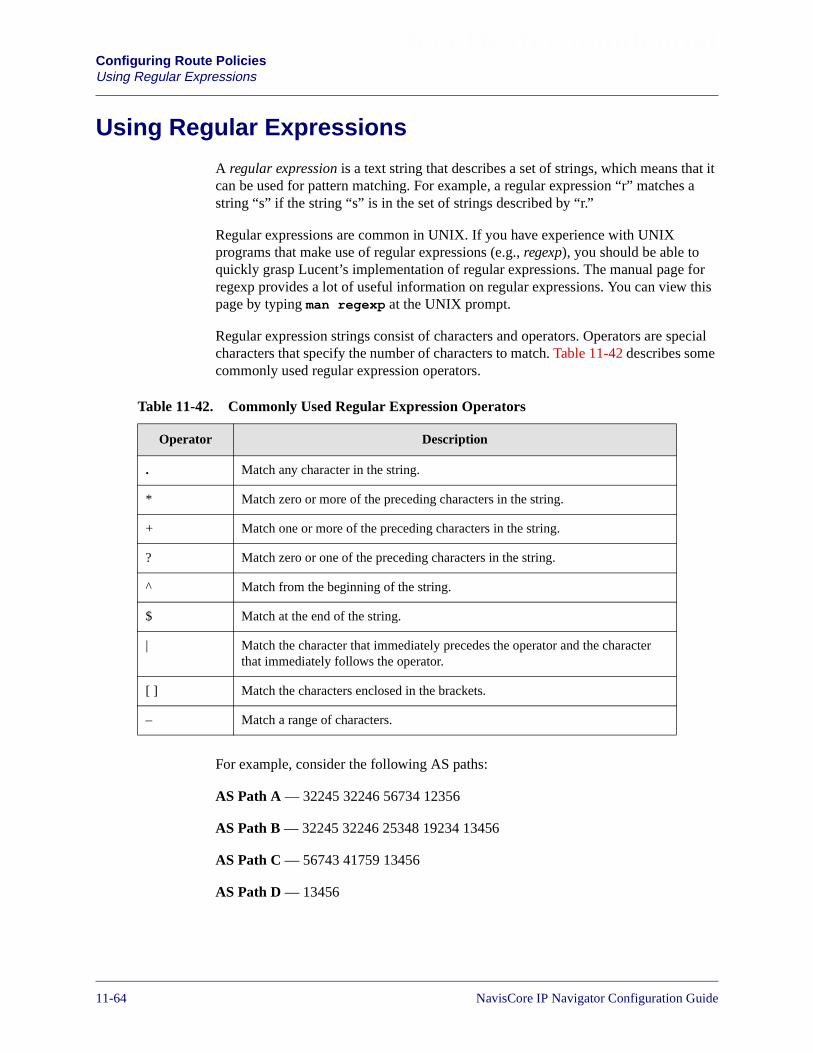
Beta Draft ConfidentialConfiguring Route PoliciesUsing Regular Expressions
Using Regular Expressions
A regular expression is a text string that describes a set of strings, which means that itcan be used for pattern matching. For example, a regular expression “r” matches astring “s” if the string “s” is in the set of strings described by “r.”
Regular expressions are common in UNIX. If you have experience with UNIXprograms that make use of regular expressions (e.g., regexp), you should be able toquickly grasp Lucent’s implementation of regular expressions. The manual page forregexp provides a lot of useful information on regular expressions. You can view thispage by typing man regexp at the UNIX prompt.
Regular expression strings consist of characters and operators. Operators are specialcharacters that specify the number of characters to match. Table 11-42 describes somecommonly used regular expression operators.
For example, consider the following AS paths:
AS Path A — 32245 32246 56734 12356
AS Path B — 32245 32246 25348 19234 13456
AS Path C — 56743 41759 13456
AS Path D — 13456
Table 11-42. Commonly Used Regular Expression Operators
Operator Description
. Match any character in the string.
* Match zero or more of the preceding characters in the string.
+ Match one or more of the preceding characters in the string.
? Match zero or one of the preceding characters in the string.
^ Match from the beginning of the string.
$ Match at the end of the string.
| Match the character that immediately precedes the operator and the characterthat immediately follows the operator.
[ ] Match the characters enclosed in the brackets.
– Match a range of characters.
11-64 NavisCore IP Navigator Configuration Guide

Beta Draft ConfidentialConfiguring Route Policies
Using Regular Expressions
The regular expressions in Table 11-43 illustrate how you can filter BGP controltraffic from these autonomous systems.
You use regular expressions in route maps in which BGP is the source. See “AddingRoute Maps” on page 11-18 for more information on route maps. In that section, thefollowing tables provide information on using regular expressions:
• Table 11-12 on page 11-25
• Table 11-13 on page 11-28
• Table 11-14 on page 11-30
• Table 11-15 on page 11-32
• Table 11-16 on page 11-34
Table 11-43. Regular Expression Examples
RegularExpression
Description Matches ASPath...
^32 Match all paths that begin with “32”. A, B
100$ Match all paths that end with “100”. No matches
56$ Match all paths that end with “56”. A, B, C, D
^13456$ Match all paths that begin and end with “13456”. D
32+ Match all paths that have one or more consecutive twos. A, B
^[5-7]+ Match all paths that begin with the numbers five, six, orseven.
C
34 Match all paths that contain “34”. A, B, D
.* Match all paths. A, B, C, D
\<41759\> Match all paths that contain “41759”. C
^$ Match all paths that contain an empty string. No matches.
Avoid using regular expressions for exact matches on AS numbers. Instead,specify AS Parameters as the match type and specify a transit AS in the routemap configuration. This is a more efficient method of processing exact matchesthan regular expressions.
NavisCore IP Navigator Configuration Guide 1/14/0211-65

Beta Draft ConfidentialConfiguring Route PoliciesUsing Regular Expressions
11-66 NavisCore IP Navigator Configuration Guide
NavisCore IP Navigator Configuration Guide
Beta Draft Confidential
12
Configuring Label Switched Paths
This chapter provides an overview of label switched paths (LSPs) and describes thefollowing configuration tasks:
• Enabling MPT LSPs and multicast LSPs
• Configuring point-to-point LSPs
• Defining a point-to-point connection path
• Displaying the operational status for point-to-point connection paths
• Configuring LSPs over OPTimum cell trunks
12-1
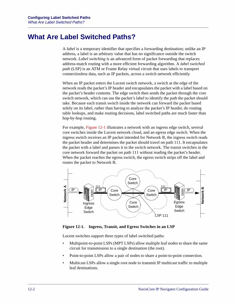
Beta Draft ConfidentialConfiguring Label Switched PathsWhat Are Label Switched Paths?
What Are Label Switched Paths?
A label is a temporary identifier that specifies a forwarding destination; unlike an IPaddress, a label is an arbitrary value that has no significance outside the switchnetwork. Label switching is an advanced form of packet forwarding that replacesaddress-match routing with a more efficient forwarding algorithm. A label switchedpath (LSP) is an ATM or Frame Relay virtual circuit that uses labels to transportconnectionless data, such as IP packets, across a switch network efficiently.
When an IP packet enters the Lucent switch network, a switch at the edge of thenetwork reads the packet’s IP header and encapsulates the packet with a label based onthe packet’s header contents. The edge switch then sends the packet through the coreswitch network, which can use the packet’s label to identify the path the packet shouldtake. Because each transit switch inside the network can forward the packet basedsolely on its label, rather than having to analyze the packet’s IP header, do routingtable lookups, and make routing decisions, label switched paths are much faster thanhop-by-hop routing.
For example, Figure 12-1 illustrates a network with an ingress edge switch, severalcore switches inside the Lucent network cloud, and an egress edge switch. When theingress switch receives an IP packet intended for Network B, the ingress switch readsthe packet header and determines the packet should travel on path 111. It encapsulatesthe packet with a label and passes it to the switch network. The transit switches in thecore network forward the packet on path 111 without reading the packet’s header.When the packet reaches the egress switch, the egress switch strips off the label androutes the packet to Network B.
Figure 12-1. Ingress, Transit, and Egress Switches in an LSP
Lucent switches support three types of label switched paths:
• Multipoint-to-point LSPs (MPT LSPs) allow multiple leaf nodes to share the samecircuit for transmission to a single destination (the root).
• Point-to-point LSPs allow a pair of nodes to share a point-to-point connection.
• Multicast LSPs allow a single root node to transmit IP multicast traffic to multipleleaf destinations.
500
IngressEdge
Switch
CoreSwitch
CoreSwitch
CoreSwitch
CoreSwitch
500
EgressEdge
Switch
IP IP111
IP111
IP
Net
wo
rkA
Net
wo
rkB
LSP 111
12-2 NavisCore IP Navigator Configuration Guide

Beta Draft ConfidentialConfiguring Label Switched Paths
What Are Label Switched Paths?
Every switch that runs IP Navigator maintains an MPT LSP circuit network if youenable MPT LSPs on the switch and create at least one IP interface on the switch.(Note that CBX 500 switches also require a Frame card.)
Both the MPT LSP and multicast LSP networks are rooted at the switch. For thispurpose, the switch maintains a root, which:
• Keeps track of MPT LSP and multicast LSP nodes
• Adds and deletes leaf nodes
• Keeps track of LSP circuits by periodically issuing keepalive messages
A root is a standard circuit endpoint that is created at initialization time on every CPcard in the B-STDX 8000/9000 and every SP card in the CBX 500. All other nodes onthis circuit network are considered leaves. As noted before, traffic flow occurs fromthe leaves to the root on MPT LSP, and from the root to the leaves on multicast LSPs.On point-to-point LSP connections, traffic is bi-directional, since each nodeconfigured on a point-to-point LSP connection acts as both a leaf and a root.
The following section discusses each type of LSP separately.
Multipoint-to-Point (MPT) LSPs
A multipoint-to-point LSP (formerly called a reverse MPT) is a unidirectional virtualcircuit created automatically to route IP traffic to other Lucent switches. An MPT LSPlets all leaf nodes of a particular connectivity tree share the same virtual path whenswitching IP data to the root node of that tree. Data flow on an MPT LSP travels fromthe leaf switches to the root switch. Figure 12-2 shows a sample MPT LSP.
Figure 12-2. MPT Label Switched Path
LucentNetwork
500
500
500
IP Traffic
MPT LSP
MPT LSPRoot
MPT LSPLeaf
IP Traffic
IP Traffic
MPT LSPLeaf
NavisCore IP Navigator Configuration Guide 1/14/0212-3

Beta Draft ConfidentialConfiguring Label Switched PathsWhat Are Label Switched Paths?
Every switch in an IP Navigator network automatically establish MPT LSP circuitswhen they are initialized, and update the MPT LSP circuits when other switches joinor leave the network. After a switch establishes an MPT LSP circuit from itself (root)to the leaf switches, it updates the MPT LSP circuits when other switches join or leavethe network.
For example, Figure 12-3 illustrates a network that includes three nodes, each ofwhich has established an MPT LSP to carry data from the leaf nodes to the root node.(The arrows in the figure indicate the data flow direction.) Node 1’s MPT LSP letsports on Nodes 2 and 3 forward packets through the Lucent switch network to Node 1.Similarly, the MPT LSPs that are rooted on Nodes 2 and 3 allow packets to beforwarded to them using labels.
Figure 12-3. MPT LSP Network
MPT LSP Initialization
When OSPF finds a new node, it notifies the root LSP module, which in turn adds thenode to a list of leaves. The list of leaves is updated based on OSPF notifications.Every 30 seconds, a grooming process scans the list, and LSPs may be rerouted basedon current network conditions and the LSP list membership.
MPT LSP Requirements
The root for an MPT LSP is created at initialization time on every CP card in aB-STDX 8000/9000 and on every SP in a CBX 500. Roots track the state of othernodes or forwarding engines (FEs), and are responsible for adding and deleting nodesor FEs as well as keeping nodes or FEs alive.
MPT LSPs will run over direct trunk and Optimum Trunk links.
9000
9000
9000
Node 2Node 1
Node 1’s MPT LSPNode 2’s MPT LSPNode 3’s MPT LSP
Node 3
12-4 NavisCore IP Navigator Configuration Guide
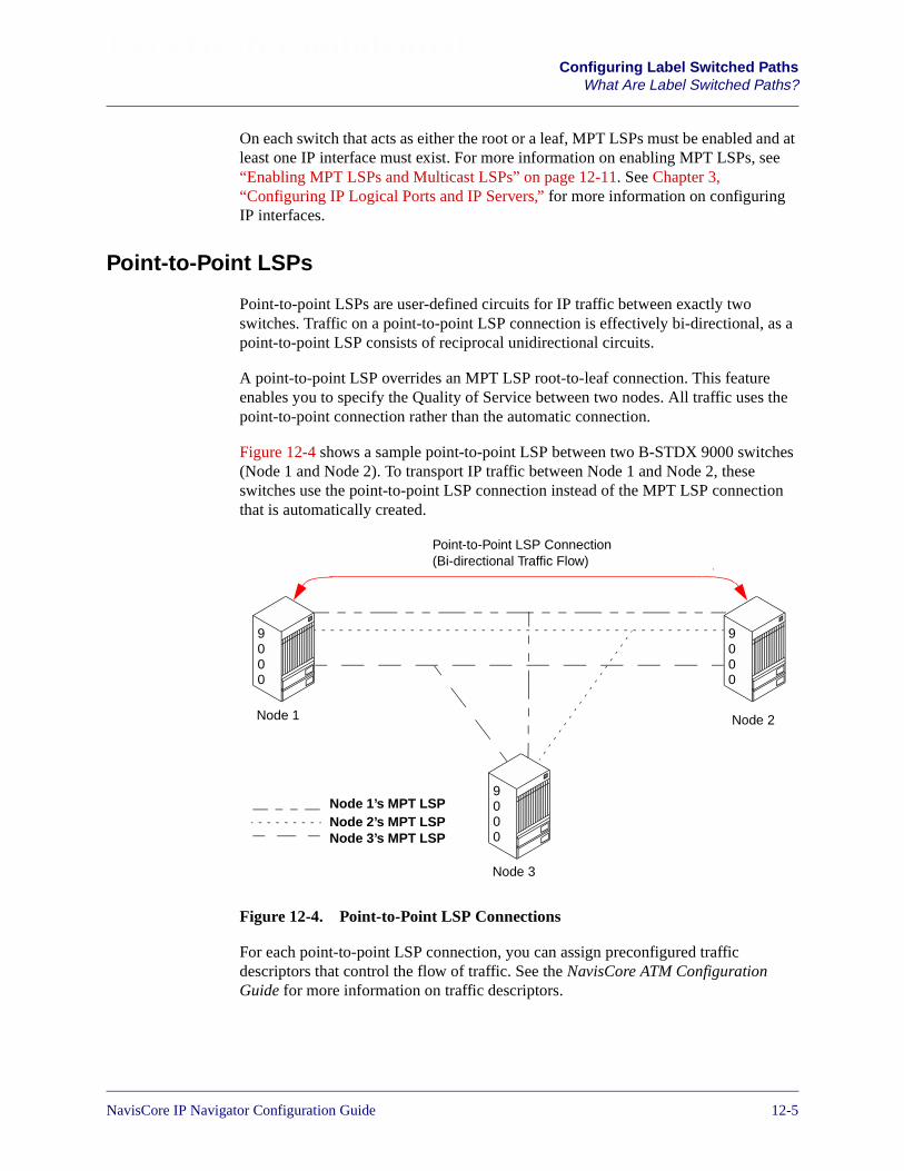
Beta Draft ConfidentialConfiguring Label Switched Paths
What Are Label Switched Paths?
On each switch that acts as either the root or a leaf, MPT LSPs must be enabled and atleast one IP interface must exist. For more information on enabling MPT LSPs, see“Enabling MPT LSPs and Multicast LSPs” on page 12-11. See Chapter 3,“Configuring IP Logical Ports and IP Servers,” for more information on configuringIP interfaces.
Point-to-Point LSPs
Point-to-point LSPs are user-defined circuits for IP traffic between exactly twoswitches. Traffic on a point-to-point LSP connection is effectively bi-directional, as apoint-to-point LSP consists of reciprocal unidirectional circuits.
A point-to-point LSP overrides an MPT LSP root-to-leaf connection. This featureenables you to specify the Quality of Service between two nodes. All traffic uses thepoint-to-point connection rather than the automatic connection.
Figure 12-4 shows a sample point-to-point LSP between two B-STDX 9000 switches(Node 1 and Node 2). To transport IP traffic between Node 1 and Node 2, theseswitches use the point-to-point LSP connection instead of the MPT LSP connectionthat is automatically created.
Figure 12-4. Point-to-Point LSP Connections
For each point-to-point LSP connection, you can assign preconfigured trafficdescriptors that control the flow of traffic. See the NavisCore ATM ConfigurationGuide for more information on traffic descriptors.
9000
9000
9000
Point-to-Point LSP Connection(Bi-directional Traffic Flow)
Node 2Node 1
Node 1’s MPT LSPNode 2’s MPT LSPNode 3’s MPT LSP
Node 3
NavisCore IP Navigator Configuration Guide 1/14/0212-5
Beta Draft ConfidentialConfiguring Label Switched PathsWhat Are Label Switched Paths?
You can define a point-to-point LSP connection between:
• Two B-STDX 8000/9000 switches
• A CBX 500 switch equipped with at least one Frame card (e.g., 6-port DS3 Framecard) and a B-STDX 8000/9000 switch
• Two CBX 500 switches, each equipped with at least one Frame card
When you configure point-to-point LSP connections between two switches, you canreserve them for use by either IP Virtual Private Networks (IP VPNs) or public traffic.IP VPNs use point-to-point LSPs to transport traffic through the Lucent networkbetween virtual routers (VRs). A virtual router is an IP VPN’s representative on aswitch; it behaves very much like a physical router. All IP VPN traffic between thevirtual routers on two switches travels through point-to-point LSP connection, if oneis configured. For more information on IP VPNs, see Chapter 16, “Configuring IPVirtual Private Networks.”
Typically, the point-to-point LSP connects switches at the network edge. Traffic istransported between the switches according to the traffic descriptors assigned to thepoint-to-point LSP connection.
An IP VPN can use:
• Point-to-point LSP connections configured explicitly for that IP VPN. Multiplepoint-to-point LSPs can connect two switches. However, for a single IP VPN, youcan configure one (and only one) point-to-point LSP connection between twoswitches. For example, suppose that you have three IP VPNs that requirepoint-to-point LSP connections between the same two switches. You canconfigure one point-to-point LSP connection for each VPN, but you cannot, forexample, configure two point-to-point LSP connections for any of the VPNs.
• Point-to-point LSP connections configured for public use (available to all IPVPNs and public traffic).
• The default, best-effort MPT LSP, which is always available for public use. ThisMPT LSP is overridden by point-to-point LSPs configured for public use.
Only one point-to-point LSP connection may be configured for public usebetween the same two switches. The public point-to-point LSP connection isoverridden by point-to-point LSP connections configured explicitly for IP VPNs.
12-6 NavisCore IP Navigator Configuration Guide

Beta Draft ConfidentialConfiguring Label Switched Paths
What Are Label Switched Paths?
Figure 12-5 shows IP VPN traffic being transported between two edge switches viapoint-to-point LSP connections. Notice the following details:
• Both VPN1 and VPN2 have a point-to-point LSP connection configured explicitlyfor each of them.
• A public, configured point-to-point LSP connection is available for use by eitherVPN1 or VPN2.
• The public, default point-to-point LSP connection is available for use by eitherVPN1 or VPN2.
Figure 12-5. IP VPN Traffic over Point-to-Point LSP Connections
Multicast LSPs
IP multicasting is the transmission of an IP datagram from one host to a host group, aset of zero or more hosts identified by a single IP destination address. A multicast LSP(formerly called a forward MPT) is constructed as a tree for an ATM or Frame Relaymultipoint virtual circuit, with the node constructing the multicast LSP serving as theroot of the tree. A separate multicast LSP is constructed for each unique set ofmulticast group members for which the root switch wants to forward IP packets.Multicast LSPs transport only multicast traffic, and traffic flows from the root switchto the leaf switches.
Multicast LSPs provide a way to forward IP multicast traffic through the Lucentnetwork. All of the switches that share a multicast LSP are in the same multicast hostgroup.
500
500
VirtualRouter
VirtualRouter
Lucent Network
VirtualRouter
VirtualRouter
VPN1
VPN2
Public (Default, Best-Effort)
Public (Configured)
VPN1
VPN2
VPN1
VPN2
P-P LSP
P-P LSP
P-P LSP
P-P LSP
P-P LSP
P-P LSP
P-P LSP
P-P LSP
At this time, the Multicast Open Shortest Path First (MOSPF) multicast routingprotocol creates multicast LSPs; but other applications, such as DVMRP and IPVPNs, actually use the multicast LSPs.
NavisCore IP Navigator Configuration Guide 1/14/0212-7

Beta Draft ConfidentialConfiguring Label Switched PathsWhat Are Label Switched Paths?
Figure 12-6 shows a sample multicast LSP.
Figure 12-6. Sample Multicast LSP
Multicast LSP Initialization
When a root switch needs to send a message to a particular multicast group, it checkswhether an appropriate multicast LSP already exists. If it does, the root switch usesthis circuit to forward data to the multicast group members. If a multicast LSP is notalready available, the root switch identifies the leaf switches in the multicast groupand begins signalling to establish the virtual circuit to each leaf switch. Until all leafnodes have confirmed the connection setup, the multicast LSP circuit is not used fordata traffic, and packets are routed to the other group nodes.
You must enable multicast LSPs on all the switches in Figure 12-6. See “EnablingMPT LSPs and Multicast LSPs” on page 12-11 for details.
LucentNetwork
500
500
500
MulticastTraffic
MulticastLSP
Multicast LSPRoot
MulticastTraffic
MulticastTraffic
MulticastLSPLeaf
MulticastLSPLeaf
12-8 NavisCore IP Navigator Configuration Guide

Beta Draft ConfidentialConfiguring Label Switched Paths
Processing LSPs
Processing LSPs
All LSPs on the CBX 500 are used to forward IP data over virtual paths (VPs) fromone switch to another. LSPs are initiated at the SP of a CBX 500 in the same way thatthey are initiated at the CP on a B-STDX 8000/9000.
However, each leaf that is added to the LSP occurs:
• In the CP on a B-STDX 8000/9000.
• In the SP on a CBX 500. Each SP and each forwarding engine (FE) on a CBX 500is added as a leaf of the LSP. FEs reassemble cells and perform IP lookups. Thereare two FEs in each of the following CBX 500 cards in Figure 12-7:
– 6-port DS3 Frame card
– 4-port Ethernet
Figure 12-7 illustrates LSP leaf occurrences in the CBX 500 and the B-STDX8000/9000.
Figure 12-7. LSP Leaf Occurrences in the CBX 500 and B-STDX 8000/9000
R
L
L
L
L
L
L
=
R =
L =
Node 2 (CBX 500)Leaf
Node 3 (CBX 500)Leaf
Node 1 (CBX 500)Root
Node 4 (B-STDX 8000/9000)Leaf
Trunk line
LSP root
LSP leaf
FR Card
FR Card
FR Card
CellIOM
CPSP
DS3 FR
DS3 FR
Cell Card
SrvrCrd
CellIOM
SP
CellIOM
DS3 FR
CellIOM
CellIOM
SP
DS3 FR
DS3 FR
Cell IOM
NavisCore IP Navigator Configuration Guide 1/14/0212-9

Beta Draft ConfidentialConfiguring Label Switched PathsLSPs and Switch Domains
LSPs and Switch Domains
There are two types of switch domains:
Cell Domain — Paths that traverse direct ATM trunks and ATM OPTimum trunks.
Frame Domain — Paths that traverse direct Frame trunks and Frame OPTimumtrunks.
A switch can belong to multiple domains if the domains are adjacent. Switches thatbelong to multiple domains must reside at the border of these domains. In addition,these switches must perform additional protocol layer processing to determine routesacross the different domains. The root maintains connections to each domain theswitch belongs to.
The Virtual Network Navigator (VNN) OSPF instance determines how LSPs connecttwo switches in different domains. The following factors apply when determiningLSPs:
• A switch that only belongs to one domain cannot add a switch from a differentdomain to its LSP. LSPs are only established between switches in the samedomain. To traverse different domains, a boundary switch that belongs to bothdomains must act as an intermediary. Each endpoint switch connects to theboundary switch via a separate LSP, and the boundary switch performs an IPlookup when routing traffic between the endpoints.
• If the shortest path between two switches in the same domain traverses a differentdomain, the switches cannot add each other to their LSPs.
LSPs use cell and Frame domains to circumvent addressing limitations in switchingATM cells. Whenever you cross boundaries between cell and Frame domains, an IPlookup is required.
12-10 NavisCore IP Navigator Configuration Guide

Beta Draft ConfidentialConfiguring Label Switched Paths
LSPs and VNN OSPF Areas
LSPs and VNN OSPF Areas
Point-to-point LSPs and multicast LSPs can traverse multiple VNN OSPF areas.However, MPT LSPs cannot traverse multiple VNN OSPF areas. Within a singleVNN OSPF area, MPT LSPs and multicast LSPs are switched. However, as soon astraffic reaches an area boundary (that is, an area border router), a routing lookup mustbe made and the traffic switched on another multicast LSP or MPT LSP, if available.
Enabling MPT LSPs and Multicast LSPs
The Set IP Parameters dialog box allows you to enable MPT LSPs and multicast LSPson a switch. By default, MPT LSPs are enabled for a switch.
The MPT LSPs value that you specify determines the use of MPT LSPs on the switchas follows:
• If the MPT LSPs value is set to Enable and no IP interfaces have been defined, theswitch does not establish MPT LSPs unless the switch is a boundary switch.
• If the MPT LSPs value is set to Enable and IP interfaces have been defined, theswitch does establish MPT LSPs as a means of forwarding IP traffic.
• If the MPT LSPs value is set to Disable and IP interfaces have been defined, theswitch does not establish MPT LSPs to forward IP traffic, but instead uses ahop-by-hop forwarding method.
• If the MPT LSPs value is set to Disable and no IP interfaces have been defined,the switch does not establish MPT LSPs.
In order for the switch to process multicast LSPs, the multicast LSPs value for theswitch must be enabled. Once you enable this setting, switches will create multicastLSPs when multicast traffic is received or IP VPNs are implemented. The multicastLSPs value is enabled by default.
To enable or disable MPT LSPs and multicast LSPs on a switch:
1. Select the switch on the network map.
2. From the Administer menu, choose Lucent IP Parameters� Set IP Parameters.The Set IP Parameters dialog box appears (see Figure 12-8).
An MPT LSP can have multiple roots at the area border router. This eliminatesthe 2048-leaf limit for the aggregate of spanned areas.
NavisCore IP Navigator Configuration Guide 1/14/0212-11

Beta Draft ConfidentialConfiguring Label Switched PathsEnabling MPT LSPs and Multicast LSPs
Figure 12-8. Set IP Parameters Dialog Box
3. Specify information in the Set IP Parameters dialog box fields described inTable 12-1.
4. Choose OK.
Table 12-1. Set IP Parameters Dialog Box: Field Descriptions
Field Action/Description
Switch Name Displays the name of the switch.
OSPF Area 1BackwardCompatible(Applies toswitches inVNN OSPFArea 1 only)
Select either Yes or No. If you select Yes, the switch:
– Can communicate with other Lucent switches in Area 1 running pre-5.0 switchsoftware.
– Can communicate with other Lucent switches in Area 1 running 5.0 switchsoftware, which are set to Yes in this field.
If you select No, the switch:
– Cannot communicate with other Lucent switches in Area 1 running pre-5.0 switchsoftware.
– Can communicate with other Lucent switches in Area 1 running 5.0 switchsoftware, which are set to No in this field.
Note that this parameter applies to VNN OSPF only. It has nothing to do with IP OPSF.See Chapter 9, “Configuring IP OSPF and VNN OSPF” for more information on VNNOSPF and IP OSPF.
MPT LSPs Set this value to Enable or Disable. To process MPT LSP connections, the MPT LSPs valuefor the switch must be set to Enable.
Multicast LSPs Set this value to Enable or Disable. In order for the switch to process multicast LSPs, themulticast LSPs value for the switch must be set to Enable.
MPT LSP CIR(Kbps)
Enter the MPT LSP Committed Information Rate (CIR). The MPT LSP CIR specifies therate in Kbps at which MPT LSPs transfer data, averaged over a minimum increment oftime. In addition, this value reserves bandwidth for MPT LSPs, which the switchoriginates. This value does not apply to multicast LSPs.
Note: This value applies to all links in the MPT LSP.
12-12 NavisCore IP Navigator Configuration Guide

Beta Draft ConfidentialConfiguring Label Switched Paths
Configuring Point-to-Point LSP Connections
Configuring Point-to-Point LSP Connections
The steps you perform to configure a point-to-point LSP connection depend onwhether:
• You want to provision the point-to-point LSP for use by an IP VPN.
• You want to provision the point-to-point LSP for public use.
To configure a point-to-point LSP and provision it for use by an IP VPN, you must:
1. Verify that network-wide traffic descriptors have been configured, if you want toassign a traffic descriptor to the point-to-point LSP. Traffic descriptors consist ofan ATM Quality of Service (QoS) class (for example, UBR/ABR or VBR) andassociated descriptors (for example, peak cell rate). See “Verifying Network-WideTraffic Descriptors” on page 12-13.
2. Select the IP VPN. See “Selecting the IP VPN” on page 16-33. Keep in mind thatthe Set All Point-to-Point LSP Connections dialog box (see Figure 12-9 onpage 12-14) provides a Select IP VPN button, which allows you to select a VPN.
3. Configure one or more point-to-point LSP connections for the IP VPN. See“Configuring the Connections” on page 12-14.
To configure a point-to-point LSP connection and provision it for public use:
1. If you want to assign a traffic descriptor to the point-to-point LSP connection,verify that network-wide traffic descriptors have been configured. See “VerifyingNetwork-Wide Traffic Descriptors” on page 12-13.
2. Configure the point-to-point LSP connection. Point-to-point LSP connections arereserved for use by the Public IP VPN unless you specify otherwise. See“Configuring the Connections” on page 12-14 for more information.
Verifying Network-Wide Traffic Descriptors
Before you assign traffic descriptors to point-to-point LSP connections:
1. Read about traffic descriptors in the NavisCore ATM Configuration Guide. Makesure that you use the ATM guide in conjunction with this guide when you assigntraffic descriptors to point-to-point LSP connections, especially if thepoint-to-point LSP traverses ATM trunks.
2. Create network-wide traffic descriptors using the procedures described in theNavisCore ATM Configuration Guide.
Traffic descriptors do not apply to Frame trunks. Instead, when thepoint-to-point LSP traverses Frame trunks, best-effort guarantees are made tomeet the CIR.
NavisCore IP Navigator Configuration Guide 1/14/0212-13
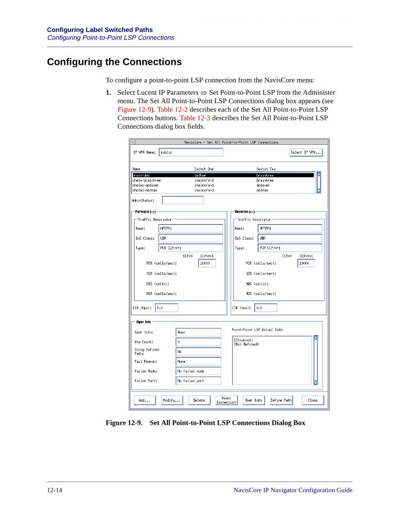
Beta Draft ConfidentialConfiguring Label Switched PathsConfiguring Point-to-Point LSP Connections
Configuring the Connections
To configure a point-to-point LSP connection from the NavisCore menu:
1. Select Lucent IP Parameters� Set Point-to-Point LSP from the Administermenu. The Set All Point-to-Point LSP Connections dialog box appears (seeFigure 12-9). Table 12-2 describes each of the Set All Point-to-Point LSPConnections buttons. Table 12-3 describes the Set All Point-to-Point LSPConnections dialog box fields.
Figure 12-9. Set All Point-to-Point LSP Connections Dialog Box
12-14 NavisCore IP Navigator Configuration Guide

Beta Draft ConfidentialConfiguring Label Switched Paths
Configuring Point-to-Point LSP Connections
Table 12-2. Set All Point-to-Point LSP Connections Dialog Box: Buttons
Button Function
Select IP VPN Allows you to select an IP VPN. Once you select the IP VPN, all management tasks youperform apply only to that IP VPN. See “Selecting the IP VPN” on page 16-33 for moreinformation on selecting an IP VPN.
Add Enables you to add a point-to-point LSP connection. To add the connection, you specify acircuit name, the endpoints, traffic descriptors, and committed information rate (CIR).
Modify Enables you to modify the parameters for a selected point-to-point LSP connection.
Delete Deletes a selected point-to-point LSP connection.
Reset Connection Enables you to toggle connection signalling on and off.
Oper Info Displays operational information about a selected point-to-point LSP connection.
Define Path Displays the Set Point-to-Point LSP Defined Path dialog box to enable you to define thepath of a selected point-to-point LSP connection. See “Defining a Point-to-PointConnection Path” on page 12-18.
Table 12-3. Set All Point-to-Point LSP Connections Dialog Box: Fields
Field Action/Description
Name/Switch One/Switch Two
Displays all of the defined point-to-point LSP connections in your network.
Forward and Reverse CIR and Traffic Descriptors
Name Displays the name of the forward and reverse traffic descriptors.
QoS Class Displays the Quality of Service (QoS) class for the forward and reverse trafficdescriptors. See the NavisCore ATM Configuration Guide for more information on theQoS classes. Note that the CBR QoS class is not supported.
Traffic descriptors are used to route traffic over ATM trunks only. For Frame trunks,best-effort attempts are made to meet the CIR.
Type Displays the forward and reverse traffic descriptor type. See the NavisCore ATMConfiguration Guide for more information.
PCR (cells/sec)
(ATM Only)
Displays the Peak Cell Rate (PCR), in cells per second, for the traffic flow across thepoint-to-point LSP connection in the forward and reverse direction. See theNavisCore ATM Configuration Guide for more information.
SCR (cells/sec)
(ATM Only)
Displays the Sustained Cell Rate (SCR), in cells per second, for the traffic flow acrossthe point-to-point LSP connection in the forward and reverse direction. See theNavisCore ATM Configuration Guide for more information.
NavisCore IP Navigator Configuration Guide 1/14/0212-15

Beta Draft ConfidentialConfiguring Label Switched PathsConfiguring Point-to-Point LSP Connections
MBS (cells)
(ATM Only)
Displays the Maximum Burst Size (MBS), in number of cells, for the traffic flowacross the point-to-point LSP connection in the forward and reverse direction. See theNavisCore ATM Configuration Guide for more information.
MCR (cells/sec)
(ATM Only)
Displays the Minimum Cell Rate (MCR), in cells per second, for the traffic flowacross the point-to-point LSP connection in the forward and reverse direction. See theNavisCore ATM Configuration Guide for more information.
CIR (Kps) Displays the forward and reverse CIR for the point-to-point LSP connection inkilobits per second (Kps). The CIR is the rate at which the network transfers data inthe forward or reverse direction under normal conditions over Frame trunks. Normalconditions refer to a properly designed network with ample bandwidth and switchcapacity. Over Frame trunks, the CIR is used by VNN OSPF to reserve bandwidth,and is not used for rate enforcement.
Oper Info
Oper Info Displays Up or Down to indicate the current operational status of a selectedpoint-to-point LSP connection.
Hop Count Displays the number of hops used in the path for a selected point-to-point LSPconnection.
Using Defined Path Displays one of the following values:
Yes – Indicates that the point-to-point LSP connection uses a user-defined path.
No – Indicates that the path uses the point-to-point LSP connection that wasautomatically defined by VNN.
Fail Reason Displays the word None if no failure exists or displays the reason in the event of afailure. These fail reasons are reported by the switch to the NMS. Refer to “LSPConnection Failure Reasons” on page B-39 for a list of possible fail reasons.
Failed Node Displays one of the following values:
No Failed Node – Indicates that no failure exists.
A Node ID value – Indicates a failure in the displayed node ID.
Failed Port Displays one of the following values:
No failed port – Indicates that no failure exists.
Logical Port Interface Number – Indicates the number that identifies a logical portinterface (that the point-to-point LSP connection is using to access the switch) in theevent of a failure.
Point-Point LSPActual Path
Displays the actual path for a selected point-to-point LSP connection.
Table 12-3. Set All Point-to-Point LSP Connections Dialog Box: Fields (Continued)
Field Action/Description
12-16 NavisCore IP Navigator Configuration Guide

Beta Draft ConfidentialConfiguring Label Switched Paths
Configuring Point-to-Point LSP Connections
2. Choose Add. The Add Point-to-Point LSP Connection dialog box appears (seeFigure 12-10).
Figure 12-10. Add Point-to-Point LSP Connection Dialog Box
3. Use the up and down arrows to select the two switches as the endpoints for thispoint-to-point LSP connection.
4. Specify the Circuit Name for this connection.
5. Select the Forward and Reverse Traffic Descriptors for the point-to-point LSPconnection. The Forward Traffic Descriptors do not have to be the same as theReverse Traffic Descriptors. See Table 12-3 on page 12-15 for more informationon traffic descriptors.
6. Specify the Forward and Reverse Committed Information Rate (CIR). SeeTable 12-3 on page 12-15 for more information on CIR.
7. Choose OK. The Set All Point-to-Point LSP Connections dialog box reappearsand the point-to-point LSP connection is included in the list of connections. VNNautomatically defines the best path for a point-to-point LSP connection. However,you can use the Define Path option to create a user-defined path. See the followingsection, “Defining a Point-to-Point Connection Path,” for details.
NavisCore IP Navigator Configuration Guide 1/14/0212-17

Beta Draft ConfidentialConfiguring Label Switched PathsConfiguring Point-to-Point LSP Connections
Defining a Point-to-Point Connection Path
VNN automatically uses the best path for a point-to-point LSP connection when youadd the connection. However, you can use the Define Path option to create auser-defined path.
To define the path for a point-to-point LSP connection:
1. Select the connection from the Set All Point-to-Point LSP Connections dialog box(see Figure 12-9).
2. Choose Define Path. The Set Point-to-Point LSP Define Path dialog box appears.
Figure 12-11. Set Point-to-Point LSP Define Path Dialog Box
3. Use the Add to Path arrow to add a hop from the Next Available Hop list to theDefined Hop list. Use the Delete From Path arrow to delete a hop from theDefined Hop list.
4. Specify the necessary information for the Defined and Alternate Path status fields,as shown in Table 12-4.
12-18 NavisCore IP Navigator Configuration Guide

Beta Draft ConfidentialConfiguring Label Switched Paths
Configuring Point-to-Point LSP Connections
Table 12-4. Set Point-to-Point LSP Defined Path Dialog Box: Fields
Field Action/Description
Connection Name Displays a unique name that identifies the point-to-point LSP connection.
From Switch Displays a name that identifies the first switch endpoint of the point-to-point LSPconnection.
To Switch Displays a name that identifies the second switch endpoint of the point-to-point LSPconnection.
Next Available Hop Lists the trunks that are available for use in defining the path for this point-to-pointLSP connection.
Defined Hop Lists the trunks that you are using for this user-defined point-to-point LSPconnection.
Path Info Displays the status of the user-defined path.
Hop Count Displays the number of hops used in the user-defined path for this point-to-point LSPconnection.
Defined Path Status Allows you to select Disable to indicate that the path is administratively down orEnable to indicate that the path is administratively up.
Alternate PathStatus
Allows you to specify whether the alternate path (the path that VNN automaticallydefined before you created that user-defined path) is administratively up or down.
• If you select Disable and the user-defined path for the point-to-point LSPconnection fails, VNN will not use the alternate path.
• If you select Enable, VNN will use the alternate path if the user-defined path fails.
NavisCore IP Navigator Configuration Guide 1/14/0212-19
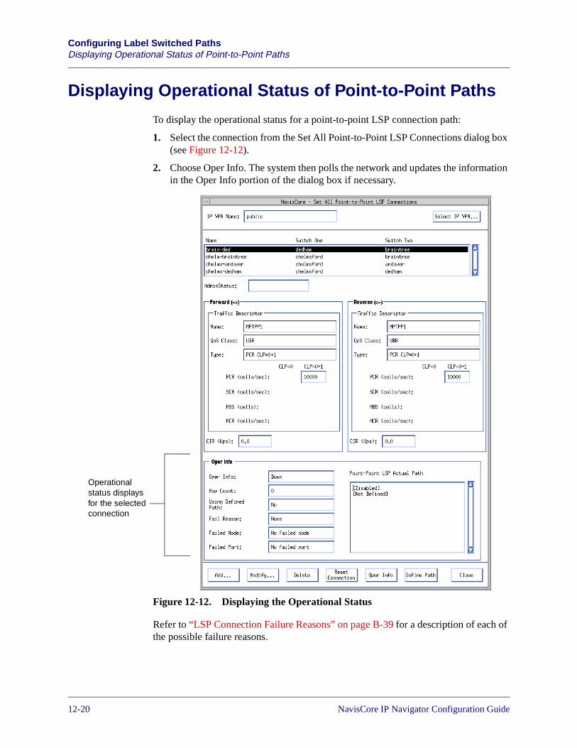
Beta Draft ConfidentialConfiguring Label Switched PathsDisplaying Operational Status of Point-to-Point Paths
Displaying Operational Status of Point-to-Point Paths
To display the operational status for a point-to-point LSP connection path:
1. Select the connection from the Set All Point-to-Point LSP Connections dialog box(see Figure 12-12).
2. Choose Oper Info. The system then polls the network and updates the informationin the Oper Info portion of the dialog box if necessary.
Figure 12-12. Displaying the Operational Status
Refer to “LSP Connection Failure Reasons” on page B-39 for a description of each ofthe possible failure reasons.
Operationalstatus displaysfor the selectedconnection
12-20 NavisCore IP Navigator Configuration Guide

Beta Draft ConfidentialConfiguring Label Switched Paths
Configuring LSPs Over OPTimum Cell Trunks
Configuring LSPs Over OPTimum Cell Trunks
An OPTimum cell trunk creates a switch-to-switch Lucent trunk through a Public DataNetwork (PDN). The Lucent OPTimum cell trunk feature allows private enterprisenetworks to purchase lower-cost, public-carrier services and configure OPTimum celltrunks between two Lucent switches. For more information about configuring anOPTimum cell trunk, see the NavisCore ATM Configuration Guide.
On CBX 500 switches, IP Navigator assigns a virtual path connection (VPC) to eachMPT LSP or point-to-point LSP crossing an OPTimum trunk. These point-to-pointVPCs carry MPT LSP and point-to-point LSP traffic in both directions and, therefore,reduce the number of paths required to interconnect switches in two given clusters.
On B-STDX 8000/9000 switches, IP Navigator assigns a Virtual Channel Connection(VCC) to each MPT LSP or point-to-point LSP crossing an OPTimum trunk.
Before IP Navigator can assign VPCs and VCCs, you must specify specific VPIvalues and ranges of VPI values for each logical port endpoint of the OPTimum trunk.You specify these values when you configure OPTimum Trunk VPI range attributeswhile adding an ATM OPTimum trunk logical port.
OPTimum Cell Trunk VPI Restrictions
The maximum allowable range of VPI values for an OPTimum cell trunk depends onwhether the trunk’s feeder logical port is configured as UNI or NNI. (See theNavisCore ATM Configuration Guide for more information on feeder logical ports.)The values range from 1 through 255 for a UNI logical port and 1 through 4095 for anNNI logical port. Since you can specify more than one OPTimum trunk on the samephysical link, make sure that the VPI value on each trunk does not exceed these limits.
In rare cases, previous VPI range configurations for OPTimum cell trunk logicalports may no longer work once you upgrade to this release of NavisCoresoftware and switch software. The upgrade procedure attempts to convert the oldvalues and is successful in most cases. In the rare cases in which the upgradeprocedure is not successful, you may have to reconfigure VPI ranges for theselogical ports according to the rules and restrictions described in this section.
NavisCore IP Navigator Configuration Guide 1/14/0212-21

Beta Draft ConfidentialConfiguring Label Switched PathsConfiguring LSPs Over OPTimum Cell Trunks
The following restrictions also apply:
• Specify a single VPI value for the default virtual channel connection (VCC). Thisconnection is used for network management and virtual circuit control on theOPTimum trunk. This value must be outside the VPI value ranges you configurefor transit MPT LSP, transit point-to-point LSP connections, and virtual UNIlogical ports. It must also not conflict with the single VPI value you specify forthe MPT LSP root.
• Specify a single VPI value for the MPT LSP root. If the switch where theOPTimum trunk logical port endpoint resides is also the root of an MPT LSP, aVPI is needed for the MPT LSP root. You can specify 0 if the switch is not anMPT LSP root. The value must be an even value between 2 and 30 (e.g., 4), and itmust be outside the VPI value ranges you configure for transit MPT LSPs, transitpoint-to-point LSP connections, virtual UNI logical ports, and the default VCC onCBX 500 switches.
• Specify a range of VPI values for virtual UNI logical ports that use the OPTimumtrunk. The range may be 0 if no PVC virtual paths traverse the trunk. This rangecannot overlap the VPI value ranges you configure for transit MPT LSPs, transitpoint-to-point LSP connections, the MPT LSP root, and the default VCC on CBX500 switches. See the NavisCore ATM Configuration Guide for more informationon virtual UNI logical ports.
• Specify a range of VPI values for transit MPT LSPs. Transit MPT LSPs areroot-to-leaf connections that traverse the trunk. This range cannot overlap the VPIvalue ranges you configure for virtual UNI logical ports, transit point-to-pointLSP connections, the MPT LSP root, and the default VCC on CBX 500 switches.
This range can be 0 if you do not want transit MPT LSPs to be established acrossthe trunk, in which case the switches at the trunk endpoints must perform an IProuting table lookup to forward data. You may want to adopt this approach if youwant to conserve VPIs.
• Specify a range of VPI values for transit point-to-point LSP connections. Transitpoint-to-point LSP connections are connections that traverse the trunk. This rangecannot overlap the VPI value ranges you configure for virtual UNI logical ports,transit MPT LSPs, the MPT LSP root, and the default VCC on CBX 500 switches.
This range can be 0 if you do not want transit point-to-point LSP connections tobe established across the trunk, in which case the switches at the trunk endpointsmust perform an IP routing table look-up in order to forward data. You may wantto adopt this approach if you want to conserve VPIs.
Switches that act as OPTimum cell trunk endpoints cannot also be point-to-pointLSP connection endpoints. They may only act as transit switches forpoint-to-point LSP connections. If you configure a switch as both an OPTimumcell trunk endpoint and as a point-to-point LSP endpoint, the point-to-point LSPwill fail.
12-22 NavisCore IP Navigator Configuration Guide

Beta Draft ConfidentialConfiguring Label Switched Paths
Configuring LSPs Over OPTimum Cell Trunks
It is important that ranges of VPI values do not overlap. For example, if you configure2-to-30 as the range of VPIs for transit MPT LSPs, the range of VPIs for virtual UNIlogical ports should be outside that range. Also, VPIs for virtual UNI logical portsshould not fall in the transit point-to-point LSP connection range.
MPT LSP Traffic Forwarding Across OPTimum Cell Trunks
Table 12-5 summarizes how traffic is forwarded between switches at the leaves ofMPT LSPs and switches at the root of MPT LSPs when the roots and switches areseparated by an OPTimum cell trunk.
Table 12-5. MPT LSP Traffic Forwarding Across OPTimum Cell Trunks
Root Leaf How Data is Forwarded
B-STDX 8000/9000 B-STDX 8000/9000 Data is forwarded over the default VCC VPI. This value isconfigured using the Opt Trunk VPI Range fields in theAdd Logical Port dialog box (see Figure 12-13 onpage 12-24). This VPI may be different on the trunkendpoint switches if the intermediate ATM network thatthe trunk traverses remaps them as it sees fit.
CBX 500 CBX 500 Data is forwarded over a virtual path connection (VPC)that uses one of the following VPIs:
– The MPT LSP VPI, which is configured using theOpt Trunk VPI Range fields in the Add Logical Portdialog box (see Figure 12-13 on page 12-24).
– A VPI from the range of transit MPT LSP VPIsconfigured using the Opt Trunk VPI Range fields inthe Add Logical Port dialog box (see Figure 12-13on page 12-24). This VPI may be different on thetrunk endpoint switches if the intermediate ATMnetwork that the trunk traverses remaps them as itsees fit.
B-STDX 8000/9000 CBX 500 Data is forwarded over the default VCC VPI. This value isconfigured in the Opt Trunk VPI field on the Add LogicalPort dialog box (see Figure 12-13 on page 12-24). ThisVPI may be different on the trunk endpoint switches if theintermediate ATM network that the trunk traverses remapsthem as it sees fit.
CBX 500 B-STDX 8000/9000 Data is forwarded over a VPC VPI. Note that the VPIsconfigured on the CBX 500 should match the VPIsconfigured on nodes at the edge of the intermediate ATMnetwork toward the B-STDX switch.
NavisCore IP Navigator Configuration Guide 1/14/0212-23
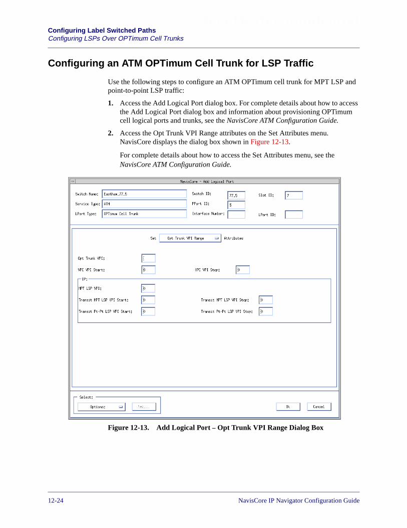
Beta Draft ConfidentialConfiguring Label Switched PathsConfiguring LSPs Over OPTimum Cell Trunks
Configuring an ATM OPTimum Cell Trunk for LSP Traffic
Use the following steps to configure an ATM OPTimum cell trunk for MPT LSP andpoint-to-point LSP traffic:
1. Access the Add Logical Port dialog box. For complete details about how to accessthe Add Logical Port dialog box and information about provisioning OPTimumcell logical ports and trunks, see the NavisCore ATM Configuration Guide.
2. Access the Opt Trunk VPI Range attributes on the Set Attributes menu.NavisCore displays the dialog box shown in Figure 12-13.
For complete details about how to access the Set Attributes menu, see theNavisCore ATM Configuration Guide.
Figure 12-13. Add Logical Port – Opt Trunk VPI Range Dialog Box
12-24 NavisCore IP Navigator Configuration Guide

Beta Draft ConfidentialConfiguring Label Switched Paths
Configuring LSPs Over OPTimum Cell Trunks
3. Specify the specific VPI values and value ranges in the fields described inTable 12-6.
Table 12-6. Opt Trunk VPI Range Attributes Fields
Field Action/Description
Opt Trunk VPI Specify the VPI value for the default virtual channel connection (VCC), which isused for network management and virtual circuit control on the OPTimum trunk.This value must be outside the VPI value ranges you configure for transit MPTLSPs, transit point-to-point LSP connections, and virtual UNIs. It must also notconflict with the MPT LSP VPI value.
VPC VPI Start
(OPTimum cell trunklogical port endpoints onCBX 500 and GX 550switches only)
Specify the first VPI value in the range of VPI values for virtual UNI logical portsthat use the OPTimum trunk. For example, if the range is 155 to 255, you wouldspecify 155 in this field. The default is 0.
The range that you specify must not overlap the ranges that you specify for transitMPT LSPs and transit point-to-point LSP connections. It must also not conflictwith the Opt Trunk VPI value and the MPT LSP VPI value.
See the NavisCore ATM Configuration Guide for more information on virtual UNIlogical ports.
VPC VPI Stop
(OPTimum cell trunklogical port endpoints onCBX 500 and GX 550switches only)
Specify the last VPI value in the range of VPI values for virtual UNI logical portsthat use the OPTimum trunk. For example, if the range is 155 to 255, you wouldspecify 255 in this field.
The range that you specify must not overlap the ranges that you specify for transitMPT LSPs and transit point-to-point LSP connections. It must also not conflictwith the Opt Trunk VPI value and the MPT LSP VPI value.
See the NavisCore ATM Configuration Guide for more information on virtual UNIlogical ports.
MPT LSP VPI
(OPTimum cell trunklogical port endpoints onCBX 500 and GX 550switches only)
Specify the VPI value for the MPT LSP root. If the switch where the OPTimumcell trunk logical port endpoint resides is also the root of an MPT LSP, a VPI isneeded for the MPT LSP root. The value must be an even value between 2 and 30(e.g., 4). The default is 0.
The MPT LSP VPI value must be outside the VPI value ranges you configure fortransit MPT LSPs, transit point-to-point LSP connections, and virtual UNI logicalports. It must also not conflict with the Opt Trunk VPI value.
Transit MPT LSP VPI Start
(OPTimum cell trunklogical port endpoints onCBX 500 and GX 550switches only)
Specify the first VPI value in the range of VPI values for transit MPT LSPs. Thedefault is 0.
The range that you specify must not overlap the ranges that you specify for virtualUNI logical ports and transit point-to-point LSP connections. It must also notconflict with the Opt Trunk VPI value and the MPT LSP VPI value.
NavisCore IP Navigator Configuration Guide 1/14/0212-25
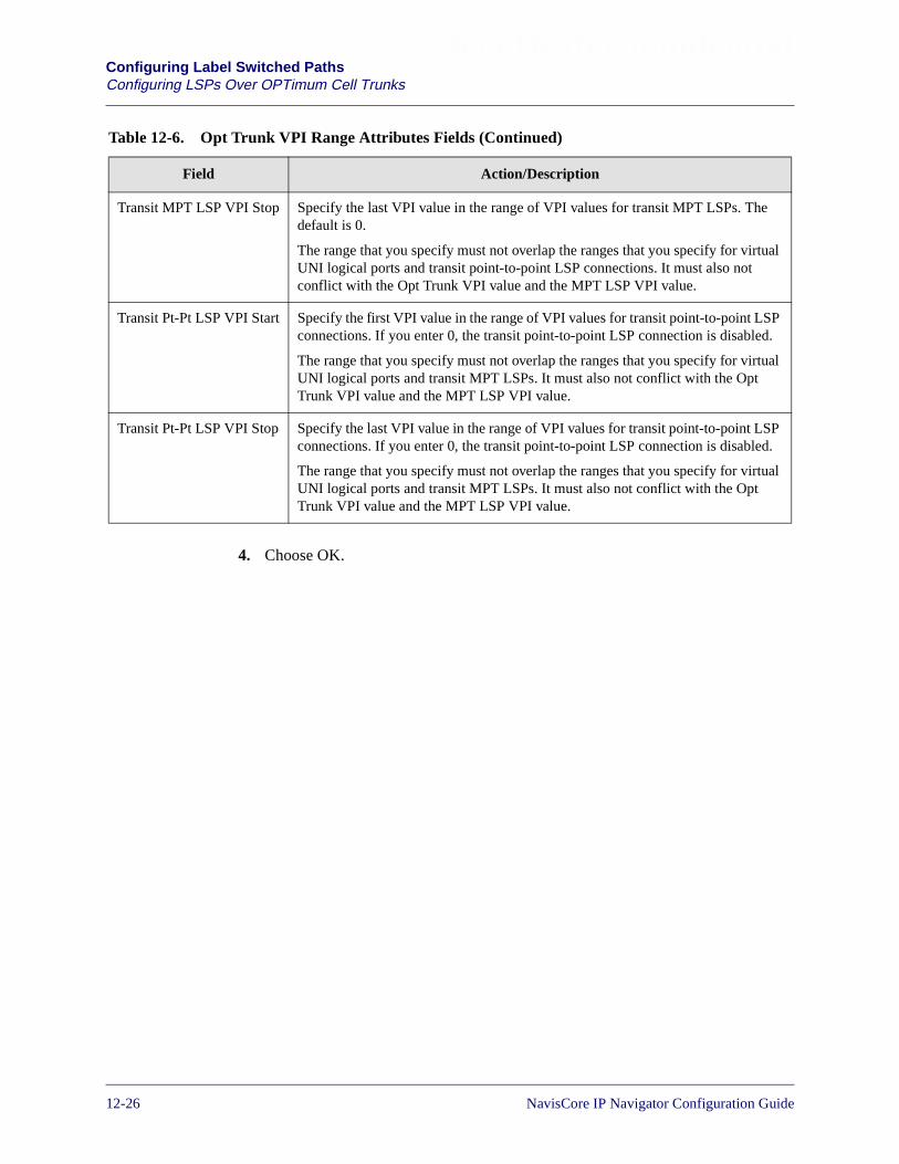
Beta Draft ConfidentialConfiguring Label Switched PathsConfiguring LSPs Over OPTimum Cell Trunks
4. Choose OK.
Transit MPT LSP VPI Stop Specify the last VPI value in the range of VPI values for transit MPT LSPs. Thedefault is 0.
The range that you specify must not overlap the ranges that you specify for virtualUNI logical ports and transit point-to-point LSP connections. It must also notconflict with the Opt Trunk VPI value and the MPT LSP VPI value.
Transit Pt-Pt LSP VPI Start Specify the first VPI value in the range of VPI values for transit point-to-point LSPconnections. If you enter 0, the transit point-to-point LSP connection is disabled.
The range that you specify must not overlap the ranges that you specify for virtualUNI logical ports and transit MPT LSPs. It must also not conflict with the OptTrunk VPI value and the MPT LSP VPI value.
Transit Pt-Pt LSP VPI Stop Specify the last VPI value in the range of VPI values for transit point-to-point LSPconnections. If you enter 0, the transit point-to-point LSP connection is disabled.
The range that you specify must not overlap the ranges that you specify for virtualUNI logical ports and transit MPT LSPs. It must also not conflict with the OptTrunk VPI value and the MPT LSP VPI value.
Table 12-6. Opt Trunk VPI Range Attributes Fields (Continued)
Field Action/Description
12-26 NavisCore IP Navigator Configuration Guide
NavisCore IP Navigator Configuration Guide
Beta Draft Confidential
13
About Next Hop Resolution Protocol
This chapter provides:
• An overview of the Next Hop Resolution Protocol (NHRP)
• An overview of Lucent’s implementation of NHRP
Overview of NHRP
NHRP is a Non-Broadcast Multiple Access (NBMA) address resolution protocol that,when supplied with a network-layer address (such as an IP address), provides a sourcestation (for example, host or router) with the NBMA address of the “next hop” towarda destination station. (Examples of NBMA addresses are ATM End System Addresses[AESAs] and native E.164 addresses, which resemble telephone numbers.) Datapackets do not have to pass through extra hops of routers when the source station anddestination station belong to different Logical Internet Subnets (LIS) of the samelogical NBMA.
NHRP enables a shortcut SVC connection to be established between two points in thenetwork so that they can exchange data packets without the services of intermediaterouters. By supporting these types of connections, the underlying NBMA networkfacilities, such as end-to-end QoS guarantees, may be fully utilized when transmittingnetwork-layer packets. For example, by using shortcut routing, ATM-provided QoSguarantees can be implemented without having to reassemble IP packets at eachnetwork-layer hop.
Although the NHRP protocol can support various network-layer andNBMA-layer address types, the Lucent IP Navigator implementation only issuesand processes NHRP packets for IP (IPv4) over ATM. See “Lucent NHRPImplementation” on page 13-13 for more information on the Lucent NHRPimplementation.
13-1

Beta Draft ConfidentialAbout Next Hop Resolution ProtocolOverview of NHRP
In the protocol's basic form, the “next hop” NBMA address to be resolved is that ofthe destination station itself when the destination station is directly connected to thelogical NBMA subnetwork; otherwise, the “next hop” NBMA address to be resolvedis that of the egress router for the NBMA subnetwork that is closest to the destination.
For example, in Figure 13-1, three CPE are directly connected to the logical NBMAnetwork, and one CPE is not. When the three CPE that are directly connected to thelogical NBMA network are the destination stations, their NBMA addresses areresolved. When the fourth CPE that is not part of the logical NBMA network is thedestination station, the NBMA address of the switch to which the CPE is connected isthe address that is resolved.
Figure 13-1. Sample Logical NBMA Network
Switch
SwitchSwitch
Switch Switch
Switch
LIS 1
LIS 2
LIS 3
Logical NBMA Network
Part ofthe logicalNBMAnetwork
Not part ofthe logical NBMAnetwork. NBMAaddress of switchis resolved.
Part ofthe logicalNBMAnetwork.
Part ofthe logicalNBMAnetwork
CPE
CPE
CPE
CPE
13-2 NavisCore IP Navigator Configuration Guide
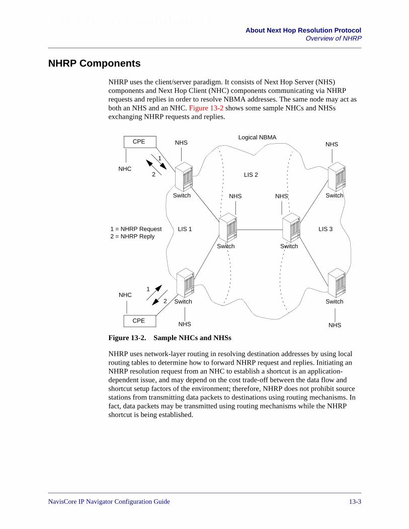
Beta Draft ConfidentialAbout Next Hop Resolution Protocol
Overview of NHRP
NHRP Components
NHRP uses the client/server paradigm. It consists of Next Hop Server (NHS)components and Next Hop Client (NHC) components communicating via NHRPrequests and replies in order to resolve NBMA addresses. The same node may act asboth an NHS and an NHC. Figure 13-2 shows some sample NHCs and NHSsexchanging NHRP requests and replies.
Figure 13-2. Sample NHCs and NHSs
NHRP uses network-layer routing in resolving destination addresses by using localrouting tables to determine how to forward NHRP request and replies. Initiating anNHRP resolution request from an NHC to establish a shortcut is an application-dependent issue, and may depend on the cost trade-off between the data flow andshortcut setup factors of the environment; therefore, NHRP does not prohibit sourcestations from transmitting data packets to destinations using routing mechanisms. Infact, data packets may be transmitted using routing mechanisms while the NHRPshortcut is being established.
LIS 1
LIS 2
LIS 3
Switch
SwitchSwitch
Switch Switch
Switch
Logical NBMA
NHC
NHC
NHS
1
2
1
2
1 = NHRP Request2 = NHRP Reply
NHS
NHS NHS
NHS
NHS
CPE
CPE
NavisCore IP Navigator Configuration Guide 1/14/0213-3
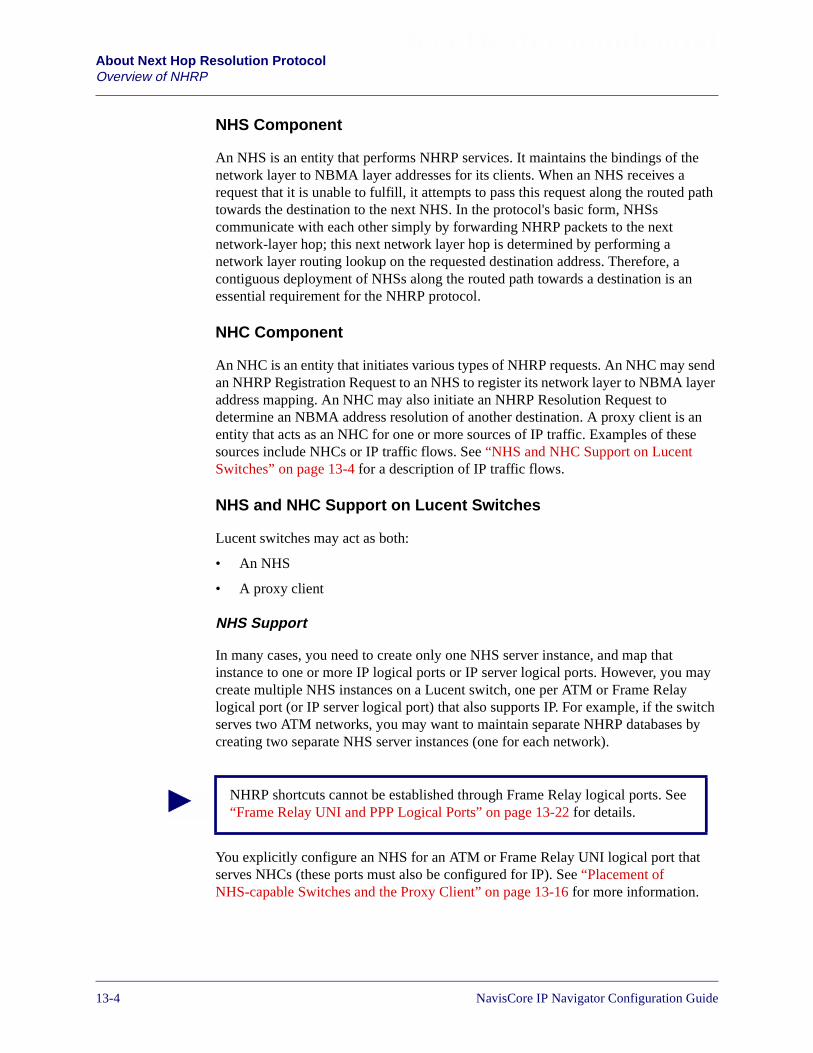
Beta Draft ConfidentialAbout Next Hop Resolution ProtocolOverview of NHRP
NHS Component
An NHS is an entity that performs NHRP services. It maintains the bindings of thenetwork layer to NBMA layer addresses for its clients. When an NHS receives arequest that it is unable to fulfill, it attempts to pass this request along the routed pathtowards the destination to the next NHS. In the protocol's basic form, NHSscommunicate with each other simply by forwarding NHRP packets to the nextnetwork-layer hop; this next network layer hop is determined by performing anetwork layer routing lookup on the requested destination address. Therefore, acontiguous deployment of NHSs along the routed path towards a destination is anessential requirement for the NHRP protocol.
NHC Component
An NHC is an entity that initiates various types of NHRP requests. An NHC may sendan NHRP Registration Request to an NHS to register its network layer to NBMA layeraddress mapping. An NHC may also initiate an NHRP Resolution Request todetermine an NBMA address resolution of another destination. A proxy client is anentity that acts as an NHC for one or more sources of IP traffic. Examples of thesesources include NHCs or IP traffic flows. See “NHS and NHC Support on LucentSwitches” on page 13-4 for a description of IP traffic flows.
NHS and NHC Support on Lucent Switches
Lucent switches may act as both:
• An NHS
• A proxy client
NHS Support
In many cases, you need to create only one NHS server instance, and map thatinstance to one or more IP logical ports or IP server logical ports. However, you maycreate multiple NHS instances on a Lucent switch, one per ATM or Frame Relaylogical port (or IP server logical port) that also supports IP. For example, if the switchserves two ATM networks, you may want to maintain separate NHRP databases bycreating two separate NHS server instances (one for each network).
You explicitly configure an NHS for an ATM or Frame Relay UNI logical port thatserves NHCs (these ports must also be configured for IP). See “Placement ofNHS-capable Switches and the Proxy Client” on page 13-16 for more information.
NHRP shortcuts cannot be established through Frame Relay logical ports. See“Frame Relay UNI and PPP Logical Ports” on page 13-22 for details.
13-4 NavisCore IP Navigator Configuration Guide

Beta Draft ConfidentialAbout Next Hop Resolution Protocol
Overview of NHRP
For trunk logical ports, you do not explicitly configure an NHS. Instead, a specialNHS instance called the default server forwards NHRP traffic on these ports. See“Placement of NHS-capable Switches and the Proxy Client” on page 13-16 for moreinformation.
Proxy Client Support
A proxy client can provision bandwidth and QoS guarantees for IP traffic flows. An IPflow is a set of packets that match a particular profile, called a flow profile, containingdefinitions of source/destination IP addresses with CIDR masks, IP protocol,source/destination protocol port numbers, and Type of Service (TOS) requirements.See “Guaranteeing QoS for IP Traffic Flows” on page 13-25 for more information onflow profiles.
Only one proxy client instance exists on a Lucent switch, but it can send NHRPResolution Requests for multiple logical ports, as long as you enable proxy clientfunctionality on those ports.
Creating Shortcuts
Once the NBMA address of the destination is known by a source (an NHC), an SVCmay be created for a direct connection, thereby eliminating the need for subsequentdata packets to traverse intermediate hops, as illustrated in Figure 13-3.
Figure 13-3. Shortcut Between Two NHCs
LIS 1
LIS 2
LIS 3
Switch/NHS
Switch/NHS
Switch/NHS
Switch/NHS
Switch/NHS
Switch/NHS
Logical NBMA
Shortcut (SVC)Between TwoNHCs
NHC NHC
NHC NHC
CPE CPE
CPECPE
NavisCore IP Navigator Configuration Guide 1/14/0213-5

Beta Draft ConfidentialAbout Next Hop Resolution ProtocolOverview of NHRP
NHRP Protocol
The NHRP protocol supports four fundamental types of packet interactions:
• NHRP Registration Request/Reply
• NHRP Resolution Request/Reply
• NHRP Purge Request/Reply
• NHRP Error Indication
NHRP Registration Request/Reply
An NHC may first register its network-layer/NBMA address mapping with a servingNHS. Typically, the network-layer address is an IP address, though NHRP canpotentially work with protocol suites other than TCP/IP. In most cases, the servingNHS is also the NHC’s default router, but the serving NHS may be a network nodeother than the default router.
To register with the NHS, the NHC sends an NHRP Registration Request to the NHS.If the NHC is configured with the serving NHS's address, the NHS's network-layeraddress may be used in the Destination Address of the NHRP Registration Request.Otherwise, the NHC's own network layer address is put in both the Destination andSource Address fields of the Request.
When an NHS receives an NHRP Registration Request from an NHC, the NHS shouldprocess the request if one of the following conditions is met:
• The Destination Address is equal to its own
• The Source and Destination Addresses are equal and the Destination Addressrepresents the LIS that this NHS is serving
Otherwise, the NHS should forward the NHRP Registration Request along the routedpath.
In response to an NHRP Registration Request, the serving NHS should send an NHRPRegistration Reply over a direct connection to the requesting NHC. Each registrationhas a hold time value for which the registration is valid; therefore, the NHC shouldperiodically transmit the NHRP Registration Requests to prevent the registration fromtiming out.
Figure 13-4 depicts the NHRP Registration process. NHC A and NHC B send NHRPRegistration Requests to NHS A and NHS B respectively, and NHS A and NHS Brespond to NHC A and NHC B with NHRP Registration Replies.
13-6 NavisCore IP Navigator Configuration Guide

Beta Draft ConfidentialAbout Next Hop Resolution Protocol
Overview of NHRP
Figure 13-4. NHRP Registration Process
NHRP Resolution Request/Reply
When an NHC (or proxy client) attempts to resolve an NBMA address, it issues anNHRP Resolution Request toward the routed path.
The manner in which an NHC initiates an NHRP Resolution Request depends on thespecific application. For example, an NHC might generate an NHRP ResolutionRequest when a data packet addressed to a particular network-layer destination (forwhich an NBMA address is unresolved) is forwarded from either a host or a transitrouter. This Resolution Request contains the destination's network layer address, thesource's network layer address, and the source's NBMA layer address. While it awaitsan NHRP Resolution Reply, the NHC may choose to perform one of the followingactions:
• Drop the data packet
• Retain the data packet until the reply is received
• Forward the data packet along the routed path
SwitchSwitch SwitchSwitch
LIS 1
LIS 2
LIS 3
Logical NBMA
NHC A NHS B NHC BNHS A
NHC ARegisters itsNBMA Addresswith NHS A(NHRPRegistrationRequest)
NHRPRegistrationReply toNHC A
NHC BRegisters itsNBMA Addresswith NHS B(NHRPRegistrationRequest)
NHRPRegistrationReply toNHC B
CPE CPE
NavisCore IP Navigator Configuration Guide 1/14/0213-7

Beta Draft ConfidentialAbout Next Hop Resolution ProtocolOverview of NHRP
When an NHS receives an NHRP Resolution Request, it initially determines whetherthe requested network-layer destination address matches any of its cached entries. Ifthere is no match, the NHS performs a routing table lookup and forwards the NHRPResolution Request along the routed path to the downstream NHS. If the NHS has acached match, it generates a positive NHRP Resolution Reply, which is forwardedback along the routed path toward the requesting NHC.
Figure 13-5 and Figure 13-6 illustrate the NHRP resolution transaction. This scenarioassumes the following conditions:
• NHC B already registered its NBMA address with NHS B
• All protocol operations are successful
• No synchronization problems have occurred
Figure 13-5. NHRP Resolution Request for NHC B’s NBMA Address
SwitchSwitch SwitchSwitch
LIS 1
LIS 2
LIS 3
Logical NBMA
NHC A NHS B NHC BNHS A
NHRPResolutionRequest forNHC B
NHRPResolutionRequest forNHC B
NHRPResolutionRequest forNHC B
NHRPResolutionRequest forNHC B
CPE CPE
13-8 NavisCore IP Navigator Configuration Guide

Beta Draft ConfidentialAbout Next Hop Resolution Protocol
Overview of NHRP
Figure 13-6. NHRP Resolution Reply with NHC B’s NBMA Address
An NHS returns a negative NHRP Resolution Reply if no NHSs in the logical NBMAnetwork can reply to the NHRP Resolution Request. This event could occur when anNHS is unable to resolve the request itself and one of the following conditions is met:
• The NHS is unable to forward the packet because there is no corresponding entryin the routing table
• The NHS is the egress node closest to the destination, but does not have theappropriate network-layer-to-NBMA mapping
SwitchSwitch SwitchSwitch
LIS 1
LIS 2
LIS 3
Logical NBMA Network
NHC A NHS B NHC BNHS A
NHRPResolutionReply withNHC B’saddress
NHRPResolutionReply withNHC B’saddress
NHRPResolutionReply withNHC B’saddress
NHRPResolutionReply withNHC B’saddress
CPE CPE
NavisCore IP Navigator Configuration Guide 1/14/0213-9
Beta Draft ConfidentialAbout Next Hop Resolution ProtocolOverview of NHRP
NHRP Purge Request
The purpose of the NHRP Purge Request is to invalidate cached address resolutioninformation before it expires due to the holding time. Either an NHS or an NHC mayinitiate the NHRP Purge Request.
The need to invalidate cached address resolution information might arise as a result ofa change in the relationship between the NHC and serving NHS. If the NHC issues anNHRP Purge Request, the same destination addressing rules as discussed in “NHRPResolution Request/Reply” on page 13-7 apply. If a serving NHS receives an NHRPPurge Request from its client, and the NHS previously responded to one or moreNHCs with an authoritative NHRP Resolution Reply containing the purgedinformation, the serving NHS must purge those NHCs of the information by sending anew NHRP Purge Request to each NHC.
In response to an NHRP Purge Request, the receiving entity purges the requestedinformation from its cache, if it exists. Then, the receiving entity sends an NHRPPurge Reply to the node identified by the source address contained in the NHRP PurgeRequest. When the NHC initiates an NHRP Purge Request, the NHS must send theNHRP Purge Reply over a direct connection between the serving NHS and the NHC.The entity that sends the NHRP Purge Request may retransmit it periodically until therequest is acknowledged or the holding time for the purged address resolutioninformation has expired.
NHRP Error Indication
The NHC or NHS sends an NHRP Error Indication packet to indicate an error in areceived NHRP packet. Some error examples include:
• Unrecognized Extension
• Invalid Extension
• NHRP Loop Detected
• Protocol Address Unreachable
• Protocol Error
• SDU Size Exceeded
• Invalid Resolution Reply Received
• Hop Count Exceeded
A requesting NHC sends an authoritative NHRP Resolution Request when itwants to receive an NHRP Resolution Reply from the serving NHS only. Theserving NHS is the NHS with which the destination NHC has registered itsNBMA address.
13-10 NavisCore IP Navigator Configuration Guide

Beta Draft ConfidentialAbout Next Hop Resolution Protocol
Overview of NHRP
When an NHC or NHS generates an NHRP Error Indication packet, the NHC or NHSdiscards the offending NHRP packet.
NHRP Extensions
To give you administrative flexibility, NHRP supports several optional extensions tothe NHRP packets. An NHS must not change the order of the extensions. Lucentswitches currently support the following extensions:
• Responder Address. See “Responder Address Extension” later in this section.
• Route Record. See “Route Record Extension” later in this section.
The NHRP packet contains a compulsory flag which indicates whether it is mandatoryfor a receiver to process the extension. If this flag is set, but the responder is unable toprocess the extension, the responder sends an NHRP Error Indication. If thecompulsory flag is cleared, then the responder can safely ignore the extension and canreturn the extension unchanged in the NHRP Reply packet.
If a transit NHS cannot process an extension with the compulsory flag set, it justforwards the packet including the extensions — it is not allowed to cache anyresolution data from the NHRP Resolution Reply.
Responder Address Extension
The Responder Address Extension is used to determine the address of the NHRPresponder. This address is not the same as the “next-hop” address in the event that aserving NHS responds to an NHC with a cached resolution address.
If an NHS generates a reply to a request containing this extension, the NHS alsoincludes this extension with its own network-layer address in the reply. This extensionmight be useful in detecting routing loops.
Route Record Extension
Route record extensions — known as the NHRP Forward Transit NHS RecordExtension and the NHRP Reverse Transit NHS Record Extension — contain a list oftransit NHSs that were traversed by an NHRP packet. When a transit NHS receives apacket with one of these extensions, it appends its network-layer address to theextension, and updates the extension length field and the packet checksum field.
The responding NHS does not update the extension. These extensions may be usefulfor loop detection, diagnostic tracing, and subnetwork-layer filtering detection.
Lucent switches do not currently support the Authentication extension.
NavisCore IP Navigator Configuration Guide 1/14/0213-11
Beta Draft ConfidentialAbout Next Hop Resolution ProtocolOverview of NHRP
NHRP Feature Summary
In summary, NHRP has the following key features:
• Resolves “next hop” NBMA addresses, regardless of whether the destinationstation is in the same LIS as the source station.
• Avoids extra hops in an NBMA with multiple LISes.
• Provides several optional extensions.
• Deals with unidirectional data flows.
• Is not specific to a particular NBMA technology or network layer technology.
• Can be used in host-to-host, host-to-router, and router-to-router communications,but some additional efforts should be applied in router-to-router communicationsto avoid persistent routing loops.
• Uses the client/server paradigm consisting of Next Hop Server (NHS)components and Next Hop Client (NHC) components.
• Supports Proxy Next Hop Clients.
• Is not a routing protocol, but depends upon present and future routing protocols.
• Does not prohibit a source station from using conventional router mechanisms totransmit packets, instead of establishing NHRP shortcuts.
13-12 NavisCore IP Navigator Configuration Guide

Beta Draft ConfidentialAbout Next Hop Resolution Protocol
Lucent NHRP Implementation
Lucent NHRP Implementation
This section provides notes on Lucent’s NHRP implementation and relatedconfiguration and management issues.
Configuration and Management Notes
This section provides notes on NHRP configuration and management issues you willencounter.
NHRP and IP VPNs
NHRP resources are public resources (that is, they are assigned to the public IP VPN).They cannot be reserved for exclusive use by private IP VPNs. The sources anddestinations of customer data that traverse NHRP SVC shortcuts, as well as controltraffic, must not be part of a private IP VPN. For example, if an NHRP traffic flowtraverses an ATM PVC from the CPE to an ingress IP logical port, the VPI/VCI mustnot be assigned to a private IP VPN. Rather, it must be assigned to the IP VPN labeledas “public.” See Chapter 16, “Configuring IP Virtual Private Networks” for moreinformation on IP VPNs.
SVC Node Prefixes
On each egress switch that processes NHRP traffic, you must configure an SVC nodeprefix. See “Configuring SVC Node Prefixes” on page 14-9 and the NavisCore ATMConfiguration Guide for more information on configuring SVC node prefixes.
For example, in Figure 13-8 on page 13-17, you would configure an SVC node prefixon Switch 4, since Switch 4 is the egress switch. In Figure 13-9 on page 13-18, youwould configure an SVC node prefix on Switch 1, since Switch 1 is the egress switch.
NHRP Logical Ports
You must add an NHRP logical port on an IP logical port (or IP Server logical port)that is associated with an NHS or a proxy client. See “Adding and Deleting NHRPLogical Ports” on page 14-10 for more information on adding NHRP logical ports.
NavisCore IP Navigator Configuration Guide 1/14/0213-13
Beta Draft ConfidentialAbout Next Hop Resolution ProtocolLucent NHRP Implementation
Addressing
Although the NHRP protocol can support various network-layer and NBMA-layeraddress types, the Lucent IP Navigator implementation only issues and processesNHRP packets for IP (IPv4) over ATM, which includes the following address formats:
• Native E.164
• AESA (i.e., NSAP)
• E.164 with Network Service Access Point (NSAP)
See “About NBMA Addressing” on page 14-4 for more information on addressformats.
MPT Aggregation Technology For Connecting Ingress andEgress Switches
B-STDX switches use proprietary features of the Lucent Virtual Network Navigator(VNN) to exchange NHRP packets in a Lucent network. To link all ingress and egressrouters, the B-STDX switches pre-establish label switched paths (LSPs) through theuse of Multipoint-to-Point Tunnel (MPT) aggregation technology. Instead of usingtraditional hop-by-hop IP routing to forward NHRP packets, the B-STDX switchesuse MPT LSPs as a best-effort message delivery mechanism.
In addition, both B-STDX and CBX switches use MPT LSPs for all data packets untilthe NHRP shortcut is established. Figure 13-7 shows an example of an MPT LSP withthree switches that act as ingress and egress routers.
AESA addressing will be used in the Lucent switch for NSAP addressing.
13-14 NavisCore IP Navigator Configuration Guide
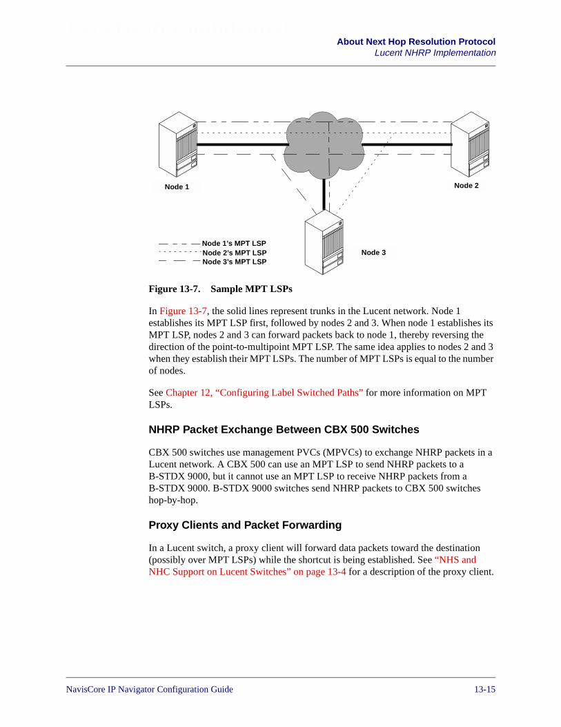
Beta Draft ConfidentialAbout Next Hop Resolution Protocol
Lucent NHRP Implementation
Figure 13-7. Sample MPT LSPs
In Figure 13-7, the solid lines represent trunks in the Lucent network. Node 1establishes its MPT LSP first, followed by nodes 2 and 3. When node 1 establishes itsMPT LSP, nodes 2 and 3 can forward packets back to node 1, thereby reversing thedirection of the point-to-multipoint MPT LSP. The same idea applies to nodes 2 and 3when they establish their MPT LSPs. The number of MPT LSPs is equal to the numberof nodes.
See Chapter 12, “Configuring Label Switched Paths” for more information on MPTLSPs.
NHRP Packet Exchange Between CBX 500 Switches
CBX 500 switches use management PVCs (MPVCs) to exchange NHRP packets in aLucent network. A CBX 500 can use an MPT LSP to send NHRP packets to aB-STDX 9000, but it cannot use an MPT LSP to receive NHRP packets from aB-STDX 9000. B-STDX 9000 switches send NHRP packets to CBX 500 switcheshop-by-hop.
Proxy Clients and Packet Forwarding
In a Lucent switch, a proxy client will forward data packets toward the destination(possibly over MPT LSPs) while the shortcut is being established. See “NHS andNHC Support on Lucent Switches” on page 13-4 for a description of the proxy client.
Node 1 Node 2
Node 3Node 1’s MPT LSPNode 2’s MPT LSPNode 3’s MPT LSP
NavisCore IP Navigator Configuration Guide 1/14/0213-15
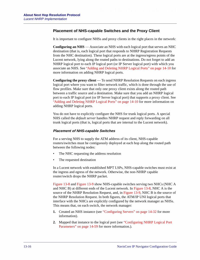
Beta Draft ConfidentialAbout Next Hop Resolution ProtocolLucent NHRP Implementation
Placement of NHS-capable Switches and the Proxy Client
It is important to configure NHSs and proxy clients in the right places in the network:
Configuring an NHS — Associate an NHS with each logical port that serves an NHCdestination (that is, each logical port that responds to NHRP Registration Requestsfrom the NHC destination). These logical ports are at the ingress/egress points of theLucent network, lying along the routed paths to destinations. Do not forget to add anNHRP logical port to each IP logical port (or IP Server logical port) with which youassociate an NHS. See “Adding and Deleting NHRP Logical Ports” on page 14-10 formore information on adding NHRP logical ports.
Configuring the proxy client — To send NHRP Resolution Requests on each ingresslogical port where you want to filter network traffic, which is done through the use offlow profiles. Make sure that only one proxy client exists along the routed pathbetween a traffic source and a destination. Make sure that you add an NHRP logicalport to each IP logical port (or IP Server logical port) that supports a proxy client. See“Adding and Deleting NHRP Logical Ports” on page 14-10 for more information onadding NHRP logical ports.
You do not have to explicitly configure the NHS for trunk logical ports. A specialNHS called the default server handles NHRP request and reply forwarding on alltrunk logical ports (that is, logical ports that are internal to the Lucent network).
Placement of NHS-capable Switches
For a serving NHS to supply the ATM address of its client, NHS-capablerouters/switches must be contiguously deployed at each hop along the routed pathbetween the following nodes:
• The NHC requesting the address resolution
• The requested destination
In a Lucent network with established MPT LSPs, NHS-capable switches must exist atthe ingress and egress of the network. Otherwise, the non-NHRP capablerouter/switch drops the NHRP packet.
Figure 13-8 and Figure 13-9 show NHS-capable switches serving two NHCs (NHC Aand NHC B) at different ends of the Lucent network. In Figure 13-8, NHC A is thesource of the NHRP Resolution Request, and, in Figure 13-9, NHC B is the source ofthe NHRP Resolution Request. In both figures, the ATM/IP UNI logical ports thatinterface with the NHCs are explicitly configured by the network manager as NHSs.This means that, on each switch, the network manager:
1. Created an NHS instance (see “Configuring Servers” on page 14-32 for moreinformation).
2. Mapped that instance to the logical port (see “Configuring NHRP Logical PortParameters” on page 14-59 for more information.).
13-16 NavisCore IP Navigator Configuration Guide

Beta Draft ConfidentialAbout Next Hop Resolution Protocol
Lucent NHRP Implementation
The intermediate trunk logical ports have NHS capabilities automatically enabled bythe default server.
Figure 13-8. First Example of NHS-capable Switches
Ingress/egressATM/IP UNI logicalport configuredas NHS
Ingress/egressATM/IP UNI logicalport configuredas NHS
Switch 4Switch 2 Switch 3Switch 1
Lucent Network
NHC B(Dest.)
NHC A(Source)
NHRPResolutionRequest
NHRPResolutionRequest
NHRPResolutionRequest
NHRPResolutionRequest
NHRPResolutionReply
NHC B hasregistered itsNBMA addresswith the NHS onSwitch 4.
Shortcut (SVC) FromNHC A to NHC B
NHS(TrunkLPorts)
NHS(TrunkLPorts)
NHS(TrunkLPorts)
NHRPResolutionReply
NHRPResolutionReply
NHRPResolutionReply
MPT or MPVC MPT or MPVCMPT or MPVC
MPT = MPT LSP
Requires SVCnode prefix
CPE CPE
NavisCore IP Navigator Configuration Guide 1/14/0213-17
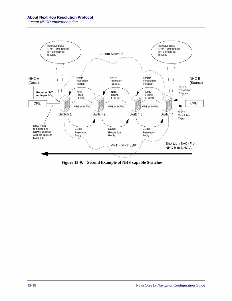
Beta Draft ConfidentialAbout Next Hop Resolution ProtocolLucent NHRP Implementation
Figure 13-9. Second Example of NHS-capable Switches
Ingress/egressATM/IP UNI logicalport configuredas NHS
Ingress/egressATM/IP UNI logicalport configuredas NHS
Switch 4Switch 2 Switch 3Switch 1
Lucent Network
NHC B(Source)
NHC A(Dest.)
NHRPResolutionRequest
NHRPResolutionRequest
NHRPResolutionRequest
NHRPResolutionReply
NHRPResolutionReply
NHRPResolutionReply
NHC A hasregistered itsNBMA addresswith the NHS onSwitch 1.
NHRPResolutionRequest
NHRPResolutionReply
Shortcut (SVC) FromNHC B to NHC A
NHS(TrunkLPorts)
NHS(TrunkLPorts)
NHS(TrunkLPorts)
MPT or MPVC MPT or MPVC MPT or MPVC
MPT = MPT LSP
Requires SVCnode prefix
CPE CPE
13-18 NavisCore IP Navigator Configuration Guide
Beta Draft ConfidentialAbout Next Hop Resolution Protocol
Lucent NHRP Implementation
Placement of Proxy Clients
The proxy client must be enabled on ingress IP logical ports where IP traffic flowsenter the Lucent network. Once the proxy client detects a flow, it sends an NHRPResolution Request to an NHS at an egress logical port. The proxy client must be theonly node in the routed path that initiates NHRP Resolution Requests.
Figure 13-10 illustrates the proper placement of the proxy client. The figure assumesthat IP traffic flows travel in one direction only — hence the presence of the proxyclient on an ingress logical port at only one end of the network.
Figure 13-10. Sample Placement of Proxy Client for Uni-directionalIP Traffic Flow
Egress ATM/IP UNIlogical port configuredas NHS
Switch 4Switch 2 Switch 3Switch 1
CPE
Lucent NetworkIngress ATM/IP UNIlogical port configuredas Proxy Client
NHRPResolutionRequest
NHRPResolutionRequest
NHRPResolutionRequest
NHRPResolutionReply
NHRPResolutionReply
NHRPResolutionReply
NHS(TrunkLPorts)
NHS(TrunkLPorts)
NHS(TrunkLPorts)
NHC B(Dest.)
NHC A(Source)
Proxy client detectsflow and issues NHRPResolution Request NHC B has registered
with NHS on Switch 4
SVC shortcutestablished for IPtraffic flow
MPT or MPVC MPT or MPVC MPT or MPVC
MPT = MPT LSP
Requires SVCnode prefix
CPE
NavisCore IP Navigator Configuration Guide 1/14/0213-19

Beta Draft ConfidentialAbout Next Hop Resolution ProtocolLucent NHRP Implementation
Figure 13-11 illustrates a network in which IP traffic flows in both directions — hencethe presence of the proxy client on ingress logical ports at both ends of the network.
Figure 13-11. Sample Placement of Proxy Clients for Bi-directionalIP Traffic Flows
Multiple NHSs in a LIS
Lucent switches do not currently support the Server Cache Synchronization Protocol(SCSP), which is recommended to support synchronized caches when multiple,redundant NHSs exist in a LIS. If more than one serving NHS is desired in a LIS toavoid a single point of failure, the NHC must register with both NHSs, and transmit allsubsequent registration refreshes and purge requests to both NHS destinations.
Ingress/egressATM/IP UNI logicalport configuredas NHS and proxyclient
Ingress/egressATM/IP UNI logicalport configuredas NHS and proxyclient
Switch 4Switch 2 Switch 3Switch 1
CPE
Lucent Network
CPE
NHRPResolutionRequests
NHRPResolutionReplies
NHS(TrunkLPorts)
NHS(TrunkLPorts)
NHS(TrunkLPorts)
NHC A(Sourceand Dest.)
Proxy client detectsflow and issues NHRPResolution Request
NHC B hasregisteredwith NHSon Switch 4
SVC shortcutestablished for IPtraffic flow
SVC shortcutestablished for IPtraffic flow
NHRPResolutionRequests
NHRPResolutionReplies
Proxy client detectsflow and issues NHRPResolution Request
NHC A hasregisteredwith NHSon Switch 1
NHC B(Sourceand Dest.)
MPT or MPVC MPT or MPVC MPT or MPVC
MPT = MPT LSPRequires SVCnode prefixRequires SVC
node prefix
13-20 NavisCore IP Navigator Configuration Guide
Beta Draft ConfidentialAbout Next Hop Resolution Protocol
Lucent NHRP Implementation
Enabling/Disabling NHRP Requests
The NHS serving a particular NHC must lie along the routed path towards the NHCdestination. In practice, this means that all egress switches must double as NHSsserving the destination beyond them.
The Lucent switch allows you to enable/disable the generation of NHRP requests perATM or Frame Relay UNI logical port. By default, these logical ports are configuredso that they do not generate NHRP requests.
By default, the ability to forward NHRP requests and replies is enabled on trunklogical ports. You cannot disable this feature.
Connection Requirements for Ingress Logical Ports
NHRP Registration Reply and NHC-initiated Purge Requests must be sent over a PVCbetween an external NHC and a serving NHS that is associated with an ingress logicalport. If a PVC does not exist, one should be created. For example, a PVC mustconnect the CPE in Figure 13-11 to the ingress logical ports on Switch 1 and Switch 4(and these logical ports must have NHSs configured for them).
If a proxy client is enabled on an ingress logical port, make sure that CPE (forexample, routers and remote access concentrators) can properly connect to the port.
SVC Connection and Termination
ATM link-layer connectivity must exist between the requesting node and the nodeidentified by the NHRP-supplied ATM address. For example, in Figure 13-11, in orderfor one CPE to request the ATM address of the other, the two CPE must be able tocommunicate using ATM.
If the destination address identifies a node that is off the logical NBMA network, theborder NHS must reply with its own ATM address to terminate the SVC. In a Lucentswitch, the address used for SVC termination is automatically generated using:
• The 13-byte AESA prefix of the management logical port address of the B-STDXCP or the CBX 500 SP
• The 7-byte ESI derived from the IOM/IOP logical port address toward thedestination
Therefore, in order to support an SVC termination from the ingress managementlogical port to the egress management logical port (and vice versa), you mustconfigure the IP management logical port addresses on the CPs or SPs of both endpoint nodes.
NavisCore IP Navigator Configuration Guide 1/14/0213-21

Beta Draft ConfidentialAbout Next Hop Resolution ProtocolLucent NHRP Implementation
No Resolution Cache Match
If an NHS receives an NHRP Resolution Request and finds no resolution cache match,the NHS applies the following rules:
• If the NHS reaches the next hop over a Frame Relay UNI logical port or a PPPlogical port, the NHS terminates the request and responds with an NHRPResolution Reply that contains its own ATM address. See “Frame Relay UNI andPPP Logical Ports” on page 13-22 for more information.
• The NHS forwards the NHRP Resolution Request if the NHS reaches the next hopover an ATM/Frame Relay OPTimum trunk, an ATM/Frame Relay Direct trunk,or an ATM interface (such as UNI, PNNI, IISP, or B-ICI).
• If the NHRP Resolution Request does not meet the criteria for termination orforwarding, the NHRP Resolution Request is negatively acknowledged by theNHS.
Frame Relay UNI and PPP Logical Ports
Although you can configure an NHS on a Frame Relay UNI or PPP logical port, anSVC shortcut connection cannot be established through it. Instead, the SVC isterminated at the Frame Relay UNI or PPP logical port, and data is forwarded to thedestination using IP routing (hop-by-hop).
See “Preventing Persistent Routing Loops” on page 13-34 for additionalinformation on reasons for terminating and negatively acknowledging NHRPresolution requests.
13-22 NavisCore IP Navigator Configuration Guide

Beta Draft ConfidentialAbout Next Hop Resolution Protocol
Lucent NHRP Implementation
Figure 13-12. SVC Terminated at Frame Relay or PPP Logical Port
Switch 2 terminates the SVC with its own ATM address. See “SVC Connection andTermination” on page 13-21 for more information.
Switch 2Switch 1
CPE
Lucent Network
CPE
Dest.Source
SVC terminatesat Switch 2.Data forwardedusing IP routing.
Ingress/egressATM/IP UNI logicalport configuredas NHS
Ingress/egressFrame Relay UNIor PPP logicalport configuredas NHS
SVC
NavisCore IP Navigator Configuration Guide 1/14/0213-23

Beta Draft ConfidentialAbout Next Hop Resolution ProtocolLucent NHRP Implementation
Extensions
In a Lucent switch, the NHRP Responder Address Extension and the Route RecordExtensions are configurable options via the NMS and are disabled by default.However, if a Lucent switch receives an NHRP request with any of these extensions,the switch processes it appropriately.
Domino Effect
When the proxy client on multiple switches along the path between sources anddestinations initiates NHRP Resolution Requests, the NHRP domino effect can occur.The NHRP domino effect produces excessive NHRP traffic and/or the establishmentof unnecessary SVCs.
As the network manager, you are responsible for solving this problem. On eachswitch, you are responsible for enabling proxy client functionality on a per logical portbasis, guaranteeing that the proxy client is the only node in the routed path, from thesource to the destination, responsible for initiating appropriate NHRP ResolutionRequests. Typically, this node is the ingress switch.
In addition, NHRP Resolution Request initiation is prohibited from originating attrunk logical ports (that is, inside a Lucent network).
Queuing of NHRP Packets
NHRP packets are queued separately for each logical port on a CP or SP to preventone logical port from starving out other logical ports.
Backward Feedback
The NHRP-established shortcuts are uni-directional. In order to support backwardfeedback (CCRMs and BCMs) from CBX 500 ports configured with the ATMFlow-Control Processor (ATM FCP), an NMS configuration option — the BandwidthReservation node parameter — is included on a per-node basis. If set, the backwardtraffic descriptor contains a QoS class of UBR with 34 cells per second bandwidthreservation. Otherwise, the reverse traffic descriptor is set to zero. See Table 14-4 onpage 14-13 for a description of the Bandwidth Reservation parameter.
No Support for Non-authoritative Requests
All NHRP Resolution Replies from Lucent switches are authoritative. Lucentswitches currently reply to non-authoritative requests only when they act asauthoritative switches.
At this time, Lucent switches do not support Authentication Extension. If aLucent switch receives this extension, the switch ignores the extension.
13-24 NavisCore IP Navigator Configuration Guide
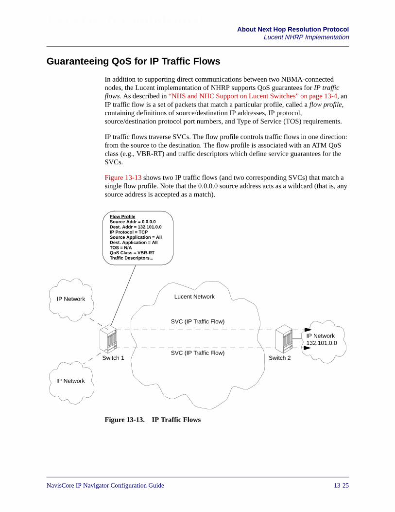
Beta Draft ConfidentialAbout Next Hop Resolution Protocol
Lucent NHRP Implementation
Guaranteeing QoS for IP Traffic Flows
In addition to supporting direct communications between two NBMA-connectednodes, the Lucent implementation of NHRP supports QoS guarantees for IP trafficflows. As described in “NHS and NHC Support on Lucent Switches” on page 13-4, anIP traffic flow is a set of packets that match a particular profile, called a flow profile,containing definitions of source/destination IP addresses, IP protocol,source/destination protocol port numbers, and Type of Service (TOS) requirements.
IP traffic flows traverse SVCs. The flow profile controls traffic flows in one direction:from the source to the destination. The flow profile is associated with an ATM QoSclass (e.g., VBR-RT) and traffic descriptors which define service guarantees for theSVCs.
Figure 13-13 shows two IP traffic flows (and two corresponding SVCs) that match asingle flow profile. Note that the 0.0.0.0 source address acts as a wildcard (that is, anysource address is accepted as a match).
Figure 13-13. IP Traffic Flows
Flow ProfileSource Addr = 0.0.0.0Dest. Addr = 132.101.0.0IP Protocol = TCPSource Application = AllDest. Application = AllTOS = N/AQoS Class = VBR-RTTraffic Descriptors...
Switch 2Switch 1
Lucent Network
IP Network132.101.0.0
IP Network
IP Network
SVC (IP Traffic Flow)
SVC (IP Traffic Flow)
NavisCore IP Navigator Configuration Guide 1/14/0213-25
Beta Draft ConfidentialAbout Next Hop Resolution ProtocolLucent NHRP Implementation
You can guarantee QoS on these SVCs through the use of ATM traffic descriptors(QoS parameters) mapped to flow profiles.
The best way to understand how flow profiles and traffic descriptors work is tounderstand the four possible roles of a Lucent switch:
• Serving NHS
• Ingress Transiting NHS
• Egress Transiting NHS
• Proxy Client
The roles apply to different scenarios, depending on the following factors:
• Whether the NHRP Resolution Request is initiated by an NHC off the Lucentnetwork (for example, from customer premises) or by a proxy client on the Lucentnetwork (that is, a Lucent switch)
• Whether the NHRP Resolution Reply is initiated from an NHS on or off theLucent network
The following four sections discuss each of the Lucent switch roles. The section“Configuring Flow Profiles and Associated QoS Parameters” on page 13-32 discussesthe Flow Profile and QoS Parameters in more detail.
13-26 NavisCore IP Navigator Configuration Guide

Beta Draft ConfidentialAbout Next Hop Resolution Protocol
Lucent NHRP Implementation
Serving NHS
In this role, the Lucent switch acts as a serving NHS for the requested destination.When the switch receives an NHRP Resolution Request from either an NHC or aproxy client, it responds with an NHRP Resolution Reply.
The serving NHS's role is illustrated in Figure 13-14 (shown as the egress NHS).
Figure 13-14. Serving NHS
CPE
Lucent Network
CPE
NHC BNHC A
Switch/IngressNHS
MPT LSP
Switch/ServingNHS
NHRP ResolutionRequest for NHC B’sNBMA Address
NHRP Resolution Reply withNHC B’s NBMA address.
NHC B previouslyregistered with theserving NHS.
NavisCore IP Navigator Configuration Guide 1/14/0213-27
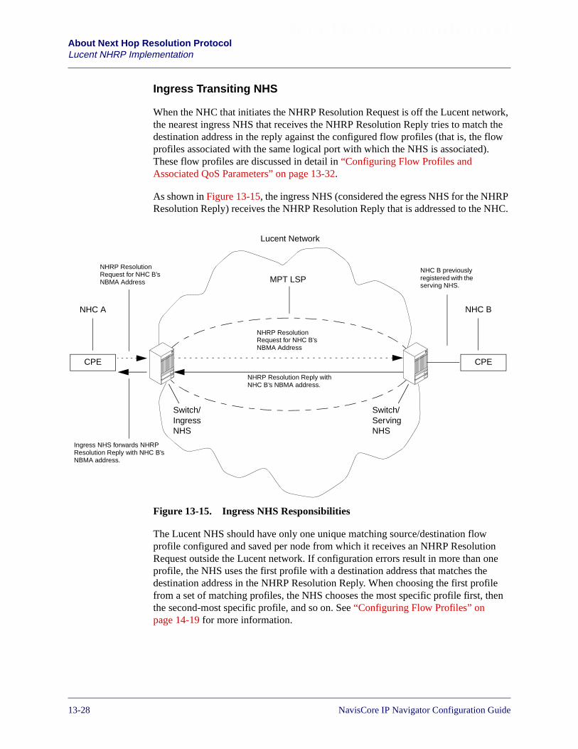
Beta Draft ConfidentialAbout Next Hop Resolution ProtocolLucent NHRP Implementation
Ingress Transiting NHS
When the NHC that initiates the NHRP Resolution Request is off the Lucent network,the nearest ingress NHS that receives the NHRP Resolution Reply tries to match thedestination address in the reply against the configured flow profiles (that is, the flowprofiles associated with the same logical port with which the NHS is associated).These flow profiles are discussed in detail in “Configuring Flow Profiles andAssociated QoS Parameters” on page 13-32.
As shown in Figure 13-15, the ingress NHS (considered the egress NHS for the NHRPResolution Reply) receives the NHRP Resolution Reply that is addressed to the NHC.
Figure 13-15. Ingress NHS Responsibilities
The Lucent NHS should have only one unique matching source/destination flowprofile configured and saved per node from which it receives an NHRP ResolutionRequest outside the Lucent network. If configuration errors result in more than oneprofile, the NHS uses the first profile with a destination address that matches thedestination address in the NHRP Resolution Reply. When choosing the first profilefrom a set of matching profiles, the NHS chooses the most specific profile first, thenthe second-most specific profile, and so on. See “Configuring Flow Profiles” onpage 14-19 for more information.
CPE
Lucent Network
CPE
NHC BNHC A
Switch/IngressNHS
MPT LSP
Switch/ServingNHS
NHRP ResolutionRequest for NHC B’sNBMA Address
Ingress NHS forwards NHRPResolution Reply with NHC B’sNBMA address.
NHC B previouslyregistered with theserving NHS.
NHRP ResolutionRequest for NHC B’sNBMA Address
NHRP Resolution Reply withNHC B’s NBMA address.
13-28 NavisCore IP Navigator Configuration Guide
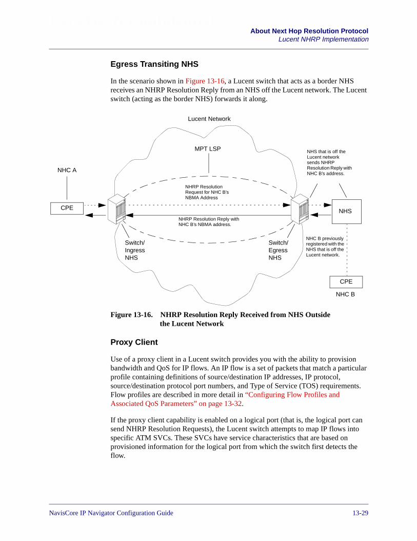
Beta Draft ConfidentialAbout Next Hop Resolution Protocol
Lucent NHRP Implementation
Egress Transiting NHS
In the scenario shown in Figure 13-16, a Lucent switch that acts as a border NHSreceives an NHRP Resolution Reply from an NHS off the Lucent network. The Lucentswitch (acting as the border NHS) forwards it along.
Figure 13-16. NHRP Resolution Reply Received from NHS Outsidethe Lucent Network
Proxy Client
Use of a proxy client in a Lucent switch provides you with the ability to provisionbandwidth and QoS for IP flows. An IP flow is a set of packets that match a particularprofile containing definitions of source/destination IP addresses, IP protocol,source/destination protocol port numbers, and Type of Service (TOS) requirements.Flow profiles are described in more detail in “Configuring Flow Profiles andAssociated QoS Parameters” on page 13-32.
If the proxy client capability is enabled on a logical port (that is, the logical port cansend NHRP Resolution Requests), the Lucent switch attempts to map IP flows intospecific ATM SVCs. These SVCs have service characteristics that are based onprovisioned information for the logical port from which the switch first detects theflow.
CPE
Lucent Network
CPE
NHC A
Switch/IngressNHS
MPT LSP
Switch/EgressNHS
NHC B previouslyregistered with theNHS that is off theLucent network.
NHRP ResolutionRequest for NHC B’sNBMA Address
NHRP Resolution Reply withNHC B’s NBMA address.
NHS
NHC B
NHS that is off theLucent networksends NHRPResolution Reply withNHC B’s address.
NavisCore IP Navigator Configuration Guide 1/14/0213-29

Beta Draft ConfidentialAbout Next Hop Resolution ProtocolLucent NHRP Implementation
The proxy client that resides in the ingress switch sends an NHRP Resolution Requestif all the following criteria are met:
• An IP packet arrives on a logical port for which NHRP Resolution Requestinitiation has been enabled
• The packet belongs to an IP flow with which a parameter profile is associated
• A corresponding shortcut connection does not already exist
• The number of SVCs on the logical port for that type of flow does not exceed theprovisioned threshold
• The number of IP flows does not exceed the provisioned threshold
• The number of packets observed for the IP flow over the specified time intervalexceeds the threshold
When the serving NHS receives the NHRP Resolution Request, it responds with theATM address of the destination for the QoS shortcut. When the proxy client receivesthe NHRP Resolution Reply, it attempts to establish an SVC, and it uses the trafficdescriptors configured for the flow profile (see Figure 13-17).
Figure 13-17. Proxy Client Role
The source address of the SVC’s termination is the address associated with the logicalport on the IOM/IOP on which the proxy client detects the flow.
Egress NHS logicalport.
CPE
Lucent Network
CPE
NHC BNHC A
Switch/IngressNHS
MPT LSP
Switch/EgressNHS
IPTrafficFlow
NHC B previouslyregistered with theegress NHS.
Proxy client issues NHRPResolution Request toegress NHS when itdetects IP traffic flow.
Egress NHS replies withNHC B’s NBMA address.
Ingress logical portconfigured asNHS/Proxy Client
Proxy client establishes shortcutusing traffic descriptorsassociated with the flow profile.
13-30 NavisCore IP Navigator Configuration Guide
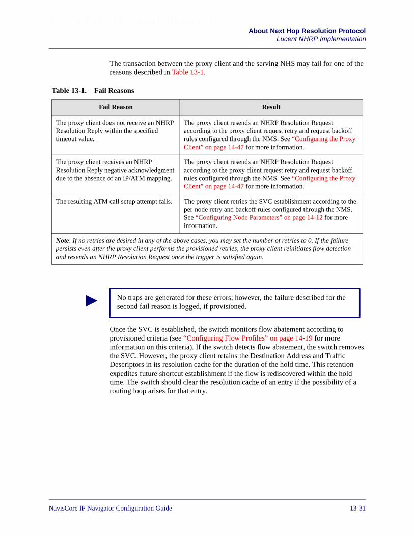
Beta Draft ConfidentialAbout Next Hop Resolution Protocol
Lucent NHRP Implementation
The transaction between the proxy client and the serving NHS may fail for one of thereasons described in Table 13-1.
Once the SVC is established, the switch monitors flow abatement according toprovisioned criteria (see “Configuring Flow Profiles” on page 14-19 for moreinformation on this criteria). If the switch detects flow abatement, the switch removesthe SVC. However, the proxy client retains the Destination Address and TrafficDescriptors in its resolution cache for the duration of the hold time. This retentionexpedites future shortcut establishment if the flow is rediscovered within the holdtime. The switch should clear the resolution cache of an entry if the possibility of arouting loop arises for that entry.
Table 13-1. Fail Reasons
Fail Reason Result
The proxy client does not receive an NHRPResolution Reply within the specifiedtimeout value.
The proxy client resends an NHRP Resolution Requestaccording to the proxy client request retry and request backoffrules configured through the NMS. See “Configuring the ProxyClient” on page 14-47 for more information.
The proxy client receives an NHRPResolution Reply negative acknowledgmentdue to the absence of an IP/ATM mapping.
The proxy client resends an NHRP Resolution Requestaccording to the proxy client request retry and request backoffrules configured through the NMS. See “Configuring the ProxyClient” on page 14-47 for more information.
The resulting ATM call setup attempt fails. The proxy client retries the SVC establishment according to theper-node retry and backoff rules configured through the NMS.See “Configuring Node Parameters” on page 14-12 for moreinformation.
Note: If no retries are desired in any of the above cases, you may set the number of retries to 0. If the failurepersists even after the proxy client performs the provisioned retries, the proxy client reinitiates flow detectionand resends an NHRP Resolution Request once the trigger is satisfied again.
No traps are generated for these errors; however, the failure described for thesecond fail reason is logged, if provisioned.
NavisCore IP Navigator Configuration Guide 1/14/0213-31

Beta Draft ConfidentialAbout Next Hop Resolution ProtocolLucent NHRP Implementation
Configuring Flow Profiles and Associated QoS Parameters
The IP flow profile is defined in terms of:
• IP source and destination addresses (with CIDR masking)
• IP protocol type
• Source and destination TCP/UDP-like protocol ports
• Type of Service (TOS) (e.g., voice)
The IP flow profile also includes the trigger criteria for flow onset and abatement. Youmay use wildcard values for any of these parameters (except trigger criteria) so that apacket only has to match the non-wildcard parameters to match the flow profile.
For example, a specific flow profile defines traffic flows for all TCP traffic thatoriginates from a particular source, but you do not care about the specific destination.You could assign a wildcard to the destination address.
Although you may use wildcards for defining the destination addresses in flowprofiles, the associated destination address for the flows themselves must beunambiguous for establishing an actual SVC. Therefore, several unambiguous flows(and subsequent SVCs) may correspond to a single flow profile. The switch tracksunambiguous flows separately.
You can configure QoS traffic descriptor parameters for the flow profiles. The trafficdescriptors are used to establish the SVC shortcuts that carry the associated trafficflows. The traffic descriptors contain the ATM UNI 4.0 parameters with the exceptionof the following optional extended QOS parameters:
• Cell Loss Ratio (CLR)
• Cell Transfer Delay (CTD)
• Cell Delay Variation (CDV)
The ATM UNI 4.0 parameters are specified in the direction of data flow, from sourceto destination (that is, from the ingress logical port that has NHS and/or proxy clientcapabilities enabled to the egress NHS logical port).
When the full amount of bandwidth requested is not available on the route, you canalso provision the ability to negotiate bandwidth parameters through UNI 4.0signaling (the alternate/minimum traffic descriptors).
Once you define the flow profiles and the QoS traffic descriptor (TD) parameters, youassociate them in any combination to ingress logical ports that have proxy clientcapabilities enabled. You may map one flow profile or TD to several logical ports. Bythe same token, you may map several corresponding flow profiles and TD pairs to asingle logical port.
13-32 NavisCore IP Navigator Configuration Guide
Beta Draft ConfidentialAbout Next Hop Resolution Protocol
Lucent NHRP Implementation
In addition, you may delete and modify these IP flow profiles or TDs and their logicalport mappings. While a flow profile is in use, you may modify or delete its logical portmapping, but you may not modify or delete the flow profile itself. If you modify ordelete a flow profile mapping after a shortcut has been established, the shortcut isremoved immediately to avoid problems involved with sustaining the shortcutindefinitely.
Since switch system performance and memory utilization depend on the number ofunambiguous flows that the switch detects, you can provision, per logical port, theupper limit on the number of simultaneously tracked flows that match a particularflow profile. You can also provision the following parameters:
• The maximum number of shortcuts for the flow profile
• The maximum number of traffic flows tracked per flow profile
• The maximum number of simultaneously tracked flows for all flow profilesassociated with a logical port
• The maximum number of shortcuts established for all flow profiles associatedwith a logical port
During the time when the upper limit of flows for a flow profile is reached on theassociated logical port, the switch does not detect a new unambiguous flow thatmatches an ambiguous flow profile. However, the list of unambiguous flows that theswitch detects is dynamic. When an unambiguous flow does not meet its triggercriteria within a specified period of time (such as 2.5 times the detection period), theswitch removes it from the detection list, thereby making room for others to bedetected.
A particular packet may map to more than one of the defined flow profiles; thereforeyou are responsible for prioritizing the flow profiles. The traffic descriptor used forcall setup is the one corresponding to the first (higher priority) flow profile that thepacket matches.
See your switch Software Release Notice (SRN) for information on the maximumnumber of flow profile/logical port mappings, and other NHRP limits.
Interaction Between NHRP Shortcuts and Policy PVCs
You may have situations in which either an NHRP shortcut or a policy PVC can beused to reach a single destination. In this case, the NHRP shortcut takes precedenceover the policy PVC. If no NHRP shortcut exists, NHRP passes traffic to the policyPVC. See “About Policy PVCs” on page 5-3 for more information on policy PVCs.
NavisCore IP Navigator Configuration Guide 1/14/0213-33
Beta Draft ConfidentialAbout Next Hop Resolution ProtocolLucent NHRP Implementation
Preventing Persistent Routing Loops
You should be aware of a condition called a persistent routing loop that results intraffic traversing the network in a circular path until the Time-to-Live timer expires.This condition tends to appear in networks that use dynamic routing protocols such asNHRP.
The following scenario illustrates a typical cause of a persistent routing loop:
1. Multiple paths connect a source and destination. One path uses an NHRP shortcut;the other path uses an intermediate hop through a router. The path that uses theNHRP shortcut is the least-cost path and, therefore, is used most often.
2. Both paths intersect at a common intermediate node between the source anddestination, merging into one path.
3. A link beyond the intersection breaks, creating the persistent routing loop.
Lucent switches can automatically prevent the creation of persistent routing loopswithin the Lucent network, as follows:
When a Lucent Switch Acts as a Proxy Client — In this situation, the switchmonitors the MPT LSP status of the shortcuts it establishes to carry IP traffic flows. Ifthe MPT LSP status of a shortcut changes, the switch tears down the shortcut andclears the associated resolution cache entry. If the traffic flow persists, the switchestablishes a new shortcut immediately.
However, this solution automatically prevents the creation of persistent routing loopswithin the Lucent network only. It does not prevent the creation of these routing loopsoutside the Lucent network. To prevent routing loop creation outside the Lucentnetwork, the NMS allows you to manually terminate shortcuts by setting a logical portconfiguration option. If you enable this option, and an egress NHS cannot resolve anNHRP Resolution Request from a proxy client, it terminates the request and sends anNHRP Resolution Reply with the NHS’s own NBMA address, thereby terminating theshortcut.
When an NHC External to the Lucent Network Initiates the Shortcut — In thissituation, when the destination is off the NBMA, the egress Lucent switch that acts asan NHS terminates the shortcut if the destination is directly connected to it (that is,there are no intermediate routers between the egress switch and the destination).
If the destination is not directly connected to the egress switch, no shortcut can beestablished between the external NHC and the destination in the first place. Theswitch will reply to the external NHC’s NHRP Resolution Request with an error in theNHRP Resolution Reply. The external NHC will have to use a Lucent switch that actsas a proxy client. If you want to guarantee a redundant path to a destination, you mayuse the NMS to override this capability on a logical port basis.
13-34 NavisCore IP Navigator Configuration Guide

NavisCore IP Navigator Configuration Guide
Beta Draft Confidential
14
Configuring Next Hop ResolutionProtocol
This chapter provides instructions on how to configure Next Hop Resolution Protocol(NHRP).
Before You Begin
The NHRP configuration tasks, the sections that describe them, and the order in whichyou should perform them are listed in Figure 14-1.
14-1

Beta Draft ConfidentialConfiguring Next Hop Resolution ProtocolBefore You Begin
Figure 14-1. NHRP Configuration Tasks
Before you perform these tasks, you should:
• Plan your NHRP network configuration
• Understand NBMA addressing
Configure node parameters. See “ConfiguringNode Parameters” on page 14-12.
Configure flow profiles. See “Configuring FlowProfiles” on page 14-19.
Configure NHSs. See “Configuring Servers”on page 14-32.
Configuring the proxy client. See “Configuringthe Proxy Client” on page 14-47.
Configure logical port parameters. See“Configuring NHRP Logical Port Parameters”on page 14-59.
Configure FP/TD associations. See“Configuring NHRP Logical Port FP/TDAssociations” on page 14-64.
Configure log parameters. See “ConfiguringLog Parameters” on page 14-75.
Add NHRP logical ports on ingress/egress IPlports. See “Adding an NHRP Logical Port” onpage 14-10.
Configure an SVC node prefix on each egressswitch. See “Configuring SVC Node Prefixes”on page 14-9.
14-2 NavisCore IP Navigator Configuration Guide
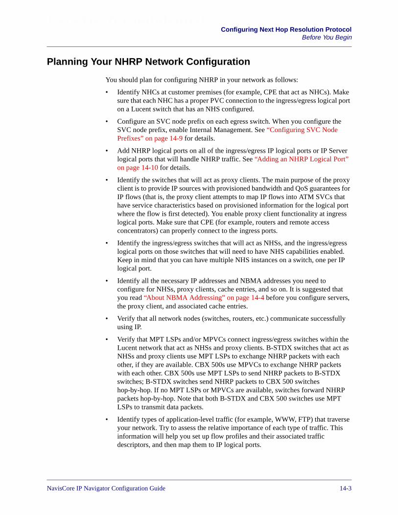
Beta Draft ConfidentialConfiguring Next Hop Resolution Protocol
Before You Begin
Planning Your NHRP Network Configuration
You should plan for configuring NHRP in your network as follows:
• Identify NHCs at customer premises (for example, CPE that act as NHCs). Makesure that each NHC has a proper PVC connection to the ingress/egress logical porton a Lucent switch that has an NHS configured.
• Configure an SVC node prefix on each egress switch. When you configure theSVC node prefix, enable Internal Management. See “Configuring SVC NodePrefixes” on page 14-9 for details.
• Add NHRP logical ports on all of the ingress/egress IP logical ports or IP Serverlogical ports that will handle NHRP traffic. See “Adding an NHRP Logical Port”on page 14-10 for details.
• Identify the switches that will act as proxy clients. The main purpose of the proxyclient is to provide IP sources with provisioned bandwidth and QoS guarantees forIP flows (that is, the proxy client attempts to map IP flows into ATM SVCs thathave service characteristics based on provisioned information for the logical portwhere the flow is first detected). You enable proxy client functionality at ingresslogical ports. Make sure that CPE (for example, routers and remote accessconcentrators) can properly connect to the ingress ports.
• Identify the ingress/egress switches that will act as NHSs, and the ingress/egresslogical ports on those switches that will need to have NHS capabilities enabled.Keep in mind that you can have multiple NHS instances on a switch, one per IPlogical port.
• Identify all the necessary IP addresses and NBMA addresses you need toconfigure for NHSs, proxy clients, cache entries, and so on. It is suggested thatyou read “About NBMA Addressing” on page 14-4 before you configure servers,the proxy client, and associated cache entries.
• Verify that all network nodes (switches, routers, etc.) communicate successfullyusing IP.
• Verify that MPT LSPs and/or MPVCs connect ingress/egress switches within theLucent network that act as NHSs and proxy clients. B-STDX switches that act asNHSs and proxy clients use MPT LSPs to exchange NHRP packets with eachother, if they are available. CBX 500s use MPVCs to exchange NHRP packetswith each other. CBX 500s use MPT LSPs to send NHRP packets to B-STDXswitches; B-STDX switches send NHRP packets to CBX 500 switcheshop-by-hop. If no MPT LSPs or MPVCs are available, switches forward NHRPpackets hop-by-hop. Note that both B-STDX and CBX 500 switches use MPTLSPs to transmit data packets.
• Identify types of application-level traffic (for example, WWW, FTP) that traverseyour network. Try to assess the relative importance of each type of traffic. Thisinformation will help you set up flow profiles and their associated trafficdescriptors, and then map them to IP logical ports.
NavisCore IP Navigator Configuration Guide 1/14/0214-3

Beta Draft ConfidentialConfiguring Next Hop Resolution ProtocolBefore You Begin
• Identify nodes and their associated addressing information that require you toconfigure static NHRP cache entries for either the proxy client or the NHS.Typically, nodes that require manually created cache entries do not support NHRPand, therefore, cannot participate in the NHRP address registration process. As analternative to creating static NHRP cache entries, you can terminate SVCs tonon-NHRP-compatible destinations at the management logical port of the egressswitch. Traffic is then forwarded hop-by-hop using IP routing.
• Identify potential persistent routing loop problems by analyzing your networktopology. See “Preventing Persistent Routing Loops” on page 13-34 for moreinformation on persistent routing loops.
About NBMA Addressing
Before you configure servers or cache entries, you should understand Non-BroadcastMultiple Access (NBMA) addressing. Remember that network nodes are identified byboth their IP addresses and their NBMA addresses, and the purpose of NHRP is toresolve IP addresses to NBMA addresses. When an IP address is resolved to anNBMA address, NHRP uses the NBMA address to establish an SVC shortcut towardthe next hop.
When you configure a server or a proxy client, you must specify its IP address and itsNBMA address. When you create a server cache entry or a proxy client cache entry,you must specify both the IP address and the NBMA address of the node associatedwith the entry.
In ATM environments, Lucent supports two types of NBMA address formats forestablishing SVCs:
ATM End System Address (AESA) formats — AESA formats give serviceproviders using a private ATM network the flexibility to develop an addressingscheme that best suits their network needs; for example, you may find that most CPEsin your network only support a specific AESA address format.
AESA Anycast Formats – AESA Anycast formats give service providers “groupaddress” functionality for each of the AESA address formats. Using the Anycastformat, a call is placed to the group address and the network selects one of themembers to which the call will be routed. This group address could, for example,represent a group of Internet servers that contain the same information andperform identical functions. It does not matter which of these servers handles thecall.
Native E.164 address format — E.164 addresses are phone numbers. This addressformat is simple and familiar; native E.164 addresses are a convenient choice forservice providers using a public ATM network (e.g., RBOCs) that already “own”E.164 address space.
The following sections describe these address formats.
14-4 NavisCore IP Navigator Configuration Guide

Beta Draft ConfidentialConfiguring Next Hop Resolution Protocol
Before You Begin
ATM End System Address Formats
NHRP resolves IP addresses to four ATM End System Address (AESA) formats:
Data Country Code (DCC) — For DCC AESA addresses, the initial domainidentifier (IDI) is a two-byte data country code field that identifies the country inwhich this address is registered. These country codes are standardized and defined inISO reference 3166. DCC Anycast AESA provides a group address function for thisaddress type.
International Country Designator (ICD) — For ICD AESA addresses, the IDI fieldcontains the international country designator that uniquely identifies an internationalorganization. The British Standards Organization administers these values. ICDAnycast AESA provides a group address function for this address type.
E.164 — For E.164 AESA addresses, the IDI field contains an eight-byte E.164address. This E.164 address uses the international format and consists of up to fifteendecimal digits. E.164 Anycast AESA provides a group address function for this addresstype.
Custom — Custom AESA addresses enable you to use a customized octet structureand a customized authority and format identifier (AFI).
All AESA address formats consist of 20 octets. Each of these address formats containthe following components:
Initial Domain Part (IDP) — Defines the type of address and the regulatoryauthority responsible for allocating and assigning the Domain Specific Part. There aretwo subfields: the AFI and IDI fields.
Authority and Format Identifier (AFI) – The AFI part of the AESA addressidentifies the authority that allocates the DCC, ICD, or E.164 part of the AESAaddress, as well as the syntax of the rest of the address. Table 14-1 lists valid AFIs.
Table 14-1. AFI Default Values
Address Type AFI
DCC 0x39
DCC Anycast 0xBD
ICD 0x47
ICD Anycast 0xC5
E.164 0x45
E.164 Anycast 0xC3
NavisCore IP Navigator Configuration Guide 1/14/0214-5

Beta Draft ConfidentialConfiguring Next Hop Resolution ProtocolBefore You Begin
Initial Domain Identifier (IDI) – A hex code that identifies the sub-authority thathas allocated the address. The format depends on the address types listed inTable 14-2.
Domain Specific Part — Consists of the HO-DSP, EDI, and SEL fields.
High-Order Domain-Specific Part (HO-DSP) – The authority specified in theAFI/IDI octets determines the format of this field. It identifies a segment ofaddress space that is assigned to a particular user or subnetwork. It should beconstructed to facilitate routing through interconnected ATM subnetworks. Thegeneral format for each address type is listed in Table 14-3.
Custom A user-specific code for custom prefixes/addresses. (Youmust know the appropriate code to enter when definingcustom prefixes/addresses.)
Table 14-2. IDI Default Values
Address Type IDI Description
DCC (includingAnycast)
Consists of 2 octets (4 hex digits) that identify the country in whichthis address is registered. The DCC is generally considered a three-digit quantity with a trailing hex “f” semi-octet. For example, theANSI IDI of 840 is encoded as 0x840f.
ICD (Anycast) Consists of 2 octets (4 hex digits) that identify an internationalorganization to which this address is registered. The ICD is generallyconsidered a four-digit quantity. For example, the US GOSIP IDI of“5” is encoded as 0x0005.
E.164 (Anycast) Consists of 8 octets in BCD format. (1-15 hex digits, plus a trailing Fh;if less than 15 digits are entered, type leading zeros to fill the 8 octets.)Represents an international E.164 address. For example, the E.164address of 978-555-1212 is encoded as 0x000009785551212f.
Table 14-3. HO-DSP Default Values
Address Type HO-DSP Description
DCC, ICD(including Anycast)
Consists of 10 octets (20 hex digits)
E.164 (Anycast) Consists of 4 octets (8 hex digits)
Custom Consists of 12 octets (24 hex digits)
Table 14-1. AFI Default Values (Continued)
Address Type AFI
14-6 NavisCore IP Navigator Configuration Guide
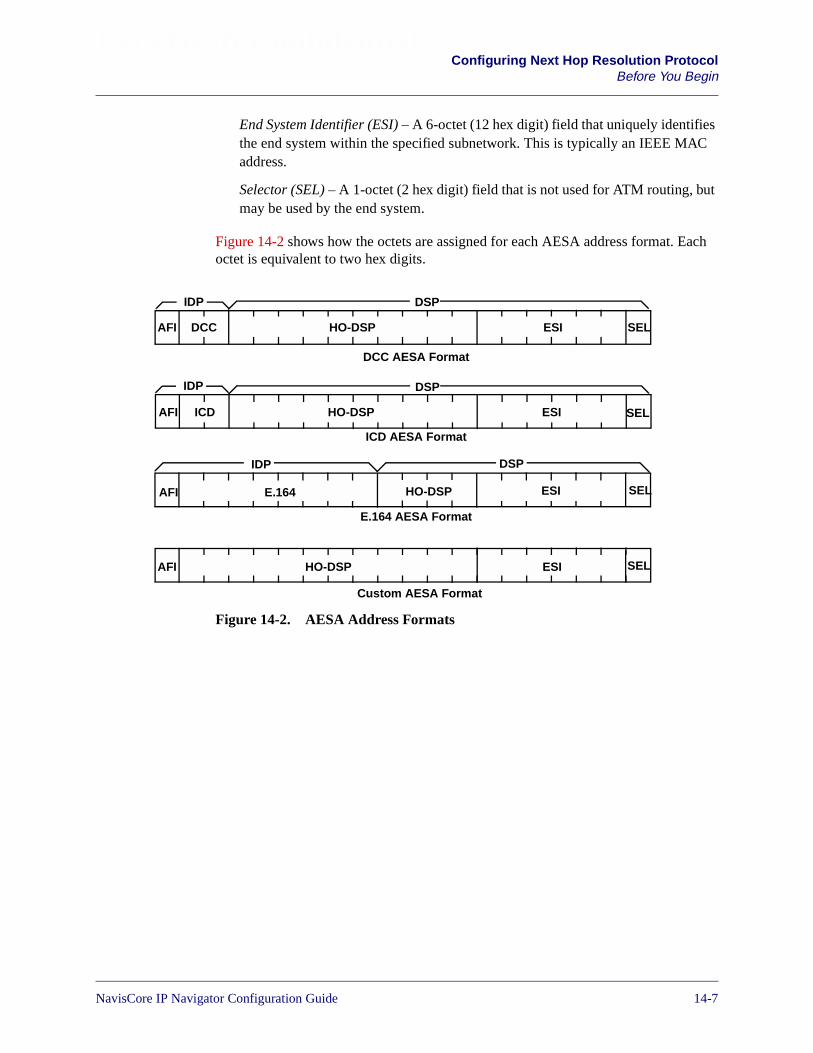
Beta Draft ConfidentialConfiguring Next Hop Resolution Protocol
Before You Begin
End System Identifier (ESI) – A 6-octet (12 hex digit) field that uniquely identifiesthe end system within the specified subnetwork. This is typically an IEEE MACaddress.
Selector (SEL) – A 1-octet (2 hex digit) field that is not used for ATM routing, butmay be used by the end system.
Figure 14-2 shows how the octets are assigned for each AESA address format. Eachoctet is equivalent to two hex digits.
Figure 14-2. AESA Address Formats
DCC AESA Format
ICD AESA Format
E.164 AESA Format
Custom AESA Format
AFI
AFI
AFI
AFI
DCC HO-DSP ESI SEL
ICD HO-DSP ESI SEL
SELE.164 HO-DSP ESI
HO-DSP
IDP DSP
IDP DSP
IDP DSP
ESI SEL
NavisCore IP Navigator Configuration Guide 1/14/0214-7
Beta Draft ConfidentialConfiguring Next Hop Resolution ProtocolBefore You Begin
Native E.164 Address Format
Native E.164 addresses are the standard Integrated Services Digital Network (ISDN)numbers, including telephone numbers. Native E.164 addresses consist of 1-15 ASCIIdigits. For example, standard 10-digit United States telephone numbers, such as508-555-1234, are native E.164 addresses.
Unlike AESA address formats, native E.164 addresses are not broken down into anAFI, HO-DSP, ESI, and SEL portion. When a native E.164 address is translated toE.164 AESA format, the native E.164 address is stored in octets 2-9 of the 20-octetAESA address, while the HO-DSP, ESI, and SEL portions are filled with zeros.Conversely, when an E.164 AESA address is translated to native E.164 addressformat, the AFI, HO-DSP, ESI, and SEL portions, as well as any leading zeros in the8-octet AESA E.164 address, are stripped off to produce the native E.164 address.
It is possible to use native E.164 addresses with Network Service Access Point(NSAP) addresses. In this case, the E.164 address is the NBMA address and the NSAPaddress is the NBMA subaddress. For example, if the switch acts as a gatewaybetween a public network that uses native E.164 addressing and a private network thatuses NSAP addresses, the switch is known to the public network by its E.164 address(the NBMA address) and is known to the private network by its NSAP address(NBMA subaddress).
Designing an Address Format Plan
The SVC address formats you select must support the equipment and services yournetwork needs to provide. Keep in mind that some CPEs may not support certainaddress formats. To avoid address conflicts, apply for globally recognized addressspace in the ATM formats you need to use.
You use address formats to develop a network numbering plan. Using an AESAaddress, you can design the IDP portion of an address to target a specific network;then use the HO-DSP portion of the address to identify subnetworks within thatnetwork, and use the ESI portion to identify a specific end system.
Regardless of the address format you choose, the network numbering plan shouldsatisfy the following goals:
• Intelligently assign network addresses
• Simplify network topology using a hierarchal organization
• Minimize the size of network routing tables
• Uniquely identify each endpoint
• Provide a high level of network scalability
For more information ATM addressing, see the NavisCore ATM Configuration Guide.
14-8 NavisCore IP Navigator Configuration Guide

Beta Draft ConfidentialConfiguring Next Hop Resolution Protocol
Configuring SVC Node Prefixes
About NHRP and IP VPNs
NHRP resources are public resources (that is, they are assigned to the public IP VPN).They cannot be reserved for exclusive use by private IP VPNs. The sources anddestinations of customer data that traverse NHRP SVC shortcuts, as well as controltraffic, must not be part of a private IP VPN. For example, if an NHRP traffic flowtraverses an ATM PVC from the CPE to an ingress IP logical port, the VPI/VCI mustnot be assigned to a private IP VPN. Rather, it must be assigned to the IP VPN labeledas “public.” See Chapter 16, “Configuring IP Virtual Private Networks” for moreinformation on IP VPNs.
Configuring SVC Node Prefixes
You must configure an SVC node prefix on each egress switch that handles NHRPtraffic. When you configure SVC node prefixes:
• Enable Internal Management
• Use an address format that is consistent with the address format you usethroughout your network. This is the format you should also use for NHSaddresses, NHC addresses, and proxy client addresses. For example, if you use theDCC AESA address format throughout the network, use this format for the SVCnode prefix.
See the NavisCore ATM Configuration Guide for more information on configuringSVC node prefixes.
NavisCore IP Navigator Configuration Guide 1/14/0214-9

Beta Draft ConfidentialConfiguring Next Hop Resolution ProtocolAdding and Deleting NHRP Logical Ports
Adding and Deleting NHRP Logical Ports
This section describes how to add and delete NHRP logical ports.
Adding an NHRP Logical Port
To add an NHRP logical port:
1. From the Administer menu, select Lucent IP Parameters� Set All IP LPorts. TheSet all IP LPorts dialog box appears (see Figure 3-2 on page 3-6).
2. Select the switch where the ingress/egress IP logical port or IP Server logical portresides from the Switch Name list at the top of the dialog box. A list of IP logicalports and IP Server logical ports configured on the switch appears in the LPortName list.
3. Select the ingress/egress IP logical port or IP Server logical port.
4. Choose IP Parameters. The Set IP Parameters dialog box appears (seeFigure 14-3).
Figure 14-3. Set IP Parameters Dialog Box (With Add NHRP LPort Button)
5. Choose Add NHRP LPort. This action adds the NHRP logical port. The AddNHRP LPort button becomes the Delete NHRP LPort button, allowing you todelete the NHRP logical port whenever it becomes necessary. See “Deleting anNHRP Logical Port” for more information on deleting an NHRP logical port.
6. Choose Close to exit.
Choose Add NHRP LPort
14-10 NavisCore IP Navigator Configuration Guide
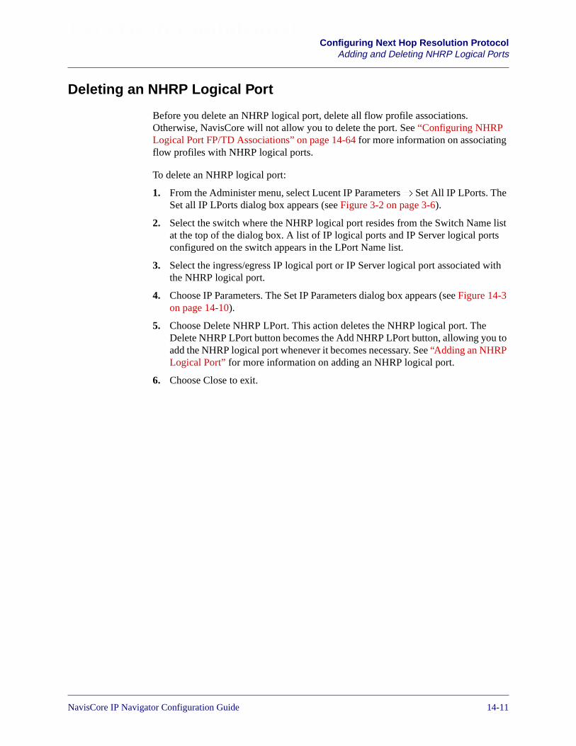
Beta Draft ConfidentialConfiguring Next Hop Resolution Protocol
Adding and Deleting NHRP Logical Ports
Deleting an NHRP Logical Port
Before you delete an NHRP logical port, delete all flow profile associations.Otherwise, NavisCore will not allow you to delete the port. See “Configuring NHRPLogical Port FP/TD Associations” on page 14-64 for more information on associatingflow profiles with NHRP logical ports.
To delete an NHRP logical port:
1. From the Administer menu, select Lucent IP Parameters� Set All IP LPorts. TheSet all IP LPorts dialog box appears (see Figure 3-2 on page 3-6).
2. Select the switch where the NHRP logical port resides from the Switch Name listat the top of the dialog box. A list of IP logical ports and IP Server logical portsconfigured on the switch appears in the LPort Name list.
3. Select the ingress/egress IP logical port or IP Server logical port associated withthe NHRP logical port.
4. Choose IP Parameters. The Set IP Parameters dialog box appears (see Figure 14-3on page 14-10).
5. Choose Delete NHRP LPort. This action deletes the NHRP logical port. TheDelete NHRP LPort button becomes the Add NHRP LPort button, allowing you toadd the NHRP logical port whenever it becomes necessary. See “Adding an NHRPLogical Port” for more information on adding an NHRP logical port.
6. Choose Close to exit.
NavisCore IP Navigator Configuration Guide 1/14/0214-11

Beta Draft ConfidentialConfiguring Next Hop Resolution ProtocolConfiguring Node Parameters
Configuring Node Parameters
NHRP node parameters allow you to specify the number of hops NHRP packets maytraverse, tune SVC establishment, and control NHRP logging. These parameters applyto all NHS instances and the proxy client on the selected switch.
You do not have to configure NHRP node parameters. Default values are alreadyconfigured for you.
To configure NHRP node parameters:
1. Select a switch from the network map.
2. From the Administer menu, select Lucent IP Parameters� Set NHRP� SetNode Parameters. The Set All NHRP Node Parameters dialog box appears (seeFigure 14-4).
Figure 14-4. Set All NHRP Node Parameters Dialog Box (With DefaultValues)
The Set All NHRP Node Parameters dialog box allows you to select a switch inthe list box at the top of the dialog box, displaying the NHRP node parameters thatare currently in effect for that switch at the bottom of the dialog box.
3. Select a switch.
4. Choose Modify to change the NHRP node parameters that are currently in effectfor the selected switch. The Set NHRP Node Parameters dialog box appears (seeFigure 14-5).
14-12 NavisCore IP Navigator Configuration Guide

Beta Draft ConfidentialConfiguring Next Hop Resolution Protocol
Configuring Node Parameters
Figure 14-5. Set NHRP Node Parameters Dialog Box
5. Modify the parameters described in Table 14-4.
Table 14-4. NHRP Node Parameters
Field Action/Description
Switch Name Displays the name of the selected switch.
Switch ID Displays the subnetwork number and host ID in the internal IP address of theswitch.
Forward Route Record Choose Enabled or Disabled (the default) to include or suppress forwardroute records in NHRP requests and replies. If you enable this parameter, arecord of the network- and link-layer addresses of all intermediate NHSsbetween the source and destination (that is, the forward direction) is includedin NHRP requests and replies. The information in route records can help youtroubleshoot network problems and detect data link filtering in NBMAnetworks.
Reverse Route Record Choose Enabled or Disabled (the default) to enable or suppress reverse routerecords in NHRP requests and replies. If you enable this parameter, a recordof the network- and link-layer addresses of all intermediate NHSs betweenthe destination and source (that is, the reverse direction) is included in NHRPrequests and replies. The information in route records can help youtroubleshoot network problems and detect data link filtering in NBMAnetworks.
NavisCore IP Navigator Configuration Guide 1/14/0214-13
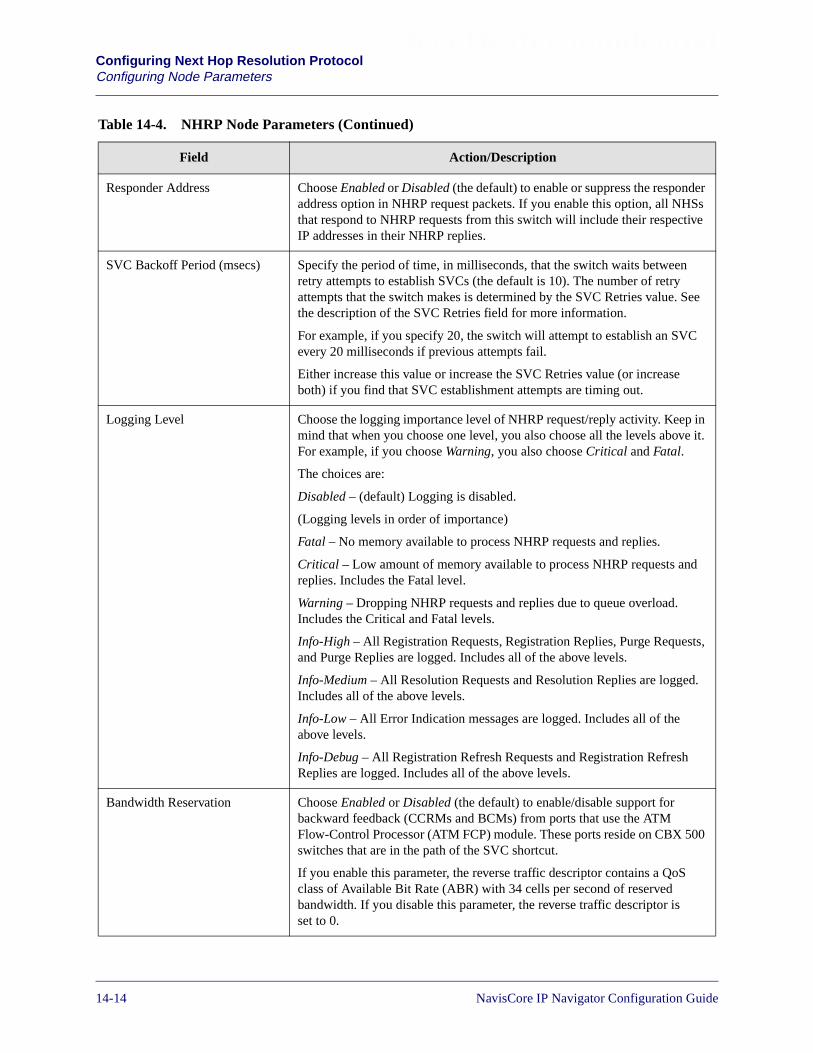
Beta Draft ConfidentialConfiguring Next Hop Resolution ProtocolConfiguring Node Parameters
Responder Address Choose Enabled or Disabled (the default) to enable or suppress the responderaddress option in NHRP request packets. If you enable this option, all NHSsthat respond to NHRP requests from this switch will include their respectiveIP addresses in their NHRP replies.
SVC Backoff Period (msecs) Specify the period of time, in milliseconds, that the switch waits betweenretry attempts to establish SVCs (the default is 10). The number of retryattempts that the switch makes is determined by the SVC Retries value. Seethe description of the SVC Retries field for more information.
For example, if you specify 20, the switch will attempt to establish an SVCevery 20 milliseconds if previous attempts fail.
Either increase this value or increase the SVC Retries value (or increaseboth) if you find that SVC establishment attempts are timing out.
Logging Level Choose the logging importance level of NHRP request/reply activity. Keep inmind that when you choose one level, you also choose all the levels above it.For example, if you choose Warning, you also choose Critical and Fatal.
The choices are:
Disabled – (default) Logging is disabled.
(Logging levels in order of importance)
Fatal – No memory available to process NHRP requests and replies.
Critical – Low amount of memory available to process NHRP requests andreplies. Includes the Fatal level.
Warning – Dropping NHRP requests and replies due to queue overload.Includes the Critical and Fatal levels.
Info-High – All Registration Requests, Registration Replies, Purge Requests,and Purge Replies are logged. Includes all of the above levels.
Info-Medium – All Resolution Requests and Resolution Replies are logged.Includes all of the above levels.
Info-Low – All Error Indication messages are logged. Includes all of theabove levels.
Info-Debug – All Registration Refresh Requests and Registration RefreshReplies are logged. Includes all of the above levels.
Bandwidth Reservation Choose Enabled or Disabled (the default) to enable/disable support forbackward feedback (CCRMs and BCMs) from ports that use the ATMFlow-Control Processor (ATM FCP) module. These ports reside on CBX 500switches that are in the path of the SVC shortcut.
If you enable this parameter, the reverse traffic descriptor contains a QoSclass of Available Bit Rate (ABR) with 34 cells per second of reservedbandwidth. If you disable this parameter, the reverse traffic descriptor isset to 0.
Table 14-4. NHRP Node Parameters (Continued)
Field Action/Description
14-14 NavisCore IP Navigator Configuration Guide
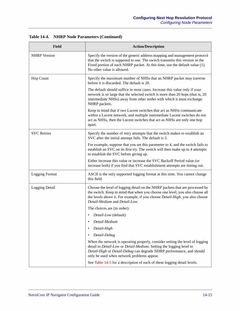
Beta Draft ConfidentialConfiguring Next Hop Resolution Protocol
Configuring Node Parameters
NHRP Version Specify the version of the generic address mapping and management protocolthat the switch is supposed to use. The switch transmits this version in theFixed portion of each NHRP packet. At this time, use the default value (1).No other value is allowed.
Hop Count Specify the maximum number of NHSs that an NHRP packet may traversebefore it is discarded. The default is 20.
The default should suffice in most cases. Increase this value only if yournetwork is so large that the selected switch is more than 20 hops (that is, 20intermediate NHSs) away from other nodes with which it must exchangeNHRP packets.
Keep in mind that if two Lucent switches that act as NHSs communicatewithin a Lucent network, and multiple intermediate Lucent switches do notact as NHSs, then the Lucent switches that act as NHSs are only one hopapart.
SVC Retries Specify the number of retry attempts that the switch makes to establish anSVC after the initial attempt fails. The default is 3.
For example, suppose that you set this parameter to 4, and the switch fails toestablish an SVC on its first try. The switch will then make up to 4 attemptsto establish the SVC before giving up.
Either increase this value or increase the SVC Backoff Period value (orincrease both) if you find that SVC establishment attempts are timing out.
Logging Format ASCII is the only supported logging format at this time. You cannot changethis field.
Logging Detail Choose the level of logging detail on the NHRP packets that are processed bythe switch. Keep in mind that when you choose one level, you also choose allthe levels above it. For example, if you choose Detail-High, you also chooseDetail-Medium and Detail-Low.
The choices are (in order):
• Detail-Low (default)
• Detail-Medium
• Detail-High
• Detail-Debug
When the network is operating properly, consider setting the level of loggingdetail to Detail-Low or Detail-Medium. Setting the logging level toDetail-High or Detail-Debug can degrade NHRP performance, and shouldonly be used when network problems appear.
See Table 14-5 for a description of each of these logging detail levels.
Table 14-4. NHRP Node Parameters (Continued)
Field Action/Description
NavisCore IP Navigator Configuration Guide 1/14/0214-15

Beta Draft ConfidentialConfiguring Next Hop Resolution ProtocolConfiguring Node Parameters
Table 14-5. Logging Detail
Detail Level Packet Type Packet Information Logged
Detail-Low NHRP Registration Request Client IP address, address family, NBMA address, NBMAsubaddress, prefix length, and preference for each clientinformation element (CIE). An NHS maintains a CIE foreach client it serves.
NHRP Registration Reply Status code, client IP address, address family, NBMAaddress, NBMA subaddress, prefix length, and preferencefor each CIE.
NHRP Resolution Request Requested destination IP address and the requestor’sIP address.
NHRP Resolution Reply The status code, next hop IP address, address family, nexthop NBMA address, next hop NBMA subaddress, prefixlength, and preference (for the first CIE, the one with thehighest preference value).
NHRP Purge Request Client IP address, address family, NBMA address, NBMAsubaddress, and prefix length for each CIE.
NHRP Purge Reply Status code, client IP address, address family, NBMAaddress, NBMA subaddress, and prefix length for each CIE.
NHRP Error Indication Error code, source NBMA address, source NBMAsubaddress, IP source address, and IP destination address.
14-16 NavisCore IP Navigator Configuration Guide

Beta Draft ConfidentialConfiguring Next Hop Resolution Protocol
Configuring Node Parameters
Detail-Medium NHRP Registration Request Everything in Detail-Low (Registration Request), plusdestination IP address, requestor’s IP address, requestor’sNBMA address, and requestor’s NBMA subaddress.
NHRP Registration Reply Everything in Detail-Low (Registration Reply), plusrequestor’s IP address, requestor’s NBMA address, andrequestor’s NBMA subaddress.
NHRP Resolution Request Everything in Detail-Low (Resolution Request), plusaddress family, requestor’s NBMA address, and requestor’sNBMA subaddress.
NHRP Resolution Reply Everything in Detail-Low (Resolution Reply) for multipleCIEs, plus requestor’s IP address, requestor’s NBMAaddress, and requestor’s NBMA subaddress.
NHRP Purge Request Everything in Detail-Low (Purge Request), plus destinationIP address, requestor’s IP address, requestor’s NBMAaddress, and requestor’s NBMA subaddress.
NHRP Purge Reply Everything in Detail-Low (Purge Reply), plus destination IPaddress, requestor’s IP address, requestor’s NBMA address,and requestor’s NBMA subaddress.
NHRP Error Indication Everything in Detail-Low (Error Indication), plus checksum
Detail-High NHRP Registration Request All of the above (Registration Request), plus flags, requestID, hold time, and Maximum Transfer Unit (MTU).
NHRP Registration Reply All of the above (Registration Reply), plus flags, request ID,hold time, and MTU.
NHRP Resolution Request All of the above (Resolution Request), plus flags, requestID, hold time, and MTU.
NHRP Resolution Reply All of the above (Resolution Reply), plus flags, request ID,hold time, and MTU.
NHRP Purge Request All of the above (Purge Request), plus flags, request ID, andhold time.
NHRP Purge Reply All of the above (Purge Reply), plus flags, request ID, andhold time.
NHRP Error Indication All of the above (Error Indication).
Table 14-5. Logging Detail (Continued)
Detail Level Packet Type Packet Information Logged
NavisCore IP Navigator Configuration Guide 1/14/0214-17

Beta Draft ConfidentialConfiguring Next Hop Resolution ProtocolConfiguring Node Parameters
6. Choose OK to enter your changes, or choose Cancel to exit without entering yourchanges.
Detail-Debug NHRP Registration Request All of the above (Registration Request), plus extensioninformation.
NHRP Registration Reply All of the above (Registration Reply), plus extensioninformation.
NHRP Resolution Request All of the above (Resolution Request), plus extensioninformation.
NHRP Resolution Reply All of the above (Resolution Reply), plus extensioninformation.
NHRP Purge Request All of the above (Purge Request), plus extensioninformation.
NHRP Purge Reply All of the above (Purge Reply), plus extension information.
NHRP Error Indication All of the above (Error Indication).
Table 14-5. Logging Detail (Continued)
Detail Level Packet Type Packet Information Logged
14-18 NavisCore IP Navigator Configuration Guide
Beta Draft ConfidentialConfiguring Next Hop Resolution Protocol
Configuring Flow Profiles
Configuring Flow Profiles
You can configure profiles of IP traffic flows called IP flow profiles. A flow profile isdefined in terms of:
• IP source and destination addresses (with Classless Interdomain Routing [CIDR]masking)
• IP protocol type
• Source and destination TCP/UDP-like protocol ports
• Type of Service (TOS) and TOS mask
After you configure these flow profiles, you associate them with IP logical ports alongwith traffic descriptors that manage the data flow. You can associate a single profilewith multiple IP logical ports on a switch, and/or associate multiple profiles with asingle IP logical port. See “Configuring NHRP Logical Port FP/TD Associations” onpage 14-64 for more information.
When you associate IP flow profiles with NHRP logical ports, the order in whichyou associate the IP flow profiles is very important. Switches allocate resourcesto IP flow profiles based on the order in which they are associated with an NHRPlogical port. The IP flow profile that is associated first has the highest resourcepriority, the IP flow profile associated second has the next highest resourcepriority, and so on. Thus, make sure you associate IP flow profiles in thefollowing order: from most important to least important.
NavisCore IP Navigator Configuration Guide 1/14/0214-19

Beta Draft ConfidentialConfiguring Next Hop Resolution ProtocolConfiguring Flow Profiles
About Wildcards
When you create a flow profile, you can use wildcards for source and destination IPaddresses, and source and destination protocol ports. The wildcard, in effect, indicatesthat the flow profile applies to “any” or “all” addresses, applications, and so on.
The flow profile controls the flow of traffic in one direction only: from source todestination. To manage the bi-directional flow of traffic between two specific points inthe network, you would have to create two or more flow profiles. The source IPaddress in one flow profile would be the destination IP address in the other profile,and vice versa.
Use of the wildcard IP address gives you a lot of flexibility. For example, you couldcreate a flow profile with a specific source IP address (such as the IP address of anetwork) and a wildcard destination IP address (0.0.0.0). This profile would thencontrol the flow of traffic from one IP network to any reachable 32-bit destinationaddress.
The use of wildcards also applies to source and destination applications. Through useof the wildcard, you can specify that the flow profile applies to all source anddestination applications. Or, you can restrict the flow profile to just specificapplications. However, keep in mind that a flow profile is unidirectional, from sourceto destination. To manage bidirectional traffic flow between applications on twospecific endpoints, you must create multiple flow profiles, one or more for eachdirection.
While the use of wildcards can be beneficial, keep in mind that their use mayadversely impact performance under high traffic load conditions. This guidelineespecially applies to the use of wildcards in the destination IP address. If you specify adestination IP address of 0.0.0.0 (the wildcard destination IP address), keep in mindthat, for each traffic flow that matches the criteria in the profile, a separate SVCshortcut will be created for each destination IP address that is detected. For example,if 20 traffic flows match the criteria in the profile, and each flow is destined for adifferent host (that is, a different IP address), then 20 SVC shortcuts will be created(one for each traffic flow). Under high traffic load conditions, performance may beadversely effected, since an excessive number of SVC shortcuts may be created.
14-20 NavisCore IP Navigator Configuration Guide
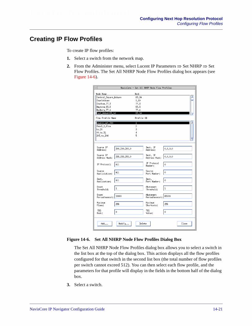
Beta Draft ConfidentialConfiguring Next Hop Resolution Protocol
Configuring Flow Profiles
Creating IP Flow Profiles
To create IP flow profiles:
1. Select a switch from the network map.
2. From the Administer menu, select Lucent IP Parameters� Set NHRP� SetFlow Profiles. The Set All NHRP Node Flow Profiles dialog box appears (seeFigure 14-6).
Figure 14-6. Set All NHRP Node Flow Profiles Dialog Box
The Set All NHRP Node Flow Profiles dialog box allows you to select a switch inthe list box at the top of the dialog box. This action displays all the flow profilesconfigured for that switch in the second list box (the total number of flow profilesper switch cannot exceed 512). You can then select each flow profile, and theparameters for that profile will display in the fields in the bottom half of the dialogbox.
3. Select a switch.
NavisCore IP Navigator Configuration Guide 1/14/0214-21

Beta Draft ConfidentialConfiguring Next Hop Resolution ProtocolConfiguring Flow Profiles
4. Choose Add. The Add NHRP Node Flow Profiles dialog box appears (seeFigure 14-7).
Figure 14-7. Add NHRP Node Flow Profiles Dialog Box
5. Specify the parameters described in Table 14-6.
6. Choose OK.
Only one of the following parameters may have an ambiguous value: Dest. IPAddress, Source Application, or Dest. Application. For Dest. IP Address, anambiguous value is expressed as 0.0.0.0. For Source Application and Dest.Application, an ambiguous value is expressed by selecting Ambiguous from thepull-down menu.
14-22 NavisCore IP Navigator Configuration Guide

Beta Draft ConfidentialConfiguring Next Hop Resolution Protocol
Configuring Flow Profiles
Table 14-6. NHRP IP Flow Profile Parameters
Field Action/Description
Switch Name Displays the name of the selected switch.
Switch ID Displays the subnetwork number and host ID in the internal IP address of theswitch.
Profile Name Specify the name of the profile. The name may not exceed 20 characters(including spaces).
Source IP Address Specify the IP address of the source of the traffic flow. You may specify anyvalid IP address in the format a.b.c.d, where a, b, c, and d must be from 0 to 255.The default address (0.0.0.0) acts as a wildcard, which means that the flowprofile applies to traffic from all sources.
Examples of valid addresses include a class B network address of 152.148.0.0, aclass B subnetwork address of 152.148.22.0, and a class B host address of152.148.22.12.
Source IP Address Mask Specify the mask for the source IP address. You may specify any valid mask inthe format a.b.c.d, where a, b, c, and d must be from 0 to 255. If you use thedefault source IP address (0.0.0.0), then use the default mask (0.0.0.0).
For example, if you specify a source IP address of 131.100.0.0 (a class Bnetwork address), you would specify a source IP address mask of 255.255.0.0.In another example, if you specify a source IP address of 131.100.25.0 (a classB address with a subnetwork number of 25), you would specify a mask of255.255.255.0.
NavisCore IP Navigator Configuration Guide 1/14/0214-23
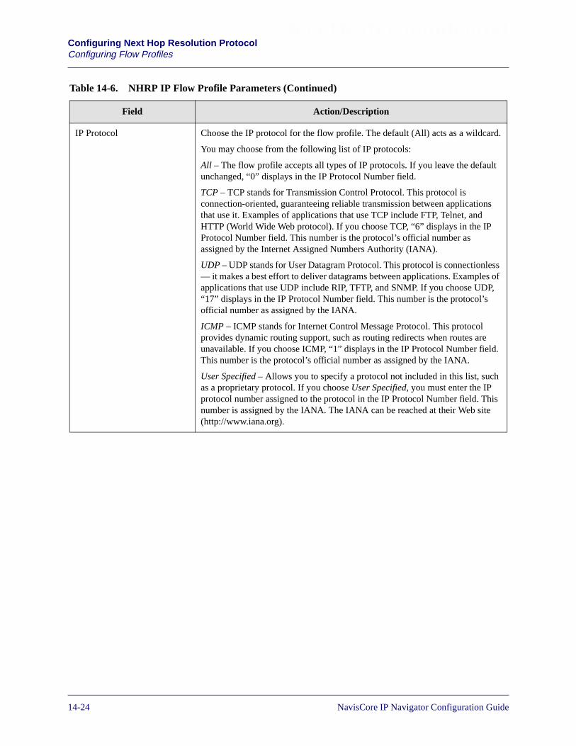
Beta Draft ConfidentialConfiguring Next Hop Resolution ProtocolConfiguring Flow Profiles
IP Protocol Choose the IP protocol for the flow profile. The default (All) acts as a wildcard.
You may choose from the following list of IP protocols:
All – The flow profile accepts all types of IP protocols. If you leave the defaultunchanged, “0” displays in the IP Protocol Number field.
TCP – TCP stands for Transmission Control Protocol. This protocol isconnection-oriented, guaranteeing reliable transmission between applicationsthat use it. Examples of applications that use TCP include FTP, Telnet, andHTTP (World Wide Web protocol). If you choose TCP, “6” displays in the IPProtocol Number field. This number is the protocol’s official number asassigned by the Internet Assigned Numbers Authority (IANA).
UDP – UDP stands for User Datagram Protocol. This protocol is connectionless— it makes a best effort to deliver datagrams between applications. Examples ofapplications that use UDP include RIP, TFTP, and SNMP. If you choose UDP,“17” displays in the IP Protocol Number field. This number is the protocol’sofficial number as assigned by the IANA.
ICMP – ICMP stands for Internet Control Message Protocol. This protocolprovides dynamic routing support, such as routing redirects when routes areunavailable. If you choose ICMP, “1” displays in the IP Protocol Number field.This number is the protocol’s official number as assigned by the IANA.
User Specified – Allows you to specify a protocol not included in this list, suchas a proprietary protocol. If you choose User Specified, you must enter the IPprotocol number assigned to the protocol in the IP Protocol Number field. Thisnumber is assigned by the IANA. The IANA can be reached at their Web site(http://www.iana.org).
Table 14-6. NHRP IP Flow Profile Parameters (Continued)
Field Action/Description
14-24 NavisCore IP Navigator Configuration Guide

Beta Draft ConfidentialConfiguring Next Hop Resolution Protocol
Configuring Flow Profiles
Source Application
(Meaningful only if TCP orUDP is selected for IPProtocol)
Choose the source application for the flow profile. The list of applications fromwhich you can choose is determined by your choice of IP protocol.
All – (default) The flow profile applies to all application traffic from source todestination.
BGP – BGP traffic.
FTP Data – FTP data traffic.
FTP Control – FTP control traffic.
Gopher – Gopher traffic.
IRC – IRC traffic.
Talk – Talk traffic.
Telnet – Telnet traffic.
WWW – HTTP traffic.
RIP – RIP traffic.
SNMP – SNMP traffic.
SNMP Traps – SNMP traps traffic.
TFTP – TFTP traffic.
Ambiguous – The traffic flows are tracked based on discrete source applicationvalues (1024 is used for the port value).
User Specified – Allows you to specify an application that is not in the list (suchas a third-party vendor application), and requires you to enter a port number thatthe application uses in the Source Port Number field. You can obtain this portnumber from the application developer. The IANA web site(http://www.iana.org) can also help you determine this number, as well asRFC 1700. There is also a listing of many port numbers at the following URL:http://www.isi.edu/in-notes/iana/assignments/port-numbers.
Dest. Application
(Meaningful only if TCP orUDP is selected for IPProtocol)
Choose the destination application for the flow profile. In most cases, yourchoices of source and destination application will be the same, sincecommunication between different types of applications is rare. See thedescription of the Source Application field for information on the choicesavailable to you.
Onset Threshold Specify the number of IP packets that must be detected within the Onset Periodin order to trigger the flow profile. For example, suppose that you set the OnsetThreshold to 10 packets and you set the Onset Period to 100 milliseconds. Thismeans that 10 or more packets must be detected within a span of 100milliseconds in order to trigger a flow onset detection.
The default value (10) should suffice in most cases.
See “Adjusting Onset and Abatement Parameters” on page 14-30 for moreinformation.
Table 14-6. NHRP IP Flow Profile Parameters (Continued)
Field Action/Description
NavisCore IP Navigator Configuration Guide 1/14/0214-25

Beta Draft ConfidentialConfiguring Next Hop Resolution ProtocolConfiguring Flow Profiles
Onset Period (msecs) Specify the span of time, in milliseconds, within which the Onset Threshold isin effect. See the description of the Onset Threshold for more information.
The default value (1000) should suffice in most cases.
See “Adjusting Onset and Abatement Parameters” on page 14-30 for moreinformation.
Maximum Flows Specify the maximum number of matching NHRP traffic flows that can besimultaneously detected on a logical port associated with this flow profile. Amatching NHRP traffic flow is one that matches the criteria defined in the flowprofile.
For example, if you use the default value (1), then only one matching NHRPtraffic flow can be detected on the associated logical port at any one time.
The default value should suffice in most cases.
Because each traffic flow uses a shortcut, the Maximum Flows value must begreater than or equal to the Maximum Shortcuts value. Otherwise, you mayencounter situations in which flows cannot be supported because insufficientshortcuts are available. See the description of “Maximum Shortcuts” onpage 14-29 for more information.
TOS Mask Specify the Type of Service (TOS) mask, in decimal, for the TOS value (see thedescription of the TOS field for more information). The mask determines thelocation of bits required for the TOS value. For example, if you specify a TOSvalue of 4 (100 in binary), you must specify a compatible TOS mask (such asdecimal 4). Valid TOS masks range from 0 to 255.
If you specify an invalid TOS mask/value combination, the NMS generates anerror.
The default TOS mask (0) combined with the default TOS value (0) means thatthe flow profile will work with any TOS.
If you use a TOS mask and TOS value other than 0, make sure you specifyvalues that are compatible with the network equipment (such as CPE) withwhich the switch exchanges service traffic (such as voice over IP).
Table 14-6. NHRP IP Flow Profile Parameters (Continued)
Field Action/Description
14-26 NavisCore IP Navigator Configuration Guide
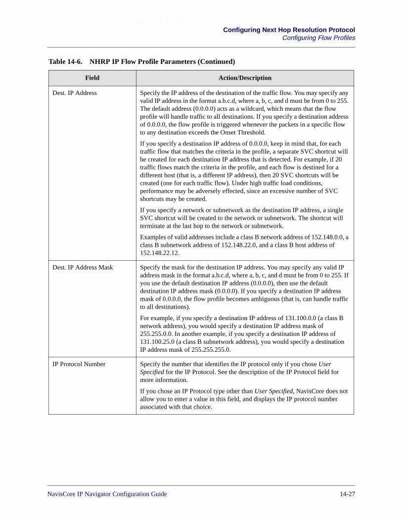
Beta Draft ConfidentialConfiguring Next Hop Resolution Protocol
Configuring Flow Profiles
Dest. IP Address Specify the IP address of the destination of the traffic flow. You may specify anyvalid IP address in the format a.b.c.d, where a, b, c, and d must be from 0 to 255.The default address (0.0.0.0) acts as a wildcard, which means that the flowprofile will handle traffic to all destinations. If you specify a destination addressof 0.0.0.0, the flow profile is triggered whenever the packets in a specific flowto any destination exceeds the Onset Threshold.
If you specify a destination IP address of 0.0.0.0, keep in mind that, for eachtraffic flow that matches the criteria in the profile, a separate SVC shortcut willbe created for each destination IP address that is detected. For example, if 20traffic flows match the criteria in the profile, and each flow is destined for adifferent host (that is, a different IP address), then 20 SVC shortcuts will becreated (one for each traffic flow). Under high traffic load conditions,performance may be adversely effected, since an excessive number of SVCshortcuts may be created.
If you specify a network or subnetwork as the destination IP address, a singleSVC shortcut will be created to the network or subnetwork. The shortcut willterminate at the last hop to the network or subnetwork.
Examples of valid addresses include a class B network address of 152.148.0.0, aclass B subnetwork address of 152.148.22.0, and a class B host address of152.148.22.12.
Dest. IP Address Mask Specify the mask for the destination IP address. You may specify any valid IPaddress mask in the format a.b.c.d, where a, b, c, and d must be from 0 to 255. Ifyou use the default destination IP address (0.0.0.0), then use the defaultdestination IP address mask (0.0.0.0). If you specify a destination IP addressmask of 0.0.0.0, the flow profile becomes ambiguous (that is, can handle trafficto all destinations).
For example, if you specify a destination IP address of 131.100.0.0 (a class Bnetwork address), you would specify a destination IP address mask of255.255.0.0. In another example, if you specify a destination IP address of131.100.25.0 (a class B subnetwork address), you would specify a destinationIP address mask of 255.255.255.0.
IP Protocol Number Specify the number that identifies the IP protocol only if you chose UserSpecified for the IP Protocol. See the description of the IP Protocol field formore information.
If you chose an IP Protocol type other than User Specified, NavisCore does notallow you to enter a value in this field, and displays the IP protocol numberassociated with that choice.
Table 14-6. NHRP IP Flow Profile Parameters (Continued)
Field Action/Description
NavisCore IP Navigator Configuration Guide 1/14/0214-27
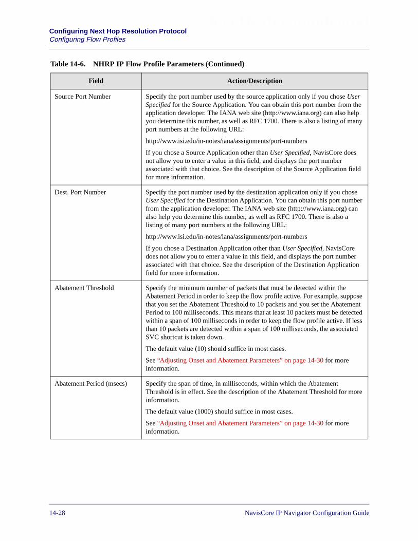
Beta Draft ConfidentialConfiguring Next Hop Resolution ProtocolConfiguring Flow Profiles
Source Port Number Specify the port number used by the source application only if you chose UserSpecified for the Source Application. You can obtain this port number from theapplication developer. The IANA web site (http://www.iana.org) can also helpyou determine this number, as well as RFC 1700. There is also a listing of manyport numbers at the following URL:
http://www.isi.edu/in-notes/iana/assignments/port-numbers
If you chose a Source Application other than User Specified, NavisCore doesnot allow you to enter a value in this field, and displays the port numberassociated with that choice. See the description of the Source Application fieldfor more information.
Dest. Port Number Specify the port number used by the destination application only if you choseUser Specified for the Destination Application. You can obtain this port numberfrom the application developer. The IANA web site (http://www.iana.org) canalso help you determine this number, as well as RFC 1700. There is also alisting of many port numbers at the following URL:
http://www.isi.edu/in-notes/iana/assignments/port-numbers
If you chose a Destination Application other than User Specified, NavisCoredoes not allow you to enter a value in this field, and displays the port numberassociated with that choice. See the description of the Destination Applicationfield for more information.
Abatement Threshold Specify the minimum number of packets that must be detected within theAbatement Period in order to keep the flow profile active. For example, supposethat you set the Abatement Threshold to 10 packets and you set the AbatementPeriod to 100 milliseconds. This means that at least 10 packets must be detectedwithin a span of 100 milliseconds in order to keep the flow profile active. If lessthan 10 packets are detected within a span of 100 milliseconds, the associatedSVC shortcut is taken down.
The default value (10) should suffice in most cases.
See “Adjusting Onset and Abatement Parameters” on page 14-30 for moreinformation.
Abatement Period (msecs) Specify the span of time, in milliseconds, within which the AbatementThreshold is in effect. See the description of the Abatement Threshold for moreinformation.
The default value (1000) should suffice in most cases.
See “Adjusting Onset and Abatement Parameters” on page 14-30 for moreinformation.
Table 14-6. NHRP IP Flow Profile Parameters (Continued)
Field Action/Description
14-28 NavisCore IP Navigator Configuration Guide

Beta Draft ConfidentialConfiguring Next Hop Resolution Protocol
Configuring Flow Profiles
Maximum Shortcuts Specify the maximum number of matching NHRP shortcuts that can besimultaneously connected to a logical port associated with this flow profile. Amatching NHRP shortcut is one that matches the criteria defined in the flowprofile.
For example, if you use the default (1), then one shortcut that matches this flowprofile can be connected to the associated logical port at any one time.
The default should suffice in most cases.
Because each traffic flow uses a shortcut, the Maximum Shortcuts value mustbe less than or equal to the Maximum Flows value. Otherwise, you mayencounter situations in which flows cannot be supported because insufficientshortcuts are available. See the description of “Maximum Flows” on page 14-26for more information.
TOS Value Specify the Type of Service (TOS) value. This value identifies a traffic flowassociated with a particular TOS, such as voice. Values may range from 0 (thedefault) to 255. The default TOS mask (0) combined with the default TOS value(0) means that the flow profile will work with any TOS.
If you specify a non-zero TOS value, you must specify a non-zero TOS mask.See the description of the TOS Mask field for more information.
If you use a TOS mask and TOS value other than 0, make sure you specifyvalues that are compatible with the network equipment (such as CPE) withwhich the switch exchanges service traffic (such as voice over IP).
Table 14-6. NHRP IP Flow Profile Parameters (Continued)
Field Action/Description
NavisCore IP Navigator Configuration Guide 1/14/0214-29
Beta Draft ConfidentialConfiguring Next Hop Resolution ProtocolConfiguring Flow Profiles
Adjusting Onset and Abatement Parameters
The onset and abatement parameters — Onset Threshold, Onset Period, AbatementThreshold, and Abatement Period — enable you to tune traffic flow processing. Inmost cases, the default values for these parameters are sufficient, but you may want touse values other than the defaults if performance is not satisfactory.
When you adjust the parameters, note the following:
• When you increase the Onset Threshold and/or decrease the Onset Period, youincrease the risk that the flow profile will not be triggered. This may result in noSVC establishment for some traffic flows, depending on how much you increasethe Onset Threshold or decrease the Onset Period.
• When you increase the Onset Period and/or decrease the Onset Threshold, youreduce the risk that the flow profile will not be triggered, thereby increasing thechance of SVC establishment for all traffic flows.
• When you increase the Abatement Threshold and/or decrease the AbatementPeriod, you increase the risk that some SVCs will be prematurely disconnected(before their associated traffic flows complete).
• When you increase the Abatement Period and/or decrease the AbatementThreshold, you reduce the risk that SVCs will be prematurely disconnected.
Modifying IP Flow Profiles
Before you attempt to modify an IP flow profile, you need to understand the followingrules:
• You may modify only IP flow profiles that are not in use. If you attempt to modifyan IP flow profile that is in use, the NMS generates an error.
• You must remove all IP flow profile associations with NHRP logical ports beforeyou can modify an IP flow profile. For example, if you have associated an IP flowprofile with two NHRP logical ports, you must remove both of those associationsbefore you can modify the IP flow profile. When you finish modifying the IP flowprofile, you must reassociate it with both logical ports.
To modify an IP flow profile:
1. Select a switch from the network map.
2. From the Administer menu, select Lucent IP Parameters� Set NHRP� SetFlow Profiles. The Set All NHRP Node Flow Profiles dialog box appears (seeFigure 14-6 on page 14-21).
3. Select a switch. A list of IP flow profiles configured for that switch appears.
4. Select the flow profile you want to modify.
5. Choose Modify. The Modify NHRP Node Flow Profiles dialog box appears. Thisdialog box is similar to the Add NHRP Node Flow Profiles dialog box (seeFigure 14-7 on page 14-22).
14-30 NavisCore IP Navigator Configuration Guide
Beta Draft ConfidentialConfiguring Next Hop Resolution Protocol
Configuring Flow Profiles
6. Modify the fields on the Modify NHRP Node Flow Profiles dialog box as needed.See Table 14-6 on page 14-23 for descriptions of these fields.
7. Choose OK.
Deleting IP Flow Profiles
Before you attempt to delete an IP flow profile, you need to understand the followingrules:
• You may delete only IP flow profiles that are not in use. If you attempt to delete anIP flow profile that is in use, the NMS generates an error.
• You must remove all IP flow profile associations with NHRP logical ports beforeyou can delete an IP flow profile. For example, if you have associated an IP flowprofile with two NHRP logical ports, you must remove both of those associationsbefore you can delete the IP flow profile.
To delete an IP flow profile:
1. Select a switch from the network map.
2. From the Administer menu, select Lucent IP Parameters� Set NHRP� SetFlow Profiles. The Set All NHRP Node Flow Profiles dialog box appears (seeFigure 14-6).
3. Select a switch. A list of IP flow profiles configured for that switch appears.
4. Select the flow profile you want to delete.
5. Choose Delete.
6. Choose OK when prompted.
NavisCore IP Navigator Configuration Guide 1/14/0214-31

Beta Draft ConfidentialConfiguring Next Hop Resolution ProtocolConfiguring Servers
Configuring Servers
You can configure one or more NHSs on a switch; however, you have the option touse the default server instead of explicitly configuring NHSs. You then associate eachexplicitly configured server (or the default server) with an NHRP logical port, one thatis used to communicate with a destination. See “Configuring NHRP Logical PortParameters” on page 14-59 for more information on associating servers with logicalports.
Although NHCs typically register their IP Address/NBMA Address mappings withthe NHS automatically, you can also manually create server cache entries for NHCs, ifnecessary.
The following sections describe how to add, modify, and delete servers and theircache entries.
About the Default Server
Each switch has a default NHS which is automatically associated with all of the trunklogical ports on the switch. The default NHS processes NHRP requests and replies onthe trunk logical ports. These requests and replies are received from and sent to otherNHSs and the proxy client on switches in the Lucent network. Though intendedprimarily for use with trunk logical ports, you may associate the default NHS with oneor more ingress/egress NHRP logical ports (such as an ATM UNI logical port) thatinteract with NHCs.
14-32 NavisCore IP Navigator Configuration Guide

Beta Draft ConfidentialConfiguring Next Hop Resolution Protocol
Configuring Servers
Adding a Server
To add a server:
1. Select a switch from the network map.
2. From the Administer menu, select Lucent IP Parameters� Set NHRP� SetServers� Set Parameters. The Set All NHRP Server Parameters dialog boxappears (see Figure 14-8).
Figure 14-8. Set All NHRP Server Parameters Dialog Box
The Set All NHRP Server Parameters dialog box allows you to select a switch inthe list box at the top of the dialog box. This action displays all the serversconfigured for that switch in the second list box. You can then select each server,and the parameters for that server display in the fields in the bottom half of thedialog box. Table 14-7 on page 14-35 describes these fields, except the CurrentClients field. This field displays the number of NHCs that are currently registeredwith the server.
You can display statistics on server activity by choosing the Statistics button. Seethe NavisCore Diagnostics Guide for descriptions of these statistics.
NavisCore IP Navigator Configuration Guide 1/14/0214-33

Beta Draft ConfidentialConfiguring Next Hop Resolution ProtocolConfiguring Servers
3. Select a switch.
4. Choose Add. The Set NHRP Server dialog box appears (see Figure 14-9).
Figure 14-9. Set NHRP Server Dialog Box
5. Specify the parameters described in Table 14-7.
6. Choose OK.
14-34 NavisCore IP Navigator Configuration Guide

Beta Draft ConfidentialConfiguring Next Hop Resolution Protocol
Configuring Servers
Table 14-7. NHRP Server Parameters
Field Action/Description
Switch Name Displays the name of the selected switch.
Switch ID Displays the subnetwork number and host ID in the internal IP address of theswitch.
NBMA Address Selection Select the type of address you are configuring for the server: NBMA Address(default) or NBMA Subaddress. You select NBMA Address regardless of theaddress format you use. You select NBMA Subaddress only if you use E.164with NSAP addressing.
If you use E.164 with NSAP addresses, you specify both an address and asubaddress. Specify the address and subaddress in the following order:
1. In the NBMA Address Selection field, select NBMA Address.
2. In the NBMA Address Format field, select E.164 with NSAP.
3. In the Decimal Digits field, specify a native E.164 address.
4. Return to the NBMA Address Selection field. Select NBMA Subaddress.
5. In the NBMA Address Selection field, select NBMA Subaddress.
6. In the NBMA Address Format field, select a valid address format.
7. Specify an AFI if you selected a subaddress format of Custom AESA.
8. In the Hex Digits field, specify the hexadecimal subaddress.
NavisCore IP Navigator Configuration Guide 1/14/0214-35
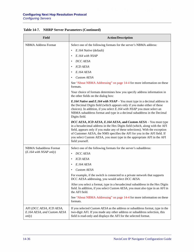
Beta Draft ConfidentialConfiguring Next Hop Resolution ProtocolConfiguring Servers
NBMA Address Format Select one of the following formats for the server’s NBMA address:
• E.164 Native (default)
• E.164 with NSAP
• DCC AESA
• ICD AESA
• E.164 AESA
• Custom AESA
See “About NBMA Addressing” on page 14-4 for more information on theseformats.
Your choice of formats determines how you specify address information inthe other fields on the dialog box:
E.164 Native and E.164 with NSAP – You must type in a decimal address inthe Decimal Digits field (which appears only if you make either of thesechoices). In addition, if you select E.164 with NSAP you must select anNBMA subaddress format and type in a decimal subaddress in the DecimalDigits field.
DCC AESA, ICD AESA, E.164 AESA, and Custom AESA – You must typein a hexadecimal address in the Hex Digits field (which, along with the AFIfield, appears only if you make any of these selections). With the exceptionof Customer AESA, the NMS specifies the AFI for you in the AFI field. Ifyou select Custom AESA, you must type in the appropriate AFI in the AFIfield yourself.
NBMA Subaddress Format(E.164 with NSAP only)
Select one of the following formats for the server’s subaddress:
• DCC AESA
• ICD AESA
• E.164 AESA
• Custom AESA
For example, if the switch is connected to a private network that supportsDCC AESA addressing, you would select DCC AESA.
After you select a format, type in a hexadecimal subaddress in the Hex Digitsfield. In addition, if you select Custom AESA, you must also type in an AFI inthe AFI field.
See “About NBMA Addressing” on page 14-4 for more information on theseformats.
AFI (DCC AESA, ICD AESA,E.164 AESA, and Custom AESAonly)
If you selected Custom AESA as the address or subaddress format, type in thetwo-digit AFI. If you made any other address or subaddress selection, thisfield is read-only and displays the AFI for the selected format.
Table 14-7. NHRP Server Parameters (Continued)
Field Action/Description
14-36 NavisCore IP Navigator Configuration Guide
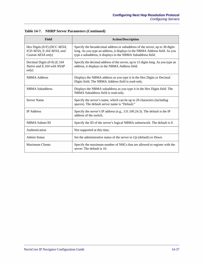
Beta Draft ConfidentialConfiguring Next Hop Resolution Protocol
Configuring Servers
Hex Digits (0-F) (DCC AESA,ICD AESA, E.164 AESA, andCustom AESA only)
Specify the hexadecimal address or subaddress of the server, up to 38 digitslong. As you type an address, it displays in the NBMA Address field. As youtype a subaddress, it displays in the NBMA Subaddress field.
Decimal Digits (0-9) (E.164Native and E.164 with NSAPonly)
Specify the decimal address of the server, up to 15 digits long. As you type anaddress, it displays in the NBMA Address field.
NBMA Address Displays the NBMA address as you type it in the Hex Digits or DecimalDigits field. The NBMA Address field is read-only.
NBMA Subaddress Displays the NBMA subaddress as you type it in the Hex Digits field. TheNBMA Subaddress field is read-only.
Server Name Specify the server’s name, which can be up to 20 characters (includingspaces). The default server name is “Default.”
IP Address Specify the server’s IP address (e.g., 131.100.24.3). The default is the IPaddress of the switch.
NBMA Subnet ID Specify the ID of the server’s logical NBMA subnetwork. The default is 0.
Authentication Not supported at this time.
Admin Status Set the administrative status of the server to Up (default) or Down.
Maximum Clients Specify the maximum number of NHCs that are allowed to register with theserver. The default is 10.
Table 14-7. NHRP Server Parameters (Continued)
Field Action/Description
NavisCore IP Navigator Configuration Guide 1/14/0214-37

Beta Draft ConfidentialConfiguring Next Hop Resolution ProtocolConfiguring Servers
Modifying a Server
To modify server parameters:
1. Select a switch from the network map.
2. From the Administer menu, select Lucent IP Parameters� Set NHRP� SetServers� Set Parameters. The Set All NHRP Server Parameters dialog boxappears (see Figure 14-8 on page 14-33).
3. Select a switch. A list of servers configured for that switch appears.
4. Select the server whose parameters you want to modify.
5. Choose Modify. The Set NHRP Server dialog box appears (see Figure 14-9 onpage 14-34).
6. Modify the parameters described in Table 14-7.
7. Choose OK.
Deleting a Server
To delete a server:
1. Select a switch from the network map.
2. From the Administer menu, select Lucent IP Parameters� Set NHRP� SetServers� Set Parameters. The Set All NHRP Server Parameters dialog boxappears (see Figure 14-8 on page 14-33).
3. Select a switch. A list of servers configured for that switch appears.
4. Select the server you want to delete.
5. Choose Delete.
6. Choose OK.
You cannot delete the default server, and you cannot delete any server if it isassociated with a logical port. You must delete all of the server’s logical portassociations before you can delete the server.
14-38 NavisCore IP Navigator Configuration Guide

Beta Draft ConfidentialConfiguring Next Hop Resolution Protocol
Configuring Servers
Adding Server Cache Entries
A server cache entry maps an IP address of a next hop to its NBMA (i.e., ATM)address. When the server receives an NHRP Resolution Request, the server looks inits cache to determine if one of the entries has an IP address that matches the IPaddress in the request. If the server finds a match, it returns an NHRP ResolutionReply containing the associated NBMA address. A shortcut can then be established tothe destination that is associated with the cache entry.
A server cache entry identifies both the IP address of the destination and the IPaddress of the next hop used to reach the destination. In many cases, these addressesare one and the same — they refer to the same network node (that is, the next hop isthe destination). However, in other cases, these addresses are different.
If the server and the registering client are directly connected by the same logicalNBMA subnetwork, then the next hop IP address and destination IP address are thesame – that is, the next hop (the registering client) is the destination. Otherwise, thenext hop IP address refers to the egress router for the NBMA subnetwork that isclosest to the destination, and the destination IP address refers to the destination itself.The NBMA address is mapped to the next hop IP address, not the destination IPaddress.
Cache entries can be added to the server cache in two ways:
Dynamically — NHCs send their IP/ATM address mappings to the server in NHRPRegistration Requests.
Manually — You add the IP/ATM address mappings yourself. You need to do this ifyou have nodes that do not support NHRP and therefore cannot register their IP/ATMaddress mappings with the NHS.
NavisCore IP Navigator Configuration Guide 1/14/0214-39

Beta Draft ConfidentialConfiguring Next Hop Resolution ProtocolConfiguring Servers
To add an entry to the server cache:
1. Select a switch from the network map.
2. From the Administer menu, select Lucent IP Parameters� Set NHRP� SetServers� Set Cache. The Set All NHRP Cache Entries dialog box appears (seeFigure 14-10).
Figure 14-10. Set All NHRP Cache Entries Dialog Box (Server)
The Set All NHRP Cache Entries dialog box allows you to select a switch in thelist box at the top of the dialog box. This action displays all the servers configuredfor that switch in the second list box. You can then select each server, and thecache entries for that server display in a list. Table 14-8 on page 14-42 describesthese fields.
3. Select a switch. The servers configured on that switch appear.
4. Select the server for which you want to add an NHRP cache entry.
14-40 NavisCore IP Navigator Configuration Guide
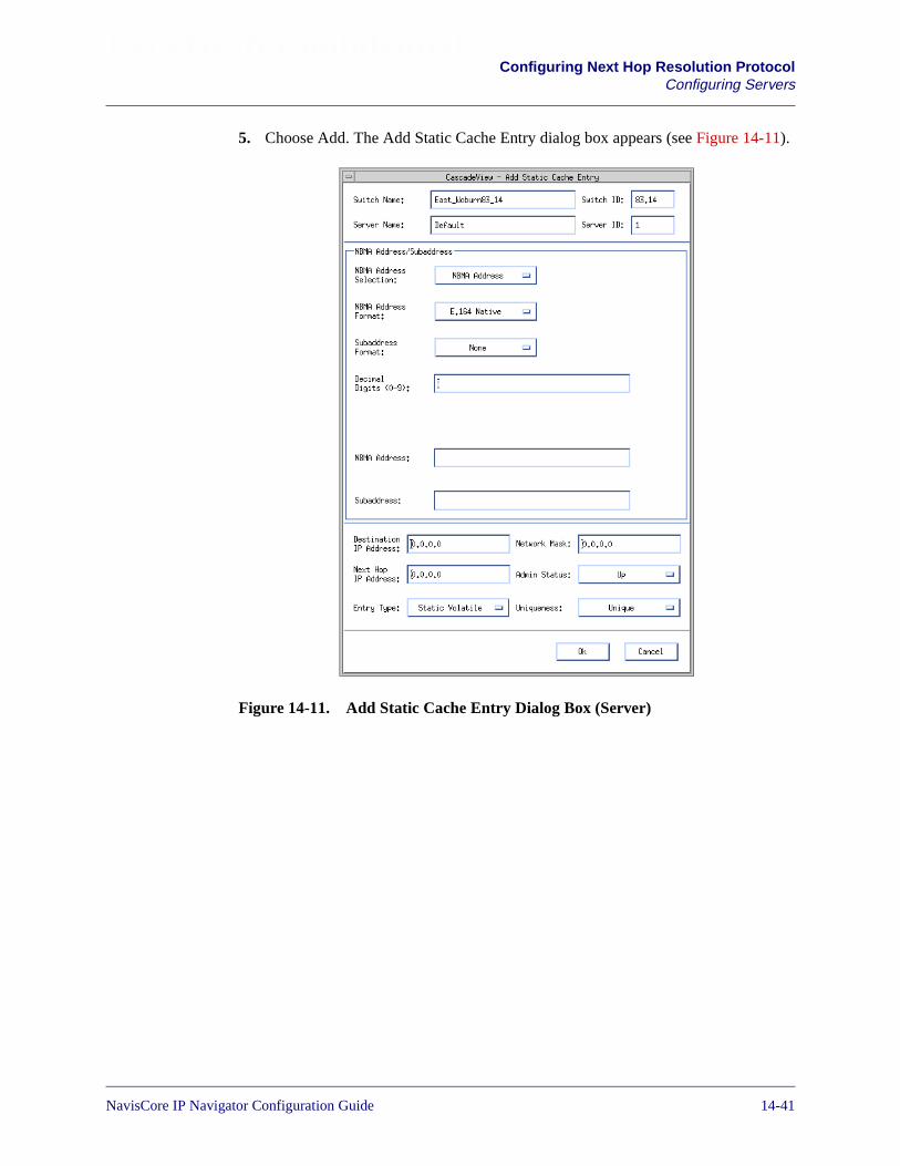
Beta Draft ConfidentialConfiguring Next Hop Resolution Protocol
Configuring Servers
5. Choose Add. The Add Static Cache Entry dialog box appears (see Figure 14-11).
Figure 14-11. Add Static Cache Entry Dialog Box (Server)
NavisCore IP Navigator Configuration Guide 1/14/0214-41

Beta Draft ConfidentialConfiguring Next Hop Resolution ProtocolConfiguring Servers
6. Specify the parameters described in Table 14-8.
Table 14-8. NHRP Server Cache Entry Parameters
Field Action/Description
Switch Name Displays the name of the selected switch.
Switch ID Displays the subnetwork number and host ID in the internal IP address of theswitch.
Server Name Displays the name of the server.
Server ID Displays the internally assigned ID of the server.
NBMA Address Selection Select the type of address you are configuring for the next hop: NBMA Address(default) or NBMA Subaddress. You select NBMA Address regardless of theaddress format you use. You select NBMA Subaddress only if you use E.164 withNSAP addressing.
If you use E.164 with NSAP addresses, you specify both an address and asubaddress in the following order:
1. In the NBMA Address Selection field, select NBMA Address.
2. In the NBMA Address Format field, select E.164 with NSAP.
3. In the Decimal Digits field, specify a native E.164 address.
4. Return to the NBMA Address Selection field. Select NBMA Subaddress.
5. In the NBMA Address Selection field, select NBMA Subaddress.
6. In the NBMA Address Format field, select a valid address format.
7. Specify an AFI if you selected a subaddress format of Custom AESA.
8. In the Hex Digits field, specify the hexadecimal subaddress.
14-42 NavisCore IP Navigator Configuration Guide

Beta Draft ConfidentialConfiguring Next Hop Resolution Protocol
Configuring Servers
NBMA Address Format Select the NBMA address format that the next hop supports:
• E.164 Native (default)
• E.164 with NSAP
• DCC AESA
• ICD AESA
• E.164 AESA
• Custom AESA
See “About NBMA Addressing” on page 14-4 for more information on theseformats.
Your choice of formats determines how you specify address information in theother fields on the dialog box:
E.164 Native and E.164 with NSAP – You must type in a decimal address in theDecimal Digits field (which appears only if you make either of these choices). Inaddition, if you select E.164 with NSAP you must select an NBMA subaddressformat and type in a decimal subaddress in the Decimal Digits field.
DCC AESA, ICD AESA, E.164 AESA, and Custom AESA – You must type in ahexadecimal address in the Hex Digits field (which, along with the AFI field,appears only if you make any of these selections). With the exception ofCustomer AESA, the NMS specifies the AFI for you in the AFI field. If you selectCustom AESA, you must type in the appropriate AFI in the AFI field yourself.
NBMA Subaddress Format(E.164 with NSAP only)
Select the NBMA subaddress format that the next hop supports:
• DCC AESA
• ICD AESA
• E.164 AESA
• Custom AESA
For example, if the next hop is connected to a private network that supports DCCAESA addressing, you would select DCC AESA.
After you select a format, type in a hexadecimal subaddress in the Hex Digitsfield. In addition, if you select Custom AESA, you must also type in an AFI in theAFI field.
See “About NBMA Addressing” on page 14-4 for more information on theseformats.
AFI (DCC AESA, ICDAESA, E.164 AESA, andCustom AESA only)
If you selected Custom AESA as the NBMA address or subaddress format, type inthe two-digit AFI. If you made any other address or subaddress selection, thisfield is read-only and displays the AFI for the selected format.
Table 14-8. NHRP Server Cache Entry Parameters (Continued)
Field Action/Description
NavisCore IP Navigator Configuration Guide 1/14/0214-43

Beta Draft ConfidentialConfiguring Next Hop Resolution ProtocolConfiguring Servers
Hex Digits (0-F) (DCCAESA, ICD AESA, E.164AESA, and Custom AESAonly)
Specify the hexadecimal address or subaddress of the next hop, up to 38 digitslong. As you type an address, it displays in the NBMA Address field. As you typea subaddress, it displays in the NBMA Subaddress field.
Decimal Digits (0-9) (E.164Native and E.164 withNSAP only)
Specify the decimal address of the next hop, up to 15 digits long. As you type anaddress, it displays in the NBMA Address field.
NBMA Address Displays the NBMA address of the next hop as you type it in the Hex Digits orDecimal Digits field. The NBMA Address field is read-only.
NBMA Subaddress Displays the NBMA subaddress of the next hop as you type it in the Hex Digitsfield. The NBMA Subaddress field is read-only.
Destination IP Address Specify the destination’s IP address (e.g., 131.100.24.3). The default is 0.0.0.0.
Next Hop IP Address Specify the next hop’s IP address (e.g., 131.100.24.3). The default is 0.0.0.0. Thenext hop IP address should match the destination IP address if the next hop andthe destination are the same (that is, the next hop is the destination). This happenswhen the destination is directly connected to the server by a logical NBMAsubnetwork.
However, if the destination is not directly connected to the server, it means that anintermediate node must be used to reach the destination, and the next hop IPaddress must refer to the egress router for the NBMA subnetwork that is closest tothe destination.
Entry Type Select the cache entry type:
Static Volatile (default) – The entry is volatile and will not be restored after a reset(e.g., a switch reboot).
Static Non Volatile – The entry is non-volatile and will be restored after a reset(e.g., a switch reboot).
Network Mask Specify the network mask for the destination IP address (for example,255.255.255.0).
Admin Status Set the administrative status of the entry to Up (default) or Down. If the status isDown, the entry cannot be used to resolve IP/ATM address mappings.
Table 14-8. NHRP Server Cache Entry Parameters (Continued)
Field Action/Description
14-44 NavisCore IP Navigator Configuration Guide

Beta Draft ConfidentialConfiguring Next Hop Resolution Protocol
Configuring Servers
7. Choose OK.
Modifying a Server Cache Entry
To modify a server cache entry:
1. Select a switch from the network map.
2. From the Administer menu, select Lucent IP Parameters� Set NHRP� SetServers� Set Cache.
3. Select a switch. The list of servers configured on the switch appears.
4. Select the server whose cache entries you want to modify. A list of cache entriesappears.
5. Select a cache entry.
6. Choose Modify. The Modify Static Cache Entry dialog box appears.
7. Modify the desired parameters. See Table 14-8 on page 14-42 for descriptions ofthese parameters.
8. Choose OK.
Uniqueness Select the uniqueness value for the entry:
Unique – (default) Mark this cache entry as unique. It is possible to have multipleNBMA addresses mapped to the same Next Hop IP Address. As a result, you willhave multiple cache entries with the same Next Hop IP Address but differentNBMA addresses. This allows the NHS to return multiple NBMA addresses to arequesting NHC. In turn, the NHC can establish a virtual circuit to alternateNBMA addresses if one establishment attempt fails.
However, the NHC may not want multiple NBMA addresses returned to it. To tellthe NHS that it only wants one NBMA address returned, the NHC sets theuniqueness flag in the NHRP Resolution Request. The NHS will then return onlythe NBMA address from the cache entry that is marked as unique.
Non Unique – Mark this cache entry as non-unique. This indicates that the NHSwill not return the NBMA address in the entry to a requesting NHC if the NHCspecifies that it only wants the unique NBMA address.
Table 14-8. NHRP Server Cache Entry Parameters (Continued)
Field Action/Description
NavisCore IP Navigator Configuration Guide 1/14/0214-45
Beta Draft ConfidentialConfiguring Next Hop Resolution ProtocolConfiguring Servers
Deleting a Server Cache Entry
To delete a server cache entry:
1. Select a switch from the network map.
2. From the Administer menu, select Lucent IP Parameters� Set NHRP� SetServers� Set Cache. The Set All NHRP Cache Entries dialog box appears (seeFigure 14-10).
3. Select a switch. The list of servers configured on the switch appears.
4. Select the server whose cache entries you want to delete. A list of cache entriesappears.
5. Select a cache entry.
6. Choose Delete.
7. Choose OK.
14-46 NavisCore IP Navigator Configuration Guide

Beta Draft ConfidentialConfiguring Next Hop Resolution Protocol
Configuring the Proxy Client
Configuring the Proxy Client
Only one proxy client can exist per switch, and the single proxy client instance isalready added for you. However, you still need to:
• Configure the proxy client parameters.
• Enable the proxy client on an NHRP logical port, one that is used to communicatewith NHCs and NHSs. See “Configuring NHRP Logical Port Parameters” onpage 14-59 for more information on enabling the proxy client on an NHRP logicalport.
Although proxy clients automatically cache the IP Address/NBMA Address mappingsthey receive from the NHS, you can also manually create cache entries for shortcuts todestinations, if necessary.
The following sections describe how to add, modify, and delete proxy clients and theircache entries.
Configuring Proxy Client Parameters
To configure proxy client parameters:
1. Select a switch from the network map.
2. From the Administer menu, select Lucent IP Parameters� Set NHRP� SetProxy Client� Set Parameters. The Set All NHRP Client Parameters dialog boxappears (see Figure 14-12).
Figure 14-12. Set All NHRP Client Parameters Dialog Box
NavisCore IP Navigator Configuration Guide 1/14/0214-47
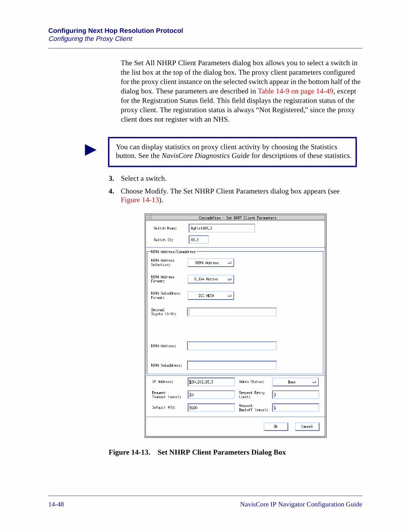
Beta Draft ConfidentialConfiguring Next Hop Resolution ProtocolConfiguring the Proxy Client
The Set All NHRP Client Parameters dialog box allows you to select a switch inthe list box at the top of the dialog box. The proxy client parameters configuredfor the proxy client instance on the selected switch appear in the bottom half of thedialog box. These parameters are described in Table 14-9 on page 14-49, exceptfor the Registration Status field. This field displays the registration status of theproxy client. The registration status is always “Not Registered,” since the proxyclient does not register with an NHS.
3. Select a switch.
4. Choose Modify. The Set NHRP Client Parameters dialog box appears (seeFigure 14-13).
Figure 14-13. Set NHRP Client Parameters Dialog Box
You can display statistics on proxy client activity by choosing the Statisticsbutton. See the NavisCore Diagnostics Guide for descriptions of these statistics.
14-48 NavisCore IP Navigator Configuration Guide
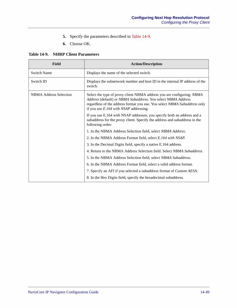
Beta Draft ConfidentialConfiguring Next Hop Resolution Protocol
Configuring the Proxy Client
5. Specify the parameters described in Table 14-9.
6. Choose OK.
Table 14-9. NHRP Client Parameters
Field Action/Description
Switch Name Displays the name of the selected switch.
Switch ID Displays the subnetwork number and host ID in the internal IP address of theswitch.
NBMA Address Selection Select the type of proxy client NBMA address you are configuring: NBMAAddress (default) or NBMA Subaddress. You select NBMA Addressregardless of the address format you use. You select NBMA Subaddress onlyif you use E.164 with NSAP addressing.
If you use E.164 with NSAP addresses, you specify both an address and asubaddress for the proxy client. Specify the address and subaddress in thefollowing order:
1. In the NBMA Address Selection field, select NBMA Address.
2. In the NBMA Address Format field, select E.164 with NSAP.
3. In the Decimal Digits field, specify a native E.164 address.
4. Return to the NBMA Address Selection field. Select NBMA Subaddress.
5. In the NBMA Address Selection field, select NBMA Subaddress.
6. In the NBMA Address Format field, select a valid address format.
7. Specify an AFI if you selected a subaddress format of Custom AESA.
8. In the Hex Digits field, specify the hexadecimal subaddress.
NavisCore IP Navigator Configuration Guide 1/14/0214-49

Beta Draft ConfidentialConfiguring Next Hop Resolution ProtocolConfiguring the Proxy Client
NBMA Address Format Select one of the following formats for the proxy client’s NBMA address:
• E.164 Native (default)
• E.164 with NSAP
• DCC AESA
• ICD AESA
• E.164 AESA
• Custom AESA
See “About NBMA Addressing” on page 14-4 for more information on theseformats.
Your choice of formats determines how you specify address information inthe other fields on the dialog box:
E.164 Native and E.164 with NSAP – You must type in a decimal address inthe Decimal Digits field (which appears only if you make either of thesechoices). In addition, if you select E.164 with NSAP you must select anNBMA subaddress format and type in a decimal subaddress in the DecimalDigits field.
DCC AESA, ICD AESA, E.164 AESA, and Custom AESA – You must typein a hexadecimal address in the Hex Digits field (which, along with the AFIfield, appears only if you make any of these selections). With the exceptionof Customer AESA, the NMS specifies the AFI for you in the AFI field. Ifyou select Custom AESA, you must type in the appropriate AFI in the AFIfield yourself.
NBMA Subaddress Format(E.164 with NSAP only)
Select one of the following formats for the proxy client’s NBMA subaddress:
• DCC AESA
• ICD AESA
• E.164 AESA
• Custom AESA
For example, if the switch is connected to a private network that supportsDCC AESA addressing, you would select DCC AESA.
After you select a format, type in a hexadecimal subaddress in the Hex Digitsfield. In addition, if you select Custom AESA, you must also type in an AFI inthe AFI field.
See “About NBMA Addressing” on page 14-4 for more information on theseformats.
AFI (DCC AESA, ICD AESA,E.164 AESA, and Custom AESAonly)
If you selected Custom AESA as the NBMA address or subaddress format,type in the two-digit AFI. If you made any other address or subaddressselection, this field is read-only and displays the AFI for the selected format.
Table 14-9. NHRP Client Parameters (Continued)
Field Action/Description
14-50 NavisCore IP Navigator Configuration Guide

Beta Draft ConfidentialConfiguring Next Hop Resolution Protocol
Configuring the Proxy Client
Hex Digits (0-F) (DCC AESA,ICD AESA, E.164 AESA, andCustom AESA only)
Specify the hexadecimal address or subaddress of the proxy client, up to 38digits long. As you type an address, it displays in the NBMA Address field.As you type a subaddress, it displays in the NBMA Subaddress field.
Decimal Digits (0-9) (E.164Native and E.164 with NSAPonly)
Specify the decimal address of the proxy client, up to 15 digits long. As youtype an address, it displays in the NBMA Address field.
NBMA Address Displays the NBMA address as you type it in the Hex Digits or DecimalDigits field. The NBMA Address field is read-only.
NBMA Subaddress Displays the NBMA subaddress as you type it in the Hex Digits field. TheNBMA Subaddress field is read-only.
IP Address Specify the proxy client’s IP address (e.g., 131.100.24.3). The default is theIP address of the switch.
Request Timeout (secs) Specify the number of seconds that the proxy client waits before timing outan NHRP Resolution Request to the NHS. The default is 10.
When NHRP Resolution Requests time out, the proxy client re-sends themaccording to the rules defined by the Request Retry Limit and RequestBackoff parameters. See the descriptions of these parameters for moreinformation.
The proxy client also re-sends NHRP Resolution Requests according to therules defined by the Request Retry Limit and Request Backoff parameters ifthe proxy client receives a negative acknowledgment from the NHS becauseno IP/ATM address mapping was found.
Default MTU Specify the default Maximum Transmission Unit (MTU), in bytes, that theclient uses to send packets. The default is 9180 bytes. Make sure that theMTU you set is compatible with the rest of the network.
If you do not set any default MTU value (that is, you remove the default andleave the field blank), the switch sets the default MTU to the value used bythe LIS/LAG.
Admin Status Set the administrative status of the proxy client to Up or Down (default).
Request Retry Limit Specify the number of times that the proxy client will retry NHRP ResolutionRequests to the NHS before giving up. Values range from 0 to 65535. Thedefault is 3. A value of 0 specifies that the proxy client will not attempt anyretries. A value of 65535 specifies that the client will retry forever.
This parameter works in conjunction with the Request Backoff parameter.For example, if you specify a Request Retry Limit of 3 and a RequestBackoff of 12 seconds, the proxy client will make three retry attempts, andwill wait 12 seconds between each attempt.
Table 14-9. NHRP Client Parameters (Continued)
Field Action/Description
NavisCore IP Navigator Configuration Guide 1/14/0214-51

Beta Draft ConfidentialConfiguring Next Hop Resolution ProtocolConfiguring the Proxy Client
Modifying Proxy Client Parameters
You may want to change proxy client parameters at a later date. To modify proxyclient parameters, follow the instructions in the previous section (see “ConfiguringProxy Client Parameters” on page 14-47).
Adding Proxy Client Cache Entries
A proxy client cache entry maps an IP address of a next hop to its NBMA (i.e., ATM)address. A shortcut can then be established to the destination that is associated withthe cache entry.
A proxy client cache entry identifies both the IP address of the destination and the IPaddress of the next hop that is used to reach the destination. In many cases, theseaddresses are one and the same — they refer to the same network node (that is, thenext hop is the destination). However, in other cases, these addresses are different.
If the proxy client and the destination are directly connected by the same logicalNBMA subnetwork, then the next hop IP address and destination IP address are thesame (that is, the next hop is the destination). Otherwise, the next hop IP addressrefers to the egress router for the NBMA subnetwork that is closest to the destination,and the destination IP address refers to the destination itself. The NBMA address ismapped to the next hop IP address, not the destination IP address.
Cache entries can be added to the server cache in two ways:
Dynamically — The proxy client caches the IP/ATM address resolution mappingsreceived in NHRP Resolution Requests from NHSs. However, these cache entriesexpire after a certain period of time, or are removed as a result of receiving NHRPPurge Request.
Manually — You add the IP/ATM address mappings yourself. You may want to dothis if you do not want your cache entries to expire, or if no NHSs are available toresolve IP/ATM address mappings.
Request Backoff (secs) Specify the number of seconds that the proxy client waits before attempting aretry of an NHRP Resolution Request to the NHS. The default is 1. Forexample, if you use the default, the client will wait 1 second beforeattempting each NHRP Resolution Request retry.
This parameter works in conjunction with the Request Retry Limit parameter.See the description of the Request Retry Limit parameter for moreinformation.
Table 14-9. NHRP Client Parameters (Continued)
Field Action/Description
14-52 NavisCore IP Navigator Configuration Guide

Beta Draft ConfidentialConfiguring Next Hop Resolution Protocol
Configuring the Proxy Client
To add an entry to the proxy client cache:
1. Select a switch from the network map.
2. From the Administer menu, select Lucent IP Parameters� Set NHRP� SetProxy Client� Set Cache. The Set All NHRP Cache Entries dialog box appears(see Figure 14-14).
Figure 14-14. Set All NHRP Cache Entries Dialog Box (Proxy Client)
The Set All NHRP Cache Entries dialog box allows you to select a switch in thelist box at the top of the dialog box. This action displays the default proxy client(“Default”) on that switch in the second list box. You can then select the defaultproxy client, and the cache entries for the proxy client display in a list.Table 14-10 on page 14-55 describes these fields.
3. Select a switch. The default proxy client (“Default”) on that switch appears.
4. Select the default proxy client.
NavisCore IP Navigator Configuration Guide 1/14/0214-53

Beta Draft ConfidentialConfiguring Next Hop Resolution ProtocolConfiguring the Proxy Client
5. Choose Add. The Add Static Cache Entry dialog box appears (see Figure 14-15).
Figure 14-15. Add Static Cache Entry Dialog Box (Proxy Client)
6. Specify the parameters described in Table 14-10.
7. Choose OK.
14-54 NavisCore IP Navigator Configuration Guide
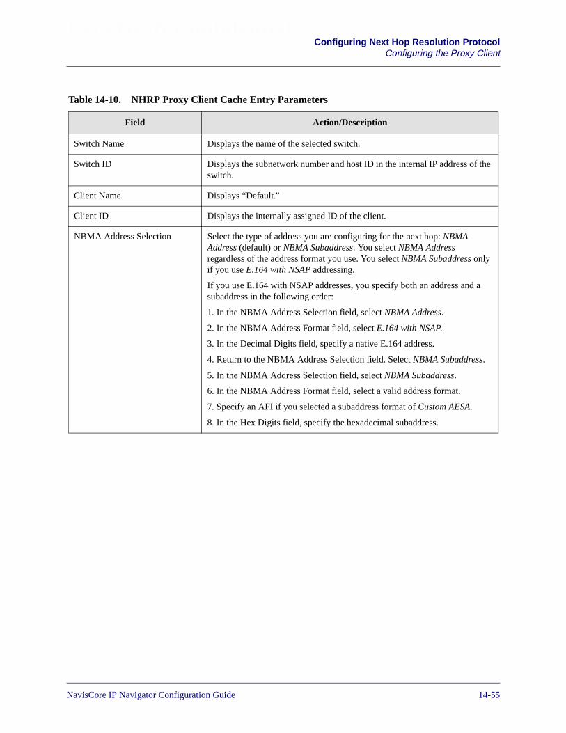
Beta Draft ConfidentialConfiguring Next Hop Resolution Protocol
Configuring the Proxy Client
Table 14-10. NHRP Proxy Client Cache Entry Parameters
Field Action/Description
Switch Name Displays the name of the selected switch.
Switch ID Displays the subnetwork number and host ID in the internal IP address of theswitch.
Client Name Displays “Default.”
Client ID Displays the internally assigned ID of the client.
NBMA Address Selection Select the type of address you are configuring for the next hop: NBMAAddress (default) or NBMA Subaddress. You select NBMA Addressregardless of the address format you use. You select NBMA Subaddress onlyif you use E.164 with NSAP addressing.
If you use E.164 with NSAP addresses, you specify both an address and asubaddress in the following order:
1. In the NBMA Address Selection field, select NBMA Address.
2. In the NBMA Address Format field, select E.164 with NSAP.
3. In the Decimal Digits field, specify a native E.164 address.
4. Return to the NBMA Address Selection field. Select NBMA Subaddress.
5. In the NBMA Address Selection field, select NBMA Subaddress.
6. In the NBMA Address Format field, select a valid address format.
7. Specify an AFI if you selected a subaddress format of Custom AESA.
8. In the Hex Digits field, specify the hexadecimal subaddress.
NavisCore IP Navigator Configuration Guide 1/14/0214-55
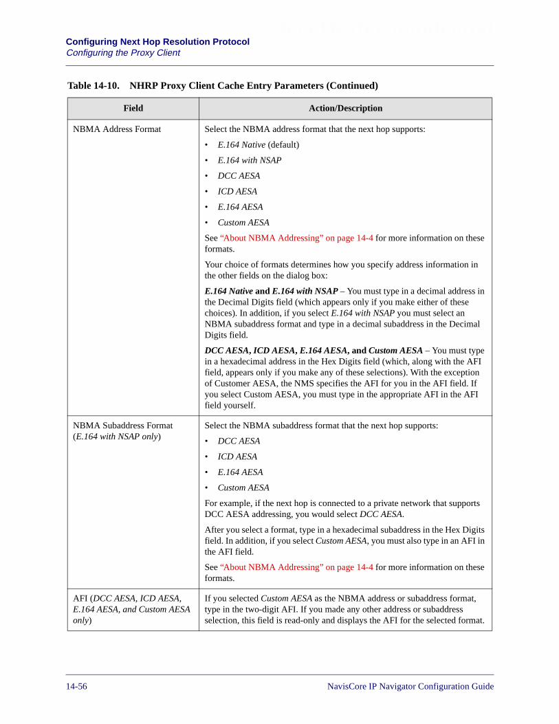
Beta Draft ConfidentialConfiguring Next Hop Resolution ProtocolConfiguring the Proxy Client
NBMA Address Format Select the NBMA address format that the next hop supports:
• E.164 Native (default)
• E.164 with NSAP
• DCC AESA
• ICD AESA
• E.164 AESA
• Custom AESA
See “About NBMA Addressing” on page 14-4 for more information on theseformats.
Your choice of formats determines how you specify address information inthe other fields on the dialog box:
E.164 Native and E.164 with NSAP – You must type in a decimal address inthe Decimal Digits field (which appears only if you make either of thesechoices). In addition, if you select E.164 with NSAP you must select anNBMA subaddress format and type in a decimal subaddress in the DecimalDigits field.
DCC AESA, ICD AESA, E.164 AESA, and Custom AESA – You must typein a hexadecimal address in the Hex Digits field (which, along with the AFIfield, appears only if you make any of these selections). With the exceptionof Customer AESA, the NMS specifies the AFI for you in the AFI field. Ifyou select Custom AESA, you must type in the appropriate AFI in the AFIfield yourself.
NBMA Subaddress Format(E.164 with NSAP only)
Select the NBMA subaddress format that the next hop supports:
• DCC AESA
• ICD AESA
• E.164 AESA
• Custom AESA
For example, if the next hop is connected to a private network that supportsDCC AESA addressing, you would select DCC AESA.
After you select a format, type in a hexadecimal subaddress in the Hex Digitsfield. In addition, if you select Custom AESA, you must also type in an AFI inthe AFI field.
See “About NBMA Addressing” on page 14-4 for more information on theseformats.
AFI (DCC AESA, ICD AESA,E.164 AESA, and Custom AESAonly)
If you selected Custom AESA as the NBMA address or subaddress format,type in the two-digit AFI. If you made any other address or subaddressselection, this field is read-only and displays the AFI for the selected format.
Table 14-10. NHRP Proxy Client Cache Entry Parameters (Continued)
Field Action/Description
14-56 NavisCore IP Navigator Configuration Guide
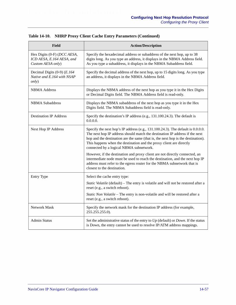
Beta Draft ConfidentialConfiguring Next Hop Resolution Protocol
Configuring the Proxy Client
Hex Digits (0-F) (DCC AESA,ICD AESA, E.164 AESA, andCustom AESA only)
Specify the hexadecimal address or subaddress of the next hop, up to 38digits long. As you type an address, it displays in the NBMA Address field.As you type a subaddress, it displays in the NBMA Subaddress field.
Decimal Digits (0-9) (E.164Native and E.164 with NSAPonly)
Specify the decimal address of the next hop, up to 15 digits long. As you typean address, it displays in the NBMA Address field.
NBMA Address Displays the NBMA address of the next hop as you type it in the Hex Digitsor Decimal Digits field. The NBMA Address field is read-only.
NBMA Subaddress Displays the NBMA subaddress of the next hop as you type it in the HexDigits field. The NBMA Subaddress field is read-only.
Destination IP Address Specify the destination’s IP address (e.g., 131.100.24.3). The default is0.0.0.0.
Next Hop IP Address Specify the next hop’s IP address (e.g., 131.100.24.3). The default is 0.0.0.0.The next hop IP address should match the destination IP address if the nexthop and the destination are the same (that is, the next hop is the destination).This happens when the destination and the proxy client are directlyconnected by a logical NBMA subnetwork.
However, if the destination and proxy client are not directly connected, anintermediate node must be used to reach the destination, and the next hop IPaddress must refer to the egress router for the NBMA subnetwork that isclosest to the destination.
Entry Type Select the cache entry type:
Static Volatile (default) – The entry is volatile and will not be restored after areset (e.g., a switch reboot).
Static Non Volatile – The entry is non-volatile and will be restored after areset (e.g., a switch reboot).
Network Mask Specify the network mask for the destination IP address (for example,255.255.255.0).
Admin Status Set the administrative status of the entry to Up (default) or Down. If the statusis Down, the entry cannot be used to resolve IP/ATM address mappings.
Table 14-10. NHRP Proxy Client Cache Entry Parameters (Continued)
Field Action/Description
NavisCore IP Navigator Configuration Guide 1/14/0214-57

Beta Draft ConfidentialConfiguring Next Hop Resolution ProtocolConfiguring the Proxy Client
Modifying a Proxy Client Cache Entry
To modify a proxy client cache entry:
1. Select a switch from the network map.
2. From the Administer menu, select Lucent IP Parameters� Set NHRP� SetProxy Client� Set Cache.
3. Select a switch. The name of the proxy client (“Default”) for the switch andassociated information appears.
4. Select the default proxy client (“Default”). A list of cache entries appears.
5. Select a cache entry.
6. Choose Modify. The Modify Static Cache Entry dialog box appears.
7. Modify the desired parameters. See Table 14-10 on page 14-55 for descriptions ofthese parameters.
8. Choose OK.
Deleting a Proxy Client Cache Entry
To delete a proxy client cache entry:
1. Select a switch from the network map.
2. From the Administer menu, select Lucent IP Parameters� Set NHRP� SetProxy Client� Set Cache. The Set All NHRP Cache Entries dialog box appears(see Figure 14-10).
3. Select a switch. The name of the proxy client (“Default”) for the switch andassociated information appears.
4. Select the default proxy client (“Default”). A list of cache entries appears.
5. Select a cache entry.
6. Choose Delete.
7. Choose OK.
14-58 NavisCore IP Navigator Configuration Guide

Beta Draft ConfidentialConfiguring Next Hop Resolution Protocol
Configuring NHRP Logical Port Parameters
Configuring NHRP Logical Port Parameters
You must configure NHRP logical ports that will process NHRP requests andresponses.
When you configure an NHRP logical port:
• Verify that the NHRP logical port has been added. See “Adding an NHRP LogicalPort” on page 14-10 for more information on adding an NHRP logical port.
• Verify the role that the port plays in the network (e.g., ingress and/or egress). If theport is at the ingress/egress of the Lucent network and interfaces with NHCs,associate a server with it. In addition, if you want to provision bandwidth and QoSguarantees for IP traffic flows, enable the proxy client. For trunk logical ports, thedefault server is already configured and you are not required to do anything.
• Make sure that you have configured NHRP servers and the proxy client. See“Configuring Servers” on page 14-32 and “Configuring the Proxy Client” onpage 14-47 for more information.
• Configure other parameters as needed.
To configure logical port parameters:
1. Select a switch from the network map.
2. From the Administer menu, select Lucent IP Parameters� Set NHRP� SetLPort Parameters. The Set All NHRP LPort Parameters dialog box appears (seeFigure 14-16).
NavisCore IP Navigator Configuration Guide 1/14/0214-59
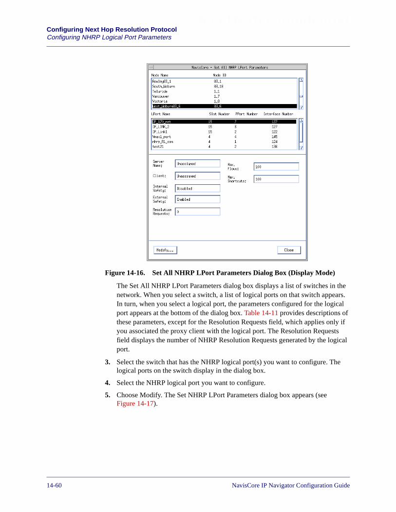
Beta Draft ConfidentialConfiguring Next Hop Resolution ProtocolConfiguring NHRP Logical Port Parameters
Figure 14-16. Set All NHRP LPort Parameters Dialog Box (Display Mode)
The Set All NHRP LPort Parameters dialog box displays a list of switches in thenetwork. When you select a switch, a list of logical ports on that switch appears.In turn, when you select a logical port, the parameters configured for the logicalport appears at the bottom of the dialog box. Table 14-11 provides descriptions ofthese parameters, except for the Resolution Requests field, which applies only ifyou associated the proxy client with the logical port. The Resolution Requestsfield displays the number of NHRP Resolution Requests generated by the logicalport.
3. Select the switch that has the NHRP logical port(s) you want to configure. Thelogical ports on the switch display in the dialog box.
4. Select the NHRP logical port you want to configure.
5. Choose Modify. The Set NHRP LPort Parameters dialog box appears (seeFigure 14-17).
14-60 NavisCore IP Navigator Configuration Guide
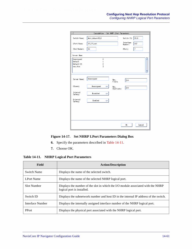
Beta Draft ConfidentialConfiguring Next Hop Resolution Protocol
Configuring NHRP Logical Port Parameters
Figure 14-17. Set NHRP LPort Parameters Dialog Box
6. Specify the parameters described in Table 14-11.
7. Choose OK.
Table 14-11. NHRP Logical Port Parameters
Field Action/Description
Switch Name Displays the name of the selected switch.
LPort Name Displays the name of the selected NHRP logical port.
Slot Number Displays the number of the slot in which the I/O module associated with the NHRPlogical port is installed.
Switch ID Displays the subnetwork number and host ID in the internal IP address of the switch.
Interface Number Displays the internally assigned interface number of the NHRP logical port.
PPort Displays the physical port associated with the NHRP logical port.
NavisCore IP Navigator Configuration Guide 1/14/0214-61
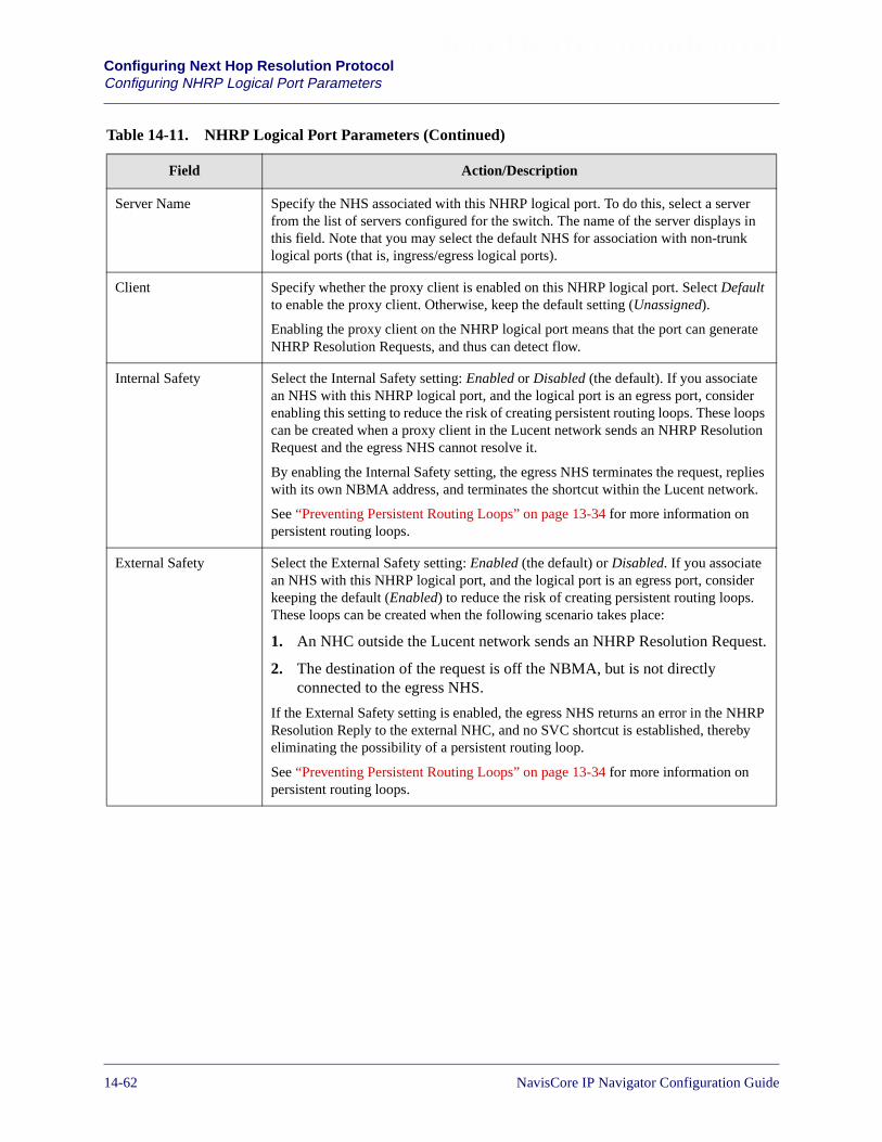
Beta Draft ConfidentialConfiguring Next Hop Resolution ProtocolConfiguring NHRP Logical Port Parameters
Server Name Specify the NHS associated with this NHRP logical port. To do this, select a serverfrom the list of servers configured for the switch. The name of the server displays inthis field. Note that you may select the default NHS for association with non-trunklogical ports (that is, ingress/egress logical ports).
Client Specify whether the proxy client is enabled on this NHRP logical port. Select Defaultto enable the proxy client. Otherwise, keep the default setting (Unassigned).
Enabling the proxy client on the NHRP logical port means that the port can generateNHRP Resolution Requests, and thus can detect flow.
Internal Safety Select the Internal Safety setting: Enabled or Disabled (the default). If you associatean NHS with this NHRP logical port, and the logical port is an egress port, considerenabling this setting to reduce the risk of creating persistent routing loops. These loopscan be created when a proxy client in the Lucent network sends an NHRP ResolutionRequest and the egress NHS cannot resolve it.
By enabling the Internal Safety setting, the egress NHS terminates the request, replieswith its own NBMA address, and terminates the shortcut within the Lucent network.
See “Preventing Persistent Routing Loops” on page 13-34 for more information onpersistent routing loops.
External Safety Select the External Safety setting: Enabled (the default) or Disabled. If you associatean NHS with this NHRP logical port, and the logical port is an egress port, considerkeeping the default (Enabled) to reduce the risk of creating persistent routing loops.These loops can be created when the following scenario takes place:
1. An NHC outside the Lucent network sends an NHRP Resolution Request.
2. The destination of the request is off the NBMA, but is not directlyconnected to the egress NHS.
If the External Safety setting is enabled, the egress NHS returns an error in the NHRPResolution Reply to the external NHC, and no SVC shortcut is established, therebyeliminating the possibility of a persistent routing loop.
See “Preventing Persistent Routing Loops” on page 13-34 for more information onpersistent routing loops.
Table 14-11. NHRP Logical Port Parameters (Continued)
Field Action/Description
14-62 NavisCore IP Navigator Configuration Guide

Beta Draft ConfidentialConfiguring Next Hop Resolution Protocol
Configuring NHRP Logical Port Parameters
Max. Flows Specify the maximum number of matching NHRP traffic flows that can besimultaneously detected on this NHRP logical port. You may not specify a valuegreater than 512.
A matching NHRP traffic flow is one that matches the criteria defined in any flowprofile associated with this logical port. See “Configuring Flow Profiles” onpage 14-19 and “Configuring NHRP Logical Port FP/TD Associations” on page 14-64for more information on creating flow profiles and associating them with logical ports.
For example, if you use the default value (100), then 100 matching NHRP trafficflows can be detected on this logical port at any one time.
There are limits on the maximum number of flows per forwarding engine (that is, themaximum number of flows from all the NHRP logical ports on the forwarding enginethat the engine can simultaneously track). See your switch Software Release Notice(SRN) for more information.
Note: Each flow profile has its own maximum flows value (see Table 14-6 onpage 14-23). Because multiple flow profiles can be associated with an NHRP logicalport, the sum of the maximum flows values of all the flow profiles associated with thelogical port cannot exceed this Max. Flows value. For example, if you associate twoflow profiles with this logical port, and you set the Max. Flows value for the logicalport to 50, then the sum of the maximum flows values of the two profiles should notexceed 50.
Max. Shortcuts Specify the maximum number of matching NHRP shortcuts that can besimultaneously connected to this logical port. You may not specify a value greaterthan 512.
A matching NHRP shortcut is one that matches the criteria defined in any flow profileassociated with this logical port. See “Configuring Flow Profiles” on page 14-19 and“Configuring NHRP Logical Port FP/TD Associations” on page 14-64 for moreinformation on creating flow profiles and associating them with logical ports.
For example, if you use the default (100), then 100 shortcuts that match any flowprofile associated with this logical port can be connected at any one time.
There are limits on the maximum number of shortcuts per forwarding engine (that is,the maximum number of shortcuts from all the logical ports on the forwarding enginethat the engine can simultaneously track). See your switch Software Release Notice(SRN) for more information.
Note: Each flow profile has its own maximum shortcuts value (see Table 14-6 onpage 14-23). Because multiple flow profiles can be associated with an NHRP logicalport, the sum of the maximum shortcuts values of all the flow profiles associated withthe logical port cannot exceed this Max. Shortcuts value. For example, if youassociate two flow profiles with this logical port, and you set the Max. Shortcuts valuefor the logical port to 50, then the sum of the maximum shortcuts values of the twoprofiles should not exceed 50.
Table 14-11. NHRP Logical Port Parameters (Continued)
Field Action/Description
NavisCore IP Navigator Configuration Guide 1/14/0214-63
Beta Draft ConfidentialConfiguring Next Hop Resolution ProtocolConfiguring NHRP Logical Port FP/TD Associations
Configuring NHRP Logical Port FP/TD Associations
After you create flow profiles, you must associate them with NHRP logical ports toput them into effect.
When you assign a flow profile to an NHRP logical port, you also specify the trafficdescriptors that manage the traffic flow over the SVC that connects the NHRP logicalport and the destination. You specify two sets of traffic descriptors:
Primary Traffic Descriptors — The desired traffic descriptors for the traffic flowover the SVC.
Secondary Traffic Descriptors — The alternative or minimum acceptable trafficdescriptors associated with the flow profile. When the traffic flow’s SVC is set up,both ends negotiate to determine the traffic descriptors to be used for the connection.If not enough resources exist for the network to meet the primary traffic descriptorrequirements, then either the alternate traffic descriptors or the minimum acceptabletraffic descriptors are used. Alternate traffic descriptors define the best possiblevalues that should be used in place of the primary traffic descriptor values. Minimumacceptable traffic descriptors define the lowest values that you are willing to accept inplace of the primary traffic descriptor values. If the minimum acceptable trafficdescriptors are configured, the actual traffic descriptors that are used for the SVC are anegotiated compromise somewhere between the primary and minimum trafficdescriptors.
When you associate traffic descriptors with flow profiles, you can specify alternatetraffic descriptors or minimum acceptable traffic descriptors — but not both. For moreinformation on alternate and minimum traffic descriptors, see the ATM User-NetworkInterface (UNI) Signalling Specification Version 4.0.
NavisCore does not allow you to delete an NHRP logical port if it has IP flowprofiles associated with it. To delete the NHRP logical port, you must first deleteall of the IP flow profile associations. See “Deleting an NHRP Logical Port” onpage 14-11 for more information.
14-64 NavisCore IP Navigator Configuration Guide

Beta Draft ConfidentialConfiguring Next Hop Resolution Protocol
Configuring NHRP Logical Port FP/TD Associations
Before You Begin
Before you begin to associate NHRP logical ports, flow profiles, and trafficdescriptors, see the NavisCore ATM Configuration Guide for traffic descriptorinformation. Make sure that you use the NavisCore ATM Configuration Guide inconjunction with this guide when you associate traffic descriptors with flow profiles.
You should also be aware of the following rules:
• You can associate a single flow profile with multiple NHRP logical ports.
• You can associate multiple flow profiles with a single NHRP logical port, but youcannot associate the same flow profile more than once with the same NHRPlogical port.
• If you associate multiple flow profiles with a single NHRP logical port, and theseprofiles have matching or overlapping parameters, the NHS chooses the mostspecific profile first, then the second-most specific profile, and so on. Forexample, the NHS chooses flow profiles with specific source and destination IPaddresses before it chooses flow profiles that have 0.0.0.0 configured for thesource and destination IP addresses. As another example, if one profile specifiesTCP protocol traffic while the other profile specifies the wildcard for protocoltraffic, the profile that specifies TCP protocol traffic is chosen to manage TCPtraffic flow before the profile that specifies the wildcard.
• Only one of the following parameters may have an ambiguous value in a flowprofile: Dest. IP Address, Source Application, or Dest. Application. For Dest. IPAddress, an ambiguous value is expressed as 0.0.0.0. For Source Application andDest. Application, an ambiguous value is expressed by selecting Ambiguous fromthe pull-down menu provided. “Configuring Flow Profiles” on page 14-19 formore information.
• You can associate up to 96 flow profiles with a single NHRP logical port. Seeyour switch software release notice for more information on this NHRP limit aswell as other NHRP limits.
NavisCore IP Navigator Configuration Guide 1/14/0214-65
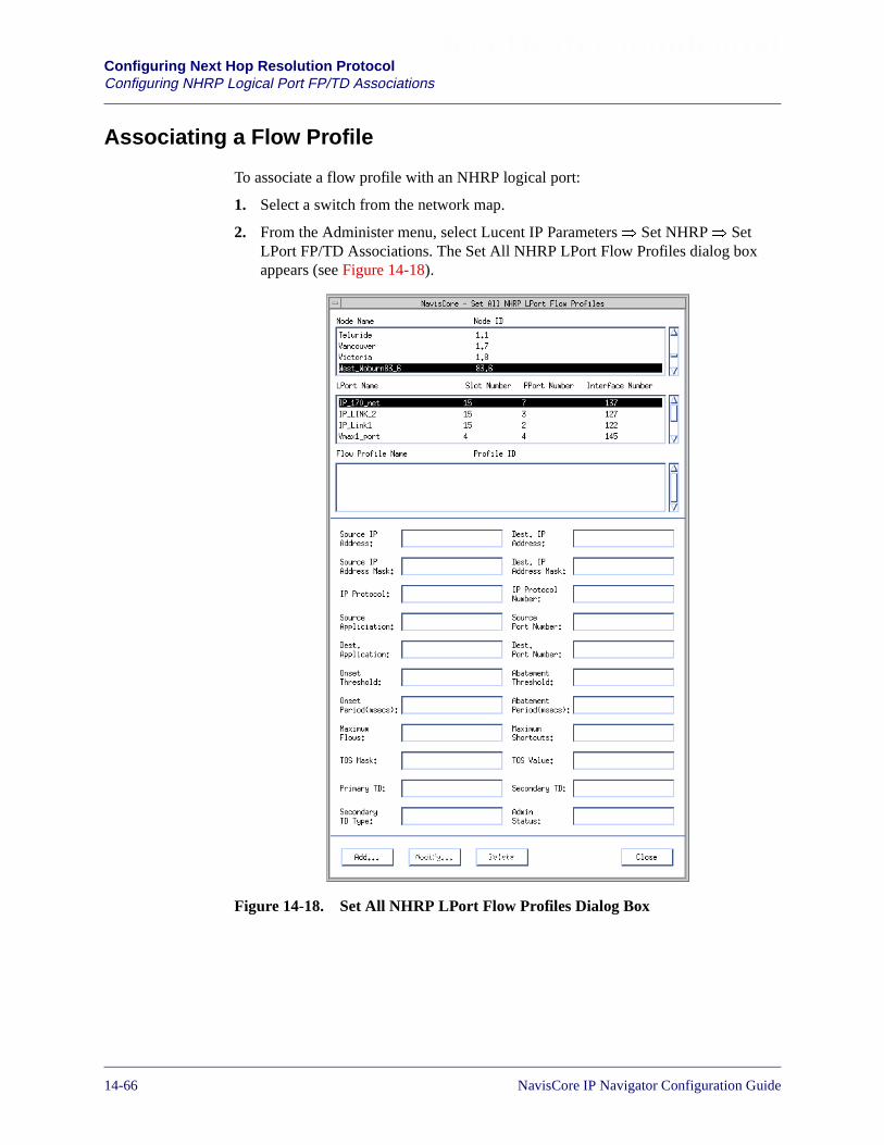
Beta Draft ConfidentialConfiguring Next Hop Resolution ProtocolConfiguring NHRP Logical Port FP/TD Associations
Associating a Flow Profile
To associate a flow profile with an NHRP logical port:
1. Select a switch from the network map.
2. From the Administer menu, select Lucent IP Parameters� Set NHRP� SetLPort FP/TD Associations. The Set All NHRP LPort Flow Profiles dialog boxappears (see Figure 14-18).
Figure 14-18. Set All NHRP LPort Flow Profiles Dialog Box
14-66 NavisCore IP Navigator Configuration Guide

Beta Draft ConfidentialConfiguring Next Hop Resolution Protocol
Configuring NHRP Logical Port FP/TD Associations
This dialog box displays a list of switches in the top list box. You can select aswitch to display all of its NHRP logical ports, and then select an NHRP logicalport to display its associated flow profiles. You can then select a flow profile, andits parameters appear in the fields in the bottom half of the dialog box. Thesefields are described in Table 14-6 on page 14-23, except for the following fields:
Primary TD — The ID of the primary traffic descriptors associated with the flowprofile.
Secondary TD Type — The type of secondary traffic descriptors: Alternate orMinimum.
Secondary TD — The ID of the secondary traffic descriptors associated with theflow profile.
Admin Status — The administrative status of the flow profile association: Up orDown. Setting the administrative status to Down disables the flow profile for useon the logical port, but does not delete the association.
3. Select the switch that has the logical port with which you want to associate theflow profile. A list of the logical ports on the switch appears.
4. Select the logical port.
The order in which you associate IP flow profiles with NHRP logical ports isvery important. Switches allocate resources to IP flow profiles based on theorder in which they are associated with NHRP logical ports. The IP flow profilethat is associated first has the highest resource priority, the IP flow profileassociated second has the next highest resource priority, and so on. Associate IPflow profiles in the following order: from most important to least important.
NavisCore IP Navigator Configuration Guide 1/14/0214-67
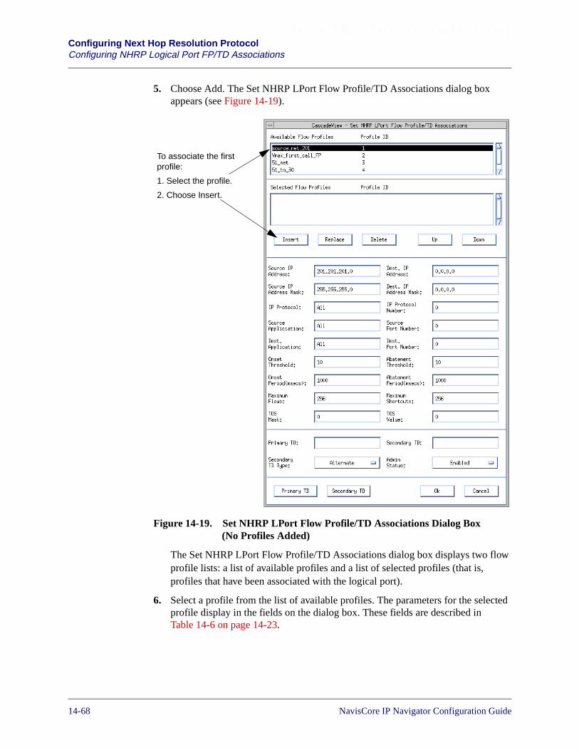
Beta Draft ConfidentialConfiguring Next Hop Resolution ProtocolConfiguring NHRP Logical Port FP/TD Associations
5. Choose Add. The Set NHRP LPort Flow Profile/TD Associations dialog boxappears (see Figure 14-19).
Figure 14-19. Set NHRP LPort Flow Profile/TD Associations Dialog Box(No Profiles Added)
The Set NHRP LPort Flow Profile/TD Associations dialog box displays two flowprofile lists: a list of available profiles and a list of selected profiles (that is,profiles that have been associated with the logical port).
6. Select a profile from the list of available profiles. The parameters for the selectedprofile display in the fields on the dialog box. These fields are described inTable 14-6 on page 14-23.
To associate the firstprofile:
1. Select the profile.
2. Choose Insert.
14-68 NavisCore IP Navigator Configuration Guide
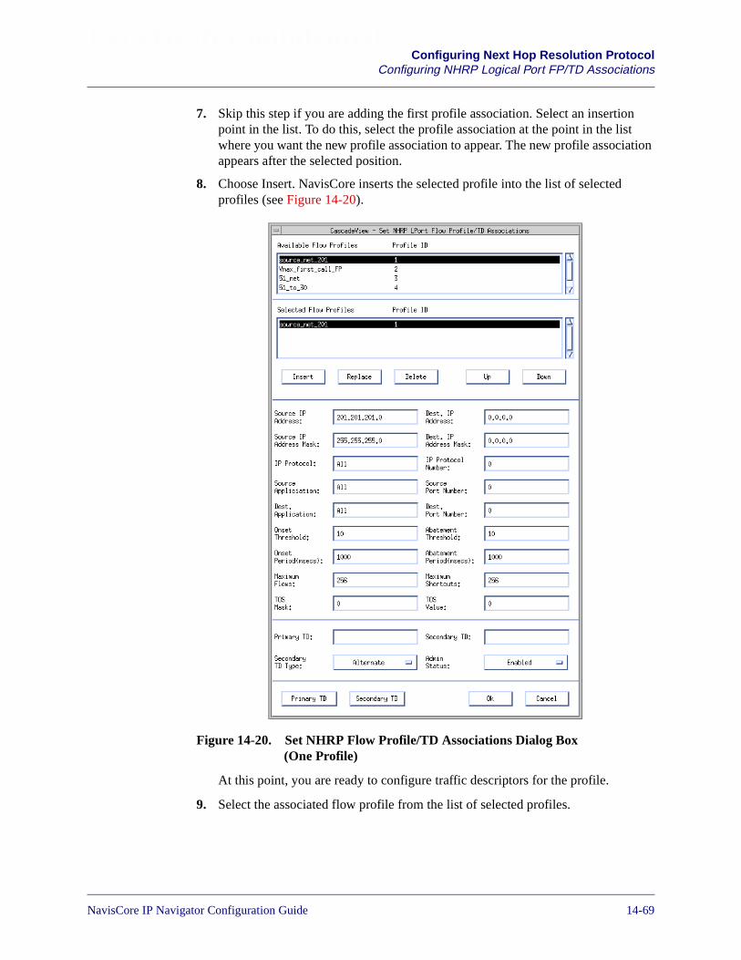
Beta Draft ConfidentialConfiguring Next Hop Resolution Protocol
Configuring NHRP Logical Port FP/TD Associations
7. Skip this step if you are adding the first profile association. Select an insertionpoint in the list. To do this, select the profile association at the point in the listwhere you want the new profile association to appear. The new profile associationappears after the selected position.
8. Choose Insert. NavisCore inserts the selected profile into the list of selectedprofiles (see Figure 14-20).
Figure 14-20. Set NHRP Flow Profile/TD Associations Dialog Box(One Profile)
At this point, you are ready to configure traffic descriptors for the profile.
9. Select the associated flow profile from the list of selected profiles.
NavisCore IP Navigator Configuration Guide 1/14/0214-69
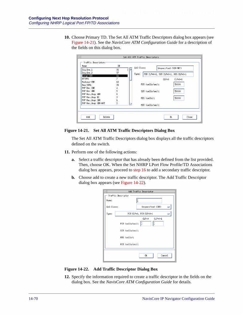
Beta Draft ConfidentialConfiguring Next Hop Resolution ProtocolConfiguring NHRP Logical Port FP/TD Associations
10. Choose Primary TD. The Set All ATM Traffic Descriptors dialog box appears (seeFigure 14-21). See the NavisCore ATM Configuration Guide for a description ofthe fields on this dialog box.
Figure 14-21. Set All ATM Traffic Descriptors Dialog Box
The Set All ATM Traffic Descriptors dialog box displays all the traffic descriptorsdefined on the switch.
11. Perform one of the following actions:
a. Select a traffic descriptor that has already been defined from the list provided.Then, choose OK. When the Set NHRP LPort Flow Profile/TD Associationsdialog box appears, proceed to step 16 to add a secondary traffic descriptor.
b. Choose add to create a new traffic descriptor. The Add Traffic Descriptordialog box appears (see Figure 14-22).
Figure 14-22. Add Traffic Descriptor Dialog Box
12. Specify the information required to create a traffic descriptor in the fields on thedialog box. See the NavisCore ATM Configuration Guide for details.
14-70 NavisCore IP Navigator Configuration Guide
Beta Draft ConfidentialConfiguring Next Hop Resolution Protocol
Configuring NHRP Logical Port FP/TD Associations
13. Choose OK. The Set All ATM Traffic Descriptors dialog box appears. The nameof the newly created traffic descriptor appears in the list of traffic descriptors.
14. Select the newly created traffic descriptor.
15. Choose OK. The Set NHRP LPort Flow Profile/TD Associations dialog boxappears.
16. Verify that the flow profile association for which you are configuring trafficdescriptors is still selected in the list of selected profiles.
17. Choose Secondary TD from the Set NHRP LPort Flow Profile/TD Associationsdialog box. The Set All ATM Traffic Descriptors dialog box appears (seeFigure 14-21). See the NavisCore ATM Configuration Guide for a description ofthe fields on this dialog box.
18. Perform one of the following actions:
a. Select a traffic descriptor that has already been defined from the list provided.Then, choose OK. When the Set NHRP LPort Flow Profile/TD Associationsdialog box appears, proceed to step 23 to specify whether the traffic descriptoris the alternative or minimum acceptable traffic descriptor.
b. Choose add to create a new traffic descriptor. The Add Traffic Descriptordialog box appears (see Figure 14-22).
19. Specify the information required to create a traffic descriptor in the fields on thedialog box. See the NavisCore ATM Configuration Guide for details.
20. Choose OK. The Set All ATM Traffic Descriptors dialog box appears. The nameof the newly created traffic descriptor appears in the list of traffic descriptors.
21. Select the newly created traffic descriptor.
22. Choose OK. The Set NHRP LPort Flow Profile/TD Associations dialog boxappears.
23. Verify that the flow profile association for which you are configuring trafficdescriptors is still selected in the list of selected profiles.
24. Select the Secondary TD Type from the Set NHRP LPort Flow Profile/TDAssociations dialog box: Alternate (the default) or Minimum.
25. Choose OK. The Show NHRP LPort Flow Profile/TD dialog box appears,displaying the flow profile association you just created.
NavisCore IP Navigator Configuration Guide 1/14/0214-71

Beta Draft ConfidentialConfiguring Next Hop Resolution ProtocolConfiguring NHRP Logical Port FP/TD Associations
Modifying a Flow Profile Association
You can modify a flow profile association’s parameters, such as its primary andsecondary traffic descriptors and its administrative status. To modify a flow profileassociation:
1. Select a switch from the network map.
2. From the Administer menu, select Lucent IP Parameters� Set NHRP� SetLPort FP/TD Associations. The Set All NHRP LPort Flow Profiles dialog boxappears (see Figure 14-18).
3. Select the switch that has the NHRP logical port whose flow profile associationsyou want to modify. A list of the logical ports on the switch appears.
4. Select the NHRP logical port associated with the flow profile association youwant to modify. A list of flow profiles associated with the NHRP logical portappears.
5. Select the flow profile you want to modify.
6. Choose Modify. The Set NHRP LPort Flow Profile/TD Associations dialog boxappears (see Figure 14-19).
7. Change the primary traffic descriptors, secondary traffic descriptors, secondarytraffic descriptors type, or administrative status as described in the previoussection, “Associating a Flow Profile” on page 14-66.
8. Choose OK from the Set NHRP LPort Flow Profile/TD Associations dialog boxwhen you finish changing parameters.
14-72 NavisCore IP Navigator Configuration Guide

Beta Draft ConfidentialConfiguring Next Hop Resolution Protocol
Configuring NHRP Logical Port FP/TD Associations
Replacing a Flow Profile Association
You can replace one flow profile association with another flow profile association. Toreplace a flow profile association:
1. Select a switch from the network map.
2. From the Administer menu, select Lucent IP Parameters� Set NHRP� SetLPort FP/TD Associations. The Set All NHRP LPort Flow Profiles dialog boxappears (see Figure 14-18).
3. Select the switch that has the NHRP logical port with which you want to associatethe flow profile. A list of the logical ports on the switch appears.
4. Select the NHRP logical port.
5. Choose Add. The Set NHRP LPort Flow Profile/TD Associations dialog boxappears (see Figure 14-19).
The Set NHRP LPort Flow Profile/TD Associations dialog box displays two flowprofile lists: a list of available profiles and a list of selected profiles (that is,profiles that have been associated with the logical port).
6. In the list of available profiles, select the profile with which you want to replacethe associated profile.
7. In the list of selected profiles, select the flow profile association that you want toreplace.
8. Choose Replace. The two selected flow profiles move from one list to the other —the flow profile that you selected in the list of available profiles moves to the listof selected profiles, and the flow profile you selected in the list of selected profilesmoves to the list of available profiles.
9. Change the primary traffic descriptors, secondary traffic descriptors, secondarytraffic descriptors type, or administrative status as described in the previoussection, “Associating a Flow Profile” on page 14-66.
10. Choose OK from the Set NHRP LPort Flow Profile/TD Associations dialog boxwhen you are finished.
NavisCore IP Navigator Configuration Guide 1/14/0214-73
Beta Draft ConfidentialConfiguring Next Hop Resolution ProtocolConfiguring NHRP Logical Port FP/TD Associations
Deleting a Flow Profile Association
You can delete flow profile associations in two ways:
• Delete all flow profile associations for a selected NHRP logical port. You performthis task from the Set All NHRP LPort Flow Profiles dialog box (seeFigure 14-18).
• Delete a single flow profile association for a selected NHRP logical port. Youperform this task from the Set NHRP LPort Flow Profile/TD Associations dialogbox (see Figure 14-20).
Deleting All Flow Profile Associations
To delete all flow profile associations for a selected NHRP logical port:
1. Select a switch from the network map.
2. From the Administer menu, select Lucent IP Parameters� Set NHRP� SetLPort FP/TD Associations. The Set All NHRP LPort Flow Profiles dialog boxappears (see Figure 14-18).
3. Select the switch that has the NHRP logical port from which you want to deletethe flow profile association. A list of the logical ports on the switch appears.
4. Select the NHRP logical port. A list of flow profiles associated with the logicalport appears.
5. Choose Delete.
Deleting a Single Flow Profile Association
To delete a single flow profile association:
1. Select a switch from the network map.
2. From the Administer menu, select Lucent IP Parameters� Set NHRP� SetLPort FP/TD Associations. The Set All NHRP LPort Flow Profiles dialog boxappears (see Figure 14-18).
3. Select the switch that has the NHRP logical port from which you want to deletethe flow profile association. A list of the logical ports on the switch appears.
4. Select the NHRP logical port.
5. Choose Modify. The Set NHRP Flow Profile/TD Associations dialog box appears(see Figure 14-20).
6. Select the flow profile association you want to delete from the list of selectedprofiles.
7. Choose Delete.
14-74 NavisCore IP Navigator Configuration Guide

Beta Draft ConfidentialConfiguring Next Hop Resolution Protocol
Configuring Log Parameters
Configuring Log Parameters
Log parameters allow you to specify:
• The network workstation and directory where NHRP logging information isstored
• When the NHRP logs are flushed from the switch to the workstation
To configure NHRP log parameters:
1. Select a switch from the network map.
2. From the Administer menu, select Lucent IP Parameters� Set NHRP� Set LogParameters. The Set All NHRP Log Parameters dialog box appears (seeFigure 14-23).
Figure 14-23. Set All NHRP Log Parameters Dialog Box
The switch “flushes” log information to a workstation over the network using theTrivial File Transfer protocol (TFTP). The workstation must run the TFTP serverin order to receive log information from the switch.
NavisCore IP Navigator Configuration Guide 1/14/0214-75
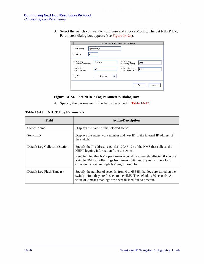
Beta Draft ConfidentialConfiguring Next Hop Resolution ProtocolConfiguring Log Parameters
3. Select the switch you want to configure and choose Modify. The Set NHRP LogParameters dialog box appears (see Figure 14-24).
Figure 14-24. Set NHRP Log Parameters Dialog Box
4. Specify the parameters in the fields described in Table 14-12.
Table 14-12. NHRP Log Parameters
Field Action/Description
Switch Name Displays the name of the selected switch.
Switch ID Displays the subnetwork number and host ID in the internal IP address ofthe switch.
Default Log Collection Station Specify the IP address (e.g., 131.100.45.12) of the NMS that collects theNHRP logging information from the switch.
Keep in mind that NMS performance could be adversely effected if you usea single NMS to collect logs from many switches. Try to distribute logcollection among multiple NMSes, if possible.
Default Log Flush Time (s) Specify the number of seconds, from 0 to 65535, that logs are stored on theswitch before they are flushed to the NMS. The default is 60 seconds. Avalue of 0 means that logs are never flushed due to timeout.
14-76 NavisCore IP Navigator Configuration Guide
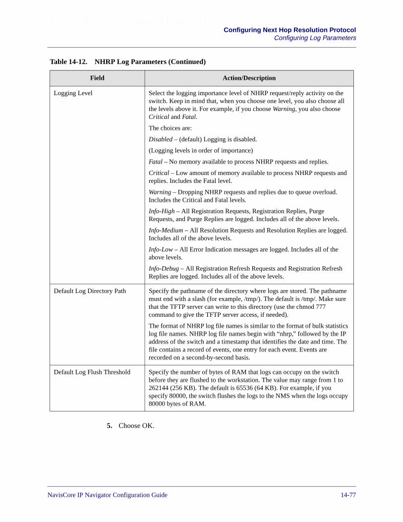
Beta Draft ConfidentialConfiguring Next Hop Resolution Protocol
Configuring Log Parameters
5. Choose OK.
Logging Level Select the logging importance level of NHRP request/reply activity on theswitch. Keep in mind that, when you choose one level, you also choose allthe levels above it. For example, if you choose Warning, you also chooseCritical and Fatal.
The choices are:
Disabled – (default) Logging is disabled.
(Logging levels in order of importance)
Fatal – No memory available to process NHRP requests and replies.
Critical – Low amount of memory available to process NHRP requests andreplies. Includes the Fatal level.
Warning – Dropping NHRP requests and replies due to queue overload.Includes the Critical and Fatal levels.
Info-High – All Registration Requests, Registration Replies, PurgeRequests, and Purge Replies are logged. Includes all of the above levels.
Info-Medium – All Resolution Requests and Resolution Replies are logged.Includes all of the above levels.
Info-Low – All Error Indication messages are logged. Includes all of theabove levels.
Info-Debug – All Registration Refresh Requests and Registration RefreshReplies are logged. Includes all of the above levels.
Default Log Directory Path Specify the pathname of the directory where logs are stored. The pathnamemust end with a slash (for example, /tmp/). The default is /tmp/. Make surethat the TFTP server can write to this directory (use the chmod 777command to give the TFTP server access, if needed).
The format of NHRP log file names is similar to the format of bulk statisticslog file names. NHRP log file names begin with “nhrp,” followed by the IPaddress of the switch and a timestamp that identifies the date and time. Thefile contains a record of events, one entry for each event. Events arerecorded on a second-by-second basis.
Default Log Flush Threshold Specify the number of bytes of RAM that logs can occupy on the switchbefore they are flushed to the workstation. The value may range from 1 to262144 (256 KB). The default is 65536 (64 KB). For example, if youspecify 80000, the switch flushes the logs to the NMS when the logs occupy80000 bytes of RAM.
Table 14-12. NHRP Log Parameters (Continued)
Field Action/Description
NavisCore IP Navigator Configuration Guide 1/14/0214-77

Beta Draft ConfidentialConfiguring Next Hop Resolution ProtocolConfiguring Log Parameters
14-78 NavisCore IP Navigator Configuration Guide
NavisCore IP Navigator Configuration Guide
Beta Draft Confidential
15
Configuring IP Multicast Routing
This chapter provides:
• An overview of IP multicast routing
• An overview of IP multicast routing protocols
• An overview of Lucent’s implementation of IP multicast routing
• Instructions on how to configure IP multicast routing in a Lucent network
Overview of IP Multicast Routing
IP multicast routing provides dynamic, real-time communications between networkhosts. It is commonly used to deliver multimedia traffic (such as video) over local-and wide-area IP networks.
Before the emergence of IP multicast routing, IP networks typically supported twotypes of host-to-host communications:
Unicast Communication — One host communicates with another host. For example,one host transfers files to another host using the File Transfer Protocol (FTP). Unicastcommunication makes efficient use of network resources, but is limited tocommunication between two hosts.
Broadcast Communication — One host simultaneously communicates with all theother hosts on its LAN. Broadcast communication enables one host to communicatewith many hosts simultaneously, but can potentially be an excessive consumer ofnetwork resources because it is indiscriminate — that is, a broadcast cannot beselectively targeted to a group of hosts. As a result, broadcast communication cannotscale to networks that have a large number of hosts.
15-1

Beta Draft ConfidentialConfiguring IP Multicast RoutingOverview of IP Multicast Routing
IP multicast routing combines the bandwidth efficiency of unicast communicationwith the ability of broadcast communication to reach multiple hosts at once. Using IPmulticast routing, a host sends data to a selected group of hosts called a multicastgroup. Each multicast group is identified by a special Class D IP address called agroup address, and each member of the group shares this same address. Class D IPaddresses begin with the bits 1110 and may range from 224.0.0.0 to 239.255.255.255,except for the addresses reserved by the Internet Assigned Numbers Authority(IANA). The IANA web site (http://www.iana.org) provides more information onreserved addresses.
Class D addresses differ somewhat from Class A, B, and C addresses. Unlike Class A,B, and C addresses, Class D addresses are not divided into network, subnetwork, andhost parts. A Class D address is a simple, non-hierarchical address that identifies agroup of multicast hosts.
Group members do not have to share the same physical link (e.g., an Ethernet LAN).Members of the same group may be dispersed on various LANs and WANs across thenetwork. As the multicast datastream traverses the network, it is replicated by routersonly on interfaces that are used to reach the multicast destinations, making efficientuse of network bandwidth.
Figure 15-1 shows a host sending a multicast data stream to a multicast group.
Figure 15-1. Multicast Transmission
Host
Host
Host
Host
Multicast Network
MulticastData Stream.Destination is224.2.1.1.
Multicast Group(224.2.1.1)
Data stream isreplicated by routerson only the interfacesused to reachmulticastdestinations.
15-2 NavisCore IP Navigator Configuration Guide
Beta Draft ConfidentialConfiguring IP Multicast Routing
IP Multicast Routing Protocols
A host joins a multicast group through use of the Internet Group ManagementProtocol (IGMP). This protocol allows hosts to register as members of a particularmulticast group. Once hosts register as multicast group members, routers in thenetwork track them dynamically. Lucent currently supports IGMP.
IP multicast traffic is transmitted from the source to the destinations via a spanningtree that connects all the hosts in the group. Different IP multicast routing protocolsuse different techniques to construct these trees. All multicast traffic is distributedthrough this tree once it is constructed.
The next section describes the techniques and protocols for constructing spanningtrees.
IP Multicast Routing Protocols
IP multicast routing protocols use one of two methods to distribute routinginformation, depending on how the multicast group members are connected in thenetwork:
Dense-mode — Dense-mode routing protocols are based on the assumptions that themulticast group members are densely distributed throughout the network (that is,many of the subnets contain at least one group member) and that bandwidth is alwaysavailable. Dense-mode multicast routing protocols rely on a broadcast-like techniquecalled flooding to propagate routing information to all routers in the network.Dense-mode routing protocols include Distance Vector Multicast Routing Protocol(DVMRP), Multicast Open Shortest Path First (MOSPF), and Protocol-IndependentMulticast — Dense Mode (PIM-DM).
Sparse-mode — Sparse-mode routing protocols assume that the multicast groupmembers are sparsely distributed throughout the network and bandwidth is notnecessarily available (for example, users may be connected via slow-speed links). Theterm “sparse-mode” does not imply that the group has a few members — the termonly means that the members are widely dispersed. In this case, using flooding topropagate routing information would unnecessarily waste network bandwidth and, asa result, could cause serious performance problems. Sparse-mode multicast routingprotocols must rely on selective techniques to set up and maintain multicast trees.Sparse-mode routing protocols include Core-Based Trees (CBT) andProtocol-Independent Multicast — Sparse Mode (PIM-SM).
The dense-mode multicast routing protocols are the more common of the two types ofmulticast routing protocols currently in use. At this time, Lucent supports thedense-mode multicast routing protocols DVMRP and MOSPF. Lucent also supports atechnique called tunneling that can be used to route IP Multicast traffic over portionsof an inter-network that do not have multicast capabilities.
NavisCore IP Navigator Configuration Guide 1/14/0215-3

Beta Draft ConfidentialConfiguring IP Multicast RoutingIP Multicast Routing Protocols
Distance Vector Multicast Routing Protocol
DVMRP was the first protocol developed to support IP multicast routing. DVMRP isdescribed in RFC 1075 and in an Internet Draft update. It has been widely used on theInternet Multicast Backbone (MBONE), which is the multicast equivalent of thetraditional unicast Internet.
DVMRP routers forward multicast datagrams over virtual interfaces (VIFs), whichcorrespond to broadcast links and point-to-point links. An example of a broadcast linkis an Ethernet LAN; an example of a point-to-point link is PPP. A router that supportsDVMRP can use a special VIF, called a DVMRP tunnel, to send DVMRP messages toother DVMRP routers through non-DVMRP routers.
DVMRP routers collectively build a different distribution tree for each source ofmulticast traffic and its destination host group. Each distribution tree is a minimumspanning tree from the multicast source at the root to all the multicast destinations atthe leaves. The distribution tree provides the shortest path between the source andeach multicast destination in the group, based on the DVMRP metric. This metric(configurable through the NMS) is typically the number of hops in the path.
The routers collectively construct a tree on demand when a source begins to transmitdatagrams to a multicast group. The datagrams follow this tree from the source to allgroup members. The routers along the paths to the group members replicate thedatagrams only at branches that lead to the group members. The routers “prune”branches that do not lead to group members. The tree construction has two phases: abroadcast phase and a pruning phase.
Broadcast Phase
During the broadcast phase, DVMRP assumes initially that every host on the networkis part of the multicast group. The designated router on the subnet where the multicasttraffic’s source host resides transmits multicast datagrams to all adjacent routers. Eachadjacent router then selectively forwards the datagrams to other routers until allmulticast group members receive the datagrams.
Upon receiving a multicast datagram, a router checks its DVMRP unicast routingtable (DVMRP has its own unicast routing protocol) to determine the interfaceassociated with the shortest path back to the source. DVMRP routers periodicallyexchange information to keep these routing tables up-to-date, insuring that all routershave a consistent network view.
Routers cannot forward multicast datagrams directly over Non-BroadcastMultiple Access (NBMA) networks, such as ATM and Frame Relay networks.Instead, DVMRP treats these networks as a DVMRP tunnel.
15-4 NavisCore IP Navigator Configuration Guide
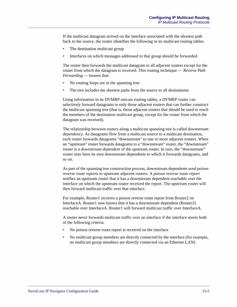
Beta Draft ConfidentialConfiguring IP Multicast Routing
IP Multicast Routing Protocols
If the multicast datagram arrived on the interface associated with the shortest pathback to the source, the router identifies the following in its multicast routing tables:
• The destination multicast group
• Interfaces on which messages addressed to that group should be forwarded
The router then forwards the multicast datagram to all adjacent routers except for therouter from which the datagram is received. This routing technique — Reverse PathForwarding — insures that:
• No routing loops are in the spanning tree
• The tree includes the shortest paths from the source to all destinations
Using information in its DVMRP unicast routing tables, a DVMRP router canselectively forward datagrams to only those adjacent routers that can further constructthe multicast spanning tree (that is, those adjacent routers that should be used to reachthe members of the destination multicast group, except for the router from which thedatagram was received).
The relationship between routers along a multicast spanning tree is called downstreamdependency. As datagrams flow from a multicast source to a multicast destination,each router forwards datagrams “downstream” to one or more adjacent routers. Whenan “upstream” router forwards datagrams to a “downstream” router, the “downstream”router is a downstream dependent of the upstream router. In turn, the “downstream”router may have its own downstream dependents to which it forwards datagrams, andso on.
As part of the spanning tree construction process, downstream dependents send poisonreverse route reports to upstream adjacent routers. A poison reverse route reportnotifies an upstream router that it has a downstream dependent reachable over theinterface on which the upstream router received the report. The upstream router willthen forward multicast traffic over that interface.
For example, Router1 receives a poison reverse route report from Router2 onInterfaceA. Router1 now knows that it has a downstream dependent (Router2)reachable over InterfaceA. Router1 will forward multicast traffic over InterfaceA.
A router never forwards multicast traffic over an interface if the interface meets bothof the following criteria:
• No poison reverse route report is received on the interface
• No multicast group members are directly connected by the interface (for example,no multicast group members are directly connected via an Ethernet LAN)
NavisCore IP Navigator Configuration Guide 1/14/0215-5

Beta Draft ConfidentialConfiguring IP Multicast RoutingIP Multicast Routing Protocols
Pruning Phase
During the pruning phase, DVMRP eliminates branches of the tree that do not lead toany multicast group members. To determine group membership, DVMRP relies onIGMP to maintain group membership information in the routers. When a routerdetermines that no hosts beyond it are members of the multicast group, it sends aprune message to its upstream router. Routers must update source and destinationgroup mapping information in their tables so that they know which branches havebeen pruned from the tree. This process continues until all of the useless branches areeliminated from the tree.
Once constructed, the multicast spanning tree is used to transmit multicast messagesfrom the source to the destination multicast members. Each router in the path forwardsmessages over only the interfaces that can be used to reach group members. Since newmembers may join the group at any time, and since these new members may dependon one of the pruned branches to receive the multicast transmission, DVMRPreconstructs the spanning tree from time to time.
Figure 15-2 illustrates construction of a DVMRP multicast spanning tree.
In two cases, routers can forward data over pruned branches:
– If a member joins a multicast group, and that member resides on a branchthat was previously pruned, a downstream neighbor sends a graft messageupstream. This message tells the routers that the previously pruned branchis part of the multicast tree again.
– Pruned branches have timers associated with them. When these timersexpire, routers can forward data to the branch until they receive a newprune message.
15-6 NavisCore IP Navigator Configuration Guide

Beta Draft ConfidentialConfiguring IP Multicast Routing
IP Multicast Routing Protocols
Figure 15-2. Constructing a DVMRP Multicast Spanning Tree
In Figure 15-2, the spanning tree is constructed as follows:
1. The multicast datagram originates from the source and reaches Router A (firsthop). Router A looks in its DVMRP unicast routing table and determines that itmust replicate the datagram and forward it to downstream dependents. Router Aforwards the datagram on all of its interfaces except for the one on which thedatagram was received.
2. The message reaches Router B, Router C, and Router D (second hop). Router Bdelivers the datagram to the group member on its LAN. Router D forwards themessage (third hop) to Router H and Router E, which in turn deliver the messageto the group members on their respective LANs.
1
2
34
Router D
Router B
Router A
Router E
Router C
Router F
Router G
Router H
Source ofMulticastData Stream
GM
GM
2
2
GM
GM
3
33
4
12
GM
Legend
= 1st Hop= 2nd Hop= 3rd Hop= 4th Hop= LAN or P-P Link
= Forwarded Message
= Group Member
= Pruned Leaf
= Tunnel
NavisCore IP Navigator Configuration Guide 1/14/0215-7

Beta Draft ConfidentialConfiguring IP Multicast RoutingIP Multicast Routing Protocols
3. Notice that Router C and Router D do not exchange messages in the third hop.This exchange does not occur because Router C and Router D know, based ontheir DVMRP unicast routing tables, that the interface they use to communicatewith each other is associated with a path to the source of the DVMRP message,but is not the shortest path to the source. In terms of reaching the source network,Router D is not a downstream dependent of Router C.
When multiple paths to a multicast source exist, a router will send a poisonreverse route report upstream only on the interface associated with the path withthe lowest cost (that is, the best path). For example, Router D never sends a poisonreverse route report to Router C, but does send a poison reverse route report toRouter A. Since Router C never receives a poison reverse route report on theinterface it uses to reach Router D, it will not know that a downstream dependentis reachable on that interface. Thus, Router C will not forward multicast traffic toRouter D.
4. The message reaches Router G. Because Router G is a leaf router with no groupmembers on its subnet, it sends a prune message back to Router F. Router F thensends a prune message to Router D. Note that Router C also sends a prunemessage to Router A.
Figure 15-3 shows the final, constructed spanning tree.
15-8 NavisCore IP Navigator Configuration Guide
Beta Draft ConfidentialConfiguring IP Multicast Routing
IP Multicast Routing Protocols
Figure 15-3. Constructed DVMRP Multicast Spanning Tree
Router D
Router B
Router A
Router E
Router H
Source ofMulticastData Stream
GM
GM
GM
GM
GM
Legend
= LAN or P-P Link
= Group Member
= Tunnel
NavisCore IP Navigator Configuration Guide 1/14/0215-9
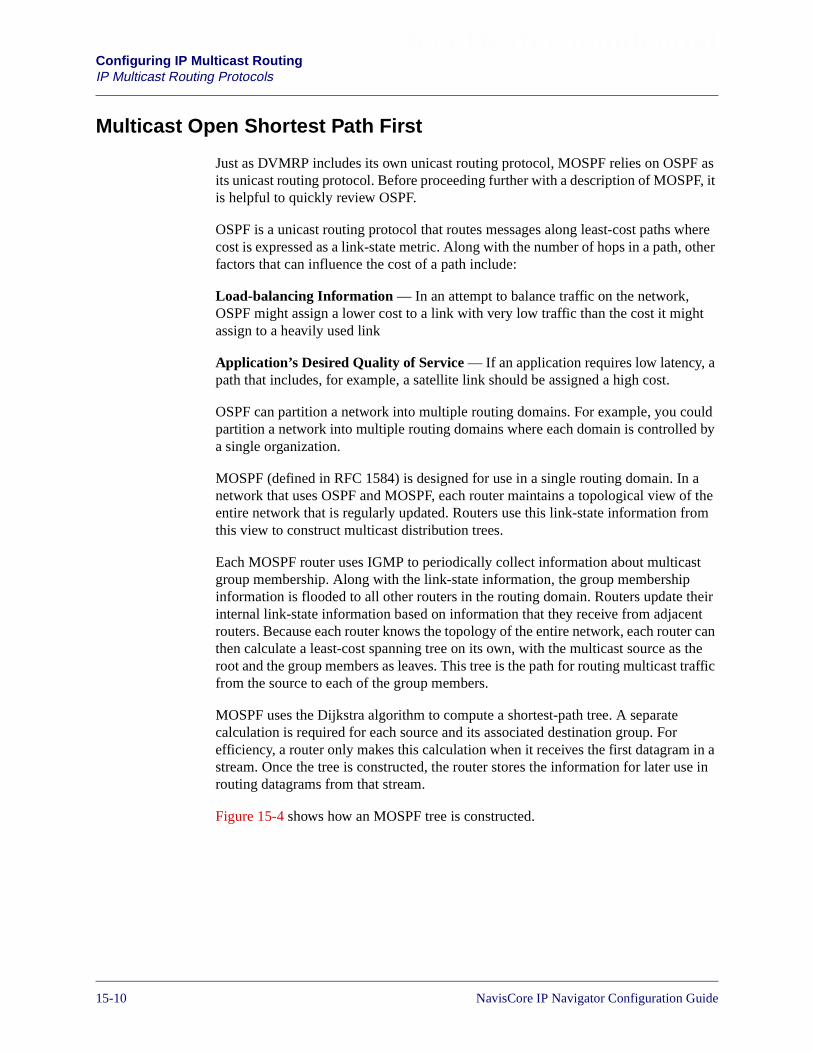
Beta Draft ConfidentialConfiguring IP Multicast RoutingIP Multicast Routing Protocols
Multicast Open Shortest Path First
Just as DVMRP includes its own unicast routing protocol, MOSPF relies on OSPF asits unicast routing protocol. Before proceeding further with a description of MOSPF, itis helpful to quickly review OSPF.
OSPF is a unicast routing protocol that routes messages along least-cost paths wherecost is expressed as a link-state metric. Along with the number of hops in a path, otherfactors that can influence the cost of a path include:
Load-balancing Information — In an attempt to balance traffic on the network,OSPF might assign a lower cost to a link with very low traffic than the cost it mightassign to a heavily used link
Application’s Desired Quality of Service — If an application requires low latency, apath that includes, for example, a satellite link should be assigned a high cost.
OSPF can partition a network into multiple routing domains. For example, you couldpartition a network into multiple routing domains where each domain is controlled bya single organization.
MOSPF (defined in RFC 1584) is designed for use in a single routing domain. In anetwork that uses OSPF and MOSPF, each router maintains a topological view of theentire network that is regularly updated. Routers use this link-state information fromthis view to construct multicast distribution trees.
Each MOSPF router uses IGMP to periodically collect information about multicastgroup membership. Along with the link-state information, the group membershipinformation is flooded to all other routers in the routing domain. Routers update theirinternal link-state information based on information that they receive from adjacentrouters. Because each router knows the topology of the entire network, each router canthen calculate a least-cost spanning tree on its own, with the multicast source as theroot and the group members as leaves. This tree is the path for routing multicast trafficfrom the source to each of the group members.
MOSPF uses the Dijkstra algorithm to compute a shortest-path tree. A separatecalculation is required for each source and its associated destination group. Forefficiency, a router only makes this calculation when it receives the first datagram in astream. Once the tree is constructed, the router stores the information for later use inrouting datagrams from that stream.
Figure 15-4 shows how an MOSPF tree is constructed.
15-10 NavisCore IP Navigator Configuration Guide

Beta Draft ConfidentialConfiguring IP Multicast Routing
IP Multicast Routing Protocols
Figure 15-4. Constructing an MOSPF Tree
The multicast transmission initiates the scenario illustrated in Figure 15-4. When itreceives a message, each router calculates exactly the same distribution tree as itspredecessors and uses the tree to forward the message.
Note that Router C chooses the least cost path to reach Router H (that is, routes themulticast stream through Router F instead of Router E). Keep in mind that MOSPFcan use OSPF to determine the best path to take to a destination.
Router E
Router B
Router A
Router F
Router H
GM
GM
GM
GM
GM
Legend
= Physical Link
= Group Member
Router D
GM
Router C Router I
Source ofMulticastData Stream
Router G
1. As first datagram in the streamreaches Router A, Router Aconstructs a tree. It knows thatthe path to Router I is throughRouter C, the path to Router H isthrough Router F, and so on.
2. As first datagram in thestream reaches Router B,Router B constructs a tree.Router B knows that the path toRouter D is direct.
2. As first datagram in thestream reaches Router C,Router C constructs a tree.Router C knows that the path toRouter I is direct, and that thebest path to Router H is throughRouter F.
3. As firstdatagram in thestream reachesRouter F, Router Fconstructs a tree.Router F knowsthat the path toRouter H is direct.
= Multicast Stream
NavisCore IP Navigator Configuration Guide 1/14/0215-11
Beta Draft ConfidentialConfiguring IP Multicast RoutingIP Multicast Routing Protocols
Tunneling
Multicast tunneling involves encapsulating multicast packets in unicast packets (IPdatagrams). Once encapsulated, multicast packets can be routed through unicastnetworks, such as the Internet, that do not support multicast routing. Multicasttunneling is also used to route multicast traffic over ATM and Frame Relay circuits.Tunneling can play an important part during a transition from unicast networking tomulticast networking.
Figure 15-5 illustrates the use of tunneling.
Figure 15-5. Tunneling
500
McastRouter
Non-Multicast Routers
ATMNetwork
McastRouter
Tunnel
Tunnel
ATMPVC
15-12 NavisCore IP Navigator Configuration Guide
Beta Draft ConfidentialConfiguring IP Multicast Routing
Lucent Implementation of IP Multicast Routing
Lucent Implementation of IP Multicast Routing
Lucent supports IGMP, DVMRP, and MOSPF in its implementation of IP multicastrouting. The rest of this section describes how Lucent implements these protocols.
IGMP Implementation
Lucent switches support Version 1 and Version 2 of IGMP on Ethernet logical ports.Version 1 is defined in RFC 1112, and Version 2 is defined in RFC 2236.
Lucent switches use IGMP to learn the existence of multicast group members on thedirectly attached Ethernet LAN. Once the switch acquires this knowledge, DVMRPand MOSPF on the Lucent switch can use it to construct multicast spanning trees.
Lucent switches may act as queriers or non-queriers. As the name implies, a querierissues IGMP queries on the physical network. A non-querier does not issue IGMPqueries.
On each physical network (e.g., an Ethernet LAN), there is only one querier. When amulticast router starts up, it is a querier by default, but it relinquishes its querier statusand becomes a non-querier when it receives a query from a router with a lower IPaddress. (The multicast router with the lowest IP address on the LAN will always bethe querier). If a router does not receive a query message from another router within acertain period of time, it assumes that it is the only router on the LAN and remains aquerier.
When acting as a querier, to learn the existence of multicast group members, theLucent switch broadcasts membership query request messages on the attachedEthernet LAN. There are two types of membership query requests:
General Query — Used to learn which multicast groups have members on the LAN.
Group-Specific Query — Used to learn if a specific multicast group has members onthe LAN.
Hosts on the LAN that want to join the group respond with membership reportmessages. Hosts that respond with membership reports may receive multicastdatagrams destined for the group.
In Lucent’s implementation of IGMP Version 1, the switch is always a querier. Itnever relinquishes its querier status.
NavisCore IP Navigator Configuration Guide 1/14/0215-13
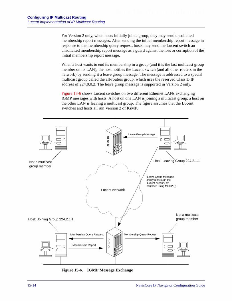
Beta Draft ConfidentialConfiguring IP Multicast RoutingLucent Implementation of IP Multicast Routing
For Version 2 only, when hosts initially join a group, they may send unsolicitedmembership report messages. After sending the initial membership report message inresponse to the membership query request, hosts may send the Lucent switch anunsolicited membership report message as a guard against the loss or corruption of theinitial membership report message.
When a host wants to end its membership in a group (and it is the last multicast groupmember on its LAN), the host notifies the Lucent switch (and all other routers in thenetwork) by sending it a leave group message. The message is addressed to a specialmulticast group called the all-routers group, which uses the reserved Class D IPaddress of 224.0.0.2. The leave group message is supported in Version 2 only.
Figure 15-6 shows Lucent switches on two different Ethernet LANs exchangingIGMP messages with hosts. A host on one LAN is joining a multicast group; a host onthe other LAN is leaving a multicast group. The figure assumes that the Lucentswitches and hosts all run Version 2 of IGMP.
Figure 15-6. IGMP Message Exchange
500
Host: Joining Group 224.2.1.1
Host: Leaving Group 224.2.1.1
Lucent Network
500
Membership Query Request
Membership Report
Leave Group Message
Membership Query Request
Leave Group Message(relayed through theLucent network byswitches using MOSPF))
Not a multicastgroup member
Not a multicastgroup member
15-14 NavisCore IP Navigator Configuration Guide
Beta Draft ConfidentialConfiguring IP Multicast Routing
Lucent Implementation of IP Multicast Routing
DVMRP and MOSPF Implementation
Lucent’s DVMRP and MOSPF implementations interoperate to support IP multicastrouting. On Lucent switches, DVMRP and MOSPF share a common multicastforwarding cache, which contains all of the routing information used by DVMRP andMOSPF.
Outside the Lucent network, Lucent switches can use DVMRP and MOSPF toexchange multicast traffic with third-party equipment such as routers.
Within the Lucent network, Lucent switches use MOSPF to route all multicast traffic(both MOSPF and DVMRP traffic) over connections called multicast label switchedpaths (multicast LSPs). Switches create these connections automatically — your onlymanagement task is to verify that multicast LSPs are enabled on the switches thatrequire them. See Chapter 12, “Configuring Label Switched Paths” for details.
To DVMRP on ingress and egress switches, the Lucent network appears as a LAN.DVMRP routes multicast traffic across the Lucent network as if it were routing thetraffic over an Ethernet network.
You may encounter situations where DVMRP and MOSPF may have to interoperateoutside the Lucent network. For example, a Lucent switch may be connected to both anetwork that supports DVMRP and a network that supports MOSPF. In this case,DVMRP exports the source networks (networks that are sources of multicast traffic) itknows about to MOSPF, and MOSPF then advertises these networks throughout theMOSPF routing domain.
By the same token, MOSPF exports the source networks it knows about to DVMRP,and DVMRP in turn advertises these networks to other DVMRP routers. If DVMRPlearns more than half of its source networks (or more) on its own, DVMRP instructsMOSPF to advertise a default route. However, if DVMRP learns half of its sourcenetworks (or more) through MOSPF, DVMRP advertises all of the individual routes toMOSPF.
To export routes from DVMRP to MOSPF, you do not have to perform anyconfiguration tasks. However, to export routes from MOSPF to DVMRP, you have toperform certain configuration tasks. See “Planning Your MOSPF Configuration” onpage 15-24 for more information.
Figure 15-7 shows a mixed network environment in which Lucent switches andthird-party equipment use both DVMRP and MOSPF to route multicast traffic. OnSwitch 3, notice how DVMRP and MOSPF pass routing information back and forthbetween the external MOSPF network and the DVMRP network.
NavisCore IP Navigator Configuration Guide 1/14/0215-15
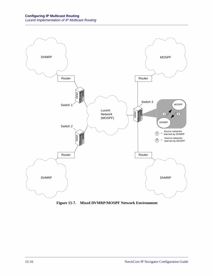
Beta Draft ConfidentialConfiguring IP Multicast RoutingLucent Implementation of IP Multicast Routing
Figure 15-7. Mixed DVMRP/MOSPF Network Environment
LucentNetwork(MOSPF)
500
Router
Router
DVMRP MOSPF
DVMRP DVMRP
Router
Router
DVMRP
MOSPF
Source networkslearned by MOSPF
21
Source networkslearned by DVMRP
2
1
=
=
500
500
Switch 1
Switch 2
Switch 3
15-16 NavisCore IP Navigator Configuration Guide

Beta Draft ConfidentialConfiguring IP Multicast Routing
Planning IP Multicast Routing
Planning IP Multicast Routing
Before you configure IP multicast routing, take some time to plan your configuration.The rest of this section helps you to plan for configuring IGMP, DVMRP, andMOSPF.
Since MOSPF and DVMRP rely on IGMP, consider configuring IGMP first (ifnecessary). Then, configure DVMRP and MOSPF.
Keep in mind that you may encounter a situation where your switch requires DVMRPand MOSPF capabilities, but does not require IGMP. For example, your switch maynot be connected to any Ethernet LANs that have multicast group members, but it stillmay have to forward multicast traffic using DVMRP or MOSPF.
Verifying Basic IP Connectivity
Before you configure IP multicast routing, verify that the switch is capable of basic IPbroadcast and unicast communications on all relevant interfaces. All IP logical ports,IP server logical ports, and/or Ethernet logical ports should be operational.
Planning Your IGMP Configuration
To plan your IGMP configuration, identify Ethernet logical ports that are associatedwith Ethernet LANs where multicast group members reside. You will have toconfigure IGMP on these logical ports.
Figure 15-8 illustrates IGMP configuration requirements for Ethernet logical ports. Inthis figure, a Lucent switch has two Ethernet logical ports. One requires IGMP to beconfigured; the other one does not.
Figure 15-8. IGMP Configuration Requirements for Ethernet Logical Ports
500
This Ethernetlogical port doesnot require you toconfigure IGMP.There are nomulticast groupmembers on theLAN.
This Ethernetlogical portrequires you toconfigure IGMP.There aremulticast groupmembers on theLAN.
MulticastGroupMember
Not aMulticastGroupMember
Not aMulticastGroupMember
MulticastGroupMember
NavisCore IP Navigator Configuration Guide 1/14/0215-17

Beta Draft ConfidentialConfiguring IP Multicast RoutingPlanning IP Multicast Routing
Planning Your DVMRP Configuration
To plan your DVMRP configuration, identify physical interfaces and tunnels, andidentify scoped boundaries. The rest of this section describes these tasks.
Identifying Physical Interfaces and Tunnels
Identify all the physical interfaces and tunnels with which you will need to associateVIFs. A physical interface is an interface to an Ethernet LAN or a Point-to-PointProtocol (PPP) line. A tunnel is either a path through a non-multicast router or aFrame Relay or ATM circuit. These physical interfaces and tunnels use DVMRP asthe multicast protocol.
You do not associate VIFs with physical interfaces that use MOSPF as the onlymulticast protocol, unless you tunnel through the MOSPF network to DVMRP nodes.
Because DVMRP depends on the services of a unicast distance-vector routingprotocol, add a RIP interface to any IP interface that uses DVMRP as themulticast routing protocol. For example, if you configure DVMRP for an IPinterface to an Ethernet LAN, you would configure a RIP interface for that IPinterface. As another example, if an IP interface acts as a tunnel endpoint, youwould configure a RIP interface for that IP interface. See “Configuring RIP atthe Logical Port” on page 7-1 for more information on configuring a RIPinterface.
15-18 NavisCore IP Navigator Configuration Guide

Beta Draft ConfidentialConfiguring IP Multicast Routing
Planning IP Multicast Routing
Figure 15-9 shows some interfaces that should be associated with VIFs and a non-VIFthat is associated with an interface to an MOSPF-only network.
Figure 15-9. Sample VIFs and a Non-VIF
500
MOSPF Only
McastRouter
McastRouter
Non-Multicast RoutersVIF
McastRouter
MulticastHost
ATMNetwork
McastRouter
PPP Link
Tunnel
TunnelNota VIF
VIF
VIF
Ethernet
ATMPVC
NavisCore IP Navigator Configuration Guide 1/14/0215-19
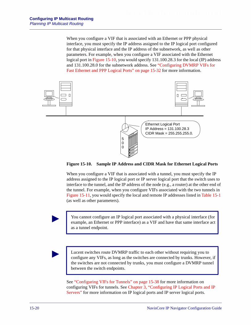
Beta Draft ConfidentialConfiguring IP Multicast RoutingPlanning IP Multicast Routing
When you configure a VIF that is associated with an Ethernet or PPP physicalinterface, you must specify the IP address assigned to the IP logical port configuredfor that physical interface and the IP address of the subnetwork, as well as otherparameters. For example, when you configure a VIF associated with the Ethernetlogical port in Figure 15-10, you would specify 131.100.28.3 for the local (IP) addressand 131.100.28.0 for the subnetwork address. See “Configuring DVMRP VIFs forFast Ethernet and PPP Logical Ports” on page 15-32 for more information.
Figure 15-10. Sample IP Address and CIDR Mask for Ethernet Logical Ports
When you configure a VIF that is associated with a tunnel, you must specify the IPaddress assigned to the IP logical port or IP server logical port that the switch uses tointerface to the tunnel, and the IP address of the node (e.g., a router) at the other end ofthe tunnel. For example, when you configure VIFs associated with the two tunnels inFigure 15-11, you would specify the local and remote IP addresses listed in Table 15-1(as well as other parameters).
See “Configuring VIFs for Tunnels” on page 15-38 for more information onconfiguring VIFs for tunnels. See Chapter 3, “Configuring IP Logical Ports and IPServers” for more information on IP logical ports and IP server logical ports.
500
Ethernet Logical PortIP Address = 131.100.28.3CIDR Mask = 255.255.255.0.
You cannot configure an IP logical port associated with a physical interface (forexample, an Ethernet or PPP interface) as a VIF and have that same interface actas a tunnel endpoint.
Lucent switches route DVMRP traffic to each other without requiring you toconfigure any VIFs, as long as the switches are connected by trunks. However, ifthe switches are not connected by trunks, you must configure a DVMRP tunnelbetween the switch endpoints.
15-20 NavisCore IP Navigator Configuration Guide
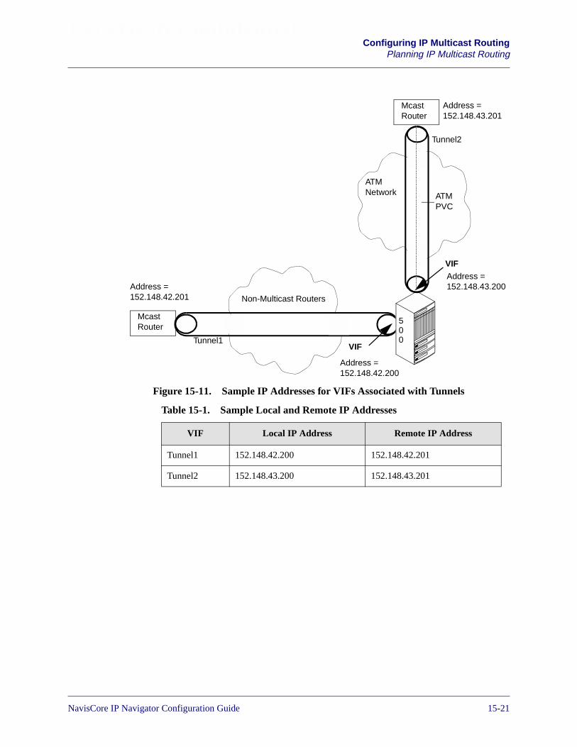
Beta Draft ConfidentialConfiguring IP Multicast Routing
Planning IP Multicast Routing
Figure 15-11. Sample IP Addresses for VIFs Associated with Tunnels
500
McastRouter
Non-Multicast Routers
ATMNetwork
McastRouter
Tunnel2
Tunnel1
VIF
ATMPVC
Address =152.148.43.200Address =
152.148.42.201
VIF
Address =152.148.42.200
Address =152.148.43.201
Table 15-1. Sample Local and Remote IP Addresses
VIF Local IP Address Remote IP Address
Tunnel1 152.148.42.200 152.148.42.201
Tunnel2 152.148.43.200 152.148.43.201
NavisCore IP Navigator Configuration Guide 1/14/0215-21

Beta Draft ConfidentialConfiguring IP Multicast RoutingPlanning IP Multicast Routing
Identifying Scoped Boundaries
Multicast addresses in the range 239.0.0.0 to 239.255.255.255 are administrativelyscoped IP addresses. This range of addresses is reserved for use within privatenetworks (such as a corporate enterprise network), but should not be used to sendmulticast traffic through public networks.
You can configure a specific VIF so that the switch does not forward private multicasttraffic on it in either direction. To accomplish this task, NavisCore allows you toconfigure a range of administratively scoped IP addresses on a VIF-by-VIF basis.When you specify this address range, the VIF will not forward any multicastdatagrams with a destination address that falls in the range. NavisCore allows you tospecify multiple address ranges for a VIF.
Address ranges are expressed by specifying a base address and a mask. The baseaddress specifies the lowest address in the range. The mask, combined with the baseaddress, specifies the highest address in the range. For example, the following baseaddress/mask combination tells the switch not to forward (on a given VIF) allmulticast datagrams with destination addresses in the range 239.0.0.0 to239.255.255.255:
Base Address — 239.0.0.0Mask — 255.0.0.0
Figure 15-12 illustrates the above address/mask combination. The figure shows twoprivate networks connected by a public network. For the VIF associated with theEthernet logical port on Switch 2, the administrator has configured the address/maskcombination shown above. This means that the switch will not forward any multicastdatagrams with destination addresses in the 239.0.0.0-to-239.255.255.255 range ineither direction (that is, datagrams originating from the private network to whichSwitch 2 is connected, or from Switch 1’s private network).
15-22 NavisCore IP Navigator Configuration Guide
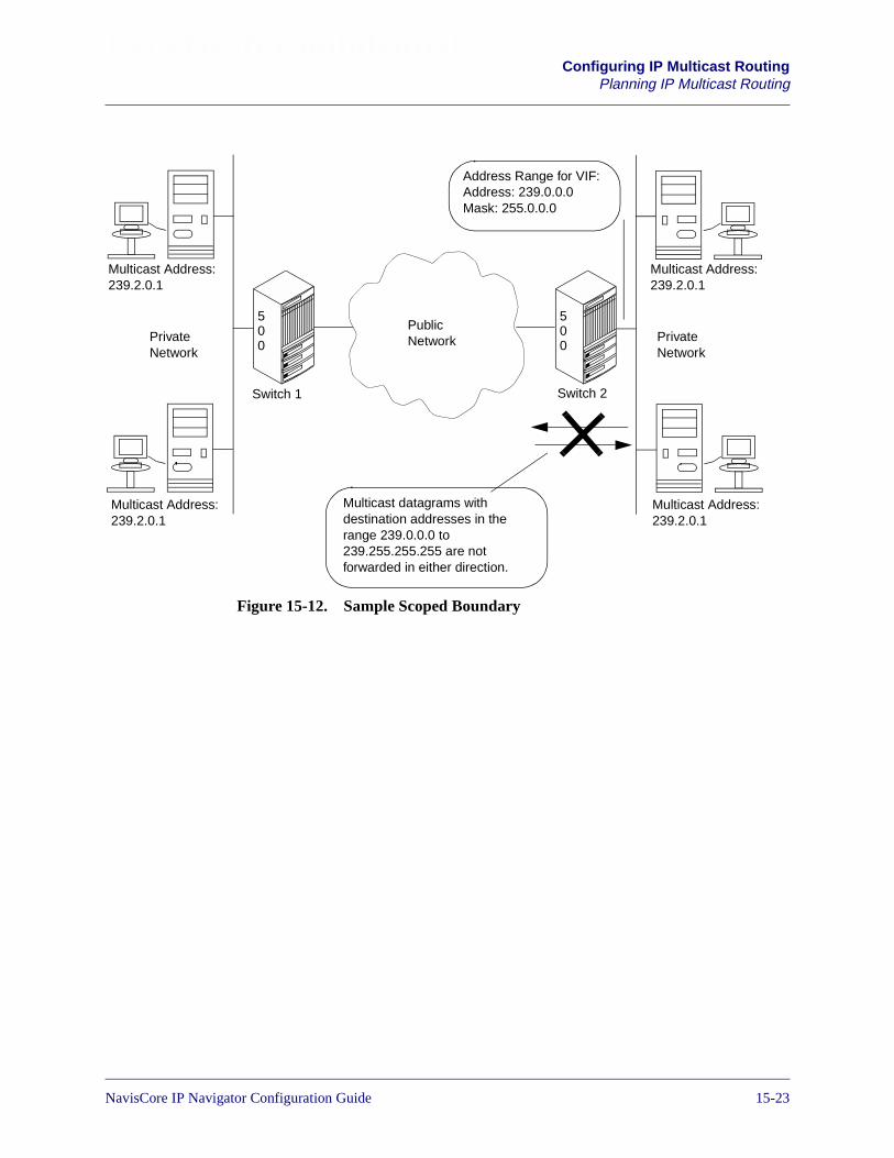
Beta Draft ConfidentialConfiguring IP Multicast Routing
Planning IP Multicast Routing
Figure 15-12. Sample Scoped Boundary
PublicNetwork
Switch 1 Switch 2
500
500
Multicast Address:239.2.0.1
Multicast Address:239.2.0.1
Multicast Address:239.2.0.1
Multicast Address:239.2.0.1
PrivateNetwork
PrivateNetwork
Address Range for VIF:Address: 239.0.0.0Mask: 255.0.0.0
Multicast datagrams withdestination addresses in therange 239.0.0.0 to239.255.255.255 are notforwarded in either direction.
NavisCore IP Navigator Configuration Guide 1/14/0215-23

Beta Draft ConfidentialConfiguring IP Multicast RoutingPlanning IP Multicast Routing
Planning Your MOSPF Configuration
To plan your MOSPF configuration, perform the following tasks:
• Verify IP OSPF router IDs
• Identify OSPF interfaces that must have multicast traffic forwarding configured
• Verify that multicast LSPs are enabled on switches
• Plan for DVMRP interoperability
The rest of this section describes these tasks.
Verify IP OSPF Router IDs
MOSPF is tightly integrated with the IP Navigator instance of OSPF. You mustconfigure an IP OSPF router ID on either:
• Switches connected to trunks that belong to IP OSPF areas
• Switches that have at least one OSPF interface configured on an IP logical port
Before you perform any other configuration tasks, verify that you have met the IPOSPF router ID requirement. See “Planning Router IDs” on page 9-22 and“Configuring IP OSPF Router IDs” on page 9-42 for more information on configuringan IP OSPF router ID.
Identifying OSPF Interfaces
Make sure that OSPF interfaces are created on the IP logical ports that will handleMOSPF traffic. MOSPF is enabled on OSPF interfaces by default. To forwardmulticast traffic, make sure that the Multicast Forwarding parameter for the OSPFinterface is set to the default value “Multicast” (in rare situations, you may want to setit to “Unicast”). Figure 15-13 shows IP logical ports with OSPF interfaces that handleMOSPF traffic.
15-24 NavisCore IP Navigator Configuration Guide
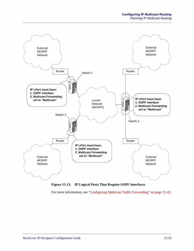
Beta Draft ConfidentialConfiguring IP Multicast Routing
Planning IP Multicast Routing
Figure 15-13. IP Logical Ports That Require OSPF Interfaces
For more information, see “Configuring Multicast Traffic Forwarding” on page 15-43.
LucentNetwork(MOSPF)
500
Router
Router
ExternalMOSPFNetwork
Router
Router
500
500
Switch 1
Switch 2
Switch 3
ExternalMOSPFNetwork
ExternalMOSPFNetwork
ExternalMOSPFNetwork
IP LPort must have:1. OSPF interface2. Multicast Forwarding
set to “Multicast” IP LPort must have:1. OSPF interface2. Multicast Forwarding
set to “Multicast”
IP LPort must have:1. OSPF interface2. Multicast Forwarding
set to “Multicast”
NavisCore IP Navigator Configuration Guide 1/14/0215-25

Beta Draft ConfidentialConfiguring IP Multicast RoutingPlanning IP Multicast Routing
Verifying That Multicast LSPs are Enabled
Make sure that multicast LSPs are enabled on all switches in the Lucent network thatwill forward multicast traffic. See “Enabling Multicast LSPs” on page 15-44 for moreinformation.
Planning DVMRP Interoperability
To plan your network so that MOSPF and DVMRP can interoperate, perform thefollowing tasks:
• Verify that you have configured one IP loopback address on each switch whereDVMRP traffic accesses the Lucent network
• Identify route maps to export MOSPF routes to DVMRP
Verifying IP Loopback Addresses
In order for DVMRP traffic to pass through a Lucent network, you must configure IPloopback addresses on the ingress/egress switches (that is, the “edge” switches). Oneach of these switches, you configure one IP loopback address.
When you configure an IP loopback address, you enter the following:
IP Address — When you configure an IP loopback address to supportDVMRP-MOSPF interoperability, always specify the IP OSPF router ID of the switchas the IP address. See “Planning Router IDs” on page 9-22 for more information onthe IP OSPF router ID.
IP OSPF Area ID — When you specify an IP OSPF area ID, specify the IP OSPFarea ID of any OSPF area of which the switch is a member (for example, the IP OSPFarea ID of a trunk connected to the switch).
For example, in Figure 15-4, there are four “edge” switches that require an IPloopback address. All of these switches require you to configure an IP loopbackaddress.
15-26 NavisCore IP Navigator Configuration Guide

Beta Draft ConfidentialConfiguring IP Multicast Routing
Planning IP Multicast Routing
Figure 15-14. IP Loopback Address Requirements
See “Configuring IP Loopback Addresses” on page 8-31 for information onconfiguring an IP loopback address.
Identifying Route Maps to Export Routes to DVMRP
If DVMRP on a switch needs to know routes learned by MOSPF, you can use routemaps to export routes from MOSPF to DVMRP. See “Exporting MOSPF Routes toDVMRP” on page 15-44 for more information.
500
500
90
00
500
DVMRPTraffic
500
DVMRPTraffic
DVMRPTraffic
DVMRPTraffic
500
90
00
0
0 0
0
00
11
IP Loopback Address:IP Address: 150.201.72.6IP OSPF Area ID: 0.0.0.0
IP Loopback Address:IP Address: 148.101.60.3IP OSPF Area ID: 0.0.0.0
IP Loopback Address:IP Address: 149.111.58.3IP OSPF Area ID: 0.0.0.0
IP Loopback Address:IP Address: 145.114.35.2IP OSPF Area ID: 0.0.0.0
IP OSPF Router ID:150.201.72.6
IP OSPF Router ID:149.111.58.3
IP OSPF Router ID:145.114.35.2
IP OSPF Router ID:148.101.60.3
NavisCore IP Navigator Configuration Guide 1/14/0215-27
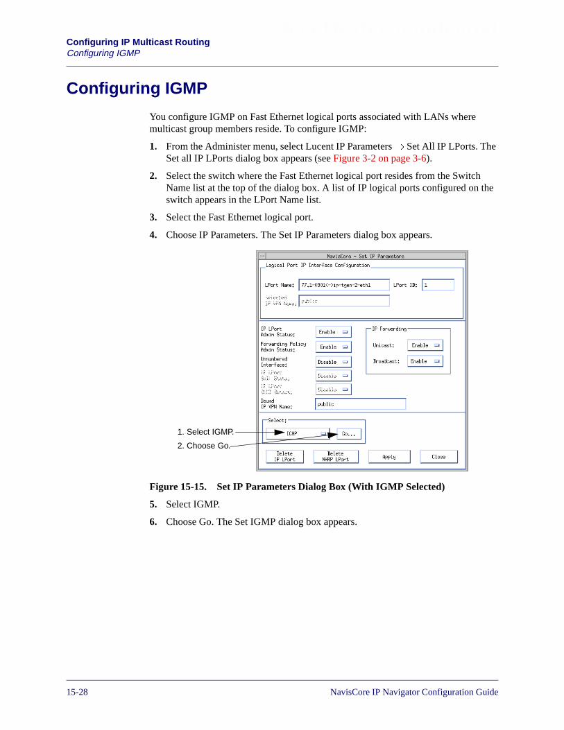
Beta Draft ConfidentialConfiguring IP Multicast RoutingConfiguring IGMP
Configuring IGMP
You configure IGMP on Fast Ethernet logical ports associated with LANs wheremulticast group members reside. To configure IGMP:
1. From the Administer menu, select Lucent IP Parameters� Set All IP LPorts. TheSet all IP LPorts dialog box appears (see Figure 3-2 on page 3-6).
2. Select the switch where the Fast Ethernet logical port resides from the SwitchName list at the top of the dialog box. A list of IP logical ports configured on theswitch appears in the LPort Name list.
3. Select the Fast Ethernet logical port.
4. Choose IP Parameters. The Set IP Parameters dialog box appears.
Figure 15-15. Set IP Parameters Dialog Box (With IGMP Selected)
5. Select IGMP.
6. Choose Go. The Set IGMP dialog box appears.
1. Select IGMP.
2. Choose Go.
15-28 NavisCore IP Navigator Configuration Guide

Beta Draft ConfidentialConfiguring IP Multicast Routing
Configuring IGMP
Figure 15-16. Set IGMP Dialog Box
7. Enter the IGMP configuration parameters in the fields in the bottom half of thedialog box. You cannot enter IGMP configuration parameters in the fields in thetop half of the dialog box, as they are calculated based on the configurationparameters you enter in the bottom half of the dialog box. Table 15-2 describesboth the configuration parameters you enter and the configuration parameters thatare calculated automatically.
Enterparametershere.
Do not enter parametershere. These parameters arecalculated based onparameters you enter in thebottom of the dialog box.
Table 15-2. IGMP Configuration Parameters
Parameter Description
Parameters You Enter
Admin Status Specify the administrative status of IGMP on the selected logical port.Choose Enable to enable IGMP on the port. Choose Disable (the default)to disable IGMP on the port.
Enable IGMP on the port only if multicast group members are on theEthernet LAN connected to the port.
Query Interval Specify the number of seconds between general queries transmitted onthe LAN associated with the selected logical port. To determine whetherany multicast group members are on the LAN, the switch periodicallytransmits general queries to solicit multicast group membershipinformation.
Specify a value from 2 to 999 seconds (the default is 125). Keep in mindthat, as you enter larger values, IGMP general queries are sent less often.
NavisCore IP Navigator Configuration Guide 1/14/0215-29
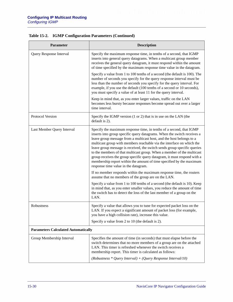
Beta Draft ConfidentialConfiguring IP Multicast RoutingConfiguring IGMP
Query Response Interval Specify the maximum response time, in tenths of a second, that IGMPinserts into general query datagrams. When a multicast group memberreceives the general query datagram, it must respond within the amountof time specified by the maximum response time value in the datagram.
Specify a value from 1 to 100 tenths of a second (the default is 100). Thenumber of seconds you specify for the query response interval must beless than the number of seconds you specify for the query interval. Forexample, if you use the default (100 tenths of a second or 10 seconds),you must specify a value of at least 11 for the query interval.
Keep in mind that, as you enter larger values, traffic on the LANbecomes less bursty because responses become spread out over a largertime interval.
Protocol Version Specify the IGMP version (1 or 2) that is in use on the LAN (thedefault is 2).
Last Member Query Interval Specify the maximum response time, in tenths of a second, that IGMPinserts into group specific query datagrams. When the switch receives aleave group message from a multicast host, and the host belongs to amulticast group with members reachable via the interface on which theleave group message is received, the switch sends group specific queriesto the members of that multicast group. When a member of the multicastgroup receives the group specific query datagram, it must respond with amembership report within the amount of time specified by the maximumresponse time value in the datagram.
If no member responds within the maximum response time, the routersassume that no members of the group are on the LAN.
Specify a value from 1 to 100 tenths of a second (the default is 10). Keepin mind that, as you enter smaller values, you reduce the amount of timethe switch has to detect the loss of the last member of a group on theLAN.
Robustness Specify a value that allows you to tune for expected packet loss on theLAN. If you expect a significant amount of packet loss (for example,you have a high collision rate), increase this value.
Specify a value from 2 to 10 (the default is 2).
Parameters Calculated Automatically
Group Membership Interval Specifies the amount of time (in seconds) that must elapse before theswitch determines that no more members of a group are on the attachedLAN. This timer is refreshed whenever the switch receives amembership report. This timer is calculated as follows:
(Robustness * Query Interval) + (Query Response Interval/10)
Table 15-2. IGMP Configuration Parameters (Continued)
Parameter Description
15-30 NavisCore IP Navigator Configuration Guide

Beta Draft ConfidentialConfiguring IP Multicast Routing
Configuring IGMP
8. Choose OK.
Startup Query Interval Specifies the number of seconds between transmissions of generalqueries when the switch first starts up and assumes that it is a querier.This timer is calculated as follows:
Query Interval * .25
Last Member Query Count Specifies the number of group specific queries that the switch sendsbefore it assumes that no members of a multicast group are currently onthe LAN. The last member query count is equal to the robustness value.
Other Querier Present Interval Specifies the number of seconds that the switch waits to receive a querymessage from another multicast router after the switch starts up. Theswitch assumes the role of querier if this timer expires before the switchreceives a query message. This timer is calculated as follows:
(Robustness * Query Interval)+ (0.5 * (Query Response Interval/10))
Startup Query Count Specifies the number of queries that the switch sends upon startup. Thestartup query count is equal to the robustness variable.
Table 15-2. IGMP Configuration Parameters (Continued)
Parameter Description
NavisCore IP Navigator Configuration Guide 1/14/0215-31

Beta Draft ConfidentialConfiguring IP Multicast RoutingConfiguring DVMRP VIFs
Configuring DVMRP VIFs
The way in which you configure DVMRP VIFs differs, depending on whether you areconfiguring DVMRP VIFs for:
• Fast Ethernet and PPP logical ports
• Tunnels
The rest of this section describes how to configure DVMRP VIFs for Fast Ethernetlogical ports and PPP links, and for tunnels.
Configuring DVMRP VIFs for Fast Ethernet and PPP Logical Ports
To configure DVMRP VIFs for Fast Ethernet and PPP logical ports:
1. From the Administer menu, select Lucent IP Parameters� Set All IP LPorts. TheSet all IP LPorts dialog box appears (see Figure 3-2 on page 3-6).
2. Select the switch where the Fast Ethernet logical port or PPP logical port residesfrom the Switch Name list at the top of the dialog box. A list of IP logical portsconfigured on the switch appears in the LPort Name list.
3. Select the Fast Ethernet or PPP logical port.
4. Choose IP Parameters. The Set IP Parameters dialog box appears.
Figure 15-17. Set IP Parameters Dialog Box (With DVMRP Selected)
5. Select DVMRP.
6. Choose Go. The Set DVMRP Interface dialog box appears.
1. Select DVMRP.
2. Choose Go.
15-32 NavisCore IP Navigator Configuration Guide
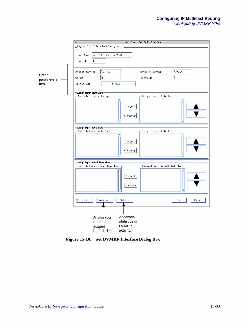
Beta Draft ConfidentialConfiguring IP Multicast Routing
Configuring DVMRP VIFs
Figure 15-18. Set DVMRP Interface Dialog Box
Enterparametershere
Accessesstatistics onDVMRPactivity.
Allows youto definescopedboundaries.
NavisCore IP Navigator Configuration Guide 1/14/0215-33

Beta Draft ConfidentialConfiguring IP Multicast RoutingConfiguring DVMRP VIFs
Table 15-3 describes the buttons on the Set DVMRP Interface dialog box.
7. Enter the DVMRP interface configuration parameters in the fields on the dialogbox. Table 15-4 describes these parameters.
Table 15-3. Set DVMRP Interface Dialog Box Buttons
Button Function
Alt Subnet Not supported.
Boundaries Allows you to define scoped boundaries. See “Configuring Scoped Boundaries forEthernet and PPP Ports” on page 15-37 for more information.
Stats Displays statistics on DVMRP activity. See the NavisCore Diagnostics Guide for moreinformation.
OK Saves your DVMRP configuration changes.
Cancel Exits the dialog box.
Table 15-4. DVMRP Interface Configuration Parameters
Parameter Description
Local IP Address Specify the IP address assigned to the associated Fast Ethernet IP logical port interface orPPP IP logical port interface (e.g., 152.148.12.107).
Subnet IP Address The subnetwork address assigned to the Fast Ethernet LAN or PPP IP logical port interface(e.g., 152.148.12.0). Do not specify this address. NavisCore calculates it for you.
Metric Specify the metric for the interface. Although you may specify a number from 1 to 32, usethe default (1).
Metrics are hop counts that assign costs to routes. As the metric for a route increases, sodoes its cost. If you have multiple routes to the same destination, the one with the lowestmetric is preferred.
As routes are propagated through the network, a route’s metric continues to increment eachtime it passes through an interface, such as an interface to an Ethernet LAN. For example,if you set the metric of the interface you are configuring to 1, then each route that passesthrough the interface will have its metric incremented by one.
For Ethernet LANs, the default metric (1) is sufficient in most cases.
15-34 NavisCore IP Navigator Configuration Guide

Beta Draft ConfidentialConfiguring IP Multicast Routing
Configuring DVMRP VIFs
Threshold Specify the Time-to-Live (TTL) threshold. This threshold allows you to control the scopeof multicast transmission. The switch will only forward a multicast datagram across aninterface if the value of the TTL field in the IP header is greater than the TTL thresholdassigned to the interface. For example, if you set the TTL threshold to 5, the switch willonly forward multicast datagrams that have a TTL field greater than 5 across the interface.
The default is 1, which allows most multicast datagrams to be forwarded. Valid valuesrange from 1 to 255.
To prevent all multicast datagrams from being forwarded across the interface, set the TTLthreshold to a high value, such as 255.
Admin Status Specify the administrative status of DVMRP on the selected Ethernet logical port. ChooseEnable to enable DVMRP on the port. Choose Disable (the default) to disable DVMRP onthe port.
Enable DVMRP on the port only if it must forward multicast traffic.
Assign Import Route Maps
Available ImportRoute Maps
The import route maps that are available for assignment to this DVMRP interface. Use theAssign button to move a route map from the Available to the Assigned list. Use theUnassign button to move a route map from the Assigned to the Available list. For moreinformation about creating route maps, see Chapter 11, “Configuring Route Policies.”
To display the parameters for any listed route map, double-click on the map.
Assigned ImportRoute Maps
The import route maps that are assigned to this DVMRP interface. All incoming routes onthis interface are filtered using the assigned route maps in the listed sequence.
Use the Assign button to move a route map from the Available to the Assigned list. Use theUnassign button to move a route map from the Assigned to the Available list. Use the upand down arrows to change the sequence of the route maps in the Assigned list. IPNavigator executes the route maps in the sequence that they are ordered in this list. Routemaps should be ordered from most specific to least specific.
To display the parameters for any listed route map, double-click on the map.
Table 15-4. DVMRP Interface Configuration Parameters (Continued)
Parameter Description
NavisCore IP Navigator Configuration Guide 1/14/0215-35

Beta Draft ConfidentialConfiguring IP Multicast RoutingConfiguring DVMRP VIFs
8. When you finish configuring the DVMRP VIF, you may choose OK to save yourchanges and exit, or configure scoped boundaries. The next section describes howto configure scoped boundaries.
Assign Export Route Map
Available ExportRoute Maps
The export route maps that are available for assignment to this DVMRP interface.
Use the Assign button to move a route map from the Available to the Assigned list. Use theUnassign button to move a route map from the Assigned to the Available list. For moreinformation about creating route maps, see Chapter 11, “Configuring Route Policies.”
To display the parameters for any listed route map, double-click on the map.
Assigned ExportRoute Maps
The export route maps that are assigned to this DVMRP interface. All outgoing routes onthis interface are filtered using the assigned route maps in the listed sequence.
Use the Assign button to move a route map from the Available to the Assigned list. Use theUnassign button to move a route map from the Assigned to the Available list. Use the upand down arrows to change the sequence of the route maps in the Assigned list. IPNavigator executes the route maps in the sequence that they are ordered in this list. Routemaps should be ordered from most specific to least specific.
To display the parameters for any listed route map, double-click on the map.
Assign Export Default Route Maps
Available ExportDefault RouteMaps
The export default route maps that are available for assignment to this DVMRP interface.
Use the Assign button to move a route map from the Available to the Assigned list. Use theUnassign button to move a route map from the Assigned to the Available list. For moreinformation about creating route maps, see Chapter 11, “Configuring Route Policies.”
To display the parameters for any listed route map, double-click on the map.
Assigned ExportDefault RouteMaps
The export default route maps that are assigned to this DVMRP interface. All outgoingroutes on this interface are filtered using the assigned route maps in the listed sequence.
Use the Assign button to move a route map from the Available to the Assigned list. Use theUnassign button to move a route map from the Assigned to the Available list. Use the upand down arrows to change the sequence of the route maps in the Assigned list. IPNavigator executes the route maps in the sequence that they are ordered in this list. Routemaps should be ordered from most specific to least specific.
To display the parameters for any listed route map, double-click on the map.
Table 15-4. DVMRP Interface Configuration Parameters (Continued)
Parameter Description
15-36 NavisCore IP Navigator Configuration Guide
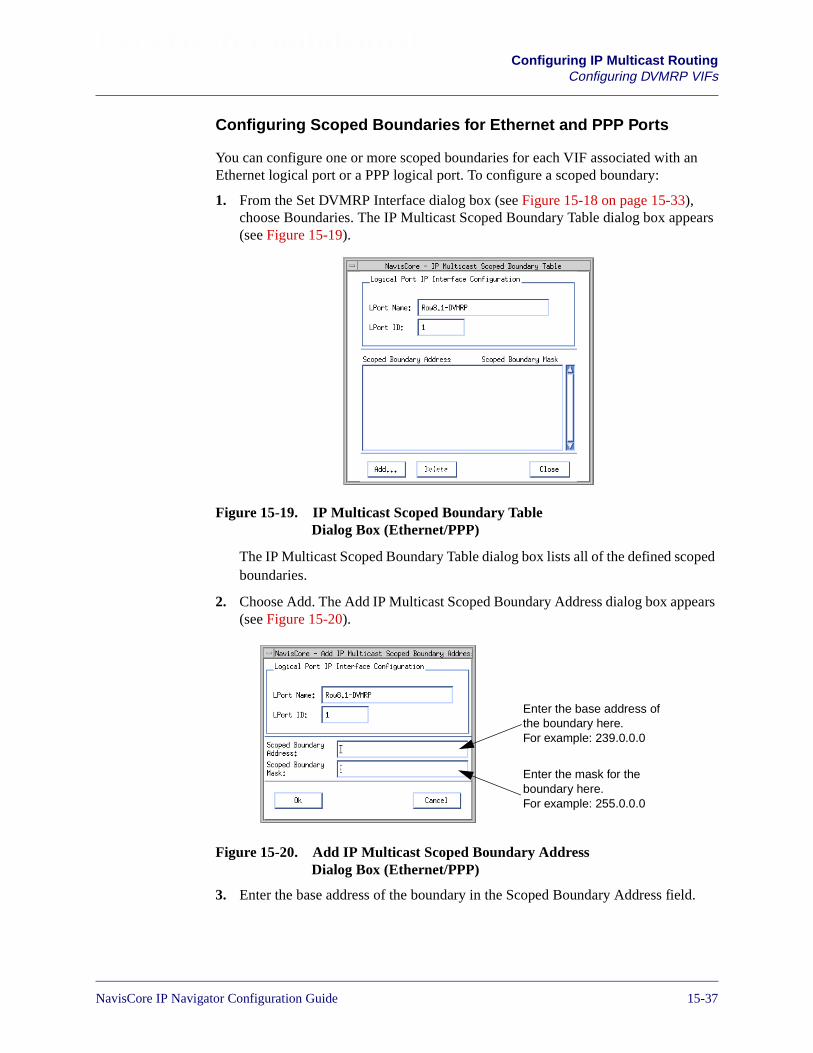
Beta Draft ConfidentialConfiguring IP Multicast Routing
Configuring DVMRP VIFs
Configuring Scoped Boundaries for Ethernet and PPP Ports
You can configure one or more scoped boundaries for each VIF associated with anEthernet logical port or a PPP logical port. To configure a scoped boundary:
1. From the Set DVMRP Interface dialog box (see Figure 15-18 on page 15-33),choose Boundaries. The IP Multicast Scoped Boundary Table dialog box appears(see Figure 15-19).
Figure 15-19. IP Multicast Scoped Boundary TableDialog Box (Ethernet/PPP)
The IP Multicast Scoped Boundary Table dialog box lists all of the defined scopedboundaries.
2. Choose Add. The Add IP Multicast Scoped Boundary Address dialog box appears(see Figure 15-20).
Figure 15-20. Add IP Multicast Scoped Boundary AddressDialog Box (Ethernet/PPP)
3. Enter the base address of the boundary in the Scoped Boundary Address field.
Enter the base address ofthe boundary here.For example: 239.0.0.0
Enter the mask for theboundary here.For example: 255.0.0.0
NavisCore IP Navigator Configuration Guide 1/14/0215-37
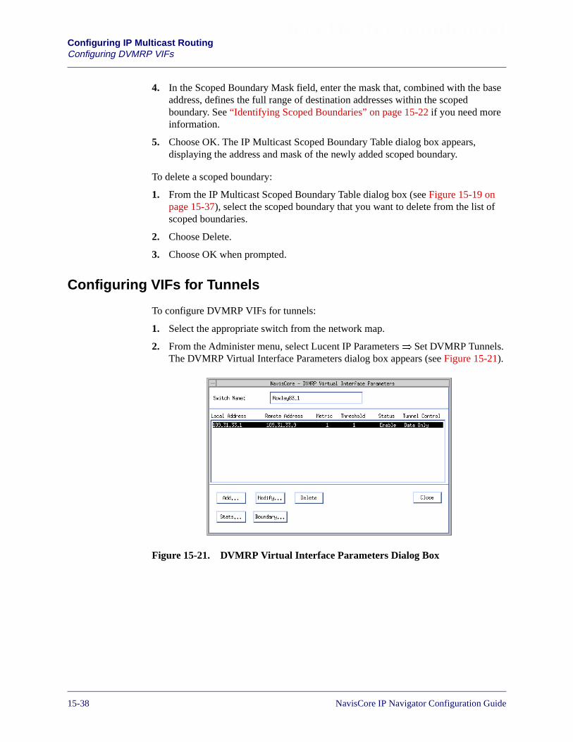
Beta Draft ConfidentialConfiguring IP Multicast RoutingConfiguring DVMRP VIFs
4. In the Scoped Boundary Mask field, enter the mask that, combined with the baseaddress, defines the full range of destination addresses within the scopedboundary. See “Identifying Scoped Boundaries” on page 15-22 if you need moreinformation.
5. Choose OK. The IP Multicast Scoped Boundary Table dialog box appears,displaying the address and mask of the newly added scoped boundary.
To delete a scoped boundary:
1. From the IP Multicast Scoped Boundary Table dialog box (see Figure 15-19 onpage 15-37), select the scoped boundary that you want to delete from the list ofscoped boundaries.
2. Choose Delete.
3. Choose OK when prompted.
Configuring VIFs for Tunnels
To configure DVMRP VIFs for tunnels:
1. Select the appropriate switch from the network map.
2. From the Administer menu, select Lucent IP Parameters� Set DVMRP Tunnels.The DVMRP Virtual Interface Parameters dialog box appears (see Figure 15-21).
Figure 15-21. DVMRP Virtual Interface Parameters Dialog Box
15-38 NavisCore IP Navigator Configuration Guide

Beta Draft ConfidentialConfiguring IP Multicast Routing
Configuring DVMRP VIFs
The DVMRP Virtual Interface Parameters dialog box lists all of the VIFs you haveconfigured for tunnels links. The buttons on the dialog box are described inTable 15-5. The fields on the dialog box are described in Table 15-6.
3. Choose Add. The Add DVMRP Tunnel dialog box appears.
Figure 15-22. Add DVMRP Tunnel Dialog Box
Table 15-5. DVMRP Virtual Interface Parameters Dialog Box Buttons
Button Function
Add Allows you to add a tunnel VIF.
Modify Allows you to modify a tunnel VIF.
Delete Allows you to delete a tunnel VIF.
Stats Displays statistics on DVMRP activity. See the NavisCore Diagnostics Guide formore information.
Boundary Allows you to define scoped boundaries for the tunnel VIF. See “Configuring ScopedBoundaries for Tunnels” on page 15-41 for more information.
Close Exits the dialog box.
NavisCore IP Navigator Configuration Guide 1/14/0215-39

Beta Draft ConfidentialConfiguring IP Multicast RoutingConfiguring DVMRP VIFs
4. Complete the fields described in Table 15-6.
5. Choose OK when you finish entering parameters. The DVMRP Virtual InterfaceParameters dialog box appears (see Figure 15-21 on page 15-38), displaying thenew VIF you just added.
Table 15-6. DVMRP Interface Configuration Parameters
Parameter Description
Local Address Specify the IP address assigned to the IP interface that the switch uses to transmitmulticast datagrams across the tunnel. See Chapter 3, “Configuring IP Logical Portsand IP Servers” for more information on IP interfaces.
Remote Address Specify the IP address of the node (e.g., a multicast router) at the other end of thetunnel.
Metric Specify the metric for the interface. You may specify a number from 1 to 32. Thedefault (1) should suffice in most cases unless you expect significant networkcongestion on the interface.
Metrics are hop counts that assign costs to routes. As the metric for a route increases,so does its cost. If you have multiple routes to the same destination, the one with thelowest metric is preferred.
As routes are propagated through the network, a route’s metric continues to incrementeach time it passes through an interface, such as an interface to a tunnel. For example,if you set the metric of the interface you are configuring to 1, then each route thatpasses through the interface will have its metric incremented by one.
Threshold Specify the Time-to-Live (TTL) threshold. This threshold allows you to control thescope of multicast transmission. The switch will only forward a multicast datagramacross an interface if the value of the TTL field in the IP header is greater than theTTL threshold assigned to the interface. For example, if you set the TTL thresholdto 5, the switch will only forward multicast datagrams that have a TTL field greaterthan 5 across the interface.
The default is 1, which allows most multicast datagrams to be forwarded. Valid valuesrange from 1 to 255.
To prevent all multicast datagrams from being forwarded across the interface, set theTTL threshold to a high value, such as 255.
Admin Status Specify the administrative status of DVMRP on the tunnel. Choose Enable (thedefault) to enable DVMRP on the tunnel. Choose Disable to disable DVMRP.
Tunnel Control Specify how you want DVMRP messages (e.g., prune messages) and multicastpackets to be sent through the tunnel:
Data Only – (default) DVMRP messages are sent as unicast packets (that is, noIP-in-IP encapsulation) through the tunnel. All other packets use IP-in-IPencapsulation.
All Packets – All packets (including DVMRP) sent through the tunnel use IP-in-IPencapsulation.
15-40 NavisCore IP Navigator Configuration Guide

Beta Draft ConfidentialConfiguring IP Multicast Routing
Configuring DVMRP VIFs
You can also modify VIF parameters and delete VIFs. To modify a VIF:
1. From the DVMRP Virtual Interface Parameters dialog box (see Figure 15-21 onpage 15-38), select the VIF you want to modify.
2. Choose Modify. The Modify DVMRP Tunnel dialog box appears. This dialog boxis similar in appearance to the Add DVMRP Tunnel dialog box (see Figure 15-22on page 15-39).
3. Modify the appropriate parameters. See Table 15-6 on page 15-40 for descriptionsof the parameters.
4. Choose OK when you are finished.
To delete a VIF:
1. From the DVMRP Virtual Interface Parameters dialog box (see Figure 15-21 onpage 15-38), select the VIF you want to delete.
2. Choose Delete.
3. Choose OK when prompted.
Configuring Scoped Boundaries for Tunnels
Optionally, you can configure scoped boundaries for the tunnel VIFs you add. Toconfigure a scoped boundary for a tunnel:
1. From the DVMRP Virtual Interface Parameters dialog box (see Figure 15-21 onpage 15-38), select the tunnel VIF for which you want to define a scopedboundary.
2. Choose Boundary. The IP Mcast Scoped Boundary Table dialog box appears (seeFigure 15-23).
Figure 15-23. IP Mcast Scoped Boundary Table Dialog Box (Tunnels)
NavisCore IP Navigator Configuration Guide 1/14/0215-41
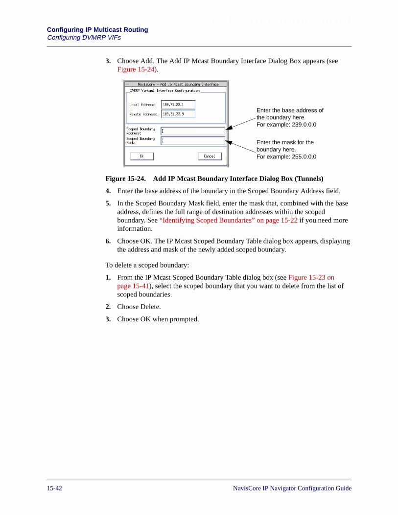
Beta Draft ConfidentialConfiguring IP Multicast RoutingConfiguring DVMRP VIFs
3. Choose Add. The Add IP Mcast Boundary Interface Dialog Box appears (seeFigure 15-24).
Figure 15-24. Add IP Mcast Boundary Interface Dialog Box (Tunnels)
4. Enter the base address of the boundary in the Scoped Boundary Address field.
5. In the Scoped Boundary Mask field, enter the mask that, combined with the baseaddress, defines the full range of destination addresses within the scopedboundary. See “Identifying Scoped Boundaries” on page 15-22 if you need moreinformation.
6. Choose OK. The IP Mcast Scoped Boundary Table dialog box appears, displayingthe address and mask of the newly added scoped boundary.
To delete a scoped boundary:
1. From the IP Mcast Scoped Boundary Table dialog box (see Figure 15-23 onpage 15-41), select the scoped boundary that you want to delete from the list ofscoped boundaries.
2. Choose Delete.
3. Choose OK when prompted.
Enter the base address ofthe boundary here.For example: 239.0.0.0
Enter the mask for theboundary here.For example: 255.0.0.0
15-42 NavisCore IP Navigator Configuration Guide

Beta Draft ConfidentialConfiguring IP Multicast Routing
Configuring MOSPF
Configuring MOSPF
When you configure MOSPF, you configure multicast traffic forwarding (at the datalink level) on the necessary OSPF interfaces, export MOSPF routes to DVMRP, andverify the multicast LSPs are enabled. The rest of this section tells you how to performthese tasks.
Configuring Multicast Traffic Forwarding
MOSPF is automatically enabled when you enable OSPF (that is, you have configuredan OSPF interface). However, you have to specify how the switch forwards multicasttraffic on the data link level using the OSPF interface, as follows:
1. Access the Set IP Interface Addresses dialog box for the IP logical port. See“Setting the IP Interface Address” on page 3-14 for more information onaccessing this dialog box.
2. Do one of the following:
• If you are adding OSPF parameters to the IP logical port, choose Add OSPF.The Add OSPF Interface dialog box appears (see Figure 15-25). See“Configuring IP OSPF on the IP Logical Port” on page 9-30 for moreinformation on this dialog box.
Figure 15-25. Add OSPF Interface Dialog Box (With Multicast Selected)
• If you are modifying the existing OSPF parameters for the logical port,choose Modify OSPF. The Modify OSPF Interface dialog box appears. Thisdialog box is almost identical in appearance to the Add OSPF Interface dialogbox.
MulticastForwarding Field
NavisCore IP Navigator Configuration Guide 1/14/0215-43

Beta Draft ConfidentialConfiguring IP Multicast RoutingConfiguring MOSPF
3. In the Multicast Forwarding field, specify one of the following:
Multicast — (default) The OSPF interface forwards multicast traffic to a multicastdata link address. Do not change the default unless you want to block multicasttraffic or (in rare circumstances) forward multicast traffic to a unicast data linkaddress.
Unicast — The OSPF interface forwards multicast traffic to a unicast data linkaddress (Ethernet MAC address, Frame Relay DLCI, ATM VPI/VCI, etc.).
Blocked — The OSPF interface does not forward multicast traffic (but MOSPFcontinues to run).
4. When you finish setting parameters, choose OK.
Exporting MOSPF Routes to DVMRP
To export routes from MOSPF to DVMRP, you set up a route map using MOSPF asthe source (that is, the “From” choice) and DVMRP as the destination (that is, the“To” choice). See Chapter 11, “Configuring Route Policies” for more information.
Enabling Multicast LSPs
MOSPF uses multicast LSPs to forward traffic through a Lucent network. You need toverify that multicast LSPs are enabled on all the switches in the network (they areenabled by default). Multicast LSPs are enabled on the Set IP Parameters dialog boxfor the switch. See Chapter 12, “Configuring Label Switched Paths” for moreinformation on multicast LSPs.
15-44 NavisCore IP Navigator Configuration Guide

NavisCore IP Navigator Configuration Guide
Beta Draft Confidential
16
Configuring IP Virtual Private Networks
An IP Virtual Private Network (VPN) is a collection of IP network resources that apublic carrier or service provider reserves for private use. Typical applications of IPVPNs include:
Corporate Intranets — A network within an enterprise, which may consist of manyinterlinked local area networks and may also use leased-lines in the wide-areanetwork. A corporate intranet may or may not include connections through one ormore gateways to the outside Internet. The main purpose of an intranet is, in mostcases, to enable employees to share company information and computing resources.An intranet can also be used to facilitate work groups and teleconferencing.
Corporate Extranets — Secure commerce-enabled networks that electronically linkdistributed organizations or individuals over the Internet in a public, semi-public, orprivate forum. These emerging networks establish virtual firewalls to extend thebenefits of a company's Intranet and enable collaborative business applications acrossmultiple organizations. Secure, collaborative, and interactive workspaces serve toconnect companies and their customers, suppliers, and other stakeholders, andproduce efficiencies in such representative business models as electronic commercecollaborative publishing, and supply-chain management.
The rest of this chapter explains how to plan for and configure IP VPNs.
16-1
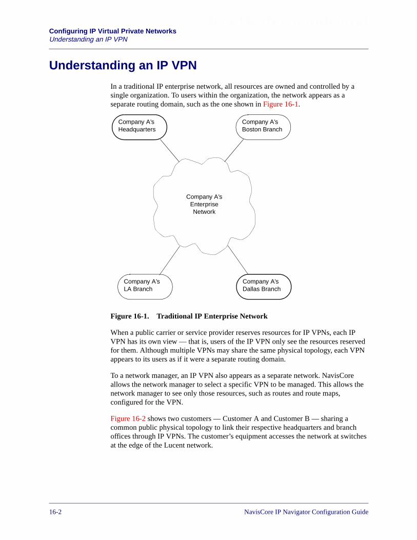
Beta Draft ConfidentialConfiguring IP Virtual Private NetworksUnderstanding an IP VPN
Understanding an IP VPN
In a traditional IP enterprise network, all resources are owned and controlled by asingle organization. To users within the organization, the network appears as aseparate routing domain, such as the one shown in Figure 16-1.
Figure 16-1. Traditional IP Enterprise Network
When a public carrier or service provider reserves resources for IP VPNs, each IPVPN has its own view — that is, users of the IP VPN only see the resources reservedfor them. Although multiple VPNs may share the same physical topology, each VPNappears to its users as if it were a separate routing domain.
To a network manager, an IP VPN also appears as a separate network. NavisCoreallows the network manager to select a specific VPN to be managed. This allows thenetwork manager to see only those resources, such as routes and route maps,configured for the VPN.
Figure 16-2 shows two customers — Customer A and Customer B — sharing acommon public physical topology to link their respective headquarters and branchoffices through IP VPNs. The customer’s equipment accesses the network at switchesat the edge of the Lucent network.
Company A’sEnterpriseNetwork
Company A’sHeadquarters
Company A’sBoston Branch
Company A’sDallas Branch
Company A’sLA Branch
16-2 NavisCore IP Navigator Configuration Guide

Beta Draft ConfidentialConfiguring IP Virtual Private Networks
Understanding an IP VPN
Figure 16-2. Multiple IP VPNs
IP Navigator supports IP VPNs through the implementation of virtual routers onLucent switches. Unlike a physical router, a virtual router exists as a logical entity inIP Navigator switch software. However, like a physical router, a virtual routerperforms routing functions, such as IP packet forwarding.
An IP VPN has its own virtual router on each switch that it uses to access the network(that is, switches at the edge of the Lucent network). Like a physical router, a virtualrouter has its own set of IP resources, such as its own private routing table, ARPcache, and route maps. Virtual routers reside on edge switches only. For example, theedge switches in Figure 16-2 (the B-STDX 9000 switches) would maintain virtualrouters, but the switches inside the Lucent network (the CBX 500 switches) wouldnot.
500
90
00
90
00
500
90
00
90
00
Router
Router
RouterRouter
Router
Customer A’sHeadquarters
Customer B’sHeadquarters
Customer B’sLA Branch
Customer A’sBoston Branch
Customer B’sDallas Branch
Customer A’sLA Branch
Router
HQDallas
LA
Cust. B’sVPN
HQ
BostonLA
Cust. A’sVPN
PhysicalTopology
View
VPNView
NavisCore IP Navigator Configuration Guide 1/14/0216-3

Beta Draft ConfidentialConfiguring IP Virtual Private NetworksUnderstanding an IP VPN
An edge switch that provides three different IP VPNs with network access wouldmaintain three virtual routers, one for each IP VPN. Each virtual router has its ownrouting tables, ARP cache, and so on.
To understand how IP VPNs work, you need to understand how IP VPN trafficaccesses the Lucent network and how IP VPN traffic is routed through the Lucentnetwork. The rest of this section explains how Lucent switches handle IP VPN traffic.
How IP VPN Traffic Accesses the Lucent Network
On a Lucent switch, IP logical ports provide IP VPNs with network access, as follows:
• For IP logical ports that use Frame Relay as the data link protocol, each IP VPNthat uses the logical port has one or more DLCIs. You associate each DLCI with aparticular IP VPN.
• For IP server logical ports and IP logical ports that use ATM as the data linkprotocol, each IP VPN that uses the port has one or more VPI/VCIs. For IP serverlogical ports, keep in mind that you must create an IP server PVC for eachVPI/VCI you want to assign to an IP VPN. You associate each VPI/VCI with aparticular IP VPN.
• For IP logical ports that use Ethernet or PPP as the data link protocol, a single IPVPN owns the port. This means that the Ethernet or PPP interface can be assignedto one (and only one) IP VPN.
When you assign a Frame Relay DLCI or an ATM VPI/VCI on a switch to an IP VPNfor the first time, you create a virtual router on that switch for that IP VPN. (ForEthernet and PPP interfaces, you assign the entire IP logical port to an IP VPN, andthereby create the virtual router.) The virtual router then performs IP routing functionsexclusively for the IP VPN on that switch. Figure 16-3 illustrates virtual routers.
16-4 NavisCore IP Navigator Configuration Guide
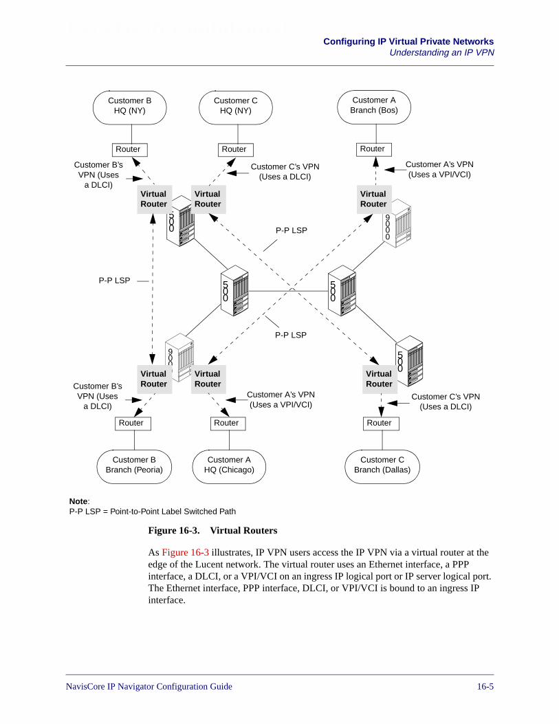
Beta Draft ConfidentialConfiguring IP Virtual Private Networks
Understanding an IP VPN
Figure 16-3. Virtual Routers
As Figure 16-3 illustrates, IP VPN users access the IP VPN via a virtual router at theedge of the Lucent network. The virtual router uses an Ethernet interface, a PPPinterface, a DLCI, or a VPI/VCI on an ingress IP logical port or IP server logical port.The Ethernet interface, PPP interface, DLCI, or VPI/VCI is bound to an ingress IPinterface.
500
500
90
00
500
90
00
Customer ABranch (Bos)
VirtualRouter
VirtualRouter
VirtualRouter
Customer AHQ (Chicago)
VirtualRouter
VirtualRouter
Router
Router
Customer BHQ (NY)
Router
Customer BBranch (Peoria)
Router
Customer CHQ (NY)
Router
Customer CBranch (Dallas)
Router
500Virtual
Router
Customer A’s VPN(Uses a VPI/VCI)
Customer B’sVPN (Uses
a DLCI)
Customer C’s VPN(Uses a DLCI)
Customer C’s VPN(Uses a DLCI)
Customer A’s VPN(Uses a VPI/VCI)
Customer B’sVPN (Uses
a DLCI)
P-P LSP
P-P LSP
P-P LSP
Note:P-P LSP = Point-to-Point Label Switched Path
NavisCore IP Navigator Configuration Guide 1/14/0216-5
Beta Draft ConfidentialConfiguring IP Virtual Private NetworksUnderstanding an IP VPN
In Figure 16-3, also notice that IP VPNs use point-to-point label switched paths(LSPs) to transport traffic through the Lucent network between virtual routers. Apoint-to-point LSP allows IP Navigator to directly forward IP packets between twoLucent switches. All IP VPN traffic between the virtual routers on the two switchestravels through the point-to-point LSP. See “How IP VPN Traffic is Routed Throughthe Lucent Network” for more information on point-to-point LSPs.
How IP VPN Traffic is Routed Through the Lucent Network
While ingress IP interfaces allow IP VPN traffic to access the Lucent network, VPNcloud IP interfaces allow IP VPN traffic to pass through the Lucent network. For aspecific IP VPN, these interfaces are created automatically on the CP or SP when theIP VPN’s virtual router is added to the switch (that is, when you assign a DLCI,VPI/VCI, Ethernet logical port, or PPP logical port to an IP VPN). The interfacesbecome active when you make the switch a trunk endpoint.
VPN cloud IP interfaces are configured just like other IP interfaces. Like ingress IPinterfaces, you create them manually and assign each one an IP address, an MTU size,and so on.
IP VPN cloud interfaces are associated with a special logical port called the IP VPNcloud logical port. When you create a trunk logical port on a switch, NavisCoreautomatically creates a VPN cloud logical port for each VPN that has a virtual routeron the switch. The virtual routers use the IP interfaces associated with the VPN cloudlogical ports to route IP VPN traffic through the Lucent network.
Figure 16-4 shows Customer A’s VPN from Figure 16-3 on page 16-5. Customer A’svirtual routers on the edge switches use IP VPN cloud IP interfaces to route data.Notice the distinction between the IP VPN cloud IP interfaces, which are maintainedon the CP/SP, and the ingress IP interfaces to which the VPI/VCIs are bound, whichare maintained on the switch card.
You cannot define an IP VPN cloud IP interface on a switch until you configurean IP loopback address for the public IP VPN on that switch. See “Identify IPOSPF Router ID and Loopback Address Requirements” on page 16-21 for moreinformation.
16-6 NavisCore IP Navigator Configuration Guide

Beta Draft ConfidentialConfiguring IP Virtual Private Networks
Understanding an IP VPN
Figure 16-4. IP VPN Cloud IP Interfaces
All virtual routers in the same IP VPN use ARP to map cloud interface IP addresses tothe internal switch address (the IP address assigned to a switch when it is installed). Ineffect, the internal switch address acts as a MAC address. ARP entries for cloud IPinterfaces can be created dynamically or statically. See Chapter 6, “Configuring StaticARP Entries” for more information on creating static ARP entries for cloud IPinterfaces.
Within the Lucent network, IP VPN virtual routers use the Open Shortest Path First(OSPF) routing protocol, the Routing Information Protocol (RIP), and static routes toroute IP VPN traffic.
90
00
90
00
Customer ABranch (Bos)
VirtualRouter
VirtualRouter
Customer AHQ (Chicago)
Router
Router
Customer A’s VPN(Uses a VPI/VCI
bound to IP interface150.1.2.1)
LucentNetwork
Cloud IP Interface(150.1.1.2)
Cloud IP Interface(150.1.1.1)
Customer A’s VPN(Uses a VPI/VCI
bound to IP interface150.1.3.1)
Internal Switch Number =150.202.77.2
InternalSwitchNumber =150.202.78.12
NavisCore IP Navigator Configuration Guide 1/14/0216-7
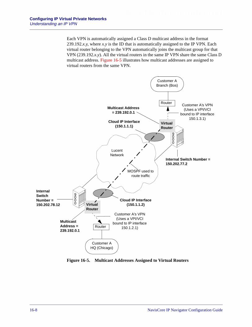
Beta Draft ConfidentialConfiguring IP Virtual Private NetworksUnderstanding an IP VPN
Each VPN is automatically assigned a Class D multicast address in the format239.192.x.y, where x.y is the ID that is automatically assigned to the IP VPN. Eachvirtual router belonging to the VPN automatically joins the multicast group for thatVPN (239.192.x.y). All the virtual routers in the same IP VPN share the same Class Dmulticast address. Figure 16-5 illustrates how multicast addresses are assigned tovirtual routers from the same VPN.
Figure 16-5. Multicast Addresses Assigned to Virtual Routers
90
00
90
00
Customer ABranch (Bos)
VirtualRouter
VirtualRouter
Customer AHQ (Chicago)
Router
Router
Customer A’s VPN(Uses a VPI/VCI
bound to IP interface150.1.2.1)
LucentNetwork
Cloud IP Interface(150.1.1.2)
Cloud IP Interface(150.1.1.1)
Customer A’s VPN(Uses a VPI/VCI
bound to IP interface150.1.3.1)
Multicast Address= 239.192.0.1
MulticastAddress =239.192.0.1
MOSPF used toroute traffic
Internal Switch Number =150.202.77.2
InternalSwitchNumber =150.202.78.12
16-8 NavisCore IP Navigator Configuration Guide
Beta Draft ConfidentialConfiguring IP Virtual Private Networks
Understanding an IP VPN
Routing and Forwarding
Within the Lucent network, IP packets belonging to an IP VPN can be forwardedbetween virtual routers in the following ways:
• Using point-to-point LSPs configured explicitly for that VPN. Multiplepoint-to-point LSPs can connect two switches. However, for a single VPN, youcan configure one (and only one) point-to-point LSP between two switches. Forexample, suppose that you have three VPNs that require point-to-point LSPsbetween the same two switches. You can configure one point-to-point LSP foreach VPN, but you cannot configure two point-to-point LSPs for any of the VPNsor configure one point-to-point LSP to support two VPNs.
• Using point-to-point LSPs configured for public use (available to all VPNs andpublic traffic).
• Using the default, best-effort Multipoint-to-Point Tunnel (MPT) LSP, which isalways available. This MPT LSP is overridden by point-to-point LSPs configuredexplicitly for public use.
• Using hop-by-hop forwarding.
IP Navigator prioritizes IP VPN traffic to be forwarded between virtual routers in aLucent network in the following order:
1. A point-to-point LSP configured explicitly for the VPN.
2. A public, configured point-to-point LSP between the switches where the virtualrouters reside.
3. The public, default MPT LSP between the switches where the virtual routersreside.
4. Hop-by-hop forwarding.
Figure 16-6 shows VPN traffic being transported between two edge switches viapoint-to-point LSPs. Notice the following details:
• VPN1 and VPN2 have point-to-point LSPs configured explicitly for each of them.
• A configured public point-to-point LSP is available for use by either VPN1 orVPN2.
• The default public MPT LSP is available for use by either VPN1 or VPN2.
In some cases, MPT LSPs may be selected over public point-to-point LSPs if theMPT LSPs provide more bandwidth and are of a lower cost than thepoint-to-point LSPs.
NavisCore IP Navigator Configuration Guide 1/14/0216-9

Beta Draft ConfidentialConfiguring IP Virtual Private NetworksUnderstanding an IP VPN
Figure 16-6. LSPs Transporting IP VPN Traffic
Typically, point-to-point LSPs connect switches at the network edge. Traffic istransported between the switches according to the QoS requirements configured forthe point-to-point LSP. See Chapter 12, “Configuring Label Switched Paths” for moreinformation on point-to-point LSPs and MPT LSPs.
500
500
VirtualRouter
VirtualRouter
Lucent Network
VirtualRouter
VirtualRouter
VPN1
VPN2
Public (Default, Best-Effort)
Public (Configured)
VPN1
VPN2
VPN1
VPN2
P-P LSP
P-P LSP
MPT LSP
P-P LSP
P-P LSP
P-P LSP
MPT LSP
P-P LSP
16-10 NavisCore IP Navigator Configuration Guide
Beta Draft ConfidentialConfiguring IP Virtual Private Networks
How IP VPNs Differ From VNN VPNs
How IP VPNs Differ From VNN VPNs
In addition to IP VPNs, Lucent provides support for Virtual Network Navigator(VNN) VPNs. Whereas VNN VPNs allow you to reserve OSI Layer 2 resources (forexample, trunks and circuits) for a customer, IP VPNs allow you to reserve OSI Layer3 resources (for example, IP interfaces and IP routing tables) for a customer.
It is possible to create a VNN VPN and an IP VPN for the same customer. The VNNVPN would reserve OSI Layer 2 resources for the customer, and the IP VPN wouldreserve OSI Layer 3 resources for the customer.
VNN VPNs are managed through the Lucent Parameters� Set All Virtual PrivateNetworks selection on the NavisCore Administer menu. See the following guides formore information on VNN VPNs:
• NavisCore Frame Relay Configuration Guide
• NavisCore ATM Configuration Guide
About the Public IP VPN
The public IP VPN is a special IP VPN that reserves network resources for public IPtraffic — IP traffic that does not originate from a private IP VPN customer. You assignIP network resources to the public IP VPN in the same way that you assign IP networkresources to private IP VPNs. The IP VPN ID of the public IP VPN is always zero (0).
NavisCore IP Navigator Configuration Guide 1/14/0216-11
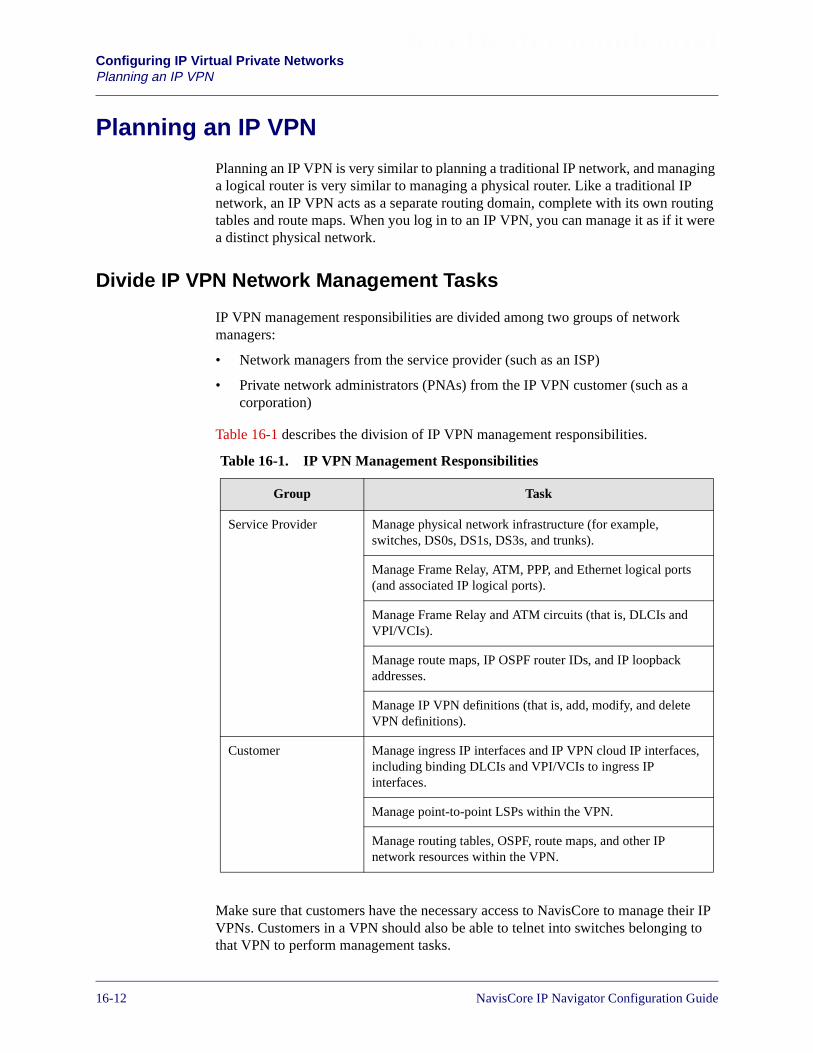
Beta Draft ConfidentialConfiguring IP Virtual Private NetworksPlanning an IP VPN
Planning an IP VPN
Planning an IP VPN is very similar to planning a traditional IP network, and managinga logical router is very similar to managing a physical router. Like a traditional IPnetwork, an IP VPN acts as a separate routing domain, complete with its own routingtables and route maps. When you log in to an IP VPN, you can manage it as if it werea distinct physical network.
Divide IP VPN Network Management Tasks
IP VPN management responsibilities are divided among two groups of networkmanagers:
• Network managers from the service provider (such as an ISP)
• Private network administrators (PNAs) from the IP VPN customer (such as acorporation)
Table 16-1 describes the division of IP VPN management responsibilities.
Make sure that customers have the necessary access to NavisCore to manage their IPVPNs. Customers in a VPN should also be able to telnet into switches belonging tothat VPN to perform management tasks.
Table 16-1. IP VPN Management Responsibilities
Group Task
Service Provider Manage physical network infrastructure (for example,switches, DS0s, DS1s, DS3s, and trunks).
Manage Frame Relay, ATM, PPP, and Ethernet logical ports(and associated IP logical ports).
Manage Frame Relay and ATM circuits (that is, DLCIs andVPI/VCIs).
Manage route maps, IP OSPF router IDs, and IP loopbackaddresses.
Manage IP VPN definitions (that is, add, modify, and deleteVPN definitions).
Customer Manage ingress IP interfaces and IP VPN cloud IP interfaces,including binding DLCIs and VPI/VCIs to ingress IPinterfaces.
Manage point-to-point LSPs within the VPN.
Manage routing tables, OSPF, route maps, and other IPnetwork resources within the VPN.
16-12 NavisCore IP Navigator Configuration Guide

Beta Draft ConfidentialConfiguring IP Virtual Private Networks
Planning an IP VPN
Determine a Unique Name and Password
Determine a unique name that identifies the IP VPN. It is a good idea to base the IPVPN name on the name of the organization(s) it serves (for example,XYZCompanyVPN).
Also, determine a password that customers must supply when they access the switchconsole. When a customer supplies this password, any console commands that thecustomer issues apply to the customer’s IP VPN only.
Identify Ingress Ports, DLCIs, and VPI/VCIs
Identify ingress IP logical ports and IP server logical ports at the edge of the Lucentnetwork that will act as IP VPN access points for users. Also, identify the DLCIs andVPIs/VCIs that you will assign to each customer on each ingress IP logical port or IPserver logical port. Observe the following rules:
• Only a single IP VPN can be assigned to an IP logical port that uses eitherEthernet or PPP as the data link protocol.
• For each IP logical port that uses Frame Relay as the data link protocol, you canassign multiple DLCIs to a single VPN, or you can distribute the DLCIs amongmultiple VPNs. This rule applies to both the B-STDX 8000/9000 and the CBX500 switches.
• For each IP logical port or IP server logical port that uses ATM as the data linkprotocol, you can assign multiple VPI/VCIs to a single IP VPN, or you candistribute the VPI/VCIs among multiple IP VPNs.
• The sum of DLCIs and VPIs/VCIs you assign to a single virtual router (i.e., IPVPN) on a switch cannot exceed the maximum protocol connection ID limit youconfigure for the IP VPN. The default maximum protocol connection ID limit is 9,but this can be changed by the service provider.
Figure 16-7 illustrates the relationship between an IP logical port that uses Ethernet asthe data link protocol and an IP VPN.
For IP server logical ports, you must create an IP server PVC for each VPI/VCIthat you assign to an IP VPN. For example, suppose you have an IP serverlogical port, and you want to assign one VPI/VCI to one IP VPN and anotherVPI/VCI to another IP VPN. You would create two IP server PVCs, one for eachIP VPN.
NavisCore IP Navigator Configuration Guide 1/14/0216-13

Beta Draft ConfidentialConfiguring IP Virtual Private NetworksPlanning an IP VPN
Figure 16-7. Ethernet/VPN Relationship
Figure 16-8 illustrates the relationship between an IP logical port that uses PPP as thedata link protocol and an IP VPN.
Figure 16-8. PPP/VPN Relationship
Lucent Network
CBX 500
An Ethernet/IP Lport canhave one (and only one) IPVPN assigned to it.
VirtualRouter(VPN)
Ethernet/IP Lport
Ethernet LAN
Lucent Network
B-STDX 8000/9000
A PPP/IP Lport can haveone (and only one) IP VPNassigned to it.
VirtualRouter(VPN)
PPP IPLport
PPP Link
16-14 NavisCore IP Navigator Configuration Guide

Beta Draft ConfidentialConfiguring IP Virtual Private Networks
Planning an IP VPN
Figure 16-9 illustrates the relationship between IP VPNs and DLCIs.
Figure 16-9. IP VPN/DLCI Relationship
VirtualRouter(VPN1)
Frame UNI/IP Lport
DLCI
VirtualRouter(VPN2)
Lucent Network
B-STDX 8000/9000
Each Frame Relay UNI/IPLport can have multipleDLCIs. The network managerassigns three DLCIs to VPN1and VPN2 each. Notice thatVPN1 and VPN2 can sharethe same IP Lport, or usedifferent IP Lports.
DLCI
Frame UNI/IP Lport
DLCI
DLCI
Frame UNI/IP Lport
DLCI
DLCI
NavisCore IP Navigator Configuration Guide 1/14/0216-15

Beta Draft ConfidentialConfiguring IP Virtual Private NetworksPlanning an IP VPN
Figure 16-10 illustrates the relationship between IP VPNs and VPI/VCIs on aB-STDX 8000/9000 switch.
Figure 16-10. IP VPN/VPI/VCI Relationship (ATM/IP Ports onthe B-STDX)
VirtualRouter(VPN1)
ATM UNI/IP Lport
VPI/VCI
VirtualRouter(VPN2)
Lucent Network
B-STDX
Each ATM UNI/IP Lport canhave multiple VPI/VCIs. Thenetwork manager assignsthree VPI/VCIs to VPN1 andthree VPI/VCIs to VPN2.Notice that VPN1 and VPN2can share the same IP Lportor use different IP Lports.
VPI/VCI
ATM UNI/IP Lport
VPI/VCIVPI/VCI
ATM UNI/IP Lport
VPI/VCIVPI/VCI
16-16 NavisCore IP Navigator Configuration Guide
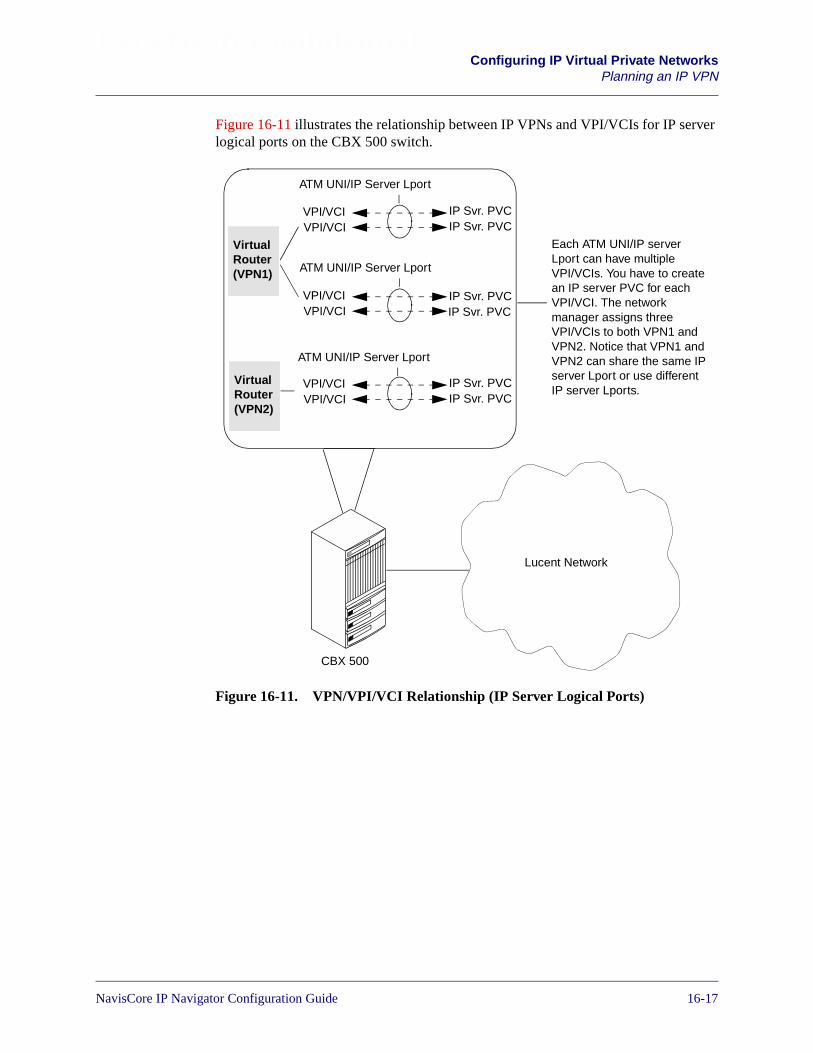
Beta Draft ConfidentialConfiguring IP Virtual Private Networks
Planning an IP VPN
Figure 16-11 illustrates the relationship between IP VPNs and VPI/VCIs for IP serverlogical ports on the CBX 500 switch.
Figure 16-11. VPN/VPI/VCI Relationship (IP Server Logical Ports)
VirtualRouter(VPN1)
ATM UNI/IP Server Lport
ATM UNI/IP Server Lport
ATM UNI/IP Server Lport
VirtualRouter(VPN2)
Lucent Network
CBX 500
VPI/VCIVPI/VCI
VPI/VCIVPI/VCI
VPI/VCIVPI/VCI
Each ATM UNI/IP serverLport can have multipleVPI/VCIs. You have to createan IP server PVC for eachVPI/VCI. The networkmanager assigns threeVPI/VCIs to both VPN1 andVPN2. Notice that VPN1 andVPN2 can share the same IPserver Lport or use differentIP server Lports.
IP Svr. PVCIP Svr. PVC
IP Svr. PVCIP Svr. PVC
IP Svr. PVCIP Svr. PVC
NavisCore IP Navigator Configuration Guide 1/14/0216-17

Beta Draft ConfidentialConfiguring IP Virtual Private NetworksPlanning an IP VPN
Identify Ingress IP Interfaces
On a given edge switch, each IP VPN has its own ingress IP interfaces. Each IPinterface is defined by an IP address, CIDR mask, and so on. You manually createthese IP interfaces, assign them to IP VPNs through NavisCore, and then bind theseinterfaces to DLCIs and VPI/VCIs. By binding DLCIs and VPI/VCIs to an IP VPN’sIP interfaces, you effectively assign the DLCIs and VPI/VCIs to the IP VPN. No otherIP VPN can own these resources. See “Configuring Ingress IP Interfaces for IP VPNs”on page 16-40 for details. Figure 16-12 shows examples of ingress IP interfacebindings.
Figure 16-12. DLCIs Bound to Ingress IP Interfaces
VirtualRouter(VPN1)
DLCI
VirtualRouter(VPN2)
Lucent Network
B-STDX
IP Interface:Addr = 193.1.1.1Mask = 255.255.255.0MTU = 4096etc.
DLCI
IP Interface:Addr = 193.1.129.2Mask = 255.255.255.0MTU = 4096etc.
DLCI
IP Interface:Addr = 193.1.144.2Mask = 255.255.255.0MTU = 4096etc.
DLCI boundto IP interface
DLCI boundto IP interface
DLCI boundto IP interface
16-18 NavisCore IP Navigator Configuration Guide
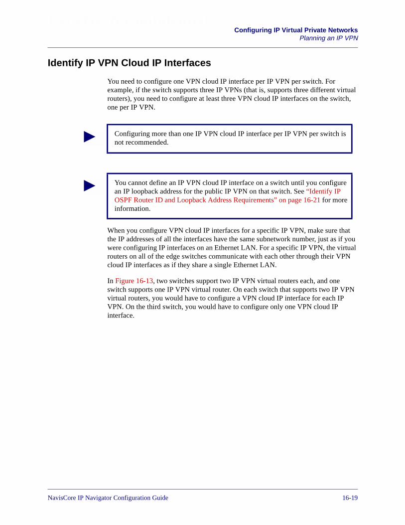
Beta Draft ConfidentialConfiguring IP Virtual Private Networks
Planning an IP VPN
Identify IP VPN Cloud IP Interfaces
You need to configure one VPN cloud IP interface per IP VPN per switch. Forexample, if the switch supports three IP VPNs (that is, supports three different virtualrouters), you need to configure at least three VPN cloud IP interfaces on the switch,one per IP VPN.
When you configure VPN cloud IP interfaces for a specific IP VPN, make sure thatthe IP addresses of all the interfaces have the same subnetwork number, just as if youwere configuring IP interfaces on an Ethernet LAN. For a specific IP VPN, the virtualrouters on all of the edge switches communicate with each other through their VPNcloud IP interfaces as if they share a single Ethernet LAN.
In Figure 16-13, two switches support two IP VPN virtual routers each, and oneswitch supports one IP VPN virtual router. On each switch that supports two IP VPNvirtual routers, you would have to configure a VPN cloud IP interface for each IPVPN. On the third switch, you would have to configure only one VPN cloud IPinterface.
Configuring more than one IP VPN cloud IP interface per IP VPN per switch isnot recommended.
You cannot define an IP VPN cloud IP interface on a switch until you configurean IP loopback address for the public IP VPN on that switch. See “Identify IPOSPF Router ID and Loopback Address Requirements” on page 16-21 for moreinformation.
NavisCore IP Navigator Configuration Guide 1/14/0216-19

Beta Draft ConfidentialConfiguring IP Virtual Private NetworksPlanning an IP VPN
Figure 16-13. Identifying VPN Cloud IP Interfaces
In Figure 16-13, notice that for each IP VPN, all of the VPN cloud IP interfaces havethe same subnetwork number. All of the VPN cloud IP interfaces in VPN1 are in150.1.1.0 and all of the VPN cloud IP interfaces in VPN2 are in 145.1.1.0.
Lucent Network
VPN Cloud IP Interface:Addr = 150.1.1.1Mask = 255.255.255.0etc.
VirtualRouter(VPN1)
VirtualRouter(VPN2)
VPN Cloud IP Interface:Addr = 145.1.1.1Mask = 255.255.255.0etc.
VirtualRouter(VPN1)
VirtualRouter(VPN2)
VirtualRouter(VPN1)
VPN Cloud IP Interface:Addr = 150.1.1.2Mask = 255.255.255.0etc.
VPN Cloud IP Interface:Addr = 145.1.1.2Mask = 255.255.255.0etc.
VPN Cloud IP Interface:Addr = 150.1.1.3Mask = 255.255.255.0etc.
16-20 NavisCore IP Navigator Configuration Guide

Beta Draft ConfidentialConfiguring IP Virtual Private Networks
Planning an IP VPN
Identify Point-to-Point LSPs
Identify the point-to-point LSPs that will connect the virtual routers on the edgeswitches in the Lucent network. Keep in mind the following rules:
• Using point-to-point LSPs configured explicitly for that VPN. Multiplepoint-to-point LSPs can connect two switches. However, for a single VPN, youcan configure one (and only one) point-to-point LSP between two switches. Forexample, suppose that you have three VPNs that require point-to-point LSPsbetween the same two switches. You can configure one point-to-point LSP foreach VPN, but you cannot configure two point-to-point LSPs for any of the VPNsor configure one point-to-point LSP to support two VPNs.
• You can configure point-to-point LSPs for public use (available to all IP VPNsand public traffic).
• A default, best-effort, MPT LSP is always available for public use. This MPT LSPis overridden by point-to-point LSPs explicitly configured for public use.
See Chapter 12, “Configuring Label Switched Paths” for more information onconfiguring point-to-point LSPs and MPT LSPs.
Verify MOSPF Support
Multicast Open Shortest Path First (MOSPF) is the multicast routing protocol used byvirtual routers to discover other group members and to exchange routing information.If your VPNs will use MOSPF, verify that the switches in the Lucent network thatcarry IP VPN traffic support MOSPF. Note that you do not have to configure MOSPFon any switches that carry IP VPN traffic. See “How IP VPN Traffic is RoutedThrough the Lucent Network” on page 16-6 for more information on how MOSPF isused to exchange routing information.
Verify RIP/OSPF Support
If your VPN will use the Routing Information Protocol (RIP) or Open Shortest PathFirst (OSPF) routing protocols to route IP VPN traffic through the network, verify thatthe switches in the Lucent network that carry IP VPN traffic support RIP or OSPF. See“How IP VPN Traffic is Routed Through the Lucent Network” on page 16-6 for moreinformation.
Identify IP OSPF Router ID and Loopback Address Requirements
In order to support IP VPN traffic, edge switches (that is, switches that provide ingressIP interfaces) require that you configure:
• An IP OSPF router ID configured for the public IP VPN (that is, IP VPN 0). Notethat, in some cases, the switch configures an IP OSPF router ID automatically. See“Planning Router IDs” on page 9-22 for more information.
NavisCore IP Navigator Configuration Guide 1/14/0216-21

Beta Draft ConfidentialConfiguring IP Virtual Private NetworksPlanning an IP VPN
• One IP loopback address configured for the public IP VPN (that is, IP VPN 0).This address is required for IP multicasting. You cannot configure an IP VPNcloud IP interface on a switch until you configure an IP loopback address for thepublic IP VPN on that switch.
Switches within the Lucent network that are not edge switches, but are connected tointermediate trunks that carry VPN traffic, require an IP OSPF router ID only.
Figure 16-14 illustrates IP OSPF router ID and IP loopback address requirements.
Figure 16-14. IP OSPF Router ID and IP Loopback Address Requirements
For information on the IP OSPF router ID, see “Planning Router IDs” on page 9-22.For information on configuring IP loopback addresses, see “Configuring IP LoopbackAddresses” on page 8-31.
500
500
90
00
500
90
00
Customer ABranch (Bos)
VirtualRouter
VirtualRouter
VirtualRouter
Customer AHQ (Chicago)
VirtualRouter
VirtualRouter
Router
Router
Customer BHQ (NY)
Router
Customer BBranch (Peoria)
Router
Customer CHQ (NY)
Router
Customer CBranch (Dallas)
Router
500
VirtualRouter
Trunk
Trunk
TrunkTrunk
Trunk
Requires:- IP loopback address- One of the following:
an IP OSPF router IDa configured OSPF cloud interfacea configured RIP cloud interface
Requires an IPOSPF router ID
Requires:- IP loopback address- One of the following:
an IP OSPF router IDa configured OSPF cloud interfacea configured RIP cloud interface
16-22 NavisCore IP Navigator Configuration Guide
Beta Draft ConfidentialConfiguring IP Virtual Private Networks
Planning an IP VPN
Determine IP VPN Resource Limits
You can set upper limits on the specific IP resources that can be configured for theVPN on switches that contain the VPN virtual routers. For each VPN, these limits areenforced on a per switch basis. All switches participating in a VPN should use thesame limits. These limits include:
• Maximum protocol connection IDs per switch. A protocol connection ID is eithera DLCI (for Frame Relay connections) or a VPI/VCI (for ATM connections).
• Maximum RIP interfaces per switch.
• Maximum static ARP entries per switch.
• Maximum routes per switch.
• Maximum network access lists per switch.
• Maximum route maps per switch.
• Maximum route maps per RIP interface.
• Maximum OSPF virtual links per switch.
• Maximum IP interfaces per switch.
• Maximum OSPF interfaces per switch.
• Maximum static routes per switch.
• Maximum network filters per switch.
• Maximum network filters per access list per switch.
• Maximum network access lists per route map per switch.
• Maximum OSPF neighbors per switch.
• Maximum OSPF area aggregates per switch.
Figure 16-15 shows two switches at the edge of the Lucent network. Each switchcontains a virtual router for a single IP VPN (Customer A’s VPN). When the networkmanager defines the IP VPN, the manager configures a single set of resource limitsthat are enforced on each switch.
When configuring IP OSPF router IDs and IP loopback addresses to support IPVPN traffic, make sure that you are in the context of the public IP VPN (that is,VPN 0). You do this by selecting the IP VPN called “Public.” See “Selecting theIP VPN” on page 16-33 for more information.
NavisCore IP Navigator Configuration Guide 1/14/0216-23
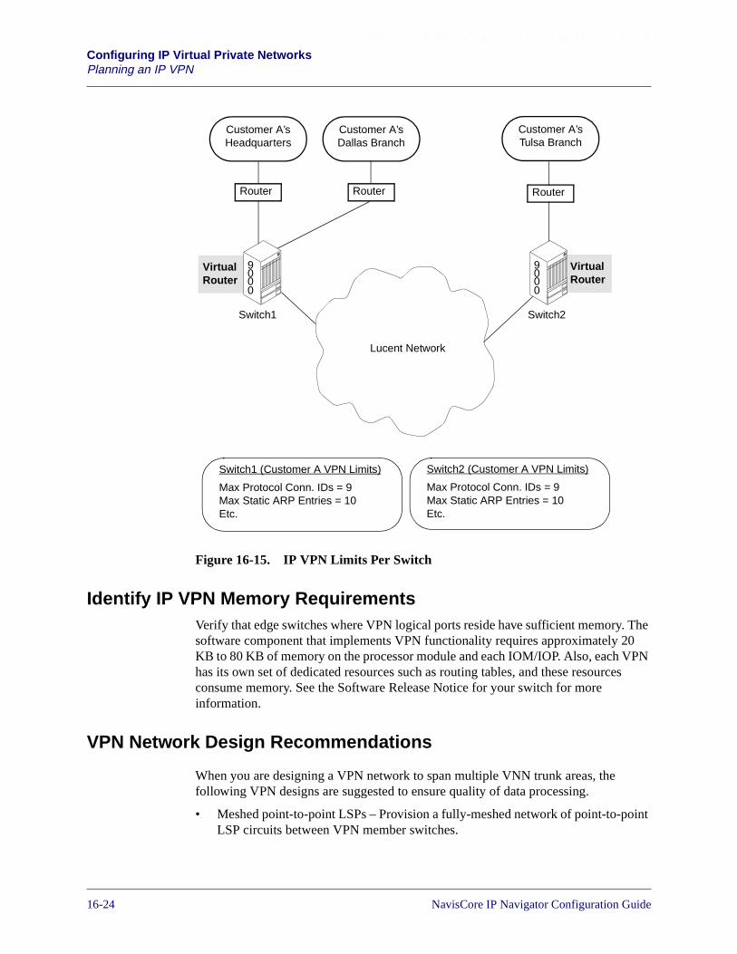
Beta Draft ConfidentialConfiguring IP Virtual Private NetworksPlanning an IP VPN
Figure 16-15. IP VPN Limits Per Switch
Identify IP VPN Memory RequirementsVerify that edge switches where VPN logical ports reside have sufficient memory. Thesoftware component that implements VPN functionality requires approximately 20KB to 80 KB of memory on the processor module and each IOM/IOP. Also, each VPNhas its own set of dedicated resources such as routing tables, and these resourcesconsume memory. See the Software Release Notice for your switch for moreinformation.
VPN Network Design Recommendations
When you are designing a VPN network to span multiple VNN trunk areas, thefollowing VPN designs are suggested to ensure quality of data processing.
• Meshed point-to-point LSPs – Provision a fully-meshed network of point-to-pointLSP circuits between VPN member switches.
VirtualRouter
VirtualRouter
90
00
90
00
Router RouterRouter
Customer A’sHeadquarters
Customer A’sTulsa Branch
Customer A’sDallas Branch
Lucent Network
Switch1 Switch2
Switch1 (Customer A VPN Limits)
Max Protocol Conn. IDs = 9Max Static ARP Entries = 10Etc.
Switch2 (Customer A VPN Limits)
Max Protocol Conn. IDs = 9Max Static ARP Entries = 10Etc.
16-24 NavisCore IP Navigator Configuration Guide
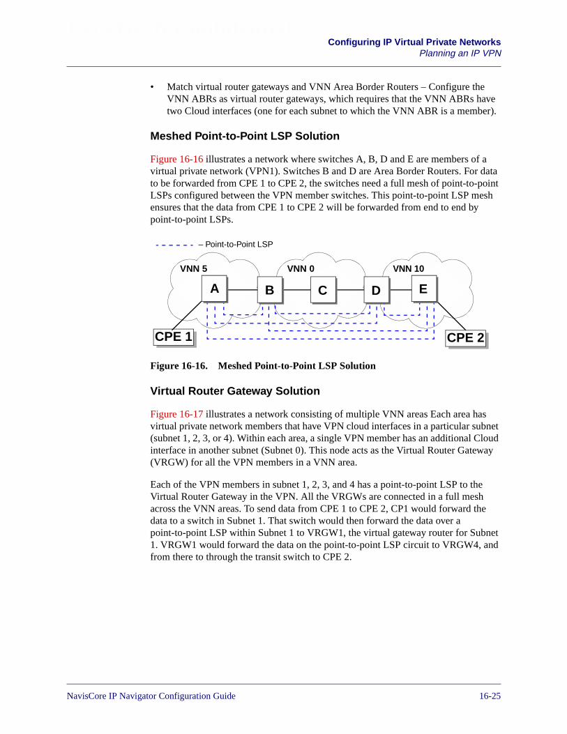
Beta Draft ConfidentialConfiguring IP Virtual Private Networks
Planning an IP VPN
• Match virtual router gateways and VNN Area Border Routers – Configure theVNN ABRs as virtual router gateways, which requires that the VNN ABRs havetwo Cloud interfaces (one for each subnet to which the VNN ABR is a member).
Meshed Point-to-Point LSP Solution
Figure 16-16 illustrates a network where switches A, B, D and E are members of avirtual private network (VPN1). Switches B and D are Area Border Routers. For datato be forwarded from CPE 1 to CPE 2, the switches need a full mesh of point-to-pointLSPs configured between the VPN member switches. This point-to-point LSP meshensures that the data from CPE 1 to CPE 2 will be forwarded from end to end bypoint-to-point LSPs.
Figure 16-16. Meshed Point-to-Point LSP Solution
Virtual Router Gateway Solution
Figure 16-17 illustrates a network consisting of multiple VNN areas Each area hasvirtual private network members that have VPN cloud interfaces in a particular subnet(subnet 1, 2, 3, or 4). Within each area, a single VPN member has an additional Cloudinterface in another subnet (Subnet 0). This node acts as the Virtual Router Gateway(VRGW) for all the VPN members in a VNN area.
Each of the VPN members in subnet 1, 2, 3, and 4 has a point-to-point LSP to theVirtual Router Gateway in the VPN. All the VRGWs are connected in a full meshacross the VNN areas. To send data from CPE 1 to CPE 2, CP1 would forward thedata to a switch in Subnet 1. That switch would then forward the data over apoint-to-point LSP within Subnet 1 to VRGW1, the virtual gateway router for Subnet1. VRGW1 would forward the data on the point-to-point LSP circuit to VRGW4, andfrom there to through the transit switch to CPE 2.
VNN 5 VNN 0 VNN 10
CPE 1 CPE 2
– Point-to-Point LSP
A B EDC
NavisCore IP Navigator Configuration Guide 1/14/0216-25

Beta Draft ConfidentialConfiguring IP Virtual Private NetworksPlanning an IP VPN
Figure 16-17. Virtual Router Gateway Solution
Subnet 1
CPE 1
CPE 2
– Point-to-Point LSP Within VNN Area
VRGW1
VRGW2
VRGW3
VRGW4
Subnet 2
Subnet 3 Subnet 4
– Point-to-Point LSP Across VNN Areas
Subnet 0
16-26 NavisCore IP Navigator Configuration Guide

Beta Draft ConfidentialConfiguring IP Virtual Private Networks
P VPN Configuration Flowchart
P VPN Configuration Flowchart
Figure 16-18 summarizes the process of configuring IP VPNs.
Figure 16-18. IP VPN Configuration Flowchart
Configure the physical network infrastructure.
Configure IP VPN cloud interfaces. See“Setting IP VPN Cloud IP Interfaces” onpage 16-35.
Configure ingress IP interfaces. See“Configuring Ingress IP Interfaces for IPVPNs” on page 16-40.
Add IP VPNs. See “Adding an IP VPN” onpage 16-28.
Configure Frame Relay, ATM, PPP, andEthernet logical ports (and associated IPlogical ports).
Configure IP OSPF router IDs and IPloopback addresses. See “Identify IP OSPFRouter ID and Loopback AddressRequirements” on page 16-21.
Configure point-to-point LSPs. See “AssigningPoint-to-Point LSPs to an IP VPN” onpage 16-57.
Configure additional IP resources (such asrouting tables). See “Assigning AdditionalNetwork Resources to an IP VPN” onpage 16-57.
Configure Frame Relay and ATM circuits(DLCIs and VPI/VCIs).
Service Provider Tasks
Customer Tasks
NavisCore IP Navigator Configuration Guide 1/14/0216-27

Beta Draft ConfidentialConfiguring IP Virtual Private NetworksAdding an IP VPN
Adding an IP VPN
To add an IP VPN:
1. From the Administer menu, select Lucent IP Parameters� Set All IP VPNs. TheSet All IP Virtual Private Networks dialog box appears (see Figure 16-19).
Figure 16-19. Set All IP Virtual Private Networks Dialog Box
The Set All IP Virtual Private Networks dialog box lists each VPN and itsassociated IP parameters. See Table 16-2 for descriptions of the buttons on thedialog box. See Table 16-3 for descriptions of the parameters.
Table 16-2. Set All IP Virtual Private Networks Dialog Box: Buttons
Button Function
Add Adds a VPN.
Modify Modifies a VPN. See “Modifying an IP VPN” on page 16-31 fordetails.
Delete Deletes a VPN. See “Deleting an IP VPN” on page 16-31 for details.
16-28 NavisCore IP Navigator Configuration Guide
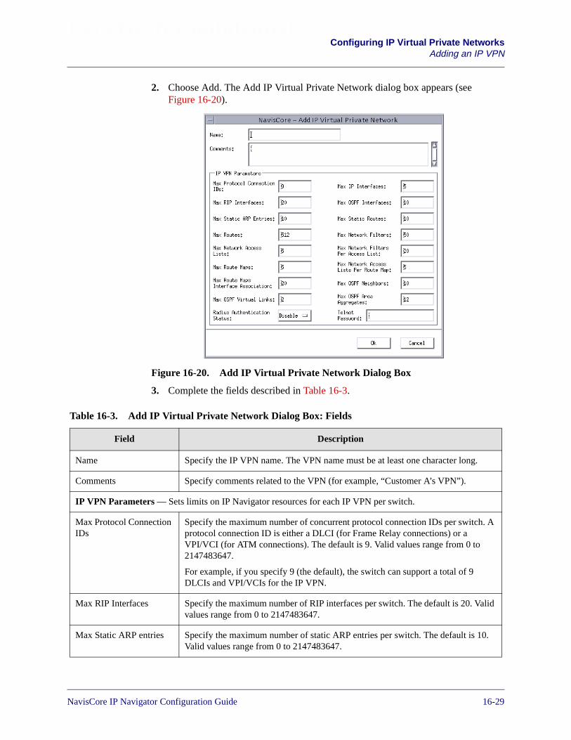
Beta Draft ConfidentialConfiguring IP Virtual Private Networks
Adding an IP VPN
2. Choose Add. The Add IP Virtual Private Network dialog box appears (seeFigure 16-20).
Figure 16-20. Add IP Virtual Private Network Dialog Box
3. Complete the fields described in Table 16-3.
Table 16-3. Add IP Virtual Private Network Dialog Box: Fields
Field Description
Name Specify the IP VPN name. The VPN name must be at least one character long.
Comments Specify comments related to the VPN (for example, “Customer A’s VPN”).
IP VPN Parameters — Sets limits on IP Navigator resources for each IP VPN per switch.
Max Protocol ConnectionIDs
Specify the maximum number of concurrent protocol connection IDs per switch. Aprotocol connection ID is either a DLCI (for Frame Relay connections) or aVPI/VCI (for ATM connections). The default is 9. Valid values range from 0 to2147483647.
For example, if you specify 9 (the default), the switch can support a total of 9DLCIs and VPI/VCIs for the IP VPN.
Max RIP Interfaces Specify the maximum number of RIP interfaces per switch. The default is 20. Validvalues range from 0 to 2147483647.
Max Static ARP entries Specify the maximum number of static ARP entries per switch. The default is 10.Valid values range from 0 to 2147483647.
NavisCore IP Navigator Configuration Guide 1/14/0216-29

Beta Draft ConfidentialConfiguring IP Virtual Private NetworksAdding an IP VPN
Max Routes Specify the maximum number of routes that can be stored in the IP VPN’s privaterouting table per switch. The default is 512. Valid values range from 0 to2147483647.
Max Network AccessLists
Specify the maximum number of network access lists per switch. The defaultis 5. Valid values range from 0 to 2147483647.
Max Route Maps Specify the maximum number of route maps per switch. The default is 5. Validvalues range from 0 to 2147483647.
Max Route MapsInterface Association
Specify the maximum number of route maps per RIP interface. The default is 5.Valid values range from 0 to 2147483647.
Max OSPF Virtual Links Specify the maximum number of IP OSPF virtual links per switch. The default is 2.Valid values range from 0 to 2147483647.
Radius AuthenticationStatus
Specify whether Radius Authentication is used to authenticate IP VPN logins.Specify Enable if you want Radius Authentication to authenticate IP VPN logins.Otherwise, specify Disable (the default).
Note: When you use RADIUS authentication for a private VPN (that is, a VPN withan ID greater than 0), you must append the VPN ID to users’ login names in theRADIUS database. For example, if you want user edison to log in to VPN 999, youmust enter his username as edison-999 in the RADIUS database. When edison logsin, he would enter “edison” at the login prompt, and the switch would append theVPN ID (“-999”) before forwarding the login to the RADIUS server forauthentication.
Max IP Interfaces Specify the maximum number of IP interfaces per switch. The default is 5. Validvalues range from 0 to 2147483647.
Max OSPF Interfaces Specify the maximum number of OSPF interfaces per switch. You can create OSPFinterfaces for the IP VPN IP cloud logical port or the ingress IP interfaces. Thedefault is 10. Valid values range from 0 to 2147483647.
Max Static Routes Specify the maximum number of static routes (from 0 to 2147483647) that can beconfigured in the IP VPN’s private routing table per switch. The default is 10.
Max Network Filters Specify the maximum number of network filters per switch. The default is 50. Validvalues range from 0 to 2147483647.
Max Network Filters PerAccess List
Specify the maximum number of network filters that can be associated with anaccess list per switch. The default is 20. Valid values range from 0 to 2147483647.
For example, if you specify 20 (the default), no more than 20 network filters can beassociated with any access list on a switch.
Table 16-3. Add IP Virtual Private Network Dialog Box: Fields (Continued)
Field Description
16-30 NavisCore IP Navigator Configuration Guide

Beta Draft ConfidentialConfiguring IP Virtual Private Networks
Modifying an IP VPN
4. Choose OK.
Modifying an IP VPN
To modify an IP VPN:
1. From the Administer menu, select Lucent IP Parameters� Set All IP VPNs. TheSet All IP Virtual Private Networks dialog box appears (see Figure 16-19 onpage 16-28).
2. Select the IP VPN you want to modify.
3. Choose Modify. The Modify IP Virtual Private Networks dialog box appears. Thisdialog box is similar to the Add IP Virtual Private Networks dialog box (seeFigure 16-20 on page 16-29).
4. Modify the fields described in Table 16-3 on page 16-29.
5. Choose OK.
Deleting an IP VPN
To delete an IP VPN:
1. Delete all resources associated with the IP VPN, such as interfaces, DLCI/VPIbindings, static routes and so on. Otherwise, you will not be able to delete the IPVPN.
Max Network AccessLists Per Route Map
Specify the maximum number of network access lists that can be associated with aroute map per switch. The default is 5. Valid values range from 0 to 2147483647.
For example, if you specify 5 (the default), no more than 5 network access lists canbe associated with a route map on a switch.
Max OSPF Neighbors Specify the maximum number of IP OSPF neighbors for the IP VPN per switch.The default is 10. Valid values range from 0 to 2147483647.
Max OSPF AreaAggregates
Specify the maximum number of IP OSPF area aggregates for the IP VPN perswitch. The default is 12. Valid values range from 0 to 2147483647.
Telnet Password Specify the password you will use to access the switch console. Once you accessthe switch console with this password, all console commands you issue retrieveinformation on your VPN’s resources only. The password can be from 6 to 20characters long. You must specify a password. Otherwise, the NMS will not allowyou to add the IP VPN.
Table 16-3. Add IP Virtual Private Network Dialog Box: Fields (Continued)
Field Description
NavisCore IP Navigator Configuration Guide 1/14/0216-31

Beta Draft ConfidentialConfiguring IP Virtual Private NetworksDeleting an IP VPN
2. From the Administer menu, select Lucent IP Parameters� Set All IP VPNs. TheSet All IP Virtual Private Networks dialog box appears (see Figure 16-19 onpage 16-28).
3. Select the IP VPN you want to delete.
4. Choose Delete.
5. Choose OK when prompted.
16-32 NavisCore IP Navigator Configuration Guide
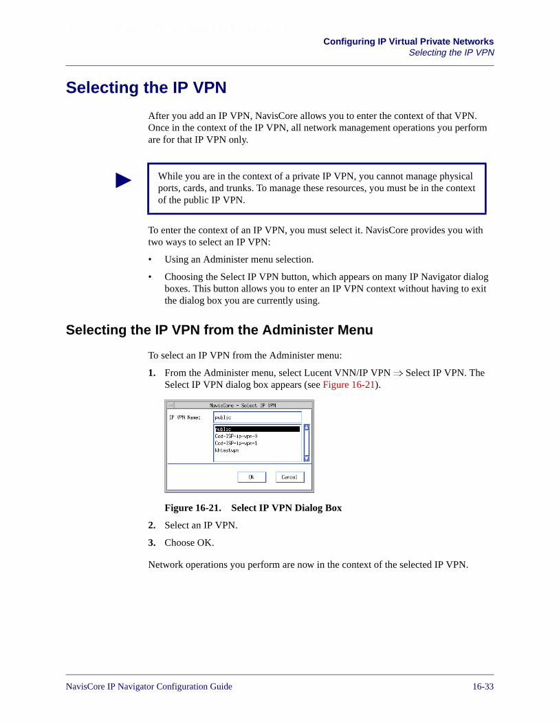
Beta Draft ConfidentialConfiguring IP Virtual Private Networks
Selecting the IP VPN
Selecting the IP VPN
After you add an IP VPN, NavisCore allows you to enter the context of that VPN.Once in the context of the IP VPN, all network management operations you performare for that IP VPN only.
To enter the context of an IP VPN, you must select it. NavisCore provides you withtwo ways to select an IP VPN:
• Using an Administer menu selection.
• Choosing the Select IP VPN button, which appears on many IP Navigator dialogboxes. This button allows you to enter an IP VPN context without having to exitthe dialog box you are currently using.
Selecting the IP VPN from the Administer Menu
To select an IP VPN from the Administer menu:
1. From the Administer menu, select Lucent VNN/IP VPN� Select IP VPN. TheSelect IP VPN dialog box appears (see Figure 16-21).
Figure 16-21. Select IP VPN Dialog Box
2. Select an IP VPN.
3. Choose OK.
Network operations you perform are now in the context of the selected IP VPN.
While you are in the context of a private IP VPN, you cannot manage physicalports, cards, and trunks. To manage these resources, you must be in the contextof the public IP VPN.
NavisCore IP Navigator Configuration Guide 1/14/0216-33
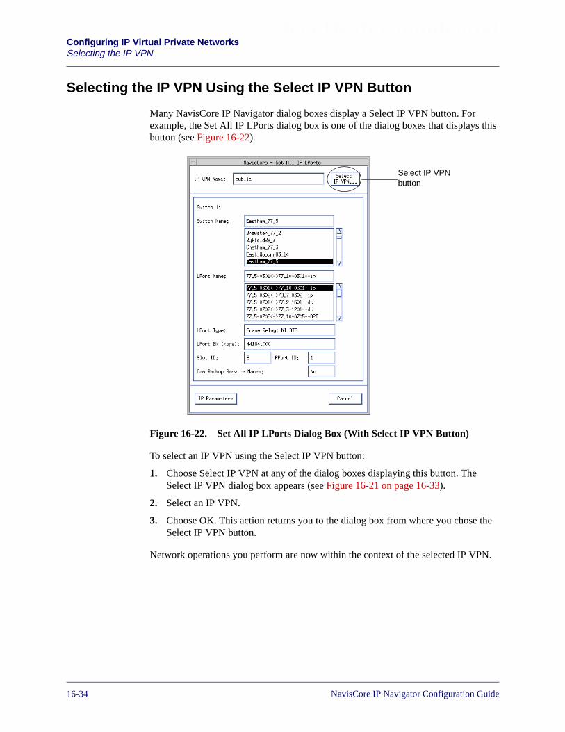
Beta Draft ConfidentialConfiguring IP Virtual Private NetworksSelecting the IP VPN
Selecting the IP VPN Using the Select IP VPN Button
Many NavisCore IP Navigator dialog boxes display a Select IP VPN button. Forexample, the Set All IP LPorts dialog box is one of the dialog boxes that displays thisbutton (see Figure 16-22).
Figure 16-22. Set All IP LPorts Dialog Box (With Select IP VPN Button)
To select an IP VPN using the Select IP VPN button:
1. Choose Select IP VPN at any of the dialog boxes displaying this button. TheSelect IP VPN dialog box appears (see Figure 16-21 on page 16-33).
2. Select an IP VPN.
3. Choose OK. This action returns you to the dialog box from where you chose theSelect IP VPN button.
Network operations you perform are now within the context of the selected IP VPN.
Select IP VPNbutton
16-34 NavisCore IP Navigator Configuration Guide
Beta Draft ConfidentialConfiguring IP Virtual Private Networks
Setting IP VPN Cloud IP Interfaces
Setting IP VPN Cloud IP Interfaces
Before you define IP VPN cloud IP interfaces, make sure that you have defined the IPVPN. See “Adding an IP VPN” on page 16-28 for more information.
For each IP VPN, you define a VPN cloud IP interface on each switch where the IPVPN’s virtual router resides. It is recommended that you create no more than one VPNcloud IP interface per IP VPN per switch.
To add VPN cloud IP interfaces:
1. From the Administer menu, select Lucent IP Parameters� Set All IP LPorts. TheSet All IP LPorts dialog box appears (see Figure 16-22 on page 16-34).
2. Choose Select IP VPN. The Select IP VPN dialog box appears (see Figure 16-21on page 16-33).
3. Select the appropriate IP VPN.
4. Choose OK. The Set All IP LPorts dialog box appears. However, this time thedialog box lists the VPN Cloud IP logical port, and the name of the VPN youselected appears in the IP VPN name field (see Figure 16-23).
You cannot define an IP VPN cloud IP interface on a switch until you configurean IP loopback address for the public IP VPN on that switch. See “Identify IPOSPF Router ID and Loopback Address Requirements” on page 16-21 for moreinformation.
If resources associated with any IP logical ports have been assigned to the IPVPN, those IP logical ports are also displayed. For example, if a DLCI has beenassigned to an IP VPN, the IP logical port associated with the DLCI is displayed.
NavisCore IP Navigator Configuration Guide 1/14/0216-35

Beta Draft ConfidentialConfiguring IP Virtual Private NetworksSetting IP VPN Cloud IP Interfaces
Figure 16-23. Set All IP LPorts Dialog Box (with VPN Cloud LPort)
5. Select the edge switch where you want to configure the VPN cloud IP interfaces.
6. The VPN Cloud LPort for that switch appears.
7. Select the VPN Cloud LPort.
8. Choose IP Interface. The Set Cloud IP Interface Addresses dialog box appears(see Figure 16-24).
16-36 NavisCore IP Navigator Configuration Guide
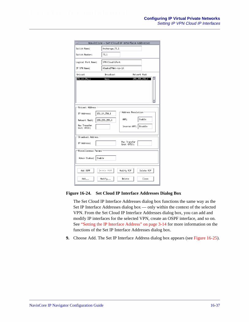
Beta Draft ConfidentialConfiguring IP Virtual Private Networks
Setting IP VPN Cloud IP Interfaces
Figure 16-24. Set Cloud IP Interface Addresses Dialog Box
The Set Cloud IP Interface Addresses dialog box functions the same way as theSet IP Interface Addresses dialog box — only within the context of the selectedVPN. From the Set Cloud IP Interface Addresses dialog box, you can add andmodify IP interfaces for the selected VPN, create an OSPF interface, and so on.See “Setting the IP Interface Address” on page 3-14 for more information on thefunctions of the Set IP Interface Addresses dialog box.
9. Choose Add. The Set IP Interface Address dialog box appears (see Figure 16-25).
NavisCore IP Navigator Configuration Guide 1/14/0216-37

Beta Draft ConfidentialConfiguring IP Virtual Private NetworksSetting IP VPN Cloud IP Interfaces
Figure 16-25. Set Cloud IP Interface Address Dialog Box
10. Complete the fields described in Table 16-4.
Table 16-4. IP VPN Cloud IP Interface Address Fields
Field Action/Description
Unicast Address
IP Address The IP address for this interface. Keep in mind that, once you configure an IP address,the IP address cannot be changed. To make any modifications to the IP address, you mustdelete the interface and re-add it with the modified IP address.
Make sure that all the VPN cloud IP interfaces in the same IP VPN are in the samesubnetwork. For example, suppose you have to configure two VPN cloud IP interfacesthat are in the same IP VPN. You could assign 180.170.10.1 to one interface and180.170.10.2 to the other interface. The common subnetwork number is 180.170.10.0.
Network Mask The mask used to determine the subnet of this IP interface. Once this value is set, youcannot use the Modify Interface Address function to modify the network mask value. Inorder to change the network mask, you must delete the IP interface and then add a newone using the correct network mask.
Max Transfer Unit(MTU)
Not supported for IP VPN cloud interfaces.
Address Resolution
ARP Select one of the following options:
Enable – (default) Enables the Address Resolution Protocol (ARP). Make sure that youkeep ARP enabled. Keep in mind that all of the IP VPN cloud IP interfaces that are in thesame IP VPN communicate with each other as if they were all on a common EthernetLAN.
Disable – Disables the ARP.
16-38 NavisCore IP Navigator Configuration Guide

Beta Draft ConfidentialConfiguring IP Virtual Private Networks
Setting IP VPN Cloud IP Interfaces
11. Choose OK. The Set Cloud IP Interface Addresses dialog box appears (seeFigure 16-24 on page 16-37), displaying the newly created IP interface.
12. Choose Add OSPF to add an OSPF interface. The Add OSPF Interface dialog boxappears.
13. Choose OK to accept the defaults. The Set Cloud IP Interface Addresses dialogbox appears (see Figure 16-24 on page 16-37).
You can now manage the interface like other IP interfaces. If RIP is used as therouting protocol over the VPN cloud, then it can be configured instead of OSPF on thecloud interfaces. For example, you can configure RIP for the cloud interface just asyou would for a logical port. For more information, see “Configuring RIP at theLogical Port” on page 7-1
Inverse ARP Not supported for IP VPN cloud interfaces.
Broadcast Address
IP Address Not supported for IP VPN cloud interfaces.
Max Transfer Unit(MTU)
Not supported for IP VPN cloud interfaces.
Miscellaneous Params
Admin Status Select one of the following options:
Enable – (default) Enables the IP interface.
Disable – Disables the IP interface.
Table 16-4. IP VPN Cloud IP Interface Address Fields (Continued)
Field Action/Description
When you add an OSPF interface on a VPN cloud logical port, it isrecommended that you do not modify the defaults — especially the Area ID.
NavisCore IP Navigator Configuration Guide 1/14/0216-39
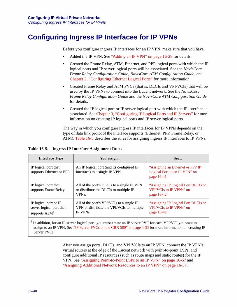
Beta Draft ConfidentialConfiguring IP Virtual Private NetworksConfiguring Ingress IP Interfaces for IP VPNs
Configuring Ingress IP Interfaces for IP VPNs
Before you configure ingress IP interfaces for an IP VPN, make sure that you have:
• Added the IP VPN. See “Adding an IP VPN” on page 16-28 for details.
• Created the Frame Relay, ATM, Ethernet, and PPP logical ports with which the IPlogical ports and IP server logical ports will be associated. See the NavisCoreFrame Relay Configuration Guide, NavisCore ATM Configuration Guide, andChapter 2, “Configuring Ethernet Logical Ports” for more information.
• Created Frame Relay and ATM PVCs (that is, DLCIs and VPI/VCIs) that will beused by the IP VPNs to connect into the Lucent network. See the NavisCoreFrame Relay Configuration Guide and the NavisCore ATM Configuration Guidefor details.
• Created the IP logical port or IP server logical port with which the IP interface isassociated. See Chapter 3, “Configuring IP Logical Ports and IP Servers” for moreinformation on creating IP logical ports and IP server logical ports.
The way in which you configure ingress IP interfaces for IP VPNs depends on thetype of data link protocol the interface supports (Ethernet, PPP, Frame Relay, orATM). Table 16-5 describes the rules for assigning ingress IP interfaces to IP VPNs.
After you assign ports, DLCIs, and VPI/VCIs to an IP VPN, connect the IP VPN’svirtual routers at the edge of the Lucent network with point-to-point LSPs, andconfigure additional IP resources (such as route maps and static routes) for the IPVPN. See “Assigning Point-to-Point LSPs to an IP VPN” on page 16-57 and“Assigning Additional Network Resources to an IP VPN” on page 16-57.
Table 16-5. Ingress IP Interface Assignment Rules
Interface Type You assign... See...
IP logical port thatsupports Ethernet or PPP.
An IP logical port (and its configured IPinterface) to a single IP VPN.
“Assigning an Ethernet or PPP IPLogical Port to an IP VPN” onpage 16-41.
IP logical port thatsupports Frame Relay.
All of the port’s DLCIs to a single IP VPNor distribute the DLCIs to multiple IPVPNs.
“Assigning IP Logical Port DLCIs orVPI/VCIs to IP VPNs” onpage 16-42.
IP logical port or IPserver logical port that
supports ATM1.
All of the port’s VPI/VCIs to a single IPVPN or distribute the VPI/VCIs to multipleIP VPNs.
“Assigning IP Logical Port DLCIs orVPI/VCIs to IP VPNs” onpage 16-42.
1 In addition, for an IP server logical port, you must create an IP server PVC for each VPI/VCI you want toassign to an IP VPN. See “IP Server PVCs on the CBX 500” on page 3-33 for more information on creating IPServer PVCs.
16-40 NavisCore IP Navigator Configuration Guide

Beta Draft ConfidentialConfiguring IP Virtual Private Networks
Configuring Ingress IP Interfaces for IP VPNs
Assigning an Ethernet or PPP IP Logical Port to an IP VPN
Before you assign an IP logical port that uses Ethernet or PPP for the data linkprotocol to an IP VPN, make sure that you have added and configured the IP logicalport (including the IP interface) as described in “Configuring IP Logical Ports” onpage 3-5.
You create the assignment from the Set IP Parameters dialog box. To assign anEthernet or PPP port to an IP VPN:
1. From the Administer menu, select Lucent IP Parameters� Set All IP LPorts. TheSet all IP LPorts dialog box appears (see Figure 16-22 on page 16-34).
2. Select the switch where the Ethernet or PPP logical port resides from the SwitchName list at the top of the dialog box. A list of IP logical ports configured on theswitch appears in the LPort Name list.
3. Select the Ethernet or PPP logical port.
4. Choose IP Parameters. The Set IP Parameters dialog box appears (seeFigure 16-26).
Figure 16-26. Set IP Parameters Dialog Box (PPP Port)
5. Select Bind IP VPN.
You may assign an IP logical port that uses Ethernet or PPP as the data linkprotocol to only one IP VPN.
1. Select Bind IP VPN.
2. Choose Go.
NavisCore IP Navigator Configuration Guide 1/14/0216-41

Beta Draft ConfidentialConfiguring IP Virtual Private NetworksConfiguring Ingress IP Interfaces for IP VPNs
6. Choose Go. The Select IP VPN dialog box appears (see Figure 16-21 onpage 16-33).
7. Select the IP VPN (the default is “public,” which means that the Ethernet or PPPlogical port can be used by public network traffic). Note that only one VPN canuse a PPP or Ethernet logical port.
8. Choose OK.
Assigning IP Logical Port DLCIs or VPI/VCIs to IP VPNs
Before you assign a Frame Relay DLCI or ATM VPI/VCI (and associated parameters)to an IP VPN, make sure that you have added and configured the associated IP logicalport as described in “Configuring IP Logical Ports” on page 3-5.
For each IP logical port that supports Frame Relay, you can assign multiple DLCIs toa single VPN, or distribute the DLCIs among multiple VPNs.
For each IP logical port that supports ATM, you can assign multiple VPI/VCIs to asingle VPN, or distribute the VPI/VCIs among multiple VPNs.
The procedure for assigning DLCIs and VPI/VCIs is divided into two parts:
• Assign a DLCI or a VPI/VCI to an IP VPN.
• Bind a DLCI or a VPI/VCI to one of the IP VPN’s IP interfaces, which you canadd during the binding process.
To assign a DLCI or VPI/VCI to a VPN:
1. From the Administer menu, select Lucent IP Parameters� Set All IP LPorts. TheSet all IP LPorts dialog box appears (see Figure 16-22 on page 16-34).
2. Select the switch where the IP logical port that supports Frame Relay or ATMresides from the Switch Name list at the top of the dialog box. A list of IP logicalports configured on the switch appears in the LPort Name list.
3. Select the IP logical port that supports Frame Relay or ATM.
If the IP logical port was previously bound to another private IP VPN, an errormessage appears at this time, notifying you that you must delete all IP interfacesconfigured for the IP logical port. When an IP logical port is bound to a privateIP VPN, you cannot bind the port to another private IP VPN until you delete theIP interfaces associated with the IP logical port.
The DLCI information in this section applies to IP logical ports that use FrameRelay as the data link protocol on both B-STDX switches and CBX 500switches. The VPI/VCI information in this section applies to IP logical ports thatuse ATM as the data link protocol on B-STDX switches only.
16-42 NavisCore IP Navigator Configuration Guide
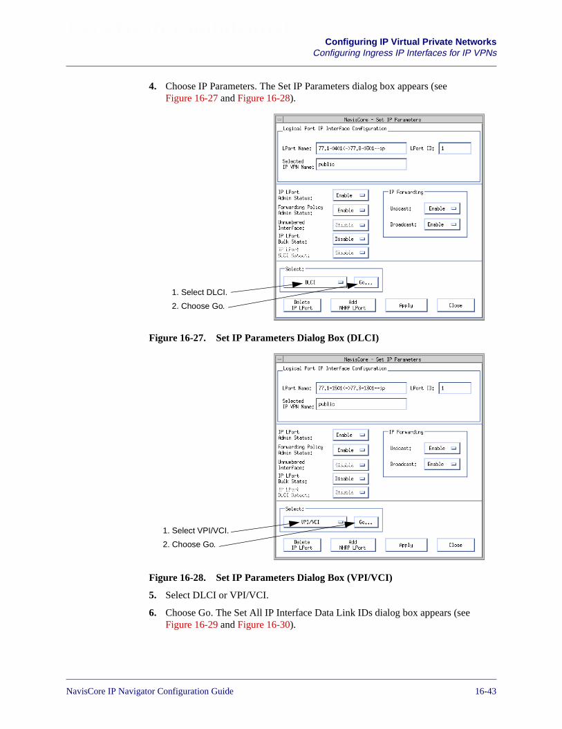
Beta Draft ConfidentialConfiguring IP Virtual Private Networks
Configuring Ingress IP Interfaces for IP VPNs
4. Choose IP Parameters. The Set IP Parameters dialog box appears (seeFigure 16-27 and Figure 16-28).
Figure 16-27. Set IP Parameters Dialog Box (DLCI)
Figure 16-28. Set IP Parameters Dialog Box (VPI/VCI)
5. Select DLCI or VPI/VCI.
6. Choose Go. The Set All IP Interface Data Link IDs dialog box appears (seeFigure 16-29 and Figure 16-30).
1. Select DLCI.
2. Choose Go.
1. Select VPI/VCI.
2. Choose Go.
NavisCore IP Navigator Configuration Guide 1/14/0216-43

Beta Draft ConfidentialConfiguring IP Virtual Private NetworksConfiguring Ingress IP Interfaces for IP VPNs
Figure 16-29. Set All IP Interface Data Link IDs Dialog Box (DLCI)
Figure 16-30. Set All IP Interface Data Link IDs Dialog Box (VPI/VCI)
The Set All IP Interface Data Link IDs dialog box displays a list of DLCIs orVPI/VCIs and the IP VPNs to which you have assigned them. Table 16-6describes the buttons on the dialog box.
Table 16-6. Set All IP Interface Data Link IDs Dialog Box Buttons
Button Function
Associate Filter Associates an IP packet filter with the Frame Relay circuit identified by the DLCI orthe ATM circuit identified by the VPI/VCI. See Chapter 4, “Configuring IP PacketFilters” for more information on IP packet filters and associating them with circuits.
Bind IP Interface Binds an IP interface to the DLCI or VPI/VCI.
Add Assigns a DLCI or VPI/VCI to a VPN.
Modify Modifies a DLCI/VPN or VPI/VCI/VPN assignment.
Delete Deletes a DLCI/VPN or VPI/VCI/VPN assignment.
16-44 NavisCore IP Navigator Configuration Guide
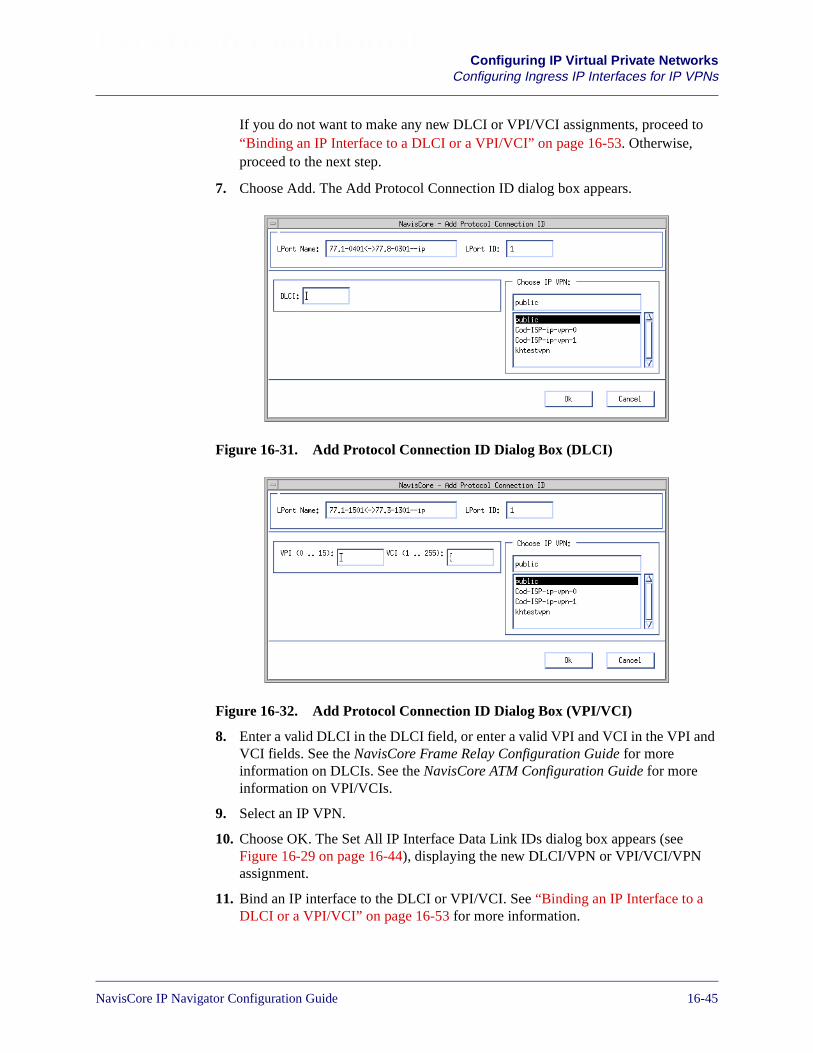
Beta Draft ConfidentialConfiguring IP Virtual Private Networks
Configuring Ingress IP Interfaces for IP VPNs
If you do not want to make any new DLCI or VPI/VCI assignments, proceed to“Binding an IP Interface to a DLCI or a VPI/VCI” on page 16-53. Otherwise,proceed to the next step.
7. Choose Add. The Add Protocol Connection ID dialog box appears.
Figure 16-31. Add Protocol Connection ID Dialog Box (DLCI)
Figure 16-32. Add Protocol Connection ID Dialog Box (VPI/VCI)
8. Enter a valid DLCI in the DLCI field, or enter a valid VPI and VCI in the VPI andVCI fields. See the NavisCore Frame Relay Configuration Guide for moreinformation on DLCIs. See the NavisCore ATM Configuration Guide for moreinformation on VPI/VCIs.
9. Select an IP VPN.
10. Choose OK. The Set All IP Interface Data Link IDs dialog box appears (seeFigure 16-29 on page 16-44), displaying the new DLCI/VPN or VPI/VCI/VPNassignment.
11. Bind an IP interface to the DLCI or VPI/VCI. See “Binding an IP Interface to aDLCI or a VPI/VCI” on page 16-53 for more information.
NavisCore IP Navigator Configuration Guide 1/14/0216-45
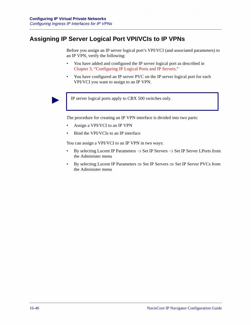
Beta Draft ConfidentialConfiguring IP Virtual Private NetworksConfiguring Ingress IP Interfaces for IP VPNs
Assigning IP Server Logical Port VPI/VCIs to IP VPNs
Before you assign an IP server logical port’s VPI/VCI (and associated parameters) toan IP VPN, verify the following:
• You have added and configured the IP server logical port as described inChapter 3, “Configuring IP Logical Ports and IP Servers.”
• You have configured an IP server PVC on the IP server logical port for eachVPI/VCI you want to assign to an IP VPN.
The procedure for creating an IP VPN interface is divided into two parts:
• Assign a VPI/VCI to an IP VPN
• Bind the VPI/VCIs to an IP interface
You can assign a VPI/VCI to an IP VPN in two ways:
• By selecting Lucent IP Parameters� Set IP Servers� Set IP Server LPorts fromthe Administer menu
• By selecting Lucent IP Parameters� Set IP Servers� Set IP Server PVCs fromthe Administer menu
IP server logical ports apply to CBX 500 switches only.
16-46 NavisCore IP Navigator Configuration Guide
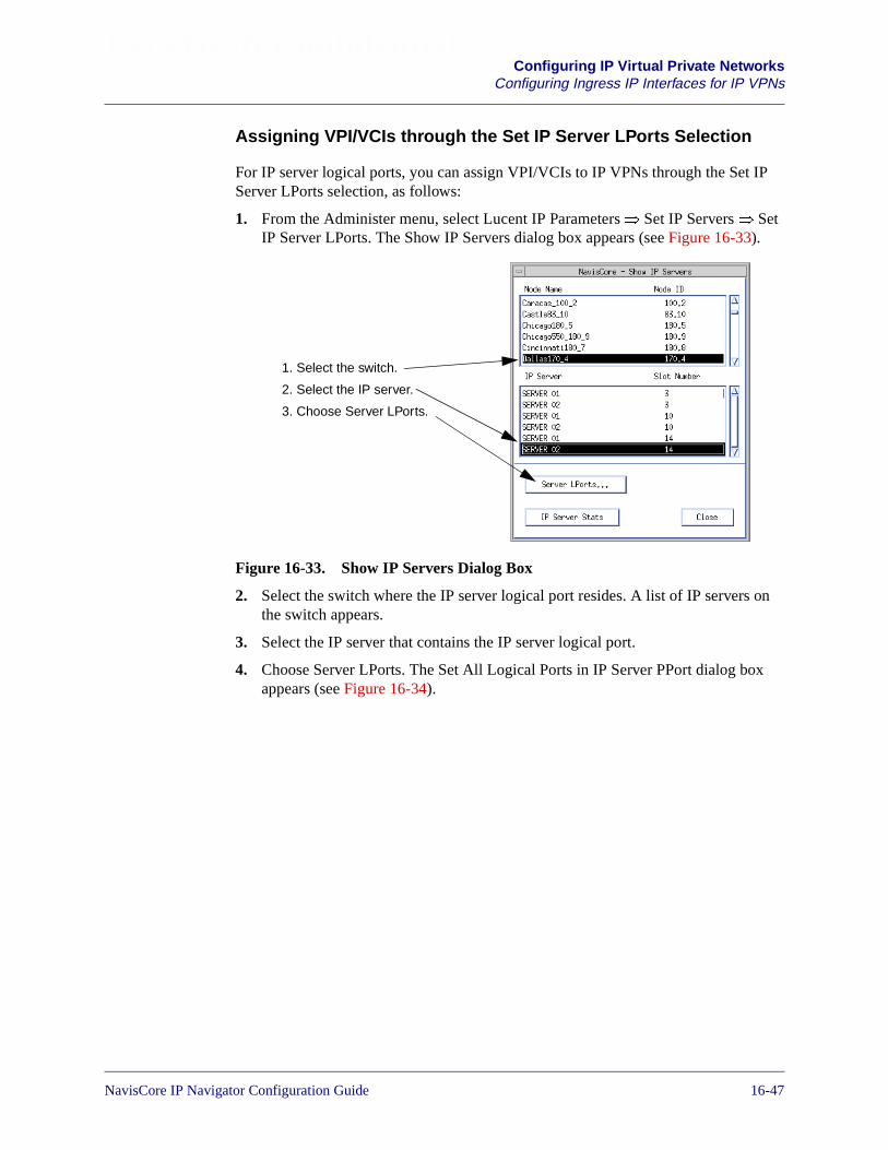
Beta Draft ConfidentialConfiguring IP Virtual Private Networks
Configuring Ingress IP Interfaces for IP VPNs
Assigning VPI/VCIs through the Set IP Server LPorts Selection
For IP server logical ports, you can assign VPI/VCIs to IP VPNs through the Set IPServer LPorts selection, as follows:
1. From the Administer menu, select Lucent IP Parameters� Set IP Servers� SetIP Server LPorts. The Show IP Servers dialog box appears (see Figure 16-33).
Figure 16-33. Show IP Servers Dialog Box
2. Select the switch where the IP server logical port resides. A list of IP servers onthe switch appears.
3. Select the IP server that contains the IP server logical port.
4. Choose Server LPorts. The Set All Logical Ports in IP Server PPort dialog boxappears (see Figure 16-34).
1. Select the switch.
2. Select the IP server.
3. Choose Server LPorts.
NavisCore IP Navigator Configuration Guide 1/14/0216-47
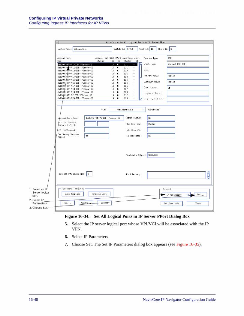
Beta Draft ConfidentialConfiguring IP Virtual Private NetworksConfiguring Ingress IP Interfaces for IP VPNs
Figure 16-34. Set All Logical Ports in IP Server PPort Dialog Box
5. Select the IP server logical port whose VPI/VCI will be associated with the IPVPN.
6. Select IP Parameters.
7. Choose Set. The Set IP Parameters dialog box appears (see Figure 16-35).
1. Select an IPServer logicalport.
2. Select IPParameters.
3. Choose Set.
16-48 NavisCore IP Navigator Configuration Guide

Beta Draft ConfidentialConfiguring IP Virtual Private Networks
Configuring Ingress IP Interfaces for IP VPNs
Figure 16-35. Set IP Parameters Dialog Box (IP Server VPI/VCI)
8. Select VPI/VCI.
9. Choose Go. The Set All IP Interface Data Link IDs dialog box appears (seeFigure 16-36).
Figure 16-36. Set All IP Interface Data Link IDs Dialog Box(IP Server VPI/VCI)
The Set All IP Interface Data Link IDs dialog box displays the VPI/VCIs for theIP server logical port and the IP VPNs to which they are assigned. Each VPI/VCIis associated with an IP server PVC. Table 16-7 describes the buttons on thedialog box.
1. Select VPI/VCI.
2. Choose Go.
NavisCore IP Navigator Configuration Guide 1/14/0216-49
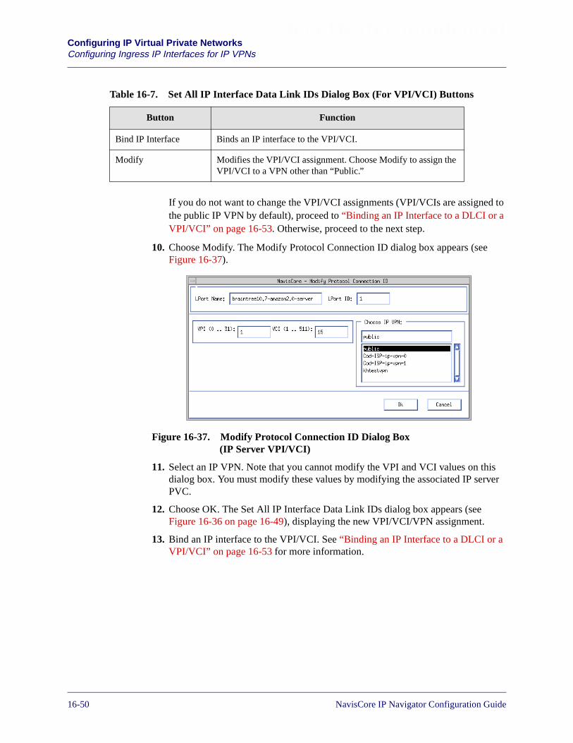
Beta Draft ConfidentialConfiguring IP Virtual Private NetworksConfiguring Ingress IP Interfaces for IP VPNs
If you do not want to change the VPI/VCI assignments (VPI/VCIs are assigned tothe public IP VPN by default), proceed to “Binding an IP Interface to a DLCI or aVPI/VCI” on page 16-53. Otherwise, proceed to the next step.
10. Choose Modify. The Modify Protocol Connection ID dialog box appears (seeFigure 16-37).
Figure 16-37. Modify Protocol Connection ID Dialog Box(IP Server VPI/VCI)
11. Select an IP VPN. Note that you cannot modify the VPI and VCI values on thisdialog box. You must modify these values by modifying the associated IP serverPVC.
12. Choose OK. The Set All IP Interface Data Link IDs dialog box appears (seeFigure 16-36 on page 16-49), displaying the new VPI/VCI/VPN assignment.
13. Bind an IP interface to the VPI/VCI. See “Binding an IP Interface to a DLCI or aVPI/VCI” on page 16-53 for more information.
Table 16-7. Set All IP Interface Data Link IDs Dialog Box (For VPI/VCI) Buttons
Button Function
Bind IP Interface Binds an IP interface to the VPI/VCI.
Modify Modifies the VPI/VCI assignment. Choose Modify to assign theVPI/VCI to a VPN other than “Public.”
16-50 NavisCore IP Navigator Configuration Guide
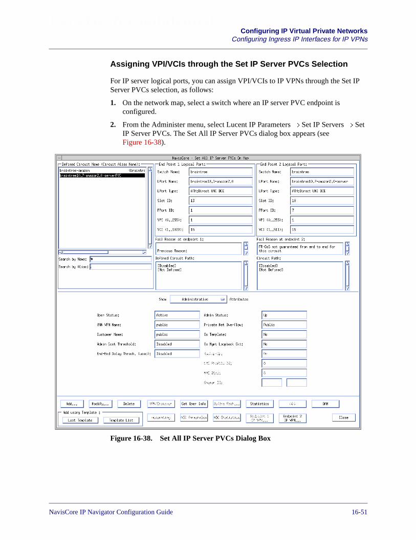
Beta Draft ConfidentialConfiguring IP Virtual Private Networks
Configuring Ingress IP Interfaces for IP VPNs
Assigning VPI/VCIs through the Set IP Server PVCs Selection
For IP server logical ports, you can assign VPI/VCIs to IP VPNs through the Set IPServer PVCs selection, as follows:
1. On the network map, select a switch where an IP server PVC endpoint isconfigured.
2. From the Administer menu, select Lucent IP Parameters� Set IP Servers� SetIP Server PVCs. The Set All IP Server PVCs dialog box appears (seeFigure 16-38).
Figure 16-38. Set All IP Server PVCs Dialog Box
NavisCore IP Navigator Configuration Guide 1/14/0216-51

Beta Draft ConfidentialConfiguring IP Virtual Private NetworksConfiguring Ingress IP Interfaces for IP VPNs
3. Select the IP server PVC. Use the Search by Name and Search by Alias fields toenter wildcard characters:
• Use an * to match any number of characters
• Use a ? to match a single character
• Type \* to match the * character
• Type \? to match the ? character
• Type \\ to match the \ character
See “Creating an IP Server PVC” on page 3-33 for a description of all the fieldsand buttons on the Set All IP Server PVCs dialog box.
4. Choose either Endpoint 1 IP VPN or Endpoint 2 IP VPN. The Set All IP InterfaceData Link IDs dialog box appears (see Figure 16-36 on page 16-49). Note that ifone of the endpoints is not an IP server logical port (for example, an ATM UNIlogical port), that associated endpoint button is grayed out.
5. Choose Modify. The Modify Protocol Connection ID dialog box appears (seeFigure 16-37 on page 16-50).
6. Select an IP VPN. Note that you cannot modify the VPI and VCI values on thisdialog box. You must modify these values by modifying the associated IP serverPVC.
7. Choose OK. The Set All IP Interface Data Link IDs dialog box appears (seeFigure 16-36 on page 16-49), displaying the new VPI/VCI/VPN assignment.
8. Bind an IP interface to the VPI/VCI. See “Binding an IP Interface to a DLCI or aVPI/VCI” on page 16-53 for more information.
If the circuit names do not appear immediately in the Defined Circuit Name listbox, insert the cursor in the blank Search by Name field and press Return. Thisaction will display a list of configured circuits.
16-52 NavisCore IP Navigator Configuration Guide

Beta Draft ConfidentialConfiguring IP Virtual Private Networks
Configuring Ingress IP Interfaces for IP VPNs
Binding an IP Interface to a DLCI or a VPI/VCI
For each IP VPN, you create its own IP interfaces on a switch. You then must bind oneof these interfaces to each DLCI or VPI/VCI you assign to an IP VPN. You bind andcreate IP interfaces during the same process.
To bind an IP interface to a DLCI or VPI/VCI (and create it):
1. At the Set All IP Interface Data Link IDs dialog box (see Figure 16-29 onpage 16-44, Figure 16-30 on page 16-44, or Figure 16-36 on page 16-49), selectthe DLCI or VPI/VCI to which you want to bind an IP interface.
2. Choose Bind IP Interface. The Bind IP Interface Address to Protocol ID dialogbox appears (see Figure 16-39).
Figure 16-39. Bind IP Interface Address to Protocol ID Dialog Box (DLCI)
Although the dialog box in Figure 16-39 is for a DLCI, the dialog box for aVPI/VCI is almost identical. The only difference is that the dialog box for aVPI/VCI displays the VPI and VCI instead of the DLCI.
NavisCore IP Navigator Configuration Guide 1/14/0216-53

Beta Draft ConfidentialConfiguring IP Virtual Private NetworksConfiguring Ingress IP Interfaces for IP VPNs
3. Choose Add IP Interface to add an IP interface to which the DLCI or VPI/VCIwill be bound. The Set IP Interface Address dialog box appears (seeFigure 16-40).
Figure 16-40. Set IP Interface Address Dialog Box
4. Complete the fields in Table 16-8.
Table 16-8. Ingress IP Interface Address Fields
Field Action/Description
Unicast Address
IP Address The IP address for this interface. Keep in mind that, once you configure an IP address,the IP address cannot be changed. To make any modifications to the IP address, you mustdelete the interface and re-add it with the modified IP address.
Network Mask The mask used to determine the subnet of this IP interface. Once this value is set, youcannot use the Modify Interface Address function to modify the network mask value. Inorder to change the network mask, you must delete the IP interface and then add a newone using the correct network mask.
Max Transfer Unit(MTU)
The maximum size of a packet that can be sent through the physical port. The defaultvalue for this field varies depending on the logical port type as follows:
LPort Type DefaultATM 9180Frame Relay 4096Ethernet 1500
Address Resolution
ARP (FrameRelay andEthernet only)
Select one of the following options:
Enable – (default) Enables the Address Resolution Protocol (ARP).
Disable – Disables the ARP.
16-54 NavisCore IP Navigator Configuration Guide

Beta Draft ConfidentialConfiguring IP Virtual Private Networks
Configuring Ingress IP Interfaces for IP VPNs
5. Choose OK. The Bind IP Interface Address to Protocol ID dialog box (seeFigure 16-39 on page 16-53) appears. By default, the IP interface is bound to theDLCI or VPI/VCI you selected in step 1 on page 16-53 (that is, it appears in theAssigned IP Interfaces list). If you want, you can select the IP interface andchoose Unassign to make the IP interface available to other DLCIs or VPI/VCIs.
6. Choose OK.
Inverse ARP(Frame Relay andATM only)
Select one of the following options:
Enable – (default) Enables the Inverse Address Resolution Protocol (InARP).
Disable – Disables the InARP.
Broadcast Address
IP Address The address used by this interface for subnet broadcasting.
Max Transfer Unit(MTU)
The maximum size of a packet that can be sent through the physical port. The defaultvalue for this field varies depending on the logical port type as follows:
LPort Type DefaultATM 9180Frame Relay 4096Ethernet 1500
Miscellaneous Params
Admin Status Select one of the following options:
Enable – (default) Enables the IP interface.
Disable – Disables the IP interface.
Table 16-8. Ingress IP Interface Address Fields (Continued)
Field Action/Description
At any time, you can delete the IP interface binding by selecting the IP interfacefrom the list of assigned IP interfaces and choosing Unassign. Choose OK afteryou have deleted the binding.
NavisCore IP Navigator Configuration Guide 1/14/0216-55
Beta Draft ConfidentialConfiguring IP Virtual Private NetworksConfiguring Ingress IP Interfaces for IP VPNs
Managing IP VPN Ingress IP Interfaces
To manage ingress IP interfaces for an IP VPN once you have configured them:
1. From the Administer menu, select Lucent IP Parameters� Set All IP LPorts. TheSet All IP LPorts dialog box appears (see Figure 16-22 on page 16-34).
2. Choose Select IP VPN. The Select IP VPN dialog box appears (see Figure 16-21on page 16-33).
3. Select the IP VPN to which the ingress IP interface was assigned.
4. Choose OK. The Set All IP LPorts dialog box appears (see Figure 16-22 onpage 16-34).
5. Select the switch where the ingress IP interface resides. A list of IP logical portsappears.
6. Select the IP logical port associated with the ingress IP interface.
7. Choose IP Parameters. The Set IP Parameters dialog box appears.
8. Select Actions� IP Interface.
9. Choose Go. The Set IP Interface Addresses dialog box appears, displaying all ofthe ingress IP interfaces assigned to the selected IP VPN on the IP logical port.
From the Set IP Interface Addresses dialog box, you can manage all of the IP VPN’singress IP interfaces associated with the selected IP logical port. For example, you canadd additional ingress IP interfaces, modify ingress IP interfaces, and delete ingress IPinterfaces.
You can also add, modify, and delete an IP OSPF interface. See Chapter 9,“Configuring IP OSPF and VNN OSPF” for more information on managing IP OSPFinterfaces.
16-56 NavisCore IP Navigator Configuration Guide

Beta Draft ConfidentialConfiguring IP Virtual Private Networks
Assigning Point-to-Point LSPs to an IP VPN
Assigning Point-to-Point LSPs to an IP VPN
You can configure point-to-point LSPs to connect the VPN’s virtual routers at theedge of the Lucent network. See “Understanding an IP VPN” on page 16-2, “IdentifyPoint-to-Point LSPs” on page 16-21, and Chapter 12, “Configuring Label SwitchedPaths” for more information.
Assigning Additional Network Resources to an IP VPN
You can assign additional IP network resources to an IP VPN. These resources includethe same kinds of resources you can manage for traditional IP networks, such as staticroutes, static ARP entries, route maps, and so on.
To assign additional IP network resources for an IP VPN, you must first select theVPN (see “Selecting the IP VPN” on page 16-33). By selecting a VPN, managementtasks you perform will be in the context of a single VPN. For example, if you add astatic route, that route is added for the selected VPN only.
Once you select a VPN, the NavisCore dialog boxes you access display the selectedVPN’s name. Figure 16-41, Figure 16-42, and Figure 16-43 provide sample dialogboxes that display the name of a selected VPN. Notice that all of these dialog boxesdisplay the Select IP VPN button, which allows you to access an IP VPN from thecurrent dialog box you are viewing.
NavisCore IP Navigator Configuration Guide 1/14/0216-57

Beta Draft ConfidentialConfiguring IP Virtual Private NetworksAssigning Additional Network Resources to an IP VPN
Figure 16-41. Sample Set All Route Maps Dialog Box
Selected VPN
16-58 NavisCore IP Navigator Configuration Guide

Beta Draft ConfidentialConfiguring IP Virtual Private Networks
Assigning Additional Network Resources to an IP VPN
Figure 16-42. Sample Set All Static ARP Entries Dialog Box
Figure 16-43. Sample Set All Static Routes Dialog Box
Selected VPN
Selected VPN
NavisCore IP Navigator Configuration Guide 1/14/0216-59
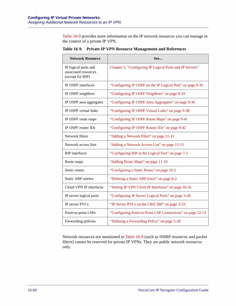
Beta Draft ConfidentialConfiguring IP Virtual Private NetworksAssigning Additional Network Resources to an IP VPN
Table 16-9 provides more information on the IP network resources you can manage inthe context of a private IP VPN.
Network resources not mentioned in Table 16-9 (such as NHRP resources and packetfilters) cannot be reserved for private IP VPNs. They are public network resourcesonly.
Table 16-9. Private IP VPN Resource Management and References
Network Resource See...
IP logical ports andassociated resources(except for RIP)
Chapter 3, “Configuring IP Logical Ports and IP Servers”
IP OSPF interfaces “Configuring IP OSPF on the IP Logical Port” on page 9-30
IP OSPF neighbors “Configuring IP OSPF Neighbors” on page 9-34
IP OSPF area aggregates “Configuring IP OSPF Area Aggregates” on page 9-36
IP OSPF virtual links “Configuring IP OSPF Virtual Links” on page 9-38
IP OSPF route maps “Configuring IP OSPF Route Maps” on page 9-41
IP OSPF router IDs “Configuring IP OSPF Router IDs” on page 9-42
Network filters “Adding a Network Filter” on page 11-13
Network access lists “Adding a Network Access List” on page 11-15
RIP interfaces “Configuring RIP at the Logical Port” on page 7-1
Route maps “Adding Route Maps” on page 11-18
Static routes “Configuring a Static Route” on page 10-2
Static ARP entries “Defining a Static ARP Entry” on page 6-2
Cloud VPN IP interfaces “Setting IP VPN Cloud IP Interfaces” on page 16-35
IP server logical ports “Configuring IP Server Logical Ports” on page 3-28
IP server PVCs “IP Server PVCs on the CBX 500” on page 3-33
Point-to-point LSPs “Configuring Point-to-Point LSP Connections” on page 12-13
Forwarding policies “Defining a Forwarding Policy” on page 5-28
16-60 NavisCore IP Navigator Configuration Guide
Beta Draft ConfidentialConfiguring IP Virtual Private Networks
Telneting Into an IP VPN
Telneting Into an IP VPN
You can telnet into a switch console within the context of an IP VPN. You can thenmanage resources assigned to the IP VPN on that switch using console commands.This feature allows customers to telnet from CPE into switches.
To telnet into a switch console within the context of an IP VPN:
1. Issue the telnet command and supply an IP address assigned to the IP VPN on theswitch. The IP address can be assigned to an ingress IP interface or to an IP VPNcloud interface.
2. When prompted for a password, specify the IP VPN’s telnet password. Thispassword was defined when the IP VPN was added. See “Adding an IP VPN” onpage 16-28 for more information on adding an IP VPN.
For example, suppose that an IP VPN has an ingress IP interface (193.2.1.5) and an IPVPN cloud interface (132.125.1.1) on a switch. You could specify either IP addresswhen you issue the telnet command. You decide to use the IP address assigned to theingress IP interface:
telnet 193.2.1.5
The telnet password defined for the IP VPN is “boston.” When prompted for thepassword, you would specify “boston.”
You can also telnet to a switch within the context of the public IP VPN. Once loggedin, you can issue the login ipvpn command to enter the context of a private IPVPN. See the next section for more information.
Do not use the HP OpenView telnet feature (accessed through Misc� TerminalConnect) to telnet to a switch within an IP VPN context. Instead, use a telnetprogram that is not part of HP OpenView.
If Radius authentication is enabled for the IP VPN, a Radius server mustauthenticate the telnet login. Otherwise, the login will fail.
It is not possible to telnet from one IP VPN to another; you can only telnet withinan IP VPN.
Avoid starting a telnet session while you are in a telnet session. This usesadditional memory.
NavisCore IP Navigator Configuration Guide 1/14/0216-61

Beta Draft ConfidentialConfiguring IP Virtual Private NetworksLogging in to an IP VPN at the Switch Console
Logging in to an IP VPN at the Switch Console
You can telnet to the switch in the context of the public IP VPN and then log in to aprivate IP VPN at the switch console. If you do this, any console commands you issueact on the IP VPN only.
When you telnet to the switch, you can login at the switch console with the standardconsole password. Then, issue the login ipvpn command as follows:
login ipvpn vpn_id
You specify the ID of the IP VPN for vpn_id. For example, the following commandlogs you into IP VPN 2:
login ipvpn 2
After you issue the command, you are prompted for a password. Enter the telnetpassword that was defined for the IP VPN when it was added. See “Adding an IPVPN” on page 16-28 for more information on adding an IP VPN.
To exit an IP VPN, type exit and press Return at the console prompt.
To determine the IDs of IP VPNs that have a virtual router on the switch, type thefollowing command:
show ip vrouter
The console output displays the IDs of all the IP VPNs in the “VPN” column.
Through NavisCore, you can also view IP VPN IDs by selecting Lucent IP Parameters� Set All IP VPNs from the NavisCore Administer menu.
16-62 NavisCore IP Navigator Configuration Guide
NavisCore IP Navigator Configuration Guide
Beta Draft Confidential
A
PRAM Upload
This appendix describes the uses for the Upload PRAM feature and supported IPobjects. For complete details about Upload PRAM, see the NavisCore NMS GettingStarted Guide.
Using the Upload PRAM Command
Occasionally, the switch configuration file for a specific I/O module and theconfiguration stored in the NMS database do not match. This situation can occur whenyou upgrade your switch software, use a network management product to manage theswitch, or use the MIB to change a switch configuration.
To resolve PRAM conflicts, use the Upload PRAM function to view the switchconfiguration file stored in PRAM. This enables you to compare the configuration filein the switch (PRAM) to the configuration file in the NMS database.
If you remove an I/O Module from one switch and install this module in asecond switch, you get a PRAM conflict. This happens because the modulecontains an unknown configuration. Do not use PRAM upload to clear thiscondition. Instead, use the Erase PRAM function to clear PRAM on this module;then reconfigure the module. Refer to the NavisCore Getting Started Guide formore information.
A-1
Beta Draft ConfidentialPRAM UploadUsing Upload PRAM After Configuring IP Objects
Using Upload PRAM After Configuring IP Objects
Before you use the Upload PRAM function, review the following points:
• If you configure IP parameters using the console commands instead of usingNavisCore, you need to upload the switch configuration to the NMS database. Seethe NavisCore Getting Started Guide for detailed instructions about how to uploada switch configuration file.
• You can use Upload PRAM to add objects from switch PRAM to the NMSdatabase, as long as the objects being added do not conflict with existing objectsin the database; for example, if the NMS database already contains a switch with aswitch that you are adding, there would be a conflict.
• Due to the interdependency of objects with other objects in the database, becareful when you use Upload PRAM to delete objects from the database. Ingeneral, do not create a situation where there are dangling objects (i.e., an objectwithout a parent) in the switch before applying Upload PRAM.
For example, deleting a logical port without first deleting all associated individualaddresses or address screens, creates dangling objects and causes a problemduring the Upload PRAM process.
Upload PRAM currently does not support MPT Point-to-Point connections. Allother IP objects are supported. See the NavisCore Console Command ReferenceGuide for more information.
A-21/14/02 NavisCore IP Navigator Configuration Guide
NavisCore IP Navigator Configuration Guide
Beta Draft Confidential
B
Troubleshooting IP Navigator Problems
This appendix describes how to troubleshoot and understand IP Navigator problemson Lucent switches.
Identifying IP Navigator Problems
The first thing to remember when troubleshooting IP Navigator problems on a Lucentswitch is that the problem may not be directly related to IP. The problem may berelated instead to one of the following causes:
• Hardware failure, such as a bad cable.
• Data link protocols that encapsulate IP packets.
IP packets that pass through Lucent switches are encapsulated in one of the followingprotocols:
Frame Relay — Frame headers encapsulate IP packets that are forwarded over FrameRelay circuits.
ATM — ATM cell headers encapsulate IP packets that are forwarded over ATMcircuits.
Ethernet — Ethernet headers encapsulate IP packets that are forwarded over EthernetLANs.
PPP — PPP headers encapsulate IP packets that are forwarded over PPP interfaces.
When IP Navigator problems occur, you should first determine if Frame Relay, ATM,or Ethernet problems also exist. Check for traps, changes in network map objectcolors, LEDs changing from green to red, and user complaints that might indicate thepresence of Frame Relay, ATM, or Ethernet problems. If problems in any of theseareas coincide with IP problems, one (or more) of these areas may be the source of theproblem. For more information on troubleshooting Frame Relay problems and ATMproblems, refer to the Naviscore Troubleshooting Guide (Product Code: 80104).
B-1

Beta Draft ConfidentialTroubleshooting IP Navigator ProblemsIsolating IP Navigator Problems
Isolating IP Navigator Problems
If you determine that the problem is related to IP Navigator, then the problem isprobably the result of configuration errors, such as a misconfigured IP address, ARPentry, routing table entry, or route maps.
You can isolate IP Navigator problems by performing the following steps:
1. Determine which nodes are unreachable (for example, switches, routers, hosts).
2. Determine the physical paths to the unreachable nodes.
3. Check the connections and configurations of each node and interface along thepath (for example, routing tables, ARP entries, IP forwarding statistics).
4. Consult other administrative personnel. For example, you may determine that thesource of the problem lies with customer premise equipment (CPE) at a customersite, and you need the assistance of administrative personnel at that site to correctthe problem.
Verifying IP Navigator Problems
Use the NMS and console commands to help you verify IP Navigator problems. Inparticular, use the IP attributes and statistics described in the NavisCore DiagnosticsGuide (Product Code: 80105) to verify the presence of problems, as well as traditionalIP troubleshooting tools such as ping and traceroute. Additionally, use the showip forward statistics command, described in “IP Forwarding ConsoleCommands” on page B-66.
IP Navigator Limitations
The IP Navigator limits for this release are described in the "IP Navigator Limits"section in the Software Release Notice (SRN) for your switch software. Unlessotherwise noted, the public and private IP VPN limits apply to both the B-STDX8000/9000 and the CBX 500.
B-21/14/02 NavisCore IP Navigator Configuration Guide
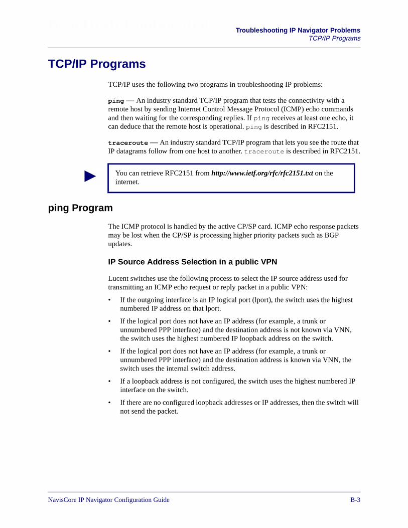
Beta Draft Confidential Troubleshooting IP Navigator ProblemsTCP/IP Programs
TCP/IP Programs
TCP/IP uses the following two programs in troubleshooting IP problems:
ping — An industry standard TCP/IP program that tests the connectivity with aremote host by sending Internet Control Message Protocol (ICMP) echo commandsand then waiting for the corresponding replies. If ping receives at least one echo, itcan deduce that the remote host is operational. ping is described in RFC2151.
traceroute — An industry standard TCP/IP program that lets you see the route thatIP datagrams follow from one host to another. traceroute is described in RFC2151.
ping Program
The ICMP protocol is handled by the active CP/SP card. ICMP echo response packetsmay be lost when the CP/SP is processing higher priority packets such as BGPupdates.
IP Source Address Selection in a public VPN
Lucent switches use the following process to select the IP source address used fortransmitting an ICMP echo request or reply packet in a public VPN:
• If the outgoing interface is an IP logical port (lport), the switch uses the highestnumbered IP address on that lport.
• If the logical port does not have an IP address (for example, a trunk orunnumbered PPP interface) and the destination address is not known via VNN,the switch uses the highest numbered IP loopback address on the switch.
• If the logical port does not have an IP address (for example, a trunk orunnumbered PPP interface) and the destination address is known via VNN, theswitch uses the internal switch address.
• If a loopback address is not configured, the switch uses the highest numbered IPinterface on the switch.
• If there are no configured loopback addresses or IP addresses, then the switch willnot send the packet.
You can retrieve RFC2151 from http://www.ietf.org/rfc/rfc2151.txt on theinternet.
NavisCore IP Navigator Configuration Guide 1/14/02B-3

Beta Draft ConfidentialTroubleshooting IP Navigator ProblemsTCP/IP Programs
IP Source Address Selection in a private VPN
Lucent switches use the following process to select the IP source address used fortransmitting an ICMP echo request or reply packet in a private VPN:
• If the outgoing interface is an IP lport, the switch uses the highest numbered IPaddress on that lport.
• If the logical port does not have an IP address, the switch uses the highestnumbered IP interface on the switch, including the cloud interface.
ping Extended Options
To run the ping program with extended options, you must log in as a privileged user.The following options are available when ping is run with extended options:
Destination address – Specify the destination IP.
Number of datagrams –– Specify the number of packets to transmit. The default is 5and there is no range.
Data Length –– Specify the packet data length. The default is 100 and the range is 1to 65507.
Vary data length –– Specify the default value by entering yes, or enter no to specifythe starting data length (range is 0 to 100) and data length increment (range is 1 to65507).
Timeout in seconds –– Specify the timeout in seconds. The default is 2 and the rangeis 1 to 120.
Source address –– Specify the source address. The local IP address should be anaddress on the Lucent switch.
Set DF Bit — Specify the Set DF Bit. The default is no. All fragmented packets willbe discarded. Enter yes to set the fragment bit to forward fragmented packets.
Data pattern — Select the default or enter a unique data pattern.
The ping program may timeout if any of the following conditions occur:
• The user specified an incorrect IP address.
• The destination IP interface is down.
• There is a problem with the cabling.
B-41/14/02 NavisCore IP Navigator Configuration Guide
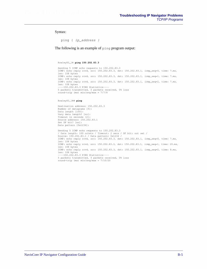
Beta Draft Confidential Troubleshooting IP Navigator ProblemsTCP/IP Programs
Syntax:
ping { ip_address }
The following is an example of ping program output:
Rowley83_1# ping 150.202.83.3
Sending 5 ICMP echo requests to 150.202.83.3ICMP: echo reply rcvd, src: 150.202.83.3, dst: 150.202.83.1, icmp_seq=0, time: 7.ms,len: 108 bytesICMP: echo reply rcvd, src: 150.202.83.3, dst: 150.202.83.1, icmp_seq=1, time: 7.ms,len: 108 bytesICMP: echo reply rcvd, src: 150.202.83.3, dst: 150.202.83.1, icmp_seq=2, time: 7.ms,len: 108 bytes----150.202.83.3 PING Statistics----5 packets transmitted, 5 packets received, 0% lossround-trip (ms) min/avg/max = 7/7/8
Rowley83_1## ping
Destination address: 150.202.83.3Number of datagrams [5]:Data length [100]:Vary data length? [no]:Timeout in seconds [2]:Source address: 150.202.83.1Set DF bit? [no]:Data pattern [0x1234]:
Sending 5 ICMP echo requests to 150.202.83.3/ Data length: 100 octets / Timeout: 2 secs / DF bit: not set /Source: 150.202.83.1 / Data pattern: 0x1234 /ICMP: echo reply rcvd, src: 150.202.83.3, dst: 150.202.83.1, icmp_seq=0, time: 7.ms,len: 108 bytesICMP: echo reply rcvd, src: 150.202.83.3, dst: 150.202.83.1, icmp_seq=1, time: 20.ms,len: 108 bytesICMP: echo reply rcvd, src: 150.202.83.3, dst: 150.202.83.1, icmp_seq=2, time: 8.ms,len: 108 bytes----150.202.83.3 PING Statistics----5 packets transmitted, 5 packets received, 0% lossround-trip (ms) min/avg/max = 7/10/20
NavisCore IP Navigator Configuration Guide 1/14/02B-5

Beta Draft ConfidentialTroubleshooting IP Navigator ProblemsTCP/IP Programs
traceroute Program
The traceroute program is handled by the CP/SP card. By default, tracerouteprovides the hop-by-hop path that an IP datagram takes to get to an IP destination.
Usage of the mpt keyword shows the ingress switch and the egress switch in thecircuit data path that the MPT takes to get to an IP destination. A transit node will notrespond to a traceroute request because the LSP leaf node at the ingress of the cloudwill forward any packet with a TTL > 1 over an LSP to the root node. A transit switchwill respond to a traceroute request if MPTs are disabled and an IP interface orloopback is configured.
traceroute traces an IP route until one of the following conditions occur:
• The IP datagram reaches its final destination.
• The connection break point is identified.
Syntax:
traceroute [mpt ip-address | ip-address]
traceroute IP Address Selection
Lucent switches use the following process to select the IP address used for replying toa traceroute request:
• If the outgoing interface is an IP logical port (lport), the switch uses the highestnumbered IP address on that lport.
• If the logical port does not have an IP address (for example, a trunk orunnumbered PPP interface) and the destination address is not known via VNN,the switch uses the highest numbered IP loopback address on the switch.
• If the logical port does not have an IP address (for example, a trunk orunnumbered PPP interface) and the destination address is known via VNN, theswitch uses the internal switch address.
• If a loopback address is not configured, the switch uses the highest numbered IPinterface on the switch.
• If there are no configured loopback addresses or IP addresses, then the switch willnot send the packet.
The traceroute command functions the same for either a public VPN 0 or aprivate VPN.
B-61/14/02 NavisCore IP Navigator Configuration Guide

Beta Draft Confidential Troubleshooting IP Navigator ProblemsIP Navigator Diagnostic Utilities
IP Navigator Diagnostic Utilities
This section describes how to use the IP trace utility and the LSP trace utility anddescribes how to:
• Create a trace profile.
• Start a trace.
• Use the IP Trace commands with IP/VPNs.
Sample trace outputs, IP Trace command syntax, ctr command syntax, and trcommand syntax are also included in this section.
IP Trace Utility
The IP trace utility is a packet trace tool for troubleshooting IP-related networkproblems. This utility has a command line interface only; you cannot use it from theNMS.
To set up, start, and stop the IP packet trace, you use the set ip trace profilecommand. You can view the packet trace setup through the show ip traceprofile command.
The IP trace utility screen output displays:
• IP packet header information.
• Data, called the payload, that follows the IP header. The payload is inhexadecimal format.
See “Sample Trace Output” on page B-14 for an example of trace output.
You can perform a trace of incoming and/or outgoing IP packets on any of thefollowing:
• IP logical ports
• Ethernet management port on the B-STDX 8000/9000 CP, CBX 500 SP or GX500 NP.
• Control port, which acts as an interface between the CP/SP/NP and theIOMs/IOPs on the switch
Trace filters allow you to trace IP packets selectively. These filters include the fields inthe IP packet header (such as source IP address and destination port).
You must be in debug mode to issue the set ip trace profile command.To enter debug mode, issue the enable debug command from the switchconsole and specify the required password when prompted.
NavisCore IP Navigator Configuration Guide 1/14/02B-7
Beta Draft ConfidentialTroubleshooting IP Navigator ProblemsIP Navigator Diagnostic Utilities
Creating a Trace Profile
A trace profile consists of three parts:
• Trace filters
• Payload length
• Trace counter
Trace Filters
A trace profile includes one or more trace filters, which specify values that the IPpacket must match to be traced. For example, only IP packets that meet both of thefollowing criteria are traced:
• IP packets with a destination IP address of 131.100.110.1
• IP packets that carry HTTP data
If you do not specify a filter value, the default (“any”) is assumed. For example, if youdo not specify a source IP address, any source IP address is accepted.
Trace profiles are stored in memory only. They are never written to a permanentstorage area. When you reset a card, trace profile information is lost.
B-81/14/02 NavisCore IP Navigator Configuration Guide

Beta Draft Confidential Troubleshooting IP Navigator ProblemsIP Navigator Diagnostic Utilities
You can specify the following trace filters as part of a trace profile:
Source IP address with optional mask — Specify a valid source IP address. A maskcan be assigned although it is optional.
Destination IP address with optional mask — Specify a valid destination IPaddress. A mask can be assigned although it is optional.
Source port — Specify the source port. You can specify a name or a decimal number.The command supports the following names: TELNET, FTP, FTPDATA, HTTP,SNMP, SNMPTRP, TFTP, and BGP. Port numbers are described in RFC1700.
Destination port — Specify the destination port. You can specify a name or a decimalnumber. The command supports the following names: TELNET, FTP, FTPDATA,HTTP, SNMP, SNMPTRP, TFTP, and BGP. Port numbers are described in RFC1700.
Protocol — Specify the protocol type. You can specify a name or a decimal number.The command supports the following names: ICMP, IGMP, IPIP, TCP, UDP, EGP,OSPF, and RAW. Protocol numbers are described in RFC1700.
Type of Service (TOS) with optional mask — Specify a hexadecimal number thatidentifies the TOS (with optional mask).
Transmission direction (send, receive, or any) — Specify the direction oftransmission (send, receive, or any).
You specify each filter on a separate command line. For example, suppose that youwant to filter IP packets on the IP logical port identified by interface number 20, andyou want to specify three filters: a source IP address of 150.140.10.5, a source port ofHTTP, and you are only interested in filtering received packets. You would specify thefollowing commands to accomplish this:
set ip trace profile port 20 source_ip 150.140.10.5set ip trace profile port 20 source_port HTTPset ip trace profile port 20 direction receive
See “IP Trace Command Syntax” on page B-15 for more information about the syntaxthat you use to specify filters.
You can retrieve RFC1700 from http://www.ietf.org/rfc/rfc1700.txt on theInternet.
NavisCore IP Navigator Configuration Guide 1/14/02B-9
Beta Draft ConfidentialTroubleshooting IP Navigator ProblemsIP Navigator Diagnostic Utilities
Payload Length
The payload length is the number of bytes of data following the IP header to be traced.You can specify a payload length in the range of 0-100 for the control port and theEthernet management port, and 0-32 for IOMs/IOPs. The default value is 0 (zero).
The data_len keyword on the set ip trace profile command line allows youto specify the payload length. For example, the following command specifies apayload length of 32 bytes:
set ip trace profile port 20 data_len 32
See “IP Trace Command Syntax” on page B-15 for more information about commandsyntax.
Trace Counter
After you start a trace the trace counter increments each time an IP packet thatmatches the trace filter is detected. If you want to reset the counter, use the countoption. For example, the following command resets the counter to zero:
set ip trace profile port 20 count 0
See “IP Trace Command Syntax” on page B-15 for more information about commandsyntax.
When you view a profile using the show ip trace profile command, the countappears in the format value/value (for example, 5/0). The first value displays thenumber of IP packets that were displayed on the console screen. The second valuedisplays the number of IP packets that could not be displayed on the console screenfor performance reasons. For example, a count of 12/2 means that 12 packets weredisplayed, but two packets were not.
Deleting Trace Profiles
To delete a trace profile, use the deleted keyword. For example, the followingcommand deletes the trace profile associated with an IP logical port identified byinterface number 10:
set ip trace profile port 10 deleted
The payload starts immediately after the IP header and includes the TCP/UDPheader, if present. Any IP header options are not included.
For all IOPB cards and IOP3 cards on B-STDX 8000/9000 switches, a full 32bytes of payload cannot be traced. For these IOPs, no more than 12 payloadbytes can be traced in the send direction. All 32 bytes are traced in the receivedirection.
B-101/14/02 NavisCore IP Navigator Configuration Guide

Beta Draft Confidential Troubleshooting IP Navigator ProblemsIP Navigator Diagnostic Utilities
The following command deletes the trace profile associated with all the ports on theswitch:
set ip trace profile port all deleted
See “IP Trace Command Syntax” on page B-15 for more information about commandsyntax.
Starting a Trace
To start tracing, you must:
• Enable logging on the switch by issuing the following command from the switchconsole:
set logging on
• Start tracing by using the set ip trace profile command. You can starttracing on a single port, all the ports associated with an IOM/IOP, or all ports onthe switch.
On a Single Port
To start tracing on a single port, issue the following command:
set ip trace profile port port_id on
The port_id variable identifies the port and can be set to any of the followingvalues:
Interface # — An interface number that identifies an IP logical port. To determine theinterface numbers of IP logical ports on the switch, use the show ip lportcommand. The interface numbers appear in the IpLport column of the commandoutput.
ethernet — Specifies the Ethernet management port on the CP/SP/NP.
control — Specifies the control port on the CP/SP/NP.
You should create trace profiles before you start tracing. If you start tracing, andno trace filters exist, all of the filters are set to “any” by default and all IP packetsare output to the console screen.
NavisCore IP Navigator Configuration Guide 1/14/02B-11
Beta Draft ConfidentialTroubleshooting IP Navigator ProblemsIP Navigator Diagnostic Utilities
When you start tracing, the trace output appears on the console screen. See “SampleTrace Output” on page B-14 for more information. Some examples are shown below:
Examples:
To start tracing on the IP logical port identified by interface number 20.
set ip trace profile port 20 on
To start tracing on the Ethernet management port.
set ip trace profile port ethernet on
To start tracing on the control port.
set ip trace profile port control on
To stop tracing on a port, use the off keyword. See “IP Trace Command Syntax” onpage B-15 for more information about command syntax.
On All Ports Associated With an IOM/IOP
To start tracing on all ports associated with an IOM/IOP, issue the followingcommand:
set ip trace profile slot_id on
The slot_id variable identifies the slot number of the IOM/IOP.
B-121/14/02 NavisCore IP Navigator Configuration Guide
Beta Draft Confidential Troubleshooting IP Navigator ProblemsIP Navigator Diagnostic Utilities
When you start tracing, the trace output appears on the console screen. See “SampleTrace Output” on page B-14 for more information.
Example:
set ip trace profile slot 4 on
This command starts tracing for all of the IP logical ports associated with theIOM/IOP in slot 4.
To stop tracing on the IOM/IOP, use the off switch. See “IP Trace Command Syntax”on page B-15 for more information about command syntax.
On All Ports on the Switch
To start tracing on all ports on the switch, issue the following command:
set ip trace profile slot all on
When you start tracing, the trace output appears on the console. See “Sample TraceOutput” on page B-14 for more information.
To stop tracing on the entire switch, use the off switch.
See “IP Trace Command Syntax” on page B-15 for more information about commandsyntax.
Using the IP Trace Commands With IP VPNs
This section describes how to use the set ip trace profile and show iptrace profile commands with IP VPNs.
set ip trace profile
You can issue the set ip trace profile command only if you are logged into thepublic IP VPN (IP VPN 0) at the switch console. See “Configuring IP VirtualNetworks” in Chapter 16 for information about a public IP VPN and for informationabout logging in to an IP VPN.
Although you can issue the set ip trace profile command while logged in tothe public IP VPN only, you can still set up and start traces for other IP VPNs. To dothis, specify an IP VPN ID at the end of the command line. For example, the followingcommand starts a trace on the IP logical port identified by interface number 3 for IPVPN 2:
set ip trace profile port 3 on vpn 2
If you do not specify an IP VPN ID, the public IP VPN is assumed, by default.
NavisCore IP Navigator Configuration Guide 1/14/02B-13
Beta Draft ConfidentialTroubleshooting IP Navigator ProblemsIP Navigator Diagnostic Utilities
To view the IP VPN trace packets, you must log in to the IP VPN at the switch consoleafter you start the trace. To log in to an IP VPN at the switch console, you mustprovide the Telnet password assigned to that IP VPN when it was added. See theNavisCore IP Navigator Configuration Guide for a description of the Telnetpassword.
When you start a trace, only the contents of the IP packets associated with the IP VPN(IP VPN 2 in the above example) are displayed. When you configure trace profiles,only the profiles for the specified IP VPN are affected.
show ip trace profile
Unlike the set ip trace profile command, you can issue the show ip traceprofile command while logged in to any IP VPN at the switch console. When youissue the show ip trace profile command, it applies to the current IP VPNunless you specify the ID of another IP VPN at the end of the command line.
Sample Trace Output
The following sample illustrates trace output for an IP packet:
xx.xx ETH ip SND ckt=N/A prot=UDP tos=0x01 ttl=64 len=93s=154.72.1.5 d=152.148.30.129 sp=SNMP dp=34750 dlen=730x00 A1 87 BE 00 49 41 01 30 3F 02 01 00 04 07 6361 73 63 61
xx.xx CTL ip RCV ckt=N/A prot=ICMP tos=0x00 ttl=225 len=84s=154.72.1.2 d=154.72.1.5 type=ECHO-REQUEST0x08 00 EF C6 4D 47 00 00 35 78 0B 29 00 06 8F 47 08 090A 0B
The trace output provides the following information:
• Header information that differs depending on the protocol
• TCP and UDP data length and port
• IP packet type and port
• DLCI or VCI/VPI circuit identifier
Ethernet management ports on CPs and SPs do not handle IP VPN traffic. Tostart a trace on these ports, do not specify any IP VPN IDs on the set iptrace profile command line.
B-141/14/02 NavisCore IP Navigator Configuration Guide

Beta Draft Confidential Troubleshooting IP Navigator ProblemsIP Navigator Diagnostic Utilities
IP Trace Command Syntax
The syntax of the set ip trace profile command is as follows:
set ip trace profile port [interface # | ethernet | control]option
set ip trace profile port [interface # ]option vpn vpn_id
set ip trace profile slot [slot # | all ] option
set ip trace profile slot [slot # | all] option vpn vpn_id
options:[on | off | deleted]source_ip [ipaddr | ipaddr ipmask | any]dest_ip [ipaddr | ipaddr ipmask | any]source_port [port # | port name| any]dest_port [port # | port name | any]protocol [protocol # | protocol name | any]tos [tos hex value | tos_hex_value hex_mask ] | any]direction [send | receive | any]data_len payload_lengthcount value
The syntax of the show ip trace profile command is as follows:
show ip trace profile port [interface # | ethernet | control ]
show ip trace profile port [interface # ] vpn vpn_id
show ip trace profile slot [ slot # | all ]
show ip trace profile slot [ slot # | all ] vpn vpn_id
LSP Trace Utility
The LSP trace utility is used to trace the LSP call signalling sequence formultipoint-to-point Label Switched Paths (MPT LSPs), point-to-point Label SwitchedPaths (point-to-point LSPs), and multicast Label Switched Paths (LSPs).
You can use trace filters to select desired trace information dynamically from massivetrace statements. The LSP trace filtering utility enables you to use trace filters to selectonly the LSP trace information that you need. This utility is command-driven, and isavailable only at the switch console.
When you use LSP trace filtering, you specify cookie values for the destinationaddress, LSP ID, and exclusions. After setting up the filters, you can start the trace.
NavisCore IP Navigator Configuration Guide 1/14/02B-15
Beta Draft ConfidentialTroubleshooting IP Navigator ProblemsIP Navigator Diagnostic Utilities
The ctr command sets up the filters, and the tr command starts the trace. To usethese commands, you must enter debug mode on the switch by issuing the enabledebug command and supplying the correct password.
ctr Command Syntax
The syntax of the ctr command is:
ctr [appid] [card] [ctype] [dest_node] [mptid][exclusion]
The following parameters are used with the ctr command:
• appid is always 16 for LSPs.
• card specifies the slot number of the card used by the LSP.
• ctype specifies any combination of numbers from zero to six, where:
– 0 (zero) specifies that one through five should be turned on.
– 1 specifies an MPT LSP.
– 2 specifies a point-to-point LSP.
– 3 specifies a multicast LSP.
– 4 specifies an unknown LSP type (the default).
– 5 specifies all the error traces (the default).
– 6 specifies that the trace must match the user’s requirements.
• dest_node specifies the IP address of the destination (leaf) node, in hexadecimalformat.
• mptid specifies the ID of the LSP, which you can obtain by issuing the showmpt all command.
• exclusion is a hexadecimal number that specifies any combination of thefollowing values:
– 0x00000000 (the default) specifies no exclusion (everything included).
– 0x00000001 specifies that Hello PDUs/messages are excluded.
– 0x00000002 specifies that LSP enable/disable manager traces areexcluded.
– 0x00000003 specifies that LSP conversion traces are excluded.
B-161/14/02 NavisCore IP Navigator Configuration Guide

Beta Draft Confidential Troubleshooting IP Navigator ProblemsIP Navigator Diagnostic Utilities
tr Command Syntax
The syntax of the tr command is:
tr [ appid ] [ level ] [ output ] [ card ]
The following parameters are used with the tr command:
• appid is always 16 for LSPs.
• level specifies the trace level from one to eight. The level specifies the amountof information that you want in the trace, from the least information (one) to themost information 8 (eight). Zero (0) disables the trace.
• output specifies how the trace statements are output as follows:
– 0 (No output)
– 1 (Output to console)
– 2 (Debug)
– 3 (Output to both console and debug)
• card specifies the slot number of the card used by the LSP.
Sample LSP Trace Output
Example 1:
cheetah## ctr 16 8 1 0x01020304 1 0
cheetah## tr 16 8 1 8
In this example, the trace output displays all of the trace statements that apply to thecard in slot 8, according to the following criteria:
• The LSP type is MPT LSP (1).
• The IP address of the leaf node is 1.2.3.4 (0x01020304).
• The LSP ID is 1.
• The trace statements are output to console if the filter cannot determine whetherthe user’s requirements are met.
Example 2:
cheetah## ctr 16 8 12 0x0a0b0c0d 1 1
cheetah## tr 16 8 1 8
NavisCore IP Navigator Configuration Guide 1/14/02B-17
Beta Draft ConfidentialTroubleshooting IP Navigator ProblemsIP Navigator Diagnostic Utilities
In this example, the trace output displays all of the trace statements that apply to thecard in slot 8, according to the following criteria:
• The LSP types are MPT LSP (1) and point-to-point LSP (2).
• The IP address of the leaf node is 10.11.12.13 (0x0a0b0c0d).
• The LSP ID is 1.
• Ignore all of the hello messages or PDUs (1).
• The trace statements are output to console if the filter cannot determine whetherthe user’s requirements are met.
Example 3:
cheetah## tr 16 8 126 0x0a0b0c0d 2 3
cheetah## tr 16 8 1 8
In this example, the trace output displays all of the trace statements that apply to thecard in slot 8, according to the following criteria:
• The MPT type is MPT LSP (1) and point-to-point LSP (2).
• The IP address of the leaf node is 10.11.12.13.
• The MPT ID is 2.
• The trace statements associated with the hello PDU/messages and MPT LSPmanager are ignored.
• The trace statements are shown if they match the user’s requirements (this isspecified by the 6 at the end of 126).
B-181/14/02 NavisCore IP Navigator Configuration Guide
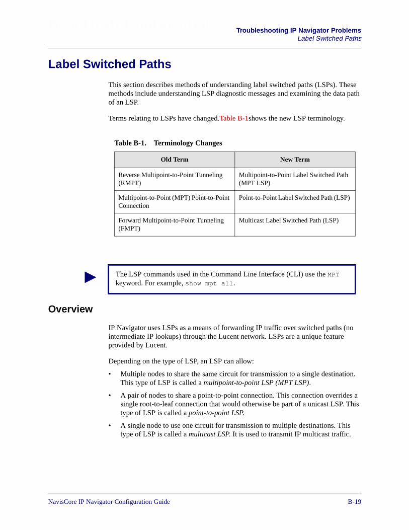
Beta Draft Confidential Troubleshooting IP Navigator ProblemsLabel Switched Paths
Label Switched Paths
This section describes methods of understanding label switched paths (LSPs). Thesemethods include understanding LSP diagnostic messages and examining the data pathof an LSP.
Terms relating to LSPs have changed.Table B-1shows the new LSP terminology.
Overview
IP Navigator uses LSPs as a means of forwarding IP traffic over switched paths (nointermediate IP lookups) through the Lucent network. LSPs are a unique featureprovided by Lucent.
Depending on the type of LSP, an LSP can allow:
• Multiple nodes to share the same circuit for transmission to a single destination.This type of LSP is called a multipoint-to-point LSP (MPT LSP).
• A pair of nodes to share a point-to-point connection. This connection overrides asingle root-to-leaf connection that would otherwise be part of a unicast LSP. Thistype of LSP is called a point-to-point LSP.
• A single node to use one circuit for transmission to multiple destinations. Thistype of LSP is called a multicast LSP. It is used to transmit IP multicast traffic.
Table B-1. Terminology Changes
Old Term New Term
Reverse Multipoint-to-Point Tunneling(RMPT)
Multipoint-to-Point Label Switched Path(MPT LSP)
Multipoint-to-Point (MPT) Point-to-PointConnection
Point-to-Point Label Switched Path (LSP)
Forward Multipoint-to-Point Tunneling(FMPT)
Multicast Label Switched Path (LSP)
The LSP commands used in the Command Line Interface (CLI) use the MPTkeyword. For example, show mpt all.
NavisCore IP Navigator Configuration Guide 1/14/02B-19

Beta Draft ConfidentialTroubleshooting IP Navigator ProblemsLabel Switched Paths
Both the MPT LSP and multicast LSP networks are rooted at the switch. A root is astandard circuit endpoint that is created at initialization time on every CP card in theB-STDX 8000/9000 and every SP card in the CBX 500. Traffic flow occurs from theleaves to the root on MPT LSPs, and from the root to the leaves on multicast LSPs. Onpoint-to-point MPT connections, traffic is bi-directional, since each node configuredon a point-to-point LSP connection acts as both a leaf and a root.
LSP Call Signalling
LSPs use a process called call signalling to set up virtual circuits and to determine thelabel switched path. Virtual circuits are used to forward IP traffic over label switchedpaths. A label switched path is a path with a circuit on it that allows data to beswitched instead of forwarded hop-by-hop.
The following list describes how the switch processes call signalling for a cell LSP:
1. As each cell IOM initializes on a CBX 500 root switch, the cell IOM sets upconnections to each forwarding engine on each frame IOM in the switch. Theseconnections allow LSP data that is received on the cell trunk to be forwarded tothe appropriate forwarding engine.
2. When OSPF determines that a node is reachable, it informs the LSP componentrunning on the SP. The LSP component then requests OSPF for a route to the leafnode.
3. The SP sends a Call Setup to the cell IOM. The LSP component on the cell IOMallocates a VPI and informs the hardware that the VPI is an LSP VPI.
4. A Call PDU is then sent to the next switch as follows:
a. At a transit node, the LSP component on the cell IOM receives the Call Setupand forwards the Call Setup to the next cell IOM.
b. At a leaf node, the LSP component on the cell IOM receives the Call Setupand forwards the Call Setup to the SP.
5. The SP receives the Call Setup and sends a confirmation back to the LSP rootindicating which FE with IP interfaces it has on its node.
6. At the root node, the LSP component on the SP receives the Confirm message andallocates a RID for each FE with IP interfaces at the leaf.
7. The LSP component on the SP informs each FE at the root about the RIDs that ithas allocated and sends a Call Setup to each FE at the leaf.
8. At the leaf node, the LSP component on the cell IOM receives the call setup andforwards each Call Setup to the appropriate FEs.
See “What Are Label Switched Paths?” on page 12-2 for more information aboutLSPs.
B-201/14/02 NavisCore IP Navigator Configuration Guide

Beta Draft Confidential Troubleshooting IP Navigator ProblemsLabel Switched Paths
LSP Call Forwarding
LSPs use a process known as call forwarding to forward IP data over label switchedpaths.
The CBX 500 call forwarding functions for a cell circuit as follows:
1. At the leaf node, the FE determines that data can be forwarded on an LSP. The FEsegments the IP packet into ATM cells and inserts the MPT VCI into the cellheader. The ATM cell is then sent across the switching fabric to the cell IOM.
2. At the transit node, the LSP cells are switched on virtual paths until they reach theLSP root.
3. At the root node, if the LSP cell is received on a cell IOM, the IOM determines thecell is an LSP based on its VPI. The IOM examines the first five bits of the VCI todetermine which FE will receive the ATM cell. The VPI bits are used to separatestreams of multiple LSPs.
4. At the root node, if the LSP cell is received on the frame IOM, the cells arereassembled based on the RID (found in the remaining 11 bits of the VCI). Oncethe packet is reassembled, another IP lookup is performed and the data isforwarded out of the physical interface.
MPT LSP Information and Restrictions
This section describes the MPT LSP network configuration requirements and knownrestrictions.
MPT LSP Configuration Prerequisites
MPT LSPs must be enabled at the switch and at least one IP interface must exist for aswitch to act as an MPT LSP root or a leaf.
An IP interface is not required if the switch is a boundary node. For example, aboundary node can be one of the following:
• OSPF area border router (ABR)
• Transit 9000 switch within a cell network
• Frame/cell domain border router
• Optimum trunk border router
NavisCore IP Navigator Configuration Guide 1/14/02B-21
Beta Draft ConfidentialTroubleshooting IP Navigator ProblemsLabel Switched Paths
VNN OSPF Domains
MPT LSPs cannot traverse multiple VNN OSPF domains (areas). However,point-to-point LSPs and multicast LSPs can traverse multiple VNN OSPF domains.
Within a single VNN OSPF domain, MPT LSPs are switched. However, as soon astraffic reaches an area boundary (that is, an area border router), a routing lookup mustbe made and the MPT LSP traffic must be switched to a new LSP.
Switch Domains
MPT LSPs and point-to-point LSPs are only established between switches in the samedomain. Multicast LSPs can be established between switches in different domains.
There are two types of switch domains. A cell domain is a path that traverses directATM trunks and ATM OPTimum trunks. A frame domain is a path that traverse directframe trunks and frame OPTimum trunks.
A switch that only belongs to one domain cannot add a switch from a different domainto its LSP. To traverse different domains, a boundary switch that belongs to bothdomains must act as an intermediary. Each endpoint switch connects to the boundaryswitch via a separate LSP, and the boundary switch performs an IP lookup whenrouting traffic between the endpoints.
OPTimum Trunks
The following criteria applies to OPTimum trunks:
• OPTtimum Trunk VPI attributes must not overlap. For instance, the VPC VPIStart and Stop range and the Transit LSP and point-to-point LSP VPI Start andStop values must not overlap with the OPTimum Trunk VPI, the LSP VPI value,or the OPTimum trunk value of a different lport on the same physical port.
• MPT LSPs must use even VPI values between 2-30 and point-to-point LSPs mustuse odd VPI values between 1-2047.
• The OPTimum Trunk range cannot overlap with the values that are configured forVirtual UNIs on the same physical port or the OPTimum trunk value of a differentlport on the same physical port.
• The OPTimum Trunk VPI values do not have to match when data is forwardedfrom the root to the leaf and the trunk traverses an intermediate ATM network.
One exception to this rule is when the leaf is a CBX 500 and the root is a B-STDX8000/9000.
B-221/14/02 NavisCore IP Navigator Configuration Guide
Beta Draft Confidential Troubleshooting IP Navigator ProblemsLabel Switched Paths
• Switches that act as OPTimum cell trunk endpoints cannot also be point-to-pointLSP endpoints.
– A switch configured as an OPTimum cell trunk endpoint can act as a transitswitch for point-to-point LSPs.
– If you configure a switch as both an OPTimum cell trunk endpoint and as apoint-to-point LSP endpoint, the point-to-point LSP will fail to establish.
• On the B-STDX 8000/9000 and CBX 500, the logical port OPTimum trunk VPIvalue that is configured in the NMS, is used for VCC connections that are neededfor IP network management and VC manager control.
Parallel Paths
An MPT LSP or point-to-point LSP will not establish when the path between twonodes contain an IP interface with a lower administrative cost than the configuredtrunks. If the IP interface is not running OSPF, the trunk will be used because OSPF ispreferred. For example, if a parallel IP link and trunk exists between two nodes, theLSP will not establish because the IP link offers the shortest path.
Traffic Descriptors
The MPT LSP Committed Information Rate (CIR) specifies the rate in Kbps at whichMPT LSPs transfer data, averaged over a minimum increment of time. In addition, thisvalue reserves bandwidth for MPT LSPs, which the switch originates.
The CIR value is based on the available line rate. The minimum CIR is 100. CIR isused as the minimum cell rate (MCR) of the available bit rate (ABR) LSP.
Disabling MPT LSP
Disabling MPT LSP on a switch prevents the node from acting as a root or a leaf to anMPT LSP.
To enable or disable MPT LSPs on a switch:
1. Select the switch on the network map.
2. From the Administer menu, choose Lucent IP Parameters� Set IP Parameters.The Set IP Parameters dialog box appears.
3. In the Set IP Parameters dialog box, set the MPT LSP option to disable to disableMPT LSPs or enable to enable MPT LSPs.
NavisCore IP Navigator Configuration Guide 1/14/02B-23
Beta Draft ConfidentialTroubleshooting IP Navigator ProblemsLabel Switched Paths
Point-to-Point LSP Information and Restrictions
The following criteria applies to point-to-point LSPs:
• A point-to-point LSP can traverse different OSPF areas and VPN areas.
• A point-to-point LSP does not support CBR QoS Class.
• The GX 550 cannot be a transit node for a point-to-point LSP in a frame domain.
• A point-to-point LSP in a cell domain will not establish if one of the transit nodesis a B-STDX 8000/9000 switch or if a cell optimum trunk is directly connected toa border node.
VNN OSPF Domains
Point-to-point LSPs can cross VNN OSPF domains.
Switch Domains
Point-to-point LSPs can not cross cell/frame domains.
OPTimum Trunks
The OPTimum trunk restrictions that apply to MPT LSPs also apply to point-to-pointLSPs. See “OPTimum Trunks” on page B-22 for a description of these restrictions.
Multicast LSP Information and Restrictions
Disabling multicast LSP on a switch will cause multicast data to be forwardedhop-by-hop if the data is going over a frame trunk:
• If data is going over a cell trunk, only the VPN multicast packets are sent hop-byhop.
• All other multicast data is discarded.
VNN OSPF Domains
Multicast LSPs can cross OSPF VNN domains.
Switch Domains
Multicast LSPs can cross cell/frame domains.
Point-to-point LSPs are operational when MPT LSPs are disabled on a switch.
B-241/14/02 NavisCore IP Navigator Configuration Guide

Beta Draft Confidential Troubleshooting IP Navigator ProblemsLabel Switched Paths
LSP Terms
Many of the following terms are used in the command line display output and can beused in a troubleshooting discussion.
Table B-2. LSP Terms/Acronyms
Term/Acronym Description
Cell Domain A network configuration of pure direct ATM trunks and ATMOptimum trunks. MPT LSPs and point-to-point LSPs do not crosscell/frame domain boundaries. Multicast LSPs do cross cell/framedomains boundaries.
Child VirtualCircuit
On the CBX 500 leaf node, the child virtual circuit (vc) receives dataon the ingress card.
FE A forwarding engine (FE) on an Ethernet or Frame IOM2. FEsreassemble cells and perform IP lookups. There are two FEs in eachof the CBX 500 Ethernet and Frame cards, one FE on the CBX 500Channelized DS3 card, and one FE on the B-STDX 8000/9000Ethernet card.
FE ID The forwarding engine identifier (FE ID) is a five bit field thatidentifies the forwarding engine at the root. Four bits of the FE IDindicate which slot the frame card is in and the other bit indicateswhich FE is on the frame card (zero or one).
Frame Domain A network configuration of direct frame trunks and frame OPTImumtrunks. MPT LSPs and point-to-point LSPs do not cross cell/framedomain boundaries. Multicast LSPs do cross cell/frame domainsboundaries.
Leaf An LSP leaf is the source of data that is forwarded over the LSP. Aleaf can either be on a B-STDX 8000/9000 CP or a forwardingengine (FE) on a Frame IOM on the CBX 500.
LSP VCI The LSP VCI is made up of the 11 bit RID and the 5 bit FE ID. Thisinformation provides the source identifier and destination ID.
mptID The LSP virtual circuit identifier is the value shown in the VCcolumn of the show mpt vcarray command. Similarly referredto as fmID.
mptTport A mptTport maintains state for downstream (nodes further awayfrom the root) connections from the point of view of the parent.
Parent VirtualCircuit
On the CBX 500 leaf node, the parent virtual circuit (vc) forwardsdata on the egress card.
Parent Function The parent function on a CBX 500 aggregates cell streams into acommon VP and delivers them upstream to the root.
NavisCore IP Navigator Configuration Guide 1/14/02B-25
Beta Draft ConfidentialTroubleshooting IP Navigator ProblemsLabel Switched Paths
RID The reassembly identifier (RID) is used when forwarding data to thesource (root). The RID allows the root to know which sourceFE/node a cell came from when cells are interleaved on the samedefault connection between the frame card and the cell card.
Root An LSP root is the destination switch of data that is forwarded overthe LSP. A root is anchored on the SP or CP and is created at switchinitialization. The root tracks the state of other nodes or FEs on thenetwork that belong to the LSPs.
RVc The RVc found in the show mpt vcarray command output is theremote VC in the LSP chain.
RVC vctype On the B-STDX, a RVC virtual circuit (vc) is used to send data to aCBX 500 or receive data from either a CBX 500 or a B-STDX8000/9000.
tleaf An LSP tleaf represents the source endpoint node and forwardingengine (FE) state of the leaves.
vcarray A vcarray is the set of virtual circuit entries for the specified node orcard.
VCC The B-STDX 8000/9000 switch uses a virtual channel connection(VCC) for each LSP crossing an optimum trunk.
vcentry A vcentry is a data structure used to store information about a virtualcircuit.
vcID The vcID is the internal local VC identifier of the LSP circuit used toforward the IP data.
vctype The vctype is a parent, child, FE, RVC, root or a leaf.
A FE type is a forwarding engine vcentry type on a leaf or root 500.
VPC The CBX 500 switch uses a virtual path connection (VPC) for eachLSP.
VPI The CBX 500 switch uses a virtual path identifier (VPI) for each LSPcrossing an optimum trunk.
Table B-2. LSP Terms/Acronyms (Continued)
Term/Acronym Description
B-261/14/02 NavisCore IP Navigator Configuration Guide
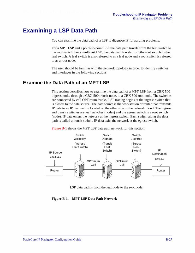
Beta Draft Confidential Troubleshooting IP Navigator ProblemsExamining a LSP Data Path
Examining a LSP Data Path
You can examine the data path of a LSP to diagnose IP forwarding problems.
For a MPT LSP and a point-to-point LSP the data path travels from the leaf switch tothe root switch. For a multicast LSP, the data path travels from the root switch to theleaf switch. A leaf switch is also referred to as a leaf node and a root switch is referredto as a root node.
The user should be familiar with the network topology in order to identify switchesand interfaces in the following sections.
Examine the Data Path of an MPT LSP
This section describes how to examine the data path of a MPT LSP from a CBX 500ingress node, through a CBX 500 transit node, to a CBX 500 root node. The switchesare connected by cell OPTimum trunks. LSP tracing begins at the ingress switch thatis closest to the data source. The data source is the workstation or router that transmitsIP data to an IP destination located on the other side of the network cloud. The ingressand transit switches are leaf switches (nodes) and the egress switch is a root switch(node). IP data enters the network at the ingress switch. Each switch along the datapath is called a transit switch. IP data exits the network at the egress switch.
Figure B-1 shows the MPT LSP data path network for this section.
Figure B-1. MPT LSP Data Path Network
LSP data path is from the leaf node to the root node.
OPTimumCell
500
500
500
RouterRouter
OPTimumCell
SwitchWellesley
(IngressLeaf Switch)
IPDestination
150.1.1.2
SwitchBraintree
(EgressRoot
Switch)
SwitchDedham
(TransitLeaf
Switch)IP Source130.2.12.1
NavisCore IP Navigator Configuration Guide 1/14/02B-27
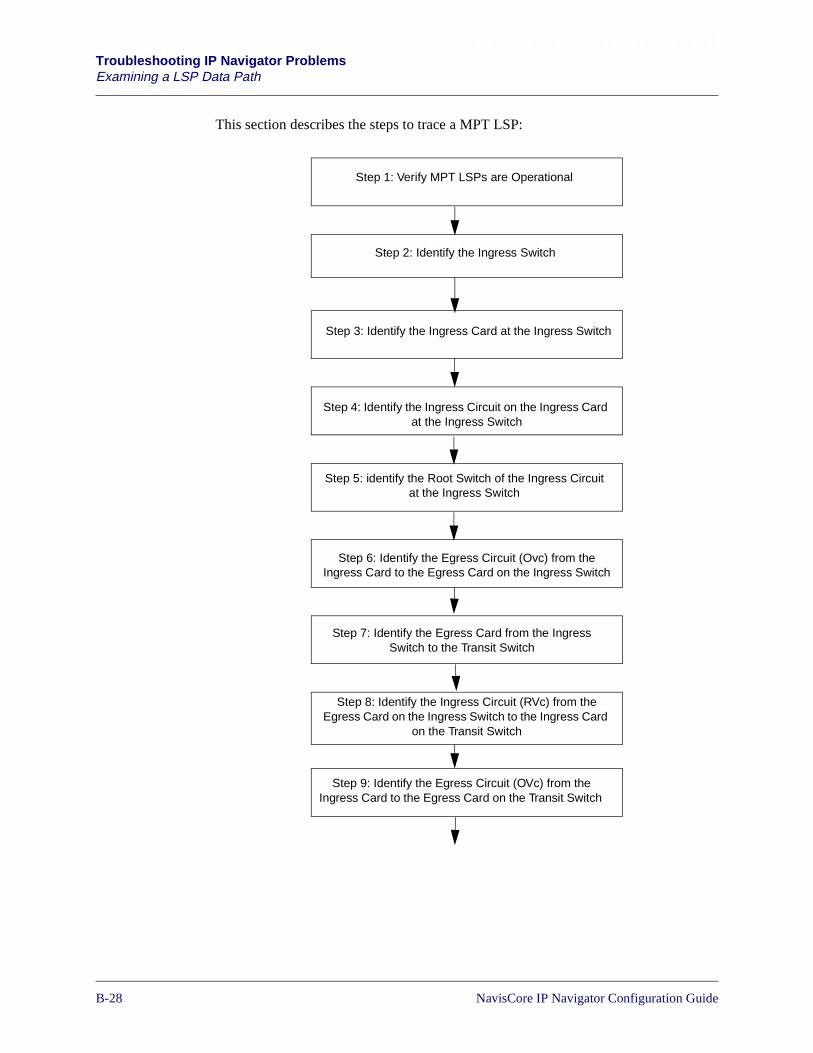
Beta Draft ConfidentialTroubleshooting IP Navigator ProblemsExamining a LSP Data Path
This section describes the steps to trace a MPT LSP:
Step 3: Identify the Ingress Card at the Ingress Switch
Step 4: Identify the Ingress Circuit on the Ingress Cardat the Ingress Switch
Step 5: identify the Root Switch of the Ingress Circuitat the Ingress Switch
Step 6: Identify the Egress Circuit (Ovc) from theIngress Card to the Egress Card on the Ingress Switch
Step 7: Identify the Egress Card from the IngressSwitch to the Transit Switch
Step 8: Identify the Ingress Circuit (RVc) from theEgress Card on the Ingress Switch to the Ingress Card
on the Transit Switch
Step 9: Identify the Egress Circuit (OVc) from theIngress Card to the Egress Card on the Transit Switch
Step 1: Verify MPT LSPs are Operational
Step 2: Identify the Ingress Switch
B-281/14/02 NavisCore IP Navigator Configuration Guide

Beta Draft Confidential Troubleshooting IP Navigator ProblemsExamining a LSP Data Path
Step 11: Identify the Egress Circuit and the FE at theRoot Switch
Step 10: Identify the Ingress Circuit (Rvc) from theEgress Card at the Transit Switch to the Ingress Card
at the Egress Switch
Step 12: Send IP Traffic Through the LSP Data Path toValidate Forwarding
NavisCore IP Navigator Configuration Guide 1/14/02B-29
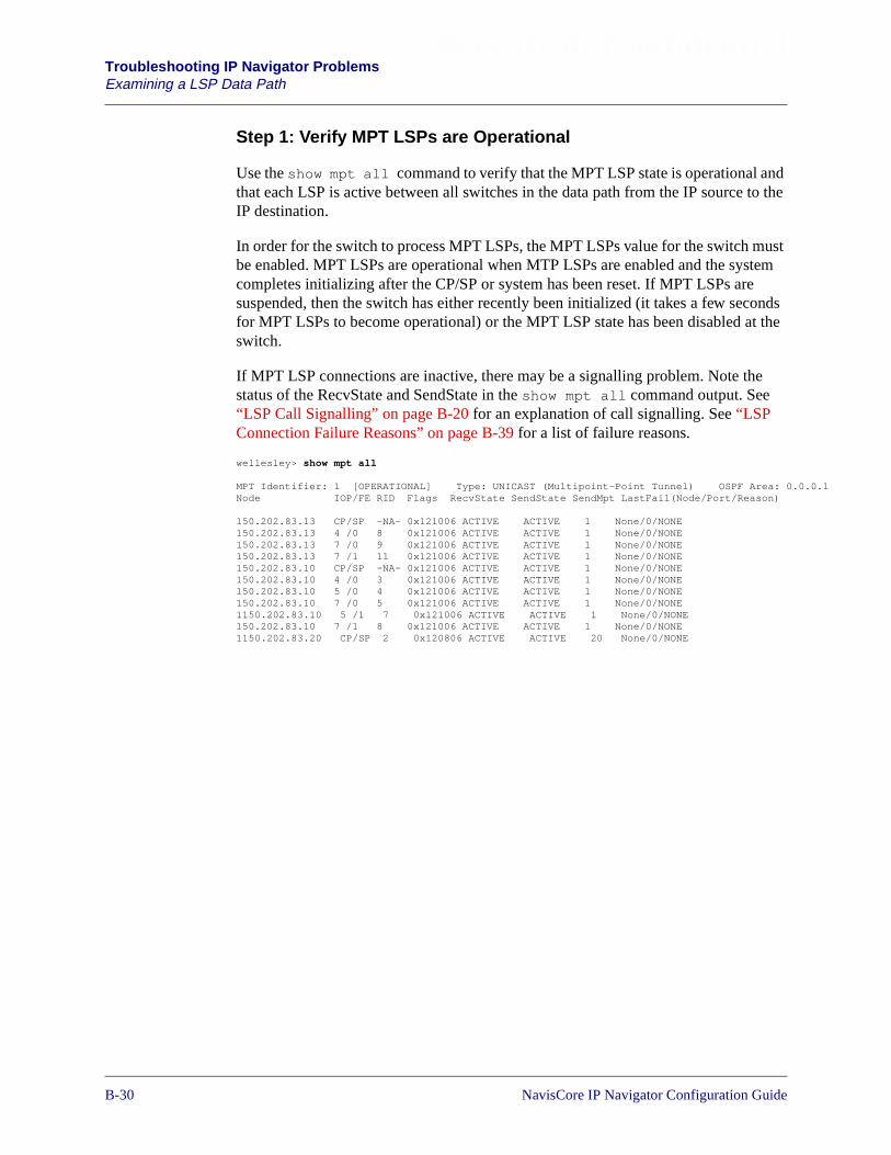
Beta Draft ConfidentialTroubleshooting IP Navigator ProblemsExamining a LSP Data Path
.0.1
Step 1: Verify MPT LSPs are Operational
Use the show mpt all command to verify that the MPT LSP state is operational andthat each LSP is active between all switches in the data path from the IP source to theIP destination.
In order for the switch to process MPT LSPs, the MPT LSPs value for the switch mustbe enabled. MPT LSPs are operational when MTP LSPs are enabled and the systemcompletes initializing after the CP/SP or system has been reset. If MPT LSPs aresuspended, then the switch has either recently been initialized (it takes a few secondsfor MPT LSPs to become operational) or the MPT LSP state has been disabled at theswitch.
If MPT LSP connections are inactive, there may be a signalling problem. Note thestatus of the RecvState and SendState in the show mpt all command output. See“LSP Call Signalling” on page B-20 for an explanation of call signalling. See “LSPConnection Failure Reasons” on page B-39 for a list of failure reasons.
wellesley> show mpt all
MPT Identifier: 1 [OPERATIONAL] Type: UNICAST (Multipoint-Point Tunnel) OSPF Area: 0.0Node IOP/FE RID Flags RecvState SendState SendMpt LastFail(Node/Port/Reason)
150.202.83.13 CP/SP -NA- 0x121006 ACTIVE ACTIVE 1 None/0/NONE150.202.83.13 4 /0 8 0x121006 ACTIVE ACTIVE 1 None/0/NONE150.202.83.13 7 /0 9 0x121006 ACTIVE ACTIVE 1 None/0/NONE150.202.83.13 7 /1 11 0x121006 ACTIVE ACTIVE 1 None/0/NONE150.202.83.10 CP/SP -NA- 0x121006 ACTIVE ACTIVE 1 None/0/NONE150.202.83.10 4 /0 3 0x121006 ACTIVE ACTIVE 1 None/0/NONE150.202.83.10 5 /0 4 0x121006 ACTIVE ACTIVE 1 None/0/NONE150.202.83.10 7 /0 5 0x121006 ACTIVE ACTIVE 1 None/0/NONE1150.202.83.10 5 /1 7 0x121006 ACTIVE ACTIVE 1 None/0/NONE150.202.83.10 7 /1 8 0x121006 ACTIVE ACTIVE 1 None/0/NONE1150.202.83.20 CP/SP 2 0x120806 ACTIVE ACTIVE 20 None/0/NONE
B-301/14/02 NavisCore IP Navigator Configuration Guide

Beta Draft Confidential Troubleshooting IP Navigator ProblemsExamining a LSP Data Path
Step 2: Identify the Ingress Switch
Use the traceroute command at the IP source to identify the Lucent switch that isclosest to the IP source and functions as the ingress switch to the network. This switchfunctions as an ingress node into the network cloud. In Figure B-1 on page B-27, thisis Switch Wellesley.
Step 3: Identify the Ingress Card at the Ingress Switch
At switch Wellesley, use the show ip interfaces command to identify the cardthat connects the switch to the IP source. The Pport column shows the ingress card andport information.
This example shows card 6 has a direct connection to the IP source.
Step 4: Identify the Ingress Circuit on the Ingress Cardat the Ingress Switch
At switch Wellesley, use the show ip route destination_ip slot_# fecommand to perform a route lookup of the destination IP address and to determine theingress circuit on the ingress card:
• Enter a complete host IP address for destination_ip. In this example, youwould enter 189.75.50.1 which is the IP address of the destination host.
• Enter the slot number for card that represents the ingress card identified in “Step3: Identify the Ingress Card at the Ingress Switch”.
• Enter the forwarding engine if the card is a CBX 500 Ethernet or Frame DS3 card.
wellesley> sho ip interfaces
IpAddr Lport Pport Card MTU ARP IARP OPER ADMIN
130.2.12.12/24 60 6.1 TFETHER-4 1500 ENA DIS UP ENA
wellesley> sho arp
IpAddr LinkType HwAddr State EntryType
130.2.12.1 ethernet 0050d197b039 Complete Dynamic
NavisCore IP Navigator Configuration Guide 1/14/02B-31

Beta Draft ConfidentialTroubleshooting IP Navigator ProblemsExamining a LSP Data Path
In this example, the ingress circuit is 159:
The route lookup display output shows important hop-by-hop and switchedinformation. If a switched circuit is not shown in the table, then the IP data isforwarded hop-by-hop. In the hop-by-hop row, the ‘*’ indicates there is not an ARPentry for the route (use the show arp command to view the arp table) and the nexthop route is probably a cell trunk. The ‘45’ indicates the egress lport identifier. In theswitched row, the ‘159’ value indicates the LSP virtual circuit. The TTL indicates thetotal number of hops the LSP takes to reach the destination node. The LSP circuit isalways 1 hop, from ingress to egress. The transit switches are not counted as hops.
Step 5: Identify the Root Switch of the Ingress Circuit
At switch Wellesley, use the show mpt rootnodes command to identify the rootswitch (node) and root egress card of the ingress circuit identified in the previous step.See “show mpt rootnodes” on page B-55 for a complete description of the command.Note that the command syntax varies for the CBX 500 and the B-STDX.
The command requires the following information:
• Specify the card identified in “Step 3: Identify the Ingress Card at the IngressSwitch”.
• Specify forwarding engine one (1) or two (2) Enter the forwarding engine if thecard is a CBX 500 Ethernet or Frame DS3 card.
• Specify the LSP virtual circuit identified in “Step 4: Identify the Ingress Circuit onthe Ingress Card at the Ingress Switch”.
In a complex network, the IP data path can traverse many MPT LSPs because ofborder router conditions. If the root switch terminates at a border router then the userneeds to perform another IP lookup to determine the next egress circuit. Border routerconditions are described in “VNN OSPF Domains” on page B-22.
wellesley> show ip route 150.1.1.2 6 1
Forwarding Engine : 1
Network: 150.1.1.0Mask: 255.255.255.0Flags:Hop-by-hop: [*, 45]Switched: [0x0/159, TTL: 1]
If the ingress or egress card is a cell trunk, you must perform the route lookupusing another card and lport that supports IP Routing. See “Logical Ports ThatSupport IP Routing on the B-STDX 8000/9000” on page B-66 and “LogicalPorts Supporting IP Routing on the CBX 500” on page B-67.
Use the show system command to locate one of these types of cards. Tospecify a forwarding engine, you enter the FE identifier after the slot number.
B-321/14/02 NavisCore IP Navigator Configuration Guide

Beta Draft Confidential Troubleshooting IP Navigator ProblemsExamining a LSP Data Path
In this example, the root node is 150.202.83.13 (switch Braintree). The egress card tothe IP destination on the root node is card 7. The feNum value of 2 representsforwarding engine 2. A value of 1 will represent forwarding engine 1.
Step 6: Identify the Egress Circuit (OVc) from the Ingress Cardto the Egress Card on the Ingress Switch
At switch Wellesley, use the show mpt rsvcarray ingress_card command todetermine the egress circuit from the ingress card to the egress card. Specify the cardthat was identified in “Step 3: Identify the Ingress Card at the Ingress Switch”.
In the vcarray display output, find the circuit (identified in “Step 4: Identify theIngress Circuit on the Ingress Card at the Ingress Switch”) in the VC column. On thesame line, find the egress circuit in the OVc column.
A VCI value is shown if the data is forwarded over a cell OPTimum trunk. The valueis used to calculate the card and forwarding engine on the root switch that the data isgoing to. This information is also available in the show mpt rootnodes commandused in step 5.
• Convert the decimal VCI value to binary.
• The FEID is contained in the upper five bits of the sixteen bit VCI.
• Of these five bits, the upper most bit represents the FE and the lower four bitsrepresents the slot.
• If the upper most bit (bit 16 of VCI) is zero, the data is destined to FE 1, otherwiseit is destined to FE 2.
• Adding a one to the value of the lower four bits of the FEID (bits 15-12),identifies the slot number that the data is destined to.
In the following example, the VCI is 45061.
10110 is the upper five binary bit value of the decimal value 45061.
The upper most bit ‘1’ represents FE 2, the lower four bits plus a value of onerepresents card 7.
Wellesley> show mpt rootnodes 6 1 159
MPT ckt/node Info: Card 6 FE 1
VcId RootNode Slot feNum mptID vpn159 150.202.83.13 7 2 1 0
NavisCore IP Navigator Configuration Guide 1/14/02B-33

Beta Draft ConfidentialTroubleshooting IP Navigator ProblemsExamining a LSP Data Path
s
In the following example, the OVc (egress circuit) is 908. The VCType is FE. Theegress card that has this egress virtual circuit is slot 10, port 2. The OPrt (45) is thelogical port identifier of the egress card. .
Step 7: Identify the Egress Card from the Ingress Switchto the Transit Switch
There are two methods to identify the egress card. You can simply use the IOP valueshown in the previous command or you can use the next two commands to identify theegress card. The advantage of using the following command is that these commandsidentify the next switch and ingress card in the signalling path to the root switch.
The show mpt spath command identifies all of the switches in the signalling pathfrom ingress switch, Wellesley, to the root switch, Braintree. Enter thenode_IP_address of the switch identified in “Step 5: Identify the Root Switch ofthe Ingress Circuit”.
The egress card is derived from the logical port identifier of the first node/lport pairshown in the show mpt spath display output. Use the show lport attributescommand to identify the logical port. The display output of this command will showthe remote node and remote interface.
In this example, the first node is 150.202.83.12 (switch Dedham), and the lportidentifier is for slot 10, port 2. Since the root node has been identified as switchBraintree, Dedham is a transit node in the signalling path to the root node.
wellesley> show mpt rsvcarray 6
VC VPN Type VCType State DNde OVc Mpt VPI VCI IOP PPrt LPort OPrt FEID OutFrames InFrame159 0 RMPT FE ACTIVE 530d 908 1 0 45061 10 2 3954 45 5 N/A-0 1
wellesley> show mpt spath 150.202.83.13
MPT in VPN 0:List of node/interface pairs in path to node 150.202.83.13:150.202.83.12/45, 150.202.83.10/156Path characteristics:PURE_CELL, FOR_IP, FE_ARCH, JADEM1_PATH, OSPF_PATH_REG
wellesley> show lport att 45
Slot: 10Port: 2Interface: 45Data Rate: 40640000
Trunk Status: Full Trunk Overhead: 5%Remote Node: 150.202.83.10 Remote Interface: 114
Trunk Out BW Out BWOversub.: Avail. Alloc.
Qos1 100% 91057 4792Qos2 100% 91057 0Qos3 100% 91057 0Qos4 100% 91057 0Administrative Status: Up Operational Status: Up
B-341/14/02 NavisCore IP Navigator Configuration Guide
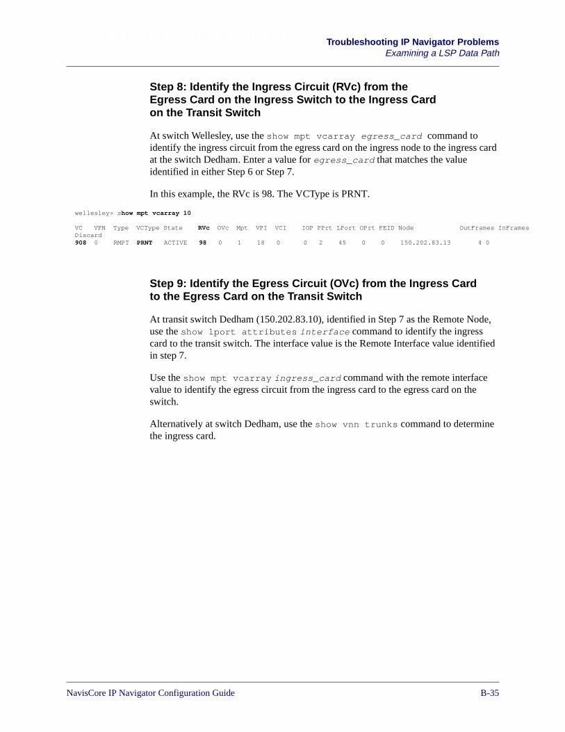
Beta Draft Confidential Troubleshooting IP Navigator ProblemsExamining a LSP Data Path
rames
Step 8: Identify the Ingress Circuit (RVc) from theEgress Card on the Ingress Switch to the Ingress Cardon the Transit Switch
At switch Wellesley, use the show mpt vcarray egress_card command toidentify the ingress circuit from the egress card on the ingress node to the ingress cardat the switch Dedham. Enter a value for egress_card that matches the valueidentified in either Step 6 or Step 7.
In this example, the RVc is 98. The VCType is PRNT.
Step 9: Identify the Egress Circuit (OVc) from the Ingress Cardto the Egress Card on the Transit Switch
At transit switch Dedham (150.202.83.10), identified in Step 7 as the Remote Node,use the show lport attributes interface command to identify the ingresscard to the transit switch. The interface value is the Remote Interface value identifiedin step 7.
Use the show mpt vcarray ingress_card command with the remote interfacevalue to identify the egress circuit from the ingress card to the egress card on theswitch.
Alternatively at switch Dedham, use the show vnn trunks command to determinethe ingress card.
wellesley> show mpt vcarray 10
VC VPN Type VCType State RVc OVc Mpt VPI VCI IOP PPrt LPort OPrt FEID Node OutFrames InFDiscard908 0 RMPT PRNT ACTIVE 98 0 1 18 0 0 2 45 0 0 150.202.83.13 4 0
NavisCore IP Navigator Configuration Guide 1/14/02B-35
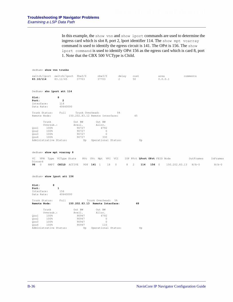
Beta Draft ConfidentialTroubleshooting IP Navigator ProblemsExamining a LSP Data Path
InFrames
N/A-0
In this example, the show vnn and show lport commands are used to determine theingress card which is slot 8, port 2, lport identifier 114. The show mpt vcarraycommand is used to identify the egress circuit is 141. The OPrt is 156. The showlport command is used to identify OPrt 156 as the egress card which is card 8, port1. Note that the CBX 500 VCType is Child.
dedham> show vnn trunks
switch/lport switch/lport fbw3/0 rbw3/0 delay cost area comments83.10/114 83.12/45 37703 37703 2 50 0.0.0.1
Dedham> sho lport att 114
Slot: 8Port: 2Interface: 114Data Rate: 40640000
Trunk Status: Full Trunk Overhead: 5%Remote Node: 150.202.83.12 Remote Interface: 45
Trunk Out BW Out BWOversub.: Avail. Alloc.
Qos1 100% 90727 4792Qos2 100% 90727 0Qos3 100% 90727 0Qos4 100% 90727 330Administrative Status: Up Operational Status: Up
dedham> show mpt vcarray 8
VC VPN Type VCType State RVc OVc Mpt VPI VCI IOP PPrt LPort OPrt FEID Node OutFramesDiscard98 0 RMPT CHILD ACTIVE 908 141 1 18 0 8 2 114 156 0 150.202.83.13 N/A-0
dedham> show lport att 156
Slot: 8Port: 1Interface: 156Data Rate: 40640000
Trunk Status: Full Trunk Overhead: 5%Remote Node: 150.202.83.13 Remote Interface: 68
Trunk Out BW Out BWOversub.: Avail. Alloc.
Qos1 100% 90947 4792Qos2 100% 90947 0Qos3 100% 90947 0Qos4 100% 90947 110Administrative Status: Up Operational Status: Up
B-361/14/02 NavisCore IP Navigator Configuration Guide

Beta Draft Confidential Troubleshooting IP Navigator ProblemsExamining a LSP Data Path
s
Step 10: Identify the Ingress Circuit (RVc) from the Egress Cardat the Transit Switch to the Ingress Card at the Egress Switch
At switch Dedham, use the show mpt vcarray egress_card command toidentify the circuit value from the egress card at the transit switch to the ingress card atthe egress switch Braintree. This command also uses card 8, as in step 9, since card 8is the ingress and egress card to switch Dedham.
In this example, the RVc is 80. The VCType is PRNT. LPort 156, is egress card 8, port1. Oprt 68 is ingress card 5, port 1, at the egress switch.
Step 11: Identify the Egress Circuit and the FE at the Root Switch
At switch Braintree, use the show lport attributes interface command withthe value from the OPrt column from step 10 to determine the ingress card number.
Use the show mpt vcarray ingress_card to identify the egress circuit from theingress card to the SP.
In the following example for card 5, the egress circuit is 117. A value of one (1) in theIOP column indicates the circuit has been passed to the primary SP in slot 1. A valueof 2 will indicate the primary SP is in slot 2. The OPrt value of 4093 is a ‘dummy’circuit for the SP. The ingress card VCType is Child..
Use the show mpt vcarray command on the SP to identify the egress circuit fromthe ingress card that terminates at the SP.
dedham> show mpt vcarray 8
VC VPN Type VCType State RVc OVc Mpt VPI VCI IOP PPrt LPort OPrt FEID Node OutFrameInFrames Discard141 0 RMPT PRNT ACTIVE 80 0 1 18 0 0 2 156 68 0 150.202.83.13 N/A-0N/A-0
At the root node, when an LSP cell has been received on a cell IOM, in this casecard 5, the IOM determines the cell is an MPT LSP based on its VPI. The IOMthen examines the first five bits of the VCI to determine which card and FE thedata is going to. This value matches the VPI value identified in “Step 6: Identifythe Egress Circuit (OVc) from the Ingress Card to the Egress Card on the IngressSwitch”.
NavisCore IP Navigator Configuration Guide 1/14/02B-37
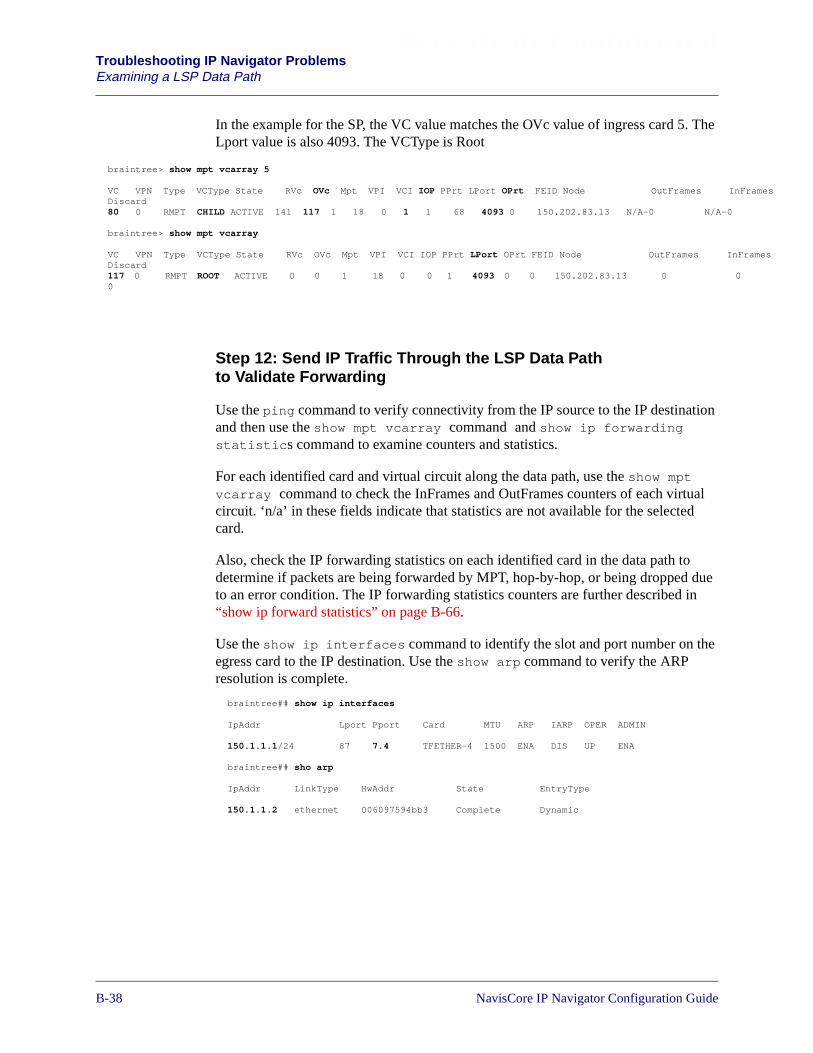
Beta Draft ConfidentialTroubleshooting IP Navigator ProblemsExamining a LSP Data Path
nFrames
nFrames
0
In the example for the SP, the VC value matches the OVc value of ingress card 5. TheLport value is also 4093. The VCType is Root
Step 12: Send IP Traffic Through the LSP Data Pathto Validate Forwarding
Use the ping command to verify connectivity from the IP source to the IP destinationand then use the show mpt vcarray command and show ip forwardingstatistics command to examine counters and statistics.
For each identified card and virtual circuit along the data path, use the show mptvcarray command to check the InFrames and OutFrames counters of each virtualcircuit. ‘n/a’ in these fields indicate that statistics are not available for the selectedcard.
Also, check the IP forwarding statistics on each identified card in the data path todetermine if packets are being forwarded by MPT, hop-by-hop, or being dropped dueto an error condition. The IP forwarding statistics counters are further described in“show ip forward statistics” on page B-66.
Use the show ip interfaces command to identify the slot and port number on theegress card to the IP destination. Use the show arp command to verify the ARPresolution is complete.
braintree> show mpt vcarray 5
VC VPN Type VCType State RVc OVc Mpt VPI VCI IOP PPrt LPort OPrt FEID Node OutFrames IDiscard80 0 RMPT CHILD ACTIVE 141 117 1 18 0 1 1 68 4093 0 150.202.83.13 N/A-0 N/A-0
braintree> show mpt vcarray
VC VPN Type VCType State RVc OVc Mpt VPI VCI IOP PPrt LPort OPrt FEID Node OutFrames IDiscard117 0 RMPT ROOT ACTIVE 0 0 1 18 0 0 1 4093 0 0 150.202.83.13 00
braintree## show ip interfaces
IpAddr Lport Pport Card MTU ARP IARP OPER ADMIN
150.1.1.1/24 87 7.4 TFETHER-4 1500 ENA DIS UP ENA
braintree## sho arp
IpAddr LinkType HwAddr State EntryType
150.1.1.2 ethernet 006097594bb3 Complete Dynamic
B-381/14/02 NavisCore IP Navigator Configuration Guide

Beta Draft Confidential Troubleshooting IP Navigator ProblemsLSP Connection Failure Reasons
LSP Connection Failure Reasons
LSP connection failure reasons are shared by MPT LSPs and point-to-point LSPs. Usethe show mpt all command to view the MPT failure reasons. TheNode/Port/Failure shows switch information that is used to isolate the point of failure.
LSP errors can occur because the LSP network configuration guidelines are notfollowed or because of system memory allocation issues.
Table B-3. LSP Connection Failure Reasons
Field MPTLSP
Point-to-
pointLSP
Description
Table Legend:• = Supported
AbrNoAltOption • The defined path and alternate path failed at the area borderrouter.
ADD_RVC • • VNN could not add a reassembly virtual circuit (RVC). This isa resource error.
ALLOC_CD • • VNN could not allocate a VCC. This is a resource error.
ALLOC_VP • • VNN could not allocate a VPC. This is a resource error.
ATMFR • • LSP is cell-only and the port is frame. This is a cell/frameboundary condition.
CNF_TIMEOUT • • During the LSP calling signalling, a confirmation timer is set toexpire after a period of time after a CALL PDU is sent from theroot to the leaf. If a confirmation response is not received bythe root from a leaf after this period of time, the timer willexpire to end the call sequencing. This may occur during a LSPcall failure when no return response is received including aLSP Reject PDU.
DEAD • • LSP hello packets are not being received.
DISABLE • The point-to-point LSP is disabled.
FRATM • • LSP is frame-only and the port is cell. This is a cell/frameboundary condition.
NavisCore IP Navigator Configuration Guide 1/14/02B-39

Beta Draft ConfidentialTroubleshooting IP Navigator ProblemsLSP Connection Failure Reasons
GROOM • • A better path exists in the network and MPT signalling is tryingto create the circuit over the new path.
ILGL_PORT • • The port cannot support the LSP signal.
IMPURE • • A shorter path exists but it is a cell/frame (mixed) path.
INACTIVE • • An inactive trunk was found.
INV_TRUNK • • An invalid trunk was found in the path.
IPROUTED • • OSPF found a better IP-routed path.
MAX_PORT • • The port number exceeds the maximum.
MGMT_ONLY • • There can be only a management trunk in the path.
MULTI9000CELL • • 9000 cannot be a cell-only transit node.
NONE • • The MPT is functional.
NO_PORT • • The port does not exist.
NOBANDWIDTH • • There is a bandwidth allocation failure.
NODETYPE • • Node type identification in progress. This is a normalcondition.
NOPATH • • The route lookup failed because a route does not exist.
NORESOURCE • • There is a memory allocation resource failure.
NORIDS • • There are no more RIDs available at this node.
Table B-3. LSP Connection Failure Reasons (Continued)
Field MPTLSP
Point-to-
pointLSP
Description
B-401/14/02 NavisCore IP Navigator Configuration Guide
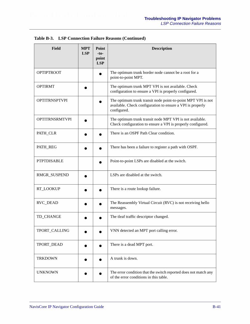
Beta Draft Confidential Troubleshooting IP Navigator ProblemsLSP Connection Failure Reasons
OPTIPTROOT • The optimum trunk border node cannot be a root for apoint-to-point MPT.
OPTIRMT • The optimum trunk MPT VPI is not available. Checkconfiguration to ensure a VPI is properly configured.
OPTITRNSPTVPI • The optimum trunk transit node point-to-point MPT VPI is notavailable. Check configuration to ensure a VPI is properlyconfigured.
OPTITRNSRMTVPI • The optimum trunk transit node MPT VPI is not available.Check configuration to ensure a VPI is properly configured.
PATH_CLR • • There is an OSPF Path Clear condition.
PATH_REG • • There has been a failure to register a path with OSPF.
PTPTDISABLE • Point-to-point LSPs are disabled at the switch.
RMGR_SUSPEND • LSPs are disabled at the switch.
RT_LOOKUP • • There is a route lookup failure.
RVC_DEAD • • The Reassembly Virtual Circuit (RVC) is not receiving hellomessages.
TD_CHANGE • • The tleaf traffic descriptor changed.
TPORT_CALLING • • VNN detected an MPT port calling error.
TPORT_DEAD • • There is a dead MPT port.
TRKDOWN • • A trunk is down.
UNKNOWN • • The error condition that the switch reported does not match anyof the error conditions in this table.
Table B-3. LSP Connection Failure Reasons (Continued)
Field MPTLSP
Point-to-
pointLSP
Description
NavisCore IP Navigator Configuration Guide 1/14/02B-41
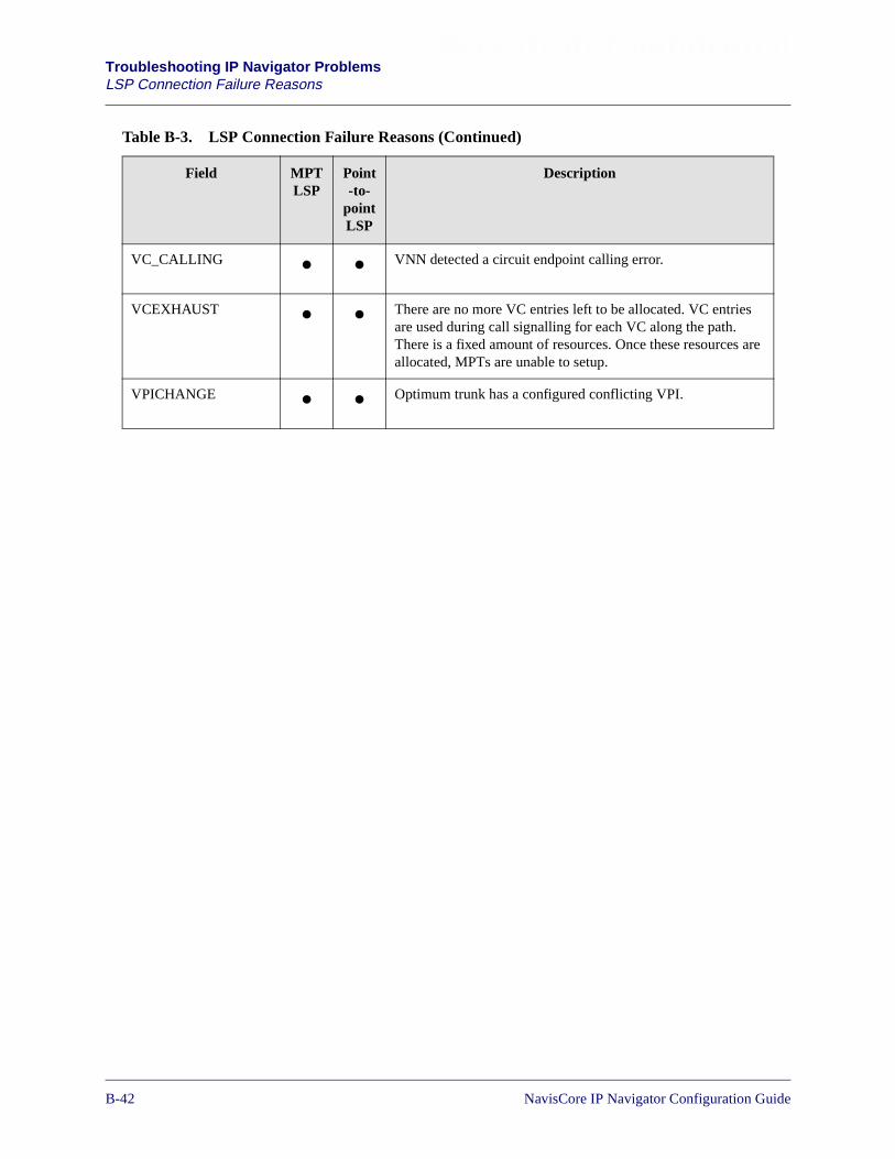
Beta Draft ConfidentialTroubleshooting IP Navigator ProblemsLSP Connection Failure Reasons
VC_CALLING • • VNN detected a circuit endpoint calling error.
VCEXHAUST • • There are no more VC entries left to be allocated. VC entriesare used during call signalling for each VC along the path.There is a fixed amount of resources. Once these resources areallocated, MPTs are unable to setup.
VPICHANGE • • Optimum trunk has a configured conflicting VPI.
Table B-3. LSP Connection Failure Reasons (Continued)
Field MPTLSP
Point-to-
pointLSP
Description
B-421/14/02 NavisCore IP Navigator Configuration Guide

Beta Draft Confidential Troubleshooting IP Navigator ProblemsLSP Path Failure Reasons
LSP Path Failure Reasons
An LSP path is a circuit path consisting of a sequence of node identifiers andoutbound interface indexes at switches along the established circuit.
The path failure reasons are shown in the display output of the show mpt spath orshow mpt dpath command. The spath shows signalling path characteristics and thedpath shows data path characteristics for a specified node IP address.
You can also view Point-to-point LSP path parameters from the network map byselecting the appropriate switch object. From the Monitor menu, select Lucent IPObjects� Show Point-to-Point LSP. The Show All Point-to-point LSP Connectionsdialog box Fields” appears.
Table B-4. LSP Path Failure Reasons
Field Description
CONFIRMTIMEOUT During the LSP calling signalling, a confirmation timer is set toexpire after a period of time after a CALL PDU is sent from the rootto the leaf. If a confirmation response is not received by the root froma leaf after this period of time, the timer will expire to end the callsequencing.
This may occur during a LSP call failure when no return response,including a MPT Reject PDU, is received.
DEAD LSP HELLO packets are no longer being received.
GROOMING A better OSPF path exists in the network and signalling is trying touse the new path.
IMPUREPATH A shorter path of mixed cells and frames exists.
NONE No problem exists.
PATHCLEAR OSPF is notifying LSP that the path is no longer preferred.
PATHREGISTER The path is not registered with OSPF.
ROUTELOOKUP The route lookup failed.
RVCDIED The RVC is not receiving LSP HELLO messages.
TPCALLING A mptTport is calling. This is expected behavior.
TPDEAD The connection is dead.
TRUNKDOWN A trunk in the LSP path is down.
VCCALLING A VC_ENTRY is calling. This is expected behavior.
NavisCore IP Navigator Configuration Guide 1/14/02B-43
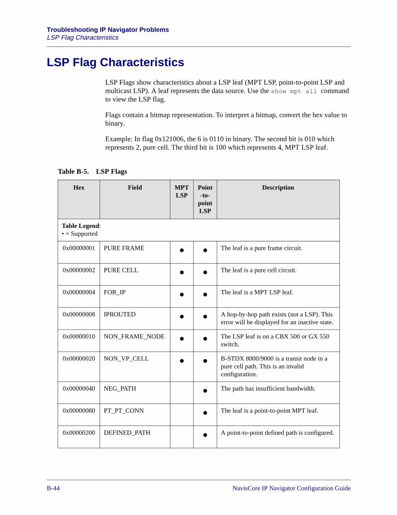
Beta Draft ConfidentialTroubleshooting IP Navigator ProblemsLSP Flag Characteristics
LSP Flag Characteristics
LSP Flags show characteristics about a LSP leaf (MPT LSP, point-to-point LSP andmulticast LSP). A leaf represents the data source. Use the show mpt all commandto view the LSP flag.
Flags contain a bitmap representation. To interpret a bitmap, convert the hex value tobinary.
Example: In flag 0x121006, the 6 is 0110 in binary. The second bit is 010 whichrepresents 2, pure cell. The third bit is 100 which represents 4, MPT LSP leaf.
Table B-5. LSP Flags
Hex Field MPTLSP
Point-to-
pointLSP
Description
Table Legend:• = Supported
0x00000001 PURE FRAME • • The leaf is a pure frame circuit.
0x00000002 PURE CELL • • The leaf is a pure cell circuit.
0x00000004 FOR_IP • • The leaf is a MPT LSP leaf.
0x00000008 IPROUTED • • A hop-by-hop path exists (not a LSP). Thiserror will be displayed for an inactive state.
0x00000010 NON_FRAME_NODE • • The LSP leaf is on a CBX 500 or GX 550switch.
0x00000020 NON_VP_CELL • • B-STDX 8000/9000 is a transit node in apure cell path. This is an invalidconfiguration.
0x00000040 NEG_PATH • The path has insufficient bandwidth.
0x00000080 PT_PT_CONN • The leaf is a point-to-point MPT leaf.
0x00000200 DEFINED_PATH • A point-to-point defined path is configured.
B-441/14/02 NavisCore IP Navigator Configuration Guide
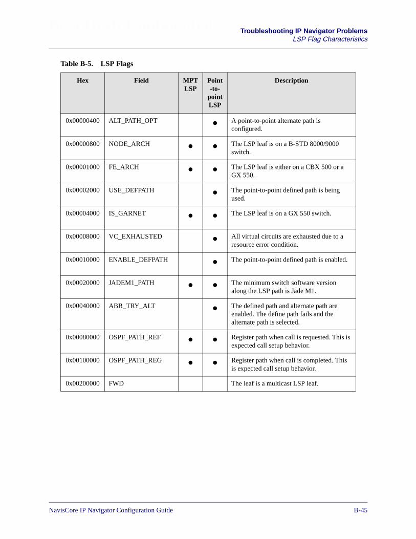
Beta Draft Confidential Troubleshooting IP Navigator ProblemsLSP Flag Characteristics
0x00000400 ALT_PATH_OPT • A point-to-point alternate path isconfigured.
0x00000800 NODE_ARCH • • The LSP leaf is on a B-STD 8000/9000switch.
0x00001000 FE_ARCH • • The LSP leaf is either on a CBX 500 or aGX 550.
0x00002000 USE_DEFPATH • The point-to-point defined path is beingused.
0x00004000 IS_GARNET • • The LSP leaf is on a GX 550 switch.
0x00008000 VC_EXHAUSTED • All virtual circuits are exhausted due to aresource error condition.
0x00010000 ENABLE_DEFPATH • The point-to-point defined path is enabled.
0x00020000 JADEM1_PATH • • The minimum switch software versionalong the LSP path is Jade M1.
0x00040000 ABR_TRY_ALT • The defined path and alternate path areenabled. The define path fails and thealternate path is selected.
0x00080000 OSPF_PATH_REF • • Register path when call is requested. This isexpected call setup behavior.
0x00100000 OSPF_PATH_REG • • Register path when call is completed. Thisis expected call setup behavior.
0x00200000 FWD The leaf is a multicast LSP leaf.
Table B-5. LSP Flags
Hex Field MPTLSP
Point-to-
pointLSP
Description
NavisCore IP Navigator Configuration Guide 1/14/02B-45
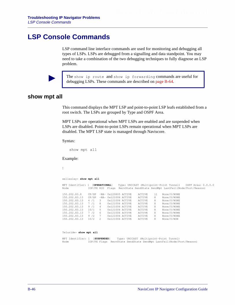
Beta Draft ConfidentialTroubleshooting IP Navigator ProblemsLSP Console Commands
0
LSP Console Commands
LSP command line interface commands are used for monitoring and debugging alltypes of LSPs. LSPs are debugged from a signalling and data standpoint. You mayneed to take a combination of the two debugging techniques to fully diagnose an LSPproblem.
show mpt all
This command displays the MPT LSP and point-to-point LSP leafs established from aroot switch. The LSPs are grouped by Type and OSPF Area.
MPT LSPs are operational when MPT LSPs are enabled and are suspended whenLSPs are disabled. Point-to-point LSPs remain operational when MPT LSPs aredisabled. The MPT LSP state is managed through Naviscore.
Syntax:
show mpt all
Example:
:
The show ip route and show ip forwarding commands are useful fordebugging LSPs. These commands are described on page B-64.
wellesley> show mpt all
MPT Identifier: 1 [OPERATIONAL] Type: UNICAST (Multipoint-Point Tunnel) OSPF Area: 0.0.0.Node IOP/FE RID Flags RecvState SendState SendMpt LastFail(Node/Port/Reason)
150.202.83.8 CP/SP -NA- 0x120805 ACTIVE ACTIVE 11 None/0/NONE150.202.83.13 CP/SP -NA- 0x121006 ACTIVE ACTIVE 8 None/0/NONE150.202.83.13 4 /1 3 0x121006 ACTIVE ACTIVE 8 None/0/NONE150.202.83.13 7 /1 8 0x121006 ACTIVE ACTIVE 8 None/0/NONE150.202.83.13 9 /1 4 0x121006 ACTIVE ACTIVE 8 None/0/NONE150.202.83.13 10/1 5 0x121006 ACTIVE ACTIVE 8 None/0/NONE150.202.83.13 7 /2 6 0x121006 ACTIVE ACTIVE 8 None/0/NONE150.202.83.13 9 /2 7 0x121006 ACTIVE ACTIVE 8 None/0/NONE150.202.83.13 10/2 2 0x121006 ACTIVE ACTIVE 8 None/0/NON
Teluride> show mpt all
MPT Identifier: 1 [SUSPENDED] Type: UNICAST (Multipoint-Point Tunnel)Node IOP/FE Flags RecvState SendState SendMpt LastFail(Node/Port/Reason)
B-461/14/02 NavisCore IP Navigator Configuration Guide
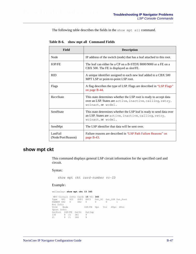
Beta Draft Confidential Troubleshooting IP Navigator ProblemsLSP Console Commands
The following table describes the fields in the show mpt all command.
show mpt ckt
This command displays general LSP circuit information for the specified card andcircuit.
Syntax:
show mpt ckt card-number vc-ID
Example:
Table B-6. show mpt all Command Fields
Field Description
Node IP address of the switch (node) that has a leaf attached to this root.
IOP/FE The leaf can either be a CP on a B-STDX 8000/9000 or a FE on aCBX 500. The FE is displayed as slot/FE.
RID A unique identifier assigned to each new leaf added to a CBX 500MPT LSP or point-to-point LSP root.
Flags A flag describes the type of LSP. Flags are described in “LSP Flags”on page B-44.
RecvState This state determines whether the LSP root is ready to accept dataover an LSP. States are active, inactive, calling, retry,wcinact,or wcdel.
SendState This state determines whether the LSP leaf is ready to send data overan LSP. States are active, inactive, calling, retry,wcinact,or wcdel.
SendMpt The LSP identifier that data will be sent over.
LastFail(Node/Port/Reason)
Failure reasons are described in “LSP Path Failure Reasons” onpage B-43.
wellesley> show mpt ckt 15 345
MPT Circuit Info: Card: 15 VC: 345Type VPI VCI SVPI SVCI Out_VC Out_IOP Out_PortPARENT 642 0 642 0 0 0 1Rvc Info:VcId Node IOP/FE Vpi Vci SVpi SVciTport Info:OutPort IOP/FE OutVc OutIop130 9 /2 381 921 9 /1 380 9
NavisCore IP Navigator Configuration Guide 1/14/02B-47
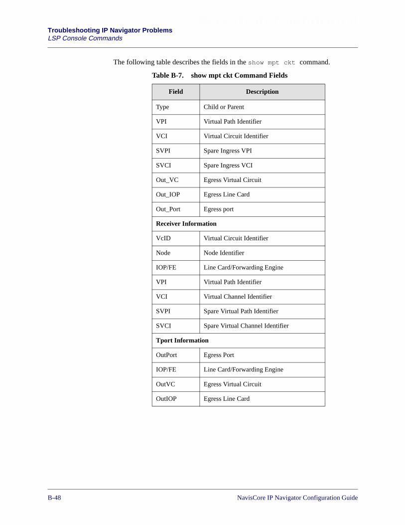
Beta Draft ConfidentialTroubleshooting IP Navigator ProblemsLSP Console Commands
The following table describes the fields in the show mpt ckt command.
Table B-7. show mpt ckt Command Fields
Field Description
Type Child or Parent
VPI Virtual Path Identifier
VCI Virtual Circuit Identifier
SVPI Spare Ingress VPI
SVCI Spare Ingress VCI
Out_VC Egress Virtual Circuit
Out_IOP Egress Line Card
Out_Port Egress port
Receiver Information
VcID Virtual Circuit Identifier
Node Node Identifier
IOP/FE Line Card/Forwarding Engine
VPI Virtual Path Identifier
VCI Virtual Channel Identifier
SVPI Spare Virtual Path Identifier
SVCI Spare Virtual Channel Identifier
Tport Information
OutPort Egress Port
IOP/FE Line Card/Forwarding Engine
OutVC Egress Virtual Circuit
OutIOP Egress Line Card
B-481/14/02 NavisCore IP Navigator Configuration Guide
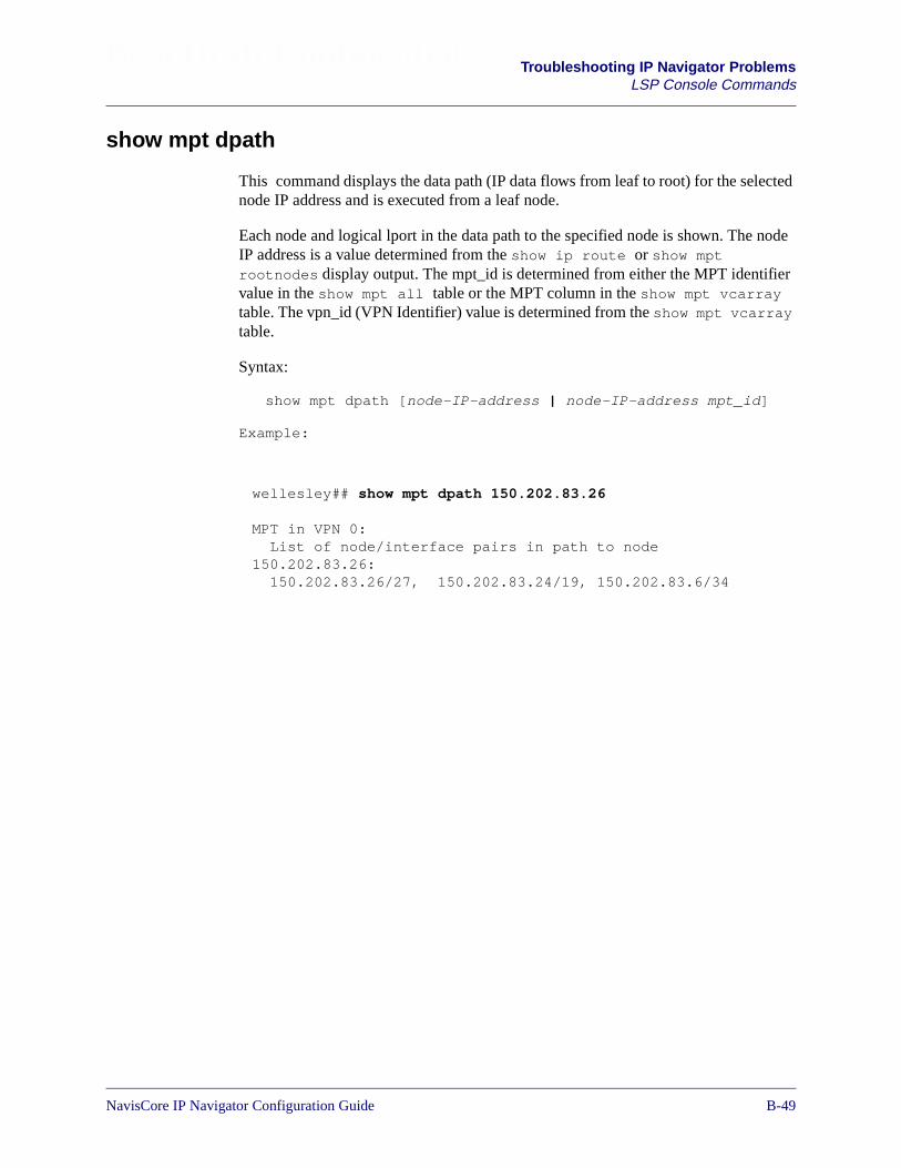
Beta Draft Confidential Troubleshooting IP Navigator ProblemsLSP Console Commands
show mpt dpath
This command displays the data path (IP data flows from leaf to root) for the selectednode IP address and is executed from a leaf node.
Each node and logical lport in the data path to the specified node is shown. The nodeIP address is a value determined from the show ip route or show mptrootnodes display output. The mpt_id is determined from either the MPT identifiervalue in the show mpt all table or the MPT column in the show mpt vcarraytable. The vpn_id (VPN Identifier) value is determined from the show mpt vcarraytable.
Syntax:
show mpt dpath [node-IP-address | node-IP-address mpt_id]
Example:
wellesley## show mpt dpath 150.202.83.26
MPT in VPN 0:List of node/interface pairs in path to node
150.202.83.26:150.202.83.26/27, 150.202.83.24/19, 150.202.83.6/34
NavisCore IP Navigator Configuration Guide 1/14/02B-49

Beta Draft ConfidentialTroubleshooting IP Navigator ProblemsLSP Console Commands
show mpt error
This command displays error counters for MPT LSPs, point-to-point LSPs, andmulticast LSPs.
The Global MPT counters represent an aggregate count for all LSPs. All othercounters represent individual error counters for each LSP type. RMPT is a MPT LSP,PTPTMPT is a point-to-point LSP, and FMPT is a multicast LSP.
The default is the active CP/SP unless a specific card value is selected.
Syntax:
show mpt error {card-number}
Example:
Global MPT Exception Info: Card: 1
errorChecksum 0errorConvert 0lastMidInvalid 0errorMidInvalid 0msgUnknownIn 0errorDVCPDUHLOIn 0errorDVCmsgHLOIn 0errorDVCPDUHAKIn 0errorDVCmsgHAKIn 0errorDVCPDUCLRIn 0errorDVCmsgCLRIn 0errorDVCPDUNAKIn 0errorDVCmsgNAKIn 0errorDVCPDUDISIn 0errorDVCmsgDISIn 0errorDVCmsgCLRIOP 0errorDVCPDUREJIn 0errorDVCmsgREJIn 0errorDVCPDURVCHLOIn 0errorDVCmsgRVCHLOIn 0errorDVCPDUTLHLOIn 0errorDVCmsgTLHLOIn 0
More...
B-501/14/02 NavisCore IP Navigator Configuration Guide
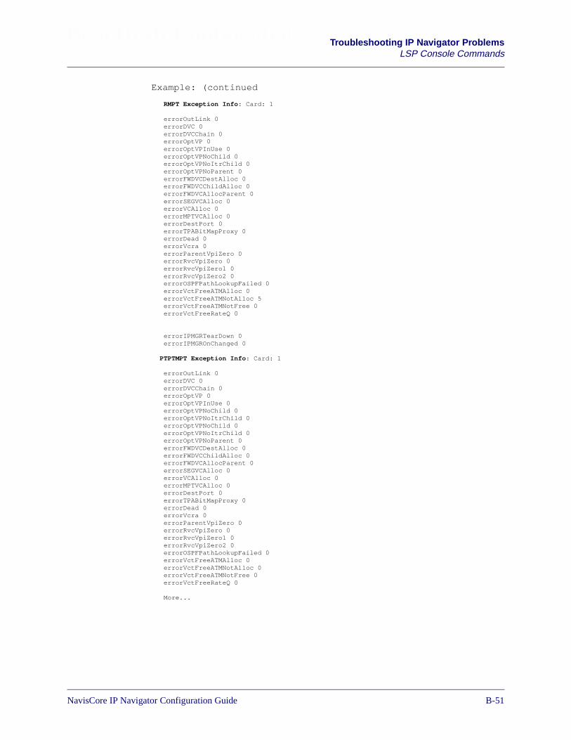
Beta Draft Confidential Troubleshooting IP Navigator ProblemsLSP Console Commands
Example: (continued
RMPT Exception Info: Card: 1
errorOutLink 0errorDVC 0errorDVCChain 0errorOptVP 0errorOptVPInUse 0errorOptVPNoChild 0errorOptVPNoItrChild 0errorOptVPNoParent 0errorFWDVCDestAlloc 0errorFWDVCChildAlloc 0errorFWDVCAllocParent 0errorSEGVCAlloc 0errorVCAlloc 0errorMPTVCAlloc 0errorDestPort 0errorTPABitMapProxy 0errorDead 0errorVcra 0errorParentVpiZero 0errorRvcVpiZero 0errorRvcVpiZero1 0errorRvcVpiZero2 0errorOSPFPathLookupFailed 0errorVctFreeATMAlloc 0errorVctFreeATMNotAlloc 5errorVctFreeATMNotFree 0errorVctFreeRateQ 0
errorIPMGRTearDown 0errorIPMGROnChanged 0
PTPTMPT Exception Info: Card: 1
errorOutLink 0errorDVC 0errorDVCChain 0errorOptVP 0errorOptVPInUse 0errorOptVPNoChild 0errorOptVPNoItrChild 0errorOptVPNoChild 0errorOptVPNoItrChild 0errorOptVPNoParent 0errorFWDVCDestAlloc 0errorFWDVCChildAlloc 0errorFWDVCAllocParent 0errorSEGVCAlloc 0errorVCAlloc 0errorMPTVCAlloc 0errorDestPort 0errorTPABitMapProxy 0errorDead 0errorVcra 0errorParentVpiZero 0errorRvcVpiZero 0errorRvcVpiZero1 0errorRvcVpiZero2 0errorOSPFPathLookupFailed 0errorVctFreeATMAlloc 0errorVctFreeATMNotAlloc 0errorVctFreeATMNotFree 0errorVctFreeRateQ 0
More...
NavisCore IP Navigator Configuration Guide 1/14/02B-51
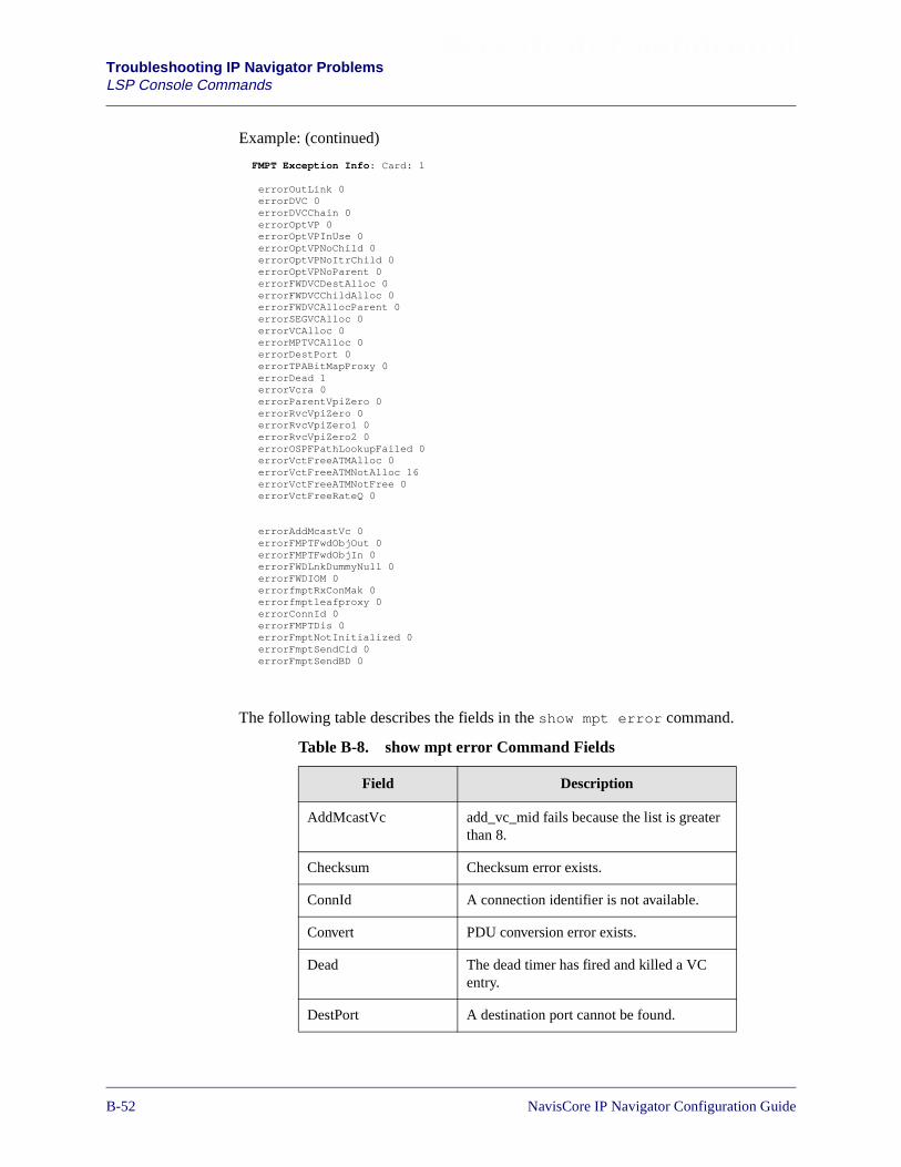
Beta Draft ConfidentialTroubleshooting IP Navigator ProblemsLSP Console Commands
Example: (continued)
The following table describes the fields in the show mpt error command.
Table B-8. show mpt error Command Fields
Field Description
AddMcastVc add_vc_mid fails because the list is greaterthan 8.
Checksum Checksum error exists.
ConnId A connection identifier is not available.
Convert PDU conversion error exists.
Dead The dead timer has fired and killed a VCentry.
DestPort A destination port cannot be found.
FMPT Exception Info: Card: 1
errorOutLink 0errorDVC 0errorDVCChain 0errorOptVP 0errorOptVPInUse 0errorOptVPNoChild 0errorOptVPNoItrChild 0errorOptVPNoParent 0errorFWDVCDestAlloc 0errorFWDVCChildAlloc 0errorFWDVCAllocParent 0errorSEGVCAlloc 0errorVCAlloc 0errorMPTVCAlloc 0errorDestPort 0errorTPABitMapProxy 0errorDead 1errorVcra 0errorParentVpiZero 0errorRvcVpiZero 0errorRvcVpiZero1 0errorRvcVpiZero2 0errorOSPFPathLookupFailed 0errorVctFreeATMAlloc 0errorVctFreeATMNotAlloc 16errorVctFreeATMNotFree 0errorVctFreeRateQ 0
errorAddMcastVc 0errorFMPTFwdObjOut 0errorFMPTFwdObjIn 0errorFWDLnkDummyNull 0errorFWDIOM 0errorfmptRxConMak 0errorfmptleafproxy 0errorConnId 0errorFMPTDis 0errorFmptNotInitialized 0errorFmptSendCid 0errorFmptSendBD 0
B-521/14/02 NavisCore IP Navigator Configuration Guide

Beta Draft Confidential Troubleshooting IP Navigator ProblemsLSP Console Commands
DVC Called VC is not available.
DVCChain Egress VC does not match.
FMPTDis A multicast LSP request is disabled.
FMPTFwdObjIn SVC forward object is missing.
FMPTFwdObjOut RVC forward object is missing.
fmptleafproxy There is an unknown port at the multicastLSP leaf.
fmptRxConMak A destination port cannot be found.
FmptSendBD No buffer multicast LSP root.
FmptSendCid A CID error has occurred sending IPmulticast into multicast LSP root.
FWDIOM A IOM2 does not exist for destination FE .
FWDLnkDummyNull The dummy link for multicast LSP FE isnull at destination slot.
FWDVCAllocParent A forward parent VC does not exist.
FWDVCChildAlloc A forward child VC does not exist at thechild leaf.
FWDVCDestAlloc A forward VC does not exist at thedestination.
IPMGROnChanged The status has changed during the groomingprocess.
IPMGRTearDown The IP Manager has torn down the LSP.
lastMidInvalid MID is invalid.
MidInvalid MID is not in vcra vcarray.
MPTVCAlloc A VC does not exist at mpt_vct_alloc.
NoMPTLeaf A leaf is not found for a LSP HELLOacknowledgement.
NoMPTRoot A root is not found for a LSP HELLOacknowledgement.
Table B-8. show mpt error Command Fields (Continued)
Field Description
NavisCore IP Navigator Configuration Guide 1/14/02B-53
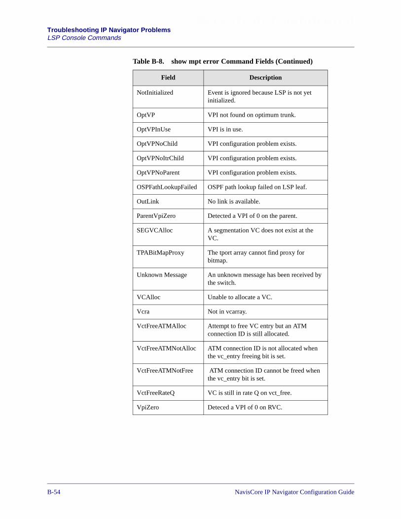
Beta Draft ConfidentialTroubleshooting IP Navigator ProblemsLSP Console Commands
NotInitialized Event is ignored because LSP is not yetinitialized.
OptVP VPI not found on optimum trunk.
OptVPInUse VPI is in use.
OptVPNoChild VPI configuration problem exists.
OptVPNoItrChild VPI configuration problem exists.
OptVPNoParent VPI configuration problem exists.
OSPFathLookupFailed OSPF path lookup failed on LSP leaf.
OutLink No link is available.
ParentVpiZero Detected a VPI of 0 on the parent.
SEGVCAlloc A segmentation VC does not exist at theVC.
TPABitMapProxy The tport array cannot find proxy forbitmap.
Unknown Message An unknown message has been received bythe switch.
VCAlloc Unable to allocate a VC.
Vcra Not in vcarray.
VctFreeATMAlloc Attempt to free VC entry but an ATMconnection ID is still allocated.
VctFreeATMNotAlloc ATM connection ID is not allocated whenthe vc_entry freeing bit is set.
VctFreeATMNotFree ATM connection ID cannot be freed whenthe vc_entry bit is set.
VctFreeRateQ VC is still in rate Q on vct_free.
VpiZero Deteced a VPI of 0 on RVC.
Table B-8. show mpt error Command Fields (Continued)
Field Description
B-541/14/02 NavisCore IP Navigator Configuration Guide

Beta Draft Confidential Troubleshooting IP Navigator ProblemsLSP Console Commands
show mpt rootnodes
This command displays the root node of a circuit. The command is executed from aleaf node. In the display output, VcId shows the virtual circuit of the leaf and slotand feNum shows where the root is located.
On the CBX 500 only, enter a value for card and forwarding engine (feid). The cardmust be an Ethernet or a Frame DS3 type. The feid is one (1) for forwarding engine1 and two (2) for forwarding engine 2.
The vcid is optional. When a virtual circuit (vc) is specified, only information aboutthis particular vc is displayed; otherwise, information about all vcs is displayed.
For the B-STDX, use the following syntax:
show mpt rootnodes {vc-id}
For the CBX, use the following syntax:
show mpt rootnodes card-number fe-id {vc-id}
The following CBX 500 example shows the rootnode of vcid 210 is 150.202.83.4.
The following B-STDX example shows the rootnode of vcid 48 is 150.202.83.12.
Byfield83_3> show mpt rootnodes 14 1
MPT ckt/node Info: Card 14 FE 1
VcId RootNode Slot FE mpt vpn210 150.202.83.4 3 1 1 0211 150.202.83.4 4 1 1 0212 150.202.83.4 12 1 1 0
Byfield83_3> show mpt rootnodes 14 1 210
MPT ckt/node Info: Card 14 FE 1
VcId RootNode Slot FE mpt vpn210 150.202.83.4 3 1 1 0
andover> show mpt rootnodes
MPT ckt/node Info:
VcId RootNode Slot feNum mptID vpn43 150.202.83.9 CP/SP N/A 1 0798 150.202.83.11 CP/SP N/A 9 16748 150.202.83.12 6 0 1 048 150.202.83.12 7 0 1 0
Andover> show mpt rootnodes 48
MPT ckt/node Info:
VcId RootNode Slot feNum mptID vpn48 150.202.83.12 6 0 1 0
NavisCore IP Navigator Configuration Guide 1/14/02B-55
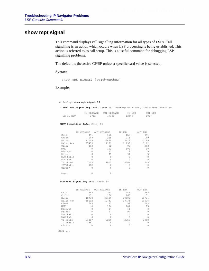
Beta Draft ConfidentialTroubleshooting IP Navigator ProblemsLSP Console Commands
show mpt signal
This command displays call signalling information for all types of LSPs. Callsignalling is an action which occurs when LSP processing is being established. Thisaction is referred to as call setup. This is a useful command for debugging LSPsignalling problems.
The default is the active CP/SP unless a specific card value is selected.
Syntax:
show mpt signal {card-number}
Example:
wellesley> show mpt signal 15
Global MPT Signalling Info: Card: 15, FEBitMap 0x1e001e0, IPFEBitMap 0x1e001e0
IN MESSAGE OUT MESSAGE IN LNK OUT LNKGR-TL HLO 2762 17109 12469 8837
RMPT Signalling Info: Card: 15
IN MESSAGE OUT MESSAGE IN LNK OUT LNKCall 491 150 153 491Cnfrm 149 215 215 149Hello 11199 27460 3115 11199Hello Ack 27453 11199 11199 3112Clear 293 92 96 293NAK 0 102 102 10Disrupt 0 13 13 9Reject 0 91 91 3RVC Hello 0 0 0 0RVC HAK 0 0 0 0TL Hello 7199 4801 4801 713IPTlHello 812 0 0 0ClrIOP 0 0 0 0
Rmgr 0 0
PtPt-MPT Signalling Info: Card: 15
IN MESSAGE OUT MESSAGE IN LNK OUT LNKCall 463 341 341 463Cnfrm 131 166 166 131Hello 10738 85139 10606 10734Hello Ack 85112 10733 10733 10606Clear 243 13 56 243NAK 0 104 104 75Disrupt 0 14 11 3Reject 0 97 97 0RVC Hello 0 0 0 0RVC HAK 0 0 0 0TL Hello 21817 2250 2250 2098IPTlHello 2381 0 0 0ClrIOP 0 0 0 0
More ...
B-561/14/02 NavisCore IP Navigator Configuration Guide

Beta Draft Confidential Troubleshooting IP Navigator ProblemsLSP Console Commands
Example: (continued)
The following table describes the fields in the show mpt signal command:
Table B-9. show mpt signal Command Fields
Field Description
Clear Number of clear messages and PDUs sent and received on the card.
ClrIOP Number of cleared IOP messages on the switch.
Disrupt Number of disrupt messages and PDUs sent and received on the card.
FEBitMap A bitmap of active FEs at the switch.
Fwd Call For multicast LSPs, the number of outgoing call messages, incomingmessages, and incoming and outgoing PDUs send and received onthe link.
Fwd Cnfrm For multicast LSPs, the number of outgoing confirm messages,incoming messages, and PDUs sent and received on the link.
GR-TL HLO Number of group tleaf HELLO messages and PDUs sent andreceived on the card.
Hello Number of hello messages and PDUs sent and received on the card.
Hello Ack Number of hello acknowledgement messages and PDUs sent andreceived on the card.
IPFEBitMap A current bitmap on the switch of FEs that have IP interfaces.
IP-TL HLO Number of IP tleaf HELLO messages and PDUs sent and received onthe card.
NAK Number of NAK messages and PDU’s sent and received on the card.
FMPT Signalling Info: Card: 15
IN MESSAGE OUT MESSAGE IN LNK OUT LNKCall 173 298 298 173Cnfrm 88 88 88 88Hello 46134 76009 43572 46134Hello Ack 76003 46134 46134 43568Clear 80 24 34 80NAK 0 31 31 7Disrupt 0 25 23 27Reject 0 35 35 0RVC Hello 0 0 0 0RVC HAK 0 0 0 0TL Hello 17961 10580 10580 12654IPTlHello 4905 0 0 0ClrIOP 0 0 0 0
NavisCore IP Navigator Configuration Guide 1/14/02B-57
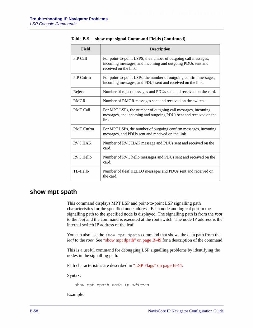
Beta Draft ConfidentialTroubleshooting IP Navigator ProblemsLSP Console Commands
show mpt spath
This command displays MPT LSP and point-to-point LSP signalling pathcharacteristics for the specified node address. Each node and logical port in thesignalling path to the specified node is displayed. The signalling path is from the rootto the leaf and the command is executed at the root switch. The node IP address is theinternal switch IP address of the leaf.
You can also use the show mpt dpath command that shows the data path from theleaf to the root. See “show mpt dpath” on page B-49 for a description of the command.
This is a useful command for debugging LSP signalling problems by identifying thenodes in the signalling path.
Path characteristics are described in “LSP Flags” on page B-44.
Syntax:
show mpt spath node-ip-address
Example:
PtP Call For point-to-point LSPS, the number of outgoing call messages,incoming messages, and incoming and outgoing PDUs sent andreceived on the link.
PtP Cnfrm For point-to-point LSPs, the number of outgoing confirm messages,incoming messages, and PDUs sent and received on the link.
Reject Number of reject messages and PDUs sent and received on the card.
RMGR Number of RMGR messages sent and received on the switch.
RMT Call For MPT LSPs, the number of outgoing call messages, incomingmessages, and incoming and outgoing PDUs sent and received on thelink.
RMT Cnfrm For MPT LSPs, the number of outgoing confirm messages, incomingmessages, and PDUs sent and received on the link.
RVC HAK Number of RVC HAK message and PDUs sent and received on thecard.
RVC Hello Number of RVC hello messages and PDUs sent and received on thecard.
TL-Hello Number of tleaf HELLO messages and PDUs sent and received onthe card.
Table B-9. show mpt signal Command Fields (Continued)
Field Description
B-581/14/02 NavisCore IP Navigator Configuration Guide

Beta Draft Confidential Troubleshooting IP Navigator ProblemsLSP Console Commands
show mpt vcarray
This command displays a list of virtual circuits for all types of LSPs. A vcarray is a setof virtual circuit entries. The summary keyword, used on a frame card, restrictsforwarding engine RVCs from being displayed. Otherwise, all RVC vctypes will bedisplayed. On a CBX 500, only the first FE send circuit is displayed in the vcarraydisplay output.
The default is the active CP/SP unless a specific card value is selected.
Syntax:
show mpt vcarray [card-number | node-IP-address |card-number node-IP-address | summary card-number]
Wellesley> show mpt spath 150.202.83.13
MPT in VPN 0:List of node/interface pairs in path to node 150.202.83.13:150.202.83.12/71, 150.202.83.28/13, 150.202.83.30/14Path characteristics:PURE_CELL, FOR_IP, FE_ARCH, JADEM1_PATH, OSPF_PATH_REG
MPT Pt-Pt in VPN 0:List of node/interface pairs in path to node 150.202.83.13:150.202.83.12/71, 150.202.83.28/13, 150.202.83.30/14Path characteristics:PURE_CELL, PT_PT_CONN, FE_ARCH, JADEM1_PATH, OSPF_PATH_REG
MPT Pt-Pt in VPN 167:Path characteristics:PT_PT_CONN, FE_ARCH
NavisCore IP Navigator Configuration Guide 1/14/02B-59
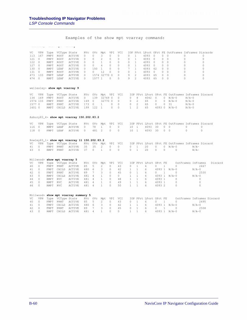
Beta Draft ConfidentialTroubleshooting IP Navigator ProblemsLSP Console Commands
Examples of the show mpt vcarray command:
wellesley show mpt vcarray
VC VPN Type VCType State RVc OVc Mpt VPI VCI IOP PPrt LPort OPrt FE OutFrames InFrames Discards113 167 PMPT ROOT ACTIVE 0 0 3 0 0 0 1 4093 0 0 0 0 0121 0 PMPT ROOT ACTIVE 0 0 2 0 0 0 1 4093 0 0 0 0 0122 0 RMPT ROOT ACTIVE 0 0 1 0 0 0 1 4093 0 0 0 0 0127 0 PMPT ROOT ACTIVE 0 0 4 0 0 0 1 4093 0 0 0 0 0130 0 RMPT LEAF ACTIVE 0 150 1 0 0 7 1 4093 62 0 0 0 0131 0 RMPT ROOT ACTIVE 0 0 12 0 0 0 1 4093 0 0 0 0 0473 133 FMPT LEAF ACTIVE 0 1574 32770 0 0 9 2 4093 65 0 0 0 0474 0 RMPT LEAF ACTIVE 0 1577 1 0 0 9 2 4093 65 0 0 0 0
wellesley> show mpt vcarray 9
VC VPN Type VCType State RVc OVc Mpt VPI VCI IOP PPrt LPort OPrt FE OutFrames InFrames Discard134 169 FMPT ROOT ACTIVE 0 139 32769 0 0 0 8 4042 0 0 N/A-0 N/A-01574 133 FMPT PRNT ACTIVE 169 0 32770 0 0 0 2 65 0 0 N/A-0 N/A-01577 0 RMPT PRNT ACTIVE 173 0 1 0 0 0 2 65 0 0 31 N/A-01601 0 RMPT CHILD ACTIVE 199 122 1 0 0 1 2 65 4093 0 N/A-0 N/A-0
Asbury83_4> show mpt vcarray 150.202.83.2
VC VPN Type VCType State RVc OVc Mpt VPI VCI IOP PPrt LPort OPrt FE OutFrames InFrames Discard116 0 RMPT LEAF ACTIVE 0 78 1 0 0 10 1 4093 30 0 0 0 0118 0 FMPT LEAF ACTIVE 0 481 2 0 0 10 1 4093 30 0 0 0 0
Rowley83_1> show mpt vcarray 11 150.202.83.2VC VPN Type VCType State RVc OVc Mpt VPI VCI IOP PPrt LPort OPrt FE OutFrames InFrames Discard41 0 FMPT PRNT ACTIVE 35 35 2 0 0 0 1 20 0 0 N/A-0 N/A-43 0 RMPT PRNT ACTIVE 37 0 1 0 0 0 1 20 0 0 0 N/A-
Millwood> show mpt vcarray 5VC VPN Type VCType State RVc OVc Mpt VPI VCI IOP PPrt LPort OPrt FE OutFrames InFrames Discard40 0 FMPT PRNT ACTIVE 85 5 2 0 43 0 1 6 0 1 0 246741 0 FMPT CHILD ACTIVE 480 6 3 0 42 1 1 6 4093 1 N/A-0 N/A-042 0 FMPT PRNT ACTIVE 89 7 3 0 45 0 1 6 0 1 0 253043 0 RMPT CHILD ACTIVE 481 4 1 0 0 1 1 6 4093 1 N/A-0 N/A-044 0 RMPT RVC ACTIVE 481 4 1 0 48 1 1 6 4093 1 0 045 0 RMPT RVC ACTIVE 481 4 1 0 49 1 1 6 4093 1 0 046 0 RMPT RVC ACTIVE 481 4 1 0 50 1 1 6 4093 2 0 0
Millwood> show mpt vcarray summary 5VC VPN Type VCType State RVc OVc Mpt VPI VCI IOP PPrt LPort OPrt FE OutFrames InFrames Discard40 0 FMPT PRNT ACTIVE 85 5 2 0 43 0 1 6 0 1 0 249541 0 FMPT CHILD ACTIVE 480 6 3 0 42 1 1 6 4093 1 N/A-0 N/A-042 0 FMPT PRNT ACTIVE 89 7 3 0 45 0 1 6 0 1 0 255843 0 RMPT CHILD ACTIVE 481 4 1 0 0 1 1 6 4093 1 N/A-0 N/A-0
B-601/14/02 NavisCore IP Navigator Configuration Guide

Beta Draft Confidential Troubleshooting IP Navigator ProblemsLSP Console Commands
The following table describes the fields in the show mpt vcarray command:
Table B-10. show mpt vcarray Command Fields
Field Description
Discard Total number of discarded frames
FE Forwarding engine identifier
Inframes Total number of incoming frames
IOP Card that contains a vcentry
Lport Logical port identifier of the card thatcontains the vcentry
Mpt Value maps to the MPT Identifier for theendpoint
OPrt Lport of the child virtual circuit from theleaf point of view or lport of a parent virtualcircuit from a root point of view
OutFrames Total number of outgoing frames
OVc Outgoing VC
PPrt Physical port identifier of the card (IOP)
RVc Remote VC
State Active, Inactive
Type MPT LSP, Point-to-point LSP, MulticastLSP
VCI Virtual Circuit Identifier
VCI Virtual Channel Identifier
VCType Child, Parent, Root, Leaf, FE, RVC
VPI Virtual Path Identifier
VPN Virtual Private Network
NavisCore IP Navigator Configuration Guide 1/14/02B-61
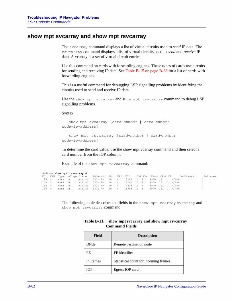
Beta Draft ConfidentialTroubleshooting IP Navigator ProblemsLSP Console Commands
ames
show mpt svcarray and show mpt rsvcarray
The svcarray command displays a list of virtual circuits used to send IP data. Thersvcarray command displays a list of virtual circuits used to send and receive IPdata. A vcarray is a set of virtual circuit entries.
Use this command on cards with forwarding engines. These types of cards use circuitsfor sending and receiving IP data. See Table B-15 on page B-68 for a list of cards withforwarding engines.
This is a useful command for debugging LSP signalling problems by identifying thecircuits used to send and receive IP data.
Use the show mpt svcarray and show mpt rsvcarray command to debug LSPsignalling problems.
Syntax:
show mpt svcarray [card-number | card-numbernode-ip-address]
show mpt rsvcarray [card-number | card-numbernode-ip-address]
To determine the card value, use the show mpt vcarray command and then select acard number from the IOP column.
Example of the show mpt rsvcarray command:
The following table describes the fields in the show mpt vcarray svcarray andshow mpt rsvcarray command.
dedham> show mpt rsvcarray 4VC VPN Type VCType State DNde OVc Mpt VPI VCI IOP PPrt LPort OPrt FE OutFrames InFr139 0 RMPT FE ACTIVE 530c 79 10 0 10242 11 2 3970 161 1 N/A-0 0140 0 RMPT FE ACTIVE 530c 79 10 0 12290 11 2 3970 161 1 N/A-0 0155 0 RMPT FE ACTIVE 530c 79 10 0 14338 11 2 3970 161 1 N/A-0 0156 0 RMPT FE ACTIVE 530c 79 10 0 16386 11 2 3970 161 1 N/A-0 0
Table B-11. show mpt svcarray and show mpt rsvcarrayCommand Fields
Field Description
DNde Remote destination node
FE FE identifier
InFrames Statistical count for incoming frames.
IOP Egress IOP card
B-621/14/02 NavisCore IP Navigator Configuration Guide

Beta Draft Confidential Troubleshooting IP Navigator ProblemsLSP Console Commands
LPort Logical port
Mpt MPT identifier
Oprt Outgoing port
OutFrames Statistical count for outgoing frames.
OVc Outgoing virtual circuit
PPrt Physical port
State State of the LSP. For example, Invalid,inactive, retry, calling,
Type Parent, Child, FE
VC Virtual Circuit
VCI Virtual Circuit Identifier
VCType Parent, Child, FE
VPI Virtual Path Identifier
VPN Virtual Private Network
Table B-11. show mpt svcarray and show mpt rsvcarrayCommand Fields (Continued)
Field Description
NavisCore IP Navigator Configuration Guide 1/14/02B-63
Beta Draft ConfidentialTroubleshooting IP Navigator ProblemsIP Forwarding
IP Forwarding
Lucent IP switching uses a combination of IP lookups and virtual circuit/paths toimprove network performance.
Routing Tables
The routing protocols running on the CP/SP are responsible for building a routingtable from information learned through their respective routing updates. To maximizeIP forwarding throughput, the routing tables are distributed to the IOPs so that routingtable lookups are a local operation.
The following routing tables are maintained on the CP/SP:
Unicast – The unicast routing table contains a list of unicast destination addresses.These addresses include the IP address that identifies the next hop to reach a network,the state and cost of the IP route, the logical port being reported on, the age (inseconds) of the route advertisement (RIP only), and a label switch path circuitindicator.
Multicast – The multicast routing table contains a list of multicast source IPaddresses. These addresses include multicast destination group IP addresses, upstreamneighbor interface, multicast LSP identification number, and number of outgoinginterfaces.
How an IP Packet is Forwarded
IP packets are checked at the ingress and egress ports of each switch in the Lucentnetwork. The following describes what happens when a Lucent switch receives an IPpacket.
1. Check if received packet matches a configured Packet Filter. If packet matchesfilter, accept or discard packet according to filter.
2. Datagrams that specify IP Header Options are automatically forwarded to the CP,which implements a full IP protocol stack capable of handling the options.
3. Check if received packet matches a configured Next Hop Resolution Protocol(NHRP) profile. If packet matches profile, forward according to profile.
4. Check if received packet matches a forwarding policy. If packet matches policy,forward according to policy.
5. Perform an IP lookup on the packet’s destination address. If the forwarding entryshows that the destination is a local switch IP address (SNMP, ping, etc.) forwardto the CP/SP for processing.
6. If the forwarding entry contains an LSP circuit, forward it over the LSP to theappropriate egress switch in the cloud.
B-641/14/02 NavisCore IP Navigator Configuration Guide
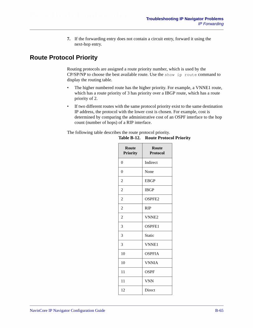
Beta Draft Confidential Troubleshooting IP Navigator ProblemsIP Forwarding
7. If the forwarding entry does not contain a circuit entry, forward it using thenext-hop entry.
Route Protocol Priority
Routing protocols are assigned a route priority number, which is used by theCP/SP/NP to choose the best available route. Use the show ip route command todisplay the routing table.
• The higher numbered route has the higher priority. For example, a VNNE1 route,which has a route priority of 3 has priority over a IBGP route, which has a routepriority of 2.
• If two different routes with the same protocol priority exist to the same destinationIP address, the protocol with the lower cost is chosen. For example, cost isdetermined by comparing the administrative cost of an OSPF interface to the hopcount (number of hops) of a RIP interface.
The following table describes the route protocol priority.Table B-12. Route Protocol Priority
RoutePriority
RouteProtocol
0 Indirect
0 None
2 EBGP
2 IBGP
2 OSPFE2
2 RIP
2 VNNE2
3 OSPFE1
3 Static
3 VNNE1
10 OSPFIA
10 VNNIA
11 OSPF
11 VNN
12 Direct
NavisCore IP Navigator Configuration Guide 1/14/02B-65
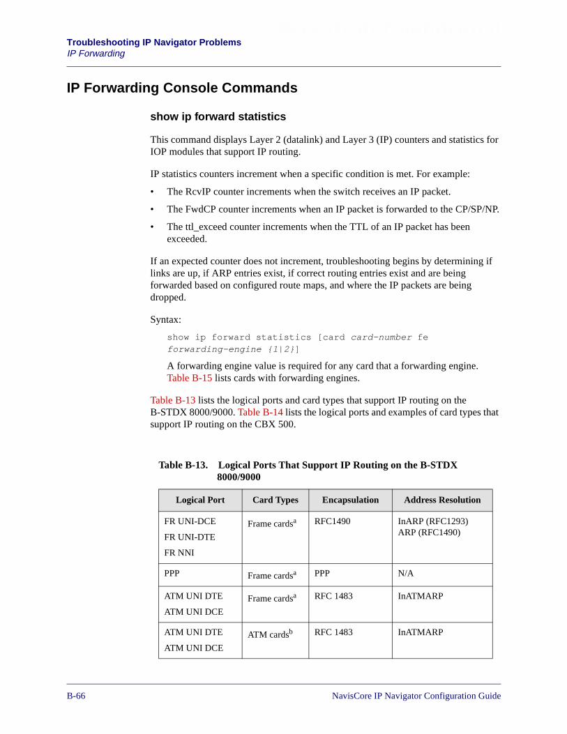
Beta Draft ConfidentialTroubleshooting IP Navigator ProblemsIP Forwarding
IP Forwarding Console Commands
show ip forward statistics
This command displays Layer 2 (datalink) and Layer 3 (IP) counters and statistics forIOP modules that support IP routing.
IP statistics counters increment when a specific condition is met. For example:
• The RcvIP counter increments when the switch receives an IP packet.
• The FwdCP counter increments when an IP packet is forwarded to the CP/SP/NP.
• The ttl_exceed counter increments when the TTL of an IP packet has beenexceeded.
If an expected counter does not increment, troubleshooting begins by determining iflinks are up, if ARP entries exist, if correct routing entries exist and are beingforwarded based on configured route maps, and where the IP packets are beingdropped.
Syntax:
show ip forward statistics [card card-number feforwarding-engine {1|2}]
A forwarding engine value is required for any card that a forwarding engine.Table B-15 lists cards with forwarding engines.
Table B-13 lists the logical ports and card types that support IP routing on theB-STDX 8000/9000. Table B-14 lists the logical ports and examples of card types thatsupport IP routing on the CBX 500.
Table B-13. Logical Ports That Support IP Routing on the B-STDX8000/9000
Logical Port Card Types Encapsulation Address Resolution
FR UNI-DCE
FR UNI-DTE
FR NNI
Frame cardsa RFC1490 InARP (RFC1293)ARP (RFC1490)
PPP Frame cardsa PPP N/A
ATM UNI DTE
ATM UNI DCE
Frame cardsa RFC 1483 InATMARP
ATM UNI DTE
ATM UNI DCE
ATM cardsb RFC 1483 InATMARP
B-661/14/02 NavisCore IP Navigator Configuration Guide

Beta Draft Confidential Troubleshooting IP Navigator ProblemsIP Forwarding
a Frame Card Examples = UIO, 4-T1, 4-E1, DSX-10, HSSI, Ch DS3, Ch DS 3/1/0, 12-E1b ATM Card Examples = ATM CS DS3, ATM CS E3, ATM OC3
Ethernet 2-portEthernet card
IEEE SNAPEthernet II
ARP
IP VPN Cloud N/A N/A ARP
Table B-14. Logical Ports Supporting IP Routing on the CBX 500
Logical Port Card Types Encapsulation Address Resolution
FR UNI-DCE
FR UNI-DTE
FR NNI
6-Port DS3FR/IP card
4-PortChannelizedDS3/1 FR/IPcard
RFC 1490 InARPARP
PPP 6-Port DS3FR/IP card
4-PortChannelizedDS3/1 FR/IPcard
PPP N/A
ATM UNI DTE
ATM UNI DCE
ATM cardswith an IPServer PVCconnection
RFC 1483 InATMARP
Ethernet 4-portEthernet card
IEEE SNAPEthernet II
ARP
IP VPN Cloud N/A N/A ARP
Table B-13. Logical Ports That Support IP Routing on the B-STDX8000/9000 (Continued)
Logical Port Card Types Encapsulation Address Resolution
NavisCore IP Navigator Configuration Guide 1/14/02B-67

Beta Draft ConfidentialTroubleshooting IP Navigator ProblemsIP Forwarding
Table B-15. Card Types with Forwarding Engine
Switch Card Type Number ofForwarding
Engines
B-STDX 8000/9000 2-port Ethernet 10/100 Base-T 1
CBX 500 4-port Ethernet 10/100 Base-T 2
CBX 500 6-port DS3 Frame/IP 2
CBX 500 4-port Channelized DS3 1
B-681/14/02 NavisCore IP Navigator Configuration Guide

Beta Draft Confidential Troubleshooting IP Navigator ProblemsIP Forwarding
This example shows IP forwarding statistics for a card with a forwarding engine.
Byfield83_3> show ip forward statistics card 13 fe 1
IP forwarding stats for Frame Engine: 1
FE_1:Inbound Layer-2 Stats/Errors:if_id = 0, trk_pid_val= 0, rcv_arp = 55bad_arp = 0, bad_snap = 0, bad_llc = 0bad_eth_v2 = 0, no_iplport = 0, bad_trk_pid= 0bad_eth_type= 0, bad_mcast = 0, discards = 0no_olnk = 0, Fwd SFPK = 55
FE_1:Inbound Layer-3 Errors:ip_vers = 0, ip_hdr_short= 0, ip_trunc_pkt = 0ip_chksum = 0, ip_filter = 0, rte_reject = 0lnk_bcst = 0, ip_bc = 0, ip_lbc = 0lock_discard= 0, ip_lnktype = 0, inact_fwd_flags= 0no_fbufs = 0, bad_prtcn_id= 0, invalid_mpt = 0no_lnk = 0, no_iplport = 0, no_lnkproxy = 0icmp_thtl = 0, iparp_thtl = 0, ip_lookup = 0rte_indirect= 0, ttl_xceed = 0, discard = 0mc_tree_pend= 0, mc_wrong_if = 0, no_mc_src = 0mc_ttl_xceed= 0, postcp_thtl = 0, unicast_in_tunnel= 0
FE_1:Inbound Layer-3 Informational Counters:Rcv IP = 553, Fwd CP = 553, Fwd Opts= 0Fwd HBH = 0, Fwd MPT= 0, Fwd Frag = 0Rcv Tunnel= 0, Fwd Mcast = 0, Fwd Tun= 0Fwd FMPT = 0, Rx Fmptitr= 0, Tx Fmptitr= 0
FE_1:Inbound IP Server statistics:IP Svr Tx = 0
FE_1:Outbound Layer-2 Stats/Errors:if_id = 0, trk_pid_val= 0, rcv_arp = 0bad_arp = 0, bad_snap = 0, bad_llc = 0bad_eth_v2 = 0, no_iplport = 0, bad_trk_pid= 0bad_eth_type= 0, bad_mcast = 0, discards = 0no_olnk = 0, Fwd SFPK = 0
FE_1:Outbound Layer-3 Errors:ip_vers = 0, ip_hdr_short= 0, ip_trunc_pkt = 0ip_chksum = 0, ip_filter = 0, rte_reject = 0lnk_bcst = 0, ip_bc = 0, ip_lbc = 0lock_discard= 0, ip_lnktype = 0, inact_fwd_flags= 0no_fbufs = 0, bad_prtcn_id= 0, invalid_mpt = 0no_lnk = 0, no_iplport = 0, no_lnkproxy = 0icmp_thtl = 347, iparp_thtl = 0, ip_lookup = 0rte_indirect= 0, ttl_xceed = 0, discard = 0mc_tree_pend= 746, mc_wrong_if = 960, no_mc_src = 0mc_ttl_xceed= 0, postcp_thtl = 0, unicast_in_tunnel= 0
FE_1:Outbound Layer-3 IP Server Counters:Rcv IP = 1142947, Fwd CP = 803, Fwd Opts= 0Fwd HBH = 0, Fwd MPT= 0, Fwd Frag = 0Rcv Tunnel= 0, Fwd Mcast = 2274890, Fwd Tun= 0Fwd FMPT = 0
FE_1:Outbound Layer-3 Informational Counters:SW Ctl = 283, SW hbh = 344, SW ckt = 0SW ipsvr= 0, SW Mcast= 0, Tx HBH = 344Tx MC ifcs = 0, Tx MC Nbrs = 0, Tx MC Trks = 0SW FMPTitr= 1142947, Tx FMPTitr= 0
NavisCore IP Navigator Configuration Guide 1/14/02B-69

Beta Draft ConfidentialTroubleshooting IP Navigator ProblemsIP Forwarding
This example shows IP forwarding statistics for a card without a forwarding engine. Inthis example, the card is a HSSI.
Rowley83_1> show ip forward statistics card 11
Ingress Counters:FwdIcmp = 0, FwdIcmpThtl = 0postMcast = 0, postOK = 0, postThrottld = 0, postTotal = 0fwd_cp = 215, fwd_hbh = 92194, fwd_mpt = 0, fwd_itr = 0options = 0, split = 0, dct = 0
Egress Counters:ntu_ctl = 1026, ntu_ckt = 62055, ntu_itr = 0, ntu_hbh = 118mpt_all = 0, mpt_gr = 0, mpt_am = 0, mpt_rdr = 0ntu_hbh_ctl = 118, tx_hbh = 130
B-701/14/02 NavisCore IP Navigator Configuration Guide

Beta Draft Confidential Troubleshooting IP Navigator ProblemsIP Forwarding
The following table describe the fields shown in the show ip forwardstatistics command.
Table B-16. show ip forward Command Fields
Fields Description
INGRESS COUNTERS
FwdIcmp ICMP post attempts
FwdIcmpThtl Number of throttled ICMP packets sent tothe CP/SP.
postMcast Multicast post attempts
postOK Posted to background
postThrottld Discarded due to foreground/backgroundthrottle
postTotal Total post attempts (OKs and failures)
fwd_cp Datagrams forwarded to CP
fwd_hbh Packet is forwarded hop-by-hop
fwd_mpt Packet is forwarded on a LSP
fwd_itr Packets received on an intermediate LSPnode
options IP datagrams specifying header options
split IP datagrams with headers split acrossBTUs
dct IP data is sent hop-by-hop to Direct CellTrunk
EGRESS COUNTERS
ntu_ctl Datagram is passed to background (control)
ntu_ckt Packet is forwarded on circuit
ntu_itr Packet is forwarded on intermediate circuit
ntu_hbh Packet is forwarded hop-by-hop
mpt_all Forward all packets on an LSP.
mpt_gr Forward all green frames
mpt_am Forward all amber frames
NavisCore IP Navigator Configuration Guide 1/14/02B-71
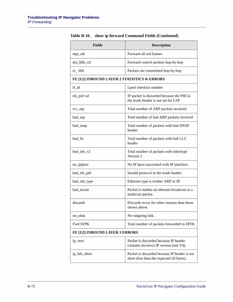
Beta Draft ConfidentialTroubleshooting IP Navigator ProblemsIP Forwarding
mpt_rdr Forward all red frames
ntu_hbh_ctl Forward control packets hop-by-hop
tx_ hbh Packets are transmitted hop-by-hop
FE [1|2] INBOUND LAYER 2 STATISTICS & ERRORS
if_id Lport interface number
trk_pid val IP packet is discarded because the PID inthe trunk header is not set for LSP.
rcv_arp Total number of ARP packets received
bad_arp Total number of bad ARP packets received
bad_snap Total number of packets with bad SNAPheader
bad_llc Total number of packets with bad LLCheader
bad_eth_v2 Total number of packets with ethertypeVersion 2
no_iplport No IP lport associated with IP interface.
bad_trk_pid Invalid protocol in the trunk header.
bad_eth_type Ethernet type is neither ARP or IP.
bad_mcast Packet is neither an ethernet broadcast or amulticast packet.
discards Discards occur for other reasons than thoseshown above.
no_olnk No outgoing link.
Fwd SFPK Total number of packets forwarded to SPFK
FE [1|2] INBOUND LAYER 3 ERRORS
ip_vers Packet is discarded because IP headercontains incorrect IP version (not V4).
ip_hdr_short Packet is discarded because IP header is tooshort (less than the expected 20 bytes) .
Table B-16. show ip forward Command Fields (Continued)
Fields Description
B-721/14/02 NavisCore IP Navigator Configuration Guide

Beta Draft Confidential Troubleshooting IP Navigator ProblemsIP Forwarding
ip_trunk_pkt Packet is discarded because IP header istruncated.
ip_chksum Packet is discarded because IP Headerchecksum is bad.
ip_filter Packet is discarded because a filter has beenconfigured to selectively block IP packets.
rte_reject Packet is discarded because a filter has beenconfigured to selectively block routes.
lnk_bcst A link broadcast packet has been received.This packet is discarded because a linkbroadcast packet is not forwarded beyondthe local segment.
ip_bc A broadcast packet has been received. Thispacket is discarded because broadcastpackets are not forwarded.
ip_lbc Subnet broadcast not forwarded.
lock_discard This counter normally increments when aprocess lock occurs. Counter is specific toIOM modules.
ip_lnktype IP data has attempted to be forwarded on abad or unsupported link type
inact_fwd_flags This counter increments when a forwardinglookup error occurs. For example, LMI maybe down at one end of the link, the link statemay be changing, or there may be aconfiguration error at the IP interface.
no_fbufs This is a memory resource error. This errormay occur during unusually intensive IPfragmentation reassembly processing orduring extensive forwarding of IP multicasttraffic.
bad_prtcn id This error occurs when the protcon doesn'tknow where to send the packet.
invalid_mpt Invalid LSP errors
no_lnk No link associated with ifNum
no_iplport No IP Lport associated with ifNum
Table B-16. show ip forward Command Fields (Continued)
Fields Description
NavisCore IP Navigator Configuration Guide 1/14/02B-73

Beta Draft ConfidentialTroubleshooting IP Navigator ProblemsIP Forwarding
no_lnkproxy No link proxy
icmp_thtl ICMP throttle discard
iparp_thtl IPARP throttle discard
ip_lookup No IP route entry exists
rts_indirect Indirect route lookup error
ttl_xceed IP ttl exceeded
discard Layer 3 discards
mc_tree_pend Cache entry in pending state
mc_wrong_if Multicast packet arrived on wrong interface
no_mc_src No multicast source entry in routing table
postcp_thtl Post throttle disards
unicast_in_tunnel Unicast packet in tunnel
mc_ttl_xceed Multicast TTL exceeded
FE [1|2] INBOUND LAYER 3 INFORMATION COUNTERS
Rcv IP IP packet is received. This counter is anaggregate of all IP packets received on aframe engine. Note that IOM2 ports shareforwarding engines.
Fwd CP IP packet is forwarded to CP/SP. Forexample, this counter will increment whenthe switch receives a PING request whichcontains a destination IP address local to theswitch.
Fwd Opts This counter is increments when a packetcontaining a header with IP Options isreceived.
Fwd HBH IP packet is forwarded hop-by-hop if a LSPis not available. This counter incrementswhen a packet arrives on a FE and isforwarded to another FE or a frame card.
Fwd MPT IP packet is forwarded on a LSP. If LSP isunavailable, packet will go hop-by-hop.
Table B-16. show ip forward Command Fields (Continued)
Fields Description
B-741/14/02 NavisCore IP Navigator Configuration Guide
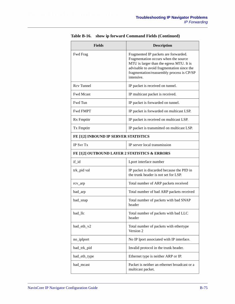
Beta Draft Confidential Troubleshooting IP Navigator ProblemsIP Forwarding
Fwd Frag Fragmented IP packets are forwarded.Fragmentation occurs when the sourceMTU is larger than the egress MTU. It isadvisable to avoid fragmentation since thefragmentation/reassembly process is CP/SPintensive.
Rcv Tunnel IP packet is received on tunnel.
Fwd Mcast IP multicast packet is received.
Fwd Tun IP packet is forwarded on tunnel.
Fwd FMPT IP packet is forwarded on multicast LSP.
Rx Fmptitr IP packet is received on multicast LSP.
Tx Fmptitr IP packet is transmitted on multicast LSP.
FE [1|2] INBOUND IP SERVER STATISTICS
IP Svr Tx IP server local transmission
FE [1|2] OUTBOUND LAYER 2 STATISTICS & ERRORS
if_id Lport interface number
trk_pid val IP packet is discarded because the PID inthe trunk header is not set for LSP.
rcv_arp Total number of ARP packets received
bad_arp Total number of bad ARP packets received
bad_snap Total number of packets with bad SNAPheader
bad_llc Total number of packets with bad LLCheader
bad_eth_v2 Total number of packets with ethertypeVersion 2
no_iplport No IP lport associated with IP interface.
bad_trk_pid Invalid protocol in the trunk header.
bad_eth_type Ethernet type is neither ARP or IP.
bad_mcast Packet is neither an ethernet broadcast or amulticast packet.
Table B-16. show ip forward Command Fields (Continued)
Fields Description
NavisCore IP Navigator Configuration Guide 1/14/02B-75

Beta Draft ConfidentialTroubleshooting IP Navigator ProblemsIP Forwarding
discards Discards occur for other reasons than thoseshown above.
Fwd SFPK Total number of packets forwarded to SPFK
FE [1|2] OUTBOUND LAYER 3 ERRORS
ip_vers Discard packets with incorrect IP version(not V4)
ip_hdr_short IP header is too short (less than the expected20 bytes)
ip_trunk_pkt IP header is truncated
ip_chksum IP Header checksum is bad
ip_filter Blocked filter packets
rte_reject IP route enter REJECT flag is set
lnk_bcst Link broadcast packet
ip_bc Broadcasts not forwarded (BC flag is set)
ip_lbc Subnet broadcasts not forwarded
lock_discard Route table is locked
ip_lnktype Bad or unsupported link type
inact_fwd_flags IP packet is discarded because circuit flowis turned off.
no_fbufs There are no FMBUFs available
bad_prtcn id This error occurs when the protcon doesn'tknow where to send the packet.
invalid_mpt Invalid MPT errors
no_lnk No link associated with ifNum
no_iplport No IP Lport associated with ifNum
no_lnkproxy No link proxy
icmp_thtl ICMP throttle discard
iparp_thtl IPARP throttle discard
ip_lookup No IP route entry exists
Table B-16. show ip forward Command Fields (Continued)
Fields Description
B-761/14/02 NavisCore IP Navigator Configuration Guide
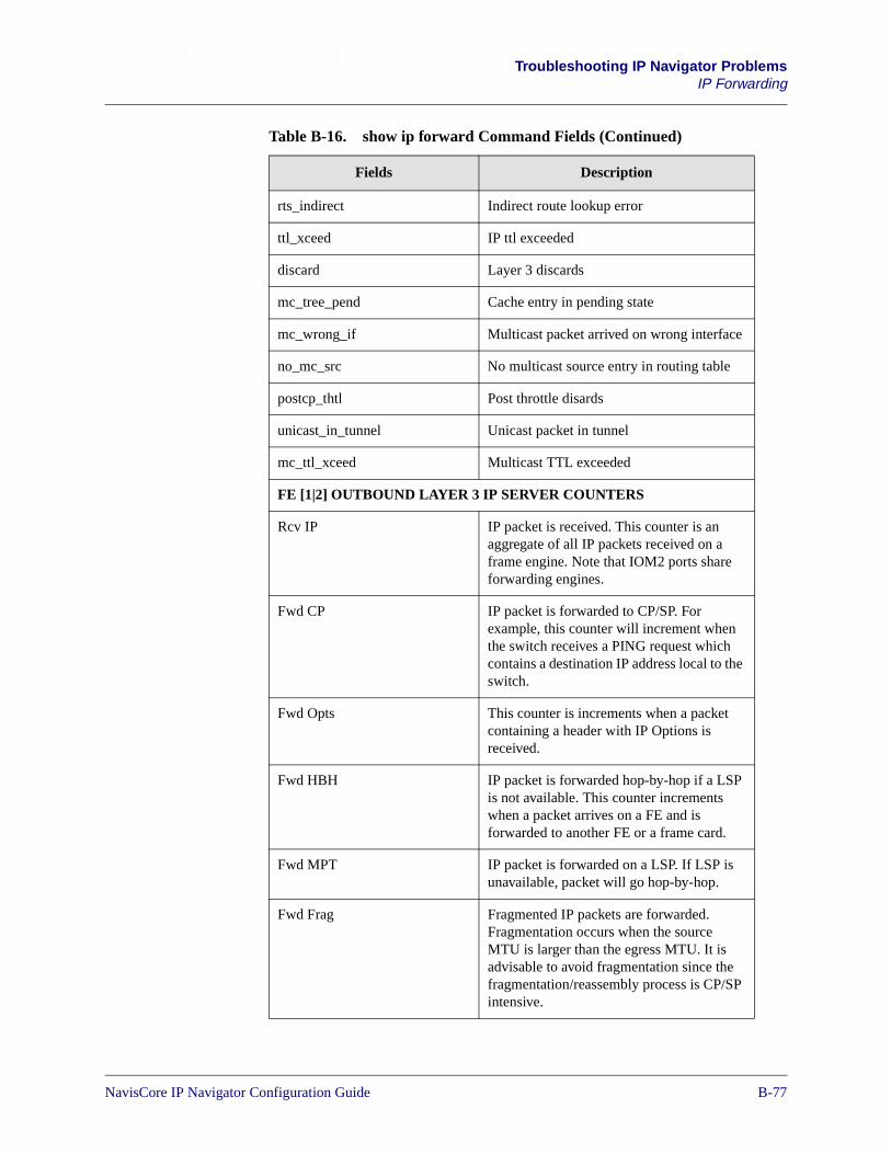
Beta Draft Confidential Troubleshooting IP Navigator ProblemsIP Forwarding
rts_indirect Indirect route lookup error
ttl_xceed IP ttl exceeded
discard Layer 3 discards
mc_tree_pend Cache entry in pending state
mc_wrong_if Multicast packet arrived on wrong interface
no_mc_src No multicast source entry in routing table
postcp_thtl Post throttle disards
unicast_in_tunnel Unicast packet in tunnel
mc_ttl_xceed Multicast TTL exceeded
FE [1|2] OUTBOUND LAYER 3 IP SERVER COUNTERS
Rcv IP IP packet is received. This counter is anaggregate of all IP packets received on aframe engine. Note that IOM2 ports shareforwarding engines.
Fwd CP IP packet is forwarded to CP/SP. Forexample, this counter will increment whenthe switch receives a PING request whichcontains a destination IP address local to theswitch.
Fwd Opts This counter is increments when a packetcontaining a header with IP Options isreceived.
Fwd HBH IP packet is forwarded hop-by-hop if a LSPis not available. This counter incrementswhen a packet arrives on a FE and isforwarded to another FE or a frame card.
Fwd MPT IP packet is forwarded on a LSP. If LSP isunavailable, packet will go hop-by-hop.
Fwd Frag Fragmented IP packets are forwarded.Fragmentation occurs when the sourceMTU is larger than the egress MTU. It isadvisable to avoid fragmentation since thefragmentation/reassembly process is CP/SPintensive.
Table B-16. show ip forward Command Fields (Continued)
Fields Description
NavisCore IP Navigator Configuration Guide 1/14/02B-77
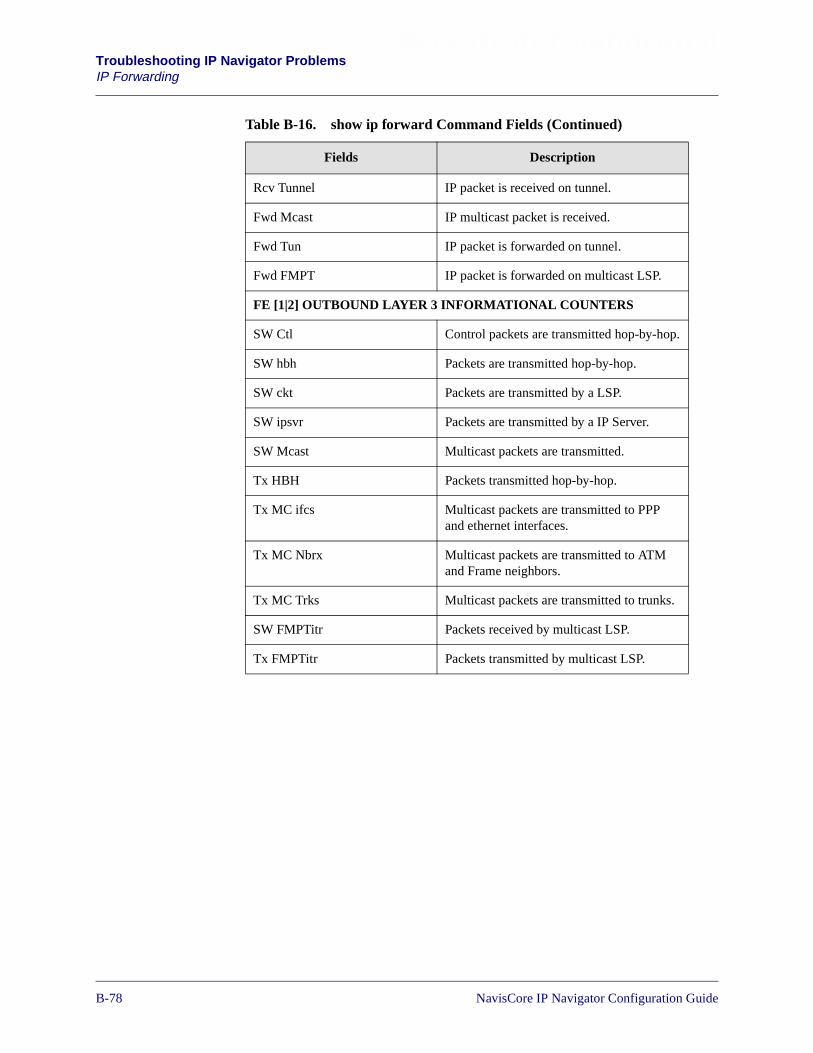
Beta Draft ConfidentialTroubleshooting IP Navigator ProblemsIP Forwarding
Rcv Tunnel IP packet is received on tunnel.
Fwd Mcast IP multicast packet is received.
Fwd Tun IP packet is forwarded on tunnel.
Fwd FMPT IP packet is forwarded on multicast LSP.
FE [1|2] OUTBOUND LAYER 3 INFORMATIONAL COUNTERS
SW Ctl Control packets are transmitted hop-by-hop.
SW hbh Packets are transmitted hop-by-hop.
SW ckt Packets are transmitted by a LSP.
SW ipsvr Packets are transmitted by a IP Server.
SW Mcast Multicast packets are transmitted.
Tx HBH Packets transmitted hop-by-hop.
Tx MC ifcs Multicast packets are transmitted to PPPand ethernet interfaces.
Tx MC Nbrx Multicast packets are transmitted to ATMand Frame neighbors.
Tx MC Trks Multicast packets are transmitted to trunks.
SW FMPTitr Packets received by multicast LSP.
Tx FMPTitr Packets transmitted by multicast LSP.
Table B-16. show ip forward Command Fields (Continued)
Fields Description
B-781/14/02 NavisCore IP Navigator Configuration Guide
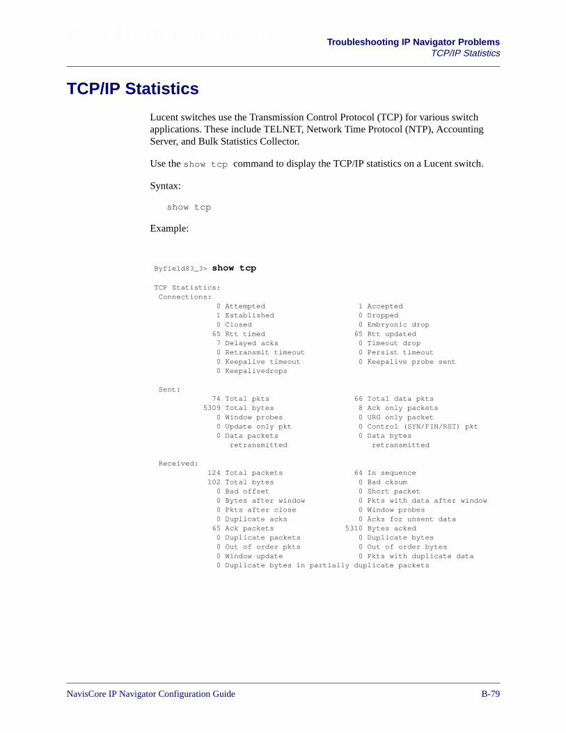
Beta Draft Confidential Troubleshooting IP Navigator ProblemsTCP/IP Statistics
TCP/IP Statistics
Lucent switches use the Transmission Control Protocol (TCP) for various switchapplications. These include TELNET, Network Time Protocol (NTP), AccountingServer, and Bulk Statistics Collector.
Use the show tcp command to display the TCP/IP statistics on a Lucent switch.
Syntax:
show tcp
Example:
Byfield83_3> show tcp
TCP Statistics:Connections:
0 Attempted 1 Accepted1 Established 0 Dropped0 Closed 0 Embryonic drop
65 Rtt timed 65 Rtt updated7 Delayed acks 0 Timeout drop0 Retransmit timeout 0 Persist timeout0 Keepalive timeout 0 Keepalive probe sent0 Keepalivedrops
Sent:74 Total pkts 66 Total data pkts
5309 Total bytes 8 Ack only packets0 Window probes 0 URG only packet0 Update only pkt 0 Control (SYN/FIN/RST) pkt0 Data packets 0 Data bytes
retransmitted retransmitted
Received:124 Total packets 64 In sequence102 Total bytes 0 Bad cksum
0 Bad offset 0 Short packet0 Bytes after window 0 Pkts with data after window0 Pkts after close 0 Window probes0 Duplicate acks 0 Acks for unsent data
65 Ack packets 5310 Bytes acked0 Duplicate packets 0 Duplicate bytes0 Out of order pkts 0 Out of order bytes0 Window update 0 Pkts with duplicate data0 Duplicate bytes in partially duplicate packets
NavisCore IP Navigator Configuration Guide 1/14/02B-79

Beta Draft ConfidentialTroubleshooting IP Navigator ProblemsTCP/IP Statistics
The following table describes the fields for the show tcp command.
Table B-17. show tcp Command Fields
Field Description
TCP CONNECTIONS
Attempted Total number of initiated connections.
Accepted Total number of SYNs (synchronizesequence numbers used to establishconnection) received in LISTEN state.
Established Total number of connections establishedactively or passively at switch.
Dropped Total number of dropped connections (afterSYN received).
Closed Total number of connections closed(includes drops).
Embryonic drop Total number of embryonic connectionsdropped before a synchronize sequencenumbers (SYN) is received.
Rtt Timed Total number of segments for which TCPtried to measure Rtt (round trip time).
Rtt Updated Total number of times Rtt estimatorsupdated.
Delayed acks Total number of delayed ACKS(acknowledgement number) sent.
Timeout drop Total number of dropped connections inretransmission timeout.
Retransmit timeout Total number of retransmit timeouts.
Persist timeout Total number of times persist timer expires.
Keepalive timeout Total number of times keepalive timer orconnection-establishment timer expire.
Keepalive probe sent Total number of keepalive probes sent.
Keepalive drops Total number of connections dropped inkeepalive (established or awaiting SYN).
SENT
Total pkts Total number of packets sent in sequence.
B-801/14/02 NavisCore IP Navigator Configuration Guide
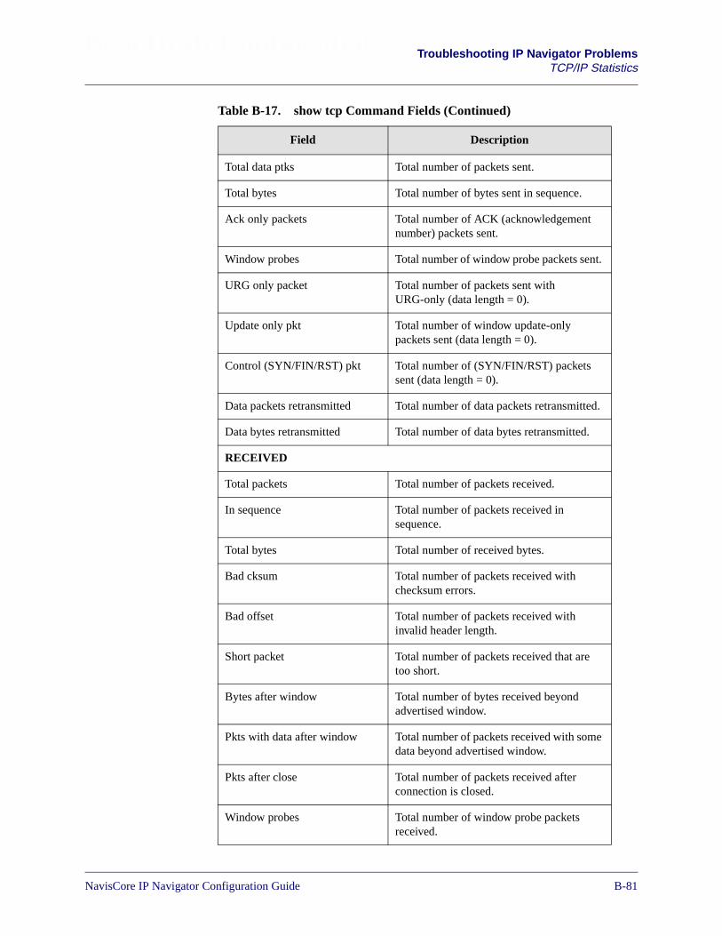
Beta Draft Confidential Troubleshooting IP Navigator ProblemsTCP/IP Statistics
Total data ptks Total number of packets sent.
Total bytes Total number of bytes sent in sequence.
Ack only packets Total number of ACK (acknowledgementnumber) packets sent.
Window probes Total number of window probe packets sent.
URG only packet Total number of packets sent withURG-only (data length = 0).
Update only pkt Total number of window update-onlypackets sent (data length = 0).
Control (SYN/FIN/RST) pkt Total number of (SYN/FIN/RST) packetssent (data length = 0).
Data packets retransmitted Total number of data packets retransmitted.
Data bytes retransmitted Total number of data bytes retransmitted.
RECEIVED
Total packets Total number of packets received.
In sequence Total number of packets received insequence.
Total bytes Total number of received bytes.
Bad cksum Total number of packets received withchecksum errors.
Bad offset Total number of packets received withinvalid header length.
Short packet Total number of packets received that aretoo short.
Bytes after window Total number of bytes received beyondadvertised window.
Pkts with data after window Total number of packets received with somedata beyond advertised window.
Pkts after close Total number of packets received afterconnection is closed.
Window probes Total number of window probe packetsreceived.
Table B-17. show tcp Command Fields (Continued)
Field Description
NavisCore IP Navigator Configuration Guide 1/14/02B-81

Beta Draft ConfidentialTroubleshooting IP Navigator ProblemsTCP/IP Statistics
Duplicate acks Total number of duplicate ACKs received.
Acks for unsent data Total number of ACKs for unsent data.
Ack packets Total number of received ACK packets.
Bytes acked Total number of bytes ACKed by receivedACKs.
Duplicate packets Total number of duplicate ACKs received.
Duplicate bytes Total number of bytes received incompletely duplicate packets.
Out of order pkts Total number of out-of-order bytes received.
Out of order bytes Total number of out-of-order bytes received.
Window update Total number of received window updatepackets.
Pkts with duplicate data Total number of packets received withcompletely duplicate bytes.
Duplicate bytes in partiallyduplicate packets
Total number of duplicate bytes inpart-duplicate packets.
Table B-17. show tcp Command Fields (Continued)
Field Description
B-821/14/02 NavisCore IP Navigator Configuration Guide

Beta Draft Confidential Troubleshooting IP Navigator ProblemsUDP Statistics
UDP Statistics
Lucent switches use the User Datagram Protocol (UDP) protocol for various switchapplications. These include software download, PRAM Sync, Switch Console DumpFunction, Radius authentication, Trap/Fault Manager and the SNMP agent.
The UDP statistics increment for datagrams received and forwarded at the switch.
Syntax:
show udp
Example:
The following table described the fields shown in the show udp command.
Table B-18. show udp Command Fields
Field Description
Total input packets Total number of received packets.
Total output packets Total number of transmitted packets.
ERRORS
Pkt shorter than header Received datagrams with packet shorterthan header.
Bad checksum Received datagrams with checksum error.
Data len larger than pkt Received datagram with data length largerthan packet.
No socket on port Received datagram with no process ondestination port.
No socket for broadcast Received broadcast/multicast datagramswith no process on destination port.
Dropped socket full Received datagrams not delivered becauseinput socket is full.
Byfield83_3> show udp
UDP Statistics:40579 total input packets, 40035 total output packets
Errors: 0 pkt shorter than header, 0 bad checksum0 data len larger than pkt, 0 no socket on port0 no socket for broadcast, 0 dropped socket full0 other
NavisCore IP Navigator Configuration Guide 1/14/02B-83

Beta Draft ConfidentialTroubleshooting IP Navigator ProblemsUDP Statistics
B-841/14/02 NavisCore IP Navigator Configuration Guide

Beta Draft Confidential
Index
A
Absolute QoS. See Next Hop Resolution ProtocolAccess lists, 11-2Address Resolution Protocol, 3-4, 6-1 to 6-5Administrative cost
threshold, 5-19trunks, 5-19, 9-26
AESA addressesAuthority and Format Identifier, 14-5Domain-Specific Part, 14-6End System Identifier, 14-7formats, 14-5 to 14-7High-Order Domain-Specific Part, 14-6Initial Domain Identifier, 14-6Initial Domain Part, 14-5octet formats, 14-7Selector, 14-7
AFI. See Authority and Format IdentifierAggregate, 8-9, 8-21Alias name, 5-18Alternate traffic descriptors, 14-64Area border routers, 9-6ARP. See Address Resolution ProtocolATM End System Addresses. See AESA addressesAuthentication keys, 9-43 to 9-48Authority and Format Identifier, 14-5
B
BGP. See Border Gateway Protocol
Border Gateway Protocolconfederation, 8-7defining aggregates, 8-21defining neighbors and assigning route filters to
them, 8-14defining switch parameters, 8-10equal-cost multi-path routing, 8-12peer groups, 8-23 to 8-28regular expression, 11-25, 11-28, 11-30, 11-32,
11-35, 11-64route dampening, 8-9, 8-29 to 8-30
C
CBR. See Constant bit rateCell domain, 12-10CIR. See Committed information rateCircuit priority, 5-21, 5-22Cloud IP interface, 6-1, 6-4, 16-6 to 16-8, 16-19 to
16-20, 16-35 to 16-39Cluster ID, 8-13Committed burst size (BC), 5-21Committed information rate, 5-21Confederation ID, 8-12Confederation member, 8-18Constant bit rate, 5-22Corporate extranets, 16-1Corporate intranets, 16-1Custom AESA addresses, 14-7
NavisCore IP Navigator Configuration Guide Index-1

Index
Beta Draft Confidential
D
Data Country Code addresses. See DCC addressesData link connection identifier
associating with an IP VPN, 16-4, 16-13, 16-42to 16-45
binding to an ingress IP interface, 3-24, 16-53 to16-56
DTE automatic recognition, 3-13for Frame Relay logical ports, 3-18for policy PVCs, 5-18for static ARP entries, 6-4
DCC addresses, 14-7Default local preference, 8-12Distance Vector Multicast Routing Protocol
configuring, 15-32 to 15-42description, 15-4 to 15-9MOSPF interoperability, 15-15physical interfaces, 15-18scoped boundaries, 15-22tunnels, 15-18virtual interfaces, 15-4, 15-18
DLCI. See Data link connection identifierDomain Specific Part, AESA addresses, 14-6Domains
cell, 12-10frame, 12-10switch, 12-10
Downstream dependency, 15-5DTE automatic DLCI recognition, 3-13DVMRP. See Distance Vector Multicast Routing
Protocol
E
E.164 addresses, 14-7EBGP. See External Border Gateway ProtocolECMP. See Equal-cost multi-path routingEnabling Lports for IP, 3-5 to 3-12End System Identifier, 14-7End-to-end delay, 5-19Equal-cost multi-path routing
BGP, 8-12OSPF, 9-48
RIP, 7-6static routes, 10-4
ESI. See End System IdentifierEthernet logical ports
associating with an IP VPN, 16-4, 16-13, 16-41attributes, 2-9configuration prerequisites, 2-1configuring, 2-1 to 2-9
Excess burst size (Be), 5-21Export route maps, 8-19, 8-27, 15-36External Border Gateway Protocol, 8-7
F
FCP. See Flow Control ProcessorFeatures
new in this release, xxxivFlow Control Processor, 5-26Flow profiles
associating with NHRP logical ports, 14-64 to14-74
configuring, 14-19 to 14-31description, 13-5, 13-25 to 13-29QoS guarantees, 13-25 to 13-29
Forwardingconsole commands, B-66
show ip forward statistics, B-66 to B-78how an IP packet is forwarded, B-64 to B-65introduction, B-64IP Navigator limitations, B-2IP trace utility, B-7 to B-15route protocol priority, B-65route tables, B-64TCP/IP, B-79
ping, B-3 to B-5show tcp, B-79 to B-82show udp, B-83traceroute, B-6
troubleshooting, B-1Forwarding policies
assigning to a logical port, 5-33defining, 5-28
Frame domain, 12-10
Index-2 NavisCore IP Navigator Configuration Guide
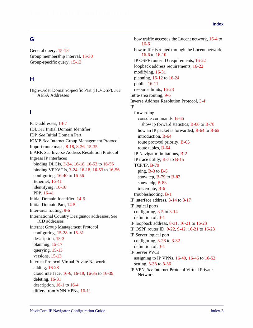
Index
Beta Draft Confidential
G
General query, 15-13Group membership interval, 15-30Group-specific query, 15-13
H
High-Order Domain-Specific Part (HO-DSP). SeeAESA Addresses
I
ICD addresses, 14-7IDI. See Initial Domain IdentifierIDP. See Initial Domain PartIGMP. See Internet Group Management ProtocolImport route maps, 8-18, 8-26, 15-35InARP. See Inverse Address Resolution ProtocolIngress IP interfaces
binding DLCIs, 3-24, 16-18, 16-53 to 16-56binding VPI/VCIs, 3-24, 16-18, 16-53 to 16-56configuring, 16-40 to 16-56Ethernet, 16-41identifying, 16-18PPP, 16-41
Initial Domain Identifier, 14-6Initial Domain Part, 14-5Inter-area routing, 9-6International Country Designator addresses. See
ICD addressesInternet Group Management Protocol
configuring, 15-28 to 15-31description, 15-3planning, 15-17querying, 15-13versions, 15-13
Internet Protocol Virtual Private Networkadding, 16-28cloud interface, 16-6, 16-19, 16-35 to 16-39deleting, 16-31description, 16-1 to 16-4differs from VNN VPNs, 16-11
how traffic accesses the Lucent network, 16-4 to16-6
how traffic is routed through the Lucent network,16-6 to 16-10
IP OSPF router ID requirements, 16-22loopback address requirements, 16-22modifying, 16-31planning, 16-12 to 16-24public, 16-11resource limits, 16-23
Intra-area routing, 9-6Inverse Address Resolution Protocol, 3-4IP
forwardingconsole commands, B-66
show ip forward statistics, B-66 to B-78how an IP packet is forwarded, B-64 to B-65introduction, B-64route protocol priority, B-65route tables, B-64
IP Navigator limitations, B-2IP trace utility, B-7 to B-15TCP/IP, B-79
ping, B-3 to B-5show tcp, B-79 to B-82show udp, B-83traceroute, B-6
troubleshooting, B-1IP interface address, 3-14 to 3-17IP logical ports
configuring, 3-5 to 3-14definition of, 3-1
IP loopback address, 8-31, 16-21 to 16-23IP OSPF router ID, 9-22, 9-42, 16-21 to 16-23IP Server logical port
configuring, 3-28 to 3-32definition of, 3-1
IP Server PVCsassigning to IP VPNs, 16-40, 16-46 to 16-52setting, 3-33 to 3-36
IP VPN. See Internet Protocol Virtual PrivateNetwork
NavisCore IP Navigator Configuration Guide Index-3

Index
Beta Draft Confidential
L
Label switched pathdescription, 12-9leaf occurrences in, 12-9over OPTimum trunks, 12-21 to 12-26point-to-point connections in, 12-13processing, 12-9purpose of root, 12-3
Label Switched Pathscall forwarding, B-21call signalling, B-20connection failure reasons, B-39 to B-42console commands, B-46
show mpt all, B-46show mpt ckt, B-47show mpt dpath, B-49show mpt error, B-50show mpt rootnodes, B-55show mpt signal, B-56show mpt spath, B-58show mpt svcarray/rsvcarray, B-62show mpt vcarray, B-59
examine the data path of an MPT LSP, B-27 toB-38
flag characteristics, B-44 to B-45information and restrictions
MPT LSPs, B-21 to B-23multicast LSPs, B-24point-to-point LSPs, B-24
introduction, B-19LSP trace utility, B-15 to B-18path failure reasons, B-43terms/acronyms, B-25 to B-26
Last member query count, 15-31Last member query interval, 15-30Link State Advertisement, 9-8Local AS, 8-12LSA. See Link State AdvertisementLSP, See Label Switched Path
M
Management DLCI, 5-19
Maximum burst size, 5-23Maximum transfer unit
ATM, 3-16, 16-54cloud IP interface, 16-38Ethernet, 3-16, 16-54Frame Relay, 3-16, 16-54
MBS. See Maximum burst sizeMED comparison, 8-11Minimum acceptable traffic descriptors, 14-64MOSPF. See Multicast OSPFMTU. See Maximum transfer unitMulticast
dense-mode protocols, 15-3description, 15-1 to 15-12DVMRP, 15-4 to 15-9IGMP, 15-3LSPs, 15-15MOSPF, 15-10 to 15-11routing within the Lucent network, 15-15sparse-mode protocols, 15-3tunneling, 15-12
Multicast OSPFdescription, 15-10 to 15-11DVMRP interoperability, 15-15enabling, 15-24, 15-43exporting routes to DVMRP, 15-27, 15-44IP loopback address requirement, 15-26IP OSPF router ID requirement, 15-24multicast LSPs, 15-26, 15-44
N
Network access listadding, 11-15 to 11-17
Network Filter, 11-2Network filter
adding, 11-13 to 11-14Next Hop Client
address registration and resolution, 13-6 to 13-9description, 13-3 to 13-5
Next Hop Resolution Protocoldescription, 13-1 to 13-12flow profiles, 13-25 to 13-29, 14-19 to 14-31,
14-64 to 14-74
Index-4 NavisCore IP Navigator Configuration Guide
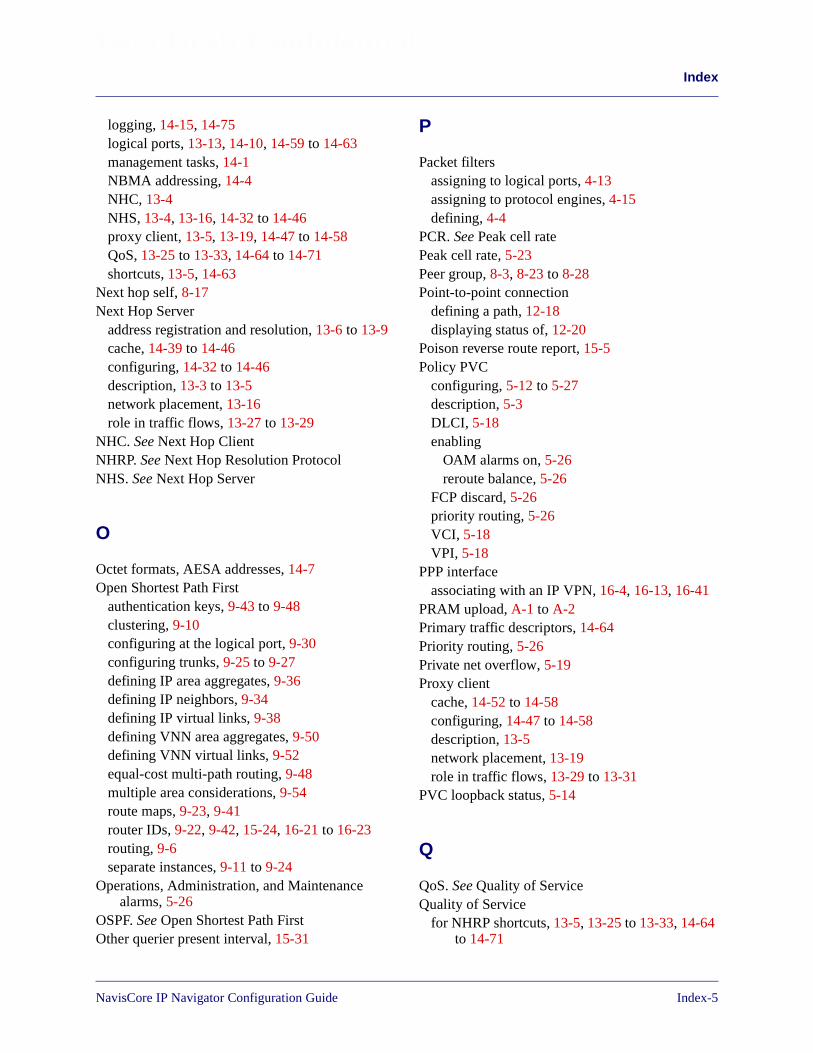
Index
Beta Draft Confidential
logging, 14-15, 14-75logical ports, 13-13, 14-10, 14-59 to 14-63management tasks, 14-1NBMA addressing, 14-4NHC, 13-4NHS, 13-4, 13-16, 14-32 to 14-46proxy client, 13-5, 13-19, 14-47 to 14-58QoS, 13-25 to 13-33, 14-64 to 14-71shortcuts, 13-5, 14-63
Next hop self, 8-17Next Hop Server
address registration and resolution, 13-6 to 13-9cache, 14-39 to 14-46configuring, 14-32 to 14-46description, 13-3 to 13-5network placement, 13-16role in traffic flows, 13-27 to 13-29
NHC. See Next Hop ClientNHRP. See Next Hop Resolution ProtocolNHS. See Next Hop Server
O
Octet formats, AESA addresses, 14-7Open Shortest Path First
authentication keys, 9-43 to 9-48clustering, 9-10configuring at the logical port, 9-30configuring trunks, 9-25 to 9-27defining IP area aggregates, 9-36defining IP neighbors, 9-34defining IP virtual links, 9-38defining VNN area aggregates, 9-50defining VNN virtual links, 9-52equal-cost multi-path routing, 9-48multiple area considerations, 9-54route maps, 9-23, 9-41router IDs, 9-22, 9-42, 15-24, 16-21 to 16-23routing, 9-6separate instances, 9-11 to 9-24
Operations, Administration, and Maintenancealarms, 5-26
OSPF. See Open Shortest Path FirstOther querier present interval, 15-31
P
Packet filtersassigning to logical ports, 4-13assigning to protocol engines, 4-15defining, 4-4
PCR. See Peak cell ratePeak cell rate, 5-23Peer group, 8-3, 8-23 to 8-28Point-to-point connection
defining a path, 12-18displaying status of, 12-20
Poison reverse route report, 15-5Policy PVC
configuring, 5-12 to 5-27description, 5-3DLCI, 5-18enabling
OAM alarms on, 5-26reroute balance, 5-26
FCP discard, 5-26priority routing, 5-26VCI, 5-18VPI, 5-18
PPP interfaceassociating with an IP VPN, 16-4, 16-13, 16-41
PRAM upload, A-1 to A-2Primary traffic descriptors, 14-64Priority routing, 5-26Private net overflow, 5-19Proxy client
cache, 14-52 to 14-58configuring, 14-47 to 14-58description, 13-5network placement, 13-19role in traffic flows, 13-29 to 13-31
PVC loopback status, 5-14
Q
QoS. See Quality of ServiceQuality of Service
for NHRP shortcuts, 13-5, 13-25 to 13-33, 14-64to 14-71
NavisCore IP Navigator Configuration Guide Index-5

Index
Beta Draft Confidential
for policy PVCs, 5-21traffic descriptors, 14-64
Query interval, 15-29Query response interval, 15-30
R
Rate enforcement scheme, 5-21Regular expression, 11-25, 11-28, 11-30, 11-32,
11-35, 11-64Remote AS, 8-17Reroute time tuning, 5-26Reverse path forwarding, 15-5Route dampening, 8-9, 8-29 to 8-30Route maps
assigning export, 8-19, 8-27, 15-36assigning import, 8-18, 8-26, 15-35flow of route information, 11-7guidelines, 11-6overview, 11-3 to 11-11protocol pairs that do not require maps, 11-8protocol pairs that require maps, 11-9steps for configuring, 11-11using multiple, 11-10when not to use, 11-6
Route reflectorconfiguring, 8-13configuring cluster ID, 8-13enabling client, 8-17
Router classifications, 9-6
S
Scoped boundaries, 15-22, 15-37SCR. See Sustainable cell rateSecondary traffic descriptors, 14-64SEL. See SelectorSelector, 14-7Sending community attributes, 8-17Shortcuts
creating, 13-5description, 13-1how they work with MPT LSPs, 13-14
maximum, 14-29Spanning tree, 15-3Startup query count, 15-31Static ARP entry, 6-2Static routes, 10-2Summary LSA, 9-8Sustainable cell rate, 5-23Switch domains, 12-10
T
Technical Support, xxxixTemplates, 5-14, 5-19TOS zero metric, 9-26Traffic descriptors
alternate, 14-64minimum acceptable, 14-64primary, 14-64secondary, 14-64
Trap control attributes, 2-8Trunks
administrative cost, 5-19, 9-26enabling IP OSPF, 9-26TOS zero metric, 9-26
Tunnel control, 15-40
U
UFR. See Unspecified frame rateUnspecified frame rate, 5-21
V
Variable frame rate non-real time, 5-21Variable frame rate real-time, 5-21VCI. See Virtual channel identifierVFR-NRT. See Variable frame rate non-real timeVFR-RT. See Variable frame rate real-timeVirtual channel identifier
associating with an IP VPN, 16-4, 16-13, 16-42to 16-52
Index-6 NavisCore IP Navigator Configuration Guide
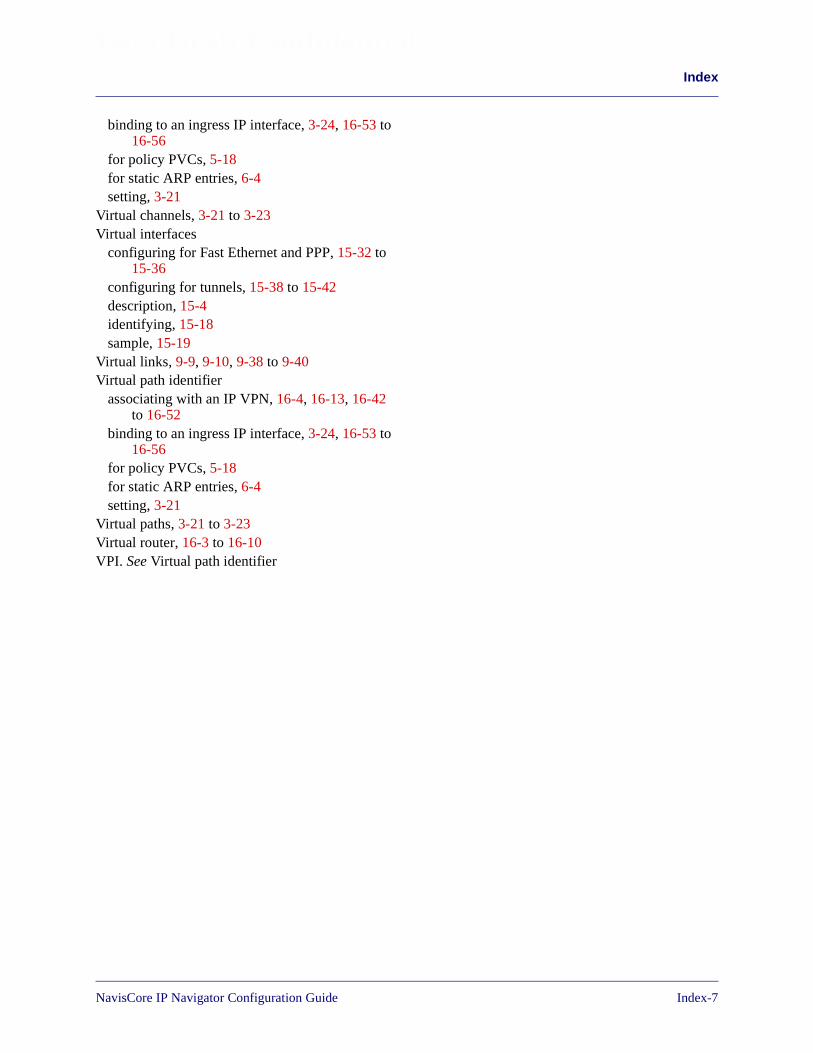
Index
Beta Draft Confidential
binding to an ingress IP interface, 3-24, 16-53 to16-56
for policy PVCs, 5-18for static ARP entries, 6-4setting, 3-21
Virtual channels, 3-21 to 3-23Virtual interfaces
configuring for Fast Ethernet and PPP, 15-32 to15-36
configuring for tunnels, 15-38 to 15-42description, 15-4identifying, 15-18sample, 15-19
Virtual links, 9-9, 9-10, 9-38 to 9-40Virtual path identifier
associating with an IP VPN, 16-4, 16-13, 16-42to 16-52
binding to an ingress IP interface, 3-24, 16-53 to16-56
for policy PVCs, 5-18for static ARP entries, 6-4setting, 3-21
Virtual paths, 3-21 to 3-23Virtual router, 16-3 to 16-10VPI. See Virtual path identifier
NavisCore IP Navigator Configuration Guide Index-7

Index
Beta Draft Confidential
Index-8 NavisCore IP Navigator Configuration Guide

NavisCore IP Navigator Configuration GuideCustomer Comments
Please take time to fill out this questionnaire so that we can do our best to meet yourdocumentation needs. Then fax or e-mail your comments to our Technical PublicationsDept. Your opinions are of great value to us!
FAX: (978) 692-1510 (Attn: Tech Pubs)E-MAIL: [email protected]
What tasks did you perform using this guide?
If you were having trouble performing a task, were you able to find the
Were the examples and illustrations helpful for performing tasks? If not, how
What did you like/not like about the manual?
Was there any information you needed that was not in the manual? If so, how
Do you have any other comments about the manual?
Page Description of Error
Name Company
Mailing Address
Phone E-mail address
information you needed? Was the index useful?
can we best deliver that information to you?
Did you install the hardware/software?
Fax No.
can they be improved?
Cu
tH
ere

Related Documents