Best Practice Core Handling Procedures Preamble Until quite recently, core orientation tests were laborious, interrupted the normal drilling cycle and commonly produced ambiguous or erroneous results. Developments in the diamond drilling fraternity, particularly in the core orientation industry has resulted in the evolution of more reliable and accurate core orientation tools. Improved diamond drilling techniques, an enhanced awareness for an improved quality of core drilling, coupled with dependable core orientation has greatly enhanced the effectiveness of core orientation surveys and the reliability of geological structural data sets. In essence, a properly drilled diamond drill borehole with precision orientation, coupled with an efficient data capture technique could provide the geologist with 100% geological exposure along the entire length of core and increase, by an order of magnitude, the geological data that can be acquired from the borehole and thereby improve confidence levels in ore reserve definition As per quote from BRETT K. DAVIS and E. JUN COWAN from OreLine in an article “Oriented Core What the ... ?”; “ A geologist must take ownership of core orientation and data collection. Don’t simply trust the drillers and the geotechs further down the line to get it right! Never, ever assume the core is correctly oriented. Perform some checks e.g. measure a feature that has a consistent orientation regionally and check that it conforms.” … the geologist, or the responsible person should accept greater accountability for the onsite core handling procedures. This paper outlines in detail proposed standard procedures for onsite meter marking and orientating diamond drill core samples that will hopefully improve onsite efficiency and provide a practical benchmark to evaluate the accuracy and precision of individual orientation tools. It is proposed to introduce two new measurements that will hopefully enhance and provide quality control measures that will benefit, not only the driller, but the geologist as well as the survey tool manufacturers. The procedures put forward in this article are an initial proposal and require the approval and corroboration from all concerned in onsite core handling procedures. In addition to experience in the style of mineralization, a Competent Person reporting Mineral Resources should have sufficient knowledge of sampling and assaying techniques relevant to the deposit under consideration and be aware of problems that could affect the reliability of the data. Some appreciation of extraction and processing techniques applicable to that deposit type would also be important. Unique Core Products Africa (PTY) LTD.

Welcome message from author
This document is posted to help you gain knowledge. Please leave a comment to let me know what you think about it! Share it to your friends and learn new things together.
Transcript
Best Practice -‐ Core Handling Procedures Preamble Until quite recently, core orientation tests were laborious, interrupted the normal drilling cycle and commonly produced ambiguous or erroneous results. Developments in the diamond drilling fraternity, particularly in the core orientation industry has resulted in the evolution of more reliable and accurate core orientation tools. Improved diamond drilling techniques, an enhanced awareness for an improved quality of core drilling, coupled with dependable core orientation has greatly enhanced the effectiveness of core orientation surveys and the reliability of geological structural data sets. In essence, a properly drilled diamond drill borehole with precision orientation, coupled with an efficient data capture technique could provide the geologist with 100% geological exposure along the entire length of core and increase, by an order of magnitude, the geological data that can be acquired from the borehole and thereby improve confidence levels in ore reserve definition As per quote from BRETT K. DAVIS and E. JUN COWAN from OreLine in an article “Oriented Core -‐ What the ... ?”; “ A geologist must take ownership of core orientation and data collection. Don’t simply trust the drillers and the geotechs further down the line to get it right! Never, ever assume the core is correctly oriented. Perform some checks e.g. measure a feature that has a consistent orientation regionally and check that it conforms.” … the geologist, or the responsible person should accept greater accountability for the on-‐site core handling procedures. This paper outlines in detail proposed standard procedures for on-‐site meter marking and orientating diamond drill core samples that will hopefully improve on-‐site efficiency and provide a practical benchmark to evaluate the accuracy and precision of individual orientation tools. It is proposed to introduce two new measurements that will hopefully enhance and provide quality control measures that will benefit, not only the driller, but the geologist as well as the survey tool manufacturers. The procedures put forward in this article are an initial proposal and require the approval and corroboration from all concerned in on-‐site core handling procedures. In addition to experience in the style of mineralization, a Competent Person reporting Mineral Resources should have sufficient knowledge of sampling and assaying techniques relevant to the deposit under consideration and be aware of problems that could affect the reliability of the data. Some appreciation of extraction and processing techniques applicable to that deposit type would also be important.
Unique Core Products Africa (PTY) LTD.
Process The meter-‐marking and core orientating procedures involve a continual process of constantly checking and verifying the previous measurements obtained from the succeeding depth mark. In most cases, be it meter-‐marking or drawing the orientation line onto the core should be inscribed with a temporary marker and should only be permanently marked once the recordings have been verified and corroborated by the information obtain from the next run. Proposed measurement parameters include; 1. Core Orientation % (CO) is defined as the percentage of the core per run that is accurately orientated. i.e. (CO = length of core orientated/length of core recovered x1 00) This parameter, measures or gives an indication of:
• Ground conditions which can be correlated with the Rock Quality Designation. • Quality of the drilling.
2. Orientation Variance (OV) is the angular deviance between successive BOC orientation readings from one orientation reading to the next measured in degrees. This parameter, can provide an indication of the:
1. Accuracy and reliability of the orientation tool 2. Precision of the on-‐site orientation marking procedure 3. Determine if there is any on-‐site falsifying of the orientation recordings. 4. Any bias in the survey tool, which may be pertinent with back-‐end tools as a result of core
rotation in the inner tube. Definitions: Driller’s depth: The depth marker inscribed by the driller represents the Drill String Length to the bottom of the hole. The accurate position of the core block in relation to the core is unknown and depends on the amount of core left down the hole after each run. The position of the core block relative to the core represents the point where the orientation was undertaken. i.e. orientation is done at the core break. Stick-‐up is a drilling technique of accurately measuring the length of the drill string to the bottom of the hole. Total measured length of all the drill rods less the quill (remaining length of outer tube extending out from the collar) Stick-‐up should be performed every time the driller has to pull the drill string., i.e. to change the bit. Stick up should also be performed in the presence of the geologist or geological technician. The bulk of the drill string is drill pipe, which has a nominal length of 3.0m meter per pipe section, however, in reality, not all pipes are the same length. Weakened or damaged ends of a pipe section will be reworked, resulting in reduced length.
Front-‐end orientation tools survey or mark the core at the break from the front of the core barrel and marks the top surface of the run. Survey tools in this category are Spear, EzyMark, Rear-‐end orientation tools orientate the inner tube and the BOC must be transferred to the front of the core barrel and then transcribed on to the bottom surface of the run. Tools in this category include the ACTII, Ballmark, CorientR and the Ezy-‐Ori Systems. Drill Break is an unnatural break in the core often indicated by grinding or crushing of the core resulting in pieces of core not being fitted together accurately, this results in the rotation of the core in the inner tube and a disruption or discontinuity to the orientation marking process. The process can be severely compromised if there are two or more drill breaks per run. Orientation line is the line representing the vertical disposition of the core. It is generally transcribed along the bottom of the core (BOC), although situations may arise when the instrument references the top of the core (TOC) Total Core Recovery (TCR) is the borehole core recovery percentage. TCR is defined as (Sum of length of core pieces) / (Total length of core run) X 100% Solid Core recovery (SCR) is the borehole core recovery percentage of solid, cylindrical, pieces of rock core. SCR is defined as (Sum of solid, cylindrical, core pieces) / (Total length of core run) X 100% Rock Quality Designation (RQD) is a rough measure of the degree of jointing or fractures in a rock mass, measured as a percentage of drill core lengths of 10cm or more. RQD is defined as (Sum of length of core pieces >100mm) X (Total length of core run) X 100% Core Orientation % (CO) Core Orientation % is the length of core per run that can be confidentially orientated, expressed as a percentage of the total core run. CO is defined as (Length of core accurately and reliably orientated) / (Total length of core run) X 100%. Factors that effect the CO are poor rock quality and poor drilling practices. The orientation line is transcribed from the orientation at the beginning and end of run and the orientation line is transcribed up or down the core. The process can be severely compromised if there are two or more drill breaks per run.
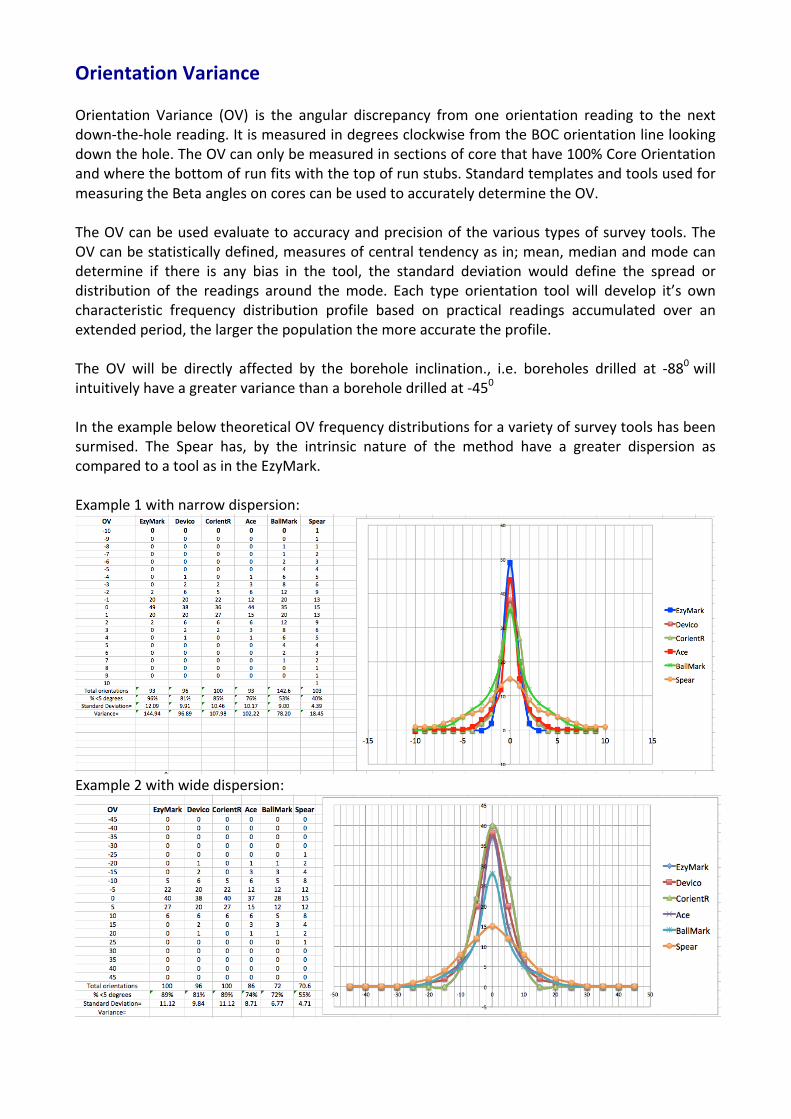
Orientation Variance Orientation Variance (OV) is the angular discrepancy from one orientation reading to the next down-‐the-‐hole reading. It is measured in degrees clockwise from the BOC orientation line looking down the hole. The OV can only be measured in sections of core that have 100% Core Orientation and where the bottom of run fits with the top of run stubs. Standard templates and tools used for measuring the Beta angles on cores can be used to accurately determine the OV. The OV can be used evaluate to accuracy and precision of the various types of survey tools. The OV can be statistically defined, measures of central tendency as in; mean, median and mode can determine if there is any bias in the tool, the standard deviation would define the spread or distribution of the readings around the mode. Each type orientation tool will develop it’s own characteristic frequency distribution profile based on practical readings accumulated over an extended period, the larger the population the more accurate the profile. The OV will be directly affected by the borehole inclination., i.e. boreholes drilled at -‐880 will intuitively have a greater variance than a borehole drilled at -‐450 In the example below theoretical OV frequency distributions for a variety of survey tools has been surmised. The Spear has, by the intrinsic nature of the method have a greater dispersion as compared to a tool as in the EzyMark. Example 1 with narrow dispersion:
Example 2 with wide dispersion:

Individual orientation tool companies will be able to produce a ‘Core Orientation Profile’ for their product. The profile should be based on practical readings recorded in the field. This profile is used as the companies marketing tool and as their ‘standard’ i.e. if their tool is used properly 89% of the readings will be within 5 degrees -‐ quantifiable
2. This can then be compared with the on-‐site measurements/ stats to determine how efficient/ accurate their readings are.
Accordingly should the frequency distribution not confirm to the instrument’s OV profile; as in the example below could indicate that the orientation readings have been forged.
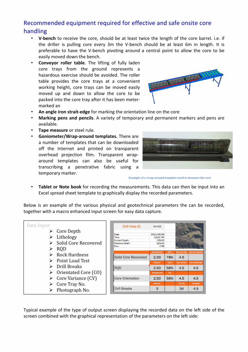
Recommended equipment required for effective and safe onsite core handling
• V-‐bench to receive the core, should be at least twice the length of the core barrel. i.e. if the driller is pulling core every 3m the V-‐bench should be at least 6m in length. It is preferable to have the V-‐bench pivoting around a central point to allow the core to be easily moved down the bench.
• Conveyor roller table. The lifting of fully laden core trays from the ground represents a hazardous exercise should be avoided. The roller table provides the core trays at a convenient working height, core trays can be moved easily moved up and down to allow the core to be packed into the core tray after it has been meter-‐marked an
• An angle iron strait-‐edge for marking the orientation line on the core • Marking pens and pencils. A variety of temporary and permanent markers and pens are
available. • Tape measure or steel rule. • Goniometer/Wrap-‐around templates. There are
a number of templates that can be downloaded off the Internet and printed on transparent overhead projection film. Transparent wrap-‐around templates can also be useful for transcribing a penetrative fabric using a temporary marker.
Example of a wrap-‐around template used to measure the core
• Tablet or Note book for recording the measurements. This data can then be input into an Excel spread sheet template to graphically display the recorded parameters.
Below is an example of the various physical and geotechnical parameters the can be recorded, together with a macro enhanced input screen for easy data capture.
Typical example of the type of output screen displaying the recorded data on the left side of the screen combined with the graphical representation of the parameters on the left side:
Data Input: Ø Core Depth Ø Lithology Ø Solid Core Recovered Ø RQD Ø Rock Hardness Ø Point Load Test Ø Drill Breaks Ø Orientated Core (CO) Ø Core Variance (CV) Ø Core Tray No. Ø Photograph No.
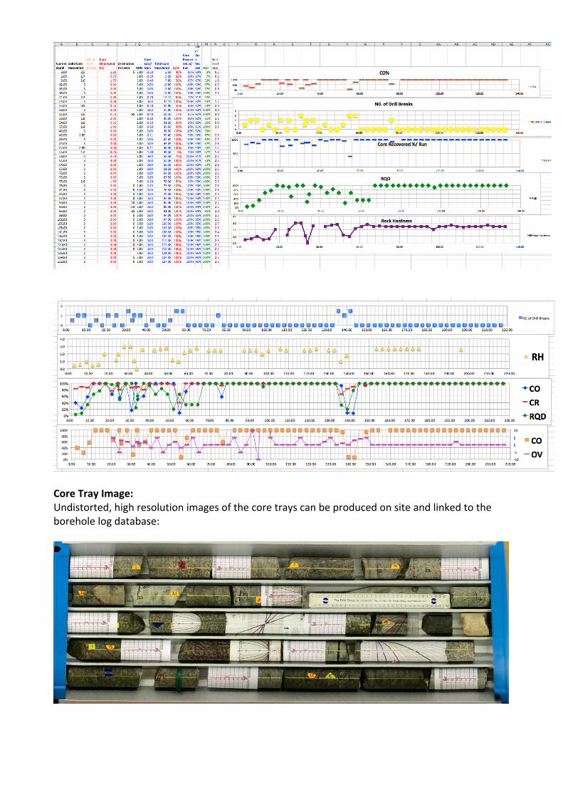
Core Tray Image: Undistorted, high resolution images of the core trays can be produced on site and linked to the borehole log database:

An exemplary borehole comprising three runs has been used to explain the proposed meter-‐marking and core orientation procedure. Run 1 represents a 3m run, depth 10.56-‐13.56m with 88.3%Core Recovery and one Drill Break and one Core Loss zone, effectively 2 drill breaks. Run 2 represents a 3m run, depth 13.86-‐16.56m with 95.0% Core Recovery and one Drill Break Run 3 represents a 3m run, depth 16.56-‐19.56m with 100% Core Recovery no Drill Breaks The procedure starts with Run 1 assuming that there is a well defined bottom break or redrill marks and explains how depth mark or orientation is used to validate and evaluate the preceding up-‐hole recordings, a process that involves continuously working up and down the hole from reliable depth markers.
Core Preparation The removal of the core from the inner tube, piecing the core together on the V-‐bench, marking the BOC orientation obtained from the survey tool and measuring the Core Recovered (CR) should be the responsibility of the driller.
1. Extract the core from the inner tube on the V-‐bench
2. Remove the head assembly and extract the core 3. Wash and clean the core 4. Starting with the bottom of run place the core
juxtapose. Any fractured or broken ground should be carefully pieced together or if necessary glued together .
5. Mark any drill breaks, demarcated by grinding, crushed or core loss zones
6. Each section of core should be marked with a down hole direction indicator
7. Mark the BOC orientation mark on the bottom of the core

Meter marking the core Marking the depths on the core and measuring of the physical or geotechnical parameters of the core should be the responsibility of the on-‐site geological technician reporting directly to the responsible geologist. The core block inserted by the driller designating the depth of the hole does not accurately indicate the actual depth of the hole, often in competent rock the core spring can slip leave a stub of core at the bottom of the hole. In other cases of incompetent core pieces of core can be dropped down the hole this can result in grinding and crushing or loss of core. The best approach is to start the meter marking from a reliable depth, determined from a driller’s stick-‐up with bottom breaks or re-‐drills demarcated by a light lip on the core.
1. Run 1, corroborate the % Core Recovery (2.65/13.56-‐10.56)=88.3%) and check the Core Loss/Gain for the run (3.0-‐2.65=-‐0.35)
2. Run 1, check and mark any drill breaks demarcated by grinding, crushed or core loss zones. Allocate the Loss/Gain to specific zones i.e. grinding.
3. Run 1, locate the actual bottom of hole, if any from the previous run 10.56m i.e. the bottom breaks or redrill marks often demarcated by a small lip on the core or core spring slip marks. Mark the depth of hole at the actual bottom and temporary measure the distance to the next depth meter.
4. Run 1 measure and temporally meter-‐mark the rest of the core run using a temporary marker as in a wax crayon or chalk, taking cognizance of the core loss/gain zones.
5. Run 2, check the Core Recovery and determine and allocate core loss/gain and mark the down-‐hole direction on each piece of core.
6. Run 2, locate the actual bottom of hole and mark the actual depth 13.56 on the core.
7. Run 1, using 13.56m depth mark, check the temporary up-‐hole meter-‐marks by measuring from the actual bottom of hole 13.65m in 6 above. Make the adjustments if nessaccary and scribe using permanent marker the revised depths on the core and remove the temporary depth marks. To assist in the logging process the core can be marked with small tick-‐marks every 10cm.
8. Run 2, using the 13.56m depth mark temporally meter-‐mark the core run taking into consideration core loss on drill breaks. .
9. Run 3, check the Core Recovery and determine and allocate core loss/gain and mark the down-‐hole direction on each piece of core., in this case 100% CR
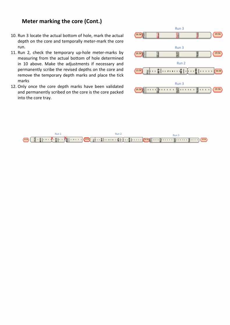
Meter marking the core (Cont.)
10. Run 3 locate the actual bottom of hole, mark the actual depth on the core and temporally meter-‐mark the core run.
11. Run 2, check the temporary up-‐hole meter-‐marks by measuring from the actual bottom of hole determined in 10 above. Make the adjustments if necessary and permanently scribe the revised depths on the core and remove the temporary depth marks and place the tick marks
12. Only once the core depth marks have been validated and permanently scribed on the core is the core packed into the core tray.

Drawing the BOC orientation Line The orientation line has to be verified by at least two consecutive orientations
In Summary; we now have 3 runs of core that have been properly meter-‐marked and orientated. Run 1 with the two drill breaks only has a CO of 65% Run 2 with one drill break with 100% CO Run 3 no drill breaks with a CO of 100%.
1. Locate the Bottom of Core (BOC) mark inscribed on the bottom of core by the driller.
2. Using a straight edge or preferably a small angle iron ruler extend the orientation line down the hole as far as the first drill break. Note that the orientation line cannot be transcribed across drill breaks. The rest of the run can only be up-‐hole orientated from the next run.
3. Run 1 -‐ Using a V-‐bench fit together the last section of core from Run 1 with the top section of core from Run 2 and transcribe the orientation line onto the Run 1 section of core. Extend the Orientation Line up the hole a far as the first drill break. Measure and calculate the % Core Orientation (CO) for the run ie (CO%= length of core orientated/length of core recovered/100)
4. Run 2 -‐ locate the BOC marked by the driller and extend the Orientation Line along the top of the core as far as the first drill break.
5. Run 2 -‐ fit together the last section of core from Run 2 with the top section of core from Run 3 and transcribe the orientation line onto the Run 2 section of core. Extend the Orientation Line up the hole a far as the first drill break. Measure and calculate the % Core Orientation (CO) for the run ie (CO%= length of core orientated/length of core run x 100)
6. Run 3 -‐ locate the BOC marked by the driller and extend the temporary Orientation Line along the top of the core to the end of the run. The BOC line

Drawing the BOC orientation Line using the Ori Block For orientation line has to be verified by at least two consecutive orientations.
Working with the Ezy-‐Mark front end Orientation system with Ori-‐blocks. It is important to understand firstly that any orientation system, whether it be back or front-‐end systems, measure the orientation of each drill break and so the depth indicated should read accordingly. Therefore the Ori-‐block essentially will replace any core depth markers inside the core tray, where the measurement provides an indication to the depth of the core break and the orientation of this core break.
7. Locate the Bottom of Core (BOC) mark inscribed on the bottom of core by the driller.
8. Using a straight edge or preferably a small angle iron ruler extend the orientation line down the hole as far as the first drill break. Note that the orientation line cannot be transcribed across drill breaks. The rest of the run can only be up-‐hole orientated from the next run.
9. Run 1 -‐ Using a V-‐bench fit together the last section of core from Run 1 with the top section of core from Run 2 and transcribe the orientation line onto the Run 1 section of core. Extend the Orientation Line up the hole a far as the first drill break. Measure and calculate the % Core Orientation (CO) for the run ie (CO%= length of core orientated/length of core recovered/100)
10. Run 2 -‐ locate the BOC marked by the driller and extend the Orientation Line along the top of the core as far as the first drill break.
11. Run 2 -‐ fit together the last section of core from Run 2 with the top section of core from Run 3 and transcribe the orientation line onto the Run 2 section of core. Extend the Orientation Line up the hole a far as the first drill break. Measure and calculate the % Core Orientation (CO) for the run ie (CO%= length of core orientated/length of core run x 100)
12. Run 3 -‐ locate the BOC marked by the driller and extend the temporary Orientation Line along the top of the core to the end of the run. The BOC line
When starting to work with the Ezy-‐Mark front-‐end system, along with the ori-‐blocks it is important to understand the above, and that each ori-‐block contains space for recording the following data points:
-‐ Depth at core break -‐ Core loss/gain -‐ The Ori-‐angle -‐ Advance -‐ Hole number -‐ Most importantly the footprint providing the orientation.
Correct procedure when working with Ori-‐Blocks:
-‐ Set up Ezy-‐Mark tool by attaching Ori-‐block as indicated -‐ Use shroud of Ori-‐block as last core depth marker -‐ Capture the orientation as per standard procedures from first tool -‐ Set up second Ezy-‐mark tool by attaching Ori-‐block -‐ Use shroud of first Ori-‐block to record information of Orientated run once bottom of hole has been
defined as per standard procedures. -‐ Follow this procedure until last orientated run has been completed. -‐
These Ori-‐blocks will provide any future geologist an audit able account of the orientations taken and is able to re-‐check any orientation completed for accurate.
Conclusions The introduction of the CO and in particular the OV will dramatically improve the quality of on site core orientation practices;
• Allow the geologist to have greater control and auditability • Allow the tool manufacturers to develop a sustainable and quantifiable record of their
tools performance • Ensure proper onsite procedures not only from the driller’s but the geologist’s and the
survey tool manufacturer’s point of view. •
A driller’s contract based primarily on production is not conducive to producing properly recorded orientated core. A bonus scheme to incentivise the driller to product quality core should be encouraged and factors such as CO, CV and No. of Drill breaks It is therefore apparent that the shorter the drill run the better the chance of improving the OV. The OV can be improved by shortening the drill run, in critical areas or fractured zones the drill run should be reduced to improve the variance. Vertical or near vertical boreholes do not provide a suitable environment for orientated core. Although there are instruments that do propound to survey vertical boreholes they are very likely to become susceptible to magnetic surrounds and can often provide spurious results. Where

possible the geologist should consider drilling inclined boreholes, drill holes of <850 inclination can provide more reliable results. It is sometimes difficult to obtain accurate recordings from small diameter drill holes. I.e. the CV is proportional to the core diameter. If a geologist is planning to drill orientated core, core sizes >N size should be considered. The BOC rather than the TOC has developed from the Spear is sometimes very confusing and can result in potential errors in recording structures. References: GeoZone Geoservices http://geozone.co.za/geotech-‐advice/logging-‐core/
Related Documents