1 © 2016 Viavi Solutions Inc. www.viavisolutions.com 1 © 2016 Viavi Solutions Inc. www.viavisolutions.com 1 © 2016 Viavi Solutions Inc. www.viavisolutions.com ‘Why’-’What’ and ‘How’ of Interference Hunting Atul Deshpande Makassar, Indonesia [email protected] 13 Sep 2016 Best Practices of Interference Management

Welcome message from author
This document is posted to help you gain knowledge. Please leave a comment to let me know what you think about it! Share it to your friends and learn new things together.
Transcript

1 © 2016 Viavi Solutions Inc. www.viavisolutions.com 1 © 2016 Viavi Solutions Inc. www.viavisolutions.com 1 © 2016 Viavi Solutions Inc. www.viavisolutions.com
‘Why’-’What’ and ‘How’ of Interference
Hunting Atul Deshpande
Makassar, Indonesia
13 Sep 2016
Best Practices of
Interference
Management

2 © 2016 Viavi Solutions Inc. www.viavisolutions.com 2 © 2016 Viavi Solutions Inc. www.viavisolutions.com 2 © 2016 Viavi Solutions Inc. www.viavisolutions.com
Agenda
• Understand ‘What’- What is Interference Management?
- What’s Interference Hunting
- Spectrum Cleaning Vs Interference Hunting
• Understand ‘Why’- Why hunt Interference?
- KPI and User experience Challenge
• Cellular Interference Issues
- Interference MATRIX (Cellular Operator)
• Understand ‘How’- How to hunt Interference Source?
- Symptoms
- Geography
- Preparation for IH
- Spectrum knowledge
- Statistics
- Site Level investigation
• 3 Steps in Interference Management
- Detect
- Identify
- Locate

3 © 2016 Viavi Solutions Inc. www.viavisolutions.com 3 © 2016 Viavi Solutions Inc. www.viavisolutions.com 3 © 2016 Viavi Solutions Inc. www.viavisolutions.com
Features
CellAdvisor BASE STATION ANALYZER SIGNAL ANALYZER RF ANALYZER CABLE & ANTENNA ANALYZERS
JD785B JD745B JD788B JD748B JD786B JD746B JD726C JD725C JD724C JD723C
Cable & Antenna Analysis
5MHz to 6GHz
5MHz to 4GHz
5MHz to 6GHz
5MHz to 4GHz
5MHz to 6GHz
5MHz to 4GHz
5MHz to 4GHz
100MHz to 2.7GHz
Insertion Gain/Loss O O O O O O O S
Bluetooth, WiFi, Web Control
O O O O O O O O O O
RF Power O O O O O O O O O O
Optical Power O O O O O O O O O O
Fiber Inspection O O O O O O O O O O
Cloud Services O O O O O O O O O O
Spectrum Analysis 9KHz to
8GHz 100KHz to
4GHz 9KHz to
8GHz 100KHz to
4GHz 9KHz to
8GHz 100KHz to
4GHz
Interference Analysis O O O O O O
PIM Detection S S S S S S
Signal Analysis O O O O
Interference Analysis O O O O O O
RFoFiber Interference O O O O O O
RFoCPRI BBU-Emulation
O O O O O O
Signal Analysis O O O O
LTE DAS Test O O O O
RF Test Portfolio Wireless Field Test Solutions O: Optional S: Standard : Not Available

4 © 2016 Viavi Solutions Inc. www.viavisolutions.com 4 © 2016 Viavi Solutions Inc. www.viavisolutions.com 4 © 2016 Viavi Solutions Inc. www.viavisolutions.com
CellAdvisor Fundamentals and Support
• Updating unit FW: http://celladvisor.updatemyunit.net
• Add-on Software (download from above link and install on Laptop):
- JDViewer (Viewing Spectrum Logs)
- JDMapCreator (For Map Creation on Google for Interference Hunting)
- JDRemote (For Remote monitoring)
• CellAdvisor JD700B User Manual
• Viavi CellAdvisor Page (Complete Portfolio and much more):
- http://www.viavisolutions.com/en-us/celladvisor
• Viavi Signal Analyzer Page (Brochure/Data Sheet/App Note/WhitePaper):
- http://www.viavisolutions.com/en-us/products/network-test-and-
certification/cell-site-test/celladvisor-signal-analyzers-jd748b-jd788b
• For support:
- Get in touch with Local Viavi Partner for immediate assistance.
- Drop me email: [email protected]

5 © 2016 Viavi Solutions Inc. www.viavisolutions.com 5 © 2016 Viavi Solutions Inc. www.viavisolutions.com 5 © 2016 Viavi Solutions Inc. www.viavisolutions.com
CellAdvisor Learning- Bookmarks!
• To learn more about Viavi InterferenceAdvisor Automated Solution:
- http://www.viavisolutions.com/en-us/interferenceadvisor
• InterferenceAdvisor Brochure
- http://www.viavisolutions.com/sites/default/files/technical-library-items/interferenceadvisor-
br-nsd-tm-ae.pdf
• InterferenceAdvisor Data Sheet (providing part numbers and specs)
- http://www.viavisolutions.com/sites/default/files/technical-library-items/interferenceadvisor-
ds-nsd-tm-ae.pdf
• Interference Hunting White Paper
- https://velocity.viavisolutions.com/servlet/JiveServlet/previewBody/4346-102-2-
6628/InterferenceHunting-wp-nsd-nse-ae.pdf
• Webinar on interference hunting
- http://content.rcrwireless.com/viavi_interference_hunting_webinar

6 © 2016 Viavi Solutions Inc. www.viavisolutions.com 6 © 2016 Viavi Solutions Inc. www.viavisolutions.com 6 © 2016 Viavi Solutions Inc. www.viavisolutions.com 6 © 2016 Viavi Solutions Inc. www.viavisolutions.com
Fundamentals-
Interference and
management

7 © 2016 Viavi Solutions Inc. www.viavisolutions.com 7 © 2016 Viavi Solutions Inc. www.viavisolutions.com 7 © 2016 Viavi Solutions Inc. www.viavisolutions.com
What is Interference and Interference Hunting?
• Interference (between radio signals) is, any RF Signal
(Modulated/CW/Baseband), oscillating at certain frequency and amplitude,
collides with another RF Signal with same frequency, (different) amplitude
@certain location.
• Interference Hunting is ‘systematic engineering approach’:
- To identify, detect and locate, RF Signal sources, infringing licenses bands
operations, at particular geography/location/area.
- Both Interferer Signal and Interfered signal can be genuine signals, sharing
similar licensed spectrum @particular location.
- New Allotted Spectrum means ‘Possibility of Interference’.
- Most of the allotted spectrum to Cellular Operators to launch new services is,
either refarmed by another Cellular Operator or service or by non-Cellular
Operators (Defense establishments, ISP, Broadcasters).

8 © 2016 Viavi Solutions Inc. www.viavisolutions.com 8 © 2016 Viavi Solutions Inc. www.viavisolutions.com 8 © 2016 Viavi Solutions Inc. www.viavisolutions.com
Introduction to RF Interference
SPECTRUM VISUALIZATION
• Spectrum is shared among an increasing number of licensed and unlicensed transmitters (Cellular, Cable TV, WiFi, AM/FM,
etc.) possibly causing interference among transmitters.
• The RF environment is also polluted by unwanted signals such as spurious, intermodulation, jammers, amplifiers and
elements that generate RF noise such as transformers and industrial machinery.
• Interference negatively affects services in terms of network coverage and mobile capacity.
• There are three main aspect for Interference analysis: Detection, Identification and Location.

9 © 2016 Viavi Solutions Inc. www.viavisolutions.com 9 © 2016 Viavi Solutions Inc. www.viavisolutions.com 9 © 2016 Viavi Solutions Inc. www.viavisolutions.com
Spectrum Cleaning Vs Interference Hunting
• Spectrum Clearing/Cleaning
- Greenfield/Brownfield network launch
- Launch of New services over refarmed
spectrum
- Mostly done Pre-launch of Network (Pre-
SCFT) or During Site Installation/AT
Phase.
- Drive testing with Receivers/Scanners
- Measure UL RSSI (measure of Clean
Spectrum).
- High RSSI (not clean Spectrum)
• Interference Hunting
- Specialized activity to ‘Detect- Identify-
Locate’ Interfering Sources
- Step 2 of High UL RSSI or Spectrum
Clearing drive.
- Network Launch/Planning Stage or
Optimization Network stage.
- Spectrum Analyzers with set of Antennas
(Omni and Directional).

10 © 2016 Viavi Solutions Inc. www.viavisolutions.com 10 © 2016 Viavi Solutions Inc. www.viavisolutions.com 10 © 2016 Viavi Solutions Inc. www.viavisolutions.com
Interference MATRIX
High Possibility
Highest Interest
Med to high Possibility
Curious Case
High Possibility
Not of our Interest
Not of our Interest
Interfered
Systems Cellular
Non-Cellular
Cellular Non- Cellular
Interfering Systems

11 © 2016 Viavi Solutions Inc. www.viavisolutions.com 11 © 2016 Viavi Solutions Inc. www.viavisolutions.com 11 © 2016 Viavi Solutions Inc. www.viavisolutions.com
• External Interference
- Radio Signal Generators, outside
Cellular Ecosystems.
- E.g. Cellular Repeaters, HAM Radios,
Police Wireless Transmitters etc.
• Interference Management Solution
can be deployed to identify ‘External
Interferences’
‘External Interference
Hunting’
External Interference Vs Internal Interference
• Internal Interference
- Radio Signal Generators, inside Cellular
Ecosystem of Opco.
- E.g. Faulty Hardware (RRU),
PIM/Intermod Generating Components
etc.
• Interference Management Solution
might be necessary but not sufficient
to address these.

12 © 2016 Viavi Solutions Inc. www.viavisolutions.com 12 © 2016 Viavi Solutions Inc. www.viavisolutions.com 12 © 2016 Viavi Solutions Inc. www.viavisolutions.com
• Interference affects ‘UL’ the ‘MOST’
- UL is more sensitive to Interference,
being low power transmission (UE to
NodeB)
- UL is un-controlled RF
- Better ‘Gain’ (to Interference) due to high
gain Antenna @Site.
- Coverage is UL limited (not DL)
- Asymmetric Traffic (UL Importance)
- Limited Optimization possible on UL
‘More Incentives to Interference
Hunters’
Why hunt Interference?

13 © 2016 Viavi Solutions Inc. www.viavisolutions.com 13 © 2016 Viavi Solutions Inc. www.viavisolutions.com 13 © 2016 Viavi Solutions Inc. www.viavisolutions.com
UPLINK
DOWNLINK
TX Power:
No limit (+43dBm)
RX Sensitivity:
-101.5 dBm
TX Power:
+23 dBm
RX Sensitivity:
-94 dBm
• Interference can affect downlink (cell-site) and
uplink (mobile).
• The uplink is more sensitive to interference due
to mobile transmission restrictions (23dBm or
0.2W).
• Interference can be generated by:
‒ External sources of the cell-site (noise generators,
other transmitters)
‒ Internal sources (spurious, harmonics, passive
inter-modulation).
Introduction to RF Interference Cellular Networks – Uplink Sensitivity
UPLINK AND DOWNLINK VISUALIZATION
CDMA UPLINK INTERFERENCE WCDMA UPLINK INTERFERENCE LTE UPLINK INTERFERENCE

14 © 2016 Viavi Solutions Inc. www.viavisolutions.com 14 © 2016 Viavi Solutions Inc. www.viavisolutions.com 14 © 2016 Viavi Solutions Inc. www.viavisolutions.com
Cellular Interference Issues
• Downlink (eNodeB to UE)
- DL more controlled
- DL Vs DL
- Inter RAT
- Intra RAT
- Neighbours
- Physical Optimization
- Parametric Optimization
- Power/Coverage/Capacity
• Uplink (UE to eNodeB)
- UL more uncontrolled
- UL Vs DL
- UL of eNodeB1 Vs DL of eNodeB2
- UL vs UL
- UL of eNodeB1 Vs Cellular
Repeaters
- UL Power Control
- UL Optimization?

15 © 2016 Viavi Solutions Inc. www.viavisolutions.com 15 © 2016 Viavi Solutions Inc. www.viavisolutions.com 15 © 2016 Viavi Solutions Inc. www.viavisolutions.com
Why Hunt Interference?
• Interference Hunting, as part of Network Optimization, is on-going process
• Network evolves-> Interference evolves
• Need improved process and tool to mitigate Interference
• Interference not-managed leads to:
- KPI Degradation at Site/Cluster level
- RRC Connection Setup, eRAN Connection Setup, Call Setup, UL throughput,
UL Quality (SINR/RSRQ), UL/DL Capacity, Call muting
- Degradation of Customer experience on Network (Inconsistent performance)
- Revenue/RoI Loss to Opco (Traffic churn)
‘Interference Hunting is full time designation is some of the
Opcos across globe and becoming more of so elsewhere’

16 © 2016 Viavi Solutions Inc. www.viavisolutions.com 16 © 2016 Viavi Solutions Inc. www.viavisolutions.com 16 © 2016 Viavi Solutions Inc. www.viavisolutions.com
• OSS/NMS Alarms
TRRIGERS!
• RF KPI Degradation
• UL RSSI
• UL Throughput
• Fix/Flexible PRB
SINR issues
• CSR Issue
• Call muting
• Customer Complaints
• Increased customer
complaints in certain
areas (due to
coverage/speed)
• In addition Opco are using GEO SON solutions to identify Interference Issues

17 © 2016 Viavi Solutions Inc. www.viavisolutions.com 17 © 2016 Viavi Solutions Inc. www.viavisolutions.com 17 © 2016 Viavi Solutions Inc. www.viavisolutions.com
• The location of Interference is a lengthy process based on directional testing at three
different positions and performing triangulation to find the intersection area where the
interferer is located.
Introduction to RF Interference Location
INTERFERENCE LOCATION VISUALIZATION

18 © 2016 Viavi Solutions Inc. www.viavisolutions.com 18 © 2016 Viavi Solutions Inc. www.viavisolutions.com 18 © 2016 Viavi Solutions Inc. www.viavisolutions.com 18 © 2016 Viavi Solutions Inc. www.viavisolutions.com
Best Practices
- Answer ‘How’

19 © 2016 Viavi Solutions Inc. www.viavisolutions.com 19 © 2016 Viavi Solutions Inc. www.viavisolutions.com 19 © 2016 Viavi Solutions Inc. www.viavisolutions.com
Best Practices
•Internal / External
On-site Analysis
•Drive large area
Detect Identify
•Optimize EagleEye
•Location Estimation
Drive Around
•Pinpoint source
•Antenna Advisor
Locate
•Report generator
Report
1. Start with the problematic site (e.g. eNB sector)
2. Drive around relatively large area to understand the problem details & the interferers characteristics
(e.g. intermittent, single tone, multi peaks, oscillating, band noise, etc)
3. Once the interferers detected, then narrow down more to find what frequency or band need to be used
for EagleEye
4. Optimize EagleEye setting using 3 different tracking modes (RSSI, Channel Power and Peak Power)
5. Drive in the direction of the strongest signal to estimate the most probable location of the source (Circle
indication, Directions & Navigations)
6. Manually pinpoint the source using AntennaAdvisor within the area estimated by EagleEye
CellAdvisor RFoCPRI
& RFoOBSAI
AntennAdvisor with
Log periodic antenna
EagleEye
Report Generator
EagleEye Spectrum &
Spectrum Control
EagleEye Location Estimation
(RSSI, Ch PWR, Peak PWR)

20 © 2016 Viavi Solutions Inc. www.viavisolutions.com 20 © 2016 Viavi Solutions Inc. www.viavisolutions.com 20 © 2016 Viavi Solutions Inc. www.viavisolutions.com
Cell Site Optimization Signal Analyzers
O: Optional S: Standard : Not Available
PERFORMANCE
RF and Optical Power
Fiber Inspection
Spectrum Clearance
AIR INTERFACE
CONNECTIVITY
Signal Analysis
PERFORMANCE RFoFiber
Interference Analysis &
BBU-Emulation
Signal Analysis
Interference Analysis
Features
CellAdvisor SIGNAL ANALYZER
JD788B JD748B
Cable & Antenna Analysis
Insertion Gain/Loss O O
Bluetooth O O
RF Power O O
Optical Power O O
Fiber Inspection O O
Cloud Services O O
Spectrum Analysis 9KHz to 8GHz 100KHz to
4GHz
Interference Analysis O O
PIM Detection S S
Signal Analysis O O
Interference Analysis O O
RFoFiber Interference O O
RFoFiber BBU Emulation O O
Signal Analysis O O
LTE DAS Test O O

21 © 2016 Viavi Solutions Inc. www.viavisolutions.com 21 © 2016 Viavi Solutions Inc. www.viavisolutions.com 21 © 2016 Viavi Solutions Inc. www.viavisolutions.com
RF
oF
ibe
r RFoFiber technology verifies CPRI and OBSAI control signals and analyzes user plane
traffic or RF (IQ) signals.
Cell Site Optimization RFoFiber Interference Analysis
Cable &
Antenna
Analysis Spectrum /
Interferenc
e
2G, 3G,
4G Signal
Analysis
Amplifier/Filter
Insertion G/L
GPS Positioning
Sync & Timing
Fiber Inspection
I/O Interface
RFoFiber
RF
signal
(RF)
CPRI
link
Framing
Grouping
Mapping
Sampling
RF
Signal
Analys
is
NEM Profiles
RFoFiber (CPRI or OBSAI) : Multi-Radios

22 © 2016 Viavi Solutions Inc. www.viavisolutions.com 22 © 2016 Viavi Solutions Inc. www.viavisolutions.com 22 © 2016 Viavi Solutions Inc. www.viavisolutions.com 22 © 2016 Viavi Solutions Inc. www.viavisolutions.com
Interference
Detection
23 © 2016 Viavi Solutions Inc. www.viavisolutions.com 23 © 2016 Viavi Solutions Inc. www.viavisolutions.com 23 © 2016 Viavi Solutions Inc. www.viavisolutions.com
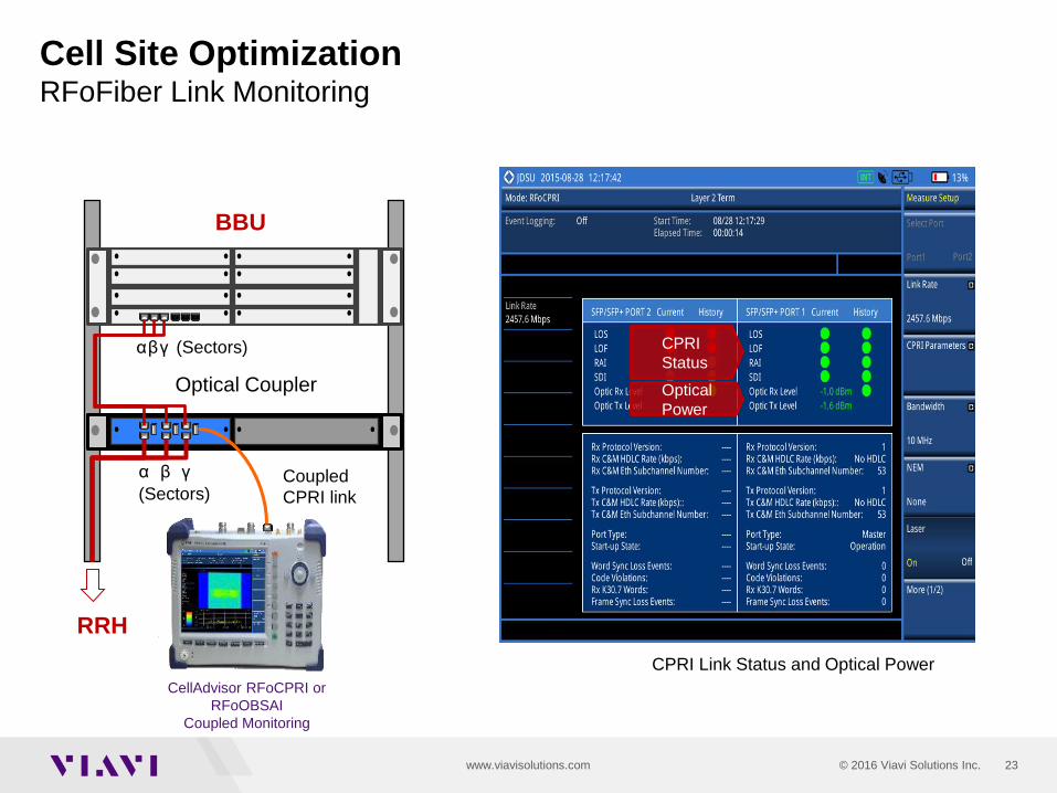
Cell Site Optimization RFoFiber Link Monitoring
BBU
α β γ
(Sectors)
Optical Coupler
α β γ (Sectors)
Coupled
CPRI link
CellAdvisor RFoCPRI or
RFoOBSAI
Coupled Monitoring
RRH
CPRI
Status
Optical
Power
CPRI Link Status and Optical Power

24 © 2016 Viavi Solutions Inc. www.viavisolutions.com 24 © 2016 Viavi Solutions Inc. www.viavisolutions.com 24 © 2016 Viavi Solutions Inc. www.viavisolutions.com
RFoCPRITM Interference Analysis
• Interference Analysis with RF Source (Multi-Carrier
WCDMA example)
Cell Site Optimization RFoFiber WCDMA Analysis (RFoCPRI & RF-Source)
RF Source @
837.5MHz RF Sources @
1906.5MHz
CellAdvisor
RFoCPRI
Copper
Fiber
Optic
al
Splitt
er
FIBER RX
RRU
BBU
RF
Sourc
e
UMTS
5MHz Channel
Bandwidt
h
3.84MHz Transmis
sion
Bandwidt
h
CPRI
CONTAI
NER
Dual Spectrogram – Active Analysis of Two Carriers
WCDMA Multi-Carrier Identification

25 © 2016 Viavi Solutions Inc. www.viavisolutions.com 25 © 2016 Viavi Solutions Inc. www.viavisolutions.com 25 © 2016 Viavi Solutions Inc. www.viavisolutions.com
RFoCPRITM Interference Analysis
• MIMO Test (Diversity Imbalance): Spectrum Analysis
and Spectrogram
Cell Site Optimization RFoFiber MIMO Test (Diversity Imbalance)
Antenn
a 2
Antenn
a 1
Dual Spectrum Analysis – Antenna 1 (Active) and Antenna 2 (Active)
Active Spectrum Analysis of Dual Antenna or Dual Carrier
Antenna 1 Antenna 2
Dual Spectrogram – Active Analysis of Two Antennas
RFoCPRI Dual Spectrum (MIMO) RFoCPRI Dual Spectrogram (MIMO)

26 © 2016 Viavi Solutions Inc. www.viavisolutions.com 26 © 2016 Viavi Solutions Inc. www.viavisolutions.com 26 © 2016 Viavi Solutions Inc. www.viavisolutions.com
RESOLUTION
BANDWITH
(RBW)
RBW = 1 MHz RBW = 100 KHz RBW = 10 KHz RBW = 1 KHz
TRACE
SIGNAL UNDER
TEST
Detecting Interference Measurement Techniques – Overview
5. RESOLUTION BANDWIDTH
4. FREQUENCY SPAN
1. A
TT
EN
UA
TIO
N
2. P
RE
AM
PL
IFIE
R
3. M
IN &
MA
X T
RA
CE
S
ATTN: 10dB
PREAMP: OFF
RBW: 300KHz
ATTN: 0dB
PREAMP: ON
RBW: 10KHz
SPECTRUM ANALYSIS
1. Attenuation. Typically
interference testing is
conducted at low power
connection points such as
antennas for which any
signal attenuation should be
removed.
2. Preamplifier. Low power
signals such as uplink will
require amplification (e.g.
10dB)
3. Min & Max Traces. Trace
control such as minimum
hold will effectively capture
interference in variable
(uplink) environments.
4. Frequency Span. A narrow
frequency span will improve
measurement time.
5. Resolution Bandwidth. A
low resolution bandwidth will
increase sensitivity and
signal detection.
Basic measurement techniques for interference testing with spectrum analysis.

27 © 2016 Viavi Solutions Inc. www.viavisolutions.com 27 © 2016 Viavi Solutions Inc. www.viavisolutions.com 27 © 2016 Viavi Solutions Inc. www.viavisolutions.com
RBW: 10KHz
Interference
Detected
RBW: 300KHz
No interference
Detecting Interference Measurement Techniques – RBW and VBW
SPECTRUM ANALYSIS - OVER THE AIR TEST
SPECTRUM ANALYSIS
GSM WCDMA CDMA
Interferences are better uncovered by: Improving sensitivity: lowering the instrument’s resolution bandwidth (RBW).
Eliminating trace noise: narrowing the video bandwidth (VBW) filter.

28 © 2016 Viavi Solutions Inc. www.viavisolutions.com 28 © 2016 Viavi Solutions Inc. www.viavisolutions.com 28 © 2016 Viavi Solutions Inc. www.viavisolutions.com
Signal
detection with
Maximum Hold
Signal trace
with spectrum
analysis
Signal trace
with minimum
hold
Detecting Interference Measurement Techniques – Maximum and Minimum Hold
SPECTRUM ANALYSIS
GSM WCMDA
SPECTRUM ANALYSIS - OVER THE AIR
Maximum and minimum power tests properly characterize variable signals: Signal level signature: holding maximum power will characterize time domain signals (GSM).
Noise level signature: holding minimum power will characterize noise floor (uplink).

29 © 2016 Viavi Solutions Inc. www.viavisolutions.com 29 © 2016 Viavi Solutions Inc. www.viavisolutions.com 29 © 2016 Viavi Solutions Inc. www.viavisolutions.com
Detecting Interference Measurement Techniques – Gated Sweep
POWER
TIME
FREQUENCY
TDD Uplink
Interference
TDD DOWNLINK TDD UPLINK
Time division duplex systems such as WiMAX-TDD and LTE-TDD share the same frequency for uplink
and downlink signals based on transmission time.
Interference detection in TDD signals is made in time-domain analysis with gate-sweep testing
enabling test-time control for uplink interference detection.
GATE-SWEEP ANALYSIS
TDD – Time Division Duplex (LTE-TDD or WiMAX)

30 © 2016 Viavi Solutions Inc. www.viavisolutions.com 30 © 2016 Viavi Solutions Inc. www.viavisolutions.com 30 © 2016 Viavi Solutions Inc. www.viavisolutions.com
Detecting Interference Intermittent Signals
Intermittent
Interference
SPECTROGRAM
WCDMA
CARRIERS
CDMA
CARRIERS
Long-term test Spectrogram test constantly
registers the spectrum over
extended periods of time.
Intermittent interference The spectrum is presented in a
color scale based on the
signal’s power level making it
easy to detect intermittent
signals.
Interference analysis Spectrogram records maintain
time and location for further
interference analysis.

31 © 2016 Viavi Solutions Inc. www.viavisolutions.com 31 © 2016 Viavi Solutions Inc. www.viavisolutions.com 31 © 2016 Viavi Solutions Inc. www.viavisolutions.com
• What is PIM?
Passive Inter-Modulation (PIM) is interference (uplink)
caused by signals derived by the combination of two or
more carriers (downlink) transmitted on a single
nonlinear feed-line.
• What causes PIM?
Nonlinearities in feed-lines can be created by improper
connections, contaminants, partial discontinuities
(cracks or dissimilar metal joints) or improper material
(ferromagnetic such as iron, nickel, cobalt).
Detecting Interference Passive Intermodulation
UPLINK
DOWNLINK
COMBINER
2G RADIO 3G RADIO
DOWNLINK
UPLINK
PIM
PIMIM3 = 2 x F1GSM – F2WCDMA = 2 x 869.2 – 891.6 = 846.8
WCDMA
G
S
M
FREQ
POWER
FREQ (MHz)
CH
869.2
128
891.6
4458
849 824
P
I
M
846.8
UPLINK
PIM

32 © 2016 Viavi Solutions Inc. www.viavisolutions.com 32 © 2016 Viavi Solutions Inc. www.viavisolutions.com 32 © 2016 Viavi Solutions Inc. www.viavisolutions.com
• PIM Detection
PIM detection is the first test made in isolated sites that are
experiencing interference.
A sensitive spectrum analyzer (< -120dBm noise floor) is
capable of detecting the presence of PIM, the test procedure
is as follows:
1. Connect the instrument to the Radio (RX) port.
2. Set the instrument to high sensitivity (-130dBm) at the uplink frequency,
preamp ON and RBW to 3KHz.
3. Stop transmission of F1 (GSM) and capture it as noise reference (PIM
not created).
4. Transmit F1 (GSM) and capture (min-hold) test to detect PIM in relation
to the reference test.
Detecting Interference Passive Intermodulation
DOWNLINK
COMBINER
2G RADIO 3G RADIO
PIM
JD745A
WCDMA
FREQ (MHz)
POWER
891.6 849 824
UPLINK G
S
M P
I
M 869.2 846.8
PIM
WCDMA
FREQ (MHz)
POWER
891.6 849 824
UPLINK
RX-MON

33 © 2016 Viavi Solutions Inc. www.viavisolutions.com 33 © 2016 Viavi Solutions Inc. www.viavisolutions.com 33 © 2016 Viavi Solutions Inc. www.viavisolutions.com 33 © 2016 Viavi Solutions Inc. www.viavisolutions.com
Interference
Identification

34 © 2016 Viavi Solutions Inc. www.viavisolutions.com 34 © 2016 Viavi Solutions Inc. www.viavisolutions.com 34 © 2016 Viavi Solutions Inc. www.viavisolutions.com
Identifying Interference Signal Interference – Identifier
Interference identifier provides information of the possible signals that can be
transmitted on the frequency under test.
SIGNAL ANALYSIS
Interference WCDMA Identifier
INTERFERENCE ANALYSIS

35 © 2016 Viavi Solutions Inc. www.viavisolutions.com 35 © 2016 Viavi Solutions Inc. www.viavisolutions.com 35 © 2016 Viavi Solutions Inc. www.viavisolutions.com
Identifying Interference Signal Analysis
Interference
WCDMA
SIGNAL ANALYSIS – GSM (SITE 36)
SPECTRUM ANALYSIS
Signal analysis demodulates interference to promptly identify its characteristics,
including site identification, expediting resolution.
SIGNAL ANALYSIS – WCDMA (SITE 267)

36 © 2016 Viavi Solutions Inc. www.viavisolutions.com 36 © 2016 Viavi Solutions Inc. www.viavisolutions.com 36 © 2016 Viavi Solutions Inc. www.viavisolutions.com 36 © 2016 Viavi Solutions Inc. www.viavisolutions.com
Interference
Location

37 © 2016 Viavi Solutions Inc. www.viavisolutions.com 37 © 2016 Viavi Solutions Inc. www.viavisolutions.com 37 © 2016 Viavi Solutions Inc. www.viavisolutions.com
Interference Drive Thumb Rule!
Mount the Omni Antenna on top of car and connect it to CellAdvisor through
BPF (of Band of Interest) and drive through suspected area.

38 © 2016 Viavi Solutions Inc. www.viavisolutions.com 38 © 2016 Viavi Solutions Inc. www.viavisolutions.com 38 © 2016 Viavi Solutions Inc. www.viavisolutions.com
Locating Interference GPS Triangulation
INTERFERENCE FINDER
Interference location requires testing with a directional antenna and performing a 3-point test
from which triangulation can be derived.
Locating interference can be a time consuming process, for which automated triangulation based
on GPS and reference mapping significantly reduces interference location time.
DIRECTIONAL RECEIVER
3-POINT TEST

39 © 2016 Viavi Solutions Inc. www.viavisolutions.com 39 © 2016 Viavi Solutions Inc. www.viavisolutions.com 39 © 2016 Viavi Solutions Inc. www.viavisolutions.com
Cell Site Optimization AntennaAdvisor Overview
Antenna Advisor
Test Activation
Sensitivity Low Noise Amp
RF
Performance
Location GPS Antenna
Test Results
Radar
Directivity
Radar Chart
CellAdvis
or
Location
Expedite Resolution: Interference Finding
Interference Finer

40 © 2016 Viavi Solutions Inc. www.viavisolutions.com 40 © 2016 Viavi Solutions Inc. www.viavisolutions.com 40 © 2016 Viavi Solutions Inc. www.viavisolutions.com
Cell Site Optimization Cloud Service : StrataSync
Manages and tracks test INSTRUMENTS
Collects RESULTS from the entire network
NOTIFY users of new firmware releases, and options.
StrataSync
*Estimated Release Apr-2014
Asset
Management
Data
Management
Viavi Updates

41 © 2016 Viavi Solutions Inc. www.viavisolutions.com 41 © 2016 Viavi Solutions Inc. www.viavisolutions.com 41 © 2016 Viavi Solutions Inc. www.viavisolutions.com
• Fronthaul
• Fiber Feed-line Optical Power and Fiber Inspection
• Trouble-Shooting
• PIM Detection
• DAS Comparison Test
• Performance
• Signal Analysis (Modulation Quality)
• LTE Broadcast (MBMS)
• LTE Advanced (Carrier Aggregation, MIMO 4x)
• Optimization
• Coverage Mapping
• RFoFiber
• Cloud Services
• Automatic Tests
• Asset Management
• Data Management
CellAdvisor Summary Cell Site Optimization
R
F
Fibe
r LTE
LTE-
A
MB
MS
RFo
Fibe
r
Clou
d DAS
StrataSync

42 © 2016 Viavi Solutions Inc. www.viavisolutions.com 42 © 2016 Viavi Solutions Inc. www.viavisolutions.com 42 © 2016 Viavi Solutions Inc. www.viavisolutions.com www.viavisolutions.com www.viavisolutions.com www.viavisolutions.com
Related Documents