1 Applicable Country & Regions: All Regions Product Service Manual – Level 2 Service Manual for BenQ: Projector/MS510 <9H.J3S77.000> Version: 00b Date:2010/09/02 Notice: For RO to input specific “Legal Requirement” in specific NS regarding to responsibility and liability statements. Please check BenQ’s eSupport web site, http://esupport.benq.com, to ensure that you have the most recent version of this manual. First Edition (July. 2010) © Copyright BenQ Corporation 2007. All Right Reserved.

Welcome message from author
This document is posted to help you gain knowledge. Please leave a comment to let me know what you think about it! Share it to your friends and learn new things together.
Transcript

1
Applicable Country & Regions: All Regions
Product Service Manual – Level 2
Service Manual for BenQ: Projector/MS510 <9H.J3S77.000>
Version: 00b Date:2010/09/02
Notice: For RO to input specific “Legal Requirement” in specific NS regarding to responsibility and liability statements. Please check BenQ’s eSupport web site, http://esupport.benq.com, to ensure that you have the most recent version of this manual.
First Edition (July. 2010) © Copyright BenQ Corporation 2007. All Right Reserved.
2
Update History
Revision Chapter Changes Date
Rev. A Initial version 13th July,2010
Rev. B Level 2: 4.1 Confirm Software and hardware
Revise “LED indicator”: Add “System events” 2nd Sep.2010

3
Content Index Abbreviations & Acronyms ....................................................................................................................... 5 About This Manual ................................................................................................................................... 6 Trademark ................................................................................................................................................ 6 Introduction ............................................................................................................................................. 6 Important Service Information ................................................................................................................ 6
RoHS (2002/95/EC) Requirements – Applied to all countries require RoHS. ................................. 6 Safety Notice ..................................................................................................................................... 7 Compliance Statement ..................................................................................................................... 7 General Descriptions ........................................................................................................................ 7 Related Service Information ............................................................................................................. 7
Product Overview ..................................................................................................................................... 8 1. Specifications ................................................................................................................................ 8 2. Timing Table ................................................................................................................................. 9 3. Projector exterior view ............................................................................................................... 12 4. Control Key Pad and LED .......................................................................................................... 13 5. Remote Controller ...................................................................................................................... 15 6. Packing ....................................................................................................................................... 17
Customer Acceptance ............................................................................................................................. 33 7. SCOPE ........................................................................................................................................ 33 8. PURPOSE ................................................................................................................................... 33 9. APPLICATION ........................................................................................................................... 33 10. DEFINITION ............................................................................................................................ 33 11. OPERATIONAL INSPECTION CRITERIA ............................................................................. 33 12. Function Test Criteria ............................................................................................................... 34
Level 1 Cosmetic / Appearance / Alignment Service .............................................................................. 39 1. Cosmetic / Appearance Inspection Criteria................................................................................ 39 2. Software/Firmware Upgrade Process .......................................................................................... 40
2.1 Firmware Upgraded Process ............................................................................................. 40 2.2 Method to enter factory menu .......................................................................................... 44
3. Adjustment / Alignment Procedure ............................................................................................ 46 3.1 Color Wheel Delay Alignment .......................................................................................... 46 3.2 ADC Calibration Procedure ............................................................................................. 48
4. Check Lamp hour information .................................................................................................. 49 5. How to reset lamp hours ............................................................................................................ 49
Level 2 Circuit Board and Standard Parts Replacement ......................................................................... 51 1. Product Exploded View .............................................................................................................. 51 2. Product Disassembly / Assembly ................................................................................................ 52
2.1 Tools .................................................................................................................................. 52
4
2.2 Disassembly Procedure ..................................................................................................... 53 2.3 Replacing the Lamp Module ............................................................................................. 60 2.4 Disassembly the Optical Engine ....................................................................................... 62
3. System Block Diagram ................................................................................................................ 65 4. Troubleshooting .......................................................................................................................... 66
4.1 Confirm Software and hardware ...................................................................................... 66 4.2 Error Count Messages Definition ..................................................................................... 73
Appendix 1 – Screw List / Torque ........................................................................................................... 74 Appendix 2 - Code List: IR / RS232 / DDC Data.................................................................................... 76
1. Remote Control Code ................................................................................................................. 76 2. RS232 code table ......................................................................................................................... 77 3. DDC Data ................................................................................................................................... 80
Appendix 3 - Ceiling Mount Drawing .................................................................................................... 83
5
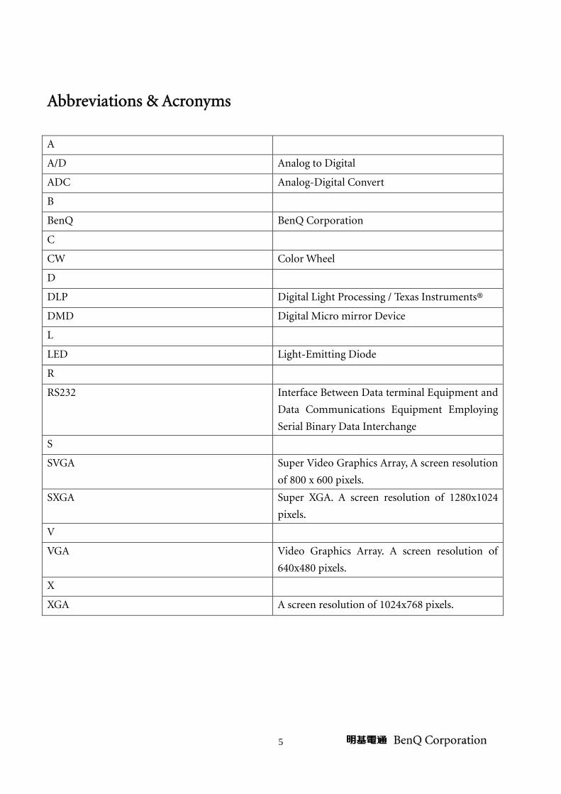
Abbreviations & Acronyms
A
A/D Analog to Digital
ADC Analog-Digital Convert
B
BenQ BenQ Corporation
C
CW Color Wheel
D
DLP Digital Light Processing / Texas Instruments®
DMD Digital Micro mirror Device
L
LED Light-Emitting Diode
R
RS232 Interface Between Data terminal Equipment and
Data Communications Equipment Employing
Serial Binary Data Interchange
S
SVGA Super Video Graphics Array, A screen resolution
of 800 x 600 pixels.
SXGA Super XGA. A screen resolution of 1280x1024
pixels.
V
VGA Video Graphics Array. A screen resolution of
640x480 pixels.
X
XGA A screen resolution of 1024x768 pixels.
6
About This Manual
This manual contains information about maintenance and service of BenQ products. Use this manual
to perform diagnostics tests, troubleshoot problems, and align the BenQ product.
Important
Only trained service personnel who are familiar with this BenQ Product shall perform
service or maintenance to it. Before performing any maintenance or service, the
engineer MUST read the “Important Safety Information”
Trademark
The following terms are trademarks of BenQ Corporation:
BenQ
Other companies, products, or service names may be the trademarks of their respective companies.
Introduction
This section contains general service information, please read through carefully. It should be stored for
easy access place.
Important Service Information
RoHS (2002/95/EC) Requirements – Applied to all countries require RoHS. The RoHS (Restriction of Hazardous Substance in Electrical and Electronic Equipment Directive) is a
legal requirement by EU (European Union) for the global electronics industry which sold in EU and
some counties also require this requirement. Any electrical and electronics products launched in the
market after June 2006 should meet this RoHS requirements. Products launched in the market before
June 2006 are not required to compliant with RoHS parts. If the original parts are not RoHS
complaints, the replacement parts can be non ROHS complaints, but if the original parts are RoHS
compliant, the replacement parts MUST be RoHS complaints.
If the product service or maintenance require replacing any parts, please confirming the RoHS
requirement before replace them.
7
Safety Notice 1 Make sure your working environment is dry and clean, and meets all government safety
requirements.
2 Ensure that other persons are safe while you are servicing the product.
3 DO NOT perform any action that may cause a hazard to the customer or make the product
unsafe.
4 Use proper safety devices to ensure your personal safety.
5 Always use approved tools and test equipment for servicing.
6 Never assume the product’s power is disconnected from the mains power supply. Check that it is
disconnected before opening the product’s cabinet.
7 Modules containing electrical components are sensitive to electrostatic discharge (ESD). Follow
ESD safety procedures while handling these parts.
8 Some products contain more than one battery. Do not disassemble any battery, or expose it to
high temperatures such as throwing into fire or it may explode.
9 Refer to government requirements for battery recycling or disposal.
Compliance Statement Caution: This Optical Storage Product contains a Laser device. Refer to the product specifications and
your local Laser Safety Compliance Requirements.
General Descriptions This Service Manual contains general information. There are 2 levels of service:
Level 1: Cosmetic / Appearance / Alignment Service
Level 2: Circuit Board or Standard Parts Replacement
Related Service Information Service Web Site
BenQ Global Service Website: http://support.benq.com/front/benqmain.asp
eSupport Website: http://esupport.benq.com/v2
8
Product Overview
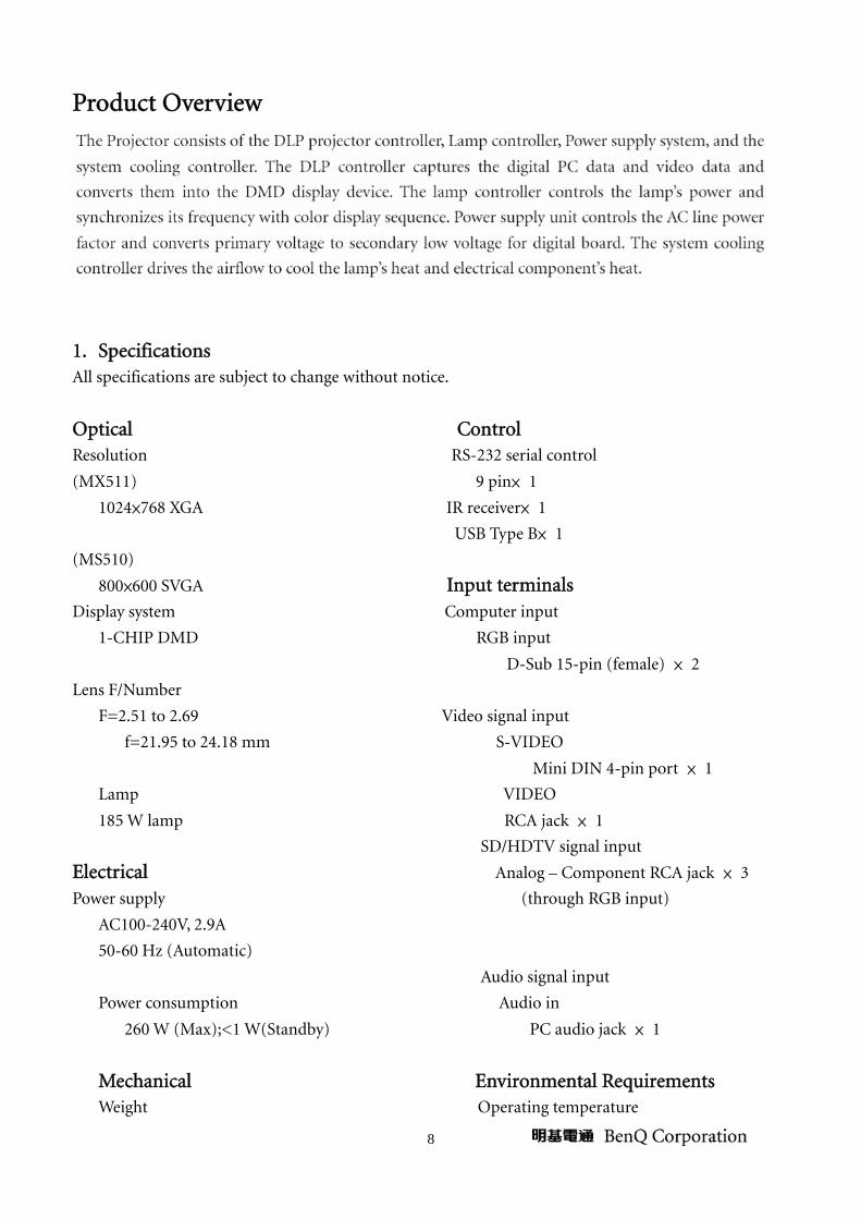
1. Specifications All specifications are subject to change without notice.
Optical Control Resolution RS-232 serial control
(MX511) 9 pin× 1
1024×768 XGA IR receiver× 1
USB Type B× 1
(MS510)
800×600 SVGA Input terminals
Display system Computer input
1-CHIP DMD RGB input
D-Sub 15-pin (female) × 2
Lens F/Number
F=2.51 to 2.69 Video signal input
f=21.95 to 24.18 mm S-VIDEO
Mini DIN 4-pin port × 1
Lamp VIDEO
185 W lamp RCA jack × 1
SD/HDTV signal input
Electrical Analog – Component RCA jack × 3
Power supply (through RGB input)
AC100-240V, 2.9A
50-60 Hz (Automatic)
Audio signal input
Power consumption Audio in
260 W (Max);<1 W(Standby) PC audio jack × 1
Mechanical Environmental Requirements Weight Operating temperature

9
2.5 Kg (5.5 lbs) 0℃-40℃ at sea level
Output terminals Operating relative humidity
RGB output 10%-90%(without condensation)
D-Sub 15-pin(female) × 1 Operating altitude
Speaker 0-1499 m at 0℃-35℃
(Stereo) 2 watt × 1 1500-3000 m at 0℃-30℃(with High
Audio signal output Altitude Mode on)
PC audio jack × 1
2. Timing Table Supported timing for PC input
Resolution
Horizontal
Frequency
(kHz)
Vertical
Frequency(Hz)
Pixel
Frequency(MHz) Mode
720×400 31.469 70.087 28.322 720×400_70
640×480
31.469 59.940 25.175 VGA_60
37.861 72.809 31.500 VGA_72
37.500 75.000 31.500 VGA_75
43.269 85.008 36.000 VGA_85
800×600
37.879 60.317 40.000 SVGA_60
48.077 72.188 50.000 SVGA_72
46.875 75.000 49.500 SVGA_75
53.674 85.061 56.250 SVGA_85
1024×768
48.363 60.004 65.000 XGA_60
56.476 70.069 75.000 XGA_70
60.023 75.029 78.750 XGA_75
68.677 84.997 94.500 XGA_85
1024×576 35.82 60.00 46.996 Netbook_1
1024×600 37.5 60.00 45.000 Netbook_2
1024×600 41.467 64.995 51.419 Netbook_3
1280×800
49.702 59.810 83.500 WXGA_60
62.795 74.934 106.500 WXGA_75
71.554 84.880 122.500 WXGA_85
1280×1024
63.981 60.020 108.000 SXGA_60
79.976 75.025 135.000 SXGA_75
91.146 85.024 157.500 SXGA_85
1280×960 60.000 60.000 108.000 1280×960_60
85.938 85.002 148.500 1280×960_85
1440×900 55.935 59.887 106.500 WXGA+_60

10
1400×1050 65.317 59.978 121.750 SXGA+_60
1600×1200 75.000 60.000 162.000 UXGA
640×480@67Hz 35.000 66.667 30.240 MAC13
832×624@75Hz 49.722 74.546 57.280 MAC16
1024×768@75Hz 60.241 75.020 80.000 MAC19
1152×870@75Hz 68.680 75.060 100.000 MAC21
Supported timing for HDMI input
Resolution Horizontal Frequency
(kHz)
Vertical
Frequency(Hz) Pixel Frequency(MHz) Mode
720×400 31.469 70.087 28.322 720×400_70
640×480
31.469 59.940 25.175 VGA_60
37.861 72.809 31.500 VGA_72
37.500 75.000 31.500 VGA_75
43.269 85.008 36.000 VGA_85
800×600
37.879 60.317 40.000 SVGA_60
48.077 72.188 50.000 SVGA_72
46.875 75.000 49.500 SVGA_75
53.674 85.061 56.250 SVGA_85
1024×768
48.363 60.004 65.000 XGA_60
56.476 70.069 75.000 XGA_70
60.023 75.029 78.750 XGA_75
68.677 84.997 94.500 XGA_85
1280×800
49.702 59.810 83.500 WXGA_60
62.795 74.934 106.500 WXGA_75
71.554 84.880 122.500 WXGA_85
1280×1024
63.981 60.020 108.000 SXGA_60
79.976 75.025 135.000 SXGA_75
91.146 85.024 157.500 SXGA_85
1280×960 60.000 60.000 108.000 1280×960_60
85.938 85.002 148.500 1280×960_85
1440×900 55.935 59.887 106.500 WXGA+_60
1400×1050 65.317 59.978 121.750 SXGA+_60
1600×1200 75.000 60.000 162.000 UXGA
640×480@67Hz 35.000 66.667 30.240 MAC13
832×624@75Hz 49.722 74.546 57.280 MAC16
1024×768@75Hz 60.241 75.020 80.000 MAC19
1152×870@75Hz 68.680 75.060 100.000 MAC21

11
VIDEO
(HDCP)
31.47 60 27 480p
31.25 50 27 576p
45.00 60 74.25 720p_60
37.50 50 74.25 720_50
33.75 60 74.25 1080i_60
28.13 50 74.25 1080i_50
67.50 60 148.5 1080p
56.25 50 148.5 1080p
Displaying a 1080i(1125i)@60Hz or 1080i(1125i)@50Hz signal may result in slight image
vibration.
Supported timing for Component-YPbPr input
Signal Format Horizontal Frequency
(kHz) Vertical Frequency(Hz)
480i(525i)@60Hz 15.73 59.94
480p(525p)@60Hz 31.47 59.94
576i(625i)@50Hz 15.63 50.00
576p(625p)@50Hz 31.25 50.00
720p(750p)@60Hz 45.00 60.00
720p(750p)@50Hz 37.50 50.00
1080i(1125i)@60Hz 33.75 60.00
1080i(1125i)@50Hz 28.13 50.00
1080p@60Hz 67.50 60.00
1080p@50Hz 56.25 50.00
Displaying a 1080i@60Hz or 1080i@50Hz signal may result in slight image vibration.
Supported timing for Video and S-Video input
Video mode Horizontal
Frequency(kHz) Vertical Frequency (Hz)
Color sub-carrier
Frequency(MHz)
NTSC 15.73 60 3.58
PAL 15.63 50 4.43
SECAM 15.63 50 4.25 or 4.41
PAL-M 15.73 60 3.58
PAL-N 15.63 50 3.58
PAL-60 15.73 60 4.43
NTSC 4.43 15.73 60 4.43
12
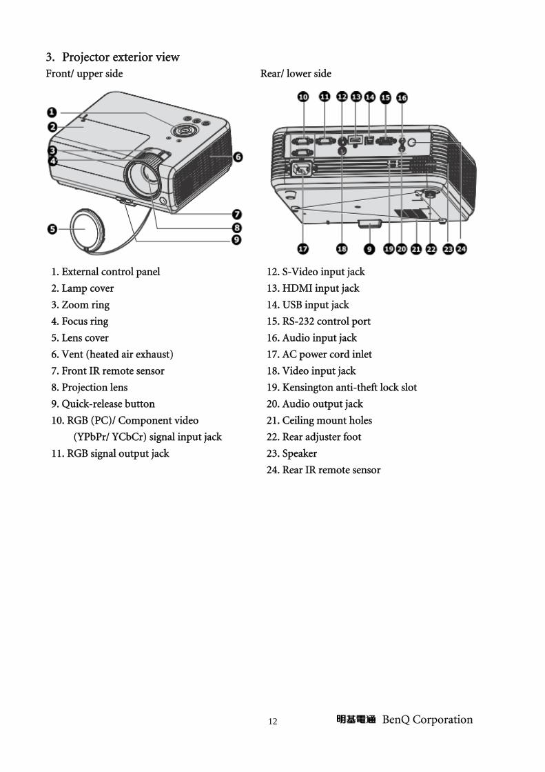
3. Projector exterior view Front/ upper side Rear/ lower side
1. External control panel 12. S-Video input jack
2. Lamp cover 13. HDMI input jack
3. Zoom ring 14. USB input jack
4. Focus ring 15. RS-232 control port
5. Lens cover 16. Audio input jack
6. Vent (heated air exhaust) 17. AC power cord inlet
7. Front IR remote sensor 18. Video input jack
8. Projection lens 19. Kensington anti-theft lock slot
9. Quick-release button 20. Audio output jack
10. RGB (PC)/ Component video 21. Ceiling mount holes
(YPbPr/ YCbCr) signal input jack 22. Rear adjuster foot
11. RGB signal output jack 23. Speaker
24. Rear IR remote sensor
13
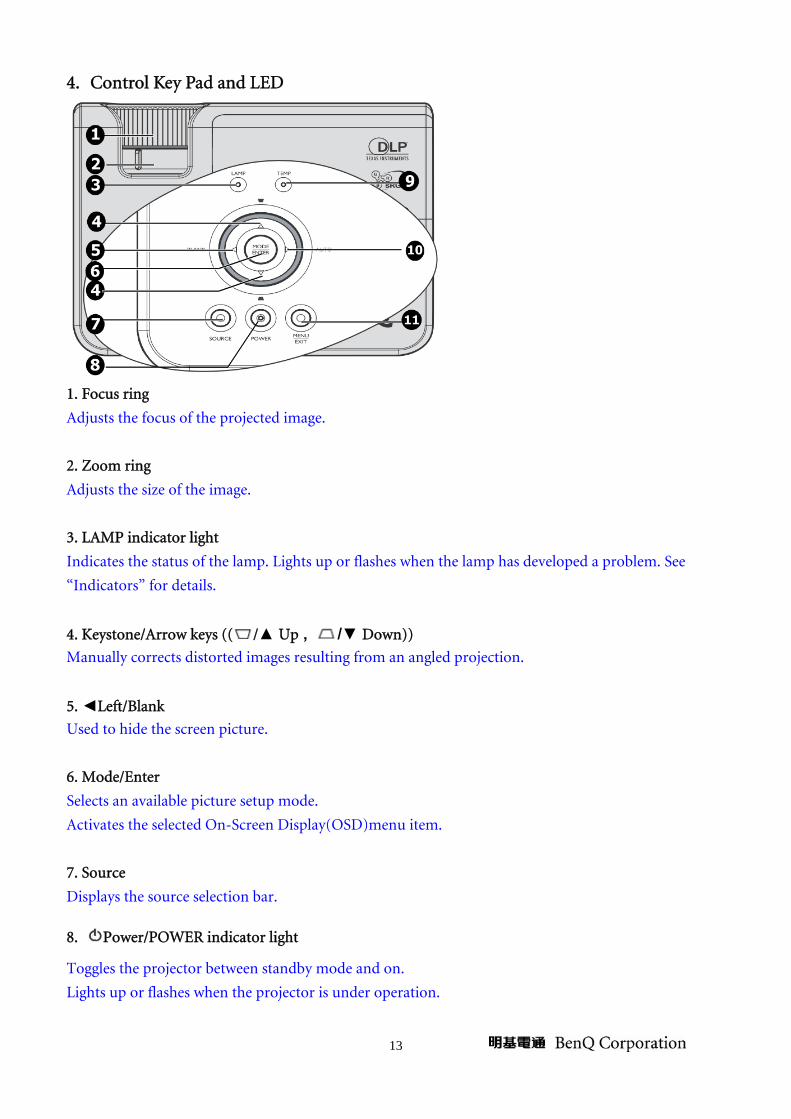
4. Control Key Pad and LED
1. Focus ring
Adjusts the focus of the projected image.
2. Zoom ring
Adjusts the size of the image.
3. LAMP indicator light
Indicates the status of the lamp. Lights up or flashes when the lamp has developed a problem. See
“Indicators” for details.
4. Keystone/Arrow keys (( /▲ Up , /▼ Down))
Manually corrects distorted images resulting from an angled projection.
5. ◄Left/Blank
Used to hide the screen picture.
6. Mode/Enter
Selects an available picture setup mode.
Activates the selected On-Screen Display(OSD)menu item.
7. Source
Displays the source selection bar.
8. Power/POWER indicator light
Toggles the projector between standby mode and on.
Lights up or flashes when the projector is under operation.

14
9. TEMPerature indicator light
Lights up red if the projector’s temperature becomes too high.
10. ►Right/Auto
When the On-Screen Display (OSD) menu is activated, the #4,#5,and #10 keys menu are used as
directional arrows to select the desired menu items and to make adjustments.
Automatically determines the best picture timing for the displayed image.
11. Menu/Exit
Turns on the On-Screen Display(OSD) menu. Goes back to previous OSD menu, exits and saves menu
settings.
15
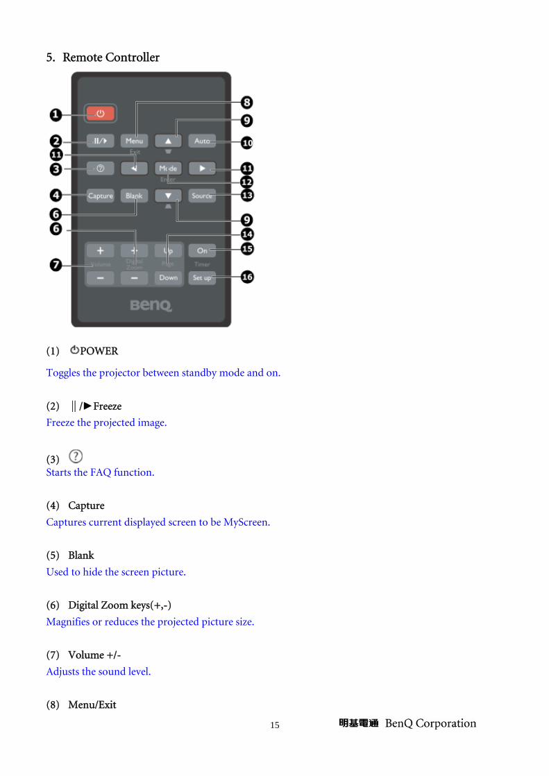
5. Remote Controller
(1) POWER
Toggles the projector between standby mode and on.
(2) ∥/►Freeze
Freeze the projected image.
(3) Starts the FAQ function.
(4) Capture
Captures current displayed screen to be MyScreen.
(5) Blank
Used to hide the screen picture.
(6) Digital Zoom keys(+,-)
Magnifies or reduces the projected picture size.
(7) Volume +/-
Adjusts the sound level.
(8) Menu/Exit

16
Turns on the On-Screen Display(OSD)menu. Goes back to previous OSD menu, exits and saves menu
settings.
(9) Keystone/Arrow keys ( /▲ Up , /▼ Down)
Manually corrects distorted images resulting from an angled projection.
(10) Auto
Automatically determines the best picture timings for the displayed image.
(11) ◄Left/►Right
When the On-Screen Display(OSD) menu is activated, the #8 and #10 keys are used as directional
arrows to select the desired menu items and to make adjustments.
(12) Mode/Enter
Selects an available pictures setup mode.
Activates the selected On-Screen Display(OSD) menu item.
(13) Source
Display the source selection bar.
(14) Page Up/ Down
Page up/down arrows when connected through USB to a PC.
(15) Timer On
Activates or displays an on-screen timer based on your own timer setting.
(16) Timer Setup
Enters presentation timer setting directly.
17
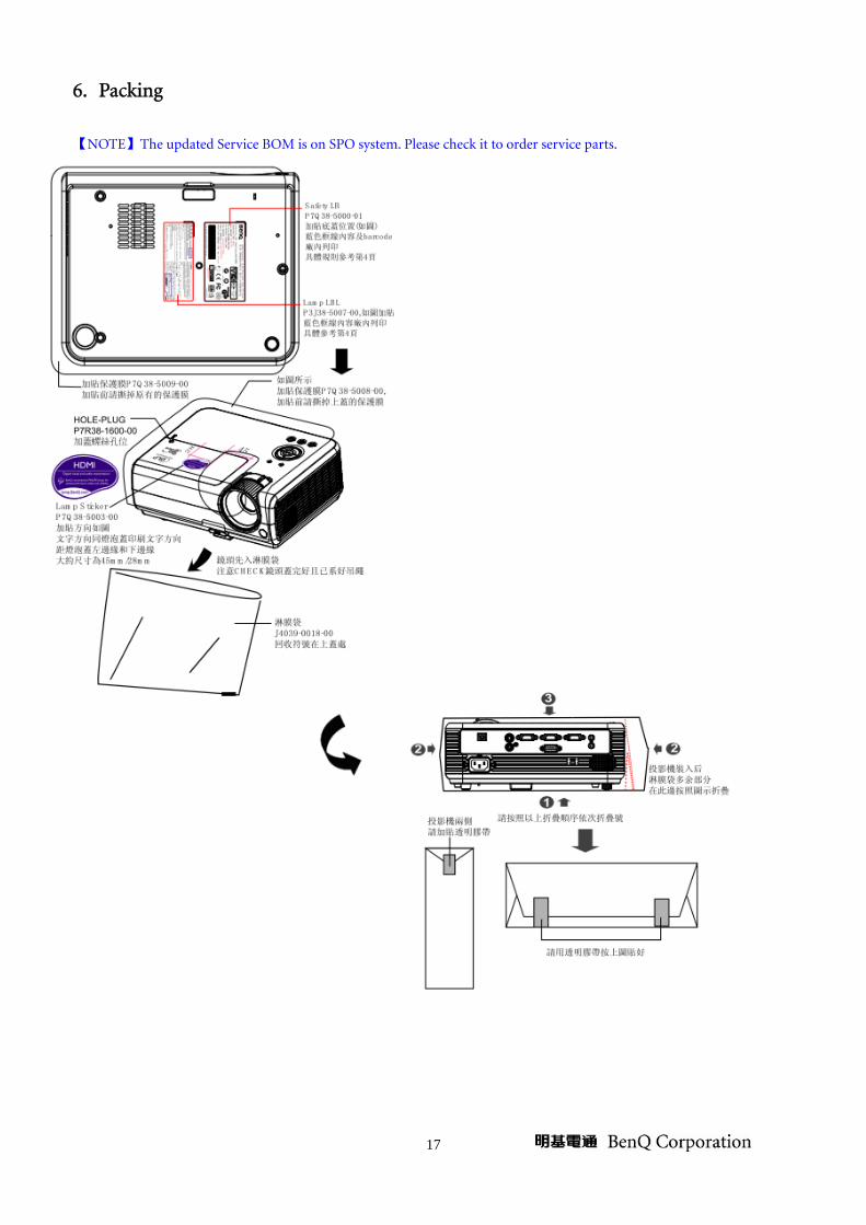
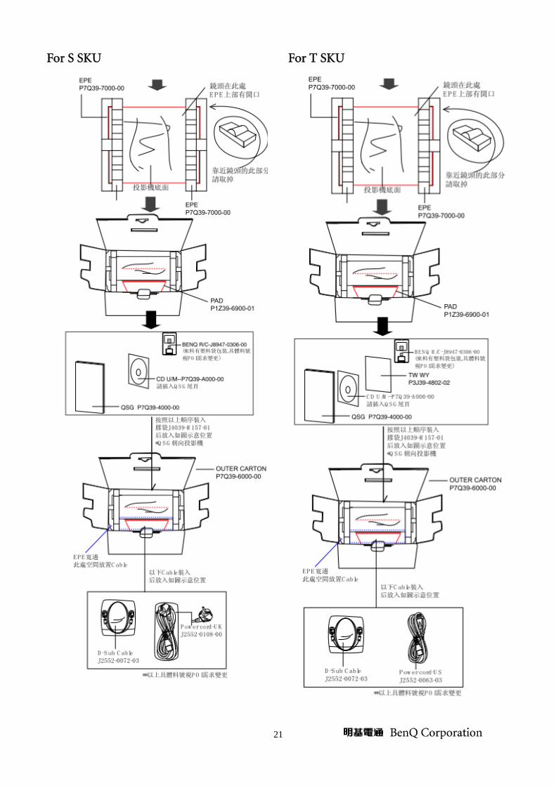
6. Packing 【NOTE】The updated Service BOM is on SPO system. Please check it to order service parts.
18
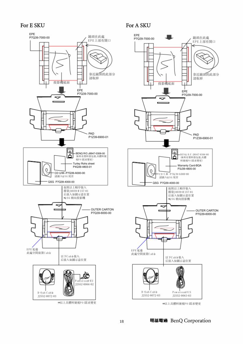
For E SKU
For A SKU
19
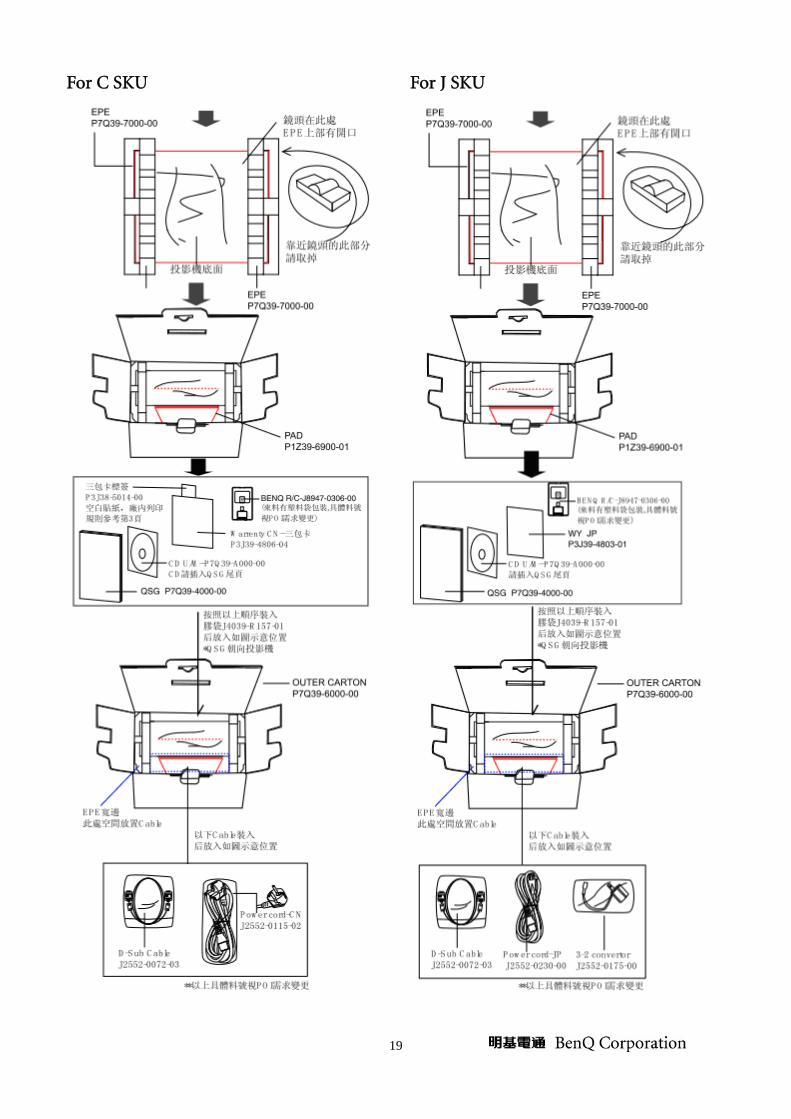
For C SKU
For J SKU

20
For K SKU
For P SKU
21
For S SKU
For T SKU

22
For U SKU
For L SKU
23
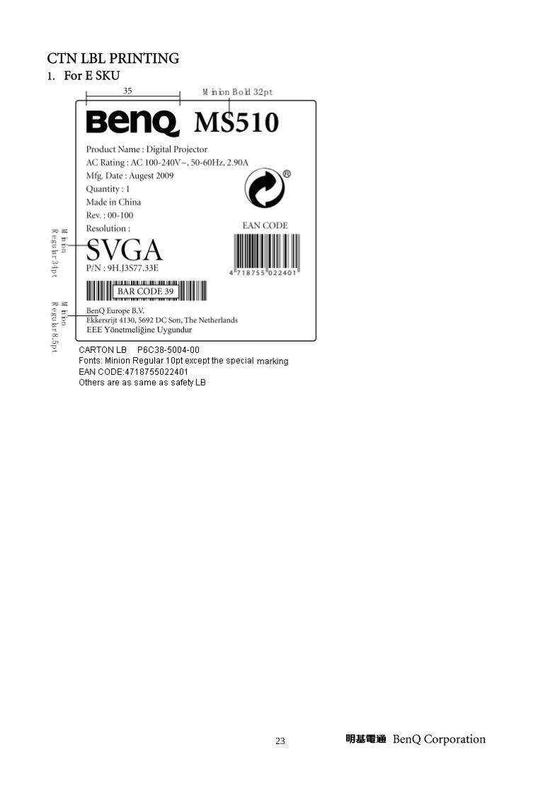
CTN LBL PRINTING 1. For E SKU

24
2. For A SKU
3. For C SKU

25
4. For J SKU
5. For K SKU

26
6. For P SKU
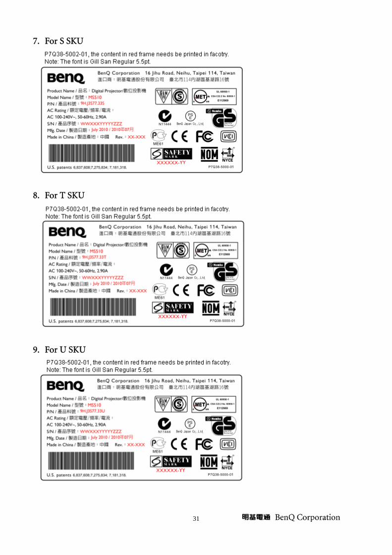
7. For S SKU

27
8. For T SKU
9. For U SKU
28
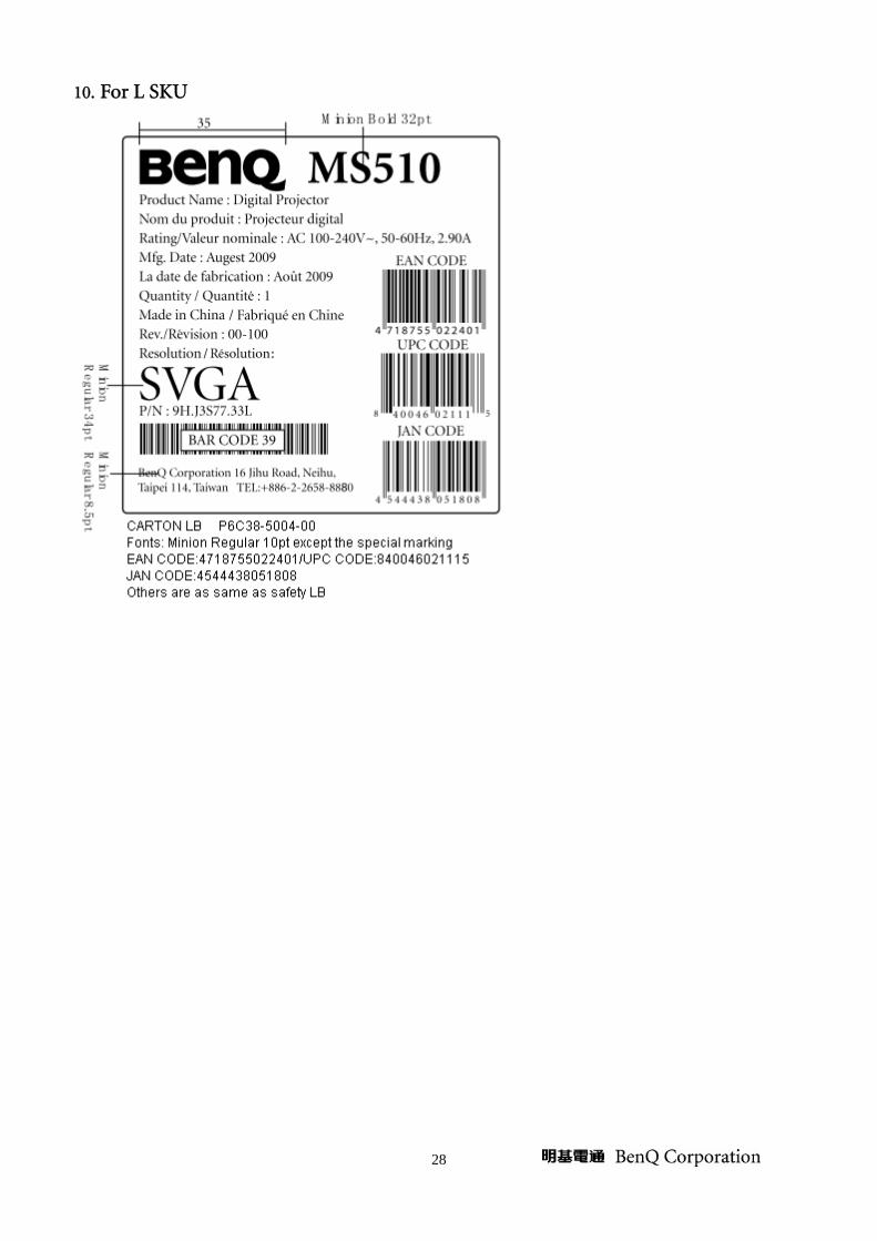
10. For L SKU

29
SPEC LBL PRINTING 1. For E SKU
2. For A SKU
3. For C SKU

30
4. For J SKU
5. For K SKU
6. For P SKU
31
7. For S SKU
8. For T SKU
9. For U SKU

32
10. For L SKU
LAMP LBL PRINTING 1. For C SKU
2. For Other SKUs
33
Customer Acceptance
7. SCOPE
This document establishes the general workmanship standards and functional acceptance criteria for
PROJECTOR produced by BENQ.
8. PURPOSE
The purpose of this publication is to define a procedure for inspection of the PROJECTOR by means
of a customer acceptance test, the method of evaluation of defects and rules for specifying acceptance
levels.
9. APPLICATION
The "Customer Acceptance Criteria" is applicable to the inspection of the PROJECTOR, completely
packed and ready for dispatch to customers. Unless otherwise specified, the customer acceptance
inspection should be conducted at manufacturer's site.
10. DEFINITION
The "Customer Acceptance Criteria" is the document defining the process of examining, testing or
otherwise comparing the product with a given set of specified technical, esthetic and workmanship
requirements leading to an evaluation of the "degree of fitness for use", including possible personal
injury or property damage for the use of the product.
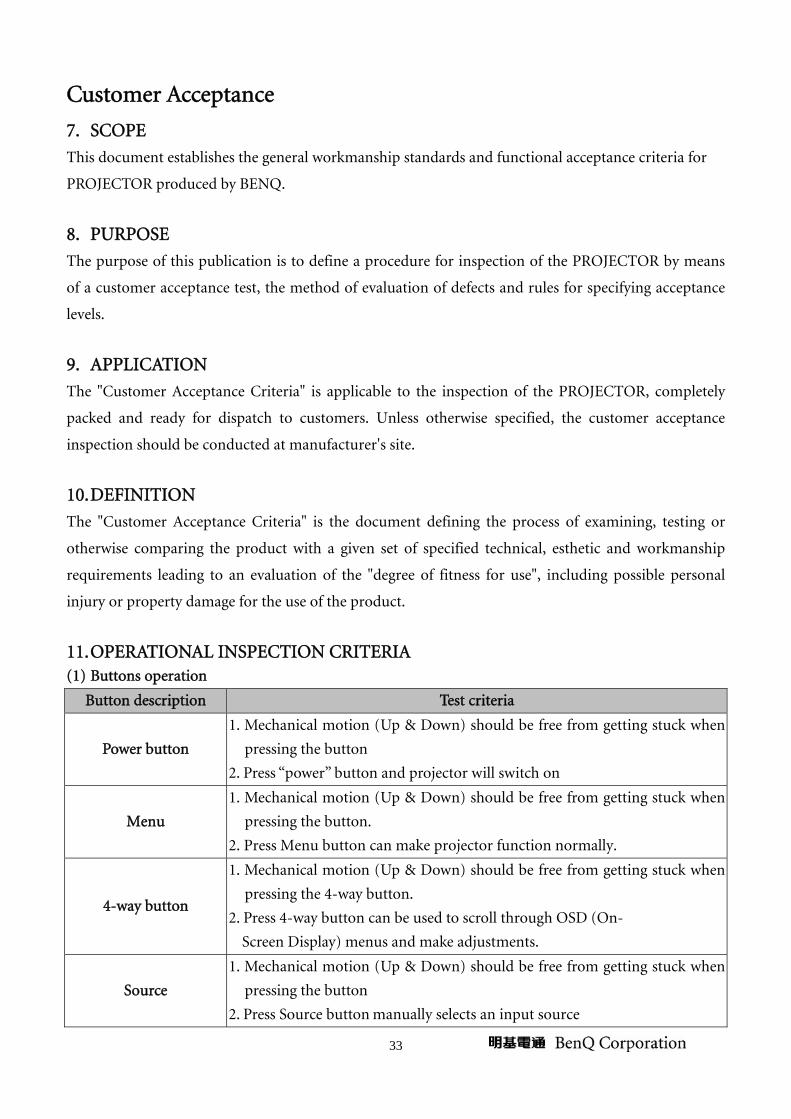
11. OPERATIONAL INSPECTION CRITERIA (1) Buttons operation
Button description Test criteria
Power button
1. Mechanical motion (Up & Down) should be free from getting stuck when
pressing the button
2. Press “power” button and projector will switch on
Menu
1. Mechanical motion (Up & Down) should be free from getting stuck when
pressing the button.
2. Press Menu button can make projector function normally.
4-way button
1. Mechanical motion (Up & Down) should be free from getting stuck when
pressing the 4-way button.
2. Press 4-way button can be used to scroll through OSD (On-
Screen Display) menus and make adjustments.
Source
1. Mechanical motion (Up & Down) should be free from getting stuck when
pressing the button
2. Press Source button manually selects an input source

34
(2) Foot adjuster operation
Foot adjuster. Test criteria
Foot adjuster button Foot adjusters should stretch downward smoothly by pressing the foot
adjuster buttons.
(3) Zoom ring and Focus ring
Ring Test criteria
Zoom ring Mechanical motion of rotating Zoom ring to the end of right and left by
hand should be free from getting stuck.
Focus ring The feeling of rotating Focus ring to the end of right and left by hand
should free from seizing.
12. Function Test Criteria (A) Check LOGO
Check Logo after power on unit is correct.
(B) Check abnormal voice
Method: Keep ear about 10cm far away from the Top Cover to listen carefully.
Criteria: Can’t allow any piping voice.
(C) Signal test (Each I/O can function normally)
Connect all connector to the jacks one after the other to check whether each channel can project
normally.
I/O port COMPUTER1,COMPUTER2(VGA)
Test Equipment Standard Pattern generator (Ex. Quantum data)
Signal format 800*600 60Hz
35
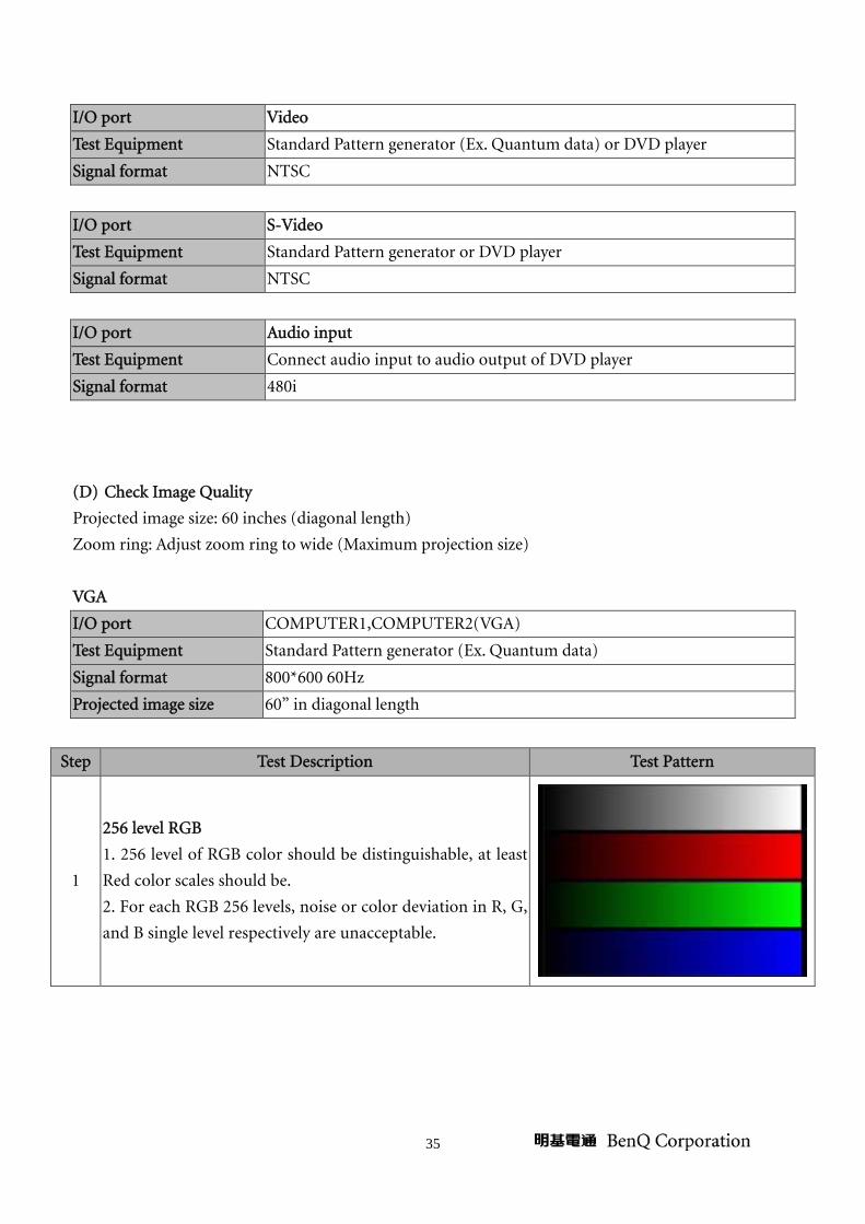
I/O port Video
Test Equipment Standard Pattern generator (Ex. Quantum data) or DVD player
Signal format NTSC
I/O port S-Video
Test Equipment Standard Pattern generator or DVD player
Signal format NTSC
I/O port Audio input
Test Equipment Connect audio input to audio output of DVD player
Signal format 480i
(D) Check Image Quality
Projected image size: 60 inches (diagonal length)
Zoom ring: Adjust zoom ring to wide (Maximum projection size)
VGA
I/O port COMPUTER1,COMPUTER2(VGA)
Test Equipment Standard Pattern generator (Ex. Quantum data)
Signal format 800*600 60Hz
Projected image size 60” in diagonal length
Step Test Description Test Pattern
1
256 level RGB
1. 256 level of RGB color should be distinguishable, at least
Red color scales should be.
2. For each RGB 256 levels, noise or color deviation in R, G,
and B single level respectively are unacceptable.
36
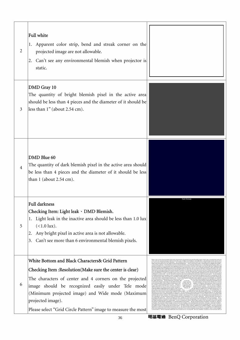
2
Full white
1. Apparent color strip, bend and streak corner on the
projected image are not allowable.
2. Can’t see any environmental blemish when projector is
static.
3
DMD Gray 10
The quantity of bright blemish pixel in the active area
should be less than 4 pieces and the diameter of it should be
less than 1” (about 2.54 cm).
4
DMD Blue 60
The quantity of dark blemish pixel in the active area should
be less than 4 pieces and the diameter of it should be less
than 1 (about 2.54 cm).
5
Full darkness
Checking Item: Light leak、DMD Blemish.
1. Light leak in the inactive area should be less than 1.0 lux
(<1.0 lux).
2. Any bright pixel in active area is not allowable.
3. Can’t see more than 6 environmental blemish pixels.
6
White Bottom and Black Characters& Grid Pattern
Checking Item :Resolution(Make sure the center is clear)
The characters of center and 4 corners on the projected
image should be recognized easily under Tele mode
(Minimum projected image) and Wide mode (Maximum
projected image).
Please select “Grid Circle Pattern” image to measure the most

37
serious halations if any opinion exists. Halation standard:
Defocus 3.0 pixels including pixel itself /Flare 4.0 pixels
including pixel itself, 1 pixel means the width of one
pixel.(P.1)
P.1
7
Twelve Grids
Checking Item : Abnormal Voice
Press “AUTO” button, more than three twinkling grids are
not allowable.
8
32 Gray Level
Checking Item: Color Gradation
32 level of gray level color should be distinguishable and no
defection.
9
Map
Checking Item: Image Quality
The land, ocean (three kinds of colors) and ground should
be distinguishable obviously.
10
Grid Circle Pattern
-The four lines of outer frame should not only be existent
but also distinguishable. -The dots in the square should be distinguishable.

38
S-Video
I/O port S-Video
Test Equipment Standard Pattern generator (Ex. Quantum data)&DVD player
Signal format NTSC
Criteria No apparent color deviation on the projected image
Video
I/O port Video
Signal format NTSC
Test Equipment Standard Pattern generator (Ex. Quantum data)&DVD player
Criteria No apparent color deviation on the projected image
HDMI
I/O port HDMI
Test Equipment HDMI source device
Signal format 480p
Criteria No apparent color deviation on the projected image nor abnormal voice.
39
Level 1 Cosmetic / Appearance / Alignment Service
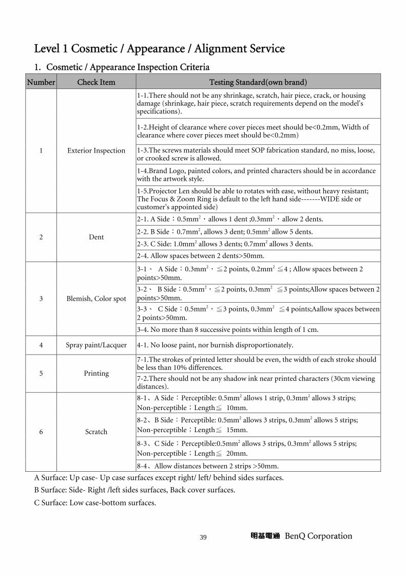
1. Cosmetic / Appearance Inspection Criteria
Number Check Item Testing Standard(own brand)
1 Exterior Inspection
1-1.There should not be any shrinkage, scratch, hair piece, crack, or housing damage (shrinkage, hair piece, scratch requirements depend on the model's specifications).
1-2.Height of clearance where cover pieces meet should be<0.2mm, Width of clearance where cover pieces meet should be<0.2mm)
1-3.The screws materials should meet SOP fabrication standard, no miss, loose, or crooked screw is allowed.
1-4.Brand Logo, painted colors, and printed characters should be in accordance with the artwork style.
1-5.Projector Len should be able to rotates with ease, without heavy resistant; The Focus & Zoom Ring is default to the left hand side-------WIDE side or customer's appointed side)
2 Dent
2-1. A Side:0.5mm2,allows 1 dent ;0.3mm2,allow 2 dents.
2-2. B Side:0.7mm2, allows 3 dent; 0.5mm2 allow 5 dents.
2-3. C Side: 1.0mm2 allows 3 dents; 0.7mm2 allows 3 dents.
2-4. Allow spaces between 2 dents>50mm.
3 Blemish, Color spot
3-1、 A Side:0.3mm2,≦2 points, 0.2mm2 ≦4 ; Allow spaces between 2 points>50mm.
3-2、 B Side:0.5mm2,≦2 points, 0.3mm2 ≦3 points;Allow spaces between 2 points>50mm.
3-3、 C Side:0.5mm2,≦3 points, 0.3mm2 ≦4 points;Aallow spaces between 2 points>50mm.
3-4. No more than 8 successive points within length of 1 cm.
4 Spray paint/Lacquer 4-1. No loose paint, nor burnish disproportionately.
5 Printing
7-1.The strokes of printed letter should be even, the width of each stroke should be less than 10% differences.
7-2.There should not be any shadow ink near printed characters (30cm viewing distances).
6 Scratch
8-1、A Side:Perceptible: 0.5mm2 allows 1 strip, 0.3mm2 allows 3 strips; Non-perceptible;Length≦ 10mm.
8-2、B Side:Perceptible: 0.5mm2 allows 3 strips, 0.3mm2 allows 5 strips; Non-perceptible;Length≦ 15mm.
8-3、C Side:Perceptible:0.5mm2 allows 3 strips, 0.3mm2 allows 5 strips; Non-perceptible;Length≦ 20mm.
8-4、Allow distances between 2 strips >50mm.
A Surface: Up case- Up case surfaces except right/ left/ behind sides surfaces.
B Surface: Side- Right /left sides surfaces, Back cover surfaces.
C Surface: Low case-bottom surfaces.
40
2. Software/Firmware Upgrade Process 2.1 Firmware Upgraded Process
This chapter provides the information regarding relevant equipments and upgrading procedure for
firmware upgrade.
Note:
1. Please check the firmware and composer version before any firmware upgrade procedures.
During firmware download period, please do not shut down PC or projector, this will cause flash
memory’s damage. And need to return the unit to manufacturer for flash memory recovery.
2. Computer for operation must be Windows XP or more advanced.
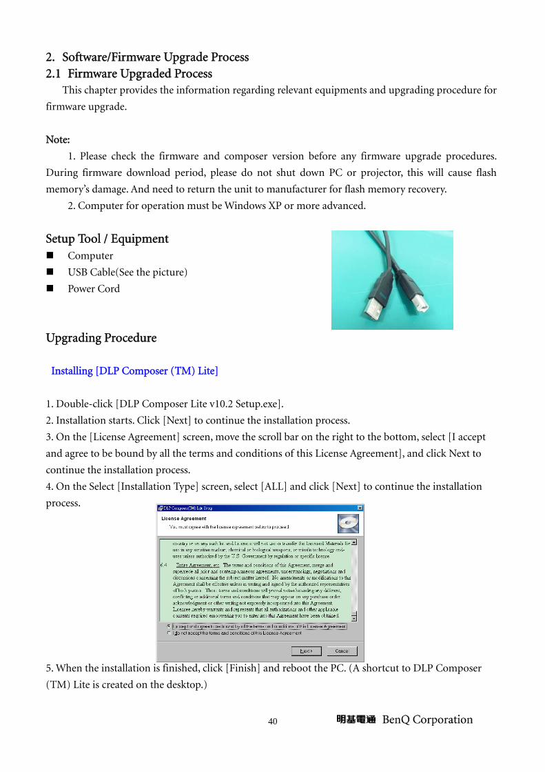
Setup Tool / Equipment Computer
USB Cable(See the picture)
Power Cord
Upgrading Procedure Installing [DLP Composer (TM) Lite]
1. Double-click [DLP Composer Lite v10.2 Setup.exe].
2. Installation starts. Click [Next] to continue the installation process.
3. On the [License Agreement] screen, move the scroll bar on the right to the bottom, select [I accept
and agree to be bound by all the terms and conditions of this License Agreement], and click Next to
continue the installation process.
4. On the Select [Installation Type] screen, select [ALL] and click [Next] to continue the installation
process.
5. When the installation is finished, click [Finish] and reboot the PC. (A shortcut to DLP Composer
(TM) Lite is created on the desktop.)

41
USB Support - Installation (All Platforms)
This release includes support for a USB communications interface to DDP2230/ DDP2430/
DDP2431 -based projectors. The setup program includes the files needed to install USB support. After
DLP Composer™ Lite is installed, to install the USB support, choose the "Install DLP Device USB
Driver" icon under "DLP Composer™ Lite" in your Start menu.
Follow the instruction on the screen to press any key and wait for the installation done.
And copy the file “FlashDeviceParameters.txt” into the C:\ Program Files\ DLP Composer Lite 10.2\
Operating procedure
1. Connect the Projector and PC via USB cable.

42
2. Double-click [DLP Composer (TM) Lite 10.2]. The following screen will appear.
3. Select [Edit]/ [Preferences]/ [Communications] to check USB in [Projector Interface].
4. Set the items on the [Vendor 0x451, Product 0x2000] of [USB Device Identification].
5. Click [OK].
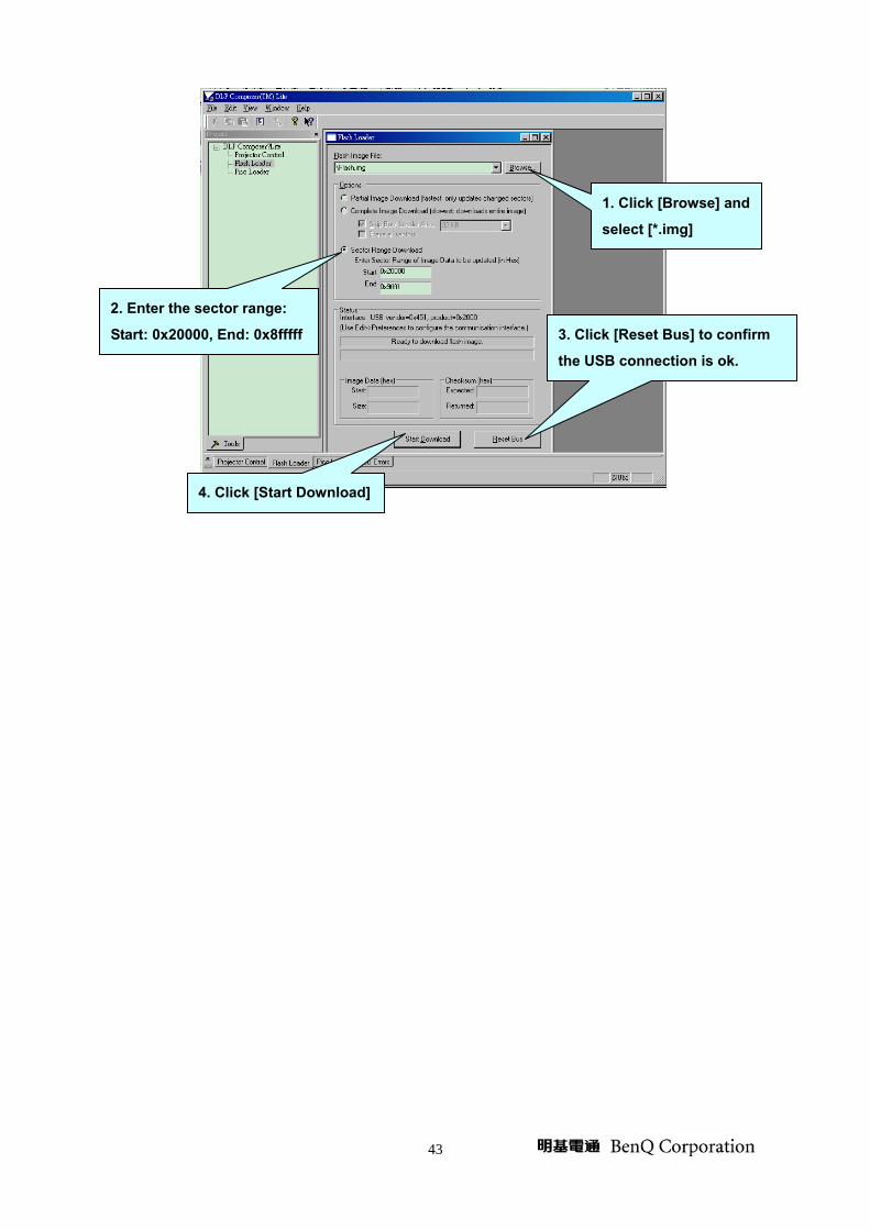
6. Move the cursor to [Flash Loader] on the Project window of [DLP Composer Lite]. (The [Flash
Loader] screen will appear.)
7. Click [Browse] and select where the firmware [xxxxxxxxx.img] is for download.
8. Make sure [Skip Boot Loader Area] is with a check.
9. Press Menu and Power buttons constantly and then give power supply (switch power on). After
around 10 seconds, Temp LED and Lamp LED will become flashing. That indicates the projector is in
the download mode. At this moment, you can release these two buttons.
10. Click [Reset Bus] firstly to check if USB connects well.
11. Click [Start Download] to start the upgrade procedure.
43
2. Enter the sector range:
Start: 0x20000, End: 0x8fffff
1. Click [Browse] and
select [*.img]
4. Click [Start Download]
3. Click [Reset Bus] to confirm
the USB connection is ok.

44
2.2 Method to enter factory menu
【Warning】
Please don’t set any sub-menu of factory menu that doesn’t refer to in this Service Manual. It may
cause damage to the projector.
(1) Press “Menu” button to open the Main menu.
(2) Move the highlight bar to “SYSTEM SETUP: Advanced” item.
(3) Press the DOWN into the selected sub-Menu.
(4) Move down the highlight bar to “Reset All Settings” item.
(5) Press below keys in order will into the Engineering Menu:
Right once Left twice Right three times Left four times.

45
NOTE: The same method by remote control.
46
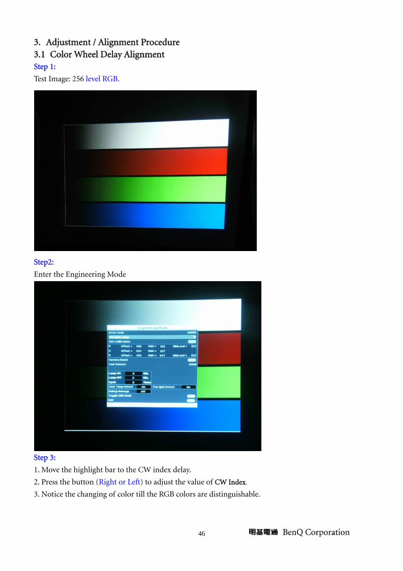
3. Adjustment / Alignment Procedure 3.1 Color Wheel Delay Alignment Step 1:
Test Image: 256 level RGB.
Step2:
Enter the Engineering Mode
Step 3:
1. Move the highlight bar to the CW index delay.
2. Press the button (Right or Left) to adjust the value of CW Index.
3. Notice the changing of color till the RGB colors are distinguishable.
47
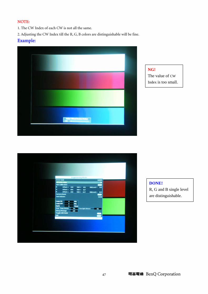
NOTE:
1. The CW Index of each CW is not all the same.
2. Adjusting the CW Index till the R, G, B colors are distinguishable will be fine.
Example:
NG! The value of CW Index is too small.
DONE! R, G and B single level are distinguishable.

48
3.2 ADC Calibration Procedure Step 1:
Test Image: W100B0
Step2:
Enter the Engineering Mode:
Step 3:
1. Move the highlight bar to the ADC Calibration.
2. Press the Enter button to execute ADC Calibration. Color deviation is unacceptable.

49
4. Check Lamp hour information (1) Press “Menu” button to open the Main menu.
(2) Move the highlight bar to “DISPLAY” item.
(3) “Equivalent lamp hour” item will display the number of hours the projector system has been used.
5. How to reset lamp hours (1) Press “Menu” button to open the Main menu.
(2) Move the highlight bar to “SYSTEM SETUP: Advanced> Lamp Settings” item.
(3) Press Enter into the selected sub-Menu.
(4) Move down the highlight bar to “Reset lamp timer” item and press Enter.

50
(5) A warning message displays asking if you want to reset the lamp timer. Highlight “Reset” and press
Enter. The lamp time will be reset to “0”.
51
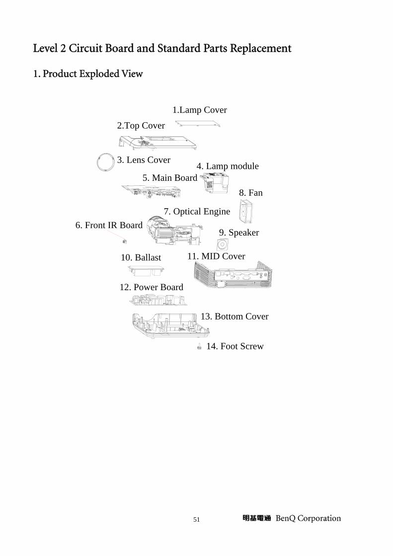
Level 2 Circuit Board and Standard Parts Replacement
1. Product Exploded View
1.Lamp Cover
2.Top Cover
3. Lens Cover
6. Front IR Board
8. Fan
4. Lamp module5. Main Board
10. Ballast
9. Speaker
12. Power Board
13. Bottom Cover
14. Foot Screw
11. MID Cover
7. Optical Engine

52
2. Product Disassembly / Assembly 2.1 Tools
Item Photo
Long Nose Nipper
Hex Sleeves 5mm
Screw Bit(+):107
Screw Bit(+):101
Screw Bit(+):102
Anti-static wrist strap
Anti-static wrist gloves

53
2.2 Disassembly Procedure
【Warning】
♦ Put on the Static Electricity Ring when starting for repair.
♦ Repair Environment suggest in Clean-room class 10000. Do not remove Optical Engine or
DMD panel outside the clean room. Please return the optical engine to supplier if your repair
condition cannot meet the requirement.
♦ While screwing or unscrewing screws, please keep the screwdriver straight. Keeping
screwdriver inclined will damage the screw holes.
♦ Please turn off the power before replacing any parts.
♦ Please wait for the projector lamp cooling down and turn off the power before changing it.
Never touch or hit the lamp module when replacing the lamp.
♦ When you replace the projector lamp, never touch the new lamp with your bare hands. The
invisible residue left by the oil on your hands may shorten the lamp life. Use lint-free gloves
or finger cots are recommended.

54
Step Figure Description
1
1. Flip the projector on the table.
2. Remove the screw on the
bottom cover as shown.
2
1. Remove all screws on the
middle cover as shown.
Screw
Screws
55
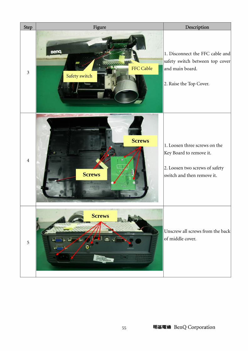
Step Figure Description
3
1. Disconnect the FFC cable and
safety switch between top cover
and main board.
2. Raise the Top Cover.
4
1. Loosen three screws on the
Key Board to remove it.
2. Loosen two screws of safety
switch and then remove it.
5
Unscrew all screws from the back
of middle cover.
Screws
FFC Cable
Safety switch
Screws
Screws

56
Step Figure Description
6
1. Unscrew four screws from the
middle cover.
2. Remove the middle cover.
7
Unscrew all screws as shown.
8
1. Unscrew all screws on the
metal sheet of Main Board.
2. Remove the metal sheet.
Note: The Speaker is connected
to Main Board through the hole
on the metal sheet. Please
disconnect it from Main board
firstly.
Screws
Speaker
Screws
Screws
57
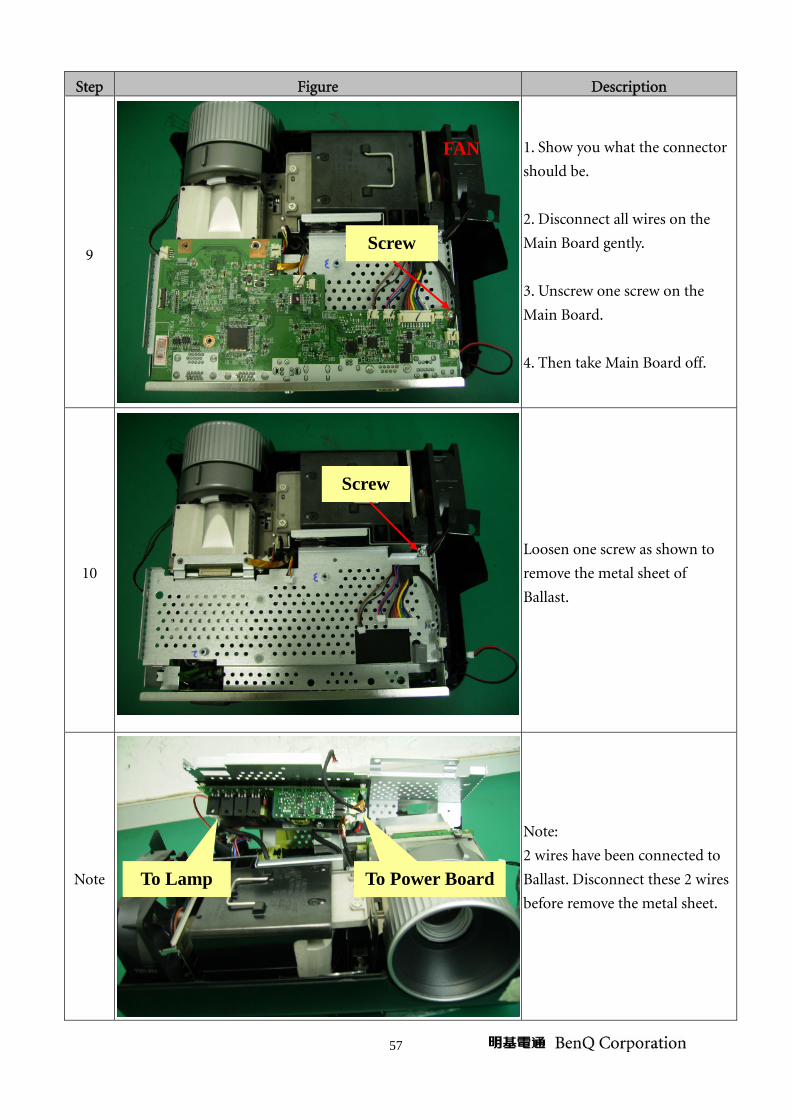
Step Figure Description
9
1. Show you what the connector
should be.
2. Disconnect all wires on the
Main Board gently.
3. Unscrew one screw on the
Main Board.
4. Then take Main Board off.
10
Loosen one screw as shown to
remove the metal sheet of
Ballast.
Note
Note:
2 wires have been connected to
Ballast. Disconnect these 2 wires
before remove the metal sheet.
FAN
Screw
To Power BoardTo Lamp
Screw
58
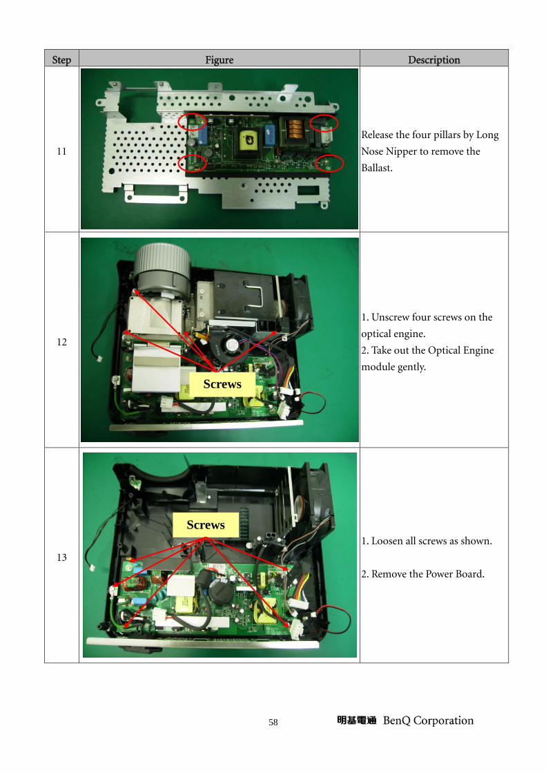
Step Figure Description
11
Release the four pillars by Long
Nose Nipper to remove the
Ballast.
12
1. Unscrew four screws on the
optical engine.
2. Take out the Optical Engine
module gently.
13
1. Loosen all screws as shown.
2. Remove the Power Board.
Screws
Screws

59
Step Figure Description
14
1. Loosen one screw on F-IR
Board.
2. Remove the F-IR Board.
Screw
60
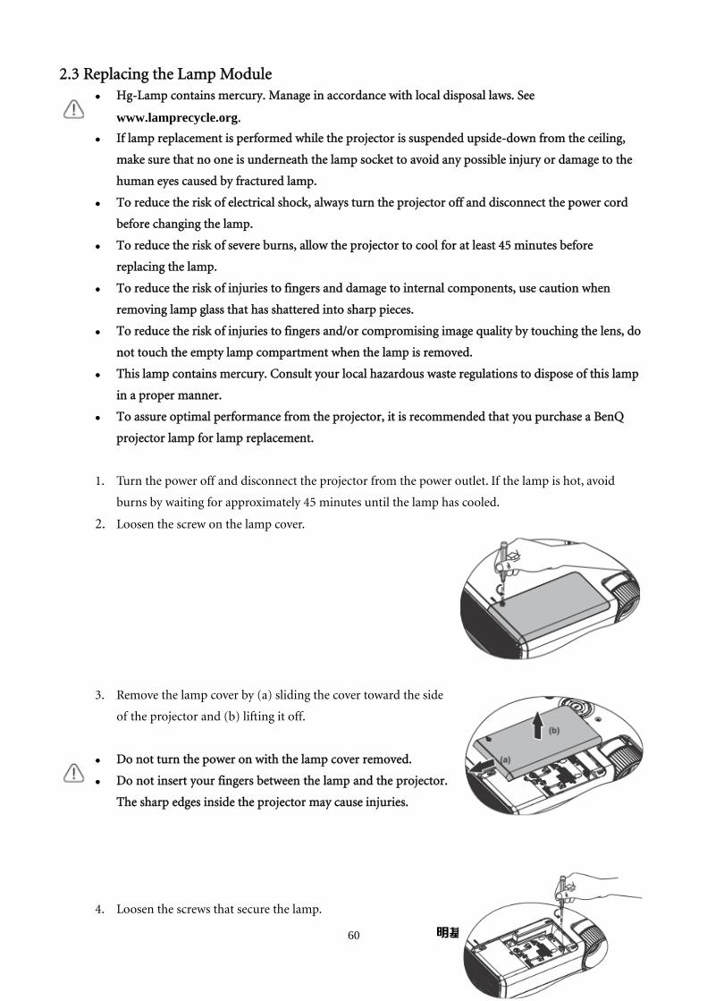
2.3 Replacing the Lamp Module Hg-Lamp contains mercury. Manage in accordance with local disposal laws. See
www.lamprecycle.org.
If lamp replacement is performed while the projector is suspended upside-down from the ceiling,
make sure that no one is underneath the lamp socket to avoid any possible injury or damage to the
human eyes caused by fractured lamp.
To reduce the risk of electrical shock, always turn the projector off and disconnect the power cord
before changing the lamp.
To reduce the risk of severe burns, allow the projector to cool for at least 45 minutes before
replacing the lamp.
To reduce the risk of injuries to fingers and damage to internal components, use caution when
removing lamp glass that has shattered into sharp pieces.
To reduce the risk of injuries to fingers and/or compromising image quality by touching the lens, do
not touch the empty lamp compartment when the lamp is removed.
This lamp contains mercury. Consult your local hazardous waste regulations to dispose of this lamp
in a proper manner.
To assure optimal performance from the projector, it is recommended that you purchase a BenQ
projector lamp for lamp replacement.
1. Turn the power off and disconnect the projector from the power outlet. If the lamp is hot, avoid
burns by waiting for approximately 45 minutes until the lamp has cooled.
2. Loosen the screw on the lamp cover.
3. Remove the lamp cover by (a) sliding the cover toward the side
of the projector and (b) lifting it off.
Do not turn the power on with the lamp cover removed.
Do not insert your fingers between the lamp and the projector.
The sharp edges inside the projector may cause injuries.
4. Loosen the screws that secure the lamp.
61
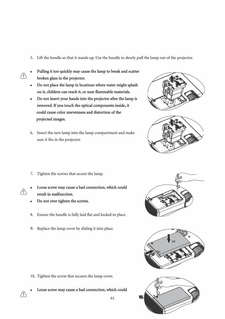
5. Lift the handle so that it stands up. Use the handle to slowly pull the lamp out of the projector.
Pulling it too quickly may cause the lamp to break and scatter
broken glass in the projector.
Do not place the lamp in locations where water might splash
on it, children can reach it, or near flammable materials.
Do not insert your hands into the projector after the lamp is
removed. If you touch the optical components inside, it
could cause color unevenness and distortion of the
projected images.
6. Insert the new lamp into the lamp compartment and make
sure it fits in the projector.
7. Tighten the screws that secure the lamp.
Loose screw may cause a bad connection, which could
result in malfunction.
Do not over tighten the screws.
8. Ensure the handle is fully laid flat and locked in place.
9. Replace the lamp cover by sliding it into place.
10. Tighten the screw that secures the lamp cover.
Loose screw may cause a bad connection, which could

62
result in malfunction.
Do not over tighten the screw.
11. Restart the projector.
Do not turn the power on with the lamp cover removed.
Resetting the lamp timer.
12. After the startup logo, open the On-Screen Display (OSD)
menu. Go to the SYSTEM SETUP: Advanced > Lamp
Settings menu. Press Mode/Enter. The Lamp Settings
page display. Press ▼ to highlight Reset lamp timer and
press Mode/Enter. A warning message displays asking if
you want to reset the lamp timer. Highlight Reset and press Mode/Enter. The lamp time will be reset
to “0”.
Do not reset if the lamp is not new or replaced as this could cause damage.
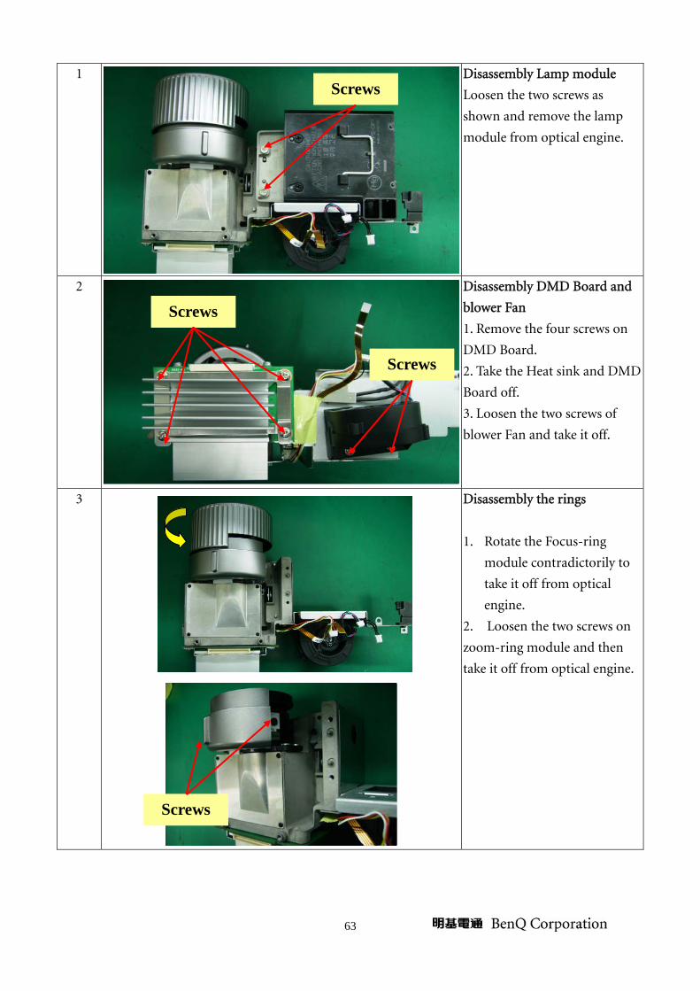
2.4 Disassembly the Optical Engine
Step Figure Description
63
1
Disassembly Lamp module
Loosen the two screws as
shown and remove the lamp
module from optical engine.
2
Disassembly DMD Board and
blower Fan
1. Remove the four screws on
DMD Board.
2. Take the Heat sink and DMD
Board off.
3. Loosen the two screws of
blower Fan and take it off.
3
Disassembly the rings
1. Rotate the Focus-ring
module contradictorily to
take it off from optical
engine.
2. Loosen the two screws on
zoom-ring module and then
take it off from optical engine.
Screws
Screws
Screws
Screws

64
4
Disassembly the Lens
Loosen four screws and then
take off the Lens carefully.
5
P.1
P.2
Disassembly the Color Wheel
1. Loosen the screw as shown
and then remove the blower
fan and the metal.(P.1)
2. Loosen the screw as shown
to remove the project cover of
Color wheel carefully.(P.2)
3. Loosen two screws as shown
to remove the Color wheel
module.(P.2)
Screws
Screw
Screws Screws

65
3. System Block Diagram
66
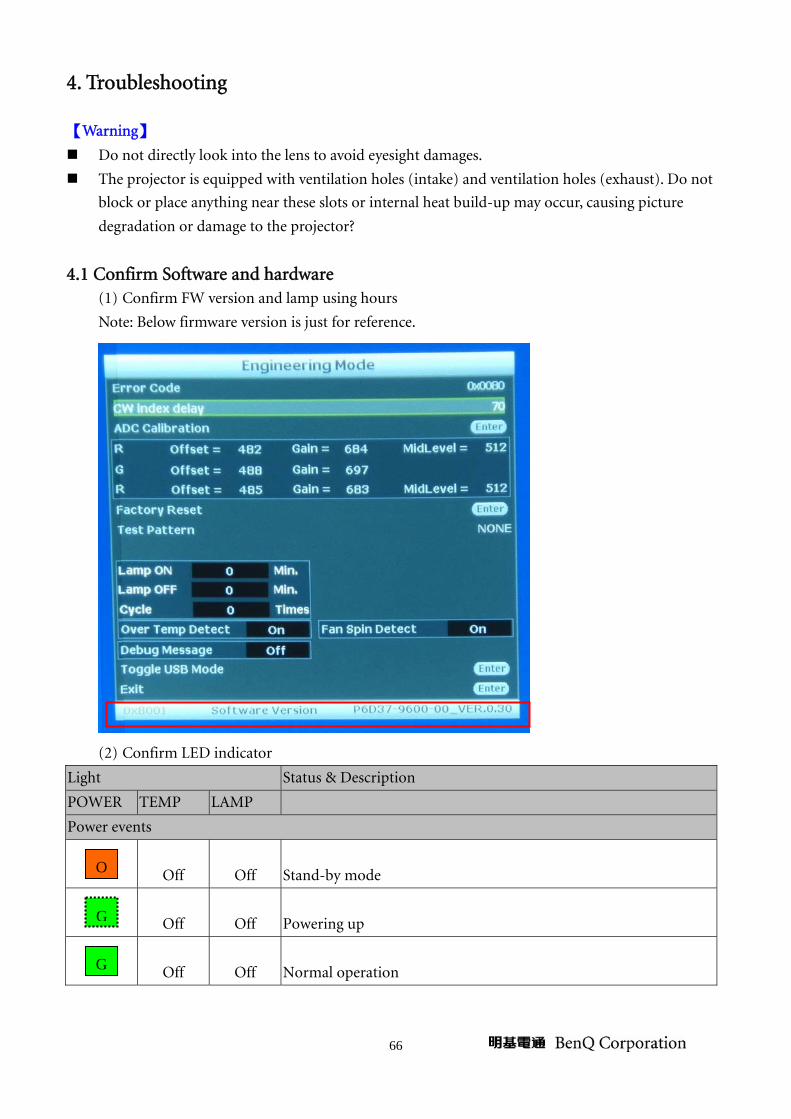
4. Troubleshooting
【Warning】
Do not directly look into the lens to avoid eyesight damages.
The projector is equipped with ventilation holes (intake) and ventilation holes (exhaust). Do not
block or place anything near these slots or internal heat build-up may occur, causing picture
degradation or damage to the projector?
4.1 Confirm Software and hardware (1) Confirm FW version and lamp using hours
Note: Below firmware version is just for reference.
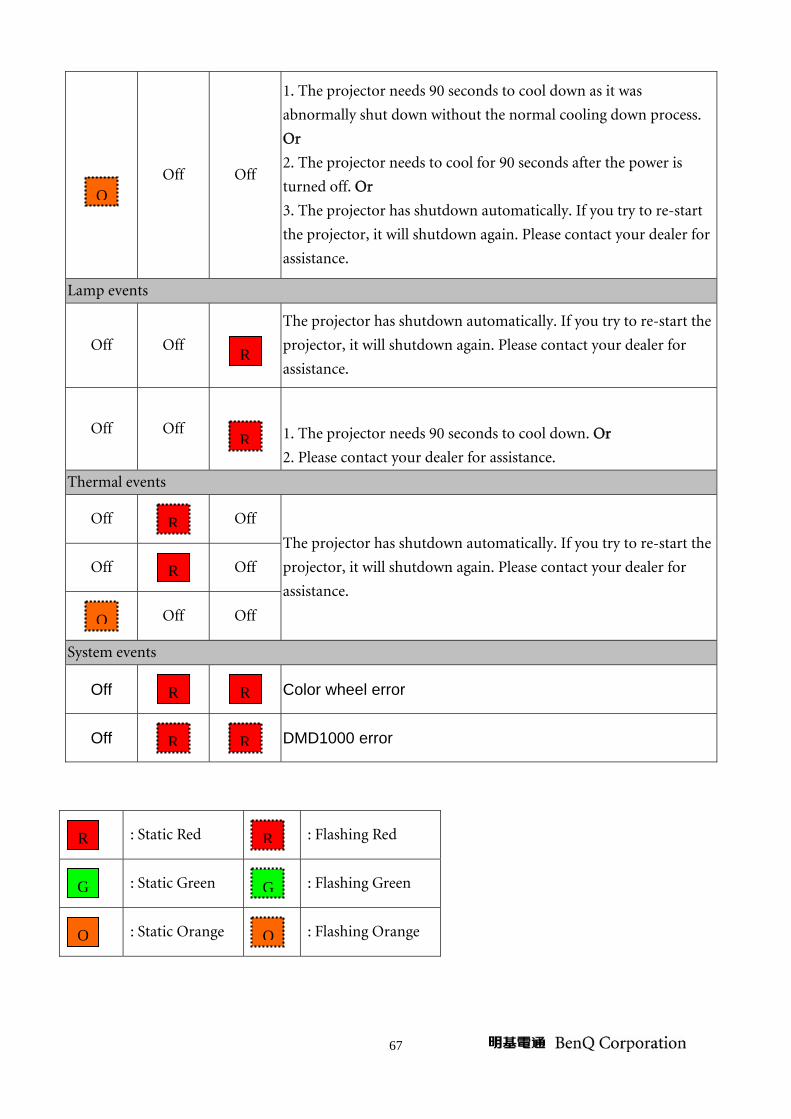
(2) Confirm LED indicator
Light Status & Description
POWER TEMP LAMP
Power events
Off Off Stand-by mode
Off Off Powering up
Off Off Normal operation G
G
O
67
Off Off
1. The projector needs 90 seconds to cool down as it was
abnormally shut down without the normal cooling down process.
Or
2. The projector needs to cool for 90 seconds after the power is
turned off. Or
3. The projector has shutdown automatically. If you try to re-start
the projector, it will shutdown again. Please contact your dealer for
assistance.
Lamp events
Off Off
The projector has shutdown automatically. If you try to re-start the
projector, it will shutdown again. Please contact your dealer for
assistance.
Off Off
1. The projector needs 90 seconds to cool down. Or
2. Please contact your dealer for assistance.
Thermal events
Off
Off
The projector has shutdown automatically. If you try to re-start the
projector, it will shutdown again. Please contact your dealer for
assistance.
Off
Off
Off Off
System events
Off Color wheel error
Off DMD1000 error
: Static Red
: Flashing Red
: Static Green
: Flashing Green
: Static Orange
: Flashing Orange
RR
R R
O
R
R
R
R
O
OO
GG
R R

68
Power Source Troubleshooting:
No Power Source
after turning on
Replace AC
socket
Replace power
board or reinstall
Replace keypad
and FPC
Replace power
board
Replace Main
board
OK
OK
OK
OK
NG
NG
NG
NG Check 7 pin Power output
Check Safety Switch
Check AC socket and
connector
Check LED and keypad
FPC
Fan failure after
turning on
Reconnect fan
Replace fan
Replace
Main board
NG
NG
NG
OK
OK
Check Main board
Check Fan
Check fan connection
Check Fuse
OK
Replace fuse
NG
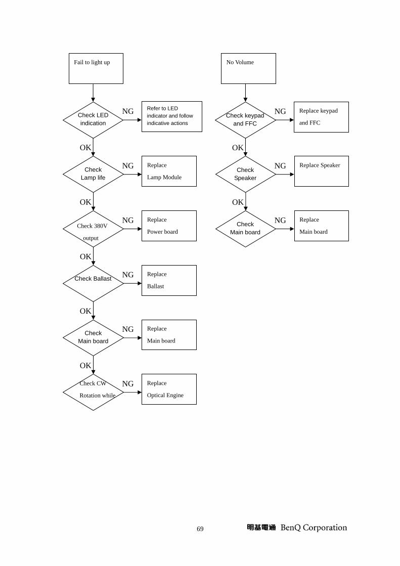
69
Fail to light up
Refer to LED indicator and follow indicative actions
Replace
Lamp Module
Replace
Power board
Replace
Ballast
Replace
Main board
OK
OK
OK
OK
OK
NG
NG
NG
NG
NG Check Main board
Check Ballast
Check Lamp life
Check LED indication
Check 380V
output
Replace
Optical Engine
NG Check CW
Rotation while
No Volume
Replace keypad
and FFC
Replace Speaker
Replace
Main board
NG
NG
NG
OK
OK
Check Main board
Check Speaker
Check keypad and FFC
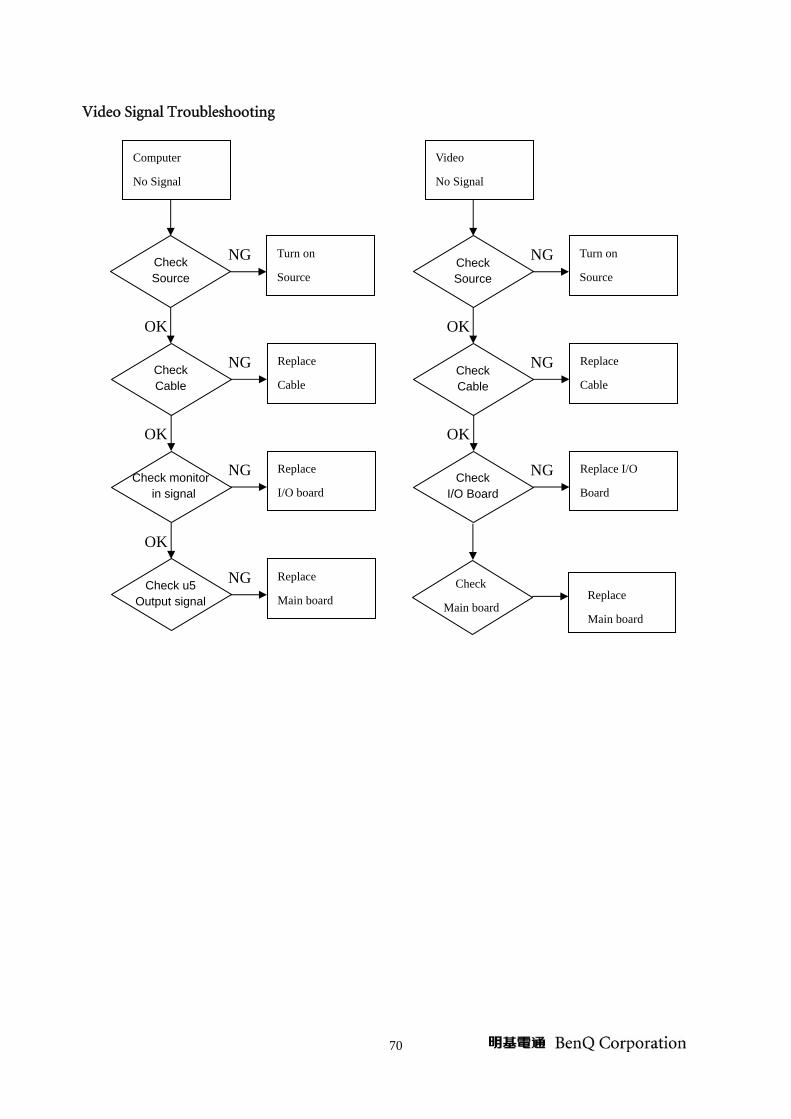
70
Video Signal Troubleshooting
Computer
No Signal
Turn on
Source
Replace
Cable
Replace
I/O board
Replace
Main board
OK
OK
OK
NG
NG
NG
NG Check u5 Output signal
Check Cable
Check Source
Check monitor in signal
Video
No Signal
Turn on
Source
Replace
Cable
Replace I/O
Board
NG
NG
NG
OK
OK
Check Cable
Check Source
Check I/O Board
Replace
Main board
Check
Main board
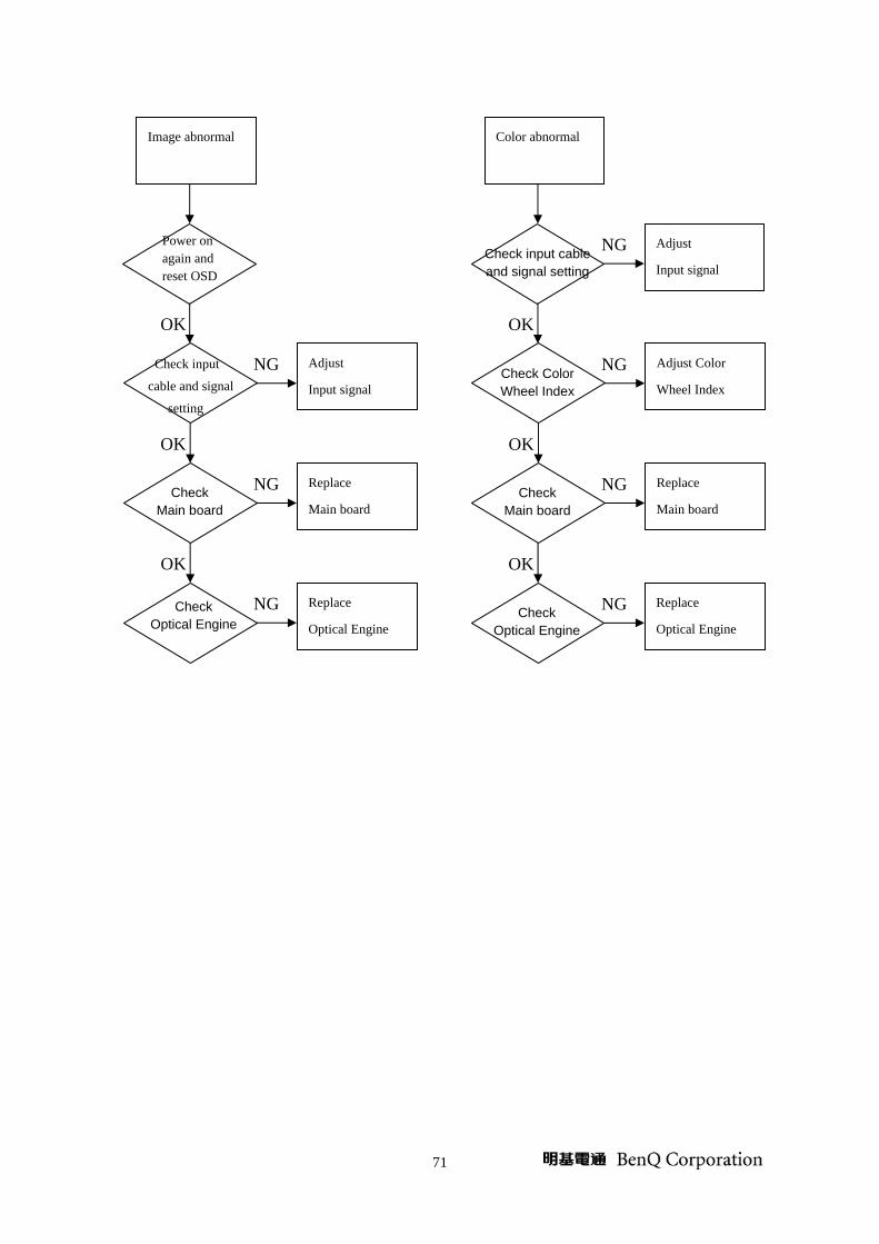
71
Image abnormal
Adjust
Input signal
Replace
Main board
Replace
Optical Engine
OK
OK
OK
NG
NG
NG Check Optical Engine
Check input
cable and signal
setting
Power on again and reset OSD
Check Main board
Color abnormal
Adjust
Input signal
Adjust Color
Wheel Index
Replace
Main board
NG
NG
NG
OK
OK
Check Main board
Check Color Wheel Index
Check input cable and signal setting
Replace
Optical Engine
OK
NG Check Optical Engine

72
Operation Function Troubleshooting
Remote Control
Failure
Replace
Battery
Replace
Remote Control
Replace
IR
Replace
Main board
OK
OK
OK
NG
NG
NG
NG Check Main board
Check Remote Control
Check Battery Level
Check IR
Button Failure
Replace
Keypad and FPC
Replace
Main board
NG
NG
OK
Check Main board
Check Keypad and FPC

73
4.2 Error Count Messages Definition Enter the factory menu to check the error message as shown.
Error Code
// 0x0400: DAD1000 Voltage Error
// 0x0200: DAD1000 Temp Error
// 0x0100: CW Error after power on
// 0x0080: Lamp No Lit when power on
// 0x0040: Communication between Main board and Ballast Error
// 0x0020: CW Error when power on
// 0x0010: FAN3 Error
// 0x0004: FAN1 Error
// 0x0001: T1 Over Temp
Will show Error
74
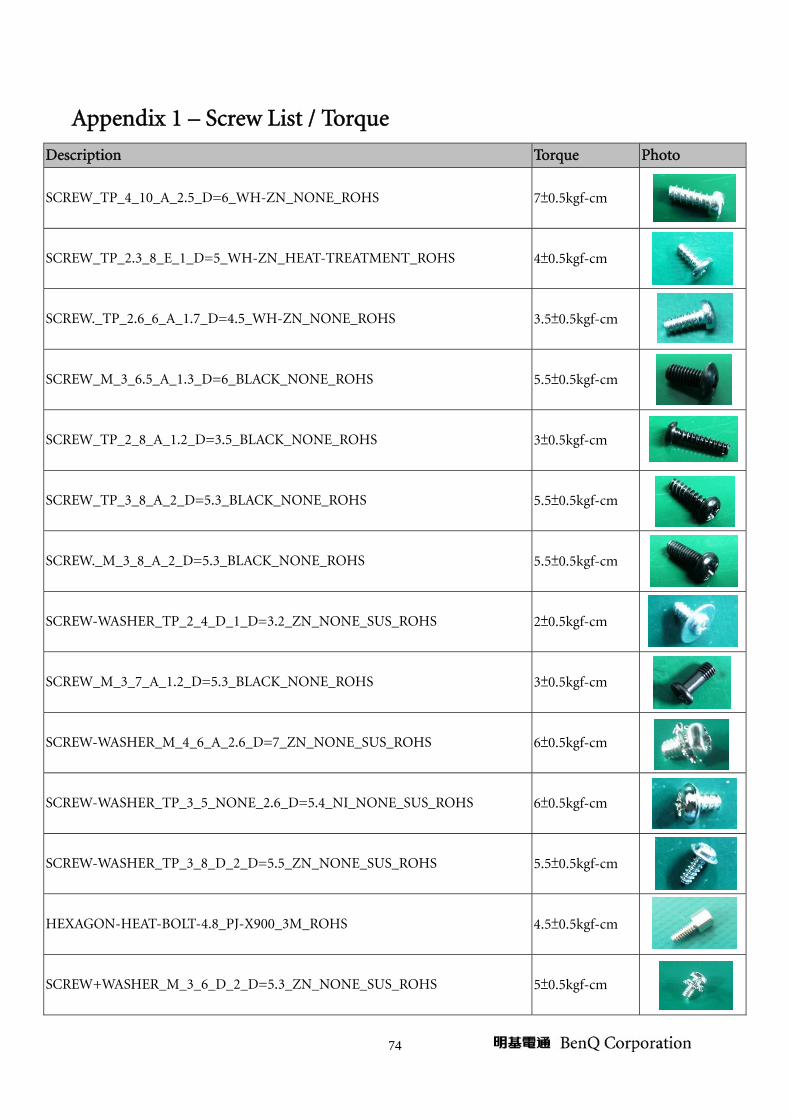
Appendix 1 – Screw List / Torque
Description Torque Photo
SCREW_TP_4_10_A_2.5_D=6_WH-ZN_NONE_ROHS 7±0.5kgf-cm
SCREW_TP_2.3_8_E_1_D=5_WH-ZN_HEAT-TREATMENT_ROHS 4±0.5kgf-cm
SCREW._TP_2.6_6_A_1.7_D=4.5_WH-ZN_NONE_ROHS 3.5±0.5kgf-cm
SCREW_M_3_6.5_A_1.3_D=6_BLACK_NONE_ROHS 5.5±0.5kgf-cm
SCREW_TP_2_8_A_1.2_D=3.5_BLACK_NONE_ROHS 3±0.5kgf-cm
SCREW_TP_3_8_A_2_D=5.3_BLACK_NONE_ROHS 5.5±0.5kgf-cm
SCREW._M_3_8_A_2_D=5.3_BLACK_NONE_ROHS 5.5±0.5kgf-cm
SCREW-WASHER_TP_2_4_D_1_D=3.2_ZN_NONE_SUS_ROHS 2±0.5kgf-cm
SCREW_M_3_7_A_1.2_D=5.3_BLACK_NONE_ROHS 3±0.5kgf-cm
SCREW-WASHER_M_4_6_A_2.6_D=7_ZN_NONE_SUS_ROHS 6±0.5kgf-cm
SCREW-WASHER_TP_3_5_NONE_2.6_D=5.4_NI_NONE_SUS_ROHS 6±0.5kgf-cm
SCREW-WASHER_TP_3_8_D_2_D=5.5_ZN_NONE_SUS_ROHS 5.5±0.5kgf-cm
HEXAGON-HEAT-BOLT-4.8_PJ-X900_3M_ROHS 4.5±0.5kgf-cm
SCREW+WASHER_M_3_6_D_2_D=5.3_ZN_NONE_SUS_ROHS 5±0.5kgf-cm

75
SCREW_M_3_5_E_1.2_D=6.5_WH-ZN_NL_ROHS 6+/-0.5kgf-cm
SCREW_M_3_5_D_2_D=5.5_NI_NONE_ROHS 6+/-0.5kgf-cm
SCREW._M_2_2.5_A_D=3_A0.8_BLACK_HEAT-TREATMENT_ROHS 2.0±0.2kgf-cm
SCREW_M_3*_7.1_NONE_1.2_D=6_BLACK_NI_ROHS 6.0±0.5kgf-cm
SCREW_M_2_5_A_D=3_A0.8_BLACK_HEAT-TREATMENT_ROHS 1.2+/-0.3kgf cm

76
Appendix 2 - Code List: IR / RS232 / DDC Data
1. Remote Control Code
IC Protocol: NEC 標準 Custom Code:0030
Name Key No. DATA CODE
Name Key No. DATA CODE
HEX BINARY HEX BINARY
K7 02 0100 0000 K20 0C 0011 0000
K6 03 1100 0000 K28 04 0010 0000
K14 0F 1111 0000 K2 82 0100 0001
K22 0B 1101 0000 K10 18 0001 1000
K30 08 0001 0000 K18 05 1010 0000
K5 20 0000 0100 K26 25 1010 0100
K13 0D 1011 0000 K1 83 1100 0001
K21 10 0000 1000 K9 19 1001 1000
K29 0E 0111 0000 K17 06 0110 0000
K4 1E 0111 1000 K25 26 0110 0100
K12 07 1110 0000
77
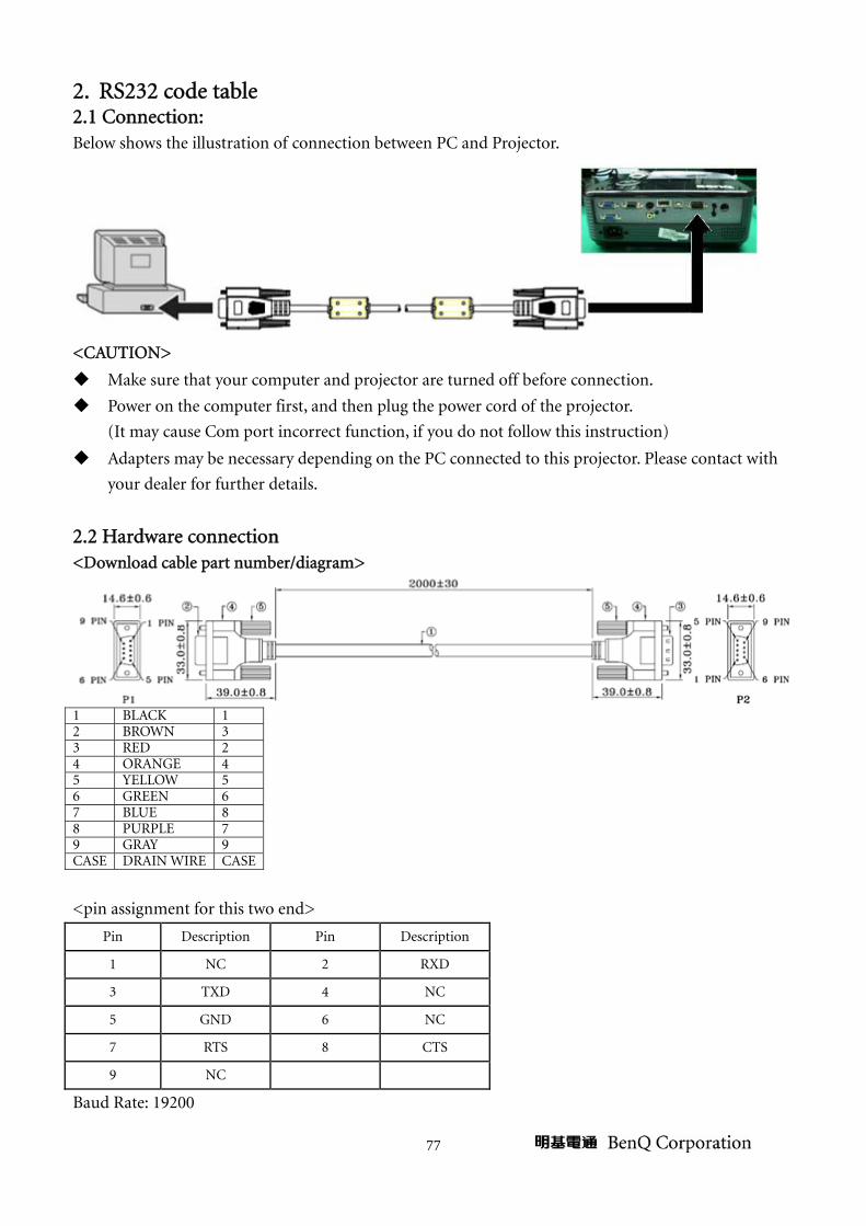
2. RS232 code table 2.1 Connection: Below shows the illustration of connection between PC and Projector.
<CAUTION>
Make sure that your computer and projector are turned off before connection.
Power on the computer first, and then plug the power cord of the projector.
(It may cause Com port incorrect function, if you do not follow this instruction)
Adapters may be necessary depending on the PC connected to this projector. Please contact with
your dealer for further details.
2.2 Hardware connection <Download cable part number/diagram>
1 BLACK 1 2 BROWN 3 3 RED 2 4 ORANGE 4 5 YELLOW 5 6 GREEN 6 7 BLUE 8 8 PURPLE 7 9 GRAY 9 CASE DRAIN WIRE CASE
<pin assignment for this two end>
Pin Description Pin Description
1 NC 2 RXD
3 TXD 4 NC
5 GND 6 NC
7 RTS 8 CTS
9 NC
Baud Rate: 19200
78
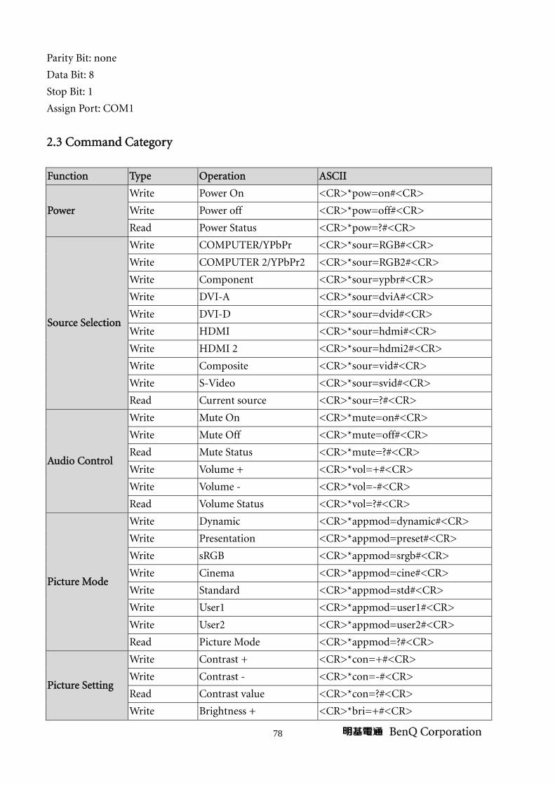
Parity Bit: none
Data Bit: 8
Stop Bit: 1
Assign Port: COM1
2.3 Command Category
Function Type Operation ASCII
Power
Write Power On <CR>*pow=on#<CR>
Write Power off <CR>*pow=off#<CR>
Read Power Status <CR>*pow=?#<CR>
Source Selection
Write COMPUTER/YPbPr <CR>*sour=RGB#<CR>
Write COMPUTER 2/YPbPr2 <CR>*sour=RGB2#<CR>
Write Component <CR>*sour=ypbr#<CR>
Write DVI-A <CR>*sour=dviA#<CR>
Write DVI-D <CR>*sour=dvid#<CR>
Write HDMI <CR>*sour=hdmi#<CR>
Write HDMI 2 <CR>*sour=hdmi2#<CR>
Write Composite <CR>*sour=vid#<CR>
Write S-Video <CR>*sour=svid#<CR>
Read Current source <CR>*sour=?#<CR>
Audio Control
Write Mute On <CR>*mute=on#<CR>
Write Mute Off <CR>*mute=off#<CR>
Read Mute Status <CR>*mute=?#<CR>
Write Volume + <CR>*vol=+#<CR>
Write Volume - <CR>*vol=-#<CR>
Read Volume Status <CR>*vol=?#<CR>
Picture Mode
Write Dynamic <CR>*appmod=dynamic#<CR>
Write Presentation <CR>*appmod=preset#<CR>
Write sRGB <CR>*appmod=srgb#<CR>
Write Cinema <CR>*appmod=cine#<CR>
Write Standard <CR>*appmod=std#<CR>
Write User1 <CR>*appmod=user1#<CR>
Write User2 <CR>*appmod=user2#<CR>
Read Picture Mode <CR>*appmod=?#<CR>
Picture Setting
Write Contrast + <CR>*con=+#<CR>
Write Contrast - <CR>*con=-#<CR>
Read Contrast value <CR>*con=?#<CR>
Write Brightness + <CR>*bri=+#<CR>
79
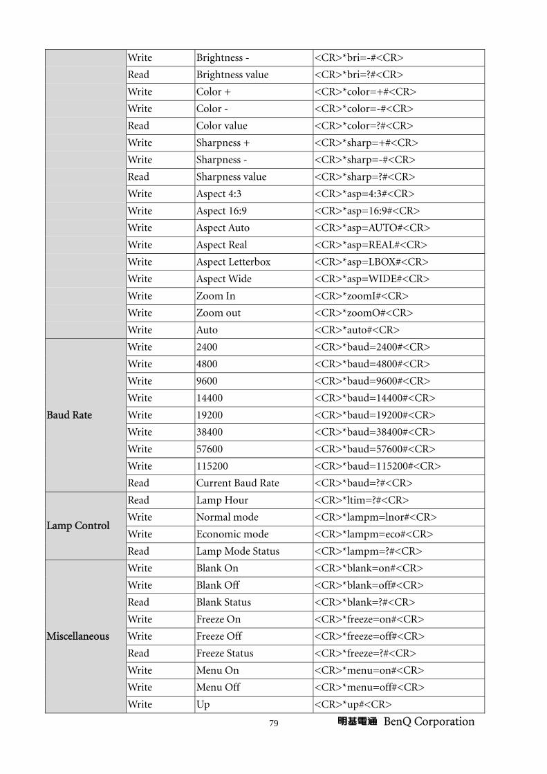
Write Brightness - <CR>*bri=-#<CR>
Read Brightness value <CR>*bri=?#<CR>
Write Color + <CR>*color=+#<CR>
Write Color - <CR>*color=-#<CR>
Read Color value <CR>*color=?#<CR>
Write Sharpness + <CR>*sharp=+#<CR>
Write Sharpness - <CR>*sharp=-#<CR>
Read Sharpness value <CR>*sharp=?#<CR>
Write Aspect 4:3 <CR>*asp=4:3#<CR>
Write Aspect 16:9 <CR>*asp=16:9#<CR>
Write Aspect Auto <CR>*asp=AUTO#<CR>
Write Aspect Real <CR>*asp=REAL#<CR>
Write Aspect Letterbox <CR>*asp=LBOX#<CR>
Write Aspect Wide <CR>*asp=WIDE#<CR>
Write Zoom In <CR>*zoomI#<CR>
Write Zoom out <CR>*zoomO#<CR>
Write Auto <CR>*auto#<CR>
Baud Rate
Write 2400 <CR>*baud=2400#<CR> Write 4800 <CR>*baud=4800#<CR> Write 9600 <CR>*baud=9600#<CR>
Write 14400 <CR>*baud=14400#<CR>
Write 19200 <CR>*baud=19200#<CR>
Write 38400 <CR>*baud=38400#<CR>
Write 57600 <CR>*baud=57600#<CR>
Write 115200 <CR>*baud=115200#<CR>
Read Current Baud Rate <CR>*baud=?#<CR>
Lamp Control
Read Lamp Hour <CR>*ltim=?#<CR>
Write Normal mode <CR>*lampm=lnor#<CR>
Write Economic mode <CR>*lampm=eco#<CR>
Read Lamp Mode Status <CR>*lampm=?#<CR>
Miscellaneous
Write Blank On <CR>*blank=on#<CR>
Write Blank Off <CR>*blank=off#<CR>
Read Blank Status <CR>*blank=?#<CR>
Write Freeze On <CR>*freeze=on#<CR>
Write Freeze Off <CR>*freeze=off#<CR>
Read Freeze Status <CR>*freeze=?#<CR>
Write Menu On <CR>*menu=on#<CR>
Write Menu Off <CR>*menu=off#<CR>
Write Up <CR>*up#<CR>

80
Write Down <CR>*down#<CR>
Write Right <CR>*right#<CR>
Write Left <CR>*left#<CR>
Write Enter <CR>*enter#<CR>
3. DDC Data
BYTES OF EDID CODE:
128 0 1 2 3 4 5 6 7 8 9
________________________________________
0 | 00 FF FF FF FF FF FF 00 09 D1
10 | 01 F8 01 00 00 00 18 14 01 03
20 | 0E 00 00 78 0A 4B 4A A0 59 5A
30 | 90 23 15 4F 5D BD EF 80 31 7C
40 | 45 7C 61 7C 61 C0 81 80 95 00
50 | 90 40 A9 40 A0 0F 20 00 31 58
60 | 1C 20 28 80 14 00 00 00 00 00
70 | 00 1E 00 00 00 FD 00 30 78 1F
80 | 63 11 00 0A 20 20 20 20 20 20
90 | 00 00 00 FE 00 42 45 4E 51 0A
100 | 20 20 20 20 20 20 20 20 00 00
110 | 00 FC 00 4D 53 35 31 30 0A 20
120 | 20 20 20 20 20 20 00 75
______________________________________________________________________
(08-09) ID Manufacturer Name ________________ = BNQ
(10-11) Product ID Code _____________________ = 01F8
(12-15) Last 5 Digits of Serial Number ______ = 00001
(16) Week of Manufacture _________________ = 24
(17) Year of Manufacture _________________ = 2010
(18) EDID Version Number _________________ = 1
(19) EDID Revision Number ________________ = 3
(20) VIDEO INPUT DEFINITION:
Analog Signal
0.700, 0.300 (0.700 Vp-p)
Separate Syncs, Composite Sync, Sync on Green,
Serration of the Vsync
(21) Maximum Horizontal Image Size ________________ = mm
(22) Maximum Vertical Image Size __________________ = mm
(23) Display Gamma ________________________________ = 2.20
(24) Power Management and Supported Feature(s):

81
Preferred Timing Mode
Display Type = R/G/B Color
(25-34) CHROMA INFO:
Red X - 0.626 Green X - 0.354 Blue X - 0.138 White X - 0.311
Red Y - 0.348 Green Y - 0.565 Blue Y - 0.082 White Y - 0.365
(35) ESTABLISHED TIMING I:
640 X 480 @ 60Hz (VGA)
640 X 480 @ 67Hz (Mac II)
640 X 480 @ 72Hz (VESA)
640 X 480 @ 75Hz (VESA)
720 X 400 @ 70Hz (VGA)
800 X 600 @ 60Hz (VESA)
(36) ESTABLISHED TIMING II:
800 X 600 @ 72Hz (VESA)
800 X 600 @ 75Hz (VESA)
832 X 624 @ 75Hz (Mac II)
1024 X 768 @ 60Hz (VESA)
1024 X 768 @ 70Hz (VESA)
1024 X 768 @ 75Hz (VESA)
1280 X 1024 @ 75Hz (VESA)
(37) Manufacturer's Reserved Timing:
1152 X 870 @ 75Hz (Mac II)
(38-53) Standard Timing Identification:
1024 X 768 @120Hz
1280 X 1024 @60Hz
1024 X 576@60Hz
1440 X900 @60Hz
1400 X1050 @60Hz
800 X 600 @120Hz
640 X 480 @120Hz
1600 X 1200 @10Hz
______________________________________________________________________
(54-71) Detailed Timing / Descriptor Block 1:
800x600 Pixel Clock: 40.00 MHz
______________________________________________________________________
Horizontal Image Size: 0 mm Vertical Image Size: 0 mm
Refreshed Mode: Non-Interlaced Normal Display - No Stereo
82
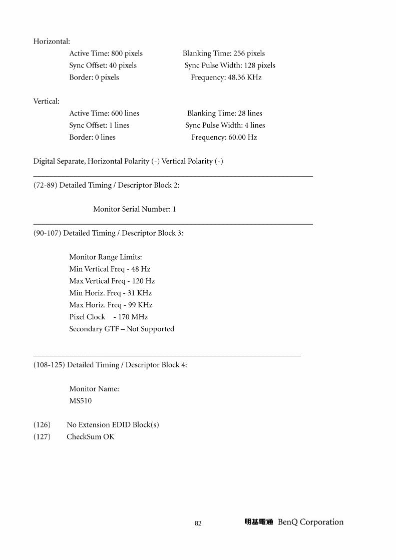
Horizontal:
Active Time: 800 pixels Blanking Time: 256 pixels
Sync Offset: 40 pixels Sync Pulse Width: 128 pixels
Border: 0 pixels Frequency: 48.36 KHz
Vertical:
Active Time: 600 lines Blanking Time: 28 lines
Sync Offset: 1 lines Sync Pulse Width: 4 lines
Border: 0 lines Frequency: 60.00 Hz
Digital Separate, Horizontal Polarity (-) Vertical Polarity (-)
______________________________________________________________________
(72-89) Detailed Timing / Descriptor Block 2:
Monitor Serial Number: 1
______________________________________________________________________
(90-107) Detailed Timing / Descriptor Block 3:
Monitor Range Limits:
Min Vertical Freq - 48 Hz
Max Vertical Freq - 120 Hz
Min Horiz. Freq - 31 KHz
Max Horiz. Freq - 99 KHz
Pixel Clock - 170 MHz
Secondary GTF – Not Supported
___________________________________________________________________
(108-125) Detailed Timing / Descriptor Block 4:
Monitor Name:
MS510
(126) No Extension EDID Block(s)
(127) CheckSum OK

83
Appendix 3 - Ceiling Mount Drawing
Related Documents