BENEFITS OF DYNAMIC PROCESS SIMULATION FOR MINERAL INDUSTRY Prashanth Parthasarathi, Virgil Szaruga and Marian Szatkowski Andritz Automation Inc., Suite 570, 125 Clairemont Ave., Decatur, GA 30030, USA ABSTRACT Using steady-state computer models for plant design has a long and well established track record in mining and metallurgical industries. In recent years, there has been growing interest in taking process modeling to another level and using dynamic computer models for mineral processing plants (Ergun et al., 2004; Liu and Spencer, 2004; Napier- Munn, 1996; Nikkah and Anderson, 2001; Salazar et al., 2009). This paper will use an example of a commercial simulation package called IDEAS to show how dynamic simulation can be used throughout the whole life-cycle of a mineral processing plant, i.e., for process design, P&ID verification, control loop tuning and checkout, as well as for operator training. A simple model of a grinding and separation circuit, typical for mineral processing plants, will be used to show how a model of a mineral plant would evolve during the project’s life cycle. INTRODUCTION The primary focus of using dynamic simulations in the mineral industry seems to be thus far on the design of process control loops and alternate circuits to improve product quality and/or reduce power consumption (Ergun et al., 2004; Jamsa-Jounela et al., 2003; Liu and Spencer, 2004). However, dynamic simulation is a powerful tool that can be used for studying a much broader range of applications, such as: - equipment sizing (tanks, pumps, pipes & valves) - designing advanced process control strategies - check-out of Distributed Control System (DCS) and Programmable Logic Controller (PLC) programs - Hazard and Operability (HAZOP) analyses - designing and testing start-up and shut-down procedures - operator training - de-bottlenecking of operations after the start-up - energy use optimization The first six of these eight tasks can be done well ahead of the actual process even being built. After the plant is in operation, the use of simulation assures that running numerous “what if” scenarios, necessary for on-going process improvements, is easy and avoids the risks of damaging process equipment or interrupting production. The Canadian oil sands industry has accepted dynamic simulation for use in controls checkup and operator training. The nature of the processes for extracting bitumen from oil sands that involves the use of volatile hydrocarbon solvents necessitated a tested process and well trained operator force from day one of any plant operation. In addition, the fast turnover of the workforce in that industry required tools for the continuous training of operators off-line. In this paper, we will present examples of how a single simulation package can be used in all the applications listed above. For this presentation, a simple model of a grinding and separation circuit, common in mineral processing plants, was simulated using a commercial, steady-state and dynamic simulation package called IDEAS. The reader will be taken through three versions of the same model (steady-state, dynamic and OTS) and will be shown how the model evolves during the project’s life cycle. IDEAS PROCESS SIMULATOR The IDEAS simulator is an object-based graphical environment, where the user builds a model by retrieving icon- based "objects" from various libraries and assembling them on a drawing-like worksheet. These objects generally have a one to one correspondence with actual process equipment, i.e., pumps, valves, tanks, transmitters, controllers, etc. The user can therefore create a model by creating a P&ID (or PFD)-like picture of the process. Individual equipment characteristics, such as pipe dimensions or pump curves, and feed characteristics, like composition and PSD, can be specified by filling in dialog box information for each object. The objects, grouped in libraries, are designed to be interconnected using stream connectors and can thus be used to create complex models. Once objects are connected and the information is entered into the dialog boxes, the simulation is ready to run. No other programming, "subroutine" connections or other software manipulations are www.andritz.com 1 of 10

Welcome message from author
This document is posted to help you gain knowledge. Please leave a comment to let me know what you think about it! Share it to your friends and learn new things together.
Transcript

BENEFITS OF DYNAMIC PROCESS SIMULATION FOR MINERAL INDUSTRY
Prashanth Parthasarathi, Virgil Szaruga and Marian Szatkowski
Andritz Automation Inc., Suite 570, 125 Clairemont Ave., Decatur, GA 30030, USA
ABSTRACT Using steady-state computer models for plant design has a long and well established track record in mining and
metallurgical industries. In recent years, there has been growing interest in taking process modeling to another level and using dynamic computer models for mineral processing plants (Ergun et al., 2004; Liu and Spencer, 2004; Napier-Munn, 1996; Nikkah and Anderson, 2001; Salazar et al., 2009).
This paper will use an example of a commercial simulation package called IDEAS to show how dynamic simulation can be used throughout the whole life-cycle of a mineral processing plant, i.e., for process design, P&ID verification, control loop tuning and checkout, as well as for operator training. A simple model of a grinding and separation circuit, typical for mineral processing plants, will be used to show how a model of a mineral plant would evolve during the project’s life cycle.
INTRODUCTION The primary focus of using dynamic simulations in the mineral industry seems to be thus far on the design of
process control loops and alternate circuits to improve product quality and/or reduce power consumption (Ergun et al., 2004; Jamsa-Jounela et al., 2003; Liu and Spencer, 2004).
However, dynamic simulation is a powerful tool that can be used for studying a much broader range of applications, such as:
- equipment sizing (tanks, pumps, pipes & valves) - designing advanced process control strategies - check-out of Distributed Control System (DCS) and Programmable Logic Controller (PLC) programs - Hazard and Operability (HAZOP) analyses - designing and testing start-up and shut-down procedures - operator training - de-bottlenecking of operations after the start-up - energy use optimization
The first six of these eight tasks can be done well ahead of the actual process even being built. After the plant is in operation, the use of simulation assures that running numerous “what if” scenarios, necessary for on-going process improvements, is easy and avoids the risks of damaging process equipment or interrupting production.
The Canadian oil sands industry has accepted dynamic simulation for use in controls checkup and operator training. The nature of the processes for extracting bitumen from oil sands that involves the use of volatile hydrocarbon solvents necessitated a tested process and well trained operator force from day one of any plant operation. In addition, the fast turnover of the workforce in that industry required tools for the continuous training of operators off-line.
In this paper, we will present examples of how a single simulation package can be used in all the applications listed above. For this presentation, a simple model of a grinding and separation circuit, common in mineral processing plants, was simulated using a commercial, steady-state and dynamic simulation package called IDEAS. The reader will be taken through three versions of the same model (steady-state, dynamic and OTS) and will be shown how the model evolves during the project’s life cycle.
IDEAS PROCESS SIMULATOR The IDEAS simulator is an object-based graphical environment, where the user builds a model by retrieving icon-
based "objects" from various libraries and assembling them on a drawing-like worksheet. These objects generally have a one to one correspondence with actual process equipment, i.e., pumps, valves, tanks, transmitters, controllers, etc. The user can therefore create a model by creating a P&ID (or PFD)-like picture of the process. Individual equipment characteristics, such as pipe dimensions or pump curves, and feed characteristics, like composition and PSD, can be specified by filling in dialog box information for each object.
The objects, grouped in libraries, are designed to be interconnected using stream connectors and can thus be used to create complex models. Once objects are connected and the information is entered into the dialog boxes, the simulation is ready to run. No other programming, "subroutine" connections or other software manipulations are
www.andritz.com 1 of 10

needed. The flows in the pipes, as well as the associated pressures throughout the piping network, will automatically be solved, displayed in the dialog boxes, and made available to transmitters and plotters.
IDEAS can perform steady-state mass and energy balances, track components, compounds and element flow and concentration, handle particle size distribution changes, and calculate specific gravity and excess enthalpy. Models can link to spreadsheets for importing multiple case-study scenarios and for exporting material and energy balance data.
Steady-state models created in IDEAS can be modified to incorporate process dynamics by adding objects such as pipes, valves, tanks, PI/PID controllers and other objects. Some unit operation models have two sets of equations already built in to allow switching between steady-state and dynamic modes of operation by simply toggling as switch in their dialog boxes. Other unit operation blocks will need to be replaced in the model with their dynamic version.
Unit operations are modeled in IDEAS using the first principle approach, i.e., the mass and energy conservation and the population balance methodology are the basis for all models of mineral processing operations. In addition to the mass and energy conservation principles used across the whole platform, the mineral processing models use semi-empirical equations and correlations specific from a given operation (hydrocyclones, screens). Furthermore, since we are dealing with natural materials (ores), the composition and the properties of which may vary widely not only from one ore deposit to another but even within the same body of ore, the models also require some basic lab or pilot plant data entered in their dialog boxes to accurately represent actual plant operations. The use of lab test data or results from either a pilot plant or the actual operation allows for verification of unit ops as the model is being built.
IDEAS mineral processing unit operation models have been developed in house based on published literature (King, 2001, Napier-Munn et al., 1996, and Morrell, 2004). The hydrocyclone unit uses two different models: the industry standard Plitt model (Plitt, Finch and Flintoff, 1980; Flintoff, Plitt and Turak, 1987) and the proprietary Krebs model for those applications that use hydrocyclones from this manufacturer.
Not all possible unit operations are available in the package, although the list is being continuously expanded as needed. Users with unique or proprietary models of their unit operations can implement their existing models in the framework of IDEAS in several ways, the easiest being by calling their dll functions(s) from IDEAS objects.
IDEAS has been successfully used in the mining and oil sands industries to develop dynamic simulations of plants by combining process dynamics with first principles models of unit operations. The IDEAS package contains libraries of industry specific models from mine operation to tailings pipelines with all the unit operations in between. It also features a flexible and customizable material properties database with components commonly used in the mineral industry. In addition to steady-state and dynamic modeling capabilities, IDEAS can connect to the plant DCS/PLC control system and be used for operator training via the IDEAS Instructor product. The Instructor product allows the trainer to present operators with a predefined set of training scenarios typical of what would be expected in the plant, and to grade the operators' response according to predefined criteria.
USE OF SIMULATION THROUGH PROJECT LIFE CYCLE A grinding circuit was selected to present the various analyses that can be performed using simulations. The
process starts with a stockpile. The ore is transported by a belt conveyor, mixed with water and sent to a SAG mill. The pebbles from the SAG mill are sent to a screen and then a pebble crusher. The crusher discharge and the product from the SAG mill are collected in a sump box where they are mixed with additional water. The slurry is pumped to a battery of hydrocyclones, the rejects of which are sent to a ball mill which recycles the ore to the sump box. The product of the hydrocyclone is sent to flotation. The process flow diagram is shown in Figure 1.
Steady-State Model Even though the purpose of this paper is to show the benefits of dynamic simulation in the mineral industry, in
order to have a complete picture of how a single simulation tool can be used, a brief example of using simulation in the early stage of the plant design, i.e., to develop process flow diagrams and mass and energy balances, will be presented.
In a typical application of steady-state modeling, numerous configurations of the grinding circuit may be produced and analyzed in order to select the best equipment configuration. When the final configuration is selected, the steady-state model may be run for different cases involving different ore types, mineral contents or production rates. Here, a single steady-state model is presented in Figure 1, with the mass and energy balance report generated, Figure 2.
www.andritz.com 2 of 10

Figure 1. Steady-State Model of Grinding Circuit
Figure 2. Mass Balance for Steady-State Grinding Circuit Model
It should be noted that the flow diagram representation of the process has been created by using so-called hierarchical blocks which allow placing a picture of choice on an existing library object (or a group of objects). For example, the SAG square is a hierarchy with the SAG mill set to run in a steady state mode, Figure 3.
Figure 3. Hierarchical structure of the SAG Mill unit
www.andritz.com 3 of 10

Dynamic Model – Equipment Sizing and Control Design During a traditional plant design process, the design work is divided between multiple disciplines, often between
different engineering companies. As each group tends to add a safety factor in their design, this may lead to a significant up-sizing of the process and therefore in increased capital costs. Using a dynamic model of the whole process (a virtual plant), one can check for any design up-sizing of tanks, pumps, pipes, valves and other critical pieces of process equipment resulting in significant capital cost reduction.
Furthermore, the virtual plant allows sizing the equipment not only for the steady-state, design production rates but also for any dynamic changes in the process. Such changes occur as a result of variation in the feed stock or disruptions in the equipment availability. The resulting changes in the amount of material moved through the process during such production swings will be affected by the dynamic and often complex equipment interactions, Having a complete representation of all the dynamic process elements is therefore very important for selecting proper equipment sizes. In addition, complex control strategies, including Advanced Process Control (APC) can be proposed and evaluated against the dynamic model during the design phase, leading to the proper selection of instruments and startup of the process in the most efficient manner.
At the same time, analyses of the virtual plant can reveal design flaws that would not have become obvious until the actual startup, thus resulting in delayed plant commissioning, redesign costs and lost production. Several cases of IDEAS dynamic models revealing mistakes in the design have been documented in oil sands applications [Foulds, Tipman].
Continuing with our example, a dynamic model of the grinding circuit for design and optimization of control loops is presented. The design of any controls in the grinding circuit will have to take into account the complex dynamics of the feed forward mass transfer part (conveyer, SAG, crasher) as well as those of the mass recycle loop (hydrocyclone and ball mill). As an illustration of the complexity of control loop design, a scheme for controlling the particle size (d50) of the product by controlling the density of the feed to the hydrocyclones has been used.
In transitioning from the steady-state to a dynamic model, some of the existing objects have been converted to their dynamic mode by a dialog box switch (mills, hydrocyclones) and additional objects such as a conveyor, tank, pump, valves and PID controllers were added to the model, as shown in Figure 4. The model was also ‘equipped” with various transmitters to monitor flows, densities, pressures and PSD of streams.
Figure 4. Dynamic Model of Grinding Circuit
As can be seen in Figure 4, the control of d50 of the feed to flotation (the product of the grinding circuit) directly involves at least three (3) control loops: the sump level control via the VSD pump, the slurry density control via controlling the dilution water to the sump, and finally, the cascade control of the hydrocyclone separation via adjusting the feed density. The control scheme is further complicated by an independent logic to control the pressure drop in the battery of hydrocyclones, where the number of active cyclones is increased or decreased to maintain the delta P within a predefined range. Without a realistic and complete representation of all process elements, such control loop design would be practically destined to fail.
www.andritz.com 4 of 10

IDEAS simulator allows tracking and processing particle size distributions of any component selected by the user. The principle of mass conservation with population balance is used in all operations that pass, mix or separate solids according to their sizes. Specific PSD “processing rules” are additionally applied in those unit ops that alter PSD of the processed materials (e.g., comminution, agglomeration, etc). Full distributions of PSD can be tracked in any process stream using PSD transmitters. As shown in Figure 5, the transmitter dialog box allows for customizing the format of the size distribution. The data can be presented in a tabular form or graphically. The transmitter also allows dynamic tracking of d50 (or d20, or d80) of an individual solid (ore) or of the mixture of all solids.
Figure 5. PSD display using PSD Transmitter
The simulation studies of this complex control strategy were done using a case of a step change in the ore hardness. The resulting upset in the size distribution of solids throughout the whole circuit resulted in an upset to the product’s d50. The changes in the d50 value as the result of a step change from ore A (softer) to ore B (harder), and back, have been shown in Figure 6. The cascade loop to control the d50 by adjusting the feed density was turned off. Only the sump level and the slurry density were automatically controlled at predefined set point values.
Figure 6. Dynamic Response of Product’s d50 to Change in Ore Hardness without d50 Control Loop
Figure 7 shows the product’s d50 response to the feed type change with the cascade loop for d50 control turned on. A significant improvement in stability of the d50 value was observed by adjusting the feed density. There is still a fair amount of oscillation in the density value. Furthermore, the independent on/off logic controlling the number of active hydrocyclones introduces fast changes to the flow distribution in the battery and these result in small “spikes” in the predicted d50 value.
www.andritz.com 5 of 10

Figure 7. Dynamic Response of Product’s d50 to Change in Ore Hardness with d50 Control Loop
Once the “proof of concept” study was done and it showed that indeed having this additional control loop will benefit the plant operation in more stable size of the flotation feed, the same model was used to pre-tune all the PID controllers. As shown in Figure 8, the upset in d50 value was reduced even further by proper tuning.
Figure 8. Dynamic Response of Product’s d50 to Change in Ore Hardness with d50 Tuned Control Loop
DCS/PLC Staging - Control Logic Verification IDEAS simulation package can communicate with a control system (DCS and/or PLC) and therefore any dynamic
plant model created for design verification can be used for DCS/PLC staging and for control loop verification. The plant control system to which the model will connect may be the actual control hardware, or the plant controls may be emulated by a software package running on a separate PC or UNIX work station.
When a dynamic process model is first built it will contain only a limited number of local controls loops that are required to run the model. These, typically, will be tank level controls and flow rate control loops as shown in Figure 4. In addition, some extra loops may be added for more in-depth analysis of control strategies. An example of such controls in Figure 4 is the cascade loop for d50 control.
A real plant control system will have all these local controls, and much more, programmed in its DCS/PLC. The exchange of data between the model and the control system is done using two communication objects: Control Input (from DCS to model) and Control Output (from model to DCS). Figure 9 shows the same model used previously but expanded by the addition of I/O objects. The I/O objects can be configured to use the communication protocol that is required by the plant’s DCS/PLC hardware.
www.andritz.com 6 of 10

Figure 9. Dynamic Model with I/O Communication Objects for DCS/PLC Connectivity
While the example used in this article is simplified and only requires approximately 20 I/O points, real plant simulators will typically have several thousands, if not tens of thousands of I/O points, all communicating with the DCS/PLC in real time.
Early in the controls checkout process, all the I/O points are placed in the model but set to a local mode. This means they do not communicate with the DCS/PLC, and Control Input objects pass values provided by local controllers, switches and sliders to control elements (valves, VSD drives). In Figure 9, these local I/O points are shown with red squares.
In the process of DCS checkout, each I/O point can be switched from “local” to “communication” mode on loopby-loop basis. This way each communication path and each control algorithm can be checked and debugged individually. In Figure 9, three I/O points related to the cascade control loop are shown to be working in the communication mode (see the highlighted I/O elements without red squares). The two local PID controllers (d50 and Density) are in a stand-by mode as the control is being performed by the DCS.
Through this loop-by-loop testing, the dynamic simulator is used not only to do a standard “loop-back” type of DCS check-out but also for much broader and more in-depth analysis of the control system. Staging the DCS against a detailed process model allows for detecting errors that involve process intent, (such as pressure response, temperature, valve and pump response) in addition to the typical logic errors found during a loop-back type of check out.
The table below shows the benefits of using a dynamic simulator to do DCS check-out.
Table 1. DCS/PLC Verification Comparison
www.andritz.com 7 of 10

Project experience has determined that a DCS checkout done with a dynamic simulator can eliminate over 80% of the errors in control system design before plant commissioning. Using dynamic models for DCS checkout has proven to save time and money for numerous companies. As an example, in one case, a client was able to start up their plant in 16 days instead of 90 days and was above the design production capacity within one month. In another case, a client was able to save three weeks in commissioning time.
Operator Training Simulators (OTS) As a result of DCS/PLC staging process, all the controls are verified and released from the internal IDEAS
controls to the DCS/PLC controls, see Figure 10
Figure 10. OTS Model
At this phase, the model communicates through the actual plant control software. The operators use the actual control system screens and graphics to interact with the process. The dynamic simulator is then ready to be used as a training tool for process operators to:
- learn the startup and shut-down procedures, - learn to diagnose and correct process upsets and equipment failures in a fail-safe environment, - learn the emergency procedures, - learn the real dynamics of the process and develop a feel for process response time , - gain understanding of the process and equipment interactions.
The dynamic simulator enhances the learning process by actively involving the operators and providing immediate feedback without risks to production. Also, a well maintained, up to date, training simulator can be used to train newly hired operators off-line and help them quickly become proficient in running a new process.
The operator training is best done using an additional software tool. The IDEAS package has its own, integrated product called IDEAS Instructor with its browser-like interface (Figure 11). The package consolidates the trainees’ database including scores and certification, trainers’ folders as well as specific training scenarios per each area. IDEAS Instructor is able to measure operator responses to various training scenarios and process malfunctions that are initiated by the software. The Instructor helps to teach and train operators on process upsets and start-up and shutdown procedures before the plant commissioning, thus assuring that the start-up is done with well trained and “seasoned” operators even if the process itself is new and unique.
www.andritz.com 8 of 10
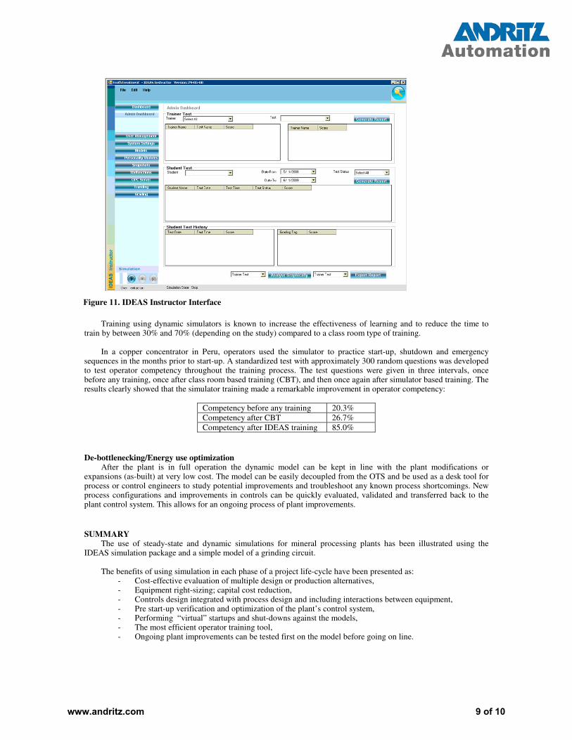
Figure 11. IDEAS Instructor Interface
Training using dynamic simulators is known to increase the effectiveness of learning and to reduce the time to train by between 30% and 70% (depending on the study) compared to a class room type of training.
In a copper concentrator in Peru, operators used the simulator to practice start-up, shutdown and emergency sequences in the months prior to start-up. A standardized test with approximately 300 random questions was developed to test operator competency throughout the training process. The test questions were given in three intervals, once before any training, once after class room based training (CBT), and then once again after simulator based training. The results clearly showed that the simulator training made a remarkable improvement in operator competency:
Competency before any training 20.3%
Competency after CBT 26.7%
Competency after IDEAS training 85.0%
De-bottlenecking/Energy use optimization After the plant is in full operation the dynamic model can be kept in line with the plant modifications or
expansions (as-built) at very low cost. The model can be easily decoupled from the OTS and be used as a desk tool for process or control engineers to study potential improvements and troubleshoot any known process shortcomings. New process configurations and improvements in controls can be quickly evaluated, validated and transferred back to the plant control system. This allows for an ongoing process of plant improvements.
SUMMARY The use of steady-state and dynamic simulations for mineral processing plants has been illustrated using the
IDEAS simulation package and a simple model of a grinding circuit.
The benefits of using simulation in each phase of a project life-cycle have been presented as: - Cost-effective evaluation of multiple design or production alternatives, - Equipment right-sizing; capital cost reduction, - Controls design integrated with process design and including interactions between equipment, - Pre start-up verification and optimization of the plant’s control system, - Performing “virtual” startups and shut-downs against the models, - The most efficient operator training tool, - Ongoing plant improvements can be tested first on the model before going on line.
www.andritz.com 9 of 10

REFERENCES Ergun, L., Ekmekci, Z., Gulsoy, O. and Benzer, H., 2004, Modelling and simulation of grinding circuit in
Madneuli copper concentrator, Physiochemical Problems of Mineral Processing, 38: 231.
Jamsa-Jounela, S.L., Dietrich, M., Halmevaara, K. and Tiili, O., 2003, Control of pulp levels in flotation cells, Control Engineering Practice, 11: 73.
Liu, Y. and Spencer, S., 2004, Dynamic simulation of grinding circuits, Minerals Engineering, 17: 1189.
Napier-Munn, T.J., et al., 1996, Mineral Comminution Circuits: their Operation and Optimisation, JKMRC Monograph Series in Mining and Mineral Processing 2. JKMRC.
Nikkah, K. and Anderson, C., 2001, Role of simulation software in design and operation of metallurgical plants: a case study, Presented at SME Annual Meeting, Denver, Colorado.
Salazar, J.L., Magne, L., Acuna, G. and Cubillos, F. 2009, Dynamic modeling and simulation of semi-autogenous mills. Minerals Engineering. 22: 70
Foulds, G. and Tipman R., 2005, Personal communication.
Plitt, L.R., Finch, J.A. and Flintoff, B.C., 1980, Modeling the hydrocyclone classifier. Euro Symp. Particle Tech,
Amsterdam, 790-804
Flintoff, B.C., Plitt, L.R. and Turak, A.A., 1987, Cyclone Modeling: a Review of Present Technology. CIM
Bulletin 80 (905), 39-50.
Morrell, S., 2004, A new autogenous and semi-autogenous mill model for scale-up, design and optimization,
Minerals Engineering, 17, 437-445.
King, R.P., 2001, Modeling and simulation of mineral processing systems, Butterworth-Heinemann.
www.andritz.com 10 of 10
Related Documents