156 | Page BENDING CAPACITY CALCULATOR FOR ROTARY TUBE Jatoth Ramachander 1 HOD & Sr. Assistant Professor of Mechanical Engineering , S.V.Engg.College Suryapet ABSTRACT Tube bending and pipe bending services produce finished parts from tubes and pipes. Plastic deformation of tubes can be achieved in numerous ways. One of the most useful types is CNC tube bending machines which is used in many industries such as aerospace, automotive, HVAC systems and so on. It is important that all components of system should mate properly after producing and because of this bend shaping requires sensitive operation on each component to ensure regularity of production processes with high quality end product. Thus, the CNC tube bending industry to become widespread. However it brings some troubleshooting like wrinkling; spring back, breakage and novelization. This failure depends on geometry of the material such as bending radius, tube thickness and also friction factor between dies and the tube. Effects of all parameters should be examined before generating the theory for a best solution. Therefore, prediction of the required moment for the proper bending process with low cost and shortened production time is needed. Key Words: Rotary draw bending, plastic bending, plastic bending moment calculator, plastic deformation. I. INTRODUCTION Over the last decade bending technology has been a sensation in the field of engineering because this area can be continually improved, resulting in higher quality with less troubleshooting and manufacturing defects. In this manner, Research and Development(R/D) departments provide time budgeting toward this issue. Before starting to analyze the theory of bending it is good to understand the bending phenomena. Bending a straight tube to form an elbow is a process of metal plastic flow. The entire dimension in the elbow changes as the plastic flow rules; this is consistent with the plastic deformation theory. Thus, plastic-deformation is the best theory to assess tube-bending topics. In addition, one of the most useful types is CNC tube bending machines used in many industries such as aerospace, automotive, HVAC systems. This global area is required high technology for sensitive production. Herber Engineering AB is working to achieve pioneer for supplying CNC tube bending. Rooted in the Swedish industry tradition, Herber has, been a highly successful manufacturer and supplier of machines used for the cold forming of tubes.

Welcome message from author
This document is posted to help you gain knowledge. Please leave a comment to let me know what you think about it! Share it to your friends and learn new things together.
Transcript

156 | P a g e
BENDING CAPACITY CALCULATOR
FOR ROTARY TUBE
Jatoth Ramachander1
HOD & Sr. Assistant Professor of Mechanical Engineering , S.V.Engg.College Suryapet
ABSTRACT
Tube bending and pipe bending services produce finished parts from tubes and pipes. Plastic deformation of
tubes can be achieved in numerous ways. One of the most useful types is CNC tube bending machines which is
used in many industries such as aerospace, automotive, HVAC systems and so on. It is important that all
components of system should mate properly after producing and because of this bend shaping requires sensitive
operation on each component to ensure regularity of production processes with high quality end product. Thus,
the CNC tube bending industry to become widespread. However it brings some troubleshooting like wrinkling;
spring back, breakage and novelization. This failure depends on geometry of the material such as bending
radius, tube thickness and also friction factor between dies and the tube. Effects of all parameters should be
examined before generating the theory for a best solution. Therefore, prediction of the required moment for the
proper bending process with low cost and shortened production time is needed.
Key Words: Rotary draw bending, plastic bending, plastic bending moment calculator, plastic deformation.
I. INTRODUCTION
Over the last decade bending technology has been a sensation in the field of engineering because this area can
be continually improved, resulting in higher quality with less troubleshooting and manufacturing defects. In this
manner, Research and Development(R/D) departments provide time budgeting toward this issue. Before starting
to analyze the theory of bending it is good to understand the bending phenomena. Bending a straight tube to
form an elbow is a process of metal plastic flow. The entire dimension in the elbow changes as the plastic flow
rules; this is consistent with the plastic deformation theory. Thus, plastic-deformation is the best theory to assess
tube-bending topics.
In addition, one of the most useful types is CNC tube bending machines used in many industries such as
aerospace, automotive, HVAC systems. This global area is required high technology for sensitive production.
Herber Engineering AB is working to achieve pioneer for supplying CNC tube bending. Rooted in the Swedish
industry tradition, Herber has, been a highly successful manufacturer and supplier of machines used for the cold
forming of tubes.
157 | P a g e
II. BACKGROUND
CNC tube bending is gaining widespread in industries such as aerospace, automotive, HVAC systems and so on.
Research regarding this subject is developing day by day in step with technological requirements. Historically
there have not been possibilities to reach the best quality for shaping of parts in a timely and low cost manner.
These facilities have begun to improve with new CNC technology.
For many years, waveguide bends for most microwave installations have been difficult and expensive to
produce. The art of tube bending was not sufficiently advanced to make economically possible to extremely
close tolerances required in waveguides. This was true even when waveguides were first introduced into radar
equipment. It later became evident, as increased power, higher aircraft speeds and missile applications made
waveguide requirements more severe, that the bending technique would have to be improved. First, a faster
method of bending had to be found, since the best of existing method required about 30 minutes to make one
bend. Second, to reduce transmission losses, the new method had to produce bends that met closer internal
cross-sectional tolerances. Third, bends of much smaller radius, more closely spaced compound bends and bend
adjacent to swaged and twisted sections had to be made to meet new design demands. In addition to this specific
improvements and innovations in the bending technique, production uniformity was desirable; since it is only
true uniformity that statistical quality control can be realized. Thus, all these developments have pioneered
today’s rotary draw bending technology.
There are several methods of analysis of CNC tube bending, such as finite element methods (FEM) and
theoretical approaches. Most articles mention same theory and background for plastic deformation in tube
bending and these have approximate values between heuristic and analytic results.
III. PURPOSE
The main goal of this project is composition of plastic deformation in tube bending theory and the effects of
CNC bending machine parts including; wiper die, mandrel, booster and supporter die to obtain optimum
bending requirements. After realization of all parameters, a forms application program was developed to find a
solution, the prediction of necessary bending moment and other outputs for bending. End-product quality,
decreased time consumption and low cost are the three most indispensable parameters for a manufacturing
company and this program is developed with awareness of these requirements.
IV. THEORY
In this chapter, the introduction of rotary draw bending is presented alongside machinery parts with their
function and effects on bending moment and failure types along with their reasons. Also shown is plastic
deformation in tube bending and the effect of tools’ parameters.
V. ROTARY DRAW BENDING
There are several varieties of bending methods and one of the most common type is rotary draw bending. This
type of machine has five different main equipment to help bending a material. Three of these equipment are
necessary for making a bend (bend die, clamp die, pressure die).The two other components mandrel and wiper

158 | P a g e
are used when there is a risk wrinkling and/or section collapse. In addition, the booster is a helper part in
bending which has the duty of adding extra bending to obtain required moment. When a tube is bent, the outer
wall thickness of the elbow becomes thinner due to stretching. In opposition to this the inner wall thickness of
the elbow increases because of compression forces.
Figure: Components of rotary draw bending
Figure: Draw Bending
VI. MACHINERY PARTS AND THEIR FUNCTIONS
The fundamental steps of rotary draw tube bending operation can be described:
He bend die assistant, clamp die and pressure die are parallel to the feeding exist before the start of the
bending operation.
The clamp die presses the tube tightly against the bend die for the purpose of preventing of the tube sliding
between them during the bending process.
The bend die and clamp die then rotates together so that the bend die draws the tube along with it and
against the pressure die, by the way this rotation provides plastic deformation at intrados and extrados
section of the tube.
The pressure die pushes the tube at the outer surface of it to reduce thinning of the tube and also assists to
completing the bend by supplying additional torque during the bending operation.
Each tool is given detail explanation.

159 | P a g e
VII. FUNCTION OF BEND DIE
The forming tool which is used to make a specific radius of bend is called a bend die. The bend usually consists
of two separate pieces called the insert and bend radius. The insert is used for clamping to the bend die before
forming. The bend radius forms the arc of the bend as the tube is drawn around the die. The bend radius is
normally sized to two times the tube diameter.
Figure: Bend die
When the ratio of the tube diameter to wall thickness is small enough, the tube can be bent on a relatively small
radius (Centerline Radius or CLR = 4 x Tube O.D.). Excessive flattening or wrinkling of the bend should not
occur. The outside and inside of the bend tend to pull towards the centerline of the tube (flattening). Two factors
that help prevent this from happening are a grooved bend die, which supports the tube along the centerline and
the natural strength of the tube; round or square.
Figure: Cross-sectional view of bended tube on bend dies
VIII. FUNCTION OF CLAMP DIE
The clamp die works in conjunction with the bend die to ensure it clamps the tube to the bend die. The clamp
die will move in and out to allow feeding of the tube. Thus, this die holds the tube or pipe in bending axis with
helping of bend die.
160 | P a g e
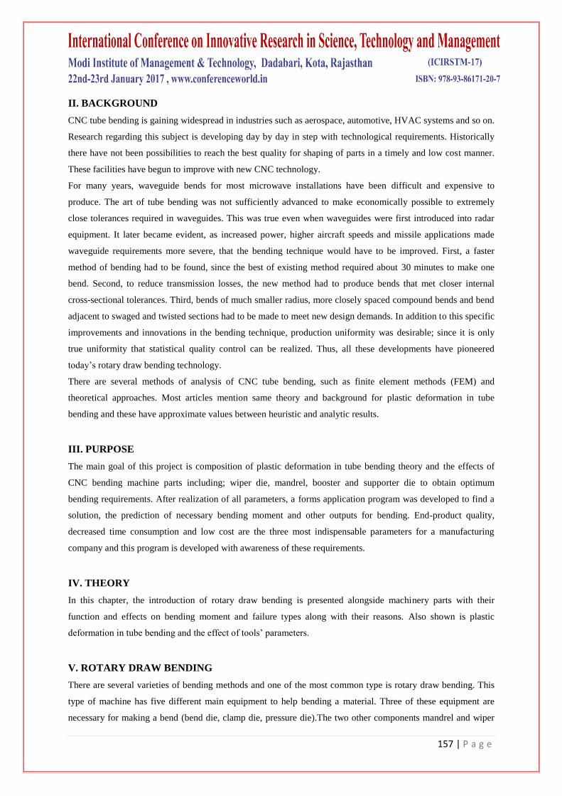
Figure: Aspects of clamp die, pressure die and bend die
IX. FUNCTION OF SUPPORT (PRESSURE) DIE
The pressure die is used to press the tube into the bend die and to provide the reaction force for the bending
moment. The pressure die will travel with the tube as it is being formed. The pressure die boost cylinder is
attached to the pressure die. The purpose of the pressure die is to keep the tube against the bend die through the
duration of bending.
X. FUNCTION OF MANDREL
There are two kinds of mandrel which have been observed in this thesis. One of them is plug mandrel and the
other one is ball mandrel. These mandrels types have special area of usage
and it depends on requirements of bending condition . The purpose of a plug mandrel is to prevent the tube from
flattening and to bend without wrinkles or kinks. The mandrel is held in a fixed position while the tube is pulled
over it.
The tube stretching process is localized on the outer radius of the bend and the material is work hardened to
retain its shape and not flatten. The material stretching is done on the forward tip of the mandrel. This force,
acting on the mandrel tip, supports the inner radius of the bend, holding it firmly into the bend die groove.
Figure: Aspect of components

161 | P a g e
When the radius of the bend is smaller and/or the wall is thinner, it becomes necessary to use a ball mandrel and
wiper die. The wiper die is used to prevent wrinkles. The ball mandrel performs like a plug mandrel. The balls
are used to keep the tube from collapsing after it leaves the mandrel shank.
XI. FUNCTION OF BOOSTER
A pressure function found on some tube-bending machines which is similar to the common assist-pressure
function but is distinguished from it by applying pressure to both sides of the tube behind the line of tangency.
Assist pressure is applied only to the outside half of the tube at the line of tangency. Boost pressure pushes the
tubing material through the point of bend as it is drawn forward around the bend die. This increased flow is
necessary when wall thinning must be kept to an extreme minimum.
XII. AFFECTS OF MACHINERY PARTS ON BENDING
The frictions between mandrel, wiper, pressure die, bending die and tube have a significant and complicate
effect on the section quality of thin-walled tube NC bending. Decreasing the frictions between mandrel, wiper
and tube is helpful to improve the section quality, but increasing the frictions between the pressure die, bending
die and tube is helpful to improve the section quality. In these four frictions, the effect on section distortion is
more significant from mandrel, wiper, pressure die to bending die and the effect on wall thinning are more
significant from mandrel, pressure die, wiper, to bending die. The effect of the friction between all dies and tube
on the wall thinning is smaller than its effect on the section distortion because its effect on stress is bigger than
its effect on strain and the section distortion mainly depends on the tangential stress and wall thinning mainly
depend on normal strain.
According to the different usage of the bending tube, the requirements on the section quality are different. In
production, except that the cross section distortion and the wall thinning must satisfy the requirements, surface
quality should be improving and the abrasion of dies decreased as far as possible. In actual product, drawing oil
may be used to lubricate the mandrel and wiper. In theory, the frictions between the pressure die and bending
die and tube should be increased. But if they are large, pressure die and bending die may scuff the tube and be
abraded seriously, so dry friction is used among the pressure die, bending die and tube in actual product. The
friction condition has been verified to be a good friction state with the experiment.
Friction impression of mandrel and wiper die has great importance on this thesis theory and It will be observed
on next steps.
XIII. TROUBLESHOOTING OF BENDING
As with every mechanical process, rotary draw bending has some failure if there is an unexpected situation such
as insufficient lubrication, mandrel position, too much or too little pressure on support die, etc. These reasons
can be analyzed before the bending process and if a problem arises it may be solved before the bending process
begins. These failures will be observed with their reasons in this section.
162 | P a g e
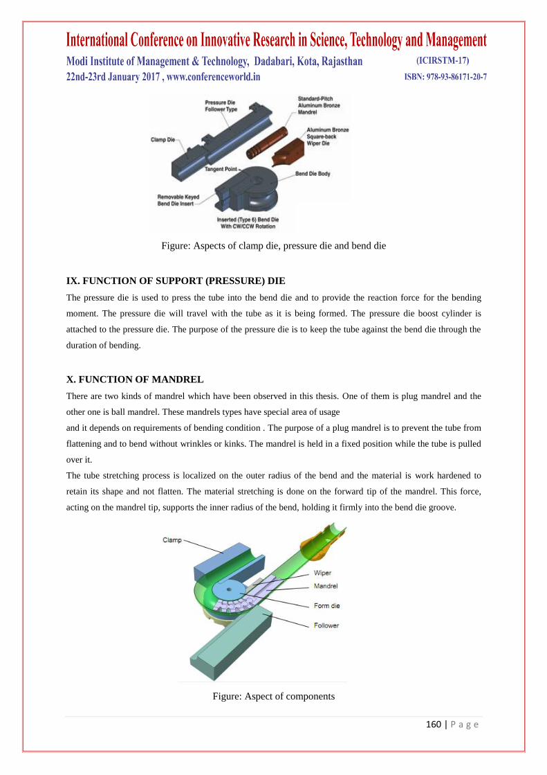
XIV. TUBE BREAKAGE
There are several reasons for breaking of tubes:
Material lacking proper ductility and elongation
Tube slipping in clamp die
Pressure die too tight causing excess drag
Material wrinkling and becoming locked between mandrel balls
Clamp die pressing on mandrel balls
Improper or insufficient lubrication
Mandrel too far forward
TUBE WRINKLING
Tube wrinkling may be caused by:
Tube slipping in clamp die
Mandrel not far enough forward
Wiper die not seated properly in bend die
Wiper die worn or of improper fit
Too much clearance between mandrel and tube
Not enough pressure on pressure die
Improper or excessive amount of lubrication
Figure: Wrinkling on bended area
XV. PLASTIC DEFORMATION IN TUBE BENDING AND PARAMETERS OF TOOLS OF
ROTARY DRAW BENDING
In this part present the base of theory’s formula and additive tools effects. In fact, theory of plastic deformation
tube bending was observed many articles but most of them are used common formulas. Actually, some of the

163 | P a g e
formulas were really complicated. Due to lack of time, engineers prefer to use simplified calculations and it is
also valid for this thesis form application program because of applying on algorithm.
Figure: Rotary Draw
NOTATION
r -Average radius of the tube cross-section
D -Outside diameter of the tube
d -Inside diameter of the tube
k- Geometry parameter
R -Bending radius
ρs - Material yield strength
α - Angle between circumferential point, center point and the topmost point in tube section
I - The moment of inertia
J - The moment of inertia (Simplified)
Wb - Section modulus
M - Bending moment
No- Integral parameter of moment of inertia formula
T - Wall thickness
FORMULAS FOR TUBE BENDING
According to Tang (2000), introducing geometry parameter of the tube is:
K =
According to Tang (2000), integral parameter of moment of inertia formula:

164 | P a g e
According to Tang(2000), formulation of moment of inertia:
Solution of the integral No is difficult, even by using some computer mathemetics programs such as Mathlab.
Tang used simplified formula and this figure show comprasion of derived and simplified bending moment
function and results of this two formulas are approximately same according to Tang (2000).
According to Tang(2000), The simplified moment of inertia is shown as J:
J = 1.41 +
Figure: Comprasion of derived and simplified bending moment function(N.C.Tang, 2000)
According to Johansson (2010), section modulus ‘Wb’ is given by:
Wb = (D3_ d
3)
After all these formulations, according to Tang (2000), bending moment is given by:
M = ρsWbj
XVI. WORKING PRINCIPLE OF ROTARY DRAW BENDING MACHINE TOOLS
The pressure die is used to press the tube into the bend die and to provide the reaction force for the bending
moment. The pressure die will travel with the tube as it is being formed. The pressure die boost cylinder is
attached to the pressure die. Thus, it covers the tube from outside and travel along bend axis and force effect on
tube helps to bending process.
165 | P a g e
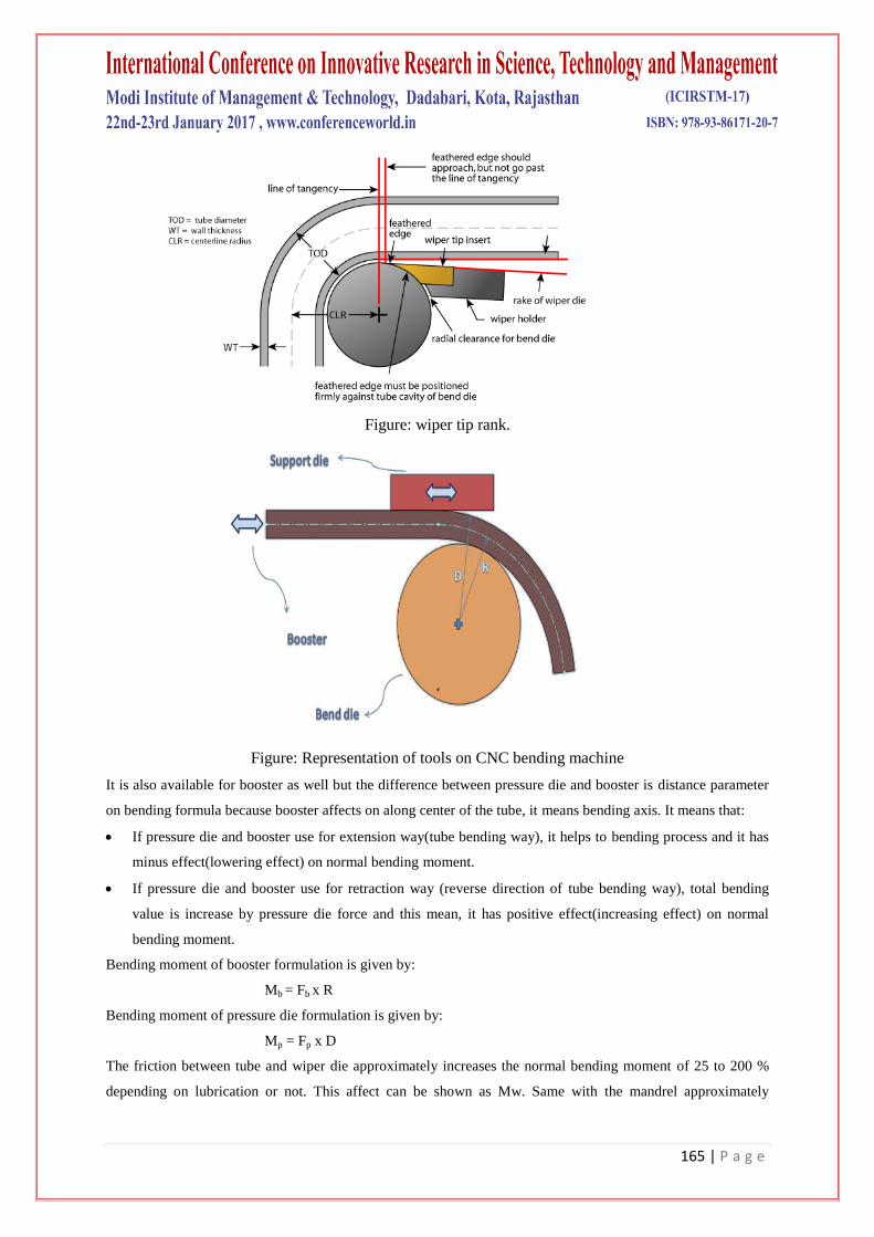
Figure: wiper tip rank.
Figure: Representation of tools on CNC bending machine
It is also available for booster as well but the difference between pressure die and booster is distance parameter
on bending formula because booster affects on along center of the tube, it means bending axis. It means that:
If pressure die and booster use for extension way(tube bending way), it helps to bending process and it has
minus effect(lowering effect) on normal bending moment.
If pressure die and booster use for retraction way (reverse direction of tube bending way), total bending
value is increase by pressure die force and this mean, it has positive effect(increasing effect) on normal
bending moment.
Bending moment of booster formulation is given by:
Mb = Fb x R
Bending moment of pressure die formulation is given by:
Mp = Fp x D
The friction between tube and wiper die approximately increases the normal bending moment of 25 to 200 %
depending on lubrication or not. This affect can be shown as Mw. Same with the mandrel approximately

166 | P a g e
increases the normal bending moment 25 to 200 % depending on lubrication or not. This affect can be shown as
Mm. It can be shown like below:
If mandrel has %50 friction effect on normal bending, it means that total bending with this effect is equal to total
bending = M+M*50/100.
As a result, total bending moment with all factors is given by:
Total bending moment = M ± Mb ± Mp + Mw + Mm
XVII. METHOD
Firstly, gathering of information to follow right way for this thesis was important before meeting with company.
It was good to understand function and working principle of CNC rotary draw bending machine. After meeting
with Herber Engineering AB, the problem was understood exactly with tool effects on bending and watching of
working machine was made requirements of the thesis clearer.
The researching of theory chapter was leading more detailed and most of articles have been used same
formulation for theory of tube bending. This was one of the good chance to understand theory way is true or not
without making any experiment about formulation. Generally, most of articles have been taken same reference
from N.C.Tang and also in this thesis as well.
There are another important parameters effects of bending machine on thesis theory and these are friction effects
of wiper die, mandrel and force effects of support die, booster. All combination of thesis theory is basis of form
application program’s algorithm and so program was implemented with this algorithm. Some parameters name
was changed as abbreviations to make the program codes easier. These abbreviations were given by:
r - Inner radius T - Wall thickness
D - Outside diameter W - Section modulus
I Moment of inertia k - Geometry parameter
R Bending radius MN Tube bending moment
Sy ield strength of material Mand Mandrel parameter(0,0-1,0)
Wip Wiper parameter(0,0-1,0) Mandef Mandrel effect on bending Moment
Wipef Wiper effect on bending moment Sup Support die force
Boos Booster force Supef Support die effect on bending moment
Boosef Booster effect on bending moment
TBM Total bending moment included with all effects

167 | P a g e
Figure: Flowchart of form application program
Finally, it was important to verify the results of program acceptable or not. There are two ways to understand
this:
Form application program has been used on Herber Engineering AB’s works and their feedback was
positive because of theory and reality quite similar. It also satisfied their expectations.
One of the best method, compare the results as analytic and heuristic values. The program outputs were
between these two main results and program results provide reliable results. This reliability will be shown
in result and analyses chapter.
XVIII. RESULTS AND DISCUSSION
In this project, the combination of theory of tube bending and tools effects of CNC rotary
draw bending was observed detailed. All these were created base of form application program algorithm. This
program was also written by Microsoft Visual Studio 2010 with C++ programming language. After
programming, it was need to check the results as some scientific references from articles’ researches and
experiences of Herber Engineering AB with their reliable references. According to Joel Johansson, there is some
scientific samples which are given below figure:

168 | P a g e
Parameter Example - I Example - II
Outer tube diameter. 45 mm 60 mm
Tube wall thickness. 5 mm 2mm
Wanted bending angle. 1800 180
0
Section modulus. 4.74 cm3 3.965 cm
3
Tube material. Sapa 6063 –T4 Sapa 6063 –T4
Wanted bend radius 80 mm 80 mm
Result Heuristic Analytic Heuristic Analytic
Mandrill type plug N / A Regular pitch N / A
Bending moment 434 Nm 618 Nm 363 Nm 584 Nm
Minimal wall thickness 3.9 mm 4.3 mm 1.5 mm 1.6 mm
Developed length 251 mm 239 mm 251 mm 228 mm
Figure: Rotary Draw Bending.
As mentioned in method chapter, the results of bending moment should be between heuristic and analytic result.
However, these examples do not include any factors of machine tools and because of this, the friction coefficient
of wiper die and mandrel are equal to zero and also support die and booster force effects as seen figure4.2 and
4.3.The results with used mandrel, wiper die, pressure die and booster were checked on Herber Engineering AB
results. This form application program is useful for Herber Engineering AB and it makes to bending process
more easily with less time spending, saving money and good quality end-product. Thus, it is clear to see, this
software is working well with all contributions. These results have been checked with form application program
to understand, program’s theory is acceptable or not. These are shown below figures for each example.

169 | P a g e
XIX. CONCLUSION
In the thesis, the rotary draw tube bending theory with all parameters performed on a form application program.
This program was written by Microsoft Visual Studio 2010 with C++ Programming language. Tube bending is
carried really big importance in most of industrial applications such as automotive industry, aerospace industry,
HVAC systems and so on. Thus, all companies work on this matter too much in their Research and
Develop(R/D) department because of being the best in competitive sector and so good quality end-product can
be produced with less time spending and reaping a profit.
All of these reasons, this thesis theory was researched detailed to reach results which more closer to reality. All
results also have been also checked by several methods as mentioned in before chapters. Finally, matching of
form application program output with reality of bending indicate that program is working well with its
algorithm.
REFERENCES
[1.] Tang,N.C, 2000, Plastic deformation analysis in tube bending, International Journal of Pressure Vessels and
Piping 77 (2000) 751-759,Canada.
[2.] Fuchs, F.J,Jr, Waveguide Bending Design Analysis, Manuscript receieved, June 4,1959,pp 1457.
[3.] Johansson, J, Automated Computer Systems for Manufacturability Analyses and Tooling Design, Chalmer
University of Technology,2011,Göthenburg
[4.] Sözen, Güler, Görgülüaslan, Kaplan, Prediction of Springback in CNC Tube Bending Process Based on
Forming Parameters,11th International LS-DYNA Users Conference, TOBB University of Economics and
Technology, Ankara.
[5.] By Ronald R. Stange, President, Tube-Bending Basics, Tools for Bending Inc., Denver, CO Li, H., Yang,
H.,Zhan, M., Gu,R.J,The interactive effects of wrinkling and other defects in thin-walled tube NC bending
process, Journal of Materials Processing Technology 187-188 (2007) 502-507, China
[6.] http://herber.se/index.php/en/nr-1-choice/about-us (accessed 25 May,2012)
[7.] http://www.hinesbending.com/BASICTUBEBENDINGGUIDE.pdf (accessed 25 May,2012)
[8.] http://files.engineering.com/download.aspx?folder=329c633c-d992-46da-9cc2-
ed01a5e2e8ee&file=tube.pdf (accessed 25 May,2012)
[9.] http://www.herber.se/index.php/en/after-sales/tooling/set-of-tools (accessed 25 May,2012) Herber Dual
300/700,http://www.herber.se/index.php/en/machines--products/700s(accessed 25 May,2012)
Related Documents