Composite Structures, 98:242–252, 2013. Benchmark Solution for Degradation of Elastic Properties due to Transverse Matrix Cracking in Laminated Composites E. J. Barbero 1 and F. A. Cosso 2 Mechanical and Aerospace Engineering, West Virginia University, Morgantown, WV 26506-6106, USA abstract Degradation of laminate moduli and laminate coefficients of thermal expansion, as well as degrada- tion of the cracked lamina moduli and lamina coefficients of thermal expansion, are predicted as a function of crack density for laminated composites with intralaminar matrix cracks. The method- ology assumes linear elastic behavior and periodicity of the transverse cracks. The representative volume element is discretized into finite elements. Stress free conditions on the crack surfaces are enforced. Periodic boundary conditions are applied so that any state of applied far-field strain can be simulated. An averaging procedure is used to yield the average stress field. Three uniaxial states of strain and a null state of strain coupled with a unit increment of temperature are used to obtain the degraded stiffness and coefficients of thermal expansion. Results are presented for a number of laminates and materials systems that are customarily used in the literature for experimenta- tion. The modeling approach and results can be used to assess the quality of approximate models. Comparisons are presented to the predictions of one such model and to experimental data. Also, comparisons are presented to classical lamination theory for asymptotic values of crack density. keyword Toughness; Intralaminar; Damage; Periodicity; Thermal Expansion. 1 Introduction Numerous approximate methods have been developed to predict the onset and evolution of trans- verse matrix cracking in laminated composites. Micromechanics of Damage Models (MMD) find an approximate elasticity solution for a laminate with a discrete crack or cracks [1–22]. Crack Open- ing Displacement (COD) models [23–30] are based on the theory of elastic bodies with voids [31]. The methods are approximate because kinematic assumptions are made, such as a linear [32] or bilinear [33] distribution of intralaminar shear stress through the thickness of each lamina, as well as particular spatial distributions of inplane displacement functions [21], stresses, and so on. 1 Corresponding author. The final publication is available at http://dx.doi.org/10.1016/j.compstruct.2012. 11.009 2 Graduate Research Assistant. 1

Welcome message from author
This document is posted to help you gain knowledge. Please leave a comment to let me know what you think about it! Share it to your friends and learn new things together.
Transcript
Composite Structures 98242ndash252 2013
Benchmark Solution for Degradation ofElastic Properties due to Transverse Matrix
Cracking in Laminated Composites
E J Barbero1 and F A Cosso 2
Mechanical and Aerospace Engineering West Virginia UniversityMorgantown WV 26506-6106 USA
abstract
Degradation of laminate moduli and laminate coefficients of thermal expansion as well as degrada-tion of the cracked lamina moduli and lamina coefficients of thermal expansion are predicted as afunction of crack density for laminated composites with intralaminar matrix cracks The method-ology assumes linear elastic behavior and periodicity of the transverse cracks The representativevolume element is discretized into finite elements Stress free conditions on the crack surfaces areenforced Periodic boundary conditions are applied so that any state of applied far-field strain canbe simulated An averaging procedure is used to yield the average stress field Three uniaxial statesof strain and a null state of strain coupled with a unit increment of temperature are used to obtainthe degraded stiffness and coefficients of thermal expansion Results are presented for a numberof laminates and materials systems that are customarily used in the literature for experimenta-tion The modeling approach and results can be used to assess the quality of approximate modelsComparisons are presented to the predictions of one such model and to experimental data Alsocomparisons are presented to classical lamination theory for asymptotic values of crack density
keyword
Toughness Intralaminar Damage Periodicity Thermal Expansion
1 Introduction
Numerous approximate methods have been developed to predict the onset and evolution of trans-verse matrix cracking in laminated composites Micromechanics of Damage Models (MMD) find anapproximate elasticity solution for a laminate with a discrete crack or cracks [1ndash22] Crack Open-ing Displacement (COD) models [23ndash30] are based on the theory of elastic bodies with voids [31]The methods are approximate because kinematic assumptions are made such as a linear [32] orbilinear [33] distribution of intralaminar shear stress through the thickness of each lamina as wellas particular spatial distributions of inplane displacement functions [21] stresses and so on
1Corresponding author The final publication is available at httpdxdoiorg101016jcompstruct2012
110092Graduate Research Assistant
1
Composite Structures 98242ndash252 2013 2
The predictions attained with various approximate methods have been compared in the lit-erature to available experimental data in order to assess the quality of the predictions Sinceexperimentation is very difficult and laborious validations are limited to comparing crack densityvs laminate strain (or stress) and laminate modulus reduction vs laminate strain (or stress) Nodata exists regarding for example degradation of the coefficients of thermal expansion at laminaand laminate levels Ply degradation has to be inferred from laminate modulus reduction Sincephysically observing and counting off-axis cracks is very difficult the measured crack density islimited to that observed in a single lamina (a 90 deg ply) with the cracks perpendicular to the loaddirection However the available approximate methods are able to predict damage in off axis pliesas well as degradation of shear modulus and Poissonrsquos ratio at the ply level Unfortunately thosepredictions cannot be validated easily
Several authors have compared approximate solutions to finite element simulations [12 26 2934ndash36] Along those lines this work proposes a finite element analysis methodology that provides anumerical solution to the 3D equations of elasticity for cracked laminated composites with no addi-tional assumptions other than linear elastic material and periodically spaced cracks The objectiveis to produce solutions for a number of responses that are very difficult to tackle experimentallyThese solutions could then be used as a benchmark to evaluate the quality of the approximationsin various models As an illustration the solutions obtained in this work are compared to discretedamage mechanics (DDM) solutions [50] Also comparisons to experimental data are presentedMost of the predictions for laminate 1 and 6 are reported herein and all the results for all sixlaminates listed in Table 1 are provided as supplementary materials in the online edition of themanuscript
The model is set up to predict the reduction of stiffness and CTE when only two symmetricallylocated laminas contain periodically spaced transverse cracks This is sufficient to validate theapproximate models in the literature Once the reduction of stiffness and CTE for this case isobtained it is possible to use a CDM approach to address the general case of multiple laminascracking [50] but such a study is beyond the scope of this work
2 Periodicity and Homogenization
Since all the approximate methods assume linear elastic material the proposed methodology retainssuch assumption but it must be noted that linearity can be easily removed in the context of finiteelement analysis (FEA) Next the proposed methodology assumes that transverse (matrix) cracksoccupy the entire ply thickness are periodically spaced and are infinitely long along the fiberdirection Once again these are common assumptions among the approximate models for whichwe wish to provide a benchmark solution The justification for these geometric assumptions are welldocumented in the literature eg [37 Section 721] As a result of periodicity a representativevolume element (RVE) is selected and analyzed The RVE includes the entire thickness of thelaminate it spans the distance between two consecutive cracks and it has a unit length along thefiber direction (Figure 1) Symmetric laminates subjected to membrane loads are chosen as theseare common laminate and load configurations used in virtually all experiments and approximatemodes in the literature A generalization to flexural deformation is possible but not trivial
Periodicity conditions are carefully applied and verified in such a way that the volume averageεi of the inhomogeneous strain field inside the RVE equals the applied applied strain ε0i Otherboundary conditions (bc) faithfully reflect the stress free condition at the crack surfaces and alsoallow for the application of any state of far field strain The analysis yields inhomogeneous strainand stress fields from which it is possible to calculate the degraded stiffness matrix of the laminate
Composite Structures 98242ndash252 2013 3
To calculate the degraded stiffness matrix of the laminate when lamina (k) is cracked the RVEis subjected to an average strain εi where i = 1 2 4 5 6 using Voigt contracted notation in thethe coordinate system (cs) of the cracked lamina The cs of the cracked lamina is chosen so thatthe stress free bc at the crack surface are easily applied With reference to Figure 1 the averagedstrain is applied by enforcing the following bc on the displacements
u(12 y z
)minus u
(minus1
2 y z)
= ε01v(12 y z
)minus v
(minus1
2 y z)
= ε06w(12 y z
)minus w
(minus1
2 y z)
= ε05
minus 12λ le y le
12λ
minus t2 le z le
t2
(1)
and
u(x 1
2λ z)minus u
(xminus 1
2λ z)
= 1λε
06
v(x 1
2λ z)minus v
(xminus 1
2λ z)
= 1λε
02
w(x 1
2λ z)minus w
(xminus 1
2λ z)
= 1λε
04
minus12 le x le
12
minus t2 le z le
t2
(2)
where t is the thickness of the laminate λ = 1(2l) is the crack density for cracks spaced a distance2l Note that the applied strains ε0i result in average strains εi
Equation (1) is applied on faces with normal in the x-direction and (2) is applied on faces withnormal in the y-direction Note that the x-direction is the fiber direction of the cracked laminaSince the laminate is in a state of plane stress no bc are imposed in the z-direction
In finite element analysis equations such as (1) are applied via constraint equations (ce)between the master node on one face and the slave node on the opposite face In three dimensional(3D) analysis every node has three degrees of freedom (dof) representing the displacements u v wat the node By specifying a fixed relationship between two nodes at opposite faces the slave dofis eliminated With reference to (1) if the x-face with normal in the positive direction of x whichis called +x-face is chosen as master surface then the dof u v w are eliminated at the slaveminusx-face
Both (1) and (2) apply at the four edges where the plusmnx-faces and plusmny-faces intersect but theequations cannot be applied independently as it is done for the faces because applying (1) elimi-nates the slave dof that are necessary to apply (2) at the same edges ie at edges where intersectingfaces share the same dof The solution for this problem is to combine (1) and (2) [38 p 155] insuch a way that both boundary equations can be applied simultaneously between a masterslavepair of edges It turns out that this is only possible among for diagonally opposite edges
With reference to Figure 2 for edges XpYp (master) and XmYp (slave) equations (1) and (2)are added together as follows
u(12
12λ z
)minus u
(minus1
2 minus12λ z
)= ε01 + 1
λε06
v(12
12λ z
)minus v
(minus1
2 minus12λ z
)= ε06 + 1
λε02
w(12
12λ z
)minus w
(minus1
2 minus12λ z
)= ε05 + 1
λε04
minus t2 le z le
t2 (3)
For edges XmYp (master) and XpYm (slave) equations (1) and (2) are subtracted from eachother as follows
u(12 minus
12λ z
)minus u
(minus1
2 12λ z
)= ε01 minus 1
λε06
v(12 minus
12λ z
)minus v
(minus1
2 12λ z
)= ε06 minus 1
λε02
w(12 minus
12λ z
)minus w
(minus1
2 12λ z
)= ε05 minus 1
λε04
minus t2 le z le
t2 (4)
Since the plusmnz-faces are free the eight vertices can be constrained along with their edges [38p 163] To aid in the programming of the Python script used to automate the modeling the edgesare labeled as the faces that define them (see Fig 2)
Composite Structures 98242ndash252 2013 4
3 Laminate Stiffness and Coefficient of Thermal Expansion
In the context of this manuscript the objective of homogenization is to obtain the apparent stiff-ness of a homogenized material where the crack is not geometrically present but having its effectrepresented by an apparent degraded stiffness Q In this work it is assumed that all cracks aresubjected to a combination of tensile and shear loads without compression For a discussion of theeffects of interfacial crack compression see [3940]
The point wise linear elastic constitutive equation with ∆T = 0 is
σ = Q ε (5)
where Q is the virgin stifness A volume average is defined as
φ =1
V
intVφ dV (6)
The apparent stiffness Q is defined in such a way that it relates the average stress and strainover the volume V of the RVE as follows
σ = Q ε (7)
The volume V = VS + VV encompasses the volume of the solid VS plus the volume of the voidVV left by the opening of the crack If a single crack is placed in the center of the periodic RVEVV is the volume of the void from that single crack If the periodic RVE is defined between twosuccessive cracks as it is done in this work then VV is composed of two half volumes of the crackson the boundary
The average strain over the RVE can be decomposed into the strain in the solid plus thedeformation of the void
ε =1
V
intVS
ε dVS +1
V
intpartVV
uotimes n dVV (8)
where u notimes are the displacement vector the outward unit normal to the void surface and thesymmetric dyadic product operator respectively The first term on the RHS is not equal to theapplied strain ε0 as it is clearly explained in [39 Eq (2)] Once the deformation of the void isadded the total average is equal to the applied strain ε0 [41]
Since the stress inside the void is zero the average stress over the RVE is
σi =1
V
intVS
σi dVS (9)
Substituting ε0 for ε in (3) the columns of the apparent stiffnessQ can be obtained by calculatingthe average stress for a canonical set of applied strains namely
Qij =1
V
intVS
σj dVS ε0j = 1 (10)
Since transverse matrix cracking primarily affects the inplane properties [26] the intact proper-ties can be used for the intralaminar components of the stiffness ie Qlowast
ij with i j = 4 5 [37 (547)]The components of the degraded stiffness matrix Qij are found by solving the discretized model
of the RVE subjected to three loading cases where only one component of the in-plane strain εj is
Composite Structures 98242ndash252 2013 5
different from zero at a time [38 (618)] and ∆T = 0 By choosing a unit value of applied strainand taking into account the enforced state of plane stress the degraded stiffness matrix is found as
Qij =λ
t
intVσidV with ε0j = 1 ∆T = 0 (11)
For each of the three cases the stress σi is computed by the FEA code and the components ofthe averaged stress σi are calculated by a post processing script that evaluates the volume integralswithin each element using Gauss quadrature then adds them for all the elements and divides theresult by the volume of the RVE
The first column of Qij is obtained by applying a strain ε0 = 1 0 0 0 0 on the boundary(faces and edges) using (1)-(2) The second column of Qij is obtained by applying a strain ε0 =0 1 0 0 0 The third column of Qij is obtained by applying a strain ε0 = 0 0 0 0 1 In allthree cases the bc are periodic for all laminas and stress free on the cracked surfaces
Next periodic boundary conditions simulating zero strain at the uncracked laminas stressfree conditions at the cracked lamina and a unit change of temperature ∆T = 1 over the entirelaminate allowing us to obtain the average thermal stress field as
σthermali =λ
t
intVσidV with εj = 0 forallj ∆T = 1 i = 1 2 6 (12)
Once the averaged thermal stress is known the laminate coefficient of thermal expansion (CTE)of the laminate is calculated as
αi = Qminus1ij σthermal
j (13)
Once the laminate stiffness Qij in the cs of the laminate is known the laminate moduli arecomputed using [37 (635)]
Ex =Q11Q22 minusQ2
12
Q22Gxy = Q66
Ey =Q11Q22 minusQ2
12
Q11νxy =
Q12
Q22
(14)
The energy release rate (ERR) is a quantity of interest for predicting the onset of intralaminarcracks and the subsequent evolution of crack density To calculate the ERR it is convenient touse the laminate stiffness Qij in the cs of the cracked lamina because in this way the ERR canbe decomposed into opening and shear modes Since the laminate stiffness is available from theanalysis as a function of crack densityλ the ERR can be calculated for a fixed strain level (load)as
GI =V
2∆A(ε2 minus α2∆T ) ∆Q2j (εj minus αj∆T ) opening mode (15)
GII =V
2∆A(ε6 minus α6∆T ) ∆Q6j (εj minus αj∆T ) shear mode (16)
where V∆A are the volume of the RVE and the increment of crack area respectively ∆Qij isthe change in laminate stiffness corresponding to the change in crack area experienced and allquantities are laminate average quantities expressed in the cs of the cracked lamina in order toallow for ERR mode decomposition [18] It can be seen that the proposed methodology providesthe key ingredients for the computation of the ERR namely the degraded stiffness and degradedCTE of the laminate both as a function of crack density
Composite Structures 98242ndash252 2013 6
4 Lamina Stiffness and CTE
Unlike approximate methods in this work the degraded stiffness of the cracked lamina is calculateddirectly by averaging the stress field in the cracked lamina The procedure is identical to that forthe laminate but integrating over the volume of the lamina
Q(k)ij =
λ
tk
intVk
σidV with εj = 1 (17)
where tk Vk are the thickness and volume of the cracked lamina respectively Since this is donesimultaneously with the analysis of the laminate there is no additional computational cost or anyadditional assumption involved
Once the degraded stiffness of the cracked lamina is known the reduction of stiffness can beinterpreted in terms of damage variables Assuming damage in the form of a second order tensorwith principal directions aligned with the cs of the cracked lamina the degraded stiffness can bewritten as
Qij =
Q11 Q12 0Q12 Q22 0
0 0 Q66
=
(1minusD11)Q011 (1minusD12)Q
012 0
(1minusD12)Q012 (1minusD22)Q
022 0
0 0 (1minusD66)Q066
(18)
where Q0ij are the coefficients of the intact lamina In other words the presence of the crack on the
boundaries of the RVE (Figure 1) is homogenized The damage variables can be calculated fromthe results of the analysis as
Dij = 1minusQijQ0ij i j = 1 2 6 (19)
Various hypothesis have been made in the literature about the relationship or lack thereofbetween the coefficients of the damage tensor For example [1920] propose that the minor Poissonrsquosratio ν21 and the transverse modulus E2 degrade at the same rate in other words that D12 asymp D22
Furthermore [42] [43] propose that D66 = 1minus (1minusDt11)(1minusDc
11)(1minusDt22)(1minusDc
22) where thesuperscripts t c indicate tension and compression Since polymer matrix composites are relativelybrittle in tensioncompression along the longitudinal direction and in transverse compression Dt
11 asympDc
11 asymp D222 asymp 0 resulting in D66 asymp D22 The present work allows us to asses these assumptions
in the context of linear elastic behavior without the kinematic assumptions of other models in theliterature
Simultaneously with the laminate thermal analysis the average thermal stress in the crackedlamina is obtained by averaging over the volume of the cracked lamina only ie
σ(k) thermali =
λ
tk
intVk
σidV with εj = 0 forallj ∆T = 1 i = 1 2 6 (20)
Once the averaged thermal stress in lamina (k) is known the laminate coefficient of thermalexpansion (CTE) of the craked lamina is calculated as
α(k) =(Q
(k)ij
)minus1σ(k) thermalj (21)
Composite Structures 98242ndash252 2013 7
5 Implementation
Since periodic boundary conditions are not readily available in Abaqus they were implemented inthis work by developing a Python script for AbaqusCAE 610-2 The script generates the RVEmeshes then generates constrains in the faces that are periodic and finally solves the model andstores the averaged stresses
The script was validated against known solutions and experimental data First when no crackis present the solution must coincide with Classical Lamination Theory (CLT) Since the strain andstresses in this case are piecewise constant throughout the body no mesh refinement is necessaryStill different meshes were used to verify that the solution does not change as a function of thenumber of nodes at the faces ie the nodes that enforce both periodicity and the applied strainWith reference to Table 1 laminate 1 was used for this validation The inplane degraded stiffnessmatrix predicted by CLT in the laminate cs is defined as
QCLTij =
1
t
Nsumk=1
Q(k)ij tk with i j = 1 2 6 (22)
where N is the number of laminas in the laminate and t tk are the laminate and lamina thicknessrespectively For laminate 1 without any cracks (intact) (22) was calculated using [44]
QCLT intactij laminate cs =
22108664 9062480 09062480 26379612 0
0 0 10993620
(23)
The QCLTij matrix can be transformed to the cs of the cracked lamina by standard coordinatetransformation [37 sect 543] yielding
QCLT intactij lamina cs =
2797925 605774 minus9029605774 2651851 209698minus9029 209698 798888
(24)
Therefore the quality of the finite element simulation of intact laminate can be benchmarkedby this result
51 Intact RVE
The procedure followed to construct the model for the undamaged (intact) RVE is as follows
1 Create the part The python script generates an extruded square of dimensions x = y = tkz = t The dimension in the x- and y-directions is chosen as the thickness of one lamina tohave a good elementrsquos aspect ratio Subsequently the script creates a part embodying a 3Ddeformable body
2 Define the material An elastic material of type Engineering Constants is created and theproperties from Table 2 are assigned to it
3 Create the section A homogenous solid section is created with the previous material
4 Create the sets In order to apply the boundary conditions a number of sets are definednamely the faces whose normal points either in x or y direction positive or negative orien-tation excluding the edges and the edges between those faces An algorithm was devised tosearch for these features using Python classes available in AbaqusCAE
Composite Structures 98242ndash252 2013 8
5 Create the LSS Planes are created to delimit the laminas A datum plane is generatedoffsetting the xy-plane by the accumulated thickness Immediately afterwards the part ispartitioned using those planes The partition process creates a cell for each lamina in thelaminate A material orientation relative to (k) is assigned to each cell The section createdin step 3 which is independent of the orientation is then assigned to every cell
6 Create the instance A new instance is created in the root assembly and translated so themid-plane is located at coordinate z=0
7 Create the Step The python script creates a new Static General step
8 Define the Field Output Requests The variables required for the analysis are requested fromthe solver E (Strain) S (Stress) IVOL (Integration Volume) U (displacements)
9 Create a Reference Point A reference point is created and a unit constant displacement isassigned to it This point is necessary because the constraint equations in Abaqus relay ondegrees of freedom Since the periodic boundary conditions (equations (1)-(2)) contain aconstant term that represents the applied strain a degree of freedom is needed to apply suchconstrain throughout the simulation this can only be achieved by using a Reference Point
10 Create the Mesh A C3D8 (8-node brick) or C3D20 (20-node brick) element for each layer isgenerated by the python script
11 Restrain Rigid Body Motion The node closer to the center of the RVE is fixed in x- y- andz-directions to prevent rigid body motion
Once the RVE is constructed the model is used as a template to generate each of the threecases as follows
1 The template model is copied to new models named case-a case-b case-c and case-d
2 Create Periodic Boundary Conditions for opposite faces The procedure followed to pick themaster and slave edges is as follows
(a) X axis The face whose normal is in the direction of x positive is chosen as the masterwhile the face whose normal is in the negative direction is slave The nodes in the slaveface are searched to pair with the nodes in the master face This is done by loopingthrough the array of nodes in the master face and selecting the slave node with theminimum distance in the yz plane Both faces master and slave must have the samenumber of nodes which is not a problem for a parallelepiped RVE such as the one usedin this study or when using a structured meshing algorithm In the interaction modulea constraint equation such as equations (1) or (2) is created for each direction (x y andz) This equation relates the displacement of the master and the slave node with thedisplacement that results from the imposed strain field multiplied by unit displacementat the reference node
(b) Y axis The same procedure used for the x axis is repeated for the y axis
3 Create Periodic Boundary Conditions for edges As explained before the constraint equationsat the edges are the combination of the equations at the intersecting faces The procedurefollowed to pick the master and slave edges is as follows
Composite Structures 98242ndash252 2013 9
(a) In the xy plane (Figure 1) there are four edges and the equations have to relate twopairs XmYm with XpYp and XmYp with XpYm If we think of m as 0 and p as 1then the pairs can be generated with a loop with i= 01 (the two pairs) The master isthe loop index value i while the slave is the bitwise negation (word size is two bits)
(b) A truth table for this relation is shown in Table 3 This procedure automates theselection of pairs of edges in the python script
(c) Once the master and slave edges have been defined a pair algorithm is used to find theslave node for each master node The algorithm looks for the pair with the minimumdistance in the z direction
(d) A constraint equation such as equation (3) for XpYp-XmYm or (4) for XmYp-XpYmis added to the model for each pair of master-slave nodes relating the displacement inx- and y-direction with the displacement that results from the imposed strain field
4 Create job A job is created and submitted The number of physical processors is assignedto execute the job in parallel
5 Get the Reduced Stiffness Matrix column For each case a b and c in item 1 the fieldoutput corresponding to the stress in the cs of lamina (k) which is the global cs for themodel is looped over the integration points and an accumulation variable is incremented bythe stress value times the integration volume The same procedure is followed for the strain
At the end of the loop the total stresses and strains are divided by the total volume yielding theaverage strains and stresses in the laminate For each case a b and c the three components ofstress yield the column 1 2 and 3 of the degraded stiffness matrix of the laminate
The degraded stiffness matrix for laminate 1 calculated using eight C3D8 elements and thirty-six nodes is obtained in the cs of the cracked lamina as
QCLT intactij lamina cs =
2797925 605774 minus9029605774 2651851 209698minus9029 209698 798888
(25)
The accuracy of the FEA solution is measured by the number of significant digits to which theFEA result concides with the CLT result
Significantij = minus lg10QFEAij minusQCLT
ij
QCLTij
(26)
which for laminate 1 yields
Significantij =
7 7 67 7 85 6 7
(27)
Equation (25) coincides with (24) up to single precision Since Abaqus results are written insingle precision we conclude that no error is found between the Abaqus solution and the CLTsolution The homogenized (averaged) strains for each case are shown in Table 4 Note that all thezeros are zeros up to single precision accuracy and ones are ones up to single precision accuracyThe strain component 3 is not zero thus confirming the plane stress state
Composite Structures 98242ndash252 2013 10
52 Cracked RVE
Once the procedure used to build the intact RVE has been validated the damaged RVE wassimulated In this section the differences with the intact template model are explained
1 Create the Part The RVE size in the y-direction is the inverse of the crack density becausethe cracks are assumed to be equally spaced along that direction by a distance 2l = 1λ TheRVE size in the x-direction is the minimum between the inverse of the crack density (1λ)and the lamina thickness (tk) leading to elements with a good aspect ratio while minimizingthe number of elements required for a good discretization
2 Normalization The lengths elastic moduli and coefficients of thermal expansion of thelamina are normalized by the maximum value of each type of data This is done to minimizenumerical errors The scale factors are saved for subsequent use to denormalize the results
3 Sub-laminate partition Because the crack faces are normal to the y-axis the periodicity inthe faces normal to the y-axis is broken at the cracking laminas Therefore the part is dividedin five cells so each cell can be treated separately
(a) Homogenized laminas below the (k) lamina (Lamina number 1 in Figure 2)
(b) Cracked lamina (k) (Lamina number 2 in Figure 2)
(c) Homogenized laminas between (k) and symmetric cracked lamina (N + 1 minus k) ieLaminas number 3 to 6 in Figure 2
(d) Cracked lamina N + 1minus k (Lamina number 7 in Figure 2)
(e) Homogenized laminas above the N + 1minus k lamina (Lamina number 8 in Figure 2)
4 Create the sets
(a) In the homogenized cells (1 3 and 5) constraints equations are set in pairs for the fourfaces whose normal is in the x- and y-directions plus and minus orientation This isdone in the same fashion as in the intact case The sets exclude the edges between thex- and y-faces Those edges feature constraint equations that are the combination of theperiodic boundary conditions for x- and y-faces (see (3)ndash(4))
(b) In the cracked lamina cells (2 and 4) constraint equations are set only for the faceswhose normal is in x-direction plus and minus direction The sets exclude the edgesbetween the x- and z-faces because these nodes were included in the homogenized cellssets The cracks faces (normal in y-faces) are left unconstrained because they are stressfree surfaces (σ2 = 0)
5 Create the LSS Cells 1 3 and 5 may contain several laminas therefore these cells (or sublaminates) are partitioned further into laminas and a similar procedure described for theintact case is followed for the assignment of the material orientation and section
6 Create the mesh The initial seed size is calculated based on the aspect ratio of the RVEand then it is modified until the number of elements in the mesh is in the desired range thatensures accuracy and affordable computational time
Similarly to the intact case once the template model has been defined each strain case isexecuted and the resultant homogenized stresses stored The differences between the intact andcracked models are highlighted below
Composite Structures 98242ndash252 2013 11
1 Create Periodic Boundary Conditions in Homogenized Cells
(a) Face constraints For each homogenized sub-laminate (1 3 and 5) and for each normalaxis (x and y) the nodes are paired following the procedure explained for the intactmodel Afterwards constrains equations in x y and z are created between the nodesin the minus and plus orientation
(b) Vertical edge constraints The same procedure to find the pair master-slave edges out-lined in the intact model is followed for the x-y edges in the homogenized cells
2 Create Periodic Boundary Conditions in cracked (k) and (N + 1minus k) cells
(a) X Face constraints For each cracking lamina (cells 2 and 4) the nodes in the faces whosenormal is in the x-direction are paired following the procedure explained for the intactmodel Afterwards constrains equations in x y and z are created between the nodesin the plus (p) or minus (m) orientations The crack surfaces are left unconstrained
6 Results
A mesh convergence study was performed for Laminate 1 with crack density λ = 1tk Thepercent error is calculated as
error =|Q11(n)minusQ11(N)|
Q11(N)times 100 (28)
where nN are the number of nodes of a given discretization and the maximum number of nodesrespectively The error is show in Figure 4 Computations were performed with N = 3 390 forC3D8 elements and N = 1 000 for C3D20 elements As it can be seen in Figure 4 once a thresholdnumber of elements is exceeded the error decreases rapidly converging to a negligible value Inthis work all the computations were performed if at all possible in terms of displacements whichare more accurate than stresses in a displacement FEM formulation and besides they are storedas double precision in Abaqus
A contour plot of normalized strain is shown in Figure 5 where the RVE is replicated eighttimes to aid the visualization The strain field in the homogenized laminas matches the appliedstrain while cracked laminas experience less deformation In the proximity of the crack tip thestrain increases up to 30 from the applied strain (ε2 = 13)
Calculated longitudinal laminate modulus vs crack densities for laminates 1 and 6 areshown in Figures 6-7 Results for the remaining laminates listed in Table 1 are shown as additionalmaterial accompanying the online edition of this manuscript
The asymptotic values of Ex for very low (λ = 10minus2) and very high (λ = 103) crack densitycoincide with the CLT solution obtained assuming that the cracked laminas are intact and fullydamaged respectively In between those values the FEA solution is the best solution available inthe sense that it is obtained with the minimum set of assumptions and simplifications That is a 3Delasticity problem of a periodically cracked media is discretized with a mesh that has been shownto yield negligible discretization error (Figure 4) The periodicity conditions are applied exactlyas far as the discretization allows it No other approximations are introduced In this sense theDDM solution is compared to the FEM solution with the latter considered to be the benchmarksolution Note that DDM assumes linear distribution of intralaminar shear stress σ4 and σ5 in eachlamina while the FEM solution with a large number of elements through the lamina thicknessdoes not impose any significant kinematic assumption
Composite Structures 98242ndash252 2013 12
Transverse laminate modulus Ey in laminate cs vs crack density plots are shown in Figures 8-9 Again the CLT solution validates the asymptotes and the FEM solution becomes the benchmarkin between
Note that when compared to the intact value the magnitude of degradation for CarbonEpoxy(Figures 7 and 9) is very small Such degradation would be very difficult to detect experimentallyApproximate models such as Abaqus and ANSYS progressive damage analysis (PDA) requiremodulus reduction data to adjust their phenomenological material parameters ie the fractureenergy [45] Since modulus reduction is so difficult to detect experimentally the identification ofmaterial parameters in approximated models such as those could be unreliable An alternative isto generate modulus reduction data through simulation using the methodology proposed hereinnamely (Figure 9) and use such simulation results to adjust the phenomenological parameters inthe approximate model
Apparent laminate coefficient of thermal expansion (CTE) in both x- and y-directions vs crackdensity are shown in Figures 10-11 for laminates 1 and 6 respectively Unlike the laminate CTEshown in Figures 10-11 the cracked lamina CTE remains constant for the six laminates analyzedie α(k) = constant
Experimental results are compared to the FEA solution in Figures 12-13 for laminate 2displaying good agreement
All the comparisons including those reported in the online edition are good The comparisonexperimental data to FEM is good The comparison of DDM to FEM is good The most notabledifference occurs in the Poissonrsquos ratio versus crack density shown in Figure 14 for laminate 3when the crack spacing is about seven lamina thickness but even then the difference is small
The damage variables calculated with (19) for laminate 1 and 6 are shown in Figures 15-16Again the DDM solution is close to the FEM benchmark Note in Figures 17-18 that D12 = D22
for all values of crack densities Therefore
Q12
Q22= ν12 = constant (29)
Since E1 asymp constant then ν21E2 = constant which agrees with the hypothesis in [19 20]that is also used in several damage models such as [46ndash48] While the major Poissonrsquos ratio ofthe lamina ν12 remains constant the Poissonrsquos ratio of the laminate νxy does degrade as shown inFigures 13ndash14
Also it can be observed in Figures 19-20 that although D66 is not exactly equal to D22 it is notfar from it either thus supporting the assumption indirectly made in [4243] ie that D66 = D22
7 Conclusions
The proposed benchmark solution is validated by the CLT solution for asymptotic values of crackdensity Also experimental data compares well with the FEM solution Confirmation is providedfor the hypothesis that D12 = D22 for all of the six laminates reported which include bothGlassEpoxy and CarbonEpoxy laminates A novel finding is provided showing that D66D22 asymp 1for all of the six laminates reported Also the cracking lamina CTE was found to be remainconstant ie unaffected by crack density The comparison between the approximate DDM solutionand FEM solution reveals that the shortcomings introduced by the approximations in DDM are notsevere The results provided can be used to benchmark the accuracy of approximate solutions Theprocedure can be applied to generate additional results for other laminates Since modulus reductionof CarbonEpoxy is difficult to detect experimentally the identification of material parameters in
Composite Structures 98242ndash252 2013 13
approximated models such as PDA could be based on modulus reduction results generated throughsimulation using the methodology proposed herein
Future work may implement a global-local strategy where the proposed methodology providesthe local solution However this would require additional effort as explained in [49] The modelpresented herein only provides the degraded stiffness of any lamina for a given crack density inthat lamina Calculating the crack density as a function of the applied loads (stress strain ortemperature) requires additional considerations (see for example [50]) The degraded stiffnesscalculated at the local level by the model presented herein can then be used as homogenizedproperties in any type of laminated element such as laminated shell or solid elements at the globallevel Additional work would be required to account for localization at the global level Finallythe tangent stiffness could be calculated by numerical differentiation based on the secant stiffnessprovided by the current model
Acknowledgments
The authors wish to thank Rene Sprunger from 3DS for facilitating a teaching grant for Abaqusthat allowed the first author to teach Abaqus and the other authors to learn it
Composite Structures 98242ndash252 2013 14
Figures
Face x+ Face y+
z
yx
ply NL+1-k
t
1λ 1
cracked p
ly k
Face z+
Figure 1 Representative volume element (RVE)
Composite Structures 98242ndash252 2013 15
Figure 2 Labeling the edges
Lamina 1 (Homogenized)
Lamina 2 (Cracked)
Laminas 3-6 (Homogenized)
Lamina 7 (Cracked)
Lamina 8 (Homogenized)
Z faces are freePlane Stress
PBC in X and Y facesDisplacements in x y and z
PBC in edges are a combinationof the faces PBC
PBC in X faces onlyDisplacements in x y and z
Figure 3 Solid model showing the boundary conditions
Composite Structures 98242ndash252 2013 16
000
002
004
006
008
010
012
014
016
018
020
8 80 800 8000
Pe
rce
nt E
rro
r
Elements
C3D8
C3D20
Figure 4 Convergence study Percentage error vs log number of elements
Composite Structures 98242ndash252 2013 17
Figure 5 Strain field in eight consecutive RVEs for ε02 = 1
Composite Structures 98242ndash252 2013 18
13000
14000
15000
16000
17000
18000
19000
001 01 1 10 100 1000
Ex[M
Pa]
Crack Density [1mm]
FEACLTDDM
Figure 6 Ex vs crack density for laminate 1
Composite Structures 98242ndash252 2013 19
67000
68000
69000
70000
71000
72000
73000
001 01 1 10 100 1000
Ex[M
Pa]
Crack Density [1mm]
FEACLTDDM
Figure 7 Ex vs crack density for laminate 6
Composite Structures 98242ndash252 2013 20
17700
18200
18700
19200
19700
20200
20700
21200
21700
22200
22700
001 01 1 10 100 1000
Ey[M
Pa]
Crack Density [1mm]
FEACLTDDM
Figure 8 Ey vs crack density for laminate 1
Composite Structures 98242ndash252 2013 21
71850
71900
71950
72000
72050
72100
72150
72200
72250
72300
001 01 1 10 100 1000
Ey[M
Pa]
Crack Density [1mm]
FEACLTDDM
Figure 9 Ey vs crack density for laminate 6
Composite Structures 98242ndash252 2013 22
95
10
105
11
115
12
001 01 1 10 100 1000
CTE[10
K]
Crack Density [1mm]
CTEyCTEx
Figure 10 CTE αx and αy vs crack density for laminate 1
Composite Structures 98242ndash252 2013 23
0
05
1
15
2
001 01 1 10 100 1000
CTEs
[10
K]
Crack Density [1mm]
CTExCTEy
Figure 11 CTE αx and αy vs crack density for laminate 6
Composite Structures 98242ndash252 2013 24
04
05
06
07
08
09
1
0 01 02 03 04 05 06 07 08 09
Normalize
dEx
Crack Density [1mm]
ExperimFEA
Figure 12 Laminate modulus Ex (normalized by the intact value) vs crack density for laminate2
Composite Structures 98242ndash252 2013 25
02
03
04
05
06
07
08
09
1
0 01 02 03 04 05 06 07 08 09 1
Normalize
dPR
xy
Crack Density [1mm]
ExperimFEA
Figure 13 Laminate Inplane Poissonrsquos ratio νxy (normalized by the intact value) vs crack densityfor laminate 2
Composite Structures 98242ndash252 2013 26
0158
0160
0162
0164
0166
0168
0170
0172
0174
0176
0178
0180
001 01 1 10 100 1000
PRxy
Crack Density [1mm]
FEACLTDDM
Figure 14 Inplane Poissonrsquos ratio νxy vs crack density for laminate 3
Composite Structures 98242ndash252 2013 27
0
0005
001
0015
002
0025
003
001 01 1 10 100 1000
D11
Crack Density [1mm]
DDMFEA
Figure 15 Damage D11 vs crack density for Laminate 1
Composite Structures 98242ndash252 2013 28
0
0001
0002
0003
0004
0005
0006
0007
001 01 1 10 100 1000
D11
Crack Density [1mm]
DDMFEA
Figure 16 Damage D11 vs crack density for Laminate 6
Composite Structures 98242ndash252 2013 29
0
01
02
03
04
05
06
07
08
09
1
001 01 1 10 100 1000
Damages
Crack Density [1mm]
FEA D12FEA D66FEA D22
Figure 17 Damage D22 D12 and D66 vs crack density for Laminate 1
Composite Structures 98242ndash252 2013 30
0
01
02
03
04
05
06
07
08
09
1
001 01 1 10 100 1000
Damages
Crack Density [1mm]
FEA D22FEA D66FEA D12
Figure 18 Damage D22 D12 and D66 vs crack density for Laminate 6
Composite Structures 98242ndash252 2013 31
0
02
04
06
08
1
12
001 01 1 10 100 1000
D66D2
2
Crack Density [1mm]
DDMFEA
Figure 19 D66D22 for laminate 1
Composite Structures 98242ndash252 2013 32
0
02
04
06
08
1
12
001 01 1 10 100 1000
D66D2
2
Crack Density [1mm]
DDMFEA
Figure 20 D66D22 for laminate 6
Composite Structures 98242ndash252 2013 33
Tables
Table 1 Laminates and materialsLaminate Stacking Sequence Material Reference
1 [0554minus 554012]S FiberiteHyE 9082Af [51]
2 [0908012]S3 [0704minus 704012]S4 [0902]S Avimid K PolymerIM6 [2]5 [0903]S6 [02902]S
Table 2 Material propertiesProperty FiberiteHyE 9082Af [51] Avimid K PolymerIM6 [2]
E1 [GPa] 447 134E2 [GPa] 127 98G12 [GPa] 58 55ν12 0297 03G23 [GPa] 45 36α1 [10-6K] 842 -009α2 [10-6K] 184 288tk [mm] 0144 0144
Table 3 Truth table used to find the slave edges corresponding to chosen master edgesi Binary Negated Binary Master Slave
0 00 or mm 11 or pp XmYm XpYp1 01 or mp 10 or pm XmYp XpYm
Composite Structures 98242ndash252 2013 34
Table 4 Averaged strains for the three cases Intact laminate 1Case (a) Case (b) Case (c)
ε1 1+4E-08 -8E-09 -1E-08ε2 -8E-09 1+4E-08 1E-08ε3 -043 -043 000058ε6 4E-08 -6E-09 1+4E-08ε5 -2E-16 -8E-16 7E-16ε4 -9E-15 -1E-14 6E-15
Composite Structures 98242ndash252 2013 35
References
[1] J A Nairn and S Hu Damage Mechanics of Composite Materials volume 9 of CompositeMaterials Series chapter Matrix Microcracking pages 187ndash244 Elsevier 1994
[2] S Liu and J A Nairn The formation and propagation of matrix microcracks in cross-plylaminates during static loading Journal of Reinforced Plastics and Composites 11(2)158ndash7802 1992
[3] J A Nairn Polymer Matrix Composites volume 2 of Comprehensive Composite Materialschapter Matrix Microcracking in Composites pages 403ndash432 Elsevier Science 2000
[4] J A Nairn The strain energy release rate of composite microcracking a variational approachJournal of Composite Materials 23(11)1106ndash29 11 1989
[5] J A Nairn S Hu S Liu and J S Bark The initiation propagation and effect of matrixmicrocracks in cross-ply and related laminates In Proc of the 1st NASA Advanced CompTech Conf pages 497ndash512 Oct 29 - Nov 1 1990 1990
[6] J A Nairn Microcracking microcrack-induced delamination and longitudinal splitting ofadvanced composite structures Technical Report NASA Contractor Report 4472 1992
[7] J A Nairn Applications of finite fracture mechanics for predicting fracture events in com-posites In 5th Intrsquol Conf on Deform and Fract of Comp 18-19 March 1999
[8] J A Nairn Fracture mechanics of composites with residual stresses imperfect interfaces andtraction-loaded cracks In Workshop lsquoRecent Advances in Continuum Damage Mechanics forCompositesrsquo volume 61 pages 2159ndash67 UK 20-22 Sept 2000 Elsevier
[9] J A Nairn and D A Mendels On the use of planar shear-lag methods for stress-transferanalysis of multilayered composites Mechanics of Materials 33(6)335ndash362 2001
[10] J A Nairn Finite Fracture Mechanics of Matrix Microcracking in Composites pages 207ndash212Application of Fracture Mechanics to Polymers Adhesives and Composites Elsevier 2004
[11] Y M Han H T Hahn and R B Croman A simplified analysis of transverse ply crackingin cross-ply laminates Composites Science and Technology 31(3)165ndash177 1988
[12] C T Herakovich J Aboudi S W Lee and E A Strauss Damage in composite laminatesEffects of transverse cracks Mechanics of Materials 7(2)91ndash107 11 1988
[13] J Aboudi S W Lee and C T Herakovich Three-dimensional analysis of laminates withcross cracks Journal of Applied Mechanics Transactions ASME 55(2)389ndash397 1988
[14] F W Crossman W J Warren A S D Wang and G E Law Initiation and growth oftransverse cracks and edge delamination in composite laminates ii - experimental correlationJournal of Composite Materials Suplement 14(1)88ndash108 1980
[15] D L Flaggs and M H Kural Experimental determination of the in situ transverse laminastrength in graphiteepoxy laminates Journal of Composite Materials 16103ndash16 03 1982
[16] S H Lim and S Li Energy release rates for transverse cracking and delaminations inducedby transverse cracks in laminated composites Composites Part A 36(11)1467ndash1476 2005
Composite Structures 98242ndash252 2013 36
[17] S Li and F Hafeez Variation-based cracked laminate analysis revisited and fundamentallyextended International Journal of Solids and Structures 46(20)3505ndash3515 2009
[18] J L Rebiere and D Gamby A decomposition of the strain energy release rate associatedwith the initiation of transverse cracking longitudinal cracking and delamination in cross-plylaminates Composite Structures 84(2)186ndash197 2008
[19] S C Tan and R J Nuismer A theory for progressive matrix cracking in composite laminatesJournal of Composite Materials 231029ndash1047 1989
[20] R J Nuismer and S C Tan Constitutive relations of a cracked composite lamina Journalof Composite Materials 22306ndash321 1988
[21] T Yokozeki and T Aoki Stress analysis of symmetric laminates with obliquely-crossed matrixcracks Advanced Composite Materials 13(2)121ndash40 2004
[22] T Yokozeki and T Aoki Overall thermoelastic properties of symmetric laminates containingobliquely crossed matrix cracks Composites Science and Technology 65(11-12)1647ndash54 2005
[23] P Gudmundson and S Ostlund First order analysis of stiffness reduction due to matrixcracking Journal of Composite Materials 26(7)1009ndash30 1992
[24] P Gudmundson and S Ostlund Prediction of thermoelastic properties of composite laminateswith matrix cracks Composites Science and Technology 44(2)95ndash105 1992
[25] P Gudmundson and W Zang An analytic model for thermoelastic properties of compositelaminates containing transverse matrix cracks International Journal of Solids and Structures30(23)3211ndash31 1993
[26] E Adolfsson and P Gudmundson Thermoelastic properties in combined bending and exten-sion of thin composite laminates with transverse matrix cracks International Journal of Solidsand Structures 34(16)2035ndash60 06 1997
[27] E Adolfsson and P Gudmundson Matrix crack initiation and progression in composite lam-inates subjected to bending and extension International Journal of Solids and Structures36(21)3131ndash3169 1999
[28] W Zang and P Gudmundson Damage evolution and thermoelastic properties of compositelaminates International Journal of Damage Mechanics 2(3)290ndash308 07 1993
[29] E Adolfsson and P Gudmundson Matrix crack induced stiffness reductions in [(0m90n+p-q)s]m composite laminates Composites Engineering 5(1)107ndash23 1995
[30] P Lundmark and J Varna Modeling thermo-mechanical properties of damaged laminatesIn 3rd International Conference on Fracture and Damage Mechanics FDM 2003 volume 251-252 of Advances in Fracture and Damage Mechanics pages 381ndash7 Switzerland 2-4 Sept 2003Trans Tech Publications
[31] M Kachanov volume 30 of Advances in Applied Mechanics chapter Elastic solids with manycracks and related problems pages 260ndash445 Academic Press Inc 1993
[32] Z Hashin Analysis of cracked laminates a variational approach Mechanics of Materials4121136 1985
Composite Structures 98242ndash252 2013 37
[33] J Zhang J Fan and C Soutis Analysis of multiple matrix cracking in [plusmnθ90n]s compositelaminates part I inplane stiffness properties Composites 23(5)291ndash304 1992
[34] T Yokozeki T Aoki and T Ishikawa Transverse crack propagation in the specimen widthdirection of cfrp laminates under static tensile loadings Journal of Composite Materials36(17)2085ndash99 2002
[35] T Yokozeki T Aoki and T Ishikawa Consecutive matrix cracking in contiguous plies ofcomposite laminates International Journal of Solids and Structures 42(9-10)2785ndash802 052005
[36] T Yokozeki T Aoki T Ogasawara and T Ishikawa Effects of layup angle and ply thicknesson matrix crack interaction in contiguous plies of composite laminates Composites Part A(Applied Science and Manufacturing) 36(9)1229ndash35 2005
[37] E J Barbero Introduction to Composite Materials DesignndashSecond Edition CRC PressPhiladelphia PA 1st edition 2010
[38] E J Barbero Finite Element Analysis of Composite Materials Taylor amp Francis 2007
[39] Fabrizio Greco Homogenized mechanical behavior of composite micro-structures includingmicro-cracking and contact evolution Engineering Fracture Mechanics 76(2)182 ndash 208 2009
[40] Fabrizio Greco Lorenzo Leonetti and Paolo Nevone Blasi Non-linear macroscopic responseof fiber-reinforced composite materials due to initiation and propagation of interface cracksEngineering Fracture Mechanics 80(0)92 ndash 113 2012 Special Issue on Fracture and ContactMechanics for Interface Problems
[41] S Nemat-Nasser and M Hori Micromechanics overall properties of heterogeneous materialsNorth Holland 1993
[42] AbaqusV61 Analysis Userrsquos Manual Providence RI USA Abaqus Inc 2010
[43] A Matzenmiller J Lubliner and R Taylor A constitutive model for anisotropic damage infiber-composites Mechanics of Materials 20125ndash152 1995
[44] E J Barbero Computer aided design environment for composites httpwww
cadec-onlinecom 2011
[45] E J Barbero F A Cosso R Roman and T L Weadon Determination of material param-eters for Abaqus progressive damage analysis of E-Glass Epoxy laminates Composites PartBEngineering 2012
[46] George J Dvorak Norman Laws and Mehdi Hejazi Analysis of progressive matrix cracking incomposite laminates - i thermoelastic properties of a play with cracks Journal of CompositeMaterials 19(3)216ndash234 1985 cited By (since 1996) 44
[47] BN Nguyen Three-dimensional modeling of transverse matrix cracking in laminated com-posites Key Engineering Materials 127-131(Pt 2)1117ndash1126 1997 cited By (since 1996)2
[48] N Laws GJ Dvorak and M Hejazi Stiffness changes in unidirectional composites causedby crack systems Mechanics of Materials 2(2)123ndash137 1983 cited By (since 1996) 85
Composite Structures 98242ndash252 2013 38
[49] Fabrizio Greco Lorenzo Leonetti and Paolo Lonetti A two-scale failure analysis of compositematerials in presence of fibermatrix crack initiation and propagation Composite Structures95(0)582ndash597 2013
[50] E Barbero and D Cortes A mechanistic model for transverse damage initiation evolutionand stiffness reduction in laminated composites Composites Part B 41124ndash132 2010
[51] J Varna R Joffe N Akshantala and R Talreja Damage in composite laminates with off-axisplies Composites Science and Technology 592139ndash2147 1999
- Introduction
- Periodicity and Homogenization
- Laminate Stiffness and Coefficient of Thermal Expansion
- Lamina Stiffness and CTE
- Implementation
-
- Intact RVE
- Cracked RVE
-
- Results
- Conclusions
-
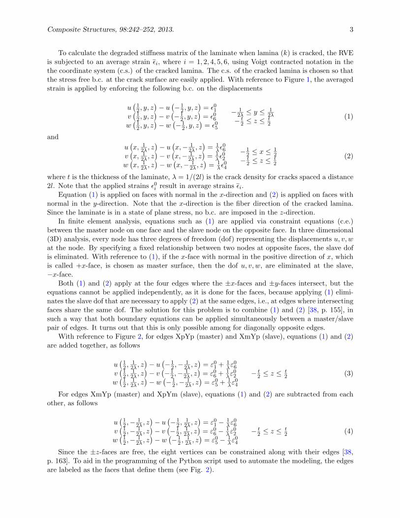
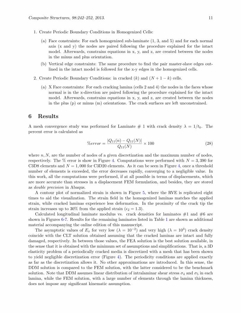
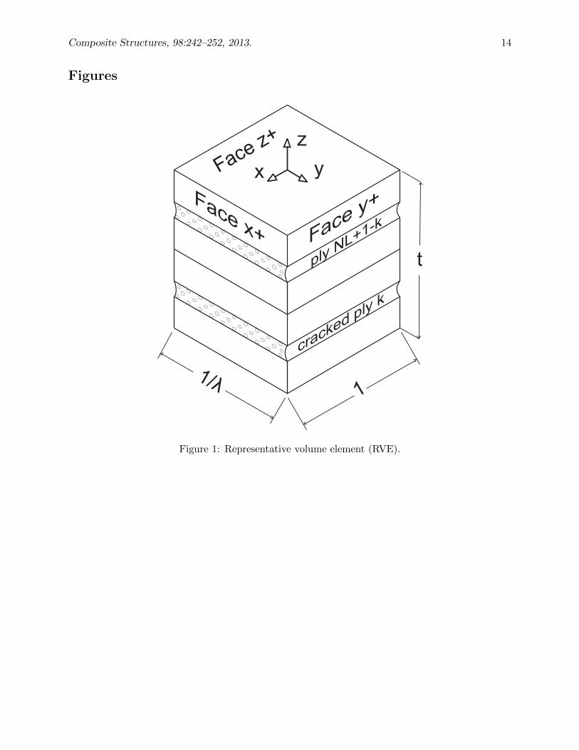
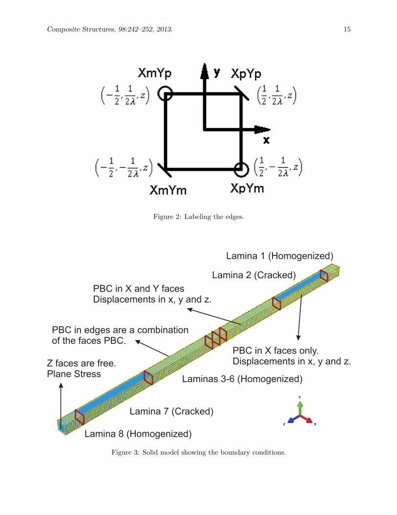
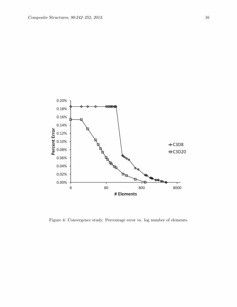
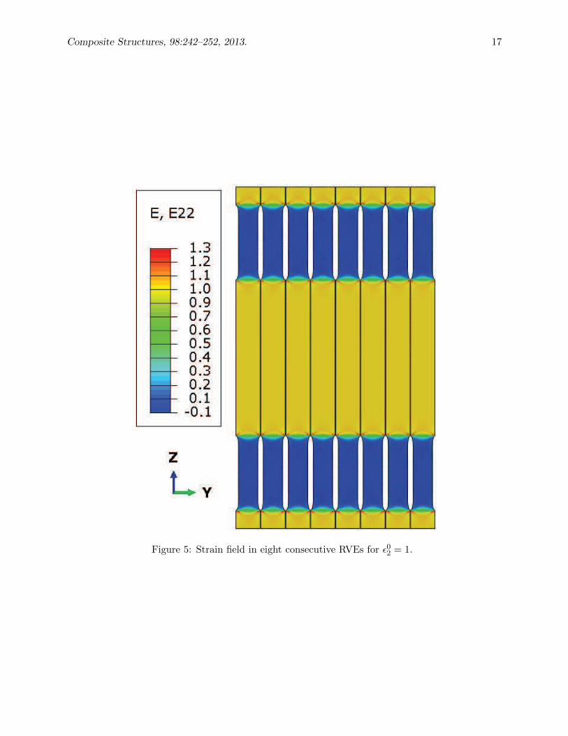
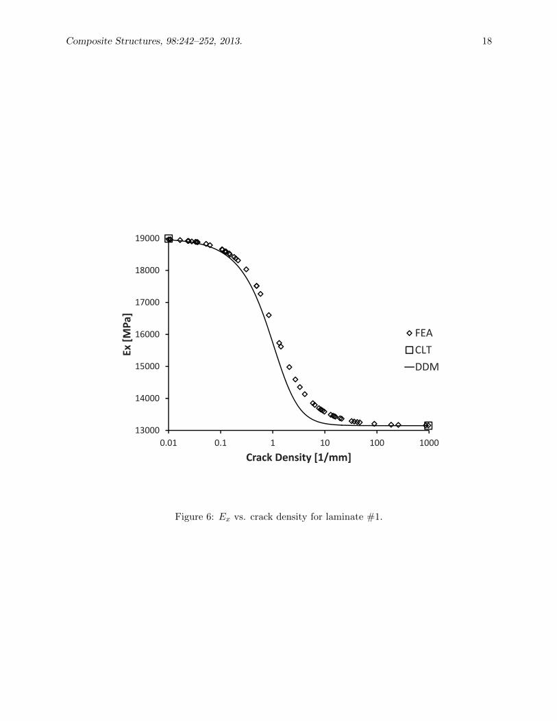
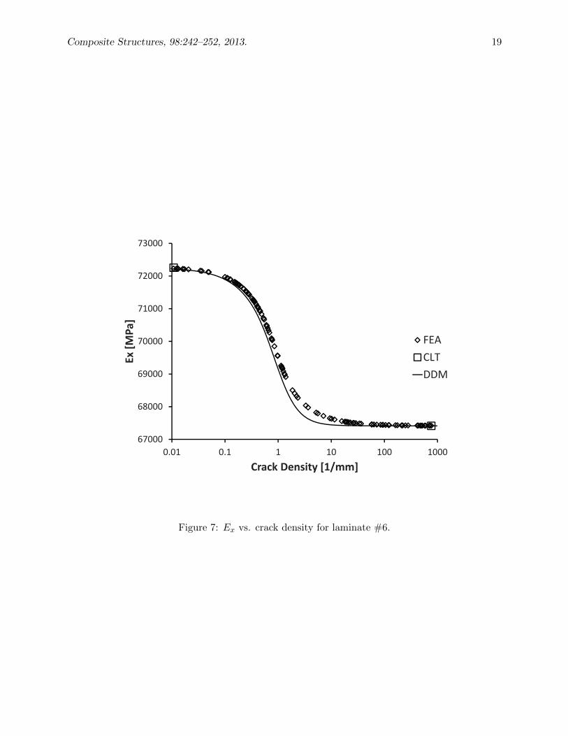
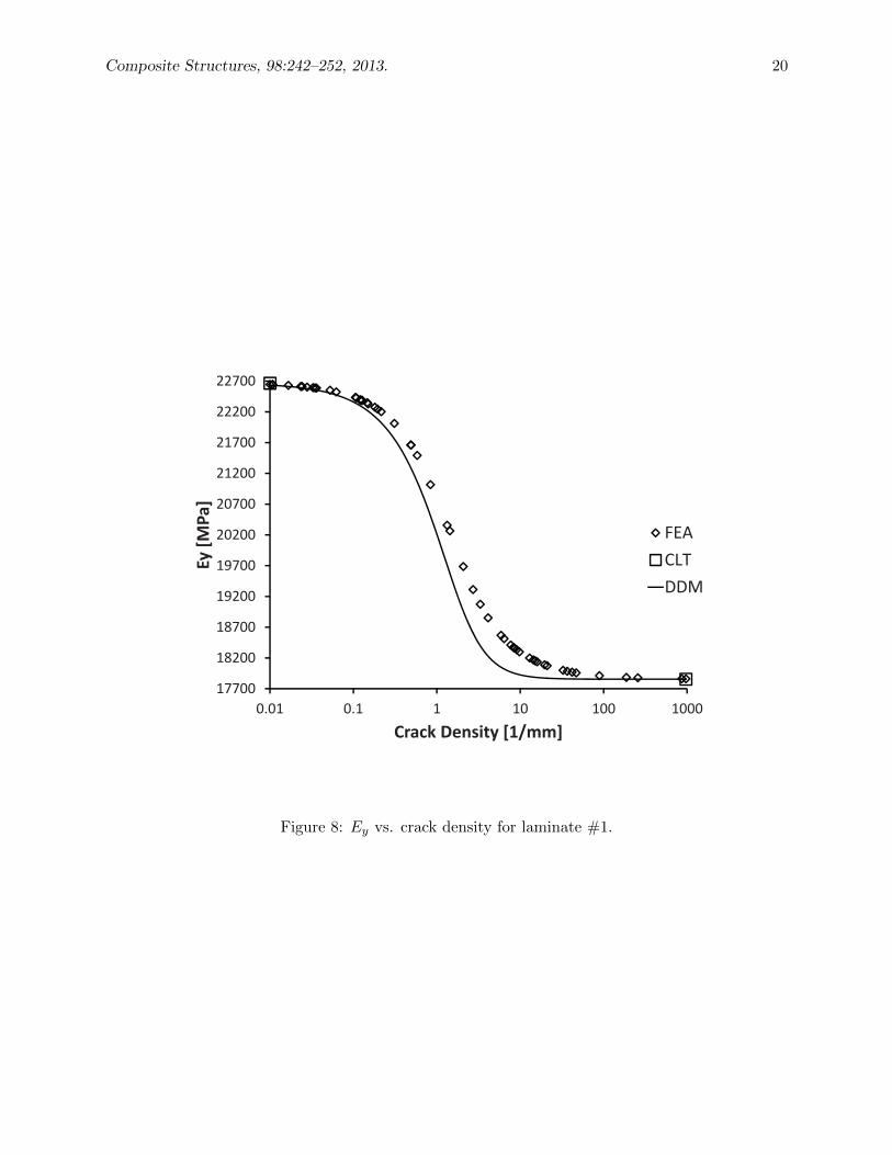
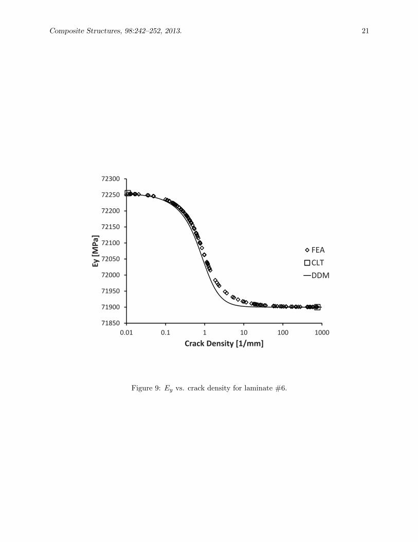
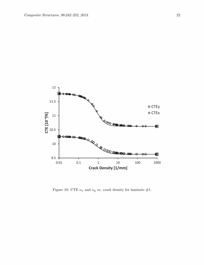
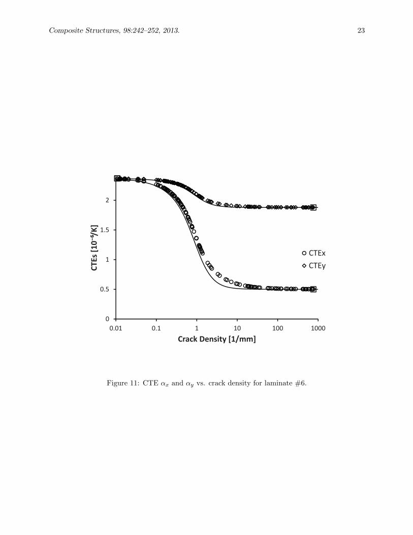
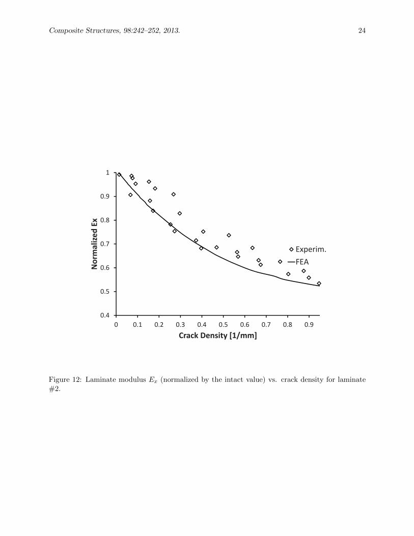
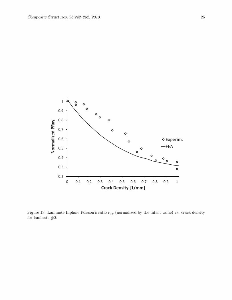
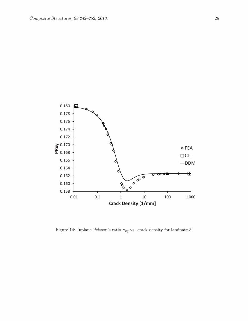
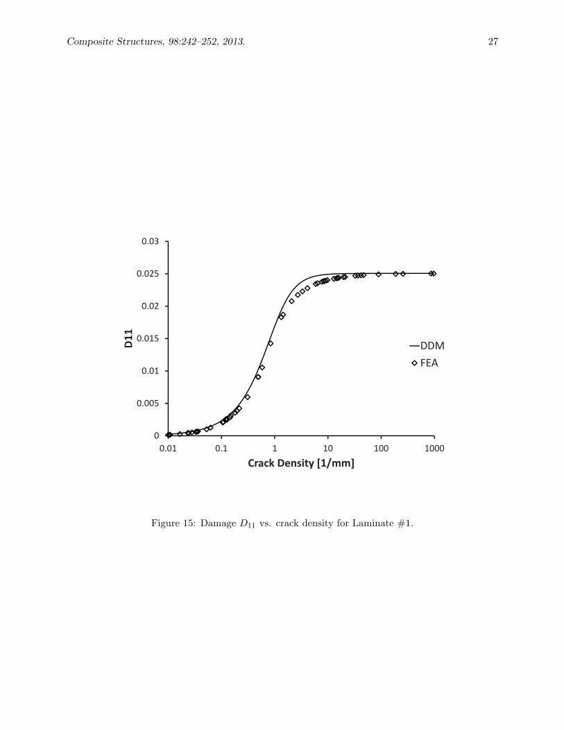
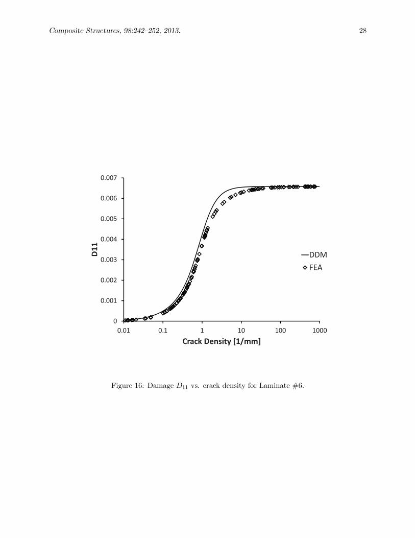
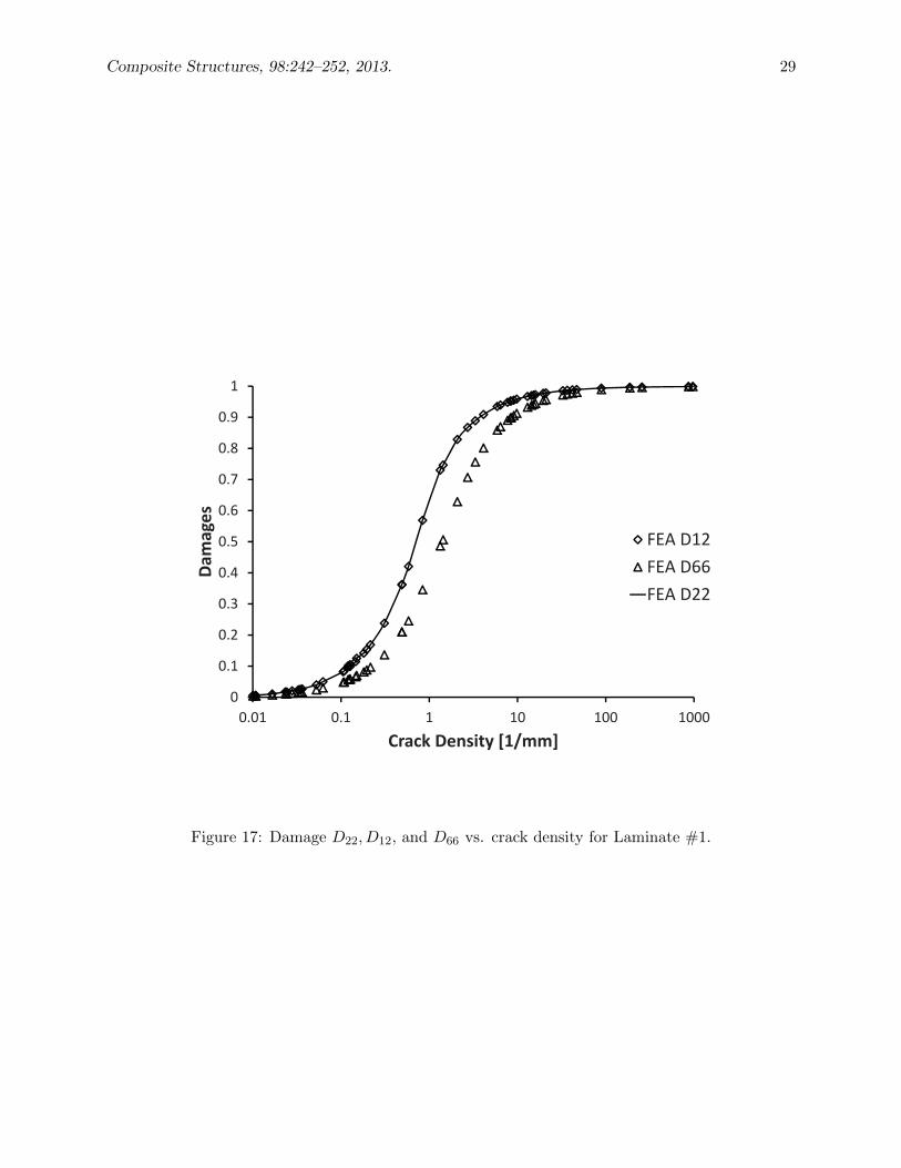
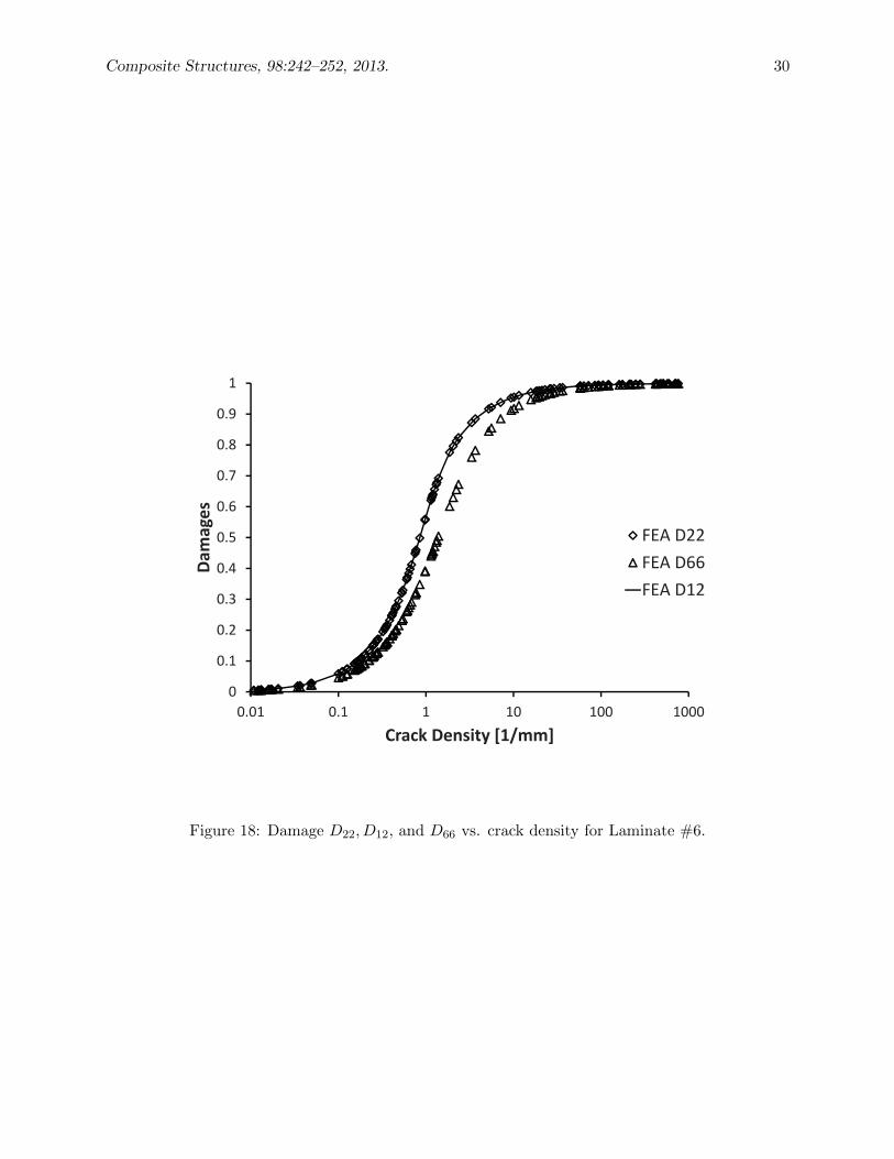
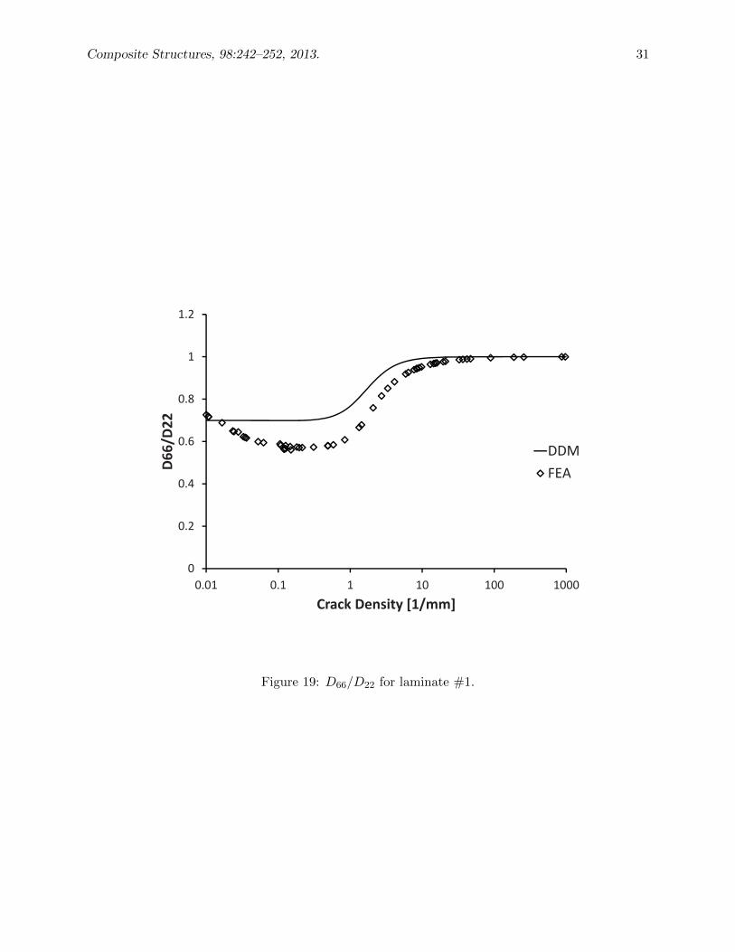
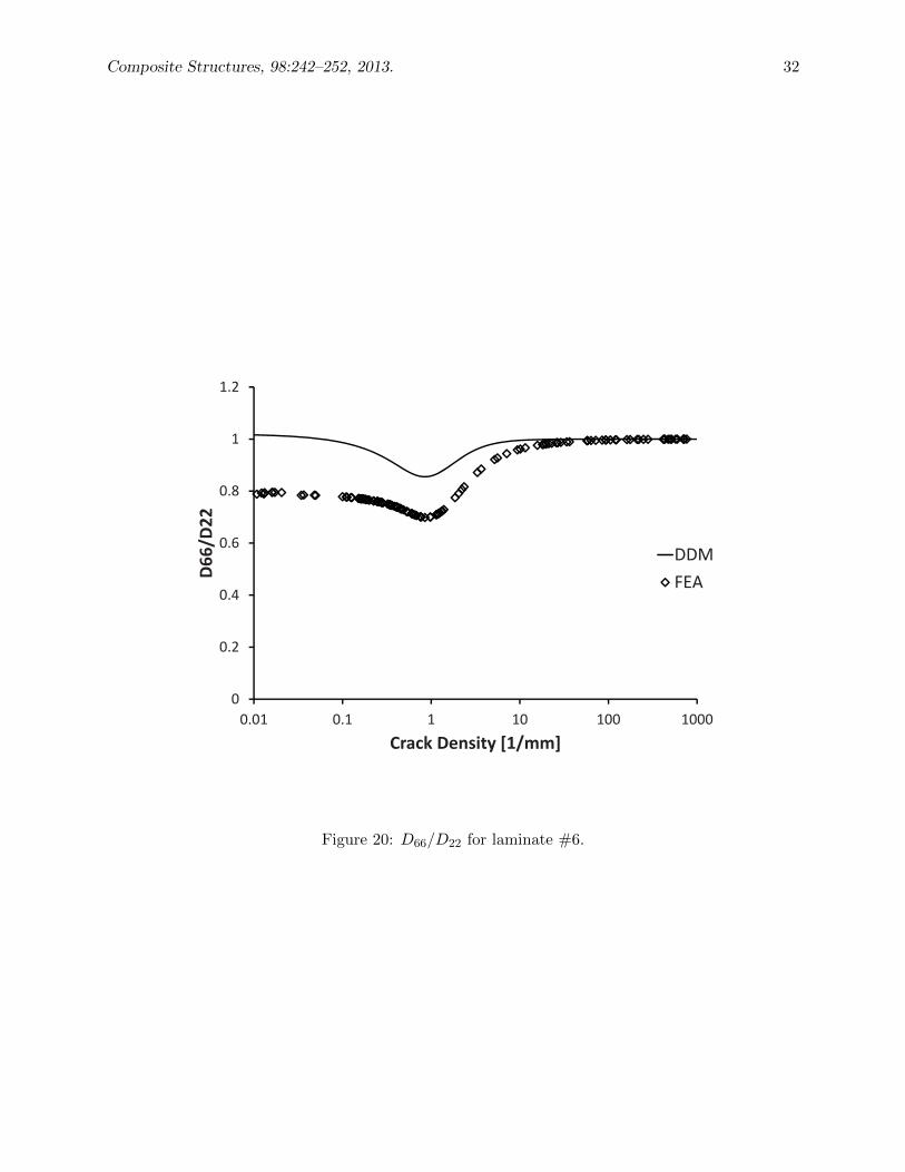
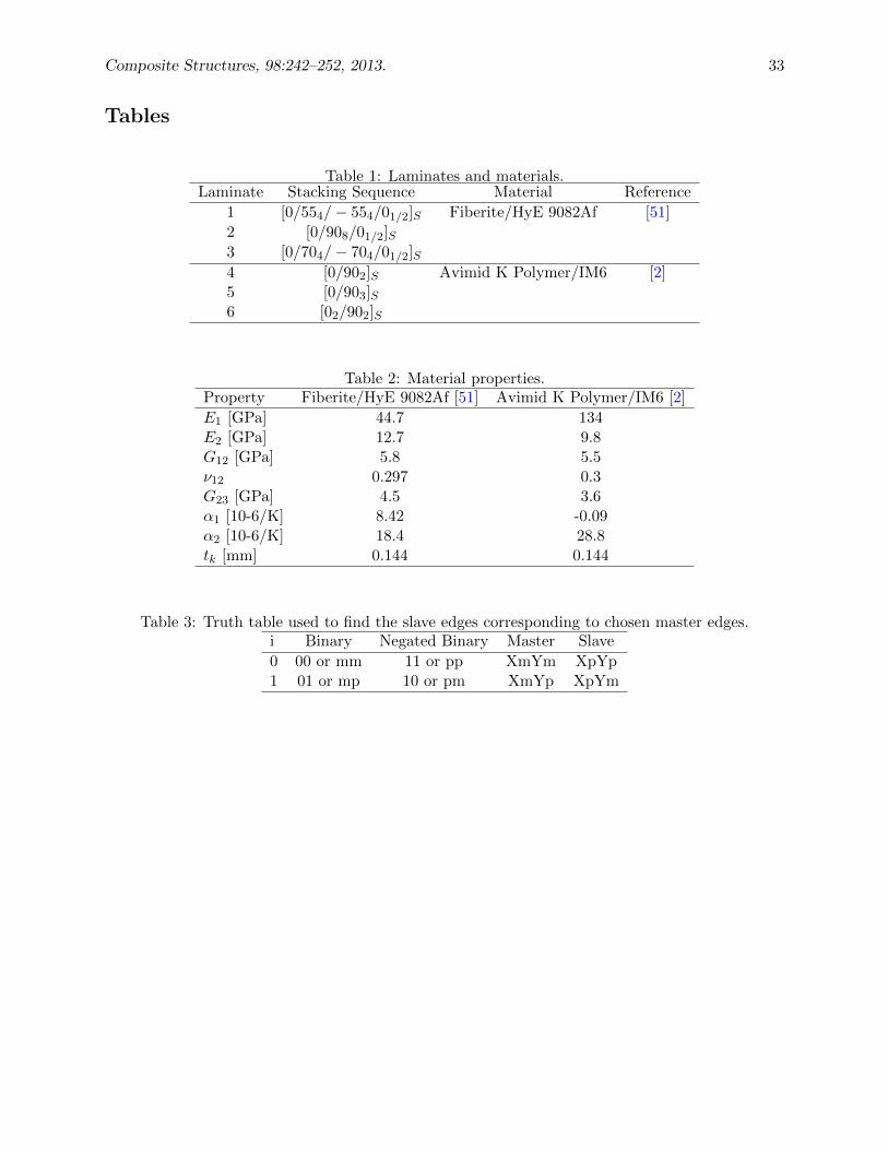
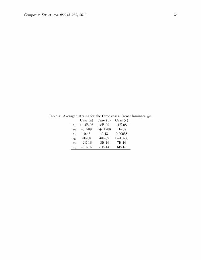
Related Documents