© 1997 Light Machines Corporation Manchester, New Hampshire, U. S. A. March, 1997 BENCHMAN VMC-4000 Machining Center Users Guide For Windows

Welcome message from author
This document is posted to help you gain knowledge. Please leave a comment to let me know what you think about it! Share it to your friends and learn new things together.
Transcript
��������������
�������� �������� ���������� � ��������������������� ������� ��!� �����������
����������������� ���������������������������
"���# $���
%�&'(((����� �����������)��*+ $�
��������������� ���������������
������������������
�������������� ���������������������������� �����������
���������������������������� ��������������������������
�������� ��������� ��� ���������������������������� ����
�������� ��������������� ������� ��������� �� ������������
���������� ���������������������� ���������������� �������
����������������
���������� ��������� !!"# $$$"%���� �%�"&&!'� ���������������
(�� �$$$��� ��������������� )���%��� �����������*�� ���
�$$$� ��������������
+���������,�-���
��� �����.�����*/0�1��0.���������)������������� �����
����������
�����������������)���������)����������������� ������������
��������������
�������
���������� ���������� ������ ��,����+�$���,�����������$��,��-��� ���$�.����$������� $ / $+���0
1��$������� ��������������� ���+ $����������+ ������������������%�&'(((����� �������
����/� $����� ���� 2+�,�������������/�����������,�����+� ���$���� ��$� ��� ������3��*+ $��

/ %�&'(((����� �����������)��*+ $�
�������������� /
��������
������������
� ��������!����� "" ����
4������5�+� ���� ����������������������������������������������������������������������������������������������� !&6
���� ���1�7+ ������ ������������������������������������������������������������������������������� !&6
���+���� ,�����1�7+ ������ ���������������������������������������������������������������� !&6
*��� ��1��$,�����8������� � ������������������������������������������������������������������������� !&9
���.�5�+�� � ���� ���������������������������������������������������������������������������������� !&9
1�� ���������4:���!��'((( ������������������������������������������������������������������� !&9
;�������5�+��#��.�;���� ��������������������������������������������������������������������������� !&'
����.�����4:���!��'((( ��������������������������������������������������������������������� !&'
� �� ������4:���!��'((( ���������������������������������������������������������������������� !&<
"��.� ��������$ ������������������������������������������������������������������������������������������ !&<
1 �������$ ���������������������������������������������������������������������������������������������� !&<
1���/����������=�!- ���/�� ����������������������������������������������������������������������� !&>
1� ������� ���������=�!- ���/�� �������������������������������������������������������������� !&>
���$�����8������� � �������������������������������������������������������������������������������������� !&�
8����� ��������� ����������$� �����; ��������������������������������������������� !&�
?�� ������;����� � ����������������������������������������������������������������������������� !&�
����. ��������� ����������$ ��������������������������������������������������������� !&@
8���� ��������� ����������$ ������������������������������������������������������������ !&@
��� ���������$�����!$$���� ������������������������������������������������������������������ !&�(
���A8;� � ���� ��� �������$��$�8��������$ ��������������������������������� !&�'
���������;������� �������������������!$$���� ������������������������������ !&�'
���� ������4:���!��'((( ������������������������������������������������������������� !&�>
���� ��;���������������$������������ ���������������������������������� !&�@
���� ������4:���!��'(((�����������+��� ������������������������������� !&�@
���� ��! �� +��� �� �������������������������������������������������������������������������� !&�@
4:���!��%�&'<((�A �������� ��������������������������������������������������������������� !&��
/ %�&'(((����� �����������)��*+ $�
��������8������� � ������������������������������������������������������������������������������������� !&6(
8����� ������������;������ ���������������������������������������������������������������� !&6(
� ����� ������������;������ ������������������������������������������������������������ !&6�
���� ��+��;������ ����������������������������������������������������������������������������������� !&6�
���� ���� +����� ������������������������������������������������������������������������������������������� !&66
4��������� � �������������������������������������������������������������������������������������������� !&66
#�����, ���������������������������������������������������������������������������������������������������� !&66
��������!� #���$�� ��% ��
����4:���!��'(((����� ������ �������������������������������������������������������� 4&6
"���+��� ������������������������������������������������������������������������������������������������������� 4&6
4:���!��'(((�������� ������������������������������������������������������������������������ 4&9
������ ����� ��������� ������������������������������������������������������������������ 4&9
����"����;����������� ������������������������������������������������������������������� 4&'
1����;����������� ���������������������������������������������������������������������������� 4&'
8��$�$���������������� ������ ������������������������������������������������������������ 4&<
����;������ �������������������������������������������������������������������������������������������������� 4&<
+�� ���������$�" -�+��� ������������������������������������������������������������������������ 4&<
#��.� ��������� ��� ���������������������������������������������������������������������������������� 4&<
� �+�������������� � �������������������������������������������������������������������������������������� 4&>
?����� ���$ � �� ��������������������������������������������������������������������������������������� 4&�
#��.�!��� ���������������������������������������������������������������������������������������������������� 4&�
�� �!�;����� +���, �������������������������������������������������������������������������������� 4&�
%������ ������������������������������������������������������������������������������������������������������� 4&�
"��7+��, ��������������������������������������������������������������������������������������������������� 4&�
;�����1�� � ��������������������������������������������������������������������������������������������� 4&�
*��+$ � ���������������������������������������������������������������������������������������������������� 4&�
:/ ���������$ � �� ��������������������������������������������������������������������������� 4&@
��������+�� ���������������������������������������������������������������������������������������������� 4&@
�+� $ �, ���������������������������������������������������������������������������������������������������� 4&@
!�� �+$� ������������������������������������������������������������������������������������������������������ 4&@
���. ���������������������������������������������������������������������������������������������������������� 4&@
% ���� � ���������������������������������������������������������������������������������������������������� 4&@
�� �� ����������������������������������������������������������������������������������������������������������� 4&@
�������������� /
�� �� ���������� ������ ������������������������������������������������������������������ 4&�
4��������� ����������������������������������������������������������������������������������������������������� 4&�
4��������/��� ������������������������������������������������������������������������������������������� 4&�(
���� �$$�� ������������������������������������������������������������������������������������������������� 4&�(
�+�� ��� � ����������������������������������������������������������������������������������������������� 4&�(
!$2+����� ����������������������������������������������������������������������������������������������� 4&��
� $�� ������������������������������������������������������������������������������������������������������� 4&�6
� $������$ ������������������������������������������������������������������������������������������� 4&�6
� $�������� ������������������������������������������������������������������������������������������ 4&�6
���. ������ � $��� �����;��, ������������������������������������������������������������� 4&�6
4���� ������������������������������������������������������������������������������������������������������������ 4&�9
� $���4��� ��������������������������������������������������������������������������������������������� 4&�9
!- ��A� /��4���� ���������������������������������������������������������������������������������������� 4&�9
�� �� ������;� ��� ����:/ ����� ������������������������������������������������� 4&�'
�� �������������+��� ��������������������������������������������������������������������������� 4&�'
�� ������"����,�A �.� ����������������������������������������������������������������������������� 4&�<
"�����,�8������$�?�� �� ������������������������������������������������������������������������������� 4&�>
�(�(((�1;�� � $�� ���������������������������������������������������������������������������������� 4&�>
A � � B ��;��.��� ������������������������������������������������������������������������������������ 4&�>
! ��% �� ������������������������������������������������������������������������������������������������������� 4&�>
!+����� ������������ ��������������������������������������������������������������������������� 4&��
*���� ���A+��������� �� ,���� �������������������������������������������������������������� 4&��
'���!- ������� ����������������������������������������������������������������������������������������� 4&��
;�+��� ������� ������������������������������������������������������������������������������������� 4&��
"���$������ �������������������������������������������������������������������������������������������� 4&�@
" �� ������ +�� �������������������������������������������������������������������������������������� 4&�@
"���$���� �� ��+���$�?����� � ������������������������������������������������������� 4&�@
�� ����� �������������������������������������������������������������������������������������������� 4&��
��������!������������&��%������������"�'���� $
���� ������������;������ ������������������������������������������������������������������������� &6
���� ������������;������� � �+�������$� ������������������������������������� &6
8��5�+����$�������� ������������������������������������������������������������������������������������������� &9
:-���� ������������;������� ���� ����������������������������������������������������������� &'
��+�4�� ������������������������������������������������������������������������������������������������������ &'
/ %�&'(((����� �����������)��*+ $�
��$��$������4�� ��������������������������������������������������������������������������������������� &'
!�������4�� ������������������������������������������������������������������������������������������������ &>
?+��+��������4�� ����������������������������������������������������������������������������������������� &�
8�+��������4�� �������������������������������������������������������������������������������������������� &@
:$ ��# $�� ������������������������������������������������������������������������������������������������� &�
���+��4�� ��������������������������������������������������������������������������������������������������� &�(
;�� � ��1��$�+� ���������������������������������������������������������������������������������������� &��
���� ��8���;��� ������������������������������������������������������������������������������������ &��
%�� �,�# $�� ��������������������������������������������������������������������������������������������� &�6
�������(!�)����� "!�� �������� � $*"��' ��
����,�1+ ���������� ������ ������������������������������������������������������������� A&6
����,�1+��� ������������������������������������������������������������������������������������������������� A&6
1���/��!$2+�� ��C�,���$�#������ ����������������������������������������������������� A&6
A������"����������� ���������������������������������������������������������������������������������� A&6
��������1 �������� ������������������������������������������������������������������������������������� A&6
��+�������#��.� ��� �������������������������������������������������������������������������������� A&6
�+������ � $���4,���$�4������ ���� � ���������������������������������������������� A&6
� �����!������$ ������. ���$�A� / ��A�/ ��� ��������������������������������� A&6
��. ��:������,� ���� ���������������������������������������������������������������������������� A&9
���� ��� �������:������,� ����4+��� ���������������������������������������������� A&9
���� ��� ����������+����C�,����$ ���������������������������������������������������� A&9
���� ��� ������ � �� � ��� �������������������������������������������������������������������� A&'
1+ ���� ��������;������ ���������������������������������������������������������������������� A&<
?����8��?�:�� �������������������������������������������������������������������������������������� A&<
!$2+������%�� �,� ��� �� ����������������������������������������������������������������������������� A&>
!$2+�������% �� ������������������������������������������������������������������������������������������ A&>
!$2+������� ���. ����������������������������������������������������������������������������������������� A&�
A�� ���������� �������������������������������������������������������������������������������������������� A&@
!$$������������������ ����, ���������������������������������������������������������������������� A&@
�������������������%�� � ��� � ����������������������������������������������������������������� A&�
%�� �,��8��?�:�� ������������������������������������������������������������������������������������ A&�(
A�,�1+�������;������ �������������������������������������������������������������������������� A&��
��+������#��.� ��� �������������������������������������������������������������������������������� A&�9
1+�����;������ ��������������������������������������������������������������������������������������� A&�9
�������������� -
��+������������
��������!�������"�'���� $���+������
����4:���!��'(((�8������� ���������������������������������������������������������������������� :&6
�� ��������������4�� ������������������������������������������������������������������������������������ :&9
�� ��# $��� ������������������������������������������������������������������������������������������������� :&9
;�������:$ ��# $��� ������������������������������������������������������������������������������� :&9
����%�� �,�# $�� �������������������������������������������������������������������������������������� :&'
�������� ��8���# $�� ��������������������������������������������������������������������������� :&'
����;�� � ��# $�� ����������������������������������������������������������������������������������� :&<
�� ���������� ������������������������������������������������������������������������������������������������� :&>
���� ��$��$�������� ��������������������������������������������������������������������������������� :&>
����!��������������� ����������������������������������������������������������������������������� :&�
����8�+���������� �������������������������������������������������������������������������������������� :&�
����?+��+���������� ����������������������������������������������������������������������������������� :&@
�� ��;���� ����������������������������������������������������������������������������������������������������� :&�
����D���������;��� ��������������������������������������������������������������������������������� :&�
����?��������;��� ������������������������������������������������������������������������������������ :&�(
�� ������ ���+��4�� ��������������������������������������������������������������������������������������� :&��
�� ��������+�4�� ���������������������������������������������������������������������������������������� :&�6
" �����+ ���������������������������������������������������������������������������������������������������� :&�6
��������$ ������������������������������������������������������������������������������������������ :&�6
?�������$ ���������������������������������������������������������������������������������������� :&�9
���������$ ���������������������������������������������������������������������������������������� :&�9
�/������$ ����������������������������������������������������������������������������������������� :&�'
�/��!����������$ �������������������������������������������������������������������������������� :&�'
;� ������$ ����������������������������������������������������������������������������������������� :&�<
;� �� ��+������$ ������������������������������������������������������������������������������ :&�<
?�� ����1�����;������ ��������������������������������������������������������������������� :&�>
:- ������$ ������������������������������������������������������������������������������������������� :&�>
:$ ����+ ���������������������������������������������������������������������������������������������������� :&��
�$������$ ���������������������������������������������������������������������������������������� :&��
1�$������$ ���������������������������������������������������������������������������������������� :&�@
+������$ ������������������������������������������������������������������������������������������� :&�@
��,�����$ ����������������������������������������������������������������������������������������� :&�@
- %�&'(((����� �����������)��*+ $�
;���������$ ���������������������������������������������������������������������������������������� :&�@
���������$ ���������������������������������������������������������������������������������������� :&��
A������� ������$ ������������������������������������������������������������������������������ :&��
" $�����$ ����������������������������������������������������������������������������������������� :&��
1�����������$ ������������������������������������������������������������������������������������ :&6(
*����� ������$ ��������������������������������������������������������������������������������� :&6(
1�+���������$ �������������������������������������������������������������������������������� :&6�
���.�����$ ����������������������������������������������������������������������������������������� :&69
������"�������$ ������������������������������������������������������������������������������� :&6'
% �����+ ��������������������������������������������������������������������������������������������������� :&6'
;�� � ������$ ����������������������������������������������������������������������������������� :&6'
���� ��8�������$ ��������������������������������������������������������������������������� :&6<
D�������������$ ������������������������������������������������������������������������������ :&6<
?��������;��������$ ����������������������������������������������������������������������� :&6<
%�� �,�# $�������$ ������������������������������������������������������������������������� :&6<
�������������$ ���������������������������������������������������������������������������������� :&6<
;���������+ �������������������������������������������������������������������������������������������� :&6>
1+E�� +������$ �������������������������������������������������������������������������� :&6>
%�� �,�����$ ��������������������������������������������������������������������������������������� :&6�
:�� �����1+� �������$ ������������������������������������������������������������������� :&6@
;�+�������$ ��������������������������������������������������������������������������������������� :&6�
"��$���$�����$ ��������������������������������������������������������������������������������� :&6�
��������$ ����������������������������������������������������������������������������������������� :&6�
��������+ �������������������������������������������������������������������������������������������������� :&9(
��+��� ����,�����$ �������������������������������������������������������������������������� :&9(
��+�������# B��$�����$ ������������������������������������������������������������������ :&96
���������������$ ������������������������������������������������������������������������������� :&96
8����������"��������$ ��������������������������������������������������������������������� :&99
�� �+���!������$ ������������������������������������������������������������������������� :&99
?�������!������$ ���������������������������������������������������������������������������� :&9'
8 � �� B�� ��� ������� �����������$ ������������������������������������������������ :&9'
��+����+ ������������������������������������������������������������������������������������������������� :&9<
���;�� � ������$ ����������������������������������������������������������������������������� :&9>
F����;�� � ������$ ��������������������������������������������������������������������������� :&9>
D��� ��� �������$ ����������������������������������������������������������������������������� :&9�
1+� ��� �������$ ���������������������������������������������������������������������������� :&9@
%�� �,� ��� �������$ ������������������������������������������������������������������������� :&'(
%�� �,��,�������$ ������������������������������������������������������������������������������ :&'9
�������������� -
��E���.����������$ ���������������������������������������������������������������������� :&'9
*����;�� � ������$ �������������������������������������������������������������������������� :&''
� �������$ ���������������������������������������������������������������������������������������� :&''
���$ ���� ,����������$ ���������������������������������������������������������������� :&''
?�����������$ �������������������������������������������������������������������������������������� :&'>
� $�������$ ������������������������������������������������������������������������������������ :&'�
4��.���������$ ���������������������������������������������������������������������������������� :&'@
����� � �������$ ������������������������������������������������������������������������������� :&'@
;��������������$ ������������������������������������������������������������������������������ :&'�
# $�����+ ��������������������������������������������������������������������������������������������� :&<�
����$������$ ������������������������������������������������������������������������������������ :&<�
� �������$ ������������������������������������������������������������������������������������������� :&<6
!������8��������$ �������������������������������������������������������������������������� :&<6
# $���� �������$ ����������������������������������������������������������������������������� :&<6
�������+ ��������������������������������������������������������������������������������������������������� :&<6
���������$ ����������������������������������������������������������������������������������������� :&<6
8$�-�����$ ���������������������������������������������������������������������������������������� :&<6
�� �����������$ ������������������������������������������������������������������������������� :&<9
�/�� ��� �������$ ��������������������������������������������������������������������������� :&<9
1������� ��� �������$ ���������������������������������������������������������������������� :&<9
� ���������A�,�����$ ������������������������������������������������������������������������� :&<9
!��+��4:���!����������$ �������������������������������������������������������������� :&<9
����� ������$� ��������������������������������������������������������������������������������������� :&<'
������������$��� ��;��&�����+� ������������������������������������������������� :&<'
;�������:$ ��# $���;��&+����+ ������������������������������������������������������ :&<'
;�� � ��# $���;��&+����+ ��������������������������������������������������������������� :&<>
%�� �,�# $���;��&+����+ ������������������������������������������������������������������� :&<>
D���������;����;��&+����+ ������������������������������������������������������������� :&<�
������������$��� ������C�,� ����������������������������������������������������������� :&<@
������������$��� ���������� ������������������������������������������������������������ :&<�
;�� � � �� ������������ ��������������������������������������������������������������������� :&>(
;�� � � ���������� ���������������������������������������������������������������������������������� :&>(
;�� � � ��# $�����$�;���� �������������������������������������������������������������� :&>(
;�� � � ��;�������:$ ��# $��� ���������������������������������������������������������� :&>�
�/ ������# $���;�� � �� �������������������������������������������������������������������� :&>�
A��. ���$�"���� ��# $�����$��������� ������������������������������������������ :&>6
- %�&'(((����� �����������)��*+ $�
A��.�$� ������������ ��������������������������������������������������������������������� :&>6
"���� �� ������������ ������������������������������������������������������������������� :&>6
�� ������?����������� ������������������������������������������������������������������������������������ :&>9
#��. �� � �+��� ����$� ������������������������������������������������������������������������� :&>9
���� ��+��;������ ����������������������������������������������������������������������������������������� :&>'
#�������;��� ������������������������������������������������������������������������������������������� :&>'
*������;��� ��������������������������������������������������������������������������������������������� :&><
?�� ���;��� ��������������������������������������������������������������������������������������������� :&>>
8����������$�;��� ���������������������������������������������������������������������������������� :&>�
�������,!�� ��������'���� $$���
����:��������������;����;������ ������������������������������������������������������������� "&6
������ ���������$� ������������������������������������������������������������������������������������� "&9
8���������!��������GHI ����������������������������������������������������������������������� "&'
!����+���!���������GJI ����������������������������������������������������������������������������� "&'
. ��GKI��$�?�� ���� . ��GEI ������������������������������������������������������������������� "&'
������� ��?������%��+��GA��$�I �������������������������������������������������������� "&<
"��$�1����G"��$�I ������������������������������������������������������������������������������������� "&>
;���������,��$���G*��$��I ��������������������������������������������������������������������� "&>
����8�������� ��*��+� ���������������������������������������������������������������������������� "&�
����� ���*��+� ����������������������������������������������������������������������������������������� "&�
����;���� ����� ��*��+� ������������������������������������������������������������������������ "&�
����#� ��*��+� ������������������������������������������������������������������������������������������ "&@
������$�,����*��+� ���������������������������������������������������������������������������� "&�
����;������� ����$��*��+� ����������������������������������������������������������������� "&�
����;������;�� � ��*��+� ������������������������������������������������������������������������� "&�
����������� ��"+�� ���*��+� ������������������������������������������������������� "&�(
�������$ ���� ,�����*��+� ����������������������������������������������������������������� "&��
����;�����;������� ��*��+� ��������������������������������������������������������������� "&��
8�+�� ����� ���+����E�����������?������G���$�I ����������������������������� "&�6
=�!- �����$ ������������;� ��G8��$�I ���������������������������������������������� "&�6
5�!- �����$ ������������;� ��GD��$�I ���������������������������������������������� "&�6
F�!- �����$ ������������;� ��GC��$�I ��������������������������������������������� "&�9
!�������!���1����+� ���������+����G���$�I ������������������������������������� "&�9
� ��������+���$���G���$��I ����������������������������������������������������������������� "&�'
�������������� -
�66L�?+��+��+�����;�� � �����" �� ����������������������������������������������������� "&�<
���L�1��+������� +����������*��� ����������������������������������������������������� "&��
��(<L�?��������������� ������������������������������������������������������������������������� "&��
4���.��+�����G���$�I ����������������������������������������������������������������������������� "&�@
+���������4���.��+�����G?��$�I ������������������������������������������������������� "&��
+���������1���������+�����G;��$�I ������������������������������������������������ "&��
;��.�A�����GM��$�I ���������������������������������������������������������������������������������� "&��
1�$ +�����!����A� �� �� ���������� ��G1��$�I ��������������������������������������� "&6(
� $��� ���$�G ��$�I ����������������������������������������������������������������������������� "&6(
����� ����� ��G���$�I ������������������������������������������������������������������������������ "&6(
=�!- �����$ ����G=�������$�I ���������������������������������������������������������������� "&6�
5�!- �����$ ����G5����%��$�I ���������������������������������������������������������������� "&6�
F�!- �����$ ����GF����#��$�I ��������������������������������������������������������������� "&6�
�������$�� ������������������������������������������������������������������������������������������ "&66
*������;������� �� +����� �� ��������������������������������������������������������������� "&69
��������!����������'���� $$���
� ����8�������� ��;������� � ���������������������������������������������������������������� *&6
��+����8�������� ��;������� � �������������������������������������������������������������� *&9
��+����8�������� ����?�����;���� ������������������������������������������������������ *&'
��� ����8�������� ��;������� � ����������������������������������������������������������� *&<
1�� $����/�����;������� � ������������������������������������������������������������������������� *&>
��$�,����;������� � ���������������������������������������������������������������������������� *&�
�� ��*@( ���������������������������������������������������������������������������������������������������� *&�
�� ��*@� ���������������������������������������������������������������������������������������������������� *&@
�� ��*@6 ���������������������������������������������������������������������������������������������������� *&�
�� ��*@9 ���������������������������������������������������������������������������������������������������� *&�
�� ��*@' �������������������������������������������������������������������������������������������������� *&�(
�� ��*@< �������������������������������������������������������������������������������������������������� *&��
�� ��*@> �������������������������������������������������������������������������������������������������� *&��
�� ��*@� �������������������������������������������������������������������������������������������������� *&�6
+���������;������� � ��������������������������������������������������������������������������� *&�9
!� �������� +�������� ������������������������������������������������������������������������ *&�'
- / %�&'(((����� �����������)��*+ $�
��������!���- ���������'���� $$���
�� ��;�����;������� � ������������������������������������������������������������������������������ �&6
�� ��������� ������$� ������������������������������������������������������������������������� �&9
�� ��*6@ ���������������������������������������������������������������������������������������������������� �&9
�� ��*6@� �����;������ ������������������������������������������������������������������� �&9
�� ��*6@�4������ ��� �� ����� � �� ������������������������������������������������������ �&'
�� ��*6� ���������������������������������������������������������������������������������������������������� �&'
�� ��*6� ���������������������������������������������������������������������������������������������������� �&<
�� ��+������������ � ����������������������������������������������������������������������������� �&>
���� ��+������������ ��G*'�E*'6I ������������������������������������������������� �&�
+������������ ��� ���8DC�%������ ����������������������������������������������������� �&�(
��� ��+������������ ��?�������GAI ������������������������������������������������� �&��
��� ��?������%��+�� ����������������������������������������������������������������������������� �&�6
��� ��?������ $�� ������������������������������������������������������������������������������� �&�9
�� �������?������ ��+����8�������� ��G*9�I ����������������������������������� �&�'
���� ��+������������ � ���������������������������������������������������������������� �&�<
�����$�����$�' �������������������������������������������������������������������������������������� �&�<
�����$��6��$�< �������������������������������������������������������������������������������������� �&�>
�����$��9��$�> �������������������������������������������������������������������������������������� �&��
�� �� ��� ���$�1���� ���$�� ���������������������������������������������������������������� �&�@
��� � �������������������������������������������������������������������������������������������������������� �&�@
� ����� ��� � ��������������������������������������������������������������������������������������� �&�@
��� ��:����!- � ������������������������������������������������������������������������������������� �&��
���� ��� �����8������� ��� ��� � ����������������������������������������������������� �&6(
1���� ���$�� ������������������������������������������������������������������������������������������� �&6�
��� �� ��� ���$�1���� ���$�� ��������������������������������������������������� �&69
�+�� ���������;������� � �������������������������������������������������������������������������� �&6'
�� ���+�� ����������$�� ������������������������������������������������������������������������ �&6'
:����� �� ������1������������ ��������������������������������������������������������������� �&6<
:����� �� �������?������ ��������������������������������������������������������������������������� �&6<
���� ��5�+���+�� ���������;������ �������������������������������������������������������� �&6>
�$�����$ �����$ ���� ,����� �������������������������������������������������������������� �&6�
���� �����$ ���� ������������������������������������������������������������������������������� �&6�
#��.����$ ���� ������������������������������������������������������������������������������������ �&6�
�+�� �������$ ����� ,����� ����������������������������������������������������������������� �&6�
�������������� -/
�� �������������?�������$�� �������������������������������������������������������������������� �&6@
�� �������?������!$2+����$�� ��������������������������������������������������������������������� �&6�
�� ��*'< ������������������������������������������������������������������������������������������������ �&6�
�� ��*'> ������������������������������������������������������������������������������������������������ �&9(
�� ��*'@ ������������������������������������������������������������������������������������������������ �&9(
�� ��*'� ������������������������������������������������������������������������������������������������ �&9(
��������!������ "�� ����������+��$ ����
"��$�1�����$�A��������+� ����������������������������������������������������������������������������� 8&6
� $��� ���$� �������������������������������������������������������������������������������������������������� 8&9
"��$�1�����$� � $��� ���$� ����� � ���������������������������������������������������������� 8&9
������,��� ��������������������������������������������������������������������������������������������������������� 8&'
:$�� ��� ������������������������������������������������������������������������������������������������������ 8&'
A� �����$������A� ��� ������������������������������������������������������������������������������ 8&<
4�� ������� ������������������������������������������������������������������������������������������������ 8&<
����� ������� ���������������������������������������������������������������������������������������������� 8&<
�������.!� +��� ���������������/*�� ����
����,�1+��� ������������������������������������������������������������������������������������������������������� D&6
����,����.� �� ������������������������������������������������������������������������������������������������� D&>
� ����$�� ��+� $�$ �������������������������������������������������������������������������������������������� D&�
:������,� ���� ����������������������������������������������������������������������������������������������� D&@
�������0!��� �����������1������2#�����*
*��$����,�*��+� ��������������������������������������������������������������������������������������������� C&6
���$����,�*��+� �������������������������������������������������������������������������������������������� C&<
����3
-/ %�&'(((����� �����������)��*+ $�
9'&���6&(((�
����������������� ���������������������������
"���# $���
�������������� -/
������������
���������!����� "" ����
��������!�� #���$�� ��% ��
��������!������������&��%�����������"�'���� $
�������(!�)����� "!�� �������� � $*"��' ��
-/ %�&'(((����� �����������)��*+ $�
��+������������
���������!�������"�'���� $���+������
�������,!�� ��������'���� $$���
��������!����������'���� $$���
��������!���- ���������'���� $$���
��������!������ "�� ����������+��$ ����
�������.!� +��� ���������������/*�� ����
�������0!��� ����������
������������ �
�������������
�� �������������������� ��
���������������� ��
�������������� !!�" ������#��
�������������� ��
$�#%� #����&&��
�������� ��
'���(���� ��)��# ����
�� �������� ��� �������
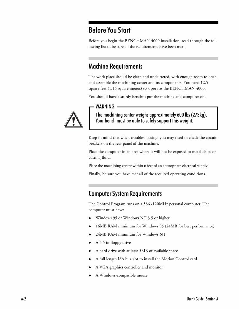
�������������Before you begin the BENCHMAN 4000 installation, read through the fol-lowing list to be sure all the requirements have been met.
��#% ������*� ��+���
The work place should be clean and uncluttered, with enough room to openand assemble the machining center and its components. You need 12.5square feet (1.16 square meters) to operate the BENCHMAN 4000.
You should have a sturdy benchto put the machine and computer on.
������
�� ������������ �� ��� ������ ��!���� �"�#$$��%��&�'()�*+,����% ���������% ��%� ������- �"��� ���������� ����+
Keep in mind that when troubleshooting, you may need to check the circuitbreakers on the rear panel of the machine.
Place the computer in an area where it will not be exposed to metal chips orcutting fluid.
Place the machining center within 6 feet of an appropriate electrical supply.
Finally, be sure you have met all of the required operating conditions.
��+&�������+���*� ��+���
The Control Program runs on a 586 /120MHz personal computer. Thecomputer must have:
� Windows 95 or Windows NT 3.5 or higher
� 16MB RAM minimum for Windows 95 (24MB for best performance)
� 24MB RAM minimum for Windows NT
� A 3.5 in floppy drive
� A hard drive with at least 5MB of available space
� A full length ISA bus slot to install the Motion Control card
� A VGA graphics controller and monitor
� A Windows-compatible mouse
������������ (
�� �������������������� ��Before you connect and run your new BENCHMAN 4000, you should:
,- Check the shipment to make sure you received everything you need.
.- Register the BENCHMAN 4000 so it is covered by warranty.
/- Prepare a workspace for the BENCHMAN 4000.
�- Unpack and set up the BENCHMAN 4000.
- Install the Motion Control Card into your computer.
When all of these procedures are complete, you can connect theBENCHMAN 4000 to your computer and install the Control Program.
�%�#0������% &+��
The first thing you should do after receiving the BENCHMAN 4000 is inspectthe packaging for any visible signs of damage. If there is damage to the outsideof the packaging, contact the shipping company as well as Light MachinesCustomer Service Department at 800-221-2763 or 603-625-8600
��� ����%������������!!!
You’ll find a registration card in the small box with the documentation andsoftware disks. Clearly print all the requested information and return thiscard to Light Machines Corporation.
�� �������� ��� ������.
1��&���������2��0�1��#�
Make sure you have all the items on hand necessary to perform the installa-tion. To install the BENCHMAN 4000, you must have ready:
� A sturdy bench on which you’ll place the BENCHMAN 4000 and yourcomputer. Placing the bench against a wall provides more stability.Make sure the wall has a 120 or 220 VAC, 15 amp polarized outlet.
� A personal computer running Windows 95 or Windows NT version 3.5 orgreater. See page A-2 for a complete list of the necessary computer equipment.
� Your PC Owner’s Manual or equivalent documentation.
'�&�#0�%������������!!!
,- Position the pallet near the bench on which you’ll set the BENCHMAN4000. The bench should be located against a wall for maximum support.
.- Remove the staples attaching the bottom of the cardboard container tothe pallet.
/- Lift the cardboard container off of the pallet.
�- Inspect the BENCHMAN 4000 chassis for signs of visual damage such as abroken shield, a dent in the chassis or damaged cables.
If any damage is noted, or if you find any discrepancies between thepacking slip and the items received, call Light Machines’ Customer Ser-vice Department (800-221-2763 or 603-625-8600).
- Remove the two lag bolts from the 2x4 cross member holding theBENCHMAN 4000 on the pallet.
��13�$��$4
/ ���� ����) ��� � ��� ����������-��� ���������������������������� �012.$$$�������� �+���������"���� �� ����� ����% �� ���� ������� �-�����"3� ��)�� ��-������ ���� !����"������ "� � �� � �4 �+
5�����1����� �����������% � � ����%� �-�����"������ ������ ������������ ������ ���� �� ������ ������ ���� ������ ���������� ��)������� �����+
������������ 6
5 � ���%������������!!!
������
�� �/7�281��.$$$�� ������ ��!���� �"�#$$��%��&�'(�)�*+9��������-���� ������� �%"��� ���- �"���� ������%"��� �:��!�� !� ������%�!+�5�-������� ������� �%"�� ��������� ����������� � ����% ��� � ���"������ ��� ������� 3�������� � ��������;��"+
There are two ways to lift and move the BENCHMAN 4000. The base of themachine is designed so that a forklift can be used to lift it off of the palletand place it on the benchtop. Or you may use the lifting ring attached tothe top of the machine. The following are the proper lifting and movingprocedures for the BENCHMAN 4000.
6��0� ����%��
,- Remove the lag bolts holding the 2x4 cross member to the pallet, andremove the cross member.
.- Carefully guide the forks of the lift under the machining center.
/- Using the forklift, raise the machine off the pallet, and move the ma-chine to the desired location.
�- Carefully lower the BENCHMAN 4000 to the benchtop.
� �����%��
You should be aware that when you lift the BENCHMAN 4000 by the lift-ing ring, the machine will tilt forward approximately 20o. For this reason,lift the machine slowly.
,- Remove the lag bolts holding the 2x4 cross member to the pallet, andremove the cross member.
.- Attach a crane or sling to the lifting ring.
/- Lift the machine off of the pallet using the lifting ring. When you liftthe machine, it will tilt forward 20o.
�- Guide the machine to its workplace.
- Carefully lower the BENCHMAN 4000 to the benchtop.
�� �������� ��� ������#
��+�7������%��8��9 ����7��
If you are required to move the BENCHMAN 4000 through a narrow areasuch as a doorway, it will be necessary to remove the X axis cover. The fol-lowing is the removal and reinstallation procedure. Please read through allthe steps before removing the cover.
,- Remove the 8 button head cap screws on the outside of the enclosurethat attach the X axis cover to the enclosure.
.- Reach under the outside of the cover and remove the nut from the PEMstud that attaches the X axis cover to the Y axis cover.
/- Remove the 9 button head cap screws on the inside of the enclosure thatscrew into the X axis cover. Be careful when removing these screws, theyare the last item attaching the cover to the enclosure.
�- If the X axis cover does not come off after all the fasteners are removed,push down on the cover sharply. This will break the original silicone sealapplied at the factory.
�� ������ ������%��8��9 ����7��
,- Remove all remaining silicone from the X axis cover and the enclosureleft over from the original seal.
.- Mount the front of the X axis cover onto the PEM stud coming out ofthe Y axis cover. Attach the X axis cover to the enclosure from the insideusing the 9 button head cap screws that were removed.
/- Install the remaining 8 button head cap screws into the bottom of the Xaxis cover on the outside of the enclosure.
�- Replace the nut on the PEM stud on the inside of the cover.
- Use the tube of DOW Corning 732 Silicone supplied with the machine,to reseal the X axis cover to the enclosure.
a) Partially remove each of the screws on the inside of the enclosureand apply a bead of silicone under the head of the screw. Tighten allthe screws and remove any excess silicone. Apply a layer of siliconeover all the PEM nuts on the inside of the enclosure.
b) Apply a bead of silicone along the seam between the enclosure andthe X axis cover on the inside of the enclosure. Smooth the siliconeout evenly, filling the entire seam. Remove any excess silicone.
c) Allow 24 hours for the silicone to cure before using the coolant option.
������������ '
��13�$��$
��� �1������2�������2�������-�����"� ������ ��� ������ ����� ������� � � �4 ��-���/��"�������������� �<2�=>����� ����� �?$($�� !?+��-����� �� ! ������������������ ��"������� ������ ��� ������������� ��3����-�"������� �� ��������� �� ������� ����)3�"�����"�� ��������������-��������+�� � �� �$3�� �������� �8������ ��� ��3�-����� ����� ��� ��� ��� �+
���������������� ��The following paragraphs review the procedures for installing all the hardwarecomponents of the BENCHMAN 4000. Be sure that your computer systemmeets all of the requirements outlined on page A-2. It should also be set up ac-cording to the instructions in your PC owners manual.
The first step is to install the Motion Control Card in your personal computer.
2������
9���������� ��� �� ������� �/7�281��.$$$������ ���� �� ��������������� ���������������� �-��������� ��� ��� �+
������ ���%���� ��������������� ��%��1�
The following paragraphs describe the procedure for installing the MotionControl Card in the chassis of your PC. You should have already set up your PCaccording to the instructions in your owner’s manual. The Motion ControlCard can be installed in any full-size slot designated for expansion card use.Refer to your computer owner’s manual to determine particular expansioncard restrictions.
2������
9������ ������ � �� �������-������ �<2�����������������2����� ������������������������ ��� ��� ����4 �% ����� � � �������� ����������4 ������% ������ �+
3&�� ���%��1���%��� �
To install the Motion Control Card, you must remove the cover of the PC.Refer to the instructions supplied with your PC for details on removing thecover. Generally, the cover is secured by four screws through the rear panel;however, some PC's may have push latches, or screws in different locations.
�� �������� ��� ������@
2������
9������ ��� �� ��-����"����<2�% -�� �� ������� �����������4 �A
������--��� � �� �������������� ��4 ��� � �� ��������������� �������� � �������� �� ��������� � � ����� ���� ���4 ������ ��4 �+
Set the cover aside and locate the slot where the card is to be mounted. Re-move the blank slot cover (if any). This requires removing a screw at the toprail of the rear panel. You may choose to discard the cover, but save thescrew for installing the Motion Control Card.
'�&�#0 ���%���� ��������������
2������
�� �� !�1�4 �2������������"�� �����4 ������������������� +����4���� ����%� ������ ������ �����3�� ����� � ����� ������������ ����������������� ��� ��� ��4������ ������-�������� ��)�����+
The card is shipped inside an anti-static envelope. Handle the card by theedges, being careful not to create any static discharge. Grounding yourselfwith a static discharge wrist strap or working on a grounded surface is sug-gested. Slide the card out of the envelope and inspect it for signs of damage,such as bent or broken components or a warped circuit card. If damage isnoted, contact Light Machines Corporation immediately.
������������ B
1�� �� �� 1�� �� ��
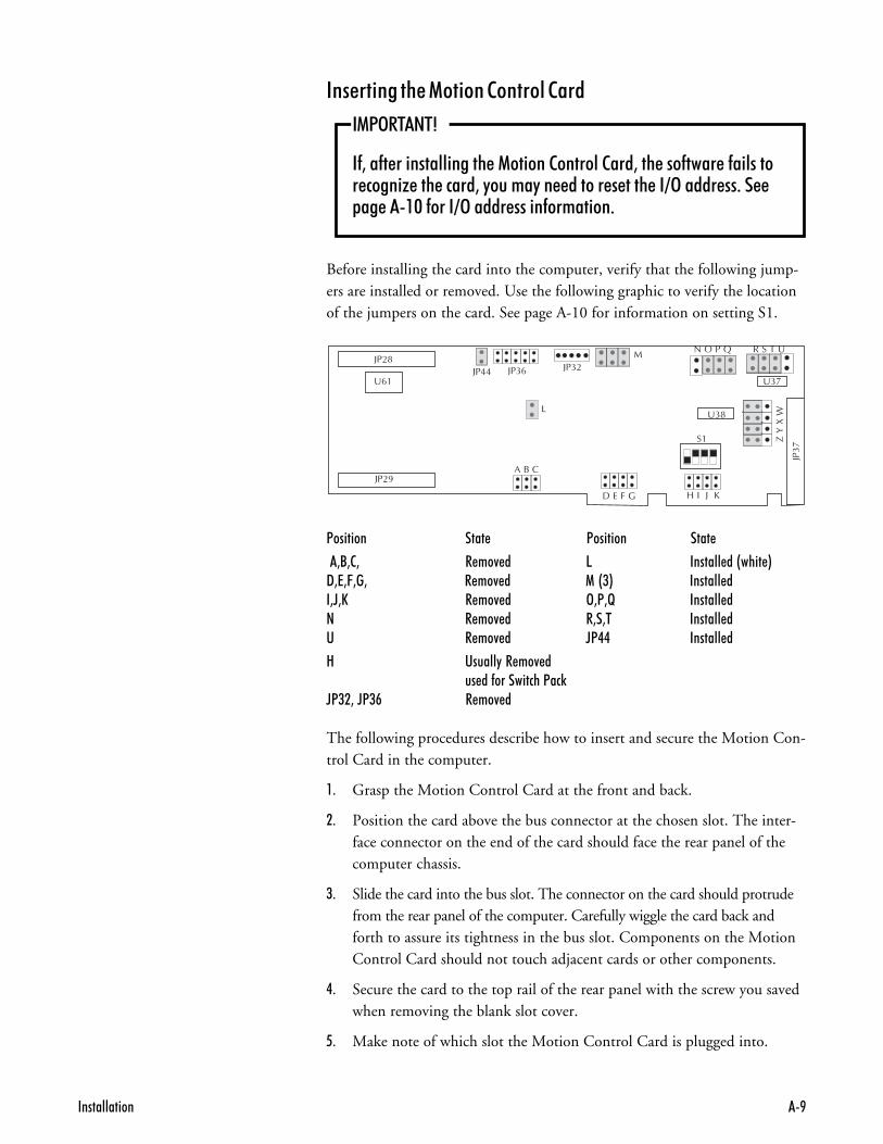
�3/323 � ��4 � 5 ������� ��&���� *9373C3�3 � ��4 � 1�&(* ������� ��3D3E � ��4 � >3<3F ������� �� � ��4 � �3�3� ������� �� � ��4 � D<.. ������� �
8 ������"�� ��4 ��� ��-����������<��)
D<(�3�D<(# � ��4 �
The following procedures describe how to insert and secure the Motion Con-trol Card in the computer.
,- Grasp the Motion Control Card at the front and back.
.- Position the card above the bus connector at the chosen slot. The inter-face connector on the end of the card should face the rear panel of thecomputer chassis.
/- Slide the card into the bus slot. The connector on the card should protrudefrom the rear panel of the computer. Carefully wiggle the card back andforth to assure its tightness in the bus slot. Components on the MotionControl Card should not touch adjacent cards or other components.
�- Secure the card to the top rail of the rear panel with the screw you savedwhen removing the blank slot cover.
- Make note of which slot the Motion Control Card is plugged into.
����� ���%���� ��������������
��13�$��$4
�-3��-� ��������������� �1������2�������2���3��� ���-���� �-�������� �����G ��� �����3�"�����"�� ������ � ���� ��=>����� ��+�� �� ��$�-����=>����� �����-��������+
Before installing the card into the computer, verify that the following jump-ers are installed or removed. Use the following graphic to verify the locationof the jumpers on the card. See page A-10 for information on setting S1.
�� �������� ��� �������$
� ���%������������������
If you are having problems getting the software to recognize the NextMovemotion card, you may have an address conflict. Address conflicts result whenthere is additional hardware using the same (default) I/O address as theNextMove Motion Card. The factory I/O address setting is 0320-0322. Thefollowing procedure should be used to reconfigure the hardware address.
,- Power off the Computer and remove the NextMove motion card. It isnecessary to remove the card in order to reset DIP switch settings. Youmay also be unable to reserve system resources while the card is still inthe system.
.- Power on your computer and allow Windows 95 to start up.
/- Click on the Start button. The Windows 95 Start Menu appears.
�- Click on the Settings option. The Settings sub-menu appears.
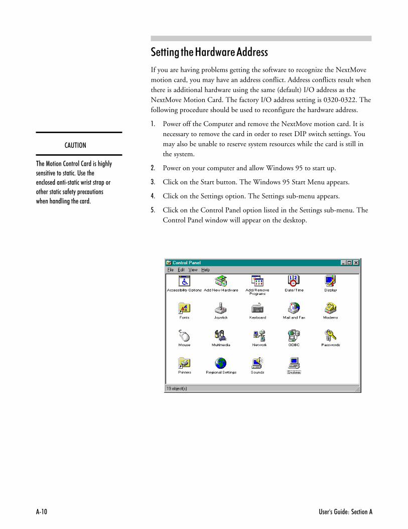
- Click on the Control Panel option listed in the Settings sub-menu. TheControl Panel window will appear on the desktop.
��'$�3�
�� �1������2�������2������������"� �����4 ����������+��� ��� ����� ����������������������� ������ �����������- �"� � ���������� ������������� �����+
������������ ��
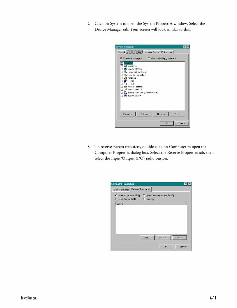
:- Click on System to open the System Properties window. Select theDevice Manager tab. Your screen will look similar to this.
;- To reserve system resources, double click on Computer to open theComputer Properties dialog box. Select the Reserve Properties tab, thenselect the Input/Output (I/O) radio button.
�� �������� ��� ��������
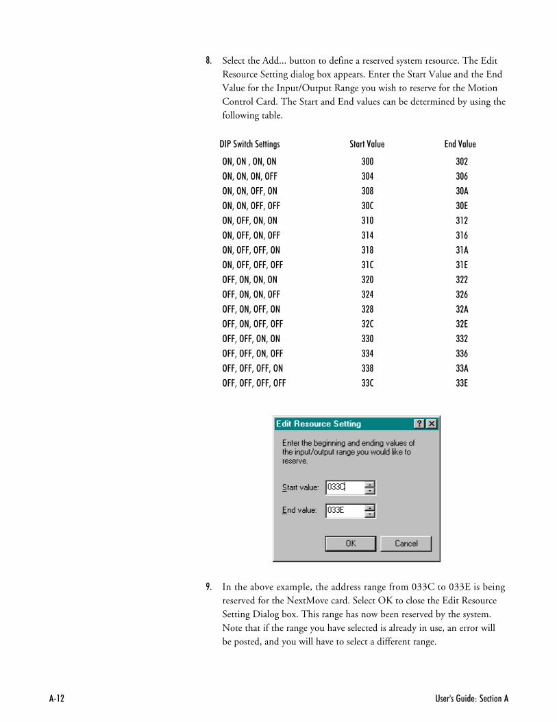
<- Select the Add... button to define a reserved system resource. The EditResource Setting dialog box appears. Enter the Start Value and the EndValue for the Input/Output Range you wish to reserve for the MotionControl Card. The Start and End values can be determined by using thefollowing table.
"�1�� #%�� ��� �������� ���������
3�=�3��=�3�=�3� ($$ ($�
3�=�3�=�3�=�366 ($. ($#
3�=�3�=�366=�3� ($@ ($
3�=�3�=�366=�366 ($2 ($7
3�=�366=�3�=�3� (�$ (��
3�=�366=�3�=�366 (�. (�#
3�=�366=�366=�3� (�@ (�
3�=�366=�366=�366 (�2 (�7
366=�3�=�3�=�3� (�$ (��
366=�3�=�3�=�366 (�. (�#
366=�3�=�366=�3� (�@ (�
366=�3�=�366=�366 (�2 (�7
366=�366=�3�=�3� (($ ((�
366=�366=�3�=�366 ((. ((#
366=�366=�366=�3� ((@ ((
366=�366=�366=�366 ((2 ((7
>- In the above example, the address range from 033C to 033E is beingreserved for the NextMove card. Select OK to close the Edit ResourceSetting Dialog box. This range has now been reserved by the system.Note that if the range you have selected is already in use, an error willbe posted, and you will have to select a different range.
������������ �(
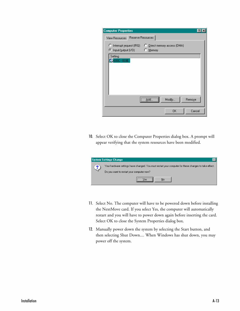
,!- Select OK to close the Computer Properties dialog box. A prompt willappear verifying that the system resources have been modified.
,,- Select No. The computer will have to be powered down before installingthe NextMove card. If you select Yes, the computer will automaticallyrestart and you will have to power down again before inserting the card.Select OK to close the System Properties dialog box.
,.- Manually power down the system by selecting the Start button, andthen selecting Shut Down.... When Windows has shut down, you maypower off the system.
�� �������� ��� �������.
��"�1�� #%�� ���������������������������
Once you have chosen a valid address in the software, the address on thecard must be set to match. Be sure to observe all static discharge procedureswhen handling the motion control card in order to prevent static damage.
,- Locate the S1 DIP switch block which is located just above the HIJKjumper pins. Using the list on page A-12, set the DIP switches to matchthe settings for the address that you have reserved for the card.
.- Insert the card into the computer, making sure that the card is fullyseated in the expansion bus. Because this is a full-length card, youshould double check to ensure that the card is seated.
/- Replace all covers and power up the computer.
���������1�����+����������%�������������
Once the card has been set to a free address, the Control Program softwaremust be set to recognize the new address.
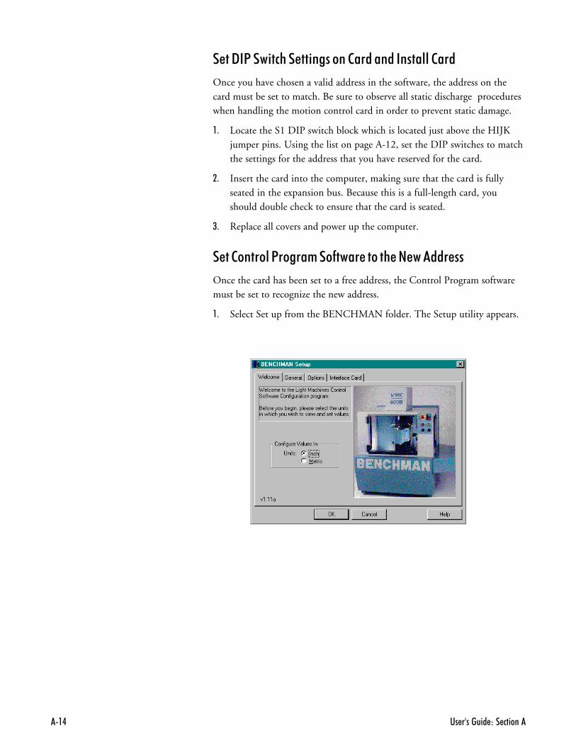
,- Select Set up from the BENCHMAN folder. The Setup utility appears.
������������ �6
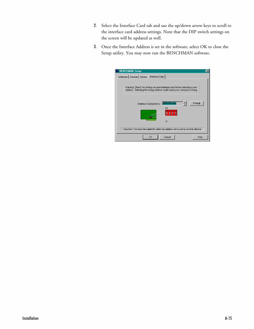
.- Select the Interface Card tab and use the up/down arrow keys to scroll tothe interface card address settings. Note that the DIP switch settings onthe screen will be updated as well.
/- Once the Interface Address is set in the software, select OK to close theSetup utility. You may now run the BENCHMAN software.

�� �������� ��� �������#
�����# ���%������������!!!
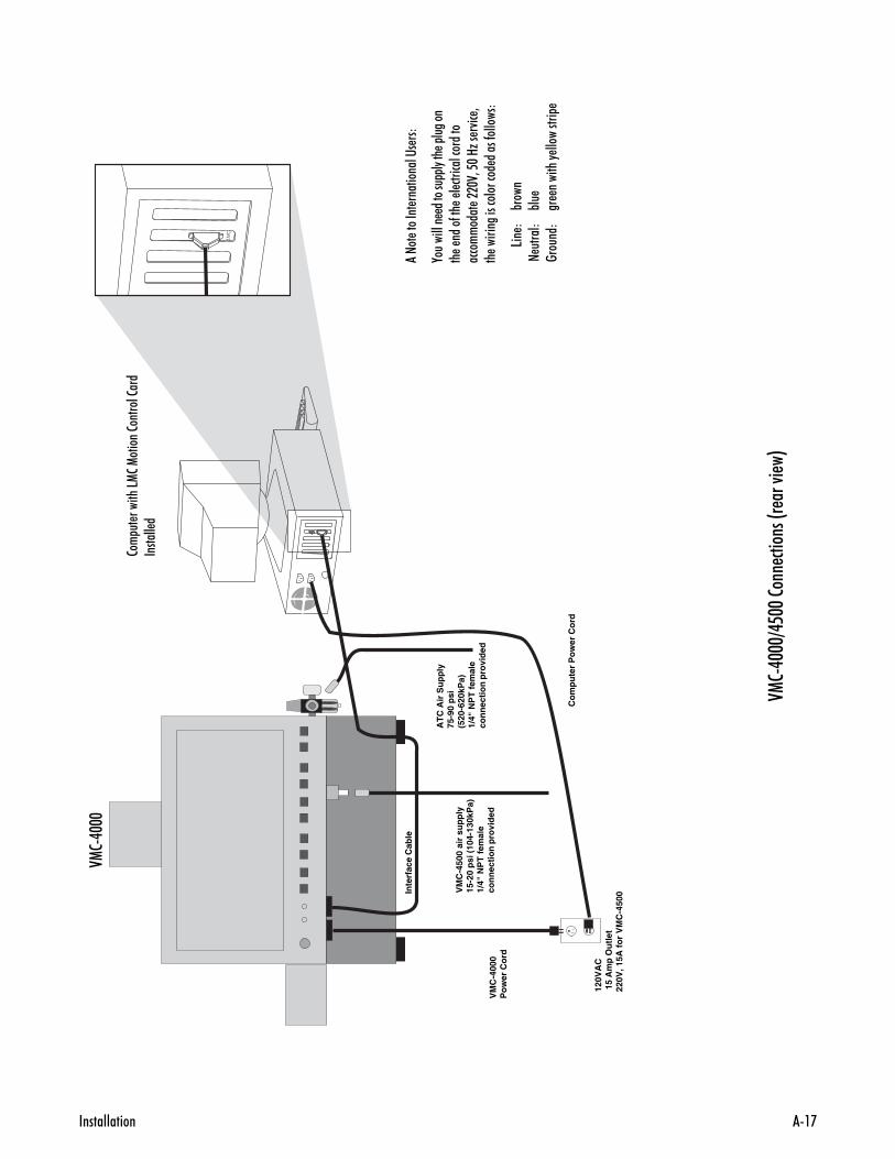
After installing the Motion Control Card in the computer and verifying itsoperation, the BENCHMAN 4000 connections can be made. The followingcables and lines must be connected:
� 100 pin interface cable between the computer and machining center;
� ATC air supply (if ATC is installed);
� Air curtain air line if you are installing a VMC-4500;
� BENCHMAN 4000 power cord;
� Computer power cord.
The connection diagram on the following page is provided as a visual aid.
2������
9���������� ��� �� ������� �/7�281��.$$$������ ���� �� ��������������� ���������������� �-��������� ��� ��� �+
� 4 ������ ������������� ����� ���%� ��������� � �� ����A�������������� ������ ������ ���� �� ���+
> ��� ��� �/7�281��.$$$������������%� ��-����"�� ��� �+
��'$�3�
��"����) ��� �2� �� ����������"�-������� ���� �-�� ���%� +�� � �� �������������� �� ���� � ��%� ���������� ���������� ������� ���� �-�� ���%� +
������������ �'
012.$$$
2�� �
� ���
����512�1������2�������2���
�����
�� �
VM
C-4
000
Po
wer
Co
rd
120V
AC
15
Am
p O
utl
et22
0V, 1
5A f
or
VM
C-4
500V
MC
-450
0 ai
r su
pp
ly15
-20
psi
(10
4-13
0kP
a)1/
4" N
PT
fem
ale
con
nec
tio
n p
rovi
ded
AT
C A
ir S
up
ply
75-9
0 p
si(5
20-6
20kP
a)1/
4" N
PT
fem
ale
con
nec
tio
n p
rovi
ded
Co
mp
ute
r P
ow
er C
ord
Inte
rfac
e C
able
�����!!!?� !!�����
�# �
���@�����7
��A
����
���
������� ���
��'�����
,��������� �������
�"��� � ������
�� � ����-���
� � ���������������
���������� ���$0
3�6$�8G
�� �4��
3�� ������
�������������� �����-�������
5�� �
%���
��
������
%��
����
���
�� �������"
���������
�� �������� ��� �������@
�����# ���%������������!!!���%����+&���
There is a single 100-pin cable that connects the machining center to thecomputer. Carefully plug this cable into the Motion Control Card that you in-stalled in your computer. Be sure the cable is installed correctly. It is possibleto make this connection backwards! Tighten the finger screws on the cableto be sure that it is firmly attached. A loose or marginal connection can causeproblems operating the machining center.
�����# ���� ���&&� ��
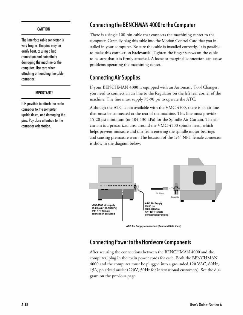
If your BENCHMAN 4000 is equipped with an Automatic Tool Changer,you need to connect an air line to the Regulator on the left rear corner of themachine. The line must supply 75-90 psi to operate the ATC.
Although the ATC is not available with the VMC-4500, there is an air linethat must be connected at the rear of the machine. This line must provide15-20 psi minimum (or 104-130 kPa) for the Spindle Air Curtain. The aircurtain is a pressurized area around the VMC-4500 spindle head, whichhelps prevent moisture and dirt from entering the spindle motor bearingsand causing premature wear. The location of the 1/4" NPT female connectoris show in the diagram below.
���������
��������
ATC Air Supply connection (Rear and Side View)
��'$�3�
�� ���� �-�� ���%� ����� �������4 �"�-����� +��� � ������"�% ����"�% ��3�����������%������ ���������� �� ������"����������� ������� ������ ��� �� �+��� ���� ��� ������������������������� ���%� ���� ����+
��13�$��$4
������ ����%� ������������� ���%� ���� ���������� ���� �� �� ��� �����3���������������� ���+�<�"����� ���� ����������� ���� �������� �������+
�����# ���1�������%�������������+&�����
After securing the connections between the BENCHMAN 4000 and thecomputer, plug in the main power cords for each. Both the BENCHMAN4000 and the computer must be plugged into a grounded 120 VAC, 60Hz,15A, polarized outlet (220V, 50Hz for international customers). See the dia-gram on the previous page.
VMC-4500 air supply15-20 psi (104-130kPa)1/4" NPT femaleconnection provided
ATC Air Supply75-90 psi(520-620kPa)1/4" NPT femaleconnection provided
������������ �B
�������������� !!�" ������#��If you have purchased a VMC-4500, you should know that there are only afew differences in operation from the BENCHMAN 4000.
� To achieve higher spindle speeds, the VMC-4500 uses a 1 hp high fre-quency induction motor. Before running at maximum speed on theVMC-4500, it is important that you run the spindle for a few minutesat 20,000 RPM to allow the bearings to warm up.
� A 220 VAC, 15 Amp outlet is required for the VMC-4500.
� Flood Coolant is not available on the VMC-4500. There should not beany fluids in the enclosure of the VMC-4500. Moisture will damagethe spindle motor.
� Although the ATC is not available with the VMC-4500, there is an airline that must be connected at the rear of the machine. This line mustprovide 15-20 psi minimum (or 104-130 kPa) for the Spindle Air Cur-tain. The air curtain is a pressurized area around the VMC-4500spindle head, which helps prevent moisture and dirt from entering thespindle motor bearings and causing premature wear. The location ofthe 1/4" NPT female connector is show in the Connection Diagram onthe previous page.
� During the software installation, you may be prompted to specify thetype of BENCHMAN product, and the spindle speed.
�� �������� ��� �������$
�������������� ��The Control Program is shipped on 3.5", 1.4MB disks. The ControlProgram must be installed on a hard drive running either Windows95, or Windows NT version 3.5 (or higher). You must have at least 5 MB offree space on your hard drive to perform this installation. See page A-2 for acomplete list of computer requirements.
������ ���%���������1�����+
The Control Program must be installed on the hard drive on your computer.The following instructions assume that your hard drive is drive C, and yourfloppy drive is drive A.
,- Turn on the computer. Wait for it to go through its internal checks andfor it to complete the start up process.
.- When your Windows desktop appears, insert the disk in the computerfloppy drive.
/- Using the Windows Explorer, (Start Menu>Programs>Windows Explorer)open the floppy drive.
Note: If you are installing on Windows NT, use either the File Manager toaccess the floppy drive, or select Run from the Program Manager.
�- Double click on Install to start the installation.
- The Welcome screen appears warning you to exit all other runningprograms. If no other programs are running, click Next.
:- The next screen is the destination directory for the Control Program. Ifyou would like to install the control program in an alternate directory,click on Browse. Otherwise, click Next.
;- A window showing the progress of the installation will appear, and whenready, will prompt you to install the second disk. After the installation iscomplete, a message will appear asking if you would like to view theReadme file. It is suggested that you read this file. It contains importantinformation about the software and the machine that may not beincluded in the manual.
<- After reading the Readme file, remove the disk from the floppy drive.Power on the machine, and then launch the Control Program by doubleclicking the BENCHMAN icon. You have the option of dragging theshortcut icon onto your desktop from the open BENCHMAN folder, orselecting the Start Menu> Programs> Benchman> BENCHMAN.
��'$�3�
�� ����� �����)���� ���� ����� ��� �� ��&(+6����)���4 ��� ����� ��� ���������� �*���� � 4 ������� ������ �����������-��� ��-���� +�������� ��4 ��� ���� � ��� �����A�2� �� ������ ������)������ "��-��� ���)�+����"������ ����)��������- � ��� ����"�-����� ��3��������3���������������� �������� �+
��'$�3�
1�) ���� �"���� ��������� ��- �"�������������������������� % -�� �"������ � ����������� 2�������<�������������� �012.$$$�-����� �-�������� +
������������ ��
'� ����� ���%���������1�����+
In the event you need to remove the Control Program from your hard drive,there is an uninstall program included on the software disks. This uninstallprogram is part of the Control Program and was copied onto your harddrive during the installation.
To uninstall the Control Program software, select Start Menu> Programs>BENCHMAN> Remove BENCHMAN. A message appears asking if youare sure you want to remove the program and all its files. Click on Yes touninstall, or No to exit the uninstall program.
$%����&�1�����+
The Setup Program allows you to select a number of program and hardwaredefaults, as well as configure the options installed on the machine. To accessthe Setup Program, you must exit the Control Program. Then select theStart Menu> Programs> BENCHMAN> Setup. The program will start andyou will see the Welcome screen. You may choose from the file tabs to viewthe defaults for each category.
The Setup Program provides defaults under the following categories:
� Welcome
� General
� Options
� Interface Card
During the software installation, the Setup window opens automatically sothat you can select the options installed on your machine. You may need toaccess the Setup Program again to remove options or to reset other defaults.See Section E: Setup Program for detailed information about the program.
��� ���������� ����������� ���������������� � � ���"��2�-�� �������"����"���4 ��� �� ������� ��������� ��-���� +
�� �������� ��� ��������
$�#%� #����&&��Should you require technical assistance, you should contact your local LightMachines dealer. If you are unable to resolve your problem through your localdealer, free technical support is available by phone, fax, or email from 8:15A.M. to 5:00 P.M. EST.
����������� ��
Make sure you have the following information gathered before contactingour Technical Support group.
� The product serial number.� The name of the owner of the product.� The specifications of your computer (e.g. hard drive size, clock speed, etc.).� Notes on any Control Program error messages.
When you call, make sure you have access to both your BENCHMAN 4000and your computer. This will allow our technical support representatives towalk through the problem with you. Our technical support numbers are:
U. S. (800) 221-2763Canada (800) 637-4829
Fax (603) 625-2137email [email protected]
2������
Light Machines' products (excluding software) carry a one-year limited war-ranty from date of purchase, as outlined in the Terms and Conditions ofSale. If you need to return a product, call Light Machines and a TechnicalSupport representative will issue you a Return Materials Authorization num-ber (RMA). You must write the RMA and your return address on the outsideof the product carton or crate. Failure to do so can result in a delay in the re-turn of your product.
�"�� ��8������ /�
$%������������!!!���#% � ��������
�����������+&�����
��������'������%����#% � ��������
� ��������%����#% ��
3&��� ������� ���
��7 ���+��������� ���
�� �� � ���%����#% � ��������
�� �� � ���%��1�� ����%�&���7 ���+��
6�#�������������3& ���
���+���������
'���(���� ��)��# ����
�� �������� ��� ������//�
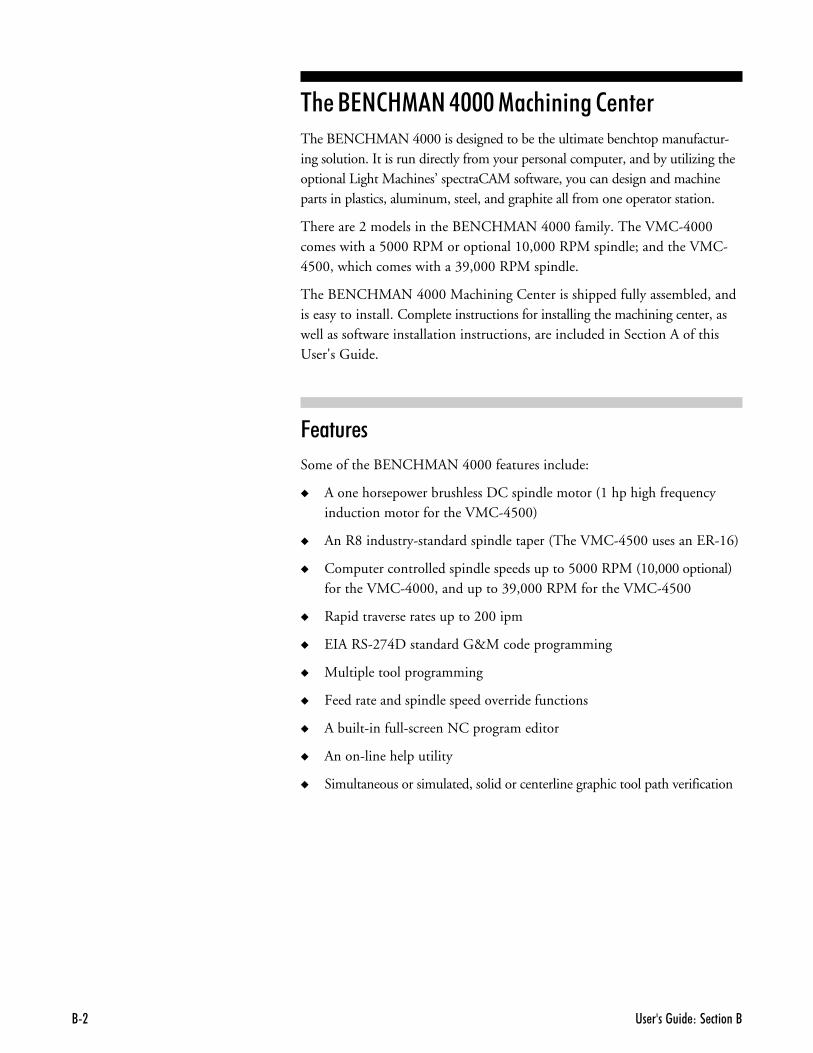
$%������������!!!���#% � ��������The BENCHMAN 4000 is designed to be the ultimate benchtop manufactur-ing solution. It is run directly from your personal computer, and by utilizing theoptional Light Machines’ spectraCAM software, you can design and machineparts in plastics, aluminum, steel, and graphite all from one operator station.
There are 2 models in the BENCHMAN 4000 family. The VMC-4000comes with a 5000 RPM or optional 10,000 RPM spindle; and the VMC-4500, which comes with a 39,000 RPM spindle.
The BENCHMAN 4000 Machining Center is shipped fully assembled, andis easy to install. Complete instructions for installing the machining center, aswell as software installation instructions, are included in Section A of thisUser's Guide.
6������
Some of the BENCHMAN 4000 features include:
� A one horsepower brushless DC spindle motor (1 hp high frequencyinduction motor for the VMC-4500)
� An R8 industry-standard spindle taper (The VMC-4500 uses an ER-16)
� Computer controlled spindle speeds up to 5000 RPM (10,000 optional)for the VMC-4000, and up to 39,000 RPM for the VMC-4500
� Rapid traverse rates up to 200 ipm
� EIA RS-274D standard G&M code programming
� Multiple tool programming
� Feed rate and spindle speed override functions
� A built-in full-screen NC program editor
� An on-line help utility
� Simultaneous or simulated, solid or centerline graphic tool path verification
�"�� ��8������ /(
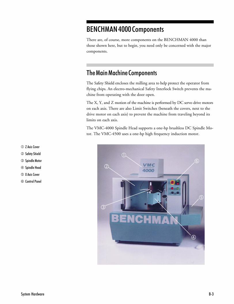
����������!!!���+&�����There are, of course, more components on the BENCHMAN 4000 thanthose shown here, but to begin, you need only be concerned with the majorcomponents.
$%���� ����#% �����+&�����
The Safety Shield encloses the milling area to help protect the operator fromflying chips. An electro-mechanical Safety Interlock Switch prevents the ma-chine from operating with the door open.
The X, Y, and Z motion of the machine is performed by DC servo drive motorson each axis. There are also Limit Switches (beneath the covers, next to thedrive motor on each axis) to prevent the machine from traveling beyond itslimits on each axis.
The VMC-4000 Spindle Head supports a one-hp brushless DC Spindle Mo-tor. The VMC-4500 uses a one-hp high frequency induction motor.
� H�!���2�4 �
� ��- �"���� ��
� � ���� �1����
� � ���� �8 ��
� :�!���2�4 �
� 2�������<�� �
�
�
�
�
�
�
�� �������� ��� ������//.
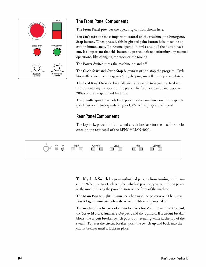
$%��6����1�������+&�����
The Front Panel provides the operating controls shown here.
You can’t miss the most important control on the machine; the EmergencyStop button. When pressed, this bright red palm button halts machine op-eration immediately. To resume operation, twist and pull the button backout. It’s important that this button be pressed before performing any manualoperations, like changing the stock or the tooling.
The Power Switch turns the machine on and off.
The Cycle Start and Cycle Stop buttons start and stop the program. CycleStop differs from the Emergency Stop; the program will not stop immediately.
The Feed Rate Override knob allows the operator to adjust the feed ratewithout entering the Control Program. The feed rate can be increased to200% of the programmed feed rate.
The Spindle Speed Override knob performs the same function for the spindlespeed, but only allows speeds of up to 150% of the programmed speed.
�����1�������+&�����
The key lock, power indicators, and circuit breakers for the machine are lo-cated on the rear panel of the BENCHMAN 4000.
EM
ERGENCY STOP
Spindle Speed50% 150%
Override
0% 200%
Feed RateOverride
CYCLE STOP CYCLE START
POWER
The Key Lock Switch keeps unauthorized persons from turning on the ma-chine. When the Key Lock is in the unlocked position, you can turn on powerto the machine using the power button on the front of the machine.
The Main Power Light illuminates when machine power is on. The DrivePower Light illuminates when the servo amplifiers are powered on.
The machine has five sets of circuit breakers for Main Power, the Control,the Servo Motors, Auxiliary Outputs, and the Spindle. If a circuit breakerblows, the circuit breaker switch pops out, revealing white at the top of theswitch. To reset the circuit breaker, push the switch up and back into thecircuit breaker until it locks in place.
�"�� ��8������ /6
��������'������%����#% � ��������The intended use of the BENCHMAN VMC-4000 Machining Center is asa conventional computer numerical controlled (CNC) vertical mill usedin industrial environments.
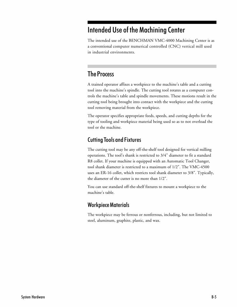
$%��1��#���
A trained operator affixes a workpiece to the machine’s table and a cuttingtool into the machine’s spindle. The cutting tool rotates as a computer con-trols the machine’s table and spindle movements. These motions result in thecutting tool being brought into contact with the workpiece and the cuttingtool removing material from the workpiece.
The operator specifies appropriate feeds, speeds, and cutting depths for thetype of tooling and workpiece material being used so as to not overload thetool or the machine.
�� ���$���������6 9����
The cutting tool may be any off-the-shelf tool designed for vertical millingoperations. The tool’s shank is restricted to 3/4" diameter to fit a standardR8 collet. If your machine is equipped with an Automatic Tool Changer,tool shank diameter is restricted to a maximum of 1/2". The VMC-4500uses an ER-16 collet, which restricts tool shank diameter to 3/8". Typically,the diameter of the cutter is no more than 1/2".
You can use standard off-the-shelf fixtures to mount a workpiece to themachine’s table.
2��0& �#������ ���
The workpiece may be ferrous or nonferrous, including, but not limited tosteel, aluminum, graphite, plastic, and wax.
�� �������� ��� ������//#
� ��������%����#% ��Do NOT use the machine for tasks it was not designed to perform. Im-proper use or modification of the machine may damage the machine andmay result in serious injury.
Misuse of the machine may result from:
� Improperly affixing a nonstandard or oversized cutting tool to the machine.
� Improperly affixing the cutting tool to the machine.
� Manually holding or feeding the workpiece into the machine.
� Improperly affixing the workpiece to the machine.
� Improperly defining feeds, speeds, and depth of cut while machining.
� Introducing hazardous materials when machining.
� Removing the safety door or making any other unauthorized modifica-tions to the machine.
� Cutting unacceptable materials.
� Using damaged or dull tooling.
�"�� ��8������ /'
3&��� ������� ���You must meet all work area, power, grounding, and environmental condi-tions before using the machine.
2��0�����
You must allow at least 12.5 square feet (1.16 square meters) of work area tooperate the machine.
�� �����1������&&��
AC power input must satisfy the following requirements:
������
120 VAC, 15 Amps +10% - 15% or230 VAC , 15 Amps +10% - 15% (International)
1.8 KVA
6��*���#�
47-63 Hz single phase, 3 wire
������ ��
A positive earth grounding system for the machine and the computer is requiredfor proper and safe operation. The ground path must have a DC resistance of 3.5ohms or less to a true earth ground.
Ground the machining center in compliance with all applicable electrical codes.

�� �������� ��� ������//@
��7 ���+��������� ���
The machining center is designed to operate within the following environ-mental limits:
$�+&������
Operating: 45o to 85o F (7o to 29o C)
Storage: 0o to 130o F (0o to 54o C)
Transition: 10o c/hr
��+ � �
5% to 80% without condensation
�� ���
Operating: 0 to 10,000 feet (3,048 meters)
Non-operating: 0 to 40,000 feet (12,192 meters)
%�#0
Non-operating: 10g in 11 milliseconds
� B�� ��
Operating: 5Hz to 500Hz, 0.5G acceleration
Non-operating: 10Hz to 500Hz, 1.0G acceleration
�� ��
70 db at 8ft.
�"�� ��8������ /B
�� �� � ���%����#% � ��������Performing preventative maintenance on your BENCHMAN 4000 MachiningCenter ensures a longer, trouble-free life for the machine. We provide instruc-tions for preventative maintenance in the following paragraphs.
�����#����
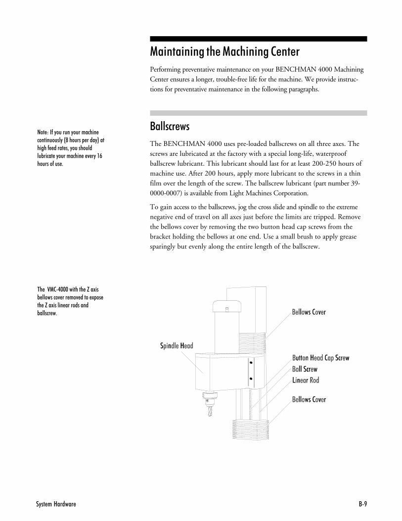
The BENCHMAN 4000 uses pre-loaded ballscrews on all three axes. Thescrews are lubricated at the factory with a special long-life, waterproofballscrew lubricant. This lubricant should last for at least 200-250 hours ofmachine use. After 200 hours, apply more lubricant to the screws in a thinfilm over the length of the screw. The ballscrew lubricant (part number 39-0000-0007) is available from Light Machines Corporation.
To gain access to the ballscrews, jog the cross slide and spindle to the extremenegative end of travel on all axes just before the limits are tripped. Removethe bellows cover by removing the two button head cap screws from thebracket holding the bellows at one end. Use a small brush to apply greasesparingly but evenly along the entire length of the ballscrew.
�� ��012.$$$�������� �H��!��% ��������4 ��� ��4 ����� ! �� �� �H��!������ �����������%������ �+
��� ���-�"�������"���������� �����������"�&@������� ����"*��������- ����� �3�"�����������%����� �"���������� � 4 �"��#�������-��� +
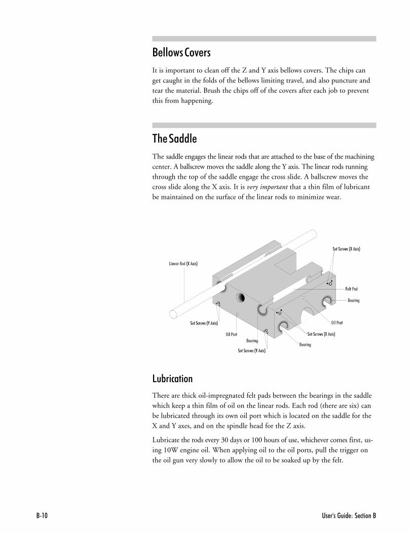
�� �������� ��� ������//�$
����������7���
It is important to clean off the Z and Y axis bellows covers. The chips canget caught in the folds of the bellows limiting travel, and also puncture andtear the material. Brush the chips off of the covers after each job to preventthis from happening.
$%�������
The saddle engages the linear rods that are attached to the base of the machiningcenter. A ballscrew moves the saddle along the Y axis. The linear rods runningthrough the top of the saddle engage the cross slide. A ballscrew moves thecross slide along the X axis. It is very important that a thin film of lubricantbe maintained on the surface of the linear rods to minimize wear.
5�B� #� ��
There are thick oil-impregnated felt pads between the bearings in the saddlewhich keep a thin film of oil on the linear rods. Each rod (there are six) canbe lubricated through its own oil port which is located on the saddle for theX and Y axes, and on the spindle head for the Z axis.
Lubricate the rods every 30 days or 100 hours of use, whichever comes first, us-ing 10W engine oil. When applying oil to the oil ports, pull the trigger onthe oil gun very slowly to allow the oil to be soaked up by the felt.
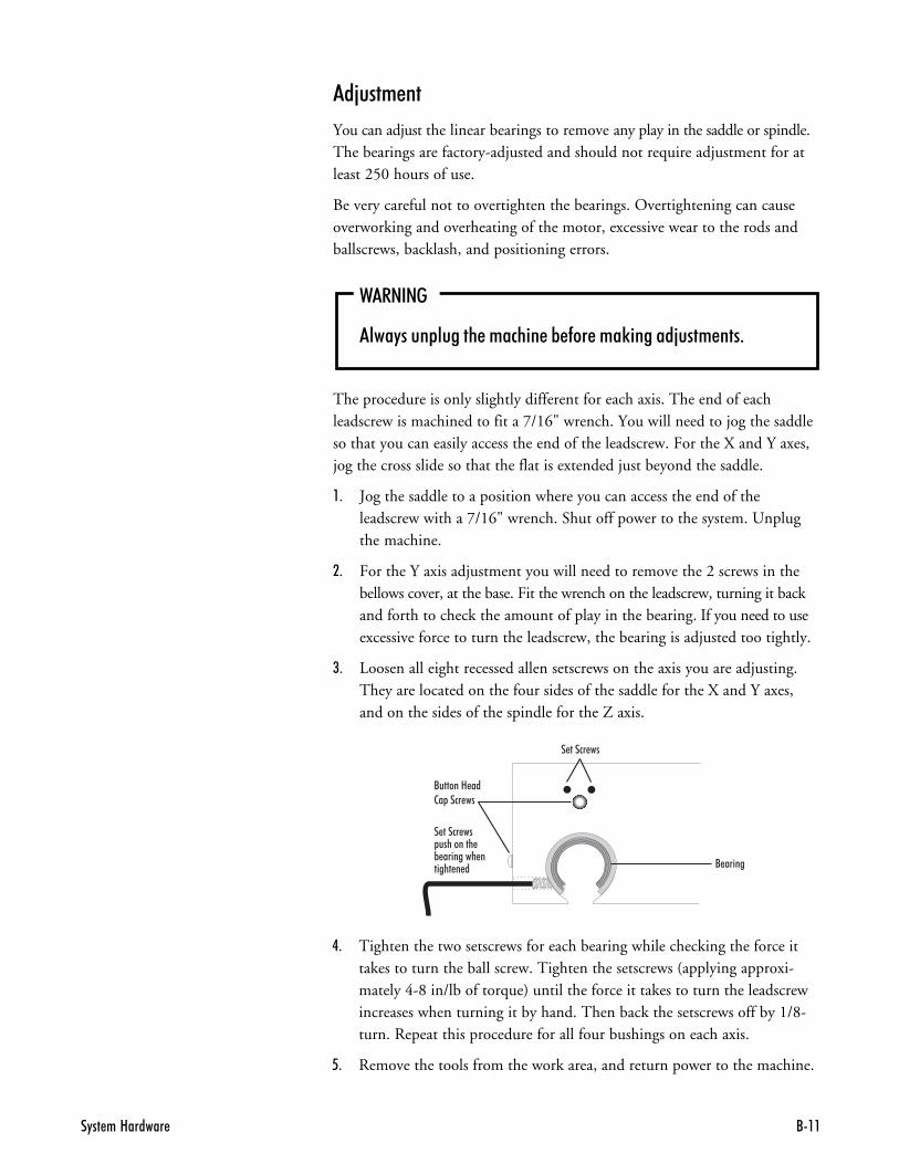
�"�� ��8������ /��
�- Tighten the two setscrews for each bearing while checking the force ittakes to turn the ball screw. Tighten the setscrews (applying approxi-mately 4-8 in/lb of torque) until the force it takes to turn the leadscrewincreases when turning it by hand. Then back the setscrews off by 1/8-turn. Repeat this procedure for all four bushings on each axis.
- Remove the tools from the work area, and return power to the machine.
��C��+��
You can adjust the linear bearings to remove any play in the saddle or spindle.The bearings are factory-adjusted and should not require adjustment for atleast 250 hours of use.
Be very careful not to overtighten the bearings. Overtightening can causeoverworking and overheating of the motor, excessive wear to the rods andballscrews, backlash, and positioning errors.
2������
���"���� ������ ������� �% -�� ���)������;���� ���+
The procedure is only slightly different for each axis. The end of eachleadscrew is machined to fit a 7/16" wrench. You will need to jog the saddleso that you can easily access the end of the leadscrew. For the X and Y axes,jog the cross slide so that the flat is extended just beyond the saddle.
,- Jog the saddle to a position where you can access the end of theleadscrew with a 7/16" wrench. Shut off power to the system. Unplugthe machine.
.- For the Y axis adjustment you will need to remove the 2 screws in thebellows cover, at the base. Fit the wrench on the leadscrew, turning it backand forth to check the amount of play in the bearing. If you need to useexcessive force to turn the leadscrew, the bearing is adjusted too tightly.
/- Loosen all eight recessed allen setscrews on the axis you are adjusting.They are located on the four sides of the saddle for the X and Y axes,and on the sides of the spindle for the Z axis.
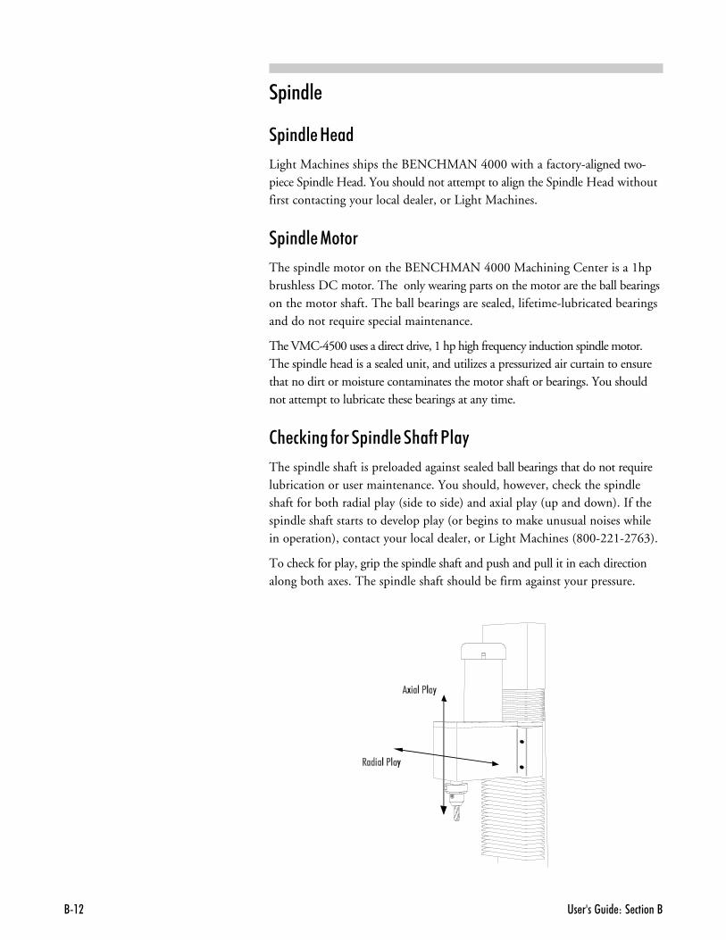
�� �������� ��� ������//��
& ����
& ���������
Light Machines ships the BENCHMAN 4000 with a factory-aligned two-piece Spindle Head. You should not attempt to align the Spindle Head withoutfirst contacting your local dealer, or Light Machines.
& ���������
The spindle motor on the BENCHMAN 4000 Machining Center is a 1hpbrushless DC motor. The only wearing parts on the motor are the ball bearingson the motor shaft. The ball bearings are sealed, lifetime-lubricated bearingsand do not require special maintenance.
The VMC-4500 uses a direct drive, 1 hp high frequency induction spindle motor.The spindle head is a sealed unit, and utilizes a pressurized air curtain to ensurethat no dirt or moisture contaminates the motor shaft or bearings. You shouldnot attempt to lubricate these bearings at any time.
�%�#0 �������& �����%���1���
The spindle shaft is preloaded against sealed ball bearings that do not requirelubrication or user maintenance. You should, however, check the spindleshaft for both radial play (side to side) and axial play (up and down). If thespindle shaft starts to develop play (or begins to make unusual noises whilein operation), contact your local dealer, or Light Machines (800-221-2763).
To check for play, grip the spindle shaft and push and pull it in each directionalong both axes. The spindle shaft should be firm against your pressure.
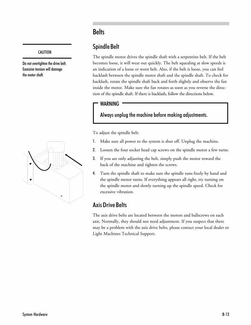
�"�� ��8������ /�(
����
& ��������
The spindle motor drives the spindle shaft with a serpentine belt. If the beltbecomes loose, it will wear out quickly. The belt squealing at slow speeds isan indication of a loose or worn belt. Also, if the belt is loose, you can feelbacklash between the spindle motor shaft and the spindle shaft. To check forbacklash, rotate the spindle shaft back and forth slightly and observe the faninside the motor. Make sure the fan rotates as soon as you reverse the direc-tion of the spindle shaft. If there is backlash, follow the directions below.
2������
���"���� ������ ������� �% -�� ���)������;���� ���+
To adjust the spindle belt:
,- Make sure all power to the system is shut off. Unplug the machine.
.- Loosen the four socket head cap screws on the spindle motor a few turns.
/- If you are only adjusting the belt, simply push the motor toward theback of the machine and tighten the screws.
�- Turn the spindle shaft to make sure the spindle runs freely by hand andthe spindle motor turns. If everything appears all right, try turning onthe spindle motor and slowly turning up the spindle speed. Check forexcessive vibration.
�9 ��"� 7������
The axis drive belts are located between the motors and ballscrews on eachaxis. Normally, they should not need adjustment. If you suspect that theremay be a problem with the axis drive belts, please contact your local dealer orLight Machines Technical Support.
��'$�3�
9�������4 ������ ���� ����4 �% ��+7!� ���4 �� ���������������� �� ����������-�+

�� �������� ��� ������//�.
�� �� � ���%��1�� ����%�&���7 ���+��There are a few general guidelines for maintaining your personal computerand software in a shop environment. See your owner’s manual for mainte-nance procedures that are specific to your computer.
��� �������%����+&���
Follow these general rules for computer care.
� Keep the computer and peripherals (mouse, keyboard, external drive,printer) out of direct sunlight and away from sources of heat and in arelatively clean environment (i.e., not right next to the foundry room).
� Cover the computer and keyboard with a dust cover when not in use.
� Keep liquids (soda, coffee, cutting fluid, grease) away from the com-puter and peripherals.
� Keep oil, grease, metal chips and excess dust away from the computer,keyboard and floppy disks.
� Use grounded, three-prong outlets for the computer and peripherals. Takeprecautions against current overload. A line-surge suppression unit can bepurchased at your local computer store to help alleviate this problem.
� Don’t block the vent holes in the computer or drives; they are requiredfor air circulation.
�"�� ��8������ /�6
��� �������6��&&��" �0�
Floppy disks are simple to use but require a few precautions to maintaintheir integrity.
� Don’t touch the magnetic disk part of the disk (the shiny, record-likepart inside the disk jacket). Dust or grease from your hand can ruin anypart of the disk that you touch and can possibly destroy the entire disk.
� Keep disks in a disk box or special disk container instead of spreadingthem out on your work space.
� Handle disks gently, don’t bend or crease them.
� Don’t write on disk labels with a ball point pen. If you must write onthe label, always write very lightly with a felt tip pen.
� Keep disks in a clean, cool environment away from excess amounts ofdust, heat, or sun.
� Beware of getting machining fluids on the disks. If you spill a liquid orcutting fluid on a disk, it is 99 percent certain that the disk and all thedata on it can never be used again.
� Keep disks away from all magnetic sources including telephones, high-voltage power sources and mill motors.
� Make back-up copies of all NC program disks each time you update them.
� Print copies of all NC programs in case of disk failure or lost disks.
No matter how cautious you are, disks will go bad; they develop bad blocks (un-readable surfaces). If this happens while you are editing a program, the programwill be lost. The solution to this disaster is simple—make back-up copies.
�� �������� ��� ������//�#
6�#�������������3& ���BENCHMAN is available with a number of factory installed options. Thissection includes information about each one.
,!=!!!��1��& ����
The 10,000 RPM Spindle (ACC-5105) allows you to machine materials atspeeds up to 10,000 RPM.
" � D ���1�#0���
The ACC-5261 Digitizing Package includes a digitizing probe and softwarethat lets you digitize existing parts and models to capture 3-D surface data.The easy-to-use PC-driven package provides reverse engineering capabilitieswith BENCHMAN. It can generate files in three different formats; an NCpart program, an ASCII text file with XYZ data points, and a DXF 3-Dmesh file.
The Digitizing Package includes a touch signal probe, a probe interfacecable, a 20mm long stylus with 3mm diameter head, a 20mm stylus exten-sion, the Digitizing Package User’s Guide, the Digitizing Package softwareon 3.5" diskettes, and an 8 mm Collet.
� ��� ��
The Air Vise (PNU-4117) has jaws that open to a maximum of 3.0 inches.The vise comes with a solenoid valve and all the tubing required to interfacewith the Pneumatic Control option (PNU-4110) if so equipped.
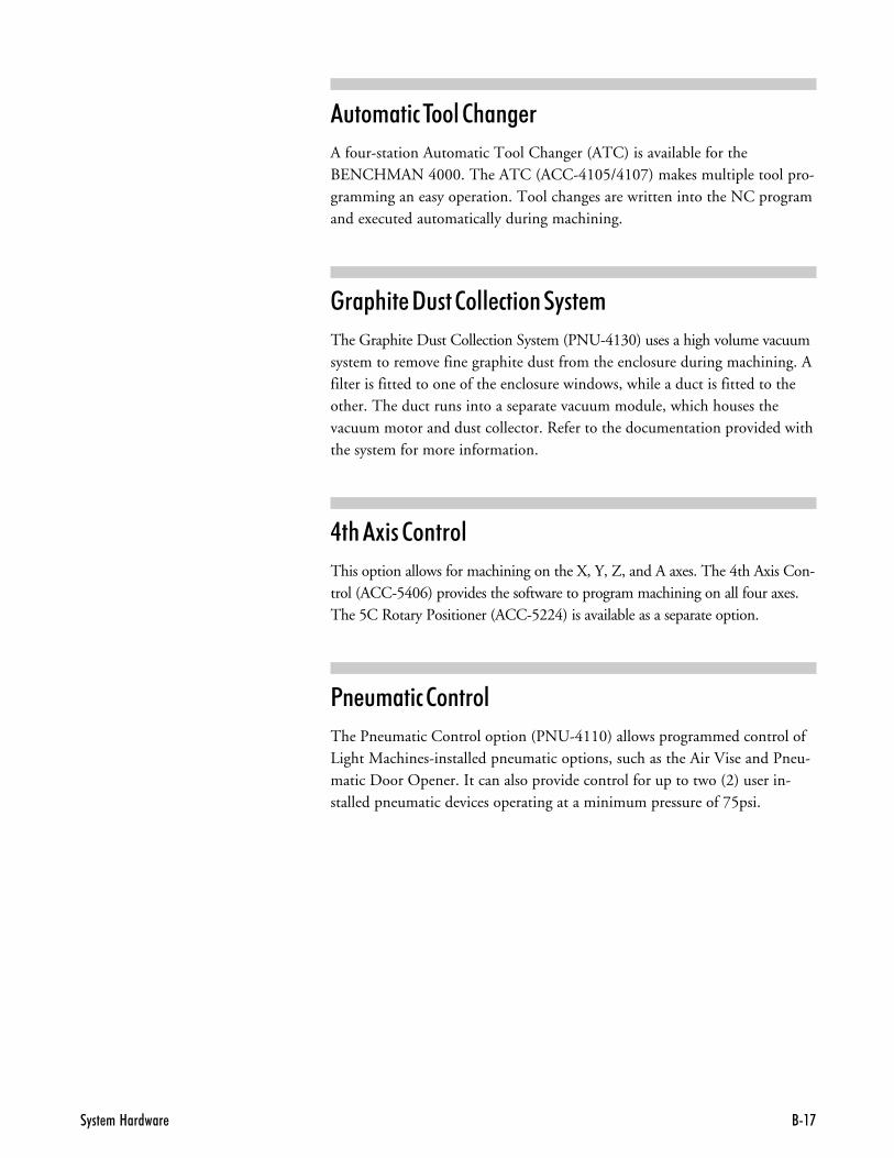
�"�� ��8������ /�'
���+� #�$�����%�����
A four-station Automatic Tool Changer (ATC) is available for theBENCHMAN 4000. The ATC (ACC-4105/4107) makes multiple tool pro-gramming an easy operation. Tool changes are written into the NC programand executed automatically during machining.
���&% ��"��������# ������+
The Graphite Dust Collection System (PNU-4130) uses a high volume vacuumsystem to remove fine graphite dust from the enclosure during machining. Afilter is fitted to one of the enclosure windows, while a duct is fitted to theother. The duct runs into a separate vacuum module, which houses thevacuum motor and dust collector. Refer to the documentation provided withthe system for more information.
�%��9 ��������
This option allows for machining on the X, Y, Z, and A axes. The 4th Axis Con-trol (ACC-5406) provides the software to program machining on all four axes.The 5C Rotary Positioner (ACC-5224) is available as a separate option.
1���+� #�������
The Pneumatic Control option (PNU-4110) allows programmed control ofLight Machines-installed pneumatic options, such as the Air Vise and Pneu-matic Door Opener. It can also provide control for up to two (2) user in-stalled pneumatic devices operating at a minimum pressure of 75psi.
�� �������� ��� ������//�@
6�����������
The BENCHMAN 4000 is available with Flood Coolant (ACC-5205). Apump provides coolant to the workpiece resulting in reduced tool wear, andevacuation of chips. The coolant pump and plumbing are installed at thefactory; the operator is required to fill the coolant sump.
Flood Coolant is not available on the VMC-4500.
6 �� ���%���+&
Benchman requires a minimum of seven (7) gallons of coolant, and holds amaximum of nine (9) gallons. Light Machines recommends the use ofValcool Coolant. Using any other brand of coolant may cause corrosion ofany parts that come in contact with the coolant. The coolant sump isshipped dry, and must be filled before using the flood coolant system.
To fill the sump:
,- Make sure the coolant is thoroughly mixed before filling the sump. Thecoolant concentrate should be diluted with water according to the fol-lowing formula: 1:17 (6%) to 1:25 (4%).
.- Press the Emergency Stop button on the front panel.
/- Open the safety shield of the machining center.
�- Carefully add at least seven (7), and not more than nine (9) gallons ofthe coolant mixture to the sump.
- Close the safety shield, and return power to the machine.
Because of evaporation of water in the coolant and other minor losses, coolantlevels should be checked weekly, along with other maintenance. The coolantalso becomes dirty, and should be replaced periodically.
6��������� �����&�����3&��� ��
Flood Coolant is a factory installed option. The BENCHMAN 4000 comesflood coolant ready.
�������6���
The pump draws coolant from the sump in the bottom of the enclosure, andcycles it through the adjustable nozzle directly onto the workpiece. The cool-ant pump is located beneath a cover in the right rear corner of the enclosure. Itcan be turned on and off either through the user interface, or by M codes inthe NC program (M08/on, M09/off). The nozzle tube is adjustable, and has apetcock built into it to control the flow of coolant.
��'$�3�
�� ����"��� �� ���� �� ��" ��-���������-����� �012.$$$+��� ��-���"���� ���" ��-����������"����� ������������� ! �� ���� ����-��� ������ 3��������� ��� ������ +
�"�� ��8������ /�B
The coolant runs off the workpiece, taking the chips with it, and back intothe sump area. There are screens over the sump to separate the chips from thecoolant. These screens should be cleaned periodically. If the chips are not re-moved from the screens, they will block the flow of coolant back into the sump.
Important! Do not drill or make holes of any sort in the enclosure, especiallyon the back panel. If holes are drilled to mount an aftermarket accessory orother device, coolant is likely to leak out and could be hazardous to othercomponents of the machine.
�� �����#�
Flood coolant machines require only a little more maintenance than noncoolant machines. It is important to perform the following maintenance.
� Keep sump screens clean to maintain the flow of coolant through the system.
� Check and refill coolant levels as necessary.
,- Open operator door.
.- Remove one of the sump screens.
/- Make sure the coolant is within an inch of the screen.
�- Refill if necessary.
� Coolant should be replaced once a month, depending on machine usage.
,- Press the Emergency Stop Button on the controller and removepower from the machining center.
.- Place an approved ten (10) gallon container below the drain plug atthe rear of the machining center.
/- Remove the drain plug.
�- When the coolant has drained into the container, replace the plugand properly dispose of the used coolant.
- Open the safety shield and refill the sump with fresh coolant. Besure the coolant is mixed thoroughly before filling the sump. Donot try to mix coolant in the sump.
��'$�3�
�� �������������������������������3�����"����� � ������ ����-����� �����������������������+

�� �������� ��� ������//�$
� ���������E������ �2�������<������ 2�
�� ���%���������1�����+
���������������&---
�9&��� ���%���������1�����+�#����
�� �����0����%����������1�����+
'���(���� ��)��# ����
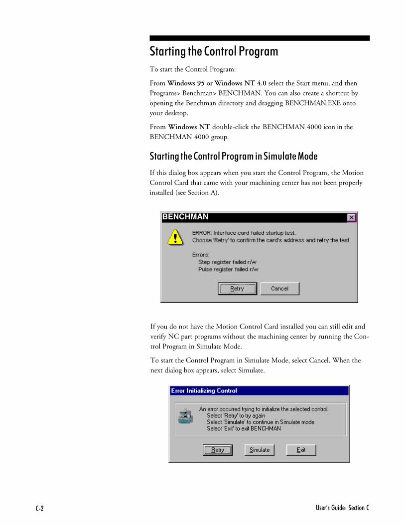
�� �I������ ��� ������22�
�� ���%���������1�����+To start the Control Program:
From Windows 95 or Windows NT 4.0 select the Start menu, and thenPrograms> Benchman> BENCHMAN. You can also create a shortcut byopening the Benchman directory and dragging BENCHMAN.EXE ontoyour desktop.
From Windows NT double-click the BENCHMAN 4000 icon in theBENCHMAN 4000 group.
�� ���%���������1�����+� �� +���������
If this dialog box appears when you start the Control Program, the MotionControl Card that came with your machining center has not been properlyinstalled (see Section A).
If you do not have the Motion Control Card installed you can still edit andverify NC part programs without the machining center by running the Con-trol Program in Simulate Mode.
To start the Control Program in Simulate Mode, select Cancel. When thenext dialog box appears, select Simulate.
BENCHMAN

� ���������E������ �2�������<������ 2(
���������������&---You can access on-line help by using the commands under the Help Menu,or by pressing F1.
For information on the functions and screens in the Control Program software,refer to Section E, Control Program Reference.
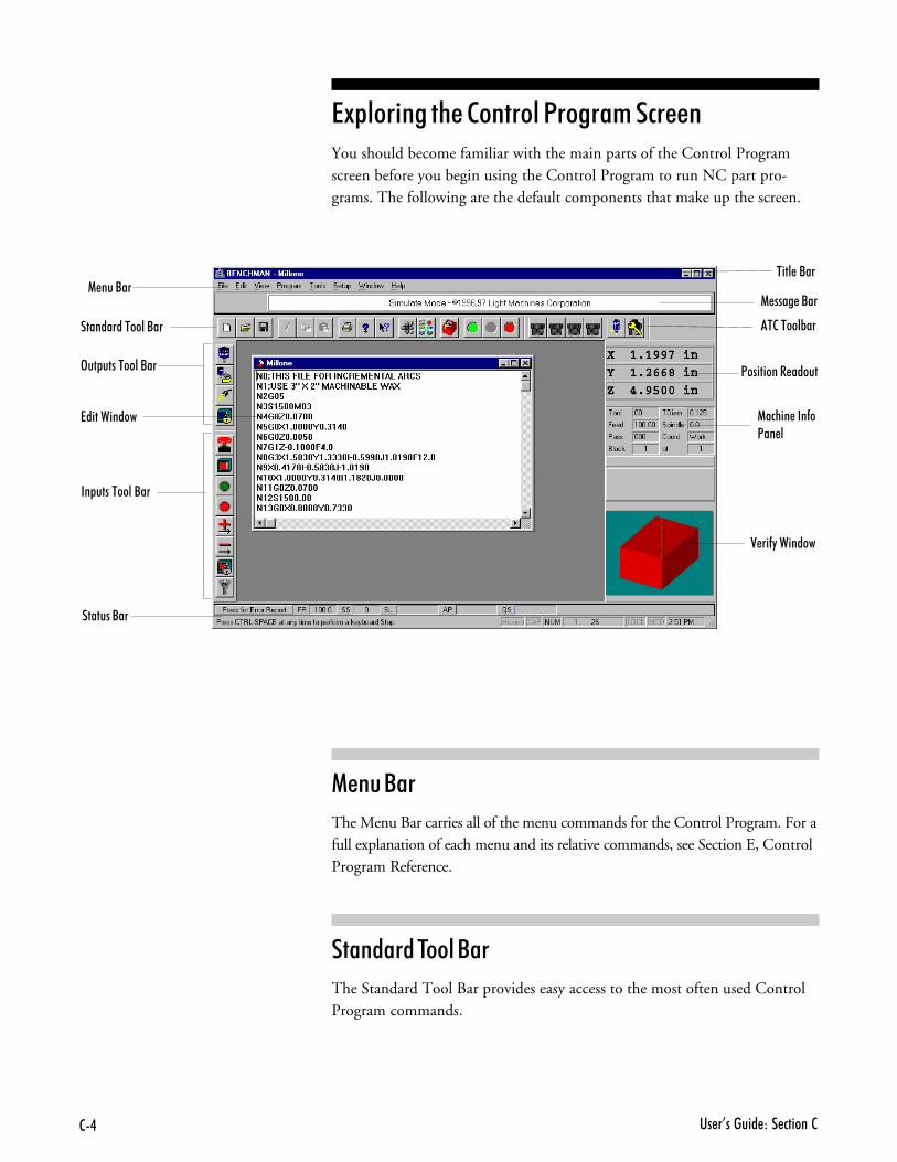
�� �I������ ��� ������22.
7����������
�� ���������/��
�9&��� ���%���������1�����+�#����You should become familiar with the main parts of the Control Programscreen before you begin using the Control Program to run NC part pro-grams. The following are the default components that make up the screen.
��������
The Menu Bar carries all of the menu commands for the Control Program. For afull explanation of each menu and its relative commands, see Section E, ControlProgram Reference.
�������$�������
The Standard Tool Bar provides easy access to the most often used ControlProgram commands.
>�� ���������/��
���� �/��1 ���/��
��������������/��
�������/��
<��������� �����
1����� ���-�<�� �
0 ��-"�������
1 ���� �/��
�2�����%��
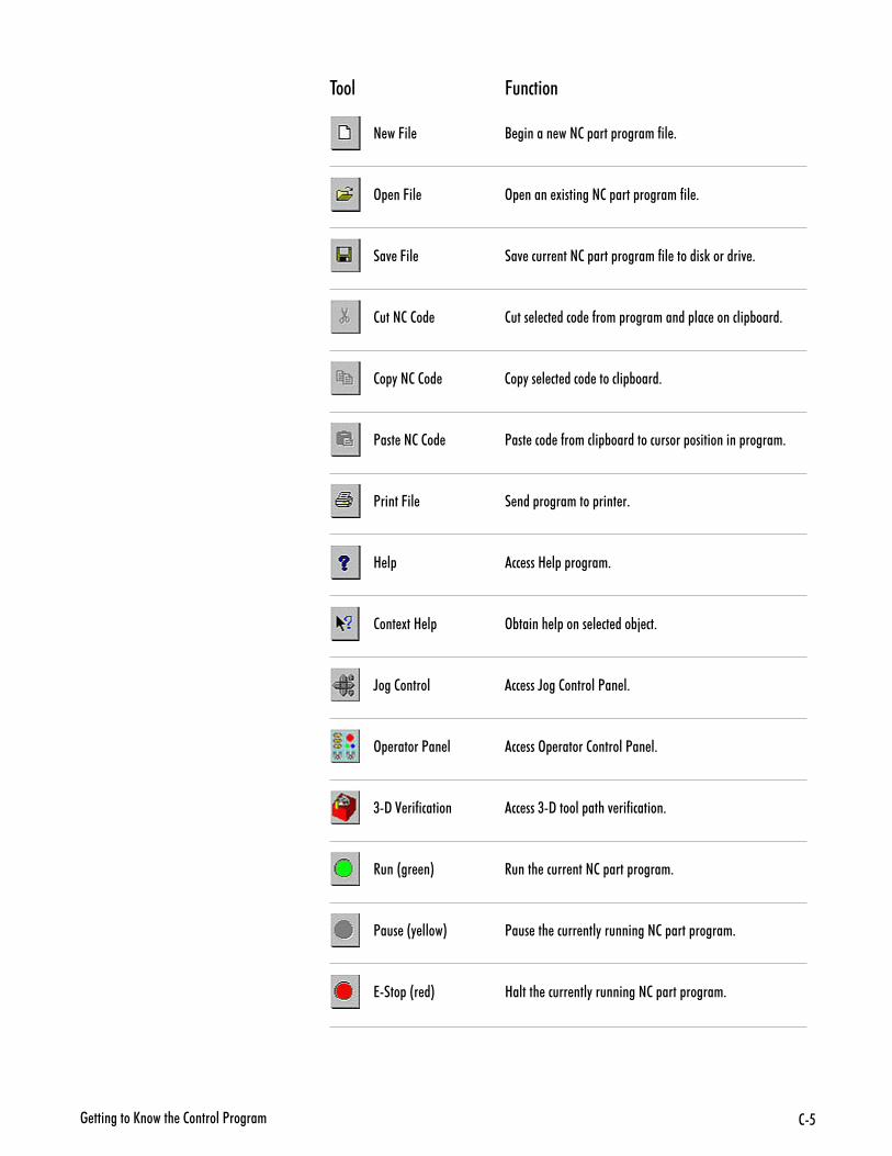
� ���������E������ �2�������<������ 26
$��� 6��# ��
� ��C�� / ������� ���2� ���� �������-�� +
> ��C�� > ����� !��������2� ���� �������-�� +
��4 �C�� ��4 ����� ����2� ���� �������-�� �������)�������4 +
2����2�2�� 2���� � �� ����� �-���� ����������� ��� ������� %����+
2� "��2�2�� 2� "�� � �� ����� ������� %����+
<��� ��2�2�� <��� ���� �-������� %��������������� ����������� ������+
<�����C�� � ��� ���������� ���� �+
8 � �� ���8 � � ������+
2��� !��8 � >%������ � ����� � �� ���%; ��+
D���2������ �� ���D���2�������<�� �+
> ������<�� � �� ���> ������2�������<�� �+
(9�0 ��-������� �� ���(9������ ����4 ��-�������+
����&�� �* ������ ����� ����2� ���� ������+
<��� �&" ����* <��� ��� ����� ���"����������2� ���� ������+
7��� �&� �* 8������ ����� ���"����������2� ���� ������+
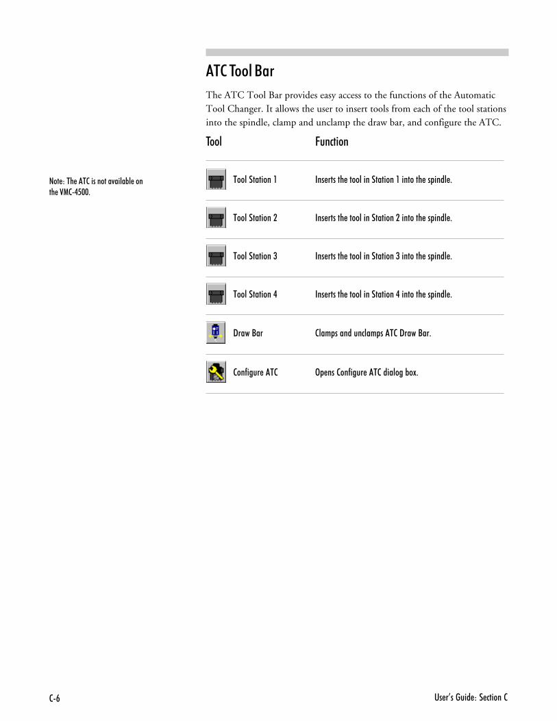
�� �I������ ��� ������22#
�$��$�������
The ATC Tool Bar provides easy access to the functions of the AutomaticTool Changer. It allows the user to insert tools from each of the tool stationsinto the spindle, clamp and unclamp the draw bar, and configure the ATC.
$��� 6��# ��
�������������� ��� ������ �������������������������� �� ���� +
�������������� ��� ������ �������������������������� �� ���� +
�������������( ��� ������ �����������������(�������� �� ���� +
�������������. ��� ������ �����������������.�������� �� ���� +
9����/�� 2��� ������������ ���2�9����/��+
2��-���� ��2 > ���2��-���� ��2��������%�!+
��� ���� ��2���������4����%� ����� �012.6$$+
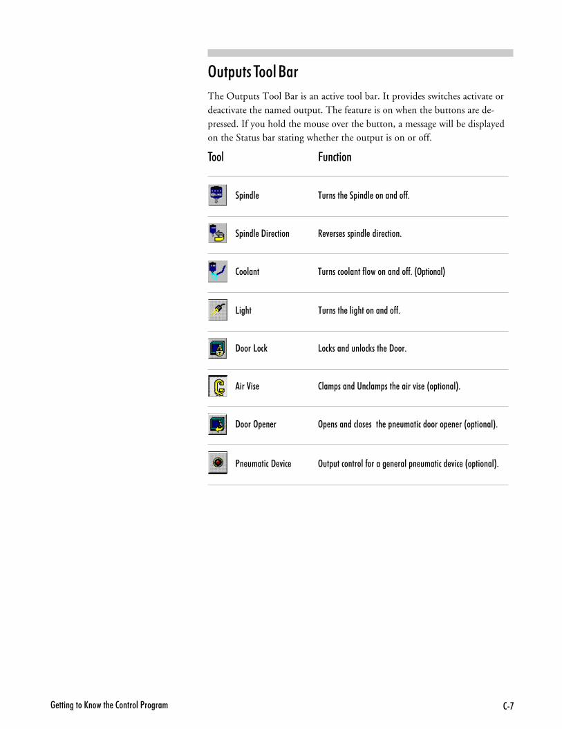
� ���������E������ �2�������<������ 2'
3�&���$�������
The Outputs Tool Bar is an active tool bar. It provides switches activate ordeactivate the named output. The feature is on when the buttons are de-pressed. If you hold the mouse over the button, a message will be displayedon the Status bar stating whether the output is on or off.
$��� 6��# ��
� ���� �������� �� ���� ���������--+
� ���� �9�� ����� � 4 �� ��� ���� ���� �����+
2������ ��������������-������������--+�&> ������*
5���� �������� ���������������--+
9����5��) 5��)�����������)���� �9���+
���0�� 2��� ������������ ���� �����4�� �&� ������*+
9����> � � > ����������� ����� � � ������������� � ��&� ������*+
<� �������9 4�� >�� �����������-������ � ���� � �������� 4�� �&� ������*+
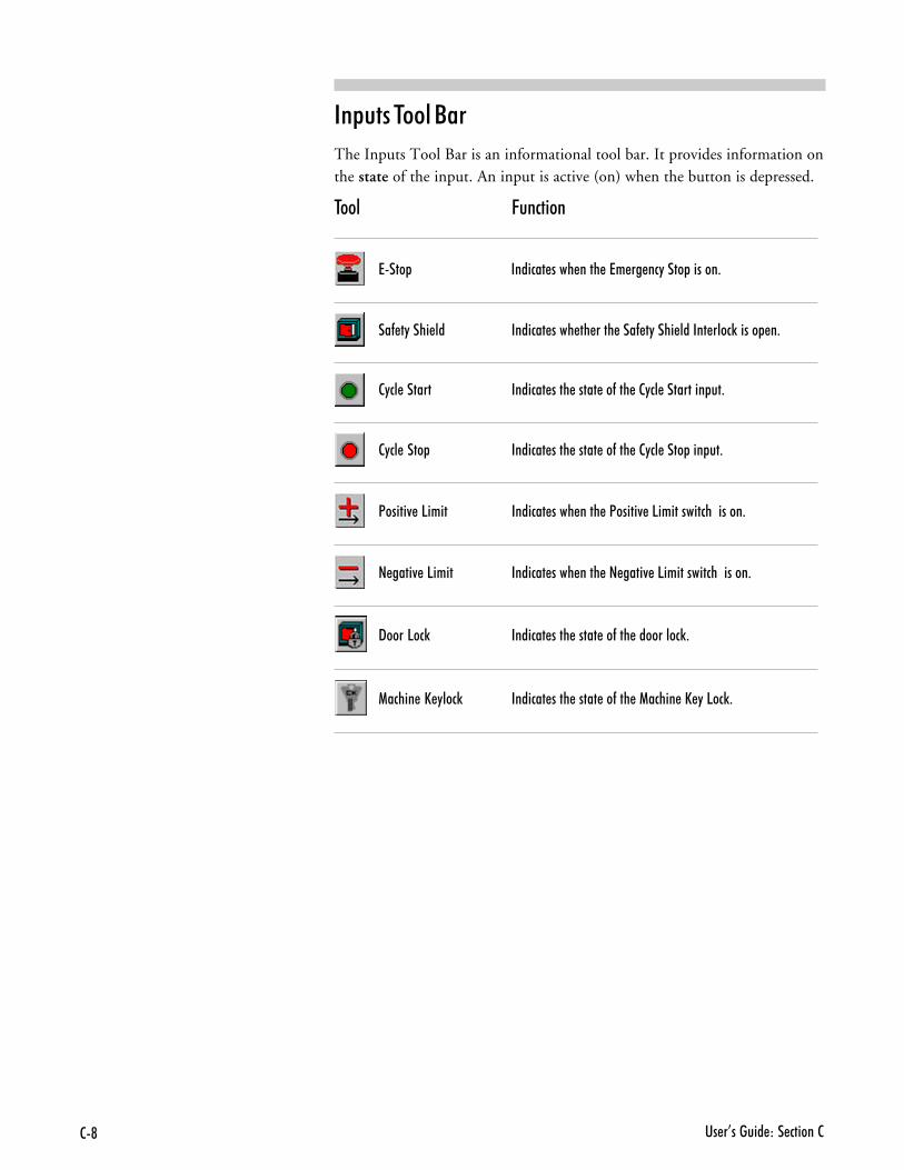
�� �I������ ��� ������22@
��&���$�������
The Inputs Tool Bar is an informational tool bar. It provides information onthe state of the input. An input is active (on) when the button is depressed.
$��� 6��# ��
7��� ������� ���� ���� �7� �� ��"���� ������+
��- �"���� �� ������� ���� �� ���� ���- �"���� ������ ����)����� �+
2"�� ������ ������� ���� ����� ��-��� �2"�� ��������� ��+
2"�� ���� ������� ���� ����� ��-��� �2"�� ���� ��� ��+
<�����4 �5���� ������� ���� ���� �<�����4 �5������������������+
� ����4 �5���� ������� ���� ���� �� ����4 �5������������������+
9����5��) ������� ���� ����� ��-��� ���������)+
1����� �E "���) ������� ���� ����� ��-��� �1����� �E "�5��)+
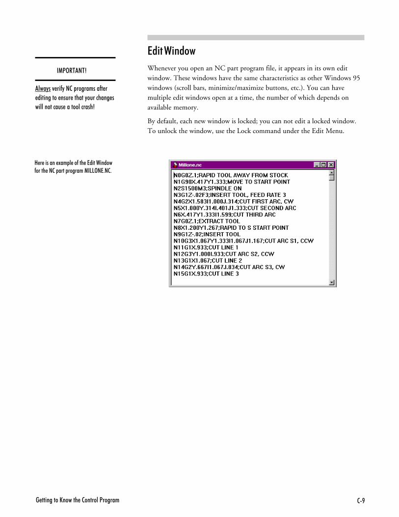
� ���������E������ �2�������<������ 2B
�� �2 ����
Whenever you open an NC part program file, it appears in its own editwindow. These windows have the same characteristics as other Windows 95windows (scroll bars, minimize/maximize buttons, etc.). You can havemultiple edit windows open at a time, the number of which depends onavailable memory.
By default, each new window is locked; you can not edit a locked window.To unlock the window, use the Lock command under the Edit Menu.
8 � ������� !�� � ��-��� �7����������-����� ��2� ���� �������1�55>�7+�2+
��13�$��$4
���"��4 ��-"��2� ���������-� � ���������� ���� ������"��������� �������������� �������������A
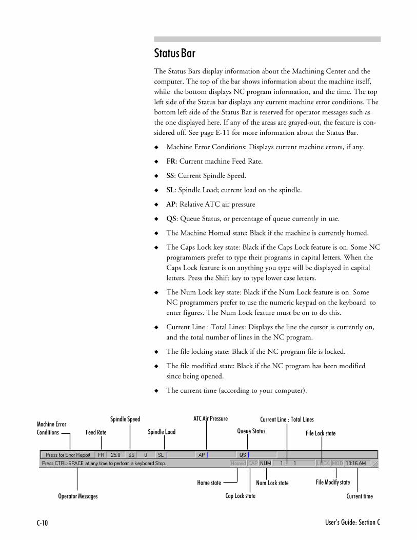
�� �I������ ��� ������22�$
�������
The Status Bars display information about the Machining Center and thecomputer. The top of the bar shows information about the machine itself,while the bottom displays NC program information, and the time. The topleft side of the Status bar displays any current machine error conditions. Thebottom left side of the Status Bar is reserved for operator messages such asthe one displayed here. If any of the areas are grayed-out, the feature is con-sidered off. See page E-11 for more information about the Status Bar.
� Machine Error Conditions: Displays current machine errors, if any.
� FR: Current machine Feed Rate.
� SS: Current Spindle Speed.
� SL: Spindle Load; current load on the spindle.
� AP: Relative ATC air pressure
� QS: Queue Status, or percentage of queue currently in use.
� The Machine Homed state: Black if the machine is currently homed.
� The Caps Lock key state: Black if the Caps Lock feature is on. Some NCprogrammers prefer to type their programs in capital letters. When theCaps Lock feature is on anything you type will be displayed in capitalletters. Press the Shift key to type lower case letters.
� The Num Lock key state: Black if the Num Lock feature is on. SomeNC programmers prefer to use the numeric keypad on the keyboard toenter figures. The Num Lock feature must be on to do this.
� Current Line : Total Lines: Displays the line the cursor is currently on,and the total number of lines in the NC program.
� The file locking state: Black if the NC program file is locked.
� The file modified state: Black if the NC program has been modifiedsince being opened.
� The current time (according to your computer).
1����� �7����2��������� C �����
� ���� �� �
� ���� �5���
�2����<� ����
F� � �������
8�� �����
2� �5��)�����
����5��)�����
2��� ���5�� ���������5�� �
C�� �5��)�����
C�� �1���-"�����
2��� ������ > ������1 ���� �
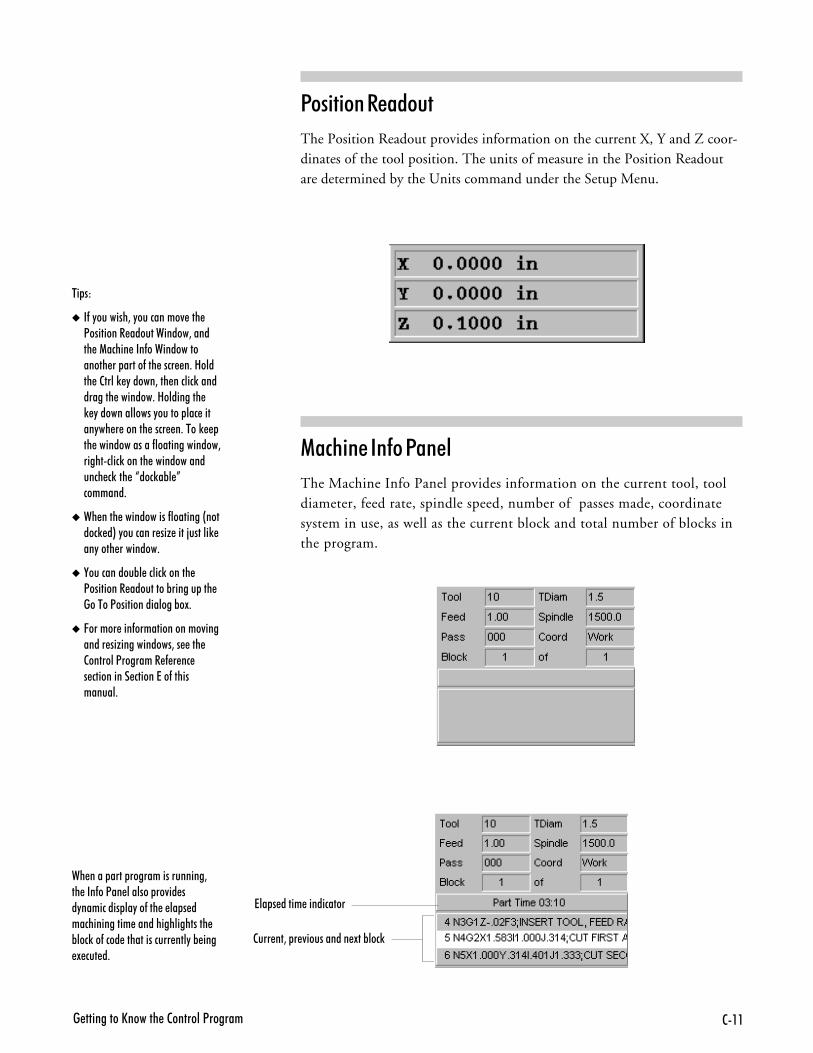
� ���������E������ �2�������<������ 2��
1�� ���������
The Position Readout provides information on the current X, Y and Z coor-dinates of the tool position. The units of measure in the Position Readoutare determined by the Units command under the Setup Menu.
$ &�)
� �-�"�������3�"���������4 ��� <��������� ������������3������ �1����� ���-���������������� �� �����-��� ���� �+�8����� �2����) "�����3��� ������)����������� �������+�8��������� ) "�������������"������ ��� �����"�� � ������ ���� �+����) �� �������������-��������������3���������)������ ��������������� �)��� �J���)�%� K�������+
� �� ���� �����������-��������&������) �*�"�������� ��G ����;������) ��"���� ��������+
� ,����������%� �����)������ <��������� ���������%������ ��� ������<���������������%�!+
� C������ ���-��������������4�������� ��G�����������3�� ��� 2�������<�������� - � �� � ���������� ������7��-�����������+
��#% ��������1����
The Machine Info Panel provides information on the current tool, tooldiameter, feed rate, spindle speed, number of passes made, coordinatesystem in use, as well as the current block and total number of blocks inthe program.
�� ���� ���� �����������������3�� ���-��<�� ������� ��4�� ��"��������� ��"��-��� � �� � �������������� ������������������ %���)��-���� ������������� ���"�% ��� ! ��� �+
7�� � ����� ����������
2��� ��3� � 4���������� !��%���)
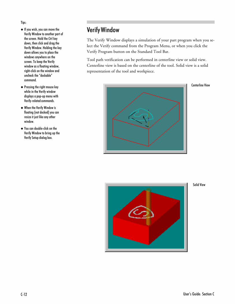
�� �I������ ��� ������22��
��� ���2 ����
The Verify Window displays a simulation of your part program when you se-lect the Verify command from the Program Menu, or when you click theVerify Program button on the Standard Tool Bar.
Tool path verification can be performed in centerline view or solid view.Centerline view is based on the centerline of the tool. Solid view is a solidrepresentation of the tool and workpiece.
$ &�)
� �-�"�������3�"���������4 ��� 0 ��-"���������������� �� �����-�� ���� �+�8������ �2����) "����3��� ������)������������ 0 ��-"�������+�8��������� �) "������������"������ ��� ��� ����������"�� � ������ ��� �+����) ��� �0 ��-"������������-��������������3���������)������ ��������������� �)��� �J���)�%� K�������+
� <� �������� ����������� �) "���� ������ �0 ��-"���������� ��"���� � � �� �������0 ��-"� ��� ����������+
� �� ���� �0 ��-"����������-��������&�������) �*�"������� ��G ����;������) ���"���� �������+
� ,����������%� ����)������ 0 ��-"�����������%������ ��� 0 ��-"�� �� ��������%�!+
2 �� ���� �0� �
������0� �
����������1�������������� � �<��� 9�
���������� ���%����#% � ��������
���� ������+&������1�����+
$��� ��)���#% � ������+&���1��
'���(���� ��)��# ���"
�� �������� ��� ������99�
���������� ���%����#% � ��������Like any other power tool, the BENCHMAN 4000 is a potentially dangerousmachine if operated in a careless manner. The importance of safely operatingthe BENCHMAN 4000, including the need for protection against personalinjury and the prevention of damage to the equipment, can not be stressedenough. You will find more information on safe machining in the ReferenceGuide: Section J.
����������
The following safety rules should be practiced by all operators of theBENCHMAN 4000 Machining Center.
��+�7����C�� ���E��������2���#%��Make a habit of checking that keys and adjusting wrenches are removed fromthe machining center before operating the machine.
"�����6��#����$���Select the feed rate and depth of cut best suited to the design, constructionand purpose of the cutting tool. It is always better to take too light a cutthan too heavy a cut.
'���%��� �%�$���Select the type of cutting tool best suited to the milling operation. Don’tforce a tool or attachment to do a job it wasn’t designed to do.
�#����%��2��0& �#�Be certain that you have firmly secured the workpiece on the cross slide andthe cutting tool in the spindle before turning on the spindle motor.
$����%��& ���������������������� ��Manually turning the spindle allows you to safely determine that the tool willnot hit the machining center bed, cross slide, or stock on start up.
$ �%����������� ��=�5�#0 �������"� 7 ���"�7 #��Tighten the work holders and tool holders. Do not over-tighten these devices.Over-tightening may damage threads or warp parts, thereby reducing accu-racy and effectiveness.
����������1�������������� � �<��� 9(
���)�,������������ ��� �7� �� ��"��� �%���������������� ��� �� ������� ����������� �� ���� ����������������3����� ��������������� ��4��������) � � +
<��� ���<��� ������������"���� ��� ������+�>�� ��� � ��� ���� ! ��� �3 ��������� �7� �� ��"���� �%���������� ���� ���- �"���� ��+
�� ��"����� �-����� ��������� ������ �3���� ��� ���� ��+�<���������� �7� �� ��"��� �%�����3��� �� � ���7�� ������� ��� �� ��) "%��������� ��� ���������� � ������+
��0 ����+�����#���&�
Before you run the BENCHMAN 4000 for the first time, you should knowhow to stop the machine should an emergency situation arise. There are anumber of ways an emergency stop can be initiated on the Machining Cen-ter: by pressing the Emergency Stop button, by simultaneously pressing theControl and Space Bar keys on the computer keyboard, by activating one of thelimit switches, or by activating the safety door interlock switch.
�&& ���� %�%���+�����#���&�����
There is an Emergency Stop button located on the front panel of the ma-chining center; it has an oversized red cap. Before power can be applied to themachining center, the Emergency Stop button must be pulled fully out fromthe front panel. Rotate the cap clockwise to release it. The Emergency Stopbutton works on the spindle even if the computer is turned off.
In the event of some machine or operator emergency, you can immediately killpower to the machining center by pushing in the Emergency Stop button.Pushing in the Emergency Stop button terminates the part program. Waituntil the machining center has completely stopped moving before openingthe safety shield.
When the error has been corrected, and the Emergency Stop button is reset (ro-tated and released), press Enter on the keyboard to close the error dialog boxthat appeared when the Emergency Stop button was pressed. Take the necessarysteps to ensure that the problem is fixed, (i.e., edit the part program to removethe tool crash, check the position of the workpiece, etc.) before running the pro-gram again. You may need to reinitialize (reset the point of origin for all axes)the machining center using the Set Position command from the Setup Menu,and you may need to home the machine again.
The Emergency Stop button should be your first target when a critical error oc-curs. You do not need to use it in situations where safety or reaction time is notan issue. For example, if you start to run a program but notice that the tool ismoving towards the wrong corner of the workpiece, use a software stop to haltthe program and reset the origin of the workpiece.
�&& ���� %�%����+&����E��B����
The execution of the part program can be interrupted by pressing keys onthe computer keyboard. To stop the part program with the keyboard, pressthe Control key and Space Bar simultaneously. The cutting stops immedi-ately and the cutting tool remains in position.
��13�$��$4
���"���� ��� �7� �� ��"���� /������������ � �� ��"����������+�������� �% �����"������� ��� ������� +
�� �������� ��� ������99.
The reason for stopping the program will determine the method used to re-start the program. If it the problem was not a critical error, and you want tocontinue from the same position, select the Run/Continue command fromthe Program Menu. In the Start At Line box, enter the number of the lastline executed, then click on the Run Program button. (The last line executedis displayed on the Machine Info Panel.)
�&& ���� %���5 + �� #%
The BENCHMAN 4000 is equipped with limit switches to sense the end oftravel on each axis. If the table travel exceeds the end of travel on any axis, alimit switch is activated and shuts down machine operation.
Once a limit switch is activated, the tool must be jogged away from it usingthe Jog Control keypad (selected from the View Menu).
To move the cross slide away from the limit switch, you must jog it in theopposite direction. Each axis has a positive and a negative limit. If a positivelimit is hit, you must jog away from it in a negative direction. If a negative limitis hit, you must jog away from it in a positive direction. If both a positive anda negative limit are hit, you must jog off the negative limits first.
If the cross slide comes close enough to the end of travel on any axis toactivate a limit switch, the following procedure must be followed to re-store normal operation.
,- Select Jog Control from the View Menu or the Standard Tool Bar.
.- Press the appropriate jog key on the jog keypad to move the cross slideaway from the triggered limit switch.
/- Check your initial machine set up to make sure it was performed correctly.
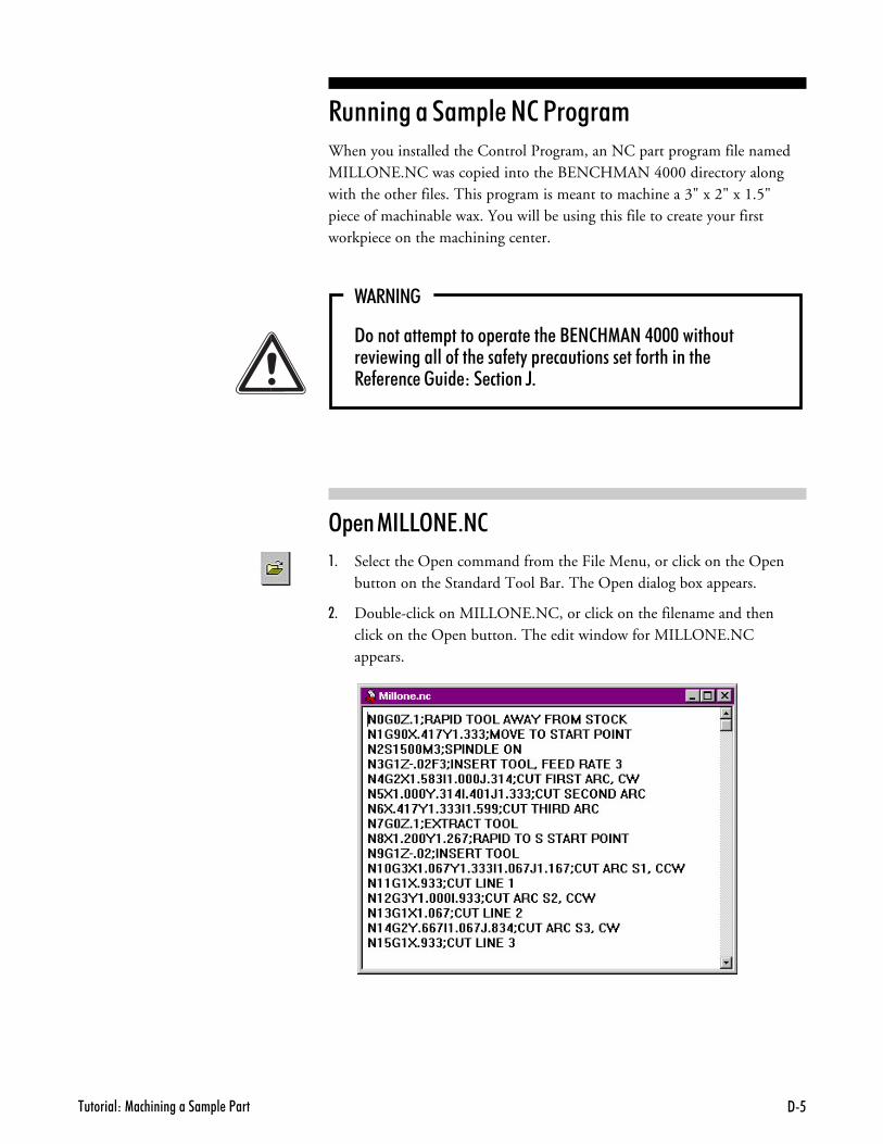
����������1�������������� � �<��� 96
���� ������+&������1�����+When you installed the Control Program, an NC part program file namedMILLONE.NC was copied into the BENCHMAN 4000 directory alongwith the other files. This program is meant to machine a 3" x 2" x 1.5"piece of machinable wax. You will be using this file to create your firstworkpiece on the machining center.
2������
9��������� � ������ ��� ��� �/7�281��.$$$��������� 4� ����������-��� ���- �"� � ���������� ��-���������� � - � �� ����� ��� ������D+
3&�����553��-��
,- Select the Open command from the File Menu, or click on the Openbutton on the Standard Tool Bar. The Open dialog box appears.
.- Double-click on MILLONE.NC, or click on the filename and thenclick on the Open button. The edit window for MILLONE.NCappears.
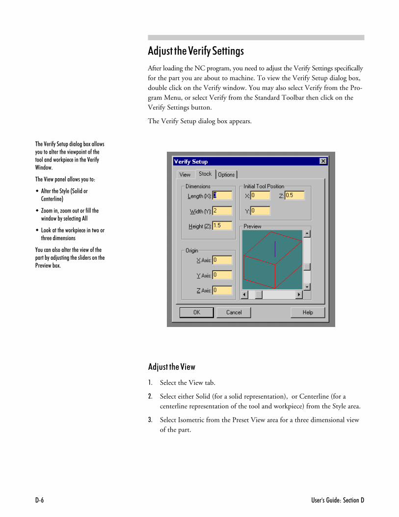
�� �������� ��� ������99#
��C���%����� ���� ���
After loading the NC program, you need to adjust the Verify Settings specificallyfor the part you are about to machine. To view the Verify Setup dialog box,double click on the Verify window. You may also select Verify from the Pro-gram Menu, or select Verify from the Standard Toolbar then click on theVerify Settings button.
The Verify Setup dialog box appears.
��C���%��� ��
,- Select the View tab.
.- Select either Solid (for a solid representation), or Centerline (for acenterline representation of the tool and workpiece) from the Style area.
/- Select Isometric from the Preset View area for a three dimensional viewof the part.
�� �0 ��-"�� �� ��������%�!�������"��������� ���� �4� � ������-��� ������������) � � ������ �0 ��-"������+
�� �0� �� �� ���������"������
� �� ���� ���"� �&��������2 �� ���� *
� H������3�G�����������-������ �������%"�� � ��������
� 5��)������ ����) � � ������������� ���� ������
,��������������� ���� �4� ���-��� ����%"���;��������� ����� �������� <� 4� ��%�!+
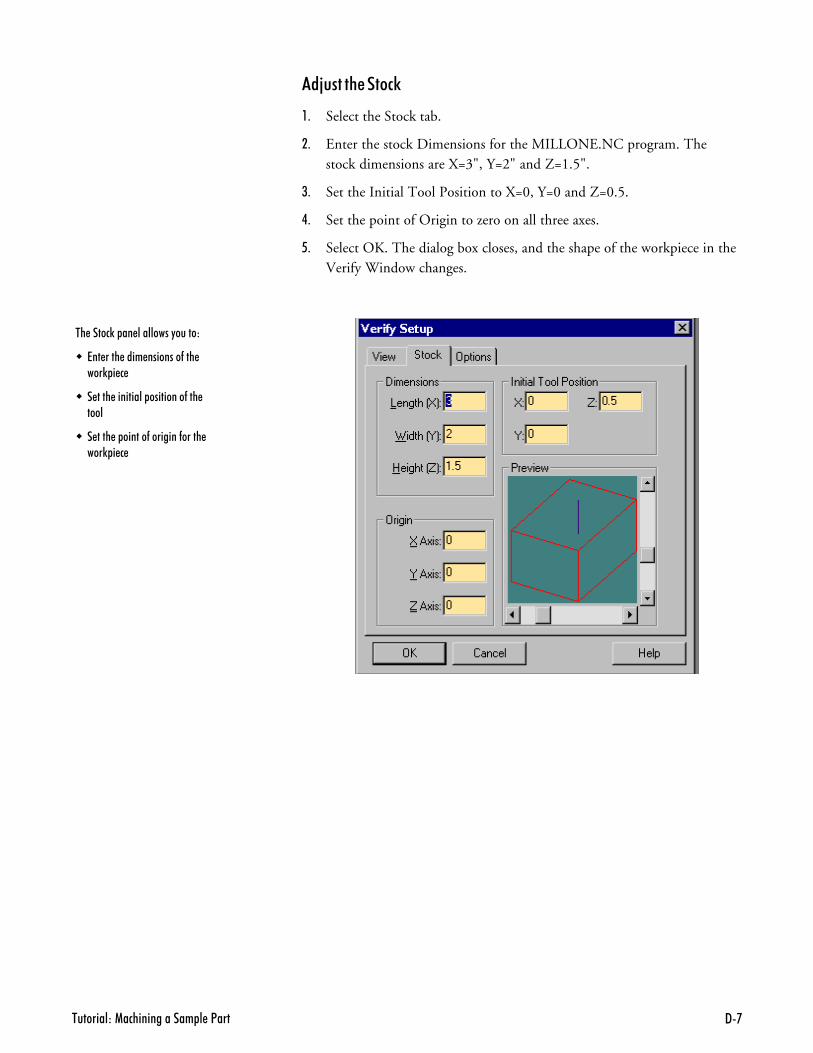
����������1�������������� � �<��� 9'
��C���%���#0
,- Select the Stock tab.
.- Enter the stock Dimensions for the MILLONE.NC program. Thestock dimensions are X=3", Y=2" and Z=1.5".
/- Set the Initial Tool Position to X=0, Y=0 and Z=0.5.
�- Set the point of Origin to zero on all three axes.
- Select OK. The dialog box closes, and the shape of the workpiece in theVerify Window changes.
�� �����)� �� ���������"������
� 7�� ���� ���� ��������-��� ���) � �
� � ���� ��������� ���������-��� ����
� � ���� � ������-��������-����� ���) � �
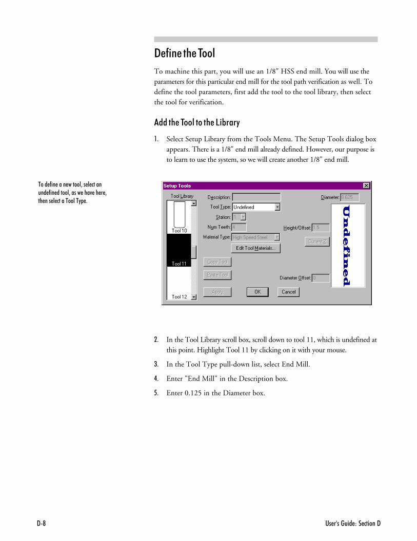
�� �������� ��� ������99@
"�� ���%��$���
To machine this part, you will use an 1/8" HSS end mill. You will use theparameters for this particular end mill for the tool path verification as well. Todefine the tool parameters, first add the tool to the tool library, then selectthe tool for verification.
����%��$������%��5 B����
,- Select Setup Library from the Tools Menu. The Setup Tools dialog boxappears. There is a 1/8" end mill already defined. However, our purpose isto learn to use the system, so we will create another 1/8" end mill.
.- In the Tool Library scroll box, scroll down to tool 11, which is undefined atthis point. Highlight Tool 11 by clicking on it with your mouse.
/- In the Tool Type pull-down list, select End Mill.
�- Enter "End Mill" in the Description box.
- Enter 0.125 in the Diameter box.
���� -�� ���� ������3�� � �������� -�� ������3����� ���4 �� � 3�� ��� � �����������" +
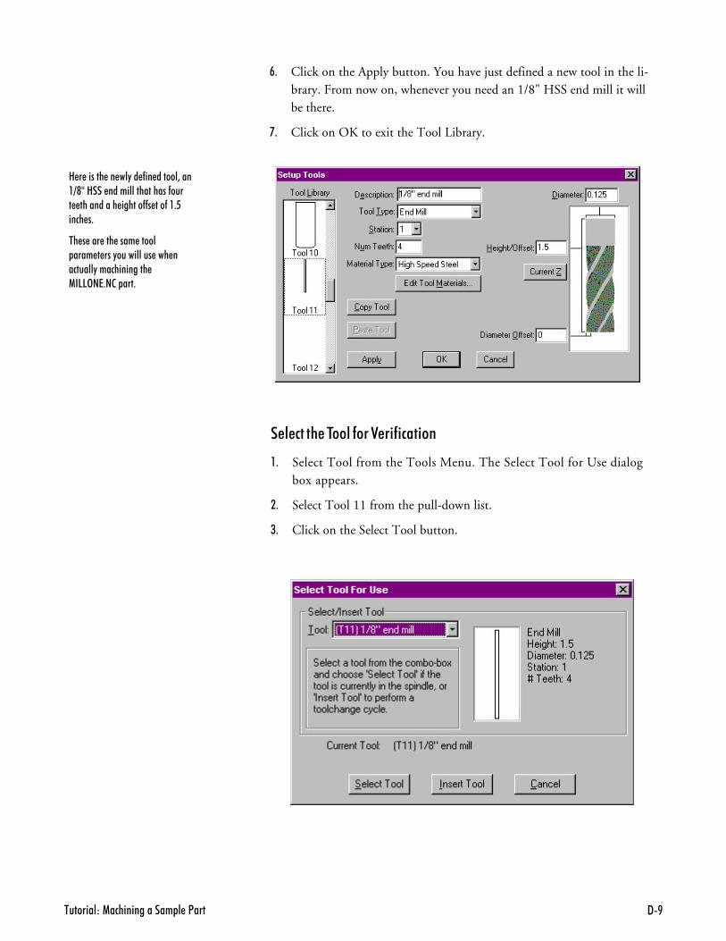
����������1�������������� � �<��� 9B
���#�%��$����������� � #� ��
,- Select Tool from the Tools Menu. The Select Tool for Use dialogbox appears.
.- Select Tool 11 from the pull-down list.
/- Click on the Select Tool button.
8 � ������ �� ��"�� -�� ������3����=@?�8��� �����������������-���� ���������� ������--� ���-��+6���� �+
�� � ��� ��� ���� ����� ���� � ���"���������� ��� ��������"������������� 1�55>�7+�2� ���+
:- Click on the Apply button. You have just defined a new tool in the li-brary. From now on, whenever you need an 1/8" HSS end mill it willbe there.
;- Click on OK to exit the Tool Library.
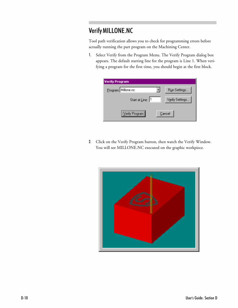
�� �������� ��� ������99�$
��� �����553��-��
Tool path verification allows you to check for programming errors beforeactually running the part program on the Machining Center.
,- Select Verify from the Program Menu. The Verify Program dialog boxappears. The default starting line for the program is Line 1. When veri-fying a program for the first time, you should begin at the first block.
.- Click on the Verify Program button, then watch the Verify Window.You will see MILLONE.NC executed on the graphic workpiece.
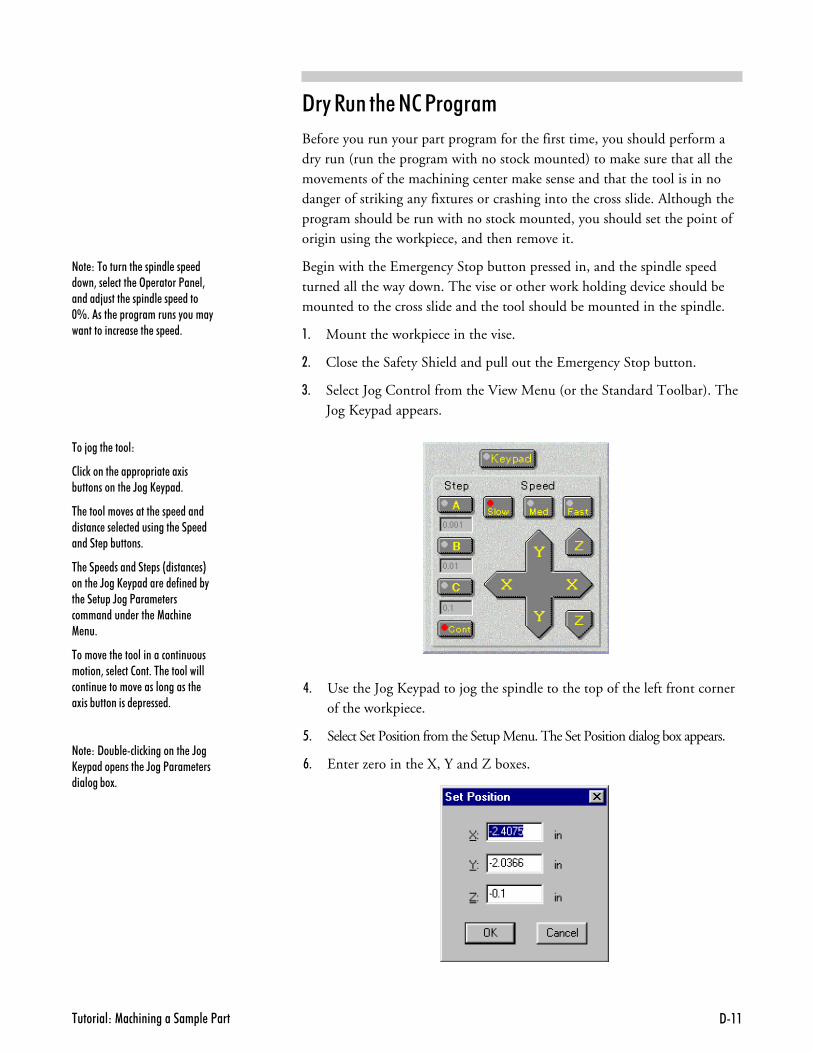
����������1�������������� � �<��� 9��
"�������%�����1�����+
Before you run your part program for the first time, you should perform adry run (run the program with no stock mounted) to make sure that all themovements of the machining center make sense and that the tool is in nodanger of striking any fixtures or crashing into the cross slide. Although theprogram should be run with no stock mounted, you should set the point oforigin using the workpiece, and then remove it.
Begin with the Emergency Stop button pressed in, and the spindle speedturned all the way down. The vise or other work holding device should bemounted to the cross slide and the tool should be mounted in the spindle.
,- Mount the workpiece in the vise.
.- Close the Safety Shield and pull out the Emergency Stop button.
/- Select Jog Control from the View Menu (or the Standard Toolbar). TheJog Keypad appears.
�- Use the Jog Keypad to jog the spindle to the top of the left front cornerof the workpiece.
- Select Set Position from the Setup Menu. The Set Position dialog box appears.
:- Enter zero in the X, Y and Z boxes.
$��C���%�����)
2���)������ �� �� ���� ��!��%������������ �D���E " ��+
�� ��������4 ������� �� ������������ �� � �� ���������� �� ������� �%������+
�� �� ��������� ��&������� �*����� �D���E " ����� �� -�� ��%"�� �� �� �D���<���� � ������������� ���� �1����� 1 ��+
�����4 ��� ���������������������������3�� � ���2���+��� ����������������� ������4 �������������� �!���%���������� � �� �+
���)�9��%� ����)��������� �D��E " ���� ����� �D���<���� � ���������%�!+
��� ������������ �� ���� �� �����3�� � ����� �> ������<�� �3������;������ �� ���� �� ����$L+����� � ������������"�����"������������ �� ��� �� �+
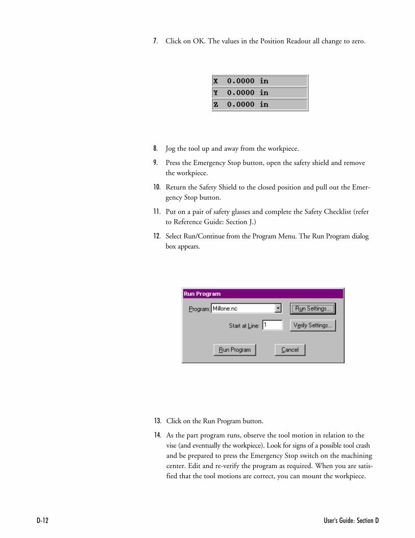
�� �������� ��� ������99��
;- Click on OK. The values in the Position Readout all change to zero.
<- Jog the tool up and away from the workpiece.
>- Press the Emergency Stop button, open the safety shield and removethe workpiece.
,!- Return the Safety Shield to the closed position and pull out the Emer-gency Stop button.
,,- Put on a pair of safety glasses and complete the Safety Checklist (referto Reference Guide: Section J.)
,.- Select Run/Continue from the Program Menu. The Run Program dialogbox appears.
,/- Click on the Run Program button.
,�- As the part program runs, observe the tool motion in relation to thevise (and eventually the workpiece). Look for signs of a possible tool crashand be prepared to press the Emergency Stop switch on the machiningcenter. Edit and re-verify the program as required. When you are satis-fied that the tool motions are correct, you can mount the workpiece.
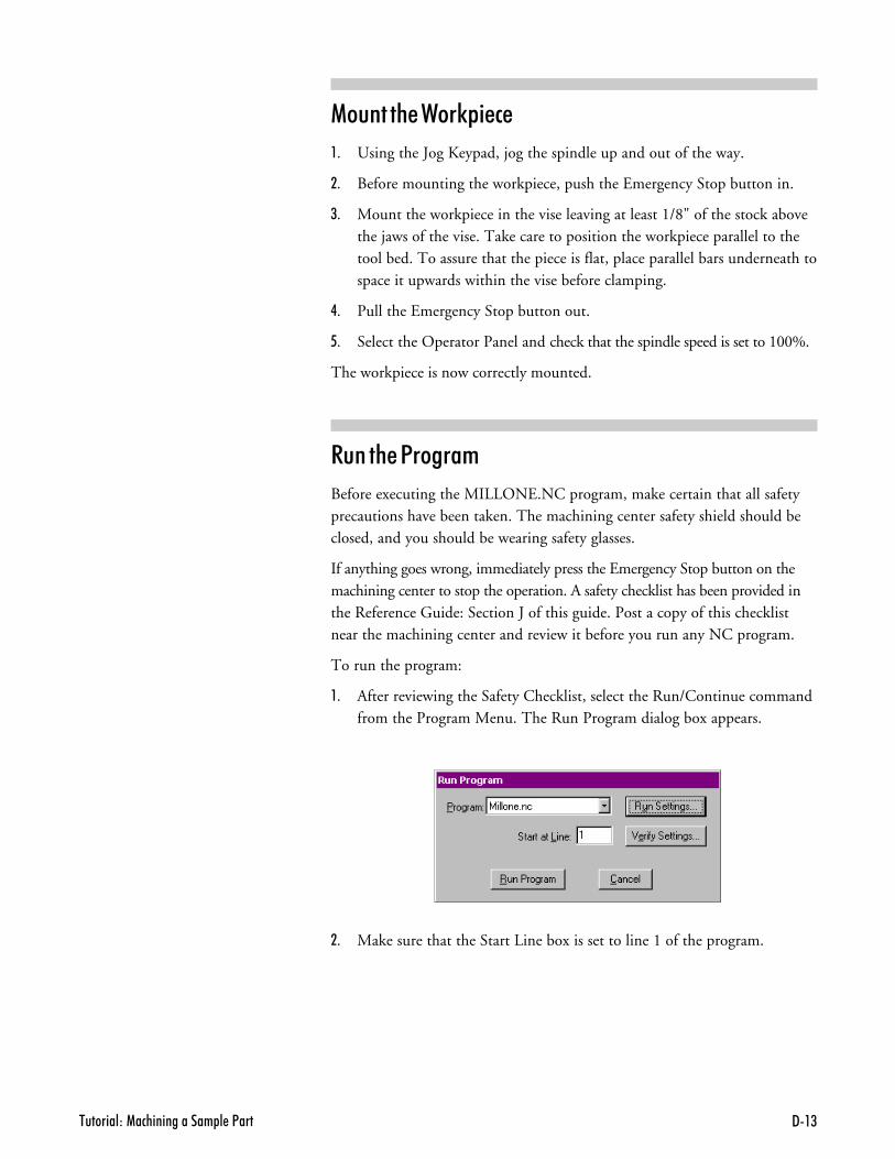
����������1�������������� � �<��� 9�(
�����%��2��0& �#�
,- Using the Jog Keypad, jog the spindle up and out of the way.
.- Before mounting the workpiece, push the Emergency Stop button in.
/- Mount the workpiece in the vise leaving at least 1/8" of the stock abovethe jaws of the vise. Take care to position the workpiece parallel to thetool bed. To assure that the piece is flat, place parallel bars underneath tospace it upwards within the vise before clamping.
�- Pull the Emergency Stop button out.
- Select the Operator Panel and check that the spindle speed is set to 100%.
The workpiece is now correctly mounted.
����%��1�����+
Before executing the MILLONE.NC program, make certain that all safetyprecautions have been taken. The machining center safety shield should beclosed, and you should be wearing safety glasses.
If anything goes wrong, immediately press the Emergency Stop button on themachining center to stop the operation. A safety checklist has been provided inthe Reference Guide: Section J of this guide. Post a copy of this checklistnear the machining center and review it before you run any NC program.
To run the program:
,- After reviewing the Safety Checklist, select the Run/Continue commandfrom the Program Menu. The Run Program dialog box appears.
.- Make sure that the Start Line box is set to line 1 of the program.
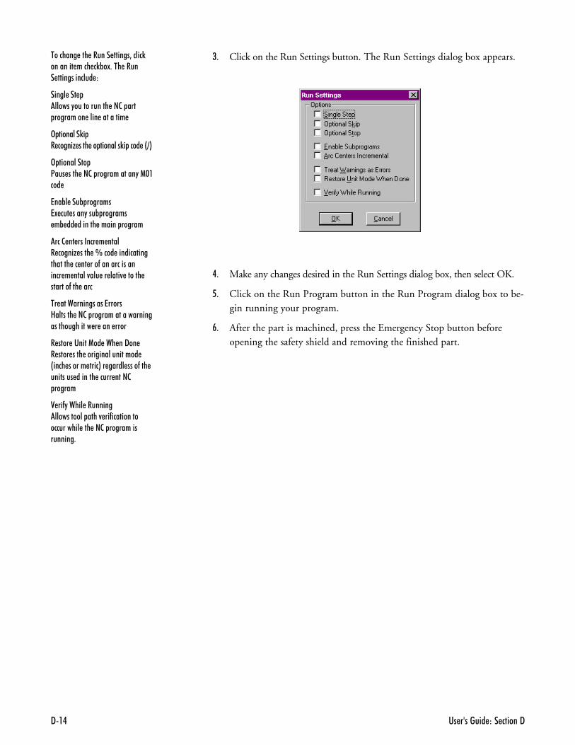
�� �������� ��� ������99�.
�������� ��� ������ ������3�����)�������� ���� �)%�!+��� ����� ������������� �
������&������"������������ ��2� ��� ��������� ���� ���������
3& �����0 &� �����G ���� �� ��������)� ���� �&=*
3& ������&<��� ���� ��2� ������������"�1$����
���B����B&�����+�7! ��� ����"���% ������� �% �� ������� ������ ������
��#����������#��+����� �����G ���� �L���� ������������������ �� �� ���-����������������� � �����4��� �� ����4 ������ �������-��� ����
$����2��� �������������8������� ��2� ��������������������������������� � ���� ����
�������'� ������2%���"���� ���� ���� ������������������ &���� ������ ����*�� ����� ����-��� �������� ������� ����� ����2 ������
��� ���2% ������� ������������� ����4 ��-�������������������� ��� ��2� ����������������+
/- Click on the Run Settings button. The Run Settings dialog box appears.
�- Make any changes desired in the Run Settings dialog box, then select OK.
- Click on the Run Program button in the Run Program dialog box to be-gin running your program.
:- After the part is machined, press the Emergency Stop button beforeopening the safety shield and removing the finished part.
7�2�������<�������� - � ��
�������1�����+��������#�
�������#���� ��)��# ����
$%������������!!!�������#�
'� ���%�������������
'� ���2 �����
'� ���$���B���
'� ���1�����
'� ���%���������
'� ���%����������
���# ������++����
1�� �� ���#�������+&�����
'� ���%��3�����$�B��
2��0 ��� �� +��� �������
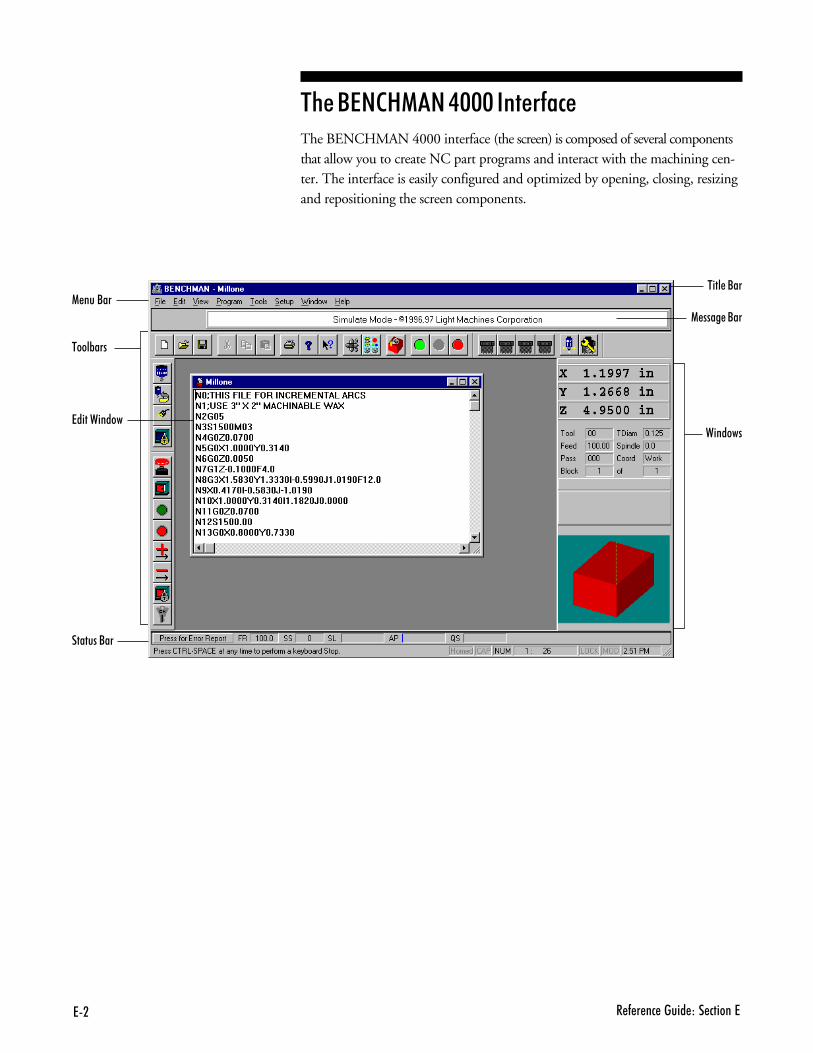
7� � - � �� ����� ��� ������7
$%������������!!!�������#�The BENCHMAN 4000 interface (the screen) is composed of several componentsthat allow you to create NC part programs and interact with the machining cen-ter. The interface is easily configured and optimized by opening, closing, resizingand repositioning the screen components.
���� �/��1 ���/��
����%���
�������/��
�������7����������
1 ���� �/��
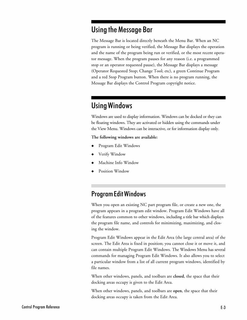
7(2�������<�������� - � ��
'� ���%�������������The Message Bar is located directly beneath the Menu Bar. When an NCprogram is running or being verified, the Message Bar displays the operationand the name of the program being run or verified, or the most recent opera-tor message. When the program pauses for any reason (i.e. a programmedstop or an operator requested pause), the Message Bar displays a message(Operator Requested Stop; Change Tool; etc), a green Continue Programand a red Stop Program button. When there is no program running, theMessage Bar displays the Control Program copyright notice.
'� ���2 �����Windows are used to display information. Windows can be docked or they canbe floating windows. They are activated or hidden using the commands underthe View Menu. Windows can be interactive, or for information display only.
The following windows are available:
� Program Edit Windows
� Verify Window
� Machine Info Window
� Position Window
1�����+��� �2 �����
When you open an existing NC part program file, or create a new one, theprogram appears in a program edit window. Program Edit Windows have allof the features common to other windows, including a title bar which displaysthe program file name, and controls for minimizing, maximizing, and clos-ing the window.
Program Edit Windows appear in the Edit Area (the large central area) of thescreen. The Edit Area is fixed in position; you cannot close it or move it, andcan contain multiple Program Edit Windows. The Windows Menu has severalcommands for managing Program Edit Windows. It also allows you to selecta particular window from a list of all current program windows, identified byfile names.
When other windows, panels, and toolbars are closed, the space that theirdocking areas occupy is given to the Edit Area.
When other windows, panels, and toolbars are open, the space that theirdocking areas occupy is taken from the Edit Area.
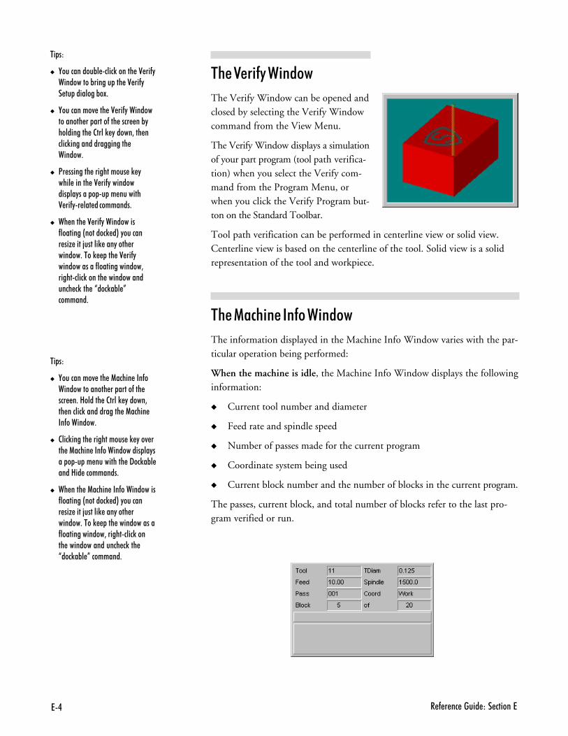
7. � - � �� ����� ��� ������7
$%����� ���2 ����
The Verify Window can be opened andclosed by selecting the Verify Windowcommand from the View Menu.
The Verify Window displays a simulationof your part program (tool path verifica-tion) when you select the Verify com-mand from the Program Menu, orwhen you click the Verify Program but-ton on the Standard Toolbar.
Tool path verification can be performed in centerline view or solid view.Centerline view is based on the centerline of the tool. Solid view is a solidrepresentation of the tool and workpiece.
$%����#% ��������2 ����
The information displayed in the Machine Info Window varies with the par-ticular operation being performed:
When the machine is idle, the Machine Info Window displays the followinginformation:
� Current tool number and diameter
� Feed rate and spindle speed
� Number of passes made for the current program
� Coordinate system being used
� Current block number and the number of blocks in the current program.
The passes, current block, and total number of blocks refer to the last pro-gram verified or run.
$ &�)
� ,����������%� ����)������ �0 ��-"����������%������ ��� �0 ��-"� �� ��������%�!+
� ,���������4 ��� �0 ��-"��������������� �� �����-��� ���� ��%"���������� �2����) "�����3��� �����)������������������� ������+
� <� �������� ����������� �) "���� ������ �0 ��-"���������� ��"���� � � �� �������0 ��-"� ��� ����������+
� �� ���� �0 ��-"����������-��������&�������) �*�"������� ��G ����;������) ���"���� �������+����) ��� �0 ��-"������������-��������������3���������)������ ��������������� �)��� �J���)�%� K�������+
$ &�)
� ,���������4 ��� �1����� ���-���������������� �� �����-��� ��� �+�8������ �2����) "�����3�� ������)������������ �1����� ��-��������+
� 2���)������ ����������� �) "��4 ��� �1����� ���-������������ ��"��� � � �� ���������� �9��)�%� ����8�� ���������+
� �� ���� �1����� ���-�����������-��������&�������) �*�"������� ��G ����;������) ���"���� �������+����) ��� ������������-��������������3����������)����� ���������������� �)��� J���)�%� K��������+
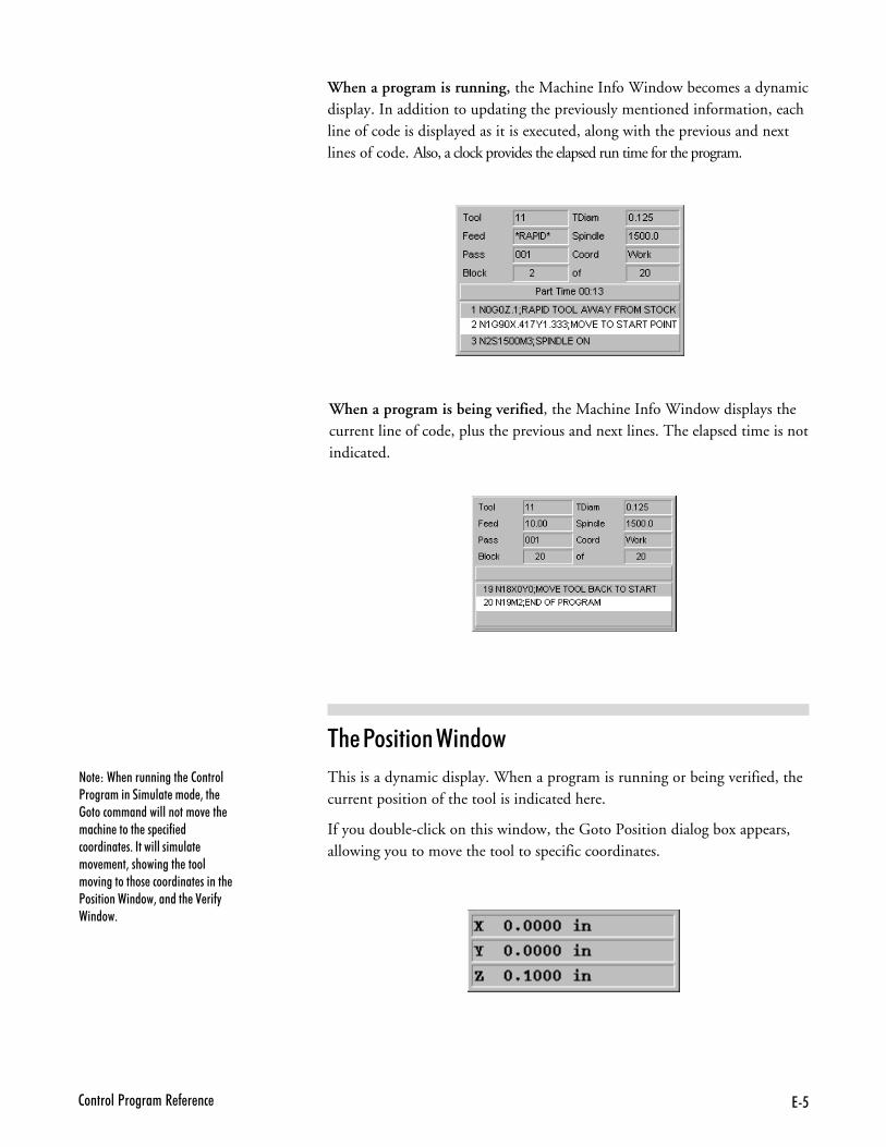
762�������<�������� - � ��
���)��� ������������ �2������<����������������� ���� 3��� ������������������������4 ��� ������ ������ �� ��-� ���������� �+���������������� ��4 � ��3����������� �������4����������� ���������� ������� <��������������3������� �0 ��-"������+
When a program is running, the Machine Info Window becomes a dynamicdisplay. In addition to updating the previously mentioned information, eachline of code is displayed as it is executed, along with the previous and nextlines of code. Also, a clock provides the elapsed run time for the program.
When a program is being verified, the Machine Info Window displays thecurrent line of code, plus the previous and next lines. The elapsed time is notindicated.
$%��1�� ���2 ����
This is a dynamic display. When a program is running or being verified, thecurrent position of the tool is indicated here.
If you double-click on this window, the Goto Position dialog box appears,allowing you to move the tool to specific coordinates.
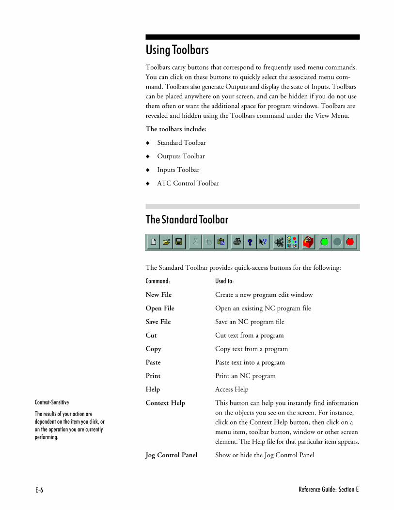
7# � - � �� ����� ��� ������7
'� ���$���B���Toolbars carry buttons that correspond to frequently used menu commands.You can click on these buttons to quickly select the associated menu com-mand. Toolbars also generate Outputs and display the state of Inputs. Toolbarscan be placed anywhere on your screen, and can be hidden if you do not usethem often or want the additional space for program windows. Toolbars arerevealed and hidden using the Toolbars command under the View Menu.
The toolbars include:
� Standard Toolbar
� Outputs Toolbar
� Inputs Toolbar
� ATC Control Toolbar
$%���������$���B��
����9���� 7�
�� �� �������-�"������������� � �� �������� ��� ��"�������)3�������� �� �������"����� ����� ���" �-������+
The Standard Toolbar provides quick-access buttons for the following:
��++���) '�����)
New File Create a new program edit window
Open File Open an existing NC program file
Save File Save an NC program file
Cut Cut text from a program
Copy Copy text from a program
Paste Paste text into a program
Print Print an NC program
Help Access Help
Context Help This button can help you instantly find informationon the objects you see on the screen. For instance,click on the Context Help button, then click on amenu item, toolbar button, window or other screenelement. The Help file for that particular item appears.
Jog Control Panel Show or hide the Jog Control Panel
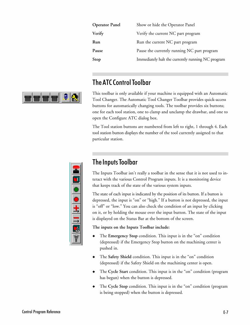
7'2�������<�������� - � ��
Operator Panel Show or hide the Operator Panel
Verify Verify the current NC part program
Run Run the current NC part program
Pause Pause the currently running NC part program
Stop Immediately halt the currently running NC program
$%���$���������$���B��
This toolbar is only available if your machine is equipped with an AutomaticTool Changer. The Automatic Tool Changer Toolbar provides quick-accessbuttons for automatically changing tools. The toolbar provides six buttons;one for each tool station, one to clamp and unclamp the drawbar, and one toopen the Configure ATC dialog box.
The Tool station buttons are numbered from left to right, 1 through 4. Eachtool station button displays the number of the tool currently assigned to thatparticular station.
$%����&���$���B��
The Inputs Toolbar isn’t really a toolbar in the sense that it is not used to in-teract with the various Control Program inputs. It is a monitoring devicethat keeps track of the state of the various system inputs.
The state of each input is indicated by the position of its button. If a button isdepressed, the input is “on” or “high.” If a button is not depressed, the inputis “off” or “low.” You can also check the condition of an input by clickingon it, or by holding the mouse over the input button. The state of the inputis displayed on the Status Bar at the bottom of the screen.
The inputs on the Inputs Toolbar include:
� The Emergency Stop condition. This input is in the “on” condition(depressed) if the Emergency Stop button on the machining center ispushed in.
� The Safety Shield condition. This input is in the “on” condition(depressed) if the Safety Shield on the machining center is open.
� The Cycle Start condition. This input is in the “on” condition (programhas begun) when the button is depressed.
� The Cycle Stop condition. This input is in the “on” condition (programis being stopped) when the button is depressed.
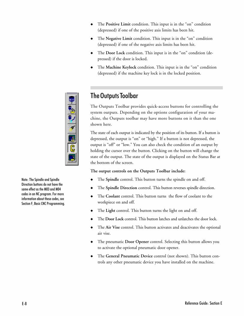
7@ � - � �� ����� ��� ������7
� The Positive Limit condition. This input is in the “on” condition(depressed) if one of the positive axis limits has been hit.
� The Negative Limit condition. This input is in the “on” condition(depressed) if one of the negative axis limits has been hit.
� The Door Lock condition. This input is in the “on” condition (de-pressed) if the door is locked.
� The Machine Keylock condition. This input is in the “on” condition(depressed) if the machine key lock is in the locked position.
$%��3�&���$���B��
The Outputs Toolbar provides quick-access buttons for controlling thesystem outputs. Depending on the options configuration of your ma-chine, the Outputs toolbar may have more buttons on it than the oneshown here.
The state of each output is indicated by the position of its button. If a button isdepressed, the output is “on” or “high.” If a button is not depressed, theoutput is “off” or “low.” You can also check the condition of an output byholding the cursor over the button. Clicking on the button will change thestate of the output. The state of the output is displayed on the Status Bar atthe bottom of the screen.
The output controls on the Outputs Toolbar include:
� The Spindle control. This button turns the spindle on and off.
� The Spindle Direction control. This button reverses spindle direction.
� The Coolant control. This button turns the flow of coolant to theworkpiece on and off.
� The Light control. This button turns the light on and off.
� The Door Lock control. This button latches and unlatches the door lock.
� The Air Vise control. This button activates and deactivates the optionalair vise.
� The pneumatic Door Opener control. Selecting this button allows youto activate the optional pneumatic door opener.
� The General Pneumatic Device control (not shown). This button con-trols any other pneumatic device you have installed on the machine.
���)��� �� ���� ������ ���� 9�� ������%����������������4 ��� ��� � -- �������� �1$(�����1$.��� ���������2� ������+�C������ ��-����������%������ � ���� �3�� � ������C3�/�����2�2�<����������+
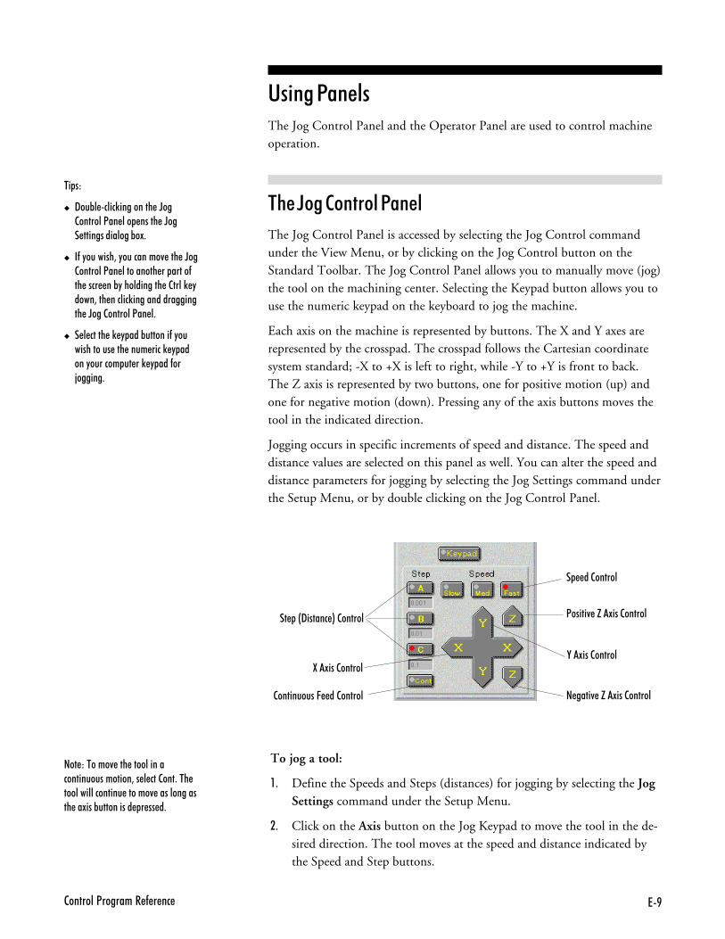
7B2�������<�������� - � ��
'� ���1�����The Jog Control Panel and the Operator Panel are used to control machineoperation.
$%��F����������1����
The Jog Control Panel is accessed by selecting the Jog Control commandunder the View Menu, or by clicking on the Jog Control button on theStandard Toolbar. The Jog Control Panel allows you to manually move (jog)the tool on the machining center. Selecting the Keypad button allows you touse the numeric keypad on the keyboard to jog the machine.
Each axis on the machine is represented by buttons. The X and Y axes arerepresented by the crosspad. The crosspad follows the Cartesian coordinatesystem standard; -X to +X is left to right, while -Y to +Y is front to back.The Z axis is represented by two buttons, one for positive motion (up) andone for negative motion (down). Pressing any of the axis buttons moves thetool in the indicated direction.
Jogging occurs in specific increments of speed and distance. The speed anddistance values are selected on this panel as well. You can alter the speed anddistance parameters for jogging by selecting the Jog Settings command underthe Setup Menu, or by double clicking on the Jog Control Panel.
$ &�)
� 9��%� ����)��������� �D��2�������<�� ��� ����� �D��� ��������������%�!+
� �-�"�������3�"���������4 ��� �D��2�������<�� ���������� �� �����-�� ���� ��%"����������� �2����) "����3��� ������)������������������ �D���2�������<�� �+
� � � ����� �) " ���%�������-�"������������ ��� ���� ����) " �����"������� �� ��) " ���-��;������+
To jog a tool:
,- Define the Speeds and Steps (distances) for jogging by selecting the JogSettings command under the Setup Menu.
.- Click on the Axis button on the Jog Keypad to move the tool in the de-sired direction. The tool moves at the speed and distance indicated bythe Speed and Step buttons.
�� �&9������ *�2������
� ��2������
2����������C ��2������
���)������4 ��� ���������������������������3�� � ������+��� ����������������� ������4 ������������� ��!���%���������� � �� �+
<�����4 �H�!���2������
,�!���2������
� ����4 �H�!���2������
:�!���2������
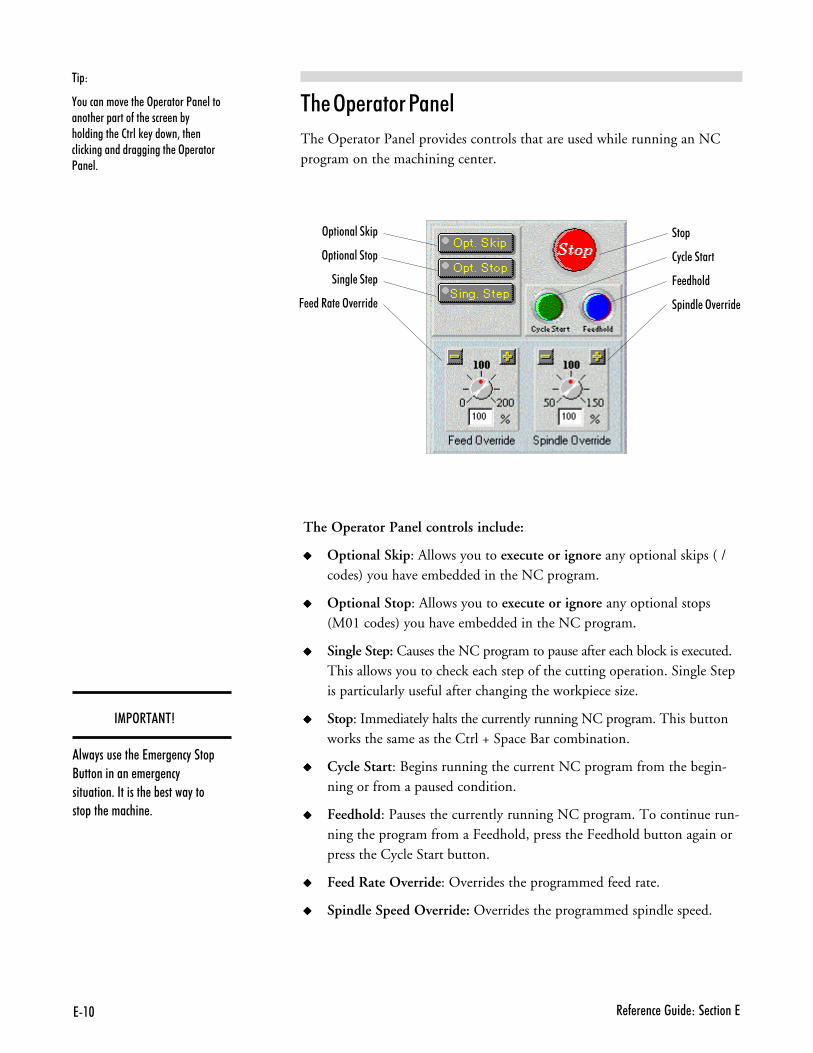
7�$ � - � �� ����� ��� ������7
The Operator Panel controls include:
����� Optional Skip: Allows you to execute or ignore any optional skips ( /codes) you have embedded in the NC program.
����� Optional Stop: Allows you to execute or ignore any optional stops(M01 codes) you have embedded in the NC program.
����� Single Step: Causes the NC program to pause after each block is executed.This allows you to check each step of the cutting operation. Single Stepis particularly useful after changing the workpiece size.
����� Stop: Immediately halts the currently running NC program. This buttonworks the same as the Ctrl + Space Bar combination.
����� Cycle Start: Begins running the current NC program from the begin-ning or from a paused condition.
����� Feedhold: Pauses the currently running NC program. To continue run-ning the program from a Feedhold, press the Feedhold button again orpress the Cycle Start button.
����� Feed Rate Override: Overrides the programmed feed rate.
����� Spindle Speed Override: Overrides the programmed spindle speed.
$ &)
,���������4 ��� �> ������<�� ��������� �� �����-��� ���� ��%"���������� �2����) "�����3��� �����)������������������� �> �����<�� �+
$%��3&������1����
The Operator Panel provides controls that are used while running an NCprogram on the machining center.
> ��������)�
> ����������
����� ���
C ����� �>4 ����
���
2"�� ������
C �����
� ���� �>4 ����
��13�$��$4
���"���� ��� �7� �� ��"���� /������������ � �� ��"���������+��������� �% �����"������ ��� ������� +
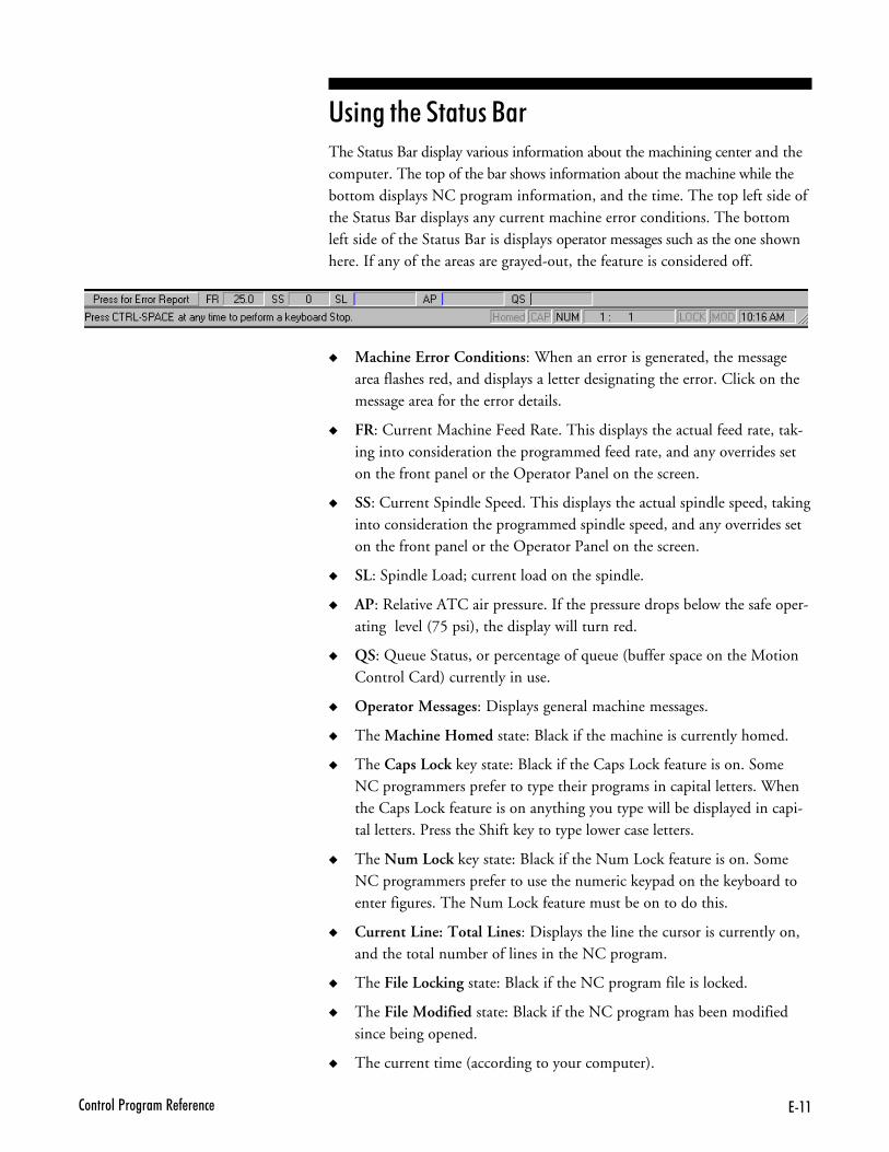
7��2�������<�������� - � ��
'� ���%���������The Status Bar display various information about the machining center and thecomputer. The top of the bar shows information about the machine while thebottom displays NC program information, and the time. The top left side ofthe Status Bar displays any current machine error conditions. The bottomleft side of the Status Bar is displays operator messages such as the one shownhere. If any of the areas are grayed-out, the feature is considered off.
� Machine Error Conditions: When an error is generated, the messagearea flashes red, and displays a letter designating the error. Click on themessage area for the error details.
� FR: Current Machine Feed Rate. This displays the actual feed rate, tak-ing into consideration the programmed feed rate, and any overrides seton the front panel or the Operator Panel on the screen.
� SS: Current Spindle Speed. This displays the actual spindle speed, takinginto consideration the programmed spindle speed, and any overrides seton the front panel or the Operator Panel on the screen.
� SL: Spindle Load; current load on the spindle.
� AP: Relative ATC air pressure. If the pressure drops below the safe oper-ating level (75 psi), the display will turn red.
� QS: Queue Status, or percentage of queue (buffer space on the MotionControl Card) currently in use.
� Operator Messages: Displays general machine messages.
� The Machine Homed state: Black if the machine is currently homed.
� The Caps Lock key state: Black if the Caps Lock feature is on. SomeNC programmers prefer to type their programs in capital letters. Whenthe Caps Lock feature is on anything you type will be displayed in capi-tal letters. Press the Shift key to type lower case letters.
� The Num Lock key state: Black if the Num Lock feature is on. SomeNC programmers prefer to use the numeric keypad on the keyboard toenter figures. The Num Lock feature must be on to do this.
� Current Line: Total Lines: Displays the line the cursor is currently on,and the total number of lines in the NC program.
� The File Locking state: Black if the NC program file is locked.
� The File Modified state: Black if the NC program has been modifiedsince being opened.
� The current time (according to your computer).
7�� � - � �� ����� ��� ������7
'� ���%����������The Menu Bar is located at the very top of the screen. It lists the categoriesof commands into which the Control Program operations are grouped.
The available menus are:
� The File Menu
� The Edit Menu
� The View Menu
� The Program Menu
� The Tools Menu
� The Setup Menu
� The Window Menu
� The Help Menu
6 �������
The File Menu provides typical file management commands and the Exitcommand.
��++���) '�����)
New Create a new program window.
Open Open an existing file.
Close Close an open program window.
Save Save a program.
Save As Save a program under a different filename or location.
Print Print an open NC program.
Print Setup Set up your printer for printing.
Recent files Open one of the eight most recently used files.
Exit Exit the Control Program.
������++���
Use the New command under the File Menu to create a new program edit window.
You can create a new program edit window at any time. The number of pro-gram edit windows that you have open at one time is limited by the amountof memory on your computer.
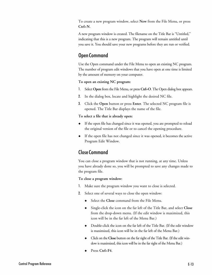
7�(2�������<�������� - � ��
To create a new program window, select New from the File Menu, or pressCtrl+N.
A new program window is created. The filename on the Title Bar is “Untitled,”indicating that this is a new program. The program will remain untitled untilyou save it. You should save your new programs before they are run or verified.
3&�����++���
Use the Open command under the File Menu to open an existing NC program.The number of program edit windows that you have open at one time is limitedby the amount of memory on your computer.
To open an existing NC program:
,- Select Open from the File Menu, or press Ctrl+O. The Open dialog box appears.
.- In the dialog box, locate and highlight the desired NC file.
/- Click the Open button or press Enter. The selected NC program file isopened. The Title Bar displays the name of the file.
To select a file that is already open:
� If the open file has changed since it was opened, you are prompted to reloadthe original version of the file or to cancel the opening procedure.
� If the open file has not changed since it was opened, it becomes the activeProgram Edit Window.
��������++���
You can close a program window that is not running, at any time. Unlessyou have already done so, you will be prompted to save any changes made tothe program file.
To close a program window:
,- Make sure the program window you want to close is selected.
.- Select one of several ways to close the open window:
� Select the Close command from the File Menu.
� Single-click the icon on the far left of the Title Bar, and select Closefrom the drop-down menu. (If the edit window is maximized, thisicon will be in the far left of the Menu Bar.)
� Double-click the icon on the far left of the Title Bar. (If the edit windowis maximized, this icon will be in the far left of the Menu Bar.)
� Click on the Close button on the far right of the Title Bar. (If the edit win-dow is maximized, this icon will be in the far right of the Menu Bar.)
� Press Ctrl+F4.
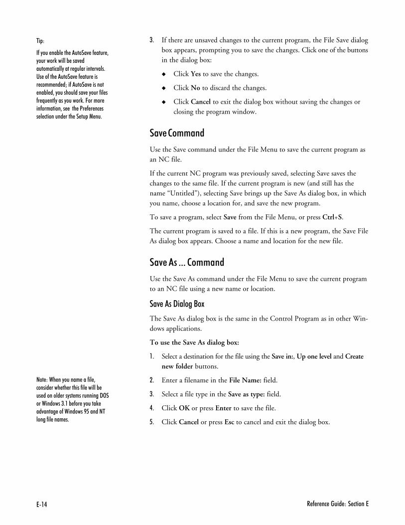
7�. � - � �� ����� ��� ������7
/- If there are unsaved changes to the current program, the File Save dialogbox appears, prompting you to save the changes. Click one of the buttonsin the dialog box:
� Click Yes to save the changes.
� Click No to discard the changes.
� Click Cancel to exit the dialog box without saving the changes orclosing the program window.
�7����++���
Use the Save command under the File Menu to save the current program asan NC file.
If the current NC program was previously saved, selecting Save saves thechanges to the same file. If the current program is new (and still has thename “Untitled”), selecting Save brings up the Save As dialog box, in whichyou name, choose a location for, and save the new program.
To save a program, select Save from the File Menu, or press Ctrl+S.
The current program is saved to a file. If this is a new program, the Save FileAs dialog box appears. Choose a name and location for the new file.
�7�����---���++���
Use the Save As command under the File Menu to save the current programto an NC file using a new name or location.
�7�����" �������9
The Save As dialog box is the same in the Control Program as in other Win-dows applications.
To use the Save As dialog box:
,- Select a destination for the file using the Save in:, Up one level and Createnew folder buttons.
.- Enter a filename in the File Name: field.
/- Select a file type in the Save as type: field.
�- Click OK or press Enter to save the file.
- Click Cancel or press Esc to cancel and exit the dialog box.
$ &)
�-�"��� ��%� ��� ������4 �- ���� 3"�������)������% ���4 �������������"����� ��������� �4���+�� ��-��� ������4 �- ���� ���� ���� �� �M��-������4 ������� ��%� �3�"������������4 �"����-�� �-� N� ���"����"������)+�C������ ��-��������3�� ���� �<� - � �� �� � ��������� ���� �� �� �1 ��+
���)��� ��"������ ���-�� 3������ ���� �� �������-�� ������% �� �������� ���"�� �����������9>������������(+��% -�� �"�����) ��4����� ��-���������B6������������-�� ���� �+
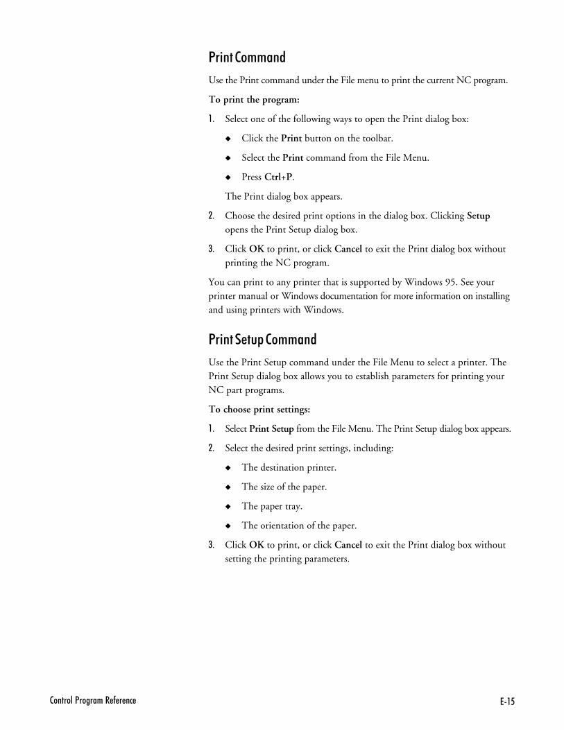
7�62�������<�������� - � ��
1� ����++���
Use the Print command under the File menu to print the current NC program.
To print the program:
,- Select one of the following ways to open the Print dialog box:
� Click the Print button on the toolbar.
� Select the Print command from the File Menu.
� Press Ctrl+P.
The Print dialog box appears.
.- Choose the desired print options in the dialog box. Clicking Setupopens the Print Setup dialog box.
/- Click OK to print, or click Cancel to exit the Print dialog box withoutprinting the NC program.
You can print to any printer that is supported by Windows 95. See yourprinter manual or Windows documentation for more information on installingand using printers with Windows.
1� ����&���++���
Use the Print Setup command under the File Menu to select a printer. ThePrint Setup dialog box allows you to establish parameters for printing yourNC part programs.
To choose print settings:
,- Select Print Setup from the File Menu. The Print Setup dialog box appears.
.- Select the desired print settings, including:
� The destination printer.
� The size of the paper.
� The paper tray.
� The orientation of the paper.
/- Click OK to print, or click Cancel to exit the Print dialog box withoutsetting the printing parameters.
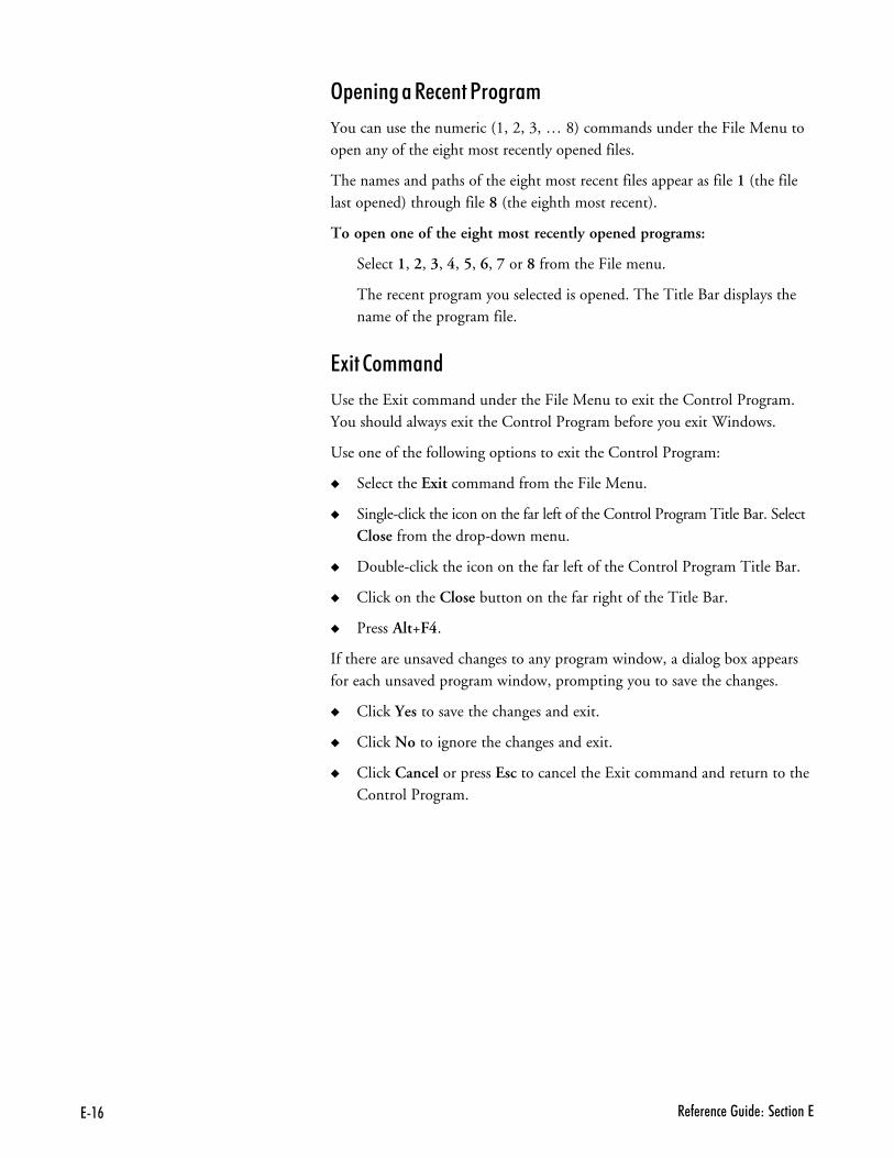
7�# � - � �� ����� ��� ������7
3&�� �������#���1�����+
You can use the numeric (1, 2, 3, … 8) commands under the File Menu toopen any of the eight most recently opened files.
The names and paths of the eight most recent files appear as file 1 (the filelast opened) through file 8 (the eighth most recent).
To open one of the eight most recently opened programs:
Select 1, 2, 3, 4, 5, 6, 7 or 8 from the File menu.
The recent program you selected is opened. The Title Bar displays thename of the program file.
�9 ���++���
Use the Exit command under the File Menu to exit the Control Program.You should always exit the Control Program before you exit Windows.
Use one of the following options to exit the Control Program:
� Select the Exit command from the File Menu.
� Single-click the icon on the far left of the Control Program Title Bar. SelectClose from the drop-down menu.
� Double-click the icon on the far left of the Control Program Title Bar.
� Click on the Close button on the far right of the Title Bar.
� Press Alt+F4.
If there are unsaved changes to any program window, a dialog box appearsfor each unsaved program window, prompting you to save the changes.
� Click Yes to save the changes and exit.
� Click No to ignore the changes and exit.
� Click Cancel or press Esc to cancel the Exit command and return to theControl Program.
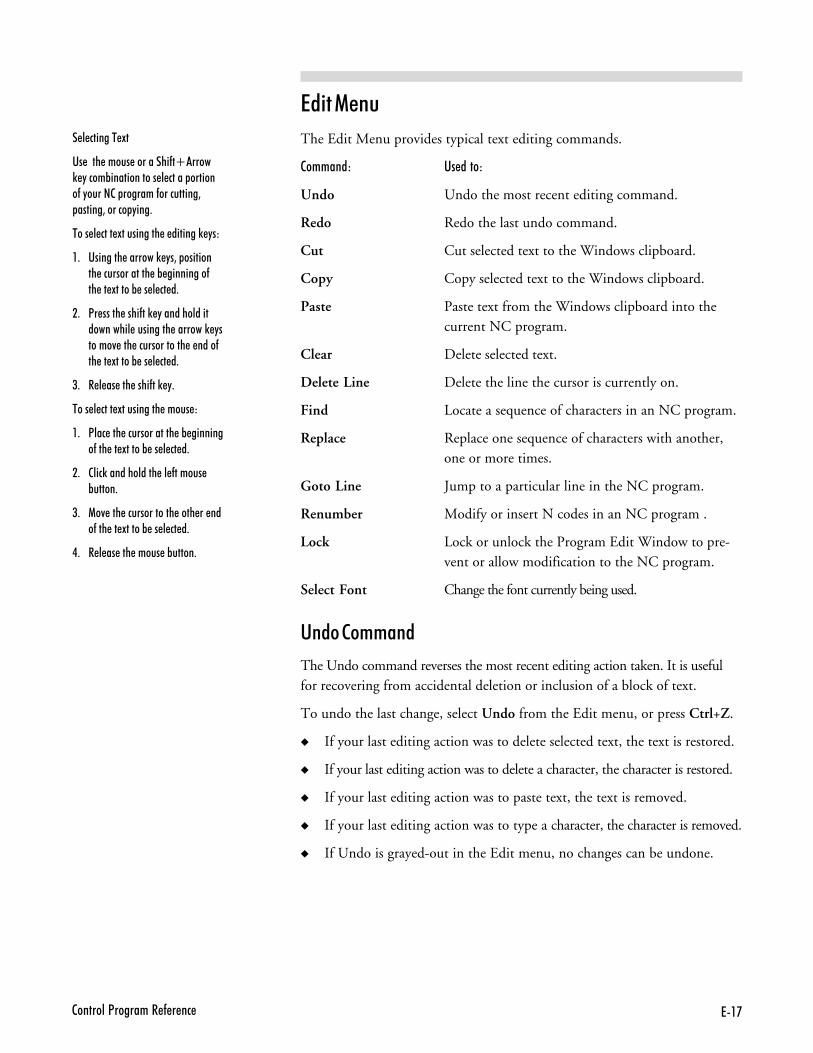
7�'2�������<�������� - � ��
�� �����
The Edit Menu provides typical text editing commands.
��++���) '�����)
Undo Undo the most recent editing command.
Redo Redo the last undo command.
Cut Cut selected text to the Windows clipboard.
Copy Copy selected text to the Windows clipboard.
Paste Paste text from the Windows clipboard into thecurrent NC program.
Clear Delete selected text.
Delete Line Delete the line the cursor is currently on.
Find Locate a sequence of characters in an NC program.
Replace Replace one sequence of characters with another,one or more times.
Goto Line Jump to a particular line in the NC program.
Renumber Modify or insert N codes in an NC program .
Lock Lock or unlock the Program Edit Window to pre-vent or allow modification to the NC program.
Select Font Change the font currently being used.
'������++���
The Undo command reverses the most recent editing action taken. It is usefulfor recovering from accidental deletion or inclusion of a block of text.
To undo the last change, select Undo from the Edit menu, or press Ctrl+Z.
� If your last editing action was to delete selected text, the text is restored.
� If your last editing action was to delete a character, the character is restored.
� If your last editing action was to paste text, the text is removed.
� If your last editing action was to type a character, the character is removed.
� If Undo is grayed-out in the Edit menu, no changes can be undone.
���# ���$�9
�� ���� ����� ������% �O�����) "����%������������ � ����� �������-�"�����2� �������-����������3 ������3������ "���+
$������#��9��� ���%���� ���0���)
�+ �������� �������) "�3� ��������� ������������� �% ���������-�� �� !�����% �� � �� �+
�+ <� ����� ����-��) "��������������������� ��������� �������) "������4 ��� ������������� � ����-�� �� !�����% �� � �� �+
(+ � � �� ��� ����-��) "+
$������#��9��� ���%��+����)
�+ <��� ��� ������������� �% ��������-��� �� !�����% �� � �� �+
�+ 2���)������������ �� -������ %�����+
(+ 1�4 ��� ������������� ���� �� ���-��� �� !�����% �� � �� �+
.+ � � �� ��� ����� �%�����+
7�@ � - � �� ����� ��� ������7
�������++���
The Redo command reverses the action of the undo command. If you de-leted a part of the text, and then decided to undo that deletion, the Redocommand will perform the original delete again.
�����++���
Use the Cut command under the Edit Menu to remove text from the NCprogram (the text is copied to the Windows clipboard). The text can then bepasted anywhere in the current program, into another program, or into anotherapplication such as Notepad. The text remains in the Windows clipboarduntil it is replaced by another Cut or Copy operation.
To cut text to the Clipboard:
,- Select the text you wish to cut.
.- Select Cut from the Edit Menu, or press Ctrl+X.
��&����++���
Use the Copy command under the Edit Menu to duplicate selected text inan NC program.
To copy text to the Clipboard:
,- Select the text you wish to copy.
.- Select Copy from the Edit Menu, or press Ctrl+C. The selected text iscopied to the Clipboard.
1������++���
Use the Paste command to insert text from the Windows clipboard into yourNC program.
To paste text from the Clipboard:
,- Place the cursor at the point in the NC program where you wish to inserttext that has been previously cut or copied to the Windows clipboard.
.- Select Paste from the Edit menu, or press Ctrl+V. The contents of theclipboard are inserted into the program. If this menu command isgrayed-out, there is no text on the clipboard to paste.
7�B2�������<�������� - � ��
��������++���
Use the Clear command under the Edit Menu to delete selected text fromyour NC program. The text is not copied to the Windows clipboard. Youcan also use the Delete key on your keyboard to achieve the same effect.
To delete text using the Clear command:
,- Select the text you wish to delete.
.- Select the Clear command from the Edit Menu. The selected text is deleted.
"�����5 �����++���
Use the Delete Line command under the Edit Menu to delete an entire lineof NC code from a program without selecting it first.
To delete a program line using the Delete Line command:
,- Place the cursor anywhere on the line of code you wish to delete.
.- Select the Delete Line command from the Edit Menu, or press F2. Theline of code is deleted.
6 �����++���
Use the Find command under the Edit Menu to locate a particular sequenceof characters within an NC program.
To use the Find command:
,- Select Find from the Edit Menu, or press Ctrl+F.
.- Enter the character sequence you are looking for in the Find: box.
/- Select the Match Case box to restrict the search to finding only those textstrings that match the case (upper or lower) of the text that you entered.
�- Select Up or Down from the Direction box to search through the textbefore or after the cursor position, respectively.
- Click Find Next or press Alt+S to begin the search. Click Cancel orpress ESC to exit the Find dialog box without performing the search.
To find the same character string again, use the Find Next button.
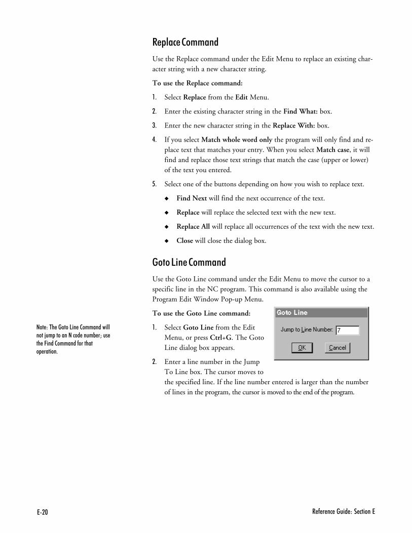
7�$ � - � �� ����� ��� ������7
��&��#����++���
Use the Replace command under the Edit Menu to replace an existing char-acter string with a new character string.
To use the Replace command:
,- Select Replace from the Edit Menu.
.- Enter the existing character string in the Find What: box.
/- Enter the new character string in the Replace With: box.
�- If you select Match whole word only the program will only find and re-place text that matches your entry. When you select Match case, it willfind and replace those text strings that match the case (upper or lower)of the text you entered.
- Select one of the buttons depending on how you wish to replace text.
� Find Next will find the next occurrence of the text.
� Replace will replace the selected text with the new text.
� Replace All will replace all occurrences of the text with the new text.
� Close will close the dialog box.
����5 �����++���
Use the Goto Line command under the Edit Menu to move the cursor to aspecific line in the NC program. This command is also available using theProgram Edit Window Pop-up Menu.
To use the Goto Line command:
,- Select Goto Line from the EditMenu, or press Ctrl+G. The GotoLine dialog box appears.
.- Enter a line number in the JumpTo Line box. The cursor moves tothe specified line. If the line number entered is larger than the numberof lines in the program, the cursor is moved to the end of the program.
���)��� ������5�� �2���������������;�� ������������ ����% �M��� �� �C����2�������-�������� ������+
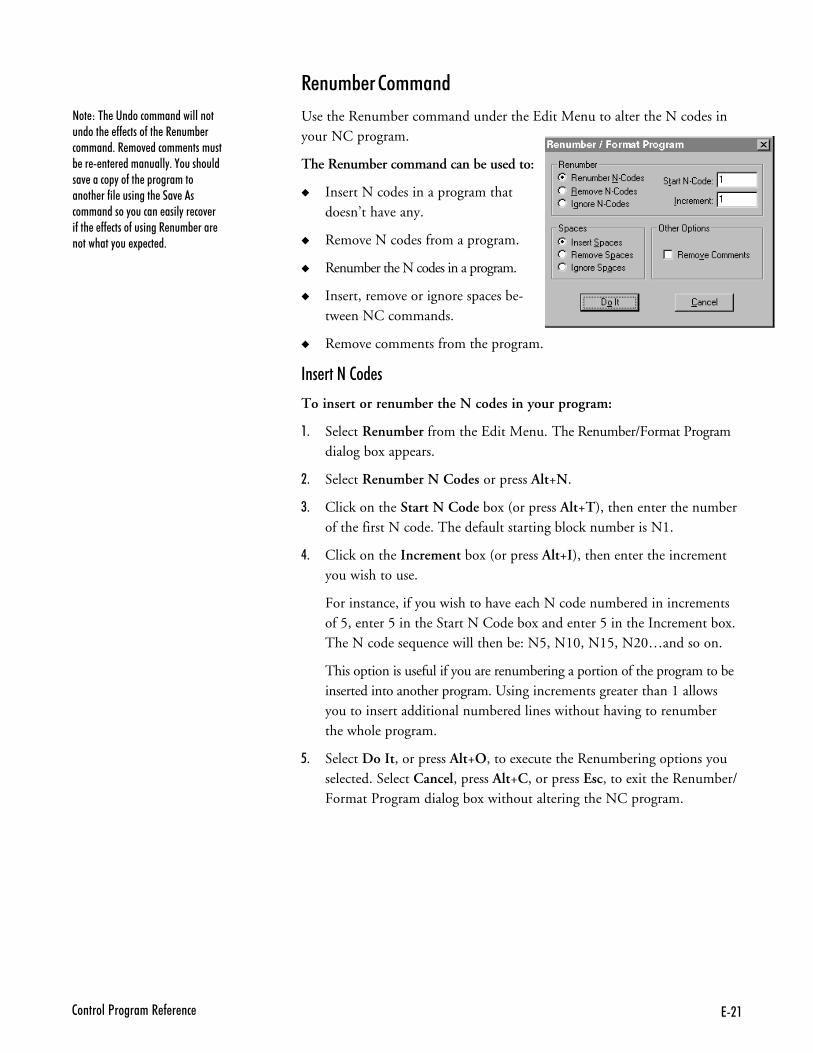
7��2�������<�������� - � ��
���)��� ����������������������������� � -- �����-��� �� ���% ��������+�� ��4 ������ ��������% �� �� � ���������"+�,�����������4 ����� "��-��� � �������������� ��-�� ��������� ���4 �������������"������� ����"�� ��4 ��-��� � -- �����-�������� ���% ���� ���������"��� ! �� �+
����+B�����++���
Use the Renumber command under the Edit Menu to alter the N codes inyour NC program.
The Renumber command can be used to:
� Insert N codes in a program thatdoesn’t have any.
� Remove N codes from a program.
� Renumber the N codes in a program.
� Insert, remove or ignore spaces be-tween NC commands.
� Remove comments from the program.
�������������
To insert or renumber the N codes in your program:
,- Select Renumber from the Edit Menu. The Renumber/Format Programdialog box appears.
.- Select Renumber N Codes or press Alt+N.
/- Click on the Start N Code box (or press Alt+T), then enter the numberof the first N code. The default starting block number is N1.
�- Click on the Increment box (or press Alt+I), then enter the incrementyou wish to use.
For instance, if you wish to have each N code numbered in incrementsof 5, enter 5 in the Start N Code box and enter 5 in the Increment box.The N code sequence will then be: N5, N10, N15, N20…and so on.
This option is useful if you are renumbering a portion of the program to beinserted into another program. Using increments greater than 1 allowsyou to insert additional numbered lines without having to renumberthe whole program.
- Select Do It, or press Alt+O, to execute the Renumbering options youselected. Select Cancel, press Alt+C, or press Esc, to exit the Renumber/Format Program dialog box without altering the NC program.
7�� � - � �� ����� ��� ������7
����+B�� ��������B&�����+�
Although the Renumber command automatically changes P codes used with(M99) codes, it does not renumber P codes used with M98 codes, nor does itrenumber O codes. Although O codes are not altered, the lines which theyoccupy are counted. So, the very next N code is numbered as though the Ocode has been renumbered, too.
For instance, N41X...N42X…O25G…N44…
In this example, although the O code has not been renumbered, the line itresides on has been counted. The N code on the following line reflects thenext number in the sequence.
�����������+�7��&�#��
To insert or remove spaces between the NC words in your program:
,- Select Renumber from the Edit Menu. The Renumber/Format Programdialog box appears.
.- Choose a Spaces option.
����� Insert Spaces inserts a space between each NC word (to the left ofthe comment code).
����� Remove Spaces removes any spaces between NC words (to the leftof the comment code).
����� Ignore Spaces ignores any spaces in the NC program.
/- Select Do It, or press Alt+O, to execute the Spaces options you selected.Select Cancel, press Alt+C, or press Esc, to exit the Renumber/FormatProgram dialog box without altering the NC program.
���)��� ����% ���-������ ����� ������������� ����% ���-��� ���� � ����������� ��� ����"��� ��� ��-��� �-���������� ������ ����������������� ��������� �� � �-� ��������� � �� ��%"��+
7�(2�������<�������� - � ��
��+�7����++���
To remove comments from your program:
,- Select Renumber from the Edit Menu. The Renumber/Format Programdialog box appears.
.- Select Remove Comments.
/- Select Do It, or press Alt+O, to execute the Remove Comments command.Select Cancel, press Alt+C, or press Esc, to exit the Renumber/FormatProgram dialog box without altering the NC program.
��+�7���������
To remove the N codes from your program:
,- Select Renumber from the Edit Menu. The Renumber/Format Programdialog box appears.
.- Select Remove N Codes or press Alt+R.
/- Select Do It, or press Alt+O, to execute the Remove N Codes command.Select Cancel, press Alt+C, or press Esc, to exit the Renumber/FormatProgram dialog box without altering the NC program.
5�#0���++���
Use the Lock command under the Edit Menu to prevent or allow changes toyour NC programs. If a check mark appears next to this command, the currentNC program is locked.
When an NC program is unlocked, it can be modified by the commands onthe Edit Menu. When an NC program is locked, the program cannot bechanged by any commands. By default, when you open a file it is automati-cally locked to prevent accidental changes. You can change this default in thepreferences dialog box.
If you have Multiple Program Edit windows open, each is individually locked orunlocked. The state of the currently selected NC program, locked or unlocked,can be easily checked by looking at the Lock Indicator on the Status Bar.
To use the Lock command to lock or unlock your NC program, select Lockfrom the Edit Menu, press Ctrl+L, or double-click the Lock Indicator onthe Status Bar.
���)��� ����������������������������� � -- �����-��� �� ��4 2��� �����������+�� ��4 ����� ���������% �� �� � ��������"+�,������������4 ����� "��-�� � ��������������� ��-�� �������� ���4 �������������������"������ ����"�� ��4 ���-��� � -- �����-������� ���% ���� ����������"�� ! �� �+
�+&����)���� ��-��� �� ���% �������������% ������ A
7�. � - � �� ����� ��� ������7
���#�6�����++���
Use the Select Font command under the Edit Menu to change the font settingsfor open NC programs. Font Settings are intended for viewing and printing pur-poses only. They do not affect the NC program in any way and are not storedwithin the program file. All open program windows use the same font settings.
To use the Select Font command:
,- Select the Select Font command from the Edit Menu.
.- Select a font from the Font list.
/- Select a font size from the Size list.
�- Click OK to change the font, or click Cancel or press Esc to exit theFont dialog box without changing the fonts.
� �������
The View Menu commands control the display of windows and toolbars.
��++���) '�����)
Position Open or close the Machine Position Window.
Machine Info Open or close the Machine Info Window.
Jog Control Open or close the Jog Control Panel.
Operator Panel Open or close the Operator Panel.
Verify Window Open or close the Verify Window.
Toolbars Open or close the toolbars.
1�� �����++���
Use the Position command on the View Menu to open or close the PositionWindow.
To open or close the Position window, select Position from the View Menu.A check mark appears next to the Position command when the PositionWindow is open.
���)��� ���������������� ������������-����� ������������ +
7�62�������<�������� - � ��
��#% ����������++���
Use the Machine Info command on the View Menu to open or close theMachine Info window.
To open or close the Machine Info window, select Machine Info from theView Menu. A check mark appears next to the Machine Info commandwhen the Machine Info Window is open.
F������������++���
Use the Jog Control command on the View Menu to open or close the Jog Con-trol Panel. You can also use the Jog Control button on the Standard Toolbar.
To open or close the Jog Control window, select Jog Control from the ViewMenu. A check mark appears next to the Jog Control command when theJog Control Panel is open.
3&������1�������++���
Use the Operator Panel command on the View Menu to open or close theOperator Panel.
To open or close the Operator Panel, select Operator Panel from the ViewMenu. A check mark appears next to the Operator Panel command whenthe Operator Panel is open.
��� ���2 �������++���
Use the Verify Window command on the View Menu to open or close theVerify Window.
To open or close the Verify Window, select Verify Window from the ViewMenu. A check mark appears next to the Verify Window command whenthe Verify Window is open.
$���B������++���
Use the Toolbars command on the View Menu to show or hide the Toolbars.
To show or hide a toolbar:
,- Select Toolbars from the View Menu. The list of available toolbars isdisplayed. Toolbars that are visible have a check mark beside them.
.- Select the toolbar that you wish to show or hide.
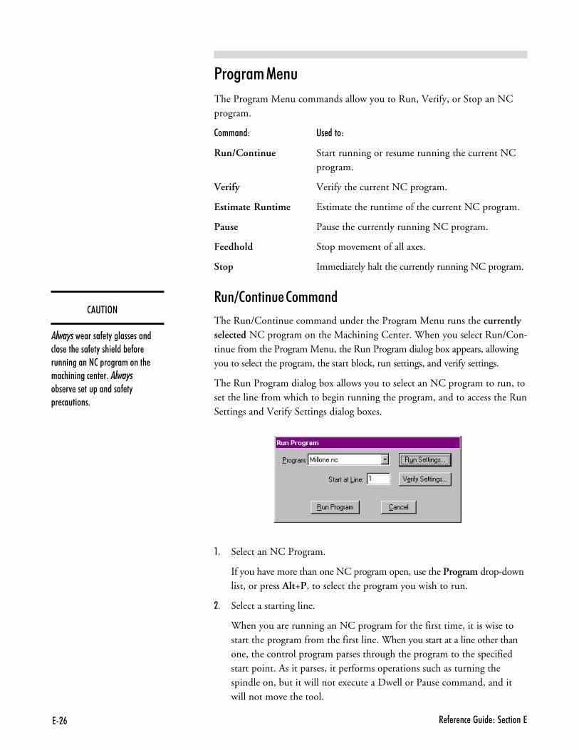
7�# � - � �� ����� ��� ������7
��'$�3�
�������� �����- �"������ ��������� ��� ���- �"���� ���% -�� ������������2� ������������ ����������� �� �+��������%� �4 �� ��� �������- �" � ��������+
1�����+�����
The Program Menu commands allow you to Run, Verify, or Stop an NCprogram.
��++���) '�����)
Run/Continue Start running or resume running the current NCprogram.
Verify Verify the current NC program.
Estimate Runtime Estimate the runtime of the current NC program.
Pause Pause the currently running NC program.
Feedhold Stop movement of all axes.
Stop Immediately halt the currently running NC program.
���?��� ������++���
The Run/Continue command under the Program Menu runs the currentlyselected NC program on the Machining Center. When you select Run/Con-tinue from the Program Menu, the Run Program dialog box appears, allowingyou to select the program, the start block, run settings, and verify settings.
The Run Program dialog box allows you to select an NC program to run, toset the line from which to begin running the program, and to access the RunSettings and Verify Settings dialog boxes.
,- Select an NC Program.
If you have more than one NC program open, use the Program drop-downlist, or press Alt+P, to select the program you wish to run.
.- Select a starting line.
When you are running an NC program for the first time, it is wise tostart the program from the first line. When you start at a line other thanone, the control program parses through the program to the specifiedstart point. As it parses, it performs operations such as turning thespindle on, but it will not execute a Dwell or Pause command, and itwill not move the tool.
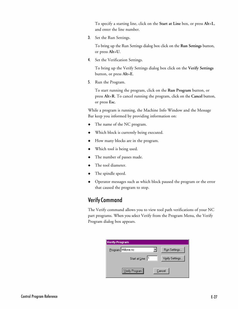
7�'2�������<�������� - � ��
To specify a starting line, click on the Start at Line box, or press Alt+L,and enter the line number.
/- Set the Run Settings.
To bring up the Run Settings dialog box click on the Run Settings button,or press Alt+U.
�- Set the Verification Settings.
To bring up the Verify Settings dialog box click on the Verify Settingsbutton, or press Alt+E.
- Run the Program.
To start running the program, click on the Run Program button, orpress Alt+R. To cancel running the program, click on the Cancel button,or press Esc.
While a program is running, the Machine Info Window and the MessageBar keep you informed by providing information on:
� The name of the NC program.
� Which block is currently being executed.
� How many blocks are in the program.
� Which tool is being used.
� The number of passes made.
� The tool diameter.
� The spindle speed.
� Operator messages such as which block paused the program or the errorthat caused the program to stop.
��� �����++���
The Verify command allows you to view tool path verifications of your NCpart programs. When you select Verify from the Program Menu, the VerifyProgram dialog box appears.
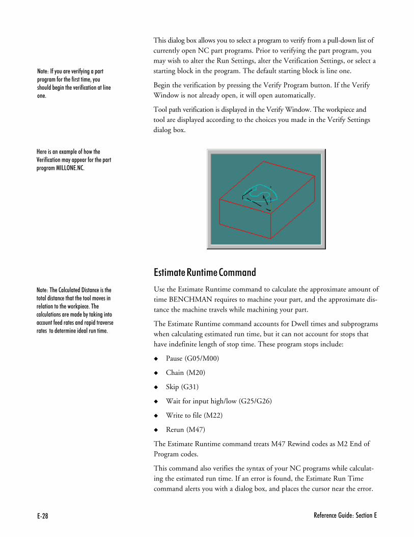
7�@ � - � �� ����� ��� ������7
�� +������ +����++���
Use the Estimate Runtime command to calculate the approximate amount oftime BENCHMAN requires to machine your part, and the approximate dis-tance the machine travels while machining your part.
The Estimate Runtime command accounts for Dwell times and subprogramswhen calculating estimated run time, but it can not account for stops thathave indefinite length of stop time. These program stops include:
� Pause (G05/M00)
� Chain (M20)
� Skip (G31)
� Wait for input high/low (G25/G26)
� Write to file (M22)
� Rerun (M47)
The Estimate Runtime command treats M47 Rewind codes as M2 End ofProgram codes.
This command also verifies the syntax of your NC programs while calculat-ing the estimated run time. If an error is found, the Estimate Run Timecommand alerts you with a dialog box, and places the cursor near the error.
���)��� �2������� ��9������ ������ ������������� �������� ��������4 ����� ������������ ����) � � +��� ��������������� ���� �%"���)����������������- ����� �������� ������4 �� ��� ������� � ���� ��� ���������� +
This dialog box allows you to select a program to verify from a pull-down list ofcurrently open NC part programs. Prior to verifying the part program, youmay wish to alter the Run Settings, alter the Verification Settings, or select astarting block in the program. The default starting block is line one.
Begin the verification by pressing the Verify Program button. If the VerifyWindow is not already open, it will open automatically.
Tool path verification is displayed in the Verify Window. The workpiece andtool are displayed according to the choices you made in the Verify Settingsdialog box.
���)��-�"����� �4 ��-"������ ��� �������-����� �-�������� 3�"���������% ������ �4 ��-�������������� �� +
8 � ������� !�� � ��-������� 0 ��-����������"�� ���-����� � ��� �������1�55>�7+�2+
7�B2�������<�������� - � ��
1�������++���
Use the Pause command to pause a running NC program. Pause may also beused during tool path verification. The pause is not immediate; it takes effectafter the current NC block has been executed.
To use the Pause command, select Pause from the Program Menu, or clickthe Pause button on the Standard Toolbar.
You may jog the machine and operate outputs during a Pause. If you jog themachine during a pause and don’t return to where the pause started, you willbe prompted with a dialog box. The software will force you to return to theresume position before continuing.
To resume running a program after a Pause, press F5, click the Run buttonon the Standard Toolbar or the Go button on the Message Bar, or press theCycle Start button on the machine.
6���%������++���
The Feedhold command is very similar to the Pause command. Use it topause a running NC program. The differences between a Pause and aFeedhold are:
� A Feedhold pauses the NC program immediately; it does not wait untilthe current block is executed.
� Feedhold does not work during tool path verification.
� You cannot jog the machine or operate outputs during a Feedhold.
To use the Feedhold command, select Feedhold from the Program menu.
To resume running a program after a Feedhold, press F5, click the Run but-ton on the Standard Toolbar or the Go button on the Message Bar, or pressthe Cycle Start button on the machine.
�&���++���
You can use the Stop command under the Program Menu to halt a running NCprogram. The machining center will immediately halt cutting.
To use the Stop command:
,- Select Stop from the Program Menu, press Ctrl+Space, or click the Stop(red) button on the Standard Toolbar. A message box appears.
.- Clear the box by clicking OK or pressing Enter. You are automaticallyreturned to the Edit mode.
To restart a program after a Stop is performed through the Control Program:
,- Manually jog the tool so it is above the workpiece to avoid a tool crash.
.- Select the Run/Continue command to restart the NC program. Theprogram will begin at the first line, unless otherwise specified.
���)����2� ����������������% ��� ��%"� � �������� �7� �� ��"��� �/����������� �-����� �� ���-��� 1���������2 �� �+
���)�/ ���� ������) ������ ��-��� ��� ��� ��2� �������������% -�� �"������ ��� �� ���� �%�!+��-�"����������������� �-����"������� � �������3"����������4 ���� �� ���� ���� ���% ������� ����=2������ �%�!+
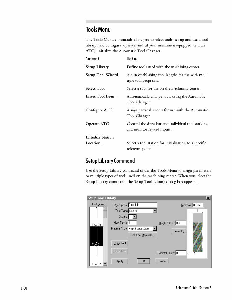
7($ � - � �� ����� ��� ������7
$���������
The Tools Menu commands allow you to select tools, set up and use a toollibrary, and configure, operate, and (if your machine is equipped with anATC), initialize the Automatic Tool Changer .
��++���) '�����)
Setup Library Define tools used with the machining center.
Setup Tool Wizard Aid in establishing tool lengths for use with mul-tiple tool programs.
Select Tool Select a tool for use on the machining center.
Insert Tool from ... Automatically change tools using the AutomaticTool Changer.
Configure ATC Assign particular tools for use with the AutomaticTool Changer.
Operate ATC Control the draw bar and individual tool stations,and monitor related inputs.
Initialize StationLocation ... Select a tool station for initialization to a specific
reference point.
��&�5 B�������++���
Use the Setup Library command under the Tools Menu to assign parametersto multiple types of tools used on the machining center. When you select theSetup Library command, the Setup Tool Library dialog box appears.
7(�2�������<�������� - � ��
You can create a new tool two ways:
� Use the Copy and Paste buttons to copy an existing tool in the Tool Librarybox and paste it into the Tool Library box under an unassigned tool num-ber. Assigned tool numbers are displayed with a tool icon. Unassigned toolnumbers have no tool icon.
� Manually create a tool using the Setup Tool Library dialog box.
To create a new tool:
,- Select an unassigned tool number from the Tool Library list.
.- Select a tool type, such as End Mill, from the Tool Type drop-down menu.
/- Enter a name for the tool in the Description field.
�- Select a Station for the tool. Station numbers are provided for those sys-tems that are equipped with an Automatic Tool Changer. If you do nothave an Automatic Tool Changer, select Station #1.
- Enter the number of teeth (Num Teeth) on the tool.
:- Enter the Material Type from which the tool should be made.
;- There is a secondary library for tool materials. You can use this library tocreate new materials or edit existing materials. To do this, click on theEdit Tool Materials button.
a) Enter a material Name.
b) Select a Material Class.
c) Enter a Multiplier. This should be set to “1” for now. This is usedwhen integrating with CAM for calculating feed rates and spindlespeeds when generating tool paths.
d) Click on the Add button.
e) Click on the Delete button to remove materials you no longer need.
f) Press Enter or click on OK to accept the new material. Click onCancel to exit the Tool Material Type dialog box without changingthe material library.
<- Enter a tool Diameter.
>- Enter a tool Height/Offset value. You may also click on the Current Zbutton to establish the current Z axis position of the tool as theHeight/Offset.
,!- Enter a Diameter Offset. The Diameter Offset is the amount of devia-tion from the actual cutter diameter to the programmed cutter diameter.This parameter is very important when using tool diameter cutter com-pensation. For example, a 0.125” diameter end mill may be specified fora job. When loading tools, the diameter of the end mill may actuallymeasure 0.1248”. The deviation in diameter is the Diameter Offset.
7(� � - � �� ����� ��� ������7
,,- Apply the new parameters to the selected tool number by clicking theApply button.
,.- Press Enter or click on OK to accept the new tool information. Click onCancel to exit the Tool Library dialog box without changing the tool library.
To alter an existing tool:
,- Select an existing tool from the Tool Library list.
.- Make the desired changes to the tool parameters, then click on theApply button.
/- Press Enter or click on OK to accept the new tool information. Click onCancel to exit the Tool Library dialog box without changing the tool library.
��&�$����2 D������++���
Use the Setup Tool Wizard as an aid in establishing tool heights for use withmultiple tool programs. The Wizard can be used if you are manually chang-ing tools, or if you are using an Automatic Tool Changer.
To use the Setup Tool Wizard:
,- Select Setup Tool Wizard from the Tools Menu. This starts the Wizard.
.- Follow the Wizard’s instructions carefully.
���#�$������++���
Use the Select Tool command under the Tools Menu to select a tool for useon the machining center.
To select a tool:
,- Select the Select Tool command from the Tools Menu. The Select Toolfor Use dialog box appears.
.- Select a tool from the drop-down Tool list. The tool parameters appearin the window to the right of the list.
/- Select an action to exit the dialog box:
� Click the Select Tool button if the tool is already in the spindle.
� Click Insert Tool to perform a tool change cycle. The machiningcenter moves to its tool change position (maximum Z axis height)and you are prompted to insert a tool into the spindle. The machinewill remain in this position until another motion is programmed.
� Click Cancel to exit the Select Tool for Use dialog box withoutselecting a tool.
���)�'����� �� � ��������2�������-�"���������� �������� N�� ����������23�����-�"�����4 ��������"���� ���������������� �� ���� +��� ������ ������� �����)��������������������� �� ���� �% -�� ���������� ������+
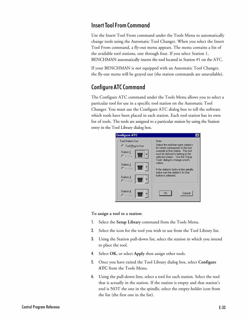
7((2�������<�������� - � ��
������$����6��+���++���
Use the Insert Tool From command under the Tools Menu to automaticallychange tools using the Automatic Tool Changer. When you select the InsertTool From command, a fly-out menu appears. The menu contains a list ofthe available tool stations, one through four. If you select Station 1,BENCHMAN automatically inserts the tool located in Station #1 on the ATC.
If your BENCHMAN is not equipped with an Automatic Tool Changer,the fly-out menu will be grayed out (the station commands are unavailable).
���� ������$����++���
The Configure ATC command under the Tools Menu allows you to select aparticular tool for use in a specific tool station on the Automatic ToolChanger. You must use the Configure ATC dialog box to tell the softwarewhich tools have been placed in each station. Each tool station has its ownlist of tools. The tools are assigned to a particular station by using the Stationentry in the Tool Library dialog box.
To assign a tool to a station:
,- Select the Setup Library command from the Tools Menu.
.- Select the icon for the tool you wish to use from the Tool Library list.
/- Using the Station pull-down list, select the station in which you intendto place the tool.
�- Select OK, or select Apply then assign other tools.
- Once you have exited the Tool Library dialog box, select ConfigureATC from the Tools Menu.
:- Using the pull-down lists, select a tool for each station. Select the toolthat is actually in the station. If the station is empty and that station’stool is NOT the one in the spindle, select the empty-holder icon fromthe list (the first one in the list).
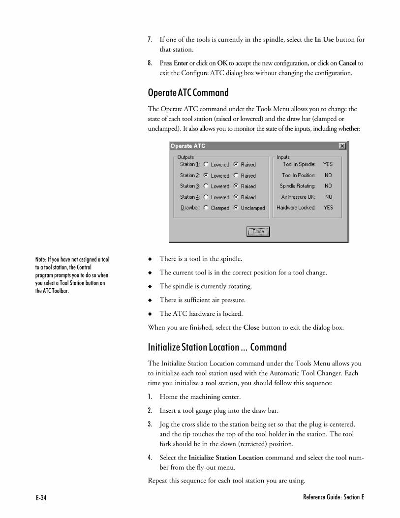
7(. � - � �� ����� ��� ������7
;- If one of the tools is currently in the spindle, select the In Use button forthat station.
<- Press Enter or click on OK to accept the new configuration, or click on Cancel toexit the Configure ATC dialog box without changing the configuration.
3&������$����++���
The Operate ATC command under the Tools Menu allows you to change thestate of each tool station (raised or lowered) and the draw bar (clamped orunclamped). It also allows you to monitor the state of the inputs, including whether:
� There is a tool in the spindle.
� The current tool is in the correct position for a tool change.
� The spindle is currently rotating.
� There is sufficient air pressure.
� The ATC hardware is locked.
When you are finished, select the Close button to exit the dialog box.
�� �� D��� ���5�#� ���---����++���
The Initialize Station Location command under the Tools Menu allows youto initialize each tool station used with the Automatic Tool Changer. Eachtime you initialize a tool station, you should follow this sequence:
,- Home the machining center.
.- Insert a tool gauge plug into the draw bar.
/- Jog the cross slide to the station being set so that the plug is centered,and the tip touches the top of the tool holder in the station. The toolfork should be in the down (retracted) position.
�- Select the Initialize Station Location command and select the tool num-ber from the fly-out menu.
Repeat this sequence for each tool station you are using.
��� ���-�"�����4 ����������� �������������������������3��� �2������ ������� ��� ���"�������������� �"���� � ������������������%���������� ��2�����%��+

7(62�������<�������� - � ��
��&�����
The Setup Menu commands control the parameters for setting up tool posi-tioning, jogging, running and verifying programs, coordinate systems, tooloffsets, etc.
��++���) '�����)
Set Position Establish the X, Y and Z position of the tool.
Zero Position Set the current tool position to X0, Y0, Z0.
Jog Settings Establish speed and distance parameters for joggingthe tool.
Run Settings Establish options for running an NC part program.
Verify Settings Establish options for verifying an NC part program.
Verify Type Select centerline or solid view for tool path verification.
Set/Check Home Establish or check a fixed known position on themachine.
Goto Position Automatically move the tool to a specific set of co-ordinates on the machining center.
Units Select Inch or Metric units of measure.
Coordinate Systems Define multiple coordinate systems or select anew coordinate system.
Offsets Modify the table of offset values used for certainNC codes.
Spindle Specify a spindle speed if you have not used an Scode in your NC program.
Backlash Define the amount of backlash in the machiningcenter axes.
Soft Limits Establish software limits for each axis within themachine coordinate system.
Preferences Establish defaults for saving files and security features.
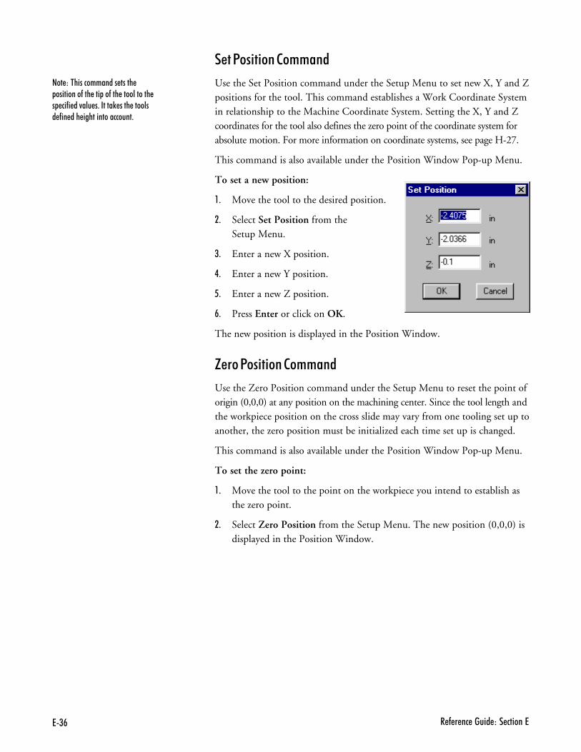
7(# � - � �� ����� ��� ������7
��1�� �����++���
Use the Set Position command under the Setup Menu to set new X, Y and Zpositions for the tool. This command establishes a Work Coordinate Systemin relationship to the Machine Coordinate System. Setting the X, Y and Zcoordinates for the tool also defines the zero point of the coordinate system forabsolute motion. For more information on coordinate systems, see page H-27.
This command is also available under the Position Window Pop-up Menu.
To set a new position:
,- Move the tool to the desired position.
.- Select Set Position from theSetup Menu.
/- Enter a new X position.
�- Enter a new Y position.
- Enter a new Z position.
:- Press Enter or click on OK.
The new position is displayed in the Position Window.
G����1�� �����++���
Use the Zero Position command under the Setup Menu to reset the point oforigin (0,0,0) at any position on the machining center. Since the tool length andthe workpiece position on the cross slide may vary from one tooling set up toanother, the zero position must be initialized each time set up is changed.
This command is also available under the Position Window Pop-up Menu.
To set the zero point:
,- Move the tool to the point on the workpiece you intend to establish asthe zero point.
.- Select Zero Position from the Setup Menu. The new position (0,0,0) isdisplayed in the Position Window.
���)��������������� ����� ���������-��� ��� ��-��� ����������� � ��-� ��4��� �+������) ���� ������� -�� ��� �����������������+
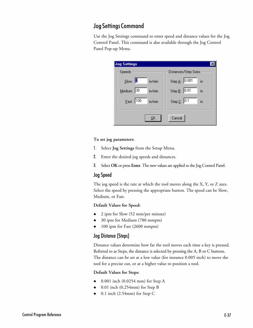
7('2�������<�������� - � ��
To set jog parameters:
,- Select Jog Settings from the Setup Menu.
.- Enter the desired jog speeds and distances.
/- Select OK or press Enter. The new values are applied to the Jog Control Panel.
F���&���
The jog speed is the rate at which the tool moves along the X, Y, or Z axes.Select the speed by pressing the appropriate button. The speed can be Slow,Medium, or Fast.
Default Values for Speed:
� 2 ipm for Slow (52 mm/per minute)� 30 ipm for Medium (780 mmpm)� 100 ipm for Fast (2600 mmpm)
F���" ���#��@�&�A
Distance values determine how far the tool moves each time a key is pressed.Referred to as Steps, the distance is selected by pressing the A, B or C buttons.The distance can be set at a low value (for instance 0.005 inch) to move thetool for a precise cut, or at a higher value to position a tool.
Default Values for Steps:
� 0.001 inch (0.0254 mm) for Step A� 0.01 inch (0.254mm) for Step B� 0.1 inch (2.54mm) for Step C
F���� ������++���
Use the Jog Settings command to enter speed and distance values for the JogControl Panel. This command is also available through the Jog ControlPanel Pop-up Menu.
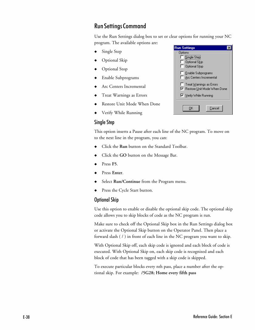
7(@ � - � �� ����� ��� ������7
����� ������++���
Use the Run Settings dialog box to set or clear options for running your NCprogram. The available options are:
� Single Step
� Optional Skip
� Optional Stop
� Enable Subprograms
� Arc Centers Incremental
� Treat Warnings as Errors
� Restore Unit Mode When Done
� Verify While Running
������&
This option inserts a Pause after each line of the NC program. To move onto the next line in the program, you can:
� Click the Run button on the Standard Toolbar.
� Click the GO button on the Message Bar.
� Press F5.
� Press Enter.
� Select Run/Continue from the Program menu.
� Press the Cycle Start button.
3& �����0 &
Use this option to enable or disable the optional skip code. The optional skipcode allows you to skip blocks of code as the NC program is run.
Make sure to check off the Optional Skip box in the Run Settings dialog boxor activate the Optional Skip button on the Operator Panel. Then place aforward slash ( / ) in front of each line in the NC program you want to skip.
With Optional Skip off, each skip code is ignored and each block of code isexecuted. With Optional Skip on, each skip code is recognized and eachblock of code that has been tagged with a skip code is skipped.
To execute particular blocks every nth pass, place a number after the op-tional skip. For example: /5G28; Home every fifth pass
7(B2�������<�������� - � ��
3& ������&
This enables or disables the optional stop code (M01). The optional stopcode allows you to place an optional stop in your NC program. To activatethe optional stop, select the Optional Stop box in the Run Settings dialogbox, or select the Optional Stop button on the Operator Panel. Be sure youhave put an M01 code on the line where you would like to pause.
With the Optional Stop option on, the M01 works like an M00 or G05.With Optional Stop off, the M01 code is ignored, the other codes on theline are executed as usual.
���B����B&�����+�
Use this option to enable or disable the use of subprograms. With this optiondisabled, M98 commands generate an error. Running or verifying a programwith subprograms enabled takes longer to start because the software parsesthe entire file for subprogram information. This extra delay should only benoticeable with large programs.
��#����������#��+����
Use this checkbox to specify the default mode for programming arc centers. Ifthis box is checked, the default mode is the Fanuc mode, in which arc centers arealways incremental. If this box isn’t checked, the default mode is EIA-274,in which arc centers follow the general programming mode: Absolute whenthe mode is absolute, and incremental when the mode is incremental.
$����2��� �������������
This command is used for special applications, where you don’t want any un-expected pauses in the program execution. For example, a warning is displayedand the program pauses, waiting for your input before it continues.
When this item is selected, any warning will halt the program, performing aProgram Stop. When motion is stopped, all outputs are turned off.
�������'� ������2%���"���
If you normally work in one unit mode (inch or metric) but would like to runa program in another mode without disrupting your default settings, selectthis box.
Select a specific unit mode by using one of the G20/G21 or G70/G71commands at the beginning of your NC program. Once the NC program isexecuted, your default unit mode will be restored.
For instance, if you normally work in Inch Mode, but have a particular pro-gram you would like to run in Metric Mode, select the Restore Unit ModeWhen Done box. Place a G21 code at the beginning of your program, thenrun it. When the program is finished, the default for your system will still beInch Mode.
���)��� ��2� ���������� �-�����4 ���� ��� �� -�����%"� ��������� ���� � ��������2 �� ���&L*���%����� ����2 �� ���&P*���� ������� -�������� ��-��� �-�� +
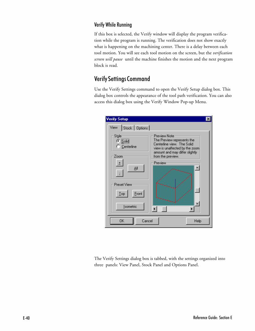
7.$ � - � �� ����� ��� ������7
��� ���2% ������� ��
If this box is selected, the Verify window will display the program verifica-tion while the program is running. The verification does not show exactlywhat is happening on the machining center. There is a delay between eachtool motion. You will see each tool motion on the screen, but the verificationscreen will pause until the machine finishes the motion and the next programblock is read.
��� ���� ������++���
Use the Verify Settings command to open the Verify Setup dialog box. Thisdialog box controls the appearance of the tool path verification. You can alsoaccess this dialog box using the Verify Window Pop-up Menu.
The Verify Settings dialog box is tabbed, with the settings organized intothree panels: View Panel, Stock Panel and Options Panel.
7.�2�������<�������� - � ��
� ���1����
The View panel allows you to control the view style and zoom factor. It alsooffers a selection of preset views.
StyleUse these radio buttons to select between Solid and Centerline views of the stock.Solid View is a solid three-dimensional view of the workpiece and toolpath.Centerline View is a view that depicts the centerline of the toolpath. Insteadof a solid model, the workpiece is shown in wireframe.
ZoomUse these buttons to control the size of the stock in the Verify Window. Youcan click on the buttons or use Alt key combinations (Alt++, Alt+-, and Alt+A).Each mouse click or key combination used zooms by an increment of one.
���� 6��# ��
+ Zoom in on the stock.- Zoom away from the stock.All Fit the stock into the window.
Preset ViewUse these buttons to select a perspective, then use the Preview Window tofine-tune the angle:
���� 6��# ��
Front View the stock directly from the front. The stockappears as a rectangle along the X, Z axes.
Top View the stock directly from above. The stock ap-pears as a rectangle along the X, Y axes.
Isometric View the stock at an angle, in three dimensions.
�#0�1����
All stock values are interpreted according to the Units Mode in effect at thetime they are set. To quickly see which Units Mode is currently in effect, checkthe Position window.
Stock DimensionsUse this area to set the dimensions of the stock used in the verificationprocess. You will see the stock in the Preview Window change as soon asyou enter a dimension.
OriginUse this area to adjust the verification for different workpiece setups. Most NCprograms set the 0,0,0 point at the top of the front-left corner of the stock. Occa-sionally, however, you may want to use a different origin (the center of the stock,for example). In this case, you must enter that point to properly verify your pro-gram. The values entered should correspond to the coordinates for the front leftcorner of the stock relative to the 0,0,0 point for the program.
7.� � - � �� ����� ��� ������7
For instance, if the origin for the program is the center of a 3x2x1 piece ofstock, set the origin to -1.5, -1.0.
Initial Tool PositionYou can select a tool start point using Initial Tool Position. This parameter isonly used for verification, not for actually running a program. When VerifyingWhile Running, the actual tool position is used as the initial tool position.
3& ����1����
The Verify Options control certain aspects of the solid and centerlineverification display.
Solid OptionsAuto-refresh automatically refreshes the solid display of the workpiece duringverification. The screen is updated when something changes, such as resizingthe Verify Window, changing the view, or changing the stock dimensions.When auto-refresh is disabled, you will need to manually cause the verifywindow to update by selecting the Redraw command from the VerifyWindow’s Pop-up Menu. This setting only affects refreshing the windowwhen no verification is in progress.
Centerline OptionsAuto-refresh automatically refreshes the centerline display of the workpiecewhen something changes during verification.
Show Tool controls whether or not the tool is displayed in the Verify Window.
Show Rapid Moves displays the rapid moves made between the end point of onecut to the start point of another.
$%��1��7 ���2 ����
The Preview Window appears in each of the above groups. The PreviewWindow shows you approximately what the Verify Window will look like.The Preview Window always depicts the stock in Centerline view.
In addition to depicting how the Verify Window will look, you can use thepreview box to change the orientation of the stock:
� Use the slider bars on the side of the Preview Window to rotate the stockalong the X, Y plane and along the Z plane. There are two ways to con-trol the sliders:
,- Select the slider button by clicking on it with the mouse. Hold theleft mouse button down while sliding the button along the bar untilthe stock is in the desired position.
.- Select the slider button by tabbing to it. The button will blink to in-dicate it is selected. Use the arrow keys on the keyboard to move theslider button along the bar until the stock is in the desired position.
���)��-�"���� ��G ��� ��������������4 ��-�������3���%���)�%�������� �������� ��� ��-��� �0 ��-"������+����������� � ���� ���%��3������� ������ ���� �4 ��-"����������J���������� K�������� ������+
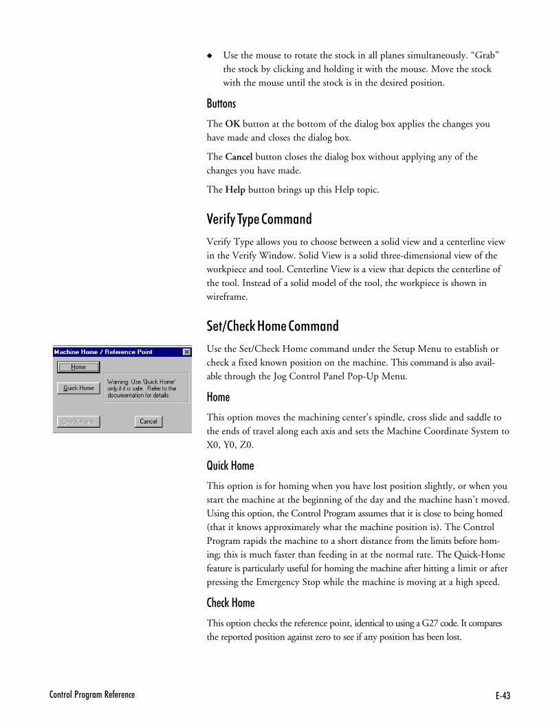
7.(2�������<�������� - � ��
� Use the mouse to rotate the stock in all planes simultaneously. “Grab”the stock by clicking and holding it with the mouse. Move the stockwith the mouse until the stock is in the desired position.
�����
The OK button at the bottom of the dialog box applies the changes youhave made and closes the dialog box.
The Cancel button closes the dialog box without applying any of thechanges you have made.
The Help button brings up this Help topic.
��� ���$�&����++���
Verify Type allows you to choose between a solid view and a centerline viewin the Verify Window. Solid View is a solid three-dimensional view of theworkpiece and tool. Centerline View is a view that depicts the centerline ofthe tool. Instead of a solid model of the tool, the workpiece is shown inwireframe.
�?�%�#0���+����++���
Use the Set/Check Home command under the Setup Menu to establish orcheck a fixed known position on the machine. This command is also avail-able through the Jog Control Panel Pop-Up Menu.
��+�
This option moves the machining center’s spindle, cross slide and saddle tothe ends of travel along each axis and sets the Machine Coordinate System toX0, Y0, Z0.
H� #0���+�
This option is for homing when you have lost position slightly, or when youstart the machine at the beginning of the day and the machine hasn’t moved.Using this option, the Control Program assumes that it is close to being homed(that it knows approximately what the machine position is). The ControlProgram rapids the machine to a short distance from the limits before hom-ing; this is much faster than feeding in at the normal rate. The Quick-Homefeature is particularly useful for homing the machine after hitting a limit or afterpressing the Emergency Stop while the machine is moving at a high speed.
�%�#0���+�
This option checks the reference point, identical to using a G27 code. It comparesthe reported position against zero to see if any position has been lost.
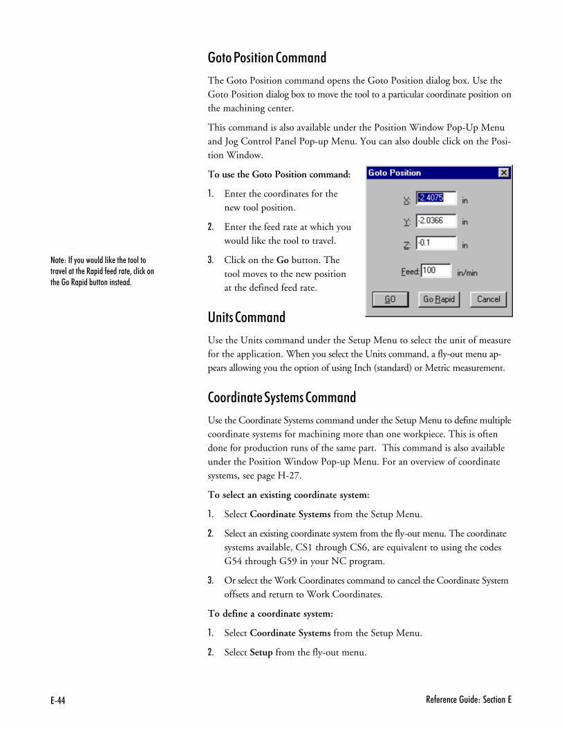
7.. � - � �� ����� ��� ������7
����1�� �����++���
The Goto Position command opens the Goto Position dialog box. Use theGoto Position dialog box to move the tool to a particular coordinate position onthe machining center.
This command is also available under the Position Window Pop-Up Menuand Jog Control Panel Pop-up Menu. You can also double click on the Posi-tion Window.
To use the Goto Position command:
,- Enter the coordinates for thenew tool position.
.- Enter the feed rate at which youwould like the tool to travel.
/- Click on the Go button. Thetool moves to the new positionat the defined feed rate.
'� ����++���
Use the Units command under the Setup Menu to select the unit of measurefor the application. When you select the Units command, a fly-out menu ap-pears allowing you the option of using Inch (standard) or Metric measurement.
����� �������+����++���
Use the Coordinate Systems command under the Setup Menu to define multiplecoordinate systems for machining more than one workpiece. This is oftendone for production runs of the same part. This command is also availableunder the Position Window Pop-up Menu. For an overview of coordinatesystems, see page H-27.
To select an existing coordinate system:
,- Select Coordinate Systems from the Setup Menu.
.- Select an existing coordinate system from the fly-out menu. The coordinatesystems available, CS1 through CS6, are equivalent to using the codesG54 through G59 in your NC program.
/- Or select the Work Coordinates command to cancel the Coordinate Systemoffsets and return to Work Coordinates.
To define a coordinate system:
,- Select Coordinate Systems from the Setup Menu.
.- Select Setup from the fly-out menu.
���)��-�"�����������) ��� �����������4 ������� ��� ���- ����� 3�����)����� ������& ��%���������� ��+
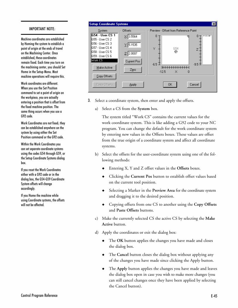
7.62�������<�������� - � ��
/- Select a coordinate system, then enter and apply the offsets.
a) Select a CS from the System box.
The system titled “Work CS” contains the current values for thework coordinate system. This is like adding a G92 code to your NCprogram. You can change the default for the work coordinate systemby entering new values in the Offsets boxes. These values are offsetfrom the true origin of a coordinate system and affect all coordinatesystems.
b) Select the offsets for the user-coordinate system using one of the fol-lowing methods:
� Entering X, Y and Z offset values in the Offsets boxes.
� Clicking the Current Pos button to establish offset values basedon the current tool position.
� Selecting a Marker in the Preview Area for the coordinate systemand dragging it to the desired position.
� Copying offsets from one CS to another using the Copy Offsetsand Paste Offsets buttons.
c) Make the currently selected CS the active CS by selecting the MakeActive button.
d) Apply the coordinates or exit the dialog box:
� The OK button applies the changes you have made and closesthe dialog box.
� The Cancel button closes the dialog box without applying anyof the changes you have made since clicking the Apply button.
� The Apply button applies the changes you have made and leavesthe dialog box open in case you wish to make more changes (youcan still cancel changes once they have been applied by selectingthe Cancel button).
��13�$��$��3$�)
1����� ���������� ���� � ���%���� �%"�8�������� ��"�� ����� ���%������ ������-������������� � �����-����4 ������ �1���������2 �� �+�>�� ���%���� �3��� � ���������� �� �����-�! �+�7������� �"������������ ������������ �� �3�"����������� �8�� ������ �� �� �1 ��+�1��������� �� �������������� N��� �����+
���)���������� ���� ���-- � ��+�� ��"����� ��� �� ��<������������������� ���� ������-������������ ����) � � 3�"����� ��������" �� ������� �����������������--� ��-����� �-�! �������� � �������+��� ��� ���������������� ��"����� ���B����� +
���)�2�������� ���� �����-�! �M��� "����% � ���%���� ����"�� � ������ �"�� ��%"������� ��� ���� �� �<��������������������� ��B����� +
��������� ����)�2�������� ��"������� ��� ���� ���������� ��"�� ���������� ���� ���6.����������6B3����� �� �� �2�������� ��"�� ���������%�!+
�-�"���� � ���� ����)�2�������� � ��� ����������B����� ��������� �������%�!3��� ��6.�6B�2�������� �"�� ���--� ������������� ����������"+
�-�"���8�� ��� ������� ����� ������2�������� ��"�� ��3��� ��--� �����������% ��-- �� �+
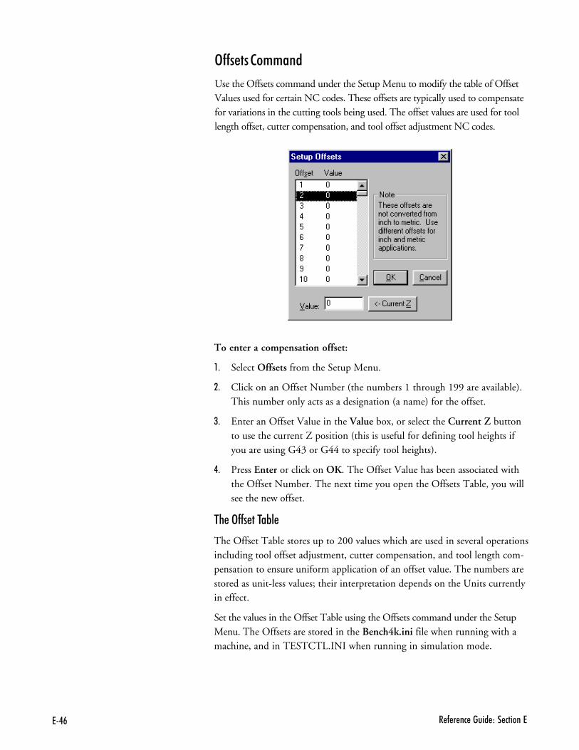
7.# � - � �� ����� ��� ������7
To enter a compensation offset:
,- Select Offsets from the Setup Menu.
.- Click on an Offset Number (the numbers 1 through 199 are available).This number only acts as a designation (a name) for the offset.
/- Enter an Offset Value in the Value box, or select the Current Z buttonto use the current Z position (this is useful for defining tool heights ifyou are using G43 or G44 to specify tool heights).
�- Press Enter or click on OK. The Offset Value has been associated withthe Offset Number. The next time you open the Offsets Table, you willsee the new offset.
$%��3�����$�B��
The Offset Table stores up to 200 values which are used in several operationsincluding tool offset adjustment, cutter compensation, and tool length com-pensation to ensure uniform application of an offset value. The numbers arestored as unit-less values; their interpretation depends on the Units currentlyin effect.
Set the values in the Offset Table using the Offsets command under the SetupMenu. The Offsets are stored in the Bench4k.ini file when running with amachine, and in TESTCTL.INI when running in simulation mode.
3��������++���
Use the Offsets command under the Setup Menu to modify the table of OffsetValues used for certain NC codes. These offsets are typically used to compensatefor variations in the cutting tools being used. The offset values are used for toollength offset, cutter compensation, and tool offset adjustment NC codes.
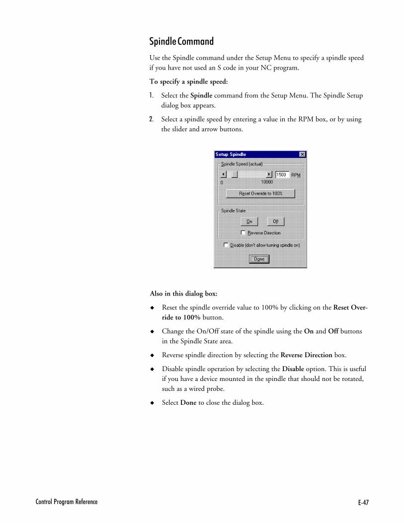
7.'2�������<�������� - � ��
& �������++���
Use the Spindle command under the Setup Menu to specify a spindle speedif you have not used an S code in your NC program.
To specify a spindle speed:
,- Select the Spindle command from the Setup Menu. The Spindle Setupdialog box appears.
.- Select a spindle speed by entering a value in the RPM box, or by usingthe slider and arrow buttons.
Also in this dialog box:
� Reset the spindle override value to 100% by clicking on the Reset Over-ride to 100% button.
� Change the On/Off state of the spindle using the On and Off buttonsin the Spindle State area.
� Reverse spindle direction by selecting the Reverse Direction box.
� Disable spindle operation by selecting the Disable option. This is usefulif you have a device mounted in the spindle that should not be rotated,such as a wired probe.
� Select Done to close the dialog box.
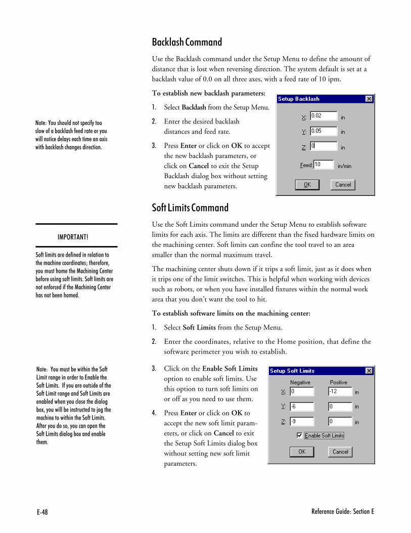
7.@ � - � �� ����� ��� ������7
��#0���%���++���
Use the Backlash command under the Setup Menu to define the amount ofdistance that is lost when reversing direction. The system default is set at abacklash value of 0.0 on all three axes, with a feed rate of 10 ipm.
To establish new backlash parameters:
,- Select Backlash from the Setup Menu.
.- Enter the desired backlashdistances and feed rate.
/- Press Enter or click on OK to acceptthe new backlash parameters, orclick on Cancel to exit the SetupBacklash dialog box without settingnew backlash parameters.
���5 + ����++���
Use the Soft Limits command under the Setup Menu to establish softwarelimits for each axis. The limits are different than the fixed hardware limits onthe machining center. Soft limits can confine the tool travel to an areasmaller than the normal maximum travel.
The machining center shuts down if it trips a soft limit, just as it does whenit trips one of the limit switches. This is helpful when working with devicessuch as robots, or when you have installed fixtures within the normal workarea that you don’t want the tool to hit.
To establish software limits on the machining center:
,- Select Soft Limits from the Setup Menu.
.- Enter the coordinates, relative to the Home position, that define thesoftware perimeter you wish to establish.
/- Click on the Enable Soft Limitsoption to enable soft limits. Usethis option to turn soft limits onor off as you need to use them.
�- Press Enter or click on OK toaccept the new soft limit param-eters, or click on Cancel to exitthe Setup Soft Limits dialog boxwithout setting new soft limitparameters.
�1<>����A
��-����������� �� -�� ������ ����������� ������� ���������� �M��� � -�� 3"����������� ��� �1���������2 �� �% -�� ���������-��������+���-����������� ���� �-��� ���-��� �1���������2 �� ���������% ����� �+
���)�,��������������� ��-"����������-���%��)�����- ����� ����"������������ �� ��"�� ������� �����!�������%��)���������� ����� �����+
���)��,��������% ���������� ���-�5��������� ������� �����7��%� ��� ��-��5�����+���-�"����� ������� ��-��� ��-��5��������� �������-��5�������� ��%� ���� ��"������� ��� �������%�!3�"��������% ��������� �����;����� ������ ������������� ���-��5�����+-� ��"��������3�"�������� ���� ��-��5�������������%�!����� ��%� �� �+
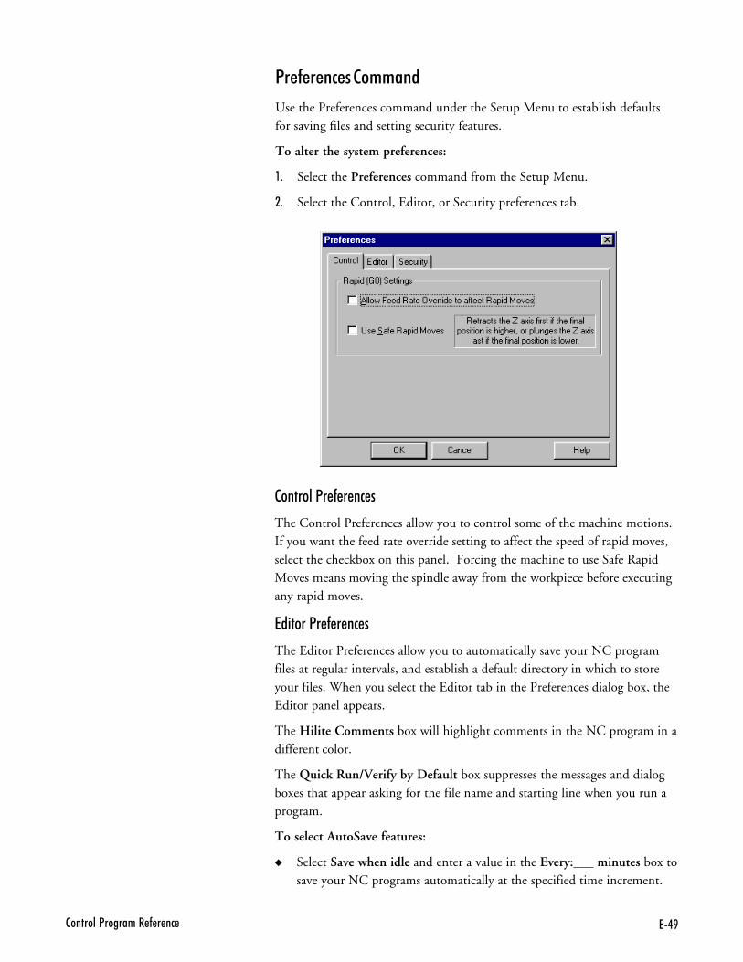
7.B2�������<�������� - � ��
�������1�������#��
The Control Preferences allow you to control some of the machine motions.If you want the feed rate override setting to affect the speed of rapid moves,select the checkbox on this panel. Forcing the machine to use Safe RapidMoves means moving the spindle away from the workpiece before executingany rapid moves.
�� ���1�������#��
The Editor Preferences allow you to automatically save your NC programfiles at regular intervals, and establish a default directory in which to storeyour files. When you select the Editor tab in the Preferences dialog box, theEditor panel appears.
The Hilite Comments box will highlight comments in the NC program in adifferent color.
The Quick Run/Verify by Default box suppresses the messages and dialogboxes that appear asking for the file name and starting line when you run aprogram.
To select AutoSave features:
� Select Save when idle and enter a value in the Every:___ minutes box tosave your NC programs automatically at the specified time increment.
1�������#�����++���
Use the Preferences command under the Setup Menu to establish defaultsfor saving files and setting security features.
To alter the system preferences:
,- Select the Preferences command from the Setup Menu.
.- Select the Control, Editor, or Security preferences tab.
76$ � - � �� ����� ��� ������7
� Select Save Before Running to save changes to your NC program priorto running it for the first time with the changes.
� Select Prompt Before AutoSaving if you wish to be prompted by theControl Program before it automatically saves the NC program at thespecified time increment.
To select File Default features:
� Enter an Extension for your NC part program files. The default is “NC.”
� Select Lock Files When Opened to have your NC programs locked by de-fault. Deselect this feature to have your NC programs unlocked by default.
� Select the Set button to specify a target directory in which to save yourNC program files. The default directory appears in the Directory box.
To exit the Preferences dialog box:
Press Enter or click on OK to accept the new preference settings, or click onCancel to exit the Preferences dialog box without setting new Editor orSecurity Preferences.
To access Help for this panel:
Select the Help button to access the Help files for this panel.
�#�� ��1�������#��
The Security Preferences allow you to control which features others may use.When you select the Security tab in the Preferences dialog box, the Securitypanel appears.
The Security Preferences panel offers two modes, User and Administrator.Administrator Mode allows a supervisor, such as a teacher in a classroom, toturn commands on or off using the Allowed Commands list. User Modedoes not have access to this feature.
To secure the software using Administrator Mode:
,- Set the Default Mode to User. (Note that this will not change the cur-rent mode.)
.- Use the Change Password button to create a password. The defaultpassword is blank (no password).
/- Select the Allowed Commands. Double-click on the listed commandsto enable or disable them. If the commands are enabled, they aremarked with an X. A description of each selected command is displayedon the right side of the panel.
�- Use the Change Mode button to change to User Mode.
- Select OK or press Enter to exit the Preferences dialog box.
76�2�������<�������� - � ��
The software is now running in User Mode. The next time you open thePreferences dialog box, the Security preference panel is displayed in UserMode. In this mode it is not possible to turn commands on or off.
To return to Administrator Mode:
,- Use the Change Mode button to toggle the Mode from User to Admin-istrator. A dialog box appears, prompting you to enter your password.
.- Enter your password and press Enter or click on OK.
To change your password:
,- Click on the Change Password button.
.- Enter your current password.
/- Enter the new password.
�- Enter the new password again to verify that it is correct.
To exit the Preferences dialog box:
Press Enter or click on OK to accept the new preference settings, or click onCancel to exit the Preferences dialog box without setting new Editor orSecurity Preferences.
To access Help for this panel:
Select the Help button to access the Help files for this panel.
2 ���������
The Window Menu commands allow you to manipulate the arrangement ofthe Program Edit Windows.
��++���) '�����)
Cascade Layer the open edit windows.
Tile Tile the open edit windows.
Arrange Icons Arrange any minimized edit windows along thebottom of the edit area.
Window List Display and select from the currently open NC pro-grams by their file names.
���#������++���
Similar to the standard Windows/Cascade command. Places the open Pro-gram Edit Windows in a layered format, cascading down to the right withthe currently selected window on top.
76� � - � �� ����� ��� ������7
$ �����++���
Similar to the standard Windows/Tile command. Places the open ProgramEdit Windows in a tiled format, filling the Edit Area from top to bottom.
���������#������++���
When you minimize a Program Edit Window, it becomes a small icon. TheArrange command under the Window Menu arranges these icons along thebottom of the edit area.
2 �����5 ����++���
Lists the currently open Program Edit Windows. The currently selected windowis designated with a check mark. You may select any window by clicking onthe window itself, or by selecting the window name from this list.
���&�����
The Help Menu commands allow you to navigate through the Help files, tosave or restore parameters set throughout the current session, and provideshandy tips and other information about the Control Program.
��++���) '�����)
Help Display Help for the current task or command.
Index List Help topics.
Using Help Display instructions about how to use Help.
Save Settings Save the current machine and application settings.
Restore Settings Reset machine and application settings from defaults.
Tip of the Day Display a Tip of the Day.
About Benchman Display program information, version number andcopyrights.
���&���++���
Use the Help command to access the Help contents. You can also press theF1 key to get information about the currently highlighted command on adrop-down or pop-up menu.
����9���++���
Use the Help Index command to access an index of available Help topics.
��� ���� ��"���� � �������� � -�������������� �� ���� �� �������������3������2���������G�������-����������������+
76(2�������<�������� - � ��
'� ������&���++���
Use the Using Help command to obtain information on using the Help utility.
�7��� ������++���
The Save Settings command allows you to retain current library, security,screen and control settings as defaults.
� Click on a particular setting(s) to tag it, then click on the Save button tosave the selected items and exit the dialog box.
� Click on the Save All button to save all settings without having to selecteach one.
� Click on the Cancel button to exit the Save Defaults dialog box withoutchanging the existing defaults.
�������� ������++���
The Restore Settings command allows you to restore all or some of the cur-rent settings to the defaults you set using the Save Settings command (UserDefaults) or to the factory set defaults.
� Click on a particular setting(s) to tag it, then click on a Restore Fromoption. Click the Restore button to restore the selected items and exitthe dialog box.
� Click on the Restore All button to restore all settings without having toselect each one.
� Click on the Cancel button to exit the Restore Defaults dialog box withoutchanging the existing defaults.
$ &����%��"�����++���
This command brings up information about the operation of the machiningcenter, tips & tricks for using the Control Program, and NC programming ideas.
�B������������---���++���
This command brings up the BENCHMAN information box. Included is in-formation on the Control Program version number, the release date, andcopyright information.
The Details box allows you to see what options have been installed, and thesoftware and firmware versions.
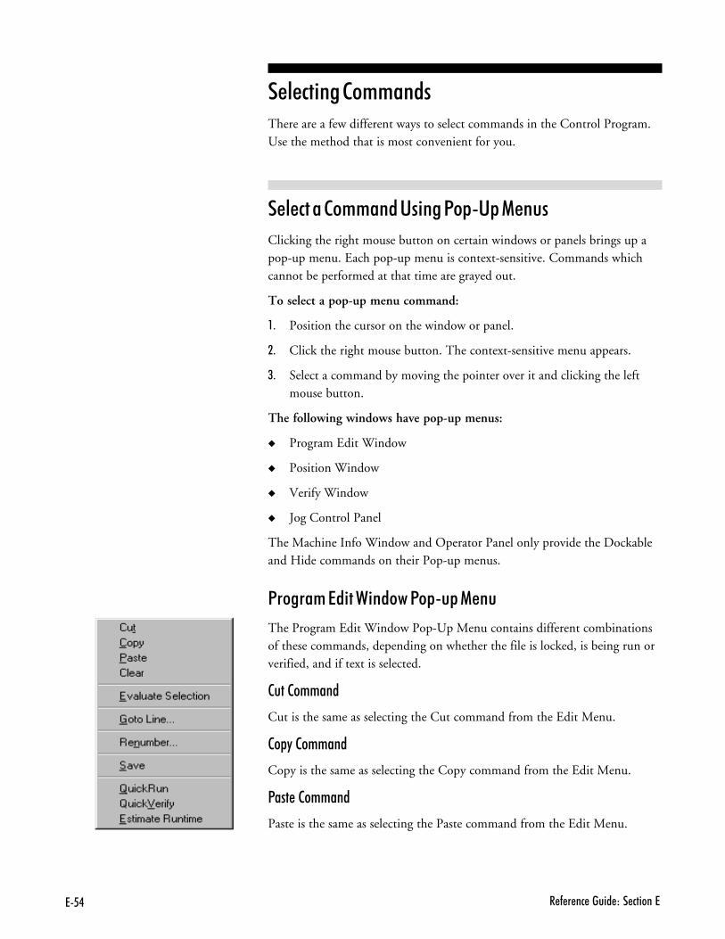
76. � - � �� ����� ��� ������7
���# �����++����There are a few different ways to select commands in the Control Program.Use the method that is most convenient for you.
���#�����++����'� ���1�&�'&������
Clicking the right mouse button on certain windows or panels brings up apop-up menu. Each pop-up menu is context-sensitive. Commands whichcannot be performed at that time are grayed out.
To select a pop-up menu command:
,- Position the cursor on the window or panel.
.- Click the right mouse button. The context-sensitive menu appears.
/- Select a command by moving the pointer over it and clicking the leftmouse button.
The following windows have pop-up menus:
� Program Edit Window
� Position Window
� Verify Window
� Jog Control Panel
The Machine Info Window and Operator Panel only provide the Dockableand Hide commands on their Pop-up menus.
1�����+��� �2 �����1�&��&�����
The Program Edit Window Pop-Up Menu contains different combinationsof these commands, depending on whether the file is locked, is being run orverified, and if text is selected.
�����++���
Cut is the same as selecting the Cut command from the Edit Menu.
��&����++���
Copy is the same as selecting the Copy command from the Edit Menu.
1������++���
Paste is the same as selecting the Paste command from the Edit Menu.

7662�������<�������� - � ��
��������++���
Cut is the same as selecting the Cut command from the Edit Menu.
�7���������# ��
This command evaluates the selected text (expression) and replaces it withthe result (e.g. selecting 3/4 and evaluating it replaces 3/4 with .75). You canuse parentheses, normal operations (+.-.*,/), modulus (%), power (^), trigfunctions (cos, sin, tan, acos, atan, asin) and SQRT.
To use the Evaluate Selection command, the program must be unlocked,and a single line selected.
����5 �����++���
Goto Line is the same as selecting the Goto Line command from the Edit Menu.
����+B�����++���
The Renumber command is the same as selecting Renumber from the EditMenu. A dialog box appears that allows you to alter the N codes in the NCprogram.
�7����++���
Saves the current program.
H� #0������++���
The QuickRun command is a shortcut that runs the currently selected NCpart program. When you click on this command, the program behaves asthough you had selected the Run/Continue Command from the ProgramMenu with the following exceptions:
� You do not have the option of selecting a starting line.
� You do not have the option of changing any settings.
H� #0��� �����++���
The QuickVerify command is a shortcut that verifies the currently selectedNC part program. When you click on this command, the program behaves asthough you had selected the Verify Command from the Program Menu withthe following exceptions:
� You do not have the option of selecting a starting line.
� You do not have the option of changing any settings.
�� +������ +�
This command performs the same function as the Estimate Runtime commandunder the Program Menu.
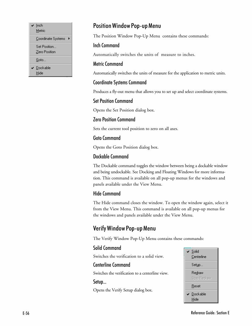
76# � - � �� ����� ��� ������7
1�� ���2 �����1�&��&�����
The Position Window Pop-Up Menu contains these commands:
��#%���++���
Automatically switches the units of measure to inches.
��� #���++���
Automatically switches the units of measure for the application to metric units.
����� �������+����++���
Produces a fly-out menu that allows you to set up and select coordinate systems.
��1�� �����++���
Opens the Set Position dialog box.
G����1�� �����++���
Sets the current tool position to zero on all axes.
������++���
Opens the Goto Position dialog box.
"�#0�B�����++���
The Dockable command toggles the window between being a dockable windowand being undockable. See Docking and Floating Windows for more informa-tion. This command is available on all pop-up menus for the windows andpanels available under the View Menu.
� �����++���
The Hide command closes the window. To open the window again, select itfrom the View Menu. This command is available on all pop-up menus forthe windows and panels available under the View Menu.
��� ���2 �����1�&��&�����
The Verify Window Pop-Up Menu contains these commands:
�� ����++���
Switches the verification to a solid view.
������ �����++���
Switches the verification to a centerline view.
��&---
Opens the Verify Setup dialog box.
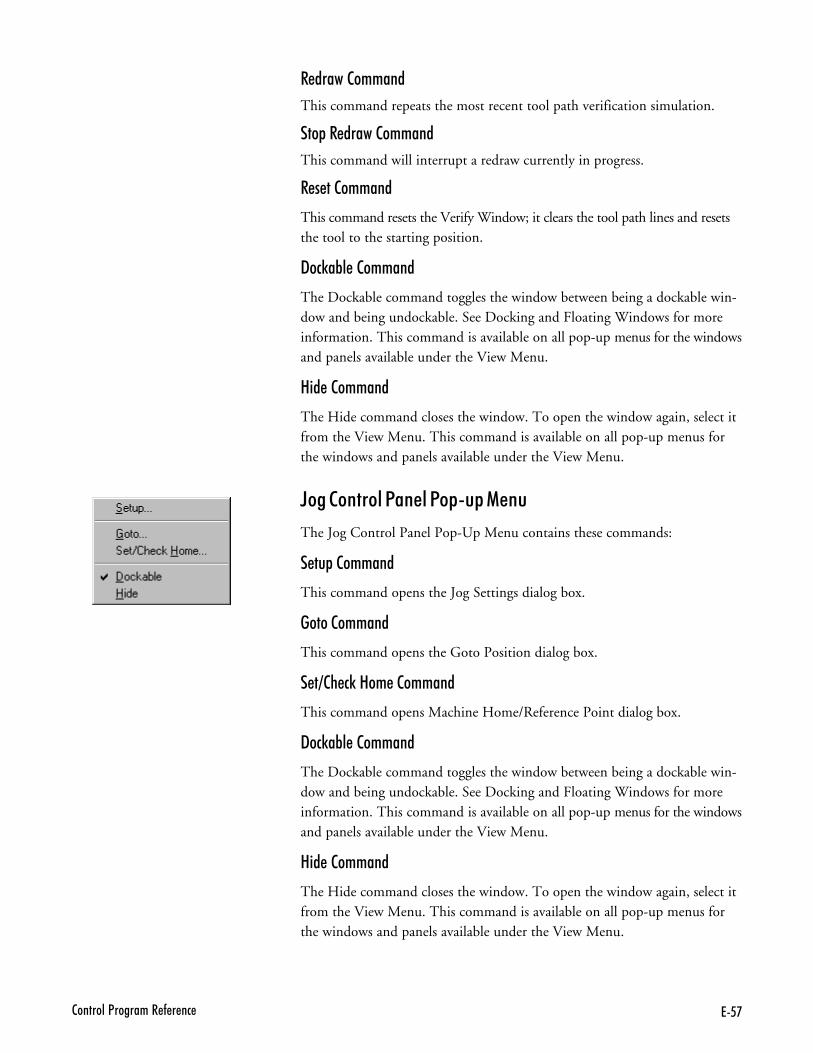
76'2�������<�������� - � ��
���������++���
This command repeats the most recent tool path verification simulation.
�&����������++���
This command will interrupt a redraw currently in progress.
�������++���
This command resets the Verify Window; it clears the tool path lines and resetsthe tool to the starting position.
"�#0�B�����++���
The Dockable command toggles the window between being a dockable win-dow and being undockable. See Docking and Floating Windows for moreinformation. This command is available on all pop-up menus for the windowsand panels available under the View Menu.
� �����++���
The Hide command closes the window. To open the window again, select itfrom the View Menu. This command is available on all pop-up menus forthe windows and panels available under the View Menu.
F����������1�����1�&��&�����
The Jog Control Panel Pop-Up Menu contains these commands:
��&���++���
This command opens the Jog Settings dialog box.
������++���
This command opens the Goto Position dialog box.
�?�%�#0���+����++���
This command opens Machine Home/Reference Point dialog box.
"�#0�B�����++���
The Dockable command toggles the window between being a dockable win-dow and being undockable. See Docking and Floating Windows for moreinformation. This command is available on all pop-up menus for the windowsand panels available under the View Menu.
� �����++���
The Hide command closes the window. To open the window again, select itfrom the View Menu. This command is available on all pop-up menus forthe windows and panels available under the View Menu.

76@ � - � �� ����� ��� ������7
���#�����++����'� ������E���
Some menu commands have one or more key designations listed next tothem on the menus; these are the hot keys for that command. Pressing thehot key(s) selects the corresponding command.
To select a command using hot keys:
Press the hot key for the desired command. For example, press Ctrl+S tosave your file. Here’s a list of the available hot keys:
E��@�A) ����?��++���)
Ctrl+C Edit Menu/Copy
Ctrl+F Edit Menu/Find
Ctrl+G Edit Menu/Goto Line
Ctrl+H Setup Menu/Set/Check Home
Ctrl+L Edit Menu/Lock
Ctrl+N File Menu/New
Ctrl+O File Menu/Open
Ctrl+P File Menu/Print
Ctrl+R Setup Menu/Run Settings
Ctrl+S File Menu/Save
Ctrl+Space Program Menu/Stop
Ctrl+T Tools Menu/Setup Library
Ctrl+V Edit Menu/Paste
Ctrl+X Edit Menu/Cut
Ctrl+Y Edit Menu/Redo
Ctrl+Z Edit Menu/Undo
Ctrl+Shift+Z Setup Menu/Zero Position
Ctrl+Shift+E Evaluate Selection
F1 Help Menu/Help
F2 Edit Menu/Delete Line
F5 Program Menu/Run/Continue
F6 Program Menu/Verify
F8 Setup Menu/Goto Position
Ctrl+KeyPad+ Increase Feed rate Override
76B2�������<�������� - � ��
Ctrl+KeyPad- Decrease Feed rate Override
Ctrl+Backspace Edit Menu/Undo
Shift+Delete Edit Menu/Cut
Shift+F1 Context Help
F4 Activate Jog Control
Ctrl+F5 QuickRun
Ctrl+F6 QuickVerify
Ctrl+TAB Next Edit Window
Ctrl+Insert Edit Menu/Copy
Shift+Insert Edit Menu/Paste
Pause Pause
���#�����++����'� ���$���B���
The Toolbars contain buttons that correspond to frequently used menu com-mands. Clicking a button on a toolbar is equivalent to selecting the samecommand from a menu, and is usually quicker. The BENCHMAN 4000Control Program provides Standard, ATC, Input, and Output toolbars. Usethe commands under the View Menu to control whether each toolbar is dis-played or hidden.
7#$ � - � �� ����� ��� ������7
1�� �� ���#�������+&�����The Control Program interface is easily configured and optimized by opening,closing, resizing, and repositioning the screen components.
1�� �� ���$���B���
You can reposition any of the toolbars (Standard, Inputs, Outputs or ATCControl) simply by dragging them off their docking areas. Once away fromthe docking area, the toolbar becomes a floating window, which can be movedand closed like any other window. To move the toolbar, click on the toolbarbackground (the area around the buttons) and drag.
1�� �� ���2 ����������1�����
The windows and panels (Position Window, Machine Info Window, VerifyWindow, Jog Control Panel, and Operator Panel) are initially docked on thedocking area on the right side of the screen. If these items are moved away fromthe docking area, they become floating windows or panels until they are movedback to the docking area.
The Verify window is initially not dockable.
To move a window or panel (create a floating window):
,- Press the Ctrl key.
.- Click on the information area with the left mouse button.
/- Hold and drag the area off the docking area.
�- Release the Ctrl key.
- When the floating window is over its new location, release the mouse button.You can move and close the window as you would any other window.
To return a floating window to its docking area (the window must bedockable):
,- Click on the title bar of the floating window.
.- Drag the area back to the docking area.
/- Release the mouse button.
For more information about Dockable and Undockable windows, see page E-62.
"�#0 �������)
�� ����"� ��������-��� ���� ��� � �����%���3��������������-����������� ����� � ��� �������������"��%; ���+
7#�2�������<�������� - � ��
1�� �� ���1�����+��� �2 �����
Program Edit Windows can be moved, resized or closed just like any otherwindow. The only restriction is that the Edit Windows can not be movedout of the edit area. For instance, you can not move an Edit Window to adocking area.
�7 ���%��2 �����1�� ���
After arranging the application’s windows on the screen, you can save theirpositions. Use the Save Settings command on the Help menu to save thewindow positions (and any other selected items). To restore your saved win-dow positions, or to restore the default window positions (the factory presetpositions), use the Restore Settings command on the Help menu.
The Control Program automatically stores the current window positions whenyou exit the software, and automatically restores them the next time you run it.
7#� � - � �� ����� ��� ������7
"�#0 �������6��� ���2 ����������$���B���
Windows and Toolbars can behave in two ways; they can be placed in a sta-tionary state, docked, or they can be in a free-floating state, and moveable.
"�#0���#�������+&�����
A docked screen component is fixed in place, unlike a floating componentwhich can be placed anywhere on the screen. When a screen component isdocked, the window frame and title disappear.
6��� ���#�������+&�����
A floating screen component can be moved to any position on the ControlProgram screen, unlike a docked screen component, which is fixed in place.When a screen component is floating it has a window frame and title.
To select the Docking/Floating state of a toolbar:
� Click on the background area of the toolbar and drag it away to float it.
� Click on the background, or the title bar of the toolbar and drag it to thedocking area to dock it.
To select the Docking/Floating state of a window:
,- Position the mouse pointer over the window you would like to dock/float.
.- Click the right mouse button.
/- Select Dockable from the drop-down menu.
When the Dockable command is checked, the window can be dragged to adocking area and docked. It can also be kept floating by moving it awayfrom the docking areas and keeping the Ctrl key pressed. Dockable windowscan not be resized.
When the Dockable command is not checked, the window will float and cannot be docked. Floating windows can be resized.
7#(2�������<�������� - � ��
'� ���%��3�����$�B��The Offset Table stores 200 values which are used in several operations includ-ing tool offset adjustment, cutter compensation, and tool length compensation toensure uniform application of an offset value. The numbers are stored as unit-lessvalues; their interpretation depends on the Unit mode currently in effect. Offsetzero is always 0.0 and cannot be modified. Using Offset zero for most compensa-tions cancels that compensation.
Set the values in the Offset Table using the Offsets command under theSetup Menu. The Offsets are stored separately for the machine, and forSimulation Mode.
2��0 ��� �� +��� �������Simulation mode is provided to allow the Control Program to be used when yourcomputer is not connected to a VMC-4000 Machining Center. This is primarilyto support the off-line development of NC programs.
NC program verification and running is supported in Simulation Mode.Programs will run in approximately the same amount of time that theywould if a machine were attached (excluding stops that have indefinitelength of stop time, see Estimate Runtime).
The principal difference between Simulation Mode and Normal Mode is,since no machine is available to send and receive data, there are no Inputsand Outputs. The Inputs and Outputs buttons on the toolbars have no affect.If your program contains commands to wait for certain input values that arenot the default, the events will never occur. If the values are the default, thewait will occur immediately.
���)��� � ��� �����>--� ����%� �3�� �-���������� �1�� 3������� �-���������1�� +��-�"�����--��� ��2 �������� 4 �� � ��������� �������4��� ��-������ ��--� ����%� 3"�������� ���� �������� "��� � � �������� ��������1�� ��--� ���%� ���������� ���� � ���������������� ������������1�� ��--� ����%� +
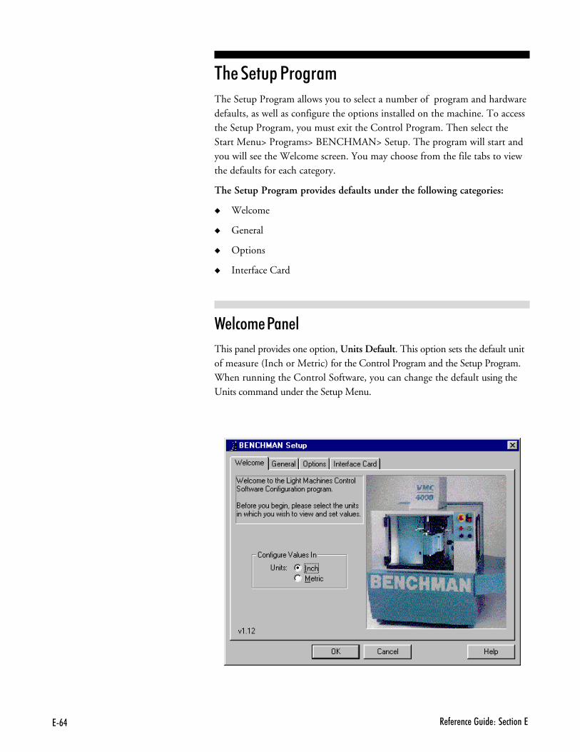
7#. � - � �� ����� ��� ������7
$%����&�1�����+The Setup Program allows you to select a number of program and hardwaredefaults, as well as configure the options installed on the machine. To accessthe Setup Program, you must exit the Control Program. Then select theStart Menu> Programs> BENCHMAN> Setup. The program will start andyou will see the Welcome screen. You may choose from the file tabs to viewthe defaults for each category.
The Setup Program provides defaults under the following categories:
� Welcome
� General
� Options
� Interface Card
2��#�+��1����
This panel provides one option, Units Default. This option sets the default unitof measure (Inch or Metric) for the Control Program and the Setup Program.When running the Control Software, you can change the default using theUnits command under the Setup Menu.
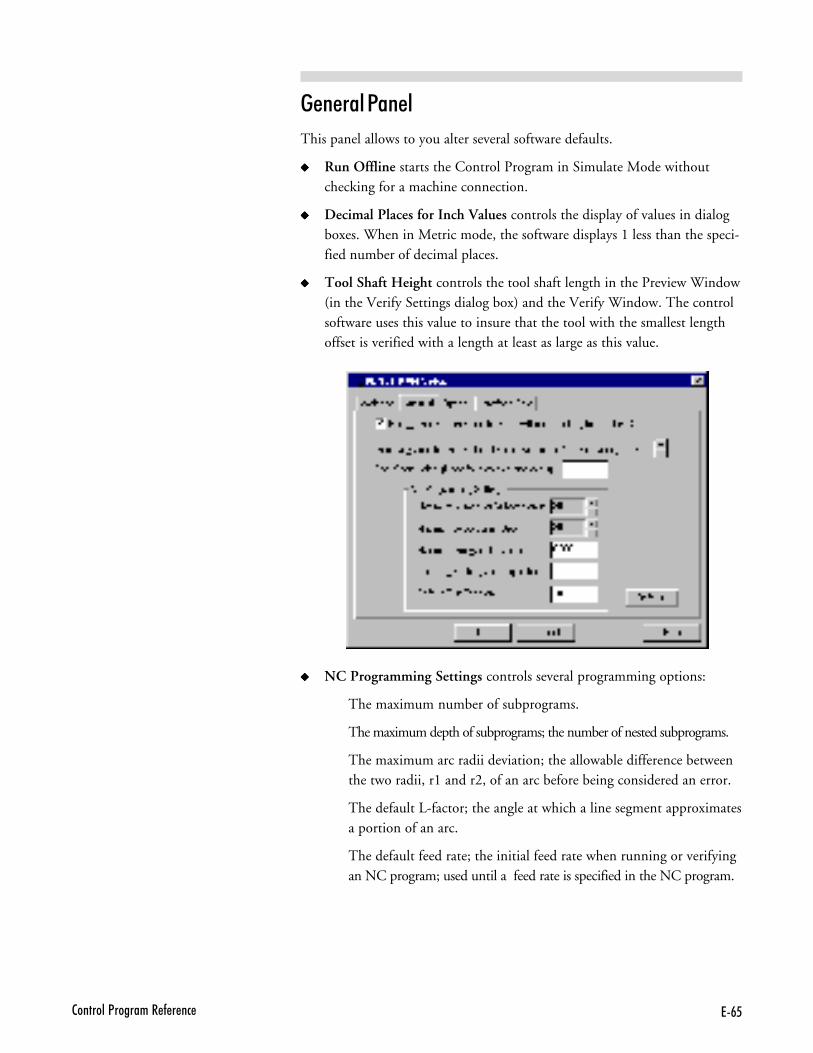
7#62�������<�������� - � ��
��������1����
This panel allows to you alter several software defaults.
����� Run Offline starts the Control Program in Simulate Mode withoutchecking for a machine connection.
����� Decimal Places for Inch Values controls the display of values in dialogboxes. When in Metric mode, the software displays 1 less than the speci-fied number of decimal places.
����� Tool Shaft Height controls the tool shaft length in the Preview Window(in the Verify Settings dialog box) and the Verify Window. The controlsoftware uses this value to insure that the tool with the smallest lengthoffset is verified with a length at least as large as this value.
����� NC Programming Settings controls several programming options:
The maximum number of subprograms.
The maximum depth of subprograms; the number of nested subprograms.
The maximum arc radii deviation; the allowable difference betweenthe two radii, r1 and r2, of an arc before being considered an error.
The default L-factor; the angle at which a line segment approximatesa portion of an arc.
The default feed rate; the initial feed rate when running or verifyingan NC program; used until a feed rate is specified in the NC program.
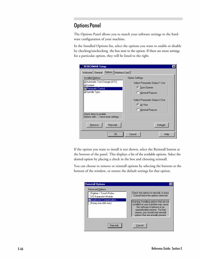
7## � - � �� ����� ��� ������7
3& ����1����
The Options Panel allows you to match your software settings to the hard-ware configuration of your machine.
In the Installed Options list, select the options you want to enable or disableby checking/unchecking the box next to the option. If there are more settingsfor a particular option, they will be listed to the right.
If the option you want to install is not shown, select the Reinstall button atthe bottom of the panel. This displays a list of the available options. Select thedesired option by placing a check in the box and choosing reinstall.
You can choose to remove or reinstall options by selecting the buttons at thebottom of the window, or restore the default settings for that option.
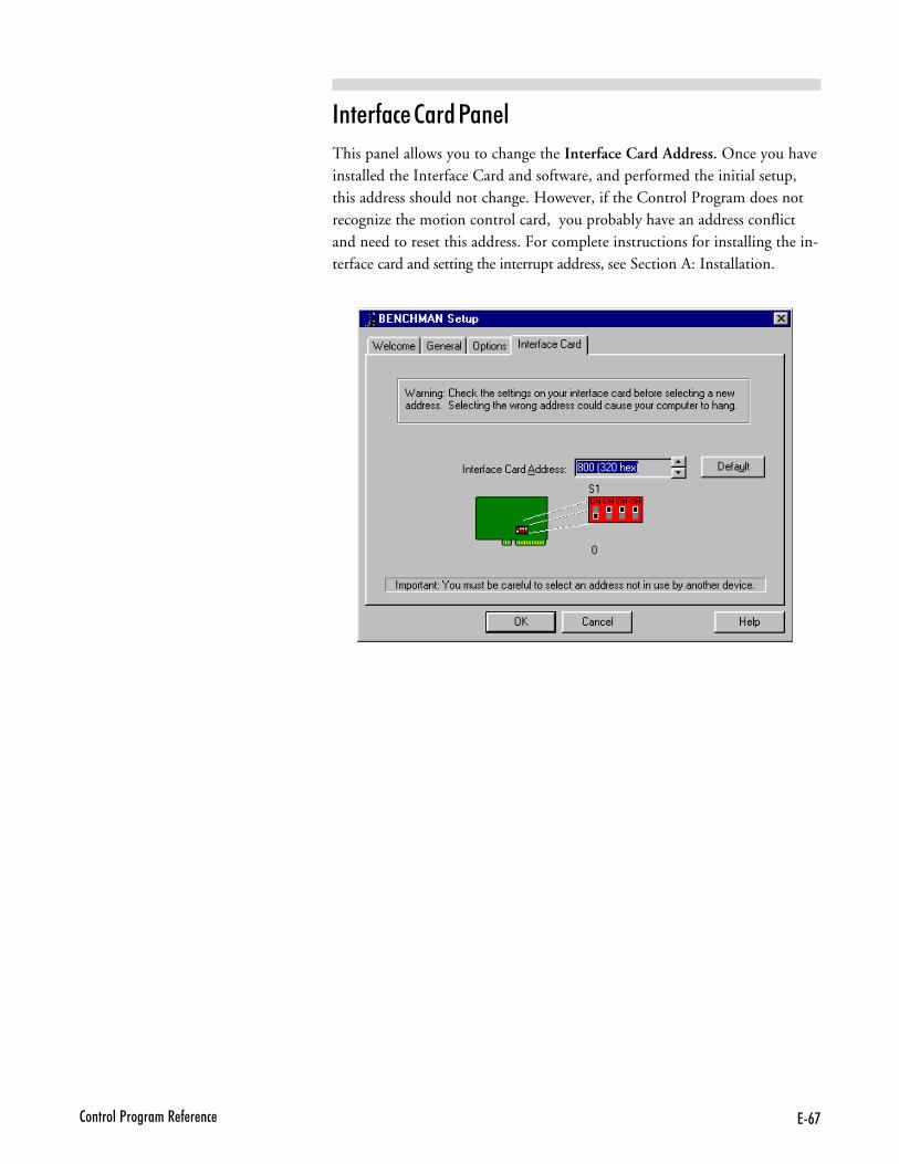
7#'2�������<�������� - � ��
������#�������1����
This panel allows you to change the Interface Card Address. Once you haveinstalled the Interface Card and software, and performed the initial setup,this address should not change. However, if the Control Program does notrecognize the motion control card, you probably have an address conflictand need to reset this address. For complete instructions for installing the in-terface card and setting the interrupt address, see Section A: Installation.

7#@ � - � �� ����� ��� ������7
C��/�����2�2�<����������
��� #�����1�����++ ��
$%�����+�������������1���1�����+
������ �������������
��������1�����++ �������� ���
�������#���� ��)��# ���6
C� � - � �� ����� ��� ������C
$%�� ���+���� ��� ��� ��� 1��� 1�����+Part programs generally incorporate two types of instructions: thosewhich define the tool path (such as X, Y and Z axis coordinates), andthose which specify machine operations (such as turning the spindle on oroff). Each instruction is coded in a form the computer can understand.
An NC program is composed of blocks (lines) of code. The maximum num-ber of blocks per program is limited by the memory (RAM) on your com-puter. You can, if necessary, chain programs together to form very large partprograms.
Each block contains a string of words. An NC word is a code made up ofan alphabetic character (called an address character) and a number (calleda parameter). There are many categories of address characters used in NCpart programs for the machining center (see Categories of NC Code).
Each block of NC code specifies the movement of the cutting tool on themachining center and a variety of conditions that support it. For example,a block of NC code might read:
N0G90G01X.5Y1.5Z0F1
If the machine is currently set for inch units, the individual words in thisblock translate as:
N0 This is the block sequence number for the program. Block 0 isthe first block in the program.
G90 This indicates absolute coordinates are used to define tool posi-tion.
G01 This specifies linear interpolation.
X.5 This specifies the X axis destination position as 0.5".
Y1.5 This specifies the Y axis destination position as 1.5".
Z0 This specifies the Z axis destination position as 0". The cuttingtool will move to the absolute coordinate position (0.5,1.5,0).
F1 This specifies a feed rate of 1 inch per minute, the speed at whichthe tool will advance to the specified coordinate points.
C(�/�����2�2�<����������
������ ��� ��� ��� ����There are many categories of NC code used for programming. The followingis a list of the NC codes (designated by the address character) supported bythe BENCHMAN 4000.
Code: Function:
% Incremental Arc Centers (Fanuc).$ Absolute Arc Centers (LMC).\ Skip./ Optional skip.D Compensation offset value.F Feed rate in inches per minute; with G04, the number of sec-
onds to dwell.G Preparatory codes.H Input selection number; Tool length offset.I Arc center, X axis dimension (circular interpolation).J Arc center, Y axis dimension (circular interpolation).K Arc center, Z axis dimension (circular interpolation).L Loop counter; Program cycle (repeat) counter for blocks and
subprograms; Specify homing tolerance.M Miscellaneous codes.N Block number (user reference only).O Subprogram starting block number.P Subprogram reference number (with M98); Uniform scale mul-
tiplier (with G51).Q Peck depth for pecking canned cycle.R Arc radius for circular interpolation (with G02 or G03); Starting
reference point for peck drilling (with canned cycle codes).S Spindle speed.T Tool specification.U Incremental X motion dimension for absolute dimensioning.V Incremental Y motion dimension for absolute dimensioning.W Incremental Z motion dimension for absolute dimensioning.X X axis motion coordinate.Y Y axis motion coordinate.Z Z axis motion coordinate.; Comments.
C. � - � �� ����� ��� ������C
��#��+����� ��#� ������ @IA
The incremental arc center code selects the Fanuc mode for programmingarc coordinates. This mode is selected for the entire NC program as wellas for any chained programs.
In the Fanuc mode, arc centers are always incremental, regardless of whetherthe system is in G90 (absolute) or G91 (incremental) mode. In contrast,arc center specifications in EIA-274 mode follow the selected program-ming mode, absolute or incremental.
You can specify the default arc center mode in the Run Settings dialogbox.
This character must stand alone on the first line of the NC program inwhich it appears.
�B������ ��#� ������� @JA
The absolute arc center code selects the EIA-274 mode of programmingarc coordinates. This mode is selected for the entire NC program as wellas for any chained programs.
In the EIA-274 mode, the mode of programming arc centers follows the se-lected programming mode; absolute (G90) or incremental (G91). In contrast,arc center specifications in Fanuc mode are always incremental, regardless ofwhether the whether the system is in absolute or incremental mode.
You can specify the default arc center mode in the Run Settings dialogbox.
This character must stand alone on the first line of the NC program inwhich it appears.
0 &� @KA� ���� 3& ����� 0 &� @?A
The Skip and Optional Skip codes allow you to skip particular lines ofcode in your program.
To use the Skip code (\):
Place the code at the beginning of the line you wish to skip. When yourun the NC program, the specified line will be skipped.
To use the Skip code (\) with a parameter:
���)��� �� ��������)� �&=*���� ���)�����"��� ���� �> ��������)� ���� � ��-������ ������ �������������%�!������+
C6�/�����2�2�<����������
Use the Skip code with a parameter to instruct the Control Program toexecute the line of code every nth pass. Place the code at the beginning ofthe line you wish to skip.
The syntax is: \n, where n is the number of passes between executions.
For example, if you want to execute a block of code every 5 passes, place\5 as the first code at the beginning of the block.
To use the Optional Skip code (/):
, - Place the code at the beginning of the line you wish to skip.
. - Select the Optional Skip option from the Run Settings dialog box orthe Operator Panel.
When you run the NC program, the specified line will be skipped. If youdo not select the Optional Skip option in the Run Settings dialog box,the skip code is ignored and the line is executed normally.
To use the Optional Skip code (/) with a parameter:
Use the Optional Skip code with a parameter to instruct the Control Programto execute the line of code every nth pass. Place the code at the beginningof the line you wish to optionally skip.
The syntax is: /n, where n is the number of passes between executions.
For example, if you want to execute a block of code every 5 passes, place /5 as the first code at the beginning of the block.
��+&���� ��� 3����� ������ @"� ����A
The D code is used to select a value from the Control Program OffsetTable. For example, D1 selects entry number 1 from the Offset Table.
Use the D code with:
� Cutter compensation codes to specify the tool radius.
� Tool offset adjust codes to specify a consistent increase or decrease inthe commanded movement.
C# � - � �� ����� ��� ������C
Use the Offsets command under the Setup Menu to view and manage theOffsets Table.
6���� ���� @6� ����A
Use the F code to:
� Specify the rate of speed at which the tool moves (feed rate).This canbe inches per minute (ipm), or millimeters per minute (mm/pm)depending on the Units setting. For example, F3 equals 3 ipm ormm/pm.
The feed rate should be set to a low value (up to 50 ipm) for cutting op-erations. Feed rate values are in millimeters per minute (mm/pm) whenusing metric units. The Control Program limits the programmed feedrate so it doesn’t exceed the maximum allowed by the machining center.
� Specify the number of seconds to dwell when used with the G04code.
1��&������� ������ @�� �����A
G codes take effect before a motion is specified. They contain informationsuch as the type of cut to be made, whether absolute or incremental di-mensioning is being used, whether to pause for operator intervention, andso on.
More than one G code from different groups can appear in each NCblock. However, you may not place more than one G code from the samegroup in the same block.
The G codes supported by the Control Program fall into the followinggroups:
� The Interpolation Group
� The Units Group
� The Plane Selection Group
� The Wait Group
� The Canned Cycle Group
� The Programming Mode Group
� The Preset Position Group
���)�1�� �������� ������ �-�����-- � ������� ������� ������ ����2�%���)+������������� ������ ���������� ���������������������� ����������������� ���������
C'�/�����2�2�<����������
� The Compensation Functions Group
� The Coordinate System Group
� The Polar Programming Group
$%�� ����&��� ��� ����&
The interpolation group allows you to specify the type of motion for in-terpolation. These G codes are retained until superseded in the NC pro-gram by another code from the interpolation group.
The supported interpolation G codes are:
G00 Rapid traverseG01 Linear interpolation (default)G02 Circular interpolation (clockwise)G03 Circular interpolation (counterclockwise)
$%�� '� �� ����&
By default, an NC program is interpreted using the units of measure(inch or metric) specified using the Units command on the Setup Menu.
The codes in the Units group, G70 (inch) and G71 (metric), are used tooverride the Units command, for the entire program, or for a single line.
If the code is placed at the beginning of the program before any tool mo-tions are made, that unit of measure is assumed for the entire program. Ifthe code appears in a block of code, the unit of measure is in effect forthat block and all following blocks. You can use these codes to switch be-tween inch and metric modes throughout your program at your conve-nience.
The Fanuc equivalents, G20 (inch) and G21 (metric), can also be used.
$%�� 1����� ���# ��� ����&
This group of codes allows you to select different planes for circular inter-polation. G17 is the Control Program default.
The supported Plane Selection Group codes are:
C@ � - � �� ����� ��� ������C
G17 Select the X, Y plane for circular interpolation. The arc centercoordinates are given by I for the X axis and J for the Y axis.
G18 Select the X, Z plane for circular interpolation. The arc centercoordinates are given by I for the X axis and K for the Z axis.
G19 Select the Y, Z plane for circular interpolation. The arc centercoordinates are given by J for the Y axis and K for the Z axis.
$%�� 2� � ����&
Wait Group codes apply only to the block in which they appear. The pro-gram does not continue until the wait conditions are satisfied.
The supported Wait Group codes are:
G04 Dwell (wait): Stop motion on all axes for the number of secondsspecified by the F code, then continue the program. Because theF code is used to specify the number of seconds, you cannot alsospecify a new feed rate in the same block.Example: G04F10; Wait for 10 seconds
G05 Pause: Used for operator intervention. Stop motion on all axesuntil the operator manually resumes program execution.
G25 Wait until TTL input #1 goes low before executing the opera-tions on this block. Used for external device synchronization.
G26 Wait until TTL input #1 goes high before executing the opera-tions on this block. Used for external device synchronization.
G31 Linear move to specified coordinate; used with H code to specifyboth the input number and the High or Low condition for stop(designated by the input operator, + or -). The move occurs untilan input is triggered or until a coordinate is reached. The movestops short if specified input goes High (if H is positive) or Low (ifH is negative). The default is input 1 High.You can have the control program go to a specified block (NCode number) if the input meets the required condition. Use aP code to specify the destination, as with the M98 code.For example, G31X5Y5H-2P50000 instructs:
Move (using the current programming mode) to theX and Y given.If input 2 goes low during the move, jump to blocknumber 50000.If input 2 doesn’t go low, continue with the nextblock in the program.
G35 Wait until TTL input #2 goes low before executing the opera-tions on this block. Used for external device synchronization.
G36 Wait until TTL input #2 goes high before executing the opera-tions on this block. Used for external device synchronization.
CB�/�����2�2�<����������
G131 Specifically for digitizing with the probe. The user specifies a Zposition and a feedrate. The probe moves from its current posi-tion to the specified Z position at the specified feedrate (or cur-rent feedrate if not specified on the same block). If the probe in-put is tripped before reaching the specified Z position, a validpoint is captured. In either event (point or no point), when theprobe stops moving down, it rapids back to the initial Z posi-tion.
$%�� ������� ��#��� ����&
Canned cycle codes allow you to perform a number of tool motions by speci-fying just one code. Canned Cycle codes are typically used for repetitive op-erations to reduce the amount of data required in an NC program. Cannedcycle codes are retained until superseded in the program by another cannedcycle code.
The supported Canned Cycle codes are:
G80 Canned cycle cancelG81 Canned cycle drillingG82 Canned cycle straight drilling with dwellG83 Canned cycle peck drillingG85 Canned cycle boringG86 Canned cycle boring with spindle off (dwell optional)G89 Canned cycle boring with dwellRefer to Section G for more information on these functions.
$%�� 1�����++ ��� ����� ����&
Programming mode G codes select the programming mode, absolute(G90) or incremental (G91). These codes remain in effect until super-seded by each other. The default code on program start up is G90.
With absolute programming, all X, Y and Z coordinates are relative toorigin of the current coordinate system. With incremental programming,each motion to a new coordinate is relative to the previous coordinate.
The supported Programming Mode codes are:
G90 Absolute programming modeG91 Incremental programming mode
$%�� 1����� 1�� ��� ����&
The preset position G codes move the tool to a predetermined position,or affect how future motions will be interpreted.
The supported Preset Position codes are:
C�$ � - � �� ����� ��� ������C
G27 Check reference point: This code moves the machine to its homeposition and compares the reported position against zero to see ifany position has been lost. The difference between the reportedposition and zero is compared to a tolerance value specified usingthe Setup Program. Use the L code in this block to override thetolerance value in the Setup Program.
G28 Set reference point: This code moves the machine to its home posi-tion and sets the machine position to 0,0,0. The G28 code per-forms an automatic calibration of the axes.
G92 Set position: This code works like the Set Position commandunder the Setup Menu. The X, Y and Z coordinates following aG92 code define the new current position of the tool.
G98 Rapid move to initial tool position after canned cycle complete.G99 Rapid move to point R (surface of material or other reference
point) after canned cycle complete.
$%�� ��+&���� ��� 6��# ���� ����&
Use the cutter compensation NC codes to automatically compensate forthe variations in a cutting tool’s radius and length. Refer to Section H formore information on using cutter compensation.
The supported Compensation codes are:
G39 Corner offset circular interpolation.G40 Cancel cutter compensation.G41 Left cutter compensation: Enables cutter compensation to the
left of programmed tool path.G42 Right cutter compensation: Enables cutter compensation to the
right of programmed tool path.G43 Tool length offset: Shifts Z axis in a positive direction by a value
in the Offset Table, specified by an H code.G44 Tool length offset: Shifts Z axis in a negative direction by a value
in the Offset Table, specified by an H code.G45 Tool offset adjust: Increases the movement amount by the value
stored in the offset value memory.G46 Tool offset adjust: Decreases the movement amount by the value
stored in the offset value memory.
C���/�����2�2�<����������
G47 Tool offset adjust: Increases the movement amount by twice thevalue stored in the offset value memory.
G40 Tool offset adjust: Decreases the movement amount by twicethe value stored in the offset value memory.
G49 Cancels tool length offset.G50 Cancels scaling.G51 Invokes scaling.G68 Invokes rotation.G69 Cancels rotation.
$%�� ����� ���� ���+� ����&
Use the coordinate system codes to establish multiple coordinate systemson one work piece to create multiple parts.
For instance, you can run a part program using a typical coordinate sys-tem (with the point of origin on the surface of the front left corner of theworkpiece), then select another coordinate system which has its origin at adifferent point on the surface of the workpiece. For an overview of coordi-nate systems, see page H-27.
There are seven coordinate system codes. One of these codes (G53) isused to rapid to specified machine coordinates. The other six codes allowyou to make up to six individual parts on the same workpiece by specify-ing different work coordinate systems for each part.
The coordinate system codes are G54 through G59, referring to coordi-nate systems 1 through 6 respectively. These coordinate systems may beset through the Coordinate Systems command on the Setup Menu.
C�� � - � �� ����� ��� ������C
$%�� 1����� 1�����++ ��� ����&
The polar programming codes allow you to perform polar programming op-erations, based on polar coordinates. The polar coordinates are defined by X(radius) and Y (angle in degrees) when programming for the X, Y plane. Re-fer to Section H of this Guide for more information on using polar program-ming.
The supported Polar Programming codes are:
G15 Polar programming ONG16 Polar programming OFF
��&�� ���# ��� ��+B��?$���� 5���%� 3����� @�����A
The H code has multiple uses. It can be used to specify inputs, inputstate changes, outputs, and offset amounts.
Use the H code in conjunction with:
� The wait codes G25 and G26, to specify the input number. If the Hcode is not used with these G codes, input 1 is assumed.
� The wait code G31, to specify input change to high or low. If the H codeis not used with this G code, input 1 High is assumed.
� The tool length offset codes G43 and G44, to specify the amount of Zaxis shift. (The Offset Table you use for Tool Length Offset H values isthe same table you use for Cutter Compensation and Tool Offset AdjustD values.)
� The transmit codes M25 and M26 for interfacing with robots or otherexternal devices, to specify the output number. If the H code is not usedwith these M codes, output 4 is assumed.
8� �9 �� ����� ���� ��� ������ 1� �� @�� ����A
In absolute programming mode (G90), the I code specifies the X axis coordi-nate of the center point of a circle when using circular interpolation. In in-cremental mode (G91), the I code specifies the X axis distance from the endof the last motion to the center point of the circle for circular interpolation.
If no I code is specified, the system uses the current X axis location as theX axis center of the arc.
C�(�/�����2�2�<����������
In Fanuc mode, all arc centers are incremental.
The I code is also used with the G51 code to specify the scale factor for the Xaxis when performing scaling functions, including scaling each axis andmirror scaling. Refer to Reference Guide Section H for more information on us-ing scaling.
�� �9 �� ����� ���� ��� ������ 1� �� @F� ����A
In absolute programming mode (G90), the J code specifies the Y axis coordi-nate of the center point of a circle when using circular interpolation. In incre-mental mode (G91), the J code specifies the Y axis distance from the startpoint of motion to the center point of the circle for circular interpolation.
If no J code is specified, the system uses the current Y axis location as theY axis center of the arc.
In Fanuc mode, all arc centers are incremental.
The J code is also used with the G51 code to specify the scale factor for the Yaxis when performing scaling functions, including scaling each axis and mirrorscaling. Refer to Reference Guide: Section I for more information on usingscaling.
G� �9 �� ����� ���� ��� ������ 1� �� @E� ����A
In absolute programming mode (G90), the K code specifies the Z axis coordi-nate of the center point of a circle when using circular interpolation. In incre-mental mode (G91), the K code specifies the Z axis distance from the end ofthe last motion to the center point of the circle for circular interpolation.
If no K code is specified, the system uses the current Z axis location as thecenter of the arc.
In Fanuc mode, all arc centers are incremental.
The K code is also used with the G51 code to specify the scale factor forthe Z axis when performing scaling functions, including scaling each axis
C�. � - � �� ����� ��� ������C
and mirror scaling. Refer to Reference Guide: Section I for more informa-tion on using scaling.
������ ��� ��#� ������ ��=� 5��&� ������� @5����A
The L code specifies the angle of arc resolution in circular interpolationprogramming. With BENCHMAN, it is only used if a helical motion is ex-ecuted, or if you specifically enable approximated arcs in that program (M111command).
Use the L code with:
� The M98 code as a loop counter for subprograms.
� The M47 code as a program cycle counter, to repeat a program aspecified number of times.
� The G27 code to specify tolerance with homing commands (this is anLMC-specific NC language extension). The difference between the cur-rent position and 0 is compared to a tolerance value specified usingthe Setup Program; use the L code to override this tolerance value.
� �#���������� ������ @�� �����A
M codes control a variety of functions while a part program is running. Mcodes should be placed on separate blocks to avoid confusion overwhether an M code is activated during or after a motion command.
The supported M codes are:
M00 Pause: Allows you to place a pause in your code. Acts like a G05 pause.M01 Optional Stop: Allows you to place an optional pause in your
code. Place an M01 in the block of code where you would liketo pause. There are switches to activate or deactivate the OptionalStop code in the Run Settings dialog box and on the OperatorPanel.With Optional Stop on, the M01 works like a G05 pause.With Optional Stop off, the M01 code is ignored, and the othercodes on the block are executed as usual.
M02 End of Program: Takes effect after all motion has stopped; turnsoff drive motors, spindle and accessories.
M03 Spindle Motor On Forward: Activated concurrently with mo-tion specified in the program block; remains in effect until su-perseded by M04 or M05.
���)
���1���� ���� ���������������� 4�� 3���������� �� ���� 3� ! ��� ������ % ���������-��� �������������-�������%���)��-��2���� +
���1���� ���� �����������--���� 4�� ! ��� ��-� ���� �������������-�������%���)������� � � �+
����4�������-�����3���������� ��� � ��� ����� ��� �1���� ������� ���� �%���)�-������ ���������������+
C�6�/�����2�2�<����������
M04 Spindle Motor On Reverse: Activated concurrently with motionspecified in the program block; remains in effect until super-seded by M03 or M05.
M05 Spindle Motor Off: Activated after the motion specified in the pro-gram block; remains in effect until superseded by M03 or M04.
M06 Tool Change: Pauses all operations, turns off spindle, retractsspindle for tool change.
M08 Coolant On: Turns on coolant; remains in effect until supersededby M09.
M09 Coolant Off: Turns off coolant; remains in effect until super-seded by M08.
M10 Air Vise On: Unclamps Air Vise; remains in effect until super-seded by M11.
M11 Air Vise Off: Clamps Air Vise; remains in effect until supersededby M10.
M20 Chain to Next Program: This code is used to chain several NC filestogether. It appears at the end of a part program and is followedon the next line by the file name of another program which isexecuted when all motion stops. Here’s an example of a partprogram chain to another program:
N37 Z.2N38 M20PROGRAM2.NC ;CHAIN TO PROGRAM TWO
If the two programs you are chaining are not in the same direc-tory on your computer, you must specify the full path name forthe next program file.
M22 Output current position to file. Typically used in digitizing.M25 Set TTL output #1 Off: Used for external device synchroniza-
tion.M26 Set TTL output #1 On: Used for external device synchroniza-
tion.M30 End of program: Same as M02.M35 Set TTL output #2 Off: Used for external device synchroniza-
tion.M36 Set TTL output #2 On: Used for external device synchroniza-
tion.M47 Rewind: Restarts the currently running program; takes effect af-
ter all motion comes to a stop. Typically used with an L code torepeat a program a set number of times.
M98 Call to subprogram. Use the P code to specify the subprogramstarting block number. Use the L code to specify the number of
C�# � - � �� ����� ��� ������C
times the subroutine is executed. You can nest subprogram callsto a depth of 20.
M99 Return from Subprogram; GotoM105 Operator Message (LMC)M122 Output current position to file. Almost identical to M22, except
that if a macro (@X@Y@Z) is used to insert a coordinate, the posi-tion of the digitized point will be used, rather than the current ma-chine position.
�..)� 3�&�� ������� 1�� ��� �� 6 ��
The M22 code is used to write information to a file while a program is run-ning. Typically, this code is used when digitizing to write the current X, Y,and Z machine coordinates to a file. The proper format for using this code is:M22(filename)DataToWriteToFile. The first time the Control Program en-counters an M22 code, it opens the specified file. You must enclose the nameof the file in parentheses for the Control Program to recognize it. If you donot specify any DataToWriteToFile text, the default data is output. This defaultis the current position, equivalent to specifying ‘X@X Y@Y Z@Z’. Notice thatthe @X,@Y,@Z ‘macros’ are replaced by the actual machine position whenthe data is written. Each M22 code automatically adds a line feed to the endof its output so the next M22 starts on a new line.
If the file name is followed by “,A” (e.g., test.nc,A), the Control Program doesnot delete previous information from the file, it appends the information tothe end of the existing information. If the file does not exist, it is created.
If you use more than one M22, only the first occurrence must have thefile name in the parentheses. The remaining M22’s may have empty pa-rentheses, ( ), or may specify a different file.
If you want to generate more than one file at a time, you must includethe filename each time you specify M22. If a filename is not specified, thefirst file opened is used.
Example:
. . . ; code to move to position; Open my1.xyz, discard contents, write coordinatesM22(my1.xyz). . . ; code to move to next position
C�'�/�����2�2�<����������
; Append to currently open data fileM22( ). . . ; code to move to next position; Open my2.xyz and append coordinatesM22(my2.xyz,A)
Information about digitizing is provided with the digitizing package. Foradditional information, please call Light Machines Technical Support.
Special codes that can be used with M22 to generate run-time reports:
@X Current X position (in current coordinate system).
@Y Current Y position (in current coordinate system).
@Z Current Z position (in current coordinate system).
~ (tilde) New Line (starts a new line in the file).
@TD Time of Day (12 hour) “11:59:59AM”
@TC Time (elapsed) for cycle “99:11:59” (0’s trimmed fromleft)
@TT Time Total (program run) “99:11:59”
@TA Time Average (per cycle) “99:11:59” (“??:??” if first part)
@TL Current Tool #. “5”
@C Cycle # (Current Pass) “3”
@D Date “12/31/94”
@FN Current File (w/o path) “PART.NC” (“UNTITLED.NC” ifuntitled)
\t TAB
\\ Outputs a single ‘\’ character.
Example:
; Start of file
… ; Process a single part
; Output part time statistics to file c:\Reports\Stats.txt(c:\Reports directory must exist)
M22 (c:\Reports\Stats.txt,A) Part #@C processed in @TC.
M47 L50 ; We want to process 50 parts.
�>>)� ������ ���+� �B&�����+=� ���
The M99 code has two specific uses; it can be used as a command to re-turn from a subprogram or it can be used as a goto command.
Using M99 with subprograms:
When used in a subprogram, this code returns you to the block followingthe last M98 (Call to Subprogram) command.
You can use the P code plus a block number to override the block re-turned to; however, if this feature is used from a nested subprogram call,
C�@ � - � �� ����� ��� ������C
all return targets are discarded. The rules for a Goto target block apply tothis use as well.
Using M99 as a Goto command:
This command can be used in the main NC program as a Goto com-mand to jump to a block on a line before the M02 command.
Use the P code to identify the block number being jumped to. Control istransferred to the first occurrence of this N code; it cannot be used totransfer control between chained programs (see M20).
This command can be used anywhere in the program to change the flowof program execution. It is good programming practice to place this com-mand on a line by itself to improve the program’s readability.
�,! )� 3&������ �������
This command is used to display messages in the Control Program. Itprovides a way to display messages to the operator on the Message Barwhile an NC program is running. You can also pause the program with acustom message. This code is a non-standard, Light Machines code.
By default, the message is centered, displayed as black characters on awhite background, and is persistent (not cleared until the operatormanually does so or until the next message is displayed).
The correct format for using this code is:
M105(the message);comment
For instance, the following line of code displays a simple message:
M105(End of Roughing Segment);Display message in white;continue
Messages can be altered by using the following alternate characters:
^ Displays the message and performs a pause requiring operator inter-vention to continue.
~ Displays the message as a Warning Message.
\b Beeps when the message is shown.
The format for using the M105 code with an alternate character is:
M105(alternate character plus the message) ;comment
For example:
C�B�/�����2�2�<����������
M105(~WARNING);Message in yellow, continue
Here are some other examples of how to use this code:
M105( ) ; clears current messageM105(^Please stop and read this!) ; Normal Message, pausesM105(~^I MEAN IT!) ; Warning Message, pausesM105(\b\b\b) ; Clears current message, beeps 3 times, and doesn’t pause
���#0� ��+B��� @�� ����A
N codes have two uses:
� To provide destinations for Gotos (M99) elsewhere in the program.
� To clearly show the organization of the code and improve readability.
Using the N code is optional; however, when you do use the N code, itmust be the first character in a block of NC codes.
Other than for the above stated uses, N codes are not recognized by the Con-trol Program. Their presence, absence, or sequential value does not affect theexecution of the NC program in any way (unless the target of a goto is miss-ing).
You may have N codes on some blocks and not on others. N code se-quence numbers do not have to be in order, but regular sequential orderdoes make it easier to follow the program.The Control Program canchange the N codes in a program by inserting, removing, or renumberingthem. See Edit Menu, Renumber Command in Section E.
�B&�����+� ���#0� ��+B��� @3� ����A
The O code is used to indicate the start of a subprogram, and must befollowed by a number which identifies the subprogram. The O code re-places the N code in the first block of the subprogram.
To call a subprogram, use the M98 code; the P code specifies which subpro-gram to execute. To return from the subprogram, use the M99 code.
Only the first block in the subprogram contains the O code. The remainingblocks may contain N codes. The O and N code numbers may be used tohelp identify and set apart the subprogram to improve readability, for ex-ample:
M98P50000;call to first subprogram…;after first subprogram is finished, M99 code returns to this point…M98P60000 ;call to second subprogram
C�$ � - � �� ����� ��� ������C
…;after second subprogram is finished, M99 code returns to this point…O50000 ;start of subprogramN50010 ;first line of subprogramN50020 ;second line of subprogramN50030M99 ;last line of subprogram…O60000 ;second subprogramN60010 ;first line of second subprogramN60020 ;second line of second subprogramN60030M99 ;last line of second subprogram
�B&�����+� �������#�� ��+B��� @1� ����A
Use the P code with:
� The G31 code to reference a goto target block.
� The G51 code to specify a uniform scaling factor.
� The M98 code to reference a subprogram using the subprogram block num-ber.
� The M99 code to specify a return block number as a goto target.
1�#0� "�&%� @H� ����A
The Q code is used with the G83 code in canned cycle peck drilling tospecify the depth of each peck.
��� ��� ��� ��#=� "� �� ��� ��� 5�#� ��� @�� ����A
As an alternative to specifying the center point of an arc (I Code, J Code,or K Code) you can specify the arc radius. Use the same value for the ra-dius in both absolute and incremental programming modes.
G02 or G03 specifies the direction of motion.
Positive values for R (radius) are specified for arcs up to 180°. Negativevalues are used for arcs greater than 180°. Full circle arcs cannot be per-formed with an R code. Spit the circle into two arcs, or use center point(I, J, and K) values for full 360° circles.
Use the R code in canned cycles to specify a Z axis reference point forpeck drilling. The point can be at the material surface or at another refer-
��'$�3�
����������� � ��������������4��� ��� ������3���������������% ���� � � ��%"� �������-��������������������� ����������� �� ��
���)�C��������� ��&(#$������*�������% � �-��� ��������������� +�� ����� ������������������������ �� �� � �����&�3�D�����E*�4��� ��-���-����(#$�
����� �+
C���/�����2�2�<����������
ence point. The R code is also used to specify the rotation angle, in de-grees, with the G68 code.
& ����� &���� @� ����A
Use the S code to set the spindle speed from within the NC program. Spindlespeed is specified by the address character “S” followed by a parameterthat represents the speed in RPM. For example, S750 is the designationfor a spindle speed of 750 RPM. For the S code to have affect the spindlemust be turned on by the M03 or M04 command. If the spindle is off, thespindle speed is stored and used when the spindle is turned on again within theprogram. Use the M05 command to turn the spindle off.
$���� ���# ��� @$� ����A
T codes specify the tool offset (number) in the Tool Library in multipletool machining operations. They do not specify the Automatic ToolChanger (ATC) station number, but they do have an ATC station associatedwith them. Tools are specified by the address character “T” followed by aparameter that represents the number of the tool. For example, T3 is thedesignation for tool number three.
���)�9������ ��� ��%����� �������� � ������������������� ���� %���)+�C��� !�� � �
�B$:�0�
��������� ����� ��� � ! �� ��������+
C�� � - � �� ����� ��� ������C
8� �9 �� ����� ���� @8� ��� '� ����A
An X code specifies the coordinate of the destination along the X axis. AU code is used in absolute programming mode (G90) to specify an incremen-tal X motion. You cannot use the U code to mix incremental and absoluteprogramming in the same block.
�� �9 �� ����� ���� @�� ��� �� ����A
A Y code specifies the coordinate of the destination along the Y axis. A V codeis used in absolute programming mode (G90) to specify an incremental Ymotion. You cannot use the V code to mix incremental and absolute pro-gramming in the same block.
G� �9 �� ����� ���� @G� ��� 2� ����A
A Z code specifies the coordinate of the destination along the Z axis(spindle axis). A W code is used in absolute programming mode (G90) tospecify an incremental Z motion. You cannot use the W code to mix in-cremental and absolute programming in the same block.
��++��� �����
The Control Program allows you to add comments to your NC blocks.The Control Program recognizes two comment codes:
� A semicolon “;”
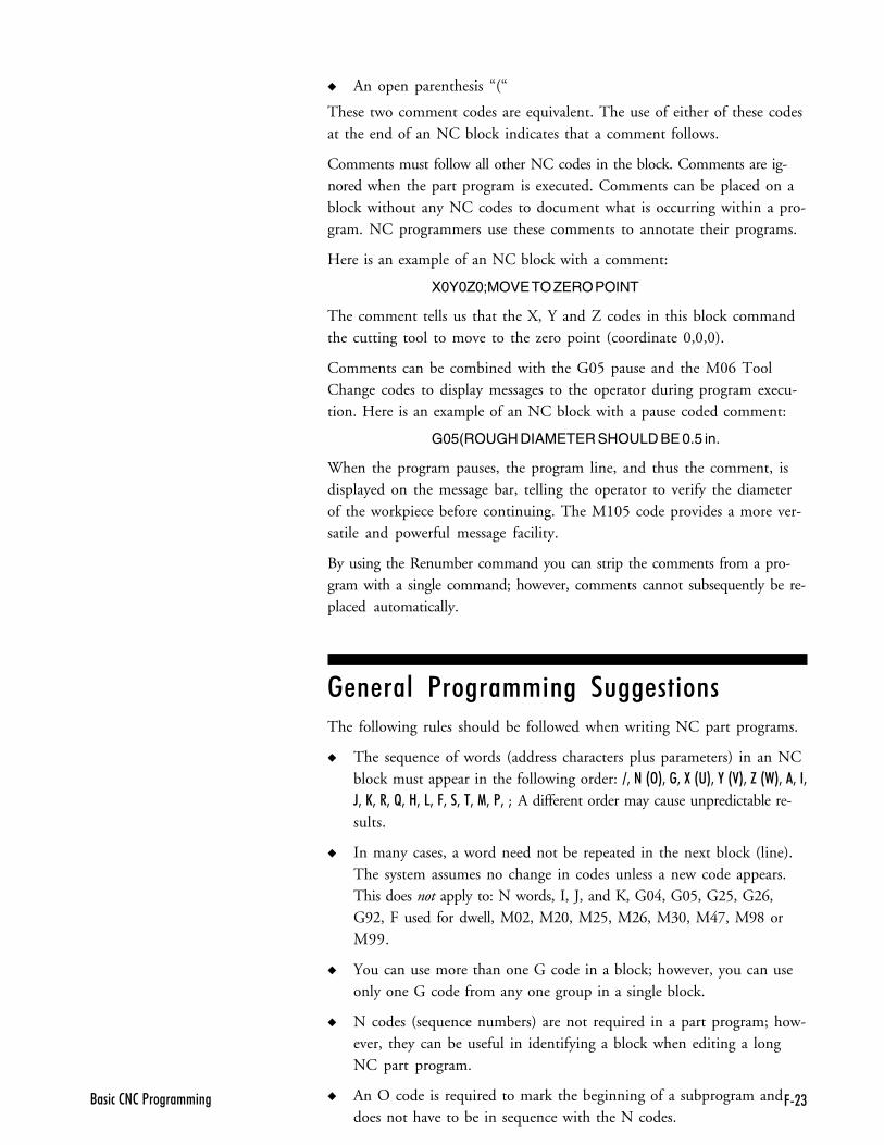
C�(�/�����2�2�<����������
� An open parenthesis “(“
These two comment codes are equivalent. The use of either of these codesat the end of an NC block indicates that a comment follows.
Comments must follow all other NC codes in the block. Comments are ig-nored when the part program is executed. Comments can be placed on ablock without any NC codes to document what is occurring within a pro-gram. NC programmers use these comments to annotate their programs.
Here is an example of an NC block with a comment:
X0Y0Z0;MOVE TO ZERO POINT
The comment tells us that the X, Y and Z codes in this block commandthe cutting tool to move to the zero point (coordinate 0,0,0).
Comments can be combined with the G05 pause and the M06 ToolChange codes to display messages to the operator during program execu-tion. Here is an example of an NC block with a pause coded comment:
G05(ROUGH DIAMETER SHOULD BE 0.5 in.
When the program pauses, the program line, and thus the comment, isdisplayed on the message bar, telling the operator to verify the diameterof the workpiece before continuing. The M105 code provides a more ver-satile and powerful message facility.
By using the Renumber command you can strip the comments from a pro-gram with a single command; however, comments cannot subsequently be re-placed automatically.
�������� 1�����++ ��� ����� ���The following rules should be followed when writing NC part programs.
� The sequence of words (address characters plus parameters) in an NCblock must appear in the following order: =3���&>*3��3�:�&�*3�,�&0*3�H�&�*3�3��3
D3�E3��3�F3�83�53�C3��3��3�13�<3�M A different order may cause unpredictable re-sults.
� In many cases, a word need not be repeated in the next block (line).The system assumes no change in codes unless a new code appears.This does not apply to: N words, I, J, and K, G04, G05, G25, G26,G92, F used for dwell, M02, M20, M25, M26, M30, M47, M98 orM99.
� You can use more than one G code in a block; however, you can useonly one G code from any one group in a single block.
� N codes (sequence numbers) are not required in a part program; how-ever, they can be useful in identifying a block when editing a longNC part program.
� An O code is required to mark the beginning of a subprogram anddoes not have to be in sequence with the N codes.

C�. � - � �� ����� ��� ������C
��1�� �2�2�<����������
���������1�����++ ��
5 ���������&��� ���1�����++ ��
� �#���������&��� ���1�����++ ��
��& ��$��7�����1�����++ ��
���������#���1�����++ ��
�B&�����+�1�����++ ��
�������#���� ��)�# ����
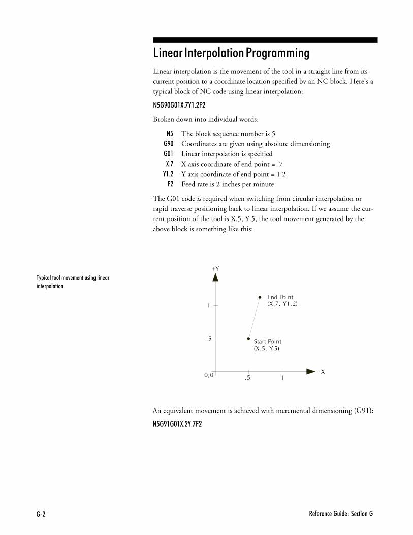
�� � - � �� ����� ��� �������
�" ������������4 � ������������ ����� � �������
5 ���������&��� ���1�����++ ��Linear interpolation is the movement of the tool in a straight line from itscurrent position to a coordinate location specified by an NC block. Here’s atypical block of NC code using linear interpolation:
�6�B$�$�:+',�+�C�
Broken down into individual words:
� The block sequence number is 5�>! Coordinates are given using absolute dimensioning�!, Linear interpolation is specified8-; X axis coordinate of end point = .7
�,-. Y axis coordinate of end point = 1.26. Feed rate is 2 inches per minute
The G01 code is required when switching from circular interpolation orrapid traverse positioning back to linear interpolation. If we assume the cur-rent position of the tool is X.5, Y.5, the tool movement generated by theabove block is something like this:
An equivalent movement is achieved with incremental dimensioning (G91):
�6�B��$�:+�,+'C�
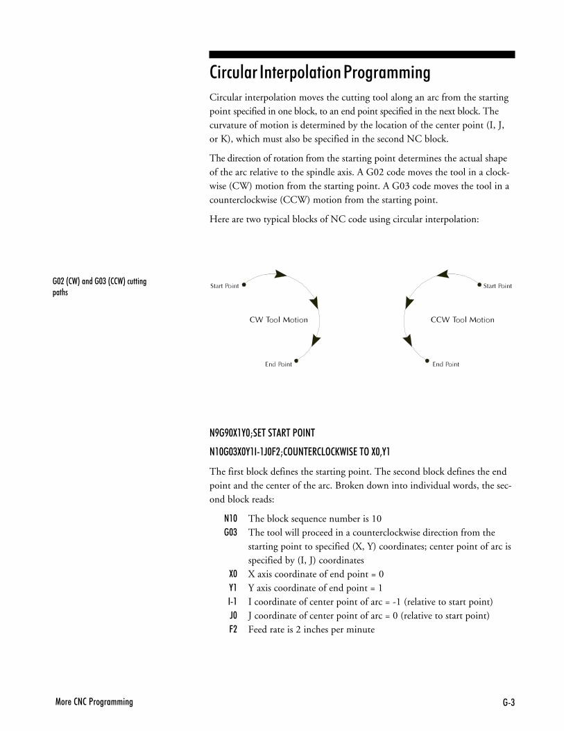
�(1�� �2�2�<����������
� �#���������&��� ���1�����++ ��Circular interpolation moves the cutting tool along an arc from the startingpoint specified in one block, to an end point specified in the next block. Thecurvature of motion is determined by the location of the center point (I, J,or K), which must also be specified in the second NC block.
The direction of rotation from the starting point determines the actual shapeof the arc relative to the spindle axis. A G02 code moves the tool in a clock-wise (CW) motion from the starting point. A G03 code moves the tool in acounterclockwise (CCW) motion from the starting point.
Here are two typical blocks of NC code using circular interpolation:
�B�B$:�,$M�7�������<>���
��$�$(:$,���D$C�M2>���7�25>2E���7��>�:$3,�
The first block defines the starting point. The second block defines the endpoint and the center of the arc. Broken down into individual words, the sec-ond block reads:
�,! The block sequence number is 10�!/ The tool will proceed in a counterclockwise direction from the
starting point to specified (X, Y) coordinates; center point of arc isspecified by (I, J) coordinates
8! X axis coordinate of end point = 0�, Y axis coordinate of end point = 1��, I coordinate of center point of arc = -1 (relative to start point)F! J coordinate of center point of arc = 0 (relative to start point)6. Feed rate is 2 inches per minute
�$��&2�*������$(�&22�*�������� ����
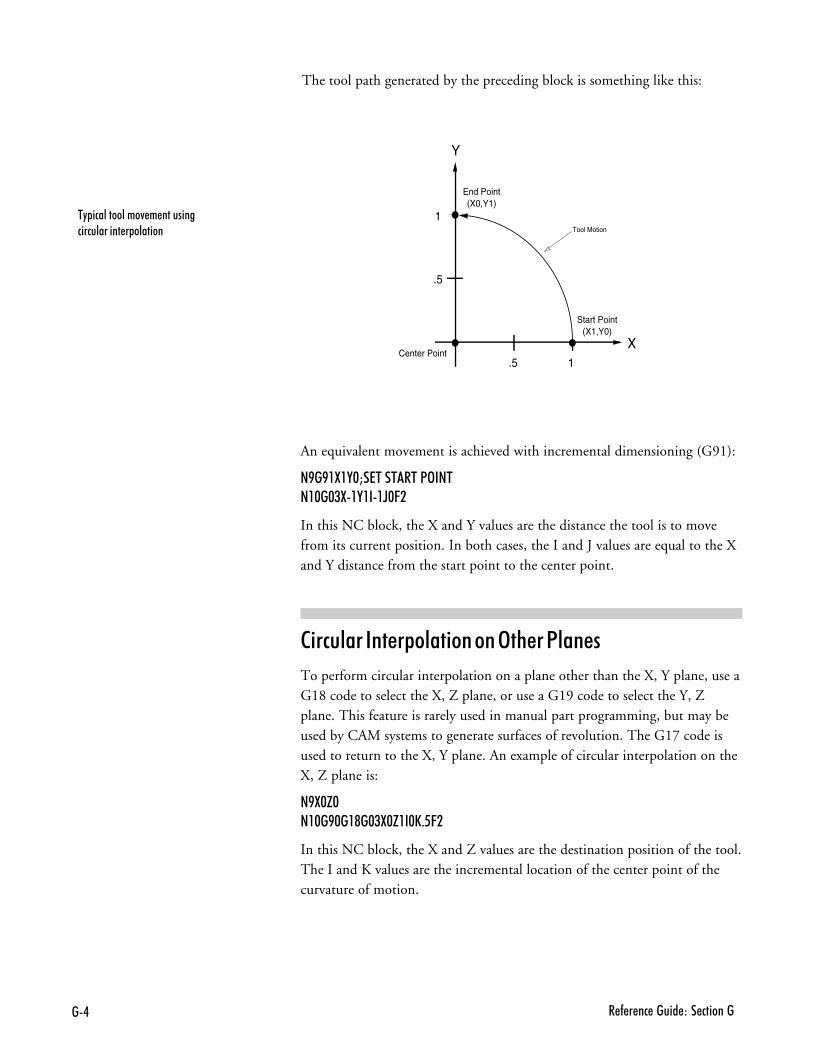
�. � - � �� ����� ��� �������
The tool path generated by the preceding block is something like this:
�" ������������4 � �������������������� � �������
X
Y
1
1
Start Point(X1,Y0)
End Point(X0,Y1)
Tool Motion
Center Point.5
.5
An equivalent movement is achieved with incremental dimensioning (G91):
�B�B�:�,$M�7�������<>�����$�$(:�,���D$C�
In this NC block, the X and Y values are the distance the tool is to movefrom its current position. In both cases, the I and J values are equal to the Xand Y distance from the start point to the center point.
� �#���������&��� ������3%���1�����
To perform circular interpolation on a plane other than the X, Y plane, use aG18 code to select the X, Z plane, or use a G19 code to select the Y, Zplane. This feature is rarely used in manual part programming, but may beused by CAM systems to generate surfaces of revolution. The G17 code isused to return to the X, Y plane. An example of circular interpolation on theX, Z plane is:
�B:$H$��$�B$��@�$(:$H��$E+6C�
In this NC block, the X and Z values are the destination position of the tool.The I and K values are the incremental location of the center point of thecurvature of motion.
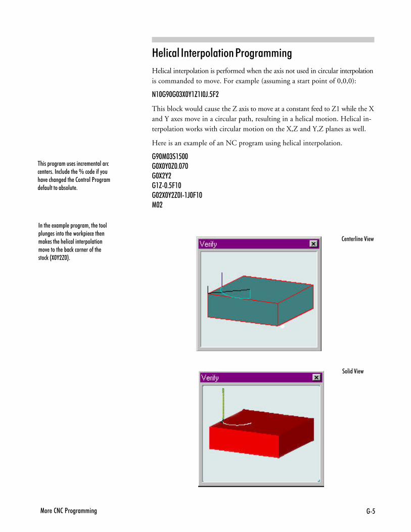
�61�� �2�2�<����������
��� #�������&��� ���1�����++ ��
Helical interpolation is performed when the axis not used in circular interpolationis commanded to move. For example (assuming a start point of 0,0,0):
��$�B$�$(:$,�H��$D+6C�
This block would cause the Z axis to move at a constant feed to Z1 while the Xand Y axes move in a circular path, resulting in a helical motion. Helical in-terpolation works with circular motion on the X,Z and Y,Z planes as well.
Here is an example of an NC program using helical interpolation.
�B$1$(��6$$�$:$,$H$+$'$�$:�,���H$+6C�$�$�:$,�H$��D$C�$1$�
����� � !�� � � ������3��� ����� ���� ��������� ����) � � ��� ���) ���� �� ��������� � ���������4 ������ �%��)����� ���-��� ����)�&:$,�H$*+
����� ��������� ������ � ��������� �� ��+������� ��� �L���� ��-�"����4 ������ ���� �2�������<������� -���������%����� +
2 �� ���� �0� �
������0� �
�# � - � �� ����� ��� �������
��& ��$��7�����1�����++ ��On the Machining Center, the rapid traverse code (G00) can move the toolat the maximum available feed rate (200 ipm) to specified coordinates. Rapidtraverse is used to reposition the tool before ending a program, or in prepara-tion for the next cut.
2������
�� ����������������% � ���� ���������������� ����������� ���4 ������������ ����������A
Rapid traverse can be used for all tool positioning motions. This will reducethe run time for the part program. The G00 code remains in effect until lin-ear (G01) or circular (G02, G03) interpolation is again specified. Linear orcircular interpolation resumes at the feed rate last specified prior to the rapidtraverse motion(s) unless you specify a new feed rate.
Here’s a sequence of typical NC blocks using rapid traverse:
�>!�!,8,6.L�1>07����������8��5��7��>�:�Q��������<1
�!!8.L��<�9���07��7��>�:Q�
8/L��<�9���07��7��>�:Q(
�!,8�L�1>07����������8��5��7��>�:Q.������<1
�'1�� �2�2�<����������
���������#���1�����++ ��Canned cycle commands allow you to perform drilling operations by specifyingjust a few codes. They are typically used for repetitive operations to reducethe amount of data required in an NC program. Canned cycle codes are re-tained until superseded in the program by another canned cycle code. Thesupported canned cycles codes are:
G80 Canned cycle cancelG81 Straight drillingG82 Straight drilling with dwell at bottomG83 Peck drillingG85 Boring cycleG86 Boring cycle with spindle off (dwell optional)G89 Boring cycle with dwell
These codes are used in conjunction with canned cycle codes:
G98 Rapid to initial position after canned cycle complete; this is thesystem default
G99 Rapid to point R after canned cycle completeQ Code Specifies the depth of cut. In peck drilling each peck uses the same
Q value. The Q value is always positive. If a negative value isspecified, it is converted to a positive value.
R Code Used for specifying a starting reference point for peck drilling. Thepoint can be at the material surface or at another reference point.
'� ����<!
To cancel a canned cycle, use the G80 code. This code cancels the currentlyrunning canned cycle and resumes normal operation. All other drilling datais cancelled as well. You can also cancel canned cycles by using a G00 or G01code; a G80 is automatically performed before the G00, G01, G02, or G03.
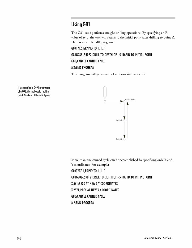
�@ � - � �� ����� ��� �������
�-�� �� ��-� �����BB�� � ����� ���-����B@3��� �������������� ����� ����������� ����-��� ��������� ����+
'� ����<,
The G81 code performs straight drilling operations. By specifying an Rvalue of zero, the tool will return to the initial point after drilling to point Z.Here is a sample G81 program.
�$:�,�H+�M�<�9��>��3��3�+�
�@��B@H+6�$C�M9��55��>�97<�8�>C�+63��<�9��>������5�<>���
�@$M2�275�2��79�2,257
1�M7�9�<�>��1
This program will generate tool motions similar to this:
More than one canned cycle can be accomplished by specifying only X andY coordinates. For example:
�$:�,�H+�M�<�9��>��3��3�+�
�@��B@H+6�$C�M9��55��>�97<�8�>C�+63��<�9��>������5�<>���
:+6,�M<72E����7��:3,�2>>�9���7�
:+�6,�M<72E����7��:3,�2>>�9���7�
�@$M2�275�2��79�2,257
1�M7�9�<�>��1
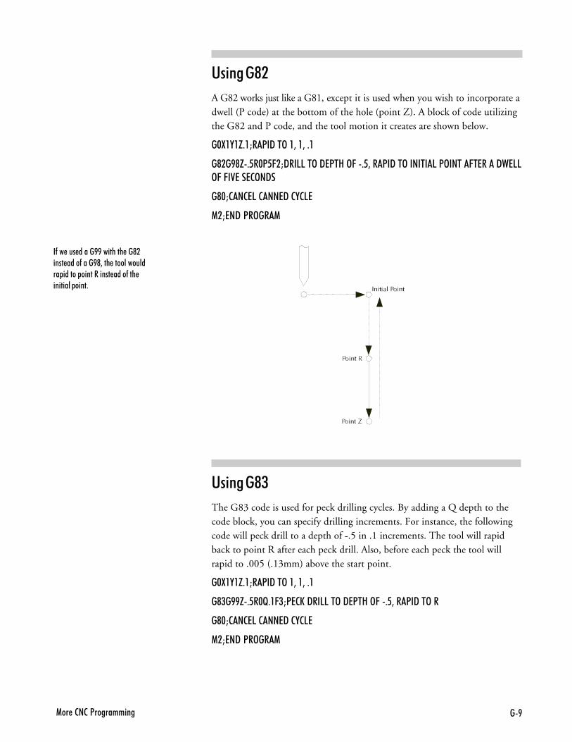
�B1�� �2�2�<����������
�-�� ��� �����BB�������� ��@����� ����-����B@3��� ������������� ������ ����������� ����-��� �������� ����+
'� ����<.
A G82 works just like a G81, except it is used when you wish to incorporate adwell (P code) at the bottom of the hole (point Z). A block of code utilizingthe G82 and P code, and the tool motion it creates are shown below.
�$:�,�H+�M�<�9��>��3��3�+�
�@��B@H+6�$<6C�M9��55��>�97<�8�>C�+63��<�9��>������5�<>����C�7���9�755>C�C�07��72>�9�
�@$M2�275�2��79�2,257
1�M7�9�<�>��1
'� ����</
The G83 code is used for peck drilling cycles. By adding a Q depth to thecode block, you can specify drilling increments. For instance, the followingcode will peck drill to a depth of -.5 in .1 increments. The tool will rapidback to point R after each peck drill. Also, before each peck the tool willrapid to .005 (.13mm) above the start point.
�$:�,�H+�M�<�9��>��3��3�+�
�@(�BBH+6�$F+�C(M<72E�9��55��>�97<�8�>C�+63��<�9��>��
�@$M2�275�2��79�2,257
1�M7�9�<�>��1
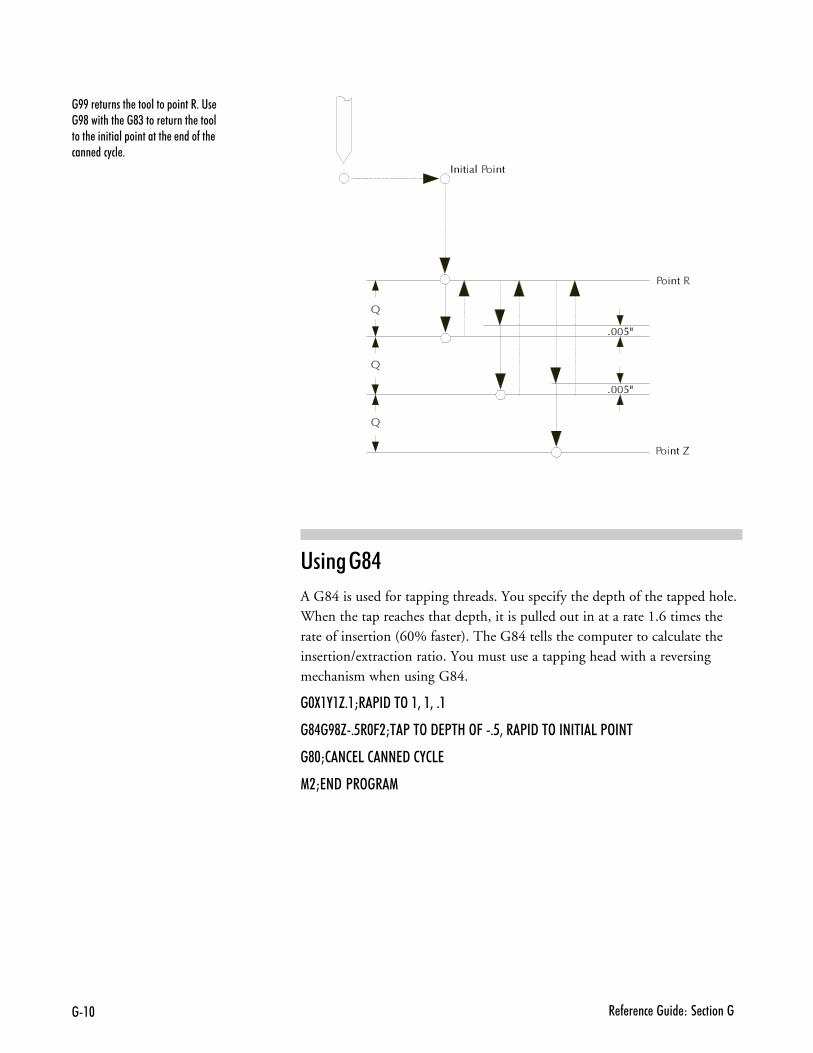
��$ � - � �� ����� ��� �������
�BB�� �������� ��������� ������+��� �B@�������� ��@(����� ������� ���������� ��������� ���������� � ����-��� ���� ���"�� +
'� ����<�
A G84 is used for tapping threads. You specify the depth of the tapped hole.When the tap reaches that depth, it is pulled out in at a rate 1.6 times therate of insertion (60% faster). The G84 tells the computer to calculate theinsertion/extraction ratio. You must use a tapping head with a reversingmechanism when using G84.
�$:�,�H+�M�<�9��>��3��3�+�
�@.�B@H+6�$C�M�<��>�97<�8�>C�+63��<�9��>������5�<>���
�@$M2�275�2��79�2,257
1�M7�9�<�>��1
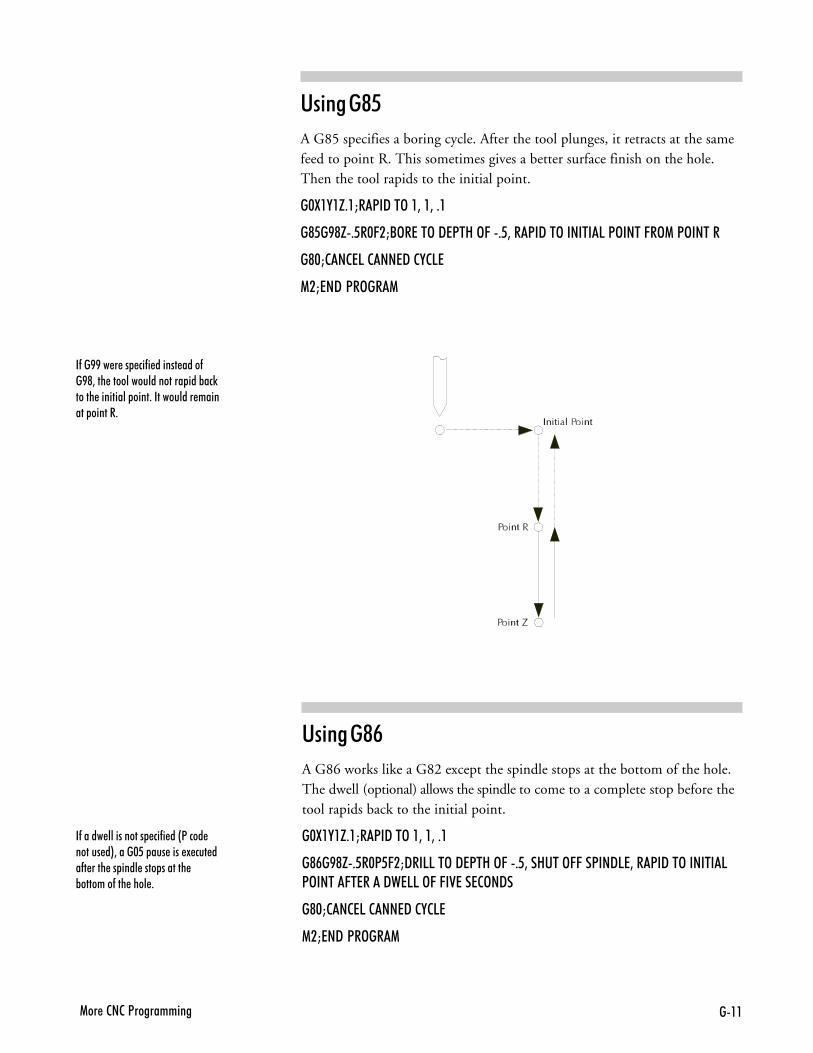
���1�� �2�2�<����������
�-��BB�� � �� ��-� ������ ����-�B@3��� ������������������ ���%��)����� ��������� ����+����������� ������� ������+
�-����� ����������� ��-� ��&<���� ������ �*3����$6� ��� ���� ! ��� ��-� ���� �� ���� ���� ������� %�������-��� ���� +
'� ����<:
A G86 works like a G82 except the spindle stops at the bottom of the hole.The dwell (optional) allows the spindle to come to a complete stop before thetool rapids back to the initial point.
�$:�,�H+�M�<�9��>��3��3�+�
�@#�B@H+6�$<6C�M9��55��>�97<�8�>C�+63��8���>CC��<��9573��<�9��>������5<>����C�7���9�755�>C�C�07��72>�9�
�@$M2�275�2��79�2,257
1�M7�9�<�>��1
'� ����<
A G85 specifies a boring cycle. After the tool plunges, it retracts at the samefeed to point R. This sometimes gives a better surface finish on the hole.Then the tool rapids to the initial point.
�$:�,�H+�M�<�9��>��3��3�+�
�@6�B@H+6�$C�M/>�7��>�97<�8�>C�+63��<�9��>������5�<>����C�>1�<>�����
�@$M2�275�2��79�2,257
1�M7�9�<�>��1
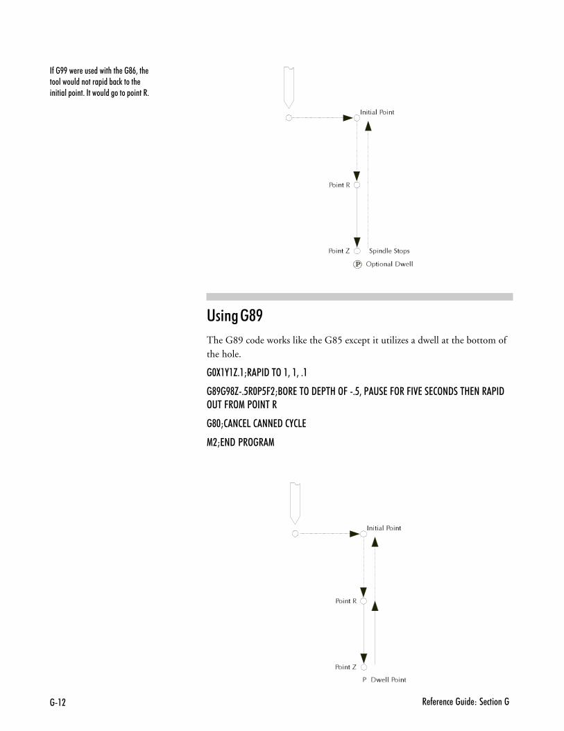
��� � - � �� ����� ��� �������
'� ����<>
The G89 code works like the G85 except it utilizes a dwell at the bottom ofthe hole.
�$:�,�H+�M�<�9��>��3��3�+�
�@B�B@H+6�$<6C�M/>�7��>�97<�8�>C�+63�<��7�C>��C�07��72>�9���87���<�9>���C�>1�<>�����
�@$M2�275�2��79�2,257
1�M7�9�<�>��1
�-��BB�� � ��� ��������� ��@#3��� ����������������� ���%��)������ �������� ����+���������������� ������+
��(1�� �2�2�<����������
�B&�����+�1�����++ ��Subprograms are used to execute repetitive routines in an NC program.Since a subprogram can be called again and again, you don’t have to enterthe same data more than once. This is especially useful if the machining op-eration you wish to repeat is lengthy or complex. The NC codes used forsubprogramming on the Machining Center are:
M98 Call to subprogram.M99 Return from subprogram.
P Code The P code is used to reference the first block of the subprogram(which begins with an O code). The P code immediately followsan M98.
L Code The L code is used as a loop counter when used insubprogramming. The computer executes the subprogram as manytimes as defined by the L code. For instance, if the code is L5, thesubprogram is executed five times. (Optional)
O Code The O code replaces the N code on the first block of a subprogram.
A subprogram is called by an M98 and a P code. When an M98 calls the sub-program, the main program is interrupted while the subprogram is executed.
The P code references the subprogram’s address (the first block of the sub-program). The first block of the subprogram uses an O code instead of an Ncode for block numbering.
When the M99 is executed, the main portion of the NC program continuesto execute from the block after the subprogram was called.
Subprograms can also be nested within other subprograms. This means thatwhile a subprogram is being executed, it can call another subprogram. Thedefault number of levels that subprograms can be nested is 20 levels deep.You can change the default by using the Setup Program (click on the Setupicon in the BENCHMAN program group).
���)��� �5���� ����������� ������ ��������"�� ������ �+�C���������� 3�-��� ������%���)��-��2���� ����"��� �����������1.'5�$3��� � ������ ! ��� ��� ����� �+�-� ���� �� ������ 3��� ���� �� ������� ���� � ���������������� �� ����� ���-�� � ������+
���)�,������������ �-�������1BB<?%���)����% �?������ � ����-��� ��% ������+������� ����������� ����� ������������ �� ��-� ��%���)+���I���) ���� �����������������+
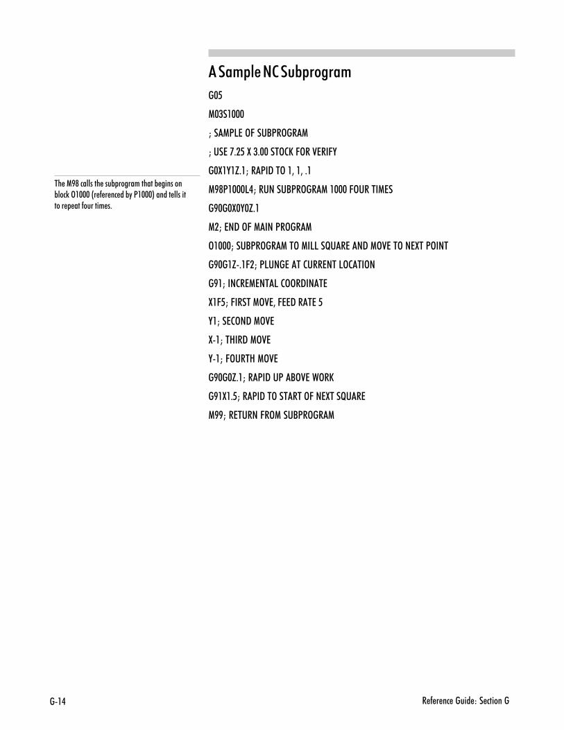
��. � - � �� ����� ��� �������
���+&�������B&�����+
�!
�!/��$$$
L��1<57�>C���/<�>��1
L���7�'+�6�:�(+$$���>2E�C>��07��C,
�!8,�,G-,L��<�9��>��3��3�+�
�><1,!!!5�L�������/<�>��1��$$$�C>�����17�
�>!�!8!�!G-,
�.L�7�9�>C�1���<�>��1
3,!!!L���/<�>��1��>�1�55��F��7��9�1>07��>��7:��<>���
�>!�,G�-,6.L�<5���7���2���7���5>2��>�
�>,L���2�717��5�2>>�9���7
8,6 L�C�����1>073�C779���7�6
�,L��72>�9�1>07
8�,L��8��9�1>07
��,L�C>���8�1>07
�>!�!G-,L��<�9��<�/>07��>�E
�>,8,- L��<�9��>������>C��7:���F��7
�>>L��7�����C�>1���/<�>��1
�� �1B@��������� ���% ������������% �������%���)�>�$$$�&� - � �� ��%"�<�$$$*������ ���������� ���-������� �+
8��4��� ��2�2�<����������
��7��#�������1�����++ ��
'� ���1�����1�����++ ��
'� ���%����+ �����++����
'� ����������+&���� ��
'� ���#�� ���������� ��������
��� &���$����1�����++ ��
'�������� �������� �������+�
'� ���$����5���%�3����������
'� ���$����3�������C��������
�������#���� ��)��# ����
8� � - � �� ����� ��� ������8
'� ���1�����1�����++ ��Using polar coordinates allows you to specify a radius and an angle by speci-fying a G16 code (polar programming on), then X and Y codes. The X codespecifies the radius. The Y code specifies the angle in degrees. A G15 is usedto cancel the polar programming mode. This programming method can beused in both absolute and incremental programming.
Polar programming is especially useful when writing programs for machiningbolt holes. An L code can be used as a multiplier for the angle value. For in-stance, this bit of code:
�$:$,$H$+$'
1$(
��#
�B�:�,$
1B@<�5��
1�
>�,($
�@�H+��$
�@$
1BB
combines the use of polar programming with a canned cycle and a subprogramto drill a hole at 30o increments. The L value was determined by dividing360 degrees by 30.
You can also cut an arc using code similar to:
��#
�B�:�,$
1B@<�5(#$
��6
1�
>�,�
1BB
In polar programming, the center point is the origin if you specify G90 andthe radius (X code). The center point is the current center if you specify onlythe angle (X and Y codes). The center point is the current point if youspecify G91 and the radius (X code).
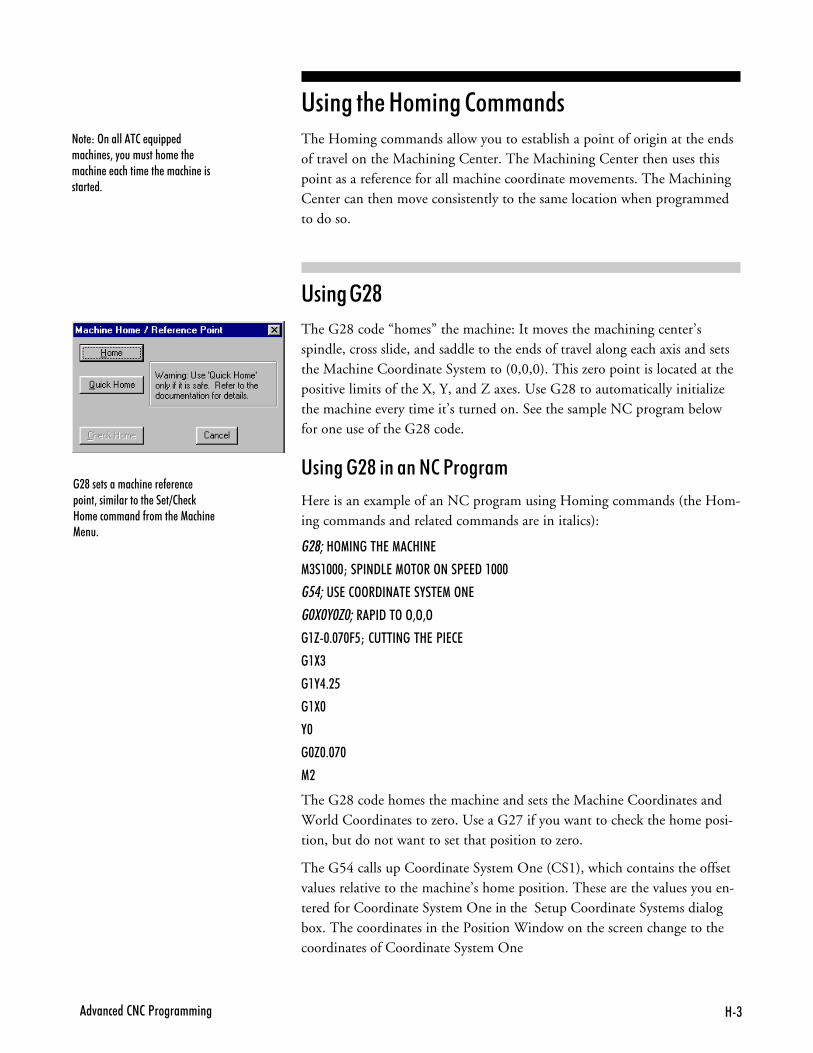
8(�4��� ��2�2�<����������
'� ���%����+ �����++����The Homing commands allow you to establish a point of origin at the endsof travel on the Machining Center. The Machining Center then uses thispoint as a reference for all machine coordinate movements. The MachiningCenter can then move consistently to the same location when programmedto do so.
'� ����.<
The G28 code “homes” the machine: It moves the machining center’sspindle, cross slide, and saddle to the ends of travel along each axis and setsthe Machine Coordinate System to (0,0,0). This zero point is located at thepositive limits of the X, Y, and Z axes. Use G28 to automatically initializethe machine every time it’s turned on. See the sample NC program belowfor one use of the G28 code.
'� ����.<� ��������1�����+
Here is an example of an NC program using Homing commands (the Hom-ing commands and related commands are in italics):
���8>1�����87�128��7
1(��$$$M��<��957�1>�>��>���<779��$$$
������7�2>>�9���7��,��71�>�7
� � � � ��<�9��>�>3>3>
��H$+$'$C6M�2��������87�<�727
��:(
��,.+�6
��:$
,$
�$H$+$'$
1�
The G28 code homes the machine and sets the Machine Coordinates andWorld Coordinates to zero. Use a G27 if you want to check the home posi-tion, but do not want to set that position to zero.
The G54 calls up Coordinate System One (CS1), which contains the offsetvalues relative to the machine’s home position. These are the values you en-tered for Coordinate System One in the Setup Coordinate Systems dialogbox. The coordinates in the Position Window on the screen change to thecoordinates of Coordinate System One
��@�� ����������� �� - � �� ����3�������������� �� �=2� �)8�� ���������-������ �1����� 1 ��+
��� ��>�������2� N�� ������� �3�"����������� ��� ������ � ������� ��� ������� �������� �+
8. � - � �� ����� ��� ������8
The next line (G0X0Y0Z0) calls for the machine to perform a rapid traversemotion from the Home position to point 0,0,0 in Coordinate System One.
The remaining lines of code instruct the machine to cut a square in apiece of stock.
'� ����.<��������� ������5 + �
Remember, Soft Limits are based on Machine Coordinates. You can not use SoftLimits until you have set the machine to the reference point using the G28 codeor pressing the Home button in the Machine Home / Reference Point dialogbox (access using the Set/Check Home command under the Setup Menu).
'� ����.;
After you have set a reference point (using either the Setup Coordinate Systemsdialog box or a G28 code) you can use the G27 code to check the actual ma-chine position against the expected machine position. This command causes themachine to perform a homing-like function, moving each axis independentlyfrom its current position to the reference point. The Control Program thencompares the current position to the one set by the G28. If the deviation islarger than a threshold you can specify in the SETUP file, the Control Pro-gram reports an error after all axes are checked. If there is no deviation, theprogram continues.
G27 also takes an optional position specified by XYZ. This position is calledthe intermediate position. You do not need to specify all axes for the interme-diate point, but for each axis that you specify the current coordinate for theintermediate point is updated to that value. Only axes that have specified coordi-nates move when you specify an intermediate point. For example, if the firstintermediate point commanded is G27Z.6, the intermediate point motion isonly to move the Z axis to .6. The machine first moves to the current inter-mediate point at rapid traverse, then performs the reference point check.
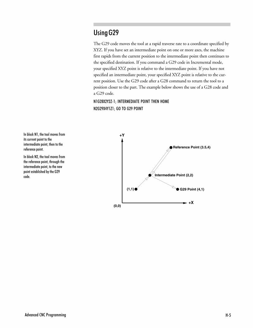
86�4��� ��2�2�<����������
'� ����.>
The G29 code moves the tool at a rapid traverse rate to a coordinate specified byXYZ. If you have set an intermediate point on one or more axes, the machinefirst rapids from the current position to the intermediate point then continues tothe specified destination. If you command a G29 code in Incremental mode,your specified XYZ point is relative to the intermediate point. If you have notspecified an intermediate point, your specified XYZ point is relative to the cur-rent position. Use the G29 code after a G28 command to return the tool to aposition closer to the part. The example below shows the use of a G28 code anda G29 code.
����@:�,�H�M����7�179��7�<>�����87��8>17
����B:.,�H�M��>��>���B�<>���
+Y
+X
G29 Point (4,1)
(0,0)
Intermediate Point (2,2)
Reference Point (3.5,4)
(1,1)
���%���)���3��� ��������4 ��-����������� ��� ���������� ��� �� ���� � ����3��� ������� � - � �� � ����+
���%���)���3��� ��������4 ��-����� �� - � �� � ����3����������� ��� �� ���� � ����3������ �� � ����� ���%���� ��%"��� ���B��� +
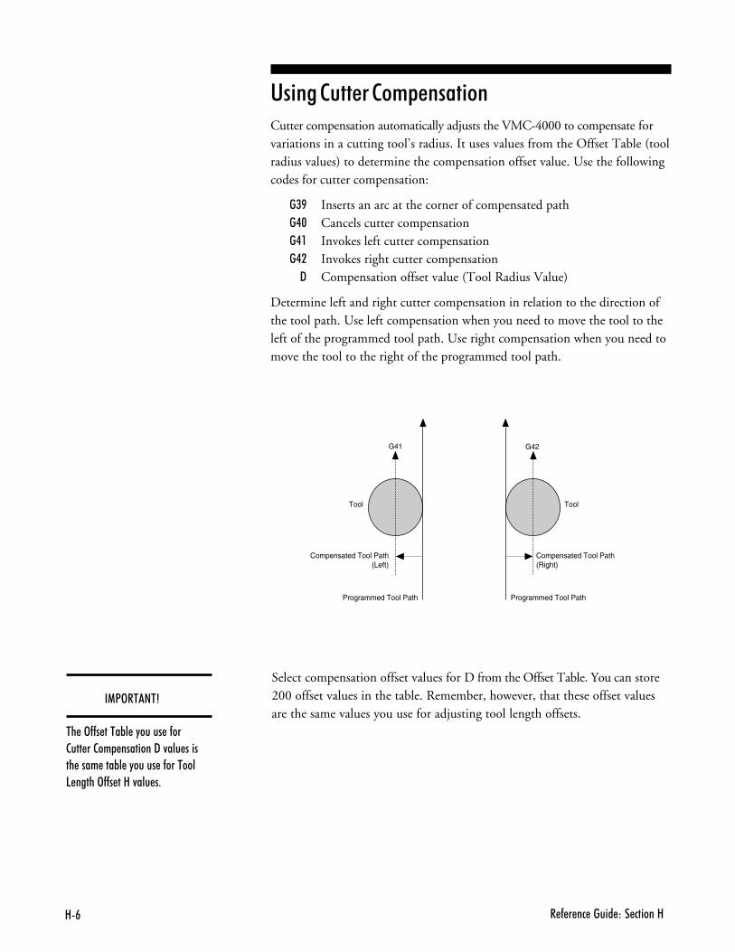
8# � - � �� ����� ��� ������8
Programmed Tool Path
Compensated Tool Path(Left)
Tool
Compensated Tool Path(Right)
Tool
G41 G42
Programmed Tool Path
'� ����������+&���� ��Cutter compensation automatically adjusts the VMC-4000 to compensate forvariations in a cutting tool’s radius. It uses values from the Offset Table (toolradius values) to determine the compensation offset value. Use the followingcodes for cutter compensation:
�/> Inserts an arc at the corner of compensated path��! Cancels cutter compensation��, Invokes left cutter compensation��. Invokes right cutter compensation
" Compensation offset value (Tool Radius Value)
Determine left and right cutter compensation in relation to the direction ofthe tool path. Use left compensation when you need to move the tool to theleft of the programmed tool path. Use right compensation when you need tomove the tool to the right of the programmed tool path.
��13�$��$4
�� �>--� ����%� �"����� �-��2��� ��2�� ��������9�4��� ������ ���� ���%� �"����� �-�������5 �����>--� ��8�4��� �+
Select compensation offset values for D from the Offset Table. You can store200 offset values in the table. Remember, however, that these offset valuesare the same values you use for adjusting tool length offsets.
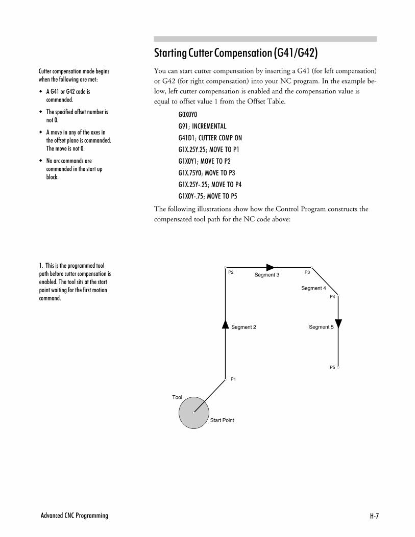
8'�4��� ��2�2�<����������
2��� ����� ����������� �% ������ ���� �-����������� �� ��
� ��.������.����� ���������� �+
� �� �� ��-� ���--� �����% ��������$+
� ���4 ������"��-��� ��! ������ ��--� �� ��� ����������� �+�� ���4 ��������$+
� ������������������ ������� ������� �������� %���)+
�� ����������+&���� ���@��,?��.A
You can start cutter compensation by inserting a G41 (for left compensation)or G42 (for right compensation) into your NC program. In the example be-low, left cutter compensation is enabled and the compensation value isequal to offset value 1 from the Offset Table.
�$:$,$
�B�M� ��2�717��5
�.�9�M�2���7��2>1<�>�
��:+�6,+�6M�1>07��>�<�
��:$,�M�1>07��>�<�
��:+'6,$M�1>07��>�<(
��:+�6,+�6M�1>07��>�<.
��:$,+'6M�1>07��>�<6
The following illustrations show how the Control Program constructs thecompensated tool path for the NC code above:
Segment 2
Segment 3
Segment 4
Segment 5
Start Point
Tool
P1
P2 P3
P4
P5
�+������������ � ������� ������ ����% -�� ����� ����� ���������� ��%� �+��� ���������������� ������ �������������-����� �-������������������+
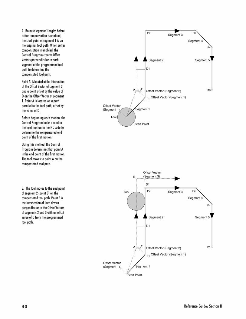
8@ � - � �� ����� ��� ������8
D1
Start Point
Tool
Offset Vector (Segment 2)A
Segment 1
Segment 2
Segment 3
Segment 5
Offset Vector (Segment 1)
A1
Offset Vector(Segment 1)
Segment 4
P1
P2 P3
P4
P5
Offset Vector(Segment 3)
D1
D1
Start Point
Tool
Offset Vector (Segment 2)A
Segment 1
Segment 2
Segment 3
Segment 5
Offset Vector (Segment 1)
A1
Offset Vector(Segment 1)
Segment 4
B
P1
P2 P3
P4
P5
�+��/ ���� �� �� �����% �����% -�� ���� ����� ����������� ��%� �3�� ������� ������-�� �� ������������ ��������������� ���+��� ������ ���� ����������� ��%� �3��� 2�������<��������� �� ��>--� �0 ������ � ������������ ���� �� ����-��� � ������� ������ �������� � ���� ��� ��� ���� ������� ���+
<��������������� ������� ���� �� ������-��� �>--� ��0 ������-�� �� ���������� ������--� ��%"��� �4��� ��-9������ �>--� ��0 ������-�� �� ���+�<�������������� ������� ��� ����� ������� ������ ���3��--� ��%"�� �4��� ��-�9+
/ -�� �% �������� ����������3��� 2�������<����������)���� ������� �� !�������������� ��2���� ���� � ���� ��� ���� ���� �� �� ������-��� �-�����������+
������������ ����3��� �2������<�������� � ���� ������� ���������� � ��� ������-��� �-�����������+�� ��������4 ����� ����������� ��� ���� ������� ���+
(+���� ��������4 ������� � ��� �����-�� �� �����& �����/*������ ��� ���� ������� ���+�<�����/����� ���� �� �������-���� ������� � �������������� �>--� ��0 ������-�� �� ����������(����������--� �4��� ��-�9�-������ � ������� ������ ���+
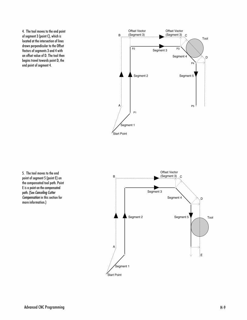
8B�4��� ��2�2�<����������
Offset Vector(Segment 3)
Start Point
Tool
A
Segment 1
Segment 2
Segment 3
Segment 5
Segment 4
B COffset Vector(Segment 3)
D
P1
P2 P3
P4
P5
Start Point
Tool
A
Segment 1
Segment 2
Segment 3
Segment 5
Segment 4
B COffset Vector(Segment 3)
D
E
.+���� ��������4 ������� � ��� �����-�� �� ���(�& �����2*3�������������� ������� ���� �� �������-���� ������� � �������������� �>--� �0 �������-�� �� ����(�����.���������--� ��4��� ��-�9+��� �������� �% ��������4 ���������� �����93��� ��� ������-�� �� ���.+
6+���� ��������4 ������� � �� ������-�� �� ���6�& �����7*����� ���� ���� ������� ���+�<����7������ ���������� ���� ���� � ���+�&� �� ��������������������� �������������� ������-����� ���-��������+*
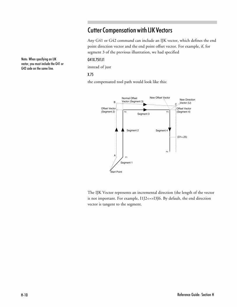
8�$ � - � �� ����� ��� ������8
���)��� ��� ��-"��������DE4 ����3�"�������������� ��� ��.�����.����� ������ ���� ���� +
�������+&���� ���� %��FE���#���
Any G41 or G42 command can include an IJK vector, which defines the endpoint direction vector and the end point offset vector. For example, if, forsegment 3 of the previous illustration, we had specified
�.�:+'6��D�
instead of just
:+'6
the compensated tool path would look like this:
(D1=.25)
Start Point
Normal Offset Vector (Segment 3)
Offset Vector(Segment 2)
A
Segment 1
Segment 2
Segment 3
Segment 4
B
Offset Vector(Segment 4)
New Offset VectorNew Direction Vector (IJ)C
P1
P2 P3
P4
The IJK Vector represents an incremental direction (the length of the vectoris not important. For example, I1J2<=>I3J6. By default, the end directionvector is tangent to the segment.
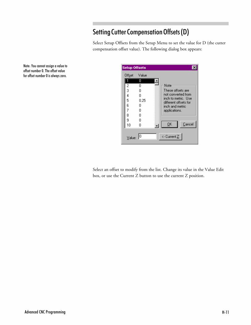
8���4��� ��2�2�<����������
� ����������+&���� ���3������@"A
Select Setup Offsets from the Setup Menu to set the value for D (the cuttercompensation offset value). The following dialog box appears:
���)�,�������������������4��� ����--� �����% ��$+��� ��--� ��4��� -����--� �����% ��$��������"��G ��+
Select an offset to modify from the list. Change its value in the Value Editbox, or use the Current Z button to use the current Z position.
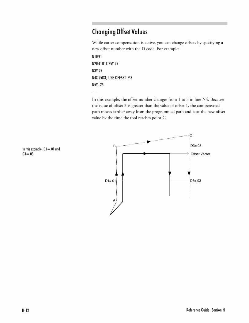
8�� � - � �� ����� ��� ������8
�%��� ���3�����������
While cutter compensation is active, you can change offsets by specifying anew offset number with the D code. For example:
���B�
���.�9�:+�6,+�6
�(,+�6
�.:+�69(M���7�>CC�7��R(
�6,+�6
S
In this example, the offset number changes from 1 to 3 in line N4. Becausethe value of offset 3 is greater than the value of offset 1, the compensatedpath moves farther away from the programmed path and is at the new offsetvalue by the time the tool reaches point C.
�������� !�� � ��9�Q+$�����9(Q+$(
B
C
D3=.03D1=.01
Offset Vector
D3=.03
A
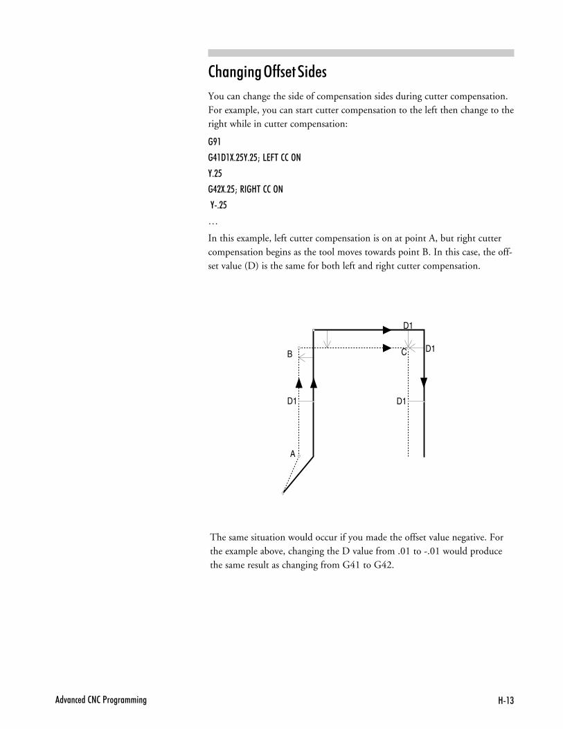
8�(�4��� ��2�2�<����������
The same situation would occur if you made the offset value negative. Forthe example above, changing the D value from .01 to -.01 would producethe same result as changing from G41 to G42.
�%��� ���3����� ���
You can change the side of compensation sides during cutter compensation.For example, you can start cutter compensation to the left then change to theright while in cutter compensation:
�B�
�.�9�:+�6,+�6M�57C��22�>�
,+�6
�.�:+�6M����8��22�>�
�,+�6
S
In this example, left cutter compensation is on at point A, but right cuttercompensation begins as the tool moves towards point B. In this case, the off-set value (D) is the same for both left and right cutter compensation.
B C
D1D1
D1
D1
A
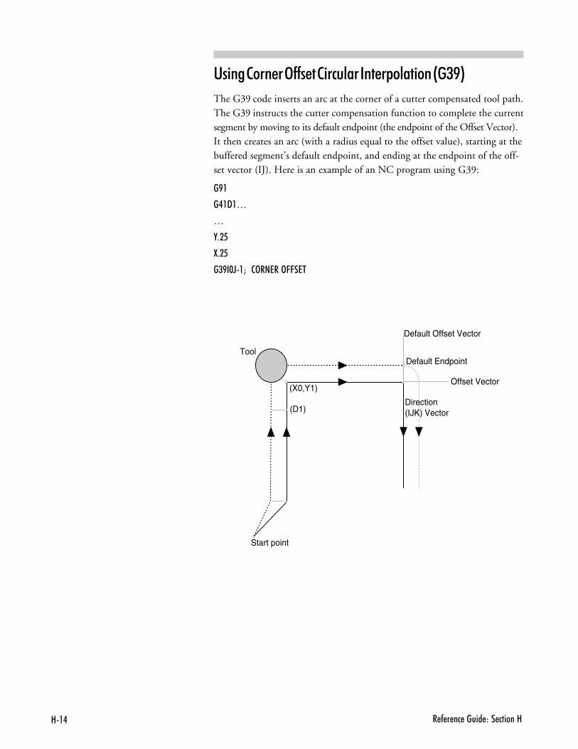
8�. � - � �� ����� ��� ������8
(X0,Y1)
(D1)
Start point
Tool
Default Offset Vector
Offset Vector
Direction (IJK) Vector
Default Endpoint
'� ����������3������ �#���������&��� ���@�/>A
The G39 code inserts an arc at the corner of a cutter compensated tool path.The G39 instructs the cutter compensation function to complete the currentsegment by moving to its default endpoint (the endpoint of the Offset Vector).It then creates an arc (with a radius equal to the offset value), starting at thebuffered segment’s default endpoint, and ending at the endpoint of the off-set vector (IJ). Here is an example of an NC program using G39:
�B�
�.�9�S
S
,+�6
:+�6
�(B�$D�M��2>��7��>CC�7�
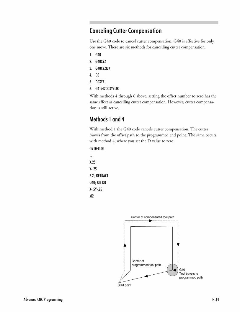
8�6�4��� ��2�2�<����������
���#�� ����������+&���� ��
Use the G40 code to cancel cutter compensation. G40 is effective for onlyone move. There are six methods for cancelling cutter compensation.
,- �.$
.- �.$:,H
/- �.$:,H�DE
�- 9$
- 9$:,H
:- �.�=.�9$:,H�DE
With methods 4 through 6 above, setting the offset number to zero has thesame effect as cancelling cutter compensation. However, cutter compensa-tion is still active.
��%����,������
With method 1 the G40 code cancels cutter compensation. The cuttermoves from the offset path to the programmed end point. The same occurswith method 4, where you set the D value to zero.
�B��.�9�
S
:+�6
,+�6
H+�M��7��2�
�.$M�>��9$
:+6,+�6
1�
Center of programmed tool path
Start point
G40 Tool travels to programmed path
Center of compensated tool path
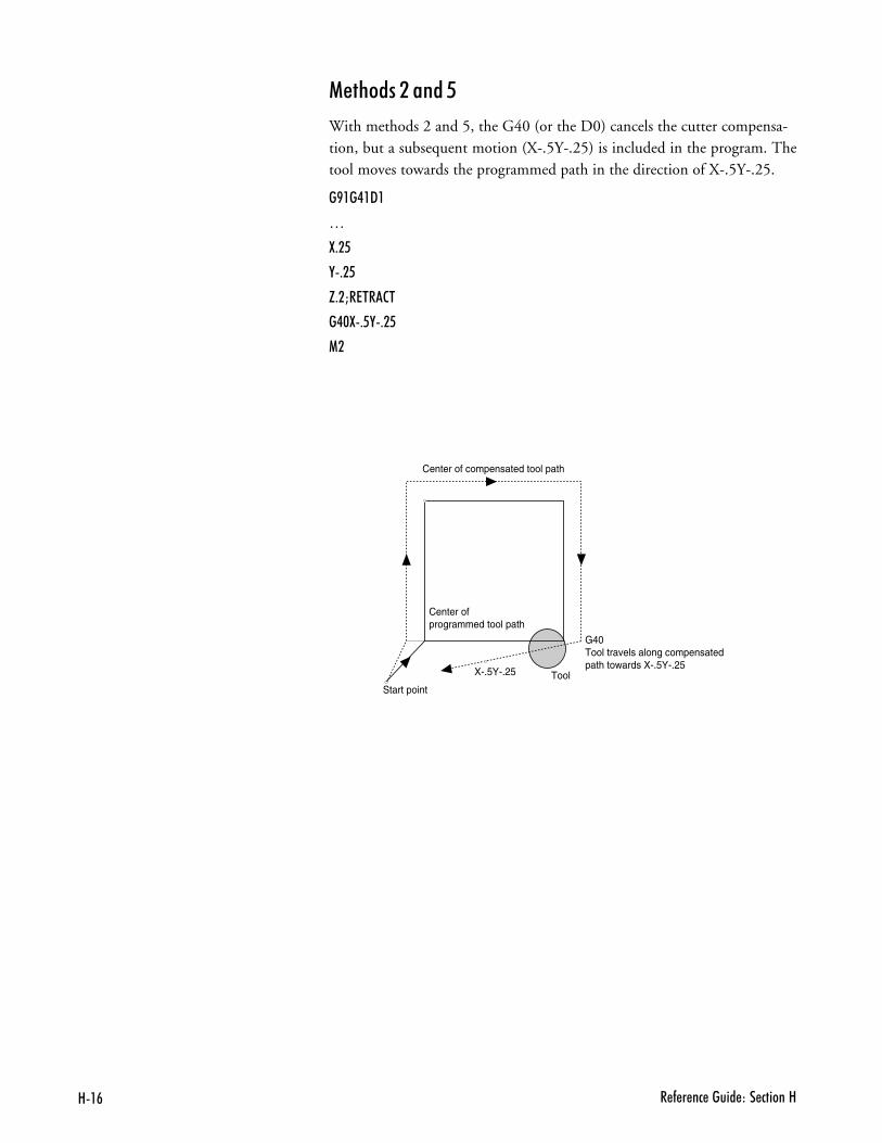
8�# � - � �� ����� ��� ������8
��%����.�����
With methods 2 and 5, the G40 (or the D0) cancels the cutter compensa-tion, but a subsequent motion (X-.5Y-.25) is included in the program. Thetool moves towards the programmed path in the direction of X-.5Y-.25.
�B��.�9�
S
:+�6
,+�6
H+�M�7��2�
�.$:+6,+�6
1�
Center of programmed tool path
Center of compensated tool path
Start point
G40 Tool travels along compensated path towards X-.5Y-.25
ToolX-.5Y-.25
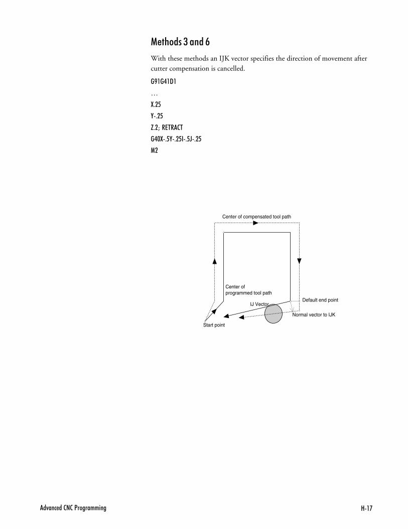
8�'�4��� ��2�2�<����������
��%����/�����:
With these methods an IJK vector specifies the direction of movement aftercutter compensation is cancelled.
�B��.�9�
S
:+�6
,+�6
H+�M��7��2�
�.$:+6,+�6�+6D+�6
1�
Center of programmed tool path
Center of compensated tool path
Start point
IJ Vector
Normal vector to IJK
Default end point
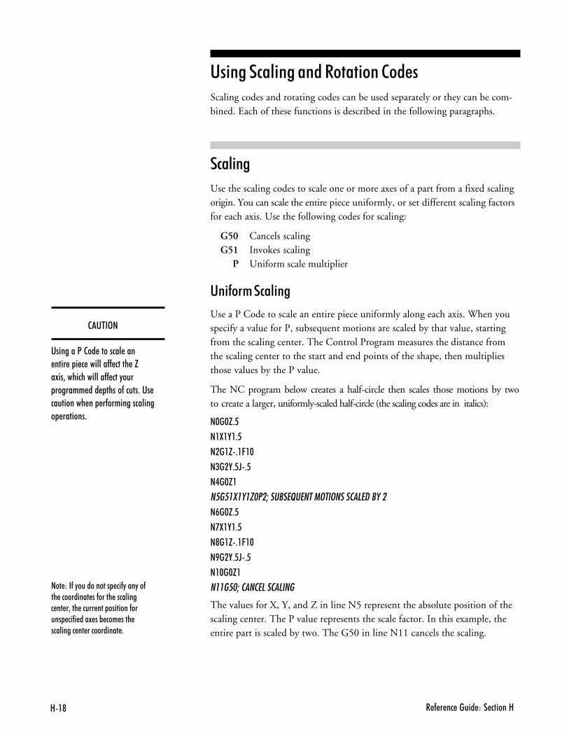
8�@ � - � �� ����� ��� ������8
���)��-�"����������� ��-"���"��-�� ���������� ��-����� ��������� �� �3��� ����� ��� ��������-����� ��-� ���! ��% ��� ���� ��������� �� ����������� +
��'$�3�
��������<�2�� �������� ��� ���� � � � �������-- ����� �H�!��3�������������-- ���"��� ������� ��� �����-�����+��� ���������� �� �-��������������� �������+
'� ���#�� ���������� ��������Scaling codes and rotating codes can be used separately or they can be com-bined. Each of these functions is described in the following paragraphs.
#�� ��
Use the scaling codes to scale one or more axes of a part from a fixed scalingorigin. You can scale the entire piece uniformly, or set different scaling factorsfor each axis. Use the following codes for scaling:
G50 Cancels scalingG51 Invokes scaling
P Uniform scale multiplier
'� ���+�#�� ��
Use a P Code to scale an entire piece uniformly along each axis. When youspecify a value for P, subsequent motions are scaled by that value, startingfrom the scaling center. The Control Program measures the distance fromthe scaling center to the start and end points of the shape, then multipliesthose values by the P value.
The NC program below creates a half-circle then scales those motions by twoto create a larger, uniformly-scaled half-circle (the scaling codes are in italics):
�$�$H+6
��:�,�+6
����H+�C�$
�(��,+6D+6
�.�$H�
���������� ��������������������������� �����
�#�$H+6
�':�,�+6
�@��H+�C�$
�B��,+6D+6
��$�$H�
����� ���������������
The values for X, Y, and Z in line N5 represent the absolute position of thescaling center. The P value represents the scale factor. In this example, theentire part is scaled by two. The G50 in line N11 cancels the scaling.
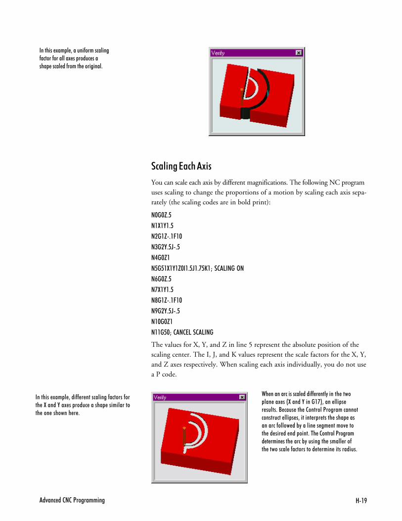
8�B�4��� ��2�2�<����������
�������� !�� � 3������-�����������-������-��������! �� ����� ������ ����� ��-������ ���������+
#�� �����#%��9 �
You can scale each axis by different magnifications. The following NC programuses scaling to change the proportions of a motion by scaling each axis sepa-rately (the scaling codes are in bold print):
�$�$H+6
��:�,�+6
����H+�C�$
�(��,+6D+6
�.�$H�
� � ,8,�,G!�,- F,-; E,L���5����3�
�#�$H+6
�':�,�+6
�@��H+�C�$
�B��,+6D+6
��$�$H�
�,,� !L������5���5���
The values for X, Y, and Z in line 5 represent the absolute position of thescaling center. The I, J, and K values represent the scale factors for the X, Y,and Z axes respectively. When scaling each axis individually, you do not usea P code.
�������� !�� � 3���-- � �����������-�������-���� �:�����,��! �� ����� ������ ������������� ��� �������� � +
�� ���������������� ����-- � ���"������ ���� ��� ��! ��&:�����,������'*3���� ��� � � �����+�/ ���� ��� �2�������<����������������������� ��� � �3������� � � ����� ���� ����������-����� ��%"������ �� �� �����4 ����� �� ��� �� ��� ����+��� �2�������<������� � ���� ���� �����%"��������� ������ ���-�� ��������� �-����������� � ���� �����������+
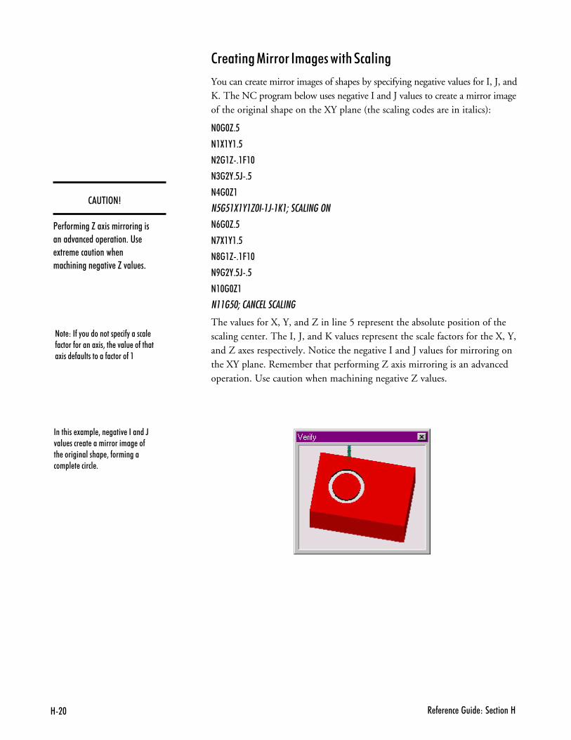
8�$ � - � �� ����� ��� ������8
���)��-�"����������� ��-"������� -������-�������!��3��� �4��� ��-������!���� -�����������-�������-��
�������� !�� � 3�� ����4 �������D4��� ���� �� �������������� ��-�� ������������� 3�-����������� � � ������ +
��'$�3�4
< �-�������H��!��������������������4��� ��� ������+��� !�� � ����������� ������������ ����4 �H�4��� ��
���� ���� ������+������ %�#�� ��
You can create mirror images of shapes by specifying negative values for I, J, andK. The NC program below uses negative I and J values to create a mirror imageof the original shape on the XY plane (the scaling codes are in italics):
�$�$H+6
��:�,�+6
����H+�C�$
�(��,+6D+6
�.�$H�
���������� �!�"!�#������������
�#�$H+6
�':�,�+6
�@��H+�C�$
�B��,+6D+6
��$�$H�
����� ���������������
The values for X, Y, and Z in line 5 represent the absolute position of thescaling center. The I, J, and K values represent the scale factors for the X, Y,and Z axes respectively. Notice the negative I and J values for mirroring onthe XY plane. Remember that performing Z axis mirroring is an advancedoperation. Use caution when machining negative Z values.
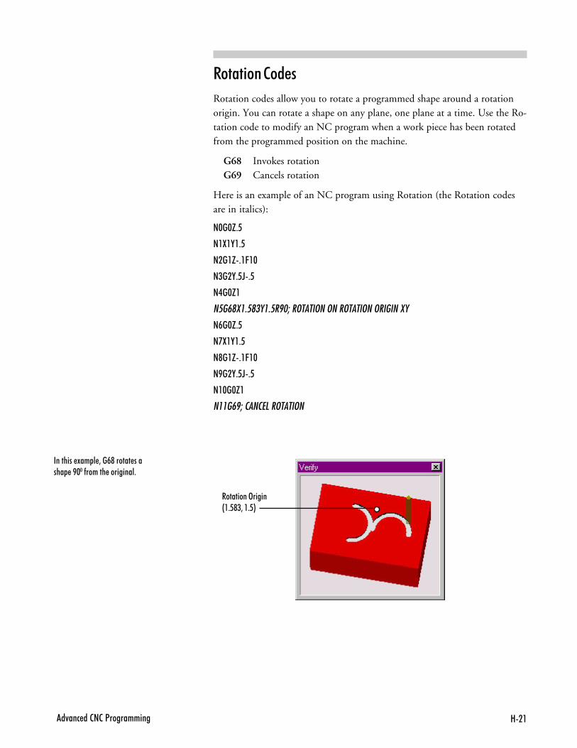
8���4��� ��2�2�<����������
�������� !�� � 3��#@������ ������ �B$$�-������ ���������+
��� ��������
Rotation codes allow you to rotate a programmed shape around a rotationorigin. You can rotate a shape on any plane, one plane at a time. Use the Ro-tation code to modify an NC program when a work piece has been rotatedfrom the programmed position on the machine.
G68 Invokes rotationG69 Cancels rotation
Here is an example of an NC program using Rotation (the Rotation codesare in italics):
�$�$H+6
��:�,�+6
����H+�C�$
�(��,+6D+6
�.�$H�
���$��%�&��%�'( �'�����������'���������'�������
�#�$H+6
�':�,�+6
�@��H+�C�$
�B��,+6D+6
��$�$H�
����$(��������'�������
���������>�����&�+6@(3��+6*
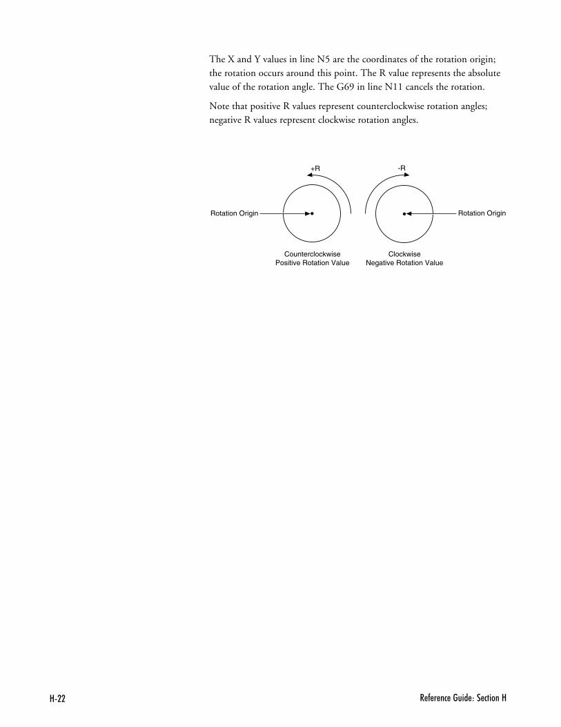
8�� � - � �� ����� ��� ������8
The X and Y values in line N5 are the coordinates of the rotation origin;the rotation occurs around this point. The R value represents the absolutevalue of the rotation angle. The G69 in line N11 cancels the rotation.
Note that positive R values represent counterclockwise rotation angles;negative R values represent clockwise rotation angles.
+R -R
CounterclockwisePositive Rotation Value
ClockwiseNegative Rotation Value
Rotation Origin Rotation Origin
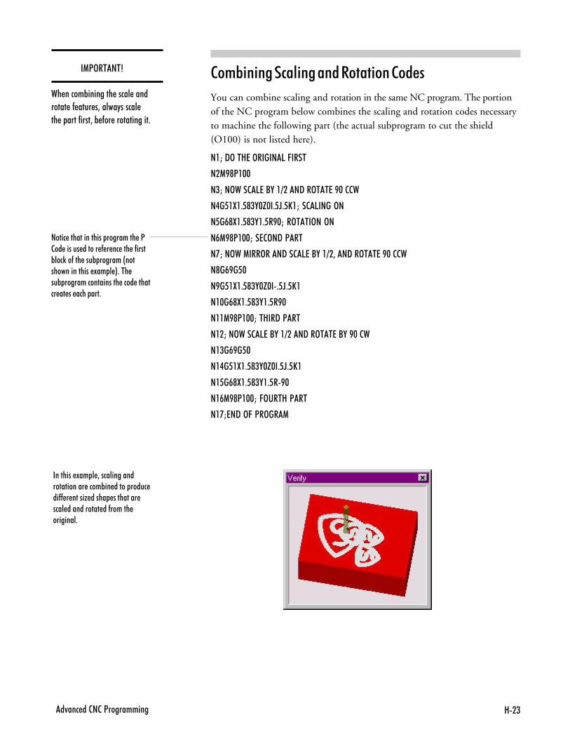
8�(�4��� ��2�2�<����������
����� �������������� ��������� �<2�� ������ ������ - � �� ��� �-����%���)��-��� ���% �������&����������������� !�� � *+��� ��% ������������������ ���� ������� �� �� ���� ���+
��13�$��$4
�� �����%�������� ����� ��������� �- ���� �3�����"���#����� � ����� ��3�% -�� ������������+
��+B � ���#�� ���������� ��������
You can combine scaling and rotation in the same NC program. The portionof the NC program below combines the scaling and rotation codes necessaryto machine the following part (the actual subprogram to cut the shield(O100) is not listed here).
��M�9>��87�>�����5�C����
��1B@<�$$
�(M��>���257�/,��=���9��>��7�B$�22�
�.�6�:�+6@(,$H$�+6D+6E�M��25����>�
�6�#@:�+6@(,�+6�B$M��>���>��>�
�#1B@<�$$M��72>�9�<��
�'M��>��1���>���9��257�/,��=�3��9��>��7�B$�22�
�@�#B�6$
�B�6�:�+6@(,$H$�+6D+6E�
��$�#@:�+6@(,�+6�B$
���1B@<�$$M��8��9�<��
���M��>���257�/,��=���9��>��7�/,�B$�2�
��(�#B�6$
��.�6�:�+6@(,$H$�+6D+6E�
��6�#@:�+6@(,�+6�B$
��#1B@<�$$M�C>���8�<��
��'M7�9�>C�<�>��1
�������� !�� � 3����������������������� ����%�� ����� ����� ��-- � �����G ����� ��������� ���� ����������� ��-������ ��������+
8�. � - � �� ����� ��� ������8
��� &���$����1�����++ ��The VMC-4000 allows you to define up to 20 different tools for use duringmilling operations. If your machine is equipped with an optional AutomaticTool Changer (ATC), multiple tool programs require very little user inter-vention, other than setup.
You will need to define tools, configure the ATC, and write the tool changesinto the NC program. For defining tools and ATC configuration, the easiestmethod is to use the Setup Tool Wizard under the Tools menu. This willwalk the user through all the setup steps.
Even if your machine is not equipped with the ATC, you may use the Wiz-ard. Defining tools is explained in the tutorial on page D-8 of this guide.Programming codes, reference tools, offsets, and testing are described below.
'� ������ &���$���������
The T code is used in the NC program to offset the cutter so that the NCprogram becomes independent of the cutter length, which is set up in theSetup Tool Library dialog box. This means you can replace a worn tool with atool of a different length without changing the NC program, just by enteringnew offsets. (Any actual tool change is performed manually.) The T code canbe located anywhere within the block of NC code, but it is normally placed afterthe G code.
When you place T codes in your program for tool changes, you should alsouse the M06 code to retract and shut off the spindle. This code instructs themachining center to shut off and retract the spindle to the top of the vertical col-umn, where it pauses until you manually change the tool. Pressing the Enterkey turns the spindle back on and moves it back to the previous position tocontinue with the NC program.
8�6�4��� ��2�2�<����������
���B� �% ���%���������#��$���
When using multiple tools, a reference tool, normally Tool #1, is set to zerofor the Z axis. This establishes a reference tool position which is used as areference point for additional tools. For demonstration purposes, we will useTool #1 as the reference tool and Tool #2 as the additional tool.
To set the reference tool:
,- Decide on a reference point (a point on the workpiece, or on a gauge,where you will jog the tip of each tool).
.- Install a tool into the spindle.
/- From the Tools Menu, choose Select Tool. If the tool is not already definedin the pull down menu, see page D-8 to define the tool.
�- Choose the tool you are using, then click the Select Tool button.
- If you are using a Tool Height Sensor (included in the Quick Changetooling package), place it on the cross slide or other conductive surface.
:- Using the Jog Control Panel, jog tool #1 to the tip of the sensor untilthe lights come on.
;- Select Set Position from the Setup Menu, set the Z axis value to zero,and click OK.
Tool #1 is now established as the reference tool.
���B� �% ���$����3�����
Now that the reference tool is established, additional tools can be assignedoffsets. You can move the tool and accept its current Z axis position as theoffset value, or you can manually enter offset values.
To set the offset for Tool #2:
,- Install tool #2 in the spindle.
.- From the Tools Menu, choose Select Tool. If the tool is not already definedin the pull down menu, see page D-8 to define the tool.
/- Choose the tool you are using, then click Select Tool.
�- Jog tool #2 to the tip of the sensor until the lights come on.
- Select Offsets from the Setup Menu.
��'$�3�
9�������� ����� ���-���������������+��� ��� �F���)�2���� ��������� ����������) ���� ��� ������ ����� ����������-������ � ���� ��� ������4��"� ������� "���������������������� �� ���� +
8�# � - � �� ����� ��� ������8
:- Choose the correct tool (the description that matches the tool you in-stalled) from the list, and click on the Current Z button at the bottomof the window. Select OK to save the value.
;- Repeat this process for each additional tool.
The offset for Tool #2 is now established.
$�� ����������� &���$����1�����+
After setting all of the tool offsets, test run your program without aworkpiece mounted and with the spindle speed turned down.
,- After installing Tool #1, close the safety shield, put on your safetyglasses, and complete the safety checklist.
.- Select the Run/Continue command from the Program Menu. Enter zeroas the start block and select the Run Program button. Throughout thetest, be prepared to press the emergency stop switch on the machining cen-ter, or the space bar on the computer keyboard in case of a tool crash.The computer will run the program until it reaches the M06 code. Ifyour machine is equipped with an ATC, the tool change will take placeautomatically, and you may ignore steps 3-7. The M06 code stops theNC program and retracts the spindle.
/- When the spindle has completely stopped and the Pause message appearson the screen, push in the Emergency Stop button on the front panel.
�- Open the safety shield.
- Remove Tool #1 and install Tool #2, making certain it is securely fas-tened to the spindle.
:- Close the door, and pull out the Emergency Stop button. Press the Enterkey on the computer keyboard. The spindle turns on and moves to theprevious position. Operation continues as programmed until the nextM06 code is encountered.
;- At each pause, repeat Steps 3 through 6, installing the appropriate toolat the appropriate points in the program.
<- Edit the program, if required. When you are satisfied that the programworks correctly, mount the workpiece, set the spindle speed, and runyour multiple tool program.
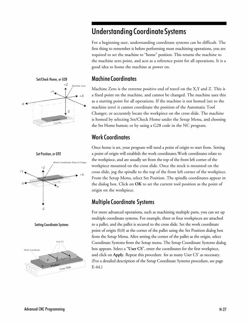
8�'�4��� ��2�2�<����������
� �=2� �)�8�� 3������@
� ��<�������3�����B�
� ������2�������� ��"�� ��
�
�
�
�
�
���������
���� ��
� ����������
�
�
����
�
��
������������� ��
������������ �������������������
���������
������
������
������������ ��
���� ���
'�������� �������� �������+�For a beginning user, understanding coordinate systems can be difficult. Thefirst thing to remember is before performing most machining operations, you arerequired to set the machine to “home” position. This returns the machine tothe machine zero point, and acts as a reference point for all operations. It is agood idea to home the machine at power on.
��#% �������� ����
Machine Zero is the extreme positive end of travel on the X,Y and Z. This isa fixed point on the machine, and cannot be changed. The machine uses thisas a starting point for all operations. If the machine is not homed (set to themachine zero) it cannot coordinate the position of the Automatic ToolChanger, or accurately locate the workpiece on the cross slide. The machineis homed by selecting Set/Check Home under the Setup Menu, and choosingthe Set Home button; or by using a G28 code in the NC program.
2��0������ ����
Once home is set, your program will need a point of origin to start from. Settinga point of origin will establish the work coordinates.Work coordinates relate tothe workpiece, and are usually set from the top of the front left corner of theworkpiece mounted on the cross slide. Once the stock is mounted on thecross slide, jog the spindle to the top of the front left corner of the workpiece.From the Setup Menu, select Set Position. The spindle coordinates appear inthe dialog box. Click on OK to set the current tool position as the point oforigin on the workpiece.
��� &�������� ��������+�
For more advanced operations, such as machining multiple parts, you can set upmultiple coordinate systems. For example, three or four workpieces are attachedto a pallet, and the pallet is secured to the cross slide. Set the work coordinatepoint of origin (0,0) at the corner of the pallet using the Set Position dialog boxfrom the Setup Menu. After setting the corner of the pallet as the origin, selectCoordinate Systems from the Setup menu. The Setup Coordinate Systems dialogbox appears. Select a “User CS”, enter the coordinates for the first workpiece,and click on Apply. Repeat this procedure for as many User CS’ as necessary.(For a detailed description of the Setup Coordinate Systems procedure, see pageE-44.)
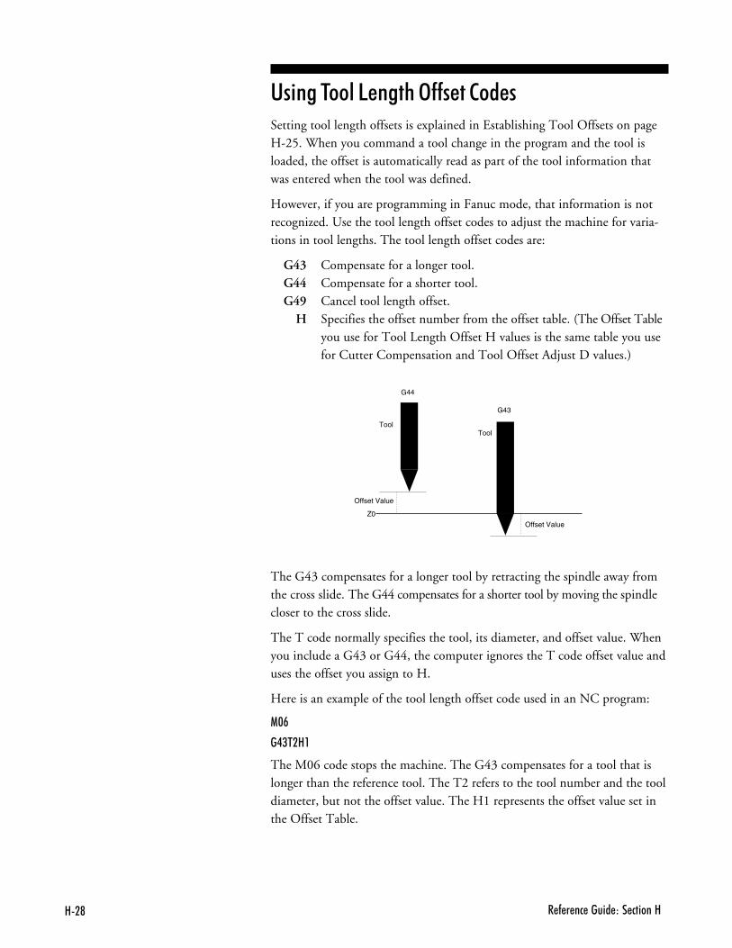
8�@ � - � �� ����� ��� ������8
'� ���$����5���%�3����������Setting tool length offsets is explained in Establishing Tool Offsets on pageH-25. When you command a tool change in the program and the tool isloaded, the offset is automatically read as part of the tool information thatwas entered when the tool was defined.
However, if you are programming in Fanuc mode, that information is notrecognized. Use the tool length offset codes to adjust the machine for varia-tions in tool lengths. The tool length offset codes are:
G43 Compensate for a longer tool.G44 Compensate for a shorter tool.G49 Cancel tool length offset.
H Specifies the offset number from the offset table. (The Offset Tableyou use for Tool Length Offset H values is the same table you usefor Cutter Compensation and Tool Offset Adjust D values.)
G44
Tool
Offset Value
Z0
Offset Value
Tool
G43
The G43 compensates for a longer tool by retracting the spindle away fromthe cross slide. The G44 compensates for a shorter tool by moving the spindlecloser to the cross slide.
The T code normally specifies the tool, its diameter, and offset value. Whenyou include a G43 or G44, the computer ignores the T code offset value anduses the offset you assign to H.
Here is an example of the tool length offset code used in an NC program:
1$#
�.(��8�
The M06 code stops the machine. The G43 compensates for a tool that islonger than the reference tool. The T2 refers to the tool number and the tooldiameter, but not the offset value. The H1 represents the offset value set inthe Offset Table.
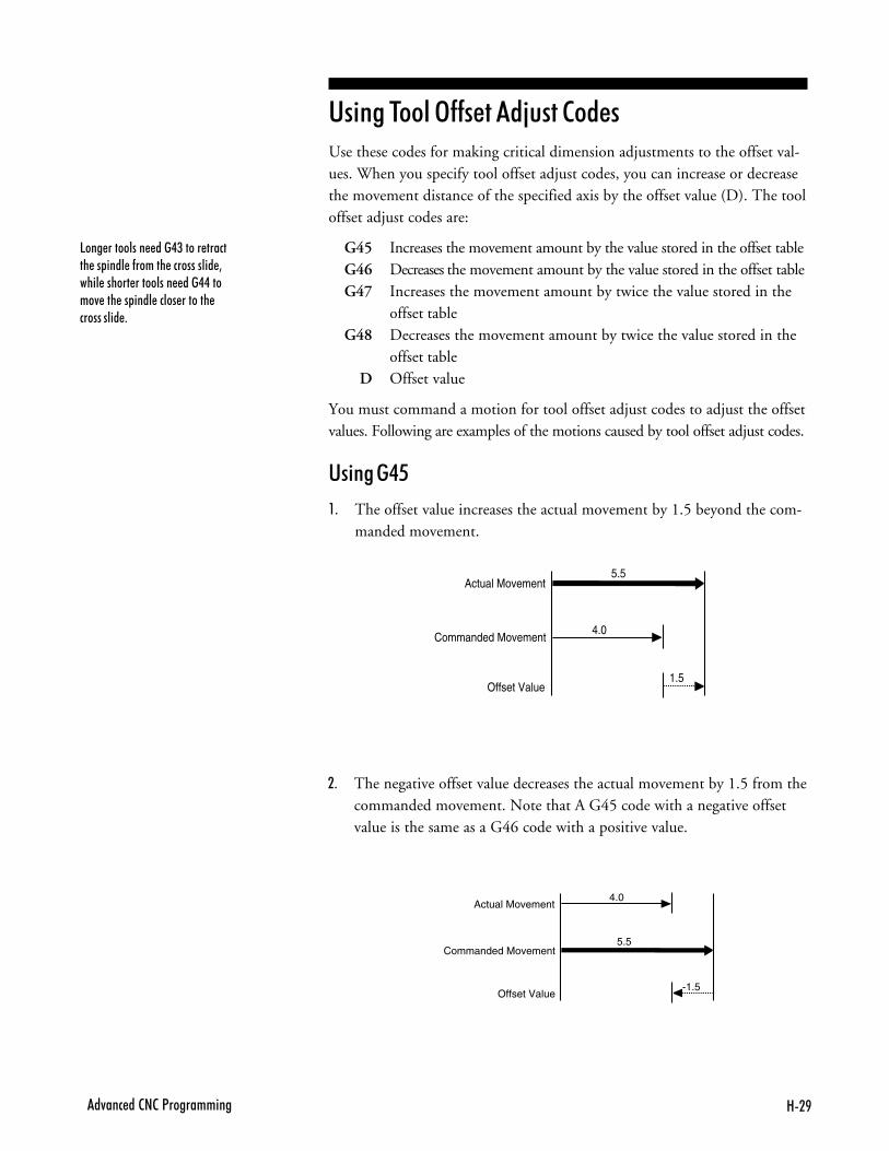
8�B�4��� ��2�2�<����������
'� ���$����3�������C��������Use these codes for making critical dimension adjustments to the offset val-ues. When you specify tool offset adjust codes, you can increase or decreasethe movement distance of the specified axis by the offset value (D). The tooloffset adjust codes are:
G45 Increases the movement amount by the value stored in the offset tableG46 Decreases the movement amount by the value stored in the offset tableG47 Increases the movement amount by twice the value stored in the
offset tableG48 Decreases the movement amount by twice the value stored in the
offset tableD Offset value
You must command a motion for tool offset adjust codes to adjust the offsetvalues. Following are examples of the motions caused by tool offset adjust codes.
'� �����
,- The offset value increases the actual movement by 1.5 beyond the com-manded movement.
5.5Actual Movement
Commanded Movement
Offset Value
4.0
1.5
5.5
Actual Movement
Commanded Movement
Offset Value
4.0
-1.5
.- The negative offset value decreases the actual movement by 1.5 from thecommanded movement. Note that A G45 code with a negative offsetvalue is the same as a G46 code with a positive value.
5��� ��������� ���.(����� ������� �� ���� �-������ ����������� 3���� ������ ��������� ���..�����4 ��� �� ���� ����� ������� ���������� +
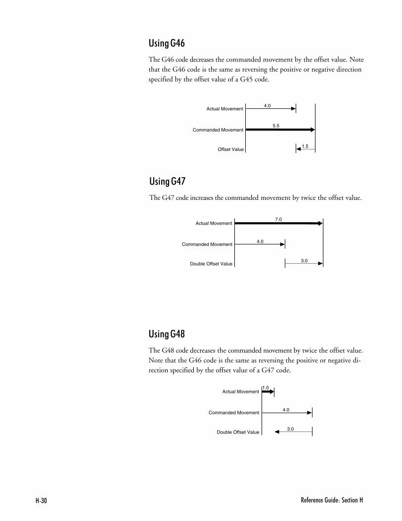
8($ � - � �� ����� ��� ������8
'� �����:
The G46 code decreases the commanded movement by the offset value. Notethat the G46 code is the same as reversing the positive or negative directionspecified by the offset value of a G45 code.
1.0Actual Movement
Commanded Movement
Double Offset Value
4.0
3.0
7.0Actual Movement
Commanded Movement
Double Offset Value
4.0
3.0
5.5
Actual Movement
Commanded Movement
Offset Value
4.0
1.5
'� �����;
The G47 code increases the commanded movement by twice the offset value.
'� �����<
The G48 code decreases the commanded movement by twice the offset value.Note that the G46 code is the same as reversing the positive or negative di-rection specified by the offset value of a G47 code.
� � ����1�����������-�������� ��
����������#% � ��������+� ��
6������������"�&%������
& �����&����
6������������& �����&�������# ��
$����$�&��
%��&�� ���$����
�������#���� ��)��# ����
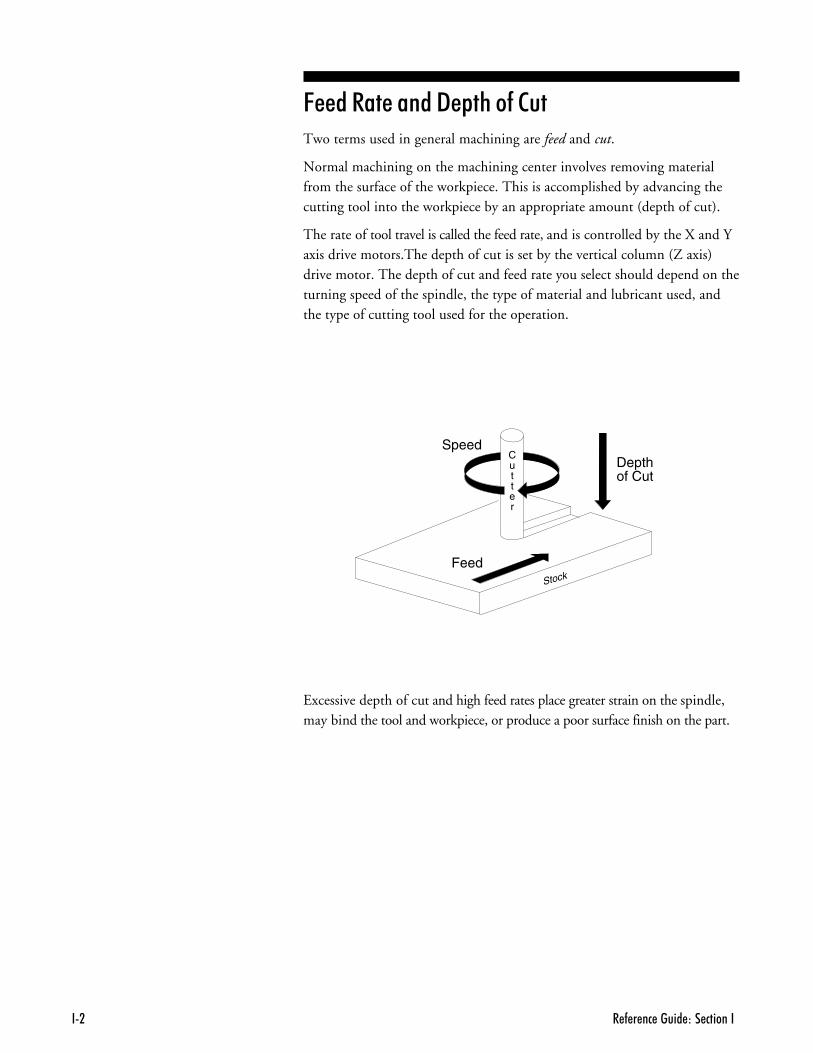
� - � �� ����� ��� ���������
6������������"�&%������Two terms used in general machining are feed and cut.
Normal machining on the machining center involves removing materialfrom the surface of the workpiece. This is accomplished by advancing thecutting tool into the workpiece by an appropriate amount (depth of cut).
The rate of tool travel is called the feed rate, and is controlled by the X and Yaxis drive motors.The depth of cut is set by the vertical column (Z axis)drive motor. The depth of cut and feed rate you select should depend on theturning speed of the spindle, the type of material and lubricant used, andthe type of cutting tool used for the operation.
SpeedDepthof Cut
Feed
Cutter
Stock
Excessive depth of cut and high feed rates place greater strain on the spindle,may bind the tool and workpiece, or produce a poor surface finish on the part.
� � ����1�����������-�������� �(
& �����&����The relative hardness of the material and the type of cutting tool (end millor drill) affect spindle speed. The harder the material is, the slower the speedshould be.
High spindle speeds may produce excess heat which causes the workpiece toexpand. If the workpiece expands, the cutting tool will rub rather than cutthe material, resulting in a poor surface finish. Slow spindle speeds cause noharm, but may be inappropriate for finishing certain types of materials.
The load put on the spindle motor must also be taken into account. Heavycuts at low speeds will make the motor run hotter than lighter cuts at higherspeeds. The selected feed rate and depth of cut should not cause the spindlemotor to greatly lose speed or cause the tool to chatter against the workpiece.
6������������& �����&�������# ��Feed rate selection for machining parts on the VMC-4000 depends onfactors such as: type of material, type of cut, depth of cut, and spindlespeed. The type of tool chosen to make the cuts also affects the depth of cutand, therefore, the feed rate. Consult your Machinist’s Handbook forselecting a feed rate based on spindle speed and material type. Experienceand experimentation will enable you to establish feed rates best suited toparticular applications.
� - � �� ����� ��� ��������.
$����$�&��Cutting tools are usually made from hardened steel and are ground to variousshapes. The clearances ground behind cutting edges are adjusted for the typeof material the tool will cut and the direction the tool will be fed along theworkpiece.
Insufficient clearance behind the cutting edge will cause the tool to rub. Ex-cessive clearance will produce a ridged or wavy finish due to the small length oftool edge in contact with the workpiece. Standard tool types are: end mills,center drills, drills and boring tools. Tools are often ground to shape by theoperator to suit a particular cutting requirement.
����� ���
End mills come in many shapes and configurations. They should be sharpand must run true. Holding end mills in a drill chuck is a poor practice; usecollets instead. Be certain the spindle speed is set correctly for the type of ma-terial being machined. An end mill can be instantly damaged if a cut is at-tempted at excessive speed.
When plunging into the workpiece, use a center cutting end mill. Center cuttingend mills have teeth at the end of the mill going into the center of the mill.
Begin with light cuts and progressively increase cuts until satisfactory resultsare obtained. End mills should not be used for drilling holes, but they can beused to enlarge holes.
��'$�3�
���"��% ���� -����� ���������� ��������+��� "���4 ����� � �� ����������� ����"�����"���������+�� � �� �������� ��� �������� ���������������%���+
� � ����1�����������-�������� �6
"� ��������������"� ���
Drills and center drills are used to drill holes in a workpiece. Center drills havea tip that starts the hole before the actual drilling takes place. The workpiece ismounted in a vise or on the cross slide.
Use small amounts of cutting lubricant with center drills. Clear the drill fre-quently, otherwise the tip may clog and twist off even in soft materials.
��� ���$����
Boring tools are used to enlarge or modify a drilled or cored hole in a workpiece.The workpiece is mounted in a vise or on the cross slide. Clearance must bemaintained behind the cutting point of the tool.
A slow feed rate and frequent tool withdrawals are required with boring toolsbecause chips cannot freely escape from the hole. Depth of cut and feed ratesmust be reduced to avoid chatter.
The tool should not be driven deeply into a hole. When boring a hole wherea flat bottom is required, stop the down feed at least 0.002 inch above thedesired depth of the smaller hole being bored out.

� - � �� ����� ��� ��������#
��- �1���������2 �� ��> ������ D�
������#% � ���������3&��� ��
����������
������%�#0� �
5 ���������� ���
�+�����#���&�
�������#���� ��)��# ���F
� - � �� ����� ��� ������DD�
����������The following safety rules should be reviewed and practiced by all operatorsof the VMC-4000.
2����������������
Foresight is better than no sight. During operation any power tool canthrow foreign objects and harmful chemicals into your eyes. Always put onsafety glasses or eye shields before starting up the machining center. Safetyglasses or shields should provide full protection at the sides, as well as thefront of the eyes.
E�����������#% ���$���
Read this guide carefully before you use the machining center and keep itreadily accessible for quick reference. Know the intended applications andlimitations of the machining center as well as its hazards.
�����������$����
The machining center has an AC power cord terminated by a three-prongplug. The power cord should be plugged into a three-hole, grounded receptacle.If a grounding adapter is used to accommodate a two-prong receptacle, theadapter wire must be attached to a known ground. Never remove the thirdprong from the plug on the AC power cord.
E��&�%�������% ���� ��1��#�
The safety shield should remain in place whenever the spindle motor is onor the cross slide is moving.
C ��-� ������ "��� � ���� �3������ ��- �"�2� �)����3����� ������ ����"�������)��� ��-���N���)�� - � �� +
��- �1���������2 �� ��> ������ D(
��+�7����C�� ���E��������2���#%��
Make it a habit to check that keys and adjusting wrenches are removedfrom the machining center before turning on the machine.
E��&�%��2��0�����������
Cluttered work areas and bench tops invite accidents.
�7� ����"�����������7 ���+��
Don’t use the machining center in damp or wet locations. Never operateelectrical equipment in the presence of volatile and flammable petroleum-based solvents and lubricants.
E��&�'��� ����� � ������������+�%���*� &+��
Children, and visitors unfamiliar with the hazards of rotating machinery,should always be kept away from the work area.
1��7���'���%�� D���'��������+�3&��� ���%�+�#% � ���#����
Lock and remove the key from the machining center control panel when thesystem is not in use.
"�����6��#����$���
Select the feed rate and depth of cut best suited to the design, constructionand purpose of the cutting tool. It is always better to take too light a cutthan too heavy a cut.
� - � �� ����� ��� ������DD.
'���%��� �%�$���
Select the type of cutting tool best suited to the milling operation. Don'tforce a tool or attachment to do a job it wasn't designed to do.
"������&&��&� ����
Don't wear loose clothing or jewelry which can get caught in moving parts.Wear a hat or net, or tie your hair back to keep it away from moving parts.
�#����%��2��0& �#�
Be certain that you have firmly secured the workpiece and the cutting toolin the collet before turning on the spindle motor.
"�����37�����#%
Keep your footing and balance at all times so you won’t fall into or grab themoving machine.
�� �� ���� ���$��������$�&����� ��
Keep cutting tools sharp and clean. Lubricate and clean machining centercomponents on a regular basis.
" �#����#�$��������������7 # ��
Always use the emergency stop switch to disconnect power and disable thespindle motor before mounting or removing the workpiece, or changing tools.Do not rely solely on a programmed Pause command to disable machiningcenter operation.
��- �1���������2 �� ��> ������ D6
�7� ���## �������� ��
Make sure the power switch on the machining center is off before pluggingin the power cord.
'�����#�++�������##����� ��
To avoid stressing the machining center and creating a hazardous machiningenvironment, use only those accessories designed for use with the VMC-4000machining center, available through Light Machines Corporation.
$ �%����������� ��=�5�#0 �������"� 7 ���"�7 #��
Tighten the collet. Do not over-tighten tool holding devices. Over-tighteningmay damage threads or warp parts, thereby reducing accuracy and effectiveness.
E��&����������������+����#� #�����+&�����
Do not allow coolant to splash into or near the computer.
"�����3&�����%����#% ���'�����%���������#������#�%������"����
Alcohol or drugs may impair your judgement and reaction time, whichcould contribute to an on-the-job accident.
�7� ��" ���# ����2% ������� ���%����#% ��
Use simple common sense and pay attention while operating any piece ofmachinery.

� - � �� ����� ��� ������DD#
������%�#0� �Before you enter the work area:
❑ Put on safety glasses.
❑ Tie back loose hair and clothing.
❑ Remove jewelry including rings, bracelets and wristwatches.
Before machining a part:
❑ Make sure you have the correct tool for the job.
❑ Secure the tool properly.
❑ Make sure all tool positions have been properly initialized.
❑ Verify the NC program on the computer before machining.
❑ Remove all loose parts and pieces from the machine.
❑ Remove adjusting keys and wrenches from the machine.
❑ Close the safety shield.
❑ Only operate the machine after being properly trained in its use.
❑ Perform a dry run:
❑ Set the spindle speed to lowest manual speed setting.
❑ Make certain there is no workpiece in place.
❑ Run the NC program to make sure all the moves make sense beforerunning the program with a workpiece in place.
❑ After completing the dry run, properly secure the workpiece to the machine.
❑ Keep fluids away from all electrical connections, electronic or electricaldevices, the computer and nearby electrical outlets.
While machining a part:
❑ Do not touch moving or rotating parts.
❑ Press the Emergency Stop button before opening the safety shield.
❑ Only open the safety shield after the spindle has stopped rotating.
❑ Press the Emergency Stop button whenever changing tools or mountingor removing a workpiece.
❑ Pull the Emergency Stop button out only after closing the safety shield.
❑ Keep all unauthorized persons away from the work area.
��13�$��$4
<������ � ���-�������� �)���������� ���)��� �+�0 ��-"������������ ����� �� �) ��--� �������� ����� �������-��� �/7�281�+
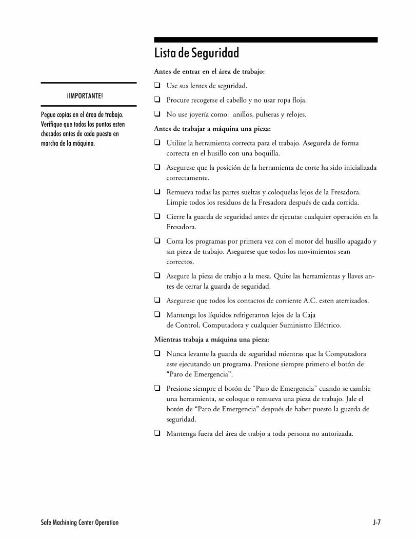
��- �1���������2 �� ��> ������ D'
5 ���������� ���Antes de entrar en el área de trabajo:
❑ Use sus lentes de seguridad.
❑ Procure recogerse el cabello y no usar ropa floja.
❑ No use joyería como: anillos, pulseras y relojes.
Antes de trabajar a máquina una pieza:
❑ Utilize la herramienta correcta para el trabajo. Asegurela de formacorrecta en el husillo con una boquilla.
❑ Asegurese que la posición de la herramienta de corte ha sido inicializadacorrectamente.
❑ Remueva todas las partes sueltas y coloquelas lejos de la Fresadora.Limpie todos los residuos de la Fresadora después de cada corrida.
❑ Cierre la guarda de seguridad antes de ejecutar cualquier operación en laFresadora.
❑ Corra los programas por primera vez con el motor del husillo apagado ysin pieza de trabajo. Asegurese que todos los movimientos seancorrectos.
❑ Asegure la pieza de trabjo a la mesa. Quite las herramientas y llaves an-tes de cerrar la guarda de seguridad.
❑ Asegurese que todos los contactos de corriente A.C. esten aterrizados.
❑ Mantenga los líquidos refrigerantes lejos de la Cajade Control, Computadora y cualquier Suministro Eléctrico.
Mientras trabaja a máquina una pieza:
❑ Nunca levante la guarda de seguridad mientras que la Computadoraeste ejecutando un programa. Presione siempre primero el botón de“Paro de Emergencia”.
❑ Presione siempre el botón de “Paro de Emergencia” cuando se cambieuna herramienta, se coloque o remueva una pieza de trabajo. Jale elbotón de “Paro de Emergencia” después de haber puesto la guarda deseguridad.
❑ Mantenga fuera del área de trabjo a toda persona no autorizada.
M��13�$��$�4
< �� ��� ���� �� ��T� ��� ����%�;�+0 ��-�N� �N� ����������� ������ �� ��� ��������� ��� ������ � ���� ��������� �����TN����+

� - � �� ����� ��� ������DD@
�+�����#���&�All BENCHMAN operators must be fully aware of how to shut down themachine quickly, should the need arise.
� In an emergency, you should always use the red Emergency Stop buttonon the machine front panel.
� You can also stop the machine by pressing the Control and Space keyson the computer keyboard, or by clicking on the stop buttons on the screenwith the mouse. But, in an emergency, always use the Emergency Stopbutton on the machine.

������1�2�� ��5��� ��%"����� E�
��������������5 ����B������&
��������B������&
��������B������&
�������#���� ��)��# ���E
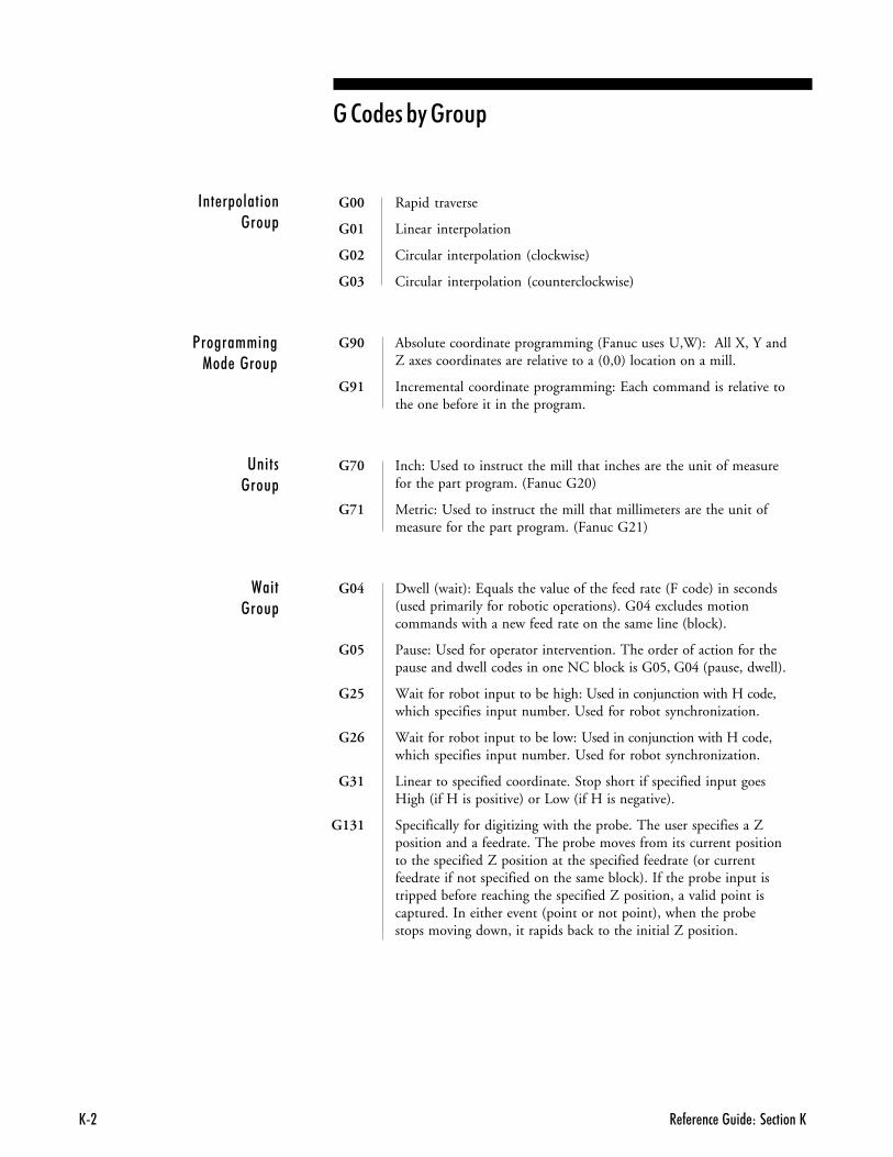
� - � �� ����� ��� ������EE�
G00 Rapid traverse
G01 Linear interpolation
G02 Circular interpolation (clockwise)
G03 Circular interpolation (counterclockwise)
G90 Absolute coordinate programming (Fanuc uses U,W): All X, Y andZ axes coordinates are relative to a (0,0) location on a mill.
G91 Incremental coordinate programming: Each command is relative tothe one before it in the program.
G70 Inch: Used to instruct the mill that inches are the unit of measurefor the part program. (Fanuc G20)
G71 Metric: Used to instruct the mill that millimeters are the unit ofmeasure for the part program. (Fanuc G21)
G04 Dwell (wait): Equals the value of the feed rate (F code) in seconds(used primarily for robotic operations). G04 excludes motioncommands with a new feed rate on the same line (block).
G05 Pause: Used for operator intervention. The order of action for thepause and dwell codes in one NC block is G05, G04 (pause, dwell).
G25 Wait for robot input to be high: Used in conjunction with H code,which specifies input number. Used for robot synchronization.
G26 Wait for robot input to be low: Used in conjunction with H code,which specifies input number. Used for robot synchronization.
G31 Linear to specified coordinate. Stop short if specified input goesHigh (if H is positive) or Low (if H is negative).
G131 Specifically for digitizing with the probe. The user specifies a Zposition and a feedrate. The probe moves from its current positionto the specified Z position at the specified feedrate (or currentfeedrate if not specified on the same block). If the probe input istripped before reaching the specified Z position, a valid point iscaptured. In either event (point or not point), when the probestops moving down, it rapids back to the initial Z position.
����&��� ������&
1�����++ �����������&
'� �����&
2� ����&
��������B������&
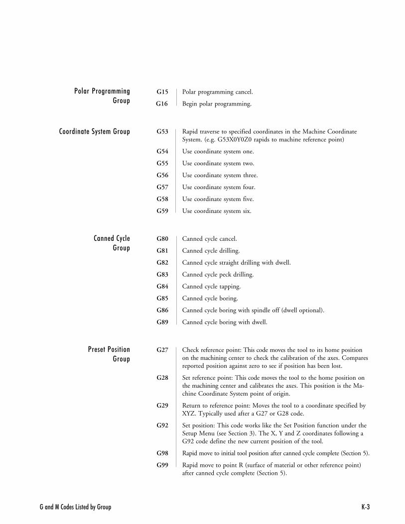
������1�2�� ��5��� ��%"����� E(
G15 Polar programming cancel.
G16 Begin polar programming.
G53 Rapid traverse to specified coordinates in the Machine CoordinateSystem. (e.g. G53X0Y0Z0 rapids to machine reference point)
G54 Use coordinate system one.
G55 Use coordinate system two.
G56 Use coordinate system three.
G57 Use coordinate system four.
G58 Use coordinate system five.
G59 Use coordinate system six.
G80 Canned cycle cancel.
G81 Canned cycle drilling.
G82 Canned cycle straight drilling with dwell.
G83 Canned cycle peck drilling.
G84 Canned cycle tapping.
G85 Canned cycle boring.
G86 Canned cycle boring with spindle off (dwell optional).
G89 Canned cycle boring with dwell.
G27 Check reference point: This code moves the tool to its home positionon the machining center to check the calibration of the axes. Comparesreported position against zero to see if position has been lost.
G28 Set reference point: This code moves the tool to the home position onthe machining center and calibrates the axes. This position is the Ma-chine Coordinate System point of origin.
G29 Return to reference point: Moves the tool to a coordinate specified byXYZ. Typically used after a G27 or G28 code.
G92 Set position: This code works like the Set Position function under theSetup Menu (see Section 3). The X, Y and Z coordinates following aG92 code define the new current position of the tool.
G98 Rapid move to initial tool position after canned cycle complete (Section 5).
G99 Rapid move to point R (surface of material or other reference point)after canned cycle complete (Section 5).
1����� 1�����++ ������&
����� �������+�����&
���������#������&
1�����1�� ������&
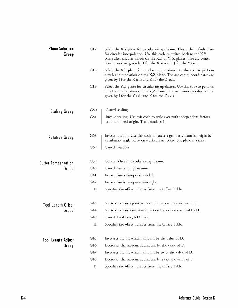
� - � �� ����� ��� ������EE.
#�� �������&
��� �������&
�������+&���� ������&
$����5���%�3��������&
$����5���%���C������&
G17 Select the X,Y plane for circular interpolation. This is the default planefor circular interpolation. Use this code to switch back to the X,Yplane after circular moves on the X,Z or Y, Z planes. The arc centercoordinates are given by I for the X axis and J for the Y axis.
G18 Select the X,Z plane for circular interpolation. Use this code to performcircular interpolation on the X,Z plane. The arc center coordinates aregiven by I for the X axis and K for the Z axis.
G19 Select the Y,Z plane for circular interpolation. Use this code to performcircular interpolation on the Y,Z plane. The arc center coordinates aregiven by J for the Y axis and K for the Z axis.
G50 Cancel scaling.
G51 Invoke scaling. Use this code to scale axes with independent factorsaround a fixed origin. The default is 1.
G68 Invoke rotation. Use this code to rotate a geometry from its origin byan arbitrary angle. Rotation works on any plane, one plane at a time.
G69 Cancel rotation.
G39 Corner offset in circular interpolation.
G40 Cancel cutter compensation.
G41 Invoke cutter compensation left.
G42 Invoke cutter compensation right.
D Specifies the offset number from the Offset Table.
G43 Shifts Z axis in a positive direction by a value specified by H.
G44 Shifts Z axis in a negative direction by a value specified by H.
G49 Cancel Tool Length Offsets.
H Specifies the offset number from the Offset Table.
G45 Increases the movement amount by the value of D.
G46 Decreases the movement amount by the value of D.
G47 Increases the movement amount by twice the value of D.
G48 Decreases the movement amount by twice the value of D.
D Specifies the offset number from the Offset Table.
1��������# ������&
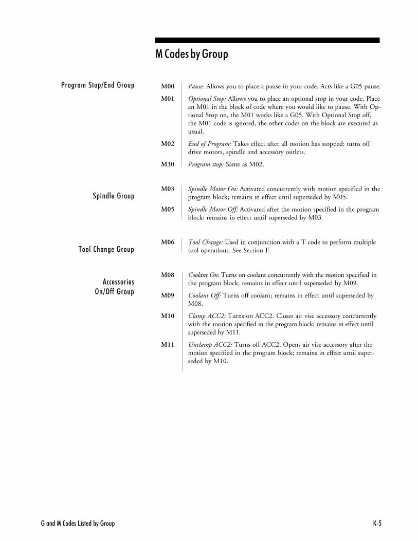
������1�2�� ��5��� ��%"����� E6
1�����+��&?��������&
& ���������&
$�����%���������&
�##����� ��3�?3�������&
M00 Pause: Allows you to place a pause in your code. Acts like a G05 pause.
M01 Optional Stop: Allows you to place an optional stop in your code. Placean M01 in the block of code where you would like to pause. With Op-tional Stop on, the M01 works like a G05. With Optional Stop off,the M01 code is ignored, the other codes on the block are executed asusual.
M02 End of Program: Takes effect after all motion has stopped; turns offdrive motors, spindle and accessory outlets.
M30 Program stop: Same as M02.
M03 Spindle Motor On: Activated concurrently with motion specified in theprogram block; remains in effect until superseded by M05.
M05 Spindle Motor Off: Activated after the motion specified in the programblock; remains in effect until superseded by M03.
M06 Tool Change: Used in conjunction with a T code to perform multipletool operations. See Section F.
M08 Coolant On: Turns on coolant concurrently with the motion specified inthe program block; remains in effect until superseded by M09.
M09 Coolant Off: Turns off coolant; remains in effect until superseded byM08.
M10 Clamp ACC2: Turns on ACC2. Closes air vise accessory concurrentlywith the motion specified in the program block; remains in effect untilsuperseded by M11.
M11 Unclamp ACC2: Turns off ACC2. Opens air vise accessory after themotion specified in the program block; remains in effect until super-seded by M10.
��������B������&
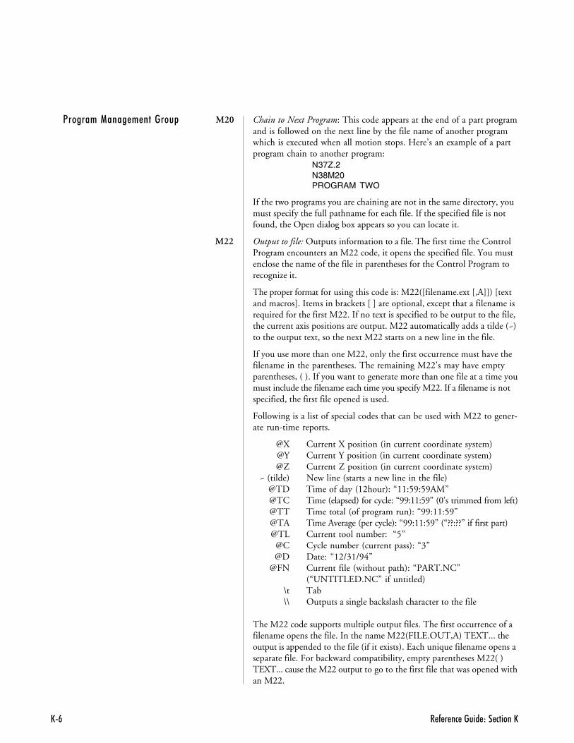
� - � �� ����� ��� ������EE#
M20 Chain to Next Program: This code appears at the end of a part programand is followed on the next line by the file name of another programwhich is executed when all motion stops. Here’s an example of a partprogram chain to another program:
N37Z.2N38M20PROGRAM TWO
If the two programs you are chaining are not in the same directory, youmust specify the full pathname for each file. If the specified file is notfound, the Open dialog box appears so you can locate it.
M22 Output to file: Outputs information to a file. The first time the ControlProgram encounters an M22 code, it opens the specified file. You mustenclose the name of the file in parentheses for the Control Program torecognize it.
The proper format for using this code is: M22([filename.ext [,A]]) [textand macros]. Items in brackets [ ] are optional, except that a filename isrequired for the first M22. If no text is specified to be output to the file,the current axis positions are output. M22 automatically adds a tilde (~)to the output text, so the next M22 starts on a new line in the file.
If you use more than one M22, only the first occurrence must have thefilename in the parentheses. The remaining M22's may have emptyparentheses, ( ). If you want to generate more than one file at a time youmust include the filename each time you specify M22. If a filename is notspecified, the first file opened is used.
Following is a list of special codes that can be used with M22 to gener-ate run-time reports.
@X Current X position (in current coordinate system)@Y Current Y position (in current coordinate system)@Z Current Z position (in current coordinate system)
~ (tilde) New line (starts a new line in the file)@TD Time of day (12hour): “11:59:59AM”@TC Time (elapsed) for cycle: “99:11:59” (0’s trimmed from left)@TT Time total (of program run): “99:11:59”@TA Time Average (per cycle): “99:11:59” (“??:??” if first part)@TL Current tool number: “5”
@C Cycle number (current pass): “3”@D Date: “12/31/94”
@FN Current file (without path): “PART.NC”(“UNTITLED.NC” if untitled)
\t Tab\\ Outputs a single backslash character to the file
The M22 code supports multiple output files. The first occurrence of afilename opens the file. In the name M22(FILE.OUT,A) TEXT... theoutput is appended to the file (if it exists). Each unique filename opens aseparate file. For backward compatibility, empty parentheses M22( )TEXT... cause the M22 output to go to the first file that was opened withan M22.
1�����+�������+�������&
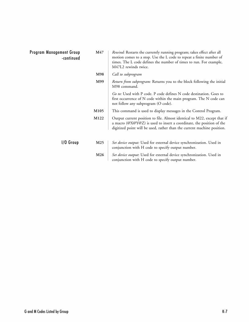
������1�2�� ��5��� ��%"����� E'
M47 Rewind: Restarts the currently running program; takes effect after allmotion comes to a stop. Use the L code to repeat a finite number oftimes. The L code defines the number of times to run. For example,M47L2 rewinds twice.
M98 Call to subprogram
M99 Return from subprogram: Returns you to the block following the initialM98 command.
Go to: Used with P code. P code defines N code destination. Goes tofirst occurrence of N code within the main program. The N code cannot follow any subprogram (O code).
M105 This command is used to display messages in the Control Program.
M122 Output current position to file. Almost identical to M22, except that ifa macro (@X@Y@Z) is used to insert a coordinate, the position of thedigitized point will be used, rather than the current machine position.
M25 Set device output: Used for external device synchronization. Used inconjunction with H code to specify output number.
M26 Set device output: Used for external device synchronization. Used inconjunction with H code to specify output number.
� �?3�����&
1�����+�������+�������&�#�� ����

� - � �� ����� ��� ������EE@

��� ! ��
�����
�+B���
�$3$$$��<1�� ���� ��/�#.���!���2��������/�'
�
%����/ �������.$$$��76(%����� ���������� � �������������� ��E�2�<�� ���� �"��/'�� ����� ���D6��� ���������� ���C��;������ �����)��9'�;������ �0� ���9#�;���� ����/���������������1�� ��76$���0�� ��/�#�� �� !�������������7(����2 �� ������� � ������7(B����� ��������76���������������������7((�2�2�����������%����7'���� -� ����7.���������������2���� ���/�'�����4 ��7.B!���9��4 �/ �����/�(
�
/��)������7.@/������� ��
��%��������/B/ �����/�(/���)�
��!��������% �� �� ��������C��-��2���� ��C�
/�������"�� �����/�������"�� ���� ���'/�������"�� �������� ������ ���'/�������"�� ������� ���� ��--���� ���'/��������������6/��������7.(
�
2���������% ���������� ����(2��� ���"��
%�������������� ����'��� ���E(�� �����B����� ����' �)������������B �������������'��������������������@�� ������� �������$
2������-���C�� "�9��)���/�62������-����� �2�� �� ���/�.2����� ��76�2 �� ��9��������62 �� ���� �> �������7.�2��������� !�� ��������E#2� �)�8�� ��7.(2� �)�,������� � ����(��������%� �) ����/.2����������� � ����������.3 8�.
����)��� 3���� �-����E������ �����)��� 3���� ��E�
2����������� � �������� �������������(2��� �22����� ��E62� ����7�B2��� �2��������7�(��� ���������--� ���7.#2�� �� ���"�� ��� N��� � ������2��-���� ��2��7((2��� �����������@2��� ������<�� ����@2��� �������� �012.$$$���#2��� �������� �012.$$$������ �2�� �� ����@2��� !��8 � ��7#2������ �<�������%�������7(2�������<������
��� ����2.����������2�
2������-��������/�@1���� ���� ��/�B
2�������C�����/�@2�������� �� �����> ��������/�@2�������� ��"�� �
��� ���E(2��������7..
2� "��7�@2��� ���--� �������������� � ���������8�.2��� ���--� ����� ��E.2���� ����7B2���O2��76@2���OC��76@2���O���76@2���O8��76@2���O5��76@2���O���76@2���O>��76@2���O<��76@2���O���76@2���O���76@2���O���-�OH��76@2���O� �� ��76@2���O���76@2���O0��76@2���O:��76@2���O,��76@2���OH��76@

012.$$$��� �I������ ��
2����� ��� �4�� �9 ���� ����.2����7�@2��� ����� ���������8#
���� ������8�6��� ���E.�DE�4 �������8�$� �������--� ����8������������8#3 8'
2"�� ��������/.3 7�$2"�� ���� ��/.
"
9 -�����0��� ��-���� ���7('9 -�� ��� �������9@9 � � ��7�B9 ����-�2��
� -�� �����9�-- � �� ����B9�����G����<��)�� ��/�#9�<��������� �������������) ����� ����� �� ����7#�9>��2�������'(��������� ��#9��4 �<�� ��5������/.9�"������9��9� ������ ��E�
�
7����1 ����7�'7���������1�� �������7(�7������������2B
��4�����7#�7������<� - � �� ���7.B7� �� ��"���� ��/.3 9(7� �� ��"���� �/�������9(7��%� ���-��5�������7.@7��%� ���% ���������7(B7���1�������.7����-� ��������E67�4����� �����2�����������/@7������ ������� ��7�@3 7667!������������7�#
6
C���76@C(��76@C6��76@C#��76@C@��76@C�����"�������� ��> �������/�#C �����
� -�� �����C ����� �>4 ���� ��/.3 7�$C �������7�BC�� �9 -������76$C�� �1 ����7��C�����7�B
-����������� ����� �� ����7#�C�����2��������/�@
�
�B���7.6� � ����<�� ���7#6� ������� ��"�-�����������������(����� ���D���������� ��E'�����5�� ��7�$�����<���������7..��� ��� �9����2��� �������"�� ���/�'�����������/'
�
8������ ���������������'8 ��������� � ����������68 � ���� !
1 ��3�2��������76�8�� ��7.(8�����
����������8(8���E "���76@
�
����� �������������� ��E����� � �������������� � �������������� ��E��������������<���������7.���������G ���������5���������7(.�� ���������/����2@�� ��������%����7'��� �����2�� ���7����� ������� ��4 �� �� ���7����� ���������7((������������3���-���� ���$��� �� ���� ��/6��� �-�� �2���
������������'��� ����)���������9(��� � �������
�����������(��� ������
��� ��� ����� ��-�����"�� -�������$� ��������$
F
D���2��������7�6D���2�������<�� ���7B
<� � �1 �������������76'D���9������ ��7('D���� ��������7('D���� ���7('
E
E "�5��)���������/.

��� ! �(
5
5���� ����(5�-�����/ ��������65����������� ���/(������������ ���9(5�� ��
��� � ������� ��������������
5�� ������ � ����������� ��E�5�� ������������� ��E�5��)��7�(5�� ������ ����� ����(5�%����������/�$
�
1����� ��� N��� � ������1����� �2�� �� �����/(1����� ���-����������7.1����<�� ��5������/.1�!�����%���)�� �� ��������C�1 ���/����2.3 7��1 ���� �/����7(1 �������� ��E�1������2�������2���
��� �������@�� ��)�����@
1������� ����) � � ��9�(1���� �� ���7(�
�
�2� ���� ���������C�� ����4 ��������9.� ��2��������7������� ����7(�
3
>���� ����(>--� �
���% ���7.#���% ����� ��E.��� �3�����������8�(4��� �3�����������8��
>--� ����%� ��7.#3 E.> ��2��������7�(> �������� � ���<��������7�#> ������� �<2�2��������'> ��� ��2��7(.> �������2�����������/'> ������<�� ���7�$3 7�6> ������
�)� ��7�$3 7(@��� ��7�$3 7(B3 E6
> ������<�� ���7.�>�������7.�>�� ������-�� ���� ��E#>�� ��������%����2#3 7@
1
<���� 3�����������% �����������(<�������
��������3��� �������76�<��� ��7�@<��� ��7�B
����� �-����E6<��� ���� ��E�<2��������� �7�4����� ����/�.< �)������������� ���'< �)�����������"�� ����B<��� �� � ��������� ���E.<� �������2��������/�'<����� ������������8�<����� ��������������� ����� ��E( ����� �������������� ��E(<� � �1 ����76.<���������7�.<��������� �������2��<����������������76
<� � �� �������������76#<�������������-���������� ����7#$<���������������%�����7#$ �����4 ��������9.<�� ����������/.<� - � �� ���7.B
!�������76$� �����"��76$
<� � ��0� ���7.� � 4 �����4 ������ ���� ��/B<� 4� ����������7.�<������7�6<������ �� ��7�6<�������7������������7(
<� � �1 �������������76.<�������1 ����7�#<���������� ���� ��E6<����������
���� ��������C�( ��5��8��6$$$�1���������2 �� �
����� ���-��/#
H
F���)�8�� ��7.(F���)�����766F���)0 ��-"��766
�
�� ������������� ���E(�� �������������� ����������� ���'�� ������ ���������� ���'�� ������4 ��
�������������#�� ������4 �� ���� ��E�3 E(� ���� �� �����������/�@

012.$$$��� �I������ �.
� ������76'� ���� ���� �012.$$$��(� ��4���:�!���2�4 ���#� ��4 �2��� �����7�(� ��4 ���2�� ���7�(� ���% ���7��� ���% �����������% ���������7��� ��� ��7�$� � ��>4 ���� ��7.'� ���� �� ��������76(� ���� ������1�� ��7(B� �����-������% ���������� ����(� ��������� - � �� � �������� ��E(� ������E'��%����"�������G��������� ���E���������
�������������8�(��� ��-����8��
������������ ���E.��� �3���- �"��D�3 D������ ��������7�'3 7(@���=2������ ��7�#3 7�B������������� � ��2�<��������963 9�(
����� ��/�$��- �"��9���- �"������ ���D���- �"���� ���9�3 D�3 D���- �"���� ����/(3 D�
��� ����)���������9(��4 ���+++��7�.��4 ���9������/�!��7�.��4 �2��������7�.��4 �� ��������76(�������
��������������8�(��� ��-����8�@�� ����������������� ��������8�$ �����!����8�B
����������� ���E.� � ������ !���������������� ��"�� ���7..� � ���C�����7�.� � ���������7(�� � ������2�������
<� � �1 �����76.� �
��%������ ����E'� ��<���������7(#� ��� - � �� � �������� ��E(� �=2� �)�8�� ��7.(� �����
�--� ����8����-����������8.
� �� �5�%���"��7($� �� �1 ����7(6
� �� �<����������3 7#.� �� �������9@���� �������������6��� ������ ����)���������/(��� ��3���- �"��D����-��H��!������ ��E.�����������7.������������1�� ��7#(����� ��� ��7�$3 7(@���� ��%�����7.����� ��%�������7.���-��5�������7.@��-���� ����������������$������> �������7.�� ��-"�� ����-�������� ���'� ��-"����������� - � �� � �������� ���'� ����21��/�� ���� ��7.'
� ����/���������--���� ��E6������������ ��E6
� ���� �1������/(3 /��� ���� ����-��<��"��/��� ���� �� ��>4 ���� ��/.3 7�$� ���� �� ����/��������������%����2.3 7#���������/���)��7�#�������/����2�$3 7������)�9�� ��������7.�����)�<�� ���7.���� ��7�$3 7�B��� �<�������%�������7(��� �� ������76'��� ���
�����) "%����3������������������3��������� ����)��9(
��������������������@��������������������� ���'������������������������� ������ ���'��"� ��7.���% ������
���������E'��% �������� - � �� �%���)���� ����(��% ������3�� �����-������� ��E'��% �����������(
� �� �����(
$
�� ������� �������$� ���������� ���������� ��76��� ��-��� �9�"��76(����
���������%���"��9@����� ���� ��E6� ������--� ���8�@

��� ! �6
� ������--� ����� ��E.�--� ����;�����8�B0 ��-"��9B
�����5�%���"��7(�������" ��7(�3 �.�������G�����7(�����%�����7#3 7�6�������D.
2� �������7(�����������C�!��� ���/6������1 ����7($
'
������ ���������)���� ��E6������7�'���-�������������8�@��������������� ���-���� �����������7..�� ��)�����.������8 � ��76(
�
0 ��-"���� ����������7.$
0 ��-"�<��������9�$0 ��-"�� ��������9#3 7�'3 7.$0 ��-"��" ��7.(0 ��-"���������2��3 7.3 7�6
<� � �1 �������������76#0� ��1 ����7�.0� ��<�� ���7.�
2
������������7�������7(B�������"�����������5�����76��������1 ����76����������7(�����3��2��C����)�� ���/'���) � � �1�� �������/6�� ��� ���D(
G
H ���<���������7(#H�����7.�

012.$$$��� �I������ �#
Related Documents