Belt-Way Scales Inc. 1 Beltway Rd. Rock Falls, IL 61071 USA Phone: (815) 625-5573 Email: [email protected] www.beltwayscales.com Conveyor Belt Scale Instruction Manual Revision 2.3

Welcome message from author
This document is posted to help you gain knowledge. Please leave a comment to let me know what you think about it! Share it to your friends and learn new things together.
Transcript
Belt-Way Scales Inc. 1 Beltway Rd.
Rock Falls, IL 61071 USA Phone: (815) 625-5573
Email: [email protected] www.beltwayscales.com
Conveyor Belt Scale Instruction Manual
Revision 2.3
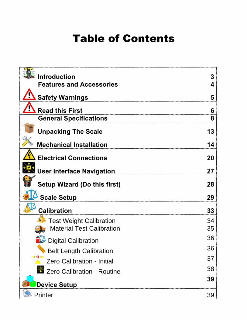
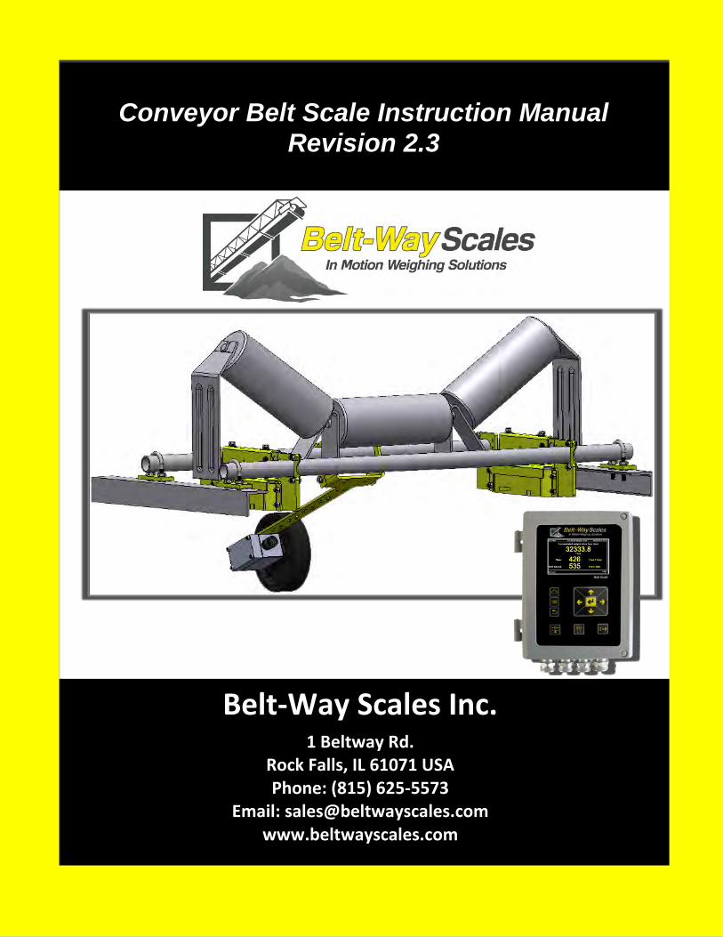
Table of Contents
Introduction 3 Features and Accessories 4
Safety Warnings 5
Read this First 6 General Specifications 8
Unpacking The Scale 13
Mechanical Installation 14
Electrical Connections 20
User Interface Navigation 27
Setup Wizard (Do this first) 28
Scale Setup 29
Calibration 33 Test Weight Calibration 34
Material Test Calibration 35
Digital Calibration 36
Belt Length Calibration 36
Zero Calibration - Initial 37
Zero Calibration - Routine 38
Device Setup 39
Printer 39
Belt-Way Scales Inc. 2 Instruction Manual
Scoreboard Display 40
USB 40
IO Board 42
Controls 44
Plant Connect 47
Totals & Diagnostics 48
Totals 48
Firmware 48
Live Weight 48
Setup Information 49
Sensors 49
IO Board 50
Voltages 51
Communication 51
Calibration 51
Administration 52
Settings 52 Select Run Mode 54
Security 54
Update Firmware 54
Calibration 55
Ethernet 56
Troubleshooting 57
Maintenance 59 Warranty 62 Drawings 64
Belt-Way Scales Inc. 3 Instruction Manual
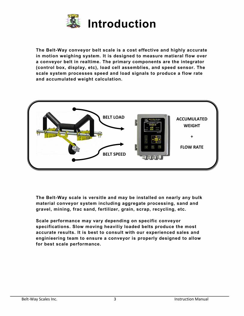
Introduction The Belt-Way conveyor belt scale is a cost effective and highly accurate in motion weighing system. It is designed to measure matieral flow over a conveyor belt in realtime. The primary components are the integrator (control box, display, etc), load cell assemblies, and speed sensor. The scale system processes speed and load signals to produce a flow rate and accumulated weight calculation.
The Belt-Way scale is versitle and may be installed on nearly any bulk material conveyor system including aggregate processing, sand and gravel, mining, frac sand, fertilizer, grain, scrap, recycling, etc. Scale performance may vary depending on specific conveyor specifications. Slow moving heaviliy loaded belts produce the most accurate results. It is best to consult with our experienced sales and enginieering team to ensure a conveyor is properly designed to allow for best scale performance.
BELT LOAD
BELT SPEED
ACCUMULATED
WEIGHT
+
FLOW RATE

Belt-Way Scales Inc. 4 Instruction Manual
Features & Accessories The new Belt-Way Integrator includes many state of the art features:
• L arge Color Graphic Display with multi- Language support.
• Easy to follow Scale Setup Wizard
• Choose from 3 available modes of menu
driven calibration o Test Weight calibration o Automatic digital calibration o Material test calibration
• Built-in USB for easy upload and download
o Log calibration and production data o Easy software upgrade o Screenshots on demand
• Standard on-board Ethernet Port
o Modbus TCP o Wireless Communication o Plant Connect Website for online
productions reports • Expanded I/O communication capabilities
o 4 digital inputs o 3 digital outputs
• 2 Independent RS-232 Serial outputs o Simultaneously connect printer and scoreboard display.
• Improved Automated Control Capabilities o Batching / Load-Out o Flow rate (TPH) control
• Consistent feed o Material load (lb/ft) control
• Increases scale accuracy o Continuous Proportional Blending
• Multiple additives to 1 main material
• Self diagnostics
o Independently view signal status for up to 8 load cells o Digital Speed Sensor frequency o Current Angle Sensor readings o Scale configuration setup parameters o I/O settings o Calibration parameters and values
• Error Reporting • Password protection capabilities • New Zero Rate Limit Feature • Internal Power Supply
Belt scale accessories include the following:
Solid State Angle Sensor The angle sensor removes the need for constant recalibration when the scale is installed on variable angle conveyor.
Self-Storing Test Weight Calibration System This item permanently stores test weights on the scale. Recalibration is fast and easy as there is no need to haul test weights to the conveyor. It also makes calibration safer where the conveyor is only accessible from one side.
Wireless Multi Scale Remote Display The remote display allows multiple scales to be controlled from one location. Wireless communication makes installation simple and inexpensive.
Plant Connect - Online Scale Production Reporting Our Plant-Connect website allows users to monitor belt scale production on a PC, tablet or smart phone. Visit www.plant-connect.com for more details.
Belt-Way Scales Inc. 5 Instruction Manual
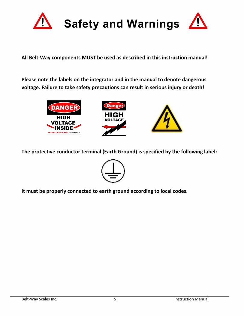
Safety and Warnings
All Belt-Way components MUST be used as described in this instruction manual!
Please note the labels on the integrator and in the manual to denote dangerous
voltage. Failure to take safety precautions can result in serious injury or death!
The protective conductor terminal (Earth Ground) is specified by the following label:
It must be properly connected to earth ground according to local codes.
Belt-Way Scales Inc. 6 Instruction Manual
Read this First Customers who are familiar with our legacy integrator should read this section first. There have been several changes to the terminoligy and functionality in the new integrator. 1. Color Display / Graphical User Interface - The Belt-Way integrator now icon and menu driven. On screen instructions make screen navigation simple. The large color display is easy to read. Runtime values can be viewed from a long distance even in direct sunlight. 2. Smaller Keypad - The complicated keypad has been replaced a simpler version. There are three shortcut keys to quickly activate frequently used functions such as Zero Calibration, Print Ticket, and Clear Weight. All other functions can be accesed through the main menu. 3. No Switches - There are no manual switches. (SW1, SW2, Gain) All scale setting adjustments are made through the user interface software. 4. Load % - There is no load % shown on the home screen. 5. Terminology - The Span number is now the Trim Factor. Set Zero is now Zero Calibration. Idler Span is now Idler Distance. The zero number is now shown in pounds or kilograms. The belt length is measured in distance units instead of pulses. 6. Weight and Rate units - It is now possible to automatically convert between Standard and Metric units without recalibration. Pounds, Tons, Long Tons, Kilograms, and Metric Tonnes are available. 7. Scale Setup Parameters - The capacity of the load cells must be entered into the integrator during the setup process. The conveyor angle should be entered if an automatic angle compensator is not used. 8. Internal Power Supply - The new power supply module must be purchased separately from the integrator. It mounts inside the integrator box. It accepts 100 - 240 VAC and produces 24 VDC. The integrator may be powered from an external 12-24 VDC source. It requires approximately 55 watts of power to operate. 9. 8 Load Cell Inputs - We can now accept 8 load cells. The load cells are no longer summed together in the integrator. Each load cell is processed independently, which allows calculation of individual mV readings making troubleshooting very easy. 10. New Digital Junction Box - The new integrator can be used with our new digital junction box. The junction box converts component signals (load cells, speed sensor, angle sensor, etc) to a digital signal and transfers it to the integrator. We feel it will be beneficial to limit the length of load cell and speed sensor cables when possible. 11. Ethernet Port with POE- The new integrator has Ethernet built in so a converter is
not required. The Power Over Ethernet allows for easy wireless transmitter installation
with no need for an external power supply.
Belt-Way Scales Inc. 7 Instruction Manual
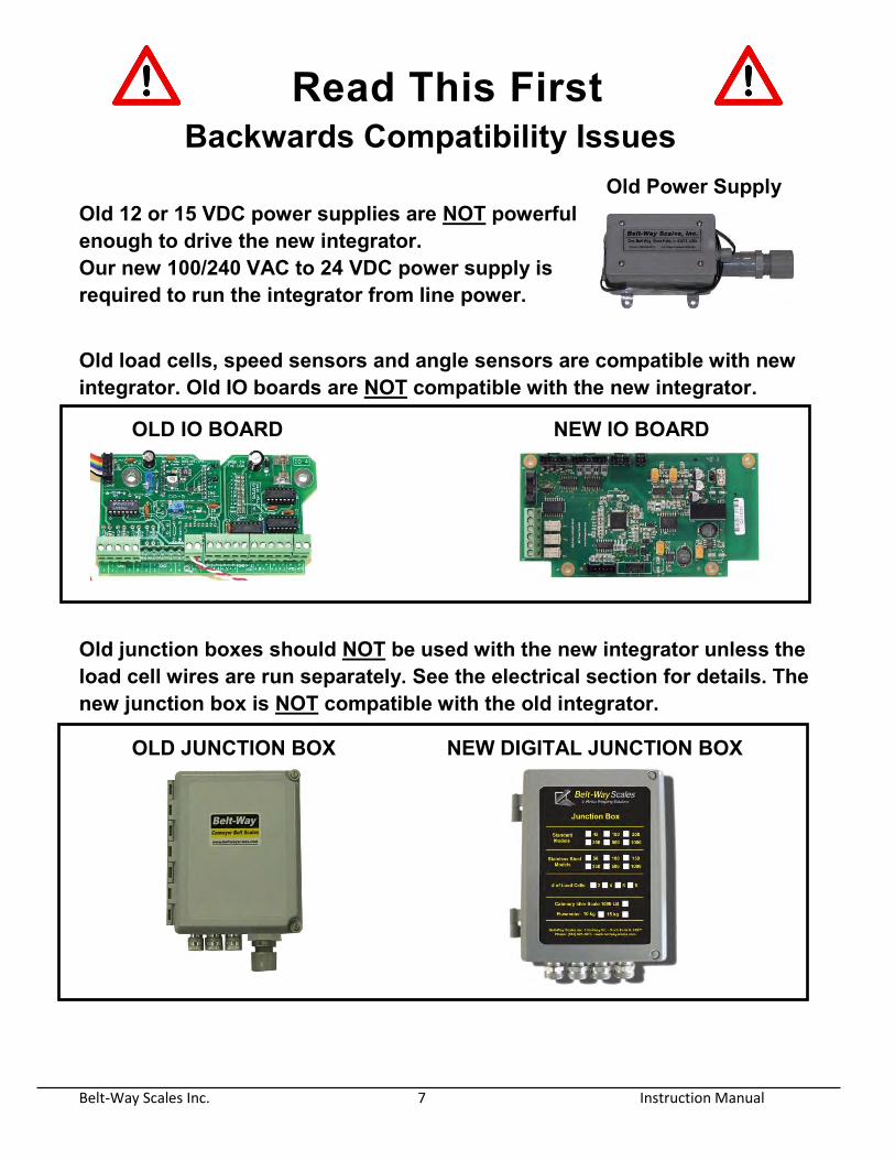
Read This First Backwards Compatibility Issues Old Power Supply Old 12 or 15 VDC power supplies are NOT powerful enough to drive the new integrator. Our new 100/240 VAC to 24 VDC power supply is required to run the integrator from line power.
Old load cells, speed sensors and angle sensors are compatible with new integrator. Old IO boards are NOT compatible with the new integrator.
OLD IO BOARD NEW IO BOARD
Old junction boxes should NOT be used with the new integrator unless the load cell wires are run separately. See the electrical section for details. The new junction box is NOT compatible with the old integrator.
OLD JUNCTION BOX NEW DIGITAL JUNCTION BOX
Belt-Way Scales Inc. 8 Instruction Manual
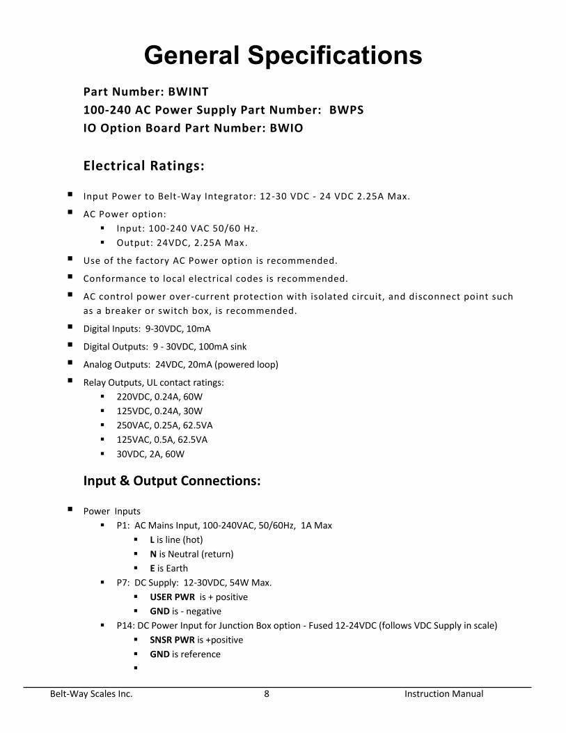
General Specifications Part Number: BWINT
100-240 AC Power Supply Part Number: BWPS
IO Option Board Part Number: BWIO
Electrical Ratings:
Input Power to Belt-Way Integrator: 12-30 VDC - 24 VDC 2.25A Max.
AC Power option:
Input: 100-240 VAC 50/60 Hz.
Output: 24VDC, 2.25A Max.
Use of the factory AC Power option is recommended.
Conformance to local electrical codes is recommended.
AC control power over-current protection with isolated circuit, and disconnect point such
as a breaker or switch box, is recommended.
Digital Inputs: 9-30VDC, 10mA
Digital Outputs: 9 - 30VDC, 100mA sink
Analog Outputs: 24VDC, 20mA (powered loop)
Relay Outputs, UL contact ratings:
220VDC, 0.24A, 60W
125VDC, 0.24A, 30W
250VAC, 0.25A, 62.5VA
125VAC, 0.5A, 62.5VA
30VDC, 2A, 60W
Input & Output Connections:
Power Inputs
P1: AC Mains Input, 100-240VAC, 50/60Hz, 1A Max
L is line (hot)
N is Neutral (return)
E is Earth
P7: DC Supply: 12-30VDC, 54W Max.
USER PWR is + positive
GND is - negative
P14: DC Power Input for Junction Box option - Fused 12-24VDC (follows VDC Supply in scale)
SNSR PWR is +positive
GND is reference
Belt-Way Scales Inc. 9 Instruction Manual
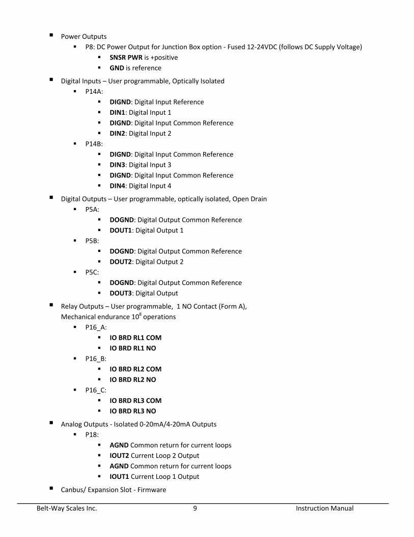
Power Outputs
P8: DC Power Output for Junction Box option - Fused 12-24VDC (follows DC Supply Voltage)
SNSR PWR is +positive
GND is reference
Digital Inputs – User programmable, Optically Isolated
P14A:
DIGND: Digital Input Reference
DIN1: Digital Input 1
DIGND: Digital Input Common Reference
DIN2: Digital Input 2
P14B:
DIGND: Digital Input Common Reference
DIN3: Digital Input 3
DIGND: Digital Input Common Reference
DIN4: Digital Input 4
Digital Outputs – User programmable, optically isolated, Open Drain
P5A:
DOGND: Digital Output Common Reference
DOUT1: Digital Output 1
P5B:
DOGND: Digital Output Common Reference
DOUT2: Digital Output 2
P5C:
DOGND: Digital Output Common Reference
DOUT3: Digital Output
Relay Outputs – User programmable, 1 NO Contact (Form A),
Mechanical endurance 108 operations
P16_A:
IO BRD RL1 COM
IO BRD RL1 NO
P16_B:
IO BRD RL2 COM
IO BRD RL2 NO
P16_C:
IO BRD RL3 COM
IO BRD RL3 NO
Analog Outputs - Isolated 0-20mA/4-20mA Outputs
P18:
AGND Common return for current loops
IOUT2 Current Loop 2 Output
AGND Common return for current loops
IOUT1 Current Loop 1 Output
Canbus/ Expansion Slot - Firmware
Belt-Way Scales Inc. 10 Instruction Manual
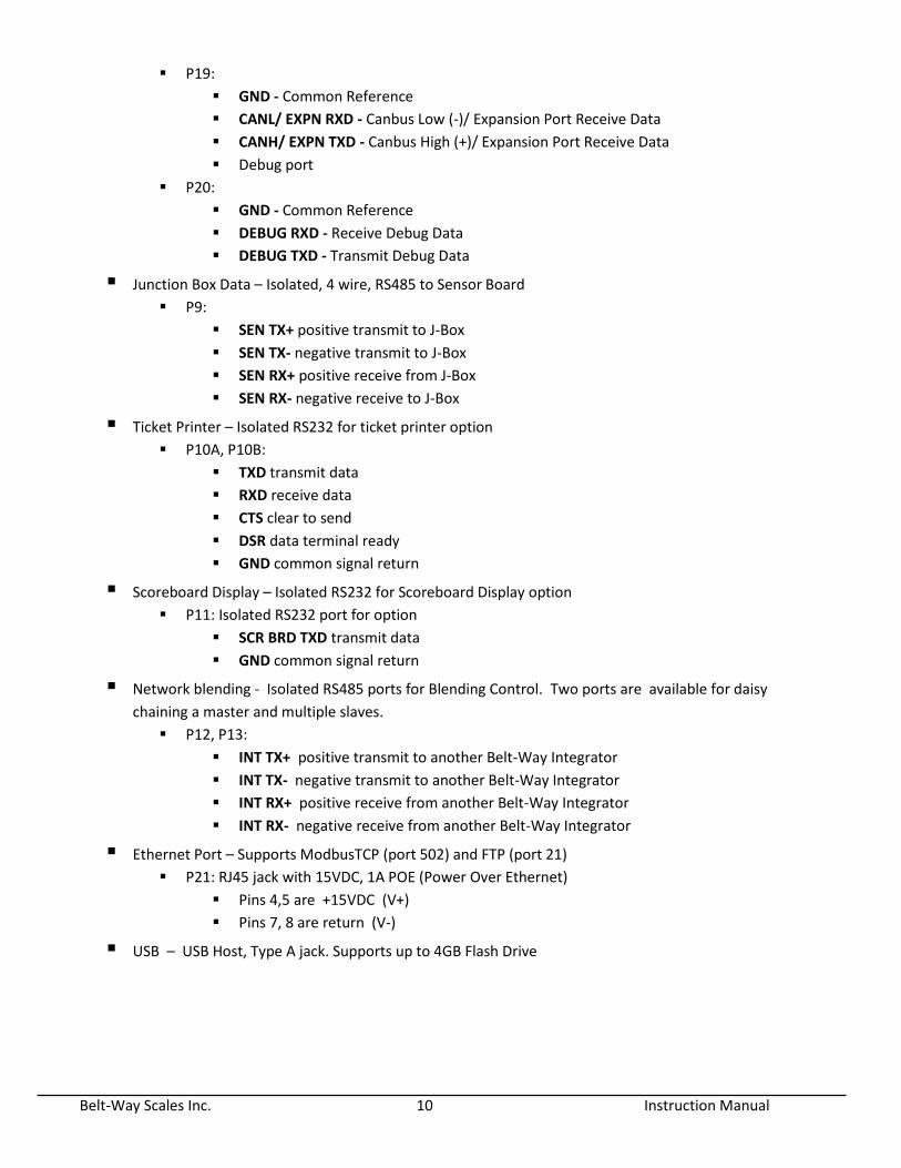
P19:
GND - Common Reference
CANL/ EXPN RXD - Canbus Low (-)/ Expansion Port Receive Data
CANH/ EXPN TXD - Canbus High (+)/ Expansion Port Receive Data
Debug port
P20:
GND - Common Reference
DEBUG RXD - Receive Debug Data
DEBUG TXD - Transmit Debug Data
Junction Box Data – Isolated, 4 wire, RS485 to Sensor Board
P9:
SEN TX+ positive transmit to J-Box
SEN TX- negative transmit to J-Box
SEN RX+ positive receive from J-Box
SEN RX- negative receive to J-Box
Ticket Printer – Isolated RS232 for ticket printer option
P10A, P10B:
TXD transmit data
RXD receive data
CTS clear to send
DSR data terminal ready
GND common signal return
Scoreboard Display – Isolated RS232 for Scoreboard Display option
P11: Isolated RS232 port for option
SCR BRD TXD transmit data
GND common signal return
Network blending - Isolated RS485 ports for Blending Control. Two ports are available for daisy
chaining a master and multiple slaves.
P12, P13:
INT TX+ positive transmit to another Belt-Way Integrator
INT TX- negative transmit to another Belt-Way Integrator
INT RX+ positive receive from another Belt-Way Integrator
INT RX- negative receive from another Belt-Way Integrator
Ethernet Port – Supports ModbusTCP (port 502) and FTP (port 21)
P21: RJ45 jack with 15VDC, 1A POE (Power Over Ethernet)
Pins 4,5 are +15VDC (V+)
Pins 7, 8 are return (V-)
USB – USB Host, Type A jack. Supports up to 4GB Flash Drive
Belt-Way Scales Inc. 11 Instruction Manual
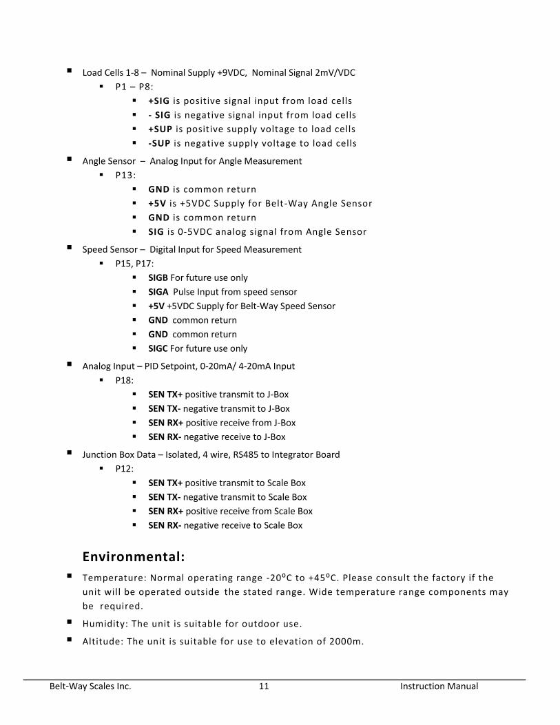
Load Cells 1-8 – Nominal Supply +9VDC, Nominal Signal 2mV/VDC
P1 – P8:
+SIG is positive signal input from load cells
- SIG is negative signal input from load cells
+SUP is positive supply voltage to load cells
-SUP is negative supply voltage to load cells
Angle Sensor – Analog Input for Angle Measurement
P13:
GND is common return
+5V is +5VDC Supply for Belt-Way Angle Sensor
GND is common return
SIG is 0-5VDC analog signal from Angle Sensor
Speed Sensor – Digital Input for Speed Measurement
P15, P17:
SIGB For future use only
SIGA Pulse Input from speed sensor
+5V +5VDC Supply for Belt-Way Speed Sensor
GND common return
GND common return
SIGC For future use only
Analog Input – PID Setpoint, 0-20mA/ 4-20mA Input
P18:
SEN TX+ positive transmit to J-Box
SEN TX- negative transmit to J-Box
SEN RX+ positive receive from J-Box
SEN RX- negative receive to J-Box
Junction Box Data – Isolated, 4 wire, RS485 to Integrator Board
P12:
SEN TX+ positive transmit to Scale Box
SEN TX- negative transmit to Scale Box
SEN RX+ positive receive from Scale Box
SEN RX- negative receive to Scale Box
Environmental:
Temperature: Normal operating range -20⁰C to +45⁰C. Please consult the factory if the
unit will be operated outside the stated range. Wide temperature range components may
be required. Humidity: The unit is suitable for outdoor use. Altitude: The unit is suitable for use to elevation of 2000m.
Belt-Way Scales Inc. 12 Instruction Manual
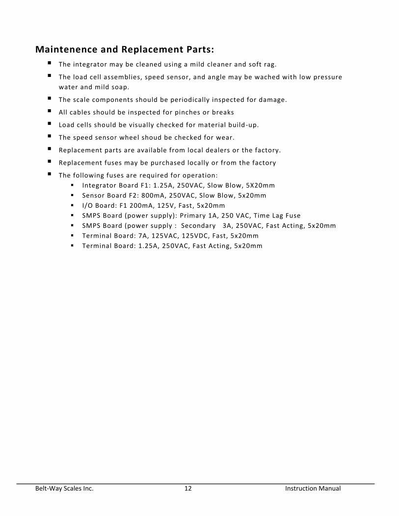
Maintenence and Replacement Parts:
The integrator may be cleaned using a mild cleaner and soft rag. The load cell assemblies, speed sensor, and angle may be wached with low pressure
water and mild soap. The scale components should be periodically inspected for damage. All cables should be inspected for pinches or breaks Load cells should be visually checked for material build -up. The speed sensor wheel shoud be checked for wear. Replacement parts are available from local dealers or the factory. Replacement fuses may be purchased locally or from the factory The following fuses are required for operation:
Integrator Board F1: 1.25A, 250VAC, Slow Blow, 5X20mm Sensor Board F2: 800mA, 250VAC, Slow Blow, 5x20mm
I/O Board: F1 200mA, 125V, Fast, 5x20mm
SMPS Board (power supply): Primary 1A, 250 VAC, Time Lag Fuse
SMPS Board (power supply : Secondary 3A, 250VAC, Fast Acting, 5x20mm
Terminal Board: 7A, 125VAC, 125VDC, Fast, 5x20mm
Terminal Board: 1.25A, 250VAC, Fast Acting, 5x20mm
Belt-Way Scales Inc. 13 Instruction Manual
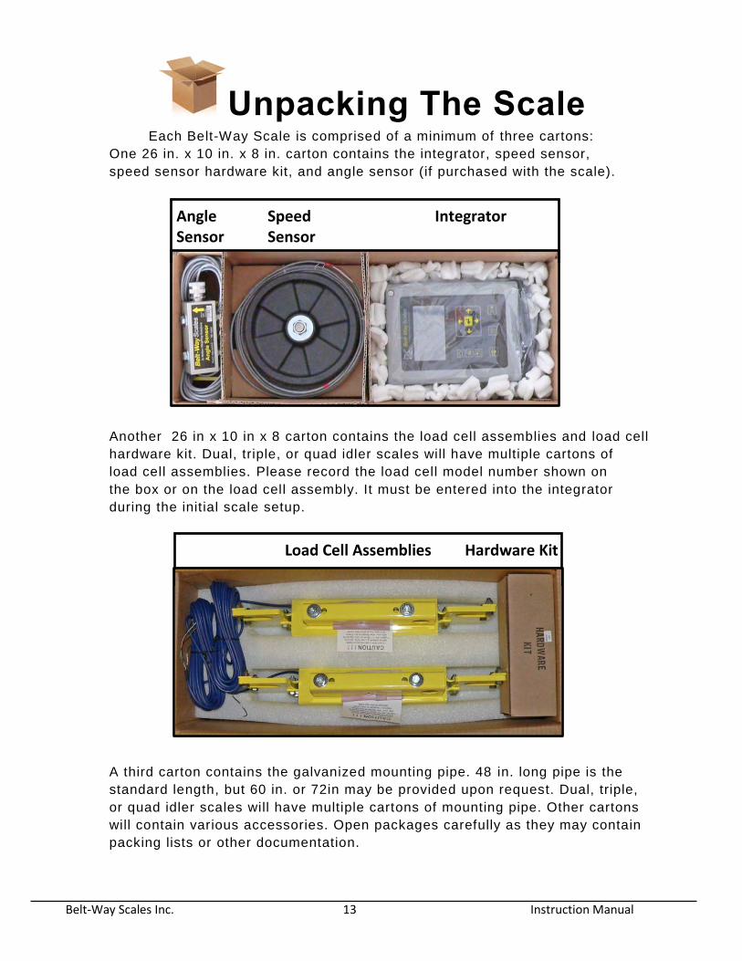
Unpacking The Scale
Each Belt-Way Scale is comprised of a minimum of three cartons:
One 26 in. x 10 in. x 8 in. carton contains the integrator, speed sensor,
speed sensor hardware kit, and angle sensor (if purchased with the scale).
Another 26 in x 10 in x 8 carton contains the load cell assemblies and load cell
hardware kit. Dual, triple, or quad idler scales will have multiple cartons of
load cell assemblies. Please record the load cell model number shown on
the box or on the load cell assembly. It must be entered into the integrator
during the init ial scale setup.
A third carton contains the galvanized mounting pipe. 48 in. long pipe is the
standard length, but 60 in. or 72in may be provided upon request. Dual, triple,
or quad idler scales will have multiple cartons of mounting pipe. Other cartons
will contain various accessories. Open packages carefully as they may contain
packing lists or other documentation.
Load Cell Assemblies Hardware Kit
Angle Speed Integrator Sensor Sensor
Belt-Way Scales Inc. 14 Instruction Manual
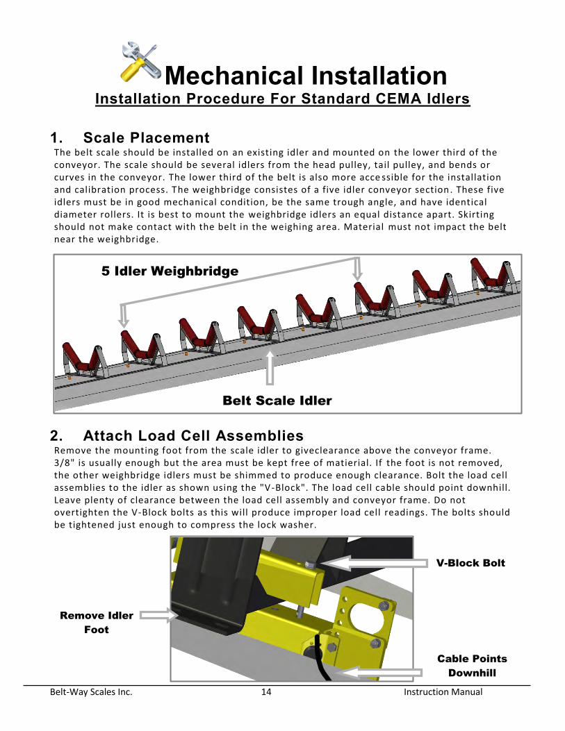
Mechanical Installation Installation Procedure For Standard CEMA Idlers
1. Scale Placement The belt scale should be installed on an existing idler and mounted on the lower third of the conveyor. The scale should be several idlers from the head pulley, tail pulley, and bends or curves in the conveyor. The lower third of the belt is also more acce ssible for the installation and calibration process. The weighbridge consistes of a five idler conveyor section . These five idlers must be in good mechanical condition, be the same trough angle, and have identical diameter rollers. It is best to mount the weighbridge idlers an equal distance apart. Skirting should not make contact with the belt in the weighing area. Material must not impact the belt near the weighbridge.
2. Attach Load Cell Assemblies Remove the mounting foot from the scale idler to giveclearance above the conveyor frame. 3/8" is usually enough but the area must be kept free of matierial. If the foot is not removed, the other weighbridge idlers must be shimmed to produce enough clearance. Bolt the load cell assemblies to the idler as shown using the "V-Block". The load cell cable should point downhill. Leave plenty of clearance between the load cell assembly and conveyor frame. Do not overtighten the V-Block bolts as this will produce improper load cell readings. The bolts should be tightened just enough to compress the lock washer.
Cable Points
Downhill
Remove Idler
Foot
V-Block Bolt
5 Idler Weighbridge
Belt Scale Idler
Belt-Way Scales Inc. 15 Instruction Manual
NOTE:Special care must be taken when installing stainless steel load cell assemlbies. Do not use a full thread bolt, or over tighten the existing V-Block bolt. The cable passes directly below the bolt and can be damaged.
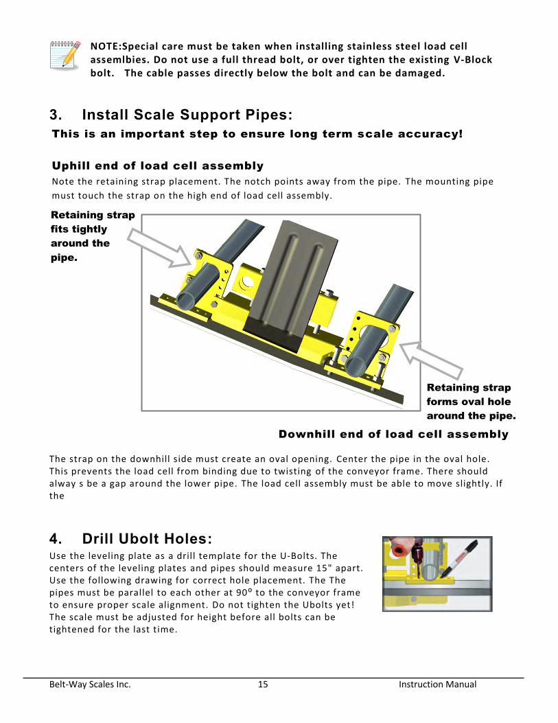
3. Install Scale Support Pipes: This is an important step to ensure long term scale accuracy!
Uphill end of load cell assembly
Note the retaining strap placement. The notch points away from the pipe. The mounting pipe
must touch the strap on the high end of load cell assembly.
Downhill end of load cell assembly
The strap on the downhill side must create an oval opening. Center the pipe in the oval hole. This prevents the load cell from binding due to twisting of the conveyor frame. There should alway s be a gap around the lower pipe. The load cell assembly must be able to move slightly. If the
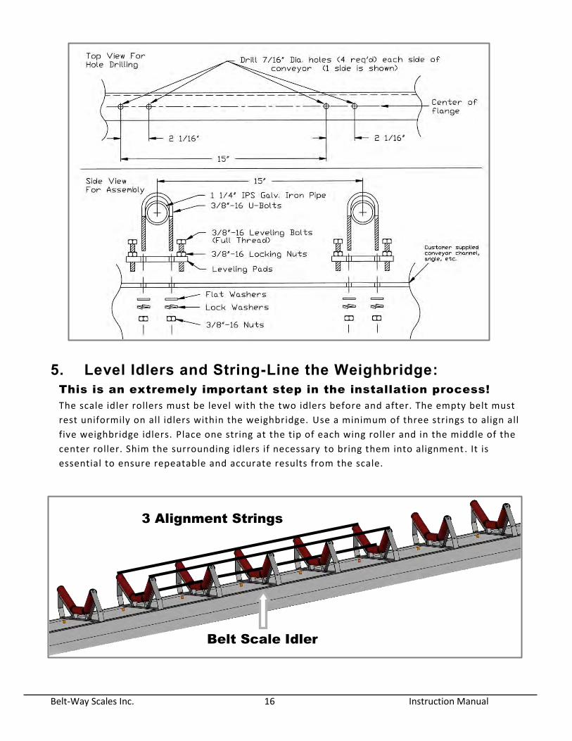
4. Drill Ubolt Holes: Use the leveling plate as a drill template for the U-Bolts. The centers of the leveling plates and pipes should measure 15" apart. Use the following drawing for correct hole placement. The The pipes must be parallel to each other at 90⁰ to the conveyor frame to ensure proper scale alignment. Do not tighten the Ubolts yet! The scale must be adjusted for height before all bolts can be tightened for the last time.
Retaining strap
fits tightly
around the
pipe.
Retaining strap
forms oval hole
around the pipe.
Belt-Way Scales Inc. 16 Instruction Manual
5. Level Idlers and String-Line the Weighbridge: This is an extremely important step in the installation process!
The scale idler rollers must be level with the two idlers before and after. The empty belt must
rest uniformily on all idlers within the weighbridge. Use a minimum of three strings to align all
five weighbridge idlers. Place one string at the tip of each wing roller and in the middle of the
center roller. Shim the surrounding idlers if necessary to bring them into alignment . It is
essential to ensure repeatable and accurate results from the scale.
Belt Scale Idler
3 Alignment Strings
Belt-Way Scales Inc. 17 Instruction Manual
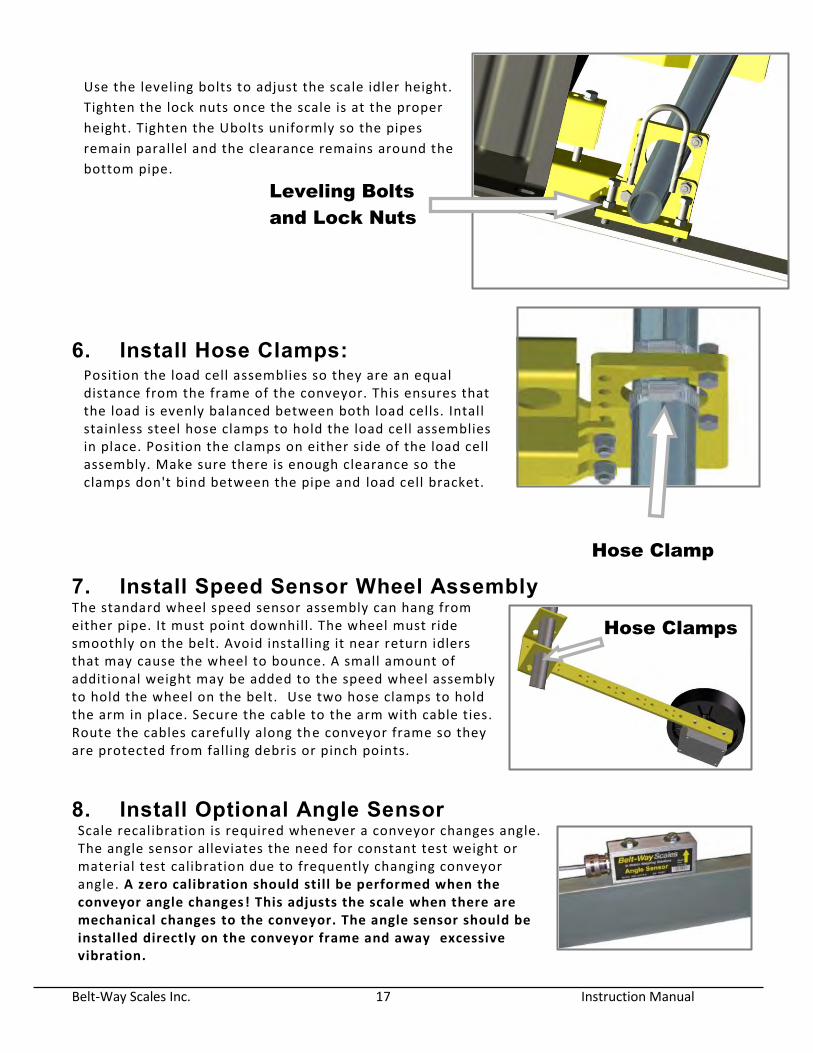
Use the leveling bolts to adjust the scale idler height.
Tighten the lock nuts once the scale is at the proper
height. Tighten the Ubolts uniformly so the pipes
remain parallel and the clearance remains around the
bottom pipe.
6. Install Hose Clamps: Position the load cell assemblies so they are an equal distance from the frame of the conveyor. This ensures that the load is evenly balanced between both load cells. Intall stainless steel hose clamps to hold the load cell assemblies in place. Position the clamps on either side of the load cell assembly. Make sure there is enough clearance so the clamps don't bind between the pipe and load cell bracket.
7. Install Speed Sensor Wheel Assembly The standard wheel speed sensor assembly can hang from either pipe. It must point downhill. The wheel must ride smoothly on the belt. Avoid installing it near return idlers that may cause the wheel to bounce. A small amount of additional weight may be added to the speed wheel assembly to hold the wheel on the belt. Use two hose clamps to hold the arm in place. Secure the cable to the arm with cable ties. Route the cables carefully along the conveyor frame so they are protected from falling debris or pinch points.
8. Install Optional Angle Sensor Scale recalibration is required whenever a conveyor changes angle. The angle sensor alleviates the need for constant test weight or material test calibration due to frequently changing conveyor angle. A zero calibration should still be performed when the conveyor angle changes! This adjusts the scale when there are mechanical changes to the conveyor. The angle sensor should be installed directly on the conveyor frame and away excessive vibration.
Leveling Bolts
and Lock Nuts
Hose Clamp
Hose Clamps
Belt-Way Scales Inc. 18 Instruction Manual
Mechanical Installation for a Channel Inset Idler (Primarily used for Portable Machines) Many producers require a weighing solution for their portable crushers, screen plants, etc. Installing a scale on this type of equipment is possible but can be more challenging than a standard conveyor. There are to many types of portable machines to cover in this document. This section is meant to offer broad exposure to portable equipment and not be a step by step guide. Scale accuracy and repeatability may vary greatly due factors beyond our control. We strongly suggest that you consult a Belt -Way dealer before attempting the following installation procedures.
1. Scale Placement
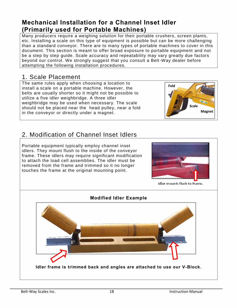
The same rules apply when choosing a location to install a scale on a portable machine. However, the belts are usually shorter so it might not be possible to utilize a five idler weighbridge. A three idler weighbridge may be used when necessary. The scale should not be placed near the head pulley, near a fold in the conveyor or directly under a magnet.
2. Modification of Channel Inset Idlers
Portable equipment typically employ channel inset idlers. They mount flush to the inside of the conveyor frame. These idlers may require significant modification to attach the load cell assemblies. The idler must be removed from the frame and trimmed so it no longer touches the frame at the original mounting point.
Modified Idler Example
Idler frame is trimmed back and angles are attached to use our V-Block.
Magnet
Scale
Fold
Belt-Way Scales Inc. 19 Instruction Manual
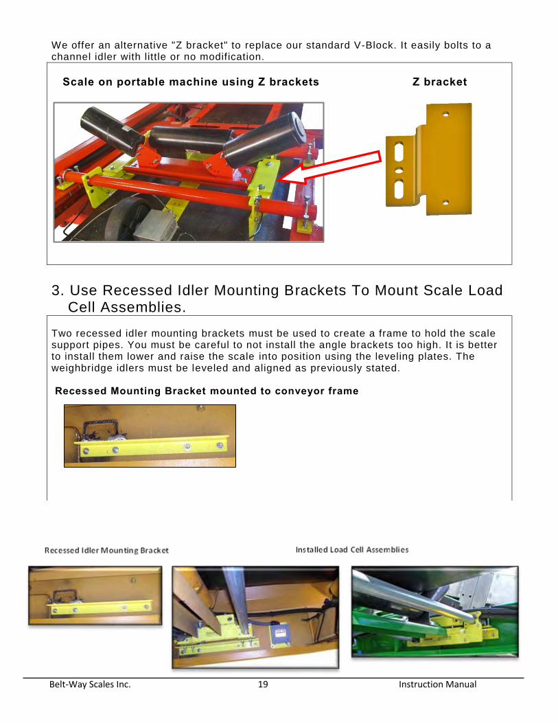
We offer an alternative "Z bracket" to replace our standard V-Block. It easily bolts to a channel idler with little or no modification.
Scale on portable machine using Z brackets Z bracket
3. Use Recessed Idler Mounting Brackets To Mount Scale Load
Cell Assemblies. Two recessed idler mounting brackets must be used to create a frame to hold the scale support pipes. You must be careful to not install the angle brackets too high. It is better to install them lower and raise the scale into position using the leveling plates. The weighbridge idlers must be leveled and aligned as previously stated. Recessed Mounting Bracket mounted to conveyor frame
Belt-Way Scales Inc. 20 Instruction Manual
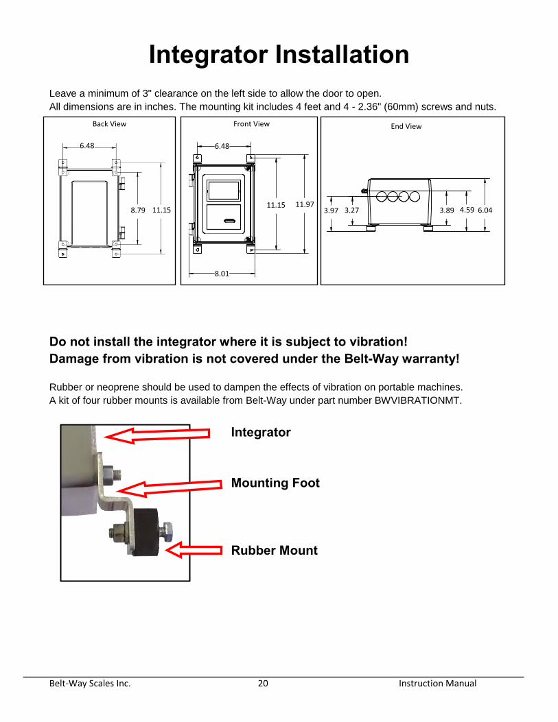
Integrator Installation Leave a minimum of 3" clearance on the left side to allow the door to open.
All dimensions are in inches. The mounting kit includes 4 feet and 4 - 2.36" (60mm) screws and nuts.
Do not install the integrator where it is subject to vibration! Damage from vibration is not covered under the Belt-Way warranty!
Rubber or neoprene should be used to dampen the effects of vibration on portable machines.
A kit of four rubber mounts is available from Belt-Way under part number BWVIBRATIONMT.
Integrator Mounting Foot Rubber Mount
6.48
8.79 11.15
6.48
11.97 11.15
8.01
3.97 3.27 3.89 4.59 6.04
Back View Front View End View
Belt-Way Scales Inc. 21 Instruction Manual
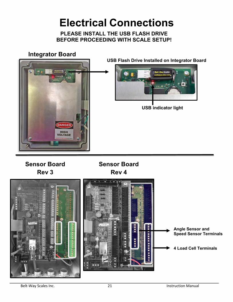
Electrical Connections PLEASE INSTALL THE USB FLASH DRIVE
BEFORE PROCEEDING WITH SCALE SETUP! Integrator Board
USB Flash Drive Installed on Integrator Board USB indicator light
Terminal Board Rev 3
Sensor Board Rev 3
Sensor Board Rev 4
Angle Sensor and Speed Sensor Terminals 4 Load Cell Terminals
Belt-Way Scales Inc. 22 Instruction Manual
WARNING! There is high voltage inside the scale integrator box so please make sure the supply power to the scale
integrator has been unplugged or disconnected at the circuit breaker to reduce the possibility of
electrocution and injury.
Make sure you LOCK OUT, TAG OUT and TRY OUT the electrical system before continuing with any
maintenance or service. Please follow all Federal, State and Company Safety procedures and policies
when working with this product.
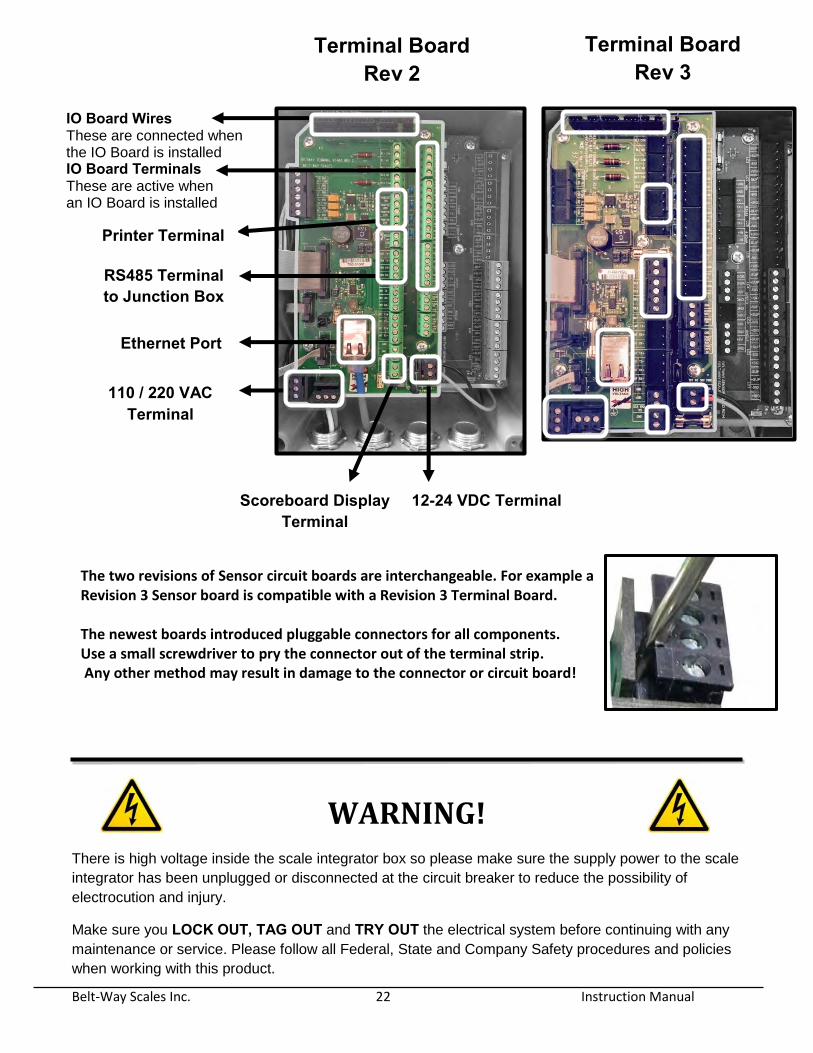
110 / 220 VAC Terminal
Ethernet Port
Scoreboard Display Terminal
Printer Terminal
RS485 Terminal to Junction Box
12-24 VDC Terminal
IO Board Wires These are connected when the IO Board is installed IO Board Terminals These are active when an IO Board is installed
Terminal Board Rev 2
Terminal Board Rev 3
The two revisions of Sensor circuit boards are interchangeable. For example a Revision 3 Sensor board is compatible with a Revision 3 Terminal Board. The newest boards introduced pluggable connectors for all components. Use a small screwdriver to pry the connector out of the terminal strip. Any other method may result in damage to the connector or circuit board!
Belt-Way Scales Inc. 23 Instruction Manual
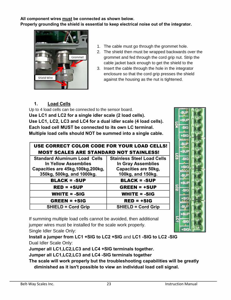
All component wires must be connected as shown below. Properly grounding the shield is essential to keep electrical noise out of the integrator.
1. The cable must go through the grommet hole.
2. The shield then must be wrapped backwards over the
grommet and fed through the cord grip nut. Strip the
cable jacket back enough to get the shield to the
3. Insert the cable through the hole in the integrator
enclosure so that the cord grip presses the shield
against the housing as the nut is tightened.
1. Load Cells Up to 4 load cells can be connected to the sensor board.
Use LC1 and LC2 for a single idler scale (2 load cells). Use LC1, LC2, LC3 and LC4 for a dual idler scale (4 load cells). Each load cell MUST be connected to its own LC terminal. Multiple load cells should NOT be summed into a single cable.
If summing multiple load cells cannot be avoided, then additional
jumper wires must be installed for the scale work properly.
Single Idler Scale Only:
Install a jumper from LC1 +SIG to LC2 +SIG and LC1 -SIG to LC2 -SIG
Dual Idler Scale Only:
Jumper all LC1,LC2,LC3 and LC4 +SIG terminals together. Jumper all LC1,LC2,LC3 and LC4 -SIG terminals together The scale will work properly but the troubleshooting capabilities will be greatly
diminished as it isn't possible to view an individual load cell signal.
USE CORRECT COLOR CODE FOR YOUR LOAD CELLS!
MOST SCALES ARE STANDARD NOT STAINLESS!
Standard Aluminum Load Cells In Yellow Assemblies
Capacities are 45kg,100kg,200kg, 350kg, 500kg, and 1000kg.
Stainless Steel Load Cells In Gray Assemblies Capacities are 50kg, 100kg, and 150kg.
BLACK = -SUP BLACK = -SUP
RED = +SUP GREEN = +SUP
WHITE = -SIG WHITE = -SIG
GREEN = +SIG RED = +SIG
SHIELD = Cord Grip SHIELD = Cord Grip

Belt-Way Scales Inc. 24 Instruction Manual
2. Speed Sensor For standard return belt speed sensor and shaft mounted speed sensor
3. Angle Sensor
Please connect the wires for the angle sensor to the ANGLE terminal as shown:
4. 100/240VAC Supply Power
The 100/240 VAC power supply is mandatory if the scale must be powered from AC line power or a
generator! The power supply converts 110/240 VAC into 24 VDC. It is mounted below the Terminal and
Sensor boards. It is best to have the power supply installed prior to shipment from the factory using
Part # BWPS but may also be shipped as a field installable kit Part # BWPSKIT.
WARNING - HIGH VOLTAGE!! Make sure you follow best safety practices! Double check to be sure there is no power on the wires while making the connections!
EARTH GROUND
GREEN
LINE
BLACK
NEUTRAL
WHITE
Belt-Way Scales Inc. 25 Instruction Manual
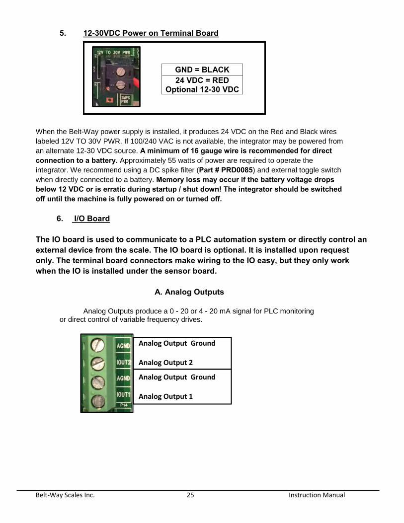
5. 12-30VDC Power on Terminal Board
When the Belt-Way power supply is installed, it produces 24 VDC on the Red and Black wires
labeled 12V TO 30V PWR. If 100/240 VAC is not available, the integrator may be powered from
an alternate 12-30 VDC source. A minimum of 16 gauge wire is recommended for direct connection to a battery. Approximately 55 watts of power are required to operate the
integrator. We recommend using a DC spike filter (Part # PRD0085) and external toggle switch
when directly connected to a battery. Memory loss may occur if the battery voltage drops below 12 VDC or is erratic during startup / shut down! The integrator should be switched off until the machine is fully powered on or turned off.
6. I/O Board
The IO board is used to communicate to a PLC automation system or directly control an external device from the scale. The IO board is optional. It is installed upon request only. The terminal board connectors make wiring to the IO easy, but they only work when the IO is installed under the sensor board.
A. Analog Outputs
Analog Outputs produce a 0 - 20 or 4 - 20 mA signal for PLC monitoring or direct control of variable frequency drives.
GND = BLACK 24 VDC = RED
Optional 12-30 VDC
Analog Output Ground Analog Output 2 Analog Output Ground Analog Output 1

Belt-Way Scales Inc. 26 Instruction Manual
C. Digital Inputs and Outputs
Digital inputs and outputs allow the integrator to be manipulated from a PLC system.
Digital inputs and outputs are SYNCING. It is best to power the inputs and outputs with 24 VDC from
the PLC to keep them fully isolated. Alternatively, the SNSR PWR and GND terminals can supply
24VDC. This method eliminates the isolation between the scale integrator and PLC.
Digital Input Ground Digital Input 4 Digital Input Ground Digital Input 3 Digital Input Ground Digital Input 2 Digital Input Ground Digital Input 1
Digital Output Ground Digital Output 3 Digital Output Ground Digital Output 2 Digital Output Ground Digital Output 1
Belt-Way Scales Inc. 27 Instruction Manual
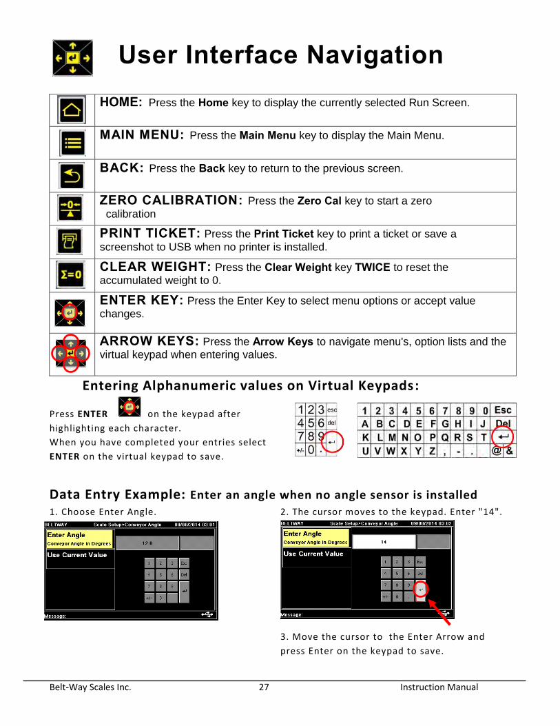
User Interface Navigation
HOME: Press the Home key to display the currently selected Run Screen.
MAIN MENU: Press the Main Menu key to display the Main Menu.
BACK: Press the Back key to return to the previous screen.
ZERO CALIBRATION: Press the Zero Cal key to start a zero
calibration
PRINT TICKET: Press the Print Ticket key to print a ticket or save a
screenshot to USB when no printer is installed.
CLEAR WEIGHT: Press the Clear Weight key TWICE to reset the
accumulated weight to 0.
ENTER KEY: Press the Enter Key to select menu options or accept value
changes.
ARROW KEYS: Press the Arrow Keys to navigate menu's, option lists and the
virtual keypad when entering values.
Entering Alphanumeric values on Virtual Keypads:
Press ENTER on the keypad after
highlighting each character.
When you have completed your entries select
ENTER on the virtual keypad to save.
Data Entry Example: Enter an angle when no angle sensor is installed
1. Choose Enter Angle. 2. The cursor moves to the keypad. Enter "14".
3. Move the cursor to the Enter Arrow and
press Enter on the keypad to save.
Belt-Way Scales Inc. 28 Instruction Manual
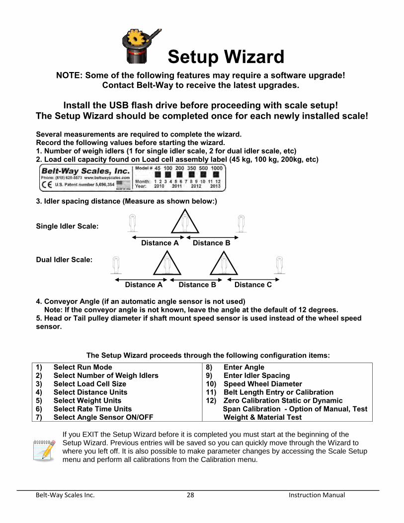
Setup Wizard NOTE: Some of the following features may require a software upgrade!
Contact Belt-Way to receive the latest upgrades.
Install the USB flash drive before proceeding with scale setup! The Setup Wizard should be completed once for each newly installed scale!
If you EXIT the Setup Wizard before it is completed you must start at the beginning of the Setup Wizard. Previous entries will be saved so you can quickly move through the Wizard to where you left off. It is also possible to make parameter changes by accessing the Scale Setup menu and perform all calibrations from the Calibration menu.
Several measurements are required to complete the wizard. Record the following values before starting the wizard. 1. Number of weigh idlers (1 for single idler scale, 2 for dual idler scale, etc) 2. Load cell capacity found on Load cell assembly label (45 kg, 100 kg, 200kg, etc)
3. Idler spacing distance (Measure as shown below:) Single Idler Scale: Distance A Distance B Dual Idler Scale: Distance A Distance B Distance C 4. Conveyor Angle (if an automatic angle sensor is not used) Note: If the conveyor angle is not known, leave the angle at the default of 12 degrees. 5. Head or Tail pulley diameter if shaft mount speed sensor is used instead of the wheel speed sensor.
The Setup Wizard proceeds through the following configuration items: 1) Select Run Mode 2) Select Number of Weigh Idlers 3) Select Load Cell Size 4) Select Distance Units 5) Select Weight Units 6) Select Rate Time Units 7) Select Angle Sensor ON/OFF
8) Enter Angle 9) Enter Idler Spacing 10) Speed Wheel Diameter 11) Belt Length Entry or Calibration 12) Zero Calibration Static or Dynamic
Span Calibration - Option of Manual, Test Weight & Material Test

Belt-Way Scales Inc. 29 Instruction Manual
Scale Setup The Scale Setup menu is available to manage important calibration parameters. You can configure the scale manually in this menu instead of walking through the Setup Wizard. Use care when modifying Scale Setup parameters as they impact the calibration of the scale.
Run Mode
The Run Mode selection determines what information is displayed on the home screen.
There are currently five run modes to choose from.
Weight / Rate
This is the default run mode. It displays total
accumulated weight, flow rate (tons per hour, etc), and
belt speed
Load Out
This run mode is best when the scale is used to load
product into trucks or rail cars. The user can quickly
choose from preset load weights if the scale is setup to
control the feed device.
Blending
This run mode is best when the scale is used to
accurately blend materials using our internal PID
control function. The blend mixture can quickly be
adjusted as needed.
The Scale Setup menu will allow you to setup and view the following scale parameters:
1) Run Mode 2) Number of Weigh Idlers 3) Load Cell Size 4) Distance Units 5) Weight Units 6) Rate Time Units 7) Conveyor Angle 8) Idler Distance 9) Speed Sensor
Belt-Way Scales Inc. 30 Instruction Manual
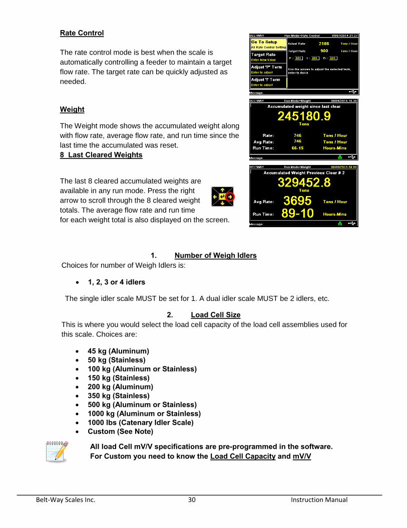
Rate Control
The rate control mode is best when the scale is
automatically controlling a feeder to maintain a target
flow rate. The target rate can be quickly adjusted as
needed.
Weight
The Weight mode shows the accumulated weight along
with flow rate, average flow rate, and run time since the
last time the accumulated was reset.
8 Last Cleared Weights
The last 8 cleared accumulated weights are
available in any run mode. Press the right
arrow to scroll through the 8 cleared weight
totals. The average flow rate and run time
for each weight total is also displayed on the screen.
1. Number of Weigh Idlers
Choices for number of Weigh Idlers is:
1, 2, 3 or 4 idlers
The single idler scale MUST be set for 1. A dual idler scale MUST be 2 idlers, etc.
2. Load Cell Size
This is where you would select the load cell capacity of the load cell assemblies used for
this scale. Choices are:
45 kg (Aluminum) 50 kg (Stainless) 100 kg (Aluminum or Stainless) 150 kg (Stainless) 200 kg (Aluminum) 350 kg (Stainless) 500 kg (Aluminum or Stainless) 1000 kg (Aluminum or Stainless) 1000 lbs (Catenary Idler Scale) Custom (See Note)
All load Cell mV/V specifications are pre-programmed in the software. For Custom you need to know the Load Cell Capacity and mV/V
Belt-Way Scales Inc. 31 Instruction Manual
3. Weight Units
Select the distance units you would like to display on the screen during operation.
Depending Distance unit selection, the choices are:
I. English Pounds
Tons
Long Tons II. Metric
Tonne (Metric Tons)
kg
4. Distance Units
Select the distance units you would like to display on the screen during operation. The
units displayed are related to the distance units previously selected. EXAMPLE: If you
select English Units the choices shown will be as listed under English units.
Choices are:
III. English Units Feet
Inches
Tons
Long Tons IV. Metric Units
Meters
Centimeters
Tonnes (Metric Tons)
Kilograms
5. Rate Time Units
Select the time based units you would like to display when in run mode.
Choices are:
Minute (min) Hour (Hr)
6. Conveyor Angle
You need to select whether you have an angle installed.
Installed: The scale will automatically look at the signals for the angle sensor and use
these signals for weight calculation.
Not Installed: You need to enter the angle of the conveyor as this effects the weight
calculation.
If you do not have an “Angle Finder”, you can download a free Inclinometer
application on your smart phone to help find the angle in degrees.

Belt-Way Scales Inc. 32 Instruction Manual
7. Idler Distance You need to enter the exact distance between the conveyor idlers and the scale idlers so
that the scale can accurately measure the weight on the belt. The measurement units
required for entry are dependent on the distance units selected in #5:
English: Inches (in)
Metric: Meters (m)
8. Speed Sensor The speed sensor default shown is for the “Return Belt Speed Sensor” however you are
able to use Belt-Way Scales shaft mount encoder or a third party encoder for speed
measurement. In order to get an accurate speed you would need change the following
values:
A. Wheel diameter: If you are using the Belt-Way Scales shaft mount encoder you will need to
measure the pulley diameter that the encoder is mounted to. This measurement
needs to be in Inches or Centimeters.
B. Pulses Per revolution:
The correct value must be entered here for the scale to work properly! The current Belt-Way speed sensor uses 100 pulses per revolution.
The model number is SP10. Firmware version 3.28 defaults to 100 pulses.
The older Model SP9 speed sensors used 200 pulses per revolution.
If you are using a third party encoder you must enter the pulses/revolution for that
specific encoder.
C. User Belt Speed
If the scales displayed belt speed is not correct and does not match the reading
from your tachometer. You can adjust the scales displayed reading to match. You
must know the pulses per revolution of the encoder being used and the correct
belt speed which you can enter here and the scale will adjust the pulley diameter
so the displayed belt speed will match the actual speed.
Belt-Way Scales Inc. 33 Instruction Manual
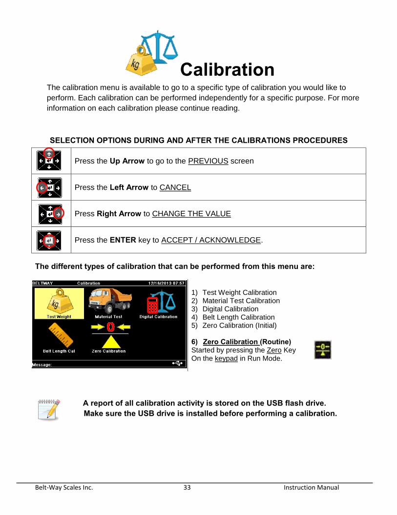
Calibration The calibration menu is available to go to a specific type of calibration you would like to
perform. Each calibration can be performed independently for a specific purpose. For more
information on each calibration please continue reading.
A report of all calibration activity is stored on the USB flash drive. Make sure the USB drive is installed before performing a calibration.
SELECTION OPTIONS DURING AND AFTER THE CALIBRATIONS PROCEDURES
Press the Up Arrow to go to the PREVIOUS screen
Press the Left Arrow to CANCEL
Press Right Arrow to CHANGE THE VALUE
Press the ENTER key to ACCEPT / ACKNOWLEDGE.
The different types of calibration that can be performed from this menu are:
1) Test Weight Calibration 2) Material Test Calibration 3) Digital Calibration 4) Belt Length Calibration 5) Zero Calibration (Initial)
6) Zero Calibration (Routine) Started by pressing the Zero Key On the keypad in Run Mode.

Belt-Way Scales Inc. 34 Instruction Manual
Test Weight Calibration
The Test Weight Calibration requires the user to hang
static weights from the load cell assemblies. A common
method is to use test weights and a test bar as shown in
the picture. Stop the belt and be sure to follow all safety
procedures when placing test weights in position on the
scale for the test weight.
Belt-Way now offers a self Storing Test Weight kit that safely holds the test weight on the scale. This system makes calibration very easy and safe. The test weight requires one person to drop the weight onto the load cells. There is no need for a man lift to hang weights even when the conveyor only has access on one side. No matter the method, the total weight including the bar must be entered before proceeding
with the calibration.
The weight value must be entered in Pounds (lbs.) or Kilograms (kg’s)
Suggested test weight amounts are as follows: Model 45 or Model 50
Model 100 or Model 150
Model 200 Model 350 Model 500 Model 1000
25-50 lbs. 50-100 lbs. 50-100 lbs. 100-200 lbs. 200+ lbs. 200+ lbs.
Check the New Trim Factor upon completion of the test weight calibration. The Trim Factor of a properly calibrated scale should be close to 1. (.950, 1.025, etc) There may be a problem if the result is not close to 1. Recheck all settings, then repeat the zero and test weight calibrations to check for repeatability. You may also view the Live Weight screen when test weights are installed on the scale. Navigate to Totals & Diagnostics > Live Weight. This screen shows the current weight on the scale. It should closely match the test weight value.
------------------------------------------------------------------------------------------------------------
Navigation Tip
Press the MENU key.
Navigate to the CALIBRATION icon and press ENTER key
Navigate to the TEST WEIGHT menu. Then press ENTER key.

Belt-Way Scales Inc. 35 Instruction Manual
Material Test Calibration
The Material Test Calibration is one method that can be used to calibrate the scale and is based on the
weight measured by the Belt scale and a Certified scale (typically a truck scale).
These two weights are entered into the scale and after acknowledging the entries, the scale will adjust
the TRIM factor so that the belt scale will read very close to the certified scale.
The CERTIFIED scale units entered is selectable and does not need to be the same
as the belt scale units because the scale will convert and adjust the scale as needed
based on the units selected for the certified. The CERTIFIED scale unit choices are:
Tons (Equal to 2000lbs) Long Ton (Equal to 2240lbs) Pounds (lbs.) Metric Tons (Tonne) Kilograms (KG)
Recommended steps to follow:
1. Weigh the truck EMPTY to get a good tare weight.
2. Make sure the scale ZERO Calibration is good. Zero Calibrate the scale if needed.
3. Clear the TOTAL weight on the belt scale.
4. Run the material to start test
5. Complete 3 tests. We recommend a minimum of 15 tons per test if possible
6. Compare the results to prove the scale is repeatable BEFORE adjusting the scale calibration.
7. If all tests are reasonably consistent, take an average of the belt scale and truck scale tests, or
simply add the tests up and enter the total weight for the belt scale and truck scale, instead of a
single load. Either of these methods will result in a more accurate calibration.
The Trim Factor of a properly calibrated scale should be close to 1.000. (.950, 1.100, etc.) If your result is not close to 1 recheck all settings and perform the calibration again! ------------------------------------------------------------------------------------------------------------
Navigation Tip
Press the MENU key.
Navigate to the CALIBRATION icon and press ENTER key
Navigate to the MATERIAL TEST menu. Then press ENTER key.
Belt-Way Scales Inc. 36 Instruction Manual
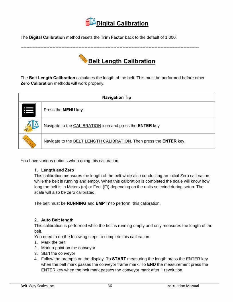
Digital Calibration
The Digital Calibration method resets the Trim Factor back to the default of 1.000.
---------------------------------------------------------------------------------------------------------------------
Belt Length Calibration
The Belt Length Calibration calculates the length of the belt. This must be performed before other
Zero Calibration methods will work properly.
You have various options when doing this calibration:
1. Length and Zero This calibration measures the length of the belt while also conducting an Initial Zero calibration
while the belt is running and empty. When this calibration is completed the scale will know how
long the belt is in Meters (m) or Feet (Ft) depending on the units selected during setup. The
scale will also be zero calibrated.
The belt must be RUNNING and EMPTY to perform this calibration.
2. Auto Belt length This calibration is performed while the belt is running empty and only measures the length of the
belt.
You need to do the following steps to complete this calibration:
1. Mark the belt
2. Mark a point on the conveyor
3. Start the conveyor
4. Follow the prompts on the display. To START measuring the length press the ENTER key
when the belt mark passes the conveyor frame mark. To END the measurement press the
ENTER key when the belt mark passes the conveyor mark after 1 revolution.
Navigation Tip
Press the MENU key.
Navigate to the CALIBRATION icon and press the ENTER key
Navigate to the BELT LENGTH CALIBRATION. Then press the ENTER key.
Belt-Way Scales Inc. 37 Instruction Manual
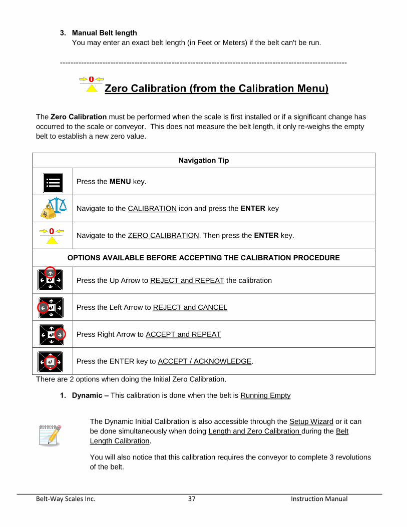
3. Manual Belt length You may enter an exact belt length (in Feet or Meters) if the belt can't be run.
------------------------------------------------------------------------------------------------------------
Zero Calibration (from the Calibration Menu)
The Zero Calibration must be performed when the scale is first installed or if a significant change has
occurred to the scale or conveyor. This does not measure the belt length, it only re-weighs the empty
belt to establish a new zero value.
There are 2 options when doing the Initial Zero Calibration.
1. Dynamic – This calibration is done when the belt is Running Empty
The Dynamic Initial Calibration is also accessible through the Setup Wizard or it can
be done simultaneously when doing Length and Zero Calibration during the Belt
Length Calibration.
You will also notice that this calibration requires the conveyor to complete 3 revolutions
of the belt.
Navigation Tip
Press the MENU key.
Navigate to the CALIBRATION icon and press the ENTER key
Navigate to the ZERO CALIBRATION. Then press the ENTER key.
OPTIONS AVAILABLE BEFORE ACCEPTING THE CALIBRATION PROCEDURE
Press the Up Arrow to REJECT and REPEAT the calibration
Press the Left Arrow to REJECT and CANCEL
Press Right Arrow to ACCEPT and REPEAT
Press the ENTER key to ACCEPT / ACKNOWLEDGE.
Belt-Way Scales Inc. 38 Instruction Manual
2. Static – This option is used when you are unable to start the belt and need to complete a
quick zero Calibration.
The belt must be STOPPED and EMPTY when doing this calibration.
------------------------------------------------------------------------------------------------------------
Zero Calibration – (from the Keypad)
This is the primary method for performing a ZERO CALIBRATION. We recommend repeating this
process daily or as frequently as required by your application. Run the belt EMPTY and press the
ZERO CALIBRATION button on the keypad. You can cancel the calibration at any time by pressing the
BACK or HOME buttons. Follow the on screen instructions to save the new zero number.
Some factors that the Routine or Daily zero calibration will help compensate for are:
Material build up on the scale
Material build up on the belt
Ambient Temperature changes
Belt temperature changes
Added belt splices and vulcanizing
Misalignment of the belt (belt tracking)
The zero calibration will overcome some of these issues but is not a replacement for routine
maintenance.
Belt-Way Scales Inc. 39 Instruction Manual
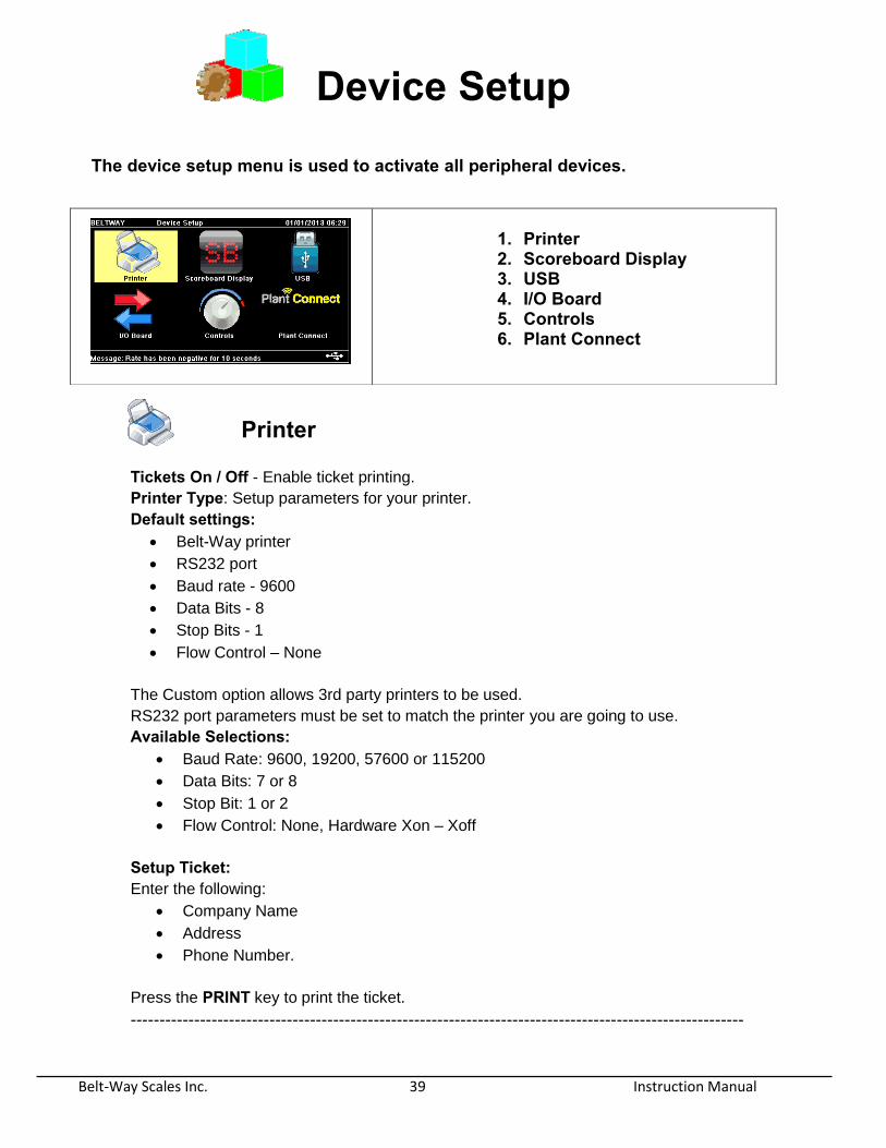
Device Setup
The device setup menu is used to activate all peripheral devices.
Printer Tickets On / Off - Enable ticket printing.
Printer Type: Setup parameters for your printer.
Default settings: Belt-Way printer
RS232 port
Baud rate - 9600
Data Bits - 8
Stop Bits - 1
Flow Control – None
The Custom option allows 3rd party printers to be used.
RS232 port parameters must be set to match the printer you are going to use.
Available Selections: Baud Rate: 9600, 19200, 57600 or 115200
Data Bits: 7 or 8
Stop Bit: 1 or 2
Flow Control: None, Hardware Xon – Xoff
Setup Ticket: Enter the following:
Company Name
Address
Phone Number.
Press the PRINT key to print the ticket.
----------------------------------------------------------------------------------------------------------
1. Printer 2. Scoreboard Display 3. USB 4. I/O Board 5. Controls 6. Plant Connect
Belt-Way Scales Inc. 40 Instruction Manual
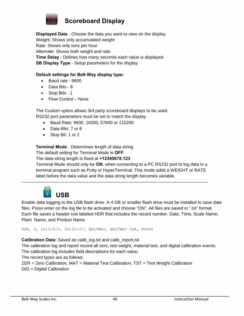
Scoreboard Display Displayed Data - Choose the data you want to view on the display Weight: Shows only accumulated weight
Rate: Shows only tons per hour.
Alternate: Shows both weight and rate.
Time Delay - Defines how many seconds each value is displayed.
SB Display Type - Setup parameters for the display.
Default settings for Belt-Way display type: Baud rate - 9600
Data Bits - 8
Stop Bits - 1
Flow Control – None
The Custom option allows 3rd party scoreboard displays to be used.
RS232 port parameters must be set to match the display.
Baud Rate: 9600, 19200, 57600 or 115200
Data Bits: 7 or 8
Stop Bit: 1 or 2
Terminal Mode - Determines length of data string.
The default setting for Terminal Mode is OFF.
The data string length is fixed at +12345678.123
Terminal Mode should only be ON, when connecting to a PC RS232 port to log data in a
terminal program such as Putty or HyperTerminal. This mode adds a WEIGHT or RATE
label before the data value and the data string length becomes variable.
---------------------------------------------------------------------------------------------------------------------
USB Enable data logging to the USB flash drive. A 4 GB or smaller flash drive must be installed to save date
files. Press enter on the log file to be activated and choose "ON". All files are saved in “.txt” format.
Each file saves a header row labeled HDR that includes the record number, Date, Time, Scale Name,
Plant Name, and Product Name.
HDR, 0, 2015/6/3, 09:02:07, BELTWAY, BELTWAY USA, ROCKS
Calibration Data: Saved as calib_log.txt and calib_report.txt
The calibration log and report record all zero, test weight, material test, and digital calibration events.
The calibration log includes field descriptions for each value.
The record types are as follows:
ZER = Zero Calibration, MAT = Material Test Calibration, TST = Test Weight Calibration
DIG = Digital Calibration
Belt-Way Scales Inc. 41 Instruction Manual
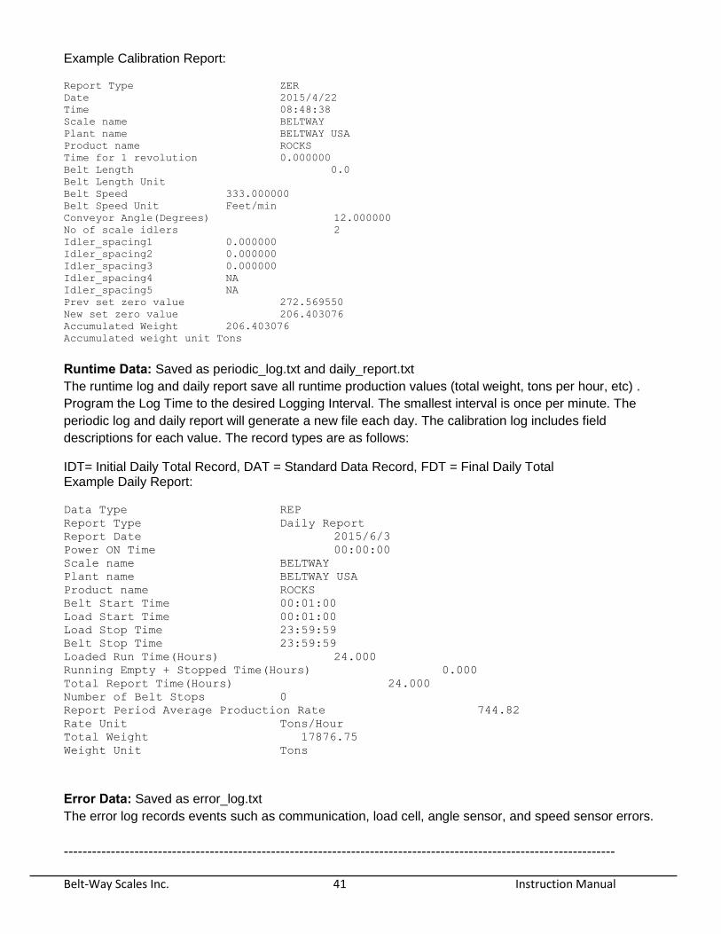
Example Calibration Report:
Report Type ZER
Date 2015/4/22
Time 08:48:38
Scale name BELTWAY
Plant name BELTWAY USA
Product name ROCKS
Time for 1 revolution 0.000000
Belt Length 0.0
Belt Length Unit
Belt Speed 333.000000
Belt Speed Unit Feet/min
Conveyor Angle(Degrees) 12.000000
No of scale idlers 2
Idler_spacing1 0.000000
Idler_spacing2 0.000000
Idler_spacing3 0.000000
Idler_spacing4 NA
Idler_spacing5 NA
Prev set zero value 272.569550
New set zero value 206.403076
Accumulated Weight 206.403076
Accumulated weight unit Tons
Runtime Data: Saved as periodic_log.txt and daily_report.txt
The runtime log and daily report save all runtime production values (total weight, tons per hour, etc) .
Program the Log Time to the desired Logging Interval. The smallest interval is once per minute. The
periodic log and daily report will generate a new file each day. The calibration log includes field
descriptions for each value. The record types are as follows:
IDT= Initial Daily Total Record, DAT = Standard Data Record, FDT = Final Daily Total Example Daily Report:
Data Type REP
Report Type Daily Report
Report Date 2015/6/3
Power ON Time 00:00:00
Scale name BELTWAY
Plant name BELTWAY USA
Product name ROCKS
Belt Start Time 00:01:00
Load Start Time 00:01:00
Load Stop Time 23:59:59
Belt Stop Time 23:59:59
Loaded Run Time(Hours) 24.000
Running Empty + Stopped Time(Hours) 0.000
Total Report Time(Hours) 24.000
Number of Belt Stops 0
Report Period Average Production Rate 744.82
Rate Unit Tons/Hour
Total Weight 17876.75
Weight Unit Tons
Error Data: Saved as error_log.txt
The error log records events such as communication, load cell, angle sensor, and speed sensor errors.
---------------------------------------------------------------------------------------------------------------------

Belt-Way Scales Inc. 42 Instruction Manual
I/O Board
Assign Inputs
Assign any one of the listed input functions to any of the 4 digital inputs. The digital inputs are optically
isolated and accept 5-30 VDC.
Input options are listed below: 1. Print Ticket - Prints a ticket if a printer is connected to the integrator.
2. Print then Clear - Prints a ticket first and then resets the Accumulated Weight to zero.
3. Enter Load - Used with legacy remote start stop stations.
4. PID Rate = Zero - Momentarily stops PID loop from calculating.
5. Zero Calibration - Initiates the dynamic Zero Calibration.
6. Error Acknowledge - Acknowledge and clear an error condition.
Assign Outputs
Assign any one of the listed output functions to any of the 3 digital outputs. The digital outputs are
optically isolated with a maximum of 30 VDC, 100 mA sinking.
A solid state relay is required to connect our output to a 100 / 240 VAC PLC input card. See drawings section for proper wiring! Relays are available upon request.
Output Options are listed below:
1. Pulsed Output - Generates a pulse for each accumulated weight unit.
Pressing Enter will take you to the next setup screen where you must program the Weight per Pulse and Pulse on Time values.
Weight per Pulse This can be set to .1, 1.0, 10 or 100 of the selected Weight Units.
For example, if the Weight unit is Tons and the Weight per Pulse is set to .1, a pulse will occur each time 0.1 Tons is accumulated. Please note that small pulse values (.1 or 1.0) will not work with small Weight units (Lbs or Kgs) as an excessive number of pulses will be created!
Pulse on Time controls how long the pulse remains on. The value is in milliseconds. This must be programmed properly so the control system can count each pulse.
2. Quadrature Wave - Allows a pulsed output to count positive or negative weight. This
requires
a second output to be programmed as the Pulsed Output channel.
3. Error Alarm - The alarm output will turn on when an error condition occurs.

Belt-Way Scales Inc. 43 Instruction Manual
Pressing the ENTER key will allow you to choose the error you wish to monitor with the
output.
1. Load Cell - Activates when any load cell malfunctions.
2. Angle Sensor - Activates when the angle sensor malfunctions.
3. Communications - Activates when there is any communication error.
4. Negative Rate - Activates when the rate drops below the Negative Rate Limit.
The Negative Rate Limit is programmed in the Admin > Settings menu.
5. Any Error - Activates when any of the previously mentioned errors occur.
6. Min/Max Speed - Activates when the speed is above or below the programmed.
Pressing Enter takes you to the setup screen where you must program the Min or Speed Setpoints
Min Speed Output (Turns on when speed is below setpoint) or
Max Speed Output (turns on when speed is above setpoint).
7. Min/Max Rate - Activates when the rate is above or below the programmed.
Pressing Enter takes you to the setup screen where you must program the Min or Max Rate Setpoint
Min Rate Output (Turns on when rate is below setpoint) or
Max Rate Output (turns on when rate is above setpoint).
8. Batching / Loadout - Activates when a batch is complete.
9. Zero Calibration - Activates when a Zero Calibration is in progress. Be sure to
assign
an input to initiate the Zero Calibration.
Assign Relays
Any one of the previously listed output functions can be assigned to any of the 3 relay outputs.
All digital output options EXCEPT pulsed outputs are available as relay outputs. The relays can accept a direct connection to a 100 / 240 VAC input.
Analog Outputs
Selection choices are 4-20 mA or 0-20 mA output. This output is used by a PLC system to monitor
scale flow rate (tons per hour etc.) or to automatically control a material feed device in blending, rate
control or load control applications if configured to do so.
1. Analog 1 Function –
Output Default - Unassigned
Belt-Way Scales Inc. 44 Instruction Manual
Selection choices available are:
0-20 mA 0 mA is the mA output when the scale rate is 0 (Tph, Kg’s / Hr)
20 mA is the maximum output when the scale rate exceeds the Max Rate value.
4-20 mA
4 mA is the mA output when the scale rate is 0 (Tph, Kg’s / Hr)
20 mA is the maximum output when the scale rate exceeds the Max Rate value.
2. Analog 1 Setpoint Default - 100%
The setpoint determines what portion of the 4-20 mA output is sent to the PLC or feed
device. 100% sends the entire value,
50% sends half the value,
10% sends one tenth of the value, etc.
The value should remain at 100% when the output is simply monitored by a control
system. It should be programmed to the required value when the scale is used for
blending.
3. Analog 1 Max Rate - The Max Rate establishes the 20 mA level for the analog output.
The default is 500.
The Max Rate MUST equal the PLC 20 mA value to make the scale and PLC rate readings match.
---------------------------------------------------------------------------------------------------------------------
Controls
PID Control
These settings are used to control feed devices. A PID control loop allows a scale to speed up or slow
down a feed device in order to keep with a programmed flow rate crossing the scale.
The PID control section is a generic setup for the other specific functions (Rate Control, Blending, etc).
PID Channel Default – 1
Selection options are: 1 or 2
This is the analog output that will control the feed device.
PID Action
Default - Reverse Action
Selection options are:
Belt-Way Scales Inc. 45 Instruction Manual
1. Reverse Action
This method causes the feed device to speed up when the actual flow rate
drops below the programmed flow rate, thus increasing the flow rate.
2. Forward Action
This method causes the feed device to slow down when the actual rate is
below the programmed rate. It can be used to control a conveyor belt to keep
a consistent level of material on the belt.
PID Setpoint The PID Setpoint is the programmed flow rate that the scale attempts to maintain
when running a PID control loop. Default - Local Setpoint Selection options are:
1. Local Setpoint The Local setpoint must be manually entered into the integrator.
2. Remote Setpoint Remote setpoint requires a separate scale to automatically update the
setpoint value in a Master - Slave configuration. See blending section for more
details.
P, I, D Terms
The default PID terms will work for most applications. However, they may be adjusted
to fine tune feeder performance. Be careful when changing the values as they may
result in abnormal feeder behavior. Contact Belt-Way with questions about PID control setup.
Load Out
This setting stops a feed device after a predetermined weight has crossed the scale and is primarily
used to automate truck and rail car loading.
8 Preset Load Weights can be programmed accommodate different size vehicles.
Each load weight can also be accompanied by a Cutoff value. The Cutoff value must
match the amount of material that is left on the conveyor after a load is complete. The
Cutoff will usually be the same for each load weight, but different values can be used if
multiple feeders are utilized in the loading process. The Cutoff must be calculated by trial
and error testing. The final Target Weight equals the Preset Load weight minus the set
Cutoff value.
------------------------------------------------------------------------------------------------------------
Belt-Way Scales Inc. 46 Instruction Manual
Blending
Blending automatically controls one or multiple feed devices to create an accurately blended mixture of
materials. A Master - Slave configuration is utilized to have one scale send its rate to the other
networked scales.
Examples of blending include: Mixing cement and water in a batching plant
Adding RAP to an asphalt mixture
Mixing several sizes of sand into a final product
Settings for the blending functions are: Number of Slaves
This must be set in the Master scale only. It determines how many scales are on the
network.
Ingredient % This is the percentage (%) of the master scale that a slave scale needs to add to the
final mixture.
Feed Delay
The Feed Delay is programmed in Seconds (s). It delays the feeder from starting if it
is a long distance from the scale.
Preload Delay
The Preload Delay is programmed in Seconds (s). It delays the Slave scale from
responding to the master scale's rate. The feeder will run a lower "bias" rate until the
delay timer expires.
Feeder Capacity - Expected capacity of the feed device.
Rate Control
Rate Control allows the scale to automatically adjust a VFD (variable frequency drive) for a feeder to
keep a consistent flow rate on the scale at all times. It is also possible to control vibratory feeders,
Augers, conveyors and other material feed systems.
Rate Control settings are as follows:
Target Rate
This is the RATE the scale is attempting to maintain.
Preload Delay
This will Delay the PID loop calculations if the scale is a long distance away from the
feed device. It is measured in Seconds (s). This method can dramatically reduce the scale's expected margin of error.

Belt-Way Scales Inc. 47 Instruction Manual
Target Load
The scale will attempt to keep the same or consistent amount of material on the belt at
all times. It must be in lbs / ft or kgs / M.
Min. Belt Speed
This is the minimum expected belt speed of the conveyor.
Preload Distance
This is the distance from the feed device to the scale.
Empty Belt Speed This is the expected belt speed of the conveyor when it is running empty.
----------------------------------------------------------------------------------------------------------
Plant Connect
Plant Connect is an Internet based reporting system that allows you to easily access and
monitor production from a PC, smart phone or Tablet. Contact Belt-Way Scales for more
information.
Belt-Way Scales Inc. 48 Instruction Manual
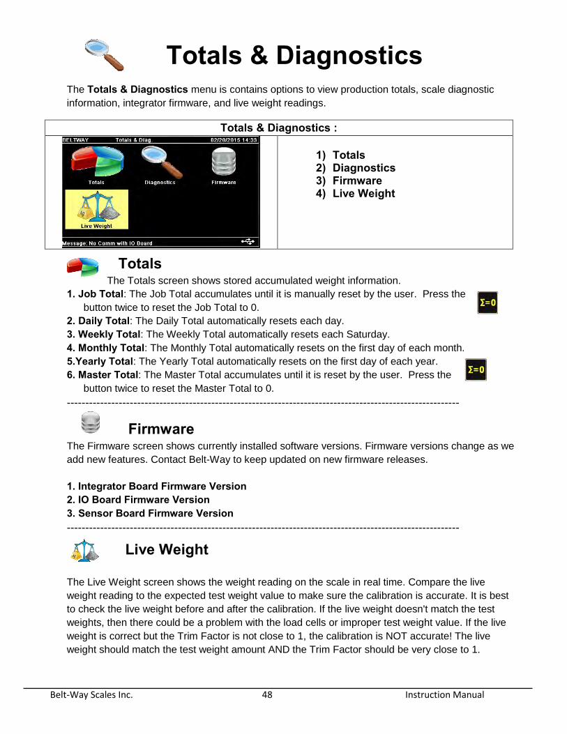
Totals & Diagnostics The Totals & Diagnostics menu is contains options to view production totals, scale diagnostic
information, integrator firmware, and live weight readings.
Totals & Diagnostics :
1) Totals 2) Diagnostics 3) Firmware 4) Live Weight
Totals The Totals screen shows stored accumulated weight information.
1. Job Total: The Job Total accumulates until it is manually reset by the user. Press the
button twice to reset the Job Total to 0.
2. Daily Total: The Daily Total automatically resets each day.
3. Weekly Total: The Weekly Total automatically resets each Saturday.
4. Monthly Total: The Monthly Total automatically resets on the first day of each month.
5.Yearly Total: The Yearly Total automatically resets on the first day of each year.
6. Master Total: The Master Total accumulates until it is reset by the user. Press the
button twice to reset the Master Total to 0.
----------------------------------------------------------------------------------------------------------
Firmware
The Firmware screen shows currently installed software versions. Firmware versions change as we
add new features. Contact Belt-Way to keep updated on new firmware releases.
1. Integrator Board Firmware Version
2. IO Board Firmware Version
3. Sensor Board Firmware Version ----------------------------------------------------------------------------------------------------------
Live Weight
The Live Weight screen shows the weight reading on the scale in real time. Compare the live
weight reading to the expected test weight value to make sure the calibration is accurate. It is best
to check the live weight before and after the calibration. If the live weight doesn't match the test
weights, then there could be a problem with the load cells or improper test weight value. If the live
weight is correct but the Trim Factor is not close to 1, the calibration is NOT accurate! The live
weight should match the test weight amount AND the Trim Factor should be very close to 1.

Belt-Way Scales Inc. 49 Instruction Manual
Diagnostics
You can view the status of the settings and live data for the following menus. Diagnostic values are READ ONLY.
Some values may be modified in the Scale Setup or Administration Menus
5) Setup Information 6) Sensors 7) I/O 8) Voltages 9) Communications 10) Calibration
Setup Information
The setup section displays the information entered when setting up the scale. This information is
related to the load cell selection, conveyor angle, and idler spacing as well how many weigh idlers are
used.
----------------------------------------------------------------------------------------------------------
Sensors The Sensors menu enables you to view the current signals from all scale components.
1. Load Cell 1-8 A Millivolt (mV) reading is displayed for each connected load cell. Each load cell should show a
similar mV value. When the belt is empty, the load cells should typically show between 2 an 5
mV depending on the capacity of the load cells and weight of the empty belt. If the reading is
2. Speed Sensor The scale speed sensor will send back a signal measured as frequency (Hz) while the belt is
running. If the signal shows 0Hz while the belt is running there is an issue with the speed
sensor, wiring or integrator. Please refer to the trouble shooting section for more details on
diagnosing the problem.
3. Angle Sensor The Angle Sensor measures the conveyor angle. The angle sensor is suited for mobile or
portable applications where the conveyor changes angle frequently. The value can be
positive or negative depending on which side of the conveyor it is installed. The angle
sensor range is from -45 to 45 degrees. However, most conveyors have an angle less
than 25 degrees.
------------------------------------------------------------------------------------------------------------

Belt-Way Scales Inc. 50 Instruction Manual
I/O
Selecting the I/O menu allows you to view the current status of the input and output functions for the scale. These selections can only viewed and cannot be changed or edited while in this menu.
Digital Inputs
You are able to view the status of the 4 Digital Inputs and what they are assigned to.
The default is Unassigned / OFF
Digital Outputs You are able to view the status of the 3 Digital Outputs and what they are assigned to.
The default is Unassigned / OFF
Relay Outputs You are able to view the status of the 3 Relay Outputs and what they are assigned to.
The default is Unassigned / OFF
Analog Outputs You are able to view the selected status of the 2 Analog Outputs.
The default is Output 4-20mA / ON
PID Control You are able to view the status of the various PID loop settings.
Defaults are as Follows:
PID Channel – 1
PID Action – Reverse Action
PID Setpoint – Local Setpoint
PID Set Rate – OFF
Proportional Term – 1
Integral Term – 1
Derivative Term – 1
IO options include the following:
1. Digital Inputs 2. Digital Outputs 3. Relay Outputs 4. Analog Outputs 5. PID Control

Belt-Way Scales Inc. 51 Instruction Manual
Voltages
The Voltages menu simply displays the Supply voltage for the load cells and speed sensor. The
load cell supply voltage should be approximately 9 volts dc and speed sensor supply voltage
should be 5 volts dc.
Communication The Communication menu shows the current status of all communications ports.
1. RS-485 Port 1 - ON when Sensor Board is connected to Integrator board
2. RS-485 Port 2 - ON when two Integrator boards are connected for blending
3. RS-232 Port 1 - Printer Port - Always ON
4. RS-232 Port 2 - Scoreboard Display Port - Always ON
5. Ethernet Port - ON only when an Ethernet connection is established between the integrator and another
Ethernet device such as a remote display or cellular modem.
Calibration 1) Trim Factor
The Trim Factor is a factor used in the weight calculation and has no unit value.
2) Zero Value This is the weight of the empty belt measured in the selected units during setup.
Measured in Pounds (lbs.) or Kilograms (kgs)
3) Belt Length This is the measured length of the belt as measured during the length calibration. This
is shown in meters (M) or feet (Ft.).
Belt-Way Scales Inc. 52 Instruction Manual
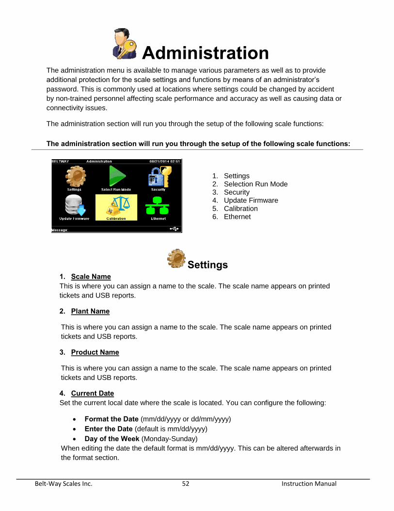
Administration The administration menu is available to manage various parameters as well as to provide
additional protection for the scale settings and functions by means of an administrator’s
password. This is commonly used at locations where settings could be changed by accident
by non-trained personnel affecting scale performance and accuracy as well as causing data or
connectivity issues.
The administration section will run you through the setup of the following scale functions:
Settings 1. Scale Name This is where you can assign a name to the scale. The scale name appears on printed
tickets and USB reports.
2. Plant Name
This is where you can assign a name to the scale. The scale name appears on printed
tickets and USB reports.
3. Product Name
This is where you can assign a name to the scale. The scale name appears on printed
tickets and USB reports.
4. Current Date Set the current local date where the scale is located. You can configure the following:
Format the Date (mm/dd/yyyy or dd/mm/yyyy) Enter the Date (default is mm/dd/yyyy)
Day of the Week (Monday-Sunday)
When editing the date the default format is mm/dd/yyyy. This can be altered afterwards in
the format section.
The administration section will run you through the setup of the following scale functions:
1. Settings 2. Selection Run Mode 3. Security 4. Update Firmware 5. Calibration 6. Ethernet
Belt-Way Scales Inc. 53 Instruction Manual
5. Current Time Set the current local time based on the scale located. You can configure the following:
Format the Time (12hr or 24hr) Enter the Time (12hr or 24Hr)
Select AM or PM (AM or PM)
6. Auto Zero The Auto Zero function automatically adjusts the zero calibration value of the scale. It is
designed to compensate for small changes in the dead load due to material accumulation,
belt tension, or weather conditions. The Auto Zero tolerance can be adjusted from 0 to 1
%. It should be turned off when the belt load is extremely low.
7. Zero Rate Limit The Zero Rate Limit is a function which will prevent weight accumulation on the scale total
if the rate of an empty belt is below a set rate limit. This function is useful if you have a
conveyor that shakes or vibrates excessively due to mechanical issues causing an
unstable rate on the scale. The load sensed and rate displayed by the scale would
possibly fluctuate positive and negative due to the mechanical issues of the conveyor.
You would then set the zero rate limit to the rate that the scale is showing when running
with an empty belt. This positive rate displayed with a belt running empty would be
ignored and not accumulated or add to the total.
8. Negative Rate Error The negative rate error is a way of logging messages when the rate being displayed
exceeds the programmed negative rate value for a programmed period of time. This error
can also be programmed to an alarm output on the I/O Board.
9. Backup / Restore a. Backup
The Backup function will “backup” the following files so they can be restored at
a later time.
Settings Parameters Totals Calibration
Please make sure you have a flash drive installed into the USB’s top port on the
inside of the door before starting this procedure.
10. Test Mode Test Mode allows the scale to simulate production when the belt can't be run.
Both speed and load test modes must be enabled to simulate tons per hour and weight
accumulation. ------------------------------------------------------------------------------------------------------------
Belt-Way Scales Inc. 54 Instruction Manual
Run Mode
Select Run Mode settings allow you to determine the mode in which you wish to use the scale.
1. Weight / Rate 2. Load Out 3. Blending 4. Rate Control 5. Weight ------------------------------------------------------------------------------------------------------------
Security Selecting the Security menu allows you to lock out unauthorized access to certain settings
and functions. You can also setup an Administrator password which needs to be entered
before these functions can be unlocked and performed.
ADMIN This turns on the need for an Admin Password when unlocking features for use.
Please note that even though the features are tagged and listed as locked they
will not be locked unless ADMIN is locked.
PASSWORD Use the Password section to define a new ADMIN password to be used to unlock
the and Lock the various sections of setup and calibration listed above.
The default password is "password". Call Belt-Way for assistance if you can't
access the password protected functions.
----------------------------------------------------------------------------------------------------
You can Lock, Unlock the use of functions and setup a password for the following:
1. Setup Wizard – Lock / Unlock feature use. 2. Calibration – Lock / Unlock feature use. 3. Zero Calibration – Lock / Unlock feature use. 4. Setup Devices – Lock / Unlock feature use. 5. Admin – Lock / Unlock feature use. Lock turns the Admin Code ON. 6. Clear Weight – Lock / Unlock feature use. 7. Passwords – Define a new unique Admin Password.

Belt-Way Scales Inc. 55 Instruction Manual
Update Firmware
The Update Firmware menu walks you through 2 items:
1. Identifying the current firmware installed on the integrator
2. Procedure of installing new firmware onto the integrator.
During a firmware update the existing scale settings and parameters will be
automatically saved and restored after the firmware update is complete so you
will not have to setup and calibrate the scale again.
The firmware may not be backward compatible depending on the changes
made from one version to the next.
Contact Belt-way Scales to confirm compatibility between firmware versions.
------------------------------------------------------------------------------------------------------------
Calibration Selecting Calibration will allow you to view or edit the current values stored for the following
calibrations
1. Trim Factor The Trim Factor is a simple multiplier that controls the weight calculation of the scale. The
default value is 1.000. When all scale parameters are correct, the scale should be
accurate with a trim number very close to 1.000. Increasing the trim number makes the
scale weigh heavier and decreasing the trim number makes the scale weigh lighter.
2. Zero Number The Zero Number is the actual weight (in pounds or kilograms) measured by the scale
when the conveyor belt is completely empty. A properly calibrated zero number will
ensure there is very little weight addition or subtraction when the belt is running empty.
3. Belt Length The Belt Length represents the length of the conveyor and is used for the zero and span
calibration processes. The belt length establishes the length of the belt for one revolution;
therefore the scale knows how long the calibration procedures need to take for single and
multiple revolutions. It is recommended that this measurement be logged via a Belt
Length calibration. If you know the exact belt length then this value can be entered here.
This number is length based and is represented in the units from when the scale was
setup, either in Feet (ft.) or Meters (m).
Use care when adjusting these calibration parameters! Improper values will cause the scale to be inaccurate!
------------------------------------------------------------------------------------------------------------
Belt-Way Scales Inc. 56 Instruction Manual
Ethernet The Ethernet menu is where you will setup the scale for network connectivity with other Ethernet
devices including the Belt-Way remote display and Plant-Connect modems. The native
protocols are Modbus TCP Server and FTP Server. Contact Belt-Way for an extensive list of
data available through Modbus and further instructions for using the FTP server.
The green indicator will appear at the bottom of the screen when an Ethernet connection
is made to the integrator. The settings available for configuration are as follows:
1. DHCP Client Enable DHCP – The server will assign an IP address to the scale. This IP address could
change periodically as it is assigned by the DHCP server. The scale MUST be connected
directly to a DHCP router for this setting to function properly.
Disable DHCP – You must assign a static IP address to the scale. This IP address would be
the same and will not change unless manually edited here.
2. IP Address This is where you would enter the IP Address for the scale. If you selected “Disable DHCP”
above in (1) then this would be your static IP address that would be used.
3. Subnet Mask This is where you would enter the Subnet Mask for the local network that the scale is
connected to. If you selected “Disable DHCP” above in (1) then this Subnet Mask would be
used for the local network.
4. Gateway This is where you would enter your Gateway IP Address for the local network that the scale is
connected to. If you selected “Disable DHCP” above in (1) then this Gateway IP Address
would be used for the local network.
5. Modbus Slave ID The Modbus Slave ID will normally remain at the default of 255 unless it must be changed to
communicate with a networked PLC or software application.
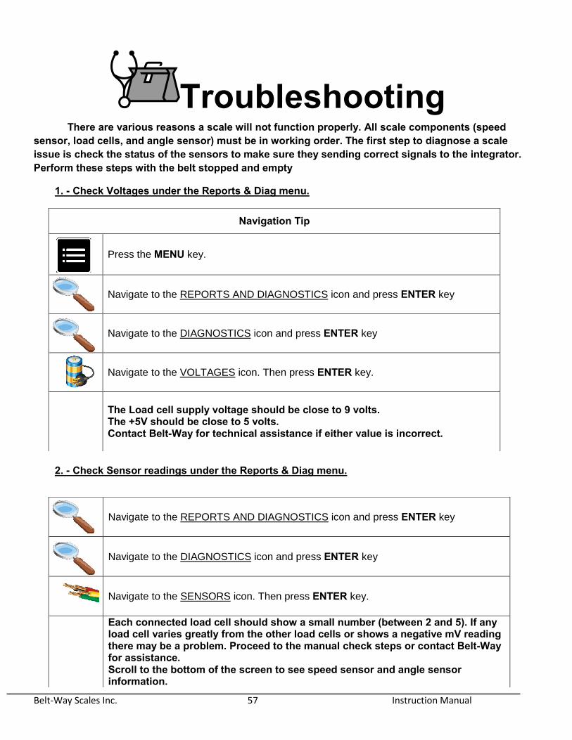
Belt-Way Scales Inc. 57 Instruction Manual
Troubleshooting There are various reasons a scale will not function properly. All scale components (speed sensor, load cells, and angle sensor) must be in working order. The first step to diagnose a scale issue is check the status of the sensors to make sure they sending correct signals to the integrator. Perform these steps with the belt stopped and empty
1. - Check Voltages under the Reports & Diag menu.
2. - Check Sensor readings under the Reports & Diag menu.
Navigation Tip
Press the MENU key.
Navigate to the REPORTS AND DIAGNOSTICS icon and press ENTER key
Navigate to the DIAGNOSTICS icon and press ENTER key
Navigate to the VOLTAGES icon. Then press ENTER key.
The Load cell supply voltage should be close to 9 volts. The +5V should be close to 5 volts. Contact Belt-Way for technical assistance if either value is incorrect.
Navigate to the REPORTS AND DIAGNOSTICS icon and press ENTER key
Navigate to the DIAGNOSTICS icon and press ENTER key
Navigate to the SENSORS icon. Then press ENTER key.
Each connected load cell should show a small number (between 2 and 5). If any load cell varies greatly from the other load cells or shows a negative mV reading there may be a problem. Proceed to the manual check steps or contact Belt-Way for assistance. Scroll to the bottom of the screen to see speed sensor and angle sensor information.
Belt-Way Scales Inc. 58 Instruction Manual
3. - Manually Check Supply Voltage, Millivolt, and Ohm Values
1. Supply/Excitation Voltage Check Leave the load cells plugged in with the integrator powered on . Measure the Voltage between the RED and BLACK load cell wires The reading should be approximately 9 VDC
2. Milli-Volt Check
Set your meter dial & leads to measure Millivolts mV. Measure between the White (-) and Green (+). The Negative lead MUST touch the WHITE wire and Positive lead MUST
touch the GREEN wire. The reading should be a small positive number. Between 1 and 7 mV is common. A negative or zero reading shows the load cell is not function properly. Inspect the mechanical installation of the load cell assembly to ensure there is no material
build-up or binding around the load cell. Have a second person pull down on the load cells to see if the mV reading increases. If no mechanical problems are found the load cell may need to be replaced.
3. Ohms Check
Unplug the load cell connector from the terminal strip. Set your meter dial & leads to measure OHMS (Ώ) . Measure between BLACK(-) & RED (+).
The reading should be approximately 420 Ohms. Measure between White(-) & Green(+).
The reading should be approximately 350 Ohms. If these measurements are good the load cells pass the resistance test. This means that there is no problem with the cable or internal load cell circuit.
For Further assistance please call the office 815 625-5573
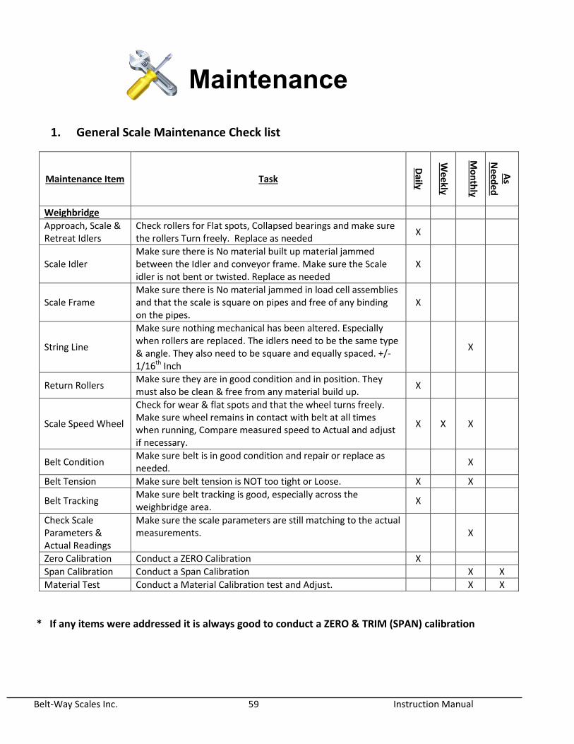
Belt-Way Scales Inc. 59 Instruction Manual
Maintenance
1. General Scale Maintenance Check list
Maintenance Item Task
Daily
Weekly
Mo
nth
ly
As
Need
ed
Weighbridge
Approach, Scale & Retreat Idlers
Check rollers for Flat spots, Collapsed bearings and make sure the rollers Turn freely. Replace as needed
X
Scale Idler Make sure there is No material built up material jammed between the Idler and conveyor frame. Make sure the Scale idler is not bent or twisted. Replace as needed
X
Scale Frame Make sure there is No material jammed in load cell assemblies and that the scale is square on pipes and free of any binding on the pipes.
X
String Line
Make sure nothing mechanical has been altered. Especially when rollers are replaced. The idlers need to be the same type & angle. They also need to be square and equally spaced. +/- 1/16th Inch
X
Return Rollers Make sure they are in good condition and in position. They must also be clean & free from any material build up.
X
Scale Speed Wheel
Check for wear & flat spots and that the wheel turns freely. Make sure wheel remains in contact with belt at all times when running, Compare measured speed to Actual and adjust if necessary.
X X X
Belt Condition Make sure belt is in good condition and repair or replace as needed.
X
Belt Tension Make sure belt tension is NOT too tight or Loose. X X
Belt Tracking Make sure belt tracking is good, especially across the weighbridge area.
X
Check Scale Parameters & Actual Readings
Make sure the scale parameters are still matching to the actual measurements. X
Zero Calibration Conduct a ZERO Calibration X
Span Calibration Conduct a Span Calibration X X
Material Test Conduct a Material Calibration test and Adjust. X X
* If any items were addressed it is always good to conduct a ZERO & TRIM (SPAN) calibration

Belt-Way Scales Inc. 60 Instruction Manual
2. Routine Calibration and Verification Procudures
Routine calibrations consist of conducting:
ZERO Calibration 2-3 times / day or when needed based on stability of empty belt
weight over time
Span Calibration with test weights (when needed)
Material tests (when needed)
3. Physical & Mathematical Verification using Tests Weights
A. Pre checks / measurements
Measure ACTUAL belt speed. (be very accurate) meters/minute ____ m/min (ft/m)
Measure ACTUAL Weigh Span (be very accurate) meters or feet ______m or Ft
Measure ACTUAL Test weight on a LAB scale (be very accurate)kg or pounds ____Kg or Lbs.
How to Calculate Actual Belt Speed without a Tachometer Using a Stop Watch
A. Mark the belt at 1 point
B. On the conveyor mark 2 reference points A & B (20 ft apart) 20 ft
C. Start and run the belt empty
D. Time in seconds how long it takes the mark from point A to B. D = _____seconds
E. Time in seconds how long it takes the mark on the belt to do 1 rev. E = ______seconds
F. Used if you cannot see the belt from where the integrator is mounted for “set Zero”
Calculate belt speed by using the following formula
Belt Speed (ft/min) = 20 feet . Time from A to B in seconds X 60 Seconds
B. Verify the scale Span & Test weight setting reads the same as Actual Measured in #1
Make sure the idler distance matches ACTUAL measured span.
Make sure the Test weight matches ACTUAL measured Test Weight.
Correct if needed.
Press weight rate.
C. Verify the scale belt speed reads the same as Actual Measured belt speed in #1
Make sure Belt speed is the same as Measured belt speed in #1
If belt speed is not the same then the pulley diameter may be manually adjusted to make
the speed match.
This formula is the same for Feet (ft). Replace Meters with Ft. measurement.
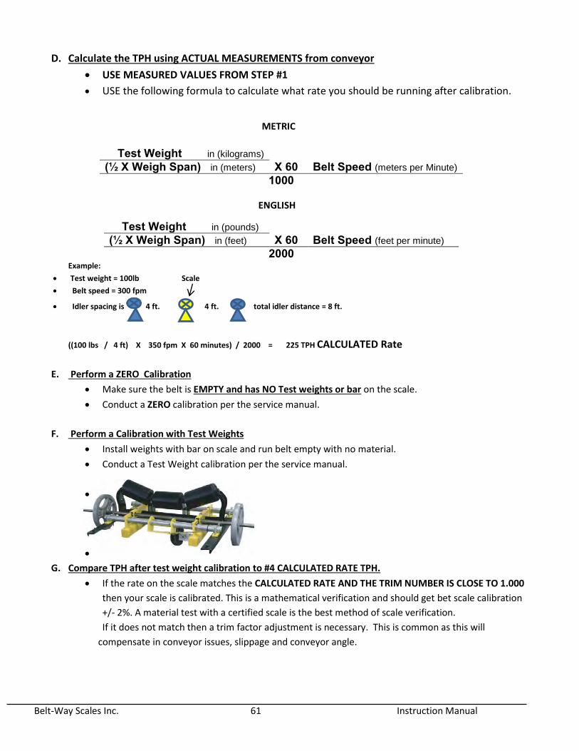
Belt-Way Scales Inc. 61 Instruction Manual
D. Calculate the TPH using ACTUAL MEASUREMENTS from conveyor
USE MEASURED VALUES FROM STEP #1
USE the following formula to calculate what rate you should be running after calibration.
Example:
Test weight = 100lb Scale
Belt speed = 300 fpm
Idler spacing is 4 ft. 4 ft. total idler distance = 8 ft.
((100 lbs / 4 ft) X 350 fpm X 60 minutes) / 2000 = 225 TPH CALCULATED Rate
E. Perform a ZERO Calibration
Make sure the belt is EMPTY and has NO Test weights or bar on the scale.
Conduct a ZERO calibration per the service manual.
F. Perform a Calibration with Test Weights
Install weights with bar on scale and run belt empty with no material.
Conduct a Test Weight calibration per the service manual.
G. Compare TPH after test weight calibration to #4 CALCULATED RATE TPH.
If the rate on the scale matches the CALCULATED RATE AND THE TRIM NUMBER IS CLOSE TO 1.000
then your scale is calibrated. This is a mathematical verification and should get bet scale calibration
+/- 2%. A material test with a certified scale is the best method of scale verification.
If it does not match then a trim factor adjustment is necessary. This is common as this will
compensate in conveyor issues, slippage and conveyor angle.
Test Weight in (kilograms) (½ X Weigh Span) in (meters) X 60 Belt Speed (meters per Minute)
1000
Test Weight in (pounds) (½ X Weigh Span) in (feet) X 60 Belt Speed (feet per minute)
2000
METRIC
ENGLISH

Belt-Way Scales Inc. 62 Instruction Manual
Product Warranty Belt-Way Scales, Inc. ("Belt-Way"), warrants its products only on the terms contained herein.
No one has the right or authority to assume or create any obligation or responsibility,
express or implied, on behalf of or in the name of Belt-Way Scales, Inc., or to bind Belt-Way
Scales, Inc., in any manner whatsoever.
Products manufactured by Belt-Way are warranted to be free of manufacturing defects for a one year period after the original date of purchase. Belt-Way's liability here under is conditioned on dealer, or in the event of a direct sale to a first-end user (then on first-end user) giving notice in writing to Belt-Way of any alleged defect. Such notice must be given immediately upon the discovery of such alleged defect.
If, within the warranty period, any machinery or parts shall be proved to the satisfaction of Belt-Way to be defective, the defective item shall be replaced or, at Belt-Way's option, repaired at Belt-Way's factory.
The right to have defective machinery or parts, repaired or replaced as set forth above, shall constitute the dealer or first-end user's sole and exclusive remedy. No warranty shall apply to machinery, parts or accessories which have been furnished, repaired or altered by others so as (in the opinion of Belt-Way) to have affected the same adversely. Belt-Way cannot and does not warrant or represent that machinery or parts furnished by it will handle specific materials or will produce specific results from such materials.
This warranty does not include damage to the product resulting from accident, misuse, improper
installation or operation. If a component should become defective within the warranty period, we
will repair or replace it free of charge at our option. Defective components must be returned freight
prepaid to Belt-Way or to an authorized Belt-Way service center.
Complete products included with our system that are not manufactured by Belt-Way such as
printers, remote displays, etc. are warranted to the extent that they are warranted to us.
The customer's sole remedy shall be such repair or replacement as is expressly provided above, and
we shall in no event be liable for any incidental or consequential damages arising out of the use or
inability to use this product for any purpose whatsoever.
Some states do not allow the exclusion or limitation of incidental or consequential damages, so the
above limitation or exclusion may not apply to you.
This warranty gives you specific legal rights. You may also have other rights which vary from state to
state. For products purchased outside the United States, see your distributor for warranty.
Belt-Way Scales Inc. 63 Instruction Manual
Limitations and Disclaimer
BELT-WAY SCALES, INC. MAKES NO REPRESENTATION OR WARRANTY OF ANY OTHER KIND, EXPRESS OR
IMPLIED, WITH RESPECT TO THE PRODUCTS, WHETHER AS TO MERCHANTABILITY, FITNESS FOR A
PARTICULAR PURPOSE OR ANY OTHER MATTER, ANY SUCH WARRANTIES BEING HEREBY EXPRESSLY
EXCLUDED. BELT-WAY SCALES, INC. DOES NOT AUTHORIZE ANYONE TO MAKE ANY OTHER WARRANTY
EXCEPT AS STATED HEREIN.
Exclusion of Consequential Damages
BELT-WAY SCALES, INC. SHALL IN NO EVENT BE RESPONSIBLE FOR SPECIAL, INCIDENTAL OR CONSEQUENTIAL
DAMAGES CAUSED BY ANY PRODUCT SOLD HEREUNDER, WHETHER ON THEORIES OF BREACH OF EXPRESS
OR IMPLIED WARRANTIES UNDER THE UNIFORM COMMERCIAL CODE, STRICT LIABILITY, NEGLIGENCE OR ANY
OTHER LEGAL THEORY REGARDLESS OF WHETHER THE LOSS RESULTED FROM ANY GENERAL OR
PARTICULAR REQUIREMENT OR NEED WHICH BELT-WAY SCALES, INC. KNEW ABOUT OR HAD REASON TO KNOW
ABOUT AT THE TIME OF THE SALE OF SUCH PRODUCTS.
BELT-WAY is a registered trademark of Belt-Way Scales, Inc.
FLO-WAY is a registered trademark of Belt-Way Scales, Inc.
Covered by U.S. PATENT 5,696,354
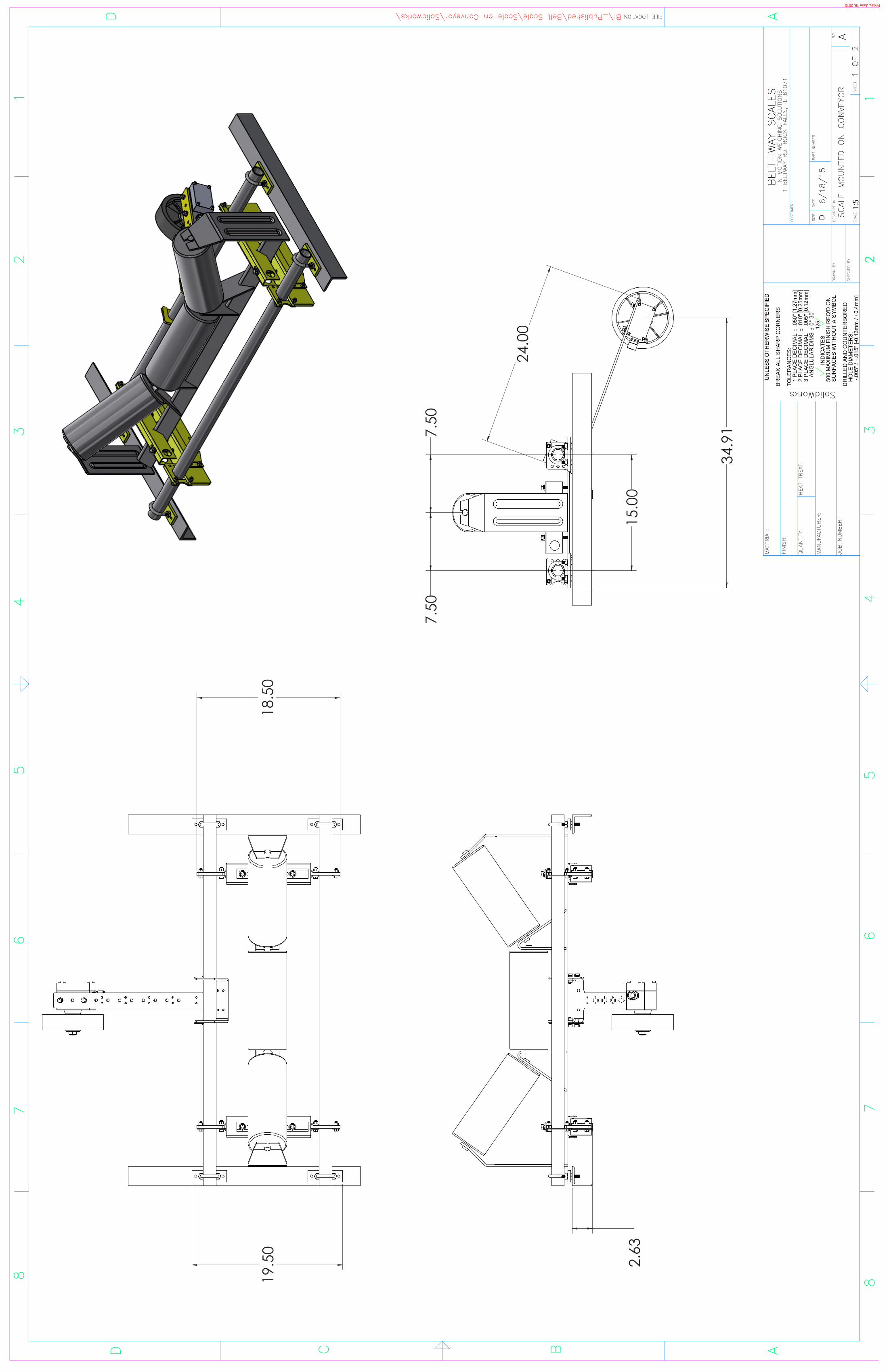
68
75
43
2
125
U
NLE
SS O
THER
WIS
E SP
ECIF
IED
BR
EAK
ALL
SHAR
P C
OR
NER
S
TO
LER
ANC
ES:
1
PLA
CE
DEC
IMAL
.0
50" [
1.27
mm
]
2 P
LAC
E D
ECIM
AL
.010
" [0.
25m
m]
3
PLA
CE
DEC
IMAL
.0
05" [
0.12
mm
]
A
NG
LULA
R D
IMS
0 3
0'
IN
DIC
ATES
5
00 M
AXIM
UM
FIN
ISH
REQ
'D O
N
SU
RFA
CES
WIT
HO
UT
A SY
MBO
L
DR
ILLE
D A
ND
CO
UN
TER
BOR
ED
H
OLE
DIA
MET
ERS:
-
.005
" / +
.015
" [-0
.13m
m /
+0.4
mm
]
QUANTITY:
FINISH:
MATERIAL:
HEAT TREAT:
SolidWorks
CHECKED BY
DRAWN BY
SCALE
DSIZE
DATE
PART NUMBER
1SHEET
DESCRIPTION
CUSTOMER
BELT-WAY SCALES
IN MOTION WEIGHING SOLUTIONS
1 BELTWAY RD. ROCK FALLS, IL 61071
D
13
42
A
56
78
D C B A
REV
FILE LOCATION:
MANUFACTURER:
JOB NUMBER:
2.63
18.5
019
.50
15.0
0
7.50
7.50
34.9
1
24.0
0
SCALE MOUNTED ON CONVEYOR
6/18/15
1:5
1 OF 2
Friday, June 19, 2015
A
B:\_Published\Belt Scale\Scale on Conveyor\Solidworks\

68
75
43
2
125
U
NLE
SS O
THER
WIS
E SP
ECIF
IED
BRE
AK
ALL
SH
ARP
CO
RNER
S
TO
LERA
NCE
S:
1 P
LACE
DEC
IMAL
.0
50" [
1.27
mm
]
2 P
LACE
DEC
IMA
L .0
10" [
0.25
mm
]
3 P
LACE
DEC
IMA
L .0
05" [
0.12
mm
]
A
NG
LULA
R D
IMS
0 3
0'
IN
DIC
ATE
S
500
MAX
IMU
M F
INIS
H R
EQ'D
ON
S
URF
ACE
S W
ITH
OU
T A
SYM
BOL
DRI
LLED
AN
D C
OU
NTE
RBO
RED
HO
LE D
IAM
ETER
S:
-.0
05" /
+.0
15" [
-0.1
3mm
/ +0
.4m
m]
QU
ANTI
TY:
FIN
ISH
:
MAT
ERIA
L:
HEA
T TR
EAT:
SolidWorks
CHEC
KED
BY
DRA
WN
BY
SCAL
EDSIZE
DAT
EPA
RT N
UM
BER
1SH
EET
DES
CRIP
TIO
N
CUST
OM
ER
BELT
-WAY
SCA
LES
IN
MO
TIO
N W
EIG
HIN
G S
OLU
TIO
NS
1 BE
LTW
AY R
D. R
OCK
FAL
LS, I
L 61
071
D
13
42
A
56
78
D C B A
REV
FILE LOCATION:
MAN
UFA
CTU
RER:
JOB
NU
MBE
R:
1
2
3
4
5
6
7
8
13
9
1011
12
ITEM
NO
.D
ESCR
IPTI
ON
QTY
.
1Lo
ad C
ell A
ssem
bly
2
2Le
velin
g Pl
ate
4
3U
nive
rsal
Str
ap4
4Sp
eed
Sens
or W
ith A
rm1
5V-
Bloc
k2
6Sp
eed
Sens
or H
ange
r Str
ap2
7St
eel C
ap S
crew
5/1
6"-1
8 x
1"8
8N
ylon
Loc
k N
ut 5
/16"
-18
8
9St
eel C
ap S
crew
3/8
"-16
x 5
"4
10Fl
at W
ashe
r 3/8
316
SS4
11Lo
ck W
ashe
r 3/8
316
SS8
12H
ex N
ut 3
/8"-
164
13St
eel C
ap S
crew
3/8
"-16
x 1
"4
SCAL
E M
OU
NTE
D O
N C
ON
VEYO
R
6/18
/15
1:3
2 O
F 2
Friday, June 19, 2015
A
B:\_Published\Belt Scale\Scale on Conveyor\Solidworks\
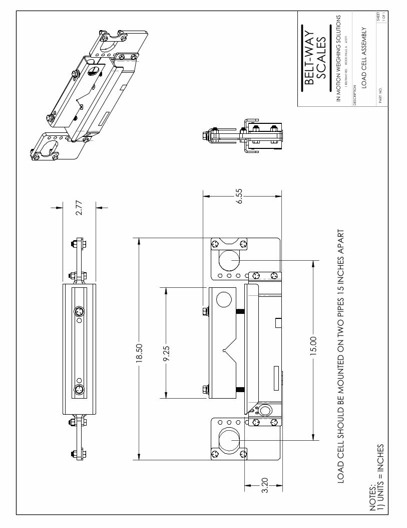
18.
50
9.2
5
6.5
5
3.2
0
15.
00
2.7
7
LOA
D C
ELL
SHO
ULD
BE
MO
UNTE
D O
N T
WO
PIP
ES 1
5 IN
CHE
S A
PART
NO
TES:
1) U
NITS
= IN
CHE
S
LOA
D C
ELL
ASS
EMBL
Y
SHEE
T1
OF
1PA
RT N
O.
BELT
-WA
YSC
ALE
SIN
MO
TION
WEI
GHI
NG
SO
LUTIO
NS
1 BE
LTW
AY
RD.
RO
CK
FALL
S, IL
6
1071
DES
CRI
PTIO
N
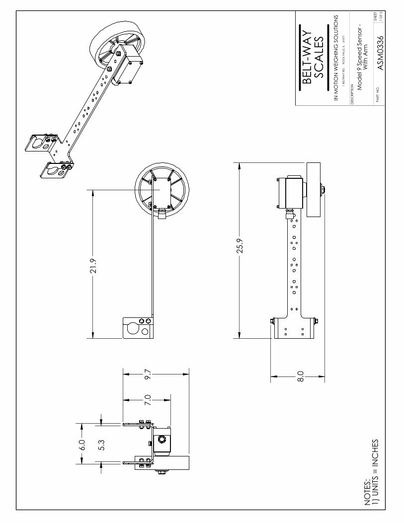
21.
9 5
.3
6.0
7.0
9
.7
25.
9
8.0
NO
TES:
1) U
NITS
= IN
CHE
S
Mod
el 9
Spe
ed S
enso
r -W
ith A
rmSH
EET
1 O
F 2
PART
NO
.
BELT
-WA
YSC
ALE
SIN
MO
TION
WEI
GHI
NG
SO
LUTIO
NS
1 BE
LTW
AY
RD.
RO
CK
FALL
S, IL
6
1071
ASM
0336
DES
CRI
PTIO
N
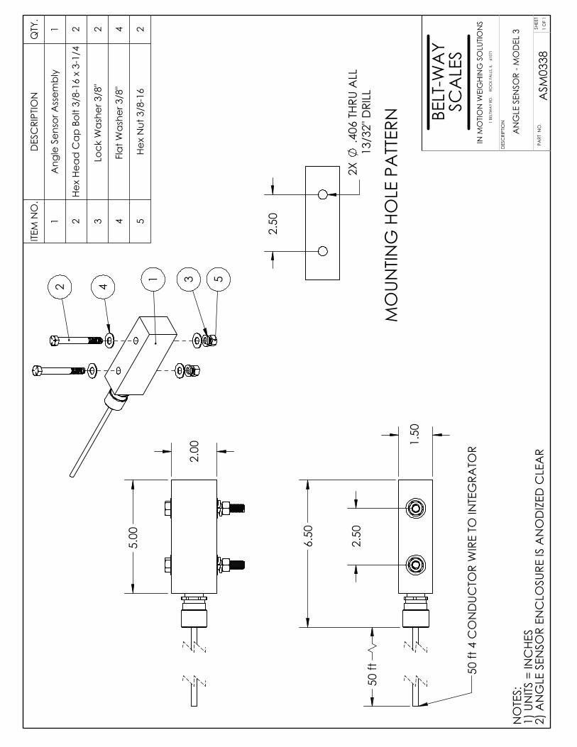
2.5
0
1.5
0
6.5
0
50
ft 50 ft
4 C
ON
DUC
TOR
WIR
E TO
INTE
GRA
TOR
5.0
0
2.0
0
142 3 5
2.5
0
2X
.406
THR
U A
LL13
/32"
DRI
LL
MO
UNTIN
G H
OLE
PA
TTER
N
NO
TES:
1) U
NITS
= IN
CHE
S2)
AN
GLE
SEN
SOR
ENC
LOSU
RE IS
AN
OD
IZED
CLE
AR
ITEM
NO
.D
ESC
RIPT
ION
QTY
.
1A
ngle
Sen
sor A
ssem
bly
1
2He
x He
ad C
ap B
olt 3
/8-1
6 x
3-1/
42
3Lo
ck W
ashe
r 3/8
" 2
4Fl
at W
ashe
r 3/8
" 4
5He
x N
ut 3
/8-1
62
AN
GLE
SEN
SOR
- MO
DEL
3
SHEE
T1
OF
1PA
RT N
O.
BELT
-WA
YSC
ALE
SIN
MO
TION
WEI
GHI
NG
SO
LUTIO
NS
1 BE
LTW
AY
RD.
RO
CK
FALL
S, IL
6
1071
ASM
0338
DES
CRI
PTIO
N
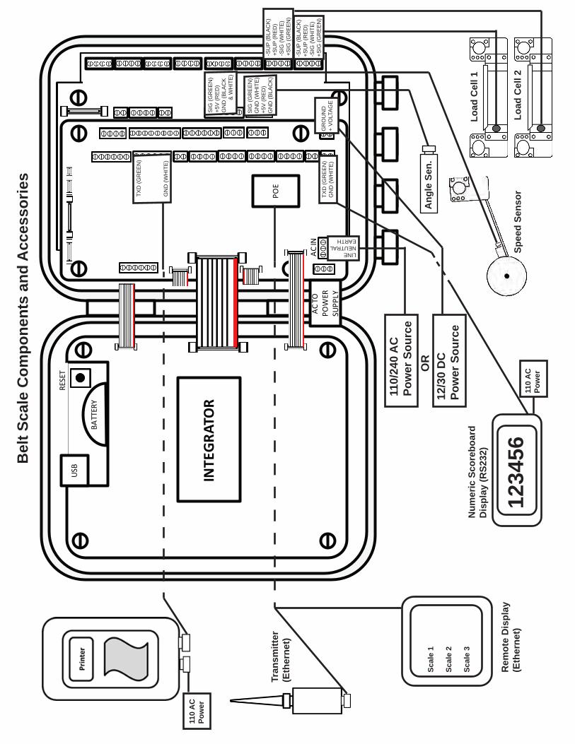
USB
POE
BATT
ERY
RESE
T
AC IN
AC TO
PO
WER
SU
PPLY
INTE
GRAT
OR
Bel
t Sca
le C
ompo
nent
s an
d A
cces
sorie
s
110/
240
AC
Pow
er S
ourc
e
LINENEUTRALEARTH
12/3
0 D
CPo
wer
Sou
rce
GR
OU
ND
+ V
OLT
AG
E
-SU
P (B
LAC
K)
+SU
P (R
ED
)-S
IG (W
HIT
E)
+SIG
(GR
EE
N)
-SU
P (B
LAC
K)
+SU
P (R
ED
)-S
IG (W
HIT
E)
+SIG
(GR
EE
N)
OR
SIG
(GR
EE
N)
GN
D (W
HIT
E)
+5V
(RE
D)
GN
D (B
LAC
K)
SIG
(GR
EE
N)
+5V
(RE
D)
GN
D (B
LAC
K
&
WH
ITE
)
Load
Cel
l 1
Load
Cel
l 2
Ang
le S
en.
Spee
d Se
nsorTX
D (G
RE
EN
)G
ND
(WH
ITE
)
Num
eric
Sco
rebo
ard
Dis
play
(RS2
32)
TXD
(GR
EE
N)
GN
D (W
HIT
E)
1234
5611
0 A
CPo
wer
110
AC
Pow
er
Tran
smitt
er(E
ther
net)
Rem
ote
Dis
play
(Eth
erne
t)
Scal
e 1
Scal
e 2
Scal
e 3
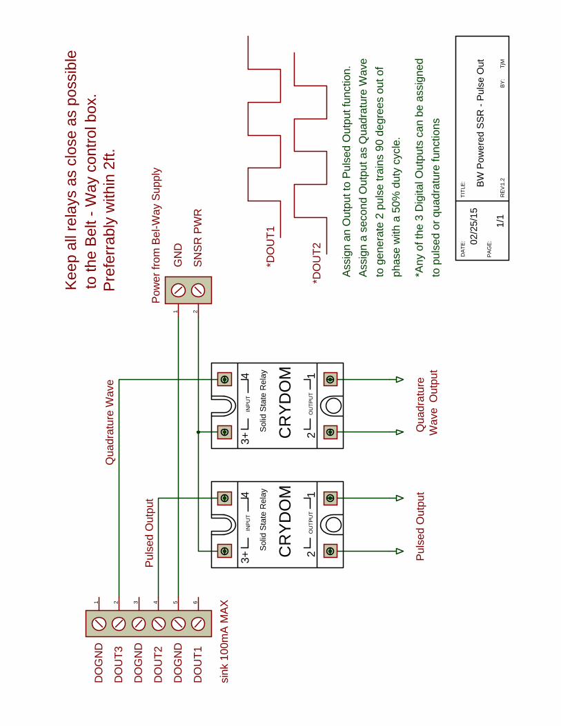
DO
UT1
DO
GN
D
DO
UT2
DO
UT3
DO
GN
D
DO
GN
D
12
43+
INP
UT
OU
TPU
T
Sol
id S
tate
Rel
ay
CR
YD
OM
to th
e B
elt -
Way
con
trol b
ox.
Pre
ferr
ably
with
in 2
ft.
TITL
E:
BY:
DAT
E:
PA
GE
:B
W P
ower
ed S
SR
- P
ulse
Out
02/2
5/15
TjM
1/1
RE
V:1
.2
12
43+
INP
UT
OU
TPU
T
Sol
id S
tate
Rel
ay
CR
YD
OM
Kee
p al
l rel
ays
as c
lose
as
poss
ible
*DO
UT1
*DO
UT2
1 2 3 4 5 6
1 2
GN
D
Pow
er fr
om B
el-W
ay S
uppl
y
SN
SR
PW
R
sink
100
mA
MA
X
Ass
ign
an O
utpu
t to
Pul
sed
Out
put f
unct
ion.
to g
ener
ate
2 pu
lse
train
s 90
deg
rees
out
of
phas
e w
ith a
50%
dut
y cy
cle.
*Any
of t
he 3
Dig
ital O
utpu
ts c
an b
e as
sign
edto
pul
sed
or q
uadr
atur
e fu
nctio
ns
Ass
ign
a se
cond
Out
put a
s Q
uadr
atur
e W
ave
Qua
drat
ure
Wav
e
Pul
sed
Out
put
Pul
sed
Out
put
Qua
drat
ure
Wav
eO
utpu
t

DO
UT1
DO
GN
D
DO
UT2
DO
UT3
DO
GN
D
DO
GN
D
12
43+
INP
UT
OU
TPU
T
Sol
id S
tate
Rel
ay
CR
YD
OM
to th
e B
elt -
Way
con
trol b
ox.
Pre
ferr
ably
with
in 2
ft.
TITL
E:
BY:
DAT
E:
PA
GE
:U
ser P
ower
ed S
SR
- P
ulse
Out
02/2
5/15
TjM
1/1
RE
V:1
.2
12
43+
INP
UT
OU
TPU
T
Sol
id S
tate
Rel
ay
CR
YD
OM
Kee
p al
l rel
ays
as c
lose
as
poss
ible
Pul
sed
Out
put
Qua
drat
ure
Wav
eO
utpu
t
Qua
drat
ure
Wav
e
Pul
sed
Out
put
*DO
UT3
*DO
UT2
1 2 3 4 5 6
GN
D
Use
r Sup
plie
d P
ower
30V
DC
MA
X
sink
100
mA
MA
X
Ass
ign
an O
utpu
t to
Pul
sed
Out
put f
unct
ion.
to g
ener
ate
2 pu
lse
train
s 90
deg
rees
out
of
phas
e w
ith a
50%
dut
y cy
cle.
*Any
of t
he 3
Dig
ital O
utpu
ts c
an b
e as
sign
edto
pul
sed
or q
uadr
atur
e fu
nctio
ns
Ass
ign
a se
cond
Out
put a
s Q
uadr
atur
e W
ave
Related Documents