SPECIFICATIONS SCOTT COMMUNITY COLLEGE – BELMONT CAMPUS ALLIED HEALTH WING CTE ADDITION & REMODEL BELMONT CAMPUS 500 Belmont Road Bettendorf, IA 52722 PROJECT 21002283.01 VOLUME 2 – MECHANICAL, ELECTRICAL, PLUMBING, & TECHNOLOGY JULY 18, 2022

Welcome message from author
This document is posted to help you gain knowledge. Please leave a comment to let me know what you think about it! Share it to your friends and learn new things together.
Transcript

SPECIFICATIONS
SCOTT COMMUNITY COLLEGE – BELMONT CAMPUS
ALLIED HEALTH WING CTE ADDITION & REMODEL
BELMONT CAMPUS
500 Belmont Road
Bettendorf, IA 52722PROJECT 21002283.01
VOLUME 2 – MECHANICAL, ELECTRICAL, PLUMBING,
& TECHNOLOGY
JULY 18, 2022


SCOTT COMMUNITY COLLEGE
BELMONT CAMPUS
ALLIED HEALTH WING
CTE ADDITION & REMODEL
BELMONT CAMPUS
500 Belmont RoadBettendorf, IA 52722
PROJECT 21002283.01
VOLUME 2
MECHANICAL, ELECTRICAL,
PLUMBING, & TECHNOLOGY
JULY 18, 2022
STUDIO 483 ARCHITECTS
201 W. Second Street, Suite 608, Davenport, Iowa 52801Telephone 563-326-2555 Fax 563-326-1108


IMEG #21002025.10 TOC - 1
EICC-Allied Health Wing-Add - Renovation
TABLE OF CONTENTS
DIVISION 03 - CONCRETE
SECTION 03 10 00 - CONCRETE FORMWORKSECTION 03 20 00 - CONCRETE REINFORCEMENTSECTION 03 30 00 - CAST-IN-PLACE CONCRETE
DIVISION 04 - MASONRY
SECTION 04 22 00 - REINFORCED UNIT MASONRY
DIVISION 05 - METALS
SECTION 05 12 23 - STRUCTURAL STEELSECTION 05 31 00 - STEEL DECKSECTION 05 40 00 - COLD-FORMED STEEL FRAMING (CFSF) SYSTEM
DIVISION 22 - PLUMBING
SECTION 22 05 00 - BASIC PLUMBING REQUIREMENTSSECTION 22 05 03 - THROUGH PENETRATION FIRESTOPPINGSECTION 22 05 05 - PLUMBING DEMOLITION FOR REMODELINGSECTION 22 05 29 - PLUMBING SUPPORTS AND ANCHORSSECTION 22 05 53 - PLUMBING IDENTIFICATIONSECTION 22 07 19 - PLUMBING PIPING INSULATIONSECTION 22 10 00 - PLUMBING PIPINGSECTION 22 10 23 - NATURAL GAS AND PROPANE PIPINGSECTION 22 10 30 - PLUMBING SPECIALTIESSECTION 22 40 00 - PLUMBING FIXTURES
DIVISION 23 - HEATING, VENTILATING, AND AIR-CONDITIONING(HVAC)
SECTION 23 05 00 - BASIC HVAC REQUIREMENTSSECTION 23 05 03 - THROUGH PENETRATION FIRESTOPPINGSECTION 23 05 05 - HVAC DEMOLITION FOR REMODELINGSECTION 23 05 13 - MOTORSSECTION 23 05 29 - HVAC SUPPORTS AND ANCHORSSECTION 23 05 53 - HVAC IDENTIFICATIONSECTION 23 05 93 - TESTING, ADJUSTING, AND BALANCINGSECTION 23 07 13 - DUCTWORK INSULATIONSECTION 23 07 19 - HVAC PIPING INSULATIONSECTION 23 09 00 - CONTROLSSECTION 23 31 00 - DUCTWORKSECTION 23 33 00 - DUCTWORK ACCESSORIESSECTION 23 34 23 - POWER VENTILATORSSECTION 23 37 00 - AIR INLETS AND OUTLETSSECTION 23 74 16.12 - PACKAGED ROOFTOP AIR CONDITIONING UNITS 25 TON AND BELOW
IMEG #21002025.10 TOC - 2
EICC-Allied Health Wing-Add - Renovation
SECTION 23 74 16.14 - PACKAGED ROOFTOP AIR CONDITIONING UNITS WITH HIGH PERCENTAGE OUTSIDE AIRSECTION 23 81 26 - SPLIT SYSTEM AIR CONDITIONING UNITSSECTION 23 82 00 - TERMINAL HEAT TRANSFER UNITS
DIVISION 26 - ELECTRICAL
SECTION 26 05 00 - BASIC ELECTRICAL REQUIREMENTSSECTION 26 05 03 - THROUGH PENETRATION FIRESTOPPINGSECTION 26 05 05 - ELECTRICAL DEMOLITION FOR REMODELINGSECTION 26 05 13 - WIRE AND CABLESECTION 26 05 26 - GROUNDING AND BONDINGSECTION 26 05 33 - CONDUIT AND BOXESSECTION 26 05 35 - SURFACE RACEWAYSSECTION 26 05 53 - ELECTRICAL IDENTIFICATIONSECTION 26 09 33 - LIGHTING CONTROL SYSTEMSSECTION 26 22 00 - DRY TYPE TRANSFORMERSSECTION 26 24 16 - PANELBOARDSSECTION 26 24 19 - MOTOR CONTROLSECTION 26 27 26 - WIRING DEVICESSECTION 26 28 13 - FUSESSECTION 26 28 16 - DISCONNECT SWITCHESSECTION 26 28 21 - CONTACTORSSECTION 26 43 00 - SURGE PROTECTION DEVICESSECTION 26 51 19 - LED LIGHTINGSECTION 26 52 15 - EMERGENCY LIGHTING INVERTER
DIVISION 27 - COMMUNICATIONS
SECTION 27 05 00 - BASIC COMMUNICATIONS SYSTEMS REQUIREMENTSSECTION 27 05 03 - THROUGH PENETRATION FIRESTOPPINGSECTION 27 05 05 - TECHNOLOGY DEMOLITION FOR REMODELINGSECTION 27 05 26 - COMMUNICATIONS BONDINGSECTION 27 05 28 - INTERIOR COMMUNICATION PATHWAYSSECTION 27 05 53 - IDENTIFICATION AND ADMINISTRATIONSECTION 27 11 00 - COMMUNICATION EQUIPMENT ROOMS (CER)SECTION 27 13 00 - BACKBONE CABLING REQUIREMENTSSECTION 27 15 00 - HORIZONTAL CABLING REQUIREMENTSSECTION 27 17 10 - TESTINGSECTION 27 17 20 - STRUCTURED CABLING SYSTEM WARRANTY
DIVISION 28 - ELECTRONIC SAFETY AND SECURITY
SECTION 28 05 00 - BASIC ELECTRONIC SAFETY AND SECURITY SYSTEM REQUIREMENTSSECTION 28 16 00 - INTRUSION DETECTION SYSTEMSECTION 28 23 00 - VIDEO SURVEILLANCESECTION 28 31 00 - FIRE ALARM AND DETECTION SYSTEMS
DIVISION 31 - EARTHWORK
SECTION 31 10 00 - SITE CLEARING
IMEG #21002025.10 TOC - 3
EICC-Allied Health Wing-Add - Renovation
SECTION 31 22 00 - GRADINGSECTION 31 23 00 - FOUNDATION EXCAVATING AND BACKFILLINGSECTION 31 23 01 – EXCAVATION & BACKFILL (SITE)SECTION 31 25 00 – EROSION & SEDIMENT CONTROL
DIVISION 32 - EXTERIOR IMPROVEMENTS
SECTION 32 13 13 - CONCRETE PAVEMENTSECTION 32 91 10 - SURFACE RESTORATION
DIVISION 33 - UTILITIES
SECTION 33 10 00 - WATER UTILITIESSECTION 33 41 00 - STORM UTILITY DRAINAGE PIPING
IMEG #21002025.10 03 10 00 - 1
EICC-Allied Health Wing-Add - Renovation
SECTION 03 10 00 - CONCRETE FORMWORK
PART 1 - GENERAL
1.1 SECTION INCLUDES
A. Design, construction and treatment of formwork and related accessories to confine and shape concrete to the required dimensions.
B. Installation of embedded items such as waterstops.
C. Structural notes indicated on the drawings regarding concrete formwork shall be considered a part of this specification.
1.2 RELATED WORK
A. Pertinent Sections of Division 01.
B. Section 03 20 00 - Concrete Reinforcement.
C. Section 03 30 00 - Cast-in-Place Concrete.
1.3 REFERENCES
A. Codes and Standards: Comply with the provisions of the following codes, specifications, and standards except where more stringent requirements are shown or specified. Where provisions of the pertinent codes and standards conflict with this specification, the more stringent provision shall govern.
1. ACI 117 - Specification for Tolerances for Concrete Construction and Materials.2. ACI 301 - Specifications for Structural Concrete.3. ACI 318 - Building Code Requirements for Structural Concrete.4. ACI 347 - Guide to Formwork for Concrete.5. ASTM C31 - Standard Practice for Making and Curing Concrete Test Specimens in the
Field.6. ASTM C39 - Standard Test Method for Compressive Strength of Cylindrical Concrete
Specimens.7. NIST - PS 1: Structural Plywood
1.4 DESIGN REQUIREMENTS
A. Design and engineering of formwork is the responsibility of the Contractor. Design, engineer and construct formwork, shoring, and bracing to conform to Contract Documents and in accordance with building code requirements. Formwork design shall be under direct supervision of a Professional Structural engineer experienced in the design of this work and licensed in the State where the project is located. Design for construction loads, lateral pressure, and requirements of the applicable building code to conform to the required shape, line, and dimensions. Contractor is responsible for formwork camber calculations.

IMEG #21002025.10 03 10 00 - 2
EICC-Allied Health Wing-Add - Renovation
B. Drawings show the design requirements and dimensions for structural strength, but structural drawings do not show all detail dimensions to fit intricate architectural and mechanical detail. Contractor shall construct the concrete work so that it will conform to the clearance required by the architectural, mechanical, and electrical design.
C. Maximum deflection of facing materials forming concrete surfaces exposed to view shall be 1/240 of the center-to-center span between structural members of the formwork.
D. Carry vertical and lateral loads to the ground by a formwork system and in-place construction that has attained adequate strength for that purpose. Where adequate foundations for shores and struts cannot be secured, provide trussed supports.
1.5 SUBMITTALS
A. Product Data: Submit manufacturer's product data, installation instructions and specifications for each of the following:
1. Waterstop profiles2. Form sealer3. Form release agent(s), including certification that agent is compatible with finish4. Form ties and spreaders
B. Testing for Formwork Removal: When methods other than cylinder tests are proposed for determining time for formwork removal, submit data on methods for approval.
C. Shop Drawings: Prepare and submit shop drawings for formwork, including dimensional layout for foundations, beams, columns, piers, walls and slabs.
D. Pour Sequence: Submit sequence of concrete operations for supported structural slab, beams, columns, and walls.
E. Shoring and Re-shoring: Submit proposed schedule and sequence of stripping formwork, shoring removal, and installing and removing reshoring.
F. Construction Joints: Submit layout of construction joints and details of construction joints.
1.6 COORDINATION
A. Coordinate with other sections of work that require attachment of components to formwork.
B. If formwork is placed after reinforcement, resulting in insufficient concrete cover to reinforcement, request instructions from the Owner's Representative or Architect or Structural Engineer before proceeding.
PART 2 - PRODUCTS
2.1 MATERIALS AND ACCESSORIES
A. Formwork Accessories: Use commercially manufactured accessories for formwork accessories partially or completely embedded in concrete, including ties and hangers.
B. Sealer: Clear, penetrating, synthetic resin sealer.
IMEG #21002025.10 03 10 00 - 3
EICC-Allied Health Wing-Add - Renovation
C. Formwork Release Agent: Use commercially manufactured form release agents that will prevent formwork absorption of moisture, prevent bond with concrete, and will not stain the concrete surface. Reapply to cleaned forms before each reuse. Formwork release agent shall be compatible with paint or any other finish applied to the concrete; submit data indicating compatibility.
D. Waterstops: Waterstops shall be a flexible butyl rubber and bentonite clay compound that swells upon contact with water.
1. Manufacturers:
a. CETCO - Waterstop RXb. Greenstreak - Swellstopc. J.P. Specialties - Earth Shield (Type 20 & 23) Waterstop
E. Form Material:
1. No aluminum shall be allowed in the concrete work unless coated to prevent aluminum-concrete reaction.
2. Concrete form materials must be used in a manner to provide the surface finish specified.3. Design formwork in accordance with the provisions of the building code or the following
standards if not covered in the building code:
a. Wood - AWC "National Design Specification".b. Plywood - American Plywood Association "Plywood Design Specification".c. Steel - AISC "Manual of Steel Construction".d. Aluminum - Aluminum Association "Aluminum Construction Manual"e. Concrete - ACI 318.f. Other materials - as directed by manufacturer.
F. Chamfer Strips:
1. Chamfer strips shall be the size as indicated on the drawings. Provide in maximum possible lengths.
2.2 FORM FINISHES
A. Rough Form Finish:
1. Concrete surfaces not exposed to view in the finished work shall have a rough-form finish. No form-facing material is specified for rough-form finish.
2. Set and maintain forms so finished concrete dimensions shall conform to the tolerances. Rough form finish is Designated Surface Finish-1.0 from ACI 301, except that surface tolerance Class C is required as specified in ACI 117.
B. Smooth Form Finish:
1. Concrete surfaces exposed to view in the finished work or surfaces to receive finishes of any type (paint, textured paint, etc.) shall have a smooth form finish. Form-facing material shall be plywood, tempered concrete-form-grade hardboard, metal, plastic, paper, or other acceptable material capable of producing the desired finish. Form-facing material shall produce a smooth, uniform texture on the concrete. Do not use form facing material with raised grain, torn surfaces, worn edges, patches, dents, or other defects that might impair the texture of the concrete surfaces.

IMEG #21002025.10 03 10 00 - 4
EICC-Allied Health Wing-Add - Renovation
2. Set and maintain forms so finished concrete dimensions shall conform to the tolerances. Smooth form finish is Designated Surface Finish-3.0 from ACI 301, including surface tolerance Class A as specified in ACI 117.
C. Patching and repairing concrete finishes are specified under Section 03 30 00.
2.3 FABRICATION AND MANUFACTURE
A. Form Ties and Spreaders: Factory-fabricated, removable or snap-off metal or glass-fiber-reinforced plastic form ties designed to resist lateral pressure of fresh concrete on forms, hold inner and outer forms for vertical concrete together, and to prevent spalling of concrete on removal.
1. Furnish units that will leave no corrodible metal closer than 1-1/2 inch to the plane of the exposed concrete surface.
2. Furnish ties that, when removed, will leave holes not larger than 1 inch in diameter in the concrete surface.
3. Furnish ties with integral water-barrier plates to walls indicated to receive dampproofing or waterproofing.
4. At horizontal pour lines, locate ties not more than 6" below the pour lines. Tighten after concrete has set and before the next pour is made.
5. For exposed concrete surfaces, provide form ties of removable type with permanent plugs and a system approved by the Architect for fixing the plugs in place.
B. Waterstops: Fabricate pieces of premolded waterstop with a maximum practicable length to hold the number of end joints to a minimum. Fabricate joints in waterstops in accordance with the manufacturer's recommendations.
PART 3 - EXECUTION
3.1 CONSTRUCTION OF TEMPORARY FORMWORK
A. In accordance with ACI 301, construct formwork:
1. Design, erect, shore, brace, and maintain formwork to support vertical, lateral, static, and dynamic loads, and construction loads that might be applied, until the concrete structure can support such loads.
2. Obtain approval before framing openings in structural members not indicated on the drawings.
B. Fabricate forms for easy removal without hammering or prying against concrete surfaces.
1. Provide crush or wrecking plates where stripping may damage cast concrete surfaces.2. Provide top forms for inclined surfaces where slope is too steep to place concrete with
bottom forms only.3. Chamfer wood inserts for forming keyways, reglets, recesses, and the like to allow wood
to swell without spalling concrete and to ensure easy removal.
C. Where end-of-work sequence requires a joint in the concrete, provide adequately designed additional formwork. Extend reinforcement through formwork as indicated on the drawings. Location of the construction joint is subject to approval by the Architect and the Structural Engineer.

IMEG #21002025.10 03 10 00 - 5
EICC-Allied Health Wing-Add - Renovation
D. Forms for Exposed Concrete:
1. At construction joints, lap contact surface of the form sheathing for flush surfaces exposed to view over the hardened concrete in the previous placement by not more than 1 inch. Ensure formwork is held firmly against hardened concrete to prevent offsets or loss of mortar at construction joints and to maintain a true surface.
2. Provide watertight formwork when architectural exposed concrete is specified.3. Unless specified in the Contract Documents, construct formwork so concrete surfaces
conform to tolerance limits. The class of surface for offset between adjacent pieces of formwork facing material shall be Class C, unless specified otherwise.
4. Do not use metal cover plates for patching holes or defects in forms.5. Provide sharp, clean corners at intersecting plans, without visible edges or offsets.6. Fill all unwanted joint openings with specified joint filler and finish flush to match adjacent
form surfaces.
E. Construct formwork for wall openings to facilitate removal and to counteract swelling of wood formwork. Keep wood forms wet as necessary to prevent shrinkage.
F. Do not use rust-stained steel form-facing material.
G. Provide temporary openings at the base of column and wall formwork and at other points where necessary to facilitate cleaning and inspection.
H. Unless noted otherwise, all footings shall be centered under walls, piers, or columns.
I. Provisions for Other Trades:
1. Place sleeves, inserts, anchors, and embedded items required for adjoining work or for support of adjoining work prior to concrete placement.
2. Position and support expansion joint material and other embedded items to prevent displacement. Fill voids in sleeves, inserts, and anchor slots temporarily with readily removable material to prevent entry of concrete into voids.
J. Projecting corners of beams, walls and columns shall be formed with a 3/4-inch chamfer, unless noted otherwise on architectural drawings.
K. Cleaning:
1. Clean surfaces of formwork and embedded materials of mortar, grout, and foreign material before concrete is placed.
2. Cover surfaces of formwork with acceptable formwork release agent. Apply form release agent before placing reinforcing steel and concrete according to manufacturer's written instructions. Do not allow formwork release agent to puddle in forms. Do not allow formwork release agent to contact reinforcing steel or hardened concrete against which fresh concrete is to be placed. Do not apply form release agent to concrete surfaces receiving special finishes or applied coverings affected by the agent.
3. Clean and inspect formwork immediately before concrete is placed.
L. Install void forms in accordance with manufacturer's recommendations. Protect forms from moisture or crushing.
IMEG #21002025.10 03 10 00 - 6
EICC-Allied Health Wing-Add - Renovation
3.2 COORDINATION
A. Install all required pipe sleeves, cavities or slots. Notify appropriate trades in due time so they may furnish information and make necessary installations. Check sizes, location and alignment of all openings, frames and other work, which are to be built-in including electrical boxes and conduit.
B. Layout the run of partitions and establish location of openings so other trades may properly locate their work.
C. Core drilling concrete is not permitted unless noted otherwise or approved in writing by the Architect. Notify the Architect in advance of conditions not shown on the drawings.
3.3 INSTALLATION OF EMBEDDED ITEMS
A. Built-In Items:
1. Confirm with Architect that all materials to be embedded are suitable for embedment in concrete.
2. Build in anchors, inserts, and other devices indicated or required for various portions of work.
3. Build in sleeves, thimbles, and other items furnished or set in place by other trades.4. Accurately position and support all embedded items prior to concrete placement. Secure
embedded items against displacement during concrete placement operations.5. Fill voids with readily removable material to prevent entry of concrete into voids.6. Mechanical and Electrical shall provide and set required sleeves.7. Coordinate setting of all embedded items.
B. Waterstops:
1. Locate waterstops in joints where indicated on the drawings.2. Build in waterstops using longest unbroken lengths possible to hold the number of end
splices to a minimum.3. Form splices and intersections strictly according to the manufacturer's instructions so
waterstops are continuous and develop an effective watertight joint.4. In general, waterstops should be located just behind outermost layer of reinforcing. Do
not place waterstops closer than 2" from face of concrete.
3.4 TOLERANCES
A. Construction formwork to maintain tolerances required by ACI 301 and ACI 117.
3.5 REMOVAL OF FORMS
A. When removal of formwork is based on concrete reaching a specified compressive strength, concrete will be presumed to have reached this strength when either of the following requirements has been met:
1. Test cylinders, molded and cured under the same conditions for moisture and temperature as used for the concrete they represent, have reached the specified compressive strength.
IMEG #21002025.10 03 10 00 - 7
EICC-Allied Health Wing-Add - Renovation
2. Concrete has been cured in accordance with the specifications for the same length of time as laboratory-cured cylinders, which have reached the specified strength. Determine the length of time concrete has been cured in the structure by the cumulative number of days or fractions thereof, not necessarily consecutive, during which the temperature of the air in contact with the concrete is above 50°F and the concrete has been damp or thoroughly sealed from evaporation and loss of moisture.
B. Forms shall remain in place for the following periods of time. These periods represent cumulative number days or hours, not necessarily consecutive, during which the temperature of the air surrounding the concrete is above 50°F:
1. Walls, Grade Beams, Columns, Sides of Beams, Girders and Footings: 67% specified compressive strength or minimum 24 hours.
C. When finishing is required, remove forms as soon as removal operations will not damage concrete.
D. Remove top forms on sloping surfaces of concrete as soon as removal will not allow concrete to sag. Perform needed repairs or treatment required at once and follow immediately with specified curing.
E. Loosen wood formwork for wall openings when this can be accomplished without causing damage to concrete.
F. Do not allow removal of formwork to damage the fresh concrete for columns, walls, sides of beams, and other parts supporting the weight of the concrete. Perform needed repair and treatment required on vertical surfaces at once and follow immediately with specified curing.
3.6 FASTENER REMOVAL
A. Remove all protruding fasteners left as a result of securing inserts to forms by Contractor responsible for insert.
B. Cutting flush with surface is not acceptable.
C. Patch exposed concrete surfaces if damaged during fastener removal process.
3.7 REMOVING AND REUSING FORMS
A. Clean and repair surfaces of forms to be reused in the Work. Split, frayed, delaminated, or otherwise damaged form-facing material will not be acceptable for exposed surfaces. Apply new form-release agent.
B. When forms are reused, clean surfaces, remove fins and laitance, and tighten to close joints. Align and secure joints to avoid offsets. Do not use patched forms for exposed concrete surfaces unless approved by the Architect.
END OF SECTION 03 10 00
IMEG #21002025.10 03 20 00 - 1
EICC-Allied Health Wing-Add - Renovation
SECTION 03 20 00 - CONCRETE REINFORCEMENT
PART 1 - GENERAL
1.1 SECTION INCLUDES
A. Fabrication and placement of reinforcing steel for concrete and all related accessories.
B. Reinforcing steel for use in bond beams, masonry columns, and lintels is specified in Division 4 and is not a part of the work in this section.
C. Structural notes indicated on the drawings regarding concrete reinforcement shall be considered a part of this specification.
1.2 RELATED WORK
A. Pertinent Sections of Division 01.
B. Section 03 10 00 - Concrete Formwork.
C. Section 03 30 00 - Cast-in-Place Concrete.
1.3 REFERENCES
A. Codes and Standards: Comply with the provisions of the following codes, specifications, and standards, except where more stringent requirements are shown or specified. Where provisions of other pertinent codes and standards conflict with this specification, the more stringent provision shall govern.
1. ACI 117 - Specification for Tolerances for Concrete Construction and Materials.2. ACI 301 - Specifications for Structural Concrete.3. ACI 318 - Building Code Requirements for Structural Concrete.4. ACI SP-066 - ACI Detailing Manual.5. ASTM A184 - Standard Specification for Welded Deformed Steel Bar Mats for Concrete
Reinforcement.6. ASTM A775 - Standard Specification for Epoxy-Coated Steel Reinforcing Bars.7. ASTM A934 - Standard Specification for Epoxy-Coated Prefabricated Steel Reinforcing
Bars 8. ASTM A1064 - Standard Specification for Carbon-Steel Wire and Welded Wire
Reinforcement, Plain and Deformed, for Concrete.9. AWS D1.4 - Structural Welding Code - Reinforcing Steel.10. AWD D1.8 - Structural Welding Code - Seismic Supplement.11. Concrete Reinforcing Steel Institute (CRSI) - Manual of Standard Practice.

IMEG #21002025.10 03 20 00 - 2
EICC-Allied Health Wing-Add - Renovation
1.4 SUBMITTALS
A. Placing Drawings: Submit placing drawings showing fabrication dimensions and locations for placement of reinforcement and reinforcement accessories. Indicate bar sizes, spacing, locations, and quantities of reinforcing steel, bending and cutting diagrams, anchors, and supporting and spacing devices. Dowels shall be shown in placing drawings for the element that is to be placed first. Reinforcing steel descriptions or shop drawings shall be inch-pound sizes.
B. Product Data: Submit product data sheets for all specified products.
C. Manufacturer's Certifications:
1. Submit mill certifications at time of delivery.2. Submit carbon equivalent (CE) for reinforcing bars to be welded.
D. Splices: Submit request for splices not indicated in the Contract Documents. Request shall indicate locations, types, and lengths of splices for approval.
E. Field Bending: Submit requests and procedure for field bending or straightening of reinforcement partially embedded in concrete not described in the Contract Documents.
F. Reinforcement Relocation: Submit requests to adjust reinforcement spacing necessitated by conflicts with other reinforcement, conduits, etc. for approval.
G. Welding Procedure Specifications: For welding of reinforcing steel, include designations of processes (e.g. SMAW, GAMW, FCAW, etc.), weld symbols, and details. All WPS shall be qualified by current Procedure Qualification Record (PQR) per AWS D1.4 and approved by the Structural Engineer.
H. Epoxy Coating: Submit product data for the proposed coating material.
I. Supports for Coated Reinforcement: Submit description of reinforcement supports and material for fastening coated reinforcement.
J. Alternative Reinforcement: Submit request to relocate any reinforcing bars that exceeds placement tolerances.
1.5 COORDINATION
A. Coordinate reinforcement installation with the placement of formwork and other embedded items such as inserts, conduit, pipe sleeves, drains, metal supports, anchor rods, etc.
1.6 DELIVERY, STORAGE AND HANDLING
A. Deliver reinforcement to the jobsite in bundles sorted and labeled with durable tags indicating bar size, length, and shop drawing mark. Bundles shall also bear testing laboratory tags indicating identified steel.
B. Store elevated clear of ground and protect at all times from contamination and deterioration.
C. Prevent bending, coating with earth, oil, or other material, or otherwise damaging the reinforcement.
IMEG #21002025.10 03 20 00 - 3
EICC-Allied Health Wing-Add - Renovation
D. For handling coated reinforcement, use equipment having contact areas padded to avoid damaging the coating. Lift bundles of coated reinforcement at multiple pick points to prevent bar-to-bar abrasion from sags in the bundles.
E. Do not drop or drag coated reinforcement. Take all necessary steps to minimize damage to coating. Damaged coatings shall be patched.
PART 2 - PRODUCTS
2.1 MATERIALS
A. Bar Deformations: Bars used for reinforcement shall be deformed except column spirals and welded wire reinforcement, which may be plain.
B. Reinforcing Steel: Reinforcing steel shall conform to the ASTM standard and grade indicated in the General Notes on the drawings.
C. Epoxy-Coated Reinforcing Bars: Steel for epoxy-coated reinforcing bars shall conform to the ASTM standard listed in the General Notes on the drawings.
1. Manufacturers:
a. E.I. DuPont De Nemours Company, Inc. - Flintflex 531-6080.b. Cook Paint and Varnish Company - Epoxy Power 720-A-009.c. Polymer Corporation - Corvel ECA-1558-Red-27000.d. Armstrong Products Company - Epoxiplate 346, 347 or 348.e. Mobil Chemical Company - Mobilox 1004-R-2.f. 3M - ScotchKote 213.g. Napco Corporation - Nap-Gard 7-2000.
D. Epoxy Patching Material: Use only patching material approved by epoxy coating manufacturer, compatible with epoxy coating and inert in fresh and hardened concrete. The maximum amount of repaired damaged areas shall not exceed 2 percent of the surface area in each lineal foot of each bar. Bars with damaged epoxy-coating areas exceeding this limit are to be rejected.
E. Welded Wire Reinforcement: Welded wire reinforcement shall conform to the ASTM standard indicated in the General Notes on the drawings.
F. Epoxy-Coated Welded Wire Reinforcement: Epoxy-coated welded wire reinforcement shall conform to ASTM A884.
G. Joint Dowel Bars: Plain-steel bars. Cut bars true to length with square ends and free of burrs.
H. Epoxy-Coated Joint Dowel Bars: Plain steel bars. Cut bars true to length with square ends and free of burrs. Patch with epoxy material.

IMEG #21002025.10 03 20 00 - 4
EICC-Allied Health Wing-Add - Renovation
I. Bar Supports: Bolsters, chairs, spacers, and other devices for spacing, supporting, and fastening reinforcing bars and welded wire reinforcement in place. Manufacture bar supports according to CRSI's "Manual of Standard Practice" from steel wire, plastic, precast concrete, or fiber-reinforced concrete of greater compressive strength than concrete, and as follows:
1. For concrete surfaces exposed to view where legs of wire bar supports contact forms, use CRSI Class 1 plastic-protected or CRSI Class 2 stainless-steel bar supports.
2. For epoxy-coated reinforcement, use epoxy-coated or other dielectric-polymer-coated wire bar supports.
3. Concrete cast against earth: Bars may be supported by precast concrete bricks or approved prefabricated wire bar supports complying with CRSI recommendations with footpads large enough to support the weight of the bars and construction traffic without being pushed into underlying grade. Precast concrete blocks shall have a minimum compressive strength of 6,000 psi.
2.2 FABRICATION
A. Fabrication Tolerances: Reinforcing steel shall be shop fabricated within tolerances according to ACI 117 and other applicable codes, and shall conform in size, shape, quantity, dimensions, etc. to the construction drawings and approved shop drawings.
B. Bar Condition: Bars shall be free from mill scale, excessive rust, and other coatings, which would reduce or destroy the bond with the concrete. Wipe oil from forms before reinforcement is placed on or adjacent to so that oil will not be tracked over or in any way come into contact with the reinforcement.
C. Bars Bending: Bars shall be bent cold, and no method of fabrication shall be used which would be injurious to the material. Heating of bars for bending is not permitted.
D. Identification: After fabrication, bars shall be sorted, bundled, and tagged with metal tags bearing the bar mark before delivery to the jobsite.
E. Splicing:
1. Continuous reinforcing in beams and grade beams shall be lapped as follows unless noted otherwise:
a. Top bars: Midspanb. Bottom bars: Directly over support
2. Locate reinforcing splices not indicated on drawings at point of minimum stress. Review location of splices with the Structural Engineer and obtain written approval prior to proceeding.
F. Where beams and grade beams are simple span, top bars shall be continuous for full length and hooked down at each end.
G. Reinforcing for continuous footings shall extend into spread footings a minimum of 2'-0".
H. Bending of Epoxy-Coated Bars: Bending of epoxy coated reinforcing bars shall conform to the epoxy manufacturer's specified requirements.
I. Dowels between footings and walls or columns shall be the same grade, size and spacing or number as the vertical reinforcing respectively, unless noted otherwise.

IMEG #21002025.10 03 20 00 - 5
EICC-Allied Health Wing-Add - Renovation
J. Epoxy Coating Applications: Prepare bar in accordance with requirements of epoxy manufacturer. Coating shall be applied to the cleaned surface as soon as possible after cleaning and before visible oxidation of the surface occurs, but in no case shall more than eight hours elapse.
K. Epoxy Coating Thickness: Electrostatically apply coating as specified by powder coating supplier.
1. Thickness after curing: 7 mils with a tolerance of plus 3 mils and minus 2 mils.2. Check coating visually after cure for continuity. It shall be free from holes, voids,
contamination, cracks, and damaged areas. Patch defects in accordance with manufacturer's recommendations.
PART 3 - EXECUTION
3.1 PLACING
A. Reinforcement Relocation: When necessary to move reinforcement beyond the specified spacing to avoid interference with other reinforcement, or embedded items, submit resulting arrangement of reinforcement to Structural Engineer for approval.
B. Reinforcement Cutting: Cutting of reinforcement which conflicts with embedded objects is not acceptable.
C. Welded Wire Reinforcement: Extend welded wire reinforcement to within 1 inch of the concrete edge. Lap edges and ends of fabric sheets a minimum of two full mesh squares. Lace edges with 16-gauge tie wire. Support welded wire reinforcement during placing of concrete to assure required positioning in the slab. Do not place wire reinforcement on grade or metal deck and raise into position in freshly-placed concrete.
D. Wire Tie Orientation: Set wire ties so ends are directed away from the concrete surface.
E. Slab on Grade Reinforcement Placement: Place shrinkage and temperature reinforcement 1/3 of the slab thickness from the top surface of the slabs on grade unless noted otherwise on the drawings.
F. Do not cut, displace, or puncture vapor retarder. Repair damage and reseal vapor retarder before placing concrete.
G. Support for Reinforcement: Unless noted otherwise, supports for reinforcement shall have Class 2 protection as defined in the CRSI Manual of Standard Practice. Submit data on supports indicating class of protection at all different locations for approval. Supports shall not be used as bases for runways for concrete-conveying equipment and similar construction loads. Do not place reinforcing bars more than 2" beyond last leg of any continuous bar support.
H. Support for Coated Reinforcement: Supports for coated reinforcement shall have Class 1 protection as defined in the CRSI Manual of Standard Practice. Submit data on supports and coatings for approval.
I. Support for Bars in Concrete Cast on Ground: Bar supports for slabs on grade, grade beams, footings, and all other concrete cast directly onto grade shall be supported at an average spacing of 4 feet or less in each direction.
IMEG #21002025.10 03 20 00 - 6
EICC-Allied Health Wing-Add - Renovation
J. Securing Reinforcing Bars: All bars must be placed, spaced, secured, and supported prior to casting concrete. Bars embedded in hardened or partially hardened concrete shall not be bent unless approved in writing prior to placement by the Structural Engineer.
K. Foot Traffic: Restrict foot traffic over the slab on grade reinforcing after it has been properly positioned.
L. Reinforcement at Expansion Joints: Do not continue reinforcement or other embedded metal items bonded to concrete through expansion joints. Dowels bonded on only one side of a joint and waterstops may extend through joint.
M. Pumping Concrete: When using a pump to place concrete, pump hose shall be supported directly on forms. Do not allow hose to rest on reinforcing bars if doing so could cause displacement of bars.
END OF SECTION 03 20 00

IMEG #21002025.10 03 30 00 - 1
EICC-Allied Health Wing-Add - Renovation
SECTION 03 30 00 - CAST-IN-PLACE CONCRETE
PART 1 - GENERAL
1.1 SECTION INCLUDES
A. All items required for executing and completing the cast-in-place concrete work and related work shown on the drawings or specified herein. Work shall include installation of items furnished in other sections of these specifications.
B. Concrete paving, walks, and curbs are specified in Division 3 or 32.
C. Structural notes indicated on the drawings regarding cast-in-place concrete shall be considered a part of this specification.
1.2 RELATED WORK
A. Pertinent Sections of Division 01.
B. Section 03 10 00 - Concrete Formwork.
C. Section 03 20 00 - Concrete Reinforcement.
D. Section 03 38 10 - Unbonded Post-Tensioned Concrete.
E. Section 05 31 00 - Steel Deck.
1.3 REFERENCES
A. Codes and Standards: Comply with the provisions of the following codes, specifications, and standards, except where more stringent requirements are shown or specified. Where any provision of other pertinent codes and standards conflict with this specification, the more stringent provision shall govern.
1. ACI 117 - Specification for Tolerances for Concrete Construction and Materials.2. ACI 301 - Specifications for Structural Concrete.3. ACI 302.1R - Guide to Concrete Floor and Slab Construction.4. ACI 302.2R - Guide for Concrete Slabs that Received Moisture-Sensitive Flooring
Materials.5. ACI 303.1 - Standard Specification for Cast-in-Place Architectural Concrete.6. ACI 304R - Guide to Measuring, Mixing, Transporting, and Placing Concrete.7. ACI 305.1 - Specification for Hot Weather Concreting.8. ACI 306.1 - Guide to Cold Weather Concreting.9. ACI 308R - Guide to External Curing of Concrete.10. ACI 309R - Guide for Consolidation of Concrete.11. ACI 318 - Building Code Requirements for Structural Concrete.12. ACI 347R - Guide to Formwork for Concrete.13. ASTM C31 - Standard Practice for Making and Curing Concrete Test Specimens in the
Field.14. ASTM C33 - Standard Specification for Concrete Aggregates.
IMEG #21002025.10 03 30 00 - 2
EICC-Allied Health Wing-Add - Renovation
15. ASTM C39 - Standard Test Method for Compressive Strength of Cylindrical Concrete Specimens.
16. ASTM C42 - Standard Test Method for Obtaining and Testing Drilled Cores and Sawed Beams of Concrete.
17. ASTM C88 - Standard Test Method for Soundness of Aggregates by Use of Sodium Sulfate or Magnesium Sulfate.
18. ASTM C94 - Standard Specification for Ready-Mixed Concrete.19. ASTM C131 - Standard Test Method for Resistance to Degradation of Small-Size Coarse
Aggregate by Abrasion and Impact in the Los Angeles Machine.20. ASTM C138 - Standard Test Method for Density (Unit Weight), Yield, and Air Content
(Gravimetric) of Concrete.21. ASTM C143 - Standard Test Method for Slump of Hydraulic Cement Concrete.22. ASTM C150 - Standard Specification for Portland Cement.23. ASTM C157 - Standard Test Method for Length Change of Hardened Hydraulic-Cement
Mortar and Concrete24. ASTM C171 - Standard Specification for Sheet Materials for Curing Concrete.25. ASTM C172 - Standard Practice for Sampling Freshly Mixed Concrete.26. ASTM C173 - Standard Test Method for Air Content of Freshly Mixed Concrete by the
Volumetric Method.27. ASTM C231 - Standard Test Method for Air Content of Freshly Mixed Concrete by the
Pressure Method.28. ASTM C260 - Standard Specification for Air-Entraining Admixtures for Concrete.29. ASTM C309 - Standard Specification for Liquid Membrane-Forming Compounds for
Curing Concrete.30. ASTM C494 - Standard Specification for Chemical Admixtures for Concrete.31. ASTM C618 - Standard Specification for Coal Fly Ash and Raw or Calcined Natural
Pozzolan for Use in Concrete.32. ASTM C1017 - Standard Specification for Chemical Admixtures for Use in Producing
Flowing Concrete.33. ASTM C1059 - Standard Specification for Latex Agents for Bonding Fresh to Hardened
Concrete.34. ASTM C1064 - Standard Test Method for Temperature of Freshly Mixed Hydraulic
Cement Concrete.35. ASTM C1077 - Standard Practice for Agencies Testing Concrete and Concrete
Aggregates for Use in Construction and Criteria for Testing Agency Evaluation.36. ASTM C1107 - Standard Specification for Packaged Dry, Hydraulic-Cement Grout
(Nonshrink).37. ASTM D1751 - Standard Specification for Preformed Expansion Joint Filler for Concrete
Paving and Structural Construction (Nonextruding and Resilient Bituminous Types).38. ASTM D2103 - Standard Specification for Polyethylene Film and Sheeting.39. ASTM E154 - Standard Test Methods for Water Vapor Retarders Used in Contact with
Earth Under Concrete Slabs, on Walls, or as Ground Cover.40. ASTM E329 - Standard Specification for Agencies Engaged in Construction Inspection,
Testing, or Special Inspection.41. ASTM E1155 - Standard Test Method for Determining FF Floor Flatness and FL Floor
Levelness Numbers.42. ASTM E1745 - Standard Specification for Plastic Water Vapor Retarders Used in Contact
with Soil or Granular Fill under Concrete Slabs.43. Concrete Reinforcing Steel Institute (CRSI) - Manual of Standard Practice.
1.4 SAMPLING AND TESTING REQUIREMENTS
A. Maintain records verifying materials used are of the specified and accepted types and sizes and are in conformance with the requirements of the Contract Documents.
IMEG #21002025.10 03 30 00 - 3
EICC-Allied Health Wing-Add - Renovation
B. Use of testing services will not relieve the Contractor of the responsibility to furnish materials and construction in full compliance with the Contract Documents.
C. Take samples of fresh concrete at the job site for each mix design placed each day. Sampling and testing shall be done after the final addition and proper mixing of any water or admixtures that are added on site.
1. Personnel and testing equipment shall meet the requirements of ASTM E329.2. Testing Frequency: Obtain at least one composite sample for each 150 cu. yd. or 5,000
sq. ft. of surface area, whichever is less or fraction thereof of each concrete mixture placed each day.
a. On a given project, if the total volume of concrete is such that the frequency of testing required above would provide less than five strength tests for a given class of concrete, tests shall be made from at least five randomly selected batches or from each batch if fewer than five batches are used.
3. A strength test shall be the average of the strengths of two 6x12 inch or three 4x8 inch cylinders made from the same sample of concrete and tested at 28 days.
D. For each sample of fresh concrete, perform the following duties:
1. Measure and record slump in accordance with ASTM C143.2. Measure and record temperature in accordance with ASTM C1064.
a. Provide one test hourly when air temperature is 40°F and below and when 80°F and above, and one test for each composite sample.
3. Measure and record air content by volume in accordance with either ASTM C231 or ASTM C173.
a. Wet cure specimens for a period of seven (7) days (including the period of time the specimens are in the mold). Wet cure may be achieved through storage in a moist cabinet or room in accordance with ASTM C511, or through storage in lime-saturated water.
b. Slump of concrete for testing shall match job requirements and need not be limited to the restrictions as stated in ASTM C157.
c. Report results in accordance with ASTM C157 at 0, 7, 14 and 28 days of drying.
4. Mold three 6x12 inch or four 4x8 inch cylinders (laboratory cylinders) in accordance with ASTM C31 to be laboratory-cured. Protect from moisture loss and maintain at 60°F to 80°F for 24 to 48 hours before moving. Deliver cylinders to testing laboratory for curing and testing.
5. Mold one cylinder (field cylinder) in accordance with ASTM C31 to be field-cured. Field cylinder shall be placed as near as possible to the in-place concrete from which it was taken, protected, and cured in the same manner. Deliver field-cured cylinder to testing laboratory, and measure and record compressive strength in accordance with ASTM C39. Field cylinder shall be used to determine if concrete footings, walls, or piers have reached the required compressive strength for steel erection to begin.

IMEG #21002025.10 03 30 00 - 4
EICC-Allied Health Wing-Add - Renovation
E. Measure and record compressive strength in accordance with ASTM C39 for laboratory cylinders. Test one laboratory cylinder at 7 days and all other cylinders at 28 days. Acceptance is based on the average of the two 6x12 inch or three 4x8 inch laboratory cured 28-day tests. Notify Architect in the event strength levels do not meet the acceptance requirements of ACI 318.
1. Any additional cylinders molded for Contractor to have a compressive strength test done before seven days shall be at the Contractor's expense.
F. Prepare and submit test reports to the Architect, Engineer, Contractor, and Supplier. Reports shall be completed and furnished within 48 hours of testing. Refer to description in Submittals.
G. When strength of field-cured cylinders is less than 85 percent of companion laboratory-cured cylinders, Contractor shall evaluate operations and provide corrective procedures for protecting and curing in-place concrete.
H. Should the strength of any grade of concrete for any portion of work, as indicated by molded test cylinders, fall below the minimum 28-day compressive strength specified on the drawings, upon approval of the Structural Engineer, the concrete supplier shall adjust the concrete mix for remaining portion of construction so that the resulting concrete meets the minimum strength requirements.
1.5 SUBMITTALS
A. Concrete Materials: Submit information on concrete materials as listed below.
1. Cementitious materials: Submit type, class, producer name, and certification not more than 90 days old of compliance with applicable ASTM standard.
2. Aggregates: Submit type, pit or quarry location, producer name, gradations, specific gravity, water content, and certification not more than 90 days old.
3. Admixtures: Submit product data sheet. Product data shall include: dosages and performance data, brand names, producers, chloride ion concentrations, and certifications of compliance with applicable ASTM standard. Certifications shall not be more than 90 days old.
4. Water: Submit name of source.
B. Product Data: Prepare and submit product and performance data for materials and accessories, including patching compounds, joint systems, curing compounds, finish materials, and other concrete related items.
C. Testing Agency Qualifications: When requested, the proposed testing agencies shall submit data on qualifications for acceptance.
D. Concrete Mix Design:
1. Concrete mix design submittals shall be submitted to the Structural Engineer and OSHPD for review and approval at least 14 days prior to placing concrete.
2. Obtain Structural Engineer and OSHPD approval for each mix design prior to use, including new mix designs required to be prepared should there be a change in materials being used.
IMEG #21002025.10 03 30 00 - 5
EICC-Allied Health Wing-Add - Renovation
3. Submit concrete mixture proportions and characteristics for each concrete mix. Include standard deviation analysis or trial batch data with mix design. Submit historical field test data to demonstrate the average compressive strength for approval. Concrete mix proportions, materials, and handling methods for field test data or trial batches shall be the same as used for the work. Include the following information for each mix design:
a. Water/cementitious materials ratio.b. Slump per ASTM C143c. Air content per ASTM C231 or ASTM C173d. Unit weight of concrete per ASTM C138e. Compressive strength at 28 days per ASTM C39f. Shrinkage (length change) as measured in accordance with ASTM C157 with the
modifications included in Section 1.3.
4. If trial batches are used, submit representative samples of each proposed ingredient to independent testing laboratory for use in preparation of mix design.
5. Include alternate mix designs when characteristics of materials, project conditions, weather, test results, or other circumstances warrant adjustments. Indicate amounts of mix water to be withheld for later addition at Project site.
6. Provide a record copy of the final mix designs and test results to the testing agency prior to commencement of the concrete work.
E. Concrete Finish Shop Drawings: Submit drawings indicating type of finish to be used at each location.
F. Slab-on-Grade Joint Layout: Submit drawings for proposed slab-on-grade control joint and construction joint layout for approval.
G. Construction Sequence Submittal: Contractor shall submit an elevated slab construction sequence indicating construction joints and the pour sequence.
H. Test Reports: Submit laboratory test reports for concrete materials, mix design, compressive strength, slump, air content, and temperature. Each report shall indicate date of sampling, date of test, mix design, and location of concrete in structure.
I. Repair Methods: When stains, rust, efflorescence, and surface deposits must be removed, submit the proposed method of removal.
J. Certificates: Submit written certification regarding the design mix from the ready-mix supplier and the admixture manufacturer stating all concrete and admixtures do not contain chloride ions in excess of concentrations specified herein.
K. Placement Notification: Notify the Architect at least 24 hours in advance of concrete placement.
L. Adjustments: Submit any adjustments to mixture proportions or changes in materials, suppliers, or sources, along with supporting documentation, during the course of the work.
M. Cold Weather Procedure Submittal: Refer to Cold Weather Concreting article in Part 3 for more information.
N. Record Documents: Accurately record actual locations of embedded utilities and components that are concealed from view.
IMEG #21002025.10 03 30 00 - 6
EICC-Allied Health Wing-Add - Renovation
1.6 DELIVERY, STORAGE, AND HANDLING
A. Cementitious materials: Store cementitious materials in dry weather tight buildings, bins, or silos that exclude contaminants.
B. Aggregates: Store and handle aggregate in a manner that will avoid segregation and prevent contamination with other materials or other sizes of aggregates. Store aggregates so as to drain freely.
C. Admixtures: Protect stored admixtures against contamination, evaporation, or damage. Protect liquid admixtures from freezing and temperature changes, which would adversely affect their performance. Handle chemical admixtures in accordance with manufacturer's instructions.
PART 2 - PRODUCTS
2.1 CONCRETE MATERIALS
A. Portland Cement: Portland cement shall conform to ASTM C150, Type I Normal, and be a standard brand of Portland cement. Use one brand of cement throughout project, unless approved in writing by the Engineer. Cement, which conforms to ASTM C150 Type II, may be used if it also meets the requirements of ASTM C150 Type I. Cement used in concrete shall be of the same brand and type as the cement used in the concrete represented by the submitted field test data or used in the trial mixtures. Maintain consistent cement color throughout project unless directed otherwise by architectural requirements.
1. Total replacement of Portland cement by supplementary cementitious materials in design mixture shall not exceed 50% (by weight).
B. Supplementary Cementitious Materials
1. Fly Ash: Fly ash shall conform to ASTM C618, Class C or Class F. Replacement of Portland cement by fly ash shall not exceed the following (percentages are by weight):
a. Concrete Flatwork: 20 percent.b. Mass Concrete (more than two feet thick): 50 percent.c. All other concrete: 25 percent.d. Concrete to be placed in cold weather as defined herein: No fly ash allowed unless
the cold weather procedure submitted has compensated for the increased setting time and decreased rate of strength gain due to cold weather and fly ash.
2. Slag Cement: ASTM C989, Grade 100 or 120.
a. Ground Granulated Blast-Furnace Slag Limit: 50% by weight of total cementitious materials.
b. In mass concrete more than 2 feet thick, the usage rate may be 80% by weight of total cementitious materials.
3. Combined Fly Ash and Ground Granulated Blast-Furnace Slag:
a. Supplementary Cementitious Materials Limit: 50% with fly ash not exceeding 25% by weight of total cementitious materials.
b. In mass concrete more than 2 feet thick: 80% with fly ash not exceeding 50% by weight of total cementitious materials.

IMEG #21002025.10 03 30 00 - 7
EICC-Allied Health Wing-Add - Renovation
C. Coarse Aggregate for Normal Weight Concrete: Comply with ASTM C33. Provide coarse aggregate from a single source for exposed concrete. Gradations shall be similar to that described in the following table:
COARSE AGGREGATE GRADATIONS
SIEVE SIZE - PERCENT PASSING
Grade No. 1-1/2" 1" 3/4" 1/2" 3/8" No. 4 No. 16
4 90-100 Note 1 20-55 0-15 --- 0-5 --- ---
57 100 95-100 --- 25-60 0-10 0-10 ---
67 --- 100 90-100 --- 20-55 0-10 ---
89 --- --- --- 100 90-100 20-55 0-10
1. Shall be 100 percent passing the 2" sieve.
D. Do not use aggregates containing deleterious substances that could cause spalling on any exterior exposed surface. These include, but are not limited to the following:
1. Organic impurities.2. Ferrous metals.3. Soluble salts.4. Coal, lignite, or other lightweight materials.5. Soft particles.6. Clay lumps and friable particles.7. Cherts of less than 2.40 specific gravity.
E. Water: Mixing water for concrete shall meet the requirements of ASTM C94. Water shall be clean and free from injurious amounts of acids, alkalis, organic materials, chloride ions and oils deleterious to concrete or reinforcing steel.
F. Testing agency shall be given access to plants and stockpiles to obtain samples for testing for compliance with the Contract Documents.
2.2 ADMIXTURES
A. Chemical Admixtures: Provide admixtures certified by manufacturer to be compatible with other admixtures. Calcium chloride thiocyanates or admixtures containing intentionally added chlorides are not permitted.
B. Water Reducing Admixture: Material shall comply with ASTM C494, Type A.
1. Acceptable:
a. BASF Corporation - MasterPozzolith Series or MasterPolyheed Series.b. Chemical Company - Eucon WR Series.c. Sika Chemical Corp. - Plastocrete 161.d. GRT - Polychem 400 NC.e. Grace Construction Products - WRDA 82.
IMEG #21002025.10 03 30 00 - 8
EICC-Allied Health Wing-Add - Renovation
C. High Range Water Reducing Admixture (superplasticizer): Material shall comply with ASTM C494, Type F or Type G.
1. Acceptable:
a. BASF Corporation - MasterRheobuild 1000 or MasterGlenium Series.b. Euclid Chemical Company - Eucon 37 or Plastol Series.c. Sika - ViscoCrete 2100.d. GRT - Melchem.e. Grace Construction Products - Mira 110.
D. High Range Water Reducing, Slump Retaining Admixture: Material shall comply with ASTM C494, Type F or Type G.
1. Acceptable:
a. BASF Corporation - MasterGlenium 7700.b. Euclid Chemical Company - Eucon 537, Eucon 1037, or Plastol Series.c. Sika - Sikament 686.d. GRT - Melchem - M.e. Grace Construction Products - ADVA FLEX.
E. Non-Chloride Accelerator: Material shall comply with ASTM C494, Type C or Type E, and not contain a higher chloride ion concentration than municipal drinking water.
1. Acceptable:
a. BASF Corporation - MasterSet FP 20 or MasterSet AC 534.b. Euclid Chemical Company - Accelguard Series.c. Sika Chemical Corp. - Sika Rapid-1.d. GRT - Polychem HE.e. Grace Construction Products - Lubricon NCA.
F. Air Entraining Admixture: Air entraining admixture shall comply with ASTM C260, and be certified by the manufacturer to be compatible with other admixtures to be used.
1. Acceptable:
a. BASF Corporation - MasterAir Series.b. Euclid Chemical Company - Air-Mix or AEA Series.c. Sika Chemical Corporation - Sika-Aer.d. GRT - Polychem VR.e. Grace Construction Products - Darex II or Daravair 1000.
G. Shrinkage Reducing and/or Shrinkage Compensating Admixture: Admixture used for the compensation and reduction of shrinkage in Portland cement concrete.
1. Acceptable:
a. Euclid Chemical Company - Conex.b. Grace Construction Products - Eclipse Floor 200.c. BASF Corporation - MasterLife SRA Series or MasterLife CRA 007 MasterSure
Z60 MasterLife 300D.

IMEG #21002025.10 03 30 00 - 9
EICC-Allied Health Wing-Add - Renovation
H. Admixtures used in concrete shall be the same brand, type, and dosage used in concrete represented by field test data or used in trial mixes.
2.3 CURING PRODUCTS
A. Moisture Retaining Cover
1. Plastic Film: Use 6 mil polyethylene film sheet materials that meet the requirements of ASTM C171.
2. White burlap-polyethylene sheet meeting ASTM C171.3. Reinforced curing paper complying with ASTM C171.4. Moisture Retaining Fabric: A naturally colored, non-woven, polypropylene fabric with a
4-mil, non-perforated reflective (white) polyethylene coating containing stabilizers to resist degradation from ultraviolet light. Fabric shall exhibit low permeability and high moisture retention. Acceptable manufacturers and products include:
a. PNA Construction Technologies, Inc.: Hydracure S16.b. PNA Construction Technologies, Inc.: Hydracure M5.c. Reef Industries Incorporated: Transguard 4000.
B. Dissipating Resin Curing Compound: Clear, waterborne, membrane-forming curing compound complying with ASTM C309, Type 1, Class B shall be composed of hydrocarbon resins and dissipating agents that begin to break down upon exposure to ultraviolet light and traffic approximately 4 to 6 weeks after application, providing a film that is removable with standard degreasing agents and mechanized scrubbing actions so as to not impair the later addition of applied finishes.
1. Curing compounds used on interior enclosed environments shall be a water-borne product and VOC compliant as required by the U.S. EPA Architectural Coating Rule.
C. Non-dissipating Curing Compound: Clear, membrane-forming curing compound complying with ASTM C309, Type 1, Class B.
1. Curing compounds used on interior enclosed environments shall be a water-borne product and VOC compliant as required by the U.S. EPA Architectural Coating Rule.
D. Curing and Sealing Compound: Clear, membrane-forming curing and sealing compound complying with ASTM C309, Type 1, and ASTM C1315, Type 1, Class A. Compound shall dry to a clear finish, resist yellowing due to ultraviolet degradation and provide a long-lasting finish that has high resistance to chemicals, oil, grease, deicing salts, and abrasion.
1. Curing and sealing compounds used on interior enclosed environments shall be a water-borne product and VOC compliant as required by the U.S. EPA Architectural Coating Rule.
2.4 MISCELLANEOUS MATERIALS
A. Patching Mortar: Non-shrink, non-slump, non-metallic, quick setting.
1. Acceptable manufacturers and products:
a. Euclid Chemical Company - Eucospeed.b. BASF Corporation - MasterEmaco N 424.c. Adhesive Technologies. - Hard Rok Vertipatch.
IMEG #21002025.10 03 30 00 - 10
EICC-Allied Health Wing-Add - Renovation
d. W.R. Meadows - Speed Crete (Red Line).e. Dayton Superior - Re-Crete 20 minute.f. SpecChem - Precast Patch.
B. Cement Grout: Mix 1 part Portland cement, 2-1/2 to 3 parts fine aggregate, and enough water for required consistency. Depending on use, consistency may range from mortar consistency to a mixture that will flow under its own weight. Do not mix more than the amount that can be used within 30 minutes. Retempering is not permitted. Use for leveling, preparing setting pads, beds, construction joints (with liquid bonding admixture) and similar uses. Do not use for grouting under bearing plates or structural members in place.
C. Dry-Pack: Mix 1 part Portland cement, 2 parts fine aggregate, and enough water to hydrate cement and provide a mixture that can be molded with the hands into a stable ball (a stiff mix). Do not mix more than the amount that can be used within 30 minutes.
D. Expansion Joint Material: Preformed, resilient, non-extruding asphalt-impregnated fiber conforming to ASTM D1751. Thickness of expansion joint material shall be 1/2" unless noted otherwise on the drawings.
E. Vapor Retarder: not less than 10 mils thick, of one of the following materials:
1. Polyethylene sheet, ASTM D 4397.2. Nonwoven, polyester-reinforced, polyethylene coated sheet.3. Furnish adhesive back polyethylene tape.
F. Bonding Agent: "Weld-Crete" manufactured by the Larsen Products Corporation or "Nitobond Acrylic" manufactured by Fosroc Inc.or approved equivalent.
G. Anti-Bonding Agent: "Thompson's Water Seal" as manufactured by A. E. Thompson, Inc., Californiaor approved equivalent.
H. Penetrating Liquid Floor Treatment: Chemically reactive, waterborne solution of inorganic silicate or siliconate materials and proprietary components; odorless; colorless; that penetrates, hardens, and densifies concrete surfaces.
1. Manufacturers and products:
a. BASF Corporation - MasterKure HD 200WB.b. Conspec Marketing & Manufacturing Co., Inc. - Intrasealc. Curecrete Chemical Co., Inc. - Ashford Formulad. Dayton Superior Corporation - Day-Chem Sure Hard (J-17)e. Euclid Chemical Company - Eucosilf. L&M Construction Chemicals, Inc. - Seal Hardg. Vexcon Chemicals, Inc - Vexcon Starseal PSh. SpecChem - SpecHard
I. Control Joint Filler: Flexible, single-component polyurethane sealant with backer rod compliant with ASTM C 920, Type S, Grade P, Class 25. Apply sealant per manufacturers written recommendations.
1. Acceptable:
a. Dayton Superior - Perma 230 SL.b. Euclid Chemical Company - Eucolastic I.
IMEG #21002025.10 03 30 00 - 11
EICC-Allied Health Wing-Add - Renovation
c. BASF Corporation - MasterSeal SL 1.
J. Slip-Resistive Aggregate Finish: Factory-graded, packaged, rustproof, non-glazing, abrasive aggregate of fused aluminum-oxide granules or crushed emery with emery aggregate containing not less than 50 percent aluminum oxide and not less than 25 percent ferric oxide; unaffected by freezing, moisture, and cleaning materials.
2.5 STRENGTH AND PROPERTIES
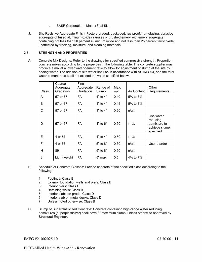
A. Concrete Mix Designs: Refer to the drawings for specified compressive strength. Proportion concrete mixes according to the properties in the following table. The concrete supplier may produce a mix at a lower water-cement ratio to allow for adjustment of slump at the site by adding water. The addition of site water shall be in accordance with ASTM C94, and the total water-cement ratio shall not exceed the value specified below.
Class
Coarse Aggregate Gradation
Fine Aggregate Gradation
Range of Slump
Max. w/c Air Content
Other Requirements
A 57 or 67 FA 1" to 4" 0.40 5% to 8%
B 57 or 67 FA 1" to 4" 0.45 5% to 8%
C 57 or 67 FA 1" to 4" 0.50 n/a�
D 57 or 67 FA 4" to 6" 0.50 �n/a
Use water reducing admixture to achieve slump specified
E 4 or 57 FA 1" to 4" 0.50 �n/a
F 4 or 57 FA 5" to 8" 0.50 n/a� Use retarder
H 89 FA 5" to 8" 0.50 n/a�
J Light-weight FA 5" max 0.5 4% to 7%
B. Schedule of Concrete Classes: Provide concrete of the specified class according to the following:
1. Footings: Class E2. Exterior foundation walls and piers: Class B3. Interior piers: Class C4. Retaining walls: Class B5. Interior slabs on grade: Class D6. Interior slab on metal decks: Class D7. Unless noted otherwise: Class B
C. Slump of Superplasticized Concrete: Concrete containing high-range water reducing admixtures (superplasticizer) shall have 8" maximum slump, unless otherwise approved by Structural Engineer.

IMEG #21002025.10 03 30 00 - 12
EICC-Allied Health Wing-Add - Renovation
D. Accelerators: Add non-chloride accelerator to all concrete slabs placed at air temperatures below 50°°F only when approved in the mix design. Use of admixtures will not relax cold weather placement requirements.
E. Water Reducer: Add water reducing admixture or high range water reducing admixtures (superplasticizers) as follows:
1. All pumped concrete.2. Fiber reinforced concrete.3. As required for placement or workability.4. As required by high temperatures, low humidity, or other adverse placement conditions.5. Concrete with water-cementitious materials ratio below 0.50.
F. Use shrinkage reducing admixture or shrinkage compensating admixture where indicated on the drawings to keep shrinkage below 0.04% or demonstrate that the proposed mix design meets the same value without the shrinkage reducing or shrinkage compensating admixture.
G. No other admixtures shall be used unless approved by Structural Engineer.
H. Chlorides: Admixtures or other ingredients including aggregates containing calcium chloride or more than 0.05% chloride ions by weight shall not be used.
I. Workability: Concrete shall have a workability such that it will fill the forms without voids, honeycombs, or rock pockets with proper vibration without permitting materials to separate or excess water to collect on the surface.
J. Concrete Temperatures: Minimum concrete temperature of fresh concrete varies in relation to average air temperature over a 24-hour period as follows:
1. Air temperature below 0°F Concrete temperature 70°F min.2. Air temperature 0°F to 30°F Concrete temperature 65°F min.3. Air temperature 30°F to 50°F Concrete temperature 50°F min.4. Air temperature above 50°F No minimum temperature5. The maximum temperature of concrete at the time of delivery shall be 90°F. When
concrete temperature exceeds 90°F, concrete supplier shall attempt to reduce temperature by shading aggregates and cement and cooling mix water. When these methods fail to reduce the concrete temperature below 90°F, supplier shall use ice in the water to reduce the concrete temperature. Use set retarding admixtures only when approved in the mix design.
PART 3 - EXECUTION
3.1 PREPARATION
A. Verify requirements for concrete cover over reinforcement.
B. Verify anchors, seats, plates, reinforcement, and other items to be cast into concrete are accurately placed, positioned securely, and will not cause hardship in placing concrete.
C. Do not place concrete until data on materials and mix designs have been approved, Architect has been notified, and all other affected trades have coordinated their work.
IMEG #21002025.10 03 30 00 - 13
EICC-Allied Health Wing-Add - Renovation
D. Remove snow, ice, frost, water, mud, and other foreign material from surfaces, reinforcing bars and embedded items against which concrete will be placed.
E. Prepare previously placed concrete by cleaning with sandblasting, steel brush, or water blast to expose aggregate to minimum 1/4" amplitude.
F. Sandblast all existing concrete surfaces older than 28 days against which concrete is to be placed, unless directed otherwise in writing by Architect/Engineer.
3.2 SLABS
A. Slab on Grade:
1. All interior slabs on grade shall have a polyethylene vapor retarder conforming to ASTM E1745. Lap all joints minimum 6" and seal edges with adhesive tape. Fit vapor retarder around utilities and seal with adhesive tape as required. Place, protect, and repair vapor-retarder sheets according to ASTM E 1643 and manufacturer's written instructions.
2. Refer to drawings and Section 31 23 00 for required sub-grade preparation beneath slabs on grade.
3. Where vapor retarder is not used below the slab on grade, wet sub-grade below slab prior to placing concrete. Subgrade shall be moist with no free water and no muddy or soft spots.
4. Saw cut control joints: Cut with power saws equipped with shatterproof abrasive or diamond-rimmed blades. Cut joints into concrete when cutting action will not tear, abrade, or otherwise damage surface and before concrete develops random contraction cracks. Control joints shall be located along column lines, with intermediate joints spaced at a maximum distance indicated on the drawings, unless noted otherwise. Control joints shall be continuous, not staggered or offset. Slab panels shall have a maximum length to width ratio of 1.5 to 1. Provide additional control joints at all reentrant or isolated corners formed in the slab on grade. Refer to the drawings for typical control joint detailing.
5. Provide isolation joints around each column, and along foundation walls. Form isolation joints with 1/2" expansion joint material. Extend isolation joint material full width and depth of joint, terminating flush with finished concrete surface, unless otherwise indicated.
6. Depress slabs as required for mats, architectural finishes, and pits,. Obtain layout and locations from Architect.
7. Verify completion of all under slab work with mechanical and electrical trades before placing slabs.
8. Slope slabs as indicated on the drawings and to provide positive drainage. Slope slab keeping bottom level and varying top. Maintain minimum thickness of concrete as indicated on the drawings. Refer to floor finishes for tolerances.
B. All supported slabs, including slabs-on-steel decking and cast-in-place concrete slabs:
1. Supported slabs have deflections that may cause areas of concrete to have thicknesses greater than indicated on the drawings. Contractor is expected to provide that volume as needed to finish the floor at the specified elevation. If specified floor finish tolerances are not achieved during the concrete floor construction, after formwork removal, the Contractor shall install, at no cost to the project, a self-leveling cementitious underlayment BASF Corporation - MasterTop 110 SL or approved equivalent to correct the floor flatness and levelness.
IMEG #21002025.10 03 30 00 - 14
EICC-Allied Health Wing-Add - Renovation
C. Embedded Items:
1. The outside diameter of embedded conduit or pipe shall not exceed one-third of the slab thickness in structural slabs, including at crossovers, and shall be placed between the top and bottom reinforcing with a minimum 3" clear cover. Conduit or pipe running parallel to each other shall be spaced at least 8" apart and no more than 2 runs stacked vertically in the slab. Conduit or pipe shall not be embedded in any supported slab less than 6" thick. No embedded conduit or pipe is allowed in any concrete slab-on-steel deck.
3.3 CONSTRUCTION JOINTS
A. Slabs: Where slab pour is to receive a subsequent topping or additional concrete, expose aggregate in top surface by brooming in two directions at right angles to each other.
B. Vertical: Locate vertical construction joints in walls not farther than a maximum of 100 feet on center. Coordinate joint locations with architectural design.
C. Horizontal: Locate horizontal joints in walls, at underside of slabs, and at the top of slabs and footings unless otherwise indicated. At least 24 hours shall elapse between placing concrete in a wall, and placing concrete in an area supported by the walls,, unless approved in writing by the Structural Engineer.
D. Reinforcing: Stop all welded wire reinforcement and/or reinforcing at construction joints in slabs on grade and provide dowel bars as detailed. Provide reinforcement at other construction joints as detailed. Roughen and thoroughly clean the surface of the concrete, remove all laitance, and wet the surface before placing new concrete against the joint. Slush vertical joints with a neat cement grout before placing new concrete.
E. Wall Control Joints: Locate vertical control joints in exposed walls at a minimum uniform spacing not to exceed 25'-0". Coordinate joint locations with architectural drawings.
F. Exposed Surfaces: Locate construction joints only at predetermined locations approved by the Architect and the Structural Engineer.
3.4 CONCRETE PLACEMENT
A. Place concrete as continuously as possible until placement is complete. Do not place against concrete that has attained initial set, except at authorized joints. If, for any reason, concrete pour is delayed for more than 45 minutes, bulkhead off pour at last acceptable construction joint. Immediately remove excess concrete and clean forms.
B. Do not begin to place concrete during periods of rain, sleet, or snow unless adequate protection is provided.
C. No concrete shall be cast onto or against sub-grades containing free water, frost, ice, or snow. If earth at bottom of forms has dried out, rewet so the soil is moist, but free of standing water and mud.
D. Notify the Architect in advance if concrete is to be pumped.
E. Do not place concrete until all reinforcement is in place, forms have been thoroughly cleaned and approval has been given.

IMEG #21002025.10 03 30 00 - 15
EICC-Allied Health Wing-Add - Renovation
F. Do not accept concrete delivered to the job site more than 90 minutes after initial mixing.
G. Concrete from its point of release to mixers, hoppers, or conveyances, shall not be permitted to drop more than 5 feet (10 feet for concrete containing high range water reducers). Deposit concrete directly into conveyances and directly from conveyances to final points of deposit. Sufficient transportation equipment in good working order shall be on hand before work begins. All conveying equipment must be clean and kept clean during concreting operations. Take every possible precaution to prevent segregation or loss of ingredients.
H. Regulate rate of placement so concrete surface is kept level throughout; a minimum being permitted to flow from one area to another. Use tremie heads spaced at approximately 10-foot intervals for placing concrete in walls. Control rate of placement consistent with form design.
I. Deposit concrete in one continuous operation until section being placed has been completed. For slab thicknesses greater than 12 inches, prevent excessive segregation of aggregate and high temperatures in accordance with ACI 304 and ACI 308. Place concrete in wall forms in layers not greater than 12 inches in depth, each layer being compacted by internal vibration before succeeding layer is placed.
J. Place concrete as near as possible to its final position to prevent segregation or loss of materials. Do not use vibrators to transport concrete within forms. Consolidate concrete in walls, columns, beams, and slabs or joist construction thicker than 8" with internal vibrators (8,000 to 12,000 VPM). Slabs less than 8" thick may be consolidated with internal vibrators (9,000 to 13,500 VPM) or vibrating screeds supported on forms, boards, or rails, approved by the Structural Engineer, supplement vibration by forking or spading by hand along surfaces adjacent to forms and construction joints. Be sure an adequate number of operating vibrator units are on hand to properly consolidate quantity of concrete to be placed, including spares for emergency use.
1. Vertically insert and remove handheld vibrators at constant intervals 18 to 30 inches apart. Vibrate concrete the maximum amount and time required for complete consolidation, without segregation, and release of entrapped air bubbles, but in no instance exceed 15 seconds per square foot of exposed surface.
K. Re-tempering of concrete shall not be permitted. Concrete that has stood more than 15 minutes after leaving the mixer shall be discarded.
L. Exercise care in placing concrete over waterproof membranes, rigid insulation, and/or protection boards to avoid damaging those materials. Report damage immediately, and do not proceed until damage is repaired.
M. Remove loose debris from hardened surfaces of previous pours, thoroughly wet and slush with a neat cement grout immediately before placing new concrete or apply bonding compound to surface and let dry before placing new concrete.
N. Protect existing concrete work to be exposed to view and other finished materials from damage and staining resulting from concreting operations. Handle concrete carefully to avoid dripping and spillage. Remove spilled concrete from existing surfaces immediately. Covering sills, ledges, and other surfaces with protective coverings may be necessary to protect the work.
O. Filling In: Fill in holes and openings left in concrete structures, unless otherwise indicated, after work of other trades is in place. Mix, place, and cure concrete, as specified, to blend with in-place construction. Provide other miscellaneous concrete filling indicated or required to complete Work.
IMEG #21002025.10 03 30 00 - 16
EICC-Allied Health Wing-Add - Renovation
P. Steel Pan Stairs: Provide concrete fill for steel pan stair treads, landings, and associated items. Cast-in inserts and accessories as shown on the drawings. Screed, tamp, and trowel-finish concrete surfaces.
3.5 CONCRETE FINISHES AND TOLERANCES
A. Exposed Smooth Formed Surfaces: Remove forms and perform necessary repairs and patch to produce surface finish-3.0 as specified in ACI 301. Apply the following to smooth-formed finished concrete exposed to view in the finished work. Confirm finishes with the Architect prior to concrete placement by submitting shop drawings indicating locations of all types of finishes.
1. Smooth-Rubbed Finish: Not later than one day after form removal, moisten concrete surfaces and rub with carborundum brick or another abrasive until producing a uniform color and texture. Do not apply cement grout other than that created by the rubbing process.
B. Related Unformed Surfaces: At tops of walls, horizontal offsets, and similar unformed surfaces adjacent to formed surfaces, strike off smooth and finish with a texture matching adjacent formed surfaces. Continue final surface treatment of formed surfaces uniformly across adjacent unformed surfaces, unless otherwise indicated.
3.6 CONCRETE SLAB FINISHES AND TOLERANCES
A. Trowel Finish:
1. Screed concrete to an even plane, float, then power trowel the surface.2. Hand trowel the surface smooth and free of trowel marks. Continue hand troweling until a
ringing sound is produced as the floor is troweled.3. Provide trowel finish as indicated on the drawings and at the following locations:
a. Concrete floors exposed in finished work unless otherwise indicated.b. Slabs to receive curing compounds and sealers.c. Slabs to receive resilient flooring or carpet.d. Slabs to receive waterproof membranes.
B. Fine Broom Finish:
1. Screed concrete to an even plane, float, then power trowel the surface. Provide fine hair broom finish perpendicular to slope, free of loose particles, ridges, projections, voids, and concrete droppings.
2. Provide fine broom finish as indicated on the drawings and at the following locations:
a. Stoop slabs.b. Raised curbs and walkway areas.c. Slabs to receive thin set ceramic tile.
C. Broom Finish:
1. Screed concrete to an even plane and then float. Immediately after concrete has received a floated finish, give the concrete surface a coarse transverse scored texture by drawing a coarse broom across the surface.
2. Provide as indicated on the drawings and at the following locations:
a. ADA ramp slabs.
IMEG #21002025.10 03 30 00 - 17
EICC-Allied Health Wing-Add - Renovation
b. Exterior walkway slabs.
D. Float Finish:
1. Screed concrete to an even plane then float.2. Provide as indicated on the drawings and at the following locations:
a. Slabs to directly receive concrete topping.b. Roof slabs to receive loose laid roof insulation.
E. Floor Finish Tolerances: Floor finish tolerances shall be measured by placing a freestanding (unleveled) 10-foot straightedge anywhere on the slab and allowing it to rest upon two high spots within 72 hours after placement of slab and removal of shoring (if present). The gap at any point between the straightedge and the floor (and between the high spots) shall not exceed:
1. Slab on Grade (Office, School): 1/4"2. Slab on Grade (General Warehouse): 3/16"3. Suspended Slabs (Steel frame): 1/4"
F. Slab Drainage: Finish all concrete slabs to proper elevations to ensure that all surface moisture will drain freely to floor drains, and that no puddle areas exist. Contractor shall bear the cost of corrections to provide positive drainage.
G. Special Tolerances for Concrete Slabs: No abrupt change in vertical elevation of 1/4" or more is acceptable at the interface between slabs and within areas where pedestrian traffic is expected.
3.7 CONCRETE CURING
A. Freshly placed concrete shall be protected from premature drying and excessively hot temperatures.
B. Concrete other than high-early strength shall be maintained above 50°°F and in a moist condition for at least the first 7 days after placement, except when special curing is used. Special curing procedures shall not be used without written permission from the Structural Engineer.
C. Formed surfaces shall be cured by leaving the formwork in place during the curing period.
D. Protect concrete from excessive changes in temperature during the curing period and at the termination of the curing process. Changes in the temperature of the concrete shall be as uniform as possible and shall not exceed 5°°F in any one hour or 50°°F in any 24-hour period.
E. Protect concrete from injury from the elements until full strength is developed. Protect from mechanical injury.
F. During cold weather construction, all footings shall be protected from frost penetration until the building is enclosed and temporary heat is provided.
3.8 SLAB CURING
A. Begin curing after finishing concrete, but not before free water has disappeared from concrete surface. Use one of the methods described below.
IMEG #21002025.10 03 30 00 - 18
EICC-Allied Health Wing-Add - Renovation
B. Moisture-Retaining-Cover Curing for Concrete Floors Not Exposed in Final Condition: Cover concrete surface with waterproof sheet material as soon as finishing operations are complete and the concrete is sufficiently hard to be undamaged by covering. The cover shall be placed flat on the concrete surface, avoiding wrinkles. Sprinkle concrete with water as necessary during application of covering. Place in widest practicable width, with sides and ends lapped at least 12 inches, and seal with waterproof tape or adhesive. Verify the concrete is continuously wet under the sheets; otherwise, add water through soaker hoses under the sheets. Weight down covering to prevent displacement. Immediately repair any holes or tears during the curing period using polyethylene sheet and waterproof tape. Curing process shall be maintained for a minimum of 7 days.
C. Moisture-Retaining-Fabric Curing for Concrete Floors to Remain Exposed: Cover concrete surface with moisture retaining fabric as soon as finishing operations are complete and the concrete is sufficiently hard to be undamaged by covering. The cover shall be installed in accordance with the manufacturer's written recommendations, in largest practical widths. Wet the slab to rejection, then thoroughly wet fabric side of cover and install with poly side up. Lap over adjacent covers a minimum of 18". Wet all laps and outside edges to prevent displacement and to ensure intimate contact with concrete and adjacent covers. Rewet as necessary and protect covers from damage during curing process.
1. After minimum 7-day cure, remove moisture retaining fabric in sections.2. A maximum of 3,500 square feet of concrete curing cover may be removed at any one
time. At no time shall the exposed area be permitted to dry prior to completion of the floor scrubbing process.
3. Using a high-powered floor scrubber capable of a minimum 80 pounds head pressure, and a mild citrus-based detergent that does not damage or mar the surface in any way, scrub the floor to remove any minerals or soluble salts that may have accumulated at the floor surface. Rinse area thoroughly with clean fresh water. Remove water and allow floor to dry. If whitening occurs during drying, repeat scrubbing process before floor dries until no whitening occurs during drying.
4. All areas of the floor shall remain wet during floor scrubbing process. Expose only the amount of floor surface that can be cleaned before any drying occurs without exceeding the maximum allowable exposed area.
D. Curing Compound: Apply uniformly in continuous operation by low pressure spray equipment or roller as soon as finishing operations are complete, free water on the surface has disappeared, and no water sheen can be seen. Follow the manufacturer's written instructions. Recoat areas subjected to heavy rainfall within three hours after initial application. Maintain continuity of coating and repair damage during curing period. Verify compatibility of the curing compound with paint, finishes, or toppings that require positive bond to the concrete. If curing compound is not compatible with paint finishes or toppings, utilize a dissipating curing compound and remove in accordance with the manufacturer's recommendations.
3.9 JOINT FILLING
A. Prepare, clean, and install joint filler according to manufacturer's written instructions.
B. Do not fill joints until construction traffic has permanently ceased.
C. Remove dirt, debris, saw cuttings, curing compounds, and sealers from joints; leave contact faces of joint clean and dry.
D. Install semi-rigid joint filler in saw-cut joints and in formed joints. Overfill joint and trim joint filler flush with top of joint after hardening.
IMEG #21002025.10 03 30 00 - 19
EICC-Allied Health Wing-Add - Renovation
3.10 APPLICATION OF FLOOR SEALER - FINISH COAT
A. Give concrete floors, as indicated in the Room Finish Schedule and where exposed in finished Work, a second coat of curing and sealing compound immediately prior to Substantial Completion.
B. Clean floors and apply sealer strictly according to manufacturer's instructions. Dilution and coverage shall be as recommended by the manufacturer. Apply sealer evenly.
3.11 COLD WEATHER CONCRETING
A. Definition: Cold weather shall be defined as a period when for more than three successive days the average daily outdoor temperature drops below 40°F. The average daily temperature is the average of the highest and lowest temperature during the period from midnight to midnight. When temperatures above 50°F occur during more than half of any 24-hour duration, the period shall not be regarded as cold weather.
B. All cast-in-place concrete work occurring during cold weather shall conform to all requirements of ACI 306.1, "Standard Specification for Cold Weather Concreting", published by the American Concrete Institute, Detroit, Michigan, except as modified by the contract documents or this specification.
C. Planning: The General Contractor, concrete contractor, concrete supplier, and Architecthall have a pre-construction conference to outline the cold weather concreting operations concerning the placing, finishing, curing and protection of the concrete during cold weather. Pre-construction conference shall occur before cold weather is expected to occur.
D. Detailed procedure submittal: Concrete contractor shall prepare and submit for review detailed procedures for the production, transportation placement, protection, curing and temperature monitoring of concrete during cold weather. Include procedures to be implemented upon abrupt changes in weather conditions. Do not begin cold weather concreting until these procedures have been reviewed and approved.
E. Mixing: Concrete flatwork poured in cold weather shall be proportioned to obtain a lower slump to minimize the amount of bleed water during finishing. All bleed water should be skimmed off flatwork prior to troweling. Concrete that will be exposed to cycles of freezing and thawing while saturated should be properly air entrained as outlined in this specification.
F. Protection of Concrete: Cure and protect concrete against damage from freezing for a minimum period of 72 hours, unless approved by the Structural Engineer. The protection period may be reduced according to ACI 306.1 requirements. Concrete contractor shall submit a letter of request to reduce the protection period, by outlining the method used to achieve the reduction per ACI 306.1.
1. When practical for the construction schedule, formwork shall be insulated and remain in place for at least the required protection period.
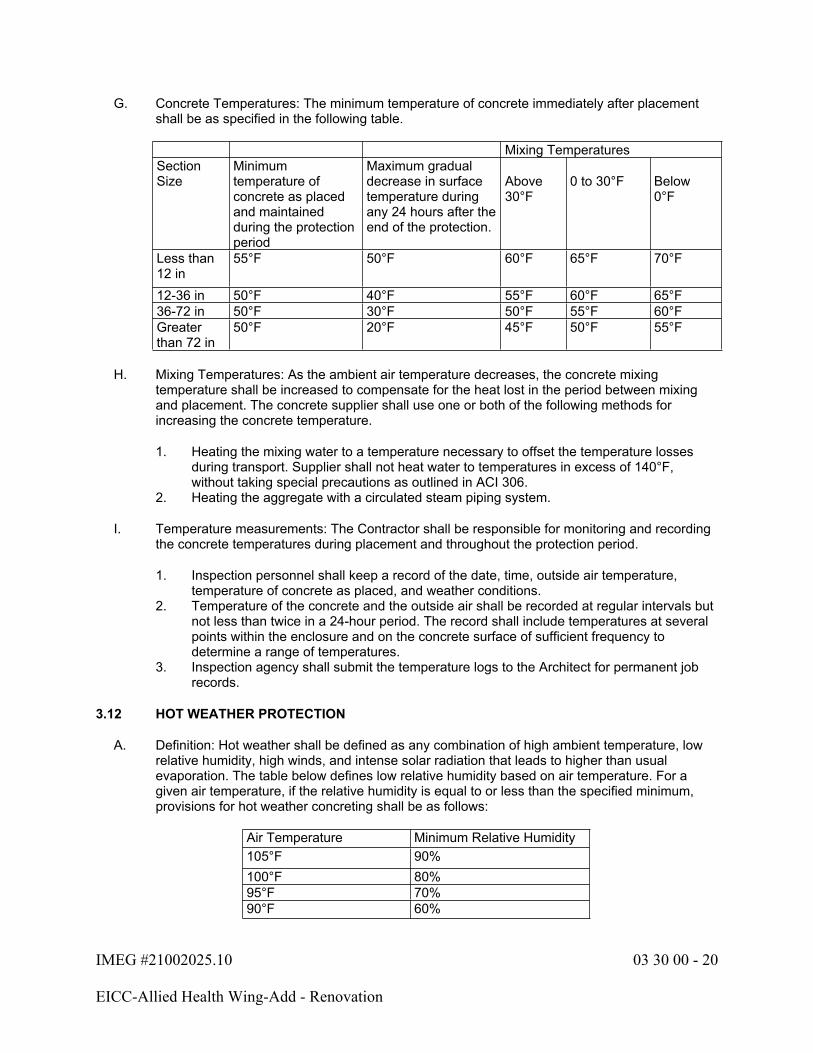
IMEG #21002025.10 03 30 00 - 20
EICC-Allied Health Wing-Add - Renovation
G. Concrete Temperatures: The minimum temperature of concrete immediately after placement shall be as specified in the following table.
Mixing TemperaturesSectionSize
Minimum temperature of concrete as placed and maintained during the protection period
Maximum gradual decrease in surface temperature during any 24 hours after the end of the protection.
Above30°F
0 to 30°F Below0°F
Less than 12 in
55°F 50°F 60°F 65°F 70°F
12-36 in 50°F 40°F 55°F 60°F 65°F36-72 in 50°F 30°F 50°F 55°F 60°FGreater than 72 in
50°F 20°F 45°F 50°F 55°F
H. Mixing Temperatures: As the ambient air temperature decreases, the concrete mixing temperature shall be increased to compensate for the heat lost in the period between mixing and placement. The concrete supplier shall use one or both of the following methods for increasing the concrete temperature.
1. Heating the mixing water to a temperature necessary to offset the temperature losses during transport. Supplier shall not heat water to temperatures in excess of 140°F, without taking special precautions as outlined in ACI 306.
2. Heating the aggregate with a circulated steam piping system.
I. Temperature measurements: The Contractor shall be responsible for monitoring and recording the concrete temperatures during placement and throughout the protection period.
1. Inspection personnel shall keep a record of the date, time, outside air temperature, temperature of concrete as placed, and weather conditions.
2. Temperature of the concrete and the outside air shall be recorded at regular intervals but not less than twice in a 24-hour period. The record shall include temperatures at several points within the enclosure and on the concrete surface of sufficient frequency to determine a range of temperatures.
3. Inspection agency shall submit the temperature logs to the Architect for permanent job records.
3.12 HOT WEATHER PROTECTION
A. Definition: Hot weather shall be defined as any combination of high ambient temperature, low relative humidity, high winds, and intense solar radiation that leads to higher than usual evaporation. The table below defines low relative humidity based on air temperature. For a given air temperature, if the relative humidity is equal to or less than the specified minimum, provisions for hot weather concreting shall be as follows:
Air Temperature Minimum Relative Humidity105°F 90%100°F 80%95°F 70%90°F 60%

IMEG #21002025.10 03 30 00 - 21
EICC-Allied Health Wing-Add - Renovation
Air Temperature Minimum Relative Humidity85°F 50%80°F 40%75°F 30%
B. Scheduling: When hot weather is expected, adjust concrete placement schedules to avoid placing or finishing during the period from noon until 3:00 pm. When possible, slab pours should be delayed until the building is enclosed to protect the concrete from wind and direct sunlight. The construction schedule shall account for 7-day moist curing period.
C. Mixing: Concrete supplier shall adjust mix designs and admixtures to minimize slump loss. Concrete shall be mixed at a water-cement ratio, which is lower than the specified maximum, to allow for the adjustment of slump by addition of water in the field. Water reduction shall be accomplished without reducing initial slump by increasing dosage of a water reducing admixture.
D. Preparation: Do not order concrete earlier than is required to avoid delays. Cool forms, subgrades and reinforcing bars with water spray from fog nozzle prior to concrete placement.
E. Delivery: Site traffic shall be coordinated, and delivery times scheduled to minimize waiting times for concrete trucks.
F. Placement: Preparations shall be made to place and consolidate the concrete at the fastest possible rate. Maintain a continuous flow of concrete to the job site to avoid development of cold joints, during placement of slabs, apply fog spray to prevent moisture loss without causing surplus water to stand on concrete surface.
G. Finishing: Finish concrete as fast as practical. Continue fogging concrete during finishing. Where fogging is not possible, apply sprayable moisture-retaining film between finishing passes.
H. Curing: Formed concrete shall be covered with a waterproof material to retain moisture. Flat work shall be moisture cured as described in this specification. Moist curing shall continue for at least 7 days.
3.13 FIELD QUALITY ASSURANCE
A. Independent Testing Agency and Special Inspector shall each perform their prescribed inspection, sampling, and testing services as described in Part 1 of this specification section.
B. In cases where samples have not been taken or tests conducted as specified or strength of laboratory test cylinders for a particular portion of the structure fails to meet requirements of ACI 301, for evaluation of concrete strength, Structural Engineer shall have the right to order compressive or flexural test specimens or both be taken from the hardened concrete according to ASTM C42, load tests according to ACI 318, or such other tests as may be necessary to clearly establish the strength of the in situ concrete, and such tests shall be paid for by the Contractor. Where cores have been cut from the Work, Contractor shall fill voids with dry-pack and patch the finish to match the adjacent existing surfaces.

IMEG #21002025.10 03 30 00 - 22
EICC-Allied Health Wing-Add - Renovation
3.14 REPAIR OF DEFECTIVE AREAS
A. All repair of defective areas shall be made, with prior approval of Architect and Structural Engineer as to method and procedure, in accordance with Section 5 of ACI 301, except specified bonding compound must be used. Cosmetic repairs of minor defects in exposed concrete surfaces shall be in a manner acceptable to the Architect. Defective areas shall be deemed when:
1. Tests on core or prism specimens fail to show specified strengths.2. Not formed as indicated or detailed.3. Not plumb or level where so indicated or required to receive subsequent work.4. Not true to intended grades and levels.5. Cut, filled, or resurfaced, unless under direction of the Structural Engineer.6. Debris is embedded therein.7. Not fully in conformance with provisions of the drawings.8. Damaged by hot or cold weather conditions.9. Mixing time exceeds 90 minutes from ready-mix plant to the time of deposit.
B. Patch form tie holes at the following locations:
1. Unfinished exposed concrete (not scheduled for painting, plus at board formed concrete finish).
2. All other areas: Prime voids with bonding compound and fill with patching mortar. Strike flush without overlap, float to uniform texture to match adjacent surfaces.
3. Exposed areas scheduled for spray texture:
a. Remove projections and protrusions: 1/16" or larger.b. Remove continuous ridges 1/32" or larger.c. Fill voids and pin holes.
4. Exposed areas scheduled for paint or epoxy:
a. Remove projections, ridges, and other protrusions 1/32" or larger.b. Fill voids and pin holes 1/16" or larger.
5. Exposed areas not scheduled for paint or other finishes:
a. Remove projections, ridges and other protrusions not conforming to requirements specified under Section 03 10 00.
b. Fill voids and pin holes not conforming to requirements specified under Section 03 10 00.
C. All structural repairs shall be made, with prior approval of the Architect/Engineer, as to method and procedure, using the specified epoxy adhesive and/or epoxy mortar.
IMEG #21002025.10 03 30 00 - 23
EICC-Allied Health Wing-Add - Renovation
D. Repairing Formed Surfaces: Surface defects include color and texture irregularities, cracks, spalls, air bubbles, honeycombs, rock pockets, fins and other projections on the surface, and stains and other discolorations that cannot be removed by cleaning.
1. Immediately after form removal, cut out honeycombs, rock pockets, and voids more than 1/2 inch in any dimension in solid concrete but not less than 1 inch in depth. Make edges of cuts perpendicular to concrete surface. Clean, dampen with water, and brush-coat holes and voids with bonding agent. Fill and compact with patching mortar before bonding agent has dried. Fill form-tie voids with patching mortar or cone plugs secured in place with bonding agent.
2. Repair defects on surfaces exposed to view by blending white Portland cement and standard Portland cement so that, when dry, patching mortar will match surrounding color. Patch a test area at inconspicuous locations to verify mixture and color match before proceeding with patching. Compact mortar in place and strike off slightly higher than surrounding surface.
3. Repair defects on concealed formed surfaces that affect concrete's durability and structural performance as determined by Architect.
E. Repairing Unformed Surfaces: Test unformed surfaces, such as floors and slabs, for finish and verify surface tolerances specified for each surface. Correct low and high areas. Test surfaces sloped to drain for trueness of slope and smoothness; use a sloped template.
1. Repair finished surfaces containing defects. Surface defects include spalls, popouts, honeycombs, rock pockets, crazing and cracks in excess of 0.01 inch wide or that penetrate to reinforcement or completely through unreinforced sections regardless of width, and other objectionable conditions.
2. After concrete has cured at least 14 days, correct high areas by grinding.3. Correct localized low areas during or immediately after completing surface finishing
operations by cutting out low areas and replacing with patching mortar. Finish repaired areas to blend into adjacent concrete.
4. Correct other low areas scheduled to receive floor coverings with a repair underlayment. Prepare, mix, and apply repair underlayment and primer according to manufacturer's written instructions to produce a smooth, uniform, plane, and level surface. Feather edges to match adjacent floor elevations.
5. Correct other low areas scheduled to remain exposed with a repair topping. Cut out low areas to ensure a minimum repair topping depth of 1/4 inch to match adjacent floor elevations. Prepare, mix, and apply repair topping and primer according to manufacturer's written instructions to produce a smooth, uniform, plane, and level surface.
6. Repair defective areas, except random cracks and single holes 1 inch or less in diameter, by cutting out and replacing with fresh concrete. Remove defective areas with clean, square cuts and expose steel reinforcement with at least 3/4-inch clearance all around. Dampen concrete surfaces in contact with patching concrete and apply bonding agent. Mix patching concrete of same materials and mix as original concrete except without coarse aggregate. Place, compact, and finish to blend with adjacent finished concrete. Cure in same manner as adjacent concrete.
7. Repair random cracks and single holes 1 inch or less in diameter with patching mortar. Groove top of cracks and cut out holes to sound concrete and clean off dust, dirt, and loose particles. Dampen cleaned concrete surfaces and apply bonding agent. Place patching mortar before bonding agent has dried. Compact patching mortar and finish to match adjacent concrete. Keep patched area continuously moist for at least 72 hours.

IMEG #21002025.10 03 30 00 - 24
EICC-Allied Health Wing-Add - Renovation
3.15 CEMENT GROUT AND DRY-PACK
A. Cement Grout: Thoroughly mix sufficient quantities to avoid combining different batches of grout mix. Ensure that grout completely fills all spaces and voids. Level, screed, or cut flush excess grout to produce smooth, neat, even exposed surfaces.
B. Dry-Pack: Thoroughly blend dry ingredients prior to mixing with water. Forcibly pack mixture to completely fill voids and spaces.
3.16 CLEANING
A. Clean exposed concrete to remove laitance, efflorescence and stains.
END OF SECTION 03 30 00
IMEG #21002025.10 04 22 00 - 1
EICC-Allied Health Wing-Add - Renovation
SECTION 04 22 00 - REINFORCED UNIT MASONRY
PART 1 - GENERAL
1.1 SECTION INCLUDES
A. Supply and installation of all reinforced concrete unit masonry work (concrete unit masonry, mortar, grout, reinforcement, anchors, and ties) and accessories as shown on the drawings and herein specified.
B. Structural notes indicated on the drawings regarding reinforced unit masonry shall be considered part of this specification.
1.2 RELATED WORK
A. Section 03 30 00 - Cast-in-Place Concrete.
B. Section 04 20 00 - Unit Masonry.
C. Section 05 12 23 - Structural Steel.
D. Section 31 23 00 - Foundation Excavating and Backfilling.
1.3 REFERENCES
A. Codes and Standards: Comply with the provisions of the following codes, specifications, and standards except where more stringent requirements are shown or specified. Where any provision of other pertinent codes and standards conflict with this specification, the more stringent provision shall govern.
1. ASTM A153 - Standard Specification for Zinc Coating (Hot-Dip) on Iron and Steel Hardware.
2. ASTM A615 - Standard Specification for Deformed and Plain Carbon-Steel Bars for Concrete Reinforcement.
3. ASTM C90 - Standard Specification for Loadbearing Concrete Masonry Units.4. ASTM C270 - Standard Specification for Mortar for Unit Masonry.5. ASTM C387 - Specification for Packaged, Dry, Combined Materials for Concrete and
High Strength Mortar.6. ASTM C476 - Standard Specification for Grout for Masonry.7. ASTM C780 - Standard Test Method for Preconstruction and Construction Evaluation of
Mortars for Plain and Reinforced Unit Masonry.8. ASTM C1019 - Standard Test Method for Sampling and Testing Grout.9. International Masonry Industry All-Weather Council (IMIAC) - Recommended Practices
and Guide Specifications for Cold Weather Masonry Construction.10. TMS 402/602 - Building Code Requirements and Specifications for Masonry Structures.11. UL - Underwriters Laboratories.
IMEG #21002025.10 04 22 00 - 2
EICC-Allied Health Wing-Add - Renovation
1.4 QUALITY ASSURANCE
A. Fire Resistance: Whenever a fire-resistant classification is indicated for unit masonry construction, provide concrete block units as tested and listed for the particular fire-resistant construction.
B. The governing building department reserves the right to take samples and make material tests prior to or during construction, without expense to the Contractor. Materials found to be defective shall be removed and replaced.
1.5 SUBMITTALS
A. Prepare and submit product data for the Engineer's approval. Data should include all horizontal reinforcement, anchoring devices, and all other embedded items herein specified.
B. Prepare and submit shop drawings detailing the fabrication, bending, and placement of reinforcing bars. Provide wall elevations showing reinforcement layout.
C. Samples: When requested by the Architect and before any materials are delivered to the Worksite, submit for approval one sample of the proposed masonry materials, showing the full range of colors and textures available.
D. Certificates:
1. Submit a letter of certification from the manufacturer of the concrete masonry units certifying all concrete masonry units delivered to the worksite are in strict conformance with the provisions of this specification.
2. Submit concrete unit masonry compressive strength test results demonstrating the units meet the specified strength. Test must be conducted by a qualified independent testing agency.
E. Submit mortar mix design and test results as follows:
1. Mix designs shall indicate type and proportions of ingredients in compliance with the proportion requirements of ASTM C270.
2. For mix designs not in accordance with the proportion requirements of ASTM C270, the mortar test history must be performed in accordance with ASTM C780 to verify performance with property requirements of ASTM C270. Tests must meet the type of mortar specified on the drawings. Tests must be done by a qualified independent testing agency.
F. Submit grout mix designs and test results as follows:
1. Mix designs shall indicate type and proportions of the ingredients in compliance with the proportion requirements of ASTM C476.
2. For mix designs not in accordance with the proportion requirements of ASTM C476, the grout test history must be performed in accordance with ASTM C1019 to verify performance with property requirements of ASTM C476. Tests must meet the type of grout specified on the drawings. Test must be done by a qualified independent testing agency.
a. Perform one test prior to construction and perform at least one test during construction for each 5000 square feet of wall.
IMEG #21002025.10 04 22 00 - 3
EICC-Allied Health Wing-Add - Renovation
1.6 DELIVERY, STORAGE, AND HANDLING
A. All masonry units shall be delivered to the worksite and stacked on pallets to allow the circulation of air through all units. Cover with a waterproof covering anchored to prevent displacement during high winds.
B. Masonry accessories, including reinforcing steel, shall be stored clear of the ground to prevent deterioration or damage due to moisture, temperature changes, contaminants, and corrosion.
C. Deliver all materials in sufficient quantity and time to maintain approved construction schedule.
D. Deliver all packaged materials in manufacturer's original containers, with labels and markings intact and legible.
E. Immediately remove all damaged materials or containers from site and replace with new items.
PART 2 - PRODUCTS
2.1 MATERIALS
A. Concrete Masonry Units: ASTM C90, Grade N-1 as follows:
1. Weight: Normal weight.2. Compressive Strength: As indicated on the drawings.3. Nominal Size: As indicated on the drawings.4. Actual Size: 3/8" less than nominal size.5. Aggregates:
a. Normal Weight: ASTM C33.
6. Provide special units for 90°° corners, lintels jambs, sash, control joints, headers, bond beams, and other special conditions conforming to ASTM C90.
7. All exposed unit masonry shall be free of chips, cracks, and other imperfections.
B. Mortar and Grout:
1. Compressive Strength: As indicated on the drawings.2. Mortar type for masonry construction shall be as designated in the General Notes of the
drawings, conforming to ASTM C270, and grout shall conform to ASTM C476.3. Portland Cement: ASTM C150, Type I, non-staining, no air entraining, natural color
cement.4. Blended Cement: ASTM C595.5. Masonry Cement: ASTM C91.6. Mortar Aggregate: ASTM C144, standard masonry type sand .7. Hydrated Lime: ASTM C207.8. Quicklime: ASTM C5, non-hydraulic type.9. Premix Mortar: ASTM C387, using gray or white cement, normal strength.10. Grout Aggregate: ASTM C404 Pea gravel with not more than 5% passing the No. 8 sieve
and 100% passing the 3/8-inch sieve .11. Grout Fine Aggregate: Sand.12. Water: Clean and potable.13. Do not use calcium chloride in mortar or grout.

IMEG #21002025.10 04 22 00 - 4
EICC-Allied Health Wing-Add - Renovation
C. Joint Reinforcement:
1. Provide joint reinforcement formed from galvanized carbon-steel wire in accordance with ASTM A641, Class 1 for interior walls; and ASTM A153, Class B-2, for exterior walls.
2. Provide welded wire units prefabricated with 9 gauge deformed continuous side rods and 9 gauge plain cross rods into straight lengths of not less than 10 feet with matching corner and tee units. Unit widths to be 1-1/2 to 2 inches less than the wall thickness.
3. For multi-wythe concrete masonry walls, provide truss type reinforcement with a third side rod extending out into the other wythe.
D. Reinforcement:
1. Use deformed billet bars with unprotected finish conforming to ASTM A615, 60 ksi yield strength.
E. Control and Expansion Joints:
1. Control joint material for unit masonry shall consist of cross-shaped extruded polyvinyl gaskets sized to match wall thickness.
2. Expansion or joint filler material, unless otherwise indicated, shall be 1/2 inch thick asphalt impregnated cellular board.
3. Compressible filler shall be pre-molded filler strips complying with ASTM D1056, Type 2, Class A, Grade 1; compressible up to 35 percent of width and thickness indicated.
4. Bond breaker strips shall be asphalt-saturated, organic roofing felt complying with ASTM D226, Type I (No. 15 asphalt felt).
F. Breath wicks: 3/16 inch diameter cotton sash cord or glass fiber rope. Provide 2 inches of exposure to the outside and space wicks at 18 inches on center along the wall.
G. Insulation Board: Refer to Board Insulation in Division 7.
H. Masonry cleaners shall be non-acidic and not harmful to masonry workers or adjacent materials.
I. Bonding Agent: Larson Products Corporation "Plasterweld" as distributed by Pioneer Builder's Supplies, Inc. Los Angeles, California or approved equivalent.
J. Waterproofing Agent: "Red Label Suconem" by Sika Corporation or approved equivalent.
PART 3 - EXECUTION
3.1 EXAMINATION
A. Verify field conditions are acceptable and are ready to receive work.
1. Verify foundations are constructed with tolerances conforming to the requirements of ACI 117.
2. Verify reinforcing dowels are positioned in accordance with the drawings.
B. Verify items provided by other Sections of work are properly sized and located.
C. Verify built-in items are in proper location and ready for roughing into masonry work.
IMEG #21002025.10 04 22 00 - 5
EICC-Allied Health Wing-Add - Renovation
D. Beginning of installation means Installer accepts existing conditions.
3.2 PREPARATION
A. Layout walls in advance for accurate spacing of bond patterns, with uniform joint widths and to properly locate openings, expansion joints, and offsets.
B. Direct and coordinate placement of metal anchors supplied to other Sections.
C. The Contractor is responsible to design, provide, and install bracing that will ensure stability of masonry during construction. Maintain in place until building structure provides permanent bracing.
D. Remove laitance, loose aggregate, and anything else that would prevent mortar from bonding to the foundation.
E. Clean all reinforcement by removing mud, oil, or other materials that will adversely affect or reduce bond at the time mortar or grout is placed.
3.3 COLD WEATHER CONSTRUCTION
A. When ambient temperature is below 40°F, implement cold weather procedures.
B. Special cold weather requirements for various temperature ranges are as follows:
1. Air temperature 40°F to 32°F: Sand or mixing water shall be heated to produce mortar temperatures between 40°F to 120°F.
2. Air temperature 32°F to 25°F:
a. Sand and mixing water shall be heated to produce mortar temperatures between 40°F to 120°F. Maintain temperature of mortar on boards above freezing.
b. Grout aggregates and mixing water shall be heated to produce grout temperature between 70°F to 120°F.
3. Air temperature 25°F to 20°F: Comply with requirements for air temperature between 32°F to 25°F and the following:
a. Provide heat sources on both sides of the wall under construction to heat masonry surfaces to 40°F. Windbreaks shall be used when wind is in excess of 15 miles per hour.
b. Heat masonry to a minimum temperature of 40°F prior to grouting.
4. Air temperature 20°F and below. Comply with requirements for air temperature between 32°F to 20°F and the following:
a. Enclosure and auxiliary heat shall be provided to maintain air temperature above freezing. Do not lay masonry units having a temperature below 20°F.
C. Cold-Weather Protection:
1. When the mean daily air temperature is 40°F to 25°F, masonry shall be completely covered for 24 hours with weather-resistive membrane.

IMEG #21002025.10 04 22 00 - 6
EICC-Allied Health Wing-Add - Renovation
2. When the mean daily air temperature is 25°F to 20°F, masonry shall be completely covered for 24 hours with insulating blankets with a weather-resistive covering. Extend time period to 48 hours for grouted masonry.
3. When the mean daily air temperature is 20°F or below, masonry temperature shall be maintained above freezing for 24 hours by enclosure and auxiliary heating. Extend time period to 48 hours for grouted masonry.
D. Do not lay masonry units having either a temperature below 20°F or containing frozen moisture, visible ice, or snow on their surfaces.
E. Remove visible ice and snow from the top surface of existing foundations and masonry to receive new construction. Heat these surfaces above freezing.
F. Top of all walls not enclosed or sheltered shall be covered with strong weather-resistive material at the end of each day or shutdown.
G. Partially completed walls shall be covered at all times when work is not in progress.
H. Any section of masonry deemed frozen and damaged shall be removed before continuing construction of that section.
I. Masonry units shall be dry at the time of placement. Wet or frozen units shall not be laid.
J. All cold weather masonry construction shall conform to TMS 402/602 Building Code Requirements and Specifications for Masonry Structures.
3.4 HOT WEATHER CONSTRUCTION
A. Hot weather construction is defined when:
1. The ambient air temperature exceeds 100°F or exceeds 90°F with a wind velocity greater than 8 mph.
B. Hot Weather Procedures:
1. Maintain sand piles in a damp, loose condition.2. Provide necessary conditions and equipment to produce mortar having a temperature
below 120°F.3. Flush mixer, mortar transport container, and mortar boards with cool water before they
come in contact with mortar ingredients or mortar.4. Use mortar within two hours of initial mixing.5. Fog spray all newly constructed masonry until damp, at least three times a day until the
masonry is three days old.6. Do not spread mortar beds more than 4 feet ahead of masonry. Set masonry within one
minute of spreading mortar.
3.5 COURSING
A. Establish lines, levels, and coursing indicated. Protect from displacement. Grouted cells shall be in vertical alignment.
B. Maintain masonry courses to uniform dimension. Form vertical and horizontal joints of uniform thickness.
IMEG #21002025.10 04 22 00 - 7
EICC-Allied Health Wing-Add - Renovation
C. Lay concrete masonry units in bond to match existing at all patch and infill locations.
D. Unless noted otherwise, provide masonry control joints at 30'-0" on center maximum.
E. Unless noted otherwise, build non-bearing interior partitions walls full height to underside of structure.
3.6 PLACING AND BONDING
A. Unless noted otherwise, construct masonry in running bond pattern.
B. Lay hollow masonry units with face shell bedding on head and bed joints.
C. Bed and Head Joints:
1. Unless otherwise required, construct 3/8 inch thick bed and head joints.2. At foundation, construct bed joint of the starting course a thickness not less than 1/4 inch,
and not more than 3/4 inch.3. Unless otherwise noted, tool joint with a round jointer when the mortar is thumbprint hard.4. Remove masonry protrusions extending 1/2 inch or more into cells or cavities to be
grouted.5. Where masonry rests on concrete, the concrete shall be sandblasted or bushed.
D. Collar Joints:
1. Unless otherwise required, solidly fill collar joints less than 3/4 inch wide with mortar as the job progresses.
E. Place hollow units as follows:
1. With face shells of bed joints fully mortared.2. With webs fully mortared in:
a. All courses of piers, columns, and pilasters.b. In the starting course on foundations.c. When necessary to confine grout or loose fill.d. When otherwise required.
3. With head joints mortared, a minimum distance from each face equal to the face shell thickness of the unit.
4. Vertical cells to be grouted are aligned and openings are unobstructed.
F. Place solid units as follows:
1. Unless otherwise required, solidly fill bed and head joints with mortar.2. Do not fill head joints by grouting with mortar.3. Construct head by shoving mortar tight against the adjoining unit.4. Do not deeply furrow bed joints.
G. Buttering corners of joints or excessive furrowing of mortar joints is not permitted.
H. Remove excess mortar as work progresses.
IMEG #21002025.10 04 22 00 - 8
EICC-Allied Health Wing-Add - Renovation
I. Interlock intersections and external corners.
J. Do not shift or tap masonry units after mortar has achieved initial set. Where adjustment must be made, remove mortar and replace.
K. Perform job site cutting of masonry units with proper tools to provide straight, clean, undamaged edges. Prevent broken masonry unit corners or edges.
L. Isolate masonry partitions from vertical structural framing members with a control joint.
M. Isolate top joint of masonry partitions from horizontal structural framing members and slabs or decks with compressible joint filler and pin top of wall with prefabricated partition anchors that allow vertical movement.
3.7 HORIZONTAL REINFORCEMENT AND ANCHORS
A. Install horizontal joint reinforcement as follows:
1. Interior non-load bearing walls - 24 inches on center vertically.2. Exterior walls and interior load bearing walls - 16 inches on center vertically.3. Parapet walls - 8 inches on center vertically unless noted otherwise.4. Foundation walls - 8 inches on center vertically unless noted otherwise.
B. Place masonry joint reinforcement in first and second horizontal joints above and below openings. Extend minimum 16 inches each side of opening.
C. Place joint reinforcement continuous in first and second joint below top of walls.
D. Lap joint reinforcement ends minimum 6 inches. Extend minimum 16 inches each side of openings.
E. Place joint reinforcement so longitudinal wires are embedded in mortar with a minimum cover of 1/2 inch when not exposed to weather or earth, and 5/8 inch when exposed to weather or earth.
F. Anchor masonry to structural members where masonry abuts or faces such members.
G. Wall Ties:
1. Embed the ends of wall ties in mortar joints. Embed wall tie ends at least 1/2" into the outer face shell of hollow units. Embed wire wall ties at least 1-1/2" into the mortar bed of solid masonry units or solid grouted hollow units.
2. Do not bend wall ties after embedded in grout or mortar.3. Unless otherwise required, install adjustable ties in accordance with the following
requirements.
a. One tie for each 1.77 square feet of wall area.b. Do not exceed 16 inches horizontal or vertical spacing.c. The maximum misalignment of bed joints from one wythe to the other is 1-1/4".d. The maximum clearance between connecting parts of the ties is 1/16".e. When pintle legs are used, provide ties with at least two legs made of wire size
W2.8.f. Install wire ties perpendicular to a vertical line on the face of the wythe from which
they protrude. Where one-piece ties or joint reinforcement is used, the bed joints of adjacent wythes shall align.
IMEG #21002025.10 04 22 00 - 9
EICC-Allied Health Wing-Add - Renovation
g. Unless otherwise required, provide additional unit ties around all openings larger than 16 inches in either dimension. Space ties around the perimeter of an opening at a maximum of 3 feet on center. Place ties within 12 inches of an opening.
3.8 VERTICAL REINFORCEMENT
A. Support and secure reinforcing bars from displacement beyond the tolerances allowed by construction loads or by placement of grout or mortar. Maintain position within 1/2 inch of masonry unit or formed surface, but not less than 1/4 inch (only when fine grout is used).
B. Dowels in footings shall be set to align with cores containing reinforcing steel.
C. Place and consolidate grout fill without displacing reinforcing. Completely embed reinforcing bars in grout.
D. All cells containing reinforcing in concrete blocks shall be filled solid with grout.
E. Do not bend reinforcement after it is embedded in grout or mortar.
F. Reinforce masonry unit cores and cavities with vertical reinforcement bars and grout as indicated on the drawings. Place reinforcement and ties in grout spaces prior to grouting.
G. Retain vertical reinforcement in position at top and bottom of cells and at intervals not exceeding 192 bar diameters.
H. Place steel in walls and flexural elements within 1/2 inch of required location.
I. Place vertical bars within 2 inches of the required location along the length of the wall.
3.9 CONCRETE UNIT MASONRY
A. Lay masonry units with core cells vertically aligned and clear of mortar dropping, debris, loose aggregates, and any material deleterious to masonry grout.
B. Do not place grout until height of masonry to be grouted has attained sufficient strength to resist grout pressure.
C. Do not wet concrete masonry units before laying.
D. Grout spaces less than two inches in width with fine grout using low lift grouting techniques. Grout spaces two inches or greater in width with course grout using high lift or low lift grouting techniques.
E. When grouting is stopped for more than one hour, terminate grout 1-1/2 inch below top of upper masonry unit to form a positive key for subsequent grout placement.
F. Grouting:
1. Place grout in lifts not to exceed five feet. Consolidate grout at time of placement.
a. Consolidate grout pours 12 inches or less in height by mechanical vibration or by puddling.

IMEG #21002025.10 04 22 00 - 10
EICC-Allied Health Wing-Add - Renovation
b. Consolidate grout pours exceeding 12 inches in height by mechanical vibration and reconsolidate by mechanical vibration after initial water loss and settlement has occurred.
2. When the grout pour height exceeds 5 feet 4 inches, provide cleanout opening no less than 3 inches high at the bottom of each cell to be grouted by cutting one face shell of masonry unit. Opening should be of sufficient size to permit removal of debris.
3. Pump grout into spaces. Maintain water content in grout to intended slump without aggregate segregation.
4. Limit grout lift to 60 inches and rod for grout consolidation. Wait 30 to 60 minutes before placing next lift.
3.10 GROUTING REINFORCED CONCRETE BLOCK WALLS
A. Provide reinforcing bars at indicated spacing and grout bars and voids solid with grout having a 28-day compressive strength as listed in the General Notes of the drawings.
3.11 GROUTING BLOCK CELLS BELOW LINTELS AND BEAMS
A. For lintel spans greater than 5'-0": Grout block cells 24 inches beneath the lintel and 24 inches each side of lintel.
3.12 LINTELS AND BOND BEAMS
A. Steel Lintels: Install steel lintels supplied from Division 5 of this specification. Provide a minimum of 8 inches of end bearing on each side of opening unless noted otherwise. All exterior exposed steel lintels shall be hot-dip galvanized in accordance with ASTM A123.
B. Bond Beams:
1. Use specially shaped lintel units at hollow masonry unit walls, with reinforcing bars as shown and filled with concrete grout.
2. Provide minimum 8 inches of end bearing at each side of opening.3. Provide reinforced concrete block lintels over openings less than 3'-0" wide which are not
scheduled.4. Place and consolidate concrete without disturbing the reinforcing.5. Allow lintels to reach 100 percent of their design strength before removing temporary
supports.6. Do not place vertical control joints above bond beams or within 16 inches each side of
bond beam.
3.13 CONTROL AND EXPANSION JOINTS
A. Do not continue horizontal joint reinforcement through control and expansion joints except above wall openings.
B. Provide vertical expansion, control, and isolation joints as indicated on the drawings. If joints are not indicated, then provide control joints at a maximum spacing of 30'-0".
C. Install all built-in masonry accessory items as work progresses.
IMEG #21002025.10 04 22 00 - 11
EICC-Allied Health Wing-Add - Renovation
D. Exposed joints to be tooled slightly concave and concealed joints to be struck flush. Use a 3/4-inch diameter round tool for making 1/2-inch joints.
1. Bed Joints: Not less than 3/8-inch and not more than 2-inch thick.2. Head Joints: To match bed joints.
E. Rake out mortar where sealants are shown or required.
3.14 BUILT-IN WORK AND EMBEDDED ITEMS
A. As work progresses, build in metal door and glazed frames, fabricated metal lintels, anchor bolts, plates, and other items furnished by other Sections.
B. Place pipes and conduits passing horizontally through masonry beams or masonry walls in steel sleeves or cored holes.
C. Install pipes and conduits passing horizontally through non-bearing masonry partitions.
D. Install and secure connectors, flashing, weep holes, weep vents, nailing blocks, and other accessories.
E. Do not embed aluminum conduits, pipes, and accessories in masonry, grout, or mortar, unless effectively coated or covered to prevent aluminum-cement chemical reaction or electrolytic action between aluminum and steel.
F. Build in items plumb and level.
G. Bed anchors of metal door and glazed frames in adjacent mortar joints. Fill frame voids solid with grout.
H. Do not build in organic materials subject to deterioration.
3.15 PREFABRICATED CONCRETE AND MASONRY ITEMS
A. Erect prefabricated concrete and masonry items in accordance with the requirements.
3.16 TOLERANCES
A. Comply with tolerances in the MSJC Specification and the following:
1. Maximum variation from alignment of columns and pilasters: 1/4 inch.2. Maximum variation from unit to adjacent unit: 1/32 inch.3. Maximum variation from plane of wall: 1/4 inch in 10 feet and 3/8 inch in 20 feet or more.4. Maximum variation from plumb: 1/4 inch per story non-cumulative.5. Maximum variation from level coursing: 1/8 inch in 3 feet and 1/4 inch in 10 feet; 1/2 inch
in 30 feet.6. Maximum variation of bed joint thickness: 1/8 inch.
3.17 CUTTING AND FITTING
A. Cut and fit for chases, pipes, conduit, sleeves, and structural members. Coordinate with other Sections of work to provide correct size, shape, and location.

IMEG #21002025.10 04 22 00 - 12
EICC-Allied Health Wing-Add - Renovation
B. Obtain the Engineer's approval prior to cutting or fitting masonry work not indicated or where appearance or strength of masonry work may be impaired.
3.18 CLEANING
A. Remove excess mortar and mortar smears.
B. Replace defective mortar.
C. Clean soiled surfaces with cleaning solution.
D. Use non-metallic tools in cleaning operations.
E. Clean exposed masonry surfaces of all stains, efflorescence, mortar or grout droppings, and debris.
F. Where new masonry wall surfaces remain stained or defaced by mortar or any other foreign matter to a degree not acceptable to the Owner, clean surfaces by a light sandblasting at no added cost. Avoid damaging masonry surfaces and joints during sandblasting operations.
3.19 PROTECTION OF FINISHED WORK
A. Without damaging completed work, provide protective boards at exposed external corners that may be damaged by construction activities.
B. Water Repellent Coating:
1. Apply sufficient coats of the approved material to achieve a consistent and uniform appearance, free from runs and sags, and with a uniformly resistive surface that will prevent penetration of water through the walls for the required period of warranty.
2. Twenty days after completion of the portion of the Work, and as a condition of its acceptance, demonstrate by running a water test showing it will successfully repel water.
a. Notify the Engineer at least 72 hours in advance and conduct the test in the Engineer's presence.
b. By means of an outrigger or similar acceptable equipment, place the nozzle of a 3/4" garden hose at a point approximately 10 feet away from the top of the wall, aiming the nozzle at a slight downward angle to direct the full stream of water onto the wall.
c. Run the water onto the wall at full available force for not less than 4 hours.d. Upon completion of the 4-hour period, inspect the interior surfaces of the wall for
evidence of moisture penetration.
3. If evidence of moisture penetration is discovered, apply an additional coat of the water repellent material to the exterior surface in areas directed by the Engineer, repeating the application and the testing, at no additional cost to the Owner, until no evidence of moisture penetration is found.
END OF SECTION 04 22 00
IMEG #21002025.10 05 12 23 - 1
EICC-Allied Health Wing-Add - Renovation
SECTION 05 12 23 - STRUCTURAL STEEL
PART 1 - GENERAL
1.1 SECTION INCLUDES
A. Fabrication and erection of structural steel work, as shown on the drawings and specified herein. Work shall include, but not be limited to the following items:
1. Structural steel.2. Base and bearing plates.3. Deck support angles and framing for roof openings.4. Steel lintel members for masonry openings.5. Edge angles and bent plates.6. Connection plates.7. Shear stud connectors.8. Architecturally Exposed Structural Steel (AESS).9. All other steel items as listed in AISC - "Code of Standard Practice for Steel Buildings and
Bridges" as shown on structural and architectural drawings.
B. Work shall also include grouting of all structural steel members where indicated.
C. Structural notes indicated on the drawings regarding structural steel framing should be considered a part of this specification.
1.2 RELATED WORK
A. Pertinent Sections of Division 01.
B. Section 03 30 00 - Cast-in-Place Concrete.
C. Section 05 05 23 - Welding.
D. Section 05 21 00 - Steel Joists.
E. Section 05 31 00 - Steel Deck.
F. Section 05 40 00 - Cold-Formed Steel Framing Systems.
G. Section 05 50 00 - Metal Fabrications.
H. Section 05 51 00 - Metal Stairs.
1.3 REFERENCES
A. Codes and Standards: Comply with the provisions of the following codes, specifications, and standards except where more stringent requirements are shown or specified. Where any provisions of other pertinent codes and standards conflict with this specification, the more stringent provision shall govern.
1. AISC - Specification for Structural Joints Using ASTM A325 or A490 Bolts.

IMEG #21002025.10 05 12 23 - 2
EICC-Allied Health Wing-Add - Renovation
2. AISC - Specification for Structural Joints Using High-Strength Bolts.3. AISC 303 - Code of Standard Practice for Buildings and Bridges.4. AISC 358-10 - Prequalified Connections for Special and Intermediate Steel Moment
Frames for Seismic Applications.5. AISC 360-10 - Specification for Structural Steel Buildings.6. ASTM A6 - Standard Specification for General Requirements for Rolled Structural Steel
Bars, Plates, Shapes, and Sheet Piling.7. ASTM A36 - Standard Specification for Carbon Structural Steel.8. ASTM A53 - Standard Specification for Pipe, Steel, Black and Hot-Dipped, Zinc-Coated,
Welded and Seamless.9. ASTM A108 - Standard Specification for Steel Bar, Carbon and Alloy, Cold-Finished.10. ASTM A123 - Standard Specification for Zinc (Hot-Dip Galvanized) Coatings on Iron and
Steel Products.11. ASTM A153 - Standard Specification for Zinc Coating (Hot-Dip) on Iron and Steel
Hardware.12. ASTM A193 - Standard Specification for Alloy-Steel and Stainless Steel Bolting for High
Temperature or High Pressure Service and Other Special Purpose Applications.13. ASTM A449 - Standard Specification for Hex Cap Screws, Bolts and Studs, Steel, Heat
Treated, 120/105/90 ksi Minimum Tensile Strength, General Use.14. ASTM A500 - Standard Specification for Cold-Formed Welded and Seamless Carbon
Steel Structural Tubing in Rounds and Shapes.15. ASTM A563 - Standard Specification for Carbon and Alloy Steel Nuts.16. ASTM A572 - Standard Specification for High-Strength Low-Alloy Columbium-Vanadium
Structural Steel.17. ASTM A992 - Standard Specification for Steel for Structural Steel Shapes.18. ASTM A1085 - Standard Specification for Cold-Formed Welded Carbon Steel Hollow
Structural Sections (HSS).19. ASTM B633 - Standard Specification for Electrodeposited Coatings of Zinc on Iron and
Steel.20. ASTM E94 - Standard Guide to Radiographic Examination Using Industrial Radiographic
Film.21. ASTM E165 - Standard Practice for Liquid Penetrant Examination for General Industry.22. ASTM E709 - Standard Guide for Magnetic Particle Testing.23. ASTM F436 - Standard Specification for Hardened Steel Washers.24. ASTM F959 - Standard Specification for Compressible-Washer-Type Direct Tension
Indicators for Use with Structural Fasteners.25. ASTM F1554 - Standard Specification for Anchor Bolts, Steel, 36, 55, and 105-ksi Yield
Strength.26. ASTM F3125 - Standard Specification for High Strength Structural Bolts, Steel and Alloy
Steel, Heat Treated, 120 ksi and 150 ksi Minimum Tensile Strength, Inch Dimensions.27. AWS D1.1 - Structural Welding Code - Steel.28. SSPC - Steel Structures Painting Council.
1.4 QUALITY ASSURANCE
A. Fabrication, Erection, and Welding Qualifications:
1. Fabricate structural steel members in accordance with AISC Specification for the design, fabrication, and erection of structural steel for buildings.
2. Steel fabricator and detailer shall not have less than five (5) years of continuous experience in fabrication of structural steel framing. Experience shall include:
a. At least three commercial buildings of 200 tons or more of structural steel.b. At least three commercial buildings of two or more stories above grade.
IMEG #21002025.10 05 12 23 - 3
EICC-Allied Health Wing-Add - Renovation
c. At least one commercial building with structural trusses comprised of wide-flange steel members.
3. All welding of structural steel shall be performed by operators who have been recently qualified as prescribed in "Qualification Procedures" of the American Welding Society (AWS).Refer to Section 05 05 23.
4. Information provided on paper-based contract documents will govern over information provided via electronic model transfer.
5. Tolerances: Tolerances shall be as indicated by the AISC Code of Standard Practice for Buildings and Bridges, except that tolerances for fabricating, rolling, cambering and erection shall not be cumulative.
1.5 SUBMITTALS
A. Shop Drawings:
1. Prepare and submit complete erection and detailed shop drawings for Engineer's approval, including framing plans indicating size, weight, and location of all structural members. Shop drawings shall indicate methods of connecting, anchoring, fastening, bracing, and attaching work of other trades.
a. Where contract documents indicate verify in field (VIF) dimensions, shop drawings shall indicate these dimensions and Contractor shall note the dimensions have been verified.
b. This specification modifies AISC Code of Standard Practice by deleting the following sentence from 4.4.1(c): "Release by the Owner's Designated Representatives for Design and Construction for the Fabricator to begin fabrication using the approved submittals." Review of the shop drawings by the Engineer shall not relieve the fabricator of this responsibility.
2. Furnish both the Engineer and Architect with one copy of the following:
a. Final shop drawings containing all review notations.b. Field Use/For Construction drawings.
3. The steel fabricator shall submit a setting plan for all embedded items for Engineer's approval.
4. Prepare and submit for approval structural calculations for all structural steel connections. Calculations shall be sealed by a Professional Structural Engineer licensed in the State the project is located.
5. Welder's Certification: Submit certification for all welders employed on the project demonstrating they have been AWS qualified to perform the welding procedures required for this project.
6. General Contractor/Construction Manager to provide copies of field concrete cylinder breaks indicating the concrete meets 75% of the design compressive strength to the steel erector.
B. The General Contractor/Construction Manager shall conduct a field survey of as-built anchors and bearing plate locations and elevations prior to steel erection. Survey shall be furnished to the steel fabricator. Contractor shall identify deviations from approved shop drawings and submit proposed repairs and modifications to the Engineer and steel fabricator for approval.
IMEG #21002025.10 05 12 23 - 4
EICC-Allied Health Wing-Add - Renovation
C. Product Data:
1. Certified copies of material test reports, commonly called mill test reports, for all structural steel used on the project. Material test reports shall comply with the requirements of ASTM A6, shall cover chemical and physical properties, and shall be accompanied by a Certificate of Compliance from the fabricator.
2. Manufacturer specifications, certifications, and installation recommendations for the following products, including laboratory test reports and other data required to prove compliance with these specifications:
a. High strength bolts, including nuts and washers.b. Unfinished bolts and nuts
3. The Contractor shall submit written procedures for the pre-installation testing, installation, snugging, pretensioning, and post-installation inspection of fasteners. The procedure(s) shall meet all requirements of the RCSC specification and the drawings. Procedures need to be submitted only for the method(s) of installation to be used by the Contractor, which may include the turn-of-nut, calibrated wrench, twist-off type tension control bolt, and direct tension indicator methods.
4. Shear Stud Connectors: Contractor shall submit the following:
a. Certifications that the studs, as supplied, meet the requirements of AWS D1.1, Sections 7.2 and 7.3.
b. Certified copies of the stud manufacturer's test reports covering the last completed set of in-plant quality control mechanical tests for the diameter supplied.
c. Certified material test reports from the steel supplier indicating diameter, chemical properties, and grade on each heat number supplied.
d. Certificate of Compliance from the Contractor.
5. Prepare and submit product data for Engineer's approval for shop applied primers, finished paint system, expansion and/or adhesive anchors, non-shrink grout and other miscellaneous materials.
1.6 DELIVERY, STORAGE AND HANDLING
A. Steel members shall be transported, stored, and erected in a manner that will avoid any damage or deformation. Materials should be stored to allow easy access for inspection and identification. Bent or deformed members will be rejected and shall be replaced or repaired at the expense of the responsible party. Store clear of the ground and in such a manner as to eliminate excessive handling.
B. Store fasteners in a protected location. Clean and re-lubricate bolts and nuts before use.

IMEG #21002025.10 05 12 23 - 5
EICC-Allied Health Wing-Add - Renovation
PART 2 - PRODUCTS
2.1 MATERIALS
A. Structural Steel:
1. All structural steel shall be free from defects impairing strength, durability, or appearance. All structural steel shall meet the latest minimum requirements as follows:
a. Structural steel wide flange shapes shall:
1) Conform to the ASTM designations listed in the General Notes of the drawings, unless noted otherwise.
2) Shapes of ASTM A572, Grade 50, mill certified to AISC Technical Bulletin #3 requirements, may be substituted for A992 with approval from the Structural Engineer.
3) Grade 50 steel shall have a minimum yield stress of 50 ksi and the yield stress, Fy, that is reported from tests shall be based on the yield strength definition in ASTM A370, using the offset method at 0.002 strain.
b. Structural steel angles, channels, bars, plates and miscellaneous steel shall conform to the ASTM designations listed in the General Notes of the drawings.
c. Square and rectangular structural tubing shall be cold formed conforming to the ASTM designations listed in the General Notes of the drawings.
B. High Strength Structural Bolts:
1. High strength structural bolts shall conform to the ASTM designations listed in the General Notes of the drawings.
2. High strength bolts shall be detailed and installed in accordance with AISC - "Specification for Structural Joints Using High-Strength Bolts."
3. Manufacturer's symbol and grade markings shall appear on all bolts and nuts.
C. Anchoring Devices:
1. Anchor Rods: Anchor rods used with structural steel members shall be plain threaded rods conforming to the ASTM designations listed in the General Notes of the drawings.
2. Expansion Anchors: Expansion anchors shall consist of one-piece wedge type carbon steel anchors with heavy-duty nuts and washers. All components shall be zinc plated in accordance with ASTM B633. Refer to the drawing details and General Notes for the expansion anchors used as the basis of design and the acceptable alternates.
3. Adhesive Anchoring System: Adhesive anchoring system shall consist of a threaded anchor rod complete with nut and washer and the adhesive cartridge. Refer to the drawing details and General Notes for the adhesive anchoring systems used as the basis of design and the acceptable alternates.
a. Nuts shall meet ASTM A563, Grade DH, and washers shall meet ASTM F436.b. All components shall be zinc plated in accordance with ASTM B633 SC1.c. Adhesive shall consist of a two-part acrylic based adhesive applied in a dual
cartridge dispensing system that properly mixes the components at the point of application.
IMEG #21002025.10 05 12 23 - 6
EICC-Allied Health Wing-Add - Renovation
D. Welding Materials:
1. Type required for material being welded in conformance with AWS D1.1.
E. Steel Stud Connectors:
1. For threaded studs that are being used to connect steel beams to embed plates, use ASTM A108, Type A, Grades 1010 through 1020 forged steel, headed uncoated with a minimum tensile strength of 61,000 psi. Fabricated within the tolerances set forth in AWS D1.1.
2. For shear connectors that are being used on steel beams in concrete slabs for composite shear transfer and embedded steel members, use ASTM A108, Type B, Grades 1010 through 1020 forged steel, headed uncoated with a minimum tensile strength of 65,000 psi. Fabricated within the tolerances set forth in AWS D1.1
3. Studs applied by means of the electric arc welding process and shall use an arc shield ferrules of heat resistant ceramic.
F. Galvanizing: Where indicated on the drawings, steel shall be galvanized by the hot-dip process after fabrication conforming to ASTM A123. All exterior steel that will remain exposed shall be galvanized, unless otherwise indicated.
G. Paints and Primers:
1. Fabricator's standard lead- and chromate-free, non-asphaltic, rust-inhibiting primer.2. Galvanizing repair paint: SSPC Paint 20.3. Refer to Specification Section 09 90 00 for additional paint requirements.
H. Non-Shrink Grout for Base and Bearing Plates: Non-shrink grout, conforming to ASTM C1107, shall be pre-mixed, non-metallic, non-corrosive, non-staining product containing selected silica sand, Portland cement, shrinkage compensating agents, plasticizing and water reducing agents. All constituents shall meet the requirements of these specifications. Minimum compressive strength at 28-days shall be 7,000 psi as determined by ASTM C109. Follow manufacturer's instructions for handling, mixing, placing, and curing. Acceptable products are:
1. Euclid Chemical Company - Euco N.S. Grout2. L&M Construction Chemical - Crystex.3. Master Builders - Masterflow 713.4. Sonneborn - Sonnogrout.5. Five Star Products Inc. - Five Star Grout.6. Dayton Superior - Sure-Grip High Performance Grout.7. Dayton Superior - 1107 Advantage Grout.
2.2 FABRICATION AND MANUFACTURE
A. Fabrication Procedures (non-AESS):
1. Fabricate all structural steel items in accordance with AISC Specifications and as indicated on the approved shop drawings.
2. Provide camber in structural members where indicated.3. Properly mark materials for field assembly and location for which intended. Fabricate for
delivery sequence that will expedite erection and minimize handling of materials.4. Complete structural steel assemblies before shop priming or galvanizing.

IMEG #21002025.10 05 12 23 - 7
EICC-Allied Health Wing-Add - Renovation
B. Shop Connections:
1. All shop connections shall be welded, unless noted otherwise on drawings. Connections shall develop the full strength of the adjoining members unless detailed otherwise.
2. All holes shall be either drilled or punched, as no burning of holes will be permitted, including the enlargement of holes. Provide all holes required for connections and for attaching the work of other trades where such holes are shown if furnished prior to fabrication.
3. Connections shall be detailed as standard framed beam connections (bearing type) in accordance with the AISC Manual of Steel Construction. Connections which require oversized holes or slotted holes in which the force is other than normal to the axis of the slot shall be detailed as "Slip-Critical Connections" and noted as such on the erection drawings. Provide bearing plates and end anchorage for beams resting on masonry.
4. All full and partial penetration welds shall be fully detailed on the shop drawings. Use backing for all full penetration welds.
5. Weld access holes shall be fabricated in accordance with the recommendations of AWS D1.1 and AISC Specification.
C. Steel Stud Connectors:
1. Steel stud shear connectors shall be securely welded in the field to structural steel beams as detailed on the drawings. Welds shall be such that the stud connector will deform before weld failure occurs. Welding shall be done in accordance with AWS D1.1.
2. Steel stud connectors for embedded plates and angles shall be welded in the fabrication shop in accordance with AWS D1.1.
D. Deck support framing and seats: Furnish all miscellaneous framing necessary to fully support the roof and floor steel decking.
E. Shop Priming:
1. Unless noted otherwise below, structural steel shall be shop primed.2. The following are steel surfaces to receive shop priming:
a. Surfaces outside the building envelope that are not galvanized, including the following:
1) Steel lintels within interior walls.
b. Surfaces to be painted per Architect's drawings.
3. If the steel pieces are to be shop primed, the following surfaces are exceptions to shop priming:
a. Surfaces embedded in concrete or mortar. Extend priming of partially embedded members to a depth of 2 inches.
b. Surfaces to be field welded.c. Surfaces to be high-strength bolted with slip-critical connections.d. Top flanges of beams supporting composite steel decking.e. Surfaces to receive sprayed fire-resistive materials.f. Galvanized surfaces.
IMEG #21002025.10 05 12 23 - 8
EICC-Allied Health Wing-Add - Renovation
4. Surface Preparation: Clean Surfaces to be painted. Remove loose rust and mill scale and spatter, slag, or flux deposits. Prepare surfaces according to the following specifications and standards:
a. SSPC-SP 3, "Power Tool Cleaning."
5. Priming: Apply primer in accordance with paint manufacturer's recommendations, and at a rate recommended by SSPC to provide a dry film thickness of not less than 1.5 mils. Use priming methods that result in full coverage of joints, corners, edges, and exposed surfaces.
F. Galvanizing:
1. Hot-Dip Galvanized Finish: Apply zinc coating by the hot-dip process to structural steel according to ASTM A123.
a. Fill vent holes and grind smooth after galvanizing.b. Unless otherwise noted on drawings or in Division 9, all exterior steel components
exposed to the elements shall be galvanized, including, but not limited to, lintels.
PART 3 - EXECUTION
3.1 SURFACE CONDITIONS
A. Examine the areas and conditions under which work of this Section will be performed. Correct conditions detrimental to timely and proper completion of the Work. Do not proceed until unsatisfactory conditions have been corrected.
3.2 ERECTION
A. Erection Procedures:
1. The erector and not the Structural Engineer shall be responsible for the means, methods, and safety of erection of the structural steel framing.
2. Erection of all structural steel items shall meet the requirements of AISC "Specification and Code of Standard Practice."
3. All work shall be erected square, plumb, straight and true, accurately fitted and with tight joints and intersections, by mechanics experienced in the erection of structural steel. Make allowances for difference between temperature at time of erection and mean temperature when structure is completed and in service.
4. Clean the bearing surface and other surfaces that will be in permanent contact before assembly.
5. All base plates shall be supported on steel wedges, steel shims or heavy-duty leveling nuts until the supported members have been leveled and plumbed.
a. Snug tighten anchor rods after supported members have been positioned and plumb. Do not remove wedges or shims but, if protruding, cut off flush with edge of base plate before packing with grout.
b. Promptly place non-shrink grout between bearing surfaces and base plates so no voids remain. Neatly finish exposed surfaces; protect grout and allow to cure. Comply with manufacturers written installation instructions for shrinkage-resistant grouts.

IMEG #21002025.10 05 12 23 - 9
EICC-Allied Health Wing-Add - Renovation
6. Field connections of structural work shall be made with either high strength bolts (bearing type) or by welding. Proper precaution shall be taken to ensure anchored items will not be distorted or overstressed due to improperly fabricated items.
7. Splice members only where indicated unless, with the Structural Engineer's approval, splices not indicated would result in lower costs due to reduced shipping expense. For splices not indicated, submit structural calculations prepared under direct supervision of and signed by a Professional Structural Engineer licensed in the state where the project is located.
8. Do not use thermal cutting during erection unless approved by the Engineer/Architect in writing.
9. Steel erection shall not proceed without concrete in footings, piers, and walls attaining 75% of the intended minimum compressive design strength. Documentation must be provided indicating compliance with this requirement.
B. Surveys:
1. Establish permanent benchmarks necessary for accurate erection of structural steel.2. Check elevations of concrete surfaces, and locations of anchor bolts and similar items,
before erection proceeds.
C. Bracing and Protection:
1. Steel shall be well plumbed, leveled and braced to prevent any movement.
a. Contractor shall provide and maintain all necessary temporary guying of steel frame to safely resist all wind and construction loads during erection and to assure proper alignment of all parts of the steel frame.
2. Provide all temporary flooring, bracing, shoring and guards necessary to prevent damage or injury. All partially erected steel shall be secured in an approved manner during interruptions of work.
D. Anchor and Foundation Rods:
1. All anchor or foundation rods and similar steel items to be built into concrete or masonry are to be set by the concrete or masonry contractors and shall be furnished promptly so they may be built in as the work progresses because cutting of structural steel members to accommodate errors pertaining to embedded items will not be permitted.
3.3 FIELD WELDING
A. Welding Procedures:
1. All field welding shall be in accordance with AISC Specifications and conform to AWS D1.1 "Structural Welding Code - Steel".
a. Comply with AISC's "Code of Standard Practice for Steel Buildings and Bridges" for bearing, adequacy of temporary connections, alignment, and removal of paint on surfaces adjacent to field welds.
b. Assemble and weld built-up sections by methods that will maintain true alignment of axes without exceeding tolerances of AISC's "Code of Standard Practice" for Steel Buildings and Bridges" for mill material.

IMEG #21002025.10 05 12 23 - 10
EICC-Allied Health Wing-Add - Renovation
2. Contractor shall remove ceramic ferrules from shear stud connectors in sufficient time to allow for inspection of welds prior to placement of the concrete.
3.4 REPAIRS, PROTECTION, AND TOUCH UP
A. Repair damaged galvanized coatings and on galvanized items with galvanized repair paint according to ASTM A780 and manufacturer's written instructions.
B. Touch up Painting: After installation, promptly clean, prepare, and prime or reprime field welds, final connections, rust spots, and abraded surfaces of prime-painted joists, bearing plates and abutting structural steel.
1. Clean and prepare surfaces by SSPC-SP 2 hand-tool cleaning or SSPC-SP 3 power-tool cleaning.
2. Apply a compatible primer of the same type as shop primer used on adjacent surfaces.3. Secure approval by the Architect prior to field painting.
3.5 GROUTING
A. Grouting under structural framing members shall be completed after all members have been plumbed and braced and before imposed loads are placed thereon.
B. Remove all defective concrete, dirt, oil, grease, and other foreign matter from surfaces to which grout will be placed.
3.6 MISCELLANEOUS STEEL AND STEEL LINTELS
A. Furnish and install all miscellaneous steel as detailed in architectural and structural drawings.
B. The steel fabricator shall furnish all steel lintels required for masonry wall construction indicated in the architectural and structural drawings and schedules.
C. Provide additional steel framing for continuous support of steel deck edges at openings and column interruptions.
D. All exterior exposed steel shall be hot-dip galvanized in accordance with ASTM A123.
END OF SECTION 05 12 23
IMEG #21002025.10 05 31 00 - 1
EICC-Allied Health Wing-Add - Renovation
SECTION 05 31 00 - STEEL DECK
PART 1 - GENERAL
1.1 SECTION INCLUDES
A. Fabrication and erection of steel deck. The Work shall include, but not be limited to the following:
1. Roof deck, roof deck accessories, and roof deck fasteners.2. Composite floor deck.3. Shear studs.
B. Structural notes indicated on the drawings regarding steel decking shall be considered a part of this specification.
1.2 RELATED WORK
A. Pertinent Sections of Division 01.
B. Section 03 30 00 - Cast-in-Place Concrete.
C. Section 05 12 23 - Structural Steel.
1.3 REFERENCES
A. Codes and Standards: Comply with the provisions of the following codes, specifications, and standards, except where more stringent requirements are shown or specified. Where any provisions of other pertinent codes and standards conflict with this specification, the more stringent provision shall govern.
1. AISI S100 - North American Specification for the Design of Cold-Formed Steel Structural Members.
2. ASCE 9 - Standard for the Structural Design of Composite Slabs and Standard Practice for Construction and Inspection of Composite Slabs.
3. ASTM A36 - Standard Specification for Carbon Structural Steel.4. ASTM A108 - Standard Specification for Steel Bar, Carbon and Alloy, Cold-Finished.5. ASTM A653 - Standard Specification for Steel Sheet, Zinc Coated (Galvanized) or
Zinc-Iron Alloy-Coated (Galvannealed) by the Hot-Dip Process.6. ASTM A924 - Standard Specification for General Requirements for Steel Sheet,
Metallic-Coated by the Hot-Dip Process.7. ASTM A1008 - Standard Specification for Steel, Sheet, Cold-Rolled, Carbon, Structural,
High-Strength Low-Alloy, High-Strength Low-Alloy with Improved Formability, Solution Hardened, and Bake Hardenable.
8. AWS D1.1 - Structural Welding Code - Steel.9. AWS D1.3 - Structural Welding Code - Sheet Steel.10. SDI Roof Deck Design Manual.11. SDI Floor Deck Design Manual.12. SDI Diaphragm Design Manual.

IMEG #21002025.10 05 31 00 - 2
EICC-Allied Health Wing-Add - Renovation
1.4 QUALITY ASSURANCE
A. Welding: Qualify Welding Procedure Specifications (WPS) and welding operator in accordance with AWS D1.3. Provide certifications that welders to be employed in the construction have satisfactorily passed AWS qualifications tests. If recertification of welders is required, retesting will be the contractor's responsibility.
B. Contractor to verify the manufacturer's steel deck type selected is listed on the UL fire rated roof assembly specified by the Architect for this project.
C. Furnish and install steel deck in accordance with the manufacturer's current ICC Research Committee Report to obtain diaphragm values indicated.
D. Contractor to have pre-installation meeting where installer demonstrates workmanship by conducting representative fastenings at pre-installation meeting, subject to guidance from mechanical fastener manufacturer representative.
1.5 SUBMITTALS
A. Prepare and submit shop drawings for Engineer's approval. Shop drawings shall indicate deck layout, depth, uncoated metal thickness, framing and supports with unit dimensions and sections, shear stud layout and complete end jointing. Contractor to verify measurements, lines, elevations, and details of field conditions to conform with actual conditions.
1. Provide details of all accessories.2. Shop drawings shall also indicate typical welding or mechanical anchoring pattern for
steel deck and accessories.
B. Prepare and submit allowable construction span tables and allowable total load tables for Engineer's approval. Tables shall be accompanied with a letter of certification from the manufacturer stating the tabulated design values were determined in accordance with the Steel Deck Institute's Design Manuals for Roof Deck, Floor Deck and Diaphragm Design.
1. The gauges and section moduli indicated on the drawings or specified herein are minimum and the gauge and section modulus of the deck furnished shall meet or exceed these minimum requirements. All gauges are United States standard, measured prior to coating.
C. Provide manufacturer's latest recommendations and installation instructions.
D. Prepare and submit product data of proposed materials.
1.6 DELIVERY, STORAGE AND HANDLING
A. All decking materials shall be transported, stored, and erected in a manner that will prevent damage or deformation of sheets. Damaged material shall not be erected or repaired without Structural Engineer's approval.
B. Deck panels shall be stored clear of the ground, elevated on one end, and protected from weather with waterproof covering.
IMEG #21002025.10 05 31 00 - 3
EICC-Allied Health Wing-Add - Renovation
PART 2 - PRODUCTS
2.1 STEEL ROOF DECK
A. Fabricate panels to comply with the "SDI Roof Deck Design Manual," and the following:
1. Steel decking sheet material, minimum yield strength, depth, gauge, profile, and finish are indicated on the drawings, as classified by the Steel Deck Institute (SDI). Panels shall be formed with integral ribs and overlapping side flanges.
2. Galvanized and Shop-Primed Steel Sheet: ASTM A653, Structural Steel (SS) Grade 50 with a G60 zinc coating; cleaned, pretreated, and primed with manufacturer's baked-on acrylic primer. Primer color to be selected by architect.
2.2 COMPOSITE STEEL FLOOR DECK
A. Composite Steel Floor Deck: Fabricate panels with integrally embossed or raised pattern ribs to comply with the "SDI Floor Deck Design Manual," and the following:
1. Steel decking sheet material, minimum yield strength, depth, gauge, profile, and finish are indicated on the drawings, as classified by the Steel Deck Institute (SDI). Panels shall be formed with integral ribs and overlapping side flanges.
2. Galvanized and Shop-Primed Steel Sheet: ASTM A653, Structural Steel (SS) Grade 50 with a G60 zinc coating; cleaned, pretreated, and primed with manufacturer's baked-on acrylic primer. Primer color to be selected by architect.
2.3 FASTENERS
A. Support Fasteners:
1. Welded: Refer to the drawings for weld size and spacing requirements.
a. Welding rods shall comply with all applicable requirements of the AWS Codes.b. Shear studs may replace support fasteners. Refer to the drawings for
requirements.
1) Provide headed stud type of cold finished carbon steel per Section 05 12 23.
2) Use ferrules suitable for use with galvanized steel deck.
c. Weld washers are required for material less than 0.028" thick. Weld washers shall be a minimum thickness of 0.0598" and be applicable to AWS D1.3 type welding and of type as recommended by the deck manufacturer.
d. Weld metal shall penetrate all layers of deck material and shall have good fusion to the supporting steel. Fasten ribbed deck to steel support members at ends and intermediate supports.
1) All welding shall be in conformance with previously cited AWS recommendations in appearance and quality of welds, and the methods used in correcting welding work.
2. Screws: Zinc-coated, self-drilling, self-tapping (minimum No. 12) steel screws. Refer to the drawings for fastener spacing requirements.
IMEG #21002025.10 05 31 00 - 4
EICC-Allied Health Wing-Add - Renovation
B. Side Lap Fasteners:
1. Mechanical: Zinc coated self-drilling, self-tapping type (minimum No. 10) steel screws. Refer to the drawings for fastener spacing requirements.
2.4 ACCESSORIES
A. Steel materials to conform to ASTM A1008 meeting the requirements of ASTM A653, G60 coating.
B. Provide all closers, fillers, starters, sump pans, metal cant strips, ridge and valley plates, pour stops, column closures, girder fillers, and similar accessories required for a complete installation. Provide cover plates at all locations where direction of deck span changes. Unless otherwise noted, accessories shall be of the same steel sheet material, finish, and thickness as the deck sections.
C. Flexible Closure Strips: Vulcanized, closed-cell, synthetic rubber.
D. Recessed Sump Pans: Single piece steel sheet of same material, finish, and thickness as the deck, with 3-inch-wide flanges and recessed pan of 1-1/2-inch minimum depth. Cut drain holes in the field.
PART 3 - EXECUTION
3.1 ERECTION
A. Verify field conditions are acceptable and are ready to receive work. Correct inaccuracies in alignment or level before deck units are finally placed.
B. Deck units and deck accessories herein specified shall be thoroughly and securely erected by experienced workmen fastening to supporting steel members specified. All work shall be in conformance with the manufacturer's latest printed recommendations and approved shop drawings.
C. Beginning of installation means installer accepts existing conditions.
D. The finished work shall be true, flat planes and to slopes indicated with end joints flush and without sharp protruding edges. Exposed underside of deck shall be true without defect.
E. Where large predetermined openings for elevators, stairs, ducts, and similar elements passing through the deck units occur, furnish prefabricated units to fit job conditions. Where other holes or openings are required in decking after erection, reinforce such holes as indicated on the drawings. Cantilever deck to the edge of slabs only as indicated on the drawings.
F. Burning of holes in decking will not be permitted.
G. Steel decking shall be installed to span supporting steel members at right angles. Panels shall be securely anchored to each structural support it rests on or passes.
H. Except where single spans are indicated, furnish decking in minimum lengths to span 2 spans with telescoping or nested 2-inch end laps and interlocking or nested side laps.
IMEG #21002025.10 05 31 00 - 5
EICC-Allied Health Wing-Add - Renovation
I. Welded seams as indicated.
3.2 ROOF DECK
A. Fasten roof deck panels to steel supporting members using welds and mechanical fasteners as specified herein and on the drawings.
B. Deck shall be fastened through the bottom of the deck rib to all structural supports for the specific deck sections.
C. End bearing of roof decking shall have a minimum of 1-1/2 inches of bearing occurring over structural supports.
D. Place deck panels on structural supports and adjust to final position with ends aligned. Attach to supports immediately after placement.
E. Roof sump pans shall be installed over openings provided in roof deck with flanges welded to the top of the deck. Space welds at 12 inches apart with at least 1 weld in each corner.
F. Install all roof deck accessories in accordance with the roof deck manufacturer's written instructions.
3.3 FLOOR DECK
A. Fasten floor deck panels to supporting steel with welds, and shear studs as specified herein and on the drawings.
B. Unless noted otherwise, secure side laps and perimeter edges of units with fasteners at mid-span between supports or 36 inches on center, whichever distance is smaller.
C. Place deck panels on structural supports and adjust to final position with ends aligned. Attach to supports immediately after placement.
D. Install deck ends over supports with a minimum end bearing of 1-1/2 inches.
E. Install pour stops and girder fillers to supporting structure according to manufacturer's recommendations.
F. Fasten column closures and cell closures to deck to provide a tight fit. Provide cell closures at changes in direction of deck units, unless otherwise noted.
G. Install all floor deck accessories in accordance with the floor deck manufacturer's written instructions.
H. If steel stud shear connectors are being applied through the deck onto the structural steel for composite floor construction, the stud welds can be used to replace the specified puddle welds.
I. Composite deck sheets with steel shear stud connectors shall be butted over supporting members. Standard tolerance for ordered lengths is plus or minus 1/2 inch.
J. Steel studs connectors shall be installed only by certified operators who are thoroughly familiar with the installation equipment.

IMEG #21002025.10 05 31 00 - 6
EICC-Allied Health Wing-Add - Renovation
K. Steel stud connectors shall have complete fusion to the steel beams underlying the decking. Where repairs are made by fillet welding, such welding shall be between stud and beam, with removal of portions of the decking as required.
L. Where the decking is thick due to heavy gauge sheets or double sheets at cellular panels, holes in one or more sheets shall be made before stud welding when required to ensure fusion of steel stud connectors to beams. When such holes are not made, fusion shall be verified.
M. Ferrules shall be removed after completion.
3.4 FIELD TOUCH UP
A. After erection, all weld burn marks and abraded spots shall be cleaned and field painted with a rust-inhibiting metal primer matching formulations and color of shop coat or a zinc-rich rust inhibiting paint for galvanized deck surfaces.
END OF SECTION 05 31 00

IMEG #21002025.10 05 40 00 - 1
EICC-Allied Health Wing-Add - Renovation
SECTION 05 40 00 - COLD-FORMED STEEL FRAMING (CFSF) SYSTEM
PART 1 - GENERAL
1.1 SECTION INCLUDES
A. Load bearing structural steel stud, framing system of 18 to 12-gauge (43 mil to 97 mil) members along with fasteners and related accessories. Furnish and install cold-form steel framing, as shown on the drawings and specified herein. Work shall include, but not be limited to the following items:
1. Bearing and non-load bearing formed steel stud exterior wall and interior bearing wall framing.
2. Provide tracks, blocking, lintels, clips angles, bridging, shoes, reinforcements, fasteners, and accessories to construct a complete steel framing system.
B. Structural notes indicated on the drawings regarding cold-formed steel framing system shall be considered a part of this Specification.
1.2 RELATED WORK
A. Pertinent Sections of Division 01.
B. Section 05 12 23 - Structural Steel.
C. Section 05 31 00 - Steel Deck.
D. Section 06 10 00 - Rough Carpentry.
E. Division 9 for non-load bearing studs of 20 gauge (33 mil) or lighter.
1.3 REFERENCES
A. Codes and Standards: Comply with the provisions of the following codes, specifications, and standards, except where more stringent requirements are shown or specified. Where any provisions of other pertinent codes and standards conflict with this specification, the more stringent provision shall govern.
1. AISI S100 - North American Specification for the Design of Cold-Formed Steel Structural Members.
2. AISI S200 - North American Standard for Cold-Formed Steel Framing - General Provisions.
3. AISI S202 - North American Standard for Cold-Formed Steel Structural Framing.4. AISI S211 - North American Standard for Cold-Formed Steel Framing - Wall Stud Design.5. AISI S212 - North American Standard for Cold-Formed Steel Framing - Header Design.6. AISI S213 - North American Standard for Cold-Formed Steel Framing - Lateral Design.7. ASTM A653 - Standard Specification for Steel Sheet, Zinc Coated (Galvanized) or
Zinc-Iron Alloy-Coated (Galvannealed) by the Hot-Dip Process.8. ASTM A1008 - Standard Specification for Steel, Sheet, Cold-Rolled, Carbon, Structural,
High-Strength Low-Alloy, High-Strength Low-Alloy with Improved Formability, Solution Hardened, and Bake Hardenable.
IMEG #21002025.10 05 40 00 - 2
EICC-Allied Health Wing-Add - Renovation
9. ASTM C955 - Standard Specification for Cold-Formed Steel Structural Framing Members.
10. ASTM C1007 - Standard Specification for Installation of Load Bearing (Transverse and Axial) Steel Studs and Related Accessories.
11. AWCI - Association of Wall and Ceiling Industries.12. AWS D1.3 - Structural Welding Code - Sheet Steel.13. SSMA - Steel Stud Manufacturers Association.
1.4 QUALITY ASSURANCE
A. Workmen Qualifications:
1. For the actual erection of cold-formed steel framing system, use only skilled journeymen steel framing erectors who are thoroughly experienced with the materials and methods specified.
2. Use qualified welders and comply with AWS standards.
B. All cold-formed steel furnished under this section shall be supplied by a manufacturer who is a current member of the Steel Stud Manufacturers Association (SSMA) or Steel Framing Industry Association (SFIA).
C. Steel studs, headers, and other elements used for this project are sized based on SSMA. Elements of equal or greater capacity may be exchanged.
1.5 SYSTEM PERFORMANCE REQUIREMENTS
A. Structural Performance:
1. Provide cold-formed steel framing (CFSF) capable of withstanding design loads indicated on the plans.
2. Design CFSF to withstand design loads meeting the following deflection limits:
a. Exterior walls backing up brick or stone veneer: Horizontal deflection of 1/600 of wall height.
b. Exterior walls clad with metal siding, exterior insulated finish systems or other flexible non-brittle finishes: Horizontal deflection of 1/240 of wall height.
c. Interior Load-Bearing Walls: Horizontal deflection of 1/240 of wall height under 5 psf load.
3. Design CFSF to provide for movement of framing members without damage or overstressing, sheathing failure, connection failure, undue strain on fasteners and anchors, or other detrimental effects when subject to a maximum ambient temperature change of 120°F.
4. Design system to accommodate construction tolerances, deflection of building structural members (1-inch maximum), and clearances of intended openings.
5. CFSF shall be designed in accordance with all AISI Standards.
IMEG #21002025.10 05 40 00 - 3
EICC-Allied Health Wing-Add - Renovation
1.6 SUBMITTALS
A. Shop Drawings:
1. Prepare and submit complete erection and detailed shop drawings for Engineer's approval, including framing plans indicating size, gauge, weight, and location of all framing members. Shop drawings shall indicate the following:
a. Component details, framed openings, bearing, anchorage, loading, welds, type and location of fasteners, bracing, bridging, strapping, connections, and accessories or items required of other related work. Provide stud, layout.
b. Describe method for securing studs to tracks and for bolted/welded framing connections.
c. Provide calculations for loadings and stresses of the steel framing system, including specially fabricated components and roof trusses, prepared by a registered Professional Structural Engineer, with registration from the State in which the project is located.
d. Detail size and location of all bridging, strapping, bracing, splices, and accessories required for installation.
B. Product Data:
1. Provide product data on standard framing members. Describe materials and finish, product criteria and limitations. Submit manufacturer's installation instructions.
1.7 DELIVERY, STORAGE AND HANDLING
A. Steel members shall be transported, stored, and erected in a manner that will avoid any damage or deformation. Bent or deformed members will be rejected and shall be replaced or repaired at the expense of the responsible party. Store clear of ground and in such a manner so as to eliminate excessive handling.
PART 2 - PRODUCTS
2.1 MATERIALS
A. Framing Materials:
1. Studs shall conform to the ASTM designations listed in the General Notes of the drawings, unless noted otherwise, and be formed to channel shape, punched web, with nominal size as indicated on the drawings.
2. Track shall be minimum 18 gauge (43 mil) thick sheet steel, channel shaped, solid web, same width as studs. Track shall provide a tight fit for studs.
B. Accessories:
1. Bracing, furring, and bridging shall consist of formed sheet steel with thickness determined for conditions encountered. Provide manufacturer's standard shapes, complete with finish same as framing members.
2. Plates, gussets, and clips shall consist of formed sheet steel with thickness determined for conditions encountered. Provide manufacturer's standard shapes, complete with finish same as framing members.
IMEG #21002025.10 05 40 00 - 4
EICC-Allied Health Wing-Add - Renovation
C. Fasteners:
1. Self-drilling, self-tapping screws, bolts, nuts, and washers shall conform to ASTM A90, complete with hot-dip galvanized coating, minimum size: 1/4-14.
2. Expansion anchors shall be "Kwik" bolts, as manufactured by Hilti, Inc.3. All other fasteners shall be as indicated on drawings or as recommended by the
cold-form manufacturer.4. Welding connections are to be performed in accordance with American Welding Society
(AWS) D1.3 "Structural Welding Code - Sheet Steel." Consult AWS D19.0 latest edition "Welding Zinc Coated Sheet" and ANSI Standard Z49.1 for information regarding welding procedures.
D. Finishes:
1. Furnish all studs, and system components with a factory galvanized (G60), finish.
2.2 FABRICATION
A. Fabricate assemblies of framed sections, of sizes and profiles required with framing members fitted, reinforced, and braced to suit design requirements.
B. Fit and assemble in largest practical sections for delivery to Worksite, ready for installation.
C. Bearing studs must be fabricated with full stud end seated against track web. Do not use studs that have been cut at punchouts.
PART 3 - EXECUTION
3.1 INSPECTION
A. Verify substrate surfaces and building framing components are ready to receive work.
B. Beginning of installation means acceptance of existing conditions and substrate.
3.2 INSTALLATION
A. General:
1. Cold-formed steel framing system shall consist of structural steel studs with locations as shown on the drawings. All work shall be in accordance with approved shop drawings and manufacturer's latest printed specifications. Framing members shall be securely attached by fusion welding with fillet, plug, butt, or seam type welds or mechanical fasteners as indicated on the drawings and as recommended by the manufacturer.
a. All field welding shall be in accordance with AWS previously cited.b. Wire tying of stud components will not be allowed.c. Complete framing system ready to receive subsequent facing material.

IMEG #21002025.10 05 40 00 - 5
EICC-Allied Health Wing-Add - Renovation
2. Provision shall be made in the studs for rigid fastening of all blocking and special braces or framing and for attachment and support of electrical outlets or other equipment indicated to be supported by stud construction.
a. All anchorage, bracing and blocking shall be in accordance with approved shop drawings and as recommended by the manufacturer.
3. Surfaces abraded by handling, weld locations and other miscellaneous defects shall be touched-up with zinc-rich galvanizing compound (ZRC) coating.
B. Erection of Studding:
1. Top and bottom track members shall be the same size and gauge as the stud and be continuous for the total length of the framing system or as long as practical and shall be securely attached a maximum of 24 inches on center with approved fastening devices. Studs shall extend in one piece full height vertically between tracks, spaced no greater than 24 inches on center, with all web cut-outs in perfect alignment. Studs shall provide solid backing at corners and jambs. Install studs with all components properly aligned and braced with all work plumb and true, ready and acceptable to receive surface materials.
a. Coordinate installation of sealant with floor and ceiling tracks.b. Field cutting of studs shall be done by sawing.c. Splices in axially loaded studs will not be permitted.d. Erect load bearing studs, brace and reinforce to develop full strength to meet
design requirements.e. Extend stud framing through ceiling to underside of floor or roof structure above.f. Install intermediate studs above and below openings with studs equally spaced to
correspond to adjacent stud spacing.g. Provide deflection allowance in stud track, directly below horizontal building
framing for non-load bearing framing.h. Framing fabricator shall ensure punchout alignment when assembling framing and
field cutting to length.i. All framing components shall be cut squarely for attachment to perpendicular
members.j. In the event a track butt joint occurs within a panel, abutting pieces of track shall be
butt welded or spliced together. No such splices shall occur at any head or sill condition.
2. Steel studs shall be located not more than 2 inches from all door, abutting partitions, partition corners and other construction. Unless detailed otherwise, track or stud member shall be used as a runner over door frames. Structural studs shall be securely and rigidly anchored in place to give total and complete support to subsequent materials attached thereto. All studs shall be securely attached to jamb and head anchor clips of each door frame by manufacturer's recommended method.
a. Construct corners using minimum three studs. Jamb studs at doors, windows, and other wall openings shall be designed to resist the tributary load of the opening and meet specified performance requirements.
b. Cold-rolled steel channel stiffeners or bridging shall be provided and installed horizontally every 60 inches in all framing systems through stud web cut-outs with clips welded in place at each stud.
END OF SECTION 05 40 00
IMEG #21002025.10 22 05 00 - 1
EICC-Allied Health Wing-Add - Renovation
SECTION 22 05 00 - BASIC PLUMBING REQUIREMENTS
PART 1 - GENERAL
1.1 SECTION INCLUDES
A. Requirements applicable to all Division 22 Sections. Also refer to Division 1 - General Requirements.
B. All materials and installation methods shall conform to the applicable standards, guidelines and codes referenced herein and within each specification section.
1.2 SCOPE OF WORK
A. This Specification and the associated drawings govern the furnishing, installing, testing and placing into satisfactory operation the Mechanical Systems.
B. Each Contractor shall provide all new materials indicated on the drawings and/or in these specifications, and all items required to make the portion of the Mechanical Work a finished and working system.
C. All work will be awarded under a single General Contract. The division of work listed below is for the Contractor's convenience and lists normal breakdown of the work.
D. Scope of Work:
1. Plumbing Work shall include, but is not necessarily limited to:
a. Furnish and install all items listed in the Plumbing Material List.b. Extend existing domestic water piping system including cold, hot, and hot water
circulating piping within the building. Insulate all piping as specified.c. Extend existing storm water drainage system for the addition as indicated on plan.d. Extend existing sanitary sewer and vent system.e. Furnish and install firestopping systems for penetrations of fire-rated construction
associated with this Contractor's work.f. Complete all applicable tests, certifications, forms, and matrices.
2. Heating Work: Refer to Section 23 05 00 "Basic HVAC Requirements".3. Air Conditioning and Ventilating Work: Refer to Section 23 05 00 "Basic HVAC
Requirements".4. Temperature Control Work: Refer to Section 23 05 00 "Basic HVAC Requirements".5. Testing, Adjusting, and Balancing Work: Refer to Section 23 05 00 "Basic HVAC
Requirements".
1.3 WORK SEQUENCE
A. All work that will produce excessive noise or interference with normal building operations, as determined by the Owner, shall be scheduled with the Owner. It may be necessary to schedule such work during unoccupied hours. The Owner reserves the right to determine when restricted construction hours will be required.
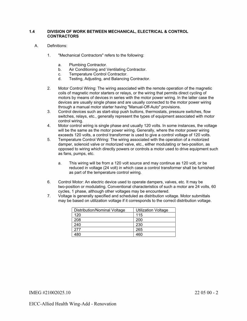
IMEG #21002025.10 22 05 00 - 2
EICC-Allied Health Wing-Add - Renovation
1.4 DIVISION OF WORK BETWEEN MECHANICAL, ELECTRICAL & CONTROL CONTRACTORS
A. Definitions:
1. "Mechanical Contractors" refers to the following:
a. Plumbing Contractor.b. Air Conditioning and Ventilating Contractor.c. Temperature Control Contractor.d. Testing, Adjusting, and Balancing Contractor.
2. Motor Control Wiring: The wiring associated with the remote operation of the magnetic coils of magnetic motor starters or relays, or the wiring that permits direct cycling of motors by means of devices in series with the motor power wiring. In the latter case the devices are usually single phase and are usually connected to the motor power wiring through a manual motor starter having "Manual-Off-Auto" provisions.
3. Control devices such as start-stop push buttons, thermostats, pressure switches, flow switches, relays, etc., generally represent the types of equipment associated with motor control wiring.
4. Motor control wiring is single phase and usually 120 volts. In some instances, the voltage will be the same as the motor power wiring. Generally, where the motor power wiring exceeds 120 volts, a control transformer is used to give a control voltage of 120 volts.
5. Temperature Control Wiring: The wiring associated with the operation of a motorized damper, solenoid valve or motorized valve, etc., either modulating or two-position, as opposed to wiring which directly powers or controls a motor used to drive equipment such as fans, pumps, etc.
a. This wiring will be from a 120 volt source and may continue as 120 volt, or be reduced in voltage (24 volt) in which case a control transformer shall be furnished as part of the temperature control wiring.
6. Control Motor: An electric device used to operate dampers, valves, etc. It may be two-position or modulating. Conventional characteristics of such a motor are 24 volts, 60 cycles, 1 phase, although other voltages may be encountered.
7. Voltage is generally specified and scheduled as distribution voltage. Motor submittals may be based on utilization voltage if it corresponds to the correct distribution voltage.
Distribution/Nominal Voltage Utilization Voltage120 115208 200240 230277 265480 460
IMEG #21002025.10 22 05 00 - 3
EICC-Allied Health Wing-Add - Renovation
B. General:
1. The purpose of these Specifications is to outline the Electrical and Mechanical Contractor's responsibilities related to electrical work required for items such as temperature controls, mechanical equipment, fans, chillers, compressors and the like. The exact wiring requirements for much of the equipment cannot be determined until the systems have been selected and submittals reviewed. Therefore, the electrical drawings show only known wiring related to such items. All wiring not shown on the electrical drawings, but required for mechanical systems, is the responsibility of the Mechanical Contractor.
2. Where the drawings require the Electrical Contractor to wire between equipment furnished by the Mechanical Contractor, such wiring shall terminate at terminals provided in the equipment. The Mechanical Contractor shall provide complete electrical power/controls wiring diagrams and supervision to the Electrical Contractor and designate the terminal numbers for correct wiring.
3. All electrical work shall conform to the National Electrical Code. All provisions of the Electrical Specifications concerning wiring, protection, etc., apply to wiring provided by the Mechanical Contractor unless noted otherwise.
4. Control low (24V) and control line (120V) voltage wiring, conduit, and related switches and relays required for the automatic control and/or interlock of motors and equipment, including final connection, are to be furnished and installed under Divisions 21, 22 and 23. Materials and installation to conform to Class 1 or 2 requirements.
5. All Contractors shall establish utility elevations prior to fabrication and shall coordinate their material and equipment with other trades. When a conflict arises, priority is as follows:
a. Light fixtures.b. Gravity flow piping, including steam and condensate.c. Electrical busduct.d. Sheet metal.e. Electrical cable trays, including access space.f. Sprinkler piping and other piping.g. Electrical conduits and wireway.
C. Mechanical Contractor's Responsibility:
1. Assumes responsibility for internal wiring of all equipment provided by the Mechanical Contractor, for example:
a. Computer Room Air Conditioning Units.b. Packaged Rooftop Units.
2. Assumes all responsibility for the Temperature Control wiring, when the Temperature Control Contractor is a Subcontractor to the Mechanical Contractor.
3. Shall verify all existing equipment sizes and capacities where units are to be modified, moved or replaced. Contractor shall notify Architect/Engineer of any discrepancies prior to ordering new units or replacement parts, including replacements of equipment motors.
4. Temperature Control Subcontractor's Responsibility:
a. Wiring of all devices needed to make the Temperature Control System functional.b. Verifying any control wiring on the electrical drawings as being by the Electrical
Contractor. All wiring required for the Control System, but not shown on the electrical drawings, is the responsibility of the Temperature Control Subcontractor.
IMEG #21002025.10 22 05 00 - 4
EICC-Allied Health Wing-Add - Renovation
c. Coordinating equipment locations (such as relays, transformers, etc.) with the Electrical Contractor, where wiring of the equipment is by the Electrical Contractor.
5. This Contractor is responsible for coordination of utilities with all other Contractors. If any field coordination conflicts are found, the Contractor shall coordinate with other Contractors to determine a viable layout.
D. Electrical Contractor's Responsibility:
1. Provides all combination starters, manual starters and disconnect devices shown on the Electrical Drawings or indicated to be by the Electrical Contractor on the Mechanical Drawings or Specifications.
2. Installs and wires all remote control devices furnished by the Mechanical Contractor or Temperature Control Subcontractor when so noted on the Electrical Drawings.
3. Provides motor control and temperature control wiring, where so noted on the drawings.4. Coordinate with the Mechanical Contractor for size of motors and/or other electrical
devices involved with repair or replacement of existing equipment.5. Furnishes, installs and connects all relays, etc., for automatic shutdown of certain fans
upon actuation of the Fire Alarm System as indicated and specified in Division 28.6. This Contractor is responsible for coordination of utilities with all other Contractors. If any
field coordination conflicts are found, the Contractor shall coordinate with other Contractors to determine a viable layout.
1.5 COORDINATION DRAWINGS
A. Definitions:
1. Coordination Drawings: A compilation of the pertinent layout and system drawings that show the sizes and locations, including elevations, of system components and required access areas to ensure that no two objects will occupy the same space.
a. Mechanical trades shall include, but are not limited to, mechanical equipment, ductwork, fire protection systems, plumbing piping, medical gas systems, hydronic piping, steam and steam condensate piping, and any item that may impact coordination with other disciplines.
b. Electrical trades shall include, but are not limited to, electrical equipment, conduit 1.5" and larger, conduit racks, cable trays, pull boxes, transformers, raceway, busway, lighting, ceiling-mounted devices, and any item that may impact coordination with other disciplines.
c. Technology trades shall include, but are not limited to, technology equipment, racks, conduit 1.5" and larger, conduit racks, cable trays, ladder rack, pull boxes, raceway, ceiling-mounted devices, and any item that may impact coordination with other disciplines.
d. Maintenance clearances and code-required dedicated space shall be included.e. The coordination drawings shall include all underground, underfloor, in-floor, in
chase, and vertical trade items.
IMEG #21002025.10 22 05 00 - 5
EICC-Allied Health Wing-Add - Renovation
2. Spaces with open/cloud ceiling architecture shall indicate the overhead utilities and locate equipment as required to maintain clearance above lights. The intent for the installation is to maintain a maximum allowable vertical clearance and an organized/clean manner in the horizontal. Notify Architect/Engineer of the maximum clearance which can be maintained. Failure to comply will result in modifications with no cost to Owner.
a. In cloud ceiling architecture, when open cabling/wire and/or cable tray crosses gaps between ceiling clouds and/or walls, cabling is to transition to conduits to span the gaps in order to conceal cabling from below.
3. The contractors shall use the coordination process to identify the proper sequence of installation of all utilities above ceilings and in other congested areas, to ensure an orderly and coordinated end result, and to provide adequate access for service and maintenance.
B. Participation:
1. The contractors and subcontractors responsible for work defined above shall participate in the coordination drawing process.
2. One contractor shall be designated as the Coordinating Contractor for purposes of preparing a complete set of composite electronic CAD coordination drawings that include all applicable trades, and for coordinating the activities related to this process. The Coordinating Contractor for this project shall be the Mechanical Contractor.
a. The Coordinating Contractor shall utilize personnel familiar with requirements of this project and skilled as draftspersons/CAD operators, competent to prepare the required coordination drawings.
3. Electronic CAD drawings shall be submitted to the Coordinating Contractor for addition of work by other trades. IMEG will provide electronic file copies of ventilation drawings for contractor's use if the contractor signs and returns an "Electronic File Transfer" waiver provided by IMEG. IMEG will not consider blatant reproductions of original file copies an acceptable alternative for coordination drawings.
C. Drawing Requirements:
1. The file format and file naming convention shall be coordinated with and agreed to by all contractors participating in the coordination process and the Owner.
a. Scale of drawings:
1) General plans: 1/4 Inch = 1'-0" (minimum).2) Mechanical, electrical, communication rooms, and including the surrounding
areas within 10 feet: 1/2 Inch = 1'-0" (minimum).3) Shafts and risers: 1/2 Inch = 1'-0" (minimum).4) Sections of shafts and mechanical and electrical equipment rooms: 1/4 Inch
= 1'-0" (minimum).5) Sections of congested areas: 1/2 Inch = 1'-0" (minimum).
2. Ductwork layout drawings shall be the baseline system for other components. Ductwork layout drawings shall be modified to accommodate other components as the coordination process progresses.
3. There may be more drawings required for risers, top and bottom levels of mechanical rooms, and shafts.

IMEG #21002025.10 22 05 00 - 6
EICC-Allied Health Wing-Add - Renovation
4. The minimum quantity of drawings will be established at the first coordination meeting and sent to the A/E for review. Additional drawings may be required if other areas of congestion are discovered during the coordination process.
D. General:
1. Coordination drawing files shall be made available to the A/E and Owner's Representative. The A/E will only review identified conflicts and give an opinion, but will not perform as a coordinator.
2. A plotted set of coordination drawings shall be available at the project site.3. Coordination drawings are not shop drawings and shall not be submitted as such.4. The contract drawings are schematic in nature and do not show every fitting and
appurtenance for each utility. Each contractor is expected to have included in the bid sufficient fittings, material, and labor to allow for adjustments in routing of utilities made necessary by the coordination process and to provide a complete and functional system.
5. The contractors will not be allowed additional costs or time extensions due to participation in the coordination process.
6. The contractors will not be allowed additional costs or time extensions for additional fittings, reroutings or changes of duct size, that are essentially equivalent sizes to those shown on the drawings and determined necessary through the coordination process.
7. The A/E reserves the right to determine space priority of equipment in the event of spatial conflicts or interference between equipment, piping, conduit, ducts, and equipment provided by the trades.
8. Changes to the contract documents that are necessary for systems installation and coordination shall be brought to the attention of the A/E.
9. Access panels shall preferably occur only in gypsum board walls or plaster ceilings where indicated on the drawings.
a. Access to mechanical, electrical, technology, and other items located above the ceiling shall be through accessible lay-in ceiling tile areas.
b. Potential layout changes shall be made to avoid additional access panels.c. Additional access panels shall not be allowed without written approval from the A/E
at the coordination drawing stage.d. Providing additional access panels shall be considered after other alternatives are
reviewed and discarded by the A/E and the Owner's Representative.e. When additional access panels are required, they shall be provided without
additional cost to the Owner.
10. Complete the coordination drawing process and obtain sign off of the drawings by all contractors prior to installing any of the components.
11. Conflicts that result after the coordination drawings are signed off shall be the responsibility of the contractor or subcontractor who did not properly identify their work requirements, or installed their work without proper coordination.
12. Updated coordination drawings that reflect as-built conditions may be used as record documents.

IMEG #21002025.10 22 05 00 - 7
EICC-Allied Health Wing-Add - Renovation
1.6 QUALITY ASSURANCE
A. Contractor's Responsibility Prior to Submitting Pricing Data:
1. The Contractor is responsible for constructing complete and operating systems. The Contractor acknowledges and understands that the Contract Documents are a two-dimensional representation of a three-dimensional object, subject to human interpretation. This representation may include imperfect data, interpreted codes, utility guidelines, three-dimensional conflicts, and required field coordination items. Such deficiencies can be corrected when identified prior to ordering material and starting installation. The Contractor agrees to carefully study and compare the individual Contract Documents and report at once in writing to the Design Team any deficiencies the Contractor may discover. The Contractor further agrees to require each subcontractor to likewise study the documents and report at once any deficiencies discovered.
2. The Contractor shall resolve all reported deficiencies with the Architect/Engineer prior to awarding any subcontracts, ordering material, or starting any work with the Contractor's own employees. Any work performed prior to receipt of instructions from the Design Team will be done at the Contractor's risk.
B. Qualifications:
1. Only products of reputable manufacturers are acceptable.2. All Contractors and subcontractors shall employ only workers skilled in their trades.
C. Compliance with Codes, Laws, Ordinances:
1. Conform to all requirements of Bettendorf, Iowa Codes, Laws, Ordinances and other regulations having jurisdiction.
2. Conform to all State Codes.3. Conform to Federal Act S.3874 requiring the reduction of lead in drinking water.4. If there is a discrepancy between the codes and regulations and these specifications, the
Architect/Engineer shall determine the method or equipment used.5. If the Contractor notes, at the time of bidding, that any parts of the drawings or
specifications do not comply with the codes or regulations, Contractor shall inform the Architect/Engineer in writing, requesting a clarification. If there is insufficient time for this procedure, Contractor shall submit with the proposal a separate price to make the system comply with the codes and regulations.
6. All changes to the system made after letting of the contract, to comply with codes or requirements of Inspectors, shall be made by the Contractor without cost to the Owner.
7. If there is a discrepancy between manufacturer's recommendations and these specifications, the manufacturer's recommendations shall govern.
8. All rotating shafts and/or equipment shall be completely guarded from all contact. Partial guards and/or guards that do not meet all applicable OSHA standards are not acceptable. Contractor is responsible for providing this guarding if it is not provided with the equipment supplied.
D. Permits, Fees, Taxes, Inspections:
1. Procure all applicable permits and licenses.2. Abide by all laws, regulations, ordinances, and other rules of the State or Political
Subdivision where the work is done, or as required by any duly constituted public authority.
3. Pay all charges for permits or licenses.4. Pay all fees and taxes imposed by the State, Municipal and/or other regulatory bodies.

IMEG #21002025.10 22 05 00 - 8
EICC-Allied Health Wing-Add - Renovation
5. Pay all charges arising out of required inspections by an authorized body.6. Pay all charges arising out of required contract document reviews associated with the
project and as initiated by the Owner or authorized agency/consultant.
E. Utility Company Requirements:
1. Secure from the appropriate private or public utility company all applicable requirements.2. Comply with all utility company requirements.3. Make application for and pay for service connections, such as sewer and water.4. Make application for and pay for all meters and metering systems required by the utility
company.
F. Examination of Drawings:
1. The drawings for the plumbing work are completely diagrammatic, intended to convey the scope of the work and to indicate the general arrangements and locations of equipment, outlets, etc., and the approximate sizes of equipment.
2. Contractor shall determine the exact locations of equipment and rough-ins, and the exact routing of pipes and ducts to best fit the layout of the job.
3. Scaling of the drawings is not sufficient or accurate for determining these locations.4. Where job conditions require reasonable changes in indicated arrangements and
locations, such changes shall be made by the Contractor at no additional cost to the Owner.
5. Because of the scale of the drawings, certain basic items, such as fittings, boxes, valves, unions, etc., may not be shown, but where required by other sections of the specifications or required for proper installation of the work, such items shall be furnished and installed.
6. If an item is either on the drawings or in the specifications, it shall be included in this contract.
7. Determination of quantities of material and equipment required shall be made by the Contractor from the documents. Where discrepancies arise between drawings, schedules and/or specifications, the greater number shall govern.
8. Where used in mechanical documents, the word "furnish" shall mean supply for use, the word "install" shall mean connect complete and ready for operation, and the word "provide" shall mean to supply for use and connect complete and ready for operation.
a. Any item listed as furnished shall also be installed, unless otherwise noted.b. Any item listed as installed shall also be furnished, unless otherwise noted.
G. Field Measurements:
1. Verify all pertinent dimensions at the job site before ordering any materials or fabricating any supports, pipes or ducts.
H. Electronic Media/Files:
1. Construction drawings for this project have been prepared utilizing Revit.2. Contractors and Subcontractors may request electronic media files of the contract
drawings and/or copies of the specifications. Specifications will be provided in PDF format.
3. Upon request for electronic media, the Contractor shall complete and return a signed "Electronic File Transmittal" form provided by IMEG.
4. If the information requested includes floor plans prepared by others, the Contractor will be responsible for obtaining approval from the appropriate Design Professional for use of that part of the document.
IMEG #21002025.10 22 05 00 - 9
EICC-Allied Health Wing-Add - Renovation
5. The electronic contract documents can be used for preparation of shop drawings and as-built drawings only. The information may not be used in whole or in part for any other project.
6. The drawings prepared by IMEG for bidding purposes may not be used directly for ductwork layout drawings or coordination drawings.
7. The use of these CAD documents by the Contractor does not relieve them from their responsibility for coordination of work with other trades and verification of space available for the installation.
8. The information is provided to expedite the project and assist the Contractor with no guarantee by IMEG as to the accuracy or correctness of the information provided. IMEG accepts no responsibility or liability for the Contractor's use of these documents.
1.7 SUBMITTALS
A. Submittals shall be required for the following items, and for additional items where required elsewhere in the specifications or on the drawings.
1. Submittals List:
Referenced Specification Section Submittal Item22 05 00 Owner Training Agenda22 05 03 Fire Seal Systems22 10 30 Plumbing Specialties22 40 00 Plumbing Fixtures
B. General Submittal Procedures: In addition to the provisions of Division 1, the following are required:
1. Transmittal: Each transmittal shall include the following:
a. Dateb. Project title and numberc. Contractor's name and addressd. Division of work (e.g., plumbing, heating, ventilating, etc.)e. Description of items submitted and relevant specification numberf. Notations of deviations from the contract documentsg. Other pertinent data
2. Submittal Cover Sheet: Each submittal shall include a cover sheet containing:
a. Dateb. Project title and numberc. Architect/Engineerd. Contractor and subcontractors' names and addressese. Supplier and manufacturer's names and addressesf. Division of work (e.g., plumbing, heating, ventilating, etc.)g. Description of item submitted (using project nomenclature) and relevant
specification numberh. Notations of deviations from the contract documentsi. Other pertinent dataj. Provide space for Contractor's review stamps

IMEG #21002025.10 22 05 00 - 10
EICC-Allied Health Wing-Add - Renovation
3. Composition:
a. Submittals shall be submitted using specification sections and the project nomenclature for each item.
b. Individual submittal packages shall be prepared for items in each specification section. All items within a single specification section shall be packaged together where possible. An individual submittal may contain items from multiple specifications sections if the items are intimately linked (e.g., pumps and motors).
c. All sets shall contain an index of the items enclosed with a general topic description on the cover.
4. Content: Submittals shall include all fabrication, erection, layout, and setting drawings; manufacturers' standard drawings; schedules; descriptive literature, catalogs and brochures; performance and test data; electrical power criteria (e.g., voltage, phase, amps, horsepower, kW, etc.) wiring and control diagrams; Short Circuit Current Rating (SCCR); dimensions; shipping and operating weights; shipping splits; service clearances; and all other drawings and descriptive data of materials of construction as may be required to show that the materials, equipment or systems and the location thereof conform to the requirements of the contract documents.
5. Contractor's Approval Stamp:
a. The Contractor shall thoroughly review and approve all shop drawings before submitting them to the Architect/Engineer. The Contractor shall stamp, date and sign each submittal certifying it has been reviewed.
b. Unstamped submittals will be rejected.c. The Contractor's review shall include, but not be limited to, verification of the
following:
1) Only approved manufacturers are used.2) Addenda items have been incorporated.3) Catalog numbers and options match those specified.4) Performance data matches that specified.5) Electrical characteristics and loads match those specified.6) Equipment connection locations, sizes, capacities, etc. have been
coordinated with other affected trades.7) Dimensions and service clearances are suitable for the intended location.8) Equipment dimensions are coordinated with support steel, housekeeping
pads, openings, etc.9) Constructability issues are resolved (e.g., weights and dimensions are
suitable for getting the item into the building and into place, sinks fit into countertops, etc.).
d. The Contractor shall review, stamp and approve all subcontractors' submittals as described above.
e. The Contractor's approval stamp is required on all submittals. Approval will indicate the Contractor's review of all material and a complete understanding of exactly what is to be furnished. Contractor shall clearly mark all deviations from the contract documents on all submittals. If deviations are not marked by the Contractor, then the item shall be required to meet all drawing and specification requirements.

IMEG #21002025.10 22 05 00 - 11
EICC-Allied Health Wing-Add - Renovation
6. Submittal Identification and Markings:
a. The Contractor shall clearly mark each item with the same nomenclature applied on the drawings or in the specifications.
b. The Contractor shall clearly indicate the size, finish, material, etc.c. Where more than one model is shown on a manufacturer's sheet, the Contractor
shall clearly indicate exactly which item and which data is intended.d. All marks and identifications on the submittals shall be unambiguous.
7. Schedule submittals to expedite the project. Coordinate submission of related items.8. Identify variations from the contract documents and product or system limitations that
may be detrimental to the successful performance of the completed work.9. Reproduction of contract documents alone is not acceptable for submittals.10. Incomplete submittals will be rejected without review. Partial submittals will only be
reviewed with prior approval from the Architect/Engineer.11. Submittals not required by the contract documents may be returned without review.12. The Architect/Engineer's responsibility shall be to review one set of shop drawing
submittals for each product. If the first submittal is incomplete or does not comply with the drawings and/or specifications, the Contractor shall be responsible to bear the cost for the Architect/Engineer to recheck and handle the additional shop drawing submittals.
13. Submittals shall be reviewed and approved by the Architect/Engineer before releasing any equipment for manufacture or shipment.
14. Contractor's responsibility for errors, omissions or deviation from the contract documents in submittals is not relieved by the Architect/Engineer's approval.
15. Schedule shall allow for adequate time to perform orderly and proper review of submittals, including time for consultants and Owner if required, and resubmittals by Contractor if necessary, and to cause no delay in Work or in activities of Owner or other contractors.
a. Allow at least two weeks for Architect’s/Engineer's review and processing of each submittal.
16. Architect/Engineer reserves the right to withhold action on a submittal which, in the Architect/Engineer’s opinion, requires coordination with other submittals until related submittals are received. The Architect/Engineer will notify the Contractor, in writing, when they exercise this right.
C. Electronic Submittal Procedures:
1. Distribution: Email submittals as attachments to all parties designated by the Architect/Engineer, unless a web-based submittal program is used.
2. Transmittals: Each submittal shall include an individual electronic letter of transmittal.3. Format: Electronic submittals shall be in PDF format only. Scanned copies, in PDF
format, of paper originals are acceptable. Submittals that are not legible will be rejected. Do not set any permission restrictions on files; protected, locked, or secured documents will be rejected.
4. File Names: Electronic submittal file names shall include the relevant specification section number followed by a description of the item submitted, as follows. Where possible, include the transmittal as the first page of the PDF instead of using multiple electronic files.
a. Submittal file name: 22 XX XX.description.YYYYMMDDb. Transmittal file name: 22 XX XX.description.YYYYMMDD
IMEG #21002025.10 22 05 00 - 12
EICC-Allied Health Wing-Add - Renovation
5. File Size: Files shall be transmitted via a pre-approved method. Larger files may require an alternative transfer method, which shall also be pre-approved.
1.8 SCHEDULE OF VALUES
A. The requirements herein are in addition to the provisions of Division 1.
B. Format:
1. Use AIA Document Continuation Sheets G703 or another similar form approved by the Owner and Architect/Engineer.
2. Submit in Excel format.3. Support values given with substantiating data.
C. Preparation:
1. Itemize work required by each specification section and list all providers. All work provided by subcontractors and major suppliers shall be listed on the Schedule of Values. List each subcontractor and supplier by company name.
2. Break down all costs into:
a. Material: Delivered cost of product with taxes paid.b. Labor: Labor cost, excluding overhead and profit.
1.9 CHANGE ORDERS
A. A detailed material and labor takeoff shall be prepared for each change order, along with labor rates and markup percentages. Change orders shall be broken down by sheet or associated individual line item indicated in the change associated narrative, whichever provides the most detailed breakdown. Change orders with inadequate breakdown will be rejected.
B. Itemized pricing with unit cost shall be provided from all distributors and associated subcontractors.
C. Change order work shall not proceed until authorized.
1.10 EQUIPMENT SUPPLIERS' INSPECTION
A. The following equipment shall not be placed in operation until a competent installation and service representative of the manufacturer has inspected the installation and certified that the equipment is properly installed, adjusted and lubricated; that preliminary operating instructions have been given; and that the equipment is ready for operation:
1. Fire Seal Systems
B. Contractor shall arrange for and obtain supplier's on-site inspection(s) at proper time(s) to assure each phase of equipment installation and/or connection is in accordance with the manufacturer's instructions.
C. Submit copies of start-up reports to the Architect/Engineer and include copies of Owner's Operation and Maintenance Manuals.

IMEG #21002025.10 22 05 00 - 13
EICC-Allied Health Wing-Add - Renovation
1.11 PRODUCT DELIVERY, STORAGE, HANDLING & MAINTENANCE
A. Exercise care in transporting and handling to avoid damage to materials. Store materials on the site to prevent damage. Keep materials clean, dry and free from harmful conditions. Immediately remove any materials that become wet or that are suspected of becoming contaminated with mold or other organisms.
B. Keep all bearings properly lubricated and all belts properly tensioned and aligned.
C. Coordinate the installation of heavy and large equipment with the General Contractor and/or Owner. If the Mechanical Contractor does not have prior documented experience in rigging and lifting similar equipment, he/she shall contract with a qualified lifting and rigging service that has similar documented experience. Follow all equipment lifting and support guidelines for handling and moving.
D. Contractor is responsible for moving equipment into the building and/or site. Contractor shall review site prior to bid for path locations and any required building modifications to allow movement of equipment. Contractor shall coordinate the work with other trades.
1.12 WARRANTY
A. Provide one-year warranty, unless otherwise noted, to the Owner for all fixtures, equipment, materials, and workmanship.
B. The warranty period for all work in this Division of the specifications shall commence on the date of final acceptance, unless a whole or partial system or any separate piece of equipment or component is put into use for the benefit of any party other than the installing contractor with prior written authorization. In this instance, the warranty period shall commence on the date when such whole system, partial system or separate piece of equipment or component is placed in operation and accepted in writing by the Owner.
C. Warranty requirements shall extend to correction, without cost to the Owner, of all Work found to be defective or nonconforming to the contract documents. The Contractor shall bear the cost of correcting all damage resulting from defects or nonconformance with contract documents.
1.13 INSURANCE
A. Contractor shall maintain insurance coverage as set forth in Division 0 of these specifications.

IMEG #21002025.10 22 05 00 - 14
EICC-Allied Health Wing-Add - Renovation
PART 2 - PRODUCTS (Not Used)
PART 3 - EXECUTION
3.1 JOBSITE SAFETY
A. Neither the professional activities of the Architect/Engineer, nor the presence of the Architect/Engineer or the employees and subconsultants at a construction site, shall relieve the Contractor and other entity of their obligations, duties and responsibilities including, but not limited to, construction means, methods, sequence, techniques or procedures necessary for performing, superintending or coordinating all portions of the work of construction in accordance with the contract documents and any health or safety precautions required by any regulatory agencies. The Architect/Engineer and personnel have no authority to exercise any control over any construction contractor or other entity or their employees in connection with their work or any health or safety precautions. The Contractor is solely responsible for jobsite safety. The Architect/Engineer and the Architect/Engineer's consultants shall be indemnified and shall be made additional insureds under the Contractor's general liability insurance policy.
3.2 EXCAVATION, FILL, BACKFILL, COMPACTION
A. General:
1. Prior to the commencement of any excavation or digging, the Contractor shall verify all underground utilities with the regional utility locator. Provide prior notice to the locator before excavations. Contact information for most regional utility locaters can be found at the following website (https://call811.com/) or by calling 811.
2. The Contractor shall do all excavating, filling, backfilling and compacting associated with the work.
B. Excavation:
1. Make all excavations to accurate, solid, undisturbed earth, and to proper dimensions.2. Where excavations are made in error below foundations, concrete of same strength as
specified for the foundations or thoroughly compacted sand-gravel fill, as determined by the Architect/Engineer, shall be placed in such excess excavations. Place thoroughly compacted, clean, stable fill in excess excavations under slabs on grade, at the Contractor's expense.
3. Trim bottom and sides of excavations to grades required for foundations.4. Protect excavations against frost and freezing.5. Take care in excavating not to damage surrounding structures, equipment, or buried
pipe. Do not undermine footing or foundation.6. Perform all trenching in a manner to prevent cave-ins and risk to workers.7. Where original surface is pavement or concrete, the surface shall be saw cut to provide
clean edges and assist in the surface restoration.8. Where satisfactory bearing soil for foundations is not found at the indicated levels, the
Architect/Engineer or their representative shall be notified immediately, and no further work shall be done until further instructions are given by the Architect/Engineer or their representative.
C. Dewatering:
1. Contractor shall furnish, install, operate, and remove all dewatering pumps and pipes needed to keep trenches and pits free of water.
IMEG #21002025.10 22 05 00 - 15
EICC-Allied Health Wing-Add - Renovation
D. Underground Obstructions:
1. Known underground piping, foundations, and other obstructions in the vicinity of construction are shown on the drawings. Use great care in making installations near underground obstruction.
2. If objects not shown on the drawings are encountered, remove, relocate, or perform extra work as directed by the Architect/Engineer.
E. Fill and Backfilling:
1. No rubbish or waste material is permitted for fill or backfill.2. Provide all necessary sand and/or CA6 for backfilling.3. Native soil materials may be used as backfill if approved by the Geotechnical Engineer.4. Dispose of the excess excavated earth as directed.5. Backfill materials (native soil material, sand, and/or CA6) shall be suitable for required
compaction, clean and free of perishable materials and stones greater than 4 inches in diameter. Water shall not be permitted to rise in unbackfilled trenches. No material shall be used for backfilling that contains frozen earth, debris, or earth with a high void content.
6. Backfill all trenches and excavations immediately after installing pipes or removal of forms, unless other protection is provided.
7. Around piers and isolated foundations and structures, backfill and fill shall be placed and consolidated simultaneously on all sides to prevent wedge action and displacement. Fill and backfill materials shall be spread in 6 inch uniform horizontal layers with each layer compacted separately to required density.
8. Lay all piping on a compacted bed of CA6 at least 3 inches deep. Backfill around pipes with CA6, 6 inch layers, and compact each layer.
9. Use native soil material (if approved), sand, or CA6 for backfill up to grade for all piping under slabs or paved areas. All other piping shall have sand or CA6 backfill to 6 inches above the top of the pipe.
10. Place all backfill above the sand/CA6 in uniform layers not exceeding 6 inches deep. Each layer shall be placed, then carefully and uniformly tamped, to eliminate lateral or vertical displacement.
11. Where the fill and backfill will ultimately be under a building, floor or paving, each layer of fill shall be compacted to 95% of the maximum density determined by AASHTO Designation T-99 or ASTM Designation D-698. Moisture content of soil at time of compaction shall not exceed plus or minus 2% of optimum moisture content determined by AASHTO T-99 or ASTM D-698 test.
F. Surface Restoration:
1. Where trenches are cut through graded, planted, or landscaped areas, the areas shall be restored to the original condition. Replace all planting removed or damaged to its original condition. A minimum of 6 inches of topsoil shall be applied where disturbed areas are to be seeded or sodded.
2. Concrete or asphalt type pavement, seal coat, rock, gravel or earth surfaces removed or damaged shall be replaced with comparable materials and restored to original condition.
3.3 ARCHITECT/ENGINEER OBSERVATION OF WORK
A. The Contractor shall provide seven (7) calendar days' notice to the Architect/Engineer prior to:
1. Placing fill over underground and underslab utilities.2. Covering exterior walls, interior partitions and chases.3. Installing hard or suspended ceilings and soffits.
IMEG #21002025.10 22 05 00 - 16
EICC-Allied Health Wing-Add - Renovation
B. The Architect/Engineer will have the opportunity to review the installation and provide a written report noting deficiencies requiring correction. The Contractor's schedule shall account for these reviews and show them as line items in the approved schedule.
C. Above-Ceiling Final Observation
1. All work above the ceilings must be complete prior to the Architect/Engineer's review. This includes, but is not limited to:
a. Pipe insulation is installed and fully sealed.b. Pipe wall penetrations are sealed.c. Pipe identification and valve tags are installed.
2. In order to prevent the Above-Ceiling Final Observation from occurring too early, the Contractor shall review the status of the work and certify, in writing, that the work is ready for the Above-Ceiling Final Observation.
3. It is understood that if the Architect/Engineer finds the ceilings have been installed prior to this review and prior to 7 days elapsing, the Architect/Engineer may not recommend further payments to the contractor until such time as full access has been provided.
3.4 PROJECT CLOSEOUT
A. The following paragraphs supplement the requirements of Division 1.
B. Final Jobsite Observation:
1. In order to prevent the Final Jobsite Observation from occurring too early, the Contractor is required to review the completion status of the project and certify that the job is ready for the final jobsite observation.
2. Attached to the end of this section is a typical list of items that represent the degree of job completeness expected prior to requesting a review.
3. Upon Contractor certification that the project is complete and ready for a final observation, the Contractor shall sign the attached certification and return it to the Architect/Engineer so that the final observation can be scheduled.
4. It is understood that if the Architect/Engineer finds the job not ready for the final observation and that additional trips and observations are required to bring the project to completion, the costs incurred by the Architect/Engineer's additional time and expenses will be deducted from the Contractor's contract retainage prior to final payment at the completion of the job.
C. Before final payment is authorized, this Contractor must submit the following:
1. Operation and maintenance manuals with copies of approved shop drawings.2. Record documents including marked-up drawings and specifications.3. A report documenting the instructions given to the Owner's representatives complete with
the number of hours spent in the instruction. The report shall bear the signature of an authorized agent of This Contractor and shall be signed by the Owner's representatives.
4. Start-up reports on all equipment requiring a factory installation inspection or start-up.5. Provide spare parts, maintenance, and extra materials in quantities specified in individual
specification sections. Deliver to project site; receipt by Architect/Engineer required prior to final payment approval.

IMEG #21002025.10 22 05 00 - 17
EICC-Allied Health Wing-Add - Renovation
3.5 OPERATION AND MAINTENANCE MANUALS
A. General:
1. Provide an electronic copy of the O&M manuals as described below for Architect/Engineer's review and approval. The electronic copy shall be corrected as required to address the Architect/Engineer's comments. Once corrected, electronic copies and paper copies shall be distributed as directed by the Architect/Engineer.
2. Approved O&M manuals shall be completed and in the Owner's possession prior to Owner's acceptance and at least 10 days prior to instruction of operating personnel.
B. Electronic Submittal Procedures:
1. Distribution: Email the O&M manual as attachments to all parties designated by the Architect/Engineer.
2. Transmittals: Each submittal shall include an individual electronic letter of transmittal.3. Format: Electronic submittals shall be in PDF format only. Scanned copies, in PDF
format, of paper originals are acceptable. Submittals that are not legible will be rejected. Do not set any permission restrictions on files; protected, locked, or secured documents will be rejected.
4. File Names: Electronic submittal file names shall include the relevant specification section number followed by a description of the item submitted, as follows. Where possible, include the transmittal as the first page of the PDF instead of using multiple electronic files.
a. O&M file name: O&M.div22.contractor.YYYYMMDDb. Transmittal file name: O&Mtransmittal.div22.contractor.YYYYMMDD
5. File Size: Files shall be transmitted via a pre-approved method. Larger files may require an alternative transfer method, which shall also be pre-approved.
6. Provide the Owner with an approved copy of the O&M manual on compact discs (CD), digital video discs (DVD), or flash drives with a permanently affixed label, printed with the title "Operation and Maintenance Instructions", title of the project and subject matter of disc/flash drive when multiple disc/flash drives are required.
7. All text shall be searchable.8. Bookmarks shall be used, dividing information first by specification section, then systems,
major equipment and finally individual items. All bookmark titles shall include the nomenclature used in the construction documents and shall be an active link to the first page of the section being referenced.
C. Operation and Maintenance Instructions shall include:
1. Title Page: Include title page with project title, Architect, Engineer, Contractor, all subcontractors, and major equipment suppliers, with addresses, telephone numbers, website addresses, email addresses and point of contacts. Website URLs and email addresses shall be active links in the electronic submittal.
2. Table of Contents: Include a table of contents describing specification section, systems, major equipment, and individual items.
3. Copies of all final approved shop drawings and submittals. Include Architect's/Engineer's shop drawing review comments. Insert the individual shop drawing directly after the Operation and Maintenance information for the item(s) in the review form.
4. Copy of final approved test and balance reports.5. Copies of all factory inspections and/or equipment startup reports.6. Copies of warranties.

IMEG #21002025.10 22 05 00 - 18
EICC-Allied Health Wing-Add - Renovation
7. Schematic electrical power/controls wiring diagrams of the equipment that have been updated for field conditions. Field wiring shall have label numbers to match drawings.
8. Dimensional drawings of equipment.9. Capacities and utility consumption of equipment.10. Detailed parts lists with lists of suppliers.11. Operating procedures for each system.12. Maintenance schedule and procedures. Include a chart listing maintenance requirements
and frequency.13. Repair procedures for major components.14. List of lubricants in all equipment and recommended frequency of lubrication.15. Instruction books, cards, and manuals furnished with the equipment.16. Owner and Contractor attendance list for domestic water systems operation,
maintenance, and flushing training.
3.6 INSTRUCTING THE OWNER'S REPRESENTATIVES
A. Adequately instruct the Owner's designated representatives in the maintenance, care, and operation of all systems installed under this contract.
B. Provide verbal and written instructions to the Owner's representatives by FACTORY PERSONNEL in the care, maintenance, and operation of the equipment and systems.
C. Contractor shall make a DVD video recording of instructions to the Owner while explaining the system so additional personnel may view the instructions at a later date. The video recording shall be the property of the Owner.
D. The instructions shall include:
1. Explanation of all system flow diagrams.2. Maintenance of equipment.3. Start-up procedures for all major equipment.4. Explanation of seasonal system changes.
E. Operating Instructions:
1. Contractor is responsible for all instructions to the Owner's representatives for the mechanical and control systems.
2. If the Contractor does not have staff that can adequately provide the required instructions the Contractor shall include in the bid an adequate amount to reimburse the Owner for the Architect/Engineer to perform these services.
3.7 SYSTEM STARTING AND ADJUSTING
A. The plumbing systems shall be complete and operating. System startup, testing, adjusting, and balancing to obtain satisfactory system performance is the responsibility of the Contractor. This includes calibration and adjustments of all controls, noise level adjustments and final adjustments as required.
B. Complete all manufacturer-recommended startup procedures and checklists to verify proper motor rotation, electrical power voltage is within equipment limitations, equipment controls maintain pressures and temperatures within acceptable ranges, all filters and protective guards are in-place, acceptable access is provided for maintenance and servicing, and equipment operation does not pose a danger to personnel or property.
IMEG #21002025.10 22 05 00 - 19
EICC-Allied Health Wing-Add - Renovation
C. Contractor shall adjust the plumbing systems and controls at season changes during the one year warranty period, as required, to provide satisfactory operation and to prove performance of all systems in all seasons.
D. All operating conditions and control sequences shall be tested during the start-up period. Test all interlocks, safety shutdowns, controls, and alarms.
E. The Contractor, subcontractors, and equipment suppliers shall have skilled technicians to ensure that all systems perform properly. If the Architect/Engineer is requested to visit the job site for trouble shooting, assisting in start-up, obtaining satisfactory equipment operation, resolving installation and/or workmanship problems, equipment substitution issues or unsatisfactory system performance, including call backs during the warranty period, through no fault of the design; the Contractor shall reimburse the Owner on a time and materials basis for services rendered at the Architect/Engineer's standard hourly rates in effect when the services are requested. The Contractor shall pay the Owner for services required that are product, installation or workmanship related. Payment is due within 30 days after services are rendered.
3.8 RECORD DOCUMENTS
A. The following paragraphs supplement Division 1 requirements.
B. Maintain at the job site a separate and complete set of plumbing drawings and specifications with all changes made to the systems clearly and permanently marked in complete detail.
C. Mark drawings to indicate revisions to piping size and location, both exterior and interior; including locations devices, requiring periodic maintenance or repair; actual equipment locations, dimensioned from column lines; actual inverts and locations of underground piping; concealed equipment, dimensioned from column lines; mains and branches of piping systems, with valves and control devices located and numbered, concealed unions located, and with items requiring maintenance located; Change Orders; concealed control system devices.
3.9 PAINTING
A. Paint all equipment that is marred or damaged prior to the Owner's acceptance. Paint and color shall match original equipment paint and shall be obtained from the equipment supplier if available.
B. Equipment in finished areas that will be painted to match the room decor will be painted by others. Should this Contractor install equipment in a finished area after the area has been painted, the Contractor shall have the equipment and all its supports, hangers, etc., painted to match the room decor.
C. Equipment in occupied spaces, or if standard to the unit, shall have a baked primer with baked enamel finish coat free from scratches, abrasions, chips, etc. If color option is specified or is standard to the unit, this Contractor shall, before ordering, verify with the Architect/Engineer the color preference and furnish this color.
D. Paint all outdoor uninsulated steel gas piping on the roof, the color selected by Owner or Architect/Engineer.
E. Paint all outdoor exposed natural gas piping the color selected by Owner or Architect/Engineer.

IMEG #21002025.10 22 05 00 - 20
EICC-Allied Health Wing-Add - Renovation
3.10 ADJUST AND CLEAN
A. Thoroughly clean all equipment and systems prior to the Owner's final acceptance of the project. Clean all foreign paint, grease, oil, dirt, labels, stickers, and other foreign material from all equipment.
B. Clean all areas where moisture is present. Immediately report any mold, biological growth, or water damage.
C. Remove all rust, scale, dirt, oils, stickers and thoroughly clean exterior of all exposed piping, hangers, and accessories.
D. Remove all rubbish, debris, etc., accumulated during construction from the premises.
3.11 IAQ MAINTENANCE FOR OCCUPIED FACILITIES UNDER CONSTRUCTION
A. Contractors shall make all reasonable efforts to prevent construction activities from affecting the air quality of the occupied areas of the building or outdoor areas near the building. These measures shall include, but not be limited to:
1. All contractors shall endeavor to minimize the amount of contaminants generated during construction. Methods to be employed shall include, but not be limited to:
a. Minimizing the amount of dust generated.b. Reducing solvent fumes and VOC emissions.c. Maintain good housekeeping practices, including sweeping and periodic dust and
debris removal. There should be no visible haze in the air.d. Protect stored on-site and installed absorptive materials from moisture damage.
2. Request that the Owner designate an IAQ representative.3. Review and receive approval from the Owner's IAQ representative for all IAQ-related
construction activities and negative pressure containment plans.4. Inform the IAQ representative of all conditions that could adversely impact IAQ, including
operations that will produce higher than normal dust production or odors.5. Schedule activities that may cause IAQ conditions that are not acceptable to the Owner's
IAQ representative during unoccupied periods.6. Unless no other access is possible, the entrance to construction site shall not be through
the existing facility.7. To minimize growth of infectious organisms, do not permit damp areas in or near the
construction area to remain for over 24 hours.8. In addition to the criteria above, provide measures as recommended in the SMACNA
"IAQ Guidelines for Occupied Buildings Under Construction".
IMEG #21002025.10 22 05 00 - 21
EICC-Allied Health Wing-Add - Renovation
READINESS CERTIFICATION PRIOR TO FINAL JOBSITE OBSERVATION
To prevent the final job observation from occurring too early, we require that the Contractor review the completion status of the project and, by copy of this document, certify that the job is indeed ready for the final job observation. The following is a typical list of items that represent the degree of job completeness expected prior to your requesting a final job observation.
1. Penetrations fire sealed and labeled in accordance with specifications.2. All plumbing fixtures installed and caulked.3. Pipe insulation complete, pipes labeled and valves tagged.4. Owner and Contractor attendance list for domestic water systems operation, maintenance, and flushing training.
Accepted by:
Prime Contractor _______________________________________________
By ___________________________________ Date ___________________
Upon Contractor certification that the project is complete and ready for a final job observation, we require the Contractor to sign this agreement and return it to the Architect/Engineer so that the final observation can be scheduled.
It is understood that if the Architect/Engineer finds the job not ready for the final observation and that additional trips and observations are required to bring the project to completion, the costs incurred by the Architect/Engineers for additional time and expenses will be deducted from the Contractor's contract retainage prior to final payment at the completion of the job.
END OF SECTION 22 05 00
IMEG #21002025.10 22 05 03 - 1
EICC-Allied Health Wing-Add - Renovation
SECTION 22 05 03 - THROUGH PENETRATION FIRESTOPPING
PART 1 - GENERAL
1.1 SECTION INCLUDES
A. Through-Penetration Firestopping.
1.2 QUALITY ASSURANCE
A. Manufacturer: Company specializing in manufacturing products specified in this Section.
B. Installer: Individuals performing work shall be certified by the manufacturer of the system selected for installation.
1.3 REFERENCES
A. UL 263 - Fire Tests of Building Construction and Materials
B. UL 723 - Surface Burning Characteristics of Building Materials
C. ANSI/UL 1479 - Fire Tests of Through Penetration Firestops
D. UL 2079 - Tests for Fire Resistance of Building Joint Systems
E. UL Fire Resistance Directory Through Penetration Firestop Systems (XHEZ)
F. Intertek / Warnock Hersey - Directory of Listed Products
G. ASTM E84 - Standard Test Method for Surface Burning Characteristics of Building Materials
H. ASTM E814 - Standard Test Method for Fire Tests of Through-Penetration Firestops
I. The Building Officials and Code Administrators National Building Code
J. 1997 Uniform Building Code
K. 2015 International Building Code
L. NFPA 5000 - Building Construction Safety Code
1.4 SUBMITTALS
A. Submit under provisions of Section 22 05 00.
B. Submit Firestopping Installers Certification for all installers on the project.
C. Shop Drawings: Submit for each condition requiring firestopping. Include descriptions of the specific penetrating item, actual wall/floor construction, manufacturer's installation instructions, and UL or Intertek / Warnock Hersey Assembly number.

IMEG #21002025.10 22 05 03 - 2
EICC-Allied Health Wing-Add - Renovation
D. Through-Penetration Firestop System Schedule: Indicate locations of each through-penetration firestop system, along with the following information:
1. Types of penetrating items.2. Types of constructions penetrated, including fire-resistance ratings and, where
applicable, thicknesses of construction penetrated.3. Through-penetration firestop systems for each location identified by firestop design
designation of qualified testing and inspecting agency.4. F ratings for each firestop system.
E. Maintain a notebook on the job site at all times that contains copies of approved submittals for all through penetration firestopping to be installed. Notebook shall be made available to the Authority Having Jurisdiction at their request and turned over to the Owner at the end of construction as part of the O&M Manuals.
1.5 DELIVERY, STORAGE, AND HANDLING
A. Store, protect and handle products on site. Accept material on site in factory containers and packing. Inspect for damage. Protect from deterioration or damage due to moisture, temperature changes, contaminants, or other causes. Follow manufacturer's instructions for storage.
B. Install material prior to expiration of product shelf life.
1.6 PERFORMANCE REQUIREMENTS
A. General: For penetrations through the following fire-resistance-rated constructions, including both empty openings and openings containing penetrating items, provide through-penetration firestop systems that are produced and installed to resist spread of fire according to requirements indicated, resist passage of smoke and other gases, and maintain original fire-resistance rating of construction penetrated.
1. Fire-resistance-rated walls including fire partitions, fire barriers, and smoke barriers.2. Fire-resistance-rated horizontal assemblies including floors, floor/ceiling assemblies, and
ceiling membranes of roof/ceiling assemblies.
B. Rated Systems: Provide through-penetration firestop systems with the following ratings determined per UL 1479:
1. F-Rated Systems: Provide through-penetration firestop systems with F-ratings indicated, but not less than that equaling or exceeding fire-resistance rating of constructions penetrated.
C. For through-penetration firestop systems exposed to light, traffic, moisture, or physical damage, provide products that, after curing, do not deteriorate when exposed to these conditions both during and after construction.
D. For through-penetration firestop systems exposed to view, provide products with flame-spread and smoke-developed indexes of less than 25 and 450, respectively, as determined per ASTM E 84.
E. For through-penetration firestop systems in air plenums, provide products with flame-spread and smoke-developed indexes of less than 25 and 50, respectively, as determined per ASTM E 84.

IMEG #21002025.10 22 05 03 - 3
EICC-Allied Health Wing-Add - Renovation
1.7 MEETINGS
A. Pre-installation meeting: A pre-installation meeting shall be scheduled and shall include the General Contractor, all Subcontractors associated with the installation of systems penetrating fire barriers, Firestopping Manufacturer's Representative, and the Owner.
1. Review foreseeable methods related to firestopping work.2. Tour representative areas where firestopping is to be installed; inspect and discuss each
type of condition and each type of substrate that will be encountered, and preparation to be performed by other trades.
1.8 WARRANTY
A. Provide one year warranty on parts and labor.
B. Warranty shall cover repair or replacement of firestop systems which fail in joint adhesion, cohesion, abrasion resistance, weather resistance, extrusion resistance, migration resistance, stain resistance, general durability, or appear to deteriorate in any manner not clearly specified by the manufacturer as an inherent quality of the material.
PART 2 - PRODUCTS
2.1 MANUFACTURERS
A. Products: Subject to compliance with requirements, provide one of the through-penetration firestop systems indicated for each application that are produced by one of the following manufacturers. All firestopping systems installed shall be provided by a single manufacturer.
1. 3M; Fire Protection Products Division.2. Hilti, Inc.3. RectorSeal Corporation, Metacaulk.4. Tremco; Sealant/Weatherproofing Division.5. Johns-Manville.6. Specified Technologies Inc. (S.T.I.)7. Spec Seal Firestop Products8. AD Firebarrier Protection Systems9. Dow Corning Corp.10. Fire Trak Corp.11. International Protective Coating Corp.
2.2 THROUGH PENETRATION FIRESTOP SYSTEMS
A. Provide materials and systems classified by or listed by Intertek / Warnock Hersey to provide firestopping equal to time rating of construction being penetrated.
B. All firestopping materials shall be free of asbestos, lead, PCB's, and other materials that would require hazardous waste removal.
C. Firestopping shall be flexible to allow for normal penetrating item movement due to expansion and contraction.
D. Firestopping systems for plumbing and wet pipe sprinkler piping shall be moisture resistant.

IMEG #21002025.10 22 05 03 - 4
EICC-Allied Health Wing-Add - Renovation
E. Provide firestopping systems capable of supporting floor loads where systems are exposed to possible floor loading or traffic.
F. Provide firestopping systems allowing continuous insulation for all insulated pipes.
G. Provide firestopping systems classified by UL or listed by Intertek / Warnock Hersey for penetrations through all fire rated construction. Firestopping systems shall be selected from the UL or listed by Intertek / Warnock Hersey Fire Resistance Directory Category XHEZ based on substrate construction and penetrating item size and material and shall fall within the range of numbers listed:
1. Combustible Framed Floors and Chase Walls - 1 or 2 Hour Rated:
a. F Rating = Floor/Wall Rating
Penetrating Item UL System No.No Penetrating Item FC 0000-0999*Metallic Pipe or Conduit FC 1000-1999Non-Metallic Pipe or Conduit FC 2000-2999Electrical Cables FC 3000-3999Cable Trays FC 4000-4999Insulated Pipes FC 5000-5999Bus Duct and Misc. Electrical FC 6000-6999Duct without Damper and Misc. Mechanical FC 7000-7999Multiple Penetrations FC 8000-8999*Alternate method of firestopping is patching opening to match original rated construction.
2. Non-Combustible Framed Walls - 1 or 2 Hour Rated:
a. F Rating = Floor/Wall Rating
Penetrating Item UL System No.No Penetrating Item WL 0000-0999*Metallic Pipe or Conduit WL 1000-1999Non-Metallic Pipe or Conduit WL 2000-2999Electrical Cables WL 3000-3999Cable Trays WL 4000-4999Insulated Pipes WL 5000-5999Bus Duct and Misc. Electrical WL 6000-6999Duct without Damper and Misc. Mechanical WL 7000-7999Multiple Penetrations WL 8000-8999*Alternate method of firestopping is patching opening to match original rated construction.
3. Concrete or Masonry Floors and Walls - 1 or 2 Hour Rated:
a. F Rating = Wall/Floor Rating
Penetrating Item UL System No.No Penetrating Item CAJ 0000-0999*Metallic Pipe or Conduit CAJ 1000-1999
IMEG #21002025.10 22 05 03 - 5
EICC-Allied Health Wing-Add - Renovation
Penetrating Item UL System No.Non-Metallic Pipe or Conduit CAJ 2000-2999Electrical Cables CAJ 3000-3999Cable Trays CAJ 4000-4999Insulated Pipes CAJ 5000-5999Bus Duct and Misc. Electrical CAJ 6000-6999Duct without Damper and Misc. Mechanical CAJ 7000-7999Multiple Penetrations CAJ 8000-8999*Alternate method of firestopping is patching opening to match original rated construction.
H. Any opening in walls or floors not covered by the listed series of numbers shall be coordinated with the firestopping manufacturer.
I. Any openings in floors or walls not described in the UL or listed by Intertek / Warnock Hersey Fire Resistance Directory, or outlined in manufacturer's information shall be sealed in a manner agreed upon by the Firestopping Manufacturer, Owner, and the Authority Having Jurisdiction.
PART 3 - EXECUTION
3.1 EXAMINATION
A. Ensure all surfaces that contact seal materials are free of dirt, dust, grease, oil, rust, or loose materials. Clean and repair surfaces as required. Remove laitance and form-release agents from concrete.
B. Ensure substrate and penetrating items have been permanently installed prior to installing firestopping systems. Ensure penetrating items have been properly spaced and have proper clearance prior to installing firestopping systems.
C. Surfaces to which sealing materials are to be installed must meet the selected UL or Intertek / Warnock Hersey system substrate criteria.
D. Prime substrates where recommended in writing by through-penetration firestop system manufacturer. Confine primer to area of bond.
3.2 INSTALLATION
A. In existing construction, provide firestopping of openings prior to and after installation of penetrating items. Remove any existing coatings on surfaces prior to firestopping installation. Temporary firestopping shall consist of packing openings with fire resistant mineral wool for the full thickness of substrate, or an alternate method approved by the Authority Having Jurisdiction. All openings shall be temporarily firestopped immediately upon their installation and shall remain so until the permanent UL or listed by Intertek / Warnock Hersey listed firestopping system is installed.
B. Install penetration seal materials in accordance with printed instructions of the UL or Intertek / Warnock Hersey Fire Resistance Directory and with the manufacturer's printed application instructions.
C. Install dams as required to properly contain firestopping materials within openings and as required to achieve required fire resistance rating. Remove combustible damming after appropriate curing.
IMEG #21002025.10 22 05 03 - 6
EICC-Allied Health Wing-Add - Renovation
3.3 CLEANING AND PROTECTING
A. Clean excess fill materials adjacent to openings as Work progresses by methods and with cleaning materials that are approved in writing by through-penetration firestop system manufacturers and that do not cause damage.
B. Provide final protection and maintain conditions during and after installation that ensure that through-penetration firestop systems are without damage or deterioration at time of Substantial Completion. If, despite such protection, damage or deterioration occurs, remove damaged or deteriorated through-penetration firestop systems immediately and install new materials to produce systems complying with specified requirements.
3.4 INSPECTION
A. All penetrations shall be inspected by the manufacturer's representative to ensure proper installation.
B. Access to firestop systems shall be maintained for examination by the Authority Having Jurisdiction at their request.
C. Proceed with enclosing through-penetration firestop system with other construction only after inspection reports are issued and firestop installations comply with requirements.
D. The contractor shall allow for visual destructive review of 5% of installed firestop systems (minimum of one) to prove compliance with specifications and manufacturer's instructions and details. Destructive system removal shall be performed by the contractor and witnessed by the engineer and manufacturer's factory representative. The engineer shall have sole discretion of which firestop system installations will be reviewed. The contractor is responsible for all costs associated with this requirement including labor and material for removing and replacing the installed firestop system. If any firestop system is found to not be installed per manufacturer's specific instructions and details, all firestop systems are subject to destructive review and replacement at the engineer's discretion and the contractor's expense.
END OF SECTION 22 05 03
IMEG #21002025.10 22 05 05 - 1
EICC-Allied Health Wing-Add - Renovation
SECTION 22 05 05 - PLUMBING DEMOLITION FOR REMODELING
PART 1 - GENERAL
1.1 SECTION INCLUDES
A. Plumbing Demolition.
B. Cutting and Patching.
PART 2 - PRODUCTS
2.1 MATERIALS AND EQUIPMENT
A. Materials and equipment shall be as specified in individual Sections.
PART 3 - EXECUTION
3.1 EXAMINATION
A. THE DRAWINGS ARE INTENDED TO INDICATE THE GENERAL SCOPE OF WORK AND DO NOT SHOW EVERY PIPE, DUCT, OR PIECE OF EQUIPMENT THAT MUST BE REMOVED. THE CONTRACTOR SHALL VISIT THE SITE AND VERIFY CONDITIONS PRIOR TO SUBMITTING A BID.
B. Where walls, ceilings, etc., are shown as being removed on general drawings, the Contractor shall remove all mechanical equipment, devices, fixtures, piping, ducts, systems, etc., from the removed area.
C. Where ceilings, walls, partitions, etc., are temporarily removed and replaced by others, This Contractor shall remove, store, and replace equipment, devices, fixtures, pipes, systems, etc.
D. Verify that abandoned utilities serve only abandoned equipment or facilities. Extend services to facilities or equipment that shall remain in operation following demolition.
E. Coordinate work with all other Contractors and the Owner. Schedule removal of equipment to avoid conflicts.
F. This Contractor shall verify all existing equipment sizes and capacities where equipment is scheduled to be replaced or modified, prior to ordering new equipment.
G. Bid submittal shall mean the Contractor has visited the project site and verified existing conditions and scope of work.
3.2 PREPARATION
A. Disconnect plumbing systems in walls, floors, and ceilings scheduled for removal.

IMEG #21002025.10 22 05 05 - 2
EICC-Allied Health Wing-Add - Renovation
B. Provide temporary connections to maintain existing systems in service during construction. When work must be performed on operating equipment, use personnel experienced in such operations.
C. Existing Plumbing System: Maintain service to all plumbing fixtures until new piping is installed. Obtain permission from Owner at least 48 hours before shutting down system for any reason. Make changeover to new piping with minimum outage. Do not disconnect any roof drainage piping until new piping is in place and operational.
3.3 DEMOLITION AND EXTENSION OF EXISTING MECHANICAL WORK
A. Demolish and extend existing plumbing work under provisions of Division 2 and this Section.
B. Remove, relocate, and extend existing installations to accommodate new construction.
C. Remove abandoned piping to source of supply and/or main lines.
D. Remove exposed abandoned pipes, including abandoned pipes above accessible ceilings. Cut pipes above ceilings, below floors and behind walls. Cap remaining lines. Repair building construction to match original. Remove all clamps, hangers, supports, etc. associated with pipe and duct removal.
E. Disconnect and remove mechanical devices and equipment serving equipment that has been removed.
F. Repair adjacent construction and finishes damaged during demolition and extension work.
G. Extend existing installations using materials and methods compatible with existing installations, or as specified.
H. Remove unused sections of domestic water piping back to mains and cap. Capped pipe shall be less than 2 feet from main to prevent "dead legs".
I. Temporarily cap all openings to the sanitary and vent system to prevent odor from entering the work area and building.
3.4 CUTTING AND PATCHING
A. This Contractor is responsible for all penetrations of existing construction required to complete the work of this project. Refer to Section 22 05 29 for additional requirements.
B. Penetrations in existing construction should be reviewed carefully prior to proceeding with any work.
C. Penetrations shall be neat and clean with smooth and/or finished edges. Core drill where possible for clean opening.
D. Repair existing construction as required after penetration is complete to restore to original condition. Use similar materials and match adjacent construction unless otherwise noted or agreed to by the Architect/Engineer prior to start of work.
E. This Contractor is responsible for all costs incurred in repair, relocations, or replacement of any cables, conduits, or other services if damaged without proper investigation.

IMEG #21002025.10 22 05 05 - 3
EICC-Allied Health Wing-Add - Renovation
3.5 CLEANING AND REPAIR
A. Clean and repair existing materials and equipment which remain or are to be reused.
B. Clean all systems adjacent to project which are affected by the dust and debris caused by this construction.
C. PLUMBING ITEMS REMOVED AND NOT RELOCATED REMAIN THE PROPERTY OF THE OWNER. CONTRACTOR SHALL PLACE ITEMS RETAINED BY THE OWNER IN A LOCATION COORDINATED WITH THE OWNER. THE CONTRACTOR SHALL DISPOSE OF MATERIAL THE OWNER DOES NOT WANT TO REUSE OR RETAIN FOR MAINTENANCE PURPOSES.
3.6 SPECIAL REQUIREMENTS
A. Install temporary filter media over outside air intakes which are within 100 feet of the limits of construction. This Contractor shall complete any cleaning required for existing systems which are affected by construction dust and debris.
B. Review locations of all new penetrations in existing floor slabs or walls. Determine construction type and review for possible interferences. Bring all concerns to the attention of the Architect/Engineer before proceeding.
END OF SECTION 22 05 05

IMEG #21002025.10 22 05 29 - 1
EICC-Allied Health Wing-Add - Renovation
SECTION 22 05 29 - PLUMBING SUPPORTS AND ANCHORS
PART 1 - GENERAL
1.1 SECTION INCLUDES
A. Hangers, Supports, and Associated Anchors.
B. Sleeves and Seals.
C. Flashing and Sealing of Equipment and Pipe Stacks.
D. Cutting of Openings.
E. Escutcheon Plates and Trim.
PART 2 - PRODUCTS
2.1 HANGER RODS
A. Hanger rods for single rod hangers shall conform to the following:
Hanger Rod DiameterPipe Size Column #1 Column #22-1/2" and smaller 3/8" 3/8"3" through 3-5/8" 3/8" 3/8"4" and 5" 1/2" 1/2"Column #1: Steel, cast iron pipe.Column #2: Copper pipe.
B. Rods for double rod hangers may be reduced one size. Minimum rod diameter is 3/8 inches.
C. Hanger rods and accessories used in mechanical spaces or otherwise dry areas shall have ASTM B633 electro-plated zinc finish.
D. All hanger rods, nuts, washers, clevises, etc., in damp areas shall have ASTM A123 hot-dip galvanized finish applied after fabrication. This applies to the following areas:
2.2 PIPE AND STRUCTURAL SUPPORTS
A. General:
1. Pipe hangers, clamps, and supports shall conform to Manufacturers Standardization Society MSS SP-58, 69, 89, and 127 (where applicable).
2. On all insulated piping, provide at each support an insert of same thickness and contour as adjoining insulation, between the pipe and insulation jacket, to prevent insulation from sagging and crushing. Refer to insulation specifications for materials and additional information.

IMEG #21002025.10 22 05 29 - 2
EICC-Allied Health Wing-Add - Renovation
3. Copper piping located in an exposed area, including indirect waste piping, shall use split ring standoff hangers for copper tubing. Support shall include plastic pipe insert similar to Unistrut Cush-A-Clamp, Hydra-Zorb, Erico Cushion Clamp or Cooper Vibra-Clamp. Use electro-galvanized or more corrosion resistant and threaded rod for floor applications. Use anchors applicable to the wall type with corrosion resistant threaded rod for wall applications.
a. Products:
1) Erico/M-Co Model #4562) B-Line Fig. 3198HCT3) Anvil Fig. CT138R4) Nibco/Tolco Fig. 301CT
B. Vertical Supports:
1. Support and laterally brace vertical pipes at every floor level in multi-story structures, unless otherwise noted by applicable codes, but never at intervals over 15 feet Support vertical pipes with riser clamps installed below hubs, couplings, or lugs. Provide sufficient flexibility to accommodate expansion and contraction to avoid compromising fire barrier penetrations or stressing piping at fixed takeoff locations.
a. Products:
1) Cooper/B-Line Fig B3373 Series2) Erico 510 Series3) Nibco/Tolco Fig. 82
2. Cold Pipe: Place restrained neoprene mounts beneath vertical pipe riser clamps to prevent sweating of cold pipes. Select neoprene mounts based on the weight of the pipe to be supported. Insulate over mounts.
a. Products:
1) Mason RBA, RCA or RDA2) Mason BR
3. Wall supports shall be used where vertical height of structure exceeds minimum spacing requirements. Install wall supports at same spacing as hangers or strut supports along vertical length of pipe runs. Wall supports shall be coordinated with the Structural Engineer.
4. Masonry Anchors: Fasten to concrete masonry units with expansion anchors or self-tapping masonry screws. For expansion anchors into hollow concrete block, use sleeve-type anchors designed for the specific application. Do not fasten in masonry joints. Do not use powder actuated fasteners, wooden plugs, or plastic inserts.
C. Hangers and Clamps:
1. Oversize all hangers, clamps, and supports on insulated piping to allow insulation and jacket to pass through unbroken. This applies to both hot and cold pipes.
2. Hangers in direct contact with bare copper pipe shall include plastic pipe insert similar to Unistrut Cush-A-Clamp, Hydra-Zorb, Erico Cushion Clamp or Cooper Vibra-Clamp within their temperature limits of -65°F to +275°F.
IMEG #21002025.10 22 05 29 - 3
EICC-Allied Health Wing-Add - Renovation
3. Vertical cold pipe drops and rough-ins to fixtures shall be supported by insulated pipe clamps to prevent thermal bridging and condensation.
4. On all insulated piping, provide a semi-cylindrical metallic shield and vapor barrier jacket.5. Unless otherwise indicated, hangers shall be as follows:
a. Clevis Type:
1) Service: Bare Metal Pipe, Insulated Cold Pipe, Insulated Hot Pipe - 3 inches & Smaller
2) Products: Bare Steel Insulated Pipe:
a) Anvil Fig. 260b) Cooper/B-Line Fig. 3100c) Erico Model 400d) Nibco/Tolco Fig. 1
3) Products: Bare Copper Pipe:
a) Cooper/B-Line Fig. B3100Cb) Nibco/Tolco Fig. 81PVC
b. Adjustable Swivel Ring Type:
1) Service: Bare Metal Pipe - 4 inches and Smaller2) Bare Steel Pipe:
a) Anvil Fig. 69b) Cooper/B-Line Fig. B3170NFc) Erico Model FCNd) Nibco/Tolco Fig. 200
3) Bare Copper Pipe:
a) Cooper/B-Line Fig. B3170CTCb) Erico 102A0 Seriesc) Nibco/Tolco Fig. 203
6. Support may be fabricated from U-channel strut or similar shapes. Piping less than 4" in diameter shall be secured to strut with clamps of proper design and capacity as required to maintain spacing and alignment. Strut shall be independently supported from hanger drops or building structure. Size and support shall be per manufacturer's installation requirements for structural support of piping. Clamps shall not interrupt piping insulation.
a. Strut used in mechanical spaces or otherwise dry areas shall have ASTM B633 electro-plated zinc finish.
b. Strut used in damp areas listed in hanger rods shall have ASTM A123 hot-dip galvanized finish applied after fabrication.
7. Unless otherwise indicated, pipe supports for use with struts shall be as follows:
a. Clamp Type:
1) Service: Bare Metal Pipe, Rigid Plastic Pipe, Insulated Cold Pipe, Insulated Hot Pipe - 3 inches and smaller
IMEG #21002025.10 22 05 29 - 4
EICC-Allied Health Wing-Add - Renovation
2) Clamps in direct contact with copper pipe shall include plastic pipe insert similar to Unistrut Cush-A-Clamp, Hydra-Zorb, Erico Cushion Clamp or Cooper Vibra-Clamp.
3) Pipes subject to expansion and contraction shall have clamps oversized to allow limited pipe movement.
4) Bare Steel, Insulated Pipe:
a) Unistrut Fig. P1100 or P2500b) Cooper/B-Line Fig. B2000 or B2400c) Nibco/Tolco Fig. A-14 or 2STR
D. Upper (Structural) Attachments:
1. Unless otherwise shown, upper attachments for hanger rods or support struts shall be as follows:
a. Steel Structure Clamps: C-Type Wide Flange Beam Clamps (for use on top and/or bottom of wide flanges. Not permitted for use with bar-joists.):
1) Products:
a) Anvil Fig. 92b) Cooper/B-Line Fig. B3033/B3034c) Erico Model 300d) Nibco/Tolco 68
b. Steel Structure Clamps: Scissor Type Beam Clamps (for use with bar-joists and wide flange):
1) Products:
a) Anvil Fig. 228, 292b) Cooper/B-Line Fig. B3054c) Erico Model 360d) Nibco/Tolco Fig. 329
c. Concrete Anchors: Fasten to concrete using cast-in or post-installed anchors designed per the requirements of Appendix D of ACI 318-0514. Post-installed anchors shall be qualified for use in cracked concrete by ACI-355.2.
d. Masonry Anchors: Fasten to concrete masonry units with expansion anchors or self-tapping masonry screws. For expansion anchors into hollow concrete block, use sleeve-type anchors designed for the specific application. Do not fasten in masonry joints. Do not use powder actuated fasteners, wooden plugs, or plastic inserts.
2.3 OPENINGS IN FLOORS, WALLS AND CEILINGS
A. Exact locations of all openings for the installation of materials shall be determined by the Contractor and given to the General Contractor for installation or construction as the structure is built.
B. Coordinate all openings with other Contractors.

IMEG #21002025.10 22 05 29 - 5
EICC-Allied Health Wing-Add - Renovation
C. Hire the proper tradesman and furnish all labor, material and equipment to cut openings in or through existing structures, or openings in new structures that were not installed, or additional openings. Repair all spalling and damage to the satisfaction of the Architect/Engineer. Make saw cuts before breaking out concrete to ensure even and uniform opening edges.
D. Said cutting shall be at the complete expense of each Contractor. Failure to coordinate openings with other Contractors shall not exempt the Contractor from providing openings at Contractor's expense.
E. Do not cut structural members without written approval of the Architect or Structural Engineer.
F. Exposed Housing Penetrations: Seal pipes with surface temperature below 150°F, penetrating housings with conical stepped, white silicone, EPDM or neoprene pipe flashings and stainless steel clamps equal to Portals Plus Pipe Boots or Pipetite.
2.4 ROOF PENETRATIONS
A. Conical Pipe Boot: Seal pipes with surface temperature below 150°F penetrating single-ply roofs with conical stepped, UV-resistant silicone, EPDM or neoprene pipe flashings and stainless steel clamps equal to Portals Plus Pipe Boots or Pipetite. Color: White shall match roofing membrane.
B. Break insulation only at the clamp for pipes between 60°F and 150°F. Seal outdoor insulation edges watertight.
2.5 SLEEVES AND LINTELS
A. Each Contractor shall provide sleeves and lintels for all duct and pipe openings required for the Contractor's work in masonry walls and floors, unless specifically shown as being by others.
B. Fabricate all sleeves from standard weight black steel pipe or as indicated on the drawings. Provide continuous sleeve. Cut or split sleeves are not acceptable.
C. Fabricate all lintels for masonry walls from structural steel shapes or as indicated on the drawings. Have all lintels approved by the Architect or Structural Engineer.
D. Sleeves through the floors on exposed risers shall be flush with the ceiling, with planed squared ends extending 1" above the floor in unfinished areas, and flush with the floor in finished areas, to accept spring closing floor plates.
E. Sleeves shall not penetrate structural members or masonry walls without approval from the Structural Engineer. Sleeves shall then comply with the Architect/Engineer's design.
F. Openings through unexcavated floors and/or foundation walls below the floor shall have a smooth finish with sufficient annular space around material passing through opening so slight settling will not place stress on the material or building structure.
G. Install all sleeves concentric with pipes. Secure sleeves in concrete to wood forms. This Contractor is responsible for sleeves dislodged or moved when pouring concrete.

IMEG #21002025.10 22 05 29 - 6
EICC-Allied Health Wing-Add - Renovation
H. Where pipes rise through concrete floors that are on earthen grade, provide 3/4" resilient expansion joint material (e.g., foam, rubber, asphalt-coated fiber, bituminous-impregnated felt, or cork) wrapped around the pipe, the full depth of concrete, at the point of penetration. Secure to prevent shifting during concrete placement and finishing.
I. Size sleeves large enough to allow expansion and contraction movement. Provide continuous insulation wrapping.
2.6 ESCUTCHEON PLATES AND TRIM
A. Fit escutcheons to all insulated or uninsulated exposed pipes passing through walls, floors, or ceilings of finished rooms.
B. Escutcheons shall be heavy gauge, cold rolled steel, copper coated under a chromium plated finish, heavy spring clip, rigid hinge and latch.
C. Install galvanized steel (unless otherwise indicated) trim strip to cover vacant space and raw construction edges of all rectangular openings in finished rooms. This includes pipe openings.
2.7 PIPE PENETRATIONS
A. Seal all pipe penetrations. Seal non-rated walls and floor penetrations with grout or caulk. Backing material may be used.
B. Seal fire rated wall and floor penetrations with fire seal system as specified.
2.8 FINISH
A. Prime coat exposed steel hangers and supports. Hangers and supports in crawl spaces, pipe shafts, and suspended ceiling spaces are not considered exposed.
PART 3 - EXECUTION
3.1 PLUMBING SUPPORTS AND ANCHORS
A. General Installation Requirements:
1. Install all items per manufacturer's instructions.2. Coordinate the location and method of support of piping systems with all installations
under other Divisions and Sections of the Specifications.3. Where pipe support members are welded to structural building framing, scrape, brush
clean, and apply one coat of zinc rich primer to welding.4. Supports shall extend directly to building structure. Do not support piping from duct
hangers unless coordinated with sheet metal contractor prior to installation. Do not allow lighting or ceiling supports to be hung from piping supports.
B. Supports Requirements:
1. Where building structural steel is fireproofed, all hangers, clamps, auxiliary steel, etc., which attach to it shall be installed prior to application of fireproofing. Repair all fireproofing damaged during pipe installation.
2. Set all concrete inserts in place before pouring concrete.

IMEG #21002025.10 22 05 29 - 7
EICC-Allied Health Wing-Add - Renovation
3. Furnish, install and prime all auxiliary structural steel for support of piping systems that are not shown on the Drawings as being by others.
4. Install hangers and supports complete with lock nuts, clamps, rods, bolts, couplings, swivels, inserts and required accessories.
5. Hangers for horizontal piping shall have adequate means of vertical adjustment for alignment.
C. Pipe Requirements:
1. Support all piping and equipment, including valves, strainers, traps and other specialties and accessories to avoid objectionable or excessive stress, deflection, swaying, sagging or vibration in the piping or building structure during erection, cleaning, testing and normal operation of the systems.
2. Do not, however, restrain piping to cause it to snake or buckle between supports or to prevent proper movement due to expansion and contraction.
3. Support piping at equipment and valves so they can be disconnected and removed without further supporting the piping.
4. Piping shall not introduce strains or distortion to connected equipment.5. Parallel horizontal pipes may be supported on trapeze hangers made of structural shapes
and hanger rods; otherwise, pipes shall be supported with individual hangers.6. Trapeze hangers may be used where ducts interfere with normal pipe hanging.7. Provide additional supports where pipe changes direction, adjacent to flanged valves and
strainers, at equipment connections and heavy fittings.8. Provide at least one hanger adjacent to each joint in grooved end steel pipe with
mechanical couplings.
D. Provided the installation complies with all loading requirements of truss and joist manufacturers, the following practices are acceptable:
1. Loads of 100 lbs. or less may be attached anywhere along the top or bottom chords of trusses or joists with a minimum 3' spacing between loads.
2. Loads greater than 100 lbs. must be hung concentrically and may be hung from top or bottom chord, provided one of the following conditions is met:
a. The hanger is attached within 6" from a web/chord joint.b. Additional L2x2x1/4 web reinforcement is installed per manufacturer's
requirements.
3. It is prohibited to cantilever a load using an angle or other structural component that is attached to a truss or joist in such a fashion that a torsional force is applied to that structural member.
4. If conditions cannot be met, coordinate installation with truss or joist manufacturer and contact Architect/Engineer.
E. After piping and insulation installation are complete, cut hanger rods back at trapeze supports so they do not extend more than 3/4" below bottom face of lowest fastener and blunt any sharp edges.
F. Do not exceed 25 lbs. per hanger and a minimum spacing of 2'-0" on center when attaching to metal roof decking (limitation not required with concrete on metal deck). This 25 lbs. load and 2'-0" spacing include adjacent electrical and architectural items hanging from deck. If the hanger restrictions cannot be achieved, supplemental framing off steel framing will need to be added.

IMEG #21002025.10 22 05 29 - 8
EICC-Allied Health Wing-Add - Renovation
G. Do not exceed the manufacturer's recommended maximum load for any hanger or support.
H. Steel/Concrete Structure: Spacing of hangers shall not exceed the compressive strength of the insulation inserts, and in no case shall exceed the following:
1. Steel (Std. Weight or Heavier - Liquid Service):
a. Maximum Spacing:
1) 1-1/4" & under: 7'-0"2) 1-1/2": 9'-0"3) 2": 10'-0"4) 2-1/2": 11'-0"5) 3": 12'-0"6) 4" & larger: 12'-0"
2. Hard Drawn Copper & Brass (Liquid Service):
a. Maximum Spacing:
1) 3/4" and under: 5'-0"2) 1": 6'-0"3) 1-1/4": 7'-0"4) 1-1/2" 8'-0"5) 2": 8'-0"
I. Installation of hangers shall conform to MSS SP-58, 69, 89 and the applicable Plumbing Code.
END OF SECTION 22 05 29

IMEG #21002025.10 22 05 53 - 1
EICC-Allied Health Wing-Add - Renovation
SECTION 22 05 53 - PLUMBING IDENTIFICATION
PART 1 - GENERAL
1.1 SECTION INCLUDES
A. Identification of products installed under Division 22.
PART 2 - PRODUCTS
2.1 MANUFACTURERS
1. 3M2. Bunting3. Calpico4. Craftmark5. Emedco6. Kolbi Industries7. Seton8. W.H. Brady9. Marking Services
2.2 MATERIALS
A. All pipe markers (purchased or stenciled) shall conform to ANSI A13.1. Marker lengths and letter sizes shall be at least the following:
OD of Pipe or Insulation Marker Length Size of LettersUp to and including 1-1/4" 8" 1/2"1-1/2" to 2" 8" 3/4"
B. Plastic Nameplates: Laminated three-layer phenolic with engraved black, 1/4" minimum letters on light contrasting background.
C. Plastic Tags: Minimum 1-1/2" square or round laminated three-layer phenolic with engraved, 1/4" minimum black letters on light contrasting background.
D. Plastic Pipe Markers: Semi-rigid plastic, preformed to fit around pipe or pipe covering; indicating flow direction and fluid conveyed.
E. Vinyl Pipe Markers: Colored vinyl with permanent pressure sensitive adhesive backing.
PART 3 - EXECUTION
3.1 INSTALLATION
A. Install all products per manufacturer's recommendations.
B. Degrease and clean surfaces to receive adhesive for identification materials.

IMEG #21002025.10 22 05 53 - 2
EICC-Allied Health Wing-Add - Renovation
C. Valves:
1. All valves (except shutoff valves at equipment) shall have numbered tags.2. Provide or replace numbered tags on all existing valves that are connected to new
systems or that have been revised.3. Provide all existing valves used to extend utilities to this project with numbered tags.
Review tag numbering sequence with the Owner prior to ordering tags.4. Secure tags with heavy duty key chain and brass "S" link or with mechanically fastened
plastic straps.5. Attach to handwheel or around valve stem. On lever operated valves, drill the lever to
attach tags.6. Number all tags and show the service of the pipe.7. Provide one Plexiglas framed valve directory listing all valves, with respective tag
numbers, uses and locations. Mount directory in location chosen by the Architect/Engineer.
D. Pipe Markers:
1. Adhesive Backed Markers: Use Brady Style 1, 2, or 3 on pipes 3" diameter and larger. Use Brady Style 4, 6, or 8 on pipes under 3" diameter. Similar styles by other listed manufacturers are acceptable. Secure all markers at both ends with a wrap of pressure sensitive tape completely around the pipe.
2. Snap-on Markers: Use Seton "Setmark" on pipes up to 5-7/8" OD. Use Seton "Setmark" with nylon or Velcro ties for pipes 6" OD and over. Similar styles by other listed manufacturers are acceptable.
3. Apply markers and arrows in the following locations where clearly visible:
a. At each valve.b. On both sides of walls that pipes penetrate.c. At least every 20 feet along all pipes.d. On each riser and each leg of each "T" joint.e. At least once in every room and each story traversed.
3.2 SCHEDULE
A. Pipes to be marked shall be labeled with text as follows, regardless of which method or material is used:
1. CONDENSATE DRAIN: White lettering; green background2. DOMESTIC COLD WATER: White lettering; green background3. DOMESTIC HOT WATER - 115°F: White lettering; green background4. DOMESTIC HOT WATER CIRCULATING - 115°F: White lettering; green background5. SANITARY SEWER: Black lettering; yellow background6. VENT: Black lettering; yellow background7. STORM SEWER (PRIMARY AND SECONDARY): White lettering; green background
END OF SECTION 22 05 53

IMEG #21002025.10 22 07 19 - 1
EICC-Allied Health Wing-Add - Renovation
SECTION 22 07 19 - PLUMBING PIPING INSULATION
PART 1 - GENERAL
1.1 SECTION INCLUDES
A. Piping Insulation.
B. Insulation Jackets.
1.2 QUALITY ASSURANCE
A. Applicator: Company specializing in piping insulation application with five years minimum experience.
B. Materials: Flame spread/smoke developed rating of 25/50 in accordance with ASTM E84, NFPA 255, or UL 723 (where required). Factory label insulation and jacket materials and adhesive, mastic, tapes, and cement material containers with appropriate markings of applicable testing agency.
C. Products shall not contain asbestos, lead, mercury, or mercury compounds.
D. Products that come in contact with stainless steel shall have a leachable chloride content of less than 50 ppm when tested according to ASTM C 871. Insulation materials for use on austenitic stainless steel shall be qualified as acceptable according to ASTM C 795.
E. Foam insulation materials shall not use CFC or HCFC blowing agents in the manufacturing process.
PART 2 - PRODUCTS
2.1 INSULATION
A. Type A: Glass fiber; ANSI/ASTM C547; 0.24 maximum 'K' value at 75°F; non-combustible. All-purpose polymer or polypropylene service jacket, 25/50 flame spread/smoke developed rating when tested in accordance with ASTM E84 (UL 723).
B. Type B: Flexible elastomeric foam insulation; closed-cell, sponge or expanded rubber (polyethylene type is not permitted); ANSI/ASTM C534 Grade 1 Type I for tubular materials; flexible plastic; 0.25 maximum 'K' value at 75°F, 25/50 flame spread/smoke developed rating when tested in accordance with ASTM E84 (UL 723). Maximum 1" thick per layer where multiple layers are specified.
C. Type C: Molded rigid cellular glass; ANSI/ASTM C-552; 0.29 maximum 'K' value at 75°F; density 7.3lb/ft; minimum compressive strength 90 psi parallel to rise; moisture resistant, non-combustible; suitable for -100°F to +900°F. For below grade installations, use asphaltic mastic paper vapor barrier jacket. Use self-seal all-purpose polymer or polypropylene service jacket for above grade installations.

IMEG #21002025.10 22 07 19 - 2
EICC-Allied Health Wing-Add - Renovation
D. Type E: Preformed rigid cellular polyisocyanurate insulation; ANSI/ASTM C591; maximum 'K' value of 0.19 at 75°F; density 4.0lb/ft; minimum compressive strength 95 psi parallel to rise; moisture resistant; 25/50 flame spread/smoke developed rating when tested in accordance with ASTM E84 (UL 723), suitable for -297°F to +300°F.
2.2 VAPOR BARRIER JACKETS
A. All-purpose polymer or polypropylene service jacket vapor barrier with self-sealing adhesive joints. Beach puncture resistance ratio of at least 50 units. Tensile strength: 35 psi minimum. Single, self-seal acrylic adhesive on longitudinal jacket laps and butt strips.
2.3 JACKET COVERINGS
A. Plastic Jackets and Fitting Covers: High impact, glossy white, 0.020" thick, self-extinguishing plastic. Suitable for use indoors or outdoors with ultraviolet inhibitors. Suitable for -40°F to 150°F. 25/50 maximum flame spread/smoke developed.
PART 3 - EXECUTION
3.1 PREPARATION
A. Install insulation after piping has been tested. Pipe shall be clean, dry and free of rust before applying insulation.
3.2 INSTALLATION
A. General Installation Requirements:
1. Install materials per manufacturer's instructions, building codes and industry standards.2. Continue insulation with vapor barrier through penetrations. This applies to all insulated
piping. Maintain fire rating of all penetrations.
B. Insulated Piping Operating Below 60°F:
1. Insulate fittings, valves, unions, flanges, strainers, flexible connections, flexible hoses, and expansion joints. Seal all penetrations of vapor barrier.
2. All balance valves with fluid operating below 60°F shall be insulated with a removable plug wrapped with vapor barrier tape to allow reading and adjusting of the valve.
C. Insulated Piping Operating Between 60°F and 140°F:
1. Do not insulate flanges and unions, but bevel and seal ends of insulation at such locations. Insulate all fittings, valves and strainers.
3.3 SUPPORT PROTECTION
A. Provide a shield on all insulated piping at each support between the insulation jacket and the support.
IMEG #21002025.10 22 07 19 - 3
EICC-Allied Health Wing-Add - Renovation
B. On all insulated piping greater than 1-1/2", provide shield with insulation insert of same thickness and contour as adjoining insulation at each support, between the pipe and insulation jacket, to prevent insulation from sagging and crushing. Inserts shall be as follows:
1. The insert shall be suitable for planned temperatures, be suitable for use with specific pipe material, and shall be a minimum 180° cylindrical segment the same length as metal shields. Inserts shall be:
a. Molded hydrous calcium silicate (only use for pipes with operating temperatures above 90°F, with a minimum compressive strength of 100 psi is acceptable for pipe sizes 14" and below. For pipe sizes larger than 14", provide rolled steel plate in addition to the shield.
b. As an alternative to separate pipe insulation insert and saddle, properly sized manufactured integral rigid insulation insert and shield assemblies may be used.
1) Products:
a) Buckaroo CoolDryb) Cooper/B-Line Fig. B3380 through B3384c) Pipe Shields A1000, A2000
c. Insulation Couplings:
1) Molded thermoplastic slip coupling, -65°F to 275°F, sizes up to 4-1/8" OD, and receive insulation thickness up to 1". Suitable for use indoors or outdoors with UV stabilizers. Vertical insulation riser clamps shall have a 1,000lb vertical load rating. On cold pipes operating below 60°F, cover joint and coupling with vapor barrier mastic to ensure continuous vapor barrier.
2) Horizontal Strut Mounted Insulated Pipe Manufacturers:
a) Klo-Shure or equal
3) Vertical:
a) Manufacturers: Klo-Shure Titan or equal
d. Rectangular blocks, plugs, or wood material are not acceptable.e. Temporary wood blocking may be used by the Piping Contractor for proper height;
however, these must be removed and replaced with proper inserts by the Insulation Contractor. Refer to Supports and Anchors specification section for additional information.
C. Neatly finish insulation at supports, protrusions, and interruptions.
D. Install metal shields between all hangers or supports and the pipe insulation. Shields shall be galvanized sheet metal, half-round with flared edges. Adhere shields to insulation. On cold piping, seal the shields vapor-tight to the insulation as required to maintain the vapor barrier, or add separate vapor barrier jacket.
E. Shields shall be at least the following lengths and gauges:
Pipe Size Shield Size1/2" to 3-1/2" 12" long x 18 gauge
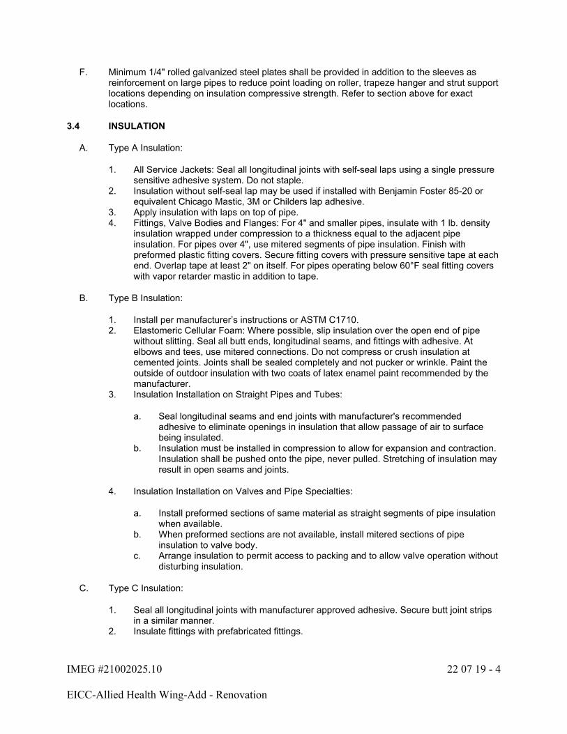
IMEG #21002025.10 22 07 19 - 4
EICC-Allied Health Wing-Add - Renovation
F. Minimum 1/4" rolled galvanized steel plates shall be provided in addition to the sleeves as reinforcement on large pipes to reduce point loading on roller, trapeze hanger and strut support locations depending on insulation compressive strength. Refer to section above for exact locations.
3.4 INSULATION
A. Type A Insulation:
1. All Service Jackets: Seal all longitudinal joints with self-seal laps using a single pressure sensitive adhesive system. Do not staple.
2. Insulation without self-seal lap may be used if installed with Benjamin Foster 85-20 or equivalent Chicago Mastic, 3M or Childers lap adhesive.
3. Apply insulation with laps on top of pipe.4. Fittings, Valve Bodies and Flanges: For 4" and smaller pipes, insulate with 1 lb. density
insulation wrapped under compression to a thickness equal to the adjacent pipe insulation. For pipes over 4", use mitered segments of pipe insulation. Finish with preformed plastic fitting covers. Secure fitting covers with pressure sensitive tape at each end. Overlap tape at least 2" on itself. For pipes operating below 60°F seal fitting covers with vapor retarder mastic in addition to tape.
B. Type B Insulation:
1. Install per manufacturer’s instructions or ASTM C1710.2. Elastomeric Cellular Foam: Where possible, slip insulation over the open end of pipe
without slitting. Seal all butt ends, longitudinal seams, and fittings with adhesive. At elbows and tees, use mitered connections. Do not compress or crush insulation at cemented joints. Joints shall be sealed completely and not pucker or wrinkle. Paint the outside of outdoor insulation with two coats of latex enamel paint recommended by the manufacturer.
3. Insulation Installation on Straight Pipes and Tubes:
a. Seal longitudinal seams and end joints with manufacturer's recommended adhesive to eliminate openings in insulation that allow passage of air to surface being insulated.
b. Insulation must be installed in compression to allow for expansion and contraction. Insulation shall be pushed onto the pipe, never pulled. Stretching of insulation may result in open seams and joints.
4. Insulation Installation on Valves and Pipe Specialties:
a. Install preformed sections of same material as straight segments of pipe insulation when available.
b. When preformed sections are not available, install mitered sections of pipe insulation to valve body.
c. Arrange insulation to permit access to packing and to allow valve operation without disturbing insulation.
C. Type C Insulation:
1. Seal all longitudinal joints with manufacturer approved adhesive. Secure butt joint strips in a similar manner.
2. Insulate fittings with prefabricated fittings.

IMEG #21002025.10 22 07 19 - 5
EICC-Allied Health Wing-Add - Renovation
D. Type E Insulation:
1. Indoors, above grade or below grade, Polyvinylidene chloride (PVDC or Saran) vapor retarder film and tape: Seal all longitudinal joints with manufacturer approved adhesive. Secure butt joint strips in a similar manner. Refer to manufacturer's recommendations for installation guidelines.
2. Insulate pipe fittings with prefabricated insulation fittings.
3.5 JACKET COVER INSTALLATION
A. Plastic Covering:
1. Provide vapor barrier as specified for insulation type. Cover with plastic jacket covering. Position seams to shed water.
2. Solvent weld all joints with manufacturer recommended cement.3. Overlap all laps and butt joints 1-1/2" minimum. Repair any loose ends that do not seal
securely. Solvent weld all fitting covers in the same manner. Final installation shall be watertight.
4. All joints in areas noted shall meet USDA standards for Totally Sealed Systems, including overlaps of 1" on circumferential and 1.5" to 2" on longitudinal seams.
5. Use plastic insulation covering on all exposed pipes including, but not limited to:
a. All exposed piping below 8'-0" above floor.
3.6 SCHEDULE
A. Refer to drawings for insulation schedule.
END OF SECTION 22 07 19
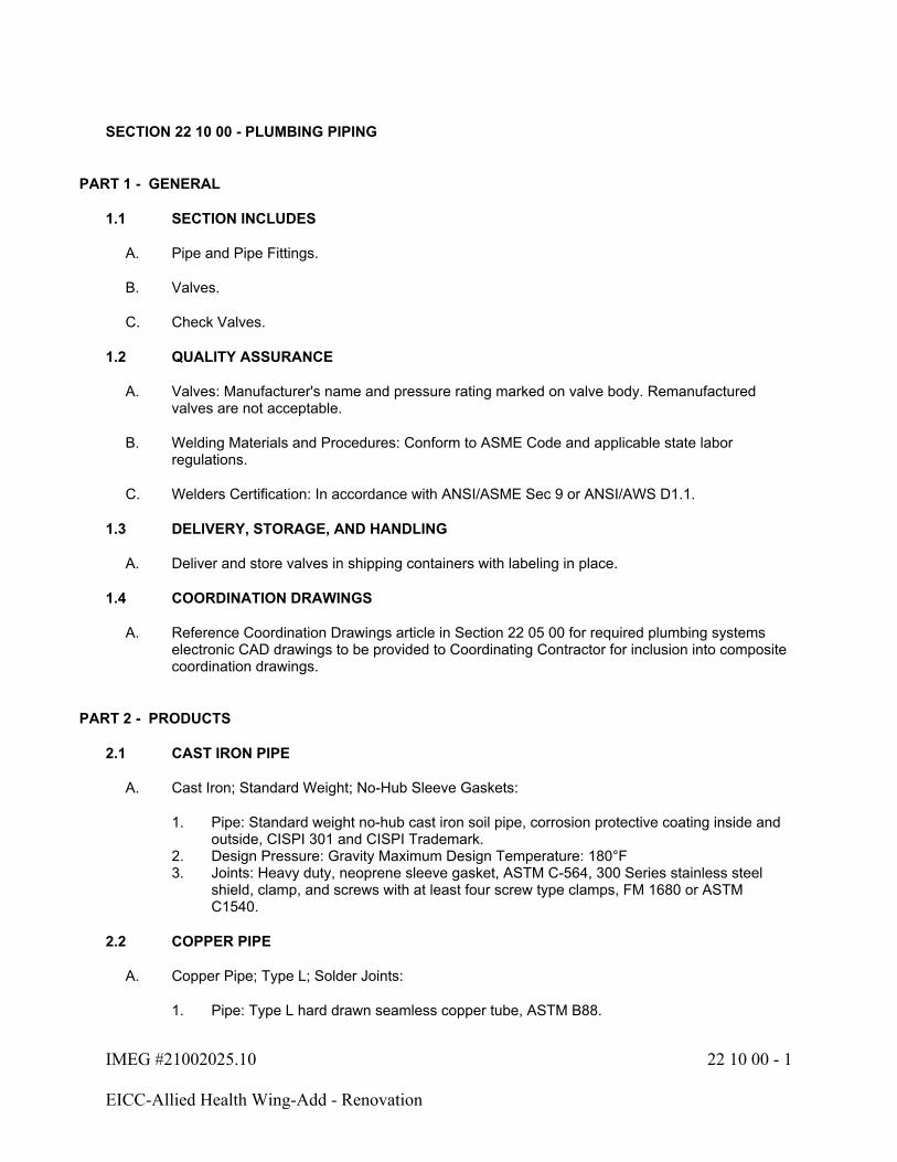
IMEG #21002025.10 22 10 00 - 1
EICC-Allied Health Wing-Add - Renovation
SECTION 22 10 00 - PLUMBING PIPING
PART 1 - GENERAL
1.1 SECTION INCLUDES
A. Pipe and Pipe Fittings.
B. Valves.
C. Check Valves.
1.2 QUALITY ASSURANCE
A. Valves: Manufacturer's name and pressure rating marked on valve body. Remanufactured valves are not acceptable.
B. Welding Materials and Procedures: Conform to ASME Code and applicable state labor regulations.
C. Welders Certification: In accordance with ANSI/ASME Sec 9 or ANSI/AWS D1.1.
1.3 DELIVERY, STORAGE, AND HANDLING
A. Deliver and store valves in shipping containers with labeling in place.
1.4 COORDINATION DRAWINGS
A. Reference Coordination Drawings article in Section 22 05 00 for required plumbing systems electronic CAD drawings to be provided to Coordinating Contractor for inclusion into composite coordination drawings.
PART 2 - PRODUCTS
2.1 CAST IRON PIPE
A. Cast Iron; Standard Weight; No-Hub Sleeve Gaskets:
1. Pipe: Standard weight no-hub cast iron soil pipe, corrosion protective coating inside and outside, CISPI 301 and CISPI Trademark.
2. Design Pressure: Gravity Maximum Design Temperature: 180°F3. Joints: Heavy duty, neoprene sleeve gasket, ASTM C-564, 300 Series stainless steel
shield, clamp, and screws with at least four screw type clamps, FM 1680 or ASTM C1540.
2.2 COPPER PIPE
A. Copper Pipe; Type L; Solder Joints:
1. Pipe: Type L hard drawn seamless copper tube, ASTM B88.
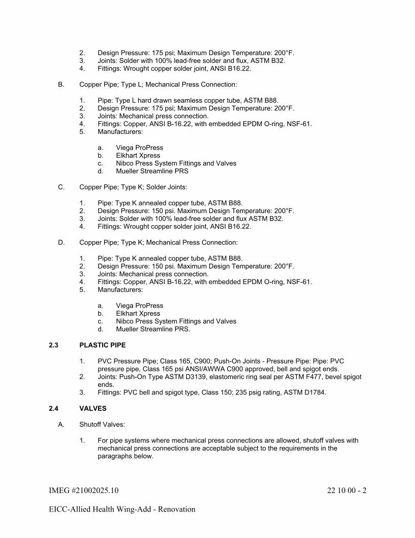
IMEG #21002025.10 22 10 00 - 2
EICC-Allied Health Wing-Add - Renovation
2. Design Pressure: 175 psi; Maximum Design Temperature: 200°F.3. Joints: Solder with 100% lead-free solder and flux, ASTM B32.4. Fittings: Wrought copper solder joint, ANSI B16.22.
B. Copper Pipe; Type L; Mechanical Press Connection:
1. Pipe: Type L hard drawn seamless copper tube, ASTM B88.2. Design Pressure: 175 psi; Maximum Design Temperature: 200°F.3. Joints: Mechanical press connection.4. Fittings: Copper, ANSI B-16.22, with embedded EPDM O-ring, NSF-61.5. Manufacturers:
a. Viega ProPressb. Elkhart Xpressc. Nibco Press System Fittings and Valvesd. Mueller Streamline PRS
C. Copper Pipe; Type K; Solder Joints:
1. Pipe: Type K annealed copper tube, ASTM B88.2. Design Pressure: 150 psi. Maximum Design Temperature: 200°F.3. Joints: Solder with 100% lead-free solder and flux ASTM B32.4. Fittings: Wrought copper solder joint, ANSI B16.22.
D. Copper Pipe; Type K; Mechanical Press Connection:
1. Pipe: Type K annealed copper tube, ASTM B88.2. Design Pressure: 150 psi. Maximum Design Temperature: 200°F.3. Joints: Mechanical press connection.4. Fittings: Copper, ANSI B-16.22, with embedded EPDM O-ring, NSF-61.5. Manufacturers:
a. Viega ProPressb. Elkhart Xpressc. Nibco Press System Fittings and Valvesd. Mueller Streamline PRS.
2.3 PLASTIC PIPE
1. PVC Pressure Pipe; Class 165, C900; Push-On Joints - Pressure Pipe: Pipe: PVC pressure pipe, Class 165 psi ANSI/AWWA C900 approved, bell and spigot ends.
2. Joints: Push-On Type ASTM D3139, elastomeric ring seal per ASTM F477, bevel spigot ends.
3. Fittings: PVC bell and spigot type, Class 150; 235 psig rating, ASTM D1784.
2.4 VALVES
A. Shutoff Valves:
1. For pipe systems where mechanical press connections are allowed, shutoff valves with mechanical press connections are acceptable subject to the requirements in the paragraphs below.
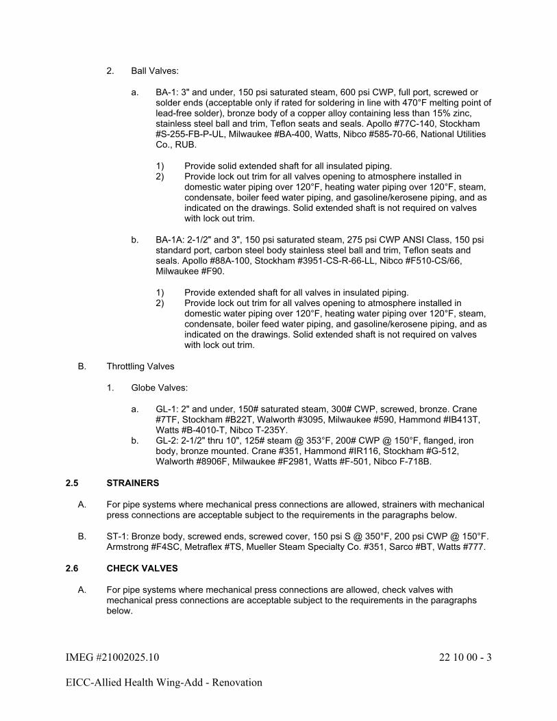
IMEG #21002025.10 22 10 00 - 3
EICC-Allied Health Wing-Add - Renovation
2. Ball Valves:
a. BA-1: 3" and under, 150 psi saturated steam, 600 psi CWP, full port, screwed or solder ends (acceptable only if rated for soldering in line with 470°F melting point of lead-free solder), bronze body of a copper alloy containing less than 15% zinc, stainless steel ball and trim, Teflon seats and seals. Apollo #77C-140, Stockham #S-255-FB-P-UL, Milwaukee #BA-400, Watts, Nibco #585-70-66, National Utilities Co., RUB.
1) Provide solid extended shaft for all insulated piping.2) Provide lock out trim for all valves opening to atmosphere installed in
domestic water piping over 120°F, heating water piping over 120°F, steam, condensate, boiler feed water piping, and gasoline/kerosene piping, and as indicated on the drawings. Solid extended shaft is not required on valves with lock out trim.
b. BA-1A: 2-1/2" and 3", 150 psi saturated steam, 275 psi CWP ANSI Class, 150 psi standard port, carbon steel body stainless steel ball and trim, Teflon seats and seals. Apollo #88A-100, Stockham #3951-CS-R-66-LL, Nibco #F510-CS/66, Milwaukee #F90.
1) Provide extended shaft for all valves in insulated piping.2) Provide lock out trim for all valves opening to atmosphere installed in
domestic water piping over 120°F, heating water piping over 120°F, steam, condensate, boiler feed water piping, and gasoline/kerosene piping, and as indicated on the drawings. Solid extended shaft is not required on valves with lock out trim.
B. Throttling Valves
1. Globe Valves:
a. GL-1: 2" and under, 150# saturated steam, 300# CWP, screwed, bronze. Crane #7TF, Stockham #B22T, Walworth #3095, Milwaukee #590, Hammond #IB413T, Watts #B-4010-T, Nibco T-235Y.
b. GL-2: 2-1/2" thru 10", 125# steam @ 353°F, 200# CWP @ 150°F, flanged, iron body, bronze mounted. Crane #351, Hammond #IR116, Stockham #G-512, Walworth #8906F, Milwaukee #F2981, Watts #F-501, Nibco F-718B.
2.5 STRAINERS
A. For pipe systems where mechanical press connections are allowed, strainers with mechanical press connections are acceptable subject to the requirements in the paragraphs below.
B. ST-1: Bronze body, screwed ends, screwed cover, 150 psi S @ 350°F, 200 psi CWP @ 150°F. Armstrong #F4SC, Metraflex #TS, Mueller Steam Specialty Co. #351, Sarco #BT, Watts #777.
2.6 CHECK VALVES
A. For pipe systems where mechanical press connections are allowed, check valves with mechanical press connections are acceptable subject to the requirements in the paragraphs below.

IMEG #21002025.10 22 10 00 - 4
EICC-Allied Health Wing-Add - Renovation
B. CK-1: 2" and under, 125# steam @ 406°F, 200# CWP @ 150°F, screwed, bronze, horizontal swing. Crane #37, Hammond #IB904, Stockham #B319-Y, Walworth #3406, Milwaukee #509, Watts #G-5000, Nibco T-413B.
2.7 CONNECTIONS BETWEEN DISSIMILAR METALS
A. Connections between dissimilar metals shall be insulating dielectric types that provide a water gap between the connected metals, and that either allow no metal path for electron transfer or that provide a wide water gap lined with a non-conductive material to impede electron transfer through the water path.
B. Joints shall be rated for the temperature, pressure, and other characteristics of the service in which they are used, including testing procedure.
C. Aluminum, iron, steel, brass, copper, bronze, galvanized steel and stainless steel are commonly used and require isolation from each other with the following exceptions:
1. Iron and steel connected to each other.2. Brass, copper, and bronze connected to each other.3. Brass or bronze valves and specialties connected in closed systems with steel, iron, or
stainless steel on both sides of the brass or bronze valves and specialties. Where two or more brass or bronze items occur together, they shall be connected with brass nipples. Brass or bronze valves and specialties cannot be used as a dielectric separation between pipe materials.
D. Dielectric protection is required at connections to equipment of a material different than the piping.
PART 3 - EXECUTION
3.1 PREPARATION
A. Install all products per manufacturer's recommendations.
B. Ream pipe and tube ends. Remove burrs. Bevel plain end ferrous pipe.
C. Remove scale and dirt, on inside and outside, before assembly.
D. Remove all scale, rust, dirt, oils, stickers and thoroughly clean exterior of all bare metal exposed piping, hangers, and accessories in preparation to be painted.
E. Connect to equipment with flanges or unions.
F. Use only piping materials rated for the maximum temperature of the application, e.g., do not use PVC for dishwasher drainage or piping that receives boiler blowdown.
G. Roof Penetration (Vent) Flashing:
1. Built-up Roofing: Flash vents with 3# seamless sheet lead of sufficient size to extend 15" into roofing felts for built-up roofs.
IMEG #21002025.10 22 10 00 - 5
EICC-Allied Health Wing-Add - Renovation
H. Existing building sewers or building drains which are shown on the documents to be reused shall be inspected and recorded by closed circuit television for their condition. Report findings back to the Architect, Engineer, and Owner before proceeding with work so any necessary rework can take place if needed.
3.2 SYSTEM, PIPING AND VALVE SCHEDULE
A. Cold Water, Hot Water, Tempered Water - Potable and Non-Potable (Above Ground):
1. Copper Pipe; Type L; Solder Joints: All Sizes2. Copper Pipe; Type L; Mechanical Press Connection: 4" and Under3. Shutoff Valves: BA-14. Check Valves: CK-1
B. Vacuum (Non-Medical):
1. Copper Pipe; Type L; Solder Joints: All Sizes2. Shutoff Valves: BA-13. |Throttling Valves: GL-14. Check Valves: CK-15. Strainers: ST-1
C. Sanitary Waste and Vent, Gravity (Above Ground):
1. Cast Iron; Standard Weight; No-Hub Sleeve Gaskets: 1-1/2" to 15"
D. Sanitary Indirect Drainage (Above Ground):
1. Cast Iron; Standard Weight; No-Hub Sleeve Gaskets: 1-1/2" to 15"2. Stainless Steel; Type 304; Hub and Spigot Joint: All Sizes
E. Storm Drainage, Gravity (Above Ground):
1. Cast Iron; Standard Weight; No-Hub Sleeve Gaskets: 1-1/2" to 15"2. Stainless Steel; Type 304; Hub and Spigot Joint: All Sizes
F. Sanitary Waste and Vent, Gravity (Underground - Inside Building):
1. Cast Iron; Standard Weight; No-Hub Sleeve Gaskets: 1-1/2" to 15"2. PVC-DWV or ABS-DWV; Schedule 40; Solvent Weld Joints: All Sizes
3.3 TESTING PIPING
A. Sanitary Drainage, Sanitary Vent, Storm Drainage:
1. Test all piping with water to prove tight.2. Test piping before insulation is applied.3. Hydrostatically test all soil, waste, and vent piping inside of building with 10 feet head of
water for 15 minutes. Inspect before fixtures are connected. If leaks appear, repair them and repeat the test.
4. Hydrostatically test interior downspouts with 10 feet head of water for 15 minutes with no leaks.
IMEG #21002025.10 22 10 00 - 6
EICC-Allied Health Wing-Add - Renovation
B. Hot Water - Potable and Non-Potable, Cold Water - Potable and Non-Potable:
1. Test the pipe with 100 psig water pressure or equal inert gas such as nitrogen. Exception: Inert gas test shall not be used to test plastic piping.
2. Hold test pressure for at least 2 hours.3. Test to be witnessed by the Architect/Engineer's representative, if requested by the
Architect/Engineer.
C. Vacuum Piping:
1. Testing pipes in chases, walls, or above non-accessible ceilings before piping is concealed.
2. Test with 100 psig compressed air or nitrogen.3. During the test, strike all soldered joints sharply with a rubber or rawhide mallet to cause
failure of any weak joints. After striking, soap test each joint.4. Repair and retest all leaking joints.5. After all joints pass the soap test, the system must maintain test pressure for 24 hours. If
system fails the 24-hour, retest ALL joints by resoaping and repair all faulty joints. Repeat this procedure until the test pressure can be maintained for 24 hours.
6. After passing the above test, operate the vacuum pump. With all vacuum valves closed, the pump and piping system shall be able to maintain a vacuum of 25" Hg for at least one hour.
7. All materials, labor and equipment for testing shall be provided by the installing Contractor.
8. Tests to be witnessed by the Architect/Engineer's representative, if requested by the Architect/Engineer.
9. After testing, seal the complete system against entry of foreign material until it is turned over to the Owner.
D. All Other Piping:
1. Test piping at 150% of normal operating pressure.2. Piping shall hold this pressure for one hour with no drop in pressure.3. Test piping using water, nitrogen, or air as compatible with the final service of the pipe.
Do not use combustible fluids.4. Drain and clean all piping after testing is complete.
3.4 CLEANING PIPING
A. All Water Piping:
1. Flush all piping using faucets, flush valves, etc. until the flow is clean.2. After flushing, thoroughly clean all inlet strainers, aerators, and other such devices.3. If necessary, remove valves to clean out all foreign material.
3.5 INSTALLATION
A. General Installation Requirements:
1. Provide dielectric connections between dissimilar metals.2. Route piping in orderly manner and maintain gradient. Install to conserve building space.3. Group piping whenever practical at common elevations.4. Install piping to allow for expansion and contraction without stressing pipe, joints, or
equipment.
IMEG #21002025.10 22 10 00 - 7
EICC-Allied Health Wing-Add - Renovation
5. Slope water piping and arrange to drain at low points.6. Where pipe supports are welded to structural building framing, scrape, brush clean, and
apply one coat of zinc rich primer to welds.7. Seal pipes passing through exterior walls with a wall seal per Section 22 05 29. Provide
Schedule 40 galvanized sleeve at least 2 pipe sizes larger than the pipe.8. All non-potable outlets shall be clearly marked with a permanently affixed laminated sign
with 3/8" high lettering saying "Non-Potable Water Not for Human Consumption." Sign shall have black lettering on a yellow background.
9. All vertical pipe drops to sinks or other equipment installed below the ceiling shall be routed within a wall cavity, unless specifically noted otherwise to be surface mounted. For renovation projects, this Contractor is responsible for opening and patching existing walls for installation of piping. Wall patching shall match existing condition.
B. Valves/Fittings and Accessories:
1. Install shutoff valves that permit the isolation of equipment/fixtures in each room without isolating any other room or portion of the building. Individual fixture angle stops do not meet this requirement. Exception: Back-to-back rooms in no more than two adjacent rooms.
2. Provide clearance for installation of insulation and access to valves and fittings.3. Provide access doors for concealed valves and fittings.4. Install valve stems upright or horizontal, not inverted.5. Provide one plug valve wrench for every ten plug valves 2" and smaller, minimum of one.
Provide each plug valve 2-1/2" and larger with a wrench with set screw.6. Install corrugated, stainless steel tubing system according to manufacturer's written
instructions. Include striker plates to protect tubing from puncture where tubing is restrained and cannot move.
C. Underground Piping:
1. Refer to Section 22 05 00 for Excavation, Fill, Backfill and Compaction requirements
D. Sanitary and Storm Piping:
1. Install all sanitary and storm piping inside the building with a slope as shown on the drawings.
2. Install horizontal offset at all connections to roof drains to allow for pipe expansion.3. Slope sanitary and storm piping outside the building to meet invert elevations shown on
drawings and to maintain a minimum velocity of 2 feet per second.4. All sanitary and storm piping shall have at least 42" of cover when leaving the building.5. Starter fittings with internal baffles are not permitted.
3.6 PIPE ERECTION AND LAYING
A. Carefully inspect all pipe, fittings, valves, equipment and accessories before installation. Any items that are unsuitable, cracked or otherwise defective shall be removed from the job immediately.
B. All pipe, fittings, valves, equipment and accessories shall have factory applied markings, stampings, or nameplates with sufficient data to determine their conformance with specified requirements.
IMEG #21002025.10 22 10 00 - 8
EICC-Allied Health Wing-Add - Renovation
C. Exercise care at every stage of storage, handling, laying and erecting to prevent entry of foreign matter into piping, fittings, valves, equipment and accessories. Do not install any item that is not clean.
D. Until system is fully operational, all openings in piping and equipment shall be kept closed except when actual work is being performed on that item or system. Closures shall be plugs, caps, blind flanges or other items specifically designed and intended for this purpose.
E. Run pipes straight and true, parallel to building lines with minimum use of offsets and couplings. Provide only offsets required to provide needed headroom or clearance and to provide needed flexibility in pipe lines.
F. Make changes in direction of pipes only with fittings or pipe bends. Changes in size only with fittings. Do not use miter fittings, face or flush bushings, or street elbows. All fittings shall be of the long radius type, unless otherwise shown on the drawings or specified.
G. Provide flanges or unions at all final connections to equipment, traps and valves.
H. Arrange piping and connections so equipment served may be totally removed without disturbing piping beyond final connections and associated shutoff valves.
I. Use full and double lengths of pipe wherever possible.
J. Unless otherwise indicated, install all piping, including shutoff valves and strainers, to coils, pumps and other equipment at line size with reduction in size being made only at control valve or equipment.
K. Cut all pipe to exact measurement and install without springing or forcing except in the case of expansion loops where cold springing is indicated on the drawings.
L. Underground pipe shall be laid in dry trenches maintained free of accumulated water. Refer to Section 22 05 00 for Excavation, Fill, Backfill and Compaction requirements.
M. Unless otherwise indicated, branch take-offs shall be from top of mains or headers at either a 45° or 90° angle from the horizontal plane for air lines, and from top, bottom or side for liquids.
N. Do not use geotextile fabric with footing tile if silt content of soil exceeds 40% or if clay content exceeds 50%. The fabric shall be installed around 1" river rock or 2" limestone.
3.7 DRAINING AND VENTING
A. Unless otherwise indicated on the drawings, all horizontal water lines, including branches, shall pitch 1" in 40 feet to low points for complete drainage, removal of condensate and venting.
B. Maintain accurate grade where pipes pitch or slope for venting and drainage. No pipes shall have pockets due to changes in elevation.
C. Provide drain valves at all low points of water piping systems for complete or sectionalized draining.
D. Use eccentric reducing fittings on horizontal runs when changing size of pipes for proper drainage and venting. Install gravity drain pipes with bottom of pipe and eccentric reducers in a continuous line; all other liquid lines with top of pipe and eccentric reducers in a continuous line.
IMEG #21002025.10 22 10 00 - 9
EICC-Allied Health Wing-Add - Renovation
E. Provide air vents at high points and wherever else required to eliminate air in all water piping systems.
F. Install air vents in accessible locations. If necessary to trap and vent air in a remote location, install an 1/8" pipe from the tapping location to an accessible location and terminate with a venting device.
G. All vent and drain piping shall be of same materials and construction for the service involved.
3.8 PLUMBING VENTS
A. Vent as shown on the drawings and in accordance with all codes having jurisdiction.
B. Extend the high side of the soil and waste stacks at least 12" above roof.
3.9 BRANCH CONNECTIONS
A. For domestic water and vent systems only, make branch connections with standard tee or cross fittings of the type required for the service.
B. Reducers are generally not shown. Where pipe sizes change at tee, the tee shall be the size of the largest pipe shown connecting to it.
C. Do not use double wye or double combination wye and eighth bend DWV fittings in horizontal piping.
D. Branch connections from the headers and mains may be mechanically formed using an extraction device. The branch piping connection shall be brazed connection for the following services only:
1. Domestic water piping above ground.
E. Further limit use of mechanically formed fittings as follows:
1. Must have at least same pressure rating as the main.2. Main must be Type K or L copper tubing.3. Permanent marking shall indicate insertion depth and orientation.4. Branch pipe shall conform to the inner curve of the piping main.5. Main must be 1" or larger.6. Branch must be 3/4" or larger.
3.10 JOINING OF PIPE
A. Solder Joints (Copper Pipe):
1. Make up joints with 100% lead-free solder, ASTM B32. Cut tubing so ends are perfectly square and remove all burrs inside and outside. Thoroughly clean sockets of fittings and ends of tubing to remove all oxide, dirt and grease just prior to soldering. Apply flux evenly, but sparingly, over all surfaces to be joined. Heat joints uniformly so solder will flow to all mated surfaces. Wipe excess solder, leaving a uniform fillet around cup of fitting.
2. Flux shall be non-acid type.

IMEG #21002025.10 22 10 00 - 10
EICC-Allied Health Wing-Add - Renovation
3. Solder end valves may be installed directly in the piping system if the entire valve is suitable for use with 470°F melting point solder. Remove discs and seals during soldering if they are not suitable for 470°F.
B. Brazed Joints (Copper Pipe):
1. Make up joints with silver alloy brazing filler metal conforming to ASTM B260 "Brazing Filler Metal" BAg-1 or BAg-2. Cut copper tubing so ends are perfectly square and remove all burrs inside and outside. Thoroughly clean sockets of fittings and ends of tubing to remove all oxide, dirt and grease just prior to brazing. Apply non-corrosive flux of the type recommended by filler alloy manufacturer, evenly, but sparingly, over all surfaces to be joined. Heat joints uniformly using oxygen-acetylene torch with tip size recommended by fitting manufacturer. Wipe and brush joint clean after alloy has set.
2. Remove discs from solder end valves during brazing.
C. Mechanical Press Connection (Copper Pipe):
1. Copper press fitting shall be made in accordance with the manufacturer's installation instructions.
2. Fully insert tubing into the fitting and mark tubing.3. Prior to making connection, the fitting alignment shall be checked against the mark made
on the tube to ensure the tubing is fully engaged in the fitting.4. Joint shall be pressed with a tool approved by the manufacturer.5. Installers shall be trained by manufacturer personnel or representative. Provide
documentation upon request.
D. Hub and Spigot Joints - Sanitary Pipe and Storm Pipe (Cast Iron Pipe):
1. Lead and Oakum Joints: Pack joint with oakum made of vegetable fiber, cotton, or hemp. Pour joint with molten lead up to top of hub. Ensure leak-free joints by working joint with inside and outside caulking irons.
2. Compression Gasket Joints: Joint shall be one-piece double seal compression type gasket made specifically for joining cast iron soil pipe. Gasket shall be neoprene, permitting joint to flex as much as 5 degrees without loss of seal. Gasket shall be extra heavy weight class, conforming to ASTM C-564.
E. No-Hub Sleeve Gaskets (No-Hub) (Cast Iron Pipe):
1. Gasket shall be heavy weight class, conforming to ASTM C564.2. The gasket shall have an internal center stop.3. The gasket shall be covered by a stainless steel band secured with a minimum of four
stainless steel bands per fitting/joint.4. Sleeve gaskets shall be installed in accordance with the manufacturer's installation
instructions.
3.11 DISINFECTION OF DOMESTIC WATER PIPING SYSTEM
A. Disinfection of the domestic water piping shall be completed within three (3) weeks prior to building occupancy. Contractor is responsible for disinfecting water piping if used by workers during construction; disinfection during construction does not eliminate the requirement for final disinfection prior to occupancy. Flushing of piping shall be completed within two (2) weeks prior to building occupancy.
B. Provide necessary connections at the start of individual sections of mains for adding chlorine.
IMEG #21002025.10 22 10 00 - 11
EICC-Allied Health Wing-Add - Renovation
C. Before starting work, verify system is complete, flushed and clean.
D. Ensure pH of water to be treated is between 7.4 and 7.6 by adding alkali (caustic soda or soda ash) or acid (hydrochloric).
E. Inject disinfectant, free chlorine in liquid, powder, tablet or gas form, throughout system to obtain 50 to 80 mg/L residual.
F. Bleed water from all outlets to ensure chlorine distribution throughout the entire domestic water system.
G. Verify initial chlorination levels by testing at minimum 15% of outlets located throughout entire building, including the last fixture connected to each main and each branch extending over 50 feet from a main.
H. Maintain disinfectant in system for 24 hours, after which test at minimum 15% of outlets located throughout entire building, including the last fixture connected to each main and each branch extending over 50 feet from a main. If final disinfectant residual tests less than 25 mg/L at any one of the tested outlets, flush the entire system and repeat disinfection and testing procedure.
I. After final disinfectant residuals test at or above 25 mg/L after a minimum 24-hour duration, flush disinfectant from system at a minimum velocity of 3.0 feet/second until residual is equal to that of incoming water or 1.0 mg/L.
J. Take water samples, no sooner than 24 hours after flushing, from 2% of outlets and from water entry. Obtain, analyze, and test samples in accordance with AWWA C651, Section 5 - Verification.
END OF SECTION 22 10 00
IMEG #21002025.10 22 10 23 - 1
EICC-Allied Health Wing-Add - Renovation
SECTION 22 10 23 - NATURAL GAS AND PROPANE PIPING
PART 1 - GENERAL
1.1 SECTION INCLUDES
A. Pipe and Pipe Fittings.
B. Valves.
C. Natural Gas Piping System.
1.2 QUALITY ASSURANCE
A. Valves: Manufacturer's name and pressure rating marked on valve body. Remanufactured valves are not acceptable.
B. Welding Materials, Procedures, and Operators: Conform to ASME Section 9, ANSI/AWS D1.1, and applicable state labor regulations.
C. Welders Certification: In accordance with ANSI/ASME Sec 9 or ANSI/AWS D1.1.
1.3 SUBMITTALS
A. Submit product data under provisions of Section 22 05 00. Include data on pipe materials, fittings, valves, and accessories.
B. Test Reports: Provide results of piping system pressure test.
C. Welders Certificates: Certify welders employed on the Work, verifying AWS qualification within previous 12 months.
1.4 DELIVERY, STORAGE, AND HANDLING
A. Store and protect piping to prevent entrance of foreign matter into pipe and to prevent exterior corrosion.
B. Deliver and store valves in shipping containers with labeling in place.
1.5 COORDINATION DRAWINGS
A. Reference Coordination Drawings article in Section 22 05 00 for the required natural gas piping system electronic CAD drawings to be provided to Coordinating Contractor for inclusion into composite coordination drawings.
PART 2 - PRODUCTS
2.1 NATURAL GAS (0 to 125 PSI)
A. Design Pressure: 125 psi. Maximum Design Temperature: 350°F
IMEG #21002025.10 22 10 23 - 2
EICC-Allied Health Wing-Add - Renovation
B. Piping - 2" and Under:
1. Pipe: Standard weight steel, threaded and coupled, ASTM A53.2. Joints: Screwed. (NOTE: For below ground, all sizes to have welded joints.)3. Fittings: 150# steam - 300# CWP, black malleable iron, banded, ASTM A197, ANSI
B16.3.4. Unions: 250# - 500# CWP, black malleable iron, ANSI B16.39, ground joint with brass
seat.
C. Piping - 2" and Under:
1. Pipe: Standard weight steel, plain end press connection sanded smooth, ASTM A53.2. Joints: Mechanical press connection.3. Fittings, Valves and Unions: ASTM A106 Grade A steel with zinc-nickel coating to reduce
corrosion, with embedded HNBR sealing element. ANSI LC 4 approved.4. Manufacturers:
a. Conbraco "Apollo" (Powerpress)b. Viega (Megapress)
D. Shutoff Valves/Throttling Valves:
1. For pipe systems where mechanical press connections are allowed, shutoff valves with mechanical press connections are acceptable subject to the requirements in the paragraphs below.
2. BA-13: 2" and under, threaded 600 psi CWP; UL listed for 250# LP, flammable liquid, heating oil, natural and manufactured gases, 150 psi steam, bronze body and chrome plated brass ball, Teflon seats and packing.
a. Manufacturers:
1) Apollo #80-1002) Nibco #T580-70-UL or #T585-70-UL3) Watts #B-6000
3. PL-1: 2" and under, 125# steam @ 450°F, 175# CWP @ 180°F, cast iron body, screwed, full port.
a. Manufacturers:
1) Walworth #17002) DeZurik #425, S-RS49
E. Design Pressure: 300 psi.
1. Maximum Design Temperature: 400°F
2.2 STRAINERS
A. Furnish pipe nipple with shutoff valve to blow down all strainer screens.
B. Use iron body strainers in ferrous piping.

IMEG #21002025.10 22 10 23 - 3
EICC-Allied Health Wing-Add - Renovation
2.3 DRAIN VALVES AND BLOWDOWN VALVES
A. Drain valve and blowdown valve shall mean a shutoff valve as specified for the intended service with added 3/4" male hose thread outlet, cap, and retaining chain.
PART 3 - EXECUTION
3.1 PREPARATION
A. Ream pipe and tube ends, remove burrs, bevel plain end ferrous pipe.
B. Remove scale and dirt on inside and outside before assembly.
C. Remove all scale, rust, dirt, oils, stickers and thoroughly clean exterior of all bare metal exposed piping, hangers, and accessories in preparation to be painted.
D. Connect to all equipment with flanges or unions.
E. After completion, fill, clean, and treat systems. Refer to Section 23 25 00 for treatment.
3.2 TESTING PIPING
A. Low Pressure - Up to 1 psi:
1. Test piping with 20 psi air pressure. System must hold this pressure without adding air for two hours.
B. High Pressure - Above 1 psi:
1. Test piping with compressed air at twice the operating gas pressure, but at least 20 psi. System must hold this pressure without adding air for two hours.
C. A non-combustible odorant, such as oil of wintergreen, may be added to help locate leaks.
3.3 CLEANING PIPING
A. Assembly:
1. Prior to assembly of pipe and piping components, remove all loose dirt, scale, oil and other foreign matter on internal or external surfaces by means consistent with good piping practice subject to approval of the Architect/Engineer. Blow chips and burrs out of pipe before assembly. Wipe cutting oil from internal and external surfaces.
2. During fabrication and assembly, remove slag and weld spatter from both internal and external joints by peening, chipping and wire brushing to the degree consistent with good piping practices.
3. Notify the Architect/Engineer prior to starting any post erection cleaning operation in time to allow witnessing the operation. Properly dispose of cleaning and flushing fluids.
4. Prior to blowing or flushing erected piping systems, disconnect all instrumentation and equipment, open wide all valves, control valves, and balance valves, and verify all strainer screens are in place.

IMEG #21002025.10 22 10 23 - 4
EICC-Allied Health Wing-Add - Renovation
3.4 INSTALLATION
A. Route piping in orderly manner, straight, plumb, with consistent pitch, parallel to building structure, with minimum use of offsets and couplings. Provide only offsets required for needed headroom or clearance and needed flexibility in pipe system.
B. Install piping to conserve building space, and not interfere with other work.
C. Do not install piping or other equipment above electrical switchboards or panelboards. This includes a dedicated space extending 25 feet from the floor to the structural ceiling with width and depth equal to the equipment.
D. Group piping whenever practical at common elevations.
E. Install piping to allow for expansion and contraction without stressing pipe, joints, or connected equipment.
F. Install thrust blocking and restraints on all buried piping at elbows and other changes in pipe direction.
G. Provide chain operators for all valves over 2" size that are over 10'-0" above finished floor. Extend to 7'-0" above finished floor.
H. Provide valve position indicator on all valves 10'-0" or greater above finish floor and not located above ceiling.
I. Provide clearance for access to valves and fittings.
J. Provide access doors where valves are not exposed.
K. Prepare pipe, fittings, supports, and accessories for finish painting.
L. Install valves with stems upright or horizontal, not inverted.
M. Arrange piping and piping connections so equipment may be serviced or totally removed without disturbing piping beyond final connections and associated shutoff valves.
N. Reducers are generally not shown. Where pipe sizes are not shown, the larger size in either direction shall continue through the fitting nearest to the indication of a smaller pipe size.
O. Seal pipes passing through exterior walls with a wall seal per Section 23 05 29. Provide Schedule 40 galvanized sleeve at least 2 pipe sizes larger than the pipe.
P. Refer to Section 23 05 00 for Excavation, Fill, Backfill and Compaction requirements.
Q. All vertical pipe drops to equipment installed below the ceiling shall be routed within a wall cavity, unless specifically noted otherwise to be surface mounted. For renovation projects, this Contractor is responsible for opening and patching existing walls for installation of piping. Wall patching shall match existing condition.
R. Install corrugated, stainless steel tubing system according to manufacturer's written instructions. Include striker plates to protect tubing from puncture where tubing is restrained and cannot move.

IMEG #21002025.10 22 10 23 - 5
EICC-Allied Health Wing-Add - Renovation
3.5 BONDING AND GROUNDING
A. Each above ground portion of a corrugated stainless steel tubing gas piping systems shall be bonded to the electrical service grounding electrode system. The bonding jumper shall connect to a metallic pipe or fitting between the point of delivery and the first downstream corrugated stainless steel tube fitting. The bonding jumper shall not be smaller than 6 AWG copper wire or equivalent. Gas piping systems that contain one or more segments of corrugated stainless steel tubing shall be bonded in accordance with this section.
B. Each above ground portion of a gas piping system, other than corrugated stainless steel tubing systems, that is likely to become energized shall be electrically continuous and bonded to an effective ground-fault current path. Gas piping, other than corrugated stainless steel tubing, shall be considered to be bonded when it is connected to appliances that are connected to the appliance grounding conductor of the circuit supplying that appliance.
C. Gas piping shall not be used as a grounding conductor or electrode.
D. Where a lightning protection system is installed, the bonding of the gas piping shall be in accordance with NFPA 780, Standard for the Installation of Lightning Protection Systems.
3.6 PIPE ERECTION AND LAYING
A. Carefully inspect all pipe, fittings, valves, equipment and accessories prior to installation. Immediately reject and remove from the job any items which are unsuitable, cracked or otherwise defective.
B. All pipe, fittings, valves, equipment and accessories shall have factory-applied markings, stampings, or nameplates sufficient to determine their conformance with specified requirements.
C. Exercise care at every stage of storage, handling, laying and erecting to prevent entry of foreign matter into piping, fittings, valves, equipment and accessories. Do not erect or install any unclean item.
D. During construction, until system is fully operational, keep all openings in piping and equipment closed at all times except when actual work is being performed on that item. Closures shall be plugs, caps, blind flanges or other items designed for this purpose.
E. Change direction of pipes only with fittings or pipe bends. Change size only with fittings. Do not use miter fittings, face or flush bushings, or street elbows. All fittings shall be long radius type, unless otherwise shown on the drawings or specified. Construct welded elbows of angles not available as standard fittings by cutting and welding standard elbows to form smooth, long radius fittings.
F. Use full and double lengths of pipe wherever possible.
G. Cut all pipe to exact measurement and install without springing or forcing.
H. Do not create, even temporarily, undue loads, forces or strains on valves, equipment or building elements.

IMEG #21002025.10 22 10 23 - 6
EICC-Allied Health Wing-Add - Renovation
3.7 DRAINING AND VENTING
A. Unless otherwise indicated on the drawings, all horizontal pipes, including branches, shall pitch 1" in 40 feet to low points for complete drainage.
B. Use eccentric reducing fittings on horizontal runs when changing size for proper drainage and venting. Install gas pipes with bottom of pipe and eccentric reducers in a continuous line.
C. Provide drip legs at low points and at the base of all risers in gas pipes. Drip legs shall be full line size on pipes through 4" and at least 4", but not less than half line size over 4". Drip legs shall be 12" minimum length, capped with a reducer to a drain valve.
3.8 BRANCH CONNECTIONS
A. Make branch connections with standard tee or cross fittings of the type required for the service unless otherwise specified herein or detailed on the drawings.
B. At the option of the Contractor, branch connections from headers and mains may be cut into black steel pipe using forged weld-on fittings.
C. Use of forged weld-on fittings is also limited as follows:
1. Must have at least same pressure rating as the main.2. Header or main must be 2-1/2" or over.3. Branch line is at least two pipe sizes under header or main size.
D. Reducers are generally not shown. Where pipe sizes change at tee, the tee shall be the size of the largest pipe shown connecting to it.
E. All branch piping connections for natural gas shall take off on the top or on the side of the main.
3.9 JOINING OF PIPE
A. Threaded Joints:
1. Ream pipe ends and remove all burrs and chips.2. Protect plated pipe and valve bodies from wrench marks when making up joints.3. Apply gas-rated Teflon tape or thread compound to male threads.
3.10 PAINTING EXPOSED PIPE
A. Paint all outdoor exposed natural gas piping on north wall the color selected by Owner or Architect/Engineer.
3.11 SERVICE CONNECTIONS
A. Utility Company shall provide new gas service complete with gas meter and regulators. Verify gas service pressure with the Utility Company.
B. P.C. is responsible for piping downstream of meter/regulator. Refer to drawings for gas riser diagram and scope of work.
END OF SECTION 22 10 23
IMEG #21002025.10 22 10 30 - 1
EICC-Allied Health Wing-Add - Renovation
SECTION 22 10 30 - PLUMBING SPECIALTIES
PART 1 - GENERAL
1.1 SECTION INCLUDES
A. Cleanouts.
B. Unions.
C. Balancing Valves.
D. Water Hammer Arresters.
E. Dielectric Fittings (Connections Between Dissimilar Metals).
F. Compressed Air Filters.
G. Compressed Air Condensate Traps.
1.2 QUALITY ASSURANCE
A. Manufacturer: For each product specified, provide components by same manufacturer throughout.
B. Piping, Fittings, Valves, and Flux for Potable Water Systems: All components shall be lead free per Federal Act S.3874, Reduction of Lead in Drinking Water Act.
PART 2 - PRODUCTS
2.1 CLEANOUTS
A. Provide cleanouts as shown and specified on the drawings as well as required by code.
B. Coordinate floor cleanout cover with surrounding floor finish. Provide either solid, recessed for tile or terrazzo or carpet marker as applicable.
C. Cleanouts on exposed pipes shall be cast iron with heavy duty cast brass plug with raised head.
D. Cleanout shall be same size as the pipe up to 6" and 6" for larger pipes.
2.2 TRAPS
A. Provide all individual connections to the sanitary system with P-traps, except where such drains discharge directly into a properly trapped collection basin or sump. Unless otherwise specified or shown, traps shall be:
1. Chromium plated cast brass when used with plumbing fixtures or when installed exposed in finished spaces.
IMEG #21002025.10 22 10 30 - 2
EICC-Allied Health Wing-Add - Renovation
2. Insulated at accessible lavatories.3. Cast iron, deep-seal pattern where concealed above ceiling, below grade or in unfinished
areas.4. Deep-seal pattern of the same material and/or coating where drainage lines are of
special materials or coatings such as polypropylene, PVDF, CPVC, etc.
B. All traps shall have accessible, removable cleanouts, except where installed on floor drains with removable strainers.
2.3 FLOOR DRAINS AND SINKS
A. Floor drains and sinks shall be in the form of a receptor with grate/strainer set flush with the surrounding floor.
B. Provide floor drains and sinks as shown and specified on the drawings as well as required by code.
2.4 HUB DRAINS AND STANDPIPES
A. A hub drain shall be in the form of a hub or pipe without a grate/strainer extending through the floor for receiving indirect waste. A hub drain has a flood level rim above the finished floor.
B. Provide hub drains as shown and specified on the drawings as well as required by code.
2.5 UNIONS
A. Copper pipe - wrought copper fitting - ground joint.
2.6 BALANCING VALVE
A. Rated for 125 psi working pressure and 250°F operating temperature, taps for determining flow with a portable meter, positive shutoff valves for each meter connection, memory feature, tight shutoff, and a permanent pressure drop between 1' and 2' water column at full flow with valve 100% open. Furnish with molded, removable insulation covers.
B. Provide a nomograph to determine flow from meter reading (and valve position on units which sense pressure across a valve). Graph shall extend below the specified minimum flow.
C. Flow rate of 0.5 GPM or larger: Valves in copper piping shall be brass or bronze. Acceptable Manufacturers: Flow Design "Accusetter", Preso "B+", Armstrong "CVB", Bell & Gossett "Circuit Setter Plus", Griswold "Quickset", Gerand "Balvalve Venturi" or Nibco Globe Style balancing valve.
D. Flow rate less than 0.5 GPM: Valves in copper piping shall be brass or bronze. Cv value shall be less than 1.0 when valve is completely open, and minimum balanceable flow rate shall not exceed 0.1 GPM with a meter reading of at least 2.5 feet. Acceptable manufacturers: Bell & Gossett "Circuit Setter RF", Flow Design, Preso, Armstrong, Griswold, Gerand, or Nibco balancing valve.
E. Manufacturer shall size balancing valves for the scheduled flow rate. Flow rate shall be measurable on manufacturer's standard meters.
IMEG #21002025.10 22 10 30 - 3
EICC-Allied Health Wing-Add - Renovation
2.7 WATER HAMMER ARRESTERS
A. Provide water hammer arresters as shown and specified on the drawings as well as required by code.
B. ANSI A112.26.1; sized and located in accordance with PDI WH-201, precharged for operation between -100°F and 300°F and maximum 250 psig working pressure.
2.8 DIELECTRIC FITTINGS (CONNECTIONS BETWEEN DISSIMILAR METALS)
A. Connections between dissimilar metals shall be insulating dielectric types that provide a water gap between the connected metals, and that either allow no metal path for electron transfer or that provide a wide water gap lined with a non-conductive material to impede electron transfer through the water path.
B. Joints shall be rated for the temperature, pressure, and other characteristics of the service in which they are used, including testing procedure.
C. Aluminum, iron, steel, brass, copper, bronze, and stainless steel are commonly used and require isolation from each other with the following exceptions:
1. Iron, steel, and stainless steel connected to each other.2. Brass, copper, and bronze connected to each other.3. Brass or bronze valves and specialties connected in closed systems with steel, iron, or
stainless steel on both sides of the brass or bronze valves and specialties. Where two or more brass or bronze items occur together, they shall be connected with brass nipples. Brass or bronze valves and specialties cannot be used as a dielectric separation between pipe materials.
D. Dielectric protection is required at connections to equipment of a material different than the piping.
2.9 AIR VENTS
A. Provide means for venting air at all high points in the piping system and at all other points where air may be trapped.
B. At end of main and other points where large volume of air may be trapped - Use 1/4" globe valve, angle type, 125 psi, Crane #89, attached to coupling in top of main, 1/4" discharge pipe turned down with cap.
2.10 DRAIN VALVES
A. Drain valves shall be shutoff valves as specified for the intended service with added 3/4" male hose thread outlet and cap.
2.11 COMPRESSED AIR FILTERS
A. Filters shall have a stainless steel sleeve, micro-glass media with epoxy coating, elastomeric filter to housing seal and sealed end caps.

IMEG #21002025.10 22 10 30 - 4
EICC-Allied Health Wing-Add - Renovation
B. Filters shall be capable of removing the following:
1. All solids 3 microns and larger.2. Liquids up to 25,000 ppm by weight.3. 99% of water droplets.4. 40% of oil aerosols.
C. Provide a differential pressure alarm for each filter. Range shall be adjustable from 10 to 35 psi differential at 100 psig.
D. Acceptable Manufacturer: Hankison.
2.12 COMPRESSED AIR CONDENSATE TRAPS
A. Furnish and install traps of the type and capacity shown on the drawings.
B. Traps shall be mechanically actuated with stainless steel construction, and 10-300 psig working pressure.
C. Acceptable Manufacturer: Hankison Series 505.
PART 3 - EXECUTION
3.1 INSTALLATION AND APPLICATION
A. Coordinate construction to receive drains at required invert elevations.
B. Install all items per manufacturer's instructions.
C. Water Hammer Arresters:
1. Install water hammer arresters in accessible locations. Provide access doors as required. Coordinate type with Architect/Engineer/Owner.
2. Water hammer arrestors shall be installed in cold and hot water lines upstream of all plumbing fixtures or equipment, with a quick acting valve or multiple quick acting valves. Quick acting valves shall be defined as solenoid actuated valves, manual flush valves, sensor activated faucets and flush valves, squeeze handle spray faucets, and other similar type valves.
3. Install multiple water hammer arrestors in toilet group branch piping greater than 20 feet in developed length from the cold and hot water mains.
D. Cleanouts:1. Provide cleanouts where shown on the drawings and as required by code, but in no case
farther apart than 50 feet in pipe less than 6" size and 100 feet apart in 6" and larger pipes inside the building. Provide cleanouts at bases of all sanitary and storm risers as shown on the drawings and as required by code.
2. Extend cleanouts to the floor with long sweep elbows.3. Install a full size, two-way cleanout within 5 feet of the foundation outside of building.4. Extend cleanouts to finished floor or wall surface. Lubricate threaded cleanout plugs with
graphite and linseed oil. Ensure clearance at cleanouts for rodding of drainage system.5. Wall cleanouts shall be installed above the flow line of the pipe they serve, but no less
than 12" above the finished floor.
IMEG #21002025.10 22 10 30 - 5
EICC-Allied Health Wing-Add - Renovation
E. Floor Drains and Floor Sinks:
1. Drains in upper floors shall have a flashing of EPDM or similar membrane sheet. The sheet shall be at least 36" X 36" square with the drain in the center. Clamp membrane in auxiliary clamping ring of floor drain. Membrane is not required if upper floor construction is single pour, cast-in-place concrete.
2. Coordinate sloping requirements with the architectural plans and specifications.3. Top of floor drain and sinks grate/strainer shall not extend above the finished floor
elevation.4. Top of floor drain and sink grate/strainer shall not extend above the finished floor
elevation. Grate/strainer shall be installed flush with surrounding finished floor. Should the Plumbing Contractor believe this presents a conflict with code, the issue should be evaluated before installation of the floor drain or sink begins. Proceeding with installing a floor drain or sink raised above the finished floor without prior approval will result in the Contractor being required to remove the drain or sink in question and reinstall it at the approved elevation.
F. Hub Drains and Standpipes:
1. The top of a hub drain/standpipe shall extend above the finished floor elevation. Refer to drawings for dimensions above the finished floor.
2. Access shall be provided to drains and standpipes for rodding.
G. Balancing Valves:
1. Install balancing valves with straight, unobstructed pipe section both upstream and downstream as required, per manufacturer's installation instructions.
END OF SECTION 22 10 30

IMEG #21002025.10 22 40 00 - 1
EICC-Allied Health Wing-Add - Renovation
SECTION 22 40 00 - PLUMBING FIXTURES
PART 1 - GENERAL
1.1 SECTION INCLUDES
A. All plumbing fixtures.
1.2 SUBMITTALS
A. Submit product data under provisions of Section 22 05 00. Submittals shall include fixture carriers for record purposes only. Architect/Engineer does not review or approve carriers except for manufacturer.
B. Include fixtures, sizes, rough-in dimensions, utility sizes, trim, and finishes.
C. For fixtures and trim requiring electrical connections, submit product data indicating general assembly, components, electrical power/controls wiring diagrams, and service connections.
D. Manufacturer shall provide special seismic certification per OSHPD CAN 2-1708a.5 with submittal. Submittals without certification will be returned and not reviewed.
PART 2 - PRODUCTS
2.1 MATERIALS
A. Wall Hung Fixture Carriers:
1. Material: All Metal, ASME/ANSI A112.6.1M.2. Manufacturers:
a. Zurnb. Smithc. Waded. Josame. Wattsf. Mifab.
B. All fixtures shall be as scheduled on the drawings.
C. All china shall be from the same manufacturer where possible.
D. All lavatory and sink trim shall be from the same manufacturer where possible.
E. All fixtures shall be lead free. Faucets, traps, stops, and other fixture accessories shall not contain more lead than allowed per the latest State or Federal Act.
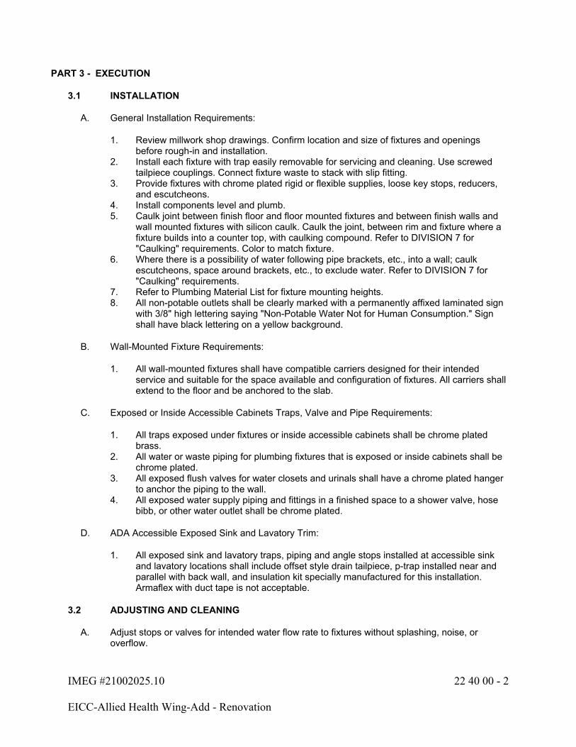
IMEG #21002025.10 22 40 00 - 2
EICC-Allied Health Wing-Add - Renovation
PART 3 - EXECUTION
3.1 INSTALLATION
A. General Installation Requirements:
1. Review millwork shop drawings. Confirm location and size of fixtures and openings before rough-in and installation.
2. Install each fixture with trap easily removable for servicing and cleaning. Use screwed tailpiece couplings. Connect fixture waste to stack with slip fitting.
3. Provide fixtures with chrome plated rigid or flexible supplies, loose key stops, reducers, and escutcheons.
4. Install components level and plumb.5. Caulk joint between finish floor and floor mounted fixtures and between finish walls and
wall mounted fixtures with silicon caulk. Caulk the joint, between rim and fixture where a fixture builds into a counter top, with caulking compound. Refer to DIVISION 7 for "Caulking" requirements. Color to match fixture.
6. Where there is a possibility of water following pipe brackets, etc., into a wall; caulk escutcheons, space around brackets, etc., to exclude water. Refer to DIVISION 7 for "Caulking" requirements.
7. Refer to Plumbing Material List for fixture mounting heights.8. All non-potable outlets shall be clearly marked with a permanently affixed laminated sign
with 3/8" high lettering saying "Non-Potable Water Not for Human Consumption." Sign shall have black lettering on a yellow background.
B. Wall-Mounted Fixture Requirements:
1. All wall-mounted fixtures shall have compatible carriers designed for their intended service and suitable for the space available and configuration of fixtures. All carriers shall extend to the floor and be anchored to the slab.
C. Exposed or Inside Accessible Cabinets Traps, Valve and Pipe Requirements:
1. All traps exposed under fixtures or inside accessible cabinets shall be chrome plated brass.
2. All water or waste piping for plumbing fixtures that is exposed or inside cabinets shall be chrome plated.
3. All exposed flush valves for water closets and urinals shall have a chrome plated hanger to anchor the piping to the wall.
4. All exposed water supply piping and fittings in a finished space to a shower valve, hose bibb, or other water outlet shall be chrome plated.
D. ADA Accessible Exposed Sink and Lavatory Trim:
1. All exposed sink and lavatory traps, piping and angle stops installed at accessible sink and lavatory locations shall include offset style drain tailpiece, p-trap installed near and parallel with back wall, and insulation kit specially manufactured for this installation. Armaflex with duct tape is not acceptable.
3.2 ADJUSTING AND CLEANING
A. Adjust stops or valves for intended water flow rate to fixtures without splashing, noise, or overflow.

IMEG #21002025.10 22 40 00 - 3
EICC-Allied Health Wing-Add - Renovation
B. At completion, clean plumbing fixtures, equipment, and faucet aerator screens.
3.3 FIXTURE ROUGH-IN SCHEDULE
A. Rough-in fixture piping connections in accordance with table on plumbing drawings of minimum sizes for particular fixtures.
END OF SECTION 22 40 00
IMEG #21002025.10 23 05 00 - 1
EICC-Allied Health Wing-Add - Renovation
SECTION 23 05 00 - BASIC HVAC REQUIREMENTS
PART 1 - GENERAL
1.1 SECTION INCLUDES
A. Requirements applicable to all Division 23 Sections. Also refer to Division 01 - General Requirements.
B. All materials and installation methods shall conform to the applicable standards, guidelines and codes referenced herein and within each specification section.
1.2 SCOPE OF WORK
A. This Specification and the associated drawings govern the furnishing, installing, testing and placing into satisfactory operation the Mechanical Systems.
B. Each Contractor shall provide all new materials indicated on the drawings and/or in these specifications, and all items required to make the portion of the Mechanical Work a finished and working system.
C. All work will be awarded under a single General Contract. The division of work listed below is for the Contractor's convenience and lists normal breakdown of the work.
D. Scope of Work:
1. Plumbing Work: Refer to Section 22 05 00 "Basic Plumbing Requirements".2. Heating Work shall include, but is not necessarily limited to:
a. Furnish and install refrigerant piping, accessories for mini-split system, and final charge of refrigerant.
b. Furnish and install condensate drain piping from cooling related equipment such as air handlers and cooling coil drain pans.
c. Furnish and install firestopping systems for penetrations of fire-rated construction associated with this Contractor's work.
3. Air Conditioning and Ventilating Work shall include, but is not necessarily limited to:
a. Furnish and install package rooftop air handling units (RTU-14, DOAS-1 and DOAS-2 complete with curbs.
b. Furnish and install complete supply air ductwork systems including all fittings, insulation, and outlets.
c. Furnish and install complete return air ductwork systems including all fittings, insulation, and inlets.
d. Furnish and install general exhaust fan and associated roof curb e. Furnish and install all temperature control systems. f. Furnish and install all fire and fire/smoke dampers.g. Furnish and install firestopping systems for penetrations of fire-rated construction
associated with this Contractor's work.
IMEG #21002025.10 23 05 00 - 2
EICC-Allied Health Wing-Add - Renovation
4. Temperature Control Work shall include, but is not necessarily limited to:
a. Furnish and install a complete temperature control system as specified in Section 23 09 00.
b. Temperature control system shall consist of a full Direct Digital Control (DDC) system including all accessories, sensors, and programming.
c. Furnish and install firestopping systems for penetrations of fire-rated construction associated with this Contractor's work.
1.3 WORK SEQUENCE
A. All work that will produce excessive noise or interference with normal building operations, as determined by the Owner, shall be scheduled with the Owner. It may be necessary to schedule such work during unoccupied hours. The Owner reserves the right to determine when restricted construction hours will be required.
B. Itemize all work and list associated hours and pay scale for each item.
1.4 DIVISION OF WORK BETWEEN MECHANICAL, ELECTRICAL & CONTROL CONTRACTORS
A. Definitions:
1. "Mechanical Contractors" refers to the following:
a. Plumbing Contractor.b. Air Conditioning and Ventilating Contractor.c. Temperature Control Contractor.d. Testing, Adjusting, and Balancing Contractor.
2. Motor Control Wiring: The wiring associated with the remote operation of the magnetic coils of magnetic motor starters or relays, or the wiring that permits direct cycling of motors by means of devices in series with the motor power wiring. In the latter case the devices are usually single phase and are usually connected to the motor power wiring through a manual motor starter having "Manual-Off-Auto" provisions.
3. Control devices such as start-stop push buttons, thermostats, pressure switches, flow switches, relays, etc., generally represent the types of equipment associated with motor control wiring.
4. Motor control wiring is single phase and usually 120 volts. In some instances, the voltage will be the same as the motor power wiring. Generally, where the motor power wiring exceeds 120 volts, a control transformer is used to give a control voltage of 120 volts.
5. Temperature Control Wiring: The wiring associated with the operation of a motorized damper, solenoid valve or motorized valve, etc., either modulating or two-position, as opposed to wiring which directly powers or controls a motor used to drive equipment such as fans, pumps, etc.
a. This wiring will be from a 120 volt source and may continue as 120 volt, or be reduced in voltage (24 volt) in which case a control transformer shall be furnished as part of the temperature control wiring.
6. Control Motor: An electric device used to operate dampers, valves, etc. It may be two-position or modulating. Conventional characteristics of such a motor are 24 volts, 60 cycles, 1 phase, although other voltages may be encountered.

IMEG #21002025.10 23 05 00 - 3
EICC-Allied Health Wing-Add - Renovation
7. Voltage is generally specified and scheduled as distribution voltage. Motor submittals may be based on utilization voltage if it corresponds to the correct distribution voltage.
Distribution/Nominal Voltage Utilization Voltage120 115208 200240 230277 265480 460
B. General:
1. The purpose of these Specifications is to outline the Electrical and Mechanical Contractor's responsibilities related to electrical work required for items such as temperature controls, mechanical equipment, fans, chillers, compressors and the like. The exact wiring requirements for much of the equipment cannot be determined until the systems have been selected and submittals reviewed. Therefore, the electrical drawings show only known wiring related to such items. All wiring not shown on the electrical drawings, but required for mechanical systems, is the responsibility of the Mechanical Contractor.
2. Where the drawings require the Electrical Contractor to wire between equipment furnished by the Mechanical Contractor, such wiring shall terminate at terminals provided in the equipment. The Mechanical Contractor shall provide complete electrical power/controls wiring diagrams and supervision to the Electrical Contractor and designate the terminal numbers for correct wiring.
3. All electrical work shall conform to the National Electrical Code. All provisions of the Electrical Specifications concerning wiring, protection, etc., apply to wiring provided by the Mechanical Contractor unless noted otherwise.
4. Control low (24V) and control line (120V) voltage wiring, conduit, and related switches and relays required for the automatic control and/or interlock of motors and equipment, including final connection, are to be furnished and installed under Divisions 21, 22 and 23. Materials and installation to conform to Class 1 or 2 requirements.
5. All Contractors shall establish utility elevations prior to fabrication and shall coordinate their material and equipment with other trades. When a conflict arises, priority is as follows:
a. Light fixtures.b. Gravity flow piping, including steam and condensate.c. Electrical busduct.d. Sheet metal.e. Electrical cable trays, including access space.f. Sprinkler piping and other piping.g. Electrical conduits and wireway.
C. Mechanical Contractor's Responsibility:
1. Assumes responsibility for internal wiring of all equipment provided by the Mechanical Contractor, for example:
a. Packaged Rooftop and Dedicated Outdoor Air Units.
2. Assumes all responsibility for the Temperature Control wiring, when the Temperature Control Contractor is a Subcontractor to the Mechanical Contractor.
IMEG #21002025.10 23 05 00 - 4
EICC-Allied Health Wing-Add - Renovation
3. Shall verify all existing equipment sizes and capacities where units are to be modified, moved or replaced. Contractor shall notify Architect/Engineer of any discrepancies prior to ordering new units or replacement parts, including replacements of equipment motors.
4. Temperature Control Subcontractor's Responsibility:
a. Wiring of all devices needed to make the Temperature Control System functional.b. Verifying any control wiring on the electrical drawings as being by the Electrical
Contractor. All wiring required for the Control System, but not shown on the electrical drawings, is the responsibility of the Temperature Control Subcontractor.
c. Coordinating equipment locations (such as relays, transformers, etc.) with the Electrical Contractor, where wiring of the equipment is by the Electrical Contractor.
5. This Contractor is responsible for coordination of utilities with all other Contractors. If any field coordination conflicts are found, the Contractor shall coordinate with other Contractors to determine a viable layout.
D. Electrical Contractor's Responsibility:
1. Provides all combination starters, manual starters and disconnect devices shown on the Electrical Drawings or indicated to be by the Electrical Contractor on the Mechanical Drawings or Specifications.
2. Installs and wires all remote control devices furnished by the Mechanical Contractor or Temperature Control Subcontractor when so noted on the Electrical Drawings.
3. Provides motor control and temperature control wiring, where so noted on the drawings.4. Coordinate with the Mechanical Contractor for size of motors and/or other electrical
devices involved with repair or replacement of existing equipment.5. Furnishes, installs and connects all relays, etc., for automatic shutdown of certain fans
upon actuation of the Fire Alarm System as indicated and specified in Division 28.6. This Contractor is responsible for coordination of utilities with all other Contractors. If any
field coordination conflicts are found, the Contractor shall coordinate with other Contractors to determine a viable layout.
1.5 COORDINATION DRAWINGS
A. Definitions:
1. Coordination Drawings: A compilation of the pertinent layout and system drawings that show the sizes and locations, including elevations, of system components and required access areas to ensure that no two objects will occupy the same space.
a. Mechanical trades shall include, but are not limited to, mechanical equipment, ductwork, fire protection systems, plumbing piping, medical gas systems, hydronic piping, steam and steam condensate piping, and any item that may impact coordination with other disciplines.
b. Electrical trades shall include, but are not limited to, electrical equipment, conduit 1.5" (40 mm) and larger, conduit racks, cable trays, pull boxes, transformers, raceway, busway, lighting, ceiling-mounted devices, and any item that may impact coordination with other disciplines.
c. Technology trades shall include, but are not limited to, technology equipment, racks, conduit 1.5" (40 mm) and larger, conduit racks, cable trays, ladder rack, pull boxes, raceway, ceiling-mounted devices, and any item that may impact coordination with other disciplines.
d. Maintenance clearances and code-required dedicated space shall be included.

IMEG #21002025.10 23 05 00 - 5
EICC-Allied Health Wing-Add - Renovation
e. The coordination drawings shall include all underground, underfloor, in-floor, in chase, and vertical trade items.
2. Spaces with open/cloud ceiling architecture shall indicate the overhead utilities and locate equipment as required to maintain clearance above lights. The intent for the installation is to maintain a maximum allowable vertical clearance and an organized/clean manner in the horizontal. Notify Architect/Engineer of the maximum clearance which can be maintained. Failure to comply will result in modifications with no cost to Owner.
a. In cloud ceiling architecture, when open cabling/wire and/or cable tray crosses gaps between ceiling clouds and/or walls, cabling is to transition to conduits to span the gaps in order to conceal cabling from below.
3. The contractors shall use the coordination process to identify the proper sequence of installation of all utilities above ceilings and in other congested areas, to ensure an orderly and coordinated end result, and to provide adequate access for service and maintenance.
B. Participation:
1. The contractors and subcontractors responsible for work defined above shall participate in the coordination drawing process.
2. One contractor shall be designated as the Coordinating Contractor for purposes of preparing a complete set of composite electronic CAD coordination drawings that include all applicable trades, and for coordinating the activities related to this process. The Coordinating Contractor for this project shall be the Mechanical Contractor.
a. The Coordinating Contractor shall utilize personnel familiar with requirements of this project and skilled as draftspersons/CAD operators, competent to prepare the required coordination drawings.
3. Electronic CAD drawings shall be submitted to the Coordinating Contractor for addition of work by other trades. IMEG will provide electronic file copies of ventilation drawings for contractor's use if the contractor signs and returns an "Electronic File Transfer" waiver provided by IMEG. IMEG will not consider blatant reproductions of original file copies an acceptable alternative for coordination drawings.
C. Drawing Requirements:
1. The file format and file naming convention shall be coordinated with and agreed to by all contractors participating in the coordination process and the Owner.
a. Scale of drawings:
1) General plans: 1/4 Inch = 1'-0" (minimum).2) Mechanical, electrical, communication rooms, and including the surrounding
areas within 10 feet: 1/2 Inch = 1'-0" (minimum).3) Shafts and risers: 1/2 Inch = 1'-0" (minimum).4) Sections of shafts and mechanical and electrical equipment rooms: 1/4 Inch
= 1'-0" (minimum).5) Sections of congested areas: 1/2 Inch = 1'-0" (minimum).
IMEG #21002025.10 23 05 00 - 6
EICC-Allied Health Wing-Add - Renovation
2. Ductwork layout drawings shall be the baseline system for other components. Ductwork layout drawings shall be modified to accommodate other components as the coordination process progresses.
3. There may be more drawings required for risers, top and bottom levels of mechanical rooms, and shafts.
4. The minimum quantity of drawings will be established at the first coordination meeting and sent to the A/E for review. Additional drawings may be required if other areas of congestion are discovered during the coordination process.
D. General:
1. Coordination drawing files shall be made available to the A/E and Owner's Representative. The A/E will only review identified conflicts and give an opinion, but will not perform as a coordinator.
2. A plotted set of coordination drawings shall be available at the project site.3. Coordination drawings are not shop drawings and shall not be submitted as such.4. The contract drawings are schematic in nature and do not show every fitting and
appurtenance for each utility. Each contractor is expected to have included in the bid sufficient fittings, material, and labor to allow for adjustments in routing of utilities made necessary by the coordination process and to provide a complete and functional system.
5. The contractors will not be allowed additional costs or time extensions due to participation in the coordination process.
6. The contractors will not be allowed additional costs or time extensions for additional fittings, reroutings or changes of duct size, that are essentially equivalent sizes to those shown on the drawings and determined necessary through the coordination process.
7. The A/E reserves the right to determine space priority of equipment in the event of spatial conflicts or interference between equipment, piping, conduit, ducts, and equipment provided by the trades.
8. Changes to the contract documents that are necessary for systems installation and coordination shall be brought to the attention of the A/E.
9. Access panels shall preferably occur only in gypsum board walls or plaster ceilings where indicated on the drawings.
a. Access to mechanical, electrical, technology, and other items located above the ceiling shall be through accessible lay-in ceiling tile areas.
b. Potential layout changes shall be made to avoid additional access panels.c. Additional access panels shall not be allowed without written approval from the A/E
at the coordination drawing stage.d. Providing additional access panels shall be considered after other alternatives are
reviewed and discarded by the A/E and the Owner's Representative.e. When additional access panels are required, they shall be provided without
additional cost to the Owner.
10. Complete the coordination drawing process and obtain sign off of the drawings by all contractors prior to installing any of the components.
11. Conflicts that result after the coordination drawings are signed off shall be the responsibility of the contractor or subcontractor who did not properly identify their work requirements, or installed their work without proper coordination.
12. Updated coordination drawings that reflect as-built conditions may be used as record documents.

IMEG #21002025.10 23 05 00 - 7
EICC-Allied Health Wing-Add - Renovation
1.6 QUALITY ASSURANCE
A. Contractor's Responsibility Prior to Submitting Pricing Data:
1. The Contractor is responsible for constructing complete and operating systems. The Contractor acknowledges and understands that the Contract Documents are a two-dimensional representation of a three-dimensional object, subject to human interpretation. This representation may include imperfect data, interpreted codes, utility guidelines, three-dimensional conflicts, and required field coordination items. Such deficiencies can be corrected when identified prior to ordering material and starting installation. The Contractor agrees to carefully study and compare the individual Contract Documents and report at once in writing to the Design Team any deficiencies the Contractor may discover. The Contractor further agrees to require each subcontractor to likewise study the documents and report at once any deficiencies discovered.
2. The Contractor shall resolve all reported deficiencies with the Architect/Engineer prior to awarding any subcontracts, ordering material, or starting any work with the Contractor's own employees. Any work performed prior to receipt of instructions from the Design Team will be done at the Contractor's risk.
B. Qualifications:
1. Only products of reputable manufacturers are acceptable.2. All Contractors and subcontractors shall employ only workers skilled in their trades.
C. Compliance with Codes, Laws, Ordinances:
1. Conform to all requirements of Bettendorf, Iowa Codes, Laws, Ordinances and other regulations having jurisdiction.
2. Conform to all State Codes.3. If there is a discrepancy between the codes and regulations and these specifications, the
Architect/Engineer shall determine the method or equipment used.4. If the Contractor notes, at the time of bidding, that any parts of the drawings or
specifications do not comply with the codes or regulations, Contractor shall inform the Architect/Engineer in writing, requesting a clarification. If there is insufficient time for this procedure, Contractor shall submit with the proposal a separate price to make the system comply with the codes and regulations.
5. All changes to the system made after letting of the contract, to comply with codes or requirements of Inspectors, shall be made by the Contractor without cost to the Owner.
6. If there is a discrepancy between manufacturer's recommendations and these specifications, the manufacturer's recommendations shall govern.
7. All rotating shafts and/or equipment shall be completely guarded from all contact. Partial guards and/or guards that do not meet all applicable OSHA standards are not acceptable. Contractor is responsible for providing this guarding if it is not provided with the equipment supplied.
D. Permits, Fees, Taxes, Inspections:
1. Procure all applicable permits and licenses.2. Abide by all laws, regulations, ordinances, and other rules of the State or Political
Subdivision where the work is done, or as required by any duly constituted public authority.
3. Pay all charges for permits or licenses.4. Pay all fees and taxes imposed by the State, Municipal and/or other regulatory bodies.5. Pay all charges arising out of required inspections by an authorized body.

IMEG #21002025.10 23 05 00 - 8
EICC-Allied Health Wing-Add - Renovation
6. Pay all charges arising out of required contract document reviews associated with the project and as initiated by the Owner or authorized agency/consultant.
E. Utility Company Requirements:
1. Secure from the appropriate private or public utility company all applicable requirements.2. Comply with all utility company requirements.3. Make application for and pay for all meters and metering systems required by the utility
company.
F. Examination of Drawings:
1. The drawings for the mechanical work are completely diagrammatic, intended to convey the scope of the work and to indicate the general arrangements and locations of equipment, outlets, etc., and the approximate sizes of equipment.
2. Contractor shall determine the exact locations of equipment and rough-ins, and the exact routing of pipes and ducts to best fit the layout of the job.
3. Scaling of the drawings is not sufficient or accurate for determining these locations.4. Where job conditions require reasonable changes in indicated arrangements and
locations, such changes shall be made by the Contractor at no additional cost to the Owner.
5. Because of the scale of the drawings, certain basic items, such as fittings, boxes, valves, unions, etc., may not be shown, but where required by other sections of the specifications or required for proper installation of the work, such items shall be furnished and installed.
6. If an item is either on the drawings or in the specifications, it shall be included in this contract.
7. Determination of quantities of material and equipment required shall be made by the Contractor from the documents. Where discrepancies arise between drawings, schedules and/or specifications, the greater number shall govern.
8. Where used in mechanical documents, the word "furnish" shall mean supply for use, the word "install" shall mean connect complete and ready for operation, and the word "provide" shall mean to supply for use and connect complete and ready for operation.
a. Any item listed as furnished shall also be installed, unless otherwise noted.b. Any item listed as installed shall also be furnished, unless otherwise noted.
G. Field Measurements:
1. Verify all pertinent dimensions at the job site before ordering any materials or fabricating any supports, pipes or ducts.
H. Electronic Media/Files:
1. Construction drawings for this project have been prepared utilizing Revit.2. Contractors and Subcontractors may request electronic media files of the contract
drawings and/or copies of the specifications. Specifications will be provided in PDF format.
3. Upon request for electronic media, the Contractor shall complete and return a signed "Electronic File Transmittal" form provided by IMEG.
4. If the information requested includes floor plans prepared by others, the Contractor will be responsible for obtaining approval from the appropriate Design Professional for use of that part of the document.
IMEG #21002025.10 23 05 00 - 9
EICC-Allied Health Wing-Add - Renovation
5. The electronic contract documents can be used for preparation of shop drawings and as-built drawings only. The information may not be used in whole or in part for any other project.
6. The drawings prepared by IMEG for bidding purposes may not be used directly for ductwork layout drawings or coordination drawings.
7. The use of these CAD documents by the Contractor does not relieve them from their responsibility for coordination of work with other trades and verification of space available for the installation.
8. The information is provided to expedite the project and assist the Contractor with no guarantee by IMEG as to the accuracy or correctness of the information provided. IMEG accepts no responsibility or liability for the Contractor's use of these documents.
1.7 SUBMITTALS
Referenced Specification Section Submittal Item23 05 00 Owner Training Agenda23 05 93 Testing, Adjusting, and Balancing23 09 00 Controls23 31 00 Ductwork Layout Drawings23 34 23 Power Ventilators23 37 00 Grilles, Registers, and Diffusers23 74 16.12 Packaged Rooftop Air Conditioning Units - 25T and Below23 81 26 Split System Air Conditioning Units23 82 00 Terminal Heat Transfer Equipment
A. General Submittal Procedures: In addition to the provisions of Division 01, the following are required:
1. Transmittal: Each transmittal shall include the following:
a. Dateb. Project title and numberc. Contractor's name and addressd. Division of work (e.g., plumbing, heating, ventilating, etc.)e. Description of items submitted and relevant specification numberf. Notations of deviations from the contract documentsg. Other pertinent data
2. Submittal Cover Sheet: Each submittal shall include a cover sheet containing:
a. Dateb. Project title and numberc. Architect/Engineerd. Contractor and subcontractors' names and addressese. Supplier and manufacturer's names and addressesf. Description of item submitted (using project nomenclature) and relevant
specification numberg. Notations of deviations from the contract documentsh. Other pertinent datai. Provide space for Contractor's review stamps
IMEG #21002025.10 23 05 00 - 10
EICC-Allied Health Wing-Add - Renovation
3. Composition:
a. Submittals shall be submitted using specification sections and the project nomenclature for each item.
b. Individual submittal packages shall be prepared for items in each specification section. All items within a single specification section shall be packaged together where possible. An individual submittal may contain items from multiple specifications sections if the items are intimately linked (e.g., pumps and motors).
c. All sets shall contain an index of the items enclosed with a general topic description on the cover.
4. Content: Submittals shall include all fabrication, erection, layout, and setting drawings; manufacturers' standard drawings; schedules; descriptive literature, catalogs and brochures; performance and test data; electrical power criteria (e.g., voltage, phase, amps, horsepower, kW, etc.) wiring and control diagrams; Short Circuit Current Rating (SCCR); dimensions; shipping and operating weights; shipping splits; service clearances; and all other drawings and descriptive data of materials of construction as may be required to show that the materials, equipment or systems and the location thereof conform to the requirements of the contract documents.
5. Contractor's Approval Stamp:
a. The Contractor shall thoroughly review and approve all shop drawings before submitting them to the Architect/Engineer. The Contractor shall stamp, date and sign each submittal certifying it has been reviewed.
b. Unstamped submittals will be rejected.c. The Contractor's review shall include, but not be limited to, verification of the
following:
1) Only approved manufacturers are used.2) Addenda items have been incorporated.3) Catalog numbers and options match those specified.4) Performance data matches that specified.5) Electrical characteristics and loads match those specified.6) Equipment connection locations, sizes, capacities, etc. have been
coordinated with other affected trades.7) Dimensions and service clearances are suitable for the intended location.8) Equipment dimensions are coordinated with support steel, housekeeping
pads, openings, etc.9) Constructability issues are resolved (e.g., weights and dimensions are
suitable for getting the item into the building and into place, sinks fit into countertops, etc.).
d. The Contractor shall review, stamp and approve all subcontractors' submittals as described above.
e. The Contractor's approval stamp is required on all submittals. Approval will indicate the Contractor's review of all material and a complete understanding of exactly what is to be furnished. Contractor shall clearly mark all deviations from the contract documents on all submittals. If deviations are not marked by the Contractor, then the item shall be required to meet all drawing and specification requirements.
IMEG #21002025.10 23 05 00 - 11
EICC-Allied Health Wing-Add - Renovation
6. Submittal Identification and Markings:
a. The Contractor shall clearly mark each item with the same nomenclature applied on the drawings or in the specifications.
b. The Contractor shall clearly indicate the size, finish, material, etc.c. Where more than one model is shown on a manufacturer's sheet, the Contractor
shall clearly indicate exactly which item and which data is intended.d. All marks and identifications on the submittals shall be unambiguous.
7. Schedule submittals to expedite the project. Coordinate submission of related items.8. Identify variations from the contract documents and product or system limitations that
may be detrimental to the successful performance of the completed work.9. Reproduction of contract documents alone is not acceptable for submittals.10. Incomplete submittals will be rejected without review. Partial submittals will only be
reviewed with prior approval from the Architect/Engineer.11. Submittals not required by the contract documents may be returned without review.12. The Architect/Engineer's responsibility shall be to review one set of shop drawing
submittals for each product. If the first submittal is incomplete or does not comply with the drawings and/or specifications, the Contractor shall be responsible to bear the cost for the Architect/Engineer to recheck and handle the additional shop drawing submittals.
13. Submittals shall be reviewed and approved by the Architect/Engineer before releasing any equipment for manufacture or shipment.
14. Contractor's responsibility for errors, omissions. or deviation from the contract documents in submittals is not relieved by the Architect/Engineer's approval.
15. Schedule shall allow for adequate time to perform orderly and proper review of submittals, including time for consultants and Owner if required, and resubmittals by Contractor if necessary, and to cause no delay in Work or in activities of Owner or other contractors.
a. Allow at least two weeks for Architect’s/Engineer's review and processing of each submittal.
16. Architect/Engineer reserves the right to withhold action on a submittal which, in the Architect/Engineer’s opinion, requires coordination with other submittals until related submittals are received. The Architect/Engineer will notify the Contractor, in writing, when they exercise this right.
B. Electronic Submittal Procedures:
1. Distribution: Email submittals as attachments to all parties designated by the Architect/Engineer, unless a web-based submittal program is used.
2. Transmittals: Each submittal shall include an individual electronic letter of transmittal.3. Format: Electronic submittals shall be in PDF format only. Scanned copies, in PDF
format, of paper originals are acceptable. Submittals that are not legible will be rejected. Do not set any permission restrictions on files; protected, locked, or secured documents will be rejected.
4. File Names: Electronic submittal file names shall include the relevant specification section number followed by a description of the item submitted, as follows. Where possible, include the transmittal as the first page of the PDF instead of using multiple electronic files.
a. Submittal file name: 23 XX XX.description.YYYYMMDDb. Transmittal file name: 23 XX XX.description.YYYYMMDD
IMEG #21002025.10 23 05 00 - 12
EICC-Allied Health Wing-Add - Renovation
5. File Size: Files shall be transmitted via a pre-approved method. Larger files may require an alternative transfer method, which shall also be pre-approved.
1.8 CHANGE ORDERS
A. A detailed material and labor takeoff shall be prepared for each change order, along with labor rates and markup percentages. Change orders shall be broken down by sheet or associated individual line item indicated in the change associated narrative, whichever provides the most detailed breakdown. Change orders with inadequate breakdown will be rejected.
B. Itemized pricing with unit cost shall be provided from all distributors and associated subcontractors.
C. Change order work shall not proceed until authorized.
1.9 EQUIPMENT SUPPLIERS' INSPECTION
A. The following equipment shall not be placed in operation until a competent installation and service representative of the manufacturer has inspected the installation and certified that the equipment is properly installed, adjusted and lubricated; that preliminary operating instructions have been given; and that the equipment is ready for operation:
1. Fire Seal Systems
B. Contractor shall arrange for and obtain supplier's on-site inspection(s) at proper time(s) to assure each phase of equipment installation and/or connection is in accordance with the manufacturer's instructions.
C. Submit copies of start-up reports to the Architect/Engineer and include copies of Owner's Operation and Maintenance Manuals.
1.10 PRODUCT DELIVERY, STORAGE, HANDLING & MAINTENANCE
A. Exercise care in transporting and handling to avoid damage to materials. Store materials on the site to prevent damage. Keep materials clean, dry and free from harmful conditions. Immediately remove any materials that become wet or that are suspected of becoming contaminated with mold or other organisms.
B. Keep all bearings properly lubricated and all belts properly tensioned and aligned.
C. Coordinate the installation of heavy and large equipment with the General Contractor and/or Owner. If the Mechanical Contractor does not have prior documented experience in rigging and lifting similar equipment, he/she shall contract with a qualified lifting and rigging service that has similar documented experience. Follow all equipment lifting and support guidelines for handling and moving.
D. Contractor is responsible for moving equipment into the building and/or site. Contractor shall review site prior to bid for path locations and any required building modifications to allow movement of equipment. Contractor shall coordinate the work with other trades.

IMEG #21002025.10 23 05 00 - 13
EICC-Allied Health Wing-Add - Renovation
1.11 WARRANTY
A. Provide one-year warranty, unless otherwise noted, to the Owner for all fixtures, equipment, materials, and workmanship.
B. The warranty period for all work in this Division of the specifications shall commence on the date of final acceptance, unless a whole or partial system or any separate piece of equipment or component is put into use for the benefit of any party other than the installing contractor with prior written authorization. In this instance, the warranty period shall commence on the date when such whole system, partial system or separate piece of equipment or component is placed in operation and accepted in writing by the Owner.
C. Warranty requirements shall extend to correction, without cost to the Owner, of all Work found to be defective or nonconforming to the contract documents. The Contractor shall bear the cost of correcting all damage resulting from defects or nonconformance with contract documents.
1.12 INSURANCE
A. Contractor shall maintain insurance coverage as set forth in Division 0 of these specifications.
PART 2 - PRODUCTS (Not Used)
PART 3 - EXECUTION
3.1 JOBSITE SAFETY
A. Neither the professional activities of the Architect/Engineer, nor the presence of the Architect/Engineer or the employees and subconsultants at a construction site, shall relieve the Contractor and other entity of their obligations, duties and responsibilities including, but not limited to, construction means, methods, sequence, techniques or procedures necessary for performing, superintending or coordinating all portions of the work of construction in accordance with the contract documents and any health or safety precautions required by any regulatory agencies. The Architect/Engineer and personnel have no authority to exercise any control over any construction contractor or other entity or their employees in connection with their work or any health or safety precautions. The Contractor is solely responsible for jobsite safety. The Architect/Engineer and the Architect/Engineer's consultants shall be indemnified and shall be made additional insureds under the Contractor's general liability insurance policy.
3.2 ARCHITECT/ENGINEER OBSERVATION OF WORK
A. The Contractor shall provide seven (7) calendar days' notice to the Architect/Engineer prior to:
1. Covering exterior walls, interior partitions and chases.2. Installing hard or suspended ceilings and soffits.
B. The Architect/Engineer will have the opportunity to review the installation and provide a written report noting deficiencies requiring correction. The Contractor's schedule shall account for these reviews and show them as line items in the approved schedule.
IMEG #21002025.10 23 05 00 - 14
EICC-Allied Health Wing-Add - Renovation
C. Above-Ceiling Final Observation:
1. All work above the ceilings must be complete prior to the Architect/Engineer's review. This includes, but is not limited to:
a. Pipe insulation is installed and fully sealed.b. Pipe and duct wall penetrations are sealed.c. Pipe identification and valve tags are installed.d. Main, branch and flexible ducts are installed.e. Diffusers, registers and grilles are installed and connected to ductwork.f. Terminal air box reheat coil piping or wiring is complete.g. Terminal air box control wiring is complete and all control boxes are closed.
2. In order to prevent the Above-Ceiling Final Observation from occurring too early, the Contractor shall review the status of the work and certify, in writing, that the work is ready for the Above-Ceiling Final Observation.
3. It is understood that if the Architect/Engineer finds the ceilings have been installed prior to this review and prior to 7 days elapsing, the Architect/Engineer may not recommend further payments to the contractor until such time as full access has been provided.
3.3 PROJECT CLOSEOUT
A. The following paragraphs supplement the requirements of Division 01.
B. Final Jobsite Observation:
1. In order to prevent the Final Jobsite Observation from occurring too early, the Contractor is required to review the completion status of the project and certify that the job is ready for the final jobsite observation.
2. Attached to the end of this section is a typical list of items that represent the degree of job completeness expected prior to requesting a review.
3. Upon Contractor certification that the project is complete and ready for a final observation, the Contractor shall sign the attached certification and return it to the Architect/Engineer so that the final observation can be scheduled.
4. It is understood that if the Architect/Engineer finds the job not ready for the final observation and that additional trips and observations are required to bring the project to completion, the costs incurred by the Architect/Engineer's additional time and expenses will be deducted from the Contractor's contract retainage prior to final payment at the completion of the job.
C. Before final payment is authorized, this Contractor must submit the following:
1. Operation and maintenance manuals with copies of approved shop drawings.2. Record documents including marked-up drawings and specifications.3. A report documenting the instructions given to the Owner's representatives complete with
the number of hours spent in the instruction. The report shall bear the signature of an authorized agent of This Contractor and shall be signed by the Owner's representatives.
4. Start-up reports on all equipment requiring a factory installation inspection or start-up.5. Provide spare parts, maintenance, and extra materials in quantities specified in individual
specification sections. Deliver to project site; receipt by Architect/Engineer required prior to final payment approval.
IMEG #21002025.10 23 05 00 - 15
EICC-Allied Health Wing-Add - Renovation
3.4 OPERATION AND MAINTENANCE MANUALS
A. General:
1. Provide an electronic copy of the O&M manuals as described below for Architect/Engineer's review and approval. The electronic copy shall be corrected as required to address the Architect/Engineer's comments. Once corrected, electronic copies and paper copies shall be distributed as directed by the Architect/Engineer.
2. Approved O&M manuals shall be completed and in the Owner's possession prior to Owner's acceptance and at least 10 days prior to instruction of operating personnel.
B. Electronic Submittal Procedures:
1. Distribution: Email the O&M manual as attachments to all parties designated by the Architect/Engineer.
2. Transmittals: Each submittal shall include an individual electronic letter of transmittal.3. Format: Electronic submittals shall be in PDF format only. Scanned copies, in PDF
format, of paper originals are acceptable. Submittals that are not legible will be rejected. Do not set any permission restrictions on files; protected, locked, or secured documents will be rejected.
4. File Names: Electronic submittal file names shall include the relevant specification section number followed by a description of the item submitted, as follows. Where possible, include the transmittal as the first page of the PDF instead of using multiple electronic files.
a. O&M file name: O&M.div23.contractor.YYYYMMDDb. Transmittal file name: O&Mtransmittal.div23.contractor.YYYYMMDD
5. File Size: Files shall be transmitted via a pre-approved method. Larger files may require an alternative transfer method, which shall also be pre-approved.
6. Provide the Owner with an approved copy of the O&M manual on compact discs (CD), digital video discs (DVD), or flash drives with a permanently affixed label, printed with the title "Operation and Maintenance Instructions", title of the project and subject matter of disc/flash drive when multiple disc/flash drives are required.
7. All text shall be searchable.8. Bookmarks shall be used, dividing information first by specification section, then systems,
major equipment and finally individual items. All bookmark titles shall include the nomenclature used in the construction documents and shall be an active link to the first page of the section being referenced.
C. Operation and Maintenance Instructions shall include:
1. Title Page: Include title page with project title, Architect, Engineer, Contractor, all subcontractors, and major equipment suppliers, with addresses, telephone numbers, website addresses, email addresses and point of contacts. Website URLs and email addresses shall be active links in the electronic submittal.
2. Table of Contents: Include a table of contents describing specification section, systems, major equipment, and individual items.
3. Copies of all final approved shop drawings and submittals. Include Architect's/Engineer's shop drawing review comments. Insert the individual shop drawing directly after the Operation and Maintenance information for the item(s) in the review form.
4. Refer to Section 23 09 00 for additional requirements for Temperature Control submittals.5. Copy of final approved test and balance reports.6. Copies of all factory inspections and/or equipment startup reports.

IMEG #21002025.10 23 05 00 - 16
EICC-Allied Health Wing-Add - Renovation
7. Copies of warranties.8. Schematic electrical power/controls wiring diagrams of the equipment that have been
updated for field conditions. Field wiring shall have label numbers to match drawings.9. Dimensional drawings of equipment.10. Capacities and utility consumption of equipment.11. Detailed parts lists with lists of suppliers.12. Operating procedures for each system.13. Maintenance schedule and procedures. Include a chart listing maintenance requirements
and frequency.14. Repair procedures for major components.15. List of lubricants in all equipment and recommended frequency of lubrication.16. Instruction books, cards, and manuals furnished with the equipment.
3.5 INSTRUCTING THE OWNER'S REPRESENTATIVES
A. Adequately instruct the Owner's designated representatives in the maintenance, care, and operation of all systems installed under this contract.
B. Provide verbal and written instructions to the Owner's representatives by FACTORY PERSONNEL in the care, maintenance, and operation of the equipment and systems.
C. Contractor shall make a DVD video recording of instructions to the Owner while explaining the system so additional personnel may view the instructions at a later date. The video recording shall be the property of the Owner.
D. The instructions shall include:
1. Explanation of all air handling systems.2. Temperature control system operation including calibration, adjustment and proper
operating conditions of all sensors.3. Maintenance of equipment.4. Start-up procedures for all major equipment.
E. Notify the Architect/Engineer of the time and place for the verbal instructions to be given to the Owner's representative so a representative can attend if desired.
F. Minimum hours of instruction for each item shall be:
1. Air Handling and Dedicated Outdoor Air System(s) - 4 hour.2. Exhaust System(s) - 1 hour.3. Temperature Controls - As defined in Section 23 09 00.
G. The Contractor shall prepare a detailed, written training agenda and submit it to the Architect/Engineer a minimum of two weeks prior to the formal training for approval. The written agenda shall include specific training points within the items described above. For example: how to adjust setpoints, troubleshooting, proper start-up, proper shut-down, seasonal changes, draining, venting, changing filters, changing belts, etc. Failure to provide and follow an approved training agenda may result in additional training required at the expense of the Contractor.
H. Operating Instructions:
1. Contractor is responsible for all instructions to the Owner's representatives for the mechanical and control systems.

IMEG #21002025.10 23 05 00 - 17
EICC-Allied Health Wing-Add - Renovation
2. If the Contractor does not have staff that can adequately provide the required instructions the Contractor shall include in the bid an adequate amount to reimburse the Owner for the Architect/Engineer to perform these services.
3.6 SYSTEM STARTING AND ADJUSTING
A. The mechanical systems shall be complete and operating. System startup, testing, adjusting, and balancing to obtain satisfactory system performance is the responsibility of the Contractor. This includes calibration and adjustments of all controls, noise level adjustments and final comfort adjustments as required.
B. Complete all manufacturer-recommended startup procedures and checklists to verify proper motor rotation, electrical power voltage is within equipment limitations, equipment controls maintain pressures and temperatures within acceptable ranges, all filters and protective guards are in-place, acceptable access is provided for maintenance and servicing, and equipment operation does not pose a danger to personnel or property.
C. Operate all HVAC systems continuously for at least one week prior to occupancy to bring construction materials to suitable moisture levels. Areas with mechanical cooling shall be maintained below 60% RH.
D. Contractor shall adjust the mechanical systems and controls at season changes during the one year warranty period, as required, to provide satisfactory operation and to prove performance of all systems in all seasons.
E. All operating conditions and control sequences shall be tested during the start-up period. Test all interlocks, safety shutdowns, controls, and alarms.
F. The Contractor, subcontractors, and equipment suppliers shall have skilled technicians to ensure that all systems perform properly. If the Architect/Engineer is requested to visit the job site for trouble shooting, assisting in start-up, obtaining satisfactory equipment operation, resolving installation and/or workmanship problems, equipment substitution issues or unsatisfactory system performance, including call backs during the warranty period, through no fault of the design; the Contractor shall reimburse the Owner on a time and materials basis for services rendered at the Architect/Engineer's standard hourly rates in effect when the services are requested. The Contractor shall pay the Owner for services required that are product, installation or workmanship related. Payment is due within 30 days after services are rendered.
3.7 RECORD DOCUMENTS
A. The following paragraphs supplement Division 01 requirements.
B. Maintain at the job site a separate and complete set of mechanical drawings and specifications with all changes made to the systems clearly and permanently marked in complete detail.
C. Mark drawings to indicate revisions to piping and ductwork, size and location, both exterior and interior; including locations of coils, dampers, other control devices, filters, and other units requiring periodic maintenance or repair; actual equipment locations, dimensioned from column lines; actual inverts and locations of underground piping; concealed equipment, dimensioned from column lines; mains and branches of piping systems, with valves and control devices located and numbered, concealed unions located, and with items requiring maintenance located (e.g., traps, strainers, expansion compensators, tanks, etc.); Change Orders; concealed control system devices.

IMEG #21002025.10 23 05 00 - 18
EICC-Allied Health Wing-Add - Renovation
D. Refer to Section 23 09 00 for additional requirements for Temperature Control documents.
3.8 PAINTING
A. Paint all equipment that is marred or damaged prior to the Owner's acceptance. Paint and color shall match original equipment paint and shall be obtained from the equipment supplier if available.
B. Equipment in occupied spaces, or if standard to the unit, shall have a baked primer with baked enamel finish coat free from scratches, abrasions, chips, etc. If color option is specified or is standard to the unit, this Contractor shall, before ordering, verify with the Architect/Engineer the color preference and furnish this color.
3.9 ADJUST AND CLEAN
A. Thoroughly clean all equipment and systems prior to the Owner's final acceptance of the project. Clean all foreign paint, grease, oil, dirt, labels, stickers, and other foreign material from all equipment.
B. Clean all drain pans and areas where moisture is present. Immediately report any mold, biological growth, or water damage.
C. Remove all rust, scale, dirt, oils, stickers and thoroughly clean exterior of all exposed bare metal ductwork, piping, hangers, and accessories.
D. Remove all rubbish, debris, etc., accumulated during construction from the premises.
3.10 SPECIAL REQUIREMENTS
A. Contractor shall coordinate the installation of all equipment, valves, dampers, operators, etc., with other trades to maintain clear access area for servicing.
B. All equipment shall be installed in such a way to maximize access to parts needing service or maintenance. Review the final field location, placement, and orientation of equipment with the Owner's designated representative prior to setting equipment.
C. Installation of equipment or devices without regard to coordination of access requirements and confirmation with the Owner's designated representative will result in removal and reinstallation of the equipment at the Contractor's expense.
3.11 IAQ MAINTENANCE FOR OCCUPIED FACILITIES UNDER CONSTRUCTION
A. Contractors shall make all reasonable efforts to prevent construction activities from affecting the air quality of the occupied areas of the building or outdoor areas near the building. These measures shall include, but not be limited to:
1. All contractors shall endeavor to minimize the amount of contaminants generated during construction. Methods to be employed shall include, but not be limited to:
a. Minimizing the amount of dust generated.b. Reducing solvent fumes and VOC emissions.c. Maintain good housekeeping practices, including sweeping and periodic dust and
debris removal. There should be no visible haze in the air.
IMEG #21002025.10 23 05 00 - 19
EICC-Allied Health Wing-Add - Renovation
d. Protect stored on-site and installed absorptive materials from moisture damage.
2. Request that the Owner designate an IAQ representative.3. Review and receive approval from the Owner's IAQ representative for all IAQ-related
construction activities and negative pressure containment plans.4. Inform the IAQ representative of all conditions that could adversely impact IAQ, including
operations that will produce higher than normal dust production or odors.5. Schedule activities that may cause IAQ conditions that are not acceptable to the Owner's
IAQ representative during unoccupied periods.6. Unless no other access is possible, the entrance to construction site shall not be through
the existing facility.7. To minimize growth of infectious organisms, do not permit damp areas in or near the
construction area to remain for over 24 hours.8. In addition to the criteria above, provide measures as recommended in the SMACNA
"IAQ Guidelines for Occupied Buildings Under Construction".9. If permanently installed air handlers are used to serve both construction and occupied
areas, all return grilles throughout construction areas shall be sealed to prevent air from construction areas being supplied to occupied areas.
10. If permanently installed air handlers are used during construction to serve only construction areas and do not supply air to adjacent occupied areas, MERV 8 filtration media shall be used to protect each return air grille or opening. The intent of this will be to prevent construction dust and debris from entering any return or supply air ductwork in the facility. All filtration media shall be replaced immediately prior to occupancy.
3.12 MAINTAINING CLEAN DUCTWORK THROUGHOUT CONSTRUCTION
A. Throughout the duration of construction, all ductwork shall be capped or sealed with sheet metal caps, polyethylene film, or other airtight protective to keep dust, dirt, and construction debris out of ducts. Similar means shall be used to seal air-side connections of HVAC equipment to include, but not limited to, air handling units, fans, terminal air boxes, fan coil units, cabinet heaters, blower coils, and the like.
B. When air terminal devices are installed, contractors shall seal all supply, return, and exhaust grilles with polyethylene film or other airtight protective to keep dust, dirt, and construction debris out of ducts.
C. Should HVAC equipment be started during construction, Contractor shall remove airtight protectives and shall install one-inch thick MERV 8 filter media over all return and exhaust grilles to prevent dust, dirt, and construction debris from entering ductwork. Filter media shall cover the entire grille face and shall be secured such that air cannot bypass filter media.
D. Should filter media become laden with dust and dirt, Contractor shall replace filter media with new media to prevent damage to air distribution system and equipment.
E. The following steps shall be taken during testing, adjusting, and balancing of each air system:
1. All construction activities in all spaces served by the air system shall stop.2. All airtight protectives and temporary filter media shall be removed from all portions of the
air system.3. Testing, adjusting, and balancing work shall not commence until all construction activity is
stopped and all airtight protectives and temporary filter media is removed.

IMEG #21002025.10 23 05 00 - 20
EICC-Allied Health Wing-Add - Renovation
4. Once testing, adjusting, and balancing work is complete for the air system, airtight protectives or temporary filter media shall be installed over all ductwork openings and air terminals on the air system prior to resuming construction activities in any spaces served by the air system.
F. The Owner shall agree the building is sufficiently clean prior to the removal of any filtration media and airtight protectives from air terminal devices.

IMEG #21002025.10 23 05 00 - 21
EICC-Allied Health Wing-Add - Renovation
READINESS CERTIFICATION PRIOR TO FINAL JOBSITE OBSERVATION
To prevent the final job observation from occurring too early, we require that the Contractor review the completion status of the project and, by copy of this document, certify that the job is indeed ready for the final job observation. The following is a typical list of items that represent the degree of job completeness expected prior to your requesting a final job observation.
1. Penetrations fire sealed and labeled in accordance with specifications.2. All air handling units operating and balanced.3. All fans shall be operating and balanced.4. All pumps operating and balanced.5. All miscellaneous mechanical systems ( cabinet heaters) operating.6. All temperature control systems operating, programmed and calibrated.7. Pipe insulation complete, pipes labeled and valves tagged.8. Fire damper access doors labeled in accordance with specifications.
Accepted by:
Prime Contractor _______________________________________________
By ___________________________________ Date ___________________
Upon Contractor certification that the project is complete and ready for a final job observation, we require the Contractor to sign this agreement and return it to the Architect/Engineer so that the final observation can be scheduled.
It is understood that if the Architect/Engineer finds the job not ready for the final observation and that additional trips and observations are required to bring the project to completion, the costs incurred by the Architect/Engineers for additional time and expenses will be deducted from the Contractor's contract retainage prior to final payment at the completion of the job.
END OF SECTION 23 05 00
IMEG #21002025.10 23 05 03 - 1
EICC-Allied Health Wing-Add - Renovation
SECTION 23 05 03 - THROUGH PENETRATION FIRESTOPPING
PART 1 - GENERAL
1.1 SECTION INCLUDES
A. Through-Penetration Firestopping.
1.2 QUALITY ASSURANCE
A. Manufacturer: Company specializing in manufacturing products specified in this Section.
B. Installer: Individuals performing work shall be certified by the manufacturer of the system selected for installation.
1.3 REFERENCES
A. UL 263 - Fire Tests of Building Construction and Materials
B. UL 723 - Surface Burning Characteristics of Building Materials
C. ANSI/UL 1479 - Fire Tests of Through Penetration Firestops
D. UL 2079 - Tests for Fire Resistance of Building Joint Systems
E. UL Fire Resistance Directory Through Penetration Firestop Systems (XHEZ)
F. Intertek / Warnock Hersey - Directory of Listed Products
G. ASTM E84 - Standard Test Method for Surface Burning Characteristics of Building Materials
H. ASTM E814 - Standard Test Method for Fire Tests of Through-Penetration Firestops
I. 2015 International Building Code
J. NFPA 5000 - Building Construction Safety Code
1.4 SUBMITTALS
A. Submit under provisions of Section 23 05 00 .
B. Submit Firestopping Installers Certification for all installers on the project.
C. Shop Drawings: Submit for each condition requiring firestopping. Include descriptions of the specific penetrating item, actual wall/floor construction, manufacturer's installation instructions, and UL or Intertek / Warnock Hersey Assembly number.
D. Through-Penetration Firestop System Schedule: Indicate locations of each through-penetration firestop system, along with the following information:
1. Types of penetrating items.
IMEG #21002025.10 23 05 03 - 2
EICC-Allied Health Wing-Add - Renovation
2. Types of constructions penetrated, including fire-resistance ratings and, where applicable, thicknesses of construction penetrated.
3. Through-penetration firestop systems for each location identified by firestop design designation of qualified testing and inspecting agency.
4. F ratings for each firestop system.
E. Maintain a notebook on the job site at all times that contains copies of approved submittals for all through penetration firestopping to be installed. Notebook shall be made available to the Authority Having Jurisdiction at their request and turned over to the Owner at the end of construction as part of the O&M Manuals.
1.5 DELIVERY, STORAGE, AND HANDLING
A. Store, protect and handle products on site. Accept material on site in factory containers and packing. Inspect for damage. Protect from deterioration or damage due to moisture, temperature changes, contaminants, or other causes. Follow manufacturer's instructions for storage.
B. Install material prior to expiration of product shelf life.
1.6 PERFORMANCE REQUIREMENTS
A. General: For penetrations through the following fire-resistance-rated constructions, including both empty openings and openings containing penetrating items, provide through-penetration firestop systems that are produced and installed to resist spread of fire according to requirements indicated, resist passage of smoke and other gases, and maintain original fire-resistance rating of construction penetrated.
1. Fire-resistance-rated walls including fire partitions, fire barriers, and smoke barriers.2. Fire-resistance-rated horizontal assemblies including floors, floor/ceiling assemblies, and
ceiling membranes of roof/ceiling assemblies.
B. Rated Systems: Provide through-penetration firestop systems with the following ratings determined per UL 1479:
1. F-Rated Systems: Provide through-penetration firestop systems with F-ratings indicated, but not less than that equaling or exceeding fire-resistance rating of constructions penetrated.
C. For through-penetration firestop systems exposed to light, traffic, moisture, or physical damage, provide products that, after curing, do not deteriorate when exposed to these conditions both during and after construction.
D. For through-penetration firestop systems exposed to view, provide products with flame-spread and smoke-developed indexes of less than 25 and 450, respectively, as determined per ASTM E 84.
E. For through-penetration firestop systems in air plenums, provide products with flame-spread and smoke-developed indexes of less than 25 and 50, respectively, as determined per ASTM E 84.
IMEG #21002025.10 23 05 03 - 3
EICC-Allied Health Wing-Add - Renovation
1.7 MEETINGS
A. Pre-installation meeting: A pre-installation meeting shall be scheduled and shall include the Construction Manager, all Subcontractors associated with the installation of systems penetrating fire barriers, Firestopping Manufacturer's Representative, and the Owner.
1. Review foreseeable methods related to firestopping work.2. Tour representative areas where firestopping is to be installed; inspect and discuss each
type of condition and each type of substrate that will be encountered, and preparation to be performed by other trades.
1.8 WARRANTY
A. Provide one year warranty on parts and labor.
B. Warranty shall cover repair or replacement of firestop systems which fail in joint adhesion, cohesion, abrasion resistance, weather resistance, extrusion resistance, migration resistance, stain resistance, general durability, or appear to deteriorate in any manner not clearly specified by the manufacturer as an inherent quality of the material.
PART 2 - PRODUCTS
2.1 MANUFACTURERS
A. Products: Subject to compliance with requirements, provide one of the through-penetration firestop systems indicated for each application that are produced by one of the following manufacturers. All firestopping systems installed shall be provided by a single manufacturer.
1. 3M; Fire Protection Products Division.2. Hilti, Inc.3. RectorSeal Corporation, Metacaulk.4. Tremco; Sealant/Weatherproofing Division.5. Johns-Manville.6. Specified Technologies Inc. (S.T.I.)7. Spec Seal Firestop Products8. AD Firebarrier Protection Systems9. Dow Corning Corp.10. Fire Trak Corp.11. International Protective Coating Corp.
2.2 THROUGH PENETRATION FIRESTOP SYSTEMS
A. Provide materials and systems classified by or listed by Intertek / Warnock Hersey to provide firestopping equal to time rating of construction being penetrated.
B. All firestopping materials shall be free of asbestos, lead, PCB's, and other materials that would require hazardous waste removal.
C. Firestopping shall be flexible to allow for normal penetrating item movement due to expansion and contraction.
D. Firestopping systems for plumbing and wet pipe sprinkler piping shall be moisture resistant.
IMEG #21002025.10 23 05 03 - 4
EICC-Allied Health Wing-Add - Renovation
E. Provide firestopping systems capable of supporting floor loads where systems are exposed to possible floor loading or traffic.
F. Provide firestopping systems allowing continuous insulation for all insulated pipes.
G. Provide firestopping systems classified by UL or listed by Intertek / Warnock Hersey for penetrations through all fire rated construction. Firestopping systems shall be selected from the UL or listed by Intertek / Warnock Hersey Fire Resistance Directory Category XHEZ based on substrate construction and penetrating item size and material and shall fall within the range of numbers listed:
1. Non-Combustible Framed Walls - 1 or 2 Hour Rated:
a. F Rating = Wall Rating
Penetrating Item UL System No.No Penetrating Item WL 0000-0999*Metallic Pipe or Conduit WL 1000-1999Non-Metallic Pipe or Conduit WL 2000-2999Electrical Cables WL 3000-3999Cable Trays WL 4000-4999Insulated Pipes WL 5000-5999Bus Duct and Misc. Electrical WL 6000-6999Duct without Damper and Misc. Mechanical WL 7000-7999Multiple Penetrations WL 8000-8999*Alternate method of firestopping is patching opening to match original rated construction.
2. Concrete or Masonry Floors and Walls - 1 or 2 Hour Rated:
a. F Rating = Wall/Floor Rating
Penetrating Item UL System No.No Penetrating Item CAJ 0000-0999*Metallic Pipe or Conduit CAJ 1000-1999Non-Metallic Pipe or Conduit CAJ 2000-2999Electrical Cables CAJ 3000-3999Cable Trays CAJ 4000-4999Insulated Pipes CAJ 5000-5999Bus Duct and Misc. Electrical CAJ 6000-6999Duct without Damper and Misc. Mechanical CAJ 7000-7999Multiple Penetrations CAJ 8000-8999*Alternate method of firestopping is patching opening to match original rated construction.
H. Any opening in walls or floors not covered by the listed series of numbers shall be coordinated with the firestopping manufacturer.
I. Any openings in floors or walls not described in the UL or listed by Intertek / Warnock Hersey Fire Resistance Directory, or outlined in manufacturer's information shall be sealed in a manner agreed upon by the Firestopping Manufacturer, Owner, and the Authority Having Jurisdiction.
IMEG #21002025.10 23 05 03 - 5
EICC-Allied Health Wing-Add - Renovation
PART 3 - EXECUTION
3.1 EXAMINATION
A. Ensure all surfaces that contact seal materials are free of dirt, dust, grease, oil, rust, or loose materials. Clean and repair surfaces as required. Remove laitance and form-release agents from concrete.
B. Ensure substrate and penetrating items have been permanently installed prior to installing firestopping systems. Ensure penetrating items have been properly spaced and have proper clearance prior to installing firestopping systems.
C. Surfaces to which sealing materials are to be installed must meet the selected UL or Intertek / Warnock Hersey system substrate criteria.
D. Prime substrates where recommended in writing by through-penetration firestop system manufacturer. Confine primer to area of bond.
3.2 INSTALLATION
A. In existing construction, provide firestopping of openings prior to and after installation of penetrating items. Remove any existing coatings on surfaces prior to firestopping installation. Temporary firestopping shall consist of packing openings with fire resistant mineral wool for the full thickness of substrate, or an alternate method approved by the Authority Having Jurisdiction. All openings shall be temporarily firestopped immediately upon their installation and shall remain so until the permanent UL or listed by Intertek / Warnock Hersey listed firestopping system is installed.
B. Install penetration seal materials in accordance with printed instructions of the UL or Intertek / Warnock Hersey Fire Resistance Directory and with the manufacturer's printed application instructions.
C. Install dams as required to properly contain firestopping materials within openings and as required to achieve required fire resistance rating. Remove combustible damming after appropriate curing.
3.3 CLEANING AND PROTECTING
A. Clean excess fill materials adjacent to openings as Work progresses by methods and with cleaning materials that are approved in writing by through-penetration firestop system manufacturers and that do not cause damage.
B. Provide final protection and maintain conditions during and after installation that ensure that through-penetration firestop systems are without damage or deterioration at time of Substantial Completion. If, despite such protection, damage or deterioration occurs, remove damaged or deteriorated through-penetration firestop systems immediately and install new materials to produce systems complying with specified requirements.
3.4 INSPECTION
A. All penetrations shall be inspected by the manufacturer's representative to ensure proper installation.
IMEG #21002025.10 23 05 03 - 6
EICC-Allied Health Wing-Add - Renovation
B. Access to firestop systems shall be maintained for examination by the Authority Having Jurisdiction at their request.
C. Proceed with enclosing through-penetration firestop system with other construction only after inspection reports are issued and firestop installations comply with requirements.
D. The contractor shall allow for visual destructive review of 5% of installed firestop systems (minimum of one) to prove compliance with specifications and manufacturer's instructions and details. Destructive system removal shall be performed by the contractor and witnessed by the Architect/Engineer and manufacturer's factory representative. The Architect/Engineer shall have sole discretion of which firestop system installations will be reviewed. The contractor is responsible for all costs associated with this requirement including labor and material for removing and replacing the installed firestop system. If any firestop system is found to not be installed per manufacturer's specific instructions and details, all firestop systems are subject to destructive review and replacement at the Architect/Engineer's discretion and the contractor's expense.
END OF SECTION 23 05 03
IMEG #21002025.10 23 05 05 - 1
EICC-Allied Health Wing-Add - Renovation
SECTION 23 05 05 - HVAC DEMOLITION FOR REMODELING
PART 1 - GENERAL
1.1 SECTION INCLUDES
A. Mechanical demolition.
B. Cutting and Patching.
PART 2 - PRODUCTS
2.1 MATERIALS AND EQUIPMENT
A. Materials and equipment shall be as specified in individual Sections.
PART 3 - EXECUTION
3.1 EXAMINATION
A. THE DRAWINGS ARE INTENDED TO INDICATE THE GENERAL SCOPE OF WORK AND DO NOT SHOW EVERY PIPE, DUCT, OR PIECE OF EQUIPMENT THAT MUST BE REMOVED. THE CONTRACTOR SHALL VISIT THE SITE AND VERIFY CONDITIONS PRIOR TO SUBMITTING A BID.
B. Where walls, ceilings, etc., are shown as being removed on general drawings, the Contractor shall remove all mechanical equipment, devices, fixtures, piping, ducts, systems, etc., from the removed area.
C. Where ceilings, walls, partitions, etc., are temporarily removed and replaced by others, This Contractor shall remove, store, and replace equipment, devices, fixtures, pipes, ducts, systems, etc.
D. Verify that abandoned utilities serve only abandoned equipment or facilities. Extend services to facilities or equipment that shall remain in operation following demolition.
E. Coordinate work with all other Contractors and the Owner. Schedule removal of equipment to avoid conflicts.
F. This Contractor shall verify all existing equipment sizes and capacities where equipment is scheduled to be replaced or modified, prior to ordering new equipment.
G. Bid submittal shall mean the Contractor has visited the project site and verified existing conditions and scope of work.
3.2 PREPARATION
A. Disconnect mechanical systems in walls, floors, and ceilings scheduled for removal.
IMEG #21002025.10 23 05 05 - 2
EICC-Allied Health Wing-Add - Renovation
B. Provide temporary connections to maintain existing systems in service during construction. When work must be performed on operating equipment, use personnel experienced in such operations.
C. Existing Heating System: Maintain existing system in service until new system is complete and ready for service. Drain system only to make switchovers and connections. Obtain permission from the Owner at least 48 hours before partially or completely draining system. Minimize outage duration.
3.3 DEMOLITION AND EXTENSION OF EXISTING MECHANICAL WORK
A. Demolish and extend existing mechanical work under provisions of Division 2 and this Section.
B. Remove, relocate, and extend existing installations to accommodate new construction.
C. Remove abandoned ducts and piping to source of supply and/or main lines.
D. Remove exposed abandoned pipes and ducts, including abandoned pipes and ducts above accessible ceilings. Cut ducts flush with walls and floors, cap duct that remains, and patch surfaces. Cut pipes above ceilings, below floors and behind walls. Cap remaining lines. Repair building construction to match original. Remove all clamps, hangers, supports, etc. associated with pipe and duct removal.
E. Disconnect and remove mechanical devices and equipment serving equipment that has been removed.
F. Repair adjacent construction and finishes damaged during demolition and extension work.
G. Maintain access to existing mechanical installations which remain. Modify installation or provide access panels as appropriate.
H. Remove unused sections of supply and return air ductwork back to mains. Patch opening with sheet metal and seal airtight. Patch existing insulation to match existing. Where existing ductwork is to be capped and reused, locate the end cap within 6" of the last branch. End caps shall be 3" pressure class and seal class "A".
I. Extend existing installations using materials and methods compatible with existing installations, or as specified.
3.4 CUTTING AND PATCHING
A. This Contractor is responsible for all penetrations of existing construction required to complete the work of this project. Refer to Section 23 05 29 for additional requirements.
B. Penetrations in existing construction should be reviewed carefully prior to proceeding with any work.
C. Penetrations shall be neat and clean with smooth and/or finished edges. Core drill where possible for clean opening.
D. Repair existing construction as required after penetration is complete to restore to original condition. Use similar materials and match adjacent construction unless otherwise noted or agreed to by the Architect/Engineer prior to start of work.

IMEG #21002025.10 23 05 05 - 3
EICC-Allied Health Wing-Add - Renovation
E. This Contractor is responsible for all costs incurred in repair, relocations, or replacement of any cables, conduits, or other services if damaged without proper investigation.
3.5 CLEANING AND REPAIR
A. Clean and repair existing materials and equipment which remain or are to be reused.
B. Clean all systems adjacent to project which are affected by the dust and debris caused by this construction.
C. MECHANICAL ITEMS REMOVED AND NOT RELOCATED REMAIN THE PROPERTY OF THE OWNER. CONTRACTOR SHALL PLACE ITEMS RETAINED BY THE OWNER IN A LOCATION COORDINATED WITH THE OWNER. THE CONTRACTOR SHALL DISPOSE OF MATERIAL THE OWNER DOES NOT WANT TO REUSE OR RETAIN FOR MAINTENANCE PURPOSES.
3.6 SPECIAL REQUIREMENTS
A. Review locations of all new penetrations in existing floor slabs or walls. Determine construction type and review for possible interferences. Bring all concerns to the attention of the Architect/Engineer before proceeding.
END OF SECTION 23 05 05
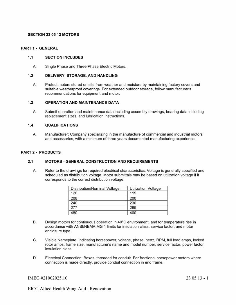
IMEG #21002025.10 23 05 13 - 1
EICC-Allied Health Wing-Add - Renovation
SECTION 23 05 13 MOTORS
PART 1 - GENERAL
1.1 SECTION INCLUDES
A. Single Phase and Three Phase Electric Motors.
1.2 DELIVERY, STORAGE, AND HANDLING
A. Protect motors stored on site from weather and moisture by maintaining factory covers and suitable weatherproof coverings. For extended outdoor storage, follow manufacturer's recommendations for equipment and motor.
1.3 OPERATION AND MAINTENANCE DATA
A. Submit operation and maintenance data including assembly drawings, bearing data including replacement sizes, and lubrication instructions.
1.4 QUALIFICATIONS
A. Manufacturer: Company specializing in the manufacture of commercial and industrial motors and accessories, with a minimum of three years documented manufacturing experience.
PART 2 - PRODUCTS
2.1 MOTORS - GENERAL CONSTRUCTION AND REQUIREMENTS
A. Refer to the drawings for required electrical characteristics. Voltage is generally specified and scheduled as distribution voltage. Motor submittals may be based on utilization voltage if it corresponds to the correct distribution voltage.
Distribution/Nominal Voltage Utilization Voltage120 115208 200240 230277 265480 460
B. Design motors for continuous operation in 40ºC environment, and for temperature rise in accordance with ANSI/NEMA MG 1 limits for insulation class, service factor, and motor enclosure type.
C. Visible Nameplate: Indicating horsepower, voltage, phase, hertz, RPM, full load amps, locked rotor amps, frame size, manufacturer's name and model number, service factor, power factor, insulation class.
D. Electrical Connection: Boxes, threaded for conduit. For fractional horsepower motors where connection is made directly, provide conduit connection in end frame.
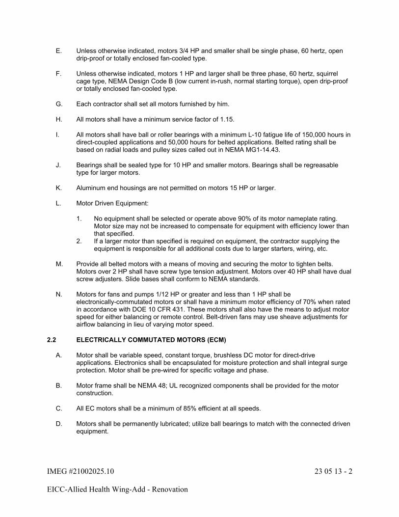
IMEG #21002025.10 23 05 13 - 2
EICC-Allied Health Wing-Add - Renovation
E. Unless otherwise indicated, motors 3/4 HP and smaller shall be single phase, 60 hertz, open drip-proof or totally enclosed fan-cooled type.
F. Unless otherwise indicated, motors 1 HP and larger shall be three phase, 60 hertz, squirrel cage type, NEMA Design Code B (low current in-rush, normal starting torque), open drip-proof or totally enclosed fan-cooled type.
G. Each contractor shall set all motors furnished by him.
H. All motors shall have a minimum service factor of 1.15.
I. All motors shall have ball or roller bearings with a minimum L-10 fatigue life of 150,000 hours in direct-coupled applications and 50,000 hours for belted applications. Belted rating shall be based on radial loads and pulley sizes called out in NEMA MG1-14.43.
J. Bearings shall be sealed type for 10 HP and smaller motors. Bearings shall be regreasable type for larger motors.
K. Aluminum end housings are not permitted on motors 15 HP or larger.
L. Motor Driven Equipment:
1. No equipment shall be selected or operate above 90% of its motor nameplate rating. Motor size may not be increased to compensate for equipment with efficiency lower than that specified.
2. If a larger motor than specified is required on equipment, the contractor supplying the equipment is responsible for all additional costs due to larger starters, wiring, etc.
M. Provide all belted motors with a means of moving and securing the motor to tighten belts. Motors over 2 HP shall have screw type tension adjustment. Motors over 40 HP shall have dual screw adjusters. Slide bases shall conform to NEMA standards.
N. Motors for fans and pumps 1/12 HP or greater and less than 1 HP shall be electronically-commutated motors or shall have a minimum motor efficiency of 70% when rated in accordance with DOE 10 CFR 431. These motors shall also have the means to adjust motor speed for either balancing or remote control. Belt-driven fans may use sheave adjustments for airflow balancing in lieu of varying motor speed.
2.2 ELECTRICALLY COMMUTATED MOTORS (ECM)
A. Motor shall be variable speed, constant torque, brushless DC motor for direct-drive applications. Electronics shall be encapsulated for moisture protection and shall integral surge protection. Motor shall be pre-wired for specific voltage and phase.
B. Motor frame shall be NEMA 48; UL recognized components shall be provided for the motor construction.
C. All EC motors shall be a minimum of 85% efficient at all speeds.
D. Motors shall be permanently lubricated; utilize ball bearings to match with the connected driven equipment.
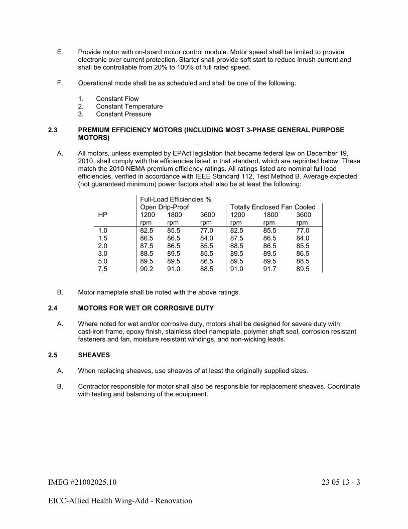
IMEG #21002025.10 23 05 13 - 3
EICC-Allied Health Wing-Add - Renovation
E. Provide motor with on-board motor control module. Motor speed shall be limited to provide electronic over current protection. Starter shall provide soft start to reduce inrush current and shall be controllable from 20% to 100% of full rated speed.
F. Operational mode shall be as scheduled and shall be one of the following:
1. Constant Flow2. Constant Temperature3. Constant Pressure
2.3 PREMIUM EFFICIENCY MOTORS (INCLUDING MOST 3-PHASE GENERAL PURPOSE MOTORS)
A. All motors, unless exempted by EPAct legislation that became federal law on December 19, 2010, shall comply with the efficiencies listed in that standard, which are reprinted below. These match the 2010 NEMA premium efficiency ratings. All ratings listed are nominal full load efficiencies, verified in accordance with IEEE Standard 112, Test Method B. Average expected (not guaranteed minimum) power factors shall also be at least the following:
Full-Load Efficiencies %Open Drip-Proof Totally Enclosed Fan Cooled
HP 1200 rpm
1800 rpm
3600 rpm
1200 rpm
1800 rpm
3600 rpm
1.0 82.5 85.5 77.0 82.5 85.5 77.01.5 86.5 86.5 84.0 87.5 86.5 84.02.0 87.5 86.5 85.5 88.5 86.5 85.53.0 88.5 89.5 85.5 89.5 89.5 86.55.0 89.5 89.5 86.5 89.5 89.5 88.57.5 90.2 91.0 88.5 91.0 91.7 89.5
B. Motor nameplate shall be noted with the above ratings.
2.4 MOTORS FOR WET OR CORROSIVE DUTY
A. Where noted for wet and/or corrosive duty, motors shall be designed for severe duty with cast-iron frame, epoxy finish, stainless steel nameplate, polymer shaft seal, corrosion resistant fasteners and fan, moisture resistant windings, and non-wicking leads.
2.5 SHEAVES
A. When replacing sheaves, use sheaves of at least the originally supplied sizes.
B. Contractor responsible for motor shall also be responsible for replacement sheaves. Coordinate with testing and balancing of the equipment.

IMEG #21002025.10 23 05 13 - 4
EICC-Allied Health Wing-Add - Renovation
PART 3 - EXECUTION
3.1 INSTALLATION
A. All rotating shafts and/or equipment shall be completely guarded from all contact. Partial guards and/or guards that do not meet all applicable OSHA standards are not acceptable. Contractor is responsible for providing this guarding if it is not provided with the equipment supplied.
B. For flexible coupled drive motors, mount coupling to the shafts in accordance with the coupling manufacturer's recommendations. Align shafts to manufacturer's requirements or within 0.002 inch per inch diameter of coupling hub.
C. For belt drive motors, mount sheaves on the appropriate shafts per manufacturer's instructions. Use a straight edge to check alignment of the sheaves. Reposition sheaves as necessary so the straight edge contacts both sheave faces squarely. After sheaves are aligned, loosen the adjustable motor base so the belt(s) can be added, and tighten the base so the belt tension is in accordance with the drive manufacturer's recommendations. Frequently check belt tension and adjust if necessary during the first day of operation and again after 80 hours of operation.
END OF SECTION 23 05 13

IMEG #21002025.10 23 05 29 - 1
EICC-Allied Health Wing-Add - Renovation
SECTION 23 05 29 - HVAC SUPPORTS AND ANCHORS
PART 1 - GENERAL
1.1 SECTION INCLUDES
A. Hangers, Supports, and Associated Anchors.
B. Sleeves and Seals.
C. Cutting of Openings.
D. Escutcheon Plates and Trim.
1.2 WORK FURNISHED BUT INSTALLED UNDER OTHER SECTIONS
A. Furnish sleeves and hanger inserts to General Contractor for placement into formwork.
PART 2 - PRODUCTS
2.1 HANGER RODS
A. Hanger rods for single rod hangers shall conform to the following:
Hanger Rod DiameterPipe Size Column #1 Column #22-1/2" and smaller 3/8" 3/8"3" through 3-5/8" 3/8" 3/8"4" and 5" 1/2" 1/2"Column #1: Steel pipe.Column #2: Copper, pipe.
B. Rods for double rod hangers may be reduced one size. Minimum rod diameter is 3/8 inches.
C. Hanger rods and accessories used in mechanical spaces or otherwise dry areas shall have ASTM B633 electro-plated zinc finish.
2.2 PIPE AND STRUCTURAL SUPPORTS
A. General:
1. Pipe hangers, clamps, and supports shall conform to Manufacturers Standardization Society MSS SP-58, 69, 89, and 127 (where applicable).
2. On all insulated piping, provide at each support an insert of same thickness and contour as adjoining insulation, between the pipe and insulation jacket, to prevent insulation from sagging and crushing. Refer to insulation specifications for materials and additional information.
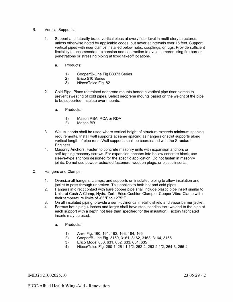
IMEG #21002025.10 23 05 29 - 2
EICC-Allied Health Wing-Add - Renovation
B. Vertical Supports:
1. Support and laterally brace vertical pipes at every floor level in multi-story structures, unless otherwise noted by applicable codes, but never at intervals over 15 feet. Support vertical pipes with riser clamps installed below hubs, couplings, or lugs. Provide sufficient flexibility to accommodate expansion and contraction to avoid compromising fire barrier penetrations or stressing piping at fixed takeoff locations.
a. Products:
1) Cooper/B-Line Fig B3373 Series2) Erico 510 Series3) Nibco/Tolco Fig. 82
2. Cold Pipe: Place restrained neoprene mounts beneath vertical pipe riser clamps to prevent sweating of cold pipes. Select neoprene mounts based on the weight of the pipe to be supported. Insulate over mounts.
a. Products:
1) Mason RBA, RCA or RDA2) Mason BR
3. Wall supports shall be used where vertical height of structure exceeds minimum spacing requirements. Install wall supports at same spacing as hangers or strut supports along vertical length of pipe runs. Wall supports shall be coordinated with the Structural Engineer.
4. Masonry Anchors: Fasten to concrete masonry units with expansion anchors or self-tapping masonry screws. For expansion anchors into hollow concrete block, use sleeve-type anchors designed for the specific application. Do not fasten in masonry joints. Do not use powder actuated fasteners, wooden plugs, or plastic inserts.
C. Hangers and Clamps:
1. Oversize all hangers, clamps, and supports on insulated piping to allow insulation and jacket to pass through unbroken. This applies to both hot and cold pipes.
2. Hangers in direct contact with bare copper pipe shall include plastic pipe insert similar to Unistrut Cush-A-Clamp, Hydra-Zorb, Erico Cushion Clamp or Cooper Vibra-Clamp within their temperature limits of -65°F to +275°F.
3. On all insulated piping, provide a semi-cylindrical metallic shield and vapor barrier jacket.4. Ferrous hot piping 4 inches and larger shall have steel saddles tack welded to the pipe at
each support with a depth not less than specified for the insulation. Factory fabricated inserts may be used.
a. Products:
1) Anvil Fig. 160, 161, 162, 163, 164, 1652) Cooper/B-Line Fig. 3160, 3161, 3162, 3163, 3164, 31653) Erico Model 630, 631, 632, 633, 634, 6354) Nibco/Tolco Fig. 260-1, 261-1 1/2, 262-2, 263-2 1/2, 264-3, 265-4
IMEG #21002025.10 23 05 29 - 3
EICC-Allied Health Wing-Add - Renovation
5. Support may be fabricated from U-channel strut or similar shapes. Piping less than 4" in diameter shall be secured to strut with clamps of proper design and capacity as required to maintain spacing and alignment. Strut shall be independently supported from hanger drops or building structure. Size and support shall be per manufacturer's installation requirements for structural support of piping. Clamps shall not interrupt piping insulation.
a. Strut used in mechanical spaces or otherwise dry areas shall have ASTM B633 electro-plated zinc finish.
b. Strut used in damp areas listed in hanger rods shall have ASTM A123 hot-dip galvanized finish applied after fabrication.
D. Upper (Structural) Attachments:
1. Unless otherwise shown, upper attachments for hanger rods or support struts shall be as follows:
a. Steel Structure Clamps: C-Type Wide Flange Beam Clamps (for use on top and/or bottom of wide flanges. Not permitted for use with bar-joists.):
1) Products:
a) Anvil Fig. 92b) Cooper/B-Line Fig. B3033/B3034c) Erico Model 300d) Nibco/Tolco 68
b. Scissor Type Beam Clamps (for use with bar-joists and wide flange):
1) Products:
a) Anvil Fig. 228, 292b) Cooper/B-Line Fig. B3054c) Erico Model 360d) Nibco/Tolco Fig. 329
c. Concentrically Loaded Open Web Joist Hangers (for use with bar joists):
1) Products:
a) MCL. M1, M2 or M3
2.3 OPENINGS IN FLOORS, WALLS AND CEILINGS
A. Exact locations of all openings for the installation of materials shall be determined by the Contractor and given to the General Contractor for installation or construction as the structure is built.
B. Coordinate all openings with other Contractors.
C. Hire the proper tradesman and furnish all labor, material and equipment to cut openings in or through existing structures, or openings in new structures that were not installed, or additional openings. Repair all spalling and damage to the satisfaction of the Architect/Engineer. Make saw cuts before breaking out concrete to ensure even and uniform opening edges.
IMEG #21002025.10 23 05 29 - 4
EICC-Allied Health Wing-Add - Renovation
D. Said cutting shall be at the complete expense of each Contractor. Failure to coordinate openings with other Contractors shall not exempt the Contractor from providing openings at Contractor's expense.
E. Do not cut structural members without written approval of the Architect or Structural Engineer.
2.4 ROOF PENETRATIONS
A. Roof Curb Enclosure: Provide weatherproof roof curb and enclosure for duct penetrations. Refer to drawings for details.
B. Conical Pipe Boot: Seal pipes with surface temperature below 150°F penetrating single-ply roofs with conical stepped, UV-resistant silicone, EPDM or neoprene pipe flashings and stainless steel clamps equal to Portals Plus Pipe Boots or Pipetite. Color: Black shall match roofing material.
C. Break insulation only at the clamp for pipes between 60°F and 150°F. Seal outdoor insulation edges watertight.
2.5 SLEEVES AND LINTELS
A. Each Contractor shall provide sleeves and lintels for all duct and pipe openings required for the Contractor's work in masonry walls and floors, unless specifically shown as being by others.
B. Fabricate all sleeves from standard weight black steel pipe or as indicated on the drawings. Provide continuous sleeve. Cut or split sleeves are not acceptable.
C. Fabricate all lintels for masonry walls from structural steel shapes or as indicated on the drawings. Have all lintels approved by the Architect or Structural Engineer.
D. Sleeves through the floors on exposed risers shall be flush with the ceiling, with planed squared ends extending 1" above the floor in unfinished areas, and flush with the floor in finished areas, to accept spring closing floor plates.
E. Sleeves shall not penetrate structural members or masonry walls without approval from the Structural Engineer. Sleeves shall then comply with the Architect/Engineer's design.
F. Openings through unexcavated floors and/or foundation walls below the floor shall have a smooth finish with sufficient annular space around material passing through opening so slight settling will not place stress on the material or building structure.
G. Install all sleeves concentric with pipes. Secure sleeves in concrete to wood forms. This Contractor is responsible for sleeves dislodged or moved when pouring concrete.
H. Where pipes rise through concrete floors that are on earthen grade, provide 3/4" resilient expansion joint material (e.g., foam, rubber, asphalt-coated fiber, bituminous-impregnated felt, or cork) wrapped around the pipe, the full depth of concrete, at the point of penetration. Secure to prevent shifting during concrete placement and finishing.
I. Size sleeves large enough to allow expansion and contraction movement. Provide continuous insulation wrapping.
IMEG #21002025.10 23 05 29 - 5
EICC-Allied Health Wing-Add - Renovation
2.6 ESCUTCHEON PLATES AND TRIM
A. Fit escutcheons to all insulated or uninsulated exposed pipes passing through walls, floors, or ceilings of finished rooms.
B. Escutcheons shall be heavy gauge, cold rolled steel, copper coated under a chromium plated finish, heavy spring clip, rigid hinge and latch.
C. Install galvanized steel (unless otherwise indicated) trim strip to cover vacant space and raw construction edges of all rectangular openings in finished rooms. This includes pipe openings.
2.7 PIPE PENETRATIONS
A. Seal all pipe penetrations. Seal non-rated walls and floor penetrations with grout or caulk. Backing material may be used.
B. Seal fire rated wall and floor penetrations with fire seal system as specified.
2.8 PIPE ANCHORS
A. Provide all items needed to allow adequate expansion and contraction of all piping. All piping shall be supported, guided, aligned, and anchored as required.
B. Repair all piping leaks and associated damage. Pipes shall not rub on any part of the building.
PART 3 - EXECUTION
3.1 HVAC SUPPORTS AND ANCHORS
A. General Installation Requirements:
1. Install all items per manufacturer's instructions.2. Coordinate the location and method of support of piping systems with all installations
under other Divisions and Sections of the Specifications.3. Where pipe support members are welded to structural building framing, scrape, brush
clean, and apply one coat of zinc rich primer to welding.4. Supports shall extend directly to building structure. Do not support piping from duct
hangers unless coordinated with sheet metal contractor prior to installation. Do not allow lighting or ceiling supports to be hung from piping supports.
B. Supports Requirements:
1. Where building structural steel is fireproofed, all hangers, clamps, auxiliary steel, etc., which attach to it shall be installed prior to application of fireproofing. Repair all fireproofing damaged during pipe installation.
2. Set all concrete inserts in place before pouring concrete.3. Furnish, install and prime all auxiliary structural steel for support of piping systems that
are not shown on the Drawings as being by others.4. Install hangers and supports complete with lock nuts, clamps, rods, bolts, couplings,
swivels, inserts and required accessories.5. Hangers for horizontal piping shall have adequate means of vertical adjustment for
alignment.

IMEG #21002025.10 23 05 29 - 6
EICC-Allied Health Wing-Add - Renovation
C. Provided the installation complies with all loading requirements of truss and joist manufacturers, the following practices are acceptable:
1. Loads of 100 lbs. or less may be attached anywhere along the top or bottom chords of trusses or joists with a minimum 3' spacing between loads.
2. Loads greater than 100 lbs. must be hung concentrically and may be hung from top or bottom chord, provided one of the following conditions is met:
a. The hanger is attached within 6" from a web/chord joint.b. Additional L2x2x1/4 web reinforcement is installed per manufacturer's
requirements.
3. It is prohibited to cantilever a load using an angle or other structural component that is attached to a truss or joist in such a fashion that a torsional force is applied to that structural member.
4. If conditions cannot be met, coordinate installation with truss or joist manufacturer and contact Architect/Engineer.
D. After piping and insulation installation are complete, cut hanger rods back at trapeze supports so they do not extend more than 3/4" below bottom face of lowest fastener and blunt any sharp edges.
E. Do not exceed 25 lbs. per hanger and a minimum spacing of 2'-0" on center when attaching to metal roof decking (limitation not required with concrete on metal deck). This 25 lbs. load and 2'-0" spacing include adjacent electrical and architectural items hanging from deck. If the hanger restrictions cannot be achieved, supplemental framing off steel framing will need to be added.
F. Do not exceed the manufacturer's recommended maximum load for any hanger or support.
G. Installation of hangers shall conform to MSS SP-58, 69, and 89.
END OF SECTION 23 05 29
IMEG #21002025.10 23 05 53 - 1
EICC-Allied Health Wing-Add - Renovation
SECTION 23 05 53 - HVAC IDENTIFICATION
PART 1 - GENERAL
1.1 SECTION INCLUDES
A. Identification of products installed under Division 23.
PART 2 - PRODUCTS
2.1 MANUFACTURERS
A. 3M
B. Bunting
C. Calpico
D. Craftmark
E. Emedco
F. Kolbi Industries
G. Seton
H. W.H. Brady
I. Marking Services.
2.2 MATERIALS
A. All pipe markers (purchased or stenciled) shall conform to ANSI A13.1. Marker lengths and letter sizes shall be at least the following:
OD of Pipe or Insulation Marker Length Size of LettersUp to and including 1-1/4" 8" 1/2" 1-1/2" to 2" 8" 3/4" 2-1/2" to 6" 12" 1-1/4" Plastic tags may be used for outside diameters under 3/4"
B. Plastic Nameplates: Laminated three-layer phenolic with engraved black, 1/4" minimum letters on light contrasting background.
C. Plastic Tags: Minimum 1-1/2" square or round laminated three-layer phenolic with engraved, 1/4" minimum black letters on light contrasting background.
D. Plastic Pipe Markers: Semi-rigid plastic, preformed to fit around pipe or pipe covering; indicating flow direction and fluid conveyed.
IMEG #21002025.10 23 05 53 - 2
EICC-Allied Health Wing-Add - Renovation
E. Vinyl Pipe Markers: Colored vinyl with permanent pressure sensitive adhesive backing.
F. Ceiling Markers:
1. Label Style:
a. The intent is for the ceiling labels to be inconspicuous but easy to find and read while standing underneath. The labels shall be located on the grid T-bar nearest the ceiling tile that can be removed to provide the best access to the serviceable side of equipment or to valves. An arrow can be used to point to the tile needing removal.
b. The label tape shall be approximately 1/2" wide with all capitalized letters approximately 3/16” tall.
c. Ceiling grid labels shall be made with a label maker with durable adhesive labels having a clear background and black letters.
d. Equipment labels shall be as designated on the drawings (e.g., FCU-606B, etc.).e. Valve labels shall be designated by the size, service, and the valve tag number
(e.g., 1-1/4” CW #123, 2” HWS #234, etc.). A single longer label can be used to identify multiple valves using spaces between the descriptors if the valves are located close together and have the same service (e.g., HWS and HWR valves serving the same equipment or CW, HW, and HWC lines serving the same restroom, etc.).
f. Fire, shall be labeled consistent with the type (e.g., Fire Damper, Fire/Smoke Damper, etc.),
2. "Dot" Style:
a. The intent is for the ceiling labels to be inconspicuous but easy to find and read while standing underneath. The labels shall be located on the grid T-bar nearest the ceiling tile that can be removed to provide the best access to the serviceable side of equipment or to valves.
b. The marker shall be a self-adhesive color dot approximately 1/2” in diameter.c. The equipment and accessories to be marked and dot color shall be coordinated
with the Architect/Engineer and Owner.
1) Equipment and accessories to be marked:
a) Fire Dampersb) VAV Boxes
PART 3 - EXECUTION
3.1 INSTALLATION
A. Install all products per manufacturer's recommendations.
B. Degrease and clean surfaces to receive adhesive for identification materials.

IMEG #21002025.10 23 05 53 - 3
EICC-Allied Health Wing-Add - Renovation
C. Pipe Markers:
1. Adhesive Backed Markers: Use Brady Style 1, 2, or 3 on pipes 3" diameter and larger. Use Brady Style 4, 6, or 8 on pipes under 3" diameter. Similar styles by other listed manufacturers are acceptable. Secure all markers at both ends with a wrap of pressure sensitive tape completely around the pipe.
2. Snap-on Markers: Use Seton "Setmark" on pipes up to 5-7/8" OD. Use Seton "Setmark" with nylon or Velcro ties for pipes 6" OD and over. Similar styles by other listed manufacturers are acceptable.
D. Equipment:
1. All equipment not easily identifiable such as controls, relays, gauges, etc.; and all equipment in an area remote from its function such as air handling units, exhaust fans, filters, reheat coils, dampers, etc.; shall have nameplates or plastic tags listing name, function, and drawing symbol. Do not label exposed equipment in public areas.
2. Fasten nameplates or plastic tags with stainless steel self-tapping screws or permanently bonding cement.
3. Mechanical equipment that is not covered by the U.S. National Appliance Energy Conservation Act (NAECA) of 1987 shall carry a permanent label installed by the manufacturer stating that the equipment complies with the requirements of ASHRAE 90.1.
E. Miscellaneous:
1. Attach self-adhesive vinyl labels at all duct access doors used to reset fusible links or actuators on fire, fire/smoke, or smoke dampers. Lettering shall be a minimum of 1/2" high. Labels shall indicate damper type.
2. Provide engraved plastic tags at all hydronic or steam system make-up water meters.
3.2 SCHEDULE
A. Pipes to be marked shall be labeled with text as follows, regardless of which method or material is used:
1. REFRIGERANT LIQUID: White lettering; purple background2. REFRIGERANT SUCTION: White lettering; purple background3. REFRIGERANT HOT GAS: White lettering; purple background
END OF SECTION 23 05 53
IMEG #21002025.10 23 05 93 - 1
EICC-Allied Health Wing-Add - Renovation
SECTION 23 05 93 - TESTING, ADJUSTING, AND BALANCING
PART 1 - GENERAL
1.1 SECTION INCLUDES
A. Testing, adjusting, and balancing of air systems.
B. Measurement of final operating condition of HVAC systems.
1.2 QUALITY ASSURANCE
A. Agency shall be a company specializing in the adjusting and balancing of systems specified in this section with minimum three years' experience. Perform work under supervision of AABC Certified Test and Balance Engineer, NEBB Certified Testing, Balancing and Adjusting Supervisor, SMARTA Certified Air and Hydronic Balancer, or TABB Certified Supervisor.
B. Work shall be performed in accordance with the requirements of the references listed at the start of this section.
1.3 SUBMITTALS
A. Submit copies of report forms, balancing procedures, and the name and qualifications of testing and balancing agency for approval within 30 days after award of Contract.
B. Electronic Copies:
1. Submit a certified copy of test reports to the Architect/Engineer for approval. Electronic copies shall be in PDF format only. Scanned copies, in PDF format, of paper originals are acceptable. Copies that are not legible will be returned to the Contractor for resubmittal. Do not set any permission restrictions on files; protected, locked, or secured documents will be rejected.
2. Electronic file size shall be limited to a maximum of 10MB. Larger files shall be divided into files that are clearly labeled as "1 of 2", "2 of 2", etc.
3. All text shall be searchable.4. Bookmarks shall be used. All bookmark titles shall be an active link to the index page and
index tabs.
1.4 REPORT FORMS
A. Submit reports on AABC, SMACNA or NEBB forms. Use custom forms approved by the Architect/Engineer when needed to supply specified information.
B. Include in the final report a schematic drawing showing each system component, including balancing devices, for each system. Each drawing shall be included with the test reports required for that system. The schematic drawings shall identify all testing points and cross-reference these points to the report forms and procedures.
C. Refer to PART 4 for required reports.

IMEG #21002025.10 23 05 93 - 2
EICC-Allied Health Wing-Add - Renovation
1.5 WARRANTY/GUARANTEE
A. The TAB Contractor shall include an extended warranty of 90 days after owner receipt of a completed balancing report, during which time the Owner may request a recheck of terminals, or resetting of any outlet, coil, or device listed in the test report. This warranty shall provide a minimum of 24 manhours of onsite service time. If it is determined that the new test results are not within the design criteria, the balancer shall rebalance the system according to design criteria.
B. Warranty/Guarantee must meet one of the following programs: TABB International Quality Assurance Program, AABC National Project Performance Guarantee, NEBB's Conformance Certification.
1.6 SCHEDULING
A. Coordinate schedule with other trades. Provide a minimum of seven days' notice to all trades and the Architect/Engineer prior to performing each test.
PART 2 - PRODUCTS (Not Used)
PART 3 - EXECUTION
3.1 GENERAL REQUIREMENTS
A. All procedures must conform to a published standard listed in the References article of this section. All equipment shall be adjusted in accordance with the manufacturer's recommendations. Any system not listed in this specification but installed under the contract documents shall be balanced using a procedure from a published standard listed in the References article.
B. The Balancing Contractor shall incorporate all pertinent documented construction changes (e.g. submittals/shop drawings, change orders, RFIs, ASIs, etc.) and include in the balancing report.
C. Recorded data shall represent actual measured or observed conditions.
D. Cut insulation, ducts, pipes, and equipment cabinets for installation of test probes to the minimum extent necessary to allow adequate performance of procedures. After testing and balancing is complete, close probe holes and patch insulation with new materials as specified. Restore vapor barrier and finish as specified.
E. Permanently mark setting of valves, dampers, and other adjustment devices allowing for settings to be restored. Set and lock memory stops.
F. Leave systems in proper working order, replacing belt guards, closing access doors, closing doors to electrical switch boxes, plugging test holes, and restoring thermostats to specified settings.
G. The Balancing Contractor shall measure terminal air box air flow, and the TCC shall adjust DDC readout to match. Refer to Section 23 09 00 for additional information.

IMEG #21002025.10 23 05 93 - 3
EICC-Allied Health Wing-Add - Renovation
H. Installations with systems consisting of multiple components shall be balanced with all system components operating.
3.2 EXAMINATION
A. Before beginning work, verify that systems are complete and operable. Ensure the following:
1. General Equipment Requirements:
a. Equipment is safe to operate and in normal condition.b. Equipment with moving parts is properly lubricated.c. Temperature control systems are complete and operable.d. Proper thermal overload protection is in place for electrical equipment.e. Direction of rotation of all fans and pumps is correct.f. Access doors are closed and end caps are in place.
2. Duct System Requirements:
a. All filters are clean and in place. If required, install temporary media.b. Duct systems are clean and free of debris.c. Fire/smoke and manual volume dampers are in place, functional and open.d. Air outlets are installed and connected.e. Duct system leakage has been minimized.
B. Report any defects or deficiencies to Architect/Engineer.
C. Promptly report items that are abnormal or prevent proper balancing.
D. If, for design reasons, system cannot be properly balanced, report as soon as observed.
E. Beginning of work means acceptance of existing conditions.
3.3 PREPARATION
A. Provide instruments required for testing, adjusting, and balancing operations. Make instruments available to the Architect/Engineer for spot checks during testing.
B. Instruments shall be calibrated within six months of testing performed for project, or more recently if recommended by the instrument manufacturer.
3.4 INSTALLATION TOLERANCES
A. ± 10% of scheduled values:
1. Adjust air inlets and outlets to ± 10% of scheduled values.
B. ± 5% of scheduled values:
1. Adjust fume exhaust systems to ± 5% of scheduled values.2. Adjust supply and exhaust air-handling systems for space pressurization to ± 5% of
scheduled values, and to provide proper pressurization.

IMEG #21002025.10 23 05 93 - 4
EICC-Allied Health Wing-Add - Renovation
C. + 5% of scheduled values:
1. Adjust outdoor air intakes to within + 5% of scheduled values.2. Adjust exhaust air through energy recovery equipment to within +5% of scheduled
values.
D. Adjust supply, return, and exhaust air-handling systems to +10% / -5% of scheduled values.
3.5 ADJUSTING
A. After adjustment, take measurements to verify balance has not been disrupted or that disruption has been rectified.
B. Once balancing of systems is complete, at least one damper or valve must be 100% open.
C. After testing, adjusting and balancing are complete, operate each system and randomly check measurements to verify system is operating as reported in the report. Document any discrepancies.
D. Contractor responsible for each motor shall also be responsible for replacement sheaves. Coordinate with contractor.
E. Contractor responsible for pump shall trim impeller to final duty point as instructed by this contractor on all pumps not driven by a VFD. Coordinate with contractor.
3.6 SUBMISSION OF REPORTS
A. Fill in test results on appropriate forms.
PART 4 - SYSTEMS TO BE TESTED, ADJUSTED AND BALANCED
4.1 VERIFICATION OF EXISTING SYSTEMS.
A. Perform a pre-balance of systems serving the area of construction prior to the start of any other work. Do not make adjustments to the systems. If the systems are not operating at maximum capacity, temporarily drive system to maximum and take readings for the system. Return the system to its original state when measurements are complete.
1. Air Handling Unit (Specific supply/return):
a. General Requirements:
1) Existing Equipment Tag (if available).2) Location.3) Manufacturer, model, arrangement, class, discharge.4) Fan RPM.
b. Duct traverse: (where indicated on plans)
c. Flow Rate:
1) Supply flow rate (cfm)
IMEG #21002025.10 23 05 93 - 5
EICC-Allied Health Wing-Add - Renovation
2) Return flow rate (cfm)
B. Report findings to Architect/Engineer on standard forms. Provide four (4) copies of report.
4.2 GENERAL REQUIREMENTS
A. Title Page:
1. Project name.2. Project location.3. Project Architect.4. Project Engineer (IMEG Corp.).5. Project General Contractor.6. TAB Company name, address, phone number.7. TAB Supervisor's name and certification number.8. TAB Supervisor's signature and date.9. Report date.
B. Report Index
C. General Information:
1. Test conditions.2. Nomenclature used throughout report.3. Notable system characteristics/discrepancies from design.4. Test standards followed.5. Any deficiencies noted.6. Quality assurance statement.
D. Instrument List:
1. Instrument.2. Manufacturer, model, and serial number.3. Range.4. Calibration date.
4.3 AIR SYSTEMS
A. Duct Leakage Test:
1. Air system and fan.2. Leakage class.3. Test pressure.4. Construction pressure.5. Flow rate (cfm): specified and actual.6. Leakage (refer to Section 23 31 00 in the specifications): specified and actual.7. Statement that fire dampers, reheat coils and other accessories were included in the test.8. Pass or Fail.9. Test performed by.10. Test witnessed by.
IMEG #21002025.10 23 05 93 - 6
EICC-Allied Health Wing-Add - Renovation
B. Air Moving Equipment:
1. General Requirements:
a. Drawing symbol.b. Location.c. Manufacturer, model, arrangement, class, discharge.d. Fan RPM.e. Multiple RPM fan curve with operating point marked. (Obtain from equipment
supplier).f. Final frequency of motor at maximum flow rate (on fans driven by VFD).
2. Flow Rate:
a. Supply flow rate (cfm): specified and actual.b. Return flow rate (cfm): specified and actual.c. Outside flow rate (cfm): specified and actual.d. Exhaust flow rate (cfm): specified and actual.
3. Pressure Drop and Pressure:
a. Filter pressure drop: specified and actual.b. Total static pressure: specified and actual. (Indicate if across fan or external to
unit).c. Inlet pressure.d. Discharge pressure.
C. Fan Data:
1. Drawing symbol.2. Location.3. Manufacturer and model.4. Flow rate (cfm): specified and actual.5. Total static pressure: specified and actual. (Indicate measurement locations).6. Inlet pressure.7. Discharge pressure.8. Fan RPM.
D. Electric Motors:
1. Drawing symbol of equipment served.2. Manufacturer, Model, Frame.3. Nameplate: HP, phase, service factor, RPM, operating amps, efficiency.4. Measured: Amps in each phase.
E. Duct Traverse
F. System zone/branch/location.1. Duct size.2. Free area.3. Velocity: specified and actual.4. Flow rate (cfm): specified and actual.5. Duct static pressure.6. Air temperature.

IMEG #21002025.10 23 05 93 - 7
EICC-Allied Health Wing-Add - Renovation
7. Air correction factor.
G. Air Terminal (Inlet or Outlet):
1. Drawing symbol.2. Room number/location.3. Terminal type and size.4. Velocity: specified and actual.5. Flow rate (cfm): specified and actual.6. Percent of design flow rate.
H. Air Flow Measuring Station:
1. Drawing symbol.2. Service.3. Location.4. Manufacturer and model.5. Size.6. Flow rate (cfm): specified and actual.7. Pressure drop: specified and actual.
I. Fire, Smoke, and Fire/Smoke Dampers:
1. Damper ID #.2. System identification.3. Type.4. Size.5. UL assembly number.6. Location of damper and access door.7. Fusible link temperature rating.8. Manufacturer and model.9. Operation pass/fail/reset.
4.4 HEATING SYSTEMS
A. Terminal Heat Transfer Units:
1. General Requirement:
a. Drawing symbol.b. Location.c. Manufacturer and model.d. Include air data only for forced air units.
2. Flow Rate:
a. Flow rate (cfm): specified and actual.b. Water flow rate (cfm): specified and actual.
3. Temperature:
a. Entering air temperature: specified and actual.b. Leaving air temperature: specified and actual.c. Entering water temperature: specified and actual.

IMEG #21002025.10 23 05 93 - 8
EICC-Allied Health Wing-Add - Renovation
d. Leaving water temperature: specified and actual.
4.5 ENERGY RECOVERY SYSTEMS
A. Air Systems - Air energy recovery devices shall be tested at ambient temperatures of less than 40°F or greater than 85°F.
1. Energy Recovery Wheel (DOAS-1 & DOAS-2):
a. General Requirements:
1) Drawing Symbol.2) Location.3) Wheel RPM.
b. Primary Air:
1) Primary Entering Air Temperature.2) Primary Leaving Air Temperature.3) Primary Air Pressure Drop.4) Primary Air Flow Rate (cfm).
c. Secondary Air:
1) Secondary Entering Air Temperature.2) Secondary Leaving Air Temperature.3) Secondary Air Pressure Drop.4) Secondary Air Flow Rate (cfm).
END OF SECTION 23 05 93

IMEG #21002025.10 23 07 13 - 1
EICC-Allied Health Wing-Add - Reno
SECTION 23 07 13 - DUCTWORK INSULATION
PART 1 - GENERAL
1.1 SECTION INCLUDES
A. Ductwork Insulation.
B. Insulation Jackets.
1.2 QUALITY ASSURANCE
A. Applicator: Company specializing in ductwork insulation application with five years minimum experience. When requested, installer shall submit manufacturer's certificate indicating qualifications.
B. Materials:
1. Flame spread/smoke developed rating of 25/50 in accordance with ASTM E84, NFPA 255, or UL 723.
2. Fungal Resistance: No growth when tested in accordance with ASTM G21 (antifungal test).
3. Rated velocity on coated air side for air erosion in accordance with UL 181 at 5,000 fpm minimum.
C. Adhesives: UL listed, meeting NFPA 90A/90B requirements.
PART 2 - PRODUCTS
2.1 MATERIALS
A. Type A: Flexible Fiberglass - Outside Wrap; ANSI/ASTM C553; commercial grade; 0.28 / 0.26 (Out-Of-Package/Installed-Compressed 25%) maximum 'K' value at 75°F; foil scrim Kraft facing, 1.0 lb./cu. ft. density. Submit both "Out of Package" and "Installed-Compressed 25%" K and R-values.
B. Type C: Flexible Fiberglass Liner; ANSI/ASTM C1071; 0.28 maximum 'K' value at 75°F; 1.5 lb/cu ft minimum density; coated air side for 5000 fpm air velocity.
C. Type E: Double wall ductwork insulation; fiberglass; 0.27 maximum 'K' value at 75°F mean temperature; 1.5 lb/cu ft density.
2.2 JACKETS
A. Vapor Barrier Jackets: Kraft reinforced foil scrim vapor barrier with self-sealing adhesive joints. Beach puncture resistance ratio of at least 25 units. Tensile strength: 35 psi minimum. Single, self-seal acrylic adhesive on longitudinal jacket laps and butt strips.

IMEG #21002025.10 23 07 13 - 2
EICC-Allied Health Wing-Add - Reno
PART 3 - EXECUTION
3.1 INSTALLATION
A. Install materials in accordance with manufacturer's instructions, codes, and industry standards.
B. Install materials after ductwork has been tested.
C. Clean surfaces for adhesives.
D. Provide insulation with vapor barrier when air conveyed may be below ambient temperature.
E. Exterior Duct Wrap - Flexible, Type A:
1. Apply with edges tightly butted.2. Cut slightly longer than perimeter of duct to insure full thickness at corners. Do not wrap
excessively tight.3. Seal joints with adhesive backed tape.4. Apply so insulation conforms uniformly and firmly to duct.5. Provide high-density insulation inserts at trapeze duct hangers and straps to prevent
crushing of insulation. Maintain continuous vapor barrier through the hanger.6. Seal all penetrations of the vapor barrier by strap hangers or slip cable hangers with
adhesive backed tape.7. Tape all joints with Royal Tapes #RT 350 (216-439-7229), Venture Tape 1525CW, or
Compac Type FSK. No substitutions will be accepted without written permission from the Architect/Engineer.
8. Press tape tightly to the duct covering with a squeegee for a tight continuous seal. Fish mouths and loose tape edges are not acceptable.
9. Staples may be used, but must be covered with tape.10. Vapor barrier must be continuous.11. Mechanically fasten on 12" centers at bottom of ducts over 24" wide and on all sides of
vertical ducts.
F. Interior Insulation - Flexible Duct Liner, Type C:
1. Observation of Duct Lining:
a. After installation of ductwork, Architect/Engineer may select random observation points in each system.
1) At each observation point, cut and remove an 18" x 18" section of ductwork and liner for verification of installation.
2) Random observation points based on one opening per 75 lineal ft. of total duct run.
b. When any of the observation points shows non-compliance, additional points will be designated by the Architect/Engineer, and observation repeated.
c. If 20% of points observed do not comply, remove and replace all lined ducts and repeat tests. Where replacement is not required, correct all non-compliances.
d. At end of observation, repair all duct lining and observation holes by installing standard, insulated, hinged access doors per Section 23 33 00.
e. Paint or finish to match adjacent duct surfaces.
IMEG #21002025.10 23 07 13 - 3
EICC-Allied Health Wing-Add - Reno
2. Impale on spindle anchors welded or mechanically fastened to the duct. Adhesive or glue fastened anchors are not acceptable. Maximum anchor spacing per SMACNA Duct Construction Standards or manufacturer's recommendations, whichever is more restrictive. Locate pins less than 3" from corners and at intervals not over 6" around the perimeter at leading and trailing edges. Locate pins within 3" of transverse joints and at intervals not over 16" long the length of the duct. Pins must be long enough to prevent compressing the insulation.
3. In addition to anchors, secure liner with UL listed adhesive covering over 90% of the duct surface.
4. Install per the latest edition of the SMACNA Manual.5. Leading edges shall be covered as follows:
a. For duct velocities below 3000 fpm, coat leading edges with adhesive. Neatly butt liner without gaps at transverse joints. Cut liner flush with end of the duct section for tight joints with no exposed duct. If adhesive is shop installed, field apply additional adhesive to the end of each duct section for complete adhesion of the liner. Protect edges from dirt and debris.
b. For duct velocities above 3000 fpm, cover leading edges with metal nosing. Use nosing on upstream edges of each section of duct. If the duct can be installed in either direction, provide nosing on each end or clearly mark the duct to allow visual verification after installation. Verify duct velocities based on the scheduled air flow rates and determine where metal nosing is required.
c. Install metal nosing in the following locations (regardless of velocity):
1) The first three fittings downstream of all fans.2) At all duct liner interruptions. This includes fire dampers, access doors,
branch connections, and all other locations where the edge of the liner is exposed.
3) Trailing edges of transverse joints do not require metal nosings.
6. Overlap liner at longitudinal joints. Make longitudinal joints at corners of the duct unless the duct size does not allow this. Coat longitudinal joints with adhesive at velocities over 2500 fpm.
7. Seal all damaged duct liner with adhesive and glass cloth. Do not damage duct liner surface coatings.
8. Duct dimensions given are net inside dimensions. Increase sheet metal to allow for insulation thickness.
G. Exterior Fire Protection, Flexible Type - Type F:
1. Cut and secure duct wrap around ductwork, support angles, and hangers per manufacturer's recommendations.
2. Seal all joints as required to maintain enclosure rating.3. Installation shall be rated for 2 hours, unless otherwise noted.4. Provide manufacturer's recommended assembly to protect all access doors to maintain
enclosure rating and to permit easy replacement of insulation.
H. Continue insulation with vapor barrier through penetrations unless code prohibits.
I. Provide 2" wide, 24" high, 26 gauge, galvanized sheet metal corner protection angles for all externally insulated ductwork extending to a floor or curb.

IMEG #21002025.10 23 07 13 - 4
EICC-Allied Health Wing-Add - Reno
3.2 SCHEDULE
A. Refer to Section 23 31 00 for scheduling of insulation.
END OF SECTION 23 07 13

IMEG #21002025.10 23 07 19 - 1
EICC-Allied Health Wing-Add - Renovation
SECTION 23 07 19 - HVAC PIPING INSULATION
PART 1 - GENERAL
1.1 SECTION INCLUDES
A. Piping Insulation.
B. Insulation Jackets.
1.2 QUALITY ASSURANCE
A. Applicator: Company specializing in piping insulation application with five years minimum experience.
B. Materials: Flame spread/smoke developed rating of 25/50 in accordance with ASTM E84, NFPA 255, or UL 723 (where required). Factory label insulation and jacket materials and adhesive, mastic, tapes, and cement material containers with appropriate markings of applicable testing agency.
C. Products shall not contain asbestos, lead, mercury, or mercury compounds.
D. Products that come in contact with stainless steel shall have a leachable chloride content of less than 50 ppm when tested according to ASTM C 871. Insulation materials for use on austenitic stainless steel shall be qualified as acceptable according to ASTM C 795.
E. Foam insulation materials shall not use CFC or HCFC blowing agents in the manufacturing process.
PART 2 - PRODUCTS
2.1 INSULATION
A. Type A: Glass fiber; ANSI/ASTM C547; 0.24 maximum 'K' value at 75°F; non-combustible. All-purpose polymer or polypropylene service jacket, 25/50 flame spread/smoke developed rating when tested in accordance with ASTM E84 (UL 723).
B. Type B: Flexible elastomeric foam insulation; closed-cell, sponge or expanded rubber (polyethylene type is not permitted); ANSI/ASTM C534, Grade 1 Type I for tubular materials; flexible plastic; 0.25 maximum 'K' value at 75°F, 25/50 flame spread/smoke developed rating when tested in accordance with ASTM E84 (UL 723). Maximum 1" thick per layer where multiple layers are specified.
C. Type C: Molded rigid cellular glass; ANSI/ASTM C-552; 0.29 maximum 'K' value at 75°F; density 7.3lb/ft; minimum compressive strength 90 psi parallel to rise; moisture resistant, non-combustible; suitable for -100°F to +900°F. For below grade installations use asphaltic mastic paper vapor barrier jacket. Use self-seal all-purpose polymer or polypropylene service jacket for above grade installations.

IMEG #21002025.10 23 07 19 - 2
EICC-Allied Health Wing-Add - Renovation
D. Type E: Preformed rigid cellular polyisocyanurate insulation; ANSI/ASTM C591; maximum 'K' value of 0.19 at 75°F; density 4.0lb/ft; minimum compressive strength 95 psi parallel to rise; moisture resistant; 25/50 flame spread/smoke developed rating when tested in accordance with ASTM E84 (UL 723); suitable for -297°F to +300°F.
PART 3 - EXECUTION
3.1 PREPARATION
A. Install insulation after piping has been tested. Pipe shall be clean, dry and free of rust before applying insulation.
B. Patch and repair torn insulation. Paint to match adjacent insulation surface.
3.2 INSTALLATION
A. General Installation Requirements:
1. Install materials per manufacturer's instructions, building codes and industry standards.2. Continue insulation with vapor barrier through penetrations. This applies to all insulated
piping. Maintain fire rating of all penetrations.3. All piping and insulation that does not meet 25/50 that is in an air plenum shall have
written approval from the Authority Having Jurisdiction and the local fire department for authorization and materials approval. If approval has been allowed, the non-rated material shall be wrapped with a product that has been listed and labeled having a flame spread index of not more than 25 and a smoke-developed index of not more than 50 when tested as a composite in accordance with ASTM E84 or UL 723.
4. On 1" and smaller piping routed through metal wall studs, provide a plastic grommet to protect the piping. The piping shall be insulated between the wall studs, and the insulation shall butt up to each stud.
B. Insulated Piping Operating Above 140°F:
1. Insulate fittings, valves, flanges, float & thermostatic steam traps, and strainers. On gate valves, the insulation shall be extended to cover the entire valve bonnet, leaving only the portion of the stem that is above the bonnet and valve operator exposed.
2. All balance valves with fluid operating above 140°F shall be insulated and an opening shall be left in the insulation to allow for reading and adjusting the valve.
3. The use of removable insulation jackets is acceptable for insulating large and non-cylindrical shaped piping components (e.g., check valves, pressure regulating valves, calibrated balance valves, gate valve bonnets, F&T traps, strainers, line sets, and the like).
C. Refrigerant Piping:
1. On refrigerant piping (25°F and above) and not required to meet the 25/50 flame/smoke, provide at each strut or clevis support an insulation coupling to support pipe and to accept insulation thickness of adjoining insulation, to prevent insulation from sagging and crushing. The coupling shall be suitable for planned temperatures, use with specified pipe material, and shall be a 360°, one-piece cylindrical segment. Use mechanical fasteners where coupling cannot be installed on pipe during installation. Contractor shall apply adhesive to ends of insulation entering insulation coupling to maintain vapor barrier.

IMEG #21002025.10 23 07 19 - 3
EICC-Allied Health Wing-Add - Renovation
D. Exposed Piping:
1. Locate and cover seams in least visible locations.2. Where exposed insulated piping extends above the floor, provide a sheet metal guard
around the insulation extending 12" above the floor. Guard shall be 0.016" cylindrical smooth or stucco aluminum and shall fit tightly to the insulation.
3.3 SUPPORT PROTECTION
A. Provide a shield on all insulated piping at each support between the insulation jacket and the support.
B. On all insulated piping greater than 1-1/2", provide shield with insulation insert of same thickness and contour as adjoining insulation at each support, between the pipe and insulation jacket, to prevent insulation from sagging and crushing. Inserts shall be as follows:
1. The insert shall be suitable for planned temperatures, be suitable for use with specific pipe material, and shall be a minimum 180° cylindrical segment the same length as metal shields. Inserts shall be:
a. Molded hydrous calcium silicate (only use for pipes with operating temperatures above 90°F, with a minimum compressive strength of 100 psi is acceptable for pipe sizes 14" and below. For pipe sizes larger than 14", provide rolled steel plate in addition to the shield.
b. Cellular glass (for all temperature ranges) with a minimum compressive strength of 90 psi is acceptable for pipe sizes 14" and below. For pipe sizes larger than 14, provide rolled steel plate in addition to the shield.
c. As an alternative to separate pipe insulation insert and saddle, properly sized manufactured integral rigid insulation insert and shield assemblies may be used.
1) Products:
a) Buckaroo CoolDryb) Cooper/B-Line Fig. B3380 through B3384c) Pipe Shields A1000, A2000
d. Insulation Couplings:
1) Molded thermoplastic slip coupling, -65°F to 275°F, sizes up to 4-1/8" OD, and receive insulation thickness up to 1". Suitable for use indoors or outdoors with UV stabilizers. Vertical insulation riser clamps shall have a 1,000lb vertical load rating. On cold pipes operating below 60°F, cover joint and coupling with vapor barrier mastic to ensure continuous vapor barrier.
2) Horizontal Strut Mounted Insulated Pipe Manufacturers:
a) Klo-Shure or equal
3) Vertical Manufacturers:
a) Manufacturers: Klo-Shure Titan or equal
e. Rectangular blocks, plugs, or wood material are not acceptable.

IMEG #21002025.10 23 07 19 - 4
EICC-Allied Health Wing-Add - Renovation
f. Temporary wood blocking may be used by the Piping Contractor for proper height; however, these must be removed and replaced with proper inserts by the Insulation Contractor. Refer to Supports and Anchors specification section for additional information.
C. Neatly finish insulation at supports, protrusions, and interruptions.
D. Install metal shields between all hangers or supports and the pipe insulation. Shields shall be galvanized sheet metal, half-round with flared edges. Adhere shields to insulation. On cold piping, seal the shields vapor-tight to the insulation as required to maintain the vapor barrier, or add separate vapor barrier jacket.
E. Shields shall be at least the following lengths and gauges:
Pipe Size Shield Size1/2" to 3-1/2" 12" long x 18 gauge4" 12" long x 16 gauge
F. Ferrous hot piping 4 inches and larger, provide steel saddle at rollers as described in Section 23 05 29 "HVAC Supports and Anchors".
G. Minimum 1/4" rolled galvanized steel plates shall be provided in addition to the sleeves as reinforcement on large pipes to reduce point loading on roller, trapeze hanger and strut support locations depending on insulation compressive strength. Refer to section above for exact locations.
3.4 INSULATION
A. Type B Insulation:
1. Install per manufacturer’s instructions or ASTM C1710.2. Elastomeric Cellular Foam: Where possible, slip insulation over the open end of pipe
without slitting. Seal all butt ends, longitudinal seams, and fittings with adhesive. At elbows and tees, use mitered connections. Do not compress or crush insulation at cemented joints. Joints shall be sealed completely and not pucker or wrinkle. Paint the outside of outdoor insulation with two coats of latex enamel paint recommended by the manufacturer.
3. Insulation Installation on Straight Pipes and Tubes:
a. Seal longitudinal seams and end joints with manufacturer's recommended adhesive to eliminate openings in insulation that allow passage of air to surface being insulated.
b. Insulation must be installed in compression to allow for expansion and contraction. Insulation shall be pushed onto the pipe, never pulled. Stretching of insulation may result in open seams and joints.
4. Insulation Installation on Valves and Pipe Specialties:
a. Install preformed sections of same material as straight segments of pipe insulation when available.
b. When preformed sections are not available, install mitered sections of pipe insulation to valve body.

IMEG #21002025.10 23 07 19 - 5
EICC-Allied Health Wing-Add - Renovation
c. Arrange insulation to permit access to packing and to allow valve operation without disturbing insulation.
3.5 SCHEDULE
A. Refer to drawings for insulation schedule.
END OF SECTION 23 07 19

IMEG #21002025.10 23 09 00 - 1
EICC-Allied Health Wing-Add - Renovation
SECTION 23 09 00 - CONTROLS
PART 1 - GENERAL
1.1 SECTION INCLUDES
A. Complete System of Automatic Controls.
B. Control Devices, Components, Wiring and Material.
C. Instructions for Owners.
D. Remodeling.
1.2 QUALITY ASSURANCE
A. Manufacturer: Company specializing in manufacturing the products specified in this Section with minimum five years' experience.
B. TCC: Company specializing in the work of this section with minimum five years temperature control experience.
C. Technician: Minimum five years' experience installing commercial temperature control systems.
D. TCCs are limited to firms regularly employing a minimum of five full-time temperature control technicians within 100 miles of the job site.
1.3 SUBMITTALS
A. Equipment Coordination:
1. The Controls Contractor shall obtain approved equipment submittals from other contractors to determine equipment wiring connections, to choose appropriate controllers, and to provide programming.
2. Control valve selections shall be based on flow rates shown in approved shop drawings.3. Coordinate the control interface of all equipment with the equipment manufacturers prior
to submittal submission.
B. Shop Drawings:
1. Submit shop drawings per Section 23 05 00. In addition, submit an electronic copy of the shop drawings in Adobe Acrobat (.pdf) format to the Owner for review.
2. Cross-reference all control components and point names in a single table located at the beginning of the submittal with the identical nomenclature used in this section.
3. Submittal shall also include a trunk cable schematic diagram depicting operator workstations, control panel locations and a description of the communication type, media and protocol.

IMEG #21002025.10 23 09 00 - 2
EICC-Allied Health Wing-Add - Renovation
4. System Architecture: Provide riser diagrams of wiring between central control unit and all control panels. This shall include specific protocols associated with each level within the architecture. Identify all interface equipment between CPU and control panels. The architecture shall include interface requirements with other systems including, but not limited to, security systems, lighting control, fire alarm, elevator status, and power monitoring system.
5. Diagrams shall include:
a. Wiring diagrams and layouts for each control panel showing all termination numbers.
b. Schematic diagrams for all control, communication, and power wiring. Provide a schematic drawing of the central system installation. Label all cables and ports with computer manufacturers' model numbers and functions. Show all interface wiring to the control system.
c. Schematic diagrams for all field sensors and controllers.d. A schematic diagram of each controlled system. The schematics shall have all
control points labeled. The schematics shall graphically show the location of all control elements in the system.
e. A schematic wiring diagram for each controlled system. Each schematic shall have all elements labeled. Where a control element is the same as that shown on the control system schematic, label it with the same name. Label all terminals.
f. A tabular instrumentation list for each controlled system. The table shall show element name, type of device, manufacturer, model number and product data sheet number.
g. All installation details and any other details required to demonstrate that the system will function properly.
h. All interface requirements with other systems.
6. The network infrastructure shall conform to the published guidelines for wire type, length, number of nodes per channel, termination, and other relevant wiring and infrastructure criteria as published. The number of nodes per channel shall be no more than 80% of the defined segment (logical or physical) limit in order to provide future system enhancement with minimal infrastructure modifications.
7. Sequences: Submit a complete description of the operation of the control system, including sequences of operation. The description shall include and reference a schematic diagram of the controlled system. The wording of the control sequences in the submittal shall match verbatim that included in the construction documents to ensure there are no sequence deviations from that intended by the Architect/Engineer. Clearly highlight any deviations from the specified sequences on the submittals.
8. Points List Schedule: Submit a complete points list of all points to be connected to the TCS and FMCS. The points list for each system controller shall include both inputs and outputs (I/O), point number, the controlled device associated with the I/O point, the location of the I/O device, and reference drawings. Where a control point is the same as that shown on the control system schematic, label it with the same name. Points list shall specifically identify alarms, trends, event history, archive, totalization, graphic points, and all mapped points from other systems (security systems, lighting control, fire alarm, etc.). Provide points lists, point naming convention, and factory support information for systems provided and integrated into the FMCS.
9. Damper Schedule: Schedule shall include a separate line for each damper and a column for each of the damper attributes:
a. Damper Identification Tag.b. Location.c. Damper Type.

IMEG #21002025.10 23 09 00 - 3
EICC-Allied Health Wing-Add - Renovation
d. Damper Size.e. Duct Size.f. Arrangement.g. Blade Type.h. Velocity.i. Pressure Drop.j. Fail Position.k. Actuator Identification Tag.l. Actuator Type.m. Mounting.
10. Valve Schedule: Valve manufacturer shall size valves and create a valve schedule. Schedule shall include a separate line for each valve and a column for each of the valve attributes:
a. Valve Identification Tag.b. Location.c. Valve Type.d. Valve Size.e. Pipe Size.f. Configuration.g. Flow Characteristics.h. Capacity.i. Valve CV.j. Design Pressure Drop.k. Pressure Drop at Design Flow.l. Fail Position.m. Close-off Pressure.n. Valve and Actuator Model Number and Type.
11. Airflow Measuring Station Schedule:
a. The manufacturer's authorized representative shall prepare the airflow measuring station submittal, or review and approve in writing the submittal prepared by the TCC prior to submission to the Architect/Engineer and prior to installation. The representative shall review air handling equipment submittals and duct fabrication drawings to ensure that all AFMS locations meet the appropriate parameters to achieve proper installation and the specified accuracy. Comply with all manufacturer's installation requirements including straight up and downstream duct lengths. Install airflow straighteners if required by the manufacturer based on installation constraints. The Architect/Engineer shall be notified for approval of any deviations.
b. Submit product data sheets for airflow measuring devices indicating minimum placement requirements, sensor density, sensor distribution, and installed accuracy to the host control system.
c. Submit installation, operation, and maintenance documentation.
IMEG #21002025.10 23 09 00 - 4
EICC-Allied Health Wing-Add - Renovation
12. Product Data Sheets: Required for each component that includes: unique identification tag that is consistent throughout the submittal, manufacturer's description, technical data, performance curves, installation/maintenance instructions, and other relevant items. When manufacturer's literature applies to a product series rather than a specific product, the data specifically applicable to the project shall be highlighted or clearly indicated by other means. Each submitted piece of literature and drawings shall clearly reference the specification and/or drawing that the submittal is to cover. General catalogs shall not be accepted as cutsheets to fulfill submittal requirements.
13. Provide PICS files indicating the BACnet functionality and configuration of each device.14. Provide documentation of submitted products that have been tested and listed by the
BACnet Testing Laboratory (BTL), or provide a letter on the manufacturer's company letterhead indicating the anticipated date by which testing is expected to be completed. If, for any reason, BTL testing and listing has not been completed, a written commitment to upgrade installed controls to a version that meets BTL testing and listing requirements if problems are found during BTL testing is required.
15. Graphic Display: Include a sample graphic of each system and component identified in the points list with a flowchart (site map) indicating how the graphics are to be linked to each other for system navigation.
16. Control System Demonstration and Acceptance: Provide a description of the proposed process, along with all reports and checklists to be used.
17. Clearly identify work by others in the submittal.18. Quantities of items submitted may be reviewed but are the responsibility of the Contractor
to verify.
C. Operation and Maintenance Manual:
1. In addition to the requirements of Section 23 05 00, submit an electronic copy of the O&M manuals in PDF format.
2. Provide three complete sets of manuals.3. Each O&M manual shall include:
a. Table of contents with indexed tabs dividing information as outlined below.b. Definitions: List of all abbreviations and technical terms with definitions.c. Warranty Contacts: Names, addresses, and 24-hour telephone numbers of
contractors installing equipment and controls and service representatives of each.d. Licenses, Guarantees, and Warranties: Provide documentation for all equipment
and systems.e. System Components: Alphabetical list of all system components, with the name,
address, and telephone number of the vendor.f. Operating Procedures: Include procedures for operating the control systems;
logging on/off; enabling, assigning, and reporting alarms; generating reports; collection, displaying, and archiving of trended data; overriding computer control; event scheduling; backing up software and data files; and changing setpoints and other variables.
g. Programming: Description of the programming language (including syntax), statement descriptions (including algorithms and calculations used), point database creation and modification, program creation and modification, and use of the editor.
h. Engineering, Installation, and Maintenance: Explain how to design and install new points, panels, and other hardware; recommended preventive maintenance procedures for all system components, including a schedule of tasks (inspection, cleaning, calibration, etc.), time between tasks, and task descriptions; how to debug hardware problems; and how to repair or replace hardware. A list of recommended spare parts.

IMEG #21002025.10 23 09 00 - 5
EICC-Allied Health Wing-Add - Renovation
i. Software: One set of CDs containing an executable copy of all custom software created using the programming language, including the setpoints, tuning parameters, and object database.
j. Graphics: A glossary or icon symbol library detailing the function of each graphic icon and graphics creation and modification. One set of CDs containing files of all color graphic screens created for the project.
D. Training Manual:
1. Provide a course outline and training manuals for each training class.
E. Record Documents:
1. Submit record documentation per Section 23 05 00.2. Provide a complete set of "as-built" drawings and application software on CDs. Provide
drawings as AutoCAD™ or Visio™ compatible files. Provide two copies of the "as-built" drawings with revisions clearly indicated in addition to the documents on compact disk. All as-built drawings shall also be installed on the FMCS server in a dedicated directory. Provide all product data sheets in PDF format.
3. Submit two hard copies and one electronic copy of as-built versions of the shop drawings, including product data and record drawings with revisions clearly indicated. Provide floor plans showing actual locations of control components including panels, thermostats, sensors, and hardware.
4. Provide all completed testing and commissioning reports and checklists, along with all trend logs for each system identified in the points lists.
5. Submit printouts of all graphic screens with current values (temperatures, pressures, etc.) to the A/E verifying completion and proper operation of all points.
1.4 DELIVERY, STORAGE AND HANDLING
A. Provide factory-shipping cartons for each piece of equipment and control device. Maintain cartons through shipping, storage, and handling as required to prevent equipment damage. Store equipment and materials inside and protected from weather.
B. Factory-Mounted Components: Where control devices specified in this section are indicated to be factory mounted on equipment, arrange for shipping control devices to unit manufacturer.
1.5 ACRONYMS
A. Acronyms used in this specification are as follows:
1. B-AAC BACnet Advanced Application Controller2. B-ASC BACnet Application Specific Controller3. BTL BACnet Testing Laboratories4. DDC Direct Digital Controls5. FMCS Facility Management and Control System6. GUI Graphic User Interface7. IBC Interoperable BACnet Controller8. IDC Interoperable Digital Controller9. LAN Local Area Network10. NAC Network Area Controller11. ODBC Open DataBase Connectivity12. OOT Object Oriented Technology13. OPC Open Connectivity via Open Standards

IMEG #21002025.10 23 09 00 - 6
EICC-Allied Health Wing-Add - Renovation
14. PICS Product Interoperability Compliance Statement15. PMI Power Measurement Interface16. POT Portable Operator's Terminal17. TCC Temperature Control Contractor18. TCS Temperature Control System19. WAN Wide Area Network20. WBI Web Browser Interface
1.6 SUMMARY
A. Extend Existing System:
1. Extend the existing FMCS for this project.2. All controllers and accessories shall interface with the existing FMCS.
B. TCC shall furnish all labor, materials, equipment, and service necessary for a complete and operating Temperature Control System (TCS) and Facility Management and Control System (FMCS) using Direct Digital Controls as shown on the drawings and as described herein.
C. All labor, material, equipment and software not specifically referred to herein or on the plans that is required to meet the intent of this specification shall be provided without additional cost to the Owner.
D. The Owner shall be the named license holder of all software associated with any and all incremental work on the project.
1.7 SYSTEM DESCRIPTION
A. The entire TCS shall be comprised of a network of interoperable, standalone digital controllers communicating via the following protocol to an NAC. Temperature Control System products shall be as specified below.
B. The FMCS shall include Network Area Controller or Controllers (NAC) within each facility. The NAC shall connect to the Owner's local or wide area network, depending on configuration. Provide access to the system, either locally in each building or remotely from a central site or sites, through standard Web browsers, via the Internet, and/or via local area network.
C. Provide materials and labor necessary to connect factory supplied control components.
D. Provide central and remote hardware, software, and interconnecting wire and conduit.
E. The FMCS shall include automated alarming software capable of calling e-mail compatible cellular telephones and pagers. The e-mail alarm paging system shall be able to segregate users, time schedules, and equipment and be capable of being programmed by the Owner.
F. For the dedicated configuration tool provided, it is preferable that it be launched from within the applicable Network Management Software. If not, include any software required for controller configuration as a leave-behind tool with enough license capability to support the installation.

IMEG #21002025.10 23 09 00 - 7
EICC-Allied Health Wing-Add - Renovation
1.8 JOB CONDITIONS
A. Cooperation with Other Trades: Coordinate the Work of this section with that of other sections to ensure that the Work will be carried out in an orderly fashion. It is this Contractor's responsibility to check the Contract Documents for possible conflicts between the Work of this section and that of other crafts in equipment location; pipe, duct and conduit runs; electrical outlets and fixtures; air diffusers; and structural and architectural features.
1.9 WARRANTY
A. Refer to Section 23 05 00 for warranty requirements.
B. Within the warranty period, any defects in the work provided under this section due to faulty materials, methods of installation or workmanship shall be promptly (within 48 hours after receipt of notice) repaired or replaced by this Contractor at no expense to the Owner.
C. Warranty requirements include furnishing and installing all FMCS software upgrades issued by the manufacturer during the one-year warranty period.
D. Update all software and back-ups during warranty period and all user documentation on the Owner's archived software disks.
1.10 WARRANTY ACCESS
A. The Owner shall grant to this Contractor reasonable access to the TCS and FMCS during the warranty period.
PART 2 - PRODUCTS
2.1 MANUFACTURERS
A. BACnet Protocol:
1. Trane Tracer SC
2.2 SYSTEM ARCHITECTURE
A. General:
1. The Temperature Control System (TCS) and Facility Management Control System (FMCS) shall consist of a network of interoperable, standalone digital controllers, a computer system, graphic user interface software, printers, network devices, valves, dampers, sensors, and other devices as specified herein.
2. The installed system shall provide secure password access to all features, functions and data contained in the overall FMCS.
B. Open, Interoperable, Integrated Architectures:
1. All components and controllers supplied under this Division shall be true "peer-to-peer" communicating devices. Components or controllers requiring "polling" by a host to pass data are not acceptable.

IMEG #21002025.10 23 09 00 - 8
EICC-Allied Health Wing-Add - Renovation
2. The supplied system must be able to access all data using standard Web browsers without requiring proprietary operator interface and configuration programs. An Open DataBase Connectivity (ODBC) or Structured Query Language (SQL) compliant server database is required for all system database parameter storage. This data shall reside on a supplier-installed server for all database access. Systems requiring proprietary database and user interface programs are not acceptable.
3. Hierarchical or "flat" topologies are required to have system response times as indicated below and to manage the flow and sharing of data without unduly burdening the customer's internal intranet network.
a. Maximum acceptable response time from any alarm occurrence (at the point of origin) to the point of annunciation shall not exceed 5 seconds for network connected user interfaces.
b. Maximum acceptable response time from any alarm occurrence (at the point of origin) to the point of annunciation shall not exceed 60 seconds for remote or dial-up connected user interfaces.
2.3 NETWORKS
A. The Local Area Network (LAN) shall be a 100 megabits/sec Ethernet network supporting BACnet, Java, XML, HTTP, and SOAP. Provide support for multiple Network Area Controllers (NACs), user workstations and, if specified, a local server.
B. Local area network minimum physical and media access requirements:
1. Ethernet; IEEE Standard 802.3.2. Cable; 100 Base-T, UTP-8 wire, Category 6.3. Minimum throughput; 100 Mbps.
C. Communication conduits shall not be installed closer than six feet from 110VAC or higher transformers or run parallel within six feet of electrical high-power cables. Route the cable as far from interference generating devices as possible. Where communication wire must cross 110VAC or higher wire, it must do so at right angles.
D. Ground all shields (earth ground) at one point only to eliminate ground loops. Provide all shield grounding at the controller location, with the shield at the sensor/device end of the applicable wire being left long and "safed" off in an appropriate manner.
E. There shall be no power wiring more than 30 VAC rms run in conduit with communications wiring. In cases where signal wiring is run in conduit with communication wiring, run all communication wiring and signal wiring using separate twisted pairs (24awg) in accordance with the manufacturer's wiring practices.
2.4 LONWORKS FMCS
A. Provide a peer-to-peer networked, standalone, distributed control system with the capability to integrate LonWorks technology, MODBUS, OPC, and other open and proprietary communication protocols in one open, interoperable system.
B. The supplied computer software shall employ object-oriented technology (OOT) for representation of all data and control devices within the system. In addition, adherence to industry standards, including LonMark to assure interoperability between all system components, is required. For each LonWorks device that does not have LonMark certification, the device supplier must provide an XIF file and a resource file for the device.
IMEG #21002025.10 23 09 00 - 9
EICC-Allied Health Wing-Add - Renovation
C. Systems employing a "flat" architecture shall encapsulate LonTalk packets into TCP/IP messages to increase network bandwidth.
D. Interoperable Digital Controller (IDC):
1. Controls shall be microprocessor based Interoperable LonMark® or LonWorks Controllers (IDC). Where possible, all Interoperable Digital Controllers shall bear the applicable LonMark® interoperability logo on each product delivered.
2. HVAC control shall be accomplished using LonMark® based devices where the application has a LonMark profile defined. Where LonMark devices are not available for a particular application, devices based on LonWorks are acceptable. For each LonWorks device that does not have LonMark certification, the device supplier must provide an XIF file for the device. Publicly available specifications for the Applications Programming Interface (API) must be provided for each LonWorks/LonMark controller defining the programming or setup of each device. The Contractor shall provide all programming, documentation and programming tools necessary to set up and configure the supplied devices per the specified sequences of operation.
3. The Contractor shall connect the LonWorks network trunk to the nearest Network Area Controller (NAC). Coordinate locations of the NACs to ensure that maximum network wiring distances, as specified by the LonWorks wiring guidelines, are not exceeded. A maximum of 126 devices may occupy any one LonWorks trunk and must be installed using the appropriate trunk termination device. All LonWorks and LonMark devices must be supplied using FTT-10A LonWorks communications transceivers.
4. The NAC shall provide all scheduling, alarming, trending, and network management for the LonMark / LonWorks based devices.
5. The IDCs shall communicate with the NAC at a baud rate of not less than 78.8K baud. The IDC shall provide LED indication of communication and controller performance to the technician without cover removal.
6. All IDCs shall be fully application programmable and shall at all times maintain their LonMark certification, if so certified. Controllers offering application selection only (non-programmable) require a 10% spare point capacity to be provided for all applications. All control sequences within or programmed into the IDC shall be stored in non-volatile memory that does not depend on a battery to be retained.
7. The Contractor supplying the IDCs shall provide documentation for each device, with the following information at a minimum:
a. Network Variable Inputs (NVIs); name and type.b. Network Variable Outputs (NVOs); name and type.c. Network configuration parameters (NCI, NCO); name and type.
8. The Contractor shall ensure that the proper Network Variable Inputs and Outputs (NVI and NVO) are provided in each IDC as required by the points list.
9. The supplier of any programmable IDC shall provide one copy of the manufacturer's programming tool, with documentation, to the Owner.
E. LonWorks Network Management:
1. The GUI software shall provide a complete set of integrated LonWorks network management tools for working with LonWorks networks. These tools shall manage a database for all LonWorks devices by type and revision, and shall provide a software mechanism for identifying each device on the network. These tools shall also be capable of defining network data connections between LonWorks devices, known as "binding." Systems requiring the use of third-party LonWorks network management tools shall not be accepted.
IMEG #21002025.10 23 09 00 - 10
EICC-Allied Health Wing-Add - Renovation
2. Network management shall include the following services:
a. Device identification.b. Device installation.c. Device configuration.d. Device diagnostics.e. Device maintenance.f. Network variable binding.
3. The network configuration tool shall also provide diagnostics to identify devices on the network, to reset devices, and to view health and status counters within devices.
4. These tools shall provide the ability to "learn" an existing LonWorks network, regardless of what network management tool(s) were used to install the existing network, so that existing LonWorks devices and newly added devices are part of a single network management database.
5. The network management database shall reside in the NAC, ensuring that anyone with proper authorization has access to the network management database at all times. Systems employing network management databases that are not resident at all times within the control system are not acceptable.
2.5 BACNET FMCS
A. The intent of this specification is to provide a peer-to-peer networked, standalone, distributed control system with the capability to integrate ANSI/ASHRAE Standard 135-2001 BACnet, MODBUS, OPC, and other open and proprietary communication protocols in one open, interoperable system.
B. The supplied computer software shall employ object-oriented technology (OOT) for representation of all data and control devices in the system. Adherence to industry standards including the latest ANSI/ASHRAE Standard 135 (BACnet) to assure interoperability between all system components is required. For each BACnet device, the device supplier must provide a PICS document showing the installed device's compliance level. Minimum compliance is Level 3; with the ability to support data read and write functionality. Physical connection of BACnet devices shall be via Ethernet (BACnet Ethernet/IP) and/or RS-485 (BACnet MSTP).
C. Interoperable BACnet Controller (IBC):
1. Controls shall be microprocessor based Interoperable BACnet Controllers (IBC) in accordance with the latest ANSI/ASHRAE Standard 135. Provide IBCs for unit ventilators, fan coils, heat pumps, terminal air boxes (TAB) and other applications. The application control program shall reside in the same enclosure as the input/output circuitry that translates the sensor signals. Provide a PICS document showing the installed system's compliance level to ANSI/ASHRAE Standard 135. Minimum compliance is Level 3.
2. The IBCs shall be listed by the BACnet Testing Laboratory (BTL) as follows:
a. BACnet Building Controller(s) (B-BC).b. BACnet Advanced Application Controller(s) (B-ACC).c. BACnet Application Specific Controller(s) (B-ASC).
3. The IBCs shall communicate with the NAC via an Ethernet connection at a baud rate of not less than 10 Mbps.
IMEG #21002025.10 23 09 00 - 11
EICC-Allied Health Wing-Add - Renovation
4. Each IBC sensor shall connect directly to the IBC and shall not use any of the I/O points of the controller. The IBC Sensor shall provide a two-wire connection to the controller that is polarity and wire type insensitive. The IBC sensor shall provide a communications jack for connection to the BACnet communication trunk to which the IBC controller is connected. The IBC sensor, the connected controller, and all other devices on the BACnet bus shall be accessible by the POT.
5. All IBCs shall be fully application programmable and shall at all times maintain their BACnet Level 3 compliance. Controllers offering application selection only (non-programmable) require a 10% spare point capacity to be provided for all applications. Store all control sequences within or programmed into the IBC in non-volatile memory that does not depend on a battery to be retained.
6. The Contractor supplying the IBCs shall provide documentation for each device, with the following information at a minimum:
a. BACnet Device; MAC address, name, type and instance number.b. BACnet Objects; name, type and instance number.
7. It is the responsibility of the Contractor to ensure that the proper BACnet objects are provided in each IBC.
D. Object Libraries:
1. A standard library of objects shall be included for development and setup of application logic, user interface displays, system services, and communication networks.
2. The objects in this library shall be capable of being copied and pasted into the user's database and shall be organized according to their function. In addition, the user shall have the capability to group objects created in their application and store the new instances of these objects in a user-defined library.
3. In addition to the standard libraries specified here, the system supplier shall maintain an on-line accessible (over the Internet) library, available to all registered users, to provide new or updated objects and applications as they are developed.
4. All control objects shall conform to the control objects specified in the BACnet specification.
5. The library shall include applications or objects for the following functions, at a minimum:
a. Scheduling Object: The schedule must conform to the schedule object as defined in the BACnet specification, providing seven-day plus holiday and temporary scheduling features and a minimum of 10 on/off events per day. Data entry to be by graphic sliders to speed creation and selection of on-off events.
b. Calendar Object: The calendar must conform to the calendar object as defined in the BACnet specification, providing 12-month calendar features to allow for holiday or special event data entry. Data entry to be by graphic "point-and-click" selection. This object must be "linkable" to any or all scheduling objects for effective event control.
c. Override Object: Provide override object that is capable of restarting equipment turned off by other energy saving programs to maintain occupant comfort or for equipment protection.
d. Start-Stop Time Optimization Object: Provide a start-stop time optimization object to start equipment just early enough to bring space conditions to desired conditions by the scheduled occupancy time. Also, allow equipment to be stopped before the scheduled unoccupied time just far enough ahead to take advantage of the building's "flywheel" effect for energy savings. Provide automatic tuning of all start-stop time object properties based on historical performance.

IMEG #21002025.10 23 09 00 - 12
EICC-Allied Health Wing-Add - Renovation
e. Demand Limiting Object: Provide a demand-limiting object that is capable of controlling demand for any selected energy utility (electric, oil, gas, etc.). The object shall be able to monitor a demand value and predict (using a sliding window prediction algorithm) the demand at the end of the user-defined interval period (1 to 60 minutes). This object shall also accommodate a utility meter time sync pulse for fixed interval demand control. Upon a prediction that will exceed the user-defined demand limit (supply a minimum of 6 per day), the demand limiting object shall issue shed commands to either turn off user specified loads or modify equipment setpoints to provide the desired energy reduction. If the list of sheddable equipment is not enough to reduce the demand to below the setpoint, display a message on the user's screen (as an alarm) instructing the user to take manual actions to maintain the desired demand. The shed lists are specified by the user and shall be selectable to be shed in either a fixed or rotating order to control which equipment is shed the most often. Upon suitable reductions in demand, the demand-limiting object shall restore the equipment that was shed in the reverse order in which it was shed. Each sheddable object shall have a minimum and maximum shed time property to provide both equipment protection and occupant comfort.
6. The library shall include control objects for the following functions:
a. Analog Input Object: Minimum requirement is to comply with the BACnet standard for data sharing. Allow high, low and failure limits to be assigned for alarming. Also, provide a time delay filter property to prevent nuisance alarms caused by temporary excursions above or below the user defined alarm limits.
b. Analog Output Object: Minimum requirement is to comply with the BACnet standard for data sharing.
c. Binary Input Object: Minimum requirement is to comply with the BACnet standard for data sharing. The user must be able to specify either input condition for alarming. This object must also include the capability to record equipment runtime by counting the amount of time the hardware input is in an "on" condition. The user must be able to specify either input condition as the "on" condition.
d. Binary Output Object: Minimum requirement is to comply with the BACnet standard for data sharing. Properties to enable minimum on and off times for equipment protection as well as start-to-start delay must be provided. Incorporate the BACnet Command Prioritization priority scheme to allow multiple control applications to execute commands on this object with the highest priority command being invoked. Provide 16 levels of priority as a minimum. Systems not employing the BACnet method of contention resolution are not acceptable.
e. PID Control Loop Object: Minimum requirement is to comply with the BACnet standard for data sharing. Each individual property must be adjustable to allow proportional control only, or proportional with integral control, or proportional, integral and derivative control.
f. Comparison Object: Allow a minimum of two analog objects to be compared to select either the highest, lowest, or equality between the two linked inputs. Also, allow limits to be applied to the output value for alarm generation.
g. Math Object: Allow a minimum of four analog objects to be tested for the minimum or maximum, or the sum, difference, or average of linked objects. Also, allow limits to be applied to the output value for alarm generation.
IMEG #21002025.10 23 09 00 - 13
EICC-Allied Health Wing-Add - Renovation
h. Custom Programming Objects: Provide a blank object template for the creation of new custom objects to meet specific user application requirements. This object must provide a simple BASIC-like programming language that is used to define object behavior. Provide a library of functions including, but not limited to, math and logic functions and string manipulation. Also, provide a comprehensive on-line debug tool to allow complete testing of the new object. Allow new objects to be stored in the library for reuse.
i. Interlock Object: Provide an interlock object that provides a means of coordination of objects within a piece of equipment, such as an air handler or other similar types of equipment. An example is to link the return fan to the supply fan such that, when the supply fan is started, the return fan object is also started automatically without the user having to issue separate commands or to link each object to a schedule object. In addition, the control loops, damper objects, and alarm monitoring (such as return air, supply air, and mixed air temperature objects) will be inhibited from alarming during a user-defined period after startup to allow for stabilization. When the air handler is stopped, the interlocked return fan is also stopped, the outside air damper is closed, and other related objects within the air handler unit are inhibited from alarming, thereby eliminating nuisance alarms during the off period.
j. Temperature Override Object: Provide an object whose purpose is to override a binary output to an "on" state in the event a user-specified high or low limit value is exceeded. Link this object to the desired binary output object as well as to an analog object for temperature monitoring to cause the override to be enabled. This object will execute a start command at the Temperature Override level of start/stop command priority, unless changed by the user.
k. Composite Object: Provide a container object that allows a collection of objects representing an application to be encapsulated to protect the application from tampering or to more easily represent large applications. This object must have the ability to allow the user to select the appropriate parameters of the "contained" application that are represented on the graphic shell of this container.
7. The object library shall include objects to support the integration of devices connected to the Network Area Controller (NAC). Provide the following as part of the standard library included with the programming software:
a. LonMark/LonWorks Devices: These devices shall include, but not be limited to, devices for control of HVAC, lighting, access, and metering. Provide LonMark manufacturer-specific objects to facilitate simple integration of these devices. Support all network variables defined in the LonMark profile. The device manufacturer shall provide information (type and function) regarding network variables not defined in the LonMark profile.
b. For devices not conforming to the LonMark standard, provide a dynamic object that can be assigned to the device based on network variable information provided by the device manufacturer. Device manufacturer shall provide an XIF file, resource file, and documentation for the device to facilitate device integration.
c. For BACnet devices, provide the following objects:
1) Analog In.2) Analog Out.3) Analog Value.4) Binary.5) Binary In.6) Binary Out.7) Binary Value.8) Multi-State In.

IMEG #21002025.10 23 09 00 - 14
EICC-Allied Health Wing-Add - Renovation
9) Multi-State Out.10) Multi-State Value.11) Schedule Export.12) Calendar Export.13) Trend Export.14) Device.
d. For each BACnet object, provide the ability to assign the object a BACnet device and object instance number.
e. For BACnet devices, provide the following support at a minimum:
1) Segmentation.2) Segmented Request.3) Segmented Response.4) Application Services.5) Read Property.6) Read Property Multiple.7) Write Property.8) Write Property Multiple.9) Confirmed Event Notification.10) Unconfirmed Event Notification.11) Acknowledge Alarm.12) Get Alarm Summary.13) Who-has.14) I-have.15) Who-is.16) I-am.17) Subscribe COV.18) Confirmed COV notification.19) Unconfirmed COV notification.20) Media Types.21) Ethernet.22) BACnet IP Annex J.23) MSTP.24) BACnet Broadcast Management Device (BBMD) function.25) Routing.
2.6 SYSTEM PROGRAMMING
A. The GUI software shall perform system programming and graphic display engineering. Access to the GUI software shall be through password access as assigned by the system administrator.
B. Provide a library of control, application, and graphic objects to enable creation of all applications and user interface screens. Applications shall be created by selecting the control objects from the library, dragging or pasting them on the screen, and linking them together using a built-in graphic connection tool. Completed applications may be stored in the library for future use. GUI screens shall be created in the same fashion. Data for the user displays shall be obtained by graphically linking the user display objects to the application objects to provide "real-time" data updates. Any real-time data value or object property may be connected to display its current value on a user display. Provide all software tools or processes to create applications and user interface displays.

IMEG #21002025.10 23 09 00 - 15
EICC-Allied Health Wing-Add - Renovation
C. Programming Methods:
1. Provide the capability to copy objects from the supplied libraries or from a user-defined library to the user's application. Link objects with a graphic linking scheme by dragging a link from one object to another. Object links will support one-to-one, many-to-one, or one-to-many relationships. Linked objects shall maintain their connections to other objects regardless of where they are positioned on the page and shall show link identification for links to objects on other pages for easy identification. Links will vary in color depending on the type of link; e.g., internal, external, hardware, etc.
2. Configuration of each object shall be done through the object's property sheet using fill-in-the-blank fields, list boxes, and selection buttons. Use of custom programming, scripting language, or a manufacturer-specific procedural language for configuration is not acceptable.
3. The software shall provide the ability to view the logic in a monitor mode. When on-line, the monitor mode shall provide the ability to view the logic in real time for easy diagnosis of the logic execution. When off-line (debug), the monitor mode shall allow the user to set values to inputs and monitor the logic for diagnosing execution before it is applied to the system.
4. All programming shall be done in real time. Systems requiring the uploading, editing, and downloading of database objects are not allowed.
5. The system shall support object duplication in a customer's database. An application, once configured, can be copied and pasted for easy reuse and duplication. All links, other than to the hardware, shall be maintained during duplication.
2.7 DDE DEVICE INTEGRATION
A. The NAC shall support the integration of device data via Dynamic Data Exchange (DDE) over the Ethernet network. The NAC shall act as a DDE client to another software application that functions as a DDE server.
B. Provide the required objects in the library included with the Graphic User Interface programming software to support the integration of these devices into the FMCS. Objects provided shall include, at a minimum:
1. DDE Generic AI Object.2. DDE Generic AO Object.3. DDE Generic BO Object.4. DDE Generic BI Object.
2.8 MODBUS SYSTEM INTEGRATION
A. The NAC shall support integration of device data from Modbus RTU, ASCII, and TCP control system devices. Connect to the Modbus system via an RS-232, RS485, or Ethernet IP as required by the device.
B. Provide the required objects in the library included with the GUI programming software to support the integration of the Modbus system data into the FMCS. Objects provided shall include, at a minimum:
1. Read/Write Modbus AI Registers.2. Read/Write Modbus AO Registers.3. Read/Write Modbus BI Registers.4. Read/Write Modbus BO Registers.

IMEG #21002025.10 23 09 00 - 16
EICC-Allied Health Wing-Add - Renovation
C. The NAC shall perform all scheduling, alarming, logging and global supervisory control functions of the Modbus system devices.
D. The FMCS supplier shall provide a Modbus system communications driver. The equipment system vendor that provided the equipment using Modbus shall provide documentation of the system's Modbus interface and shall provide factory support at no charge during system commissioning.
2.9 CONTROL DAMPERS
A. Rectangular Control Dampers - Standard Construction:
1. Shall be licensed to bear the AMCA Certified Rating Seal.2. Test leakage and pressure drop per AMCA 500.3. Frame: Hat-shaped channel, minimum 12 gauge extruded aluminum, and minimum 4"
deep. Caulk or weld seams to prevent leakage.4. Blades: Minimum 12 gauge extruded aluminum airfoil design, minimum 6" wide, and
overlapping blades and blade seals (overlapping blade seals only is unacceptable).5. Shaft: Non-cylindrical, solid aluminum or zinc plated steel with opening in blade to match
profile of shaft. Shaft shall be securely fastened to the blade and of sufficient length to mount direct-coupled actuator. Damper manufacturer shall provide drive pin extensions and outboard bearing support brackets as required.
6. Bearings: Acetal (Delrin/Celcon) inner bearing fixed to an aluminum shaft, rotating within a polycarbonate outer bearing inserted in the frame. Provide thrust bearings for vertical damper applications.
7. Blade Seals: Extruded silicone gaskets secured in an integral slot within the blade.8. Side Seals: Stainless steel compression type or extruded silicone gasket secured in an
integral slot within the frame.9. Linkage: Shall be concealed in the frame, constructed of aluminum or corrosion-resistant
zinc plated steel, and securely fastened to shaft. Blades linked for opposed operation, unless noted otherwise on the drawings. Blades shall close evenly. Use one direct-coupled actuator per damper section. Jack-shafting is not acceptable.
10. Size Limits: 48" maximum horizontal blade length, 24 square foot maximum area per damper. Total cross-sectional area of dampers in ducts shall be at least as large as the duct without the use of blank-off sections.
11. Maximum Leakage: Class 1A at 1" w.c. pressure differential for a 24" x 24" damper.12. Maximum Pressure Drop for Opposed Blade Damper: 0.15" for 8,000 cfm through a 24" x
24" damper (2000 fpm).13. Maximum Pressure Drop for Parallel Blade Damper: 0.08" for 8,000 cfm through a 24" x
24" damper (2000 fpm).
B. Thermally Insulated Control Damper:
1. Shall be licensed to bear the AMCA Certified Rating Seal.2. Test leakage and pressure drop per AMCA 500.3. Frame: Extruded aluminum, minimum 4" deep, 0.080" minimum thickness.4. Blades: Minimum 12 gauge extruded aluminum airfoil design, minimum 6" wide, internally
insulated with expanded polyurethane foam and thermally broken, with overlapping blades and blade seals (overlapping blade seals only is unacceptable).
5. Shaft: Non-cylindrical, solid aluminum or zinc plated steel shaft with opening in blade to match profile of shaft. Shaft shall be securely fastened to the blade and of sufficient length to mount direct-coupled actuator. Damper manufacturer shall provide drive pin extensions and outboard bearing support brackets as required.
IMEG #21002025.10 23 09 00 - 17
EICC-Allied Health Wing-Add - Renovation
6. Bearings: Acetal (Delrin/Celcon) inner bearing fixed to an aluminum shaft, rotating within a polycarbonate outer bearing inserted in the frame. Provide thrust bearings for vertical damper applications.
7. Side Seals: Stainless steel compression type or extruded silicone gasket secured in an integral slot within the frame.
8. Linkage: Shall be concealed in the frame, constructed of aluminum or corrosion-resistant zinc plated steel, and securely fastened to shaft. Blades linked for opposed operation, unless noted otherwise on the drawings. Blades shall close evenly. Use one direct-coupled actuator per damper section. Jack-shafting is not acceptable.
9. Size Limits: 48" maximum horizontal blade length, 24 square foot maximum area per damper. Total cross-sectional area of dampers in ducts shall be at least as large as the duct without the use of blank-off sections.
10. Maximum Leakage: Class 1A at 1" w.c. pressure differential for a 24" x 24" damper.11. Maximum Pressure Drop: 0.21" for 8,000 cfm through a 24" x 24" damper (2000 fpm).
2.10 DAMPER ACTUATORS
A. Damper Actuators - Electronic:
1. Actuator shall be UL 873 or 60730 listed and provided with NEMA housing for applicable environment, electronic overload protection to prevent actuator damage due to over-rotation. Mount actuator by means of a V-bolt dual nut clamp with a V-shaped toothed cradle, directly couple and mount to the valve bonnet stem, or ISO-style direct-coupled mounting pad. Actuators shall be capable of being mechanically and electrically paralleled to increase torque, if required.
2. Actuators shall be warranted for a period of five (5) years from the date of production, with the first two (2) years unconditional.
3. Proportional actuator position shall be proportional to analog or pulse width modulating signal from electronic control system.
4. Fail-Safe Dampers: Where shown on the drawings or sequences, fail-safe mechanism shall operate the damper to the fail position following power interruption.
a. Mechanical/Spring: Mechanical spring return mechanism to drive controlled drive to an end position (open or close) on loss of power.
b. Electronic: Electronic fail-safe shall incorporate an active balancing circuit to maintain equal charging rates among the capacitors. The power fail position shall be proportionally adjustable between 0 to 100% in 10 percent increments with a 10 second operational delay.
5. Feedback: Where shown on drawings or sequences, provide analog feedback signal for positive position indication.
6. Damper End Switches: Where shown on the drawings or sequences, provide end switches to prove damper reaches open/closed position.
2.11 CONTROL INSTRUMENTATION
A. Temperature Measuring Devices:
1. Electric Thermostats:
a. Single Temperature - Line Voltage Electric: Integral manual ON/OFF/AUTO selector switch, minimum dead band of 5°F, concealed temperature adjustment, locking cover, rated for load, single or double pole as required.

IMEG #21002025.10 23 09 00 - 18
EICC-Allied Health Wing-Add - Renovation
2. Low Limit Switch:
a. Provide one foot of sensing element for each one square foot of coil area, maximum element length 25 feet, of the vapor tension type, so that any point along the entire length of measuring element can trigger the switch.
b. Provide 3" minimum radius capillary support clips at each turn.c. Furnish each thermostat with one single pole, single throw normally-opened switch
and one single pole, single throw normally-closed auxiliary switch.d. Setpoint range shall be 15°F to 55°F with a permanent stop at 35°F.e. Differential shall be fixed at approximately 5°F and supplied with manual reset.
B. Temperature Sensors:
1. Room Temperature Sensor:
a. Sensor Only: Two-piece construction, ventilated plastic enclosure, off-white color, thermistor sensing element or resistance temperature device (RTD), 45°F to 90°F operating range, ± 0.50°F accuracy, no setpoint adjustment or override button.
2. Duct Temperature Sensor:
a. Thermistor or RTD type. Pneumatic transmitters with transducers are not acceptable.
3. Water Temperature Sensor:
a. Install in immersion wells. Separate thermometers as specified elsewhere, also of the immersion well type, shall be installed within 2 feet of each temperature sensor.
C. Humidity Measuring Devices:
1. Humidity Sensors:
a. Humidity Sensors: Fully electronic with no moving parts or parts requiring periodic service. Accuracy shall be ± 2% of reading.
2. Humidistats:
a. Duct Humidistats: Proportioning insertion type, with adjustable 2% RH throttling range and operating range from 20% to 80% at temperatures up to 150°F. Accuracy shall be minimum of 1.5 %RH accuracy from 0-90 %RH and 2.5 %RH accuracy from 90-100 %RH at temperatures from 50°F to 104°F.
b. High Limit Duct Humidistat: 2-position insertion type, with differential maximum 2% RH.
D. Combination Room Temperature/Humidity Sensors:
1. Wall-mounted two-piece construction, plastic enclosure, off-white color with temperature and humidity measurement, exposed single setpoint adjustment and occupant override. Large display with temperature and %RH readout display, occupied/unoccupied override button with LED, and membrane keypad and gasketing for wipe-down cleaning.
2. Temperature Component: Thermistor sensing element or resistance temperature device (RTD), 45°F to 90°F operating range, ± 0.50°F accuracy.
IMEG #21002025.10 23 09 00 - 19
EICC-Allied Health Wing-Add - Renovation
3. Humidity Component: Proportioning type, with adjustable 2% RH throttling range, operating range from 0% to 90% at temperatures up to 110°F. Accuracy shall be minimum of 2.0 %RH accuracy from 0-90 %RH.
E. Pressure Measuring Devices
1. Differential Pressure Switches:
a. High Pressure Switches (Manual Reset):
1) Differential pressure switch with single pole, double-throw snap switch and enclosure.
2) Rated for pressure specified in sequence of control.3) Electrical rating shall be 15 amps at 120-480 volts.4) Setpoint adjustment shall be screw type located inside enclosure.5) Provide optional manual reset for overpressure protection with all tubing,
brackets, and adapters.6) Repeatability: ± 3%.
2. Pressure Transmitters/Transducer:
a. Air-to-Air:
1) Provide transducer having the following minimum performance for measuring duct static pressure for VFD control or measuring differential pressure across filter banks:
a) Accuracy: ±1.0% FSb) Non-Linearity, BFSL: ±0.96% FSc) Hysteresis: 0.10% full scaled) Non-Repeatability: 0.05% full scalee) Thermal Effects (compensated range): 0°F to +150°Ff) Maximum Line Pressure: 10 PSIg) Zero/Span Shift: 0.033%FS/°Fh) Long Term Stability: 0.5%FS/1year
F. Flow Measuring Devices:
1. Airflow Measuring Stations:
a. In accordance with the requirements of LEED EQc1: Outdoor Air Delivery Monitoring, any AFMS used to measure outside air CFM shall have an accuracy of ±15% of the design minimum outdoor air flow rate (or better). The AFMS accuracy shall also comply with requirements outlined in the following paragraphs of this specification.
b. Duct Mounted Airflow Measuring Stations (AFMS) - Thermal Dispersion:
1) Provide airflow/temperature measurement devices where indicated on the plans.

IMEG #21002025.10 23 09 00 - 20
EICC-Allied Health Wing-Add - Renovation
2) Each AFMS shall consist of one or more sensor probes and a single, remotely mounted, microprocessor-based transmitter capable of independently processing up to 16 independently wired sensor assemblies.
a) Each sensor assembly shall contain two individually wired, hermetically sealed bead-in-glass thermistors.
b) Thermistors shall be mounted in the sensor assembly using a marine-grade, waterproof epoxy. Thermistor leads shall be protected and not exposed to the environment.
c) Devices using chip-in-glass or diode-case chip thermistors are not acceptable.
d) Devices using less than two thermistors in each sensor assembly are not acceptable.
e) Devices using platinum wire RTDs are not acceptable.f) Devices having electronic circuitry mounted in or at the sensor probe
are not acceptable.g) Pitot tubes and arrays are not acceptable.h) Vortex shedding devices are not acceptable.
3) All Sensor Probes:
a) Each sensor assembly shall independently determine the velocity and temperature at its measurement point.
b) Each sensor assembly shall be calibrated at a minimum of 16 airflow rates and 3 temperatures to standards that are traceable to the National Institute of Standards and Technology (NIST).
c) Airflow measuring station assembly accuracy shall be ± 2% of Reading over the entire operating airflow range. Temperature accuracy shall be ± 0.15° F between -20° F and 160° F.
d) The operating humidity range for each sensor probe shall be 0-99% RH (non-condensing).
e) Each sensor probe shall have an integral, UL listed, plenum rated cable and terminal plug for connection to the remotely mounted transmitter. A single manufacturer shall provide both the airflow/temperature measuring probe(s) and transmitter for each measurement location.
f) The number of probes shall be as recommended by the manufacturer to achieve the specified accuracy.
4) Duct and Plenum Probes:
a) Probes shall be constructed of extruded, gold anodized, 6063 aluminum tube. All wires within the aluminum tube shall be Kynar coated.
b) Probe assembly mounting brackets shall be constructed of 304 stainless steel.
c) The operating airflow range shall be 0 to 5,000 FPM unless otherwise indicated on the plans.
IMEG #21002025.10 23 09 00 - 21
EICC-Allied Health Wing-Add - Renovation
5) Sensor Density:
Area (sq.ft.) Total # of Sensors RequiredLess than 2 42 to less than 4 64 to less than 8 88 to less than 16 12≥ 16 16
6) Transmitters:
a) The transmitter shall have an integral 16-character alphanumeric LCD display capable of simultaneously displaying individual airflow and temperature.
b) The transmitter shall be capable of field configuration and diagnostics using an on-board interface and LCD display.
c) The operating temperature range for the transmitter shall be -20° F to 120° F.
d) The transmitter shall be capable of communicating with other devices using one of the following interface options:
e) Option 1: Linear analog output signals for airflow and temperature: Field selectable, fuse protected and isolated, 0-10VDC/4-20mA (4-wire)
f) Option 2: RS-485: Field selectable BACnet-ARCNET, BACnet-MS/TP, Modbus-RTU or Johnson Controls N2-Bus. BACnet devices shall provide analog variables for airflow and temperature containing individual sensor airflow rate and temperature data.
g) Option 3: 10 Base-T Ethernet: Field selectable BACnet Ethernet, BACnet-IP, Modbus-TCP and TCP/IP. Provide dynamic link libraries and VBA functions to interface Ethernet devices to Microsoft Excel for remote monitoring of airflow and temperature using a Windows 2000 or Windows XP based PC.
h) Option 4: LonWorks Free Topology
G. Current Measuring Devices:
1. Current Switches for Constant Speed Motors:
a. Digital device rated for amperage load of motor or device with split core design, adjustable high and low trip points, 600 VAC rms isolation, induced power from the monitored load, LED indicator lamps for output status and sensor power. The device shall sense overloading, belt-loss, and power failure with a single signal.
2. Current Switches for Motors Controlled by VFD:
a. Digital device rated for amperage load of motor or device with split core design, factory programmed to detect motor undercurrent conditions on variable or constant volume loads, self-calibrating, positive status indication, LED indicator lamps, 600 VAC rms isolation, induced power from the monitored load with NO output. The current sensor shall store the motor current operating parameters in non-volatile memory and have a pushbutton reset to clear the memory if the operating parameters change or the sensor is moved to another load. The device shall sense overloading, belt-loss, and power failure with a single signal. The sensor shall be mounted on the load side of variable frequency drives.

IMEG #21002025.10 23 09 00 - 22
EICC-Allied Health Wing-Add - Renovation
H. Miscellaneous Devices:
1. Application Specific Controller Power Supply:
a. For use with terminal air boxfan coil unit.b. Provide multiple enclosures with the following accessories and components as
required to provide 24VAC power to terminal air boxes, differential pressure monitors, damper actuators, valve actuators, and other components and devices as required.
c. NEMA-1 steel enclosures (12"x12"x6") with separate high and low voltage compartments and separate access covers.
d. Either one 300 VA power supply with three 100 VA Class 2 outputs, or one 500 VA power supply with five 100 VA Class 2 outputs.
e. Primary side shall receive 480/277/240/120 input to 24 VAC ungrounded, isolated output on the secondary side.
f. Each secondary output shall include a 4 amp breaker, on/off switch, and LED indicator. Terminal blocks shall accept 16-22 AWG wire.
g. Acceptable Manufacturer:
1) RIB Functional Devices Model MSH300A-LVC or PSH500A-LVC
2. Control Relays:
a. Form "C" contacts rated for the application with "push-to-test" contact transfer feature and an integral LED to indicate coil energization.
b. Mount all relays and power supplies in a NEMA 1 enclosure beside the FMCS panel or controlled device and clearly label their functions.
2.12 CONDUIT AND BOXES
A. Conduit and Boxes: Refer to Electrical Section 26 05 33 for materials, sizing, and other requirements
B. Conduit and Box Identification (Color and Labeling):
1. Refer to the Temperature Control Contractor notes located on the temperature controls cover sheet for raceway and box color requirements.
2. Refer to Electrical Section 26 05 53 for raceway and box labeling requirements.
2.13 WIRE AND CABLE
A. Wire and Cable: Refer to Electrical Section 26 05 13 for wire and cable materials.
1. Wire and Cable Color: Refer to the Temperature Control Contractor notes located on the temperature controls cover sheet for wire and cable color requirements.
PART 3 - EXECUTION
3.1 GENERAL INSTALLATION
A. Verify that systems are ready to receive work. Beginning of installation means installer accepts existing conditions.

IMEG #21002025.10 23 09 00 - 23
EICC-Allied Health Wing-Add - Renovation
B. Install system and materials in accordance with manufacturer's instructions.
C. Drawings of the TCS and FMCS network are diagrammatic only. Any apparatus not shown but required to meet the intent of the project documents shall be furnished and installed without additional cost.
D. Install all operators, sensors, and control devices where accessible for service, adjustment, calibration, and repair. Do not install devices where blocked by piping or ductwork. Devices with manual reset or limit adjustments shall be installed below 6'-0" if practical to allow inspection without using a ladder.
E. Verify locations of wall-mounted devices (such as thermostats, temperature and humidity sensors, and other exposed sensors) with drawings and room details before installation. Coordinate mounting heights to be consistent with other wall-mounted devices. Maximum height above finished floor shall not exceed ADA mounting requirements.
F. Provide valves over 3/4" size with position indicators and pilot positioners where sequenced with other controls.
G. Mount control panels adjacent to associated equipment on vibration-free walls or freestanding angle iron supports. One cabinet may accommodate more than one system in same equipment room.
H. After completion of installation, test and adjust control equipment.
I. Check calibration of instruments. Recalibrate or replace.
J. Furnish and install conduit, wire, and cable per the National Electric Code, unless noted otherwise in this section.
K. All hardware, software, equipment, accessories, wiring (power and sensor), piping, relays, sensors, power supplies, transformers, and instrumentation required for a complete and operational FMCS system, but not shown on the electrical drawings, are the responsibility of the TCC.
L. Remodeling:
1. All room devices as indicated on the drawings shall be removed by this Contractor. The Contractor shall also prepare the wall for finishes. Preparing the wall shall include patching old anchor holes (after the anchoring device has been removed) and sanding the wall to remove old paint outlines remaining from original devices. The wall shall be painted to match the existing wall prior to the installation of the new room device. If wall covering requires patching, the Contractor shall furnish new wall covering to match existing. If new wall covering is not available to match existing, the Contractor shall furnish a white acrylic or Plexiglas plate, 1/4" thick and sized to cover the void.
M. Labels For Control Devices:
1. Provide labels indicating service of all control devices in panels and other locations.2. Labels may be made with permanent marking pen in the control panels if clearly legible.3. Use engraved labels for items outside panel such as outside air thermostats.4. Labels are not required for room thermostats, damper actuators and other items where
their function is obvious.
IMEG #21002025.10 23 09 00 - 24
EICC-Allied Health Wing-Add - Renovation
N. VFDs:
1. This project includes several variable frequency drives to control the flow of fans and/or pumps based on a control variable.
2. If VFD has a bypass feature, auxiliary contacts on the drive may not be used for motor status. A separate relay must be used to indicate motor rotation in either hand or auto positions.
3. If a separate current transmitter or switch is indicated for status, install this device between the VFD and the motor. In this case, the drive status may be connected to the auxiliary contacts in the VFD.
4. Some devices, such as low limits and fire alarm shutdown relays, must be hardwired to the fan motor. Make connections such that fan will shut down whether in hand or auto position if the unit has a bypass feature.
O. Airflow Stations:
1. The transmitter shall be installed at a location that is protected from weather, water, and vibration.
2. Mount transmitter where they can easily be read (36" to 66" above floor). Do not fasten transmitters directly to ductwork or compromise duct insulation.
3. The manufacturer's authorized representative shall visit the project site during construction prior to station installations to confirm all submitted sizes, mounting requirements and locations. Size adjustments shall be made at no additional cost. The representative shall meet on site with the TCC to support and train them on proper installation procedures and calibration.
4. Install labels at each sensor and transmitter identifying its service.
3.2 CONDUIT AND BOXES INSTALLATION
A. Conduit and Box Installation: Refer to Electrical Section 26 05 33 for execution and installation.
B. Conduit and Box Identification (color and labeling) installation. Refer to Electrical Section 26 05 53 for raceway and box identification installation.
C. Outlet Box Schedule: Thermostat/temperature sensor:
1. Dry Interior Locations: Provide 4" square galvanized steel with raised cover to fit flush with finished wall line. When located in concrete block walls, provide square edge title cover of sufficient depth to extend out to face of block or masonry boxes.
2. Other Conditions: Refer to Electrical Section 26 05 33 for requirements.
3.3 WIRE AND CABLE INSTALLATION
A. Wire and Cable Installation: Refer to Electrical Section 26 05 13 for execution and installation.
B. Field Quality Control:
1. Inspect wire and cable for physical damage and proper connection.2. Torque test conductor connections and terminations to manufacturer's recommended
values.3. Perform continuity test on all conductors.

IMEG #21002025.10 23 09 00 - 25
EICC-Allied Health Wing-Add - Renovation
4. Protection of cable from foreign materials:
a. It is the Contractor's responsibility to provide adequate physical protection to prevent foreign material application or contact with any cable type. Foreign material is defined as any material that would negatively impact the validity of the manufacturer's performance warranty. This includes, but is not limited, to overspray of paint (accidental or otherwise), drywall compound, or any other surface chemical, liquid or compound that could come in contact with the cable, cable jacket or cable termination components.
b. Overspray of paint on any cable, cable jacket or cable termination component will not be accepted. It shall be the Contractor's responsibility to replace any component containing overspray, in its entirety, at no additional cost to the project. Cleaning of the cables with harsh chemicals is not allowed. This requirement is regardless of the PASS/FAIL test results of the cable containing overspray. Should the manufacturer and warrantor of the structured cabling system desire to physically inspect the installed condition and certify the validity of the structured cabling system (via a signed and dated statement by an authorized representative of the structured cabling manufacturer), the Owner may, at their sole discretion, agree to accept said warranty in lieu of having the affected cables replaced. In the case of plenum cabling, in addition to the statement from the manufacturer, the Contractor shall also present to the Owner a letter from the local Authority Having Jurisdiction stating that they consider the plenum rating of the cable to be intact and acceptable.
C. Installation Schedule:
1. Conduit terminations to all devices installed in applications with rotating equipment, expansion/contraction or vibration shall be made with flexible metallic conduit, unless noted otherwise. Final terminations to exterior devices installed in damp or wet locations shall be made with liquidtight flexible metallic conduit. Terminations in hazardous areas, as defined in the National Electrical Code, shall be made with flexible conduit rated for the environment.
3.4 FMCS INSTALLATION
A. Coordinate voltage and ampacity of all contacts, relays, and terminal connections of equipment being monitored or controlled. Voltage and ampacity shall be compatible with equipment voltage and be rated for full ampacity of wiring or overcurrent protection of circuit controlled.
B. Naming Conventions: Coordinate all point naming conventions with Owner standards. In the absence of Owner standards, naming conventions shall use equipment designations shown on plans.
3.5 PREPARATION FOR BALANCING
A. Verify that all dampers are in the position indicated by the controller (e.g., open, closed or modulating).
B. Check the calibration and setpoints of all controllers.
C. Check the locations of all thermostats and humidistats for potential erratic operation from outside influences such as sunlight, drafts, or cold walls.
IMEG #21002025.10 23 09 00 - 26
EICC-Allied Health Wing-Add - Renovation
D. Check that all sequences operate as specified. Verify that no simultaneous heating and cooling occurs, unless specified. Observe that heating cannot begin at TAB reheat terminals until the unit is at the minimum cfm.
E. Verify the operation of all interlock systems.
3.6 TEST AND BALANCE COORDINATION
A. The Contractor shall furnish a single set of all tools necessary to interface to the control system for test and balance purposes.
B. The Contractor shall provide a minimum of four (4) hours training for the Balancing Contractor in the use of these tools.
C. In addition, the Contractor shall provide a qualified technician to assist in the test and balance process until the first 20 terminal units are balanced.
D. The tools used during the test and balance process shall be returned at the completion of the testing and balancing.
3.7 DEMONSTRATION AND ACCEPTANCE
A. At completion of installation, provide two days minimum instruction for operators. Demonstrate operation of all controls and systems. Describe the normal operation of all equipment.
3.8 TRAINING
A. On-Site:
1. After completion of commissioning, the manufacturer shall provide 8 hours of training on consecutive days for 4 Owner's representatives. The training course shall enable the Owner's representatives to perform Day-to-Day Operations as defined herein. A factory-trained instructor with experience in presenting the training material and the system programmer for this project shall perform the training.
3.9 INSTALLATION OF SENSORS
A. Install sensors in accordance with the manufacturer's recommendations.
B. Mount sensors rigidly and adequately for the environment within which the sensor operates.
C. Room temperature sensors shall be installed on concealed junction boxes properly supported by the wall framing.
D. All wires attached to sensors shall be air sealed in their raceways or in the wall to stop air transmitted from other areas affecting sensor readings.
E. Averaging sensors and low limits shall be installed at the top of the assembly with the element on a slight downward incline away from the sensor making a serpentine pattern over the cross-sectional area with elements spaced not over 12" apart and within 6" of the top and bottom of the area.
IMEG #21002025.10 23 09 00 - 27
EICC-Allied Health Wing-Add - Renovation
F. All pipe-mounted temperature sensors shall be installed in immersion wells. Install all liquid temperature sensors with heat-conducting fluid in thermal wells.
G. Install outdoor air temperature sensors on exterior of north wall, complete with sun shield at designated location approved by Architect/Engineer. TCC shall prime and paint the device enclosure. Color selection by Architect.
H. Install all wall-mounted CO2 sensors between 3 feet and 6 feet above the floor.
END OF SECTION 23 09 00

IMEG #21002025.10 23 31 00 - 1
EICC-Allied Health Wing-Add - Renovation
SECTION 23 31 00 - DUCTWORK
PART 1 - GENERAL
1.1 SECTION INCLUDES
A. Galvanized Ductwork
B. Ductwork Sealants
C. Rectangular Ductwork
D. Round and Flat Oval Ductwork
E. Exposed Ductwork (Rectangular, Round, or Oval)
F. Flexible Duct
G. Ductwork Penetrations
H. Painting
1.2 DEFINITIONS
A. Duct Sizes shown on drawings are inside clear dimensions. Maintain clear dimensions inside any lining.
B. Transitions are generally not shown in single-line ductwork. Where sizes change at a divided flow fitting, the larger size shall continue through the fitting.
C. Interior Duct: Ductwork located within the conditioned envelope including return air plenums and indirectly conditioned spaces.
1.3 COORDINATION DRAWINGS
A. Reference Coordination Drawings article in Section 23 05 00 for required duct systems electronic CAD drawings to be provided to Coordinating Contractor for inclusion into composite coordination drawings.
B. Duct drawings shall be at 1/4" minimum scale complete with the following information:
1. Actual duct routing, ductwork fittings, actual sheet metal dimensions including insulation liner and wrap, duct hanger and support types, ductwork accessories, etc. with lengths and weights noted.
2. Differentiate ducts that are lined or wrapped. Include insulation thickness, type of insulation, and acoustical lagging.
3. Location and size of all duct access doors.4. Room names and numbers, ceiling types, and ceiling heights.5. Indicate location of all beams, bar joists, etc. along with bottom of steel elevations for
each member.
IMEG #21002025.10 23 31 00 - 2
EICC-Allied Health Wing-Add - Renovation
6. IMEG will provide electronic file copies of ventilation drawings for contractor's use if the contractor signs and returns an "Electronic File Transfer" waiver provided by IMEG. IMEG will not consider blatant reproductions of original file copies an acceptable alternative for coordination drawings. Architectural plans will need to be obtained from the Architect.
PART 2 - PRODUCTS
2.1 SHAPE
A. Rectangular Duct - Single Wall:
1. General Requirements:
a. All ductwork gauges and reinforcements shall be as listed in SMACNA Duct Construction Standards Chapter 2. Where necessary to fit in confined spaces, furnish heaviest duct gauge and least space consuming reinforcement.
b. Transitions shall not exceed the angles in Figure 4-7.
2. Exceptions and modifications to the 2005 HVAC Duct Construction Standards are:
a. All ducts shall be cross-broken or beaded.b. Snap lock seams are not permitted.c. Turning vanes shall be used in all 90° mitered elbows, unless clearly noted
otherwise on the drawings. Vanes shall be as follows:
1) Type 1:
a) Description: Single wall type with 22-gauge (0.029") or heavier vanes, 3-1/4" blade spacing, and 4" to 4-1/2" radius. Vanes hemmed if recommended by runner manufacturer. Runners shall have extra-long locking tabs. C-value independently tested at below 0.26. EZ Rail II by Sheet Metal Connectors or equal.
b) Usage: Limited to 3,000 fpm and vane lengths 36" and under.
2) Turning vanes shall operate quietly. Repair or replace vanes that rattle or flutter.
3) Runners must be installed at a 45° angle. Elbows with different size inlet and outlet must be radius type.
4) Omitting every other vane is prohibited.
d. Where smooth radius rectangular elbows are shown, they shall be constructed per SMACNA Figure 4-2. Type RE1 shall be constructed with a centerline duct radius R/W of 1.0. Where shown on drawings, Type RE3 elbows with 3 vanes shall be used with centerline duct radius R/W of 0.6 (SMACNA r/W=0.1). RE1 or RE3 elbows may be used where mitered elbows are shown if space permits. Mitered elbows (with or without turning vanes) may not be substituted for radius elbows. Do not make branch takeoffs within 4 duct diameters on the side of the duct downstream from the inside radius of radius elbows.
e. Rectangular branch and tee connections in ducts over 1" pressure class shall be 45° entry type per Figs. 4-5 and 4-6. Rectangular straight taps are not acceptable above 1" pressure class.
IMEG #21002025.10 23 31 00 - 3
EICC-Allied Health Wing-Add - Renovation
f. Bellmouth fittings shown on return duct inlets shall expand at a 60-degree total angle horizontally and vertically (space permitting) and have length of at least 25% of the smallest duct dimension.
g. Round taps off rectangular unlined ducts shall be flanged conical or bellmouth type (equal to Buckley Bellmouth or Sheet Metal Connectors E-Z Tap), or 45° rectangular with transition to round (equal to Sheet Metal Connectors Inc. High Efficiency Takeoff). Straight taps are acceptable if pressure class is 1" or less, round duct is 12" diameter or less, and the tap is not located between fans and TAB devices.
h. Duct offsets shall be constructed as shown on drawings. Additional offsets required in the field shall be formed of mitered elbows without turning vanes for offsets up to 30° maximum angle in accordance with SMACNA offset Type 2. Offsets of greater than 30° angle shall be formed of radius elbows with centerline radius R/W=1.0 or greater. SMACNA Type 1 offsets are not permitted.
i. All lined duct shall utilize dovetail joints where round or conical taps occur. The dovetail joints shall extend past the liner before being folded over.
j. Cushion heads are acceptable only downstream of TAB devices in ducts up to ± 2" pressure class, and must be less than 6" in length.
k. Slide-on flanged transverse joint systems are acceptable provided they are a manufactured product that has been tested for conformance with Chapter 2 of the SMACNA HVAC Duct Construction Standards for sheet and joint deflection at the specified pressure class.
1) Apply sealant to all inside corners. Holes at corners are not acceptable.2) Manufacturers:
a) Ductmate Industries - 25/35/45b) Nexusc) Mezd) WDCIe) Other manufacturers must submit test data and fabrication standards
and receive Architect/Engineer's approval before any fabrication begins.
B. Round and Flat Oval Spiral Seam Ductwork - Single Wall (where shown on plans):
1. Conform to applicable portions of Rectangular Duct Section. Round or flat oval ductwork may be substituted for rectangular ductwork where approved by the Architect/Engineer. The spiral seam ductwork shall meet the standards set forth in this specification. The ductwork shall meet or exceed the specified cross-sectional area and insulation requirements. The substitution shall be coordinated with all other trades prior to installation.
2. Flat oval duct in negative pressure applications shall have flat sides reinforced as required for rectangular ducts of the same gauge with dimensions equal to the flat span of the oval duct.
3. 90° elbows shall be smooth radius or have a minimum of five sections with mitered joints and R/D of at least 1.5.
4. Duct and fittings shall meet the required minimum gauges listed in chapter 3 of the SMACNA requirements for the specified pressure class. Ribbed and lightweight duct are not permitted.
5. Ductwork shall be suitable for velocities up to 5,000 fpm.6. Divided flow fittings may be made as separate fittings or factory installed taps with sound,
airtight, continuous welds at intersection of fitting body and tap.
IMEG #21002025.10 23 31 00 - 4
EICC-Allied Health Wing-Add - Renovation
7. Spot weld and bond all fitting seams in the pressure shell. Coat galvanizing damaged by welding with corrosion resistant paint to match galvanized duct color.
8. Ducts with minor axis less than 22" shall be spiral seam type. Larger ducts may be rolled, longitudinal welded seam type. SMACNA seams RL-2 and RL-3 are not permitted.
9. Reinforce flat oval ducts with external angles. Internal tie rods are permitted only as indicated for rectangular ductwork.
10. Transverse Joint Connections:
a. Crimped joints are not permitted.b. Ducts and fittings 36" in diameter and smaller shall have slip joint connections. Size
fitting ends to slip inside mating duct sections with minimum 2-inch insertion length and a stop bead. Use inside slip couplings for duct-to-duct joints, and outside slip couplings for fitting-to-fitting joints.
c. Ducts and fittings larger than 36" shall have flanged connections.d. Secure all joints with at least 3 sheet metal screws before sealing.e. Manufacturers:
1) Slide-on Flanges:2) Ductmate Industries - SpiralMate3) Accuflange4) Sheet Metal Connectors are acceptable.
f. Manufacturers, Self-Sealing Duct Systems:
1) Lindab2) Ward "Keating Coupling"
C. Round and Flat Oval Spiral Seam Ductwork - Double Wall:
1. Conform to applicable portions of Rectangular Duct Section. Spiral seam round or flat oval double wall ductwork may be substituted for double wall rectangular ductwork where approved by the Architect/Engineer. Double wall spiral seam ductwork shall meet the standards set forth in this specification. Ductwork shall meet or exceed the specified cross-sectional area and insulation requirements. The substitution shall be coordinated with all other trades prior to installation.
2. Interior ducts shall have an airtight outer pressure shell, a 1" insulation layer, and a perforated inner wall that completely covers the insulation.
3. All perforated inner walls shall have a 25/50 compliant liner between the insulation and the perforated inner wall to prevent contact between fiberglass and air stream. For exterior ductwork this shall form a continuous vapor barrier.
4. Insulation shall have flame spread/smoke developed ratings of under 25/50 per ASTM E84, NFPA 255, or UL 723.
5. 90°° elbows shall be smooth radius or have a minimum of 5 mitered joints, and R/D of at least 1.5.
6. Duct and Fittings shall meet the required minimum gauges listed in chapter 3 of the SMACNA standards for the specified pressure class. Ribbed and lightweight duct are not permitted.
7. Ductwork shall be suitable for up to 5,000 fpm velocity.8. Divided flow fittings may be separate fittings or factory installed taps with the following
construction requirements:
a. Sound airtight, continuous welds at intersection of fitting body and tap.b. Tap liner welded to inner liner with weld spacing not over 3".c. Insulation packed around the tap area for complete cavity filling.

IMEG #21002025.10 23 31 00 - 5
EICC-Allied Health Wing-Add - Renovation
d. Carefully fit branch connections to cut-out openings in inner liner without spaces for air erosion of insulation or sharp projections for noise and airflow disturbance.
9. Spot weld and bond all fitting seams in the pressure shell. Coat galvanizing damaged by welding with corrosion resistant paint to match galvanized duct color.
10. Support inner liner of ducts and fittings with metal spacers welded to maintain spacing and concentricity.
11. Ducts with minor axis under 22" shall be spiral seam type. Larger ducts may be rolled, longitudinal welded seam type. SMACNA seams RL-2 and RL-3 are not permitted.
12. Transverse Joint Connections:
a. Crimped joints are not permitted.b. Provide couplings to align the inner liners. Butt joints are not permitted for inner
liners. Make alignment by extending the liner of the fitting into the duct or by using a double concentric coupling with the two couplings held by spacers for rigidity and wall spacing.
c. Above 34" ID provide a separate coupling for inner alignment with the pressure shells joined by angle ring flanged connections.
d. Use outside slip couplings for fitting-to-fitting joints.e. Secure all joints with at least 3 sheet metal screws before sealing.f. Manufacturers
1) Slide-on Flanges:2) Ductmate Industries - SpiralMate3) Accuflange4) Sheet Metal Connectors
g. Manufacturers, Self-Sealing Duct System:
1) Lindab2) Ward "Keating Coupling"
2.2 MATERIAL AND APPLICATION SPECIFIC
A. Galvanized Steel:
1. General Requirements:
a. Duct and reinforcement materials shall conform to ASTM A653 and A924.b. Interior Ductwork and reinforcements: G60 galvanized (0.60 ounces per square
foot total zinc coating for two sides per ASTM A90) unless noted otherwise.c. Exterior Ductwork: G90 galvanized (0.90 ounces per square foot total zinc coating
for two sides per ASTM A90) unless noted otherwise. G60 is not acceptable for exterior use.
d. Ductwork reinforcement shall be of galvanized steel.
2. Duct Hangers and Support:
a. Ductwork supports shall be of galvanized or painted steel.b. Strap hanger shall be a minimum of 1 inch, 18 gauge galvanized steel attached to
the bottom of ducts with spacing as required by SMACNA.
IMEG #21002025.10 23 31 00 - 6
EICC-Allied Health Wing-Add - Renovation
c. Aircraft cable and slip cable hangers are acceptable for ducts up to 18"øø. Protective sleeve tubing shall be used on the cable when supporting duct with exterior insulation. Corner saddles are required when supporting rectangular ductwork.
1) Manufacturers; Supports:
a) Grippleb) Ductmatec) Duro Dyned) Architect/Engineer approved
2.3 DUCTWORK REINFORCEMENT
A. All reinforcement shall be external to the duct except that tie rods may be used with the following limitations.
1. Ducts must be over 18" wide.2. Duct dimensions must be increased 2" in one dimension (h or w) for each row of tie rods
installed.3. Tie rods must not exceed 1/2" diameter.4. Manufacturer of tie rod system must certify pressure classifications of various
arrangements, and this must be in the shop drawings.
2.4 DUCTWORK SEALANTS
A. Two-part joint sealers shall consist of a minimum 3" wide mineral-gypsum compound impregnated fiber tape and a liquid sealant. Sealant system shall meet the following requirements: maximum 48-hour cure time, service temperature of 0°F to 200°F, resistant to mold, mildew, and water, flame spread rating below 25 and smoke developed rating below 50 when tested in accordance with ASTM E84, suitable for all SMACNA seal classes and pressure classes.
2.5 FLEXIBLE DUCT
A. Flexible duct shall be listed and labeled as UL 181 Class 1 Air Duct Material, and shall comply with NFPA 90A and 90B, and meet GSA, FHA and other U.S. Government agency standards. Flexible duct shall bear the ADC Seal of Certification.
B. Flame Spread/Smoke Developed: Not over 25/50.
C. Stretch all flexible duct to prevent sags and reduce air friction. Shorten and reinstall all sagging or loose flexible duct. Avoid sharp elbows. Elbows shall maintain 1.5 diameter centerline turning radius.
D. Install per the SMACNA Flexible Duct Manual. Secure inner layer with draw band. Wrap with pressure sensitive tape for protection prior to installing draw band. Pressure sensitive tape alone is not acceptable.
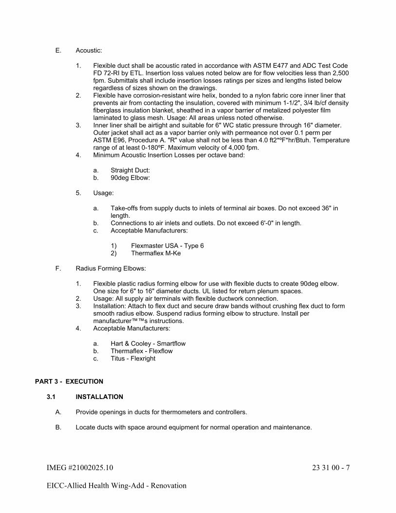
IMEG #21002025.10 23 31 00 - 7
EICC-Allied Health Wing-Add - Renovation
E. Acoustic:
1. Flexible duct shall be acoustic rated in accordance with ASTM E477 and ADC Test Code FD 72-RI by ETL. Insertion loss values noted below are for flow velocities less than 2,500 fpm. Submittals shall include insertion losses ratings per sizes and lengths listed below regardless of sizes shown on the drawings.
2. Flexible have corrosion-resistant wire helix, bonded to a nylon fabric core inner liner that prevents air from contacting the insulation, covered with minimum 1-1/2", 3/4 lb/cf density fiberglass insulation blanket, sheathed in a vapor barrier of metalized polyester film laminated to glass mesh. Usage: All areas unless noted otherwise.
3. Inner liner shall be airtight and suitable for 6" WC static pressure through 16" diameter. Outer jacket shall act as a vapor barrier only with permeance not over 0.1 perm per ASTM E96, Procedure A. "R" value shall not be less than 4.0 ft2*ºF*hr/Btuh. Temperature range of at least 0-180ºF. Maximum velocity of 4,000 fpm.
4. Minimum Acoustic Insertion Losses per octave band:
a. Straight Duct:b. 90deg Elbow:
5. Usage:
a. Take-offs from supply ducts to inlets of terminal air boxes. Do not exceed 36" in length.
b. Connections to air inlets and outlets. Do not exceed 6'-0" in length.c. Acceptable Manufacturers:
1) Flexmaster USA - Type 62) Thermaflex M-Ke
F. Radius Forming Elbows:
1. Flexible plastic radius forming elbow for use with flexible ducts to create 90deg elbow. One size for 6" to 16" diameter ducts. UL listed for return plenum spaces.
2. Usage: All supply air terminals with flexible ductwork connection.3. Installation: Attach to flex duct and secure draw bands without crushing flex duct to form
smooth radius elbow. Suspend radius forming elbow to structure. Install per manufacturer™™s instructions.
4. Acceptable Manufacturers:
a. Hart & Cooley - Smartflowb. Thermaflex - Flexflowc. Titus - Flexright
PART 3 - EXECUTION
3.1 INSTALLATION
A. Provide openings in ducts for thermometers and controllers.
B. Locate ducts with space around equipment for normal operation and maintenance.

IMEG #21002025.10 23 31 00 - 8
EICC-Allied Health Wing-Add - Renovation
C. Do not install ducts or other equipment above electrical switchboards or panelboards. This includes a dedicated space extending 25 feet from the floor to the structural ceiling with width and depth equal to the electrical equipment. Unless intended to serve these rooms, do not install any ductwork or equipment in electrical rooms, transformer rooms, electrical closets, telephone rooms or elevator machine rooms.
D. Provide temporary closures of metal or taped polyethylene on open ducts to prevent dust from entering ductwork.
E. Supply ductwork shall be free of construction debris, and shall comply with Level "B" of the SMACNA Duct Cleanliness for New Construction Guidelines.
F. Repair all duct insulation and liner tears.
G. Install manual volume dampers in branch supply ducts so all outlets can be adjusted. Do not install dampers at air terminal device or in outlets, unless specifically shown.
H. Insulate terminal air box reheat coils. Seal insulation tight to form a tight vapor barrier.
I. Install flexible duct in accordance with the ADC Flexible Duct Performance and Installation Standards.
J. Flexible duct shall NOT be joined to flat-oval connections. Provide sheet metal oval-to-round transitions where required, to include, but not limited to, all connections to air inlets, air outlets, and terminal air boxes.
K. Install all exterior ductwork per SMACNA Fig. 6-3. Where drawings do not indicate otherwise, ductwork seams and joints shall be sealed watertight and pitched to shed water.
L. Support all duct systems in accordance with the SMACNA HVAC Duct Construction Standards: Metal and Flexible and the SMACNA Seismic Restraint Manual: Guidelines for Mechanical Systems, where applicable. Refer to Section 23 05 50 for seismic requirements.
M. Adhesives, sealants, tapes, vapor retarders, films, and other supplementary materials added to ducts, plenums, housing panels, silencers, etc. shall have flame spread/smoke developed ratings of under 25/50 per ASTM E84, NFPA 255, or UL 723.
N. All duct support shall extend directly to building structure. Do not support ductwork from pipe hangers unless coordinated with piping contractor prior to installation. Do not allow lighting or ceiling supports to be hung from ductwork or ductwork supports.
3.2 DUCTWORK APPLICATION SCHEDULE
A. Duct System Description: Furnace Supply Duct
1. Shape: Rectangular Duct - Single Wallt2. Material: Galvanized Steelt3. Pressure Class: <+2.0"4. Seal Class: A5. Insulation: 1-1/2" thick Type A (R=4.5)
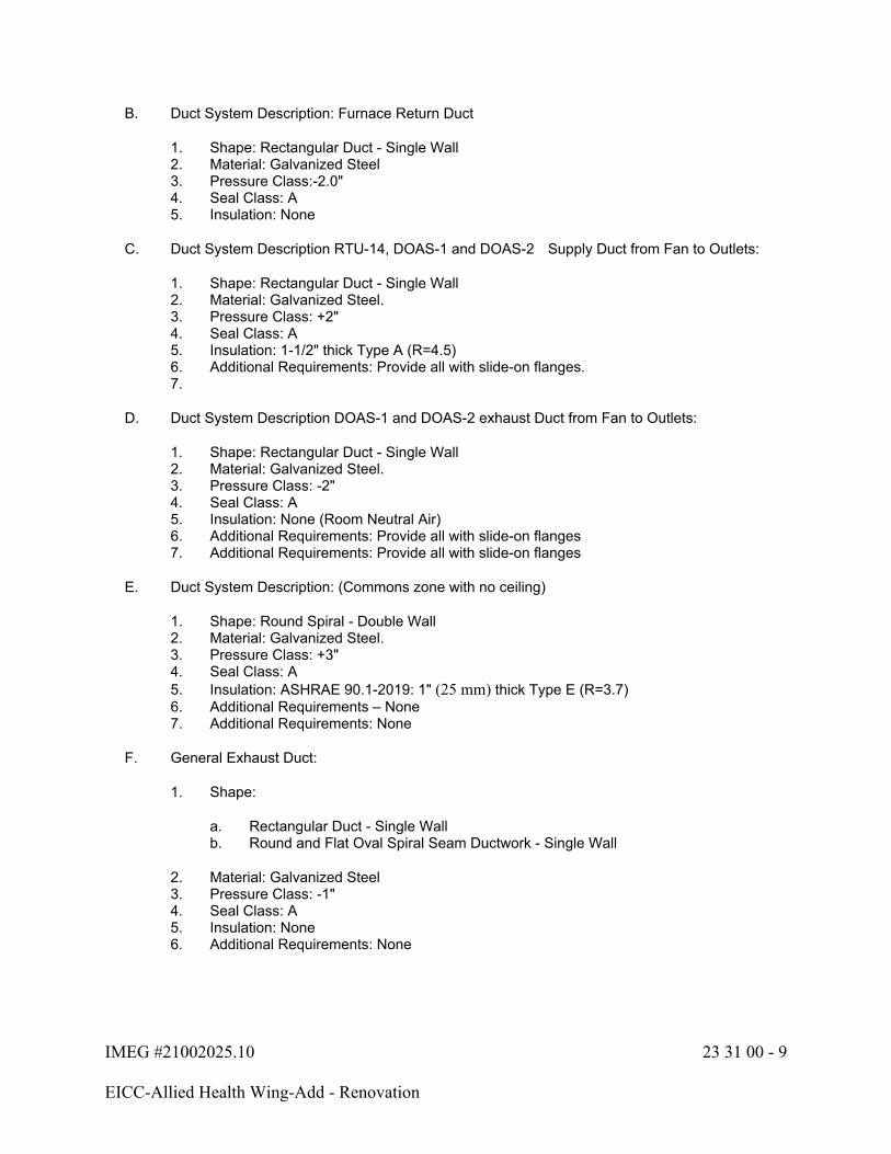
IMEG #21002025.10 23 31 00 - 9
EICC-Allied Health Wing-Add - Renovation
B. Duct System Description: Furnace Return Duct
1. Shape: Rectangular Duct - Single Wall2. Material: Galvanized Steel3. Pressure Class:-2.0"4. Seal Class: A5. Insulation: None
C. Duct System Description RTU-14, DOAS-1 and DOAS-2 Supply Duct from Fan to Outlets:
1. Shape: Rectangular Duct - Single Wall2. Material: Galvanized Steel.3. Pressure Class: +2"4. Seal Class: A5. Insulation: 1-1/2" thick Type A (R=4.5)6. Additional Requirements: Provide all with slide-on flanges.7.
D. Duct System Description DOAS-1 and DOAS-2 exhaust Duct from Fan to Outlets:
1. Shape: Rectangular Duct - Single Wall2. Material: Galvanized Steel.3. Pressure Class: -2"4. Seal Class: A5. Insulation: None (Room Neutral Air)6. Additional Requirements: Provide all with slide-on flanges7. Additional Requirements: Provide all with slide-on flanges
E. Duct System Description: (Commons zone with no ceiling)
1. Shape: Round Spiral - Double Wall 2. Material: Galvanized Steel.3. Pressure Class: +3"4. Seal Class: A5. Insulation: ASHRAE 90.1-2019: 1" (25 mm) thick Type E (R=3.7)6. Additional Requirements – None7. Additional Requirements: None
F. General Exhaust Duct:
1. Shape:
a. Rectangular Duct - Single Wallb. Round and Flat Oval Spiral Seam Ductwork - Single Wall
2. Material: Galvanized Steel3. Pressure Class: -1"4. Seal Class: A5. Insulation: None 6. Additional Requirements: None

IMEG #21002025.10 23 31 00 - 10
EICC-Allied Health Wing-Add - Renovation
G. Transfer Ducts:
1. Shape:
a. Rectangular Duct - Single Wall
2. Material: Galvanized Steel3. Pressure Class: -1/2"4. Seal Class: A 5. Insulation: 1" thick Type C (R=3.6)
H. Linear Diffuser Supply Plenum:
1. Insulation:
a. IECC-2021: 1/2" thick Type C (R=1.8)
3.3 DUCTWORK SEALING
A. General Requirements:
1. Openings, such as rotating shafts, shall be sealed with bushings or similar.2. Pressure sensitive tape shall not be used as the primary sealant unless it has been
certified to comply with UL-181A or UL-181B by an independent testing laboratory and the tape is used in accordance with that certification.
3. All connections shall be sealed including, but not limited to, taps, other branch connections, access doors, access panels, and duct connections to equipment. Sealing that would void product listings is not required. Spiral lock seams need not be sealed.
4. Mastic-based duct sealants shall be applied to joints and seams in minimum 3 inch wide by 20 mil thick bands using brush, putty knife, trowel, or spray, unless manufacturer's data sheet specifies other application methods or requirements.
B. All ducts systems, regardless of pressure class, shall be Seal Class A as defined by Section 5-1 of SMACNA HVAC Air Duct Leakage Test Manual per the Energy Code, unless specifically noted otherwise. Seal Class A shall include sealing of all transverse joints, longitudinal seams, and duct wall penetrations with welds, gaskets, mastics, or fabric-embedded mastic system. Joints are inclusive of, but not limited to, girth joints, branch and sub-branch intersections, duct collar tap-ins, fitting subsections, louver and air terminal connections to ducts, access door and access panel frames and jambs, duct, plenum, and casing abutments to building structures.
C. Double-wall ductwork: Install insulation end fittings at all transitions from double to single-wall construction.
3.4 TESTING
A. Interior Duct - Less than 3" WG (positive or negative):
1. Leak testing of these pressure classes is not normally required for interior ductwork (inside the building envelope). However, leak tests will be required if, in the opinion of the Architect/Engineer, the leakage appears excessive. All exterior ductwork shall be tested. If duct has outside wrap, testing shall be done before it is applied.
2. Leak test shall be at the Contractor's expense and shall require capping and sealing all openings.
3. Seal ducts to bring the air leakage into compliance.

IMEG #21002025.10 23 31 00 - 11
EICC-Allied Health Wing-Add - Renovation
4. Contractor shall notify the Architect/Engineer five business days prior to pressurizing ductwork for testing.
B. Test Procedure:
1. Testing shall be as listed in the latest edition of the SMACNA HVAC Duct Leakage Manual, with the following additional requirements:
a. The required leakage class for Seal Class A, rectangular ducts, shall be 4; round shall be 2.
b. Test pressure shall be the specified duct pressure class. Testing at reduced pressures and converting the results mathematically is not acceptable. This is required to test the structural integrity of the duct system.
c. If any leak causes discernible noise at a distance of 3 feet, that leak shall be eliminated, regardless of whether that section of duct passed the leakage test.
d. All joints shall be felt by hand, and all discernible leaks shall be sealed.e. Totaling leakage from several tested sections and comparing them to the allowable
leakage for the entire system is not acceptable. Each section must pass the test individually.
f. Contractor shall notify the Architect/Engineer five business days prior to pressurizing ductwork for testing. Failure to notify the Architect/Engineer of pressure testing may require the contractor to repeat the duct pressure test after proper notification.
g. Upon completion of the pressure test, the contractor shall submit an air duct leakage test summary report as outlined in the SMACNA HVAC Duct Leakage Test Manual.
h. All access doors, taps to terminal air boxes, and other accessories and penetrations must be installed prior to testing. Including terminal air boxes in the test is not required.
i. Positive pressure leakage testing is acceptable for negative pressure ductwork.
3.5 DUCTWORK PENETRATIONS
A. All duct penetrations of firewalls shall have fire or fire/smoke dampers where required by code.
B. Dampers shall be compatible with fire rating of wall assembly. Verify actual rating of any wall being penetrated with Architect/Engineer.
C. Seal all duct penetrations of walls that are not fire rated by caulking or packing with fiberglass. Install trim strip to cover vacant space and raw construction edges of all openings in finished rooms. Install escutcheon ring at all round duct openings in finished rooms. Trim strips and rings shall be same material and finish as exposed duct.
END OF SECTION 23 31 00

IMEG #21002025.10 23 33 00 - 1
EICC-Allied Health Wing-Add - Renovation
SECTION 23 33 00 - DUCTWORK ACCESSORIES
PART 1 - GENERAL
1.1 SECTION INCLUDES
A. Manual Volume Dampers.
B. Fire Dampers.
C. Fire/Smoke Dampers.
D. Backdraft Dampers.
E. Fabric Connectors.
F. Duct Access Doors.
G. Duct Test Holes.
H. Remote Volume Control Devices.
PART 2 - PRODUCTS
2.1 MANUAL VOLUME DAMPERS
A. Fabricate in accordance with SMACNA Duct Construction Standards, and as indicated.
B. Fabricate single blade dampers for duct sizes to 9-1/2 x 30 inches.
C. Fabricate multi-blade damper of opposed blade pattern with maximum blade sizes 12" x 72". Assemble center and edge crimped blades in prime coated or galvanized channel frame with suitable hardware.
D. Except in round ductwork 12 inches and smaller, provide end bearings. On multiple blade dampers, provide molded synthetic or oil-impregnated nylon or sintered bronze bearings.
E. Provide locking quadrant regulators on single and multi-blade dampers.
F. On insulated ducts, mount quadrant regulators on stand-off mounting brackets, bases, or adapters.
G. If blades are in open position and extend into the main duct, mount damper so blades are parallel to airflow.
2.2 DYNAMIC CURTAIN BLADE FIRE DAMPERS (FD)
A. Furnish and install fire dampers in ducts, where shown on the drawings, at the point where they pass through a fire wall or a floor and in all other locations required by the local fire department, The National Fire Protection Association's Pamphlet No. 90A and all other applicable codes.
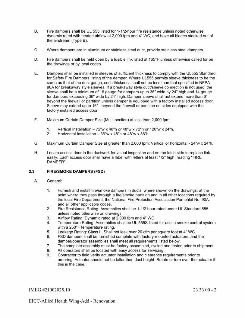
IMEG #21002025.10 23 33 00 - 2
EICC-Allied Health Wing-Add - Renovation
B. Fire dampers shall be UL 555 listed for 1-1/2-hour fire resistance unless noted otherwise, dynamic rated with heated airflow at 2,000 fpm and 4" WC, and have all blades stacked out of the airstream (Type B).
C. Where dampers are in aluminum or stainless steel duct, provide stainless steel dampers.
D. Fire dampers shall be held open by a fusible link rated at 165°F unless otherwise called for on the drawings or by local codes.
E. Dampers shall be installed in sleeves of sufficient thickness to comply with the UL555 Standard for Safety Fire Dampers listing of the damper. Where UL555 permits sleeve thickness to be the same as that of the duct gauge, such thickness shall not be less than that specified in NFPA 90A for breakaway style sleeves. If a breakaway style duct/sleeve connection is not used, the sleeve shall be a minimum of 16 gauge for dampers up to 36" wide by 24" high and 14 gauge for dampers exceeding 36" wide by 24" high. Damper sleeve shall not extend more than 6" beyond the firewall or partition unless damper is equipped with a factory installed access door. Sleeve may extend up to 16" beyond the firewall or partition on sides equipped with the factory installed access door.
F. Maximum Curtain Damper Size (Multi-section) at less than 2,000 fpm:
1. Vertical Installation – 72"w x 48"h or 48"w x 72"h or 120"w x 24"h.2. Horizontal Installation – 36"w x 48"h or 48"w x 36"h.
G. Maximum Curtain Damper Size at greater than 2,000 fpm: Vertical or horizontal - 24"w x 24"h.
H. Locate access door in the ductwork for visual inspection and on the latch side to replace link easily. Each access door shall have a label with letters at least 1/2" high, reading "FIRE DAMPER".
2.3 FIRE/SMOKE DAMPERS (FSD)
A. General:
1. Furnish and install fire/smoke dampers in ducts, where shown on the drawings, at the point where they pass through a fire/smoke partition and in all other locations required by the local Fire Department, the National Fire Protection Association Pamphlet No. 90A, and all other applicable codes.
2. Fire Resistance Rating: Assemblies shall be 1-1/2 hour rated under UL Standard 555 unless noted otherwise on drawings.
3. Airflow Rating: Dynamic rated at 2,000 fpm and 4" WC.4. Temperature Rating: Assemblies shall be UL 555S listed for use in smoke control system
with a 250°F temperature rating.5. Leakage Rating: Class II. Shall not leak over 20 cfm per square foot at 4" WC.6. FSD dampers shall be furnished complete with factory-mounted actuators, and the
damper/operator assemblies shall meet all requirements listed below.7. The complete assembly must be factory assembled, cycled and tested prior to shipment.8. All operators shall be located with easy access for servicing.9. Contractor to field verify actuator installation and clearance requirements prior to
ordering. Actuator should not be taller than duct height. Rotate or turn over the actuator if this is the case.
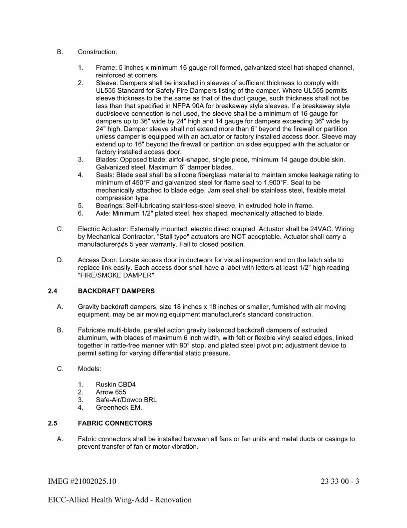
IMEG #21002025.10 23 33 00 - 3
EICC-Allied Health Wing-Add - Renovation
B. Construction:
1. Frame: 5 inches x minimum 16 gauge roll formed, galvanized steel hat-shaped channel, reinforced at corners.
2. Sleeve: Dampers shall be installed in sleeves of sufficient thickness to comply with UL555 Standard for Safety Fire Dampers listing of the damper. Where UL555 permits sleeve thickness to be the same as that of the duct gauge, such thickness shall not be less than that specified in NFPA 90A for breakaway style sleeves. If a breakaway style duct/sleeve connection is not used, the sleeve shall be a minimum of 16 gauge for dampers up to 36" wide by 24" high and 14 gauge for dampers exceeding 36" wide by 24" high. Damper sleeve shall not extend more than 6" beyond the firewall or partition unless damper is equipped with an actuator or factory installed access door. Sleeve may extend up to 16" beyond the firewall or partition on sides equipped with the actuator or factory installed access door.
3. Blades: Opposed blade; airfoil-shaped, single piece, minimum 14 gauge double skin. Galvanized steel. Maximum 6" damper blades.
4. Seals: Blade seal shall be silicone fiberglass material to maintain smoke leakage rating to minimum of 450°F and galvanized steel for flame seal to 1,900°F. Seal to be mechanically attached to blade edge. Jam seal shall be stainless steel, flexible metal compression type.
5. Bearings: Self-lubricating stainless-steel sleeve, in extruded hole in frame.6. Axle: Minimum 1/2" plated steel, hex shaped, mechanically attached to blade.
C. Electric Actuator: Externally mounted, electric direct coupled. Actuator shall be 24VAC. Wiring by Mechanical Contractor. "Stall type" actuators are NOT acceptable. Actuator shall carry a manufacturer¢¢s 5 year warranty. Fail to closed position.
D. Access Door: Locate access door in ductwork for visual inspection and on the latch side to replace link easily. Each access door shall have a label with letters at least 1/2" high reading "FIRE/SMOKE DAMPER".
2.4 BACKDRAFT DAMPERS
A. Gravity backdraft dampers, size 18 inches x 18 inches or smaller, furnished with air moving equipment, may be air moving equipment manufacturer's standard construction.
B. Fabricate multi-blade, parallel action gravity balanced backdraft dampers of extruded aluminum, with blades of maximum 6 inch width, with felt or flexible vinyl sealed edges, linked together in rattle-free manner with 90° stop, and plated steel pivot pin; adjustment device to permit setting for varying differential static pressure.
C. Models:
1. Ruskin CBD42. Arrow 6553. Safe-Air/Dowco BRL4. Greenheck EM.
2.5 FABRIC CONNECTORS
A. Fabric connectors shall be installed between all fans or fan units and metal ducts or casings to prevent transfer of fan or motor vibration.

IMEG #21002025.10 23 33 00 - 4
EICC-Allied Health Wing-Add - Renovation
B. The fabric connectors shall be completely flexible material which shall be in folds and not drawn tight.
C. Fabric connectors shall be of glass fabric double coated with neoprene, with UL approval. Weight = 30 oz. per square yard minimum. Fabric shall not be affected by mildew and shall be absolutely waterproof, airtight and resistant to acids, alkalis, grease and gasoline, and shall be noncombustible.
D. Fabric connections shall not exceed 6" in length on ductwork that has a positive pressure. On ductwork that has a negative pressure, the length shall not exceed 2" in length.
E. All corners shall be folded, sealed with mastic and stapled on 1" centers.
F. Fabric connectors shall not be painted.
G. Unless otherwise shown on the drawings, the fabric connection at the inlet to centrifugal fans shall be at least one duct diameter from the fan to prevent inlet turbulence.
H. Materials:
1. Durodyne MFN-4-1002. Vent Fabrics, Inc.3. "Ventglas"4. Proflex PFC3NGA
I. Fabric connectors exposed to sunlight and weather shall be as described above, except the coating shall be hypalon in lieu of neoprene.
J. Materials:
1. Durodyne "Duralon MFD-4-100"2. Vent Fabrics, Inc.3. "Ventlon"4. Proflex PFC3HGA
2.6 DRIP PANS
A. Install drip pans under all rooftop exhaust fans, intake hoods, exhaust hoods and other roof penetrations that do not have ductwork below them to intercept dripping water.
B. Drip pans shall be 22 gauge minimum cross-broken or reinforced sheet metal with 2" welded upturned lips.
C. Pans shall extend 6" in all directions beyond the opening and shall have the top of the lip located 25% of the maximum throat dimension below the opening.
D. Insulate interior of drip pan with 1" thick elastomeric foam insulation. Adhere foam to drip pan with standard foam adhesive.
2.7 DUCT ACCESS DOORS
A. Fabricate per Fig. 7-2 and 7-3 of the SMACNA HVAC Duct Construction Standards and as indicated.
IMEG #21002025.10 23 33 00 - 5
EICC-Allied Health Wing-Add - Renovation
B. Review locations prior to fabrication. Install access doors at fire dampers, smoke dampers, motorized dampers, fan bearings, filters, automatic controls, humidifiers, louvers, duct coils and other equipment requiring service inside the duct.
C. Provide duct access door in all horizontal return ductwork at 20 foot intervals per NFPA 90A.
D. Construction shall be suitable for the pressure class of the duct. Fabricate rigid, airtight, and close-fitting doors of materials identical to adjacent ductwork with sealing gaskets butt or piano hinges, and quick fastening locking devices. For insulated ductwork, install minimum one inch thick insulation with sheet metal cover.
E. Access doors with sheet metal screw fasteners are not acceptable.
F. Minimum size for access doors shall be 24" x 16" or full duct size, whichever is less.
G. Provide quantity of access doors such that two hands can fit inside ductwork to manually reset fire dampers. This will typically require one access door on the bottom and one access door on an accessible side of the duct for sizes 12x12 and smaller.
2.8 DUCT TEST HOLES
A. Cut or drill temporary test holes in ducts as required. Cap with neat patches, neoprene plugs, threaded plugs, or threaded or twist-on metal caps.
2.9 REMOTE VOLUME CONTROL DEVICES - MANUAL
A. Remote volume control balancing damper shall be supplied with either miter gears or right angle worm gears. Provide all damper shafts, gearboxes, couplings, U-joints, bearings, shafts, offsets, adapters, and adjustable concealed covers as required.
B. When distances, angles, or offsets prevent installing solid rods, the mechanical cable control system may be utilized. Provide all damper shafts, rack and pinion gear operator, cables and sleeves, and adjustable ceiling mounting cups.
C. Manufacturers:
1. Young Regulator Company2. Metropolitan Air Technology
2.10 DUCTWORK ACCESSORY SEALANTS
A. Ductwork accessory sealants and adhesives shall conform to Section 23 31 00.
PART 3 - EXECUTION
3.1 INSTALLATION
A. General Installation Requirements:
1. Install accessories in accordance with manufacturer's instructions.2. Where duct access doors are located above inaccessible ceilings, provide ceiling access
doors. Coordinate location with the Architect/Engineer.
IMEG #21002025.10 23 33 00 - 6
EICC-Allied Health Wing-Add - Renovation
3. Coordinate and install access doors provided by others.4. Provide access doors for all equipment requiring maintenance or adjustment above an
inaccessible ceiling. Minimum size shall be 24" x 24".5. Provide duct test holes where indicated and as required for testing and balancing
purposes.
B. Manual Volume Damper:
1. Provide manual volume dampers at points on low pressure supply, return, and exhaust systems where branches are taken from larger ducts where indicated on drawings and as required for air balancing. Use splitter dampers only where indicated.
2. Provide ceiling access doors for manual volume dampers. When manual volume dampers are located above an inaccessible ceiling and an access door cannot be installed, provide a remote-controlled volume control device for operation of the damper. Coordinate location with the Architect/Engineer.
C. Fire Damper, Fire Smoke Damper:
1. Provide fire dampers, at locations indicated, where ducts and outlets pass through fire rated components, and where required by authorities having jurisdiction. Install with required perimeter mounting angles, sleeves and duct connections.
2. Demonstrate resetting of fire dampers to authorities having jurisdiction and Owner's representative.
3. At fire dampers, smoke dampers and combination fire smoke damper where duct is:
a. Internally insulated, exterior duct wrap shall be installed from the wall out to 1 foot from the wall. All edges shall be taped.
b. Externally insulated, the exterior duct wrap shall extend up to the wall.
END OF SECTION 23 33 00
IMEG #21002025.10 23 34 23 - 1
EICC-Allied Health Wing-Add - Renovation
SECTION 23 34 23 - POWER VENTILATORS
PART 1 - GENERAL
1.1 SECTION INCLUDES
A. Roof Exhaust Fan.
B. Rooftop Fan Curbs.
1.2 QUALITY ASSURANCE
A. Performance Ratings: Conform to AMCA 210 and bear AMCA Certified Rating Seal.
B. Sound Ratings: AMCA 301, tested to AMCA 300.
C. Fabrication: Conform to AMCA 99.
D. Fan Energy Index (FEI): Fans shall meet or exceed the minimum FEI scheduled at the specified airflow, pressure, and air density (duty point). In no case shall the FEI at the specified duty point fall below 1.1.
1.3 SUBMITTALS
A. Submit shop drawings per Section 23 05 00. Include data on all fans and accessories. Submit sound power levels for both fan inlet and outlet at rated capacity. Submit motor ratings and electrical characteristics, plus motor and electrical accessories. Submit multi-speed fan curves including minimum and maximum fan speed with specified operating points clearly plotted. Submit the Fan Energy Index (FEI) at the selected duty point (ceiling and HVLS fans are exempt from FEI submittal requirements).
B. Submit manufacturer's installation instructions.
C. Submit electrical power/controls wiring diagrams and product data indicating general assembly, components, safety controls, and service connections.
PART 2 - PRODUCTS
2.1 ROOFTOP EXHAUST FAN - BELT DRIVEN
A. Mill aluminum finish.
2.2 ROOFTOP EXHAUST FAN - DIRECT DRIVEN
A. Fan Wheel: Centrifugal type, aluminum or composite with backward inclined or airfoil blades, statically and dynamically balanced.
B. Housing: Removable, spun aluminum dome or rectangular top, with square, one piece, aluminum base and curb cap with Venturi inlet cone.

IMEG #21002025.10 23 34 23 - 2
EICC-Allied Health Wing-Add - Renovation
C. Fan Shaft: Turned, ground and polished steel; keyed to wheel hub.
D. All steel parts galvanized or epoxy coated. Non-corrosive fasteners.
E. Direct drive, motor mounted outside of air stream and ventilated with outside air.
F. Aluminum or brass bird screen. Plastic mesh will not be allowed.
G. Furnish factory mounted and wired disconnect switch: Non-fusible type with thermal overload protection mounted inside fan housing, factory wired through an aluminum conduit.
H. Furnish normally closed, electric motorized damper. Provide step-down transformer if required. Install and wire damper to open when fan runs.
I. Dampers shall be aluminum with brass bushings, blade seals and blade tie rods. Leakage shall not exceed 4 cfm/sq.ft @1" SP (or shall be AMCA Class 1 certified).
J. Mill aluminum finish.
K. Furnish permanently lubricated sealed ball type motor and drive shaft bearings. Motor and wheel supported by vibration isolators.
L. Manufacturers:
1. Aerovent "FACX"2. Cook "ACE-D"3. Greenheck4. ILG - CRD5. ACME PX6. PennBarry DX7. Carnes8. Twin City DCRU
2.3 ROOFTOP FAN CURBS
A. Furnish and install prefabricated roof curbs for all rooftop fans.
B. Size curb to match the curb cap of fan.
C. Roof Mounting Curb: Minimum 14 inches, minimum 14 gauge galvanized steel, one-piece construction, insulated, all welded, wood nailer.
D. Unitized construction, continuous arc welded corner seams. Insulated with 1-1/2" thick, 3 lb. density rigid fiberglass board. Damper support angle. Pressure treated wood nailer.
E. If called for in the drawings, curbs shall be of the sound attenuation type. Sound attenuation curbs shall reduce the fan sone rating by at least 40% and not decrease fan cfm more than 8% (which is accounted for in the scheduled fan cfm). Baffles shall be removable for access to the dampers.
F. 14-gauge aluminum construction.
G. Curb without cant.
IMEG #21002025.10 23 34 23 - 3
EICC-Allied Health Wing-Add - Renovation
H. Manufacturers:
1. Same manufacturer as the fan2. Pate3. RPS4. Thy
PART 3 - EXECUTION
3.1 INSTALLATION
A. Install in accordance with manufacturer's instructions.
B. Attach ductwork to inlet and outlet connection collars of circular inline duct fans in accordance with manufacturer’s instructions.
END OF SECTION 23 34 23
IMEG #21002025.10 23 37 00 - 1
EICC-Allied Health Wing-Add - Renovation
SECTION 23 37 00 - AIR INLETS AND OUTLETS
PART 1 - GENERAL
1.1 SECTION INCLUDES
A. Grilles And Registers.
B. Architectural Square Panel Diffusers.
1.2 QUALITY ASSURANCE
A. Test and rate performance of air inlets and outlets per ASHRAE 70.
B. Test and rate performance of louvers per AMCA 500L-99.
C. All air handling and distribution equipment mounted outdoors shall be designed to prevent rain intrusion into the airstream when tested at design airflow and with no airflow, using the rain test apparatus described in Section 58 of UL 1995.
1.3 REGULATORY REQUIREMENTS
A. Conform to ANSI/NFPA 90A.
B. Conform to ASHRAE 90.1.
PART 2 - PRODUCTS
2.1 AIR TERMINALS - GRILLES AND REGISTERS
A. Reference to a grille means an air supply, exhaust or transfer device without a damper.
B. Reference to a register means an air supply, exhaust or transfer device with a damper.
C. The type of unit, margin, material, finish, etc., shall be as shown on the drawing schedule and suitable for the intended use.
D. All margins shall be compatible with ceiling types specified (including 'Thin-Line' T-bar lay-in grid system). Any discrepancies in contract documents shall be brought to the attention of the Architect/Engineer, in writing, prior to Bid Date. Submission of Bid indicates ceiling and air inlet and outlet types have been coordinated.
E. The capacity and size of the unit shall be as shown on the drawings.
F. All units shall handle the indicated cfm as shown on the drawings while not exceeding an NC level of 25, referenced to 10-12 watts with a 10 dB room effect. Noise in classrooms and offices may not exceed 35 dBA or 55 dBC per ANSI Standard S12.60-2002 and ASHRAE 70.
G. Refer to the drawings for construction material, color and finish, margin style, deflection, and sizes of grilles and registers.

IMEG #21002025.10 23 37 00 - 2
EICC-Allied Health Wing-Add - Renovation
H. Provide with 3/4" blade spacing. Blades shall have steel friction pivots to allow for blade adjustment, plastic pivots are not acceptable.
I. Corners of steel grilles and registers shall be welded and ground smooth before painting. Aluminum grilles and registers shall have staked corners.
J. Where specified to serve registers, provide opposed blade volume dampers operable from the face of the register.
K. Screw holes for surface fasteners shall be countersunk for a neat appearance. Provide concealed fasteners for installation in lay-in ceilings and as specified on the drawings.
L. Manufacturers:
1. Tuttle & Bailey2. Titus3. Nailor4. Carnes5. Metalaire6. Krueger
2.2 AIR TERMINALS - ARCHITECTURAL SQUARE PANEL DIFFUSERS
A. Reference to a diffuser means an air supply device, ceiling mounted, that shall diffuse air uniformly throughout the conditioned space.
B. The type of unit, margin, material, finish, etc., shall be as shown on the drawing schedule. Flat-oval inlets are not acceptable for connection to flexible ducts.
C. All margins shall be compatible with ceiling types specified (including 'Thin-Line' T-bar lay-in grid system). Any discrepancies in contract documents should be brought to the attention of the Architect/Engineer, in writing, prior to Bid Date. Submission of Bid indicates ceiling and air inlet and outlet types have been coordinated.
D. The capacity and size of the unit shall be as shown on the drawings.
E. All units shall handle the indicated cfm as shown on the drawings while not exceeding an NC level of 25, referenced to 10-12 watts with a 10 dB room effect. Noise in classrooms may not exceed 35 dBA or 55 dBC per ANSI Standard S12.60-2002 and ASHRAE 70.
F. Diffusers shall be architectural solid square panel and flush with ceiling.
G. The exposed surface shall be smooth, flat and free of visible fasteners. The face panel shall be 22 gauge steel with a rolled edge or shall be 18 gauge with a smooth ground, uniform edge.
H. The back pan shall be one piece 22 gauge stamped and shall include an integral inlet. (Welded inlets and corner joints are not acceptable).
I. Diffusers with a 24x24 back pan shall have a minimum 18x18 face panel size. Diffusers with a 12x12 back pan shall have a minimum 9x9 face panel size.
J. The face panel shall be mechanically fastened to the back panel with steel components. (Plastic fasteners are not acceptable.)

IMEG #21002025.10 23 37 00 - 3
EICC-Allied Health Wing-Add - Renovation
K. Manufacturers:
1. Tuttle & Bailey2. Titus3. Price4. Nailor5. Carnes6. Metalaire7. Krueger
PART 3 - EXECUTION
3.1 INSTALLATION
A. General Installation Requirements:
1. Install items in accordance with manufacturers' instructions.2. Check location of inlets and outlets and make necessary adjustments in position to
conform to architectural features, symmetry, and lighting arrangement.3. Install diffusers to ductwork with air tight connections.4. Flexible ducts shall NOT be joined to flat-oval connections. Provide sheet metal
oval-to-round transitions where required.5. Supply air diffusers in operating rooms (Class B and C surgery) shall be opened and
cleaned before the space is used.6. Supply grille and register blades shall be aimed in the field to provide adequate air
distribution in the space. All return grilles and registers blades shall be oriented to minimize sight distance beyond installed device.
B. Volume Damper:
1. Provide manual volume dampers on duct take-off to diffusers when there are multiple connections to a common duct. Locate volume dampers as far as possible from the air inlet or outlet.
C. Maintaining Duct Cleanliness:
1. When grilles, registers, and diffusers are installed, Contractor shall prevent construction dust, dirt, and debris from entering ductwork as required by Section 23 05 00.
END OF SECTION 23 37 00

IMEG #21002025.10 23 74 16.12 - 1
EICC-Allied Health Wing-Add - Renovation
SECTION 23 74 16.12 - PACKAGED ROOFTOP AIR CONDITIONING UNITS 25 TON AND BELOW
PART 1 - GENERAL
1.1 SECTION INCLUDES
A. Packaged Rooftop Unit.
B. Unit Controls.
C. Roof Mounting Frame and Base.
D. Economizers.
E. Power Exhaust.
1.2 QUALITY ASSURANCE
A. All insulation inside the unit and in the air stream must comply with the requirement of NFPA 90A (maximum flame spread of 25 and maximum smoke developed of 50).
B. All units must be UL or ETL listed and must contain UL labeled components.
C. Fans shall be tested and rated in cabinet in accordance with AMCA Standard 210. All fan assemblies shall be dynamically balanced in cabinet at final assembly.
D. Conform to ASHRAE 90.1.
E. All air handling and distribution equipment mounted outdoors shall be designed to prevent rain intrusion into the airstream when tested at design airflow and with no airflow, using the rain test apparatus described in Section 58 of UL 1995.
1.3 SUBMITTALS
A. Submit shop drawings and product data under provisions of Section 23 05 00.
B. Indicate electrical service and duct connections on shop drawings or product data.
C. Submit manufacturer's installation instructions.
D. Submit electrical power/controls wiring diagrams and product data indicating general assembly, components, safety controls, and service connections.
E. Provide 8 octave maximum sound power levels at unit discharge and return connection.
1.4 DELIVERY, STORAGE, AND HANDLING
A. Protect units from physical damage by storing off site until roof mounting frames are in place, ready for immediate installation of units.
IMEG #21002025.10 23 74 16.12 - 2
EICC-Allied Health Wing-Add - Renovation
1.5 OPERATION AND MAINTENANCE DATA
A. Submit operation and maintenance data.
B. Include manufacturer's descriptive literature, installation instructions, maintenance and repair data, and parts listing.
1.6 WARRANTY
A. Provide five (5) year manufacturer's warranty for compressors.
B. Provide five (5) year manufacturer's warranty for heat exchanger.
C. Provide standard year manufacturer's warranty for controls and electrical components (thermostats, etc.).
PART 2 - PRODUCTS
2.1 MANUFACTURERS
A. Basis of Design: The scheduled manufacturer is the Basis of Design. The Contractor is responsible for all costs, schedule impacts, and construction coordination, including design costs and regulatory agency approvals, related to using a specified alternate product other than the Basis of Design. Refer to Section 23 05 00 for additional information.
B. Trane
C. York
D. Daikin
2.2 MANUFACTURED UNITS
A. Unit shall be self-contained, packaged, factory assembled, pre-wired and tested, consisting of cabinet and frame, supply fan, exhaust fan, heat exchanger and burner, controls, air filters, refrigerant cooling coil and compressor, condenser coil, condenser fan, and a full refrigerant charge.
B. Unit shall be furnished with non-fused disconnect switch, short fuse protection of all internal electrical components, and all necessary motor starters, contactors, and over-current protection.
C. SCCR ratings of 5,000 kAIC required.
2.3 FABRICATION
A. Cabinet: Galvanized steel with baked enamel finish, access doors or removable access panels with quick fasteners locking door handle type with piano hinges. Access doors shall be provided at each section (e.g., filter section, supply fan section, etc.). All exterior access panels must be permanently labeled on the outside indicating what is behind the panel. Structural members shall be minimum 18 gauge, with access doors or removable panels of minimum 20 gauge.

IMEG #21002025.10 23 74 16.12 - 3
EICC-Allied Health Wing-Add - Renovation
B. Outside Air Intakes: The outside air intakes shall be located a minimum of 15 inches above the roof mounting curb to minimize the effect of heat pickup from the roof during the natural cooling cycle and the effects of snow on the roof during winter operation. Each air intake shall be furnished with rain eliminators.
C. Insulation: Minimum of 1/2" thick, 1.5 lb./cu.ft. density coated glass fiber insulation on surfaces where conditioned air is handled. Protect edges from erosion.
D. Air Filters: Two inch thick glass fiber disposable media in metal frames.
2.4 ROOF MOUNTING FRAME AND BASE
A. Roof Mounting Curb: Minimum 24 inches high, minimum 14 gauge galvanized steel, one-piece construction, insulated, all welded, wood nailer.
2.5 FANS/MOTORS
A. Fans:
1. Supply Fans: FC centrifugal; SWSI plenum fan.2. Exhaust Fans: Propeller or SWSI plenum fan. 3. All fans shall be aluminum or composite construction with fan shaft: turned, ground and
polished steel; keyed to wheel hub.4. Fan and motor assemblies shall be resiliently mounted.5. Direct drive motor or with V-belt drive and rubber isolated hinge mounted motor.6. All fan bearings must be capable of being lubricated by easily accessible grease fittings.7. All fans must be statically and dynamically balanced.
B. Motors:
1. Motor shall have 1.15 service factor.2. ECM motors shall be provided.
2.6 BURNER
A. Gas Burner: Forced draft type burner with adjustable combustion air supply, pressure regulator, gas valves, manual shutoff, intermittent spark or glow coil ignition, flame sensing device, and automatic 100 percent shutoff pilot. Fully modulating gas valve with minimum 2.5:1 turndown.
B. Gas Burner Safety Controls: Energize ignition, limit time for establishment of flame, prevent opening of gas valve until pilot flame is proven, stop gas flow on ignition failure, energize blower motor, and after airflow proven and slight delay, allow gas valve to open.
C. High Limit Control: Temperature sensor with fixed stop at maximum permissible setting, de-energize burner on excessive bonnet temperature and energize burner when temperature drops to lower safe value.
D. Supply Fan Control: Temperature sensor sensing bonnet temperatures and independent of burner controls, or adjustable time delay relays with switch for continuous fan operation.
2.7 EVAPORATOR COIL
A. Provide copper tube with aluminum fin coil assembly.

IMEG #21002025.10 23 74 16.12 - 4
EICC-Allied Health Wing-Add - Renovation
B. Install a drain pan under each cooling coil meeting requirements as outlined in ASHRAE 62.1. The drain pans shall extend the entire width of each coil, including piping and header if in the air stream. The length shall be as necessary to limit water droplet carryover beyond the drain pan to 0.0044oz per ft2 of face area per hour under peak sensible and peak dew point design conditions, considering both latent load and coil face velocity. Pitch drain pans in two directions towards the outlet, with a slope of at least 1/8" per foot.
C. Provide capillary tubes or thermostatic expansion valves for units of 6 tons capacity and less, and thermostatic expansion valves and alternate row circuiting for units 7.5 tons cooling capacity and larger.
D. Provide insulation on liquid refrigerant and suction piping between compressor and evaporator coil where not protected by drain pans. Insulation shall be elastomeric cellular foam; ANSI/ASTM C534; flexible plastic; 0.27 maximum 'K' value at 75°F, 25/50 flame spread/smoke developed rating when tested in accordance with ASTM E84 (UL 723). Maximum 1" thick per layer where multiple layers are specified.
2.8 HOT GAS REHEAT COIL
A. Provide copper tube with aluminum fin coil assembly.
B. Valves to reroute hot refrigerant gas from the discharge line of the compressor through the reheat coil.
2.9 COMPRESSOR
A. Provide hermetic or semi-hermetic compressors (quantity as scheduled on drawings), 3600 rev/min maximum, resiliently mounted with positive lubrication, crankcase heater for operation down to 0°F, high and low pressure safety controls, motor overload protection, suction and discharge service valves and gauge ports, and filter drier.
B. Five minute timed off circuit shall delay compressor start.
C. Provide capacity control by staging multiple compressors.
D. The use of hydrochlorofluorocarbon (HCFC) or chlorofluorocarbon (CFC) based refrigerants is prohibited.
2.10 CONDENSER
A. Provide copper tube aluminum fin coil assembly with sub-cooling rows.
B. Provide direct drive low noise blade design propeller fans, resiliently mounted with fan guard, motor overload protection, wired to operate with compressor. Fan blade design shall be a dynamic profile for low tip speed. Fan blade shall be aluminum or composite material.
C. Provide outdoor thermostat to cycle condenser fans.
D. Provide hail guards on all condenser coils.
E. Liquid and discharge isolation valves with staged and digital scrolls.
IMEG #21002025.10 23 74 16.12 - 5
EICC-Allied Health Wing-Add - Renovation
F. Fan motors shall be an ECM type motor for proportional control. The motor shall include thermal overload protection and protect the motor in the case of excessive motor temperatures. The motor shall have phase failure protection and prevent the motor from operation in the event of a loss of phase.
2.11 MIXING SECTION
A. Dampers: Provide outside, return, and relief dampers with damper operator and control package to automatically vary outside air quantity. Outside air damper shall fail to closed position. Relief dampers may be gravity balanced.
B. Gaskets: Provide tight fitting dampers with edge gaskets. Gaskets must be mechanically fastened (use of adhesive alone shall not be acceptable). Damper blades shall be gasketed with side seals to provide an air leakage rate of Class 1A at 1" w.c. pressure differential for a 24"x 24" damper. A barometric exhaust damper shall be provided to exhaust air out the back of the unit. A bird screen shall be provided to prevent infiltration of rain and foreign materials. Exhaust damper blades shall be lined with vinyl gasketing on contact edges. Control of the dampers shall be by a factory installed direct coupled actuator.
C. Damper Actuator: 24 volt with gear train sealed in oil, with spring return on units 7.5 tons cooling capacity and larger.
2.12 ECONOMIZERS
A. Factory installed by approved rooftop unit manufacturer with fully modulating motorized outside air and return air dampers.
B. To be controlled by fixed enthalpy and fixed dry-bulb controller with minimum position setting.
C. Shall be equipped with 100% capable relief barometric damper relieving up to 100% return air and sealed to meet ASHRAE 90.1 requirements.
D. Shall be capable of introducing up to 100% outside air.
E. Shall maintain minimum airflow into the building during occupied period and provide design ventilation rate for full occupancy.
F. Dampers shall be capable of completely closing when unit is in unoccupied mode.
G. Outside air damper normally closed and return air damper normally open.
H. Provide factory installed and tested, outdoor air monitor that controls outdoor air ± 15% accuracy down to 40 cfm per ton.

IMEG #21002025.10 23 74 16.12 - 6
EICC-Allied Health Wing-Add - Renovation
I. Economizer Fault Detection and Diagnostics (FDD):
1. Air-cooled unitary direct-expansion units that are equipped with an economizer shall include a fault detection and diagnostics system complying with the following:
a. The following temperature sensors shall be permanently installed to monitor system operation:
1) Outside air.2) Supply air.3) Return air.
b. Temperature sensors shall have an accuracy of ±2°F over the range of 40°F to 80°F.
c. Refrigerant pressure sensors, where used, shall have an accuracy of ± 3 percent of full scale.
d. The unit controller shall be configured to provide system status by indicating the following:
1) Free cooling available.2) Economizer enabled.3) Compressor enabled.4) Heating enabled.5) Mixed air low limit cycle active.6) The current value of each sensor.
e. The unit controller shall be capable of manually initiating each operating mode so that the operation of compressors, economizers, fans, and the heating system can be independently tested and verified.
f. The fault detection and diagnostics system shall be configured to detect the following faults:
1) Air temperature sensor failure/fault.2) Not economizing when the unit should be economizing.3) Economizing when the unit should not be economizing.4) Damper not modulating.5) Excess outdoor air.
g. The unit shall be configured to report faults to a fault management application available for access by day-to-day operating or service personnel or annunciated locally on zone thermostats.
2.13 POWER EXHAUST
A. Factory installed by economizer supplier or compatible equivalent.
B. Controlled by economizer controls.
C. Power exhaust shall be factory wired to electrical section complete with conduit, feeders, disconnect, and overcurrent protection. Power exhaust shall be energized based on building pressure or when dampers open past the adjustable setpoint of the economizer control.
D. Must comply with Energy Code Fan Power Limitation formula.

IMEG #21002025.10 23 74 16.12 - 7
EICC-Allied Health Wing-Add - Renovation
E. Fans:
1. Exhaust Fans: Propeller2. All fans shall be aluminum or composite construction with fan shaft: turned, ground and
polished steel; keyed to wheel hub.3. Fan and motor assemblies shall be resiliently mounted4. Direct drive motor.5. All fan bearings must be capable of being lubricated by easily accessible grease fittings.6. All fans must be statically and dynamically balanced.
F. Motors:
1. Motors shall be open drip-proof with grease lubricated bearings.2. No equipment shall be selected or operate above 90% of its motor nameplate rating.3. Motor shall have 1.15 service factor.4. ECM motors may be provided.
2.14 ELECTRICAL
A. Provide with single point power connection to service all controls, dampers, outlet, and fans, complete with non-fused disconnect switch, short circuit protection of all internal electrical components, and all necessary motor starters, contactors, and over-current protection, transformer, and convenience outlet.
B. All units must be so constructed that when the electrical section access panel is opened, all electrical power to the unit (with the exception of the 120 volt duplex convenience outlet) is disconnected by means of a single disconnect.
C. All wiring must be labeled, numbered, and terminate in "spade clips". All terminal strips must be keyed to the wiring numbers. Each control device must be permanently labeled to indicate its function.
D. Wiring diagrams for all circuits must be permanently affixed to the inside of the electrical section access panel. The markings of terminal strips and wiring must agree with the numbering on the wiring diagrams.
E. All units shall include a transformer for controls and convenience outlet.
F. Only one power cable connection to the unit shall be necessary.
G. Motor shall include phase failure protection and prevent the motor from operation in the event of phase loss.
2.15 OPERATING CONTROLS - SINGLE ZONE UNITS
A. When ECM are applied:
1. Single Zone VAV: The unit controller shall proportionally control the ECM motors on the supply fan based on space temperature. The unit controller shall increase/decrease the speed of the supply fan in order to maintain the space temperature within its setpoint and deadband. The unit controller shall provide discharge air temperature control with the compressor modulation.

IMEG #21002025.10 23 74 16.12 - 8
EICC-Allied Health Wing-Add - Renovation
B. Room thermostat shall incorporate:
1. Automatic switching from heating to cooling.2. Preferential rate control to minimize overshoot and deviation from set point.3. Set-up for four separate temperatures per day.4. Instant override of setpoint for continuous or timed period from one hour to 31 days.5. Short cycle protection.6. Programming based on weekdays, Saturday and Sunday.7. Switch selection features including imperial or metric display, 12 or 24 hour clock,
keyboard disable, remote sensor, fan on-auto.
C. Room thermostat display shall include:
1. Time of day.2. Actual room temperature.3. Programmed temperature.4. Programmed time.5. Duration of timed override.6. Day of week.7. System model indication: heating, cooling, auto, off, fan auto, fan on.8. Stage (heating or cooling) operation.
D. Provide low limit sequence to close outside air dampers and stop supply fan.
E. Mixed Air Controls: Maintain selected supply air temperature and revert dampers to minimum outside air position on a call for heating[ and above 75°F ambient, when ambient air enthalpy exceeds return air enthalpy].
2.16 DDC TEMPERATURE CONTROLS
A. Install standalone control module providing communication between unit controls and packaged DDC temperature control system.
B. Control module shall be compatible with temperature control system specified in Section 23 09 00. Provide BACnet gateway for communication.
PART 3 - EXECUTION
3.1 EXAMINATION
A. Verify that roof is ready to receive work and opening dimensions are as indicated on shop drawings and illustrated by the manufacturer.
B. Verify that proper power supply is available.
3.2 INSTALLATION
A. Install in accordance with manufacturer's instructions.
B. Mount units on factory built roof mounting curb and provide watertight enclosure to protect ductwork and utility services. Install unit level.
IMEG #21002025.10 23 74 16.12 - 9
EICC-Allied Health Wing-Add - Renovation
C. All field wiring shall be in accordance with the National Electrical Code.
D. P-traps must be provided for all drain pans.
E. Comb all coils to repair bent fins.
END OF SECTION 23 74 16.12
IMEG #21002025.10 23 74 16.14 - 1
EICC-Allied Health Wing-Add - Renovation
SECTION 23 74 16.14 - PACKAGED ROOFTOP AIR CONDITIONING UNITS WITH HIGH PERCENTAGE OUTSIDE AIR
PART 1 - GENERAL
1.1 SECTION INCLUDES
A. Packaged Rooftop Unit.
1. DOAS-1
2. DOAS-2
B. Unit Controls.
C. Roof Mounting Frame and Base.
D. Economizers.
E. Heat Recovery.
F. Power Exhaust.
1.2 QUALITY ASSURANCE
A. All insulation inside the unit and in the air stream must comply with the requirement of NFPA 90A (maximum flame spread of 25 and maximum smoke developed of 50).
B. All units must be UL or ETL listed and must contain UL labeled components.
C. Fans shall be tested and rated in cabinet in accordance with AMCA Standard 210. All fan assemblies shall be dynamically balanced in cabinet at final assembly.
D. Conform to ASHRAE 90.1.
E. All air handling and distribution equipment mounted outdoors shall be designed to prevent rain intrusion into the airstream when tested at design airflow and with no airflow, using the rain test apparatus described in Section 58 of UL 1995.
1.3 SUBMITTALS
A. Submit shop drawings and product data under provisions of Section 23 05 00.
B. Indicate electrical service and duct connections on shop drawings or product data.
C. Submit manufacturer's installation instructions.
D. Submit electrical power/controls wiring diagrams and product data indicating general assembly, components, safety controls, and service connections.
E. Provide 8 octave maximum sound power levels at unit discharge and return connection.

IMEG #21002025.10 23 74 16.14 - 2
EICC-Allied Health Wing-Add - Renovation
1.4 DELIVERY, STORAGE, AND HANDLING
A. Protect units from physical damage by storing off site until roof mounting frames are in place, ready for immediate installation of units.
1.5 OPERATION AND MAINTENANCE DATA
A. Submit operation and maintenance data.
B. Include manufacturer's descriptive literature, installation instructions, maintenance and repair data, and parts listing.
1.6 WARRANTY
A. Provide five (5) year manufacturer's warranty for compressors.
B. Provide five (5) year manufacturer's warranty for heat exchanger.
C. Provide three (3) year manufacturer's warranty for controls and electrical components (thermostats, VFD, etc.).
PART 2 - PRODUCTS
2.1 MANUFACTURERS
A. Basis of Design: The scheduled manufacturer is the Basis of Design. The Contractor is responsible for all costs, schedule impacts, and construction coordination, including design costs and regulatory agency approvals, related to using a specified alternate product other than the Basis of Design. Refer to Section 23 05 00 for additional information.
B. Trane
C. York
D. Daikin
2.2 MANUFACTURED UNITS
A. Provide roof-mounted units having gas burner,.
B. Unit shall be self-contained, packaged, factory assembled, pre-wired and tested, consisting of cabinet and frame, supply fan exhaust fan, heat exchanger and burner, electric heating elements, controls, air filters, refrigerant cooling coil and compressor, condenser coil, condenser fan, and a full refrigerant charge.
C. Unit shall be furnished with non-fused disconnect switch, short fuse protection of all internal electrical components, and all necessary motor starters, contactors, and over-current protection.

IMEG #21002025.10 23 74 16.14 - 3
EICC-Allied Health Wing-Add - Renovation
2.3 FABRICATION
A. Cabinet: Galvanized steel with baked enamel finish, access doors with locking door handle with piano hinges. Access doors shall be provided at each section (e.g., filter section, supply fan section, etc.). All exterior access panels must be permanently labeled on the outside indicating what is behind the panel. Structural members shall be minimum 18 gauge, with access doors or removable panels of minimum 20 gauge.
B. Outside Air Intakes: The outside air intakes shall be located a minimum of 15 inches above the roof mounting curb to minimize the effect of heat pickup from the roof during the natural cooling cycle and the effects of snow on the roof during winter operation. Each air intake shall be furnished with rain eliminators.
C. Insulation: All sections shall be double wall, foam injected casings.
D. Heat Exchangers: Stainless steel, of welded construction.
E. Air Filters: Two inch thick glass fiber disposable media in metal frames.
F. Heat Recovery: Heat wheel.
2.4 ROOF MOUNTING FRAME AND BASE
A. Roof Mounting Curb: Minimum 24 inches, minimum 14 gauge galvanized steel, one-piece construction, insulated, all welded, wood nailer.
2.5 FANS/MOTORS
A. Fans:
1. Supply Fans: Airfoil ; SWSI plenum.2. Return Fans: Airfoil SWSI plenum.3. Exhaust Fans: Airfoil SWSI plenum or vane axial fan.4. All fans shall be aluminum or composite construction with fan shaft: turned, ground and
polished steel; keyed to wheel hub.5. Fan and motor assemblies shall be resiliently mounted.6. Direct drive motor.7. All fan bearings must be capable of being lubricated by easily accessible grease fittings.8. All fans must be statically and dynamically balanced.
B. Motors:
1. Motors shall be open drip-proof with grease lubricated bearings.2. No equipment shall be selected or operate above 90% of its motor nameplate rating.3. ECM motors may be provided.

IMEG #21002025.10 23 74 16.14 - 4
EICC-Allied Health Wing-Add - Renovation
2.6 BURNER
A. Gas Burner: Forced draft type burner with adjustable combustion air supply, pressure regulator, gas valves, manual shutoff, intermittent spark or glow coil ignition, flame sensing device, and automatic 100 percent shutoff pilot. Fully modulating gas valve with minimum 10:1 turndown. The burner shall operate efficiently at all firing rates. The burner shall have proven open damper low-high-low pre-purge cycle and proven low fire start. The combustion air control damper shall be in the closed position during the off cycle to reduce losses.
B. Gas Burner Safety Controls: Energize ignition, limit time for establishment of flame, prevent opening of gas valve until pilot flame is proven, stop gas flow on ignition failure, energize blower motor, and after airflow proven and slight delay, allow gas valve to open.
C. High Limit Control: Temperature sensor with fixed stop at maximum permissible setting, de-energize burner on excessive bonnet temperature and energize burner when temperature drops to lower safe value.
D. Supply Fan Control: Temperature sensor sensing bonnet temperatures and independent of burner controls, or adjustable time delay relays with switch for continuous fan operation.
2.7 EVAPORATOR COIL
A. Provide copper tube with aluminum fin coil assembly.
B. Install a drain pan under each cooling coil meeting requirements as outlined in ASHRAE 62.1. The drain pans shall extend the entire width of each coil, including piping and header if in the air stream. The length shall be as necessary to limit water droplet carryover beyond the drain pan to 0.0044oz per ft2 of face area per hour under peak sensible and peak dew point design conditions, considering both latent load and coil face velocity. Pitch drain pans in two directions towards the outlet, with a slope of at least 1/8" per foot.
C. Provide capillary tubes or thermostatic expansion valves for units of 6 tons capacity and less, and thermostatic expansion valves and alternate row circuiting for units 7.5 tons cooling capacity and larger.
D. Provide insulation on liquid refrigerant and suction piping between compressor and evaporator coil where not protected by drain pans. Insulation shall be elastomeric cellular foam; ANSI/ASTM C534; flexible plastic; 0.27 maximum 'K' value at 75°F, 25/50 flame spread/smoke developed rating when tested in accordance with ASTM E84 (UL 723). Maximum 1" thick per layer where multiple layers are specified.
2.8 HOT GAS REHEAT COIL
A. Provide copper tube with aluminum fin coil assembly.
B. Valves to reroute hot refrigerant gas from the discharge line of the compressor through the reheat coil.
2.9 COMPRESSOR
A. Provide hermetic or semi-hermetic compressors (quantity as scheduled on drawings), 3600 rev/min maximum, resiliently mounted with positive lubrication high and low pressure safety controls, motor overload protection, suction and discharge service valves and gauge ports, and filter drier.

IMEG #21002025.10 23 74 16.14 - 5
EICC-Allied Health Wing-Add - Renovation
B. Five minute timed off circuit shall delay compressor start.
C. Provide capacity control by providing digital scrolls.
D. The use of hydrochlorofluorocarbon (HCFC) or chlorofluorocarbon (CFC) based refrigerants is prohibited.
2.10 CONDENSER
A. Provide copper tube aluminum fin coil assembly with sub-cooling rows.
B. Provide direct drive low noise blade design propeller fans, resiliently mounted with fan guard, motor overload protection, wired to operate with compressor. Fan blade design shall be a dynamic profile for low tip speed. Fan blade shall be aluminum or composite material.
C. Provide outdoor thermostat to cycle condenser fans.
D. Provide hail guards on all condenser coils.
E. Liquid and discharge isolation valves with staged and digital scrolls.
F. Fan motors shall be an ECM type motor for proportional control. The motor shall include thermal overload protection and protect the motor in the case of excessive motor temperatures. The motor shall have phase failure protection and prevent the motor from operation in the event of a loss of phase.
2.11 MIXING SECTION
A. Dampers: Provide outside, return, and relief dampers with damper operator and control package to automatically vary outside air quantity. Outside air damper shall fail to closed position. Relief dampers may be gravity balanced.
B. Gaskets: Provide tight fitting dampers with edge gaskets. Gaskets must be mechanically fastened (use of adhesive alone shall not be acceptable). Damper blades shall be gasketed with side seals to provide an air leakage rate of Class 1A at 1" w.c. pressure differential for a 24"x 24" damper. A barometric exhaust damper shall be provided to exhaust air out the back of the unit. A bird screen shall be provided to prevent infiltration of rain and foreign materials. Exhaust damper blades shall be lined with vinyl gasketing on contact edges. Control of the dampers shall be by a factory installed direct coupled actuator.
C. Damper Actuator: 24 volt with gear train sealed in oil, with spring return on units 7.5 tons cooling capacity and larger.
2.12 ECONOMIZERS
A. Factory installed by approved rooftop unit manufacturer with fully modulating motorized outside air and return air dampers.
B. To be controlled by fixed enthalpy and fixed dry-bulb controller with minimum position setting.
C. Shall be capable of introducing up to 100% outside air.
IMEG #21002025.10 23 74 16.14 - 6
EICC-Allied Health Wing-Add - Renovation
D. Shall maintain minimum airflow into the building during occupied period and provide design ventilation rate for full occupancy.
E. Dampers shall be capable of completely closing when unit is in unoccupied mode.
F. Outside air damper normally closed and return air damper normally open.
G. Provide factory installed and tested, outdoor air monitor that controls outdoor air ± 15% accuracy down to 40 cfm per ton.
H. Economizer Fault Detection and Diagnostics (FDD):
1. Air-cooled unitary direct-expansion units that are equipped with an economizer shall include a fault detection and diagnostics system complying with the following:
a. The following temperature sensors shall be permanently installed to monitor system operation:
1) Outside air.2) Supply air.3) Return air.
b. Temperature sensors shall have an accuracy of ±2°F over the range of 40°F to 80°F.
c. Refrigerant pressure sensors, where used, shall have an accuracy of ± 3 percent of full scale.
d. The unit controller shall be configured to provide system status by indicating the following:
1) Free cooling available.2) Economizer enabled.3) Compressor enabled.4) Heating enabled.5) Mixed air low limit cycle active.6) The current value of each sensor.
e. The unit controller shall be capable of manually initiating each operating mode so that the operation of compressors, economizers, fans, and the heating system can be independently tested and verified.
f. The fault detection and diagnostics system shall be configured to detect the following faults:
1) Air temperature sensor failure/fault.2) Not economizing when the unit should be economizing.3) Economizing when the unit should not be economizing.4) Damper not modulating.5) Excess outdoor air.
g. The unit shall be configured to report faults to a fault management application available for access by day-to-day operating or service personnel or annunciated locally on zone thermostats.

IMEG #21002025.10 23 74 16.14 - 7
EICC-Allied Health Wing-Add - Renovation
2.13 HEAT RECOVERY
A. Heat Wheel:
1. Heat Recovery Device: Heat Wheel - Aluminum Substrate with 4 Angstrom Molecular Sieve Desiccant:
a. Energy recovery shall be an integral part of unit from the manufacturer. No field assembly, ducting, or wiring shall be required with the energy recovery option.
b. Energy recovery media shall be accessible through a 2" thick, foam-injected, double-wall, hinged access door with quarter-turn latches.
c. Energy recovery shall be provided through a total enthalpy wheel providing sensible and latent energy transfer per the scheduled performance.
d. Energy recovery wheel media shall be constructed of fluted aluminum with permanently-bonded zeolite desiccant.
e. Energy recovery wheel cassette shall be mounted perpendicular (90°) to the base of the unit.
f. A VFD shall be required to modulate the speed of the wheel and to provide soft start to extend the life of the belt.
g. Wheel bearings shall be selected to provide an L-10 life in excess of 400,000 hours.
h. Rotor media shall be reinforced using aluminum structural spokes with extruded central hub and shaft and shall be connected to shaft using pillow bearings.
i. Energy wheel cassette shall include seals, drive motor, and linked drive belt.j. Latent energy shall be transferred entirely in the vapor phase with no
condensation.k. The energy recovery cassette and wheel drive motor shall be an Underwriters
Laboratories recognized component for electrical and fire safety.l. Thermal performance shall be certified by the wheel manufacturer in accordance
with ASHRAE Standard 84, Method of Testing Air-to-Air Heat Exchangers and AHRI Standard 1060, Rating Air-to-Air Energy Recovery Ventilation Equipment.
2. Heat Recovery Device: Heat Wheel - Polymer Substrate with Silica Gel Desiccant:
a. Energy recovery shall be an integral part of unit from the manufacturer. No field assembly, ducting, or wiring shall be required with the energy recovery option.
b. Energy recovery media shall be accessible through a 2" thick, foam-injected, double-wall, hinged access door with quarter-turn latches.
c. Energy recovery shall be provided through a total enthalpy wheel providing sensible and latent energy transfer per the scheduled performance.
d. Energy recovery wheel shall be constructed of lightweight polymer substrate with permanently-bonded silica gel desiccant.
e. Energy recovery wheel cassette shall be mounted perpendicular (90°) to the base of the unit.
f. A VFD shall be required to modulate the speed of the wheel and to provide soft start to extend the life of the belt.
g. Individual pie-shaped wheel sections shall be removable from wheel cassette for maintenance.
h. Wheel bearings shall be selected to provide an L-10 life in excess of 400,000 hours.
i. Rim shall be continuous rolled stainless steel, and the wheel shall be connected to the shaft by means of taper locks.
j. Energy wheel cassette shall include seals, drive motor, and urethane drive belt.
IMEG #21002025.10 23 74 16.14 - 8
EICC-Allied Health Wing-Add - Renovation
k. Latent energy shall be transferred entirely in the vapor phase with no condensation.
l. The energy recovery cassette and wheel drive motor shall be an Underwriters Laboratories recognized component for electrical and fire safety.
m. Thermal performance shall be certified by the wheel manufacturer in accordance with ASHRAE Standard 84, Method of Testing Air-to-Air Heat Exchangers and AHRI Standard 1060, Rating Air-to-Air Energy Recovery Ventilation Equipment.
2.14 POWER EXHAUST
A. Factory installed by economizer supplier or compatible equivalent.
B. Controlled by economizer controls.
C. Power exhaust shall be factory wired to electrical section complete with conduit, feeders, disconnect, and overcurrent protection. Power exhaust shall be energized based on building pressure or when dampers open past the adjustable setpoint of the economizer control.
D. Must comply with Energy Code Fan Power Limitation formula.
E. Fans:
1. Exhaust Fans: SWSI plenum fan.2. All fans shall be aluminum or composite construction with fan shaft: turned, ground and
polished steel; keyed to wheel hub.3. Fan and motor assemblies shall be resiliently mounted.4. Direct drive motor.5. All fan bearings must be capable of being lubricated by easily accessible grease fittings.6. All fans must be statically and dynamically balanced.
F. Motors:
1. No equipment shall be selected or operate above 90% of its motor nameplate rating.2. Motor shall have 1.15 service factor.3. ECM motors may be provided.
2.15 ELECTRICAL
A. Provide with single point power connection to service all controls, dampers, outlet, and fans, complete with non-fused disconnect switch, short circuit protection of all internal electrical components, and all necessary motor starters, contactors, and over-current protection, transformer, and convenience outlet. All units must be so constructed that when the electrical section access panel is opened, all electrical power to the unit (with the exception of the 120 volt duplex convenience outlet) is disconnected by means of a single disconnect.
B. All wiring must be labeled, numbered, and terminate in "spade clips". All terminal strips must be keyed to the wiring numbers. Each control device must be permanently labeled to indicate its function.
C. Wiring diagrams for all circuits must be permanently affixed to the inside of the electrical section access panel. The markings of terminal strips and wiring must agree with the numbering on the wiring diagrams.
D. All units shall include a transformer for controls and convenience outlet.

IMEG #21002025.10 23 74 16.14 - 9
EICC-Allied Health Wing-Add - Renovation
E. Only one power cable connection to the unit shall be necessary.
F. Motor shall include phase failure protection and prevent the motor from operation in the event of phase loss.
2.16 OPERATING CONTROLS - SINGLE ZONE UNITS
A. When ECMs are applied:
1. Single Zone VAV: The unit controller shall proportionally control the ECM motors on the supply fan based on space temperature. The unit controller shall increase/decrease the speed of the supply fan in order to maintain the space temperature within its setpoint and deadband. The unit controller shall provide discharge air temperature control with the compressor modulation.
B. Provide low limit sequence to close outside air dampers and stop supply fan.
C. Dehumidification Controls: Maintain the relative humidity setpoint with the hot refrigerant gas reheat coil.
2.17 DDC TEMPERATURE CONTROLS
A. Install standalone control module providing communication between unit controls and packaged DDC temperature control system.
B. Control module shall be compatible with temperature control system specified in Section 23 09 00. Provide BACnet gateway for communication.
Octave Band Center Frequency (Hz)(dB re: 10-12W)
163
2125
3250
4500
51000
62000
74000
88000
Discharge
Inlet
PART 3 - EXECUTION
3.1 EXAMINATION
A. Verify that roof is ready to receive work and opening dimensions are as indicated on shop drawings and illustrated by the manufacturer.
B. Verify that proper power supply is available.
3.2 INSTALLATION
A. Install in accordance with manufacturer's instructions.
B. Mount units on factory built roof mounting curb and provide watertight enclosure to protect ductwork and utility services. Install unit level.
IMEG #21002025.10 23 74 16.14 - 10
EICC-Allied Health Wing-Add - Renovation
C. All field wiring shall be in accordance with the National Electrical Code.
D. P-traps must be provided for all drain pans.
E. Comb all coils to repair bent fins.
3.3 MANUFACTURER'S FIELD SERVICES
A. Provide initial start-up and shutdown during first year of operation.
END OF SECTION 23 74 16.14

IMEG #21002025.10 23 81 26 - 1
EICC-Allied Health Wing-Add - Renovation
SECTION 23 81 26 - SPLIT SYSTEM AIR CONDITIONING UNITS
PART 1 - GENERAL
1.1 SECTION INCLUDES
A. Split system air conditioning units.
1.2 SUBMITTALS
A. Submit shop drawings under provisions of Section 23 05 00.
B. Indicate drain, electrical, and refrigeration rough-in connections on shop drawings or product data.
C. Submit manufacturer's installation instructions.
1.3 DELIVERY, STORAGE, AND HANDLING
A. Accept units and components on site in factory protective containers, with factory shipping skids and lifting lugs. Inspect for damage.
B. Comply with manufacturer's installation instruction for rigging, unloading, and transporting units.
C. Protect units from weather and construction traffic by storing in dry, roofed location until units are ready for immediate installation.
1.4 REGULATORY REQUIREMENTS
A. Conform to ANSI/NFPA 90A for the installation of computer room air conditioning units.
B. Conform to ASHRAE 90.1 (latest published edition) - Energy Standard for Buildings Except Low-Rise Residential Buildings.
1.5 OPERATION AND MAINTENANCE DATA
A. Submit operation and maintenance data.
B. Include manufacturer's descriptive literature, operating instructions, installation instructions, and maintenance and repair data.
1.6 WARRANTY
A. Provide five (5) year manufacturer's warranty on all compressors.

IMEG #21002025.10 23 81 26 - 2
EICC-Allied Health Wing-Add - Renovation
PART 2 - PRODUCTS
2.1 SPLIT SYSTEM WALL AND CEILING-MOUNTED UNITS
A. Manufacturers:
1. Carrier/Toshiba2. LG3. Panasonic/Sanyo4. Samsung5. Daikin Applied6. Trane/Mitsubishi
B. Manufactured Units:
1. Provide packaged, air-cooled, factory assembled, pre-wired and pre-piped unit consisting of cabinet, fans, filters, remote condensing unit, and controls. Wall-mounted units shall be furnished with integral wall mounting bracket and mounting hardware.
2. Assemble unit for wall-mounted or ceiling installation with service access required.3. Performance shall be as scheduled on the drawings.4. Unit shall be rated per AHRI Standards 210/240 and listed in the AHRI directory as a
matched system.5. Provide unit with factory-supplied cleanable air filters.6. The units shall be listed by Electrical Laboratories (ETL) in accordance with UL-1995
certification and bear the ETL label.7. All wiring shall be in accordance with the National Electric Code (NEC).
C. Evaporator Cabinet and Frame:
1. Cabinet:
a. Refer to schedule on drawings for mounting type.b. Exposed units shall have a finished appearance with concealed refrigerant piping,
condensate drain piping, and wiring connections.
D. Evaporator Fans and Motors:
1. Fans:
a. The evaporator fan shall be direct drive with a single motor having permanently lubricated bearings.
b. The fan shall be statically and dynamically balanced.c. The indoor fan shall have at least three speeds.
2. Motor:
a. Direct driven, digitally controlled with multiple speeds. Permanently lubricated with internal overload protection.
E. Evaporator Coils (Direct Expansion):
1. Direct expansion cooling coil of seamless copper tubes expanded into aluminum fins.2. Single refrigeration circuit with externally equalized expansion valve.3. Coils shall be pressure tested at the factory.
IMEG #21002025.10 23 81 26 - 3
EICC-Allied Health Wing-Add - Renovation
4. A sloped, corrosion-resistant condensate pan with drain shall be provided under the coil.
F. Electrical Panel:
1. Service Connections, Wiring, and Disconnect Requirements: Conform to the National Electrical Code and local electrical codes.
G. Control:
1. The unit shall have a hard-wired 7-day programmable remote controller to operate the system. Provide wall mounting bracket for controller.
2. Remote controller shall have "automatic", "dry" (dehumidification), and "fan only" operating modes.
3. The remote controller shall have the following features:
a. On/Off power switch.b. Mode Selector to operate the system in auto, cool, heat, fan, or dehumidification
(dry) operation.c. Fan Setting to provide multiple fan speeds.d. Swing Louver for adjusting supply louver discharge.e. On/Off Timer for automatically switching the unit off or on.f. Temperature Adjustment allows for the increase or decrease of the desired
temperature.g. Powerful Operation to allow quick cool down or heating up in the desired space to
achieve maximum desired temperature in the shortest allowable time.
4. The remote controller shall perform fault diagnostic functions that may be system related, indoor or outdoor unit related depending on the fault code.
5. Temperature range on the remote controller shall be 64°F to 90°F in cooling mode and 50°F to 86°F in heating mode.
6. The indoor unit microprocessor shall have the capability to receive and process commands via return air temperature and indoor coil temperature sensors enabled by commands from the remote controller.
H. Outdoor Unit:
1. General:
a. The outdoor unit shall be specifically matched to the corresponding indoor unit size. The outdoor unit shall be completely factory assembled and pre-wired with all necessary electronic and refrigerant controls.
2. Cabinet:
a. The outdoor unit shall be fabricated of galvanized steel, bonderized and coated with a baked enamel finish for corrosion protection.
3. Fan:
a. The fan shall be direct drive, propeller type fan with fan guard.b. Fan blades shall be statically and dynamically balanced.c. The fan shall have permanently lubricated type bearings.d. Motor shall be protected by internal thermal overload protection.e. Airflow shall be horizontal discharge.
IMEG #21002025.10 23 81 26 - 4
EICC-Allied Health Wing-Add - Renovation
4. Coil:
a. The outdoor coil shall be nonferrous construction with corrugated fin tube.b. The coil shall be protected with an internal guard.c. Refrigerant flow from the condenser shall be controlled via a metering device.
5. Compressor:
a. Hermetic or scroll refrigerant compressors with resilient suspension system, inverter driven, oil strainer, sight glass/moisture indicator, internal motor protection, high pressure switch, and crankcase heater.
b. The outdoor unit shall have an accumulator and four-way reversing valve.
6. Refrigerant:
a. Unit shall use R-410a.b. The use of chlorofluorocarbon (CFC)-based refrigerants is prohibited.
I. Integral Condensate Pump:
1. Packaged unit matched to evaporator unit including float switch, pump, motor assembly, check valve, and reservoir.
2. Provide alarm to indicate high level reservoir.3. Unit shall be powered from evaporator unit with appropriate field connections available.
J. Condensate Pump:
2.2 PIPING
A. Design Pressure: 450 psig; Maximum Design Temperature: 250°F
B. Refrigerant linesets are permitted.
1. Provide manufacturer-packaged refrigerant linesets and accessories of sizes needed for installation. Verify lengths of piping required for installation.
2.3 INSULATION
A. EPDM (NBR/PVC Blend is not permitted) elastomeric cellular foam; ANSI/ASTM C534; flexible plastic; 0.25 maximum 'K' value at 75°F, 25/50 flame spread/smoke developed rating when tested in accordance with ASTM E84 (UL 723). Minimum 1/2" thick for pipe sizes less than 1-1/4" and 3/4" thick for pipe sizes 1-1/4" and above.
2.4 ROOF MOUNTING CURB
A. Curb height as shown on drawings. Minimum 14 inches, minimum 14 gauge galvanized steel, one-piece construction, insulated, all welded, wood nailer.
IMEG #21002025.10 23 81 26 - 5
EICC-Allied Health Wing-Add - Renovation
PART 3 - EXECUTION
3.1 EXAMINATION
A. Verify that proper power supply is available.
3.2 INSTALLATION
A. General Installation Requirements:
1. Install piping to allow for expansion and contraction without stressing pipe, joints, or connected equipment.
2. Install units in accordance with manufacturer's instructions. Install all units level and plumb. Indoor units shall be installed using manufacturer's standard mounting hardware securely fastened to building structure.
3. Refer to Section 23 05 29 for roof support rails for outdoor unit.4. Coordinate the exact mounting location of all indoor and outdoor units with architectural
and electrical work. Coordinate installation of ceiling-mounted units with ceiling grid layout. Provide additional ceiling grid reinforcement or modification as required and coordinate the work with the GC. Locate the indoor unit where it is readily accessible for maintenance and filter changes. Where outdoor units are located on the roof, locate at least 10' from the roof edge.
5. Verify locations of wall-mounted remote controllers with drawings and room details before installation. Coordinate mounting heights to be consistent with other wall-mounted devices. Height above finished floor shall not exceed 48".
B. Condensate Removal:
1. Install condensate piping with trap and route from drain pan to nearest drain. Discharge to nearest code-approved receptor or to a properly vented indirect waste fitting. Flush all piping before making final connections to units.
C. Comb all coils to repair bent fins.
D. Install new filters in the unit at Substantial Completion.
E. A factory-authorized service agent shall assist in commissioning the unit and inspecting the installation prior to startup. Submit startup report with O&M manuals.
3.3 REFRIGERANT PIPING
A. Install refrigerant piping from the indoor unit(s) to the condensing unit. Refrigerant pipe sizes, lengths, specialties and configurations shall be as recommended by the manufacturer. Evacuate refrigerant piping and fully charge system with refrigerant per manufacturer's requirements.
B. Provide weather-tight insulated roof curb to accommodate refrigerant piping and conduit roof penetrations.
C. Insulate all refrigerant piping. Both liquid and suction lines shall be insulated between the indoor and outdoor units.

IMEG #21002025.10 23 81 26 - 6
EICC-Allied Health Wing-Add - Renovation
D. Joining of Piping:
1. Brazed Joints:
a. Make up joints with brazing filler metal conforming to ANSI/AWS A5.8. Cut copper tubing ends perfectly square and remove all burrs inside and outside. Thoroughly clean sockets of fittings and ends of tubing to remove all oxide, dirt, and grease just prior to brazing. Apply flux evenly, but sparingly, to all surfaces to be joined. Brazing filler metal with a flux coating may also be used. Heat joints uniformly to proper brazing temperature so braze filler metal flows to all mated surfaces. Wipe excess braze filler metal, leaving a uniform fillet around cup of fitting.
b. Flux shall conform to ANSI/AWS A5.31.c. Remove composition discs and all seals during brazing if not suitable for a
minimum of 840°For greater than the melting temperature of the brazing filler metal, whichever is greater.
2. Mechanical Press Connection:
a. Copper press fitting shall be made in accordance with the manufacturer's installation instructions.
b. Examination: Upon delivery to the jobsite, examine copper tubing and fittings for debris, defects, incise marks (manufacturer's engraving on tube), holes, or cracks.
c. Fully insert tubing into the fitting and mark tubing.d. Prior to making connection, the fitting alignment shall be checked against the mark
made on the tube to ensure the tubing is fully engaged in the fitting.e. Joint shall be pressed with a tool approved by the manufacturer.f. Installers shall be trained by manufacturer personnel or representative. Provide
documentation upon request.
E. Insulation:
1. Insulate all refrigerant pipes between the heat pump and indoor units. This includes the liquid pipe, the suction pipe, the hot gas pipe, and the high/low pressure gas pipe. All fittings, valves, and specialty refrigerant components in the piping between the indoor and heat pump units shall also be insulated. The insulation shall have a continuous vapor barrier and shall pass through hangers and supports unbroken. All exterior insulated piping shall be painted with minimum of one (1) coat of UV resistant paint. Over size hangers and supports to allow the insulation to pass through unbroken. Following are the minimum insulation thicknesses unless noted otherwise in the manufacturer's literature or required by local AHJ:
2. ASHRAE 2016:3. IECC 2015:
a. Refrigerant Suction (40°F & Below):
1) Up to 1": 1/2"
b. Refrigerant Suction (41°F to 60°F):
1) Up to1-1/2": 1/2"
c. Refrigerant Liquid:
1) Up to 1-1/2": 1"

IMEG #21002025.10 23 81 26 - 7
EICC-Allied Health Wing-Add - Renovation
2) 1-1/2" and up: 1-1/2"
END OF SECTION 23 81 26
IMEG #21002025.10 23 82 00 - 1
EICC-Allied Health Wing-Add - Reno
SECTION 23 82 00 - TERMINAL HEAT TRANSFER UNITS
PART 1 - GENERAL
1.1 SECTION INCLUDES
A. Cabinet Heaters.
1.2 SUBMITTALS
A. Submit shop drawings per Section 23 05 00.
B. Submit catalog data including arrangements, cross sections of cabinets, grilles, bracing, typical elevations.
C. Submit schedules of equipment and enclosures indicating length, number of pieces of element and enclosure, corner pieces, end caps, cap strips, access doors, and comparison of specified to actual heat output.
D. Indicate mechanical and electrical service locations and requirements. Show deviations from scheduled products.
E. Submit manufacturers' installation instructions.
F. Submit electrical power/controls wiring diagrams and product data indicating general assembly, components, safety controls, and service connections.
1.3 DELIVERY, STORAGE AND HANDLING
A. Protect units from physical damage by storing in protected areas and leaving factory covers in place.
1.4 REGULATORY REQUIREMENTS
A. Conform to ASHRAE 90.1.
1.5 OPERATION AND MAINTENANCE DATA
A. Submit manufacturer's operation and maintenance data. Include operating, installation, maintenance and repair data, and parts listings.
PART 2 - PRODUCTS
2.1 ELECTRIC CABINET HEATERS
A. Forced air wall mounted heaters shall include cabinet, fan, motor, coil, inlet grille and discharge grille.
B. Coil: Electric dual element with finned steel sheaths.
IMEG #21002025.10 23 82 00 - 2
EICC-Allied Health Wing-Add - Reno
C. Blower shall have a two-speed split capacitor motor and a concealed unit mounted "Off-Low-High" fan speed switch.
D. Power connections, circuit breaker, or disconnect shall be provided by the Mfr.
E. Units shall have 1" disposable filters ahead of all coils.
F. Cabinets shall have 16 gauge exposed surfaces, 18 gauge concealed surfaces, and no exposed plastic parts.
G. Baked enamel finish. Color selected by Architect.
H. Manufacturers:
1. Trane.2. Berko.3. Redd-i.
2.2 ELECTRIC BASEBOARD HEATERS
A. Wall fin radiation with sloping top and full backplate.
B. Enclosures: 16 gauge steel with baked enamel finish.
C. Furnish end caps as required.
D. Heating Element: Stainless steel sheathed electric resistance element in aluminum tubes mechanically expanded into aluminum fins.
E. Unit shall have an automatic-reset thermal cutout. Front surface shall not exceed 130°F.
F. Unit mounted line voltage thermostat that doubles as disconnect.
G. Manufacturers:
1. Trane.2. Vulcan.3. Berko.4. Redd-i.
PART 3 - EXECUTION
3.1 INSTALLATION
A. General Installation Requirements:
1. Install all products per manufacturers' instructions.2. Coordinate recess sizes for recessed equipment.3. Protect units with protective covers during construction.4. Comb all coils to repair bent fins.
IMEG #21002025.10 23 82 00 - 3
EICC-Allied Health Wing-Add - Reno
3.2 CLEANING
A. After construction is complete, including painting, clean exposed surfaces of units. Vacuum clean coils and inside of cabinets.
B. Touch-up marred or scratched surfaces of factory-finished cabinets, with materials furnished by manufacturer.
C. Install new filters.
END OF SECTION 23 82 00
IMEG #21002025.10 26 05 00 - 1
EICC-Allied Health Wing-Add - Renovation
SECTION 26 05 00 - BASIC ELECTRICAL REQUIREMENTS
PART 1 - GENERAL
1.1 SECTION INCLUDES
A. Requirements applicable to all Division 26 Sections. Also refer to Division 1 - General Requirements. This section is also applicable to Interior Communications Pathways Section 27 05 28. This section is also applicable to Fire Alarm and Detection Systems Section 28 31 00.
B. All materials and installation methods shall conform to the applicable standards, guidelines and codes referenced herein and within each specification section.
1.2 REFERENCES
A. NFPA 70 - National Electrical Code (NEC)
1.3 SCOPE OF WORK
A. This Specification and the associated drawings govern furnishing, installing, testing and placing into satisfactory operation the Electrical Systems.
B. The Contractor shall furnish and install all new materials as indicated on the drawings, and/or in these specifications, and all items required to make the portion of the Electrical Work a finished and working system.
C. All work will be awarded under a single General Contract. The division of work listed below is for the Contractor's convenience and lists normal breakdown of the work.
D. Description of Systems shall be as follows:
1. Electrical power system to and including luminaires, equipment, motors, devices, etc.2. Grounding system.3. Fire alarm system.4. Security system.5. Wiring system for temperature control system as shown on the drawings.6. Wiring of equipment furnished by others.7. Removal work and/or relocation and reuse of existing systems and equipment.8. Technology Systems as described in Division 27/28 and on the T-series documents as
described in the Suggested Matrix of Scope Responsibility.9. Furnish and install firestopping systems for penetrations of fire-rated construction
associated with this Contractor's work.
E. Work Not Included:
1. Telecommunications cabling will be by Division 27, in raceways and conduits furnished and installed as part of the Electrical work.
2. Temperature control wiring for plumbing and HVAC equipment (unless otherwise indicated) will be by other Contractors.

IMEG #21002025.10 26 05 00 - 2
EICC-Allied Health Wing-Add - Renovation
1.4 OWNER FURNISHED PRODUCTS
A. The Owner will supply manufacturer's installation data for Owner-purchased equipment for this project.
B. This Contractor shall make all electrical system connections shown on the drawings or required for fully functional units.
C. This Contractor is responsible for all damage to Owner furnished equipment caused during installation.
1.5 WORK SEQUENCE
A. All work that will produce excessive noise or interference with normal building operations, as determined by the Owner, shall be scheduled with the Owner. It may be necessary to schedule such work during unoccupied hours. The Owner reserves the right to determine when restricted construction hours are required.
B. Itemize all work and list associated hours and pay scale for each item.
1.6 DIVISION OF WORK BETWEEN MECHANICAL, ELECTRICAL, and CONTROL CONTRACTORS
A. Division of work is the responsibility of the Prime Contractor. Any scope of work described at any location on the contract document shall be sufficient for including said requirement in the project. The Prime Contractor shall be solely responsible for determining the appropriate subcontractor for the described scope. In no case shall the project be assessed an additional cost for scope that is described on the contract documents on bid day. The following division of responsibility is a guideline based on typical industry practice.
B. Definitions:
1. "Mechanical Contractors" refers to the Contractors listed in Division 21/22/23 of this Specification.
2. "Technology Contractors" refers to the Contractors furnishing and installing systems listed in Division 27/28 of this Specification.
3. Motor Power Wiring: The single phase or 3 phase wiring extending from the power source (transformer, panelboard, feeder circuits, etc.) through disconnect switches and motor controllers to, and including the connections to the terminals of the motor.
4. Motor Control Wiring: The wiring associated with the remote operation of the magnetic coils of magnetic motor starters or relays, or the wiring that permits direct cycling of motors by means of devices in series with the motor power wiring. In the latter case, the devices are usually single phase, have "Manual-Off-Auto" provisions, and are usually connected into the motor power wiring through a manual motor starter.
5. Control devices such as start-stop push buttons, thermostats, pressure switches, flow switches, relays, etc., generally represent the types of equipment associated with motor control wiring.
6. Motor control wiring is single phase and usually 120 volts. In some instances, the voltage will be the same as the motor power wiring. When the motor power wiring exceeds 120 volts, a control transformer is usually used to give a control voltage of 120 volts.

IMEG #21002025.10 26 05 00 - 3
EICC-Allied Health Wing-Add - Renovation
7. Temperature Control Wiring: The wiring associated with the operation of a motorized damper, solenoid valve or motorized valve, etc., either modulating or two-position, as opposed to wiring that directly powers or controls a motor used to drive equipment such as fans, pumps, etc. This wiring will be from a 120-volt source and may continue as 120 volt, or be reduced in voltage (24 volt), in which case a control transformer shall be furnished as part of the temperature control wiring.
8. Control Motor: An electric device used to operate dampers, valves, etc. It may be two-position or modulating. Conventional characteristics of such a motor are 24 volts, 60 cycles, 1 phase, although other voltages may be encountered.
9. Low Voltage Technology Wiring: The wiring associated with the technology systems, used for analog or digital signals between equipment.
10. Telecommunications/Technology Rough-in: Relates specifically to the backboxes, necessary plaster rings and other miscellaneous hardware required for the installation or mounting of telecommunications/technology information outlets.
C. General:
1. The purpose of these Specifications is to outline the Electrical and Mechanical Contractors' responsibilities related to electrical work required for items such as temperature controls, mechanical equipment, fans, chillers, compressors, etc. The exact wiring requirements for much of the equipment cannot be determined until the systems have been selected and submittals approved. Therefore, the electrical drawings show only known wiring related to such items. All wiring not shown on the electrical drawings, but required for mechanical systems, is the responsibility of the Mechanical Contractor.
2. Where the drawings require the Electrical Contractor to wire between equipment furnished by the Mechanical Contractor, such wiring shall terminate at terminals provided in the equipment. The Mechanical Contractor shall furnish complete wiring diagrams and supervision to the Electrical Contractor and designate the terminal numbers for correct wiring.
3. The Electrical Contractor shall establish electrical utility elevations prior to fabrication and installation. The Electrical Contractor shall coordinate utility elevations with other trades. When a conflict arises, priority shall be as follows:
a. Luminaires.b. Gravity flow piping, including steam and condensate.c. Electrical bus duct.d. Sheet metal.e. Cable trays, including access space.f. Other piping.g. Conduits and wireway.
D. Mechanical Contractor's Responsibility:
1. Assumes responsibility for internal wiring of all equipment furnished by the Mechanical Contractor.
2. Assumes all responsibility for miscellaneous items furnished by the Mechanical Contractor that require wiring but are not shown on the electrical drawings or specified in the Electrical Specification. If items such as relays, flow switches, or interlocks are required to make the mechanical system function correctly or are required by the manufacturer, they are the responsibility of the Mechanical Contractor.
3. Assumes all responsibility for Temperature Control wiring, if the Temperature Control Contractor is a Subcontractor to the Mechanical Contractor.

IMEG #21002025.10 26 05 00 - 4
EICC-Allied Health Wing-Add - Renovation
4. This Contractor is responsible for coordination of utilities with all other Contractors. If any field coordination conflicts are found, the Contractor shall coordinate with other Contractors to determine a viable layout.
E. Temperature Control Contractor's or Subcontractor's Responsibility:
1. Wiring of all devices needed to make the Temperature Control System functional.2. Verifying any control wiring on the electrical drawings as being by the Electrical
Contractor. All wiring required for the Control System, but not shown on the electrical drawings, is the responsibility of the Temperature Control Contractor or Subcontractor.
3. Coordinating equipment locations (such as PE's, EP's, relays, transformers, etc.) with the Electrical Contractor, where wiring of the equipment is by the Electrical Contractor.
F. Electrical Contractor's Responsibility:
1. Furnishes and installs all combination starters, manual starters and disconnect devices shown on the Electrical Drawings or indicated to be by the Electrical Contractor in the Mechanical Drawings or Specifications.
2. Installs and wires all remote-control devices furnished by the Mechanical Contractor or Temperature Control Contractor when so noted on the Electrical Drawings.
3. Furnishes and installs motor control and temperature control wiring, when noted on the drawings.
4. Furnishes, installs, and connects all relays, etc., for automatic shutdown of certain mechanical equipment (supply fans, exhaust fans, etc.) upon actuation of the Fire Alarm System.
5. This Contractor is responsible for coordination of utilities with all other Contractors. If any field coordination conflicts are found, the Contractor shall coordinate with other Contractors to determine a viable layout.
G. General (Electrical/Technology):
1. "Electrical Contractor" as referred to herein shall be responsible for scope listed in Division 27/28 of this specification when the "Suggested Matrix of Scope Responsibility" indicated work shall be furnished and installed by the EC. Refer to the Contract Documents for this "Suggested Matrix of Scope Responsibility".
2. The purpose of these Specifications is to outline the Electrical and Technology Contractor's work responsibilities as related to Telecommunications Rough-in, conduit, cable tray, power wiring and Low Voltage Technology Wiring.
3. The exact wiring requirements for much of the equipment cannot be determined until the systems have been purchased and submittals approved. Therefore, only known wiring, conduits, raceways and electrical power related to such items is shown on the Technology drawings. Other wiring, conduits, raceways, junction boxes and electrical power not shown on the Technology Drawings but required for operation of the systems is the responsibility of the Technology Contractor and included in said Contractor's bid.
4. Where the Electrical Contractor is required to install conduit, conduit sleeves and/or power connections in support of Technology systems, the final installation shall not be until a coordination meeting between the Electrical Contractor and the Technology Contractor has convened to determine the exact location and requirements of the installation.
5. Where the Electrical Contractor is required to install cable tray that will contain Low Voltage Technology Wiring, installation shall not begin prior to a coordination review of the cable tray shop drawings by the Technology Contractor.

IMEG #21002025.10 26 05 00 - 5
EICC-Allied Health Wing-Add - Renovation
H. Technology Contractor's Responsibility:
1. Assumes all responsibility for the low voltage technology wiring of all systems, including cable support where open cable is specified.
2. Assumes all responsibility for all required backboxes, conduit and power connections not specifically shown as being furnished and installed by the Electrical Contractor on the "Suggested Matrix of Scope Responsibility".
3. Assumes all responsibility for providing and installing all ladder rack and other cable management hardware (as defined herein).
4. Responsible for providing the Electrical Contractor with the required grounding lugs or other hardware for each piece of technology equipment which is required to be bonded to the telecommunications ground bar.
5. This Contractor is responsible for coordination of utilities with all other Contractors. If any field coordination conflicts are found, the Contractor shall coordinate with other Contractors to determine a viable layout.
1.7 COORDINATION DRAWINGS
A. Definitions:
1. Coordination Drawings: A compilation of the pertinent layout and system drawings that show the sizes and locations, including elevations, of system components and required access areas to ensure that no two objects will occupy the same space.
a. Mechanical trades shall include, but are not limited to, mechanical equipment, ductwork, fire protection systems, plumbing piping, medical gas systems, hydronic piping, steam and steam condensate piping, and any item that may impact coordination with other disciplines.
b. Electrical trades shall include, but are not limited to, electrical equipment, conduit 1.5" and larger, conduit racks, cable trays, pull boxes, transformers, raceway, busway, lighting, ceiling-mounted devices, and any item that may impact coordination with other disciplines.
c. Technology trades shall include, but are not limited to, technology equipment, racks, conduit 1.5" and larger, conduit racks, cable trays, ladder rack, pull boxes, raceway, ceiling-mounted devices, and any item that may impact coordination with other disciplines.
d. Maintenance clearances and code-required dedicated space shall be included.e. The coordination drawings shall include all underground, underfloor, in-floor, in
chase, and vertical trade items.
2. Spaces with open/cloud ceiling architecture shall indicate the overhead utilities and locate equipment as required to maintain clearance above lights. The intent for the installation is to maintain a maximum allowable vertical clearance and an organized/clean manner in the horizontal. Notify Architect/Engineer of the maximum clearance which can be maintained. Failure to comply will result in modifications with no cost to Owner.
a. In cloud ceiling architecture, when open cabling/wire and/or cable tray crosses gaps between ceiling clouds and/or walls, cabling is to transition to conduits to span the gaps in order to conceal cabling from below.
3. The contractors shall use the coordination process to identify the proper sequence of installation of all utilities above ceilings and in other congested areas, to ensure an orderly and coordinated end result, and to provide adequate access for service and maintenance.

IMEG #21002025.10 26 05 00 - 6
EICC-Allied Health Wing-Add - Renovation
B. Participation:
1. The contractors and subcontractors responsible for work defined above shall participate in the coordination drawing process.
2. One contractor shall be designated as the Coordinating Contractor for purposes of preparing a complete set of composite electronic CAD coordination drawings that include all applicable trades, and for coordinating the activities related to this process. The Coordinating Contractor for this project shall be the Mechanical Contractor.
a. The Coordinating Contractor shall utilize personnel familiar with requirements of this project and skilled as draftspersons/CAD operators, competent to prepare the required coordination drawings.
3. Electronic CAD drawings shall be submitted to the Coordinating Contractor for addition of work by other trades. IMEG will provide electronic file copies of ventilation drawings for contractor's use if the contractor signs and returns an "Electronic File Transfer" waiver provided by IMEG. IMEG will not consider blatant reproductions of original file copies an acceptable alternative for coordination drawings.
C. Drawing Requirements:
1. The file format and file naming convention shall be coordinated with and agreed to by all contractors participating in the coordination process and the Owner.
a. Scale of drawings:
1) General plans: 1/4 Inch = 1'-0" (minimum).2) Mechanical, electrical, communication rooms, and including the surrounding
areas within 10 feet: 1/2 Inch = 1'-0" (minimum).3) Shafts and risers: 1/2 Inch = 1'-0" (minimum).4) Sections of shafts and mechanical and electrical equipment rooms: 1/4 Inch
= 1'-0" (minimum).5) Sections of congested areas: 1/2 Inch = 1'-0" (minimum).
2. Ductwork layout drawings shall be the baseline system for other components. Ductwork layout drawings shall be modified to accommodate other components as the coordination process progresses.
3. There may be more drawings required for risers, top and bottom levels of mechanical rooms, and shafts.
4. The minimum quantity of drawings will be established at the first coordination meeting and sent to the A/E for review. Additional drawings may be required if other areas of congestion are discovered during the coordination process.
D. General:
1. Coordination drawing files shall be made available to the A/E and Owner's Representative. The A/E will only review identified conflicts and give an opinion, but will not perform as a coordinator.
2. A plotted set of coordination drawings shall be available at the project site.3. Coordination drawings are not shop drawings and shall not be submitted as such.4. The contract drawings are schematic in nature and do not show every fitting and
appurtenance for each utility. Each contractor is expected to have included in the bid sufficient fittings, material, and labor to allow for adjustments in routing of utilities made necessary by the coordination process and to provide a complete and functional system.
IMEG #21002025.10 26 05 00 - 7
EICC-Allied Health Wing-Add - Renovation
5. The contractors will not be allowed additional costs or time extensions due to participation in the coordination process.
6. The contractors will not be allowed additional costs or time extensions for additional fittings, reroutings or changes of duct size, that are essentially equivalent sizes to those shown on the drawings and determined necessary through the coordination process.
7. The A/E reserves the right to determine space priority of equipment in the event of spatial conflicts or interference between equipment, piping, conduit, ducts, and equipment provided by the trades.
8. Changes to the contract documents that are necessary for systems installation and coordination shall be brought to the attention of the A/E.
9. Access panels shall preferably occur only in gypsum board walls or plaster ceilings where indicated on the drawings.
a. Access to mechanical, electrical, technology, and other items located above the ceiling shall be through accessible lay-in ceiling tile areas.
b. Potential layout changes shall be made to avoid additional access panels.c. Additional access panels shall not be allowed without written approval from the A/E
at the coordination drawing stage.d. Providing additional access panels shall be considered after other alternatives are
reviewed and discarded by the A/E and the Owner's Representative.e. When additional access panels are required, they shall be provided without
additional cost to the Owner.
10. Complete the coordination drawing process and obtain sign-off of the drawings by all contractors prior to installing any of the components.
11. Conflicts that result after the coordination drawings are signed off shall be the responsibility of the contractor or subcontractor who did not properly identify their work requirements, or installed their work without proper coordination.
12. Updated coordination drawings that reflect as-built conditions may be used as record documents.
1.8 QUALITY ASSURANCE
A. Contractor's Responsibility Prior to Submitting Pricing/Bid Data:
1. The Contractor is responsible for constructing complete and operating systems. The Contractor acknowledges and understands that the Contract Documents are a two-dimensional representation of a three-dimensional object, subject to human interpretation. This representation may include imperfect data, interpreted codes, utility guides, three-dimensional conflicts, and required field coordination items. Such deficiencies can be corrected when identified prior to ordering material and starting installation. The Contractor agrees to carefully study and compare the individual Contract Documents and report at once in writing to the Architect/Engineer any deficiencies the Contractor may discover. The Contractor further agrees to require each subcontractor to likewise study the documents and report at once any deficiencies discovered.
2. The Contractor shall resolve all reported deficiencies with the Architect/Engineer prior to awarding any subcontracts, ordering material, or starting any work with the Contractor's own employees. Any work performed prior to receipt of instructions from the Architect/Engineer will be done at the Contractor's risk.
B. Qualifications:
1. Only products of reputable manufacturers as determined by the Architect/Engineer are acceptable.

IMEG #21002025.10 26 05 00 - 8
EICC-Allied Health Wing-Add - Renovation
2. All Contractors and subcontractors shall employ only workmen who are skilled in their trades. At all times, the number of apprentices at the job site shall be less than or equal to the number of journeymen at the job site.
C. Compliance with Codes, Laws, Ordinances:
1. Conform to all requirements of the City of Bettendorf, Iowa Codes, Laws, Ordinances and other regulations having jurisdiction.
2. If there is a discrepancy between the codes and regulations and these specifications, the Architect/Engineer shall determine the method or equipment used.
3. If the Contractor notes, at the time of bidding, that any parts of the drawings or specifications do not comply with the codes or regulations, Contractor shall inform the Architect/Engineer in writing, requesting a clarification. If there is insufficient time for this procedure, Contractor shall submit with the proposal a separate price to make the system comply with the codes and regulations.
4. All changes to the system made after the letting of the contract to comply with codes or the requirements of the Inspector, shall be made by the Contractor without cost to the Owner.
5. If there is a discrepancy between manufacturer's recommendations and these specifications, the manufacturer's recommendations shall govern.
6. If there are no local codes having jurisdiction, the current issue of the National Electrical Code shall be followed.
D. Permits, Fees, Taxes, Inspections:
1. Procure all applicable permits and licenses.2. Abide by all laws, regulations, ordinances, and other rules of the State or Political
Subdivision where the work is done, or as required by any duly constituted public authority.
3. Pay all charges for permits or licenses.4. Pay all fees and taxes imposed by State, Municipal, and other regulatory bodies.5. Pay all charges arising out of required inspections by an authorized body.6. Pay all charges arising out of required contract document reviews associated with the
project and as initiated by the Owner or authorized agency/consultant.7. Where applicable, all fixtures, equipment and materials shall be listed by Underwriter's
Laboratories, Inc. or a nationally recognized testing organization.8. Pay all telephone company charges related to the service or change in service.
E. Examination of Drawings:
1. The drawings for the electrical work are completely diagrammatic, intended to convey the scope of the work and to indicate the general arrangements and locations of equipment, outlets, etc., and the approximate sizes of equipment.
2. Contractor shall determine the exact locations of equipment and rough-ins, and the exact routing of raceways to best fit the layout of the job. Conduit entry points for electrical equipment including, but not limited to, panelboards, switchboards, switchgear and unit substations, shall be determined by the Contractor unless noted in the contract documents.
3. Scaling of the drawings will not be sufficient or accurate for determining these locations.4. Where job conditions require reasonable changes in arrangements and locations, such
changes shall be made by the Contractor at no additional cost to the Owner.
IMEG #21002025.10 26 05 00 - 9
EICC-Allied Health Wing-Add - Renovation
5. Because of the scale of the drawings, certain basic items, such as junction boxes, pull boxes, conduit fittings, etc., may not be shown, but where required by other sections of the specifications or required for proper installation of the work, such items shall be furnished and installed.
6. If an item is either shown on the drawings or called for in the specifications, it shall be included in this contract.
7. The Contractor shall determine quantities and quality of material and equipment required from the documents. Where discrepancies arise between drawings, schedules and/or specifications, the greater and better-quality number shall govern.
8. Where used in electrical documents the word "furnish" shall mean supply for use, the word "install" shall mean connect up complete and ready for operation, and the word "provide" shall mean to supply for use and connect up complete and ready for operation.
9. Any item listed as furnished shall also be installed unless otherwise noted.10. Any item listed as installed shall also be furnished unless otherwise noted.
F. Electronic Media/Files:
1. Construction drawings for this project have been prepared utilizing Revit.2. Contractors and Subcontractors may request electronic media files of the contract
drawings and/or copies of the specifications. Specifications will be provided in PDF format.
3. Upon request for electronic media, the Contractor shall complete and return a signed "Electronic File Transmittal" form provided by IMEG.
4. If the information requested includes floor plans prepared by others, the Contractor will be responsible for obtaining approval from the appropriate Design Professional for use of that part of the document.
5. The electronic contract documents can be used for preparation of shop drawings and as-built drawings only. The information may not be used in whole or in part for any other project.
6. The drawings prepared by IMEG for bidding purposes may not be used directly for ductwork layout drawings or coordination drawings.
7. The use of these CAD documents by the Contractor does not relieve them from their responsibility for coordination of work with other trades and verification of space available for the installation.
8. The information is provided to expedite the project and assist the Contractor with no guarantee by IMEG as to the accuracy or correctness of the information provided. IMEG accepts no responsibility or liability for the Contractor's use of these documents.
G. Field Measurements:
1. Verify all pertinent dimensions at the job site before ordering any conduit, conductors, wireways, bus duct, fittings, etc.
IMEG #21002025.10 26 05 00 - 10
EICC-Allied Health Wing-Add - Renovation
1.9 SUBMITTALS
A. Submittals shall be required for the following items, and for additional items where required elsewhere in the specifications or on the drawings.
1. Submittals list:
ReferencedSpecification Section Submittal Item26 05 35 Surface Raceways26 09 3326 22 00
Lighting Control SystemDry Type Transformers
26 24 16 Panelboards26 24 19 Motor Control26 27 26 Wiring Devices
26 28 1326 28 1626 28 2126 43 00
FusesDisconnect SwitchesContactorsSurge Protection Devices
26 51 19 LED Lighting26 52 15 Emergency Lighting Inverter28 31 00 Fire Alarm and Detection SystemsDrawings Clock SystemDrawings Photocells, Timeclocks, Relays
B. General Submittal Procedures: In addition to the provisions of Division 1, the following are required:
1. Transmittal: Each transmittal shall include the following:
a. Dateb. Project title and numberc. Contractor's name and addressd. Division of work (e.g., electrical, plumbing, heating, ventilating, etc.)e. Description of items submitted and relevant specification numberf. Notations of deviations from the contract documentsg. Other pertinent data
2. Submittal Cover Sheet: Each submittal shall include a cover sheet containing:
a. Dateb. Project title and numberc. Architect/Engineerd. Contractor and subcontractors' names and addressese. Supplier and manufacturer's names and addressesf. Division of work (e.g., electrical, plumbing, heating, ventilating, etc.)g. Description of item submitted (using project nomenclature) and relevant
specification numberh. Notations of deviations from the contract documentsi. Other pertinent dataj. Provide space for Contractor's review stamps

IMEG #21002025.10 26 05 00 - 11
EICC-Allied Health Wing-Add - Renovation
3. Composition:
a. Submittals shall be submitted using specification sections and the project nomenclature for each item.
b. Individual submittal packages shall be prepared for items in each specification section. All items within a single specification section shall be packaged together where possible. An individual submittal may contain items from multiple specifications sections if the items are intimately linked (e.g., pumps and motors).
c. All sets shall contain an index of the items enclosed with a general topic description on the cover.
4. Content: Submittals shall include all fabrication, erection, layout, and setting drawings; manufacturers' standard drawings; schedules; descriptive literature, catalogs and brochures; performance and test data; wiring and control diagrams; dimensions; shipping and operating weights; shipping splits; service clearances; and all other drawings and descriptive data of materials of construction as may be required to show that the materials, equipment or systems and the location thereof conform to the requirements of the contract documents.
5. Contractor's Approval Stamp:
a. The Contractor shall thoroughly review and approve all shop drawings before submitting them to the Architect/Engineer. The Contractor shall stamp, date and sign each submittal certifying it has been reviewed.
b. Unstamped submittals will be rejected.c. The Contractor's review shall include, but not be limited to, verification of the
following:
1) Only approved manufacturers are used.2) Addenda items have been incorporated.3) Catalog numbers and options match those specified.4) Performance data matches that specified.5) Electrical characteristics and loads match those specified.6) Equipment connection locations, sizes, capacities, etc. have been
coordinated with other affected trades.7) Dimensions and service clearances are suitable for the intended location.8) Equipment dimensions are coordinated with support steel, housekeeping
pads, openings, etc.9) Constructability issues are resolved (e.g., weights and dimensions are
suitable for getting the item into the building and into place, sinks fit into countertops, etc.).
d. The Contractor shall review, stamp and approve all subcontractors' submittals as described above.
e. The Contractor's approval stamp is required on all submittals. Approval will indicate the Contractor's review of all material and a complete understanding of exactly what is to be furnished. Contractor shall clearly mark all deviations from the contract documents on all submittals. If deviations are not marked by the Contractor, then the item shall be required to meet all drawing and specification requirements.
6. Submittal Identification and Markings:
a. The Contractor shall clearly mark each item with the same nomenclature applied on the drawings or in the specifications.
IMEG #21002025.10 26 05 00 - 12
EICC-Allied Health Wing-Add - Renovation
b. The Contractor shall clearly indicate the size, finish, material, etc.c. Where more than one model is shown on a manufacturer's sheet, the Contractor
shall clearly indicate exactly which item and which data is intended.d. All marks and identifications on the submittals shall be unambiguous.
7. Schedule submittals to expedite the project. Coordinate submission of related items.8. Identify variations from the contract documents and product or system limitations that
may be detrimental to the successful performance of the completed work.9. Reproduction of contract documents alone is not acceptable for submittals.10. Incomplete submittals will be rejected without review. Partial submittals will only be
reviewed with prior approval from the Architect/Engineer.11. Submittals not required by the contract documents may be returned without review.12. The Architect/Engineer's responsibility shall be to review one set of shop drawing
submittals for each product. If the first submittal is incomplete or does not comply with the drawings and/or specifications, the Contractor shall be responsible to bear the cost for the Architect/Engineer to recheck and handle the additional shop drawing submittals.
13. Submittals shall be reviewed and approved by the Architect/Engineer before releasing any equipment for manufacture or shipment.
14. Contractor's responsibility for errors, omissions or deviation from the contract documents in submittals is not relieved by the Architect/Engineer's approval.
15. Schedule shall allow for adequate time to perform orderly and proper review of submittals, including time for consultants and Owner if required, and resubmittals by Contractor if necessary, and to cause no delay in Work or in activities of Owner or other contractors.
a. Allow at least two weeks for Architect’s/Engineer's review and processing of each submittal.
16. Architect/Engineer reserves the right to withhold action on a submittal which, in the Architect/Engineer’s opinion, requires coordination with other submittals until related submittals are received. The Architect/Engineer will notify the Contractor, in writing, when they exercise this right.
C. Electronic Submittal Procedures:
1. Distribution: Email submittals as attachments to all parties designated by the Architect/Engineer, unless a web-based submittal program is used.
2. Transmittals: Each submittal shall include an individual electronic letter of transmittal.3. Format: Electronic submittals shall be in PDF format only. Scanned copies, in PDF
format, of paper originals are acceptable. Submittals that are not legible will be rejected. Do not set any permission restrictions on files; protected, locked, or secured documents will be rejected.
4. File Names: Electronic submittal file names shall include the relevant specification section number followed by a description of the item submitted, as follows. Where possible, include the transmittal as the first page of the PDF instead of using multiple electronic files.
a. Submittal file name: 26 XX XX.description.YYYYMMDDb. Transmittal file name: 26 XX XX.description.YYYYMMDD
5. File Size: Files shall be transmitted via a pre-approved method. Larger files may require an alternative transfer method, which shall also be pre-approved.
IMEG #21002025.10 26 05 00 - 13
EICC-Allied Health Wing-Add - Renovation
1.10 CHANGE ORDERS
A. A detailed material and labor takeoff shall be prepared for each change order, along with labor rates and markup percentages. Change orders shall be broken down by sheet or associated individual line item indicated in the change associated narrative, whichever provides the most detailed breakdown. Change orders with inadequate breakdown will be rejected.
B. Itemized pricing with unit cost shall be provided from all distributors and associated subcontractors.
C. Change order work shall not proceed until authorized.
1.11 PRODUCT DELIVERY, STORAGE, HANDLING and MAINTENANCE
A. Exercise care in transporting and handling to avoid damage to materials. Store materials on the site to prevent damage.
B. Keep all materials clean, dry and free from damaging environments.
C. Coordinate the installation of heavy and large equipment with the General Contractor and/or Owner. If the Electrical Contractor does not have prior documented experience in rigging and lifting similar equipment, he/she shall contract with a qualified lifting and rigging service that has similar documented experience. Follow all equipment lifting and support guidelines for handling and moving.
D. Contractor is responsible for moving equipment into the building and/or site. Contractor shall review site prior to bid for path locations and any required building modifications to allow movement of equipment. Contractor shall coordinate the work with other trades.
1.12 NETWORK / INTERNET CONNECTED EQUIPMENT
A. These specifications may require certain equipment or systems to have network, Internet and/or remote access capability ("Network Capability"). Any requirement for Network Capability shall be interpreted only as a functional capability and is not to be construed as authority to connect or enable any Network Capability. Network Capability may only be connected or enabled with the express written consent of the Owner.
1.13 WARRANTY
A. Provide one-year warranty for all fixtures, equipment, materials, and workmanship.
B. The warranty period for all work in this specification Division shall commence on the date of Substantial Completion or successful system performance whichever occurs later. The warranty may also commence if a whole or partial system or any separate piece of equipment or component is put into use for the benefit of any party other than the installing contractor with prior written authorization of the Owner. In this instance, the warranty period shall commence on the date when such whole system, partial system or separate piece of equipment or component is placed in operation and accepted in writing by the Owner.
C. Warranty requirements extend to correction, without cost to the Owner, of all work found to be defective or nonconforming to the contract documents. The Contractor shall bear the cost of correcting all damage due to defects or nonconformance with contract documents excluding repairs required as a result of improper maintenance or operation, or of normal wear as determined by the Architect/Engineer.

IMEG #21002025.10 26 05 00 - 14
EICC-Allied Health Wing-Add - Renovation
1.14 INSURANCE
A. This Contractor shall maintain insurance coverage as set forth in Division 1 of these specifications.
1.15 MATERIAL SUBSTITUTION
A. Where several manufacturers’ names are given, the manufacturer for which a catalog number is given is the basis for job design and establishes the quality.
B. Equivalent equipment manufactured by the other listed manufacturers may be used. Contractor shall ensure that all items submitted by these other manufacturers meet all requirements of the drawings and specifications and fits in the allocated space. When using other listed manufacturers, the Contractor shall assume responsibility for any and all modifications necessary (including, but not limited to structural supports, electrical connections and rough-in, and regulatory agency approval, etc.) and coordinate such with other contractors. The Architect/Engineer shall make the final determination of whether a product is equivalent.
C. Any material, article or equipment of other unnamed manufacturers which will adequately perform the services and duties imposed by the design and is of a quality equal to or better than the material, article or equipment identified by the drawings and specifications may be used if approval is secured in writing from the Architect/Engineer via addendum. The Contractor assumes all costs incurred as a result of using the offered material, article or equipment, on the Contractors part or on the part of other Contractors whose work is affected.
D. Voluntary add or deduct prices for alternate materials may be listed on the bid form. These items will not be used in determining the low bidder. This Contractor assumes all costs incurred as a result of using the offered material or equipment on the Contractors part or on the part of other Contractors whose work is affected.
E. All material substitutions requested after the final addendum must be listed as voluntary changes on the bid form.
PART 2 - PRODUCTS
2.1 GENERAL
A. All items of material having a similar function (e.g., safety switches, panelboards, switchboards, contactors, motor starters, dry type transformers) shall be of the same manufacturer unless specifically stated otherwise on drawings or elsewhere in specifications.

IMEG #21002025.10 26 05 00 - 15
EICC-Allied Health Wing-Add - Renovation
PART 3 - EXECUTION
3.1 JOBSITE SAFETY
A. Neither the professional activities of the Architect/Engineer, nor the presence of the Architect/Engineer or the employees and subconsultants at a construction site, shall relieve the Contractor and any other entity of their obligations, duties and responsibilities including, but not limited to, construction means, methods, sequence, techniques or procedures necessary for performing, superintending or coordinating all portions of the work of construction in accordance with the contract documents and any health or safety precautions required by any regulatory agencies. The Architect/Engineer and personnel have no authority to exercise any control over any construction contractor or other entity or their employees in connection with their work or any health or safety precautions. The Contractor is solely responsible for jobsite safety. The Architect/Engineer and the Architect/Engineer's consultants shall be indemnified and shall be made additional insureds under the Contractor's general liability insurance policy.
3.2 EXCAVATION, FILL, BACKFILL, COMPACTION
A. General:
1. Prior to the commencement of any excavation or digging, the Contractor shall verify all underground utilities with the regional utility locator. Provide prior notice to the locator before excavations. Contact information for most regional utility locaters can be found by calling 811.
2. The Contractor shall do all excavating, filling, backfilling, compacting, and restoration in connection with the work.
B. Excavation:
1. Make all excavations to accurate, solid, undisturbed earth, and to proper dimensions.2. If excavations are carried in error below indicated levels, concrete of same strength as
specified for the foundations or thoroughly compacted sand-gravel fill, as determined by the Architect/Engineer shall be placed in such excess excavations under the foundation. Place thoroughly compacted, clean, stable fill in excess excavations under slabs on grade, at the Contractor's expense.
3. Trim bottom and sides of excavations to grades required for foundations.4. Protect excavations against frost and freezing.5. Take care in excavating not to damage surrounding structures, equipment or buried pipe.
Do not undermine footing or foundation.6. Perform all trenching in a manner to prevent cave-ins and risk to workmen.7. Where original surface is pavement or concrete, the surface shall be saw cut to provide
clean edges and assist in the surface restoration.8. If satisfactory bearing soil is not found at the indicated levels, immediately notify the
Architect/Engineer or their representative, and do no further work until the Architect/Engineer or their representative gives further instructions.
9. Excavation shall be performed in all ground conditions, including rock, if encountered. Bidders shall visit the premises and determine the soil conditions by actual observations, borings, or other means. The cost of all such inspections, borings, etc., shall be borne by the bidder.
10. If a trench is excavated in rock, a compacted bed with a depth of 3" (minimum) of sand and gravel shall be used to support the conduit unless masonry cradles or encasements are used.
IMEG #21002025.10 26 05 00 - 16
EICC-Allied Health Wing-Add - Renovation
11. Mechanical excavation of the trench to line and grade of the conduit or to the bottom level of masonry cradles or encasements is permitted, unless otherwise indicated on the electrical drawings.
12. Mechanical excavation of the trench to line and grade where direct burial cables are to be installed is permitted provided the excavation is made to a depth to permit installation of the cable on a fine sand bed at least 3 inches deep.
C. Dewatering:
1. Furnish, install, operate and remove all dewatering pumps and pipes needed to keep trenches and pits free of water.
D. Underground Obstructions:
1. Known underground piping, conduit, feeders, foundations, and other obstructions in the vicinity of construction are shown on the drawings. Review all Bid Documents for all trades on the project to determine obstructions indicated. Take great care in making installations near underground obstructions.
2. If objects not shown on the drawings are encountered, remove, relocate, or perform extra work as directed by the Architect/Engineer.
E. Fill and Backfilling:
1. No rubbish or waste material is permitted for fill or backfill.2. Provide all necessary sand and/or CA6 for backfilling.3. Native soil materials may be used as backfill if approved by the Geotechnical Engineer.4. Dispose of the excess excavated earth as directed.5. Backfill materials (native soil material, sand, and/or CA6) shall be suitable for required
compaction, clean and free of perishable materials, frozen earth, debris, earth with a high void content, and stones greater than 4 inches in diameter. Water is not permitted to rise in unbackfilled trenches.
6. Backfill all trenches and excavations immediately after installing of conduit, or removing forms, unless other protection is directed.
7. Around piers and isolated foundations and structures, backfill and fill shall be placed and consolidated simultaneously on all sides to prevent wedge action and displacement. Spread fill and backfill materials in 6" uniform horizontal layers with each layer compacted separately to required density.
8. For conduits that are not concrete encased, lay all conduits on a compacted bed of sand at least 3" deep. Backfill around conduits with sand, in 6" layers and compact each layer.
9. Conduits that are concrete encased or in a ductbank, conduit spacers, and cradles shall be installed on a bed of compacted CA-6 gravel. Refer to conduit section for backfilling and ductbank requirements.
10. Backfill with native soil material (if approved) or sand up to grade for all conduits under slabs or paved areas. All other conduits shall have sand backfill to 6" above the top of the conduit.
11. Place all backfill above the sand in uniform layers not exceeding 6" deep. Place then carefully and uniformly tamp each layer to eliminate lateral or vertical displacement.
12. Where the fill and backfill will ultimately be under a building, floor or paving, each layer of fill shall be compacted to 95% of the maximum density as determined by AASHTO Designation T-99 or ASTM Designation D-698. Moisture content of soil at time of compaction shall not exceed plus or minus 2% of optimum moisture content as determined by AASHTO T-99 or ASTM D-698 test.
13. After backfilling of trenches, no superficial loads shall be placed on the exposed surface of the backfill until a period of 48 hours has elapsed.
IMEG #21002025.10 26 05 00 - 17
EICC-Allied Health Wing-Add - Renovation
F. Surface Restoration:
1. Where trenches are cut through graded, planted or landscaped areas, the areas shall be restored to the original condition. Replace all planting and landscaping features removed or damaged to its original condition. At least 6" of topsoil shall be applied where disturbed areas are to be seeded or sodded. All lawn areas shall be sodded unless seeding is called out in the drawings or specifications.
2. Concrete or asphalt type pavement, seal coat, rock, gravel or earth surfaces removed or damaged shall be replaced with comparable materials and restored to original condition. Broken edges shall be saw cut and repaired as directed by Architect/Engineer.
3.3 ARCHITECT/ENGINEER OBSERVATION OF WORK
A. The contractor shall provide seven (7) calendar days' notice to the Architect/Engineer prior to:
1. Placing fill over underground and underslab utilities.2. Covering exterior walls, interior partitions and chases.3. Installing hard or suspended ceilings and soffits.
B. The Architect/Engineer will review the installation and provide a written report noting deficiencies requiring correction. The contractor's schedule shall account for these reviews and show them as line items in the approved schedule.
C. Above-Ceiling Final Observation:
1. All work above the ceilings must be complete prior to the Architect/Engineer's review. This includes, but is not limited to:
a. All junction boxes are closed and identified in accordance with Section 26 05 53 Electrical Identification.
b. Luminaires, including ceiling-mounted exit and emergency lights, are installed and operational.
c. Luminaire whips are supported above the ceiling.d. Conduit identification is installed in accordance with Section 26 05 53 Electrical
Identification.e. Luminaires are suspended independently of the ceiling system when required by
these contract documents.f. All wall penetrations have been sealed.
2. To prevent the Above-Ceiling Final Observation from occurring too early, the Contractor shall review the status of the work and certify, in writing, that the work is ready for the Above-Ceiling Final Observation.
3. It is understood that if the Architect/Engineer finds the ceilings have been installed prior to this review and prior to seven days elapsing, the Architect/Engineer may not recommend further payments to the contractor until full access has been provided.
3.4 PROJECT CLOSEOUT
A. The following paragraphs supplement the requirements of Division 1.
IMEG #21002025.10 26 05 00 - 18
EICC-Allied Health Wing-Add - Renovation
B. Final Jobsite Observation:
1. To prevent the Final Jobsite Observation from occurring too early, the Contractor shall review the completion status of the project and certify that the job is ready for the final jobsite observation.
2. Attached to the end of this section is a typical list of items that represent the degree of job completeness expected prior to requesting a review. The Contractor shall sign the attached certification and return it to the Architect/Engineer so that the final observation can be scheduled.
3. It is understood that if the Architect/Engineer finds the job not ready for the final observation and additional trips and observations are required to bring the project to completion, the cost of the additional time and expenses incurred by the Architect/Engineer will be deducted from the Contractor's final payment.
4. Contractor shall notify Architect/Engineer 48 hours prior to installation of ceilings or lay-in ceiling tiles.
C. The following must be submitted before Architect/Engineer recommends final payment:
1. Operation and maintenance manuals with copies of approved shop drawings.2. Record documents including marked-up drawings and specifications.3. A report documenting the instructions given to the Owner's representatives complete with
the number of hours spent in the instruction. The report shall bear the signature of an authorized agent of this Contractor and shall be signed by the Owner's representatives.
4. Provide spare parts, maintenance, and extra materials in quantities specified in individual specification sections. Deliver to project site and place in location as directed and submit receipt to Architect/Engineer.
5. Inspection and testing report by the fire alarm system manufacturer.6. Start-up reports on all equipment requiring a factory installation or start-up.
3.5 OPERATION AND MAINTENANCE MANUALS
A. General:
1. Provide an electronic copy of the O&M manuals as described below for Architect/Engineer's review and approval. The electronic copy shall be corrected as required to address the Architect/Engineer's comments. Once corrected, electronic copies and paper copies shall be distributed as directed by the Architect/Engineer.
2. Approved O&M manuals shall be completed and in the Owner's possession prior to Owner's acceptance and at least 10 days prior to instruction of operating personnel.
B. Electronic Submittal Procedures:
1. Distribution: Email the O&M manual as attachments to all parties designated by the Architect/Engineer.
2. Transmittals: Each submittal shall include an individual electronic letter of transmittal.3. Format: Electronic submittals shall be in PDF format only. Scanned copies, in PDF
format, of paper originals are acceptable. Submittals that are not legible will be rejected. Do not set any permission restrictions on files; protected, locked, or secured documents will be rejected.

IMEG #21002025.10 26 05 00 - 19
EICC-Allied Health Wing-Add - Renovation
4. File Names: Electronic submittal file names shall include the relevant specification section number followed by a description of the item submitted, as follows. Where possible, include the transmittal as the first page of the PDF instead of using multiple electronic files.
a. O&M file name: O&M.div26.contractor.YYYYMMDDb. Transmittal file name: O&Mtransmittal.div26.contractor.YYYYMMDD
5. File Size: Files shall be transmitted via a pre-approved method. Larger files may require an alternative transfer method, which shall also be pre-approved.
6. Provide the Owner with an approved copy of the O&M manual on compact discs (CD), digital video discs (DVD), or flash drives with a permanently affixed label, printed with the title "Operation and Maintenance Instructions", title of the project and subject matter of disc/flash drive when multiple disc/flash drives are required.
7. All text shall be searchable.8. Bookmarks shall be used, dividing information first by specification section, then systems,
major equipment and finally individual items. All bookmark titles shall include the nomenclature used in the construction documents and shall be an active link to the first page of the section being referenced.
C. Operation and Maintenance Instructions shall include:
1. Title Page: Include title page with project title, Architect, Engineer, Contractor, all subcontractors, and major equipment suppliers, with addresses, telephone numbers, website addresses, email addresses and point of contacts. Website URLs and email addresses shall be active links in the electronic submittal.
2. Table of Contents: Include a table of contents describing specification section, systems, major equipment, and individual items.
3. Copies of all final approved shop drawings and submittals. Include Architect's/Engineer's shop drawing review comments. Insert the individual shop drawing directly after the Operation and Maintenance information for the item(s) in the review form.
4. Copies of all factory inspections and/or equipment startup reports.5. Copies of warranties.6. Schematic wiring diagrams of the equipment that have been updated for field conditions.
Field wiring shall have label numbers to match drawings.7. Dimensional drawings of equipment.8. Detailed parts lists with lists of suppliers.9. Operating procedures for each system.10. Maintenance schedule and procedures. Include a chart listing maintenance requirements
and frequency.11. Repair procedures for major components.12. Replacement parts and service material requirements for each system and the frequency
of service required.13. Instruction books, cards, and manuals furnished with the equipment.14. Include record drawings of the one-line diagrams for each major system. The graphic for
each piece of equipment shown on the one-line diagram shall be an active link to its associated Operation & Maintenance data.
15. Copies of all panel schedules in electronic Microsoft Excel spreadsheet (.xlsx) file. Each panelboard shall be a separate tab in the workbook.
3.6 INSTRUCTING THE OWNER'S REPRESENTATIVE
A. Adequately instruct the Owner's designated representatives in the maintenance, care, and operation of the complete systems installed under this contract.
IMEG #21002025.10 26 05 00 - 20
EICC-Allied Health Wing-Add - Renovation
B. Provide verbal and written instructions to the Owner's representatives by FACTORY PERSONNEL in the care, maintenance, and operation of the equipment and systems.
C. The Owner has the option to make a video recording of all instructions. Coordinate schedule of instructions to facilitate this recording.
D. The instructions shall include:
1. Maintenance of equipment.2. Start-up procedures for all major equipment.3. Description of emergency system operation.
E. Notify the Architect/Engineer of the time and place for the verbal instructions to be given to the Owner's representative so a representative can be present if desired.
F. Minimum hours of instruction time for each item and/or system shall be as indicated in each individual specification section.
G. Operating Instructions:
1. Contractor is responsible for all instructions to the Owner's representatives for the electrical and specialized systems.
2. If the Contractor does not have staff that can adequately provide the required instructions, the Contractor shall include in the bid an adequate amount to reimburse the Owner for the Architect/Engineer to perform these services.
3.7 RECORD DOCUMENTS
A. The following paragraphs supplement Division 1 requirements.
B. Maintain at the job site a separate and complete set of electrical drawings and specifications with all changes made to the systems clearly and permanently marked in complete detail.
C. Mark drawings and specifications to indicate approved substitutions; Change Orders, and actual equipment and materials used. All Change Orders, RFI responses, Clarifications and other supplemental instructions shall be marked on the documents. Record documents that merely reference the existence of the above items are not acceptable. Should this Contractor fail to complete Record Documents as required by this contract, this Contractor shall reimburse Architect/Engineer for all costs to develop record documents that comply with this requirement. Reimbursement shall be made at the Architect/Engineer's hourly rates in effect at the time of work.
D. Record changes daily and keep the marked drawings available for the Architect/Engineer's examination at any normal work time.
E. Upon completing the job, and before final payment is made, give the marked-up drawings to the Architect/Engineer.
F. Record actual routing of conduits exceeding 2 inches.
IMEG #21002025.10 26 05 00 - 21
EICC-Allied Health Wing-Add - Renovation
3.8 PAINTING
A. Paint all equipment that is marred or damaged prior to the Owner's acceptance. Paint and color shall match original equipment paint and shall be obtained from the equipment supplier if available. All equipment shall have a finished coat of paint applied unless specifically allowed to be provided with a prime coat only.
B. Equipment in finished areas that will be painted to match the room decor will be painted by others. Should this Contractor install equipment in a finished area after the area has been painted, the Contractor shall have the equipment and all its supports, hangers, etc., painted to match the room decor. Painting shall be performed as described in project specifications.
C. Equipment cabinets, casings, covers, metal jackets, etc., located in equipment rooms or concealed spaces, shall be furnished in standard finish, free from scratches, abrasions, chippings, etc.
D. Equipment in occupied spaces, or if standard to the unit, shall have a baked primer with baked enamel finish coat free from scratches, abrasions, chipping, etc. If color option is specified or is standard to the unit, verify with the Architect the color preference before ordering.
E. Do NOT paint electric conduits in crawl spaces, tunnels, or spaces above suspended ceilings except that where conduit is in a damp location give exposed threads at joints two coats of sealer after joint is made up.
3.9 ADJUST AND CLEAN
A. Thoroughly clean all equipment and systems prior to the Owner's final acceptance of the project.
B. Clean all foreign paint, grease, oil, dirt, labels, stickers, etc. from all equipment.
C. Remove all rubbish, debris, etc., accumulated during construction from the premises.
3.10 SPECIAL REQUIREMENTS
A. Coordinate the installation of all equipment, controls, devices, etc., with other trades to maintain clear access area for servicing.
B. Install all equipment to maximize access to parts needing service or maintenance. Review the final location, placement, and orientation of equipment with the Owner's representative prior to setting equipment.
C. Installation of equipment or devices without regard to coordination of access requirements and confirmation with the Owner's representative will result in removal and reinstallation of the equipment at the Contractor's expense.
D. Raceway and Cable Routing Restrictions: Raceways and cable are restricted from being routed in the following locations, unless serving the space or permitted by the authority having jurisdiction.
1. Elevator machine rooms and hoistways.2. Exit enclosures.3. Other areas restricted by code.
IMEG #21002025.10 26 05 00 - 22
EICC-Allied Health Wing-Add - Renovation
4. Technology, data, server rooms.5. Normal power in emergency power equipment rooms: Limited to feeders and branch
circuits serving the emergency power equipment located in the room.6. Emergency power in normal power equipment rooms: Limited to feeders and branch
circuits serving the normal power equipment located in the room.
3.11 INDOOR AIR QUALITY (IAQ) MAINTENANCE FOR OCCUPIED FACILITIES UNDER CONSTRUCTION
A. Within the Limits of Construction:
1. The Electrical Contractor shall coordinate all work with the contractor responsible for IAQ.2. The means, methods and materials used by the Electrical Contractor shall be
coordinated with the contractor responsible for IAQ and shall comply with the IAQ requirements set forth in Division 1 and Division 21/22/23 of these specifications.
B. Outside the Limits of Construction:
1. IAQ shall be the responsibility of the electrical contractor for work that is required outside the limits of construction.
2. The Electrical Contractor is responsible for the IAQ set forth in Division 1 and Division 21/22/23 of these specifications.
3. The Electrical Contractor shall review and coordinate all IAQ plans and procedures with the owner's IAQ representative.
C. Contractors shall make all reasonable efforts to prevent construction activities from affecting the air quality of the occupied areas of the building or outdoor areas near the building. These measures shall include, but not be limited to:
1. All contractors shall endeavor to minimize the amount of contaminants generated during construction. Methods to be employed shall include, but not be limited to:
a. Minimizing the amount of dust generated.b. Reducing solvent fumes and VOC emissions.c. Maintain good housekeeping practices, including sweeping and periodic dust and
debris removal. There should be no visible haze in the air.
2. Request that the Owner designate an IAQ representative.3. Review and receive approval from the Owner's IAQ representative for all IAQ-related
construction activities and negative pressure containment plans.4. Inform the IAQ representative of all conditions that could adversely impact IAQ, including
operations that will produce higher than normal dust production or odors.5. Schedule activities that may cause IAQ conditions that are not acceptable to the Owner's
IAQ representative during unoccupied periods.6. Unless no other access is possible, the entrance to construction site shall not be through
the existing facility.7. To minimize growth of infectious organisms, do not permit damp areas in or near the
construction area to remain for over 24 hours.8. In addition to the criteria above, provide measures as recommended in the SMACNA
"IAQ Guidelines for Occupied Buildings under Construction".
IMEG #21002025.10 26 05 00 - 23
EICC-Allied Health Wing-Add - Renovation
3.12 SYSTEM STARTING AND ADJUSTING
A. The electrical systems shall be complete and operating. System startup, testing, adjusting, and balancing to obtain satisfactory system performance is the responsibility of the Contractor. This includes all calibration and adjustment of electrical controls, balancing of loads, troubleshooting and verification of software, and final adjustments that may be needed.
B. Complete all manufacturer-recommended startup procedures and checklists to verify proper equipment operation and does not pose a danger to personnel or property.
C. All operating conditions and control sequences shall be tested during the start-up period. Testing all interlocks, safety shut-downs, controls, and alarms.
D. The Contractor, subcontractors, and equipment suppliers shall have skilled technicians to ensure that all systems perform properly. If the Architect/Engineer is requested to visit the job site for trouble shooting, assisting in start-up, obtaining satisfactory equipment operation, resolving installation and/or workmanship problems, equipment substitution issues or unsatisfactory system performance, including call backs during the warranty period, through no fault of the design; the Contractor shall reimburse the Owner on a time and materials basis for services rendered at the Architect/Engineer's standard hourly rates in effect when the services are requested. The Contractor shall pay the Owner for services required that are product, installation or workmanship related. Payment is due within 30 days after services are rendered.
3.13 FIELD QUALITY CONTROL
A. General:
1. Conduct all tests required during and after construction. Submit test results in NETA format, or equivalent form, that shows the test equipment used, calibration date, tester's name, ambient test conditions, humidity, conductor length, and results corrected to 40°C.
2. Supply necessary instruments, meters, etc., for the tests. Supply competent technicians with training in the proper testing techniques.
3. All cables and wires shall be tested for shorts and grounds following installation and connection to devices. Replace shorted or grounded wires and cables.
4. Any wiring device, electrical apparatus or luminaire, if grounded or shorted on any integral "live" part, shall have all defective parts or materials replaced.
5. Test cable insulation of service and panel feeder conductors for proper insulation values. Tests shall include the cable, all splices, and all terminations. Each conductor shall be tested and shall test free of short circuits and grounds and have an insulation value not less than Electrical Code Standards. Take readings between conductors, and between conductors and ground.
6. If the results obtained in the tests are not satisfactory, make adjustments, replacements, and changes as needed. Then repeat the tests, and make additional tests, as the Architect/Engineer or authority having jurisdiction deems necessary.
B. Other Equipment:
1. Give other equipment furnished and installed by the Contractor all standard tests normally made to assure that the equipment is electrically sound, all connections properly made, phase rotation correct, fuses and thermal elements suitable for protection against overloads, voltage complies with equipment nameplate rating, and full load amperes are within equipment rating.
IMEG #21002025.10 26 05 00 - 24
EICC-Allied Health Wing-Add - Renovation
C. If any test results are not satisfactory, make adjustments, replacements and changes as needed and repeat the tests and make additional tests as the Architect/Engineer or authority having jurisdiction deem necessary.
3.14 UTILITY REBATE
A. Submit utility rebate forms, where offered at project location, with rebate items completed. Rebate may include lighting, lighting controls, variable speed drives, heat pumps, package terminal A/C, air conditioners, chillers, water heaters, programmable thermostats, and motors.
B. Contractor must submit notification of any value engineering or product substitution that will affect the utility rebate amount prior to approval.

IMEG #21002025.10 26 05 00 - 25
EICC-Allied Health Wing-Add - Renovation
READINESS CERTIFICATION PRIOR TO FINAL JOBSITE OBSERVATION
To prevent the final job observation from occurring too early, we require that the Contractor review the completion status of the project and, by copy of this document, certify that the job is indeed ready for the final job observation. The following is a typical list of items that represent the degree of job completeness expected prior to your requesting a final job observation.
1. Penetrations of fire-rated construction fire sealed in accordance with specifications.2. Electrical panels have typed circuit identification.3. Operation and Maintenance manuals have been submitted as per Section 26 05 00.4. Bound copies of approved shop drawings have been submitted as per Section 26 05 00.5. Report of instruction of Owner's representative has been submitted as per Section 26 05 00.6. Fire alarm inspection and testing report has been submitted as per Sections 26 05 00 and 28 31 00.7. Start-up reports from factory representative have been submitted as per Section 26 05 00.
Accepted by:
Prime Contractor _______________________________________________
By ___________________________________ Date ___________________
Upon Contractor certification that the project is complete and ready for a final job observation, we require the Contractor to sign this agreement and return it to the Architect/Engineer so that the final observation can be scheduled.
It is understood that if the Architect/Engineer finds the job not ready for the final observation and that additional trips and observations are required to bring the project to completion, the costs incurred by the Architect/Engineers for additional time and expenses will be deducted from the Contractor's contract retainage prior to final payment at the completion of the job.
END OF SECTION 26 05 00
IMEG #21002025.10 26 05 03 - 1
EICC-Allied Health Wing-Add - Renovation
SECTION 26 05 03 - THROUGH PENETRATION FIRESTOPPING
PART 1 - GENERAL
1.1 SECTION INCLUDES
A. Through-Penetration Firestopping.
1.2 QUALITY ASSURANCE
A. Manufacturer: Company specializing in manufacturing products specified in this Section.
B. Installer: Individuals performing work shall be certified by the manufacturer of the system selected for installation.
1.3 REFERENCES
A. UL 263 - Fire Tests of Building Construction and Materials
B. UL 723 - Surface Burning Characteristics of Building Materials
C. ANSI/UL 1479 - Fire Tests of Through Penetration Firestops
D. UL 2079 - Tests for Fire Resistance of Building Joint Systems
E. UL Fire Resistance Directory Through Penetration Firestop Systems (XHEZ)
F. Intertek / Warnock Hersey - Directory of Listed Products
G. ASTM E84 - Standard Test Method for Surface Burning Characteristics of Building Materials
H. ASTM E814 - Standard Test Method for Fire Tests of Through-Penetration Firestops
I. 2015 International Building Code
1.4 DELIVERY, STORAGE, AND HANDLING
A. Store, protect and handle products on site. Accept material on site in factory containers and packing. Inspect for damage. Protect from deterioration or damage due to moisture, temperature changes, contaminants, or other causes. Follow manufacturer's instructions for storage.
B. Install material prior to expiration of product shelf life.

IMEG #21002025.10 26 05 03 - 2
EICC-Allied Health Wing-Add - Renovation
1.5 PERFORMANCE REQUIREMENTS
A. General: For penetrations through the following fire-resistance-rated constructions, including both empty openings and openings containing penetrating items, provide through-penetration firestop systems that are produced and installed to resist spread of fire according to requirements indicated, resist passage of smoke and other gases, and maintain original fire-resistance rating of construction penetrated.
1. Fire-resistance-rated walls including fire partitions, fire barriers, and smoke barriers.2. Fire-resistance-rated horizontal assemblies including floors, floor/ceiling assemblies, and
ceiling membranes of roof/ceiling assemblies.
B. Rated Systems: Provide through-penetration firestop systems with the following ratings determined per UL 1479:
1. F-Rated Systems: Provide through-penetration firestop systems with F-ratings indicated, but not less than that equaling or exceeding fire-resistance rating of constructions penetrated.
2. L-Rated Systems: Provide through-penetration firestop systems with L-ratings of not more than 5.0 cfm/sq.ft. at both ambient temperature and 400°F.
C. For through-penetration firestop systems exposed to light, traffic, moisture, or physical damage, provide products that, after curing, do not deteriorate when exposed to these conditions both during and after construction.
D. For through-penetration firestop systems exposed to view, provide products with flame-spread and smoke-developed indexes of less than 25 and 450, respectively, as determined per ASTM E 84.
E. For through-penetration firestop systems in air plenums, provide products with flame-spread and smoke-developed indexes of less than 25 and 50, respectively, as determined per ASTM E 84.
1.6 MEETINGS
A. Pre-installation meeting: A pre-installation meeting shall be scheduled and shall include the Construction Manager, General Contractor, all Subcontractors associated with the installation of systems penetrating fire barriers, Firestopping Manufacturer's Representative, and the Owner.
1. Review foreseeable methods related to firestopping work.2. Tour representative areas where firestopping is to be installed; inspect and discuss each
type of condition and each type of substrate that will be encountered, and preparation to be performed by other trades.
1.7 WARRANTY
A. Provide one year warranty on parts and labor.
B. Warranty shall cover repair or replacement of firestop systems which fail in joint adhesion, cohesion, abrasion resistance, weather resistance, extrusion resistance, migration resistance, stain resistance, general durability, or appear to deteriorate in any manner not clearly specified by the manufacturer as an inherent quality of the material.
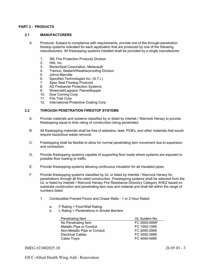
IMEG #21002025.10 26 05 03 - 3
EICC-Allied Health Wing-Add - Renovation
PART 2 - PRODUCTS
2.1 MANUFACTURERS
A. Products: Subject to compliance with requirements, provide one of the through-penetration firestop systems indicated for each application that are produced by one of the following manufacturers. All firestopping systems installed shall be provided by a single manufacturer.
1. 3M; Fire Protection Products Division2. Hilti, Inc.3. RectorSeal Corporation, Metacaulk4. Tremco; Sealant/Weatherproofing Division5. Johns-Manville6. Specified Technologies Inc. (S.T.I.)7. Spec Seal Firestop Products8. AD Firebarrier Protection Systems9. Wiremold/Legrand: FlameStopper10. Dow Corning Corp11. Fire Trak Corp12. International Protective Coating Corp
2.2 THROUGH PENETRATION FIRESTOP SYSTEMS
A. Provide materials and systems classified by or listed by Intertek / Warnock Hersey to provide firestopping equal to time rating of construction being penetrated.
B. All firestopping materials shall be free of asbestos, lead, PCB's, and other materials that would require hazardous waste removal.
C. Firestopping shall be flexible to allow for normal penetrating item movement due to expansion and contraction.
D. Provide firestopping systems capable of supporting floor loads where systems are exposed to possible floor loading or traffic.
E. Provide firestopping systems allowing continuous insulation for all insulated pipes.
F. Provide firestopping systems classified by UL or listed by Intertek / Warnock Hersey for penetrations through all fire rated construction. Firestopping systems shall be selected from the UL or listed by Intertek / Warnock Hersey Fire Resistance Directory Category XHEZ based on substrate construction and penetrating item size and material and shall fall within the range of numbers listed:
1. Combustible Framed Floors and Chase Walls - 1 or 2 Hour Rated:
a. F Rating = Floor/Wall Ratingb. L Rating = Penetrations in Smoke Barriers
Penetrating Item UL System No.No Penetrating Item FC 0000-0999*Metallic Pipe or Conduit FC 1000-1999Non-Metallic Pipe or Conduit FC 2000-2999Electrical Cables FC 3000-3999Cable Trays FC 4000-4999

IMEG #21002025.10 26 05 03 - 4
EICC-Allied Health Wing-Add - Renovation
Penetrating Item UL System No.Insulated Pipes FC 5000-5999Bus Duct and Misc. Electrical FC 6000-6999Duct without Damper and Misc. Mechanical FC 7000-7999Multiple Penetrations FC 8000-8999*Alternate method of firestopping is patching opening to match original rated construction.
2. Non-Combustible Framed Walls - 1 or 2 Hour Rated:
a. F Rating = Wall Ratingb. L Rating = Penetrations in Smoke Barriers
Penetrating Item UL System No.No Penetrating Item WL 0000-0999*Metallic Pipe or Conduit WL 1000-1999Non-Metallic Pipe or Conduit WL 2000-2999Electrical Cables WL 3000-3999Cable Trays WL 4000-4999Insulated Pipes WL 5000-5999Bus Duct and Misc. Electrical WL 6000-6999Duct without Damper and Misc. Mechanical WL 7000-7999Multiple Penetrations WL 8000-8999*Alternate method of firestopping is patching opening to match original rated construction.
3. Concrete or Masonry Floors and Walls - 1 or 2 Hour Rated:
a. F Rating = Wall/Floor Ratingb. L Rating = Penetrations in Smoke Barriers
Penetrating Item UL System No.No Penetrating Item CAJ 0000-0999*Metallic Pipe or Conduit CAJ 1000-1999Non-Metallic Pipe or Conduit CAJ 2000-2999Electrical Cables CAJ 3000-3999Cable Trays CAJ 4000-4999Insulated Pipes CAJ 5000-5999Bus Duct and Misc. Electrical CAJ 6000-6999Duct without Damper and Misc. Mechanical CAJ 7000-7999Multiple Penetrations CAJ 8000-8999*Alternate method of firestopping is patching opening to match original rated construction.
G. Any opening in walls or floors not covered by the listed series of numbers shall be coordinated with the firestopping manufacturer.
H. Any openings in floors or walls not described in the UL or listed by Intertek / Warnock Hersey Fire Resistance Directory, or outlined in manufacturer's information shall be sealed in a manner agreed upon by the Firestopping Manufacturer, Owner, and the Authority Having Jurisdiction.
IMEG #21002025.10 26 05 03 - 5
EICC-Allied Health Wing-Add - Renovation
PART 3 - EXECUTION
3.1 EXAMINATION
A. Ensure all surfaces that contact seal materials are free of dirt, dust, grease, oil, rust, or loose materials. Clean and repair surfaces as required. Remove laitance and form-release agents from concrete.
B. Ensure substrate and penetrating items have been permanently installed prior to installing firestopping systems. Ensure penetrating items have been properly spaced and have proper clearance prior to installing firestopping systems.
C. Surfaces to which sealing materials are to be installed must meet the selected UL or Intertek / Warnock Hersey system substrate criteria.
D. Prime substrates where recommended in writing by through-penetration firestop system manufacturer. Confine primer to area of bond.
3.2 INSTALLATION
A. In existing construction, provide firestopping of openings prior to and after installation of penetrating items. Remove any existing coatings on surfaces prior to firestopping installation. Temporary firestopping shall consist of packing openings with fire resistant mineral wool for the full thickness of substrate, or an alternate method approved by the Authority Having Jurisdiction. All openings shall be temporarily firestopped immediately upon their installation and shall remain so until the permanent UL or listed by Intertek / Warnock Hersey listed firestopping system is installed.
B. Install penetration seal materials in accordance with printed instructions of the UL or Intertek / Warnock Hersey Fire Resistance Directory and with the manufacturer's printed application instructions.
C. Install dams as required to properly contain firestopping materials within openings and as required to achieve required fire resistance rating. Remove combustible damming after appropriate curing.
3.3 CLEANING AND PROTECTING
A. Clean excess fill materials adjacent to openings as Work progresses by methods and with cleaning materials that are approved in writing by through-penetration firestop system manufacturers and that do not cause damage.
B. Provide final protection and maintain conditions during and after installation that ensure that through-penetration firestop systems are without damage or deterioration at time of Substantial Completion. If, despite such protection, damage or deterioration occurs, remove damaged or deteriorated through-penetration firestop systems immediately and install new materials to produce systems complying with specified requirements.
IMEG #21002025.10 26 05 03 - 6
EICC-Allied Health Wing-Add - Renovation
3.4 IDENTIFICATION
A. Provide and install labels adjacent to each firestopping location. Label shall be provided by the firestop system supplier and contain the following information in a contrasting color:
1. The words "Warning - Through Penetration Firestop System - Do Not Disturb. Notify Building Management of Any Damage."
2. Firestop System Supplier; UL or listed by Intertek / Warnock Hersey system number; date installed; contractor name and phone number; manufacturer's representative name, address, and phone number.
3.5 INSPECTION
A. All penetrations shall be inspected by the manufacturer's representative to ensure proper installation.
B. Access to firestop systems shall be maintained for examination by the Authority Having Jurisdiction at their request.
C. Proceed with enclosing through-penetration firestop system with other construction only after inspection reports are issued and firestop installations comply with requirements.
D. The contractor shall allow for visual destructive review of 5% of installed firestop systems (minimum of one) to prove compliance with specifications and manufacturer's instructions and details. Destructive system removal shall be performed by the contractor and witnessed by the Architect/Engineer and manufacturer's factory representative. The Architect/Engineer shall have sole discretion of which firestop system installations will be reviewed. The contractor is responsible for all costs associated with this requirement including labor and material for removing and replacing the installed firestop system. If any firestop system is found to not be installed per manufacturer's specific instructions and details, all firestop systems are subject to destructive review and replacement at the Architect/Engineer's discretion and the contractor's expense.
END OF SECTION 26 05 03
IMEG #21002025.10 26 05 05 - 1
EICC-Allied Health Wing-Add - Renovation
SECTION 26 05 05 - ELECTRICAL DEMOLITION FOR REMODELING
PART 1 - GENERAL
1.1 SECTION INCLUDES
A. Electrical demolition
PART 2 - PRODUCTS
2.1 MATERIALS AND EQUIPMENT
A. Materials and equipment for patching and extending work shall be as specified in individual Sections.
PART 3 - EXECUTION
3.1 EXAMINATION
A. THE DRAWINGS ARE INTENDED TO INDICATE THE SCOPE OF WORK REQUIRED AND DO NOT INDICATE EVERY BOX, CONDUIT, OR WIRE THAT MUST BE REMOVED. THE CONTRACTOR SHALL VISIT THE SITE PRIOR TO SUBMITTING A BID AND VERIFY EXISTING CONDITIONS.
B. Where walls, ceilings, structures, etc., are indicated as being removed on general or electrical drawings, the Contractor shall be responsible for the removal of all electrical equipment, devices, fixtures, raceways, wiring, systems, etc., from the removed area.
C. Where ceilings, walls, structures, etc., are temporarily removed and replaced by others, this Contractor shall be responsible for the removal, storage, and replacement of equipment, devices, fixtures, raceways, wiring, systems, etc.
D. Where mechanical or technology equipment is indicated as being removed on electrical, mechanical, or technology drawings, the Contractor shall be responsible for disconnecting the equipment and removing all starters, VFD, controllers, electrical equipment, raceways, wiring, etc. associated with the device.
E. Verify that abandoned wiring and equipment serve only abandoned equipment or facilities. Extend conduit and wire to facilities and equipment that will remain in operation following demolition. Extension of conduit and wire to equipment shall be compatible with the surrounding area. Extended conduit and conductors to match existing size and material.
F. Coordinate scope of work with all other Contractors and the Owner at the project site. Schedule removal of equipment and electrical service to avoid conflicts.
G. Bid submittal shall mean the Contractor has visited the project site and has verified existing conditions and scope of work.

IMEG #21002025.10 26 05 05 - 2
EICC-Allied Health Wing-Add - Renovation
3.2 PREPARATION
A. The Contractor shall obtain approval from the Owner before turning off power to circuits, feeders, panels, etc. Coordinate all outages with Owner.
B. Coordinate utility service outages with Utility Company.
C. Provide temporary wiring and connections to maintain existing systems in service during construction. When work must be performed on energized equipment or circuits, use personnel experienced in such operations. Assume all equipment and systems must remain operational unless specifically noted otherwise on drawings.
D. Disconnect electrical systems in walls, floors, structures, and ceilings scheduled for removal.
3.3 DEMOLITION AND EXTENSION OF EXISTING ELECTRICAL WORK
A. Demolish and extend existing electrical work under provisions of Division 1 of Specifications and this Section.
B. Remove, relocate, and extend existing installations to accommodate new construction.
C. Remove abandoned wiring and raceway to source of supply. Existing conduit in good condition may be reused in place by including an equipment ground conductor in reused conduit. Reused conduit and boxes shall have supports revised to meet current codes. Relocating conduit shall not be allowed.
D. Remove exposed abandoned raceway, including abandoned raceway above accessible ceiling finishes. Cut raceway flush with walls and floors, and patch surfaces. Remove all associated clamps, hangers, supports, etc. associated with raceway removal.
E. Disconnect and remove outlets and devices that are to be demolished. Remove conduit, supports, and conductors back to source. Devices' back box and conduit mounted in walls that are to remain can be abandoned in place. Provide appropriate cover plate for all abandoned back boxes. Cover plates shall match existing plates used in the adjacent areas.
F. Disconnect and remove abandoned panelboards and distribution equipment.
G. Disconnect and remove electrical devices and equipment serving utilization equipment that has been removed.
H. Disconnect and remove abandoned luminaires. Remove brackets, stems, hangers, and other accessories. Ballasts in light fixtures installed prior to 1980 shall be incinerated in EPA approved incinerator or disposed of in EPA certified containers and deposited in an EPA landfill certified for PCB disposal or recycled by permitted ballast recycler. Punctured or leaking ballasts must be disposed of according to Federal Regulations under the Toxic Substance Control Act. Provide Owner and Architect/Engineer with a Certificate of Destruction to verify proper disposal.
I. Repair adjacent construction and finishes damaged during demolition and extension work. Patch openings to match existing surrounding finishes.
J. Maintain access to existing electrical installations that remain active. Modify installation or provide junction boxes and access panel as appropriate.

IMEG #21002025.10 26 05 05 - 3
EICC-Allied Health Wing-Add - Renovation
K. Extend existing installations using materials and methods compatible with existing electrical installations, or as specified. Extended conduit and conductors to match existing size and material.
L. HID and fluorescent lamps, determined by the Toxicity Characteristic Leachate procedure (TCLP), to be hazardous waste shall be disposed of in an EPA-permitted hazardous waste disposal facility or by a permitted lamp recycler.
M. Regulatory Requirements: Comply with governing EPA notification regulations before beginning demolition. Comply with hauling and disposal regulations of authorities having jurisdiction.
N. This Contractor is responsible for all costs incurred in repair, relocations, or replacement of any cables, conduits, or other services if damaged without proper investigation.
3.4 CLEANING AND REPAIR
A. Clean and repair existing materials and equipment that remain or are to be reused.
B. Panelboards: Clean exposed surfaces and check tightness of electrical connections. Replace damaged circuit breakers and provide closure plates for vacant positions. Provide typed circuit directory showing revised circuiting arrangement.
C. Luminaires: Remove existing luminaires for cleaning as indicated on the drawings. Use mild detergent to clean all exterior and interior surfaces; rinse with clean water and wipe dry. Replace lamps, ballasts, and broken electrical parts. Replacement parts shall match specified components for new luminaires of same type when applicable. Reinstall luminaire and connect to circuiting as indicated on drawings.
D. ELECTRICAL ITEMS (E.G., LIGHTING FIXTURES, RECEPTACLES, SWITCHES, CONDUIT, WIRE, ETC.) REMOVED AND NOT RELOCATED REMAIN THE PROPERTY OF THE OWNER. CONTRACTOR SHALL PLACE ITEMS RETAINED BY THE OWNER IN A LOCATION COORDINATED WITH THE OWNER. THE CONTRACTOR SHALL BE RESPONSIBLE FOR THE DISPOSAL OF MATERIAL THE OWNER DOES NOT WANT.
3.5 INSTALLATION
A. Install relocated materials and equipment under the provisions of Division 1 of Specifications.
END OF SECTION 26 05 05

IMEG #21002025.10 26 05 13 - 1
EICC-Allied Health Wing-Add - Renovation
SECTION 26 05 13 - WIRE AND CABLE
PART 1 - GENERAL
1.1 SECTION INCLUDES
A. Building wire
B. Cabling for remote control, signal, and power limited circuits
1.2 RELATED WORK
A. Section 26 05 53 - Electrical Identification: Refer to electrical identification for color and identification labeling requirements.
1.3 REFERENCES
A. NEMA WC 70 - Power Cables Rated 2,000V or Less for the Distribution of Electrical Energy
B. NFPA 70 - National Electrical Code (NEC)
C. UL 44 - Thermoset-Insulated Wires and Cables
D. UL 83 - Thermoplastic-Insulated Wires and Cables
E. UL 1581 - Standard for Electrical Wires, Cables, and Flexible Cords
PART 2 - PRODUCTS
2.1 BUILDING WIRE
A. Feeders and Branch Circuits 8 AWG and larger: Copper, stranded conductor, 600-volt insulation, THHN/THWN or XHHW-2.
B. Feeders and Branch Circuits 8 AWG and larger in Underground Conduit: Copper, stranded conductor, 600-volt insulation, THWN or XHHW-2.
C. Feeders and Branch Circuits 10 AWG and Smaller: Copper, solid or stranded conductor, 600-volt insulation, THHN/THWN, unless otherwise noted on the drawings.
D. Motor Feeder from Variable Frequency Drives: Copper conductor, 600-volt XHHW-2 insulation, stranded conductor, unless otherwise noted on the drawings.
E. Control Circuits: Copper, stranded conductor 600-volt insulation, THHN/THWN.
F. Each 120 and 277-volt branch circuit shall have a dedicated neutral conductor. Neutral conductors shall be considered current-carrying conductors for wire derating.

IMEG #21002025.10 26 05 13 - 2
EICC-Allied Health Wing-Add - Renovation
2.2 CABLING FOR REMOTE CONTROL, SIGNAL, AND POWER LIMITED CIRCUITS
A. Wire for the following specialized systems shall be as designated on the drawings, or elsewhere in these specifications. If not designated on the drawings or specifications, the system manufacturer's recommendations shall be followed.
1. Fire alarm2. Low voltage switching and lighting control3. Other specialized cabling, signal, and power limited cabling. Refer to the appropriate
Division 23, 27, or 28 requirements; including, but not limited, to the following:
a. Building Automation Systems and Controls, Division 23.b. Information Technology Backbone and Horizontal Cabling, Division 27.c. Electronic Access Control, Intrusion Detection Systems, Video Surveillance,
Division 28.
B. Control Cable for Class 1 Remote Control and Signal Circuits: Copper conductor, 600-volt insulation, rated 60°C, individual conductors twisted together, shielded, and covered with a PVC jacket.
C. Control Cable for Class 2 or Class 3 Remote Control and Signal Circuits: Copper conductor, 300-volt insulation, rated 60°C, individual conductors twisted together, shielded, and covered with a PVC jacket; UL listed.
D. Plenum Cable for Class 2 or Class 3 Remote Control and Signal Circuits: Copper conductor, 300-volt insulation, rated 60°C, individual conductors twisted together, shielded, and covered with a nonmetallic jacket; UL listed for use in air handling ducts, hollow spaces used as ducts, and plenums.
PART 3 - EXECUTION
3.1 WIRE AND CABLE INSTALLATION SCHEDULE
A. Above Accessible Ceilings:
1. Building wire shall be installed in raceway.2. Metal clad cable, Type MC, 1/2" size with minimum #12 conductors and ground, shall be
allowed for flexible whips to individual luminaires on non-essential circuits. The flexible whips shall be between 18" to 72" in length per Electrical Code.
B. All Other Locations: Building wire in raceway.
C. Above Grade: All conductors installed above grade shall be type "THHN".
D. Underground or In Slab: All conductors shall be type "THWN".
IMEG #21002025.10 26 05 13 - 3
EICC-Allied Health Wing-Add - Renovation
E. Low Voltage Cable (less than 100 volts): Low voltage cables in ducts, plenums, and other air handling spaces shall be plenum listed. Low voltage cables in non-accessible areas shall be installed in conduit. Low voltage cable may be installed without conduit in accessible areas using the following types of cable supports. Cable support types/systems shall comply with the warranty requirements of the low voltage cable manufacturer.
1. J-hooks2. Bridle rings with saddle supports
3.2 CONTRACTOR CHANGES
A. The basis of design is copper conductors installed in raceway based on ambient temperature of 30°C, NEC Table 310.16 (2011 - 2017 edition 310.15(B)(16)). Service entrance conductors are based on copper conductor installed in underground electrical ducts, NEC Table B.2(7) (2011 - 2017 edition Table B310.15(B)(2)(7); 2008 or later edition B.301.7) or calculated in accordance with Annex B Application Information for Ampacity Calculation..
B. The Contractor shall be responsible for derating and sizing conductors and conduits to equal or exceed the ampacity of the basis of design circuits, if he/she chooses to use methods or materials other than the basis of design.
C. Underground electrical duct ampacity rating shall be in accordance with NEC Table 310.16 (2011 - 2017 edition 310.15(B)(16)) or calculated in accordance with Annex B Application Information for Ampacity Calculation. The calculations and a sketch of the proposed installation shall be submitted prior to any conduit being installed.
D. Record drawing shall include the calculations and sketches.
3.3 GENERAL WIRING METHODS
A. Use no wire smaller than 12 AWG for power and lighting circuits, and no smaller than 14 AWG for control wiring.
B. Use no wire smaller than 18 AWG for low voltage control wiring below 100 volts.
C. Use 10 AWG conductor for 20 ampere, 120-volt branch circuit home runs longer than 75 feet, and for 20 ampere, 277-volt branch circuit home runs longer than 200 feet.
D. Use no wire smaller than 8 AWG for outdoor lighting circuits.
E. The ampacity of multiple conductors in one conduit shall be derated per the Electrical Code. In no case shall more than 4 conductors be installed in one conduit to such loads as motors larger than 1/4 HP, panelboards, motor control centers, etc.
F. Where installing parallel feeders, place an equal number of conductors for each phase of a circuit in same raceway or cable.
G. Splice only in junction or outlet boxes.
H. Neatly train and lace wiring inside boxes, equipment, and panelboards.
I. Make conductor lengths for parallel circuits equal.
IMEG #21002025.10 26 05 13 - 4
EICC-Allied Health Wing-Add - Renovation
J. All conductors shall be continuous in conduit from last outlet to their termination.
K. Terminate all spare conductors on terminal blocks, and label the spare conductors.
L. Cables or wires shall not be laid out on the ground before pulling.
M. Cables or wires shall not be dragged over earth or paving.
N. Care shall be taken so as not to subject the cable or wire to high mechanical stresses that would cause damage to the wire and cable.
O. At least six (6)-inch loops or ends shall be left at each outlet for installation connection of luminaires or other devices.
P. All wires in outlet boxes not connected to fixtures or other devices shall be rolled up, spliced if continuity of circuit is required, and insulated.
3.4 WIRING INSTALLATION IN RACEWAYS
A. Pull all conductors into a raceway at the same time. Use UL listed wire pulling lubricant for pulling 4 AWG and larger wires.
B. Install wire in raceway after interior of building has been physically protected from the weather and all mechanical work likely to injure conductors has been completed.
C. Pulling shall be continuous without unnecessary stops and starts with wire or cable only partially through raceway.
D. Where reels of cable or wire are used, they shall be set up on jacks close to the point where the wire or cable enters the conduit or duct so that the cable or wire may be unreeled and run into the conduit or duct with a minimum of change in the direction of the bend.
E. Conductors shall not be pulled through conduits until plastering or masonry work is completed and conduits are free from moisture. Care shall be taken so that long pulls of wire or pulls around several bends are not made where the wire may be permanently stretched and the insulation damaged.
F. Only nylon rope shall be permitted to pull cables into conduit and ducts.
G. Completely and thoroughly swab raceway system before installing conductors.
H. Conductor Supports in Vertical Raceways:
1. Support conductors in vertical raceways in accordance with the Electrical Code Spacing of Conductors Supports.
2. Supports shall be of insulated wedge type (OZ Gedney Type S, or equal) and installed in a tapered insulated bushing fitting or a metal woven mesh with a support ring that fits inside conduit fitting installed in an accessible junction box (Hubbell Kellems support grip or equal).
3.5 CABLE INSTALLATION
A. Provide protection for exposed cables where subject to damage.
IMEG #21002025.10 26 05 13 - 5
EICC-Allied Health Wing-Add - Renovation
B. Use suitable cable fittings and connectors.
C. Run all open cable parallel or perpendicular to walls, ceilings, and exposed structural members. Follow the routing as illustrated on the drawings as closely as possible. Cable routing on drawings scaled 1/4"=1'-0" or less shall be considered diagrammatical, unless noted otherwise. The correct routing, when shown diagrammatically, shall be chosen by the Contractor based on information in the contract documents; in accordance with the manufacturer's written instructions, applicable codes, the NECA's "Standard of Installation", recognized industry standards; and coordinated with other contractors.
D. Open cable shall be supported by the appropriate size J-hooks or other means if called for on the drawings. Wire and cable from different systems shall not be installed in the same J-hook. J-hooks shall be sized with 20% spare capacity. J-hooks shall provide proper bend radius support for data cable and fiber cables.
E. Open cable installed above suspended ceilings shall not rest on the suspended ceiling construction, nor utilize the ceiling support system for wire and cable support.
F. J-hook support spans shall be based on the smaller of the manufacturer's load ratings and code requirements. In no case shall horizontal spans exceed 5 feet and vertical spans exceed 4 feet. All J-hooks shall be installed where completely accessible and not blocked by piping, ductwork, inaccessible ceilings, etc. J-hooks shall be independently rigidly attached to a structural element. J-hooks shall be installed to provide 2" horizontal separation and 6" vertical separation between systems.
G. Open cable shall only be installed where specifically shown on the drawings, or permitted in these specifications.
3.6 WIRING CONNECTIONS AND TERMINATIONS
A. Splice and tap only in accessible junction boxes.
B. Use solderless, tin-plated copper, compression terminals (lugs) applied with circumferential crimp for conductor terminations, 8 AWG and larger.
C. Use solderless, tin-plated, compression terminals (lugs) applied with indenter crimp for copper conductor terminations, 10 AWG and smaller.
D. Use solderless pressure connectors with insulating covers for copper wire splices and taps, 8 AWG and smaller. For 10 AWG and smaller, use insulated spring wire connectors with plastic caps.
E. Use compression connectors applied with circumferential crimp for conductor splices and taps, 6 AWG and larger. Tape uninsulated conductors and connectors with electrical tape to 150 percent of the insulation value of conductor.
F. Thoroughly clean wires before installing lugs and connectors.
G. Make splices, taps and terminations to carry full ampacity of conductors without perceptible temperature rise.
H. Phase Sequence: All apparatus shall be connected to operate in the phase sequence A-B-C representing the time sequence in which the phase conductors so identified reach positive maximum voltage.

IMEG #21002025.10 26 05 13 - 6
EICC-Allied Health Wing-Add - Renovation
I. As a general rule, applicable to switches, circuit breakers, starters, panelboards, switchgear and the like, the connections to phase conductors are intended thus:
1. Facing the front and operating side of the equipment, the phase identification shall be:
a. Left to Right - A-B-Cb. Top to Bottom - A-B-C
J. Connection revisions as required to achieve correct rotation of motors shall be made at the load terminals of the starters or disconnect switches.
3.7 FIELD QUALITY CONTROL
A. Field inspection and testing will be performed under provisions of Division 1.
B. Building Wire and Power Cable Testing: Perform an insulation-resistance test on each conductor with respect to ground and adjacent conductors. Test shall be made by means of a low-resistance ohmmeter, such as a "Megger". The applied potential shall be 500 volts dc for 300 volt rated cable and 1000 volts dc for 600 volt rated cable. The test duration shall be one minute. Insulation resistance must be greater than 100 mega-ohm for 600 volt and 25 mega-ohm for 300 volt rated cables per NETA Acceptance Testing Standard. Verify uniform resistance of parallel conductors.
C. Inspect wire and cable for physical damage and proper connection.
D. Torque test conductor connections and terminations to manufacturer's recommended values.
E. Perform continuity test on all power and equipment branch circuit conductors. Verify proper phasing connections.
F. Documentation indicating that the torque wrench has been calibrated not more than 30 days prior to tightening of lugs shall be provided.
G. Protection of wire and cable from foreign materials:
1. It is the Contractor's responsibility to provide adequate physical protection to prevent foreign material application or contact with any wire or cable type. Foreign material is defined as any material that would negatively impact the validity of the manufacturer's performance warranty. This includes, but is not limited to, overspray of paint (accidental or otherwise), drywall compound, or any other surface chemical, liquid, or compound that could come in contact with the cable, cable jacket, or cable termination components.
H. Overspray of paint on any wire or cable will not be accepted. It shall be the Contractor's responsibility to replace any component containing overspray, in its entirety, at no additional cost to the project. Cleaning of the cables with harsh chemicals is not allowed.
END OF SECTION 26 05 13
IMEG #21002025.10 26 05 26 - 1
EICC-Allied Health Wing-Add - Renovation
SECTION 26 05 26 - GROUNDING AND BONDING
PART 1 - GENERAL
1.1 SECTION INCLUDES
A. Equipment grounding system
B. Bonding system
1.2 QUALITY ASSURANCE
A. Electrical Components, Devices, and Accessories: Listed and labeled as defined in Electrical Code, Article 100, by a testing agency acceptable to authorities having jurisdiction, and marked for intended use.
B. Comply with UL 467 Grounding and Bonding Equipment.
1.3 REFERENCES
A. NFPA 70 - National Electrical Code (NEC)
1.4 SUMMARY
A. This section includes grounding of electrical systems and equipment. Grounding requirements specified in this Section may be supplemented by special requirements of systems described in other Sections.
PART 2 - PRODUCTS
2.1 GROUNDING CONDUCTORS
A. For insulated conductors, comply with Division 26 Section 26 05 13 "Wire and Cable".
B. Material: Copper.
C. Equipment Grounding Conductors: Insulated. Refer to Section 26 05 53 for insulation color.
D. Underground Conductors: Bare, tinned, stranded, unless otherwise indicated.
2.2 CONNECTOR PRODUCTS
A. Comply with UL 467; listed for use for specific types, sizes, and combinations of conductors and connected items.

IMEG #21002025.10 26 05 26 - 2
EICC-Allied Health Wing-Add - Renovation
PART 3 - EXECUTION
3.1 CONNECTIONS
A. General: Make connections so galvanic action or electrolysis possibility is minimized. Select connectors, connection hardware, conductors, and connection methods so metals in direct contact will be galvanically compatible.
1. Use electroplated or hot-tin-coated materials to ensure high conductivity and to make contact points closer to order of galvanic series.
2. Make connections with clean, bare metal at points of contact.3. Make aluminum-to-steel connections with stainless-steel separators and mechanical
clamps.4. Make aluminum-to-galvanized steel connections with tin-plated copper jumpers and
mechanical clamps.5. Coat and seal connections having dissimilar metals with inert material to prevent future
penetration of moisture to contact surfaces.
B. Equipment Grounding Conductor Terminations: For No. 8 AWG and larger, use pressure-type grounding lugs. No. 10 AWG and smaller grounding conductors may be terminated with winged pressure-type connectors.
C. Noncontact Metal Raceway Terminations: If metallic raceways terminate at metal housings without mechanical and electrical connection to housing, terminate each conduit with a grounding bushing. Connect grounding bushings with a bare grounding conductor to grounding bus or terminal in housing. Bond electrically non-continuous conduits at entrances and exits with grounding bushings and bare grounding conductors, unless otherwise indicated.
D. Connections at back boxes, junction boxes, pull boxes, and equipment terminations: The equipment grounding conductor(s) associated with all circuits in the box shall be connected together and to the box using a suitable grounding screw. The removal of the respective receptacle, luminaire, or other device served by the box shall not interrupt the grounding continuity. The connection to the non-metallic boxes shall be made to any metallic fitting or device requiring grounding.
E. Tighten screws and bolts for grounding and bonding connectors and terminals according to manufacturer's published torque-tightening values. If manufacturer's torque values are not indicated, use those specified in UL 486A.
F. Moisture Protection: If insulated grounding conductors are connected to ground rods or grounding buses, insulate entire area of connection and seal against moisture penetration of insulation and cable.
3.2 INSTALLATION
A. Use only copper conductors for both insulated and bare grounding conductors in direct contact with earth, concrete, masonry, crushed stone, and similar materials.
B. Grounding Conductors: Route along shortest and straightest paths possible, unless otherwise indicated. Avoid obstructing access or placing conductors where they may be subjected to strain, impact, or damage. Each grounding conductor that passes through a below grade wall must be provided with a waterstop.
C. In raceways, use insulated equipment grounding conductors.
IMEG #21002025.10 26 05 26 - 3
EICC-Allied Health Wing-Add - Renovation
D. Underground Grounding Conductors: Use tinned copper conductor, No. 2/0 AWG minimum. Bury at least 24 inches below grade or bury 12 inches above duct bank when installed as part of the duct bank.
3.3 EQUIPMENT GROUNDING SYSTEM
A. Comply with Electrical Code, for types, sizes, and quantities of equipment grounding conductors, unless specific types, larger sizes, or more conductors than required by Electrical Code are indicated.
B. Install equipment grounding conductors in all feeders and circuits. Terminate each end on a grounding lug or bus.
C. Nonmetallic Raceways: Install an equipment grounding conductor in nonmetallic raceways unless they are designated for telephone or data cables.
3.4 FIELD QUALITY CONTROL
A. Inspect grounding and bonding system conductors and connections for tightness and proper installation.
3.5 GRADING AND PLANTING
A. Restore surface features, including vegetation, at areas disturbed by Work of this Section. Reestablish original grades, unless otherwise indicated. If sod has been removed, replace it as soon as possible after backfilling is completed. Restore areas disturbed by trenching, storing of dirt, cable laying, and other activities to their original condition. Include application of topsoil, fertilizer, lime, seed, sod, sprig, and mulch. Comply with Division 2. Maintain restored surfaces. Restore disturbed paving.
END OF SECTION 26 05 26

IMEG #21002025.10 26 05 33 - 1
EICC-Allied Health Wing-Add - Renovation
SECTION 26 05 33 - CONDUIT AND BOXES
PART 1 - GENERAL
1.1 SECTION INCLUDES
A. Rigid metallic conduit and fittings (RMC)
B. Electrical metallic tubing and fittings (EMT)
C. Flexible metallic conduit and fittings (FMC)
D. Liquidtight flexible metallic conduit and fittings (LFMC)
E. Rigid polyvinyl chloride conduit and fittings (PVC)
F. Wall and ceiling outlet boxes
G. Electrical connection
H. Pull and junction boxes
I. Handholes
J. Accessories
1.2 RELATED WORK
A. Section 26 05 53 - Electrical Identification: Refer to electrical identification for color and identification labeling requirements.
1.3 REFERENCES
A. American National Standards Institute (ANSI):
1. ANSI C80.1 - Rigid Steel Conduit, Zinc-Coated2. ANSI C80.3 - Electrical Metallic Tubing, Zinc-Coated and Fittings3. ANSI C80.4 - Fittings for Rigid Metal Conduit and Electrical Metallic Tubing4. ANSI C80.6 - Intermediate Metal Conduit, Zinc Coated5. ANSI/NEMA OS 1 - Sheet-Steel Outlet Boxes, Device Boxes, Covers and Box Supports6. ANSI/NEMA OS 2 - Nonmetallic Outlet Boxes, Device Boxes, Covers and Box Supports
B. Federal Specifications (FS):
1. A-A-50553A - Fittings for Conduit, Metal, Rigid, (Thick-Wall and Thin-Wall (EMT) Type2. A-A-55810 - Specification for Flexible Metal Conduit
C. NECA "Standards of Installation"

IMEG #21002025.10 26 05 33 - 2
EICC-Allied Health Wing-Add - Renovation
D. National Electrical Manufacturers Association (NEMA):
1. ANSI/NEMA FB 1 - Fittings, Cast Metal Boxes, and Conduit Bodies for Conduit, Electrical Metallic Tubing and Cable
2. RN 1 - Polyvinyl chloride (PVC) Externally Coated Galvanized Rigid Steel Conduit, Rigid Aluminum Conduit, and Intermediate Metal Conduit
3. TC 2 - Electrical Polyvinyl Chloride (PVC) Conduit4. TC 9 - Fittings for PVC Plastic Utilities Duct for Underground Installation
E. NFPA 70 - National Electrical Code (NEC)
F. Underwriters Laboratories (UL): Applicable Listings
1. UL 1 - Flexible Metal Conduit2. UL 6 - Rigid Metal Conduit3. UL 360 - Liquid Tight Flexible Steel Conduit4. UL514-B - Conduit Tubing and Cable Fittings5. UL651-A - Type EB and a PVC Conduit and HDPE Conduit6. UL746A - Standard for Polymeric Materials - Short Term Property Evaluations7. UL797 - Electrical Metal Tubing
G. Definitions:
1. Fittings: Conduit connection or coupling.2. Body: Enlarged fittings with opening allowing access to the conductors for pulling
purposes only.3. Mechanical Spaces: Enclosed areas, usually kept separated from the general public,
where the primary use is to house service equipment and to route services. These spaces generally have exposed structures, bare concrete and non-architecturally emphasized finishes.
4. Finished Spaces: Enclosed areas where the primary use is to house personnel and the general public. These spaces generally have architecturally emphasized finishes, ceilings and/or floors.
5. Concealed: Not visible by the general public. Often indicates a location either above the ceiling, in the walls, in or beneath the floor slab, in column coverings, or in the ceiling construction.
6. Above Grade: Not directly in contact with the earth. For example, an interior wall located at an elevation below the finished grade shall be considered above grade but a wall retaining earth shall be considered below grade.
7. Slab: Horizontal pour of concrete used for a floor or sub-floor.
PART 2 - PRODUCTS
2.1 RIGID METALLIC CONDUIT (RMC) AND FITTINGS
A. Manufacturers:
1. Allied2. LTV3. Steelduct4. Calbond Calpipe5. Wheatland Tube Co6. O-Z Gedney
IMEG #21002025.10 26 05 33 - 3
EICC-Allied Health Wing-Add - Renovation
7. or approved equal.
B. Manufacturers of RMC Conduit Fittings:
1. Appleton Electric2. O-Z/Gedney Co.3. Electroline4. Raco5. Bridgeport6. Midwest7. Regal8. Thomas & Betts9. Crouse-Hinds10. Killark11. Orbit Industries 12. or approved equal.
C. Minimum Size Galvanized Steel: 3/4 inch, unless otherwise noted.
D. Fittings and Conduit Bodies:
1. End Bell Fittings: Malleable iron, hot dip galvanized, threaded flare type with provisions for mounting to form.
2. Expansion Joints: Malleable iron and hot dip galvanized providing a minimum of 4 inches of movement. Fitting shall be watertight with an insulating bushing and a bonding jumper.
3. Expansion Joint for Concrete Encased Conduit: Neoprene sleeve with bronze end coupling, stainless steel bands and tinned copper braid bonding jumper. Fittings shall be watertight and concrete-tight.
4. Conduit End Bushings: Malleable iron type with molded-on high impact phenolic thermosetting insulation. Where required elsewhere in the contract documents, bushing shall be complete with ground conductor saddle and clamp. High impact phenolic threaded type bushings are not acceptable.
5. All other fittings and conduit bodies shall be of malleable iron construction and hot dip galvanized.
E. PVC Externally Coated Conduit: Compliant with UL 6, ANSI C80.1 and NEMA RN 1; rigid galvanized steel conduit with external 40 mil PVC coating and internal 2 mil urethane coating surface. All fittings and conduit bodies shall be complete with coating. The PVC coated system shall include necessary PVC coated fittings, boxes and covers to form a complete encapsulated system.
1. Acceptable Manufacturers:
a. Calbond Calpipeb. Robroyc. T&B Ocald. or approved equal.
2.2 ELECTRICAL METALLIC TUBING (EMT) AND FITTINGS
A. Minimum Size Electrical Metallic Tubing: 3/4 inch, unless otherwise noted.

IMEG #21002025.10 26 05 33 - 4
EICC-Allied Health Wing-Add - Renovation
B. Manufacturers of EMT Conduit:
1. Allied2. Calbond Calpipe3. LTV4. Steelduct5. Wheatland Tube Co6. or approved equal.
C. Fittings and Conduit Bodies:
1. 2" Diameter or Smaller: Compression type of steel designed for their specific application.2. 1/2" and 3/4" Conduit: Push-on connectors and couplers with locking ring and washer of
zinc plated steel, listed for use in dry locations.3. Larger than 2": Compression type of steel designed for their specific application.4. Manufacturers of EMT Conduit Fittings:
a. Appleton Electricb. O-Z/Gedney Co.c. Electrolined. Racoe. Bridgeportf. Midwestg. Regalh. Thomas & Bettsi. Orbit Industries j. or approved equal.
2.3 FLEXIBLE METALLIC CONDUIT (FMC) AND FITTINGS
A. Minimum Size Galvanized Steel: 3/4 inch, unless otherwise noted. Lighting branch circuit wiring to an individual luminaire may be a manufactured, UL listed 3/8" flexible metal conduit and fittings with #14 AWG THHN conductors and an insulated ground wire. Maximum length of 3/8" FMC shall be six (6) feet.
B. Manufacturers:
1. American Flex2. Alflex3. Electri-Flex Co4. or approved equal.
C. Construction: Flexible steel, approved for conduit ground, zinc coated, threadless type formed from a continuous length of spirally wound, interlocked zinc coated strip steel. Provide a separate equipment grounding conductor when used for equipment where flexibility is required.
D. Fittings and Conduit Bodies:
1. Threadless hinged clamp type, galvanized zinc coated cadmium plated malleable cast iron or screw-in type, die-cast zinc.
2. Fittings and conduit bodies shall include plastic or cast metal inserts supplied by the manufacturer to protect conductors from sharp edges.

IMEG #21002025.10 26 05 33 - 5
EICC-Allied Health Wing-Add - Renovation
3. Manufacturers:
a. O-Z/Gedney Co.b. Thomas & Bettsc. Appleton Electricd. Electrolinee. Bridgeportf. Midwestg. Regalh. Orbit Industries i. or approved equal.
2.4 LIQUIDTIGHT FLEXIBLE METALLIC CONDUIT (LFMC) AND FITTINGS
A. Manufacturers:
1. Anaconda Type UA2. Electri-Flex Type LA3. Alflex4. Carlon (Lamson & Sessions) 5. or approved equal.
B. Construction: Flexible steel, approved for conduit ground, zinc coated, threadless type formed from a continuous length of spirally wound, interlocked zinc coated strip steel and an extruded PVC cover.
C. Fittings and Conduit Bodies:
1. Watertight, compression type, galvanized zinc coated cadmium plated malleable cast iron, UL listed.
2. Fittings and conduit bodies shall include plastic or cast metal inserts supplied by the manufacturer to protect conductors from sharp edges.
3. Manufacturers:
a. Appleton Electricb. O-Z/Gedney Co. c. Electrolined. Bridgeporte. Thomas & Bettsf. Midwestg. Regalh. Carlon (Lamson & Sessions)i. Orbit Industries j. or approved equal.
2.5 RIGID NON-METALLIC CONDUIT (PVC) AND FITTINGS
A. Minimum Size Rigid Smooth-Wall Nonmetallic Conduit: 3/4 inch, unless otherwise noted.
B. Acceptable Manufacturers:
1. Carlon (Lamson & Sessions) Type 402. Cantex, J.M. Mfg.3. or approved equal.
IMEG #21002025.10 26 05 33 - 6
EICC-Allied Health Wing-Add - Renovation
C. Construction: Schedule 40 and Schedule 80 rigid polyvinyl chloride (PVC), UL labeled for 90°C.
D. Fittings and Conduit Bodies: NEMA TC 3; sleeve type suitable for and manufactured especially for use with the conduit by the conduit manufacturer.
E. Plastic cement for joining conduit and fittings shall be provided as recommended by the manufacturer.
2.6 OUTLET BOXES
A. Sheet Metal Outlet Boxes: ANSI/NEMA OS 1; galvanized steel, 16 gauge (approximately 0.0625 inches), with 1/2-inch male fixture studs where required.
B. Nonmetallic Outlet Boxes: ANSI/NEMA OS 2.
C. Cast Boxes: NEMA FB1, Type FD, Aluminum, cast feralloy, or stainless steel deep type, gasketed cover, threaded hubs.
D. Outlet boxes for luminaires to be not less than 1-1/2" deep, deeper if required by the number of wires or construction. The box shall be coordinated with surface luminaires to conceal the box from view or provide a finished trim plate.
E. Switch outlet boxes for local light control switches, dimmers and occupancy sensors shall be 4 inches square by 2-1/8 inches deep, with raised cover to fit flush with finish wall line. Multiple gang switch outlets shall consist of the required number of gang boxes appropriate to the quantity of switches comprising the gang. Where walls are plastered, provide a plaster raised cover. Where switch outlet boxes occur in exposed concrete block walls, boxes shall be installed in the block cavity with a raised square edge tile cover of sufficient depth to extend out to face of block or masonry boxes.
F. Outlet boxes for telephone substations in walls and columns shall be 4 inches square and 2-1/8 inches deep with single gang raised cover to fit flush with finished wall line equipped with flush telephone plate.
G. Wall or column receptacle outlet boxes shall be 4 inches square with raised cover to fit flush with finished wall line. Boxes in concrete block walls shall be installed the same as for switch boxes in block walls.
2.7 ECONN; ELECTRICAL CONNECTION
A. Electrical connection to equipment and motors, sized per Electrical Code. Coordinate requirements with contractor furnishing equipment or motor. Refer to specifications and general installation notes for terminations to motors.
2.8 JB; PULL AND JUNCTION BOXES
A. Sheet Metal Boxes: ANSI/NEMA OS 1; galvanized steel.
B. Sheet metal boxes larger than 12 inches in any dimension that contain terminations or components: Continuous hinged enclosure with 1/4 turn latch and white back panel for mounting terminal blocks and electrical components.

IMEG #21002025.10 26 05 33 - 7
EICC-Allied Health Wing-Add - Renovation
C. Cast Metal Boxes for Outdoor and Wet Location Installations: NEMA 250; Type 4 and Type 6, flat-flanged, surface-mounted junction box, UL listed as raintight. Galvanized cast iron box and cover with ground flange, neoprene gasket, and stainless steel cover screws.
D. Cast Metal Boxes for Underground Installations: NEMA 250; Type 4, inside flanged, recessed cover box for flush mounting, UL listed as raintight. Galvanized cast iron box and plain cover with neoprene gasket and stainless steel cover screws.
E. Flanged type boxes shall be used where installed flush in wall.
2.9 HANDHOLES
A. HH-1; Handhole, composite polymer concrete body and cover. Stainless steel hardware. Bolted non-skid cover rated for 5,000 pounds. Design load occasional non-deliberate vehicular traffic. Stack units to achieve depth shown on plans. Units in landscaped areas shall be green in color. 11"W, 18"L, 18"D or dimensions as shown on plans.
1. Manufacturers:
a. Hubbell/Quazite PG####BB18, PG####HA00b. Carson Industries H Seriesc. Armorcastd. Highline Productse. Synertech
2.10 ACCESSORIES
A. Fire Rated Moldable Pads: UL #9700, moldable sheet putty at required thickness on all five sides of back boxes. Kinetics Noise Control - IsoBacker Pad, SpecSeal - SSP Putty and Pads, 3M #MPP-4S or equal.
B. Sound Barrier Insulation Pads: Mastic, non-hardening, sheet material, minimum 1/8" thickness applied to all five sides of back boxes. Kinetics Noise Control - SealTight Backer Pad, L.H. DOTTIE Co., #68 or equal.
PART 3 - EXECUTION
3.1 CONDUIT INSTALLATION SCHEDULE AND SIZING
A. In the event the location of conduit installation represents conflicting installation requirements as specified in the following schedule, a clarification shall be obtained from the Architect/Engineer. If this Contractor is unable to obtain a clarification as outlined above, concealed rigid galvanized steel conduit installed per these specifications and the Electrical Code shall be required.
B. Installation Schedule: Refer to drawings.
IMEG #21002025.10 26 05 33 - 8
EICC-Allied Health Wing-Add - Renovation
C. Size conduit as shown on the drawings and specifications. Where not indicated in the contract documents, conduit size shall be according to the Electrical Code. Conduit and conductor sizing shall be coordinated to limit conductor fill to less than 40%, maintain conductor ampere capacity as required by the Electrical Code (to include enlarged conductors due to temperature and quantity derating values) and to prevent excessive voltage drop and pulling tension due to long conduit/conductor lengths.
D. Minimum Conduit Size (Unless Noted Otherwise):
1. Above Grade: 3/4 inch. (The use of 1/2 inch would be allowed for installation conduit to individual light switches, individual receptacles and individual fixture whips from junction box.)
2. Below Grade 5' or less from Building Foundation: 1 inch. 3. Below Grade More than 5' from Building Foundation: 1 inch. 4. Telecommunication Conduit: 1 inch.5. Controls Conduit: 1/2 inch.
E. Conduit sizes shall change only at the entrance or exit to a junction box, unless specifically noted on the drawings.
3.2 CONDUIT ARRANGEMENT
A. In general, conduit shall be installed concealed in walls, in finished spaces and where possible or practical, or as noted otherwise. Conduit shall be installed parallel or perpendicular to walls, ceilings, and exposed structural members. In unfinished spaces, mechanical and utility areas, conduit may run either concealed or exposed as conditions dictate and as practical unless noted otherwise on drawings. Installation shall maintain headroom in exposed vicinities of pedestrian or vehicular traffic.
B. Exposed conduit on exterior walls or above roof will not be allowed without prior written approval of Architect/Engineer. A drawing of the proposed routing and a photo of the location shall be submitted 14 days prior to start of conduit rough-in. Routing shall be shown on coordination drawings.
C. Conduit shall not share the same cell as structural reinforcement in masonry walls.
D. Conduit runs shall be routed as shown on large scale drawings. Conduit routing on drawings scaled 1/4"=1'-0" or less shall be considered diagrammatic, unless noted otherwise. The correct routing, when shown diagrammatically shall be chosen by the Contractor based on information in the contract documents, in accordance with manufacturer's written instructions, applicable codes, the NECA's "Standard of Installation", in accordance with recognized industry standards, and coordinated with other contractors.
E. Contractor shall adapt Contractor's work to the job conditions and make such changes as required and permitted by the Architect/Engineer, such as moving to clear beams and joists, adjusting at columns, avoiding interference with windows, etc., to permit the proper installation of other mechanical and/or electrical equipment.
F. Contractor shall cooperate with all contractors on the project. Contractor shall obtain details of other contractor's work to ensure fit and avoid conflict. Any expense due to the failure of This Contractor to do so shall be paid for in full by Contractor. The other trades involved as directed by the Architect/Engineer shall perform the repair of work damaged as a result of neglect or error by This Contractor. The resultant costs shall be borne by This Contractor.

IMEG #21002025.10 26 05 33 - 9
EICC-Allied Health Wing-Add - Renovation
3.3 CONDUIT SUPPORT
A. Conduit runs installed above a suspended ceiling shall be properly supported. In no case shall conduit rest on the suspended ceiling construction, nor utilize ceiling support system for conduit support.
1. Support wire used to independently support raceway and wiring systems above suspending ceilings shall be supported on both ends, minimum 12 gauge suspended ceiling support wire, and distinguishable from ceiling support systems by color (field paint), tagging, or equivalent means.
B. Conduit shall not be supported from ductwork, water, sprinkler piping, or other non-structural members, unless approved by the Architect/Engineer. All supports shall be from structural slabs, walls, structural members, and bar joists, and coordinated with all other applicable contractors, unless noted otherwise.
C. Conduit shall be held in place by the correct size of galvanized one-hole conduit clamps, two-hole conduit straps, patented support devices, clamp back conduit hangers, or by other means if called for on the drawings.
D. Support individual horizontal raceways with separate, malleable-iron pipe hangers or clamps.
E. Spring-steel conduit clips specifically designed for supporting single conduits or tubing may be used in lieu of malleable-iron hangers for 1-1/2" and smaller raceways serving lighting and receptacle branch circuits above accessible ceilings and for securing raceways to slotted channel and angle supports.
F. Group conduits in parallel runs where practical and use conduit racks or trapeze hangers constructed of steel channel, suspended with threaded solid rods or wall mounted from metal channels with conduit straps or clamps. Provide space in each rack or trapeze for 25% additional conduits.
G. Do not exceed 25 lbs. per hanger and a minimum spacing of 2'-0" on center when attaching to metal roof decking (excludes concrete on metal deck). This 25 lbs. load and 2'-0" spacing include adjacent electrical and mechanical items hanging from deck. If the hanger restrictions cannot be achieved, supplemental framing off steel framing will need to be added.
H. Arrange supports in vertical runs so the weight of raceways and enclosed conductors is carried entirely by raceway supports, with no weight load on raceway terminals.
I. Supports for metallic conduit shall be no greater than 10 feet. A smaller interval may be used if necessitated by building construction, but in no event shall support spans exceed the Electrical Code requirements. Conduit shall be securely fastened within 3 feet of each outlet box, junction box, device box, cabinet, or fitting.
J. Supports of flexible conduit shall be within 12 inches of each outlet box, junction box, device box, cabinet, or fitting and at intervals not to exceed 4.5 feet.
K. Supports for non-metallic conduit shall be at sufficiently close intervals to eliminate any sag in the conduit. The manufacturer's recommendations shall be followed, but in no event shall support spans exceed the Electrical Code requirements.
L. Where conduit is to be installed in poured concrete floors or walls, provide concrete-tight conduit inserts securely fastened to forms to prevent conduit misplacement.
IMEG #21002025.10 26 05 33 - 10
EICC-Allied Health Wing-Add - Renovation
M. Finish:
1. Prime coat exposed steel hangers and supports. Hangers and supports in crawl spaces, pipe shafts, and above suspended ceiling spaces are not considered exposed.
2. Trim all ends of exposed field fabricated steel hangers, slotted channel and threaded rod to within 1" of support or fastener to eliminate potential injury to personnel unless shown otherwise on the drawings. Smooth ends and install elastomeric insulation with two coats of latex paint if exposed steel is within 6'-6" of finish floor and presents potential injury to personnel.
3.4 CONDUIT INSTALLATION
A. Conduit Connections:
1. Shorter than standard conduit lengths shall be cut square using industry standards. The ends of all conduits cut shall be reamed or otherwise finished to remove all rough edges.
2. Metallic conduit connections in slab on grade installation shall be sealed and one coat of rust inhibitor primer applied after the connection is made.
3. Where conduits with tapered threads cannot be coupled with standard couplings, then approved split or Erickson couplings shall be used. Running threads will not be permitted.
4. Install expansion/deflection joints where conduit crosses structure expansion/seismic joints.
B. Conduit terminations for all low voltage wiring shall have nylon bushings installed on each end of every conduit run.
C. Conduit Bends:
1. Use a hydraulic one-shot conduit bender or factory elbows for bends in conduit 2" in size or larger. All steel conduit bending shall be done cold; no heating of steel conduit shall be permitted.
2. All bends of rigid polyvinyl chloride conduit (PVC) shall be made with the manufacturer's approved bending equipment. The use of spot heating devices will not be permitted (i.e. blow torches).
3. A run of conduit shall not contain more than the equivalent of four (4) quarter bends (360°), including those bends located immediately at the outlet or body.
4. Telecommunications conduits shall have no more than two (2) 90-degree bends between pull points and contain no continuous sections longer than 100 feet. Insert pull points or pull boxes for conduits exceeding 100 feet in length.
a. A third bend is acceptable if:
1) The total run is not longer than (33) feet.2) The conduit size is increased to the next trade size.
5. Telecommunications pull boxes shall not be used in lieu of a bend. Align conduits that enter the pull box from opposite ends with each other. Pull box size shall be twelve (12) times the diameter of the largest conduit. Slip sleeves or gutters can be used in place of a pull box.
6. Telecommunications Conduit(s): Maintain appropriate conduit bend radius at all times. For conduits with an internal diameter of less than 2", maintain a bend radius of at least 6 times the internal diameter. For conduits with an internal diameter 2" or greater, maintain a bend radius of at least 10 times the internal diameter.

IMEG #21002025.10 26 05 33 - 11
EICC-Allied Health Wing-Add - Renovation
7. Rigid polyvinyl chloride conduit (PVC) runs longer than 100 feet or runs which have more than two 90° equivalent bends (regardless of length) shall use rigid metal or RTRC factory elbows for bends.
8. Use conduit bodies to make sharp changes in direction (i.e. around beams).
D. Conduit Placement:
1. Conduit shall be mechanically continuous from source of current to all outlets. Conduit shall be electrically continuous from source of current to all outlets, unless a properly sized grounding conductor is routed within the conduit. All metallic conduits shall be bonded per the Electrical Code.
2. Route exposed conduit and conduit above suspended ceilings (accessible or not) parallel/perpendicular to the building structural lines, and as close to building structure as possible. Wherever possible, route horizontal conduit runs above water and steam piping.
3. Route conduit through roof openings provided for piping and ductwork where possible. If not provided or routing through provided openings is not possible, route through roof jack with pitch pocket. Coordinate roof penetrations with other trades.
4. Conduits, raceway, and boxes shall not be installed in concealed locations in metal deck roofing or less than 1.5" below bottom of roof decking.
5. Avoid moisture traps where possible. Where unavoidable, provide a junction box with drain fitting at conduit low point.
6. All conduits through walls shall be grouted or sealed into openings. Where conduit penetrates firewalls and floors, seal with a UL listed sealant. Seal penetrations with intumescent caulk, putty, or sheet installed per manufacturer's recommendations. All materials used to seal penetrations of firewalls and floors shall be tested and certified as a system per ASTM E814 Standard for fire tests or through-penetration fire stops as manufactured by 3M or approved equal; refer to Section 26 05 03 for through penetration firestopping requirements.
7. CONTRACTOR SHALL BE RESPONSIBLE FOR ALL OPENINGS REQUIRED IN MASONRY OR EXTERIOR WALLS UNDER THIS DIVISION. A QUALIFIED MASON AT THE EXPENSE OF THIS CONTRACTOR SHALL REPAIR ALL OPENINGS TO MATCH EXISTING CONDITIONS.
8. Seal interior of conduit at exterior entries, air handling units, coolers/freezers, etc., and where the temperature differential can potentially be greater than 20°F, to prevent moisture penetration. Seal shall be placed where conduit enters warm space. Conduit seal fitting shall be a drain/seal, with sealing compound, identified for use with cable and raceway system, equal to O-Z/Gedney type EYD.
9. Horizontal conduit routing through slabs above grade
a. No conduits are allowed to be routed horizontally through slabs above grade.
10. Do not route conduits across each other in slabs on grade.11. Rigid polyvinyl chloride conduit (PVC) shall be installed when material surface
temperatures and ambient temperature are greater than 40°F.12. Where rigid polyvinyl chloride conduit (PVC) is used below grade, in a slab, below a slab,
etc., a transition to rigid galvanized steel or PVC-coated steel conduit shall be installed before conduit exits earth. The metallic conduit shall extend a minimum of 6" into the surface concealing the non-metallic conduit.
13. Contractor shall provide suitable mechanical protection around all conduits stubbed out from floors, walls or ceilings during construction to prevent bending or damaging of stubs due to carelessness with construction equipment.
14. Contractor shall provide a polypropylene pull cord with 2000 lbs. tensile strength in each empty conduit (indoor and outdoor), except in sleeves and nipples.

IMEG #21002025.10 26 05 33 - 12
EICC-Allied Health Wing-Add - Renovation
15. Telecommunications conduits that protrude through the structural floor shall be installed 1 to 3" above finished floor (AFF).
16. Telecommunications conduits that enter into Telecommunications rooms below the finished ceiling shall terminate a minimum of 4" below ceiling and as close to the wall as possible.
17. Telecommunications conduits that are below grade and enter into a building shall terminate a minimum of 4" above finished floor (AFF) and as close to the wall as possible.
3.5 CONDUIT TERMINATIONS
A. Where conduit bonding is indicated or required in the contract documents, the bushings shall be a grounding type sized for the conduit and ground bonding conductor as manufactured by O-Z/Gedney, Appleton, Thomas & Betts, Burndy, Regal, Orbit Industries or approved equal.
B. Conduits with termination fittings shall be threaded for one (1) lock nut on the outside and one (1) lock nut and bushing on the inside of each box.
C. Where conduits terminate in boxes with knockouts, they shall be secured to the boxes with lock nuts and provided with approved screw type tinned iron bushings or fittings with plastic inserts.
D. Where conduits terminate in boxes, fittings, or bodies with threaded openings, they shall be tightly screwed against the shoulder portion of the threaded openings.
E. Conduit terminations to all motors shall be made with flexible metallic conduit (FMC), unless noted otherwise. Final connections to roof exhaust fans, or other exterior motors and motors in damp or wet locations shall be made with liquidtight flexible metallic conduit (LFMC). Motors in hazardous areas, as defined in the Electrical Code, shall be connected using flexible conduit rated for the environment. Flexible conduit shall not exceed 6' in length. Route equipment ground conductors from circuit ground to motor ground terminal through flexible conduit.
F. Rigid polyvinyl chloride conduit (PVC) shall be terminated using fittings and bodies produced by the manufacturer of the conduit, unless noted otherwise. Prepare conduit as per manufacturer's recommendations before joining. All joints shall be solvent welded by applying full even coat of plastic cement to the entire areas that will be joined. Turn the conduit at least a quarter to one half turn in the fitting and let the joint cure for 1-hour minimum or as per the manufacturer's recommendations.
G. All conduit ends shall be sealed with plastic immediately after installation to prevent the entrance of any foreign matter during construction. The seals shall be removed and the conduits blown clear of all foreign matter prior to any wires or pull cords being installed.
3.6 UNDERGROUND CONDUIT INSTALLATION
A. Conduit Connections:
1. Conduit joints in a multiple conduit run shall be staggered at least one foot apart.
B. Conduit Bends (Lateral):
1. Conduits shall have long sweep radius elbows instead of standard elbows wherever special bends are indicated and noted on the drawings, or as required by the manufacturer of the equipment or system being served.
IMEG #21002025.10 26 05 33 - 13
EICC-Allied Health Wing-Add - Renovation
2. Telecommunications conduit bend radius shall be six times the diameter for conduits under 2" and ten times the diameter for conduits over 2". Where long cable runs are involved, sidewall pressures may require larger radius bends. Coordinate with Architect/Engineer prior to conduit installation to determine bend radius.
C. Conduit Elbows (vertical):
1. Minimum metal or RTRC elbow radiuses shall be 30 inches for primary conduits (greater than 600V) and 18 inches for secondary conduits (less than 600V). Increase radius, as required, based on pulling tension calculation requirements.
D. Conduit Placement:
1. Conduit runs shall be pitched a minimum of 4" per 100 feet to drain toward the terminations. Duct runs shall be installed deeper than the minimum wherever required to avoid any conflicts with existing or new piping, tunnels, etc.
2. For parallel runs, use suitable separators and chairs installed not greater than 4' on centers. Band conduit together with suitable banding devices. Securely anchor conduit to prevent movement during concrete placement or backfilling.
3. Where concrete is required, the materials for concreting shall be thoroughly mixed to a minimum f'c = 2500 and immediately placed in the trench around the conduits. No concrete that has been allowed to partially set shall be used.
4. Before the Contractor pulls any cables into the conduit, Contractor shall have a mandrel 1/4" smaller than the conduit inside diameter pulled through each conduit and if any concrete or obstructions are found, the Contractor shall remove them and clear the conduit. Spare conduit shall also be cleared of all obstructions.
5. Conduit terminations in manholes, masonry pull boxes, or masonry walls shall be with malleable iron end bell fittings.
6. All spare conduits not terminated in a covered enclosure shall have its terminations plugged as described above.
7. Ductbanks and conduit shall be installed a minimum of 24" below finished grade, unless otherwise noted on the drawings or elsewhere in these specifications.
8. All non-metallic conduit installed underground outside of a slab shall be rigid.
E. Raceway Seal:
1. Where a raceway enters a building or structure, it shall be sealed with a sealing bushing or duct seal to prevent the entry of liquids or gases. Seal must be compatible with conductors and raceway system. Spare or unused raceway shall also be sealed.
2. All telecommunications conduits and innerducts, including those containing cables, shall be plugged at the building and vault with "JackMoon" or equivalent duct seal, capable of withstanding a 10-foot head of water (5 PSI).
3.7 BOX INSTALLATION SCHEDULE
A. Galvanized steel boxes may be used in:
1. Concealed interior locations above ceilings and in hollow studded partitions.2. Exposed interior locations in mechanical rooms and in rooms without ceilings; higher than
8' above the highest platform level.3. Direct contact with concrete except slab on grade.4. Recessed in stud wall of kitchens and laundries.

IMEG #21002025.10 26 05 33 - 14
EICC-Allied Health Wing-Add - Renovation
B. Cast boxes shall be used in:
1. Exterior locations.2. Direct contact with concrete in slab on grade.3. Wet locations.4. Kitchens and laundries when exposed on wall surface.
3.8 COORDINATION OF BOX LOCATIONS
A. Provide electrical boxes as shown on the drawings, and as required for splices, taps, wire pulling, equipment connections, and code compliance.
B. Electrical box locations shown on the Contract Drawings are approximate, unless dimensioned. Verify location of floor boxes and outlets in offices and work areas prior to rough-in.
C. Locate and install boxes to allow access. Avoid interferences with ductwork, piping, structure, equipment, etc. Recessed luminaires shall not be used as access to outlet, pull, and junction boxes. Where installation is inaccessible, provide access doors. Coordinate locations and sizes of required access doors with the Architect/Engineer and General Contractor.
D. Locate and install to maintain headroom and to present a neat appearance.
E. Coordinate locations with Heating Contractor to avoid baseboard radiation cabinets.
3.9 OUTLET BOX INSTALLATION
A. Do not install boxes back-to-back in walls.
1. Provide a minimum horizontal separation of 6 inches between boxes installed on opposite sides of non-rated stud walls. When the minimum separation cannot be maintained, install sound insulation pads on all five sides of the back box in accordance with the manufacturer's instructions.
2. Provide a minimum horizontal separation of 24 inches between boxes installed on opposite sides of fire-rated walls. When the minimum separation cannot be maintained, the box is greater than 16 square inches or the total box area (all trades) per 100 square feet is greater than or equal to 100 square inches, install fire-rated moldable pads to all five sides of the back box to maintain the fire rating of the wall. Install moldable pads in accordance with UL listing for the specific product. Sound insulation pads are not acceptable for use in fire-rated wall applications unless the product carries the necessary fire rating.
B. Install sound insulation pads on all five sides of the back of all boxes in sound-rated wall assemblies. Sound-rated wall assemblies are defined as partition types carrying a Sound Transmission Class (STC) rating.
C. The Contractor shall anchor switch and outlet box to wall construction so that it is flush with the finished masonry, paneling, drywall, plaster, etc. The Contractor shall check the boxes as the finish wall surface is being installed to assure that the box is flush. (Provide plaster rings as necessary.)
D. Mount at heights shown or noted on the drawings or as generally accepted if not specifically noted.
IMEG #21002025.10 26 05 33 - 15
EICC-Allied Health Wing-Add - Renovation
E. Locate boxes in masonry walls to require cutting of masonry unit corner only. Coordinate masonry cutting to achieve neat openings for boxes.
F. Provide knockout closures for unused openings.
G. Support boxes independently of conduit.
H. Use multiple-gang boxes where more than one device is mounted together; do not use sectional boxes. Provide barriers to separate wiring of different voltage systems.
I. Install boxes in walls without damaging wall insulation.
J. Coordinate mounting heights and locations of outlets mounted above counters, benches, backsplashes, and below baseboard radiation.
K. Position outlets to locate luminaires as shown on reflected ceiling drawings.
L. Provide recessed outlet boxes in finished areas; secure boxes to interior wall and partition studs, accurately positioned to allow for surface finish thickness. Use stamped steel stud bridges for flush outlets in hollow stud wall, and adjustable steel channel fasteners for flush ceiling outlet boxes.
M. Align wall-mounted outlet boxes for switches, thermostats, and similar devices.
N. Provide cast outlet boxes in exterior locations and wet locations, and where exposed rigid or intermediate conduit is used.
3.10 PULL AND JUNCTION BOX INSTALLATION
A. Locate pull boxes and junction boxes above accessible ceilings or in unfinished areas.
B. Support pull and junction boxes independent of conduit.
C. Do not install boxes back-to-back in walls.
1. Provide a minimum horizontal separation of 6 inches between boxes installed on opposite sides of non-rated stud walls. When the minimum separation cannot be maintained, install sound insulation pads on all five sides of the back box in accordance with the manufacturer's instructions.
2. Provide a minimum horizontal separation of 24 inches between boxes installed on opposite sides of fire-rated walls. When the minimum separation cannot be maintained, the box is greater than 16 square inches or the total box area (all trades) per 100 square feet is greater than or equal to 100 square inches, install fire-rated moldable pads to all five sides of the back box to maintain the fire rating of the wall. Install moldable pads in accordance with UL listing for the specific product. Sound insulation pads are not acceptable for use in fire-rated wall applications unless the product carries the necessary fire rating.
D. Install sound insulation pads on all five sides of the back of all boxes in sound-rated wall assemblies. Sound-rated wall assemblies are defined as partition types carrying a Sound Transmission Class (STC) rating.
IMEG #21002025.10 26 05 33 - 16
EICC-Allied Health Wing-Add - Renovation
3.11 EXPOSED BOX INSTALLATION
A. Boxes shall be secured to the building structure with proper size screws, bolts, hanger rods, or structural steel elements.
B. On brick, block and concrete walls or ceilings, exposed boxes shall be supported with no less than two (2) Ackerman-Johnson, Paine, Phillips, or approved equal screw anchors or expansion shields and round head machine screws. Cast boxes shall not be drilled.
C. On steel structures, exposed boxes shall be supported to the steel member by drilling and tapping the member and fastening the boxes by means of round head machine screws.
D. Boxes may be supported on steel members by APPROVED beam clamps if conduit is supported by beam clamps.
E. Boxes shall be fastened to wood structures by means of a minimum of two (2) wood screws adequately large and long to properly support. (Quantity depends on size of box.)
F. Wood, plastic, or fiber plugs shall not be used for fastenings.
G. Explosive devices shall not be used unless specifically allowed.
END OF SECTION 26 05 33
IMEG #21002025.10 26 05 35 - 1
EICC-Allied Health Wing-Add - Renovation
SECTION 26 05 35 - SURFACE RACEWAYS
PART 1 - GENERAL
1.1 SECTION INCLUDES
A. Architectural surface raceways
B. Surface metal raceways
1.2 REFERENCES
A. FS W-C-582 - Conduit, Raceway, Metal, and Fitting; Surface
1.3 SUBMITTALS
A. Submit shop drawings under provisions of Section 26 05 00.
B. Include product data for surface metal raceways, multi-outlet assemblies, surface non-metallic raceways, auxiliary gutters, and accessories.
PART 2 - PRODUCTS
2.1 ARCHITECTURAL SURFACE RACEWAY
A. Surface Metal Raceway: Steel channel with fitted cover, size per circuit requirements.
B. Finish: Color selection by Architect.
C. Fittings: Couplings, elbows, and connectors designed for use with the raceway system.
D. Boxes and Extension Rings: Designed for use with the raceway system.
E. Manufacturers:
1. Wiremold V500/V700 series2. Mono-Systems SMS500/SMS700 series3. Hubbell HBL500/HBL700 series.
2.2 SURFACE METAL RACEWAY
A. Surface Metal Raceway: FS W-C-582; sheet metal channel with fitted cover, suitable for use as a continuous surface metal raceway.
B. Finish: Rust inhibiting primer coat for field painting. Coordinate paint color with Architect.
C. Fittings: Couplings, elbows, and connectors designed for use with raceway system.
D. Boxes and Extension Rings: Designed for use with raceway systems.
IMEG #21002025.10 26 05 35 - 2
EICC-Allied Health Wing-Add - Renovation
E. Coverplates shall be same material and finish as raceway.
F. Normal power receptacles shall be same color as raceway. Coordinate color with Architect.
G. Receptacles and outlets shown on raceway on drawings shall be mounted with overlapping faceplates in the raceway and shall not be mounted in boxes unless specifically noted otherwise.
H. WW-1; Surface metal raceway, metallic cover, minimum 2" opening, power / communication divider, minimum 1.3 square inch capacity.
1. Manufacturers
a. Wiremold 2400D b. Mono-Systems c. Hubbell .
PART 3 - EXECUTION
3.1 INSTALLATION - SURFACE METAL RACEWAY ASSEMBLY
A. Use flat-head screws to fasten channel to surfaces. Mount plumb and level.
B. Use suitable insulating bushings and inserts at connections to outlets and corner fittings.
C. Maintain grounding continuity between raceway components to provide a continuous grounding path.
D. Fastener: Use clips and straps suitable for the purpose.
E. Field cuts to be clean and straight and use the proper tools as recommended by the system manufacturer to prohibit damage to factory finish or raceway. Joints to be matched so there are no gaps or spaces in the cover. Furnish and install manufacturer's raceway accessories as needed.
F. Provide conduits to technology raceway per drawings or provide a minimum of one (1) 1-1/4" conduit per six feet of assembly (minimum 2) to above ceiling for technology requirements if assembly has technology raceway (Contractor shall provide quantities of conduits that provide maximum capacity to assembly). Provide conduits equally spaced within entire length of assembly.
3.2 INSTALLATION - ARCHITECTURAL SURFACE RACEWAY
A. Use flat-head screws to fasten channel to surfaces. Mount plumb and level.
B. Maintain grounding continuity between raceway components to provide a continuous grounding path.
C. Fastener: Use clips and straps suitable for the purpose.
IMEG #21002025.10 26 05 35 - 3
EICC-Allied Health Wing-Add - Renovation
D. Field cuts to be clean and straight and use the proper tools as recommended by the system manufacturer to prohibit damage to factory finish or raceway. Joints to be matched so there are no gaps or spaces in the cover. Furnish and install manufacturer's raceway accessories as needed.
E. Routing and Planning: Coordinate routings with existing vertical/horizontal building lines and features (doorways, wall trim, at wall/ceiling interface, etc.). Match the square / parallel lines of other existing features. Do not route raceway across large open spaces of the wall unless required by the application.
3.3 INSTALLATION - WIREWAY AND TROUGH
A. Bolt auxiliary gutter to steel channels fastened to the wall or in self-supporting structure. Install level.
B. Gasket each joint in oil-tight gutter.
C. Mount rain-tight gutter in horizontal position only.
D. Coordinate installation with other trades on project to avoid interferences. Relocation of equipment shall be at Contractor's expense at the direction of the Architect/Engineer to resolve interference problems.
END OF SECTION 26 05 35

IMEG #21002025.10 26 05 53 - 1
EICC-Allied Health Wing-Add - Renovation
SECTION 26 05 53 - ELECTRICAL IDENTIFICATION
PART 1 - GENERAL
1.1 SECTION INCLUDES
A. Adhesive Markings and Field Labels
B. Nameplates and Signs
C. Product Colors
1.2 REFERENCES
A. NFPA 70E - National Electrical Safety Code
B. NFPA 70 - National Electrical Code (NEC)
C. ANSI A13.1 - Standard for Pipe Identification
D. ANSI Z535.4 - Standard for Product Safety Signs and Labels
PART 2 - PRODUCTS
2.1 ADHESIVE MARKINGS AND FIELD LABELS
A. Colored Adhesive Marking Tape for banding Raceways, Wires, and Cables: Self-adhesive vinyl tape not less than 3 mils thick by 1 inch to 2 inches in width.
B. Pretensioned Flexible Wraparound Colored Plastic Sleeves for Cable Identification: flexible acrylic bands sized to suit the cable diameter and arranged to stay in place by pre-tensioned gripping action when coiled around the cable.
C. Wire/Cable Designation Tape Markers: Vinyl or vinyl-cloth, self-adhesive, wraparound, cable/conductor markers with preprinted numbers and letter.
D. Cable Ties: Fungus-inert, self-extinguishing, one-piece, self-locking nylon cable ties, 0.18-inch minimum width, 50-lb minimum tensile strength, and suitable for a temperature range from -40°F to 185°F (-40°C to 85°C), type 2/2S or type 21/21S based on application. Provide ties in specified colors when used for color coding. Cable ties shall be listed and identified for the application, securement, and support.
E. Underground Plastic Markers: Bright colored continuously printed plastic ribbon tape of not less than 6 inches wide by 4 mil thick, printed legend indicating type of underground line, manufactured for direct burial service. Tape shall contain a continuous metallic wire to allow location with a metal detector.
F. Aluminum, Wraparound Marker Bands: 1-inch width, 0.014 (5mm) inch thick aluminum bands with stamped or embossed legend, and fitted with slots or ears for permanently securing around wire or cable jacket or around groups of conductors.
IMEG #21002025.10 26 05 53 - 2
EICC-Allied Health Wing-Add - Renovation
G. Brass or Aluminum Tags: 2" (50mm) by 2" (50mm) by .05-inch metal tags with stamped legend, punched for fastener.
H. Indoor/Outdoor Number and Letters: Outdoor grade vinyl label with acrylic adhesive designed for permanent application in severe indoor and outdoor environments.
I. Text Sizes:
1. The following information shall be used for text heights, fonts, and size, unless otherwise noted.
a. Font: Normal 721 Swiss Boldb. Adhesive Labels: 3/16 inch minimum text heightc. Vinyl / Plastic Laminate Labels: 3/4" inch minimum text height
2.2 NAMEPLATES AND SIGNS
A. Engraved, Plastic-Laminated Labels, Signs and Instruction Plates: Engraving stock melamine plastic laminate, 1/16-inch minimum thick for signs up to 20 square inches, or 8 inches in length; 1/8 inch thick for larger sizes. Labels shall be punched for mechanical fasteners.
B. Text Sizes:
1. The following information shall be used for text heights, fonts, and size, unless otherwise noted.
a. Text Height: 3/8 inch minimum
C. Baked-Enamel Signs for interior Use: Preprinted aluminum signs, punched, or drilled for fasteners, with colors, legend, and size required for application. Mounting ¼" grommets in corners.
D. Exterior, Metal-Backed, Butyrate Signs: Weather-resistant, nonfading, preprinted, cellulose-acetate butyrate signs with 0.0396 inch galvanized-steel backing: and with colors, legend, and size required for application. Mounting 1/4" grommets in corners.
E. Safety Signs: Comply with 29 CFR, Chapter XVII, Part 1910.145.
F. Fasteners for Plastic-Laminated Signs; Self-tapping stainless steel screws or number 10/32 stainless steel machine screws with nuts and flat and lock washers.
2.3 PRODUCT COLORS
A. Adhesive Markings and Field Labels:
1. Normal Power and General Labels: Black letters on white face Control Labels: Black letters on white face Fire Alarm: Red letters on white face Emergency: Red letters on white face
B. Nameplates and Signs:
1. NORMAL POWER: Black letters on white face2. Control Labels: Black letters on white face

IMEG #21002025.10 26 05 53 - 3
EICC-Allied Health Wing-Add - Renovation
3. EMERGENCY: White letters on red face4. GROUNDING: White letters on green face.
C. Raceways and Conduit:
1. Provide color coded conduit as indicated below. Conduit shall be colored by the manufacturer:
a. Normal Power and General Distribution: Silverb. Emergency Power Distribution System:
1) All Emergency: Orange
c. Fire Alarm System: Redd. Temperature Controls: Refer to mechanical cover sheet for colore. Low Voltage and Telephone: Purplef. Clock, Sound, Security System, and Intercom: Black
D. Box Covers:
1. Box cover colors shall match conduit colors listed above.
E. Conductor Color Identification: Refer to Part 3 for additional information.
PART 3 - EXECUTION
3.1 INSTALLATION
A. Lettering and Graphics: Coordinate names, abbreviations, colors, and other designations used in electrical identification work with corresponding designations specified or indicated. Install numbers, lettering, and colors as required by code.
B. Exposed Ceilings and Finished Spaces: The project includes exposed ceilings in finished spaces. The installation of colored raceways and labeling may not be aesthetically desirable in finished spaces. The contractor shall coordinate identification requirements in exposed ceilings of finished spaces with the A/E prior to installation and ordering of materials.
C. Install identification devices in accordance with manufacturer's written instruction and requirements of Electrical Code.
D. Sequence of Work: Where identification is to be applied to surfaces that require finish, install identification after completion of finish work. All mounting surfaces shall be cleaned and degreased prior to identification installation.
E. Circuit Identification: Tag or label conductors as follows:
1. Multiple Power or Lighting Circuits in Same Enclosure: Where multiple branch circuits are terminated or spliced in a box or enclosure, label each conductor with source and circuit number.
IMEG #21002025.10 26 05 53 - 4
EICC-Allied Health Wing-Add - Renovation
2. Multiple Control Wiring and Communication/Signal Circuits in Same Enclosure: For control and communications/signal wiring, use wire/cable marking tape at terminations in wiring boxes, troughs, and control cabinets. Use consistent letter/number conductor designations throughout on wire/cable marking tape.
3. Match identification markings with designations used in panelboards shop drawings, Contract Documents, and similar previously established identification schemes for the facility's electrical installations.
F. Apply warning, caution and instruction signs as follows:
1. Install warning, caution or instruction signs where required by Electrical Code, where indicated, or where reasonably required to assure safe operation and maintenance of electrical systems and of the items to which they connect. Install engraved plastic-laminated instruction signs with approved legend where instructions or explanations are needed for system or equipment operation. Install metal-backed butyrate signs for outdoor items.
2. Emergency Operating Signs: Install, where required by Electrical Code, where indicated, or where reasonably required to assure safe operation and maintenance of electrical systems and of the items to which they connect, engraved laminate signs with white legend on red background with minimum 3/8-inch high lettering for emergency instructions on power transfer, load shedding, or other emergency operations.
G. Apply circuit/control/item designation labels of engraved plastic laminate for pushbuttons, pilot lights, alarm/signal components, and similar items, except where labeling is specified elsewhere.
H. Install labels parallel to equipment lines at locations as required and at locations for best convenience of viewing without interference with operation and maintenance of equipment.
I. Install ARC FLASH WARNING signs on all switchboards, panelboards, industrial control panels, and motor control centers.
1. Sample Label:
! WARNINGARC FLASH AND SHOCK HAZARDAPPROPRIATE PPE REQUIRED FAILURE TO COMPLY CAN RESULT IN DEATH OR INJURYREFER TO NFPA 70E
J. Underground Electrical Lines: For exterior underground power, control, signal, and communication lines, install continuous underground plastic line marker located directly above line at 6 (150mm) to 8 (205mm) inches below grade. A single plastic line marker is permitted when the width of the common trench does not exceed 16 inches; provide a second plastic line marker to mark each edge of the trench when 16 inches of width is exceeded. Install line marker for underground wiring, both direct-buried cables and cables in raceway.
3.2 LIGHTING CONTROL AND RECEPTACLE COVER PLATES
A. Product:
1. Adhesive labels and field markings2. Nameplates and signs
IMEG #21002025.10 26 05 53 - 5
EICC-Allied Health Wing-Add - Renovation
B. Identification material to be a clear, 3/8-inch Kroy tape or Brother self-laminating vinyl label with black letters. Embossed Dymo-Tape labels are not acceptable. Permanently affix identification label to cover plates, centered above the receptacle openings.
C. Provide identification on all switch and receptacle cover plates. Identification shall indicate source and circuit number serving the device (e.g. "C1A #24"). Identification for switch cover plates shall be installed on the inside cover.
3.3 BOX LABELING
A. Products:
1. Adhesive labels and field markings
B. Identify Junction, Pull and Connection Boxes: Labeling shall be 3/8-inch Kroy tape OR Brother self-laminating vinyl label, letters/numbers. In rooms that are painted out, provide labeling on inside of cover.
C. All junction, pull, and connection boxes shall be identified as follows:
1. For power and lighting circuits, indicate system voltage and identity of contained circuits ("120V, 1LA1-3,5,7").
2. For other wiring, indicate system type and description of wiring ("FIRE ALARM NAC #1").
3.4 CONDUCTOR COLOR CODING
A. Products:
1. All wires and cables, 6 AWG or larger, used in motor circuits, main feeders, sub-main feeders, and branch circuits shall be coded by the application of plastic tape. The tape shall be 3-M, Plymouth or Permacel in colors specified below. The tape shall be applied at each conductor termination with two 1-inch tape bands at 6-inch centers. Contractor option to use colored cabling in lieu of the tape at each end for conductor 6 AWG to 500 KCM. Wire and cables smaller than 6 AWG shall be color coded by the manufacturer.
B. Color coding shall be applied at all panels, switches, junction boxes, pull boxes, vaults, manholes etc., where the wires and cables are visible and terminations are made. The same color coding shall be used throughout the entire electrical system, therefore maintaining proper phasing throughout the entire project.
C. Colored cable ties shall be applied in groups of three ties of specified color to each conductor at each terminal or splice point starting 3 inches from the termination and spaced at 3- inches centers. Tighten to a snug fit, and cut off excess length.
D. Where more than one nominal voltage system exists in a building or facility, each ungrounded conductor of a multi-wire branch circuit, where accessible, shall be identified by phase and system.
E. Conductors shall be color coded as follows:
1. 208Y/120 Volt, 4-Wire:
a. A-Phase - Black
IMEG #21002025.10 26 05 53 - 6
EICC-Allied Health Wing-Add - Renovation
b. B-Phase - Redc. C-Phase - Blued. Neutral - Whitee. Ground Bond - Green
2. 480Y/277 Volt, 4-Wire:
a. A-Phase - Brownb. B-Phase - Orangec. C-Phase - Yellowd. Neutral - Graye. Ground Bond - Green
3. Grounding Conductors:
a. Equipment grounding conductors, main/system/supply-side bonding jumpers: Green.
b. Isolated Equipment Ground Conductors: Green with colored distinctive yellow stripe along the entire length of the conductor. Isolated ground for feeders, use colored tape with alternating bands of green and yellow to provide a minimum of three bands of green and two bands of yellow.
4. Cabling for Remote Control, Signal, and Power Limited Circuits:
a. Fire Alarm: Refer to Fire Alarm and Automatic Detection Section 28 31 00 for cable color requirements.
b. Low Voltage Switching: Per manufacturer recommendations and code requirements.
c. Building Automation Systems and Control: Refer to the Temperature Control Contactor notes located on the mechanical cover sheet.
d. Electronic Control: Per manufacturer recommendations and code requirements.e. Audio/Visual Systems: Refer to Division 27.f. Structured Cabling: Refer to Division 27.
3.5 CONTROL EQUIPMENT IDENTIFICATION
A. Products:
1. Nameplates and signs
B. Provide identification on the front of all control equipment such as combination starters, starters, VFDs, contactors, motor control centers, etc.
C. Identification shall be provided for all connections to equipment furnished by this Contractor, other contractors, or the Owner.
D. Labeling shall include:
1. Equipment type and contract documents designation of equipment being served.2. Location of equipment being served if it is not located within sight.3. Voltage and phase of circuit(s).4. Panel and circuit number(s) serving the equipment.5. Method of automatic control, if included ("AUTO CONTROL BY FMCS").

IMEG #21002025.10 26 05 53 - 7
EICC-Allied Health Wing-Add - Renovation
6. Sample Label:
EXHAUST FAN EF-1 ("LOCATED ON ROOF")480V, 3-PHASEFED FROM "1HA1-1"AUTO CONTROL BY FMCS
3.6 EQUIPMENT CONNECTION IDENTIFICATION
A. Products:
1. Nameplates and signs
B. Provide identification for hard wired electrical connections to equipment such as disconnects switches, starters, etc. Plug and cord type connections do not require this specific label.
C. Identification shall be provided for all connections to equipment furnished by this Contractor, other contractors, or the Owner. The following list of equipment is specifically being listed to receive an equipment connection label; this list does not limit the equipment that shall receive a label:
1. Mechanical heating, ventilation, and air conditioning equipment; chillers, boilers, pumps, air handing ventilation units, condensing units, unit heaters, and similar equipment
2. Plumbing equipment
D. Labeling shall include:
1. Equipment type and contract documents designation of equipment being served2. Location of equipment being served if it is not located within sight.3. Voltage and rating of the equipment.4. Panel and circuit numbers(s) serving the equipment5. Sample Label:
UNIT HEATER UH-1 ("LOCATED IN STORAGE ROOM 200")480V: 3-PHASEFED FROM "1HA1-1"
3.7 POWER DISTRIBUTION EQUIPMENT IDENTIFICATION
A. Products:
1. Nameplates and signs
B. Provide identification on the front of all power distribution equipment such as panelboards, switchboards, switchgear, motor control centers, generators, UPS, storage battery disconnects, transfer switches, etc. Labels shall be visible on the exterior of the gear, correspond to the one-line diagram nomenclature, and identify each cubicle of multi-section gear.
1. Interior Equipment: The identification material shall be engraved plastic-laminated labels.2. Exterior Equipment: The identification material shall be engraved vinyl labels.3. Labeling shall include:
a. Equipment type and contract documents designation of equipment.
IMEG #21002025.10 26 05 53 - 8
EICC-Allied Health Wing-Add - Renovation
b. Voltage of the equipment.c. Name of the upstream equipment and location of the upstream equipment if it is
not located within sight.d. Rating and type of the overcurrent protection device serving the equipment if it is
not located within sight ("FED BY 400A/3P BREAKER").e. Sample Label:
DISTRIBUTION PANEL DP-H1480Y/277VFED FROM SWITCHBOARD "SB-1" (LOCATED IN MAIN ELEC ROOM)
C. Adjustable-Trip Over Current Protection Label:
1. Provide a separate engraved plastic laminate label adjacent to each overcurrent projection device with adjustable trip settings. Provide label separate from load identification label.
a. Label:
1) Long-time delay:2) Long-time pickup:3) Short-time delay:4) Short-time pickup:5) Instantaneous:6) Ground fault delay:7) Ground fault:
b. Sample Label:
Long-time delay: 10.0Long-time pickup: 1.0Short-time delay: 0.15Short-time pickup: 5.0Instantaneous: 2.0Ground fault delay: 0.25Ground fault: 50.0
D. Nominal System Voltage Label:
1. Where more than one nominal voltage system exists in a building or facility, the identification of color coding used in the panelboard or equipment shall be permanently posted on the interior of the door or cover.
E. Distribution panelboards and switchboards shall have each overcurrent protection device identified with name and location of the load being served ("AHU-1 LOCATED IN PENTHOUSE 1"). Provide a separate engraved plastic laminate label adjacent to each overcurrent projection device with feeder wire size, feeder wire quantity, conductor material and distance in feet. Provide label separate from load identification label and adjustable trip settings label.
1. Sample Labels for Feeders:
4#3/0 CU & 1#6 CU GND, 125FT4#250KCM AL & 1#6 GND CU, 125FT2 SETS 4#400KCM CU & 1#1 GND CU, 125FT

IMEG #21002025.10 26 05 53 - 9
EICC-Allied Health Wing-Add - Renovation
F. Branch panelboards shall be provided with typed panel schedules upon completion of the project. Existing panelboards shall have their existing panel schedules typed, with all circuit changes, additions or deletions also typed on the panel schedules. A copy of all panel schedules for the project shall be turned over as part of the O&M Manuals. Refer to Section 26 05 00 for other requirements.
3.8 TRANSFORMER EQUIPMENT IDENTIFICATION
A. Products:
1. Nameplates and signs
B. Provide identification on the front of all transformers. The identification nameplate shall be an engraved plastic-laminated label.
C. Labeling shall include:
1. Equipment type and contract documents designation of equipment2. Name of the upstream equipment.3. Voltage and rating of the equipment.4. Location of the upstream equipment if it is not located within sight.5. Sample Label:
TRANSFORMER TR-15480V: 208Y/120V 15KVAFED FROM SWITCHBOARD "SB-1" (LOCATED IN ELEC 123)
3.9 ELECTRICAL WORKING CLEARANCE IDENTIFICATION
A. Products:
1. Safety Yellow paint and custom stencils
B. Provide custom identification of electrical equipment working clearances in mechanical, electrical, storage, janitorial, and similar non-public areas.
C. Identification shall include a painted rectangular box (on the finished floor) in front of the electrical equipment to define the code-required working clearance. Provide additional diagonal stripping inside the rectangle box. All painted stripping shall be safety yellow paint with 3 inch wide stripes.
1. Width of area: Width of equipment or as required by code2. Depth of area: Depth as required by code
3.10 POLE IDENTIFICATION
A. Product:
1. Adhesive labels and field markings2. Nameplates and signs
IMEG #21002025.10 26 05 53 - 10
EICC-Allied Health Wing-Add - Renovation
B. Lighting poles, bollards and overhead distribution poles shall be individually identified with a unique number, for maintenance purposes. Apply the vinyl label number above the hand hole cover or 24" (610mm) above grade. Bollards may be identified with a number applied inside the luminaire that is visible from the exterior.
END OF SECTION 26 05 53
IMEG #21002025.10 26 09 33 - 1
EICC-Allied Health Wing-Add - Renovation
SECTION 26 09 33 - LIGHTING CONTROL SYSTEMS
PART 1 - GENERAL
1.1 SECTION INCLUDES
A. Line and low voltage standalone lighting controls
B. Automatic load control relay (ALCR3)
C. Automatic load control relay (ALCR20)
D. Distributed lighting control
1.2 RELATED SECTIONS
A. The lighting system design includes a combination of luminaire sources, lighting control components, programming sequences, and supplementary components for building and energy code compliance. The design uses performance-based specifications for portions of the lighting system to account for the limitation of comparable product solutions available by competitive manufacturers. The Contractor shall reference related specification sections, plans, schedules, and details prior to submitting pricing, submittals, and installation. The Contractor shall coordinate system component compatibility among various manufacturers and suppliers for a turnkey lighting system. Referenced sections include, but are not limited to, the following:
1. 26 51 19 LED Lighting2. 26 52 15 Emergency Lighting Inverter3. Electrical Drawings: Plans, luminaire schedules, lighting control sequence of operations,
diagrams, and details.
1.3 RELATED WORK
A. Section 26 51 00 - Lighting
1.4 QUALITY ASSURANCE
A. Manufacturers shall be regularly engaged in the manufacture of lighting control equipment and ancillary equipment, of types and capacities required, whose products have been in satisfactory use in similar service for not less than five (5) years.
B. All components and assemblies are to be factory pre-tested prior to delivery and installation.
C. Comply with Electrical Code as applicable to electrical wiring work.
D. Comply with applicable portions of NEMA standards pertaining to types of electrical equipment and enclosures.
E. Panels and accessory devices are to be UL listed under UL 916 Energy Management Equipment. Panels and accessories used for control of life safety and critical branch circuits shall be listed under UL 924 Emergency Lighting and Power Equipment.

IMEG #21002025.10 26 09 33 - 2
EICC-Allied Health Wing-Add - Renovation
F. All assemblies are to be in compliance with FCC emissions standards specified in Part 15 Subpart J for Class A applications.
1.5 REFERENCES
A. FCC Rules and Regulations, Part 15, Subpart J - Radio Frequency Interference
B. FS W S 896 Switch, Toggle
C. International Energy Conservation Code (IECC)
D. NEMA WD 1 - General Color Requirements for Wiring Devices
E. NEMA WD 7 - Occupancy Motion Sensors
F. NFPA 70 - National Electrical Code (NEC)
G. UL Standard 916 Energy Management Equipment
H. UL 924 - Emergency Lighting and Power Equipment
I. UL 1472 - Solid-State Dimming Controls
1.6 SUBMITTALS
A. Submit product data under provisions of Section 26 05 00.
B. Submit a comprehensive package including devices, hardware, software, product specification, finishes, dimensions, installation instructions, warranty, system software requirements.
C. Provide floor plan showing location, orientation, and coverage area of each control device, sensor, and controller/interface. For areas requiring multiple sensor devices for appropriate coverage, submit specific manufacturer-approved sensor layout as an overlay directly on the project drawings, either in print or approved electronic form.
D. Submit a list of devices and equipment that will be installed for each sequence of operation.
E. Submit project specific control wiring diagrams showing all equipment, line voltage, and control wiring requirements for all components including, but not limited to, dimmers, relays, low voltage switches, occupancy sensors, control stations, and communication interfaces and programming instructions for each sequence of operation. Include network cable specification and end-of-line termination details, if required.
1.7 EXTRA STOCK
A. Provide extra stock under provisions of Section 26 05 00.
B. Sensors, Controls, Power Supplies, and Relays: Five (5) percent of quantity installed. Minimum of two (2) of each configuration and type.
C. Relays and Dimmer Modules: Five (5) percent of quantity installed. Minimum of two (2) of each size and type.
IMEG #21002025.10 26 09 33 - 3
EICC-Allied Health Wing-Add - Renovation
D. Control Stations: One (1) of each configuration and type, except for LCD touch screens requiring factory setup prior to installation.
1.8 PROJECT RECORD DOCUMENTS
A. Submit project record documents under provisions of Section 26 05 00.
B. Accurately record location of all controls and devices. Include description of switching sequences and circuiting arrangements.
1.9 OPERATION AND MAINTENANCE DATA
A. Submit emergency, operation, and maintenance data under provisions of Section 26 05 00. Data shall also include the following:
1. Schedule for routine maintenance, inspection, and calibration of all lighting control devices and system components. Recommended schedule for inspection and recalibration of sensors.
2. Complete narrative describing intended operation and sequence for each control scenario and system component, updated to reflect all changes resulting from commissioning of systems. Narrative shall indicate recommended settings for devices where applicable.
3. Replacement part numbers for all system components.
B. Identify installed location and labeling for each luminaire controlled by automated lighting controls.
1.10 SYSTEM DESCRIPTION
A. Performance Statement: This specification section and the accompanying lighting design documents describe the minimum material quality, required features, and operational requirements of the lighting control system (LCS). These documents do not convey every wire that must be installed and every equipment connection that must be made. Based on the performance required of the system, as presented in these documents, the Contractor and system manufacturer/vendor are solely responsible for determining all equipment, wiring, and programming required for a complete and operational system.
B. Provide an integrated lighting controls system consisting of panels, power supplies, controllers, sensors, relays, switches, devices, wiring, etc. necessary to perform the Lighting Control Sequence of Operation as defined on the plans and specifications. Contractor is responsible for confirming that all components and luminaires interoperate as a single system.
1. Sequence of Operation: Describes the required operation and performance for lighting control in each space. Sequences of operation are indicated on the drawings.
2. Drawings: The drawings include sequences of operation, locations of control interface devices, sensors, and control zones. Wiring and additional equipment to make a complete and functioning system has not been shown, but shall be submitted with the shop drawings.

IMEG #21002025.10 26 09 33 - 4
EICC-Allied Health Wing-Add - Renovation
C. The following control types and features are acceptable. Acceptable control locations are shown on the drawings.
1. Line Voltage Control: Control equipment consists of traditional line voltage wiring devices and equipment such as switches, dimmers and combination occupancy/vacancy sensor switches, etc.
2. Distributed Control: Control equipment is in the space/zone being controlled; not reliant on centralized controllers.
1.11 COMMISSIONING
A. The system shall be functionally tested by a factory-authorized engineer and comply with the Sequence of Operation. All loads shall be tested live for continuity and freedom from defects, and all control wiring shall be tested for continuity and connections prior to energizing the system.
1.12 WARRANTY
A. Manufacturer shall warrant products under normal use and service to be free from defects in materials and workmanship for a period of two (2) years from date of commissioning.
B. Occupancy, vacancy, daylight sensors and controls shall have a five (5) year warranty from date of Substantial Completion.
PART 2 - PRODUCTS
2.1 LIGHTING CONTROLS
A. All items of material having a similar function (e.g., switches, dimmers, sensors, contactors, relays, etc.) shall be of the same manufacturer, unless specifically stated otherwise on drawings or elsewhere in the specifications. Lighting control switches, systems, and components shall be listed.
B. Color of lighting controls and sensors shall match the receptacle wiring devices specified in the space.
C. The functions described in the lighting sequence of operation shall dictate the actual lighting control device required to accomplish the functions described for the space.
2.2 LIGHTING CONTROL STATION
A. SW; The lighting control station shall contain the controls required by the lighting sequence of operation in a common coverplate. The controls may consist of switches, dimmers, occupancy sensors, pushbuttons, etc.
1. In spaces where the wall control station is shown in multiple locations, the sequence of operation shall be the same at all locations, unless noted otherwise.
2. The controls supplier shall prepare control station shop drawings showing arrangement of controls, dimensioned elevations, wiring diagram, and recommended backboxes. The shop drawing submittal should be identified with the lighting sequence that the station provides. Submit data sheets on the switches, dimmers, sensors, buttons, etc. contained in the control station.
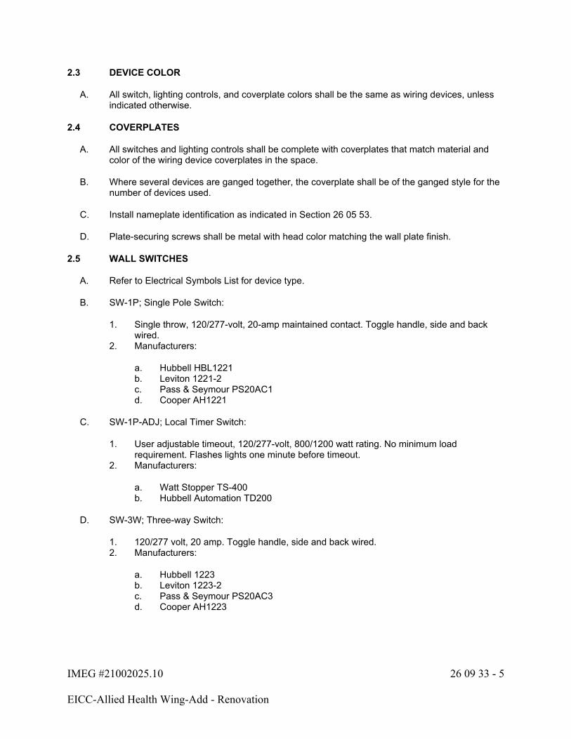
IMEG #21002025.10 26 09 33 - 5
EICC-Allied Health Wing-Add - Renovation
2.3 DEVICE COLOR
A. All switch, lighting controls, and coverplate colors shall be the same as wiring devices, unless indicated otherwise.
2.4 COVERPLATES
A. All switches and lighting controls shall be complete with coverplates that match material and color of the wiring device coverplates in the space.
B. Where several devices are ganged together, the coverplate shall be of the ganged style for the number of devices used.
C. Install nameplate identification as indicated in Section 26 05 53.
D. Plate-securing screws shall be metal with head color matching the wall plate finish.
2.5 WALL SWITCHES
A. Refer to Electrical Symbols List for device type.
B. SW-1P; Single Pole Switch:
1. Single throw, 120/277-volt, 20-amp maintained contact. Toggle handle, side and back wired.
2. Manufacturers:
a. Hubbell HBL1221b. Leviton 1221-2c. Pass & Seymour PS20AC1d. Cooper AH1221
C. SW-1P-ADJ; Local Timer Switch:
1. User adjustable timeout, 120/277-volt, 800/1200 watt rating. No minimum load requirement. Flashes lights one minute before timeout.
2. Manufacturers:
a. Watt Stopper TS-400b. Hubbell Automation TD200
D. SW-3W; Three-way Switch:
1. 120/277 volt, 20 amp. Toggle handle, side and back wired.2. Manufacturers:
a. Hubbell 1223b. Leviton 1223-2c. Pass & Seymour PS20AC3d. Cooper AH1223
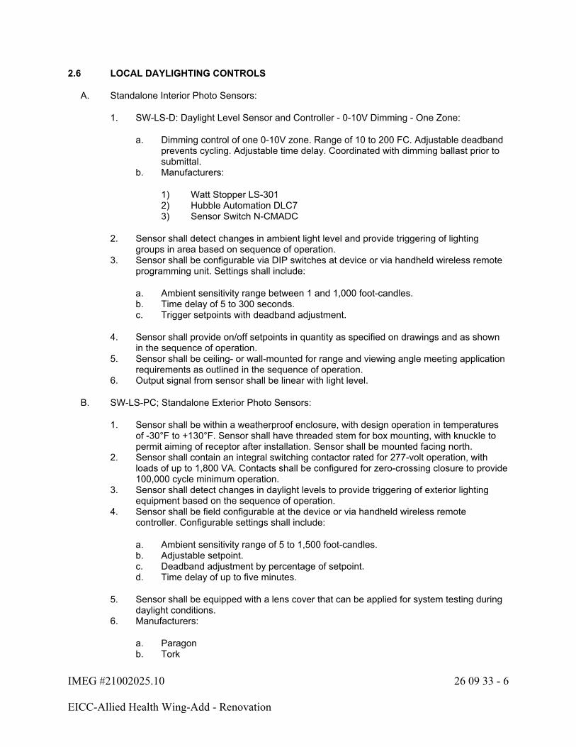
IMEG #21002025.10 26 09 33 - 6
EICC-Allied Health Wing-Add - Renovation
2.6 LOCAL DAYLIGHTING CONTROLS
A. Standalone Interior Photo Sensors:
1. SW-LS-D: Daylight Level Sensor and Controller - 0-10V Dimming - One Zone:
a. Dimming control of one 0-10V zone. Range of 10 to 200 FC. Adjustable deadband prevents cycling. Adjustable time delay. Coordinated with dimming ballast prior to submittal.
b. Manufacturers:
1) Watt Stopper LS-3012) Hubble Automation DLC73) Sensor Switch N-CMADC
2. Sensor shall detect changes in ambient light level and provide triggering of lighting groups in area based on sequence of operation.
3. Sensor shall be configurable via DIP switches at device or via handheld wireless remote programming unit. Settings shall include:
a. Ambient sensitivity range between 1 and 1,000 foot-candles.b. Time delay of 5 to 300 seconds.c. Trigger setpoints with deadband adjustment.
4. Sensor shall provide on/off setpoints in quantity as specified on drawings and as shown in the sequence of operation.
5. Sensor shall be ceiling- or wall-mounted for range and viewing angle meeting application requirements as outlined in the sequence of operation.
6. Output signal from sensor shall be linear with light level.
B. SW-LS-PC; Standalone Exterior Photo Sensors:
1. Sensor shall be within a weatherproof enclosure, with design operation in temperatures of -30°F to +130°F. Sensor shall have threaded stem for box mounting, with knuckle to permit aiming of receptor after installation. Sensor shall be mounted facing north.
2. Sensor shall contain an integral switching contactor rated for 277-volt operation, with loads of up to 1,800 VA. Contacts shall be configured for zero-crossing closure to provide 100,000 cycle minimum operation.
3. Sensor shall detect changes in daylight levels to provide triggering of exterior lighting equipment based on the sequence of operation.
4. Sensor shall be field configurable at the device or via handheld wireless remote controller. Configurable settings shall include:
a. Ambient sensitivity range of 5 to 1,500 foot-candles.b. Adjustable setpoint.c. Deadband adjustment by percentage of setpoint.d. Time delay of up to five minutes.
5. Sensor shall be equipped with a lens cover that can be applied for system testing during daylight conditions.
6. Manufacturers:
a. Paragonb. Tork

IMEG #21002025.10 26 09 33 - 7
EICC-Allied Health Wing-Add - Renovation
c. Intermatic
2.7 INDOOR OCCUPANCY AND VACANCY SENSORS
A. General Description: Wall- or ceiling-mounting, solid-state units with a separate power supply/relay unit.
1. Operation: Unless otherwise indicated, turn lights on when covered area is occupied and off when unoccupied, with a time delay for turning lights off, adjustable over a minimum range of 1 to 30 minutes. Vacancy sensors require a manual switch operation to turn lights on and off, with a time delay for turning lights off when unoccupied.
2. Sensor Output: Contacts rated to operate the connected relay, complying with UL 773A. Sensor shall be powered from the relay unit.
3. Relay Unit: Dry contacts rated for 20 A ballast load at 120 and 277 VAC, for 13-amp tungsten at 120 VAC, and for 1 hp at 120 VAC. Power supply to sensor shall be 24 V dc, 150-mA, Class 2 power source as defined by Electrical Code.
4. Mounting:
a. Sensor: Suitable for mounting in any position on a standard outlet box.b. Relay: Externally mounted through a 1/2-inch knockout in a standard electrical
enclosure. Mount relay above accessible ceiling near entry door to room or area.c. Time Delay and Sensitivity Adjustments: Recessed and concealed.
5. Indicator: LED to show when motion is being detected during testing and normal operation of the sensor.
6. Bypass Switch: Override the on function in case of sensor failure.7. Power Supply and Child Packs: Provide as required for sensor quantity and switching
scheme. Mount to standard 1/2" knockout on electrical box above accessible ceiling near entry door to room or area. Sensor power shall be from emergency circuit if emergency lighting is in the area.
8. Detection Coverage (Room): Detect occupancy anywhere in an area based on hand motion.
9. Detection Coverage (Corridor): Detect occupancy based on a half-step motion.10. Warranty: Five (5) year warranty.
B. Dual-Technology Type: Detect occupancy by using a combination of PIR and ultrasonic detection methods in area of coverage. Particular technology or combination of technologies that controls on and off functions shall be selectable in the field by operating controls on unit.
1. SW-VC-D or SW-OC-D; 360 Degree Coverage Pattern:
a. Frequency greater than 40 KHz. Dual sensing verifications (requires both technologies to activate), either technology maintains on status. Integrated ambient light level sensor (2 to 200 FC range), adjustable sensitivity and time delay. Sensor shall control all circuits in area, unless noted otherwise. Initial settings: ambient sensor 40 FC.
b. Manufacturers:
1) Watt Stopper DT 300 Series2) Hubbell OMNI-DT2000 or ATD2000C3) Greengate OAC-DT4) Leviton OSC##-MOW5) Sensor Switch CM PDT 10
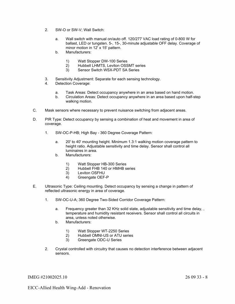
IMEG #21002025.10 26 09 33 - 8
EICC-Allied Health Wing-Add - Renovation
2. SW-O or SW-V; Wall Switch:
a. Wall switch with manual on/auto off. 120/277 VAC load rating of 0-800 W for ballast, LED or tungsten. 5-, 15-, 30-minute adjustable OFF delay. Coverage of minor motion in 12' x 15' pattern.
b. Manufacturers:
1) Watt Stopper DW-100 Series2) Hubbell LHMTS, Leviton OSSMT series3) Sensor Switch WSX-PDT SA Series
3. Sensitivity Adjustment: Separate for each sensing technology.4. Detection Coverage:
a. Task Areas: Detect occupancy anywhere in an area based on hand motion.b. Circulation Areas: Detect occupancy anywhere in an area based upon half-step
walking motion.
C. Mask sensors where necessary to prevent nuisance switching from adjacent areas.
D. PIR Type: Detect occupancy by sensing a combination of heat and movement in area of coverage.
1. SW-OC-P-HB; High Bay - 360 Degree Coverage Pattern:
a. 20' to 40' mounting height. Minimum 1.3:1 walking motion coverage pattern to height ratio. Adjustable sensitivity and time delay. Sensor shall control all luminaires in area.
b. Manufacturers:
1) Watt Stopper HB-300 Series2) Hubbell FHB 140 or HMHB series3) Leviton OSFHU4) Greengate OEF-P
E. Ultrasonic Type: Ceiling mounting. Detect occupancy by sensing a change in pattern of reflected ultrasonic energy in area of coverage.
1. SW-OC-U-A; 360 Degree Two-Sided Corridor Coverage Pattern:
a. Frequency greater than 32 KHz solid state, adjustable sensitivity and time delay, , temperature and humidity resistant receivers. Sensor shall control all circuits in area, unless noted otherwise.
b. Manufacturers:
1) Watt Stopper WT-2250 Series2) Hubbell OMNI-US or ATU series3) Greengate ODC-U Series
2. Crystal controlled with circuitry that causes no detection interference between adjacent sensors.

IMEG #21002025.10 26 09 33 - 9
EICC-Allied Health Wing-Add - Renovation
2.8 AUTOMATIC LOAD CONTROL RELAY (ALCR) (INDIVIDUAL LUMINAIRE - INTEGRAL)
A. This section includes information related to factory and field installed ALCR devices intended for individual luminaires.
B. ALCR3; Automatic Load Control Relay ALCR, 120/277 volt, dry/damp listed, 32°F to 113°F (0°C to 45°C) operating temperature, plenum NEMA 1 rated, test button with visual indicator, remote test and fire alarm control, listed for factory or field installation within luminaire, UL924 listed latest edition, Electrical Code Article 700 compliant.
1. Rating: 3 Amp LED driver, ballast, or incandescent.2. Lighting Control Coordination: Provide ALCR device compatible with designated lighting
zone controls. Example: Switched, 0-10 volt dimming, DALI control, 2 wire dimming, or DMX.
3. Operation:
a. ALCR device shall allow the same local lighting control devices to control both the normal lights and emergency designated lighting. Devices that require separate local lighting controls for the normal and designated emergency lighting are NOT allowed.
b. ALCR device shall monitor the normal power circuit and shunt/bypass the local lighting controls upon loss of power, remote test switch, or fire alarm override to provide full lumen output for designated emergency lighting.
c. ALCR device shall return designated emergency lighting to local lighting control after a 15-minute delay upon return of normal power or remote test/fire alarm override release.
4. Manufacturers:
a. LVS Controls EPC-2-FM (switched)b. EPC-2-D-FM Series (0-10V dimming)c. EPC Series (alternative lighting control)d. Iota ETS-step (switched)e. ETC-DR (0-10V dimming)f. ETC Series (alternative lighting control)g. Lighting control manufacturer
2.9 AUTOMATIC LOAD CONTROL RELAY (ALCR)
A. ALCR20; Automatic Load Control Relay ALCR, 120/277 volt, dry/damp listed, 32°F to 113°F (0°C to 45°C) operating temperature, plenum NEMA 1 rated, test button with visual indicator, remote test and fire alarm control, UL924 listed latest edition, Electrical Code Article 700 compliant.
1. Rating:
a. 20 amp (16 A permitted) LED driver and ballast.b. 10 A (1,200 watt) incandescent.
2. Lighting Control Coordination: Provide ALCR device compatible with designated lighting zone controls. Example: switched, 0-10 volt dimming, DALI control, 2 wire dimming, or DMX.
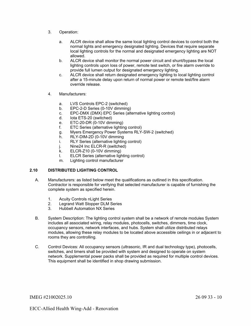
IMEG #21002025.10 26 09 33 - 10
EICC-Allied Health Wing-Add - Renovation
3. Operation:
a. ALCR device shall allow the same local lighting control devices to control both the normal lights and emergency designated lighting. Devices that require separate local lighting controls for the normal and designated emergency lighting are NOT allowed.
b. ALCR device shall monitor the normal power circuit and shunt/bypass the local lighting controls upon loss of power, remote test switch, or fire alarm override to provide full lumen output for designated emergency lighting.
c. ALCR device shall return designated emergency lighting to local lighting control after a 15-minute delay upon return of normal power or remote test/fire alarm override release.
4. Manufacturers:
a. LVS Controls EPC-2 (switched)b. EPC-2-D Series (0-10V dimming)c. EPC-DMX (DMX) EPC Series (alternative lighting control)d. Iota ETS-20 (switched)e. ETC-20-DR (0-10V dimming) f. ETC Series (alternative lighting control)g. Myers Emergency Power Systems RLY-SW-2 (switched)h. RLY-DIM-2D (0-10V dimmingi. RLY Series (alternative lighting control)j. Nine24 Inc ELCR-R (switched)k. ELCR-Z10 (0-10V dimming)l. ELCR Series (alternative lighting control)m. Lighting control manufacturer
2.10 DISTRIBUTED LIGHTING CONTROL
A. Manufacturers: as listed below meet the qualifications as outlined in this specification. Contractor is responsible for verifying that selected manufacturer is capable of furnishing the complete system as specified herein.
1. Acuity Controls nLight Series2. Legrand Watt Stopper DLM Series3. Hubbell Automation NX Series
B. System Description: The lighting control system shall be a network of remote modules System includes all associated wiring, relay modules, photocells, switches, dimmers, time clock, occupancy sensors, network interfaces, and hubs. System shall utilize distributed relays modules, allowing these relay modules to be located above accessible ceilings in or adjacent to rooms they are controlling.
C. Control Devices: All occupancy sensors (ultrasonic, IR and dual technology type), photocells, switches, and timers shall be provided with system and designed to operate on system network. Supplemental power packs shall be provided as required for multiple control devices. This equipment shall be identified in shop drawing submission.
IMEG #21002025.10 26 09 33 - 11
EICC-Allied Health Wing-Add - Renovation
D. Relay Modules: Mounted in NEMA enclosure with physically separate 120/277-volt wiring compartment from low voltage control wiring. Provide low voltage digital communication to control devices as shown on drawings and schedules. Supplemental power packs shall be provided as required for multiple control devices. This equipment shall be identified in shop drawing submission. Dimmable relay modules shall be provided where indicated. Relay modules shall contain up to four (4) relays. Relay modules shall be labeled with room number that relays control lighting within.
E. Single-Pole Relays: Mechanically held unless otherwise indicated; split-coil, momentary-pulsed type, rated 20 A, 125-volt AC for tungsten filaments and 20 A, 277-volt AC for electronic ballasts, 50,000 cycles at rated capacity.
2.11 CONDUCTORS AND CABLES
A. Control Wiring:
1. Where installed with the line-voltage wiring, control wiring shall be copper conductors not smaller than No. 16 AWG with insulation voltage rating and temperature rating equal to that of the line-voltage wiring, complying with Division 26 Section 26 05 13 "Wire and Cable."
2. Tap conductors to switches or relays: Stranded copper conductors of 16 AWG or solid 16 or 18 AWG with insulation rating equal to that of the line-voltage wiring.
3. Tap conductors to dimming ballasts: Solid copper conductors of 18 AWG with insulation voltage rating equal to that of the line-voltage wiring and insulation temperature rating not less than 90°C.
4. Network cabling as required by manufacturer.
B. Splices and Taps:
1. Tapping or wire trap connectors shall be used to splice all Class 1 and Class 2 control wiring. Twist-on, wire-nut type connectors are not allowed.
PART 3 - EXECUTION
3.1 PRE-CONSTRUCTION MEETING
A. Schedule a pre-construction meeting with the controls representative, installing contractor, Architect/Engineer, and Owner to explain the proposed lighting control centralized, wireless, and distributed systems.
3.2 EXAMINATION
A. Verify that surfaces are ready to receive work.
B. Verify field dimensions and coordinate physical size of all equipment with the architectural requirements of the spaces into which they are to be installed. Allow space for adequate ventilation and circulation of air.
C. Verify that required utilities are available, in proper location, and ready for use.
D. Beginning of installation means installer accepts existing conditions.
IMEG #21002025.10 26 09 33 - 12
EICC-Allied Health Wing-Add - Renovation
3.3 INSTALLATION
A. Install in accordance with manufacturer's instructions and approved shop drawings.
B. All wiring shall be installed in conduit. Class II low voltage control wiring may be open wiring and shall maintain 150 mm (6 inch) spacing from electronic ballast and other RFI/EMI sources.
C. All branch load circuits shall be live tested before connecting the loads to the lighting control panel.
3.4 AUTOMATIC LOAD CONTROL RELAYS (ALCR20) AND BRANCH CIRCUIT EMERGENCY LIGHTING TRANSFER SWITCH (BCELTS)
A. Field install per manufacturer requirements.
3.5 SUPPORT SERVICES
A. System Startup:
1. Manufacturer shall provide factory authorized technician to confirm proper installation and operation of all system components.
B. Testing:
1. System shall be completely functional tested by a factory-authorized technician. All loads shall be tested live for continuity and freedom from defects, and all control wiring shall be tested for continuity and connections prior to energizing the system components.
2. Programming of initial zones, schedules, lighting levels, control station groups, and sensor settings shall be performed by a factory-authorized technician. Lighting Control Sequence of Operation shall serve as a basis for programming, However, all final decisions regarding groups and schedules shall be at the direction of the Owner. The following procedures shall be performed at a minimum:
a. Confirm occupancy sensor placement, sensitivity, and time delay settings to meet specified performance criteria.
b. Confirm daylight sensor placement, sensitivity, deadband, and delay settings to meet specified performance criteria.
c. Confirm that schedules and time controls are configured to meet specified performance criteria and Owner's operating requirements.
3. Verify occupancy/vacancy and daylight sensor operation is correct after furniture and equipment is installed in each area. Make adjustments to sensor settings and time delays to allow proper operation.
4. Verify occupancy/vacancy sensors are located to provide complete coverage for the area served with no nuisance switching.
a. Relocate sensors or provide additional sensors as necessary to provide adequate coverage.
b. Mask occupancy sensors where necessary to prevent nuisance switching from adjacent areas.
IMEG #21002025.10 26 09 33 - 13
EICC-Allied Health Wing-Add - Renovation
C. Training:
1. Manufacturer shall provide competent factory-authorized technician to train Owner personnel in the operation, maintenance and programming of the lighting control system. Submit training plan with notification seven (7) days prior to proposed training dates.
2. Training duration shall be no less than three (3) days, with one (1) day being scheduled at least two (2) weeks after initial training.
D. Documentation:
1. Manufacturer shall provide system documentation including:
a. System one-line showing all panels, number and type of control stations and sensors, communication line, and network or BMS/BAS interface unit.
b. Drawings for each panel showing hardware configuration and numbering.c. Panel wiring schedules.d. Typical diagrams for each component.
END OF SECTION 26 09 33

IMEG #21002025.10 26 22 00 - 1
EICC-Allied Health Wing-Add - Renovation
SECTION 26 22 00 - DRY TYPE TRANSFORMERS
PART 1 - GENERAL
1.1 SECTION INCLUDES
A. Dry type two winding transformers (TR-#)
1.2 REFERENCES
A. NEMA - ST 1 - Specialty Transformers
B. NEMA ST 20 - Dry Type Transformers for General Applications
C. ANSI/IEEE C57.12.01 - General Requirements for Dry Type Distribution and Power Transformers
D. ANSI/IEEE C57.12.91 - Test Code for Dry Type Distribution and Power Transformers
E. Department of Energy 10 CFR Part 431 - Energy Conservation Program for Commercial Equipment: Distribution Transformers Energy Conservation Standards; Final Rule.
F. NEMA TP 2 - Standard Test Method for Measuring the Energy Consumption of Distribution Transformers
G. NEMA TP 3 - Standard for the Labeling of Distribution Transformer Efficiency
1.3 SUBMITTALS
A. Submit product data under provisions of Section 26 05 00.
B. Include outline and support point dimensions of enclosures and accessories, unit weight, voltage, KVA, and impedance ratings and characteristics, loss data, efficiency at 35, 50, 75 and 100 percent rated load, sound level, tap configurations, insulation system type, and rated temperature rise.
1.4 DELIVERY, STORAGE, AND HANDLING
A. Store and protect products under provisions of Section 26 05 00.
B. Store in a warm, dry location with uniform temperature. Cover ventilating openings to keep out dust.
C. Handle transformers using only lifting eyes and brackets provided for that purpose. Protect units against entrance of rain, sleet, or snow if handled in inclement weather.
IMEG #21002025.10 26 22 00 - 2
EICC-Allied Health Wing-Add - Renovation
PART 2 - PRODUCTS
2.1 DRY TYPE TWO WINDING TRANSFORMERS
A. Acceptable Manufacturers:
1. Square D 7400 EX##T / SK300##KB Series2. Eaton V48M / H48M / B48M Series3. ABB 9T Series4. Hammond SG / SMK Series5. Siemens 3F3 Series
B. Dry Type Transformers: NEMA ST 20, factory-assembled, air-cooled dry type transformers; ratings as shown on the drawings. Transformers supplied under this project shall meet the US Department of Energy (DOE) 2016 Efficiency requirements or the most current DOE CFR in effect.
C. Insulation system and average winding temperature rise for rated KVA as follows:
Ratings Class Rise (degree C)
Less than 15 185 As shown on the drawingsor higher 220 As shown on the drawings
D. Case temperature shall not exceed 40°C rise above ambient at its warmest point.
E. Winding Taps, Transformers Less than 15 KVA: Two 5 percent below rated voltage, full capacity taps on primary winding.
F. Winding Taps, Transformers 15 KVA and Larger: Two (2) 2-1/2% below and two (2) 2-1/2% above rated voltage, full capacity taps on primary winding.
G. Sound Levels: Average audible sound level shall not exceed the values given below when tested to NEMA ST 20 standards:
Average Sound Level, Decibels
Self-Cooled Ventilated Self-Cooled Sealed
Equivalent Winding kVA Range
K-Factor = 1K-Factor = 4K-Factor = 9
K-Factor = 13K-Factor = 20
Forced Air w/ Fans Running
0-9 40 40 67 459.01-30.00 45 45 67 5030.01-50.00 45 48 67 5050.01-150.00 50 53 67 55150.01-300.00 55 58 67 57300.01-500.00 60 63 67 59500.01-700.00 62 65 67 61700.00-1000.00 64 67 67 63
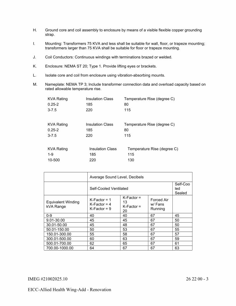
IMEG #21002025.10 26 22 00 - 3
EICC-Allied Health Wing-Add - Renovation
H. Ground core and coil assembly to enclosure by means of a visible flexible copper grounding strap.
I. Mounting: Transformers 75 KVA and less shall be suitable for wall, floor, or trapeze mounting; transformers larger than 75 KVA shall be suitable for floor or trapeze mounting.
J. Coil Conductors: Continuous windings with terminations brazed or welded.
K. Enclosure: NEMA ST 20; Type 1. Provide lifting eyes or brackets.
L. Isolate core and coil from enclosure using vibration-absorbing mounts.
M. Nameplate: NEMA TP 3; Include transformer connection data and overload capacity based on rated allowable temperature rise.
KVA Rating Insulation Class Temperature Rise (degree C)0.25-2 185 803-7.5 220 115
KVA Rating Insulation Class Temperature Rise (degree C)0.25-2 185 803-7.5 220 115
KVA Rating Insulation Class Temperature Rise (degree C)1-9 185 11510-500 220 130
Average Sound Level, Decibels
Self-Cooled VentilatedSelf-Cooled Sealed
Equivalent Winding kVA Range
K-Factor = 1K-Factor = 4K-Factor = 9
K-Factor = 13K-Factor = 20
Forced Air w/ Fans Running
0-9 40 40 67 459.01-30.00 45 45 67 5030.01-50.00 45 48 67 5050.01-150.00 50 53 67 55150.01-300.00 55 58 67 57300.01-500.00 60 63 67 59500.01-700.00 62 65 67 61700.00-1000.00 64 67 67 63

IMEG #21002025.10 26 22 00 - 4
EICC-Allied Health Wing-Add - Renovation
2.2 ACCESSORIES
A. Electronic Isolation Shield:
1. Provide electrostatic winding shield with separate insulated grounding connection as shown on the drawings.
PART 3 - EXECUTION
3.1 INSTALLATION
A. Set transformer plumb and level.
B. Use flexible conduit, 2 feet minimum length, for connections to transformer case. Make conduit connections to side panel of enclosure.
C. Mount transformers on four 3”x3”x1/2” thick, 50 durometer rubber vibration isolating pads suitable for isolating the transformer noise from the building structure.
D. Ventilated transformers: Provide factory label on horizontal surface to prohibit storage on top, front, or adjacent to transformer.
3.2 FIELD QUALITY CONTROL
A. Check for damage and tight connections prior to energizing transformer.
B. Measure primary and secondary voltages and make appropriate tap adjustments. Adjustments shall be made at completion of project and at approximately 6 months following project acceptance when requested by the Owner.
END OF SECTION 26 22 00
IMEG #21002025.10 26 24 16 - 1
EICC-Allied Health Wing-Add - Renovation
SECTION 26 24 16 - PANELBOARDS
PART 1 - GENERAL
1.1 SECTION INCLUDES
A. Lighting and appliance branch circuit panelboards: Panel '###'
1.2 RELATED SECTIONS AND WORK
A. Refer to the Electrical Distribution Diagram and Electrical Schedules for size, rating, and configuration.
1.3 REFERENCES
A. NEMA AB 1 - Molded Case Circuit Breakers
B. NEMA PB 1 - Panelboards
C. NEMA PB 1.1 - Instructions for Safe Installation, Operation and Maintenance of Panelboards Rated 600 Volts or Less
D. NEMA PB 1.2 - Application Guide for Ground-fault Protective Devices for Equipment
E. UL 67 - Panelboards
1.4 SUBMITTALS
A. Submit shop drawings for equipment and component devices under provisions of Section 26 05 00.
B. Include outline and support point dimensions, voltage, main bus ampacity, integrated short circuit ampere rating, circuit breaker and fusible switch arrangement and sizes.
C. Submit manufacturer's instructions under provisions of Section 26 05 00.
1.5 SPARE PARTS
A. Keys: Furnish four (4) each to the Owner.
B. Fuses: Furnish 10% or a minimum of three (3) spare fuses of each type and rating installed to the Owner.
C. Fuse Pullers: Furnish one (1) fuse puller to the Owner.
IMEG #21002025.10 26 24 16 - 2
EICC-Allied Health Wing-Add - Renovation
PART 2 - PRODUCTS
2.1 RATINGS
A. Definitions:
1. Series rated equipment shall be defined as equipment that can achieve a required UL AIC rating with an upstream device such as a main breaker or a combination of devices to meet or exceed a required UL AIC rating. All series rated equipment shall have a permanently attached nameplate indicating that device rating must be maintained. See Section 26 05 53 for additional requirements.
2. Fully rated equipment shall be defined as equipment where all devices in that equipment shall carry a minimum of the AIC rating that is specified.
B. The panelboards for this project shall be fully rated unless otherwise specifically noted in the Drawings or Specifications.
2.2 BRANCH CIRCUIT PANELBOARDS
A. General
1. Manufacturers:
a. Square D NQ, NFb. ABB A Seriesc. Siemens P1d. Eaton PRL1, PRL2
B. Lighting and Appliance Branch Circuit Panelboards: NEMA PB 1; circuit breaker type.
C. Enclosure: NEMA PB 1; Type 1.
D. Provide cabinet front with door-in-door construction, concealed hinge, and flush lock all keyed alike. Door hardware shall provide swing clear operation (180-degree swing). Finish in manufacturer's standard gray enamel.
E. Provide panelboards with copperbus, ratings as scheduled on the drawings. Provide copper ground bus in all panelboards.
F. All unlabeled circuits shown on the panelboard schedule shall be fully prepared spaces for future breakers.
G. All multiple-section panelboards shall have the same dimensional back box and cabinet front size.
H. Minimum Integrated Short Circuit Rating: As shown on the drawings.
I. Provide handle lock-on devices for all breakers serving exit sign and lighting circuits with emergency battery units. Provide handle lock-on devices and red handles for breakers serving fire alarm panels.
IMEG #21002025.10 26 24 16 - 3
EICC-Allied Health Wing-Add - Renovation
J. Molded Case Circuit Breakers: Bolt-on type thermal magnetic trip circuit breakers, with common trip handle for all poles. Provide circuit breakers UL listed as Type SWD for lighting circuits. Provide UL Class A ground fault interrupter circuit breakers where scheduled on the drawings. Do not use tandem circuit breakers.
2.3 (DPM) DIGITAL AC POWER MONITOR:
A. Capable of measuring, calculating and directly displaying; Volts (L-L, L-N), Amps, KW, KWH. Monitor shall be true RMS measurement with programmable set-up parameters. All setup parameters data shall be stored in non-volatile memory to protect from power outages.
PART 3 - EXECUTION
3.1 INSTALLATION
A. Height: 6 feet to handle of highest device.
B. Provide filler plates for unused spaces in panelboards.
C. Provide custom typed circuit directory for each branch circuit panelboard. Provide updated custom typed circuit directory for each existing branch circuit panelboard with new or revised circuits per the scope of work. Label shall include equipment name or final approved room name, room number, and load type for each circuit (examples: SUMP SP-1 or ROOM 101 RECEPT). Revise directory to reflect circuit changes required to balance phase loads. Printed copies of the bid document panel schedules are not acceptable as circuit directories.
D. Stub five (5) empty one-inch conduits to accessible location above ceiling out of each recessed panelboard.
3.2 FIELD QUALITY CONTROL
A. Measure steady state load currents at each panelboard feeder. Should the difference at any panelboard between phases exceed 20 percent, rearrange circuits in the panelboard to balance the phase loads within 20 percent. Take care to maintain proper phasing for multi-wire branch circuits.
B. Visual and Mechanical Inspection: Inspect for physical damage, proper alignment, anchorage, and grounding. Check proper installation and tightness of connections for circuit breakers, fusible switches, and fuses.
END OF SECTION 26 24 16

IMEG #21002025.10 26 24 19 - 1
EICC-Allied Health Wing-Add - Renovation
SECTION 26 24 19 - MOTOR CONTROL
PART 1 - GENERAL
1.1 SECTION INCLUDES
A. Manual motor starters
B. Magnetic motor starters
1.2 RELATED SECTIONS AND WORK
A. Refer to the Disconnect and Starter Schedule and One-Line Diagram for rating and configuration.
1.3 REFERENCES
A. ANSI/UL Standard 508. Standard for Industrial Control Equipment
B. FCC Rules and Regulations, Part 15, Subpart J- Radio Frequency Interference
C. FS W-S-865 - Switch, Box, (Enclosed), Surface-Mounted
D. IEEE Standard 519-1981 - Guide for Harmonic Control and Reactive Compensation of Static Power Converters
E. NEMA ICS 2 - Industrial Control Devices, Controllers, and Assemblies
F. NEMA ICS 6 - Enclosures for Industrial Controls and Systems
G. NEMA KS 1 - Enclosed Switches
1.4 SUBMITTALS
A. Submit shop drawings and product data under provisions of Section 26 05 00.
B. Indicate on shop drawings, front and side views of motor control center enclosures with overall dimensions. Include conduit entrance locations and requirements; wiring diagrams that differentiate between manufacturer-installed and field-installed wiring; nameplate legends; size and number of bus bars per phase, neutral, and ground; electrical characteristics including voltage, frame size and trip ratings, withstand ratings, and time-current curves of all equipment and components.
C. Provide product data on motor starters and combination motor starters, relays, pilot devices, and switching and over-current protective devices.
D. Submit manufacturer's instructions under provisions of Section 26 05 00.
1.5 DELIVERY, STORAGE, AND HANDLING
A. Deliver products to site under provisions of Section 26 05 00.
IMEG #21002025.10 26 24 19 - 2
EICC-Allied Health Wing-Add - Renovation
B. Deliver in 60-inch maximum width shipping splits, individually wrapped for protection, and mounted on shipping skids.
C. Store and protect products under provisions of Section 26 05 00.
D. Store in a clean, dry space. Maintain factory wrapping or provide an additional heavy canvas or heavy plastic cover to protect units from fumes, dirt, water, construction debris, traffic, and physical damage.
E. Handle in accordance with manufacturer's written instructions. Lift only with lugs provided for the purpose. Handle carefully to avoid damage to motor control center components, enclosure, and finish.
1.6 OPERATION AND MAINTENANCE DATA
A. Submit operation and maintenance data under provisions of Section 26 05 00.
B. Include spare parts data listing; source and current prices of replacement parts and supplies; and recommended maintenance procedures and intervals.
PART 2 - PRODUCTS
2.1 MANUAL MOTOR STARTERS
A. Acceptable Manufacturers:
1. Square D 2500 Series2. Eaton MS Series3. ABB4. Siemens SMF / MMS Series
B. Manual Motor Starter: NEMA ICS 2; AC general-purpose Class A manually operated non-reversing full-voltage controller for induction motors rated in horsepower, with overload relay, and toggle operator.
C. Fractional Horsepower Manual Starter: NEMA ICS 2; AC general-purpose Class A manually operated, full-voltage controller for fractional horsepower induction motors, with thermal overload unit, and toggle operator.
D. Motor Starting Switch: NEMA ICS 2; AC general-purpose Class A manually operated, full-voltage controller for fractional horsepower induction motors, without thermal overload unit, and toggle operator.
E. Enclosure: NEMA ICS 6; Type 1.
2.2 MAGNETIC MOTOR STARTERS
A. Acceptable Manufacturers:
1. Square D2. Eaton3. ABB

IMEG #21002025.10 26 24 19 - 3
EICC-Allied Health Wing-Add - Renovation
4. Siemens5. Franklin Control
B. Magnetic Motor Starters: NEMA ICS 2; AC general-purpose Class A magnetic controller for induction motors rated in horsepower.
C. Full Voltage Starting: Non-reversing type, unless otherwise indicated.
D. Reduced Voltage Starting: Closed-circuit transition wye-delta type: NEMA ICS 2, closed transition with adjustable time delay.
E. Coil Operating Voltage: 120 volts, 60 Hertz, obtained from integral control power transformer of sufficient capacity to operate connected pilot, indicating, and control devices, plus 100% spare capacity.
F. Size: NEMA ICS 2; size as shown on the drawings.
G. Overload Relay:
1. Adjustable Overload Relay: Dip switch selectable for motor running overload protection with NEMA ICS 2, Class 20 tripping characteristic, and selected to protect motor against voltage and current unbalance and single phasing. Provide relay with Class II ground-fault protection, with start and run delays to prevent nuisance trip on starting.
H. Enclosure: NEMA ICS 6; Type 1.
I. Combination Motor Starters: Combine motor starters with disconnect switch in common enclosure. Provide with disconnecting means as indicated on drawings.
J. Auxiliary Contacts: NEMA ICS 2; two normally open, field convertible contacts in addition to seal-in contact.
K. Pushbuttons: NEMA ICS 2; START/STOP in front cover.
L. Indicating Lights: NEMA ICS 2; RUN: red in front cover.
M. Selector Switches: NEMA ICS 2; HAND/OFF/AUTO, in front cover.
N. Relays: NEMA ICS 2; .
O. Control Power Transformers: 120 volt fused secondary, fused primary, minimum VA as scheduled:
1. Size 1 - 100 VA2. Size 2 - 100 VA3. Size 3 - 150 VA4. Size 4 - 300 VA5. Size 5 - 300 VA6. Size 6 - 300 VA
P. Provide phase loss protection relay with contacts to de-energize the starter for each starter serving motors 5 HP or greater.
IMEG #21002025.10 26 24 19 - 4
EICC-Allied Health Wing-Add - Renovation
PART 3 - EXECUTION
3.1 INSTALLATION
A. Install motor control equipment in accordance with manufacturer's instructions on concrete bases.
B. Select and install heater elements in motor starters to match installed motor characteristics.
C. Set field-adjustable switches and circuit-breaker trip ranges.
D. Motor Data: Provide neatly typed label inside each motor starter enclosure door identifying motor served, nameplate horsepower, full load amperes, code letter, service factor, and voltage/phase rating.
E. Coordinate size and location of concrete bases. Cast anchor-bolt inserts into bases.
END OF SECTION 26 24 19
IMEG #21002025.10 26 27 26 - 1
EICC-Allied Health Wing-Add - Renovation
SECTION 26 27 26 - WIRING DEVICES
PART 1 - GENERAL
1.1 SECTION INCLUDES
A. Device plates and box covers
B. Modular connectors
C. Receptacles
D. Floor boxes (FB-#)
1.2 QUALITY ASSURANCE
A. Provide similar devices from a single manufacturer.
B. Electrical Components, Devices, and Accessories: Listed and labeled as defined in the Electrical Code, by a testing agency to Authorities Having Jurisdiction and marked for intended use.
C. Comply with the Electrical Code.
1.3 REFERENCES
A. DSCC W-C-896F - General Specification for Electrical Power Connector
B. FS W-C-596 - Electrical Power Connector, Plug, Receptacle, and Cable Outlet
C. NEMA WD 1 - General Color Requirements for Wiring Devices
D. NEMA WD 6 - Wiring Devices - Dimensional Requirements
E. NFPA 70 - National Electrical Code (NEC)
F. UL 498 - Standard for Attachment Plugs and Receptacles
G. UL 943 - Standard for Ground Fault Circuit Interrupters
1.4 SUBMITTALS
A. Submit product data under provisions of Section 26 05 00.
B. Provide product data showing configurations, finishes, dimensions, and manufacturer's instructions.
1.5 COORDINATION
A. Receptacles for Owner Furnished Equipment: Match plug configurations.
IMEG #21002025.10 26 27 26 - 2
EICC-Allied Health Wing-Add - Renovation
B. Cord and Plug Sets: Match equipment requirements.
C. Coordinate installation of receptacle assemblies in and furniture with the Contractor providing the or furniture. Contractor shall coordinate penetrations and conduit routing in and furniture with drawings and other obstacles below the installation surface.
PART 2 - PRODUCTS
2.1 DEVICE COLOR
A. All switch, receptacle, and outlet colors shall be ivory, unless indicated otherwise.
2.2 COVERPLATES
A. All switches, receptacles, and outlets shall be complete with the following:
1. #302 stainless steel coverplates in finished spaces where walls are finished.2. #302 stainless steel coverplates in unfinished spaces for flush boxes.3. Galvanized steel coverplates in unfinished spaces for surface mounted boxes.
B. Where several devices are ganged together, the coverplate shall be of the ganged style for the number of devices used.
C. Install nameplate identification as indicated in Section 26 05 53.
D. Plate securing screws shall be metal with head color matching the wall plate finish.
2.3 MODULAR CONNECTORS
A. Devices listed below are traditional wired devices. Contractor option to provide equivalent modular connector-type devices (Hubbell Snap Connect, Pass & Seymour Plug Tail, Leviton Lev-Lock, Copper ArrowLink) where applicable.
2.4 RECEPTACLES
A. Refer to Electrical Symbols List for device type.
B. REC-DUP: NEMA 5-20R Duplex Receptacle:
1. Spec Grade: 125-volt, 20 amp, 3-wire grounding type with impact resistant thermoplastic face and brass back strap.
a. Manufacturers:
1) Hubbell 53522) Leviton 5362-S3) Pass & Seymour 53624) Cooper 5362
IMEG #21002025.10 26 27 26 - 3
EICC-Allied Health Wing-Add - Renovation
C. REC-DUP-GFI: NEMA 5-20R Ground Fault Duplex Receptacle:
1. Standard Grade: 125-volt, 20 amp, 3-wire grounding type with test and reset buttons in impact resistant thermoplastic face.
a. Device shall perform self-test of GFCI circuitry in accordance with UL 943.b. Manufacturers:
1) Hubbell GF20L2) Leviton GFNT23) Pass & Seymour 20974) Cooper SGF20
D. REC-DUP-WP: NEMA 5-20R Weatherproof Ground Fault Duplex Receptacle:
1. 125-volt, 20 amp, 3-wire grounding type with test and reset buttons in impact resistant thermoplastic face, weather resistant WR listed. Provide extra-duty NEMA 3R rated while-in-use clear cover.
2. Device shall perform self-test of GFCI circuitry in accordance with UL 943.
a. Manufacturers:
1) Hubbell GFTWRST20 with clear housing RW573002) Leviton GFWT2 with clear housing 5977-CL3) Pass & Seymour 2097TRWR with clear housing WIUC10-C4) Cooper WRSGF20 with clear housing WIU-1
E. REC-SUR: NEMA 5-20R Surge Suppression Duplex Receptacle:
1. Standard Grade: 125-volt, 20 amp, 3-wire grounding type with orange impact resistance thermoplastic face, light, and alarm.
a. Manufacturers:
1) Hubbell IG5362OSA 2) Leviton 5380-IG3) Pass & Seymour IG5362-OSP4) Cooper IG5362RNS
F. REC-USB: NEMA 5-20R Receptacle with USB Charger:
1. Standard Grade Type A USB: 125-volt, 20-amp, tamper resistant, 3-wire grounding type with impact resistant thermoplastic face. Type A USB charging rated at 5VDC 3.0A minimum. Mounted in double gang backbox.
a. Manufacturers:
1) Hubbell USB20X22) Pass & Seymour TR5362USB3) Cooper TR7766
IMEG #21002025.10 26 27 26 - 4
EICC-Allied Health Wing-Add - Renovation
G. REC-SIM-520R: NEMA 5-20R Simplex Receptacle:
1. 125-volt, 20 amp, 3-wire grounding type with impact resistant thermoplastic face.
a. Manufacturers:
1) Hubbell HBL53612) Leviton 53613) Pass & Seymour 53614) Cooper 5361
H. REC-SIM-1430R: NEMA 14-30R Simplex Receptacle:
1. 125/250-volt, 30 amp, 3-pole, 4-wire grounding type with thermoplastic face. Flush mounted at +24 AFF.
a. Manufacturers:
1) Hubbell HBL9430A2) Leviton 2783) Pass & Seymour 38644) Cooper 5744N
I. REC-QUAD: NEMA 5-20R Double Duplex Receptacle:
1. Consists of two duplex receptacles, double gang box, plaster ring and faceplate.
a. Manufacturers:
1) Refer to Duplex Receptacle above.
J. REC-QUAD-GFI: NEMA 5-20R Double Duplex GFI Receptacle:
1. Consists of two duplex GFI receptacles, double gang box, plaster ring and faceplate.
a. Manufacturers:
1) Refer to Duplex GFI Receptacle above.
K. Back wired devices shall be complete with eight holes that are screw activated with metal clamps for connection to #12 or #10 copper conductors.
L. Side wired devices shall have four binding screws that are undercut for positive wire retention.
M. Ground fault circuit interrupter (GFCI) receptacles shall comply with UL 943 requiring increased surge immunity, improved corrosion resistance, improved resistance to false tripping and diagnostic indication for miswiring if the line and load conductors are reversed during installation.
N. Integral surge suppression receptacles with integral surge suppression shall comply with the following:
1. Category A3 listed.

IMEG #21002025.10 26 27 26 - 5
EICC-Allied Health Wing-Add - Renovation
2. Line to ground, line to neutral, and neutral to ground modes.3. Metal-oxide varistors with a nominal clamp level rating of 500 volts and minimum single
transient pulse energy dissipation of 210 joules per mode.4. Status indication: Light visible in the face of the device and audible alarm to indicate
device is no longer active or in service.5. Distinctive symbol on device face to denote SPD-type device.6. Device shall be blue with stainless coverplate.7. NEMA 5-20R duplex receptacle, 125-volt, 20 amp, 3-wire grounding type heavy duty
industrial grade with impact resistant thermoplastic face and one-piece brass back strap.
a. Manufacturers:
1) Hubbell HBL5362SA2) Leviton3) Pass & Seymour4) Cooper
2.5 FLOOR BOXES
A. Cover Color and Style: Verify with Architect from manufacturer standard options.
B. Refer to Technology drawings for voice/data, Audio/Video outlet, and coordination requirements.
C. Floor Boxes Housing Material Based on Cast-in-Place Floor Type:
1. Slab on Grade: Cast Iron or listed for slab on grade with special kit, coating ,or equivalent; corrosion resistant.
D. FB-4: Concealed Center Compartment:
1. Floor Box, flush-mounted hinged cover, square/rectangular center service area with closed while-in-use cover and cable egress doors in cover, provide complete with appropriate outlet cover plates and hardware. For use with 4-inch minimum concrete pour floors, fully adjustable, UL 514 scrub water listed.
2. Gang / Outlet Descriptions:
a. 125 Volt, 20 amp, NEMA 5-20R duplex receptacle with 3/4-inch conduit.b. Spare with 1-1/4-inch conduit
3. Manufacturers:
a. Hubbell CFB Seriesb. Legrand Wiremold RFB Seriesc. ABB Steel City 664/665/667 Series
4. Installation: Group route raceway conduits under slab on grade or in ceiling space below to nearest wall or as shown on plans. Provide provisions to core drill elevated floors and route conduits to ceiling space of associated floor box. Provide hub reducers when applicable.
IMEG #21002025.10 26 27 26 - 6
EICC-Allied Health Wing-Add - Renovation
E. FB-1: Concealed Center Compartment:
1. Floor Box, flush-mounted hinged cover, square/rectangular center service area with closed while-in-use cover and cable egress doors in cover, provide complete with appropriate outlet cover plates and hardware. For use with 4-inch minimum concrete pour floors, fully adjustable, UL 514 scrub water listed.
2. Gang / Outlet Descriptions:
a. Two (2) 125 Volt, 20 amp, NEMA 5-20R duplex receptacle with 3/4-inch conduit.b. Voice/Data outlet with 1-1/4-inch conduit. Refer to Technology drawings for
additional information.
3. Manufacturers:
a. Hubbell CFB Seriesb. Legrand Wiremold RFB Seriesc. ABB Steel City 664/665/667 Series
4. Installation: Group route raceway conduits under slab on grade or in ceiling space below to nearest wall or as shown on plans. Provide provisions to core drill elevated floors and route conduits to ceiling space of associated floor box. Provide hub reducers when applicable.
F. FB-2: Concealed Center Compartment:
1. Floor Box, flush-mounted hinged cover, square/rectangular center service area with closed while-in-use cover and cable egress doors in cover, provide complete with appropriate outlet cover plates and hardware. For use with 4-inch minimum concrete pour floors, fully adjustable, UL 514 scrub water listed.
2. Gang / Outlet Descriptions:
a. 125 Volt, 20 amp, NEMA 5-20R duplex receptacle with 3/4-inch conduit.b. Data outlet with 1-1/4-inch conduit. Refer to Technology drawings for additional
information.
3. Manufacturers:
a. Hubbell CFB Seriesb. Legrand Wiremold RFB Seriesc. ABB Steel City 664/665/667 Series
4. Installation: Group route raceway conduits under slab on grade or in ceiling space below to nearest wall or as shown on plans. Provide provisions to core drill elevated floors and route conduits to ceiling space of associated floor box. Provide hub reducers when applicable.
G. FB-3: Concealed Center Compartment:
1. Floor Box, flush-mounted hinged cover, square/rectangular center service area with closed while-in-use cover and cable egress doors in cover, provide complete with appropriate outlet cover plates and hardware. For use with 4-inch minimum concrete pour floors, fully adjustable, UL 514 scrub water listed.
IMEG #21002025.10 26 27 26 - 7
EICC-Allied Health Wing-Add - Renovation
2. Gang / Outlet Descriptions:
a. Two (2) 125 Volt, 20 amp, NEMA 5-20R duplex receptacle with 3/4-inch conduit.b. Data outlet with 1-1/4-inch conduit. Refer to Technology drawings for additional
information.
3. Manufacturers:
a. Hubbell CFB Seriesb. Legrand Wiremold RFB Seriesc. ABB Steel City 664/665/667 Series
4. Installation: Group route raceway conduits under slab on grade or in ceiling space below to nearest wall or as shown on plans. Provide provisions to core drill elevated floors and route conduits to ceiling space of associated floor box. Provide hub reducers when applicable.
PART 3 - EXECUTION
3.1 INSTALLATION
A. Install convenience receptacles at elevations indicated in the General Installation Notes on the contract drawings.
B. Install specific-use receptacles at heights shown on the contract drawings. Install devices level, plumb, and square with building lines. Coordinate installation of adjacent devices of separate systems with common mounting heights, including lighting, power, systems, technology, and temperature control device rough-ins.
C. Ground Fault Protection: Provide ground fault protection for all branch circuit breakers serving 120/208 receptacle outlets rated 21 - 50 amps single phase and 21-100 amps three phase in the following locations, as shown on drawings, or required by adopted code:
1. Bathrooms, locker rooms, shower rooms2. Kitchens3. Rooftops4. Interior/Exterior locations subject to damp/wet conditions5. When located within 6 feet of sinks, bathtubs, and shower stalls
D. Install receptacles vertically with ground slot up or where indicated on the drawings, horizontally with ground slot to the left.
E. Install decorative plates on switch, receptacle, and blank outlets in finished areas, using jumbo size plates for outlets installed in masonry walls.
F. Install galvanized steel plates on outlet boxes and junction boxes in unfinished areas, above accessible ceilings, and on surface-mounted outlets.
G. Install devices and wall plates flush and level.

IMEG #21002025.10 26 27 26 - 8
EICC-Allied Health Wing-Add - Renovation
H. Install nameplate identification to receptacle cover plates indicated. Identification shall identify panel name and circuit number. Refer to Specification Section 26 05 53 - Electrical Identification.
I. Test receptacles for proper polarity, ground continuity and compliance with requirements.
J. Floor Box Installation:
1. Set boxes level and flush with finish flooring material.2. Use cast iron floor boxes for installations in slab on grade. Trim shall match floor covering
to be used.3. Provide a minimum horizontal offset of 24 inches between boxes.4. Provide saw-cutting and patching of existing concrete floors as necessary for floor box
installations within existing floors.
END OF SECTION 26 27 26

IMEG #21002025.10 26 28 13 - 1
EICC-Allied Health Wing-Add - Renovation
SECTION 26 28 13 - FUSES
PART 1 - GENERAL
1.1 SECTION INCLUDES
A. Fuses
B. Spare Fuse Cabinet
1.2 REFERENCES
A. UL 198C - High-Interrupting Capacity Fuses; Current Limiting Types
B. UL 198E - Class R Fuses
C. FS W-F-870 - Fuseholders (For Plug and Enclosed Cartridge Fuses)
D. NEMA FU 1 - Low Voltage Cartridge Fuses
E. NFPA 70 - National Electrical Code (NEC)
1.3 SUBMITTALS
A. Submit product data under provisions of Section 26 05 00.
1.4 EXTRA MATERIALS
A. Provide two fuse pullers.
B. Provide three of each size and type of fuse installed.
1.5 PROJECT CONDITIONS
A. Where ambient temperature to which fuses are directly exposed is less than 40°F or more than 100°F, apply manufacturer's ambient temperature adjustment factors to fuse ratings.
PART 2 - PRODUCTS
2.1 MANUFACTURERS - FUSES
A. Bussman, Division of Eaton
B. Edison Fuse, Division of Cooper Industries
C. Mersen
D. Littelfuse Inc
IMEG #21002025.10 26 28 13 - 2
EICC-Allied Health Wing-Add - Renovation
2.2 FUSES
A. Dimensions and Performance: NEMA FU 1, Class as specified or indicated.
B. Voltage: Provide fuses with voltage rating suitable for circuit phase-to-phase voltage.
C. Fuses with ratings larger than 600 amperes: Class L (time delay), unless otherwise noted on the drawings.
D. Fuses with ratings larger than 200 amperes but equal to or less than 600 amperes: Class RK-1 (time delay), unless otherwise noted on the drawings.
E. Fuses with ratings less than or equal to 200 amperes (not including control transformer fuses): Class RK-5, unless otherwise noted on the drawings.
F. Control transformer fuses: Class CC (time delay).
G. Fuses for packaged equipment: Size and type as recommended by equipment manufacturer.
2.3 SPARE FUSE CABINET
A. Cabinet: Wall-mounted, 0.05-inch- thick steel unit with full-length, recessed piano-hinged door and key-coded cam lock and pull.
1. Size: Adequate for storage of spare fuses specified with 15 percent spare capacity minimum.
2. Finish: Gray, baked enamel.3. Identification: "SPARE FUSES" in 1-1/2-inch- high letters on exterior of door.4. Fuse Pullers: For each size of fuse.
PART 3 - EXECUTION
3.1 INSTALLATION
A. Install fuses where indicated on the drawings and specifications.
B. Install fuses in accordance with manufacturer's instruction.
C. Install fuses in packaged equipment as required by equipment manufacturer.
D. Install fuse with label oriented such that manufacturer, type, and size are easily read.
E. Install spare fuse cabinet in the Main Electrical Room.
END OF SECTION 26 28 13
IMEG #21002025.10 26 28 16 - 1
EICC-Allied Health Wing-Add - Renovation
SECTION 26 28 16 - DISCONNECT SWITCHES
PART 1 - GENERAL
1.1 SECTION INCLUDES
A. Fusible switches
B. Non-fusible switches
C. Elevator Service Disconnect Switch
1.2 RELATED SECTIONS AND WORK
A. Refer to the Disconnect and Starter Schedule for rating and configuration.
1.3 REFERENCES
A. NEMA KS 1 - Enclosed Switches
1.4 SUBMITTALS
A. Submit product data under provisions of Section 26 05 00.
B. Product Data: For each type of enclosed switch, circuit breakers, accessory and component indicated, include dimensions, weights, and manufacturer's technical data on features, performance, and ratings.
C. Electrical Characteristics: For each type of enclosed switch, enclosure types, current and voltage ratings, short-circuit current ratings, UL listing for series rating of installed devices, features, characteristics, ratings, and factory settings of individual overcurrent protective devices and auxiliary components.
1.5 COORDINATION
A. Coordinate layout and installation of switches, circuit breakers, and components with other construction, including conduit, piping, equipment, and adjacent surfaces. Maintain required workspace clearances and required clearances for equipment access doors and panels.
PART 2 - PRODUCTS
2.1 FUSIBLE AND NON-FUSIBLE SWITCHES
A. Acceptable Manufacturers:
1. Square D 3110 Series2. Eaton DH Series3. ABB TH Series4. Siemens HNF / HF Series
IMEG #21002025.10 26 28 16 - 2
EICC-Allied Health Wing-Add - Renovation
B. FDS-#; Fusible Switch Assemblies: NEMA KS 1; Type heavy duty, quick-make, quick-break, load interrupter enclosed knife switch with externally operable handle interlocked to prevent opening front cover with switch in ON position. Handle lockable in OFF position. Fuse Clips: Class 'R' fuse clips only, unless indicated otherwise on the drawings.
C. DS-#; Non-fusible Switch Assemblies: NEMA KS 1; Type heavy duty, quick-make, quick-break, load interrupter enclosed knife switch with externally operable handle interlocked to prevent opening front cover with switch in ON position. Handle lockable in OFF position.
D. Enclosures: Type as indicated on the disconnect schedule.
E. Accessories: As indicated on the disconnect schedule.
2.2 ELEVATOR SERVICE DISCONNECT SWITCH
A. Acceptable Manufacturers:
1. Eaton Bussmann PS Series2. Mersen ES Series 3. Littlefuse LPS Series
B. Elevator Service Disconnect Switch, three phase fused switch with lockable handle, ratings per drawing schedule, 120 volt shut trip, two field convertible mechanically interlocked form C auxiliary contacts, shunt trip voltage monitor relay, integral control transformer, Pilot Light "on", neutral bar/lug, NEMA 1 enclosure, minimum 100K SCCR, UL Listed.
C. Provide with fire alarm interface relays for:
1. Elevator Recall2. Elevator Alternative Floor Recall3. Elevator Shut Down Sequence4. Fire Fighter's Cab Visual Alarm
PART 3 - EXECUTION
3.1 INSTALLATION
A. Install disconnect switches where indicated on the drawings.
B. Install fuses in fusible disconnect switches.
C. Provide adhesive label on inside door of each switch indicating UL fuse class and size for replacement.
3.2 ELEVATOR SERVICE DISCONNECT SWITCH
A. Coordinate installation with elevator requirements and contractor.
B. Coordinate installation with fire alarm contractor.

IMEG #21002025.10 26 28 16 - 3
EICC-Allied Health Wing-Add - Renovation
3.3 MOBILE DIAGNOSTICS SERVICE DISCONNECT
A. Coordinate installation with mobile medical equipment requirements and vendor.
3.4 ADJUSTING
A. Set field-adjustable circuit breaker trip ranges.
END OF SECTION 26 28 16

IMEG #21002025.10 26 28 21 - 1
EICC-Allied Health Wing-Add - Renovation
SECTION 26 28 21 - CONTACTORS
PART 1 - GENERAL
1.1 SECTION INCLUDES
A. Lighting contactors
1.2 RELATED SECTIONS AND WORK
A. Refer to Lighting Contactor Schedule.
1.3 REFERENCES
A. ANSI/NEMA ICS 6 - Enclosures for Industrial Controls and Systems
B. NEMA ICS 2 - Industrial Control Devices, Controllers, and Assemblies
C. UL 508 - Industrial Control Equipment
1.4 SUBMITTALS
A. Submit shop drawings under provisions of Section 26 05 00.
B. Include outline drawings with dimensions, and equipment ratings for voltage, capacity, and poles.
C. Submit manufacturer's instructions under provisions of Section 26 05 00.
PART 2 - PRODUCTS
2.1 MANUFACTURERS
A. Schneider Electric 8903 Series
B. Eaton Corporation C30CN / CN35 Series
C. Siemens LC / CLM / CM Series
2.2 LC-#; LIGHTING CONTACTORS
A. Contactors: NEMA ICS 2 and UL 508; electrically held,-wire control.
B. Coil Operating Voltage: 277 volts, 60 Hertz.
C. Contacts: 30 amp, 600 volts, 60 Hertz.
D. Poles: 6 Field convertible NO and NC configurations.
E. Enclosure: ANSI/NEMA ICS 6; Type 1.
IMEG #21002025.10 26 28 21 - 2
EICC-Allied Health Wing-Add - Renovation
F. Provide solderless pressure wire terminals.
G. Provide Hand-Off-Auto selector switch.
PART 3 - EXECUTION
3.1 INSTALLATION
A. Install in accordance with manufacturer's instructions.
B. Wiring within Enclosures: Bundle, lace, and train conductors to terminal points. Separate power-limited and nonpower-limited conductors according to conductor manufacturer's written instructions.
C. Size conductors according to lighting control device manufacturer's written instructions, unless otherwise indicated.
D. Splices, Taps, and Terminations: Make connections only on numbered terminal strips in junction boxes: and equipment enclosures.
E. Tighten electrical connectors and terminals according to manufacturer's published torque-tightening values. If manufacturer's torque values are not indicated, use those specified in UL 486A and UL 486B.
END OF SECTION 26 28 21

IMEG #21002025.10 26 43 00 - 1
EICC-Allied Health Wing-Add - Renovation
SECTION 26 43 00 - SURGE PROTECTION DEVICES
PART 1 - GENERAL
1.1 SECTION INCLUDES
A. This section describes materials and installation requirements for factory and field wired low voltage surge protection devices (SPD) for the protection of all AC electrical circuits. SPD equipment to be installed at designated service entrance equipment, distribution panels, electronic equipment, and receptacle devices..
1.2 QUALITY ASSURANCE
A. The specified unit shall be designed, manufactured, tested and installed in compliance with the above references. The unit shall be "Listed by Underwriters Laboratories" to UL 1449.
B. Each unit shall be designed and manufactured by a qualified manufacturer of power conditioning equipment. The qualified manufacturer must have been engaged in the design and manufacturer of such products for a minimum of five years.
1.3 REFERENCES
A. ANSI/IEEE C62.33 - IEEE Guide on Testing of MOV components
B. ANSI/IEEE C62.35 - IEEE Guide on Testing of SAD components
C. ANSI/IEEE C62.41 - IEEE Recommended Practice on Surge Voltage in Low Voltage AC Power Circuits
D. ANSI/IEEE C62.45 - IEEE Guide on Surge Testing for Equipment Connected to Low Voltage AC Power Circuits
E. ANSI/UL 1449 Latest Edition - UL Standard for Safety for Surge Protective Devices
F. CBEMA - Computer Business Equipment Manufacturers Association
G. IEC 664 - International Engineering Consortium, Standard for Clamping Voltage
H. NFPA 70 - National Electrical Code (NEC)
I. UL 67 - Listed for Internal Panelboard Transient Voltage Surge Suppressors
J. UL 96A - Devices listed as approved for secondary surge arrestors (VZCA)
K. UL 248-1 - Fusing
L. UL 1283 - Electromagnetic Interference Filters, Fifth Edition
IMEG #21002025.10 26 43 00 - 2
EICC-Allied Health Wing-Add - Renovation
1.4 SUBMITTALS
A. Shop Drawings: Should include device dimensions, mounting requirements including wire size and over-current protection device rating, nameplate nomenclature, electrical ratings, short circuit current rating, and test results as indicated below under "Testing, Warranty and Life Expectancy" as provided by an independent test lab or a UL certified test lab for the category(ies) of suppression device(s) specified using the appropriate IEEE test wave. Product data sheets with installation instructions for each size and type of device are required. Shop drawings submitted without the testing data as required by section this section will be rejected.
B. Fuse information: Provide fuse information if required for operation. Include size, manufacturer, time-current chart responses to UL 1449 testing requirements, maximum surge protection capability per mode and phase as limited by the fuse, and verification of repetitive surge protection device operation without system degeneration greater than 10%.
1.5 SPARE PARTS
A. Surge Protection Modules: Furnish 1 replacement module for each type installed.
B. Fuses: Furnish to the Owner 3 spare fuses of each type and rating installed.
1.6 TESTING, WARRANTY AND LIFE EXPECTANCY
A. Manufacturer must provide independent testing on repetitive capability and maximum surge current rating of service entrance suppressor units. This shall be performed at a nationally recognized lab not affiliated with the manufacturer.
1. Single pulse surge current capacity: Single pulse surge current tested in a mode at rated surge currents.
2. Single pulse surge current capacity test: An initial UL 1449 defined 1.2 x 50µs, 6000V open circuit voltage waveform and an 8 x 20µs, 500A and 3kA short circuit current waveform shall be applied to benchmark the unit's suppression voltage (VPR).
3. A single 8 x 20µs waveform pulse of maximum rated surge current per mode shall then be applied. To complete the test, another UL 1449 surge shall be applied to verify the unit's survival. Survival is achieved if the suppression voltage measured from the two UL1449 surges does not vary by more than 10%.
B. Minimum Repetitive Surge Current Capacity:
1. Service entrance suppressor units should be tested repetitively at an independent lab to verify repetitive capacity.
2. Minimum Repetitive Surge Current Capacity Test:
a. An initial UL 1449 surge defined as 1.2 x 50µs, 6000V open circuit voltage waveform and an 8 x 20µs, 500A and 3kA short circuit current waveform shall be applied to benchmark the unit's suppression voltage.
b. A repetitive number of ANSI/IEEE C62.41.2-2002 (Category C3) surges, defined as a 1.2 x 50µs 10kV or 20kV open circuit voltage waveform and an 8 x 20µs 10,000A short circuit current waveform, shall then be applied at one-minute intervals.
c. To complete the test, another UL 1449 surge shall be applied to verify the unit's survival.
3. Survival is achieved if the suppression voltage (VPR) does not vary by more than 10%.4. Proof of such testing shall be the test log generated by the surge generator.
IMEG #21002025.10 26 43 00 - 3
EICC-Allied Health Wing-Add - Renovation
C. Provide UL 1449 classification white sheet pages indicating the VPR (voltage protection rating) for each SPD unit submitted for this product using the 6kV/3kA combination wave surge.
D. Warranty: Ten (10) years. Includes workmanship, installation and programming.
E. No scheduled parts replacement or preventative maintenance shall be required.
PART 2 - PRODUCTS
2.1 DESCRIPTION
A. General: The unit shall provide transient voltage suppression, surge current diversion and high-frequency noise attenuation, when connected in parallel to the facilities distribution system. The unit MCOV shall not be less than 115% of the nominal system voltage. Operating frequency shall be for a 60 Hz system. The unit shall provide protection in all normal modes for "wye" and "delta" systems.
B. Short Circuit Current Rating: Provide factory label for SCCR rating. The short circuit current rating shall be the larger of the listed value on the drawings or as required by the equipment protected.
2.2 RATINGS
A. SPD-C1; Service Entrance Suppressors:
1. For 277/480-volt, 3 phase, 4 wire, type 2, category C3 unit.
a. Surge current capacity: 80,000/160,000 amps per protection mode/phaseb. Nominal Discharge Current: 20 kA.c. Mounting: Refer to the drawings.d. Voltage Protection Rating: Refer to requirements below.e. Components: Minimum component size of 20mm thermally protected metal oxide
varistors (MOV).f. Disconnect: Surge-rated disconnect with 200,000 SCCR.
2. Manufacturers:
a. Square D Surgelogic EMA Seriesb. Siemens TPS3 Seriesc. Eaton SPD Seriesd. Current Technology Current Guard Pluse. ASCO Power Technologies 400 Seriesf. LEA International LSS Series
B. SPD-B1 Secondary Distribution Suppressors:
1. For 120/208-volt, 3 phase, 4 wire, type 2, category B3/C1 unit.
a. Surge current capacity: 60,000/120,000 amps per protection mode/phaseb. Nominal Discharge Current (IN): 20 kA.c. Mounting: Refer to the drawings.d. Voltage Protection Rating: Refer to requirements below.
IMEG #21002025.10 26 43 00 - 4
EICC-Allied Health Wing-Add - Renovation
e. Components: Minimum component size of 20mm metal thermally protected oxide varistors (MOV).
2. Manufacturers:
a. Square D Surgelogic EMA Seriesb. Siemens TPS3 Seriesc. Eaton SPD Seriesd. Current Technology Current Guard Pluse. ASCO Power Technologies 400 Seriesf. LEA International CFS Series
C. Receptacles:
1. For 120-volt, 1 phase, 3 wire, type 3, category A3 unit.
a. Surge current capacity (IN): 12,000 amps per protection mode.b. Components: 20mm MOVc. Maximum Continuous Operating Voltage: 150 Volts
2. Refer to Specification Section 26 27 26 for additional receptacle construction information.
D. Voltage Protection Rating:
1. Protection modes and UL 1449 voltage protection rating for surge suppression units per each mode (L-N, L-L, L-G, and N-G as appropriate).
a. 277/480 Volt, 3 phase, 4 wire.1200 Volt L-N, L-G, N-G and 1800 Volt L-Lb. 120/208 Volt, 3 phase, 4 wire. 700 Volt L-N, N-G, 800 Volt L-G and 1200 Volt L-L
E. EMI/RFI Noise Rejection or Filtering:
1. Each unit shall include a UL1283 first order, high-frequency filter for noise filtering between 10 KHz and 100 MHz.
F. Indication:
1. Each unit shall include solid-state indicators with externally mounted LED visual status indicators that indicate on-line status of each protection mode of the unit.
2. Each unit shall include an audible alarm with silencing switch to indicate when protection has failed.
3. Provide each service entrance secondary distribution type unit(s) with a transient counter.4. Each unit shall contain form "C" contacts for remote indication of an alarm status.
G. Fuses:
1. Use fuses recommended by the manufacturer to satisfy repetitive UL 1449 operation of the surge suppression unit.
2. Fuses shall be rated 200, 000 AIC minimum interrupting capacity.
IMEG #21002025.10 26 43 00 - 5
EICC-Allied Health Wing-Add - Renovation
PART 3 - EXECUTION
3.1 INSPECTION
A. Examine equipment for size and type of surge protection device to be used to ensure physical compatibility.
B. Inspect surge protection device for any signs of physical damage due to shipping or handling before installing surge protection device.
3.2 INSTALLATION
A. Mounting Location:
1. The unit shall be installed as close as practical to the panel and transformer secondary lugs in accordance with applicable national/Local Electrical Codes and the manufacturer's recommended installation instructions. Connect the unit to ther panel using a conduit nipple. Flush mount the unit in the front of the switchboard. Mount unit directly across from the breaker or disconnect serving it.
2. Integral surge protection devices mount between the main and branch circuit breakers. 3. If internal surge protection device is specified, device shall be installed in a barrier
compartment isolated from other components.
B. Connections:
1. Conductors from the protected bus to the unit shall not be any longer than necessary avoiding unnecessary bends. The conductor leads shall be twisted together and as short as possible. Connection shall be with mechanical lugs for each phase, neutral, and ground if applicable. Contractor shall provide wire and circuit breakers sized per the approved manufacturer's requirements. Maximum lead length from protected bus to surge protection device shall be per manufacturer's requirements, but no greater than 5'-0".
2. The surge protection unit shall be isolatable from the electrical distribution system via 3 pole circuit breaker mounted in the switchboard/panelboard. Single phase 120-volt units shall be hardwired without a disconnecting means.
3. Neutral and ground shall not be bonded together at secondary panelboard locations.
C. General:
1. Check unit for proper operation of protection and indication under start-up.2. Check unit to ensure all MOVs for each mode of protection are operational. Verify integral
fuse links are operational and have not melted.3. Surge suppression devices shall not be installed ahead of the main service disconnect(s).4. Install fuses in all fuse holders and fused disconnects internal to the surge protection unit.
Use fuses recommended by the manufacturer to satisfy repetitive UL 1449 operation of the surge suppression unit. External fusing of the surge protection device is not allowed.
5. Coordinate location of surge protection device to allow adequate clearances for maintenance.
6. Manufacturer service phone number shall be posted on the front of the surge protection device.
END OF SECTION 26 43 00
IMEG #21002025.10 26 51 19 - 1
EICC-Allied Health Wing-Add - Renovation
SECTION 26 51 19 - LED LIGHTING
PART 1 - GENERAL
1.1 SECTION INCLUDES
A. Interior luminaires and accessories
B. Exterior luminaires and accessories
C. Light-emitting diode (LED) luminaire systems
D. Emergency exit signs
E. Lighting poles
1.2 RELATED SECTIONS
A. The lighting system design includes a combination of luminaire sources, lighting control components, programming sequences, and supplementary components for building and energy code compliance. The design uses performance-based specifications for portions of the lighting system to account for the limitation of comparable product solutions available by competitive manufacturers. The Contractor shall reference related specification sections, plans, schedules, and details prior to submitting pricing, submittals, and installation. The Contractor shall coordinate system component compatibility among various manufacturers and suppliers for a turnkey lighting system. Referenced sections include, but are not limited to, the following:
1. 26 09 33 Lighting Control Systems
a. Automatic load control relay (ALCR) (individual luminaire - integral) (ALCR3)
2. 26 52 15 Emergency Lighting Inverter3. Electrical drawings: Plans, luminaire schedules, lighting control sequence of operations,
diagrams, and details.
1.3 REFERENCES
A. ANSI C78.377 - Specifications for the Chromaticity of Solid State Lighting Products
B. ANSI C82.16 - Light-Emitting Diode Drivers - Method of Measurement
C. ANSI C82.77 - Standard for Harmonic Emission Limits and Related Power Quality Requirements for Lighting Equipment
D. NFPA 70E - National Electrical Safety Code
E. NEMA SSL1 - Electronic Drivers for LED Devices, Arrays or System
F. UL 8750 - Light Emitting Diode (LED) Equipment for use in Lighting Products
IMEG #21002025.10 26 51 19 - 2
EICC-Allied Health Wing-Add - Renovation
G. LM-79 - Approved Method: Electrical and Photometric Measurements of Solid-State Lighting Products
H. LM-80 - Measuring Luminous Flux and Color Maintenance of LED
I. FS W-L-305 - Light Set, General Illumination (Emergency or Auxiliary)
J. UL 924 - Standard for Emergency Lighting and Power Equipment
K. UL676 Standard for Underwater Luminaires and Submersible Junction Box
L. Project site classification as defined in IESNA RP-33 LZ2.
1.4 SUBMITTALS
A. Submit product data under provisions of Section 26 05 00.
B. Basic Requirements of Submittal:
1. Submit product data sheets for luminaires, LED light engines, drivers and poles. Include complete product model number with all options as specified. Submittal shall be arranged with luminaires listed in ascending order, and with each luminaire's, LED light engine, driver, or pole information following luminaire's product data. Failure to organize submittal in this manner will result in the submittal being rejected.
2. Submit lens product data, dimensions and weights if not included in product data sheet submittal.
3. Include outline drawings, support points, weights, and accessory information for each luminaire.
4. Submit manufacturer origin of LED chipset and driver.
C. LED Lighting - Performance Testing Submittal (when requested by Architect/Engineer):
1. IESNA LM-79: Include photometric report for the latest generation system being furnished. Provide name of independent testing laboratory, report number, date of test, luminaire series/model number, input wattage, and light source specifications.
2. IESNA LM-80: Measuring Lumen Maintenance of LED Light Sources.
D. LED Lighting - Control Compatibility Submittal:
1. Submit lighting control capability data for each LED luminaire. The submittal shall clearly identify device data proposed by the Contractor and approved by the luminaire manufacturer for dimming, switching, addressable, wireless, and similar control characteristics.
E. Submit utility rebate forms where offered at project location. Submit completed rebate forms within 30 days of Substantial Completion.
1.5 EXTRA STOCK
A. Provide extra stock under provisions of Section 26 05 00.
IMEG #21002025.10 26 51 19 - 3
EICC-Allied Health Wing-Add - Renovation
B. LED Light Engines or Modules: Three (3) percent of quantity installed, minimum one (1) of each size and type of field replaceable light engine or module. Provide field replacement installation instructions.
C. LED Drivers: Three (3) percent of quantity installed, minimum one (1) of each size and type.
D. Exit Signs: Provide two (2) additional exit sign luminaires complete with labor, conduit, and wire. Additional exit luminaires shall be located per the Architect/Engineer or provided as attic stock when a location is not defined prior to Owner occupancy. When multiple exit signs are scheduled, the quantity listed above shall represent each type listed.
1.6 DELIVERY, STORAGE, AND HANDLING
A. Deliver products to site. Store and protect under provisions of Section 26 05 00.
B. Protect luminaire finishes, lenses, and trims from damage during storage and installation. Do not remove protective films until construction cleanup within each area is complete.
C. Handle site lighting poles carefully to prevent breakage and damage to finish.
1.7 WARRANTY
A. The warranty period begins at the date of Substantial Completion.
B. LED Light Engines and Drivers:1. LED Drivers and Dimming Drivers: Five (5) years2. Light Emitting Diode (LED) Light Engines: Five (5) years
C. Emergency Lighting Units and Exit Signs:
1. Exit Signs: Three (3) year, non-prorated2. Emergency Unit and Exit Sign Battery: Sealed lead acid or lead calcium cell, requiring no
maintenance or replacement for ten (10) years under normal conditions.
D. Automatic Load Control Relay (ALCR): Five (5) year
E. Pole Finish: Three (3) year warranty of pole color and finish
1.8 REGULATORY REQUIREMENTS
A. Conform to NFPA 101 for installation requirements
PART 2 - PRODUCTS
2.1 INTERIOR LUMINAIRES AND ACCESSORIES - GENERAL
A. Lensed Troffers: Provide hinged frames with latches and 0.125-inch thick virgin acrylic lenses. Prismatic lenses shall have depth of no less than 0.080", KSH12 or equal. Other lenses as scheduled.

IMEG #21002025.10 26 51 19 - 4
EICC-Allied Health Wing-Add - Renovation
B. Recessed Luminaires: Confirm ceiling and wall type and furnish trim and accessories necessary to permit proper installation in each system. Where fire-rated ceiling or wall assemblies are specified, furnish and install listed enclosures around luminaires that maintain the system rating.
C. Luminaires: Louvers shall be anodized low iridescent specular aluminum with mitered corners and interlocking construction.
D. Suspended Luminaires: Coordinate power feed and suspension canopies with ceiling type and architectural RCP for proper fit and location. Ensure finished installations are plumb and level at elevations specified. Verify suspension length prior to submittal.
E. Painted reflector surfaces shall have a minimum reflectance of 90%.
2.2 EXTERIOR LUMINAIRES AND ACCESSORIES - GENERAL
A. Listed for wet or damp location as scheduled. Provide ingress protection (IP) rating when scheduled.
B. Provide low temperature LED drivers, with reliable starting to -20°F.
C. Exterior LED luminaires shall contain separate, easily accessible and replaceable Category C surge protection device.
2.3 LIGHT EMITTING DIODE (LED) LUMINAIRE SYSTEMS
A. Refer to the luminaire schedule for color temperature and minimum color rendering index CRI requirements. Provide light source color consistency by utilizing a binning tolerance within a maximum 3-step McAdam ellipse unless noted otherwise.
B. LED chip arrays specified as color changing shall have chip colors as noted on the luminaire schedule.
C. Rated life shall be minimum of 50,000 hours at L70.
D. LED chips shall be wired so that failure of one chip does not prohibit operation of the remainder of the chip array.
E. Luminaire delivered lumens is defined as the absolute lumens per the manufacturers LM-79-08 test report.
F. LED luminaires shall be designed for ease of component replacement including modular replaceable boards or Zhaga sockets. Luminaires that are factory sealed and do not have field replaceable parts shall provide a 10-year warranty.
G. LED light engine shall have a maximum LLD of 0.85 at 50,000 hours at 25°C ambient.
H. LED Driver:
1. Solid state driver with integral heat sink. Driver shall have over-heat, short-circuit and overload protection, power factor 0.90 or above and maximum total harmonic distortion of 20%. Driver shall have a voltage fluctuation tolerance of +/- 10%.
IMEG #21002025.10 26 51 19 - 5
EICC-Allied Health Wing-Add - Renovation
2. Drivers shall have dimming capabilities as outlined in the luminaire schedule for each luminaire type. Dimming shall control light output in a continuous curve from 100% to 10% unless noted otherwise.
3. Driver shall have a minimum of 50,000 hours rated life.4. Driver shall be tested to ANSI C82-16 for input current inrush, total harmonic distortion
(THD), and power factor. Driver start time shall be less than 0.5 seconds to 98% of initial light output. Flicker should be less than 30% throughout the operating range.
5. Driver shall be field replaceable without removal of the luminaire.6. Class A sound rating; inaudible in a 27 dBA ambient.7. Demonstrate no visible change in light output with a variation of plus or minus 10 percent
change in line-voltage input.
2.4 EMERGENCY EXIT SIGNS
A. Exit Signs: Stencil face, 6-inch high letters, directional arrows as indicated, universal mounting type as indicated on the drawings.
B. Directional Indicators: The directional indicator for exit signage shall be of a chevron type meeting all requirements of NFPA 101.
2.5 LIGHTING POLES
A. Manufacturers:
1. Manufacturer of luminaire (metallic pole)2. Valmont Poles (metallic pole)3. U.S. Pole Company (metallic pole)4. KW Industries (metallic pole)
B. Metal Poles: Round straight steel anchor base.
1. Painted steel poles shall have electrostatic applied polyester powder coated paint finish thermally cured with UV protection. Interior of pole shall be coated with same coating for a minimum of 12" from base plate.
2. Galvanized steel hot dipped finish to standard AASHTO M 111.3. Anodized aluminum finish to MIL-A-8625 Type II, minimum 0.8 mil thickness. Provide
anodized color sample to Architect/Engineer prior to ordering.
C. Wind Load: 100 MPH velocity, with 1.3 gust factor with luminaires and brackets mounted.
D. Hand Hole: 2 x 4 inches with removable weatherproof cover installed at manufacturer's standard location. Provide matching gasketed cover plate.
E. Pole Top: Provide mast arm(s) in array as indicated.
F. Anchor Bolts: As recommended by pole manufacturer. Provide template, flat washers, lock washers, and hex nuts for each pole. Grout between anchor plate and concrete base with non-shrink grout after pole is plumbed.
G. Vibration Damper: Canister or snake type second mode vibration damper internal to the metal pole as recommended by pole manufacturer. Provide additional pole top damper for first mode vibration on single-head metal poles where recommended by manufacturer.
IMEG #21002025.10 26 51 19 - 6
EICC-Allied Health Wing-Add - Renovation
PART 3 - EXECUTION
3.1 INSTALLATION
A. Securely fasten luminaires to the listed and labeled ceiling framing member by mechanical means such as bolts, screws, rivets or listed clips identified for use with the type of ceiling framing members. The architectural ceiling framing system may be used in lieu of independent support with prior written approval by the ceiling system manufacturer and Authority Having Jurisdiction (AHJ). Luminaires and wiring installed in fire-rated ceiling assemblies shall be independently supported for all applications.
1. Install recessed flanged luminaires to permit removal from below. Use manufacturer-supplied plaster frames and swing gate supports. Provide independent support as follows:
a. Luminaires less than 56 lbs: Provide a minimum of two (2) #12 gauge suspended ceiling support wires located on diagonal corners of the luminaires.
b. Luminaires 56 lbs or greater: Provide a minimum of four (4) #12 gauge suspended ceiling support wires located on diagonal corners of the luminaires. Support luminaire independent of the ceiling system.
c. Luminaires larger than eight square feet (8 ft2): Support luminaire independent of the ceiling system.
B. Do not fasten luminaire supports to piping, ductwork, mechanical equipment, or conduit, unless otherwise noted. Support wires shall be tightly wrapped (minimum of three turns within 3 inches of the connection) and sharply bend to prevent vertical movement.
C. Support suspended or pendant mounted luminaires independent of ceiling grid with adjustable stainless steel aircraft cables or per luminaire schedule mounting requirements. Suspension assembly and anchors shall be capable of supporting 300 pounds dead load at each suspension point.
D. Support wire used to independently support luminaires, raceways, and wiring systems shall be distinguishable from ceiling support systems by color (field paint), tagging or equivalent means.
E. Recessed luminaires and other optical accessories shall remain in protective wraps or films until construction in area is complete and area has been cleaned.
F. Industrial Pendant Luminaires: Use hangers rated 500 pounds minimum or provide safety chain between driver and structure. Provide safety chain between reflector and driver.
G. Luminaire Pole Bases: Sized and constructed as indicated on the drawings. Project anchor bolts 2 inches minimum above base. Install poles plumb with double nuts for adjustment. Grout around pole anchor base.
H. Use belt slings or non-chafing ropes to raise and set pre-finished luminaire poles.
3.2 CONSTRUCTION USE OF PROJECT LUMINAIRES
A. The Contractor shall provide temporary construction lighting per the requirements of Division 1.
B. The project luminaires shown on the construction documents shall not be used for temporary construction purposes without providing a plan for Owner approval that addresses energy and luminaire operating hours.

IMEG #21002025.10 26 51 19 - 7
EICC-Allied Health Wing-Add - Renovation
3.3 AUTOMATIC LOAD CONTROL RELAYS
A. Factory or field installation per manufacturer requirements.
B. Remote Test Switch: Provide connection to remote test switch.
3.4 EMERGENCY EXIT SIGNS
A. Install units plumb and level.
B. Aim directional lamp heads as directed.
C. Test emergency lighting equipment for 60 minutes to determine proper operation, prior to Substantial Completion. Provide electronic copy of periodic test log form to Owner's Representative. Explain and instruct Owner's Representative of requirements for testing and maintenance. Refer to latest adopted NFPA 101 for testing and logging requirements.
3.5 RELAMPING
A. Replace failed LED light engine modules or arrays at completion of work.
3.6 ADJUSTING AND CLEANING
A. Align luminaires and clean lenses and diffusers at completion of work. Clean paint splatters, dirt, and debris from installed luminaires.
B. Touch up luminaire and pole finish at completion of work.
3.7 OWNER TRAINING
A. Test emergency lighting equipment for 60 minutes to determine proper operation, prior to Substantial Completion, with the Owner's Representative.
B. Provide electronic copy of periodic test log form to Owner's Representative. Explain and instruct Owner's Representative of requirements for testing and maintenance. Refer to latest adopted NFPA 101 for testing and logging requirements.
3.8 LUMINAIRE SCHEDULE
A. As shown on the drawings.
END OF SECTION 26 51 19

IMEG #21002025.10 26 52 15 - 1
EICC-Allied Health Wing-Add - Renovations
SECTION 26 52 15 - EMERGENCY LIGHTING INVERTER
PART 1 - GENERAL
1.1 SECTION INCLUDES
A. Emergency lighting inverter INV-#
1.2 REFERENCE AND REGULATORY
A. UL924 - Standard Emergency Lighting and Power Equipment
B. UL924A - Auxiliary Lighting
C. NFPA 101 - Life Safety Code
D. NFPA 111 - Standard on Stored Electrical Energy Emergency and Standby Power Systems
E. ANSI C62.41 (IEEE 587)
F. ANSI C62.42.45 (Cat A & B)
G. OSHA - Occupational Safety and Health Administration
1.3 RELATED SECTIONS
A. The lighting system design includes a combination of luminaire sources, lighting control components, programming sequences, and supplementary components for building and energy code compliance. The design uses performance-based specifications for portions of the lighting system to account for the limitation of comparable product solutions available by competitive manufacturers. The Contractor shall reference related specification sections, plans, schedules, and details prior to submitting pricing, submittals, and installation. The Contractor shall coordinate system component compatibility among various manufacturers and suppliers for a turnkey lighting system. Referenced sections include, but are not limited to, the following:
1. 26 09 33 Lighting Controls2. 26 51 19 LED Lighting3. Electrical drawings: Plans, luminaire schedules, lighting control sequence of operations,
diagrams, and details
1.4 SUBMITTALS
A. Submit product data under provisions of Section 26 05 00.
B. Indicate unit ratings, dimensions, and finishes. Include performance data for batteries.
C. Submit manufacturer's installation instructions under provisions of Section 26 05 00.
1.5 DELIVERY, STORAGE, AND HANDLING
A. Deliver products to site under provisions of Section 26 05 00.

IMEG #21002025.10 26 52 15 - 2
EICC-Allied Health Wing-Add - Renovations
B. Store and protect products under provisions of Section 26 05 00.
1.6 SYSTEM DESCRIPTION
A. System Configuration: Emergency lighting inverter, line interactive, solid-state power supply with cabinet enclosure.
B. Operating Sequence: When utility power is available, it is supplied by the normal power source. When utility power fails, the load is transferred to the emergency battery. When utility is restored, load is retransferred and battery charger restores battery charge.
1.7 OPERATION AND MAINTENANCE DATA
A. Submit data under provisions of Section 26 05 00.
B. Include battery maintenance and unit testing procedures.
1.8 WARRANTY
A. Emergency Lighting Inverter: Two (2) year
B. Battery: Sealed lead calcium VRLA, ten (10) year
PART 2 - PRODUCTS
2.1 MANUFACTURERS
A. Myers Emergency Power System Illuminator Series
B. Signify Chloride HC Series
C. Acuity Iota
D. Perfect Power Systems Power Ride Series
2.2 EMERGENCY LIGHTING INVERTER
A. Emergency lighting inverter, line interactive, solid-state power supply with cabinet enclosure. The system shall be suitable LED, and fluorescent lamp sources without extinguishing the illumination arc upon load transfer. UL924 listed latest edition.
B. Input Voltage: 277 volts, 60 Hertz, single phase
C. Output Voltage: 277
D. Output Power: 3 Kw at 1.0 power factor. The inverter shall have the ability to supply the rated Kw from a power factor of 0.7 lagging to 0.7 leading. Overload capability of 115% for 2 minutes.
E. Battery Operating Time: 90 minutes at full load and within output voltage limits.
F. Recharge Time: 24 hours maximum after full discharge.
IMEG #21002025.10 26 52 15 - 3
EICC-Allied Health Wing-Add - Renovations
G. Inverter Output:
1. Voltage Stability: +/- 5%2. Frequency: +/- 1%3. Harmonic Distortion: 10% maximum at full load4. Crest Factor: 3 to 1
H. Battery: Lead calcium, sealed maintenance-free type. Low voltage battery disconnect protects the battery from "deep discharge" during prolonged power outages.
I. Charger: Designed to maintain battery in full-charge condition during normal conditions.
J. Control and Interface: Provide operation monitoring and control with audible alarm, visual indicators, manual test switch, and alarm silence button. Systems exceeding 500VA shall have the following individual visual indicators with common audible annunciator and monitoring:
1. Instrument display monitoring: Battery voltage, system output voltage and current per leg, system output frequency.
2. Visual Indicators:
a. Load on normal powerb. Load on emergency powerc. Output circuit breaker opend. Output overload/overcurrente. High temperaturef. ECE in bypass modeg. Low batteryh. Major alarmi. Minor alarm
K. Self-Test and Self-Diagnostics: Provide unit with self-test and self-diagnostics capability. Include the following automatically programmed tests and diagnostics:
1. Monthly Test and Diagnostics: NFPA compliant2. Yearly Test and Diagnostics: 90 minutes NFPA compliant3. History and Recording: History log shall maintain at least three (3) years of test,
diagnostic, and alarm event data.
L. Output Circuit Breakers:
1. Provide output circuit breakers:6 single pole circuit breakers.2. Circuit Breakers: 20 amp, single pole, voltage to match output voltage.
M. Accessories:
1. Remote Monitor: Provide remote monitor display with user interface, alarm, and silence switch similar to display on the main unit. Refer to plans for installation location.
IMEG #21002025.10 26 52 15 - 4
EICC-Allied Health Wing-Add - Renovations
PART 3 - EXECUTION
3.1 INSTALLATION
A. Install units plumb and level with required clearances.
B. Provide interconnection between cabinets.
C. Branch Circuit: The manufacturer recommended input circuit breaker size may vary between manufacturers. Provide branch circuit breaker and wire size per manufacturer recommendations in lieu of the scheduled sizes when applicable.
3.2 MANUFACTURER'S FIELD SERVICES
A. Provide manufacturer's field services under provisions of Section 26 05 00.
B. Include services of technician to supervise adjustments, final connections, and system start-up.
END OF SECTION 26 52 15

IMEG #21002025.10 27 05 00 - 1
EICC-Allied Health Wing-Add - Renovation
SECTION 27 05 00 - BASIC COMMUNICATIONS SYSTEMS REQUIREMENTS
PART 1 - GENERAL
1.1 SECTION INCLUDES
A. Basic Communications Systems Requirements specifically applicable to Division 27 sections, in addition to Division 1 - General Requirements.
B. All materials and installation methods shall conform to the applicable standards, guidelines and codes referenced herein and within each specification section.
1.2 SCOPE OF WORK
A. This Specification and the associated drawings govern furnishing, installing, testing and placing into satisfactory operation the Communications Systems.
B. The Contractor shall furnish and install all new materials as indicated on the drawings, and/or in these specifications, and all items required to make the portion of the Communications Work a finished and working system.
C. Description of Systems include, but are not limited to, the following:
1. Complete Structured Cabling System including, but not limited to:
a. Voice and data backbone cabling and terminations.b. Voice and data horizontal cabling and terminations.c. Information outlets (IOs) including faceplates, jacks and labeling.d. Equipment racks, cabinets, cable management and equipment.e. Telecommunication Room equipment including patch panels, optical distribution
cabinets, and termination blocks.f. Cabling pathways.g. Grounding and Bondingh. Testing
2. Mounting and patching of wireless access points provided by others.3. Removal/demolition work and/or relocation and reuse of existing systems and equipment.4. Low Voltage Communications Wiring (less than +120VAC) as specified and required for
proper system control and communications.5. All associated electrical backboxes, conduit, miscellaneous cabling, and power supplies
required for proper system installation and operation as defined in the "Suggested Matrix of Scope Responsibility".
6. Firestopping of penetrations as described in Section 27 05 03.
1.3 OWNER FURNISHED PRODUCTS
A. Network switches, routers, hubs.
B. Wireless access points.
C. Patch cords.

IMEG #21002025.10 27 05 00 - 2
EICC-Allied Health Wing-Add - Renovation
D. Printers, copiers, fax machines.
1.4 WORK SEQUENCE
A. All construction work that will produce excessive noise levels and interference with normal building operations, as determined by the Owner, shall be scheduled with the Owner. It may be necessary to schedule such work during non-occupied hours. The Owner shall reserve the right to set policy as to when restricted construction hours will be required.
1.5 DIVISION OF WORK BETWEEN ELECTRICAL AND COMMUNICATIONS CONTRACTORS
A. Division of work is the responsibility of the Prime Contractor. Any scope of work described in the contract document shall be sufficient for including said requirement in the project. The Prime Contractor shall be solely responsible for determining the appropriate subcontractor for the described scope. In no case shall the project be assessed an additional cost for scope that is described in the contract documents. The following division of responsibility is a guideline based on typical industry practice.
B. Definitions:
1. "Electrical Contractor" as referred to herein refers to the Contractors listed in Division 26 of this Specification.
2. "Electrical Contractor" shall also refer to the Contractor listed in Division 27 of this specification when the "Suggested Matrix of Scope Responsibility" indicates the work shall be provided by the EC. Refer to the Contract Documents for the "Suggested Matrix of Scope Responsibility".
3. "Technology Contractor" as referred to herein refers to the Contractors listed in Division 27 of this Specification.
4. Low Voltage Technology Wiring: The wiring (less than 120VAC) associated with the Technology Systems, used for analog and/or digital signals between equipment.
5. Telecommunications/Technology Rough-in: Relates specifically to the backboxes, necessary plaster rings and other miscellaneous hardware required for the installation and mounting of the telecommunications/technology outlet. Rough-in shall include conduit from the information outlet backbox to above the lay-in ceiling. Where surface mounted backboxes are required, conduit shall be routed to above the lay-in ceiling.
C. General:
1. The purpose of these specifications is to outline typical Electrical and Technology Contractor's work responsibilities as related to technology systems including telecommunications rough-in, audio/visual systems rough-in, conduit, power wiring, and low voltage communications and technology wiring. The prime contractor is responsible for all divisions of work.
2. The exact wiring requirements for much of the equipment cannot be determined until the systems have been purchased and submittals are approved. Therefore, only known wiring, conduits, raceways, and electrical power as related to such items, is shown on the technology drawings. Other wiring, conduits, raceways, junction boxes, and electrical power not shown on the technology drawings but required for the successful operation of the systems shall be the responsibility of the Technology Contractor and included in the Contractor's bid.
IMEG #21002025.10 27 05 00 - 3
EICC-Allied Health Wing-Add - Renovation
3. Where the Electrical Contractor is required to install conduit, conduit sleeves and/or power connections in support of technology systems, the final installation shall not begin until a coordination meeting between the Electrical Contractor and the Technology Contractor has convened to determine the exact location and requirements of the installation.
4. This Contractor shall establish electrical and technology utility elevations prior to fabrication and installation. The Technology Contractor shall cooperate with the Electrical Contractor and the determined elevations in accordance with the guidelines below. This Contractor shall coordinate utility elevations with other trades. When a conflict arises, priority shall be as follows:
a. Lighting Fixturesb. Gravity Flow Piping, including Steam and Condensatec. Sheet Metald. Electrical Busducte. Sprinkler Piping and other Pipingf. Conduit and Wirewayg. Open Cabling
D. Electrical Contractor's Responsibility:
1. Assumes all responsibility for all required conduit and power connections when shown on the "Suggested Matrix of Scope Responsibility" to be provided by the Electrical Contractor.
2. Responsible for Communications Systems grounding and bonding.3. This Contractor is responsible for coordination of utilities with all other Contractors. If any
field coordination conflicts are found, the Contractor shall coordinate with other Contractors to determine a viable layout.
E. Technology Contractor's Responsibility:
1. Assumes all responsibility for the low voltage technology wiring of all systems, including cable support where open cable is specified.
2. Assumes all responsibility for all required backboxes, conduit and power connections not specifically shown as being provided by the Electrical Contractor on the "Suggested Matrix of Scope Responsibility."
3. Assumes all responsibility for providing and installing all ladder rack and other cable management hardware (as defined herein).
4. Responsible for providing the Electrical Contractor with the required grounding lugs or other hardware for each piece of technology equipment which is required to be bonded to the technology bonding system.
5. This Contractor is responsible for coordination of utilities with all other Contractors. If any field coordination conflicts are found, the Contractor shall coordinate with other Contractors to determine a viable layout.
IMEG #21002025.10 27 05 00 - 4
EICC-Allied Health Wing-Add - Renovation
1.6 COORDINATION DRAWINGS
A. Definitions:
1. Coordination Drawings: A compilation of the pertinent layout and system drawings that show the sizes and locations, including elevations, of system components and required access areas to ensure that no two objects will occupy the same space.
a. Mechanical trades shall include, but are not limited to, mechanical equipment, ductwork, fire protection systems, plumbing piping, medical gas systems, hydronic piping, steam and steam condensate piping, and any item that may impact coordination with other disciplines.
b. Electrical trades shall include, but are not limited to, electrical equipment, conduit 1.5" and larger, conduit racks, pull boxes, transformers, raceway, busway, lighting, ceiling-mounted devices, and any item that may impact coordination with other disciplines.
c. Technology trades shall include, but are not limited to, technology equipment, racks, conduit 1.5" and larger, conduit racks, ladder rack, pull boxes, raceway, ceiling-mounted devices, and any item that may impact coordination with other disciplines.
d. Maintenance clearances and code-required dedicated space shall be included.e. The coordination drawings shall include all underground, underfloor, in-floor, in
chase, and vertical trade items.
2. Spaces with open/cloud ceiling architecture shall indicate the overhead utilities and locate equipment as required to maintain clearance above lights. The intent for the installation is to maintain a maximum allowable vertical clearance and an organized/clean manner in the horizontal. Notify Architect/Engineer of the maximum clearance which can be maintained. Failure to comply will result in modifications with no cost to Owner.
a. In cloud ceiling architecture, when open cabling/wire and/or cable tray crosses gaps between ceiling clouds and/or walls, cabling is to transition to conduits to span the gaps in order to conceal cabling from below.
3. The contractors shall use the coordination process to identify the proper sequence of installation of all utilities above ceilings and in other congested areas, to ensure an orderly and coordinated end result, and to provide adequate access for service and maintenance.
B. Participation:
1. The contractors and subcontractors responsible for work defined above shall participate in the coordination drawing process.
2. One contractor shall be designated as the Coordinating Contractor for purposes of preparing a complete set of composite electronic CAD coordination drawings that include all applicable trades, and for coordinating the activities related to this process. The Coordinating Contractor for this project shall be the Construction Manager.
a. The Coordinating Contractor shall utilize personnel familiar with requirements of this project and skilled as draftspersons/CAD operators, competent to prepare the required coordination drawings.

IMEG #21002025.10 27 05 00 - 5
EICC-Allied Health Wing-Add - Renovation
3. Electronic CAD drawings shall be submitted to the Coordinating Contractor for addition of work by other trades. IMEG will provide electronic file copies of ventilation drawings for contractor's use if the contractor signs and returns an "Electronic File Transfer" waiver provided by IMEG. IMEG will not consider blatant reproductions of original file copies an acceptable alternative for coordination drawings.
C. Drawing Requirements:
1. The file format and file naming convention shall be coordinated with and agreed to by all contractors participating in the coordination process and the Owner.
a. Scale of drawings:
1) General plans: 1/4 Inch = 1'-0" (minimum).2) Mechanical, electrical, communication rooms, and including the surrounding
areas within 10 feet: 1/2 Inch = 1'-0" (minimum).3) Shafts and risers: 1/2 Inch = 1'-0" (minimum).4) Sections of shafts and mechanical and electrical equipment rooms: 1/4 Inch
= 1'-0" (minimum).5) Sections of congested areas: 1/2 Inch = 1'-0" (minimum).
2. Ductwork layout drawings shall be the baseline system for other components. Ductwork layout drawings shall be modified to accommodate other components as the coordination process progresses.
3. There may be more drawings required for risers, top and bottom levels of mechanical rooms, and shafts.
4. The minimum quantity of drawings will be established at the first coordination meeting and sent to the A/E for review. Additional drawings may be required if other areas of congestion are discovered during the coordination process.
D. General:
1. Coordination drawing files shall be made available to the A/E and Owner's Representative. The A/E will only review identified conflicts and give an opinion, but will not perform as a coordinator.
2. A plotted set of coordination drawings shall be available at the project site.3. Coordination drawings are not shop drawings and shall not be submitted as such.4. The contract drawings are schematic in nature and do not show every fitting and
appurtenance for each utility. Each contractor is expected to have included in his/her bid sufficient fittings, material, and labor to allow for adjustments in routing of utilities made necessary by the coordination process and to provide a complete and functional system.
5. The contractors will not be allowed additional costs or time extensions due to participation in the coordination process.
6. The contractors will not be allowed additional costs or time extensions for additional fittings, reroutings or changes of duct size, that are essentially equivalent sizes to those shown on the drawings and determined necessary through the coordination process.
7. The A/E reserves the right to determine space priority of equipment in the event of spatial conflicts or interference between equipment, piping, conduit, ducts, and equipment provided by the trades.
8. Changes to the contract documents that are necessary for systems installation and coordination shall be brought to the attention of the A/E.
IMEG #21002025.10 27 05 00 - 6
EICC-Allied Health Wing-Add - Renovation
9. Access panels shall preferably occur only in gypsum board walls or plaster ceilings where indicated on the drawings.
a. Access to mechanical, electrical, technology, and other items located above the ceiling shall be through accessible lay-in ceiling tile areas.
b. Potential layout changes shall be made to avoid additional access panels.c. Additional access panels shall not be allowed without written approval from the A/E
at the coordination drawing stage.d. Providing additional access panels shall be considered after other alternatives are
reviewed and discarded by the A/E and the Owner's Representative.e. When additional access panels are required, they shall be provided without
additional cost to the Owner.
10. Complete the coordination drawing process and obtain signoff of the drawings by all contractors prior to installing any of the components.
11. Conflicts that result after the coordination drawings are signed off shall be the responsibility of the contractor or subcontractor who did not properly identify their work requirements, or installed their work without proper coordination.
12. Updated coordination drawings that reflect as-built conditions may be used as record documents.
1.7 QUALITY ASSURANCE
A. Telecommunications Structured Cabling System Standards:
1. All work and equipment shall conform to the most current ratified version of the following published standards unless otherwise indicated that draft standards are to be followed:
a. ANSI/NECA/BICSI 568 - Standard for Installing Commercial Building Telecommunications Cabling
b. ANSI/TIA-568-C.0 - Generic Telecommunications Cabling for Customer Premises
1) C.1 - Commercial Building Telecommunications Standard2) C.2 - Balanced Twisted-Pair Telecommunications Cabling and Components
Standard3) C.3 - Optical Fiber Cabling Components Standard
c. ANSI/TIA-569-C - Telecommunications Pathways and Spacesd. ANSI/TIA-606-B - Administration Standard for Commercial Telecommunications
Infrastructuree. ANSI/TIA-607-B - Commercial Building Grounding (Earthing) and Bonding
Requirements for Telecommunicationsf. ANSI/TIA-942-A - Telecommunications Infrastructure Standard for Data Centersg. ANSI/TIA-1152 - Requirements for Field Test Instruments and Measurements for
Balanced Twisted-Pair Cablingh. ANSI/TIA/EIA-598-C - Optical Fiber Cable Color Codingi. NFPA 70 (NEC) - National Electrical Code (Current Edition)j. UL 444 - Standard for Safety for Communications Cable
B. Refer to individual sections for additional Quality Assurance requirements.
IMEG #21002025.10 27 05 00 - 7
EICC-Allied Health Wing-Add - Renovation
C. Qualifications:
1. Only products of reputable manufacturers as determined by the Architect/Engineer will be acceptable.
2. The installing Contractor shall be certified by the manufacturer of the structured cabling system. Certification of Contractor shall have been in place for a minimum of one (1) year prior to bidding this project. Documentation of certification is required at the time of bid. Shop drawings will not be approved until proof of certification is submitted. Refer to the end of this specification section for certification documentation requirements.
3. Each Contractor and their subcontractors shall employ only workers who are skilled in their respective trades and fully trained. All workers involved in the termination of cabling shall be individually certified by the manufacturer.
4. The Contractor shall be experienced in all aspects of this work and shall be required to demonstrate direct experience on recent systems of similar type and size.
5. The Contractor shall own and maintain tools and equipment necessary for successful installation and testing of optical and copper structured cabling systems and have personnel adequately trained in the use of such tools and equipment.
6. The Contractor must have a BICSI RCDD (Registered Communications Distribution Designer) or CNet CNIDP (Certified Network Infrastructure Design Professional) on-staff serving as a project manager. Project shop drawings and test reports shall be stamped by the RCDD or CNIDP.
7. The Contractor shall have certified BICSI installation technicians or CNet CNIT (Certified Network Infrastructure Technician) on staff to perform the following tasks on the project:
a. Act as the field superintendent or job foreman with the responsibility of monitoring the daily work of each technician.
b. Oversee all testing and termination of cabling.
8. The Contractor shall have certified BICSI Installer 2 or CNet CNCI (Certified Network Cabling Installer) on staff to perform the following tasks:
a. Installation and termination of copper cable.b. Installation and termination of optical fiber.
9. A resume of qualification shall be submitted with the Contractor's bid indicating the following:
a. Documentation of certification of This Contractor by the proposed structured cabling system manufacturer as required at the end of this specification section.
b. Resume and certification of the RCDD or CNIDP for the project as required by the form at the end of this specification section.
c. Resume and certification of the BICSI installation technician or CNet CNIT for the project.
D. Compliance with Codes, Laws, Ordinances:
1. Conform to all requirements of the City of Bettendorf, Iowa Codes, Laws, Ordinances and other regulations having jurisdiction.
2. Conform to all published standards of Eastern Iowa Community College.3. In the event there are no local codes having jurisdiction over this job, the current issue of
the National Electrical Code shall be followed.4. If there is a discrepancy between the codes and regulations having jurisdiction over this
installation, and these specifications, Architect/Engineer shall determine the method or equipment used.
IMEG #21002025.10 27 05 00 - 8
EICC-Allied Health Wing-Add - Renovation
5. If the Contractor notes, at the time of bidding, any parts of the drawings and specifications which are not in accordance with the applicable codes or regulations, he shall inform the Architect/Engineer in writing, requesting a clarification. If there is insufficient time to follow this procedure, he shall submit with the proposal, a separate price required to make the system shown on the drawings comply with the codes and regulations.
6. Verify the installation environment prior to purchasing or installing any cable. Cable installed in a plenum environment shall be appropriately rated. Bring all discrepancies between the contract documents and installation conditions to the attention of the Architect/Engineer prior to purchase or installation.
7. All changes to the system made after the letting of the contract, in order to comply with the applicable codes or the requirements of the Inspector, shall be made by the Contractor without cost to the Owner.
E. Permits, Fees, Taxes, Inspections:
1. Procure all applicable permits and licenses.2. Abide by all applicable laws, regulations, ordinances, and other rules of the State or
Political Subdivision wherein the work is done, or as required by any duly constituted public authority.
3. Pay all applicable charges for such permits or licenses that may be required.4. Pay all applicable fees and taxes imposed by the State, Municipal and/or other regulatory
bodies.5. Pay all charges arising out of required inspections due to codes, permits, licenses or as
otherwise may be required by an authorized body.6. Pay all charges arising out of required contract document reviews associated with the
project and as initiated by the Owner or authorized independent agency/consultant.7. Pay any charges by the service provider related to the service or change in service to the
project.8. All equipment and materials shall be as approved or listed by the following (unless
approval or listing is not applicable to an item by all acceptable manufacturers):
a. Factory Mutualb. Underwriters' Laboratories, Inc.
F. Examination of Drawings:
1. The drawings for the technology systems work are diagrammatic, intended to convey the scope of the work and to indicate the general arrangements and locations of equipment etc., and the approximate sizes of equipment.
2. Contractor shall determine the exact locations of equipment and the exact routing of cabling to best fit the layout of the job. Scaling of the drawings will not be sufficient or accurate for determining this layout. Where a specific route is required, such route will be indicated on the drawings.
3. Where job conditions require reasonable changes in indicated arrangements and locations, such changes shall be made by the Contractor at no additional cost to the Owner.
4. If an item is either shown on the drawings, called for in the specifications or required for proper operation of the system, it shall be considered sufficient for including same in this contract.
5. The determination of quantities of material and equipment required shall be made by the Contractor from the drawings. Schedules on the drawings and in the specifications are completed as an aid to the Contractor but where discrepancies arise, the greater number shall govern.
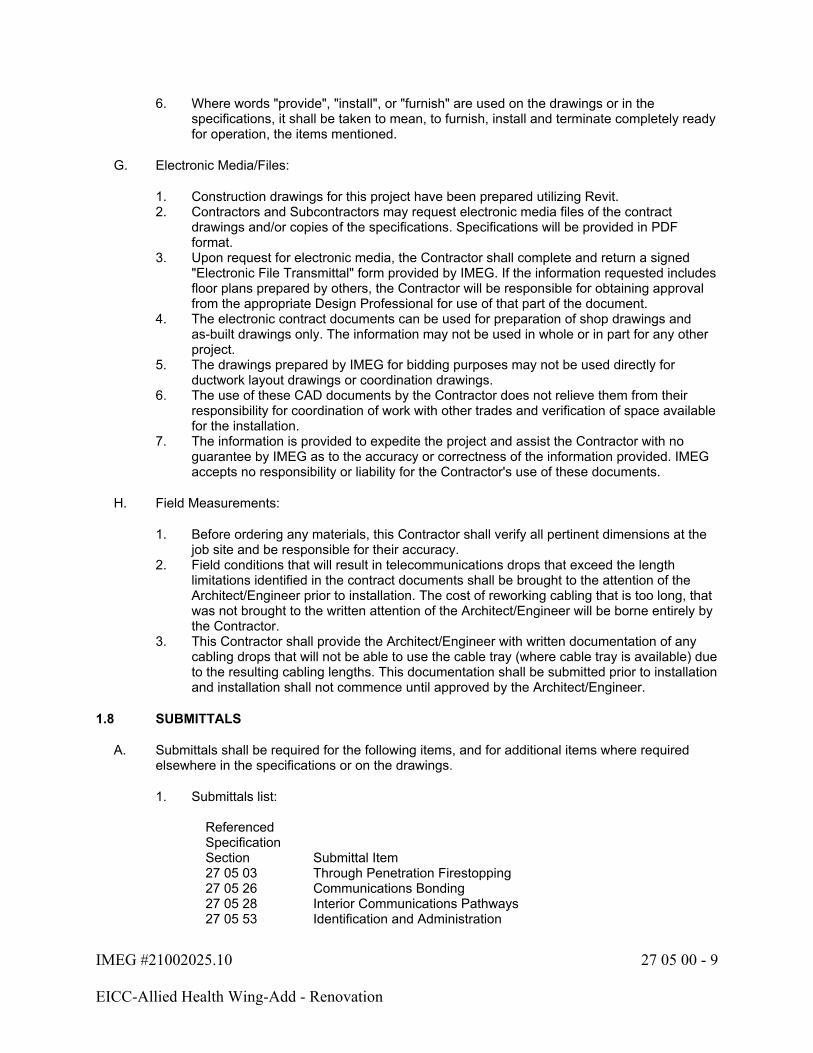
IMEG #21002025.10 27 05 00 - 9
EICC-Allied Health Wing-Add - Renovation
6. Where words "provide", "install", or "furnish" are used on the drawings or in the specifications, it shall be taken to mean, to furnish, install and terminate completely ready for operation, the items mentioned.
G. Electronic Media/Files:
1. Construction drawings for this project have been prepared utilizing Revit.2. Contractors and Subcontractors may request electronic media files of the contract
drawings and/or copies of the specifications. Specifications will be provided in PDF format.
3. Upon request for electronic media, the Contractor shall complete and return a signed "Electronic File Transmittal" form provided by IMEG. If the information requested includes floor plans prepared by others, the Contractor will be responsible for obtaining approval from the appropriate Design Professional for use of that part of the document.
4. The electronic contract documents can be used for preparation of shop drawings and as-built drawings only. The information may not be used in whole or in part for any other project.
5. The drawings prepared by IMEG for bidding purposes may not be used directly for ductwork layout drawings or coordination drawings.
6. The use of these CAD documents by the Contractor does not relieve them from their responsibility for coordination of work with other trades and verification of space available for the installation.
7. The information is provided to expedite the project and assist the Contractor with no guarantee by IMEG as to the accuracy or correctness of the information provided. IMEG accepts no responsibility or liability for the Contractor's use of these documents.
H. Field Measurements:
1. Before ordering any materials, this Contractor shall verify all pertinent dimensions at the job site and be responsible for their accuracy.
2. Field conditions that will result in telecommunications drops that exceed the length limitations identified in the contract documents shall be brought to the attention of the Architect/Engineer prior to installation. The cost of reworking cabling that is too long, that was not brought to the written attention of the Architect/Engineer will be borne entirely by the Contractor.
3. This Contractor shall provide the Architect/Engineer with written documentation of any cabling drops that will not be able to use the cable tray (where cable tray is available) due to the resulting cabling lengths. This documentation shall be submitted prior to installation and installation shall not commence until approved by the Architect/Engineer.
1.8 SUBMITTALS
A. Submittals shall be required for the following items, and for additional items where required elsewhere in the specifications or on the drawings.
1. Submittals list:
Referenced Specification Section Submittal Item27 05 03 Through Penetration Firestopping27 05 26 Communications Bonding27 05 28 Interior Communications Pathways27 05 53 Identification and Administration
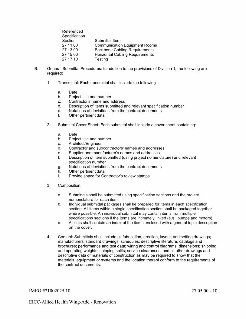
IMEG #21002025.10 27 05 00 - 10
EICC-Allied Health Wing-Add - Renovation
Referenced Specification Section Submittal Item27 11 00 Communication Equipment Rooms27 13 00 Backbone Cabling Requirements27 15 00 Horizontal Cabling Requirements27 17 10 Testing
B. General Submittal Procedures: In addition to the provisions of Division 1, the following are required:
1. Transmittal: Each transmittal shall include the following:
a. Dateb. Project title and numberc. Contractor's name and addressd. Description of items submitted and relevant specification numbere. Notations of deviations from the contract documentsf. Other pertinent data
2. Submittal Cover Sheet: Each submittal shall include a cover sheet containing:
a. Dateb. Project title and numberc. Architect/Engineerd. Contractor and subcontractors' names and addressese. Supplier and manufacturer's names and addressesf. Description of item submitted (using project nomenclature) and relevant
specification numberg. Notations of deviations from the contract documentsh. Other pertinent datai. Provide space for Contractor's review stamps
3. Composition:
a. Submittals shall be submitted using specification sections and the project nomenclature for each item.
b. Individual submittal packages shall be prepared for items in each specification section. All items within a single specification section shall be packaged together where possible. An individual submittal may contain items from multiple specifications sections if the items are intimately linked (e.g., pumps and motors).
c. All sets shall contain an index of the items enclosed with a general topic description on the cover.
4. Content: Submittals shall include all fabrication, erection, layout, and setting drawings; manufacturers' standard drawings; schedules; descriptive literature, catalogs and brochures; performance and test data; wiring and control diagrams; dimensions; shipping and operating weights; shipping splits; service clearances; and all other drawings and descriptive data of materials of construction as may be required to show that the materials, equipment or systems and the location thereof conform to the requirements of the contract documents.

IMEG #21002025.10 27 05 00 - 11
EICC-Allied Health Wing-Add - Renovation
5. Contractor's Approval Stamp:
a. The Contractor shall thoroughly review and approve all shop drawings before submitting them to the Architect/Engineer. The Contractor shall stamp, date and sign each submittal certifying it has been reviewed.
b. Unstamped submittals will be rejected.c. The Contractor shall provide proof of RCDD or CNIDP review on the submittal.d. The Contractor's review shall include, but not be limited to, verification of the
following:
1) Only approved manufacturers are used.2) Addenda items have been incorporated.3) Catalog numbers and options match those specified.4) Performance data matches that specified.5) Electrical characteristics and loads match those specified.6) Equipment connection locations, sizes, capacities, etc. have been
coordinated with other affected trades.7) Dimensions and service clearances are suitable for the intended location.8) Equipment dimensions are coordinated with support steel, housekeeping
pads, openings, etc.9) Constructability issues are resolved (e.g., weights and dimensions are
suitable for getting the item into the building and into place, sinks fit into countertops, etc.).
e. The Contractor shall review, stamp and approve all subcontractors' submittals as described above.
f. The Contractor's approval stamp is required on all submittals. Approval will indicate the Contractor's review of all material and a complete understanding of exactly what is to be furnished. Contractor shall clearly mark all deviations from the contract documents on all submittals. If deviations are not marked by the Contractor, then the item shall be required to meet all drawing and specification requirements.
6. Submittal Identification and Markings:
a. The Contractor shall clearly mark each item with the same nomenclature applied on the drawings or in the specifications.
b. The Contractor shall clearly indicate the size, finish, material, etc.c. Where more than one model is shown on a manufacturer's sheet, the Contractor
shall clearly indicate exactly which item and which data is intended.d. All marks and identifications on the submittals shall be unambiguous.
7. Schedule submittals to expedite the project. Coordinate submission of related items.8. Identify variations from the contract documents and product or system limitations that
may be detrimental to the successful performance of the completed work.9. Reproduction of contract documents alone is not acceptable for submittals.10. Incomplete submittals will be rejected without review. Partial submittals will only be
reviewed with prior approval from the Architect/Engineer.11. Submittals not required by the contract documents may be returned without review.12. The Architect/Engineer's responsibility shall be to review one set of shop drawing
submittals for each product. If the first submittal is incomplete or does not comply with the drawings and/or specifications, the Contractor shall be responsible to bear the cost for the Architect/Engineer to recheck and handle the additional shop drawing submittals.

IMEG #21002025.10 27 05 00 - 12
EICC-Allied Health Wing-Add - Renovation
13. Submittals shall be reviewed and approved by the Architect/Engineer before releasing any equipment for manufacture or shipment.
14. Contractor's responsibility for errors, omissions or deviation from the contract documents in submittals is not relieved by the Architect/Engineer's approval.
15. Schedule shall allow for adequate time to perform orderly and proper review of submittals, including time for consultants and Owner if required, and resubmittals by Contractor if necessary, and to cause no delay in Work or in activities of Owner or other contractors.
a. Allow at least two weeks for Architect’s/Engineer's review and processing of each submittal.
16. Architect/Engineer reserves the right to withhold action on a submittal which, in the Architect/Engineer’s opinion, requires coordination with other submittals until related submittals are received. The Architect/Engineer will notify the Contractor, in writing, when they exercise this right.
C. Electronic Submittal Procedures:
1. Distribution: Email submittals as attachments to all parties designated by the Architect/Engineer, unless a web-based submittal program is used.
2. Transmittals: Each submittal shall include an individual electronic letter of transmittal.3. Format: Electronic submittals shall be in PDF format only. Scanned copies, in PDF
format, of paper originals are acceptable. Submittals that are not legible will be rejected. Do not set any permission restrictions on files; protected, locked, or secured documents will be rejected.
4. File Names: Electronic submittal file names shall include the relevant specification section number followed by a description of the item submitted, as follows. Where possible, include the transmittal as the first page of the PDF instead of using multiple electronic files.
a. Submittal file name: 27 XX XX.description.YYYYMMDDb. Transmittal file name: 27 XX XX.description.YYYYMMDD
5. File Size: Files shall be transmitted via a pre-approved method. Larger files may require an alternative transfer method, which shall also be pre-approved.
1.9 SCHEDULE OF VALUES
A. The requirements herein are in addition to the provisions of Division 1.
B. Format:
1. Use AIA Document Continuation Sheets G703 or another similar form approved by the Owner and Architect/Engineer.
2. Submit in Excel format.3. Support values given with substantiating data.
C. Preparation:
1. Itemize work required by each specification section and list all providers. All work provided by subcontractors and major suppliers shall be listed on the Schedule of Values. List each subcontractor and supplier by company name.
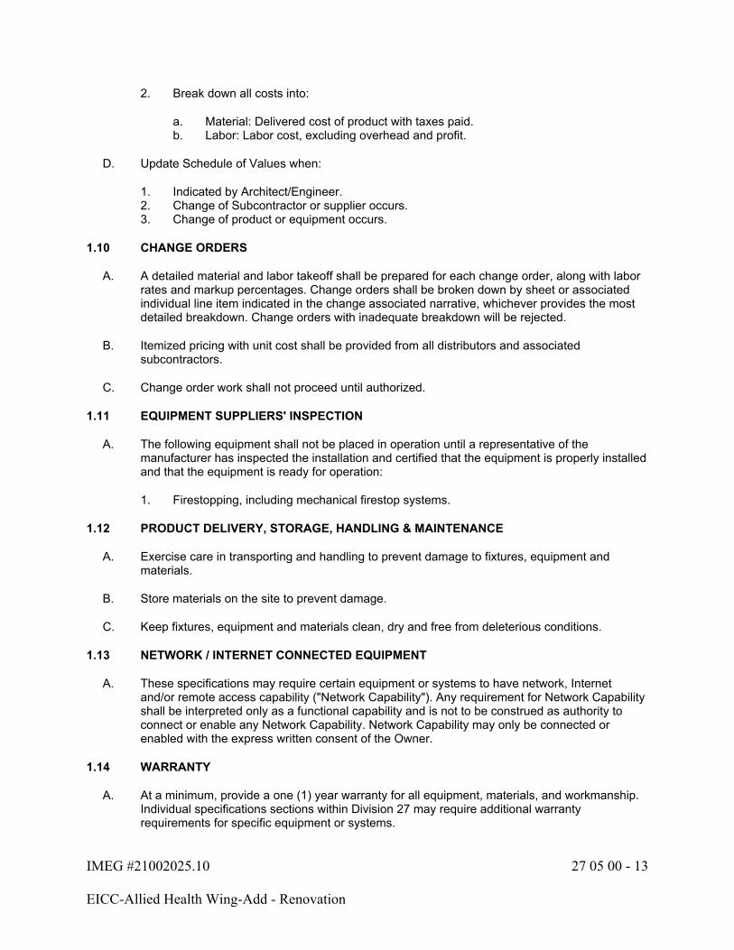
IMEG #21002025.10 27 05 00 - 13
EICC-Allied Health Wing-Add - Renovation
2. Break down all costs into:
a. Material: Delivered cost of product with taxes paid.b. Labor: Labor cost, excluding overhead and profit.
D. Update Schedule of Values when:
1. Indicated by Architect/Engineer.2. Change of Subcontractor or supplier occurs.3. Change of product or equipment occurs.
1.10 CHANGE ORDERS
A. A detailed material and labor takeoff shall be prepared for each change order, along with labor rates and markup percentages. Change orders shall be broken down by sheet or associated individual line item indicated in the change associated narrative, whichever provides the most detailed breakdown. Change orders with inadequate breakdown will be rejected.
B. Itemized pricing with unit cost shall be provided from all distributors and associated subcontractors.
C. Change order work shall not proceed until authorized.
1.11 EQUIPMENT SUPPLIERS' INSPECTION
A. The following equipment shall not be placed in operation until a representative of the manufacturer has inspected the installation and certified that the equipment is properly installed and that the equipment is ready for operation:
1. Firestopping, including mechanical firestop systems.
1.12 PRODUCT DELIVERY, STORAGE, HANDLING & MAINTENANCE
A. Exercise care in transporting and handling to prevent damage to fixtures, equipment and materials.
B. Store materials on the site to prevent damage.
C. Keep fixtures, equipment and materials clean, dry and free from deleterious conditions.
1.13 NETWORK / INTERNET CONNECTED EQUIPMENT
A. These specifications may require certain equipment or systems to have network, Internet and/or remote access capability ("Network Capability"). Any requirement for Network Capability shall be interpreted only as a functional capability and is not to be construed as authority to connect or enable any Network Capability. Network Capability may only be connected or enabled with the express written consent of the Owner.
1.14 WARRANTY
A. At a minimum, provide a one (1) year warranty for all equipment, materials, and workmanship. Individual specifications sections within Division 27 may require additional warranty requirements for specific equipment or systems.
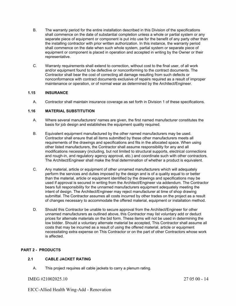
IMEG #21002025.10 27 05 00 - 14
EICC-Allied Health Wing-Add - Renovation
B. The warranty period for the entire installation described in this Division of the specifications shall commence on the date of substantial completion unless a whole or partial system or any separate piece of equipment or component is put into use for the benefit of any party other than the installing contractor with prior written authorization. In this instance, the warranty period shall commence on the date when such whole system, partial system or separate piece of equipment or component is placed in operation and accepted in writing by the Owner or their representative.
C. Warranty requirements shall extend to correction, without cost to the final user, of all work and/or equipment found to be defective or nonconforming to the contract documents. The Contractor shall bear the cost of correcting all damage resulting from such defects or nonconformance with contract documents exclusive of repairs required as a result of improper maintenance or operation, or of normal wear as determined by the Architect/Engineer.
1.15 INSURANCE
A. Contractor shall maintain insurance coverage as set forth in Division 1 of these specifications.
1.16 MATERIAL SUBSTITUTION
A. Where several manufacturers' names are given, the first named manufacturer constitutes the basis for job design and establishes the equipment quality required.
B. Equivalent equipment manufactured by the other named manufacturers may be used. Contractor shall ensure that all items submitted by these other manufacturers meets all requirements of the drawings and specifications and fits in the allocated space. When using other listed manufacturers, the Contractor shall assume responsibility for any and all modifications necessary (including, but not limited to structural supports, electrical connections and rough-in, and regulatory agency approval, etc.) and coordinate such with other contractors. The Architect/Engineer shall make the final determination of whether a product is equivalent.
C. Any material, article or equipment of other unnamed manufacturers which will adequately perform the services and duties imposed by the design and is of a quality equal to or better than the material, article or equipment identified by the drawings and specifications may be used if approval is secured in writing from the Architect/Engineer via addendum. The Contractor bears full responsibility for the unnamed manufacturers equipment adequately meeting the intent of design. The Architect/Engineer may reject manufacturer at time of shop drawing submittal. The Contractor assumes all costs incurred by other trades on the project as a result of changes necessary to accommodate the offered material, equipment or installation method.
D. Should this Contractor be unable to secure approval from the Architect/Engineer for other unnamed manufacturers as outlined above, this Contractor may list voluntary add or deduct prices for alternate materials on the bid form. These items will not be used in determining the low bidder. Should a voluntary alternate material be accepted, This Contractor shall assume all costs that may be incurred as a result of using the offered material, article or equipment necessitating extra expense on This Contractor or on the part of other Contractors whose work is affected.
PART 2 - PRODUCTS
2.1 CABLE JACKET RATING
A. This project requires all cable jackets to carry a plenum rating.
IMEG #21002025.10 27 05 00 - 15
EICC-Allied Health Wing-Add - Renovation
2.2 Refer to individual sections.
PART 3 - EXECUTION
3.1 JOBSITE SAFETY
A. Neither the professional activities of the Architect/Engineer, nor the presence of the Architect/Engineer or his or her employees and subconsultants at a construction site, shall relieve the Contractor and any other entity of their obligations, duties and responsibilities including, but not limited to, construction means, methods, sequence, techniques or procedures necessary for performing, superintending or coordinating all portions of the work of construction in accordance with the contract documents and any health or safety precautions required by any regulatory agencies. The Architect/Engineer and his or her personnel have no authority to exercise any control over any construction contractor or other entity or their employees in connection with their work or any health or safety precautions. The Contractor is solely responsible for jobsite safety. The Architect/Engineer and the Architect/Engineer's consultants shall be indemnified and shall be made additional insureds under the Contractor's general liability insurance policy.
3.2 GENERAL INSTALLATION REQUIREMENTS
A. Installation of all conduit and cabling shall comply with Sections 26 05 33 and 26 05 13. Additional conduit requirements described within this Division shall be supplemental to the requirement described in Section 26 05 33. Should conflicts exist between the two Divisions the more stringent (more expensive material and labor) condition shall prevail until bidding addendum or construction clarification or RFI can be submitted and responded to. In no case shall the Contractor carry the least stringent condition in the pricing.
B. It is the Contractor's responsibility to survey the site and include all necessary costs to perform the installation as specified.
C. The Contractor shall be responsible for identifying and reporting to the Architect/Engineer any existing conditions including but not limited to damage to walls, flooring, ceiling and furnishings prior to start of work. All damage to interior spaces caused by this Contractor shall be repaired at this Contractor's expense to pre-existing conditions, including final colors and finishes.
D. All cables and devices installed in damp or wet locations, including any underground or underslab location, shall be listed as suitable for use in such environments. Follow manufacturer's recommended installation practices for installing cables and devices in damp or wet locations. Any cable or device that fails as a result of being installed in a damp or wet location shall be replaced at the Contractor's expense.
3.3 FIELD QUALITY CONTROL
A. General:
1. Refer to specific Division 27 sections for further requirements.2. The Contractor shall conduct all tests required and applicable to the work both during and
after construction of the work.3. The necessary instruments and materials required to conduct or make the tests shall be
supplied by the Contractor who shall also supply competent personnel for making the tests who has been schooled in the proper testing techniques.

IMEG #21002025.10 27 05 00 - 16
EICC-Allied Health Wing-Add - Renovation
4. In the event the results obtained in the tests are not satisfactory, This Contractor shall make such adjustments, replacements and changes as are necessary and shall then repeat the test or tests which disclose faulty or defective work or equipment, and shall make such additional tests as the Architect/Engineer or code enforcing agency deems necessary.
5. All communications cable tests that fail, including those due to excessive cabling lengths, shall be remedied by the Contractor without cost to the project.
B. Protection of cable from foreign materials:
1. It is the Contractor's responsibility to provide adequate physical protection to prevent foreign material application or contact with any cable type. Foreign material is defined as any material that would negatively impact the validity of the manufacturer's performance warranty. This includes, but is not limited, to overspray of paint (accidental or otherwise), drywall compound, or any other surface chemical, liquid or compound that could come in contact with the cable, cable jacket or cable termination components.
2. Application of foreign materials of any kind on any cable, cable jacket or cable termination component will not be accepted. It shall be the Contractor's responsibility to replace any component containing overspray, in its entirety, at no additional cost to the project. Cleaning of the cables with harsh chemicals is not allowed. This requirement is regardless of the PASS/FAIL test results of the cable containing overspray. Should the manufacturer and warrantor of the structured cabling system desire to physically inspect the installed condition and certify the validity of the structured cabling system (via a signed and dated statement by an authorized representative of the structured cabling manufacturer), the Owner may, at their sole discretion, agree to accept said warranty in lieu of having the affected cables replaced. In the case of plenum cabling, in addition to the statement from the manufacturer, the Contractor shall also present to the Owner a letter from the local Authority Having Jurisdiction stating that they consider the plenum rating of the cable to be intact and acceptable.
3.4 PROJECT CLOSEOUT
A. Refer to the Division 1 Section: PROJECT CLOSEOUT for requirements. The following paragraphs supplement the requirements of Division 1.
B. Final Jobsite Observation:
1. The Architect/Engineer will not perform a final jobsite observation until the project is ready. This is not dictated by schedule, but rather by completeness of the project.
2. Refer to the end of this specification section for a "STATEMENT INDICATING READINESS FOR FINAL JOBSITE OBSERVATION."
3. The Contractor shall sign this form and return it to the Architect/Engineer so that the final observation can commence.
C. Before final payment will be authorized, this Contractor must have completed the following:
1. Submitted operation and maintenance manuals to the Architect/Engineer for review.2. Submitted bound copies of approved shop drawings.3. Record documents including edited drawings and specifications accurately reflecting field
conditions, inclusive of all project revisions, change orders, and modifications.4. Submitted a report stating the instructions given to the Owner's representative complete
with the number of hours spent in the instruction. The report shall bear the signature of an authorized agent of This Contractor and shall be signed by the Owner's representative as having received the instructions.
IMEG #21002025.10 27 05 00 - 17
EICC-Allied Health Wing-Add - Renovation
5. Submitted testing reports for all systems requiring final testing as described herein.6. Submitted start-up reports on all equipment requiring a factory installation inspection
and/or start.7. Provide spare parts, maintenance, and extra materials in quantities specified in individual
specification sections. Deliver to project site; submit receipt to Architect/Engineer prior to final payment being approved.
8. Provide System Assurance Warranty certificate for the telecommunications system.
3.5 OPERATION AND MAINTENANCE MANUALS
A. General:
1. Provide an electronic copy of the O&M manuals as described below for Architect/Engineer's review and approval. The electronic copy shall be corrected as required to address the Architect/Engineer's comments. Once corrected, electronic copies and paper copies shall be distributed as directed by the Architect/Engineer.
2. Approved O&M manuals shall be completed and in the Owner's possession prior to Owner's acceptance and at least 10 days prior to instruction of operating personnel.
B. Electronic Submittal Procedures:
1. Distribution: Email the O&M manual as attachments to all parties designated by the Architect/Engineer.
2. Transmittals: Each submittal shall include an individual electronic letter of transmittal.3. Format: Electronic submittals shall be in PDF format only. Scanned copies, in PDF
format, of paper originals are acceptable. Submittals that are not legible will be rejected. Do not set any permission restrictions on files; protected, locked, or secured documents will be rejected.
4. File Names: Electronic submittal file names shall include the relevant specification section number followed by a description of the item submitted, as follows. Where possible, include the transmittal as the first page of the PDF instead of using multiple electronic files.
a. O&M file name: O&M.div27.contractor.YYYYMMDDb. Transmittal file name: O&Mtransmittal.div27.contractor.YYYYMMDD
5. File Size: Files shall be transmitted via a pre-approved method. Larger files may require an alternative transfer method, which shall also be pre-approved.
6. Provide the Owner with an approved copy of the O&M manual on compact discs (CD), digital video discs (DVD), or flash drives with a permanently affixed label, printed with the title "Operation and Maintenance Instructions", title of the project and subject matter of disc/flash drive when multiple disc/flash drives are required.
7. All text shall be searchable.8. Bookmarks shall be used, dividing information first by specification section, then systems,
major equipment and finally individual items. All bookmark titles shall include the nomenclature used in the construction documents and shall be an active link to the first page of the section being referenced.
C. Operation and Maintenance Instructions shall include:
1. Title Page: Include title page with project title, Architect, Engineer, Contractor, all subcontractors, and major equipment suppliers, with addresses, telephone numbers, website addresses, email addresses and point of contacts. Website URLs and email addresses shall be active links in the electronic submittal.
IMEG #21002025.10 27 05 00 - 18
EICC-Allied Health Wing-Add - Renovation
2. Table of Contents: Include a table of contents describing specification section, systems, major equipment, and individual items.
3. Copies of all final approved shop drawings and submittals. Include Architect's/Engineer's shop drawing review comments. Insert the individual shop drawing directly after the Operation and Maintenance information for the item(s) in the review form.
4. Copy of final approved test and balance reports.5. Copies of all factory inspections and/or equipment startup reports.6. Copies of warranties.7. Schematic wiring diagrams of the equipment that have been updated for field conditions.
Field wiring shall have label numbers to match drawings.8. Dimensional drawings of equipment.9. Capacities and utility consumption of equipment.10. Detailed parts lists with lists of suppliers.11. Operating procedures for each system.12. Maintenance schedule and procedures. Include a chart listing maintenance requirements
and frequency.13. Repair procedures for major components.14. List of lubricants in all equipment and recommended frequency of lubrication.15. Instruction books, cards, and manuals furnished with the equipment.
3.6 INSTRUCTING THE OWNER'S REPRESENTATIVE
A. Adequately instruct the Owner's designated representative or representatives in the maintenance, care, and operation of the complete systems installed under this contract.
B. Provide verbal and written instructions to the Owner's representative or representatives by FACTORY PERSONNEL in the care, maintenance, and operation of the equipment and systems.
C. The Architect/Engineer shall be notified of the time and place for the verbal instructions to be given to the Owner's representative so that their representative can be present if desirable.
D. Refer to the individual specification sections for minimum hours of instruction time for each system.
E. Operating Instructions:
1. The Contractor is responsible for all instructions to the Owner and/or Owner's operating staff on the Communications Systems.
2. If the Contractor does not have Engineers and/or Technicians on staff who can adequately provide the required instructions on system operation, performance, troubleshooting, care and maintenance, they shall include in the bid an adequate amount to reimburse the Owner for the Architect/Engineer to perform these services.
3.7 SYSTEM STARTING AND ADJUSTING
A. The Communications Systems included in the construction documents are to be complete and operating systems. The Architect/Engineer will make periodic job site observations during the construction period. The system start-up, testing, configuration, and satisfactory system performance is the responsibility of the Contractor. This shall include all calibration and adjustments of electrical equipment controls, equipment settings, software configuration, troubleshooting and verification of software, and final adjustments that may be required.
IMEG #21002025.10 27 05 00 - 19
EICC-Allied Health Wing-Add - Renovation
B. All operating conditions and control sequences shall be simulated and tested during the start-up period.
C. The Contractor, subcontractors, and equipment suppliers are expected to have skilled technicians to ensure that the system performs as designed. If the Architect/Engineer is requested to visit the job site for the purpose of trouble shooting, assisting in the satisfactory start-up, obtaining satisfactory equipment operation, resolving installation and/or workmanship problems, equipment substitution issues or unsatisfactory system performance, including call backs during the warranty period through no fault of the design; the Contractor shall reimburse the Owner on a time and material basis for services rendered at the Architect/Engineer's standard hourly rates in effect at the time the services are requested. The Contractor shall be responsible for making payment to the Owner for services required that are product, installation or workmanship related. Payment is due within 30 days after services are rendered.
3.8 RECORD DOCUMENTS
A. Refer to the Division 1 Section: PROJECT CLOSEOUT for requirements. The following paragraphs supplement the requirements of Division 1.
B. Mark specifications to indicate approved substitutions, change orders, and actual equipment and materials used.
C. This Contractor shall maintain at the job site, a separate and complete set of technology drawings which shall be clearly and permanently marked and noted in complete detail any changes made to the location and arrangement of equipment or made to the Technology Systems and wiring as a result of building construction conditions or as a result of instructions from the Architect or Engineer. All Change Orders, RFI responses, Clarifications and other supplemental instructions shall be marked on the documents. Record documents that merely reference the existence of the above items are not acceptable. Should This Contractor fail to complete Record Documents as required by this contract, This Contractor shall reimburse Architect/Engineer for all costs to develop record documents that comply with this requirement. Reimbursement shall be made at the Architect/Engineer's hourly rates in effect at the time of work.
D. Record actual routing of all conduits sized 2" or larger.
E. The above record of changes shall be made available for the Architect and Engineer's examination during any regular work time.
F. Upon completion of the job, and before final payment is made, This Contractor shall give the marked-up drawings to the Architect/Engineer.
3.9 ADJUST AND CLEAN
A. Contractor shall thoroughly clean all equipment and systems prior to the Owner's final acceptance of the project.
B. Contractor shall clean all foreign paint, grease, oil, dirt, labels, stickers, and other foreign material from equipment.
C. Contractor shall remove all rubbish, debris, etc., accumulated during the Contractor's operations from the premises.
IMEG #21002025.10 27 05 00 - 20
EICC-Allied Health Wing-Add - Renovation
STATEMENT INDICATING READINESS FOR FINAL JOBSITE OBSERVATION
To assist the contractor in a timely close-out of the project, it is crucial that the final jobsite observation is not conducted prior to the project being ready. The contractor is required to review the completion status of the project at the time the observation is scheduled. This review, and the subsequent submittal of this form to the Architect/Engineer, shall indicate the contractor's agreement that the area of the project being requested for final observation is ready as defined below. The following list represents the degree of completeness required prior to requesting a final observation:
1. All cabling pathways ( ladder rack, conduit sleeves, etc.) are installed and all cabling has been pulled through them.
2. All mechanical firestop products are installed and all other penetrations have been sealed.3. All telecommunications jacks are installed in the faceplates.4. All telecommunications cabling is pulled and at least 75% of all jacks have been terminated at the jack
and at the telecom room.5. Telecommunications testing is in progress and at least 25% of testing has been completed.6. Telecommunications labeling has been provided on at least 25% of each type of component requiring
a label.7. All telecommunications related grounding is complete.8. All CCTV cameras, mounts, cabling and all headend equipment are installed, programmed and
operational.9. All access control system equipment, including card readers, conduits, cabling, electronic locks,
controllers and all headend equipment, is installed, programmed and operational.
Prime Contractor: _________________________ By: _____________________________
Requested Observation Date ________________ Today's Date: _____________________
Contractor shall sign this readiness statement and transmit to Architect/Engineer at least 10 days prior to the requested date of observation.
It is understood that if the Architect/Engineer finds that the project is not complete as defined above and that the final jobsite observation cannot be completed on the requested date, the Architect/Engineer will return to the site at a later date. All additional visits to the site for the purposes of completing the final observation will be billed T&M to the Contractor at our standard hourly rates, including travel expenses or the contractor's retainage may be deducted for the same amount.
IMEG #21002025.10 27 05 00 - 21
EICC-Allied Health Wing-Add - Renovation
TELECOMMUNICATIONS - PROOF OF CERTIFICATION
There are specific Contractor qualification requirements for this project as defined in Section 27 05 00, which may include Manufacturer Certification and RCDD or CNIDP credentials. This Proof of Certification document, and the supporting documentation require herein, is required to be submitted at the time of bid to show compliance with the requirements of 27 05 00.
Statement of Compliance:The named Contractor's base bid is a structured cabling solution from the connectivity manufacturer Commscope. Named Contractor is trained and certified, under the named manufacturer's formal certification program to provide and install all materials and work required by this project. Further, said Contractor is authorized, by the named manufacturer, to offer all product, labor and system assurance warranties required for this project by these contract documents.
The certification of this named manufacturer is valid, current and in effect as of the bid day of this project, the ______ day of _________, 20____.
The named Contractor is not employing any other sub-contractor on the telecommunications portion of this project that does not also meet this certification requirement.
Contractor Company Name: ________________________________________________________
Authorized Representative: (print) ____________________________________________________
Date: _________________Manufacturer Certification Number (if any): ___________________
If this project requires RCDD certification, complete the following:
RCDD or CNIDP Name: ________________________RCDD #: ____________ Expiration: ____________
Submit the following with the bid:This form.Proof of Manufacturer Certification indicated above.Proof of RCDD or CNIDP status.
END OF SECTION 27 05 00

IMEG #21002025.10 27 05 03 - 1
EICC-Allied Health Wing-Add - Renovation
SECTION 27 05 03 - THROUGH PENETRATION FIRESTOPPING
PART 1 - GENERAL
1.1 SECTION INCLUDES
A. Through-Penetration Firestopping.
1.2 QUALITY ASSURANCE
A. Manufacturer: Company specializing in manufacturing products specified in this Section.
B. Installer: Individuals performing work shall be certified by the manufacturer of the system selected for installation.
1.3 REFERENCES
A. UL 263 - Fire Tests of Building Construction and Materials
B. UL 723 - Surface Burning Characteristics of Building Materials
C. ANSI/UL 1479 - Fire Tests of Through Penetration Firestops
D. UL 2079 - Tests for Fire Resistance of Building Joint Systems
E. UL Fire Resistance Directory Through Penetration Firestop Systems (XHEZ)
F. Intertek / Warnock Hersey - Directory of Listed Products
G. ASTM E84 - Standard Test Method for Surface Burning Characteristics of Building Materials
H. ASTM E814 - Standard Test Method for Fire Tests of Through-Penetration Firestops
I. The Building Officials and Code Administrators National Building Code
J. 2015 International Building Code
K. NFPA 5000 – Building Construction Safety Code
1.4 DELIVERY, STORAGE, AND HANDLING
A. Store, protect and handle products on site. Accept material on site in factory containers and packing. Inspect for damage. Protect from deterioration or damage due to moisture, temperature changes, contaminants, or other causes. Follow manufacturer's instructions for storage.
B. Install material prior to expiration of product shelf life.
IMEG #21002025.10 27 05 03 - 2
EICC-Allied Health Wing-Add - Renovation
1.5 PERFORMANCE REQUIREMENTS
A. General: For penetrations through the following fire-resistance-rated constructions, including both empty openings and openings containing penetrating items, provide through-penetration firestop systems that are produced and installed to resist spread of fire according to requirements indicated, resist passage of smoke and other gases, and maintain original fire-resistance rating of construction penetrated.
1. Fire-resistance-rated walls including fire partitions, fire barriers, and smoke barriers.2. Fire-resistance-rated horizontal assemblies including floors, floor/ceiling assemblies, and
ceiling membranes of roof/ceiling assemblies.
B. Rated Systems: Provide through-penetration firestop systems with the following ratings determined per UL 1479:
1. F-Rated Systems: Provide through-penetration firestop systems with F-ratings indicated, but not less than that equaling or exceeding fire-resistance rating of constructions penetrated.
C. For through-penetration firestop systems exposed to light, traffic, moisture, or physical damage, provide products that, after curing, do not deteriorate when exposed to these conditions both during and after construction.
D. For through-penetration firestop systems exposed to view, provide products with flame-spread and smoke-developed indexes of less than 25 and 450, respectively, as determined per ASTM E 84.
E. For through-penetration firestop systems in air plenums, provide products with flame-spread and smoke-developed indexes of less than 25 and 50, respectively, as determined per ASTM E 84.
1.6 MEETINGS
A. Pre-installation meeting: A pre-installation meeting shall be scheduled and shall include the Construction Manager, all Subcontractors associated with the installation of systems penetrating fire barriers, Firestopping Manufacturer's Representative, and the Owner.
1. Review foreseeable methods related to firestopping work.2. Tour representative areas where firestopping is to be installed; inspect and discuss each
type of condition and each type of substrate that will be encountered, and preparation to be performed by other trades.
1.7 WARRANTY
A. Provide one year warranty on parts and labor.
B. Warranty shall cover repair or replacement of firestop systems which fail in joint adhesion, cohesion, abrasion resistance, weather resistance, extrusion resistance, migration resistance, stain resistance, general durability, or appear to deteriorate in any manner not clearly specified by the manufacturer as an inherent quality of the material.

IMEG #21002025.10 27 05 03 - 3
EICC-Allied Health Wing-Add - Renovation
PART 2 - PRODUCTS
2.1 MANUFACTURERS
A. Products: Subject to compliance with requirements, provide one of the through-penetration firestop systems indicated for each application that are produced by one of the following manufacturers. All firestopping systems installed shall be provided by a single manufacturer.
1. 3M; Fire Protection Products Division2. Hilti, Inc.3. Specified Technologies Inc. (S.T.I.)
2.2 THROUGH PENETRATION FIRESTOP SYSTEMS
A. Provide materials and systems classified by or listed by Intertek / Warnock Hersey to provide firestopping equal to time rating of construction being penetrated.
B. All firestopping materials shall be free of asbestos, lead, PCB's, and other materials that would require hazardous waste removal.
C. Firestopping shall be flexible to allow for normal penetrating item movement due to expansion and contraction.
D. Firestopping systems for plumbing and wet pipe sprinkler piping shall be moisture resistant.
E. Provide firestopping systems capable of supporting floor loads where systems are exposed to possible floor loading or traffic.
F. Provide firestopping systems allowing continuous insulation for all insulated pipes.
G. Provide firestopping systems classified by UL or listed by Intertek / Warnock Hersey for penetrations through all fire rated construction. Firestopping systems shall be selected from the UL or listed by Intertek / Warnock Hersey Fire Resistance Directory Category XHEZ based on substrate construction and penetrating item size and material and shall fall within the range of numbers listed:
1. Combustible Framed Floors and Chase Walls - 1 or 2 Hour Rated:
a. F Rating = Floor/Wall Rating
Penetrating Item UL System No.No Penetrating Item FC 0000-0999*Metallic Pipe or Conduit FC 1000-1999Non-Metallic Pipe or Conduit FC 2000-2999Electrical Cables FC 3000-3999Cable Trays FC 4000-4999Insulated Pipes FC 5000-5999Bus Duct and Misc. Electrical FC 6000-6999Duct without Damper and Misc. Mechanical FC 7000-7999Multiple Penetrations FC 8000-8999*Alternate method of firestopping is patching opening to match original rated construction.
IMEG #21002025.10 27 05 03 - 4
EICC-Allied Health Wing-Add - Renovation
2. Non-Combustible Framed Walls - 1 or 2 Hour Rated:
a. F Rating = Wall Rating
Penetrating Item UL System No.No Penetrating Item WL 0000-0999*Metallic Pipe or Conduit WL 1000-1999Non-Metallic Pipe or Conduit WL 2000-2999Electrical Cables WL 3000-3999Cable Trays WL 4000-4999Insulated Pipes WL 5000-5999Bus Duct and Misc. Electrical WL 6000-6999Duct without Damper and Misc. Mechanical WL 7000-7999Multiple Penetrations WL 8000-8999*Alternate method of firestopping is patching opening to match original rated construction.
3. Concrete or Masonry Floors and Walls - 1 or 2 Hour Rated:
a. F Rating = Wall/Floor Rating
Penetrating Item UL System No.No Penetrating Item CAJ 0000-0999*Metallic Pipe or Conduit CAJ 1000-1999Non-Metallic Pipe or Conduit CAJ 2000-2999Electrical Cables CAJ 3000-3999Cable Trays CAJ 4000-4999Insulated Pipes CAJ 5000-5999Bus Duct and Misc. Electrical CAJ 6000-6999Duct without Damper and Misc. Mechanical CAJ 7000-7999Multiple Penetrations CAJ 8000-8999*Alternate method of firestopping is patching opening to match original rated construction.
H. Any opening in walls or floors not covered by the listed series of numbers shall be coordinated with the firestopping manufacturer.
I. Any openings in floors or walls not described in the UL or listed by Intertek / Warnock Hersey Fire Resistance Directory, or outlined in manufacturer's information shall be sealed in a manner agreed upon by the Firestopping Manufacturer, Owner, and the Authority Having Jurisdiction.
PART 3 - EXECUTION
3.1 EXAMINATION
A. Ensure all surfaces that contact seal materials are free of dirt, dust, grease, oil, rust, or loose materials. Clean and repair surfaces as required. Remove laitance and form-release agents from concrete.
IMEG #21002025.10 27 05 03 - 5
EICC-Allied Health Wing-Add - Renovation
B. Ensure substrate and penetrating items have been permanently installed prior to installing firestopping systems. Ensure penetrating items have been properly spaced and have proper clearance prior to installing firestopping systems.
C. Surfaces to which sealing materials are to be installed must meet the selected UL or Intertek / Warnock Hersey system substrate criteria.
D. Prime substrates where recommended in writing by through-penetration firestop system manufacturer. Confine primer to area of bond.
3.2 INSTALLATION
A. In existing construction, provide firestopping of openings prior to and after installation of penetrating items. Remove any existing coatings on surfaces prior to firestopping installation. Temporary firestopping shall consist of packing openings with fire resistant mineral wool for the full thickness of substrate, or an alternate method approved by the Authority Having Jurisdiction. All openings shall be temporarily firestopped immediately upon their installation and shall remain so until the permanent UL or listed by Intertek / Warnock Hersey listed firestopping system is installed.
B. Install penetration seal materials in accordance with printed instructions of the UL or Intertek / Warnock Hersey Fire Resistance Directory and with the manufacturer's printed application instructions.
C. Install dams as required to properly contain firestopping materials within openings and as required to achieve required fire resistance rating. Remove combustible damming after appropriate curing.
3.3 CLEANING AND PROTECTING
A. Clean excess fill materials adjacent to openings as Work progresses by methods and with cleaning materials that are approved in writing by through-penetration firestop system manufacturers and that do not cause damage.
B. Provide final protection and maintain conditions during and after installation that ensure that through-penetration firestop systems are without damage or deterioration at time of Substantial Completion. If, despite such protection, damage or deterioration occurs, remove damaged or deteriorated through-penetration firestop systems immediately and install new materials to produce systems complying with specified requirements.
3.4 INSPECTION
A. All penetrations shall be inspected by the manufacturer's representative to ensure proper installation.
B. Access to firestop systems shall be maintained for examination by the Authority Having Jurisdiction at their request.
C. Proceed with enclosing through-penetration firestop system with other construction only after inspection reports are issued and firestop installations comply with requirements.
IMEG #21002025.10 27 05 03 - 6
EICC-Allied Health Wing-Add - Renovation
D. The contractor shall allow for visual destructive review of 5% of installed firestop systems (minimum of one) to prove compliance with specifications and manufacturer's instructions and details. Destructive system removal shall be performed by the contractor and witnessed by the Architect/Engineer and manufacturer's factory representative. The Architect/Engineer shall have sole discretion of which firestop system installations will be reviewed. The contractor is responsible for all costs associated with this requirement including labor and material for removing and replacing the installed firestop system. If any firestop system is found to not be installed per manufacturer's specific instructions and details, all firestop systems are subject to destructive review and replacement at the Architect/Engineer's discretion and the contractor's expense.
END OF SECTION 27 05 03

IMEG #21002025.10 27 05 05 - 1
EICC-Allied Health Wing-Add - Reno
SECTION 27 05 05 - TECHNOLOGY DEMOLITION FOR REMODELING
PART 1 - GENERAL
1.1 SECTION INCLUDES
A. Technology demolition.
1.2 RELATED WORK
A. Section 27 05 00 - Basic Communications Systems Requirements.
1.3 REFERENCES
A. NFPA 70 - National Electrical Code.
PART 2 - PRODUCTS
2.1 MATERIALS AND EQUIPMENT
A. Materials and equipment for terminating, patching and cross connecting of existing telecommunications and security systems shall be as specified in individual Sections.
PART 3 - EXECUTION
3.1 EXAMINATION
A. THE DRAWINGS ARE INTENDED TO INDICATE THE SCOPE OF WORK REQUIRED AND DO NOT INDICATE EVERY OUTLET, BOX, CONDUIT, OR CABLE THAT MUST BE REMOVED.
B. THE CONTRACTOR SHALL VISIT THE SITE PRIOR TO SUBMITTING A BID AND VERIFY EXISTING CONDITIONS AND SCOPE OF WORK.
C. Where walls, ceilings, structures, etc., are indicated as being renovated on general drawings, the Contractor shall be responsible for the removal of all technology equipment including but not limited to: copper, fiber and coaxial cable, faceplates and jacks, raceways, racking and equipment mounted to the racking, etc., from the renovated area.
D. Where ceilings, walls, structures, etc., are temporarily removed and replaced by others, this Contractor shall be responsible for the removal, storage, and replacement of equipment, devices, fixtures, raceways, wiring, systems, etc.
E. Verify that abandoned wiring and equipment serve only abandoned equipment or facilities. Extend conduit and wire to facilities and equipment that will remain in operation following demolition. Extension of conduit and wire to equipment shall be compatible with the surrounding area.

IMEG #21002025.10 27 05 05 - 2
EICC-Allied Health Wing-Add - Reno
F. Coordinate scope of work with all other Contractors and the Owner at the project site. Schedule removal of equipment and technology service to avoid conflicts.
3.2 PREPARATION
A. Not all services within the building will be inactive or abandoned. Verify abandonment status with the building owner, General Contractor and Architect/Engineer prior to demolition.
B. Prior to commencing with demolition, a proposed implementation narrative with schedule shall be submitted to the Architect/Engineer for approval.
C. The contractor shall provide proof that only qualified personnel with extensive telecommunications experience will perform the demolition. No laborers will be allowed in the cable removal process.
D. The contractor shall coordinate with owner to verify all cabling, patch cords and cross connects have been removed from active equipment that is to remain during the duration of the renovation.
E. Provide temporary wiring and connections to maintain existing systems in service during construction. When work must be performed on active equipment, use technicians experienced in such operations. Assume all equipment and systems must remain operational unless specifically noted otherwise on drawings.
3.3 DEMOLITION AND EXTENSION OF EXISTING TECHNOLOGY WORK
A. Demolish and extend existing technology work under provisions of Division 1 of Architectural Specifications and this Section.
B. Some cabling within the ceiling space may serve other building tenants; care shall be exercised to prevent service interrupts.
C. Remove, relocate, and extend existing installations to accommodate new construction.
D. Remove abandoned low voltage cabling and raceway to source of cabling according to the NEC. Refer to the NEC for definition of Abandoned Communications Cabling.
E. Remove exposed abandoned raceway, including abandoned raceway above accessible ceiling finishes. Cut raceway flush with walls and floors, and patch surfaces. Remove all associated clamps, hangers, supports, etc. associated with raceway removal.
F. Disconnect abandoned outlets and remove devices. Remove abandoned outlets if conduit servicing them is removed. Patch openings created from removal of devices to match surrounding finishes.
G. Disconnect and remove abandoned patch panels, blocks and other distribution equipment.
H. Repair adjacent construction and finishes damaged during demolition and extension work. Patch openings to match existing surrounding finishes.
I. Maintain access to existing technology installations that remain active. Modify installation or provide access panels as appropriate.
IMEG #21002025.10 27 05 05 - 3
EICC-Allied Health Wing-Add - Reno
J. Extend existing installations using materials and methods compatible with existing technology installations, or as specified.
K. Regulatory Requirements: Comply with governing EPA notification regulations before beginning demolition. Comply with hauling and disposal regulations of authorities having jurisdiction.
L. This Contractor is responsible for all costs incurred in repair, relocations, or replacement of any cables, conduits, or other services if damaged without proper investigation.
3.4 CLEANING AND REPAIR
A. Clean and repair existing materials and equipment that remain or are to be reused.
B. Patch panels, blocks and other connectivity equipment: Clean exposed surfaces and check tightness of connections. Re-terminate any loose connections; the contractor shall notify the Architect/Engineer of any permanently damaged or unusable equipment.
C. TECHNOLOGY ITEMS (E.G., PATCH PANELS, EQUIPMENT RACKS, JACKS, FACEPLATES, BLOCKS, CABLING, ETC.) REMOVED AND NOT RELOCATED REMAIN THE PROPERTY OF THE OWNER. CONTRACTOR SHALL PLACE ITEMS RETAINED BY THE OWNER IN A LOCATION COORDINATED WITH THE OWNER. THE CONTRACTOR SHALL BE RESPONSIBLE FOR THE DISPOSAL OF MATERIAL THE OWNER DOES NOT WANT.
3.5 INSTALLATION
A. Install relocated materials and equipment under the provisions of applicable Division 27 specifications.
END OF SECTION 27 05 05
IMEG #21002025.10 27 05 26 - 1
EICC-Allied Health Wing-Add - Renovation
SECTION 27 05 26 - COMMUNICATIONS BONDING
PART 1 - GENERAL
1.1 SECTION INCLUDES
A. Bonding Conductors
B. Bonding Connectors
C. Grounding Busbar (TMGB and TGB)
D. Rack-mount Telecommunications Grounding Busbar
1.2 RELATED WORK
A. Section 26 05 33 - Conduit and Boxes
B. Section 26 05 13 - Wire and Cable
C. Section 26 05 26 - Grounding and Bonding
D. Section 26 41 00 - Lightning Protection Systems
E. Section 27 05 00 - Basic Communications Systems Requirements
F. Section 27 05 03 - Through Penetration Firestopping
G. Section 27 11 00 - Communication Equipment Rooms
H. Section 27 05 28 - Interior Communication Pathways
I. Section 27 05 53 - Identification and Administration
1.3 QUALITY ASSURANCE
A. Refer to Section 27 05 00 for relevant standards.
B. Communications bonding system component, device, equipment, and material manufacturer(s) shall have a minimum of five (5) years documented experience in the manufacture of communications bonding products.
C. The entire installation shall comply with all applicable electrical codes, safety codes, and standards. All applicable components, devices, equipment, and material shall be listed by Underwriters' Laboratories, Inc.
1.4 REFERENCES
A. ANSI/IEEE 1100 - Recommended Practice for Power and Grounding Sensitive Electronic Equipment in Industrial and Commercial Power Systems

IMEG #21002025.10 27 05 26 - 2
EICC-Allied Health Wing-Add - Renovation
B. ANSI/TIA/EIA 568-C - Commercial Building Telecommunications Cabling Standard
C. ANSI/TIA/EIA 569-A - Commercial Building Standard for Telecommunications Pathways and Spaces
D. ANSI/TIA/EIA 606 - Administration Standard for the Telecommunications Infrastructure of Commercial Buildings
E. ANSI-J-STD-607-A - Commercial Building Grounding (Earthing) and Bonding Requirements for Telecommunications
F. IEEE 81 - IEEE Guide for Measuring Earth Resistivity, Ground Impedance, and Earth Surface Potentials of a Ground System Part 1: Normal Measurements
G. IEEE 837 - IEEE Standard for Qualifying Permanent Connections Used in Substation Grounding
H. NFPA 70 - National Electrical Code
I. UL 467 - Grounding and Bonding Equipment
1.5 SUBMITTALS
A. Submit product data and shop drawings under provisions of Section 27 05 00 and Division 1.
B. Provide manufacturer's technical product specification sheet for each individual component type. Submitted data shall show the following:
1. Compliance with each requirement of these documents. The submittal shall acknowledge each requirement of this section, item-by-item, including construction, materials, ratings, and all other parameters identified in Part 2 - Products.
2. Manufacturer's installation instructions indicating application conditions and limitations of use stipulated by product testing agency. Include instructions for storage, handling, protection, examination, preparation, installation, and starting of product.
C. Provide CAD-generated, project-specific system shop drawings as follows:
1. Provide a system block diagram indicating system configuration, system components, interconnection between components, and conductor routing. The diagram shall clearly indicate all wiring and connections required in the system. When multiple devices or pieces of equipment are required in the exact same configuration (e.g., multiple identical equipment racks or sections of ladder tray), the diagram may show one device and refer to the others as "typical" of the device shown. The diagram shall list room numbers where system equipment will be located.
2. Installation details for all system components.
D. Provide system checkout test procedure to be performed at acceptance.
1.6 DELIVERY, STORAGE, AND HANDLING
A. Deliver products to the site under the provisions of Section 27 05 00.
B. Store and protect products under the provisions of Section 27 05 00.
IMEG #21002025.10 27 05 26 - 3
EICC-Allied Health Wing-Add - Renovation
C. Contractor shall exercise care to prevent corrosion of any products prior to installation. Corroded products shall not be acceptable for use on this project.
1.7 SYSTEM DESCRIPTION
A. This section describes the requirements for the furnishing, installation, adjusting, and testing of a complete turnkey communications bonding system, including connection to the electrical ground grid.
B. Performance Statement: This specification section and the accompanying drawings are performance based, describing the minimum material quality, required features, operational requirements, and performance of the system. These documents do not convey every wire that must be installed, every equipment connection that must be made, or every feature and function that must be configured. Based on the equipment constraints described and the performance required of the system as presented in these documents, the Contractor is solely responsible for determining all components, devices, equipment, wiring, connections, and terminations required for a complete and operational system that provides the required performance.
C. This document describes the major components of the system. All additional hardware, subassemblies, supporting equipment, and other miscellaneous equipment required for complete, proper system installation and operation shall be provided by the Contractor.
D. Basic System Requirements:
1. A complete communications bonding infrastructure is required for this project. Refer to the drawings and the requirements of ANSI-J-STD-607-A and NFPA 70 for complete information.
2. The bonding system shall include, but not be limited to, the following major components:
a. Bonding Conductor for Telecommunications (BCT)b. Telecommunications Main Grounding Busbar (TMGB)c. Telecommunications Bonding Backbone (TBB)d. Telecommunications Grounding Busbar(s) (TGB)e. Rack mount Telecommunications Grounding Busbar(s)f. Bonding Conductor(s) (BC)g. Bonding Connectorsh. Bonding system labeling and administration as defined in Section 27 05 53.
1.8 PROJECT RECORD DOCUMENTS
A. Submit documents under the provisions of Section 27 05 00.
B. Provide final system block diagram showing any deviations from approved shop drawing submittal.
C. Provide floor plans that document the following:
1. Actual locations of system components, devices, and equipment.2. Actual conductor routing.3. Actual system component, device, equipment, and conductor labels.
D. Provide statement that system checkout test, as outlined in the approved shop drawing submittal, is complete and test results were satisfactory.
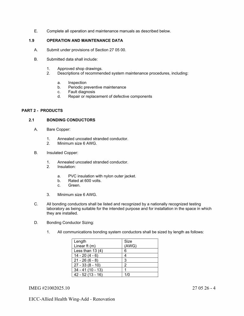
IMEG #21002025.10 27 05 26 - 4
EICC-Allied Health Wing-Add - Renovation
E. Complete all operation and maintenance manuals as described below.
1.9 OPERATION AND MAINTENANCE DATA
A. Submit under provisions of Section 27 05 00.
B. Submitted data shall include:
1. Approved shop drawings.2. Descriptions of recommended system maintenance procedures, including:
a. Inspectionb. Periodic preventive maintenancec. Fault diagnosisd. Repair or replacement of defective components
PART 2 - PRODUCTS
2.1 BONDING CONDUCTORS
A. Bare Copper:
1. Annealed uncoated stranded conductor.2. Minimum size 6 AWG.
B. Insulated Copper:
1. Annealed uncoated stranded conductor.2. Insulation:
a. PVC insulation with nylon outer jacket.b. Rated at 600 volts.c. Green.
3. Minimum size 6 AWG.
C. All bonding conductors shall be listed and recognized by a nationally recognized testing laboratory as being suitable for the intended purpose and for installation in the space in which they are installed.
D. Bonding Conductor Sizing:
1. All communications bonding system conductors shall be sized by length as follows:
LengthLinear ft (m)
Size(AWG)
Less than 13 (4) 614 - 20 (4 - 6) 421 - 26 (6 - 8) 327 - 33 (8 - 10) 234 - 41 (10 - 13) 142 - 52 (13 - 16) 1/0
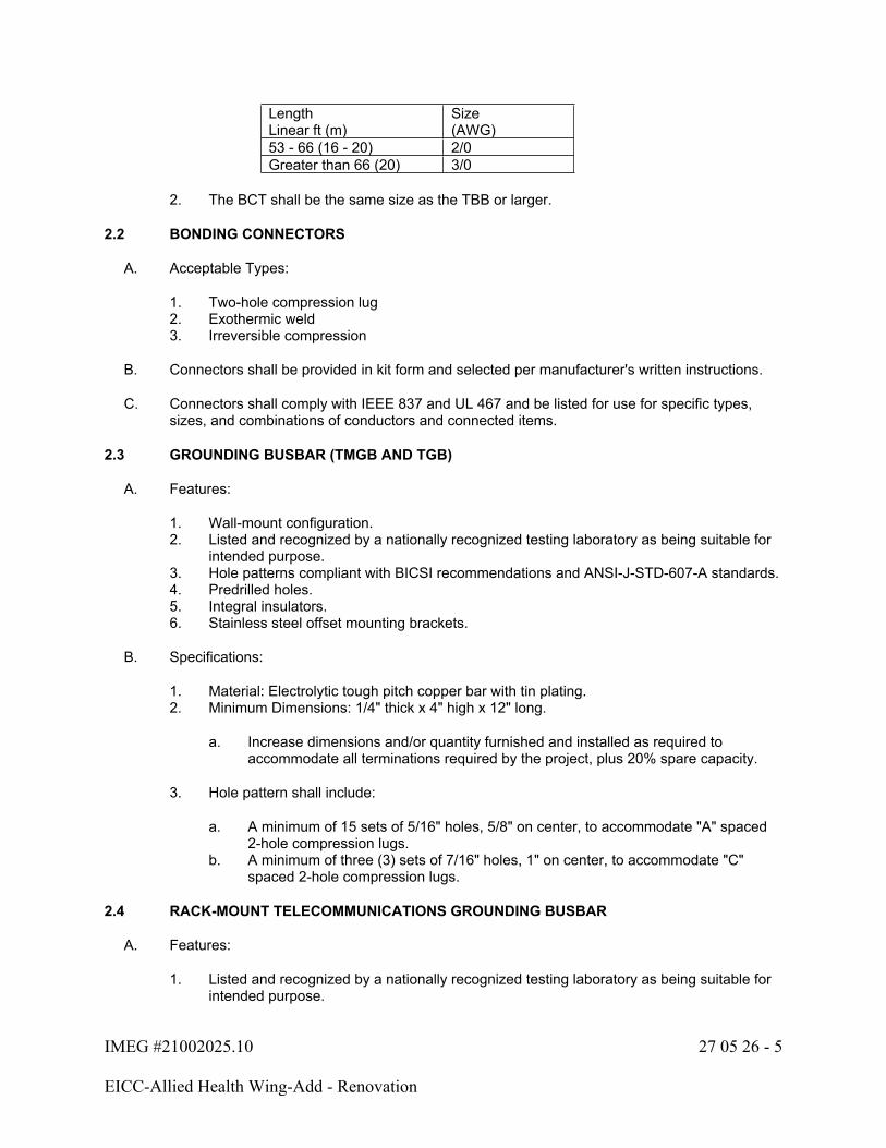
IMEG #21002025.10 27 05 26 - 5
EICC-Allied Health Wing-Add - Renovation
LengthLinear ft (m)
Size(AWG)
53 - 66 (16 - 20) 2/0Greater than 66 (20) 3/0
2. The BCT shall be the same size as the TBB or larger.
2.2 BONDING CONNECTORS
A. Acceptable Types:
1. Two-hole compression lug2. Exothermic weld3. Irreversible compression
B. Connectors shall be provided in kit form and selected per manufacturer's written instructions.
C. Connectors shall comply with IEEE 837 and UL 467 and be listed for use for specific types, sizes, and combinations of conductors and connected items.
2.3 GROUNDING BUSBAR (TMGB AND TGB)
A. Features:
1. Wall-mount configuration.2. Listed and recognized by a nationally recognized testing laboratory as being suitable for
intended purpose.3. Hole patterns compliant with BICSI recommendations and ANSI-J-STD-607-A standards.4. Predrilled holes.5. Integral insulators.6. Stainless steel offset mounting brackets.
B. Specifications:
1. Material: Electrolytic tough pitch copper bar with tin plating.2. Minimum Dimensions: 1/4" thick x 4" high x 12" long.
a. Increase dimensions and/or quantity furnished and installed as required to accommodate all terminations required by the project, plus 20% spare capacity.
3. Hole pattern shall include:
a. A minimum of 15 sets of 5/16" holes, 5/8" on center, to accommodate "A" spaced 2-hole compression lugs.
b. A minimum of three (3) sets of 7/16" holes, 1" on center, to accommodate "C" spaced 2-hole compression lugs.
2.4 RACK-MOUNT TELECOMMUNICATIONS GROUNDING BUSBAR
A. Features:
1. Listed and recognized by a nationally recognized testing laboratory as being suitable for intended purpose.
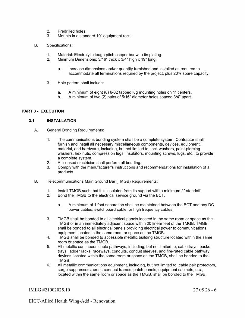
IMEG #21002025.10 27 05 26 - 6
EICC-Allied Health Wing-Add - Renovation
2. Predrilled holes.3. Mounts in a standard 19" equipment rack.
B. Specifications:
1. Material: Electrolytic tough pitch copper bar with tin plating.2. Minimum Dimensions: 3/16" thick x 3/4" high x 19" long.
a. Increase dimensions and/or quantity furnished and installed as required to accommodate all terminations required by the project, plus 20% spare capacity.
3. Hole pattern shall include:
a. A minimum of eight (8) 6-32 tapped lug mounting holes on 1" centers.b. A minimum of two (2) pairs of 5/16" diameter holes spaced 3/4" apart.
PART 3 - EXECUTION
3.1 INSTALLATION
A. General Bonding Requirements:
1. The communications bonding system shall be a complete system. Contractor shall furnish and install all necessary miscellaneous components, devices, equipment, material, and hardware, including, but not limited to, lock washers, paint-piercing washers, hex nuts, compression lugs, insulators, mounting screws, lugs, etc., to provide a complete system.
2. A licensed electrician shall perform all bonding.3. Comply with the manufacturer's instructions and recommendations for installation of all
products.
B. Telecommunications Main Ground Bar (TMGB) Requirements:
1. Install TMGB such that it is insulated from its support with a minimum 2" standoff.2. Bond the TMGB to the electrical service ground via the BCT.
a. A minimum of 1 foot separation shall be maintained between the BCT and any DC power cables, switchboard cable, or high frequency cables.
3. TMGB shall be bonded to all electrical panels located in the same room or space as the TMGB or in an immediately adjacent space within 20 linear feet of the TMGB. TMGB shall be bonded to all electrical panels providing electrical power to communications equipment located in the same room or space as the TMGB.
4. TMGB shall be bonded to accessible metallic building structure located within the same room or space as the TMGB.
5. All metallic continuous cable pathways, including, but not limited to, cable trays, basket trays, ladder racks, raceways, conduits, conduit sleeves, and fire-rated cable pathway devices, located within the same room or space as the TMGB, shall be bonded to the TMGB.
6. All metallic communications equipment, including, but not limited to, cable pair protectors, surge suppressors, cross-connect frames, patch panels, equipment cabinets, etc., located within the same room or space as the TMGB, shall be bonded to the TMGB.
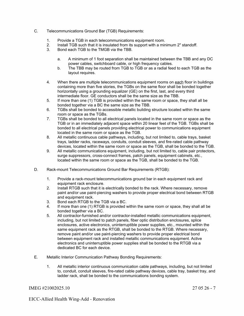
IMEG #21002025.10 27 05 26 - 7
EICC-Allied Health Wing-Add - Renovation
C. Telecommunications Ground Bar (TGB) Requirements:
1. Provide a TGB in each telecommunications equipment room.2. Install TGB such that it is insulated from its support with a minimum 2" standoff.3. Bond each TGB to the TMGB via the TBB.
a. A minimum of 1 foot separation shall be maintained between the TBB and any DC power cables, switchboard cable, or high frequency cables.
b. The TBB may be routed from TGB to TGB or as a radial feed to each TGB as the layout requires.
4. When there are multiple telecommunications equipment rooms on each floor in buildings containing more than five stories, the TGBs on the same floor shall be bonded together horizontally using a grounding equalizer (GE) on the first, last, and every third intermediate floor. GE conductors shall be the same size as the TBB.
5. If more than one (1) TGB is provided within the same room or space, they shall all be bonded together via a BC the same size as the TBB.
6. TGBs shall be bonded to accessible metallic building structure located within the same room or space as the TGBs.
7. TGBs shall be bonded to all electrical panels located in the same room or space as the TGB or in an immediately adjacent space within 20 linear feet of the TGB. TGBs shall be bonded to all electrical panels providing electrical power to communications equipment located in the same room or space as the TGB.
8. All metallic continuous cable pathways, including, but not limited to, cable trays, basket trays, ladder racks, raceways, conduits, conduit sleeves, and fire-rated cable pathway devices, located within the same room or space as the TGB, shall be bonded to the TGB.
9. All metallic communications equipment, including, but not limited to, cable pair protectors, surge suppressors, cross-connect frames, patch panels, equipment cabinets, etc., located within the same room or space as the TGB, shall be bonded to the TGB.
D. Rack-mount Telecommunications Ground Bar Requirements (RTGB):
1. Provide a rack-mount telecommunications ground bar in each equipment rack and equipment rack enclosure.
2. Install RTGB such that it is electrically bonded to the rack. Where necessary, remove paint and/or use paint-piercing washers to provide proper electrical bond between RTGB and equipment rack.
3. Bond each RTGB to the TGB via a BC.4. If more than one (1) RTGB is provided within the same room or space, they shall all be
bonded together via a BC.5. All contractor-furnished and/or contractor-installed metallic communications equipment,
including, but not limited to patch panels, fiber optic distribution enclosures, splice enclosures, active electronics, uninterruptible power supplies, etc., mounted within the same equipment rack as the RTGB, shall be bonded to the RTGB. Where necessary, remove paint and/or use paint-piercing washers to provide proper electrical bond between equipment rack and installed metallic communications equipment. Active electronics and uninterruptible power supplies shall be bonded to the RTGB via a dedicated BC for each device.
E. Metallic Interior Communication Pathway Bonding Requirements:
1. All metallic interior continuous communication cable pathways, including, but not limited to, conduit, conduit sleeves, fire-rated cable pathway devices, cable tray, basket tray, and ladder rack, shall be bonded to the communications bonding system.
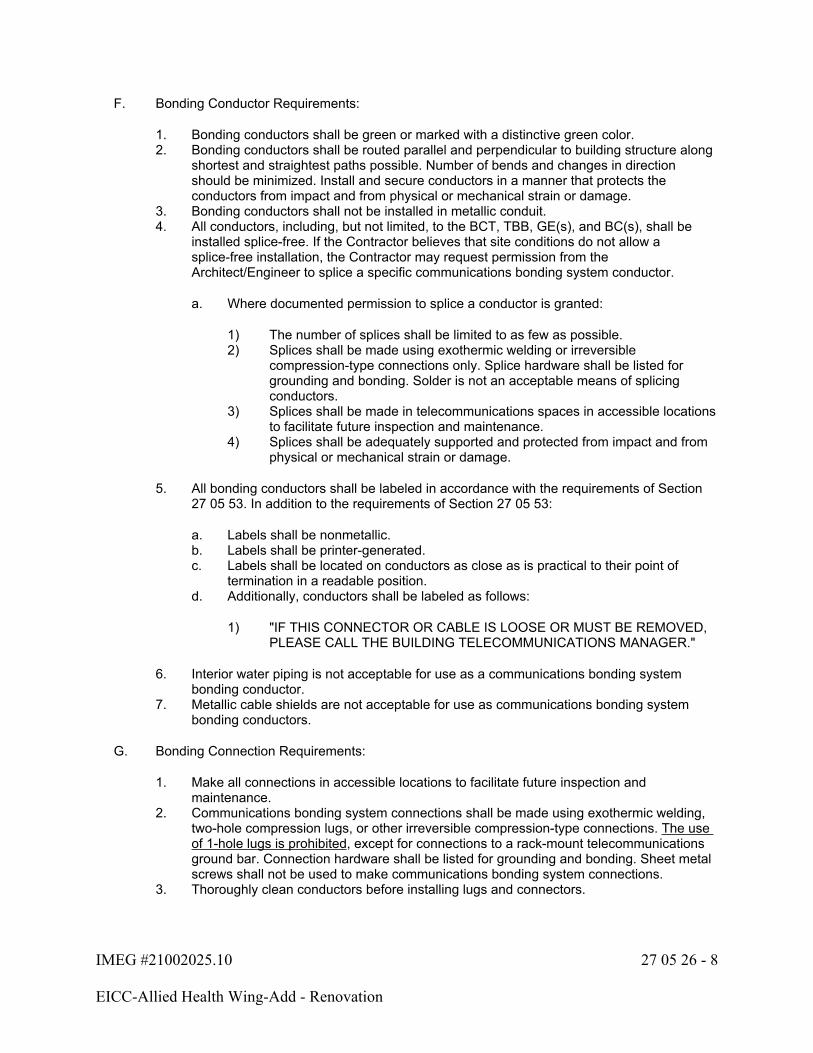
IMEG #21002025.10 27 05 26 - 8
EICC-Allied Health Wing-Add - Renovation
F. Bonding Conductor Requirements:
1. Bonding conductors shall be green or marked with a distinctive green color.2. Bonding conductors shall be routed parallel and perpendicular to building structure along
shortest and straightest paths possible. Number of bends and changes in direction should be minimized. Install and secure conductors in a manner that protects the conductors from impact and from physical or mechanical strain or damage.
3. Bonding conductors shall not be installed in metallic conduit.4. All conductors, including, but not limited, to the BCT, TBB, GE(s), and BC(s), shall be
installed splice-free. If the Contractor believes that site conditions do not allow a splice-free installation, the Contractor may request permission from the Architect/Engineer to splice a specific communications bonding system conductor.
a. Where documented permission to splice a conductor is granted:
1) The number of splices shall be limited to as few as possible.2) Splices shall be made using exothermic welding or irreversible
compression-type connections only. Splice hardware shall be listed for grounding and bonding. Solder is not an acceptable means of splicing conductors.
3) Splices shall be made in telecommunications spaces in accessible locations to facilitate future inspection and maintenance.
4) Splices shall be adequately supported and protected from impact and from physical or mechanical strain or damage.
5. All bonding conductors shall be labeled in accordance with the requirements of Section 27 05 53. In addition to the requirements of Section 27 05 53:
a. Labels shall be nonmetallic.b. Labels shall be printer-generated.c. Labels shall be located on conductors as close as is practical to their point of
termination in a readable position.d. Additionally, conductors shall be labeled as follows:
1) "IF THIS CONNECTOR OR CABLE IS LOOSE OR MUST BE REMOVED, PLEASE CALL THE BUILDING TELECOMMUNICATIONS MANAGER."
6. Interior water piping is not acceptable for use as a communications bonding system bonding conductor.
7. Metallic cable shields are not acceptable for use as communications bonding system bonding conductors.
G. Bonding Connection Requirements:
1. Make all connections in accessible locations to facilitate future inspection and maintenance.
2. Communications bonding system connections shall be made using exothermic welding, two-hole compression lugs, or other irreversible compression-type connections. The use of 1-hole lugs is prohibited, except for connections to a rack-mount telecommunications ground bar. Connection hardware shall be listed for grounding and bonding. Sheet metal screws shall not be used to make communications bonding system connections.
3. Thoroughly clean conductors before installing lugs and connectors.

IMEG #21002025.10 27 05 26 - 9
EICC-Allied Health Wing-Add - Renovation
4. Install and tighten all connectors in accordance with manufacturer's instructions, using the appropriate purpose-designed tool(s) recommended by the manufacturer for that purpose. Exercise care not to tighten connectors beyond manufacturer's recommendations.
5. Where necessary, remove paint and/or use paint-piercing washers to provide proper electrical bond at all connections.
6. All bonding connections shall be coated in anti-oxidant joint compound that is purpose-designed and purpose-manufactured for that use. Anti-oxidant joint compound shall be applied in accordance with manufacturer's recommendations and instructions.
7. All installed connectors on conductors installed in damp locations shall be sealed with dielectric grease and then covered with heat shrink tubing to protect against moisture ingress. Applied heat shrink tubing shall overlap conductor's outer jacket a minimum of four (4) inches past connector and be installed in accordance with manufacturer's recommendations and instructions.
3.2 FIELD QUALITY CONTROL
A. Field inspection and testing shall be performed under provisions of Section 27 05 00.
B. Where these specifications require a product or assembly without the use of a brand or trade name, provide a product from a reputable manufacturer that meets the requirements of the specifications.
C. Periodic observations will be performed during construction to verify compliance with the requirements of the specifications. These services do not relieve the Contractor of responsibility for compliance with the contract documents.
3.3 ADJUSTING
A. Adjust work under provisions of Section 27 05 00.
B. Contractor shall make any and all adjustments to the communications bonding system necessary to ensure that the installed system meets all requirements listed herein. Modifications necessary to comply with listed requirements or to provide specified performance shall be completed by the Contractor at no additional cost to the Owner.
3.4 TESTING
A. Test installed system under provisions of Section 27 17 10.
B. Measure and document resistance to ground at TMGB, each TGB, each RTGB, and each electrical distribution panel bonded to the TMGB or a TGB.
1. Measurements shall be made not less than two full days after the last trace of precipitation, and without the soil being moistened by any means other than natural drainage or seepage, and without chemical treatment or other artificial means of reducing natural ground resistance. Perform tests by the fall-of-potential method according to IEEE 81.
2. Measured resistance to ground at TMGB, each TGB, and each RTGB must not exceed 1 ohm.
3. Under no circumstances shall any point in the communications bonding system have a lower resistance to ground than that of nearby electrical distribution system components that it is bonded to.

IMEG #21002025.10 27 05 26 - 10
EICC-Allied Health Wing-Add - Renovation
C. Include measurement documentation in test data submitted at completion of project under provisions of Section 27 17 10.
END OF SECTION 27 05 26

IMEG #21002025.10 27 05 28 - 1
EICC-Allied Health Wing-Add - Renovation
SECTION 27 05 28 - INTERIOR COMMUNICATION PATHWAYS
PART 1 - GENERAL
1.1 RELATED WORK
A. Section 26 05 33 - Conduit and Boxes
B. Section 27 05 00 - Basic Communications Systems Requirements
C. Section 27 05 26 - Communications Bonding
1.2 QUALITY ASSURANCE
A. Refer to Section 27 05 00 for requirements.
1.3 REFERENCES
A. ANSI/NFPA 70 - National Electrical Code
1.4 SUBMITTALS
A. Under the provisions of Section 27 05 00 and Division 1, prior to the start of work the Contractor shall submit:
1. Manufacturer's data covering all products proposed, including construction, materials, ratings and all other parameters identified in Part 2 - Products, below.
2. Manufacturer's installation instructions.
B. Coordination Drawings:
1. Include cable tray and conduit sleeve layout in composite electronic coordination files. Refer to Section 27 05 00 for coordination drawing requirements.
1.5 DRAWINGS
A. The drawings, which constitute a part of these specifications, indicate the general route of the wire mesh support systems, conduit, sleeves, etc. Data presented on these drawings is as accurate as preliminary surveys and planning can determine until final equipment selection is made. Accuracy is not guaranteed and field verification of all dimensions, routing, etc., is required.
PART 2 - PRODUCTS
2.1 CONDUIT
A. Refer to Section 26 05 33 for conduit requirements for this project.
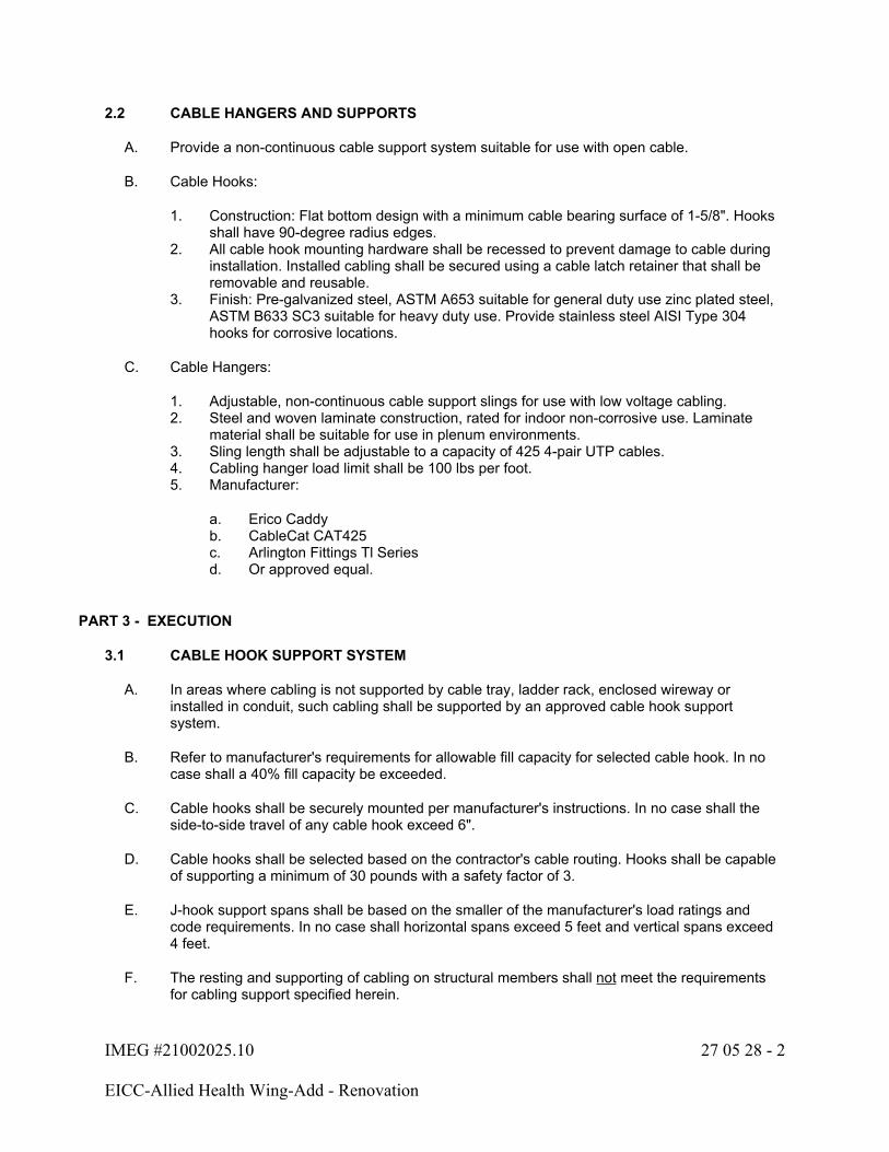
IMEG #21002025.10 27 05 28 - 2
EICC-Allied Health Wing-Add - Renovation
2.2 CABLE HANGERS AND SUPPORTS
A. Provide a non-continuous cable support system suitable for use with open cable.
B. Cable Hooks:
1. Construction: Flat bottom design with a minimum cable bearing surface of 1-5/8". Hooks shall have 90-degree radius edges.
2. All cable hook mounting hardware shall be recessed to prevent damage to cable during installation. Installed cabling shall be secured using a cable latch retainer that shall be removable and reusable.
3. Finish: Pre-galvanized steel, ASTM A653 suitable for general duty use zinc plated steel, ASTM B633 SC3 suitable for heavy duty use. Provide stainless steel AISI Type 304 hooks for corrosive locations.
C. Cable Hangers:
1. Adjustable, non-continuous cable support slings for use with low voltage cabling.2. Steel and woven laminate construction, rated for indoor non-corrosive use. Laminate
material shall be suitable for use in plenum environments.3. Sling length shall be adjustable to a capacity of 425 4-pair UTP cables.4. Cabling hanger load limit shall be 100 lbs per foot.5. Manufacturer:
a. Erico Caddyb. CableCat CAT425c. Arlington Fittings Tl Series d. Or approved equal.
PART 3 - EXECUTION
3.1 CABLE HOOK SUPPORT SYSTEM
A. In areas where cabling is not supported by cable tray, ladder rack, enclosed wireway or installed in conduit, such cabling shall be supported by an approved cable hook support system.
B. Refer to manufacturer's requirements for allowable fill capacity for selected cable hook. In no case shall a 40% fill capacity be exceeded.
C. Cable hooks shall be securely mounted per manufacturer's instructions. In no case shall the side-to-side travel of any cable hook exceed 6".
D. Cable hooks shall be selected based on the contractor's cable routing. Hooks shall be capable of supporting a minimum of 30 pounds with a safety factor of 3.
E. J-hook support spans shall be based on the smaller of the manufacturer's load ratings and code requirements. In no case shall horizontal spans exceed 5 feet and vertical spans exceed 4 feet.
F. The resting and supporting of cabling on structural members shall not meet the requirements for cabling support specified herein.

IMEG #21002025.10 27 05 28 - 3
EICC-Allied Health Wing-Add - Renovation
G. The use of tie-wraps or hook and loop type fasteners is specifically prohibited as a substitute for cable hooks specified herein.
3.2 CONDUIT AND CABLE ROUTING
A. Refer to Section 26 05 33 for additional requirements.
B. All conduits shall be reamed and shall be installed with a nylon bushing.
C. Maintain appropriate conduit bend radius at all times. For conduits with an internal diameter of less than 2", maintain a bend radius of at least 6 times the internal diameter. For conduits with an internal diameter 2" or greater, maintain a bend radius of at least 10 times the internal diameter.
D. No conduit or sleeve containing more than two (2) cables shall exceed 40% fill ratio, regardless of length.
E. Any conduit exceeding 90' in length or containing more than two (2) 90-degree bends shall contain a pull box sized per ANSI/TIA/EIA 569 requirements.
1. A separate pull box is required for each 90' (or greater) length section.2. A separate pull box is required after any two (2) consecutive 90-degree bends.3. Pull box shall be located in an area that maintains accessibility of box, including the
ability to remove box lid without removal or relocation of any other materials.
F. Any conduit with bends totaling 90 degrees or more shall have the fill capacity derated by 15% for each 90 degrees of cumulative bend.
G. Cables installed in any conduits that do not meet the above requirements shall be replaced at the Contractor's expense, after the conduit condition has been remedied.
3.3 ATTACHMENT TO METAL DECKING
A. Where supports for cable trays and cable hook systems attach to metal roof decking, excluding concrete on metal decking, do not exceed 25 lbs. per hangar and a minimum spacing of 2'-0" on center. This 25-lb. load and 2'-0" spacing include adjacent electrical and mechanical items hanging from deck. If the hanger restrictions cannot be achieved, supplemental framing off steel framing will need to be added.
END OF SECTION 27 05 28
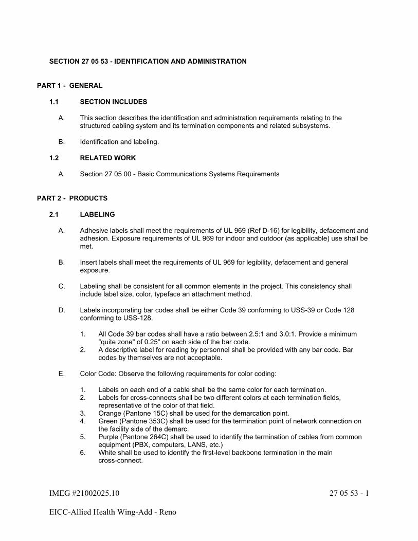
IMEG #21002025.10 27 05 53 - 1
EICC-Allied Health Wing-Add - Reno
SECTION 27 05 53 - IDENTIFICATION AND ADMINISTRATION
PART 1 - GENERAL
1.1 SECTION INCLUDES
A. This section describes the identification and administration requirements relating to the structured cabling system and its termination components and related subsystems.
B. Identification and labeling.
1.2 RELATED WORK
A. Section 27 05 00 - Basic Communications Systems Requirements
PART 2 - PRODUCTS
2.1 LABELING
A. Adhesive labels shall meet the requirements of UL 969 (Ref D-16) for legibility, defacement and adhesion. Exposure requirements of UL 969 for indoor and outdoor (as applicable) use shall be met.
B. Insert labels shall meet the requirements of UL 969 for legibility, defacement and general exposure.
C. Labeling shall be consistent for all common elements in the project. This consistency shall include label size, color, typeface an attachment method.
D. Labels incorporating bar codes shall be either Code 39 conforming to USS-39 or Code 128 conforming to USS-128.
1. All Code 39 bar codes shall have a ratio between 2.5:1 and 3.0:1. Provide a minimum "quite zone" of 0.25" on each side of the bar code.
2. A descriptive label for reading by personnel shall be provided with any bar code. Bar codes by themselves are not acceptable.
E. Color Code: Observe the following requirements for color coding:
1. Labels on each end of a cable shall be the same color for each termination.2. Labels for cross-connects shall be two different colors at each termination fields,
representative of the color of that field.3. Orange (Pantone 15C) shall be used for the demarcation point.4. Green (Pantone 353C) shall be used for the termination point of network connection on
the facility side of the demarc.5. Purple (Pantone 264C) shall be used to identify the termination of cables from common
equipment (PBX, computers, LANS, etc.)6. White shall be used to identify the first-level backbone termination in the main
cross-connect.
IMEG #21002025.10 27 05 53 - 2
EICC-Allied Health Wing-Add - Reno
7. Gray (Pantone 422C) shall be used to identify the second-level backbone termination in the main cross-connect.
8. Blue (Pantone 291C) shall be used to identify the termination of station cabling at the telecommunications closet and/or equipment room end of the cable.
9. Brown (Pantone 465C) shall be used to identify the termination of the interbuilding backbone cable terminations.
10. Yellow (Pantone 101C) shall be used to identify the termination of auxiliary circuits, alarms, maintenance, security, etc.
11. Red (Pantone 184C) shall be used to identify the termination of key telephone systems.12. In facilities that do not contain a main cross-connect, the color white may be used to
identify second-level backbone terminations.
F. Tag all CAT 3, CAT 6, and optical fiber cables at both the Communications Equipment Room and the information outlets using the following alphanumeric labeling system:
1. (Room Number) - (Outlet Number) - (Jack Number) - (Use).2. "Outlet Number" shall start with 1 in each room, with additional outlets in each room
numbered sequentially.3. "Jack Number" shall start with 1 for the upper left jack in each outlet, increasing
sequentially from left to right and top to bottom across the outlet face.4. "Use" shall be designated by the following:
a. "V" for voice (RJ-45)b. "D" for data (RJ-45)
5. Example #1: "106-1-1-V" indicates the top left voice jack in outlet #1 in Room 106.6. Example #2: "109-3-4-D" indicates the bottom right data jack (assuming a 4-port
faceplate) in outlet #3 in Room 109.
2.2 DOCUMENTATION/AS-BUILTS/RECORDS
A. General:
1. Upon completion of the installation, the Contractor shall submit as-builts per the requirements of Section 27 05 00 and Division 1. Documentation shall include the items detailed in the subsections below.
2. All documentation, including hard copy and electronic forms shall become the property of the Owner.
B. Record Drawings:
1. The drawings are to include cable routes and outlet locations. Outlet locations shall be identified by their sequential number as defined elsewhere in this document. Numbering, icons and drawing conventions used shall be consistent throughout all documentation provided.
PART 3 - EXECUTION
3.1 IDENTIFICATION AND LABELING
A. Cable Labeling: Backbone and horizontal cables shall be labeled at each end.
1. Provide additional cable labeling at each manhole and pull box.
IMEG #21002025.10 27 05 53 - 3
EICC-Allied Health Wing-Add - Reno
2. Cables that are routed through multiple pathway segments shall contain reference to all pathway segments in the pathway linkage field.
3. Cables that differ only by performance class shall have a suitable marking or label to indicate the higher performance class. For example, station cabling utilizing the blue color, may include blue with a white stripe to indicate the higher performance class station cabling.
B. Information Outlet Labeling: Tag all voice and data jacks as defined herein.
C. Termination Hardware Labeling:
1. An identifier shall be provided at each termination hardware location or its label.
D. Grounding/Bonding Labeling:
1. The TMGB shall be labeled "TMGB." There shall be only one TMGB in the facility.2. Label all TBB conductors connecting to the TMGB with a unique label, located at both
ends of the TBB.3. Each TGB shall be labeled with a unique label.4. All TBB conductors connecting to the TGB shall be labeled uniquely at each end of the
cable.
END OF SECTION 27 05 53
IMEG #21002025.10 27 11 00 - 1
EICC-Allied Health Wing-Add - Renovation
SECTION 27 11 00 - COMMUNICATION EQUIPMENT ROOMS (CER)
PART 1 - GENERAL
1.1 SECTION INCLUDES
A. This section describes the products and execution requirements related to furnishing and installing equipment for communication equipment rooms.
1.2 RELATED WORK
A. Section 27 05 00 - Basic Communications Systems Requirements
B. Section 27 05 26 - Communications Bonding
C. Section 27 05 28 - Interior Communication Pathways
D. Section 27 15 00 - Horizontal Cabling Requirements
1.3 QUALITY ASSURANCE
A. Refer to Section 27 05 00 for applicable standards.
1.4 SUBMITTALS
A. Under the provisions of Section 27 05 00 and Division 1, prior to the start of work the Contractor shall submit:
1. Manufacturer's data covering all products including construction, materials, ratings and all other parameters identified in Part 2 - Products, below.
B. Coordination Drawings:
1. Include ladder racking, equipment racks, cable tray and conduit sleeve layout in composite electronic coordination files. Refer to Section 27 05 00 for coordination drawing requirements.
PART 2 - PRODUCTS
2.1 EQUIPMENT GROUNDING
A. Refer to specification section 27 05 26 for grounding requirements.
B. All equipment required to be grounded shall be provided with a grounding lug suitable for termination of the specified size electrode conductor.

IMEG #21002025.10 27 11 00 - 2
EICC-Allied Health Wing-Add - Renovation
2.2 EQUIPMENT RACKS
A. Where identified on the drawings in Communication Equipment Rooms, equipment racks and/or equipment cabinets shall be furnished and installed by the Contractor to house cable termination components (e.g., copper, optical fiber, coax) and network electronics.
B. The equipment rack shall conform to the following requirements:
1. Standard TIA/EIA 19" Floor Rack:
a. Equipment rack shall be 84" in height, self-supporting and provide a useable mounting height of 45 rack units (RU) (1 RU = 1 ¾").
b. Channel uprights shall be spaced to accommodate industry standard 19" mounting.c. Equipment rack shall be double side drilled and tapped to accept 12-24 screws.
Uprights shall also be drilled on back to accept cable brackets, clamps, power strip(s), etc. Hole pattern on rack front shall be per TIA/EIA specifications (5/8"-5/8"-1/2"). Hole pattern on the rear shall be at 3" intervals to accept cable brackets.
d. Equipment racks shall be provided with a supply of spare screws (minimum of 24).e. Equipment racks shall be provided with a ground bar and #6 AWG ground lug.f. Provide all mounting hardware and accessories as required for a complete
installation.
2.3 CABLE MANAGEMENT - VERTICAL AND HORIZONTAL
A. Equipment Racks:
1. Equipment racks shall be equipped with vertical and horizontal cable management hardware in the form of rings and guides. Racks shall incorporate vertical andhorizontal covers, to allow an orderly, hidden, routing of copper, optical fiber, and coax jumpers from the modular patch panels and/or 110-type termination blocks to the customer provided network electronics. Vertical and horizontal cable management hardware shall be as follows:
a. Horizontal cable management hardware shall be 16 gauge cold rolled steel construction with six (6) pass-thru holes and seven (7) front-mounted 3.5" steel rod D-rings. Provide with cover designed to conceal and protect cable.
b. At a minimum, horizontal cable management hardware shall be positioned above and below (a) each grouping of two rows of jacks on modular patch panels, and (b) above and below each optical fiber patch panel and (c) each grouping of two rows of F-type connectors on coax patch panels.
c. Vertical cable management hardware shall provide for cable routing on front and rear of each rack and be 14" deep x 6" wide (minimum). Where multiple equipment racks are to be installed, this hardware shall be mounted between the uprights of adjacent equipment racks. Equipment rack uprights and the spacers shall be secured together per manufacturer's recommendations. Provide with cover designed to conceal and protect cable.
2. Each equipment rack shall be supplied with a minimum of 12 releasable (e.g., "hook and loop") cable support ties.

IMEG #21002025.10 27 11 00 - 3
EICC-Allied Health Wing-Add - Renovation
3. Where cable termination hardware is wall-mounted, the Contractor shall be responsible for establishing a cable pathway for jumpers routed from the equipment rack(s) to the wall. This shall be in the form of slotted ducts or troughs. Routing of jumpers via the overhead cable tray or ladder rack system is NOT acceptable. The proposed method shall be included in the submittals required by this document and shall be approved by the Architect/Engineer prior to installation.
B. 110-type Termination Blocks:
1. Horizontal troughs incorporating plastic distribution rings shall be provided by the Contractor to accommodate routing of jumpers. Horizontal troughs shall be positioned at the top of each column of 110-type termination blocks and between each 100-pair 110-type termination block.
2. Vertical troughs incorporating metal distribution rings shall be provided for vertical routing of jumper and/or cross-connect wire.
2.4 OPTICAL FIBER PANELS
A. All terminated optical fibers shall be mated to simplex LC-type couplings mounted on enclosed fiber distribution cabinets. Couplings shall be mounted on a panel that, in turn, snaps into the enclosure. The proposed enclosure shall be designed to accommodate a changing variety of connector types including SC, ST, Fixed Shroud Duplex (e.g., "FDDI Connector"), Biconic, FC, and MT-RJ by changing panels on which connector couplings are mounted.
B. The fiber distribution cabinet shall be sized to accommodate the total fiber count to be installed at each location as defined in the specifications and drawings, including those not terminated (if applicable). Connector panels and connector couplings (sleeves, bulkheads, etc.) adequate to accommodate the number of fibers to be terminated shall be furnished and installed by the Contractor.
C. The fiber distribution cabinet shall be an enclosed assembly affording protection to the cable subassemblies and to the terminated ends. The enclosures shall incorporate a hinged or retractable front cover designed to conceal and protect the optical fiber couplings, connectors, and cable.
D. Access to the inside of the fiber distribution cabinet's enclosure during installation shall be from the front and/or rear. Panels that require any disassembly of the fiber distribution cabinet to gain entry will not be accepted.
E. The fiber distribution cabinet's enclosure shall provide for strain relief of incoming optical fiber cables and shall incorporate radius control mechanisms to limit bending of the optical fiber to the manufacturer's recommended minimums or ½", whichever is larger.
F. All fiber distribution cabinets shall provide protection to both the "facilities" and "user" side of the coupling. The fiber distribution cabinet's enclosure shall be configured to require front access only when patching. The incoming optical fiber cables (e.g., backbone, riser, horizontal, etc.) shall not be accessible from the patching area of the panel. The fiber distribution cabinet's enclosure shall provide a physical barrier to access such optical fiber cables.
IMEG #21002025.10 27 11 00 - 4
EICC-Allied Health Wing-Add - Renovation
G. Where "Loose Buffered" cables are installed, the 250 µm coated optical fibers contained in these cables may be terminated either by (1) splicing of factory-terminated cable assemblies ("pigtails") or (2) the use of a "fan-out" kit. In the latter approach, individual fibers are to be secured in a protective covering, an Aramid (e.g., Kevlar™) reinforced tube for example, with connectors mated to the resulting assembly. In both instances, the proposed termination hardware shall incorporate a mechanism by which cable and subassemblies are secured to prevent damage. Splicing shall be by the "fusion" method. Individual splice loss shall not exceed 0.3 dB for multi-mode fibers. Direct termination of 250 µm coated optical fibers shall not be permitted.
2.5 OPTICAL FIBER COUPLERS/ADAPTERS
A. Optical Fiber Couplings (LC-type) (Multimode/Singlemode):
1. LC-type optical fiber couplings shall be used to terminate optical fiber backbone cable on fiber distribution cabinet panels in communication equipment rooms. Horizontal optical fiber cables shall also be terminated using optical fiber couplings at their designated work area locations on information outlet faceplates for "fiber to the desk."
2. LC-type optical fiber couplings shall be snap-type with locking washer and nut.3. LC-type optical fiber couplings shall incorporate domed zirconia ferrule and shall utilize a
PC polish to ensure fiber-to-fiber physical contact for low loss and reflections.4. LC-type optical fiber couplings shall accept 125-micron outside diameter multimode fiber.5. The attenuation per mated pair shall not exceed 0.7 dB (individual) and 0.5 dB (average).
Connectors shall sustain a minimum of 200 mating cycles per TIA/EIA-455-21 without violating specifications.
6. LC-type optical fiber couplings shall meet the following performance criteria:
Test Procedure Maximum Attenuation ChangeCable Retention (FOTP-6) 0.2 dBDurability (FOTP-21) 0.2 dBImpact (FOTP-2) 0.2 dBThermal Shock (FOTP-3) 0.2 dBHumidity (FOTP-5) 0.2 dB
7. Performance Requirements:
a. Length: 2 inchesb. Operating Temperature: -40 to 85 degrees C
8. Basis of Design:
a. Panduit
2.6 TERMINATION BLOCKS
A. Where identified on the drawings in Communication Equipment Rooms, 110-type termination blocks shall be furnished and installed by the Contractor for termination of copper cable.
B. Each horizontal row of the 110-type termination block must be capable of terminating one (1) 25-pair binder group (backbone cables) or six (6) 4-pair groups (horizontal cables). Backbone and horizontal 110-type termination blocks shall be segregated, clearly identifying their function.
IMEG #21002025.10 27 11 00 - 5
EICC-Allied Health Wing-Add - Renovation
C. The Mechanical Termination Shall:
1. Have the ability of terminating 22 - 26 AWG plastic insulated, solid and stranded copper conductors.
2. Provide a direct connection between the cable and jumper wires.3. Have less than 0.2 dB of attenuation from 1-16 MHz.4. Have less than 100 mW of DC resistance.5. Have less than 5 mw of resistance imbalance.6. Have minimal signal impairments at all frequencies up to 16 MHz.
D. The 110-type termination block shall identify pair position by a color designation - Blue, Orange, Green, Brown and Slate (backbone only).
E. The 110-type termination block shall be designed to maintain the cables' pair twists as closely as possible to the point of mechanical termination.
2.7 LADDER RACK
A. Provide complete ladder rack system including metallic ladder rack, splice connectors, fastening hardware and other miscellaneous materials as required for a complete installation per manufacturer's recommendations.
B. Steel C-Channel Stringer Style Ladder Rack:
1. Rolled steel siderail stringer, 2" stringer height, 9" spaced welded rungs.2. Steel shall meet the requirements of ASTM A1011 SS Grade 33.3. Loading limits shall be 292 lbs/ft for 4 ft spans.
C. Ladder rack finish shall be flat black powder coat.
2.8 D-RINGS
A. Rounded edge D-rings for support of cabling in vertical and horizontal configurations.
B. EIA 310D compliant, manufactured from materials meeting UL94-V0 specifications.
C. Provide ¼" screw holes for wall mounting.
2.9 POWER STRIPS
A. Provide power strips on all equipment racks, unless noted otherwise. These power strips shall have the following characteristics:
1. Standard Rack Mount:
a. TIA/EIA 19" equipment rack mountable.b. Compliant with UL-1449 Third Edition and UL-497A.c. Provide transient suppression to 12,000-A. Protection shall be in all three modes
(line-neutral, line-ground and neutral-ground).d. Shall meet or exceed ANSI C62 Category A3 requirements.e. Provide high-frequency noise suppression as follows:
1) Greater than 20-dB @ 50 kHz
IMEG #21002025.10 27 11 00 - 6
EICC-Allied Health Wing-Add - Renovation
2) Greater than 40-dB @ 150 kHz3) Greater than 80-dB @ 1 MHz4) Greater than 30-dB @ 6 to 1000 MHz
f. Protection Modes and UL 1449 Clamping Voltage: 475 volt L-N, L-G, and N-G.g. Components: Nonmodular units composed of 20mm metal oxide varistors (MOV).
Series inductors, SAD, or selenium cells may be used in addition to MOVs.h. Be equipped with a 10-foot power cord.i. Provide with raised floor twistlock compatible.
2.10 COPPER PATCH CORDS
A. Owner Provided and Installed
B. Modular Patch Panel:
1. Owner provided and installed
2.11 FIBER PATCH CORDS
A. Optical Fiber Patch Cords (Singlemode):
1. Owner provided and installed.
PART 3 - EXECUTION
3.1 EQUIPMENT RACKS
A. Equipment racks shall be furnished and installed as shown on the drawings.
B. The Contractor shall bolt the rack to the floor as recommended by the manufacturer. Multiple racks shall be joined and the ground made common on each. The rack shall be stabilized by extending a brace to the wall. Alternately, overhead ladder rack by which the cabling accesses the equipment rack(s) may provide this function.
C. A space between the rack upright and the wall (approximately 4") should be provided to allow for cabling in that area. The rear of the rack should be approximately 40" from the wall to allow for access by maintenance personnel. In all cases, a minimum of 40" workspace in front of the rack is also required. Locations where these guidelines cannot be followed should be brought to the attention of the Architect/Engineer for resolution prior to installation.
D. All hardware and equipment is to be mounted between 18" and 79" above floor level. This is to afford easy access and, in the case of the lower limit, prevent damage to the components. Positioning of hardware should be reviewed and approved by the Architect/Engineer and Site Coordinator(s) prior to installation.
E. Equipment racks shall be equipped with cable management hardware as to allow an orderly and secure routing of optical fiber and/or copper cabling to the optical fiber distribution cabinets and/or modular patch panels. At minimum, one such horizontal jumper management panel shall be placed below each optical fiber distribution cabinet installed by the Contractor. Additional Jumper Management panels may be required pending installation of other cable types on the equipment rack.

IMEG #21002025.10 27 11 00 - 7
EICC-Allied Health Wing-Add - Renovation
F. Each rack shall be grounded to the Telecommunications Ground Bar (GND) using a #6 AWG (or larger) insulated stranded copper conductor (GREEN jacket) directly or via an adjacent grounded equipment rack. Refer to grounding requirements below.
3.2 LADDER RACK
A. Provide support for ladder rack on 4 ft centers.
B. Maintain a 1.5 safety factor on all load limits specified herein.
C. Ladder rack support shall be by 5/8" diameter threaded rod when ceiling mounted. Ladder rack requiring wall mounting shall utilize accessories supplied by the ladder rack manufacturer specifically for the purpose of wall mounting ladder rack.
3.3 D-RINGS
A. Provide D-rings for cable routing and management in all areas where open cabling is routed along the wall in an Equipment Room.
B. Locate D-rings on 24" centers vertically and horizontally.
C. Securely attach D-rings to the wall as required by the manufacturer.
3.4 GROUNDING
A. Provide a complete grounding system in accordance with the requirements of Section 27 05 26.
3.5 CROSS CONNECT INSTALLATION
A. Bend radius of cable shall not exceed 4 times the outside cable diameter or manufacturer's recommendation, whichever is less.
B. Cables shall be neatly bundled and dressed to their respective panels and/or blocks. Each shall be fed by an individual bundle separated and dressed to the point of cable entrance into the rack and/or frame.
C. The cable jacket shall be maintained as close as possible to the termination point.
D. Each cable shall be clearly labeled on the cable jacket behind the patch panel at a location that is visible without removing the bundle support.
3.6 OPTICAL FIBER TERMINATION
A. All fiber slack shall be neatly coiled within fiber splice enclosures or splice trays. No slack loops shall be allowed external to the enclosure.
B. Each cable shall be individually attached to the respective fiber enclosure by mechanical means. The cable strength member shall be securely attached to the cable strain relief bracket in the enclosure.
C. Each cable shall be clearly labeled at the entrance to all enclosures.
D. A maximum of 12 strands shall be spliced in any tray.
IMEG #21002025.10 27 11 00 - 8
EICC-Allied Health Wing-Add - Renovation
3.7 CONDUITS AND CABLE ROUTING
A. Refer to Section 26 05 33 for additional requirements.
B. Where conduits enter a telecommunications room, conduits shall be terminated on the wall where shown on the contract documents. Conduits entering the room from the floor shall extend 3" above the floor slab.
C. Where cabling rises vertically in a telecommunications rooms, provide vertical cable management to support the cabling from floor to ceiling level.
D. All conduits shall be reamed and shall be installed with a nylon bushing.
E. Maintain appropriate conduit bend radius at all times. For conduits with an internal diameter of 2" or less, maintain a bend radius of at least 6 times the internal diameter. For conduits with an internal diameter greater than 2", maintain a bend radius of at least 10 times the internal diameter.
END OF SECTION 27 11 00

IMEG #21002025.10 27 13 00 - 1
EICC-Allied Health Wing-Add - Renovation
SECTION 27 13 00 - BACKBONE CABLING REQUIREMENTS
PART 1 - GENERAL
1.1 SECTION INCLUDES
A. This section describes the products and execution requirements relating to furnishing and installing backbone communications cabling and termination components and related subsystems as part of a cabling plant. The cabling plant consists of both optical fiber and/or copper cabling.
1.2 RELATED WORK
A. Section 27 05 00 - Basic Technology Systems Requirements.
B. Section 27 15 00 - Horizontal Cabling Requirements.
C. Section 27 17 20 - Structured Cabling System Warranty.
1.3 QUALITY ASSURANCE
A. Refer to Section 27 05 00 for relevant standards.
1.4 SUBMITTALS
A. Under the provisions of Section 27 05 00 and Division 1, prior to the start of work the Contractor shall submit:
1. Manufacturer's data covering all products proposed, including construction, materials, ratings and all other parameters identified in Part 2 - Products, below.
PART 2 - PRODUCTS
2.1 GENERAL
A. The basis of design is listed herein. Refer to Section 27 17 20 for additional acceptable manufacturers.
2.2 OPTICAL FIBER BACKBONE - INSIDE PLANT
A. Singlemode (SM):
1. This optical fiber backbone cable shall be suitable for installation in building riser systems, in conduit, in cable tray and/or in innerduct.
2. Optical fiber cable materials shall be all dielectric (no conductive material).3. Optical fiber cable shall carry an OFNR (optical fiber non-conductive riser) or OFNP
(optical fiber non-conductive plenum) rating. Refer to Section 27 05 00 for project requirements.
4. Optical fiber cable shall be interlocking armored cable.

IMEG #21002025.10 27 13 00 - 2
EICC-Allied Health Wing-Add - Renovation
5. Outer Sheath: The outer sheath shall be marked with the manufacturer's name, date of manufacture, fiber type, flame rating, UL symbol, and sequential length markings every two feet.
6. Temperature Range:
a. Storage: -40°C to +70°C (no irreversible change in attenuation).b. Operating: -40°C to +70°C.
7. Humidity Range: 0% to 100%.8. Maximum Tensile Strength (≥ 12 fibers):
a. During Installation: 1332 N (300 lb. force) (no irreversible change in attenuation).b. Long-Term: 600 N (135 lb. force).
9. Maximum Tensile Strength (≤ 6 fibers):
a. During Installation: 1000 N (225 lb. force) (no irreversible change in attenuation).b. Long-Term: 100 N (67 lb. force).
10. Bending Radius:
a. During Installation: 20 times cable diameter.b. No Load: 10 times cable diameter.
B. Optical fiber cables suitable for installation in multiple environments (e.g., underground duct and building risers) may be used at the Contractor's option. Such optical fiber cables shall meet all specifications noted above for cables designated for each environment through which the optical fiber cable shall pass.
C. Basis of Design (Singlemode):
1. Panduit2. Additional acceptable manufacturers.
a. Corningb. Commscope
2.3 COPPER BACKBONE - INSIDE PLANT
A. CAT 3 Backbone Cable:
1. The CAT 3 backbone cable shall link Communication Equipment Rooms serving the building. These CAT 3 backbone cables shall be terminated on 110-type termination blocks.
2. CAT 3 backbone cable shall incorporate 24 AWG solid annealed copper conductors insulated with a polyvinyl chloride (PVC) CMR or thermoplastic CMP plenum rated skin. Refer to Section 27 05 00 for project requirements. Conductors shall be twisted to form pairs and be fully color-coded.
3. Conductors shall be identified by the insulation color of each conductor. The color code shall follow the industry standard composed of 10 distinctive colors to identify 25-pairs in accordance with ICEA publication S-80-576-1988. Marking of each mate of the primary conductor in a pair with the color of that primary conductor is optional.
4. CAT 3 backbone cable shall meet the TIA/EIA Category 3 performance requirements.
IMEG #21002025.10 27 13 00 - 3
EICC-Allied Health Wing-Add - Renovation
5. When CAT 3 backbone cables of larger than 25-pairs are required, the core shall be assembled into 25-pair sub-units, each color-coded in accordance with ICEA publication S-80-576-1988. CAT 3 backbone cables with over 600-pair shall have 25-pair binder groups combined into super units. These super units shall be wrapped with a solid color thread that follows the primary color scheme of white, red, black, yellow and violet. Binder color code integrity shall be maintained wherever cables are spliced.
6. CAT 3 backbone cables shall be Air Core with an 8-mil ALVYN Sheath.7. Basis of Design:
a. Belden
b. Additional acceptable manufactures1) Mohawk2) Berk-Tek3) Superior Essex
Test Procedure Maximum Attenuation ChangeCable Retention (FOTP-6) 0.2dBDurability (FOTP-21) 0.2dBImpact (FOTP-2) 0.2dBThermal Shock (FOTP-3) 0.2dBHumidity (FOTP-5) 0.2dB
2.4 OPTICAL FIBER BACKBONE PERFORMANCE
A. Singlemode (SM):
1. Fiber Type: Singlemode; doped silica core surrounded by a concentric glass cladding.2. Core Diameter: 8 to 9 µm. All optical fibers shall be of the same nominal core diameter
and profile.3. Cladding Diameter: 125 ± 1.0 µm.4. Cladding Non-circularity: ≤ 1%.5. Core to Cladding Offset: ≤ 0.8 µm.6. Fiber Coating Diameter:
a. 245 ± 15µm (primary coating).b. 900-nm (nominal) secondary coating (tight buffer).c. All coatings shall be mechanically strippable without damaging the optical fiber.
7. Cut-off Wavelength (cabled fiber; ccf) ≤ 1260-nm.8. Mode Field Diameter: 8.3 to 9.8 m at 1300-nm; 10.5 ± 1.0 µm at 1550-nm.9. Zero Dispersion Wavelength (0): 1301.5 nm less than l0 less than 1321.5 nm.10. Zero Dispersion Slope (S0): Less than 0.092 ps/nm2*km.

IMEG #21002025.10 27 13 00 - 4
EICC-Allied Health Wing-Add - Renovation
11. Fiber Attenuation (maximum @ 23 ± 5°C; Backbone):
a. @ 1300-nm: 2.0 dB/kmb. @ 1550-nm: 1.75 dB/km
1) When tested in accordance with FOTP-3, "Procedure to Measure Temperature Cycling Effects on Optical Fibers, Optical Cable, and Other Passive Fiber Optic Components," the average change in attenuation over the rated temperature range of the optical fiber cable shall not exceed 0.05 dB/km at 1550-nm. The magnitude of the maximum attenuation change of each individual optical fiber shall not be greater than 0.15 dB/km at 1550-nm.
12. Fiber Dispersion (maximum):
a. @ 1285 to 1330-nm: 3.2-ps/nm*kmb. @ 1550-nm: 18-ps/nm*km
13. No optical fiber shall show a point discontinuity greater than 0.1 dB at the specified wavelengths. Such a discontinuity or any discontinuity showing a reflection at that point shall be cause for rejection of that optical fiber by the Owner.
PART 3 - EXECUTION
3.1 CABLE INSTALLATION REQUIREMENTS
A. Cable slack shall be provided in each backbone fiber optic cable. This slack is exclusive of the length of fiber that is required to accommodate termination requirements and is intended to provide for cable repair and/or equipment relocation. The cable slack shall be stored in a fashion as to protect it from damage and be secured in the termination enclosure or a separate enclosure designed for this purpose. Multiple cables may share a common enclosure.
B. A minimum of 5 meters (approximately 15 feet) of slack cable (each cable if applicable) shall be coiled and secured at both ends located in the entrance room, Telecommunications Room or main equipment room, for backbone and intra-building cable.
C. Where exposed, all backbone fiber optic cable shall be installed in protective inner duct. This includes areas where the cable is routed in cable tray and where making a transition between paths (e.g., between conduit and cable tray or into equipment racks). The inner duct should extend into the termination and/or storage enclosure(s) at system endpoints.
3.2 CROSS-CONNECTS
A. The Contractor will be responsible for all cross-connects between the data backbone cabling and network electronics and between the data network electronics and horizontal cabling.
B. The Contractor shall be responsible for the cross-connect wiring between the horizontal and backbone voice cabling.
1. All four (4) pairs of the horizontal cable shall be terminated on modular patch panels. Two (2) pairs of the horizontal cable shall be cross-connected to the backbone cable. Refer to the drawings for requirements of the 110 to RJ-45 cross connect cable.

IMEG #21002025.10 27 13 00 - 5
EICC-Allied Health Wing-Add - Renovation
2. Fastening cables directly to support brackets with wire or plastic ties will not be accepted. All cabling shall be neatly laced, dressed and supported. Avaya 88A retainer clips (or equivalent) shall be used on each 110-type termination block to secure jumper wires on the wiring block(s).
C. This Contractor shall not be responsible for cross-connects between the cabling terminations at the Entrance Room and the telephone utility network point-of-presence. It shall be the responsibility of the Contractor, to work with the Owner and provide the necessary assistance to allow Owner and/or telephone company personnel to make the necessary connections to establish service on the new cable system. These activities include, but are not limited to cross-connect documentation, general wiring overview and cable pair identification.
END OF SECTION 27 13 00
IMEG #21002025.10 27 15 00 - 1
EICC-Allied Health Wing-Add - Renovation
SECTION 27 15 00 - HORIZONTAL CABLING REQUIREMENTS
PART 1 - GENERAL
1.1 SECTION INCLUDES
A. This section describes the products and execution requirements relating to furnishing and installing horizontal communications cabling and termination components and related subsystems as part of a cabling plant. The cabling plant consists of copper cabling.
1.2 RELATED WORK
A. Section 27 05 00 - Basic Communications Systems Requirements
B. Section 27 17 20 - Structured Cabling System Warranty
1.3 QUALITY ASSURANCE
A. Refer to Section 27 05 00 for relevant standards and plenum or non-plenum cable requirements.
B. The channel shall be required to meet the performance requirements indicated herein. The manufacturer shall warranty the performance of their system to the required performance (and not just to the Standard, should the required performance exceed the Standard).
C. Specific components of the channel shall be required, at a minimum, to meet the Standard component requirements for that particular component.
D. The installing contractor must be certified by the manufacturer of the structured cabling system.
1.4 SUBMITTALS
A. Under the provisions of Section 27 05 00 and Division 1, prior to the start of work the Contractor shall submit:
1. Manufacturer's data covering all products proposed, including construction, materials, ratings and all other parameters identified in Part 2 - Products, below.
PART 2 - PRODUCTS
2.1 HORIZONTAL CABLE
A. CAT 6 Cable:
1. The horizontal cable requirements must be met, as well as the following channel requirements.
2. CAT 6 cable shall terminate on rack-mounted modular patch panels in their respective communication equipment room as indicated on the drawings.
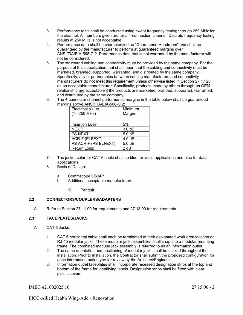
IMEG #21002025.10 27 15 00 - 2
EICC-Allied Health Wing-Add - Renovation
3. Performance tests shall be conducted using swept frequency testing through 250 MHz for the channel. All numbers given are for a 4-connection channel. Discrete frequency testing results at 250 MHz is not acceptable.
4. Performance data shall be characterized as "Guaranteed Headroom" and shall be guaranteed by the manufacturer to perform at guaranteed margins over ANSI/TIA/EIA-568-C.2. Performance data that is not warranted by the manufacturer will not be considered.
5. The structured cabling and connectivity must be provided by the same company. For the purpose of this specification that shall mean that the cabling and connectivity must be marketed, branded, supported, warranted, and distributed by the same company. Specifically, ally or partnerships between cabling manufacturers and connectivity manufacturers do not meet this requirement unless otherwise listed in Section 27 17 20 as an acceptable manufacturer. Specifically, products made by others through an OEM relationship are acceptable if the products are marketed, branded, supported, warranted, and distributed by the same company.
6. The 4-connector channel performance margins in the table below shall be guaranteed margins above ANSI/TIA/EIA-568-C.2:
Electrical Value(1 - 250 MHz)
Minimum Margin
Insertion Loss: 5%NEXT: 3.0 dBPS NEXT: 5.0 dBACR-F (ELFEXT): 4.0 dBPS ACR-F (PS ELFEXT): 5.0 dBReturn Loss: 2 dB
7. The jacket color for CAT 6 cable shall be blue for voice applications and blue for data applications.
8. Basis of Design:
a. Commscope CS34Pb. Additional acceptable manufacturers:
1) Panduit
2.2 CONNECTORS/COUPLERS/ADAPTERS
A. Refer to Section 27 11 00 for requirements and 27 13 00 for requirements.
2.3 FACEPLATES/JACKS
A. CAT 6 Jacks:
1. CAT 6 horizontal cable shall each be terminated at their designated work area location on RJ-45 modular jacks. These modular jack assemblies shall snap into a modular mounting frame. The combined modular jack assembly is referred to as an information outlet.
2. The same orientation and positioning of modular jacks shall be utilized throughout the installation. Prior to installation, the Contractor shall submit the proposed configuration for each information outlet type for review by the Architect/Engineer.
3. Information outlet faceplates shall incorporate recessed designation strips at the top and bottom of the frame for identifying labels. Designation strips shall be fitted with clear plastic covers.
IMEG #21002025.10 27 15 00 - 3
EICC-Allied Health Wing-Add - Renovation
4. Where standalone CAT 6 only modular jacks are identified, the information outlet faceplate shall be configured as to allow for the addition of one (1) additional modular jack (CAT 3, CAT 5E, or CAT 6) to be installed to supplement each such modular jack as defined by this project. The installation of these supplemental modular jacks is NOT part of this project.
5. Any unused modular jack positions on an information outlet faceplate shall be fitted with a removable blank inserted into the opening.
6. The information outlet faceplate shall be constructed of high impact plastic (except where noted otherwise). The information outlet faceplate color shall:
a. Match the receptacle color used for other utilities in the building, orb. When installed in surface raceway (if applicable), match the color of that raceway.
7. Different faceplate and frame designs for locations, which include optical fiber cabling relative to those, that terminate only copper cabling are acceptable. Information outlets that incorporate optical fiber shall be compliant with the above requirements plus:
a. Be a low-profile assembly.b. Incorporate a mechanism for storage of cable and fiber slack needed for
termination.c. Position the optical fiber couplings to face downward or at a downward angle to
prevent contamination.d. Incorporate a shroud that protects the optical fiber couplings from impact damage.
8. All information outlets and the associated modular jacks shall be of the same manufacturer throughout the project.
9. The CAT 6 modular jacks shall be non-keyed 8-pin modular jacks.10. The interface between the modular jack and the horizontal cable shall be a 110-type
termination block or insulation displacement type contact. Termination components shall be designed to maintain the horizontal cable's pair twists as closely as possible to the point of mechanical termination.
11. CAT 6 modular jacks shall be pinned per TIA-568B.12. CAT 6 termination hardware shall, as a minimum, meet all the mechanical and electrical
performance requirements of the following standards:
a. ANSI/TIA/EIA-568-A-5b. ANSI/TIA/EIA-568Ac. ISO/IEC 11801d. IEC 603-7e. FCC PART 68 SUBPART F
13. The color for CAT 6 jacks shall be bluet for voice applications and blue for data applications. Alternately, a color-coded bezel or icon may be used to identify the CAT 6 modular jack.
IMEG #21002025.10 27 15 00 - 4
EICC-Allied Health Wing-Add - Renovation
PART 3 - EXECUTION
3.1 CABLE INSTALLATION REQUIREMENTS
A. Horizontal Cabling:
1. The maximum horizontal cable drop length for Data UTP shall not exceed 295 feet in order to meet data communications performance specifications. This length is measured from the termination panel in the wiring closet to the outlet and must include any slack required for the installation and termination. The Contractor is responsible for installing horizontal cabling in a fashion so as to avoid unnecessarily long runs. Any area that cannot be reached within the above constraints should be identified and reported to the Architect/Engineer prior to installation. Changes to the contract documents shall be approved by the Architect/Engineer.
2. All cable shall be free of tension at both ends. In cases where the cable must bear some stress, Kellum grips may be used to spread the strain over a longer length of cable.
3. Manufacturer's minimum bend radius specifications shall be observed in all instances.4. Horizontal cabling installed as open cabling shall be supported at a maximum of 5'
between supports. Refer to the specifications for required cable supports.5. Horizontal cabling installed as open cable or in cable tray shall be bundled at not less
than 10' intervals with hook-and-loop tie wraps. The use of plastic cable ties is strictly prohibited.
6. The maximum conduit fill for horizontal cabling shall not exceed 40% regardless of conduit length.
7. Cable sheaths shall be protected from damage from sharp edges. Where a cable passes over a sharp edge, a bushing or grommet shall be used to protect the cable.
B. A coil of 3 feet in each cable shall be placed in the ceiling at the last support (e.g., J-hook, bridle ring, etc.) before the cables enter a fishable wall, conduit, surface raceway or box. At any location where cables are installed into movable partition walls or modular furniture via a service pole, approximately 15-feet of slack shall be left in each horizontal cable under 250 feet in length to allow for change in the office layout without re-cabling. These "service loops" shall be secured at the last cable support before the cable leaves the ceiling and shall be coiled from 100% to 200% of the cable recommended minimum bend radius.
1. To reduce or eliminate EMI, the following minimum separation distances from 480V power lines shall be adhered to:
a. Twelve (12) inches from power lines of less than 5-kVa.b. Eighteen (18) inches from high-voltage lighting (including fluorescent).c. Thirty-nine (39) inches from power lines of 5-kVa or greater.d. Thirty-nine (39) inches from transformers and motors.
2. Information outlets shown on floor plans with the subscript "W" are intended to be used for wall mounted telephones. Back boxes for wall mounted telephones shall not be located within 12" vertically, or horizontally, from any light switches, power receptacles, nurse call devices, thermostats, or any other architectural element that would otherwise prevent the installation of a wall mounted telephone on the mating lugs.
IMEG #21002025.10 27 15 00 - 5
EICC-Allied Health Wing-Add - Renovation
3.2 CABLE TERMINATION REQUIREMENTS
A. Cable Terminations - Data UTP:
1. Modular patch panels shall be designed and installed in a fashion as to allow future horizontal cabling to be terminated on the panel without disruption to existing connections.
2. If the "last" patch (per rack) is greater than 50% utilized, one additional patch panel shall be provided for future use..
3. At information outlets and modular patch panels, the Contractor shall ensure that the twists in each cable pair are preserved to within 0.5-inch of the termination for data cables. The cable jacket shall be removed only to the extent required to make the termination.
END OF SECTION 27 15 00
IMEG #21002025.10 27 17 10 - 1
EICC-Allied Health Wing-Add - Renovation
SECTION 27 17 10 - TESTING
PART 1 - GENERAL
1.1 SECTION INCLUDES
A. This section describes the testing requirements relating to the structured cabling system and its termination components and related subsystems.
1.2 RELATED WORK
A. Section 27 05 00 - Basic Communications Systems Requirements
1.3 QUALITY ASSURANCE
A. Refer to Section 27 05 00 for relevant standards.
1.4 SUBMITTALS
A. Under the provisions of Section 27 05 00 and Division 1, prior to the start of work, the Contractor shall submit:
1. Complete information on testing procedure as described herein.2. Test plan summary for each cable type to be tested including equipment to be used,
setup, test frequencies or wavelengths, results format, etc.
PART 2 - PRODUCTS
2.1 TESTING COPPER
A. General Requirements:
1. Perform acceptance tests as indicated below for each sub-system (e.g., backbone, horizontal, etc.) as it is completed.
2. Supply all equipment and personnel necessary to conduct the acceptance tests. The method of testing shall be approved by the Architect/Engineer.
3. Visually inspect all cabling and termination points to ensure that they are complete and conform to the wiring pattern defined herein. Provide the Architect/Engineer with a written certification that this inspection has been made.
4. Conduct acceptance testing according to a schedule coordinated with the Owner/Architect/Engineer. Representatives of the Owner may be in attendance to witness the test procedures. Provide a minimum of one (1) week's advance notice to the Architect/Engineer to allow for such participation. The notification shall include a written description of the proposed conduct of the tests, including copies of blank test result sheets to be used.
5. Tests related to connected equipment of others shall only be done with the permission and presence of the Contractor involved. The Contractor shall ascertain that testing only is required to prove the wiring connections are correct.

IMEG #21002025.10 27 17 10 - 2
EICC-Allied Health Wing-Add - Renovation
6. Provide test results and describe the conduct of the tests including the date of the tests, the equipment used, and the procedures followed. At the request of the Architect/Engineer, provide copies of the original test results in their native format.
7. All cabling shall be 100% fault-free unless noted otherwise. If any cable is found to be outside the specification defined herein, that cable and the associated termination(s) shall be replaced at the expense of the Contractor. The applicable tests shall then be repeated.
8. Should it be found by the Architect/Engineer that the materials or any portion thereof furnished and installed under this Contract fail to comply with the specifications and drawings with respect or regard to the quality, amount, or value of materials, appliances, or labor used in the work, it shall be rejected and replaced by the Contractor and all work disturbed by changes necessitated in consequence of said defects or imperfections shall be made good at the Contractor's expense.
a. CAT 3 Cable:
1) Indoor/Backbone Cable:
a) Backbone CAT 3 copper cable shall be free of shorts within the pairs and be verified for continuity, pair validity and polarity, and conductor position on the termination blocks (e.g., 110). Any mis-positioned pairs must be identified and corrected. The percentage of "bad" pairs shall not exceed 3% in any backbone (riser or tie) cable based on total pair count. All bad pairs must be identified and documented.
b. CAT 6 Cable:
1) Testing shall be from the modular jack at the information outlet to the modular patch panel in the communication equipment room.
2) Horizontal cable shall be free of shorts within the pairs, and be verified for continuity, pair validity and polarity, and conductor position on the modular jack (e.g., wire map). Any defective, split, or mis-positioned pairs must be identified and corrected.
3) CAT 6 horizontal cable shall be tested to 250 MHz as defined by TIA/EIA-568-C.2. Measurements shall be of the "Permanent Link", including cabling and modular jacks at the information outlet and modular patch panel. Parameters to be tested must include:
a) Wire Mapb) Lengthc) NEXT Loss (Pair-to-Pair)d) NEXT (Power Sum)e) ELFEXT (Pair-to-Pair)f) ELFEXT (Power Sum)g) Return Lossh) Attenuationi) Propagation Delayj) Delay Skew
4) The maximum length of horizontal cable shall not exceed 295 feet, which allows 33 feet for technology equipment and modular patch cords.
IMEG #21002025.10 27 17 10 - 3
EICC-Allied Health Wing-Add - Renovation
5) To establish testing baselines, cable samples of known length and of the cable type and lot installed shall be tested. The cable may be terminated with an eight-position CAT 6 modular connector (8-pin) to facilitate testing. Nominal Velocity of Propagation (NVP) and nominal attenuation values shall be calculated based on this test and be utilized during the testing of the installed cable plant. This requirement can be waived if NVP and nominal attenuation data is available from the cable manufacturer for the exact cable type under test.
6) CAT 6 horizontal cable testing shall be performed using a test instrument designed for testing to 250 MHz or higher. Test records shall verify, "PASS" on each cable and display the specified parameters, comparing test values with standards based "templates" integral to the unit. Test records that report a PASS*, FAIL*, or FAIL result for any of the parameters will not be accepted.
7) In the event results of the tests are not satisfactory, the Contractor shall make adjustments, replacements, and changes as necessary and shall then repeat the test or tests that disclosed faulty or defective material, equipment, or installation methods, and shall make additional tests as the Architect/Engineer deems necessary at no additional expense to the project or user agency.
2.2 TESTING FIBER
A. General Requirements:
1. Perform acceptance tests as indicated below for each optical fiber sub-system (e.g., backbone, horizontal, etc.) as it is completed.
2. Supply all equipment and personnel necessary to conduct the acceptance tests. The method of testing shall be approved by the Architect/Engineer.
3. Visually inspect all optical fiber cabling and termination points to ensure that they are complete and conform to the standards defined herein. Provide the Architect/Engineer with a written certification that this inspection has been made.
4. Conduct acceptance testing according to a schedule coordinated with the Owner/Architect/Engineer. Representatives of the Owner may be in attendance to witness the test procedures. Provide a minimum of one (1) week's advance notice to the Architect/Engineer to allow for such participation. The notification shall include a written description of the proposed conduct of the tests, including copies of blank test result sheets to be used.
5. Tests related to connected equipment of others shall only be done with the permission and presence of the Contractor involved. The Contractor shall ascertain that testing only is required to prove that the optical fiber connections are correct.
6. Provide test results and describe the conduct of the tests including the date of the tests, the equipment used and the procedures followed. At the request of the Architect/Engineer, provide copies of the original test results.
7. All optical fiber cabling shall be 100% fault-free unless noted otherwise. If any optical fiber cable is found to be outside the specification defined herein, that optical fiber cable and the associated connector(s) shall be replaced at the expense of the Contractor. The applicable tests shall then be repeated.
8. Should it be found by the Architect/Engineer that the materials or any portion thereof furnished and installed under this Contract fail to comply with the specifications and drawings with respect or regard to the quality, amount, or value of materials, appliances, or labor used in the work, it shall be rejected and replaced by the Contractor and all work disturbed by changes necessitated in consequence of said defects or imperfections shall be made good at the Contractor's expense.
IMEG #21002025.10 27 17 10 - 4
EICC-Allied Health Wing-Add - Renovation
9. The optical fibers utilized in the installed cable shall be traceable to the manufacturer. Upon request by the Owner, provide cable manufacturer's test report for each reel of cable provided. These test reports shall include manufacturer's on-reel attenuation test results at 850-nm and 1300-nm for each optical fiber of each reel prior to shipment from the manufacturer.
a. On-the-reel bandwidth performance as tested at the factory. Factory data shall be provided upon request.
b. The testing noted for optical fiber cabling utilizes an Optical Time Domain Reflectometer (OTDR). However, the Contractor may submit to the Architect/Engineer for pre-approval of alternate fiber optic testing equipment.
B. Tests Prior to Installation: The Contractor, at their discretion and at no cost to the Owner, may perform an attenuation test with an OTDR at 850-nm or 1300-nm on each optical fiber of each cable reel prior to installation. Supply this test data to the Architect/Engineer prior to installation.
C. Tests After Installation: Upon completion of cable installation and termination, the optical fiber cabling shall be tested to include:
1. Optical Attenuation ("Insertion Loss" Method):
a. Optical Attenuation shall be measured on all terminated optical fibers in one direction of transmission using the "Insertion Loss" method measurement in accordance with the TIA/EIA 526-14, Method B, and be inclusive of the optical connectors and couplings installed at the system endpoints. Access jumpers shall be used at both the transmit and receive ends to ensure that an accurate measurement of connector losses is made. Multimode optical fibers shall be tested at 850 ± 30 nm. Singlemode optical fibers (if applicable) shall be tested at 1300 ± 20 nm.
2. Verification of Link Integrity (OTDR):
a. All optical fibers shall be documented in one direction of transmission using an Optical Time Domain Reflectometer (OTDR). Multimode optical fibers shall be tested at 850-nm and 1300-nm (nominal). Singlemode optical fibers (if applicable) shall be tested at 1310-nm and 1550-nm (nominal). The OTDR(s) shall incorporate high-resolution optics optimized for viewing of short cable sections. Access jumpers of adequate length to allow viewing of the entire length of the cable, including the connectors at the launch and receive end, shall be used. Access jumpers used for testing shall match the type and core diameter of the fiber optic strand under test.
b. Set OTDR's test variables to the manufacturer's published backscatter coefficient and velocity of propagation figure for the specific strand of fiber under test. OTDR's range should be set to approximately 1.5 times the length of the strand under test, pulse width should be optimized for the length of the fiber optic strand under test, and number of averages should be adjusted to approximately 120 seconds per wavelength.

IMEG #21002025.10 27 17 10 - 5
EICC-Allied Health Wing-Add - Renovation
c. OTDR traces revealing a point discontinuity greater than 0.2 dB in a multimode optical fiber or 0.1 dB in a singlemode optical fiber (if applicable) at any of the tested wavelengths or any discontinuity showing a reflection at that point shall be a valid basis for rejection of that optical fiber by the Owner. The installation of that optical fiber cable shall be reviewed in an effort to remove any external stress that may be causing the fault. If such efforts do not remove the fault, that optical fiber cable and the associated terminations shall be replaced at the expense of the Contractor.
2.3 DOCUMENTATION/AS-BUILTS/RECORDS
A. General:
1. Upon completion of the installation, submit as-builts per the requirements of Section 27 05 00 and Division 1. Documentation shall include the items detailed in the subsections below.
2. All documentation, including hard copy and electronic forms, shall become the property of the Owner.
3. The Architect/Engineer may request that a 10% random field retest be conducted on the cable system at no additional cost to verify documented findings. Tests shall be a repeat of those defined above. If findings contradict the documentation submitted by the Contractor, additional testing can be requested to the extent determined necessary by the Architect/Engineer, including a 100% retest. This retest shall be at no additional cost to the Owner.
B. Copper Media Test Data:
1. Test results shall include a record of test frequencies, cable type, conductor pair and cable (or Outlet) I.D., measurement direction, test equipment type, model and serial number, date, reference setup, and crew member name(s).
2. Printouts generated for each cable by the wire test instrument shall be submitted as part of the documentation package. The Contractor shall furnish this information in electronic form (USB thumb drive). The thumb drive shall contain the electronic equivalent of the test results as defined by the bid specification and be in the tester's native format as well as summaries of each test in pdf format. Provide a licensed copy of the software required to view and print the data that is provided in a proprietary format. Furnish one (1) copy of the data and display (if applicable) software.
C. Optical Fiber Media Test Data:
1. Test results shall include a record of test wavelengths, cable type, fiber and cable (or Outlet) I.D., measurement direction, test equipment type, model and serial number, date, reference setup, and crew member name(s).
2. OTDR traces of individual optical fiber "signatures" obtained as specified above shall be provided to the Architect/Engineer in electronic form for review. Trace files shall be so named as to identify each individual optical fiber by location in the cable system and optical fiber number or color. Where traces are provided in electronic form, provide along with the above documentation, one (1) licensed copy of software that will allow for the display of OTDR traces provided. The software shall run on a Microsoft Windows-based personal computer.
IMEG #21002025.10 27 17 10 - 6
EICC-Allied Health Wing-Add - Renovation
D. Record Drawings:
1. The drawings are to include cable routes and outlet locations. Outlet locations shall be identified by their sequential number as defined elsewhere in this document. Numbering, icons, and drawing conventions used shall be consistent throughout all documentation provided.
PART 3 - EXECUTION (Not Used)
END OF SECTION 27 17 10

IMEG #21002025.10 27 17 20 - 1
EICC-Allied Health Wing-Add - Reno
SECTION 27 17 20 - STRUCTURED CABLING SYSTEM WARRANTY
PART 1 - GENERAL
1.1 SECTION INCLUDES
A. This section describes support and warranty requirements relating to the structured cabling system and related subsystems.
1.2 RELATED WORK
A. Section 27 05 00 - Basic Technology Systems Requirements.
B. Section 27 11 00 - Communication Equipment Room (CER).
C. Section 27 13 00 - Backbone Cabling Requirements.
D. Section 27 15 00 Horizontal Cabling Requirements.
1.3 QUALITY ASSURANCE
A. Refer to Section 27 05 00 for relevant standards.
1.4 SUBMITTALS
A. Under the provisions of Section 27 05 00 and Division 1, prior to close of the project the Contractor shall submit:
1. A numbered certificate from the manufacturing company registering the installation.
PART 2 - PRODUCTS
2.1 WARRANTY
A. A twenty-five (25) year Product Installation Warranty shall be provided for the structured cabling system as described in the contract documents.
B. The Product Installation Warranty shall cover the replacement or repair of the defective product(s) and labor for the replacement or repair of such defective product(s).
C. Upon successful completion of the installation and subsequent inspection, the Owner shall be provided with a numbered certificate from the manufacturing company registering the installation.

IMEG #21002025.10 27 17 20 - 2
EICC-Allied Health Wing-Add - Reno
PART 3 - EXECUTION
3.1 WARRANTY REQUIREMENTS
A. This Contractor shall be responsible for providing, installing and testing a structured cabling system that will meet the manufacturer's warranty requirements.
END OF SECTION 27 17 20
IMEG #21002025.10 27 41 00 - 1
EICC-Allied Health Wing-Add - Renovation
SECTION 27 41 00 - PROFESSIONAL AUDIO/VIDEO SYSTEM
PART 1 - GENERAL
1.1 SECTION INCLUDES
A. System Components
B. Audio Connectors
C. Audio Cabling
D. Digital Video Cabling
E. Transmission Connectors
F. Transmission Cabling
G. Control Cabling
H. Horizontal Copper and Fiber Cabling and Connectors
1.2 RELATED WORK
A. Section 26 05 33 - Conduit
B. Section 26 05 13 - Wire and Cable
C. Section 27 05 00 - Basic Communications Requirements
D. Section 27 05 26 - Communications Bonding
E. Section 27 05 03 - Through Penetration Firestopping
F. Section 27 11 00 - Communication Equipment Rooms
G. Section 27 05 28 - Interior Communications Pathway
H. Section 27 15 00 - Horizontal Cabling Requirements
1.3 QUALITY ASSURANCE
A. Manufacturer: The manufacturer of equipment shall have a complete service organization for all products in the manufacturer's line.
B. Integrator/Dealer: The Contractor shall be a factory-authorized and certified integrator/dealer specializing in each selected manufacturer's products, with demonstrated prior experience with the selected manufacturer's system installation and programming.
IMEG #21002025.10 27 41 00 - 2
EICC-Allied Health Wing-Add - Renovation
C. The following qualifications have been endorsed by the AudioVisual and Integrated Experience Association (AVIXA), which is formerly known as InfoComm International.
1. The Contractor shall have a Certified Technology Specialist[ with a specialized Installation endorsement (CTS-I) and or a Certified Technology Specialist with a specialized Design endorsement (CTS-D)on staff and supervising the project.
a. Review final testing and calibration of the systems and provide a letter with the documented results or transmittal of the results stating the test results and calibration compliance with the contract documents.
D. A certification of CCENT or CCNA from CISCO. CCNP certification satisfies either of these requirements.
E. Control System Dealer: The media control system shall be provided, terminated, installed, and programmed by a factory-authorized and certified dealer and integrator in good standing with the manufacturer. The dealer shall have direct purchasing and support authority. These services shall not be subcontracted.
F. Control System Programmer: The media control system shall be programmed by a factory-trained and certified programmer.
1. Should the installer of the system not employ a factory-trained and certified programmer, a representative from the equipment manufacturer or certified independent programmer shall be retained for programming services. The Contractor shall be responsible for payment of his/her services until the job is complete and signed off.
2. The Contractor shall have all certifications required by the manufacturer(s) for the installed system components on staff for the appropriate duties and responsibilities required by the manufacturer.
a. The control system programmer shall have all refresher courses completed for the latest features of the control platform prior to bidding the project to ensure that the Contractor is up to date with the latest software features.
G. Audio System Programmer: All digital sound processing equipment (DSP) used on the project shall be setup, programmed and calibrated by a factory-trained and certified technician. The audio system programmer shall have the following complementary certifications:
1. Associated manufacturer certifications2. Dante Level III
H. Video System Programmer: All video distribution and processing used on the project shall be setup, programmed and calibrated by a factory-trained and certified technician.
I. The Contractor shall have acquired and maintained all certifications for a minimum of one (1) month prior to the posted bid date of this project.
J. Servicing Contractor: The installer must be factory certified to provide service on the installed manufacturer's equipment and must have local service representatives within a 100 mile radius of the project site.
1.4 REFERENCES
A. ADA - Americans with Disabilities Act
IMEG #21002025.10 27 41 00 - 3
EICC-Allied Health Wing-Add - Renovation
B. ADAAG - Americans with Disability Accessibility Guidelines
C. ANSI - American National Standards Institute
D. AVIXA - Audiovisual and Integrated Experience Association (Formerly InfoComm)
E. ANSI/InfoComm A102.01:2017 - Audio Coverage Uniformity
F. ANSI/InfoComm 2M-2010 - Standard Guide for Audiovisual Systems Design and Coordination Processes
G. ANSI/InfoComm F501.01:2015 - Cable Labeling for Audiovisual Systems
H. ANSI/InfoComm 10:2013 - Audiovisual Systems Performance Verification
I. ANSI/AVIXA V202.01:2016 - Display Image Size for 2D Content in Audiovisual Systems
J. IBC - International Building Code
K. IEC - International Electrotechnical Commission
L. NFPA 70 - National Electrical Code (NEC)
M. UL 813 - Commercial Audio Equipment
N. UL 1419 - Professional Video and Audio Equipment
O. UL 1492 - Audio/Video Products and Accessories
1.5 SUBMITTALS
A. Submit shop drawings and product data under provisions of Section 27 05 00.
B. General Requirements:
1. Submittals will be submitted in multiple passes over the course of construction. Each pass will be a dedicated single submission for review as outlined in the general submittal requirements outlined in section 27 05 00.
2. Should the Contractor not provide shop drawings in a timely fashion, not complete requirements, or extend the time of any resubmittals so as to jeopardize schedules, cause delay, or limit access for field work, the Contractor bears responsibility for impact and delay that may occur. This includes access or lift to overhead positions and associated protection of work already in place.
C. First Pass Submittals: To be submitted after the project is awarded but before equipment is submitted, purchased and installed.
1. Contractor(s) resume of qualifications, when requested.2. All certifications shall be current and valid. Any certificate with expired dates will not be
accepted.3. All applicable AudioVisual and Integrated Experience Association (AVIXA) certifications.
Qualifications from InfoComm that have not expired will be accepted.

IMEG #21002025.10 27 41 00 - 4
EICC-Allied Health Wing-Add - Renovation
4. All certifications outlined in the qualifications shall be included in this submittal. Refer to the qualifications section for additional information. Certifications include, but are not limited to:
a. All installed manufacturer certifications required by the manufacturer.b. Control system authorized dealer certification.c. Control system certified programmer certification(s).d. Audio system DSP dealer certification.e. Audio system DSP programmer certification.f. Professional audio components dealer certification(s).g. Video system dealer certification(s).h. All other applicable dealer, installation and programming certifications.i. All applicable networking certifications.
5. If an alternate manufacturer(s) is submitted, the equivalent certifications to the basis of design manufacturer(s) shall be required and submitted.
6. Audio and video calibration equipment certifications.7. Audio and video testing and calibration equipment and software procedures and
manufacturer-specific equipment calibration certificates.
D. Second Pass Submittals: To be submitted after all initial submittals have been approved but before equipment is purchased, installed, configured, and programmed.
1. Alternate System Drawings: If an approved alternate manufacturer is submitted, the Contractor shall provide project-specific system CAD drawings. These will be required to be submitted with the product data.
a. Provide a system block diagram noting system components and interconnection between components. The interconnection of components shall clearly indicate all wiring required in the system. When multiple pieces of equipment are required in the exact same configuration (e.g., multiple identical controllers), the diagram may show one device and refer to the others as "typical" of the device shown.
2. Product Data: Provide manufacturer's technical product specification sheet for each individual component type. Submitted data shall show the following:
a. Compliance with each requirement of these documents.b. All component options and accessories specific to this project.c. Electrical power consumption rating and voltage.d. Wiring requirements.e. Pre-terminated cable distances and requirements identified by each room where
required.f. Product manuals are not an acceptable format and will be rejected.
IMEG #21002025.10 27 41 00 - 5
EICC-Allied Health Wing-Add - Renovation
E. Final Pass Submittals: To be submitted after all initial submittals have been approved but before the equipment is installed, configured and programmed. These should not be submitted until after the pre-installation meeting outlined in Part 3.
1. System Drawings: Project-specific system drawings shall be provided as follows:
a. Provide a system block diagram noting system components and interconnection between components. The interconnection of components shall clearly indicate all wiring required in the system. When multiple pieces of equipment are required in the exact same configuration (e.g., multiple identical controllers), the diagram may show one device and refer to the others as "typical" of the device shown.
b. Submittals shall contain shop drawings indicating physical plan locations and placement of installed devices and accessories with associated scope or field conditions for review and coordination. Provide mounting details, suspensions, and rough-in notes with trade demarcations.
1) Identify any non-standard back boxes or mounting assembly required by product or specifications and elaborate contractor means and methods for mounting.
2) Provide rack drawing(s) showing the mounting of equipment in each rack or cabinet on the project.
3) All display mounts shall be coordinated with the Architect to verify the exact vertical and horizontal positioning of the display. Coordinate in-wall stud locations for installation of recessed display mounts to install in the exact location as coordinated with the architectural drawings.
4) Projector mounts, projector screens, recessed ceiling speakers, in-ceiling microphones, and all other above ceiling devices shall be coordinated with other trades in the field (e.g., mechanical ductwork, lights, diffusers, etc.) to minimize changes that will impact the performance of the system design.
c. Submit wiring and cable path requirements, including field wiring, path verification, signal separation, and outside diameter of cables for conduit sizing and verification that can be used for field installation and electrical coordination.
d. Reproduction of contract documents is not acceptable for submittals. Wire CAD type drawings and cable tag lists or schedules, or typical manufacturer's abbreviated single lines alone, are not complete.
2. The Contractor shall submit graphic or emulated representations of the control system touch panels for each unique space and layout prior to purchase, installation and programming for review and comment by the Architect/Engineer and Owner. These shall show and describe the intended programming/macro control features and functions of each button/icon for all pages.
3. The Contractor shall submit graphic or emulated representations of the control system keypads for each unique space and layout prior to purchase, installation and programming for review and comment by the Architect/Engineer and Owner. These shall show and describe the intended programming/macro control features and functions of each button/knob.
4. The Contractor shall submit the actual DSP audio processor files or single line audio path file diagram prior to installation for review and comment by the Architect/Engineer. Provide preliminary settings with processor blocks identified and note resources allocated.
5. The Contractor shall submit the number of IP addresses, VLANS, and subnetworks that will be required from the Owner's Information Systems Department.

IMEG #21002025.10 27 41 00 - 6
EICC-Allied Health Wing-Add - Renovation
6. Submit meeting agenda for planning/programming meetings as required in Part 3 of this specification.
7. Submit detailed description of Owner training to be conducted at project end, including specific training times and typical attendees expected.
8. Provide rack drawing(s) showing the mounting of equipment in each rack or cabinet on the project. Rack drawings shall include the following:
a. Equipment placement including mounting on the front or rear of the rack.b. Spacing separation as required by equipment for adequate airflow and heat
dissipation.c. Signal separation based on AVIXA standards as required by the design.d. Heating/cooling load requirements for submitted equipment to verify the
heating/cooling load of the rack. This shall include Owner-provided equipment coordinated with the Owner.
e. Power requirements for each rack including plug type and loads based on the final approved products.
F. Discontinued Products and New Model Releases:
1. For each product, the Contractor shall submit (in addition to the specified product) a product cut sheet if the specified product has been replaced, improved upon, phased out or otherwise upgraded at the time of shop drawing submittal.
a. The intent of this requirement is for the Contractor to submit only direct replacements for the specified products. A direct replacement shall be defined as a product of newer release that has equal or greater capabilities, which is available for not more than a 10% premium over the specified product's bid unit cost.
b. It is not the intent of this requirement for the Contractor to submit new products or other product options that significantly differ in capability and/or cost from the specified product.
G. Coordination Drawings:
1. Include all ceiling-mounted devices in composite electronic coordination files. Refer to Section 27 05 00 for coordination drawing requirements.
1.6 SYSTEM DESCRIPTION
A. This specification section describes the furnishing, installation, commissioning and programming of audio/video components and systems.
B. Performance Statement: This specification section and the accompanying Contract Documents are performance based, describing the minimum material quality, required features, and operational requirements of the system. These documents do not convey every wire that must be installed, every equipment connection that must be made and every feature and function that must be programmed and configured. Based on the equipment constraints described and the performance required of the system, as presented in these documents, the Vendor and the Contractor are solely responsible for determining all wiring, programming and miscellaneous equipment required for a complete and operational system.
C. This document describes the major components of the system. All additional hardware, subassemblies, supporting equipment and other miscellaneous equipment required for proper system installation and operation shall be provided by the Contractor.
IMEG #21002025.10 27 41 00 - 7
EICC-Allied Health Wing-Add - Renovation
D. This document describes the major programming features and functions of the system. All additional programming, configuration and integration required for proper system installation and operation shall be provided by the Contractor.
E. When a specific manufacturer is not provided in this document for minor pieces of equipment, the Contractor shall provide only those materials considered to be of the same industry commercial and professional quality level as the major equipment manufacturers.
F. General System Description:
1. The purpose of this section is to define the overall AV system requirements for each space identified on the project drawings. This is to represent the end-user needs, applications, tasks and Functions and features for each space to assist with identifying programing requirements for each space.
G. Room Type Description: Refer to drawings for equipment locations, quantity, and connections.
1. Tri LED Room:
a. The AV system in Tri LED classroom shall provide support for audio and video presentations for classroom activities.
b. System Requirements:
1) Three (3) wall-mounted displays will be provided for media presentation from OFE PC at the teaching station.
2) Document camera, wireless interactive screen receiver, and wireless remote presentation receiver shall be connected to OFE classroom PC via USB ports. Provide USB 3.0 4-port hub if necessary.
3) Provide routing of OFE classroom PC video source via an HDBaseT video distribution amplifier.
4) Video and display control signals to be transported from the video distribution amplifier to the HDBaseT receivers located at wall- mounted displays via shielded SF/UTP CAT 6A cabling certified to 475 MHz bandwidth and 24 AWG. All RJ-45 plugs and jacks shall be shielded. Basis of design is Extron XTP-DTP 24 cabling.
5) Provide ceiling loudspeakers and associated electronics to reproduce the mono or summed-stereo to mono audio signal.
6) Provide “sit down�" podium for teaching station.7) Provide an equipment rack for the systems’ permanently mounted
equipment within the sit down podium.8) Provide a control system with six (6) pushbutton control panel and rotary
volume knob to be mounted in surface mount box located on top of “sit down�" podium.
9) Provide a 5-port network switch to interface classroom control system with OPE school network for help desk button functionality and wall-mounted display control.
10) The control system to provide control for:
a) Displays On/Offb) Auto Imagec) Freeze On/Off d) Blank ON/OFFe) Notify Help Deskf) Volume Up/Down
IMEG #21002025.10 27 41 00 - 8
EICC-Allied Health Wing-Add - Renovation
2. Single LED TV Classroom:
a. The AV system in Single LED classroom shall provide support for audio and video presentations for classroom activities.
b. System Requirements:
1) One (1) wall-mounted display will be provided for media presentation from OFE PC at the teaching station.
2) Document camera and wireless remote presentation receiver shall be connected to OFE classroom PC via USB ports. Provide USB 3.0 4-port hub if necessary.
3) Provide routing of OFE classroom PC video source and via a video distribution amp.
4) Video and display control signals to be transported from the video distribution amplifier to the HDBaseT receivers located at wall- mounted displays via shielded SF/UTP CAT 6A cabling certified to 475 MHz bandwidth and 24 AWG. All RJ-45 plugs and jacks shall be shielded. Basis of design is Extron XTP-DTP 24 cabling.
5) Provide ceiling loudspeakers and associated electronics to reproduce the mono or summed-stereo to mono audio signal.
6) Provide “sit down�" podium for teaching station.7) Provide an equipment rack for the systems’ permanently mounted
equipment within the sit down podium.8) Provide a control system with six (6) pushbutton control panel and rotary
volume knob to be mounted in surface mount box located on top of “sit down�" podium.
9) Provide a 5-port network switch to interface classroom control system with OPE school network for help desk button functionality and wall-mounted display control.
10) The control system to provide control for:
a) Displays On/Offb) Auto Imagec) Freeze On/Off d) Blank ON/OFFe) Notify Help Deskf) Volume Up/Down
3. Dual LED Room:
a. The AV system in Dual LED classroom shall provide support for audio and video presentations for classroom activities.
b. System Requirements:
1) Two (2) wall-mounted displays will be provided for media presentation from OFE PC at the teaching station.
2) Document camera and wireless remote presentation receiver shall be connected to OFE classroom PC via USB ports. Provide USB 3.0 4-port hub if necessary.
3) Provide routing of OFE classroom PC video source and via a video distribution amp.
IMEG #21002025.10 27 41 00 - 9
EICC-Allied Health Wing-Add - Renovation
4) Video and display control signals to be transported from the video distribution amplifier to the HDBaseT receivers located at wall- mounted displays via shielded SF/UTP CAT 6A cabling certified to 475 MHz bandwidth and 24 AWG. All RJ-45 plugs and jacks shall be shielded. Basis of design is Extron XTP-DTP 24 cabling.
5) Provide ceiling loudspeakers and associated electronics to reproduce the mono or summed-stereo to mono audio signal.
6) Provide “sit down�" podium for teaching station.7) Provide an equipment rack for the systems’ permanently mounted
equipment within the sit down podium.8) Provide a control system with six (6) pushbutton control panel and rotary
volume knob to be mounted in surface mount box located on top of “sit down�" podium.
9) Provide a 5-port network switch to interface classroom control system with OPE school network for help desk button functionality and wall-mounted display control.
10) The control system to provide control for:
a) Displays On/Offb) Auto Imagec) Freeze On/Off d) Blank ON/OFFe) Notify Help Deskf) Volume Up/Down
4. Standard Classroom with Zoom:
a. The AV system in the Standard Classroom with Zoom shall provide support for audio and video presentations for classroom activities that require remote learning functionality via Zoom software codec.
b. System Requirements:
1) Three (3) wall-mounted displays will be provided for media presentation from OFE PC at the teaching station.
2) Document camera and wireless remote presentation receiver shall be connected to OFE classroom PC via USB ports. Provide USB 3.0 4-port hub if necessary.
3) Provide routing of OFE classroom PC video source and via a video distribution amp.
4) Video and display control signals to be transported from the video distribution amplifier to the HDBaseT receivers located at wall- mounted displays via shielded SF/UTP CAT 6A cabling certified to 475 MHz bandwidth and 24 AWG. All RJ-45 plugs and jacks shall be shielded. Basis of design is Extron XTP-DTP 24 cabling.
5) Video and display control signals to be transported from the OFE classroom PC to wall-mounted confidence monitor directly via the HDBaseT transmitter to a receiver located at wall-mounted display via shielded SF/UTP CAT 6A cabling certified to 475 MHz bandwidth and 24 AWG. All RJ-45 plugs and jacks shall be shielded. Basis of design is Extron XTP-DTP 24 cabling.
6) Provide ceiling loudspeakers and associated electronics to reproduce the mono or summed-stereo to mono audio signal.
7) Provide USB camera for support of software codec video conferences to be mounted on tripod for mobile use.
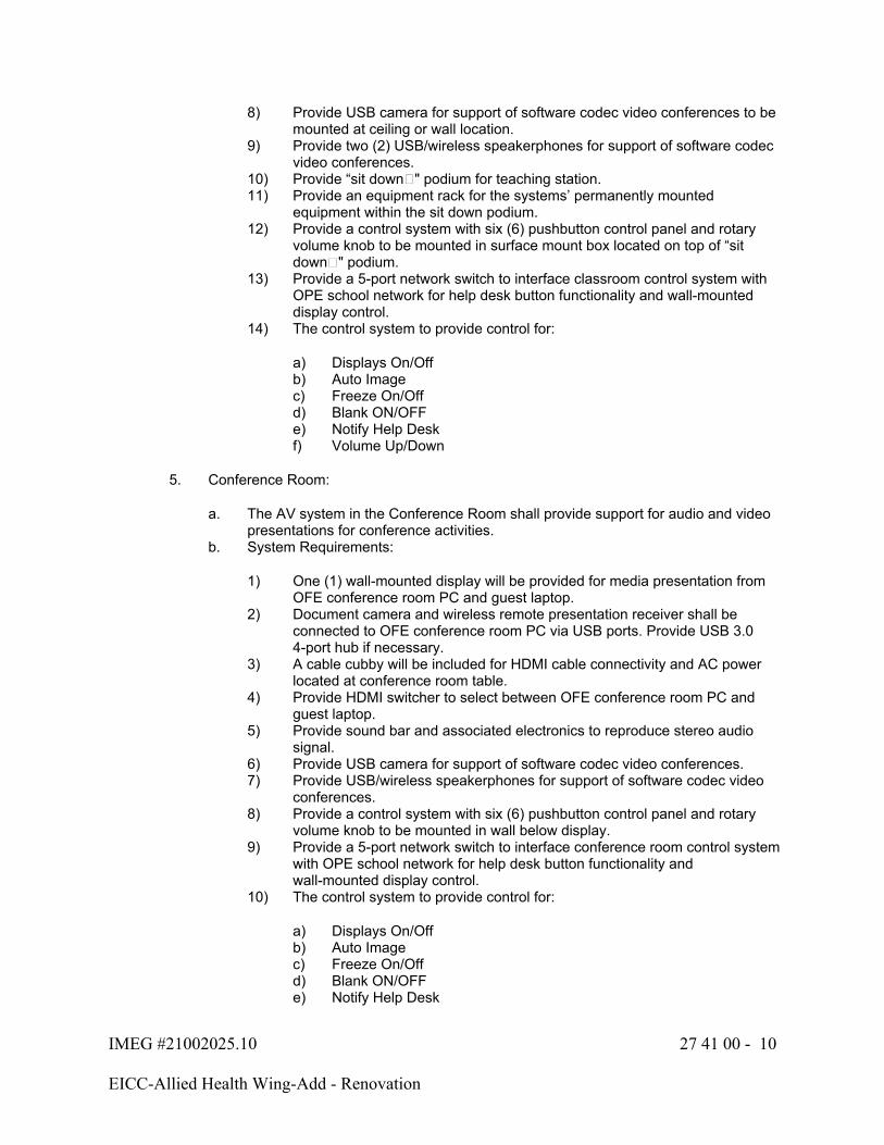
IMEG #21002025.10 27 41 00 - 10
EICC-Allied Health Wing-Add - Renovation
8) Provide USB camera for support of software codec video conferences to be mounted at ceiling or wall location.
9) Provide two (2) USB/wireless speakerphones for support of software codec video conferences.
10) Provide “sit down�" podium for teaching station.11) Provide an equipment rack for the systems’ permanently mounted
equipment within the sit down podium.12) Provide a control system with six (6) pushbutton control panel and rotary
volume knob to be mounted in surface mount box located on top of “sit down�" podium.
13) Provide a 5-port network switch to interface classroom control system with OPE school network for help desk button functionality and wall-mounted display control.
14) The control system to provide control for:
a) Displays On/Offb) Auto Imagec) Freeze On/Off d) Blank ON/OFFe) Notify Help Deskf) Volume Up/Down
5. Conference Room:
a. The AV system in the Conference Room shall provide support for audio and video presentations for conference activities.
b. System Requirements:
1) One (1) wall-mounted display will be provided for media presentation from OFE conference room PC and guest laptop.
2) Document camera and wireless remote presentation receiver shall be connected to OFE conference room PC via USB ports. Provide USB 3.0 4-port hub if necessary.
3) A cable cubby will be included for HDMI cable connectivity and AC power located at conference room table.
4) Provide HDMI switcher to select between OFE conference room PC and guest laptop.
5) Provide sound bar and associated electronics to reproduce stereo audio signal.
6) Provide USB camera for support of software codec video conferences.7) Provide USB/wireless speakerphones for support of software codec video
conferences.8) Provide a control system with six (6) pushbutton control panel and rotary
volume knob to be mounted in wall below display. 9) Provide a 5-port network switch to interface conference room control system
with OPE school network for help desk button functionality and wall-mounted display control.
10) The control system to provide control for:
a) Displays On/Offb) Auto Imagec) Freeze On/Off d) Blank ON/OFFe) Notify Help Desk
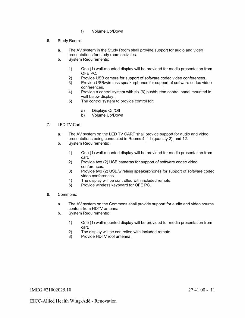
IMEG #21002025.10 27 41 00 - 11
EICC-Allied Health Wing-Add - Renovation
f) Volume Up/Down
6. Study Room:
a. The AV system in the Study Room shall provide support for audio and video presentations for study room activities.
b. System Requirements:
1) One (1) wall-mounted display will be provided for media presentation from OFE PC.
2) Provide USB camera for support of software codec video conferences.3) Provide USB/wireless speakerphones for support of software codec video
conferences.4) Provide a control system with six (6) pushbutton control panel mounted in
wall below display. 5) The control system to provide control for:
a) Displays On/Offb) Volume Up/Down
7. LED TV Cart:
a. The AV system on the LED TV CART shall provide support for audio and video presentations being conducted in Rooms 4, 11 (quantity 2), and 12.
b. System Requirements:
1) One (1) wall-mounted display will be provided for media presentation from cart.
2) Provide two (2) USB cameras for support of software codec video conferences.
3) Provide two (2) USB/wireless speakerphones for support of software codec video conferences.
4) The display will be controlled with included remote.5) Provide wireless keyboard for OFE PC.
8. Commons:
a. The AV system on the Commons shall provide support for audio and video source content from HDTV antenna.
b. System Requirements:
1) One (1) wall-mounted display will be provided for media presentation from cart.
2) The display will be controlled with included remote.3) Provide HDTV roof antenna.

IMEG #21002025.10 27 41 00 - 12
EICC-Allied Health Wing-Add - Renovation
1.7 LICENSING REQUIREMENTS
A. All user licenses required for system operation shall be included in the Contractor's bid. User licenses shall include, but not be limited to, server and workstation software and any other licensing that is required by the manufacturer for operation of any system component.
1. Licenses shall be provided on a one-to-one basis. One license shall be provided for each server, workstation, and device requiring a license. In the event the manufacturer requires the purchase of a block of licenses, the minimum standard licensing package to support all devices with 10% growth shall be provided.
1.8 INTELLECTUAL PROPERTY OWNERSHIP
A. All supporting documentation, programming, uncompiled source code, graphic files, DSP code and diagrams, written and electronic files, including all latest versions of the documentation and software necessary to edit and adapt the system(s), shall be provided to the Owner for all spaces and all systems. The integrator and/or programmer shall also maintain a current copy to be provided at the Owner's request.
1. The Owner shall have the right to modify the intellectual property directly, or to have the intellectual property modified by any party of the Owner's choosing.
1.9 PROJECT RECORD DOCUMENTS
A. Submit documents under the provisions of Section 27 05 00.
B. Provide all applicable certifications.
C. Provide statement that system checkout test, as outlined in the shop drawing submittal, is complete and satisfactory.
D. Provide schedules documenting all terminal block wiring, including cable numbers.
E. Warranty: Submit written warranty and complete all Owner registration forms.
F. Complete all operation and maintenance manuals as described below.
G. The Contractor shall include all factory-provided test results for equipment installed on the project.
H. The Contractor shall include all test results from system demonstration and performance testing specified in this document.
I. Record Drawings shall minimally include:
1. All revisions to, or deviations from the original drawings, as well as final dimensions, cable routes, connector panel drawings, cable numbering charts, and control system programming documentation. A complete as-installed equipment list, listed by room, and with manufacturers' names, model numbers, serial numbers, and quantities of each item.
2. A complete and correct system schematic, showing detailed connections for all parts of the system, including wire numbers, terminal block numbers and layouts, and other designations and programming code.
3. Complete equipment rack layouts showing locations of all rack-mounted equipment items.

IMEG #21002025.10 27 41 00 - 13
EICC-Allied Health Wing-Add - Renovation
4. Additional information, diagrams or explanations as designated under respective equipment or systems specification section.
J. Within each equipment room, the appropriate floor plan for which that equipment room serves shall be laminated and mounted for use by the Owner. Functional drawings shall be posted at each AV closet or included at every AV rack within a room.
K. Upon completion and final acceptance of the project, the Contractor shall provide the Owner a copy of the programming code for any and all AV systems and devices programmed by the Contractor.
1. For any subsequent modifications to the programming code, an updated copy of the code shall be provided to the Owner.
1.10 OPERATION AND MAINTENANCE DATA
A. Submit documents under the provisions of Section 27 05 00.
B. Manuals: Final copies of the manuals shall be delivered after completing the installation. Each manual's contents shall be identified on the cover. The manual shall include names, addresses, and telephone numbers of the Contractor responsible for the installation and maintenance of the system and the factory representatives for each item of equipment for each system. The manuals shall have a table of contents and labeled sections. The final copies delivered after completion of the installation shall include all modifications made during installation, checkout, and acceptance. Manuals shall be submitted in electronic format. The manuals shall consist of the following:
1. Functional Design Manual: The functional design manual shall identify the operational requirements for the system and explain the theory of operation, design philosophy, and specific functions. A description of hardware and software functions, interfaces, and requirements shall be included.
2. Hardware Manual: The manual shall describe all equipment furnished including:
a. General description and specifications.b. Installation and checkout procedures.c. Equipment layout and electrical schematics to the component level.d. System layout drawings and schematics.e. Alignment and calibration procedures.f. Manufacturers repair parts list indicating sources of supply.
3. Software Manual: The software manual shall describe the functions of all software and shall include all other information necessary to enable proper loading, testing, and operation. The manual shall include:
a. Definition of terms and functions.b. System use and application software.c. Initializations, startup, and shutdown.d. Reports generation.e. Details on forms customization and field parameters.
4. Operator's Manual: The operator's manual shall fully explain all procedures and instructions for the operation of the system including:
a. Computers and peripherals.
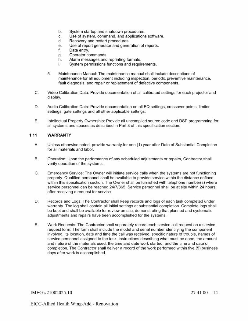
IMEG #21002025.10 27 41 00 - 14
EICC-Allied Health Wing-Add - Renovation
b. System startup and shutdown procedures.c. Use of system, command, and applications software.d. Recovery and restart procedures.e. Use of report generator and generation of reports.f. Data entry.g. Operator commands.h. Alarm messages and reprinting formats.i. System permissions functions and requirements.
5. Maintenance Manual: The maintenance manual shall include descriptions of maintenance for all equipment including inspection, periodic preventive maintenance, fault diagnosis, and repair or replacement of defective components.
C. Video Calibration Data: Provide documentation of all calibrated settings for each projector and display.
D. Audio Calibration Data: Provide documentation on all EQ settings, crossover points, limiter settings, gate settings and all other applicable settings.
E. Intellectual Property Ownership: Provide all uncompiled source code and DSP programming for all systems and spaces as described in Part 3 of this specification section.
1.11 WARRANTY
A. Unless otherwise noted, provide warranty for one (1) year after Date of Substantial Completion for all materials and labor.
B. Operation: Upon the performance of any scheduled adjustments or repairs, Contractor shall verify operation of the systems.
C. Emergency Service: The Owner will initiate service calls when the systems are not functioning properly. Qualified personnel shall be available to provide service within the distance defined within this specification section. The Owner shall be furnished with telephone number(s) where service personnel can be reached 24/7/365. Service personnel shall be at site within 24 hours after receiving a request for service.
D. Records and Logs: The Contractor shall keep records and logs of each task completed under warranty. The log shall contain all initial settings at substantial completion. Complete logs shall be kept and shall be available for review on site, demonstrating that planned and systematic adjustments and repairs have been accomplished for the systems.
E. Work Requests: The Contractor shall separately record each service call request on a service request form. The form shall include the model and serial number identifying the component involved, its location, date and time the call was received, specific nature of trouble, names of service personnel assigned to the task, instructions describing what must be done, the amount and nature of the materials used, the time and date work started, and the time and date of completion. The Contractor shall deliver a record of the work performed within five (5) business days after work is accomplished.

IMEG #21002025.10 27 41 00 - 15
EICC-Allied Health Wing-Add - Renovation
F. System Modifications: The Contractor shall make any recommendations for system modification in writing to the Owner. No system modifications shall be made without prior approval of the Owner. Any modifications made to the system shall be incorporated into the operations and maintenance manuals, and other documentation affected. To the fullest extent possible, the Owner shall be provided with electronic restorable versions of all configurations prior to the modifications being made.
G. Software: The Contractor shall provide all software and firmware updates during the period of the warranty and verify operation of the system upon installation. These updates shall be accomplished in a timely manner, fully coordinated with system operators, shall include training for the new changes/features, and shall be incorporated into the operations and maintenance manuals, and software documentation.
H. Refer to the individual product sections for further warranty requirements of individual system components.
PART 2 - PRODUCTS
2.1 SYSTEM COMPONENTS
A. Refer to the project drawings for basis of design system components. Equivalent products shall meet or exceed all requirements defined on the project drawings. The following product information represents the minimum additional requirements for equivalent products:
B. Audio/Video GUI Control Systems:
1. Contractor shall furnish a programmable software-based audio/video control system. The system shall be field configurable and programmable by the factory and/or a factory-trained programmer.
2. The control system shall be TCP/IP based allowing direct connection of the system processors to a 10/100BaseT compatible Ethernet network.
3. Virtual touch panel and keypad control shall be provided for remote trouble shooting and control.
4. Refer to project drawings for required central processors, touch panels, keypads and additional information.
C. Microphone Systems:
1. Wireless Microphones:
a. Wireless microphones shall not operate in the 614 to 806 MHz band (channels 38 to 69).
b. Features:
1) Dual antenna reception with true diversity reception.
c. Microphone systems that are common (shared) by multiple spaces or when the receivers are in a remote area shall include a compatible wireless antenna distribution system by the same manufacturer as the wireless microphone system.
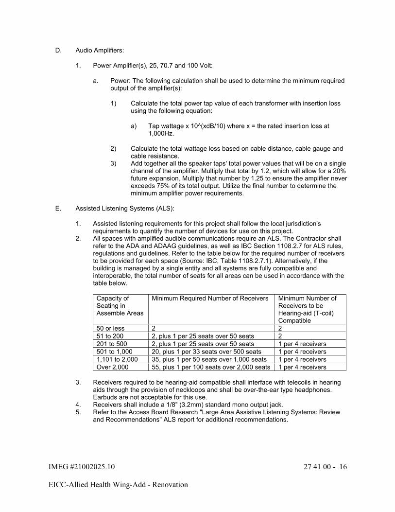
IMEG #21002025.10 27 41 00 - 16
EICC-Allied Health Wing-Add - Renovation
D. Audio Amplifiers:
1. Power Amplifier(s), 25, 70.7 and 100 Volt:
a. Power: The following calculation shall be used to determine the minimum required output of the amplifier(s):
1) Calculate the total power tap value of each transformer with insertion loss using the following equation:
a) Tap wattage x 10^(xdB/10) where x = the rated insertion loss at 1,000Hz.
2) Calculate the total wattage loss based on cable distance, cable gauge and cable resistance.
3) Add together all the speaker taps' total power values that will be on a single channel of the amplifier. Multiply that total by 1.2, which will allow for a 20% future expansion. Multiply that number by 1.25 to ensure the amplifier never exceeds 75% of its total output. Utilize the final number to determine the minimum amplifier power requirements.
E. Assisted Listening Systems (ALS):
1. Assisted listening requirements for this project shall follow the local jurisdiction's requirements to quantify the number of devices for use on this project.
2. All spaces with amplified audible communications require an ALS. The Contractor shall refer to the ADA and ADAAG guidelines, as well as IBC Section 1108.2.7 for ALS rules, regulations and guidelines. Refer to the table below for the required number of receivers to be provided for each space (Source: IBC, Table 1108.2.7.1). Alternatively, if the building is managed by a single entity and all systems are fully compatible and interoperable, the total number of seats for all areas can be used in accordance with the table below.
Capacity of Seating in Assemble Areas
Minimum Required Number of Receivers Minimum Number of Receivers to be Hearing-aid (T-coil) Compatible
50 or less 2 251 to 200 2, plus 1 per 25 seats over 50 seats 2201 to 500 2, plus 1 per 25 seats over 50 seats 1 per 4 receivers501 to 1,000 20, plus 1 per 33 seats over 500 seats 1 per 4 receivers1,101 to 2,000 35, plus 1 per 50 seats over 1,000 seats 1 per 4 receiversOver 2,000 55, plus 1 per 100 seats over 2,000 seats 1 per 4 receivers
3. Receivers required to be hearing-aid compatible shall interface with telecoils in hearing aids through the provision of neckloops and shall be over-the-ear type headphones. Earbuds are not acceptable for this use.
4. Receivers shall include a 1/8" (3.2mm) standard mono output jack.5. Refer to the Access Board Research "Large Area Assistive Listening Systems: Review
and Recommendations" ALS report for additional recommendations.
IMEG #21002025.10 27 41 00 - 17
EICC-Allied Health Wing-Add - Renovation
F. Digital Video Signal Equalizers and Regenerators:
1. For any cable run that exceeds the manufacturer-recommended distances or fails to transmit video or audio due to cable length, the Contractor shall provide and install a signal equalizer at the far end (sink) with the following minimum features:
a. HDMI/DVI equalizers shall be HDCP compliant and support actively buffered DDC transmission.
b. Display port equalizers shall be HDCP and DPCP compliant, support actively buffered DDC transmission, and be DP++ compatible.
c. Provide automatic equalization.d. Pass all embedded audio and metadata.e. Have an auxiliary power input when adequate power is not available on the cable.f. Provide output reclocking and jitter reduction for multi-rate SDI signals.
2. For any cable run that that fails to transmit video or audio due to a weak source signal, the Contractor shall provide and install a signal regenerator at the near end (source) with the following minimum features:
a. HDMI/DVI regenerators shall be HDCP compliant and support actively buffered DDC.
b. Display port regenerators shall be HDCP and DPCP compliant, support DDC transmission, and be DP++ compatible.
c. Provide automatic output reclocking and jitter reduction.d. Pass all embedded audio and metadata.e. Have an auxiliary power input when adequate power is not available on the cable.
G. Extended Display Identification Data (EDID) Emulators:
1. If any source or Owner-furnished equipment (OFE) is not outputting video properly, the Contractor shall provide and install an EDID Emulator and set it to the highest common EDID table of the displays (sinks) being outputted to, with the following minimum features:
a. EDID capture mode from a display.b. Have an auxiliary power input when adequate power is not available on the cable.
H. Audio Unbalanced to Balanced Converters, Balanced to Unbalanced Converters, Combiners, Dividers, Isolation Transformers, and Line Drivers Minimum Requirements:
1. Unbalanced to Balanced Active Converter:
a. Provide signal isolation from the audio signals of differing channels.b. Provide output trim gain and set to optimal output level while preventing over
amplification and clipping of the signal.c. Minimum frequency response of 20 Hz to 20 kHz (± 0.5dB).d. Provide with appropriate power supply and mounting kit for rack or wall use.e. Provide appropriate converter for mono to mono, mono to stereo, stereo to stereo,
or stereo to mono to match the input of the equipment to which it is being connected.
2. Balanced to Unbalanced Passive Converter:
a. Provide transformer isolation from the input to output.
IMEG #21002025.10 27 41 00 - 18
EICC-Allied Health Wing-Add - Renovation
b. Provide output trim attenuation and set to optimal output level while preventing over-amplification and clipping of the signal.
c. Minimum frequency response of 20 Hz to 20 kHz (± 0.5dB).d. Provide with appropriate mounting kit for rack or wall use.e. Provide appropriate converter for mono to mono, mono to stereo, stereo to stereo,
or stereo to mono to match the input of the equipment to which it is being connected.
3. Stereo to Mono and Mono to Stereo Passive Combiner/Divider:
a. Passive resistive network.b. Provide RF filtering.c. Provide a minimum of 3dB of isolation between channels.d. Provide no greater than 3dB of Insertion Loss.e. Minimum frequency response of 20 Hz to 20 kHz (± 3dB).f. Provide with appropriate mounting kit for rack or wall use.g. Provide appropriate passive combiner for low impedance or high impedance and
balanced or unbalanced signals to maintain the original signal type.
4. Passive Isolation Transformer:
a. Provide Galvanic Isolation.b. Minimum frequency response of 20 Hz to 20 kHz (± 3dB).c. Isolate the input shield from the output shield. Input shield is electrically isolated
from the transformer chassis and provides a ground return. The output shield is connected to the transformer chassis.
d. Provide with appropriate mounting kit for rack or wall use.e. Provide appropriate isolation transformer for low impedance or high impedance,
stereo or mono signals, and balanced or unbalanced signals to maintain the original signal type.
5. Active Signal Line Driver:
a. Provide balanced or unbalanced inputs with balanced outputs.b. Provide input trim gain for a minimum of unity gain from -14dBu to +24dBu, set to
optimal output level while preventing over-amplification and clipping of the signal.c. Provide a minimum balanced output of +4dBu nominal for a minimum output gain
of +25dBu.d. Minimum frequency response of 20 Hz to 20 kHz (± 0.5dB).e. Provide with appropriate power supply and mounting kit for rack or wall use.f. Provide appropriate line driver for low impedance or high impedance and stereo or
mono signals.
I. Refer to project drawings for all other equipment not listed.
2.2 AUDIO CONNECTORS
A. This article includes minimum requirements for all connectors that are acceptable on this project. Should the Contractor request an alternative connector, it shall be submitted with the product submittals and clearly identified with which connector it will be replaced.

IMEG #21002025.10 27 41 00 - 19
EICC-Allied Health Wing-Add - Renovation
B. Phono Jack:
1. Panel Mount:
a. Professional grade, three conductor, stereo, 0.375" hole diameter mounting, self-locking, double-open circuit.
b. Manufacturers:
1) Switchcraft2) Neutrik
2. Cable Mount:
a. Professional grade, three conductor, stereo, all-metal construction, integral cable clamp, nickel body, cable strain relief.
b. Manufacturers:
1) Switchcraft2) Neutrik
C. Phono Plug:
1. Professional grade, 1/4" stereo phone plug, strain relief, internal cable clamp, all metal body, tin-plated solder terminals.
2. Manufacturers:
a. Switchcraftb. Neutrikc. Mogami
D. RCA Jack:
1. Panel Mount:
a. Professional grade, isolated, gold-plated connectors, solders connection.
1) Manufacturers:
a) Switchcraftb) Neutrikc) Mogami
2. Panel Mount (Recessed):
a. Professional grade, isolated, gold-plated connectors, solders connection.b. Manufacturers:
1) Switchcraft2) Neutrik3) Mogami
IMEG #21002025.10 27 41 00 - 20
EICC-Allied Health Wing-Add - Renovation
3. Cable Mount:
a. Professional grade, nickel-plated body, metal shell, heavy-duty cable clamp.b. Manufacturers:
1) Switchcraft2) Neutrik3) Mogami
E. RCA Plug:
1. Professional grade, nickel-plated metal shell, solid center pin, gold-plated contact surface.
2. Manufacturers:
a. Switchcraftb. Neutrikc. Mogami
F. XLR Jack:
1. Panel Mount: Professional grade, crimped insert for vibration control, nickel shell, silver pins, pin quantity as required for application.
2. Manufacturers:
a. Switchcraftb. Neutrikc. Mogami
G. XLR Plug:
1. Professional grade, 360° strain relief, nickel shell, silver pins. Provide colored boot.2. Manufacturers:
a. Switchcraftb. Neutrikc. Mogami
2.3 AUDIO CABLING
A. Refer to Section 27 05 00 for cable rating requirements.
B. Microphone and Line Level Audio Cabling:
1. For patch cables less than or equal to 25 feet:
a. 22 AWG 2-conductor, twisted, stranded (7x30) tinned bare copper.b. Single Layer Shield:
1) Shield: 100% aluminum foil shield
c. Nominal Capacitance for non-plenum cable: 24.0pF/Ftd. Nominal Capacitance for plenum cable: 35.0 pF/Ft
IMEG #21002025.10 27 41 00 - 21
EICC-Allied Health Wing-Add - Renovation
e. Manufacturers:
1) Belden2) West Penn3) Liberty
2. For cable runs greater than or equal to 25 feet:
a. 18 AWG 2-conductor, twisted, stranded (16x30) tinned bare copper.b. Single Layer Shield:
1) Shield: 100% aluminum foil shield
c. Manufacturers:
1) Belden2) West Penn3) Liberty
C. Constant Voltage Speaker Cabling:
1. Class 2, stranded, twisted, 2-conductor, minimum of 16-gauge wire for all 25/70.7/100-volt applications unless noted otherwise.
2. The Contractor shall size cabling as required for distance power and shall provide larger gauge cable as required.
3. Manufacturers:
a. Beldenb. Libertyc. Or pre-approved equal
D. Low Capacitance Speaker/Subwoofer Cabling:
1. Class 2, high strand count (65x34), oxygen free copper, low capacitance (19.9 pF/Ft), twisted, 2-conductor, 16-gauge wire for all 2/4/8/16 ohm low impedance applications where amplifier output is 150 watts or less and/or the distance is less than 50', unless noted otherwise.
2. The Contractor shall size cabling as required for distance power and shall provide larger gauge cable as required.
3. Cable shall be installed in conduit within plenum areas.4. Manufacturers:
a. Beldenb. Libertyc. Or pre-approved equal
2.4 DIGITAL VIDEO CABLING
A. All digital video cabling shall be pre-assembled and tested in a factory and not field terminated. The contractor shall field verify the cable distance and provide the proper cable type and length.
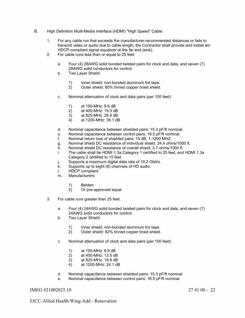
IMEG #21002025.10 27 41 00 - 22
EICC-Allied Health Wing-Add - Renovation
B. High Definition Multi-Media Interface (HDMI) "High Speed" Cable:
1. For any cable run that exceeds the manufacturer-recommended distances or fails to transmit video or audio due to cable length, the Contractor shall provide and install am HDCP-compliant signal equalizer at the far end (sink).
2. For cable runs less than or equal to 25 feet:
a. Four (4) 28AWG solid bonded twisted pairs for clock and data, and seven (7) 28AWG solid conductors for control.
b. Two Layer Shield:
1) Inner shield: non-bonded aluminum foil tape.2) Outer shield: 85% tinned copper braid shield.
c. Nominal attenuation of clock and data pairs (per 100 feet):
1) at 100-MHz: 9.6 dB2) at 400-MHz: 19.3 dB3) at 825-MHz: 28.9 dB4) at 1200-MHz: 36.1 dB
d. Nominal capacitance between shielded pairs: 15.3 pF/ft nominal.e. Nominal capacitance between control pairs: 16.5 pF/ft nominal.f. Nominal return loss of shielded pairs: 15 dB, 1-1200 MHZ.g. Nominal shield DC resistance of individual shield: 24.4 ohms/1000 ft.h. Nominal shield DC resistance of overall shield: 3.7 ohms/1000 ft.i. The cable shall be HDMI 1.3a Category 1 certified to 25 feet, and HDMI 1.3a
Category 2 certified to 15 feet.j. Supports a maximum digital data rate of 10.2 Gbit/s.k. Supports up to eight (8) channels of HD audio.l. HDCP compliant.m. Manufacturers:
1) Belden 2) Or pre-approved equal
3. For cable runs greater than 25 feet:
a. Four (4) 24AWG solid bonded twisted pairs for clock and data, and seven (7) 24AWG solid conductors for control.
b. Two Layer Shield:
1) Inner shield: non-bonded aluminum foil tape.2) Outer shield: 82% tinned copper braid shield.
c. Nominal attenuation of clock and data pairs (per 100 feet):
1) at 100-MHz: 6.0 dB2) at 400-MHz: 13.5 dB3) at 825-MHz: 19.8 dB4) at 1200-MHz: 24.1 dB
d. Nominal capacitance between shielded pairs: 15.3 pF/ft nominal.e. Nominal capacitance between control pairs: 16.5 pF/ft nominal.
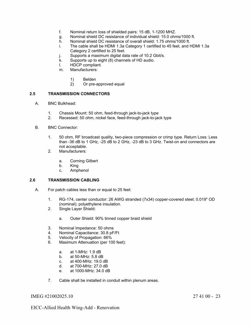
IMEG #21002025.10 27 41 00 - 23
EICC-Allied Health Wing-Add - Renovation
f. Nominal return loss of shielded pairs: 15 dB, 1-1200 MHZ.g. Nominal shield DC resistance of individual shield: 15.0 ohms/1000 ft.h. Nominal shield DC resistance of overall shield: 1.75 ohms/1000 ft.i. The cable shall be HDMI 1.3a Category 1 certified to 45 feet, and HDMI 1.3a
Category 2 certified to 25 feet.j. Supports a maximum digital data rate of 10.2 Gbit/s.k. Supports up to eight (8) channels of HD audio.l. HDCP compliant.m. Manufacturers:
1) Belden 2) Or pre-approved equal
2.5 TRANSMISSION CONNECTORS
A. BNC Bulkhead:
1. Chassis Mount: 50 ohm, feed-through jack-to-jack type2. Recessed: 50 ohm, nickel face, feed-through jack-to-jack type
B. BNC Connector:
1. 50 ohm, RF broadcast quality, two-piece compression or crimp type. Return Loss: Less than -36 dB to 1 GHz, -25 dB to 2 GHz, -23 dB to 3 GHz. Twist-on and connectors are not acceptable.
2. Manufacturers:
a. Corning Gilbertb. Kingc. Amphenol
2.6 TRANSMISSION CABLING
A. For patch cables less than or equal to 25 feet:
1. RG-174, center conductor: 26 AWG stranded (7x34) copper-covered steel; 0.019" OD (nominal); polyethylene insulation.
2. Single Layer Shield:
a. Outer Shield: 90% tinned copper braid shield
3. Nominal Impedance: 50 ohms4. Nominal Capacitance: 30.8 pF/Ft5. Velocity of Propagation: 66%6. Maximum Attenuation (per 100 feet):
a. at 1-MHz: 1.9 dBb. at 50-MHz: 5.8 dBc. at 400-MHz: 19.0 dBd. at 700-MHz: 27.0 dBe. at 1000-MHz: 34.0 dB
7. Cable shall be installed in conduit within plenum areas.
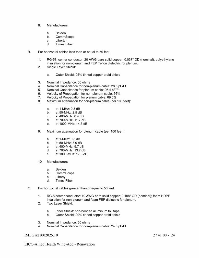
IMEG #21002025.10 27 41 00 - 24
EICC-Allied Health Wing-Add - Renovation
8. Manufacturers:
a. Beldenb. CommScopec. Libertyd. Times Fiber
B. For horizontal cables less than or equal to 50 feet:
1. RG-58, center conductor: 20 AWG bare solid copper; 0.037" OD (nominal); polyethylene insulation for non-plenum and FEP Teflon dielectric for plenum.
2. Single Layer Shield:
a. Outer Shield: 95% tinned copper braid shield
3. Nominal Impedance: 50 ohms4. Nominal Capacitance for non-plenum cable: 28.5 pF/Ft5. Nominal Capacitance for plenum cable: 26.4 pF/Ft6. Velocity of Propagation for non-plenum cable: 66%7. Velocity of Propagation for plenum cable: 69.5%8. Maximum attenuation for non-plenum cable (per 100 feet):
a. at 1-MHz: 0.3 dBb. at 50-MHz: 2.5 dBc. at 400-MHz: 8.4 dBd. at 700-MHz: 11.7 dBe. at 1000-MHz: 14.5 dB
9. Maximum attenuation for plenum cable (per 100 feet):
a. at 1-MHz: 0.5 dBb. at 50-MHz: 3.0 dBc. at 400-MHz: 9.7 dBd. at 700-MHz: 13.7 dBe. at 1000-MHz: 17.3 dB
10. Manufacturers:
a. Beldenb. CommScopec. Libertyd. Times Fiber
C. For horizontal cables greater than or equal to 50 feet:
1. RG-8 center conductor: 10 AWG bare solid copper; 0.108" OD (nominal); foam HDPE insulation for non-plenum and foam FEP dielectric for plenum.
2. Two Layer Shield:
a. Inner Shield: non-bonded aluminum foil tapeb. Outer Shield: 90% tinned copper braid shield
3. Nominal Impedance: 50 ohms4. Nominal Capacitance for non-plenum cable: 24.8 pF/Ft
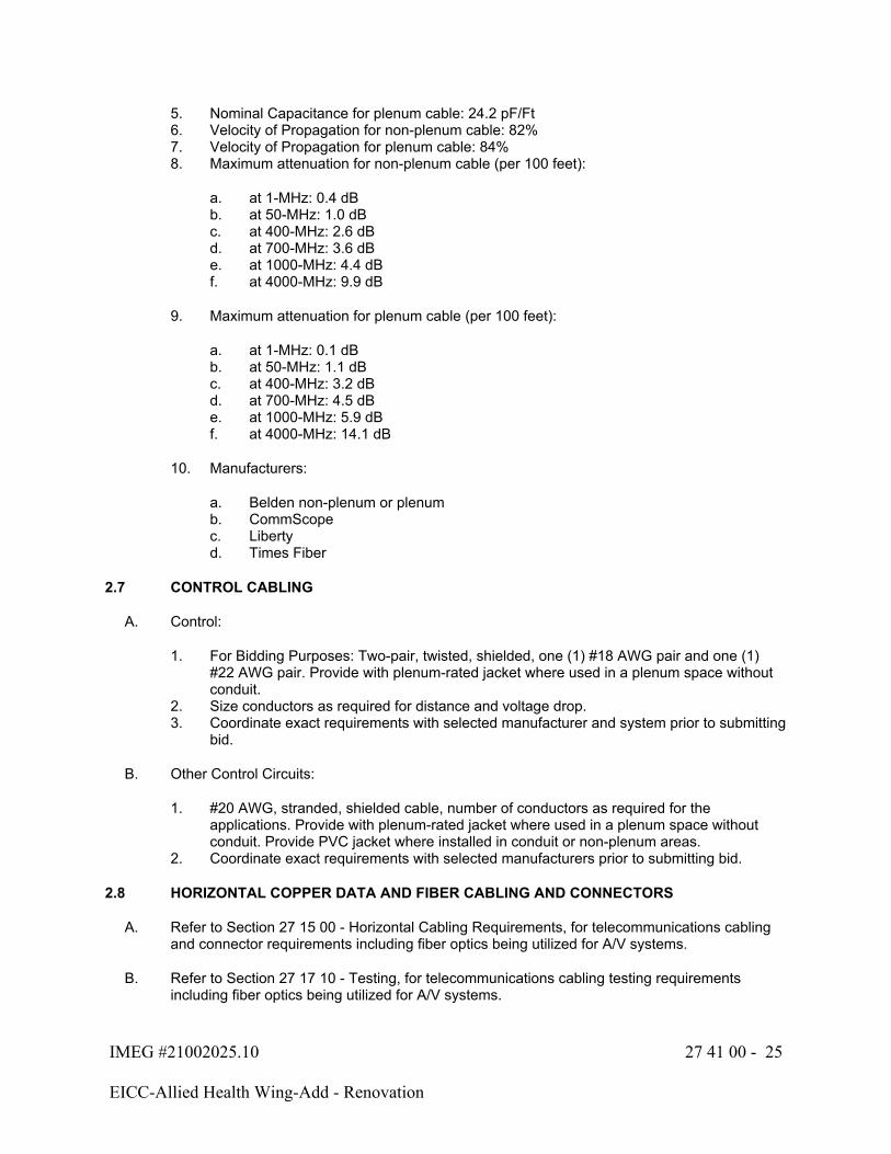
IMEG #21002025.10 27 41 00 - 25
EICC-Allied Health Wing-Add - Renovation
5. Nominal Capacitance for plenum cable: 24.2 pF/Ft6. Velocity of Propagation for non-plenum cable: 82%7. Velocity of Propagation for plenum cable: 84%8. Maximum attenuation for non-plenum cable (per 100 feet):
a. at 1-MHz: 0.4 dBb. at 50-MHz: 1.0 dBc. at 400-MHz: 2.6 dBd. at 700-MHz: 3.6 dBe. at 1000-MHz: 4.4 dBf. at 4000-MHz: 9.9 dB
9. Maximum attenuation for plenum cable (per 100 feet):
a. at 1-MHz: 0.1 dBb. at 50-MHz: 1.1 dBc. at 400-MHz: 3.2 dBd. at 700-MHz: 4.5 dBe. at 1000-MHz: 5.9 dBf. at 4000-MHz: 14.1 dB
10. Manufacturers:
a. Belden non-plenum or plenumb. CommScopec. Libertyd. Times Fiber
2.7 CONTROL CABLING
A. Control:
1. For Bidding Purposes: Two-pair, twisted, shielded, one (1) #18 AWG pair and one (1) #22 AWG pair. Provide with plenum-rated jacket where used in a plenum space without conduit.
2. Size conductors as required for distance and voltage drop.3. Coordinate exact requirements with selected manufacturer and system prior to submitting
bid.
B. Other Control Circuits:
1. #20 AWG, stranded, shielded cable, number of conductors as required for the applications. Provide with plenum-rated jacket where used in a plenum space without conduit. Provide PVC jacket where installed in conduit or non-plenum areas.
2. Coordinate exact requirements with selected manufacturers prior to submitting bid.
2.8 HORIZONTAL COPPER DATA AND FIBER CABLING AND CONNECTORS
A. Refer to Section 27 15 00 - Horizontal Cabling Requirements, for telecommunications cabling and connector requirements including fiber optics being utilized for A/V systems.
B. Refer to Section 27 17 10 - Testing, for telecommunications cabling testing requirements including fiber optics being utilized for A/V systems.
IMEG #21002025.10 27 41 00 - 26
EICC-Allied Health Wing-Add - Renovation
C. All category-rated copper data cabling and fiber optic cabling shall be installed, terminated, tested and certified by the Division 27 Telecommunications contractor certified by the selected manufacturers for the copper and fiber optic cabling plant. The Contractor shall submit all cabling and certifications to the Architect/Engineer for approval in the shop drawings.
D. The A/V contractor shall coordinate purchase, installation, testing and certification with the telecommunications contractor for all required category-rated copper data cabling and fiber optic cabling required for A/V system operation prior to bid.
E. Digital Video Over Twisted Pair Cable XTP DTP 24 (non-plenum):
1. Provide interconnection of digital video over twisted pair switching, distribution, and extension devices when terminated with an applicable RJ-45 plug or jack.
a. Shielded twisted pair cable for digital video over twisted pair devices.
1) Cable shall be optimized for use in digital video over twisted pair applications.
2) Cable shall be certified to 475 MHz bandwidth at distances up to 100 meters (330 feet).
3) Cable shall provide protection from outside electrical interference.4) Cable shall utilize SF/UTP construction.
a) An overall tinned copper braid with 55% coverage.b) An overall aluminized Mylar shield.c) Four unshielded twisted pair conductors (eight individual conductors)
of 24 AWG solid copper.
5) Nominal pair-to-pair skew shall be no less than 8 nano-seconds per 100 meters, and no more than 25 nano-seconds per 100 meters.
6) Cable shall comply with NEC – National Electrical Code Article 800 CM and UL 1685 standards at 75 degrees Celsius.
7) Cable shall be rated and in compliance with European Commission CPR, Construction Products Regulation (EU 305/2011).
a) Euroclass Dca-s2,d0 classification.
8) Cable shall be packaged in spools of 1000 feet (305 meters).9) Complementary cable termination products, including shielded RJ-45 Plugs,
Punch Down Jacks, and Couplers, shall be available from the same source as the cable.
b. Approved cable shall be Extron XTP DTP 24, part number 22-236-03; no alternates or equals.
c. Available complementary cable termination products shall be the Extron XTP DTP 24 Plug, part number 101-005-02; Extron XTP DTP 24 Jack, part number 101-023-01; and Extron XTP DTP 24 Coupler, part number 101-022-02; no alternates or equals
IMEG #21002025.10 27 41 00 - 27
EICC-Allied Health Wing-Add - Renovation
F. Digital Video Over Twisted Pair Cable XTP DTP 24P (plenum):
1. Provide interconnection of digital video over twisted pair switching, distribution, and extension devices when terminated with an applicable RJ-45 plug or jack.
a. Shielded twisted pair cable for digital video over twisted pair devices.
1) Cable shall be optimized for use in digital video over twisted pair applications.
2) Cable shall be certified to 475 MHz bandwidth at distances up to 100 meters (330 feet).
3) Cable shall provide protection from outside electrical interference.4) Cable shall utilize fire-resistant SF/UTP construction.
a) An overall tinned copper braid with 55% coverage.b) An overall aluminized Mylar shield.c) Four unshielded twisted pair conductors (eight individual conductors)
of 24 AWG solid copper.d) Solid FEP - Fluorinated ethylene propylene insulation.e) Fire-resistant PVC outer jacket.
5) Nominal pair-to-pair skew shall be no less than 8 nano-seconds per 100 meters, and no more than 25 nano-seconds per 100 meters.
6) Cable shall comply with NEC – National Electrical Code Article 800 CMP and UL 910 standards at 75 degrees Celsius.
7) Cable shall be rated and in compliance with European Commission CPR, Construction Products Regulation (EU 305/2011).
a) Euroclass Dca-s1,d0 classification.
8) Cable shall be packaged in spools of 1000 feet (305 meters).9) Complementary cable termination products, including shielded RJ-45 Plugs,
Punch Down Jacks, and Couplers, shall be available from the same source as the cable.
b. Approved cable shall be Extron XTP DTP 24P, part number 22-235-03; no alternates or equals.
c. Available complementary cable termination products shall be the Extron XTP DTP 24 Plug, part number 101-005-02; Extron XTP DTP 24 Jack, part number 101-023-01; and Extron XTP DTP 24 Coupler, part number 101-022-02; no alternates or equals
PART 3 - EXECUTION
3.1 EXAMINATION
A. Verify that surfaces are ready to receive work.
B. Verify field dimensions and coordinate physical size of all equipment with the architectural requirements of the spaces into which they are to be installed. Allow space for adequate ventilation and circulation of air.
C. Verify that required utilities are available, in proper location, and ready for use.
IMEG #21002025.10 27 41 00 - 28
EICC-Allied Health Wing-Add - Renovation
D. Beginning of installation means installer accepts existing conditions.
3.2 PRE-INSTALLATION
A. A pre-installation meeting shall be held after the project has been awarded but before any submittals or work has been conducted. The purpose of this meeting is to review the drawings and specifications to assist with the construction and installation process that will occur during construction. The meeting will include the Engineer, Architect, Owner's Representative, and all relevant installing contractors for this system. The meeting will be chaired by the project manager for the AV contract and will include the following topics:
B. The Contractor shall be responsible for submitting all requested submittals and holding the pre-installation meeting prior to any purchasing, installation, programming, and construction coordination. Any delays or changes to the project as a result of meeting this requirement will be at the Contractor's expense.
3.3 INSTALLATION
A. Comply with the manufacturer's instructions and recommendations for installation of all products.
B. Provide all system wiring between all components as directed by the manufacturer or required for proper system operation.
C. Mount all touch screen and keypad devices where shown on plans in accordance with Americans with Disabilities Act (ADA) requirements for both side reach and front reach.
D. Cabling Requirements:
1. Non-plenum rated cabling may be used instead of plenum when installed with-in conduit in plenum rated areas.
2. All cabling shall be routed according to function. Cabling shall be grouped and bundled by groups, such as: microphone and line level audio, control, video and speaker. In no case shall cabling from different functional groups be intermixed. No cabling shall be routed parallel to 120 VAC or higher power circuits unless separated by a minimum of 6" and the 120 VAC or higher power is installed in conduit.
3. When cabling is installed in conduit, a separate conduit shall be provided for each cabling functional type.
4. Cable bundles shall be loosely bundled to allow the visual following of individual cables within the bundle and to permit the easy removal and addition of cables as necessary.
5. Horizontal cabling installed as open cable or in cable tray shall be bundled at not less than 10' intervals with hook-and-loop tie wraps. The use of plastic cable zip ties is strictly prohibited in any situation.
6. Cabling shall not be spliced under any circumstances.7. Each cable shall be appropriately identified (as defined on the record documents) at each
end's termination point using pressure sensitive label strips.8. Audio Cabling:
a. All amplified audio cabling shall not be in the same enclosed pathway as any other type of cabling as required by the NEC. Refer to the NEC for definitions and additional requirements.
b. The polarity of all cabling shall remain consistent throughout the project, on all equipment. Red conductors shall be used for the positive "+" side, and black used for the negative "-" side.
IMEG #21002025.10 27 41 00 - 29
EICC-Allied Health Wing-Add - Renovation
c. Cable shield length shall be equal to the cable's conductor length.d. All shielded cables drain wire SHALL be grounded and continuous throughout the
entire length of the system, including splices where speakers are installed.e. Balanced audio connections shall be used whenever the mating equipment allows.f. Do not run unbalanced cables longer than 3m. For interconnecting of unbalanced
equipment in lengths longer than 3m, the Contractor shall provide a line driver located at the source.
9. Video Cabling:
a. All video cabling, unless otherwise noted, shall be provided with BNC connectors of the two-piece compression type. Twist-on BNC connectors are not permitted.
b. Provide BNC 75-ohm terminators where required for all open BNC connectors.c. All coaxial video cables used for S-video, component/RGB and RGBHV shall be
the same length to minimize skew.
10. Twisted Pair Cabling for All Applications:
a. The Contractor shall ensure that the twists in each cable pair are preserved to within 0.5 inch of the termination. The cable jacket shall be removed only to the extent required to make the termination.
b. The Contractor shall ensure that the cable shields are continuous throughout, terminated, and grounded according to the manufacturer's recommendations.
E. Grounding Requirements:
1. Provide a minimum of #6 AWG conductor from the nearest electrical service ground bus or nearest telecommunications room ground bus bar to the A/V equipment racks and cabinets regardless of location. Size cable as required by the NEC.
2. Cables containing shields shall not have the shields grounded at conduits, boxes, racks, etc. Ground the shield only at the equipment end.
3. Audio cable shields for line-level signals shall be connected to the metal equipment chassis at both ends of the cable.
4. Audio cables connected to transformers shall have the cable shield connected to the transformer shield and transformer case ground.
5. The Contractor shall not connect cable shields together from differing cables.6. XLR cable shields shall be connected to chassis ground.7. Signal-grounded balanced shields are not acceptable and shall not be installed. All
balanced shields shall be chassis grounded.
F. Rack and Cabinet Requirements:
1. Ground equipment racks/cabinets as noted within this specification section and Section 27 05 26 - Communications Grounding.
2. Provide one (1) RU of space between adjacent pieces of equipment with top and/or bottom vents, above the topmost piece of equipment, and below the bottommost piece of equipment. Provide a vented cover panel covering each rack space.
3. Terminate all speaker cabling on individual barrier strips for positive "+", negative "-", and shield. The shield barrier strip shall be grounded.
4. Provide a power conditioning surge arrestor in the rack for distribution of AC power from the wall receptacles indicated on the plans. The quantity of plugs shall be adequate so that no equipment in the rack shall require plugging into an AC source outside the rack.
IMEG #21002025.10 27 41 00 - 30
EICC-Allied Health Wing-Add - Renovation
5. Power sequencing shall be provided in the racks where shown on the drawings. All amplifiers located in the racks shall be sequenced "last on – first off". Power sequencers shall provide power conditioning and surge protection.
G. Audio System Installation Requirements:
1. The Contractor shall perform calculations for the optimal speaker tap settings to reach the desired SPL level and coverage without overloading the amplifier(s).
a. At a minimum, the following calculations shall be used:
1) Add together all speaker taps that will be on a single channel of the amplifier. Multiply that total by 1.2, which will allow for a 20% future expansion. Multiply that number by 1.25 to ensure the amplifier never exceeds 75% of its total output. Utilize the final number to determine the minimum amplifier power requirements.
2) For direct coupled systems (low impedance), allow a minimum of 10 dB headroom before any distortion occurs at the amplifier input indicator when beginning gain stage tests are set up. Increase headroom as appropriate for high impact and clarity needs, typically exceeding 12 to 15 dB during continuous operation.
2. Connections of balanced to unbalanced equipment shall only be done through an active converter at the unbalanced side.
3. Connections of unbalanced to balanced equipment shall only be done through an active converter at the unbalanced side.
4. Connections from stereo balanced or unbalanced equipment to mono equipment of the same signal type shall only be done through a passive combiner.
5. Connections from mono balanced or unbalanced equipment to stereo equipment of the same signal type shall only be done through a passive divider.
6. The Contractor shall provide an isolation transformer for any balanced or unbalanced audio line that exhibits a hum, noise from EMI or RFI, power line noise, or ground loops.
7. The Contractor shall provide an active audio line driver for all balanced and unbalanced signals that exceed the distance limitations of the cabling.
H. Control System Installation Requirements:
1. The Contractor shall perform calculations for the required wire AWG size based on distance for system power for touch panels, keypads and other devices being powered. A minimum of a 15% overhead is required.
3.4 VIDEO SYSTEM TESTING AND CALIBRATION
A. All video equipment shall receive proper testing and configuration.
B. Color Space Optimization:
1. The Contractor shall set the color space of each source and display device to a uniform color space to optimize the switching speed and compatibility of a digital video system. Each device shall be set to an RGB or YCbCr color space depending on the systems primary function and compatibility of the devices.

IMEG #21002025.10 27 41 00 - 31
EICC-Allied Health Wing-Add - Renovation
2. If the primary function of the space is video and other digital media, the color space of each device shall be set to a YCbCr color space. If the primary function of the space is computer-based graphics and presentations, the color space of each device shall be set to an RGB color space.
3. Chroma subsampling shall be set to a consistent 4:4:4 or 4:2:2 across all devices. Set to 4:4:4 when all equipment is capable.
4. If all devices are not capable of displaying a certain color space, all devices shall be set to a common shared color space.
C. Extended Display Identification Data (EDID) Management:
1. The Contractor shall set the EDID management tables in capable equipment so all sources output the highest common EDID table of the displays (sinks).
2. For systems with capable matrix switches, the matrix shall dynamically adjust its EDID tables so any source will output the highest common EDID table of the displays (sinks) being outputted to.
3. If any source or Owner-furnished equipment (OFE) is not outputting properly, the Contractor shall provide and install an EDID Emulator and set it to the highest common EDID table of the displays (sinks) being outputted to.
D. Projectors, monitors and receivers shall be tested and adjusted for proper signal sync, convergence, brightness, contrast, and color level. The Contractor shall adjust all other parameters necessary to achieve a proper video image.
E. All video source selections shall be tested and verified.
F. All projectors and displays shall have a minimum burn-in time of 96 hours prior to any adjustments are made and the completion of the project
G. All projectors and displays shall have their hue/tint and color/saturation calibrated with a video signal test generator and blue lens filter after a minimum warmup time of 20 minutes. Provide all calibrated settings results for each projector and display in the final documentation.
H. All projectors and displays shall have their brightness, contrast and sharpness calibrated with a video signal test generator after a minimum warmup time of 20 minutes. Provide all calibrated settings results for each projector and display in the final documentation.
I. All dynamic contrast functions shall be turned off.
3.5 AUDIO SYSTEM TESTING AND CALIBRATION:
A. This Contractor shall field adjust any surface-mounted or flown loudspeaker orientation to achieve the necessary coverage pattern to the intended listening plane. Loudspeakers always face listeners and minimize coverage on walls. The contractor shall be familiar with the named and specified nominal coverage angle of all speakers above its crossover point or for speech range, (500-4,000 Hz).
B. All speakers shall be tested for polarity prior to high work and a table of test results shall be included for A/E inspection. All loudspeakers shall be connected with uniform polarity, where a positive pressure pulse at the input corresponds to a positive driver excursion, and all drivers are uniform always moving in the same direction. Main speakers shall not be lifted or hoisted into high access areas without polarity testing.
IMEG #21002025.10 27 41 00 - 32
EICC-Allied Health Wing-Add - Renovation
C. The Contractor shall make incremental adjustments on the equipment output and input tolerances to achieve matching signal levels while preserving +10 dB minimum headroom and also unity gain. Insert all broadband or high pass filters first for system protection after review of manufacturers specifications for power and bandpass.
D. The Contractor shall utilize a Real Time Audio (RTA) spectrum analyzer with AES2 Broadband pink noise at a minimum of 1/3 octave, capable of providing detailed plots and reports.
1. The Contractor shall have and own a calibrated Type 1 or Type 1.5 microphone for all measurements, that is recently calibrated within the last year.
2. Calibration by ear, tablets and portable phones with integrated microphones are never acceptable. All software analysis tools require a calibrated interface and calibrated microphone. No Android devices are used for metering or calibration. IOS devices with calibrated software and interfaces may be used.
E. Provide high quality media with full bandpass program material for critical listening. MP3 or streaming audio is not acceptable. Testing shall illustrate WAV file quality playback for impact and clarity.
F. The Contractor shall provide graphic plots of the reference ambient noise for each space at the time of the calibration and submit with the calibration results. Test signal shall be 10dB minimum above ambient noise levels during testing.
G. The Contractor shall use a listener sitting height of four (4) feet ± 1" for rooms where the primary function will be sitting. The Contractor shall use a listener standing height of five feet three inches (5.25') ± 1" for rooms where the primary function will be standing
3.6 ASSISTED LISTENING SYSTEM (ALS) PERFORMANCE REQUIREMENTS
A. The Contractor shall verify that the ALS system(s) meets the following minimum performance requirements at the earphone or headset:
1. Reach a minimum total SPL of 75 dBA and no greater than 95 dBA, with a minimum of a 50dB dynamic range volume control.
2. Achieve a minimum signal-to-noise (S/N) ratio of 18dB. It is recommended to achieve a minimum signal-to-noise (S/N) ratio of 25dB to accommodate children.
3. Ensure the peak clipping levels do not exceed 18dB down from the peak input signal level.
B. FM-based systems shall operate within the FCC-reserved assisted listening frequencies of 72 to 76 MHz or the 216 to 217 MHz (preferred) range and comply with the FCC transmitter power requirements.
3.7 DSP-BASED AUDIO PROCESSOR PROGRAMMING
A. Full system programming shall be provided for the system. Programming shall be performed by a factory trained and certified programmer or an employee of the equipment manufacturer.
B. DSP pathfile with initial settings shall be provided by the Contractor for review by the Architect/Engineer before installation.
C. The IP-based audio (IEEE AVB, Dante, etc.) and components shall be on a dedicated Virtual LAN (VLAN) for the A/V systems. These components shall be on a dedicated subnetwork of the VLAN. The Contractor shall coordinate these requirements with the Owner prior to installation.
IMEG #21002025.10 27 41 00 - 33
EICC-Allied Health Wing-Add - Renovation
D. A parametric EQ shall be provided after each crossover point or as approved in the DSP pathfile during shop submittal review. These equalizers should not be made available to the user to adjust.
E. Levelers, compressor/limiters, duckers, gates and delays shall be preset during testing and commissioning and are not available for user adjustment following commissioning.
1. Adjust delays for time of flight plus 8 to 10 ms, typical.
F. Provide each microphone input with high-pass filter, 5-band parametric EQ, auto-leveler and volume module. Provide line level inputs with high-pass filter, 3-band parametric EQ, compressor/limiter, and volume module.
G. Acoustic Echo Cancelation (AEC) shall be provided for each conference microphone input.
H. A broadband pink noise generator shall be provided with a selectable on/off control button within the DSP pathfile. The noise shall be routable through all processing EQs and speaker outputs during testing.
I. Provide volume meters with labeling for each input and each output.
J. The Contractor shall utilize the latest version of the programming software.
K. The Contractor shall ensure that all components are updated to the latest firmware at the completion of the project.
3.8 DSP-BASED AUDIO PROCESSOR CONTROL SOFTWARE PROGRAMMING
A. Full system software programming shall be provided for the system. Programming shall be performed by a factory-trained and certified programmer or an employee of the equipment manufacturer.
B. The Contractor shall schedule a series of meetings with the Owner and Architect/Engineer to define and determine the exact page layout requirements prior to the final configuration of the audio system. An Owner sign-off of the final layouts shall be required.
C. The Contractor shall use the latest version of the software.
D. At a minimum, there shall be password-protected pages for zone combining, input/output volume control with meters, speaker output volume control with meters, signal routing, signal processing (EQ's, feedback suppression, etc.), and supervision/maintenance for all spaces and combined zones.
3.9 MULTIMEDIA CONTROL SYSTEM INTEGRATION AND PROGRAMMING
A. Programming and Integration for Control Systems:
1. Full system programming shall be provided for the system. Programming shall be performed by a factory trained and certified programmer or an employee of the equipment manufacturer.
2. The Contractor shall schedule a series of meetings with the Owner and Architect/Engineer to define and determine the exact integration requirements of the control system prior to the installation of the control system and components. An Owner sign-off of the final configuration shall be required.
IMEG #21002025.10 27 41 00 - 34
EICC-Allied Health Wing-Add - Renovation
3. This section only defines the minimum requirements. The programmer shall provide complete programming for a fully functional system.
4. The Contractor shall utilize the latest version of the programming software.5. The Contractor shall ensure that all components are updated to the latest firmware at the
completion of the project.6. The IP-based control system and controlled components shall be on a dedicated Virtual
LAN (VLAN) for the A/V systems. These components shall be on a dedicated subnetwork of the VLAN. The Contractor shall coordinate these requirements with the Owner prior to installation.
7. Integration and programming of the following pieces of equipment shall be provided, with the following minimum features and functions:
a. All equipment shall include on/off control, except for equipment that must remain active for system functionality.
b. Integration of HDCP (High-bandwidth Digital Content Protection) and DPCP (Display Port Content Protection) protected content and sources:
1) No protected sources or content shall be allowed to be selected to route through non-protected devices and displays. A warning shall be displayed stating this information to the user.
c. Matrix Switcher Integration:
1) The Contractor shall provide bi-directional RS-232 or Ethernet control system connections and programming with the following minimum functions:
a) On/off control of the matrix switcher.b) Allow for independent video routing of individual video inputs to any
audio number of audio outputs.c) Allow for audio follow video switcher mode.d) Provide source detection of video inputs.e) HDCP (High-bandwidth Digital Content Protection) and DPCP
(Display Port Content Protection) Protection:f) For HDCP/DPCP - compliant sources; switcher shall only allow for
routing of signals to HDCP compliant devices.g) For HDCP/DPCP - complaint switchers; room combining/uncombining
features shall allow for complete audio and /or video devices to be connected to the system using a simplified interface.
d. DSP Audio Processor Integration:
1) The Contractor shall provide bi-directional RS-232 or Ethernet control system connections and programming with the following minimum functions:
a) On/off control of all microphones.b) Volume and mute control of microphones and input sources.c) Master Volume and mute control of all outputs.d) Advanced routing of audio signals.
IMEG #21002025.10 27 41 00 - 35
EICC-Allied Health Wing-Add - Renovation
e. Display Integration:
1) The displays shall be integrated into the A/V control system via bi-directional RS-232 or Ethernet control. Provide with the following minimum functions:
a) On/off control.b) Display status feedback.c) Source switching control.d) Tuner channel control with direct channel access.
f. Video Conference/Telepresence Integration:
1) The Contractor shall provide bi-directional RS-232 or Ethernet control system connections and programming with the following minimum functions:
a) Refer to DSP Audio Processor Integration for audio requirements.b) Video conferencing dialer keypad with speed dials.c) PTZ near end camera control.d) PTZ far end camera control with lockout control at the far end.e) Multi-window control with multiple presets the contractor shall
coordinate with the Owner and users on designed layouts. All system inputs shall be selectable for each window.
g. Pan/Tilt/Zoom (PTZ) Camera Integration:
1) The Contractor shall provide bi-directional RS-232 or Ethernet control system connections and programming with the following minimum functions:
a) Provide full pan, tilt and zoom control.b) Provide presets for fixed camera positions, contractor shall coordinate
with the Owner for desired preset positions.
h. Document Camera/Visualizer Integration:
1) The Contractor shall provide bi-directional RS-232 or Ethernet control system connections and programming with the following minimum functions:
a) The Contractor shall provide, at a minimum, power on and off functions as well as zoom and focus functions.
b) Bulb life and equipment status shall be monitored (if available).
i. Divisible Room Integration and Programming:
1) The following represents the minimum integration and programming requirements for divisible rooms.
a) The touch panel shall show a grid or map of the rooms and spaces that are combinable.
b) The user shall be able to highlight a group of rooms or spaces in any combination and hit combine.
c) Once combined, all functions shall operate as a single space including, but not limited to, master audio volume control and lighting.
d) All input sources shall be selectable to be output to any combination of displays.
IMEG #21002025.10 27 41 00 - 36
EICC-Allied Health Wing-Add - Renovation
e) Once rooms are combined all speaker volume levels shall normalize and all volume controls shall adjust the system as a whole.
f) Once rooms are combined all lighting levels shall normalize and all lighting controls shall adjust the system as a whole.
B. Programming and Configuration for Keypads:
1. This section only defines the minimum requirements. The programmer shall provide complete keypad layouts and programming for a fully functional system.
2. Full system programming and configuration shall be provided for the system. Programming and configuration shall be performed by a factory-trained and certified programmer or an employee of the equipment manufacturer.
3. This section only defines the minimum requirements. The programmer shall provide complete programming and configuration for a fully functional system.
4. The Contractor shall utilize the latest version of the programming and configuration software.
5. The Contractor shall ensure that all components are updated to the latest firmware at the completion of the project.
6. All programming and configuration for interface and control of all devices shown on the drawings shall be provided. Programming and configuration shall be provided for the following minimum functionality:
a. A master system on and off button.
1) All capable components within the system shall be turned off or placed on standby when the system is selected to be off.
b. A master volume control up/down buttons or knob and a mutec. Source select or source toggle button(s).d. TV channel up and down control.e. All unused hard buttons shall not be labeled.
3.10 SYSTEM COMMISSIONING
A. The Contractor shall notify the Architect/Engineer and Owner prior to conducting final system commissioning.
B. System verification testing is part of the commissioning process. Verification testing shall be performed by the Contractor and witnessed and documented by the Commissioning Agent. Refer to Section 01 09 00 - General Commissioning for system verification tests and commissioning requirements.
C. Contractor shall demonstrate system performance of all equipment and adjust settings as directed by the Architect/Engineer and/or Owner.
1. All system settings, software options and other parameters shall be simulated and tested by the Contractor
3.11 FIELD QUALITY CONTROL
A. Where these specifications require a product or assembly without the use of a brand or trade name, provide a product that meets the requirements of the specifications, as supplied and warranted by the system vendor. If the product or assembly is not available from the system vendor, provide product or assembly as recommended by the system vendor.
IMEG #21002025.10 27 41 00 - 37
EICC-Allied Health Wing-Add - Renovation
B. Periodic observations will be performed during construction to verify compliance with the requirements of the specifications. These services do not relieve the Contractor of responsibility for compliance with the Contract Documents.
3.12 FIELD SERVICES
A. The installer shall conduct a planning meeting with the Owner. The purpose of this meeting shall be to determine all equipment settings that are considered preferences (where proper system operation does not depend on the setting).
B. The installer shall include labor for all planning and all programming activities required to implement the Owner's preferences for equipment settings.
C. It shall be the responsibility of the Contractor/installer to provide a complete, functional system as described by the design documents. These responsibilities include:
1. Complete hardware setup, installation and wiring and software configuration.2. Complete programming of software in accordance with the Owner's desires determined
by the planning meeting.3. Complete system diagnostic verification.4. Complete system commissioning.
3.13 SYSTEM ACCEPTANCE
A. The Contractor shall submit for review a formal acceptance and system checkout procedure. The system checkout procedures shall include all system components and software. The Contractor shall perform the tests and settings and document all results.
3.14 SYSTEM DOCUMENTATION
A. Complete documentation shall be provided for the system. The documentation shall describe:
1. All operational parameters of the system.2. Complete documentation of programming and features.3. Complete operating instructions for all hardware and software.
B. The following sections shall be provided in the system documentation:
1. User Manual: A step-by-step guide and instructions detailing all system user functions.2. Technical Manual: A comprehensive document providing all system operations,
troubleshooting flowcharts, functional system layout, wiring diagrams, block diagrams and schematic diagrams.
3. Maintenance Manual: A comprehensive document on all aspects of physical maintenance of the systems, including cleaning of the displays, bulb changes, filter cleaning, filter changing and UPS maintenance.
3.15 SYSTEM TRAINING
A. All labor and materials required for on-site system training shall be provided. Training shall be conducted at the project site using the project equipment.
1. Provide two week's advanced notice of training to the Owner and Architect/Engineer.2. The Architect/Engineer shall be presented with the option to attend the training.

IMEG #21002025.10 27 41 00 - 38
EICC-Allied Health Wing-Add - Renovation
3. Provide a training outline agenda describing the subject matter and the recommended audience for each topic.
B. At a minimum, the following training shall be conducted:
1. User Manual: A course detailing the system functions and operations that a daily user will encounter.
2. Technical User: Provide configuration training on all aspects of the system(s), including equipment and software.
3. Maintenance User: Provide training on all aspects of physical maintenance of the systems, including cleaning of the displays, bulb changes, filter cleaning and filter changing.
C. Minimum on-site training times shall be:
1. User Manual: One (1) hour.2. Technical user: Four (4) hours.
END OF SECTION 27 41 00
IMEG #21002025.10 28 05 00 - 1
EICC-Allied Health Wing-Add - Renovation
SECTION 28 05 00 - BASIC ELECTRONIC SAFETY AND SECURITY SYSTEM REQUIREMENTS
PART 1 - GENERAL
1.1 SECTION INCLUDES
A. Basic Safety and Security System Requirements (herein referred to Security) specifically applicable to Division 28 sections, in addition to Division 1 - General Requirements.
B. All materials and installation methods shall conform to the applicable standards, guidelines and codes referenced herein and within each specification section.
1.2 SCOPE OF WORK
A. This Specification and the accompanying drawings govern the work involved in furnishing, installing, testing and placing into satisfactory operation the security systems as shown on the drawings and specified herein.
B. Each Contractor shall provide all new materials as indicated in the schedules on the drawings, and/or in these specifications, and all items required to make the portion of the security systems a finished and working system.
C. Description of systems include but are not limited to the following: 1. Electronic intrusion detection system2. Video surveillance3. Fire detection and alarm.4. Low voltage security wiring (less than +120VAC) as specified and required for proper
system control and communications.5. All associated electrical backboxes, conduit, miscellaneous cabling, and power supplies
required for proper system installation and operation as defined in the "Suggested Matrix of Scope Responsibility".
6. Firestopping of penetrations of fire-rated construction as described in Section 28 05 03.
1.3 OWNER FURNISHED PRODUCTS
A. Servers, switches routers, hubs, workstations, head end equipment.
1.4 WORK SEQUENCE
A. All construction work that will produce excessive noise levels and interference with normal building operations, as determined by the Owner, shall be scheduled with the Owner. It may be necessary to schedule such work during non-occupied hours. The Owner shall reserve the right to set policy as to when restricted construction hours will be required.
1.5 ALTERNATES
A. Base Bid includes cost of intrusion detection, electronic access control, and video surveillance systems from Per Mar Security Services, Davenport Iowa.
B. Alternate price for intrusion detection, electronic access control and video surveillance systems by Contractor.
IMEG #21002025.10 28 05 00 - 2
EICC-Allied Health Wing-Add - Renovation
1.6 DIVISION OF WORK BETWEEN ELECTRICAL AND SECURITY CONTRACTORS
A. Division of work is the responsibility of the Prime Contractor. Any scope of work described in the contract document shall be sufficient for including said requirement in the project. The Prime Contractor shall be solely responsible for determining the appropriate subcontractor for the described scope. In no case shall the project be assessed an additional cost for scope that is described in the contract documents. The following division of responsibility is a guideline based on typical industry practice.
B. Definitions:
1. "Electrical Contractor" as referred to herein refers to the Contractors listed in Division 26 of this Specification.
2. "Electrical Contractor" shall also refer to the Contractor listed in Division 28 of this specification when the "Suggested Matrix of Scope Responsibility" indicates the work shall be provided by the EC. Refer to the Contract Documents for the "Suggested Matrix of Scope Responsibility".
3. "Security Contractor" as referred to herein refers to the Contractors listed in Division 28 of this Specification.
4. Low Voltage Security Wiring: The wiring (less than 120VAC) associated with the Security Systems, used for analog and/or digital signals between equipment.
C. General:
1. The purpose of these Specifications is to outline typical Electrical and Security Contractor's work responsibilities as related to security systems including back boxes, conduit, power wiring and low voltage security wiring. The prime contractor is responsible for all divisions of work.
2. The exact wiring requirements for much of the equipment cannot be determined until the systems have been purchased and submittals are approved. Therefore, only known wiring, conduits, raceways, and electrical power as related to such items, is shown on the Security Drawings. Other wiring, conduits, raceways, junction boxes, and electrical power not shown on the Security Drawings but required for the successful operation of the systems shall be the responsibility of the Security Contractor and included in the Contractor's bid.
3. Where the Electrical Contractor is required to install conduit, conduit sleeves and/or power connections in support of Security systems, the final installation shall not begin until a coordination meeting between the Electrical Contractor and the Security Contractor has convened to determine the exact location and requirements of the installation.
4. Where the Electrical Contractor is required to install cable tray that will contain Low Voltage Security Wiring, the installation shall not begin until the Security Contractor has completed a coordination review of the cable tray shop drawing.
5. This Contractor shall establish Electrical and Security utility elevations prior to fabrication and installation. The Security Contractor shall cooperate with the Electrical Contractor and the determined elevations in accordance with the guidelines below. This Contractor shall coordinate utility elevations with other trades. When a conflict arises, priority shall be as follows:
a. Lighting Fixturesb. Gravity Flow Piping, including Steam and Condensatec. Sheet Metald. Electrical Busducte. Sprinkler Piping and other Piping
IMEG #21002025.10 28 05 00 - 3
EICC-Allied Health Wing-Add - Renovation
f. Conduit and Wirewayg. Open Cabling
D. Electrical Contractor's Responsibility:
1. Assumes all responsibility for all required conduit and power connections when shown on the "Suggested Matrix of Scope Responsibility" to be provided by the Electrical Contractor.
2. Responsible for Security Systems grounding and bonding.3. This Contractor is responsible for coordination of utilities with all other Contractors. If any
field coordination conflicts are found, the Contractor shall coordinate with other Contractors to determine a viable layout.
E. Security Contractor's Responsibility:
1. Assumes all responsibility for the low voltage security wiring of all systems, including cable support where open cable is specified.
2. Assumes all responsibility for all required backboxes, conduit and power connections not specifically shown as being provided by the Electrical Contractor on the "Suggested Matrix of Scope Responsibility."
3. Responsible for providing the Electrical Contractor with the required grounding lugs or other hardware for each piece of security equipment which is required to be bonded to the telecommunications bonding system.
4. This Contractor is responsible for coordination of utilities with all other Contractors. If any field coordination conflicts are found, the Contractor shall coordinate with other contractors to determine a viable layout.
1.7 COORDINATION DRAWINGS
A. Definitions:
1. Coordination Drawings: A compilation of the pertinent layout and system drawings that show the sizes and locations, including elevations, of system components and required access areas to ensure that no two objects will occupy the same space.
a. Mechanical trades shall include, but are not limited to, mechanical equipment, ductwork, fire protection systems, plumbing piping, medical gas systems, hydronic piping, steam and steam condensate piping, and any item that may impact coordination with other disciplines.
b. Electrical trades shall include, but are not limited to, electrical equipment, conduit 1.5" and larger, conduit racks, cable trays, pull boxes, transformers, raceway, busway, lighting, ceiling-mounted devices, and any item that may impact coordination with other disciplines.
c. Technology trades shall include, but are not limited to, technology equipment, racks, conduit 1.5" and larger, conduit racks, cable trays, ladder rack, pull boxes, raceway, ceiling-mounted devices, and any item that may impact coordination with other disciplines.
d. Maintenance clearances and code-required dedicated space shall be included.e. The coordination drawings shall include all underground, underfloor, in-floor, in
chase, and vertical trade items.

IMEG #21002025.10 28 05 00 - 4
EICC-Allied Health Wing-Add - Renovation
2. Spaces with open/cloud ceiling architecture shall indicate the overhead utilities and locate equipment as required to maintain clearance above lights. The intent for the installation is to maintain a maximum allowable vertical clearance and an organized/clean manner in the horizontal. Notify Architect/Engineer of the maximum clearance which can be maintained. Failure to comply will result in modifications with no cost to Owner.
a. In cloud ceiling architecture, when open cabling/wire and/or cable tray crosses gaps between ceiling clouds and/or walls, cabling is to transition to conduits to span the gaps in order to conceal cabling from below.
3. The contractors shall use the coordination process to identify the proper sequence of installation of all utilities above ceilings and in other congested areas, to ensure an orderly and coordinated end result, and to provide adequate access for service and maintenance.
B. Participation:
1. The contractors and subcontractors responsible for work defined above shall participate in the coordination drawing process.
2. One contractor shall be designated as the Coordinating Contractor for purposes of preparing a complete set of composite electronic CAD coordination drawings that include all applicable trades, and for coordinating the activities related to this process. The Coordinating Contractor for this project shall be the Construction Manager.
a. The Coordinating Contractor shall utilize personnel familiar with requirements of this project and skilled as draftspersons/CAD operators, competent to prepare the required coordination drawings.
3. Electronic CAD drawings shall be submitted to the Coordinating Contractor for addition of work by other trades. IMEG will provide electronic file copies of ventilation drawings for contractor's use if the contractor signs and returns an "Electronic File Transfer" waiver provided by IMEG. IMEG will not consider blatant reproductions of original file copies an acceptable alternative for coordination drawings.
C. Drawing Requirements:
1. The file format and file naming convention shall be coordinated with and agreed to by all contractors participating in the coordination process and the Owner.
a. Scale of drawings:
1) General plans: 1/4 Inch = 1'-0" (minimum).2) Mechanical, electrical, communication rooms, and including the surrounding
areas within 10 feet: 1/2 Inch = 1'-0" (minimum).3) Shafts and risers: 1/2 Inch = 1'-0" (minimum).4) Sections of shafts and mechanical and electrical equipment rooms: 1/4 Inch
= 1'-0" (minimum).5) Sections of congested areas: 1/2 Inch = 1'-0" (minimum).
2. Ductwork layout drawings shall be the baseline system for other components. Ductwork layout drawings shall be modified to accommodate other components as the coordination process progresses.
3. There may be more drawings required for risers, top and bottom levels of mechanical rooms, and shafts.
IMEG #21002025.10 28 05 00 - 5
EICC-Allied Health Wing-Add - Renovation
4. The minimum quantity of drawings will be established at the first coordination meeting and sent to the A/E for review. Additional drawings may be required if other areas of congestion are discovered during the coordination process.
D. General:
1. Coordination drawing files shall be made available to the A/E and Owner's Representative. The A/E will only review identified conflicts and give an opinion, but will not perform as a coordinator.
2. A plotted set of coordination drawings shall be available at the project site.3. Coordination drawings are not shop drawings and shall not be submitted as such.4. The contract drawings are schematic in nature and do not show every fitting and
appurtenance for each utility. Each contractor is expected to have included in the bid sufficient fittings, material, and labor to allow for adjustments in routing of utilities made necessary by the coordination process and to provide a complete and functional system.
5. The contractors will not be allowed additional costs or time extensions due to participation in the coordination process.
6. The contractors will not be allowed additional costs or time extensions for additional fittings, reroutings or changes of duct size, that are essentially equivalent sizes to those shown on the drawings and determined necessary through the coordination process.
7. The A/E reserves the right to determine space priority of equipment in the event of spatial conflicts or interference between equipment, piping, conduit, ducts, and equipment provided by the trades.
8. Changes to the contract documents that are necessary for systems installation and coordination shall be brought to the attention of the A/E.
9. Access panels shall preferably occur only in gypsum board walls or plaster ceilings where indicated on the drawings.
a. Access to mechanical, electrical, technology, and other items located above the ceiling shall be through accessible lay-in ceiling tile areas.
b. Potential layout changes shall be made to avoid additional access panels.c. Additional access panels shall not be allowed without written approval from the A/E
at the coordination drawing stage.d. Providing additional access panels shall be considered after other alternatives are
reviewed and discarded by the A/E and the Owner's Representative.e. When additional access panels are required, they shall be provided without
additional cost to the Owner.
10. Complete the coordination drawing process and obtain signoff of the drawings by all contractors prior to installing any of the components.
11. Conflicts that result after the coordination drawings are signed off shall be the responsibility of the contractor or subcontractor who did not properly identify their work requirements, or installed their work without proper coordination.
12. Updated coordination drawings that reflect as-built conditions may be used as record documents.
1.8 QUALITY ASSURANCE
A. Qualifications:
1. Only products of reputable manufacturers as determined by the Architect/Engineer will be acceptable.

IMEG #21002025.10 28 05 00 - 6
EICC-Allied Health Wing-Add - Renovation
2. Each Contractor and their subcontractors shall employ only workers who are skilled in their respective trades and fully trained. All workers involved in the installation, termination, testing, and placing into operation electronic security devices shall be individually trained by the manufacturer.
3. The Contractor shall be experienced in all aspects of this work and shall be required to demonstrate direct experience on recent systems of similar type and size.
4. The Contractor shall own and maintain tools and equipment necessary for successful installation and testing of electronic security devices and have personnel adequately trained in the use of such tools and equipment.
B. Compliance with Codes, Laws, Ordinances:
1. Conform to all requirements of the City of Bettendorf, Iowa Codes, Laws, Ordinances and other regulations having jurisdiction.
2. Conform to all published standards of Eastern Iowa Community College.3. In the event there are no local codes having jurisdiction over this job, the current issue of
the National Electrical Code shall be followed.4. If there is a discrepancy between the codes and regulations having jurisdiction over this
installation, and these specifications, Architect/Engineer shall determine the method or equipment used.
5. If the Contractor notes, at the time of bidding, that any parts of the drawings or specifications do not comply with the codes or regulations, Contractor shall inform the Architect/Engineer in writing, requesting a clarification. If there is insufficient time to follow this procedure, Contractor shall submit with the proposal a separate price to make the system comply with the codes and regulations.
6. Verify the installation environment prior to purchasing or installing any cable. Cable installed in a plenum environment shall be appropriately rated. Bring all discrepancies between the contract documents and installation conditions to the attention of the Architect/Engineer prior to purchase or installation.
7. All changes to the system made after the letting of the contract, in order to comply with the applicable codes or the requirements of the Inspector, shall be made by the Contractor without cost to the Owner.
C. Permits, Fees, Taxes, Inspections:
1. Procure all applicable permits and licenses.2. Abide by all applicable laws, regulations, ordinances, and other rules of the State or
Political Subdivision wherein the work is done, or as required by any duly constituted public authority.
3. Pay all applicable charges for such permits or licenses that may be required.4. Pay all applicable fees and taxes imposed by the State, Municipal and/or other regulatory
bodies.5. Pay all charges arising out of required inspections due to codes, permits, licenses or as
otherwise may be required by an authorized body.6. Pay all charges arising out of required contract document reviews associated with the
project and as initiated by the Owner or authorized independent agency/consultant.7. All equipment, and materials shall be as approved or listed by the following: (Unless
approval or listing is not applicable to an item by all acceptable manufacturers.)
a. Factory Mutualb. Underwriters' Laboratories, Inc.
IMEG #21002025.10 28 05 00 - 7
EICC-Allied Health Wing-Add - Renovation
D. Examination of Drawings:
1. The drawings for the Security Systems work are diagrammatic, intended to convey the scope of the work and to indicate the general arrangements and locations of equipment etc., and the approximate sizes of equipment.
2. Contractor shall determine the exact locations of equipment and the exact routing of cabling to best fit the layout of the job. Scaling of the drawings will not be sufficient or accurate for determining this layout. Where a specific route is required, such route will be indicated on the drawings.
3. Where job conditions require reasonable changes in indicated arrangements and locations, such changes shall be made by the Contractor at no additional cost to the Owner.
4. If an item is either shown on the drawings, called for in the specifications or required for proper operation of the system, it shall be considered sufficient for including same in this contract.
5. The determination of quantities of material and equipment required shall be made by the Contractor from the drawings. Schedules on the drawings and in the specifications are completed as an aid to the Contractor but where discrepancies arise, the greater number shall govern.
6. Where words "provide", "install", or "furnish" are used on the drawings or in the specifications, it shall be taken to mean, to furnish, install and terminate completely ready for operation, the items mentioned.
E. Electronic Media/Files:
1. Construction drawings for this project have been prepared utilizing Revit.2. Contractors and Subcontractors may request electronic media files of the contract
drawings and/or copies of the specifications. Specifications will be provided in PDF format.
3. Upon request for electronic media, the Contractor shall complete and return a signed "Electronic File Transmittal" form provided by IMEG. If the information requested includes floor plans prepared by others, the Contractor will be responsible for obtaining approval from the appropriate Design Professional for use of that part of the document.
4. The electronic contract documents can be used for preparation of shop drawings and as-built drawings only. The information may not be used in whole or in part for any other project.
5. The drawings prepared by IMEG for bidding purposes may not be used directly for ductwork layout drawings or coordination drawings.
6. The use of these CAD documents by the Contractor does not relieve them from their responsibility for coordination of work with other trades and verification of space available for the installation.
7. The information is provided to expedite the project and assist the Contractor with no guarantee by IMEG as to the accuracy or correctness of the information provided. IMEG accepts no responsibility or liability for the Contractor's use of these documents.
F. Field Measurements:
1. Before ordering any materials, this Contractor shall verify all pertinent dimensions at the job site and be responsible for their accuracy.
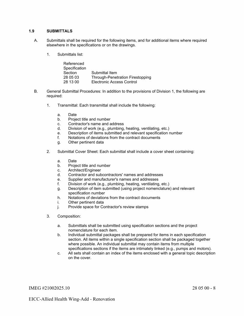
IMEG #21002025.10 28 05 00 - 8
EICC-Allied Health Wing-Add - Renovation
1.9 SUBMITTALS
A. Submittals shall be required for the following items, and for additional items where required elsewhere in the specifications or on the drawings.
1. Submittals list:
ReferencedSpecification Section Submittal Item28 05 03 Through-Penetration Firestopping28 13 00 Electronic Access Control
B. General Submittal Procedures: In addition to the provisions of Division 1, the following are required:
1. Transmittal: Each transmittal shall include the following:
a. Dateb. Project title and numberc. Contractor's name and addressd. Division of work (e.g., plumbing, heating, ventilating, etc.)e. Description of items submitted and relevant specification numberf. Notations of deviations from the contract documentsg. Other pertinent data
2. Submittal Cover Sheet: Each submittal shall include a cover sheet containing:
a. Dateb. Project title and numberc. Architect/Engineerd. Contractor and subcontractors' names and addressese. Supplier and manufacturer's names and addressesf. Division of work (e.g., plumbing, heating, ventilating, etc.)g. Description of item submitted (using project nomenclature) and relevant
specification numberh. Notations of deviations from the contract documentsi. Other pertinent dataj. Provide space for Contractor's review stamps
3. Composition:
a. Submittals shall be submitted using specification sections and the project nomenclature for each item.
b. Individual submittal packages shall be prepared for items in each specification section. All items within a single specification section shall be packaged together where possible. An individual submittal may contain items from multiple specifications sections if the items are intimately linked (e.g., pumps and motors).
c. All sets shall contain an index of the items enclosed with a general topic description on the cover.
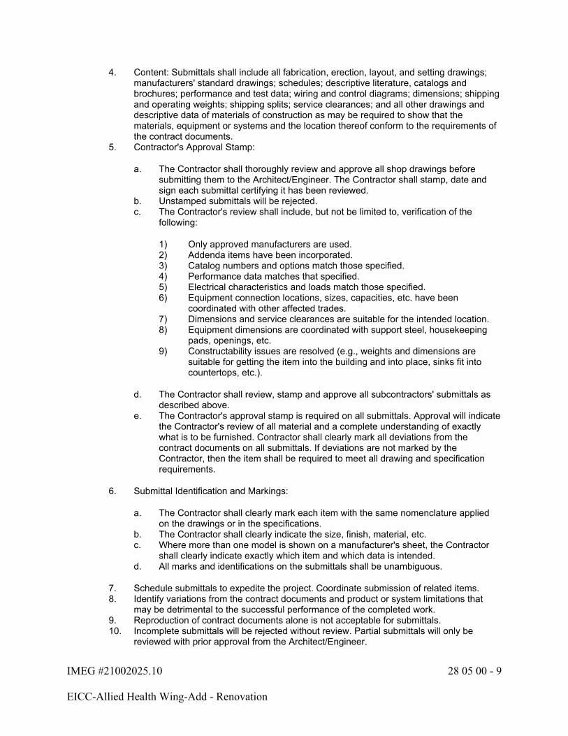
IMEG #21002025.10 28 05 00 - 9
EICC-Allied Health Wing-Add - Renovation
4. Content: Submittals shall include all fabrication, erection, layout, and setting drawings; manufacturers' standard drawings; schedules; descriptive literature, catalogs and brochures; performance and test data; wiring and control diagrams; dimensions; shipping and operating weights; shipping splits; service clearances; and all other drawings and descriptive data of materials of construction as may be required to show that the materials, equipment or systems and the location thereof conform to the requirements of the contract documents.
5. Contractor's Approval Stamp:
a. The Contractor shall thoroughly review and approve all shop drawings before submitting them to the Architect/Engineer. The Contractor shall stamp, date and sign each submittal certifying it has been reviewed.
b. Unstamped submittals will be rejected.c. The Contractor's review shall include, but not be limited to, verification of the
following:
1) Only approved manufacturers are used.2) Addenda items have been incorporated.3) Catalog numbers and options match those specified.4) Performance data matches that specified.5) Electrical characteristics and loads match those specified.6) Equipment connection locations, sizes, capacities, etc. have been
coordinated with other affected trades.7) Dimensions and service clearances are suitable for the intended location.8) Equipment dimensions are coordinated with support steel, housekeeping
pads, openings, etc.9) Constructability issues are resolved (e.g., weights and dimensions are
suitable for getting the item into the building and into place, sinks fit into countertops, etc.).
d. The Contractor shall review, stamp and approve all subcontractors' submittals as described above.
e. The Contractor's approval stamp is required on all submittals. Approval will indicate the Contractor's review of all material and a complete understanding of exactly what is to be furnished. Contractor shall clearly mark all deviations from the contract documents on all submittals. If deviations are not marked by the Contractor, then the item shall be required to meet all drawing and specification requirements.
6. Submittal Identification and Markings:
a. The Contractor shall clearly mark each item with the same nomenclature applied on the drawings or in the specifications.
b. The Contractor shall clearly indicate the size, finish, material, etc.c. Where more than one model is shown on a manufacturer's sheet, the Contractor
shall clearly indicate exactly which item and which data is intended.d. All marks and identifications on the submittals shall be unambiguous.
7. Schedule submittals to expedite the project. Coordinate submission of related items.8. Identify variations from the contract documents and product or system limitations that
may be detrimental to the successful performance of the completed work.9. Reproduction of contract documents alone is not acceptable for submittals.10. Incomplete submittals will be rejected without review. Partial submittals will only be
reviewed with prior approval from the Architect/Engineer.
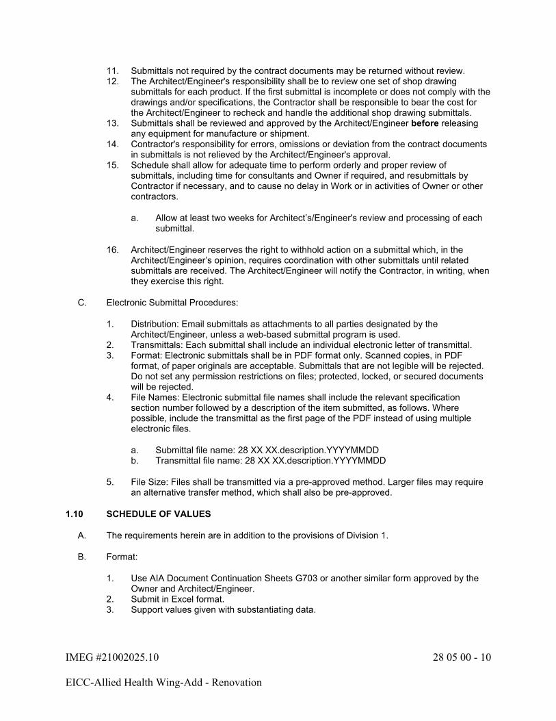
IMEG #21002025.10 28 05 00 - 10
EICC-Allied Health Wing-Add - Renovation
11. Submittals not required by the contract documents may be returned without review.12. The Architect/Engineer's responsibility shall be to review one set of shop drawing
submittals for each product. If the first submittal is incomplete or does not comply with the drawings and/or specifications, the Contractor shall be responsible to bear the cost for the Architect/Engineer to recheck and handle the additional shop drawing submittals.
13. Submittals shall be reviewed and approved by the Architect/Engineer before releasing any equipment for manufacture or shipment.
14. Contractor's responsibility for errors, omissions or deviation from the contract documents in submittals is not relieved by the Architect/Engineer's approval.
15. Schedule shall allow for adequate time to perform orderly and proper review of submittals, including time for consultants and Owner if required, and resubmittals by Contractor if necessary, and to cause no delay in Work or in activities of Owner or other contractors.
a. Allow at least two weeks for Architect’s/Engineer's review and processing of each submittal.
16. Architect/Engineer reserves the right to withhold action on a submittal which, in the Architect/Engineer’s opinion, requires coordination with other submittals until related submittals are received. The Architect/Engineer will notify the Contractor, in writing, when they exercise this right.
C. Electronic Submittal Procedures:
1. Distribution: Email submittals as attachments to all parties designated by the Architect/Engineer, unless a web-based submittal program is used.
2. Transmittals: Each submittal shall include an individual electronic letter of transmittal.3. Format: Electronic submittals shall be in PDF format only. Scanned copies, in PDF
format, of paper originals are acceptable. Submittals that are not legible will be rejected. Do not set any permission restrictions on files; protected, locked, or secured documents will be rejected.
4. File Names: Electronic submittal file names shall include the relevant specification section number followed by a description of the item submitted, as follows. Where possible, include the transmittal as the first page of the PDF instead of using multiple electronic files.
a. Submittal file name: 28 XX XX.description.YYYYMMDDb. Transmittal file name: 28 XX XX.description.YYYYMMDD
5. File Size: Files shall be transmitted via a pre-approved method. Larger files may require an alternative transfer method, which shall also be pre-approved.
1.10 SCHEDULE OF VALUES
A. The requirements herein are in addition to the provisions of Division 1.
B. Format:
1. Use AIA Document Continuation Sheets G703 or another similar form approved by the Owner and Architect/Engineer.
2. Submit in Excel format.3. Support values given with substantiating data.

IMEG #21002025.10 28 05 00 - 11
EICC-Allied Health Wing-Add - Renovation
C. Preparation:
1. Itemize work required by each specification section and list all providers. All work provided by subcontractors and major suppliers shall be listed on the Schedule of Values. List each subcontractor and supplier by company name.
2. Break down all costs into:
a. Material: Delivered cost of product with taxes paid.b. Labor: Labor cost, excluding overhead and profit.
D. Update Schedule of Values when:
1. Indicated by Architect/Engineer.2. Change of subcontractor or supplier occurs.3. Change of product or equipment occurs.
1.11 CHANGE ORDERS
A. A detailed material and labor takeoff shall be prepared for each change order, along with labor rates and markup percentages. Change orders shall be broken down by sheet or associated individual line item indicated in the change associated narrative, whichever provides the most detailed breakdown. Change orders with inadequate breakdown will be rejected.
B. Itemized pricing with unit cost shall be provided from all distributors and associated subcontractors.
C. Change order work shall not proceed until authorized.
1.12 EQUIPMENT SUPPLIERS' INSPECTION
A. The following equipment shall not be placed in operation until a representative of the manufacturer has inspected the installation and certified that the equipment is properly installed and that the equipment is ready for operation:
1. Firestopping, including mechanical firestop systems.
1.13 PRODUCT DELIVERY, STORAGE, HANDLING & MAINTENANCE
A. Exercise care in transporting and handling to prevent damage to fixtures, equipment and materials.
B. Store materials on the site to prevent damage.
C. Keep fixtures, equipment and materials clean, dry and free from harmful conditions.
1.14 NETWORK / INTERNET CONNECTED EQUIPMENT
A. These specifications may require certain equipment or systems to have network, Internet and/or remote access capability ("Network Capability"). Any requirement for Network Capability shall be interpreted only as a functional capability and is not to be construed as authority to connect or enable any Network Capability. Network Capability may only be connected or enabled with the express written consent of the Owner.
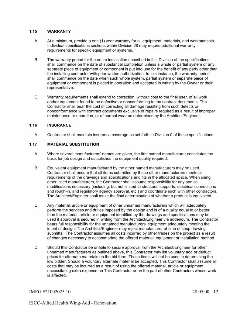
IMEG #21002025.10 28 05 00 - 12
EICC-Allied Health Wing-Add - Renovation
1.15 WARRANTY
A. At a minimum, provide a one (1) year warranty for all equipment, materials, and workmanship. Individual specifications sections within Division 28 may require additional warranty requirements for specific equipment or systems.
B. The warranty period for the entire installation described in this Division of the specifications shall commence on the date of substantial completion unless a whole or partial system or any separate piece of equipment or component is put into use for the benefit of any party other than the installing contractor with prior written authorization. In this instance, the warranty period shall commence on the date when such whole system, partial system or separate piece of equipment or component is placed in operation and accepted in writing by the Owner or their representative.
C. Warranty requirements shall extend to correction, without cost to the final user, of all work and/or equipment found to be defective or nonconforming to the contract documents. The Contractor shall bear the cost of correcting all damage resulting from such defects or nonconformance with contract documents exclusive of repairs required as a result of improper maintenance or operation, or of normal wear as determined by the Architect/Engineer.
1.16 INSURANCE
A. Contractor shall maintain insurance coverage as set forth in Division 0 of these specifications.
1.17 MATERIAL SUBSTITUTION
A. Where several manufacturers' names are given, the first named manufacturer constitutes the basis for job design and establishes the equipment quality required.
B. Equivalent equipment manufactured by the other named manufacturers may be used. Contractor shall ensure that all items submitted by these other manufacturers meets all requirements of the drawings and specifications and fits in the allocated space. When using other listed manufacturers, the Contractor shall assume responsibility for any and all modifications necessary (including, but not limited to structural supports, electrical connections and rough-in, and regulatory agency approval, etc.) and coordinate such with other contractors. The Architect/Engineer shall make the final determination of whether a product is equivalent.
C. Any material, article or equipment of other unnamed manufacturers which will adequately perform the services and duties imposed by the design and is of a quality equal to or better than the material, article or equipment identified by the drawings and specifications may be used if approval is secured in writing from the Architect/Engineer via addendum. The Contractor bears full responsibility for the unnamed manufacturers' equipment adequately meeting the intent of design. The Architect/Engineer may reject manufacturer at time of shop drawing submittal. The Contractor assumes all costs incurred by other trades on the project as a result of changes necessary to accommodate the offered material, equipment or installation method.
D. Should this Contractor be unable to secure approval from the Architect/Engineer for other unnamed manufacturers as outlined above, this Contractor may list voluntary add or deduct prices for alternate materials on the bid form. These items will not be used in determining the low bidder. Should a voluntary alternate material be accepted, This Contractor shall assume all costs that may be incurred as a result of using the offered material, article or equipment necessitating extra expense on This Contractor or on the part of other Contractors whose work is affected.
IMEG #21002025.10 28 05 00 - 13
EICC-Allied Health Wing-Add - Renovation
PART 2 - PRODUCTS
2.1 Refer to individual sections.
PART 3 - EXECUTION
3.1 JOBSITE SAFETY
A. Neither the professional activities of the Architect/Engineer, nor the presence of the Architect/Engineer or the employees and subconsultants at a construction site, shall relieve the Contractor and any other entity of their obligations, duties and responsibilities including, but not limited to, construction means, methods, sequence, techniques or procedures necessary for performing, superintending or coordinating all portions of the work of construction in accordance with the contract documents and any health or safety precautions required by any regulatory agencies. The Architect/Engineer and personnel have no authority to exercise any control over any construction contractor or other entity or their employees in connection with their work or any health or safety precautions. The Contractor is solely responsible for jobsite safety. The Architect/Engineer and the Architect/Engineer's consultants shall be indemnified and shall be made additional insureds under the Contractor's general liability insurance policy.
3.2 GENERAL INSTALLATION REQUIREMENTS
A. Installation of all conduit and cabling shall comply with Sections 26 05 33 and 26 05 13. Additional conduit requirements described within this Division shall be supplemental to the requirement described in Section 26 05 33. Should conflicts exist between the two Divisions the more stringent (more expensive material and labor) condition shall prevail until bidding addendum or construction clarification or RFI can be submitted and responded to. In no case shall the Contractor carry the least stringent condition in the pricing.
B. It is the Contractor's responsibility to survey the site and include all necessary costs to perform the installation as specified.
C. The Contractor shall be responsible for identifying and reporting to the Architect/Engineer any existing conditions including but not limited to damage to walls, flooring, ceiling and furnishings prior to start of work. All damage to interior spaces caused by this Contractor shall be repaired at this Contractor's expense to pre-existing conditions, including final colors and finishes.
D. All cables and devices installed in damp or wet locations, including any underground or underslab location, shall be listed as suitable for use in such environments. Follow manufacturer's recommended installation practices for installing cables and devices in damp or wet locations. Any cable or device that fails as a result of being installed in a damp or wet location shall be replaced at the Contractor's expense.
3.3 FIELD QUALITY CONTROL
A. General:
1. Refer to specific Division 28 sections for further requirements.2. The Contractor shall conduct all tests required and applicable to the work both during and
after construction of the work.3. The necessary instruments and materials required to conduct or make the tests shall be
supplied by the Contractor who shall also supply competent personnel for making the tests who has been schooled in the proper testing techniques.

IMEG #21002025.10 28 05 00 - 14
EICC-Allied Health Wing-Add - Renovation
4. In the event the results obtained in the tests are not satisfactory, This Contractor shall make such adjustments, replacements and changes as are necessary and shall then repeat the test or tests which disclose faulty or defective work or equipment, and shall make such additional tests as the Architect/Engineer or code enforcing agency deems necessary.
B. Protection of cable from foreign materials:
1. It is the Contractor's responsibility to provide adequate physical protection to prevent foreign material application or contact with any cable type. Foreign material is defined as any material that would negatively impact the validity of the manufacturer's performance warranty. This includes, but is not limited, to overspray of paint (accidental or otherwise), drywall compound, or any other surface chemical, liquid or compound that could come in contact with the cable, cable jacket or cable termination components.
2. Application of foreign materials of any kind on any cable, cable jacket or cable termination component will not be accepted. It shall be the Contractor's responsibility to replace any component containing overspray, in its entirety, at no additional cost to the project. Cleaning of the cables with harsh chemicals is not allowed. This requirement is regardless of the PASS/FAIL test results of the cable containing overspray. Should the manufacturer and warrantor of the structured cabling system desire to physically inspect the installed condition and certify the validity of the structured cabling system (via a signed and dated statement by an authorized representative of the structured cabling manufacturer), the Owner may, at their sole discretion, agree to accept said warranty in lieu of having the affected cables replaced. In the case of plenum cabling, in addition to the statement from the manufacturer, the Contractor shall also present to the Owner a letter from the local Authority Having Jurisdiction stating that they consider the plenum rating of the cable to be intact and acceptable.
3.4 PROJECT CLOSEOUT
A. Refer to the Division 1 Section: PROJECT CLOSEOUT for requirements. The following paragraphs supplement the requirements of Division 1.
B. Final Jobsite Observation:
1. The Architect/Engineer will not perform a final jobsite observation until the project is ready. This is not dictated by schedule, but rather by completeness of the project.
2. Refer to the end of Section 27 05 00 for a "STATEMENT INDICATING READINESS FOR FINAL JOBSITE OBSERVATION."
3. The Contractor shall sign this form and return it to the Architect/Engineer so that the final observation can commence.
C. Before final payment will be authorized, this Contractor must have completed the following:
1. Submitted operation and maintenance manuals to the Architect/Engineer for review.2. Submitted bound copies of approved shop drawings.3. Record documents including edited drawings and specifications accurately reflecting field
conditions, inclusive of all project revisions, change orders, and modifications.4. Submitted a report stating the instructions given to the Owner's representative complete
with the number of hours spent in the instruction. The report shall bear the signature of an authorized agent of This Contractor and shall be signed by the Owner's representative as having received the instructions.
5. Submitted testing reports for all systems requiring final testing as described herein.

IMEG #21002025.10 28 05 00 - 15
EICC-Allied Health Wing-Add - Renovation
6. Submitted start-up reports on all equipment requiring a factory installation inspection and/or start.
7. Provide spare parts, maintenance, and extra materials in quantities specified in individual specification sections. Deliver to project site; submit receipt to Architect/Engineer prior to final payment being approved.
3.5 OPERATION AND MAINTENANCE MANUALS
A. General:
1. Provide an electronic copy of the O&M manuals as described below for Architect/Engineer's review and approval. The electronic copy shall be corrected as required to address the Architect/Engineer's comments. Once corrected, electronic copies and paper copies shall be distributed as directed by the Architect/Engineer.
2. Approved O&M manuals shall be completed and in the Owner's possession prior to Owner's acceptance and at least 10 days prior to instruction of operating personnel.
B. Electronic Submittal Procedures:
1. Distribution: Email the O&M manual as attachments to all parties designated by the Architect/Engineer.
2. Transmittals: Each submittal shall include an individual electronic letter of transmittal.3. Format: Electronic submittals shall be in PDF format only. Scanned copies, in PDF
format, of paper originals are acceptable. Submittals that are not legible will be rejected. Do not set any permission restrictions on files; protected, locked, or secured documents will be rejected.
4. File Names: Electronic submittal file names shall include the relevant specification section number followed by a description of the item submitted, as follows. Where possible, include the transmittal as the first page of the PDF instead of using multiple electronic files.
a. O&M file name: O&M.div28.contractor.YYYYMMDDb. Transmittal file name: O&Mtransmittal.div28.contractor.YYYYMMDD
5. File Size: Files shall be transmitted via a pre-approved method. Larger files may require an alternative transfer method, which shall also be pre-approved.
6. All text shall be searchable.7. Bookmarks shall be used, dividing information first by specification section, then systems,
major equipment and finally individual items. All bookmark titles shall include the nomenclature used in the construction documents and shall be an active link to the first page of the section being referenced.
C. Operation and Maintenance Instructions shall include:
1. Title Page: Include title page with project title, Architect, Engineer, Contractor, all subcontractors, and major equipment suppliers, with addresses, telephone numbers, website addresses, email addresses and point of contacts. Website URLs and email addresses shall be active links in the electronic submittal.
2. Table of Contents: Include a table of contents describing specification section, systems, major equipment, and individual items.
3. Copies of all final approved shop drawings and submittals. Include Architect's/Engineer's shop drawing review comments. Insert the individual shop drawing directly after the Operation and Maintenance information for the item(s) in the review form.
4. Copy of final approved test and balance reports.

IMEG #21002025.10 28 05 00 - 16
EICC-Allied Health Wing-Add - Renovation
5. Copies of all factory inspections and/or equipment startup reports.6. Copies of warranties.7. Schematic wiring diagrams of the equipment that have been updated for field conditions.
Field wiring shall have label numbers to match drawings.8. Dimensional drawings of equipment.9. Capacities and utility consumption of equipment.10. Detailed parts lists with lists of suppliers.11. Operating procedures for each system.12. Maintenance schedule and procedures. Include a chart listing maintenance requirements
and frequency.13. Repair procedures for major components.14. List of lubricants in all equipment and recommended frequency of lubrication.15. Instruction books, cards, and manuals furnished with the equipment.
3.6 INSTRUCTING THE OWNER'S REPRESENTATIVE
A. Adequately instruct the Owner's designated representative or representatives in the maintenance, care, and operation of the complete systems installed under this contract.
B. Provide verbal and written instructions to the Owner's representative or representatives by FACTORY PERSONNEL in the care, maintenance, and operation of the equipment and systems.
C. Notify the Architect/Engineer of the time and place for the verbal instructions to be given to the Owner's representative so a representative can be present if desired.
D. Refer to the individual specification sections for minimum hours of instruction time for each system.
E. Operating Instructions:
1. The Contractor is responsible for all instructions to the Owner and/or Owner's operating staff on the security systems.
2. If the Contractor does not have Engineers and/or Technicians on staff that can adequately provide the required instructions on system operation, performance, troubleshooting, care and maintenance, the Contractor shall include in the bid an adequate amount to reimburse the Owner for the Architect/Engineer to perform these services.
3.7 SYSTEM STARTING AND ADJUSTING
A. The security systems included in the construction documents are to be complete and operating systems. The Architect/Engineer will make periodic job site observations during the construction period. The system start-up, testing, configuration, and satisfactory system performance is the responsibility of the Contractor. This shall include all calibration and adjustments of electrical equipment controls, equipment settings, software configuration, troubleshooting and verification of software, and final adjustments that may be required.
B. All operating conditions and control sequences shall be simulated and tested during the start-up period.

IMEG #21002025.10 28 05 00 - 17
EICC-Allied Health Wing-Add - Renovation
C. The Contractor, subcontractors, and equipment suppliers are expected to have skilled technicians to ensure that the system performs as designed. If the Architect/Engineer is requested to visit the job site for the purpose of trouble shooting, assisting in the satisfactory start-up, obtaining satisfactory equipment operation, resolving installation and/or workmanship problems, equipment substitution issues or unsatisfactory system performance, including call backs during the warranty period through no fault of the design; the Contractor shall reimburse the Owner on a time and material basis for services rendered at the Architect/Engineer's standard hourly rates in effect at the time the services are requested. The Contractor shall be responsible for making payment to the Owner for services required that are product, installation or workmanship related. Payment is due within 30 days after services are rendered.
3.8 RECORD DOCUMENTS
A. Refer to the Division 1 Section: PROJECT CLOSEOUT for requirements. The following paragraphs supplement the requirements of Division 1.
B. Mark specifications to indicate approved substitutions, change orders, and actual equipment and materials used.
C. This Contractor shall maintain at the job site, a separate and complete set of Security Drawings which shall be clearly and permanently marked and noted in complete detail any changes made to the location and arrangement of equipment or made to the Technology Systems and wiring as a result of building construction conditions or as a result of instructions from the Architect or Engineer. All Change Orders, RFI responses, Clarifications and other supplemental instructions shall be marked on the documents. Record documents that merely reference the existence of the above items are not acceptable. Should This Contractor fail to complete Record Documents as required by this contract, This Contractor shall reimburse Architect/Engineer for all costs to develop record documents that comply with this requirement. Reimbursement shall be made at the Architect/Engineer's hourly rates in effect at the time of work.
D. Record actual routing of all conduits sized 2" or larger.
E. The above record of changes shall be made available for the Architect and Engineer's examination during any regular work time.
F. Upon completion of the job, and before final payment is made, This Contractor shall give the marked-up drawings to the Architect/Engineer.
3.9 ADJUST AND CLEAN
A. Contractor shall thoroughly clean all equipment and systems prior to the Owner's final acceptance of the project.
B. Contractor shall clean all foreign paint, grease, oil, dirt, labels, stickers, and other foreign material from equipment.
C. Contractor shall remove all rubbish, debris, etc., accumulated during the Contractor's operations from the premises.
END OF SECTION 28 05 00

IMEG #21002025.10 28 16 00 - 1
EICC-Allied Health Wing-Add - Renovation
SECTION 28 16 00 - INTRUSION DETECTION SYSTEM
PART 1 - GENERAL
1.1 SECTION INCLUDES
A. Security Control Panel.
B. Access Control.
C. Initiation Devices.
D. Notification Devices.
E. Request to Exit Devices.
F. Camera.
G. Video Recorder.
H. Video Monitor.
1.2 RELATED WORK
A. Section 26 05 33 - Conduit and Boxes
B. Section 26 05 13 - Wire and Cable
C. Section 28 05 00 - Basic Electronic Safety and Security System Requirements
D. Section 28 31 00 - Fire Detection and Alarm Systems
E. Section 28 23 00 - Video Surveillance
1.3 QUALITY ASSURANCE
A. Manufacturer: The access control system shall be a single-source manufacturer such that the single vendor distributes, supports, warranties and services all components. The manufacturer shall have a minimum of five (5) years documented experience.
B. Installer: The installing dealer must be a factory-authorized service and support company specializing in the selected manufacturer's product, with demonstrated prior experience with the selected manufacturer's system installation and programming.
C. Servicing Contractor: The manufacturer of the system must have local service representatives within 40 miles of the project site.
1.4 REFERENCES
A. NFPA 70 - National Electrical Code.

IMEG #21002025.10 28 16 00 - 2
EICC-Allied Health Wing-Add - Renovation
B. UL 294 - Standard for Access Control Systems.
1.5 SUBMITTALS
A. Submit shop drawings and product data under provisions of Section 28 05 00.
B. Product Data Submittal: Provide manufacturer's technical product specification sheet for each individual component type. Submitted data shall show the following:
1. Compliance with each requirement of these documents. The submittal shall acknowledge each requirement of this section, item-by-item.
2. All component options and accessories specific to this project.3. Electrical power consumption rating and voltage.4. Wiring requirements.
C. System Drawings: Project-specific system CAD drawings shall be provided as follows:
1. Provide a system block diagram noting system components and interconnection between components. The interconnection of components shall clearly indicate all wiring required in the system. When multiple pieces of equipment are required in the exact same configuration (i.e., multiple identical controllers), the diagram may show one device and refer to the others as "typical" of the device shown.
2. Provide schedules describing each system input location by an architecturally familiar reference (i.e., Door 312A). The architectural door schedule shall be used as the basis.
D. Submit detailed description of Owner training to be conducted at project end, including specific training times.
E. Quality Assurance:
1. Provide materials documenting experience requirements of the manufacturer and Installing Contractor.
2. Provide system checkout test procedure to be performed at acceptance. Test procedures shall include all external alarm events.
F. Coordination Drawings:
1. Include all ceiling-mounted devices in composite electronic coordination files. Refer to Section 28 05 00 for coordination drawing requirements.
1.6 SYSTEM DESCRIPTION
A. This specification section describes the furnishing, installation, commissioning and programming of a complete, turnkey security management system.
B. Performance Statement: This specification section and the accompanying access control-specific design documents are performance based, describing the minimum material quality, required features, and operational requirements of the system. These documents do not convey every wire that must be installed and every equipment connection that must be made. Based on the equipment constraints described and the performance required of the system, as presented in these documents, the Vendor and the Contractor are solely responsible for determining all wiring, programming and miscellaneous equipment required for a complete and operational system.

IMEG #21002025.10 28 16 00 - 3
EICC-Allied Health Wing-Add - Renovation
C. Basic System Description: The security management system shall provide an integrated hardware and software solution for access control.
1.7 PROJECT RECORD DOCUMENTS
A. Submit documents under the provisions of Section 28 05 00.
B. Provide final system block diagram showing any deviations from shop drawing submittal.
C. Provide statement that system checkout test, as outlined in the shop drawing submittal, is complete and satisfactory.
D. Provide schedules documenting:
1. Controller installation locations including specific door numbers being controlled.2. All terminal block wiring, including cable numbers.
E. Warranty: Submit written warranty and complete all Owner registration forms.
F. Complete all operation and maintenance manuals as described below.
1.8 OPERATION AND MAINTENANCE DATA
A. Submit documents under the provisions of Section 28 05 00.
B. Operation Data: Provide full system operation instructions for each piece of equipment.
C. Maintenance Data: Document any manufacturer's recommended preventative maintenance procedures to be performed by the Owner.
1.9 WARRANTY
A. Unless otherwise noted, provide warranty for one (1) year after Date of Substantial Completion for all materials and labor.
B. The warranty shall include emergency service and repair on-site, with acknowledgment response time of one (1) hour from time of notification and on-site response within four (2) hours. The system shall be repaired and restored to operation within twenty-four (24) hours of notification.
C. Refer to the individual product sections for further warranty requirements of individual system components.

IMEG #21002025.10 28 16 00 - 4
EICC-Allied Health Wing-Add - Renovation
1.10 ANNUAL SERVICE CONTRACT
A. Provide annual cost for extended service and maintenance warranty after the first year, for the access control system according to the following terms:
1. The term of the warranty shall begin on the system acceptance date and shall continue for one (1) year. The extended service and maintenance warranty may begin following this first year if accepted by the Owner. The term may be automatically renewed for successive one-year periods unless canceled by the Owner. The service and maintenance agreement shall include the following basic services to the Owner, including all necessary parts, labor and service equipment:
a. Repair or replace any security equipment item that fails to perform as initially installed, as specified, or as determined per the manufacturer's performance criteria.
b. Perform semi-annual preventive maintenance on the security equipment. This preventive maintenance shall include, but is not limited to, cleaning, realignment, inspection, and testing of security devices. The Owner shall receive a written report of these inspections that identifies the security device's status and, if required, a list of all necessary repairs or replacements.
c. Provide software maintenance on the security system. Contractor shall install and configure any software updates that the manufacturer provides at no cost. Any additional software options, updates, or enhancements purchased by the Owner shall be installed. The Contractor shall not be responsible for the purchase of additional software packages or the maintenance of Owner data.
2. The Contractor shall be compensated for any repairs or maintenance provided as a result of Owner abuse, misuse, intentional damage, accidental damage, or power fluctuations exceeding specified equipment tolerances.
3. System defects or failures shall be corrected within four (4) hours on the same business day if the Owner makes a service request before 11:00 a.m., or before 12:00 noon the next business day if the Owner makes the request after 11:00 a.m. If requested by the Owner, the Contractor shall respond or remain at the site after normal business hours, and the Owner shall reimburse the Contractor for the incremental cost difference between premium labor rates and standard labor rates. This reimbursement applies to premium labor rates that do not exceed time-and-one-half rates after normal business hours, and double-time rates for Sundays and holidays. The Contractor's services shall be performed in a good and workmanlike manner and remain free from defects for a period of one (1) year.
B. Provide complete terms and conditions of warranty and service.
C. The Owner will enter into a contract directly with the Vendor. This specification is not a contract between the Owner and the Vendor to perform these services.
PART 2 - PRODUCTS
2.1 INTRUSION DETECTION SYSTEM MANUFACTURERS
A. DMP

IMEG #21002025.10 28 16 00 - 5
EICC-Allied Health Wing-Add - Renovation
2.2 SECURITY CONTROL PANEL
A. Control Panel: Modular construction with surface wall-mounted enclosure.
B. Power Supply: Adequate to serve control panel modules ,remote detectors and alarm signaling devices.
1. Include battery operated emergency power supply with capacity for operating system in standby mode for 24 hours.
C. System Supervision: Provide electrically-supervised system, with supervised alarm initiating and alarm signaling circuits. Component or power supply failure places system in alarm mode.
D. Initiating Circuits: Supervised zone module with alarm and trouble indication.
E. Signal Circuits: Supervised signal module, sufficient for signal devices connected to system; occurrence of single ground or open condition places circuit in trouble mode and does not disable that circuit from transmitting alarm.
F. Remote Station Signal Transmitter: Electrically supervised, capable of transmitting alarm and trouble signals over radio to central station receiver. Radio shall be registered to PerMar for monitoring .
G. Auxiliary Relays: Provide sufficient SPDT auxiliary relay contacts for each detection zone to provide accessory functions specified.
H. Alarm Sequence of Operation: Actuation of Intrusion Detecting device places system in alarm mode, which causes the following operations:
1. Sound and display local alarm signaling devices with non-coded signal.
2.3 ARMING STATION
A. Keypad:
1. Industry standard Wiegand output keypad. 8-Bit word.2. Vandal and impact resistant construction. Weatherproof design, including in 100%
humidity.
2.4 INITIATION DEVICES
A. Duress/Panic Switch:
1. SPDT, 12 VDC switch 2. Small form factor white ABS plastic housing (2" W x 3" H x 1" D) containing electronics
and magnetic contacts.3. Housing to contact actuator lever alarming at 20 to 45-degree movement (approximately
1") from resting position.
B. Door Contacts:
1. Contacts shall be single-pole, double-throw (SPDT) suitable for use in a line supervision circuit. Gap length shall be 1" on the latch side.
IMEG #21002025.10 28 16 00 - 6
EICC-Allied Health Wing-Add - Renovation
2. Provide magnetic alarm contacts at each door (recessed in the door header) where shown on the plans. Contacts shall provide a signal to the controller when the contact status changes.
3. The contacts shall have the capability of being shunted by a request-to-exit device. When the system grants access at a controlled point, the system shall shunt the door alarm input for that point.
C. Motion Detectors:
1. Passive infrared, ceiling mounted, 12 VDC.2. Adaptive technology for humidity and temperature stability.3. 360-degree coverage, 60' coverage range.4. Fresnel pattern lens with a minimum of a 30-zone pattern.
D. Glass Break Detectors:
1. Shock sensor type, mounted to glass.2. 10' protection range on single-pane glass.3. Piezo transducer technology providing power to sensor. No external power is required.4. +15 VDC maximum input.
2.5 NOTIFICATION DEVICES
A. Alarm Horn:
1. Ceiling mounted, location above the ceiling adjacent to the security point.2. Piezo siren type, with alternating high/low sound.3. 106 dB at 10'.4. 6 to 13.8 VDC operation.
PART 3 - EXECUTION
3.1 INSTALLATION
A. Comply with the manufacturer's instructions and recommendations for installation of all products.
B. Provide all system wiring between all components as directed by the manufacturer.
C. Install, terminate and test all door alarm contacts. Contacts shall be recessed in the door header.
3.2 FIELD QUALITY CONTROL
A. Where these specifications require a product or assembly without the use of a brand or trade name, provide a product that meets the requirements of the specifications, as supplied and warranted by the system vendor. If the product or assembly is not available from the system vendor, provide product or assembly as recommended by the system vendor.
B. Periodic observations will be performed during construction to verify compliance with the requirements of the specifications. These services do not relieve the Contractor of responsibility for compliance with the Contract Documents.
IMEG #21002025.10 28 16 00 - 7
EICC-Allied Health Wing-Add - Renovation
3.3 MANUFACTURER'S FIELD SERVICES
A. Installation shall be performed by a factory-trained and certified Contractor Installer.
B. The Installer shall provide a comprehensive, site-specific customer planning guide for the system. The installer shall conduct a conference with the Owner prior to any installation to discuss the programming options of the system and the planning guide. The result of this planning guide shall be the determination of the system access policies for each point.
C. The Installer shall include labor for all planning and all programming activities required to implement the Owner's access policies for each system point. Any software programmable access policy, within the bounds of the hardware specified, shall be included.
D. It shall be the responsibility of the Contractor/Installer to provide a complete, functional system as described by the Contract Documents. These responsibilities include:
1. Complete hardware setup, installation and wiring, and software configuration of the system.
2. Complete programming of all operator software in accordance with the Owner's access policies determined by the planning guide conference.
3. Complete system diagnostic verification.
3.4 SYSTEM ACCEPTANCE
A. The SMS Vendor shall submit for review a formal acceptance and system checkout program. The system checkout procedures shall include all system components and software, including but not limited to all system computers, field controllers, card reader devices, biometric readers and remote system interfaces. The Contractor shall perform the tests and document all results under the supervision of the manufacturer's system engineer.
B. All operational scenarios, as defined by the customer planning guide, shall be tested to simulate the actual use of the system in the normal operating environment. The successful completion of these operational scenarios shall be documented.
3.5 SYSTEM DOCUMENTATION
A. Complete documentation shall be provided for the system. The documentation shall describe:
1. All operational parameters of the system.2. Complete documentation of programming and access policies.3. All data sets.4. Complete operating instructions for all hardware and software.
B. The following sections shall be provided in the system documentation:
1. User Manual: A step-by-step guide and instructions detailing all system user functions.2. Technical Maintenance Manual: A comprehensive document providing all maintenance
actions, system testing schedules, troubleshooting flowcharts, functional system layout, wiring diagrams, block diagrams and schematic diagrams.

IMEG #21002025.10 28 16 00 - 8
EICC-Allied Health Wing-Add - Renovation
3.6 SYSTEM TRAINING
A. All labor and materials required for on-site system training by a certified representative of the system manufacturer shall be provided. Training shall be conducted at the project site using the project equipment.
B. Provide two weeks advanced notice of training to the Owner.
C. Provide a training outline agenda describing the subject matter and the recommended audience for each topic.
D. At a minimum, the following training shall be conducted:
1. Alarm Monitoring Users: Provide a detailed course outlining the operational features of all aspects of the user interface. Topics shall include alarm monitoring functions, reports, error handling, alarm handling, output relay control and general overview of the report hardware.
E. Minimum on-site training times shall be:
1. Alarm Monitoring Users: One day.
END OF SECTION 28 16 00

IMEG #21002025.10 28 23 00 - 1
EICC-Allied Health Wing-Add - Renovation
SECTION 28 23 00 - VIDEO SURVEILLANCE
PART 1 - GENERAL
1.1 SECTION INCLUDES
A. Cameras and Accessories.
B. Cabling.
1.2 RELATED WORK
A. Section 26 05 33 - Conduit and Boxes
B. Section 26 05 13 - Wire and Cable
C. Section 27 15 00 - Horizontal Cabling Requirements
D. Section 28 05 00 - Basic Electronic Safety and Security System Requirements
E. Section 28 31 00 - Fire Detection and Alarm Systems
F. Section 28 13 00 - Electronic Access Control
1.3 QUALITY ASSURANCE
A. NVMS Software Developer (Manufacturer): The NVMS system shall be a single-source manufacturer such that the single manufacturer develops, supports, and warranties the NVMS software solution. The manufacturer shall have three (3) years documented experience.
B. Integrator/Installer (Contractor): The Contractor must be a Salient NVMS-certified installation, service, and support company specializing in the selected manufacturer's product, with demonstrated prior experience with the selected manufacturer's system installation and programming.
1. The integrator must have local service representatives within 40 miles of the project site.
1.4 REFERENCES
A. NFPA 70 - National Electrical Code
B. Electronic Industries Association (EIA) Video Surveillance Equipment Standards
C. UL 2044 - Standard for Commercial Closed Circuit Television Equipment
D. UL 3044 - Standard for Safety for Surveillance Closed Circuit Television Equipment
1.5 SUBMITTALS
A. Submit shop drawings and product data under provisions of Section 28 05 00.

IMEG #21002025.10 28 23 00 - 2
EICC-Allied Health Wing-Add - Renovation
B. Product Data Submittal: Provide manufacturer's technical product specification sheet for each individual component type. Submitted data shall show the following:
1. Compliance with each requirement of these documents.2. All component options and accessories specific to this project.3. Electrical power consumption rating and voltage.4. Heat generation for all power consuming devices.5. All required wiring shall be identified.6. Number of IP addresses that will be required from the Owner's Information Systems
Department.7. Statement of Acceptability of Designed Server:
a. If the Contractor agrees that the server(s) designed and described herein is acceptable for the chosen manufacturer's solution and meets the demand of the application, this shall be stated in writing and submitted as part of the shop drawing submittal.
b. If the Contractor does not agree that the server(s) designed and described herein is acceptable for the chosen manufacturer's solution, Contractor shall itemize the quantity, technical specifications, and capacities of the servers required to support the functionality and device quantities required by the project drawings. Indicate the capacity utilization factor for each server.
c. Contractor's bid shall include any required changes in server(s) capacity.
8. Provide annual cost and all terms and conditions for the NVMS Software Maintenance Agreement. Include all additional costs and terms and conditions for any Annual Service Contracts provided by the Contractor for all services that are not included in the Software Maintenance Agreement.
C. System Drawings: Project-specific system CAD drawings shall be provided as follows:
1. Provide a system block diagram noting system components and interconnection between components. The interconnection of components shall clearly indicate all wiring required in the system. When multiple pieces of equipment are required in the exact same configuration (e.g., multiple identical cameras), the diagram may show one device and refer to the others as "typical" of the device shown.
D. Sample format of site specific programming guides to be used for system planning/programming conference with Owner.
E. Meeting agenda for planning/programming conference required in Part 3 of this specification.
F. Submit detailed description of Owner training to be conducted at project end, including specific training time.
G. Quality Assurance:
1. Provide materials documenting experience requirements of the manufacturer and installing contractor.
2. Provide system checkout test procedure to be performed at acceptance. Test procedures shall include all external alarm events.
IMEG #21002025.10 28 23 00 - 3
EICC-Allied Health Wing-Add - Renovation
H. Coordination Drawings:
1. Include all ceiling-mounted devices in composite electronic coordination files. Refer to Section 28 05 00 for coordination drawing requirements.
1.6 SYSTEM DESCRIPTION
A. This specification section describes the extension of an existing VMS. All licensing shall be new for each installed device.
B. Performance Statement: This specification section and the accompanying project drawings are performance based, describing the minimum material quality, required features, and operational requirements of the system. These documents do not convey every wire that must be installed and every equipment connection that must be made. Based on the equipment constraints described and the performance required of the system as presented in these documents, the vendor and the Contractor are solely responsible for determining all wiring, programming and miscellaneous equipment required for a complete and operational system.
C. Refer to the project drawings for model numbers for the Basis of Design for all equipment.
1.7 OWNER-SUPPLIED MATERIALS
A. Network Switch
1.8 LICENSING REQUIREMENTS
A. All licenses required for system operation shall be included in the Contractor's bid. Licenses shall include, but not be limited to, server and workstation software, cameras, encoders/decoders, and any other licensing that is required by the manufacturer for operation of any system component.1. Camera licenses shall be provided for all cameras shown on floor plans. The system
shall be provided with installed software capacity to accommodate a minimum quantity of 16 2-MP cameras. The licensing for all 16 cameras shall be included in the Contractor's bid. In no case shall the Owner be required to upgrade the software provided in the Contractor's bid to achieve support for a total of 16 cameras, including the payment of any software upgrade fees, installing a different software version, etc.
2. Camera licensing that is restricted to a particular device MAC address or in any way is only valid for a particular manufacturer or model number is not acceptable. Camera licenses shall be issued such that the Owner can replace a camera with another camera brand and/or model number and transfer the license from the old camera to the new camera at no additional cost at any future time. This license transfer procedure shall be capable of being performed by the Owner and shall not require the services of an integrator.
a. Exception: When a camera license is issued as a no-cost license in the limited condition that the NVMS manufacturer and the camera manufacturer are the same company, it is permissible to charge a future license fee to the Owner if the Owner elects to replace the NVMS manufacturer-branded camera with a third-party manufacturer's camera.
3. The system described herein is an extension of an existing Salient system. All licensing shall be new for each installed device. The Contractor shall not use any of the Owner's existing (spare) licenses for any new components.
IMEG #21002025.10 28 23 00 - 4
EICC-Allied Health Wing-Add - Renovation
4. The Contractor shall fill out the NVMS Bid Inventory Form located herein and provide at the time of bid.
1.9 PROJECT RECORD DOCUMENTS
A. Submit documents under the provisions of Section 28 05 00.
B. Provide final system block diagram showing any deviations from shop drawing submittal.
C. Provide statement that system checkout test, as outlined in shop drawing submittal, is complete and satisfactory.
D. Provide final camera type and camera requirements schedules documenting all changes made during construction.
E. Warranty: Submit written warranty and complete all Owner registration forms.
F. Complete all operation and maintenance manuals as described below.
1.10 OPERATION AND MAINTENANCE DATA
A. Submit documents under the provisions of Section 28 05 00.
B. Manuals: Final copies of the manuals shall be delivered within 30 days after completing the installation test. Each manual's contents shall be identified on the cover. The manual shall include names, addresses, and telephone numbers of the contractor responsible for the installation and maintenance of the system and the manufacturer for each piece of equipment for each system. The manuals shall have a table of contents and labeled sections. The final copies delivered after completion of the installation test shall include all modifications made during installation, checkout, and acceptance testing. The manuals shall consist of the following:
1. Hardware Manual: The manual shall describe all equipment furnished including:
a. General description and specifications.b. Installation and check out procedures.c. System layout drawings and schematics.d. Alignment and calibration procedures.
2. Software Manual: The software manual shall describe the functions of all software and shall include all other information necessary to enable proper installation, testing, and operation. The manual shall include:
a. Definition of terms and functions.b. System use and application software.c. Graphical user interface use.d. Reports generation.
3. Operator's Manual: The operator's manual shall fully explain all procedures and instructions for the operation of the system including:
a. Computers and peripherals.b. System startup and shutdown procedures.

IMEG #21002025.10 28 23 00 - 5
EICC-Allied Health Wing-Add - Renovation
c. Use of system.d. Recovery and restart procedures.e. Use of report generator and generation of reports.f. Data entry.g. Operator commands.h. Alarm messages.i. System permissions functions and requirements.
4. Maintenance Manual: The maintenance manual shall include descriptions of maintenance for all equipment including inspection, periodic preventive maintenance, fault diagnosis, and repair or replacement of defective components.
1.11 WARRANTY
A. Unless otherwise noted, provide warranty for one (1) year after Date of Substantial Completion for all materials and labor.
B. Onsite Work During Warranty Period: This work shall be included in the Contractor's bid and performed during regular working hours, Monday through Friday.
1. Inspections: Perform one minor inspection six-months after Substantial Completion and one major inspection prior to the expiration of the warranty.
2. Minor Inspections: Inspections shall include:
a. Visual checks and operational tests of all equipment, field hardware, and electrical and mechanical controls.
b. Mechanical adjustments if required on any mechanical or electromechanical devices.
c. Install all available software updates, patches, or bug fixes available from the NVMS manufacturer.
3. Major Inspections: Inspections shall include all work described under paragraph Minor Inspections and the following work:
a. Clean all equipment, including interior and exterior surfaces.b. Perform diagnostics on all equipment, including all system software diagnostics,
and correct all diagnosed problems.c. Adjust all camera alignments that have become out of alignment from their
documented position at Substantial Completion.d. Install all available software updates, patches, or bug fixes available from the
NVMS manufacturer.e. All warrantable system deficiencies during the Major Inspection shall be remedied
under warranty at no cost to the Owner.
C. Operation: Upon the performance of any scheduled adjustments or repairs, verify operation of the NVMS system.
D. Emergency Service: The Owner will initiate service calls when the NVMS system is not functioning properly. Qualified personnel shall be available to provide service within the distance defined above. The Owner shall be furnished with telephone number(s) where service personnel can be reached 24/7/365.

IMEG #21002025.10 28 23 00 - 6
EICC-Allied Health Wing-Add - Renovation
E. Records and Logs: Keep records and logs of each task completed under warranty. The log shall contain all initial settings upon Substantial Completion. Complete logs shall be kept and shall be available for review on site, demonstrating that planned and systematic adjustments and repairs have been accomplished for the NVMS system.
F. Work Requests: Record each service call request on a service request form. The form shall include the model and serial number identifying the component involved, its location, date and time the call was received, specific nature of trouble, names of service personnel assigned to the task, instructions describing what must be done, the amount and nature of the materials used, the time and date work started, and the time and date of completion. Deliver a record of the work performed within five (5) days after work is accomplished.
G. System Modifications: Make any recommendations for system modification in writing to the Owner. No system modifications shall be made without prior approval of the Owner. Any modifications made to the system shall be incorporated into the operations and maintenance manuals, and other documentation affected. To the fullest extent possible, the Owner shall be provided with electronic restorable versions of all configurations prior to the modifications being made.
H. Software: Provide all software updates during the period of the warranty and verify operation in the system. These updates shall be accomplished in a timely manner, fully coordinated with NVMS system operators, shall include training for the new changes/features enabled, and shall be incorporated into the operations and maintenance manuals, and software documentation.
I. Refer to the individual product sections for further warranty requirements of individual system components.
1.12 SOFTWARE MAINTENANCE AGREEMENT/ANNUAL SERVICE CONTRACT
A. Provide annual cost and all terms and conditions for the Software Maintenance Agreement (SMA) provided by the NVMS manufacturer and/or the Contractor.
B. The Owner will enter into a contract directly with the vendor. This specification is not a contract between the Owner and the vendor to perform these services. The cost and terms of the SMA may be used by the Owner for NVMS solution selection.
PART 2 - PRODUCTS
2.1 NETWORK VIDEO MANAGEMENT SYSTEM - GENERAL REQUIREMENTS
A. The network video management system (NVMS) shall be an enterprise-class client/server based video security solution that provides management of digital video, audio and data across a TCP/IP network.
B. Provide a turnkey solution that includes furnishing, installation, and configuration of a separate IP network, complete with all required network electronics, switches, and other hardware.
C. The NVMS system shall be an "open system."
1. To meet this requirement, the NVMS must directly support cameras from a minimum of three (3) readily available camera manufacturers.
2. The three (3) camera manufacturers must have no corporate relationship to the NVMS manufacturer.

IMEG #21002025.10 28 23 00 - 7
EICC-Allied Health Wing-Add - Renovation
3. "Directly support" shall be defined as plug-n-play using drivers that are commercially available at the time of bid.
4. In addition to the requirement to support three (3) independent manufacturer's cameras, the NVMS may support an unlimited additional quantity of in-house or other proprietary cameras.
5. The open system shall not require proprietary storage solutions. It shall support third party storage solutions, including:
a. Commercially available Direct Attached Storage (DAS) devices.b. Network Attached Storage (NAS) devices.c. Storage Area Networks (SAN) for primary or archival storage purposes. Primary
support for SAN shall be defined as:
1) The ability to directly record to SAN device without first recording to an NAS or DAS.
2) The NVMS is provided with a user experience that makes the video recorded to the SAN transparent to the user. This shall be defined as:
a) Full search, bookmarking, and other software features for finding, marking, locating, and identifying video are supported by the NVMS for video recorded to a SAN in an identical way to video that is recorded to an NAS or DAS.
b) No loading of the video from the SAN into the NVMS shall be required.
c) Full playback, windowing of camera video, archiving, and exporting is supported by the NVMS for video recorded to the SAN in an identical way as video recorded to an NAS or DAS.
6. The system must have a published API/SDK permitting third party integrations to the product without restrictions.
7. The NVMS shall support active directory using LDAP protocol.
D. The NVMS system shall consist of the following hardware/software components:
1. Software:
a. Server and clientb. Recording services, archival services, and storage managementc. Configuration tools
2. System storage as specified on the project drawings.3. Cameras and related hardware as specified on the project drawings.4. Hardware: Servers, workstations, and miscellaneous hardware (keyboard, mouse, KVM)
as specified on the projects drawings.5. Network electronics and related hardware and software as specified on the project
drawings.
E. Video from any camera on the system (on the LAN, WAN or Internet) shall be capable of being viewed from single or multiple workstations simultaneously at any time, limited only by network bandwidth.
IMEG #21002025.10 28 23 00 - 8
EICC-Allied Health Wing-Add - Renovation
F. The NVMS shall support simultaneous displaying of live (30 fps) video of a minimum of 16 cameras while the video monitoring screen is configured in a 16-camera split configuration. In no case shall the frame rate of the camera be required to be restricted to less than 30 fps to display a 16-camera split view.
G. Simultaneous display and recording of every camera shall be supported with independent user-adjustable frame rates that can be set differently for the display stream and the recording stream. These independent settings shall be unique per camera.
H. The NVMS monitoring software shall support any combination of recorded and live video in any multiple camera split view, including viewing recorded video and live video from the same camera.
I. The NVMS shall support continuous recording and event-based recording simultaneously. This shall be capable of being set on a per camera basis.
J. Viewing of video (live and recorded) shall be possible from client software from any client hardware that is connected to the security LAN/WAN or Internet (through appropriate firewalls). In addition, system administration shall be permitted from remote client hardware.
2.2 NVMS MANUFACTURERS
A. Basis of Design:
1. Salient Software
2.3 NVMS SYSTEM DETAILED REQUIREMENTS
A. Network Requirements: The NVMS shall support Ethernet 10/100 BaseT and Gigabit Ethernet.
1. Network protocols shall be supported including TCP/IP, IPX, and UDP.2. The network interface shall allow remote access of the NVMS from anywhere on the
end-user's LAN/WAN or Internet (behind firewall).3. The system shall permit limiting of frame rate transmission to individual clients.4. Both Multicast and Unicast shall be supported.5. All transmission of system data shall be secured using Secure Socket Layer (SSL)
security on the TCP/IP network.6. Simple Network Management Protocol (SNMP) shall be supported.
2.4 ENCODERS
A. Digital video encoder (Encoder) shall transmit video across the network for remote viewing and recording by the NVMS.
B. Simultaneous transmission of multiple channel video across the LAN and WAN to connected network digital video recorders and master workstations shall be provided.
C. Encoders shall be configurable remotely from the network.
D. Encoders shall be capable of a minimum of 10 simultaneous viewing/recording streams per encoder.
E. The LAN interface shall be 10/100/1000 Mbps, TCP/IP Unicast with DHCP support.
IMEG #21002025.10 28 23 00 - 9
EICC-Allied Health Wing-Add - Renovation
F. Encoders shall feature an auto-reboot function that shall automatically initiate a reboot of the encoder when the system detects that the encoder is not responding.
G. PTZ control of a PTZ camera connected to the encoder shall be supported from the user interface application over Ethernet.
H. Video motion detection shall be built into the encoder. Video motion detection shall be monitored by the NVMS to only transmit over the network and record when motion is detected. This feature shall be capable of being turned off. When turned off, motion detection shall be capable of being done at the NVMS rather than at the encoder.
I. Refer to the Material List for the technical requirements and model numbers for the encoders.
2.5 NVMS CABLING
A. Refer to Division 27 for all cabling requirements.
PART 3 - EXECUTION
3.1 INSTALLATION
A. Comply with the manufacturer's instructions and recommendations for installation of all products.
B. Provide all system wiring between all components as shown on the project drawings or as directed by the manufacturer, whichever is the more stringent requirement.
C. Mount all cameras in the approximate locations shown on the drawings. Coordinate installation with other trades and utilities in the vicinity. Cameras containing fixed lenses, moved by more than 1'-0" from their location shown on the drawings, shall have a new lens calculation performed by the Contractor. Provide Architect/Engineer with results of lens calculation before proceeding with installation.
D. Coordinate with Owner's IT Department to acquire network connections as well as any network configuration information, such as IP numbers, that will be required to connect NVMS to Owner network (if applicable).
E. Provide all low voltage and +120 VAC power to all devices as required for proper system operation. Refer to Sections 26 05 33 and 26 05 13 for further requirements.
F. All low voltage security wiring shall be routed and supported separately from all other telecommunications cabling.
G. Cabling shall be plenum rated when installed outside of conduit in plenum ceilings.
3.2 FIELD QUALITY CONTROL
A. Where these specifications require a product or assembly without the use of a brand or trade name, provide a product that meets the requirements of the specifications as supplied and warranted by the system vendor. If the product or assembly is not available from the system vendor, provide product or assembly as recommended by the system vendor.

IMEG #21002025.10 28 23 00 - 10
EICC-Allied Health Wing-Add - Renovation
B. Periodic observations will be performed during construction to verify compliance with the requirements of the specifications. These services do not relieve the Contractor of responsibility for compliance with the project drawings.
C. It shall be the Contractor's responsibility to correct all inadequate picture quality issues prior to acceptance of the system.
3.3 MANUFACTURER'S FIELD SERVICES
A. Installation shall be performed by a factory-trained and certified Contractor.
1. Provide a comprehensive, site-specific customer planning guide for the system. Conduct a conference with the Owner prior to any installation to discuss the programming options of the system and the planning guide. The result of this planning guide shall be the determination of the system options for each device and for the software.
B. Include labor for all planning and all programming activities required to implement the Owner's operational preferences for each device and software. Any software programmable option, within the bounds of the capabilities of the hardware specified, shall be included.
C. Provide a complete, functional system as described by the project drawings. These responsibilities include:
1. Complete hardware setup, installation, wiring, and software configuration of the system, including all remote operator locations and all peripheral hardware.
2. Complete programming of all hardware and software options in accordance with the Owner's preferences as determined by the planning guide conference.
3. Programming of all custom graphic GUI screens including devices.4. Complete system diagnostic verification.
D. Provide an authorized manufacturer representative to commission the system and ensure that facility-wide standards and project setup procedures are adhered to.
3.4 SYSTEM ACCEPTANCE
A. Submit for review a formal acceptance and system checkout program. The system checkout procedures shall include all system components and software. Perform the tests and document all results under the supervision of the manufacturer's system engineer.
B. All operational scenarios, as defined by the customer planning guide, shall be tested to simulate the actual use of the system in the normal operating environment. The successful completion of these operational scenarios shall be documented.
3.5 SYSTEM DOCUMENTATION
A. Complete documentation shall be provided for the system. The documentation shall describe:
1. All operational parameters of the system.2. Complete documentation of all programming and options.3. Complete operating instructions for all hardware and software.
IMEG #21002025.10 28 23 00 - 11
EICC-Allied Health Wing-Add - Renovation
B. The following sections shall be provided in the system documentation:
1. System Administrator Manual: Provides an overview and a step-by-step guide and instructions detailing all system administrator responsibilities and functions.
2. User Manual: A step-by-step guide and instructions detailing all system user functions.3. Technical Maintenance Manual: A comprehensive document providing all maintenance
actions, system testing schedules, troubleshooting flowcharts, functional system layout, wiring diagrams, block diagrams, and schematic diagrams.
3.6 SYSTEM TRAINING
A. All labor and materials required for on-site system training by a certified representative of the system manufacturer shall be provided. Training shall be conducted at the project site using the project equipment.
B. Provide two weeks advanced notice of training to the Owner.
C. Provide a training outline agenda describing the subject matter and the recommended audience for each topic.
D. At a minimum, the following training shall be conducted:
1. System Administrators: A course detailing the system functions and operations. Provide configuration training on all aspects of the system.
2. Users: Provide a detailed course outlining the operational features of all aspects of the user interface. Topics shall include alarm monitoring functions, reports, error handling, alarm handling, output relay control, and general overview of the report hardware.
3. GUI Editing: Conduct detailed training on using the GUI editing software. Topics shall include the editing of existing graphical maps and the creation of new graphical maps.
E. Minimum on-site training times shall be:
1. System Administrators: Three (3) days.

IMEG #21002025.10 28 23 00 - 12
EICC-Allied Health Wing-Add - Renovation
Item Cost/Other
Total fixed (lump sum cost) for the entire project:
Itemize the total fixed lump sum cost as follows:
Include below Server Acknowledgement Statement per Section 28 23 00, Article 2.3, Paragraph In
List below all separate software options, licensing or other monetary features that the Integrator interprets as not being requested by this RFP, but that are available from the NVMS manufacturer for purchase. Attach separate document if needed.
END OF SECTION 28 23 00
IMEG #21002025.10 28 31 00 - 1
EICC-Allied Health Wing-Add - Reno
SECTION 28 31 00 - FIRE ALARM AND DETECTION SYSTEMS
PART 1 - GENERAL
1.1 SECTION INCLUDES
A. Fire alarm and detection systems.
1.2 RELATED WORK
A. Section 26 05 53 - Electrical Identification: Refer to electrical identification for color and identification labeling requirements.
1.3 QUALITY ASSURANCE
A. Manufacturer: Company specializing in smoke detection and fire alarm systems with ten years' experience.
B. Installer: A factory-authorized Electrical or Security Contractor licensed with the State and local jurisdiction with five years' experience in the design, installation, and maintenance of fire alarm systems by that manufacturer.
C. Qualifications: The person managing/overseeing the preparation of shop drawings and the system installation/programming/testing shall be trained and certified by the system manufacturer and shall be Fire Alarm Certified by NICET, minimum Level 2. This person's name and certification number shall appear on the start-up and testing reports.
1.4 REFERENCES
A. NFPA 70 - National Electrical Code (NEC)
B. NFPA 72 - National Fire Alarm and Signaling Code
C. NFPA 101 - Life Safety Code
D. UL 2017 - General Purpose Signaling Devices and Systems
E. UL 217 / 268 - Standard for Smoke Alarms / Smoke Detectors for Fire Alarm Systems
1.5 SUBMITTALS
A. Submit shop drawings and product data under provisions of Section 26 05 00 and as noted below.
1. Failure to comply with all the following and all the provisions in 26 05 00 will result in the shop drawing submittal being rejected without review.
2. Failure to submit the fire alarm without all requirements fulfilled in a single comprehensive submittal will be grounds to require a complete resubmittal.
B. Provide product catalog data sheets as shop drawings.

IMEG #21002025.10 28 31 00 - 2
EICC-Allied Health Wing-Add - Reno
1. Provide a product catalog data sheet for each item shown on the Electrical Symbols List and for each piece of equipment that is not shown on the drawings, but required for the operation of the system.
2. Where a particular Electrical Symbols List item has one or more variations (such as those denoted by subscripts, etc.) a separate additional product catalog data sheet shall be provided for each variation that requires a different part number to be ordered. The corresponding Electrical Symbols List symbol shall be shown on the top of each sheet.
3. Where multiple items and options are shown on one data sheet, the part number and options of the item to be used shall be clearly denoted.
C. Submit CAD Floor Plans as Shop Drawings:
1. The complete layout of the entire system, device addresses, auxiliary equipment, and manufacturer's wiring requirements shall be shown.
2. Indicate the precise routing of notification appliance circuits under the provisions of circuit survivability. Refer to "Wiring" under Part 3 - Execution of this specification section for requirements.
3. A legend or key shall be provided to show which symbols shown on the submittal floor plans correspond with symbols shown on the Contract Documents.
D. About all fire alarm circuits, provide the following: manufacturer's wiring requirements (manufacturer, type, size, etc.) and voltage drop calculations.
E. Provide information on the system batteries as follows: total battery capacity, total capacity used by all devices on this project, total available future capacity.
F. Submit photocopy proof of NICET certification of the person overseeing the preparation of drawings and installation/testing.
G. When required to comply with local or state regulatory reviews, the fire alarm submittal shall have a Professional Engineer's stamp and signature of the state in which the project is completed. NOTE: The Architect/Engineer cannot stamp and seal submittal drawings not prepared under their supervision.
1.6 EXTRA MATERIALS
A. Furnish extra materials that match products installed and that are packaged with protective covering for storage and identified with labels describing contents.
1. Provide quantity equal to 2 percent (2%) of amount of each type installed, but no less than two (2) units of each type.
a. Smoke and heat detectors, manual pull stations, duct smoke detectors, monitor modules, control modules and relays.
b. Notification Appliances: Speakers, speaker strobes, and strobes.
2. Keys: The installing contractor shall collect all equipment spare keys provided with each lockable or resettable device/cabinet minimum of one (1) set each and shall turn over to the Owner upon completion.
1.7 DELIVERY, STORAGE, AND HANDLING
A. Deliver products to site under provisions of Section 26 05 00.
IMEG #21002025.10 28 31 00 - 3
EICC-Allied Health Wing-Add - Reno
B. Store and protect products under provisions of Section 26 05 00.
1.8 REGULATORY REQUIREMENTS
A. System: UL or FM Global listed.
B. Conform to requirements of NFPA 101.
C. Conform to requirements of Americans with Disabilities Act (ADA).
D. Conform to UL 864 Fire Alarm, UL 1076 Security, UL2017 General Signaling, and UL 2572 Mass Notification Communications.
1.9 SYSTEM DESCRIPTION
A. Performance Statement: This specification section and the accompanying fire alarm specific design documents describe the minimum material quality, required features, and operational requirements of the system. These documents do not convey every wire that must be installed and every equipment connection that must be made. Based on the equipment described and the performance required of the system, as presented in these documents, the Vendor and the Contractor are solely responsible for determining all wiring, programming and miscellaneous equipment required for a complete and operational system.
B. This section of the specifications includes the furnishing, installation and connection of the microprocessor controlled, intelligent reporting, fire alarm equipment required to form a complete coordinated system that is ready for operation. It shall include, but is not limited to, alarm initiating devices, control panels, auxiliary control devices, annunciators, power supplies, and wiring as indicated on the drawings and specified herein.
C. Extending the Existing Fire Alarm System: Provide all items, components, devices, hardware, software, programming, expansion components, conduit, wiring etc. needed to extend the existing fire alarm system. This includes, but is not limited to, additional power supplies, initiating devices and circuits, signaling devices and circuits, monitoring devices and circuits, auxiliary control and related devices such as, door holders and their control, smoke damper control, fan shutdown, etc. The existing fire alarm system shall be extended such that the existing fire alarm system's functionality, integrity and annunciation shall be equivalent to pre-construction conditions, unless noted otherwise. The functionality and integrity shall be maintained during construction. The entire system shall be able to be completely reset from any single reset location point. The entire system shall be annunciated at any annunciation location.
D. Extending the Existing Johnson Controls Fire Alarm System: The existing control panel shall remain and shall be operational throughout construction. The system shall only be disabled to make new connections and to modify the programming. A fire watch shall be provided for all areas affected during outages. All system outages must be scheduled with the Owner at least one week prior. Individual devices may be disabled as needed based on construction activities to reduce the potential for false alarms, but all devices must be operational when the Contractor is not physically on site. New initiating devices may be connected to the existing signaling line circuits where capacity is available. Provide additional signaling line circuits as needed based on existing and new device quantity, including replacement of existing panel components. Provide new notification circuits to serve the new devices, including all necessary power supplies, amplifiers, batteries, and 120-volt input circuits. All new devices shall be programmed to provide the same sequence of operation as the existing devices of the same type, unless noted otherwise.
IMEG #21002025.10 28 31 00 - 4
EICC-Allied Health Wing-Add - Reno
E. Fire Alarm System: NFPA 72; Automatic and manual fire alarm system, non-coded, analog-addressable with automatic sensitivity control of certain detectors, multiplexed signal transmission.
F. Voice Communication: The facility shall have an emergency voice alarm communication system. The digitized recorded voice message shall notify occupants that a fire condition has been reported. Emergency manual voice override shall be provided.
G. System Supervision: Provide electrically supervised system, with supervised Signal Line Circuit (SLC) and Notification Appliance Circuit (NAC). Occurrence of single ground or open condition in initiating or signaling circuit places circuit in TROUBLE mode. Component or power supply failure places system in TROUBLE mode.
H. Alarm Reset: Key-accessible RESET function resets alarm system out of ALARM if alarm initiating circuits have cleared.
I. Lamp Test: Manual LAMP TEST function causes alarm indication at each zone at fire alarm control panel and at annunciator panels.
J. Drawings: Only device layouts and some equipment have been shown on the contract drawings. Wiring and additional equipment to make a complete and functioning system has not been shown, but shall be submitted on the shop drawings.
1.10 PROJECT RECORD DOCUMENTS
A. Submit documents under the provisions of Section 26 05 00.
B. Include location of end-of-line devices.
C. Provide a CAD drawing of each area of the building (minimum scale of 1/16" = 1'-0") showing each device on the project and its address. The devices shall be shown in their installed location and shall be labeled with the same nomenclature as is used in the fire alarm panel programming.
D. Submit test results of sound pressure level (dBA) and intelligibility (STI) with the rooms tested designated on the floor plan. Notification devices shall have the tap wattage designated.
1.11 OPERATION AND MAINTENANCE DATA
A. Submit data under provisions of Section 26 05 00.
B. Include operating instructions, and maintenance and repair procedures.
C. Include results of testing of all devices and functions.
D. Include manufacturer's representative's letter stating that system is operational.
E. Include the CAD floor plan drawings.
F. Include shop drawings as reviewed by the Architect/Engineer and the local Authority Having Jurisdiction.

IMEG #21002025.10 28 31 00 - 5
EICC-Allied Health Wing-Add - Reno
1.12 WARRANTY
A. Provide one (1) year warranty on all materials and labor from Date of Substantial Completion.
B. Warranty requirements shall include furnishing and installing all software upgrades issued by the manufacturer during the one (1) year warranty period.
PART 2 - PRODUCTS
2.1 MANUFACTURERS
A. Johnson Controls - Simplex
2.2 SIGNALING LINE CIRCUIT DEVICES
A. Combination Devices: Subscripts identify combination type devices when applicable. Contractor shall provide the combination device or provide multiple device(s) to meet the functionality when the manufacturer does not offer the required functionality with a single device.
B. Signal Line Device(s):
1. Subscripts: Subscripts are used to define the device type, installation, and identify the device with a specific sequence of operation.
a. Device type as follows:
1) W = Weather Proof 2) WG = Wire guard is required 3) Candela Ratings:
a) ## = 15 Candela, 30 Candela; 75 Candela; 110 Candela; 177 Candela
b) CD = NICET designer shall select Candela rating as required to provide full coverage of the space.
b. Sequence of operation as follows:
1) E = Elevator Recall 2) D = HVAC Control 3) DH = Door Hold Release 4) FD = Fire Door Release
C. FA-120; Smoke Detectors:
1. Subscripts are used to define the device type, installation, and identify the device with a specific sequence of operation.
a. Device types as follows:
1) Blank = Photoelectric 2) BR = Beam Receiver 3) BT = Beam Transmitter
IMEG #21002025.10 28 31 00 - 6
EICC-Allied Health Wing-Add - Reno
2. (BLANK) Analog Photoelectric Type Sensor: Shall use the photoelectric principle to measure smoke density and send data to the control panel representing the analog level of smoke density measured.
3. (BR) and (BT) Projected Beam Type Detectors: This device shall utilize photoelectric analog smoke sensor technology. Provide with transmitter and associated receiver. Microprocessor-based detector shall provide a minimum of eight sensitivity levels, temperature and dirt compensation, and automatic gain control. Sensor to contain beam alignment adjustments and receiver calibration.
a. Detector shall connect directly to an SLC loop or shall be provided with multiple monitor modules, as required, to connect to the SLC loop and for monitoring alarm and trouble output contacts. The detector shall be provided complete with all mounting hardware provided and installed where indicated on the drawings.
4. Each smoke detector shall connect directly to an SLC loop, unless listed as stand alone. 5. Each detector shall be mounted, where shown on the drawings, on a twist-lock base with
all mounting hardware provided. Provide a two-piece head/base design. 6. Each detector shall have a manual switching means to set the internal identifying code
(address) of that detector, which the control panel shall use to identify its address with the type of sensor connected.
7. Dual alarm and power indicators shall be provided that flash under normal conditions and remain continuous under alarm or trouble conditions. Remote indicator terminals shall be provided. Provide a remote LED indicator device if detector is not visible from a floor standing position.
8. A test means shall be provided to simulate an alarm condition. 9. Where operation is noted as required below 32°F and/or above 120°F, a conventional
device shall be installed with a unique monitor module located in the nearest available location with maintained temperatures between 32°F and 120°F.
D. FA-121; Gas Detectors:
1. Subscripts are used to define the device type, installation, and identify the device with a specific sequence of operation.
a. Device types as follows:
1) CO = Carbon Monoxide
E. FA-122; Duct Smoke Detectors, Sampling Tube Type:
1. Subscripts are used to define the device type, installation, and identify the device with a specific sequence of operation.
a. Device types as follows:
1) # = Equipment or system
b. Duct-type smoke detectors shall use the same analog photoelectric sensor technology, with the same features specified for standard smoke detectors, except with additional features as specified below.
c. Provide sampling tubes and mounting hardware to match the duct to which it is attached. Where the detector housing is larger than the duct height, Contractor shall fabricate a mounting bracket for the detector and attach according to the fire alarm manufacturer's recommendations.

IMEG #21002025.10 28 31 00 - 7
EICC-Allied Health Wing-Add - Reno
d. Provide a remote alarm LED indicator device (FA-241) or (FA-242) if detector is not visible from a floor-standing position. If detector is located above a suspended ceiling, mount remote indicator in ceiling directly below detector with a white single-gang faceplate labeled: Duct Smoke Detector.
F. FA-130; Manual Pull Stations:
1. Manual pull station, addressable, double action, reset key lock, semi-flush mount, red high abuse plastic or cast metal construction with white lettering. Provided with all necessary mounting hardware. Use surface mount only on precast concrete or structure.
2. Manual stations shall connect directly to an SLC loop. Stations shall provide address setting means using rotary decimal or DIP switches.
3. Where operation is noted as required below 32°F and/or above 120°F, a conventional device shall be installed with a unique monitor module located in the nearest available location, with maintained temperatures between 32°F and 120°F.
G. FA-140; Heat Detectors:
1. Subscripts are used to define the device type, installation, and identify the device with a specific sequence of operation.
a. Device types as follows:
1) Blank = Combination Rate of Rise / Fixed Temp 2) F = Fixed Temp
2. (BLANK) Combination rate of rise and 135°F fixed temperature analog thermal type sensor. Factory programmed to alarm at 135°F and at 15°F per minute rate-of-rise. Sensor shall measure heat level and send data to the control panel representing the analog level of thermal measurement and rate-of-rise.
3. (F) 200°F fixed temperature. Provide a remote addressable monitor module to interface with addressable system as shown on the plans.
4. Provide a two-piece head/base design, with a manual switching means to set the internal identifying code (address) of that detector, which the control panel shall use to identify its address with the type of sensor connected.
5. Heat detectors shall connect directly to SLC loops. Where fixed temperature or explosion proof detectors are used, one monitor module may be used to monitor all detectors in one room/area as shown on the drawings.
6. Detectors shall be mounted, where shown on the drawings, on a twist-lock base with all mounting hardware provided.
7. Provide a remote LED indicator device if detector is not visible from a floor-standing position.
8. Dual alarm and power indicators shall be provided that flash under normal conditions and remain continuous under alarm or trouble conditions. A connection for attachment of a remote indicator shall be provided.
9. A test means shall be provided to simulate an alarm condition. 10. Where operation is noted as required below 32°F and/or above 120°F, a conventional
device shall be installed with a unique monitor module located in the nearest available location with maintained temperatures between 32°F and 120°F.
H. FA-160; Monitor Modules:
1. Subscripts are used to define the device type, installation, and identify the device with a specific sequence of operation.
IMEG #21002025.10 28 31 00 - 8
EICC-Allied Health Wing-Add - Reno
a. Device types as follows:
1) Blank = Refer to Plans 2) KB = Knox Box Monitor
2. Monitor Module shall connect directly to an SLC loop and receive power from a separate 24 VDC circuit. It shall interface initiating devices with the control panel using Style D or Style B circuits. Contractor Option: Use an interface module (2-wire operation) for Style B circuits connected to normally-open dry contacts, such as a flow switch.
3. The module shall be mounted in an enclosure located in an accessible service location as near as possible to the device(s) being monitored, or where shown on the drawings. All mounting hardware shall be provided.
4. The module shall supply the required power to operate the monitored device(s). 5. The module shall provide address setting means using rotary decimal or DIP switches.
I. FA-161; Addressable Control Module:
1. Subscripts are used to define the device type, installation, and identify the device with a specific sequence of operation
a. Device types as follows:
1) Blank = Refer to Plans 2) DH = Door Hold Open
2. Relay that represents an addressable control point used primarily for the control of auxiliary devices as indicated on the drawings. Contractor to provide additional child relay(s), as required, rated for the electrical load being controlled (Contractor to match voltage, amps, etc.).
3. Relay shall connect directly to an SLC loop and receive power from a separate 24 VDC circuit.
4. The relay shall be mounted in an enclosure located in an accessible service location as near as possible to the device(s) being controlled, unless otherwise shown on the drawings. All mounting hardware shall be provided.
5. The relay shall supply 24 VDC power to the device(s) being controlled, unless otherwise indicated on the drawings.
2.3 NOTIFICATION APPLIANCE DEVICES
A. Combination Devices: Subscripts identify combination type devices when applicable. Contractor shall provide the combination device or provide multiple device(s) to meet the functionality when the manufacturer does not offer the required functionality with a single device.
B. Notification Appliance Device(s):
1. Subscripts: Subscripts are used to define the device type, installation, and identify the device with a specific sequence of operation.
a. Device types as follows:
1) W = Weather Proof 2) WG = Wire guard is required 3) Candela Ratings:

IMEG #21002025.10 28 31 00 - 9
EICC-Allied Health Wing-Add - Reno
a) ## = 15 Candela; 30 Candela; 75 Candela; 110 Candela; 177 Candela
b) CD = NICET designer shall select Candela rating as required to provide full coverage of the space.
C. Notification Device(s):
1. Wall Mounted: Red housing with white lettering or pictogram. 2. Ceiling Mounted: White housing with red lettering or pictogram.
D. FA-200; Visual Alarm Devices:
1. Wall or ceiling mounted, refer to plans. 2. High intensity (Candela rating as scheduled on the drawings) xenon strobe or equivalent
under a lens. Candela rating shall be visible from exterior of the device. 3. The maximum pulse duration shall be 0.2 seconds with a maximum duty cycle of 40%.
The flash rate shall be 1 Hz. Where more than two strobes are visible from any one location, the fire alarm visual devices shall be synchronized.
4. Device, housing, and backbox shall be UL listed for fire alarm/emergency applications. 5. (W) Weatherproof Visual Notification Device: High intensity strobe, square housing, 75
Candela rating, suitable for wet locations. Provide with weatherproof back box.
a. Mounting: Semi-flush wall. b. Conduit shall not be exposed.
E. FA-210; Audio Horn Alarm Devices:
1. Subscripts are used to define the device type, installation, and identify the device with a specific sequence of operation.
2. Wall or ceiling mounted, refer to plans. 3. Sound Rating: 85 dB at 10 feet. Sound levels for alarm signals shall not exceed 120 dBA
in the occupied area. 4. Device shall be capable of a high and low dB level setting. Unless noted otherwise, the
device shall be set to the high setting at building completion. 5. Device, housing, and backbox shall be UL listed for fire alarm/emergency applications.
F. FA-211; Combination Audio Horn and Visual Alarm Device:
1. Wall or ceiling mounted, refer to plans. 2. Combine audio and visual components into a single device. Refer to the corresponding
paragraphs above for requirements of each component. 3. (W) Weatherproof Audio/Visual Notification Device: Electronic horn with high intensity
strobe, square housing, 75 Candela, suitable for wet locations. Provide with weatherproof back box.
a. Mounting: Semi-flush wall. b. Conduit shall not be exposed.
2.4 DOOR HOLD-OPEN DEVICES
A. FA-270; Electromagnetic Door Holder Devices:
1. Floor mounted. 2. Voltage: 120V.
IMEG #21002025.10 28 31 00 - 10
EICC-Allied Health Wing-Add - Reno
3. Holding force shall be 25 pounds minimum. 4. Provide fail-safe operation; power failure releases door. 5. Provide self-adjusting swivel catch plate with pivot points to adjust to door alignment
changes. 6. Provide all hardware and wiring needed to accommodate the complete functioning door
holder installation. 7. Ensure that the door hardware and trim projections are compatible with total projection of
door release. 8. Provide firm anchoring for the electromagnet, such that the mounting box and device will
not move independently from the wall or floor they are mounted to. This device and mounting will function as a doorstop and hold the force of the door closer mechanism.
9. Follow manufacturer's recommended installation and location instructions unless noted otherwise.
10. Electromagnetic door holder devices, housing, and back box shall be UL listed.
2.5 NOTIFICATION APPLIANCE CIRCUIT PANEL (NAC)
A. As shown on the plans or as a Contractor's option if not shown, furnish and install NAC extender panels as necessary to provide remote power supply for notification appliance circuits (NAC). Contractor shall indicate quantity and locations of each NAC on the shop drawing submittals.
B. Each NAC shall be self-contained remote power supply with batteries, and battery charger mounted in a surface lockable cabinet. Battery capacity shall be sufficient for operation for 24 hours in a non-alarm state followed by alarm for 15 minutes, plus 25% spare capacity for future devices. Each NAC provides a minimum of up to 4 outputs, 2A continuous, or 6A full load total capacity.
C. Power for each NAC shall be from a local 120 VAC circuit. Provide two #12 conductors and one #12 ground in 1/2" conduit to each NAC from a dedicated 20A/1P circuit breaker with a red handle and a manufacturer's standard handle lock-on device. Coordinate panel and circuit number with the Architect/Engineer prior to installation.
D. NAC extender panels may be installed only where shown on drawings.
E. Mounting: Surface.
2.6 ANNUNCIATION
A. FAA; Remote LCD Annunciators:
1. Auxiliary annunciators shall indicate alarm and trouble conditions visually and audibly as shown on the drawings. Provide local TROUBLE ACKNOWLEDGE, TEST, and ALARM SILENCE capability. Minimum 80-character display.
2. Communications and power to the annunciators shall be supervised. The annunciator shall receive power from the fire alarm control panel.
3. A single key switch shall enable all switches on the annunciator. 4. Mounting: Flush.
B. FA-242; Fire Alarm Remote Indicator and Test Switch:
1. Red LED type. 2. Key switch test selector. 3. Mounts flush to a single gang box.
IMEG #21002025.10 28 31 00 - 11
EICC-Allied Health Wing-Add - Reno
2.7 CONNECTIONS TO AUXILIARY DEVICES PROVIDED BY OTHERS
A. FA-271; Door Hold Device:
1. Subscript: Subscripts are used to define the device type, installation, and identify the device with a specific sequence of operation.
a. DH - Door Hold Open
2. (BLANK) Integral with door hardware, 120 VAC. Furnished and installed by GC. Fire alarm control and power connections by EC.
3. (PD) Hold open override connection to GC-provided power door operator. EC shall intercept the hold open switch wiring (unless specific contacts for this purpose are provided on the door) and connect addressable relay to override this switch and allow the door to close. All modifications to the power door operator shall be coordinated with the GC.
2.8 WIRING
A. Fire alarm wiring/cabling shall be furnished and installed by the Contractor in accordance with the manufacturer's recommendations and pursuant to National Fire Codes. Cabling shall be UL listed and labeled as complying with the Electrical Code for power-limited fire alarm signal service.
B. Fire Alarm Cable:
1. Manufacturers:
a. Comtran Corp. b. Helix/HiTemp Cables, Inc. c. Rockbestos-Suprenant Cable Corp. d. West Penn Wire/CDT. e. Radix.
PART 3 - EXECUTION
3.1 SEQUENCES OF FIRE ALARM OPERATION
A. General:
1. Refer to the Fire Alarm Operation Matrix on the drawings for basic requirements and system operation.
2. All system output programs assigned via control-by-event equations to be activated by the particular point in alarm shall be executed, and the associated system outputs (alarm notification appliances and/or relays) shall be activated.
B. Panel/Annunciator Alarm, Trouble, Supervisory Indication:
1. Appropriate system Alarm, Trouble, or Supervisory LED shall flash at the control panel, transponder, and annunciator locations.
2. A local signal in the control panel shall sound.
IMEG #21002025.10 28 31 00 - 12
EICC-Allied Health Wing-Add - Reno
3. The LCD display shall indicate all information associated with the condition, including the name of the item, type of device and its location within the protected premises.
4. Printing and history storage equipment shall log the information associated with the fire alarm control panel (FAP) condition, along with the time and date.
5. Transmit the appropriate signal (supervisory, trouble, alarm) to the central station via the digital communicator.
6. Transmit the appropriate signal (supervisory, trouble, alarm) to the building automation system via addressable relays tied to contact monitors on the system.
C. Audible Alarms Sequence:
1. Audible alarms throughout the building shall sound.
D. Visual Alarms Sequence:
1. Visual alarms throughout the building shall flash.
E. Smoke Damper Control Sequence:
1. The fire alarm system shall utilize an addressable relay to open the power connection to smoke or fire/smoke dampers and allow them to close. Coordinate other requirements with damper installer.
2. Where a damper is in a main air duct, where closure of that single damper will entirely block airflow in the duct system, the smoke damper sequence shall also initiate the AHU and mechanical fan shutdown sequence for the affected unit.
3. The AHU and mechanical fan shutdown sequence shall be initiated only when ALL the dampers associated with that unit or mechanical fan are closed. Otherwise, the AHU or mechanical fan shall continue to serve other areas.
4. Smoke and fire/smoke dampers located in branch ductwork shall be closed individually or in groups, as identified on the plans.
F. AHU and Mechanical Fan Shutdown Sequence:
1. The fire alarm system shall utilize addressable relays to de-energize all AHU motor controllers and mechanical fans. Coordinate other requirements with HVAC installer.
2. The fire alarm system shall directly shut down the AHU or mechanical fan through the local HVAC control device (i.e., variable frequency drive or motor starter).
3. Where a facility has more than one AHU or mechanical fan, each shall be shutdown individually based on input from initiation devices in the area served by the unit or designated for each air distribution system.
G. Door Holder Release Sequence:
1. The fire alarm system shall utilize an addressable relay to open the power connection to integral and magnetic door holders.
2. The fire alarm system shall utilize an addressable relay to open the 'hold' switch circuitry, integral to the power door.
3. Door holders shall release individually based on initiation devices in the vicinity of the door and noted specifically for door closure.
4. All door holders throughout the floor shall release simultaneously.
IMEG #21002025.10 28 31 00 - 13
EICC-Allied Health Wing-Add - Reno
H. Elevator Recall Sequence:
1. Elevator recall sequences shall meet the requirements of ASME/ANSI A17.1 and NFPA 72.
2. Upon signal from a smoke detector in the machine room, hoistway, or any elevator lobby other than the "designated level" the fire alarm shall utilize an addressable relay to signal the elevator to recall to the designated level as determined by the Authority Having Jurisdiction.
3. Upon signal from a smoke detector in the elevator lobby of the "designated level," the fire alarm system shall utilize an addressable relay to signal the elevator to recall to the "alternate level" as determined by the Authority Having Jurisdiction.
4. All elevators, throughout the building, shall be recalled simultaneously. 5. All elevators that share the same hoistway, machine room or lobby shall be recalled
simultaneously. Elevators served by different machine rooms, hoistways and lobbies shall continue to operate.
I. Firefighter's Cab Visual Alarm Sequence:
1. Upon signal from a detector in the machine room or elevator hoistway, the fire alarm system shall utilize an addressable relay to signal the elevator controller to illuminate and flash the firefighters cab visual alarm.
J. Elevator Shutdown Sequence:
1. Elevator shutdown shall meet the requirements of ASME/ANSI A17.1. 2. All elevators that share the same hoistway, machine room, or lobby shall be shut down
simultaneously. Elevators served by different machine rooms, hoistways, and lobbies shall continue to operate.
3. The fire alarm system shall utilize an addressable relay to energize the shunt trip of the main elevator breaker, disconnecting power to the elevator.
4. The fire alarm system shall utilize an addressable relay to de-energize the relay on the elevator power module, disconnecting power to the elevator.
3.2 INSTALLATION
A. Install system in accordance with manufacturer's instructions and referenced codes.
B. Devices:
1. General:
a. All ceiling-mounted devices shall be located where shown on the reflected ceiling and floor plans. If not shown on the reflected ceiling or reflected floor drawings, the devices shall be installed in the relative locations shown on the floor drawings in a neat and uniform pattern.
b. All devices shall be coordinated with luminaires, diffusers, sprinkler heads, piping and other obstructions to maintain a neat and operable installation. Mounting locations and spacing shall not exceed the requirements of NFPA 72.
c. Where the devices are to be installed in a grid type ceiling system, the detectors shall be centered in the ceiling tile.

IMEG #21002025.10 28 31 00 - 14
EICC-Allied Health Wing-Add - Reno
d. The location of all fire alarm devices shall be coordinated with other devices mounted in the proximity. Where a conflict arises with other items or with architectural elements that will not allow the device to be mounted at the location or height shown, the Contractor shall notify the Architect/Engineer to coordinate a different acceptable location.
2. Per the requirements of NFPA, detector heads shall not be installed until after the final construction cleaning unless required by the local Authority Having Jurisdiction (AHJ). If detector heads must be installed prior to final cleaning (for partial occupancy, to monitor finished areas or as otherwise required by the AHJ), they shall not be installed until after the fire alarm panel is installed, with wires terminated, ready for operation. Any detector head installed prior to the final construction cleaning shall be removed and cleaned prior to closeout.
3. Protection of Fire Alarm System:
a. A smoke detector shall be installed within the vicinity of the main fire alarm panel and every NAC extender panel per NFPA 72. A heat detector may be substituted when a smoke detector is not appropriate for the environment of installation.
4. Analog Smoke and Heat Detectors:
a. In elevator shafts and elevator equipment rooms, provide a heat detector for elevator shutdown within 2' of every sprinkler head. Coordinate with fire protection contractor.
5. Duct-type Analog Smoke Detectors:
a. Duct-type analog smoke detectors shall be installed on the duct where shown on the drawings and details. The sampling tubes shall be installed in the respective duct at the approximate location where shown on the electrical drawings to meet the operation requirements of the system.
b. All detectors shall be accessible. c. Duct-type detectors shall be installed according to the manufacturer's instructions.
6. Manual Pull Stations:
a. Stations shall be located where shown and at the height noted on the drawings.
7. Addressable Relays and Monitor Modules:
a. Modules shall be located as near to the respective monitor or control devices as possible, unless otherwise indicated on the drawings.
b. All modules shall be mounted in or on a junction box in an accessible location. c. Where not visible from a floor standing position, a remote indicator shall be
installed to allow inspection of the device status from a local floor standing location.
8. SLC Loop Isolation Modules:
a. Isolation modules shall be installed to limit the number of addressable devices that are incapacitated by a circuit fault.
b. Install all Isolation Modules within the fire alarm control panel, unless otherwise indicated on the drawings. Refer to the fire alarm riser diagram for requirements. Refer to the floor plans for areas served by separate isolation modules.
IMEG #21002025.10 28 31 00 - 15
EICC-Allied Health Wing-Add - Reno
9. Notification Appliance Devices:
a. Devices shall be located where shown on the drawings. b. Wall-mounted audio, visual and audio/visual alarm devices shall be mounted as
denoted on the drawings. c. Where ceiling mounted visual alarm devices or combination audio/visual alarm
devices are shown where the ceiling is greater than 30'-0" high, they shall be stem mounted so that the entire unit is below 30'-0". This does not apply to audio-only alarm devices.
C. Annunciators:
1. Remote Annunciators: The annunciators shall be located where shown on the drawings and approved by the fire marshal.
D. Wiring:
1. Fire alarm wiring/cabling shall be provided by the Contractor in accordance with the manufacturer's recommendations and pursuant to National Fire Codes.
2. Wiring shall be installed in conduit. Refer to Identification Section 26 05 13 for color and identification requirements.
3. All junction boxes with SLC and NAC circuits shall be identified on cover. Refer to Identification Section 26 05 13 for color and identification requirements.
4. Fire Alarm Power Branch Circuits: Building wiring as specified in Section 26 05 13. 5. Notification Appliance Circuits shall provide the features listed below. These
requirements may require separate circuits for visual and audible devices.
a. Fire alarm temporal audible notification for all audio appliances. b. Synchronization of all visual devices where two or more devices are visible from
the same location. c. Ability to silence audible alarm while maintaining visual device operation.
6. Notification Appliance Circuits shall not span floors. 7. Signal line circuits connecting devices shall not span floors or 2-hour smoke
compartments. 8. No wiring other than that directly associated with fire alarm detection, alarm or auxiliary
fire protection functions shall be in fire alarm conduits. Wiring splices shall be avoided to the extent possible, and if needed, they shall be made only in junction boxes, and enclosed by plastic wire nut type connectors. Transposing or changing color coding of wires shall not be permitted. All conductors in conduit containing more than one wire shall be labeled on each end, in all junction boxes, and at each device with "E-Z Markers" or equivalent. Conductors in cabinets shall be carefully formed and harnessed so that each drops off directly opposite to its terminal. Cabinet terminals shall be numbered and coded, and no unterminated conductors are permitted in cabinets or control panels. All controls, function switches, etc. shall be clearly labeled on all equipment panels.
E. Fire Alarm Cabling Color Code: Provide circuit conductors with insulation color coding as follows, or using colored tape at each conductor termination and in each junction box.
1. Power Branch Circuit Conductors: In accordance with Section 26 05 53. 2. Signaling Line Circuit: Overall red jacket with black and red conductors. 3. DC Power Supply Circuit: Overall red jacket with violet and brown conductors. 4. Notification Appliance Circuit: Overall red jacket with blue and white conductors. 5. Door Release Circuit: Gray conductors.

IMEG #21002025.10 28 31 00 - 16
EICC-Allied Health Wing-Add - Reno
6. Central Station Trip Circuit: Orange conductors. 7. Central Station Fire Alarm Loop: Black and white conductors.
F. Devices surface mounted in finished areas shall be mounted on surface backboxes furnished by fire alarm equipment supplier. Backboxes shall be painted to match device, shall be the same shape and size as the device shall not have visible knockouts.
G. Make conduit and wiring connections to door release devices, sprinkler flow and pressure switches, sprinkler valve monitor switches, fire suppression system control panels, duct analog smoke detectors and all other system devices shown or noted on the Contract Documents or required in the manufacturer's product data and shop drawings.
3.3 FIELD QUALITY CONTROL
A. Field inspection and testing will be performed under provisions of Section 26 05 00.
B. Test in accordance with NFPA 72, Chapter 14 and local fire department requirements. Submit documentation with O & M manuals in accordance with Section 14.6 of the Code.
C. Contractor shall test and adjust the fire alarm system as follows:
1. Speaker taps shall be adjusted to the lowest tap setting which achieves a sound level higher than or equal to the greatest of the following:
a. 70dBA. b. 15 dBA above ambient levels as indicated in NFPA 72 Table A.18.4.3. c. 15 dBA above measured ambient. 5 dBA above the maximum measured sound
level with duration of more than 60 seconds. d. As specified on the drawings.
2. Sound level measurement procedure shall meet the following requirements:
a. All measurements shall use the 'A' weighted, dBA, sound measurement scale. b. All measurements shall be taken after furnishings, wall coverings and floor
coverings are in place. c. All measurements shall be taken after fixed equipment (HVAC units, etc.)
producing ambient noise is installed and is in operation. d. Final ambient sound measurements shall be taken during occupancy and the units
shall be re-adjusted at that time, if necessary. e. All sound level measurements shall be taken at a height of 5' above the finished
floor level. f. Measurements shall be taken in every unique room. If there are multiple rooms,
which have the identical dimensions and function, 10%, or a minimum of two (2) rooms shall be tested. The results from the rooms tested shall be averaged and the remaining rooms may be adjusted per the average.
g. Measurements shall be taken on a 20' x 20' grid and the results for all points taken shall be averaged. If the room is smaller than 20' x 20' a minimum of two measurements are required.
h. Measurements shall be taken halfway between speakers or halfway between a speaker and the wall. No measurements shall be taken at the extreme edges of the room, nor directly under speakers.
IMEG #21002025.10 28 31 00 - 17
EICC-Allied Health Wing-Add - Reno
3.4 MANUFACTURER'S FIELD SERVICES
A. Provide manufacturer's field services under provisions of Section 26 05 00.
B. Include services of certified technician to supervise installation, adjustments, final connections, and system testing.
C. Note that room numbers depicted on the architectural/engineering drawings will not necessarily reflect the actual room (signage) numbers that the Owner selects. Contractor and fire alarm manufacturer shall coordinate the actual room numbers as the Owner directs to identify each device. This list shall be a part of the floor plan record drawing to be turned in at the project closeout.
D. Include the services to train up to three of the Owner's staff in operation, maintenance, and programming of the fire alarm system at the manufacturer's factory. Airfare and lodging expenses for the Owner's staff will be by the Owner.
E. System Occupancy Adjustments: When requested by Owner within 12 months of date of Substantial Completion, provide on-site system adjustments to suit actual occupied conditions. For this purpose, provide up to two (2) site visits, four (4) hours each visit, outside normal occupancy hours.
3.5 SYSTEM TRAINING
A. System training shall be performed under provisions of Section 26 05 00.
B. Minimum on-site training times shall be:
1. System Operators: One (1) day.
END OF SECTION 28 31 00
IMEG #21002025.10 31 10 00- 1
EICC-Allied Health Wing-Add - Renovation
SECTION 31 10 00 - SITE CLEARING
PART 1 GENERAL
1.1 SECTION INCLUDES
A. Removal of surface debris, landscaping, pavement, sidewalk, designated plant life, and grass.
B. Removal of topsoil, subsoil, rough grading, and site contouring.
1.2 RELATED SECTIONS
A. Section 31 22 00 - Grading
1.3 REGULATORY REQUIREMENTS
A. Conform to applicable local and state code for disposal of debris.
B. Coordinate clearing work with utility companies.
PART 2 PRODUCTS
NOT USED
PART 3 EXECUTION
3.1 PREPARATION
A. Identify and protect utilities to remain from damage.
B. Verify that survey benchmark and intended elevations for the Work are as indicated.
3.2 CLEARING
A. Clear areas required for access to site and execution of work to a minimum depth of 6 in.
B. Areas of sidewalk/pavement removal shall be saw cut to full depth of pavement prior to removal. Protect edge of pavements to remain.
3.3 CLEAN UP
A. Dispose of all debris from site according to all State and Federal solid waste disposal laws and regulations and solid waste determinations of the EPA at the Contractor’s expense.
B. Remove demolished materials from site as work progresses.
END OF SECTION 31 10 00

IMEG #21002025.10 31 22 00 - 1
EICC-Allied Health Wing-Add - Renovation
SECTION 31 22 00 - GRADING
PART 1 GENERAL
1.1 SECTION INCLUDES
A. Rough grading the site for earthwork, utilities, and pavement.
B. Finished grading.
1.2 RELATED SECTIONS
A. Section 31 10 00 – Site Clearing
B. Section 31 23 01 – Excavation & Backfill (Site)
1.3 REFERENCES
A. Iowa Department of Transportation (IDOT): Standard Specifications for Highway and Bridge Construction, 2015.
1.4 PROJECT CONDITIONS
A. Verify all existing utility locations prior to beginning earthwork operations.
B. Protect benchmarks, survey control points, existing structures, fences, sidewalks, paving and curbs to remain from grading equipment and vehicular traffic.
C. Protect above- and below-grade utilities that remain.
D. Promptly repair damage to adjacent facilities caused by earthwork operations. Cost of repairs at Contractor’s expense.
E. Promptly notify Engineer of unexpected sub-surface conditions.
1.5 QUALITY ASSURANCE
A. Installer’s qualifications: General Contractor shall demonstrate at least 3 years of successful installation experience on projects with work similar to that required for this project or be preapproved by Scott Community College.
B. Record drawings: At project close-out, submit record drawings of installed work. Especially note located utilities, areas of over-excavation, removal of unsuitable soils, and backfill.
PART 2 PRODUCTS
NOT USED
IMEG #21002025.10 31 22 00 - 2
EICC-Allied Health Wing-Add - Renovation
PART 3 EXECUTION
3.1 EXAMINATION
A. Verify that survey benchmark and intended elevations for the work are as indicated.
3.2 PREPARATION
A. Identify required lines, levels, contours, and datum.
B. Stake and flag locations of known utilities.
C. Locate, identify, and protect utilities that remain, from damage.
D. Notify utility company to remove and relocate utilities as necessary.
E. Protect plant life, lawns, and other features remaining as a portion of the finish landscaping.
F. Provide separate stockpiles for different soils material types as required.
G. Protect benchmarks, and survey control point.
3.3 ROUGH GRADING
A. Remove topsoil from areas to be further excavated or areas to receive structures, or pavement.
B. Identify required lines, levels, contours, and datum.
C. Cut and fill to transform site to indicated elevations and contours. Elevations listed on the plans are to top of pavement or top of finished grade for landscape areas. Establish rough grades at proper elevations to receive indicated thicknesses of topsoil, base fill material, slabs, concrete surfacing and other finished materials.
D. When excavating through roots, perform work by hand and cut roots with sharp axe.
E. Prepare subgrade in accordance with Iowa Department of Transportation (IDOT): Standard Specifications for Highway and Bridge Construction, 2015, unless exceeded herein.
F. Stability: Replace damaged or displaced subsoil to same requirements as for specified fill.
G. Slope grades so as to provide positive drainage. Remove large stones, boulders and debris from the site. Rough grading shall be finished by blading to reasonably smooth contours with uniform transitions and slopes.
3.4 FINISH GRADING
A. Before Finish Grading:
1. Verify trench backfilling have been inspected.
2. Verify subgrade has been contoured and compacted.
B. All disturbed areas to be left as greenspace shall receive 6” of topsoil. Final elevation of the topsoil shall be consistent with the proposed final grades as shown on the plans.

IMEG #21002025.10 31 22 00 - 3
EICC-Allied Health Wing-Add - Renovation
C. After finish grading the topsoil, remove clods, lumps, roots, litter, other undesirable material, or stones, in excess of 1/2 inch in size.
3.5 CLEANING AND PROTECTION
A. Remove unused stockpiled topsoil. Grade stockpile area to prevent standing water.
B. Remove all excess materials and debris from site to proper disposal location according to all state and local ordinances.
C. Leave site clean and raked, ready to receive landscaping.
D. Site landscaping and final seeding to be performed by the Contractor.
END OF SECTION 31 22 00

IMEG #21002025.10 31 23 00 - 1
EICC-Allied Health Wing-Add - Reno
SECTION 31 23 00 - FOUNDATION EXCAVATING AND BACKFILLING
PART 1 - GENERAL
1.1 SECTION INCLUDES
A. Foundation, excavating, and backfilling within five feet of the building perimeter. Work shall include, but not be limited to, the following items:
1. Removal of all unacceptable soil.2. Furnish and install acceptable fill.3. Prepare subgrade for footings and slab on grade.
B. The following items are not a part of this specification:
1. Utility trenching and related backfilling outside the building footprint.2. Subgrade for exterior walks and paving.
C. Structural notes indicated on the drawings regarding foundation excavating and backfilling shall be considered part of this specification.
1.2 RELATED WORK
A. Pertinent Sections of Division 01.
B. Pertinent Sections of Division 31.
1.3 REFERENCES
A. Codes and Standards: Comply with the provisions of the following codes, specifications and standards, except where more stringent requirements are shown or specified. Where any provisions of other pertinent codes and standards conflict with this specification, the more stringent provision shall govern.
1. ASTM C136 - Standard Test Method for Sieve Analysis of Fine and Coarse Aggregates.2. ASTM D698 - Standard Test Methods for Laboratory Compaction Characteristics of Soil
Using Standard Effort.3. ASTM D1557 - Standard Test Methods for Laboratory Compaction Characteristics of Soil
Using the Modified Effort.4. ASTM D2487 - Standard Practice for Classification of Soils for Engineering Purposes
(Unified Soil Classification System).5. ASTM D2940 - Standard Specification for Graded Aggregate Material for Bases or
Subbases for Highways or Airports.6. ASTM D4253 - Standard Test Methods for Maximum Index Density and Unit Weight of
Soils Using a Vibratory Table.7. ASTM D4254 - Standard Test Methods for Minimum Index Density and Unit Weight of
Soils and Calculation of Relative Density.8. ASTM D4318 - Standard Test Methods for Liquid Limit, Plastic Limit, and Plasticity Index
of Soils.9. ASTM D6938 - Standard Test Methods for In-Place Density and Water Content of Soil
and Soil-Aggregate by Nuclear Methods (Shallow Depth).
IMEG #21002025.10 31 23 00 - 2
EICC-Allied Health Wing-Add - Reno
1.4 TESTING
A. Minimum testing frequency and locations:
1. Laboratory Testing:
a. Granular fill: One representative gradation test for each type of material.b. Cohesive soils: One representative set of Atterberg limits and moisture density test
for each type of material used.c. Non-cohesive soils: One representative moisture density test for each type of
material used.
2. Field Testing:
a. The Inspector shall determine the location of testing.b. Testing of final utility trench backfill shall begin at a depth of 2 feet above the top of
the pipe.c. In-place field density test and moisture content tests shall be performed as follows:
1) Fills not within the influence of building foundations and slab on grade: Per civil specifications.
2) For fills within the influence of building foundations and slab on grade, the following criteria shall apply: One test for each 8-inch vertical lift of compacted fill placed per 2,500 square feet of fill area (minimum of two tests per lift per structure for areas smaller than 5,000 square feet).
d. Additional testing may be required by the Inspector if noncompliance or a change in conditions occurs.
e. If a test fails, the Contractor shall rework the material, recompact and retest as necessary until specific compaction is achieved in all areas of the trench. All costs associated with this work, including retesting, shall be the responsibility of the Contractor.
1.5 SUBMITTALS
A. Material Test Reports: Provide the Owner and Architect with the on-site material test reports from the Inspection Agency indicating the interpreting test results for compliance with this specification.
1.6 PROTECTION
A. Contractor shall provide for design, permits and installation of all cribbing, bracing, shoring and other methods required to safely retain earth banks and excavations.
B. Notify the Architect immediately and discontinue work in affected area if adjacent existing footings are encountered during excavation. Underpin other adjacent structures that may be damaged by excavation work, including service utilities and pipe chases.
C. Notify the Architect of unexpected subsurface conditions and discontinue work in affected areas until notification to resume.
D. Protect benchmarks, existing structures, fences, sidewalks, paving, curbing, etc., from excavation equipment and vehicular traffic.

IMEG #21002025.10 31 23 00 - 3
EICC-Allied Health Wing-Add - Reno
E. Maintain and protect above and below grade utilities that are to remain.
F. Provide temporary heating or protective insulating materials to protect subgrades and foundations soils against freezing temperatures or frost during cold weather conditions.
PART 2 - PRODUCTS
2.1 MATERIALS
A. General: Provide borrow soil materials when sufficient acceptable soil materials are not available from excavations.
B. Acceptable soils shall comply with the following:
1. Meet ASTM D2487 soil classification groups GW, GP, GM, SW, SP, SM or a combination of these group symbols.
2. Be free of rock or gravel larger than 3 inches in any dimension.3. Be free of debris, waste, frozen materials, vegetation and other deleterious materials.4. Have a liquid limit less than 45 and a plasticity index less than 20.5. Be approved by the Inspection Agency.
C. Unacceptable soils shall be defined as following:
1. ASTM D2487 soil classification groups GC, SC, ML, MH, CL, CH, OL, OH, PT or a combination of these group symbols.
2. Unacceptable soils also to include acceptable soils not maintained within 2 percent of optimum moisture content at time of compaction.
D. Free-Draining Granular Fill: Free-draining granular fill shall comply with the following:
1. Be a naturally or artificially graded mixture of natural or crushed gravel, crushed stone.2. Be clean and free of fines.3. Comply with ASTM D2940.4. Be uniformly graded as follows:
Coarse Aggregate GradationsSieve Size - Percent PassingGrade No. 1-1/2" 1" 3/4" 1/2" 3/8" No. 4CA7 100 95 ± 5 - 45 ± 15 - 5 max
5. Be approved by the Inspection Agency.
E. Engineered Fill and Utility Base Course shall comply with the following:
1. Be a naturally or artificially graded mixture of natural or crushed gravel, crushed stone, natural or crushed sand..
2. Comply with ASTM D2940.
IMEG #21002025.10 31 23 00 - 4
EICC-Allied Health Wing-Add - Reno
3. Be uniformly graded as follows:
Coarse Aggregate GradationsSieve Size - Percent PassingGrade No. 1-1/2" 1" 1/2" No. 4 No. 16 No. 200CA6 100 to 90 95 ± 5 75 ± 15 43 ± 13 25 ± 15 8 ± 4
4. Be approved by the Inspection Agency.
F. Material Applications: Provide and install material meeting with the above requirements as follows:
1. General fill: Acceptable soils. 2. Backfill against basement and retaining walls for 2 feet directly adjacent to wall:
Free-draining granular fill. 3. Backfill at over-excavated areas beneath footings: Engineered fill. 4. Sub-grade layer beneath slabs-on-grade: Refer to drawings.
G. Spoil material displaced by drilled pier installation is unacceptable as fill material and shall be disposed of offsite.
PART 3 - EXECUTION
3.1 PREPARATION
A. Identify and verify required lines, levels, contours and benchmark elevations for the work are as indicated.
B. Protect plant life, lawns, other features and vegetation to remain as a portion of the final landscaping.
C. Free groundwater is not expected during excavation. Contractor shall provide for de-watering of excavations from surface water, ground water or seepage. Where ground water occurs during excavation, special procedures shall be implemented as recommended by the Geotechnical Engineer of Record.
D. Identify known underground utility locations with stakes and flags.
3.2 EXCAVATION
A. All excavations shall be safely and properly backfilled.
B. All abandoned footings, utilities and other structures that interfere with new construction shall be removed.
C. All unacceptable material and organic material shall be removed from below all proposed slabs-on-grade and the exposed natural soil shall be proof rolled and the compaction verified by the soils testing firm prior to placing fill. Proof-roll with a loaded tandem dump truck, loaded ready-mix truck, roller, or equivalent weight vehicle. Materials exhibiting weakness, such as those exhibiting rutting or pumping, shall be removed and replaced with acceptable compacted fill material.
IMEG #21002025.10 31 23 00 - 5
EICC-Allied Health Wing-Add - Reno
D. Do not excavate within the 45-degree bearing splay of any adjacent foundations.
E. Remove lumped subsoil, boulders and rock up to 1/3 cubic yard (measured by volume). Provide Owner with unit price per cubic yard for obstructions larger than 1/3 cubic yard.
F. Outside 45-degree bearing splay of foundations, correct areas over excavated with aggregate at no additional cost to the Owner.
G. Within the 45-degree bearing splay of foundations, correct areas over excavated with 2000 psi concrete fill at no additional cost to the Owner. Notify the Architect prior to performing such work.
H. Hand trim final excavation to remove all loose material.
I. Contractor shall form all dams and perform other work necessary for keeping the excavation clear of water during the progress of the work and, at Contractor's expense, shall pump or otherwise remove all surface and perched water which accumulates in the excavations. Perched water that cannot be de-watered in 48 hours of continuous pumping at a minimum rate of 60 gpm in dry weather shall be considered ground water.
J. If de-watering is required to lower the static level of the ground water, it will be paid for by the Owner on a unit price basis per hour as extra compensation.
K. Stockpile excavated material in the area designated and remove excess material not being used, from the site.
3.3 BACKFILLING
A. Verify foundation perimeter drainage system is complete and has been inspected prior to backfilling against foundation walls.
B. Support pipe and conduit during placement and compaction of bedding fill.
C. Systematically backfill to allow necessary time for natural settlement. Do not backfill over porous, wet, spongy, or frozen subgrade surfaces.
D. Backfill areas to contours and elevations with unfrozen materials.
E. Unless noted otherwise on the drawings, make grade changes gradual.
F. Unless noted otherwise on the drawings, slope grade away from the building a minimum of 2 inches in 10 feet.
G. Contractor shall procure the approval of the subgrade from the Inspection Agency prior to the start of any filling or bedding operations.
H. Place a minimum width of 24 inches of free-draining granular fill against all basement and retaining walls for the full height of the wall.
I. Do not begin any backfill operations against any concrete walls until the concrete has achieved its specified strength.

IMEG #21002025.10 31 23 00 - 6
EICC-Allied Health Wing-Add - Reno
J. Do not backfill against below grade walls without necessary bracing to support the walls or until supporting slab or framing is installed and has been anchored to the wall per the drawings.
K. Place and mechanically compact granular fill in continuous layers not to exceed 6 inches compacted depth.
L. Employ a placement method that does not disturb or damage adjacent utilities, vapor barriers, foundation perimeter drainage and foundation waterproofing.
M. All surplus fill materials are to be removed from the site.
N. Fill material stockpiles shall be free of unacceptable soil materials.
O. After work is complete, remove all excess stockpile material and repair stockpile area to its original condition.
3.4 COMPACTION
A. Compact all fill that will support building footings or floor slabs to 95 percent of the maximum dry density in accordance with ASTM D1557. For relative cohesionless fill materials, where the percent passing the #200 sieve is less than 10 and the moisture density curve indicates only slight sensitivity to changing moisture content, compaction requirements should be changed to 75 percent relative density in accordance with ASTM D4253 and ASTM D4254.
B. Compact all fills that support paving and landscape per civil specifications.
3.5 FOUNDATIONS
A. Each footing excavation should be cleared of all obstructions and other organic or deleterious materials.
B. Localized areas of unstable or unacceptable material may be discovered during the stripping and excavation operation and may require over-excavation and backfilling. The Inspection Agency shall be present during the proof rolling to evaluate any localized areas and make recommendations regarding over-excavation, backfilling and recompaction of these areas. Fill placement and compaction shall be inspected and tested by the Inspection Agency.
C. Footing elevations shown on the drawings designate a minimum depth of footing where an appropriate soil bearing pressure is expected. Footings, piers and/or walls shall be lowered or extended as required to reach soil meeting the design bearing pressure. This work shall be performed per the recommendations of the Inspection Agency.
D. All footing excavations shall be recompacted by hand-operated, vibratory compaction equipment, except where compaction will degrade the integrity of subgrade soils. In these instances, bottom of footing excavations should be hand-trimmed to remove loosened material.
E. All excavation and recompacted surfaces shall be inspected and tested to a depth of 2.0 feet below the excavated elevation by the Inspection Agency. Additional field density tests should be performed for each one foot of fill material placed. Any areas not in compliance with the compaction requirements should be corrected and re-tested prior to placement of fill material.
F. For foundation areas where over excavation is performed, place and mechanically compact Engineered fill material in continuous layers not to exceed 6 inches compacted depth.

IMEG #21002025.10 31 23 00 - 7
EICC-Allied Health Wing-Add - Reno
3.6 SLAB-ON-GRADE
A. All disturbed areas after the clearing and stripping operation should be proof-rolled and recompacted with a heavy vibratory drum roller (approved by the Inspection Agency) in the static mode. The compactor should make a minimum of 10 passes, with a minimum of one foot overlap of each pass. The compactor speed should be less than 0.2 MPH.
B. The Inspection Agency shall monitor proof-rolling and compaction operations. This area should then be tested for compaction to a depth of 2.0 feet below the compacted surface prior to the placement of any structural fill material.
C. Refer to drawings for required sub-grade preparation beneath slabs-on-grade.
3.7 UTILITY TRENCH BACKFILL (AT SLAB-ON-GRADE LOCATIONS)
A. Excavate and backfill utility trenches under wall footings as shown on the drawings.
B. Place utility base course on subgrades free of mud, frost, snow, or ice.
C. Place and compact utility base course on trench bottoms and where indicated.
D. Lay underground utilities on 6" sand bedding, which meets the acceptable criteria of Section 2.1B.
E. Shape bedding course to provide continuous support for bells, joints, and barrels of pipes and for joints, fittings, and bodies of conduits.
F. After connection joints are made, any misalignment can be corrected by tamping the sand around the utilities.
G. Place and compact initial backfill of acceptable sand to a height of 6 inches over the utility pipe or conduit in 6 inch layers meeting specified compaction requirements.
H. Carefully compact initial backfill under pipe haunches and compact evenly up on both sides and along the full length of utility piping or conduit to avoid damage or displacement of piping or conduit.
I. Place and compact final backfill using acceptable soil to final subgrade elevation meeting specified compaction requirements.
J. Backfill voids with acceptable soil while installing and removing shoring and bracing.
K. Inspection Agency shall monitor and test compacted backfill to verify final compaction meets the specified requirement.
3.8 TOLERANCES
A. Top surface of backfilling under paved areas: Plus or minus 1/2 inch from required elevation.
B. Top surface of general backfilling: Plus or minus 1 inch from required elevation.
END OF SECTION 31 23 00

IMEG #21002025.10 31 23 00 - 1
EICC-Allied Health Wing-Add - Renovation
SECTION 31 23 01 - EXCAVATION AND BACKFILL (SITE)
PART 1 GENERAL
1.1 SECTION INCLUDES
A. Rough grading and filling the site for base course and paving.
B. Over excavation and stabilization of unsuitable pavement subgrades.
C. Excavation and backfill of trenches for utilities.
D. Final grading of site.
1.2 RELATED SECTIONS
A. Section 31 22 00 – Grading
B. Section 31 25 00 – Erosion and Sediment Control
C. Section 32 13 13 – Concrete Pavement
D. Section 33 41 00 – Storm Utility Drainage Piping
1.3 REFERENCES
A. Iowa Department of Transportation (IDOT): Standard Specifications for Highway and Bridge Construction, Series 2015.
B. Iowa Statewide Urban Design and Specifications (SUDAS): Standard Specifications; 2020 Edition.
C. ASTM C136 – Standard Test Method for Sieve Analysis of Fine and Coarse Aggregates.
D. ASTM D1556 - Standard Test Method for Density and Unit Weight of Soil in Place by the Sand-Cone Method; 2000.
E. ASTM D698 - Standard Test Methods for Laboratory Compaction Characteristics of Soil Using Standard Effort (12,400 ft-lbf/ft3 (600 kN-m/m3)); 2000a.
F. ASTM D2167 - Standard Test Method for Density and Unit Weight of Soil in Place by the Rubber Balloon Method; 1994 (2001).
G. ASTM D2487 - Standard Practice for Classification of Soils for Engineering Purposes (Unified Soil Classification System); 2000.
H. ASTM D2922 - Standard Test Methods for Density of Soil and Soil-Aggregate in Place by Nuclear Methods (Shallow Depth); 2001.
I. ASTM D3017 - Standard Test Method for Water Content of Soil and Rock in Place by Nuclear Methods (Shallow Depth); 2001.
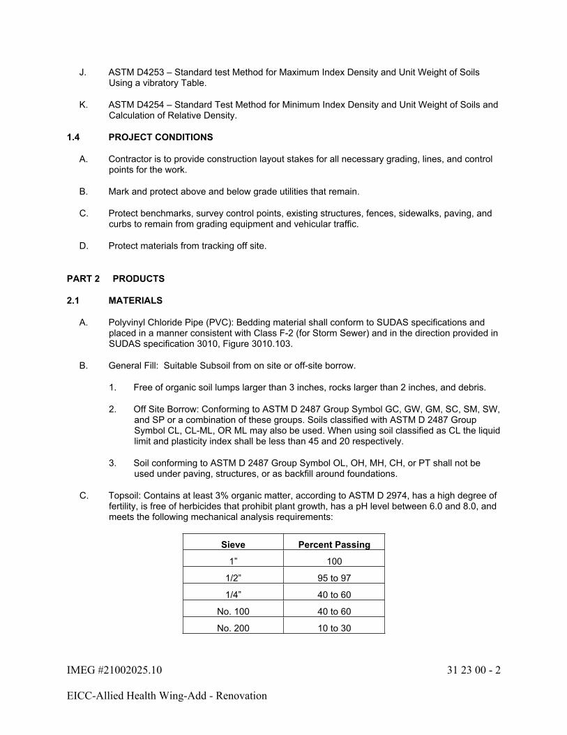
IMEG #21002025.10 31 23 00 - 2
EICC-Allied Health Wing-Add - Renovation
J. ASTM D4253 – Standard test Method for Maximum Index Density and Unit Weight of Soils Using a vibratory Table.
K. ASTM D4254 – Standard Test Method for Minimum Index Density and Unit Weight of Soils and Calculation of Relative Density.
1.4 PROJECT CONDITIONS
A. Contractor is to provide construction layout stakes for all necessary grading, lines, and control points for the work.
B. Mark and protect above and below grade utilities that remain.
C. Protect benchmarks, survey control points, existing structures, fences, sidewalks, paving, and curbs to remain from grading equipment and vehicular traffic.
D. Protect materials from tracking off site.
PART 2 PRODUCTS
2.1 MATERIALS
A. Polyvinyl Chloride Pipe (PVC): Bedding material shall conform to SUDAS specifications and placed in a manner consistent with Class F-2 (for Storm Sewer) and in the direction provided in SUDAS specification 3010, Figure 3010.103.
B. General Fill: Suitable Subsoil from on site or off-site borrow.
1. Free of organic soil lumps larger than 3 inches, rocks larger than 2 inches, and debris.
2. Off Site Borrow: Conforming to ASTM D 2487 Group Symbol GC, GW, GM, SC, SM, SW, and SP or a combination of these groups. Soils classified with ASTM D 2487 Group Symbol CL, CL-ML, OR ML may also be used. When using soil classified as CL the liquid limit and plasticity index shall be less than 45 and 20 respectively.
3. Soil conforming to ASTM D 2487 Group Symbol OL, OH, MH, CH, or PT shall not be used under paving, structures, or as backfill around foundations.
C. Topsoil: Contains at least 3% organic matter, according to ASTM D 2974, has a high degree of fertility, is free of herbicides that prohibit plant growth, has a pH level between 6.0 and 8.0, and meets the following mechanical analysis requirements:
Sieve Percent Passing
1” 100
1/2” 95 to 97
1/4” 40 to 60
No. 100 40 to 60
No. 200 10 to 30

IMEG #21002025.10 31 23 00 - 3
EICC-Allied Health Wing-Add - Renovation
PART 3 EXECUTION
3.1 EXAMINATION
A. Verify that survey benchmarks and intended elevations for the work are as indicated.
B. Fill areas in the order shown on the drawings. Other fill sources: Excavations from on-site provided they meet the requirements of 2.1 Materials above.
C. Topsoil – Salvage from on-site sources if it meets the above criteria. Otherwise off-site material may be brought in.
3.2 PREPARATION
A. Identify required lines, levels, contours, and datum.
B. Stake and flag locations of known utilities.
C. Locate, identify, and protect utilities that remain, from damage.
D. Notify utility company to remove and relocate utilities as necessary.
E. Mark and verify removal items and limits.
F. Protect plant life, lawns, and other features remaining as a portion of the finish landscaping.
G. Provide separate stockpiles for different soil material types as required.
H. Comply with the site erosion control plan and permit requirements.
I. Clean and maintain a tire cleaning area at the entrance to the site during operations.
J. Protect benchmarks, survey control points, fences, paving, and curbs to remain from excavating equipment and vehicular traffic. Prevent fill materials from tracking off site.
3.3 ROUGH GRADING
A. Identify required lines, levels, contours, and datum.
B. Before placing fill, prepare existing ground according to the project soils report, smooth and level the surface of the existing soil and compact using heavy vibratory equipment until there is no loss of elevation. Remove any debris, vegetation, or organic material.
C. Do not remove wet subsoil unless it is subsequently processed to obtain optimum moisture content.
D. Prepare subgrades in accordance with Iowa DOT: Standard Specifications for Highway and Bridge Construction, Series 2015.
E. In general, areas within the influence lines of building foundations, walks, and other hard features (cohesive soils) will require 95% Standard Proctor density. Non-cohesive soils in these areas will require 98% Standard Proctor density, (ASTM D698).
F. Provide allowance for 6” of topsoil in areas adjacent to the building addition, sidewalk, and in

IMEG #21002025.10 31 23 00 - 4
EICC-Allied Health Wing-Add - Renovation
the construction laydown and detention areas. Topsoil must be left smooth, uniform, without debris, lumps, and rocks larger than 1/2” and ready to be seeded by others.
G. Stability: Replace damaged or displaced subsoil to same requirements as for specified fill.
H. Remove large stones, boulders and debris from the site. Rough grading shall be finished by blading to reasonably smooth contours with uniform transitions and slopes.
I. Place and maintain silt fence and other erosion control items to prevent silt from entering adjacent properties or ROW. Comply with erosion control requirements and permit.
3.4 SOIL REMOVAL
A. In areas to receive new construction and where grades are changed, remove all organic soils (topsoil) and fill materials placed without adequate compaction. Store materials for reuse.
B. Stockpiles: Use areas designated on site or as agreed to; pile depth not to exceed 8 feet; protect from erosion. Grade stockpile area to prevent standing water.
3.5 FINAL GRADING
A. Before Final Grading:
1. Verify subgrade backfilling has been inspected.
2. Verify subgrade has been contoured and compacted.
3. Verify utility excavation is complete, utilities are installed, tested, and are ready for use.
B. Remove any subgrade debris, roots, branches, stones, in excess of 1/2 inch in size.
C. Verify landscape locations and depths to receive topsoil.
3.6 TOLERANCES
A. Top Surface of Subgrade areas: Plus or minus 0.08 foot from required elevation.
B. Grading around buildings, between curbs, adjacent to sidewalks as final surfaces, slope to drain and plus or minus .05 foot.
3.7 TESTING
A. Verify soil materials comply with Section 2.01 above.
B. Verify that the Owner’s testing agency has moisture density curves for the material and is ready to perform testing.
C. Spread soils in loose lifts not to exceed 8” in depth. Disk or dry soils to optimum moisture plus or minus 2% prior to applying compactive effort. Roll as required to obtain density. Adjust moisture content by adding water or disking as needed to reach moisture required. No additional pay allowance will be made for moisture adjustment.
D. Shape fills such that water does not pond.

IMEG #21002025.10 31 23 00 - 5
EICC-Allied Health Wing-Add - Renovation
E. Additional lifts may not be made unless the density requirements are met on the in-place lift.
F. Density testing will be performed at the intervals specified by the Owner’s independent testing company. Initially testing will be required continuously until the required densities are achieved and a workable process is in place. Continuous testing will start again if the material source changes or the Owner’s quality assurance testing indicates the results are inconsistent.
3.8 CLEANING AND PROTECTION
A. Leave site clean uniform, ready to receive future work or temporary seeding. Clean mud from the tire cleaning area and the accessway periodically during the work.
B. Remove sediment from the on-site detention areas as needed, and at project completion, prior to final topsoil application.
C. Rake and clean entire disturbed areas for seeding.
END OF SECTION 31 23 00
IMEG #21002025.10 31 25 00 - 1
EICC-Allied Health Wing-Add - Renovation
SECTION 31 25 00 - EROSION AND SEDIMENT CONTROL
PART 1 GENERAL
1.1 SECTION INCLUDES
A. Preparation of soils, collection and management of surface water and erosion.
B. Permanent Fertilizer, Seeding, Mulching, and Sodding.
C. Removal of stabilized areas used on a temporary basis for construction activities.
1.2 RELATED SECTIONS
A. Section 31 10 00 – Site Clearing
B. Section 31 22 00 – Grading
C. Section 31 23 01 – Excavation and Backfill (Site)
D. Section 32 13 13 – Concrete Pavement
E. Section 33 41 00 – Storm Utility Drainage Piping
1.3 REFERENCES
A. Iowa Department of Transportation (IDOT): Standard Specifications for Highway and Bridge Construction, Series 2015.
B. SUDAS Standard Specifications Section 9010-Seeding
C. SUDAS Standard Specifications Section 9040-Erosion and Sediment Control
D. City of Riverdale, IA regulations.
E. Storm Water Pollution Prevention Plan and Erosion Control Plan
F. Erosion Control Testing Council (ECTC)
PART 2 PRODUCTS
2.1 MATERIALS
A. Erosion Control Materials, Section 4169 of the Iowa Department of Transportation (IDOT): Standard Specifications for Highway and Bridge Construction, Series 2015
B. Temporary Erosion Control Seeding: Table 4169.02-02, 65% Rye, 35% Oats.
C. Permanent Seeding and Landscaping: By Contractor.
D. Perimeter Sediment Control: Section 4196.01,B. and I.M. 496.01.
IMEG #21002025.10 31 25 00 - 2
EICC-Allied Health Wing-Add - Renovation
PART 3 EXECUTION
3.1 STORM WATER POLLUTION PREVENTION PLAN (SWPPP)
A. Erosion Control Plan Sheets: A general approach is included in the project plan sheets. It is understood and expected that actual conditions during construction will require ongoing adjustments to the Erosion Control Plan (ECP).
B. Responsibility: The City of Riverdale, IA, and the Iowa DNR, through the COSESCO permits, are the jurisdictional controls for this project. All persons performing surface disturbing activities on the site to take responsibility for their actions by conforming with the plan as permitted, or by adjusting the plan to accommodate schedule and method changes. Persons performing work on site are required to log in to the plan and log out when they have completed their activities. Changes to the plan are permitted, and various controls are shown in the ECP to allow flexibility of the plan without violating the permit.
C. Plan Modifications: Changes to the ECP must be in compliance with the conditions of the prevailing permit. These changes, along with periodic inspection reports mandated by time and rainfall events during construction are subject to inspection by the City of Riverdale and the EPA. Failure to keep the appropriate records and failure to comply with the permit are reasons for enforcement action involving all parties.
D. At the termination of the project, the contractor shall be responsible for removing the full depth of all stabilized areas. A combination of topsoil and general fill shall be used to restore the disturb locations to pre-project conditions or to proposed finished grade, as indicated on the plans. The top 4 inches shall be topsoil. These locations shall be left in a condition for immediate final seeding.
3.2 INSTALLATION
A. Per Manufacturer’s Instructions.
3.3 SCHEDULE
A. Refer to the Erosion Control drawing for project details and schedule for silt filter fence locations.
B. Refer to plans for details on utilities.
C. All materials are to be installed in accordance with the manufacturer’s guidelines.
D. Temporary Seeding: 100 lbs per acre application and reseeded at 7 day intervals on bare areas regardless of weather conditions.
E. Permanent Seeding and Landscaping: By Contractor.
F. Permanent seeding shall be of material typical to this region and consistent with SUDAS Specification Section 9010 - Seeding. Contractor to submit seeding mix prior to application for approval. Method of seeding, mulching and fertilization shall be Hydraulic Seeding
3.4 SUBMITTALS
A. All seed material is to be certified as meeting the above criteria prior to incorporation in the project.

IMEG #21002025.10 31 25 00 - 3
EICC-Allied Health Wing-Add - Renovation
B. Erosion Control items require product certification for their intended use.
END OF SECTION 31 25 00
IMEG #21002025.10 32 13 13 - 1
EICC-Allied Health Wing-Add - Renovation
SECTION 32 13 13 - CONCRETE PAVEMENT
PART 1 GENERAL
1.1 SECTION INCLUDES
A. Non-structural concrete flatwork.
B. Compacted granular base.
C. Backfilling form lines with appropriate material.
D. Miscellaneous Concrete.
1.2 RELATED SECTIONS
A. Section 31 23 00 – Excavation and Backfill (Site)
B. Section 31 25 00 – Erosion and Sediment Control
C. Section 33 41 00 – Storm Utility Drainage Piping
1.3 REFERENCES
A. Iowa Department of Transportation (IDOT): Standard Specification for Highway and Bridge Construction, Series 2015.
B. SUDAS Specification Manual
1.4 PROJECT CONDITION
A. Verify that subgrade elevations meet tolerances in Section 31 23 01 Excavation and Backfill (Site).
B. Provide sufficient paving operations to meet project schedule and requirements.
C. Verify that survey benchmarks and intended elevations for the Work are as indicated, and that building floor elevations, curb elevations, and pavement elevations are clear and coordinated prior to commencing.
PART 2 PRODUCTS
2.1 MATERIALS
A. All products must meet or exceed the requirements of the Iowa Department of Transportation (IDOT): Standard Specifications for Highway and Bridge Construction, Series 2015.
B. Portland Cement Concrete Pavements and Sidewalks as per Section 2511 of the Iowa Department of Transportation (IDOT): Standard Specifications for Highway and Bridge Construction, Series 2015.
IMEG #21002025.10 32 13 13 - 2
EICC-Allied Health Wing-Add - Renovation
C. Miscellaneous Concrete shall conform to Section 2403, of the Iowa Department of Transportation (IDOT); Standard Specifications for Highway and Bridge construction, Series 2015.
D. Aggregate Base: Gradation #11 as per Section 4121 (quality) of the Iowa Department of Transportation (IDOT) Standard Specifications for Highway and Bridge construction, Series 2015.
E. Provide from an Iowa DOT certified source, P.C. concrete meeting all of the following characteristics:
Compressive Strength at 28 days: 4,000 psi.
Slump: 4 inches maximum.
Air Entrainment: 5 - 8 percent.
2.2 ACCESSORIES
A. None
PART 3 EXECUTION
3.1 EXAMINATION
A. Verify gradients and elevations of base.
B. Verify compacted sub-grade is dry and ready to support paving and imposed loads.
C. Verify that all utilities within the work area have been installed, tested, and are ready to be paved over.
3.2 PREPARATION
A. Scarify sub-grade surface to a depth of 6 inches in all areas compacted by construction activities prior to placing fill.
B. Compact sub-grade to density equal to or greater than the requirements for subsequent fill material.
C. Moisten substrate to minimize absorption of water from fresh concrete.
3.3 BASE CONSTRUCTION
A. Fill areas to contours and elevations using unfrozen materials.
B. Place aggregate fill materials in continuous layers not exceeding 8” on top of geotechnical fabric (if specified).
IMEG #21002025.10 32 13 13 - 3
EICC-Allied Health Wing-Add - Renovation
C. Aggregate Base: Verify specific aggregate bases needed for individual pavement sections, as they differ. Compact aggregates in 8" deep lifts maximum, within 0 to +4% above optimum moisture content, and compact each lift by approved methods to not less than 95% of the maximum density given by ASTM D698 (Standard Proctor Density). Keep compacted lifts relatively smooth and level.
D. Maintain optimum moisture content of fill materials to attain required compaction density.
3.4 FORMING
A. Place and secure forms to correct location, dimension, and profile.
B. Place joint filler in joints, vertical in position, in straight lines. Secure to formwork.
C. Place joint filler between paving components and other appurtenances.
3.5 PLACING CONCRETE
A. Mixing and handling of fresh concrete, including transit time, shall be as per Section 2301 of the Iowa Department of Transportation (IDOT): Standard Specifications for Highway and Bridge Construction, Series 2015.
B. Place Portland Cement Concrete in accordance with Section 2301 of the Iowa Department of Transportation (IDOT): Standard Specifications for Highway and Bridge Construction, Series 2015.
C. Special scoring, architectural joint treatment, color, or special surface treatments as specified.
3.6 FINISHING
A. Paving shall be finished according to Section 2301 of the Iowa Department of Transportation (IDOT): Standard Specifications for Highway and Bridge Construction, Series 2015.
B. Sidewalks: Standard, Light broom, radi used and trowel joint edges. Joint pattern shall be uniform and not exceeding the sidewalk width unless specified elsewhere.
C. Sidewalk ramps: Finish per ADAAG Standards.
D. Architecturally treated surfaces must be water cured unless membrane curing can be demonstrated which does not alter the appearance of the work. Adjacent facilities and vehicles must be protected if membrane curing is used.
3.7 TOLERANCES
A. Flatness: Maximum variation of one-quarter inch in ten feet as measured with a ten-foot straight edge.
B. Compacted Scheduled Thickness (sub-grades): Within one-quarter inch of design thickness.
C. Variation from True Elevation: One half inch.
IMEG #21002025.10 32 13 13 - 4
EICC-Allied Health Wing-Add - Renovation
3.8 JOINTS
A. Sidewalk joint spacing will be 5’ or equal to the width of the walk if greater than 5’ in width, unless specified elsewhere.
B. Patio joint spacing will be as indicated on the Architectural plans.
C. Joints shall be tooled.
D. 5” PCC pavement shall be jointed at 10 feet maximum O.C. All cold joints shall be doweled. Jointing shall be in accordance with SUDAS standard detail 7010.101.
E. Joints shall be sealed with a polyurethane sealant, color matched to the finished concrete color.
END OF SECTION 32 13 13
IMEG #21002025.10 32 91 10 - 1
EICC-Allied Health Wing-Add - Renovation
SECTION 32 91 10 - SURFACE RESTORATION
PART 1 GENERAL
1.1 SECTION INCLUDE
A. Finished Grading.
B. Seeding.
1.2 DESCRIPTION OF WORK
A. Finish Grading
1. This item includes hauling, depositing and spreading topsoil on disturbed areas within the project limits and including all areas disturbed by changes in grade. Site clearing or operations of the Contractor, which are not to be paved or contain plantings or structures, shall be spread with topsoil and prepared for seeding and lawn establishment.
B. Seeding
1. This item includes the preparation of topsoil for seed and the sowing of seed, fertilizer, mulch and establishing vegetative cover for the disturbed areas in accordance with the Contract Documents.
1.3 DELIVERY, STORAGE AND HANDLING
A. All seed shall be furnished in sealed containers. Seed which has become wet, moldy, or otherwise damaged in transit or storage, will not be acceptable.
1.4 SUBMITTALS
A. Submit seed vendor's certified statement for grass seed mixture, stating botanical and common name, percentage by weight and percentages of purity, germination and weed seed.
B. Submit vendor's certified statement for fertilizer composition.
PART 2 PRODUCTS
2.1 FINISH GRADING
A. Topsoil
1. On-site topsoil material shall be that material excavated from the top 4"-10" of the disturbed areas as verified by the Contractor except for stripping of vegetation in the top 2".
2. Use of on-site topsoil material shall be subject to Engineer's approval.
3. Imported topsoil material, as needed, shall meet the requirements of paragraph 2.01.A.4.
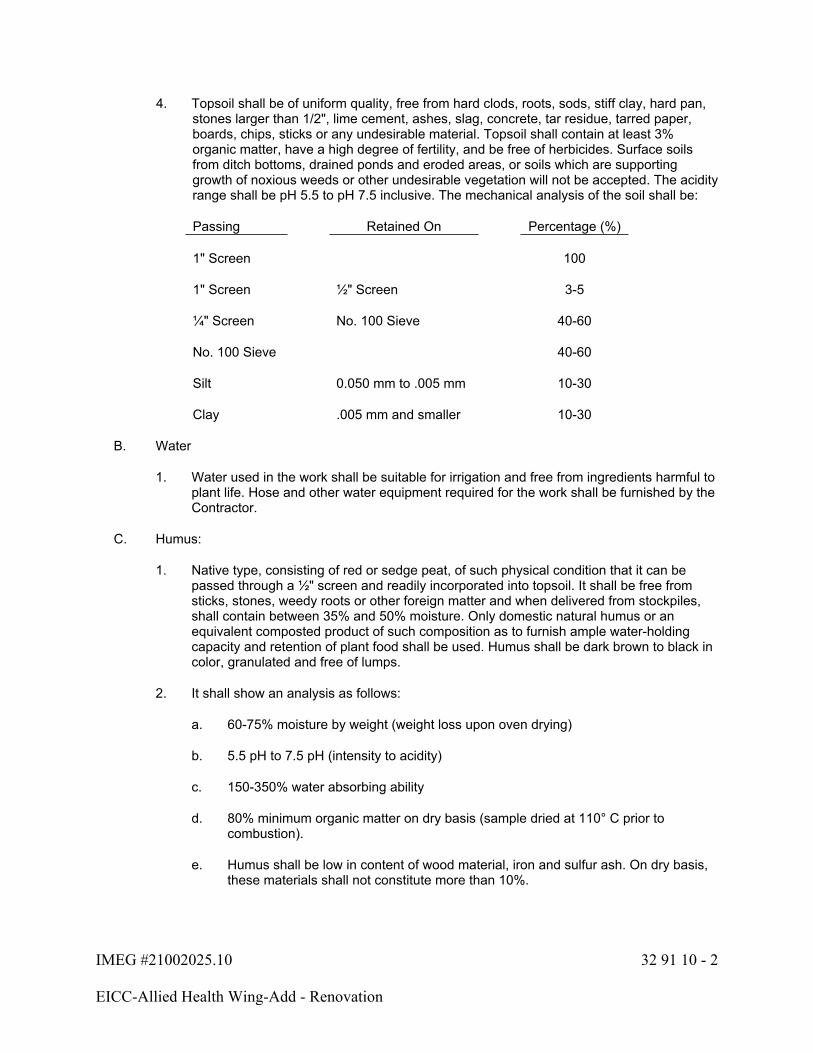
IMEG #21002025.10 32 91 10 - 2
EICC-Allied Health Wing-Add - Renovation
4. Topsoil shall be of uniform quality, free from hard clods, roots, sods, stiff clay, hard pan, stones larger than 1/2", lime cement, ashes, slag, concrete, tar residue, tarred paper, boards, chips, sticks or any undesirable material. Topsoil shall contain at least 3% organic matter, have a high degree of fertility, and be free of herbicides. Surface soils from ditch bottoms, drained ponds and eroded areas, or soils which are supporting growth of noxious weeds or other undesirable vegetation will not be accepted. The acidity range shall be pH 5.5 to pH 7.5 inclusive. The mechanical analysis of the soil shall be:
Passing Retained On Percentage (%)
1" Screen 100
1" Screen ½" Screen 3-5
¼" Screen No. 100 Sieve 40-60
No. 100 Sieve 40-60
Silt 0.050 mm to .005 mm 10-30
Clay .005 mm and smaller 10-30
B. Water
1. Water used in the work shall be suitable for irrigation and free from ingredients harmful to plant life. Hose and other water equipment required for the work shall be furnished by the Contractor.
C. Humus:
1. Native type, consisting of red or sedge peat, of such physical condition that it can be passed through a ½" screen and readily incorporated into topsoil. It shall be free from sticks, stones, weedy roots or other foreign matter and when delivered from stockpiles, shall contain between 35% and 50% moisture. Only domestic natural humus or an equivalent composted product of such composition as to furnish ample water-holding capacity and retention of plant food shall be used. Humus shall be dark brown to black in color, granulated and free of lumps.
2. It shall show an analysis as follows:
a. 60-75% moisture by weight (weight loss upon oven drying)
b. 5.5 pH to 7.5 pH (intensity to acidity)
c. 150-350% water absorbing ability
d. 80% minimum organic matter on dry basis (sample dried at 110° C prior to combustion).
e. Humus shall be low in content of wood material, iron and sulfur ash. On dry basis, these materials shall not constitute more than 10%.
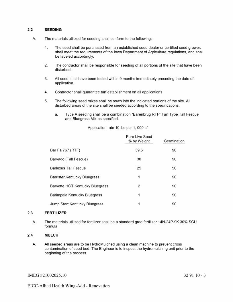
IMEG #21002025.10 32 91 10 - 3
EICC-Allied Health Wing-Add - Renovation
2.2 SEEDING
A. The materials utilized for seeding shall conform to the following:
1. The seed shall be purchased from an established seed dealer or certified seed grower, shall meet the requirements of the Iowa Department of Agriculture regulations, and shall be labeled accordingly.
2. The contractor shall be responsible for seeding of all portions of the site that have been disturbed.
3. All seed shall have been tested within 9 months immediately preceding the date of application.
4. Contractor shall guarantee turf establishment on all applications
5. The following seed mixes shall be sown into the indicated portions of the site. All disturbed areas of the site shall be seeded according to the specifications.
a. Type A seeding shall be a combination “Barenbrug RTF” Turf Type Tall Fescue and Bluegrass Mix as specified.
Application rate 10 lbs per 1, 000 sf
Pure Live Seed % by Weight Germination
Bar Fa 767 (RTF) 39.5 90
Barvado (Tall Fescue) 30 90
Barlexus Tall Fescue 25 90
Barrister Kentucky Bluegrass 1 90
Barvette HGT Kentucky Bluegrass 2 90
Barimpala Kentucky Bluegrass 1 90
Jump Start Kentucky Bluegrass 1 90
2.3 FERTILIZER
A. The materials utilized for fertilizer shall be a standard grad fertilizer 14N-24P-9K 30% SCU formula
2.4 MULCH
A. All seeded areas are to be HydroMulched using a clean machine to prevent cross contamination of seed bed. The Engineer is to inspect the hydromulching unit prior to the beginning of the process.

IMEG #21002025.10 32 91 10 - 4
EICC-Allied Health Wing-Add - Renovation
2.5 WATER
A. The Contractor shall furnish and apply water to all areas for a minimum of 3 weeks and 2 cuttings to achieve 1” of water per week. The watering should not be applied in one application of 1”, but rather in small increments of 1/8” to 1/4”.
B. The Contractor shall furnish all equipment required to execute watering
C. Water shall be free of substances harmful to the growth of vegetation.
2.6 DITCH EROSION CONTROL AND SLOPE PROTECTION
A. Wood Excelsior Mat
1. Wood excelsior mat shall be a mat of interlocking wood fibers with a plastic netting applied to both sides for holding the excelsior in place. The mat shall be nontoxic to growth of plants and germination of seeds. The netting applied to both sides shall have a mesh size of approximately 5/8-inch by ¾ inch. The mat shall be furnished in rolls with a tolerance of minimum 1 inch and plus 3 inches. As furnished, the mat shall have a minimum weight of 0.88 pound per square yard. The mat shall be furnished in plastic bags or otherwise protected to prevent damage from weather or handling.
B. Liquid Mulch Binder
1. Liquid mulch binder shall be synthetic binder, unless otherwise changed by Special Provisions.
2. Synthetic Binder
a. Bonded Fiber Matrix for erosion control shall be "Soil Guard", as manufactured by Weyerhaeuser Engineered Fiber Products, Snoqualmie, WA 98065, or approved equal.
3. Wood fiber
4. Tackifier or Binder
2.7 EQUIPMENT
A. Equipment shall meet the requirements of Sections 2001 and 2601.03A of the Iowa Department of Transportation Standard Specifications for Highway and Bridge Construction.
B. Contractor shall use a brillion drop seeder to press seed into the native soil.
C. Clean hydro seeding equipment shall be used to apply mulch at the specified rate only and is to be free of seed contamination.
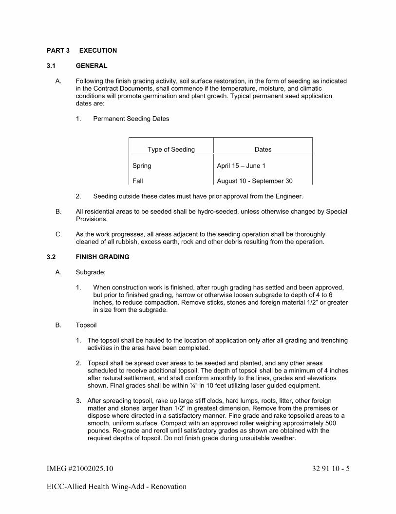
IMEG #21002025.10 32 91 10 - 5
EICC-Allied Health Wing-Add - Renovation
PART 3 EXECUTION
3.1 GENERAL
A. Following the finish grading activity, soil surface restoration, in the form of seeding as indicated in the Contract Documents, shall commence if the temperature, moisture, and climatic conditions will promote germination and plant growth. Typical permanent seed application dates are:
1. Permanent Seeding Dates
Type of Seeding Dates
Spring April 15 – June 1
Fall August 10 - September 30
2. Seeding outside these dates must have prior approval from the Engineer.
B. All residential areas to be seeded shall be hydro-seeded, unless otherwise changed by Special Provisions.
C. As the work progresses, all areas adjacent to the seeding operation shall be thoroughly cleaned of all rubbish, excess earth, rock and other debris resulting from the operation.
3.2 FINISH GRADING
A. Subgrade:
1. When construction work is finished, after rough grading has settled and been approved, but prior to finished grading, harrow or otherwise loosen subgrade to depth of 4 to 6 inches, to reduce compaction. Remove sticks, stones and foreign material 1/2” or greater in size from the subgrade.
B. Topsoil
1. The topsoil shall be hauled to the location of application only after all grading and trenching activities in the area have been completed.
2. Topsoil shall be spread over areas to be seeded and planted, and any other areas scheduled to receive additional topsoil. The depth of topsoil shall be a minimum of 4 inches after natural settlement, and shall conform smoothly to the lines, grades and elevations shown. Final grades shall be within ¼” in 10 feet utilizing laser guided equipment.
3. After spreading topsoil, rake up large stiff clods, hard lumps, roots, litter, other foreign matter and stones larger than 1/2" in greatest dimension. Remove from the premises or dispose where directed in a satisfactory manner. Fine grade and rake topsoiled areas to a smooth, uniform surface. Compact with an approved roller weighing approximately 500 pounds. Re-grade and reroll until satisfactory grades as shown are obtained with the required depths of topsoil. Do not finish grade during unsuitable weather.

IMEG #21002025.10 32 91 10 - 6
EICC-Allied Health Wing-Add - Renovation
4. The seeding operation shall follow the finish grading activities as closely as is practical in order to minimize the potential for soil erosion.
5. Excess topsoil which is not used on the job site shall be removed from the site by the Contractor.
C. Humus shall be applied to the surface of the spread topsoil and worked into the mix during raking operations. Apply quantity of humus as necessary to meet the 3% organic matter content previously specified.
3.3 PREPARATION
A. Seedbed Preparation
1. The area to be seeded shall be relatively smooth, and all washes and gullies shall be filled to conform to the desired cross section. Weeds shall be removed. When such fills exceed 6 inches, the material shall be compacted with a tractor wheel or other suitable field equipment. Preparation of all ditches designated for special ditch control shall be coordinated with the seedbed preparation.
2. Residential Areas
a. The Contractor shall prepare the seedbed by scarifying the topsoil 2-3 inches deep and removing all debris larger than ½ inch, including stones, clods, organic debris and other objectionable material.
B. Following finish grading and seedbed preparation, an application of fertilizer shall be completed. The fertilizer shall be applied at a rate:
SEEDBED PREPARATION
Fertilizer
lbs./acre
Lime
lbs./acre (ECCE) N P2O5 K2O
3,000 – 4,000 50 100 100
C. Following the fertilizer application, the area shall be disked and rolled. A harrow or rake may be used in place of a roller.
3.4 SEEDING AND MULCHING
A. Preparation of Seed
1. All seed for permanent seeding shall be treated with a non-mercurial fungicide (76\5% concentration or equivalent) at a rate of 5½ oz. per 100 lbs. of seed.
2. Mechanical mixing equipment shall be used for application of the sticking agent, inoculant, and fungicide on seed quantities over 50 lbs. per batch.
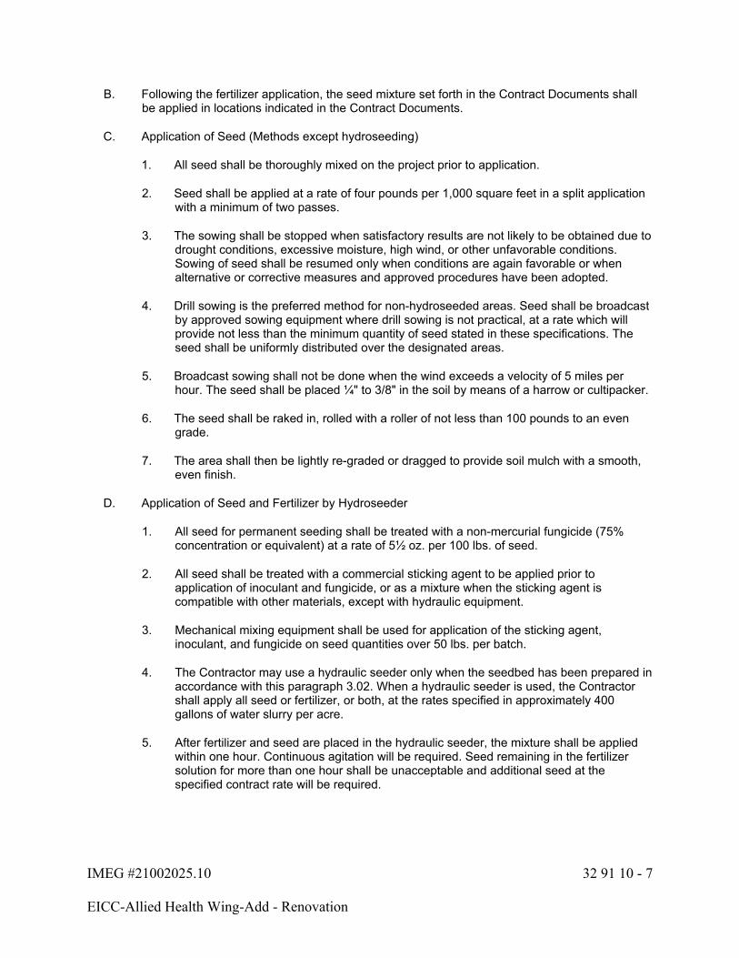
IMEG #21002025.10 32 91 10 - 7
EICC-Allied Health Wing-Add - Renovation
B. Following the fertilizer application, the seed mixture set forth in the Contract Documents shall be applied in locations indicated in the Contract Documents.
C. Application of Seed (Methods except hydroseeding)
1. All seed shall be thoroughly mixed on the project prior to application.
2. Seed shall be applied at a rate of four pounds per 1,000 square feet in a split application with a minimum of two passes.
3. The sowing shall be stopped when satisfactory results are not likely to be obtained due to drought conditions, excessive moisture, high wind, or other unfavorable conditions. Sowing of seed shall be resumed only when conditions are again favorable or when alternative or corrective measures and approved procedures have been adopted.
4. Drill sowing is the preferred method for non-hydroseeded areas. Seed shall be broadcast by approved sowing equipment where drill sowing is not practical, at a rate which will provide not less than the minimum quantity of seed stated in these specifications. The seed shall be uniformly distributed over the designated areas.
5. Broadcast sowing shall not be done when the wind exceeds a velocity of 5 miles per hour. The seed shall be placed ¼" to 3/8" in the soil by means of a harrow or cultipacker.
6. The seed shall be raked in, rolled with a roller of not less than 100 pounds to an even grade.
7. The area shall then be lightly re-graded or dragged to provide soil mulch with a smooth, even finish.
D. Application of Seed and Fertilizer by Hydroseeder
1. All seed for permanent seeding shall be treated with a non-mercurial fungicide (75% concentration or equivalent) at a rate of 5½ oz. per 100 lbs. of seed.
2. All seed shall be treated with a commercial sticking agent to be applied prior to application of inoculant and fungicide, or as a mixture when the sticking agent is compatible with other materials, except with hydraulic equipment.
3. Mechanical mixing equipment shall be used for application of the sticking agent, inoculant, and fungicide on seed quantities over 50 lbs. per batch.
4. The Contractor may use a hydraulic seeder only when the seedbed has been prepared in accordance with this paragraph 3.02. When a hydraulic seeder is used, the Contractor shall apply all seed or fertilizer, or both, at the rates specified in approximately 400 gallons of water slurry per acre.
5. After fertilizer and seed are placed in the hydraulic seeder, the mixture shall be applied within one hour. Continuous agitation will be required. Seed remaining in the fertilizer solution for more than one hour shall be unacceptable and additional seed at the specified contract rate will be required.
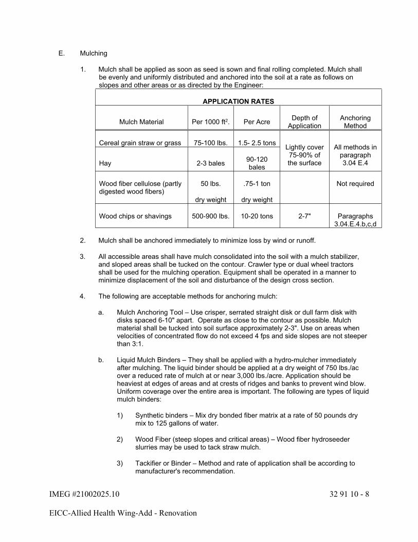
IMEG #21002025.10 32 91 10 - 8
EICC-Allied Health Wing-Add - Renovation
E. Mulching
1. Mulch shall be applied as soon as seed is sown and final rolling completed. Mulch shall be evenly and uniformly distributed and anchored into the soil at a rate as follows on slopes and other areas or as directed by the Engineer:
APPLICATION RATES
Mulch Material Per 1000 ft2. Per Acre Depth of Application
Anchoring Method
Cereal grain straw or grass 75-100 lbs. 1.5- 2.5 tons
Hay 2-3 bales 90-120 bales
Lightly cover 75-90% of the surface
All methods in paragraph 3.04 E.4
Wood fiber cellulose (partly digested wood fibers)
50 lbs.
dry weight
.75-1 ton
dry weight
Not required
Wood chips or shavings 500-900 lbs. 10-20 tons 2-7" Paragraphs 3.04.E.4.b,c,d
2. Mulch shall be anchored immediately to minimize loss by wind or runoff.
3. All accessible areas shall have mulch consolidated into the soil with a mulch stabilizer, and sloped areas shall be tucked on the contour. Crawler type or dual wheel tractors shall be used for the mulching operation. Equipment shall be operated in a manner to minimize displacement of the soil and disturbance of the design cross section.
4. The following are acceptable methods for anchoring mulch:
a. Mulch Anchoring Tool – Use crisper, serrated straight disk or dull farm disk with disks spaced 6-10" apart. Operate as close to the contour as possible. Mulch material shall be tucked into soil surface approximately 2-3". Use on areas when velocities of concentrated flow do not exceed 4 fps and side slopes are not steeper than 3:1.
b. Liquid Mulch Binders – They shall be applied with a hydro-mulcher immediately after mulching. The liquid binder should be applied at a dry weight of 750 lbs./ac over a reduced rate of mulch at or near 3,000 lbs./acre. Application should be heaviest at edges of areas and at crests of ridges and banks to prevent wind blow. Uniform coverage over the entire area is important. The following are types of liquid mulch binders:
1) Synthetic binders – Mix dry bonded fiber matrix at a rate of 50 pounds dry mix to 125 gallons of water.
2) Wood Fiber (steep slopes and critical areas) – Wood fiber hydroseeder slurries may be used to tack straw mulch.
3) Tackifier or Binder – Method and rate of application shall be according to manufacturer's recommendation.

IMEG #21002025.10 32 91 10 - 9
EICC-Allied Health Wing-Add - Renovation
c. Mulch Nettings – Lightweight, degradable, plastic, polyester, or paper nets may be stapled over the mulch according to manufacturer's recommendations.
d. Peg and Twine (only in areas where other methods cannot be used) – Drive 7/8-inch to 1-inch wooden pegs to within 3 inches of the soil surface every 4 feet in all directions. Stakes may be driven before or after straw is spread. Secure mulch by stretching twine between pegs in a criss-cross-within-a-square pattern. Turn twine 2 or more times around each peg.
5. Areas on which mulch has been disturbed before final acceptance by the Engineer shall be remulched.
F. Synthetic binder mulch applied with seed and fertilizer.
1. Synthetic Binders – Mix dry bonded fiber matrix at a rate of 50 pounds dry mix to 125 gallons of water. Add seed and fertilizer to the mix at the rate specified.
2. Apply by hydroseeder at a minimum dry rate of 3,000 pounds per acre to even surfaces and 4,000 pounds per acre for uneven and irregular surfaces, and in accordance with manufacturer's requirements.
3. The bonded fiber matrix shall have the opportunity to dry for 24 hours after installation. The application shall not occur less than 24 hours in advance of a rainfall.
G. All seeded areas to be watered, as required, by the Contractor. Seed areas shall receive sufficient watering to allow a good stand of grass within 4 weeks.
3.5 MAINTENANCE
A. Until the project is finally accepted, the Contractor shall be required to mow and maintain vegetation between 2 and 4 inches in height. Not more than 1/3 of the grass lead shall be cut in any mowing.
B. The Contractor will be required to remove weeds and repair or replace, or both, all seeding and mulching that is defective or becomes damaged. When seeding is approved and accomplished out of season and all other work on the contract has been satisfactorily completed but a determination cannot be made as to whether or not an established stand of grass has or may result, then payment for the areas seeded out of season will be withheld until such time as this requirement has been met.
C. When any work included in the contract is washed out or damaged prior to final acceptance of the project, the Engineer may order replacement of the damaged portion and will advise the Contractor of the approximate quantity of replacement required. The Contractor shall make these repairs during the normal permanent seeding period and shall be responsible for satisfactory maintenance of the work in a manner satisfactory to the Engineer.
1. Contractor shall be responsible for the first reseeding.
2. The Owner shall pay for any subsequent reseeding at contract prices.
IMEG #21002025.10 32 91 10 - 10
EICC-Allied Health Wing-Add - Renovation
3.6 DEFECTIVE WORK
A. Areas which are seeded and do not show a stand of grass acceptable to the Engineer, by September 1 following spring seeding, and May 1 following fall seeding, shall be reseeded in accordance with the Contract Documents at the expense of the Contractor.
END OF SECTION 32 91 10

IMEG #21002025.10 33 10 00 - 1
EICC-Allied Health Wing-Add - Renovation
SECTION 33 10 00 - WATER UTILITIES
PART 1 - GENERAL
1.1 SECTION INCLUDES
A. Provide all materials and labor necessary to furnish and install new lines, valves, and accessories, as indicated on the drawing or as in this Section; and connect said system to the existing mains as shown.
B. Coordinate connections with Iowa American Water Company. Contractor must conform to the City of Davenport and Iowa DNR requirements for all construction, pressure testing, and disinfection operations.
1.2 RELATED SECTIONS
A. Section 31 23 00 – Excavation and Fill
B. Section 31 25 00 – Erosion and Sediment Control
C. Section 32 13 13 – Concrete Pavement
1.3 REFERENCES
A. City of Davenport Plumbing Code Ordinance (Construction Rules and Regulations for the City of Davenport Chapter 15.28 Plumbing Code) which references the Uniform Plumbing Code 2003 Edition as published by the International Association of Plumbing and Mechanical Officials is hereby adopted by reference as the Plumbing Code for the City of Davenport, with the following revisions and amendments:
1. Water: Iowa-American Water Standards
2. Fire Protection: NFPA 24 and 13
B. City of Davenport Standard Specifications and Details, Latest Edition. Note permitting and traffic lane closure requirements as applicable.
C. Iowa Department of Transportation (IDOT): Standard Specifications for Highway and Bridge Construction, Latest Edition.
1.4 SUBMITTALS
A. Submit catalog cuts for intended use products for approval.
IMEG #21002025.10 33 10 00 - 2
EICC-Allied Health Wing-Add - Renovation
PART 2 - PRODUCTS
2.1 MATERIALS
A. Water Main shall be Ductile Iron Pipe (D.I.P.) in conformance with ANSI A21.51 (AWWA C151), Class 350 per ANSI A21.50 (AWWA C150) tar (seal) coated and cement lined per ANSI A21.4 (AWWA C104) with push-on joints per ANSI A21.11 (AWWA C111) a minimum of three (3) brass wedges per joint shall be installed. D.I.P. shall be polyethylene wrapped in accordance with ANSI A21.50 (AWWA C105).
B. All fittings shall be ANSI/AWWA C153/A21.53-88 ductile iron compact fittings, with mechanical joints and shall be rated for 350 psi. All fittings shall be cement lined meeting ANSI/AWWA C104/A21.4-90. Connecting pipe shall be at least 18 inches long. All fittings that require restraint shall receive retainer glands for that purpose, equipped with corrosion resistant set screws.
C. Tapping Sleeve and Valve: Provide Tapping Sleeves meeting AWWA C223 and NSF/ANSI 61-G installed per manufacturers recommendations and American Water Company requirements. Smith/Blair 622 Tapping Sleeve is approved. Provide valves for tapping meeting the requirements of the American Water Company and AWWA C509 certified to ANSI/NSF 61. Mueller A-2360 Resilient Wedge Gate Valves are approved. Valve boxes shall be Tyler 6860-DD complete with #6 base or equivalent.
D. Couplings shall be Smith-Blair #441 Cast Coupling with appropriate gasket, or approved equal, suitable for ductile iron or polyvinyl chloride pipe.
E. Gate Valves shall meet the requirements of the Iowa American Water Company and the City of Davenport. Valves, including hydrant service valves, shall be: Mueller A-2360 resilient wedge, or equal. Mueller is the preferred manufacturer. Valve Boxes shall be: Tyler 6860-DD complete with #6 base or equivalent.
F. Service Saddle: Body: Stainless steel band fully enclosing host pipe. Lugs: Stainless steel. Stud Bolts: Stainless steel. Size: 8” x 1-1/2” tap, Manufacturer: Model 3412 by Power Seal or equal.
G. Backfill Materials: Materials meeting the requirements of Section 31 23 00 Excavation and Fill.
H. Street pavement repair: Street patch shall be performed in accordance with the City requirements.
I. Site irrigation connection: See Landscape Architectural plans
PART 3 - EXECUTION
3.1 EXCAVATION
A. Excavate trench to uniform widths to provide for a maximum twelve (12) inches of Working clearance on each side of the pipe. Ditch excavations must conform to OSHA safety requirements. Ditch must provide 5.5 feet of cover when measured from finished surface to the top of the pipe.
B. Saw cut existing pavement, PCC sidewalk, and PCC curb and gutter, as necessary to provide true edge for restoration and sufficient width for trench and City of Davenport requirements for restoration. Main Street section may include HMA over PCC material.
C. Trench wall shall be vertical from trench bottom to a point twelve (12) inches above the bottom of the pipe.

IMEG #21002025.10 33 10 00 - 3
EICC-Allied Health Wing-Add - Renovation
D. Trench bottom shall provide a smooth, firm, stable, and rock free foundation for the entire length of the pipe.
E. Trench Backfill for pipe and other water service features placed under pavements.
1. Place and compact to at least 95% of the material’s maximum standard proctor density according to ASTM D 698.
2. Backfill to the proposed sub-grade of the finished pavement’s aggregate base.
3. Place all materials in layers or lifts of not more than eight (8) inches loose measure, and compact by hand-operated tampers to required elevations.
4. See Section 31 23 00 – Excavation and Backfill for additional requirements.
3.2 GENERAL
A. Connections to existing main:
1. Connect to existing main as directed by the Iowa American Water Company, and as shown on the Site Utility Plan.
2. Contractor to notify City of and obtain any necessary permits, inspections, and tapping fees for in street work.
3. Above work is incidental to the water system work.
4. Additional fittings may be required to vertically clear other utilities as part of the work.
B. Restoration of surfaces: Existing surfaces shall be replaced as directed. Site restoration per these specifications and City of Davenport requirements.
3.3 TESTING
A. Testing and Disinfection:
1. The Contractor shall perform pressure and leakage test, flush and disinfect all in accordance with the Iowa American Water Company and DNR policy. A hydrostatic pressure test shall be performed on the completed water main with a minimum pressure of 150 psi. for a period of not less than 1 hour and not more than 6 hours. The basic provisions of AWWA C-600 and C-603 shall be applicable for the test.
2. Contractor is responsible for any fees regarding testing and/or disinfection.
END OF DOCUMENT 33 10 00

IMEG #21002025.10 33 41 00 - 1
EICC-Allied Health Wing-Add - Renovation
SECTION 33 41 00- STORM UTILITY DRAINAGE PIPING
PART 1 GENERAL
1.1 SECTION INCLUDES
A. Provide all materials and labor necessary to furnish and install new storm sewer system and accessories as indicated on the drawings or in this Section.
1.2 RELATED SECTIONS
A. Section 31 23 01 – Excavation & Backfill (Site)
B. Section 31 25 00 – Erosion and Sediment Control
C. Section 32 13 13 – Concrete Pavement
1.3 REFERENCES
A. American Society of Testing and Materials (ASTM)
B. Iowa Statewide Urban Design and Specifications (SUDAS): Standard Specifications; 2020 Edition.
C. Iowa Department of Transportation (IDOT): Standard Specifications for Highway and Bridge Construction, Series 2015.
D. Trench bedding and backfill for pipe, see Section 31 23 01 – Excavation & Backfill (Site).
1.4 SUBMITTALS
A. Submit shop drawing and specification sheet for pipe materials, inlet and manhole components, castings, and special pipe fittings.
PART 2 PRODUCTS
2.1 STORM SEWER MATERIAL
A. High Density Polyethylene (HDPE) per IDOT Standard Specifications for Highway and Bridge Construction, Series 2015, Section 4149.03 with corrugated exterior and smooth interior meeting ASTM D3350 and ASTM D 2412.
B. Polyvinyl Chloride Pipe (PVC): Per Section 4146 Plastic Pipe/Section 4149.03, paragraph C, Polyvinylchloride with a smooth interior and corrugated exterior meeting ASTM F 949, using matching fittings. Iowa Department of Transportation (IDOT). Suitable for roof drain leaders only.
IMEG #21002025.10 33 41 00 - 2
EICC-Allied Health Wing-Add - Renovation
C. Manhole and Inlet Castings: As shown on the plans. Inlets and castings shall be Heavy Duty cast iron for the support of traffic loads. Size and flow capacities are specific to the castings and or-equal substitutions must comply with the same characteristics. Holes for various connections, underdrain, surface drains, and future roof drains are to be precast into the inlet structures. Comply with Iowa Department of Transportation (IDOT): Standard Specifications for Highway and Bridge Construction, Series 2015. Castings, frames and grates per Section 4149.04, Part I. Castings (Ring, Cover, Grate, and Extensions). All frames shall be bolted to the manhole and all grates and lids shall be bolted or otherwise secured in a manner (other than relying solely on the castings physical weight) such that they resist undesired removal by non-authorized persons.
D. Cast-in-place concrete mix for collars and fillets to requirements of Section 2403, Class C concrete.
2.2 BACKFILL
A. Bedding Materials: See details and Section 31 23 01 – Excavation & Backfill (Site).
B. Backfill Materials: See details and Section 31 23 01 – Excavation & Backfill (Site).
PART 3 EXECUTION
3.1 EXCAVATION
A. Excavate trench to uniform widths to provide for a maximum twelve (12) inches of working clearance on each side of the pipe. Trench wall shall be vertical from trench bottom to a point twelve (12) inches above the top of the pipe. Trench construction must meet applicable OSHA safety standards. Trench bottom shall provide a smooth, firm, stable, and rock free foundation for the entire length of the pipe.
B. Remove unsuitable materials from the trench, when deemed necessary by the Engineer, and provide, furnish and install bedding material of an approved aggregate for proper bedding and support.
C. Utility Trench Backfill for pipe placed under pavement: Place and compact material from the bottom of the pipe to the bottom of the proposed sub-grade of the finished pavement’s aggregate base according to the appropriate paving specification.
D. Surface stabilization, in accordance with the site ECP, shall be constructed once the installation has been completed.
3.2 GENERAL
A. Install pipe beginning at the low point of the pipe run, Place bell joint ends of pipe facing upstream. Set Pre-cast flared end sections per standard with toe support.
B. Pipe bedding shall be as per contract documents or manufacturer’s specifications. The more stringent requirements shall govern.
C. Pipe installation and storm water inlets must be protected from infiltration of mud, silt and debris in accordance with the site Erosion Control Plan (ECP).
D. Install pipe in proper alignment and continuous grade.

IMEG #21002025.10 33 41 00 - 3
EICC-Allied Health Wing-Add - Renovation
E. Install gaskets or sealant in accordance with manufacturer’s recommendations.
F. Clean interior of pipe prior to installation and flush clean when complete to remove miscellaneous debris.
G. Contractor shall remove and reinstall, at his expense, any piping and/or backfill not meeting the Architect’s approval due to any of the following:
1. Poor alignment.
2. Failure of testing requirements.
3. Improper backfill procedures.
4. Pipe material defects.
H. Contractor shall place piping in accordance with all federal, state and local requirements.
I. Contractor shall provide and maintain the temporary surface over storm sewer trenches until such time final restoration or project construction is complete and ready for use in accordance with Section 31 23 01 Excavation & Backfill (Site).
J. Contractor shall install manholes, inlets and castings to the elevations shown on the Site Grading Plan. Fill areas or Cut and Fill areas shall be compacted and tested at the direction of the Engineer prior to the installation of structures and pipe.
K. Restoration of surfaces: per Section 31 25 00 - Erosion and Sediment Control for surface stabilization requirements.
3.3 SCHEDULE
A. See plans for storm sewer locations, inlet and manhole locations, and pipe sizes.
END OF SECTION 33 41 00
Related Documents