259 E 5.615.0/04.13 1. DESCRIPTION 1.1. GENERAL Bell housings are connection elements between drive motors and hydraulic pumps. Both connecting flanges are supplied ready for installation. The bell housings are made from an aluminium cast alloy. 1.2. MODELS Bell housings in both flexible and rigid design are available in dimensions to the VDMA 24561 standard. Bell Housings with Rigid / Flexible Pump Mounting PTS / PT Test set-up Noise level [db(A)] Pressure (bar) rigid flexible Noise level diagram 2. TECHNICAL SPECIFICATIONS 2.1. GENERAL 2.1.1 Mounting position Optional. 2.1.2 Operating temperature -20 °C to +100 °C 2.1.3 Noise level reduction The noise level reduction achieved depends on many factors such as pump type, operating pressure, type of fitting, design etc. It is therefore not possible to quote exact figures. In general, noise level reductions of up to 6 db(A) can be achieved. The illustration in the next column shows how the test is set up, together with a graph showing typical noise level improvements when using a flexible bell housing compared to a rigid bell housing. Bell housing with foot bracket mounted on the oil tank cover plate.

Welcome message from author
This document is posted to help you gain knowledge. Please leave a comment to let me know what you think about it! Share it to your friends and learn new things together.
Transcript

259
E 5.
615.
0/04
.13
1. Description1.1. GeneralBell housings are connection elements between drive motors and hydraulic pumps. Both connecting flanges are supplied ready for installation. The bell housings are made from an aluminium cast alloy. 1.2. MoDelsBell housings in both flexible and rigid design are available in dimensions to the VDMA 24561 standard.
Bell Housings with Rigid / Flexible Pump MountingPTS / PT
Test set-up
Noi
se le
vel [
db(A
)]
Pressure (bar)
rigid
flexible
Noise level diagram
2. technical specifications
2.1. General2.1.1 Mounting positionOptional.2.1.2 operating temperature-20 °C to +100 °C2.1.3 noise level reductionThe noise level reduction achieved depends on many factors such as pump type, operating pressure, type of fitting, design etc. It is therefore not possible to quote exact figures. In general, noise level reductions of up to 6 db(A) can be achieved.The illustration in the next column shows how the test is set up, together with a graph showing typical noise level improvements when using a flexible bell housing compared to a rigid bell housing.
Bell housing with foot bracket mounted on the oil tank cover plate.

260
E 5.
615.
0/04
.13
2.1.4 notes on mountingThe fixing bolts used for mounting the motor to the pump must be long enough in order to fully utilize the available thread depth on the bell housing. If the bolts used are too short, there is the risk of damaging the thread.2.1.5 Weight loadingThe permitted radial or axial load of the bell housing with flexible and rigid pump mounting, allowing for an operating temperature of +60 °C:
Bel
l hou
sing
s
Nom
inal
siz
e
Type
of
Dam
ping
ring
Per
mitt
ed fo
rce
due
to
grav
ity F
max
. [N
]
Cen
tre o
f gra
vity
di
stan
ce fo
r rad
ial
load
L [m
m]
160 Only rigid bell housing possible
200E 400
200K 500
250E 600
200K 800
300E 1000
200K 1300
350E 1500
200K 2000
400E 2200
200K 3000
450E 4000
200K 5500
550E 4000
200K 5500
660E 4500
200K 6000
800 Only rigid bell housing possibleFor a larger centre of gravity distance l* the permitted force due to gravity is reduced according to the following formula:
Fpermitt.* = Fmax. • L [N]L*If the centre of gravity distance l* of the pump is smaller than the centre of gravity distance l in the table, then the permitted force due to gravity fpermitt. for the pump is equal to the maximum force due to gravity fmax in the table.
Fpermitt.
Fmax
L
L*
2.2. specifications2.2.1 Permitted fluidsMineral oil to DIN 51524, other fluids on request.
noteThe information in this brochure relates to the operating conditions and applications described.For applications and operating conditions not described, please contact the relevant technical department.Subject to technical modifications.

261
E 5.
615.
0/04
.13
type PTS = Rigid bell housing PT = Flexible bell housing
nominal size for iec standard motor (type of mounting B5, B35, V1, V15) Nominal size
PTS / PTType
Rigid FlexibleElectric
motor sizeOutput
n = 1430 rpm160 x 71 0.25 - 0.37 kW200 x x 80/90 0.55 - 1.5 kW250 x x 100/112 2.2 - 4.0 kW300 x x 132 5.5 - 7.5 kW350 x x 160/180 11 - 22 kW400 x x 200 30 kW450 x x 225 37 - 45 kW550 x x 250/280 55 - 90 kW660 x x 315 110 - 200 kW800 x 335/400 250 - 400 kW
Model with additional bores Rigid PTS
Flexible PT
Additional bores
2.0 5.0 Without additional bore (standard)5.1 5.1 1x Leakage bore5.3 5.3 Additional bores to Cnomo standard*
Mineral oil resistance (Special models on request)
Bore template code for pump connection (see our sizing program PT-WIN)
type of damping ring (only required for flexible bell housings) e = standard K = damping ring for higher loads (greater rigidity)
accessories ... = without accessories (no details) f3 = bell housing foot bracket
* Cnomo: 1x mounting hole with grille, 1x leakage bore
pt – 250 / 5.0 / M / fl001 – e / f33. MoDel coDe

262
E 5.
615.
0/04
.13
3.1. DiMensions3.1.1 Dimensions of rigid bell housing pts
3.1.2 Dimensions of flexible bell housing PT
Electric motor size KW at n =1500 1/min Drive shaft Ød1 x I3 Bell housing Ø A Ø B Ø C E M Ø d L1 L471 0.25 - 0.37 14x30 PTS-160 160 110 110 130 M8 9 13 480 0.55 - 0.75 19x40
PTS-200 200 130 145 165 M10 11 16 690S-90L 1.1 - 1.5 24x50
100L-112M 2.2 - 4 28x60 PTS-250 250 180 190 215 M12 14 19 6132S-132M 5.5 - 7.5 38x80 PTS-300 300 230 234 265 M12 14 20 6160M-160L 11 - 15 42x110
PTS-350 350 250 260 300 M16 18 25 6180M-180L 18.5 - 22 48x110
200 L 30 55x110 PTS-400 400 300 300 350 M16 18 25 6225S-225M 37 - 45 60x140 PTS-450 450 350 350 400 M16 18 25 6
250M 55 65x140PTS-550 550 450 450 500 M16 18 26 6
280S-280M 75 - 90 75x140315S-315L 110 - 200 80x170 PTS-660 660 550 550 600 M20 22 32 6355L-400L 250 - 400 95x170 PTS-800 800 680 680 740 M20 23 60 10
Electric motor size KW at n =1500 1/min Drive shaft Ød1 x I3 Bell housing Ø A Ø B Ø C E M Ø d L1 L480 0.55 - 0.75 19x40
PT-200 200 130 145 165 M10 11 16 690S-90L 1.1 - 1.5 24x50
100L-112M 2.2 - 4 28x60 PT-250 250 180 190 215 M12 14 20 6132S-132M 5.5 - 7.5 38x80 PT-300 300 230 234 265 M12 14 20 6160M-160L 11 - 15 42x110
PT-350 350 250 260 300 M16 18 25 6180M-180L 18.5 - 22 48x110
200 L 30 55x110 PT-400 400 300 300 350 M16 18 25 6225S-225M 37 - 45 60x140 PT-450 450 350 350 400 M16 18 25 6
250M 55 65x140PT-550 550 450 450 500 M16 18 40 6
280S-280M 75 - 90 75x140315S-315L 110 - 200 80x170 PT-660 660 550 550 600 M20 22 32 6
To identify the bore template code (dimensions N, S, K, M1), please use our sizing program PT-WIN as far as possible, or consult Head Office. You can download and use the PT-WIN program free of charge from our website www.hydac.com by clicking through Support » Download » Software » Product Division - Accessories.accessories: For the range of accessories (bell housing foot brackets, bell housing mounting plate, damping rails, damping rings and couplings) please use our supplementary brochure "Bell Housing Accessories". This brochure can be downloaded from our website www.hydac.com.
hYDac accessories Gmbh Hirschbachstr. 2 66280 sulzbach/saar Tel.: +49 (0)6897 - 509-01 Fax: +49 (0)6897 - 509-1009 Internet: www.hydac.com E-Mail: [email protected]

263
E 5.
601.
14/0
4.13
1. Description1.1. GeneralBell housings are connection elements between drive motors and hydraulic pumps.Both connecting flanges are supplied ready for installation.The bell housings are made from an aluminium cast alloy.On the PTK (bell housing with built-in oil/air cooler) the oil is cooled efficiently by an air stream produced by a fan mounted on the motor shaft.This combination of noise-damping bell housing and oil/air cooler considerably simplifies the construction and reduces the cost of hydraulic systems.The high cooling capacity of the built-in cooler enables the user to reduce his tank capacity.This reduction in oil quantity results in a reduction in operating costs and oil disposal costs.1.2. MoDelsBell housings with flexible pump mounting and oil/air cooler are supplied with dimensions to the VDMA 24561 standard.
Bell Housings with Flexible Pump Mounting with Oil/Air CoolerPTK Series
2. technical specifications
2.1. General2.1.1 Mounting positionOptional.Once both mounting bolts have been removed, the cooler element can be turned through 180° (ports point towards the motor or to the pump).2.1.2 temperature rangesDuring operation of the PTK, ensure that the maximum oil temperature of +100 °C is not exceeded.Warning! If there is a temperature difference of over 50 °C between the oil inlet on the cooler element and the ambient temperature, large fluctuations in temperature (e.g. by turning on and off frequently) must be avoided. Otherwise this could result in significant reduction in lifetime or direct damage to the element through stress cracking.Permitted ambient temperature: -20 °C to +60 °C
Test set-up
Noi
se le
vel [
db(A
)]
Pressure (bar)
rigid
flexible
Noise level diagram
2.1.3 noise level reductionPTKs have a flexible damping ring as standard between the bell housing and pump flange.This ensures a complete decoupling of the pump from the motor and bell housing.The additional use of flexible damping rails reduces the noise level still further.Basically, the noise level reduction achieved depends on many factors such as pump type, operating pressure, type of fitting, design etc.It is therefore not possible to quote exact figures.In general, noise level reductions of up to 6 dB(A) can be achieved by using the flexible pump mounting.The illustration below shows how the test is set up, together with a graph showing typical noise level improvements when using a flexible bell housing compared with a rigid bell housing.

264
E 5.
601.
14/0
4.13
2.1.4 notes on mountingThe fixing bolts used for mounting the motor to the pump must be long enough in order to fully utilize the available thread depth on the PTK. If the bolts used are too short, there is the risk of damaging the thread and consequently the whole unit.2.1.5 Weight loadingThe permitted radial or axial load of the PTK with flexible pump mounting, allowing for an operating temperature of +60 °C:
PTK
N
omin
al s
ize
Type
of
dam
ping
ring
Per
mitt
ed fo
rce
due
to g
ravi
ty
F m
ax. [
N]
Cen
tre o
f gra
vity
di
stan
ce
for r
adia
l loa
d L
[mm
]
200/ 2001 E 400 200
250 E 700 200
300 E 1150 200
350/ 3501 E 1500 200
For a larger centre of gravity distance l* the permitted force due to gravity is reduced according to the following formula:
Fpermitt.* = Fmax. • L [N]L*If the centre of gravity distance l* of the pump is smaller than the centre of gravity distance l in the table, then the permitted force due to gravity fpermitt. for the pump is equal to the maximum force due to gravity fmax in the table.
Fpermitt.
Fmax
L
L*
2.2. specifications2.2.1 coolantMineral oil to DIN 51524, other fluids on request2.2.2 nominal rpm for driven=1430 1/min (Base rpm for the stated technical data)(up to 3000 1/min possible)2.2.3 Direction of rotationWhen looking at the pump shaft clockwise
2.2.4 AirflowrateNominal size VolumePTK-200 approx. 72 m³/hPTK-2001 approx. 72 m³/hPTK-250 approx. 260 m³/hPTK-300 approx. 435 m³/hPTK-350 approx. 780 m³/hPTK-3501 approx. 780 m³/h
2.2.5 power requirement for fanNominal size
Rotation speed1430 1/min 1800 1/min
PTK-200 20 Watt 30 WattPTK-2001 20 Watt 30 WattPTK-250 30 Watt 50 WattPTK-300 90 Watt 130 WattPTK-350 140 Watt 220 WattPTK-3501 140 Watt 220 Watt
2.2.6 noise levels for ptK with electric motor without pump (measured to DIN 45635, Part 1)
Nominal size
Output ofelectric motor at1430 1/min
PTK withelectric motor
PTK-200 1.5 kW 52 db(A)PTK-250 4 kW 58 db(A)PTK-300 5.5 kW 69 db(A)PTK-350 11 kW 70 db(A)
The noise levels with electric motor depend on the make of motor.The noise levels are only a guide as the acoustic properties of a room and reflections have an effect on the noise level.
noteThe information in this brochure relates to the operating conditions and applications described.For applications and operating conditions not described, please contact the relevant technical department.Subject to technical modifications.
2.3. hyDraulic Data2.3.1 cooler elementMaterial Aluminiumpressure resistance– At an operating pressure of ≤ 16 bar
and a temperature ≤ 50 °C, 1 million cycles (2 Hz) are achieved. For higher operating pressures and/or temperatures, the life expectancy will be shorter.
– Maximum operating pressure at static pressure resistance is 40 bar.
Mounting When mounting or dismantling the threaded connection of the cooler inlet or outlet, the torque must be countered (protects the cooler element from distortions). Please also see the assembly instructions supplied with the product.

265
E 5.
601.
14/0
4.13
2.3.3 PressuredropΔpinthecoolerelementFlow direction is optional. The differential pressure Δp is shown against flow rate for different viscosities.
2.3.2 cooling capacityCooling capacity against oil flow rate for different temperature differentials ΔT between oil inlet and air inlet. (Motor rpm 1430 1/min)
ptK-200/ptK-2001
ptK-250
ptK-300
ptK-350/ptK-3501
Coo
ling
capa
city
P (k
W)
Flow rate l/min
Coo
ling
capa
city
P (k
W)
Flow rate l/min
Flow rate l/min
Flow rate l/min
Coo
ling
capa
city
P (k
W)
Coo
ling
capa
city
P (k
W)
ptK-200/ptK-2001
Pre
ssur
e dr
op ∆
p (b
ar)
Flow rate l/minptK-250
Pre
ssur
e dr
op ∆
p (b
ar)
Flow rate l/minptK-300
Flow rate l/min
Pre
ssur
e dr
op ∆
p (b
ar)
ptK-350/ptK-3501
Flow rate l/min
Pre
ssur
e dr
op ∆
p (b
ar)
266
E 5.
601.
14/0
4.13
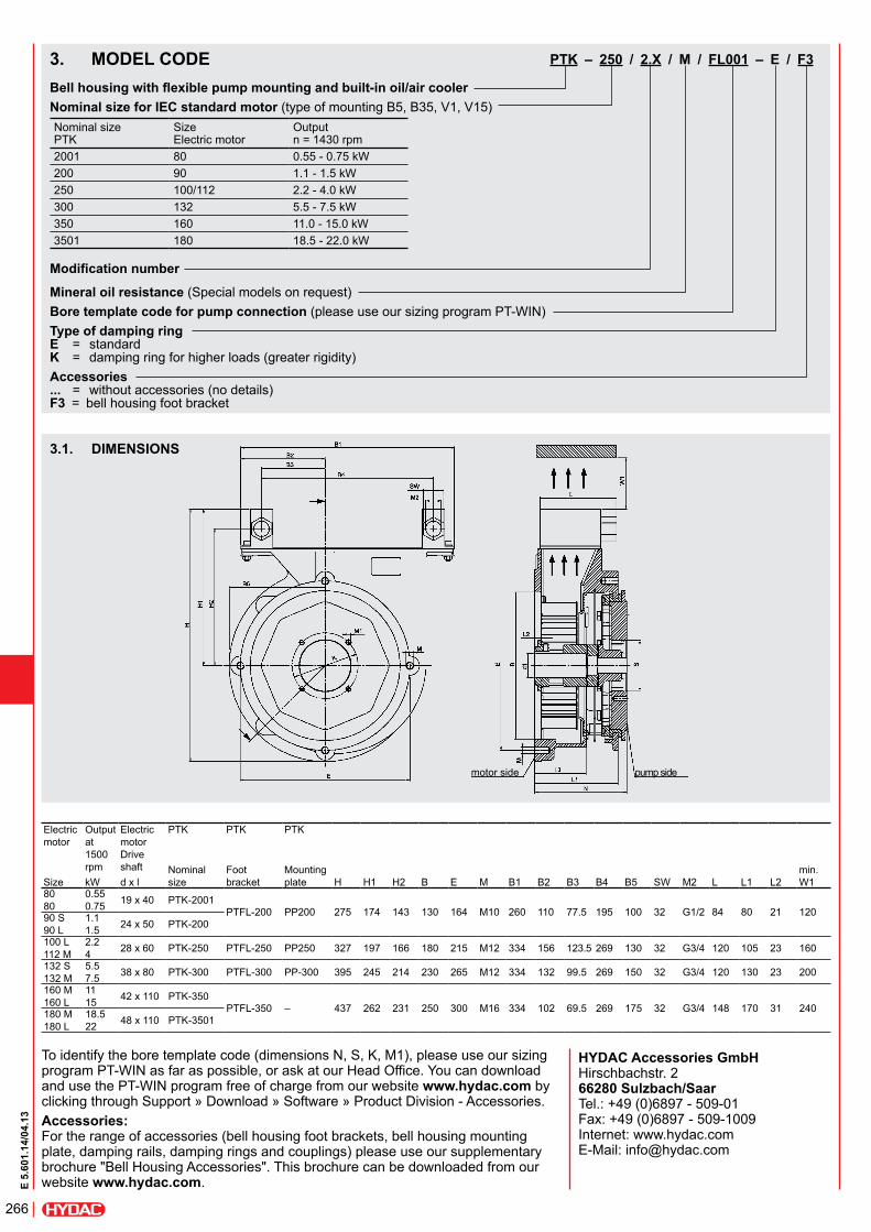
3.1. DiMensions
motor side pump side
Electricmotor
Outputat1500rpm
ElectricmotorDriveshaft
PTK PTK PTK
Nominalsize
Foot bracket
Mounting plate
min.W1Size kW d x l H H1 H2 B E M B1 B2 B3 B4 B5 SW M2 L L1 L2
8080
0.550.75 19 x 40 PTK-2001
PTFL-200 PP200 275 174 143 130 164 M10 260 110 77.5 195 100 32 G1/2 84 80 21 12090 S90 L
1.11.5 24 x 50 PTK-200
100 L112 M
2.24 28 x 60 PTK-250 PTFL-250 PP250 327 197 166 180 215 M12 334 156 123.5 269 130 32 G3/4 120 105 23 160
132 S132 M
5.57.5 38 x 80 PTK-300 PTFL-300 PP-300 395 245 214 230 265 M12 334 132 99.5 269 150 32 G3/4 120 130 23 200
160 M160 L
1115 42 x 110 PTK-350
PTFL-350 – 437 262 231 250 300 M16 334 102 69.5 269 175 32 G3/4 148 170 31 240180 M180 L
18.522 48 x 110 PTK-3501
To identify the bore template code (dimensions N, S, K, M1), please use our sizing program PT-WIN as far as possible, or ask at our Head Office. You can download and use the PT-WIN program free of charge from our website www.hydac.com by clicking through Support » Download » Software » Product Division - Accessories.accessories: For the range of accessories (bell housing foot brackets, bell housing mounting plate, damping rails, damping rings and couplings) please use our supplementary brochure "Bell Housing Accessories". This brochure can be downloaded from our website www.hydac.com.
ptK – 250 / 2.X / M / fl001 – e / f3
Bellhousingwithflexiblepumpmountingandbuilt-inoil/aircoolernominal size for iec standard motor (type of mounting B5, B35, V1, V15)Nominal size PTK
Size Electric motor
Output n = 1430 rpm
2001 80 0.55 - 0.75 kW200 90 1.1 - 1.5 kW250 100/112 2.2 - 4.0 kW300 132 5.5 - 7.5 kW350 160 11.0 - 15.0 kW3501 180 18.5 - 22.0 kW
Modificationnumber
Mineral oil resistance (Special models on request)Bore template code for pump connection (please use our sizing program PT-WIN)type of damping ring e = standard K = damping ring for higher loads (greater rigidity)accessories ... = without accessories (no details) f3 = bell housing foot bracket
3. MoDel coDe
HYDACAccessoriesGmbH Hirschbachstr. 2 66280Sulzbach/Saar Tel.: +49 (0)6897 - 509-01 Fax: +49 (0)6897 - 509-1009 Internet: www.hydac.com E-Mail: [email protected]
271
E 5.
616.
1/04
.13
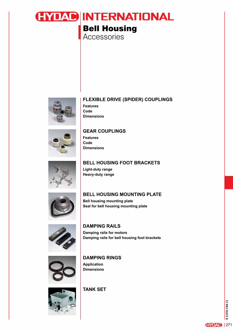
Bell HousingAccessories
Flexible drive (spider) couplingsFeaturescodedimensions
gear couplingsFeaturescodedimensions
bell housing Foot bracketslight-duty rangeheavy-duty range
bell housing mounting platebell housing mounting plateseal for bell housing mounting plate
damping railsdamping rails for motorsdamping rails for bell housing foot brackets
damping ringsapplicationdimensions
tank set

272
E 5.
616.
1/04
.13
Flexible Drive (Spider) Couplings
Features zTorsionally flexible and vibration damping due to elastomer toothed insert (spider) with 98° Shore A (polyurethane) zElastomer is only subjected to compression loading zAxial plug-in zFailsafe as a result of positive-fit power transmission zMaintenance-free zAxial, radial and angular misalignment compensation zAvailable in aluminium (Al), cast iron (GG/GGG) or steel (St) zTemperature range: -30 °C to +90 °C for continuous operation, -40 °C to +120 °C for short-term operation
model code(also order example)
coupling 24/28 – 28 / 22.2 F alu
coupling size
version of motor hub 28 = 28H7 cylindrical bore with key to DIN 6885
version of pump hub 22.2F = 22.2 code F (7/8") imperial hole B17...TN2A = tapered bores SAE ... = profiled bores / spline shafts
special model ... = coupling in cast iron or steel (no details required) ALU = coupling in aluminium ATEX = with ATEX approval

273
E 5.
616.
1/04
.13
coupling hubs in steel / cast iron Order example: Coupling 24/28-20/24
type
max. kw at 1000 rpm
max. kW at 1500 rpm
bores
dimensions [mm] Weight [kg]
a-hub b-hub
Pilot hole
Finished bore Ø d Pilot
hole
Finished bore Ø d
min max min max A B OM L L1+ L2 E s b C C1 dh g f19/24 1.1 1.5 – 6 19 – 12 24 40 32 39 66 25 16 2 12 20 21 18 M5 10 0.3524/28 2.2 4 – 10 24 – 14 32 55 40 52 78 30 18 2 14 24 26 27 M5 10 128/38 5.5 7.5 – 12 28 22 24 38 65 45 62 90 35 20 2.5 15 28 29 30 M6 15 1.638/45 11 15 – 14 38 30 38 45 80 66 77 114 45 24 3 18 37 37 38 M8 15 2.342/55 22 30 – 19 42 15 42 55 95 75 94 126 50 26 3 20 40 40 46 M8 20 3.648/60 30 45 – 19 48 15 48 60 105 85 102 140 56 28 3.5 21 45 45 51 M8 20 4.855/70 37 55 – 19 55 47 55 70 120 98 118 160 65 30 4 22 52 52 60 M10 20 7.465/75 55 90 – 22 65 57 65 75 135 115 132 185 75 35 4.5 26 61 59 68 M10 20 10.975/90 90 132 – 30 75 50 75 90 160 135 158 210 85 40 5 30 69 65 80 M10 25 17.790/100 250 315 29 40 90 79 90 100 200 160 180 245 100 45 5.5 34 81 81 100 M10 25 29.5100/110 315 315 – – – 40 55 110 225 – 200 270 110 50 6 38 – 89 113 M12 30 43.5
coupling hubs in aluminiumOrder example: Coupling 19/24-24/14 ALU
type
max. kW at 1000 rpm
max. kW at 1500 rpm
bores
dimensions [mm] Weight [kg]
a-hub b-hub
Pilot hole
Finished bore Ø d Pilot
hole
Finished bore Ø d
min max min max A B OM L L1+ L2 E s b C C1 dh g f19/24 1.1 1.5 5 6 19 18 19 24 40 32 39 66 25 16 2 12 20 21 18 M5 10 0.1324/28 2.2 4 7 8 24 15 16 32 55 40 53 78 30 18 2 14 24 26 27 M5 10 0.2628/38 5.5 7.5 8 10 28 25 28 38 65 48 63 90 35 20 3 15 28 29 30 M6 15 0.4638/45 11 15 13 14 38 35 38 45 80 66 79 114 45 24 3 18 37 39 38 M8 15 0.942/55 22 30 13 19 42 40 42 55 95 75 94 126 50 26 3 20 40 41 46 M8 20 1.3948/60 30 45 18 19 48 46 48 60 105 85 104 140 56 28 4 21 45 46 51 M8 20 1.86
dimensions
hub combination a/ae.g. Coupling 28 – 28/20
hub combination a/be.g. Coupling 28/38 – 28/35
hub combination b/be.g. Coupling 28/38 – 38/38
274
E 5.
616.
1/04
.13
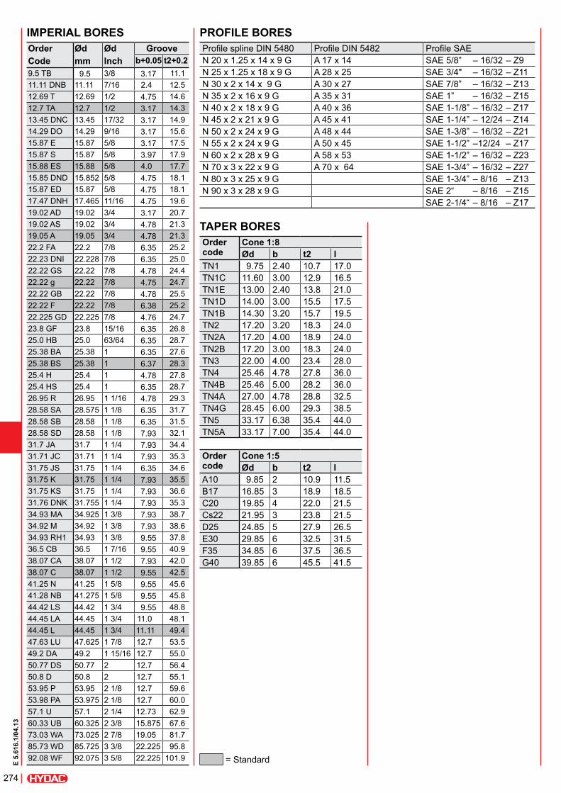
taper boresorder code
cone 1:8Ød b t2 l
TN1 9.75 2.40 10.7 17.0TN1C 11.60 3.00 12.9 16.5TN1E 13.00 2.40 13.8 21.0TN1D 14.00 3.00 15.5 17.5TN1B 14.30 3.20 15.7 19.5TN2 17.20 3.20 18.3 24.0TN2A 17.20 4.00 18.9 24.0TN2B 17.20 3.00 18.3 24.0TN3 22.00 4.00 23.4 28.0TN4 25.46 4.78 27.8 36.0TN4B 25.46 5.00 28.2 36.0TN4A 27.00 4.78 28.8 32.5TN4G 28.45 6.00 29.3 38.5TN5 33.17 6.38 35.4 44.0TN5A 33.17 7.00 35.4 44.0
order code
cone 1:5Ød b t2 l
A10 9.85 2 10.9 11.5B17 16.85 3 18.9 18.5C20 19.85 4 22.0 21.5Cs22 21.95 3 23.8 21.5D25 24.85 5 27.9 26.5E30 29.85 6 32.5 31.5F35 34.85 6 37.5 36.5G40 39.85 6 45.5 41.5
proFile boresProfile spline DIN 5480 Profile DIN 5482 Profile SAEN 20 x 1.25 x 14 x 9 G A 17 x 14 SAE 5/8” – 16/32 – Z9N 25 x 1.25 x 18 x 9 G A 28 x 25 SAE 3/4" – 16/32 – Z11N 30 x 2 x 14 x 9 G A 30 x 27 SAE 7/8” – 16/32 – Z13N 35 x 2 x 16 x 9 G A 35 x 31 SAE 1” – 16/32 – Z15N 40 x 2 x 18 x 9 G A 40 x 36 SAE 1-1/8” – 16/32 – Z17N 45 x 2 x 21 x 9 G A 45 x 41 SAE 1-1/4” – 12/24 – Z14N 50 x 2 x 24 x 9 G A 48 x 44 SAE 1-3/8” – 16/32 – Z21N 55 x 2 x 24 x 9 G A 50 x 45 SAE 1-1/2” –12/24 – Z17N 60 x 2 x 28 x 9 G A 58 x 53 SAE 1-1/2” – 16/32 – Z23N 70 x 3 x 22 x 9 G A 70 x 64 SAE 1-3/4” – 16/32 – Z27N 80 x 3 x 25 x 9 G SAE 1-3/4” – 8/16 – Z13N 90 x 3 x 28 x 9 G SAE 2“ – 8/16 – Z15
SAE 2-1/4“ – 8/16 – Z17
imperial boresordercode
Ødmm
Ødinch
grooveb+0.05 t2+0.2
9.5 TB 9.5 3/8 3.17 11.111.11 DNB 11.11 7/16 2.4 12.512.69 T 12.69 1/2 4.75 14.612.7 TA 12.7 1/2 3.17 14.313.45 DNC 13.45 17/32 3.17 14.914.29 DO 14.29 9/16 3.17 15.615.87 E 15.87 5/8 3.17 17.515.87 S 15.87 5/8 3.97 17.915.88 ES 15.88 5/8 4.0 17.715.85 DND 15.852 5/8 4.75 18.115.87 ED 15.87 5/8 4.75 18.117.47 DNH 17.465 11/16 4.75 19.619.02 AD 19.02 3/4 3.17 20.719.02 AS 19.02 3/4 4.78 21.319.05 A 19.05 3/4 4.78 21.322.2 FA 22.2 7/8 6.35 25.222.23 DNI 22.228 7/8 6.35 25.022.22 GS 22.22 7/8 4.78 24.422.22 g 22.22 7/8 4.75 24.722.22 GB 22.22 7/8 4.78 25.522.22 F 22.22 7/8 6.38 25.222.225 GD 22.225 7/8 4.76 24.723.8 GF 23.8 15/16 6.35 26.825.0 HB 25.0 63/64 6.35 28.725.38 BA 25.38 1 6.35 27.625.38 BS 25.38 1 6.37 28.325.4 H 25.4 1 4.78 27.825.4 HS 25.4 1 6.35 28.726.95 R 26.95 1 1/16 4.78 29.328.58 SA 28.575 1 1/8 6.35 31.728.58 SB 28.58 1 1/8 6.35 31.528.58 SD 28.58 1 1/8 7.93 32.131.7 JA 31.7 1 1/4 7.93 34.431.71 JC 31.71 1 1/4 7.93 35.331.75 JS 31.75 1 1/4 6.35 34.631.75 K 31.75 1 1/4 7.93 35.531.75 KS 31.75 1 1/4 7.93 36.631.76 DNK 31.755 1 1/4 7.93 35.334.93 MA 34.925 1 3/8 7.93 38.734.92 M 34.92 1 3/8 7.93 38.634.93 RH1 34.93 1 3/8 9.55 37.836.5 CB 36.5 1 7/16 9.55 40.938.07 CA 38.07 1 1/2 7.93 42.038.07 C 38.07 1 1/2 9.55 42.541.25 N 41.25 1 5/8 9.55 45.641.28 NB 41.275 1 5/8 9.55 45.844.42 LS 44.42 1 3/4 9.55 48.844.45 LA 44.45 1 3/4 11.0 48.144.45 L 44.45 1 3/4 11.11 49.447.63 LU 47.625 1 7/8 12.7 53.549.2 DA 49.2 1 15/16 12.7 55.050.77 DS 50.77 2 12.7 56.450.8 D 50.8 2 12.7 55.153.95 P 53.95 2 1/8 12.7 59.653.98 PA 53.975 2 1/8 12.7 60.057.1 U 57.1 2 1/4 12.73 62.960.33 UB 60.325 2 3/8 15.875 67.673.03 WA 73.025 2 7/8 19.05 81.785.73 WD 85.725 3 3/8 22.225 95.892.08 WF 92.075 3 5/8 22.225 101.9 = Standard
275
E 5.
616.
1/04
.13
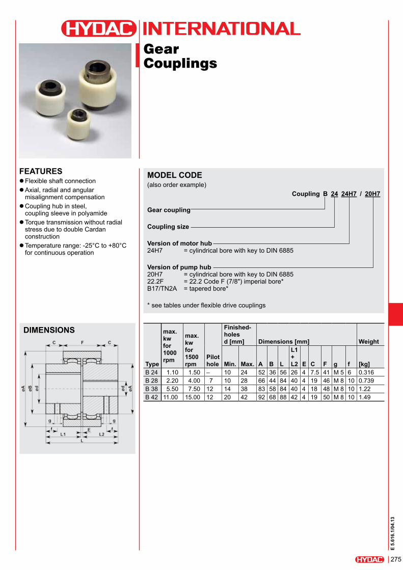
Gear Couplings
Features zFlexible shaft connection zAxial, radial and angular misalignment compensation zCoupling hub in steel, coupling sleeve in polyamide zTorque transmission without radial stress due to double Cardan construction zTemperature range: -25°C to +80°C for continuous operation
model code(also order example)
coupling b 24 24h7 / 20h7 gear coupling
coupling size
version of motor hub 24H7 = cylindrical bore with key to DIN 6885
version of pump hub 20H7 = cylindrical bore with key to DIN 6885 22.2F = 22.2 Code F (7/8") imperial bore* B17/TN2A = tapered bore*
* see tables under flexible drive couplings
dimensions
type
max. kw for 1000 rpm
max. kw for 1500 rpm
pilot hole
Finished- holes d [mm] dimensions [mm] Weight
min. max. a b l
l1 + l2 e c F g f [kg]
B 24 1.10 1.50 – 10 24 52 36 56 26 4 7.5 41 M 5 6 0.316B 28 2.20 4.00 7 10 28 66 44 84 40 4 19 46 M 8 10 0.739B 38 5.50 7.50 12 14 38 83 58 84 40 4 18 48 M 8 10 1.22B 42 11.00 15.00 12 20 42 92 68 88 42 4 19 50 M 8 10 1.49

276
E 5.
616.
1/04
.13
Bell Housing Foot Bracketsfor PT, PTK, PTS
light-duty range to vdma 24561size part no. a a1 a2 b b1 b2 b3 b4 b5 h h1 d c e d1PF-160/3 3130712 160 140 – 80 15 50 7 12 – 100 10 9 110 130 9PF-200/3 953938 210 180 200 93 14 60 3 8 23 112 12 11 146 165 11PF-250/3 for PT, PTS
3326868 250 220 – 110 20 60 21 19 – 132 15 14 190 215 14
PF-250/3 for PTK* 3290117 250 220 – 110 20 60 21 19 – 132 15 14 190 215 14
PF-300/3 953710 290 260 300 120 19 80 19 15 32 160 15 14 240 265 14* additional counterbore for use with countersunk screws
heavy-duty range to vdma 24561size part no. a a1 b b1 b2 b3 b4 h h1 d c e d1PF-350/3* 953942 350 300 305 70 265 18 22 180 18 18 265 300 18PF-250/4 3045399 250 215 260 60 185 15 24 155 15 14 190.3 215 14PF-300/4 3043132 300 265 270 75 225 18 24 185 18 14 234.5 265 14PF-350/4 3045259 350 300 305 90 265 18 30 235 18 18 260 300 18PF-400/4 3044298 400 350 350 100 300 20 30 260 20 18 302 350 18PF-450/4 3044299 450 400 385 110 335 22 30 295 20 18 352 400 18PF-550/4 3030682 550 500 465 140 415 25 30 350 25 18 452 500 18PF-660/4 3044300 660 600 555 165 495 30 40 380 30 22 552 600 22
* PF-350/3 is part of the light-duty range but has dimensions according to drawing on left

277
E 5.
616.
1/04
.13
Bell Housing Mounting Platefor Bell Housings Type PT, PTK, PTS
bell housing mounting plate oil tank cut-out
seal for bell housing mounting plate
size part no. a b c d e F g h k r l m n o s tPP 200 273931 325 190 140 250 225 146 165 11 9.5 60 200 175 50 M8 84 168PP 250 272058 350 190 140 300 275 194 215 14 9.5 60 250 175 50 M8 135 134PP 300 272059 423 225 150 350 330 246 265 14 14.5 98 300 200 100 M12 160 190PP 350 637939 475 225 160 410 380 262 300 18 14 110 350 200 136 M12 112 307.5
size part no. a b c d e k r l s tPPD 200 952788 325 190 140 250 225 10 60 200 84 168PPD 250 952789 350 190 140 300 275 10 60 250 135 134PPD 300 952812 420 225 150 360 330 15 90 300 160 190PPD 350 3159093 475 225 160 410 380 20 110 350 112 307.5
Features zEnables the complete motor-pump unit to be fitted and removed from outside the tank zSimplifies cleaning and maintenance zBell housing mounting plate in aluminium, seal in NBR rubber (mineral oil resistant)

278
E 5.
616.
1/04
.13
Damping Railsfor Electric Motors Mounting-Type IMB35
damping rails
For type
part no. l l1 l2 h h1 h2 b b1 b2 d d1 m
MDS 080 80 3134999 176 146 100 40 8 12 50 22 25 14 20 M8MDS 090S 90S 721987 196 156 100 40 8 12 50 22 25 14 20 M8MDS 090L 90L 721988 240 205 125 40 8 12 50 24 25 14 20 M8MDS 100L 100L 721989 240 205 140 40 8 12 50 24 25 14 20 M10MDS 112M 112M 3065818 240 205 140 40 8 12 50 20 25 14 20 M10MDS 132S 132S 721990 285 245 140 45 8 12 50 20 25 14 20 M10MDS 132M 132M 721991 285 245 178 45 8 12 50 20 25 14 20 M10MDS 160M 160M 721992 340 300 210 60 15 15 70 28 35 18 26 M12MDS 160L 160L 3128252 416 370 254 60 15 15 70 28 35 18 26 M12MDS 180M 180M 3234395 416 370 241 60 15 15 70 35 35 18 26 M12MDS 180L 180L 721995 446 400 279 60 15 15 70 35 35 18 26 M12MDS 200L 200L 724279 496 430 305 60 15 15 70 35 35 22 32 M16MDS 225S 225S 3042916 496 430 286 60 15 15 70 35 35 22 32 M16MDS 225M 225M 723832 496 445 311 60 15 15 70 35 35 22 32 M16MDS 250M 250M 722801 496 445 349 60 15 15 100 50 50 25 40 M20MDS 280S 280S 3042928 580 530 368 60 15 15 100 50 50 25 40 M20MDS 280M 280M 3042929 580 530 419 60 15 15 100 50 50 25 40 M20MDS 315S 315S 3026755 660 610 406 70 15 15 150 60 75 25 40 M24MDS 315M 315M 3026452 660 610 457 70 15 15 150 60 75 25 40 M24MDS 315L 315L 3065559 720 670 508 70 15 15 150 60 75 25 40 M24
Features zHorizontal base mounting (not overhead mounted) zMachined ready for IMB 35 motors zNoise reduction due to decoupling zResistant to mineral oil due to NBR rubber compound zSpecial lengths and models are possible on request

279
E 5.
616.
1/04
.13
Damping Railsfor Bell Housing Foot Bracket
damping rails *
For type part no. l l1 l2 h h1 h2 b b1 b2 d d1 m
FDS 200/3 PF200/3 721983 190 150 60 40 8 12 50 25 29 14 20 M10FDS 250/3 PF250/3 721984 225 185 60 40 8 12 50 25 29 14 20 M12FDS 300/3 PF300/3 721985 285 245 80 45 8 12 50 25 29 14 20 M12FDS 350/3 PF350/3 721986 380 340 265 60 8 12 70 35 29 18 26 M16FDS 300/4 PF300/4 3169191 350 300 225 40 8 12 50 20 25 14 20 M12FDS 350/4 PF350/4 3169192 375 340 265 60 15 15 70 35 29 18 26 M16FDS 400/4 PF400/4 3044302 420 385 300 60 15 15 70 35 30 18 26 M16FDS 450/4 PF450/4 3044304 455 420 335 60 15 15 70 35 30 18 26 M16FDS 550/4 PF550/4 3044305 535 500 415 60 15 15 70 35 30 18 26 M16FDS 660/4 PF660/4 3044306 660 610 495 60 15 15 70 35 30 22 32 M20
* FDS .../3 for bell housing foot bracket for the light-duty range FDS .../4 for bell housing foot bracket for heavy-duty range
Features zHorizontal base mounting (not overhead mounted) zReady machined for bell housing base zNoise reduction due to decoupling zResistant to mineral oil due to NBR rubber compound zSpecial lengths and models are possible on request
280
E 5.
616.
1/04
.13
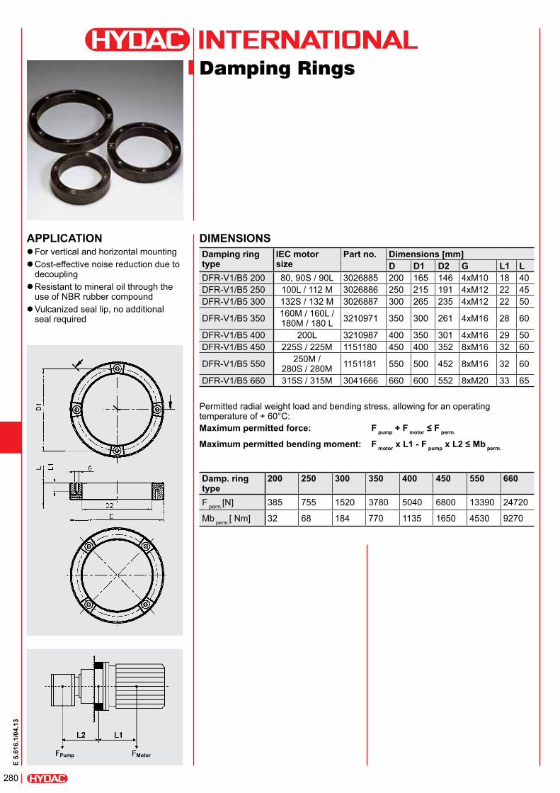
Damping Rings
application zFor vertical and horizontal mounting zCost-effective noise reduction due to decoupling zResistant to mineral oil through the use of NBR rubber compound zVulcanized seal lip, no additional seal required
pump motor
dimensionsdamping ring type
iec motor size
part no. dimensions [mm]d d1 d2 g l1 l
DFR-V1/B5 200 80, 90S / 90L 3026885 200 165 146 4xM10 18 40DFR-V1/B5 250 100L / 112 M 3026886 250 215 191 4xM12 22 45DFR-V1/B5 300 132S / 132 M 3026887 300 265 235 4xM12 22 50
DFR-V1/B5 350 160M / 160L / 180M / 180 L 3210971 350 300 261 4xM16 28 60
DFR-V1/B5 400 200L 3210987 400 350 301 4xM16 29 50DFR-V1/B5 450 225S / 225M 1151180 450 400 352 8xM16 32 60
DFR-V1/B5 550 250M / 280S / 280M 1151181 550 500 452 8xM16 32 60
DFR-V1/B5 660 315S / 315M 3041666 660 600 552 8xM20 33 65
Permitted radial weight load and bending stress, allowing for an operating temperature of + 60°C:maximum permitted force: F pump + F motor ≤ F perm.
maximum permitted bending moment: F motor x l1 - F pump x L2 ≤ Mb perm.
damp. ring type
200 250 300 350 400 450 550 660
F perm.[N] 385 755 1520 3780 5040 6800 13390 24720
Mb perm.[ Nm] 32 68 184 770 1135 1650 4530 9270
281
E 5.
616.
1/04
.13
hydac accessories gmbh Hirschbachstr. 2 66280 sulzbach/saar Tel.: +49 (0)6897 - 509-01 Fax: +49 (0)6897 - 509-1009 Internet: www.hydac.com E-Mail: [email protected]
noteThe information in this brochure relates to the operating conditions and applications described.For applications and operating conditions not described, please contact the relevant technical department.Subject to technical modifications.
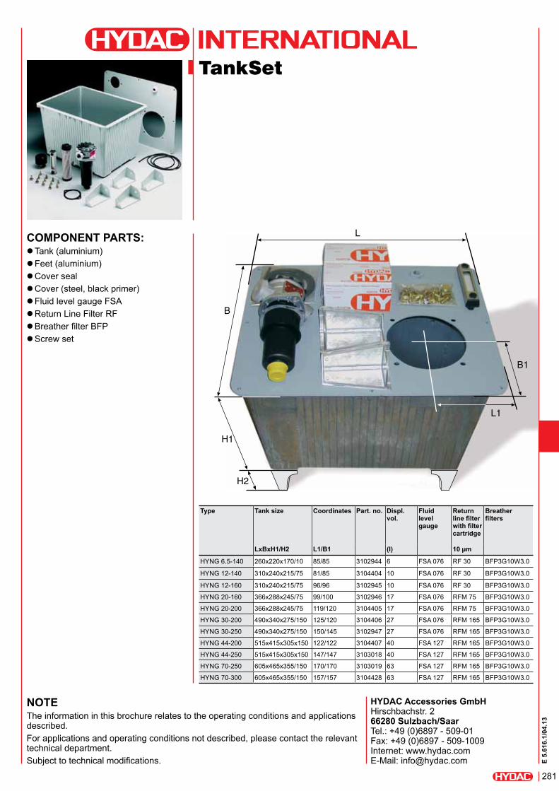
TankSet
component parts: zTank (aluminium) zFeet (aluminium) zCover seal zCover (steel, black primer) zFluid level gauge FSA zReturn Line Filter RF zBreather filter BFP zScrew set
type tank size
coordinates part. no. displ. vol.
Fluid level gauge
return line filter with filter cartridge
breather filters
lxbxh1/h2 l1/b1 (l) 10 µm
HYNG 6.5-140 260x220x170/10 85/85 3102944 6 FSA 076 RF 30 BFP3G10W3.0
HYNG 12-140 310x240x215/75 81/85 3104404 10 FSA 076 RF 30 BFP3G10W3.0
HYNG 12-160 310x240x215/75 96/96 3102945 10 FSA 076 RF 30 BFP3G10W3.0
HYNG 20-160 366x288x245/75 99/100 3102946 17 FSA 076 RFM 75 BFP3G10W3.0
HYNG 20-200 366x288x245/75 119/120 3104405 17 FSA 076 RFM 75 BFP3G10W3.0
HYNG 30-200 490x340x275/150 125/120 3104406 27 FSA 076 RFM 165 BFP3G10W3.0
HYNG 30-250 490x340x275/150 150/145 3102947 27 FSA 076 RFM 165 BFP3G10W3.0
HYNG 44-200 515x415x305x150 122/122 3104407 40 FSA 127 RFM 165 BFP3G10W3.0
HYNG 44-250 515x415x305x150 147/147 3103018 40 FSA 127 RFM 165 BFP3G10W3.0
HYNG 70-250 605x465x355/150 170/170 3103019 63 FSA 127 RFM 165 BFP3G10W3.0
HYNG 70-300 605x465x355/150 157/157 3104428 63 FSA 127 RFM 165 BFP3G10W3.0

282
E 5.
616.
1/04
.13
Related Documents