BHARAT ELECTRONICS PROJECT REPORT SUBMITTED BY: 1

Welcome message from author
This document is posted to help you gain knowledge. Please leave a comment to let me know what you think about it! Share it to your friends and learn new things together.
Transcript

BHARAT ELECTRONICS
PROJECT REPORT
SUBMITTED BY: NAME : NARENDER KUMAR
ROLL NO: 2724031002INSTITUTE: SUNDERDEEP
1

ENGINEERING COLLEGE
CONTENTS
1 : CERTIFICATE2 : ACKNOWLEDGEMENT3 : PREFACE4 : BHARAT ELECTRONICS INDUSTRY5 : COMPANY PROFILE6 : FORMATION OF GZB. UNIT7 : ROTATION PROGRAME8 : INTRODUCTION TO RADAR9 : PROJECT ON IFF UNIT
2

CERTIFICATE
TO WHOM SO EVER IT MAY CONCERN
This is to certify that VISHAL RAJWANSHI, student of B.tech
Electronics and Communication Engineering from VIRA COLLEGE
OF ENGINEERING (UTTAR PRADESH TECHNICAL UNIVERSITY)
LUCKNOW has undergone an industrial training on project titled ‘Study of
IDENTIFICATION OF FRIEND AND FOE of INDRA RADAR
PC ’ at BHARAT ELECTRONICS LIMITED, GHAZIABAD w.e.f
June 15, 2009 to july 25, 2009 under the guidance of Mr. BHUPINDER
KUMAR Sr ASST ENGR and Mr ADESH KUMAR, J S O
They worked diligently and made valuable contribution during this period. All
their works are genuine and original.
PROJECT GUIDE)
BHUPINDER KUMAR JASSAL
(SR ASST ENGR)
PA-R1,INDRA TESTING
BHARAT ELECTRONICS LTD
GHAZIABAD-201010
(
3

2. ACKNOWLEDGEMENTS
I take this opportunity to express my sincere gratitude towards institute…………………for forwarding my training letter to Bharat Electronics, Ghaziabad and also to Mr. Tapas Bose, Manager, Bharat Electronics, Ghaziabad for accepting my letter and allowing me to complete my training in Bharat Electronics.
Further I would like to thanks Mr. P K CHANGOIWALA,Sr DGM, PA –R1 Mr. Bhupinder Kumar Jassal. Sr Asst Engineer, and Mr. Adesh Kumar jso, for their kind help extended during the entire period of training.
Finally, I would like to thanks each and every member of BEL family for making me feel comfortable and helping me in every possible manner.
Name…………….Roll No…………..
4

3. PREFACE
With the ongoing revolution in electronics and communication where
innovations are taking place at the blink of eye, it is impossible to keep
pace with the emerging trends.
Excellence is an attitude that the whole of the human race is born with. It is
the environment that makes sure that whether the result of this attitude is
visible or otherwise. A well planned, properly executed and evaluated
industrial training helps a lot in collocating a professional attitude. It
provides a linkage between a student and industry to develop an awareness
of industrial approach to problem solving, based on a broad understanding
of process and mode of operation of organization.
During this period, the student gets the real experience for working in the
industry environment. Most of the theoretical knowledge that has been
gained during the course of their studies is put to test here. Apart from this
the student gets an opportunity to learn the latest technology, which
immensely helps in them in building their career.
I had the opportunity to have a real experience on many ventures, which
increased my sphere of knowledge to great extent. I got a chance to learn
many new technologies and also interfaced too many instruments. And all
this credit goes to organization Bharat Electronics Limited.
5

4. ABOUT
BHARAT ELECTRONICS
LIMITED (BEL)
BHARAT ELECTRONICS LIMITED
THE INDUSTRY
After Independence India had many responsibilities from basic necessity to telecomm & defence equipment so after adoption of its constitution in 1950, the government was seized with the plans to lay the foundation of a strong, self-sufficient Modern India. On the industrial announced in the year 1952. It was recognized that in certain core sectors infrastructure facilities require huge investments, which cannot be met by private sector and as such, the idea of Public Sector Enterprise (PSE) was mooted. Under this a Professional Electronics company in India incorporated that was front, industrial policy resolution (IPR) was BHARAT ELECTRONICS LIMITED.
BEL was established in 1954 as a Public Sector Enterprise under the administrative control of Ministry of Defence as the fountain head to manufacture and supply electronics components and equipment. BEL, with a noteworthy history of pioneering achievements, has met the requirements of state-of –art professional electronic equipment for Defence, broadcasting, Civil Defence and telecommunications as well as the component requirement of entertainment and medical X-ray industry. Over the years, BEL has grown to a multi- product, multi-unit and technology driven company with track record of a profit earning PSU.
6

BEL was born to meet the growing needs of Indian Defence services for electronic systems. Employing the best engineering talent available in the country, BEL has progressed manufacturing state-of-the-art products in the field of Defence Electronics like Communications including encryption, Radars and strategic components.
Over the years, BEL has diversified to meet the needs of civilian customers as well and has provided products and network solutions on turnkey basis to customers in India and abroad.
With the Research & Development efforts, its engineers have fructified it into a world-class organization. The company has a unique position in India of having dealt with all the generations of electronic component and equipment. Having started with a HF receiver in collaboration with T-CSF of France, the company’s equipment designs have had a long voyage through the hybrid, solid-state discrete component to the state-of-art integrated circuit technology. In the component arena also, the company established its own electron valvemanufacturing facility. It moved on to semiconductors with the manufacture ofgermanium and silicon devices and then to manufacture of Integrated circuits. To keep in pace with the component and equipment technology, its manufacturing and product assurance facilities have also undergone sea change. The design groups have CADD’s facility, the manufacturing has CNC machines and a Mass Manufacture Facility, and QC checks are performed with multi-dimensional profile measurement machines. Automatic testing machines, environmental labs to check extreme weather and other operational conditions are there. All these facilities have been established to meet the stringent requirements of MIL grade systems.
Product mix of the company are spread over the entire electromagnetic (EM) spectrum ranging from tiny audio frequency semiconductor to huge radar systems and X-ray tubes on the upper edge of the spectrum. Its manufacturing units have special focus towards the product ranges like Defence Communications, Radars, Optical & Opto-electronics, Telecommunications, Sound and Vision broadcasting, Electronic components, etc.
Besides manufacturing and supply of a wide variety of products, BEL offers a variety of services like Telecom and Radar Systems Consultancy, Contract Manufacturing, Calibration of test& measuring instruments, etc. At the moment, the company is installing MSSR radar at important airports under the modernization of airports plan of National Airport Authority (NAA).
BEL has nurtured and built a strong in-house R&D base by absorbing technologies from more than 50 leading companies worldwide and DRDO labs for a wide range of products. A team of more than 800 engineers is working in R&D. Each unit has its own R&D Division to bring out new products to the production lines. Central Research Laboratory (CRL) at Bangalore and Ghaziabad works as
7

independent agency to undertake contemporary design work on state-of-art and futuristic technologies. About 70% of BEL‘s products are of in-house design.
BEL was amongst the first Indian companies to manufacture computer parts and peripherals under arrangement with International Computers India Limited (ICIL)
in 1970’s. BEL assembled a limited number of 1901 systems under the arrangement with ICIL. However, following Government’s decision to restrict the computer manufacture to ECIL, BEL could not progress in its computer manufacturing plans. As many of its equipment were microprocessor based, the company continued to develop computers based application, both hardware and software. Most of its software requirements are in real time. EMCCA, software intensive naval ships control and command system is probably one of the first project of its nature in India and Asia. BEL has won a number of national and international awards for Import Substitution, Productivity, Quality, Safety etc.
Today, BEL has set up impressive infrastructure spread in 9 location with 29-production division and manufacturing facilities in their ISO-9001/9002 certified production units around the country. They are –Bangalore, Ghaziabad, Pune, Taloja (Maharashtra), Hyderabad, Panchkula (Haryana), Chennai, Machilipathnam (A.P.) and Kotdwara (U.P.)
BEL has won a number of national and international awards for Import Substitution, Productivity, Quality, Safety Standardization etc. BEL was ranked no.1 in the field of Electronics and 46th overall among the top 1000 private and public sector undertakings in India by the Business Standard in its special supplement "The BS 1000 (1997-98)". This organization also stands on number 7 th position in the best 100 public and private companies according to the "electronic for u" in 2002. BEL was listed 3rd among the Mini Ratna’s (category II) by the Government of India, 49 th
among Asia's top 100 Electronic Companies by the Electronic Business Asia and within the top 100 worldwide Defence Companies by the Defence News, USA.
8
VARIOUS UNITS
Its corporate office is at Bangalore. Bangalore complex is the BEL’s first and largest unit and it accounts for two-thirds of both the company’s turnover and manpower. This unit’s product range covers over 300 Defence and Civilian products. Ghaziabad is the second largest unit of BEL and it specializes in radars, communication equipments & microwave-components.
In total BEL has got 9 units. These are distributed in all over the India as:
BANGALORE (Corporate Office)
GHAZIABAD
PANCHKULA
MACHILIPATNAM
PUNE
HYDERABAD
CHENNAI
KOTDWARA
TALOJA
9

Bangalore (Karnataka)
BEL started its production activities in Bangalore in 1954 with 400W high frequency (HF) transmitter and communication receiver for the Army. Since then, the Bangalore Complex has grown to specialize in communication and Radar/Sonar Systems for the Army, Navy and Air Force. BEL's in-house R&D and successful tie-ups with foreign Defence companies and Indian Defence Laboratories has seen the development and production of over 300 products in Bangalore alone. The Unit has now diversified into manufacturing of electronic products for the civilian customers such as DOT, VSNL, AIR and Doordarshan, Meteorological Dept., ISRO, Police, Civil Aviation, and Railways. As an aid to Electorate, the unit has developed Electronic Voting Machines that are produced at its Mass Manufacturing Facility (MMF).
Ghaziabad (Uttar Pradesh)
The second largest Unit at Ghaziabad was set up in 1974 to manufacture special types of Radars for the Air Defence Ground Environment Systems (Plan ADGES). The Unit provides Communication Systems to the Defence Forces and Microwave Communication Links to the various departments of the State and Central Govt. and other users. The Unit's product range
10

included Static and Mobile Radars, Troposcatter equipment, professional grade Antennae and Microwave components.
JOINT VENTURES
1. BE-Delft Electronics Limited
BE-Delft Electronics Limited, Pune, the first joint venture of the company with Delft Instruments, Holland and UTI was established in the year 1990 for conducting research, development and manufacture of Image Intensifier Tubes and associated high voltage power supplies for use in military, security and commercial systems. Its products include night vision goggles and binoculars, night vision weapon sights and low light level input applications.
2. GE BE Private Limited
GE BE Private Limited, Bangalore, a JV with General Electric Medical Systems, USA has been established in 1997-98 for manufacture of High End Rotating Anode Medical Diagnostic X-ray tube called CT MAX, which is used in CT Scanners. The joint venture unit will also establish a reloading facility for X-ray tubes and will also market the conventional X-ray tubes made at Pune Unit of BEL. South ast Asia market are addressed by this joint venture.
BEL- Multitone Private Limited
A joint venture between Bharat Electronics and Multitone Electronics Plc, UK has also been established in Bangalore in 1997-98 to manufacture state-of-art
Mobile Communication for the workplace. Multitone invented paging in 1956 when it developed the world's first system to serve the "life or death" environment of St. Thomas Hospital, London. With the strength of Bharat Electronics in the Radio Communications field and the technology of Multitone, in the field of Radio Paging, the joint venture company is in a position to offer tailor made solution to the Mobile Communication needs at workplace in various market segments.
11

CORPORATE MOTTO, MISSION AND OBJECTIVES
The passionate pursuit of excellence at BEL is reflected in repulsion with its
customers that can be described in its motto, mission and objectives :
Corporate Motto “Quality, Technology and Innovation”
Corporate Mission To be the market leader in DefenceElectronics and in other chosen fields and products.
Corporate Objectives
(a) To become a customer-driven company supplying quality products at competitive prices at the expected time and providing excellent customer support.
(b) To achieve growth in the operations commensurate with the growth of
professional electronics industry in the country.
(c) To generate internal resources for financing the investments required for modernization, expansion and growth for ensuring a fair return to the investor.
(d) In order to meet the Nation's strategic needs, to strive for self reliance by indigenization of materials and components.
(e) To retain the technological leadership of the company in Defence and other chosen fields of electronics through in-house.
12

(f) Research and Development as well as through collaboration/co-operation with Defence/National Research Laboratories, International Companies, Universities and Academic institutions.
(g) To progressively increase overseas sales of its products and services.
(h) To create an organizational culture which encourages members of the organization to realize their full potential through continuous learning on the job and through other HRD initiatives.
Quality Policy
BEL is committed to consistently deliver enhanced value to our customers,
through continual improvement of our products and processes.
Quality Objectives
(a) Effective and Efficient design and development process, considering the present and future needs of customers.
(b) Enhanced customer satisfaction by on-time delivery of defect free
products and effective life cycle support.
(c) Continual upgradation and utilization of infrastructure and human resources.
(d) Mutually beneficial alliances with suppliers.
e) Continual improvement of processes through innovation, technology and knowledge management.
The management of BEL is convinced of the need for Quality Enhancement, on a continuous basis, in the company. Need was felt to impart Education / Training to all the officers on the various facets of quality management. Accordingly, an institute called Bharat Electronics Quality Institute (BEQI) was established in 1999.
Bharat Electronics Ltd., (BEL), a premier Professional Electronics Company of India, has established and nurtured a strong in-house R&D base over the years to emerge and remain as a market leader in the chosen areas of business in professional electronics. Each of the nine manufacturing units of BEL is having its own in-house R&D Division to develop new products in its field of operations.
13

Besides, there are two Central Research Laboratories (CRL) located at Bangalore and Ghaziabad, to address futuristic technologies of interest to BEL.
Main areas of R&D activities at BEL include development of Military Radars, Naval Systems, Military Communication Products, Electronic Warfare Systems, Telecommunication products, Sound and Vision Broadcasting Equipment and Systems, Opto Electronic Products, and Electronic Components. CRL performs the dual role of carrying out blue sky research for the development of future technologies and supporting the D&E Divisions of BEL's nine units with state-of-the-art core technology solutions in areas like Embedded Computers and applications, Radar Signal Processing, VLSI designs, RF & Microwave Communication Technologies, Software modules etc.
BEL's R&D Units have state-of-the-art R&D infrastructure, facilities, and manpower with relevant technical expertise for product development. There are about 1000 engineers working in BEL on various D&E projects. BEL spends around 5 % of company turnover for the year on R&D every year. HRD Divisions of BEL take adequate initiatives for the all round development and expertise upgradation of R&D human resources. State of the art infrastructures, test equipment, computers & workstations, Software packages etc. are augmented every year for the R&D divisions. BEL R&D Units are recognized by the Department of Scientific & Industrial Research under the Ministry of Science & Technology, Govt. of India.
14

5. CUSTOMER PROFILE Equipment
DefenceArmy Tactical and Strategic Communication Equipment and
Systems, Secrecy Equipment, Digital Switches, Battlefield Surveillance Radars, Air Defence and Fire Control Radars, Opto-Electronic Instruments, Tank Fire Control Systems, Stabilizer Systems, Stimulators and Trainers.
Navy Navigational, Surveillance, Fire Control Radars, IFF, SONAR Systems, Torpedo Decoys, Display Systems, EW Systems, Simulators, Communication Equipment and Systems.
Air Force Surveillance and Tracking Radars, Communication Equipment and Systems, IFF and EW Systems.
Non-DefencePara-Military Communication Equipment and Systems.Space Department Precision Tracking Radars, Ground Electronics, Flight and
On-Board Sub-systems.All India Radio MW, SW & FM Transmitters.Doordarshan(TV Network)
Low, Medium and High Power Transmitters, Studio Equipment, OB Vans, Cameras, Antennae, Mobile and Transportable Satellite Uplinks.
NCERT TV Studios on Turnkey Basis for Educational Programs.Department ofTelecommunications
Transmission Equipment (Microwave and UHF) and PCM Multiplex, Rural and Main Automatic Exchanges, Flyaway Satellite Terminals, Solar Panels for Rural Exchanges.
Videsh SancharNigam and otherCorporate Bodies
MCPC VSATs, SCPC VSATs, Flyaway Earth Stations. Hub Stations, Up/Down Convertors, LNA Modems
Civil Aviation Airport Surveillance Radars, Secondary Surveillance Radars.
Meteorological Department
Cyclone Warning and Multipurpose Meteorological Radars.
Power Sector Satellite Communication Equipment.Oil Industry Communication Systems, Radars.Forest Departments,Irrigation &Electricity Boards
Communication Systems.
Medical &Health Care
Clinical and Surgical Microscope with Zoom.
Railways Communication Equipment for Metros, Microwave Radio
15

Relays, Digital Microwave Radio Relays.
3. Components
Defence Transmitting Tubes, Microwave Tubes, Lasers, Batteries, Semiconductors-Discrete, Hybrid and Integrated Circuits.
Non-DefenceAll India Radio,Doordarshan(TV Network),Department of
Telecommand Civil Industries
Transmitting Tubes, Microwave Tubes, and Vacuum Tubes.
EntertainmentIndustry
B/W TV Tubes, Silicon Transistors, Integrated Circuits, Bipolar and CMOS, Piezo Electric Crystals, Ceramic Capacitors and SAW Filters.
Telephone Industry Integrated Circuits, Crystals.Switching Industry Vacuum Interrupters.InstrumentationIndustry
Liquid Crystal Displays.
Medical &Health Care
X-ray Tubes.
4. Systems / Network
Identity Card Systems Software, Office Automation Software, LCD On-line Public Information Display Systems Communication Networks / VSAT Networks.
16

6 Formation of unit
In the mid 60's, while reviewing the defence requirement of the country, the government focused its attention to strengthen the air defence system, in particular the ground electronics system support, for the air defence network. This led to the formulation of a very major plan for an integrated Air Defence Ground Environment System known as the Plan ADGES with Prime Minister as the presiding officer of the apex review committee. At about the same time, Public attention was focused on the report of the Bhabha Committee on the development and production of electronic equipment. The ministry of defence immediately realized the need to establish production capacity for meeting the electronic equipment requirements for its Plan ADGES.
BEL was then entrusted with the task of meeting the development and production requirement for the Plan ADGES and in view of the importance of the project it was decided to create additional capacity at a second unit of the company.
In December 1970 the Govt. sanctioned an additional unit for BEL. In 1971, the industrial license for manufacture of radar and microwave equipment was obtained; 1972 saw the commencement of construction activities and production was launched in 1974.Over the years, the Unit has successfully manufactured a wide variety of equipment needed for defence and civil use. It has also installed and commissioned a large number of systems on turnkey basis. The Unit enjoys a unique status as manufacturer of IFF systems needed to match a variety of Primary Raiders. More than 30 versions of IFF’s have already been supplied traveling the path from vacuum technology to solid-state to latest Microwave Component based system.
17

The operations at BEL Ghaziabad are headed by General Manager with Additional / Deputy General Manager heading various divisions - Design & Engineering Divisions, Development and Engineering-R, Development and Engineering-C and Development and Engineering-Antenna.
Ghaziabad unit is primarily engaged in manufacture, supply and Turn-key execution of Radars, Communication equipments & Antennas /Systems for defence as well as
non-defence sectors. It has four major manufacturing divisions i.e. Radar, Communication, Antenna & Microwave Components with support divisions like D&E, SYSTEMS ,P&M, CS, MKTG & CC, QA&T, MM, P&A, F&A
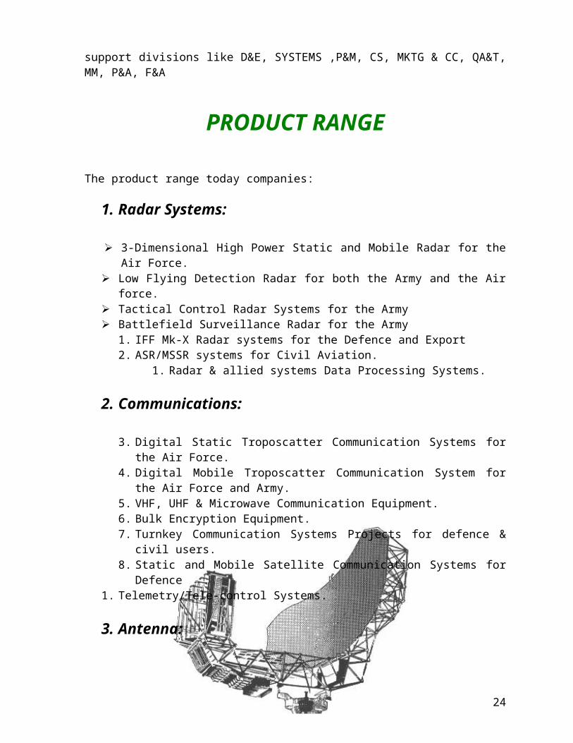
PRODUCT RANGE
The product range today companies:
1. Radar Systems:
3-Dimensional High Power Static and Mobile Radar for the Air Force. Low Flying Detection Radar for both the Army and the Air force. Tactical Control Radar Systems for the Army Battlefield Surveillance Radar for the Army
1. IFF Mk-X Radar systems for the Defence and Export2. ASR/MSSR systems for Civil Aviation.
1. Radar & allied systems Data Processing Systems.
2. Communications:
3. Digital Static Troposcatter Communication Systems for the Air Force.4. Digital Mobile Troposcatter Communication System for the Air Force and
Army.5. VHF, UHF & Microwave Communication Equipment.6. Bulk Encryption Equipment.7. Turnkey Communication Systems Projects for defence & civil users.8. Static and Mobile Satellite Communication Systems for Defence
1. Telemetry/Tele-control Systems.
3. Antenna:
18

9. Antennae for Radar, Terrestrial & Satellite Communication Systems.10.Antennae for TV Satellite Receive and Broadcast applications.11.Antennae for Line-of-sight Microwave Communication Systems.
4. Microwave Component:
1. Active Microwave components like LNAs, Synthesizer, and Receivers etc.2. Passive Microwave components like Double Balanced Mixers, etc
Most of these products and systems are the result of a harmonious combination of technology absorbed under ToT from abroad, defence R&D Laboratories and BEL's own design and development efforts.
Organization:
The operations at BEL Ghaziabad are headed by General Manager with Additional / Deputy General Manager heading various divisions as follows:
Design & Engineering Divisions : 1. Development and Engineering-R,1. Development and Engineering-C, 1. Development and Engineering-Antenna.
Equipment Manufacturing Divisions :
1) Radar,1) Communication,
Antenna, Systems,
I. Microwave Components.
Support Divisions :
a. Material Management,b. Marketing & Customer Co-ordination,c. Quality Assurance & Torque,
19

d. Central Services,e. PCB & Magnetics,f. Information Systems,g. Finance & Accounts, h. Personnel & Administration,
a. Management Services.
1. Design & Engineering:
The pace of development and technological obsolescence in their field of electronics necessitates a strong Research and Development base. This is all the more important in the area of defence Electronics. BEL Ghaziabad has since its inception laid a heavy emphasis on indigenous research and development. About 70% of its manufacture today relate to items developed in-house. For the development and production of the Mobile Troposcatter System and the IFF equipment, BEL was awarded the Gold Shield for Import Substitution.
Design facilities are also constantly being modernized and substantial computer-aided design facilities are being introduced including installation of mini- and micro-computers and dedicated design application. About 170 graduate and post-graduate engineers are working on research and development and indication of the importance R&D has in BEL's growth.
Three Design and Engineering groups are product based viz. Communication, Radar and Antenna. These divisions are further divided into different departments to look after products of a particular nature. Each of them has a drawing office attached to them, which are equipped with latest drafting and engineering software. The PCB layout and PCB master making is done at CADD Centre. A central Records & Printing section takes care of the preserving the engineering documents and distribution thereof. Most of the engineering documents are available online.
2. Equipment Manufacturing Divisions:
As a supplier of equipment to the defence services and professional user, strict adherence to specifications and tolerances has to be in-built into the design and manufacturing process. For this BEL Ghaziabad has well defined standards and processes for as well as manufacturing and testing activities. Activities are divided into various departments like Production Control, Works Assembly, and QC WORKS. The manufacture and control of production is through a central system, BELMAC, BEL's own homegrown ERP system.
20

Apart from conventional machines, BEL Ghaziabad has been equipped with several Computer Numerical Control (CNC) machines for ensuring repeat occurrences and increased throughput. A separate NC programming cell has been set up to develop the programs for execution on the CNC machines.
3. Microwave Component Group:
Frequencies greater than 1 GHz is termed as Microwaves. Microwaves Integrated Circuits (MIC) used extensively in the production of subsystems for Radar and Communication equipment constitutes a very vital part of the technology for these systems and is generally imported. Owing to the crucial and building block nature of the technology involved, BEL is currently setting up a modern MIC manufacturing facility at a planned expenditure of Rs. 2 crore. When in full operation, this facility will be the main centre for the MIC requirements of all the units of the company.
The manufacturing facilities of hybrid microwave components available at BEL, Ghaziabad includes facility for preparation of substrates, assembly of miniaturized component viz. directional couplers, low noise amplifiers, phase shiftier, etc
SPECIFIC PRODUCT OF ‘BEL’
Electronics Voting MachineIRMA, INDRA, Reporter, Flycatcher
Simulators & Trainers
Secure Facsimile (SECFAX)Integrated Fish finder Cum Navigational Guidance Systems (IFFNGS)GPS Based Vehicle Tracking SystemsEnergy Savers for Air ConditionersAlarm Systems for Railway Unmanned Level Crossings Pager Amplifier/UHF Paging TransmitterCockpit Display System for LCAAutomatic Test Equipment Cellular AntennaPC Mother BoardSIMPUTERX-Ray CablesTelevision Receive Only AntennaElectronic Warfare EquipmentTrain Actuated Warning System
21

Magnesium Manganese Dioxide Battery PacksDosimeter LocketTelemedicine SystemVLSI & ASCIs
7 ROTATION PROGRAMME
Under this the students are introduced to the company by putting
them under a rotation program to various departments. The several
departments where I had gone under my rotational program is as
follows:
1. TEST EQUIPMENT & AUTOMATION
2. P.C.B FABRICATION
3. QUALITY CONTROL (WORKS)
22

4. MAGNETICS
5. MICROWAVE LAB
6. ENVIRONMENTAL LAB
7. CS- ELECTRICAL
8. WORKS ASSEMBLY-RADAR
During the rotation period , I had to go to various departments,
listed above to get some introduction about the work that is being done
in that particular department. The co-operative staff at various
department made the learning process very interesting, who allowed me
to know more about the company in a very short time. The various
departments are now given in detail.
TEST EQUIPMENT & AUTOMATION
This department deals with the various instruments used at
BEL. There are three hundred equipments and they are of sixteen
types.
Examples of some test equipment are:
23
1. Oscilloscope (C.R.O)
2. Multimeter
3. Signal Analyzer
4. Logical Pulsar
5. Counters
6. Function Generator etc.
Mainly the calibration of instruments is carried out here, they are
compared with the standard of National Physical Laboratory (NPL). So it
is said to be one set up down to NPL. As every instrument has a
calibration period after which the accuracy of the instrument falls from
the required standards. So if any of the instruments is not working
properly, it is being sent here for its correct calibration. To calibrate
instrument software techniques are used which includes the program
written in any suitable programming language. So it’s not the calibration
but the programming takes that time. For an industry to gets it’s
instrument calibrated by NPL is very costly, so it is the basic need
for every industry to have it’s own calibration unit if it can afford it.
Moreover those who have this unit can make memory by providing
their standards to others.
Test equipment and automation laboratory mainly deals with
the equipment that is used for testing and calibration.This section
calibrates and maintains the measuring instrument mainly used for
Defense purpose. A Calibration is basically testing of equipment with a
24

standard one. It is done with the help of standard equipment should be
of some make, model and type.
The national physical laboratory (NPL) New Delhi provides the
standard values yearly. BEL follows International Standard Organization
(ISO) standard. The test equipment is calibrated either half yearly or
yearly.
After testing, different tags are labeled on the equipment according
to the observations.
GREEN ---O.K, Perfect
YELLOW --- Satisfactory but some trouble is present
RED --- Cannot be used, should be disposed off.
PRINTED CIRCUIT BOARD (P.C.B.)
INTRODUCTION:-
As the name suggests, printed circuit board refers to a
board on which a circuit is imprinted. The circuit appears as copper
25

tracks on non conducting surface. Here the surface or the board is a
glass epoxy sheet with copper coating on either both sides or on one
side only. The board material is not restricted to glass epoxy only, it can
be any hard surface (non conducting) with copper coating. In some
cases we use Teflon sheets also.
Generally the PCBs can be categorized in three forms viz.:
SINGLE SIDED PCB
DOUBLE SIDED PCB
MULTI LAYERED PCB
In the following sections we would consider the various steps
which come together to fabricate a single or double sided PCBs :-
1-Launching
2-C.N.C. Drilling
3-Through Hole Plating
4-Photo Tool Generation
5-Photo Resist Printing
6-Pattern Plating
7-Resist/Tin Stripping & Etching
8-Solder Masking
9-Hot Air Leveling
10-Reverse Marking
11-Routing, Shearing & Deburring
12-Inspection
QUALITY CONTROL(WORKS ASSEMBLY)
According to some laid down standards , the quality control
department ensures the quality of product . The raw materials and
26

components etc. purchased are inspected according to the
specifications by I.G. department . similarly Q.C. work department
inspects all the items manufactured in the factory. The fabrication
department checks all the fabricated parts and ensures that these are
made according to the part drawing , painting , plating and stenciling etc
are done as per BEL standards .
The assembly inspection department inspects all the
assembled parts such as PCB , cable assembling , cable form , modules
,racks and shelters as per latest documents and bel standards.
The mistakes in the PCB can be categorized as-
1. D & E mistakes
2. Shop mistakes
3. Inspection mistakes
The process card is attached to each PCB under inspection. Any error
in the PC is entered in the process card by certain code specified for
each error or defect.
After a mistake is detected, following action are taken:
1. Observation is made
2. Object code is given
3. Division code is given
4. Change code is prepared
5. Recommended action is taken.
MAGNETICS
27

This department is making all types of transformers and coils that
are used in various equipments. This department basically consists of
four sections:
1. Planning section
2. Mechanical assembly section
3. Moldings section
4. Inspection
The D & E department gives the following description – numbers
of layers, numbers of turns /layers, types of winding , gapes in core ,
insulation between layers , ac/dc impedance , dielectric strength ,
electrical parameters and earthing.
The various types of transformer being made are:
1.Open type transformer
2.Oil cooling types transformer
3.Moulding type transformer
4.PCB moulding type transformer
The transformer is mechanically assembled, leads are taken out
and checking of specification is done .
Winding machines are of three types:
1. Heavier one – DNR for 0.1 to 0.4 mm diameter.
2. LC control machine
3. Torroidal machines having 32 operations from winding to mechanical
assembly.
The various types of windings used are :-
1. Hand-winding
28

2. Torroidal-winding
3. Sector-winding
4. Pitch-winding
5. Variable winding
6. Wave winding
Two types of cores used are :
1. E-type for 3-phase
2. C-type for singal phase
Various procedures involved in the manufacture of transformers
are;-
1. Formers of glass – expoxy
2. Winding
3. Core winding
4. Varnishing
5. Impregnation various varnished coils are heated, than cooled,
reheated and put into vacuum. Then air is blown to remove the
humidity.
6. Moulding-araldite mixed with black dye is used to increase
mechanical as well as electrical strength. Moulding is done at 120
degrees centigrade for twelve hours.
7. A RDB compound is used for leakage production . oil is boiled at 70
to 80 degrees under vacuum conditions to remove air bubbles . after
the is the cols are dipped in varnish and core is attached.
8. Painting
9. Mechanical assembly
29

10. Termination
11. Testing: dielectric testing is done at 50 KV voltage applied for a
minimum of one minute. During inspection, the following characteristics
are checked :-
(a)Turn ratio
(b)DC resistance of or each coil
(c) Inductance
(d)No load voltage
(e)Leakage
30

MICROWAVE LABORATORY
This section deals with very high frequency measurements or
very short wavelength measurements. The testing of microwave
components is done with the help of various radio and communication
devices. Phase and magnitude measurements are done in this section.
Power measurements are done for microwave components because
current and voltage are very high at such frequencies.
Different type of waveguides is tested in this department like
rectangular waveguides, circular waveguides. These waveguides can be
used to transmit TE mode or TM mode.This depends on the user’s
requirements.Waveguides work as high pass filters to waves passing
through them. A good waveguide should have fewer losses and its walls
should be perfect conductors.
In rectangular waveguides the distortion is minimum. Circular
waveguides are used where the antenna is rotating. The power
measurement being done in microwave lab. are in terms of S-
parameters.
Mainly the testing is done on coupler and isolators and
parameters are tested here. There are two methods of testing:
1.ATP (Acceptance Test Procedure)
2. PTP (Production Test Procedure)
31

Drawings of various equipments that are to be tested is
obtained and testing is performed on manufactured part. In the antenna
section as well as SOHANA site various parameters such as
gain, bandwidth, VSWR, phase, return loss, reflection etc. are checked.
The instruments used for this purpose are as follows:-
1.Filters
2.Isolators
3.Reflectors
4.Network Analyzers
5.Spectrum Analyzers
6.Amplifiers and Accessories
32

CS -(ELECTRICAL)
The main task of this department is to supply power to the all
production units, administrative block and other parts of the factory. This
department is arranged into one main station and five sub stations at
different locations in the company. The power is received from the Uttar
Pradesh Vidyut Board through 33 KV power line at the main station.
At the main station the power is stepped down to 11KV using
33/11KV step down transformer. The main station is provided with gang-
operated switch, air circuit breakers (ACB), oil circuit breaker (OCB).
The air circuit breaker being used is of rating 11000 V , 800 A. The gang
operated switch is to be operated always OFF-load. This is operated
when there is some fault in the incoming power line. In case we operate
the gang operated switch ON-load, large amount of sparks will be
produced. There are two transformers at the main station. Out of these
two only one is used at a time and second one is standby transformer.
i.e. It is operated in case when first transformer does not work properly.
33

Current transformers are used at the main station for the measurement
of power consumption. Lighting arresters are used at the main station to
protect the station and all the electrical equipments from being
damaged. For extra security two different set of lighting arresters are
used one above the other so that station is not damaged at any cost and
the excess charge gets grounded.
There are five sub stations at BEL which receive the power from
main station at 11 KV and stepped down to 433 V for the use of various
machines in the factory. The transformers being used
at various sub stations are of rating1600 KVA. These sub stations
provide power to different divisions of the factory. Like the main station
these stations are also provided with lighting arresters, ACB’s, OCB’s
and gang operated switches.
In case of power failure there are two generators, which can
supply the power to production divisions only, and some other important
sections. These generators are imported from Czechoslovakia and are
of Ascorda make. These generators are air starting type and need a
pressure of 1000 Pound for starting. These can develop a power of 325
bhp. And consume 400 Litres/Hr. of diesel each. Each generator is
having 6 cylinders. These have a firing order of 15-36-24 to operate the
cylinders in the same order. These are of capacity 860 KV and each
generator generates 400 V at 50 Hz.This voltage is stepped up by a
transformer to 11KV and supplied to the sub stations
34

ENVIRONMENTAL LAB
Various tests are conducted in the environmental lab in BEL in
order to ensure reliability. Reliability is defined as the probability of a
device performing its purpose adequately for the period intended under
the given operating condition. In a given reliability is given as
The standards available here are:
JSS55555- Joint services specifications ( Military Standard of India)
MII Standards – U.S Military standers
QM333 – Civil Avitation and police
VARIOUS TESTS :-
1. Thermal Shock Test
2. High Temperature Operate and Storage
35

3. Low Temperature Operate and Storage
4. Altitude Test
5. Bump / Vibrations Test
6. Salt Spray Test
7. Tropical Exposure Test
8. Rain Test
9. Humidity Test
10. Dust Test
11.Transportation Test
12. Shock Test
13. Burn in Test
WORKS ASSEMBLY
This department plays an important role in the production. Its
main function is to assemble various components, equipments and
instruments in a particular procedure. It has been broadly classified as :
WORK ASSEMBLY RADAR e.g.:INDRA-2, REPORTER
The stepwise process followed by work assembly department is:
1. Preparation of part list that is to be assembled.
2. Preparation of general assembly.
3. Schematic diagram to depict all connect to be made and brief idea
about all components.
36

4. Writing list of all components.
In work assembly following things are done.
Preparation:
This is done before mounting and undertakes two procedures.
Tinning:
The resistors, capacitors and other components are tinned with
the help of tinned lead solution. The wire coming out from the
component is of copper and it is tinned nicely by applying flux on it is so
that it does not tarnished and seventh soldering becomes easy.
Bending :
Preparation is done by getting the entire documents j, part list
drawing and bringing all the components before doing the work.
Mounting:
It means soldering the components of the PCB plate with the
help of soldering tools. The soldering irons are generally of 25 W and
are of variable temperature, one of the wires of the components is
soldered so that they don’t move from their respective places on the
37

PCB plate. On the other hand of the component is also adjusted so that
the PCB does not burn.
Wave Soldering:
This is done in a machine and solder sticks on the entire path,
which are tinned. Wave soldering machine consists of following parts
1. Conveyor
2. Fluxer
3. Heater
4. Flux Cleaner
Touch up:
This is done by hand after the finishing is done.
Inspection:
This comes under quality work.
Heat ageing:
This is done in environment lab at temperature of 400C
for 4 hrs and three cycles.
Lacquering: Lacquering is only done on the components, which are not
variable.
8 INTRODUCTION TO RADAR :RADAR :-
RADAR is an abbreviation of word RADIO DETECTING AND RANGING. It is an electromagnetic system for detection and location of object. It operates by transmitting a particular type of waveform.
38

An elementary form of radar consists of a transmitting antenna emitting electromagnetic radiation generated by an oscillator, a receiving antenna, and an energy detecting device or receiver. A position of the transmitted signal is intercepted by a reflecting object (target) and is re-radiated in all the directions. The receiving antenna collects the returned energy and delivers it to a receiver, where it is processed. The distance to the target is determined by measuring the time taken by the radar signal to travel and come back. The direction or angular position of the target may be determined from the detection of arrival of the reflected wavefront .
APPLICATION OF RADAR has been employed on the ground, in air, on the sea and in space. Some important areas of applications are
:Air traffic control ( ATC ) A ir craft navigation Ship safetySpaceRemote sensingMilitary WORKING OF A SIMPLE RADAR
A simple RADAR system, as found on many merchant ships, has three main parts. These are:-
1. Antenna unit or the scanner.2. the transmitter/receiver or transceiver and the visual display unit.
The antenna is about 2 or 3 meters wide and focuses pulses of very high frequency radio energy into a narrow vertical beam. The frequency of the radio waves is usually about 10,000 MHz. the antenna is rotated at the speed of 10 to 25 revolutions per minute so
that the radar beam sweeps through 300 degrees all around the ship out to a range of about 90 kilometers.
39

In all RADARS it is vital that the transmitting and receiving in the transceiver are in close harmony. Everything depends on accurate measurement of the time which passes between the transmission of the pulse and the return of the ECHO about 1,000 pulses per second are transmitted. Though it is varied to suit requirements. Short pulses are best for short-range work, longer pulses are better for long range.
An important part of the transceiver is the modulator circuit. This keys the transmitter so that it can oscillate, or pulses, for exactly the right length of time. The pulses so generated are video pulses. These pulses are short range pulses and hence cannot serve out purpose of long-distance communication. In order to modify these pulses into radio frequency pulses or RF pulses, we need to generate power. The transmitted power is generated in a device called ‘magnetron’, which can handle these very short pulses and very high oscillations.
Between each pulse, the transmitter is switched off and isolated. The weak echoes from the target are picked up by the antenna and fed into the receiver. To avoid overlapping of these echoes with the next transmitted pulse, another device called duplexer is used. Thus, by means of a duplexer, undisturbed, two-way communication is established. The RF echoes emerging from the duplexer are now fed into the mixer where they are mixed with pulses of RF energy. These pulses are generated by means of a local oscillator. Once the two are mixed, a signal is produced in the output witch is of intermediate frequency range or IF range. The IF signals is received by a receiver where it is demodulated to video frequency range, amplified, and then passed to the display unit.
The display unit usually carried all the controls necessary for the operation of the whole radar. It has a cathode ray tube, which consist of an electron gun in its neck. The gun shoots a beam of electron at a phosphorescent screen at the far end. The phosphorescent screen glows when hit by the electrons and, the resulting spot of light can be
seen through a glass surface. The screen is circular and is calibrated in degrees around its edge. The electron beam travels out from the center to the edge. This random motion of the electron beam, known as the trace, is matched with the rotation of the antenna. So, when the trace is at zero degrees on the tube calibration, the antenna is pointing dead ahead. The beginning of each trace corresponds exactly which the moment at which the radar energy is transmitted.
40

When an echo is received it brightens up the trace for a moment. This is a blip, and its distance from the center of the tube corresponds exactly with the time taken for the radar pulse to travel to the target and return. So that blip on the screen gives the range and bearing of the target. As the trace rotates, a complete picture is built up from the coating of the tube. This type of display is called a PPI (plane position indicator) and is the most common form of presenting radar information.
TYPES OF RADARBased on its functions, RADAR may be classified as:
1. PRIMARY RADAR AND2. SECONDARY RADAR
A PRIMARY RADAR locates an object by transmitting a signal and detecting the reflected echo. A SECONDARY RADAR SYSTEM is similar in operation to primary radar except that the return signal is radiated from a transmitter on board the target rather than by reflection. In other words, secondary radar operates with a co-operative ACTIVE TARGET while the primary radar operates with a PASSIVE TARGET. But in cases such as controlling of air traffic, the controller must be able to identify the air craft and know whether it is of a friend or a foe. It is also desired to know the height of the aircraft, so that on the same source but flying at different levels can be kept apart.
To give the controller this information, a second radar called a ‘secondary surveillance radar’ (SSR) is used. This works differently and needs the help of the target aircraft. It senses out the sequence of pulses to an electronic black box, called an transponder fitted on the aircraft. The basic operation of a secondary radar is as follows:
SECONDARY RADAR SYSTEM
The secondary radar system consists of an INTERROGATOR and a TRANSPONDER. The interrogator transmitter in the ground station interrogates transponder equipped aircraft, providing a two way data link to separate transmit and receive frequencies. The transponder, on board
41

the aircraft, on receipt of a chain of pulses from the ground interrogator, automatically transmits a reply. The reply, coded for purposes of Identification is received back at the ground interrogator where it is decoded and displayed on a radar type presentation.
The secondary radar gives the aircraft identity code and height data derived from a pressure capsule in the aircraft. In the Secondary Surveillance Radar (SSR), by providing the interrogation pulses above the minimum triggering level, the transponder makes a powerful reply. This enables the interrogator transmitters to be of lower power and the ground equipment simpler.
9 PROJECT ON IFF
42
IFF ANTENNA
RF SWITCH UNIT
TRANSMITTER
RECEIVER
MK X DECODER
MODE S DRAWER
REMOTE CONTROL PANEL
CONTROL UNIT
PPI(INTERROGATOR – DECODER)GROUND / SHIP INTERROGATOR

IFF SYSTEM BASIC PRINCIPLE
(THE IFF UNIT)
GENERALThe identification of Friend and Foe (IFF) is basically a radar
beacon system employed for the purposes of general identification of military targets. The beacon system when used for the control of civil air traffic is called as secondary surveillance radar (SSR).
Primary radar locates an object by transmitting a signal and detecting the reflected echo. A secondary radar system is similar in ration to primary radar except that the return signal is radiated from a transmitter on board the target rather than by reflection, i.e. it operates with a co-operative ‘active’ target while the primary radar operates with ‘passive’ target.
Secondary radar system consists of an interrogator and a transponder. The interrogator transmitter in the ground station interrogates transponder equipped aircraft, providing a two way data link on separate transmitting and receiving frequencies. The transponder, on board the aircraft, on receipt of a chain of pulses from the ground interrogator, automatically transmits a reply, coded for purposes of identification, is received back at the ground interrogator where it is decoded and displayed on a radar type presentation.
ADVANTAGES OF SSR OVER PRIMARY RADAR:
a) Reply pulses are stronger than the echo signals of primary radar.b) Separate transmitting and receiving frequencies eliminate ground
clutter and weather return problems.c) Reply signal is independent of target cross section.d) Interrogation and reply path coding provide discrete target
identification and altitude data. The interrogator transmitter operates in S Band at 1030 MHz and the airborne transponder operates at 1090 MHz.
43

BASIC CONSIDERATIONS:
The SSR interrogate transponder equipped aircraft with coded pulses train whose spacing denotes whether identity or altitude replies are being requested. The elicited reply comprises up to 14 pulses, spaced at multiples of 1.45 microseconds. Two pulses in this code train define the pulse train and the other pulses contain the code data these positions provide up to 4096 discrete identify codes including the altitude.
The position of the scanning antenna and the elapsed time between the interrogation and receipt of the transponder reply give the azimuth and range. Thus range, azimuth and altitude are derived. Special code provisions enable to declare an emergency or communication failure, special identification of a particular aircraft when the same identify code has been used by two or more aircraft.
OPERATION
The SSR system can operate in association with both static and mobile primary radar or independently with its own monitor display. The transmitter can be triggered either internally or externally. Interrogations are pre-triggered with respect to the primary radar pulse transmission (external triggering) to provide for a timing match between radar echoes and SSR replies at the PPI display. The PRF of the interrogation transmission is either the same as the primary radar or counted down to maintain a nominal value as the case may be. The interrogation modes provide for separation of replies by function. For e.g., mode C is the automatic altitude mode. Interlacing of two modes is done to update identity and altitude data on each scan of the ground based antenna.
PURPOSE
The IDENTIFICATION FRIEND AND FOE (IFF) is basically a Radar Beacon System employed for the purpose of general identification of Military targets. The Beacon System when used for the control of civil air traffic is called as secondary surveillance Radar (SSR). The Beacon System is designated in general as Secondary Radar and the normal radar as Primary Radar for distinguishing.
44

TECHNICAL SPECIFICATIONS
INTEROGATION AND RESPONSE SIGNALS
INTERROGATION SIGNAL
P1 P2 P3
IFF INTEROGATION SIGNAL
The interrogation signal of the IFF ground equipment consists of a signal consisting of 3 pulses are designated as P1, P2 and P3 as shown in the figure above. The P1 and P3 pulses are known as the INTERROGATE PULSES and pulse P2 is known as the CONTROL PULSE.
The three pulses viz P1, P2, P3 are produced to achieve the 3 pulse side lobe suppression. The pulses P1, P2 and P3 are of same width viz 0.8 microseconds each.
The P1 and P3 pulses occur at discrete pulse intervals and the P1, P3 combination is known as MODE. The aircraft transponder on receipt of the mode pulses P1and P3 recognizes the mode and responds with its suitable reply code.
The pulse P2, control pulse, is always positioned at 2 microseconds from P1 and is used for achieving the 3 pulse side lobe suppression. The P2 pulse determines whether the interrogation is true or false. If the interrogation is false, the aircraft transponder uses side lobe suppression technique to inhibit the reply. In this technique, P1, P2 and P3 are transmitted in succession in different directions in such a manner
45

that amplitude of P1 and P3 are greater than that of P2 only along the direction of the main beam of the signal. In all other directions, amplitude of P2 is greater than that of the other pulses. The target is required to
respond only when it finds the amplitude of the P1 and P3 greater than that of P2.
NOTE: THE CONTROL PULSE P2 DOES NOT CARRY ANY SIGNIFICANCE TO THE DECODING EQUIPMENT (VIDEO PROCESSOR).
MODE PULSES
The combination of P1 and P3 interrogation pulses is known as MODES. The pulse interval between P1 and P3 ranges from 3 microsecond to 21 microsecond to form 4 different modes. P1, P3 pulse pairs signify the mode of interrogation of the ground transmitter. The interrogation is done on a particular mode to obtain a desired response from the airborne transponder. The mode pulse pair protects against random signal pulses eliciting a response from the transponder.
46

The
following are the different modes employed in IFF MK 10 ground equipment.
MODE P1 P3 INTERVAL (IN µ SECS) PURPOSE
1 2 3/A C
3 5 8
21
Defence Air CraftDefence Air CraftCivil/International
Altitude-Height
To each proper interrogation the aircraft transponder transmits a reply containing the required data for the particular mode of interrogation.
MODE 1
MODE 2
MODE 3/A
MODE C
MODE S
47

The complex code trains consist of a series of pulses, representing coded intelligence, contained within a pair of bracket pulses spaced at
20.3 microsecond apart (between leading edges). The bracket pulses, are known as frame pulses, are an essential part of the response code and are always present. The other pulses making up the actual code are the information pulses.
F1 C1 A1C2 A2C4A4 X B1D1B2D2B4 D4 F2
The bracket pulses or frame pulses are designated as F1 and F2 .The reply pulse code train consists of twelve information pulses bracketed between the two frame pulses F1 and F2.
The framing pulses F1 and F2 are spaced at 20.3 microsecond apart and form the most elementary code. The information pulses are spaced in increments of 1.45 microseconds from the first frame pulse F1.
The designation and position of these information pulses are as follows:
PULSES POSITION (µSECS)
C1 1.45 A1 2.90 C2 4.35 A2 5.80 C4 7.25 A4 8.70 X 10.15 B1 11.60 D1 13.05 B2 14.50 D2 15.95 B4 17.40 D4 18.85
48

The position of the X pulse is specified only as a technical standard and at present is not used. It is reserved for future use. Thus, eliminating the pulse X, the reply code train consists of 12 pulses formed by A B C D combination and bracketed within F1 and F2 pulses. All reply pulses have pulse duration of 0.45 ±0. 1 microsecond and pulse rise time between 0.05 to 0.1 microseconds and pulse decay time
between 0.05 and 0.1 microseconds. The pulse amplitude variation of one pulse with respect to any other pulse in a reply train does not exceed 1dB.
The pulse spacing tolerance for each pulse including the last frame pulse F2 with respect to t he first frame pulse F1 of the reply group is ± 0.15 microsecond.The pulse spacing tolerance of any pulse in the reply group with respect to any other pulse (except the first frame pulse F1) does not exceed + -0.15 microsecond.
SPECIAL POSITION IDENTIFICATION In addition to the information pulses provided, a special position identification pulse (SPI) which may be transmitted with any of the other information pulses, is positioned at a pulse interval of 4.35 microseconds following the last framing pulse F2.
The pulse interval tolerance of the SPI pulse with respect to the last frame pulse of the reply group is ±0.1 microsecond.
CODE NOMENCLATUREThe code designation consists of digits between 0 and 7 inclusive and consists of the sum of the subscripts of the pulse numbers.
DIGIT PULSE GROUPFirst (least significant) ASecond BThird CFourth D
49

Thus, there are 8 possible ABCD combinations, making 4096 total code possibilities extending from 0000 to 7777.
The different types of reply received are:
a) NORMAL REPLY The normal reply consists of the F1; F2 frame pulses bracketed the code pulses appropriate to that particular aircraft for the mode of interrogation
b) MODE 1 REPLY
When an aircraft is interrogated in mode 1, which consists of P1 and P3 pulses spaced 3 microseconds apart, the transponder sends back accede train with the characteristics of the SI code train. SI is another designation for mode 1 and is the abbreviation for “SECURITY IDENTIFICATION” .The returning SI code train is the basic “FRIEND AND FOE” identification.The reply signal consists of the framing pulses F1 and F2 spaced at 20.3 microseconds apart with all the pulses having pulse duration of 0.45 microseconds and 1.45 microseconds apart.
c) MODE 2 REPLY
When the IFF ground interrogator transmits a mode 2 interrogation, consisting of P1, P3 spaced at five microseconds apart, the aircraft transponder replies with a PERSONAL IDENTITY (PI) code train. Different aircraft return different codes, and the designation of the PI codes for specific aircraft varies in different areas or zones.The code train consists of the two frame pulses F1, F2 spaced at 20.3 microseconds apart, with pulse duration of 0.45 microseconds.The IFF MK 10 with SIF (SELECTIVE IDENTIFICATION FEATURE) has the ability to change operating frequencies for security and also has complex coded replies to positively identify the aircraft as friendly. It would be practically impossible for any unfriendly aircraft to know the frequency and codes with which we were expecting the friendly aircraft to reply. Besides distinguishing the aircraft as friendly, the SIF reply codes tell its type and mission. e) MODE 3 REPLY
50

The aircraft transponders response to mode 3 interrogation, consisting of P1, P3 spaced at 8 micro second . The mode 3 reply is assigned differently in certain areas or zones.
f) MODE C REPLY The mode C interrogation, consisting of two interrogation pulses P1, P3 spaced at 21 microseconds apart, is common for both military and civil use. The mode C is employed for altitude data. On interrogation in mode c the transponder responses for automatic pressure altitude – transmission.
The replies on the above modes of interrogation consist of the two frame pulses F1, F2 spaced at 20.3 microseconds apart bracketing the information code pulses.
REPLY CODE IDENTIFICATION
On all modes except mode C the transponder manually selects the codes from the 4096 possible codes while in mode C interrogation the transponder automatically replies the pressure – altitude data. The pressure- altitude is reported in 100 ft increments by selection of pulses.EMERGENCY REPLY CODES : CodeMilitary emergency condition : 0000 Civil emergency : 7700Military/civil communication failure : 7600Hijacking code : 7500
51

DISPLAY OF IFF SYMBOLS ON PPI
52
ALL AIRCRAFT SIGNALEMER / COMMN
FAILURE
PASSIVE CODE MATCH
SPECIAL POSITION IDENTIFICATION (SPI)
MILITARY EMERGENCY CONDITION
Military emergency reply consists of four frame pulse pairs spaced at 4.35 microseconds apart. The first frame pulse pair carries the normal code; remaining pairs may or may not contain information pulses.In modes 1 and 2 the first pair carries the normal reply code while in mode 3 ( common with civil mode A), the first frame pulse pair carries code 7700 with rest 3 pairs may or may not carry any code.
For identification purposes, when two SPI pulses are identified in a reply code train, the reply code is declared as military emergency.
CIVIL EMERGENCY
Under civil emergency the normal reply code on mode A, B interrogations carries the code 7700.MILITARY / CIVIL COMMUNICATION FAILURE
The communication failure reply consists of a normal reply with code 7600 in response to mode 2, 3/A, or B interrogations.
GARBLE INDICATION
Whenever two reply code pulse trains are received in interleaved or overlapped condition the indication for garble detection is provided. The indicator lamp for garble glows.
SYSTEM OPERATIONS
The air surveillance over the thousand of square kilometers surrounding the equipment site must depend on the data obtained from the search radar and the radar identification systems. The identified data must be decoded and presented in such a way that the PPI operator can interpret it quickly and easily.
The IFF decoder processing unit does the decoding of the received signal and generates video pulses to be displayed on the PPI at the request of the operator. Such type of video presentation is known as the passive decoding. By examining all the code trains received and then
53

decoding only the ones chosen by the PPI operator at a particular scope, the passive decoding circuits present the data as slashes or arcs on the PPI. The slashes are generated by the symbol generation circuitry.
The operator can select the mode and code he wants to monitor, and see on his PPI the identification for only the air craft replying in that mode and with that particular code.
BRIEF DESCRIPTION
Operating PrincipleThe Interrogator-Decoder system with integrated feed
antenna is designed to identify aircraft fitted with MK-X transponders within the intended radius of operation. The intended range of operation of IFF is specified as 90 kilometers when integrated with INDRA PC MK11 RADAR.
Interrogation is done by radiating two RF pulses P1 and P3 with interval depending upon mode of interrogation through a directional pattern. Pulse P2 is radiated through control pattern for achieving interrogation side lobe suppression (ISLS). The transponder fitted in aircraft compares pulse P1 and P2 and initiates reply only if P1 is greater than P2 by 9dB corresponding to reception within main beam of directional pattern. Separation between P1 and P3 is used for identifying the mode of interrogation and selecting the corresponding replies. The reply consists of two framing pulses (F1 and F2) with 12 possible pulses within the frame. Presence or absence of these pulses determines the reply code to one of the 4096 possible combinations. The mode/code combinations of friendly aircraft are preset on the ground equipment and identification is done by matching the received code with the preset code. After matching, the video signals are send to the primary radar system.
i. Passive decodingii. Active decoding
54

PASSIVE DECODINGIn passive decoding, the IFF video-processing unit (decoder unit)
along with decoding the reply code generates video pulses to be displayed on the PPI. The operator sets the mode and code
combinations on the thumbwheel switches (code match) provided in the control units and the decoded reply codes are displayed as ‘slashes’ or ‘arcs’ on the PPI. The slash patterns for different situations are as follows:
Normal reply A single slash or arc represents the normal reply also known as the all aircraft signal or AA signal after decoding. This slash appears over the radar reply.
Passive Decoding Signal Whenever there is passive code match between the reply received and interrogated mode and code the passive match is represented in the PPI in the form of two arcs over the radar reply.
Special Position Identification This response is controlled in the aircraft and is send back for positive identification of the location of the specific aircraft. An aircraft transponder transmits a SPI pulse, spaced at 24.5 µ secs from the first frame pulse. The SPI recognition is represented by the three arcs one above the other space apart by 24.65 µ secs behind preceding is over the radar reply.
Military/Civil Emergency And Communication failureThis response is also controlled in the air craft and is used to
indicate an emergency condition or communication failure. In the case of military emergency the received signal consists of 4 pairs of frame pulses with the first pair carrying the reply code and the rest three pairs may or may not carry any reply code. While the civil emergency signal is represented by the reply code carrying code 7700. The communication failure reply code contains code 7600.
55

Passive height match The display on the passive height match on the PPI consists of a slash with width equal to 5 times the normal slash width. There will be two slashed on over the radar reply and the second slash with 5 times the width of the first slash and precedes the first arc by 24.65 µ secs.
The display of the IFF signal on the PPI is shown. In the control panel a provision exists for variation of slash width to 6, 12, 18 or 24 µ secs depending on the requirements.
There will be two slashed on over the radar reply and a second slash with 5 times the width of first slash and precedes the first arc by 24.65 microsecond.
In addition to passive decoding the Decoder processing unit does the active decoding function .By this process the IFF equipment actively decode the code train of an unknown air craft . The active decoding operation does not interfere with the passive decoding. The actively decoded signal is displayed by numerical indicators on the control panel located near the PPI.
The function of active decoding is to display the incoming code corresponding to a selected target on digital indicators located on the control panel. In active decoding the operator designates the target on the PPI with a suitable designation unit. On designation of an air craft, active enable gate signals are generated and fed to the decoder. The timing of the active gate input to the decoder from the PPI position defines the range and azimuth of the designated aircraft. The response is taken as valid when at least five replies from the air craft are identified in a beam width period.
ACTIVE DECODINGWith the help of designation pulse generated from primary radar display, the actual code of the designated target can be read on control unit by means of active decoding. The mode for active decoding can be selected with the help of thumbwheel switches (as in passive decoding)
56

provided in the control units. The code is then displayed on a 4 digit numeric indicator. The fifth digit displays the validity of the incoming code. Altitude of the target aircraft can also be displayed on control unit when the IFF is operated in mode ‘C’.
OTHER USES OF RADAR Apart from the above mentioned uses, radar may be employed for
other purposes as well. Most missiles to their respective destination by means of a radar mounted on their nose. Radars using continuous wave transmission rather than pulses are fitted in devices such as the proximity fuse which causes the missile or shell to explode when closed to the target.
Radars are also fitted on board of some aircraft to warn the pilot of air turbulence and thunderstorms. They now play an important role in weather forecasting and are also found on board spacecraft,
57

TX – 400W CAVITY DIPLEXER RF SU
MOD DRIVER RX PROCESSORPCB
PIN DIODEATTENUATOR
GATED XTALOSCILLATOR
1030 MHz
MIC RECEIVER
GATED XTALOSCILLATOR
1090 MHz
40 dB3 dB
MODEGENERATOR
SIMULATOR
GENERALDECODER
SELECTIVEDECODER
CONTROL PANNEL
AZIMUTH PROCESSOR
TX PROCESSER PCBTRANSMITER
PROCESSOR
RECEIVER+12V
0 – 20db
RF
+12V
-12V
TRIGGER
VIDEOMONITOR
RAW VIDEO
RAWVIDEO
240V,AC
STEP ATTN.
0 - 6 db
10db
CRYSTAL DETECTOR
TEST PULSE
+12V
P2
P1,P3P1,P2,P3
DETECTED RF PULSE
BITEPRY TRIGGER
PRE TRIGGER
SIMULATED VIDEO
PRE TRIGGER
PRE TRIGGER +MODE PLUSES
MODE PULSES
TX POWER MONITOR
TO RX
BLOCK DIAGRAM OF INTERROGATOR - DECODER
PPI
IFF VIDEO
RDP
58

PCB ASSY - TX DETECTOR
TX – 400 WVARIABLE
ATTENUATORDIPLEXER
1090 MHZ OSCILLATOR
VARIABLEATTENUATOR
RECEIVER
LOCAL OSCILLATOR
PCB ASSY - RXP
BLOCK DIAGRAM OF TX - RX
PRE – TRIGGERMODE PULSEDETECTED RF
MONITOR
MODULATION FAIL INDICATION
TX STATUS TO CONTROL PANNELPRE TRIGGER + MODE PULSE
TEST PULSES
TX POWER MONITOR
RF TO/FROM RF SWITCH
TX MODULE
RX MODULE
Rx STATUS TO CONTROL PANNEL MODULE
RAW VIDEO TO PROCESSOR ( IFF)
RAW VIDEO MONITOR
IF SIGNAL MONITOR
(RX + PROCESSOR)TEST MODULE
P1,P2,P3
P1,P2,P3
P1,P2,P3
59

REGULATED POWER SUPPLY MODULE PS III REGULATED
INCORPORATES 5 REGULATED PCB’S FOR
VOLTAGES REGULATION .CURRENT LIMITING OVER VOLTAGE PROTECTION
REGULATOR PCB +5V / +12 V / -12 V /
+24 V / +28 V
UNREGULATEDVOLTAGES
REGULATED DC VOLTAGES
DC FOR MONITORING ON FRONT PANEL
LED INDICATION ON FRONT PANEL
REGULATED POWER SUPPLY MODULE PS III REGULATED
INCORPORATES 5 REGULATED PCB’S FOR
VOLTAGES REGULATION .CURRENT LIMITING OVER VOLTAGE PROTECTION
REGULATOR PCB +5V / +12 V / -12 V /
+24 V / +28 V
UNREGULATEDVOLTAGES
REGULATED DC VOLTAGES
DC FOR MONITORING ON FRONT PANEL
LED INDICATION ON FRONT PANEL
60

POWER SUPPLY 50 V
TRANSFORMERREGULATED
P C B50 V
MAINS AC
+ 50 V TO Tx FOR Tx 400 W
+ 50 V MONITOR ON FP AND CONTROL PANEL
INPUT – 240 VOUTPUT – 51 V PERFORMS
RECTIFICATIONVOLTAGE REGULATIONCURRENT LIMITINGOVERVOLTAGE PROTECTION
CURRENT – 350 mAOVERVOLTAGE – 54 V
61

MODE GENERATOR (PCB ASSY. – MG1)
DECODER (PCB ASSY – A 010)
DEFRUITER(PCB ASSY – A 011)
SIMULATORPCB ASSY
A012
SELECTIVE DECODER
PCB ASSY – SD 1×2PCB ASSY – SD 2 PCB ASSY – SD 3
AZIMUTH DECODER
PCB ASSY – AD 1PCB ASSY – AD 2
MONITORING AND
CONTROLINTERFACE
(PCB ASSY – MC1)
ACTIVE CODE HT & RANGE
PASSIVE CHANNEL SELECTION
SAMPLE OF DC VOLTAGES
PRY. TRIGGER
MODE PULSES TO TX TPA-400W
INT.EXT. PRY. TRIGGER STATUS
MONITOR
RAW VIDEO
TEST VIDEOAA (MONITOR)
PRY - TRIGGER TEST
VIDEO
MONITOR
DECODER STATUS
DEFRUITER STATUS
INTERROGATOR STATUS
METER
IFF FAIL SIGNAL TO CONTROL PANNEL
INTERROGATOR FAIL LEDDECODER FAIL LEDDEFRUITER FAIL LED
BLOCK DIAGRAM OF IFF PROCESSOR
GYR
PRY. TRIGGERPRE. TRIGGERMODE. PULSE
IFF VEDIO
62

PCB ASSY MG 1MODE GENERATOR
S1
S2
OFF
ON
P2
DE
LA
YA
DV
AN
CE
S3
S4
x 1 S
EC
x 10 S
EC
SWITCH SETTINGS
S1& S2 : Set to align IFF video position wrt primary video
S3 : In ON position ( P2 will not be generated in OFF position)
S4 : In DELAY mode, ( Generation of IFF pre-Trig. wrt Primary Trigger)
63

PCB ASSY MC 1MONITORING & CONTROL
ON
SW
1
SWITCH SETTINGS
SW1 :In OFF position ( Local challenge ON / OFF switch)
64

BLOCK DIAGRAM OF GRL 600 (SERIES) SSR IFF FOR INDRA-II PC RADAR
DISPLAY SHELTER
IFF DECODER&
CONTROL PANEL
P30+PI,P2,P3
IFFBITE
RAW VIDEO
TX. Rx. STATUS
TX- SHELTER
INT TX-Rx&
RFSU
ANTENNA VEHICLE
CONTROL CH.
HYBIRD COUPLER
HYBIRD COUPLER
DIPOLE MOUNTED ON BACK SIDE OF REFLECTOR
DIPOLES MOUNTED ON HORN ASSY
Interrogate pulse P1,P3
Control pulse P2
RF OUT/IN
RF OUT
P2 P1,P3INTERROGATE
CH
INTEGRATED IFF RADIATION NET WORK
65

UNREGULATED POWER SUPPLY PS – III UNREGULATED MODULE
TRANSFORMER
RECTIFIER
RECTIFIER
RECTIFIER
RECTIFIER
TO240 V
ACMAINS
33 V
17,18 V
17,18 V
11,3 V
UNREGULATED VOLTAGES
REGULATED VOLTAGESSUPPLY
MODULE
MAINS ‘ON’ INDICATION AND MAINS FUSE ON FRONT PANEL. FUSES FOR EACH OF THE FIVE VOLTAGES ON FRONT PANEL
66
Related Documents


![Bharat Nagar [Post], Ghaziabad-201010 No: 12930/64/HRD/GAD ...bel-india.in/Documentviews.aspx?fileName=ITI-Advertisement-English-11419.pdf · Candidates passed ITI Training under](https://static.cupdf.com/doc/110x72/5e43ff36d32a0d392523703f/bharat-nagar-post-ghaziabad-201010-no-1293064hrdgad-bel-indiain-filenameiti-advertisement-english-11419pdf.jpg)