Beholder Builder’s Guide Version 1 September 27, 2021 John W Snyder

Welcome message from author
This document is posted to help you gain knowledge. Please leave a comment to let me know what you think about it! Share it to your friends and learn new things together.
Transcript
BeholderBuilder’s Guide
Version 1September 27, 2021John W Snyder
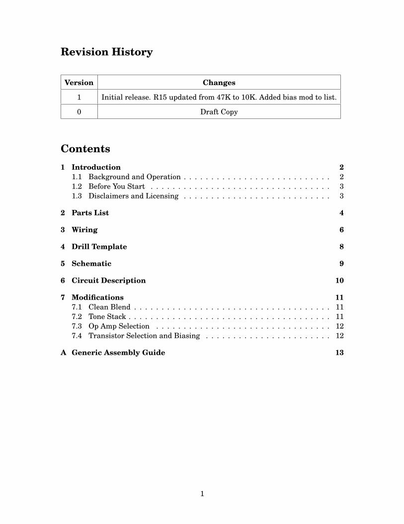
Revision History
Version Changes
1 Initial release. R15 updated from 47K to 10K. Added bias mod to list.
0 Draft Copy
Contents1 Introduction 2
1.1 Background and Operation . . . . . . . . . . . . . . . . . . . . . . . . . . . 21.2 Before You Start . . . . . . . . . . . . . . . . . . . . . . . . . . . . . . . . . 31.3 Disclaimers and Licensing . . . . . . . . . . . . . . . . . . . . . . . . . . . 3
2 Parts List 4
3 Wiring 6
4 Drill Template 8
5 Schematic 9
6 Circuit Description 10
7 Modifications 117.1 Clean Blend . . . . . . . . . . . . . . . . . . . . . . . . . . . . . . . . . . . . 117.2 Tone Stack . . . . . . . . . . . . . . . . . . . . . . . . . . . . . . . . . . . . . 117.3 Op Amp Selection . . . . . . . . . . . . . . . . . . . . . . . . . . . . . . . . 127.4 Transistor Selection and Biasing . . . . . . . . . . . . . . . . . . . . . . . 12
A Generic Assembly Guide 13
1
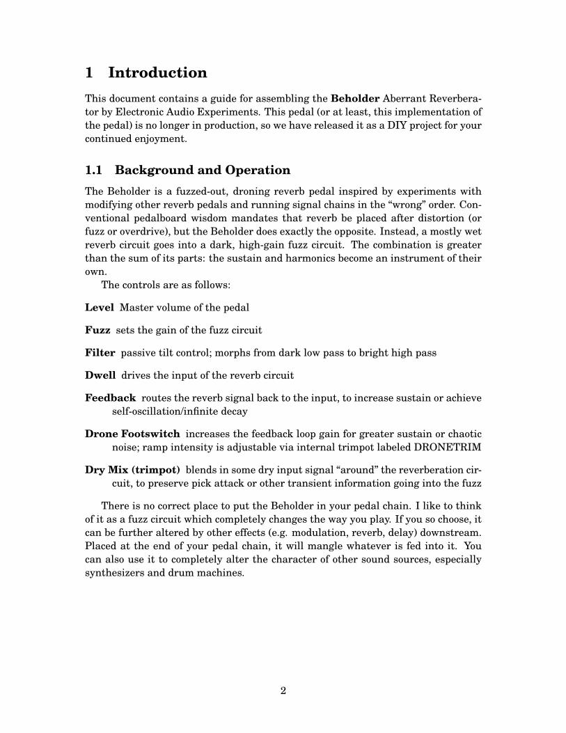
1 IntroductionThis document contains a guide for assembling the Beholder Aberrant Reverbera-tor by Electronic Audio Experiments. This pedal (or at least, this implementation ofthe pedal) is no longer in production, so we have released it as a DIY project for yourcontinued enjoyment.
1.1 Background and OperationThe Beholder is a fuzzed-out, droning reverb pedal inspired by experiments withmodifying other reverb pedals and running signal chains in the “wrong” order. Con-ventional pedalboard wisdom mandates that reverb be placed after distortion (orfuzz or overdrive), but the Beholder does exactly the opposite. Instead, a mostly wetreverb circuit goes into a dark, high-gain fuzz circuit. The combination is greaterthan the sum of its parts: the sustain and harmonics become an instrument of theirown.
The controls are as follows:
Level Master volume of the pedal
Fuzz sets the gain of the fuzz circuit
Filter passive tilt control; morphs from dark low pass to bright high pass
Dwell drives the input of the reverb circuit
Feedback routes the reverb signal back to the input, to increase sustain or achieveself-oscillation/infinite decay
Drone Footswitch increases the feedback loop gain for greater sustain or chaoticnoise; ramp intensity is adjustable via internal trimpot labeled DRONETRIM
Dry Mix (trimpot) blends in some dry input signal “around” the reverberation cir-cuit, to preserve pick attack or other transient information going into the fuzz
There is no correct place to put the Beholder in your pedal chain. I like to thinkof it as a fuzz circuit which completely changes the way you play. If you so choose, itcan be further altered by other effects (e.g. modulation, reverb, delay) downstream.Placed at the end of your pedal chain, it will mangle whatever is fed into it. Youcan also use it to completely alter the character of other sound sources, especiallysynthesizers and drum machines.
2
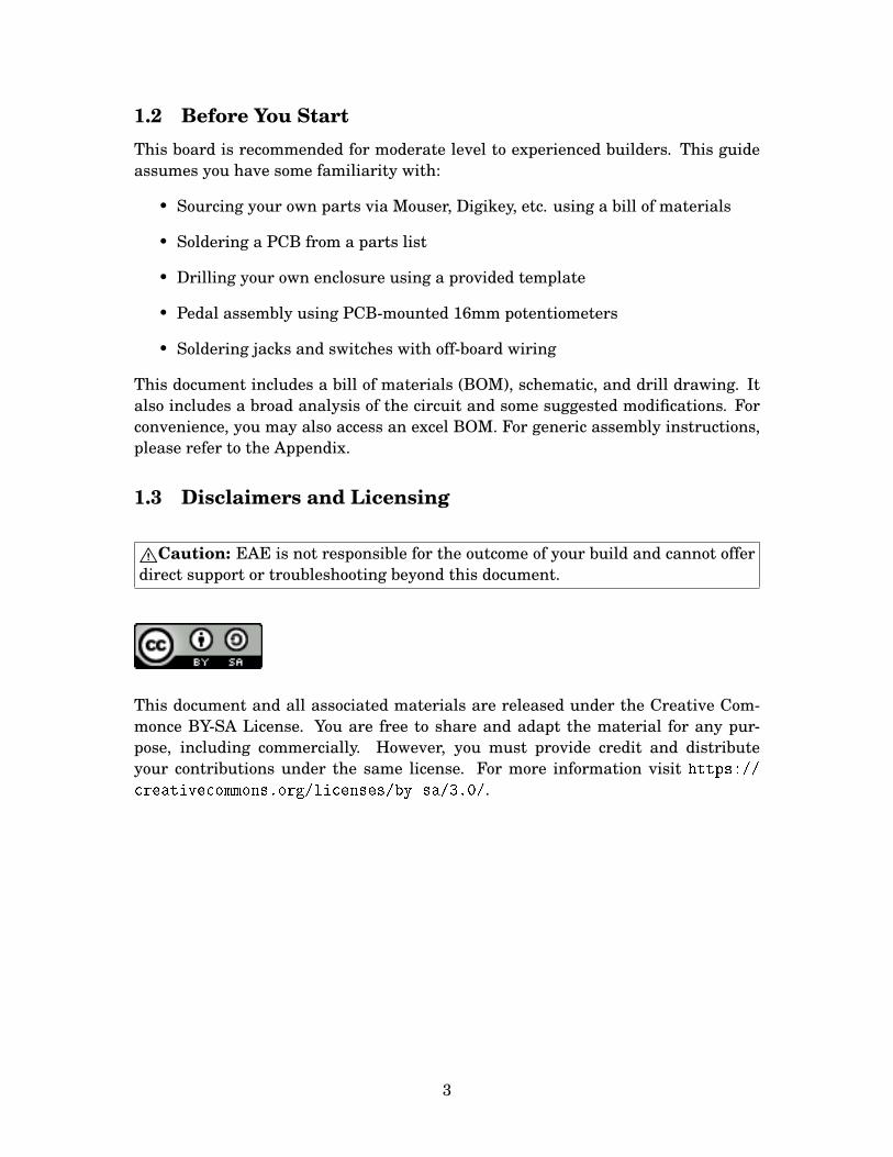
1.2 Before You StartThis board is recommended for moderate level to experienced builders. This guideassumes you have some familiarity with:
• Sourcing your own parts via Mouser, Digikey, etc. using a bill of materials
• Soldering a PCB from a parts list
• Drilling your own enclosure using a provided template
• Pedal assembly using PCB-mounted 16mm potentiometers
• Soldering jacks and switches with off-board wiring
This document includes a bill of materials (BOM), schematic, and drill drawing. Italso includes a broad analysis of the circuit and some suggested modifications. Forconvenience, you may also access an excel BOM. For generic assembly instructions,please refer to the Appendix.
1.3 Disclaimers and Licensing
"Caution: EAE is not responsible for the outcome of your build and cannot offerdirect support or troubleshooting beyond this document.
This document and all associated materials are released under the Creative Com-monce BY-SA License. You are free to share and adapt the material for any pur-pose, including commercially. However, you must provide credit and distributeyour contributions under the same license. For more information visit https://
creativecommons.org/licenses/by-sa/3.0/.
3
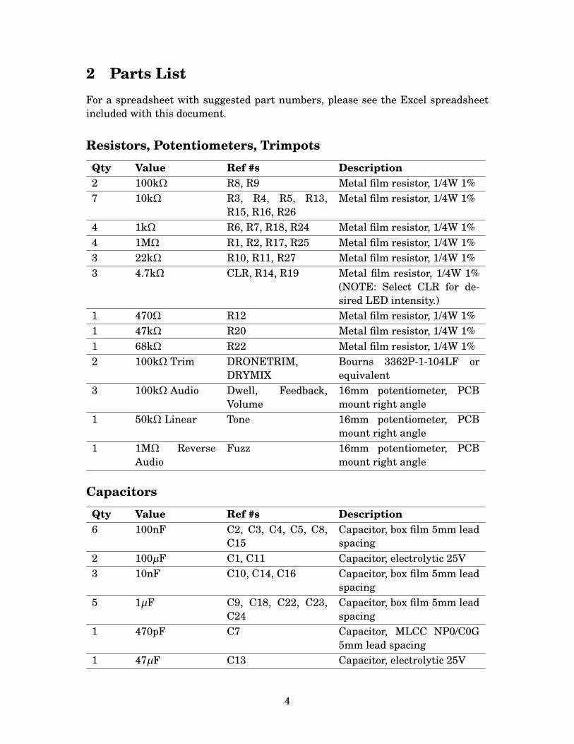
2 Parts ListFor a spreadsheet with suggested part numbers, please see the Excel spreadsheetincluded with this document.
Resistors, Potentiometers, Trimpots
Qty Value Ref #s Description2 100kΩ R8, R9 Metal film resistor, 1/4W 1%7 10kΩ R3, R4, R5, R13,
R15, R16, R26Metal film resistor, 1/4W 1%
4 1kΩ R6, R7, R18, R24 Metal film resistor, 1/4W 1%4 1MΩ R1, R2, R17, R25 Metal film resistor, 1/4W 1%3 22kΩ R10, R11, R27 Metal film resistor, 1/4W 1%3 4.7kΩ CLR, R14, R19 Metal film resistor, 1/4W 1%
(NOTE: Select CLR for de-sired LED intensity.)
1 470Ω R12 Metal film resistor, 1/4W 1%1 47kΩ R20 Metal film resistor, 1/4W 1%1 68kΩ R22 Metal film resistor, 1/4W 1%2 100kΩ Trim DRONETRIM,
DRYMIXBourns 3362P-1-104LF orequivalent
3 100kΩ Audio Dwell, Feedback,Volume
16mm potentiometer, PCBmount right angle
1 50kΩ Linear Tone 16mm potentiometer, PCBmount right angle
1 1MΩ ReverseAudio
Fuzz 16mm potentiometer, PCBmount right angle
Capacitors
Qty Value Ref #s Description6 100nF C2, C3, C4, C5, C8,
C15Capacitor, box film 5mm leadspacing
2 100µF C1, C11 Capacitor, electrolytic 25V3 10nF C10, C14, C16 Capacitor, box film 5mm lead
spacing5 1µF C9, C18, C22, C23,
C24Capacitor, box film 5mm leadspacing
1 470pF C7 Capacitor, MLCC NP0/C0G5mm lead spacing
1 47µF C13 Capacitor, electrolytic 25V
4
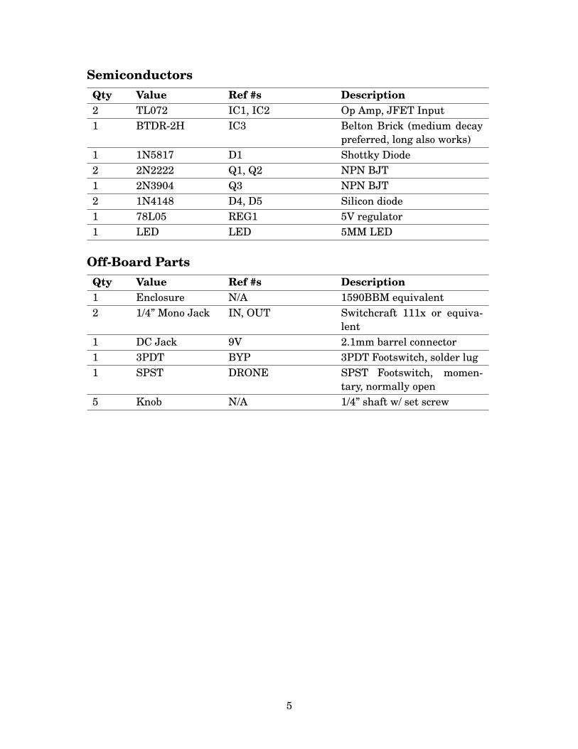
SemiconductorsQty Value Ref #s Description2 TL072 IC1, IC2 Op Amp, JFET Input1 BTDR-2H IC3 Belton Brick (medium decay
preferred, long also works)1 1N5817 D1 Shottky Diode2 2N2222 Q1, Q2 NPN BJT1 2N3904 Q3 NPN BJT2 1N4148 D4, D5 Silicon diode1 78L05 REG1 5V regulator1 LED LED 5MM LED
Off-Board PartsQty Value Ref #s Description1 Enclosure N/A 1590BBM equivalent2 1/4” Mono Jack IN, OUT Switchcraft 111x or equiva-
lent1 DC Jack 9V 2.1mm barrel connector1 3PDT BYP 3PDT Footswitch, solder lug1 SPST DRONE SPST Footswitch, momen-
tary, normally open5 Knob N/A 1/4” shaft w/ set screw
5
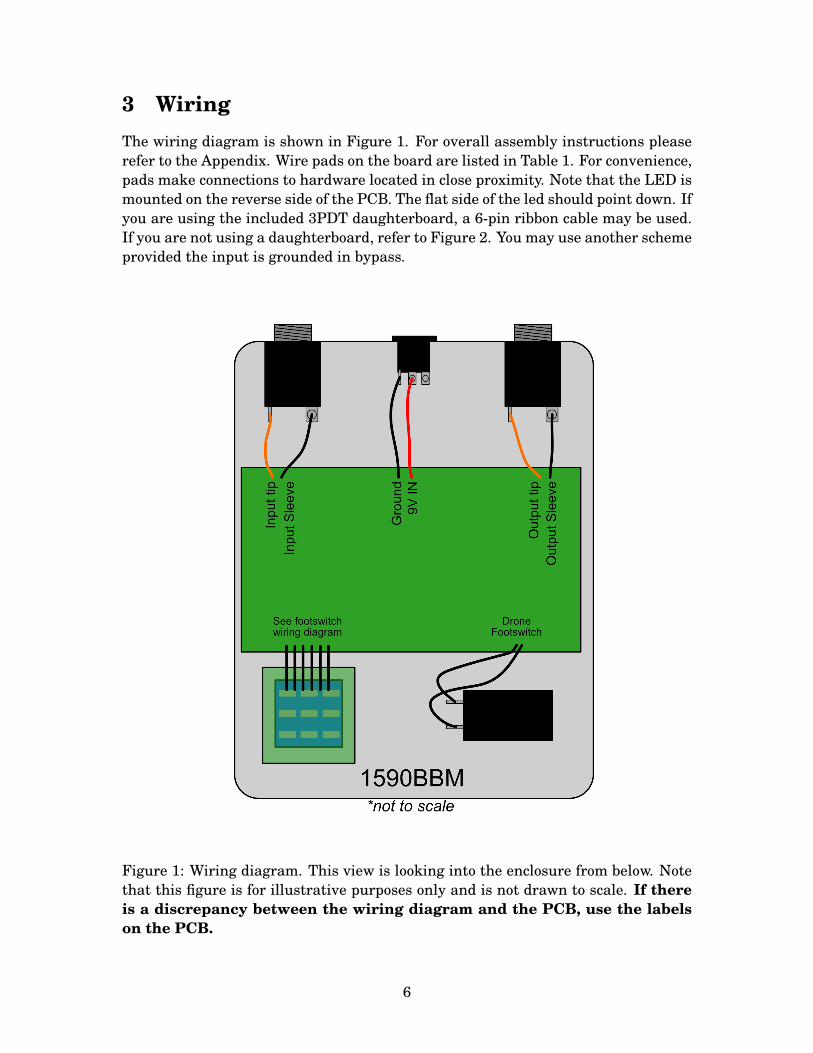
3 WiringThe wiring diagram is shown in Figure 1. For overall assembly instructions pleaserefer to the Appendix. Wire pads on the board are listed in Table 1. For convenience,pads make connections to hardware located in close proximity. Note that the LED ismounted on the reverse side of the PCB. The flat side of the led should point down. Ifyou are using the included 3PDT daughterboard, a 6-pin ribbon cable may be used.If you are not using a daughterboard, refer to Figure 2. You may use another schemeprovided the input is grounded in bypass.
Figure 1: Wiring diagram. This view is looking into the enclosure from below. Notethat this figure is for illustrative purposes only and is not drawn to scale. If thereis a discrepancy between the wiring diagram and the PCB, use the labelson the PCB.
6
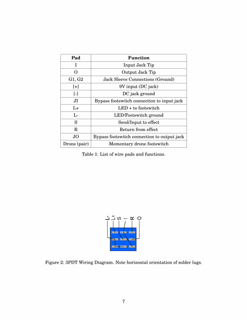
Pad FunctionI Input Jack TipO Output Jack Tip
G1, G2 Jack Sleeve Connections (Ground)[+] 9V input (DC jack)[-] DC jack groundJI Bypass footswitch connection to input jackL+ LED + to footswitchL- LED/Footswitch groundS Send/Input to effectR Return from effect
JO Bypass footswitch connection to output jackDrone (pair) Momentary drone footswitch
Table 1: List of wire pads and functions.
Figure 2: 3PDT Wiring Diagram. Note horizontal orientation of solder lugs.
7
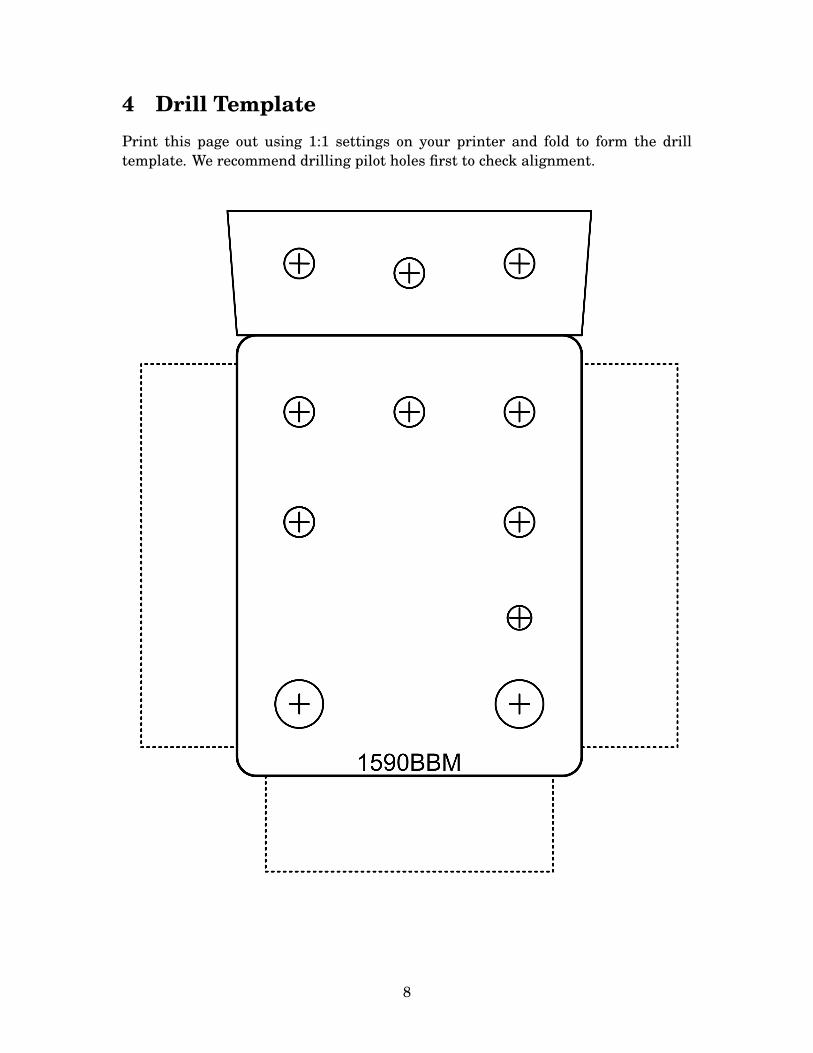
4 Drill TemplatePrint this page out using 1:1 settings on your printer and fold to form the drilltemplate. We recommend drilling pilot holes first to check alignment.
8
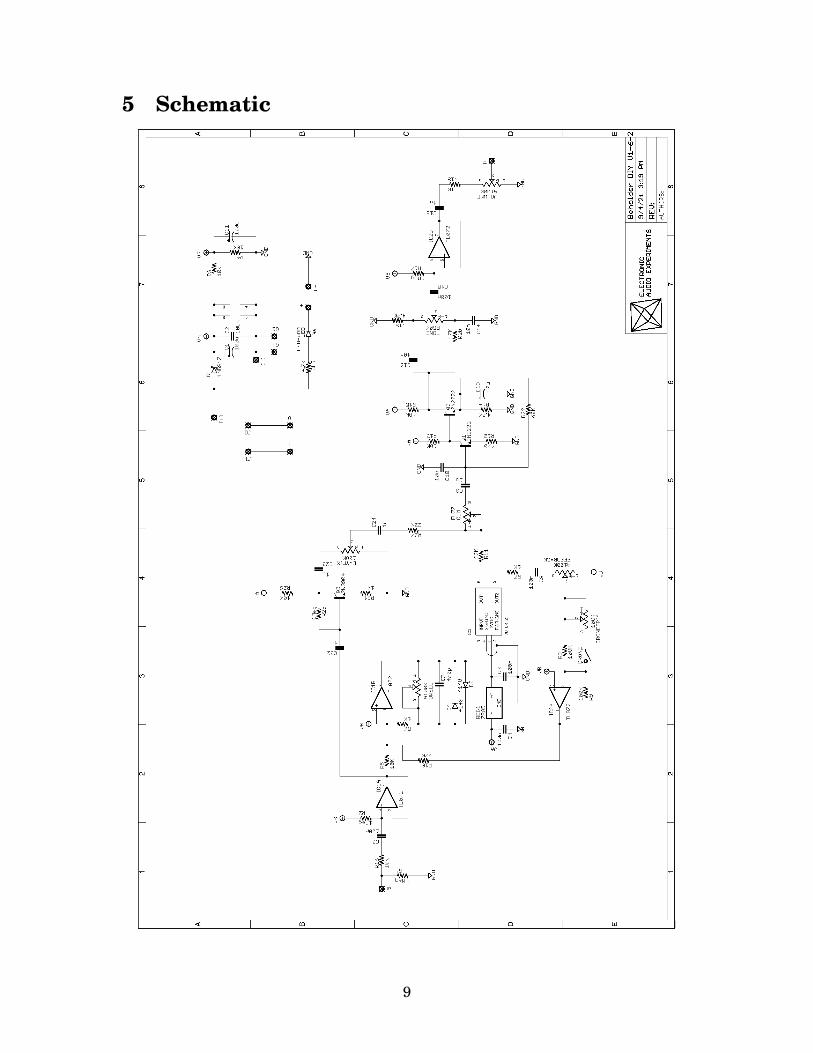
5 Schematic
9
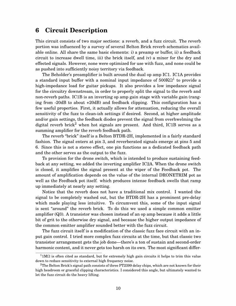
6 Circuit DescriptionThis circuit consists of two major sections: a reverb, and a fuzz circuit. The reverbportion was influenced by a survey of several Belton Brick reverb schematics avail-able online. All share the same basic elements: i) a preamp or buffer, ii) a feedbackcircuit to increase dwell time, iii) the brick itself, and iv) a mixer for the dry andeffected signals. However, none were optimized for use with fuzz, and none could beas pushed into sufficiently noisy territory via feedback.
The Beholder’s preamplifier is built around the dual op amp IC1. IC1A providesa standard input buffer with a nominal input impedance of 500KΩ1 to provide ahigh-impedance load for guitar pickups. It also provides a low impedance signalfor the circuitry downstream, in order to properly split the signal to the reverb andnon-reverb paths. IC1B is an inverting op amp gain stage with variable gain (rang-ing from -20dB to about +20dB) and feedback clipping. This configuration has afew useful properties. First, it actually allows for attenuation, reducing the overallsensitivity of the fuzz to clean-ish settings if desired. Second, at higher amplitudeand/or gain settings, the feedback diodes prevent the signal from overhwelming thedigital reverb brick2 when hot signals are present. And third, IC1B serves as asumming amplifier for the reverb feedback path.
The reverb “brick” itself is a Belton BTDR-2H, implemented in a fairly standardfashion. The signal enters at pin 3, and reverberated signals emerge at pins 5 and6. Since this is not a stereo effect, one pin functions as a dedicated feedback pathand the other serves as the output to the fuzz.
To provision for the drone switch, which is intended to produce sustaining feed-back at any setting, we added the inverting amplifier IC2A. When the drone switchis closed, it amplifies the signal present at the wiper of the Feedback pot. Theamount of amplification depends on the value of the internal DRONETRIM pot aswell as the Feedback pot itself. which produces intense feedback swells that rampup immediately at nearly any setting.
Notice that the reverb does not have a traditional mix control. I wanted thesignal to be completely washed out, but the BTDR-2H has a prominent pre-delaywhich made playing less intuitive. To circumvent this, some of the input signalis sent “around” the reverb brick. To do this we used a simple common emitteramplifier (Q3). A transistor was chosen instead of an op amp because it adds a littlebit of grit to the otherwise dry signal, and because the higher output impedance ofthe common emitter amplifier sounded better with the fuzz circuit.
The fuzz circuit itself is a modification of the classic fuzz face circuit with an in-put gain control. I tried more complex fuzz circuits at the time, but that classic twotransistor arrangement gets the job done—there’s a ton of sustain and second-orderharmonic content, and it never gets too harsh on its own. The most significant differ-
11MΩ is often cited as standard, but for extremely high gain circuits it helps to trim this valuedown to reduce sensitivity to external high frequency noise.
2The Belton Brick’s signal path consists of three PT2399 delay chips, which are not known for theirhigh headroom or graceful clipping characteristics. I considered this angle, but ultimately wanted tolet the fuzz circuit do the heavy lifting.
10
ence is that, instead of grounding the first emitter (Q1) I added an emitter resistor.The inclusion of an emitter resistor keeps the transistor bias more consistent, at theexpense of some gain. There’s already so much gain here that it’s not a problem.Notice that Q1 is also used as a summing node for the reverb and “clean” paths, byway of R11 and R27.
After the fuzz is a simple passive tilt EQ (the ubiquitous Big Muff tone stack)with a buffer on the output to ensure that the tone control does not interact with thepassive output volume control.
7 Modifications"Caution: Modifications should not be attempted unless you have the means totroubleshoot changes beyond the base configuration.
7.1 Clean BlendI understand not everyone is trying to conjure up a raging wall of noise every timethey turn on their reverb pedal, so if you want to add a simple unity gain clean blendyou can perform the following steps. This mod takes a signal from the input bufferand routes it to a blend pot at the output. The only extra part required is a B10K orB25K pot. Note that this mod disables the internal “dry path”.
1. Do not install the following parts: R25, R26, R24, Q3, C23, DRYMIX trim,C24, R27
2. Solder a wire from the middle pin of Q3 (at least, where Q3 would have been)to Lug 1 of the blend pot.
3. Solder a wire from the R pad (normally reserved for the bypass footswitch) toLug 3 of the pot
4. Solder a wire from Lug 2 of the pot to the return pin on the footswitch wherethe effect output normally would be.
The pot should now pan from the buffered clean input signal to the fully wet signalof the Beholder. You can use the Volume control to match levels.
7.2 Tone StackSince this is such a common tone stack configuration, feel free to build it with yourfavorite values. Earlier Beholder units were more heavily scooped, and later oneshad a flatter response.
11
7.3 Op Amp SelectionIC1 and IC2 work great using the humble TL072. We built some units with theTLC2272, which has rail to rail output (meaning the output can go within about0.2V of both the positive and negative supply voltages). The signal present at theoutput buffer is enough to clip it at certain settings, which does add some extra hashto the sound. But the selection is not critical. Feel free to experiment!
7.4 Transistor Selection and BiasingSocketing the fuzz transistors Q1 and Q2 is recommended. We had a box of old stock2N2222s which worked well here. Other low to medium gain transistors, like the2N3904 and 2N4401, are also great. Q3 selection is not critical, any decent NPNsilicon part will work here. For a greater variety of fuzz sounds, including morestarved/gated tones, R15 can be made adjustable. Try a 50KΩ trimpot with a 4.7KΩresistor in series. Experimentation is welcome.
12
A Generic Assembly GuideThis is a fully general pedal assembly procedure that applies to all EAE open sourceprojects. Note that minor details can vary between PCBs. But this will serve as aquick reference for those already familiar with this type of assembly.
1. Populate and solder the PCB per the parts list. Do not solder in enclosure-mounted components such as pots, indicator LEDs, and/or toggle switches.Ensure that all leads are trimmed to 0.1” or less.
2. Drill the enclosure per the template. Use a center punch first to mark holesfor accuracy. If you have one, a stepper bit is very convenient here. If you areunsure about any hole sizes, check using the appropriate hardware.
3. Solder pots and toggle switches (if present) to the PCB using the enclosure asa jig to hold the hardware in place. We recommend using potentiometers withdust covers. If the pots are not insulated, ensure they are not making contactwith the back of the PCB.
4. Install PCB mounted LED on the reverse side of the board. Gently bend thelegs to hold it in place, but do not solder yet.
5. Install flying wires on the board. These go to the jacks and footswitch(es).
6. Insert PCB into enclosure and tighten all hardware. Fit LED(s) into place,solder, and trim the leads.
7. Solder flying wires to the appropriate pads. Refer to the wiring diagram ortable for the specific pedal in question.
8. Pedal is ready for testing!
13
Related Documents