Thin-Walled Structures 14 (1992) 265-278 Behaviour and Ultimate Load Estimates for Thin-Walled Trussed Plane Frames R. C. Batista & E. M. Batista COPPE/UFRJ -- Civil Engineering, C. Postal 68506, CEP 21945, Rio de Janeiro, Brazil (Received 20 November 1990; revised version received 30 October 1991; accepted 10 December 1991) ABSTRACT The elastic non-linear buckling behaviour and collapse of trussed plane frames having toM-formed steel members are analysed via FEM models. Local buckling interaction at a section level between the thin walls of a member is taken into account through the effective width approach. Interaction between this local and Euler buckling mode is also considered in the analysis. The solution of the resulting non-linear equations is sought by a hybrid numerical scheme that makes use of both incremental-iterative plus secant methods. Large-span thin-walled trusses are analysed and the resulting non- linear behaviour and associated ultimate loads are critically examined in the light of conventional elastic calculations and predictions from existing design codes. Correlations with experimental results for pin-ended columns with slender crossZsections are also presented to back up the results found for trussed plane frames. INTRODUCTION Non-linear buckling interaction plays a major role in the behaviour of light-weight steel structures composed by cold-formed thin-walled slender members. The whole structure under increasing loading displays a mechanical behaviour highly dependent on local loss of stiffness of the 265 Thin-Walled Structures 0263-8231/92/$05.00© 1992 Elsevier Science Publishers Ltd, England. Printed in Great Britain

Welcome message from author
This document is posted to help you gain knowledge. Please leave a comment to let me know what you think about it! Share it to your friends and learn new things together.
Transcript
Thin-Walled Structures 14 (1992) 265-278
Behaviour and Ultimate Load Estimates for Thin-Walled Trussed Plane Frames
R. C. Batista & E. M. Batista
COPPE/UFRJ - - Civil Engineering, C. Postal 68506, CEP 21945, Rio de Janeiro, Brazil
(Received 20 November 1990; revised version received 30 October 1991; accepted 10 December 1991)
ABSTRACT
The elastic non-linear buckling behaviour and collapse of trussed plane frames having toM-formed steel members are analysed via FEM models. Local buckling interaction at a section level between the thin walls of a member is taken into account through the effective width approach. Interaction between this local and Euler buckling mode is also considered in the analysis. The solution of the resulting non-linear equations is sought by a hybrid numerical scheme that makes use of both incremental-iterative plus secant methods. Large-span thin-walled trusses are analysed and the resulting non- linear behaviour and associated ultimate loads are critically examined in the light of conventional elastic calculations and predictions from existing design codes. Correlations with experimental results for pin-ended columns with slender crossZsections are also presented to back up the results found for trussed plane frames.
INTRODUCTION
Non-linear buckling interaction plays a major role in the behaviour of light-weight steel structures composed by cold-formed thin-walled slender members. The whole structure under increasing loading displays a mechanical behaviour highly dependent on local loss of stiffness of the
265 Thin-Walled Structures 0263-8231/92/$05.00© 1992 Elsevier Science Publishers Ltd, England. Printed in Great Britain
266 R. C. Batista, E. h~ Batista
buckled walls and on the elastic-plastic instability mechanisms related to the post-critical strength reserve of the assembled thin plates.
Some simplified semi-analytical iterative approaches ~-4 have been specially developed to describe the thin-walled column non-linear behaviour under local/global buckling mode interaction. On the other hand, because the present approach 5' 6 was developed within the frame- work of the finite element method it can be easily extended to the analysis of plane truss or plane frame structures composed of cold- formed members.
This paper concentrates on the application of the proposed approach to trussed plane frames. The structure is discretized by using beam- column finite elements in a number that fulfills the required numerical convergence. For a given loading case the solution of the resulting non- linear equations is sought by a hybrid numerical scheme that combines adequately the known convergence properties of an incremental- iterative tangent formulation together with both compatibility and equilibrium insurance from a secant-iterative approach. Under increasing load the non-linear axial stress distribution in a cross-section and the consequent local buckling interaction between the thin plates are taken into account by using the effective width approximation; this latter approximation is briefly described herein. The effects of local geometric imperfections and residual stresses are also taken into account by the effective width expressions. Overall geometric imperfections can of course also be taken into account in the analysis via coordinates of nodal points.
Changes of local stiffness properties occurring under increasing load is considered by up-dating elements of sectional properties at the end of the iterative procedure for each load step. Equilibrium at this load stage is restored by applying a direct secant-iterative method. The internal unbalanced forces that result from the change in location of the effective section centroid for each element are accordingly taken by the adopted numerical scheme that uses the Newton-Raphson iterative strategy.
The capability of the proposed approach to describe the non-linear collapse behaviour of trussed plane frame structures has been partially demonstrated 6 through favourable comparisons between theoretical and experimental results for thin-walled C-shaped cold-formed steel columns. It is worthwhile observing that as the present theoretical model is capable of representing the variations under the increasing load of axial strains and geometric properties of the effective cross-section along a column length, it can be extended to the analysis of plane frames in which the thin-walled members resist the applied loading predominantly through extensional action.

Load estimates for thin-walled trussed plane frames 267
Complete validation of this approach will, however, have to await forthcoming experimental test results from typical plane frames. Meanwhile the present FEM model has been extended to the non-linear collapse analysis of large-span truss-like plane frames. Comparisons between the present estimates for ultimate loads and those given by conventional elastic calculations, together with prescribed rules from current design codes, indicate that the latter could be, under certain assumptions, very conservative or even slightly non-conservative.
EFFECTIVE CROSS SECTION ESTIMATES
The effect of local buckling reducing the axial and bending stiffness properties of a hat-shaped or a C-shaped thin-walled cross-section (Fig. 1) is considered by treating each wall component separately, as if it was a thin plate simply supported along its longitudinal edge stiffeners.
For the case of an isolated edge stiffened plate under uniform inplane axial compression, it is used as a simple previously proposed procedure 3
bf
S
-1.,,
b: ,,~ bo
Y = ~I I ~ 2
ORIGINAL CENIROIDE / - -
CENTAOIDE OF IHE S-SECTION
b~
Fig. 1. Effective cross-section of C-shaped thin-walled member.
268 R C. Batista, £ M. Batista
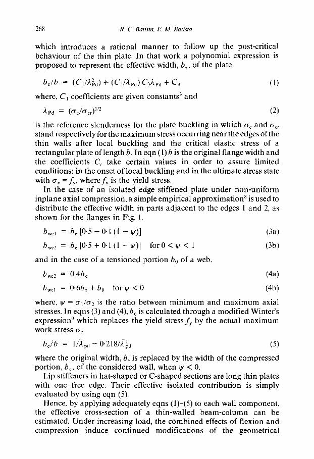
which introduces a rational manner to follow up the post-critical behaviour of the thin plate. In that work a polynomial expression is proposed to represent the effective width, b~, of the plate
be/b = (C1/A.~,d) + (C2/A, pd) C32.ea + C4 (1)
where, C1 coefficients are given constants 3 and
~'Pd = (O'e/O'cr) 1/2 (2)
is the reference slenderness for the plate buckling in which ¢re and crcr stand respectively for the maximum stress occurring near the edges of the thin walls after local buckling and the critical elastic stress of a rectangular plate of length b. In eqn (1) b is the original flange width and the coefficients Ci take certain values in order to assure limited conditions: in the onset of local buckling and in the ultimate stress state with o'e =fy, wherefy is the yield stress.
In the case of an isolated edge stiffened plate under non-uniform inplane axial compression, a simple empirical approximation 8 is used to distribute the effective width in parts adjacent to the edges 1 and 2, as shown for the flanges in Fig. 1.
bwe~ = be 10.5 - 0.1 (1 - q/)] (3a)
bwe2 = be [0.5 + 0.1 (1 - gt)] for 0 < ~ < 1 (3b)
and in the case of a tensioned portion b0 of a web,
bwe2 = 0.4be (4a)
bwel = 0-6be+b0 f o r q t < 0 (4b)
where, q/= err~or2 is the ratio between minimum and maximum axial stresses. In eqns (3) and (4), be is calculated through a modified Winter's expression 9 which replaces the yield stress fy by the actual maximum work stress oe
b i b = l/~,pd - 0"218/,~2j (5)
where the original width, b, is replaced by the width of the compressed portion, be, of the considered wall, when q /< 0.
Lip stiffeners in hat-shaped or C-shaped sections are long thin plates with one free edge. Their effective isolated contribution is simply evaluated by using eqn (5).
Hence, by applying adequately eqns (1)-(5) to each wall component, the effective cross-section of a thin-walled beam-column can be estimated. Under increasing load, the combined effects of flexion and compression induce continued modifications of the geometrical
Load estimates for thin-walled trussed plane frames 269
characteristics of the effective cross-section, with changes in the position of the centroid and in the values of area and second moment of area.
HYBRID NUMERICAL SCHEME
The resulting non-linear finite element equations applied to a thin- walled plane frame are solved by means of a hybrid numerical scheme. This incremental-iterative (I/I) scheme makes use of conventional non- linear incremental (tangent) and direct (secant) methods} °' t l
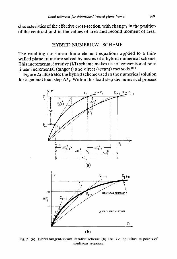
Figure 2a illustrates the hybrid scheme used in the numerical solution for a general load step AF;. Within this load step the numerical process
i I' i : 1'~ i
~ / [ [3 >
°~-~_ ~0~j ~ ~0~ - ~ ~°~ ~ i ~ ~D i
(a)
~F Ci+ i Ci+m
- Ci
[3
(b) Fig. 2. (a) Hybrid tangent/secant iterative scheme. (b) Locus of equilibrium points of
nonlinear response.
270 R. C. Ba t i s ta , E. M . B a t i s t a
starts from an equilibrium state E;. (shown in this figure as an encircled dot) and searches for another equilibrium state E; + ~ at the end of it. Of course the equilibrium state E; has been reached in previous converged load step AF; _ ~. For an evaluated deformation state described by (F; _ t: D;_ ~) on the path response A = Ci. in which each element has known stiffness properties (Ae; Ie) from the previous load step ( i - 1), an incremental/iterative scheme is used to reach the equilibrium state E;. For each iteration j in this stage the incremental displacements are solved by using the tangent stiffness matrix K~, i.e.
KTA.j_ ~" AD,-Aj = AF~j (6)
and the internal forces in each element are then calculated for the accumulated displacements AD, .a
f i , i = KTA/" AD~; (7)
The process stops when numerical convergence is achieved for AF,., ---} 0.
At the equilibrium state E~, on the path A = C;, by applying the internal forces f,.A the effective sectional stiffness properties A e and I~ are changed according to some given analytical/experimental effective width expressions (eqns 1-5). Equilibrium for the same previous deformation state is now only possible on another path response B = C; + ~ in Fig. 2a, at a load level lower than F;.
This reduction AF* in load magnitude from F; is then calculated by a secant-iterative scheme for the total displacement D A
AF*= F ; - K A..(D;_ +AD, .A)-AF, A (8) s , I 1
where K A is the secant stiffness matrix related to the original undeformed geometry of the structure and the last term on the right-hand side ofeqn (8) is the unbalanced internal force vector, arising from changes in geometrical properties of the effective cross-section for each element. At this stage a new intermediate equilibrium state is reached, named El'.
From E,!' on, the residual load AF* is incremented and the final equilibrium state E; +~ (shown in Fig. 2a as an encircled dot) is found. This letter state described by (D;; F;) is reached by using again an incremental/iterative scheme. For each iteration, j , in this stage the incremental displacements are solved by using the new (with changes in stiffness coefficients due to changes in member/section stiffness properties) tangent stiffness matrix K B, i.e.
a • ADBi = AF B (9) K T , j - 1 , ~,.1 - 1
The whole process is repeated for each new load step A F; until the
Load estimates for thin-walled trussed plane frames 271
ultimate load Pu is detected by applying any simple criteria of either elastic overall instability or localized onset of plasticity.
Figure 2b shows (bold line) the sought non-linear load-deflection response which is the locus of the equilibrium points E; (shown as encircled dots) located on distinct path responses given by the traced lines C;.
SUMMARY OF HYBRID I/I SCHEME
(1) Specify load increments AF;; i = 1,N. (2) Using I/I method, solve equilibrium equations for current degree of
non-linearity
KT.j- I 'ADi , j = AFy_I
to obtain equilibrium configuration E: described by displacements ADi = ZAD;.j.
(3) Using these displacements and/or internal resultant forces calculate new member stiffness properties (i.e. new properties of buckled sections) and form the overall secant stiffness matrix, Ks,j.
(4) Solve the new equilibrium equations by direct method under displacement control (for a given D:) to obtain the equilibrium configuration E:'.
(5) Specify the residual load increment AF* to reach Fi. (6) Using again I/I method, solve equilibrium equations for this new
degree of non-linearity to obtain the sought equilibrium configuration Ei+ 1.
(7) Repeat steps 1-6 for each new load increment AFi.
APPLICABILITY OF THE PROPOSED NUMERICAL SCHEME
This hybrid numerical algorithm 5-7 was implemented in a standard FEM program for plane frame and several test examples were run in a micro-computer to investigate its limitations in dealing with structures of distinct overall geometries and members of many geometrical properties. It was found that in the case of thin-walled members the proposed approach is suitable for plane frames in which extensional deformations are always dominant during loading.
In any case the Euler buckling mode of a member or overall buckling of a plane frame can only be considered to occur in the same plane of the structure. To prevent any other type of transverse deflection or buckling
272 R C. Batista, E. M. Bat#ta
mode the plane structure is thought to be well braced (then avoiding lateral or torsional buckling of the whole structure) and all thin-walled members have larger bending stiffness in a plane transversal to the plane of the structure; i.e. br > bw. Moreover torsional buckling of an axially compressed thin-walled member is not considered in the analysis.
EXAMPLES OF APPLICATION
Centra l ly l o a d e d c o l u m n
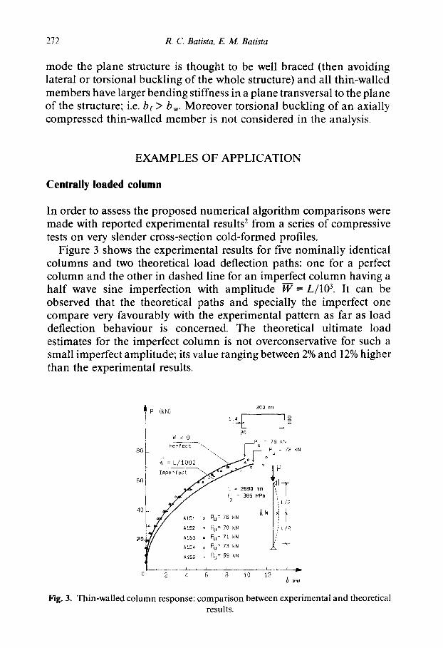
In order to assess the proposed numerical algorithm comparisons were made with reported experimental results 2 from a series of compressive tests on very slender cross-section cold-formed profiles.
Figure 3 shows the experimental results for five nominally identical columns and two theoretical load deflection paths: one for a perfect column and the other in dashed line for an imperfect column having a half wave sine imperfection with amplitude W = L/10 3. It can be observed that the theoretical paths and specially the imperfect one compare very favourably with the experimental pattern as far as load deflection behaviour is concerned. The theoretical ultimate load estimates for the imperfect column is not overconservative for such a small imperfect amplitude; its value ranging between 2% and 12% higher than the experimental results.
80
60
40
20,
300 mm P (kN)
i f : o ~o
Per fec t ~ \ F ~ p 9 2 : N kN
~:L/looo " " ~ o °t °
• I
~ / l l / At52 ~ PU: 70 kN L/2
A153 a PU = 71 kN / / At53 a Pu = 7i kN
f Ai54 ~, Pu = 73 kN -
At56 . PU = 69 kN
--2 6 B 'i0 ~2 (mmJ
Fig. 3. Thin-walled column response: comparison between experimental and theoretical results.
Load estimates for thin-walled trussed plane frames 273
I . 01 Ae
0.9
0 .8
0.7
0 .6 L
0 20
/A o , I e /I o
J-~° %
6(? p (kN)
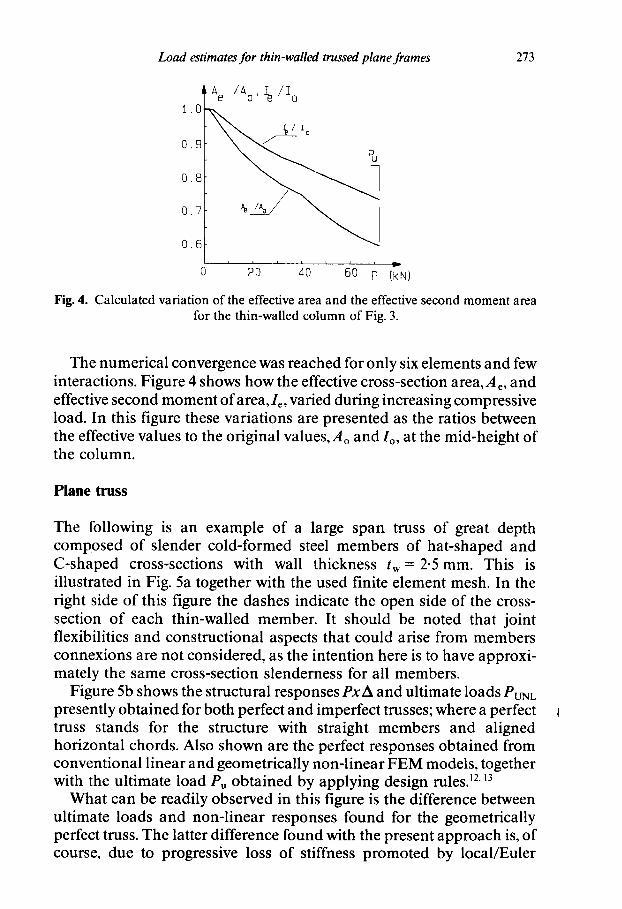
Fig. 4. Calculated variation of the effective area and the effective second moment area for the thin-walled column of Fig. 3.
The numerical convergence was reached for only six elements and few interactions. Figure 4 shows how the effective cross-section area, A e, and effective second moment of area, Ie, varied during increasing compressive load. In this figure these variations are presented as the ratios between the effective values to the original values, Ao and Io, at the mid-height of the column.
Plane truss
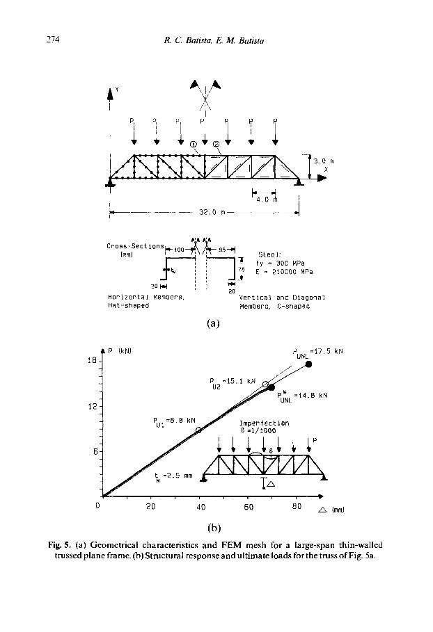
The following is an example of a large span truss of great depth composed of slender cold-formed steel members of hat-shaped and C-shaped cross-sections with wall thickness tw = 2.5 mm. This is illustrated in Fig. 5a together with the used finite element mesh. In the right side of this figure the dashes indicate the open side of the cross- section of each thin-walled member. It should be noted that joint flexibilities and constructional aspects that could arise from members connexions are not considered, as the intention here is to have approxi- mately the same cross-section slenderness for all members.
Figure 5b shows the structural responses PxA and ultimate loads PUNL
presently obtained for both perfect and imperfect trusses; where a perfect truss stands for the structure with straight members and aligned horizontal chords. Also shown are the perfect responses obtained from conventional linear and geometrically non-linear FEM models, together with the ultimate load Pu obtained by applying design rulesJ 2,13
What can be readily observed in this figure is the difference between ultimate loads and non-linear responses found for the geometrically perfect truss. The latter difference found with the present approach is, of course, due to progressive loss of stiffness promoted by local/Euler
274 R. C. Batista, E. M. Batista
Y
L 32.o m I-
Cross-Sections ..^ ~,A~ (mmJ ~- luu-~]3 \ / ~ - 95-~ Steel:
I fy = 300 MPa i
' E = 210000 MPa i , ~ J i
2014d ' ~ ' ~ 20
Horizontal Members, Vertical and Diagonal Hat-shaped Members, C-shaped
(a)
i
18-
12
P IkNJ PUNL=17.5 kN
PUI=B.B k / - P U N L = ~ 4 N ~ Imperfection B kN
20 dO 60 BO ~ (mmJ
(b) Fig, 5, (a) Geometrical characteristics and FEM mesh for a large-span thin-walled
trussed plane frame. (b) Structural response and ultimate loads for the truss of Fig. 5a.

Load estimates for thin-wailed trussed plane frames 275
buckling mode interaction occurring in the thin-walled members under increasing loading. More surprising is that the present estimates for ultimate load (PtmL = 17"5 kN) is higher than the values (Pul = 8.8 kN; Pu2 = 15.1 kN) founded by applying design rules 12.13 on the results given by conventional linear or geometrical non-linear FEM approaches. It should be noted that no load factor was applied to P and that Put and Pu2 were calculated by considering respectively the members having pinned or elastically clamped ends.
By taking then the total length of the most compressed member (i.e. the longitudinal member indicated in Fig. 5a by an encircled 2) as its effective length (l = 4.0 m) and by applying the AISI ~2 buckling curve one gets an ultimate load Pu~ which is almost half of the present value PtmL associated with member instability.
On the other hand, if one considers for this most compressed member the effects of elastically restrained ends (given by the stiffnesses of all other members connected to its end through the rigid joints), its effective length (k~ = 0.7), as prescribed by the A I S C 13 together with the mIS112 buckling curve, leads to an ultimate load Pu2 which is only 15% lower than the value yielded by the present approach.
It should be emphasized that warping is thought to be prevented at all member ends by the rigid joints. In this case simple calculations indicate that for this most compressed member the in-plane flexural buckling load is lower than the buckling load associated with the combined torsional-flexural mode. What this latter result also indicates is that the localized collapse (encircled 1 in Fig. 5a) in the trussed frame is likely to occur by in-plane local-global flexural buckling interaction, as considered by the present approach.
By considering geometric imperfections, as shown in Fig. 5b in the central members of the upper chord in the form of Euler mode with small amplitude (e =//10 3 = 4 mm), the resulting ultimate load as found by the present approach comes to a value P~mL = 14"8 kN, which is again around 15% lower than the value found for the perfect truss and very close to the value Pu2 obtained by applying design rules.
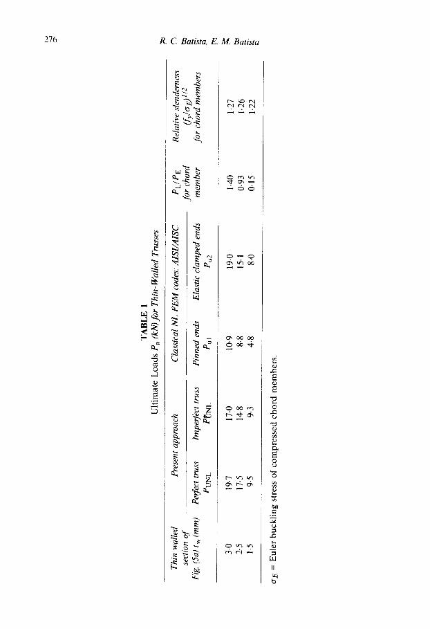
However, if the wall thickness is varied from tw = 2.5 mm to tw = 3.0 mm and tw = 1.5 mm the design estimates for ultimate load Pu2 becomes respectively non-conservative or slightly conservative as compared to the values P~L found through the present approach for the trusses with the same previous imperfection pattern. Table 1 summarizes the obtained results for ultimate loads; all them associated with member instability (i.e. non-positive stiffness matrix warning given as output by the computer program). Also shown in Table 1 are the relative slender- ness of the horizontal members with elastically clamped ends and the
TA
BL
E
1 U
ltim
ate
Lo
ads
Pu
(kN
) for
Thi
n-W
alle
d Tr
usse
s
Thi
n w
alle
d se
ctio
n of
F
ig. (
Sa) t
w (
mm
)
Pre
sent
app
roac
h
Per
fect
tru
ss
Imp
erfe
ct trus
s P
UN
L P
~NL
Cla
ssic
al N
L F
EM
cod
es: A
ISI/
AIS
C
Pin
ned
en
ds
Ela
stic
clam
ped
ends
P
u 1
Pu2
PL
/PE
fo
r ch
ord
mem
ber
Rel
ativ
e sl
ende
rnes
s OC
V/CY E
) 1/2
fo
r ch
ord
mem
bers
3-0
19.7
17
.0
10-9
19
-0
1.40
1.
27
"~
2.5
17.5
14
.8
8.8
15-1
0.
93
1.26
1.
5 9.
5 9-
3 4.
8 8.
0 0.
15
1.22
~"
~r E
= E
uler
bu
ckli
ng
str
ess
of
com
pre
ssed
ch
ord
mem
ber
s.

Load estimates for thin-walled trussed plane frames 277
ratio (PL/PE) between their local and Euler buckling loads, which expresses modes interaction effect.
CONCLUSION
The following are some conclusions which can be drawn from the present theoretical results obtained for the analysed columns and thin- walled trussed plane frames. Caution has to be taken with the latter results as it is difficult to be definitive about these conclusions since tests on full scale structures of this type are still desirable:
(a) the present approach is suitable to analyse thin-walled cold- formed columns under concentric load, considering global geometrical imperfections;
(b) it is also suitable to analyse thin-walled plane frames in which extensional deformations, caused by the applied joint loads, are dominant;
(c) if the effective lengths of members in a trussed plane frame are taken as approximately their full length, as prescribed by current design codes, the ultimate loads found by using these codes are very conservative;
(d) on the other hand, if the effective lengths are reduced by the elastically clamped ends, the ultimate loads found for the perfect trusses are close upper-bounds to practical estimates from current design codes when local/Euler modes interaction is not so strong (i.e. PL/PE is not close to 1'0);
(e) when imperfections are considered, internal bending moments are enhanced by second order effects due to changes in cross- section centroid locations. The non-linearity is increased and ultimate load estimates from current design codes, for reduced effective member lengths, seem to be:
a good approximation, when PL/PE is close to 1.0; - - somewhat non-conservative, when PL/PE is higher than 1.0; - - slightly conservative, when PL/PE is lower than 1.0; as
compared to the present predictions.
REFERENCES
1. Skaloud, M. & Naprstek, J. Limit State of Thin-Walled Steel Columns. Trans- actions of the Czechoslovak Academy of Sciences, ISSN 0069-2301. Prague (1977).
278 R C. Batista, E. M. Batista
2. Thomasson, P. O. Thin-Walled C-Shaped Panels in Axial Compression. Swedish Council for Building Research, Doc. D1, Stockholm (1978).
3. Mulligan, G. P. & Pekoz, T. Local buckled thin-walled column. J. Structural Div., ASCE, 110(11) (1984) 2635-2654.
4. Batista, E. M. Etude de la Stabilit6 de Profils h Parois Mince et section ouverte de type U et C, Doctoral Thesis, Universit6 de Lirge (1988).
5. Batista, R. C. & Pfeil, M. S. A hybrid I/I algorithm for solution of structural systems with localized nonlinearities. X Iberic and Latin-American Congress on Computational Methods for Engineering, MECOM' 89, September 25-27, University of Porto, Portugal (1989), Vol. 1, pp A454-A472.
6. Batista, E. M., Batista, R. C. & Almeida, S. B. A numerical solution for nonlinear analysis of C-shaped cold-formed columns. International Academic Publishers. Beijing, P. R. of China, pp 311-7 (1989).
7. Batista, R. C. & Batista, E. M. Ultimate load estimates for thin-walled trussed plane frames. SSRC Structural Stability Research Council, Annual Technical Session and Meeting Proceedings, Lehigh University, Bethlehem PA, (1991).
8. ECCS. Behaviour and design of steel plated structures, European Cony. for Constr. Steelwork, TWG8.3, (ed. P. Dub~s and E. Gehri), Applied Statics and Steel Structures ETH -- HOnggerberg Publishers, Zurich (1986).
9. Winter, G. Strength of thin-walled compression flanges. Trans. ASCE, 112 (1947) 527-54.
10. Bathe, K. J. Finite Element Procedures in Engineering Analysis. Prentice-Hall, USA, 1982.
11. Chajes, A. & Churchill, J. Nonlinear frame analysis by finite element method. J. Struct. Eng., ASCE, 113(6) (1987) 1221-1235.
12. AISI m American Iron and Steel Institute. Specification for the design of cold-formed steel structural members, American Iron and Steel Institute, Washington (1986).
13. AISC -- Load and resistance factor design specification for structural steel buildings, American Institute for Steel Construction Chicago (1986).
Related Documents