1 1 BEHAVIOUR AND MODELLING BEHAVIOUR AND MODELLING OF COMPOSITE BEAMS OF COMPOSITE BEAMS AT AT ELEVATED TEMPERATURES ELEVATED TEMPERATURES - - Ductility issues Ductility issues RONNY BUDI RONNY BUDI DHARMA DHARMA KANG HAI KANG HAI TAN TAN

Welcome message from author
This document is posted to help you gain knowledge. Please leave a comment to let me know what you think about it! Share it to your friends and learn new things together.
Transcript

11
BEHAVIOUR AND MODELLING BEHAVIOUR AND MODELLING OF COMPOSITE BEAMSOF COMPOSITE BEAMS
ATATELEVATED TEMPERATURESELEVATED TEMPERATURES
-- Ductility issues Ductility issues
RONNY BUDI RONNY BUDI DHARMADHARMAKANG HAI KANG HAI TANTAN
22
Scope of DiscussionScope of Discussion
Motivation for the researchMotivation for the researchExperimental Investigation on Rotational Experimental Investigation on Rotational CapacityCapacityFinite Element Analysis on Rotational Finite Element Analysis on Rotational CapacityCapacityModellingModelling of Momentof Moment--Rotational Rotational RelationshipRelationshipConclusions and RecommendationsConclusions and Recommendations

33
Literature Review of Concrete Literature Review of Concrete PropertiesProperties
StressStress--Strain RelationshipStrain Relationship
Stress σ c,T
Strain ε c,Tε crush,Tε cu,T
f c,T
eq. (3.9)
Follows EC4:1.2 proposal which is Follows EC4:1.2 proposal which is regarded as the lower regarded as the lower bound values for different test results of normal strength bound values for different test results of normal strength
concreteconcrete
0.0
0.2
0.4
0.6
0.8
1.0
0 200 400 600 800 1000 1200Temperature (°C)
Red
uctio
n Fa
ctor kc,T (NC)
kc,T (LC)
kct,T
k c,T (NC)k c,T (LC)
k ct,T

44
Local Buckling and DuctilityLocal Buckling and Ductility
Motivation of research Motivation of research A considerable distortion of the crossA considerable distortion of the cross--section in section in the highest moment region near to supportthe highest moment region near to supportLimits the rotation capacity of beam and the Limits the rotation capacity of beam and the degree of moment redistribution available at degree of moment redistribution available at the supportthe supportMay lead to premature failure May lead to premature failure Has been observed in many fire incidentsHas been observed in many fire incidents
55
Local Buckling and DuctilityLocal Buckling and Ductility
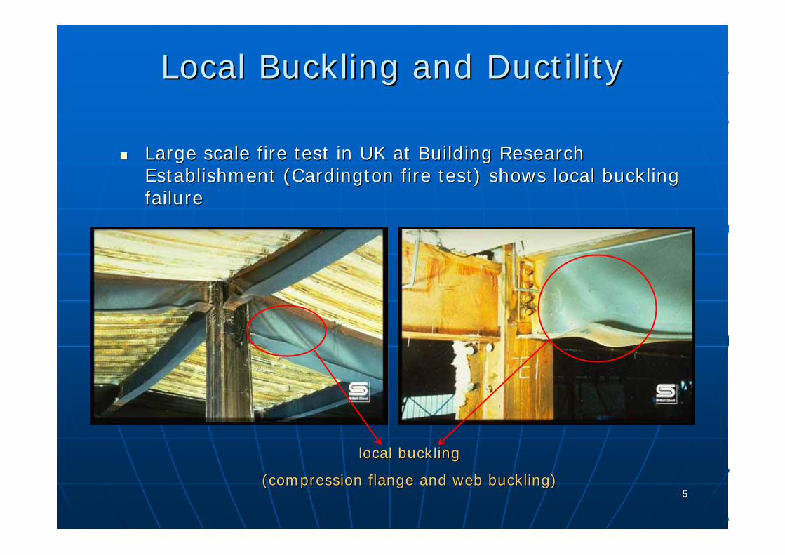
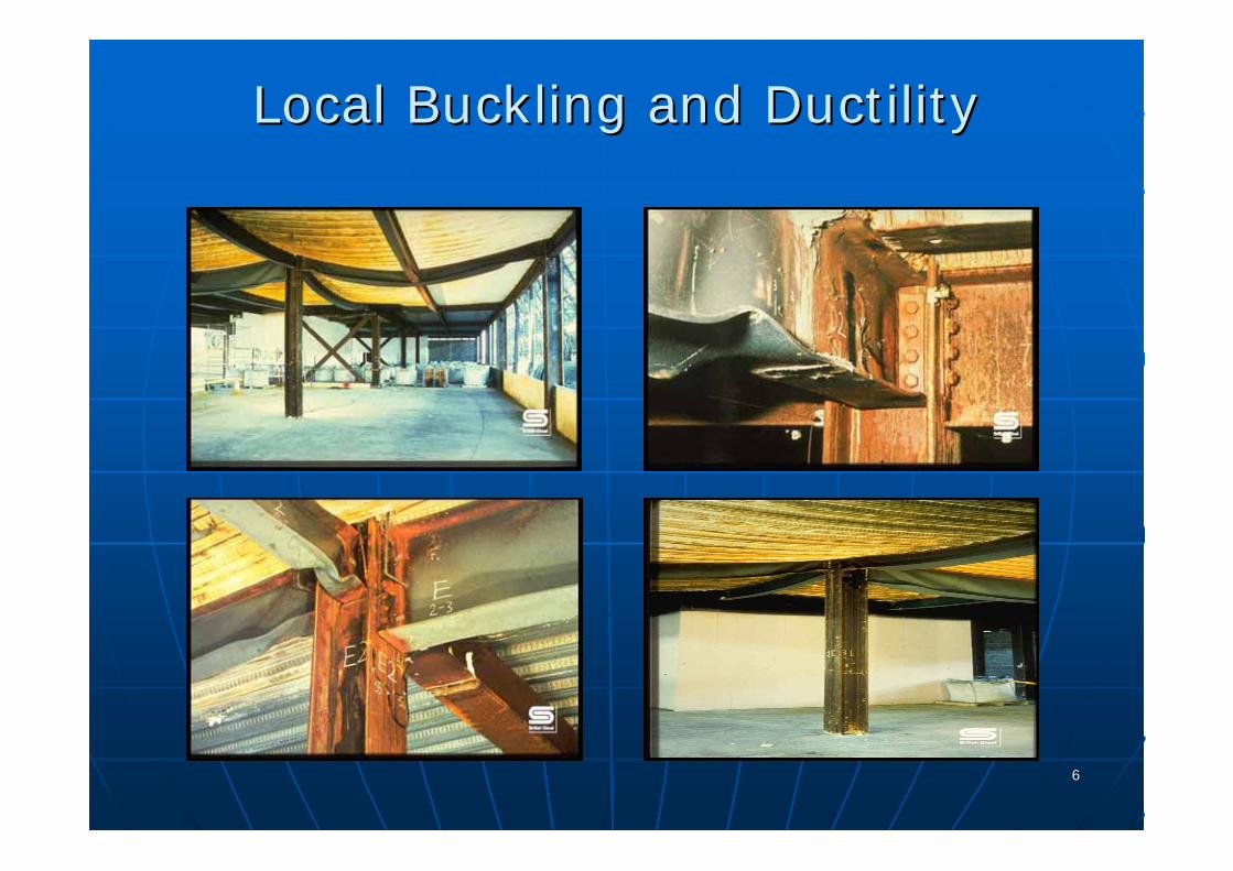
Large scale fire test in UK at Building Research Large scale fire test in UK at Building Research Establishment (Cardington fire test) shows local buckling Establishment (Cardington fire test) shows local buckling failurefailure
local bucklinglocal buckling
(compression flange and web buckling)(compression flange and web buckling)
66
Local Buckling and DuctilityLocal Buckling and Ductility

77
Local Buckling and DuctilityLocal Buckling and Ductility
2004: Fontana and 2004: Fontana and KnoblochKnobloch proposed a structural proposed a structural model for steel plates in bending and compression at model for steel plates in bending and compression at elevated temperatureselevated temperatures
Very Limited Research on the Local Very Limited Research on the Local Buckling and Ductility at Elevated Buckling and Ductility at Elevated
Temperature!Temperature!
88
Local Buckling and DuctilityLocal Buckling and Ductility
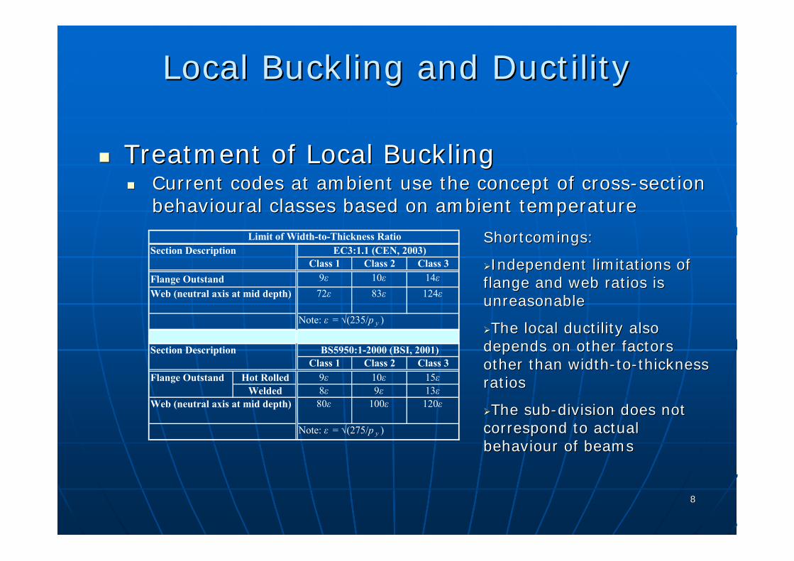
Treatment of Local BucklingTreatment of Local BucklingCurrent codes at ambient use the concept of crossCurrent codes at ambient use the concept of cross--section section behaviouralbehavioural classes based on ambient temperatureclasses based on ambient temperature
Limit of Width-to-Thickness RatioSection Description EC3:1.1 (CEN, 2003)
Class 1 Class 2 Class 3Flange Outstand 9ε 10ε 14εWeb (neutral axis at mid depth) 72ε 83ε 124ε
Note: ε = √(235/p y )
Section Description BS5950:1-2000 (BSI, 2001)Class 1 Class 2 Class 3
Flange Outstand Hot Rolled 9ε 10ε 15εWelded 8ε 9ε 13ε
Web (neutral axis at mid depth) 80ε 100ε 120ε
Note: ε = √(275/p y )
Shortcomings:Shortcomings:
Independent limitations of Independent limitations of flange and web ratios is flange and web ratios is unreasonableunreasonable
The local ductility also The local ductility also depends on other factors depends on other factors other than widthother than width--toto--thickness thickness ratiosratios
The subThe sub--division does not division does not correspond to actual correspond to actual behaviourbehaviour of beamsof beams

99
Local Buckling and DuctilityLocal Buckling and Ductility
Member Member behaviouralbehavioural classes should be used instead of classes should be used instead of crosscross--sectional sectional behaviouralbehavioural classesclassesQuantifying ductility by measuring the available inelastic Quantifying ductility by measuring the available inelastic rotationrotation aθ
paaR θθ=
θ aθ p
θ /θ p
Mom
ent M
/Mp
1
1
1010
Local Buckling and DuctilityLocal Buckling and Ductility
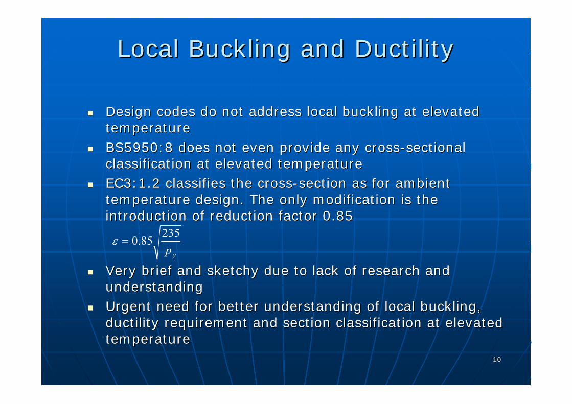
Design codes do not address local buckling at elevated Design codes do not address local buckling at elevated temperature temperature BS5950:8 does not even provide any crossBS5950:8 does not even provide any cross--sectional sectional classification at elevated temperatureclassification at elevated temperatureEC3:1.2 classifies the crossEC3:1.2 classifies the cross--section as for ambient section as for ambient temperature design. The only modification is the temperature design. The only modification is the introduction of reduction factor 0.85introduction of reduction factor 0.85
yp23585.0=ε
Very brief and sketchy due to lack of research and Very brief and sketchy due to lack of research and understandingunderstandingUrgent need for better understanding of local buckling, Urgent need for better understanding of local buckling, ductility requirement and section classification at elevated ductility requirement and section classification at elevated temperaturetemperature

1111
Experimental Study on Rotational Experimental Study on Rotational Capacity of Steel BeamsCapacity of Steel Beams
Design of SpecimenDesign of SpecimenConcept of a substitute memberConcept of a substitute member
: lateral restraint
L i
θ : rotation
M max
M p
Standard Beam Arrangement
Deflected Shape
Bending Moment Diagram
Plastic hinge usually located Plastic hinge usually located at an internal support in a at an internal support in a continuous beamcontinuous beam
Beam segment between the Beam segment between the plastic hinge and adjacent plastic hinge and adjacent point of inflection represented point of inflection represented by each half of the simply by each half of the simply supported beamsupported beam

1212
Experimental Investigation on Experimental Investigation on Rotational CapacityRotational Capacity
Details of Steel SpecimensDetails of Steel SpecimensTwo temperaturesTwo temperatures
(415(415°°C and 615C and 615°°C)C)
S3S3--1: ambient 1: ambient temperature testtemperature test
S1 and S2: S1 and S2: effective effective lengthlength investigationinvestigation
S1 and S3: S1 and S3: flange flange slendernessslenderness investigationinvestigation
S3 and S4: S3 and S4: web web slendernessslenderness investigationinvestigation
1313
Experimental Investigation on Experimental Investigation on Rotational CapacityRotational Capacity
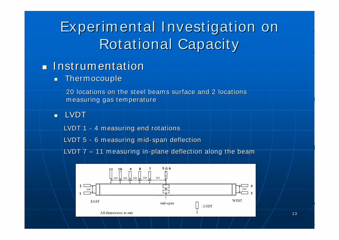
InstrumentationInstrumentation
20 locations on the steel beams surface and 2 locations 20 locations on the steel beams surface and 2 locations measuring gas temperaturemeasuring gas temperature
ThermocoupleThermocouple
LVDTLVDT
LVDT 1 LVDT 1 -- 4 measuring end rotations4 measuring end rotations
LVDT 5 LVDT 5 -- 6 measuring mid6 measuring mid--span deflectionspan deflection
LVDT 7 LVDT 7 –– 11 measuring in11 measuring in--plane deflection along the beamplane deflection along the beam
EAST WEST: LVDT
2
1 3
4
5 & 67891011
mid-span
482
All dimensions in mm
200200200200
200 200
1414
Experimental Investigation on Experimental Investigation on Rotational CapacityRotational Capacity
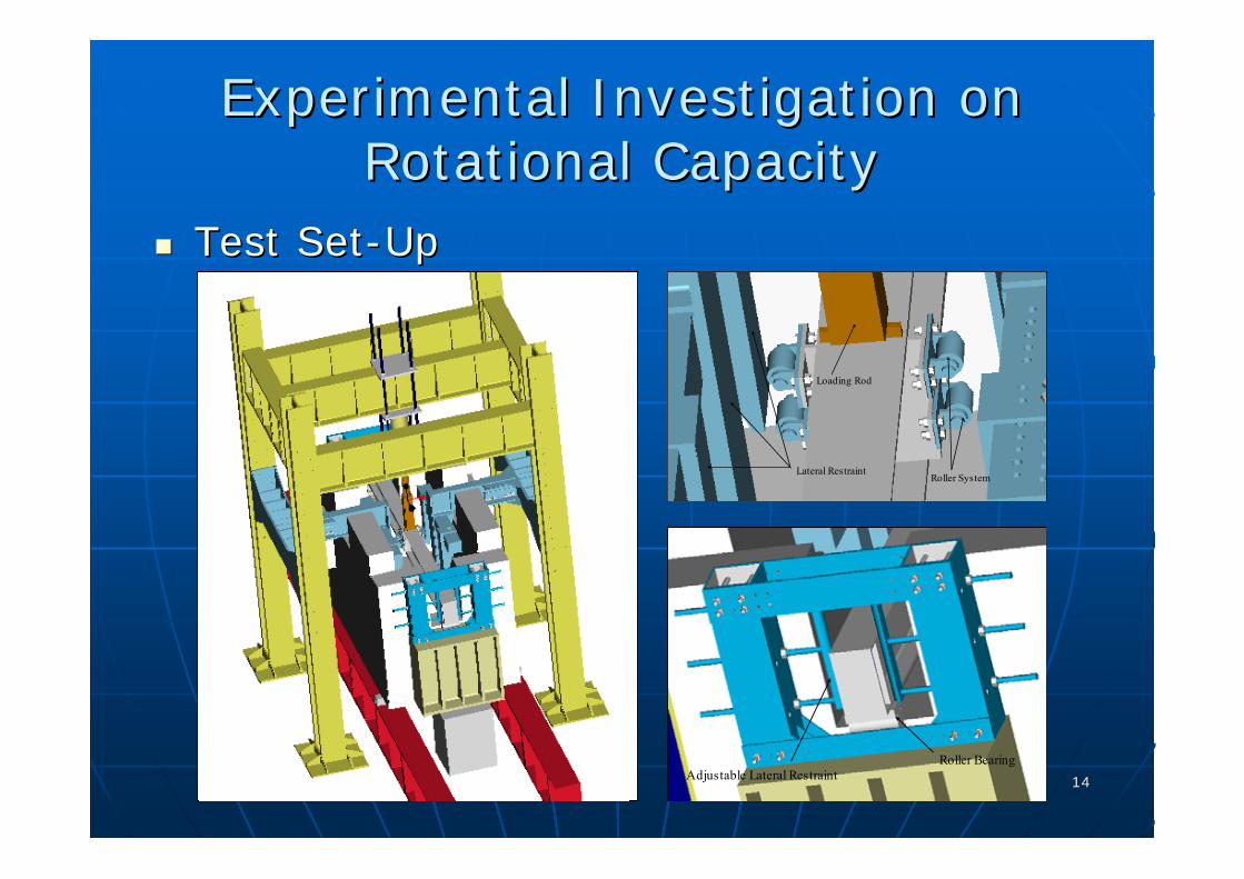
Test SetTest Set--UpUp
Roller BearingAdjustable Lateral Restraint
Roller SystemLateral Restraint
Loading Rod

1515
Experimental Investigation on Experimental Investigation on Rotational CapacityRotational Capacity
Results & General ObservationsResults & General Observations

1616
Experimental Investigation on Experimental Investigation on Rotational CapacityRotational Capacity
Results & General ObservationsResults & General Observations
No local and global buckling took place before the No local and global buckling took place before the plastic moment capacity was reached plastic moment capacity was reached –– design of design of specimens is indeed successful!!!specimens is indeed successful!!!Beams tested at 615Beams tested at 615°°C deviated from linearity at an C deviated from linearity at an earlier stage compared with those tested at 415earlier stage compared with those tested at 415°°C C After attaining plastic moment capacity, the beam After attaining plastic moment capacity, the beam deflection and rotation started to increase rapidly deflection and rotation started to increase rapidly No sudden failureNo sudden failureTwo failure modes observed: local buckling of the Two failure modes observed: local buckling of the beam flange and web near to midbeam flange and web near to mid--span and global span and global bucklingbuckling

1717
Experimental Investigation on Experimental Investigation on Rotational CapacityRotational Capacity
Results & General ObservationsResults & General Observations
S3-2
S4-1
Local bucklingLocal buckling with antiwith anti--symmetric mode at symmetric mode at equiequi--distance from the distance from the restrained midrestrained mid--spanspan
Web buckling less Web buckling less obvious than flange obvious than flange bucklingbuckling
Global bucklingGlobal buckling with with lateral movement mostly lateral movement mostly near midnear mid--spanspan
Due to spread of yielding Due to spread of yielding (different from elastic LTB)(different from elastic LTB)

1818
Experimental Investigation on Experimental Investigation on Rotational CapacityRotational Capacity
Temperature EffectsTemperature EffectsAmbient (S3Ambient (S3--1): 1):
considerable rotational considerable rotational capacity (capacity (rraa = 7.57) and = 7.57) and maximum moment of 33% maximum moment of 33% above its theoretical value above its theoretical value
415415°°C (S3C (S3--2): moment2): moment--rotation curve became nonrotation curve became non--linear and the rotational linear and the rotational capacity reduced to 2.28 capacity reduced to 2.28 even with additional lateral even with additional lateral restraints restraints
615615°°C (S3C (S3--3): rotational 3): rotational capacity further reduced to capacity further reduced to 1.111.11
00.10.20.30.40.50.60.70.80.9
11.11.21.31.4
0 1 2 3 4 5 6 7 8 9 10 11 12 13 14 15θ/θ e
M/M
p,T
Elastic-Plastic LineS3-1S3-2S3-3
(r a =7.57)(r a =2.28)(r a =1.11)
Conservatism of design plastic moment Conservatism of design plastic moment capacity has reduced from up to 30% capacity has reduced from up to 30% to a low of 10% as temperature to a low of 10% as temperature increased to 615increased to 615°°
1919
Experimental Investigation on Experimental Investigation on Rotational CapacityRotational Capacity
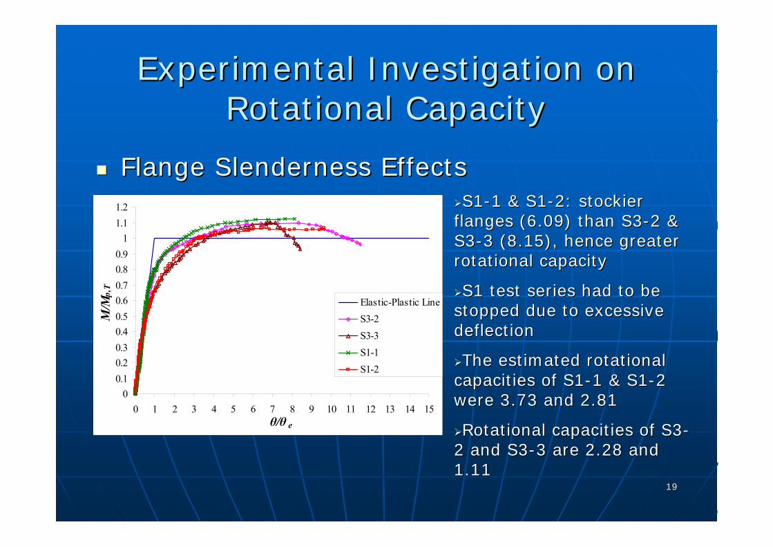
Flange Slenderness EffectsFlange Slenderness EffectsS1S1--1 & S11 & S1--2: stockier 2: stockier
flanges (6.09) than S3flanges (6.09) than S3--2 & 2 & S3S3--3 (8.15), hence greater 3 (8.15), hence greater rotational capacity rotational capacity
S1 test series had to be S1 test series had to be stopped due to excessive stopped due to excessive deflection deflection
The estimated rotational The estimated rotational capacities of S1capacities of S1--1 & S11 & S1--2 2 were 3.73 and 2.81were 3.73 and 2.81
Rotational capacities of S3Rotational capacities of S3--2 and S32 and S3--3 are 2.28 and 3 are 2.28 and 1.11 1.11
00.10.20.30.40.50.60.70.80.9
11.11.2
0 1 2 3 4 5 6 7 8 9 10 11 12 13 14 15θ/θ e
M/M
p,T
Elastic-Plastic LineS3-2S3-3S1-1S1-2

2020
Experimental Investigation on Experimental Investigation on Steel Beams’ Rotational CapacitySteel Beams’ Rotational Capacity
Web Slenderness EffectsWeb Slenderness EffectsS4S4--1 & S41 & S4--2 provided less 2 provided less
rotational capacity than S3rotational capacity than S3--2 & 2 & S3S3--3, respectively, because they 3, respectively, because they have more slender webshave more slender webs
S4S4--2 (6152 (615°°C) merely reached C) merely reached its plastic moment capacityits plastic moment capacity
Higher grade of steel (S355) Higher grade of steel (S355) used in S4 series may also used in S4 series may also contribute to less ductilitycontribute to less ductility
The stockier the web, the The stockier the web, the greater the restraints it provided greater the restraints it provided against flange buckling, thus against flange buckling, thus enhancing the ductilityenhancing the ductility
00.10.20.30.40.50.60.70.80.9
11.11.2
0 1 2 3 4 5 6 7 8 9 10 11 12 13 14 15θ/θ e
M/M
p,T
Elastic-Plastic LineS3-2S3-3S4-1S4-2
Even though flanges are the primary elements of flexural Even though flanges are the primary elements of flexural resistance in Iresistance in I--sections, the web slenderness effect is also sections, the web slenderness effect is also dominant.dominant.
2121
Experimental Investigation on Experimental Investigation on Steel Beams’ Rotational CapacitySteel Beams’ Rotational Capacity
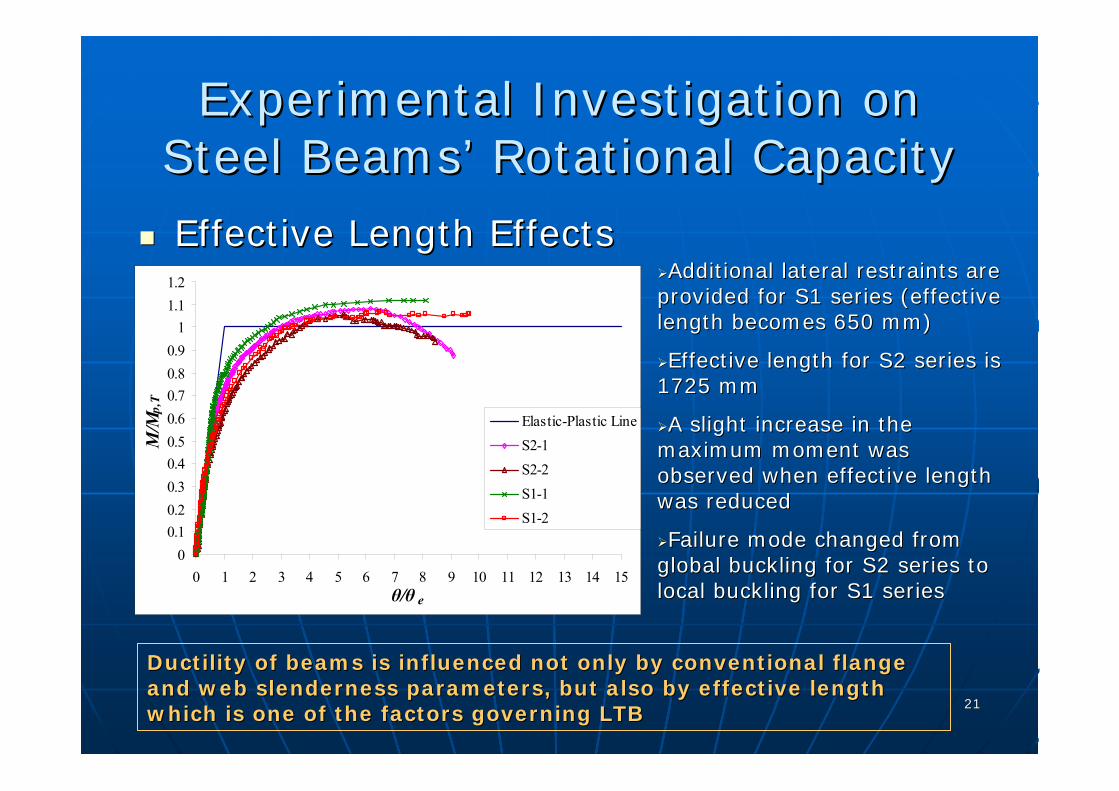
Effective Length EffectsEffective Length EffectsAdditional lateral restraints are Additional lateral restraints are
provided for S1 series (effective provided for S1 series (effective length becomes 650 mm) length becomes 650 mm)
Effective length for S2 series is Effective length for S2 series is 1725 mm1725 mm
A slight increase in the A slight increase in the maximum moment was maximum moment was observed when effective length observed when effective length was reducedwas reduced
Failure mode changed from Failure mode changed from global buckling for S2 series to global buckling for S2 series to local buckling for S1 serieslocal buckling for S1 series
Ductility of beams is influenced not only by conventional flangeDuctility of beams is influenced not only by conventional flangeand web slenderness parameters, but also by effective length and web slenderness parameters, but also by effective length which is one of the factors governing LTBwhich is one of the factors governing LTB
00.10.20.30.40.50.60.70.80.9
11.11.2
0 1 2 3 4 5 6 7 8 9 10 11 12 13 14 15θ/θ e
M/M
p,T
Elastic-Plastic LineS2-1S2-2S1-1S1-2
2222
Experimental Investigation on Experimental Investigation on Composite BeamsComposite Beams
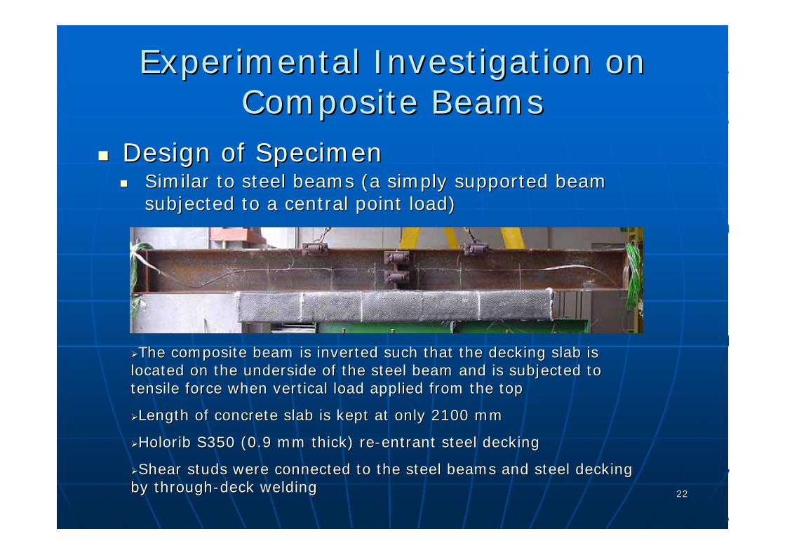
Design of SpecimenDesign of SpecimenSimilar to steel beams (Similar to steel beams (a simply supported beam a simply supported beam subjected to a central point load)subjected to a central point load)
The composite beam is inverted such that the decking slab is The composite beam is inverted such that the decking slab is located on the underside of the steel beam and is subjected to located on the underside of the steel beam and is subjected to tensile force when vertical load applied from the top tensile force when vertical load applied from the top
Length of concrete slab is kept at only 2100 mm Length of concrete slab is kept at only 2100 mm
HoloribHolorib S350 (0.9 mm thick) reS350 (0.9 mm thick) re--entrant steel decking entrant steel decking
Shear studs were connected to the steel beams and steel decking Shear studs were connected to the steel beams and steel decking by throughby through--deck weldingdeck welding

2323
Experimental Investigation on Experimental Investigation on Composite BeamsComposite Beams
Design of SpecimenDesign of SpecimenAfter concrete curing, double layer of fire protection After concrete curing, double layer of fire protection
material consisted of 25 mm thick vermiculite and 30 material consisted of 25 mm thick vermiculite and 30 mm thick ceramic blanket applied to exposed surface mm thick ceramic blanket applied to exposed surface of concrete of concrete

2424
Experimental Investigation on Experimental Investigation on Composite BeamsComposite Beams
PushPush--Out Test (Shear Studs)Out Test (Shear Studs)
Push-Out Specimen Configuration
254x254UC89
150
Point Load
260 150
150
250
250
all reinforcement:10mm dia.
deformed bar
(all dimensions are in mm)
Push-Out Test Set-Up
Average maximum shear strength was 115 Average maximum shear strength was 115 kNkN per per connectorconnector
0
20
40
60
80
100
120
140
0 2 4 6 8 10Slip (mm)
Load
(kN
)
Push-Out Test 1Push-Out Test 2Best-Fit

2525
Experimental Investigation on Experimental Investigation on Composite BeamsComposite Beams
Temperature DevelopmentsTemperature DevelopmentsFurnace temperature set Furnace temperature set
between 650 and 800between 650 and 800°°C C based on 7 to 10based on 7 to 10°°C/minC/min
Temp of rebar (100 mm Temp of rebar (100 mm above top flange) and above top flange) and concrete (concrete (hhcc = 100 mm) = 100 mm) was very closewas very close
Shear stud temperature Shear stud temperature was in between the was in between the recorded concrete recorded concrete temperature closest to temperature closest to top flange (top flange (hhcc = 0 mm) = 0 mm) and and hhcc = 50 mm = 50 mm

2626
Experimental Investigation on Experimental Investigation on Composite BeamsComposite Beams
Temperature DevelopmentsTemperature DevelopmentsAverage top flange temperature Average top flange temperature
around 0.86 of bottom flange around 0.86 of bottom flange temperature due to the heat sink and temperature due to the heat sink and shielding effect of concrete slab shielding effect of concrete slab
Web temperature varied Web temperature varied parabolicallyparabolicallybetween the top and bottom flange between the top and bottom flange temperaturestemperatures
Temperature profile of concrete Temperature profile of concrete seemed to be parabolic as wellseemed to be parabolic as well
The maximum temperature of the The maximum temperature of the shear stud connector for all beams was shear stud connector for all beams was 340340°°CC
2727
Experimental Investigation on Experimental Investigation on Composite BeamsComposite Beams
General ObservationsGeneral Observations
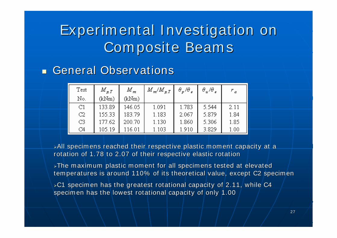
All specimens reached their respective plastic moment capacity aAll specimens reached their respective plastic moment capacity at a t a rotation of 1.78 to 2.07 of their respective elastic rotationrotation of 1.78 to 2.07 of their respective elastic rotation
The maximum plastic moment for all specimens tested at elevated The maximum plastic moment for all specimens tested at elevated temperatures is around 110% of its theoretical value, except C2 temperatures is around 110% of its theoretical value, except C2 specimenspecimen
C1 specimen has the greatest rotational capacity of 2.11, while C1 specimen has the greatest rotational capacity of 2.11, while C4 C4 specimen has the lowest rotational capacity of only 1.00specimen has the lowest rotational capacity of only 1.00

2828
Experimental Investigation on Experimental Investigation on Composite BeamsComposite Beams
General ObservationsGeneral Observations
C1
0
0.2
0.4
0.6
0.8
1
1.2
0 1 2 3 4 5 6 7 8 9 10θ/θ e
M/M
p,T
Plastic LineTest
No local or global buckling was seen on FEM before the plastic mNo local or global buckling was seen on FEM before the plastic moment oment capacity was reachedcapacity was reached
A gradual load reduction occurred without sudden failureA gradual load reduction occurred without sudden failure
Failure mode Failure mode -- mainly local buckling near midmainly local buckling near mid--span span
C4
0
0.2
0.4
0.6
0.8
1
1.2
0 1 2 3 4 5 6 7 8 9 10θ/θ e
M/M
p,T
Plastic LineTest

2929
Experimental Investigation on Experimental Investigation on Composite BeamsComposite Beams
General ObservationsGeneral ObservationsAntiAnti--symmetric local symmetric local
buckling of bottom flange buckling of bottom flange where one side of flange where one side of flange curled up while the other curled up while the other side twisted downwardsside twisted downwards
Local buckling of web Local buckling of web occurred at almost the full occurred at almost the full depth of the webdepth of the web
Local buckling failure Local buckling failure occurred on only one half of occurred on only one half of the beam the beam
C3
C4 C4
C3

3030
Experimental Investigation on Experimental Investigation on Composite BeamsComposite Beams
Key Findings & DiscussionsKey Findings & DiscussionsThe main component of composite beam is the primary reinforcemenThe main component of composite beam is the primary reinforcementt
Plastic neutral axis located within the top flange, or near to tPlastic neutral axis located within the top flange, or near to the webhe web--top flange top flange junctionjunction
Degree of shear connection was not reduced even when the beam waDegree of shear connection was not reduced even when the beam was heated, s heated, since the temperature of shear stud was below 300since the temperature of shear stud was below 300°°CC
An increase in ultimate moment capacity for C2 due to misalignmeAn increase in ultimate moment capacity for C2 due to misalignment of beam nt of beam during test setduring test set--up; protection material was skewed to one side up; protection material was skewed to one side
Effects of flange and web slenderness, effective length, degree Effects of flange and web slenderness, effective length, degree of shear of shear connection and reinforcement ratio cannot be quantified from theconnection and reinforcement ratio cannot be quantified from the test results test results since only four tests had been conducted and the temperature dissince only four tests had been conducted and the temperature distribution for tribution for each test was different each test was different
3131
Experimental Investigation on Experimental Investigation on Composite BeamsComposite Beams
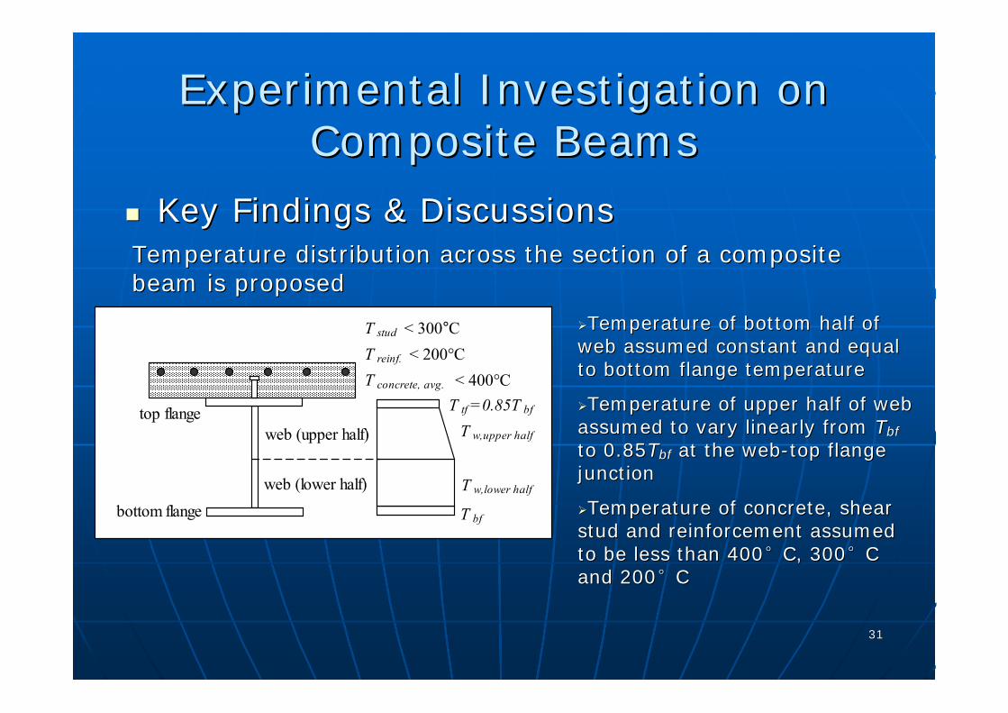
Key Findings & DiscussionsKey Findings & DiscussionsTemperature distribution across the section of a composite Temperature distribution across the section of a composite beam is proposed beam is proposed
T bf
T w,lower half
T tf =0.85T bf
T w,upper half
bottom flange
top flange
web (lower half)
web (upper half)
T stud < 300°CT reinf. < 200°CT concrete, avg. < 400°C
Temperature of bottom half of Temperature of bottom half of web assumed constant and equal web assumed constant and equal to bottom flange temperatureto bottom flange temperature
Temperature of upper half of web Temperature of upper half of web assumed to vary linearly from assumed to vary linearly from TTbfbf
to 0.85to 0.85TTbfbf at the webat the web--top flange top flange junctionjunction
Temperature of concrete, shear Temperature of concrete, shear stud and reinforcement assumed stud and reinforcement assumed to be less than 400to be less than 400°°C, 300C, 300°°C C and 200and 200°°C C

3232
Experimental Investigation on Experimental Investigation on Composite BeamsComposite Beams
Key Findings & DiscussionsKey Findings & DiscussionsComparisons of failure modes with Cardington testComparisons of failure modes with Cardington test
distance to local buckling
distance to local buckling
C2 Cardington Test
C3 Cardington Test
3333
Experimental Investigation on Experimental Investigation on Composite BeamsComposite Beams
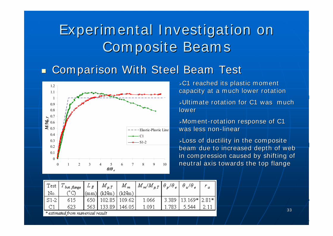
Comparison With Steel Beam TestComparison With Steel Beam Test
00.10.20.30.40.50.60.70.80.9
11.11.2
0 1 2 3 4 5 6 7 8 9 10θ/θ e
M/M
p,T
Elastic-Plastic LineC1S1-2
C1 reached its plastic moment C1 reached its plastic moment capacity at a much lower rotationcapacity at a much lower rotation
Ultimate rotation for C1 was much Ultimate rotation for C1 was much lower lower
MomentMoment--rotation response of C1 rotation response of C1 was less nonwas less non--linearlinear
Loss of ductility in the composite Loss of ductility in the composite beam due to increased depth of web beam due to increased depth of web in compression caused by shifting of in compression caused by shifting of neutral axis towards the top flange neutral axis towards the top flange

3434
Four node rectangular thick shell element from Four node rectangular thick shell element from MSC.MARC MSC.MARC MentatMentatGeometrical and material nonlinearities Geometrical and material nonlinearities ArcArc--length approachlength approachVon Von MisesMises yield criterion yield criterion Initial imperfection in the form of a half sine Initial imperfection in the form of a half sine curve curve Validate FEM with Validate FEM with LukeyLukey and Adams tests and Adams tests (1969) (1969)
Finite Element Analysis (Steel)Finite Element Analysis (Steel)
OverviewOverview

3535
Moment-Rotation Curve
00.10.20.30.40.50.60.70.80.9
11.11.2
0 2 4 6 8 10 12θ /θp
M/M
p Elastic-Plastic
FEA
Test
θ
Specimen B-3
Moment-Rotation Curve
00.10.20.30.40.50.60.70.80.9
11.11.2
0 2 4 6 8 10 12
θ /θ p
M/M
p Elastic-Plastic
FEA
Test
θ
Specimen C-4
Finite Element Analysis (Steel)Finite Element Analysis (Steel)
00.10.20.30.40.50.60.70.80.9
11.11.21.31.4
0 1 2 3 4 5 6 7 8 9 10 11 12 13 14 15θ/θ e
M/M
p
Elastic-Plastic Line
S3-1(Test)
S3-1(FEA)
θ a /θ e
θ p /θ e
IELM
T
iTpe 2
,=θ
Validation (Ambient Temperature)Validation (Ambient Temperature)

3636
Finite Element Analysis (Steel)Finite Element Analysis (Steel)Validation (Elevated Temperature)Validation (Elevated Temperature)
00.10.20.30.40.50.60.70.80.9
11.11.2
0 1 2 3 4 5 6 7 8 9 10 11 12 13 14 15θ/θ e
M/M
p,T
Elastic-Plastic LineS2-1(Test)S2-2(Test)S2-1(FEA)S2-2(FEA)
0
0.10.2
0.3
0.40.5
0.6
0.70.8
0.9
11.1
1.2
0 1 2 3 4 5 6 7 8 9 10 11 12 13 14 15θ/θ e
M/M
p,T
Elastic-Plastic LineS3-2(Test)S3-3(Test)S3-2(FEA)S3-3(FEA)
Predictions of maximum moments within 2%Predictions of maximum moments within 2%
Excellent agreement between test results and FE predictions due Excellent agreement between test results and FE predictions due to to accuracy of initial imperfectionaccuracy of initial imperfection
Slight discrepancy in response may be attributed to the differenSlight discrepancy in response may be attributed to the differences ces between the stressbetween the stress--strain relationships proposed by EC3:1.2 and the strain relationships proposed by EC3:1.2 and the actual stressactual stress--strain relationshipstrain relationship

3737
Finite Element Analysis (Steel)Finite Element Analysis (Steel)Parametric Study (Temperature)Parametric Study (Temperature)
Rotational capacity reduces as Rotational capacity reduces as temperature increasestemperature increases
Compare the trend of rotational Compare the trend of rotational capacity with the ratio of elastic capacity with the ratio of elastic modulus to yield strength at modulus to yield strength at elevated temperatureelevated temperature
0
0.2
0.4
0.6
0.8
1
1.2
1.4
0 2 4 6 8 10 12 14 16 18 20 22 24θ/θ e
M/M
p,T Elastic-Plastic
RB2-T=600°CRB2-T=AmbientRB2-T=300°CRB2-T=400°CRB2-T=500°CRB2-T=700°CRB2-T=800°C
00.5
11.5
22.5
33.5
44.5
0 100 200 300 400 500 600 700 800
Temperature (°C)
Rot
atio
nal C
apac
ity r a
RB2RB4
0
0.2
0.4
0.6
0.8
1
1.2
0 100 200 300 400 500 600 700 800
Temperature (°C)
k E/k
y
T yT E y yE f k E k f=

3838
Finite Element Analysis (Steel)Finite Element Analysis (Steel)Parametric Study (Effective Length)Parametric Study (Effective Length)
Reducing the effective length increases both the maximum moment Reducing the effective length increases both the maximum moment and and rotational capacityrotational capacity
A change of failure modes when effective length is reducedA change of failure modes when effective length is reduced
Improvement to the rotational capacity can be achieved by reduciImprovement to the rotational capacity can be achieved by reducing the ng the effective length for beams in which global buckling mode is obseeffective length for beams in which global buckling mode is observedrved
0
0.2
0.4
0.6
0.8
1
1.2
0 2 4 6 8 10 12 14θ/θ e
M/M
p,T
Elastic-Plastic
RB1RB1-Le=600
RB1-Le=500RB1-Le=300RB1-L E =400
RB1-L E =600
RB1-L E =500
RB1-L E =300
3D ViewPlan View
RB3-L e =600RB3-L E=600
Plan View 3D View
RB3-L e =300RB3-L E=300

3939
Structural steel Structural steel -- four node rectangular thick shell four node rectangular thick shell elementelementConcrete slab Concrete slab -- 2020--node node isoiso--parametric solid elementparametric solid elementReinforcement Reinforcement -- isoiso--parametric, threeparametric, three--dimensional, 20dimensional, 20--node solid elementnode solid elementAdjacent top flange and concrete nodes tied together Adjacent top flange and concrete nodes tied together using rigid links in two global displacementsusing rigid links in two global displacementsThe relative slip in The relative slip in xx--direction between the steel beam direction between the steel beam and concrete element is governed by the loadand concrete element is governed by the load--slip slip relationship of shear stud connectors, and is simulated relationship of shear stud connectors, and is simulated using linear springsusing linear springsUniaxialUniaxial representation of constitutive law in terms of representation of constitutive law in terms of true stress and logarithmic straintrue stress and logarithmic strain
FE Analysis (Composite)FE Analysis (Composite)OverviewOverview
4040
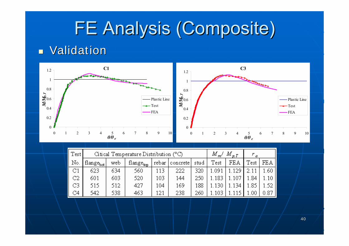
FE Analysis (Composite)FE Analysis (Composite)ValidationValidation
C1
0
0.2
0.4
0.6
0.8
1
1.2
0 1 2 3 4 5 6 7 8 9 10θ/θ e
M/M
p,T
Plastic LineTestFEA
C3
0
0.2
0.4
0.6
0.8
1
1.2
0 1 2 3 4 5 6 7 8 9 10θ/θ e
M/M
p,T
Plastic LineTestFEA

4141
FE Analysis (Composite)FE Analysis (Composite)ValidationValidation
C4 TEST C4 FEA
C1 FEAC1 TEST
4242
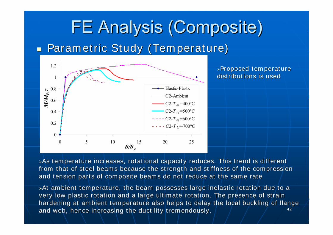
FE Analysis (Composite)FE Analysis (Composite)Parametric Study (Temperature)Parametric Study (Temperature)
As temperature increases, rotational capacity reduces. This trenAs temperature increases, rotational capacity reduces. This trend is different d is different from that of steel beams because the strength and stiffness of tfrom that of steel beams because the strength and stiffness of the compression he compression and tension parts of composite beams do not reduce at the same rand tension parts of composite beams do not reduce at the same rate ate
At ambient temperature, the beam possesses large inelastic rotatAt ambient temperature, the beam possesses large inelastic rotation due to a ion due to a very low plastic rotation and a large ultimate rotation. The prevery low plastic rotation and a large ultimate rotation. The presence of strain sence of strain hardening at ambient temperature also helps to delay the local bhardening at ambient temperature also helps to delay the local buckling of flange uckling of flange and web, hence increasing the ductility tremendously.and web, hence increasing the ductility tremendously.
0
0.2
0.4
0.6
0.8
1
1.2
0 5 10 15 20 25θ/θ e
M/M
p,T Elastic-Plastic
C2-AmbientC2-Tbf=400CC2-Tbf=500CC2-Tbf=600CC2-Tbf=700C
C2-T bf =400°CC2-T bf =500°CC2-T bf =600°CC2-T bf =700°C
Proposed temperature Proposed temperature distributionsdistributions is usedis used
4343
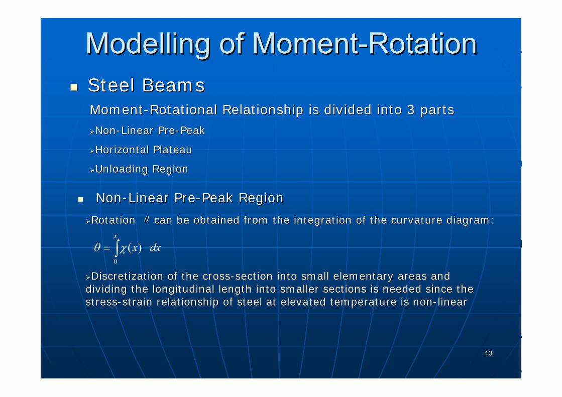
ModellingModelling of Momentof Moment--RotationRotationSteel BeamsSteel Beams
NonNon--Linear PreLinear Pre--Peak RegionPeak Region
MomentMoment--Rotational Relationship is divided into 3 partsRotational Relationship is divided into 3 parts
NonNon--Linear PreLinear Pre--PeakPeak
Horizontal PlateauHorizontal Plateau
Unloading RegionUnloading Region
Rotation Rotation θθ can be obtained from the integration of the curvature diagram:can be obtained from the integration of the curvature diagram:
0
( )x
x dxθ χ= ∫DiscretizationDiscretization of the crossof the cross--section into small elementary areas and section into small elementary areas and
dividing the longitudinal length into smaller sectionsdividing the longitudinal length into smaller sections is needed since is needed since the the stressstress--strain relationship of steel at elevated temperature is nonstrain relationship of steel at elevated temperature is non--linearlinear
4444
ModellingModelling of Momentof Moment--RotationRotationSteel BeamsSteel Beams
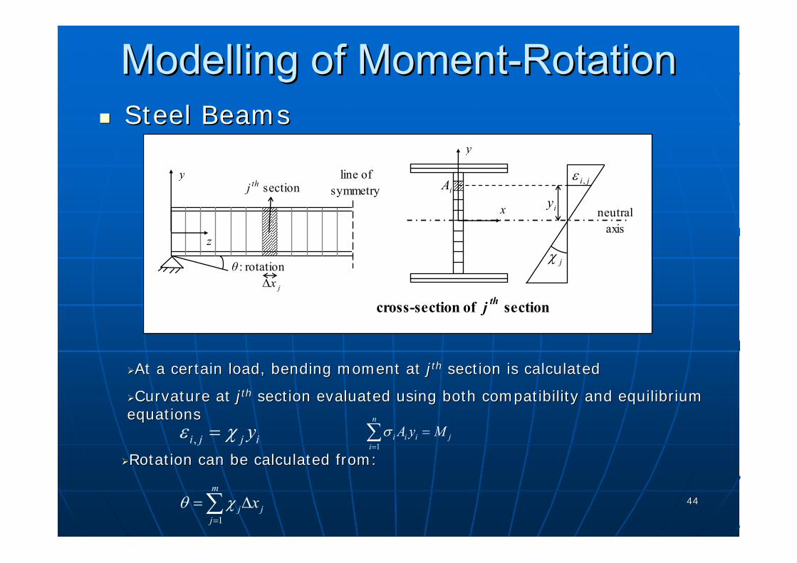
Rotation can be calculated from:Rotation can be calculated from:
jxΔ
z
θ : rotation
line of symmetry
yj th section
neutralaxis
iyiA ji ,ε
jχ
x
y
cross-section of j th section
,i j j iyε χ=1
n
i i i ji
A y Mσ=
=∑
At a certain load, bending moment at At a certain load, bending moment at jjthth section is calculatedsection is calculated
Curvature at Curvature at jjthth section evaluated using both compatibility and equilibrium section evaluated using both compatibility and equilibrium equationsequations
1
m
j jj
xθ χ=
= Δ∑
4545
ModellingModelling of Momentof Moment--RotationRotationSteel BeamsSteel Beams
Since the maximum moment achieved for steel beams with temperatuSince the maximum moment achieved for steel beams with temperature re exceeding 400exceeding 400°°C is generally less than 10% above their plastic moment C is generally less than 10% above their plastic moment capacity, it is sufficient to use a horizontal line at the plastcapacity, it is sufficient to use a horizontal line at the plastic moment capacity ic moment capacity to connect the nonto connect the non--linear prelinear pre--peak curve with the unloading curvepeak curve with the unloading curve
Horizontal line will begin at plastic rotation Horizontal line will begin at plastic rotation θθpp up to ultimate rotation up to ultimate rotation θθuu, in , in which the unloading curve crosses the plastic moment capacitywhich the unloading curve crosses the plastic moment capacity
Horizontal Plateau RegionHorizontal Plateau Region
Unloading Region (Statistical Approach)Unloading Region (Statistical Approach)
Both the ultimate rotation Both the ultimate rotation θθuu, which determines the start of unloading curve, , which determines the start of unloading curve, and the unloading momentand the unloading moment--rotation equation need to be determinedrotation equation need to be determined
A multiA multi--linear regression model is used to predict the ultimate rotationlinear regression model is used to predict the ultimate rotation
a quadratic equation with coefficients obtained from the regressa quadratic equation with coefficients obtained from the regression of ion of FEFE’’sspostpost--buckling curvesbuckling curves is used to describe the unloading momentis used to describe the unloading moment--rotational rotational relationshiprelationship
4646
ModellingModelling of Momentof Moment--RotationRotationSteel BeamsSteel Beams
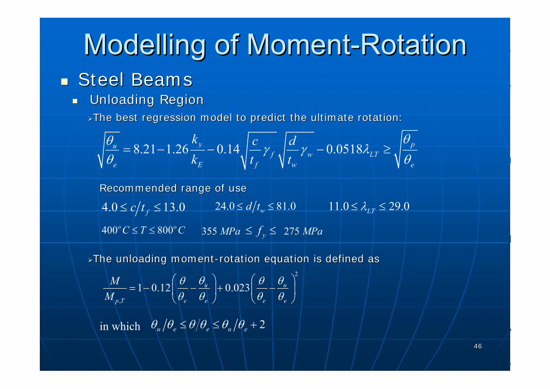
The best regression model to predict the ultimate rotationThe best regression model to predict the ultimate rotation::
Unloading RegionUnloading Region
8.21 1.26 0.14 0.0518y puf w LT
e E f w e
k c dk t t
θθ γ γ λθ θ
= − − − ≥
Recommended range of useRecommended range of use
4.0 13.0fc t≤ ≤ 24.0 81.0wd t≤ ≤ 11.0 29.0LTλ≤ ≤
275 MPayf≤ ≤355 MPa400 800o oC T C≤ ≤
The unloading momentThe unloading moment--rotation equation is defined asrotation equation is defined as2
,
1 0.12 0.023u u
p T e e e e
MM
θ θθ θθ θ θ θ⎛ ⎞ ⎛ ⎞
= − − + −⎜ ⎟ ⎜ ⎟⎝ ⎠ ⎝ ⎠
in which 2u e e u eθ θ θ θ θ θ≤ ≤ +

4747
ModellingModelling of Momentof Moment--RotationRotationSteel BeamsSteel Beams
Validation of Design ModelValidation of Design Model
0
0.2
0.4
0.6
0.8
1
1.2
0 2 4 6 8 10θ/θ e
M/M
p,T
eu θθep θθ
unloading curve: eq. (7.8)
pre-peak curve:integration of M-χ diagram
horizontal plateau
[eq. (7.7)] 00.10.2
0.30.40.50.6
0.70.8
0.91
1.11.2
0 1 2 3 4 5 6 7 8 9 10 11 12 13 14 15θ/θ e
M/M
p,T
Elastic-Plastic Line
S2-1(Test)
S2-1(FEA)
S2-1(Model)
00.10.20.30.40.50.60.70.80.9
1
1.11.2
0 1 2 3 4 5 6 7 8 9 10 11 12 13 14 15θ/θ e
M/M
p,T
Elastic-Plastic Line
S3-2(Test)
S3-2(FEA)
S3-2(Model)
4848
ModellingModelling of Momentof Moment--RotationRotationSteel BeamsSteel Beams
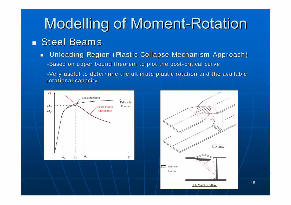
Unloading Region (Plastic Collapse Mechanism Approach)Unloading Region (Plastic Collapse Mechanism Approach)Based on upper bound theorem to plot the postBased on upper bound theorem to plot the post--critical curvecritical curve
Very useful to determine the ultimate plastic rotation and the aVery useful to determine the ultimate plastic rotation and the available vailable rotational capacityrotational capacity
Failure byFracture
M p
θ p θm θ u
M
M m Local PlasticMechanism
Local Buckling
θ
3D VIEW
ELEVATION VIEW
Plastic Zone
Yield Line

4949
ModellingModelling of Momentof Moment--RotationRotationSteel BeamsSteel Beams
Unloading Region (Plastic Collapse Mechanism Approach)Unloading Region (Plastic Collapse Mechanism Approach)Many different models available for steel beams at ambient Many different models available for steel beams at ambient
temperature. The model by temperature. The model by GioncuGioncu & & PetcuPetcu (2001) is extended to (2001) is extended to elevated temperature in this researchelevated temperature in this research
ηc
ηc
Buckled shape of the compression Buckled shape of the compression flange is represented by a doubleflange is represented by a double--triangular plastic zone and several triangular plastic zone and several yield linesyield lines
Buckled shape of the web is Buckled shape of the web is represented by an upper triangular represented by an upper triangular plastic zone connected by several plastic zone connected by several yield lines to the centre of rotation yield lines to the centre of rotation ““1212””
As rotation occurs, the tension zone As rotation occurs, the tension zone remains in plane and experiences remains in plane and experiences simple tensile inelastic deformationsimple tensile inelastic deformation

5050
ModellingModelling of Momentof Moment--RotationRotation
At point of collapse (local plastic mechanism is formed), the At point of collapse (local plastic mechanism is formed), the total external virtual work done:total external virtual work done:
∑ Δ= iiext PW
The total internal virtual work of the mechanism:The total internal virtual work of the mechanism:
∑∑ +=j
jzi
il WWW )()(int
in which,in which,
∫=pl
yl dlf
ptW )(
4
2
θ
∫=pA
yz dAftpW )(ε
θyp
l ptl
W4
2
=
εypz tpAW =
Steel BeamsSteel BeamsUnloading Region (Plastic Collapse Mechanism Approach)Unloading Region (Plastic Collapse Mechanism Approach)
5151
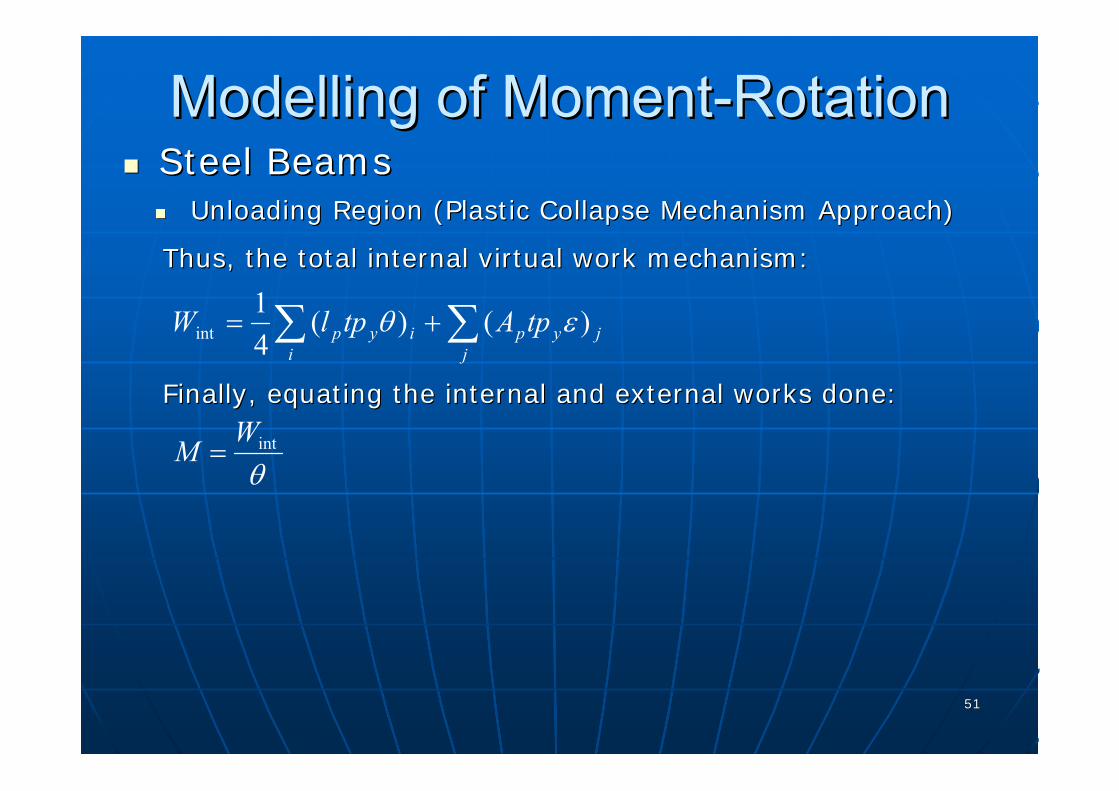
Thus, the total internal virtual work mechanism:Thus, the total internal virtual work mechanism:
Finally, equating the internal and external works done:Finally, equating the internal and external works done:
jj
ypiyi
p tpAtplW )()(41
int ∑∑ += εθ
θintW
M =
ModellingModelling of Momentof Moment--RotationRotationSteel BeamsSteel Beams
Unloading Region (Plastic Collapse Mechanism Approach)Unloading Region (Plastic Collapse Mechanism Approach)

5252
Extension of the model to elevated temperature:Extension of the model to elevated temperature:
ModellingModelling of Momentof Moment--RotationRotationSteel BeamsSteel Beams
Unloading Region (Plastic Collapse Mechanism Approach)Unloading Region (Plastic Collapse Mechanism Approach)
Length of mechanism slightly reduced at elevated temperature becLength of mechanism slightly reduced at elevated temperature because of ause of the disappearance of strainthe disappearance of strain--hardening phenomenon which limits the spread hardening phenomenon which limits the spread of plasticityof plasticity
Parameter Parameter ββ which determines the length of mechanism modified aswhich determines the length of mechanism modified as3/ 41/ 4
,
2750.7130.7
f E yT
yf c w
t k kdf b t
β⎛ ⎞ ⎛ ⎞⎛ ⎞= ⎜ ⎟ ⎜ ⎟⎜ ⎟
⎝ ⎠ ⎝ ⎠⎝ ⎠
modifies the material coefficient of modifies the material coefficient of 0.713 and indicates that, as the 0.713 and indicates that, as the steel grade increases the length of steel grade increases the length of mechanism is reduced, which is in mechanism is reduced, which is in line with experimental and line with experimental and numerical evidencenumerical evidence
take into account the effect of take into account the effect of temperature on the unloading temperature on the unloading curve and rotational capacitycurve and rotational capacity

5353
ModellingModelling of Momentof Moment--RotationRotation
S3-2
0
0.2
0.4
0.6
0.8
1
1.2
0 5 10 15 20θ/θ e
M/M
p,T
Test
FEA
M-rot. model
(b)
Steel BeamsSteel BeamsValidationValidation
PCM method is best used within the limits of parameters:PCM method is best used within the limits of parameters:
S4-1
0
0.2
0.4
0.6
0.8
1
1.2
0 1 2 3 4 5 6 7 8 9 10 11 12 13 14 15θ/θ e
M/M
p,T Test
FEA
PCM
4.0 ( ) 10.0f fc t γ≤ ≤ 24.0 ( ) 44.0w wd t γ≤ ≤ 11.0 20.0LTλ≤ ≤
( ) ( )( )/ / 5.5w w f fd t c tγ γ ≤ 400 800o oC T C≤ ≤

5454
ModellingModelling of Momentof Moment--RotationRotationComposite BeamsComposite Beams
Unloading Region (Plastic Collapse Mechanism Approach)Unloading Region (Plastic Collapse Mechanism Approach)
One additional internal work done by the plastic zone of the One additional internal work done by the plastic zone of the reinforcementreinforcement has to includedhas to included
This internal work done by the reinforcementThis internal work done by the reinforcement can be calculated by can be calculated by integrating the strain energy over the deforming volume (plasticintegrating the strain energy over the deforming volume (plastic zone):zone):
The preThe pre--peak region before buckling can be evaluated peak region before buckling can be evaluated the same way as steel beamsthe same way as steel beams
,reinf
int s p yr TW A x f θ=
ηc13concrete
rebar
x p
centroid of steel section
h r
5555
ModellingModelling of Momentof Moment--RotationRotationComposite BeamsComposite Beams
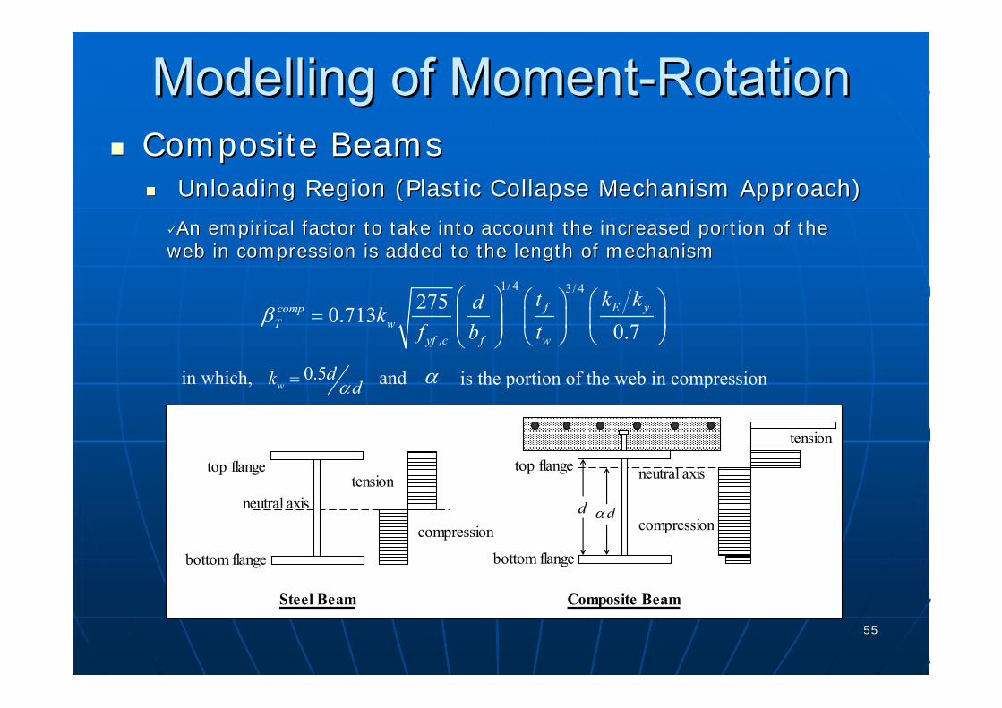
Unloading Region (Plastic Collapse Mechanism Approach)Unloading Region (Plastic Collapse Mechanism Approach)
An empirical factor to take into account the increased portion oAn empirical factor to take into account the increased portion of the f the web in compression is added to the length of mechanismweb in compression is added to the length of mechanism
1/ 4 3/ 4
,
2750.7130.7
f E ycompT w
yf c f w
t k kdkf b t
β⎛ ⎞ ⎛ ⎞ ⎛ ⎞
= ⎜ ⎟ ⎜ ⎟ ⎜ ⎟⎜ ⎟ ⎝ ⎠⎝ ⎠⎝ ⎠
in which, and is the portion of the web in compression0.5w
dk dα= α
bottom flange
top flange
neutral axis
Steel Beam
compression
tension
bottom flange
top flange neutral axis
Composite Beam
compression
tension
d dα

5656
ModellingModelling of Momentof Moment--RotationRotation
C1
00.10.20.30.40.50.60.70.80.9
11.11.2
0 1 2 3 4 5 6 7 8 9 10θ/θ e
M/M
p,T
Elastic-Plastic
Test
PCM based Model
(a)
C3
00.10.20.30.40.50.60.70.80.9
11.11.2
0 1 2 3 4 5 6 7 8 9 10θ/θ e
M/M
p,T
Elastic-Plastic
Test
PCM based Model
(c)
Composite BeamsComposite BeamsValidationValidation

5757
ConclusionsConclusions
The ductility issue of both steel and composite The ductility issue of both steel and composite beams in the hogging moment regions under beams in the hogging moment regions under fire conditions has been highlighted by 4 fire conditions has been highlighted by 4 composite beam specimenscomposite beam specimensExtensive numerical analysis to identify key Extensive numerical analysis to identify key factors affecting the local buckling and the factors affecting the local buckling and the failure patternsfailure patternsPropose a momentPropose a moment--rotational relationship for rotational relationship for both steel and composite beams subjected to both steel and composite beams subjected to hogging moment at elevated temperatureshogging moment at elevated temperaturesThe proposed momentThe proposed moment--rotation design model rotation design model comprises three parts: a noncomprises three parts: a non--linear prelinear pre--peak peak curve, a horizontal plateau at the plastic curve, a horizontal plateau at the plastic moment capacity and an unloading curvemoment capacity and an unloading curve

5858
RecommendationsRecommendations
Additional tests on composite beams to includes Additional tests on composite beams to includes beams with partial shear connections or other beams with partial shear connections or other types of decking and shear connectorstypes of decking and shear connectorsStudy the momentStudy the moment--rotational relationship of the rotational relationship of the inner span of continuous beam under hogging inner span of continuous beam under hogging moment, that is, thermal restraint is presentmoment, that is, thermal restraint is presentBehaviour of steel and composite frames related Behaviour of steel and composite frames related to redistribution of moment during fire be studied to redistribution of moment during fire be studied using proposed momentusing proposed moment--rotational relationship to rotational relationship to incorporate the local buckling effectincorporate the local buckling effectStudy the Study the behaviourbehaviour of composite beams with the of composite beams with the joints under joints under elevated temperatureselevated temperatures

5959
THANK YOUTHANK YOU

6060
Q&A SESSIONQ&A SESSION

6161
List of PublicationsList of Publications1.1. Dharma, R. B. and Tan, K. H. (2005), Dharma, R. B. and Tan, K. H. (2005), ““Alternative Alternative
Approach for Lateral Approach for Lateral TorsionalTorsional Buckling of Unrestrained Buckling of Unrestrained Beams in FireBeams in Fire””, , Proceedings of the Fourth International Proceedings of the Fourth International Conference on Advances in Steel StructuresConference on Advances in Steel Structures, Shanghai, , Shanghai, Elsevier Ltd., pp.949Elsevier Ltd., pp.949--957.957.
2.2. Dharma, R. B. and Tan, K. H. (2005), Dharma, R. B. and Tan, K. H. (2005), ““A Numerical Study A Numerical Study of Rotational Capacity of Steel Beams in Fireof Rotational Capacity of Steel Beams in Fire””, , Proceedings Proceedings of the Fourth International Conference on Advances in of the Fourth International Conference on Advances in Steel StructuresSteel Structures, Shanghai, Elsevier Ltd., pp.981, Shanghai, Elsevier Ltd., pp.981--989.989.
3.3. Dharma, R. B. and Tan, K. H. (2006), Dharma, R. B. and Tan, K. H. (2006), ““Ductility of Steel Ductility of Steel and Composite Beams under Fire Conditionsand Composite Beams under Fire Conditions””, , Proceedings Proceedings of the International Symposium on Advances in Steel and of the International Symposium on Advances in Steel and Composite StructuresComposite Structures, Singapore, CACS, pp. 84, Singapore, CACS, pp. 84--99.99.
4.4. Dharma, R. B. and Tan, K. H. (2006), Dharma, R. B. and Tan, K. H. (2006), ““Proposed Design Proposed Design Methods for Lateral Methods for Lateral TorsionalTorsional Buckling of Unrestrained Buckling of Unrestrained Steel Beams in FireSteel Beams in Fire””, accepted for publication in , accepted for publication in Journal of Journal of Constructional Steel ResearchConstructional Steel Research..
6262
List of PublicationsList of Publications
5.5. Dharma, R. B. and Tan, K. H. (2006), Dharma, R. B. and Tan, K. H. (2006), ““Rotational Capacity Rotational Capacity of Steel Iof Steel I--Beams under Fire Conditions, Part I: Beams under Fire Conditions, Part I: Experimental StudyExperimental Study””, accepted for publication in , accepted for publication in Engineering StructuresEngineering Structures..
6.6. Dharma, R. B. and Tan, K. H. (2006), Dharma, R. B. and Tan, K. H. (2006), ““Rotational Capacity Rotational Capacity of Steel Iof Steel I--Beams under Fire Conditions, Part II: Numerical Beams under Fire Conditions, Part II: Numerical SimulationsSimulations””, accepted for publication in , accepted for publication in Engineering Engineering StructuresStructures..
7.7. Dharma, R. B. and Tan, K. H. (2006), Dharma, R. B. and Tan, K. H. (2006), ““Experimental and Experimental and Numerical Investigation on Ductility of Composite Beams in Numerical Investigation on Ductility of Composite Beams in the Hogging Moment Regions under Fire Conditionsthe Hogging Moment Regions under Fire Conditions””, , submitted for publication in submitted for publication in ASCE Journal of Structural ASCE Journal of Structural EngineeringEngineering. .

6363
Literature Review of Steel PropertiesLiterature Review of Steel Properties
StressStress--Strain RelationshipStrain Relationship
0
0.2
0.4
0.6
0.8
1
0 0.5 1 1.5 2 2.5 3
Strain (%)
Stre
ss r
atio
(σ/f y
)
100°C (test)200°C (test)300°C (test)400°C (test)500°C (test)600°C (test)700°C (test)800°C (test)
100°C
200°C
300°C 400°C500°C
600°C
700°C
800°C

6464
Literature Review of Literature Review of LoadLoad--Slip Slip Relationship of Shear StudRelationship of Shear Stud
Based on Zhao & Based on Zhao & KruppaKruppa (1995) Model(1995) Model
0
0.2
0.4
0.6
0.8
1
1.2
0 2 4 6 8γ (mm)
( )Cu
T
oPP
20,
γ
100°C
200°C
300°C
400°C
500°C
600°C
700°C800°C
Related Documents