BegrensSkade/REMEDY Risk Reduction of Groundwork Damage Deliverable 4.3 Vibration induced damage due to construction work – Effect of vibrations on slope stability Work Package 4 – Vibrations due to construction activities Work Package Leader: Karin Norén-Cosgriff Revision: 0 NGI Report prepared by: Jörgen Johansson NGI 08 / 2019

Welcome message from author
This document is posted to help you gain knowledge. Please leave a comment to let me know what you think about it! Share it to your friends and learn new things together.
Transcript
BegrensSkade/REMEDY Risk Reduction of Groundwork Damage
Deliverable 4.3
Vibration induced damage due to construction work – Effect of vibrations on slope stability
Work Package 4 – Vibrations due to construction activities Work Package Leader: Karin Norén-Cosgriff Revision: 0 NGI Report prepared by: Jörgen Johansson NGI
08 / 2019

Risk Reduction of Groundwork Damage
Note about contributors
Lead partner responsible for the deliverable:
NGI
Deliverable prepared by: NGI Other contributors:
Project information
Project period: 1. September 2017 – 21. August 2022 Web-site: www.ngi.no/nor/Prosjekter/BegrensSkade-II-REMEDY-Risk-
Reduction-of-Groundwork-Damage Project partners: Norwegian Geotechnical Institute, Norway (p.nr. 20170774)
Sintef Norwegian University of Science and Technology Norconsult Geovita Multiconsult Rambøll Hallingdal bergboring Entreprenørservice Keller Kynningsrud Jetgrunn Skanska Veidekke Finans Norge Huth & Wien Engineering National Public Road Authority (Statens Vegvesen) National Railroad Authority (Bane NOR)

Risk Reduction of Groundwork Damage
Acknowledgements Research Funding organizations
Risk Reduction of Groundwork Damage
Deliverable no.: D4.3 Date: 2019-08-29 Rev.no.: 0
Summary
A landslide-triggered tsunami caused extensive material damage at Statland, Norway in 2014. Other landslides in Sweden and US have also been triggered by man-made vibrations. To understand better how vibrations from vibratory compaction affect slope stability a numerical tool has been extended to account for realistic non-linear soil behaviour. The tool is validated by comparison field experiments of vibratory compaction. The nonlinear analysis is believed to have captured the essential behaviour of the vibratory compaction and the response of the slope. The peak response at the frequency is close to the one stated by the operator of the vibratory roller and the manufacturer's data sheet. The numerical analysis and evaluations strongly indicate vibratory compaction can have contributed to triggering the slide at Statland. To perform compaction in the vicinity of slopes with low stability near the shoreline with vibration susceptible soils we suggest:
• Using lighter equipment and/or higher loading frequencies or performing compaction without vibration. Avoiding excessive jumping of the vibratory roller drum is imperative.
• Applying thinner layers and more time between compaction passes. Allowing for more time between placing of layers reduces the number of load cycle sensed by the soil and allows for drainage of potential built up pore pressures.
• Monitor slope horizontal and vertical displacements at some critical points. • Monitor pore pressures at critical points if possible.
Further work with and possible extension of the numerical tool is needed to capture better, the change in load and response amplitude when the vibratory roller drum is jumping.
Risk Reduction of Groundwork Damage
Deliverable no.: D4.3 Date: 2019-08-29 Rev.no.: 0
Contents 1 Introduction 6 2 Vibratory induced landslides 6 3 Statland landslide 7 4 Vibrations from vibratory roller 8
4.1 Vibration amplitude and jumping rollers 9 5 Numerical method 10
5.1 Frequency dependent foundation stiffness and damping 10 5.2 Frequency domain finite element analysis with hyperbolic soil model 12 5.3 Equivalent linear stiffness and material damping for representing nonlinear soil behaviour 14 5.4 Validation by comparison with vibratory roller compaction experiments 16
6 Vibration analysis of the Statland case 18 6.1 Numerical model 18 6.2 Geometry and material parameters 18 6.3 Loading and vibro compactor info 22
7 Results and discussion 25 7.1 Effect of soil nonlinearity and bedrock depth on the vertical response of drum 25 7.2 Effect of jumping roller 27 7.3 Effect of frequency dependent load and compacted top layer on response 28
8 Findings and conclusions 31 References 33
Review and reference page
Risk Reduction of Groundwork Damage Page 6 of 36
Deliverable no.: D4.3 Date: 2019-08-29 Rev.no.: 0
1 Introduction
A landslide-triggered tsunami caused extensive material damage at Statland, Norway in 2014. The investigation of technical cause concluded that the slide was likely triggered by vibratory compaction /22/. During a follow-up study /23/, a basis on how to account for cyclic- and dynamic effects during vibratory compaction near slopes with vibration sensitive material, was proposed. One possible trigger of the Statland slide and other corresponding landslides are manmade vibrations, particularly from construction activity. To evaluate the effect of vibratory compaction on slope stability we have developed a numerical tool which is validated and applied to the Statland case. A similar approach may be applied to other vibration-generating construction activities like rock blasting and pile-driving. Section 2 give a few examples of vibratory induced landslides. The Statland slide is described briefly in section 3. Vibrations from vibro compaction are described in section 4. The numerical method is described in section 5. The numerical model and results for the Statland case are presented in section 6 and 7. Conclusions are given in section 7.3. 2 Vibratory induced landslides
It is vital to understand better the processes involved in landslide failure where vibratory loads may be involved, its dynamics, and tsunami generation, in order to ensure a safer and more reliable urban development in nearshore environments. Thus it is very important to learn from case histories by commissions investigating the technical causes. Nordal et. al. /21/ give four examples from Norwegian landslides. In additition to the Statland slide a few cases of vibratory induced landslides have been encountered in the literature:
The Trestycke vatten slide south of Uddevalla, Sweden in 1990 /6/ was most likely triggered by a heavy vibratory roller which caused the failure of a berm designed to provide additional stability to an embankment for the E6 highway.
The Åsele-slide in 1983, also in Sweden /10/ caused the failure of a road embankment that was partially submerged due to filling up of hydro-electric reservoir. The slide was triggered by tractor- pulled 3.3 ton vibratory roller.
The 1987 Lake Ackerman slide caused damage to Highway 94 in Michigan, USA /15/. Six 22-ton trucks with vibrator plates generating signals for a seismic refraction study triggered the slide. The road embankment consisted of hydraulic fill of loosely deposited sand. Hryciw et al. estimated the cyclic shear strains induced in the fill of up to 0.06%, which can be enough to generate pore pressure build up and cause failure in fine silty sand (/9/).
The 1994 Skagway landslide reported in /7/ have similarities with the Statland case, however there is limited information on the road construction done shortly before the slide. Further cases of submarine landslides are given in /12/.
Risk Reduction of Groundwork Damage Page 7 of 36
Deliverable no.: D4.3 Date: 2019-08-29 Rev.no.: 0
3 Statland landslide
January 29, 2014, a submarine landslide and a resulting tsunami caused damage to port facilities and nearshore infrastructure at Statland, in the county of Nord-Trøndelag, Norway. Some photos of the damage are shown Figure 3.1. The newly constructed road and part of an old molo was swept away by the landslide. Luckily no humans was in area when the landslide occurred. The tsunami slammed into buildings which were totally or partially destroyed. The deltaic deposits outside the small community of Statland, have accumulated over years along the margin of Namsfjorden. The deposits consist mainly of loose sands and silts overlaying marine and partly sensitive clays (quick clays). The soft and weak soil conditions result in very low static factors of safety for the partially submarine slope /22/. In addition, there are considerable amount of organic material down to depths of 14 m beneath the seabed /22/, originated from sawmill industry that has operated in the area for the last 120 years. The sedimentation rate in the area is estimated to be in the order of 12 cm/year. Thus, there are considerable amounts of material still undergoing consolidation. Such loose silty soils are susceptible to degradation due to vibrations, and thus some preliminary analysis of the impact of vibratory compaction on the slope stability was performed in /22/. The analysis indicated that compaction may have contributed to slide triggering in combination with other factors such as low tide and low static stability. Numerical simulations of effects from vibro-compaction /22/, were based on linear elastic material properties. Accounting for soil nonlinearity (reduction of stiffness with increased loading) were done manually by introducing lower material stiffness in the layers subjected to the largest cyclic strains. Recently we implemented a new feature in Comsol Multiphysics, the tool used for numerical analysis of ground vibration, to account directly for soil nonlinearity by means of laboratory measured strain dependent secant stiffness and damping. This extended tool has been applied to the Statland slide in retrospect and is described in the following sections.

Risk Reduction of Groundwork Damage Page 8 of 36
Deliverable no.: D4.3 Date: 2019-08-29 Rev.no.: 0
Figure 3.1 Photos showing damage caused by the Statland landslide. The right hand side photos compare the situation before and after the landslide.
4 Vibrations from vibratory roller
Ground vibrations from vibratory rollers transmits large dynamic loads to the soil which can cause build-up of pore pressure and reduce soil strength in vibration susceptible soils such as loose silt and sand, and sensitive clays. This should be considered when carrying out construction work near slopes with such soils. The strength reduction depends on soil conditions, cyclic load amplitude and number of load cycles. Vibratory roller compaction is performed by passing over the same area up to 8 times (e.g. as specified in NS 3458) which means a soil element is exposed to a large number of vibration cycles. The number of cycles depends on the speed of the roller and the vibration frequency. Vibratory rollers have vibration frequencies between 20-40 Hz and both the load amplitude and vibration frequency can be varied, depending on the type of soil and the thickness of the compacted layers. The speed of the roller is typically between 0.5 m/s to 1.5 m/s. E.g. for the case of the Statland landslide (/22/ and /23/) a low estimate was that each exposed soil element experienced several hundred load cycles.
After
Before
Risk Reduction of Groundwork Damage Page 9 of 36
Deliverable no.: D4.3 Date: 2019-08-29 Rev.no.: 0
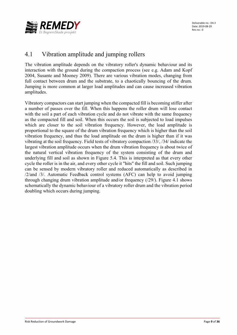
4.1 Vibration amplitude and jumping rollers The vibration amplitude depends on the vibratory roller's dynamic behaviour and its interaction with the ground during the compaction process (see e.g. Adam and Kopf 2004, Susante and Mooney 2009). There are various vibration modes, changing from full contact between drum and the substrate, to a chaotically bouncing of the drum. Jumping is more common at larger load amplitudes and can cause increased vibration amplitudes. Vibratory compactors can start jumping when the compacted fill is becoming stiffer after a number of passes over the fill. When this happens the roller drum will lose contact with the soil a part of each vibration cycle and do not vibrate with the same frequency as the compacted fill and soil. When this occurs the soil is subjected to load impulses which are closer to the soil vibration frequency. However, the load amplitude is proportional to the square of the drum vibration frequency which is higher than the soil vibration frequency, and thus the load amplitude on the drum is higher than if it was vibrating at the soil frequency. Field tests of vibratory compaction /33/, /34/ indicate the largest vibration amplitude occurs when the drum vibration frequency is about twice of the natural vertical vibration frequency of the system consisting of the drum and underlying fill and soil as shown in Figure 5.4. This is interpreted as that every other cycle the roller is in the air, and every other cycle it "hits" the fill and soil. Such jumping can be sensed by modern vibratory roller and reduced automatically as described in /2/and /3/. Automatic Feedback control systems (AFC) can help to avoid jumping through changing drum vibration amplitude and/or frequency (/29/). Figure 4.1 shows schematically the dynamic behaviour of a vibratory roller drum and the vibration period doubling which occurs during jumping.

Risk Reduction of Groundwork Damage Page 10 of 36
Deliverable no.: D4.3 Date: 2019-08-29 Rev.no.: 0
Figure 4.1 Dynamic behaviour of a vibratory roller drum, a) full contact, b) periodic loss of contact, and c) jumping. Spectrum show the period doubling when the drum jumps. After /3/.
5 Numerical method
5.1 Frequency dependent foundation stiffness and damping
In this study the vibro-compaction is modelled as a vibrating foundation on soil. Therefore, as a background, a brief description of frequency dependent dynamic foundation behaviour is given. It is important to understand the effect of vibratory compaction on the behaviour of the soil in the slope and how it affects the stability. Based on many decades of research see e.g. /16/ it is well established that dynamic foundation stiffness and damping depend on loading-frequency and direction, foundation dimensions and dynamic and cyclic behaviour of the soil surrounding the foundation. For foundations in or on a soil layer over a rigid base, there is a clear cut-off frequency (the first natural frequency of the system) below which waves from the
Risk Reduction of Groundwork Damage Page 11 of 36
Deliverable no.: D4.3 Date: 2019-08-29 Rev.no.: 0
foundation do not propagate outwards in the soil. When a foundation is cyclically loaded at frequencies below the cut off frequency, a part of the surrounding soil mass moves in phase with the foundation. Due to inertia, this soil mass causes the dynamic foundation stiffness to reduce with increasing frequency up to the cut off frequency. The reduction in stiffness with increasing frequency can roughly be represented by a static stiffness (spring) and an apparent mass. The frequency variation of the dynamic stiffness, 𝐾𝐾𝑑𝑑𝑑𝑑𝑑𝑑, can then be estimated by the equation𝐾𝐾𝑑𝑑𝑑𝑑𝑑𝑑 = 𝐾𝐾𝑠𝑠𝑠𝑠𝑠𝑠𝑠𝑠𝑠𝑠𝑠𝑠 − 𝑚𝑚𝜔𝜔2, where 𝑚𝑚 is the apparent added mass of the interacting soil and the mass of the foundation. 𝜔𝜔 is the angular frequency (= 2𝜋𝜋𝑓𝑓) of the foundation motion. An example is shown in for a vertically oscillating slab foundation in Figure 5.1. Wave propagation in the soil around the foundation is restrained for frequencies below the cut off frequency, 𝑓𝑓𝑠𝑠, and thus the soil layers cannot carry energy away from the foundation. This means that below the cut off frequency there is little or no radiation damping and only material damping contributes to the foundation damping. Above the cut off frequency the waves propagate away into the soil surrounding the foundation and give a damping force increasing approximately linearly with frequency. This can often be represented within a limited frequency range by a viscous dashpot with a constant damping coefficient, C. The dynamic foundation stiffness and damping is often conveniently represented by a complex stiffness, 𝐾𝐾∗ = 𝐾𝐾 + 𝐾𝐾𝑠𝑠 = 𝐾𝐾(1 + 𝑖𝑖2𝐷𝐷), where 𝐾𝐾 is the elastic stiffness, 𝐷𝐷 is the hysteretic soil damping, and i is the imaginary unit. This is analogue to the representation of the complex soil material stiffness described later in section 5.2. For loading frequencies above the cut off frequency of a stratum, the stiffness can be approximate by 𝐾𝐾∗ = 𝐾𝐾 + 𝑖𝑖𝜔𝜔𝐶𝐶 where C is an equivalent viscous dashpot representing the radiation damping. The contribution of radiation damping to total foundation damping can be very large and is mostly dominant for frequencies above the cut off frequency. There is only a clear cut off frequency for soil deposits with a large stiffness contrast between a stiff layer at depth and the overlying softer soil layers. For horizontal foundation motion, the cut off frequency in a soil layer with thickness 𝐻𝐻 and shear-wave velocity, 𝑣𝑣𝑠𝑠, over a stiff base is given by 𝑓𝑓𝑠𝑠𝑐𝑐 = 𝑣𝑣𝑠𝑠 4𝐻𝐻⁄ . For rocking or vertical motion studied here, the cut off frequency is given as 𝑓𝑓𝑠𝑠𝑐𝑐 = 𝑣𝑣𝐿𝐿𝑑𝑑 4𝐻𝐻⁄ , where 𝑣𝑣𝐿𝐿𝑑𝑑 is the average so called Lysmer wave speed of the layer defined as 𝑣𝑣𝐿𝐿𝑑𝑑 = 3.4/(𝜋𝜋(1 −𝜈𝜈)𝑣𝑣𝑠𝑠) /11/, where v is Poisson's ratio.

Risk Reduction of Groundwork Damage Page 12 of 36
Deliverable no.: D4.3 Date: 2019-08-29 Rev.no.: 0
Figure 5.1 Typical sketch of real and imaginary part of stiffness for vibrating foundation.
5.2 Frequency domain finite element analysis with hyperbolic
soil model
The FE software COMSOL Multiphysics was used to perform the analysis. This section gives brief description of the approach based on frequency domain equilibrium equations. For a complete derivation see e.g. /26/ or /36/. Using COMSOL terminology, the governing equations are given in Eqs. (1) and (2). (COMSOL, 2018).
−𝜌𝜌𝜔𝜔2𝐮𝐮 = ∇ ∙ S + 𝐅𝐅𝑽𝑽𝑒𝑒𝑠𝑠𝑖𝑖 (1)
S ∙ n = 𝐅𝐅𝑨𝑨𝑒𝑒𝑠𝑠𝑖𝑖 (2) where 𝜌𝜌 is soil/ rock mass density, 𝜔𝜔 is angular frequency, 𝐮𝐮 is the dependent displacement field, with the radial and vertical displacement components u and w in an axi-symmetric model, S is the second Piola-Kirchhoff stress tensor, 𝐅𝐅𝑽𝑽 and 𝐅𝐅𝑨𝑨 are volume and boundary force vectors, and 𝜙𝜙 is the phase angle between the forces and displacements. In the static nonlinear analysis the left hand side of Eq. (1) is set to zero and the phase angle is zero. The elastic stress-strain relationship of the material is given by
S = Sad + 𝐂𝐂: 𝜀𝜀𝑒𝑒𝑒𝑒 (3)
Frequency [Hz]”Cut-off” frequency, fc
Rea
l and
Imag
inar
ypa
rt of
Stif
fnes
s
Real part
Stiffness reduction due to added mass
Risk Reduction of Groundwork Damage Page 13 of 36
Deliverable no.: D4.3 Date: 2019-08-29 Rev.no.: 0
where Sad is the initial stress tensor, C is the 4th order elasticity tensor that is a function of Young’s modulus, E, and shear modulus, G, and εel is elastic strain. The Green-Lagrange strain tensor is given by
𝜀𝜀 =12
((∇𝐮𝐮)T + ∇𝐮𝐮 + (∇𝐮𝐮)T∇𝐮𝐮) (4) For nonlinear elastic domains the stress, S, is dependent on the secant shear modulus, 𝐺𝐺𝑠𝑠, and the initial bulk modulus, 𝐾𝐾, as shown in Eq. (4).
The secant shear modulus, 𝐺𝐺𝑠𝑠, is dependent on the initial shear modulus, 𝐺𝐺, and the maximum shear strain, γ, as shown for example by the hyperbolic relationship in Eq. (5).
𝐺𝐺𝑠𝑠 = 𝐺𝐺1
1 + � |𝛾𝛾|𝛾𝛾𝑟𝑟𝑒𝑒𝑟𝑟
�𝑑𝑑 (6)
where n and γref are material parameters. A frequency domain solution uses constant elastic parameters, and it cannot directly follow the variation of the shear modulus according to Eq. 6 within each load cycle; therefore, an iterative solution is used in COMSOL. For each loading frequency the COMSOL solver iterates until there is strain compatibility in an equivalent linear sense in the whole domain. In the iteration, secant shear modulus and damping vary with the shear strain amplitude in the soil around the foundation. We limit the number of allowed iterations steps to 1000 in the solver. However, as described below, for some analysis cases with large loads, convergence was not obtained. In the frequency domain analysis the maximum shear strain, γ, is a complex variable, which cannot be used directly in the built-in model. Therefore, it was modified by taking the absolute value of the maximum shear strain. The material damping is modelled with a frequency independent damping, which is included in the soil stiffness by replacing the shear modulus with a complex shear modulus, 𝐺𝐺𝑠𝑠∗ = 𝐺𝐺𝑠𝑠(1 + 𝑖𝑖2𝐷𝐷), where, 𝐷𝐷 is the material damping factor, and 𝑖𝑖 the imaginary unit. The above method is not restricted to the hyperbolic law in Eq. (5), other formulations such as presented in /1/, /13/ and /35/, or simple tabulated data points for shear strain versus 𝐺𝐺/𝐺𝐺𝑠𝑠 , or damping, for specific materials are also possible. The material damping in the performed analysis were given as tabulated values.
S = Sad + 2𝐺𝐺𝑠𝑠 ∙ dev(𝜀𝜀𝑒𝑒𝑒𝑒) + 𝐾𝐾 ∙ trace(𝜀𝜀𝑒𝑒𝑒𝑒)𝐼𝐼 (5)
Risk Reduction of Groundwork Damage Page 14 of 36
Deliverable no.: D4.3 Date: 2019-08-29 Rev.no.: 0
5.3 Equivalent linear stiffness and material damping for representing nonlinear soil behaviour
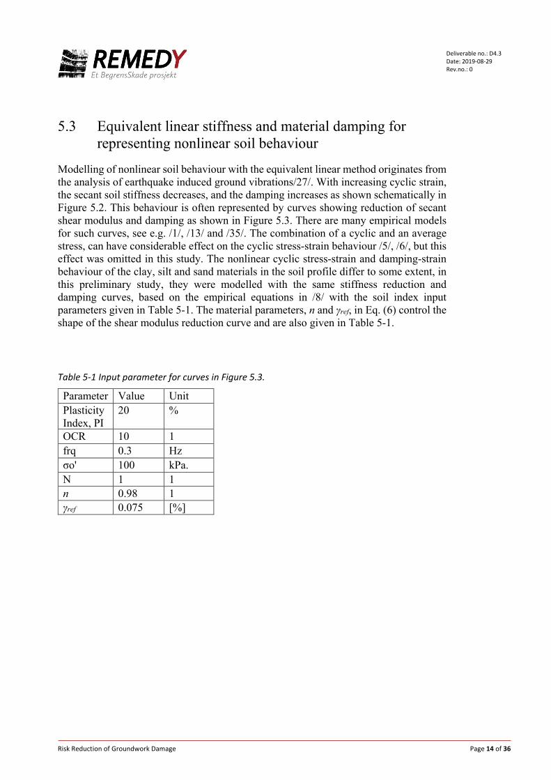
Modelling of nonlinear soil behaviour with the equivalent linear method originates from the analysis of earthquake induced ground vibrations/27/. With increasing cyclic strain, the secant soil stiffness decreases, and the damping increases as shown schematically in Figure 5.2. This behaviour is often represented by curves showing reduction of secant shear modulus and damping as shown in Figure 5.3. There are many empirical models for such curves, see e.g. /1/, /13/ and /35/. The combination of a cyclic and an average stress, can have considerable effect on the cyclic stress-strain behaviour /5/, /6/, but this effect was omitted in this study. The nonlinear cyclic stress-strain and damping-strain behaviour of the clay, silt and sand materials in the soil profile differ to some extent, in this preliminary study, they were modelled with the same stiffness reduction and damping curves, based on the empirical equations in /8/ with the soil index input parameters given in Table 5-1. The material parameters, n and γref, in Eq. (6) control the shape of the shear modulus reduction curve and are also given in Table 5-1.
Table 5-1 Input parameter for curves in Figure 5.3.
Parameter Value Unit Plasticity Index, PI
20 %
OCR 10 1 frq 0.3 Hz σo' 100 kPa. N 1 1 n 0.98 1 γref 0.075 [%]

Risk Reduction of Groundwork Damage Page 15 of 36
Deliverable no.: D4.3 Date: 2019-08-29 Rev.no.: 0
Figure 5.2 Schematic cyclic stress-strain loops for a soil element or load-displacements for a foundation. The red triangle and the grey shaded loop shows the definition of elastic energy and hysteretic loss energy respectively in one loop. The cyclic "back-bone" or "skeleton" curve which controls the shape of the hysteresis loops, is shown by the blue dotted line. Assuming a hyperbolic shape this line is given by Eq. (6).
Figure 5.3 Shear Modulus reduction and damping versus shear strain used in COMSOL analysis.
Displacementor strain
Load or stress
10 -4 10 -3 10 -2 10 -1 10 0 10 1
Shear Strain [%]
0
0.2
0.4
0.6
0.8
1
G/G
max
0
2
4
6
8
10
12
14
16
18
Dam
ping
[%]
Modulus Reduction and Damping vs. Shear strain
G/Gmax
Damping
Risk Reduction of Groundwork Damage Page 16 of 36
Deliverable no.: D4.3 Date: 2019-08-29 Rev.no.: 0
5.4 Validation by comparison with vibratory roller compaction experiments
To demonstrate that the equivalent linear method can capture essential features of nonlinear dynamic soil behaviour, we have compared numerical results with field experiments of vibratory roller compaction. The experiments are described in detail in /33/ and /34/, and in references therein. The objective of the experiments was to evaluate the effect of vibration frequency on the compaction efficiency. Several frequency sweep tests were run with the roller passing over the compacted area. The results of the sweep tests are shown in Figure 5.4a). Within each pass over the compacted area the frequency is increased in a "sweep" from 15 to 35 Hz. With increasing number of passes of the vibratory roller, the frequency of the first peak found between 15 and 20 Hz increases due to increasing soil stiffness. The second peak above 30 Hz, decreases with number of passes, caused by a reduced soil stiffness due to local failure and soil heave induced by the jumping drum. Jumping reduces efficiency of compaction as shown by measurements in /33/. The experimental setup consist of 2 meter high bottomless concrete box embedded in soil deposit. The box size is 7 m by 20 m. In the top 1 m there is a layer of gravel fill which is compacted. The gravel fill has particle size diameter between 0 and 32 mm, and moisture content of 2%. The optimum water content was 6%. Beneath the gravel fill there is a layer of crushed rock fill several meters thick. The depth to bedrock is unknown. To allow for fast numerical analysis the vibro-compaction experiment was simulated in an axi-symmetric model. The drum, the compacted layer and the rock fill were modelled with solid elements with quadratic interpolation. A stiff block with a mass of 7600 kg represents the roller drum. The vertical dynamic load on the drum, due to an eccentric moment of 7.3 kgm, is proportional to the square of the rotation frequency giving a load amplitude of 83 kN at 17 Hz. The depth to bedrock was assumed 5 m in the model. To evaluate input parameters, initial shear modulus, density and Poisson's ratio of the gravel fill were estimated as follows: The initial shear modulus of the fill layer was computed with an empirical equation and input parameters for grain size distribution curve, most similar to the fill layer based on /35/. The average void ratio in the fill layer before and after compaction was estimated to 0.34 and 0.29 respectively based on the density measurement reported in /33/. The confining pressure is necessary input to estimate the initial shear modulus. We assumed an average increase in confining stress of 30 kPa in the fill due to the static stress beneath drum from the self-weight of vibratory roller. Suction in the unsaturated fill is likely small /14//19/ and assumed to cause an additional confining pressure of 10 kPa. The resulting fill layer shear wave speed before and after compaction is estimated to 220 and 230 m/s respectively beneath the drum. Without the static drum influence, the shear wave speeds became 160 m/s and 170 m/s respectively. A Poisson's ratio of 0.3 was used. The rock fill shear wave speed was assumed to vary linearly between from 220 m/s beneath the fill to 270 m/s at 5 depth, and the density and Poisson's ratio was set to 2000 kg/m3 and 0.3.

Risk Reduction of Groundwork Damage Page 17 of 36
Deliverable no.: D4.3 Date: 2019-08-29 Rev.no.: 0
To model the effect of soil nonlinearity on the response of the drum, the curves for shear modulus reduction and damping versus shear strain shown in Figure 5.3 were used for the gravel fill. For simplicity, the same curves were used for the underlying rock fill. To account for the densification during compaction, the model was run with different initial shear modulus of the fill layer, corresponding to shear wave velocities of 160, 180, 200 and 220 m/s. Varying the initial sheer wave velocity from 180 m/s to 220 m/s gives good match with the frequencies and captures the frequency variation observed in the experiment. It is obviously necessary to use a nonlinear soil behaviour to obtain a sufficient match with experiments. As shown in Figure 5.5 the shear modulus reduces to less than 10% of the initial one beneath the drum and the material damping factor exceeds 15%. To capture the increasing vibration amplitude with the number of passes, as observed in the experiments, tests were performed with reduced material damping with increased initial shear wave speed. Since material damping is reduced by densification, we scaled the damping in reverse proportion to the initial shear wave velocity. This scaling was necessary to obtain a response similar to the compaction experiments. The high damping could possibly be attributed to the densification of the soil. Such densification does not occur in typical laboratory tests to determine damping (see e.g. /20/).
a) b) Figure 5.4 Vertical displacement amplitude of vibratory roller drum in frequency sweep test. a) Experimental result (Modified after /34/). b) Numerical results.
Dis
plac
emen
t am
plitu
de [m
m]
Frequency [Hz]

Risk Reduction of Groundwork Damage Page 18 of 36
Deliverable no.: D4.3 Date: 2019-08-29 Rev.no.: 0
a) b) Figure 5.5 a) Shear modulus reduction and b) damping factor in soil beneath vibrating block representing roller drum at 17 Hz for initial shear wave velocity of 200 m/s in fill layer.
6 Vibration analysis of the Statland case
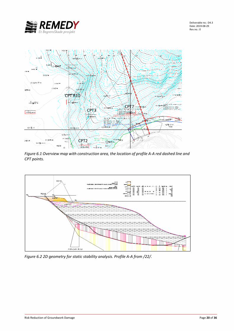
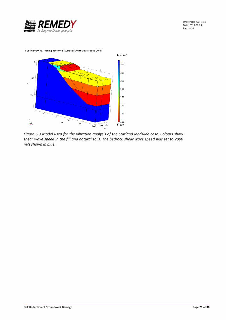
6.1 Numerical model A three-dimensional calculation model has been established in the software Comsol Multiphysics (shown in Figure 6.3). Calculation of the vibration is performed as frequency domain analysis. This means that excitation from the vibratory roller and the vibration propagation is calculated for one frequency at a time throughout the relevant frequency range. In the calculations, the module "Structural Mechanics" in Comsol is used. The material properties are assumed to be linearly elastic, approximately with a secant module and a hysteresis attenuation. Input is Cp (propagation velocity for p-waves), Cs (propagation velocity for shear waves), hysteretic damping and mass density given for each zone in which the calculation profile is divided. (See Figure 3.4). In clay, a so-called U-P formulation is used in Comsol to avoid artificially high stiffness, which can occur when the Poisson's number is high, which is the case for water-saturated soil (ν=0.5). 6.2 Geometry and material parameters The geometry and layering in the numerical model is based on the profile shown in Figure 6.2. The location of the profile is shown with red dashed line in Figure 6.1 adopted from /22/. The 3D geometry (shown in Figure 6.3) in the analysis is "extruded" based on the 2D geometry used in the investigation of the technical cause of the slide /22/. In Figure 6.3 the compacted rock fill is shown in yellow to the left of an older fill shown with red colour. Replaced fill is shown in turquoise, and green areas are older fill material. The old filling contains various materials such as wood etc. Bed rock is in blue and the three layers in yellow, orange, and red are loose recently deposited material consisting of sand, silt and clay.
Risk Reduction of Groundwork Damage Page 19 of 36
Deliverable no.: D4.3 Date: 2019-08-29 Rev.no.: 0
Another profile than the selected one for vibration analysis turned out to be more critical in terms of static stability. However, for computing the vibrations due to vibro compaction the slight difference in geometry and soil parameters should have little influence on the results. Shear wave velocity in replaced masses and in fillings is based on NGI's experience with similar materials. Shear wave velocity and stratification in sand, silt and clay masses are based on interpretation of CPT data. Various empirical relationships have been used to establish a shear wave velocity profile. The profile used in the calculations is based on equations from Robertson /25/, and is shown with red line in Figure 6.4. Vertical axis shows depth from the seabed / ground surface. Depth 0 corresponds to kote -2 where CPT 7 starts (location shown Figure 6.1). Figure 6.4 shows that the estimated shear wave velocity decreases with depth and varies from over 200 m/s between depth of 2 m to 3 m to about 100 m/s at 25 m depth. Based on the CPT-based shear wave velocity profile, we have established a simplified calculation profile with three layers in the sand, silt and clay masses with shear wave velocities of 150, 120 and 100 m/s respectively. These values are shown with green lines in Figure 6.4. The shear wave speeds are shown with colours in Figure 6.3. These are initial shear wave speeds which are reduced depending on the shear strain amplitude in the calculations. The shear wave speed (shear modulus) and damping are modified according to the red and blue curves, respectively, in Figure 5.3. The Poisson's value in the fill mass is set to 0.4 and in soil below ground water level 0.495. The bedrock is linear elastic with an assumed shear wave speed of 2000 m/s. Sea water is not modelled. In a more detailed analysis the effect of sea water may warrant further evaluation, since water can increase both the damping and dynamic mass /17/.
Risk Reduction of Groundwork Damage Page 20 of 36
Deliverable no.: D4.3 Date: 2019-08-29 Rev.no.: 0
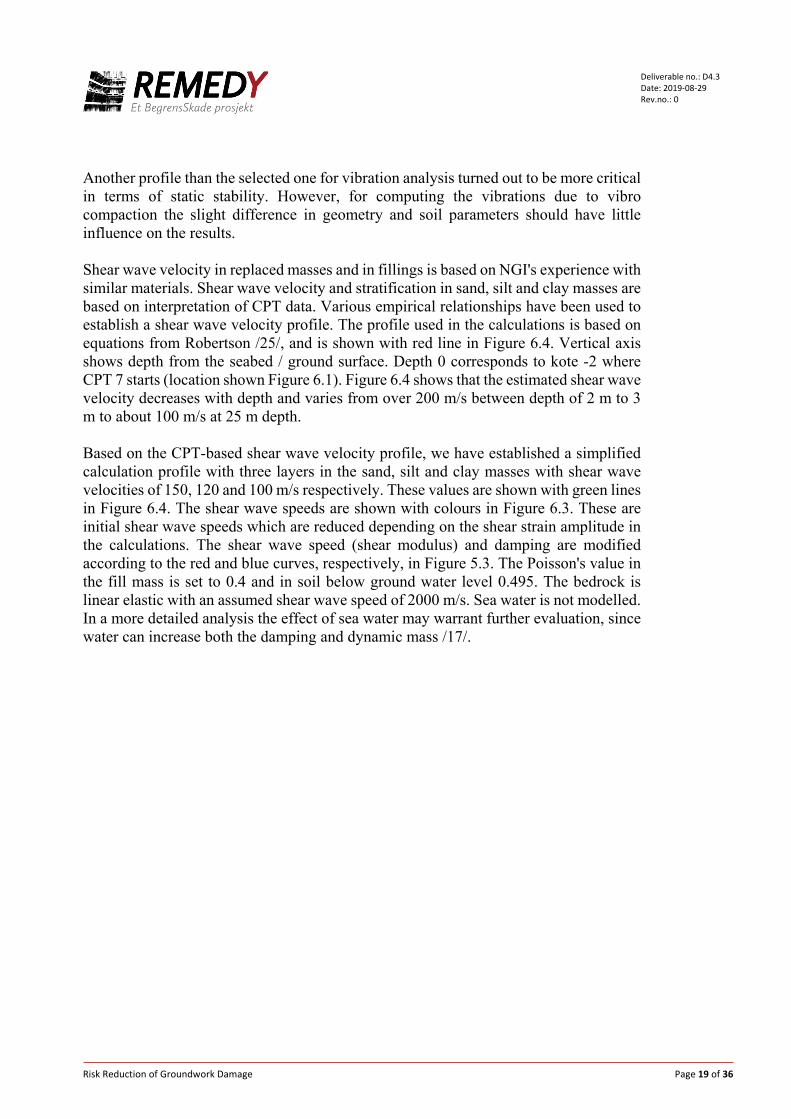
Figure 6.1 Overview map with construction area, the location of profile A-A red dashed line and CPT points.
Figure 6.2 2D geometry for static stability analysis. Profile A-A from /22/.
CPT2
CPT3CPT7
CPT R10
Risk Reduction of Groundwork Damage Page 21 of 36
Deliverable no.: D4.3 Date: 2019-08-29 Rev.no.: 0
Figure 6.3 Model used for the vibration analysis of the Statland landslide case. Colours show shear wave speed in the fill and natural soils. The bedrock shear wave speed was set to 2000 m/s shown in blue.

Risk Reduction of Groundwork Damage Page 22 of 36
Deliverable no.: D4.3 Date: 2019-08-29 Rev.no.: 0
Figure 6.4 Shear wave velocity interpreted from CPT data based on empirical formulas. Green lines showing idealized profile used in numerical analysis.
6.3 Loading and vibro compactor info Figure 6.5 show the vibro compactor used at Statland, a Volvo CE SD 115D. Technical information about the vibro compactor is given in Table 6-1 based on references /30/ and /31/. The drum is 2.1 m wide and has a diameter of 1.5 m. The dynamic mass is estimated to 3570 kg based on the nominal displacement amplitude of 1.92 mm and load amplitude of 258 kN. Other makers have vibratory compactors of similar specifications e.g. Dynapac CA 2800 D, Hamm H 12i, Ammann ASC 120 D, and Bomag BW 212 DH-5. The drum is modelled as 2.1 m x 0.3 m plate, assuming a contact width of 0.3 m. The plate is made stiff with an equivalent Young's modulus to reflect the drum bending
0 50 100 150 200 250
0
5
10
15
20
25
Shear wave velocity from CPTU sounding: File :cpt 7
Shear Wave Velocity [m/s]
Dep
th b
elow
sur
face
[m]
Roberson (2012) - All soilsMayne & Rix (1993) - Clay

Risk Reduction of Groundwork Damage Page 23 of 36
Deliverable no.: D4.3 Date: 2019-08-29 Rev.no.: 0
stiffness and a mass corresponding to the dynamic mass of the drum. The dynamic load is applied uniformly to the plate. The compaction frequency used at the time of sliding event was about 20 Hz according to the contractor. The data sheet of the producer suggests frequencies from 23 to 30 Hz. To capture the differences in vibration frequency, we have used the same load amplitude but varied the loading frequencies. To evaluate the effect the frequency dependent load due the eccentric mass several cases with different load amplitudes have been computed, which are presented below in section 7.1. In this way we can also evaluate the effect of potential jumping of the vibratory drum which may cause larger loads at lower frequencies as described above in section 4.1. In section 7.3 results are given for a frequency dependent load corresponding to high nominal amplitude as described above. The static load from the vibro compactor may increase the stiffness and strength of the soil just beneath the drum, but it is not accounted for in analysis. The static load diminishes quickly with depth as compared to the dynamic loads. As a verification the static stresses in the model because of the weight of the plate have been compared with field measurement /24/ of a similar vibro compactor. The stresses are of the similar magnitude. Analysis performed in connection with the validation showed the increase in static stress beneath the drum has little effect on the overall vibration response. Therefore it has little consequence for the evaluation of the effect of vibro compaction on slope stability.
Figure 6.5. Vibrotory roller Volvo SD115D used at Statland when compacting a road fill (photo NVE).

Risk Reduction of Groundwork Damage Page 24 of 36
Deliverable no.: D4.3 Date: 2019-08-29 Rev.no.: 0
Figure 6.6 Vibrotory drum on the left and the idealization used in the numerical model.
Table 6-1 Specifications for the Volvo SD 115 D6.
Parameter Value Remark Static mass 11845 kg Total for the machine 6215 kg - Part on drum 5630 kg - Part on rubber wheels Vibration frequency 23.3/23.8/25.8/28.3/
33.8 Hz Possible frequency settings. From data sheet of producer
20 Hz Used at Statland according to contractor. Number of load cycles per distance compacted
40 hits/m According to contractor.
Driving speed
0 – 13.3 km/h and 0 – 5.1 km/h
From data sheet of producer
1.8 km/h Back calculated from 40 hit/m at 20 Hz 0.5 m/s = 1.8 km/h
Dynamic load 264 kN At highest amplitude. From data sheet of producer.
Nominal vibration amplitude
1.92 mm Free vibration of drum in air (i.e. no contact with soil)
Dynamic mass of drum 3570 kg Back calculated from nominal amplitude, dynamic load and frequency
Width of drum 2134 mm Diameter of drum 1500 mm
2B
Fsyklisk
2B
Fsyklisk mplate
Risk Reduction of Groundwork Damage Page 25 of 36
Deliverable no.: D4.3 Date: 2019-08-29 Rev.no.: 0
7 Results and discussion
7.1 Effect of soil nonlinearity and bedrock depth on the vertical response of drum
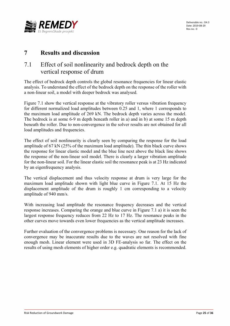
The effect of bedrock depth controls the global resonance frequencies for linear elastic analysis. To understand the effect of the bedrock depth on the response of the roller with a non-linear soil, a model with deeper bedrock was analysed. Figure 7.1 show the vertical response at the vibratory roller versus vibration frequency for different normalized load amplitudes between 0.25 and 1, where 1 corresponds to the maximum load amplitude of 269 kN. The bedrock depth varies across the model. The bedrock is at some 6-9 m depth beneath roller in a) and in b) at some 15 m depth beneath the roller. Due to non-convergence in the solver results are not obtained for all load amplitudes and frequencies. The effect of soil nonlinearity is clearly seen by comparing the response for the load amplitude of 67 kN (25% of the maximum load amplitude). The thin black curve shows the response for linear elastic model and the blue line next above the black line shows the response of the non-linear soil model. There is clearly a larger vibration amplitude for the non-linear soil. For the linear elastic soil the resonance peak is at 23 Hz indicated by an eigenfrequency analysis. The vertical displacement and thus velocity response at drum is very large for the maximum load amplitude shown with light blue curve in Figure 7.1. At 15 Hz the displacement amplitude of the drum is roughly 1 cm corresponding to a velocity amplitude of 940 mm/s. With increasing load amplitude the resonance frequency decreases and the vertical response increases. Comparing the orange and blue curve in Figure 7.1 a) it is seen the largest response frequency reduces from 22 Hz to 17 Hz. The resonance peaks in the other curves move towards even lower frequencies as the vertical amplitude increases. Further evaluation of the convergence problems is necessary. One reason for the lack of convergence may be inaccurate results due to the waves are not resolved with fine enough mesh. Linear element were used in 3D FE-analysis so far. The effect on the results of using mesh elements of higher order e.g. quadratic elements is recommended.
Risk Reduction of Groundwork Damage Page 26 of 36
Deliverable no.: D4.3 Date: 2019-08-29 Rev.no.: 0
a) b) Figure 7.1 Vertical displacement amplitude at drum versus vibration frequency for different load amplitudes. Load amplitude is constant with frequency. a) bedrock at 6-9 m depth beneath drum and b) bedrock depth is at some 15 m depth.
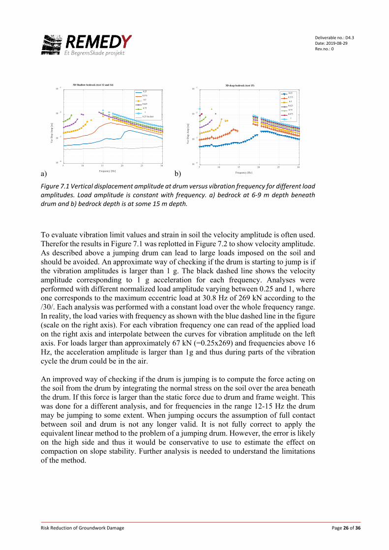
To evaluate vibration limit values and strain in soil the velocity amplitude is often used. Therefor the results in Figure 7.1 was replotted in Figure 7.2 to show velocity amplitude. As described above a jumping drum can lead to large loads imposed on the soil and should be avoided. An approximate way of checking if the drum is starting to jump is if the vibration amplitudes is larger than 1 g. The black dashed line shows the velocity amplitude corresponding to 1 g acceleration for each frequency. Analyses were performed with different normalized load amplitude varying between 0.25 and 1, where one corresponds to the maximum eccentric load at 30.8 Hz of 269 kN according to the /30/. Each analysis was performed with a constant load over the whole frequency range. In reality, the load varies with frequency as shown with the blue dashed line in the figure (scale on the right axis). For each vibration frequency one can read of the applied load on the right axis and interpolate between the curves for vibration amplitude on the left axis. For loads larger than approximately 67 kN (=0.25x269) and frequencies above 16 Hz, the acceleration amplitude is larger than 1g and thus during parts of the vibration cycle the drum could be in the air. An improved way of checking if the drum is jumping is to compute the force acting on the soil from the drum by integrating the normal stress on the soil over the area beneath the drum. If this force is larger than the static force due to drum and frame weight. This was done for a different analysis, and for frequencies in the range 12-15 Hz the drum may be jumping to some extent. When jumping occurs the assumption of full contact between soil and drum is not any longer valid. It is not fully correct to apply the equivalent linear method to the problem of a jumping drum. However, the error is likely on the high side and thus it would be conservative to use to estimate the effect on compaction on slope stability. Further analysis is needed to understand the limitations of the method.
5 10 15 20 25 30
Frequency [Hz]
10 -4
10 -3
10 -2
10 -1
Ver
Dis
p A
mp
[m]
3D Shallow bedrock (test 12 and 14)
0.25
0.375
0.5
0.625
0.75
1
0.25 lin elast
5 10 15 20 25 30
Frequency [Hz]
10 -4
10 -3
10 -2
10 -1
Ver
Dis
p A
mp
[m]
3D deep bedrock (test 15)
0.25
0.375
0.5
0.625
0.75
0.875
1
Risk Reduction of Groundwork Damage Page 27 of 36
Deliverable no.: D4.3 Date: 2019-08-29 Rev.no.: 0
Figure 7.2 Velocity amplitude on left axis (corresponding to the displacement amplitudes in Figure 7.1). Black dashed line show the velocity amplitude corresponding to 1 g acceleration. The blue dashed line show the frequency dependent normalized load applied to the drum (scale on right axis). Maximum load is 269 kN.
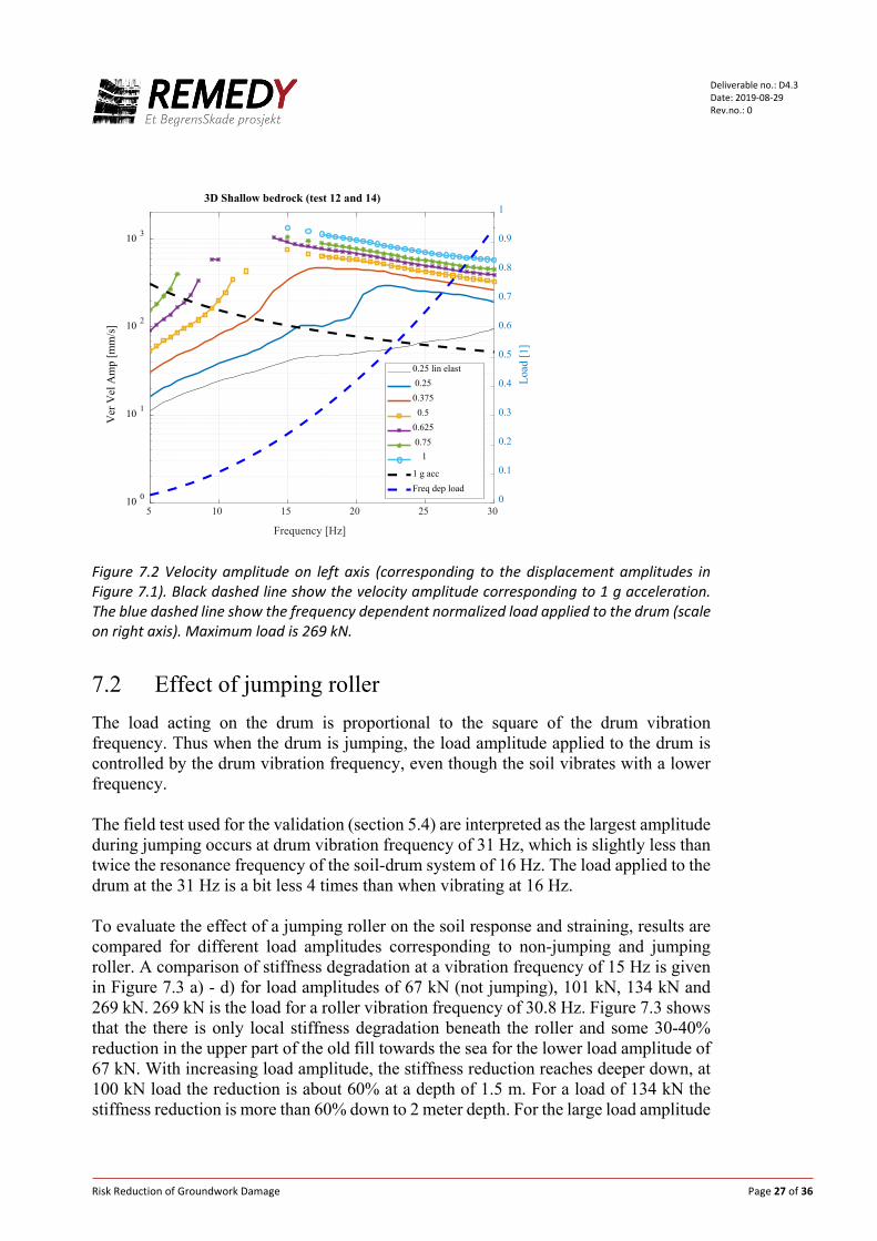
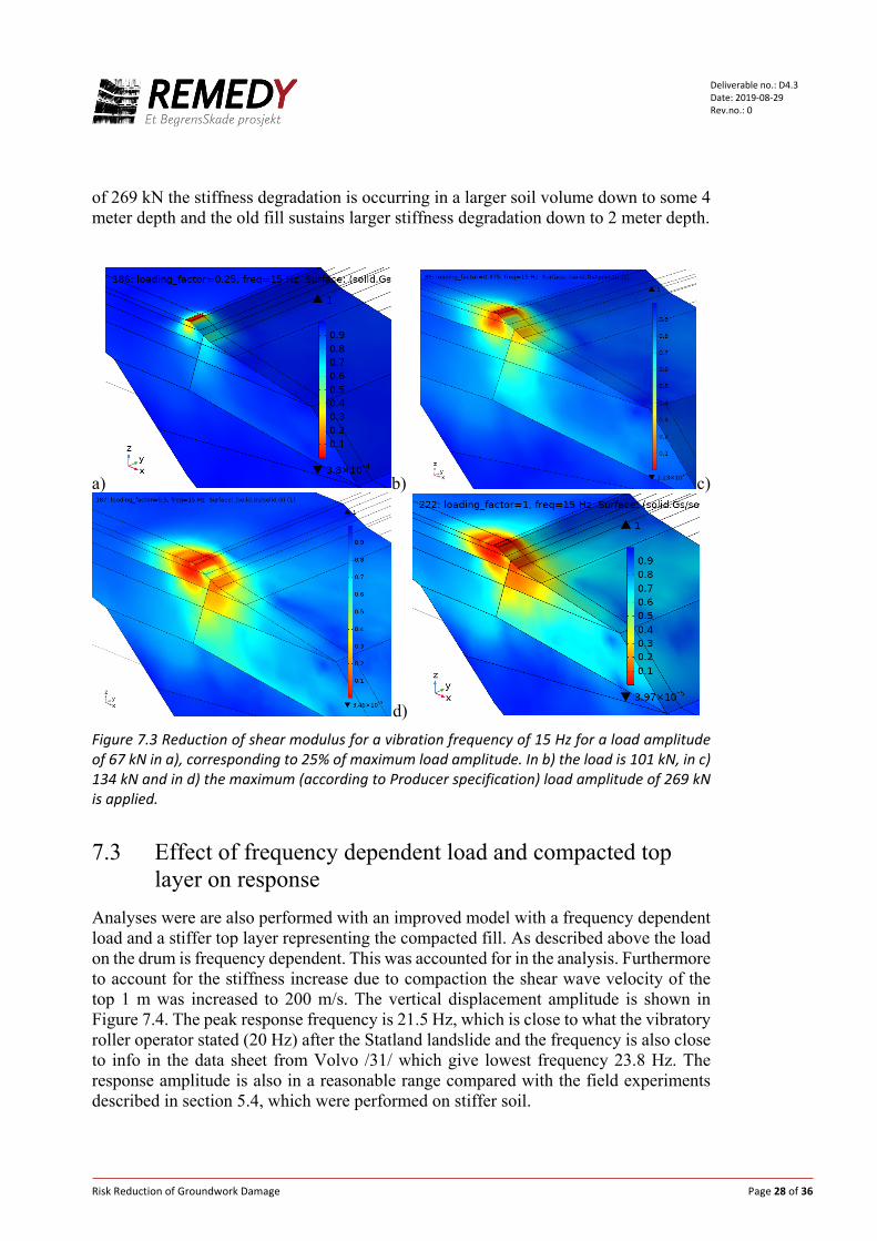
7.2 Effect of jumping roller The load acting on the drum is proportional to the square of the drum vibration frequency. Thus when the drum is jumping, the load amplitude applied to the drum is controlled by the drum vibration frequency, even though the soil vibrates with a lower frequency. The field test used for the validation (section 5.4) are interpreted as the largest amplitude during jumping occurs at drum vibration frequency of 31 Hz, which is slightly less than twice the resonance frequency of the soil-drum system of 16 Hz. The load applied to the drum at the 31 Hz is a bit less 4 times than when vibrating at 16 Hz. To evaluate the effect of a jumping roller on the soil response and straining, results are compared for different load amplitudes corresponding to non-jumping and jumping roller. A comparison of stiffness degradation at a vibration frequency of 15 Hz is given in Figure 7.3 a) - d) for load amplitudes of 67 kN (not jumping), 101 kN, 134 kN and 269 kN. 269 kN is the load for a roller vibration frequency of 30.8 Hz. Figure 7.3 shows that the there is only local stiffness degradation beneath the roller and some 30-40% reduction in the upper part of the old fill towards the sea for the lower load amplitude of 67 kN. With increasing load amplitude, the stiffness reduction reaches deeper down, at 100 kN load the reduction is about 60% at a depth of 1.5 m. For a load of 134 kN the stiffness reduction is more than 60% down to 2 meter depth. For the large load amplitude
5 10 15 20 25 30
Frequency [Hz]
10 0
10 1
10 2
10 3
Ver
Vel
Am
p [m
m/s
]
0
0.1
0.2
0.3
0.4
0.5
0.6
0.7
0.8
0.9
1
Load
[1]
3D Shallow bedrock (test 12 and 14)
0.25 lin elast 0.250.375 0.50.625 0.75 1
1 g accFreq dep load
Risk Reduction of Groundwork Damage Page 28 of 36
Deliverable no.: D4.3 Date: 2019-08-29 Rev.no.: 0
of 269 kN the stiffness degradation is occurring in a larger soil volume down to some 4 meter depth and the old fill sustains larger stiffness degradation down to 2 meter depth.
a) b) c)
d) Figure 7.3 Reduction of shear modulus for a vibration frequency of 15 Hz for a load amplitude of 67 kN in a), corresponding to 25% of maximum load amplitude. In b) the load is 101 kN, in c) 134 kN and in d) the maximum (according to Producer specification) load amplitude of 269 kN is applied.
7.3 Effect of frequency dependent load and compacted top
layer on response Analyses were are also performed with an improved model with a frequency dependent load and a stiffer top layer representing the compacted fill. As described above the load on the drum is frequency dependent. This was accounted for in the analysis. Furthermore to account for the stiffness increase due to compaction the shear wave velocity of the top 1 m was increased to 200 m/s. The vertical displacement amplitude is shown in Figure 7.4. The peak response frequency is 21.5 Hz, which is close to what the vibratory roller operator stated (20 Hz) after the Statland landslide and the frequency is also close to info in the data sheet from Volvo /31/ which give lowest frequency 23.8 Hz. The response amplitude is also in a reasonable range compared with the field experiments described in section 5.4, which were performed on stiffer soil.

Risk Reduction of Groundwork Damage Page 29 of 36
Deliverable no.: D4.3 Date: 2019-08-29 Rev.no.: 0
If the drum is in full contact with the soil the cyclic normal stress amplitude on the plate should not become larger than the static stress. To check this the computed normal stresses under the plate are integrated to obtain a cyclic load. The cyclic load is larger than the static load on the drum due the drum and vibratory roller frame weight (6000 kg according to /31/) for loading frequencies above 15 Hz. Thus, it is likely the drum starts jumping when the layer is compacted to a stiffness corresponding to 200 m/s. The computed shear strains in the soil are above 0.1% down to 4 m depth and some 13 m distance towards the slope surface as shown in Figure 7.5. For this strain level the soil stiffness is reduced with some 60% as shown by Figure 5.3 which is beyond threshold strain amplitude for volumetric change /32/. The shallow near shore soil layers are more vibration sensitive, and stiffness and strength reduces faster than given by the curve in Figure 5.3. In addition in slopes with low stability as for the Statland case there are zones which are already highly mobilized. For such zones the stiffness reduces much faster with increasing strain amplitude, and pore pressure and permanent strains will build up as well. In the case of Statland there were zones consisting of very loose silty material with saw dust. These zones are very vibration susceptible and few cycles can lead to failure. Example of shear modulus reduction curves is given in Figure 7.6 for various sands and clays developed from contour diagrams /4/ based on laboratory tested soil samples. The blue and red dashed curves based on /8/ similarly to the curve in Figure 5.3. The curves accounting for stress mobilization prior to cyclic loading show a much faster reduction in stiffness, at 0.1% shear strain the stiffness reduction is on average about 90%. This indicate the large pore pressures are built up due to the cyclic loading and also permanent straining occurs, which lead to further mobilization of the slope. These results are based on a jumping drum. However, even for a non-jumping drum of the vibratory roller modelled here it seems possible to induce large enough loads to cause strains that could soften and weaken the soil enough to trigger a slope failure. As a first measure a jumping drum should be avoided. The slide at Statland took place after the compaction work was finished. This indicates pore pressure was likely built up by the compaction and some time was needed for redistribution of stresses to cause the formation a fully mobilized failure surface in the slope. Allowing for more time placing layers and/or passes will allow the soil to drain excess pore pressure. It is recommended to use lighter compaction equipment, allowing for more time between placing of layers to allow for drainage to occur, and to monitor slope horizontal and vertical displacements.

Risk Reduction of Groundwork Damage Page 30 of 36
Deliverable no.: D4.3 Date: 2019-08-29 Rev.no.: 0
Figure 7.4 Vertical displacement amplitude versus loading frequency. Peak value at 21.5 Hz.
Figure 7.5 Maximum shear strain at 21.5 Hz. Colour scale is logarithmic from 0.01 % to 10% shear strain. At a depth of 2 m the shear strain is 0.1 %.
10
1.0
0.1
0.01
[%]
13 m
4.0 m

Risk Reduction of Groundwork Damage Page 31 of 36
Deliverable no.: D4.3 Date: 2019-08-29 Rev.no.: 0
Figure 7.6 Shear modulus reduction curves. Blue and red dashed curves based on /8/. The other solid with or without marker are for various sands and clays from NGI's data base.
8 Findings and conclusions
The numerical analysis and evaluations strongly indicate vibratory compaction can have contributed to triggering the slide at Statland. The nonlinear analysis is believed to have captured the essential behaviour of the vibratory compaction and the response of the slope. The peak response at the frequency is close to the one stated by the operator of the vibratory roller and the manufacturer's data sheet. To perform compaction in the vicinity of slopes with low stability near the shoreline with vibration susceptible soils we suggest
• Using lighter equipment and/or higher loading frequencies or performing compaction without vibration. Avoiding excessive jumping of the vibratory roller drum is imperative.
• Applying thinner layers and more time between compaction passes. Allowing for more time between placing of layers reduces the number of load cycle sensed by the soil and allows for drainage of potential built up pore pressures.
• Monitor slope horizontal and vertical displacements at some critical points. • Monitor pore pressures at critical points if possible.
0
0.1
0.2
0.3
0.4
0.5
0.6
0.7
0.8
0.9
1
0.00001 0.0001 0.001 0.01 0.1 1 10
G/G
max
Shear strain [%]
Sand 1Sand 2Clay 3Sand 4Clay 5Sand 6Sand 7Sand 8Clay 9Sand 10Clay 11Sand 12Sand 13Clay 14Clay 15Sand DClay D
Risk Reduction of Groundwork Damage Page 32 of 36
Deliverable no.: D4.3 Date: 2019-08-29 Rev.no.: 0
Our assessment of the Statland case show that compaction, with vibratory roller of the size of Volvo SD 115 D and similar rollers, with a non-jumping drum can have caused shear strains large enough to reduce the stiffness and strength which may have contributed to the slope failure. The numerical analysis further indicate for a jumping roller, i.e. the roller drum is partially in the air during the vibration cycle during compaction, the effect on stiffness and strength degradation can be even larger. Thus avoiding jumping of the drum is imperative when compacting near vibration sensitive soils. Many modern vibratory compaction rollers can sense and automatically reduce the jumping /2/. There are no vibration measurements available from the Statland case or for other cases in the literature where landslide where induced. Therefore it is not known how large the vibration amplitude was or how large the load impacting on the slope was. The analysis here has tried to capture a range of possible load amplitudes and frequencies, to understand the effect compaction on slope stability and if it is possible to establish a vibration limit to avoid slope instabilities. The vibration amplitude on the ground surface is very high near the vibratory roller, but attenuates quickly with distance. Since the roller is moving around it is difficult to establish a vibration limit since the distance to the roller is not known. The vibration could be large even though the vibration sensor do not sense large vibrations. The global natural frequency of the roller-soil-rock system is dependent on the nonlinear behaviour of the soil, i.e. it is dependent on geometry, soil properties, roller drum mass, machine weight, eccentric mass in the drum, and vibration frequency. The vibration frequency range of many vibratory rollers lies within range that can coincide with global natural frequency for the Statland case. Further analysis is needed to understand how the global natural frequency, the local natural frequency of the drum-soil, and the loading frequency are affected by soil nonlinearity. Further study may reveal certain site conditions when vibratory compaction still can be used and thus allow for optimized compaction procedure. For such analysis it is recommended to use more detailed parameters for the cyclic soil behaviour to account for e.g. highly stressed zones in the slope. For load amplitudes large enough to cause jumping of the drum, the performed frequency domain analysis does not capture the partial or full non-contact between the drum and the soil. The compute vibration amplitude is likely on the high side and as such can be used to evaluate if e.g. lighter equipment should be used. However, this may lead to conservatism that puts limitations on the progress and quality of the compaction. Further analysis are needed to understand the limitations how to account for these. For higher load amplitudes the solver in the COMSOL software did not manage to reach convergence and obtain results. There maybe be several factors contributing to this issue: 1) Too large load amplitude was likely applied in the model. For the more realistic
frequency dependent load amplitude as described in section 7.3 the results converged without problem.
Risk Reduction of Groundwork Damage Page 33 of 36
Deliverable no.: D4.3 Date: 2019-08-29 Rev.no.: 0
2) The size of mesh in relation to vibration wave length. In the models used here number of elements per wave length is less than 10, which is typical criteria for the linear elements used in the FE mesh. Refining the mesh will likely give more accurate results and may allow the solver to produce results for larger load amplitudes.
3) There are different numerical solvers to be evaluated and several solver parameters that can be modified. Further evaluation of these parameter may be necessary to obtain solutions for larger load amplitudes. Establishment of a smaller model and test which parameters allow for obtaining results at large amplitudes with resonance in the model. E.g. model of typical laboratory resonant column test could be performed.
References
/1/ Amir-Faryar, B.; Aggour, M. S. & McCuen, R. H., Universal model forms for predicting the shear modulus and material damping of soils, Geomechanics and Geoengineering, Informa UK Limited, 2016, 12, 60-71
/2/ Adam, D., Pistrol, J.: "Dynamic roller compaction for earthworks and roller-integrated continuous compaction control: State of the art overview and recent developments"; Talk: Conferenze di Geotecnica di Torino, XXIV Ciclio, Turin (invited); 02-25-2016 - 02-26-2016; in: "Conferenze di Geotecnica di Torino, XXIV Ciclio", M. Manassero, A. Dominijanni, S. Foti, G. Musso (ed.); (2016), 1 - 41
/3/ Anderegg, Roland and Kuno Kaufmann Intelligent Compaction with Vibratory Rollers Feedback Control Systems in Automatic Compaction and Compaction Control. Transportation Research Record: Journal of the Transportation Research Board, No. 1868, TRB, National Research Council, Washington, D.C., 2004, pp. 124–134.
/4/ Andersen, K. H., Cyclic soil parameters for offshore foundation design, The Third ISSMGE McClelland Lecture, ISFOG III, Meyer, V. (Ed.), CRC Press, 2015
/5/ Andersen, K. H., Cyclic soil parameters for offshore foundation design, The Third ISSMGE McClelland Lecture, ISFOG III, Meyer, V. (Ed.), CRC Press, 2015
/6/ Bernander, Stig, Progressive landslides in long natural slopes: Formation, potential extension and configuration of finished slides in strain-softening soils. 2011. 240 p. Doctoral thesis, Luleå University of Technology.
/7/ Cornforth, Derek, Landslides in Practice: Investigation, Analysis, and Remedial/Preventative Options in Soils, ISBN: 978-0-471-67816-8 April 2005 624 Pages,
/8/ Darendeli M. B., Development of a new family of normalized modulus reduction and material damping curves, Ph.D. Dissertation, The University of Texas at Austin, August, 2001.

Risk Reduction of Groundwork Damage Page 34 of 36
Deliverable no.: D4.3 Date: 2019-08-29 Rev.no.: 0
/9/ Dobry, R., Vasquez-Herrera, A., Mohamad, R., and Vucetic, M. (1985). "Liquefaction flow failure of silty sand by torsional cyclic tests." Proc, Session on Advances in the Art of Testing Soils Under Cyclic Conditions, ASCE, 29-50.
/10/ Ekström, A., & Olofsson, T. (1985). Water and frost-stability risks for embankments of fine-grained soils. In From Proceedings of the Symposium on Failures in Earthworks, organized by the Institution of Civil Engineers, held in London, March 6-7, 1985.
/11/ Gazetas, G. Analysis of machine foundation vibrations: State of the art International Journal of Soil Dynamics and Earthquake Engineering, Elsevier BV, 1983, 2, 2-42
/12/ Glimsdal, S., et al. The 29th January 2014 submarine landslide at Statland, Norway—landslide dynamics, tsunami generation, and run-up. Landslides , 13 (6), 1435–1444. https://doi.org/10.1007/s10346-016-0758-7, 2016
/13/ Groholski, D. R.; Hashash, Y. M. A.; Kim, B.; Musgrove, M.; Harmon, J. & Stewart, J. P., Simplified Model for Small-Strain Nonlinearity and Strength in 1D Seismic Site Response Analysis, Journal of Geotechnical and Geoenvironmental Engineering, American Society of Civil Engineers (ASCE), 2016, 142, 04016042
/14/ Heyerdahl, H. & Pabst, T. Geotech Geol Eng (2018) 36: 1365. https://doi.org/10.1007/s10706-017-0398-2
/15/ Hryciw, R., Vitton, S., and Thomann, T. (1990). ”Liquefaction and Flow Failure During Seismic Exploration.” J. Geotech. Engrg., 116(12), 1881–1899.
/16/ Kausel, E. Early history of soil–structure interaction Soil Dynamics and Earthquake Engineering, Elsevier BV, 2010, 30, 822-832
/17/ Kaynia, A.M., Kausel, E., and Madshus, C.M. (1998). “Impedances of Underwater Rigid Square Foundations.” Proc. ASCE Spec. Conf. Geotech. Earthquake Engng, Seattle, WA, USA, 1283-1293.
/18/ Løvholt, F., C. Madshus, and K. H. Andersen. "Intrinsic Soil Damping from Cyclic Laboratory Tests with Average Strain Development." Geotechnical Testing Journal 43 (forthcoming). https://doi.org/10.1520/GTJ20170411.
/19/ Lu, N., Kim, T.-H., Sture, S., & Likos, W. J. (2009). Tensile Strength of Unsaturated Sand. Journal of Engineering Mechanics , 135 (12), 1410–1419. https://doi.org/10.1061/(asce)em.1943-7889.0000054
/20/ Madhusudhan, B. N., & Kumar, J. (2013). Damping of Sands for Varying Saturation. Journal of Geotechnical and Geoenvironmental Engineering , 139 (9), 1625–1630. https://doi.org/10.1061/(asce)gt.1943-5606.0000895
/21/ Nordal, Steinar, et. al., Stability of shoreline slopes – what did we learn from appointing committees to evaluate the cause of sliding? Geoteknikkdagen 2017. (Annual Norwegian geotechnical symposium).
/22/ NVE The landslide at Nord-Statland. Investigation of technical causes. Report nr. 93-2014. ISBN-nr. 978-82-410-1042-2, http://www.naturfare.no/_attachment/751994/binary/1007572, in Norwegian.
Risk Reduction of Groundwork Damage Page 35 of 36
Deliverable no.: D4.3 Date: 2019-08-29 Rev.no.: 0
/23/ NVE, "Dynamic loading and landslide hazard ", (in Norwegian, title: Dynamiske påkjenninger og skredfare) https://brage.bibsys.no/xmlui/handle/11250/2498527, Report nr. 16-2016, 2016.
/24/ R.V. Rinehart and M.A. Mooney, "Measurement depth of vibratory roller-measured soil stiffness", Géotechnique, Volume 59, Issue 7, 01 September 2009, pages 609 –619.
/25/ Robertson, P. K. (2009). Interpretation of cone penetration tests — a unified approach. Canadian Geotechnical Journal, 46 (11), 1337–1355. https://doi.org/10.1139/t09-065
/26/ Robertson, P. (2010). ”Evaluation of Flow Liquefaction and Liquefied Strength Using the Cone Penetration Test.” J. Geotech. Geoenviron. Eng., 136(6), 842–853
/27/ Schnabel, P.B., Lysmer, J., Seed, H.B., 1972. SHAKE: a computer program for earthquake response analysis of horizontally layered sites, Report EERC 72-12, Earthquake Engineering Research Center, U.C.Berkeley.
/28/ Semblat, J. & Pecker, A. Waves and Vibrations in Soils: Earthquakes, Traffic, Shocks, Construction works IUSS Press, 2009
/29/ Transportation Research Board, Intelligent Soil Compaction Systems, NCHRP report 676, 2010, http://www.trb.org/Publications/Blurbs/164279.aspx.
/30/ Volvo Construction Equipment. Personal communication through e-mail. 2019.
/31/ Volvo Construction Equipment. Specifications for SD 115 vibrocompactor. /32/ Vucetic, M. (1994). Cyclic Threshold Shear Strains in Soils. Journal of
Geotechnical Engineering, 120 (12), 2208–2228. https://doi.org/10.1061/(asce)0733-9410(1994)120:12(2208)
/33/ Wersäll, C., Nordfelt, I., & Larsson, S. (2017). Soil compaction by vibratory roller with variable frequency. Géotechnique , 67 (3), 272–278. https://doi.org/10.1680/jgeot.16.p.051
/34/ Wersäll, C., Nordfelt, I., & Larsson, S.. Resonant roller compaction of gravel in full-scale tests, Transportation Geotechnics, 14, 93–97, 2018, https://doi.org/10.1016/j.trgeo.2017.11.004
/35/ Wichtmann, T. & Triantafyllidis, T. Effect of Uniformity Coefficient on G/Gmax and Damping Ratio of Uniform to Well-Graded Quartz Sands Journal of Geotechnical and Geoenvironmental Engineering, American Society of Civil Engineers (ASCE), 2013, 139, 59-72
/36/ Wolf, J. P. Dynamic Soil-Structure Interaction (Prentice-Hall International Series in Civil Engineering and Engineering Mechanics) Prentice Hall, 1985

Risk Reduction of Groundwork Damage
Review and reference page Document information Deliverable title
Vibration induced damage due to construction work – Effect of vibrations on slope stability Deliverable No. D4.3
Work package No. 4
Distribution Open
Date- 2019-08-29 Rev. No and date 0
Client The Research Council of Norway
Keywords Vibration, damage, blast, ground work, landslide
Document control
Quality assurance according to NS-EN ISO9001
Rev. Reason for revision Self review by:
Colleague review
by:
Independent review by:
Inter-disciplinary
review by:
0 Original document JJO 29 Aug-2019
KNC 29 Aug-2019
Related Documents


