Beckhoff PlugIn August 2015 - V01.05.00

Welcome message from author
This document is posted to help you gain knowledge. Please leave a comment to let me know what you think about it! Share it to your friends and learn new things together.
Transcript

Beckhoff PlugIn
August 2015 - V01.05.00

Important and general information
Beckhoff PlugIn V01.05.00.docx IPETRONIK GmbH & Co. KG ipetronik.com 2/ 31
Table of contents
1 Important and general information ......................................................................................................... 4
1.1 Important information ......................................................................................................................... 4
1.1.1 Safety and Warning instructions .................................................................................................... 4
1.2 Terms and Conditions ........................................................................................................................ 4
1.3 General information ........................................................................................................................... 5
1.3.1 About this manual .......................................................................................................................... 5
1.3.2 Version ........................................................................................................................................... 5
1.3.3 Legend of used icons ..................................................................................................................... 5
1.3.4 Support .......................................................................................................................................... 5
2 PlugIn Overview........................................................................................................................................ 6
2.1 PlugIn Installation .............................................................................................................................. 6
2.2 Supported Interfaces ......................................................................................................................... 6
2.2.1 BK Bus Couplers - based on Modbus TCP ................................................................................... 6
2.2.2 EtherCAT - based on ADS and R3IO ............................................................................................ 6
3 Configuring a system with BK Bus Couplers ........................................................................................ 7
3.1 Connecting Bus Coupler to PC .......................................................................................................... 7
3.2 Creating a BK System ....................................................................................................................... 7
3.3 Configuring Coupler Interface Parameters ........................................................................................ 8
3.3.1 Entering IP address of coupler ...................................................................................................... 8
3.3.2 Enable / Disable Watchdog ........................................................................................................... 9
3.3.3 Fast Mode (only for coupler BK9000) ............................................................................................ 9
3.4 Automatic reconnect to the bus coupler .......................................................................................... 10
3.5 Adding IO Terminals to the Coupler ................................................................................................ 11
3.6 Removing vs Deactivating IO Terminals ......................................................................................... 12
3.7 Channel Scaling ............................................................................................................................... 13
3.8 Supported KL IO Terminals ............................................................................................................. 14
3.9 Configure generic IO terminals – Example KL 3172 ....................................................................... 14
3.10 Konfiguration information for special terminals................................................................................ 18
3.10.1 Terminal KL 3362 – Oscilloscope terminal .............................................................................. 18
3.10.2 Terminal KL 3222 – Resistance measurement (Ohm) ............................................................ 21
3.10.3 Terminal KL 3311 – Thermocouple measurement .................................................................. 21
3.10.4 Terminal KL 1512 – 16 bit counter input .................................................................................. 22
4 EtherCAT interface ................................................................................................................................. 27
4.1 System architecture ......................................................................................................................... 27
4.2 TwinCAT - Beckhoff CPU configuration .......................................................................................... 27
4.3 TwinCAT – Task configuration......................................................................................................... 28
4.4 Supported EtherCAT IO Terminals .................................................................................................. 29

Important and general information
Beckhoff PlugIn V01.05.00.docx IPETRONIK GmbH & Co. KG ipetronik.com 3/ 31
4.4.1 Adding generic IO terminals – from template terminals .............................................................. 30
5 Starting Measurement ............................................................................................................................ 31

Important and general information
Beckhoff PlugIn V01.05.00.docx IPETRONIK GmbH & Co. KG ipetronik.com 4/ 31
1 Important and general information
1.1 Important information
Please follow these instructions before and during the use and application on any IPETRONIK product!
1.1.1 Safety and Warning instructions
Please follow the instructions and information as contained in the user manual!
1. The user can influence an electronic system by applying the IPETRONIK product. This might cause risk of personal injury or property damages.
2. The use and application of the IPETRONIK product is permitted only to qualified professional staff, as well as, only in appropriate manner and in the designated use.
3. Before using an IPETRONIK measurement system in the vehicle it has to be verified that no function of the vehicle, which is relevant for secure operation, might be influenced: - by the installation of the IPETRONIK measurement system in the vehicle, - by an potential malfunction of the IPETRONIK system during the test drive. In order to avoid possible danger or personal injury and property damages, appropriate actions are to be taken; such actions have to bring the entire system into a secured condition (e.g. by using a system for emergency stop, an emergency operation, monitoring of critical values).
Please check the following points to avoid errors:
- Adaption of sensors to components of the electrical system / electronics, brake system, engine and transmission control, chassis, body.
- Tap of one or several bus systems (CAN, LIN, ETHERNET) including the required electrical connection(s) for data acquisition.
- Communication with the vehicle’s control units (ECUs), especially with such of the brake system and/or of the engine and transmission control (power train control system).
- Installation of components for remote data transmission (mobiles, GSM/GPRS modems, WiFi and Bluetooth components).
4. Before directly or indirectly using the data acquired by an IPETRONIK measurement system to calibrate control units, please review the data regarding to plausibility.
5. With regard to the application of IPETRONIK products in vehicles during use on public roads the manufacturer and/or registered user of the vehicle has to ensure that all changes/modifications have no influence concerning the license of the vehicle or its license of operation.
6. User does agree to the instructions and regulations as mentioned above. In case the user does not agree with the instructions and regulations as mentioned above, he has to notify this expressly and immediately in writing to IPETRONIK before confirming the sales contract.
1.2 Terms and Conditions
See IPETRONIK website for details: http://www.ipetronik.com/en/terms-conditions

Important and general information
Beckhoff PlugIn V01.05.00.docx IPETRONIK GmbH & Co. KG ipetronik.com 5/ 31
1.3 General information
1.3.1 About this manual
This manual describes how to use the Beckhoff PlugIn together with the IPEmotion data acquisition software.
1.3.2 Version
This manual has the version number V01.05.00.released [03.08.2015] © All rights reserved !
PlugIn version used for this documentation: V01.05.00.
1.3.3 Legend of used icons
Tip This icon indicates a useful tip that facilitates the application of the software.
Information This icon indicates additional information for a better understanding.
Attention! This icon indicates important information to avoid potential error messages.
1.3.4 Support
Headquarter:
IPETRONIK GmbH & Co. KG
Im Rollfeld 28
76532 Baden-Baden, Germany
Phone +49 7221 9922 0
Fax +49 7221 9922 100
[email protected] www.ipetronik.com
Limited commercial partnership with its head office in Baden-Baden, registry court HRA No. 201313
IPETRONIK Verwaltungs-GmbH Baden-Baden is an individually liable society, registry court Mannheim HRB No. 202089
CEOs: Andreas Wocke, Dirk Korn
Technical support and product information
www.ipetronik.com e-mail: [email protected]
PlugIn Overview
Beckhoff PlugIn V01.05.00.docx IPETRONIK GmbH & Co. KG ipetronik.com 6/ 31
2 PlugIn Overview
2.1 PlugIn Installation
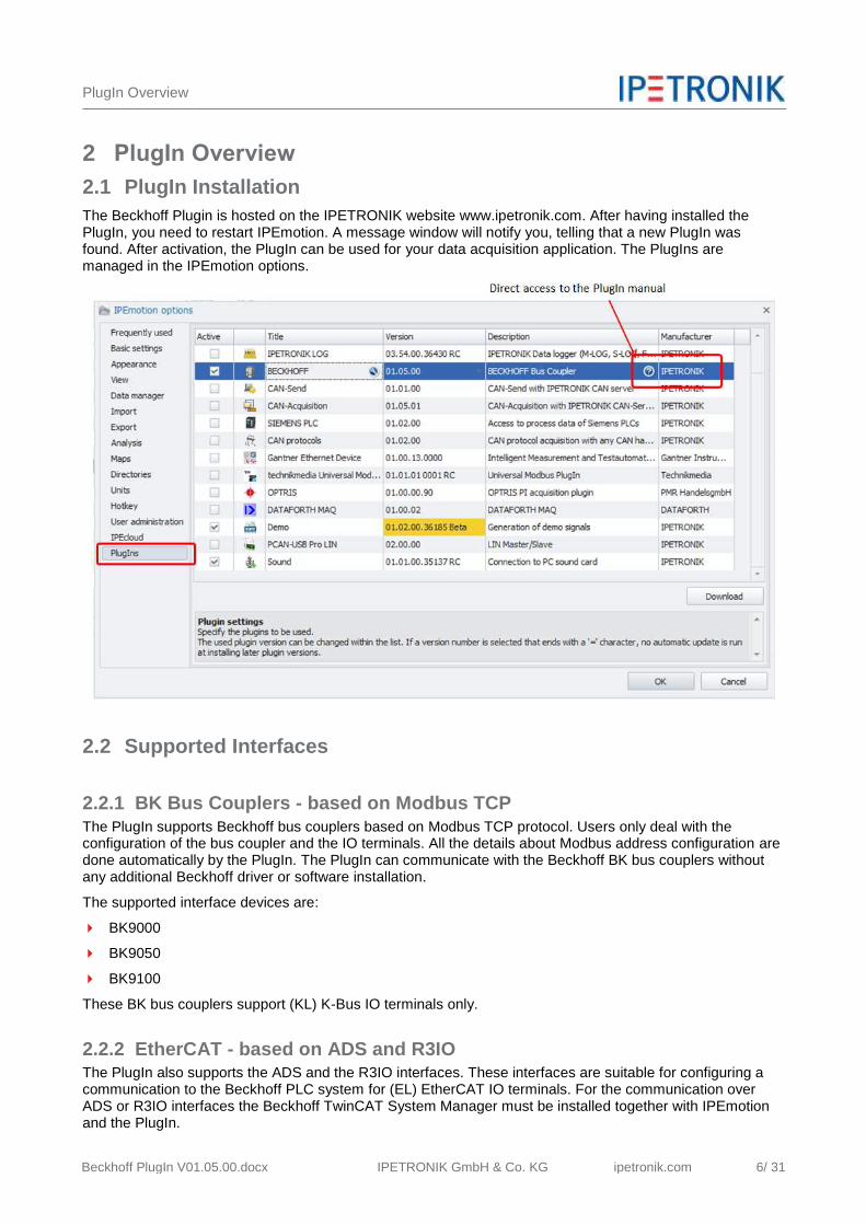
The Beckhoff Plugin is hosted on the IPETRONIK website www.ipetronik.com. After having installed the PlugIn, you need to restart IPEmotion. A message window will notify you, telling that a new PlugIn was found. After activation, the PlugIn can be used for your data acquisition application. The PlugIns are managed in the IPEmotion options.
2.2 Supported Interfaces
2.2.1 BK Bus Couplers - based on Modbus TCP
The PlugIn supports Beckhoff bus couplers based on Modbus TCP protocol. Users only deal with the configuration of the bus coupler and the IO terminals. All the details about Modbus address configuration are done automatically by the PlugIn. The PlugIn can communicate with the Beckhoff BK bus couplers without any additional Beckhoff driver or software installation.
The supported interface devices are:
BK9000
BK9050
BK9100
These BK bus couplers support (KL) K-Bus IO terminals only.
2.2.2 EtherCAT - based on ADS and R3IO The PlugIn also supports the ADS and the R3IO interfaces. These interfaces are suitable for configuring a communication to the Beckhoff PLC system for (EL) EtherCAT IO terminals. For the communication over ADS or R3IO interfaces the Beckhoff TwinCAT System Manager must be installed together with IPEmotion and the PlugIn.
Configuring a system with BK Bus Couplers
Beckhoff PlugIn V01.05.00.docx IPETRONIK GmbH & Co. KG ipetronik.com 7/ 31
3 Configuring a system with BK Bus Couplers
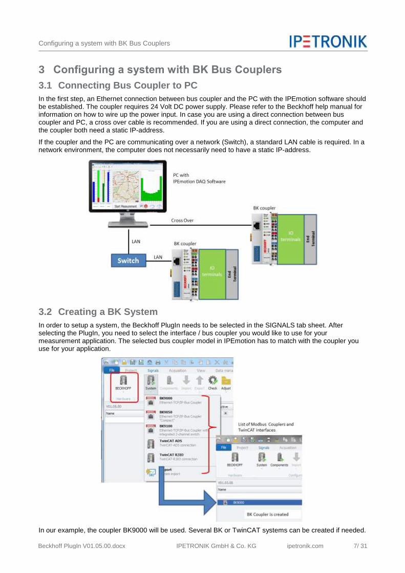
3.1 Connecting Bus Coupler to PC
In the first step, an Ethernet connection between bus coupler and the PC with the IPEmotion software should be established. The coupler requires 24 Volt DC power supply. Please refer to the Beckhoff help manual for information on how to wire up the power input. In case you are using a direct connection between bus coupler and PC, a cross over cable is recommended. If you are using a direct connection, the computer and the coupler both need a static IP-address.
If the coupler and the PC are communicating over a network (Switch), a standard LAN cable is required. In a network environment, the computer does not necessarily need to have a static IP-address.
3.2 Creating a BK System
In order to setup a system, the Beckhoff PlugIn needs to be selected in the SIGNALS tab sheet. After selecting the PlugIn, you need to select the interface / bus coupler you would like to use for your measurement application. The selected bus coupler model in IPEmotion has to match with the coupler you use for your application.
In our example, the coupler BK9000 will be used. Several BK or TwinCAT systems can be created if needed.

Configuring a system with BK Bus Couplers
Beckhoff PlugIn V01.05.00.docx IPETRONIK GmbH & Co. KG ipetronik.com 8/ 31
3.3 Configuring Coupler Interface Parameters
The next important step is to configure the interface parameters which consist of the following options:
IP-address of the coupler
Enable / disable Watchdog
Fast Mode (supported only for coupler BK9000)
3.3.1 Entering IP address of coupler
The IP address is entered in the connection parameters tab sheet.
The factory default IP address is 172.16.17.0 (0 = if all dip switches of the coupler are in the OFF position). When all dip switches are in the ON position, the IP address is 172.16.17.255.
The modification of the last digit of the IP-address through the dip switches becomes effective, when switch 9 and 10 are in the OFF position. The following tables gives you an overview of how to change the last position of the IP-address through the dip switches No 1-8.
The new settings of the dip switches become effective after power OFF / ON and a new startup of the bus coupler.
Configuring a system with BK Bus Couplers
Beckhoff PlugIn V01.05.00.docx IPETRONIK GmbH & Co. KG ipetronik.com 9/ 31
If you need to reset the bus coupler to the factory settings, the following steps are required:
Power off the bus coupler and remove all IO terminals
Connect only end terminal KL9010 to the coupler
Change all dip switches to the ON position
Apply the 24 V DC power to the coupler
After successful reset of the settings, LED ERROR and LED I/O RUN and LED I/O ERR are flashing
After that you can power on the system and carry on with your software and hardware configurations
Tip If you like to define any IP address for the coupler, you need to refer to the Beckhoff manual. One useful tool is Beckhoff's BootP server .
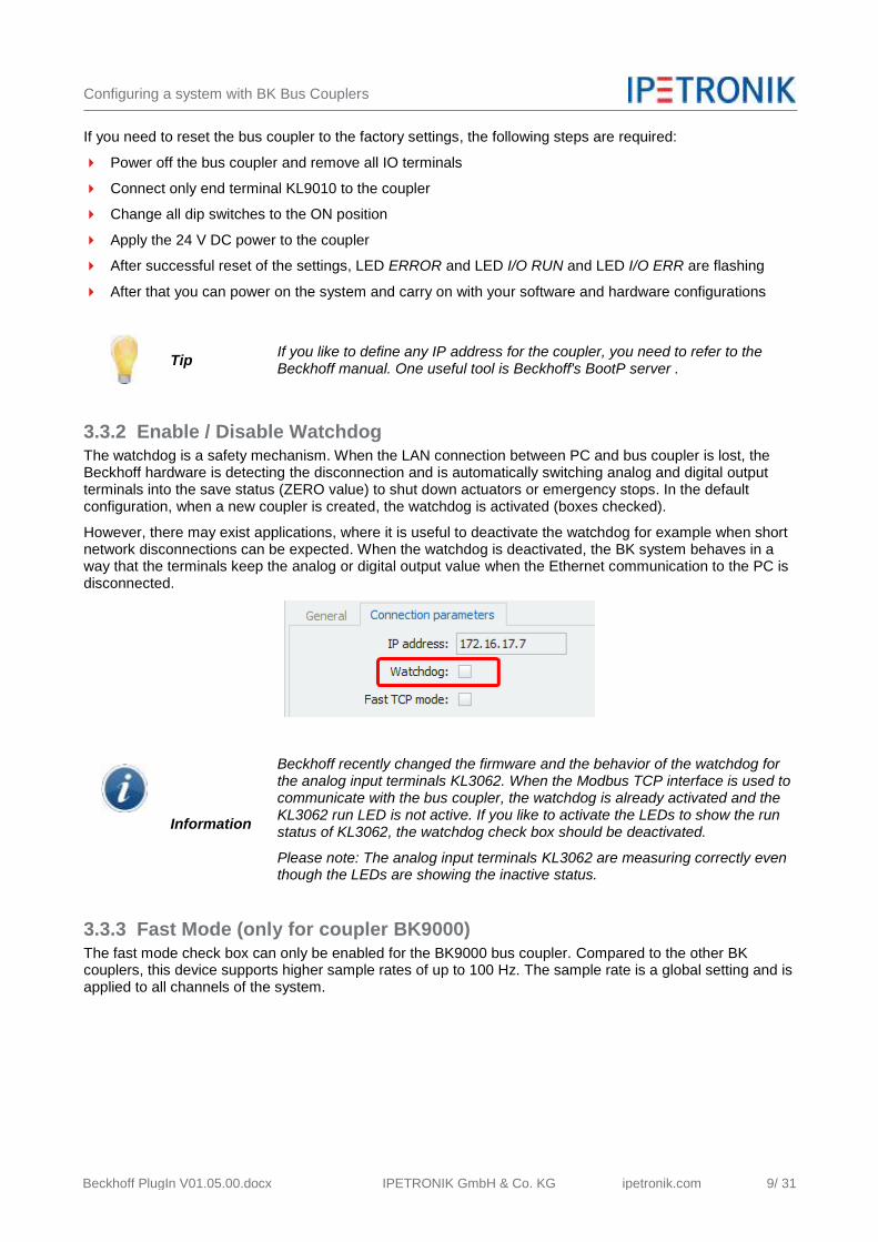
3.3.2 Enable / Disable Watchdog The watchdog is a safety mechanism. When the LAN connection between PC and bus coupler is lost, the Beckhoff hardware is detecting the disconnection and is automatically switching analog and digital output terminals into the save status (ZERO value) to shut down actuators or emergency stops. In the default configuration, when a new coupler is created, the watchdog is activated (boxes checked).
However, there may exist applications, where it is useful to deactivate the watchdog for example when short network disconnections can be expected. When the watchdog is deactivated, the BK system behaves in a way that the terminals keep the analog or digital output value when the Ethernet communication to the PC is disconnected.
Information
Beckhoff recently changed the firmware and the behavior of the watchdog for the analog input terminals KL3062. When the Modbus TCP interface is used to communicate with the bus coupler, the watchdog is already activated and the KL3062 run LED is not active. If you like to activate the LEDs to show the run status of KL3062, the watchdog check box should be deactivated.
Please note: The analog input terminals KL3062 are measuring correctly even though the LEDs are showing the inactive status.
3.3.3 Fast Mode (only for coupler BK9000)
The fast mode check box can only be enabled for the BK9000 bus coupler. Compared to the other BK couplers, this device supports higher sample rates of up to 100 Hz. The sample rate is a global setting and is applied to all channels of the system.

Configuring a system with BK Bus Couplers
Beckhoff PlugIn V01.05.00.docx IPETRONIK GmbH & Co. KG ipetronik.com 10/ 31
3.4 Automatic reconnect to the bus coupler
The PlugIn is supporting an auto connect function and tries to reconnect to the coupler in case the communication was stopped. If the connection (coupler –PC) is reestablished, the system continues with the measurements of input terminals and operation of the output terminals.

Configuring a system with BK Bus Couplers
Beckhoff PlugIn V01.05.00.docx IPETRONIK GmbH & Co. KG ipetronik.com 11/ 31
3.5 Adding IO Terminals to the Coupler
After creating the interface device (bus coupler), the IO terminals must be created. The order of the IO terminals in IPEmotion must match exactly the same order of the IO terminals and power input terminals used by the hardware setup. The physical order of the IO terminals is reflecting the Modbus address structure and the PlugIn is automatically reading the correct values from the different terminals.
The following screen shot shows a complete system with several IO terminals.

Configuring a system with BK Bus Couplers
Beckhoff PlugIn V01.05.00.docx IPETRONIK GmbH & Co. KG ipetronik.com 12/ 31
Information
The IO terminals must be initially created in the right order as used by the hardware setup. It is misleading to use a sorting function to bring the modules in the same order as used in the HW setup e.g. by renaming the IO terminals.
It is recommended to including the end terminal KL9010 in the IPEmotion process structure. For the Mobus addressing point of few it is not necessary to include the end terminal. The measurement will work correctly without an end terminal in the IPEmotion configuration.
3.6 Removing vs Deactivating IO Terminals
If your hardware configuration is changing, e.g. terminals are physically removed you need to delete these terminal from the IO list also. The Modbus addresses are only updated when the IO terminals are deleted. When you deactivate an IO terminal, the address mapping remains and only the measurement of these inputs is deactivated.
Configuring a system with BK Bus Couplers
Beckhoff PlugIn V01.05.00.docx IPETRONIK GmbH & Co. KG ipetronik.com 13/ 31
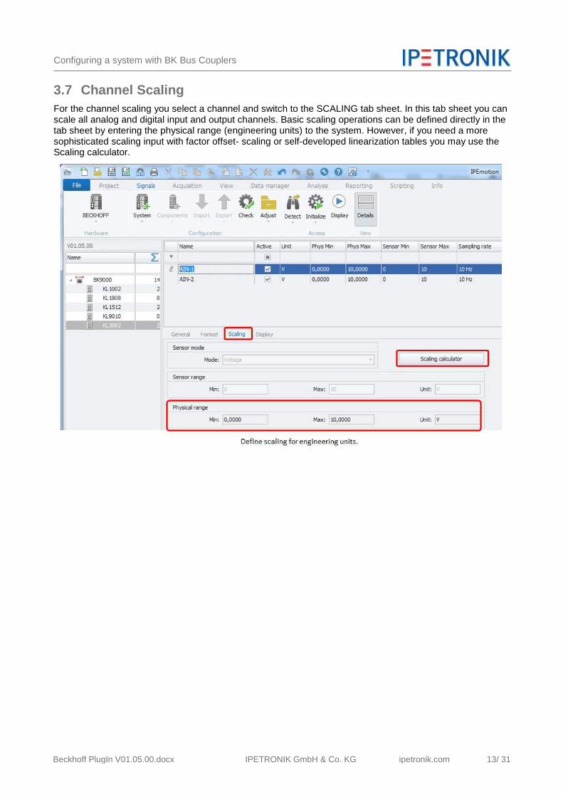
3.7 Channel Scaling
For the channel scaling you select a channel and switch to the SCALING tab sheet. In this tab sheet you can scale all analog and digital input and output channels. Basic scaling operations can be defined directly in the tab sheet by entering the physical range (engineering units) to the system. However, if you need a more sophisticated scaling input with factor offset- scaling or self-developed linearization tables you may use the Scaling calculator.

Configuring a system with BK Bus Couplers
Beckhoff PlugIn V01.05.00.docx IPETRONIK GmbH & Co. KG ipetronik.com 14/ 31
3.8 Supported KL IO Terminals
This PlugIn version supports the following KL IO terminals. The list of terminals is growing along with new customer projects.
The terminals indicated with the red arrow e.g. K1xxx, KL2xxx etc... are generic terminals which can be used to create new terminals using a generic template. The concept is explained below.
3.9 Configure generic IO terminals – Example KL 3172
Beckhoff offers a large range of IO terminals and not all terminal types are implemented in the PlugIn, yet. However, the PlugIn provides generic terminals which give users the possibility to create their own terminals individually.
K 1Gxxx This is a group terminal for multiple DIG IO
KL 1xxx Generic Digital input terminal
KL 2xxx Generic Digital output terminal
KL 3xxx Generic Analog input terminal
KL 4xxx Generic Analog output terminal
KL 9xxx Generic special terminal
If a specific terminal is missing in the PlugIn you can create a terminal from the five main IO terminals by your own. In the following example a two channel high precision analog input terminal (KL 3172) with a 0 - 2 Volt measurement range is created.

Configuring a system with BK Bus Couplers
Beckhoff PlugIn V01.05.00.docx IPETRONIK GmbH & Co. KG ipetronik.com 15/ 31
Information Not all IO terminals can be created through the generic templates. If you require a special IO terminal please contact IPETRONIK for support.
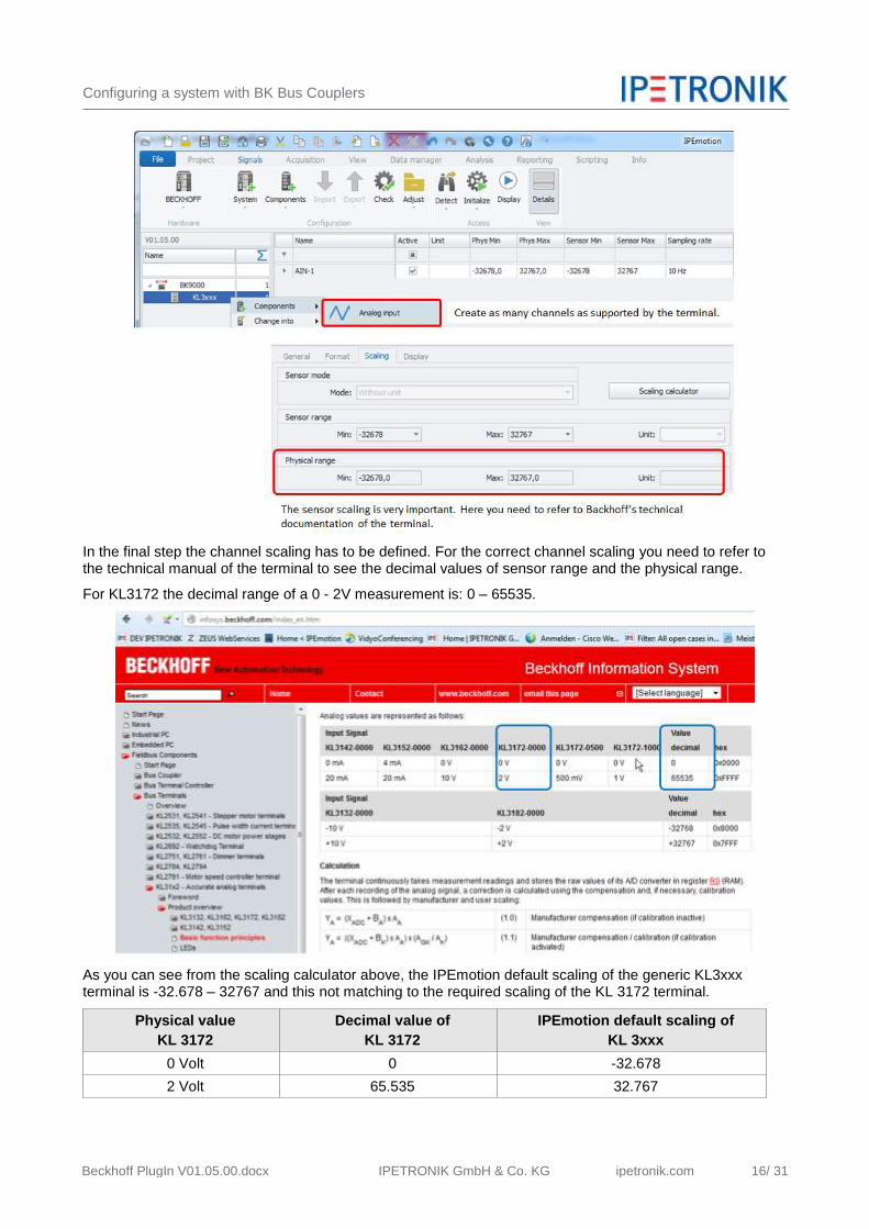
After creating a generic input terminal KL3xxx, the analog input channels need to be created. The KL 3172 has 2 analog inputs. Therefore, 2 input channels are created.
Information Even if you like to measure only one input e.g. of KL3172, it is still required to create as many channels (2 inputs) on the software side as provided by the terminal in order to set up the correct Modbus address register.
Configuring a system with BK Bus Couplers
Beckhoff PlugIn V01.05.00.docx IPETRONIK GmbH & Co. KG ipetronik.com 16/ 31
In the final step the channel scaling has to be defined. For the correct channel scaling you need to refer to the technical manual of the terminal to see the decimal values of sensor range and the physical range.
For KL3172 the decimal range of a 0 - 2V measurement is: 0 – 65535.
As you can see from the scaling calculator above, the IPEmotion default scaling of the generic KL3xxx terminal is -32.678 – 32767 and this not matching to the required scaling of the KL 3172 terminal.
Physical value
KL 3172
Decimal value of
KL 3172
IPEmotion default scaling of
KL 3xxx
0 Volt 0 -32.678
2 Volt 65.535 32.767

Configuring a system with BK Bus Couplers
Beckhoff PlugIn V01.05.00.docx IPETRONIK GmbH & Co. KG ipetronik.com 17/ 31
In order to scale this terminal correctly the scaling mode “Free 2-point scaling” is required. The scaling is defined for the ordinate (x-axis) in the range of the KL3172 IO terminal from 0 - 65535.
The physical value (y-axis) is configured according to the input measurement range of 0 - 2 Volt.

Configuring a system with BK Bus Couplers
Beckhoff PlugIn V01.05.00.docx IPETRONIK GmbH & Co. KG ipetronik.com 18/ 31
3.10 Konfiguration information for special terminals
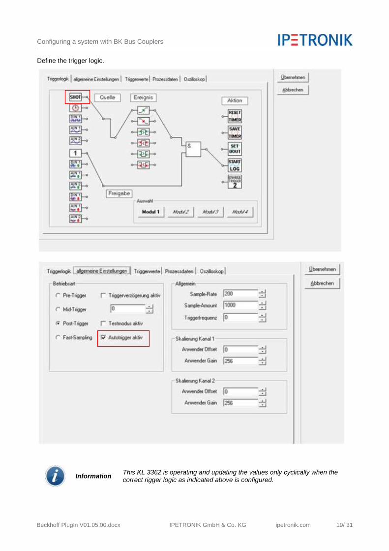
3.10.1 Terminal KL 3362 – Oscilloscope terminal
This terminal is a 2 channel oscilloscope terminal which is designed for dynamic data acquisition applications. The results you will measure in IPEmotion are depending on the measurement mode of the terminal. The measurement mode is defined through the Beckhoff KS2000 software. The functions of the terminal are not discussed in this document. See here for Beckhoff’s technical documentation.
General settings is dealing about sample rate the overall trigger mode.
Configuring a system with BK Bus Couplers
Beckhoff PlugIn V01.05.00.docx IPETRONIK GmbH & Co. KG ipetronik.com 19/ 31
Define the trigger logic.
Information This KL 3362 is operating and updating the values only cyclically when the correct rigger logic as indicated above is configured.

Configuring a system with BK Bus Couplers
Beckhoff PlugIn V01.05.00.docx IPETRONIK GmbH & Co. KG ipetronik.com 20/ 31
Define measurement mode.
The terminal is supporting different measurement modes like:
Peak value
Min value
Average
True RMS
Etc…
Depending on the settings defined here you will get the result transferred to IPEmotion.

Configuring a system with BK Bus Couplers
Beckhoff PlugIn V01.05.00.docx IPETRONIK GmbH & Co. KG ipetronik.com 21/ 31
3.10.2 Terminal KL 3222 – Resistance measurement (Ohm) This is a 2 channel input terminal is generally designed for resistance measurement (Ohm) and RTD (Pt100, etc.) temperature measurements. The terminal is currently configured for Ohm measurement only. You can change with the KS2000 software the Ohm measurement range from 0-5000 Ohm or 0- 1200 Ohm. If you like to measure RTD temperatures [°C] with this terminal, a modification of the PlugIn is required. Please contact IPETRONIK support.
3.10.3 Terminal KL 3311 – Thermocouple measurement
This 1 channel input terminal is supporting thermocouple temperature measurement for TC types J, K, L, B, E, N, R, S, T, U and mV measurement. The factory default setting is the measurement of Thermocouple type K. You can change with the KS2000 software the thermocouple type.
This terminal is currently not supporting mV measurements in IPEmotion. If you like to measure mV a new version of the PlugIn required. Please contact IPETRONIK support.

Configuring a system with BK Bus Couplers
Beckhoff PlugIn V01.05.00.docx IPETRONIK GmbH & Co. KG ipetronik.com 22/ 31
3.10.4 Terminal KL 1512 – 16 bit counter input This digital 2 channel pulse counter input terminal is designed for pulse counting. The counter is 16 bit. After 65.535 counts the counter is starting from 0 again.
Application example Pulse counting – Flow Rate & Volume totalizer
The following example will show how to use IPEmotion Math functions to count overall water consumption The customer used the e.g. the sensor from "IDEA-VORTEX" flow meter which gives pulse outputs proportional to the flow rate.
For flow rate applications the following inputs are usually required:
Online flow rate (ml/s)
TOTAL Volume (ml)
The current online flow rate is compute with the following formula:
DIFF("Counter x") (see definition of Counter_x formula below)

Configuring a system with BK Bus Couplers
Beckhoff PlugIn V01.05.00.docx IPETRONIK GmbH & Co. KG ipetronik.com 23/ 31
Der the TOTAL Volume can be calculated through the following formula:
TOTAL Volume [ml]: ("Counter_x"+"Resets_Cx")* "SensorFlowRate_Constant y"
x: Is the ID of the channel (1 input one of the terminal, or 2).
y: Is the ID for the constant of the sensor in used indicating how much volume [ml] are related to one pulse.(8, 10, 15, 20 or 25 ml).
Counter_x Is the actual value from the counter terminal.
The current value is calculated by the following term using the VALID formula in order to overcome the “NoValue “reading when the terminal is reset from 65535 back to zero. During the reset procedure a “NoValue” is transferred to IPEmotion
Counter_x = IF(VALID("CNT-x"); "CNT-x";0)
Resets_Cx This is a logic condition to ensure that the counter keeps counting (totalizing) even if the counter input passed its overflow is starting from zero all over. When the counter has reached 65.535 ticks the terminal is starting from zero all over again. Resets_Cx = IF((VALID("Resets_Cx")); IF((("Counter_x" <> PREV("Counter_x")) AND ("Counter_x"=65535)); "Resets_Cx"+65535; "Resets_Cx");0)
SensorFlowRate_Constant y This is the constant flow rate of the sensor and depending of the diameter of the sensor. In the example the sensor flow rates per pulse
DM 8: 0,56 ml/pulse 8mm diameter
DM 10: 1,40 ml/pulse 10mm diameter
DM 15: 3,09 ml/pulse 15mm diameter
DM 20: 6,22 ml/pulse 20mm diameter
DM 25: 12,40 ml/pulse 25mm diameter
Configuring a system with BK Bus Couplers
Beckhoff PlugIn V01.05.00.docx IPETRONIK GmbH & Co. KG ipetronik.com 24/ 31
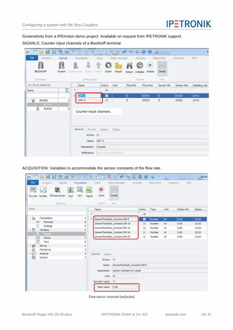
Screenshots from a IPEmoton demo project: Available on request from IPETRONIK support.
SIGANLS: Counter input channels of a Beckhoff terminal.
ACQUISITION: Variables to accommodate the sensor constants of the flow rate.

Configuring a system with BK Bus Couplers
Beckhoff PlugIn V01.05.00.docx IPETRONIK GmbH & Co. KG ipetronik.com 25/ 31
You will find the flow rate [ml/pulse] in the sensor data sheet. See extract below:
ACQUISITION – Overview of math and logic functions

Configuring a system with BK Bus Couplers
Beckhoff PlugIn V01.05.00.docx IPETRONIK GmbH & Co. KG ipetronik.com 26/ 31
3.11

EtherCAT interface
Beckhoff PlugIn V01.05.00.docx IPETRONIK GmbH & Co. KG ipetronik.com 27/ 31
4 EtherCAT interface
4.1 System architecture
The PlugIn is also supporting the direct data communication to Beckhoff CPU systems. For this architecture the ADS or R3IO interface is used to get the measurements from the Beckhoff CPU system integrated to IPEmotion.
4.2 TwinCAT - Beckhoff CPU configuration
On the CPU (e.g. CX1100) all the IO terminals are configured using the TwinCAT System Manager software. The IO terminals are listed exactly in the same order as they are physically connected to each other.

EtherCAT interface
Beckhoff PlugIn V01.05.00.docx IPETRONIK GmbH & Co. KG ipetronik.com 28/ 31
4.3 TwinCAT – Task configuration
In order to setup a data communication between the Beckhoff CPU and the IPEmotion PC a separate TwinCAT System manager installation on the IPEmotion PC is required. In this TwinCAT System Manager a new process task is defined which included all or only a subset of IO terminals you like to interface to IPEmotion.
On the IPEmotion side the whole IO structure of the task needs to be created, as well. The interface between IPEmotion and the Task is established over the Port number.

EtherCAT interface
Beckhoff PlugIn V01.05.00.docx IPETRONIK GmbH & Co. KG ipetronik.com 29/ 31
A nice function of the TwinCAT System Manager is that IO terminals can be allocated to several task classes which are related e.g. to different sample rates. When you have defined several task classes with individual port numbers these task classes can be integrated into IPEmotion.
4.4 Supported EtherCAT IO Terminals
This PlugIn supports the following EL IO terminals. The list of terminals is growing along with customer projects and new requirements.

EtherCAT interface
Beckhoff PlugIn V01.05.00.docx IPETRONIK GmbH & Co. KG ipetronik.com 30/ 31
4.4.1 Adding generic IO terminals – from template terminals Beckhoff offers a large range of IO terminals and not all terminal types are jet implemented in the PlugIn. However, the PlugIn provides generic terminals which give users the possibility to create their own terminals, individually.
EL 1xxx Generic Digital input terminal
EL 2xxx Generic Digital output terminal
EL 3xxx Generic Analog input terminal
EL 4xxx Generic Analog output terminal
EL 9xxx Generic special terminal
Creating a new terminal over the templating process is working with EtherCAt terminals in the same way as discussed in chapter 3.
Information Not all IO terminals can be created though the generic templates. If you require a special IO terminal please contact IPETRONIK for support.

Starting Measurement
Beckhoff PlugIn V01.05.00.docx IPETRONIK GmbH & Co. KG ipetronik.com 31/ 31
5 Starting Measurement
In order to start measurement and to test the communication you just need to run the start display button. The online measurements are directly displayed.
Related Documents


