Revision 5 January 4, 2019 Individual chapters of the Kalsi Seals Handbook are periodically updated. To determine if a newer revision of this chapter exists, please visit www.kalsi.com/seal-handbook.htm. NOTICE: The information in this chapter is provided under the terms and conditions of the Offer of Sale, Disclaimer, and other notices provided in the front matter of this handbook. Document 3088 © 2019 Kalsi Engineering, Inc. All rights reserved. Kalsi Seals Handbook Chapter D20 Bearing mistakes to avoid

Welcome message from author
This document is posted to help you gain knowledge. Please leave a comment to let me know what you think about it! Share it to your friends and learn new things together.
Transcript

Revision 5 January 4, 2019
Individual chapters of the Kalsi Seals Handbook are periodically updated. To determine if
a newer revision of this chapter exists, please visit www.kalsi.com/seal-handbook.htm.
NOTICE: The information in this chapter is provided under the terms and conditions of the Offer of
Sale, Disclaimer, and other notices provided in the front matter of this handbook.
Document 3088 © 2019 Kalsi Engineering, Inc. All rights reserved.
Kalsi Seals Handbook
Chapter D20
Bearing mistakes to avoid

Bearing mistakes to avoid Chapter D20 Page 1
Search this handbook Contact Kalsi Engineering
1. What is this chapter doing in a rotary seal handbook?
Rotary seal implementation requires a systems approach to equipment design, which is
why this seal handbook exists. If equipment design is not appropriate, then seal
performance will not be optimal.
Bearings are one of the most important elements in a piece of rotary equipment. For
example, in a sealed bearing mud motor, the bearings react the enormous drilling thrust
load to the drillstring, guide the drill bit, and guide the shaft that the rotary seals run
against. Seal abrasion and extrusion resistance suffers when the bearings cannot do their
job properly. The role of the rotary seals is to protect the bearings, and if the bearings fail
due to faulty bearing implementation, then the customer may incorrectly place blame
upon the seals. For this reason, we have more than a passing interest in helping our
customers implement their bearings properly. This chapter is not a comprehensive guide
to bearing implementation, but it will help you to avoid several serious mistakes. Don’t
let a faulty bearing arrangement torpedo your seal implementation.
2. Inadequate thrust bearing support
Thrust bearing shoulders should fully support the rollers. Failure to fully support the
rollers greatly reduces bearing load capacity, and leads to premature roller damage.
Figure 1 provides an example of an improperly supported thrust bearing. The housing and
shaft shoulders are too small to provide complete support to the races, and the load is
borne primarily by the central part of the rollers. If subjected to heavy loads, the central
part of the rollers may receive damage. Severe shock loads may cause brinelling (Figure
15), and subsequent operation may cause spalling. The spalling will contaminate the
lubricant with metal particles, which is a less than optimum situation for the rotary seals.
Eventually the bearing will fail altogether, causing significant component and rotary seal
damage. The root cause may be difficult to diagnose amidst the destruction: Was it a
bearing failure or a rotary seal failure? Avoid this problem by providing adequate thrust
bearing support. Figure 2 shows a roller from a mud motor thrust bearing that operated
only 50 hours with inadequate support.
Two actions can rectify the problem depicted in Figure 1:
1. Increase the housing and shaft shoulder areas, or
2. Provide adequately thick backup washers.

Bearing mistakes to avoid Chapter D20 Page 2
Search this handbook Contact Kalsi Engineering
Figure 1
Inadequate thrust bearing support
If heavily loaded, this thrust bearing may fail prematurely due to inadequate support. To establish proper support, use bigger housing and shaft support shoulders, or backup washers.
Figure 2
A thrust bearing roller that operated with inadequate support
Due to inadequate support of the bearing race, the center of this mud motor thrust bearing roller suffered damage after only 50 hours of rotation at a shaft speed of 250 rpm. Providing adequate backup washer thickness cured the problem.

Bearing mistakes to avoid Chapter D20 Page 3
Search this handbook Contact Kalsi Engineering
3. Spherical roller thrust bearing orientation
In the implementation shown in Figure 3 (fixed shaft shoulder), spherical roller thrust
bearings provide practically no angular control of the shaft. Instead, they function in a
manner similar to a ball joint. If such a bearing implementation is set up; to guide the
shaft, then the result will be gross runout, metal-to-metal contact between the shaft and
the outer housing, and rapid failure of the rotary shaft seals.
Even oppositely implemented (fixed housing shoulder), spherical roller thrust bearings
can tend to provide relatively imprecise radial control of the shaft. For example, bearing
end play causes radial clearance, allowing excessive radial shaft motion. Spherical roller
thrust bearings are not well suited for high axial shock loads, due to the relative fragility
of the typically-sized thrust shoulder on the inner race.
Figure 3
This orientation provides virtually no angular control
In this orientation (fixed shaft shoulder), spherical roller thrust bearings provide very little angular control of the shaft.

Bearing mistakes to avoid Chapter D20 Page 4
Search this handbook Contact Kalsi Engineering
4. Thermal binding of thrust-capable bearings
In Figure 4, the shaft absorbs the seal generated heat, causing the shaft to thermally
expand more than the bearing housing. Such differential thermal expansion between the
shaft and the housing can grossly overload and rapidly destroy the bearings. Do not
position thrust-capable bearings far apart from one another if the shaft can become hotter
than the bearing housing.
As Figure 5 shows, positioning the angular contact bearings (that locate the shaft axially)
close together makes them immune to axial differential thermal expansion between the
shaft and housing. The radial bearing at the opposite end of the shaft has no thrust
capacity; therefore, axial shaft thermal expansion cannot overload it. Although the left-
hand bearing in the illustration is a roller bearing, a ball bearing – with one race installed
with a slip fit, and the other with a press fit, per normal bearing fitting practice – will
achieve the same effect.
Figure 4
Differential thermal expansion can destroy thrust-capable bearings
The angular contact bearings shown in this hydraulic swivel are too far apart. The shaft will thermally expand more than the housing due to seal and bearing generated heat. Due to the high modulus of elasticity of the shaft and housing, the thermal expansion will overload and destroy the bearings. As a result of the bearing failure, the Kalsi Seals will be unable to perform satisfactorily as hydraulic swivel seals.

Bearing mistakes to avoid Chapter D20 Page 5
Search this handbook Contact Kalsi Engineering
Figure 5
Accommodating axial thermal expansion of the rotary shaft
In this hydraulic swivel sealing arrangement, the thrust-capable angular contact bearings are close together, and the radial bearing at the opposite end of the shaft has no thrust capability. Axial differential thermal expansion between the shaft and the housing will not overload the angular contact bearings because they are next to each other. The angular contact bearings are shown in a “face-to-face” arrangement, to minimize resistance to moments. This helps to prevent the angular contact bearings from binding with respect to the left-hand if the bearing mounting bores in the housing are eccentric with respect to one another.
5. Over constraint of radial bearings
The exaggerated schematic of Figure 6 illustrates the effects of incorporating too many
radial bearings in misaligned threaded housings. The amount of eccentricity and/or
angular misalignment between the housings is causing an offset that exceeds the rather
minute bearing clearance. This situation, called “over constraint,” causes bearings to fail
prematurely, because of gross overloading due to the stiffness of the shaft. The same
situation can occur with journal bearings. Eliminating the middle bearing can reduce the
risk of over constraint.

Bearing mistakes to avoid Chapter D20 Page 6
Search this handbook Contact Kalsi Engineering
Figure 6
Shaft over-constraint
In this exaggerated schematic, thread eccentricity and shoulder misalignment are binding the shaft. This will result in bearing overload, and premature failure.
6. Thread-induced binding
In Figure 7, the radial bearing and rotary seal are close to a tapered “box and pin” type
threaded oilfield connection. Tightening such connections to very high toque values
ensures that the connecting remains tight in downhole service. A radial component of the
thread tension causes the pin to elastically deform inward. The magnitude of deformation
can easily cause the bearing to bind with respect to the rotary shaft, and may cause the
extrusion gap of the rotary shaft seal to drag against the shaft. The result will be rapid
bearing and seal destruction.
When using such threaded connections, analyze the deformation, and design around it.
The preferred workaround is to position bearings and seals far enough from the threads so
that thread-induced elastic deformation does not affect them. In some cases, this is simply
not possible. For example, in mud motors, it may be necessary to position a threaded
connection around a radial bearing in order to keep the tool as short as possible.

Bearing mistakes to avoid Chapter D20 Page 7
Search this handbook Contact Kalsi Engineering
In such cases, it may be preferred to apply light torque to ensure shoulder-to-shoulder
contact, and then finish tightening with controlled angular makeup, instead of controlled
torque. This method provides controlled deformation of the threaded part of the seal
carrier, because the stress and deformation resulting from tightening are not influenced
by variations in thread and shoulder friction.
Figure 7
Thread-induced binding
With tightening of the mud motor threaded joint shown here, a component of the resulting thread tension causes the male threaded member to elastically deform in the inward radial direction. This deformation can bind the journal bearing against the shaft, and may cause the extrusion gap bore to rub on the shaft. Such deformation-induced contact can destroy the bearing and the rotary shaft seal.
7. Thrust bearing misalignment
In the exaggerated schematic of Figure 8, an out-of-square shoulder causes the shaft to
angularly misalign with the right-hand housing. This misalignment causes
non-uniform bearing support. While there can be various causes of angular shaft
misalignment, if heavy thrust loads are present, then shortening of the thrust bearing life
can result.
One commercially available cure for static misalignment is a two-piece self-aligning race
arrangement, where the interface between the two race components is spherically ground
(Figure 9). Bearing manufacturers do not recommend such arrangements for service
conditions with continually changing alignment.

Bearing mistakes to avoid Chapter D20 Page 8
Search this handbook Contact Kalsi Engineering
Figure 8
Angular misalignment shortens thrust bearing life
As shown by this exaggerated schematic, angular shaft misalignment causes uneven thrust bearing support. This situation causes significantly shortened thrust bearing life, especially if heavy thrust loads are present. Out-of-square shoulders comprise one potential cause, among several, for angular misalignment.

Bearing mistakes to avoid Chapter D20 Page 9
Search this handbook Contact Kalsi Engineering
Figure 9
A self-aligning washer accommodates static misalignment
As shown by this exaggerated schematic, the spherical interface of a two-piece self-aligning race arrangement accommodates static misalignment. (Not recommended for service conditions that have continually changing alignment.)

Bearing mistakes to avoid Chapter D20 Page 10
Search this handbook Contact Kalsi Engineering
8. Bearing mounting fit
With bearings that have two races, the typical practice is to provide an interference fit for
the race that has relative rotation with respect to the load. Consult your bearing
manufacturer’s literature for fitting practices. Failure to provide an interference fit on the
correct race can lead to race slippage and wear of bearing mountings surfaces (Figure
10). This wear can potentially put metal particles into the lubricant, which can damage
the bearings and rotary shaft seals.
Figure 10
Failure to press fit the race that has relative rotation with the load
Bearing race slippage galled this shaft of an oilfield downhole drilling tool. The race was a slip fit, and had a tang intended to cause the race to rotate with the shaft. Angular acceleration due to
drillstring stick/slip1 caused tang failure (Figure 11), allowing the hardened race to slip on the shaft. The resulting slippage galled the EN 30B – BS 970 grade 835M30 alloy steel shaft.
1 For information on stick/slip, see SPE Paper No. 145910, "Drill Pipe Measurements Provide
Valuable Insight into Drill String Dysfunctions”.

Bearing mistakes to avoid Chapter D20 Page 11
Search this handbook Contact Kalsi Engineering
Figure 11
Evidence of angular acceleration due to drillstring stick/slip
This race caused the galling shown in Figure 10. The undersized tang, intended to cause the race to rotate with the shaft, failed due to drillstring stick/slip.
9. Drillstring angular and axial acceleration
Oilfield mud motors and rotary steerable tools are subject to extreme angular and axial
accelerations due to drillstring elasticity and length2. Securely anchoring such
components, such as thrust bearing removable load shoulders, is necessary to prevent
acceleration related galling (Figure 13) and impact damage. Figure 12 shows a used mud
motor shaft coated with a bearing lubricant filled with metal particles. The metal particles
are the result of too much angular clearance at the anti-rotation feature of the thrust
bearing removable load shoulder. This excessive angular clearance created the metal
flakes by two mechanisms: Galling between the removable load shoulder and the shaft,
and angular impact between the anti-rotation feature and the shaft. Such metal particles in
the lubricant may damage the bearings and the rotary shaft seals.
Figure 11 shows an undersized anti-rotation tang of a bearing race that failed due to
angular impact resulting from drillstring stick/slip. Anti-rotation features need to be very
robust in oilfield downhole drilling tools. Sizing and carefully designing all components
to withstand immense G-forces in service is a must.
2 For information on drillstring vibration, see SPE papers 14330, 15560, 15561, 15563, 15564, 145910,
147747, SPE/IADC paper no. 18652, and Erik Skaugen, et al., “Experimental and Theoretical Studies of Vibrations in Drill Strings Incorporating Shock Absorbers” (12th World Petroleum Congress, 1987).

Bearing mistakes to avoid Chapter D20 Page 12
Search this handbook Contact Kalsi Engineering
Figure 12
Metal particles in mud motor seal lubricant due to angular impact
The metal particles shown here are due to impact between the anti-rotation feature of a thrust bearing removable load shoulder and the mating shaft recess due to high angular acceleration, and due to galling resulting from a slight amount of relative angular motion between the removable shoulder and the shaft. Such metal particles can reduce the life of the bearings and rotary seals.
Figure 13
Galling from motion resulting from angular acceleration
This oilfield mud motor thrust bearing removable load shoulder shows galling due to angular motion relative to the shaft caused by severe angular acceleration. The problem resulted from too much clearance in the anti-rotation feature of the load shoulder.

Bearing mistakes to avoid Chapter D20 Page 13
Search this handbook Contact Kalsi Engineering
10. Improper spacer length calculation can damage thrust bearings
In some types of tools, such as oilfield mud motor sealed bearing assemblies, a custom
length spacer accounts for component tolerance and sets the thrust bearing end clearance
(Figure 14). Typically, this involves the following steps:
1. Assemble the tool with an intentionally oversized spacer length, applying just
enough thread torque to take up all axial clearance.
2. Measure the gap at the thread shoulder.
3. Calculate the spacer length required to provide the desired end clearance, by
subtracting the shoulder gap measurement and the desired end play from the
length of the oversized spacer. (The end play is necessary to accommodate
differential thermal expansion, measurement error, variations in makeup torque,
and variations in friction at the threads and shoulder.)
4. Reassemble the tool with a spacer having the calculated spacer length.
Not considering the axial makeup associated with full assembly torque in this procedure
can result in excessive spacer length and crushed thrust bearings. For example, on a mud
motor sealed bearing assembly that we designed and tested, 5,000 ft-lb of makeup torque
on a 4.1-4 stub acme 2G thread caused about 16.7° motion after the shoulders contacted,
using lubricated threads and shoulders. This equates to about 0.012” of axial
advancement. Not including this axial advancement when calculating the required spacer
length will result in the thrust bearings overloading and in all probability receiving
brinelling type damage (Figure 15).

Bearing mistakes to avoid Chapter D20 Page 14
Search this handbook Contact Kalsi Engineering
Figure 14
Improper spacer length calculation causes damaged thrust bearings
In order to avoid crushing the thrust bearings, don’t forget to consider the axial motion caused by thread makeup torque when calculating the thrust bearing spacer length.
Bearing mistakes to avoid Chapter D20 Page 15
Search this handbook Contact Kalsi Engineering
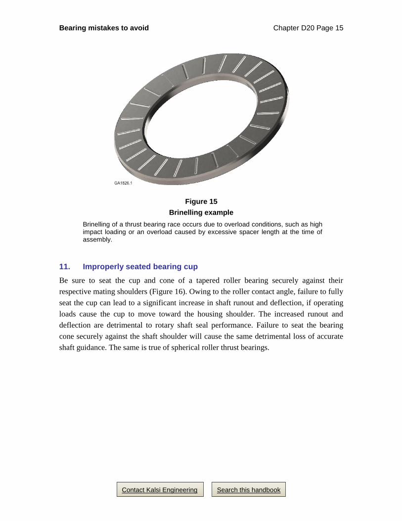
Figure 15
Brinelling example
Brinelling of a thrust bearing race occurs due to overload conditions, such as high impact loading or an overload caused by excessive spacer length at the time of assembly.
11. Improperly seated bearing cup
Be sure to seat the cup and cone of a tapered roller bearing securely against their
respective mating shoulders (Figure 16). Owing to the roller contact angle, failure to fully
seat the cup can lead to a significant increase in shaft runout and deflection, if operating
loads cause the cup to move toward the housing shoulder. The increased runout and
deflection are detrimental to rotary shaft seal performance. Failure to seat the bearing
cone securely against the shaft shoulder will cause the same detrimental loss of accurate
shaft guidance. The same is true of spherical roller thrust bearings.

Bearing mistakes to avoid Chapter D20 Page 16
Search this handbook Contact Kalsi Engineering
Figure 16
Completely seat tapered roller bearing races
Failure to completely seat bearing cups or cones can lead to loss of precise radial control when the race position shifts under load, and increases radial clearance. The resulting loss of shaft control can damage the rotary seals, or cause leakage. Special tools are available to facilitate the race seating operation.
12. Designing shoulders for ease of bearing extraction
Improper shoulder sizing (Figure 17) can make bearing extraction problematic. When
practical, design shaft and housing shoulders that allow use of a tool to extract the
bearing. Examples of suitable tools are specially sized sleeves, used in conjunction with a
hydraulic press, and conventional bearing pullers.
Figure 17
Don’t pick an inconvenient shoulder diameter
Choose a shoulder diameter that allows use of a tool to extract the bearing.

Bearing mistakes to avoid Chapter D20 Page 17
Search this handbook Contact Kalsi Engineering
13. Avoid stress risers on rotating shafts
Avoid sharp corners on shafting with side loads. Sharp corners are stress risers that can
initiate fatigue failure (Figure 18). In oilfield downhole tools, fatigue failure leads to
expensive fishing operations to retrieve the lost part of the shaft.
For information on fatigue failure prediction and prevention, consult engineering
handbooks such as:
• Shigley & Mischke, “Mechanical Engineering Design”, McGraw-Hill, Inc.
• “Technical Report on Fatigue Properties”, SAE J-1099, Society of
Automotive Engineers, Inc., 400 Commonwealth Drive, Warrendale, PA
15096, U. S. A.
• Peterson, R. E., “Stress Concentration Factors”, John Wiley & Sons, Inc.,
1979.
• “Fatigue Design Handbook”, Society of Automotive Engineers, Inc., 1968.
• Faupel and Fisher, “Engineering Design”, 2nd Edition, John Wiley & Sons,
Inc., 1981.
• Barson and Rolfe, “Fracture & Fatigue Control in Structures”, 2nd
Edition, Prentice-Hall, Inc., 1987.
Figure 18
Excessively sharp internal corners on rotary shafts are a fatigue concern
Excessively sharp corners on rotating shafts are a fatigue concern. They create stress risers that promote fatigue cracks, which can eventually lead to complete failure of the shaft.

Bearing mistakes to avoid Chapter D20 Page 18
Search this handbook Contact Kalsi Engineering
14. Inadequate lubricant viscosity
In heavily loaded equipment, such as oilfield mud motors, the bearings require adequate
lubricant viscosity; consult the bearing manufacturer for recommendations. Inadequate
lubricant viscosity can cause bearings to fail prematurely. Be sure to consider the
adequacy of the viscosity at the upper end of the equipment operating temperature range.
Consult the Catalog & Technical Data section of this handbook to evaluate the impact a
lubricant change will have on the hydrodynamic pumping related leakage of the Kalsi
Seals.
15. Pressure-related thrust
In equipment where differential pressure acts over the sealed area(s) of a shaft, do not
forget to take the pressure-related thrust load into account when sizing the thrust
bearings.
16. Orientation of angular contact bearings
The various ways that angular contact ball bearings can be employed is beyond the scope
of this rotary seal handbook. Nevertheless, it is worth pointing out that the orientation of
such bearings is critical. For example, in Figure 19 a set of angular contact bearings are
clamped in a “back-to-back” arrangement, to provide thrust capacity in both directions,
and to resist moments that would tend to make the seal carrier rock with respect to the
rotary shaft. If the bearings were accidentally installed in a “face-to-face” arrangement,
the bearings would still provide thrust capacity in both directions, but the resistance to
moments would be greatly diminished, and seal carrier would be more prone to rocking
relative to the shaft. If the bearings were accidentally installed so that both were facing
the same direction, the resistance to moments would be diminished, and thrust capacity
would only be present in one direction. It is critical to train your mechanics to install
angular contact bearings in the intended orientation, and it is equally critical to make sure
that the machine designer picks an appropriate bearing orientation.
In Figure 5, the angular contact bearings are installed in a “face-to-face” arrangement, to
purposely minimize resistance to moments. This makes it less likely that the angular
contact bearings will bind with respect to the left-hand radial bearing in the event that the
bore for the angular contact bearings is misaligned with respect to the bore for the left-
hand radial bearing.

Bearing mistakes to avoid Chapter D20 Page 19
Search this handbook Contact Kalsi Engineering
Figure 19
Orientation of angular contact bearings matters In this arrangement, angular contact bearings are mounted “back-to-back”, to provide resistance to moments, so that the seal carrier does not rock with respect to the rotary shaft. If the bearings are inadvertently installed “face-to-face”, much of the resistance to moments is lost. Either the “back-to-back” or “face-to-face” orientation provides thrust capability in both directions. If both bearings are oriented in the same direction (“tandem”), thrust capacity is present only in one direction, and resistance to moments is significantly diminished.
17. Bearing availability
Check availability before finalizing bearing selection. Many cataloged bearings are not
readily available, and have prohibitively long manufacturing lead times.

Bearing mistakes to avoid Chapter D20 Page 20
Search this handbook Contact Kalsi Engineering
18. Seal considerations related to the bearing implementation
To achieve the best concentricity between the shaft and the seal groove and between the
shaft and the seal housing bore that defines the extrusion gap with the shaft, place the
radial bearing that guides the shaft in the seal housing (Figure 20). To prevent the bearing
from scoring the seal running surface during bearing installation onto the shaft, make the
diameter of the seal running surface slightly smaller than the diameter of the shaft that
mates with the bearing (Figure 20). To minimize shaft deflection at the rotary seal, place
the radial bearing close to the rotary seal (Figure 20).
Figure 20
Seal considerations For the best concentricity between the seal housing and the shaft, locate the radial bearing in the seal housing. Place the seal groove close to the radial bearing to minimize shaft deflection at the rotary seal location. To protect the seal running surface from bearing installation damage, make the running surface smaller than the shaft surface that mates with the bearing.
Related Documents