A GUIDE TO ELECTRIC VEHICLE INFRASTRUCTURE Bringing power to life. A BEAMA practical guide

Welcome message from author
This document is posted to help you gain knowledge. Please leave a comment to let me know what you think about it! Share it to your friends and learn new things together.
Transcript
A GUIDE TO ELECTRIC VEHICLEINFRASTRUCTURE
Bringingpower to life.
A BEAMApractical guide

About BEAMA 03
Foreword 04
Executive summary 05
Background 08
Introduction 09
Vehicle types 10 (relevant to this guide)
Charging equipment 11 1.1 Charging modes 12
1.2 Charge times and equipment types 16
1.3 Network operation 19
1.4 Charging requirements of different vehicles 20
Installation locations 22 2.1 Typical criteria priority for charge point selection 22
2.2 Other systems 24
2.3 Charging infrastructure for buses 25
2.4 Charging infrastructure for trucks 25
Market development 26 3.1 Government support and public chargepoints 26
3.2 Smart charging 27
3.3 Innovations 30
3.4 Standards 31
Appendices 32 A1 Connector specifications 32
A2 Published standards and regulations 33
A3 Future standards work activity 34
A4 Glossary 36
A5 Definitions 37
CONTENTS
Supported by the Low Carbon Vehicle Partnership
03 A GUIDE TO ELECTRIC VEHICLE INFRASTRUCTURE
ABOUT BEAMA
BEAMA represents manufacturers in the electrotechnical industry in Britain, with 250 members ranging from SMEs to large multinationals.
Our EV infrastructure group is made up of members with interests in charging equipment, smart grid, and related safety and energy supply and control technology.
As part of the Emerging Markets section of BEAMA, our aim is to explore and develop opportunities, and to foster sustainable growth in new markets.
BEAMA members involved in the production of this guide:
This guide is also available as a PDF which will be updated as necessary. The PDF can be found at wwwbeama.org.uk
04 A GUIDE TO ELECTRIC VEHICLE INFRASTRUCTURE
FOREWORD
The UK Government has been amongst the most proactive in devising policies to encourage and enable the electrification of the vehicle fleet. The ultimate objective is, of course, to cut road transport carbon emissions and deliver on targets enshrined in law by the UK’s 2008 Climate Change Act.
After a range of development and demonstration activities, technology, culture, and economics are coalescing to provide a confidence in the electric vehicle (EV) market that has not been seen before. In the coming decade it looks likely that EVs will move towards mainstream status.
In an August 2014 briefing paper to its clients, UBS Bank predicted that battery costs will more than halve by 2020 bringing near price parity between electric and internal combustion engine vehicles (without subsidy). It also predicts that a combination of technical progress in renewable energy production and battery storage will provide cost competitiveness with conventionally generated electricity. Against this backdrop, the paper suggests that utilities’ role in the ‘smart grid’ will become central to their prosperity.
The UK Government’s vision is that by 2050 almost every car and van in the UK will be an Ultra Low Emission Vehicle (ULEV), many of these electric plug-in models. Several reports, including one commissioned by the LowCVP (‘Investing in the Low Carbon Journey’, 2014), have found that there are significant employment and economic opportunities arising from the UK being amongst the leaders in road transport carbon reduction, providing substantial added benefits in terms of energy security and air quality as well as lower costs for motorists.
The Low Carbon Vehicle Partnership is very pleased to be able to support BEAMA’s work in the production of this guide. The guide seeks to enable the growth of a sustainable market for EVs, enhancing stakeholders’ knowledge and understanding of this new field.
The provision of chargepoints has much wider-ranging implications than a cursory investigation might suggest. Systems must be safe, reliable and interoperable and, most crucially, be an integrated part of the energy grid which will have ever more complex demands placed on it.
The guide provides an impartial summary of the current options for EV charging, their suitability in different scenarios, interoperability and standards, all within the context of the wider energy infrastructure and the future need for smart charging.
Andy EastlakeManaging DirectorLow Carbon Vehicle Partnership
Governments worldwide are taking unprecedented steps to transform the nature of the vehicles driven on our roads and their impact on the environment.
THE UK GOVERNMENT’S VISION IS THAT BY 2050 ALMOST EVERY CAR AND VAN IN THE UK WILL BE AN ULTRA LOW EMISSION VEHICLE (ULEV), MANY OF THESE ELECTRIC PLUG-IN MODELS.
05 A GUIDE TO ELECTRIC VEHICLE INFRASTRUCTURE
The small but rapidly growing market for electric vehicles (EVs) in the UK requires a corresponding battery charging infrastructure for drivers to readily charge at home, at depots, or while out and about. Charging equipment, referred to as “Electric Vehicle Supply Equipment” (EVSE), safely and conveniently connects an electric vehicle to the mains electrical supply. Charging can be carried out from a dedicated chargepoint or from non-specialised infrastructure (e.g. the domestic 3 pin socket-outlet). Charging falls into one of two broad categories:
AC, where alternating current is supplied to the vehicle and equipment built into the vehicle converts the current to DC to charge the battery
DC, where the mains AC is converted to DC current within the chargepoint before it is supplied to the vehicle.
In addition to this most basic distinction, the BS EN 61851-1 standard defines 4 different modes for electric vehicle charging:
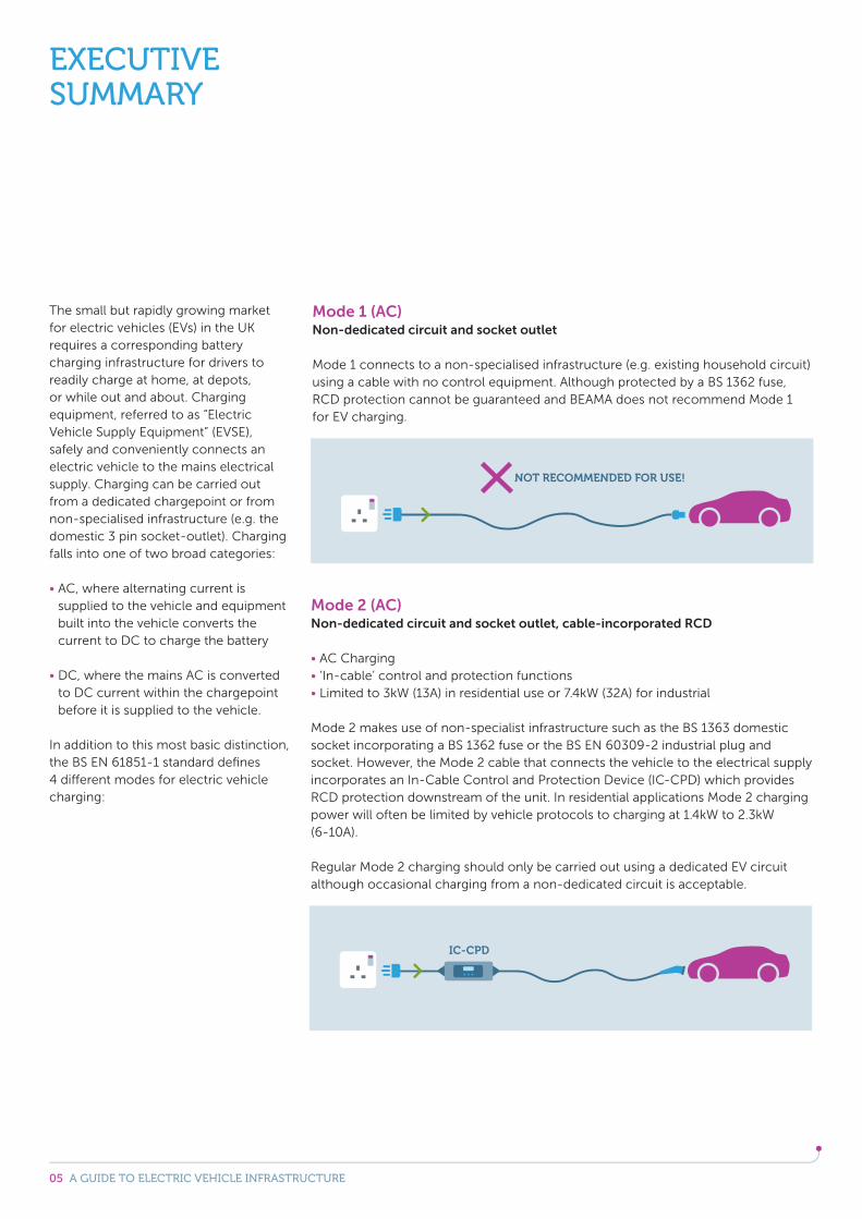
Mode 1 (AC)Non-dedicated circuit and socket outlet
Mode 1 connects to a non-specialised infrastructure (e.g. existing household circuit) using a cable with no control equipment. Although protected by a BS 1362 fuse, RCD protection cannot be guaranteed and BEAMA does not recommend Mode 1 for EV charging.
Mode 2 (AC)Non-dedicated circuit and socket outlet, cable-incorporated RCD
AC Charging ‘In-cable’ control and protection functions Limited to 3kW (13A) in residential use or 7.4kW (32A) for industrial
Mode 2 makes use of non-specialist infrastructure such as the BS 1363 domestic socket incorporating a BS 1362 fuse or the BS EN 60309-2 industrial plug and socket. However, the Mode 2 cable that connects the vehicle to the electrical supply incorporates an In-Cable Control and Protection Device (IC-CPD) which provides RCD protection downstream of the unit. In residential applications Mode 2 charging power will often be limited by vehicle protocols to charging at 1.4kW to 2.3kW (6-10A).
Regular Mode 2 charging should only be carried out using a dedicated EV circuit although occasional charging from a non-dedicated circuit is acceptable.
EXECUTIVE SUMMARY
06 A GUIDE TO ELECTRIC VEHICLE INFRASTRUCTURE
Wireless
There are future plans for a wireless charging standard under the series BS EN 61980. Wireless charging is not yet widely adopted and is not commercially available in the UK so falls outside the current scope of this guide.
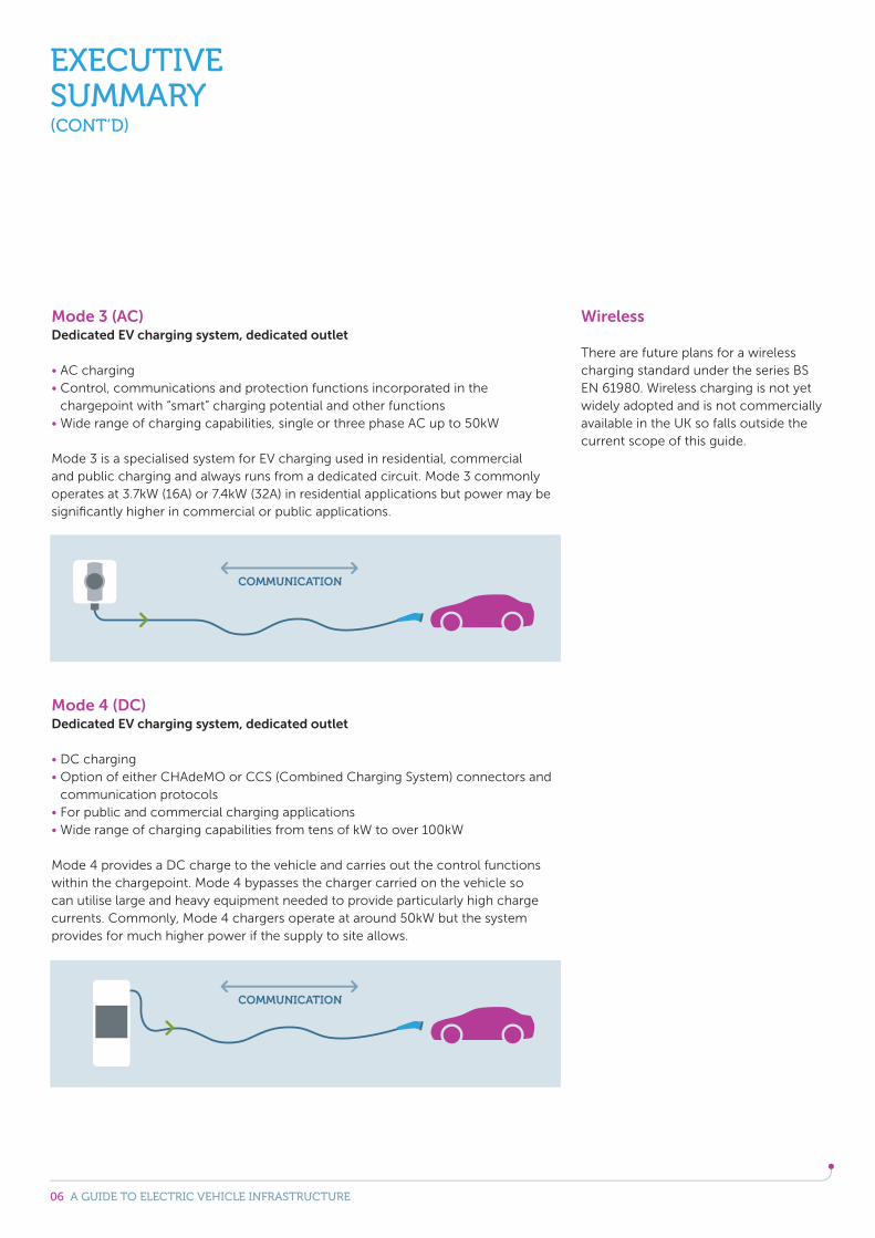
Mode 3 (AC) Dedicated EV charging system, dedicated outlet
AC charging Control, communications and protection functions incorporated in the chargepoint with “smart” charging potential and other functions
Wide range of charging capabilities, single or three phase AC up to 50kW
Mode 3 is a specialised system for EV charging used in residential, commercial and public charging and always runs from a dedicated circuit. Mode 3 commonly operates at 3.7kW (16A) or 7.4kW (32A) in residential applications but power may be significantly higher in commercial or public applications.
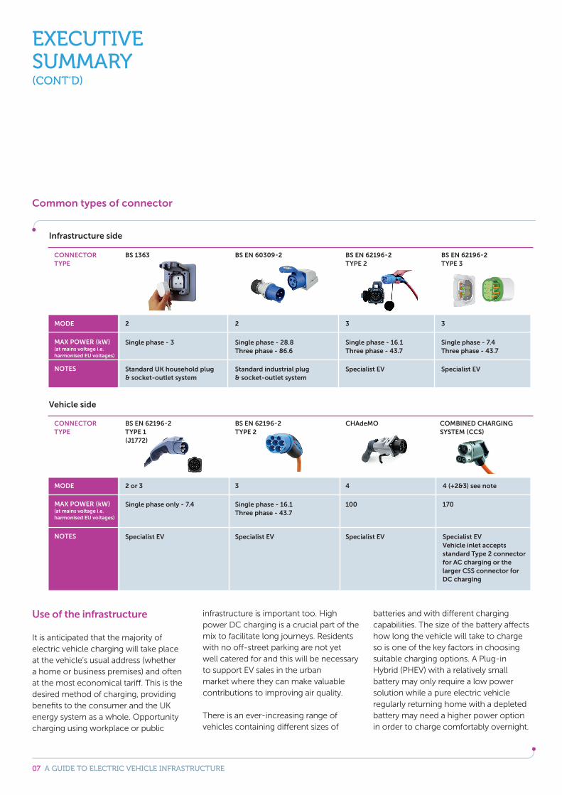
Mode 4 (DC) Dedicated EV charging system, dedicated outlet
DC charging Option of either CHAdeMO or CCS (Combined Charging System) connectors and communication protocols
For public and commercial charging applications Wide range of charging capabilities from tens of kW to over 100kW
Mode 4 provides a DC charge to the vehicle and carries out the control functions within the chargepoint. Mode 4 bypasses the charger carried on the vehicle so can utilise large and heavy equipment needed to provide particularly high charge currents. Commonly, Mode 4 chargers operate at around 50kW but the system provides for much higher power if the supply to site allows.
EXECUTIVE SUMMARY(CONT’D)
07 A GUIDE TO ELECTRIC VEHICLE INFRASTRUCTURE
Use of the infrastructure
It is anticipated that the majority of electric vehicle charging will take place at the vehicle’s usual address (whether a home or business premises) and often at the most economical tariff. This is the desired method of charging, providing benefits to the consumer and the UK energy system as a whole. Opportunity charging using workplace or public
infrastructure is important too. High power DC charging is a crucial part of the mix to facilitate long journeys. Residents with no off-street parking are not yet well catered for and this will be necessary to support EV sales in the urban market where they can make valuable contributions to improving air quality.
There is an ever-increasing range of vehicles containing different sizes of
batteries and with different charging capabilities. The size of the battery affects how long the vehicle will take to charge so is one of the key factors in choosing suitable charging options. A Plug-in Hybrid (PHEV) with a relatively small battery may only require a low power solution while a pure electric vehicle regularly returning home with a depleted battery may need a higher power option in order to charge comfortably overnight.
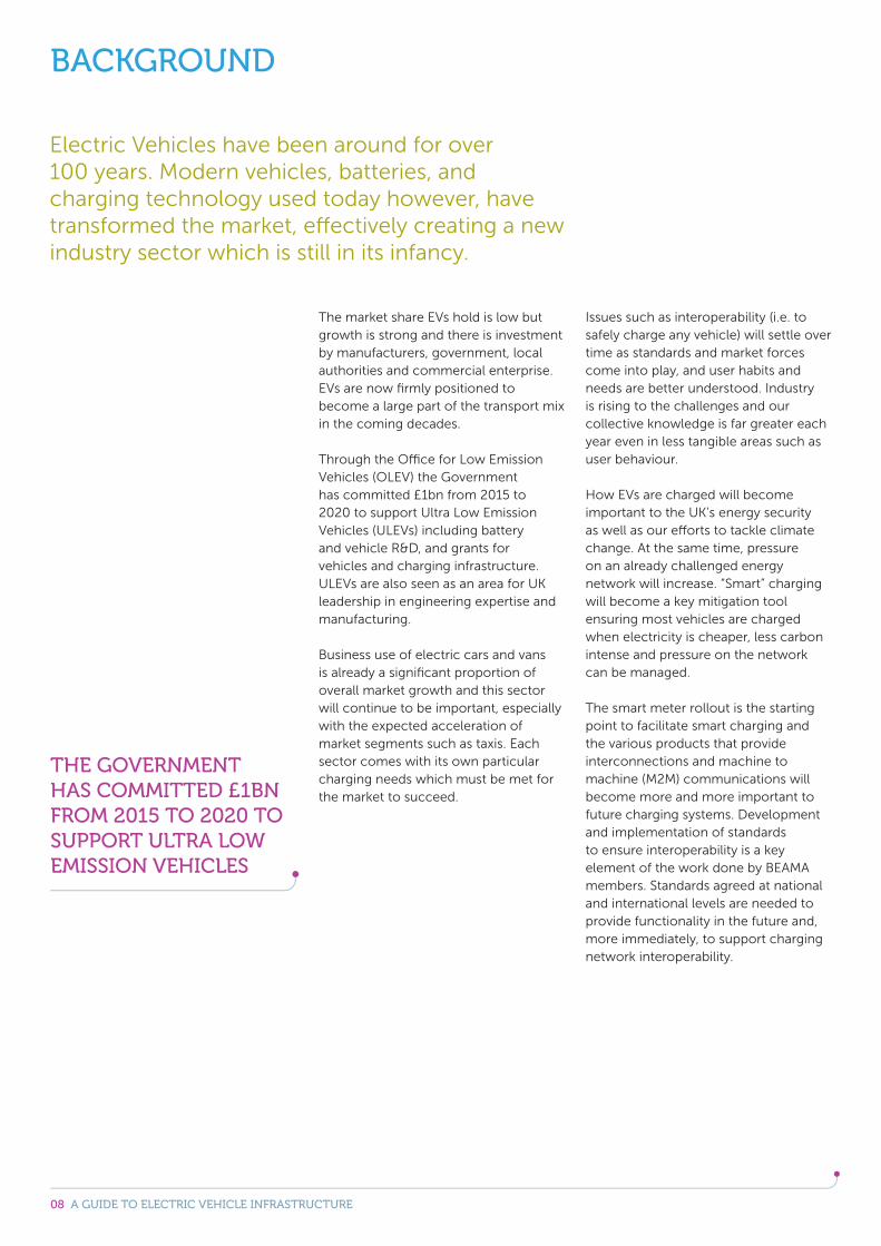
Common types of connector
EXECUTIVE SUMMARY(CONT’D)
MODE
MAX POWER (kW)(at mains voltage i.e. harmonised EU voltages)
NOTES
2
Single phase - 3
3
Single phase - 16.1Three phase - 43.7
Specialist EVSpecialist EVStandard industrial plug & socket-outlet system
Standard UK household plug & socket-outlet system
3
Single phase - 7.4Three phase - 43.7
2
Single phase - 28.8Three phase - 86.6
Infrastructure side
CONNECTOR TYPE
BS 1363 BS EN 62196-2 TYPE 2
BS EN 62196-2 TYPE 3
BS EN 60309-2
Vehicle side
CONNECTOR TYPE
MODE
MAX POWER (kW)(at mains voltage i.e. harmonised EU voltages)
NOTES
BS EN 62196-2TYPE 1 (J1772)
2 or 3
Single phase only - 7.4
CHAdeMO
4
COMBINED CHARGING SYSTEM (CCS)
Specialist EVVehicle inlet accepts standard Type 2 connector for AC charging or the larger CSS connector for DC charging
Specialist EVSpecialist EVSpecialist EV
4 (+2&3) see note
BS EN 62196-2TYPE 2
3
Single phase - 16.1Three phase - 43.7
100 170
08 A GUIDE TO ELECTRIC VEHICLE INFRASTRUCTURE
The market share EVs hold is low but growth is strong and there is investment by manufacturers, government, local authorities and commercial enterprise. EVs are now firmly positioned to become a large part of the transport mix in the coming decades.
Through the Office for Low Emission Vehicles (OLEV) the Government has committed £1bn from 2015 to 2020 to support Ultra Low Emission Vehicles (ULEVs) including battery and vehicle R&D, and grants for vehicles and charging infrastructure. ULEVs are also seen as an area for UK leadership in engineering expertise and manufacturing.
Business use of electric cars and vans is already a significant proportion of overall market growth and this sector will continue to be important, especially with the expected acceleration of market segments such as taxis. Each sector comes with its own particular charging needs which must be met for the market to succeed.
Issues such as interoperability (i.e. to safely charge any vehicle) will settle over time as standards and market forces come into play, and user habits and needs are better understood. Industry is rising to the challenges and our collective knowledge is far greater each year even in less tangible areas such as user behaviour.
How EVs are charged will become important to the UK’s energy security as well as our efforts to tackle climate change. At the same time, pressure on an already challenged energy network will increase. “Smart” charging will become a key mitigation tool ensuring most vehicles are charged when electricity is cheaper, less carbon intense and pressure on the network can be managed.
The smart meter rollout is the starting point to facilitate smart charging and the various products that provide interconnections and machine to machine (M2M) communications will become more and more important to future charging systems. Development and implementation of standards to ensure interoperability is a key element of the work done by BEAMA members. Standards agreed at national and international levels are needed to provide functionality in the future and, more immediately, to support charging network interoperability.
BACKGROUND
Electric Vehicles have been around for over 100 years. Modern vehicles, batteries, and charging technology used today however, have transformed the market, effectively creating a new industry sector which is still in its infancy.
THE GOVERNMENT HAS COMMITTED £1BN FROM 2015 TO 2020 TO SUPPORT ULTRA LOW EMISSION VEHICLES
09 A GUIDE TO ELECTRIC VEHICLE INFRASTRUCTURE
Primarily for industry, this guide is intended to support anyone wishing to understand the fundamentals of electric vehicle charging; whether specifying / installing equipment or those coming from a broader context such as policymaking who need to enhance their technical knowledge.
The guide explains core concepts and product types, and discusses how they are used so that the reader may gain a good appreciation of all the infrastructure-side elements involved in charging electric vehicles. Over time, this guide will be supplemented with more detailed information and position papers accessible from the BEAMA website.
BEAMA members manufacture all types of EV chargepoint but their activities also encompass all the electrical equipment that supports this final piece of charging infrastructure. In this respect, BEAMA members have a unique perspective as interests are spread across the entire integrated system. Not least is how EVSE and charging behaviour interacts with the energy network and how in the future this will be affected by smart meters and smart grid.
Members of BEAMA’s EV group cover a wide range of disciplines from electrical engineers to marketing directors, from experts in electrical standards and safety to the operation of the UKs electricity infrastructure. Through BEAMA, members have been developing and negotiating international standards to ensure the UKs high safety standards are maintained, that our systems will be compatible, and that British industry can compete on a level playing field. This broad range of expertise has been brought to bear in the production of this guide.
INTRODUCTION
THIS GUIDE LOOKS AT ALL THE INFRASTRUCTURE ELEMENTS OF ELECTRIC VEHICLE CHARGING - EVERYTHING NOT BUILT INTO THE VEHICLE ITSELF.
10 A GUIDE TO ELECTRIC VEHICLE INFRASTRUCTURE
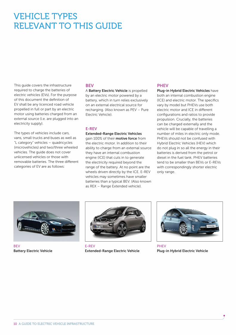
This guide covers the infrastructure required to charge the batteries of electric vehicles (EVs). For the purpose of this document the definition of EV shall be any licenced road vehicle propelled in full or part by an electric motor using batteries charged from an external source (i.e. are plugged into an electricity supply).
The types of vehicles include cars, vans, small trucks and buses as well as “L category” vehicles – quadricycles (microvehicles) and two/three wheeled vehicles. The guide does not cover unlicensed vehicles or those with removable batteries. The three different categories of EV are as follows:
BEV A Battery Electric Vehicle is propelled by an electric motor powered by a battery, which in turn relies exclusively on an external electrical source for recharging. (Also known as PEV – Pure Electric Vehicle).
E-REVExtended-Range Electric Vehicles gain 100% of their motive force from the electric motor. In addition to their ability to charge from an external source they have an internal combustion engine (ICE) that cuts in to generate the electricity required beyond the range of the battery. At no point are the wheels driven directly by the ICE. E-REV vehicles may sometimes have smaller batteries than a typical BEV. (Also known as REX – Range Extended vehicle).
PHEVPlug-in Hybrid Electric Vehicles have both an internal combustion engine (ICE) and electric motor. The specifics vary by model but PHEVs use both electric motor and ICE in different configurations and ratios to provide propulsion. Crucially, the batteries can be charged externally and the vehicle will be capable of travelling a number of miles in electric only mode. PHEVs should not be confused with Hybrid Electric Vehicles (HEV) which do not plug in so all the energy in their batteries is derived from the petrol or diesel in the fuel tank. PHEV batteries tend to be smaller than BEVs or E-REVs with correspondingly shorter electric only range.
VEHICLE TYPESRELEVANT TO THIS GUIDE
BEVBattery Electric Vehicle
E-REVExtended-Range Electric Vehicle
PHEVPlug-in Hybrid Electric Vehicle
11 A GUIDE TO ELECTRIC VEHICLE INFRASTRUCTURE
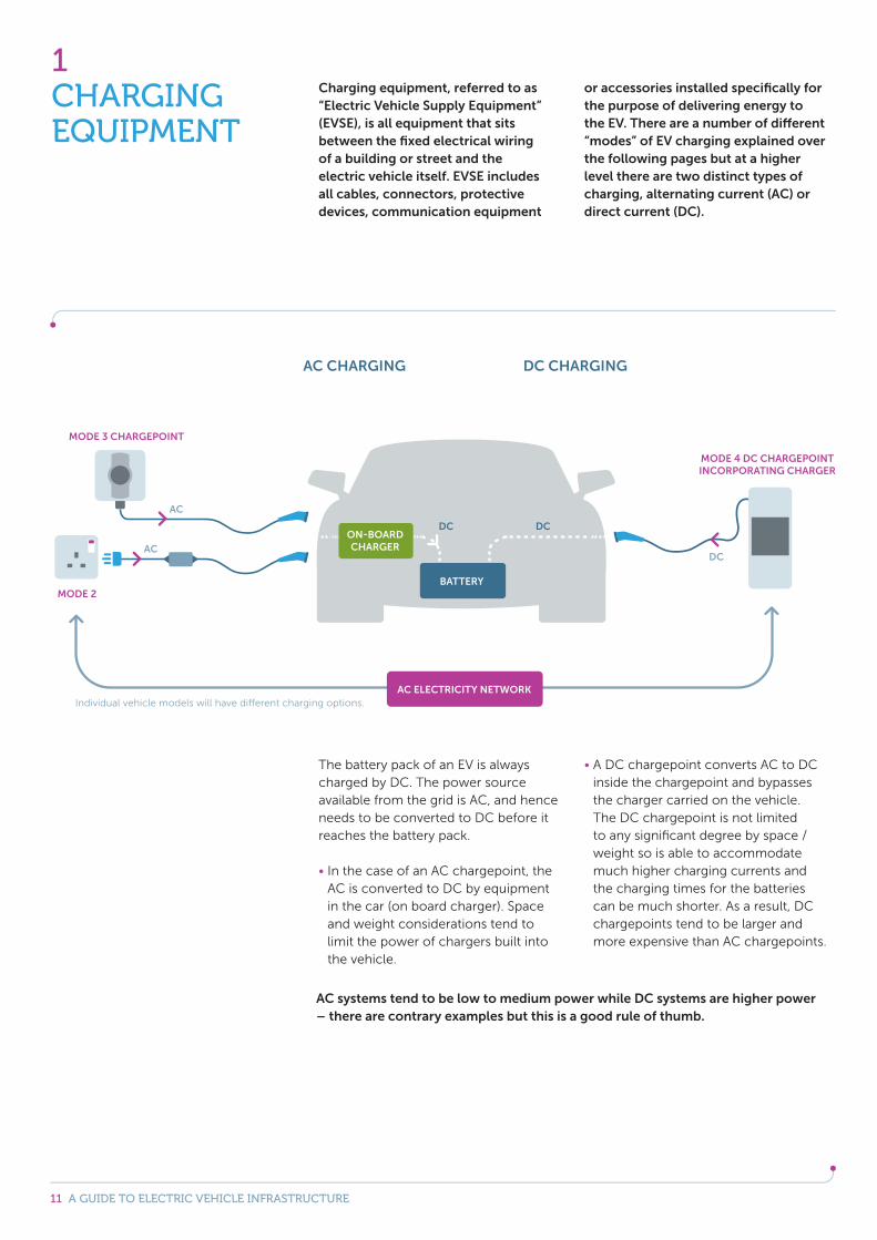
The battery pack of an EV is always charged by DC. The power source available from the grid is AC, and hence needs to be converted to DC before it reaches the battery pack.
In the case of an AC chargepoint, the AC is converted to DC by equipment in the car (on board charger). Space and weight considerations tend to limit the power of chargers built into the vehicle.
A DC chargepoint converts AC to DC inside the chargepoint and bypasses the charger carried on the vehicle. The DC chargepoint is not limited to any significant degree by space / weight so is able to accommodate much higher charging currents and the charging times for the batteries can be much shorter. As a result, DC chargepoints tend to be larger and more expensive than AC chargepoints.
Charging equipment, referred to as “Electric Vehicle Supply Equipment” (EVSE), is all equipment that sits between the fixed electrical wiring of a building or street and the electric vehicle itself. EVSE includes all cables, connectors, protective devices, communication equipment
or accessories installed specifically for the purpose of delivering energy to the EV. There are a number of different “modes” of EV charging explained over the following pages but at a higher level there are two distinct types of charging, alternating current (AC) or direct current (DC).
AC systems tend to be low to medium power while DC systems are higher power – there are contrary examples but this is a good rule of thumb.
1CHARGING EQUIPMENT
Individual vehicle models will have different charging options.
12 A GUIDE TO ELECTRIC VEHICLE INFRASTRUCTURE
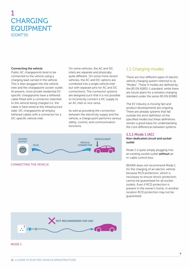
Connecting the vehiclePublic AC chargepoints tend to be connected to the vehicle using a charging lead carried in the vehicle. This is then plugged into the vehicle inlet and the chargepoint socket-outlet.At present, most private residential EV specific chargepoints have a tethered cable fitted with a connector matched to the vehicle being charged (i.e. the cable is hard wired at the infrastructure side). DC chargepoints all employ tethered cables with a connector for a DC-specific vehicle inlet.
On some vehicles, the AC and DC inlets are separate and physically quite different. On some more recent vehicles, the AC and DC options are combined into a single vehicle inlet but with separate pins for AC and DC connections. The connector systems are designed such that it is not possible to incorrectly connect a DC supply to an AC inlet or vice versa.
As well as providing the connection between the electricity supply and the vehicle, a charge point performs various safety, control, and communication functions.
1.1 Charging modes
There are four different types of electric vehicle charging system referred to as “Modes”. These 4 modes are defined by the BS EN 61851-1 standard, while there are future plans for a wireless charging standard under the series BS EN 61980.
The EV industry is moving fast and product developments are ongoing. There are already systems that fall outside the strict definition of the specified modes but these definitions remain a good basis for understanding the core differences between systems.
1.1.1 Mode 1 (AC)Non-dedicated circuit and socket outlet Mode 1 is quite simply plugging into an existing socket outlet without an in-cable control box.
BEAMA does not recommend Mode 1 for the charging of an electric vehicle because RCD protection, which is necessary to ensure shock-protection, cannot be guaranteed for all socket-outlets. Even if RCD protection is present in the owner’s home, in another location RCD protection may not be guaranteed.
1CHARGING EQUIPMENT(CONT’D)
MODE 1
CONNECTING THE VEHICLE
PLUG
VEHICLE INLET
VEHICLE CONNECTOR
SOCKET-OUTLET
13 A GUIDE TO ELECTRIC VEHICLE INFRASTRUCTURE
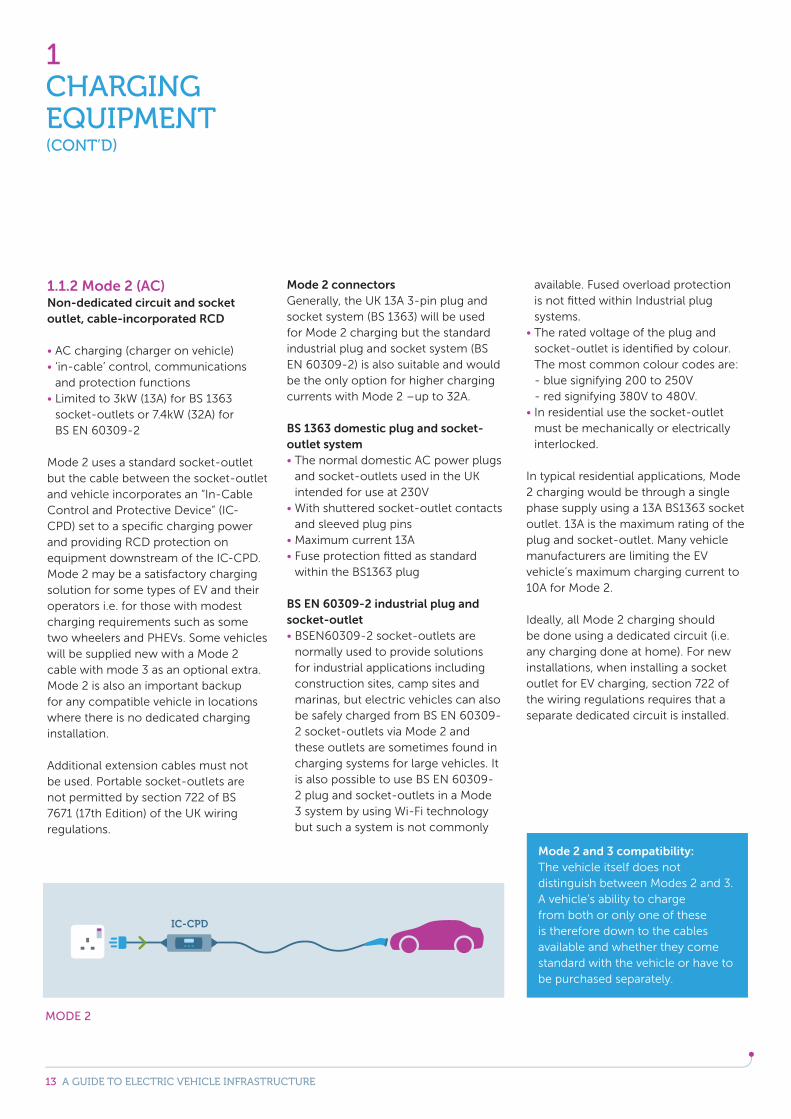
1.1.2 Mode 2 (AC)Non-dedicated circuit and socket outlet, cable-incorporated RCD
AC charging (charger on vehicle) ‘in-cable’ control, communications and protection functions
Limited to 3kW (13A) for BS 1363 socket-outlets or 7.4kW (32A) for BS EN 60309-2
Mode 2 uses a standard socket-outlet but the cable between the socket-outlet and vehicle incorporates an “In-Cable Control and Protective Device” (IC-CPD) set to a specific charging power and providing RCD protection on equipment downstream of the IC-CPD. Mode 2 may be a satisfactory charging solution for some types of EV and their operators i.e. for those with modest charging requirements such as some two wheelers and PHEVs. Some vehicles will be supplied new with a Mode 2 cable with mode 3 as an optional extra. Mode 2 is also an important backup for any compatible vehicle in locations where there is no dedicated charging installation.
Additional extension cables must not be used. Portable socket-outlets are not permitted by section 722 of BS 7671 (17th Edition) of the UK wiring regulations.
Mode 2 connectorsGenerally, the UK 13A 3-pin plug and socket system (BS 1363) will be used for Mode 2 charging but the standard industrial plug and socket system (BS EN 60309-2) is also suitable and would be the only option for higher charging currents with Mode 2 –up to 32A.
BS 1363 domestic plug and socket-outlet system The normal domestic AC power plugs and socket-outlets used in the UK intended for use at 230V
With shuttered socket-outlet contacts and sleeved plug pins
Maximum current 13A Fuse protection fitted as standard within the BS1363 plug
BS EN 60309-2 industrial plug and socket-outlet BSEN60309-2 socket-outlets are normally used to provide solutions for industrial applications including construction sites, camp sites and marinas, but electric vehicles can also be safely charged from BS EN 60309-2 socket-outlets via Mode 2 and these outlets are sometimes found in charging systems for large vehicles. It is also possible to use BS EN 60309-2 plug and socket-outlets in a Mode 3 system by using Wi-Fi technology but such a system is not commonly
available. Fused overload protection is not fitted within Industrial plug systems. The rated voltage of the plug and socket-outlet is identified by colour. The most common colour codes are: - blue signifying 200 to 250V - red signifying 380V to 480V. In residential use the socket-outlet must be mechanically or electrically interlocked.
In typical residential applications, Mode 2 charging would be through a single phase supply using a 13A BS1363 socket outlet. 13A is the maximum rating of the plug and socket-outlet. Many vehicle manufacturers are limiting the EV vehicle’s maximum charging current to 10A for Mode 2.
Ideally, all Mode 2 charging should be done using a dedicated circuit (i.e. any charging done at home). For new installations, when installing a socket outlet for EV charging, section 722 of the wiring regulations requires that a separate dedicated circuit is installed.
1CHARGING EQUIPMENT(CONT’D)
MODE 2
Mode 2 and 3 compatibility:The vehicle itself does not distinguish between Modes 2 and 3. A vehicle’s ability to charge from both or only one of these is therefore down to the cables available and whether they come standard with the vehicle or have to be purchased separately.
14 A GUIDE TO ELECTRIC VEHICLE INFRASTRUCTURE
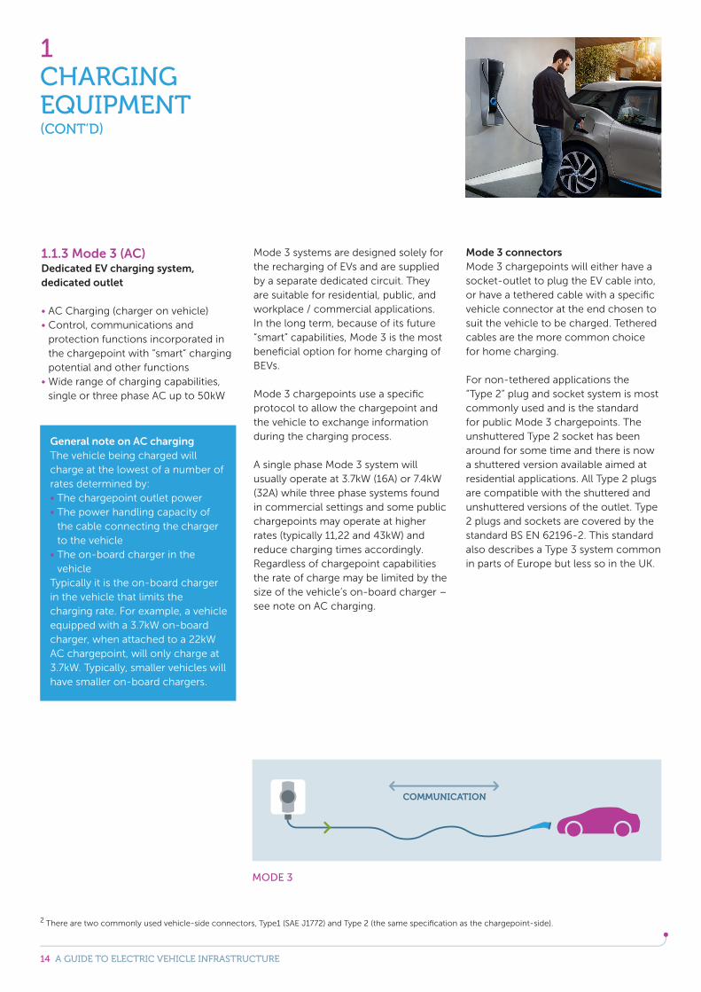
1.1.3 Mode 3 (AC)Dedicated EV charging system, dedicated outlet AC Charging (charger on vehicle) Control, communications and protection functions incorporated in the chargepoint with “smart” charging potential and other functions
Wide range of charging capabilities, single or three phase AC up to 50kW
Mode 3 systems are designed solely for the recharging of EVs and are supplied by a separate dedicated circuit. They are suitable for residential, public, and workplace / commercial applications. In the long term, because of its future “smart” capabilities, Mode 3 is the most beneficial option for home charging of BEVs.
Mode 3 chargepoints use a specific protocol to allow the chargepoint and the vehicle to exchange information during the charging process.
A single phase Mode 3 system will usually operate at 3.7kW (16A) or 7.4kW (32A) while three phase systems found in commercial settings and some public chargepoints may operate at higher rates (typically 11,22 and 43kW) and reduce charging times accordingly. Regardless of chargepoint capabilities the rate of charge may be limited by the size of the vehicle’s on-board charger – see note on AC charging.
Mode 3 connectorsMode 3 chargepoints will either have a socket-outlet to plug the EV cable into, or have a tethered cable with a specific vehicle connector at the end chosen to suit the vehicle to be charged. Tethered cables are the more common choice for home charging.
For non-tethered applications the “Type 2” plug and socket system is most commonly used and is the standard for public Mode 3 chargepoints. The unshuttered Type 2 socket has beenaround for some time and there is now a shuttered version available aimed at residential applications. All Type 2 plugs are compatible with the shuttered and unshuttered versions of the outlet. Type 2 plugs and sockets are covered by the standard BS EN 62196-2. This standard also describes a Type 3 system common in parts of Europe but less so in the UK.
1CHARGING EQUIPMENT(CONT’D)
MODE 3
2 There are two commonly used vehicle-side connectors, Type1 (SAE J1772) and Type 2 (the same specification as the chargepoint-side).
General note on AC chargingThe vehicle being charged will charge at the lowest of a number of rates determined by: The chargepoint outlet power The power handling capacity of the cable connecting the charger to the vehicle
The on-board charger in the vehicle
Typically it is the on-board charger in the vehicle that limits the charging rate. For example, a vehicle equipped with a 3.7kW on-board charger, when attached to a 22kW AC chargepoint, will only charge at 3.7kW. Typically, smaller vehicles will have smaller on-board chargers.
15 A GUIDE TO ELECTRIC VEHICLE INFRASTRUCTURE
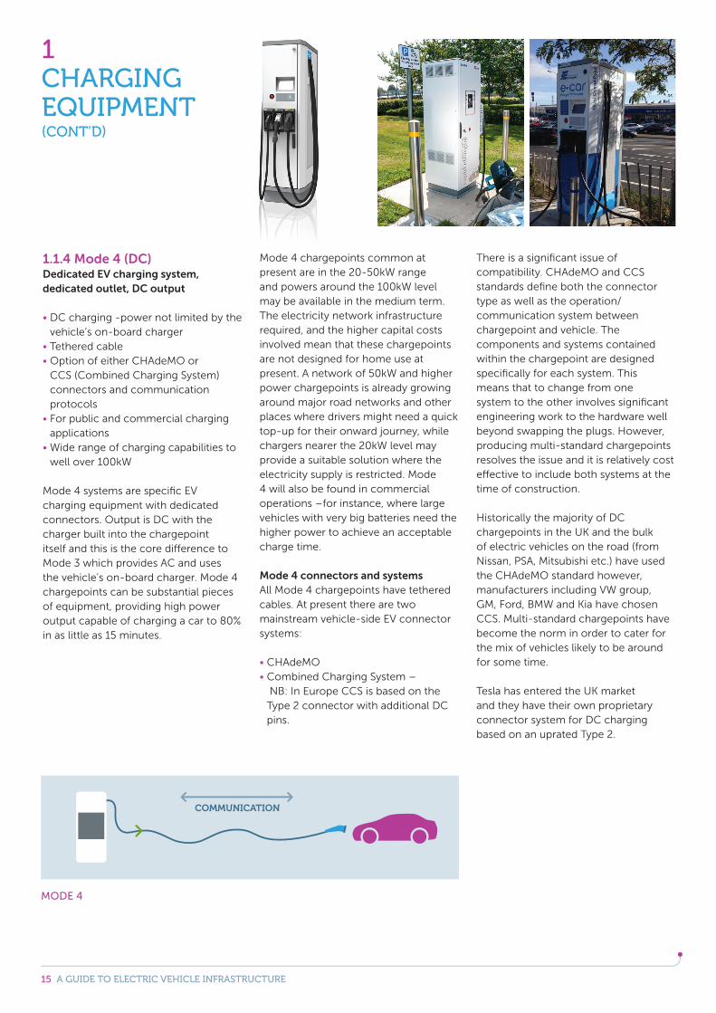
1.1.4 Mode 4 (DC)Dedicated EV charging system, dedicated outlet, DC output DC charging -power not limited by the vehicle’s on-board charger
Tethered cable Option of either CHAdeMO or CCS (Combined Charging System) connectors and communication protocols
For public and commercial charging applications
Wide range of charging capabilities to well over 100kW
Mode 4 systems are specific EV charging equipment with dedicated connectors. Output is DC with the charger built into the chargepoint itself and this is the core difference to Mode 3 which provides AC and uses the vehicle’s on-board charger. Mode 4 chargepoints can be substantial pieces of equipment, providing high power output capable of charging a car to 80% in as little as 15 minutes.
Mode 4 chargepoints common at present are in the 20-50kW range and powers around the 100kW level may be available in the medium term. The electricity network infrastructure required, and the higher capital costs involved mean that these chargepoints are not designed for home use at present. A network of 50kW and higher power chargepoints is already growing around major road networks and other places where drivers might need a quick top-up for their onward journey, while chargers nearer the 20kW level may provide a suitable solution where the electricity supply is restricted. Mode 4 will also be found in commercial operations –for instance, where large vehicles with very big batteries need the higher power to achieve an acceptable charge time.
Mode 4 connectors and systemsAll Mode 4 chargepoints have tethered cables. At present there are two mainstream vehicle-side EV connector systems:
CHAdeMO Combined Charging System – NB: In Europe CCS is based on the Type 2 connector with additional DC pins.
There is a significant issue of compatibility. CHAdeMO and CCS standards define both the connector type as well as the operation/communication system between chargepoint and vehicle. The components and systems contained within the chargepoint are designed specifically for each system. This means that to change from one system to the other involves significant engineering work to the hardware well beyond swapping the plugs. However, producing multi-standard chargepoints resolves the issue and it is relatively cost effective to include both systems at the time of construction.
Historically the majority of DC chargepoints in the UK and the bulk of electric vehicles on the road (from Nissan, PSA, Mitsubishi etc.) have used the CHAdeMO standard however, manufacturers including VW group, GM, Ford, BMW and Kia have chosen CCS. Multi-standard chargepoints have become the norm in order to cater for the mix of vehicles likely to be around for some time.
Tesla has entered the UK market and they have their own proprietary connector system for DC charging based on an uprated Type 2.
1CHARGING EQUIPMENT(CONT’D)
MODE 4
16 A GUIDE TO ELECTRIC VEHICLE INFRASTRUCTURE
1.2 Charge times and equipment types
The time taken to charge the battery of an electric vehicle is dependent on a wide range of factors including:
Those associated with the vehicle e.g.- battery size and technology, - the capacity and efficiency of the
on-board charger (AC charging),- and the temperature of the battery.
And those associated with the installed equipment e.g.
- rated current of the plug and socket-outlet,
- the cable size, - and the supply circuit.
All these things will influence the time required for a full charge. The information in this section provides general guidance on charging times for comparative purposes.
1CHARGING EQUIPMENT(CONT’D)
socket system.
provide a reasonable comparison.
as big will take twice as long to charge at the same rate.
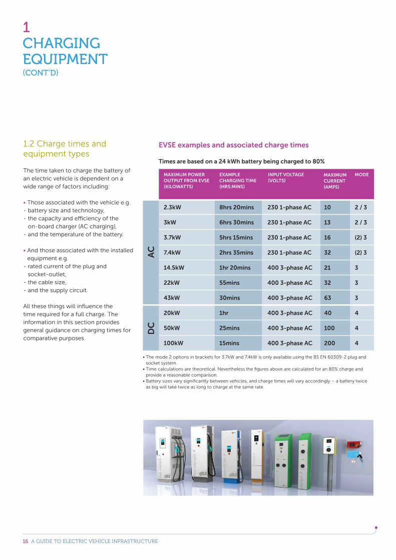
MAXIMUM POWER OUTPUT FROM EVSE(KILOWATTS)
2.3kW
3kW
3.7kW
7.4kW
14.5kW
22kW
43kW
20kW
50kW
100kW
8hrs 20mins
6hrs 30mins
5hrs 15mins
2hrs 35mins
1hr 20mins
55mins
30mins
1hr
25mins
15mins
230 1-phase AC
230 1-phase AC
230 1-phase AC
230 1-phase AC
400 3-phase AC
400 3-phase AC
400 3-phase AC
400 3-phase AC
400 3-phase AC
400 3-phase AC
10
13
16
32
21
32
63
40
100
200
2 / 3
2 / 3
(2) 3
(2) 3
3
3
3
4
4
4
EXAMPLE CHARGING TIME (HRS:MINS)
INPUT VOLTAGE(VOLTS)
MAXIMUM CURRENT (AMPS)
MODE
AC
DC
EVSE examples and associated charge times
Times are based on a 24 kWh battery being charged to 80%
17 A GUIDE TO ELECTRIC VEHICLE INFRASTRUCTURE
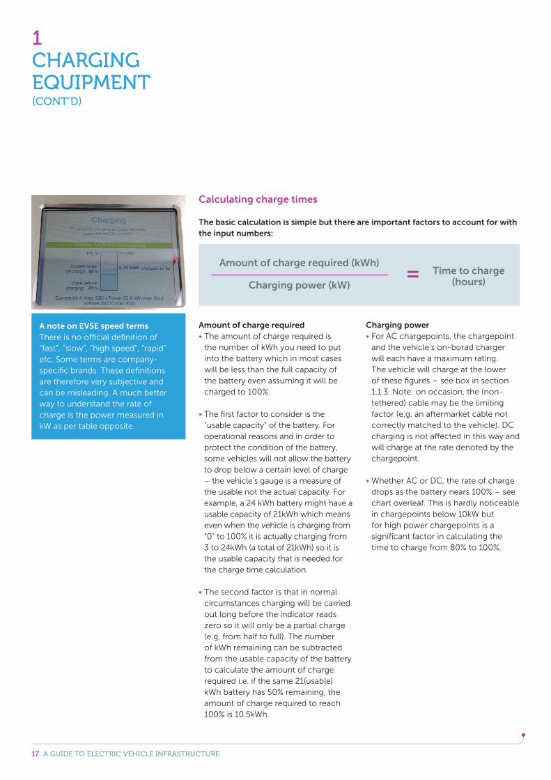
Calculating charge times
The basic calculation is simple but there are important factors to account for with the input numbers:
Amount of charge required The amount of charge required is the number of kWh you need to put into the battery which in most cases will be less than the full capacity of the battery even assuming it will be charged to 100%.
The first factor to consider is the “usable capacity” of the battery. For operational reasons and in order to protect the condition of the battery, some vehicles will not allow the battery to drop below a certain level of charge – the vehicle’s gauge is a measure of the usable not the actual capacity. For example, a 24 kWh battery might have a usable capacity of 21kWh which means even when the vehicle is charging from “0” to 100% it is actually charging from 3 to 24kWh (a total of 21kWh) so it is the usable capacity that is needed for the charge time calculation.
The second factor is that in normal circumstances charging will be carried out long before the indicator reads zero so it will only be a partial charge (e.g. from half to full). The number of kWh remaining can be subtracted from the usable capacity of the battery to calculate the amount of charge required i.e. if the same 21(usable)kWh battery has 50% remaining, the amount of charge required to reach 100% is 10.5kWh.
Charging power For AC chargepoints, the chargepoint and the vehicle’s on-borad charger will each have a maximum rating. The vehicle will charge at the lower of these figures – see box in section 1.1.3. Note: on occasion, the (non-tethered) cable may be the limiting factor (e.g. an aftermarket cable not correctly matched to the vehicle). DC charging is not affected in this way and will charge at the rate denoted by the chargepoint.
Whether AC or DC, the rate of charge drops as the battery nears 100% – see chart overleaf. This is hardly noticeable in chargepoints below 10kW but for high power chargepoints is a significant factor in calculating the time to charge from 80% to 100%.
1CHARGING EQUIPMENT(CONT’D)
A note on EVSE speed termsThere is no official definition of “fast”, “slow”, “high speed”, “rapid” etc. Some terms are company-specific brands. These definitions are therefore very subjective and can be misleading. A much better way to understand the rate of charge is the power measured in kW as per table opposite.
Amount of charge required (kWh)
Charging power (kW)Time to charge
(hours)=
18 A GUIDE TO ELECTRIC VEHICLE INFRASTRUCTURE
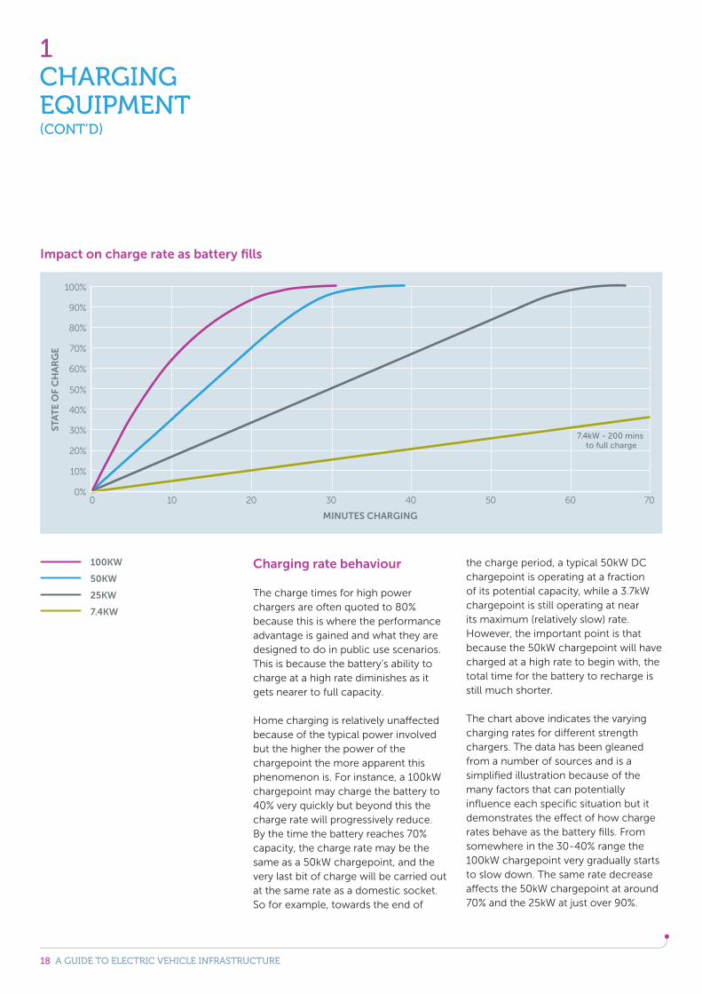
Charging rate behaviour
The charge times for high power chargers are often quoted to 80% because this is where the performance advantage is gained and what they are designed to do in public use scenarios. This is because the battery’s ability to charge at a high rate diminishes as it gets nearer to full capacity.
Home charging is relatively unaffected because of the typical power involved but the higher the power of the chargepoint the more apparent this phenomenon is. For instance, a 100kW chargepoint may charge the battery to 40% very quickly but beyond this the charge rate will progressively reduce. By the time the battery reaches 70% capacity, the charge rate may be the same as a 50kW chargepoint, and the very last bit of charge will be carried out at the same rate as a domestic socket. So for example, towards the end of
the charge period, a typical 50kW DC chargepoint is operating at a fraction of its potential capacity, while a 3.7kW chargepoint is still operating at near its maximum (relatively slow) rate. However, the important point is that because the 50kW chargepoint will have charged at a high rate to begin with, the total time for the battery to recharge is still much shorter.
The chart above indicates the varying charging rates for different strength chargers. The data has been gleaned from a number of sources and is a simplified illustration because of the many factors that can potentially influence each specific situation but it demonstrates the effect of how charge rates behave as the battery fills. From somewhere in the 30-40% range the 100kW chargepoint very gradually starts to slow down. The same rate decrease affects the 50kW chargepoint at around 70% and the 25kW at just over 90%.
100KW
50KW
25KW
7.4KW
1CHARGING EQUIPMENT(CONT’D)
Impact on charge rate as battery fills
19 A GUIDE TO ELECTRIC VEHICLE INFRASTRUCTURE
1CHARGING EQUIPMENT(CONT’D)
1.3 Network operation
An effective EV charging network requires integrating the charging equipment with communications and management software linked to back office services.
Chargepoints can be operated as standalone devices or can be connected to a back-office service provider via a network connection.
Many chargepoints will incorporate a sim card and have the capability to receive firmware updates (e.g. to ensure compatibility with the latest vehicles), and for single, privately owned chargepoints, this is likely to be all that is needed. For charging networks, connectivity is key for monitoring and capturing data and, together with back office services, can support drivers and operators alike.
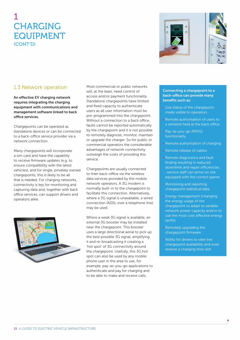
Most commercial or public networks will, at the least, need control of access and/or payment functionality. Standalone chargepoints have limited and fixed capacity to authenticate users as all user information must be pre-programmed into the chargepoint. Without a connection to a back office, faults cannot be reported automatically by the chargepoint and it is not possible to remotely diagnose, monitor, maintain or upgrade the charger. So for public or commercial operators the considerable advantages of network connectivity outweigh the costs of providing this service.
Chargepoints are usually connected to their back-office via the wireless data services provided by the mobile network operators. A 3G modem is normally built-in to the chargepoint to facilitate this connection. Alternatively, where a 3G signal is unavailable, a wired connection (ADSL over a telephone line) may be used.
Where a weak 3G signal is available, an external 3G booster may be installed near the chargepoint. This booster uses a large directional aerial to pick up the best possible 3G signal, amplifying it and re-broadcasting it creating a ‘hot spot’ of 3G connectivity around the chargepoint. Usefully, this 3G hot spot can also be used by any mobile phone user in the area to use, for example, pay-as-you-go applications to authenticate and pay for charging and to be able to make and receive calls.
Connecting a chargepoint to a back-office can provide many benefits such as:
Live status of the chargepoint made visible to operators
Remote authorisation of users to a whitelist held at the back office
Pay-as-you-go (PAYG) functionality
Remote authorisation of charging
Remote release of cables
Remote diagnostics and fault finding resulting in reduced downtime and repair efficiencies -service staff can arrive on site equipped with the correct spares
Monitoring and reporting chargepoint statistical data
Energy management (changing the energy usage of the chargepoint to adapt to variable network power capacity and/or to use the most cost effective energy tariffs)
Remotely upgrading the chargepoint firmware
Ability for drivers to view live chargepoint availability and even reserve a charging time slot
20 A GUIDE TO ELECTRIC VEHICLE INFRASTRUCTURE
1.4 Charging requirements of different vehicles
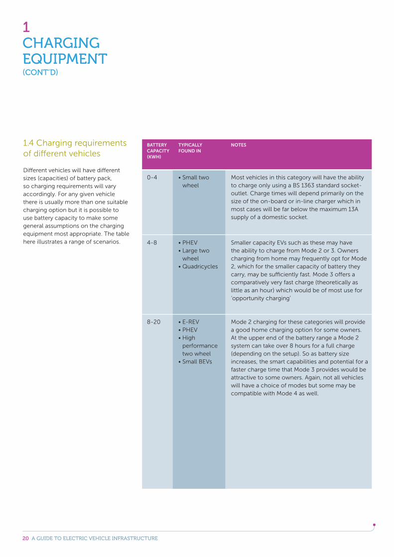
Different vehicles will have different sizes (capacities) of battery pack, so charging requirements will vary accordingly. For any given vehicle there is usually more than one suitable charging option but it is possible to use battery capacity to make some general assumptions on the charging equipment most appropriate. The table here illustrates a range of scenarios.
1CHARGING EQUIPMENT(CONT’D)
BATTERY CAPACITY(KWH)
0-4
4-8
8-20
wheel
TYPICALLY FOUND IN
wheel
performance two wheel
Most vehicles in this category will have the ability to charge only using a BS 1363 standard socket-outlet. Charge times will depend primarily on the size of the on-board or in-line charger which in most cases will be far below the maximum 13A supply of a domestic socket.
NOTES
Smaller capacity EVs such as these may have the ability to charge from Mode 2 or 3. Owners charging from home may frequently opt for Mode 2, which for the smaller capacity of battery they carry, may be sufficiently fast. Mode 3 offers a comparatively very fast charge (theoretically as little as an hour) which would be of most use for ‘opportunity charging’
Mode 2 charging for these categories will provide a good home charging option for some owners. At the upper end of the battery range a Mode 2 system can take over 8 hours for a full charge (depending on the setup). So as battery size increases, the smart capabilities and potential for a faster charge time that Mode 3 provides would be attractive to some owners. Again, not all vehicles will have a choice of modes but some may be compatible with Mode 4 as well.
21 A GUIDE TO ELECTRIC VEHICLE INFRASTRUCTURE
1CHARGING EQUIPMENT(CONT’D)
BATTERY CAPACITY(KWH)
20-50
50-100
100+
and small/medium vans
TYPICALLY FOUND IN
performance cars
vans, trucks and buses including BEV, E-REV, PHEV
very large vehicles
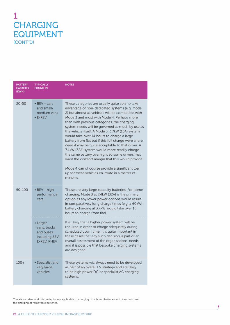
These categories are usually quite able to take advantage of non-dedicated systems (e.g. Mode 2) but almost all vehicles will be compatible with Mode 3 and most with Mode 4. Perhaps more than with previous categories, the charging system needs will be governed as much by use as the vehicle itself. A Mode 3, 3.7kW (16A) system would take over 14 hours to charge a large battery from flat but if this full charge were a rare need it may be quite acceptable to that driver. A 7.4kW (32A) system would more readily charge the same battery overnight so some drivers may want the comfort margin that this would provide.
Mode 4 can of course provide a significant top up for these vehicles en-route in a matter of minutes.
NOTES
These are very large capacity batteries. For home charging, Mode 3 at 7.4kW (32A) is the primary option as any lower power options would result in comparatively long charge times (e.g. a 60kWh battery charging at 3.7kW would take over 16 hours to charge from flat).
It is likely that a higher power system will be required in order to charge adequately during scheduled down time. It is quite important in these cases that any such decision is part of an overall assessment of the organisations’ needs and it is possible that bespoke charging systems are designed.
These systems will always need to be developed as part of an overall EV strategy and are likely to be high power DC or specialist AC charging systems.
The above table, and this guide, is only applicable to charging of onboard batteries and does not cover the charging of removable batteries.
22 A GUIDE TO ELECTRIC VEHICLE INFRASTRUCTURE
It is widely accepted that over 80% of electric vehicle charging will take place at home and mostly overnight. This provides benefits not only to the consumer but also to the UK energy system as a whole. Opportunity or en route charging from workplace or public infrastructure is a smaller but just as important part of the picture, not least for PHEVs to maximise use of their battery-only mode. To some extent, the installation of on street chargepoints has been motivated by the anticipation of drivers’ “range anxiety” which can be reduced by having a chargepoint on every street. However, many people believe this concern will naturally diminish as EV ownership grows
without the need for an over-generous vehicle to chargepoint ratio. In order to provide confidence for drivers and deliver commercial longevity for the infrastructure, accessibility and carefully planned locations are probably more important considerations than total chargepoint numbers.
Some vehicles are depot based which brings a different set of issues and opportunities.
The following pages consider various applications for EV Supply Equipment and the criteria that needs to be taken into consideration in selecting the appropriate equipment type.
2INSTALLATION LOCATIONS
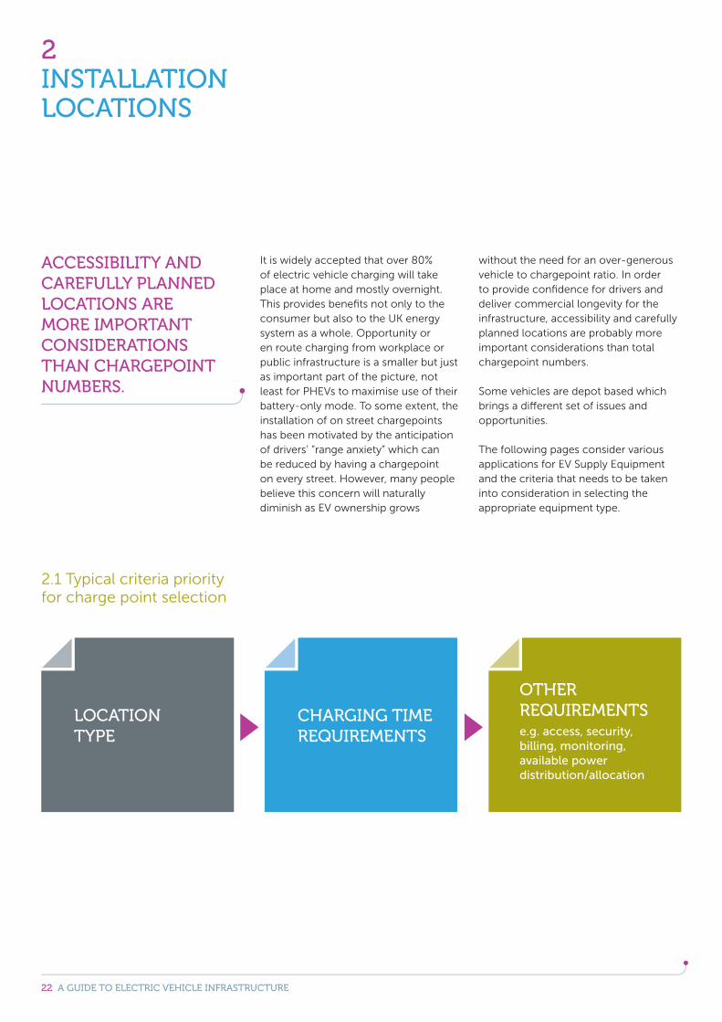
2.1 Typical criteria priority for charge point selection
ACCESSIBILITY AND CAREFULLY PLANNED LOCATIONS ARE MORE IMPORTANT CONSIDERATIONS THAN CHARGEPOINT NUMBERS.
LOCATION TYPE
CHARGING TIME REQUIREMENTS
OTHER REQUIREMENTSe.g. access, security, billing, monitoring, available power distribution/allocation
23 A GUIDE TO ELECTRIC VEHICLE INFRASTRUCTURE
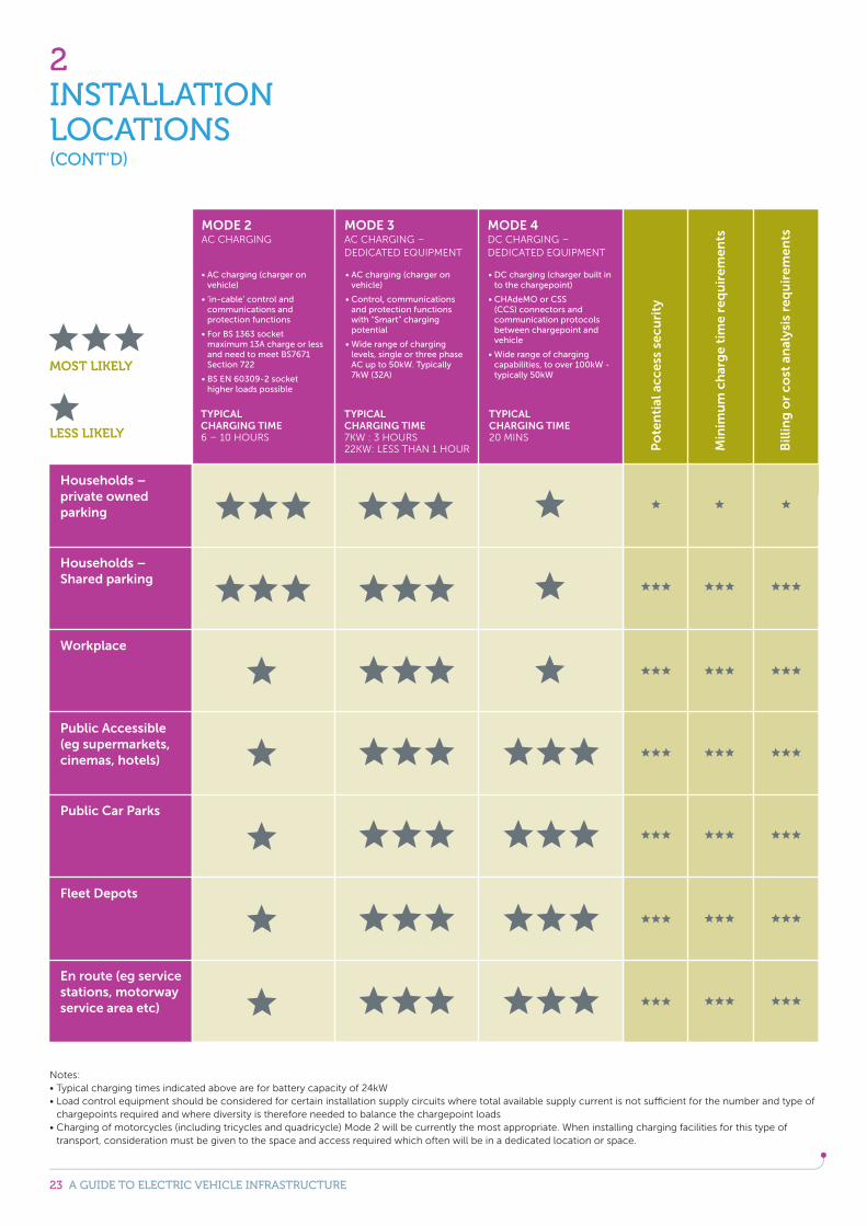
2INSTALLATION LOCATIONS(CONT’D)
Notes:
chargepoints required and where diversity is therefore needed to balance the chargepoint loads
transport, consideration must be given to the space and access required which often will be in a dedicated location or space.
Households – private owned parking
Po
ten
tial
acc
ess
secu
rity
Households – Shared parking
Workplace
Public Accessible (eg supermarkets, cinemas, hotels)
Public Car Parks
Fleet Depots
En route (eg service stations, motorway service area etc)
MODE 2AC CHARGING
vehicle)
communications and protection functions
Section 722
higher loads possible
vehicle)
and protection functions with “Smart” charging potential
levels, single or three phase
to the chargepoint)
communication protocols between chargepoint and vehicle
TYPICAL CHARGING TIME 6 – 10 HOURS
MODE 3AC CHARGING –
TYPICAL CHARGING TIME 7KW : 3 HOURS22KW: LESS THAN 1 HOUR
MODE 4DC CHARGING –
TYPICAL CHARGING TIME 20 MINSLESS LIKELY
MOST LIKELY
Min
imu
m c
har
ge
tim
e re
qu
irem
ents
Bill
ing
or
cost
an
alys
is r
equ
irem
ents
24 A GUIDE TO ELECTRIC VEHICLE INFRASTRUCTURE
Planning Ahead
ResidentialAt present, not all vehicles on the market can utilise the additional capacity of a 7.4kW (32A) mode 3 system but it may become increasingly common in the future. To help future-proof the installation, BEAMA recommends an evaluation be made of the additional cost of including some elements of a 7.4kW system - even when a 3.7kW chargepoint is being installed. For instance, a very modest initial investment to install higher rated cables, could save a lot of cost at a later date if an upgrade is desired.
Public and commercialPlanning as far ahead as possible is important and there is a strong case for future-proofing installations by incorporating capacity for additional chargepoints. On initial installation, the cost of hardware to provide for future capacity tends to be far less than the labour and other costs (particularly groundwork) associated with upgrading systems at a later date. Management and enforcement of EV parking spaces is an important consideration when planning public chargepoint installation.
2.2 Other systems
To date, the electrification of large vehicles has been limited. This is linked to a number of factors such as capital cost, risk management and the high demands on the vehicles themselves. However, in the right applications there are economic and environmental gains to be made in the long term so this area is expected to gain momentum, particularly as the technology develops.
Given the nascent status of this sector, this guide does not seek to provide technical detail here but because large vehicles may become a more important part of EV charging needs in the future, some of the primary points are outlined.
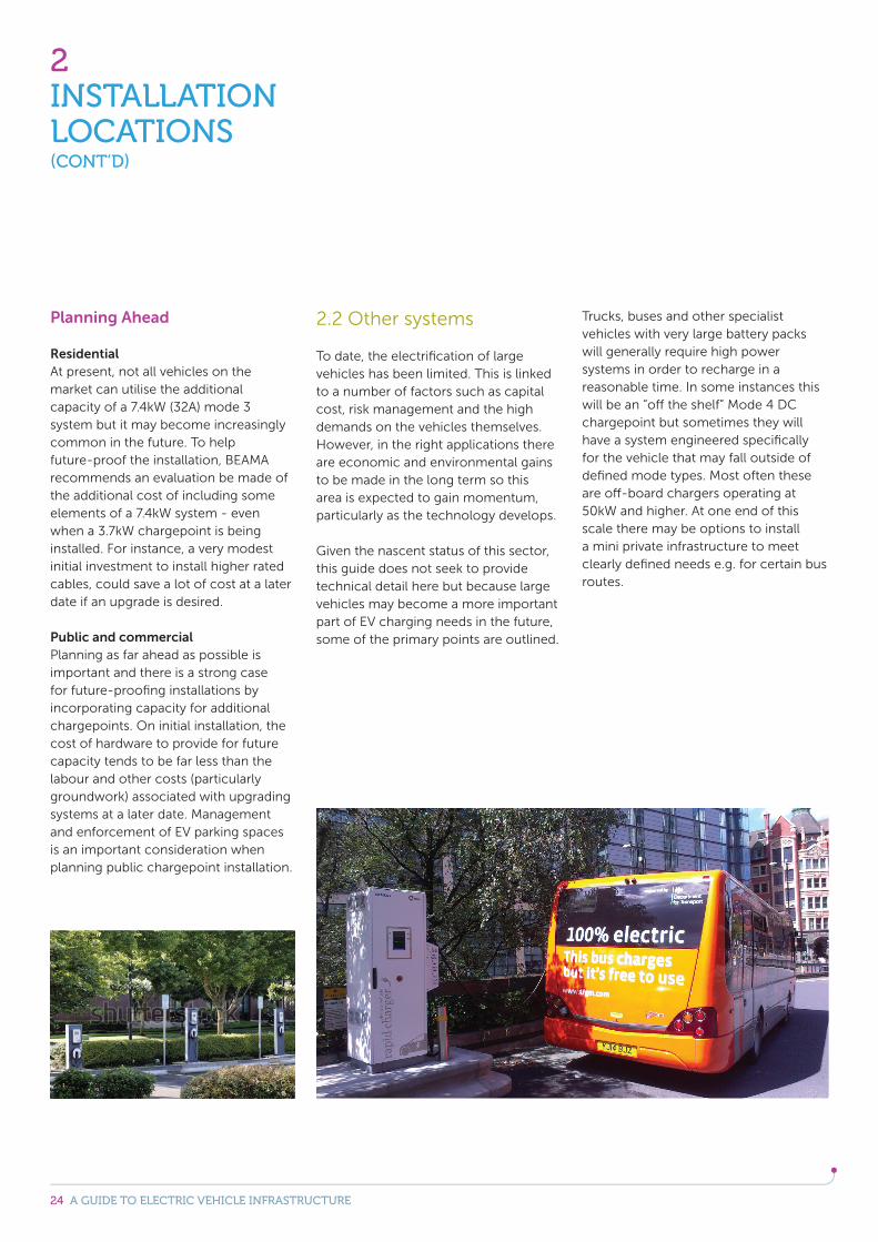
Trucks, buses and other specialist vehicles with very large battery packs will generally require high power systems in order to recharge in a reasonable time. In some instances this will be an “off the shelf” Mode 4 DC chargepoint but sometimes they will have a system engineered specifically for the vehicle that may fall outside of defined mode types. Most often these are off-board chargers operating at 50kW and higher. At one end of this scale there may be options to install a mini private infrastructure to meet clearly defined needs e.g. for certain bus routes.
2INSTALLATION LOCATIONS(CONT’D)
25 A GUIDE TO ELECTRIC VEHICLE INFRASTRUCTURE
2INSTALLATION LOCATIONS(CONT’D)
2.3 Charging infrastructure for buses
Whilst the vast majority of UK buses remain diesel powered, the government’s Green Bus Fund has assisted with the purchase costs of “low carbon buses”. The majority of these are diesel hybrid but the fund has stimulated the battery electric sector as well. Several bus manufacturers are experimenting with PHEV and BEV buses, and trials of such vehicles are running in the UK and other countries.
The duty cycle of most buses creates major challenges for battery charging:
Often very high utilisation per day – 18 hours is not unusual – which can present challenges for charging times and battery capacity.
Opportunities for charging during the operation period are extremely short – often measured in seconds rather than minutes.
Buses also present opportunities that could counter some of the challenges:
Many buses are operated exclusively in densely populated urban environments which means the opportunity to reduce or eliminate exhaust emissions has particularly high social and environmental value. As buses usually run on fixed routes, charging station locations can be precisely targeted to serve specific requirements. Possible to achieve very high asset utilisation once the buses enter service.
There are no clearly established norms for charging scenarios or interfaces for BEV or PHEV buses while “opportunity charging” of busses means making the most of each second i.e:
Charging at 100kW and above may be needed which can strain some energy networks so local storage may be needed. Speedy connection to the electricity supply whether wireless charging or automatic mechanisms for conductive charging is also an important consideration.
All of the above suggests highly tailored solutions and initially at least, joint developments between vehicle and charging equipment manufacturers.
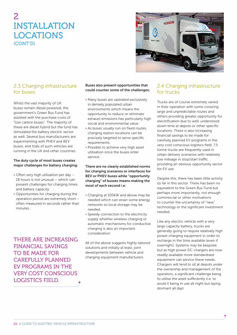
2.4 Charging infrastructure for trucks
Trucks are of course extremely varied in their operation with some covering large and unpredictable routes and others providing greater opportunity for electrification due to well-understood down time at depots or other specific locations. There is also increasing financial savings to be made for carefully planned EV programs in the very cost conscious logistics field. 7.5 tonne trucks are frequently used in urban delivery scenarios with relatively low mileage in stop/start traffic providing an obvious opportunity sector for EV use.
Despite this, there has been little activity so far in this sector. There has been no equivalent to the Green Bus Fund but perhaps more importantly, not enough commercial or other motivations to counter the uncertainty of “new” technology or the significant investment needed.
Like any electric vehicle with a very large capacity battery, trucks are generally going to require relatively high power charging equipment in order to recharge in the time available (even if overnight). Systems may be bespoke but as high power DC chargers are now readily available more standardised equipment can service these needs. Chargers will tend to sit at depots under the ownership and management of the operators, a significant challenge being to utilise the asset sufficiently (i.e. to avoid it being in use all night but laying dormant all day).
THERE ARE INCREASING FINANCIAL SAVINGS TO BE MADE FOR CAREFULLY PLANNED EV PROGRAMS IN THE VERY COST CONSCIOUS LOGISTICS FIELD.

26 A GUIDE TO ELECTRIC VEHICLE INFRASTRUCTURE
3MARKET DEVELOPMENT
The EV market is very dynamic and is affected by developments in technology, public and media attitudes, government policy and many other outside influences. However unpredictable the market, most stakeholders do agree that sustainable levels of growth are achievable given the right conditions. Many standards have been developed over the last few years and we are starting to see a level of standardisation in this area although it continues to be important to proactively identify needs and respond accordingly. There are also challenges ahead for interoperability, reliability, and safety as equipment is produced outside of agreed standards and certification norms.
As the market grows and develops, fated technologies will flourish while others will remain niche or disappear altogether. It is important that the industry responds effectively to, and benefits from, new products and systems, and that it also helps to provide stability in order to maintain confidence levels from the wider public.
3.1 Government support and public chargepoints
Support from Government through the Office for Low Emission Vehicles (OLEV) has been an important element in establishing the bourgeoning EV market in the UK. Core to this has been grants for both vehicles and for chargepoints, and the OLEV strategy published in September 2013 confirmed the Government’s continuing commitment in this area. From 2015 to 2020, the Government has committed £1 billion to support growth in the ultra low emission vehicle sector including electric vehicles. How this support is targeted will be a significant influence on market direction and the uptake of individual technologies.
Arguably the best use for electric vehicles is in the urban environment but most urban dwellers do not have off-street parking to install their own chargepoint and are reliant on having a public chargepoint nearby. OLEV have sought to support this market through grant funds for Local Authorities to install on-street chargers at the request of EV owners.
Details of grants and how they operate can be found at:https://www.gov.uk/government/organisations/office-for-low-emission-vehicles
The European Commission also has a strong commitment to electric vehicles. This is reflected in the Alternative Fuels Directive which requires all EU governments to provide national plans demonstrating how they will encourage substantive growth in the EV market and not least, through their support of charging infrastructure.
27 A GUIDE TO ELECTRIC VEHICLE INFRASTRUCTURE
3MARKET DEVELOPMENT(CONT’D)
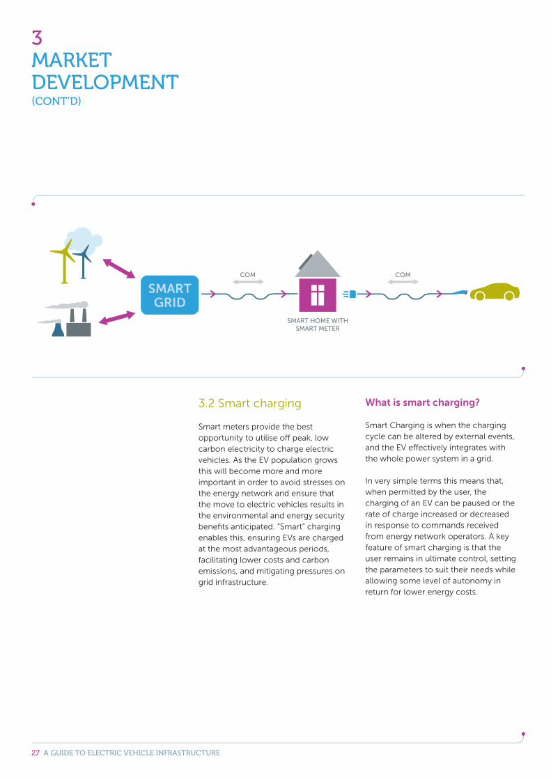
3.2 Smart charging
Smart meters provide the best opportunity to utilise off peak, low carbon electricity to charge electric vehicles. As the EV population grows this will become more and more important in order to avoid stresses on the energy network and ensure that the move to electric vehicles results in the environmental and energy security benefits anticipated. “Smart” charging enables this, ensuring EVs are charged at the most advantageous periods, facilitating lower costs and carbon emissions, and mitigating pressures on grid infrastructure.
What is smart charging?
Smart Charging is when the charging cycle can be altered by external events, and the EV effectively integrates with the whole power system in a grid.
In very simple terms this means that, when permitted by the user, the charging of an EV can be paused or the rate of charge increased or decreased in response to commands received from energy network operators. A key feature of smart charging is that the user remains in ultimate control, setting the parameters to suit their needs while allowing some level of autonomy in return for lower energy costs.

28 A GUIDE TO ELECTRIC VEHICLE INFRASTRUCTURE
3MARKET DEVELOPMENT(CONT’D)
Ultimately, smart charging will allow the user to specify when they require their vehicle (e.g. by 7:00am) and the system will provide the optimal charging profile to deliver lowest cost while ensuring the vehicle is ready when needed. At times of low demand, the system may charge immediately in one block or at other times may charge in a series of blocks in response to fluctuating demand, local network pressure, availability of renewable power etc. but will always meet the specified needs of the user.
To achieve smart charging a number of elements must be present:
Grid or local network communications
Smart meter
An interface – Consumer Access Device (CAD)
Mode 3 chargepoint with requisite components
Compatible vehicle communication
Some of these elements are well on the way to being implemented (smart meters for instance will be in everyone’s homes by 2020) but the interoperability between all parts is the key to achieving full functionality. There is ongoing work in the UK and across Europe to ensure there is a regulatory and policy framework to support the “Demand Side Response” market. European Standardisation committees are progressing in developing standards for the electric vehicle market in response to EC Mandate 468, and work has also been done to join this with standards for smart grids (M490) to ensure standards can support the development of a smart charging process across Europe.
Fully-featured smart charging is some way off being market ready however, there are stages leading up to this that will bring benefits in the shorter term.
What is available today?
TimersTimers are a well known and a well used form of customer control of electrical equipment. Whilst current systems cannot provide the dynamic charging of Smart systems, an off-peak or specific EV tariff coupled with a delayed timer will ensure charging takes place at lower cost.
A range of solutions are available including timers built into the vehicle as well as those connected to the outlet from which the vehicle is being charged.
As the UK moves to a ‘smarter; charging system over the medium to long term (including home automation linked to the smart grid), it is anticipated that the use of basic timers will reduce. Point to point communication - trial basis only This is the direct communication from a service provider to a device / appliance, in this instance an EV, providing a price signal / incentive for the customer to shift demand in the home. The majority of Low Carbon Network Fund projects use this form of communication to trial smart energy use including smart charging of electric vehicles. This is achievable today through communication via a mobile signal direct to appliances using GPRS, or increasingly, via broadband internet connections communicating wirelessly into the home.
While this is technically feasible today, the market structures to enable service providers to provide price signals to a customer in the home are not yet available and therefore this only exists on a trial basis.
29 A GUIDE TO ELECTRIC VEHICLE INFRASTRUCTURE
3MARKET DEVELOPMENT(CONT’D)
The future of smart charging linked to Smart Meter Deployment
UK smart meter rollout will commence in 2016, this will see smart meters and in-home displays rolled out to every home in the UK by 2020. The specification for the metering system is agreed, along with the commercial framework for the Data Communications Company (DCC) who is responsible for data handling for the new metering system.
The smart meter will enable customers to have access to their real time energy use data and this will be shown on their in home display. With more real-time data now available to customer and energy suppliers, industry can work with government to design more advanced applications for this data in the home, including smart charging of electric vehicles.
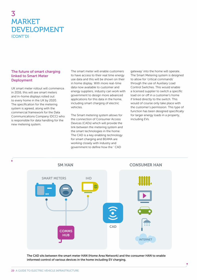
The Smart metering system allows for the connection of Consumer Access Devices (CADs) which will provide the link between the metering system and the smart technologies in the home. The CAD is a key enabling technology for smart charging and BEAMA are working closely with industry and government to define how the ‘ CAD
gateway’ into the home will operate. The Smart Metering system is designed to allow for ‘critical commands’ through the use of Auxiliary Load Control Switches. This would enable a licensed supplier to switch a specific load on or off in a customer’s home if linked directly to the switch. This would of course only take place with the customer’s permission. This type of function has been designed specifically for larger energy loads in a property, including EVs.
The CAD sits between the smart meter HAN (Home Area Network) and the consumer HAN to enable informed control of various devices in the home including EV charging.
30 A GUIDE TO ELECTRIC VEHICLE INFRASTRUCTURE
3MARKET DEVELOPMENT(CONT’D)
3.3 Innovations
There are regular technical and product innovations coming through the pipeline, any of which could be the next revolution for EVs or their charging needs. Predicting what developments will be successful or not is beyond the scope of this guide but there are some areas that while not yet commonplace, are receiving a lot of attention or are near market ready so we have provided some commentary below.
Vehicle to home and vehicle to grid
As the UKs electricity generation becomes more variable and distributed due to factors such as increased wind generation, our energy system will necessarily become more dynamic. With these developments, it is likely that the market for energy storage at individual residential level will become more economical for customers.
The battery pack of some EVs holds significant potential in this arena. The stored energy in a population of connected EVs can be employed in two ways:
By acting as a temporary energy source for the home when prices are high (and thus placing no additional demand on grid generation during a peak demand).
Or, by going a stage further, and selling power back into the grid, either to support grid generation or to mitigate short-term overloading on a local network.
In both cases, the EV then recharges when demand drops and prices are lower, leaving the householder with a positive balance either directly or by advantageous contract with the supplier for providing the facility.
The market frameworks for this type of application are not available today, and this is a longer term aspiration for the industry. However some chargepoint manufactures are designing their home charging systems to enable easy retrofit to allow for such functionality and the bi-directional flow of energy to and from the vehicle.
DC charging
High power DC charging is discussed earlier in the guide but lower power DC chargers (10kW and above) are available and there is a growing body of opinion that DC charging may become more popular in the future. DC charging has the advantage that it does not rely on the size of the vehicle’s on-board charger. Any compatible vehicle will be able to charge at up to the full rate of the chargepoint. With AC charging, if the vehicle’s on board charger is 6kW that will be the maximum rate it can charge regardless of the rating of the chargepoint.
There are advantages to vehicle manufactures if DC chargers were widely adopted as they would not have to provide the on-board charger in every vehicle at extra cost and adding to vehicle weight.
Wireless charging
Dedicated inductive EV charging: Potentially home, public and commercial applications No cable to connect to vehicle – just park over an inductive ‘pad’ to start charging. Limited market penetration at present
Wireless charging will operate from a dedicated circuit and have similar control and communication features to a mode 3 system but instead of a physical plug and socket connection to the vehicle there will be an induction pad on the ground and an equivalent receiver built into the car. Communications normally conducted through cables are also done wirelessly via specific protocols.
At present there is only limited use of wireless charging in the UK, but this may change in the coming years. In the short to medium term the greatest benefit will possibly come from specialist applications such as buses, taxis and commercial vehicles where the systems are matched to specific systems or performance criteria and the need for instant connection is great.

31 A GUIDE TO ELECTRIC VEHICLE INFRASTRUCTURE
3MARKET DEVELOPMENT(CONT’D)
3.4 Standards
Current standardisation activity
The EV infrastructure industry has needed to develop a new set of internationally agreed standards to ensure safety for users and support EU regulations drafted to achieve interoperability. These standards, worked on by BEAMA members, help to provide stability and confidence in the industry and thus support sustainable growth in the wider EV market.
In 2010 the European Commission and European Free Trade Association issued the mandate M/468 to CEN, CENELEC and ETSI (the European standardisation bodies) on European Electro-mobility standardisation.
The mandate seeks to:
Ensure interoperability and connectivity of the charging network so that all types of electric vehicles may be recharged in any EU state.
Appropriately consider any smart charging issue with respect to the charging of electric vehicles.
Appropriately consider safety risks and electromagnetic compatibility of the charger of electric vehicles in the field [Directive 2006/95/EC (LV) and Directive 2004/108/EC (EMC)].
There are a number of European and international standards bodies relevant to the development of an interoperable and functional electric vehicle infrastructure network. These include the IEC, ISO, ITU-T, and their European counterparts CEN, CENELEC, and ETSI. Access to these bodies and their technical committees is mainly through membership of the relevant BSI Technical Committee. It is a complex working environment dealing with many cross-sector issues and BEAMA is involved on a number of fronts.
BEAMA is represented on the main Technical Committees producing the Mandated standards and holds the Chair at European and National level of TC 69 - as well as the CEN CENELEC eMobility Coordination Group and it’s Steering Committee which monitors and coordinates the work of the TCs involved.
In addition to this international work, efforts are being made to draw together the variety of connected activities such as smart grid and adapt them to suit the UK market and infrastructure. Much of this work is at the early stages but is vital to gaining the full economic and environmental benefits that EVs have to offer.
The communications aspects of electro-mobility standardisation are being dealt with in other existing groups, including the CEN, CENELEC and ETSI Smart Grid Co-ordination Group and the CEN, CENELEC and ETSI Group for Intelligent Transport Systems.
32 A GUIDE TO ELECTRIC VEHICLE INFRASTRUCTURE
4APPENDICES
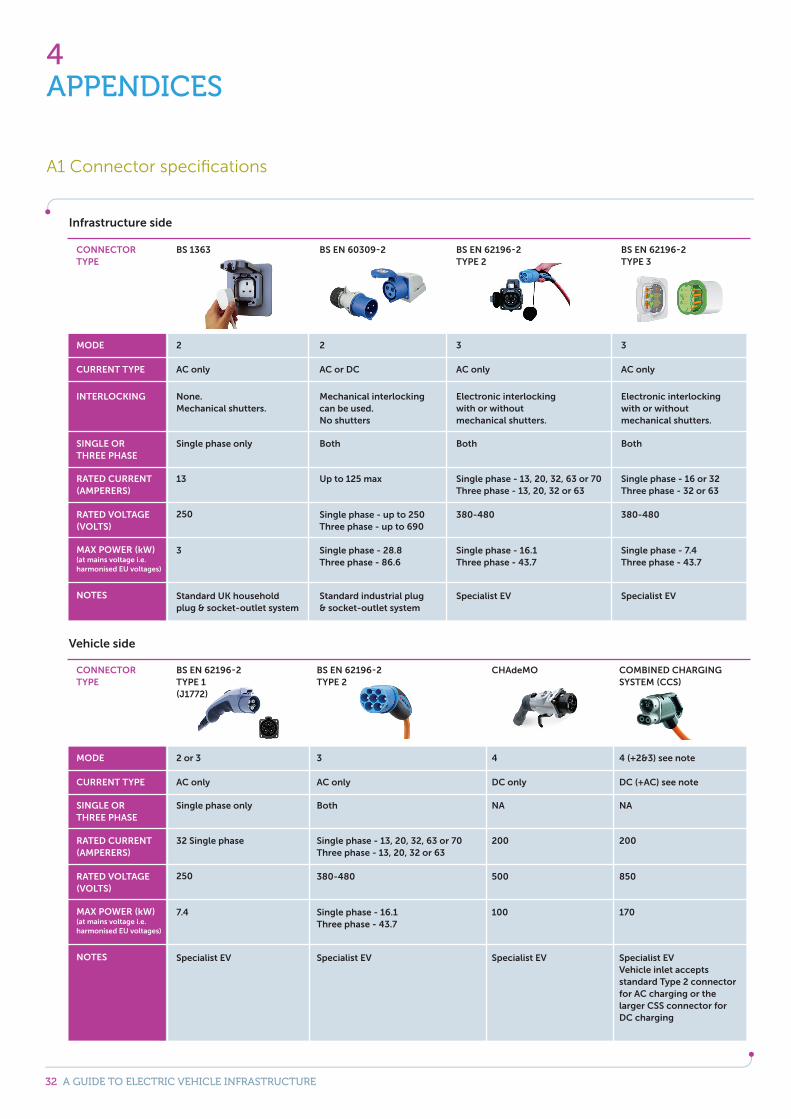
A1 Connector specifications
Infrastructure side
Vehicle side
CONNECTOR TYPE
CONNECTOR TYPE
MODE
MODE
INTERLOCKING
CURRENT TYPE
CURRENT TYPE
SINGLE OR THREE PHASE
SINGLE OR THREE PHASE
RATED CURRENT (AMPERERS)
RATED CURRENT (AMPERERS)
RATED VOLTAGE (VOLTS)
RATED VOLTAGE (VOLTS)
MAX POWER (kW)(at mains voltage i.e. harmonised EU voltages)
MAX POWER (kW)(at mains voltage i.e. harmonised EU voltages)
NOTES
NOTES
BS 1363
BS EN 62196-2TYPE 1 (J1772)
2
2 or 3
None.Mechanical shutters.
AC only
AC only
Single phase only
Single phase only
13
32 Single phase
250
250
3
7.4
BS EN 62196-2 TYPE 2
CHAdeMO
3
4
Electronic interlocking with or without mechanical shutters.
AC only
DC only
Both
NA
Single phase - 13, 20, 32, 63 or 70Three phase - 13, 20, 32 or 63
200
380-480
500
BS EN 62196-2 TYPE 3
COMBINED CHARGING SYSTEM (CCS)
Specialist EV
Specialist EVVehicle inlet accepts standard Type 2 connector for AC charging or the larger CSS connector for DC charging
Specialist EV
Specialist EV
Standard industrial plug & socket-outlet system
Specialist EV
Standard UK household plug & socket-outlet system
Specialist EV
3
4 (+2&3) see note
Electronic interlocking with or without mechanical shutters.
AC only
DC (+AC) see note
Both
NA
Single phase - 16 or 32Three phase - 32 or 63
200
380-480
850
BS EN 60309-2
BS EN 62196-2TYPE 2
2
3
Mechanical interlocking can be used.No shutters
AC or DC
AC only
Both
Both
Up to 125 max
Single phase - 13, 20, 32, 63 or 70Three phase - 13, 20, 32 or 63
Single phase - up to 250Three phase - up to 690
380-480
Single phase - 28.8Three phase - 86.6
Single phase - 16.1Three phase - 43.7
Single phase - 16.1Three phase - 43.7
100
Single phase - 7.4Three phase - 43.7
170
33 A GUIDE TO ELECTRIC VEHICLE INFRASTRUCTURE
4APPENDICES(CONT’D)
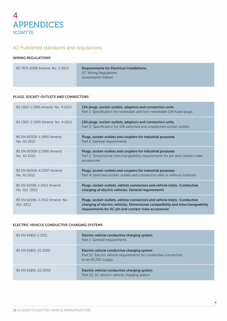
BS 7671:2008 Amend. No. 2:2013
BS EN 61851-1:2011
BS EN 61851-21:2002
BS EN 61851-22:2002
BS 1363-1:1995 Amend. No. 4:2012
BS EN 60309-2:1990 Amend. No. A2:2012
BS 1363-2:1995 Amend. No. 4:2012
BS EN 60309-4:2007 Amend. No. A1:2012
BS EN 60309-1:1990 Amend. No. A2:2012
BS EN 62196-1:2012 Amend. No. A11 :2013
BS EN 62196-2:2012 Amend. No. A11 :2013
WIRING REGULATIONS
ELECTRIC VEHICLE CONDUCTIVE CHARGING SYSTEMS
PLUGS, SOCKET-OUTLETS AND CONNECTORS
Requirements for Electrical Installations.IET Wiring RegulationsSeventeenth Edition
Electric vehicle conductive charging systemPart 1: General requirements
Electric vehicle conductive charging systemPart 21: Electric vehicle requirements for conductive connection to an AC/DC supply
Electric vehicle conductive charging systemPart 22: AC electric vehicle charging station
13A plugs, socket-outlets, adaptors and connection units. Part 1: Specification for rewireable and non-rewireable 13A fused plugs
Plugs, socket-outlets and couplers for industrial purposes Part 2: Dimensional interchangeability requirements for pin and contact-tube accessories
13A plugs, socket-outlets, adaptors and connection units.Part 2: Specification for 13A switched and unswitched socket-outlets
Plugs, socket-outlets and couplers for industrial purposes Part 4: Switched socket-outlets and connectors with or without interlock
Plugs, socket-outlets and couplers for industrial purposesPart 1: General requirements
Plugs, socket-outlets, vehicle connectors and vehicle inlets -Conductive charging of electric vehicles. General requirements
Plugs, socket-outlets, vehicle connectors and vehicle inlets -Conductive charging of electric vehicles. Dimensional compatibility and interchangeability requirements for AC pin and contact-tube accessories
A2 Published standards and regulations

34 A GUIDE TO ELECTRIC VEHICLE INFRASTRUCTURE
4APPENDICES(CONT’D)
IEC 61850-6 ed. 2.0
IEC 61850-3 ed. 1.0
IEC 61850-5 ed. 1.0
IEC 61850-1 ed. 1.0
IEC 61850-4 ed. 2.0
IEC 61850-10 ed. 2.0
ISO/IEC 15118-1
ISO/IEC 15118-2
ISO/IEC 15118-3
ISO 15118-4
ISO 15118-5
ELECTRIC VEHICLE COMMUNICATION
Communication networks and systems for power utility automation Part 6: Configuration description language for communication in electrical substations related to IEDs
Communication networks and systems in substations Part 3: General requirements
Communication networks and systems in substations Part 5: Communication requirements for functions and device models
Communication networks and systems in substations Part 1: Introduction and overview
Communication networks and systems for power utility automationPart 4: System and project management
Communication networks and systems for power utility automationPart 10: Conformance testing
Road vehicles - Vehicle to grid communication interface Part 1: General information and use-case definition
Road vehicles - Vehicle to grid communication interface Part 2: Network and application protocol requirements
Road vehicles - Vehicle to grid Communication InterfacePart 3: Physical and data link layer requirements
Road vehicles - Vehicle to grid Communication InterfacePart 4: Network and application protocol conformance test
Road vehicles - Vehicle to grid Communication InterfacePart 5: Physical layer and data link layer conformance test
BS EN 62196-3
BS EN 62196-4
PLUGS, SOCKET-OUTLETS AND CONNECTORS
Plugs, socket-outlets, and vehicle couplers - Conductive charging of electric vehiclesPart 3. Dimensional compatibility and interchangeability requirements for DC and AC/DC pin and tube-type contact vehicle couplers.
Plugs, socket-outlets, and vehicle couplers - Conductive charging of electric vehicles Part 4. Dimensional compatibility and interchangeability requirements for AC, DC and AC/DC vehicle couplers for Class II or Class III light electric vehicles (LEV).
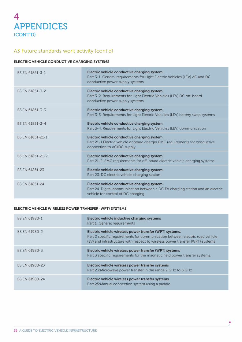
A3 Future standards work activity
35 A GUIDE TO ELECTRIC VEHICLE INFRASTRUCTURE
4APPENDICES(CONT’D)
BS EN 61851-3-1
BS EN 61980-1
BS EN 61851-3-4
BS EN 61851-3-2
BS EN 61980-2
BS EN 61851-21-1
BS EN 61851-3-3
BS EN 61980-3
BS EN 61851-21-2
BS EN 61980-23
BS EN 61851-23
BS EN 61980-24
BS EN 61851-24
ELECTRIC VEHICLE CONDUCTIVE CHARGING SYSTEMS
ELECTRIC VEHICLE WIRELESS POWER TRANSFER (WPT) SYSTEMS
Electric vehicle conductive charging system. Part 3-1. General requirements for Light Electric Vehicles (LEV) AC and DC conductive power supply systems
Electric vehicle inductive charging systems Part 1: General requirements
Electric vehicle conductive charging system. Part 3-4. Requirements for Light Electric Vehicles (LEV) communication
Electric vehicle conductive charging system. Part 3-2. Requirements for Light Electric Vehicles (LEV) DC off-board conductive power supply systems
Electric vehicle wireless power transfer (WPT) systems. Part 2 specific requirements for communication between electric road vehicle (EV) and infrastructure with respect to wireless power transfer (WPT) systems
Electric vehicle conductive charging system. Part 21-1.Electric vehicle onboard charger EMC requirements for conductive connection to AC/DC supply
Electric vehicle conductive charging system. Part 3-3. Requirements for Light Electric Vehicles (LEV) battery swap systems
Electric vehicle wireless power transfer (WPT) systems Part 3 specific requirements for the magnetic field power transfer systems.
Electric vehicle conductive charging system. Part 21-2. EMC requirements for off-board electric vehicle charging systems
Electric vehicle wireless power transfer systemsPart 23:Microwave power transfer in the range 2 GHz to 6 GHz
Electric vehicle conductive charging system. Part 23. DC electric vehicle charging station
Electric vehicle wireless power transfer systems Part 25:Manual connection system using a paddle
Electric vehicle conductive charging system. Part 24. Digital communication between a DC EV charging station and an electric vehicle for control of DC charging
A3 Future standards work activity (cont’d)
36 A GUIDE TO ELECTRIC VEHICLE INFRASTRUCTURE
4APPENDICES(CONT’D)
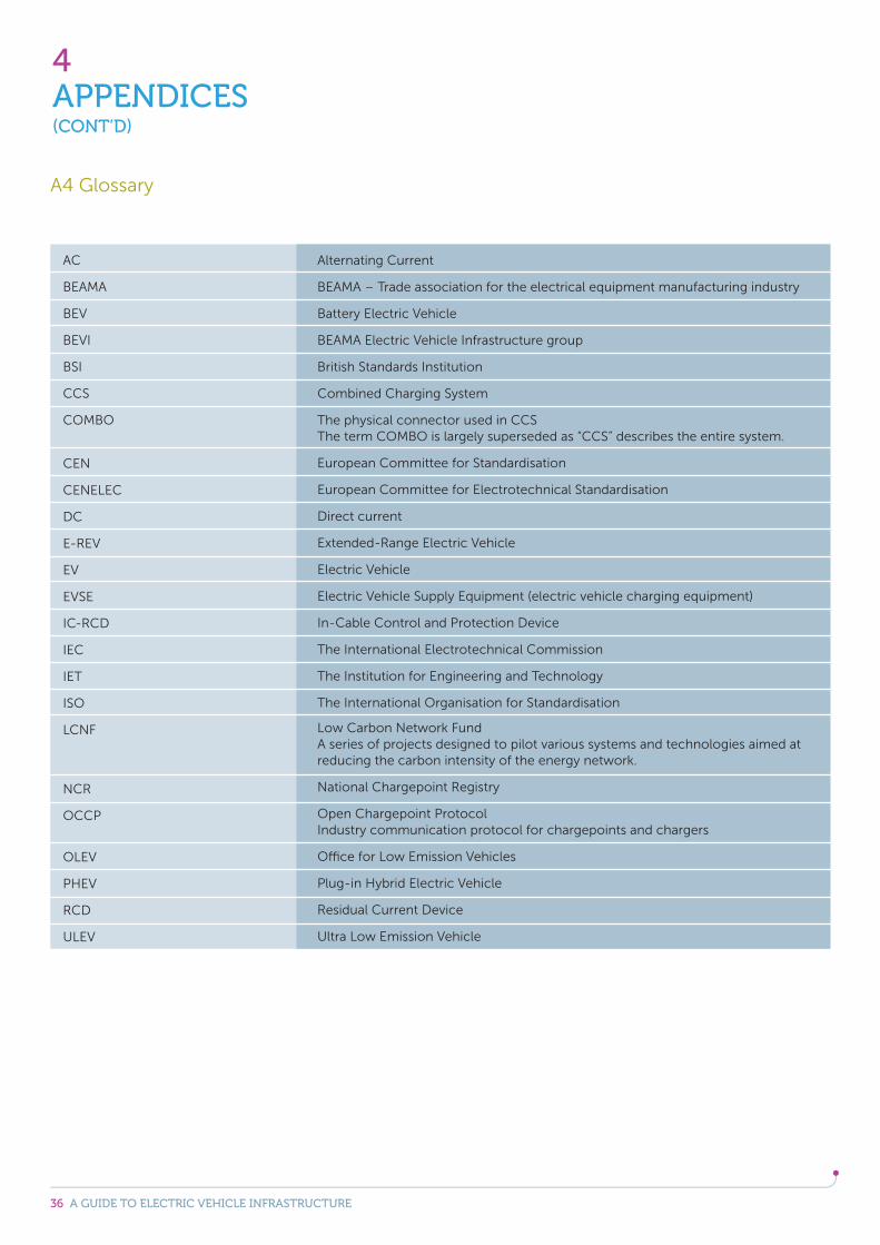
AC
BEAMA
BEV
BEVI
BSI
CCS
COMBO
CEN
CENELEC
DC
E-REV
EV
EVSE
IC-RCD
IEC
IET
ISO
LCNF
NCR
OCCP
OLEV
PHEV
RCD
ULEV
Alternating Current
BEAMA – Trade association for the electrical equipment manufacturing industry
Battery Electric Vehicle
BEAMA Electric Vehicle Infrastructure group
British Standards Institution
Combined Charging System
The physical connector used in CCS The term COMBO is largely superseded as “CCS” describes the entire system.
European Committee for Standardisation
European Committee for Electrotechnical Standardisation
Direct current
Extended-Range Electric Vehicle
Electric Vehicle
Electric Vehicle Supply Equipment (electric vehicle charging equipment)
In-Cable Control and Protection Device
The International Electrotechnical Commission
The Institution for Engineering and Technology
The International Organisation for Standardisation
Low Carbon Network Fund A series of projects designed to pilot various systems and technologies aimed at reducing the carbon intensity of the energy network.
National Chargepoint Registry
Open Chargepoint Protocol Industry communication protocol for chargepoints and chargers
Office for Low Emission Vehicles
Plug-in Hybrid Electric Vehicle
Residual Current Device
Ultra Low Emission Vehicle
A4 Glossary
37 A GUIDE TO ELECTRIC VEHICLE INFRASTRUCTURE
4APPENDICES(CONT’D)
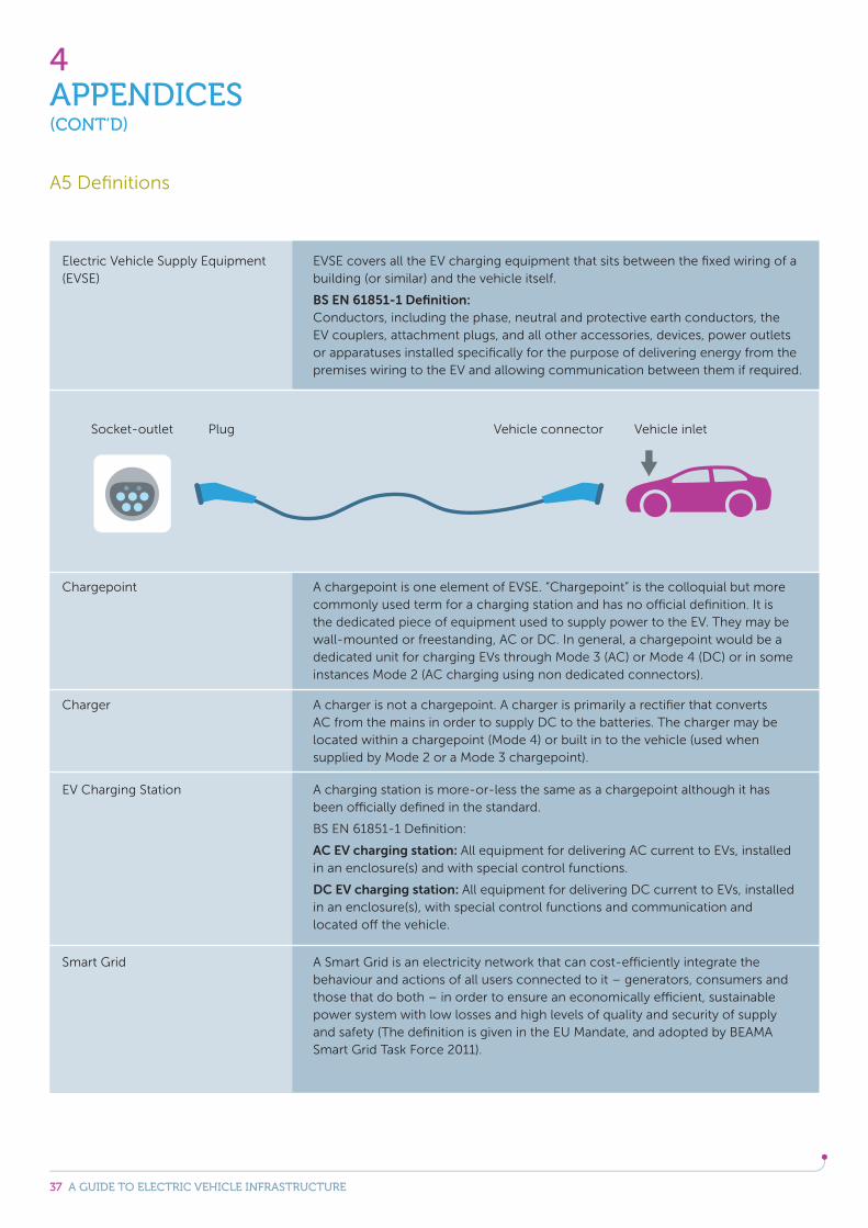
Electric Vehicle Supply Equipment (EVSE)
Chargepoint
Charger
EV Charging Station
EVSE covers all the EV charging equipment that sits between the fixed wiring of a building (or similar) and the vehicle itself.
BS EN 61851-1 Definition: Conductors, including the phase, neutral and protective earth conductors, the EV couplers, attachment plugs, and all other accessories, devices, power outlets or apparatuses installed specifically for the purpose of delivering energy from the premises wiring to the EV and allowing communication between them if required.
A chargepoint is one element of EVSE. “Chargepoint” is the colloquial but more commonly used term for a charging station and has no official definition. It is the dedicated piece of equipment used to supply power to the EV. They may be wall-mounted or freestanding, AC or DC. In general, a chargepoint would be a dedicated unit for charging EVs through Mode 3 (AC) or Mode 4 (DC) or in some instances Mode 2 (AC charging using non dedicated connectors).
A charger is not a chargepoint. A charger is primarily a rectifier that converts AC from the mains in order to supply DC to the batteries. The charger may be located within a chargepoint (Mode 4) or built in to the vehicle (used when supplied by Mode 2 or a Mode 3 chargepoint).
A charging station is more-or-less the same as a chargepoint although it has been officially defined in the standard.
BS EN 61851-1 Definition:
AC EV charging station: All equipment for delivering AC current to EVs, installed in an enclosure(s) and with special control functions.
DC EV charging station: All equipment for delivering DC current to EVs, installed in an enclosure(s), with special control functions and communication and located off the vehicle.
A5 Definitions
Socket-outlet Plug Vehicle inletVehicle connector
Smart Grid A Smart Grid is an electricity network that can cost-efficiently integrate the behaviour and actions of all users connected to it – generators, consumers and those that do both – in order to ensure an economically efficient, sustainable power system with low losses and high levels of quality and security of supply and safety (The definition is given in the EU Mandate, and adopted by BEAMA Smart Grid Task Force 2011).
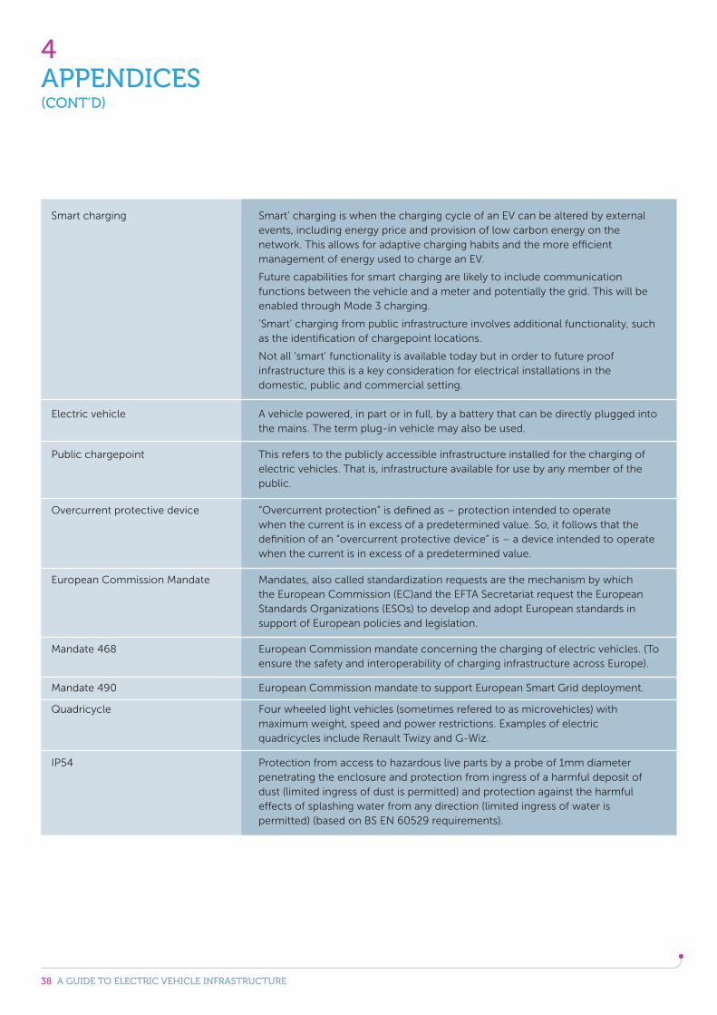
38 A GUIDE TO ELECTRIC VEHICLE INFRASTRUCTURE
4APPENDICES(CONT’D)
European Commission Mandate
Mandate 468
IP54
Mandate 490
Mandates, also called standardization requests are the mechanism by which the European Commission (EC)and the EFTA Secretariat request the European Standards Organizations (ESOs) to develop and adopt European standards in support of European policies and legislation.
European Commission mandate concerning the charging of electric vehicles. (To ensure the safety and interoperability of charging infrastructure across Europe).
Protection from access to hazardous live parts by a probe of 1mm diameter penetrating the enclosure and protection from ingress of a harmful deposit of dust (limited ingress of dust is permitted) and protection against the harmful effects of splashing water from any direction (limited ingress of water is permitted) (based on BS EN 60529 requirements).
European Commission mandate to support European Smart Grid deployment.
Four wheeled light vehicles (sometimes refered to as microvehicles) with maximum weight, speed and power restrictions. Examples of electric quadricycles include Renault Twizy and G-Wiz.
Overcurrent protective device “Overcurrent protection” is defined as – protection intended to operate when the current is in excess of a predetermined value. So, it follows that the definition of an “overcurrent protective device” is – a device intended to operate when the current is in excess of a predetermined value.
Smart charging Smart’ charging is when the charging cycle of an EV can be altered by external events, including energy price and provision of low carbon energy on the network. This allows for adaptive charging habits and the more efficient management of energy used to charge an EV.
Future capabilities for smart charging are likely to include communication functions between the vehicle and a meter and potentially the grid. This will be enabled through Mode 3 charging.
‘Smart’ charging from public infrastructure involves additional functionality, such as the identification of chargepoint locations.
Not all ‘smart’ functionality is available today but in order to future proof infrastructure this is a key consideration for electrical installations in the domestic, public and commercial setting.
Electric vehicle
Public chargepoint
A vehicle powered, in part or in full, by a battery that can be directly plugged into the mains. The term plug-in vehicle may also be used.
This refers to the publicly accessible infrastructure installed for the charging of electric vehicles. That is, infrastructure available for use by any member of the public.

DISCLAIMER This publication is subject to the copyright of BEAMA Ltd. While the information herein has been compiled in good faith, no warranty is given or should be implied for its use and BEAMA hereby disclaims any liability that may arise from its use to the fullest extent permitted under applicable law.
© BEAMA Ltd 2015 Copyright and all other intellectual property rights in this document are the property of BEAMA Ltd. Any party wishing to copy, reproduce or transmit this document or the information contained within it in any form, whether paper, electronic or otherwise should contact BEAMA Ltd to seek permission to do so.
BEAMA would like to thank the following organisations for their contribution to various aspects of this guide:
– Alexander Dennis
– BMW
– Energy Saving Trust
– Motorcycle Industry Association
– Society of Motor Manufacturers and Traders
– Tesla
– Toyota
– Transport for London
– Vauxhall

Westminster Tower3 Albert EmbankmentLondon SE1 7SL
www.beama.org.uk
Supported by the Low Carbon Vehicle Partnership
Related Documents


