Beam Transport for MW Class FEL Drivers D. Douglas & G. Biallas Jefferson Lab

Beam Transport for MW Class FEL Drivers D. Douglas & G. Biallas Jefferson Lab.
Dec 24, 2015
Welcome message from author
This document is posted to help you gain knowledge. Please leave a comment to let me know what you think about it! Share it to your friends and learn new things together.
Transcript

Beam Transport for MW Class FEL Drivers
D. Douglas & G. Biallas
Jefferson Lab

System Paradigm (Prejudice, Obsession)
Low peak, high average power FEL driven by SRF ERL• it’s elegant
• it’s in my comfort zone: it’s what I know & like
• it might just work
• nobody’s publicly admitted to producing kW-level CW average power with anything else (yet)
Consider me the King’s Fool: I will tell you the truth (hopefully with humor). You may ignor it, avoid it, or use it. You may smack me as you will, but it will be the truth…

Machine Concept
100 MeV 0.5 A Pbeam ~50 MW
FEL ~2 % PFEL ~ 1 MW
SRF linac
wiggler/optical cavity
dump
injectorhere there be dragons…
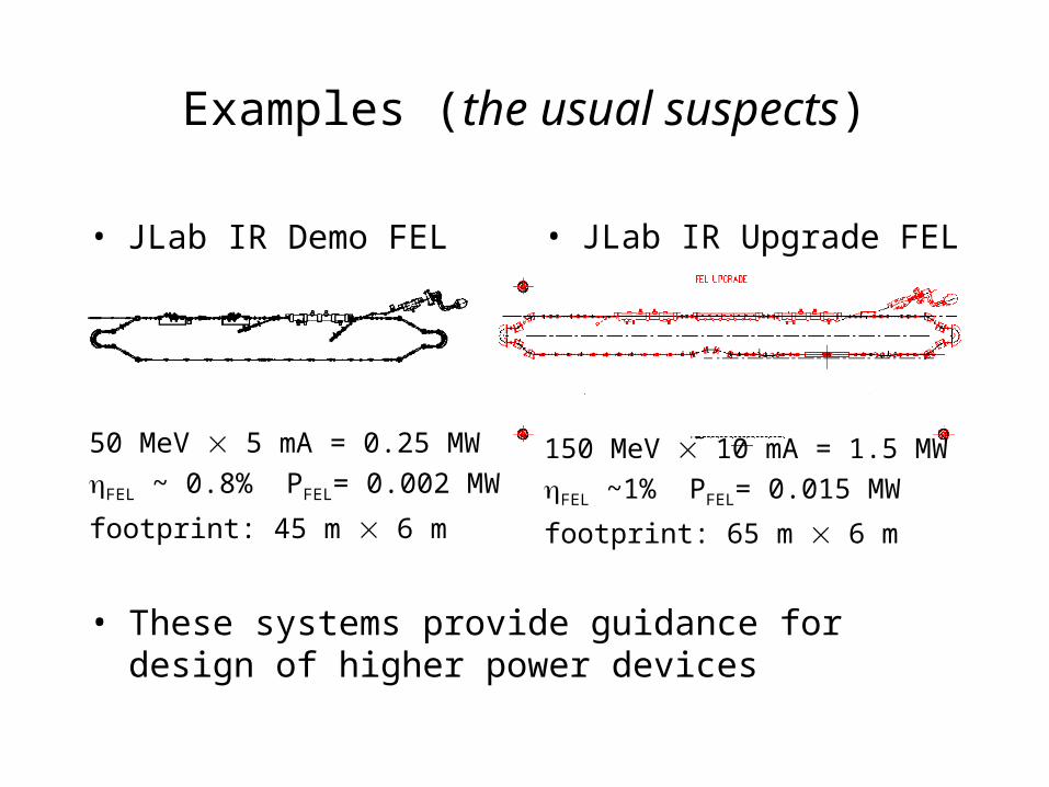
Examples (the usual suspects)
• JLab IR Demo FEL
50 MeV 5 mA = 0.25 MW
FEL ~ 0.8% PFEL= 0.002 MW
footprint: 45 m 6 m
• JLab IR Upgrade FEL
150 MeV 10 mA = 1.5 MW
FEL ~1% PFEL= 0.015 MW
footprint: 65 m 6 m
• These systems provide guidance for design of higher power devices

Issues/Requirements
• Management of full 6-d phase space from source to FEL, from FEL to dump
• Halo management• Suppression/control of instabilities and other
collective effects• Beam quality preservation

Phase Space Management• Transverse
– include RF focusing effects– keep envelopes small– may need to select/control phase advances to suppress instabilities– CSR management
• Longitudinal– accelerate long bunch to avoid instabilities; compress length just before wiggler– energy compress during energy recovery– typically must compensate RF waveform curvature (both in bunch length and
energy compression)• either magnetic or harmonic RF effective; one or other may be help in packaging system
– Note: can’t energy recover even harmonic RF (avoid sawtooth waveforms!)– Note: unless you do something special to waveform, must use opposite signs of
compaction to compress bunch length and energy (or recover more/less than 180o apart in RF phase)
• Status: phase space management is straightforward, but to date has required tunable system (variable quads, sextupoles)

Halo Management• Halo is likely a major limitation to very high powers
– halo generation: complex topic poorly understood by ordinary mortals, and thus largely ignored by machine designers (like me)
– halo likely largely formed in front end– chunks of it scrape off and melt stuff, irradiate things and make life
generally unpleasant. Need well less than 1 A loss.
• Current loss is worse for big beam envelopes (beam large, lattice sensitive), small apertures, high currents
• Experience in CEBAF, IR Demo, CEBAF-ER suggests C~10-6, so in ~1 A machine need aperture larger than beam envelope (!!??) to limit losses to 1 A.
• Status: unsolved problem, under study - but only at most rudimentary level and at low powers (signal to noise – core beam swamps diagnostic at few mA). Much work needed!
Ia
CIloss

Instabilities & Collective Effects
• Wakes – keep bunch long until you need it short
– shield components
• CSR– same approach – don’t compress until you need to, in fact, generalize to
say…
– keep at least some bunch dimensions well beyond coherence length (so if its short, make it a pancake – very wide & high, like in IR Demo)
– impact smaller at larger emittance & emittance spec loose for IR FELs, so not as critical as in UV, X FEL

Instabilities & Collective Effects• BBU/HOM
– HOM suppression by proper SRF system design (milestone 43 – “then a miracle occurs”)
– feedback stabilization– suppression supported by proper choice of betatron phase
• non-zero chromaticity may help - phase decoherence across large momentum spread bunch decorrelates betatron response to HOM kicks
– need to worry about power deposition from propagating modes!!!
• Status:– phenomina are pretty well understood & probably manageable– further measurements (esp. CSR, BBU, propagating HOM) and benchmarking of
codes needed• expect to see BBU when 3rd module installed in Upgrade (rich HOM spectrum, implying
low threshold), • will be able to more carefully benchmark theory & simulation• learn how to build effective feedback systems.
– work on HOM management, feedback, and transport system design needed before very high powers will be achieved
• motivates move toward lower frequency structures with fewer cells• effect of power deposition from propagating modes is not well understood at high powers

Beam Quality Preservation• Be sure to suppress collective effects (CSR, wakes)
– make bunch short only where it needs to be short– shielded beamline components– avoid overly strong bending, focusing
• Control magnitude & impact of errors on beam– magnetic field inhomogeneities have transverse and longitudinal emittance dilution
effects (B/B generates x’ error, couples to (x,x’) through M12 and M22; couples to (RF,E) through M52)
• Status– probably understand magnetostatic effects and seem to be able to control them (IR
Demo, IR Upgrade, CEBAF-ER all show well-defined beam and rational beam behavior)
• but need to carefully spec out system components
– learning about collective effects• wakes• CSR• BBU• space charge – may become issue as bunch charge increases

Developing the Technology
• probably won’t successfully run initial high power (100+ kW) FELs without a tunable driver accelerator
• probably will be able to run offspring high power systems with a “precast” compact driver – particularly if you commission using a blue-tip wrench (recut pole-pieces, move stuff around)
• suggests that FEL and driver evolve along matrixed developmental tracks– have a separate operationally flexible & tunable “facility testbed driver”
for each generation of FEL (10 kW (exists), 100 kW, 1 MW). When it works, move FEL to a deployable “generational field driver”
– reduce flexibility of each subsequent generational driver (compact 100 kW, very compact 1 MW)
– allows separate, controlled development of source, driver accelerator, FEL, and system integration/packaging process

Example System “Family Tree”
JLab 10 kW driver & FEL
upgraded 10 kW “facility driver” & 100 kW FEL
upgraded 100 kW facility driver & 1 MW FEL
100 kW “field driver” & FEL
MW field driver & FEL
upgrade driver and FEL
migrate FEL
upgrade FEL
migrate FEL
upgrade driver upgrade driver

Technology Choices
• Lower RF frequency with fewer cells– “better” HOM spectrum & impedances
– bigger apertures
– requires lower compaction
– allows use of harmonic RF correction of RF waveform• simplifies magnetic transport
– potential for higher temp. operation (4 Ko)
• magnets: electromagnetic for facility driver, PM for field drivers
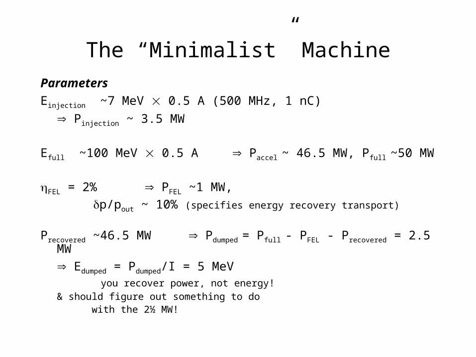
The “Minimalist” Machine
Parameters
Einjection ~7 MeV 0.5 A (500 MHz, 1 nC)
Pinjection ~ 3.5 MW
Efull ~100 MeV 0.5 A Paccel ~ 46.5 MW, Pfull ~50 MW
FEL = 2% PFEL ~1 MW,
p/pout ~ 10% (specifies energy recovery transport)
Precovered ~46.5 MW Pdumped = Pfull - PFEL - Precovered = 2.5 MW
Edumped = Pdumped/I = 5 MeV you recover power, not energy!& should figure out something to do with the 2½ MW!

The “Minimalist” Machine• Linearized RF
– 500 MHz fundamental, 1500 MHz 3rd harmonic SRF• 20 MV/m at 500 MHz 5 m active fundamental, probably 8 m real estate• 25 MV at 1500 MHz 1 m active harmonic, probably 2 m real estate
10 m of SRF• Injection “somehow”
– Beam materializes on linac axis miraculously matched to rest of system• beam envelopes = linac acceptance (use RF focusing)• long bunch/low momentum spread • RF curvature corrected
• Simplistic phase space management– Accelerator serendipitously provides beam transversely matched (via RF focusing)
to mirror-bend achromat (with chicane for bunch length compression)• nose-pieces to fix T566 of chicane?
– Two quads, properly placed, match beam to wiggler– Two quads, properly placed, match beam to return arc mirror bend, which, through
some undetermined feat of parlor magic, provides proper transverse match to cryomodule for energy recovery whilst its compaction sets the longitudinal match
• Big, nasty dump

Example of MW Class Dumpsred: dumps; blue: FEL
yeah yeah yeah its not a fair comparison ‘cause they are 6 GeV x 200 mA, but, you get the idea, right? It isn’t easy…

System Concept
Major Components:– injector (milestone 43a: a second
miracle)– 100 MeV linac (4 500 MHz
cavities, 2 1500 MHz cavities)– 4 Ko refrigeration– 6 dipoles (10 kG, PM)– 4 quads (PM)
Integration Overview:– footprint: 13 m 2 m
– weight ******* lbs
– cost if you have to ask…
injector
wigglerlocation
500/1500 MHz cryomodule
dump

Parting Salvo• Make it long and skinny. Do not consider a spherical, cubical, conical,
ellipsoidal, or otherwise blob-shaped FEL. Its called a “linac” for a reason.
• And while we’re talking about linacs – do not be delusional about available real estate gradients.
– SLAC is a pretty peppy linac and it only gets 17 MV/m (50 GeV/3 km) – pulsed – by SLEDing. Transients and all. And you don’t want the transients…
– Don’t expect vastly more from SRF, and don’t expect technology to conform to preconceived notions of usage for shipboard volume
• It’s front end loaded. The injector is definitely not easy.– required performance is orders of magnitude higher than prior art:
• combination of current-charge/bunch-longitudinal emittance, desired cathode lifetime,…
– footprint
– operability (come visit, and see what a real man’s injector is all about!)
– integration (how to bring beam into the ERL)
• What’s with that dump? What do you do with ~5 MeV 0.5 A = 2.5 MW? Quite a dump! Quite a footprint; quite a bit of shielding.
Related Documents