Beam combination schemes and technologies for the Planet Formation Imager Stefano Minardi a,b , Sylvestre Lacour c , Jean-Philippe Berger d , Lucas Labadie e , Robert R. Thomson f , Chris Haniff g , and Michael Ireland h a Institute of Applied Physics, Friedrich Schiller University, Max-Wien-Platz 1, 07743 Jena, Germany b Leibnitz-Institut f¨ ur Astrophysik Potsdam, An der Sternwarte 16, 14482 Potsdam, Germany c LESIA, CNRS/UMR-8109, Observatoire de Paris-Meudon, 5 place Jules Janssen, 92195 Meudon, France d European Southern Observatory, Karl-Schwarzschild-Str. 2, 85748 Garching bei M¨ unchen, Germany e 1st Institute of Physics, University of Cologne, Z¨ ulpicher Str. 77, 50937 Cologne, Germany f Scottish Universities Physics Alliance (SUPA), Institute of Photonics and Quantum Sciences (IPaQS), Heriot Watt University, Riccarton, Edinburgh, EH14 4AS g Cavendish Laboratory, JJ Thomson Avenue, Cambridge CB3 0HE, United Kingdom h Research School of Astronomy & Astrophysics, Mount Stromlo Observatory, Cotter Road, Weston Creek, ACT 2611, Australia ABSTRACT The Planet Formation Imager initiative aims at developing the next generation large scale facility for imaging astronomical optical interferometry operating in the mid-infrared. Here we report on the progress of the Planet Formation Imager Technical Working Group on the beam-combination instruments. We will discuss various available options for the science and fringe-tracker beam combination instruments, ranging from direct imaging, to non-redundant fiber arrays, to integrated optics solutions. Besides considering basic characteristics of the schemes, we will investigate the maturity of the available technological platforms at near- and mid-infrared wavelengths. Keywords: Stellar interferometry, future interferometric facilities, multi-telescope beam combiners. 1. INTRODUCTION The Planet Formation Imager (PFI) initiative 1 is aiming at developing the next generation large scale facility for imaging astronomical optical interferometry at mid-infrared wavelength. The main scientific goal of the PFI facility will be the high-angular-resolution characterization of planet forming regions and young Jupiter-mass exoplanets in the neighborhood of our Sun. 2 This science case justifies the choice of the operating optical bands (from L to Q), due to the favorable contrast between the central star and the low-mass companions achievable at mid-infrared wavelengths. Due to the long operating wavelengths, maximal baselines in the order of 1 Km will be necessary to resolve the Hill sphere (i.e. the radius of the gravitational sphere of influence of a forming planet) of a Jupiter mass planet, estimated to be approximatly ∼ 2.5 mas at the distance of the nearest star forming region (140 pc). A conceptual technical study is currently underway to identify suitable key technologies for the realization of the PFI facility (see Ireland et al. 2016 3 for an overview of the current status of the technical study). Here we report on the progress of the Technical Working Group (TWG) on the beam-combination instruments. The goal Further author information: (Send correspondence to S.M.) S.M.: E-mail: [email protected], Telephone: +49 (0) 331 7499 687 Optical and Infrared Interferometry and Imaging V, edited by Fabien Malbet, Michelle J. Creech-Eakman, Peter G. Tuthill, Proc. of SPIE Vol. 9907, 99071N © 2016 SPIE · CCC code: 0277-786X/16/$18 · doi: 10.1117/12.2232656 Proc. of SPIE Vol. 9907 99071N-1 DownloadedFrom:http://proceedings.spiedigitallibrary.org/on02/26/2017TermsofUse:http://spiedigitallibrary.org/ss/termsofuse.aspx

Welcome message from author
This document is posted to help you gain knowledge. Please leave a comment to let me know what you think about it! Share it to your friends and learn new things together.
Transcript

Beam combination schemes and technologies for the PlanetFormation Imager
Stefano Minardia,b, Sylvestre Lacourc, Jean-Philippe Bergerd, Lucas Labadiee, Robert R.Thomsonf, Chris Haniffg, and Michael Irelandh
aInstitute of Applied Physics, Friedrich Schiller University, Max-Wien-Platz 1, 07743 Jena,Germany
bLeibnitz-Institut fur Astrophysik Potsdam, An der Sternwarte 16, 14482 Potsdam, GermanycLESIA, CNRS/UMR-8109, Observatoire de Paris-Meudon, 5 place Jules Janssen, 92195
Meudon, FrancedEuropean Southern Observatory, Karl-Schwarzschild-Str. 2, 85748 Garching bei Munchen,
Germanye1st Institute of Physics, University of Cologne, Zulpicher Str. 77, 50937 Cologne, Germany
fScottish Universities Physics Alliance (SUPA), Institute of Photonics and Quantum Sciences(IPaQS), Heriot Watt University, Riccarton, Edinburgh, EH14 4AS
gCavendish Laboratory, JJ Thomson Avenue, Cambridge CB3 0HE, United KingdomhResearch School of Astronomy & Astrophysics, Mount Stromlo Observatory, Cotter Road,
Weston Creek, ACT 2611, Australia
ABSTRACT
The Planet Formation Imager initiative aims at developing the next generation large scale facility for imagingastronomical optical interferometry operating in the mid-infrared. Here we report on the progress of the PlanetFormation Imager Technical Working Group on the beam-combination instruments. We will discuss variousavailable options for the science and fringe-tracker beam combination instruments, ranging from direct imaging,to non-redundant fiber arrays, to integrated optics solutions. Besides considering basic characteristics of theschemes, we will investigate the maturity of the available technological platforms at near- and mid-infraredwavelengths.
Keywords: Stellar interferometry, future interferometric facilities, multi-telescope beam combiners.
1. INTRODUCTION
The Planet Formation Imager (PFI) initiative1 is aiming at developing the next generation large scale facilityfor imaging astronomical optical interferometry at mid-infrared wavelength. The main scientific goal of the PFIfacility will be the high-angular-resolution characterization of planet forming regions and young Jupiter-massexoplanets in the neighborhood of our Sun.2 This science case justifies the choice of the operating optical bands(from L to Q), due to the favorable contrast between the central star and the low-mass companions achievableat mid-infrared wavelengths. Due to the long operating wavelengths, maximal baselines in the order of 1 Kmwill be necessary to resolve the Hill sphere (i.e. the radius of the gravitational sphere of influence of a formingplanet) of a Jupiter mass planet, estimated to be approximatly ∼ 2.5 mas at the distance of the nearest starforming region (140 pc).
A conceptual technical study is currently underway to identify suitable key technologies for the realization ofthe PFI facility (see Ireland et al. 20163 for an overview of the current status of the technical study). Here wereport on the progress of the Technical Working Group (TWG) on the beam-combination instruments. The goal
Further author information: (Send correspondence to S.M.)S.M.: E-mail: [email protected], Telephone: +49 (0) 331 7499 687
Optical and Infrared Interferometry and Imaging V, edited by Fabien Malbet, Michelle J. Creech-Eakman, Peter G. Tuthill, Proc. of SPIE Vol. 9907, 99071N
© 2016 SPIE · CCC code: 0277-786X/16/$18 · doi: 10.1117/12.2232656
Proc. of SPIE Vol. 9907 99071N-1
Downloaded From: http://proceedings.spiedigitallibrary.org/ on 02/26/2017 Terms of Use: http://spiedigitallibrary.org/ss/termsofuse.aspx
of this TWG is to identify eventually the architecture and underlying technology for the beam combination in-struments needed for PFI. Our working baseline scenario considers an array of 12 to 21, adaptive-optics-equippedtelescopes and two alternative options for the science beam combination, namely a dispersed heterodyne4(bandsN and Q) or a dispersed homodyne scheme (L,M,N bands). In both cases, fringe tracking at near-infrared wave-lengths will be necessary to access faint targets, thus requiring an additional beam-combiner instrument, mostprobably operating in the near-infrared.
This paper will review the state-of-the-art of homodyne multi-telescope beam combiners encompassing bulk,fiber and integrated optical solutions (Section 2). In Section 3 we will use a simple numerical model to comparethe intrinsic per-baseline sensitivity of three different beam combination architectures assuming a coherenceretrieval algorithm based on the Visibility to Pixel Matrix formalism (V2PM5). In Section 4 we will discussthe state-of-the-art of photonics technologies for the mid-infrared which could enable the manufacturing of thescience beam-combiner for PFI. A discussion of the present technological challenges and a tentative roadmap forthe development of a mid-infrared beam combination instrument measuring most of the available baselines atPFI are proposed in Section 5. Conclusions and recommendations are presented in Section 6.
2. REVIEW OF HOMODYNE BEAM COMBINATION INSTRUMENTS
In this Section, we will present existing interferometric beam combination solutions broadly classified by keytechnologies and/or combination concepts. In particular, we will consider beam combiners based on bulk optics,optical fibers and integrated optics technologies, as well as discussing the concept of direct imaging. Throughoutthe text, we will also adopt the conventional high-level classification of multi-telescope beam combiners accordingto the fringe and baseline encoding (see Le Bouquin et al. 20046). Fringe encoding can be temporal, spatial ormatricial depending on whether the interference fringes are measured in temporal/spatial domain or recordedfrom the outputs of a phase-shifting interferometry set-up. Notice that spatial and matricial schemes can alsobe operated in temporal fringe scanning mode at the expense of a lower sensitivity. The baseline encoding canbe pairwise, partial or all-in-one. Pairwise combiners encode at each output fringes resulting from a single pairof telescopes. In partial encoding the baselines are divided among several partial beam combiners. All-in-oneschemes multiplex fringes from all possible baselines at each individual output.
2.1 Bulk-optics combiners
A general advantage of bulk optics beam combiners is that they can be designed to achieve high transmissionwith highly achromatic response. Nonetheless they tend to be more voluminous than e.g. fibered or integratedoptics beam combiners, which potentially raises manufacturing and operation costs, due to the larger size of thecryo-vacuum vessel required to house the cold optics.
A bulk optics pairwise combiner with traditional design (cascade of beam splitters/combiners) would almostcertainly be prohibitively complex for Nt ≥12 telescopes, as appears to be needed for PFI. However a highlysimplified design for a white-light, pairwise multi-telescope combination measuring simultaneously all possiblebaselines has been proposed by Ribak et al. 20077 and successfully tested in the laboratory for up to 6 channels.This design could be easily scaled up to a large number of apertures. However, the 2D spatial fringe patternsreadout requires large detectors and the implementation of a high-resolution spectro-interferometric setup is notstraightforward.
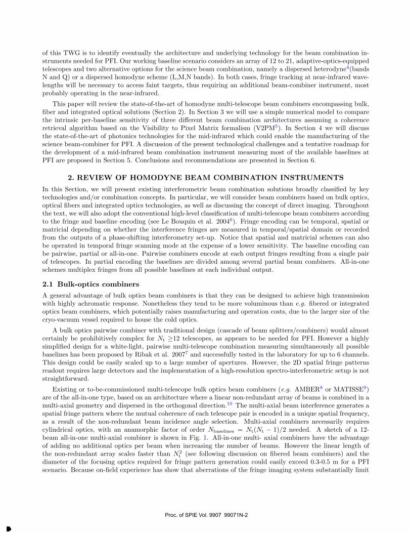
Existing or to-be-commissioned multi-telescope bulk optics beam combiners (e.g. AMBER8 or MATISSE9)are of the all-in-one type, based on an architecture where a linear non-redundant array of beams is combined in amulti-axial geometry and dispersed in the orthogonal direction.10 The multi-axial beam interference generates aspatial fringe pattern where the mutual coherence of each telescope pair is encoded in a unique spatial frequency,as a result of the non-redundant beam incidence angle selection. Multi-axial combiners necessarily requirescylindrical optics, with an anamorphic factor of order Nbaselines = Nt(Nt − 1)/2 needed. A sketch of a 12-beam all-in-one multi-axial combiner is shown in Fig. 1. All-in-one multi- axial combiners have the advantageof adding no additional optics per beam when increasing the number of beams. However the linear length ofthe non-redundant array scales faster than N2
t (see following discussion on fibered beam combiners) and thediameter of the focusing optics required for fringe pattern generation could easily exceed 0.3-0.5 m for a PFIscenario. Because on-field experience has show that aberrations of the fringe imaging system substantially limit
Proc. of SPIE Vol. 9907 99071N-2
Downloaded From: http://proceedings.spiedigitallibrary.org/ on 02/26/2017 Terms of Use: http://spiedigitallibrary.org/ss/termsofuse.aspx

Detector
Window
Cylindrical LensStack
Weak Lens
CylindricalLens
Grating
CameraLens
Detector
Window
Cylindrical LensStack
Weak (collimating) Lens
CylindricalLens
Grating
CameraLens
Figure 1. Top down (Left) and side-on (Right) views of a 12-beam bulk-optics all-in-one combiner based on the non-redundant, multi-axial combination scheme. The full width from window to detector is <1 m. Left: Dispersion directionschematic, showing how a stack of offset cylindrical lenses could take beams from physically different locations outside adewar, and co-align them. Right: In the fringe direction, the beam (with 3 of the 12 beams shown) directions are arrangedon a non-redundant grid to extract the visibility of all possible baselines from the analysis of the interferogram. The twocylindrical components appear now as plane parallel glass blocks, and it is clear that all beams can originate from thesame height outside the dewar. The element marked ”Camera Lens” is almost certainly a multi-element camera, and maybe a reflective camera.
the performance of the multi-axial beam combiner, design and manufacturing of large aperture optical elementssuitable for the beam combination task could be challenging.
Pupil plane, all-in-one multi-telescope beam combiners based on assemblies of multiple semi-reflecting mirrorshave been used in the past to combine the beams at the COAST11 and NPOI12 interferometers. This beamcombiner is very stable due to the absence of moving parts and is operated in temporal scanning mode. Proposedupgrades of this design to measure simultaneously visibilities of up to 6 telescopes featured however footprintsin the order of 0.5 m2 (Baron et al. 2006,13 Buscher et al. 200814), posing scaling constraints of the cold opticsenclosure similar to the the multi-axial architecture in case a much larger number of telescopes are combinedsimultaneously. However, instruments combining simultaneously a relatively small number of telescopes can beused as partial combiners for larger arrays by cycling the combined telescope multiplets with a fast reconfigurableswitchyard.13
2.2 Direct imaging instruments
Conventional homodyne/heterodyne interferometric instruments measure the complex coherence function ofelectromagnetic fields, from which images of the astronomical target can be retrieved. The concept of pupildensification and the hyper-telescope15 can be exploited to design an instrument forming the convolution of theobject and a relatively compact point spread function (PSF) on the detector, which can be interpreted as animage of the object.
The densification process defines how an input pupil will be remapped into an output pupil that respects theoverall telescope distribution (the inner pupil central positions are homothetic to the outer ones) but scales up theratio between the output pupil diameters and the distances between pupils. The result of the pupil densificationis a reduction of the ratio between the field of view of the reconstructed image and the interferometric PSF.
Lardiere et al. 200716 and Patru et al. 200717 have explored how well different array architectures, i.e.input pupil distributions, can be densified. Their conclusions show that the choice of pupil distribution will leadto different field of views, angular resolution and halo level and therefore require a compromise based on thescientific goals. Additionally, it should be noted that projection effects caused by the source trajectory on thesky were not considered there, but could in principle be implemented.
Guided optics (whether fibers or 3D integrated optics) can be of great use to implement the densification ofthe input pupil since they simplify considerably the routing of light. Direct imaging and densification with fibershave already been explored experimentally by Patru et al. 2008.18 The scheme is easily scalable to an arbitrarylarge array of telescopes provided an accurate fringe tracking system for the whole array is available.
The key limitation of a direct imaging instrument is signal-to-noise in the case of a sparse (e.g. non-redundant)pupil. The fraction of the light in the central core is proportional to (NtD
2/B2max)× (γD/γB)2, where D is the
Proc. of SPIE Vol. 9907 99071N-3
Downloaded From: http://proceedings.spiedigitallibrary.org/ on 02/26/2017 Terms of Use: http://spiedigitallibrary.org/ss/termsofuse.aspx

telescope diameter, Bmax the maximum baseline and γD and γB the magnification factors for telescope pupilsand baselines respectively. For example, for a 9-telescope non-redundant array (Golay 197119), this fractionis 0.36, or 0.326 once the geometric factor of circular pupils fitting in a hexagonal grid is taken into account.For background-limited direct imaging or imaging of faint structures around a bright star, the signal-to-noise isreduced by this factor. Recovering this signal-to-noise is possible by analysing the direct image with methodsanalogous to aperture-mask interferometry, however those techniques require λ/∆λ > (Bmax/D)× (γB/γD). Forthe fields of view required for PFI, this either means another significant sensitivity loss with small ∆λ, or anintegral field unit, removing the simplicity of the direct imaging scheme and making the beam combiner similarto any other all-in-one combiner.
The strength of the direct imaging combiner architecture is in a redundant configuration, where the den-sified pupil is fully filled. This requires a much greater number of telescopes, where Nt ≈ (θFOV/∆θ)2. Thisconfiguration would only be competitive if relatively small telescopes were very much more affordable than largeones.3
2.3 Fibered beam combiners
The advantage of using optical fibers to perform efficient modal filtering and improve the precision of interfero-metric measurements by simultaneous photometric correction has been demonstrated long ago.20 Two schemesof combination rely on the properties of fibered photonic components: 1) pairwise combiners based on fibrecouplers,21 and 2) all-in-one multi-axial combiners.22 Simple fibered 2x2 couplers operating in the H and Kbands were used in pioneering photonic beam combiners such as FLUOR.21 Experiments with L-band couplerswere carried out,23 but have never been used in an instrument delivering science data. The pairwise combinationscheme could be easily scaled up to multi-telescope arrays by means of a cascade of fiber couplers needed to dis-tribute and combine simultaneously the starlight on all possible baselines. However, the main limitations of thisapproach are the problematic control of differential dispersion and the sensitivity of fibers to thermo-mechanicalnoise, which both grow with the total length of the fibre patches.
All-in-one, multi-axial, fibered beam combiners (see e.g. MIRC22 and FIRST24) are in construction identicalto their bulk-optics analogues, but use single mode optical fibers for modal filtering of the PSF of the telescopesand deliver the collected light to a V-groove, where the fiber-ends are arranged to form a non-redundant lineararray. To date, up to 15 channels were successfully combined in the laboratory,25 and up to 9 were used on-sky in prototype instruments.24 A non redundant configuration for 24 telescopes has been already calculated∗.As mentioned before, the physical length of the non-redundant array grows steeply as N2
t logNt (see Fig. 2).Although the use of fibers and micro-optics can reduce considerably the size of the multi-axial combinationscheme as compared to a bulk-optics design, a cryo-vacuum vessel of relatively large footprint is still needed tohost the beam focusing optics.
A possible amelioration of the scheme is the arrangement of the fibers in a 2D non-redundant array.26 Thiswould result in a more compact optical arrangement, however the main difficultly would be the implementationof a cross-dispersion scheme, e.g. by means of a highly-spatially-resolved integral field unit sampling the fringes.A general limitation of fibered beam combiners is related to the long term phase drifts of thermo-mechanicalorigin, which can only be partially removed by closure phase techniques. A possible solution to this problemcould be provided by rescaled versions of integrated optics pupil remappers, such as the Dragonfly instrument.27
As discussed in the next paragraph, the resilience of integrated optical components to thermo-mechanical per-turbations makes them inherently phase-stable. The technological challenge would mainly be related to copewith the dimension constraints imposed by the need of coupling many large-diameter, free-space input beamsinto the reformatting waveguides.
2.4 Integrated optics beam combiners
First proposed nearly 20 years ago by Malbet et al.,28 integrated optics (IO) beam combiners represent an effectiveand compact way to combine interferometrically the light collected by many telescopes. IO beam combinersleverage on the modal filtering properties of fibers/waveguides and an enhanced thermo-mechanical stability,
∗D. Mozurkewich, personal communication.
Proc. of SPIE Vol. 9907 99071N-4
Downloaded From: http://proceedings.spiedigitallibrary.org/ on 02/26/2017 Terms of Use: http://spiedigitallibrary.org/ss/termsofuse.aspx

NFie-2
D '=4tl' o NFie=3
O O O NFm=4
D'=tzd' o o o o o oe oe NF,13=5
D'=16d' o o o o o o o oe o o o o NFlb=6
D '=26tl' o o a o 0 0 0 o o o 0 0 0 0 o 0 0 0 o NFie-7
D '=35d' oo000000000000000000000000o NFie=6
D'=45d' N000000000000000000000505000000050000000 NFl009
D'-56d' M000a000000000000000oaeooe000000000000000000000 NFie-10
D'=92d' eeeeeeasmaeeeeeeeeeeeeeeemeeeemeaeeeeeaeeeeemaeveemeeeveeveemeememeesa NFib=12
D '-130d' NFe-14
D '=154d' NFe 15
Z10°
Data simulationN2
N3
N2 log(N)
10 101 102
N of combined telescopes
IO Beam combiners Baseline encoding
Fringe encoding
Temporal
Spatial
Matricial
Pairwise Partial All-in-one
2T-LETI/LEMO[Berger et al. 2001]
3T-IOTA[Berger et al. 2003]
3T-3D[Rodenas et al. 2012]
3T-Multiaxial[Berger et al. 2000]
4T- PIONIER /GRAVITY[Benisty et al. 2009]
18T-FIRST-I0[Latour 2016]
Ir 4T-MMI[Rooms et al. 2003]
8T- Multiaxial[Jovanovic et al. 2012]
3T -DBC[Saviauk et al. 2013]
Figure 2. Left: non-redundant fiber arrays optimized for compact beam combination of up to 15 telescopes (from Lacour201026). Right: number of pixels per wavelength channel needed to code all the information of the baselines, as a functionof the combined telescopes (stars). A minimal sampling of 4 pixels per fringe is assumed. Red line: N2
t scaling law. Greenline: N3
t scaling law. Blue line: N2t logNt scaling law.
due to the inherent rigidity of the IO component substrate. Miniaturization and absence of alignment degrees offreedom add up to the advantages of this technology. To date, several IO beam combiners have been proposedand/or tested in the laboratory and on-sky. Fig. 3 is an attempt to sort the various developed IO componentsaccording to the conventional classification scheme of the beam combiners outlined in the introduction.
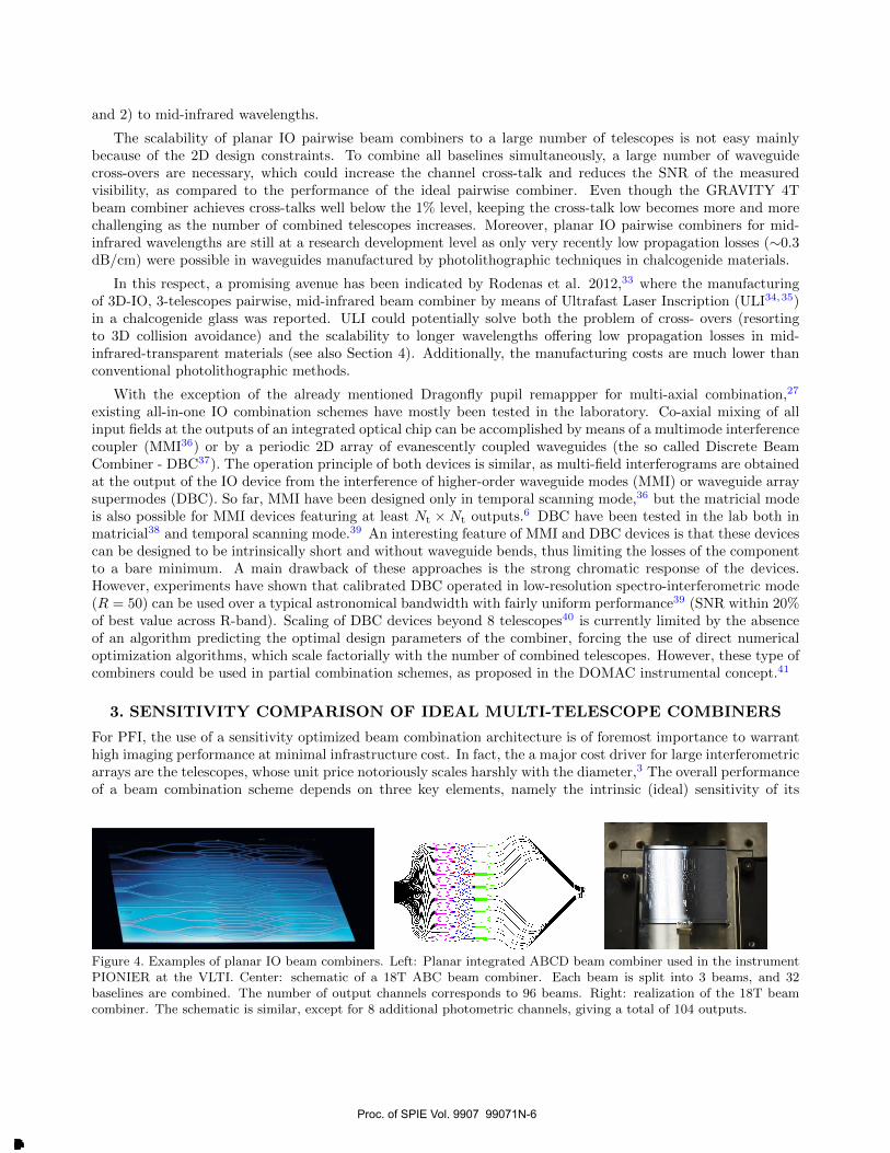
Pairwise planar IO beam combiners are the most developed devices so far, which have already been suc-cessfully tested on sky to combine simultaneously up to 4 telescopes both in temporal or matricial mode fringeencoding.29–31 Additionally, a laboratory demonstration of a pairwise/spatial beam combiners was reported inBerger et al. 2000.32 These components were operating in H- or K-band, leveraging on the high maturity ofion-indiffusion or silica-on-insulator planar IO technologies, which have been developed for telecom applications.Silica-on-insulator technology has been also used for manufacturing the partial/matricial beam combiner devel-oped at the Observatoire de Paris Muedon, which combines simultaneously 18 channels over 32 selected baselinesfor the FIRST-IO instrument† (see Figure 4). From the PFI perspective, conventional pairwise, planar-IO beamcombiners measuring all baselines have limitations regarding the scalability to 1) a large number of telescopes,
†S. Lacour, personal communication
Figure 3. Existing (TRL≥ 4) IO beam combiners classified according to Le Bouquin et al. 20046
Proc. of SPIE Vol. 9907 99071N-5
Downloaded From: http://proceedings.spiedigitallibrary.org/ on 02/26/2017 Terms of Use: http://spiedigitallibrary.org/ss/termsofuse.aspx
and 2) to mid-infrared wavelengths.
The scalability of planar IO pairwise beam combiners to a large number of telescopes is not easy mainlybecause of the 2D design constraints. To combine all baselines simultaneously, a large number of waveguidecross-overs are necessary, which could increase the channel cross-talk and reduces the SNR of the measuredvisibility, as compared to the performance of the ideal pairwise combiner. Even though the GRAVITY 4Tbeam combiner achieves cross-talks well below the 1% level, keeping the cross-talk low becomes more and morechallenging as the number of combined telescopes increases. Moreover, planar IO pairwise combiners for mid-infrared wavelengths are still at a research development level as only very recently low propagation losses (∼0.3dB/cm) were possible in waveguides manufactured by photolithographic techniques in chalcogenide materials.
In this respect, a promising avenue has been indicated by Rodenas et al. 2012,33 where the manufacturingof 3D-IO, 3-telescopes pairwise, mid-infrared beam combiner by means of Ultrafast Laser Inscription (ULI34,35)in a chalcogenide glass was reported. ULI could potentially solve both the problem of cross- overs (resortingto 3D collision avoidance) and the scalability to longer wavelengths offering low propagation losses in mid-infrared-transparent materials (see also Section 4). Additionally, the manufacturing costs are much lower thanconventional photolithographic methods.
With the exception of the already mentioned Dragonfly pupil remappper for multi-axial combination,27
existing all-in-one IO combination schemes have mostly been tested in the laboratory. Co-axial mixing of allinput fields at the outputs of an integrated optical chip can be accomplished by means of a multimode interferencecoupler (MMI36) or by a periodic 2D array of evanescently coupled waveguides (the so called Discrete BeamCombiner - DBC37). The operation principle of both devices is similar, as multi-field interferograms are obtainedat the output of the IO device from the interference of higher-order waveguide modes (MMI) or waveguide arraysupermodes (DBC). So far, MMI have been designed only in temporal scanning mode,36 but the matricial modeis also possible for MMI devices featuring at least Nt ×Nt outputs.6 DBC have been tested in the lab both inmatricial38 and temporal scanning mode.39 An interesting feature of MMI and DBC devices is that these devicescan be designed to be intrinsically short and without waveguide bends, thus limiting the losses of the componentto a bare minimum. A main drawback of these approaches is the strong chromatic response of the devices.However, experiments have shown that calibrated DBC operated in low-resolution spectro-interferometric mode(R = 50) can be used over a typical astronomical bandwidth with fairly uniform performance39 (SNR within 20%of best value across R-band). Scaling of DBC devices beyond 8 telescopes40 is currently limited by the absenceof an algorithm predicting the optimal design parameters of the combiner, forcing the use of direct numericaloptimization algorithms, which scale factorially with the number of combined telescopes. However, these type ofcombiners could be used in partial combination schemes, as proposed in the DOMAC instrumental concept.41
3. SENSITIVITY COMPARISON OF IDEAL MULTI-TELESCOPE COMBINERS
For PFI, the use of a sensitivity optimized beam combination architecture is of foremost importance to warranthigh imaging performance at minimal infrastructure cost. In fact, the a major cost driver for large interferometricarrays are the telescopes, whose unit price notoriously scales harshly with the diameter,3 The overall performanceof a beam combination scheme depends on three key elements, namely the intrinsic (ideal) sensitivity of its
Figure 4. Examples of planar IO beam combiners. Left: Planar integrated ABCD beam combiner used in the instrumentPIONIER at the VLTI. Center: schematic of a 18T ABC beam combiner. Each beam is split into 3 beams, and 32baselines are combined. The number of output channels corresponds to 96 beams. Right: realization of the 18T beamcombiner. The schematic is similar, except for 8 additional photometric channels, giving a total of 104 outputs.
Proc. of SPIE Vol. 9907 99071N-6
Downloaded From: http://proceedings.spiedigitallibrary.org/ on 02/26/2017 Terms of Use: http://spiedigitallibrary.org/ss/termsofuse.aspx

architecture, 2) the numerical stability of the coherence retrieval algorithm, and 3) the fabrication imperfections.The intrinsic sensitivity of the architecture can be roughly evaluated from the signal-to-noise ratio (SNR -defined as mean value over standard deviation) of a visibility measurement which, in the absence of thermalbackground, can be evaluated as:42
SNR = |V | ·√
2 · Tout · I, (1)
where |V | is the visibility modulus, Tout is the overall throughput of an individual beam combiner output,and I is the number of photons collected by a single telescope during the interferometric measurement. Thenumerical stability of the coherence retrieval algorithm is crucial to avoid large errors in the determination ofthe complex visibilities from noisy interference data. While these two factors can be evaluated theoretically frombasic principles, the impact of fabrication imperfections can be assessed only with comparative experimental testson existing prototypes. Aim of this section is to derive the intrinsic sensitivity on the basis of a simple numericalmodel describing the three types of beam-combiner architectures, namely the non- redundant multi-axial array,the pairwise ABCD, and the DBC. While this analysis cannot give a definitive assessment of the performanceof a realistic beam combiner, it nevertheless helps setting global loss margins for which a given architecture canperform better than another one.
The numerical model underlying our analysis is based on the ideal V2PM description of the analysed ar-chitectures5 and a statistical model of the detection photon-shot-noise (detector read-out-noise is ignored, theapproximation is equivalent to the so called ”photon-rich” detection regime). We also ignore the contributionof thermal background, as it strongly depends on contingent parameters of the telescope array and cold opticsenvironment (see also Ireland et al. 20163). The model is used in a Monte-Carlo simulation to extract expecta-tion values of the SNR of the fringe visibility amplitude for an unresolved target (V = 1), as a function of thedetected flux per-telescope (assumed to be exactly equal for all telescopes). In each realisation step, the inputfield of each telescope is calculated as a constant amplitude multiplied by a random phase term. The inputfields are fed to the V2PM of the beam combiner to derive the expected detected photon numbers at each ofthe output pixels of the instrument. A noise realisation with gaussian distribution and amplitude equal to thesquare root of the detected photon number is then added to the signal of each output pixel before retrievingthe input coherences by applying the P2VM (Moore- Penrose pseudo-inverse of the V2PM). The coherencesare then used to calculate the visibility amplitude for each baseline of the input array. From a statistics of theretrieved visibility amplitudes over all calculated realisations (in our case 1000), we could estimate the SNR ofeach combiner architecture for a range of detected photons per-telescope.
To allow a fair comparison between the three investigated architectures, we limited our simulations to thecase of arrays composed by 6-telescopes, as it enabled the comparison of the largest set of combiners. TheV2PM of the pairwise ABCD follows design of Benisty et al. 200943 scaled up to 6-telescopes and includes 61x5 splitters with each output ending up in a 2-way 50/50 splitter, whose ends are connected by 2x2 50/50directional couplers according to the required baselines combinations. Ideal π/2 phase shifts are assumed togenerate the ABCD phase pattern, but no cross-over induced cross-talk between channels is modelled. The DBCdesign follows the indications of the optimal 6 telescope configuration identified for square waveguide arrays inErrmann&Minardi 201640 and which consists in an array of 9 × 9 waveguides. The multi-axial combiner wasmodelled assuming the non-redundant configuration displayed in Fig. 2, a 4 pixel sampling for the fringes withthe highest spatial frequency, and a window encompassing 2 full fringes at the smallest spatial frequency. A5% photometric pick-off for each channel and a gaussian envelope of the individual beam with a waist 2.5 timessmaller than the window were additionally assumed. Large variations of the design parameters of multi-axialscheme did not change qualitatively this picture (SNR variations ±7% depending on design parameters). Allsimulations were carried out in the monochromatic approximation assuming that dispersive effects are negligible,e.g. because of dispersion control in the optical setup or sufficiently large spectral dispersion at the output of thedevice. Results of the simulations are displayed in Fig. 5. A comparison between the plots shows a qualitativedifference between the three architectures. The first result is that the ABCD and DBC architectures offer a ∼ 2times better SNR than the multi-axial architecture for a given detected flux. Due to the scaling law of the SNRto the detected photon flux, this would mean that an ABCD/DBC component could be about 5-6 dB more lossythan the multi-axial scheme, and still perform better (loss margin). For combiners featuring the same globallosses this is equivalent to a sensitivity gain of ∼ 1.6 magnitudes (∼ 1.2 magnitudes for the DBC in average)
Proc. of SPIE Vol. 9907 99071N-7
Downloaded From: http://proceedings.spiedigitallibrary.org/ on 02/26/2017 Terms of Use: http://spiedigitallibrary.org/ss/termsofuse.aspx

Ideal sensitivity of 6-telescope combiners
-pairwise ABCD-DBC best baseline- DBC worst baseline
DBC average
Multi axial
or,
or, OPP
1 03 1 04
Average detected photons per-telescope1 05
Figure 5. Visibility amplitude SNR as a function to the detected flux per-telescope for ideal 6T ABCD (red line), DBC(blue lines) and multi-axial (purple dashed line) beam combiners. Only the effect of the photon shot noise was take intoaccount in this simulation (see text for details).
respect to a comparable multi-axial scheme. These results do not take into account covariances between visibilityamplitudes, which mean that for a large number of baselines the uncertainty in measuring individual telescopephotometry may have little influence on imaging signal-to-noise, despite causing correlated errors on individualbaselines.
Interestingly, and differently from the other two investigated architectures, the DBC scheme features abaseline-dependent sensitivity. The best DBC baselines offer an 8% better SNR, while the worst ones a 35%lower SNR compared to the ABCD scheme (the baseline averaged SNR of the DBC is only 20% lower thanABCD). This feature may find an application in the optimisation of the telescope array combination configura-tion for the improvement of the fidelity of interferometric image reconstruction. Since our simulations show thatthe SNR scales linearly with the visibility amplitude of the measured baseline, the beam combiner inputs couldbe arranged to be associated long baselines (which could in general resolve the target) to the most performantcombination channel, while the short baselines (for which the target is unresolved) would be associated to the lessperformant combination channel. In fact, this configuration would give as a result a more uniform visibility SNRacross the sampled (u,v) plane, which could potentially impact the quality of the reconstructed interferometricimage.
4. TECHNOLOGICAL PLATFORMS FOR MID-INFRARED PHOTONICS
In this section we review the raw materials and fabrication technologies for fibres and integrated optics suitablefor both bulk and photonic mid-infrared beam combination instruments.
Materials The PFI science case will require optical instruments operating over a very broad wavelength rangeextending from 3 to 30µm. This is significantly larger than the near-IR range and in principle more difficultto cover with one single material or technology. The availability of transparent materials encompassing themid-infrared range is large and diverse. Suitable materials are typically expected to have good chemical and
Proc. of SPIE Vol. 9907 99071N-8
Downloaded From: http://proceedings.spiedigitallibrary.org/ on 02/26/2017 Terms of Use: http://spiedigitallibrary.org/ss/termsofuse.aspx
Wavelength
3.4µm
Platform Propagationlosses
Modalbehavior
It Silicon on sili 6-0.7
Silicon on nitride Ml 5.2 dB /cm i3.4µm
µm i: i 11115 dB/cm -1.114illisiao et al. 2009, Martin et al. 2014
3.4 µm SM
Mashanovic et al. 2011
Kahn et al. 2013
Gallium Lanthanum Sulfide 0.8 dB/cm
2.1 dB/cm
0.3 dB/cm
mµ i[ Silicon nitride on silica SM
4.0 µm ZBLAN
Arriola et al. 2014
Tai Lin et al. 2013
SM Gross et al. 2015
4.5 µm JILSilicon on sapphire jik2ç1B/cmlESlMEL Li et al. 2011
4.7 µm1111.1111 As2S3 on LiNbOL 0.3 dB/cm SM/MIlljamk_ Xia et al. 2010
MP µ 11111r GeAsSe/GeAS II3 dB/1.11M011.111111.- Ma et al. 2013.5.8µm-' Germanium on silicon ir 2.5 dB/cm-1.1 SM Mr Chang et al. 2012
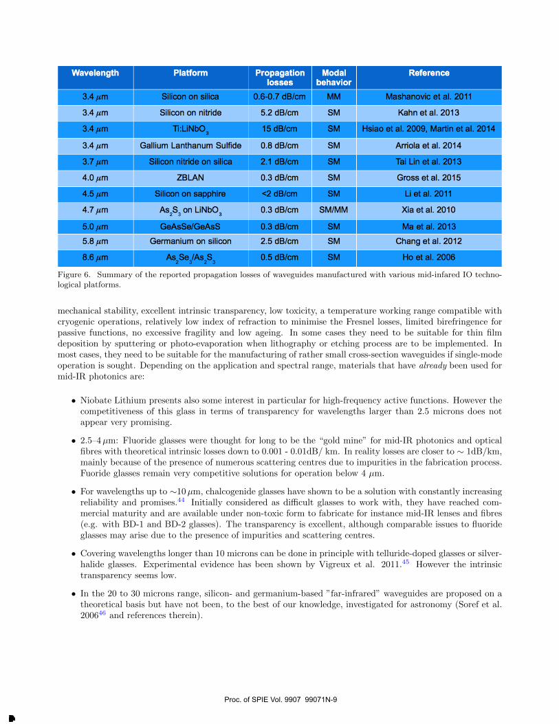
As2 Se3/As2 S3 0.5 dB/cm Ho et al. 2006Mkµr 41=111 Se,Figure 6. Summary of the reported propagation losses of waveguides manufactured with various mid-infared IO techno-logical platforms.
mechanical stability, excellent intrinsic transparency, low toxicity, a temperature working range compatible withcryogenic operations, relatively low index of refraction to minimise the Fresnel losses, limited birefringence forpassive functions, no excessive fragility and low ageing. In some cases they need to be suitable for thin filmdeposition by sputtering or photo-evaporation when lithography or etching process are to be implemented. Inmost cases, they need to be suitable for the manufacturing of rather small cross-section waveguides if single-modeoperation is sought. Depending on the application and spectral range, materials that have already been used formid-IR photonics are:
• Niobate Lithium presents also some interest in particular for high-frequency active functions. However thecompetitiveness of this glass in terms of transparency for wavelengths larger than 2.5 microns does notappear very promising.
• 2.5–4µm: Fluoride glasses were thought for long to be the “gold mine” for mid-IR photonics and opticalfibres with theoretical intrinsic losses down to 0.001 - 0.01dB/ km. In reality losses are closer to ∼ 1dB/km,mainly because of the presence of numerous scattering centres due to impurities in the fabrication process.Fuoride glasses remain very competitive solutions for operation below 4 µm.
• For wavelengths up to ∼10µm, chalcogenide glasses have shown to be a solution with constantly increasingreliability and promises.44 Initially considered as difficult glasses to work with, they have reached com-mercial maturity and are available under non-toxic form to fabricate for instance mid-IR lenses and fibres(e.g. with BD-1 and BD-2 glasses). The transparency is excellent, although comparable issues to fluorideglasses may arise due to the presence of impurities and scattering centres.
• Covering wavelengths longer than 10 microns can be done in principle with telluride-doped glasses or silver-halide glasses. Experimental evidence has been shown by Vigreux et al. 2011.45 However the intrinsictransparency seems low.
• In the 20 to 30 microns range, silicon- and germanium-based ”far-infrared” waveguides are proposed on atheoretical basis but have not been, to the best of our knowledge, investigated for astronomy (Soref et al.200646 and references therein).
Proc. of SPIE Vol. 9907 99071N-9
Downloaded From: http://proceedings.spiedigitallibrary.org/ on 02/26/2017 Terms of Use: http://spiedigitallibrary.org/ss/termsofuse.aspx

Fibers The availability of mid-infrared fibres is a major aspect for the application of mid-IR photonics toastronomical instrumentation. In particular for stellar interferometry a fibered interface between the telescopesand the recombination unit has proven to be a reliable solution to obtain a workable instrument. In general theuse of fibres allows a simplification of the general optical design of the instrument.Significant progress has been achieved in the last years, which led to the industrial maturity of a number of fibresolutions.
• 2–5 microns single-mode Zirconium/Indium fluoride fibres with 0.2 dB/m losses are commercially availableat a competitive price. In the OHANA experiment,47 customized fibers with dB/km losses were fabricated.These fibres appear as the prime solution to cover the K, L and M astronomical bands.
• Chalcogenide commercial fibres up to 9 microns, SM and MM, with different level of dB/m losses. Multi-modes up to 9 microns transparency achieve 0.2 dB/m as well. Very recently, chalcogenide polarisationmaintaining fibres with losses below 0.5 dB/m in the mid-infrared here manufactured.48
• Large-core hollow-core (∼ 1 mm) multimode fibres for 10 microns light transport commercially availablewith 0.1 dB/m and zero dispersion.
• Very low-loss research grade micro-structured fibres with 0.3 to 0.03 dB/m in the L band.49
Mid-infrared integrated optics Planar and 3D IO manufacturing processes suitable for MIR wavelengthsare still in a development phase, and do not currently offer the quality of silica based micro fabrication. InTable 6 a non-exhaustive list of some of the leading results that have been achieved in the L, M and N bands ispresented. Only very recently a few technology platforms achieved sub-dB/cm propagation losses in the mid-IR.But low propagation losses are only one of the requirements for a useful beam combination technology. It will,for example, be essential to realise integrated components that utilise low cross-talk waveguide crossings andhigh quality beam splitters that are ideally achromatic, and that are suitable for efficient coupling to mid-IRtransmitting fibres. Here we highlight a few technologies which have already been considered for applications tostellar interferometry:
• Deposition of thin films followed by chemical etching or lithography. This is a direct extension of pro-cesses successfully used at shorter wavelengths. Single- and multi-mode channel waveguides have beendemonstrated.50,51
• (CW- and ultrafast) laser writing is a recent but promising technique relying on the use of ultrashort laserpulses to directly inscribe three-dimensional waveguide structures inside a transparent glass substrate.Ultrafast laser writing provides the ability to fabricate waveguide crossings with zero cross-talk and beamcombiners based on two- dimensional arrays of coupled waveguides (DBC, see previous section). Two- andthree-telescope structures have been successfully realised for mid-infrared (Labadie et al. 2011,52;33 Arriolaet al. 2014,53 Gross et al. 2015,54 Tepper et al. 201655). Low propagation losses in the order of 0.2 dB/cmhave also been reported in ZBLAN54 and GLS‡. A current limitation of the method is the generation of aremarkable, long-range stress-birefringence (see Diener et al. 201656), which could constrain the realisationof complex 3D photonic structures.
• Ion-exchange and diffusion in glasses. This platform has been very successful in the telecommunicationrange and is at use for the visible in astronomy. It has been applied at longer wavelength in Germanateglasses. Channel waveguides for the mid-IR have been fabricated but only tested at 1.5 µm.57 2-telescopeand 3-telescope Ti:diffusion Niobate Lithium combiners for the L band have been also fabricated with thisplatform.58,59
‡R.R. Thomson, personal communication
Proc. of SPIE Vol. 9907 99071N-10
Downloaded From: http://proceedings.spiedigitallibrary.org/ on 02/26/2017 Terms of Use: http://spiedigitallibrary.org/ss/termsofuse.aspx

5. TECHNOLOGICAL CHALLENGES
Our review of beam combination schemes and fabrication technologies lead us to identify several technologicalchallenges which need to be overcome in order to enable efficient mid-infrared, multi-telescope beam combinationschemes suitable for PFI. We can distinguish two main challenges, which relate to the identification of 1) thebeam combination architecture and, 2) the technological approach.
The first challenge is to select the best beam combination architecture for a given interferometric array. Thesolution to this problem include both array architecture and image reconstruction considerations and couples tothe choice of a suitable technological platform and beam combination scheme for science and fringe tracking. Fromthe respective of the beam combination instrument, the main choice is between a scheme allowing the combinationof all possible baselines or a sub-set of them (e.g. for efficient fringe tracking). The imaging capabilities of thearray could depend from a trade-off between the number of baselines and the SNR of visibility measurements onindividual baselines. The combination of a sub-set of baselines could increase the SNR at the expense of (u,v)plane coverage, thus a compromise has to be found. This choice should be also confronted with the technicalfeasibility of an instrument suitable for the combination of all baselines. As we have seen in Section 2, thescalability of existing beam combination schemes up to Nt = 21 telescopes is not trivial, due to the rapidlyincreasing complexity of fabrication constraints.
A further challenge is to understand which technological approach (bulk optics or photonic) could deliverthe best interferometric performance in terms of sensitivity and precision. Given that the PFI design assumesadaptive optics correction for all telescopes, modal filtering may not be required anymore for the achievement ofhigh precision visibility measurements, as long as high order aberration correction is available.
In this respect, bulk optics combiners could exhibit a better throughput than photonic ones, as the couplingefficiency into a single mode waveguide of the PSF of an aberration-free telescope with circular pupil cannotbe greater than 80%.60 However, very recent advance in micro-structured fibres demonstrated that couplingefficiencies of up to 93.7% could be achieved for beams shaped as ideal PSF of a telescope with circular aperture.61
In the short term, a further advantage of bulk optics solutions for the mid-infrared is that this technology hasalready been tested on sky, as indicated in Fig. 7, where we attempted to the list the Technological ReadinessLevel (TRL62) of V2 beam combiners for stellar interferometry, sorted by operating astronomical band andtechnology is shown.
Even though photonic beam combiners for mid-infrared have reached at most the level of laboratory demon-stration, integrated optics solutions are in a good position to reach soon the level of on-sky test for a moderatenumber of combined telescopes (e.g. Nt = 4), considering the recent successful laboratory test of buildingblocks like 2x2 couplers,54,55 pairwise 3-telescope combiners33 and the reported on-sky test of a two aperturesmid-infrared nuller.63
Nonetheless, current critical points of photonic combiners are the propagation losses and the polarisationstate control, which require further R&D .
In this context, the recent achievement of mid-infrared waveguides with propagation losses in the order of0.2 dB/cm makes ultrafast laser inscription a very promising technological platform for the manufacturing ofmid-infrared IO components, offering also very low production costs as compared to photolithographic processes.A current limitation of the ULI technique is however the low achievable index contrast (from ∼ 10−4 to ∼10−3 depending on the substrate material), which imposes large curvature radii for bended waveguides in orderto suppress radiation losses. This translates in very elongated IO components which could result in beamcombiner lengths of the order of several centimetres, implying both a higher impact of intrinsic losses and moredifficult control of the optical path difference in the manufactured component. Additionally, the long range(∼ 100− 200µm) tensile stresses induced in the substrate by the ULI,56 could make the control of the transverseuniformity and birefringence of complex waveguide circuits rather tricky.
6. CONCLUSIONS AND RECOMMENDATIONS
As outlined in this paper, several competing beam combination and related technological solutions are availableor will soon be available to meet the requirements of the beam combination instruments at the PFI facility, allof them entailing design and/or technological challenges which require further R&D.
Proc. of SPIE Vol. 9907 99071N-11
Downloaded From: http://proceedings.spiedigitallibrary.org/ on 02/26/2017 Terms of Use: http://spiedigitallibrary.org/ss/termsofuse.aspx

Technological Readiness Level of Beam Combiners for Long -baseline Stellar Interferometry
Bands s Integrated optics
Pairwise2T,3T &6T
Multi-axial
3T &4T
Directimaging
Pairwise2T
Multi-axial6T
Directimaging
5T
2D2x2 couplerY- junction
2DpairwiseABCD4T &8T
MMI2T &4T
3D Multi-pairwise axial
3T 8T
3DDBC3T
v /R/]-band
9 (3T)[1-laniff2004]
9[Mourard
2009]
4[Patty2016]
1 9[Garcia2016]
4[Mourard
2014]
1 1 1 1 1 4[Saviauk
2013]
4 (6T)[Ribak2007]
H -band 1 9[Petrov2007]
1 9[Perrin1995]
9[Monnier
2004]
1 9[Berger 2001]
9[Le Bouquin
2011]
4[Rooms2003]
9[Berger2003]
9[Jovanovic
2012]
1
K -band
L -band
M -band
N -band
1 9[Petrov2007]
8[Lopez2006]
8[Lopez2006]
8[Lopez2006]
1
1
1
9[Perrin1995]
1 1 9[Berger 2001]
9[Jocou 2016]
1 1
4[Rodenas
2012]
1 1
5[Mennesson
1999]
4[Tepper 2016]
4[Tepper 2016]
4[Labadie
2011]
4[Kenchington
Goldsmith2016]
9[Leinert2003]
Figure 7. Resuming table of the TRL of various beam combiner technologies for V2 long-baseline stellar interferometrydivided by astronomical bands. TRL 1: concept. TRL 4: lab test. TRL 5: validation on sky. TRL 8: instrumentqualified. TRL 9: instrument operative.
Concerning the fringe tracker beam combination scheme, near-infrared fringe measurement on a selection ofshort/intermediate baselines is required. Some level of redundancy in the combination scheme will be necessaryto limit the impact of failure of fringe tracking on individual baselines. As for the fringe tracker instrument,we believe that near-infrared IO will play a central role in delivering a stable and compact device with highthroughput. As mentioned before, planar IO in near-infrared is already technologically mature to deliver suchbaselines-selective beam combiners. Additionally, ultrafast laser inscription could be used to avoid cross-overs inthe beam combination scheme and thus limit the cross-talk between the combined channels.
Design challenges for the science combiner are mainly related to the identification of the best combinationarchitecture (partial or full baseline coverage) compromising between SNR and (u,v) plane coverage whichcould enable high-fidelity and high-dynamic-range images for the generic PFI target. This first decision willinfluence the final choice of the type of beam combination instrument which will be eventually adopted by PFI.Additionally, the design of a compact and mostly maintenance-free cold optics setup is also an issue to reducethe financial investment and operation costs of the instrument.
As discussed on Section 3, fundamental properties of the beam combiner architecture and related coherenceretrieval algorithm make pairwise ABCD and all-in-one DBC schemes intrinsically more sensitive than a multi-axial all-in-one solution by about 1.5 magnitudes. Because the costs of the telescopes is the main driver of theoverall PFI facility,3 essentially more sensitive schemes are in principle best candidates for the beam combinationinstrument. We warn however that technological/manufacturing issues like e.g. the overall beam combinertransmission, scalability to large arrays of telescopes, conditioning of the V2PM, polarisation and intrinsicchromatic dispersion of the beam combiners can have a more determinant role in setting the sensitivity of thefinal beam combination instrument. In this context, the direction of future developments of photonic technologies
Proc. of SPIE Vol. 9907 99071N-12
Downloaded From: http://proceedings.spiedigitallibrary.org/ on 02/26/2017 Terms of Use: http://spiedigitallibrary.org/ss/termsofuse.aspx

for the mid-infrared will be also a crucial ingredient for the choice of a suitable beam combination scheme andrelative manufacturing technology.
As from the current stand of the technological development, we mention that a full-baseline coverage fora 21 telescopes array would be a very challenging task for any of the discussed beam combination schemes ortechnologies. Partial beam combination schemes by means of replication or temporal multiplexing of intermediatesize beam combiners (e.g. for Nt = 6) could represent a practical solution, at least in the short term.
ACKNOWLEDGMENTS
S.M. and L.L. acknowledge the financial support of the German Ministry of Research and Education (BMBF)under grant ”ALSI - Advanced Laser-writing for Stellar Interferometry”. (05A14SJA).
REFERENCES
[1] Monnier, J. D., Kraus, S., Buscher, D., Berger, J.-P., Haniff, C., Ireland, M., Labadie, L., Lacour, S.,Le Coroller, H., Petrov, R. G., Pott, J.-U., Ridgway, S., Surdej, J., ten Brummelaar, T., Tuthill, P., andvan Belle, G., “Planet formation imager (PFI): introduction and technical considerations,” in [Optical andInfrared Interferometry IV ], Proc. SPIE 9146, 914610 (July 2014).
[2] Kraus, S., Monnier, J., Harries, T., Dong, R., Bate, M., Whitney, B., Zhu, Z., Buscher, D., Berger, J.-P.,Haniff, C., Ireland, M., Labadie, L., Lacour, S., Petrov, R., Ridgway, S., Surdej, J., ten Brummelaar, T.,Tuthill, P., and van Belle, G., “The science case for the Planet Formation Imager (PFI),” in [Optical andInfrared Interferometry IV ], Proc. SPIE 9146, 914611 (July 2014).
[3] Ireland, M. J., Monnier, J. D., Kraus, S., Isella, A., Minardi, S., Petrov, R., ten Brummelaar, T., Young, J.,Vasisht, G., Mozurkewich, D., and Rinehard, S., “Status of the Planet Formation Imager (PFI) concept,”Proc. SPIE 9907, 9907–55 (2016).
[4] Ireland, M. J. and Monnier, J. D., “A dispersed heterodyne design for the planet formation imager,” in[Optical and Infrared Interferometry IV ], Proc. SPIE 9146, 914612 (July 2014).
[5] Tatulli, E., Millour, F., Chelli, A., Duvert, G., Acke, B., Utrera, O. H., Hofmann, K.-H., Kraus, S., Malbet,F., Mege, P., Petrov, R., Vannier, M., Zins, G., Antonelli, P., Beckmann, U., Bresson, Y., Dugue, M.,Gennari, S., Gluck, L., Kern, P., Lagarde, S., Coarer, E. L., Lisi, F., Perraut, K., Puget, P., Rantakyro,F., Robbe-Dubois, S., Roussel, A., Weigelt, G., Accardo, M., Agabi, K., Altariba, E., Arezki, B., Aristidi,E., Baffa, C., Behrend, J., Blocker, T., Bonhomme, S., Busoni, S., Cassaing, F., Clausse, J.-M., Colin, J.,Connot, C., Delboulbe, A., de Souza, A. D., Driebe, T., Feautrier, P., Ferruzzi, D., Forveille, T., Fossat,E., Foy, R., Fraix-Burnet, D., Gallardo, A., Giani, E., Gil, C., Glentzlin, A., Heiden, M., Heininger, M.,Kamm, D., Kiekebusch, M., Contel, D. L., Contel, J.-M. L., Lesourd, T., Lopez, B., Lopez, M., Magnard,Y., Marconi, A., Mars, G., Martinot-Lagarde, G., Mathias, P., Monin, J.-L., Mouillet, D., Mourard, D.,Nussbaum, E., Ohnaka, K., Pacheco, J., Perrier, C., Rabbia, Y., Rebattu, S., Reynaud, F., Richichi, A.,Robini, A., Sacchettini, M., Schertl, D., Scholler, M., Solscheid, W., Spang, A., Stee, P., Stefanini, P.,Tallon, M., Tallon-Bosc, I., Tasso, D., Testi, L., Vakili, F., von der Luhe, O., Valtier, J.-C., and Ventura, N.,“Interferometric data reduction with amber/vlti. principle, estimators and illustration,” A&A 464, 29–42(2007).
[6] Le Bouquin, J.-B. J., Berger, J.-P., Labeye, P. R., Tatulli, E., Malbet, F., Rousselet-Perraut, K., and Kern,P. Y., “Comparison of integrated optics concepts for a near-infrared multi-telescope beam combiner,” in[New Frontiers in Stellar Interferometry ], Traub, W. A., ed., Proc. SPIE 5491, 1362 (Oct. 2004).
[7] Ribak, E. N., Gai, M., Loreggia, D., and Lipson, S. G., “Simple beam combination for stellar interferometry,”Opt. Lett. 32, 1075–1077 (May 2007).
[8] Petrov, R. G., Malbet, F., Weigelt, G., Antonelli, P., Beckmann, U., Bresson, Y., Chelli, A., Dugue, M.,Duvert, G., Gennari, S., Gluck, L., Kern, P., Lagarde, S., Le Coarer, E., Lisi, F., Millour, F., Perraut, K.,Puget, P., Rantakyro, F., Robbe-Dubois, S., Roussel, A., Salinari, P., Tatulli, E., Zins, G., Accardo, M.,Acke, B., Agabi, K., Altariba, E., Arezki, B., Aristidi, E., Baffa, C., Behrend, J., Blocker, T., Bonhomme,S., Busoni, S., Cassaing, F., Clausse, J.-M., Colin, J., Connot, C., Delboulbe, A., Domiciano de Souza,A., Driebe, T., Feautrier, P., Ferruzzi, D., Forveille, T., Fossat, E., Foy, R., Fraix-Burnet, D., Gallardo,
Proc. of SPIE Vol. 9907 99071N-13
Downloaded From: http://proceedings.spiedigitallibrary.org/ on 02/26/2017 Terms of Use: http://spiedigitallibrary.org/ss/termsofuse.aspx

A., Giani, E., Gil, C., Glentzlin, A., Heiden, M., Heininger, M., Hernandez Utrera, O., Hofmann, K.-H.,Kamm, D., Kiekebusch, M., Kraus, S., Le Contel, D., Le Contel, J.-M., Lesourd, T., Lopez, B., Lopez, M.,Magnard, Y., Marconi, A., Mars, G., Martinot-Lagarde, G., Mathias, P., Mege, P., Monin, J.-L., Mouillet,D., Mourard, D., Nussbaum, E., Ohnaka, K., Pacheco, J., Perrier, C., Rabbia, Y., Rebattu, S., Reynaud,F., Richichi, A., Robini, A., Sacchettini, M., Schertl, D., Scholler, M., Solscheid, W., Spang, A., Stee, P.,Stefanini, P., Tallon, M., Tallon-Bosc, I., Tasso, D., Testi, L., Vakili, F., von der Luhe, O., Valtier, J.-C.,Vannier, M., and Ventura, N., “AMBER, the near-infrared spectro-interferometric three-telescope VLTIinstrument,” A&A 464, 1–12 (Mar. 2007).
[9] Lopez, B., Wolf, S., Lagarde, S., Abraham, P., Antonelli, P., Augereau, J. C., Beckman, U., Behrend, J.,Berruyer, N., Bresson, Y., Chesneau, O., Clausse, J. M., Connot, C., Demyk, K., Danchi, W. C., Dugue,M., Flament, S., Glazenborg, A., Graser, U., Henning, T., Hofmann, K. H., Heininger, M., Hugues, Y.,Jaffe, W., Jankov, S., Kraus, S., Laun, W., Leinert, C., Linz, H., Mathias, P., Meisenheimer, K., Matter,A., Menut, J. L., Millour, F., Neumann, U., Nussbaum, E., Niedzielski, A., Mosonic, L., Petrov, R., Ratzka,T., Robbe-Dubois, S., Roussel, A., Schertl, D., Schmider, F.-X., Stecklum, B., Thiebaut, E., Vakili, F.,Wagner, K., Waters, L. B. F. M., and Weigelt, G., “MATISSE: perspective of imaging in the mid-infraredat the VLTI,” in [Society of Photo-Optical Instrumentation Engineers (SPIE) Conference Series ], Proc.SPIE 6268, 0 (June 2006).
[10] Bedding, T. R., Robertson, J. G., and Marson, R. G., “An optical interferometer with wavelength disper-sion.,” A&A 290 (Oct. 1994).
[11] Haniff, C. A., Baldwin, J. E., Basden, A. G., Bharmal, N. A., Boysen, R. C., Buscher, D. F., Keen, J. W.,Mackay, C. D., O’Donovan, B., Seneta, E. B., Thorsteinsson, H., Thureau, N. D., Tubbs, R. N., Warner,P. J., Wilson, D. M., and Young, J. S., “COAST: recent technology and developments,” in [New Frontiersin Stellar Interferometry ], Traub, W. A., ed., Proc. SPIE 5491, 511 (Oct. 2004).
[12] Armstrong, J. T., Mozurkewich, D., Rickard, L. J., Hutter, D. J., Benson, J. A., Bowers, P. F., Elias, II,N. M., Hummel, C. A., Johnston, K. J., Buscher, D. F., Clark, III, J. H., Ha, L., Ling, L.-C., White, N. M.,and Simon, R. S., “The Navy Prototype Optical Interferometer,” Astrph. J. 496, 550–571 (Mar. 1998).
[13] Baron, F., Buscher, D. F., Coyne, J., Creech-Eakman, M. J., Haniff, C. A., Jurgenson, C. A., and Young,J. S., “Beam combiner studies for the Magdalena Ridge Observatory Interferometer,” in [Society of Photo-Optical Instrumentation Engineers (SPIE) Conference Series ], Proc. SPIE 6268, 62681R (June 2006).
[14] Buscher, D., Baron, F., Coyne, J., Haniff, C., and Young, J., “BOBCAT - A Photon-efficient Multi-wayCombiner for the VLTI,” in [The Power of Optical/IR Interferometry: Recent Scientific Results and 2ndGeneration ], Richichi, A., Delplancke, F., Paresce, F., and Chelli, A., eds., 407 (2008).
[15] Labeyrie, A., “Resolved imaging of extra-solar planets with future 10-100km optical interferometric arrays.,”A&A Suppl. Ser. 118, 517–524 (Sept. 1996).
[16] Lardiere, O., Martinache, F., and Patru, F., “Direct imaging with highly diluted apertures - I. Field-of-viewlimitations,” Month. Not. R. Astr. Soc. 375, 977–988 (Mar. 2007).
[17] Patru, F., Mourard, D., Lardiere, O., and Lagarde, S., “Optimization of the direct imaging properties of anoptical-fibred long baseline interferometer,” Month. Not. R. Astr. Soc. 376, 1047–1053 (Apr. 2007).
[18] Patru, F., Mourard, D., Clausse, J.-M., Delage, L., Reynaud, F., Dubreuil, M., Bonneau, D., Bosio, S.,Bresson, Y., Hugues, Y., Lardiere, O., and Roussel, A., “First results from a laboratory hypertelescopeusing single-mode fibers,” A&A 477, 345–352 (Jan. 2008).
[19] Golay, M. J. E., “Point arrays having compact, nonredundant autocorrelations,” J. Opt. Soc. Am. 61,272–273 (Feb 1971).
[20] Coude du Foresto, V., Ridgway, S., and Mariotti, J.-M., “Deriving object visibilities from interferogramsobtained with a fiber stellar interferometer,” A&A Supp. Ser. 121 (Feb. 1997).
[21] Perrin, G., Coude du Foresto, V., Ridgway, S. T., Mariotti, J.-M., and Benson, J. A., “Fibered recombinationunit for the Infrared-Optical Telescope Array,” in [Fiber Optics in Astronomical Applications ], Barden, S. C.,ed., Proc. SPIE 2476, 120–128 (June 1995).
[22] Monnier, J. D., Berger, J.-P., Millan-Gabet, R., and ten Brummelaar, T. A., “The michigan infraredcombiner (mirc): Ir imaging with the chara array,” in [Proc. SPIE ], 5491, 1370–1379 (2004).
Proc. of SPIE Vol. 9907 99071N-14
Downloaded From: http://proceedings.spiedigitallibrary.org/ on 02/26/2017 Terms of Use: http://spiedigitallibrary.org/ss/termsofuse.aspx

[23] Mennesson, B., Mariotti, J. M., Coude du Foresto, V., Perrin, G., Ridgway, S., Ruilier, C., Traub, W. A.,Carleton, N. P., Lacasse, M. G., and Maze, G., “Thermal infrared stellar interferometry using single-modeguided optics: first results with the TISIS experiment on IOTA,” A&A 346, 181–189 (June 1999).
[24] Huby, E., Perrin, G., Marchis, F., Lacour, S., Kotani, T., Duchene, G., Choquet, E., Gates, E. L., Woillez,J. M., Lai, O., Fedou, P., Collin, C., Chapron, F., Arslanyan, V., and Burns, K. J., “First, a fibered aperturemasking instrument i. first on-sky test results,” A&A 541, A55 (2012).
[25] Mozurkewich, D. and Traore, A., “Beam combination with a large number of apertures,” in [Optical andInfrared Interferometry II ], Proc. SPIE 7734, 773443 (July 2010).
[26] Lacour, S., Imagerie des etoiles evoluees par interferometrie. Rearrangement de pupille, PhD thesis, PhDThesis, 2010 (2010).
[27] Jovanovic, N., Tuthill, P. G., Norris, B., Gross, S., Stewart, P., Charles, N., Lacour, S., Ams, M., Lawrence,J. S., Lehmann, A., Niel, C., Robertson, J. G., Marshall, G. D., Ireland, M., Fuerbach, A., and With-ford, M. J., “Starlight demonstration of the Dragonfly instrument: an integrated photonic pupil-remappinginterferometer for high-contrast imaging,” Month. Not. R. Astr. Soc. 427, 806–815 (Nov. 2012).
[28] Malbet, F., Kern, P., Schanen-Duport, I., Berger, J.-P., Rousselet-Perraut, K., and Benech, P., “Integratedoptics for astronomical interferometry,” A&A Suppl. Ser. 138, 135–145 (1999).
[29] Berger, J. P., Haguenauer, P., Kern, P., Perraut, K., Malbet, F., Schanen, I., Severi, M., Millan-Gabet,R., and Traub, W., “Integrated optics for astronomical interferometry. IV. First measurements of stars,”A&A 376, L31–L34 (Sept. 2001).
[30] Berger, J.-P., Hagenauer, P., Kern, P., Perraut, K., Malbet, F., Gluck, S., Lagny, L., Schanen, I., Laurent,E., Delboulbe, A., Magnard, Y., Tatulli, E., Traub, W., Carleton, N., Millan-Gabet, R., Monnier, J. D.,and Pedretti, E., “An integrated-optics 3-way beam combiner for iota,” in [Proc. SPIE ], 4838, 1099–1106(2003).
[31] Bouquin, J.-B. L., Berger, J.-P., Lazareff, B., Zins, G., Haguenauer, P., Jocou, L., Kern, P., Millan-Gabet,R., Traub, W., Absil, O., Augereau, J.-C., Benisty, M., Blind, N., Bonfils, X., Bourget, P., Delboulbe, A.,Feautrier, P., M.Germain, Gitton, P., Gillier, D., Kiekebusch, M., Kluska, J., Knudstrup, J., Labeye, P.,Lizon, J.-L., Monin, J.-L., Magnard, Y., Malbet, F., Maurel, D., Menard, F., Micallef, M., Michaud, L.,Montagnier, G., Morel, S., Moulin, T., Perraut, K., Popovic, D., Rabou, P., Rochat, S., Rojas, C., Roussel,F., Roux, A., Stadler, E., Stefl, S., Tatulli, E., and Ventura, N., “Pionier: a 4-telescope visitor instrumentat vlti,” A&A 535, A67 (2011).
[32] Berger, J.-P., Benech, P., Schanen-Duport, I., Maury, G., Malbet, F., and Reynaud, F., “Combining up toeight telescope beams in a single chip,” in [Proc. SPIE ], 4006, 986–995 (2000).
[33] Rodenas, A., Martin, G., Arzeki, B., Psaila, N. D., Jose, G., Jha, A., Labadie, L., Kern, P., Kar, A. K., andThomson, R. R., “Three-dimensional mid-infrared photonic circuits in chalcogenide glass,” Opt. Lett. 37,392–394 (2012).
[34] Nolte, S., Will, M., Burghoff, J., and Tunnermann, A., “Ultrafast laser processing: new options for three-dimensional photonic structures,” J. Mod. Opt. 51, 2533–2542 (2004).
[35] Thomson, R. R., Kar, A. K., and Allington-Smith, J., “Ultrafast laser inscription: an enabling technologyfor astrophotonics,” Optics Express 17, 1963–1969 (Feb. 2009).
[36] Rooms, F., Morand, A., Schanen-Duport, I., Broquin, J.-E., Haguenauer, P., Berger, J.-P., Martin, M., andBenyattou, T., “New concept for combining three telescopes with integrated optics: multi-mode interfer-ences (MMI),” in [Interferometry for Optical Astronomy II ], Traub, W. A., ed., Society of Photo-OpticalInstrumentation Engineers (SPIE) Conference Series 4838, 1359–1369 (Feb. 2003).
[37] Minardi, S. and Pertsch, T., “Interferometric beam combination with discrete optics,” Opt. Lett. 35, 3009–3011 (2010).
[38] Minardi, S., Dreisow, F., Grafe, M., Nolte, S., and Pertsch, T., “Three-dimensional photonic component formultichannel coherence measurements,” Opt. Lett. 37, 3030–3032 (2012).
[39] Saviauk, A., Minardi, S., Dreisow, F., Nolte, S., and Pertsch, T., “3D-integrated optics component forastronomical spectro-interferometry,” Appl. Opt. 52, 4556 (July 2013).
[40] Errmann, R. and Minardi, S., “6- and 8-telescope discrete beam combiners,” Proc. SPIE 9907, 9907–112(2016).
Proc. of SPIE Vol. 9907 99071N-15
Downloaded From: http://proceedings.spiedigitallibrary.org/ on 02/26/2017 Terms of Use: http://spiedigitallibrary.org/ss/termsofuse.aspx

[41] Minardi, S., Labadie, L., and Lacour, S., “Discrete optical multi-aperture combiner: instrumental concept,”in [Optical and Infrared Interferometry III ], Proc. SPIE 8445, 844526 (July 2012).
[42] Glindemann, A., [Principles of Stellar Interferometry ], Springer (2011).
[43] Benisty, M., Berger, J.-P., Jocou, L., Labeye, P., Malbet, F., Perraut, K., and Kern, P., “An integratedoptics beam combiner for the second generation vlti instruments,” A&A 498, 601–613 (2009).
[44] Eggleton, B. J., Luther-Davies, B., and Richardson, K., “Chalcogenide photonics,” Nature Photonics 5,141–148 (Mar. 2011).
[45] Vigreux, C., Barthelemy, E., Bastard, L., Broquin, J.-E., Barillot, M., Menard, S., Parent, G., and Pradel,A., “Realization of single-mode telluride rib waveguides for mid-IR applications between 10 and 20 µm,”Opt. Lett. 36, 2922–2924 (Aug. 2011).
[46] Soref, R. A., Emelett, S. J., and Buchwald, W. R., “Silicon waveguided components for the long-waveinfrared region,” Journal of Optics A: Pure and Applied Optics 8, 840–848 (Oct. 2006).
[47] Kotani, T., Perrin, G., Vergnole, S., Woillez, J., and Guerin, J., “Characterization of fluoride fibers for theOptical Hawaiian Array for Nanoradian Astronomy project,” Appl. Opt. 44, 5029–5035 (Aug. 2005).
[48] Caillaud, C., Gilles, C., L.Provino, Brilland, L., Jouan, T., Ferre, S., Carras, M., Brun, M., Mechin, D.,Adam, J.-L., and Troles, J., “Highly birefringent chalcogenide optical fiber for polarization-maintaining inthe 3-8.5 µm mid-ir window,” Opt. Expr. 24, 7977–7986 (Apr 2016).
[49] Yu, F., Wadsworth, W. J., and Knight, J. C., “Low loss silica hollow core fibers for 3-4 µm spectral region,”Opt. Expr. 20, 11153 (May 2012).
[50] Xia, X., Chen, Q., Tsay, C., Arnold, C. B., and Madsen, C. K., “Low-loss chalcogenide waveguides onlithium niobate for the mid-infrared,” Optics Letters 35, 3228 (Sept. 2010).
[51] Ma, P., Choi, D.-Y., Yu, Y., Gai, X., Yang, Z., Debbarma, S., Madden, S., and Luther-Davies, B., “Low-losschalcogenide waveguides for chemical sensing in the mid-infrared,” Opt. Expr. 21, 29927 (Dec. 2013).
[52] Labadie, L., Martın, G., Anheier, N. C., Arezki, B., Qiao, H. A., Bernacki, B., and Kern, P., “First fringeswith an integrated-optics beam combiner at 10 µm. A new step towards instrument miniaturization formid-infrared interferometry,” A&A 531, A48 (July 2011).
[53] Arriola, A., Mukherjee, S., Choudhury, D., Labadie, L., and Thomson, R. R., “Ultrafast laser inscriptionof mid-IR directional couplers for stellar interferometry,” Opt. Lett. 39, 4820 (Aug. 2014).
[54] Gross, S., Jovanovic, N., Sharp, A., Ireland, M., Lawrence, J., and Withford, M. J., “Low loss mid-infraredZBLAN waveguides for future astronomical applications,” Opt. Expr. 23, 7946 (Mar. 2015).
[55] Tepper, J., Diener, R., Labadie, L., Minardi, S., Muthusubramanian, B., Pott, J.-U., Nolte, S., Arriola,A., Madden, G., Choudhury, D., MacPherson, W. N., and Thomson, R. R., “All-in-one 4-telescope beamcombination with a zig-zag array of waveguides,” Proc. SPIE 9907, 9907–110 (2016).
[56] Diener, R., Minardi, S., Tepper, J., nolte, S., and L., L., “All-in-one 4-telescope beam combination with azig-zag array of waveguides,” Proc. SPIE 9907, 9907–110 (2016).
[57] Barillot, M., Barthelemy, E., Broquin, J.-E., Frayret, J., Grelin, J., Hawkins, G., Kirschner, V., Parent, G.,Pradel, A., Rossi, E., Vigreux, C., Zhang, S., and Zhang, X., “Integrated optics for nulling interferometryin the thermal infrared,” in [Optical and Infrared Interferometry ], Proc. SPIE 7013, 701314 (July 2008).
[58] Hsiao, H.-K., Winick, K. A., Monnier, J. D., and Berger, J.-P., “An infrared integrated optic astronomicalbeam combiner for stellar interferometry at 3-4 µm,” Opt. Expr. 17, 18489–18500 (Oct. 2009).
[59] Martin, G., Heidmann, S., Thomas, F., de Mengin, M., Jocou, L., Ulliac, G., Courjal, N., Morand, A.,Benech, P., and le Coarer, E. P., “Lithium Niobate active beam combiners: results of on-chip fringe lock-ing, fringe scanning and high contrast integrated optics interferometry and spectrometry,” in [Optical andInfrared Interferometry IV ], Proc. SPIE 9146, 91462I (July 2014).
[60] Shaklan, S. and Roddier, F., “Single-mode fiber optics in long-baseline interferometer,” Appl. Opt. 26,2159–2163 (1987).
[61] Gris-Sanchez, I., Ras, D. V., and Birks, T. A., “The airy fiber: an optical fiber that guides light diffractedby a circular aperture,” Optica 3, 270–276 (Mar 2016).
[62] NASA, “Definition of Technology Readiness Level.” https://esto.nasa.gov/files/trl_definitions.
pdf. (Accessed: 26 June 2016).
Proc. of SPIE Vol. 9907 99071N-16
Downloaded From: http://proceedings.spiedigitallibrary.org/ on 02/26/2017 Terms of Use: http://spiedigitallibrary.org/ss/termsofuse.aspx

[63] Norris, B. R., Cvetojevic, N., Gross, S., Arriola Martiarena, A., Tuthill, P. G., Lawrence, J. S., Withford,M. J., Richards, S. N., Goodwin, M., and Zheng, J. R., “An integrated-optic single-mode photonic nuller:development and on-sky testing,” Proc. SPIE 9907, 9907–119 (2016).
Proc. of SPIE Vol. 9907 99071N-17
Downloaded From: http://proceedings.spiedigitallibrary.org/ on 02/26/2017 Terms of Use: http://spiedigitallibrary.org/ss/termsofuse.aspx
Related Documents


