US Particle Accelerator School, SRF Practices and Hands-on Measurements, Jan. 19-23, 2015 Bead-pulling Measurement Principle and Technique Used for the SRF Cavities at JLab Instructor: Haipeng Wang, [email protected], (804)-836-0539 Assistant: Jiquan Guo, [email protected], (650)-804-9662 Lab Place: TL-1009-1011 (RF Structure Lab) (757)-269-6473 -6475 Next Monday-Thursday, Jan. 26-30 Thomas Jefferson Lab, Newport News, VA 23606 January 21, 2015

Welcome message from author
This document is posted to help you gain knowledge. Please leave a comment to let me know what you think about it! Share it to your friends and learn new things together.
Transcript
US Particle Accelerator School, SRF Practices and Hands-on Measurements, Jan. 19-23, 2015
Bead-pulling Measurement Principle and Technique Used for the SRF Cavities at JLab
Instructor: Haipeng Wang, [email protected], (804)-836-0539
Assistant: Jiquan Guo, [email protected], (650)-804-9662
Lab Place: TL-1009-1011 (RF Structure Lab) (757)-269-6473 -6475
Next Monday-Thursday, Jan. 26-30
Thomas Jefferson Lab, Newport News, VA 23606
January 21, 2015

US Particle Accelerator School, SRF Practices and Hands-on Measurements, Jan. 19-23, 2015
Bead-pulling Measurement Curriculum Bead-pull measurement • Using a non-conducting wire (like a fishing line) to pull a bead (made of dielectric/metallic
or ferromagnetic material) through a RF cavity to measure the electromagnetic fields distribution on resonance inside
Syllabus • Principle of bead-pull
1. Perturbation theory 2. Form factors of metallic and dielectric ellipsoids 3. Calculations of EM field distribution and R/Q from SuperFish and bead-pulling data
• Measurement techniques 1. Methods and tricks 2. Bead-pull setup, bead selection, S parameters by VNA, 3. Comparison to simulation and error analysis 4. External Q measurement by S11 and S21 formula for FPC and FP setup
• Advanced topics 1. Multiple modes, HOMs bead-pull 2. Magnetic field extrapolation
• Homework given here is due on next Monday in Q&A session (01/26)
US Particle Accelerator School, SRF Practices and Hands-on Measurements, Jan. 19-23, 2015
Perturbation of a Resonator – Material Medium Change
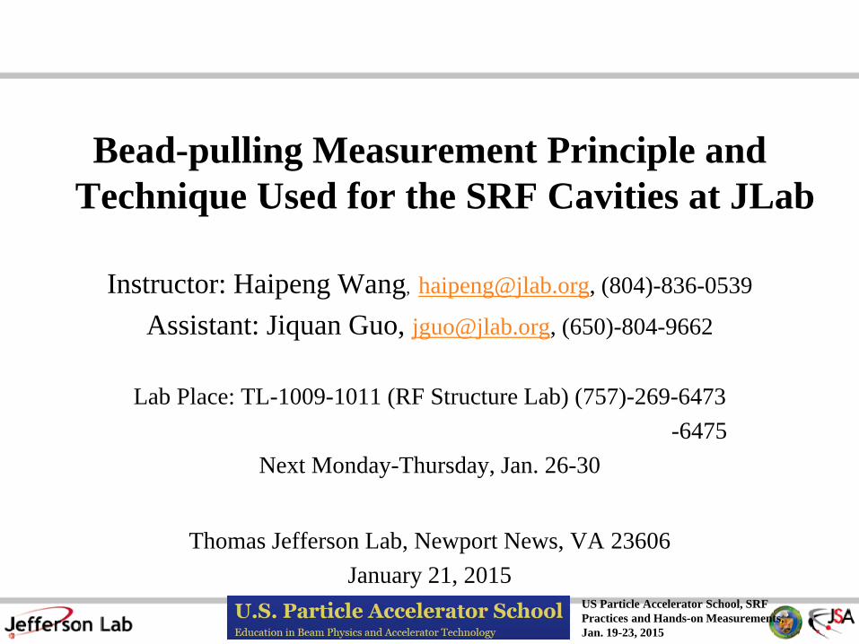
Cavity performance like resonance frequency f or quality factor Q can be changed by introducing a small perturbation to the resonance EM fields.
Bead-pull measurement involves two types of perturbations: 1. Small material perturbation, like a small dielectric bead enters a large
volume of cavity. Although permittivity change from air to bead material could be large, the bead volume is small.

US Particle Accelerator School, SRF Practices and Hands-on Measurements, Jan. 19-23, 2015
Perturbation of a Resonator – Cavity Shape Change
2. Small cavity volume change, like a small metallic bead enters a large volume of cavity. Although cavity volume change may or my not be on the wall, the bead “repelling” volume is small.
3. Bead material could be either dielectric εr>1, or metallic σ→∞, or low σ ferromagnetic µr>1. A lossy material can be also used for the bead-pull as long as the cavity loaded QL is taking account into the frequency f change

US Particle Accelerator School, SRF Practices and Hands-on Measurements, Jan. 19-23, 2015
Perturbation of a Resonator – Frequency Change
Before the perturbation, the EM field inside of cavity can be described as:
𝑬𝑬 = 𝑬𝑬𝟎𝟎𝒆𝒆𝒋𝒋𝝎𝝎𝝎𝝎 H= 𝑯𝑯𝟎𝟎𝒆𝒆𝒋𝒋𝝎𝝎𝝎𝝎 (1)
Here E0 and H0 are function of position before perturbation. After the perturbation, the field changes are E1 and H1, frequency change is ∆ω
𝑬𝑬′ = 𝑬𝑬𝟎𝟎 + 𝑬𝑬𝟏𝟏 𝒆𝒆𝒋𝒋 𝝎𝝎+∆𝝎𝝎 𝝎𝝎 𝑯𝑯′ = 𝑯𝑯𝟎𝟎 + 𝑯𝑯𝟏𝟏 𝒆𝒆𝒋𝒋 𝝎𝝎+∆𝝎𝝎 𝝎𝝎
Here E1<<E0 , and H1<<H0 are result of small perturbation or small volume
(2)
1st and 2nd Maxwell’s equation:
𝛻𝛻 × 𝑬𝑬 = −𝜕𝜕𝑩𝑩𝜕𝜕𝜕𝜕
(3)
𝛻𝛻 × 𝑯𝑯 =𝜕𝜕𝑫𝑫𝜕𝜕𝜕𝜕
(4)

US Particle Accelerator School, SRF Practices and Hands-on Measurements, Jan. 19-23, 2015
Perturbation of a Resonator – Frequency Change
Apply (1) (2) to (3) :
𝛁𝛁 × 𝑬𝑬𝟎𝟎 = −𝒋𝒋𝝎𝝎𝑩𝑩𝟎𝟎 (5)
𝛁𝛁 × 𝑬𝑬𝟎𝟎 + 𝑬𝑬𝟏𝟏 = −𝒋𝒋 𝝎𝝎 + ∆𝝎𝝎 𝑩𝑩𝟎𝟎 + 𝑩𝑩𝟏𝟏 (6)
Apply (6)-(5):
𝛁𝛁 × 𝑬𝑬𝟏𝟏 = −𝒋𝒋𝝎𝝎𝑩𝑩𝟏𝟏 − 𝒋𝒋∆𝝎𝝎 𝑩𝑩𝟎𝟎 + 𝑩𝑩𝟏𝟏 (7) Similarly apply (1) (2) to (4):
𝛁𝛁 × 𝑯𝑯𝟎𝟎 = 𝒋𝒋𝝎𝝎𝑫𝑫𝟎𝟎 (8)
𝛁𝛁 × 𝑯𝑯𝟎𝟎 + 𝑯𝑯𝟏𝟏 = 𝒋𝒋 𝝎𝝎 + ∆𝝎𝝎 𝑫𝑫𝟎𝟎 + 𝑫𝑫𝟏𝟏 (9) Apply (9)-(8):
𝛁𝛁 × 𝑯𝑯𝟏𝟏 = 𝒋𝒋 𝝎𝝎𝑫𝑫𝟏𝟏 + ∆𝝎𝝎 𝑫𝑫𝟎𝟎 + 𝑫𝑫𝟏𝟏 (10)

US Particle Accelerator School, SRF Practices and Hands-on Measurements, Jan. 19-23, 2015
Perturbation of a Resonator – Frequency Change
H0* conjugated H0 dot times (7):
(11)
(12)
𝑯𝑯𝟎𝟎∗ ∙ 𝛁𝛁 × 𝑬𝑬𝟏𝟏 = −𝒋𝒋 𝝎𝝎𝑯𝑯𝟎𝟎
∗ ∙ 𝑩𝑩𝟏𝟏 + ∆𝝎𝝎𝑯𝑯𝟎𝟎∗ ∙ 𝑩𝑩𝟎𝟎 + 𝑩𝑩𝟏𝟏
E0* conjugated E0 dot times (10):
𝑬𝑬𝟎𝟎∗ ∙ 𝛁𝛁 × 𝑯𝑯𝟏𝟏 = 𝒋𝒋 𝝎𝝎𝑬𝑬𝟎𝟎∗ ∙ 𝑫𝑫𝟏𝟏 + ∆𝝎𝝎𝑬𝑬𝟎𝟎∗ ∙ 𝑫𝑫𝟎𝟎 + 𝑫𝑫𝟏𝟏
Apply (12)-(11):
𝑬𝑬𝟎𝟎∗ ∙ 𝛁𝛁 × 𝑯𝑯𝟏𝟏−𝑯𝑯𝟎𝟎∗ ∙ 𝛁𝛁 × 𝑬𝑬𝟏𝟏
= 𝒋𝒋𝝎𝝎 𝑬𝑬𝟎𝟎∗ ∙ 𝑫𝑫𝟏𝟏 + 𝑯𝑯𝟎𝟎∗ ∙ 𝑩𝑩𝟏𝟏
+ 𝒋𝒋∆𝝎𝝎 𝑬𝑬𝟎𝟎∗ ∙ 𝑫𝑫𝟎𝟎 + 𝑯𝑯𝟎𝟎∗ ∙ 𝑩𝑩𝟎𝟎 + 𝑬𝑬𝟎𝟎∗ ∙ 𝑫𝑫𝟏𝟏 + 𝑯𝑯𝟎𝟎
∗ ∙ 𝑩𝑩𝟏𝟏 (13)
Use vector differential operation and (5) and (8) relationship:
𝛁𝛁 ∙ 𝑬𝑬𝟎𝟎∗ × 𝑯𝑯𝟏𝟏 −𝑯𝑯𝟎𝟎∗ × 𝑬𝑬𝟏𝟏 ≡ 𝑯𝑯𝟏𝟏 ∙ 𝛁𝛁 × 𝑬𝑬𝟎𝟎∗ − 𝑬𝑬𝟎𝟎
∗ ∙ 𝛁𝛁 × 𝑯𝑯𝟏𝟏 + 𝑬𝑬𝟏𝟏 ∙ 𝛁𝛁 × 𝑯𝑯𝟎𝟎∗ +
𝑯𝑯𝟎𝟎∗ ∙ 𝛁𝛁 × 𝑬𝑬𝟏𝟏= 𝒋𝒋𝝎𝝎𝑯𝑯𝟏𝟏 ∙ 𝑩𝑩𝟎𝟎
∗ + 𝒋𝒋𝝎𝝎𝑬𝑬𝟏𝟏 ∙ 𝑫𝑫𝟎𝟎∗ − 𝑬𝑬𝟎𝟎∗ ∙ 𝛁𝛁 × 𝑯𝑯𝟏𝟏 − 𝑯𝑯𝟎𝟎
∗ ∙ 𝛁𝛁 × 𝑬𝑬𝟏𝟏

US Particle Accelerator School, SRF Practices and Hands-on Measurements, Jan. 19-23, 2015
Perturbation of a Resonator – Frequency Change
This leads to:
𝑬𝑬𝟎𝟎∗ ∙ 𝛁𝛁 × 𝑯𝑯𝟏𝟏 − 𝑯𝑯𝟎𝟎∗ ∙ 𝛁𝛁 × 𝑬𝑬𝟏𝟏
= 𝒋𝒋𝝎𝝎 𝑯𝑯𝟏𝟏 ∙ 𝑩𝑩𝟎𝟎∗ + 𝑬𝑬𝟏𝟏 ∙ 𝑫𝑫𝟎𝟎
∗ − 𝛁𝛁 ∙ 𝑬𝑬𝟎𝟎∗ × 𝑯𝑯𝟏𝟏 − 𝑯𝑯𝟎𝟎∗ × 𝑬𝑬𝟏𝟏 (14)
Apply (14) to (13):
𝒋𝒋𝝎𝝎 𝑯𝑯𝟏𝟏 ∙ 𝑩𝑩𝟎𝟎∗ + 𝑬𝑬𝟏𝟏 ∙ 𝑫𝑫𝟎𝟎
∗ − 𝛁𝛁 ∙ 𝑬𝑬𝟎𝟎∗ × 𝑯𝑯𝟏𝟏 − 𝑯𝑯𝟎𝟎∗ × 𝑬𝑬𝟏𝟏
= 𝒋𝒋𝝎𝝎 𝑬𝑬𝟎𝟎∗ ∙ 𝑫𝑫𝟏𝟏 + 𝑯𝑯𝟎𝟎∗ ∙ 𝑩𝑩𝟏𝟏
+ 𝒋𝒋∆𝝎𝝎 𝑬𝑬𝟎𝟎∗ ∙ 𝑫𝑫𝟎𝟎 + 𝑯𝑯𝟎𝟎∗ ∙ 𝑩𝑩𝟎𝟎 + 𝑬𝑬𝟎𝟎∗ ∙ 𝑫𝑫𝟏𝟏 + 𝑯𝑯𝟎𝟎
∗ ∙ 𝑩𝑩𝟏𝟏 (15)
Integration over whole volume of cavity V0 on both sides of (15) :
𝒋𝒋∆𝝎𝝎 𝑬𝑬𝟎𝟎∗ ∙ 𝑫𝑫𝟎𝟎 + 𝑯𝑯𝟎𝟎∗ ∙ 𝑩𝑩𝟎𝟎 + 𝑬𝑬𝟎𝟎∗ ∙ 𝑫𝑫𝟏𝟏 + 𝑯𝑯𝟎𝟎
∗ ∙ 𝑩𝑩𝟏𝟏𝑽𝑽𝟎𝟎
𝑑𝑑𝑑𝑑
= 𝒋𝒋𝝎𝝎 𝑬𝑬𝟏𝟏 ∙ 𝑫𝑫𝟎𝟎∗ − 𝑬𝑬𝟎𝟎∗ ∙ 𝑫𝑫𝟏𝟏 + 𝑯𝑯𝟏𝟏 ∙ 𝑩𝑩𝟎𝟎
∗ − 𝑯𝑯𝟎𝟎∗ ∙ 𝑩𝑩𝟏𝟏
𝑽𝑽𝟎𝟎𝑑𝑑𝑑𝑑
−∰ 𝛻𝛻 ∙𝑽𝑽𝟎𝟎𝑬𝑬𝟎𝟎∗ × 𝑯𝑯𝟏𝟏 − 𝑯𝑯𝟎𝟎
∗ × 𝑬𝑬𝟏𝟏 dv (16)

US Particle Accelerator School, SRF Practices and Hands-on Measurements, Jan. 19-23, 2015
According to divergence theorem, second term of (16) can become the surface integration on the cavity inner wall S0 where E0 and H0 vanish:
𝛻𝛻 ∙𝑉𝑉0
𝑬𝑬𝟎𝟎∗ × 𝑯𝑯𝟏𝟏 − 𝑯𝑯𝟎𝟎∗ × 𝑬𝑬𝟏𝟏 𝑑𝑑𝑑𝑑 = 𝑬𝑬𝟎𝟎∗ × 𝑯𝑯𝟏𝟏 − 𝑯𝑯𝟎𝟎
∗ × 𝑬𝑬𝟏𝟏 ∙ 𝑑𝑑𝒔𝒔 = 0𝑆𝑆0
(17)
So the (16) becomes:
∆𝜔𝜔𝜔𝜔
=∰ 𝑬𝑬𝟏𝟏 ∙ 𝑫𝑫𝟎𝟎
∗ − 𝑬𝑬𝟎𝟎∗ ∙ 𝑫𝑫𝟏𝟏 + 𝑯𝑯𝟏𝟏 ∙ 𝑩𝑩𝟎𝟎∗ − 𝑯𝑯𝟎𝟎
∗ ∙ 𝑩𝑩𝟏𝟏𝑽𝑽𝟎𝟎𝑑𝑑𝑑𝑑
∰ 𝑬𝑬𝟎𝟎∗ ∙ 𝑫𝑫𝟎𝟎 + 𝑯𝑯𝟎𝟎∗ ∙ 𝑩𝑩𝟎𝟎 + 𝑬𝑬𝟎𝟎∗ ∙ 𝑫𝑫𝟏𝟏 + 𝑯𝑯𝟎𝟎
∗ ∙ 𝑩𝑩𝟏𝟏𝑽𝑽𝟎𝟎𝑑𝑑𝑑𝑑
(18)
Equation (18) is an exact expression of cavity relative frequency change due to the perturbations on cavity shape and medium. Its application to the bead-pull needs a further approximation. Since |D1|<<|D0| and |B1|<<|B0| or their contribution in V1 to the cavity volume V0 integration is small, so the second term in (18)’s denominator is approximately zero. Also E1, D1 and H1, B1 in volume of V0-V1 are nearly same to their values in volume V0 as their subscripts change from 1 to 0. So in (18)’s numerator the volume integration can be approximately over volume V1 only.
Perturbation of a Resonator – Frequency Change

US Particle Accelerator School, SRF Practices and Hands-on Measurements, Jan. 19-23, 2015
Perturbation of a Resonator – Frequency Change due to Shape Perturbation
(19)
If V1 is a metallic volume, inside of V1:
∆𝑓𝑓𝑓𝑓
=∆𝜔𝜔𝜔𝜔
=∰ 𝑬𝑬𝟏𝟏 ∙ 𝑫𝑫𝟎𝟎
∗ − 𝑬𝑬𝟎𝟎∗ ∙ 𝑫𝑫𝟏𝟏 + 𝑯𝑯𝟏𝟏 ∙ 𝑩𝑩𝟎𝟎∗ − 𝑯𝑯𝟎𝟎
∗ ∙ 𝑩𝑩𝟏𝟏𝑽𝑽𝟏𝟏𝑑𝑑𝑑𝑑
∰ 𝑬𝑬𝟎𝟎∗ ∙ 𝑫𝑫𝟎𝟎 + 𝑯𝑯𝟎𝟎∗ ∙ 𝑩𝑩𝟎𝟎𝑽𝑽𝟎𝟎
𝑑𝑑𝑑𝑑
(20) 𝐸𝐸′ = 0 𝐷𝐷′ = 𝐷𝐷0 𝐵𝐵′ = 0 𝐻𝐻′ = 𝐻𝐻0
Then field changes inside of V1: 𝐸𝐸1 = 𝐸𝐸′ − 𝐸𝐸0 = −𝐸𝐸0 𝐷𝐷1 = 𝐷𝐷′ − 𝐷𝐷0 = 0
(22)
(21)
𝐵𝐵1 = 𝐵𝐵′ − 𝐵𝐵0 = −𝐵𝐵0 𝐻𝐻1 = 𝐻𝐻′ − 𝐻𝐻0 = 0 Apply (21) (22) to equation (19), the cavity frequency change due to a metallic boundary perturbation is:
∆𝑓𝑓𝑓𝑓≅∰ 𝑯𝑯𝟎𝟎
∗ ∙ 𝑩𝑩𝟎𝟎 − 𝑬𝑬𝟎𝟎 ∙ 𝑫𝑫𝟎𝟎∗
𝑽𝑽𝟏𝟏𝑑𝑑𝑑𝑑
∰ 𝑬𝑬𝟎𝟎∗ ∙ 𝑫𝑫𝟎𝟎 + 𝑯𝑯𝟎𝟎∗ ∙ 𝑩𝑩𝟎𝟎𝑽𝑽𝟎𝟎
𝑑𝑑𝑑𝑑 (23)

US Particle Accelerator School, SRF Practices and Hands-on Measurements, Jan. 19-23, 2015
Perturbation of a Resonator – Frequency Change due to a Metallic Boundary Change
If V1 is deformed in such a way that can be considered as a small perturbation, the new surface S1 is parallel to the original surface S0, then metallic boundary volume of δV:
∆𝑓𝑓𝑓𝑓≅∰ 𝝁𝝁 𝑯𝑯𝟎𝟎
𝟐𝟐 − 𝜀𝜀 𝑬𝑬𝟎𝟎 𝟐𝟐𝜹𝜹𝑽𝑽 𝑑𝑑𝑑𝑑
∰ 𝝁𝝁 𝑯𝑯𝟎𝟎𝟐𝟐 + 𝜀𝜀 𝑬𝑬𝟎𝟎 𝟐𝟐
𝑽𝑽𝟎𝟎𝑑𝑑𝑑𝑑
(24) 𝑩𝑩𝟎𝟎 = 𝜇𝜇𝑯𝑯𝟎𝟎 𝑫𝑫𝟎𝟎 = 𝜀𝜀𝑬𝑬𝟎𝟎
(25)
1/4 of denominator in (25) r.s. is the cavity stored energy before the perturbation. 1/4 of numerator in (25) r.s. is the time averaged force like LFD. 1. The frequency change due to a perturbation of E field is going down, and is up
due to the H field. 2. Pulling a metallic bead is actually measuring both E and H fields inside of
cavity 3. To get an independent E and H field, one needs two types of bead, metallic
and dielectric, by pulling them separately (advanced topic)

US Particle Accelerator School, SRF Practices and Hands-on Measurements, Jan. 19-23, 2015
Perturbation of a Resonator – Frequency Change due to a Dielectric Bead
Homework (HW)1: After equation (18) to derive a frequency change due to the material medium perturbation:
∆𝑓𝑓𝑓𝑓≅ −
∰ 𝝁𝝁𝒓𝒓 − 𝟏𝟏 𝝁𝝁𝟎𝟎𝑯𝑯𝟏𝟏 ∙ 𝑯𝑯𝟎𝟎∗ + 𝜺𝜺𝒓𝒓 − 𝟏𝟏 𝜺𝜺𝟎𝟎𝑬𝑬𝟏𝟏 ∙ 𝑬𝑬𝟎𝟎∗𝜹𝜹𝑽𝑽 𝑑𝑑𝑑𝑑
∰ 𝝁𝝁 𝑯𝑯𝟎𝟎𝟐𝟐 + 𝜀𝜀 𝑬𝑬𝟎𝟎 𝟐𝟐
𝑽𝑽𝟎𝟎𝑑𝑑𝑑𝑑
(26)
1/4 of denominator in (26) r.s. is the cavity stored energy before the perturbation 1. Both E and H fields perturbation can cause the cavity frequency going down 2. Pulling a dielectric bead with 𝜺𝜺𝒓𝒓 > 𝟏𝟏, 𝝁𝝁𝒓𝒓 = 𝟏𝟏 is actually measuring E field
only. 3. High 𝝁𝝁𝒓𝒓 material can be used to make a bead to measure the H field, but it
might be under preformed than a metallic bead 4. When 𝜺𝜺𝒓𝒓 ≫ 𝟏𝟏 or 𝝁𝝁𝒓𝒓 ≫ 𝟏𝟏 , E1 and H1 can not be approximated to zero

US Particle Accelerator School, SRF Practices and Hands-on Measurements, Jan. 19-23, 2015
Sphere Shape Bead Perturbations
When a bead is introduced into cavity, the change in the stored energy will be equal to the work done in expanding the bead volume from zero to V1 volume against the forces of the fields. A simple geometry of such bead is a sphere with a finite radius of a. If we assume the sphere to be small so that the fields can be regarded as uniform for an appreciable distance beyond the sphere, then we can use the potential function of a sphere introduced into an uniform E0 and H0 fields
(27)
HW2: Use static E/H potentials inside of metal sphere to derive the frequency change due to a metallic bead:
𝑈𝑈∆𝑓𝑓𝑓𝑓
= 𝜋𝜋𝑎𝑎3𝜇𝜇𝐻𝐻02
2− 𝜀𝜀𝐸𝐸02
HW3: Use static E/H potentials inside of dielectric sphere to derive the frequency change due to a dielectric bead:
𝑈𝑈∆𝑓𝑓𝑓𝑓
= −𝜋𝜋𝑎𝑎3𝜇𝜇𝑟𝑟 − 1𝜇𝜇𝑟𝑟 + 2
𝜇𝜇0𝐻𝐻02 +𝜀𝜀𝑟𝑟 − 1𝜀𝜀𝑟𝑟 + 2
𝜀𝜀0𝐸𝐸02 (28)

US Particle Accelerator School, SRF Practices and Hands-on Measurements, Jan. 19-23, 2015
Ellipsoid Shape Perturbations
Metallic Ellipsoids: The potential functions of metallic ellipsoids are derived and although ellipsoidal coordinates and elliptic integrations are involved [7], it is possible to calculate the work done when an ellipsoid is expanded from zero to a finite volume for the fields aligns its various axes.
Dielectric Ellipsoids: The potential functions of both inside and outside sphere are known by solving Laplace’s equation in ellipsoidal coordinates although such a solution needs elliptic integration. It is possible to calculate the work done in a similar way to the metallic.
In order to obtain the orientation of the fields, an elongated body must be used for bead-pull.
The perturbation of an originally uniform electric field is shown due to the dielectric ellipsoid. The dielectric polarization inside the object is homogenous, however not parallel to the initial field.
E field perpendicular to surface
H field parallel to surface

US Particle Accelerator School, SRF Practices and Hands-on Measurements, Jan. 19-23, 2015
Metallic Ellipsoid Shape Perturbation Formulae sphere a=b=c
𝝅𝝅𝒂𝒂𝟑𝟑𝝁𝝁𝟎𝟎𝑯𝑯𝟎𝟎
𝟐𝟐
𝟐𝟐− 𝜺𝜺𝟎𝟎𝑬𝑬𝟎𝟎𝟐𝟐
prolate spheroid like football a>b=c, β=b/a, e= 1 − 𝛽𝛽2
oblate spheroid like pill a=b>c, β=c/a, e= 1 − 𝛽𝛽2
E0 parallel to a −
𝜋𝜋𝑎𝑎33 𝑒𝑒3𝜀𝜀0𝐸𝐸02
12 𝑙𝑙𝑙𝑙
1 + 𝑒𝑒1 − 𝑒𝑒 − 𝑒𝑒
E0 parallel to a or b −
2𝜋𝜋𝑎𝑎33 𝑒𝑒3𝜀𝜀0𝐸𝐸02
𝜋𝜋2 − 𝜕𝜕𝑎𝑎𝑙𝑙−1 𝛽𝛽𝑒𝑒 − 𝛽𝛽𝑒𝑒
E0 perpendicular to a −
2𝜋𝜋𝑎𝑎33 𝑒𝑒3𝜀𝜀0𝐸𝐸02
𝑒𝑒𝛽𝛽2 −
12 𝑙𝑙𝑙𝑙
1 + 𝑒𝑒1 − 𝑒𝑒
E0
perpendicular to a or b
−𝜋𝜋𝑎𝑎3
3 𝑒𝑒3𝜀𝜀0𝐸𝐸02
𝑒𝑒𝛽𝛽 + 𝜕𝜕𝑎𝑎𝑙𝑙−1 𝛽𝛽𝑒𝑒 −
𝜋𝜋2
H0 parallel to a
𝜋𝜋𝑎𝑎33 𝑒𝑒3𝜇𝜇0𝐻𝐻02
𝑒𝑒𝛽𝛽2 −
12 𝑙𝑙𝑙𝑙
1 + 𝑒𝑒1 − 𝑒𝑒
H0 parallel to a or b
2𝜋𝜋𝑎𝑎33 𝑒𝑒3𝜇𝜇0𝐻𝐻02
𝜕𝜕𝑎𝑎𝑙𝑙−1 𝛽𝛽𝑒𝑒 + 2 − 𝛽𝛽2𝛽𝛽 e − 𝜋𝜋
2
H0 perpendicular to a
2𝜋𝜋𝑎𝑎33 𝑒𝑒3𝜇𝜇0𝐻𝐻02
2𝛽𝛽2 − 1𝛽𝛽2 𝑒𝑒 + 1
2 𝑙𝑙𝑙𝑙1 + 𝑒𝑒1 − 𝑒𝑒
H0
perpendicular to a or b
𝜋𝜋𝑎𝑎33 𝑒𝑒3𝜇𝜇0𝐻𝐻02
𝜋𝜋2 − 𝜕𝜕𝑎𝑎𝑙𝑙−1 𝛽𝛽𝑒𝑒 − 𝛽𝛽𝑒𝑒
𝑈𝑈∆𝑓𝑓𝑓𝑓
=
E Form factor of syringe needle
H Form factor of syringe needle
𝜋𝜋𝑙𝑙3𝜀𝜀0𝐸𝐸02
8𝑙𝑙𝑙𝑙 la − 1
More accurate E form factor for cylinder by ref. [8]. a is radius, l islength

US Particle Accelerator School, SRF Practices and Hands-on Measurements, Jan. 19-23, 2015
Dielectric Ellipsoid Shape Perturbation Formulae
sphere a=b=c −𝝅𝝅𝒂𝒂𝟑𝟑
𝜺𝜺𝒓𝒓 − 𝟏𝟏𝜺𝜺𝒓𝒓 + 𝟐𝟐
𝜺𝜺𝟎𝟎𝑬𝑬𝟎𝟎𝟐𝟐
prolate spheroid like football a>b=c, β=b/a, e= 1 − 𝛽𝛽2
oblate spheroid like pill a=b>c, β=c/a, e= 1 − 𝛽𝛽2
E0 parallel to a −
𝜋𝜋𝑎𝑎33 𝜀𝜀𝑟𝑟 − 1 𝜀𝜀0𝐸𝐸02
𝜀𝜀𝑟𝑟 − 1𝑒𝑒3
12 𝑙𝑙𝑙𝑙
1 + 𝑒𝑒1 − 𝑒𝑒 − 𝑒𝑒 + 1
E0 parallel to a or b −
𝜋𝜋𝑎𝑎33 𝜀𝜀𝑟𝑟 − 1 𝜀𝜀0𝐸𝐸02
𝜀𝜀𝑟𝑟 − 1𝑒𝑒3
12 𝑙𝑙𝑙𝑙
1 + 𝑒𝑒1 − 𝑒𝑒 − 𝑒𝑒 + 1
E0 perpendicul
ar to a
−𝜋𝜋𝑎𝑎3
3 𝜀𝜀𝑟𝑟 − 1 𝜀𝜀0𝐸𝐸02
𝜀𝜀𝑟𝑟 − 12𝑒𝑒3
𝑒𝑒𝛽𝛽2 −
12 𝑙𝑙𝑙𝑙
1 + 𝑒𝑒1 − 𝑒𝑒 + 1
E0
perpendicular
to a or b
−𝜋𝜋𝑎𝑎3
3 𝜀𝜀𝑟𝑟 − 1 𝜀𝜀0𝐸𝐸02
𝜀𝜀𝑟𝑟 − 12𝑒𝑒3
𝑒𝑒𝛽𝛽2 −
12 𝑙𝑙𝑙𝑙
1 + 𝑒𝑒1 − 𝑒𝑒 + 1
𝑈𝑈∆𝑓𝑓𝑓𝑓
=
Form factor of cylinder for axial direction
Form factor of disc for radial direction

US Particle Accelerator School, SRF Practices and Hands-on Measurements, Jan. 19-23, 2015
Perturbation due to Metallic Prolate Spheroids
Use cylinder to pick up Ez field where H field is zero

US Particle Accelerator School, SRF Practices and Hands-on Measurements, Jan. 19-23, 2015
Perturbation due to Metallic Oblate Spheroids
Use disc to pick up Ex/Ey field where Hz field is zero

US Particle Accelerator School, SRF Practices and Hands-on Measurements, Jan. 19-23, 2015
Perturbation due to Dielectric Prolate Spheroids

US Particle Accelerator School, SRF Practices and Hands-on Measurements, Jan. 19-23, 2015
Perturbation due to Dielectric Prolate Spheroids

US Particle Accelerator School, SRF Practices and Hands-on Measurements, Jan. 19-23, 2015
Perturbation due to Dielectric Prolate Spheroids
HW 4: Prove this-- For the same shape of spheroids, metallic always pick E fields better than dielectric.

US Particle Accelerator School, SRF Practices and Hands-on Measurements, Jan. 19-23, 2015
Perturbation due to Dielectric Prolate Spheroids
Use dielectric cylinder elongated to the E field polarized direction

US Particle Accelerator School, SRF Practices and Hands-on Measurements, Jan. 19-23, 2015
Cavity Acceleration Voltage and R/Q Definition
RF cavity acceleration voltage [6]:
𝑉𝑉𝑐𝑐 = 𝐸𝐸𝑧𝑧 𝑟𝑟 = 0, 𝑧𝑧 𝑒𝑒𝑒𝑒𝑒𝑒𝑖𝑖𝜔𝜔𝑧𝑧𝛽𝛽𝛽𝛽
𝑑𝑑𝑧𝑧𝐿𝐿/2
−𝐿𝐿/2
Cavity R/Q, also called shunt impedance to quality factor ratio in unit of Ohm:
Volt (29)
𝑅𝑅𝑄𝑄
=𝑉𝑉𝑐𝑐2 𝑃𝑃⁄𝜔𝜔𝑈𝑈 𝑃𝑃⁄
=𝑉𝑉𝑐𝑐2
𝜔𝜔𝑈𝑈 Ω (30)
R/Q is cavity geometry shape dependent only, acceleration voltage Vc is normalized to cavity stored energy U, ω=2πf, f is cavity resonance frequency in Hz. This definition is from Accelerator Physics. Some Electrical Engineering folks use a definition of R/Q with an extra factor of 2 in denominator. Make sure to use corresponding R/Q value for your design when reading literatures and tech notes.
R/Q for CEBAF C100 7-cell, 1497MHz SRF cavity is 871.5Ω.
HW5: use SuperFish (SF,2D) code to calculate R/Q value to confirm this. (download SF and SF input file with cavity geometry is provided separately)

US Particle Accelerator School, SRF Practices and Hands-on Measurements, Jan. 19-23, 2015
Cavity R/Q Calculation from Bead-pull Measurement
From (29) (30):
𝑅𝑅𝑄𝑄
=∫ 𝐸𝐸𝑧𝑧 𝑟𝑟 = 0, 𝑧𝑧 𝑒𝑒𝑒𝑒𝑒𝑒 𝑖𝑖𝜔𝜔𝑧𝑧
𝛽𝛽𝛽𝛽 𝑑𝑑𝑧𝑧𝐿𝐿/2−𝐿𝐿/2
2
𝜔𝜔𝑈𝑈
From (19) pulling a bead to measure the cavity ∆f(z)/f can measure the sqrt[Ez(r=0,z)]/U :
Ω (31)
∆𝑓𝑓 𝑧𝑧𝑓𝑓
=∆𝑊𝑊𝑚𝑚 𝑧𝑧 − ∆𝑊𝑊𝑒𝑒 𝑧𝑧
𝑊𝑊𝑚𝑚 + 𝑊𝑊𝑒𝑒=∆𝑊𝑊𝑚𝑚 𝑧𝑧 − ∆𝑊𝑊𝑒𝑒 𝑧𝑧
𝑈𝑈 (32)
For example, using a Teflon sphere bead or syringe needle, Hz(r=0,z)≈0 in this case :
∆𝑓𝑓 𝑧𝑧𝑓𝑓
𝐹𝐹𝑏𝑏𝑒𝑒𝑏𝑏𝑏𝑏𝜔𝜔
=𝐸𝐸𝑧𝑧(𝑧𝑧) 2
𝜔𝜔𝑈𝑈 (33)
Here, Fbead or its alternative factor with multiplication to other constants is called bead form factor which is only defined by the bead geometry and material which we have found early. So the bead-pull measurement can measure the normalized EM field distribution along the pulling direction which is not cavity frequency and drive power dependent parameter.

US Particle Accelerator School, SRF Practices and Hands-on Measurements, Jan. 19-23, 2015
Cavity R/Q Calculation from Bead-pull Measurement
HW6: Use SF to calculate Ez(r=0,z)2/(ωU) field in Excel format to be ready before the hands-on class next week for simulation to measurement comparison.
simulation
measurement

US Particle Accelerator School, SRF Practices and Hands-on Measurements, Jan. 19-23, 2015
RF Measurement Basics-S parameters HW 7: Refer to [6] pp149-151 to prove following two-port S parameter formulae (34)-(37) (38) no mater of β1 <1 or β1>1 or β2 <1 or β2>1. The conditions of approximation in (39) and the relative error for a 10o of phase change:
)()1(2
)(21
2121 fi
fSΩ+++
=ββ
ββ
−=Ω
ff
ffQf 0
00)(
(34)
(35)
𝛽𝛽1 =𝑄𝑄0𝑄𝑄𝑒𝑒1
Qe1 is input coupler external Q (36)
𝛽𝛽2 =𝑄𝑄0𝑄𝑄𝑒𝑒2
Qe2 is output coupler external Q (37)
When f=f0 or Ω(f0)=0:
++
= 221
21021 )1(
4log10)(ββ
ββfS dB (38)
( )021
121 2
1tan)(
ffQfSang L
∆−≈
++
Ω−=∆ −
ββ
𝑄𝑄𝐿𝐿 =𝑄𝑄0
1 + 𝛽𝛽1 + 𝛽𝛽2
Radian and (39) ∆f=f-f0

US Particle Accelerator School, SRF Practices and Hands-on Measurements, Jan. 19-23, 2015
RF Measurement Basics-S parameters
HW 8: Refer to [6] p153 to prove following S parameter formulae (40)-(44):
( ))(1)(1
1
1
fifif
Ω++Ω−−
=Γββ
111)(1
1
10 ≤
+−
=Γ≤−ββf
(40)
(41)
(42)
In the case of β1<<1, S11~1, (41) gives a large error. We used (42) instead of (41) in the bench measurement:
(43)
( ) ( )10
21
102
021
101
4)(dBfS
Le QfQ ⋅++
=ββ
β (44)
( )( )011
01101 1
1)(
fSfS
f
±=β Upper sign is for β1>1 (over-coupled)
Lower sign is for β1<1 (under-coupled)
( ) ( )( ) ( )011011
0110111 1
1ffSfSffSfS
>>+
>>−≈β |f|>>f0 is off resonance condition
f=f0 is on resonance
Reflection:
Transmission:
In the case of β2<<1, S22~1, we measure S21 instead of S22: No cable calibration is needed
cable calibration is needed
US Particle Accelerator School, SRF Practices and Hands-on Measurements, Jan. 19-23, 2015
Field Flatness Measurement from Bead-pull Data
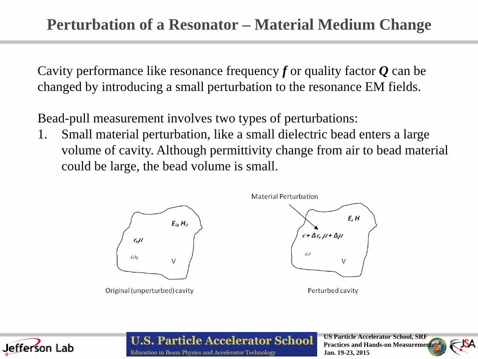
The original definition of the N-cell cavity field flatness is
%1001
1
1
minmax ×
−
−=
∑=
N
ici
ccff
VN
VVη
Here Vci is the accelerating voltage of the ith cell. Vcmax and Vcmin is the maximum and minimum cell voltage in the cavity, respectively.
For a fixed βg=v/c structure, all the cells in the cavity have an equal accelerating gap d= βc/(2f0). The cell’s accelerating voltage is
∫−=+=
2/
2/ 0 )()cos()(L
L ccc dTEdzLzzfEV φπ
Here Ec is the peak axial electric field along the beam axis z. The f(z) is the field distribution function. As long as the cavity shape and the gap L don’t change from cell to cell, or a small perturbation change which only changes the Ec but not f(z) and d. So the transit time factor T(d) will be a constant. Then the equation (46) becomes:
%1001
11
1
1
minmax
1
minmax ×
∆
∆−∆−=
−
−=
∑∑==
N
ici
ccN
iic
ccff
NE
N
EE
φ
φφη
(45)
(46)
(47)
Here Eci is the peak axial electric field in the ith cell. ∆φci is S21 phase change in bead-pull data after correction of slop and offset

US Particle Accelerator School, SRF Practices and Hands-on Measurements, Jan. 19-23, 2015
Bead-pull Formula for Dielectric Sphere and its Error Analysis
Except the approximation in [39], additional relative errors caused by measurement parameters are:
(48)
(49)
From page 17 and equation [39], we can derive:
−𝐸𝐸𝑧𝑧2
𝜔𝜔𝑈𝑈=
𝜕𝜕𝑎𝑎𝑙𝑙 ∆𝑎𝑎𝑙𝑙𝑎𝑎𝑆𝑆21𝜔𝜔𝑄𝑄𝐿𝐿𝜀𝜀0𝐹𝐹𝑏𝑏𝑑𝑑−𝑠𝑠𝑠𝑠𝑠𝑒𝑒𝑟𝑟𝑒𝑒
Here Fdi-sphere is dielectric sphere form factor:
Fdi−sphere = 2𝜋𝜋𝑎𝑎3𝜀𝜀𝑟𝑟 − 1𝜀𝜀𝑟𝑟 + 2
2∆𝐸𝐸𝑧𝑧𝐸𝐸𝑧𝑧
=∆φφ
+∆𝑄𝑄𝐿𝐿𝑄𝑄𝐿𝐿
+ 3∆𝑎𝑎𝑎𝑎
+ 3∆𝜀𝜀𝑟𝑟
𝜀𝜀𝑟𝑟 − 1 𝜀𝜀𝑟𝑟 + 2 (50)
For a teflon sphere |∆Ez/Ez|~(1%+1%+3*0.2%+3*1%)/2~5% HW9 optional: Try to estimate cavity frequency shift due to a nylon (εr=4) fishing wire (dia.=0.019 inch) stretching through the axis of C100 cavity. When using ∆F method to measure the E field, should you consider this frequency shift? Try to confirm your estimate in your experiment.

US Particle Accelerator School, SRF Practices and Hands-on Measurements, Jan. 19-23, 2015
Bead-pull Measurement Systems
JLab system with wire holders on x-y stages ODU system with wire loop frame

US Particle Accelerator School, SRF Practices and Hands-on Measurements, Jan. 19-23, 2015
Bead-pull Measurement Techniques
System ODU JLab wire pulling device close loop with spring tension on
pulleys weight drop with multi-loop
travel on pulleys step-motor-drive 1D in Z w/ Labview 3D w/ X-Y stages
automation control Labview 2010 Labview 2014
measure with VNA search S21 peak f to find ∆f/f0=(fpeak-f0)/f0
S21 phase ∆f/f0=tan(∆arg(S21))/(2Ql)
pros no wire over latch on reel; no bead vibration issue;
no Ql measurement; change bead w/o rewiring
fast; can be manual operation for quick setup;
multi-mode measure in one pull is possible
cons slow, frequency drift; need automation;
suitable for short cavity
possible bead vibration; wire over latch caused
pulling speed change; phase lock drift; bead change
needs rewiring

US Particle Accelerator School, SRF Practices and Hands-on Measurements, Jan. 19-23, 2015
Bead-pull Measurement Common Errors and Remedy Tricks
Common Errors Most Possible Causes Remedy Tricks
large noise small signal
Too weak in couplings, small drive power, high IF frequency, drive frequency off resonance in phase measurement
P=0-10dBm, IF<1kHz, S21_loss >-60dB 0.01<S11~S22. Use RF amplifier is needed. Scan for new peak drive frequency
Bead vibration String suspension structure resonance with motor step frequency
Increase string tension or hanging weight, use damper on wire eye
Field tilts to one side Not a real tilt, too strong coupling on weak peak side
Control β1~β2<0.1. Large β causes f0 ↓ Antenna not perturb f0 by <20kHz
Positive phase or frequency change
off-axis pulling, picking up H field Wrong mode
Re-align the wire Change drive frequency
Phase display jump during time sweep
Phase near ±180o , normal in VNA phase lock sweep
Use phase delay on the VNA display screen
Too large phase change Too large bead size or wrong shape Change bead
Signal base line tilt Cavity frequency/VNA phase drift Correct slop in data process Faster pulling speed Use small IF<500Hz
Large error on R/Q calculation
Bead size measurement error εr error, wrong calculation formula Misalignment of Ez field versus cavity position z
Use caliper to measure bead size Calibrate bead-pulling speed/distance with stop watch Calibrate εr with a pillbox cavity

US Particle Accelerator School, SRF Practices and Hands-on Measurements, Jan. 19-23, 2015
Qext Measurement Common Errors and Remedy Tricks
Common Errors Most Possible Causes Remedy Tricks
Calibration error Changed cable, Cal Kit standards are misused
Recalibrated cable Follow calibration procedure
Input beam pipe coupler is too strong
Cavity field perturbed and tilted by input antenna
Reduce the β1<0.1
Bad cable Extra loss on bad connector Change the cable Using mismatched top hat Extra loss on top hat Use Adaptor Removal
Calibration Procedure Nb top hat on C50 cavity waveguide FPC
Extra waveguide mode build up
Avoid assembly structure with waveguide build up
antenna perpendicular to E field or loop plane parallel to H field
Very sensitive to coupler tilting angle or rotation
Use “L” shape rod antenna, mark the orientation of rotation for reassembly
Large Qext difference between bench and cold measurements
Third port or add-on structure affect S21 transmission coupling
Measure the S21 with full assembly, avoid any ghost mode nearby, use simulation to understand the coupling
US Particle Accelerator School, SRF Practices and Hands-on Measurements, Jan. 19-23, 2015
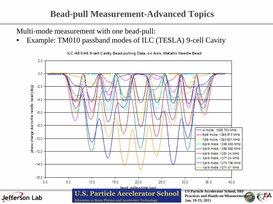
Bead-pull Measurement-Advanced Topics
Multi-mode measurement with one bead-pull: • Example: TM010 passband modes of ILC (TESLA) 9-cell Cavity

US Particle Accelerator School, SRF Practices and Hands-on Measurements, Jan. 19-23, 2015
Bead-pull Measurement-Advanced Topics
Bead-pull for HOMs • Example: TM110 π modes
• Use analytical or 3D simulation to understand EM field pattern • Use metallic spherical bead to pick up on-axis Bx field • Use metallic disc or sphere to pick up off-axis Bx and Ez fields • Use ceramic spherical or needle bead to pick up off-axis Ez field • Rotate ceramic sphere around beam axis to measure the dipole polarization
US Particle Accelerator School, SRF Practices and Hands-on Measurements, Jan. 19-23, 2015
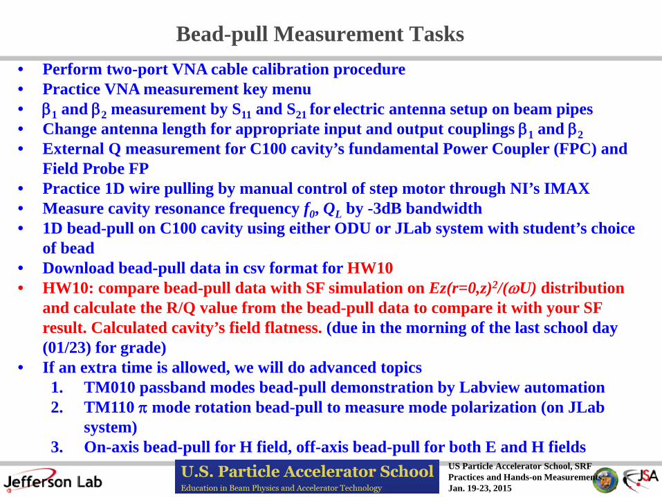
Bead-pull Measurement Tasks • Perform two-port VNA cable calibration procedure • Practice VNA measurement key menu • β1 and β2 measurement by S11 and S21 for electric antenna setup on beam pipes • Change antenna length for appropriate input and output couplings β1 and β2 • External Q measurement for C100 cavity’s fundamental Power Coupler (FPC) and
Field Probe FP • Practice 1D wire pulling by manual control of step motor through NI’s IMAX • Measure cavity resonance frequency f0, QL by -3dB bandwidth • 1D bead-pull on C100 cavity using either ODU or JLab system with student’s choice
of bead • Download bead-pull data in csv format for HW10 • HW10: compare bead-pull data with SF simulation on Ez(r=0,z)2/(ωU) distribution
and calculate the R/Q value from the bead-pull data to compare it with your SF result. Calculated cavity’s field flatness. (due in the morning of the last school day (01/23) for grade)
• If an extra time is allowed, we will do advanced topics 1. TM010 passband modes bead-pull demonstration by Labview automation 2. TM110 π mode rotation bead-pull to measure mode polarization (on JLab
system) 3. On-axis bead-pull for H field, off-axis bead-pull for both E and H fields

US Particle Accelerator School, SRF Practices and Hands-on Measurements, Jan. 19-23, 2015
References
1. Wikipedia page: http://en.wikipedia.org/wiki/Cavity_perturbation_theory 2. David M. Pozar, Microwave Engineering, 2nd edition, Wiley, New York,
NY, 1998, Section 6.8 Cavity Perturbation, pages 340-344 3. J. D. Jackson, Classical Electrodynamics, John Wiley and Sons, Inc. 4. L. B. Mullett, Perturbation of a Resonator, UK Atomic Energy Research
Establishment, Harwell, Berkshire, 1957, Unclassified A.E.R.E. G/R 853 5. R. G. Carter, Engineering Department, Lancaster University, Lancaster
LA14YR, U.K., School Teaching Note, year? 6. H. Padamsee, J. Knobloch and T. Hays, RF Superconductivity for
Accelerators, Wiley Series in Beam Physics and Accelerator Technology 7. L. C. Maier Jr. and J. C. Slater, Field Strength Measurements in Resonator
Cavities, Journal of Applied Physics Vol. 23, No. 1, Jan. 1952 8. H. Hahn and H.J. Halama, Pertubation measurements of transverse R/Q in
irisi-loaded waveguides, IEEE Trans. MTT-16, no.1, p. 20 (January 1968)

US Particle Accelerator School, SRF Practices and Hands-on Measurements, Jan. 19-23, 2015
Backup Slides

US Particle Accelerator School, SRF Practices and Hands-on Measurements, Jan. 19-23, 2015
R/Q Calculation from Bead-pull Data Procedure
1. Take phase change (deg) raw data 2. Correct baseline slop 3. Subtract baseline offset to zero
1
3
2

US Particle Accelerator School, SRF Practices and Hands-on Measurements, Jan. 19-23, 2015
R/Q Calculation from Bead-pull Data Procedure
4. -Ez^2/(ωU)=∆arg(S21)/(ωQLε0Fbead) 5. sqrt(|Ez^2/(ωU)|) 6. Subtract offset sqrt(Ez^2/ωU)
4
6
5
US Particle Accelerator School, SRF Practices and Hands-on Measurements, Jan. 19-23, 2015
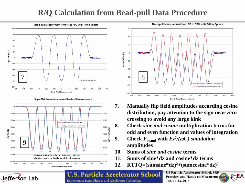
R/Q Calculation from Bead-pull Data Procedure
7. Manually flip field amplitudes according cosine distribution, pay attention to the sign near zero crossing to avoid any large kink
8. Check sine and cosine multiplication terms for odd and even function and values of integration
9. Check Fbeand with Ez2/(ωU) simulation amplitudes
10. Sums of sine and cosine terms 11. Sums of sine*dz and cosine*dz terms 12. RTTQ=(sumsine*dz)2+(sumcosine*dz)2
7
9
8
Related Documents