GG71 GUIDE COST-EFFECTIVE REDUCTION OF FUGITIVE SOLVENT EMISSIONS GOOD PRACTICE: Proven technology and techniques for profitable environmental improvement Be Solvent Wise

Welcome message from author
This document is posted to help you gain knowledge. Please leave a comment to let me know what you think about it! Share it to your friends and learn new things together.
Transcript

GG71GUIDE
COST-EFFECTIVE REDUCTION OF FUGITIVESOLVENT EMISSIONS
GOOD PRACTICE: Proven technology and techniques for profitable environmental improvement
Be S o l v e n t W i s e

© Crown copyright. First printed March 1997. This material may be freely reproduced except for sale or advertising purposes.
Printed on paper containing 75% post-consumer waste.
COST-EFFECTIVE REDUCTION OF FUGITIVESOLVENT EMISSIONS
This Good Practice Guide was produced by the
Environmental Technology Best Practice Programme
Prepared with assistance from:
McLellan and Partners Ltd
John Crane International

This Good Practice Guide describes techniques that can be used to reduce the cost of organicsolvents lost as leaks from pipework components.
Companies that manufacture, use or recycle organic solvents as part of their operations could belosing 10% or more of their total solvent consumption to the atmosphere through leaks (fugitiveemissions) from valves, pumps and other equipment. This Guide is intended to help companiesdecide whether it would be cost-effective to reduce fugitive emissions. It provides guidance on thebest approach to preventing and minimising them.
The Guide indicates the many sources of fugitive emissions of organic solvents from pipelinecomponents and stresses the benefits of reducing such emissions. Advice is given on how to:
■ quantify the release of fugitive emissions;
■ calculate the cost of fugitive emissions;
■ monitor fugitive emissions;
■ control leakage from valves, pump shaft seals and other sources of fugitive emissions.
The choice of different techniques for monitoring and controlling fugitive emissions for both largeand small businesses is discussed. A number of these techniques, such as tightening pipe flanges,capping open-ended lines and adjusting valve glands, are no-cost or low-cost measures that can beimplemented immediately. Other approaches, which involve greater expenditure and planning,include replacing unsuitable equipment or redesigning parts of the plant. This Guide describes therange of techniques available and indicates the resources needed to implement the variouscorrective measures.
An Action Plan is provided to help you get started on a programme to save money by reducingfugitive emissions.
S U M M A R Y

Section Page
1 Introduction 1
1.1 Benefits of reducing fugitive emissions 2
2 Sources of fugitive emissions 3
3 Fugitive emission control strategy 5
3.1 The true cost of fugitive emissions 6
3.2 Estimating the extent of fugitive emissions 8
3.3 Prioritise remedial work 10
3.4 Implement corrective action 11
3.5 Regular monitoring 11
3.6 Review 12
4 Monitoring and detecting fugitive emissions 13
4.1 General principles of monitoring 13
4.2 Monitoring equipment 14
5 Preventing leakage from valves 18
5.1 Valve sealing arrangements 18
5.2 Selection of valve packing 18
5.3 Installation and maintenance 20
6 Preventing leakage from pump shaft seals 23
6.1 Different types of seal 23
6.2 Pump seal selection 27
6.3 Installation and maintenance of pump shaft seals 28
7 Preventing leakage from other sources 30
7.1 Pressure relief valves 30
7.2 Slow rotating equipment 30
7.3 Pipework joints and flanges 31
7.4 Filling operations 32
7.5 Quick release couplings 33
7.6 Open-ended filling lines 33
7.7 Filters 33
7.8 Leaking pipelines 34
8 Action plan 35
Appendix Annual cost of fugitive emissions 36
C O N T E N T S


UK manufacturing companies use large quantities of organic solvents. For the purposes of thisGood Practice Guide ‘solvent’ means an organic liquid that evaporates readily at normaltemperature and pressure, giving rise to volatile organic compound (VOC) emissions. Current levelsof VOCs in the atmosphere are a subject of widespread concern and regulation, primarily becauseof their role in the formation of low-level ozone. Industrial solvents are a major source of VOCemissions in the UK.
A fugitive emission is an emission to the atmosphere which is not vented to a stack or otherextraction equipment. Some fugitive emissions occur as a result of an accident and are relativelyinfrequent. Other fugitive emissions may be due to leaking equipment, such as valves and pumps,or may arise as a result of incomplete solvent capture - for example when filling containers. Fugitiveemissions are inherently difficult to identify as they often involve leaks to atmosphere, and due tothe nature of organic solvent any visual liquid leak will rapidly evaporate.
Companies that manufacture, use or recycle solvents as part of their operations may be losingthousands of pounds worth of solvent material to the atmosphere through leaks from componentssuch as pipework, valves, pumps and vessels.
This Good Practice Guide is intended to help companies:
■ identify the true costs of fugitive emissions of organic solvents;
■ reduce the potential for leakage;
■ stop leaks.
The mention of an organisation in this Guide should not be regarded as an endorsement of itsservices or products by the Environmental Technology Best Practice Programme.
The Guide is primarily concerned with fugitive emissions from solvents transported in piped systems.While the advice it contains is applicable to all sectors of manufacturing industry, it is particularlyrelevant to the following sectors:
■ solvent manufacture and use;
■ petrochemical manufacture;
■ chemical and pharmaceutical manufacture;
■ printing ink manufacture and use;
■ adhesive manufacture and use;
■ paint manufacture and use;
■ other coating manufacture and use.
1
I N T R O D U C T I O N1
section
1

Fugitive emissions also arise during general plant operations or ineffective solvent capture. Furtherinformation and advice on reducing solvent losses in these circumstances is contained in other GoodPractice Guides, including:
■ Good Practice Guide (GG12) Solvent Capture for Recovery and Re-use from Solvent-ladenGas Streams;
■ Good Practice Guide (GG13) Cost-effective Solvent Management;
■ Good Practice Guide (GG28) Good Housekeeping Measures for Solvents.
These Guides are available free of charge through the Environmental Helpline on 0800 585794.
1.1 BENEFITS OF REDUCING FUGITIVE EMISSIONS
Taking action to identify and reduce fugitive emissions will lead to many financial benefits. Specificadvantages include:
■ reduced solvent consumption;
■ increased plant availability;
■ reduced maintenance costs;
■ better working conditions;
■ fewer odours;
■ improved environmental, health and safety performance;
■ improved environmental image.
2
section
1
Pound for Pound Improvements
One petrochemical company recently investigated the potential benefits of retrofitting amodern graphite valve packing to its leaking gate valves.
After extensive trials, the company concluded that, for every pound spent on replacing thevalve packing, over a pound was saved. The benefits arose because:
■ no new valves were required as the new packing was retrofitted to existing valves (40%of saving);
■ stopping leaks reduced material use (30% of saving);
■ the new packing material has a longer life (30% of saving).

A fugitive emission can be defined as any chemical or mixture of chemicals (in any physical form)which represents an unanticipated or spurious leak from anywhere on an industrial site.
Fugitive emissions can originate from a wide range of sources (see Fig 1), including:
■ valve glands;
■ pump shaft seals;
■ mixing vessels;
■ open filling nozzles;
■ pressure relief valves;
■ joints;
■ sample lines.
Fugitive emissions may be due to:
■ wear;
■ corrosion;
■ incorrect specification;
■ incorrect installation;
■ incorrect maintenance;
■ incorrect process operation;
■ poor working practices.
Determining the breakdown of emission sources at a particular site will enable cost-effectivecorrective action to be taken. For example, at large continuous petrochemical plants, over 90% ofa typical site’s fugitive emissions from pumps resulted from approximately 10% of the pump seals.Concentrating action on this specific proportion of the site’s equipment provides for a potential90% reduction in fugitive emissions.
3
section
2
S O U R C E S O F F U G I T I V EE M I S S I O N S
2
Fig 1 Typical sources of fugitive emissions
Filling lines
Storagevessel
Pressurereliefvalves
Pressurereliefvalves
Gaskets Pumps Valves
Open-endedlines
Mixingtank seals
Potentialfugitive emission

This example highlights the benefits of assessing emissions from different parts of the plant andprioritising action. The relative importance of the various sources of fugitive emissions will bedifferent for every process. For example, most fugitive emissions in batch processing plants occurwhen solvents are transferred between vessels.
4
section
2
Fig 2 Breakdown of emission sources at a petrochemical plant
Storage tanks10%
Gaskets5%
Valves60%
Relief valves15%
Pump seals10%
Prioritising Pays Dividends
Studies at one petrochemical plant revealed that most of the fugitive emissions originated fromvalve glands (see Fig 2). This information enabled the company to give priority to valvemaintenance and achieve savings of over £200 000/year.

The approach to controlling fugitive emissions recommended by this Guide follows the same generalprinciples for all companies - from small vehicle refinishing workshops to large continuous-chemical-processing companies. The main differences between these two extremes are:
■ the resources available;
■ the method adopted;
■ the equipment used.
Fig 3 outlines a general approach to controlling fugitive emissions. This methodology is similar tomost management control systems and can be incorporated into an overall solvent managementplan. Good Practice Guide (GG13) Cost-effective Solvent Management describes a solventmanagement framework and suggests measures to manage solvent use. This Guide is available freeof charge through the Environmental Helpline on 0800 585794.
Before taking action to control fugitive emissions, it is worth examining the true cost to the companyof fugitive emissions and the potential savings that could be achieved.
5
section
3
Fig 3 Fugitive emission control strategy
Calculate the cost offugitive emissions
Estimate potentialsavings
Prioritiseremedial work
Implement correctiveaction
Monitor regularly
Review controlstrategy
Identify sources of fugitiveemissions by monitoring
Estimate the extentof fugitive emissions
Either Or
F U G I T I V E E M I S S I O N C O N T R O LS T R AT E G Y
3

3.1 THE TRUE COST OF FUGITIVE EMISSIONS
In some companies the cost of fugitive emissions can be significant - often accounting for 10% ormore of total solvent consumption. Apart from this direct cost, other indirect costs will exist. Theseare frequently ignored. Such costs typically include:
■ labour to repair leaks;
■ materials used to repair leaks.
In practice, the value of the lost solvent may be only the ‘tip of the iceberg’ (see Fig 4) and the overallcost of fugitive emissions may be several times higher than the cost of solvent lost.
Other costs that are more difficult to quantify include the financial risks associated with:
■ potential fines for environmental pollution;
■ potential claims for harm or personal injury;
■ neighbouring companies or local residents complaining about odours;
■ lost sales due to poor environmental image.
6
section
3
Fig 4 ‘Iceberg’ model of hidden costs
Lost solvent
Labour
New materials
Energy
Other costs
'Invisible' cost
'Visible' cost
Total annual cost of a leak from any component
= Cost of lost solvent + Labour costs to rectify leak + Cost of replacement parts

3.1.1 Cost of lost solvent
The quantity of solvent lost depends on:
■ the number and size of the leaks;
■ the system pressure (higher pressures result in larger quantities lost).
This Guide provides data on the annual cost of leaks from nine different types or size of pipelinecomponent (see the Appendix). For example, Table 1 shows the typical annual cost of fugitiveemissions from single components for a solvent costing £600/tonne.
Component Annual cost of leak (£)
Solvent industry: gas valve 30
light liquid valve 50
light liquid pump 200
gas/liquid connector 60
Petrochemical industry: gas valve 100
light liquid valve 120
light liquid pump 900
heavy liquid pump 670
gas/liquid connector 1 000
Table 1 Cost of leaks of solvent worth £600/tonne from different pipeline components
Table 1 shows that, for a solvent worth £600/tonne, any single leaking component is likely to costat least £30/year, and possibly over £1 000, in solvent losses alone.
The potential annual costs of solvent lost through fugitive emissions for solvents worth £100 - £1 000/tonne are given in the Appendix. Graphs are presented, for each of the ninecomponent categories, of the annual cost of 0 - 100 leaking components. Although these graphsdo not include indirect costs, they can be used to give an idea of the cost of fugitive emissions fora particular plant.
3.1.2 Labour costs
The cost equation should include the cost of the time spent by employees rectifying leakingequipment. If there were no leaks, these employees could be used to develop plant and implementcost-saving ideas, rather than maintaining the status quo.
Table 2 shows typical times for remedial work on leaking equipment.
Job Time taken
Adjusting valve gland packing materials Minutes.
Repacking a valve About an hour. Depends on whether the packing
material can be replaced in situ or if the valve has to
be removed.
Replacing the mechanical shaft seals on a pump At least an hour.
Table 2 Typical times for remedial work on leaking equipment
3.1.3 Material costs
Replacement parts can cost several tens to several hundreds of pounds per component, dependingon the application. Valve packings typically cost tens of pounds to replace per valve, whereasmechanical shaft seals on large pumps can cost hundreds of pounds per seal.
7
section
3

3.2 ESTIMATING THE EXTENT OF FUGITIVE EMISSIONS
A preliminary estimate of the extent of solvent losses through fugitive emissions can be obtainedusing several simple techniques. Such a calculation will help to identify the largest sources of lostsolvent. Alternatively, solvent losses, and hence the potential savings, can be estimated beforecommitting resources to monitoring fugitive emissions.
3.2.1 Mass balance
The total amount of solvent emitted from the site to the atmosphere can be estimated by carryingout a simple mass balance calculation. Solvent emissions can be obtained by subtracting the changein stock levels and the total solvent output from the total solvent input, ie:
Solvent emissions = Inputs - Outputs - Changes in stock levels.
If you have an idea of what is being emitted from your stacks, the fugitive emission is:
Fugitive emission = solvent emission - stack emissions
This technique is described in detail in Good Practice Guide (GG13) Cost-effective SolventManagement, available free of charge through the Environmental Helpline on 0800 585794.
3.2.2 Average emission factor
This technique estimates total fugitive emissions using published average emission factors. It ispossibly the simplest option available for estimating the magnitude of fugitive emissions withoutresorting to monitoring.
The technique involves determining the number of pipework components on the plant andmultiplying each component by the appropriate average emission factor. Table 3 gives suggestedfactors developed from studies at 24 organic chemical manufacturing plants.
This method of estimating fugitive emissions assumes that the leak frequency of components at aparticular plant is similar to those from which the average emission factors were derived.
8
section
3
Costs Add Up
The total annual cost of a leak from a valve carrying a light liquid solvent worth £600/tonneand which takes two hours/year to repair with new materials costing £45 is:
= Cost of lost solvent + Labour costs to rectify leak + Cost of replacement parts
= £50 + £20 + £45 = £115
These operating costs can be reduced by specifying a superior quality valve packing. Such apacking, which can be obtained relatively cheaply, has a significantly increased service life.
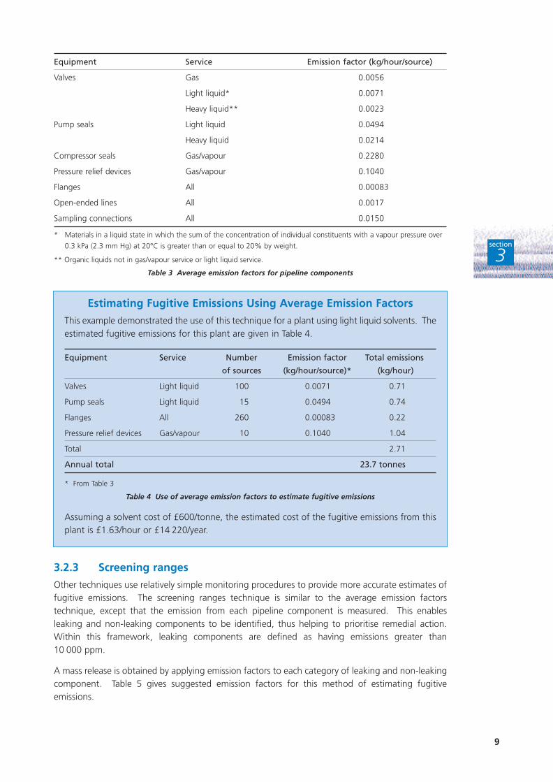
Equipment Service Emission factor (kg/hour/source)
Valves Gas 0.0056
Light liquid* 0.0071
Heavy liquid** 0.0023
Pump seals Light liquid 0.0494
Heavy liquid 0.0214
Compressor seals Gas/vapour 0.2280
Pressure relief devices Gas/vapour 0.1040
Flanges All 0.00083
Open-ended lines All 0.0017
Sampling connections All 0.0150
* Materials in a liquid state in which the sum of the concentration of individual constituents with a vapour pressure over
0.3 kPa (2.3 mm Hg) at 20°C is greater than or equal to 20% by weight.
** Organic liquids not in gas/vapour service or light liquid service.
Table 3 Average emission factors for pipeline components
3.2.3 Screening ranges
Other techniques use relatively simple monitoring procedures to provide more accurate estimates offugitive emissions. The screening ranges technique is similar to the average emission factorstechnique, except that the emission from each pipeline component is measured. This enablesleaking and non-leaking components to be identified, thus helping to prioritise remedial action.Within this framework, leaking components are defined as having emissions greater than 10 000 ppm.
A mass release is obtained by applying emission factors to each category of leaking and non-leakingcomponent. Table 5 gives suggested emission factors for this method of estimating fugitiveemissions.
9
section
3
Estimating Fugitive Emissions Using Average Emission Factors
This example demonstrated the use of this technique for a plant using light liquid solvents. Theestimated fugitive emissions for this plant are given in Table 4.
Equipment Service Number Emission factor Total emissions
of sources (kg/hour/source)* (kg/hour)
Valves Light liquid 100 0.0071 0.71
Pump seals Light liquid 15 0.0494 0.74
Flanges All 260 0.00083 0.22
Pressure relief devices Gas/vapour 10 0.1040 1.04
Total 2.71
Annual total 23.7 tonnes
* From Table 3
Table 4 Use of average emission factors to estimate fugitive emissions
Assuming a solvent cost of £600/tonne, the estimated cost of the fugitive emissions from thisplant is £1.63/hour or £14 220/year.

Equipment Service Emission factor (kg/hour/source)
Leaking Non-leaking
(greater than 10 000 ppm) (less than 10 000 ppm)
Valves Gas 0.0541 0.00048
Light liquid 0.0852 0.00171
Heavy liquid 0.00023 0.00023
Pump seals Light liquid 0.4370 0.01200
Heavy liquid 0.3885 0.01350
Compressor seals Gas/vapour 1.6080 0.08940
Pressure relief devices Gas/vapour 1.6910 0.04470
Flanges All 0.0375 0.00006
Open-ended lines All 0.01195 0.00150
Table 5 Emission factors for ‘screening ranges’ technique
Estimating fugitive emissions using screening ranges
At a plant using light liquid solvents, investigations have been carried out to determine the numberof components that are actually leaking. The estimated emissions are shown in Table 6.
Equipment Service Number of Emission factor Total emissions
sources (kg/hour/ source)* (kg/hour)
Valves Light liquid 10 Leaking 0.0852 0.85
90 Non-leaking 0.00171 0.15
Pump seals Light liquid 2 Leaking 0.4370 0.87
13 Non-leaking 0.01200 0.16
Flanges All 10 Leaking 0.0375 0.38
250 Non-leaking 0.00006 0.02
Pressure relief devices Gas/vapour 1 Leaking 1.6910 1.69
9 Non-leaking 0.04470 0.40
Total 4.52
Annual total 39.6 tonnes
* From Table 5
Table 6 Use of screening ranges technique to estimate fugitive emissions
Assuming a solvent cost of £600/tonne, the estimated cost of the fugitive emissions from this plantusing this more accurate technique is £2.71/hour or £23 760/year.
Comparison of Tables 4 and 6 highlights the greater accuracy that can be obtained by identifyingwhich components are actually leaking before estimating the extent of fugitive emissions.Preliminary monitoring also helps to prioritise remedial work.
3.3 PRIORITISE REMEDIAL WORK
Early detection of a leak is essential. If equipment is not monitored, it is possible for a leak tocontinue undetected for a long time. The monitoring and detection of solvent emissions aredescribed in Section 4.
10
section
3

In the case of continuous process plant, it may not be possible to gain access to repair a known leakuntil the next planned shutdown of the plant. This is particularly true in the case of single-streamcontinuous processes. This problem can be avoided by paying appropriate attention to thearrangement of pipework, valves and pumps during the design phase.
Once the leaking components have been identified, a programme of remedial action can be agreed.Priority should be given to activities that:
■ save money;
■ will have a major effect on reducing fugitive emissions, eg replacing valve packing with newmaterial;
■ can be completed easily, eg tightening flange joints.
3.4 IMPLEMENT CORRECTIVE ACTION
The corrective action taken will depend on the type of plant involved, the resources available andthe potential payback. Typical corrective actions include:
■ tightening valve glands and flange gaskets;
■ capping open-ended lines;
■ upgrading filtration systems;
■ replacing valve packing with superior materials.
Actions specific to valves, pump shaft seals and other pipeline components are described in Sections 5 - 7.
3.5 REGULAR MONITORING
This is important for continued improvement. Regular monitoring can highlight areas where apersistent problem may occur, enabling action to be concentrated on eliminating the problem, egthrough redesign or installation of superior materials.
Implementation of a leak detection and repair (LDAR) monitoring regime involves regular monitoringof components and prompt remedial work. Such a monitoring regime can be incorporated intoexisting management systems such as the maintenance planning procedure.
The time and resources required to set up such systems and continue monitoring depends on thecomplexity of the plant. Table 7 summarises the typical resources required for different companysizes.
Size of company Resources needed to:
Set up system Run system
More than 250 employees Two people for six months One person full-time
100 - 250 employees One person for one month One person for oneday/month
Under 100 employees One person for one week Incorporate into healthand safety monitoring
Table 7 Typical resources required to set up and run a LDAR system
11
section
3

3.6 REVIEW
A review stage is a vital element of any management system. It provides a mechanism for obtainingfeedback on the effectiveness of the system. At this stage, the control strategy should be reviewedand, if necessary, changed.
12
section
3
Remember:
If you don’t measure it, you can’t manage it.

Various types of VOC monitors are available to detect fugitive emissions in the workplace. Thechoice of instrument depends on the:
■ extent of the study;
■ process;
■ budget;
■ human resources;
■ accuracy required.
In many small companies, checks on a limited number of components can be made as part of aregular monitoring programme undertaken under the Control of Substances Hazardous to Health(COSHH) Regulations. Provided accuracy is not required, and the results are only used to identifydeterioration in the plant, the same equipment can often be used for both purposes.
For larger organisations, where the potential for savings may be greater, the purchase of specialisedmonitoring equipment may be justified. The task of regular monitoring can then be incorporatedinto an employee’s job description.
Certain types of monitors respond differently to different solvents and, in some cases, may beaffected by non-volatile compounds in the gas stream. It is, therefore, important to identify thesolvents likely to be released from specific equipment and discuss this with potential instrumentsuppliers.
4.1 GENERAL PRINCIPLES OF MONITORING
The following general guidelines should be adopted when monitoring plant and equipment forfugitive emissions:
■ Identify the point of greatest leakage for each component. Monitor at this point.
■ Where practicable, hold the probe against the leak. If this is not practicable, hold the probeabout 1 cm from the leak.
■ The probe should be perpendicular to the potential leak interface (see Fig 5).
■ Measure for at least twice as long as the equipment response time.
■ Protect the monitor from the effects of wind or draughts as much as possible.
■ Ensure that the probe is not contaminated with oil or dirt.
■ Use the same sampling flow rate for all tests.
■ The temperature and pressure of the process fluid should be the same for repeat tests.
■ The sampling probe should be the same size for all tests.
13
M O N I T O R I N G A N D D E T E C T I N GF U G I T I V E E M I S S I O N S
4
section
4

When using more sophisticated equipment, it may be advisable to monitor in accordance withprotocols based on US EPA Method 21* or an equivalent procedure.
4.2 MONITORING EQUIPMENT
A range of equipment is available for monitoring fugitive emissions, from low-cost soap bubbleassessments and stain tubes to relatively sophisticated equipment based on Fourier transforminfrared (FTIR) techniques. The key features of such equipment are summarised in the followingSections.
4.2.1 Soap bubble assessment
This method, which involves spraying a soap solution or proprietary compound onto the surface ofthe component, is the simplest way of testing for leaks. If no bubbles form, the equipment isconsidered to have no leaks. If bubbles are observed, the equipment should be investigated further.This method, which cannot be used to quantify emissions, can be affected by rain, ice and snow.
Typical applications for this procedure include:
■ use in small companies;
■ initial assessment of fugitive emissions.
4.2.2 Stain tubes
This low-cost technique makes use of monitoring equipment commonly used for health and safetysurveillance. Stain tubes give an approximate indication of the level of fugitive emissions and, if usedregularly, can demonstrate a deterioration in the leakage rate.
Stain tubes (see Fig 6) consist of glass phials containing reactive chemicals which change colourwhen brought into contact with solvents. Samples are introduced into the phials by squeezing ahand pump. As the reagent in the tube reacts with specific chemical substances, it is essential toknow which solvents are being monitored and to use an appropriate selection of phials. For thisreason, it is difficult to monitor emissions of complex solvent mixtures using this technique.
Pumping equipment for stain tubes typically costs £150 and £750 for hand and battery-operatedsystems respectively (1997 prices); the phials are consumable items costing about £3 each (1997prices).
Although the accuracy of this technique is generally low, it uses equipment that many companiesmay already possess. The low cost of the equipment will also appeal to smaller companies.
14
section
4
Fig 5 Typical sampling points for a valve and a flange
Samplehere
* Protocol for Equipment Leak Emission Estimates, US Environmental Protection Agency. US EPA - 453/R.93.026

Typical applications for stain tubes include:
■ combined health and safety surveillance and leak detection;
■ analysis of simple solvent mixtures;
■ use in small companies.
4.2.3 Flammable gas personal exposure alarms
If flammable solvents are being used, plant operators may already wear exposure alarms whencarrying out certain tasks. These devices are normally calibrated against a methane standard andemit an audible alarm if the gaseous concentration approaches the lower explosive limit (LEL) forthat solvent.
These devices typically have a detection limit of 0.1% (volume/volume) and, if held close to asuspected leak, will indicate fugitive emissions. However, care should be taken to ensure that thedevice has a good response to the solvent being assessed.
Typical applications for personal exposure alarms include:
■ detection of flammable organic gases;
■ initial identification of a leak.
4.2.4 Flame ionisation detectors
These devices ionise solvents in a hydrogen flame located between two electrodes. A current iscreated between the electrodes which is proportional to the carbon content of the sample. For thisreason, flame ionisation detectors (FIDs) are commonly known as carbon counters. Although FIDsare used mainly to measure total VOCs, they can be linked to gas chromatographs to identifyindividual solvent substances.
FID monitors are well suited to leak detection as their response time is typically less than a second.
15
Fig 6 Typical stain tubes
Phot
ogra
ph c
ourt
esy
of D
raeg
er L
td
section
4

The cost of a typical FID ranges from about £4 000 for a basic hand-held device (see Fig 7) to£10 000 (1997 prices) for a unit linked to a gas chromatograph.
Because some solvents ionise more readily than others,problems can arise when quantifying emissions using aflame ionisation detector. The monitoring team should,therefore, be aware which solvents they may detect andapply the appropriate correction. This should not provedifficult as the composition of the solvent stream beingmonitored is normally known when screening specificcomponents for fugitive emissions.
Another potential problem with this type of monitoringequipment is that, at low solvent concentrations, errorscan arise if the FID reacts with any water vapour presentor water condenses in the sample tube. This difficultycan be overcome by using heated sample lines.
Typical applications for FIDs include:
■ improved quantification of solvent emissions;
■ leak detection at large companies with potential leaks of significant magnitude;
■ detection of solvent in mixtures with inorganic gases;
■ leak detection in accordance with the US EPA Reference Method 21.
4.2.5 Photoionisation detector
Photoionisation detectors (PIDs) operate in a similar way to FIDs, except that a high voltageultraviolet lamp is used to ionise the sample gas. PIDs therefore have the advantage, compared toFIDs, of not needing a hydrogen cylinder which has to be to refilled and maintained.
PIDs typically cost £2 000 - £20 000 (1997 prices), depending on the specification.
In common with FID techniques, PID devices (see Fig 8) have the following advantages:
■ a quick response time;
■ the ability to identify individual organic substanceswhen linked to a gas chromatograph;
■ emission levels can be detected as low as parts perbillion.
The main problems associated with using PIDs tomonitor for fugitive solvents are that they:
■ can be affected by inorganic gases such asammonia and sulphur dioxide;
■ are not specific for hydrocarbons;
■ can have a low battery life.
Typical applications for PIDs include:
■ detection of complex chlorinated solvents;
■ plants where VOCs and inorganic compounds have to be detected using the sameinstrument.
16
section
4
Fig 7 Typical hand-held flame ionisation
detector
Phot
ogra
ph c
ourt
esy
of E
Ti L
td/P
E Ph
otov
ac
Fig 8 Typical hand-held photoionisation
detector
Phot
ogra
ph c
ourt
esy
of E
Ti L
td/P
E Ph
otov
ac

4.2.6 Fourier transform infrared detectors
Fourier transform infrared (FTIR) detectors combine the benefits of sophisticated infrared analysis ina portable unit. Such devices, a relatively recent development, can identify individual solventsubstances and provide ‘real time’ data.
This type of instrument is expensive, typically costing in the region of £50 000. However, thepossibility of hiring the equipment may bring FTIR instruments within the reach of more companies.
Typical applications for FTIRs include:
■ analysis of individual, ‘real time’ solvent emissions;
■ process optimisation;
■ detection of emissions at large companies with potential large leaks of significant magnitude.
17
section
4

Popular valves such as ‘gate’ and ‘ball’ designs can be a major source of fugitive emissions, withmost of the leakage occurring at the valve gland. Typically, a badly leaking valve can emit over 500 kg/year; for solvent costing £600/tonne, this leakage could cost the company over £300/yearfor this valve alone.
Major savings can clearly be achieved by addressing leakage from valve glands and ensuring thatmodern gland sealing systems are installed.
Provided the process parameters and economics are suitable, an alternative is to consider installingdiaphragm valves. Such valves, in which the solvent is isolated from the stem by an imperviousdiaphragm, can be suitable for applications up to 1 600 kN/m2 (16 bar) and 175°C. Themanufacturer’s advice should be obtained with respect to the specific application and the choice ofmaterial for the diaphragm.
5.1 VALVE SEALING ARRANGEMENTS
Valve gland seals traditionally consisted of a packing of braided cotton or asbestos yarn, wrappedaround the valve stem and compressed into the stuffing box of the valve (see Fig 9). Modernpacking materials such as PTFE, aramid and graphite have generally replaced the traditionalmaterials. These newer packing materials offer better sealing properties. An increasing range ofother alternative sealing systems is available to suit a variety of temperature, pressure and chemicalconditions.
5.2 SELECTION OF VALVE PACKING
5.2.1 Conventional stem packing options
Compression packing, which is the most common form of sealing arrangement, is available in twogeneric types.
18
section
5
P R E V E N T I N G L E A K A G E F R O MVA LV E S
5
Fig 9 Cross-section through a valve gland
Gland followerValve stem
Stuffing box
Compressionpacking
Process fluidpressure

Braided material
This is a versatile packing suitable for manyapplications and therefore used widely. Theappropriate length of packing material can becut from a coil (see Fig 10). This eliminates theneed to stock large quantities of individually-sized packing material and thus reduces thestores inventory. However, the emission controlachievable with this type of packing is generallylimited to around 10 000 ppm. This may beunacceptable for certain applications.
The materials used for braided packing includeacrylic, aramid, PTFE, exfoliated graphite andhigh temperature polymers.
Pre-formed rings
These are manufactured from braid, extrusionsor die-pressed products. Pre-formed rings (see Fig 11) are generally used where higherstandards of emission control are required.These rings are manufactured to tighttolerances and to suit each stem/stuffing boxarrangement. However, this may require a largeinventory of replacement parts.
5.2.2 Advanced stem packingoptions
Special valve gland seals are available forspecific applications.
Combination packing sets
This type of valve packing assembly consists of die-formed graphite rings, with braided graphitewiper rings located at the top and bottom (see Fig 12). Combination packing sets provide a superiorlevel of emission control, typically less than 500 ppm. Profiling the die-pressed rings with ‘cup andcone’ or ‘chevron’ designs increases the ‘sealability’ of the valve. This allows more opportunity forre-tightening the gland during normal operation and hence achieving longer service life.
19
section
5
Fig 10 Typical braided graphite length-form packing
Phot
ogra
ph c
ourt
esy
of J
ames
Wal
ker
and
Com
pany
Ltd
Fig 11 Typical exfoliated graphite pre-formed rings
Phot
ogra
ph c
ourt
esy
of J
ames
Wal
ker
and
Com
pany
Ltd
Fig 12 ‘Kalrez’ profiled valve packing
Phot
ogra
ph c
ourt
esy
of D
uPon
t D
ow E
last
omer
s

Combination packing sets provide good sealing properties on corroded and pitted stems, thusmaking them suitable for retrofitting into old, worn valves and prolonging valve life.
Bellows seals
Bellows seals for valve stems consist of heavy-walled bellows made from metal or polymericmaterials. The bellows isolate the valve stem from the process fluid and, as a consequence, areregarded as ‘zero emission’ seals.
Bellows seals are generally used for highly toxic applications or in situations where escape of anyprocess fluid is unacceptable. However, if the bellows arrangement fails, the potential release ofprocess fluid can be significant. Conventional packing seals are, therefore, often installed as asecondary sealing system.
5.2.3 Choice of stem sealing option
The technique chosen to seal a valve stem depends on the application. The factors that influencethe choice of material include:
■ chemical compatibility;
■ temperature;
■ pressure;
■ cost;
■ life expectancy of the component;
■ frequency of valve use;
■ ease and cost of maintenance;
■ implications of failure.
Table 8 summarises the applicability and costs associated with the different types of valve sealingarrangement.
Material Emission Maximum Maximum Relative
control (ppm) temperature (°C) pressure (bar) cost*
Braided synthetic fibre packing <10 000 190 80 1
Moulded or machined thermoplastic packing <500 285 170 2
Carbon or graphite-based braid packing <10 000 550** 170 3
Asbestos-based yarn packing >10 000 480 275 3
Carbon or graphite-based die-formed rings <500 550** 310 4
Polymeric bellows 0 150 20 5
Metal bellows 0 550** 170 6
* Cost increases from 1 to 6.
** Under non-oxidising conditions, a higher temperature may be reliably achieved. Always refer specific applications to
the original manufacturer.
Table 8 Applications of different valve sealing materials
5.3 INSTALLATION AND MAINTENANCE
Valves that are properly installed and maintained will:
■ operate correctly;
■ need low maintenance;
■ achieve good emission control.
20
section
5
The following guidelines represent good installation and maintenance practice.
5.3.1 Valve installation
The operational life of a valve is reduced by any condition which causes vibration or distortion.Situations that can damage, bend or introduce foreign bodies into the seal of the valve stem orpipework connections should therefore be avoided.
The following general guidelines are applicable to all valves, though individual manufacturers mayspecify additional requirements:
■ Ensure the valve meets the appropriate specification for the application.
■ Ensure the valve is protected in the stores from dust, damage and corrosion.
■ Keep all instructions and information with the valve until it is used.
■ Do not drop the valve.
■ Do not carry the valve by the hand wheel, lever or stem.
■ Ensure all flange surfaces are clean.
■ Install the valve with the correct orientation of flow.
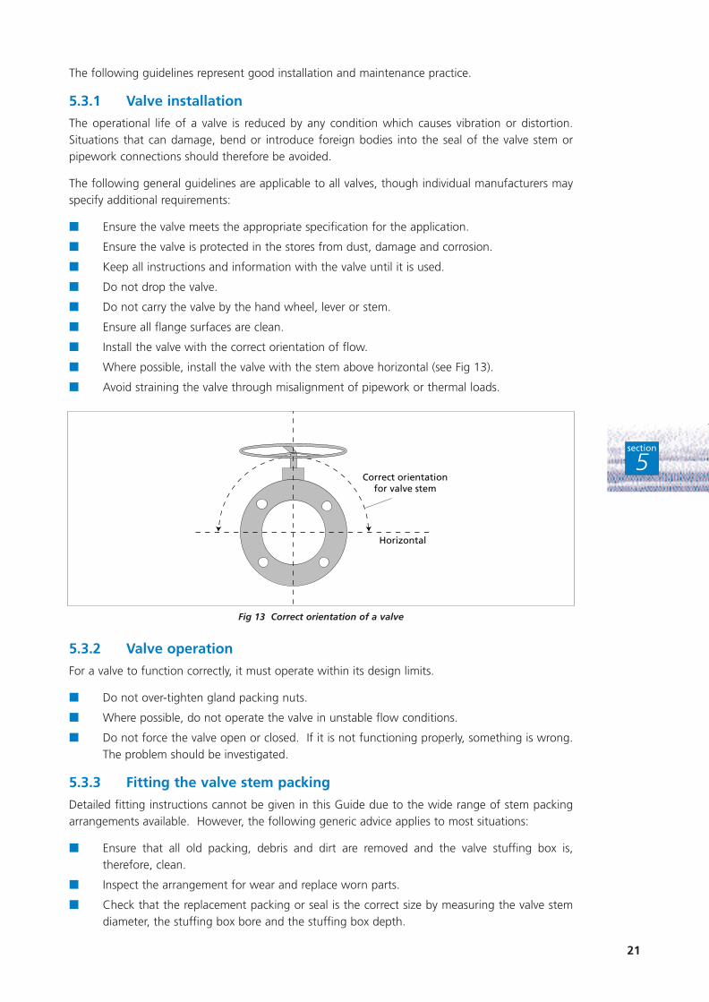
■ Where possible, install the valve with the stem above horizontal (see Fig 13).
■ Avoid straining the valve through misalignment of pipework or thermal loads.
5.3.2 Valve operation
For a valve to function correctly, it must operate within its design limits.
■ Do not over-tighten gland packing nuts.
■ Where possible, do not operate the valve in unstable flow conditions.
■ Do not force the valve open or closed. If it is not functioning properly, something is wrong.The problem should be investigated.
5.3.3 Fitting the valve stem packing
Detailed fitting instructions cannot be given in this Guide due to the wide range of stem packingarrangements available. However, the following generic advice applies to most situations:
■ Ensure that all old packing, debris and dirt are removed and the valve stuffing box is,therefore, clean.
■ Inspect the arrangement for wear and replace worn parts.
■ Check that the replacement packing or seal is the correct size by measuring the valve stemdiameter, the stuffing box bore and the stuffing box depth.
21
section
5
Fig 13 Correct orientation of a valve
Correct orientationfor valve stem
Horizontal

■ Select the correct packing material appropriate for the application.
■ Follow installation instructions provided by the seal manufacturer. Install spacers and/or anti-extrusion rings where necessary.
■ Where compression rings are fitted, ensure that the correct amount of pre-compression isapplied. Split ring joints should be staggered, so that the joints are 90° apart.
■ The gland follower should penetrate the stuffing box to a depth of half the cross-section ofan individual packing ring.
■ Use a torque wrench to tighten the gland nuts.
■ Consider using ‘live loading’ (see Section 7.2) for highly compressible packing material, orapplications subject to thermal cycling.
■ Actuate the valve several times and check the torque of the stuffing box nuts. Adjust ifnecessary.
■ Where combination packing sets are installed, pre-compress the assembly using the glandnuts before fitting the top wiper ring.
5.3.4 Maintenance of valve stem packing
If leakage is detected from the gland of the valve, the stem seal will require attention. Re-tighteningthe gland bolts will generally reduce such leakage to some extent, without the need to remove thevalve or take it out of service. It is normal to re-tighten the gland at least two or three times beforethe valve needs repacking.
To prevent damage to the packing material when re-tightening gland bolts, ensure that the nuts are:
■ tightened gradually and evenly;
■ not over-tightened.
22
section
5

Modern pumps almost exclusively use mechanical seals as shaft seals for solvent pumpingapplications. Mechanical seals are capable of achieving low fugitive emissions and a long life.
The main categories of mechanical seal are discussed in the following Sections.
Zero emission operation can be achieved, where necessary, using:
■ dual seals (pressurised and unpressurised);
■ gas barrier seals;
■ sealless pumping systems.
6.1 DIFFERENT TYPES OF SEAL
6.1.1 Single mechanical seals
Single mechanical seals (see Fig 14) have traditionally been perceived as a significant source offugitive emissions from pumps and other rotating machinery. However, modern seal designs cannow achieve emission control levels below 500 ppm (US EPA Reference Method 21). Singlemechanical seals are used to pump process fluids with a specific gravity greater than 0.4 and wherethe vapour pressure margin in the seal chamber is greater than 170 kN/m2. As with manymechanical seals, the process fluid has to provide adequate lubrication of the seal faces.
Single mechanical seals have a minimum number of parts and are generally considered both reliableand economical.
6.1.2 Secondary containment seals
Secondary containment seals, which are fitted in the seal housing between the single seal andatmosphere, provide an extra level of security without the need to resort to buffer/barrier fluids.
Such seals are available in many forms.
23
P R E V E N T I N G L E A K A G E F R O MP U M P S H A F T S E A L S
6
Fig 14 Cross-section through a single mechanical seal
section
6

Low technology solutions
These include:
■ packing rings (usually lubricated by steam);
■ dry running lip seal (usually lubricated by steam);
■ pressure-activated lip seal;
■ fixed-throttle bushing;
■ segmented floating spring-loaded throttle bushing (see Fig 15).
In normal operation these seals may not provide the best low emissions performance. However, theyprovide a useful warning of high seal leakage and impending seal failure when used in conjunctionwith a pressure switch or other sensor. This arrangement enables the pump to be shut down beforethe leakage becomes excessive.
High technology solutions
These include:
■ dry-running contacting mechanical seal;
■ pressure-activated stand-by mechanical seal;
■ non-contacting mechanical seal (see Fig 16).
Because they can be used with a vent connection to a vapour recovery or flare system, these hightechnology solutions can achieve lower emissions performance under normal operating conditions.They can also be used with pressure switches or other sensors to flag inboard seal failure.
High technology secondary containment seals are able to take full service pressure in the event ofeither increased leakage from the primary seal or its complete failure. This allows the pump to beshut down safely and remedial action taken.
These secondary containment seals can be used for several hours at full duty conditions andthousands of hours at lower duties. This is especially beneficial in a batch process, where it may bepossible to complete a batch before complete shutdown.
24
section
6
Fig 15 Cross-section through a single mechanical seal with segmented floating spring-loaded throttle bushing

6.1.3 Dual unpressurised seals
Dual unpressurised or tandem seals (see Fig 17) are used when more stringent emission control isrequired and where contamination of the process fluid by a buffer fluid cannot be tolerated.Emissions of less than 10 ppm (US EPA Reference Method 21) have been reported from pumps at ahydrocarbon plant in the USA using this type of seal.
The seal arrangement consists of an inner and outer seal separated by a buffer fluid maintained ata lower pressure than the process fluid. The buffer fluid is typically water, glycol or alcohol-based.
Any failure of the inner seal will cause process fluid to enter the buffer fluid. In practice, someleakage of process fluid into the buffer fluid is inevitable and, if necessary, leakage of lighthydrocarbons can be fed to a flare or solvent recovery system.
6.1.4 Dual pressurised seals
Dual pressurised or double seals (see Fig 18) are designed to achieve ‘zero emission’ by maintainingthe pressure of the barrier fluid at a higher pressure than the process fluid. The barrier fluid is either
25
section
6
Fig 16 Cross-section through a single mechanical seal with a non-contacting secondary containment seal
Fig 17 Cross-section through a dual unpressurised seal

liquid or gaseous. Double seals can be used where loss of any process fluid is unacceptable or wherethe process fluid has poor lubricating properties.
During normal operation, some barrier fluid inevitably enters the process fluid. In the event of theinner seal failing, larger quantities of the barrier fluid are lost to the process stream. To ensureproduct quality remains unaffected by a seal failure, the barrier fluid must be chemically inert andnot react with the process fluid.
6.1.5 Gas barrier seals
Gas barrier seals are a type of dual pressurised seal that use an inert gas such as nitrogen as thebarrier fluid. This arrangement can be used with both contacting and non-contacting seal faces.
Some types of non-contacting designs possess grooves in the seal faces to generate lift andseparation of the faces during both dynamic and stationary conditions. Such non-contactingsystems can improve seal life, while the pressurised gas barrier provides zero emission of the processfluid to atmosphere. Such seals are usually bought as a pre-assembled cartridge and use nitrogenor compressed air as the gas barrier.
26
section
6
Fig 18 Cross-section through a dual pressurised seal
Fig 19 Cross-section through a gas barrier seal

6.1.6 Sealless pumps
Sealless pumps reduce fugitive emissions by eliminating all rotary seals. The technology of this typeof pump is improving and sealless pumps are beginning to find new applications.
There are two main types of sealless pump:
■ the canned pump (see Fig 20), where the motor and pump unit are totally enclosed in a shell;
■ the magnetic drive pump, where power is transferred from an external motor to the pumpvia rotating magnets and a sealed magnetic fluid coupling.
6.2 PUMP SEAL SELECTION
Fig 21 and Table 9, which are based on data supplied by the European Sealing Association, indicatethe applicability of different mechanical seal arrangements.
27
section
6
Fig 20 Typical canned pump
Phot
ogra
ph c
ourt
esy
of H
MD
Sea
l/les
s Pu
mps
Ltd

Area Maximum leakage Specific gravity Acceptable sealing solution
rate (g/hour) of process fluid
1 2.5 - 24 > 0.4 General purpose single seals
Advanced technology single seals
Dual unpressurised and pressurised seals
2 0.5 - 2.5 > 0.4 to 0.7 Advanced technology single seals
Dual unpressurised and pressurised seals
3 < 0.5 > 0.4 Advanced technology single seals vented to
a closed system
Dual unpressurised and pressurised seals
vented to a closed system
< 0.4 Dual pressurised seals
Table 9 Acceptable sealing solutions for different levels of emission control.
Based on data supplied by the European Sealing Association
6.3 INSTALLATION AND MAINTENANCE OF PUMP SHAFT SEALS
The performance of a mechanical seal on a pump depends on various factors associated with theoperation of the pump, including:
■ pump operating parameters;
■ installation of the pump;
■ installation of the seal.
While the instructions supplied by the equipment manufacturer should always be consulted, thefollowing general guidelines on the maintenance and operation of pumps should ensure thatcomponents do not fail prematurely.
28
section
6
Fig 21 Maximum mass emission level control for mechanical seals
0.9
0.8
0.7
0.6
0.5
0.4
1 50 100 500 1 000 10 000
Maximum emission control level (ppm) (measured in accordance with US EPA Method 21)
Spec
ific
gra
vity
of
pro
cess
flu
id
Area 3
Area 2
Area 1
6.3.1 Pump installation
A pump that is incorrectly installed can set up vibrations and oscillations which may reduce the lifeof a mechanical seal. It is therefore important to:
■ ensure that shafts and pipework are correctly aligned.
6.3.2 Pump operation
The day-to-day operation of a pump can affect the life of a mechanical seal. For optimumoperation:
■ avoid vibration and cavitation;
■ ensure ancillary equipment, such as buffer/barrier fluid systems, operate correctly;
■ before starting the pump, ensure that buffer/barrier fluid circulation is established.
6.3.3 Pump shaft seal installation
Correct installation has a profound influence on the life and performance of shaft seals. However,the installation procedure begins before actual fitting.
Before fitting the seal, take care to:
■ ensure the part number is correct;
■ check seal, shaft and bore dimensions;
■ follow instructions (where available);
■ ensure personnel are properly trained;
■ avoid mechanical damage;
■ remove packaging carefully;
■ check arrangement drawing;
■ check shaft for straightness and the surface finish for wear or damage;
■ check the shaft and housing for sharp edges;
■ ensure all edges onto which the mechanical seal is pushed are chamfered and de-burred.
When fitting the seal, take care to:
■ follow the manufacturer’s instructions;
■ ensure the seal, shaft and workspace are clean and free of dust;
■ not use excessive force;
■ avoid kinks with ‘O’ rings;
■ lubricate the ‘O’ rings prior to fitting;
■ not roll ‘O’ rings into position.
29
section
6

7.1 PRESSURE RELIEF VALVES
Pressure relief valves can be categorised into two common types:
■ pilot-operated relief valves;
■ spring-loaded relief valves.
The valve seats of pressure relief valves traditionally involve metal to metal contact; this requireslapping to ensure a tight seal. More pliant materials such as PTFE are now becoming morewidespread as the seat material in relief valves. Depending on the application, these flexible sealsmay need to be replaced every two to five years.
Fugitive losses from pressure relief valves are usually due to:
■ incorrect re-seating of the valve after operation;
■ frequent operation of the valve due to the system pressure being too close to the setactuation pressure;
■ valve operation in response to a genuine over-pressure situation.
Pilot-operated relief valves are designed so that the seal is maintained by the system pressure actingabove and below the main seal. When the system pressure increases to the set point pressure, apilot line vents to atmosphere. This decreases the pressure above the main seal and enables thevalve to vent fully. Pilot-operated relief valves typically commence operation at around 95% of theset point pressure. With spring-loaded relief valves, however, the system pressure acts against aspring and the valve commences opening at approximately 90% of the set point pressure.
A less common design is the buckling pin relief valve. This device relies on a retaining pin yieldingunder load to give full bore venting. Such pins must be replaced after operation.
Fitting a rupture disc upstream of relief valves can help to reduce fugitive emissions. Such discs mustbe replaced after failure.
An alternative approach - which may be suitable for some applications - is to pipe the exhaust portof the relief valve to a secondary system and thus allow the solvent to be recovered or piped to aflare stack. The risk of over-pressure due to system back pressure necessitates careful design of suchsystems.
7.2 SLOW ROTATING EQUIPMENT
Leakage from slow rotating equipment using gland packing seals, such as mixers and filters, can becontrolled in certain applications by fitting disc springs to the gland nuts. This technique, known as‘live loading’, involves applying a constant force to the gland follower. It can be used to compensatefor thermal and pressure cycling effects.
Further leakage may occur through the packing as a result of the vessel oscillating on the shaft asit rotates. This leakage can be reduced by incorporating floating gland seal arrangements - whichmove with the shaft - in the design.
30
section
7
P R E V E N T I N G L E A K A G E F R O M O T H E R S O U R C E S
7

7.3 PIPEWORK JOINTS AND FLANGES
Where possible, pipework joints should be avoided. Welded joints should be used where screwedor flanged joints are not required for maintenance purposes. Where mechanical joints such asflanges are required, the joint should be designed to suit the temperature and pressurerequirements.
Flanges are commonly used for connecting pipework to components such as valves, pumps andvessels. A gasket is fitted between the faces of the mating flanges to accommodate imperfectionsin the face material and slight misalignment.
Typical defects encountered on flanged joints include:
■ non-parallel flange faces;
■ face damage;
■ poor surface condition;
■ face distortion;
■ incorrect bolt specification or tightening procedure;
■ incorrect bolt stress;
■ incorrectly rated flanges;
■ unsuitable face design;
■ unsuitable gasket material or thickness.
All these problems can be avoided by careful attention to detail and by following the advice givenin the following Sections.
7.3.1 Flange gasket materials
A range of gasket materials is available for flanged joints.
Compressed fibre materials
These materials have been used for many years as the basis of the gasket seal. The fibres, whichmay be either organic or inorganic, are bound with elastomers under high load to provide sheetmaterials compatible with a wide range of fluids.
By selecting various fibres and bonding them with different elastomers, the performance of thesheet materials can be tailored to meet specific applications.
Compressed asbestos fibre
Historically, compressed asbestos fibre has been the most widely used material for flange gasketapplications. For many applications it is being superseded by alternative fibres.
Correct storage is important for all compressed fibre materials. The elastomeric structure undergoesageing, with subsequent loss of performance with time.
Carbon fibre
Carbon-based gaskets have excellent thermal stability, load retention characteristics and chemicalcompatibility. The capability to operate at high temperatures ensures that carbon fibre gaskets aresuitable for most applications, except where oxidation may occur.
PTFE
PTFE gaskets are traditionally used in chemical applications where inert sealing materials arerequired. PTFE is a soft material, which is unaffected by many chemicals, including strong acids.
31
section
7

However, the material can suffer from poor recovery after deformation. PTFE gaskets are, therefore,vulnerable to creep; this is more significant at higher temperatures.
Table 10 summarises the properties of some common gasket materials.
Gasket Max Sealability Density Compressibility Creep Recovery after
material temp (°C) (ml/hour)* (g/cm3) (%) (%) deformation (%)
Compressed fibre 350 0.2 1.76 7 - 17 15 50
Carbon fibre 550 0.1 1.76 7 - 17 9 65
PTFE 260 0.1 2.19 7 - 12 12 - 40 40
* Based on iso-octane fuel with a gasket load of 7 000 kN/m2 and an internal pressure of 70 kN/m2.
Table 10 Technical data for common gasket materials
7.3.2 Installing flange gaskets
Installing flange gaskets is a relatively simple operation. The performance and life of the flangedjoint can be maximised by:
■ ensuring the flange surfaces are clean;
■ using the thinnest suitable gasket;
■ placing the gasket centrally on the flange;
■ ensuring the surface finish and flatness are satisfactory;
■ tightening the bolts to compress the gasket uniformly;
■ always applying torque to the bolts in a cross-bolting sequence, as advised by the flange orgasket supplier;
■ using a torque wrench and well-lubricated fasteners;
■ tightening all bolts in 1/3 increments;
■ re-torquing the bolts after 12 to 24 hours of operation;
■ not using gasket or sealing compounds on the gasket faces.
7.3.3 Maintaining flange gaskets
Stress relaxation of gaskets can occur as a result of time, pressure, temperature or creep.Occasionally, the bolts may loosen as a result of vibration.
Flanged joints should be routinely inspected and re-torqued.
7.4 FILLING OPERATIONS
Significant fugitive emissions may arise when filling storage vessels, mixing vessels or othercontainers due to the displacement of solvent-rich air.
When filling vessels from storage tanks, intermediate bulk containers (IBCs) or larger vessels, aprinciple known as back venting (see Fig 22) or balanced pumping can be used. With thisarrangement, the displaced air is vented back to the original vessel, thus preventing its escape toatmosphere.
An alternative approach is to pass the displaced air through a solvent recovery vessel or anadsorption canister prior to its release to atmosphere (see Fig 23).
32
section
7

7.5 QUICK RELEASE COUPLINGS
These components should be kept clean and the seals maintained in a good state of repair.
Filling and discharge connections to road tankers can be self-sealing, dry break couplings. If thetanker drives off while it is still connected, the coupling separates and seals, thus preventing spillage.This can be particularly important for applications using flammable solvents where safety issues areparamount.
7.6 OPEN-ENDED FILLING LINES
These are often found at the connections between storage or mixing tanks and product containers.Such lines can allow significant quantities of solvent to escape as fugitive emissions.
Table 11 shows different measures that can be taken to isolate different types of open-ended fillinglines. Investigations should be carried out to determine whether these measures are both feasibleand safe.
Condition Control measure
The line is no longer used Insert a blank
The line is used occasionally Insert a plug
The line is used frequently Fit a second valve or quick release blank
Table 11 Measures to prevent fugitive emissions from open-ended filling lines
Employees should be made aware of the need to seal open lines. Regular checks should beperformed to ensure that this is occurring.
7.7 FILTERS
In certain specialist sectors, such as adhesives manufacture, products containing solvent may needto be filtered prior to filling containers.
Muslin bags, which are cheap and easy to replace, are often used for this purpose. However, thismethod of filtration gives rise to fugitive emissions, which usually require local exhaust ventilation.The use of enclosed filtration systems should be considered.
33
Fig 22 Back venting during filling of an IBC Fig 23 Solvent recovery during filling of an IBC
IBC
IBC
Adsorptioncanister
section
7

7.8 LEAKING PIPELINES
Mechanical damage or corrosion can give rise to leaks of solvent from pipework. Such leaks cancreate a significant hazard.
Most defects of this kind can be rectified as soon as they are detected. However, if it is not possibleto take the pipework out of service immediately due to other, overwhelming safety considerations,the use of specialist companies with expertise in repairing leaks in pressurised pipelines should beconsidered.
34
section
7

35
A C T I O N P L A N8
IF YOU WANT TO:
Reduce your fugitive emissions and save money
Estimate your fugitive losses by performing a mass balance, using averageemission factors or employing more advanced techniques involving monitoring.
Identify the main sources of fugitive emissions.
Review your maintenance procedures and check that your equipment is installedand maintained correctly.
Review your solvent emission control and monitoring strategies. Significantimprovements can be achieved through simple monitoring and review proceduresand without the need for sophisticated equipment.
Prioritise your actions based on potential savings and ease of implementation.
If economically viable, consider changing your process, procedures or sealingsystems.
In addition to the short-term costs of a fugitive emissions control programme,consider:
- the long-term cost to your company of fugitive emissions;
- the potential savings from reduced maintenance;
- the health and safety benefits, including an improved, cleaner workplace;
- the potential reduction in your legal liability;
- your corporate environmental and other objectives.
Consider developing a Solvent Management System which incorporates yourfugitive emissions control programme. Three other Good Practice Guides -available free of charge through the Environmental Helpline on 0800 585794 - willhelp you. Ask for:
- Good Practice Guide (GG12) Solvent Capture for Recovery and Re-use fromSolvent-laden Gas Streams.
- Good Practice Guide (GG13) Cost-effective Solvent Management;
- Good Practice Guide (GG28) Good Housekeeping Measures for Solvents;
The Environmental Helpline can also:
- give you details about the techniques and products described in this Guide;
- tell you about relevant environmental and other regulations that could affectyour operations;
- arrange for a specialist to contact your company free of charge if you employfewer than 250 people.
section
8

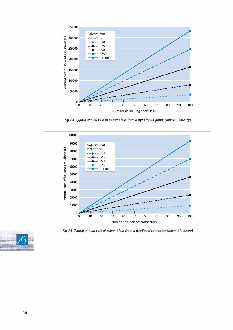
The following graphs shows typical annual costs for solvent leaks from common pipelinecomponents at:
■ Sites manufacturing, using or recycling organic solvents as part of their operations, egcompanies manufacturing organic chemicals.
■ Petrochemical facilities. These tend to be larger sites with the potential for individual leaksof a significantly higher magnitude.
Each graph shows the annual cost (1997 prices) for up to 100 leaking components for solvent worth£100 - £1 000/tonne. The graphs are based on data obtained from US Environmental ProtectionAgency publications. A leak is defined as being greater than 10 000 ppm.
Table A1 lists the components considered in the nine graphs.
Component Graph
Solvent industry: gas valve Fig A1
light liquid valve Fig A2
light liquid pump Fig A3
gas/liquid connector Fig A4
Petrochemical industry: gas valve Fig A5
light liquid valve Fig A6
light liquid pump Fig A7
heavy liquid pump Fig A8
gas/liquid connector Fig A9
Table A1 Types of component considered in the graph series
36
appx
A1
A N N U A L C O S T O F F U G I T I V EE M I S S I O N S
Appendix

37
appx
A1
Fig A1 Typical annual cost of solvent loss from a gas valve (solvent industry)
£100£250£500£750£1 000
Solvent costper tonne
6 000
5 000
4 000
3 000
2 000
1 000
00 10 20 30 40 50 60 70 80 90 100
Number of leaking valves
An
nu
al c
ost
of
solv
ent
emis
sio
ns
(£)
Fig A2 Typical annual cost of solvent loss from a light liquid valve (solvent industry)
9 000
5 000
6 000
7 000
8 000
4 000
3 000
2 000
1 000
00 10 20 30 40 50 60 70 80 90 100
Number of leaking valves
An
nu
al c
ost
of
solv
ent
emis
sio
ns
(£)
£100£250£500£750£1 000
Solvent costper tonne
38
Fig A3 Typical annual cost of solvent loss from a light liquid pump (solvent industry)
10 000
15 000
20 000
25 000
30 000
35 000
5 000
00 10 20 30 40 50 60 70 80 90 100
Number of leaking shaft seals
An
nu
al c
ost
of
solv
ent
emis
sio
ns
(£)
£100£250£500£750£1 000
Solvent costper tonne
Fig A4 Typical annual cost of solvent loss from a gas/liquid connector (solvent industry)
9 000
10 000
5 000
6 000
7 000
8 000
4 000
3 000
2 000
1 000
00 10 20 30 40 50 60 70 80 90 100
Number of leaking connectors
An
nu
al c
ost
of
solv
ent
emis
sio
ns
(£)
£100£250£500£750£1 000
Solvent costper tonne
appx
A1

39
Fig A5 Typical annual cost of solvent loss from a gas valve (petrochemical industry)
16 000
10 000
12 000
14 000
6 000
8 000
4 000
2 000
00 10 20 30 40 50 60 70 80 90 100
Number of leaking valves
An
nu
al c
ost
of
solv
ent
emis
sio
ns
(£) £100
£250£500£750£1 000
Solvent costper tonne
Fig A6 Typical annual cost of solvent loss from a light liquid valve (petrochemical industry)
16 000
18 000
20 000
10 000
12 000
14 000
6 000
8 000
4 000
2 000
00 10 20 30 40 50 60 70 80 90 100
Number of leaking valves
An
nu
al c
ost
of
solv
ent
emis
sio
ns
(£) £100
£250£500£750£1 000
Solvent costper tonne
appx
A1

40
Fig A7 Typical annual cost of solvent loss from a light liquid pump (petrochemical industry)
160 000
100 000
120 000
140 000
60 000
80 000
40 000
20 000
00 10 20 30 40 50 60 70 80 90 100
Number of leaking shaft seals
An
nu
al c
ost
of
solv
ent
emis
sio
ns
(£) £100
£250£500£750£1 000
Solvent costper tonne
Fig A8 Typical annual cost of solvent loss from a heavy liquid pump (petrochemical industry)
100 000
120 000
60 000
80 000
40 000
20 000
00 10 20 30 40 50 60 70 80 90 100
Number of leaking shaft seals
An
nu
al c
ost
of
solv
ent
emis
sio
ns
(£) £100
£250£500£750£1 000
Solvent costper tonne
appx
A1

The Environmental Technology Best Practice Programme is a joint Department of Trade and
Industry and Department of the Environment initiative. It is managed by AEA Technology plc
through ETSU and the National Environmental Technology Centre.
The Programme offers free advice and information for UK businesses and promotes
environmental practices that:
■ increase profits for UK industry and commerce;
■ reduce waste and pollution at source.
To find out more about the Programme please call the Environmental Helpline on freephone
0800 585794. As well as giving information about the Programme, the Helpline has access to
a wide range of environmental information. It offers free advice to UK businesses on technical
matters, environmental legislation, conferences and promotional seminars. For smaller
companies, a free counselling service may be offered at the discretion of the Helpline Manager.
FOR FURTHER INFORMATION, PLEASE CONTACT THE ENVIRONMENTAL HELPLINE
0800 585794e-mail address: [email protected]
World wide web: http://www.etsu.com/ETBPP/
Related Documents


