BDC 1360 1360 ROW CLEANER with DC MOUNTS (for Deere 7200 and Later with no-till coulter) Martin Planter Attachments Martin Industries LLC 206 Elk Fork Road Elkton, KY 42220 Telephone: 270-265-5817 E-Mail: [email protected] www.martintill.com VERSION 06012012 Installation Instructions SHOWN WITH OPTIONAL SIDE TREADER WHEELS & CAM ADJUST (STW-04 & CA03-D)

Welcome message from author
This document is posted to help you gain knowledge. Please leave a comment to let me know what you think about it! Share it to your friends and learn new things together.
Transcript

BDC 1360 1360 ROW CLEANER with DC MOUNTS (for Deere 7200
and Later with no-till coulter)
Martin Planter Attachments
Martin Industries LLC
206 Elk Fork Road
Elkton, KY 42220
Telephone: 270-265-5817
E-Mail: [email protected]
www.martintill.com VERSION 06012012
Installation Instructions
SHOWN WITH OPTIONAL SIDE
TREADER WHEELS & CAM ADJUST
(STW-04 & CA03-D)
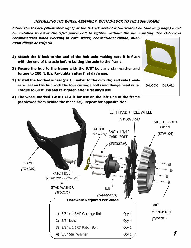
INSTALLING THE WHEEL ASSEMBLY WITH D-LOCK TO THE 1360 FRAME
Either the D-Lock (illustrated right) or the D-Lock deflector (illustrated on following page) must
be installed to allow the 5/8” patch bolt to tighten without the hub rotating. The D-Lock is
recommended when working in corn stalks, conventional tillage, mini-
mum tillage or strip till.
1) Attach the D-lock to the end of the hub axle making sure it is flush
with the end of the axle before bolting the axle to the frame.
2) Secure the hub to the frame with the 5/8” bolt and star washer and
torque to 200 ft. lbs. Re-tighten after first day’s use.
3) Install the toothed wheel (part number to the outside) and side tread-
er wheel on the hub with the four carriage bolts and flange head nuts.
Torque to 60 ft. lbs and re-tighten after first day’s use.
4) The wheel marked TW3813-L4 is for use on the left side of the frame
(as viewed from behind the machine). Repeat for opposite side.
D-LOCK DLR-01
1
3/8”
FLANGE NUT
(N38CFL)
Hardware Required Per Wheel
1) 3/8” x 1 3/4” Carriage Bolts Qty 4
2) 3/8” Nuts Qty 4
3) 5/8” x 1 1/2” Patch Bolt Qty 1
4) 5/8” Star Washer Qty 1
LEFT HAND 4 HOLE WHEEL
(TW3813-L4)
FRAME
(FR1360)
D-LOCK
(DLR-01)
PATCH BOLT
(B5M58NC112MICRO)
&
STAR WASHER
(W58EIL) HUB
(HA44270-D)
3/8” x 1 3/4”
CARR. BOLT
(B5C38134)
SIDE TREADER
WHEEL
(STW -04)
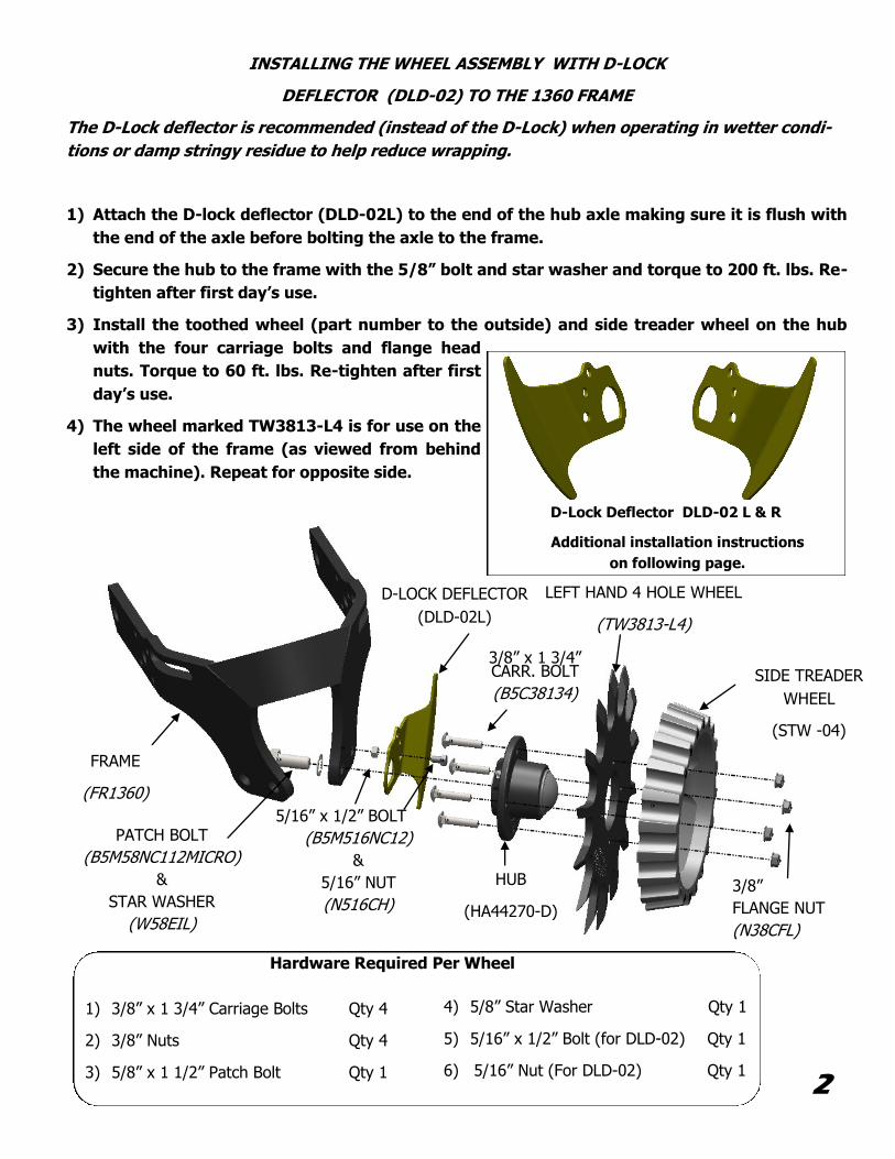
INSTALLING THE WHEEL ASSEMBLY WITH D-LOCK
DEFLECTOR (DLD-02) TO THE 1360 FRAME
The D-Lock deflector is recommended (instead of the D-Lock) when operating in wetter condi-
tions or damp stringy residue to help reduce wrapping.
1) Attach the D-lock deflector (DLD-02L) to the end of the hub axle making sure it is flush with
the end of the axle before bolting the axle to the frame.
2) Secure the hub to the frame with the 5/8” bolt and star washer and torque to 200 ft. lbs. Re-
tighten after first day’s use.
3) Install the toothed wheel (part number to the outside) and side treader wheel on the hub
with the four carriage bolts and flange head
nuts. Torque to 60 ft. lbs. Re-tighten after first
day’s use.
4) The wheel marked TW3813-L4 is for use on the
left side of the frame (as viewed from behind
the machine). Repeat for opposite side.
1) 3/8” x 1 3/4” Carriage Bolts Qty 4
2) 3/8” Nuts Qty 4
3) 5/8” x 1 1/2” Patch Bolt Qty 1
Hardware Required Per Wheel
2
D-LOCK DEFLECTOR
(DLD-02L)
HUB
(HA44270-D)
FRAME
(FR1360)
D-Lock Deflector DLD-02 L & R
Additional installation instructions
on following page.
5/16” x 1/2” BOLT
(B5M516NC12)
&
5/16” NUT
(N516CH) 3/8”
FLANGE NUT
(N38CFL)
3/8” x 1 3/4” CARR. BOLT
(B5C38134)
PATCH BOLT
(B5M58NC112MICRO)
&
STAR WASHER
(W58EIL)
LEFT HAND 4 HOLE WHEEL
(TW3813-L4)
SIDE TREADER
WHEEL
(STW -04)
4) 5/8” Star Washer Qty 1
5) 5/16” x 1/2” Bolt (for DLD-02) Qty 1
6) 5/16” Nut (For DLD-02) Qty 1
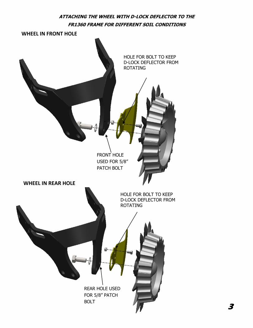
ATTACHING THE WHEEL WITH D-LOCK DEFLECTOR TO THE
FR1360 FRAME FOR DIFFERENT SOIL CONDITIONS
HOLE FOR BOLT TO KEEP D-LOCK DEFLECTOR FROM ROTATING
WHEEL IN FRONT HOLE
WHEEL IN REAR HOLE
FRONT HOLE
USED FOR 5/8”
PATCH BOLT
3
REAR HOLE USED
FOR 5/8” PATCH
BOLT
HOLE FOR BOLT TO KEEP D-LOCK DEFLECTOR FROM ROTATING
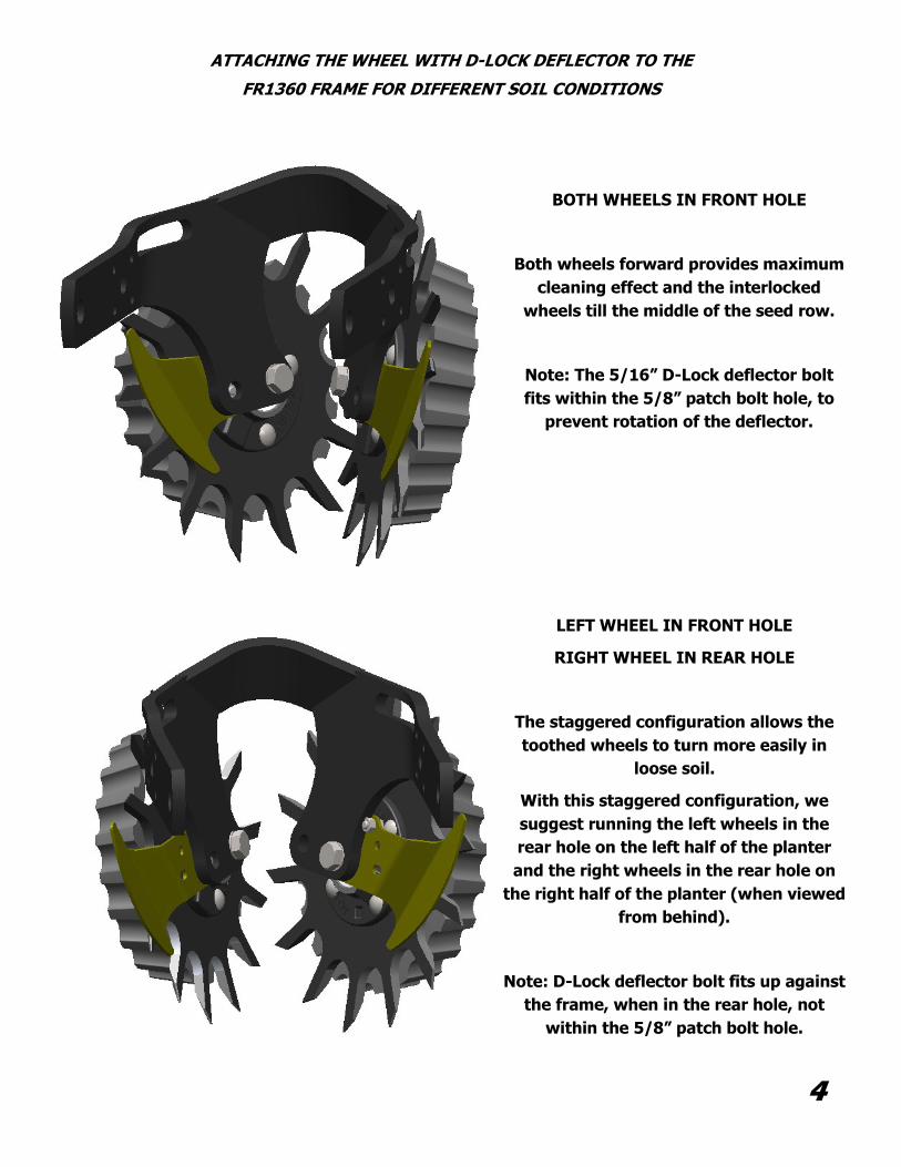
BOTH WHEELS IN FRONT HOLE
Both wheels forward provides maximum
cleaning effect and the interlocked
wheels till the middle of the seed row.
Note: The 5/16” D-Lock deflector bolt
fits within the 5/8” patch bolt hole, to
prevent rotation of the deflector.
LEFT WHEEL IN FRONT HOLE
RIGHT WHEEL IN REAR HOLE
The staggered configuration allows the
toothed wheels to turn more easily in
loose soil.
With this staggered configuration, we
suggest running the left wheels in the
rear hole on the left half of the planter
and the right wheels in the rear hole on
the right half of the planter (when viewed
from behind).
Note: D-Lock deflector bolt fits up against
the frame, when in the rear hole, not
within the 5/8” patch bolt hole.
ATTACHING THE WHEEL WITH D-LOCK DEFLECTOR TO THE
FR1360 FRAME FOR DIFFERENT SOIL CONDITIONS
4
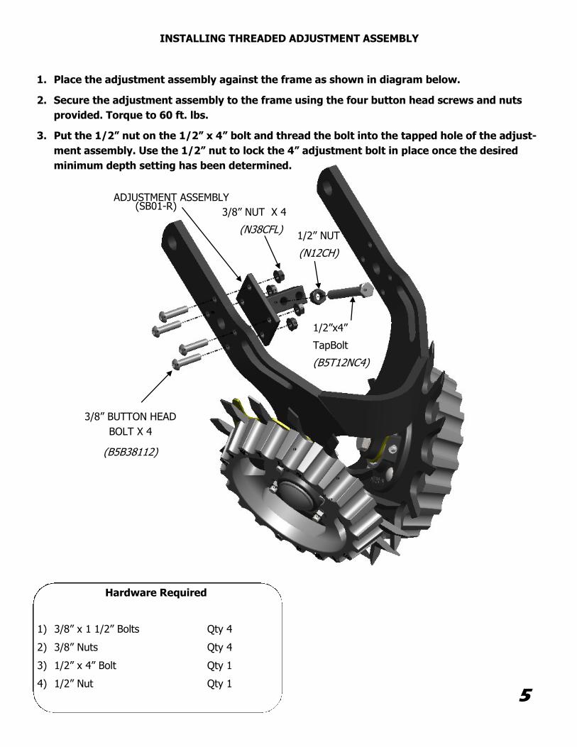
Hardware Required
1) 3/8” x 1 1/2” Bolts Qty 4
2) 3/8” Nuts Qty 4
3) 1/2” x 4” Bolt Qty 1
4) 1/2” Nut Qty 1
INSTALLING THREADED ADJUSTMENT ASSEMBLY
1. Place the adjustment assembly against the frame as shown in diagram below.
2. Secure the adjustment assembly to the frame using the four button head screws and nuts
provided. Torque to 60 ft. lbs.
3. Put the 1/2” nut on the 1/2” x 4” bolt and thread the bolt into the tapped hole of the adjust-
ment assembly. Use the 1/2” nut to lock the 4” adjustment bolt in place once the desired
minimum depth setting has been determined.
5
ADJUSTMENT ASSEMBLY (SB01-R)
3/8” BUTTON HEAD
BOLT X 4
(B5B38112)
3/8” NUT X 4
(N38CFL) 1/2” NUT
(N12CH)
1/2”x4”
TapBolt
(B5T12NC4)
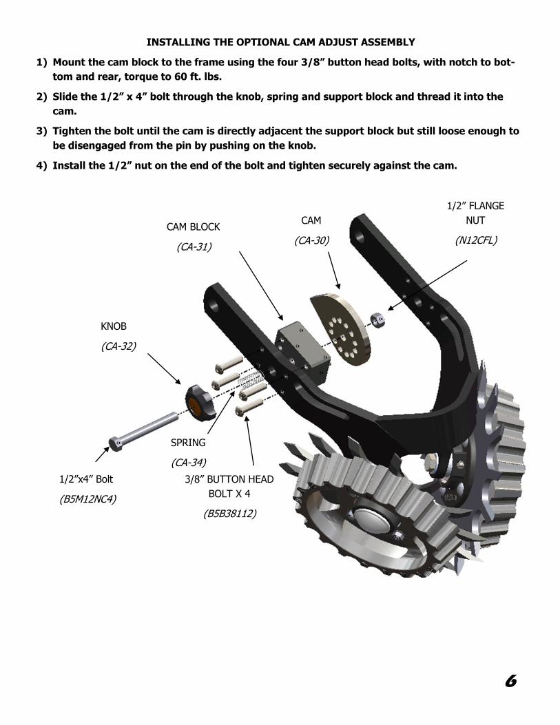
INSTALLING THE OPTIONAL CAM ADJUST ASSEMBLY
1) Mount the cam block to the frame using the four 3/8” button head bolts, with notch to bot-
tom and rear, torque to 60 ft. lbs.
2) Slide the 1/2” x 4” bolt through the knob, spring and support block and thread it into the
cam.
3) Tighten the bolt until the cam is directly adjacent the support block but still loose enough to
be disengaged from the pin by pushing on the knob.
4) Install the 1/2” nut on the end of the bolt and tighten securely against the cam.
CAM
(CA-30)
CAM BLOCK
(CA-31)
KNOB
(CA-32)
SPRING
(CA-34)
6
1/2”x4” Bolt
(B5M12NC4)
3/8” BUTTON HEAD
BOLT X 4
(B5B38112)
1/2” FLANGE
NUT
(N12CFL)
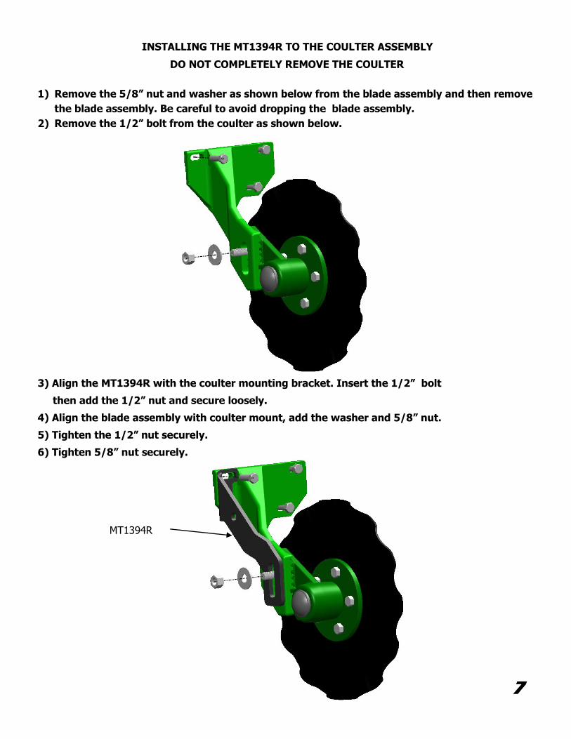
INSTALLING THE MT1394R TO THE COULTER ASSEMBLY
DO NOT COMPLETELY REMOVE THE COULTER
1) Remove the 5/8” nut and washer as shown below from the blade assembly and then remove
the blade assembly. Be careful to avoid dropping the blade assembly.
2) Remove the 1/2” bolt from the coulter as shown below.
3) Align the MT1394R with the coulter mounting bracket. Insert the 1/2” bolt
then add the 1/2” nut and secure loosely.
4) Align the blade assembly with coulter mount, add the washer and 5/8” nut.
5) Tighten the 1/2” nut securely.
6) Tighten 5/8” nut securely.
7
MT1394R
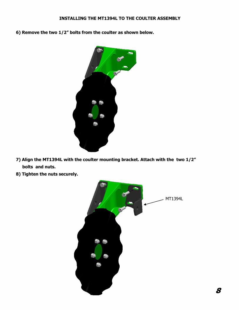
INSTALLING THE MT1394L TO THE COULTER ASSEMBLY
8
6) Remove the two 1/2” bolts from the coulter as shown below.
7) Align the MT1394L with the coulter mounting bracket. Attach with the two 1/2”
bolts and nuts.
8) Tighten the nuts securely.
MT1394L
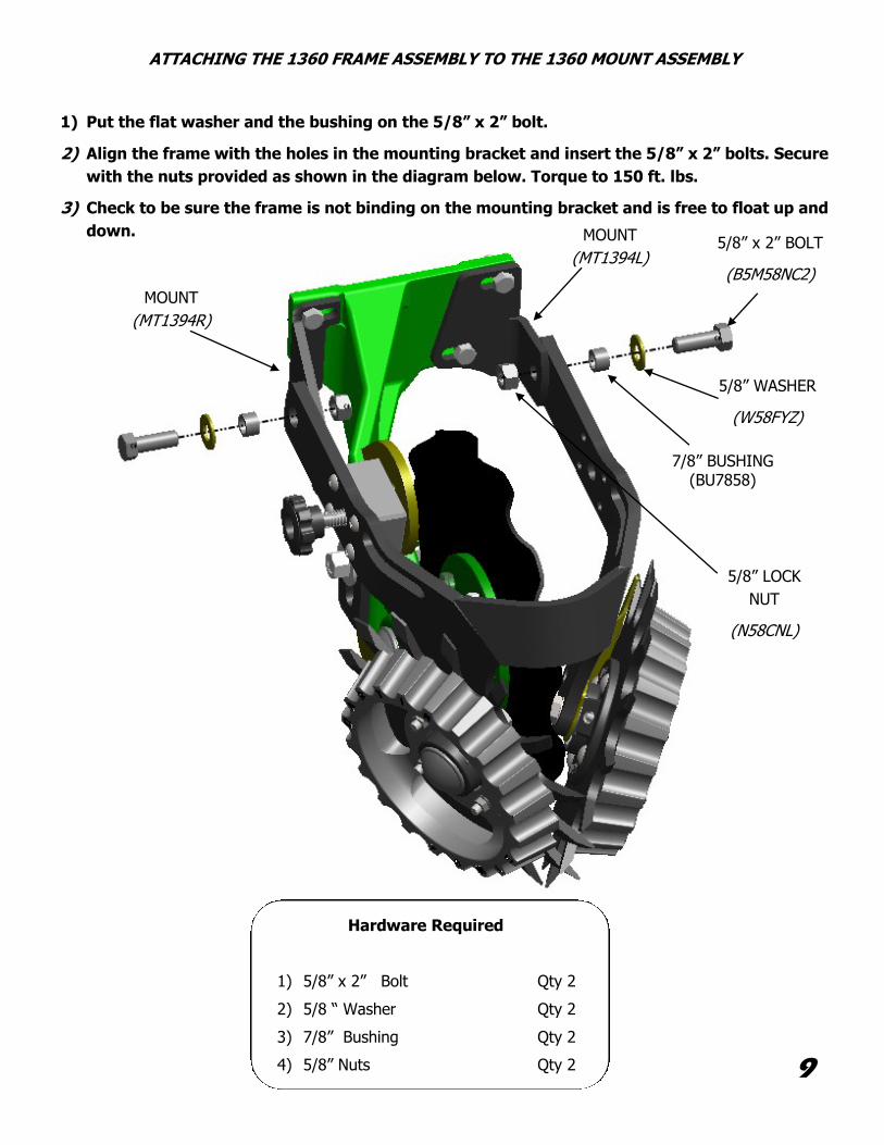
ATTACHING THE 1360 FRAME ASSEMBLY TO THE 1360 MOUNT ASSEMBLY
1) Put the flat washer and the bushing on the 5/8” x 2” bolt.
2) Align the frame with the holes in the mounting bracket and insert the 5/8” x 2” bolts. Secure
with the nuts provided as shown in the diagram below. Torque to 150 ft. lbs.
3) Check to be sure the frame is not binding on the mounting bracket and is free to float up and
down.
Hardware Required
1) 5/8” x 2” Bolt Qty 2
2) 5/8 “ Washer Qty 2
3) 7/8” Bushing Qty 2
4) 5/8” Nuts Qty 2 9
5/8” NUT
5/8” WASHER
(W58FYZ)
5/8” x 2” BOLT
(B5M58NC2)
7/8” BUSHING (BU7858)
MOUNT
(MT1394L)
MOUNT
(MT1394R)
5/8” LOCK
NUT
(N58CNL)
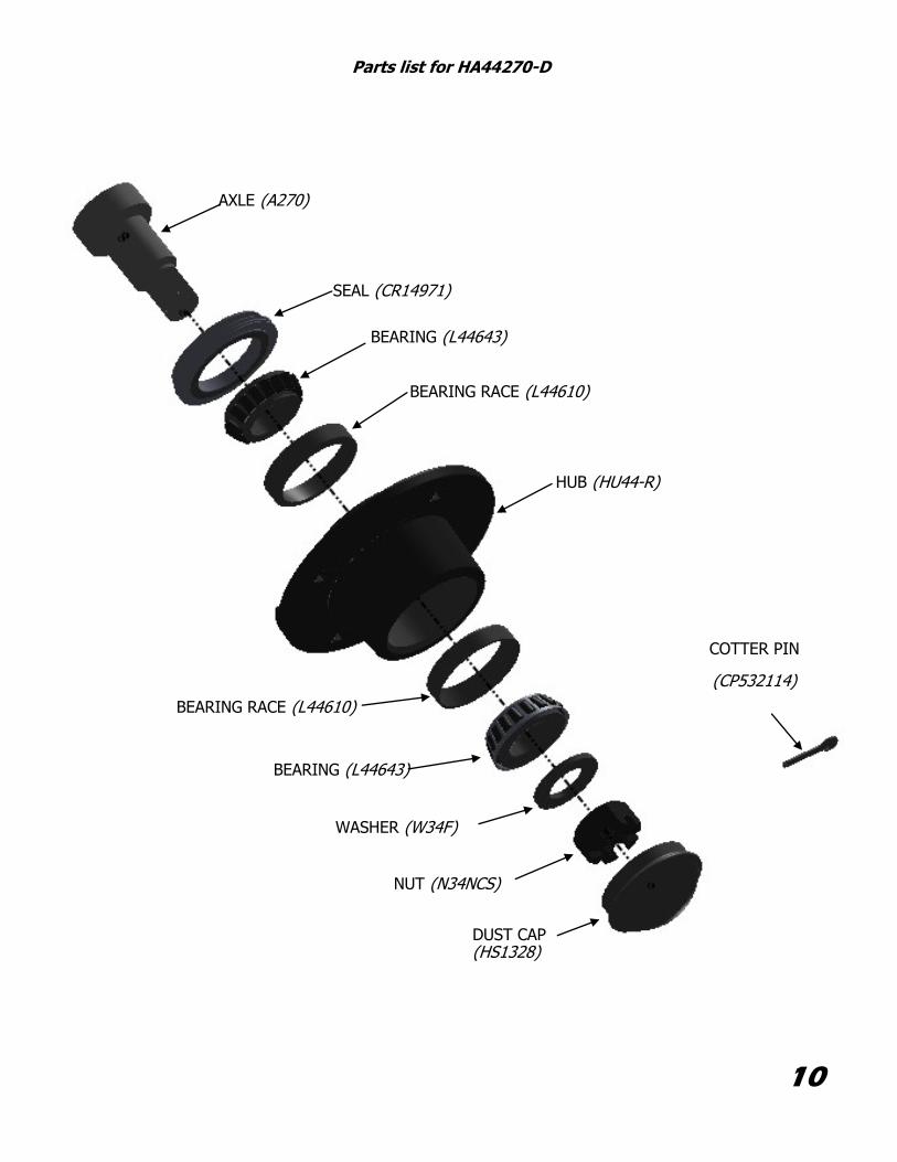
10
AXLE (A270)
SEAL (CR14971)
BEARING (L44643)
BEARING RACE (L44610)
HUB (HU44-R)
WASHER (W34F)
NUT (N34NCS)
DUST CAP (HS1328)
COTTER PIN
(CP532114)
BEARING RACE (L44610)
BEARING (L44643)
Parts list for HA44270-D
Related Documents