Welcome message from author
This document is posted to help you gain knowledge. Please leave a comment to let me know what you think about it! Share it to your friends and learn new things together.
Transcript


Cisco Certified Network Professional CCNP
BCMSN Lab Manual
Revision 1
Developed by
M. Irfan Ghauri M. Rizwan Khan
Etronics Solution Provider C-32/1 Block-5 Gulshan-e-Iqbal, Karachi ESP Press Ph #021-6034003 Copyrights 2008

LAB.
LABS DESCRIPTION
PAGE NO.
1
Basics of Native IOS
1
2
Configuring VLAN and VTP
6
3
Configuring Traditional Spanning Tree Protocol (PVST)
8
4
Vlan Load Balancing in PVST
9
5
Configuring Uplink fast and Port fast
11
6
Configuring RSTP and MST
13
7
Configuring Inter-Vlan Routing
16
8
Securing STP (Root Guard, Bpdu Guard)
20
9
Configuring Ether Channel
22
10
Configuring HSRP
25
11
Securing Switched network using VACL
27
12
Securing Switched network using Private Vlans
29
13
Securing Switched network using Port Security
31
14
Implementing Wireless Lan using Cisco Aironet Access Point
33
15
Configuring Cisco IP Telephony using Cisco Call Manager &
Cisco IP Phones
52

BCMSN Lab Manual
- 1 -
Lab # 1
Basics of Native IOS Objective This lab includes basic commands of Native IOS on 2950 & 3560. Diagram
2950 3560
Configuratio Step 1: After con Switch con0 is now a Press RETURN to ge Switch>
Etronics Solution P
Console Port 0
Console Port 0n
necting your PC to the Console Port.
vailable
t started.
(User Mode)
rovider
BCMSN Lab Manual
- 2 -
Step 2: To Enter Into Privilege executive mode From User Mode & Vice- Versa. Switch>enable Switch# Switch#disable Switch> Step 3: To Enter Into Global Configuration Mode. Switch# Switch#config t Switch(config)# Step 4: To change the Host Name of Switch. Switch(config)#hostname 3560 Step 5(A): Set the Line Console Password on the switch. 3560(config)#line console 0 3560(config-line)#password cisco 3560(config-line)#login Step 5(B): Verification Line Console Password on the switch. 3560 con0 is now available Press RETURN to get started. User Access Verification Password: 3560>enable Step 6(A): Set the privileged mode password in clear text. 3560(config)#enable password cisco Step 6(B): Verifying the privileged mode password in clear text. 3560#disable 3560>enable Password:
Etronics Solution Provider
BCMSN Lab Manual
- 3 -
Step 7(A): Set the Privileged Mode password in encrypted form. 3560(config)#enable secret cisco1 Step 7(B): Verifying the Privileged Mode password in encrypted form. 3560#disable 3560>enable Password: Step 8: Set the Line VTY Password on the switch. 3560(config)#line vty 0 15 3560(config-line)#password cisco 3560(config-line)#login Step 9: Show contents of Current Configuration (RAM). 3560#show running-config Step 10: To give the IP Address of Management Domain Interface OF 3560. 3560(config)#int vlan 1 3560(config-if)#ip address 10.0.0.10 255.0.0.0 3560(config-if)#no shutdown Step 11: Display the information of Management VLAN Interface. 3560#show int vlan 1 Step 12: Display the information of All Interfaces on the switch. 3560#show ip interface brief Step 13: Set a IP Default Network In a Switched Network. 3560(config)#ip default-gateway 10.0.0.1 Step 14: Display the Flash Information. 3560#dir Etronics Solution Provider

BCMSN Lab Manual
- 4 -
OR 3560#show flash: Step 15: Display the Status of the Interfaces on the switch. 3560#show interfaces status Step 16: Display the Detailed Information of Interfaces. 3560#show interfaces OR 3560#show interfaces fastEthernet 0/1 Step 17: Display the Information of the Mode of Interfaces (Switchport). 3560#show interfaces switchport OR 3560#show interfaces fastEthernet 0/1 switchport Step 18: Display the Detailed Information of Interfaces Capabilities. 3560#show interfaces capabilities OR 3560#show interfaces fastEthernet 0/1 capabilities Step 19: Display the Information of the Trunk Interfaces (Ports). 3560#show interfaces trunk Step 20: Display the Version Information of the Switch. 3560#show version Etronics Solution Provider

BCMSN Lab Manual
- 5 -
Step 21: Display the Information of Dynamic Trunking Protocol (DTP). 3560#show dtp Step 22: Display the Information of CDP. 3560#show cdp Step 23: Display the Information of CDP Enabled Interfaces. 3560#show cdp interfaces Step 24: Enabled the CDP on the switch. Switch(config)#cdp run Step 25: Enable CDP on the Interface FastEthernet 0/1. Switch(config)#interface fastethernet 0/1 Switch(config-if)#cdp enable Step 26: Shown the MAC Address Table Information. 3560#show mac address-table dynamic Step 27: Copy the Current Configuration Into Startup Configuration. 3560#copy running-config startup-config Step 28: Configuring the Multiple Interfaces. 3560(config)#int range fastEthernet 0/1 - 5 3560(config-if-range)#switchport mode access Step 29: Setting Of Speed, Duplex and Description On Interface. 3560(config)#int fastEthernet 0/1 3560(config-if)#speed 100 3560(config-if)#duplex full 3560(config-if)#description Fast-Ethernet-Port-1
Etronics Solution Provider
BCMSN Lab Manual
- 6 -
Lab # 2
VLAN & VTP Objective To understand VLAN & VTP operations in switched environment.
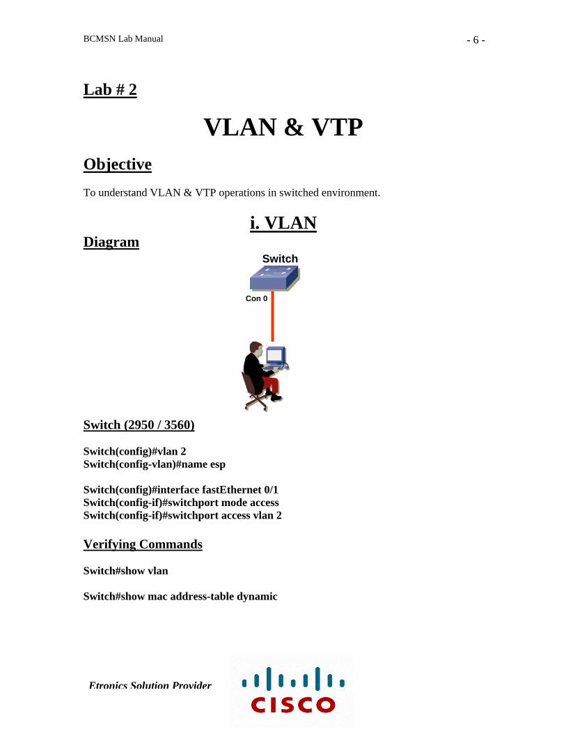
i. VLAN Diagram
Switch
Con 0
Switch (2950 / 3560) Switch(config)#vlan 2 Switch(config-vlan)#name esp Switch(config)#interface fastEthernet 0/1 Switch(config-if)#switchport mode access Switch(config-if)#switchport access vlan 2 Verifying Commands Switch#show vlan Switch#show mac address-table dynamic
Etronics Solution Provider
BCMSN Lab Manual
- 7 -
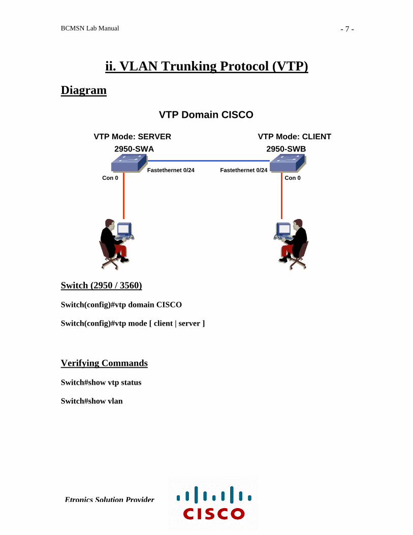
ii. VLAN Trunking Protocol (VTP) Diagram
VTP Domain CISCO
VTP Mode: SERVER VTP Mode: CLIENT 2950-SWB 2950-SWA
Fastethernet 0/24 Fastethernet 0/24Con 0 Con 0
Switch (2950 / 3560) Switch(config)#vtp domain CISCO Switch(config)#vtp mode [ client | server ] Verifying Commands Switch#show vtp status Switch#show vlan
Etronics Solution Provider

BCMSN Lab Manual
- 8 -
Lab # 3
Spanning Tree Protocol Objective To understand the Spanning tree protocol operation in switched environment. Diagram
Switch (2950-SWB) Switch(config)#spanning-tree vlan 1 priority 0 Switch (2950-SWA) Switch(config)#int fastethernet 0/24 Switch(config-if)#spanning-tree vlan 1 cost 18 Verifying Commands Switch#show spanning-tree Switch#show spanning-tree vlan 1
Con 0
Priority: 32768 Priority: 0 Root Switch
MAC: 0012.43a0.b840 MAC: 0012.43a0.b940
Fa 0/23 Fa 0/23 2950-SWB 2950-SWA Blocked Port Designated Port
Fa 0/24 Fa 0/24 Con 0 Designated Port Root Port
Non Root Switch
Etronics Solution Provider

BCMSN Lab Manual
- 9 -
Lab # 4
Vlan Load Balancing in PVST Objective To understand Vlan Load Balancing in PVST. Diagram
MAC: 0012.43a0.b840 MAC: 0012.43a0.b940
Fa 0/23 Fa 0/23
Switch (2950-SWA) Switch(config)#vlan 10 Switch(config)#vlan 20 Switch(config)#spanning-tree vlan 10 priority 0 Switch (2950-SWB) Switch(config)#vlan 10 Switch(config)#vlan 20 Switch(config)#spanning-tree vlan 20 priority 0
Con 0
2950-SWB 2950-SWA
Fa 0/24 Fa 0/24 Con 0
Root Switch for Vlan 10
Root Switch for Vlan 10
Etronics Solution Provider

BCMSN Lab Manual
- 10 -
Verifying Commands Switch# show spanning-tree vlan 10 Switch# show spanning-tree vlan 20
Etronics Solution Provider
BCMSN Lab Manual
- 11 -
Lab # 5
Tuning Spanning Tree Protocol
(Port-Fast, Uplink-Fast) Objective Tune the spanning tree protocol for enhancing network performance and minimizing the network downtime by enabling port-fast & uplink-fast features.
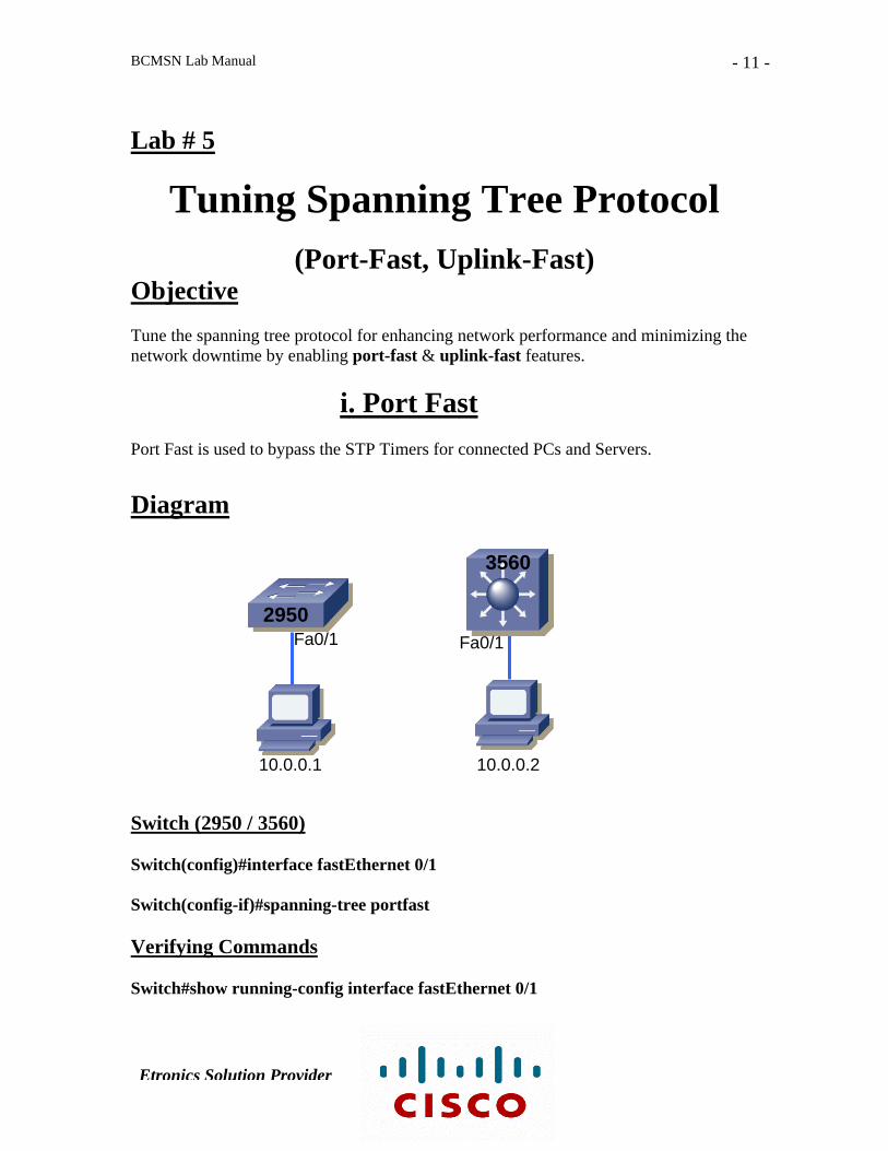
i. Port Fast Port Fast is used to bypass the STP Timers for connected PCs and Servers. Diagram
3560
2950 Fa0/1 Fa0/1
10.0.0.1 10.0.0.2 Switch (2950 / 3560) Switch(config)#interface fastEthernet 0/1 Switch(config-if)#spanning-tree portfast Verifying Commands Switch#show running-config interface fastEthernet 0/1
Etronics Solution Provider
BCMSN Lab Manual
- 12 -
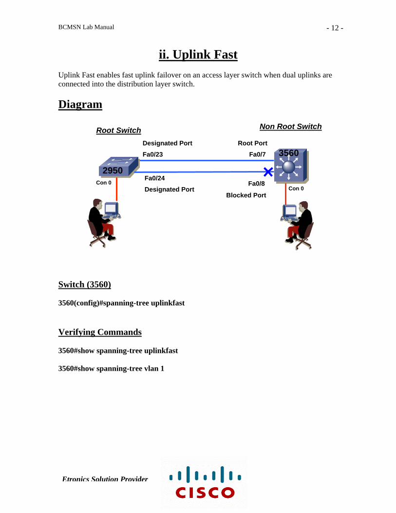
ii. Uplink Fast Uplink Fast enables fast uplink failover on an access layer switch when dual uplinks are connected into the distribution layer switch. Diagram
Non Root Switch Root Switch Designated Port Root Port
3560 Fa0/23 Fa0/7
2950 Fa0/24
Con 0 Fa0/8 Designated Port
Blocked Port Con 0
Switch (3560) 3560(config)#spanning-tree uplinkfast Verifying Commands 3560#show spanning-tree uplinkfast 3560#show spanning-tree vlan 1
Etronics Solution Provider
BCMSN Lab Manual
- 13 -
Lab # 6
Rapid Spanning Tree Protocol &
Multiple Spanning Tree Lab Objective :
1. Enable RSTP on cisco catalyst switches. 2. Enable MST on cisco catalyst switches.
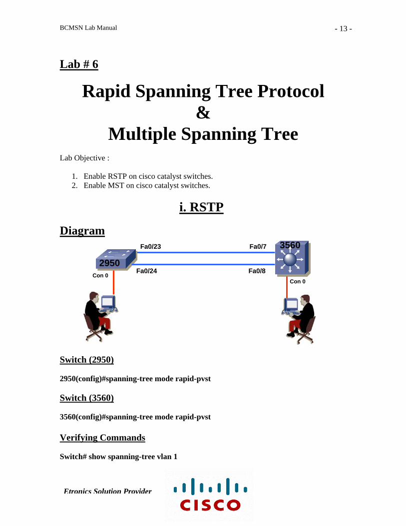
i. RSTP
Diagram 3560 Fa0/23 Fa0/7
2950 Fa0/24 Fa0/8
Con 0 Con 0
Switch (2950) 2950(config)#spanning-tree mode rapid-pvst Switch (3560) 3560(config)#spanning-tree mode rapid-pvst Verifying Commands Switch# show spanning-tree vlan 1
Etronics Solution Provider

BCMSN Lab Manual
- 14 -
ii. MST Diagram
3560 Fa0/23 Fa0/7
2950 Fa0/24 Fa0/8
Con 0 Con 0
Switch (2950) 2950(config)#vlan 10 2950(config-vlan)#name vlan-10 2950(config)#vlan 20 2950(config-vlan)#name vlan-20 2950(config)#vlan 30 2950(config-vlan)#name vlan-30 2950(config)#vlan 40 2950(config-vlan)#name vlan-40 2950(config)#spanning-tree mode mst 2950(config)#spanning-tree mst configuration 2950(config-mst)#name MST-REGION 2950(config-mst)#revision 5 2950(config-mst)#instance 1 vlan 10,20 2950(config-mst)#instance 2 vlan 30,40 2950(config-mst)#show pending Switch (3560) 3560(config)#vlan 10 3560(config-vlan)#name vlan-10 3560(config)#vlan 20
3560(config-vlan)#name vlan-20 3560(config)#vlan 30
Etronics Solution Provider

BCMSN Lab Manual
- 15 -
3560(config-vlan)#name vlan-30 3560(config)#vlan 40 3560(config-vlan)#name vlan-40 3560(config)#spanning-tree mode mst 3560(config)#spanning-tree mst configuration 3560(config-mst)#name MST-REGION 3560(config-mst)#revision 5 3560(config-mst)#instance 1 vlan 10,20 3560(config-mst)#instance 2 vlan 30,40 3560(config-mst)#show pending 3560(config)#spanning-tree mst 2 priority 0 Verifying Commands Switch#show spanning-tree mst
Etronics Solution Provider

BCMSN Lab Manual
- 16 -
Lab # 7
1. Inter-VLAN Routing (Router on a Stick)
Objective To transport packets between VLANs by a Router. Diagram
Switch Switch(config)#vlan 10 Switch(config-vlan)#name vlan-10 Switch(config)#vlan 20 Switch(config-vlan)#name vlan-10
Vlan 10 Vlan 20
Host A 10.0.0.1/8 10.0.0.10
Host B 20.0.0.1/8 20.0.0.10
Fa 0/24
Fa 0/1 Fa 0/11
Fa 0 / 0.10 10.0.0.10 / 8
Fa 0 / 0.20 20.0.0.10 / 8
Fa 0/0
2811
2950
Etronics Solution Provider
BCMSN Lab Manual
- 17 -
Switch(config)#interface range fastEthernet 0/1 - 10 Switch(config-if-range)#switchport mode access Switch(config-if-range)#switchport access vlan 10 Switch(config)#interface range fastEthernet 0/11 - 20 Switch(config-if-range)#switchport mode access Switch(config-if-range)#switchport access vlan 20 Switch(config)#interface fastEthernet 0/24 Switch(config-if)#switchport mode trunk Router Router(config)#interface fastEthernet 0/0 Router(config-if)#no ip address Router(config-if)#no shutdown Router(config)#interface fastEthernet 0/0.10 Router(config-subif)#encapsulation dot1Q 10 Router(config-subif)#ip address 10.0.0.10 255.0.0.0 Router(config-subif)#exit Router(config)#interface fastEthernet 0/0.20 Router(config-subif)#encapsulation dot1Q 20 Router(config-subif)#ip address 20.0.0.10 255.0.0.0 Router(config-subif)#exit Verifying Commands Switch#show vlan Switch#show interface trunk Router#show ip int brief
Etronics Solution Provider
BCMSN Lab Manual
- 18 -
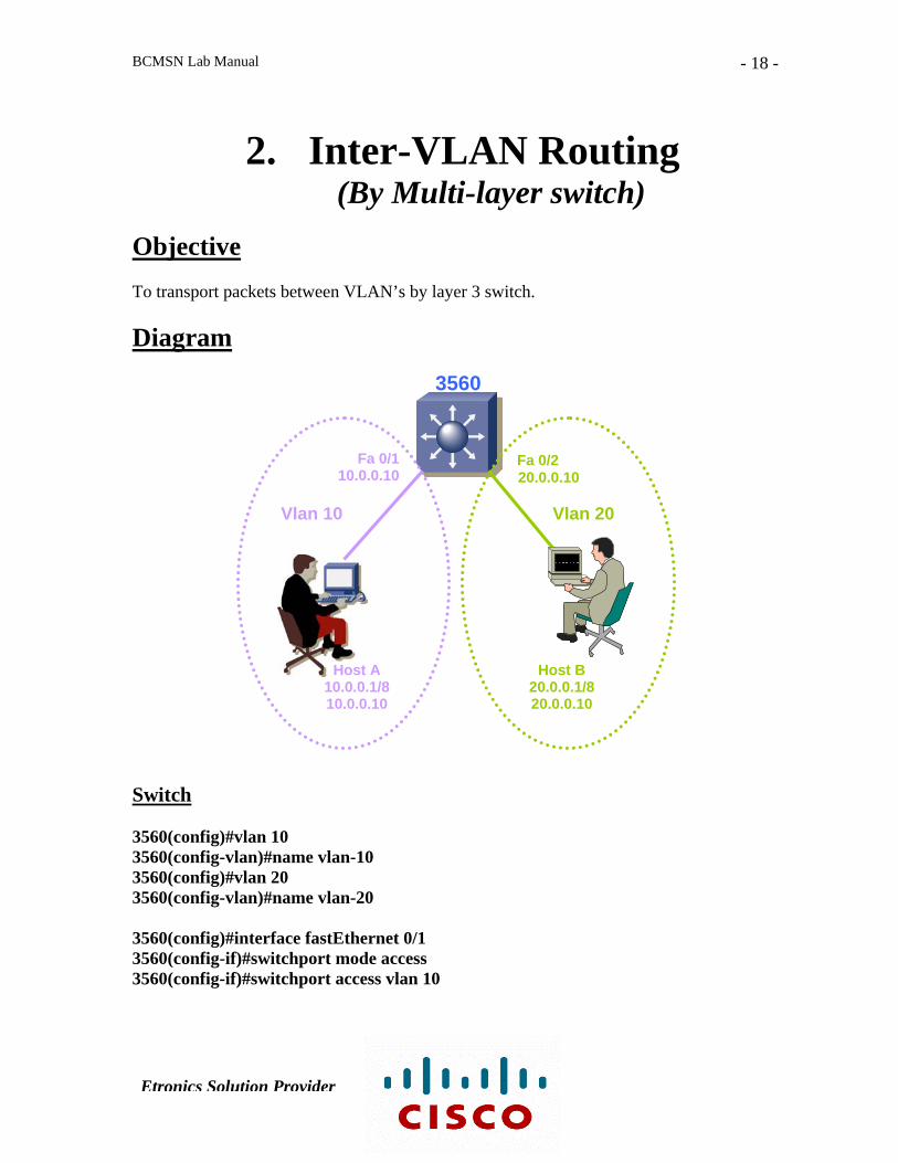
2. Inter-VLAN Routing (By Multi-layer switch)
Objective To transport packets between VLAN’s by layer 3 switch. Diagram
Fa 0/1 Fa 0/2 10.0.0.10 20.0.0.10
Vlan 10 Vlan 20
Host A Host B 10.0.0.1/8 20.0.0.1/8 10.0.0.10 20.0.0.10
3560
Switch 3560(config)#vlan 10 3560(config-vlan)#name vlan-10 3560(config)#vlan 20 3560(config-vlan)#name vlan-20 3560(config)#interface fastEthernet 0/1 3560(config-if)#switchport mode access 3560(config-if)#switchport access vlan 10 Etronics Solution Provider

BCMSN Lab Manual
- 19 -
3560(config)#interface fastEthernet 0/2 3560(config-if)#switchport mode access 3560(config-if)#switchport access vlan 20 3560(config)#interface vlan 10 3560(config-if)#ip address 10.0.0.10 255.0.0.0 3560(config-if)#no shutdown 3560(config)#interface vlan 20 3560(config-if)#ip address 20.0.0.10 255.0.0.0 3560(config-if)#no shutdown 3560(config)#ip routing Verifying Command Switch#show vlan Switch#show ip route
Etronics Solution Provider

BCMSN Lab Manual
- 20 -
Lab # 8
Protecting Spanning Tree Protocol Topology
(BPDU Guard, Root-Guard) Objective Tune the spanning tree protocol for protecting the STP topology by using BPDU Guard & Root Guard features.
i. BPDU-Guard (Port) Diagram
Non Root Switch Root Switch Designated Port Root Port
3560 Fa0/23 Fa0/7
2950 Fa0/24
Con 0 Fa0/8 Con 0 Designated Port BPDU-Guard
Enabled port
Switch (3560) 3560(config)#interface fastEthernet 0/8 3560(config-if)#spanning-tree bpduguard enable Etronics Solution Provider
BCMSN Lab Manual
- 21 -
Verifying Commands 3560#show spanning-tree interface fastEthernet 0/8 detail 3560#show interfaces fastEthernet 0/8 status err-disabled
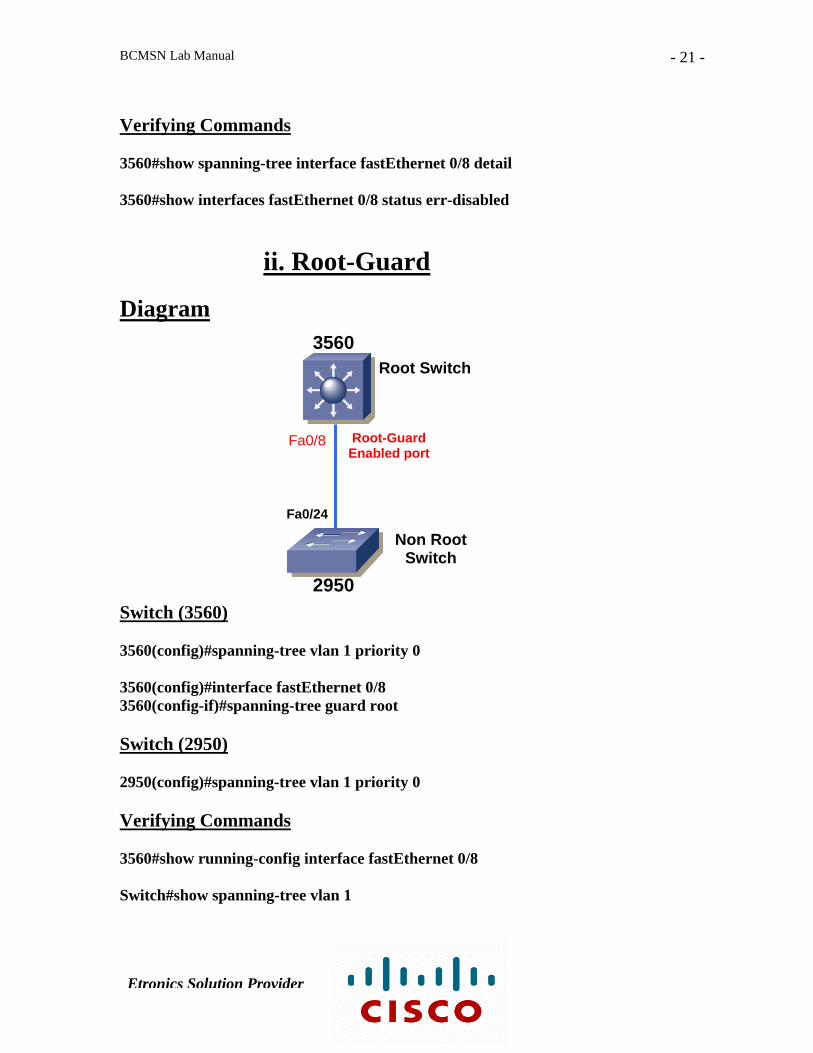
ii. Root-Guard Diagram
3560 Root Switch
Root-Guard Fa0/8 Enabled port
Fa0/24
Non Root Switch
2950 Switch (3560) 3560(config)#spanning-tree vlan 1 priority 0 3560(config)#interface fastEthernet 0/8 3560(config-if)#spanning-tree guard root Switch (2950) 2950(config)#spanning-tree vlan 1 priority 0 Verifying Commands 3560#show running-config interface fastEthernet 0/8 Switch#show spanning-tree vlan 1
Etronics Solution Provider
BCMSN Lab Manual
- 22 -
Lab # 9
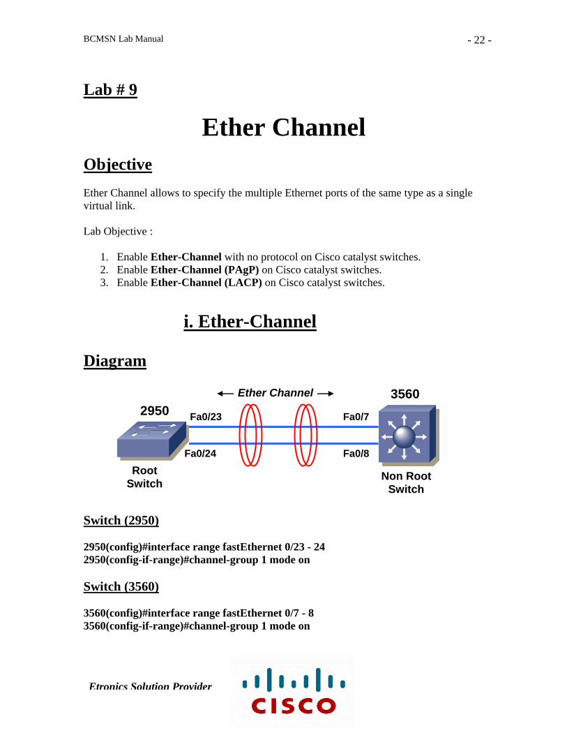
Ether Channel Objective Ether Channel allows to specify the multiple Ethernet ports of the same type as a single virtual link. Lab Objective :
1. Enable Ether-Channel with no protocol on Cisco catalyst switches. 2. Enable Ether-Channel (PAgP) on Cisco catalyst switches. 3. Enable Ether-Channel (LACP) on Cisco catalyst switches.
i. Ether-Channel
Diagram
Ether Channel 3560
Switch (2950) 2950(config)#interface range fastEthernet 0/23 - 24 2950(config-if-range)#channel-group 1 mode on Switch (3560) 3560(config)#interface range fastEthernet 0/7 - 8 3560(config-if-range)#channel-group 1 mode on
Root Switch Non Root
Switch
2950 Fa0/23
Fa0/24 Fa0/8
Fa0/7
Etronics Solution Provider

BCMSN Lab Manual
- 23 -
Verifying Commands Switch#show etherchannel Switch#show etherchannel protocol Switch#show etherchannel port Switch#show etherchannel port-channel Switch#show etherchannel summary
ii. Ether-Channel (PAgP) Diagram
Ether Channel 3560
Switch (2950) 2950(config)#interface range fastEthernet 0/23 - 24 2950(config-if-range)#channel-group 1 mode desirable Switch (3560) 3560(config)#interface range fastEthernet 0/7 - 8 3560(config-if-range)#channel-group 1 mode auto Verifying Commands Switch#show etherchannel Switch#show etherchannel protocol
Root Switch Non Root
Switch
2950 Fa0/23
Fa0/24 Fa0/8
Fa0/7
Etronics Solution Provider
BCMSN Lab Manual
- 24 -
Switch#show etherchannel port Switch#show etherchannel port-channel Switch#show etherchannel summary
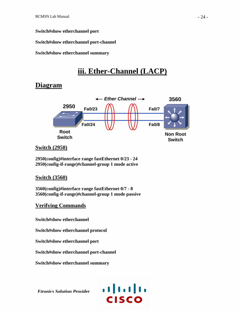
iii. Ether-Channel (LACP) Diagram
Ether Channel 3560
Switch (2950) 2950(config)#interface range fastEthernet 0/23 - 24 2950(config-if-range)#channel-group 1 mode active Switch (3560) 3560(config)#interface range fastEthernet 0/7 - 8 3560(config-if-range)#channel-group 1 mode passive Verifying Commands Switch#show etherchannel Switch#show etherchannel protocol Switch#show etherchannel port Switch#show etherchannel port-channel Switch#show etherchannel summary
Root Switch Non Root
Switch
2950 Fa0/23
Fa0/24 Fa0/8
Fa0/7
Etronics Solution Provider

BCMSN Lab Manual
- 25 -
Lab#10
Hot Standby Router Protocol
(HSRP) Objective Understanding the Layer 3 device redundancy.
Diagram
Virtual Router
10.0.0.20
L0 15.0.0.1
L0 15.0.0.1
E0 10.0.0.5 S0 13.0.0.1 S0 13.0.0.2 RA ISP-1
HSRP
S0 14.0.0.1
RB ISP-2 S0 14.0.0.2
E0 10.0.0.10
GROUP 64
Host A 10.0.0.1
Etronics Solution Provider

BCMSN Lab Manual
- 26 -
Router A RouterA(config)# interface ethernet0 RouterA(config-if)# ip address 10.0.0.5 255.0.0.0 RouterA(config-if)# standby 64 ip 10.0.0.20 RouterA(config-if)# standby 64 priority 150 RouterA(config-if)# standby 64 preempt RouterA(config-if)# standby 64 track serial 0 100 Router B RouterB(config)# interface ethernet0 RouterB(config-if)# ip address 10.0.0.10 255.0.0.0 RouterB(config-if)# standby 64 ip 10.0.0.20 RouterB(config-if)# standby 64 preempt RouterB(config-if)# standby 64 track serial 0 50 Verifying Commands Router# debug standby Router# show standby
Etronics Solution Provider

BCMSN Lab Manual
- 27 -
Lab # 11
VLAN ACL Objective The VLAN ACL’s are filters that can directly affect how packets are handled within a VLAN. Diagram
3560
Fa/1 Fa/2 VLAN 2 VLAN 2
Switch (3560) 3560(config)#vlan 2 3560(config-vlan)#name vlan-2 3560(config)#interface range fastEthernet 0/1 - 2 3560(config-if-range)#switchport mode access 3560(config-if-range)#switchport access vlan 2
www & ftp Server
Host B Host A Ip Add: 10.0.0.2 Ip Add: 10.0.0.1
Etronics Solution Provider
BCMSN Lab Manual
- 28 -
3560(config)#access-list 110 permit tcp host 10.0.0.2 host 10.0.0.1 eq www 3560(config)#access-list 110 permit tcp host 10.0.0.2 host 10.0.0.1 eq ftp 3560(config)#vlan access-map VLAN-ACL 10 3560(config-access-map)#match ip address 110 3560(config-access-map)#action drop 3560(config)#vlan access-map VLAN-ACL 20 3560(config-access-map)#action forward 3560(config)#vlan filter VLAN-ACL vlan-list 2 Verifying Commands 3560#show access-lists 3560#show vlan access-map VLAN-ACL 3560#show vlan filter vlan 2 3560#show vlan filter access-map VLAN-ACL
Etronics Solution Provider
BCMSN Lab Manual
- 29 -
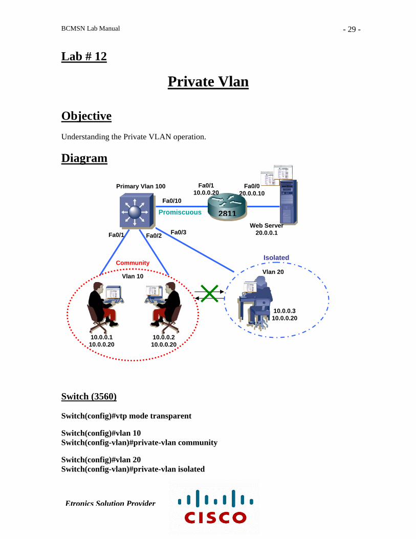
Lab # 12
Private Vlan Objective Understanding the Private VLAN operation. Diagram
Fa0/1 10.0.0.20
Fa0/0 20.0.0.10
Primary Vlan 100
Fa0/10
Promiscuous 2811Web Server
Fa0/3 20.0.0.1 Fa0/1 Fa0/2
Isolated Community
Vlan 20 Vlan 10
10.0.0.3 10.0.0.20
10.0.0.1 10.0.0.210.0.0.20 10.0.0.20
Switch (3560) Switch(config)#vtp mode transparent Switch(config)#vlan 10 Switch(config-vlan)#private-vlan community Switch(config)#vlan 20 Switch(config-vlan)#private-vlan isolated
Etronics Solution Provider

BCMSN Lab Manual
- 30 -
Switch(config)#vlan 100 Switch(config-vlan)#private-vlan primary Switch(config-vlan)#private-vlan association 10,20 Switch(config)#int range fastEthernet 0/1 - 2 Switch(config-if-range)#switchport mode private-vlan host Switch(config-if-range)#switchport private-vlan host-association 100 10 Switch(config)#int fa0/3 Switch(config-if)#switchport mode private-vlan host Switch(config-if)#switchport private-vlan host-association 100 20 Switch(config)#int fa0/10 Switch(config-if)#switchport mode private-vlan promiscuous Switch(config-if)#switchport private-vlan mapping 100 10,20 Verifying Commands Switch#show vlan private-vlan Switch# show vlan private-vlan type
Etronics Solution Provider

BCMSN Lab Manual
- 31 -
Lab # 13
Port Security
Objective To demonstrates the concept of port security mechanism on Switch. Diagram
2950-SW
Fastethernet 0 / 9
Secure MAC Address 0011.d8b5.4126
Switch (2950) Switch(config)#int fa0/9 Switch(config-if)#switchport mode access Switch(config-if)#switchport port-security Switch(config-if)#switchport port-security maximum 1 Switch(config-if)#switchport port-security mac-address sticky Switch(config-if)#switchport port-security violation shutdown Verifying Commands Switch#show mac-address-table
Etronics Solution Provider

BCMSN Lab Manual
- 32 -
Switch#show port-security Switch#show port-security interface fa0/9 Switch#show interface status err-disabled
Etronics Solution Provider
BCMSN Lab Manual
- 33 -
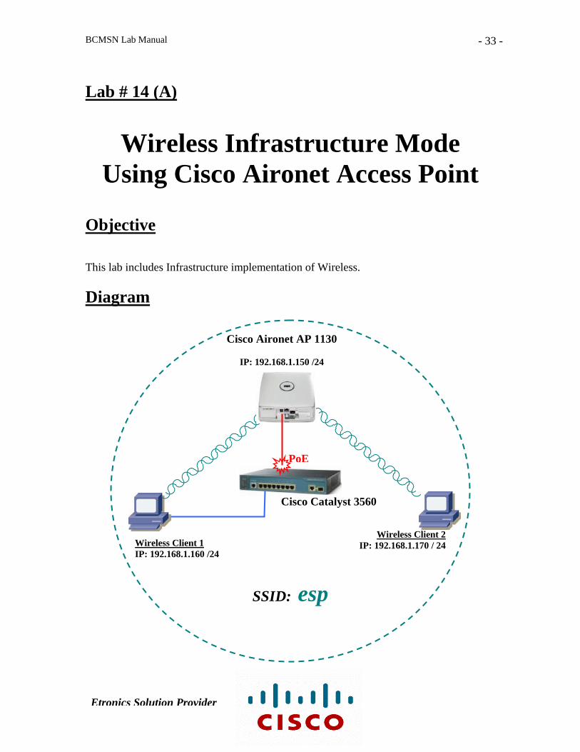
Lab # 14 (A)
Wireless Infrastructure Mode Using Cisco Aironet Access Point
Objective This lab includes Infrastructure implementation of Wireless. Diagram
Cisco Aironet AP 1130
IP: 192.168.1.150 /24
PoE
Cisco Catalyst 3560
Wireless Client 2 Wireless Client 1 IP: 192.168.1.170 / 24 IP: 192.168.1.160 /24
SSID: esp
Etronics Solution Provider
BCMSN Lab Manual
- 34 -
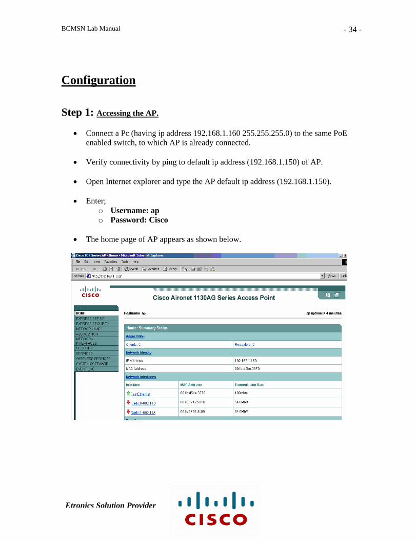
Configuration Step 1: Accessing the AP.
• Connect a Pc (having ip address 192.168.1.160 255.255.255.0) to the same PoE enabled switch, to which AP is already connected.
• Verify connectivity by ping to default ip address (192.168.1.150) of AP.
• Open Internet explorer and type the AP default ip address (192.168.1.150).
• Enter;
o Username: ap o Password: Cisco
• The home page of AP appears as shown below.
Etronics Solution Provider
BCMSN Lab Manual
- 35 -
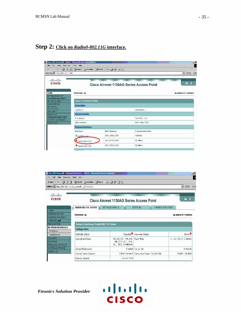
Step 2: Click on Radio0-802.11G interface.
Etronics Solution Provider

BCMSN Lab Manual
- 36 -
Step 3: Go to the ‘SETTINGS’ tab and select ‘Enable’ in the ‘Enable Radio’ option & press ‘Apply’.
Step 4: Go to ‘EXPRESS SECURITY’ and type an SSID ( esp ) and select the check box ‘Broad SSID in Beacons’ & press ‘Apply’.
Etronics Solution Provider

BCMSN Lab Manual
- 37 -
Step 5: Open Aironet Desktop Utility on the wireless client 1.
Step 6: Go to ‘Profile Management’ tab and click ‘Scan’.
Etronics Solution Provider
BCMSN Lab Manual
- 38 -
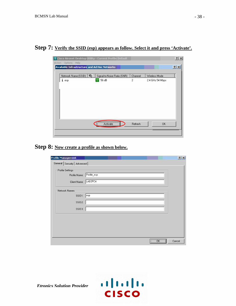
Step 7: Verify the SSID (esp) appears as follow. Select it and press ‘Activate’.
Step 8: Now create a profile as shown below.
Etronics Solution Provider
BCMSN Lab Manual
- 39 -
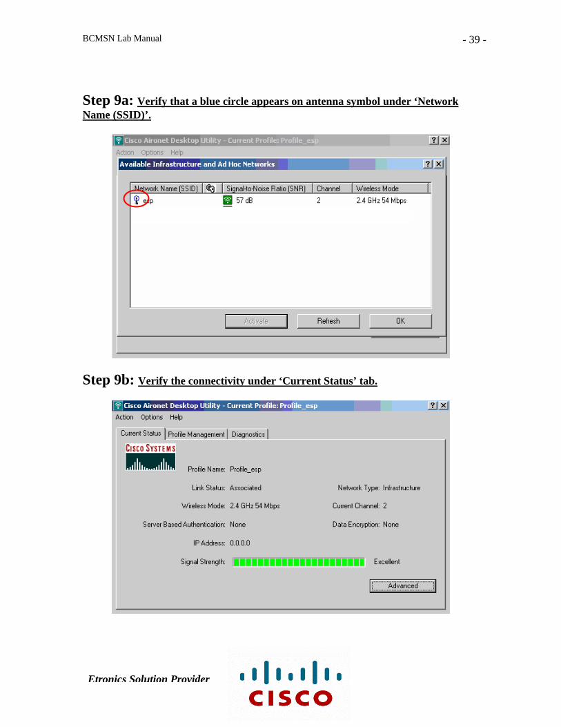
Step 9a: Verify that a blue circle appears on antenna symbol under ‘Network Name (SSID)’.
Step 9b: Verify the connectivity under ‘Current Status’ tab.
Etronics Solution Provider

BCMSN Lab Manual
- 40 -
Step 10: Verify association of wireless client 1 with AP in the ASSOCIATION option.
Step 11: On wireless client 2, open wireless desktop utility. No association appears for some time.
Etronics Solution Provider

BCMSN Lab Manual
- 41 -
Step 12: Go to ‘Site Survey’ tab and see the SSID (esp) as shown below. Select it and press ‘Connect’.
Step 13: Verify that wireless client 2 is also connected to Ap.
Etronics Solution Provider

BCMSN Lab Manual
- 42 -
Step 14: Verify association of wireless client 2 with AP in the ASSOCIATION option.
Etronics Solution Provider

BCMSN Lab Manual
- 43 -
Lab # 14 (B)
Wireless Adhoc Mode Objective This lab includes Adhoc implementation of Wireless Lan. Diagram
Wireless Client 1
SSID: esp-adhoc
Wireless Client 2 IP: 10.0.0.44/ 8 IP: 10.0.0.33/ 8
Etronics Solution Provider
BCMSN Lab Manual
- 44 -
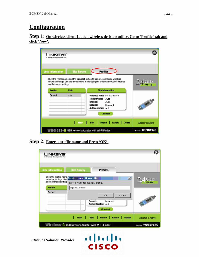
Configuration
Step 1: On wireless client 1, open wireless desktop utility. Go to ‘Profile’ tab and click ‘New’.
Step 2: Enter a profile name and Press ‘OK’.
Etronics Solution Provider
BCMSN Lab Manual
- 45 -
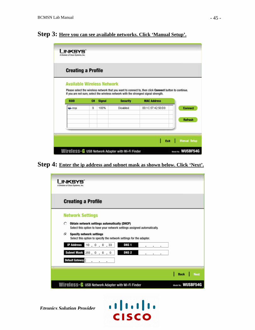
Step 3: Here you can see available networks. Click ‘Manual Setup’.
Step 4: Enter the ip address and subnet mask as shown below. Click ‘Next’.
Etronics Solution Provider

BCMSN Lab Manual
- 46 -
Step 5: Select Wireless Mode as ‘Ad-Hoc Mode’. Enter SSID (esp-adhoc) and click Next.
Step 6: Select Channel and Network Mode as shown below and click Next.
Etronics Solution Provider
BCMSN Lab Manual
- 47 -
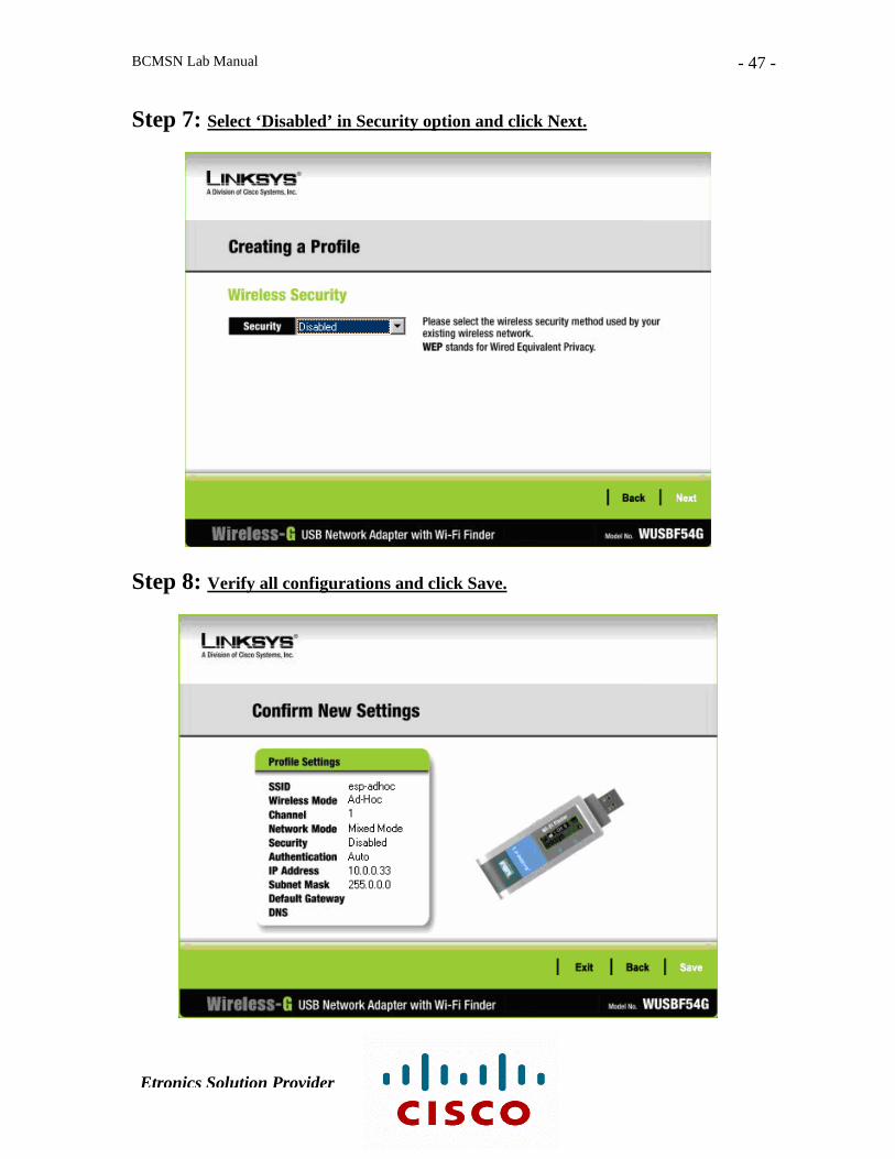
Step 7: Select ‘Disabled’ in Security option and click Next.
Step 8: Verify all configurations and click Save.
Etronics Solution Provider
BCMSN Lab Manual
- 48 -
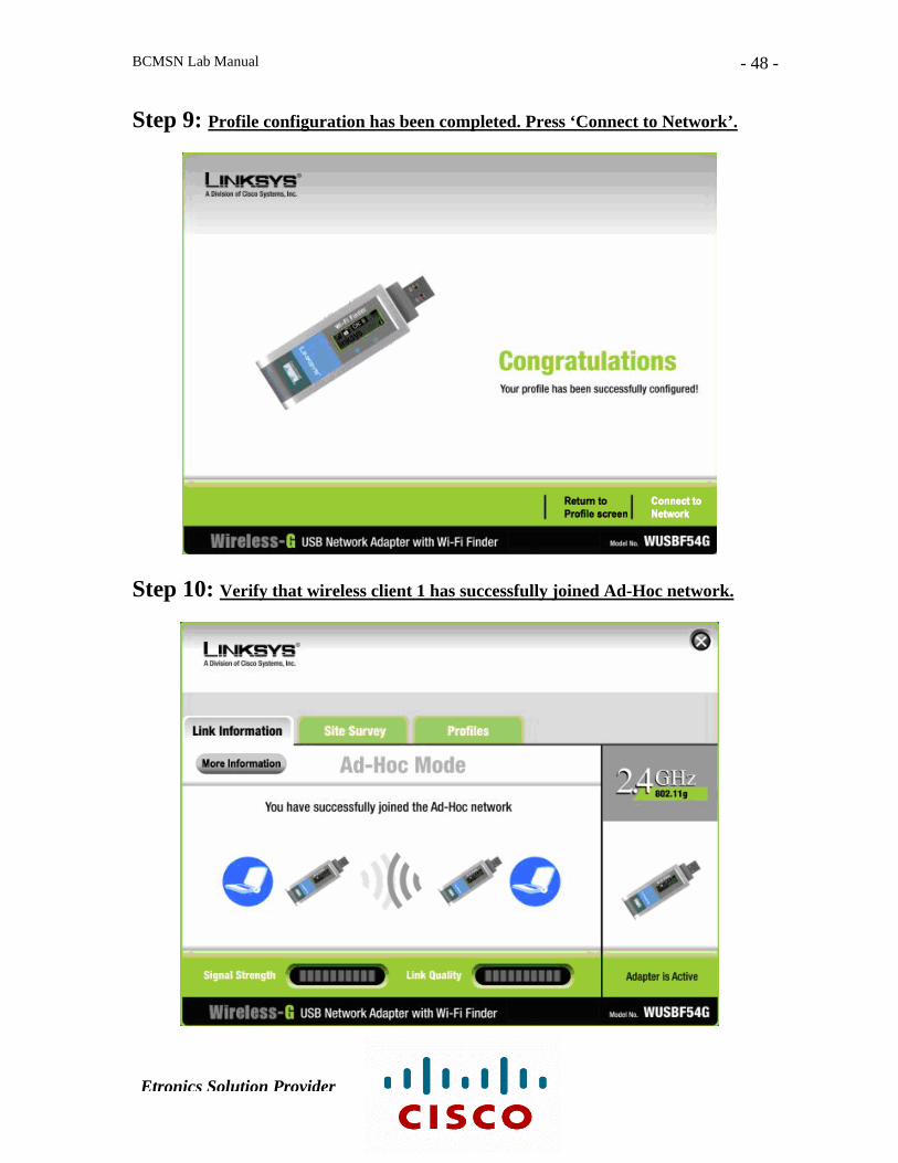
Step 9: Profile configuration has been completed. Press ‘Connect to Network’.
Step 10: Verify that wireless client 1 has successfully joined Ad-Hoc network.
Etronics Solution Provider
BCMSN Lab Manual
- 49 -
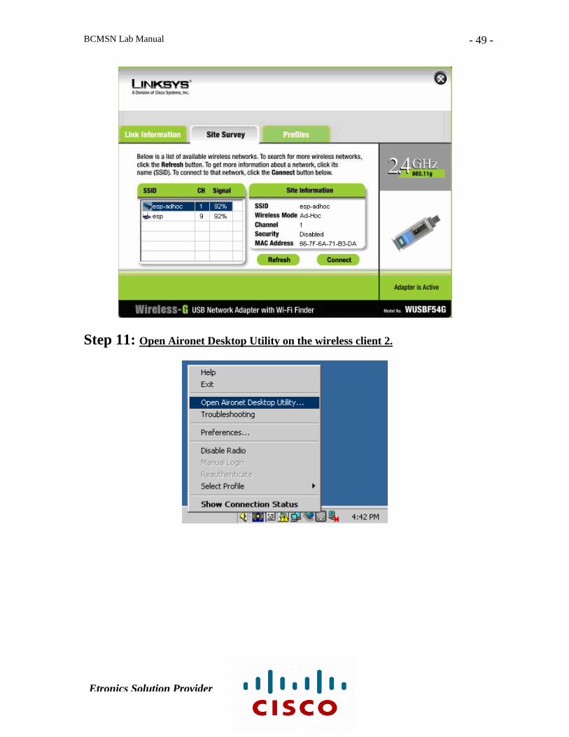
Step 11: Open Aironet Desktop Utility on the wireless client 2.
Etronics Solution Provider
BCMSN Lab Manual
- 50 -
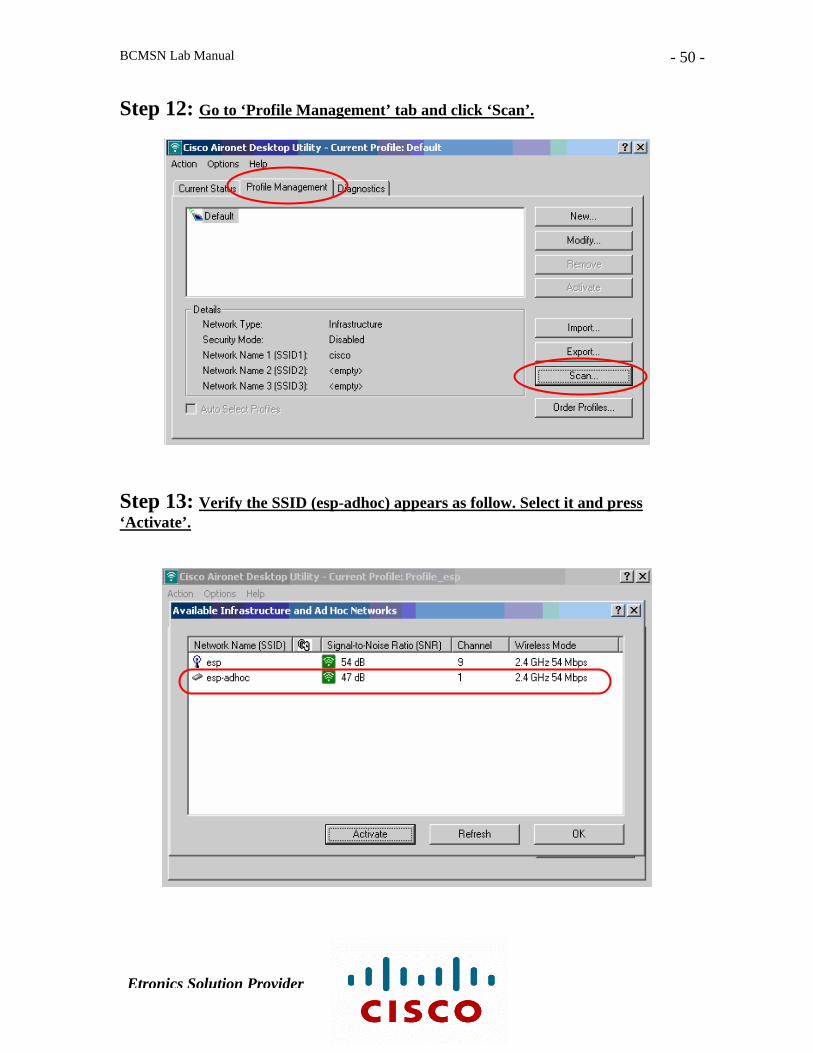
Step 12: Go to ‘Profile Management’ tab and click ‘Scan’.
Step 13: Verify the SSID (esp-adhoc) appears as follow. Select it and press ‘Activate’.
Etronics Solution Provider
BCMSN Lab Manual
- 51 -
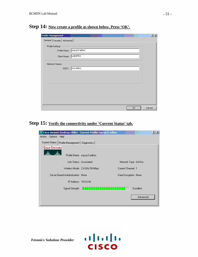
Step 14: Now create a profile as shown below. Press ‘OK’.
Step 15: Verify the connectivity under ‘Current Status’ tab.
Etronics Solution Provider

BCMSN Lab Manual
- 52 -
Lab # 15
Configuring Cisco IP Telephony Using Cisco Call Manager & Cisco IP Phones
Objective
Establishing VoIP call using Cisco Call Manager & Cisco IP Phones: 7940 & 7971.
Cisco Call Manager
Client 1 Client 2 Cisco 7940 Cisco 7971 IP Phone IP Phone
Etronics Solution Provider
Related Documents


![CCNP BCMSN Quick Reference Sheets - ipmanager.iripmanager.ir/r/Ebook/Cisco.Press.CCNP.BCMSN.Quick.Reference.Sheets...[ 4 ] CCNP BCMSN Quick Reference Sheets. ... — Clients attach](https://static.cupdf.com/doc/110x72/5ad05c807f8b9a6c6c8e29ce/ccnp-bcmsn-quick-reference-sheets-4-ccnp-bcmsn-quick-reference-sheets-.jpg)