Seattle City Light Heat Pump & Air Conditioning Unit Commissioning Procedure, page 1 April 1999 STANDARD COMMISSIONING PROCEDURE FOR PACKAGED HEAT PUMP (AIR-TO-AIR) & AIR CONDITIONING UNITS BUILDING NAME: APPLICATION #: BUILDING ADDRESS: NAME & FIRM OF PERSON(S) DOING TEST: DATE(S) OF TEST: General Notes: 1. This is a generic test procedure for self -contained single zone packaged and split-system heat pumps and air conditioning units less than 20 tons in capacity. For larger, more complex, or built-up units, use the Standard Commissioning Procedure for Air Handling Units. If the complexity, configuration, or other aspects of a specific project require substitute tests or additional tests, explain on the comments sheets, and attach the additional test procedures and field data. Attach all relevant functional performance verification sheets, and always attach the final signed and dated procedure certification page. 2. In all test sections, circl e or otherwise highlight any responses that indicat e deficiencies (i.e. responses that don’t meet the criteria for acceptance). Acceptance requires correction and retest of all deficiencies, as defined in each test section under “Criteria for Acceptance” or “Acceptance”. Attach all retest data sheets. Complete the Deficiency Report Form for all deficiencies. 3. This Commissioning Pr ocedure does not address fire and li fe safety or basic equipment safety controls. 4. To ensure that this Commissi oning Procedure will not damage any equipment or affect any equipment warranties, have the equipment manufacturer’s representative review any interventive test procedures prior to execution. OPERATOR INTERVIEW (Existing Buildings Only): Determine from a discussion with the building operator whether the heat pump and/or air conditioning units are operating properly to the best of their knowledge. Use the table to note any known problems, and possible solutions. Address each unit. In the 2nd column, write “none” for any units with no known problems. Add sheets as needed. UNIT SYMBOL & AREA SERVED PROBLEM DESCRIPTION & EFFECT PROPOSED SOLUTION

Welcome message from author
This document is posted to help you gain knowledge. Please leave a comment to let me know what you think about it! Share it to your friends and learn new things together.
Transcript

7/30/2019 bca6
http://slidepdf.com/reader/full/bca6 1/17
7/30/2019 bca6
http://slidepdf.com/reader/full/bca6 2/17
Building Name:
Seattle City Light Heat Pump & Air Conditioning Unit Commissioning Procedure, page 2 April 1999
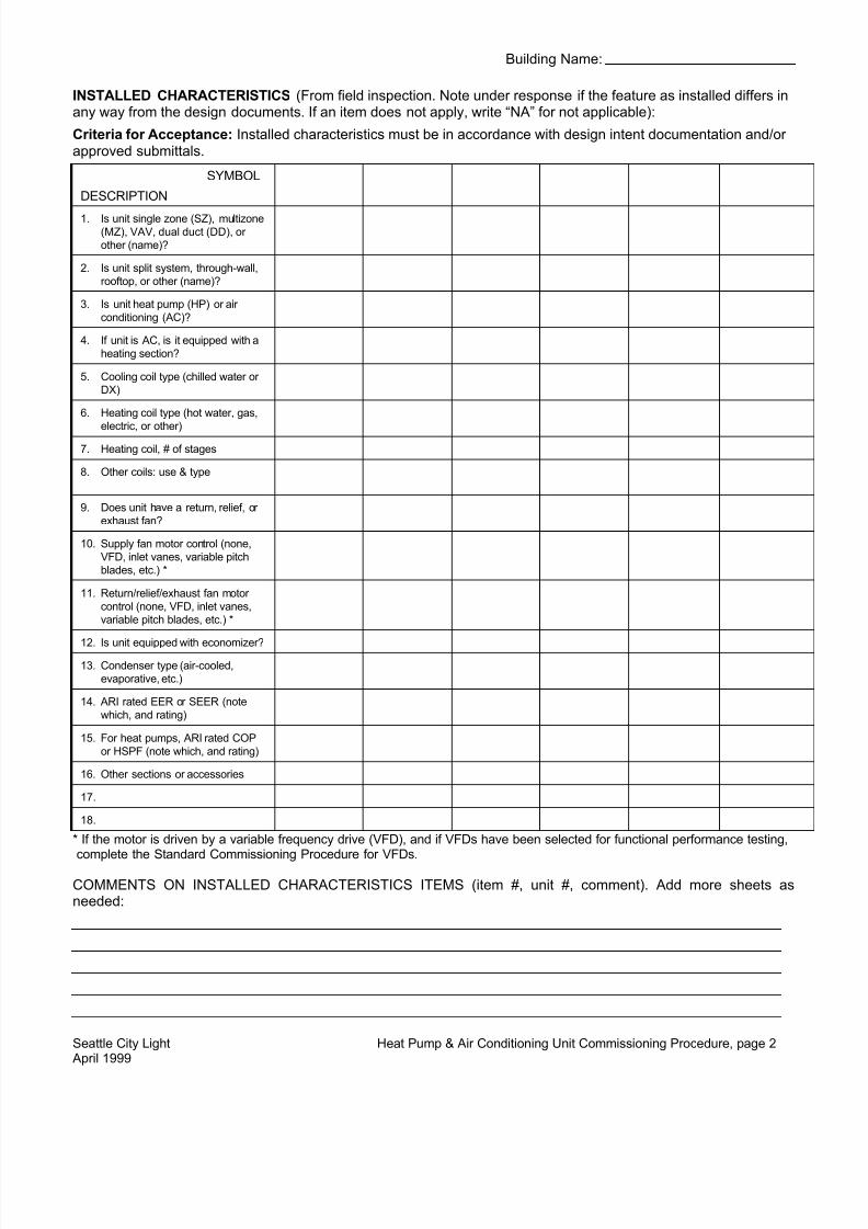
INSTALLED CHARACTERISTICS (From field inspection. Note under response if the feature as installed differs inany way from the design documents. If an item does not apply, write “NA” for not applicable):
Criteria for Acceptance: Installed characteristics must be in accordance with design intent documentation and/or approved submittals.
SYMBOL
DESCRIPTION
1. Is unit single zone (SZ), multizone(MZ), VAV, dual duct (DD), or other (name)?
2. Is unit split system, through-wall,rooftop, or other (name)?
3. Is unit heat pump (HP) or air conditioning (AC)?
4. If unit is AC, is it equipped with aheating section?
5. Cooling coil type (chilled water or DX)
6. Heating coil type (hot water, gas,
electric, or other)
7. Heating coil, # of stages
8. Other coils: use & type
9. Does unit have a return, relief, or exhaust fan?
10. Supply fan motor control (none,VFD, inlet vanes, variable pitchblades, etc.) *
11. Return/relief/exhaust fan motor control (none, VFD, inlet vanes,variable pitch blades, etc.) *
12. Is unit equipped with economizer?
13. Condenser type (air-cooled,evaporative, etc.)
14. ARI rated EER or SEER (notewhich, and rating)
15. For heat pumps, ARI rated COPor HSPF (note which, and rating)
16. Other sections or accessories
17.
18.
* If the motor is driven by a variable frequency drive (VFD), and if VFDs have been selected for functional performance testing,complete the Standard Commissioning Procedure for VFDs.
COMMENTS ON INSTALLED CHARACTERISTICS ITEMS (item #, unit #, comment). Add more sheets asneeded:

7/30/2019 bca6
http://slidepdf.com/reader/full/bca6 3/17
Building Name:
Seattle City Light Heat Pump & Air Conditioning Unit Commissioning Procedure, page 3 April 1999
NAMEPLATE DATA (from equipment nameplates, as recorded in field):
Criteria for Acceptance: Nameplate data must be in accordance with approved submittals.
UNIT #
DESCRIPTIONManufacturer (pkgd or outdoor units)
Model #
Serial #
Mfctr, indoor unit, if split
Model #, indoor unit
Rated Cooling Cap., tons
Rated Heating Cap., MBtu
Supply Fan Motor, hp
Return/exhaust Fan, hp
Voltage / φ, pkgd or outdoor unit
Voltage / φ, indoor unit
If any of the equipment nameplate data differ from the design parameters as described in the above equipmentdescription and in the design documents, note data item and unit number, and comment here:

7/30/2019 bca6
http://slidepdf.com/reader/full/bca6 4/17

7/30/2019 bca6
http://slidepdf.com/reader/full/bca6 5/17
Building Name:
Seattle City Light Heat Pump & Air Conditioning Unit Commissioning Procedure, page 5 April 1999
UNIT #DESCRIPTION
Supply Fan Section:
16. Fan belt tension & condition okay?
17. Fan rotation correct?
18. Fan blades clean & in good condition?
19. Motor contactors in good condition?
20. Motor overload heaters properly sized?
21. Fan motor volts, rated
22. Fan motor volts into motor. Acceptance: ±10% of rating, all phases
23. Voltage Imbalance into motor, (V max,min -Vavg ) / V avg
24. Voltage imbalance into motor is <2%?
25. Fan motor FLA, rated
26. Fan motor full speed Amps, measured atmotor (downstream of VFD)
27. Fan motor measured Amps < Rated FLA?
28. Current imbalance at motor is <2%?
Return/Relief/Exhaust Fan Section:
29. Fan belt tension & condition okay?
30. Fan rotation correct?
31. Fan blades clean & in good condition?
32. Motor contactors in good condition?
33. Motor overload heaters properly sized?
34. Fan motor volts, rated
35. Fan motor volts into motor. Acceptance: ±10% of rating, all phases
36. Voltage Imbalance into motor, (V max,min -Vavg ) / V avg
37. Voltage imbalance into motor is <2%?
38. Fan motor FLA, rated
39. Fan motor full speed Amps, measured atmotor (downstream of VFD)
40. Fan motor measured Amps < Rated FLA? 41. Current imbalance at motor is <2%?
Refrigeration Section (facing front: data for left hand / right hand compressor):
42. Refrigerant sightglasses clear of bubbleswhen compressors loaded?
/ / / / / /
43. Sightglasses indicate no moisture? / / / / / /
44. Compressor oil level correct? Record level / / / / / /

7/30/2019 bca6
http://slidepdf.com/reader/full/bca6 6/17
Building Name:
Seattle City Light Heat Pump & Air Conditioning Unit Commissioning Procedure, page 6 April 1999
UNIT #DESCRIPTION
45. Compressor motor measured Amps <Rated FLA?
/ / / / / /
46. Record head pressure under load, eachcompressor. Acceptance: per mfctr.
/ / / / / /
47. Record suction pressure under load, eachcompressor.
/ / / / / /
48. Record suction temperature at TXV bulb,each compressor.
/ / / / / /
49. Calculate superheat. Acceptance: 8 to 20degrees F, or per mfctr’s instructions.
/ / / / / /
50. Refrigerant charge okay based on suction& head pressures, superheat, &sightglasses?
/ / / / / /
51. Thermal expansion valve bulbs attachedfirmly to suction lines, and adequatelyinsulated
/ / / / / /
52. Suction line insulated? 53. Coil clean & in good condition?
54. Condensate piping trapped properly &drained to outside or floor drain?
55. For heat pumps: Strip heat locked outduring warm-up ("O" for OSA control, "I"for intelligent ramp-up, "N" for no lock-out)
Heat Section (items marked “G” apply to gas-fired equipment only):
56. Maintenance access is adequate?
57. Insulation is complete & undamaged?
58. Section is clean & airflow is unobstructed? 59. Adequate clearance from heating
elements?
60. Electrical connections tight?
61. (G) Pipe fittings & accessories complete?
62. (G) Gas pilot flame stable when fan is on?
Condenser:
63. All fans are operational?
64. Fan inlet screens are free of debris?
General Run Test: 65. Run Test: Observe unit under normal
operation & load 2 times in a 12 hour period, at least 3 hours apart. Verify thatthere is no unusual noise, vibration,cycling, overheating, or other problems atthe fan section, damper section, coils,compressors, condenser, electrical, etc..Note whether under htg (H) or clg (C) load
Observation #1: Time of Day, H or C / Acceptable?
/ / / / / /

7/30/2019 bca6
http://slidepdf.com/reader/full/bca6 7/17
Building Name:
Seattle City Light Heat Pump & Air Conditioning Unit Commissioning Procedure, page 7 April 1999
UNIT #DESCRIPTION
Observation #2: Time of Day, H or C / Acceptable?
/ / / / / /
COMMENTS ON INSTALLATION VERIFICATION CHECKLIST ITEMS (add more sheets if needed):
ITEM # UNIT # COMMENT

7/30/2019 bca6
http://slidepdf.com/reader/full/bca6 8/17
Building Name:
Seattle City Light Heat Pump & Air Conditioning Unit Commissioning Procedure, page 8 April 1999
CONTROLS CALIBRATION:
Instructions: All control points listed under each unit refer to sensors and stats that are dedicated to that unit, andfor the most part physically located close to or in the unit, not global (building-level) points. For thermostats andhumidistats, slowly adjust the setpoint until the controlled response begins (i.e. contact make or break). Note thesetpoint when that occurs and the simultaneous measured value on a calibrated instrument held in close proximityto the sensing bulb. If sensor location is improper, explain in comments. If the unit serves more than one zone,check calibration of zone temperature for two sample zones only. Enter other control points that are critical to thecontrol sequence in the blank spaces for each unit, as appropriate. It is not necessary to repeat any calibration thatwas documented in the Standard Commissioning Procedure for EMSs, but refer to that document where relevant.
Criteria for Acceptance: Temperature sensors, EMS or contact make/break values ± 2 F degrees from measuredvalues. Static pressure sensors, less than ± 0.1” from measured values. Relative humidity sensors, less than ± 10%from measured values.
CONTROL TYPE SENSOR / STATLOCATION
CONTROLLOCATION OK?
MEASUREDVALUE
EMS VALUEor
MAKE/BRKVALUE
ACCEPTABLE? / COMMENTS
Outdoor air temp.,global (EMS)
Outdoor air % RH,global (EMS)
Unit # -__________:
OSA temp or enthalpy
Discharge air temp.
Mixed air temp.
Return air temp.
Static pressure
Zone temp.
Zone temp.
Unit # -__________:
OSA temp or enthalpy
Discharge air temp.
Mixed air temp.
Return air temp.
Static pressure
Zone temp.
Zone temp.
Unit # -__________:
OSA temp or enthalpy
Discharge air temp.
Mixed air temp.
Return air temp.
Static pressure
Zone temp.
Zone temp.

7/30/2019 bca6
http://slidepdf.com/reader/full/bca6 9/17
Building Name:
Seattle City Light Heat Pump & Air Conditioning Unit Commissioning Procedure, page 9 April 1999
CONTROL TYPE SENSOR / STATLOCATION
CONTROLLOCATION OK?
MEASUREDVALUE
EMS VALUEor
MAKE/BRKVALUE
ACCEPTABLE? / COMMENTS
Unit # -__________:
OSA temp or enthalpy
Discharge air temp.Mixed air temp.
Return air temp.
Static pressure
Zone temp.
Zone temp.
Unit # -__________:
OSA temp or enthalpy
Discharge air temp.
Mixed air temp.Return air temp.
Static pressure
Zone temp.
Zone temp.
Unit # -__________:
OSA temp or enthalpy
Discharge air temp.
Mixed air temp.
Return air temp.Static pressure
Zone temp.
Zone temp.
CONTROLS CALIBRATION COMMENTS:Unit # / Control Point / Comment

7/30/2019 bca6
http://slidepdf.com/reader/full/bca6 10/17
Building Name:
Seattle City Light Heat Pump & Air Conditioning Unit Commissioning Procedure, page 10 April 1999
FUNCTIONAL PERFORMANCE VERIFICATION:
The following sections are a series of field tests that are intended to verify that the heat pumps and/or air conditioning units operate as they were intended to operate by the manufacturer and designer. For each test, firstdetermine and record the design operation, and then record the actual field observation. Following each test, inparentheses, are the appropriate response choices or units. If the field observation does not correspond to theintended design operation, also write a comment number that refers to an explanatory comment in the commentssection or on attached comments sheets. If a test does not apply, write "NA" for not applicable. If you were not
able to complete a test, write "ND" for not done, and explain in a comment.If the standard test procedures are not applicable or adequate, document the sequences, tests, and results on thepages that follow the standard procedures. First describe the control sequences for each unit for each applicablesequence type: start/stop, warm-up mode, fan capacity, temperature control, safeties, and other. Next describe indetail what tests you plan to do to verify each control sequence. Finally, describe your test results and conclusions,including any deficiencies found. See the attached example for the level of detail required. Add sheets asnecessary. It is not necessary to repeat any tests that were documented in the Standard Commissioning Procedurefor EMSs, but refer to that document where relevant.
Attach to this form all relevant field data, monitored data, graphs, trend logs, and so forth. Annotate any data andgraphs so that it is clear what the data are proving. EMS trend logs of EMS outputs, program print-outs, or scheduleand setpoint print-outs are not acceptable as proof of operation, unless the information is first verified to beaccurate and documentation is attached. Trend logs of sensor inputs to the EMS are acceptable.
Sampling: If there are more than 10 units of a given model, you may select a sample for the followingperformance tests. The sample should be at least 10% of the total number of that model units, or 4 units,whichever is greater. If there is failure of any test for more than 10% of the sampled units, or 2 units, whichever isgreater, then the project heat pump and/or air conditioning unit installation shall be considered to be not inconformance. In that case, follow the contractual procedures for reporting and correcting deficiencies.

7/30/2019 bca6
http://slidepdf.com/reader/full/bca6 11/17
Building Name:
Seattle City Light Heat Pump & Air Conditioning Unit Commissioning Procedure, page 11 April 1999
Scheduled Start/Stop and Unoccupied Setback/Setup Test: Perform the following tests by monitoring and/or observingeach piece of controlled equipment under actual operation. It is permissible to adjust the schedules and/or setpoints for easier testing. If this is done, reset to the original schedules and setpoints, or as directed by the building operator, at theconclusion of testing. If the original values are not consistent with energy efficient operation, discuss with the buildingoperator. Use of dataloggers or trend logs of EMCS input channels over a 2 or 3 day period is recommended. Annotate anylogger data and graphs so that it is clear what the data are proving, and attach these to this form. (See attached example of an annotated graph.) EMCS trend logs of EMCS output signals are not acceptable as proof of operation unless you have
first verified and documented (attach) that the output signals accurately represent actual operation.Criteria for Acceptance: The following shall be considered deficiencies: 1) Equipment doesn’t start and/or stop within 15minutes of the scheduled times, 2) Occupied space temperatures fall more than 2 F degrees below the heating setpoint or rise more than 2 F degrees above the cooling setpoint, 3) Unoccupied space temperatures go more than 3 degrees F below(above) the setback (setup) temperature setpoints, 4) Unoccupied space temperatures are maintained more than 3 degreesF above (below) the setback (setup) setpoints, 5) Equipment that is to be interlocked with the unit doesn’t operate on thesame schedule.
UNIT #
1. Start time setting. (For the following tests,select 1 typical day from the observed data.)
2. Observed (or monitored) start time
3. Occupied setpoints, heating / cooling ( °F) / / / / / /
4. Observed (or monitored) stabilized spacetemperature range.
/ / / / / /
5. Stop time setting
6. Observed (or monitored) stop time
7. Unoccupied setpoints, heating / cooling ( °F) / / / / / /
8. Observed (or monitored) minimum / maximumunoccupied space temperature
/ / / / / /
9. If observed minimum (maximum) temperature ishigher (lower) than the unoccupied heating(cooling) setpoint, does equipment operate tomaintain that temperature? If “yes”, this is a
deficiency.
10. List all interlocked equipment by symbol.Include pumps, fans, etc. as relevant.
11. Does all interlocked equipment as listed in #10start & stop on the same schedule as the unit?
12. Are final schedules consistent with energyefficient operation? If “no”, comment.
13. Are final occupied & unoccupied setpointsconsistent with energy efficient operation? If “no”, comment.
COMMENTS ON SCHEDULED START/STOP AND SETBACK TEST ITEMS (add more sheets if needed):ITEM # COMMENT
7/30/2019 bca6
http://slidepdf.com/reader/full/bca6 12/17
7/30/2019 bca6
http://slidepdf.com/reader/full/bca6 13/17
Building Name:
Seattle City Light Heat Pump & Air Conditioning Unit Commissioning Procedure, page 13 April 1999
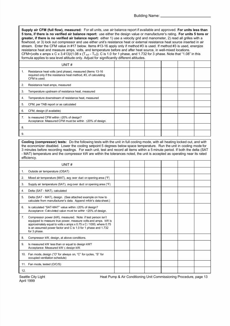
Supply air CFM (full flow), measured: For all units, use air balance report if available and approved. For units less than5 tons, if there is no verified air balance report: use either the design value or manufacturer’s rating. For units 5 tons or greater, if there is no verified air balance report: either 1) use a velocity grid and manometer, 2) read all grilles with aflowhood, or 3) lock out compressor and use either unit’s resistance heat or external resistance heat source inserted in air stream. Enter the CFM value in #17 below. Items #13-16 apply only if method #3 is used. If method #3 is used, energizeresistance heat and measure amps, volts, and temperature before and after heat source, in well-mixed locations.CFM=(volts x amps x C x 3.413)/(1.08 x (T out - T in)). C is 1.0 for 1 phase, and 1.732 for 3 phase. Note that “1.08” in thisformula applies to sea level altitude only. Adjust for significantly different altitudes.
UNIT #
1. Resistance heat volts (and phase), measured (Items 13-16required only if the resistance heat method, #3, of calculatingCFM is used.
2. Resistance heat amps, measured
3. Temperature upstream of resistance heat, measured
4. Temperature downstream of resistance heat, measured
5. CFM, per TAB report or as calculated
6. CFM, design (if available)
7. Is measured CFM within ±20% of design? Acceptance: Measured CFM must be within ±20% of design.
8.
9.
Cooling (compressor) tests: Do the following tests with the unit in full cooling mode, with all heating locked out, and withthe economizer disabled. Lower the cooling setpoint 5 degrees below space temperature. Run the unit in cooling mode for 3 minutes before recording readings. For each unit, test and record all items within a 5 minute period. If both the delta (SAT- MAT) temperature and the compressor kW are within the tolerances noted, the unit is accepted as operating near its ratedefficiency.
UNIT #
1. Outside air temperature (OSAT) 2. Mixed air temperature (MAT), avg over duct or opening area (°F)
3. Supply air temperature (SAT), avg over duct or opening area (°F)
4. Delta (SAT - MAT), calculated
5. Delta (SAT - MAT), design. (See attached example on how tocalculate from manufacturer’s data. Append mfctr’s data sheet.)
6. Is calculated “SAT-MAT” value within ±20% of design? Acceptance: Calculated value must be within ±20% of design.
7. Compressor power (kW), measured. Note: if test person isn’tequipped to measure true power, measure volts and amps. kW isapproximately equal to volts x amps x 0.75 x C / 1000, where 0.75
is an assumed power factor and C is 1.0 for 1 phase and 1.732for 3 phase.
8. Compressor kW, design, at above conditions.
9. Is measured kW less than or equal to design kW? Acceptance: Measured kW ≤ design kW.
10. Fan mode, design (“O” for always on, “C” for cycles, “S” for occupied ventilation schedule)
11. Fan mode, tested (O/C/S)
12.
7/30/2019 bca6
http://slidepdf.com/reader/full/bca6 14/17
Building Name:
Seattle City Light Heat Pump & Air Conditioning Unit Commissioning Procedure, page 14 April 1999
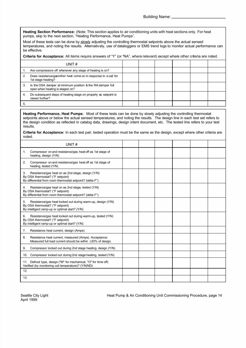
Heating Section Performance: (Note: This section applies to air conditioning units with heat sections only. For heatpumps, skip to the next section, “Heating Performance, Heat Pumps”.
Most of these tests can be done by slowly adjusting the controlling thermostat setpoints above the actual sensedtemperatures, and noting the results. Alternatively, use of dataloggers or EMS trend logs to monitor actual performance canbe effective.
Criteria for Acceptance: All items require answers of “Y” (or “NA”, where relevant) except where other criteria are noted.
UNIT #
1. Are compressors off whenever any stage of heating is on? 2. Does resistance/gas/other heat come on in response to a call for
1st stage heating?
3. Is the OSA damper at minimum position & the RA damper fullopen when heating is staged on?
4. Do subsequent steps of heating stage on properly as setpoint israised further?
5.
Heating Performance, Heat Pumps: Most of these tests can be done by slowly adjusting the controlling thermostatsetpoints above or below the actual sensed temperatures, and noting the results. The design line in each test set refers tothe design condition as reflected in catalog data, drawings, design intent document, etc. The tested line refers to your testresults.
Criteria for Acceptance: In each test pair, tested operation must be the same as the design, except where other criteria arenoted.
UNIT #
1. Compressor on and resistance/gas heat off as 1st stage of heating, design (Y/N)
2. Compressor on and resistance/gas heat off as 1st stage of heating, tested (Y/N)
3. Resistance/gas heat on as 2nd stage, design (Y/N) By OSA thermostat? (°F setpoint) By differential from room thermostat setpoint? (delta F°)
4. Resistance/gas heat on as 2nd stage, tested (Y/N) By OSA thermostat? (°F setpoint) By differential from room thermostat setpoint? (delta F°)
5. Resistance/gas heat locked out during warm-up, design (Y/N) By OSA thermostat? (°F setpoint) By intelligent ramp-up or optimal start? (Y/N)
6. Resistance/gas heat locked out during warm-up, tested (Y/N) By OSA thermostat? (°F setpoint) By intelligent ramp-up or optimal start? (Y/N)
7. Resistance heat current, design (Amps)
8. Resistance heat current, measured (Amps). Acceptance:Measured full load current should be within ±20% of design.
9. Compressor locked out during 2nd stage heating, design (Y/N)
10. Compressor locked out during 2nd stage heating, tested (Y/N)
11. Defrost type, design ("M" for mechanical, "O" for time off) Verified (by monitoring coil temperature)? (Y/N/ND)
12.
13.

7/30/2019 bca6
http://slidepdf.com/reader/full/bca6 15/17
Building Name:
Seattle City Light Heat Pump & Air Conditioning Unit Commissioning Procedure, page 15 April 1999
Other Control, Unit # :Describe the control sequence:
Describe the tests that were done to verify the control sequence:
Conclusions:
Other Control, Unit # :Describe the control sequence:
Describe the tests that were done to verify the control sequence:
Conclusions:

7/30/2019 bca6
http://slidepdf.com/reader/full/bca6 16/17
Building Name:
Seattle City Light Heat Pump & Air Conditioning Unit Commissioning Procedure, page 16 April 1999
COMMENTS ON FUNCTIONAL PERFORMANCE VERIFICATION ITEMS (add more sheets if needed):
TEST / ITEM # / UNIT # COMMENT
I certify that the data and test results as recorded herein are accurate.
Signature, Commissioning Agent Date
Firm Name (Area Code) Phone Number
file:\msoffice\winword\docs\scl\cxproc\hpacqas.pro

7/30/2019 bca6
http://slidepdf.com/reader/full/bca6 17/17
Seattle City Light Heat Pump & Air Conditioning Unit Commissioning Procedure, page 17 April 1999
CALCULATIONS FOR DETERMINING DELTA TEMPERATURE (SAT-MAT) ACROSS DX COIL
1. Find the manufacturer’s data sheet for the appropriate unit, or combination of indoor and outdoor sections.2. Determine the actual operating conditions, as tested. For this example, using the data sheet excerpt below,
let’s assume that you measured the air flow at 2000 CFM, the wet bulb temperature of the air entering the DXcoil at 62 °F, and the dry bulb temperature of the air entering the outdoor condenser at 75 °F. (If the operatingconditions don’t correspond to the manufacturer’s rating values, it will be necessary to interpolate between the
manufacturer’s values, apply manufacturer’s adjustments if available, or carefully extrapolate.)3. The unit(s) should be in full return.4. Read the value for sensible cooling capacity at the operating conditions. In this example, we see that the
sensible cooling capacity is 54.0 MBtuh, or 54,000 Btu/hr.5. Calculate the temperature differential, or delta T, as: Delta T = Btu/hr / (1.08 x CFM). In this example, we get:
Delta T = 54,000 Btu/hr / (1.08 x 2000 CFM) = 25.0 °F. Note that the value 1.08 applies to locations near sealevel only. For higher elevations, adjust the air density value.
6. To determine whether the measured delta T is within ±20% of the rated delta T, subtract the rated value fromthe measured value and divide that answer by the rated value. In this example, if we had measured the delta Tat, say 23.5 °F, we can calculate the percentage difference as: (23.5 - 25.0) / 25.0 = -0.060, or -6.0%.
COOLING CAPACITIES FOR THE COOL-RITE AXT2000:
CONDENSER ENTERING AIR TEMPERATURE, F
EVAPORATOR AIR 75 85Capacity, MBtuh Capacity, MBtuh
CFM EWB Total Sensible Total kW Total Sensible Total kW
72 55.8 32.5 4.95 63.8 31.9 5.44
67 56.2 42.3 4.89 58.7 41.4 5.35
1800 63 56.6 41.2 4.84 54.4 40.1 5.29
62 56.0 51.4 4.82 53.5 50.2 5.27
57 54.4 54.4 4.79 52.4 52.4 5.25
72 66.4 33.5 5.06 64.4 33.0 5.55
67 61.9 44.4 5.00 59.3 43.4 5.47
2000 63 57.6 43.1 4.95 55.0 42.0 5.40
62 56.8 54.0 4.93 54.4 52.8 5.39
57 55.9 55.9 4.92 53.9 53.9 5.37
Related Documents


