BC-MUX © Zahner 10/2018

Welcome message from author
This document is posted to help you gain knowledge. Please leave a comment to let me know what you think about it! Share it to your friends and learn new things together.
Transcript

BC-MUX
© Zahner 10/2018

BC-MUX - 2 -
BC-MUX - 3 -
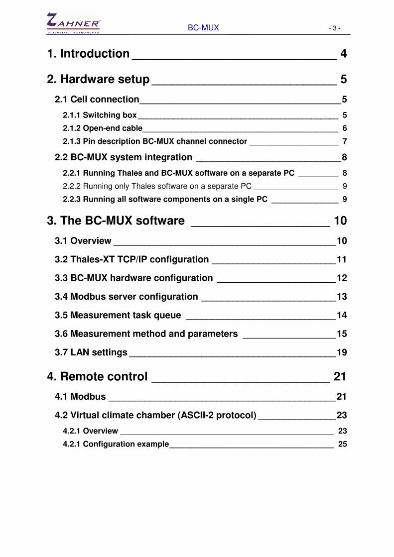
1. Introduction _______________________________ 4
2. Hardware setup ____________________________ 5
2.1 Cell connection _______________________________________ 5
2.1.1 Switching box _____________________________________________ 5
2.1.2 Open-end cable____________________________________________ 6
2.1.3 Pin description BC-MUX channel connector ____________________ 7
2.2 BC-MUX system integration ____________________________ 8
2.2.1 Running Thales and BC-MUX software on a separate PC _________ 8
2.2.2 Running only Thales software on a separate PC ___________________ 9
2.2.3 Running all software components on a single PC _______________ 9
3. The BC-MUX software _____________________ 10
3.1 Overview ___________________________________________ 10
3.2 Thales-XT TCP/IP configuration ________________________ 11
3.3 BC-MUX hardware configuration _______________________ 12
3.4 Modbus server configuration __________________________ 13
3.5 Measurement task queue _____________________________ 14
3.6 Measurement method and parameters __________________ 15
3.7 LAN settings ________________________________________ 19
4. Remote control ___________________________ 21
4.1 Modbus ____________________________________________ 21
4.2 Virtual climate chamber (ASCII-2 protocol) _______________ 23
4.2.1 Overview ________________________________________________ 23
4.2.1 Configuration example _____________________________________ 25

BC-MUX - 4 -
1. Introduction With the BC-MUX you can interface a Zennium electrochemical workstations to DC multichannel battery testers. A seamless integration of electrochemical impedance spectroscopy can be achieved using TCP/IP technologies. The BC-MUX can route up to 16 independent objects from a battery cycler to the EIS system. So, battery cycling is done by the DC tester and EIS of single objects by the ECW. The BC-MUX kit consists of the hardware (BC-MUX controller + opt. up to 16 switching boxes) and the controlling software which can be interfaced from external devices over TCP/IP. The BC-MUX software configures and controls the Thales-XT software remotely over TCP/IP. This can be done in two ways: Modbus TCP: The Modbus protocol exists since 1979 and is still an industrial communication standard for programmable control systems. ASCII-2 interface protocol from “Weiss Technik”: The “ASCII-2-Schnittstellenprotokoll” is a remote control protocol for climatic chambers from the company “Weiss Technik”. An interface for this climatic chamber manufacturer is integrated into many battery cycler control software. This protocol can be used to control the BC-MUX as a “virtual climate chamber”. You can connect the BC-MUX to a PC by USB or LAN. When starting an EIS at a certain channel the BC-MUX controller reconnects the chosen cell from the battery tester to the Zennium workstation sets all EIS parameters at the Thales-XT software and starts the measurement.

BC-MUX - 5 -
2. Hardware setup
2.1 Cell connection Switching the test objects between battery tester and Zennium electrochemical workstation can be done in different ways. In any case it is important that the object will be switched floating.
2.1.1 Switching box
We offer two variants of ready-made switching boxes with a driving current of 20A and 60A. These boxes switch current drive and sense lines with relays.
For EIS measurement the object is completely disconnected from the battery tester. The switching box is needed for each channel in use.

BC-MUX - 6 -
2.1.2 Open-end cable
If the battery tester has the feature to disconnect its outputs potential-free, there is no need to use a switching box. In this case both the battery tester and the BC-MUX controller are connected to the object with an open-end cable for each channel:
Both current driving pairs are connected to the object and the potential sense pairs are controlled by the BC-MUX. In normal operation, when EIS is idle, the sense is connected to the battery tester. When measuring EIS, the sense is redirected to the Zennium device and the BC-MUX current driving cables are connected to the object in parallel to the battery tester. This solution has the disadvantage that the battery tester cables and output stages are connected to the object during EIS. This can have an influence on the quality of EIS data.
BC-MUX - 7 -
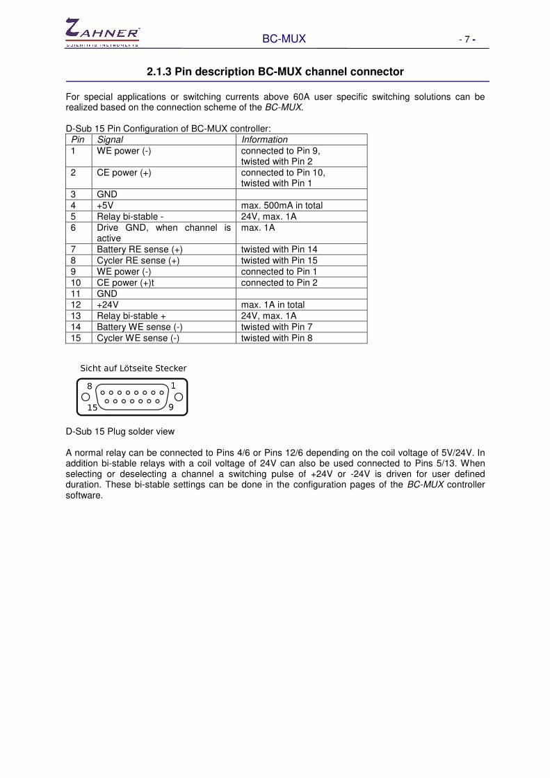
2.1.3 Pin description BC-MUX channel connector
For special applications or switching currents above 60A user specific switching solutions can be realized based on the connection scheme of the BC-MUX. D-Sub 15 Pin Configuration of BC-MUX controller: Pin Signal Information
1 WE power (-) connected to Pin 9, twisted with Pin 2
2 CE power (+) connected to Pin 10, twisted with Pin 1
3 GND
4 +5V max. 500mA in total
5 Relay bi-stable - 24V, max. 1A
6 Drive GND, when channel is active
max. 1A
7 Battery RE sense (+) twisted with Pin 14
8 Cycler RE sense (+) twisted with Pin 15
9 WE power (-) connected to Pin 1
10 CE power (+)t connected to Pin 2
11 GND 12 +24V max. 1A in total
13 Relay bi-stable + 24V, max. 1A
14 Battery WE sense (-) twisted with Pin 7
15 Cycler WE sense (-) twisted with Pin 8
D-Sub 15 Plug solder view A normal relay can be connected to Pins 4/6 or Pins 12/6 depending on the coil voltage of 5V/24V. In addition bi-stable relays with a coil voltage of 24V can also be used connected to Pins 5/13. When selecting or deselecting a channel a switching pulse of +24V or -24V is driven for user defined duration. These bi-stable settings can be done in the configuration pages of the BC-MUX controller software.

BC-MUX - 8 -
2.2 BC-MUX system integration The cycler software is the master controller for the integration of Zennium electrochemical workstations into the battery test stand. Special commands for the acquisition of impedance spectra can be send to the BC-MUX controller over TCP/IP with Modbus protocol or as „virtual“ temperature controller. The BC-MUX controller software sets the channel multiplexer, configures EIS measurement parameters and starts the EIS in the Thales-XT software over TCP/IP. The BC-MUX controller unit can be connected to a PC over USB or Ethernet. For this three different configurations are available.
2.2.1 Running Thales and BC-MUX software on a separate PC
The battery cycler master software controls the BC-MUX software over TCP/IP over Ethernet. BC-MUX control software and Thales-XT software package runs on the same PC and interface over TCP/IP at local host. The BC-MUX controller is connected over USB or Ethernet.

BC-MUX - 9 -
2.2.2 Running only Thales software on a separate PC
In this case the battery cycler master software controls the BC-MUX software over TCP/IP at local host. The BC-MUX software has a remote control of the Thales-XT software package over TCP/IP and Ethernet. Also the BC-MUX controller device is connected to the master PC via Ethernet. This configuration has the advantage that the master PC is controlling both the battery cycler and the BC-MUX EIS setup. So this control PC can be placed somewhere in the lab or office. The second PC controlling the Zennium device with the Thales-XT software has to be placed in the near of the measurement objects.
2.2.3 Running all software components on a single PC
In this configuration with a single computer all configurations are over TCP/IP at local host. The BC-MUX controller device can be connected via USB or Ethernet.
BC-MUX - 10 -
3. The BC-MUX software
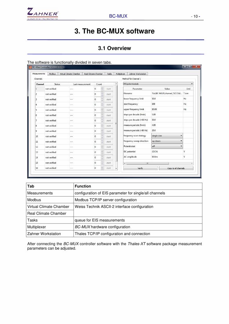
3.1 Overview The software is functionally divided in seven tabs.
Tab Function
Measurements configuration of EIS parameter for single/all channels
Modbus Modbus TCP/IP server configuration
Virtual Climate Chamber Weiss Technik ASCII-2 interface configuration
Real Climate Chamber
Tasks queue for EIS measurements
Multiplexer BC-MUX hardware configuration
Zahner Workstation Thales TCP/IP configuration and connection
After connecting the BC-MUX controller software with the Thales-XT software package measurement parameters can be adjusted.

BC-MUX - 11 -
3.2 Thales-XT TCP/IP configuration Thales-XT has a TCP/IP interface (server) for remote control. Therefore the Thales-XT software must be running on the EIS measurement PC where the Zennium device is connected. After the Thales-XT software windows appear, the BC-MUX software can establish a connection to the Thales-XT server.
Type in the IP address of the Thales-XT computer as Host address. Now the BC-MUX software can connect to the Thales-XT software. When running both software on the same PC the host name will be local host „127.0.0.1“.
While connecting the BC-MUX software the Thales-XT window will be minimized and the control of the Thales software is only allowed by the BC-MUX client. After disconnecting the BC-MUX software the Thales-XT software will be available again.

BC-MUX - 12 -
3.3 BC-MUX hardware configuration The BC-MUX controller can be connected via USB or Ethernet to a PC. The software identifies the BC-MUX controller automatically and displays a list in the pull-down box „Available devices“. The network search of a BC-MUX controller connected over Ethernet can be manually started with the „search lan“ button.
Depending on the type of switching box the „relay type“ has to be chosen. The information about relay type and driving pulse duration is marked on each switching box. To check the basic communication between BC-MUX controller and software each channel can be selected with the „Manual control“ box.

BC-MUX - 13 -
3.4 Modbus server configuration A Modbus server can be configured in the BC-MUX software.
The standard TCP/IP-Port for the Modbus server is Port 502. The Modbus identifier is preset as “0” and can be adjusted to user demand. The Modbus data will be logged to an ASCII file for debugging. The server complies to the Modbus application protocol V1.1b (http://www.modbus.org/docs/Modbus_Application_Protocol_V1_1b.pdf).

BC-MUX - 14 -
3.5 Measurement task queue When a measurement is started while the Zennium device is still recording a previous EIS this task is queued.
The tab “Tasks” displays the running and pending EIS measurements in descending order.

BC-MUX - 15 -
3.6 Measurement method and parameters
The measurement parameters of each channel can be set separately or copied to all channels. When choosing a channel in the left table, the corresponding EIS parameters will be shown on the right.
The channel table shows additional information for each channel (status, date/time of last EIS measurement, counter of measured EIS). The counter value can also be edit manually and increment by every EIS spectra. This counter value can be used for defining path name and/or file name for the EIS data files. An EIS measurement can be started manually by pressing the start button. The method table on the right hand side defines the kind of EIS method and the single parameters. List of EIS methods: Poteniostatic EIS impedance spectroscopy with DC potential and AC potential Galvanostatic EIS impedance spectroscopy with DC current and AC current Pseudogalvanostatic EIS impedance spectroscopy with DC current and AC potential Potentiostatic EIS at drifting OCP impedance spectroscopy with AC potential at OCP Variables can be used to define a customized folder trees and filenames.

BC-MUX - 16 -
Variable Info Example
%Y Year (2 Stellen) 18
%M Month 02
%D Day 20
%h Hour 14
%m Minute 30
%s Second 59
%d Date (yyyy-mm-dd) 2018-02-20
%t Time (hh-mm-ss) 14-30-59
%c Measurement Count 37
%C Channel Number 1
%n Name of Method EIS potentiostatic
%u „Documents“ System Path C:\Users\username\Documents\
Folders will be created automatically. Example: The filename setting „%u\BC-MUX\channel_%C\%d_%t_count_%c_%n.ism“ will create the following measurement file: „C:\Users\username\Documents\BC-MUX\channel_1\2018-02-14_09-22-32_count_1_EIS potentiostatic.ism“. Each parameter will be checked single when edited. But before starting an EIS or copying the setup to other channels the whole parameter set will be verified by the Thales-XT software depending on the active potentiostat. This ensures the consistence of the parameters within the hardware limits. To start a method check click on the „Verify“ button.

BC-MUX - 17 -
Improper parameters will be automatically corrected and highlighted:
These red marked settings should be checked again by the user and readjust if necessary. After a method parameter set is verified the status of the chosen channel will become “verification done”. This enables the start button of this channel and a proven EIS can be started.

BC-MUX - 18 -
Normally all channels will be measured with the same EIS settings. For this these parameter set can easily be copied to all channels.
“Copy to all channels” will synchronize the whole measurement setting with all channels. All channels will show the status “verification done” and provide the EIS “start” button.
BC-MUX - 19 -
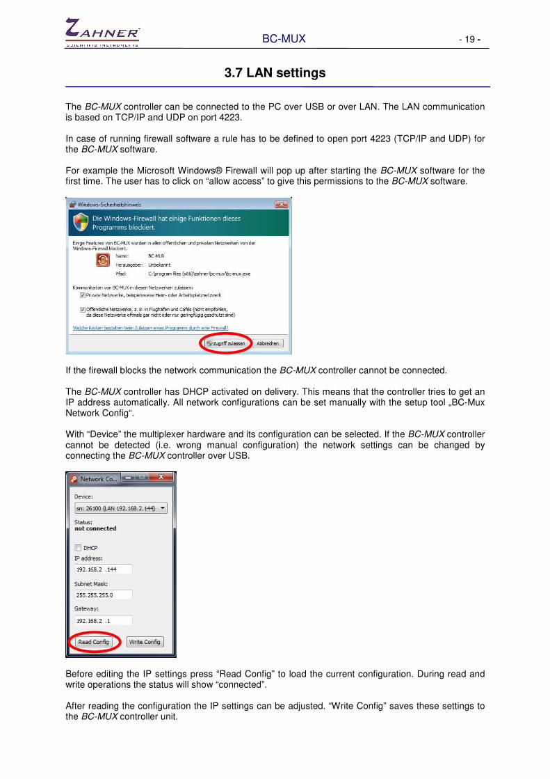
3.7 LAN settings The BC-MUX controller can be connected to the PC over USB or over LAN. The LAN communication is based on TCP/IP and UDP on port 4223. In case of running firewall software a rule has to be defined to open port 4223 (TCP/IP and UDP) for the BC-MUX software. For example the Microsoft Windows® Firewall will pop up after starting the BC-MUX software for the first time. The user has to click on “allow access” to give this permissions to the BC-MUX software.
If the firewall blocks the network communication the BC-MUX controller cannot be connected. The BC-MUX controller has DHCP activated on delivery. This means that the controller tries to get an IP address automatically. All network configurations can be set manually with the setup tool „BC-Mux Network Config“. With “Device” the multiplexer hardware and its configuration can be selected. If the BC-MUX controller cannot be detected (i.e. wrong manual configuration) the network settings can be changed by connecting the BC-MUX controller over USB.
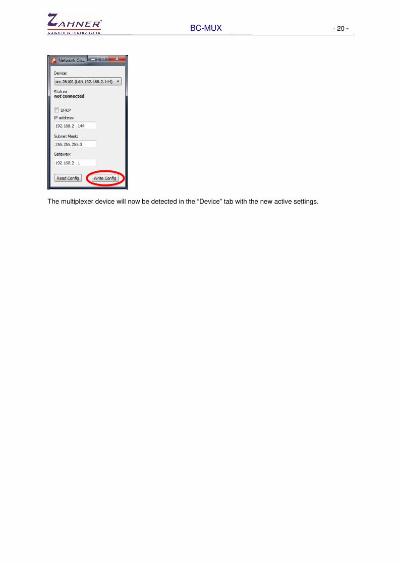
Before editing the IP settings press “Read Config” to load the current configuration. During read and write operations the status will show “connected”. After reading the configuration the IP settings can be adjusted. “Write Config” saves these settings to the BC-MUX controller unit.
BC-MUX - 20 -
The multiplexer device will now be detected in the “Device” tab with the new active settings.
BC-MUX - 21 -
4. Remote control
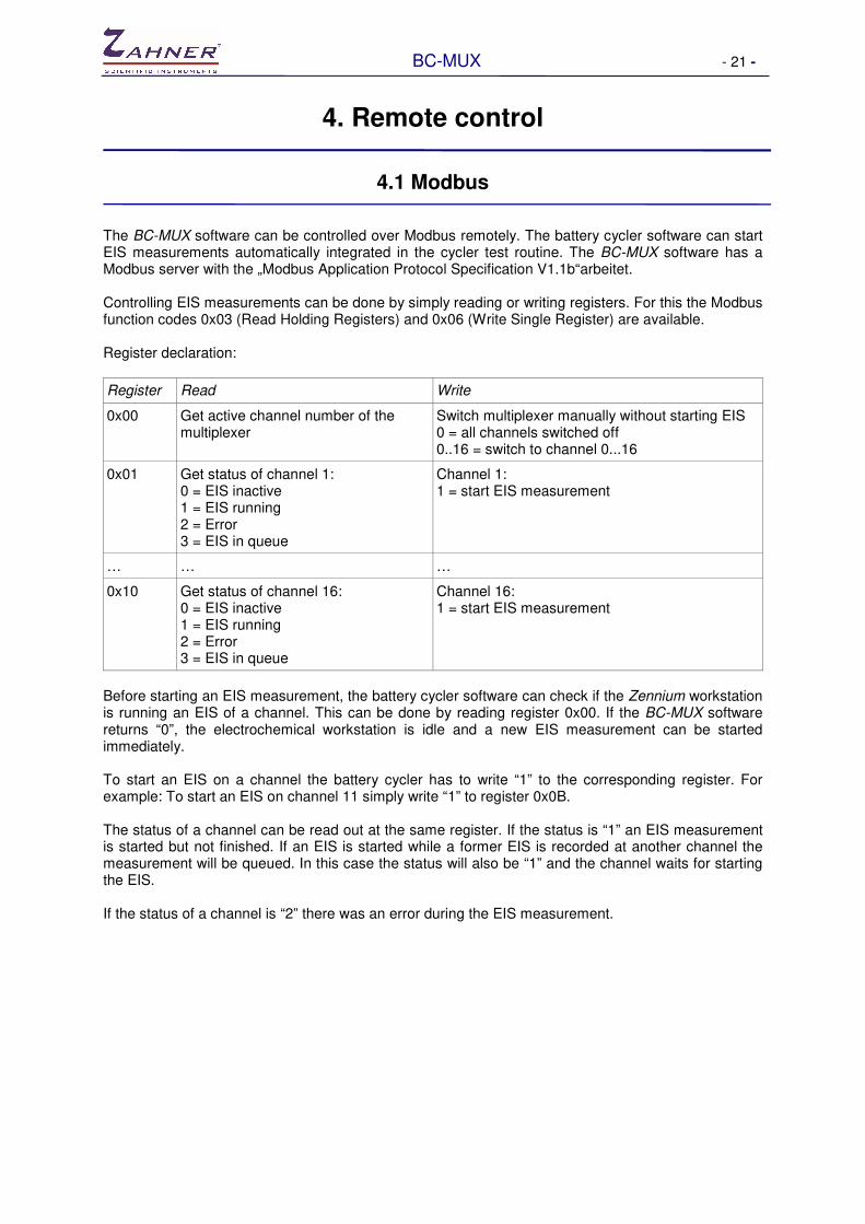
4.1 Modbus The BC-MUX software can be controlled over Modbus remotely. The battery cycler software can start EIS measurements automatically integrated in the cycler test routine. The BC-MUX software has a Modbus server with the „Modbus Application Protocol Specification V1.1b“arbeitet. Controlling EIS measurements can be done by simply reading or writing registers. For this the Modbus function codes 0x03 (Read Holding Registers) and 0x06 (Write Single Register) are available. Register declaration:
Register Read Write
0x00 Get active channel number of the multiplexer
Switch multiplexer manually without starting EIS 0 = all channels switched off 0..16 = switch to channel 0...16
0x01 Get status of channel 1: 0 = EIS inactive 1 = EIS running 2 = Error 3 = EIS in queue
Channel 1: 1 = start EIS measurement
… … …
0x10 Get status of channel 16: 0 = EIS inactive 1 = EIS running 2 = Error 3 = EIS in queue
Channel 16: 1 = start EIS measurement
Before starting an EIS measurement, the battery cycler software can check if the Zennium workstation is running an EIS of a channel. This can be done by reading register 0x00. If the BC-MUX software returns “0”, the electrochemical workstation is idle and a new EIS measurement can be started immediately. To start an EIS on a channel the battery cycler has to write “1” to the corresponding register. For example: To start an EIS on channel 11 simply write “1” to register 0x0B. The status of a channel can be read out at the same register. If the status is “1” an EIS measurement is started but not finished. If an EIS is started while a former EIS is recorded at another channel the measurement will be queued. In this case the status will also be “1” and the channel waits for starting the EIS. If the status of a channel is “2” there was an error during the EIS measurement.

BC-MUX - 22 -
Example: Flow chart of an EIS measurement at channel 1

BC-MUX - 23 -
4.2 Virtual climate chamber (ASCII-2 protocol)
4.2.1 Overview
Besides Modbus the BC-MUX can also be controlled as a virtual climate chamber by the battery cycler software. For this the ASCII-2 interface protocol of the manufacturer “Weiss Technik” is used. The BC-MUX control software simulates a “Weiss Technik” climate chamber and interprets a defined temperature as a measurement trigger. When the EIS measurement has finished the BC-MUX software returns the defined set temperature as the actual temperature of the virtual climate chamber. The defined set temperature for starting EIS measurements is 200°C. Any other set temperature will return immediately as actual temperature without doing EIS. A separate virtual climate chamber has to be defined for each channel. For this up to 16 virtual climate chambers has to be set up in the battery cycler software. Some battery cycler software can handle only one climate chamber for each channel. In this case the BC-MUX software can work as a “proxy server” and loop all set temperatures to the real climate chamber except the defined EIS trigger temperature of 200°C.
This tab shows the status of all 16 virtual chambers. The TCP ports are defined by the ASCII-2 interface protocol and can’t be changed. These ports have to be defined in the battery cycler software. One real climate chamber can be linked to each channel. And a group of channels can be linked to the same real climate chamber.

BC-MUX - 24 -
In the „Real Climate Chamber“ tab this configuration can be done be setting the corresponding Host, Port and Address.
After the BC-MUX software connects to the real climate chamber the set value and the actual temperature are displayed.

BC-MUX - 25 -
4.2.1 Configuration example
The example is a setup of 16 cells. All cells are stored in the same climate chamber. To control the EIS measurements of all channels 16 virtual climate chambers have to be defined. The real climate chamber has to be set as “real climate chambers” at channel 1. The other 15 virtual chambers can be left undefined. In the “virtual climate chambers” tab all channels have to be linked to the real chamber channel 1. Now the set temperatures of the battery cycler software are forwarded to the real climate chamber.
The BC-MUX software returns the actual temperature of the one real climate chamber to each 16 climate chambers. When setting a new temperature to one of these chambers this set value will be redirected to the real chamber. Only the defined set temperature of 200°C is blocked to the real chamber. Instead of setting a temperature this command will start an EIS measurement at the channel of the virtual chamber. While the EIS measurement of a channel is not finished, the BC-MUX software returns the last real climate chamber temperature to the battery cycler software. After the EIS has finished the BC-MUX software returns the 200°C to the battery cycler. Therefore the battery cycler script waits until the set temperature has been reached respectively the EIS measurement has finished. Only after setting a new temperature to the virtual climate chamber this set value will be forwarded to the real chamber and the BC-MUX software will return the actual temperature of the real chamber.

BC-MUX - 26 -
A test schedule of a cell can look like this: Test schedule command Activity
Set temperature 40° Climate chamber will be set to 40° Script will proceed after the actual temperature reached 40°
Charge cell with DC current for x minutes Charge cell with constant current for a certain time
Set temperature 200° Start EIS measurement Script will proceed after EIS has finished (200° reached)
Set temperature 40° Important after EIS measurement! Last true temperature will be set again Set temperature and actual temperature corresponds to the real climate chamber again
Discharge cell with DC current for x minutes
Discharge cell with constant current for a certain time
Set temperature 200° Start EIS measurement Script will proceed after EIS has finished (200° reached)
Set temperature 0° Climate chamber will be set to 0° Script will proceed after the actual temperature reached 0°
Set temperature 200° Start EIS measurement Script will proceed after EIS has finished (200° reached)
Set temperature 0° Important after EIS measurement! Last true temperature will be set again Set temperature and actual temperature corresponds to the real climate chamber again
Related Documents