BC-3200 Auto Hematology Analyzer Service Manual

Welcome message from author
This document is posted to help you gain knowledge. Please leave a comment to let me know what you think about it! Share it to your friends and learn new things together.
Transcript

BC-3200
Auto Hematology Analyzer
Service Manual


© 2003-2005 Shenzhen Mindray Bio-medical Electronics Co., Ltd. All rights
Reserved.
For this Service Manual, the issued Date is 2007-04 (Version: 1.1).
Intellectual Property Statement
SHENZHEN MINDRAY BIO-MEDICAL ELECTRONICS CO., LTD. (hereinafter called
Mindray) owns the intellectual property rights to this Mindray product and this manual. This
manual may refer to information protected by copyrights or patents and does not convey any
license under the patent rights of Mindray, nor the rights of others. Mindray does not assume
any liability arising out of any infringements of patents or other rights of third parties.
Mindray intends to maintain the contents of this manual as confidential information.
Disclosure of the information in this manual in any manner whatsoever without the written
permission of Mindray is strictly forbidden.
Release, amendment, reproduction, distribution, rent, adaption and translation of this
manual in any manner whatsoever without the written permission of Mindray is strictly
forbidden.
are the registered trademarks or trademarks owned by Mindray in China
and other countries. All other trademarks that appear in this manual are used only for
editorial purposes without the intention of improperly using them. They are the property of
their respective owners.
Responsibility on the Manufacturer Party
Contents of this manual are subject to changes without prior notice.
All information contained in this manual is believed to be correct. Mindray shall not be liable
for errors contained herein nor for incidental or consequential damages in connection with the
furnishing, performance, or use of this manual.
I

Mindray is responsible for safety, reliability and performance of this product only in the
condition that:
• all installation operations, expansions, changes, modifications and repairs of this product
are conducted by Mindray authorized personnel;
• the electrical installation of the relevant room complies with the applicable national and
local requirements;
• the product is used in accordance with the instructions for use.
Upon request, Mindray may provide, with compensation, necessary circuit diagrams,
calibration illustration list and other information to help qualified technician to maintain and
repair some parts, which Mindray may define as user serviceable.
Note
This equipment is not intended for family usage.
This equipment must be operated by skilled/trained medical professionals.
Warning
It is important for the hospital or organization that employs this equipment to carry out a
reasonable service/maintenance plan. Neglect of this may result in machine breakdown or
injury of human health.
II

Warranty
THIS WARRANTY IS EXCLUSIVE AND IS IN LIEU OF ALL OTHER WARRANTIES,
EXPRESSED OR IMPLIED, INCLUDING WARRANTIES OF MERCHANTABILITY OR
FITNESS FOR ANY PARTICULAR PURPOSE.
Exemptions
Mindray's obligation or liability under this warranty does not include any transportation or
other charges or liability for direct, indirect or consequential damages or delay resulting from
the improper use or application of the product or the use of parts or accessories not approved
by Mindray or repairs by people other than Mindray authorized personnel.
This warranty shall not extend to:
any Mindray product which has been subjected to misuse, negligence or accident;
any Mindray product from which Mindray's original serial number tag or product
identification markings have been altered or removed;
any product of any other manufacturer.
Safety, Reliability and Performance
Mindray is not responsible for the effects on safety, reliability and performance of 3200 Auto
Hematology Analyzer if:
Assembly operations, extensions, re-adjusts, modifications or repairs are carried out by
persons other than those authorized by Mindray.
Personnel unauthorized by Mindray repairs or modifies the instrument.
III

Return Policy
Return Procedure
In the event that it becomes necessary to return this product or part of this product to Mindray,
the following procedure should be followed:
1. Obtain return authorization: Contact the Mindray Service Department and obtain a
Customer Service Authorization (Mindray) number. The Mindray number must appear
on the outside of the shipping container. Returned shipments will not be accepted if the
Mindray number is not clearly visible. Please provide the model number, serial number,
and a brief description of the reason for return.
2. Freight policy: The customer is responsible for freight charges when this product is
shipped to Mindray for service (this includes customs charges).
3. Return address: Please send the part(s) or equipment to the address offered by
Customer Service department
Company Contact
Manufacture: Shenzhen Mindray Bio-Medical Electronics Co., Ltd.
Address: Mindray Building, Keji 12th Road South, Hi-tech Industrial
Park, Nanshan, Shenzhen, P.R.China,518057
Phone: +86 755 26582479 26582888
Fax: +86 755 26582500 26582501
Authorized Representative
Name: Shanghai International Holding Corp. GmbH (Europe)
Address: Eiffestraβe 80 D-20537 Hamburg Germany
Phone: +49 40 2513175
Fax: +49 40 255726
IV
Content
CHAPTER1 HARDWARE INTRODUCTION........................................................................ 1-1
1.1 POSITION OF ELECTRONIC UNIT ............................................................................ 1-1
1.2 POSITION AND FUNCTION OF THE VOLUMETRIC UNIT ........................................... 1-2
1.3 POWER SUPPLY UNIT ............................................................................................. 1-2
1.4 PANELS .................................................................................................................. 1-3
CHAPTER2 HARDWARE ........................................................................................................ 2-1
2.1 CPU BOARD........................................................................................................... 2-1
2.1.2 POWER SUPPLY ..................................................................................................................... 2-3
2.1.3RTC....................................................................................................................................... 2-4
2.1.4CPU AND PERIPHERAL DEVICES ........................................................................................... 2-5
2.2. ANALOG BOARD .................................................................................................. 2-10
2.2.1 OVERVIEW ....................................................................................................................... 2-10
2.3 DRIVE BOARD...................................................................................................... 2-15
2.4 VOLUMETRIC UNIT .............................................................................................. 2-20
2.5 KEYPAD ............................................................................................................... 2-21
2.6 LCD ADAPTER .................................................................................................... 2-23
CHAPTER3 DISASSEMBLE/REPLACE PARTS AND COMPONENTS ........................... 3-1
3.1 SYSTEM STRUCTURE ............................................................................................. 3-1
3.2 DISASSEMBLE MAIN UNIT ..................................................................................... 3-6
CHAPTER4 FLUIDIC SYSTEM.............................................................................................. 4-1
4.1 CHANGE INTRODUCTION ....................................................................................... 4-1
4.2 INTRODUCTION OF BASIC TIMING ......................................................................... 4-1
4.3 TIMING .................................................................................................................. 4-3
CHAPTER5 HISTOGRAMS AND PULSE GRAPHS............................................................ 5-1
5.1 HISTOGRAMS....................................................................................................... 5-1
5.2 PULSE GRAPHS ................................................................................................... 5-4
CHAPTER6 MAINTAINING YOUR ANALYZER................................................................. 6-1
6.1 GENERAL GUIDELINES...................................................................................................... 6-1
CHAPTER7 TROUBLESHOOTING....................................................................................... 7-1
7.1 ERROR CODES ....................................................................................................... 7-1
7.2 SOFTWARE ERROR.................................................................................................. 7-2
7.3 SOLUTION .............................................................................................................. 7-2
CHAPTER8 PASSWORD.......................................................................................................... 8-1
I

APPENDIXA SPARE PART LIST ................................................................................................ I
LIQUID SYSTEM DIAGRAM...................................................................................................... I
II
Chapter 1 Hardware Introduction
Chapter1 Hardware Introduction
According to the mechanical structure design, the hardware structure can be divided into
four modules: electronic unit, volumetric unit, power supply unit and panels
1.1 Position of Electronic Unit
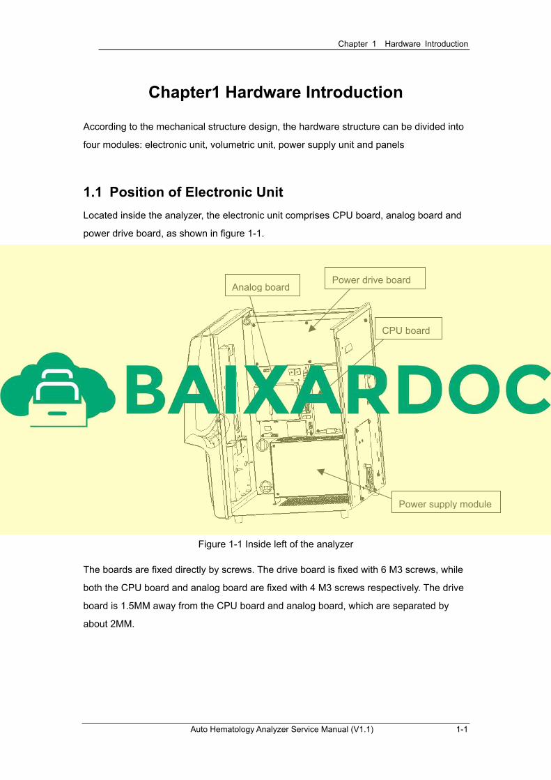
Located inside the analyzer, the electronic unit comprises CPU board, analog board and
power drive board, as shown in figure 1-1.
CPU board
Power drive board Analog board
Power supply module
Figure 1-1 Inside left of the analyzer
The boards are fixed directly by screws. The drive board is fixed with 6 M3 screws, while
both the CPU board and analog board are fixed with 4 M3 screws respectively. The drive
board is 1.5MM away from the CPU board and analog board, which are separated by
about 2MM.
Auto Hematology Analyzer Service Manual (V1.1) 1-1
Chapter 1 Hardware Introduction
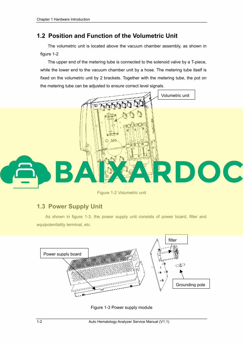
1.2 Position and Function of the Volumetric Unit
The volumetric unit is located above the vacuum chamber assembly, as shown in
figure 1-2
The upper end of the metering tube is connected to the solenoid valve by a T-piece,
while the lower end to the vacuum chamber unit by a hose. The metering tube itself is
fixed on the volumetric unit by 2 brackets. Together with the metering tube, the pot on
the metering tube can be adjusted to ensure correct level signals.
Volumetric unit
Figure 1-2 Volumetric unit
1.3 Power Supply Unit
As shown in figure 1-3, the power supply unit consists of power board, filter and
equipotentiality terminal, etc.
filter
Power supply board
Grounding pole
Figure 1-3 Power supply module
1-2 Auto Hematology Analyzer Service Manual (V1.1)
Related Documents