Future development of the electricity systems with Distributed Generation Angel Antonio Bayod Rújula Pr of . Tit ular Depart ment of El ectr ical Engi neering Univer si ty of Zaragoza, Spain

Welcome message from author
This document is posted to help you gain knowledge. Please leave a comment to let me know what you think about it! Share it to your friends and learn new things together.
Transcript

7/30/2019 Bayod
http://slidepdf.com/reader/full/bayod 1/34
Future development of the
electricity systems withDistributed Generation
Angel Antonio Bayod Rújula
Prof. Titular Department of Electrical Engineering
University of Zaragoza, Spain

7/30/2019 Bayod
http://slidepdf.com/reader/full/bayod 2/34
Traditional electricity system
Large Central
Generatión
Transmission
Network
Distribution
Network
Demand
Bulk transport of electricity
Coordination of control
Meshed network
Delivery system,Passive
Radial networks
Passive, uncontrollable

7/30/2019 Bayod
http://slidepdf.com/reader/full/bayod 3/34
Some drawbacks
• High level of dependence on imported fossil fuels
– fossil fuels running out – environmental impact of greenhouse gases and other
pollutants
– security of supply under threat
• Transmission losses
• Necessity for continuous upgrading andreplacement of transmission and distribution
facilities
– Load demand is continuously growing

7/30/2019 Bayod
http://slidepdf.com/reader/full/bayod 4/34

7/30/2019 Bayod
http://slidepdf.com/reader/full/bayod 5/34
Distributed generation
• Use of small generating units installed
close to load centres• Other terms:
– Decentralized generation – Embedded generation
– Disperse generation
• Trend: generators sized from kW to MW at
load sites

7/30/2019 Bayod
http://slidepdf.com/reader/full/bayod 6/34
• “When planning the development of the
distribution network, energy efficiency/demand-side management measures
and/or distributed generation that might
supplant the need to upgrade or replace
electricity capacity shall be considered by
the distribution system operator” Article 14/7 of the Directive of the European Parliament and
of the Council concerning common rules for the internal
market in electricity
7/30/2019 Bayod
http://slidepdf.com/reader/full/bayod 7/34
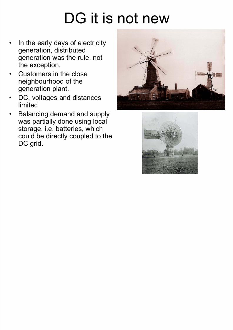
DG it is not new
• In the early days of electricitygeneration, distributedgeneration was the rule, notthe exception.
• Customers in the closeneighbourhood of the
generation plant.• DC, voltages and distanceslimited
• Balancing demand and supply
was partially done using localstorage, i.e. batteries, whichcould be directly coupled to theDC grid.

7/30/2019 Bayod
http://slidepdf.com/reader/full/bayod 8/34
Renewed interest for DG
IEA lists five major factors
• developments in distributed generationtechnologies,
• constraints on the construction of newtransmission lines,
• increased customer demand for highly
reliable electricity,• the electricity market liberalisation and
• concerns about climate change.

7/30/2019 Bayod
http://slidepdf.com/reader/full/bayod 9/34
• Kyoto Objectives means to achieve an 8% CO2reduction between 2008 and 2012 compared to1990 level.
• Other current EU targets: – increase of the share of RES from 6% to 12% of gross energy consumption by 2010
– increasing the share of electricity from RES to 21% of
gross electricity consumption by 2010 (from 14% in2003);
• Different studies:
– By 2010, DGs will take nearly 25%-30% of the newfuture electric generation,
– PV industries and companies expect about onemillion rooftops equipped by PV modules
– Very big rise of wind farms capacities, etc

7/30/2019 Bayod
http://slidepdf.com/reader/full/bayod 10/34
Applications
• Stand alone, (Rural and remote applications)
• Standby – to supply power for sensitive loads during grid outages
• Peak load shaving – supply loads at peak periods (high electricity cost)
• Combined heat and power (CHP)
• Utility-owned DGs – support the grid, voltage profile,
reduce power losses, improve PQ
• Connected to the grid to sell kWh

7/30/2019 Bayod
http://slidepdf.com/reader/full/bayod 11/34
Technologies
Reciprocating Engines
Gas Turbines
Micro turbines
Fuel CellsPhotovoltaic Systems
Wind Energy
BiomassHydro electric resources
7/30/2019 Bayod
http://slidepdf.com/reader/full/bayod 12/34
Benefits of DG
• RES: Reduce fossil fuel consumption (emissions)
• Efficiency
– CHP
– Reduction of T & D electrical losses
• Deferral investments in T & D systems (enhance network
capacity)• Network support and ancillary services (?)
• Continuity, Reliability and Security of supply
• Improve competitiveness and Market opportunities• Flexibility and locality (resources, business, employment,
no new T&D lines)

7/30/2019 Bayod
http://slidepdf.com/reader/full/bayod 13/34
Technical problems
• Electricity grids are complex, integrated systems:
interaction between generators, grid and load.
• Inversion of energy flow
– Protection
– Operation
• Voltage control
• Initial network investments
• Reliability (?)• Additional stand-by and spinning-
reserve needed
-1.5
-1
-0.5
0
0.5
1
1.5

7/30/2019 Bayod
http://slidepdf.com/reader/full/bayod 14/34
Technical problems (II)
• Impact on Power
Quality
• Management of
reactive power

7/30/2019 Bayod
http://slidepdf.com/reader/full/bayod 15/34
The Future
Large CentralGeneratión
Transmission
Network
DistributionNetwork
Demand
Coordination of control
Meshed network
Active distribution networks
Coordination of controlMeshed networks
Responsive Demand
DistributedGeneration

7/30/2019 Bayod
http://slidepdf.com/reader/full/bayod 16/34
Active Distribution Networks
• Coordination of control
• Connectivity – Increase Interconnection
– Decide best operation IN REAL TIME – More sensors and actuators
– Ancillary services (stability, voltage support)

7/30/2019 Bayod
http://slidepdf.com/reader/full/bayod 17/34
Microgrids
• Low voltage networks with DG sources, together with local storage devices and controllable loads
• They connect multiple customers to multipledistributed sources of generation and storage
• Although they operate mostly connected to thedistribution network, they can be automaticallytransferred to islanded mode.
• They can be operated as a single aggregated loador generator. Given attractive remuneration, it cansupport the network, providing ancillary services

7/30/2019 Bayod
http://slidepdf.com/reader/full/bayod 18/34
Microgrids
Slide from CEU Microgrids project

7/30/2019 Bayod
http://slidepdf.com/reader/full/bayod 19/34
Virtual Utilities
• New model of energy infrastructure which
consists on integrate different kind of distributed generation utilities in an energy
(electricity and heat) generation network
controlled by a central energy
management system (EMS).

7/30/2019 Bayod
http://slidepdf.com/reader/full/bayod 20/34
• Centralized control with the EMS and different clusters of distributedgeneration utilities and heat storage tanks.
• Each of these clusters is controlled by a local management station
(LMS).• Every LMS has information about the requirements (heat, cold and
electricity) of the users connected to its cluster and the state of theutilities and water level of the storage tanks in its cluster.
• The EMS receives the information from the LMSs and sets theelectricity input or output of every cluster in the network.
• With the information ordered by the EMS, the LMS set the run or stand-by of the utilities of its cluster.
• The EMS can give priority to renewable energy sources instead of the use of fossil fuels.
• The electricity production in the network is subordinated to the heatnecessity of every user. The thermal energy is consumed on site;the electricity is generated and distributed in the entire network.

7/30/2019 Bayod
http://slidepdf.com/reader/full/bayod 21/34
Virtual Utility

7/30/2019 Bayod
http://slidepdf.com/reader/full/bayod 22/34
New network technologies
• Advanced Power Electronics
– FACTS – ASD and other high efficiency systems
• Demand-side Management and Demand-response techniques
• Stationary energy storage• Information and Communication
Technology (ICT)

7/30/2019 Bayod
http://slidepdf.com/reader/full/bayod 23/34
Conclusions

7/30/2019 Bayod
http://slidepdf.com/reader/full/bayod 24/34
• Within the Energy Theme, the Commission proposal for the Seventh Framework Programme (COM(2005) 119
final) confirms power networks and distributedgeneration as a priority for future research activitiesrequiring a European approach.
• The objective of the research area, referred to as ‘SmartEnergy Networks’ is
• “to increase the efficiency, safety and reliability of theEuropean electricity (and gas) system and networks, e.g.by transforming the current electricity grids into aninteractive (customers/operators) service network, and toremove the technical obstacles to the large scale
deployment and effective integration of distributed andrenewable energy sources.”

7/30/2019 Bayod
http://slidepdf.com/reader/full/bayod 25/34
• Thank you

7/30/2019 Bayod
http://slidepdf.com/reader/full/bayod 26/34

7/30/2019 Bayod
http://slidepdf.com/reader/full/bayod 27/34
• Smaller amounts of energy produced by
numerous, small, modular energyconversion units
• Often located close to the point of enduse.
• These units can be stand-alone or
integrated into the electricity grid.
Fuente Eurobserv´ER

7/30/2019 Bayod
http://slidepdf.com/reader/full/bayod 28/34
Fuente Eurobserv ER
Eurobarometer 2004

7/30/2019 Bayod
http://slidepdf.com/reader/full/bayod 29/34
Technologies (I)
Reciprocating Engines
Main choice for emergency or standby power supplies, and generation < 1 MW
Gas Turbines
Small industrial gas turbines of 1- 20 MW are commonly used in CHP.
Particularly useful when higher temperature steam is required
Micro turbinesIndividual units range from 30-200 kW
Extremely high rotational speed ( up to 120 000 rpm)

7/30/2019 Bayod
http://slidepdf.com/reader/full/bayod 30/34
Technologies (II)Fuel Cell
Compact, quiet
Use hydrogen and oxygen to make electricity.
No combustion, noxious emissions are low.
Photovoltaic Systems
Capital-intensive,
Generate no heat and are inherently small-scale.
Best suited to household or small commercial applications,
Wind
Rapidly growing in importance. About 4.2 GW of capacity was installed during the year 2000.
Biomass
Hydro electric resources
E i i

7/30/2019 Bayod
http://slidepdf.com/reader/full/bayod 31/34
Emissions
Fuel
Cells Gas-Fired
Engine Diesel
Eng. SCR
Micro
Turbine
Small Gas
Turbine Photo-
voltaics
Wind
Turbine
Electric
Efficiency (LHV) 40-70% 25-45% 30-50% 20-30% 25-40% 15-30% 20-46%
Typical
Capacity
(kW) 2 1000 1000 25 4600 5000 1500
NO x
(lb/MWh) 0.03 0.50 4.70 0.44 1.15 0.00 0.00
SO 2
(lb/MWh) 0.006 0.007 0.454 0.008 0.008 0.000 0.000
PM-10(lb/MWh) 0.00 0.03 0.78 0.09 0.08 0.00 0.00
CO 2
(lb/MWh) 1078 1376 1432 1596 1494 0 0
Key:
NO x = Nitrogen oxides PM = Particulate Matter LHV= Lower Heating Value
SO 2 = Sulfur dioxide CO 2 = Carbon dioxide SCR= Selective Catalytic Reduction
ource: Emissions data from Joel Bluestein, Energy and Environmental Analysis, Inc.

7/30/2019 Bayod
http://slidepdf.com/reader/full/bayod 32/34
Transformador
Subestación
transformadoraRed MT (20 kV)
Red AT (220 kV)
Generadores BT (690 V)

7/30/2019 Bayod
http://slidepdf.com/reader/full/bayod 33/34
V+
Zth pcc
Loads
DG

7/30/2019 Bayod
http://slidepdf.com/reader/full/bayod 34/34
Related Documents