ELSEVIER Materials Science and Engineering A207 (1996) l-1 1 MATERIALS SCIEMCE & ENGINEERING A The Bauschinger effect in a particulate reinforced Al alloy S.F. Corbin*, D.S. Wilkinson, J.D. Embury Department of Materials Science and Engineering, M&faster University, 1280 Main Street West, Hamilton, Ont., LSS 4L7, Canada Received 25 August 1994;in revised form 6 July 1995 Abstract An experimental characterization of the Bauschinger effect in a particulate reinforced Al alloy revealed two important features: (1) the magnitude of permanent softening was small; (2) transient softening was significant and developed non-linearly with plastic strain. The Bauschinger effect (and associated internal stress)in these materials is dominated by relaxation processes which include plastic flow in the matrix and damage’accumulation. Consequently internal stress is limited in its magnitude and develops only at low strains. The non-uniform particle distribution contributes to the inhomogeneous deformation occurring in the composite, leading to the large transient softening effect observed. A simple model used to describe stresspartitioning between the two phases was successful in describing qualitatively the non-linear development of internal stress observed experimentally. Keywords: Bauschinger effect; Aluminium alloy; Softening 1. Introduction Two-phase materials, which contain particulates that are significantly harder than the matrix, exhibit inhomogeneous deformation. In model systems at least, it is possible to monitor the associated elastic stresses born by the hard particulate phase using neutron diffraction [l] and other methods [2]. These diffraction techniques give a direct measure of the strains in the constituent phases resulting from inhomogeneous de- formation. Alternatively, one can evaluate the influence of the accumulated internal stresses on the plastic flow of the matrix. This can be done by monitoring the effect of a change in strain path or by measuring the dimen- sional stability of a deformed sample [3]. The simplest form of strain path change to consider is the Bauschinger test in which the sense of deformation is reversed. The detailed form of the Bauschinger effect has been discussed by a number of authors [4,5] and can be summarized in diagrammatic form as in Fig. 1, which shows the existence of both permanent and tran- sient softening. In model materials, such as pure Cu reinforced with * Present address: Sherritt Technologies, Sherritt Inc., Fort Saskatchewan, Alberta, T6C OR7,Canada. 0921-5093/96/$15.00 0 1996 - Elsevier Science S.A. All rights reserved either continuous W fibres [6] or a fine dispersion of Si02 particles [7], permanent softening is observed. This can be related directly to the elastic load carried by the hard reinforcement. An analysis which leads to this result assumes that the metal matrix itself exhibits no Bauschinger effect and undergoes homogeneous plastic deformation away from the reinforcement. Further- more, it assumes that the plastic structure around the second phase is stable (i.e. unrelaxed) during forward deformation, and on a reversal in strain path, and no damage accumulation such as particle cracking or par- ticle/matrix decohesion occurs. Transient softening is more complex and makes the interpretation of parameters such as E, (Fig. 1) difficult. This type of softening results from inhomogeneous plastic flow which is unstable and relaxes on a reversal in strain path. Consequently, many materials exhibit substantial softening immediately following a change in strain path but very little thereafter. Transient softening is exhibited by a large range of materials including polycrystalline metals [8] and two-phase alloys [2]. When interpreting the behaviour of more complex materials such as particulate reinforced metal matrix composites (PMMCs), further complexity is added. The matrices within PMMCs are usually multiphase poly- crystalline alloys themselves, which will exhibit inhomo-

Welcome message from author
This document is posted to help you gain knowledge. Please leave a comment to let me know what you think about it! Share it to your friends and learn new things together.
Transcript

ELSEVIER Materials Science and Engineering A207 (1996) l-1 1
MATERIALS SCIEMCE &
ENGINEERING
A
The Bauschinger effect in a particulate reinforced Al alloy S.F. Corbin*, D.S. Wilkinson, J.D. Embury
Department of Materials Science and Engineering, M&faster University, 1280 Main Street West, Hamilton, Ont., LSS 4L7, Canada
Received 25 August 1994; in revised form 6 July 1995
Abstract
An experimental characterization of the Bauschinger effect in a particulate reinforced Al alloy revealed two important features: (1) the magnitude of permanent softening was small; (2) transient softening was significant and developed non-linearly with plastic strain. The Bauschinger effect (and associated internal stress) in these materials is dominated by relaxation processes which include plastic flow in the matrix and damage’accumulation. Consequently internal stress is limited in its magnitude and develops only at low strains. The non-uniform particle distribution contributes to the inhomogeneous deformation occurring in the composite, leading to the large transient softening effect observed. A simple model used to describe stress partitioning between the two phases was successful in describing qualitatively the non-linear development of internal stress observed experimentally.
Keywords: Bauschinger effect; Aluminium alloy; Softening
1. Introduction
Two-phase materials, which contain particulates that are significantly harder than the matrix, exhibit inhomogeneous deformation. In model systems at least, it is possible to monitor the associated elastic stresses born by the hard particulate phase using neutron diffraction [l] and other methods [2]. These diffraction techniques give a direct measure of the strains in the constituent phases resulting from inhomogeneous de- formation. Alternatively, one can evaluate the influence of the accumulated internal stresses on the plastic flow of the matrix. This can be done by monitoring the effect of a change in strain path or by measuring the dimen- sional stability of a deformed sample [3]. The simplest form of strain path change to consider is the Bauschinger test in which the sense of deformation is reversed. The detailed form of the Bauschinger effect has been discussed by a number of authors [4,5] and can be summarized in diagrammatic form as in Fig. 1, which shows the existence of both permanent and tran- sient softening.
In model materials, such as pure Cu reinforced with
* Present address: Sherritt Technologies, Sherritt Inc., Fort Saskatchewan, Alberta, T6C OR7, Canada.
0921-5093/96/$15.00 0 1996 - Elsevier Science S.A. All rights reserved
either continuous W fibres [6] or a fine dispersion of Si02 particles [7], permanent softening is observed. This can be related directly to the elastic load carried by the hard reinforcement. An analysis which leads to this result assumes that the metal matrix itself exhibits no Bauschinger effect and undergoes homogeneous plastic deformation away from the reinforcement. Further- more, it assumes that the plastic structure around the second phase is stable (i.e. unrelaxed) during forward deformation, and on a reversal in strain path, and no damage accumulation such as particle cracking or par- ticle/matrix decohesion occurs.
Transient softening is more complex and makes the interpretation of parameters such as E, (Fig. 1) difficult. This type of softening results from inhomogeneous plastic flow which is unstable and relaxes on a reversal in strain path. Consequently, many materials exhibit substantial softening immediately following a change in strain path but very little thereafter. Transient softening is exhibited by a large range of materials including polycrystalline metals [8] and two-phase alloys [2].
When interpreting the behaviour of more complex materials such as particulate reinforced metal matrix composites (PMMCs), further complexity is added. The matrices within PMMCs are usually multiphase poly- crystalline alloys themselves, which will exhibit inhomo-

2 S.F. Corbin et al. I Materials Science and Engineering A207 (1996) 1 -I1
geneous plastic deformation and a Bauschinger effect. Therefore, the primary effect of the particulate phase is not to introduce inhomogeneous deformation but rather to increase its magnitude. In particular, because of the relatively coarse scale, and (in some cases) the non-uniform distribution of the second-phase particles [9], large plastic strain gradients develop during defor- mation. These gradients can also be distributed on a macroscopic scale sometimes creating regions of de- formed and undeformed material of the order of 50- 100 pm [lo].
The scale of the second-phase particles also plays a major role in determining the relaxation of internal stress. The plastic structure around a large particle is complex and is generally characterized by multiple slip in a polycrystalline matrix. This structure is inherently less stable than that developed around a finely dis- persed phase, leading to a relaxation of the internal stress in the forward and reverse strain paths. This instability is emphasized by the extensive work of Wilson and Bate [2,11,12] who analysed the Bauschinger effect in spheroidized steels. In this case the reverse flow curve does not exhibit permanent soft- ening even after strains of 10% [4].
The occurrence of damage accumulation complicates further the interpretation of the Bauschinger effect.
(3
T S _--__.
Fig. 1. Schematic diagram of the Bauschingkr effect, indicating both permanent and transient softening. The line TS is reflected in the reverse quadrant (BC) so that permanent softening AG can be defined. Both the Bauschinger stress CJ~ and strain Ed are used to define transient softening. an is the offset strain at a reverse stress which is defined as a fraction of the forward stress (in this case 0.50,). gb is equal to (nF - 0,)/2, where cf is the maximum forward stress (point T) and 6, is the reverse yield strength determined at an offset strain of 0.001 (point D).
This is particularly true for PMMCs in which the large scale and high volume fraction of hard second phase leads to significant rates of damage accumulation even at low strains [13,14]. This will alter the nature and magnitude of internal stress developed during deforma- tion, making it difficult to interpret permanent soften- ing. This is complicated further by the fact that the rate of damage accumulation can be dependent on the stress state (i.e. damage occurs more readily in tension than in compression) [15,16]. The purpose of this investigation was to characterize experimentally the Bauschinger effect in a particulate reinforced Al alloy and analyse its behaviour in the context of permanent and transient softening.
2. Experimental procedure
The materials under investigation were supplied by Alcan International (Kingston Research and Develop- ment Centre, Kingston, Ont.). The composites are based on an age hardenable Al-Si-Mg alloy (A356) containing a eutectic Si phase (5 vol.%), and were produced by a molten metal mixing route followed by extrusion. The particles are approximately equiaxed (average aspect ratio of 2) with an average particle size of 8 pm. Additional details are provided elsewhere [lo]. Various ageing treatments were used to produce under- aged (T4), peak aged (T61) and overaged (OAZOO and OA300) matrix microstructures [17].
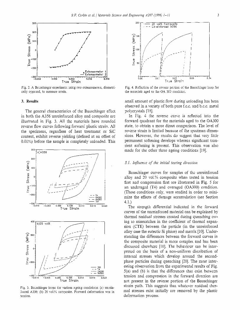
The experimental set-up used to perform the Bauschinger experiments has been described previously [lo]. Specimen geometry plays a critical role in ensuring the validity of a Bauschinger experiment [4]. In order to avoid barrelling instabilities and non-uniform stresses due to gauge length end constraints, high aspect ratio specimens are required. However, the possibility of buckling instabilities increases with aspect ratio which limits the length which can be used. For the relatively small (lo/,- 1.5%) compressive strains involved in this work and the flow stress and strain hardening character- istics of the materials studied, previous work [lo] shows that a length-to-diameter ratio of 4 is optimum. This estimate, however, depends critically on good specimen alignment, and alignment procedures used in this study are discussed elsewhere [lo]. The degree of alignment achieved was evaluated using two extensometers which were positioned diametrically opposite to one another on a composite specimen. The specimen was then de- formed in tension to about 1% strain and then deformed in compression by a similar amount (Fig. 2). Some small differences exist between the two extensometers con- cerning the measurement of the elastic modulus. How- ever, the flow curve is nearly identical, both in the forward and reverse directions, indicating negligible buckling during compressive loading.
S.F. Corbin et al. / Materials Science and Engineering A207 (1996) l-1 1 3
. Extensometer 1 - Extensometor 2
True Stiiain
Fig. 2. A Bauschinger experiment using two extensomtters, diametri- cally opposed, to measure strain.
3. Results
The general characteristics of the Bauschinger effect in both the A356 unreinforced alloy and composite are illustrated in Fig. 3. All the materials have rounded reverse flow curves following forward plastic strain. All the specimens, regardless of heat treatment or SIC content, exhibit reverse yielding (defined at an offset of 0.01%) before the sample is completely unloaded. This
I- -
-3oo:,,,~~,,,,,.,,~,,,,,,,,,,,,,,,,,,,,,,,,,,,,,,,,,,,,,,,,,,,,,l -0.010 -0.005 0.000 0.005 0.010 0.015 0.020
True Strain
Fig. 3. Bauschinger loops for various ageing conditions: (a) unrein- forced A356; (b) 20 vol.% composite. Forward deformation was in tension.
200 - 20 ~01% Composite --- Unreinforced A356
Fig. 4. Reflection of the reverse portion of the Bauschinger loop for the materials aged to the OA 300 condition.
small amount of plastic flow during unloading has been observed in a variety of both pure f.c.c. and b.c.c. metal polycrystals [18].
In Fig. 4 the reverse curve is reflected into the forward quadrant for the materials aged to the OA300 state, to obtain a more direct comparison. The level of reverse strain is limited because of the specimen dimen- sions. However, the results do suggest that very little permanent softening develops whereas significant tran- sient softening is present. This observation was also made for the other three ageing conditions [19].
3.1. Influence of the initial testing direction
Bauschinger curves for samples of the unreinforced alloy and 20 vol.% composite when tested in tension first and compression first are illustrated in Fig. 5 for an underaged (T4) and overaged (OA300) condition. (These conditions only, were studied in order to mini- mize the effects of damage accumulation (see Section 4.1.)
The strength differential indicated in the forward curves of the unreinforced material can be explained by thermal residual stresses created during quenching ow- ing to mismatches in the coefficient of thermal expan- sion (CTE) between the particle (in the unreinforced alloy case the eutectic Si phase) and matrix [lo]. Under- standing the differences between the forward curves in the composite material is more complex and has been discussed elsewhere [lo]. The behaviour can be inter- preted on the basis of a non-uniform distribution of internal stresses which develop around the second- phase particles during quenching [20]. The most inter- esting observation from the experimental results of Fig. 5(a) and (b) is that the differences that exist between tension and compression in the forward direction are not present in the reverse portion of the Bauschinger strain path. This suggests that whatever residual ther- mal stresses exist initially are removed by the plastic deformation process.

4 S.F. Corbin et al. / Materiah Science and Engineering A207 (1996) l-11
In the above experiments the focus was on the low strain regime where both forward and reverse strains were limited to about 1% because of the sample geome- try. Work by Beaulieu [21] on the same materials is shown in Fig. 6. In this case the composite (in the T61 condition) was tested to a higher prestrain (approxi- mately 0.015). In tension first tests (Fig. 6(a)) no perma- nent softening is observed; indeed the reverse curve exceeds the stress level predicted by extrapolating the forward curve to the same cumulative strain. This observation is dependent on the initial testing direction. If, as shown in Fig. 6(b), the composite is tested first in compression, the reverse strain hardening rate is lower than in the previous case and a permanent softening effect appears present. However, because of the higher prestrain and the “harder” ageing condition, damage accumulation has contributed significantly to this be- haviour. This is discussed further in Sections 4.1 and 4.2.
3.2. InjTuence of matrix ageing condition
The Bauschinger strain, at load reversals of 50%- 70% of the maximum forward stress, was measured for
200 - - Compreseion First Tests - Temmn First Tests r*
a)A358 - -
True Strain
b)ZO VOX
True Strain 0.040
Fig. 5. Reflected Bauschinger loops for tension first and compression first tests: (a) A356 alloy in T4 and OA300 states; (b) 20 vol.% composite in T4 and OA300 states.
True Strain
400 jb)
a4
Fig. 6. Reflected Bauschinger loops for the 20 vol.% composite in the T61 condition: (a) deformed initially in tension; (b) deformed initially in compression [19].
various ageing conditions (Fig. 7). It is clear that, at the level of prestrain chosen (approximately O.Ol), the Bauschinger strain is always larger in the composite than the alloy alone. Similar trends are obtained at all levels of load reversal. As expected, the Bauschinger strain increases with the level of load reversal chosen for measurement. At a given load reversal the Bau-
O.W‘l
0.0035
2 0.003 0
Composite
Unreinforced alloy
-I 0.45 0.5 0.55 0.6 0.65 0.7 0.75 0.6 0.85
Level of Reverse Stress
Fig. 7. The Bauschinger strain measured at various levels of reverse loading for the A356 alloy and 20 vol.% composite.

S.F. Corbin et al. I Materials Science and Engineering A207 (1996) 1-11 5
Fig. 8. Schematic representation of multiple forward and reverse loading for a material which exhibits a Bauschinger effect.
schinger strain is roughly the same in the T4 and T61 conditions and is significantly higher in the OA200 con- dition. In both the composite and alloy aB decreases in the OA300 condition (compared with the OA200 state). However, this decrease is more significant in the alloy where r, falls back to the levels observed for the T4 and T61 conditions.
3.3. Injuence of the level of plastic deformation
Bauschinger strain measurements require only a small degree of reverse loading. Consequently, the influ- ence of total forward plastic strain on the Bauschinger effect can be measured using a single specimen. The procedure is described in Fig. 8. If a material exhibits no Bauschinger effect, then the reverse stress-strain curve (after a forward prestrain to cf, point A) will remain elastic unless a stress of - ~~ is exceeded. In the presence of a Bauschinger effect plastic deformation begins on reverse loading before a stress of -Go is reached (point B’ in Fig. 8). If the sample is then reloaded from this point in the forward direction, a hysteresis loop will form. This procedure can be re- peated as a function of forward plastic strain by further straining in the forward direction (to point C) and then reverse loading again (to point D). These loops can be used to measure the Bauschinger strain, as well as the reverse yield stress at a given offset strain (from which the Bauschinger stress can be calculated). However, both these measurements require that a linear elastic portion in the unloading curve be defined. Typically the unloading curve is somewhat rounded, making it difficult to measure an offset strain. This difficulty can be avoided by simply measuring the width of the hys- teresis loop formed in such a test (termed the Bauschinger loop width). As the loop width increases the Bauschinger effect increases. Provided the degree of reverse loading is always the same percentage of the
forward stress, this technique can be used to compare qualitatively the effects of Sic content, matrix ageing condition and the level of plastic strain on internal stress development in complex materials. Work by Buckley and Entwistle [22] indicates that the level of reverse loading used to measure cB has little influence on the observed trends. Consequently, reverse loading of 50% was used in order to minimize the disturbance of reverse flow on the state of the material developed in the forward direction.
To verify the validity of the multi-loop tests, com- parisons of the stress-strain curves for monotonic, sin- gle and multi-loop tests were made. This is shown in Fig. 9(a) for the unreinforced alloy in the T61 condi- tion The unloading procedure does not alter signifi- cantly the shape of the forward stress-strain curve. In addition, when the stress-strain curve is recon- structed from the forward portions of the multi-loop experiments (Fig. 9(b)), it matches the monotonic curve. This is the case for both unreinforced and com- posite materials (Fig. 9(b)).
In Fig. 10, the Bauschinger loop width is plotted as a function of the plastic strain for the unreinforced alloy, 10 and 20 vol.% composites in the T4, T61 and OA300
300
- / - I -_-r - Multi-loop
l--d-- - - - Single loop ----- monotonic
-3oo,, ,,# / ,,,/ ,, ,( / ,,, / ,,, r 0.000 0.005 0.010 0.015 0.1
True Strain
1 32
400 / \ I -1 _____-----
10 ~01% Sic/A356
Reconstructions from multi-loop
- Monotonic tension
True Strain
0
Fig. 9. (a) Comparisons of single, multi-loop and monotonic stress- strain curves; (b) reconstruction of the stress-strain curve from multi-loop tests for the alloy, 10 vol.% and 20 vol.% composites.

6 S.F. Corbin et al. / Materials Science and Engineering A207 (1996) I-l I
AAAAA 20~01% Sic/A356 *t*t* 1 Owl% Sic/A356 cccxx) unreinforced A356
True Plastic Strain
AAAAA 2Ovol% Sic/A356 iti;** 1 OvolX Sic/A356 coax unreinforced A356
I ““‘, 0.010 0.020 0.030 0.040
True Plastic Strain
-20 ~1% Sic/A356 ***** 10 ~1% Sic/A356
-.-,- True Plastic Strain
Fig. 10. Bauschinger loop width vs. plastic strain for the alloy and composites aged to (a) T61, (b) T4 and (c) OA300 states.
states. The loop width initially increases rapidly with strain followed by a very slow increase after plastic strains of about 0.015. This trend with prestrain is con- firmed using other Bauschinger parameters measured from the multi-loop experiments. The Bauschinger stress g,, as measured from two separate multi-loop experiments for the 20 vol.% composite in the T61 condition is shown in Fig. 11. Also included is a measurement made from a single-loop test which was deformed to a prestrain of 0.95%. All three specimens give consistent results.
The rise in the Bauschinger effect with strain is more rapid as the SIC content is increased and is most
a a Multi-loop sample 1 Multi-loop sample 1 0 0 Multi-loop sample 2 Multi-loop sample 2 * Single loop test * Sinqle lo011 test -
I / I / I I4 I , 4, / I , I / I / I I4 I, 4, / I, 0.01 0.01 0.02 0.02 0.03 0.03 C C
True Plastic Strain True Plastic Strain
r 1.0 4
Fig. Il. The Bauschinger stress as a function of plastic strain for the 20 vol.% composite in the T61 condition. Included are measurements from two separate multi-loop tests and a single-loop test.
significant in the OA300 state (Fig. 10(c)). This aspect is illustrated further in Fig. 12 in which the Bauschinger loop width at a cumulative prestrain of 0.025 is plotted for the three different heat treatments. As in the case of the single-loop tests (Fig. 7), the Bauschinger effect is similar for the alloy in these three ageing conditions. However, in the composite it increases on going from the T61 to OA300 states.
4. Discussion
4.1. Injbence of ageing condition
There have been a number of investigations concern- ing the ageing sequence in Al alloys and its influence on the Bauschinger effect. The most extensive work has been performed on Al-Cu systems [23-261 although other Al alloys have been studied [24,27]. This work indicates that ageing to form shearable precipitates (e.g. GP zones) results in a small Bauschinger effect, while non-shearable semi-coherent or incoherent particles in-
0.0018 I O’Oo2 1 3 0.0016 - B
3 0.0014 -
.$ 0.0012~ a :! I 0.001 . LL?
0.0008
1
. . ...* ..1*” ,.....”
+ . - . - . - . - . - +.- .-.-.-.- l
0.0006 I T61 T4 OA300
Fig. 12. The Bauschinger loop width at a cumulative prestrain of 0.025 as a function of heat treatment for the unreinforced alloy and 10 and 20 vol.% composites.
S.F. Corbin et al. 1 Materials Science and Engineering A207 (1996) I-11
crease the effect. This is primarily because the non- shearable precipitates can support long-range internal stresses of the type described by Brown and Clarke [28].
For the class of alloy studied here (i.e. Al-Si-Mg) several studies [29-321 using transmission electron mi- croscopy (TEM) and X-ray diffraction, indicate the following precipitation sequence:
supersaturated solid solution
--t GP Zones --f ,f3’ --t p (Mg,Si)
GP zones are coherent with the matrix, while p’ and p are semi-coherent and incoherent Mg,Si precipitates respectively [29-311. It has been established using TEM [17] that the four ageing conditions investigated here result in the following matrix microstructures: (1) the T4 and T61 conditions consist of GP zones only; (2) the OA200 condition exhibits a complex microstructure consisting of GP zones, p’ precipitates and the equi- librium ,D phase; (3) the OA300 state is characterized by relatively coarse p precipitates.
The trends in the Bauschinger effect observed during this investigation for the unreinforced alloy are consis- tent with the precipitate structures found in each ageing condition. The Bauschinger effect is small in the T4 and T61 conditions which are characterized by shearable GP zones. It is largest in the OA200 condition in which the p’ precipitate exists. These precipitates are needle shaped and therefore have a large aspect ratio and, because they are non-shearable, can support large long- range stresses that contribute significantly to the Bauschinger effect. The decrease in the Bauschinger effect in the OA300 state back to the levels observed in the T4 and T61 states, results from the dissolution of the ,f?’ precipitates that occurs during ageing at 300°C. The p phase present in the OA300 state is equiaxed, relatively coarse and present in small amounts. There- fore it would not be expected to contribute a great deal to internal stress development.
The trends in the composite with ageing do not reflect those found in the alloy. In this case the com- posite exhibits a Bauschinger effect which increases in going from the T61 to OA300 state (Figs. 7 and 12). This result can be explained by considering damage accumulation.
Previous studies [13-16,331 indicate that, for MMCs reinforced with large ceramic particles (5-15 pm in size), damage accumulation occurs primarily in the form of particle fracture and that the number of cracked particles increases with applied strain [13,34]. This cracking is a result of the elastic stress borne by the particles due to load transfer from the metal matrix during deformation. Consequently, the degree of dam- age accumulation in these composites should be depen- dent on matrix strength, which in turn is dependent on ageing condition (see Fig. 3). One way to measure the
1.00 s * _ * *
2 . . n *
3098 J
l
Z’ :
zs : *
. * l
a : q l f
fi 0.90 - Z’
i 1 .
0” 0.94 -
z : .
- ~mmmm 20 ~01% SiC/A356-T61 : t*t*t 20 ~01% SiC/A356-OA300 m
0.92 II/I//II/,/II///~I~,~~II//I~I,~II/11III/IIIII~III,~III~~II 0.000 0.010 0.020 0.030 0.040 0.050 0. True Plastic Strain
n 01 30
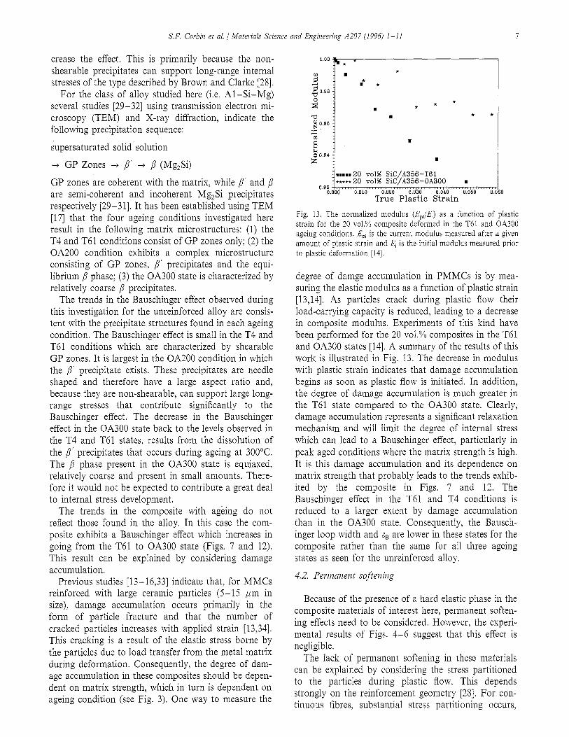
Fig. 13. The normalized modulus (EJE,) as a function of plastic strain for the 20 vol.% composite deformed in the T61 and OA300 ageing conditions. Ep, is the current modulus measured after a given amount of plastic strain and El is the initial modulus measured prior to plastic deformation [14].
degree of damge accumulation in PMMCs is by mea- suring the elastic modulus as a function of plastic strain [13,14]. As particles crack during plastic flow their load-carrying capacity is reduced, leading to a decrease in composite modulus. Experiments of this kind have been performed for the 20 vol.% composites in the T61 and OA300 states [14]. A summary of the results of this work is illustrated in Fig. 13. The decrease in modulus with plastic strain indicates that damage accumulation begins as soon as plastic flow is initiated. In addition, the degree of damage accumulation is much greater in the T61 state compared to the OA300 state. Clearly, damage accumulation represents a significant relaxation mechanism and will limit the degree of internal stress which can lead to a Bauschinger effect, particularly in peak aged conditions where the matrix strength is high. It is this damage accumulation and its dependence on matrix strength that probably leads to the trends exhib- ited by the composite in Figs. 7 and 12. The Bauschinger effect in the T61 and T4 conditions is reduced to a larger extent by damage accumulation than in the OA300 state. Consequently, the Bausch- inger loop width and sg are lower in these states for the composite rather than the same for all three ageing states as seen for the unreinforced alloy.
4.2. Permanent softening
Because of the presence of a hard elastic phase in the composite materials of interest here, permanent soften- ing effects need to be considered. However, the experi- mental results of Figs. 4-6 suggest that this effect is negligible.
The lack of permanent softening in these materials can be explained by considering the stress partitioned to the particles during plastic flow. This depends strongly on the reinforcement geometry [28]. For con- tinuous fibres, substantial stress partitioning occurs,

8 S.F. Corbin et al. 1 Materials Science and Engineering A207 (1996) 1-l 1
resulting in significant permanent softening. For equiaxed particles, stress partitioning and the associated permanent softening are expected to be much smaller. Nevertheless permanent softening has been measured in two-phase materials such as single crystals of copper containing a fine dispersion of spherical SiO, particles [7]. Therefore, the reinforcement geometry alone cannot rule out the possibility of a significant permanent soft- ening effect.
As mentioned in the introduction, the scale of the second-phase particles in a PMMC means that relax- ation, leading to instabilities in the plastic structure, can be significant even at low strains. Comparison of theo- retical with experimental stress-strain curves [35] sug- gests a rather strong relaxation effect in discontinuously reinforced MMCs which prevents the particles from being loaded to the degree that a model, based on an unrelaxed state, would predict. In a previous study [19,36] a simple model for stress partitioning based on spherical particles embedded in a work hardening ma- trix was developed. The approach was based on Eshel- by’s equivalent inclusion method and utilizes a self-consistent analysis. Because this is a continuum analysis, plastic relaxation occurs whenever the stress in the matrix phase exceeds its macroscopic yield strength. A constitutive equation is used to treat work hardening in the matrix. The Ramburg-Osgood equation was chosen because it can describe accurately the elastic and plastic portions of the stress-strain curve. The overall stress-strain curve of the composite is determined nu- merically assuming incrementally linear behaviour. This method predicts the stress-strain behaviour of a com- posite and can be used to indicate the degree of stress partitioning that occurs between the particle and matrix during composite straining. Fig. 14 illustrates the stress-strain curve of a composite (solid line) as pre- dicted by this self-consistent analysis. This example is based on an A356 matrix in the T61 condition rein-
-2 800 1
.% _
-----i I
700: __/- SiCi Cr-- I
g 800: .’
/’ I
2 500: ,I’
I /
i - i i
& 400: t 0 1 ’ Composite Stress
i
I
-1001 / / / I / I j I / / , I / I / / I / , / / / , / / I I , , , / I , , / , / , , , , , , . , I 0.000 0.005 0.010 0.015 0.020 0.025
Composite Strain
Fig. 14. The stress-strain curve of the composite (solid line) pre- strained to 2% and unloaded to zero. Dashed line indicates stress in the Al and Sic phases at a given composite strain.
forced with 20 vol.% Sic particles. The stresses in both the particle and matrix phases are also shown, as a function of the composite strain (dashed lines). It is clear that the majority of the stress transferred to the Sic particles occurs in the first 0.5% strain. Once the matrix yields, stress in the Sic rises very slowly. Conse- quently, for the case of large-scale particles, the degree of load transfer is limited to the low strain regime and the level of internal stress developed which can lead to permanent softening is small.
As indicated in the previous discussion, damage ac- cumulation also limits the amount of internal stress and therefore permanent softening that can be developed in the composite. In addition, the dependence of damage accumulation on the direction of the strain path further complicates the interpretation of permanent softening. This is illustrated b,y the experiments of Fig. 6.
In the case where the initial strain path is in tension, the strain hardening rate drops off rapidly with strain. On load reversal, the hardening rate is much higher in compression. This is due partly to the suppression of particle cracking during compressive loading. This re- sults in the apparent observance of no permanent soft- ening. In fact the flow stress of the reverse curve exceeds that of the initial stress-strain curve. In the case where the initial strain path is in compression, the hardening rate decreases much less dramatically, again because of damage suppression. However, on load re- versal, hardening in tension again drops off rapidly. Therefore, in the compression first case the Bauschinger experiment appears to indicate permanent softening. This effect however is due primarily to the differences in damage accumulation when testing in compression and tension and could lead to misinterpretation of the pres- ence and magnitude of permanent softening.
The creation of thermal stresses during quenching also contributes to the difficulties in interpreting the Bauschinger effect. For the unreinforbed alloy, the strength differential seen in the foward curve (Fig. 5) indicates the presence of a thermal stress which is tensile in the matrix and compressive in the eutectic Si particles. Interestingly, the strength differential is not present in the reverse curves. This indicates that the residual stresses initially present are removed by plastic deformation. As Fig, 5 indicates, in the unreinforced alloy the presence of a thermal stress would lead to an overestimation of the Bauschinger effect when tested in compression first and an underestimation when tested in tension first.
In the composite, the “cross over” effect seen when comparing prestrains in compression and tension (see Fig. 5(b) and [14,19]) has been interpreted based on a non-uniform distribution of internal stress around the second-phase particles [10,20]. Because of this non-uni- form distribution these thermal stresses probably influ- ence transient softening to a greater extent than

S.F. Corbin et al. / Materials Science and Engineering A207 (1996) 1-l 1
permanent softening and are discussed in the next section.
4.3. Transient softening
The most common explanation of transient softening is based on inhomogeneous plastic flow resulting from a microstructure which is itself inhomogeneous. The simplest example of such a material is a polycrystalline metal where the individual grains will yield at different applied stress because of their various orientations to the loading axis. A description of transient softening in such a material has been provided by Masing [8] and Sowerby et al. [37]. This inhomogeneous yielding leads to the build-up of internal stresses that are distributed non-uniformly through the material, and which are removed easily on load reversal.
When SIC particles are added to the base alloy it is difficult to achieve a uniform distribution throughout the metal matrix. In the present composite system there is evidence that the Sic particles are distributed non- uniformly [9]. In particular, there are a large number of particles whose interparticle spacing is less than about 3 pm. This leads to a particle-rich region of the mi- crostructure having a local volume fraction which is significantly above the average volume fraction of the composite. When plastic flow begins, the regions con- taining low volume fractions of particles yield first, while particle-rich regions remain elastic to higher strains [36]. With continued straining the particle-rich regions will begin to deform plastically. Alternatively the high stresses borne by the particles in these regions, because they remain elastic, may cause them to fracture [38]. In either case the load transfer and therefore internal stress will be relaxed. This leads to a non-linear development of internal stress which contributes to the large transient softening effect seen by the composites in this study.
An investigation of the effects of particle distribution [36] indicates that when the second phase is clustered in this way, the strain hardening rate in the composite increases owing to an increase in load transfer to the particle-rich regions of the microstructure (Fig. 15). This figure also indicates that the stress-strain curve becomes increasingly non-linear. This phenomena is a significant contributor to the large transient softening seen in the composite materials.
The self-consistent model which leads to the results of Fig. 14 can also be used to describe qualitatively the non-linear development of internal stress in the com- posite. For simplicity the description below is based on a uniform particle distribution, and is similar to the approach used by Withers and coworkers [1,39]. Fig. 16 plots the predicted stress in the Sic phase and the Al alloy as a function of composite stress, both during loading and unloading. On unloading, both the particle
=‘jb) I
----- Unreinforced alloy
I
09000 y ,,,/,,,,,,,,,,,,, 0.005 / 0.010 ,,,,,, / ,,,, 0.015 ,/,, True Strain
Fig. 15. Predictions of the influence of particle clustering on the stress-strain behaviour of a 20 vol.% composite [36]. For reference the dashed line indicates the stress-strain curve of the unreinforced alloy. Predictions for the composite include a uniform 20 vol.% distribution and clusters such that the overall volume fraction of 20 vol.% is distributed into particle-rich regions of 30%, 35% and 40% and particle-free regions.
and matrix relax elastically as shown, In both cases, the particles and matrix are assumed to unload elastically in the same proportion as they loaded elastically ini- tially in the forward direction. (This assumes that the plastic structure developed around the particles is stable during unloading. If this structure begins to reverse or relax, the particles may be unloaded to a larger extent than that predicted in the figure). While both phases deform elastically the stress partitioning ratio remains constant (line segments OP and OP’). At point P, the matrix yields. The load transfer to the particles is modified by sampling the current strain hardening rate (or tangent modulus) of the matrix. In this way, the model predicts the additional stress partitioned to the particles which arises as a result of plastic flow in the matrix. (The dashed line indicates the stress that would have been partitioned to the particles had the matrix remained elastic.) After a forward deformation of 2% the composite is completely unloaded. During this pro-
Elastic Line
-1001 ,, 0
I ,,,,~,~,,~~,,,~~~~,~~~,,,,,~ 100 200 300
,r
Composite Stress (MPa) 4
Fig. 16. The stress predicted in the Al and Sic phases at a given composite stress during prestraining and unloading to zero.

S.F. Corbin et al. I Materials Science and Engheerblg A207 (1996) l-11
Calculation based on 20 ~01% uniform SIC content 200
0.0, 0.02 0.03
Composite Plastic Strain
Fig. 17. The predicted internal stress, G: (defined in the text and in Fig. 16) developed during forward flow as a function of the level of plastic strain in the composite.
cess both the matrix and the particles are unloaded elastically in the same proportion as they were loaded originally in the elastic regime. However, the amount of stress partitioning to the particles as a result of plastic flow cannot be removed as long as the matrix remains elastic and the plastic structure around the particle remains stable. The point U represents the point at which the matrix is unloaded to zero. It is clear that, at this point, the particles are still loaded in tension by GP. Unloading the composite to zero applied stress (point 0) results in a situation of internal stress such that Vpop + Vmom = 0. The compressive stress in the matrix then aids reverse flow resulting in a Bauschinger effect.
An estimate of internal stress, as defined by OF, is plotted as a function of the composite plastic strain in Fig. 17. Comparison of this description with the exper- imental results of Fig. 10 reveals good qualitative agree- ment concerning the overall trends. In particular, internal stress develops rapidly at low strains but in- creases gradually at strain levels above 0.01.
As mentioned previously, thermal residual stress can also influence transient softening behaviour. The fact that the particles themselves are not uniformly dis- tributed throughout the matrix, compounds the inho- mogeneous distribution of thermal stresses that exist around an individual particle. Consequently, the yield strength of the matrix in particle-rich regions is proba- bly altered to a greater extent by thermally induced stresses than particle-free regions. This further increases the inhomogeneous plastic flow occurring in the com- posite which will lead to an increased transient soften- ing effect.
An extension of the self-consistent analysis beyond the general description of Figs. 14 and 16 to include a prediction of transient and permanent softening in the reverse flow curve, is difficult. This is primarily the result of the complex reverse flow that arises owing to instability of the plastic structure formed in the forward
direction [ 1,4,11,12]. However, the model does elucidate the role that stress partitioning to the second phase in a PMMC plays in the development of internal stress. In particular it predicts that behaviour which is dominated by plastic relaxation in the matrix leads to non-linear strain hardening [36] as well as a non-linear develop- ment of internal stress which is most significant at low strains. Clearly this process of internal stress develop- ment would be influenced by the particle distribution within the matrix; however, development of the model to include unloading of a non-uniform microstructure and the incorporation of thermal stresses is beyond the scope of this study.
5. Summary and conclusions
An experimental investigation of the Bauschinger effect in a particulate reinforced MMC suggests that the magnitude of permanent softening developed in the materials is small. Instead, the Bauschinger effect is characterized primarily by transient softening which develops non-linearly with plastic strain. In both the composite materials and the unreinforced alloy, the Bauschinger loop width saturates by strains of about 2%, indicating little increase in internal stress beyond this point. This behaviour suggests that internal stress development is influenced strongly by relaxation pro- cesses including plastic flow in the matrix adjacent to the reinforcing phase and damage accumulation. Both damage and thermal residual stresses make it difficult to interpret the small amount of permanent softening that may be present. Damage is also responsible for the differences observed between the composite and alloy regarding the influence of ageing.
A relatively simple model describing the stress parti- tioned to the two phases during plastic flow can be used to analyse qualitatively the experimental results. It suc- cessfully predicts the non-linear development of internal stress indicated by the experimental results and sup- ports the conclusion that the inhomogeneous plastic flow introduced by the second-phase particles con- tributes to the transient softening effect observed exper- imentally.
Acknowledgements
The authors would like to thank Dr. Z.S. Basinski and Dr. W. Poole for many fruitful discussions which have contributed significantly to this work. We are grateful to Dr. D.J. Lloyd for the provision of materi- als. The financial support of NSERC and a university/ industrial consortium consisting of Alcan International, INCO Limited, Ontario Hydro Research, Pratt and Whitney Canada Inc. and Sherritt Inc. is greatly appre- ciated.
S.F. Corbiil et al. / Materials Science and Engineering A207 (1996) 1-l 1 11
References
Ul
PI [31 [41
[51 VI
[71
181 [91
VOI
[ill WI u31 [I41
[I51
1161
1171
WI
P.J. Withers, W.M. Stobbs and O.B. Pedersen, Acta Metall., 37 (1989) 3061. D.V. Wilson and P.S. Bate, Acta Melall., 34 (1986) 1107. J.D. Embury, Mater. Forum, 10 (1987) 21. P.B. Prangnell, W.M. Stobbs and P.J. Withers, submitted to Mater. Sci. Eng., Al59 (1992) 43. A. Abel, Mater. Form, 10 (1987) 11. A. Kelly and N.H. MacMillan, Strong Solids, Oxford Science Publications, 3rd edn. J.D. Atkinson, L.M. Brown and W.M. Stobbs, Philos. Mag., 30 (1974) 1247. G. Masing, Wiss. Veroff Siernem-Komern, Z/I; 1927. D.J. Lloyd, N. Hansen, D. Juul Jensen, T. Leffers, H. Lilholt, T. Lorentzen, AS. Pedersen and B. Ralph, (eds.), Proc. 12th Riso Inter. Symp., Riso National Laboratory, Denmark, 1991, p. 81. S.F. Corbin and D.S. Wilkinson Acra Merall. Mater., 42 (1994) 1319. D.V. Wilson, Acta Me~all., 13 (1965) 807. D.V. Wilson and P.S. Bate, Mater. Form, 10 (1987) 33. D.J. Lloyd, Acta Metall. Mater., 39 (1991) 59. S.F. Corbin and D.S. Wilkinson, Acta Metall. Mater., 42 (1994) 1329. S. Tao, M. Eug. Thesis, McMaster University, Hamilton, Ont., 1991. F. Zok, Ph.D. Thesis, McMaster University, Hamilton, Ont., 1988. S.F. Corbin and D.S. Wilkinson, in press Can. Met. Q. (1996). R.L. Woolley, Philos. Mag., 44 (1954) 597.
1191
WI VI
P21 ~231 1241 ~251 WI
~271 WI v91 [301 [311 ~321 [331
[341
[351
L361
I371
[381
[391
S.F. Corbin, Ph.D Thesis, McMaster University, Hamilton, Ont., 1992. A. Levy and J.M. Papazian, Acta Metal/. Mater., 39 (1991) 2255. G. Beaulieu, M.Sc Thesis, McMaster University, Hamilton,-‘Ont. 1991. S.N. Buckley and K.M. Entwistle, Acta Metal/., 4 (1956) 352. A. Abel and R.K. Ham, Acta Metal/., 14 (1966) 1489. R.E. Stoltz and R.M. Pelloux, Metall. Trans. ‘4, 7 (1976) 1295. G.D. Moan and J.D. Embury, Acta Metall., 27 (1979) 903. P. Bate, W.T. Roberts and D.V. Wilson, Acta Metall., 30 (1982) 725. S.P. Gupta and S.P. Kodali, Tram JIM, 17 (1976) 261. L.M. Brown and D.R. Clarke, Acta Metall., 23 (1975) 821. G. Thomas, J. Inst. Met., 90 (1961) 57. A. Lulls, Acta Metall., 9 (1961) 577. M.H. Jacobs, Philos. Mag., 26 (1972) 1. W.F. Smith, Merall. Trans., 4 (1973) 2435. Y. Brechet, J.D. Embury, S. Tao and L. Luo, Acta Metall. Mater., 39 (1991) 1781. D.J. Lloyd, P.L. Morris and E. Nehme, in J. Masounave and F.G. Hamel (eds.) Fabrication of Particulate Reinforced Metal MaKx Composites, 1991, p. 235. P.J. Withers, O.B. Pedersen, L.M. Brown and W.M. Stobbs, Mater. Sci. Eng., A108 (1989) 281. S.F. Corbin and D.S. Wilkinson, Acta Metal1 Mater., 42 (1994) 1311. R. Sowerby, D.K. Uko and Y. Tomita, Mater. Sci. Eng., 41 (1979) 43. D.J. Lloyd, H. Lagace, A. Mcleod and P.L. Morris, Mater. Sci. Eng., A107 (1989) 73. P.J. Withers, T. Lorentzen and O.B. Pedersen, in N. Hansen, D. Juul Jensen, T. Leffers, H. Lilholt, T. Lorentzen, A.S. Pedersen and B. Ralph (eds.), Proc. 12th Riso Int. Symp., Riso National Laboratory, Denmark, 1991, p. 189.
Related Documents


