BAUMÜLLER Technical description and operation manual Edition 11. January 1996 POWER CONVERTER BKD 6 / ... 6000 BKF12 / ... 6000 E 5.95001.02

Welcome message from author
This document is posted to help you gain knowledge. Please leave a comment to let me know what you think about it! Share it to your friends and learn new things together.
Transcript

BAUMÜLLER
Technical description andoperation manual
Edition 11. January 1996
POWER CONVERTERBKD 6 / ... 6000BKF12 / ... 6000
E 5.95001.02

BAUMÜLLER
POWER CONVERTER
BKD 6/ ... 6000, BKF 12/ ... 6000
Technical description and operation manual
Edition January 1996
5.95001.02
PLEASE READ AND PAY ATTENTION TO SAFETY INSTRUCTIONSAND OPERATING GUIDE PRIOR TO COMMISSIONING
This manual contains the necessary information for normal operation of the products describedtherein. The drives may only be used, maintained and repaired by personnel familiar with the operationmanual and the applicable regulations on working safety and accident prevention. The devices aremanufactured to a high technical specification and are operationally safe. Provided that all safetyinstructions habe been adhered to, there will be no personal danger during the installation andcommissioning stages.
The commisioning is prohibited until it has been positively determined that the machine, into whichthese components are to be incorporated, complies with EC machine regulations.
This technical description replaces and nullifies all provious description. In order to provide the bestpossible service, we reserve the right to alter information without notice.
Manufacturer and Baumüller Nürnberg GmbH
Supplier's address: Ostendstr. 80
90482 Nürnberg
Germany
Tel. (++49-911) 5432 - 0 Fax (++49-911) 5432 - 130
Copyright: The technical description and the operation manual may not be copied or
duplicated without our permission.
Country of origin: Made in Germany
Date of manufacture: Determined from the serial number on the machine/motor.

Table of Contents
BKD 6/ ... 6000, BKF 12/ ... 6000 IBaumüller Nürnberg GmbH 5.95001.02
TABLE OF CONTENTS
1 Safety Information............................................................................................. 1
2 Technical Data................................................................................................... 52.1 General....................................................................................................................... 5
2.2 Type Code .................................................................................................................. 9
2.3 Technical Data of Power Converter Units.................................................................... 10
2.4 Technical Data of Field Power Converter.................................................................... 12
2.5 Technical Data of Mains Unit ...................................................................................... 13
2.5.1 Standard Version with Conventional Mains Unit ........................................... 132.5.2 Special Version with Switching Mains Unit and External 24-V Supply .......... 14
2.6 Technical Data of Power stage.................................................................................... 15
2.7 Technical Data of Processor Board 3.8934 ................................................................. 16
2.8 Technical Data of Supplementary Modules ................................................................. 20
2.8.1 "Dual DAC 12", Daughterboard 3.9201 ........................................................ 202.8.2 "Input/Output Expansion", Daughterboard 3.9217 ........................................ 202.8.3 InterBus-S Interface Board, 3.9208.............................................................. 222.8.4 RS232, RS485 Interface Card, 3.8947......................................................... 232.8.5 RS485 with USS Protocol or as a CS31 System Bus Interface, 3.9493 ........ 24
2.9 Power Loss of Power Converter, Line Converter and Fuses........................................ 25
2.10 Construction Drawings .............................................................................................. 26
2.10.1 CPU Board 3.8934..................................................................................... 262.10.2 Field Supply 3.8942 ................................................................................... 30
2.11 Adapting Power Converters to Different Connection Voltages ................................... 38
3 Transportation And Unpacking........................................................................ 39
4 Assembly ........................................................................................................... 414.1 Dimensions.................................................................................................................42
4.1.1 BKD 6 and BKF12 .../6000, Size I (30 A to 200 A) ....................................... 434.1.2 BKD 6 and BKF12 .../6000, Size II (300 A to 600 A) .................................... 454.1.3 BKD 6 and BKF 12 .../6000 Sizes III and IV ................................................. 47
4.2 Weights ...................................................................................................................... 53
4.3 Assembly Information ................................................................................................. 54
5 Installation ......................................................................................................... 575.1 Danger and Warning Information ................................................................................ 57
5.2 Standardization Information ........................................................................................ 58
5.3 Connection Plans........................................................................................................ 59
5.3.1 Connecting Controller Module Sizes I ... IV.................................................. 605.3.2 Connecting Power Stage BKF 12/6000 Sizes I ... IV .................................... 675.3.3 Connecting Power Stage BKD 6/6000 Sizes I ... IV...................................... 74

Table of Contents
II BKD 6/ ... 6000, BKF 12/ ... 6000
5.95001.02 Baumüller Nürnberg GmbH
5.4 Connecting Daughterboards........................................................................................ 84
5.4.1 "Dual DAC 12", 3.9201 Daughterboard ........................................................ 845.4.2 "Input/Output Expansion", 3.9217 Daughterboard ........................................ 855.4.3 InterBus-S Interface Board .......................................................................... 905.4.4 RS 232, RS 485 Interface Board.................................................................. 915.4.5 RS485 with USS Protocol or as a CS31 System Bus Interface, 3.9493........ 92
5.5 Position of the Electrical Connections and Modules .................................................... 94
5.5.1 BKD 6 and BKF 12 .../6000, Size I (30 A to 200 A) ...................................... 945.5.2 BKD 6 and BKF 12 .../6000, Size II (300 A to 600 A) ................................... 945.5.3 Controller and Field Supply for Sizes III and IV (750 A to 2050 A) ............... 95
5.6 Semiconductor Fuses ................................................................................................. 96
5.6.1 Unit Size I.................................................................................................... 965.6.2 Unit Size II................................................................................................... 985.6.3 Unit Size III.................................................................................................. 985.6.4 Unit Size IV ................................................................................................. 995.6.5 Fuse Sizes................................................................................................... 995.6.6 Field Semiconductor Fuses ......................................................................... 99
5.7 Line Commutators ...................................................................................................... 100
5.8 Accessories ................................................................................................................ 103
6 Functions ........................................................................................................... 1056.1 Function Plans............................................................................................................ 105
6.2 Specifying the Controller Structure.............................................................................. 111
6.3 Nominal Value Assignment ......................................................................................... 114
6.4 Current Limits ............................................................................................................. 119
6.4.1 Current Limits for the Armature.................................................................... 1196.4.2 Current Limitation at the Field Current Converter......................................... 121
6.5 Monitoring................................................................................................................... 122
6.5.1 Ready for Use Relay K1 .............................................................................. 1226.5.2 Relay K2...................................................................................................... 1236.5.3 Relay K3...................................................................................................... 1246.5.4 Linking the Armature Current Monitoring Relays of K2 and K3..................... 1266.5.5 Relay K4...................................................................................................... 1276.5.6 Displaying and Checking the Relay Functions.............................................. 129
6.6 Analog Output on Measuring Channels 1 ... 4 ............................................................. 130

Table of Contents
BKD 6/ ... 6000, BKF 12/ ... 6000 IIIBaumüller Nürnberg GmbH 5.95001.02
6.7 Controlling the Power Converter, Sequence of Switching On and Off ......................... 134
6.7.1 Enables on the Power Converter and Main Contactor Control ...................... 1346.7.2 Additional Switching and Control Inputs ....................................................... 1406.7.3 Sequence of Switching On and Off .............................................................. 145
6.8 Automatic Restarting after Brief Mains Disturbances................................................... 149
6.8.1 Standard Unit............................................................................................... 1496.8.2 Automatic Restart for Special Versions with a Switching Mains Unit ............ 151
6.9 Load Measurement with Cranes (S04.12 and above) .................................................. 153
7 Commissioning ................................................................................................. 1577.1 Danger and Warning Information ................................................................................ 157
7.2 Operating the Power Converter................................................................................... 160
7.2.1 Overview ..................................................................................................... 1607.2.2 Keypad and Display on the Power Converter ............................................... 1617.2.3 Operation Using a PC.................................................................................. 165
7.3 Commissioning Guidelines.......................................................................................... 182
7.3.1 Stock-Taking ............................................................................................... 1827.3.2 Parameterization ......................................................................................... 1847.3.3 Equipment Set-Up ....................................................................................... 190
7.4 Configuration and Commissioning Record .................................................................. 196
7.5 Parameter Documentation .......................................................................................... 197
8 Parameters......................................................................................................... 207
9 Maintenance....................................................................................................... 2519.1 Maintenance Information ............................................................................................ 252
9.2 Error Messages........................................................................................................... 253
9.3 Error List..................................................................................................................... 255
9.4 Spares ........................................................................................................................ 261
9.4.1 Modules and Complete Units ....................................................................... 2619.4.2 Replacement boards, Daughterboards and Individual Parts ......................... 262
9.5 Disposal...................................................................................................................... 263
10 Appendix .......................................................................................................... 26510.1 Complementary Documentation................................................................................ 265
10.2 Manufacturer Declaration.......................................................................................... 266
10.3 Declaration of Conformity ......................................................................................... 267
10.4 Conditions of Business and Delivery ......................................................................... 268
10.5 Index......................................................................................................................... 268
Abbreviations
IV BKD 6/ ... 6000, BKF 12/ ... 6000
5.95001.02 Baumüller Nürnberg GmbH
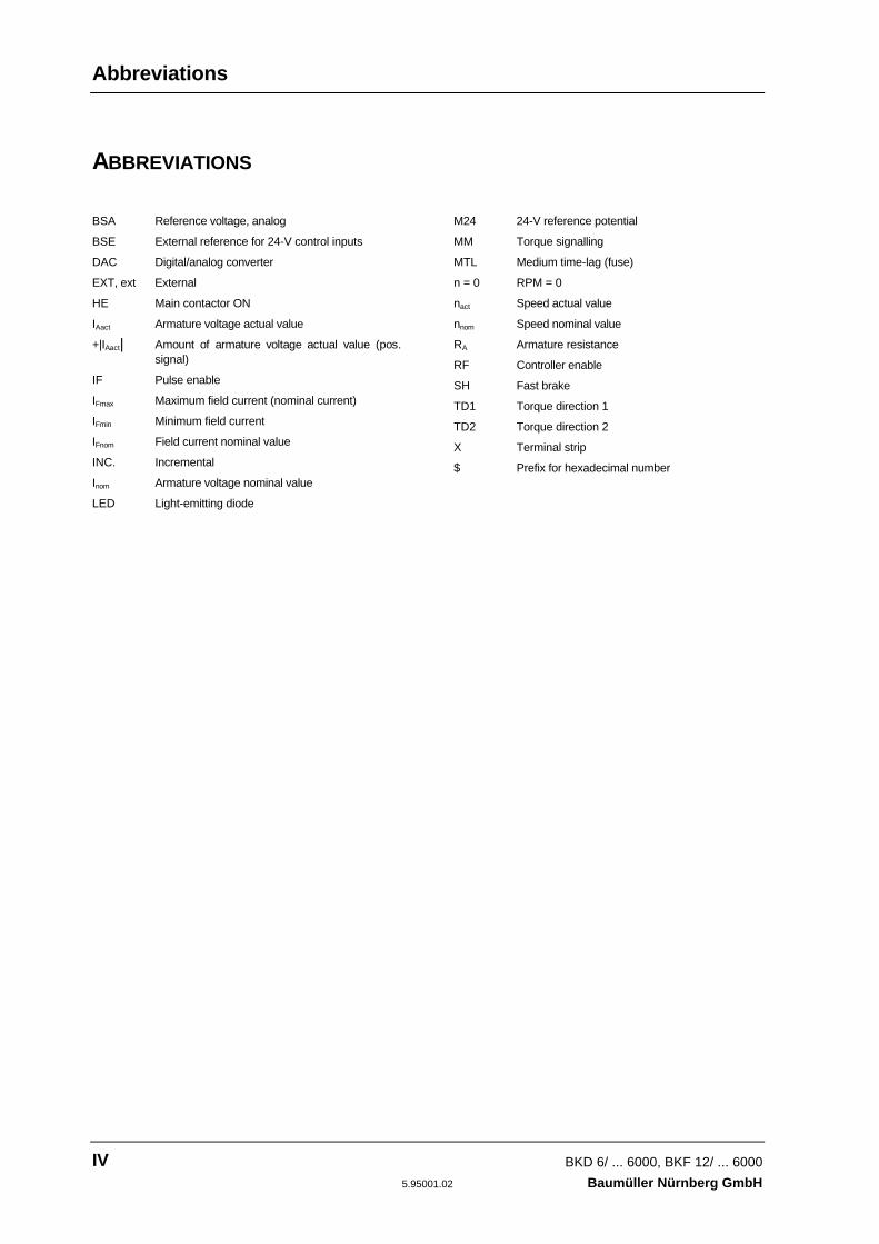
ABBREVIATIONS
BSA Reference voltage, analog
BSE External reference for 24-V control inputs
DAC Digital/analog converter
EXT, ext External
HE Main contactor ON
IAact Armature voltage actual value
+|IAact| Amount of armature voltage actual value (pos.signal)
IF Pulse enable
IFmax Maximum field current (nominal current)
IFmin Minimum field current
IFnom Field current nominal value
INC. Incremental
Inom Armature voltage nominal value
LED Light-emitting diode
M24 24-V reference potential
MM Torque signalling
MTL Medium time-lag (fuse)
n = 0 RPM = 0
nact Speed actual value
nnom Speed nominal value
RA Armature resistance
RF Controller enable
SH Fast brake
TD1 Torque direction 1
TD2 Torque direction 2
X Terminal strip
$ Prefix for hexadecimal number

Safety Information
BKD 6/ ... 6000, BKF 12/ ... 6000 1Baumüller Nürnberg GmbH 5.95001.02
1 SAFETY INFORMATION
Preliminary Remarks
During operation, the principles on which the power converter and the motor work lead to leakagecurrents to earth occur that may be dissipated via the specified protective earths and may result in acurrent-operated e.l.c.b. on the input side blowing prematurely.In the case of a short-circuit to frame or to ground, a direct proportion may arise in the leakage cur-rent that makes triggering a higher-level current-operated e.l.c.b. either more difficult or totally im-possible.This means that connecting the power converter to the mains using only the current-operated e.l.c.b.is prohibited (preliminary standard EN 50178/VDE 0160/11.94, Sections 5.2.11 and 5.3.2.1)
The units are protected from direct contact by being installed in commercially available switchingcabinets that meet the minimum protection requirements of preliminary standard EN 50178/VDE0160/ 11.94, Section 5.2.4.
Sheets of plastic covering the control electronics, the power stage and the equipment connection actas additional guards preventing accidental contact at commissioning and in the case of casual use ofcontrol elements located close to the equipment (DIN VDE 0106 Part 100, Accident PreventionRegulation VBG4 "Electrical Systems and Equipment").
At routine testing of this equipment, a high-voltage test is carried out that conforms with preliminarystandard EN 50178/VDE 0160/11.94, Section. 9.4.5.
The protective measures and safety regulations according to DIN/VDE are binding for personal se-curity. Neglecting to fit PE connections on the equipment or the motor will result in serious personalinjury and/or considerable damage to property.
General Information
These operating instructions contain all the information necessary for correct operation of the prod-ucts described. The document is intended for specially trained, technically qualified personnel whoare well-versed in all warnings and commissioning activities. The equipment is manufactured usingstate-of-the-art technology and is safe in operation. It can safely be installed and commissioned andfunctions without problems if the safety information in these operating instructions is followed.
WARNINGWhen operating electrical equipment, some parts of the equipment always carry dangerous voltages.Ignoring these safety instructions and warnings may result in serious personal injury and/or damage toproperty.Only qualified personnel who are familiar with the safety information, assembly, operation and main-tenance instructions may carry out work on this equipment.

Safety Information
2 BKD 6/ ... 6000, BKF 12/ ... 6000
5.95001.02 Baumüller Nürnberg GmbH
Danger Information
On the one hand, the information below is for your own personal safety and on the other to preventdamage to the described products or to other connected equipment.
In the context of the operating instructions and the information on the products themselves, the termsused have the following meanings:
DANGERThis means that death, severe personal injury, or damage to property will occur unless appropriatesafety measures are taken.
WARNINGThis means that death, severe personal injury, or damage to property may occur unless appropriatesafety measures are taken.
NOTEThis draws your attention to important information about the product, handling of the product or to aparticular section of the documentation.
Qualified Personnel
In the context of the safety-specific information in this document or on the products themselves,qualified personnel are considered to be persons who are familiar with setting up, assembling, com-missioning and operating the product and who have qualifications appropriate to their activities:
Trained or instructed or authorized to commission, ground and mark circuits and equipment in accor-dance with recognized safety standards.
Trained or instructed in accordance with recognized safety standards in the care and use of appropri-ate safety equipment.
Safety Information
BKD 6/ ... 6000, BKF 12/ ... 6000 3Baumüller Nürnberg GmbH 5.95001.02
Appropriate Use
WARNINGYou may only use the equipment/system for the purposes specified in the operating instructions andin conjunction with the third-party equipment and components recommended or authorized byBAUMÜLLER NÜRNBERG GmbH.
For safety reasons, you must not change or add components on/to the equipment/system.
The machine minder must report immediately any changes that occur which adversely affect thesafety of the equipment/system.

Technical Data
4 BKD 6/ ... 6000, BKF 12/ ... 6000
5.95001.02 Baumüller Nürnberg GmbH
General Technical Data
BKD 6/ ... 6000, BKF 12/ ... 6000 5Baumüller Nürnberg GmbH 5.95001.02
2 TECHNICAL DATA
2.1 General
BAUMOTRONIC Series 6000 power converters are line-commutated units for speed-controlled DCdrives with microprocessor closed-loop control.
Single- and four-quadrant versions are available, which differ only in the version of the power unitused for armature control:
In the case of the BKD 6/.../...-6000 single-quadrant version, the power stage is a fully controlledthree-phase current bridge circuit (B6C); with the BKF12/../..-6000 four-quadrant version by contrast,the power stage is a circular current-free counter-parallel circuit (B6C)2I.
In general, a B2HKF semi-controlled two-phase bridge, which is controlled by the microprocessor, isused as the field supply.
Single-quadrant power converters have rated currents of between 30 A and 2050 A; rated currents ofbetween 30 A and 1650 A are available for four-quadrant versions.
This means that it is possible to run on a 500-V 3~ industrial supply DC drives with power ranges ofapproximately 5 kW to 800 kW in the case of four-quadrant power converters (armature voltage 520V) and up to approximately 1100 kW with single-quadrant versions (armature voltage 600 V).
The equipment series is divided into four performance levels that are designated in general as unitsize I to IV. They differ from one another by virtue of the construction and size of the power stagesand the arrangement of the open-loop and closed-loop control module.
Size I and size II units have the tried and tested compact structure. The power stage is in the lowerpart of the device and comprises electrically insulated thyristor modules on a potential-free heat sink.The control electronics, including the microprocessor PCB, are mounted above the power stage andseparated from it by a metal panel to ensure interference immunity.
Size III and size IV units consist of two modules, i.e. the control unit and the power stage; these com-ponents must be mounted separately next to one another in the control cabinet. Amongst otherthings, the closed-loop control module contains the microprocessor PCB, the mains unit and the fieldcontroller and it is contained in its own housing. The two units are electrically connected via a plug-inbus cable. The thyristor block is fitted with disk-type thyristors.
In the case of size I and size II units, the necessary phase and armature fuses must be arranged ex-ternally, whereas with size III and size IV units, the units already contain semiconductor fuses.
With this series, a powerful 16-bit microprocessor system, which is located on the microprocessorPCB, carries out open- and closed loop control, communications and general signal processing. ThePCB and the rest of the electronic components, such as the mains unit and the field unit are the samewith all unit sizes. The microprocessor PCB is a lid board: this means that you can easily reach all therelevant components and they are accessible from the front. The power converter's operating soft-ware is stored in two plug-in EPROMs that you can easily replace if necessary.

Technical Data General
6 BKD 6/ ... 6000, BKF 12/ ... 6000
5.95001.02 Baumüller Nürnberg GmbH
Parameters and data sets are stored on the lid board in a plug-in EEPROM. If required, you can pre-program it. You can also carry out parameterization via an external controller.
This versatile series of equipment can be used in a wide variety of applications:
First of all, this series is intended to replace existing analog equipment such as BKF 12/../2000, BKF12/../3000 or BKD 6/../2000. The appropriate analog nominal value and additional inputs and digitalcontrol inputs are already available.
The equipment achieves optimum efficiency when linked with PCs, PLCs, NCs or CNCs. Adaptationto various bus systems is possible, for example, by means of supplementary modules (interfaceboards) that you can optionally fit on the lid board. It is possible to fit a maximum of two supplemen-tary modules.
Features
• Signal processing
– By means of a 16-bit 68000 microprocessor
• Operation
– By means of an integrated keyboard, display via LEDs and seven-segment displays
– Optionally menu-driven via PC (standard RS232, 9600 bps) for rapid commissioning anddocumentation
• Controller structures
– Speed control via tachometer generator with/without field weakening
– Speed control via incremental encoder (option) with/without field weakening
– Armature voltage control with constant field
– Torque control with constant field
• Four data sets
– Freely programmable for adaptation to different applications
– If technically sensible, switchable online via the serial interface or terminals even during op-eration:
from tachometer control to e.m.f. control(in the case of a tachometer breakdown)from constant field to field weakening(to extend the speed range)from one drive stage to anotherdifferent nominal value sources (inching, ext. nominal value,motor potentiometer)
General Technical Data
BKD 6/ ... 6000, BKF 12/ ... 6000 7Baumüller Nürnberg GmbH 5.95001.02
• 16 nominal value sources including, amongst others, analog or digital nominal value source,nominal value generator, inching function and motor potentiometer function
• Ramp function generator and S-ramp generator
• Microprocessor-controlled field supply, with or without field weakening as well as zero-speedfield
• Mains monitoring and connection monitoring on the AC and DC sides (also applies to tachome-ter connection)
• Control via decoupled partially programmable switching inputs
• Analog input, e.g. for external current limits or reversing direction of rotation
• Up to four 0 – ±10 V analog outputs for continuous checking of 47 test points within the unit
• One non-digitized 0 – ±10 V analog output for display of armature voltage
• Indication of the operating status by means of four partially programmable relay outputs
• Power converters BKD and BKF completely identical except for the power stages

Technical Data General
8 BKD 6/ ... 6000, BKF 12/ ... 6000
5.95001.02 Baumüller Nürnberg GmbH
Block Diagram

Type Code Technical Data
BKD 6/ ... 6000, BKF 12/ ... 6000 9Baumüller Nürnberg GmbH 5.95001.02
2.2 Type Code
1) 460 V at the original mains voltage of 380 V ±10% or at a mains voltage of 400 V +6%, -15%.470 V according to DIN 40030/09.93 since the raising of the mains voltage in accordance withDIN IEC 38/05.87 to 400 V +6%, -10%.The 460-V voltage specification in the type code is retained, even after the raising of the mainsvoltage, in the interests of uniform type designations.
2) 400 V at the original mains voltage of 380 V ±10% or at a mains voltage of 400 V +6%, -15%.
420 V according to DIN 40030/09.93 since the raising of the mains voltage in accordance withDIN IEC 38/05.87 to 400 V +6%, -10%.The 400-V voltage specification in the type code is retained, even after the raising of the mainsvoltage, in the interests of uniform type designations.

Technical Data Power Converter
10 BKD 6/ ... 6000, BKF 12/ ... 6000
5.95001.02 Baumüller Nürnberg GmbH
2.3 Technical Data of Power Converter Units
BKD 6/.../460-6000BKF12/.../400-6000
BKD 6/.../600-6000BKF12/.../520-6000
Connection Voltage 2) 3 x 400 V 3 x 460 V 3 x 500 V
Permiss. mains voltage tolerance 2) ±10%
Mains Frequency 47 ... 63 Hz
Nominal DC current acc. to 2)
DIN 40030/09.93BKF 3)
BKD
420 V470 V
480 V550 V
520 V600 V
In unit sizes I and II, the graduationof the nominal DC current of BKD6and BKF12 is the same 1)
Size I 30 A Correcting range 15 A ... 30 A50 A (P025) 25 A ... 50 A70 A 35 A ... 70 A
100 A 50 A ... 100 A120 A 60 A ... 120 A150 A 75 A ... 150 A200 A 100 A ... 200 A
Size II 300 A 150 A ... 300 A400 A 200 A ... 400 A500 A 250 A ... 500 A600 A 300 A ... 600 A
In unit sizes III and IV, the nominalDC currents of BKD6 and BKF12 aredifferent 1)
Size III(BKD6/.../...-6000)
750 A 375 A ... 750 A920 A 460 A ... 920 A
1100 A 550 A ... 1100 A
Size III(BKF12/.../...-6000)
850 A 425 A ... 850 A
Size IV(BKD6/.../...-6000)
1550 A 775 A ... 1550 A1750 A 875 A ... 1750 A2050 A 1025 A ... 2050 A
Size IV(BKF12/.../...-6000)
1250 A 625 A ... 1250 A1400 A 700 A ... 1400 A1650 A 825 A ... 1650 A
Operating temperature range
At temperatures up to 55°C
At H > 1000 m above sea level
Self-ventilated: 30-A unit 0 ... 45°CForce-ventilated: 50-A and above unit 0 ... 35°C
Reduction of the nominal DC current by 1% per °C
Reduction of the nominal DC current by 10% per 1000 m
Storage & transportation temperature -30 ... +70 °C
(Humidity rating acc. to DIN 40440) (F; power stages of unit sizes III and IV: E)
Climatic category acc. to EN 60721 3K3
Type of protection acc. to EN 60529or DIN VDE 0470-1
IP 00
Dimensions Refer to 4.1, Assembly
Weight Refer to 4.1, Assembly
Speed range > 1:100

Power Converter Technical Data
BKD 6/ ... 6000, BKF 12/ ... 6000 11Baumüller Nürnberg GmbH 5.95001.02
1) The nominal DC voltage applies to the stated temperature range up to an altitude of 1000 mabove sea level (the permanently permissible nominal DC voltage)
2) Refer to 2.11 for the adaptation of power converters to different connection voltages
3) Output voltage of the power converters in dependence on delay angle α:
U Udiα πα =
3 2mains
⋅⋅ ⋅ cos
The correcting range of the delay angle α depends on the unit type (BKD or BKF) and on parame-ters P105: "Nominal mains voltage" and P110: "Armature/Mains voltage".You can request the limits set in the power converter at any one time using display parametersP111: "Final rectifier position αG" and P112: "Final inverter position αW". You can only change thelimits indirectly using parameters P105 and P110 mentioned above.
Example of P105 = 400 V
Unit BKF + BKD BKD
P105 [V] 400 V
P110 0.8 0.85 0.90 0.95 1.00 1.05 1.10 1.15 1.21
P111 [°] 49 46 42 39 35 30 25 19 10
P112 [°] 150
Technical Data Field Current Converter
12 BKD 6/ ... 6000, BKF 12/ ... 6000
5.95001.02 Baumüller Nürnberg GmbH
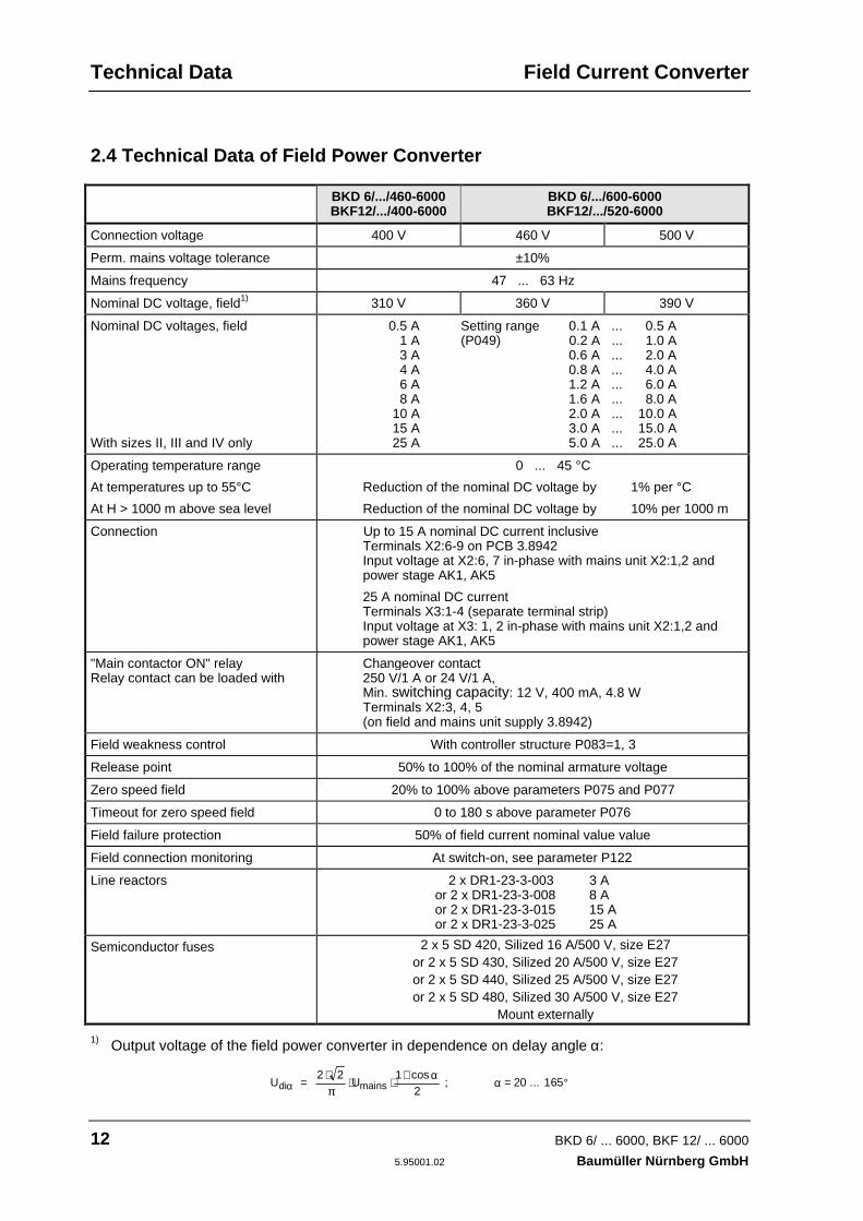
2.4 Technical Data of Field Power Converter
BKD 6/.../460-6000BKF12/.../400-6000
BKD 6/.../600-6000BKF12/.../520-6000
Connection voltage 400 V 460 V 500 V
Perm. mains voltage tolerance ±10%
Mains frequency 47 ... 63 Hz
Nominal DC voltage, field1) 310 V 360 V 390 V
Nominal DC voltages, field
With sizes II, III and IV only
0.5 A Setting range 0.1 A ... 0.5 A1 A (P049) 0.2 A ... 1.0 A3 A 0.6 A ... 2.0 A4 A 0.8 A ... 4.0 A6 A 1.2 A ... 6.0 A8 A 1.6 A ... 8.0 A
10 A 2.0 A ... 10.0 A15 A 3.0 A ... 15.0 A25 A 5.0 A ... 25.0 A
Operating temperature range
At temperatures up to 55°C
At H > 1000 m above sea level
0 ... 45 °C
Reduction of the nominal DC voltage by 1% per °C
Reduction of the nominal DC voltage by 10% per 1000 m
Connection Up to 15 A nominal DC current inclusiveTerminals X2:6-9 on PCB 3.8942Input voltage at X2:6, 7 in-phase with mains unit X2:1,2 andpower stage AK1, AK5
25 A nominal DC currentTerminals X3:1-4 (separate terminal strip)Input voltage at X3: 1, 2 in-phase with mains unit X2:1,2 andpower stage AK1, AK5
"Main contactor ON" relayRelay contact can be loaded with
Changeover contact250 V/1 A or 24 V/1 A,Min. switching capacity: 12 V, 400 mA, 4.8 WTerminals X2:3, 4, 5(on field and mains unit supply 3.8942)
Field weakness control With controller structure P083=1, 3
Release point 50% to 100% of the nominal armature voltage
Zero speed field 20% to 100% above parameters P075 and P077
Timeout for zero speed field 0 to 180 s above parameter P076
Field failure protection 50% of field current nominal value value
Field connection monitoring At switch-on, see parameter P122
Line reactors 2 x DR1-23-3-003 3 Aor 2 x DR1-23-3-008 8 Aor 2 x DR1-23-3-015 15 Aor 2 x DR1-23-3-025 25 A
Semiconductor fuses 2 x 5 SD 420, Silized 16 A/500 V, size E27or 2 x 5 SD 430, Silized 20 A/500 V, size E27or 2 x 5 SD 440, Silized 25 A/500 V, size E27or 2 x 5 SD 480, Silized 30 A/500 V, size E27
Mount externally
1) Output voltage of the field power converter in dependence on delay angle α:
U Udi mainsα πα
α = 2 2
; = 20 ... 165⋅
⋅ ⋅+
°1
2cos
Mains Unit Technical Data
BKD 6/ ... 6000, BKF 12/ ... 6000 13Baumüller Nürnberg GmbH 5.95001.02
2.5 Technical Data of Mains Unit
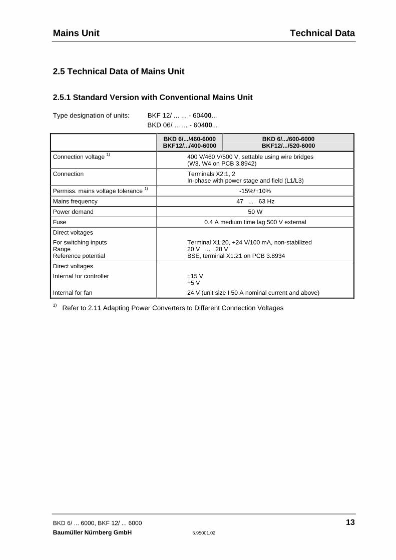
2.5.1 Standard Version with Conventional Mains Unit
Type designation of units: BKF 12/ ... ... - 60400...BKD 06/ ... ... - 60400...
BKD 6/.../460-6000BKF12/.../400-6000
BKD 6/.../600-6000BKF12/.../520-6000
Connection voltage 1) 400 V/460 V/500 V, settable using wire bridges(W3, W4 on PCB 3.8942)
Connection Terminals X2:1, 2In-phase with power stage and field (L1/L3)
Permiss. mains voltage tolerance 1) -15%/+10%
Mains frequency 47 ... 63 Hz
Power demand 50 W
Fuse 0.4 A medium time lag 500 V external
Direct voltages
For switching inputsRangeReference potential
Terminal X1:20, +24 V/100 mA, non-stabilized20 V ... 28 VBSE, terminal X1:21 on PCB 3.8934
Direct voltages
Internal for controller
Internal for fan
±15 V+5 V
24 V (unit size I 50 A nominal current and above)
1) Refer to 2.11 Adapting Power Converters to Different Connection Voltages
Technical Data Mains Unit
14 BKD 6/ ... 6000, BKF 12/ ... 6000
5.95001.02 Baumüller Nürnberg GmbH
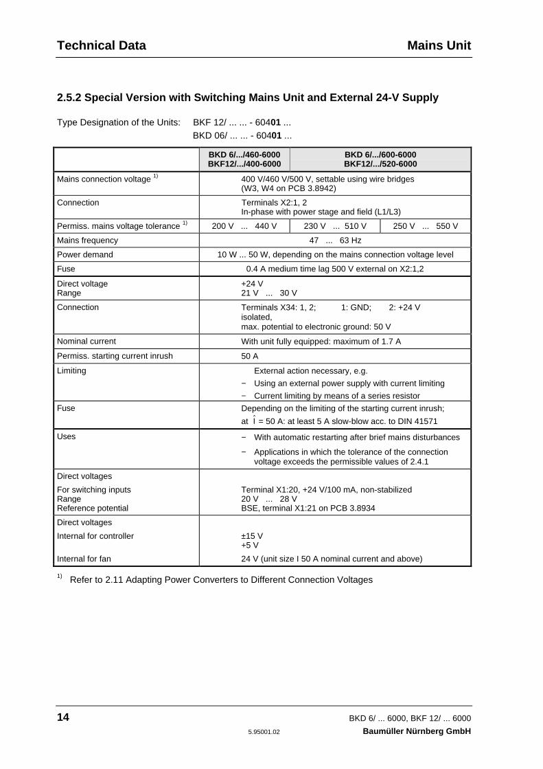
2.5.2 Special Version with Switching Mains Unit and External 24-V Supply
Type Designation of the Units: BKF 12/ ... ... - 60401 ...BKD 06/ ... ... - 60401 ...
BKD 6/.../460-6000BKF12/.../400-6000
BKD 6/.../600-6000BKF12/.../520-6000
Mains connection voltage 1) 400 V/460 V/500 V, settable using wire bridges(W3, W4 on PCB 3.8942)
Connection Terminals X2:1, 2In-phase with power stage and field (L1/L3)
Permiss. mains voltage tolerance 1) 200 V ... 440 V 230 V ... 510 V 250 V ... 550 V
Mains frequency 47 ... 63 Hz
Power demand 10 W ... 50 W, depending on the mains connection voltage level
Fuse 0.4 A medium time lag 500 V external on X2:1,2
Direct voltageRange
+24 V21 V ... 30 V
Connection Terminals X34: 1, 2; 1: GND; 2: +24 Visolated,max. potential to electronic ground: 50 V
Nominal current With unit fully equipped: maximum of 1.7 A
Permiss. starting current inrush 50 A
Limiting External action necessary, e.g.
− Using an external power supply with current limiting
− Current limiting by means of a series resistor
Fuse Depending on the limiting of the starting current inrush;
at I = 50 A: at least 5 A slow-blow acc. to DIN 41571
Uses − With automatic restarting after brief mains disturbances
− Applications in which the tolerance of the connectionvoltage exceeds the permissible values of 2.4.1
Direct voltages
For switching inputsRangeReference potential
Terminal X1:20, +24 V/100 mA, non-stabilized20 V ... 28 VBSE, terminal X1:21 on PCB 3.8934
Direct voltages
Internal for controller
Internal for fan
±15 V+5 V
24 V (unit size I 50 A nominal current and above)
1) Refer to 2.11 Adapting Power Converters to Different Connection Voltages

Power Stage Technical Data
BKD 6/ ... 6000, BKF 12/ ... 6000 15Baumüller Nürnberg GmbH 5.95001.02
2.6 Technical Data of Power stage
BKD 6/.../460-6000BKF12/.../400-6000
BKD 6/.../600-6000BKF12/.../520-6000
Connection voltage 1) 3 x 400 V 3 x 460 V 3 x 500 V
Connection Phases L1 and L3 identical with mains unit and fieldAK1, AK3 and AK5, clockwise-rotating field
Power stageSizes I, II: Modular thyristorSizes III, IV: Disk-type thyristor
SKKT .. /12SKT .. /12
SKKT .. /16SKT .. /16
SKKT .. /16SKT .. /16
Permiss. mains voltage tolerance 1) ±10%
Mains frequency 47 ... 63 Hz
Fan
Size IFrom 50 A ... 200 A
Size II300 A ... 600 A
Size IIIBKD 6/.../...-6000, 750 A .. 1100 ABKF 12/ / -6000, 850 A
Size IVBKD 6/.../...-6000, 1550 A .. 2050 ABKF 12/ / -6000, 1250 A .. 1650 A
24 V/4.5 W/3000 RPMRange: 12 V- ... 28 V-,Internal connectionOrder No. 19007542
400 V/3 ~/50 Hz/0.23 A/120 W/2680 RPM400 V/3 ~/60 Hz/0.3 A/180 W/2680 RPMConnection via plug-in contact X100 on fanOrder No. 19007543
230 V/1 ~/0.94 A at 50 Hz
400 V/3 ~/1.2 A at 50 Hz
Current transformer
Size I
Size II
Size III
Size IV
50 A/70 mA Order No. 19007313120 A/70 mA Order No. 19007314
250 A/70 mA Order No. 19007304400 A/70 mA Order No. 19007300
720 A/70 mA Order No. 19007338
1200 A/70 mA Order No. 190073391500 A/70 mA Order No. 19007340
With unit sizes III and IV only:Fuse monitoring
Terminals X100:1, 2Contact loading: max. of 250 V~/2 Aor 30 V-/2 A, min. of 24 V-/100 mA
1) Refer to 2.11 Adapting Power Converters to Different Connection Voltages
Technical Data Processor Board
16 BKD 6/ ... 6000, BKF 12/ ... 6000
5.95001.02 Baumüller Nürnberg GmbH
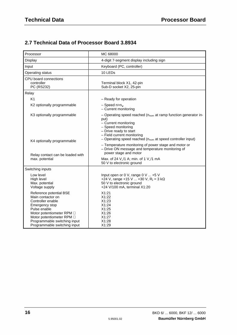
2.7 Technical Data of Processor Board 3.8934
Processor MC 68000
Display 4-digit 7-segment display including sign
Input Keyboard (PC, controller)
Operating status 10 LEDs
CPU board connectionscontrollerPC (RS232)
Terminal block X1, 42-pinSub-D socket X2, 25-pin
Relay
K1
K2 optionally programmable
K3 optionally programmable
K4 optionally programmable
Relay contact can be loaded withmax. potential
– Ready for operation
– Speed n>nx– Current monitoring
– Operating speed reached (nnom at ramp function generator in-put)– Current monitoring– Speed monitoring– Drive ready to start– Field current monitoring– Operating speed reached (nnom at speed controller input)
– Temperature monitoring of power stage and motor or– Drive ON message and temperature monitoring of power stage and motor
Max. of 24 V-/1 A; min. of 1 V-/1 mA50 V to electronic ground
Switching inputs
Low levelHigh levelMax. potentialVoltage supply
Reference potential BSEMain contactor onController enableEmergency stopPulse enableMotor potentiometer RPM ⇑Motor potentiometer RPM ⇓Programmable switching inputProgrammable switching input
Input open or 0 V, range 0 V ... +5 V+24 V, range +15 V ... +30 V, Ri = 3 kΩ50 V to electronic ground+24 V/100 mA, terminal X1:20
X1:21X1:22X1:23X1:24X1:25X1:26X1:27X1:28X1:29
Processor Board Technical Data
BKD 6/ ... 6000, BKF 12/ ... 6000 17Baumüller Nürnberg GmbH 5.95001.02
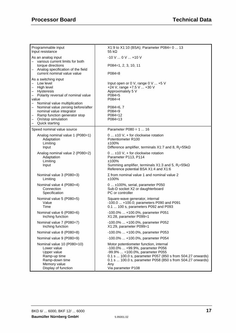
Programmable inputInput resistance
As an analog input– various current limits for both
torque directions– Analog specification of the field
current nominal value value
As a switching input– Low level– High level– Hysteresis– Polarity reversal of nominal valuevalue– Nominal value multiplication– Nominal value zeroing before/after
nominal value integrator– Ramp function generator stop– On/stop simulation– Quick starting
X1:9 to X1:10 (BSA); Parameter P084= 0 ... 1355 kΩ
-10 V ... 0 V ... +10 V
P084=1, 2, 3, 10, 11
P084=8
Input open or 0 V, range 0 V ... +5 V+24 V, range +7.5 V ... +30 VApproximately 5 VP084=5P084=4
P084=6, 7P084=9P084=12P084=13
Speed nominal value source
Analog nominal value 1 (P080=1)AdaptationLimitingInput
Analog nominal value 2 (P080=2)AdaptationLimitingInput
Nominal value 3 (P080=3)Limiting
Nominal value 4 (P080=4)ConnectionSpecification
Nominal value 5 (P080=5)ValueTime
Nominal value 6 (P080=6)Inching function
Nominal value 7 (P080=7)Inching function
Nominal value 8 (P080=8)
Nominal value 9 (P080=9)
Nominal value 10 (P080=10)Lower valueUpper valueRamp-up timeRamp-down timeMemory valueDisplay of function
Parameter P080 = 1 ... 16
0 ... ±10 V, + for clockwise rotationPotentiometer R100±100%Difference amplifier, terminals X1:7 and 8, Ri=55kΩ
0 ... ±10 V, + for clockwise rotationParameter P113, P114±100%Summing amplifier, terminals X1:3 and 5, Ri=55kΩReference potential BSA X1:4 and X1:6
Σ from nominal value 1 and nominal value 2±100%
0 ... ±100%, serial, parameter P050Sub-D socket X2 or daughterboardPC or controller
Square-wave generator, internal-100.0 ... +100.0; parameters P090 and P0910.1 ... 100 s, parameters P092 and P093
-100.0% ... +100.0%, parameter P051X1:28, parameter P099=1
-100.0% ... +100.0%, parameter P052X1:29, parameter P099=1
-100.0% ... +100.0%, parameter P053
-100.0% ... +100.0%, parameter P054
Motor potentiometer function, internal-100.0% ... +99.9%, parameter P056-99.9% ... +100.0%, parameter P0550.1 s ... 100.0 s, parameter P057 (850 s from S04.27 onwards)0.1 s ... 100.0 s, parameter P058 (850 s from S04.27 onwards)AnyVia parameter P108
Technical Data Processor Board
18 BKD 6/ ... 6000, BKF 12/ ... 6000
5.95001.02 Baumüller Nürnberg GmbH
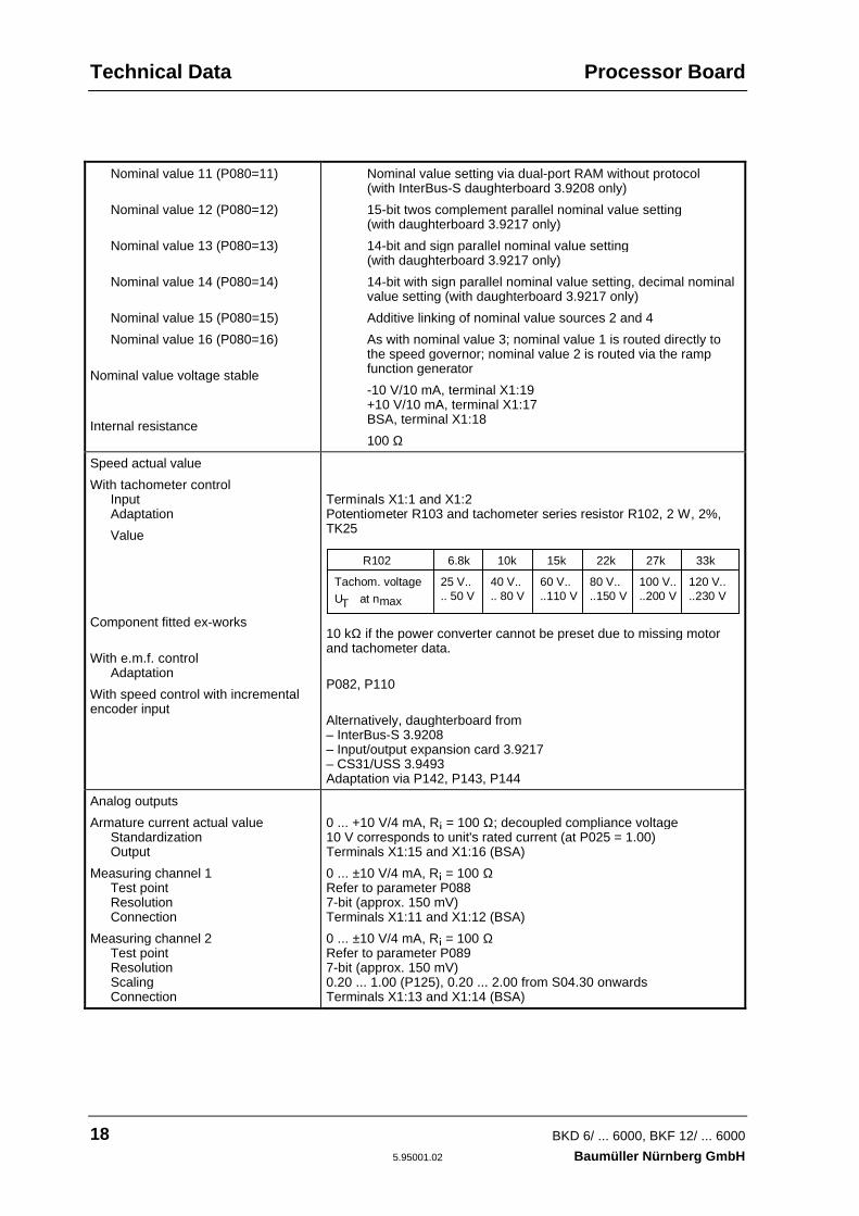
Nominal value 11 (P080=11)
Nominal value 12 (P080=12)
Nominal value 13 (P080=13)
Nominal value 14 (P080=14)
Nominal value 15 (P080=15)
Nominal value 16 (P080=16)
Nominal value voltage stable
Internal resistance
Nominal value setting via dual-port RAM without protocol(with InterBus-S daughterboard 3.9208 only)
15-bit twos complement parallel nominal value setting(with daughterboard 3.9217 only)
14-bit and sign parallel nominal value setting(with daughterboard 3.9217 only)
14-bit with sign parallel nominal value setting, decimal nominalvalue setting (with daughterboard 3.9217 only)
Additive linking of nominal value sources 2 and 4
As with nominal value 3; nominal value 1 is routed directly tothe speed governor; nominal value 2 is routed via the rampfunction generator
-10 V/10 mA, terminal X1:19+10 V/10 mA, terminal X1:17BSA, terminal X1:18
100 Ω
Speed actual value
With tachometer controlInputAdaptation
Value
Component fitted ex-works
With e.m.f. controlAdaptation
With speed control with incrementalencoder input
Terminals X1:1 and X1:2Potentiometer R103 and tachometer series resistor R102, 2 W, 2%,TK25
R102 6.8k 10k 15k 22k 27k 33k
Tachom. voltageU at nmaxT
25 V.. 40 V.. 60 V.. 80 V.. 100 V.. 120 V.... 50 V .. 80 V ..110 V ..150 V ..200 V ..230 V
10 kΩ if the power converter cannot be preset due to missing motorand tachometer data.
P082, P110
Alternatively, daughterboard from– InterBus-S 3.9208– Input/output expansion card 3.9217– CS31/USS 3.9493Adaptation via P142, P143, P144
Analog outputs
Armature current actual valueStandardizationOutput
Measuring channel 1Test pointResolutionConnection
Measuring channel 2Test pointResolutionScalingConnection
0 ... +10 V/4 mA, Ri = 100 Ω; decoupled compliance voltage10 V corresponds to unit's rated current (at P025 = 1.00)Terminals X1:15 and X1:16 (BSA)
0 ... ±10 V/4 mA, Ri = 100 ΩRefer to parameter P0887-bit (approx. 150 mV)Terminals X1:11 and X1:12 (BSA)
0 ... ±10 V/4 mA, Ri = 100 ΩRefer to parameter P0897-bit (approx. 150 mV)0.20 ... 1.00 (P125), 0.20 ... 2.00 from S04.30 onwardsTerminals X1:13 and X1:14 (BSA)
Processor Board Technical Data
BKD 6/ ... 6000, BKF 12/ ... 6000 19Baumüller Nürnberg GmbH 5.95001.02
Analog outputs
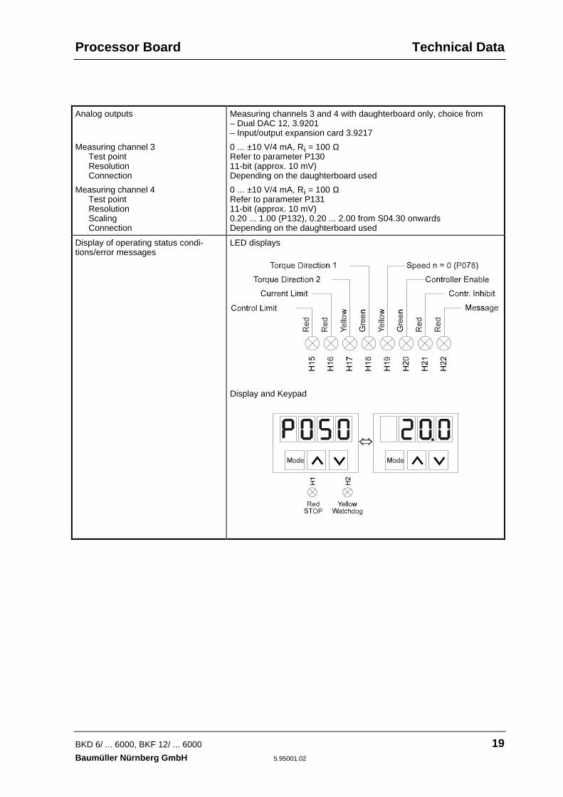
Measuring channel 3Test pointResolutionConnection
Measuring channel 4Test pointResolutionScalingConnection
Measuring channels 3 and 4 with daughterboard only, choice from– Dual DAC 12, 3.9201– Input/output expansion card 3.9217
0 ... ±10 V/4 mA, Ri = 100 ΩRefer to parameter P13011-bit (approx. 10 mV)Depending on the daughterboard used
0 ... ±10 V/4 mA, Ri = 100 ΩRefer to parameter P13111-bit (approx. 10 mV)0.20 ... 1.00 (P132), 0.20 ... 2.00 from S04.30 onwardsDepending on the daughterboard used
Display of operating status condi-tions/error messages
LED displays
Display and Keypad

Technical Data Supplementary Modules
20 BKD 6/ ... 6000, BKF 12/ ... 6000
5.95001.02 Baumüller Nürnberg GmbH
2.8 Technical Data of Supplementary Modules
As an option, you can fit several different daughterboards on the CPU board, which have the follow-ing functions:
2.8.1 "Dual DAC 12", Daughterboard 3.9201
Additional measuring channels 3 and 4
Measuring channel 3Test pointResolutionConnection
Measuring channel 4Test pointResolutionScalingConnection
0 ... ±10 V/4 mA, Ri = 100 ΩRefer to parameter P13011-bit (approx. 10 mV)Terminals X4:1 and X4:2 (BSA)
0 ... ±10 V/4 mA, Ri = 100 ΩRefer to parameter P13111-bit (approx. 10 mV)0.20 ... 1.00 (P132), 0.20 ... 2.00 from S04.30Terminals X4:3 and X4:4 (BSA)
Assembly By means of a 22-mm spacer bolt on CPU card 3.8934 and64-pin ribbon cable X15
2.8.2 "Input/Output Expansion", Daughterboard 3.9217
Incremental encoder input for speedmeasurementAlternatively
Incremental encoder with +5-V supplyfor two 90° phase-shifted differentialimpulses
Signal levelConnection
Incremental encoder with +24-V sup-ply for two 90° phase-shifted differen-tial impulses
Signal levelConnection
Encoder selection via jumpers
Speed rangeNo. of incr. encoder graduationsMaximum frequencyPolarity reversal
Achievable maximum speed
– Differential input– Power supply of encoder possible from daughterboard
LOW signal: 0 ... +0.45 V HIGH signal: +2.4 V ... +5.25 VSub-D socket15-pin X7A
– Isolated via optocoupler– Power must be supplied to encoder externally
LOW signal: 0 ... +4 V HIGH signal: +15 V ... +30 V Ri = 3 kΩTerminal block X7B:15-17
W1 and W2P142: 100 ... 6000 min-1
P143: 250 ... 4096300 kHzP144: on, off
[ ]nnom RPMPulse number
= • •60 300
1000

Supplementary Modules Technical Data
BKD 6/ ... 6000, BKF 12/ ... 6000 21Baumüller Nürnberg GmbH 5.95001.02
Two additional measuring channels
Measuring channel 3Test pointResolutionConnection
Measuring channel 4Test pointResolutionScalingConnection
0 ... ±10 V/4 mA, Ri = 100 ΩRefer to parameter P13011-bit (approx. 10 mV)Terminals X7B:2 and X7B:1 (BSA)
0 ... ±10 V/4 mA, Ri = 100 ΩRefer to parameter P13111-bit (approx. 10 mV)0.20 ... 1.00 (P132), 0.20 ... 2.00 from S04.30Terminals X7B:4 and X7B:3 (BSA)
Digital parallel nominal value setting
Signal levelConnectionNominal value source
– Isolated via optocoupler– Max. potential to electronic ground: 50 V
LOW signal: 0 ... +4 V HIGH signal: +15 V ... +30 V Ri = 3 kΩTerminal block X7B:21-38Parallel nominal value settingP080=12: 15-bit twos complementP080=13: 14-bit and signP080=14: 12-bit and sign, decimal nominal value settings
Digital outputs
ConnectionSignals
– Isolated via optocoupler– Loadable with 35 V/100 mA– Max. potential to electronic ground: 50 V
Terminal block X7B:5-14DA0: Loaded data setDA1: Loaded data setDA2: Loaded data setDA3: Not assignedDA4: Not assignedDA5: Not assignedDA6: Not assignedDA7: Frequency message
Assembly By means of a 22-mm spacer bolt on CPU card 3.8934 and64-pin ribbon cable X15
Technical Data Supplementary Modules
22 BKD 6/ ... 6000, BKF 12/ ... 6000
5.95001.02 Baumüller Nürnberg GmbH
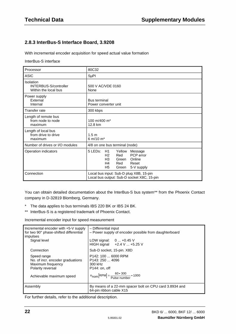
2.8.3 InterBus-S Interface Board, 3.9208
With incremental encoder acquisition for speed actual value formation
InterBus-S interface
Processor 80C32
ASIC SµPI
IsolationINTERBUS-S/controllerWithin the local bus
500 V AC/VDE 0160None
Power supplyExternalInternal
Bus terminalPower converter unit
Transfer rate 300 kbps
Length of remote busfrom node to nodemaximum
100 m/400 m*12.8 km
Length of local busfrom drive to drivemaximum
1.5 m6 m/10 m*
Number of drives or I/O modules 4/8 on one bus terminal (node)
Operation indicators 5 LEDs: H1 Yellow MessageH2 Red PCP errorH3 Green OnlineH4 Red ResetH5 Green 5-V supply
Connection Local bus input: Sub-D plug X8B, 15-pinLocal bus output: Sub-D socket X8C, 15-pin
You can obtain detailed documentation about the InterBus-S bus system** from the Phoenix Contactcompany in D-32819 Blomberg, Germany.
* The data applies to bus terminals IBS 220 BK or IBS 24 BK.** InterBus-S is a registered trademark of Phoenix Contact.
Incremental encoder input for speed measurement
Incremental encoder with +5-V supplyfor two 90° phase-shifted differentialimpulses
Signal level
Connection
Speed rangeNo. of incr. encoder graduationsMaximum frequencyPolarity reversal
Achievable maximum speed
– Differential input– Power supply of encoder possible from daughterboard
LOW signal: 0 ... +0.45 VHIGH signal +2.4 V ... +5.25 V
Sub-D socket, 15-pin. X8D
P142: 100 ... 6000 RPMP143: 250 ... 4096300 kHzP144: on, off
[ ]nnom RPMPulse number
= • •60 300
1000
Assembly By means of a 22-mm spacer bolt on CPU card 3.8934 and64-pin ribbon cable X15
For further details, refer to the additional description.
Supplementary Modules Technical Data
BKD 6/ ... 6000, BKF 12/ ... 6000 23Baumüller Nürnberg GmbH 5.95001.02
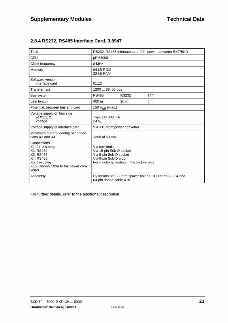
2.8.4 RS232, RS485 Interface Card, 3.8947
Task RS232, RS485 interface card ⇐⇒ power converter BKF/BKD
CPU µP 68008
Clock frequency 8 MHz
Memory 64 kB ROM32 kB RAM
Software versioninterface card 01.12
Transfer rate 1200 ... 38400 bps
Bus system RS485 RS232 TTY
Line length 400 m 20 m 5 m
Potential, between bus and card 150 Veff (max.)
Voltage supply on bus sideat X1:1, 2voltage
Typically 300 mA24 V-
Voltage supply of interface card Via X15 from power converter
Maximum current loading of connec-tions X3 and X4 Total of 50 mA
ConnectionsX1: 24-V supplyX2: RS232X3: RS485X4: RS485X5: Test plugX15: Ribbon cable to the power con-verter
Via terminalsVia 15-pin Sub-D socketVia 9-pin Sub-D socketVia 9-pin Sub-D plugFor functional testing in the factory only
Assembly By means of a 22-mm spacer bolt on CPU card 3.8934 and64-pin ribbon cable X15
For further details, refer to the additional description.
Technical Data Supplementary Modules
24 BKD 6/ ... 6000, BKF 12/ ... 6000
5.95001.02 Baumüller Nürnberg GmbH
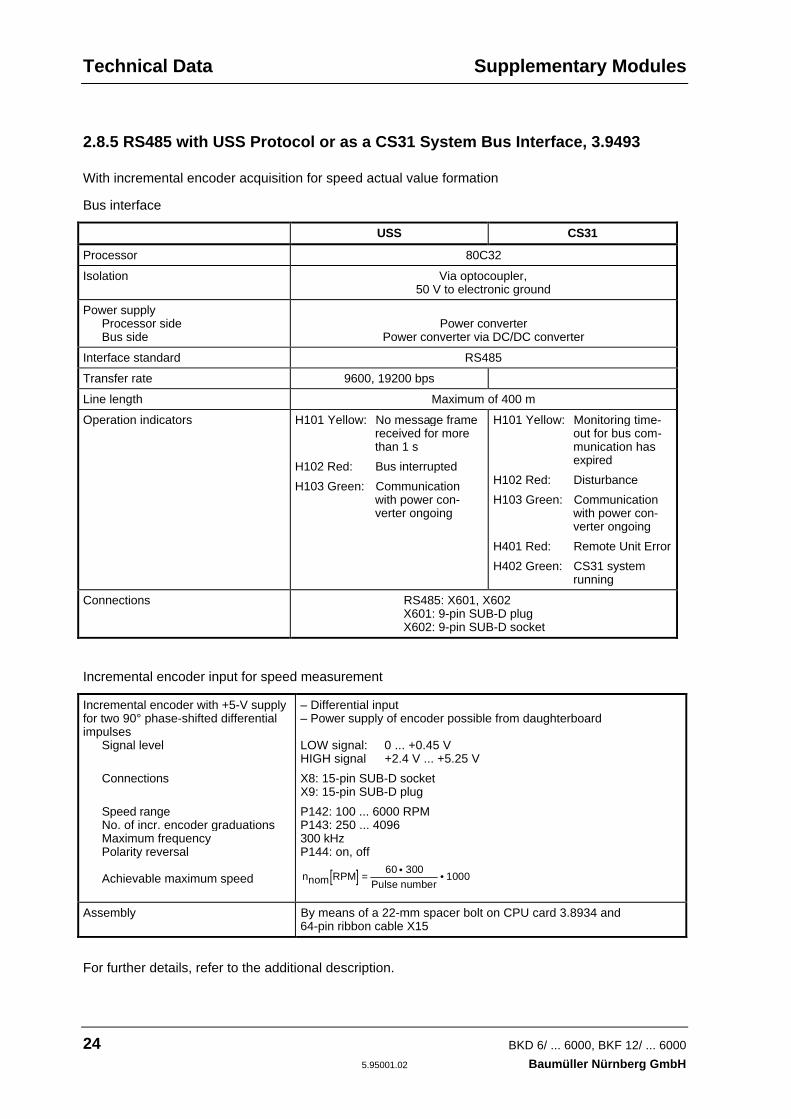
2.8.5 RS485 with USS Protocol or as a CS31 System Bus Interface, 3.9493
With incremental encoder acquisition for speed actual value formation
Bus interface
USS CS31
Processor 80C32
Isolation Via optocoupler,50 V to electronic ground
Power supplyProcessor sideBus side
Power converterPower converter via DC/DC converter
Interface standard RS485
Transfer rate 9600, 19200 bps
Line length Maximum of 400 m
Operation indicators H101 Yellow: No message framereceived for morethan 1 s
H102 Red: Bus interrupted
H103 Green: Communicationwith power con-verter ongoing
H101 Yellow: Monitoring time-out for bus com-munication hasexpired
H102 Red: Disturbance
H103 Green: Communicationwith power con-verter ongoing
H401 Red: Remote Unit Error
H402 Green: CS31 systemrunning
Connections RS485: X601, X602X601: 9-pin SUB-D plugX602: 9-pin SUB-D socket
Incremental encoder input for speed measurement
Incremental encoder with +5-V supplyfor two 90° phase-shifted differentialimpulses
Signal level
Connections
Speed rangeNo. of incr. encoder graduationsMaximum frequencyPolarity reversal
Achievable maximum speed
– Differential input– Power supply of encoder possible from daughterboard
LOW signal: 0 ... +0.45 VHIGH signal +2.4 V ... +5.25 V
X8: 15-pin SUB-D socketX9: 15-pin SUB-D plug
P142: 100 ... 6000 RPMP143: 250 ... 4096300 kHzP144: on, off
[ ]nnom RPMPulse number
= • •60 300
1000
Assembly By means of a 22-mm spacer bolt on CPU card 3.8934 and64-pin ribbon cable X15
For further details, refer to the additional description.

Power Losses Technical Data
BKD 6/ ... 6000, BKF 12/ ... 6000 25Baumüller Nürnberg GmbH 5.95001.02
2.9 Power Loss of Power Converter, Line Converter and Fuses
When using the additional components (line converter, semiconductor fuses) listed in chapter 4, thepower losses shown below result at the equipment's nominal working point:
Power Losses
Power ConverterBKD or BKF
NominalCurrent
Unit * LineConverter
Fuses ** BKD BKF
Total BKD BKF
Size I:
BK ../30 30 A 120 W 40 W 15 W 35 W 175 W 195W
BK ../50 50 A 195 W 55 W 30 W 50 W 280 W 300 W
BK ../70 70 A 290 W 60 W 50 W 85 W 400 W 435 W
BK ../100 100 A 340 W 90 W 45 W 80 W 475 W 510 W
BK ../120 120 A 380 W 100 W 50 W 85 W 530 W 565 W
BK ../150 150 A 420 W 105 W 55 W 125 W 580 W 650 W
BK ../200 200 A 590 W 120 W 90 W 190 W 800 W 900 W
Size II
BK ../300 300 A 850 W 170 W 85 W 185 W 1100 W 1200 W
BK ../400 400 A 1170 W 180 W 185 W 310 W 1530 W 1660 W
BK ../500 500 A 1250 W 200 W 145 W 280 W 1590 W 1730 W
BK ../600 600 A 1550 W 300 W 195 W 350 W 2050 W 2200 W
Size III
BKD 6/750 750 A 2700 W 350 W 380 W 3430 W
BKD 6/920 920 A 2900 W 370 W 410 W 3680 W
BKD 6/1100 1100 A 3600 W 400 W 550 W 4550 W
BKF 12/850 850 A 2550 W 360 W 310 W 3220 W
Size IV
BKD 6/1550 1550 A 4450 W *** 730 W
BKD 6/1750 1750 A 5700 W *** 750 W
BKD 6/2050 2050 A 5750 W *** 920 W
BKF 12/1250 1250 A 3550 W *** 510 W
BKF 12/1400 1400 A 4500 W *** 640 W
BKF 12/1250 1650 A 4400 W *** 710 W
* The power loss of the power converter includes the losses of the power stage for armature andfield supply as well as electronics supply.
** In the case of unit sizes I and II, you must arrange the mains semiconductor protective fuses(phase fuses) outside the power converter in the control cabinet. In addition, with the BKF youmust also take into account the armature circuit fuses. Unit sizes III and IV have arm-circuitfuses that are already integrated in the equipment.The chapter entitled Installation contains, to some extent, a choice of two types of fuses. Thestated power loss refers to the type with the higher losses, i.e. if you use the other fuse, thepower loss is more favourable.
*** On request
Technical Data Construction Drawings
26 BKD 6/ ... 6000, BKF 12/ ... 6000
5.95001.02 Baumüller Nürnberg GmbH
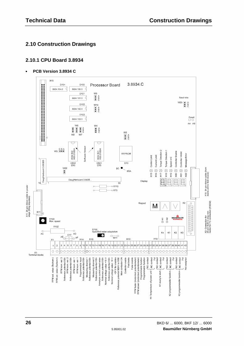
2.10 Construction Drawings
2.10.1 CPU Board 3.8934
•••• PCB Version 3.8934 C
Construction Drawings Technical Data
BKD 6/ ... 6000, BKF 12/ ... 6000 27Baumüller Nürnberg GmbH 5.95001.02
Internal Functions:
Plug-in jumpers: W2: A-BW3: A-BW4: B-CW5: B-CW6: A-BW7: A-BW9: A-BW10: A-BW20: B-C (baud rate 9600 bps)W22: Fitted
Resistors on R73: Rv for power stage identificationsolder tags: R110: Rv for power stage temperature
Soldering jumper W11: Reference point for control inputs X1:22 ... 29– fitted if the unit's +24 V is used for controlling the power converter–not fitted if the external controller carries out direct control.
In this case, terminal X1:21 (BSE) is the reference potential.– The jumper is fitted in the factory
Condenser C17: 0.47 µFLow pass filter in nact measurement with speed control via tachometer genera-tor.
Resistor R102: Series resistor for adapting the tachometer voltage of the electronics (controllerstructure P083 = 0 or 1).
R102 6.8k 10k 15k 22k 27k 33k
Tachom. voltageU at n
maxT
25 V.. 40 V.. 60 V.. 80 V.. 100 V.. 120 V.... 50 V .. 80 V ..110 V ..150 V ..200 V ..230 V
Potentiometer R103: Fine-tuning the maximum speed
Potentiometer R100: Nominal value adaptation with nominal value source P080 = 1, 3, 16. Onlyaffects the differential gain input (gain: 0.9 ... 2.0)
Solder tags AA-AB: Jumpering results in a hardware reset.
NOTEYou must only specify a reset for the power converter when the controller is disabled and the motor isidle.
Solder tag BC Device-internal reference point BSA, e.g. for measurements.
Technical Data Construction Drawings
28 BKD 6/ ... 6000, BKF 12/ ... 6000
5.95001.02 Baumüller Nürnberg GmbH
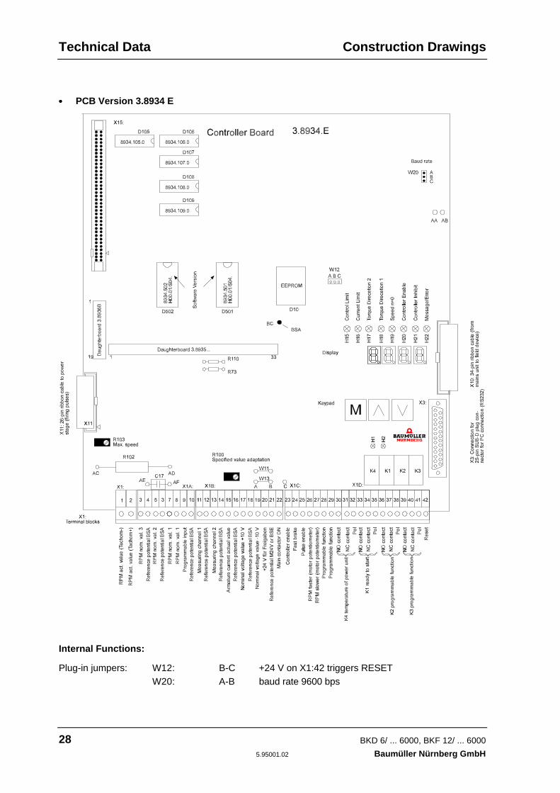
•••• PCB Version 3.8934 E
Internal Functions:
Plug-in jumpers: W12: B-C +24 V on X1:42 triggers RESETW20: A-B baud rate 9600 bps

Construction Drawings Technical Data
BKD 6/ ... 6000, BKF 12/ ... 6000 29Baumüller Nürnberg GmbH 5.95001.02
Resistors R73: Rv for power stage identificationon solder tags: R110: Rv for temperature determination
Solder tagsAA-AB: Open, do not connect!
NOTE
With PCB 3.8934.C you could trigger a hardware reset via solder tags AA-AB without switching off theunit. This is not allowed with PCB version 3.8934.E. In this case, a hardware reset is activated byapplying +24 V at terminal X1:42 (this terminal was not assigned in PCB version 3.8934.C).You must only specify a reset for the power converter when the controller is disabled and the motor isidle.
Soldering jumper W11: Reference point for control inputs X1:22 ... 29– fitted if the unit's +24 V is used for controlling the power converter–not fitted if the external controller carries out direct control.
In this case, terminal X1:21 (BSE) is the reference potential– The jumper is fitted in the factory
Soldering jumper W13: Specification of the reference point for control input X1:25 (pulse enable)
–Tag A-B selects the reference point that is to be specified with W11 for theother control inputs (fitted in the factory)
–Tag B-C connects the reference point permanently to the device-internalreference ground (M24V). If there is a break in the signal/a voltagefailure, this prevents the deletion of the firing pulses in the higher-level controller
Resistor R102: Series resistor for adapting the tachometer voltage of the electronics (controllerstructure P083 = 0 or 1).
R102 6.8k 10k 15k 22k 27k 33k
Tachom. voltageU at n
maxT
25 V.. 40 V.. 60 V.. 80 V.. 100 V.. 120 V.... 50 V .. 80 V ..110 V ..150 V ..200 V ..230 V
Condenser C17: 0.47 µFLow pass filter in nact measurement with speed control via tachometer genera-
tor.
Potentiometer R103: Fine-tuning the maximum speed
Potentiometer R100: Nominal value adaptation with nominal value source P080 = 1, 3, 16. Onlyaffects the differential gain input (gain: 0.9 ... 2.0)
Solder tag BC Device-internal reference point BSA, e.g. for measurements.
Technical Data Construction Drawings
30 BKD 6/ ... 6000, BKF 12/ ... 6000
5.95001.02 Baumüller Nürnberg GmbH
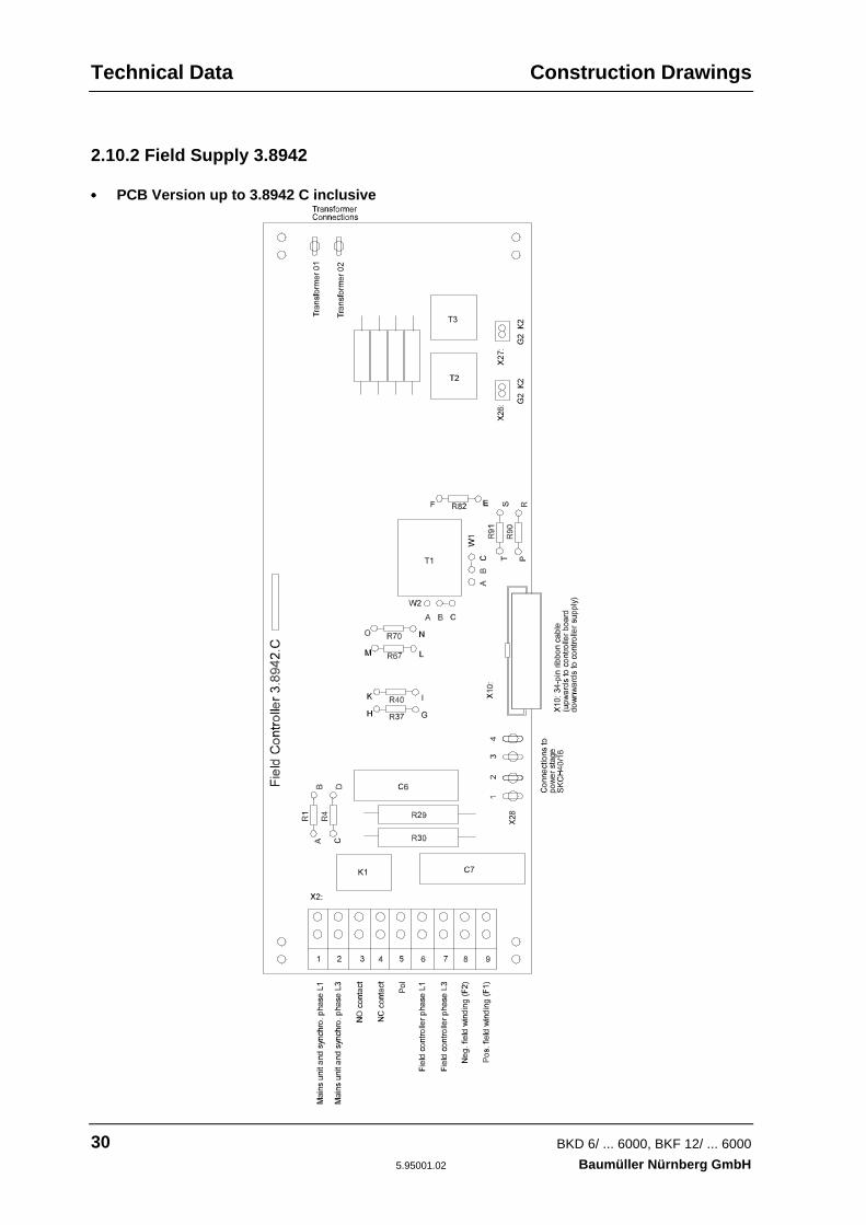
2.10.2 Field Supply 3.8942
•••• PCB Version up to 3.8942 C inclusive
Construction Drawings Technical Data
BKD 6/ ... 6000, BKF 12/ ... 6000 31Baumüller Nürnberg GmbH 5.95001.02
Transformer conns.: Transformer 01, transformer 02400 V connection voltage: Transformer Order No. 19007175500 V connection voltage: Transformer Order No. 19007178
R1, R2: Input resistors for acquiring the connection voltage for the mains unit
R37, R40: Input resistors for acquiring the field voltage (AC side)
R67, R70: Input resistors for acquiring the field voltage (DC side)
R82: Load impedance for matching the field unit rated current
W1, W2: Specification of the field current range[0.5 .. 4 A, 5 ... 10 A]

Technical Data Construction Drawings
32 BKD 6/ ... 6000, BKF 12/ ... 6000
5.95001.02 Baumüller Nürnberg GmbH
•••• PCB Version 3.8942 E
Construction Drawings Technical Data
BKD 6/ ... 6000, BKF 12/ ... 6000 33Baumüller Nürnberg GmbH 5.95001.02
W3: Mains voltage adaptationA-B: 500 V mainsC-B: 400 V mains
Transformer conns.: Transformer 01: 0 V blackTransformer 02: 400 V blueTransformer 03: 500 V brownTransformer Order No. 19007178
R1, R2: Input resistors for acquiring the connection voltage for the mains unit
R37, R40: Input resistors for acquiring the field voltage (AC side)
R67, R70: Input resistors for acquiring the field voltage (DC side)
R82, R83: Load impedance for matching the field unit rated current
W1, W2: Specification of the field current range[0.5 .. 4 A, 5 ... 10 A]

Technical Data Construction Drawings
34 BKD 6/ ... 6000, BKF 12/ ... 6000
5.95001.02 Baumüller Nürnberg GmbH
•••• PCB Version 3.8942 F

Construction Drawings Technical Data
BKD 6/ ... 6000, BKF 12/ ... 6000 35Baumüller Nürnberg GmbH 5.95001.02
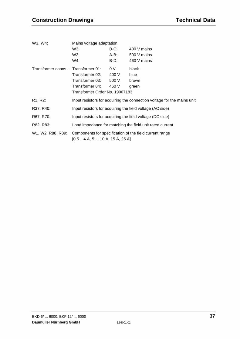
W3, W4: Mains voltage adaptationW3: B-C: 400 V mainsW3: A-B: 500 V mainsW4: B-D: 460 V mains
Transformer conns.: Transformer 01: 0 V blackTransformer 02: 400 V blueTransformer 03: 500 V brownTransformer 04: 460 V greenTransformer Order No. 19007183
R1, R2: Input resistors for acquiring the connection voltage for the mains unit
R37, R40: Input resistors for acquiring the field voltage (AC side)
R67, R70: Input resistors for acquiring the field voltage (DC side)
R82, R83: Load impedance for matching the field unit rated current
W1, W2: Specification of the field current range[0.5 .. 4 A, 5 ... 10 A]

Technical Data Construction Drawings
36 BKD 6/ ... 6000, BKF 12/ ... 6000
5.95001.02 Baumüller Nürnberg GmbH
•••• PCB Version 3.8942 K
Construction Drawings Technical Data
BKD 6/ ... 6000, BKF 12/ ... 6000 37Baumüller Nürnberg GmbH 5.95001.02
W3, W4: Mains voltage adaptationW3: B-C: 400 V mainsW3: A-B: 500 V mainsW4: B-D: 460 V mains
Transformer conns.: Transformer 01: 0 V blackTransformer 02: 400 V blueTransformer 03: 500 V brownTransformer 04: 460 V greenTransformer Order No. 19007183
R1, R2: Input resistors for acquiring the connection voltage for the mains unit
R37, R40: Input resistors for acquiring the field voltage (AC side)
R67, R70: Input resistors for acquiring the field voltage (DC side)
R82, R83: Load impedance for matching the field unit rated current
W1, W2, R88, R89: Components for specification of the field current range[0.5 .. 4 A, 5 ... 10 A, 15 A, 25 A]

Technical Data Adaptation
38 BKD 6/ ... 6000, BKF 12/ ... 6000
5.95001.02 Baumüller Nürnberg GmbH
2.11 Adapting Power Converters to Different Connection Voltages
Power Demand 220 V±10%
230 V+6%-15%
230 V±10%
220 V±10%
230 V+6%-15%
230 V±10%
Nominal direct voltage *BKD 6 /... 6000
260 V 260 V 275 V 460 V 460 V 460 V
Nominal direct voltage *BKF 12 /... 6000
230 V 230 V 240 V 400 V 400 V 400 V
Field weakening control unit **3.8942
400-V versionBridge W3: B-C
Power stage *** 400-V version
Mains unit *** ≈ 50 VA No adaptation necessary
Fan: Size I: 30 A50 A ... 200 A
Unventilated24 V-/4.5 Wsupplied internally
No adaptation necessary
Size II: 300 A ... 600 A 400 V/3 ~/50Hz/0.23 A/120 W
By means of an autotransformer
Size III: BKD: 750 A ... 1100 ABKF: 850 A
230 V/1 ~/50Hz/0.94 A
No adaptation necessary
Size IV: BKD: 1550 A ... 2050 ABKF: 1250 A ... 1650 A
400 V/3 ~/50Hz/1.2 A
By means of an autotransformer
Parameters:P105: Rated mains voltageP110: Rated armature/mains volt. * BKD
BKF
220 V1.211.05
220 V1.211.05
230 V1.211.05
400 V1.211.05
400 V1.211.05
400 V1.211.05
Miscellaneous Possible only with specialversion of unit with switch-ing power supply and ex-ternal 24-V supply
Possible only with a trans-former for the power andmains units (220 V to 400 Vand 230 V to 400 V respec-tively)
* Maximum permissible values relative to the lower tolerance level
** The field supply may be connected to another mains supply with a different voltage if it can beguaranteed that the phase relation to the other mains connections is correct on the power con-verter (refer to the connection suggestion). Observe the field voltage of the motor!
*** The power stage and the mains unit must be connected to the same mains supply taking into ac-count the phase relation.

Adaptation Technical Data
BKD 6/ ... 6000, BKF 12/ ... 6000 39Baumüller Nürnberg GmbH 5.95001.02
380 V±10%
400 V+6%-15%
400 V±10%
415 V+6%-15%
415 V±10%
440 V±10%
460 V±10%
500 V±10%
Nominal direct voltage *BKD 6 /... 6000
460 V 460 V 485 V 485 V 500 V 530 V 550 V 600 V
Nominal direct voltage *BKF 12 /... 6000
400 V 400 V 420 V 420 V 435 V 460 V 480 V 520 V
Field weakening control unit **3.8942
400-V version
Bridge W3: B-C
500-V version
Bridge W4: B-D
BridgeW3:A-B
Power stage *** 400-V version 500-V version
Mains unit *** No adaptation necessary
Fan: Size I: 30 A50 A ... 200 A No adaptation necessary
Size II: 300 A ... 600 A No adaptation By means of an autotransformer
Size III: BKD: 750 A ... 1100 ABKF: 850 A
By means of an autotransformer
Size IV: BKD: 1550 A ... 2050 ABKF: 1250 A ... 1650 A
No adaptation By means of an autotransformer
Parameters:P105: Rated mains voltageP110: Rated armature/mains volt. * BKD
BKF
380 V1.211.05
380 V1.211.05
400 V1.211.05
400 V1.211.05
415 V1.211.05
440 V1.211.05
460 V1.211.05
500 V1.211.05
Miscellaneous ****
* Maximum permissible values relative to the lower tolerance level
** The field supply may be connected to another mains supply with a different voltage if it can beguaranteed that the phase relation to the other mains connections is correct on the power con-verter (refer to the connection suggestion). Observe the field voltage of the motor!
*** The power stage and the mains unit must be connected to the same mains supply taking intoaccount the phase relation.
**** Possible only with the special version of the unit with switching power supply and external 24-V
supply

Transportation, Unpacking
40 BKD 6/ ... 6000, BKF 12/ ... 6000
5.95001.02 Baumüller Nürnberg GmbH

Transportation, Unpacking
BKD 6/ ... 6000, BKF 12/ ... 6000 41Baumüller Nürnberg GmbH 5.95001.02
3 TRANSPORTATION AND UNPACKING
The equipment is packed at the factory in accordance with the order.
You should avoid jolting or dropping the package during transportation.
You can start assembly after unpacking the equipment and checking that it is complete and undam-aged.
The equipment is packed in cardboard, corrugated sheeting and or wooden packaging material thatyou should dispose of in accordance with local regulations.
Report any damage in transit immediately.
DANGERIf the equipment was damaged in transit, a qualified person must check, repair and test it before itmay be connected.
Ignoring this information can result in death, serious injury or considerable damage to property.

Assembly
42 BKD 6/ ... 6000, BKF 12/ ... 6000
5.95001.02 Baumüller Nürnberg GmbH

Assembly
BKD 6/ ... 6000, BKF 12/ ... 6000 43Baumüller Nürnberg GmbH 5.95001.02
4 ASSEMBLY
WARNINGYou are responsible for mounting the described equipment, the motor, the commutating reactor andthe other equipment in accordance with appropriate safety regulations (e.g. DIN, VDE); equally, youmust ensure that all other relevant national or local regulations are met with regard to cable ratingsand protection, grounding, disconnectors, overcurrent protection, etc.
During operation, the equipment is protected from direct contact such that it is suitable for use in en-closed electrical premises (DIN VDE 0558 Part 1/07.87, Section 5.4.3.2, preliminary standard EN50178/VDE 0160/11.94, Section 5.2.6, 5.2.7).
Assembly Dimensions
44 BKD 6/ ... 6000, BKF 12/ ... 6000
5.95001.02 Baumüller Nürnberg GmbH
4.1 Dimensions
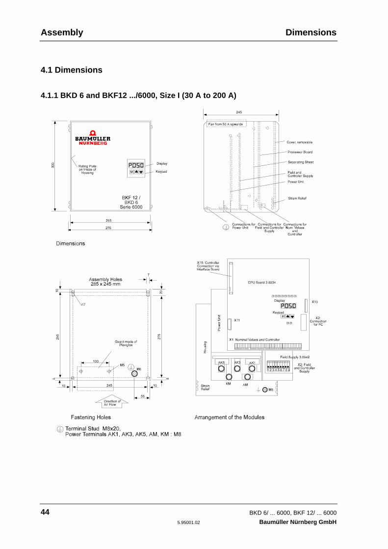
4.1.1 BKD 6 and BKF12 .../6000, Size I (30 A to 200 A)

Dimensions Assembly
BKD 6/ ... 6000, BKF 12/ ... 6000 45Baumüller Nürnberg GmbH 5.95001.02
4.1.2 BKD 6 and BKF12 .../6000, Size II (300 A to 600 A)

Assembly Dimensions
46 BKD 6/ ... 6000, BKF 12/ ... 6000
5.95001.02 Baumüller Nürnberg GmbH
4.1.3 BKD 6 and BKF 12 .../6000 Sizes III and IV
Size III and IV power converters comprise two modules:
1. Module for closed-loop control (containing amongst other things the controller, the mains unit andthe field unit)
2. Power stage module (BKD 6: fully controlled three-phase current bridge circuit B6C; BKF12: twoantiparallel switched circular current-free three-phase current bridge circuits (B6C)2I).
The two modules are mounted next to one another; by preference, you should set-up the controller onthe left. The modules are electrically connected by an X11 bus cable that is approximately one metrelong.
Apart from the depth of the housing, this controller module is electrically and mechanically identicalwith size I and II controller modules.
Dimensions Assembly
BKD 6/ ... 6000, BKF 12/ ... 6000 47Baumüller Nürnberg GmbH 5.95001.02
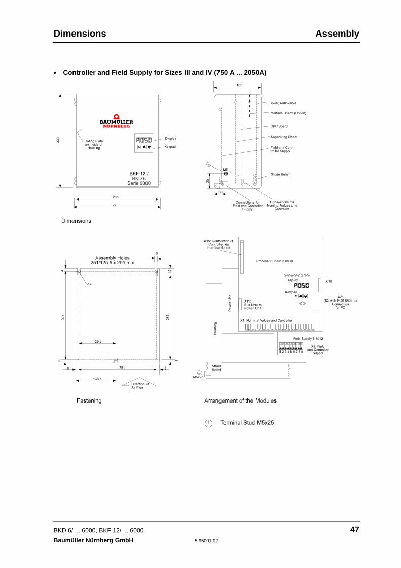
• • • • Controller and Field Supply for Sizes III and IV (750 A ... 2050A)

Assembly Dimensions
48 BKD 6/ ... 6000, BKF 12/ ... 6000
5.95001.02 Baumüller Nürnberg GmbH
• • • • Power stages for Unit Sizes III and IV
Power stage BKD 6../6000 Size III (750A, 920A)

Dimensions Assembly
BKD 6/ ... 6000, BKF 12/ ... 6000 49Baumüller Nürnberg GmbH 5.95001.02
Power stage BKD 6../6000 Size III (1100 A)

Assembly Dimensions
50 BKD 6/ ... 6000, BKF 12/ ... 6000
5.95001.02 Baumüller Nürnberg GmbH
Power stage BKF 12../6000 Size III (850A)

Dimensions Assembly
BKD 6/ ... 6000, BKF 12/ ... 6000 51Baumüller Nürnberg GmbH 5.95001.02
Power stage to Size IV
BKD 6 .../6000: 1550 A, 1750 A, 2050 ABKF 12 .../6000: 1250 A, 1400 A, 1650 A

Assembly Dimensions
52 BKD 6/ ... 6000, BKF 12/ ... 6000
5.95001.02 Baumüller Nürnberg GmbH
Power connections:
The brackets below are available as an option for connection to DC bars KM and AM:
Order No. 1231965
The use of these brackets depends on the type of electrical connection to the DC bars:
If you use crimping cable lugs, the distance between the mounting holes on bars AM and KM may insome circumstances be too small for you to carry out assembly correctly.
Weights Assembly
BKD 6/ ... 6000, BKF 12/ ... 6000 53Baumüller Nürnberg GmbH 5.95001.02
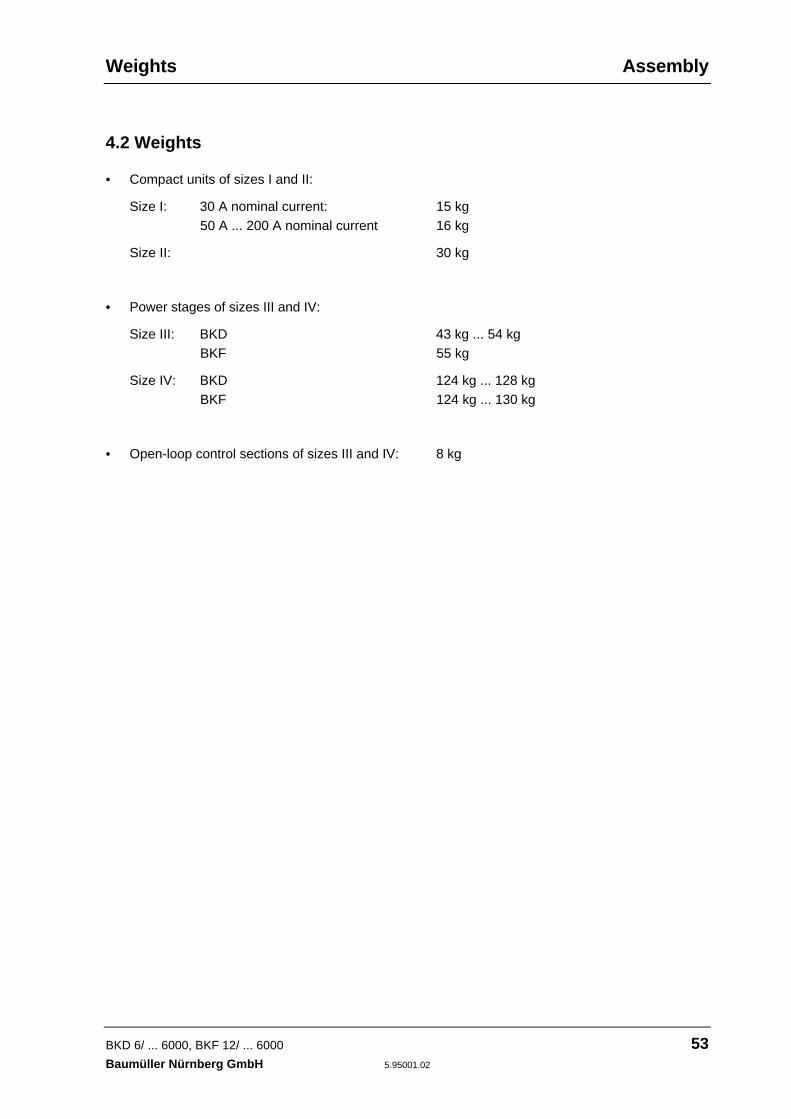
4.2 Weights
• Compact units of sizes I and II:
Size I: 30 A nominal current: 15 kg50 A ... 200 A nominal current 16 kg
Size II: 30 kg
• Power stages of sizes III and IV:
Size III: BKD 43 kg ... 54 kgBKF 55 kg
Size IV: BKD 124 kg ... 128 kgBKF 124 kg ... 130 kg
• Open-loop control sections of sizes III and IV: 8 kg

Assembly Assembly Information
54 BKD 6/ ... 6000, BKF 12/ ... 6000
5.95001.02 Baumüller Nürnberg GmbH
4.3 Assembly Information
WARNINGPersonal injury or damage to property can be caused by lifting the equipment incorrectly. The unitmay only be lifted by qualified personnel using appropriate equipment.
• You must install the units in a closed control cabinet.
WARNINGIt is vital to carry out the ventilation measures listed below.Ignoring these measures may lead to the equipment overheating.
• Power converters are designed to be mounted vertically.If you want to mount the unit in another position ask for more information at the factory
• The equipment must be ventilated from the bottom to the top.
• Ensure that the flow of air is not obstructed.
• The clearance above and below the equipment must be at least150 mm with size I units200 mm with size II units250 mm (beside the fan too) with size III units300 mm with size IV units
Ignoring these measures may lead to the equipment overheating.
• Temperature of coolant 50 mm below the equipment:– Power stage
30-A power converter (self-ventilated): up to 45°CAll other units (force-ventilated): up to 35°C
At relatively high temperatures (up to a maximum of 55°C) the unit's nominal current must bereduced by 1% per degree Centigrade.
– Field current converterreferred to the rated-load field currents10 A, 15 A and 25 A up to 45°C
At relatively high temperatures (up to a maximum of 55°C), the unit's nominal current must bereduced by 1% per degree Centigrade.
Assembly Information Assembly
BKD 6/ ... 6000, BKF 12/ ... 6000 55Baumüller Nürnberg GmbH 5.95001.02
• Do not mount any additional sources of heat above or below the equipment.
• Avoid soiling grades 3 and 4 according to provisional standard EN 50178/VDE 0160/11.94, Sec-tion 5.2.15.2.
• Make the PE connection to the central grounding point as short as possible.
• Size III and IV power converters comprise two modules. By preference, you should place thesmaller module – the controller with the mains unit and field supply – on the left hand side at adistance of about 100 mm from the power stage.

Installation
56 BKD 6/ ... 6000, BKF 12/ ... 6000
5.95001.02 Baumüller Nürnberg GmbH

Danger Information Installation
BKD 6/ ... 6000, BKF 12/ ... 6000 57Baumüller Nürnberg GmbH 5.95001.02
5 INSTALLATION
5.1 Danger and Warning Information
WARNINGThis equipment carries a dangerously high voltage and has dangerous rotating parts (fans). Ignoringthe safety and warning information may result in death, severe personal injury or damage to property.
The machine operator is responsible for mounting the power converter, the motor, the commutatingreactor and any other equipment in accordance with appropriate safety regulations (e.g. DIN, VDE);equally, you must ensure that all other relevant national and local regulations are met with regard tocable ratings and protection, grounding, disconnectors, overcurrent protection, etc.
The most important factors for protecting people are the DIN/VDE protective measures and safetyregulations. If there are no protective earth connections on the equipment, the commutating reactor orthe motor, personal injuries are inevitable, since the surfaces can carry dangerously high voltages.
The power converter's terminal connections are energized!
Even when the main contactor has tripped, parts of the power converter (the mains unit, the fieldpower converter) still carry a dangerous voltage.
During operation, the principles on which the power converter and the motor work lead to leakagecurrents to earth that are dissipated via the specified protective earths and may result in a current-operated e.l.c.b. on the input side blowing prematurely.In the case of a short-circuit to frame or to ground, a direct proportion may arise in the leakage cur-rent that makes triggering of a higher-level current-operated e.l.c.b. either more difficult or totallyimpossible. You must make the protective earth connection in accordance with DIN EN 60204 Part 1/VDE 0113Part 1/06.93/Section 8.2.2 taking into account provisional standard EN 50178/VDE 0160/11.94, Sec-tions 5.3.2.1 and 8.3.4.4.You may only use variable speed drives in applications corresponding to applicable VDE regulations.
Speed monitoring systems in the equipment must not just be complemented by a stand-alone moni-toring system on the motor. You can implement this control of the RPM speed, which is independentof the controller, by means of inductive, optical or torque-dependent encoders. Refer to the appropri-ate motor's operating and maintenance instructions.
Be particularly careful before touching the drive shaft directly or indirectly with your hands. This isonly allowed when the system is deenergized and the drive is stationary.
Safety devices must never be deactivated.
According to applicable regulations (DIN EN 60204 Part 1/VDE 0113 Part 1/06.93/Section 8.2.2),stopping the drive by means of the four enabling inputs at terminals X1:22 ... 25, does not, on its own,represent a safe stop condition. A disturbance in the control electronics can lead to accidental startingof the motor.
Installation Standardization Information
58 BKD 6/ ... 6000, BKF 12/ ... 6000
5.95001.02 Baumüller Nürnberg GmbH
5.2 Standardization InformationSeries BKD 6/...- and BKF 12/...6000 are built-in units in the sense of provisional standard EN 50178/VDE0160/11.94, Section 5.2.6 and DIN VDE 0558 Part 1/07.87, Section 5.4.3.2.1. They are intended for installationin commercially available control cabinets whose degrees of protection meet the minimum requirements ofprovisional standard EN 50178/VDE 0160/11.94, Section 5.2.4 (IP 2x, possibly IP4x according to EN60529/5.1).
Plastic covers on the equipment provide additional protection against accidental contact in the case of casualuse of control elements located close to the equipment (DIN VDE 0106 Part 100, Accident Prevention Regula-tion VBG4 "Electrical Systems and Equipment").
If you intend to set up the equipment in closed electrical workshops according to provisional standard EN50178/VDE 0160/11.94, Section 5.2.7 and DIN VDE 0558 Part 1/07.87, Section 5.4.3.2.2, you must implementadditional measures to ensure compliance with the requirements of provisional standard EN 50178/VDE0160/11.94, Section 5.2.4.
Power converters are intended for permanent mains connection to conventional TN and TT systems accordingto DIN VDE 0100 Part 410/11.83 with a diametric voltage of up to 3 × 500 Veff.Connecting to a system with an insulated neutral point (IT system) is only possible under special circumstances.If necessary, enquire at the factory.
With regard to climatic conditions, the equipment conforms to category 3K3 for sheltered locations according toprovisional standard EN 50178/VDE 0160/11.94, Section 6.1, Table 7, Line 3 or Table 1 of EN 60721-3-1,2,3,4respectively, taking into account Remarks 1 and 3 of provisional standard EN 50178/VDE 0160/11.94, Section6.1. The actual operating temperature range is higher and is in the range 0 .. +55°C. The information in Table 7(lines 5 and 6) of provisional standard EN 50178/VDE 0160/11.94, Section 6.1 also applies to storage andtransportation.The storage and transportation temperature of the equipment varies from this information in as much as it maybe between -30 ... +70°C (refer to Chapter 2.3 of the Power Converter's Technical Data).
The units are in protection class IP 00 according to EN 60529 (DIN VDE 0470-1)
The units are equipment in protection class I corresponding to IEC 536/3 and DIN VDE 0106 Part 1 (provisionalstandard EN 50178/VDE 0160/11.94, Section 5.2.9).Equipment of protection class I is equipment whose protection against dangerous shock currents is not limitedto basic insulation but which also has additional safety devices. This additional protection is provided by con-necting the housing and other parts to the protective earth such that if the basic insulation fails no voltage canremain. With these power converters, the entire insulation is carried out according to provisional standard EN50178/VDE 0160/11.94, Section 5.2.9.1, at least to basic insulation standard. This also applies to the insulationbetween the individual circuits.The power converters' control terminals are designed for connection of FELV circuits that must be protectedfrom direct and indirect contact. The rated insulation voltage is 300 Veff , i.e. you can use normal plastic-insulated control lines.You may not connect SELV and PELV circuits without taking special measures.
At measurement of the creepage distances and clearances, the following criteria were taken into account:
− Soiling grade 2 according to provisional standard EN 50178/VDE 0160/11.94, Section 5.2.15.2, Table 2,Line 3:
Normally, only non-conducting pollutants are produced. When the equipment is out of service, brief conduc-tivity can occur due to condensation.
− Overvoltage category III according to IEC 664-1, Table 1 for the air clearances of mains circuits to theirenvironment according to provisional standard EN 50178/VDE 0160/11.94, Section 5.2.16.1.
− The rated insulation voltage of the mains circuits for TN and TT systems according to DIN VDE 0100 Part410/11.83 with a diametric voltage of 3 x 500 V.
− Insulation material IIIa for creepage distances according to provisional standard EN 50178/VDE 0160/11.94,Section 5.2.17.
Series 6000 line-commutated power converters are short-circuit-proof in the sense of provisional standard EN50178/VDE 0160/11.94, Section 6.3.4, assuming that you use the protective semiconductor fuses specified inSection 5.4 of this technical description to protect the thyristors.

Terminal Diagrams Installation
BKD 6/ ... 6000, BKF 12/ ... 6000 59Baumüller Nürnberg GmbH 5.95001.02
5.3 Connection Plans
The open- and closed-loop control module is the same with all the power converters, regardless ofthe size of the unit, or whether it is used as a single-quadrant power converter or as a four-quadrant one.
The only differences are in the type and version of the power stage fitted.
For this reason, the terminal diagrams shown below are subdivided as follows
• terminal diagram for the controller module
• terminal diagrams for the individual power stages
• terminal diagrams for various daughterboards
NOTEYou must wire the equipment according to the connection suggestion or the terminal connection dia-gram.
The nominal value and actual value cables must be screened and run separate from the powerlines (the motor armature, the field and the mains connection). You must also run the control linesseparate from the power lines in their own cable ducts.
Ensure that the contactors in the vicinity of the unit are protected by appropriate fuses. A faultyequipment connection can result in the power converter being damaged or completely destroyed.

Installation Terminal Diagrams
60 BKD 6/ ... 6000, BKF 12/ ... 6000
5.95001.02 Baumüller Nürnberg GmbH
5.3.1 Connecting Controller Module Sizes I ... IV
Screening of the electrical signal lines:You must screen the signal lines on the cable clamps mounted on the side of the power converter(next to terminal strip X1).
• Standard Unit (Type Code BKF 12/.../... -60400... and BKD 6/.../... -60400...)
* PCB version 3.8934.E and above** Ri = 100 Ω*** Ri = 100 Ω

Terminal Diagrams Installation
BKD 6/ ... 6000, BKF 12/ ... 6000 61Baumüller Nürnberg GmbH 5.95001.02
• Special Design with Switching Mains Unit (Type Code BKF 12/.../... -60401... and BKD 6/.../... -60401...)
* PCB version 3.8934.E and above
** Ri = 100 Ω
*** Ri = 100 Ω
**** Automatic restart with the special version with a switching power supply and a stored energytime of up to six seconds (see 6.8.2). See also chapter 2.11, Adapting Power Converters toDifferent Connection Voltages.Connection for the uninterruptible power supply (UPS) X34:1/2Range: 21 V- ... 30 V-, Nom. current: 1.7 A with unit completely fittedPerm. starting current inrush: max. of 50 A, limiting by external measures (e.g. R1)

Installation Terminal Diagrams
62 BKD 6/ ... 6000, BKF 12/ ... 6000
5.95001.02 Baumüller Nürnberg GmbH
Connection Information
Soldering jumpers:
W11: Reference point for control inputs X1:22 ... 29 is fitted if the +24 V is to be taken at the unit for power converter enables; do not fit it if theenables come directly from the PLC or the controller! In this case, the reference potential is terminal X1:21 (BSE); the jumper is fitted at the fac-tory.
W13: Specifying the reference point for control input X1:25 (pulse enable). Jumper A-B selects the reference point that was specified with W11 for the other control in-puts.
You use jumper B-C to permanently connect the reference point to the device-internalground reference (M24V). This makes possible connection of pulse enable to the powerconverter's 24V even when the higher-level controller supplies the other enables.With this control variant, voltage failures in the external controller, which would otherwiseresult in pulse inhibit do not negatively affect the power converter:Uncontrolled removal of pulse enable at the power converter can damage the unit:Pulse enable is a completely hardware function that intervenes directly in the output stage(pulse generation). If the firing pulses are suppressed during braking, this can lead to thefuse in the mains line dropping. In a worst case situation, the thyristors can be damaged(inverter tilting)!
Terminal strip X1: Terminal blocksTerminal cross-section 0.2 ... 2.5 mm²
X1: 1 RPM actual value Polarity negative with clockwise rotation of motor (A-side)
X1: 2 Reference potential For RPM actual valueBSA
X1: 3 RPM spec. value 3 0 ... ±10 V, summing amplifier input. The sum of RPM nominalvalues 2 and 3 together should not exceed 10 V. Values above10 V are limited.Input resistance RE = 55 kΩ.
X1: 4 Reference potential For RPM actual value 3BSA
X1: 5 RPM nom. value 2 0 ... ±10 V, summing amplifier input. The sum of RPM nominalvalues 2 and 3 together should not exceed 10 V. Values above10 V are limited.Input resistance RE = 55 kΩ.

Terminal Diagrams Installation
BKD 6/ ... 6000, BKF 12/ ... 6000 63Baumüller Nürnberg GmbH 5.95001.02
X1: 6 Reference potential For RPM nominal value 2BSA
X1: 7,8 RPM spec. value 1 0 ... ±10 V, differential amplifier input. Nominal value adaptation to10 V by means of potentiometer R 100. Input resistance RE = 55 kΩ.
X1: 9,10 Programmable Can be programmed via P084input Analog input: 0 ... ±10 V
Switching input: 0 V or +24 V
X1: 11,12 Meas. channel 1 0 ... ±10 V, maximum of 4 mA, selection of test point using P088;Resolution 150 mV; highest resolution with daughterboard 3.9201: Dual DAC 12, for example. For interference immunity, usescreened cables.
X1: 13,14 Meas. channel 2 0 ... ±10 V, maximum of 4 mA, selection of test point using P089;Resolution 150 mV; highest resolution with daughterboard 3.9201: Dual DAC 12, for example. For interference immunity, usescreened cables.
X1: 15 Armature current 0 ... ±10 V, 4 mA, corresponds to nominal current with P025=1;actual value with P025 < 1, the value reduces proportionally. The system takes
the value directly from the load resistor so that it is not digitized;the signal is not decoupled. For interference immunity, usescreened cables.
X1: 16 Reference potential BSA for armature current actual value
X1: 17 Nom. value supply RPM specified voltage value stabilized, +10 V/10 mA, Ri = 100 Ω
X1: 18 BSA Reference potential for RPM nominal values ±10 V
X1: 19 Nom. value supply RPM specified voltage value stabilized, -10 V/10 mA, Ri = 100 Ω
X1: 20 + 24 V/100 mA For enables only, voltage not stabilized, short-circuit-protected (PTC)
X1: 21 Reference potential For enables; when using the device-internal 24 V from X1 :20,BSE jumper W11 must be fitted. When using the 24 V from the control-
ler, W11 must not be fitted. This electrically isolates the controllerfrom the electronic ground (optocoupler inputs). In the case ofelectrical isolation, a difference in potential to the electronicground of 50 V is permissible.
X1: 22 Main contactor ON
X1: 23 Controller enable
X1: 24 Cancel fast brake
X1: 25 Pulse enable
Related Documents