BUREAU VERITAS FINAL BASIS OF DESIGN REPORT SUNRISE POWERLINK 230kV & 500kV ACCESS ROADS & MAINTENANCE PADS Prepared for: San Diego Gas & Electric Company 8316 Century Park Blvd, Bldg CP52G San Diego, CA 92123-1548 Prepared by: Bureau Veritas North America, Inc. 11590 West Bernardo Court, Suite 100 San Diego, CA 92717-1624 April 2, 2009 Updated April 21,2009 Updated August 6,2010 Basis of Design Report 8/6/2010

Welcome message from author
This document is posted to help you gain knowledge. Please leave a comment to let me know what you think about it! Share it to your friends and learn new things together.
Transcript
BUREAUVERITAS
FINALBASIS OF DESIGN REPORT
SUNRISE POWERLINK
230kV &500kV ACCESS ROADS&MAINTENANCE PADS
Prepared for:
San Diego Gas & Electric Company8316 Century Park Blvd, Bldg CP52G
San Diego, CA 92123-1548
Prepared by:
Bureau Veritas North America, Inc.11590 West Bernardo Court, Suite 100
San Diego, CA 92717-1624
April 2, 2009Updated April 21,2009
Updated August 6,2010
Basis of Design Report 8/6/2010

Sunrise Powerlink230kV & 500kV Access Roads & Maintenance Pads
TABLE OF CONTENTS
SECTION NO. DESCRIPTION PAGE
1 Purpose 1
2 Authorization 1
3 Project Description 1
4 General Criteria 5
5 CADD Criteria 5
6 Grading and Drainage Criteria 6
7 Retaining Wall Criteria 19
8 Quality Check 23
Basis of Design Report 8/6/2010

Sunrise Powerlink230kV & 500kV Access Roads & Maintenance Pads
TABLES
SECTION NO. DESCRIPTION
3 Table 1- Segment Details
8 Table 2· Reference Guide· SDG&EDesign & Procedure Manual
9 Table 3· Retaining Wall Guidelines
10 Table 4· Sunrise Powerlink PlanChecklist
FIGURES
PAGE
4
7
21
35
SECTION NO. DESCRIPTION PAGE
3
6
6
6
6
6
7
7
8
8
Figure 1 • Sunrise Powerlink Alignment
Figure 2 • Guidelines for Maintenance PadPlacement
Figure 3 • Tangent/Light Angle Maintenance Pad• 9C Site 252
Figure 4· Tangent/Light Angle Maintenance Pad• 10B Site 339
Figure 5- Deadend/Strain Maintenance Pad- 9C Site 255-2
Figure 6 - Access Road Turnaround Detail
Figure 7 - Hilfilker Retaining Wall Details
Figure 8 • Retaining Fill Wall Cross SectionDiagram
Figure 9 - Bureau Veritas Quality CommitmentSheet
Figure 10· Deviation from Standard
3
12
13
14
15
16
20
22
24
39
Basis of Design Report 8/6/2010
Sunrise Powerlink230kV & 500kV Access Roads & Maintenance Pads
LIST OF REFERENCES(Under Separate Cover)
REFERENCE NO. DESCRIPTION
1 SDG&E Transmission Engineering ConstRJctionSpecification General Requirements Specification No.TE-0100
2 SDG&E Transmission Engineering ConstRJctionSpecification Site Preparation and Access RoadsSpecification No. TE-0101
3 Project Blasting Preparation and Protection PlansSDG&E Requirements for Review Package Submittal
4 SDG&E Water Quality Construction Best ManagementPractices Manual dated December 2002
5 California Regional Water Quality Control Board - SanDiego Region - Order NO. R9-2007-0001, NPDES no.CAS0108758 Waste Discharge Requirements forDischarges of Urban Runoff
6 California Stormwater Quality Association Stormwater Best Management Practice HandbookConstruction dated January 2003
7 California Stormwater Quality Association Stormwater Best Management Practice Handbook Industrial and Commercial dated January 2003
Basis of Design Report 8/6/2010
Sunrise Powerlink230kV & 500kV Access Roads & Maintenance Pads
APPENDICES
SECTION NO. DESCRIPTION
A Sunrise Powerlink Plan Preparation - CADD Standards
B Civil 3D Guidelines
C SDG&E Civil/Structural Engineering Design &Procedure Manual for Transmission Line AccessRoads
o Condor Maintenance Vehicle
E Draft Sunrise Powerlink EIRIEIS Mitigation DesignStandards Access Roads
F County Of San Diego Hydrologic Reference Material
G County Of Imperial Hydrologic Reference Material
H Hydraulic Reference Material
Basis of Design Report 8/6/2010

1. PURPOSE
This report supports and documents the basis of design for the final design workperformed for San Diego Gas and Electric Company's (SDG&E) Sunrise Powerlink500kV Access Roads and Structure Pads.
This report presents design objectives and approaches, and the controlling factors thatinfluenced the final design product. As well, it establishes the design parameters to beused, and variations from the design criteria.
This Basis of Design Report is the foundation for the work on the access roads andstructure pads on the Sunrise Powerlink Project.
2. AUTHORIZATION
San Diego Gas and Electric Company's (SDG&E) has contracted with Bureau VeritasNorth America, Inc. (BV) for engineering consulting services on the Sunrise Powerlink230kV and 500kV Access Roads and Maintenance Pads. The contract states:
"The Consultant shall perform, at its own proper cost and expense, in the mostsubstantial and skillful manner, to the satisfaction of the Company, engineering serviceswhich include, but are not limited to: project scoping, conceptual design, development ofP&ID'S, engineering design, geotechnical investigation, geotechnical design, StormWater Permitting, other miscellaneous permit processing, and construction support, allas further described in each Release issued by the Company hereunder"
This work program has been structured such that the overall design contract and scopeof work has been agreed upon. However, BV will perform the work based on individualtask authorizations called "Releases". Each release has scope, schedule, products, andfee defined in writing and approved by SDG&E for each separate Release.
SDG&E has divided the length of the project into 17 sections as shown in Table 1.
This Basis of Design Report covers the Sections 4A through 10B and includes theaccess roads, structure maintenance pads, tower staging access pad, pull sites,construction yards, rehabilitation of existing roads and a bridge design for the SunrisePowerlink Project.
3. PROJECT DESCRIPTION
The SDG&E Sunrise Powerlink Project is planned to increase electrical power supplyand options for the San Diego area. It is roughly a 150 mile electrical transmission lineextending from the Penasquitos Substation in San Diego easterly to the Imperial ValleySubstation near EI Centro (Figure 1). The general purpose of the this contract withBureau Veritas is to provide engineering support and to provide construction drawingsand documents (Le., wall profiles, cost estimates, controls, etc.) for the transmission lineaccess roads and structure maintenance pads.
SDG&E has divided the length of the project into sections and numbered the towerlocations. Table 1 summarizes the sections and tower numbers. In addition, SDG&E
Basis of Design Report 1 8/6/2010
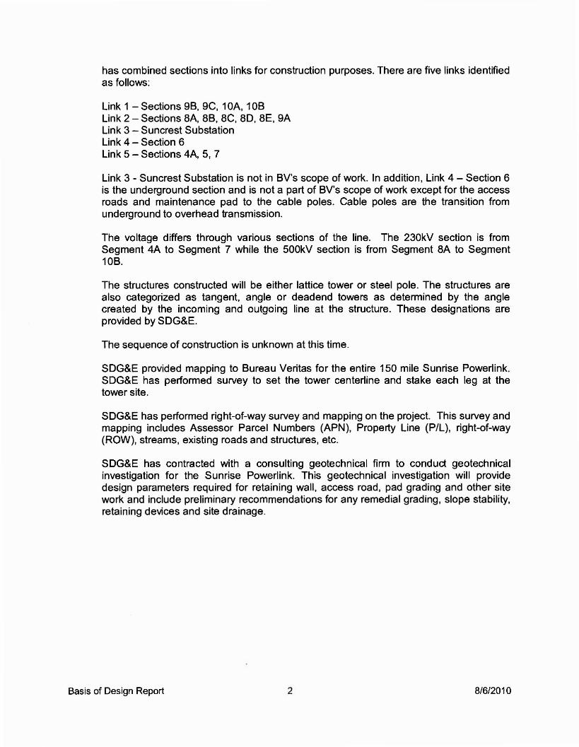
has combined sections into links for construction purposes. There are five links identifiedas follows:
Link 1 - Sections 9B, 9C, 10A, 10BLink 2 - Sections 8A, 8B, 8C, 80, 8E, 9ALink 3 - Suncrest SubstationLink 4 - Section 6Link 5 - Sections 4A, 5, 7
Link 3 - Suncrest Substation is not in BV's scope of work. In addition, Link 4 - Section 6is the underground section and is not a part of BV's scope of work except for the accessroads and maintenance pad to the cable poles. Cable poles are the transition fromunderground to overhead transmission.
The voltage differs through various sections of the line. The 230kV section is fromSegment 4A to Segment 7 while the 500kV section is from Segment 8A to Segment108.
The structures constructed will be either lattice tower or steel pole. The structures arealso categorized as tangent, angle or deadend towers as determined by the anglecreated by the incoming and outgoing line at the structure. These designations areprovided by SOG&E.
The sequence of construction is unknown at this time.
SOG&E provided mapping to Bureau Veritas for the entire 150 mile Sunrise Powerlink.SOG&E has performed survey to set the tower centerline and stake each leg at thetower site.
SOG&E has performed right-of-way survey and mapping on the project. This survey andmapping includes Assessor Parcel Numbers (APN), Property Line (P/L), right-of-way(ROW), streams, existing roads and structures, etc.
SOG&E has contracted with a consulting geotechnical firm to conduct geotechnicalinvestigation for the Sunrise Powerlink. This geotechnical investigation will providedesign parameters required for retaining wall, access road, pad grading and other sitework and include preliminary recommendations for any remedial grading, slope stability,retaining devices and site drainage.
Basis of Design Report 2 8/6/2010

ElC41nlnl NavalAulclIIIyNt alation
,I
.~j
.,1j
I
,......
o• Ilr....w....... ...... _....-• .... uow...... -"-• .... 'IIWltlJW'..W....... ........~IOOW... U. .. ' ........ LIIli
I!lt'*llIOOW~UlII ..........m'UOtNR-. ~.,o.tMN'--
~1IIW~... CJ -_... l'MIIIIUIIf
.....,.W~U- c:::J --- U... I'lIa ...............
.......WT,.......... c:::J """~M. .......,,.. ....L..w
er-.IO~"- c:::J ...................., ~1f ...............LIIIIlI- --- ---- .. .. -- --'- ___ I....
3 FIGURE 1
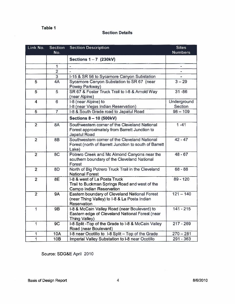
Table 1Section Details
Link No. Section Section Description SitesNo. Numbers
Sections 1 - 7 (230kV)
1 - -2 - -3 1-15 & SR 56 to Sycamore Canyon Substation -
5 4A Sycamore Canyon Substation to SR 67 (near 3-29Poway Parkway)
5 5 SR 67 & Foster Truck Trail to 1-8 & Arnold Way 31 -86(near Alpine)
4 6 1-8 (near Alpine) to Underground1-8 (near Viejas Indian Reservation) Section
5 7 1-8 & South Grade road to Japatul Road 98 -109
Sections 8 - 10 (500kV)
2 8A Southwestern corner of the Cleveland National 1 -41Forest approximately from Barrett Junction toJapatul Road
2 8B Southwestern corner of the Cleveland National 42 -47Forest (north of Barrett Junction to south of BarrettLake)
2 8C Potrero Creek and Mc Almond Canyons near the 48 - 67southern boundary of the Cleveland NationalForest
2 8D North of Big Potrero Truck Trail in the Cleveland 68 - 88National Forest
2 8E 1-8 & west of La Posta Truck 89 -120Trail to Buckman Springs Road and west of theCampo Indian Reservation
2 9A Eastern boundary of Cleveland National Forest 121 -140(near Thing Valley) to 1-8 & La Posta IndianReservation
1 9B 1-8 & McCain Valley Road (near Boulevard) to 141 - 215Eastern edge of Cleveland National Forest (nearThing Valley)
1 9C 1-8 Split -Top of the Grade to 1-8 & McCain Valley 217 - 269Road (near Boulevard)
1 10A 1-8 near Ocotillo to 1-8 Split - Top of the Grade 270 - 2811 10B Imperial Valley Substation to 1-8 near Ocotillo 291 - 363
Source: SDG&E April 2010
Basis of Design Report 4 8/6/2010
4. GENERAL CRITERIA
The services provided by Bureau Veritas to complete the final design of access roadsand maintenance pads for the SDG&E Sunrise Powerlink Project shall be in accordancewith the latest SDG&E standards, methods, procedures and policies for transmission linedesign and include the following:
• SDG&E Design and Procedure Manual for Transmission Line Access Roads,May 18, 2007
• SDG&E Construction Specifications General Requirements No TE-0100,December 15, 2006
• SDG&E Construction Specifications Site Preparation and Access Roads No. TE0101, May 18, 2007
• Project Blasting Preparation and Protection Plans - SDG&E Requirements forReview Package Submittal, May 25, 2007
• San Diego County Drainage Design Manual• San Diego County Hydrology Manual• Imperial Valley Hydrology Manual• San Diego Area Regional Standard Drawing• Caltrans Highway Design Manual, Section 200• Sempra Energy Utilities Water Quality Construction Best Management Practice
Manual• California Regional Water Quality Control Board Guidelines for Construction
Practices• California State Water Resources Control board Construction Storm Water
General NPDES Permit
As standards are updated, the design may be modified based on discussion withSDG&E. Additionally, standards of local agencies and other utilities shall be adhered to,in so far as they are not in conflict with SDG&E standard design criteria or policy.
5. CADD CRITERIA
A Computer Aided Drafting and Design (CADD) standard titled "Sunrise Powerlink PlanPreparation" dated July 21,2008 (Appendix A) was developed for the project in order toprovide consistency in the creation of CADD drawings, maximum flexibility, productivity,and automated quality control. This was accomplished by defining template files, projectdirectories and CADD file names, page setups and plotting, text styles, and layer names.
Naming conventions were established for the electronic drawing files, which allowedCADD users to organize and to provide clear structure for both sheet and referencedrawing files within the project directories.
The CADD work for the project will be performed in Civil 3D Version 2008. In addition tothe CADD standards, Civil 3D conventions (Appendix B) have also been developed toassist the designer.
Plan submittals will be full size sheets in pdf format. In addition, the final submittal willalso include the Civil 3D files.
Basis of Design Report 5 8/6/2010

6. GRADING AND DRAINAGE CRITERIA
6.1 Description of Work
The plans, specifications, and cost estimate for the access roads and structure padsshall be prepared to the final level of completion. Plans shall include details, profiles,retaining wall profiles, notes, and control information. Plans shall be prepared for theneeded modifications or new construction.
6.2 Design Approach
All proposed roadway grades, cross slopes, widths, and curvatures shall comply withSDG&E standard design practices as stated in the SDG&E Civil/Structural EngineeringDesign and Procedure Manual for Transmission Line Access Roads dated May 18, 2007(Appendix C). Any proposed improvements affecting roadways shall be shown. Allstructure pad grades, cross slopes, widths, and access requirements shall comply withSDG&E standard design practices.
For supplemental information, SDG&E Transmission Engineering has preparedspecifications titled Construction Specification Site Preparation and Access Roads,Specification No. TE-0101 and Construction Specification General Requirements No.TE-0100. These are incorporated in by reference (References 1 and 2).
Deviations from SDG&E standards shall be submitted in writing to SDG&E.
Plans shall be prepared on SDG&E sheets in conformance to SDG&E requirements andstandards. Plans shall be prepared at a scale of 1 inch =30 feet. Plans shall besubmitted at the 50%, 90%, and Final levels of completion. In addition, supplementalsubmittals were made at 70% for construction bid purposes.
With respect to maintenance pads, SDG&E has noted that tower foundations can beconstructed on local non-level areas. However, level areas immediately adjacent to thestructures and accessible by spur roads are required.
To facilitate designers, a Reference Guide to the SDG&E Design and Procedure Manualin Appendix B is shown in Table 2.
When a portion of an access road is designed as a through cut road it shall be for alength no greater than 200-ft so that flow does not become concentrated and causerutting through the life of a road. There are currently nine through cut roads that varybetween 50-ft and 160-ft in length. Five of these roads provide access to temporary pullsites which will only be used during construction. Water bars and energy dissipators willbe located at the end of each through cut road where they transition back to having a fillslope.
Basis of Design Report 6 8/6/2010
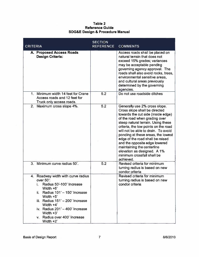
Table 2Reference Guide
SDG&E Design & Procedure Manual
SECTIONCRITERIA REFERENCE COMMENTS
A. Proposed Access Roads Access roads shall be placed onDesign Criteria: natural terrain that does not
exceed 15% grades; variancesmay be acceptable pendnggoverning agency approval. Theroads shall also avoid rocks, trees,environmental sensitive areas,and cultural areas previouslydetermined by the governingagencies.
1. Minimum width 14 feet for Crane 5.2 Do not use roadside ditchesAccess roads and 12 feet forTruck only access roads.
2. Maximum cross slope 4%. 5.2 Generally use 2% cross slope.Cross slope shall be directedtowards the cut side (inside edge)of the road when grading oversteep natural terrain. Using thesecriteria, the low points on the roadwill not be able to drain. To avoidponding at these areas, the lowestedge of the road shall be raisedand the opposite edge loweredmaintaining the centerlineelevation as designed. A 1%minimum crossfall shall beachieved.
3. Minimum curve radius 50'. 5.2 Revised criteria for minimumturning radius is based on newcondor criteria
4. Roadway width with curve radius Revised criteria for minimumover 50': turning radius is based on newi. Radius 50'-100' Increase condor criteria
Width +6'ii. Radius 101' - 150' Increase
Width +5'iii. Radius 151' - 200' Increase
Width +4'iv. Radius 201' - 400' Increase
Width +3'v. Radius over 400' Increase
Width +2'
Basis of Design Report 7 8/6/2010

SECTIONCRITERIA REFERENCE COMMENTS
5. "Y" type or circular turnaround 5.26. Grades 12% - 20%, limited to
250' in length.7. Maximum Grades - 12% 5.3 Continuous grade8. Maximum Grades - 12% to 20% 5.3 Limit to 250' in length9. Maximum vertical grade break 5.3
6% without vertical curve1O. Alignment and length For access roads greater than
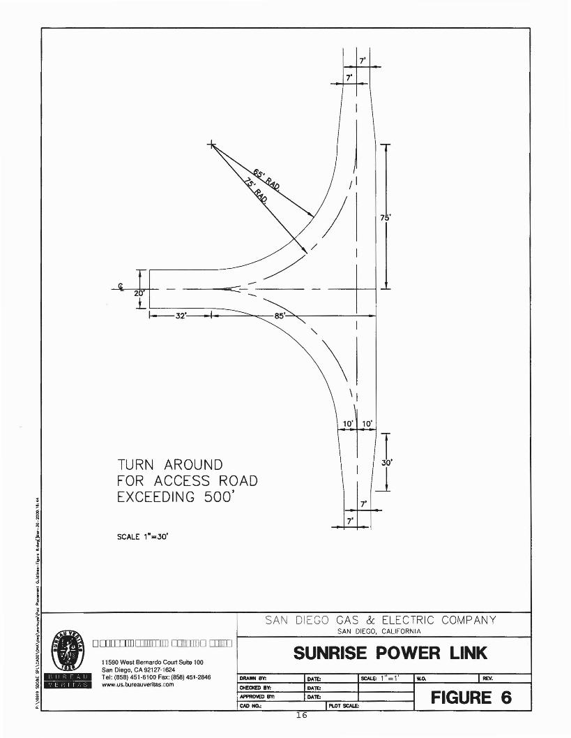
500' in length, provide Y-type or T-type (75' in length perpendicular toaccess road) or adequate for truckand emergency vehicles. Theturnaround may be located whereterrain allows within the 500'length, preferably near pad. (SeeFigure 6)
11. Water bar spacing requirements 5.6 Do not drain over fill slopes unlessi. <5% -300' prefabricated down drains areii. 5% -125' provided. In addition, water barsiii. 10% -75' shall be placed at low points toiv. 15% - 60' avoid ponding.v. 20% - 50'vi. 25% - 40'
12. Site Distance 5.313. Grades take precedence over 5.3 Minimized drainage crossings
drainage crossing preferred.14. Hydrology, codes, & regulations 4.4.6, 4.5.3,
4.6.3, 5.3, 5.515. Energy dissipators Provide 5 feet x 5 feet rip rap pads
at the outlet of any concentratedflows.Place rip rap pads where thedischarge will not erode proposedgrading.
16. Down drains Provide pre-fabricated metal orconcrete down drains whenconveying water down slopes.
17. Brow ditches Provide concrete brow ditch abovecut slopes when drainage areawarrants it.
18. Minimum cut slopes at 2:1. Fill 5.4 Contour grade slopes higher thanslopes typically at 1.5:1, 50 feetminimum at 2: 1
Basis of Design Report 8 8/6/2010

SECTIONCRITERIA REFERENCE COMMENTS
19. Minimum cut slope in rock 'Y2: 1 5.4or as recommended by theGeotechnical Engineer.
20. Fill slopes require keys when 5.4existing slope is > 5: 1
21. Repair existing access roads 4.3.1 & 4.4.322. Minimize impacts outside of 5.2 In general, do not grade outside
Right-of-Way the Right-of-Way except toconnect to existing access road.
23. Details 7.024. Earthwork Balance earthwork at each site
whenever possible; allow 10-20%additional cut material over fillmaterial quantity for shrinkage.Cut and fill sources and locationshould also be considered tominimize hauling.
25. Roadway Profiles Provide centerline stations onroad centerlines.Use sections to show roadcenterline, road cross section, andpad cross section. Show majorfeatures of site, Le. walls, cutslopes, fill slope, drainage.
B. Pad design criteria: Pads shall be placed on naturalterrain that does not exceed 15%grades; variances may beacceptable pending governingagency approval. The area shallalso avoid rocks, trees,environmental sensitive areas,and cultural areas alreadydetermined by such agencies.Pads shall be located to blend inwith the existing natural terrain asmuch as possible followingcontour lines and other naturalfeatures.
1. Maximum cross slope 2%. 5.2 Provide sheet flow across the padnot concentrated flow. Provideearth berm at top of fill slope.
2. Minimize impacts to outside of 5.2 In general, do not grade outsideRight-of-Way the Right-of-Way except to
connect to existing access road.Walls, brow ditches and otherstructures shall not be placedoutside of the ROW.
Basis of Design Report 9 8/6/2010
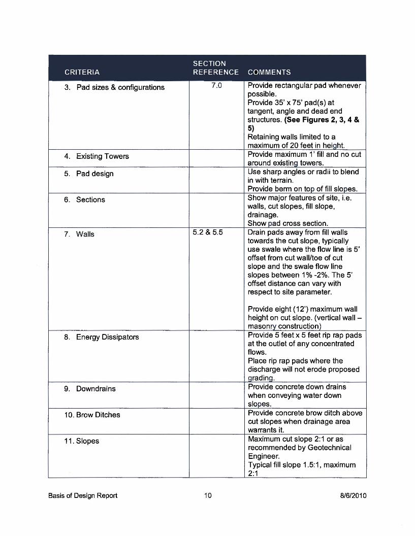
SECTIONCRITERIA REFERENCE COMMENTS
3. Pad sizes & configurations 7.0 Provide rectangular pad wheneverpossible.Provide 35' x 75' pad(s) attangent, angle and dead endstructures. (See Figures 2, 3, 4 &5)Retaining walls limited to amaximum of 20 feet in heioht.
4. Existing Towers Provide maximum l' fill and no cutaround existina towers.
5. Pad design Use sharp angles or radii to blendin with terrain.Provide berm on top of fill slopes.
6. Sections Show major features of site, Le.walls, cut slopes, fill slope,drainage.Show pad cross section.
7. Walls 5.2 & 5.5 Drain pads away from fill wallstowards the cut slope, typicallyuse swale where the flow line is 5'offset from cut wall/toe of cutslope and the swale flow lineslopes between 1% -2%. The 5'offset distance can vary withrespect to site parameter.
Provide eight (12') maximum wallheight on cut slope. (vertical wall -masonry construction)
8. Energy Dissipators Provide 5 feet x 5 feet rip rap padsat the outlet of any concentratedflows.Place rip rap pads where thedischarge will not erode proposedaradinQ.
9. Downdrains Provide concrete down drainswhen conveying water downslopes.
10. Brow Ditches Provide concrete brow ditch abovecut slopes when drainage areawarrants it.
11. Slopes Maximum cut slope 2:1 or asrecommended by GeotechnicalEngineer.Typical fill slope 1.5:1, maximum2:1
Basis of Design Report 10 8/6/2010
6.2 Design Approach (cont'd)
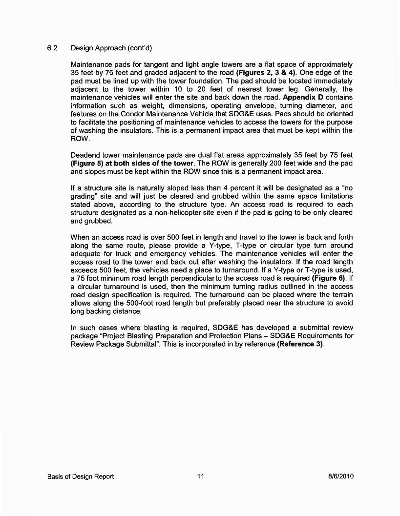
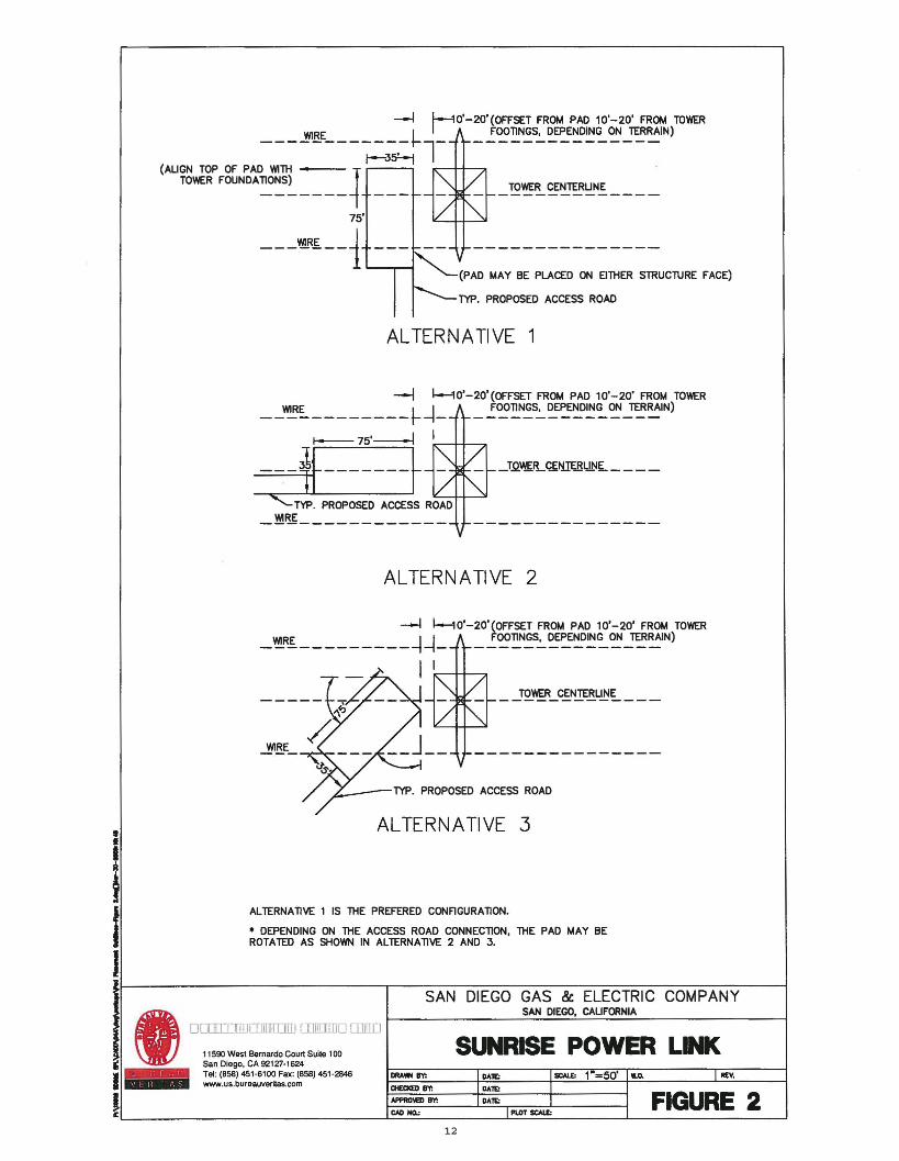
Maintenance pads for tangent and light angle towers are a flat space of approximately35 feet by 75 feet and graded adjacent to the road (Figures 2, 3 & 4). One edge of thepad must be lined up with the tower foundation. The pad should be located immediatelyadjacent to the tower within 10 to 20 feet of nearest tower leg. Generally, themaintenance vehicles will enter the site and back down the road. Appendix D containsinformation such as weight, dimensions, operating envelope, turning diameter, andfeatures on the Condor Maintenance Vehicle that SDG&E uses. Pads should be orientedto facilitate the positioning of maintenance vehicles to access the towers for the purposeof washing the insulators. This is a permanent impact area that must be kept within theROW.
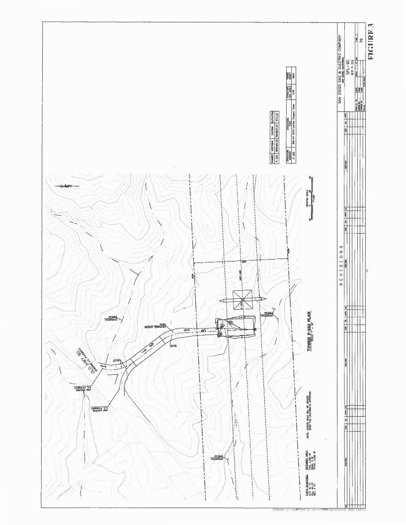
Deadend tower maintenance pads are dual flat areas approximately 35 feet by 75 feet(Figure 5) at both sides of the tower. The ROW is generally 200 feet wide and the padand slopes must be kept within the ROW since this is a permanent impact area.
If a structure site is naturally sloped less than 4 percent it will be designated as a "nograding" site and will just be cleared and grubbed within the same space limitationsstated above, according to the structure type. An access road is required to eachstructure designated as a non-helicopter site even if the pad is going to be only clearedand grubbed.
When an access road is over 500 feet in length and travel to the tower is back and forthalong the same route, please provide a V-type, T-type or circular type turn aroundadequate for truck and emergency vehicles. The maintenance vehicles will enter theaccess road to the tower and back out after washing the insulators. If the road lengthexceeds 500 feet, the vehicles need a place to turnaround. If a V-type or T-type is used,a 75 foot minimum road length perpendicular to the access road is required (Figure 6). Ifa circular turnaround is used, then the minimum turning radius outlined in the accessroad design specification is required. The turnaround can be placed where the terrainallows along the 500-foot road length but preferably placed near the structure to avoidlong backing distance.
In such cases where blasting is required, SDG&E has developed a submittal reviewpackage "Project Blasting Preparation and Protection Plans - SDG&E Requirements forReview Package Submittal". This is incorporated in by reference (Reference 3).
Basis of Design Report 11 8/6/2010
-I ~O'-20'(OFFSETFROM PAD 10'-20' FROM TOWER
--_~oBL_- - - --~ ll- - !~~N~S.:..~~~~~~_1'E!RAIN)
1-3S!-l(AUGN TOP OF PAD WITH' ~
TOWER FOUNDA1l0NS) TOWER CENTERUNE------- --- -------------
75'
---~~--1 ---------------(PAD MAY BE PLACED ON EITHER STRUCTURE FACE)
TYP. PROPOSED ACCESS ROAD
ALTERNATIVE 1
-1 1---10'-20'(OFFSET FROM PAD 10'-20' FROM TOWER__~~ t-~_ _!~~N~.:..~~EN~~~~_1'E!RAIN)
I--- 75'--/ ....1 --++-..."
---if------+ -'TYPo PROPOSED ACCESS ROIC.A-D-f+~
-~~------------
ALTERNATIVE 2
-I 1---10'-20'(OFFSET FROM PAD 10'-20' FROM TOWER
_ ~Ri. -I~_ _!~~N~S.:..~~~~~~_1'E!~N)
I I..--+~
TOWER CENTERUNE
TYP. PROPOSED ACCESS ROAD
•
iIJ
ALTERNATIVE 3
ALTERNAllVE 1 IS lHE PREFERED CONFlGURA1l0N.
• DEPENDING ON THE ACCESS ROAD CONNECllON, THE PAD MAY BEROTATED AS SHOWN IN ALTERNAllVE 2 AND 3.
SUNRISE POWER LINK
SAN DIEGO GAS & ELECTRIC COMPANYSAN DIEGO, CAUFORNIA
REV.seAL£: 1 =50' w.o.
I_ D==~:'.:O[[]lli]. \W7 San Diego, CA 92127·1624
I Tel: (858) 451·6100 Fax: (858) 451·2848 DRAWN BY:www.us.bureauveritas.com 0tECICED B'n
j - BY: FIGURE 2£L- ----l-=CAll:::...::;HO.:=.· J..:.::.:..==- .L- -.l
12
iI
III
•••ill:
~-------------------------lllntt':~
l:e ~..~..~
I /,-, J
~ IIJ \( ,.----/- ,-
\--
....... ,: .....-./ \
..........-' /
1 \,-/1;{ '~
_./
I
/ (./
{
II
/ (I
---l II
i~'! (
/r- / I
( / IJ
/" r'\
<;(
~~\. \-c;.,)~ - ,fiL
/ '5-~ -,\ y-'___ I
'=r;I /I\=~
{ I
/( I
t"\
(,//
rI \II-r '
,.-- I
\) :)\
-~ ,I
\I,\
NlIl.
t
I
Ul
Z
o-IUl I
>w
'"

>-....
z I ~<ll. =>~ '"u ;;:
ug. Iul ~ m'j I"::l.w ...J ~-
oIlg B; " I
n~~! I0 I
'" III~0
~ ' ..en
ill:
I v ~ I ,I I
I1 , ,
i,
I I, ---.l..,~1 10',, 1
,I r- I
,
I I1
I l~ .;.{I II ~,
I 1,
I II'
~'-' ", QYOtiI 5RXJ'f DH\l$ll(J I.
--rI /~
, 1 ' ,1 (
,1
,, , I
~1
~, , VI, II z,
~, ,
I , 1 ',-/ 0
I :>.. ~ I
I I }I VI I
, !V I >I w
I a:
1,r,
I ----I I1
~--I"-
~
I I ~, I ;'1
.I I Ii ,I
,,I ,...- I
,I
1 1I,
I I, ,
~ 5S3:XW M1SIO: 1 :............!
,, I,
I , I I :-t-Ir I ~ "
1-r- , "",,-I_...
~~-...... ,
lat.. .....,. INTO , ,r
,I 3~
,
,III
,I I
, "-
I1
II I
1,,I , 1, 1 I1
I,
.I1 1I 1 1 /' 11
, 1 I, 1 ,I
, ,V I J_ J:/ ,
I, [I, ,-' 1 ..J !I , ---I i/ , -I '-- r .I
')Ir ·'1 ___
I,:/
,, ,f-/
, r1 i I, I- , " , I!l~'., , \. , } I '\-I ,
( II I :/ ii~, 1 ,, 1 I1 1 1 , I1
", ,
1
I ../1, 1
I1 ,-,
!,1
---1 , I'"1 1 j, 1
\ \ ~~~, ,1 I r! ! ) !
COITDUCE OATA
..-.1...... ....1H KAMtO/bD.TA ANCI..[
L1 ..... N.S4"Q2"5n
C1 ,"'.. 134.17 Sl.,.'W
U '00.71 fil!l5'U'!le"t
,"'.. ..." 21'27'~
11.1S ...........L4 11.27 N1S'2.J'1."
OJ "'.. .... ,.nO'Ja".. 102.12 NST47'21"'1:
C4 11&0.00 Sl.4I 21':M'~
11~30 N7t'21"'"'t:
CIWHlC """XI 0 30 eo
1 .JIj
t
~r~T;'1/~
,,,,\" ,,.,
IIIlMlIlU.DO'*DIWJrt:1SlF.RPRJ#:li!1O$f'.
1.fHCrnt000ACtUSItOID: 781LT
-.....
\' ,\ \\ \
\ '\ \ I
~w=-,,,,,,,",
IllOIlIIIlEUII<PH): ',m"=':t&Sfr
rtJtIH A'AHDJJfflCUT: ~ cr.I'LL: 281 cr.NET: 14 cr.
FOR PULLS/TE (NORTH) P-255-25,EE DWG. 09C-P255-2-PS-C
,,
" //,!..
"",-
"'-
,,/
"","I//,
I
:4I,
~~"*~//P-~2~ KV IJlHD lAtu.~ T_ -41.21 112.15 / /
I \ / //' ~l /,;0-- -,L._-r I
/ 4" ." / ~
---~~.._~-- ,!-----/ N"N ...t-~04 I I
, /~. //~ / ~, I
)(' Ii -_...~1/,
/',,/ -,~ "TOWII!.~ I'LM
.-
\
--~
ITYPICAL ACtUS ROAD CROSS SECTlOH
STA 0+00.00 TO 4+31.03STA 0+00.00 TO ,)+50.04
"'.$.
I. REV I 5 ION 5 SAN DIEGO GAS'" ELECTRIC COMPANYIi ~ ...._.....-.~l A _V......N............ - -- - - - - -- - - - - -- - - - SPL-9C (UNK 1)
! \W7 ~~==-. SITE P-Z55-2i _ :,:'l...."":--~ .'!iiCM.~.. ~..DD = -- I· .. ~'" - II
~ /FC': -- _ 09C P255 2-51.. _ __ '.1
•• FlGI.IIE II
7'
7'
----EE::::::- -----
I/ I
7'
SUNRISE POWER LINK
SAN DIEGO GAS & ELECTRIC COMPANYSAN DIEGO, CALIFORNIA
SCALE 1-=30'
REV.SCAI.£: 1"= 1. w.o.
"'-
\\ I
10' 10'
r.J
7'
7'
DRAWN BY: DAlE:
CHEOIED BY: DAre
TURN AROUNDFOR ACCESS ROADEXCEEDING 500'
11590 West Bernardo Court Sune 100San Diego. CA 92127-1624Tel: (858) 451-6100 Fax: (858) 451-2846www.us.bureauveritas.com
011111111111111111111111 OJIIIIIIJO OJITIIJ
! _O\ED BY: DAre FIGURE 6,;:L- ---L._CAD_IlO.:_·__~~--'-PI.O-T-SQ-~-. ----'- ---'
16

6.3 Tower Staging/Access Pad
Tower Staging/Access Pad (TSAP) are permanent helicopter landing areas which will berequired for those sites inaccessible by roads. All TSAPs will be partially or completelylocated outside the SDG&E right-of-way and require a 100' diameter easement with thelanding loc.ation centered in the easement. The landing area is a 20' by 20' square.
Generally, the maximum walk-in distance between the tower and TSAP location is 300feet. In most cases, the TSAP is located a minimum of 85 feet from the centerline of thetransmission line to avoid flying too close to the wires. There are exceptions to bothrules, especially when there are limited suitable landing locations in steep terrain.
The TSAP are field located by a team which includes SDG&E, BV, biological monitor,cultural monitor and surveyors. The BV and SDG&E members locate the TSAP basedon maintenance/engineering requirements then the biological and cultural monitorapproves or rejects the site based on biological/cultural impacts. If the site is rejected,the BV and SDG&E members look for another suitable location and the processcontinues until a site suitable for all parties is found. If the site is approved, the surveyorssurvey a 100' by 100' grid, a walking path between the tower and TSAP and the fourcomers of the landing area. Other terrain features may also be surveyed such asboulders, large rock outcroppings and trees.
BV will provide site plans that designate the type and location of the TSAPs. TheTSAPs will be either clear and grub or graded. The criteria for each designation isdetermined by the slope (or angle) of the existing terrain as follows:
-Existing slope < 8% (5 degrees) is a clear and grub site.-Existing slope >8% (5 degrees) is a graded site
Clear and grub sites will not require grading but simply be cleared and grubbed withinthe 20' by 20' square area. The remaining area between the pad and the 100' diametereasement will have the vegetation trimmed to 24" above the ground.
Graded sites will have pads graded at 2% across the 20' by 20' square area anddraining towards the fill slope. No drainage structures will be required since the pad andgraded area is relatively minimal. Cut slopes will follow the geotechnicalrecommendations however will never be graded steeper than 1:1. All fill slopes will be1.5:1. The earthwork will be balanced so that there will be 15%-20% more cut materialthan fill material to allow for shrinkage. The remaining area between the grading daylightand the 100' diameter easement will have the vegetation trimmed to 24" above theground.
6.4 EIRIEIS Mitigation Design Standards
SDG&E has issued a Draft Sunrise Powerlink EIRIEIS Mitigation Standards for AccessRoads dated August 25, 2008 (Appendix E). These mitigation standards focus onmeasures that will direct the design of temporary and permanent access roads toSunrise Powerlink facilities.
Basis of Design Report 17 8/6/2010

All access road design shall adhere to the mitigation standards as outlined. Where aconflict or deviation occurs, it shall be presented to SDG&E for their approval anddisposition.
Highlights from the Mitigation Standards include:
• Avoid vernal pools• Access roads at right angles to watercourses• Restrictions on construction time and location• Minimize disturbance at waterways• Avoid watercourses to the extent possible• Construction routes to avoid and minimize disturbance to stream channels• Avoid new disturbance, erosion and degradation• Restoration of temporary roads• Avoid sensitive features• Mitigate for loss of trees• Provide restoration of loss of sensitive features• Reduce in-line view of scars• Reduce visual/color contrast• Minimize vegetation removal• Reduce land scarring• Prepare and implement Scenery Conservation Plan• Avoid and protect culturally significant cultural resources• Protect desert pavement
6.5 Right-of-Way
For temporary or permanent construction land impacts beyond SDG&E's right-of-way(ROW), acquisitions or easements would be required. Although ROW can be obtained, itis time consuming and costly. Previous work to date has not identified any additionalROW. Therefore, SDG&E has directed that designs are to be maintained with in existingSDG&E ROW.
However, SDG&E also recognizes that the potential for an illogical, costly design withthe existing ROW as an absolute parameter. If such a case would occur, it shall bepresented to SDG&E for evaluation and approval.
SDG&E has also noted that military land and open County land is particularly difficult toobtain and would prefer that an engineering solution be determined rather than obtainany ROW.
6.6 Erosion Control
Erosion control will be addressed as outlined in the SDG&E Design and ProceduresManual, Section 6.2 (Appendix C). Additionally, the Sempra Utilities "Water QualityConstruction Best Management Practices Manual dated December 2002 is incorporatedherein by reference (Reference 4).
Basis of Design Report 18 8/6/2010
A Storm Water Pollution Prevention Plan (SWPPP) will be written for the project inaccordance with the California Water Resource Control Board General ConstructionStorm Water Permit and local Regional Water Quality Control Board (RWQCB) guidanceor directives (References 5, 6, & 7).
7. RETAINING WALL CRITERIA
7.1 Description of Work
The plans, specifications, and cost estimate for the access roads and structure padsshall include any necessary retaining walls for the project and shall be prepared to theFinal level of completion. Plans shall include retaining wall plan, sections, details, notes,and control information.
7.2 Design Approach
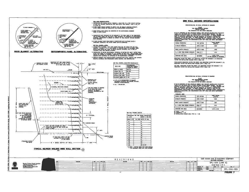
SDG&E has directed retained fill walls shall use Hilfiker Retaining Walls Welded WireWalls. A typical section was developed for Segment 4A and is shown in Figure 7. TheNational Cooperative Highway Research Program, Report 556, Design and ConstructionGuidelines for Geosynthetic-Reinforced Soil Bridge
Basis of Design Report 19 8/6/2010
»T.J"'"
o.75l1o.n
lIAIIV .""'"(laSJ'"1)
...,
0.75 • 0.75Oft SIlE sP£af1C AS 1tE0l.Ilt!D
..,.....,
...........
..,. • I&T7
..,. .....
....,"""..
CAE!P lIIIlm S1RD«I1K
APlJI'Ml£ 5Ul (M.)
T.. • lCJfG l"fJQI DDIGN 51ROfGlH I IGU. 17 •
.....uu.T[ SlflOG1M
ftlIltUMY.2ClOI
lA.TlMAtt SlMNCTH
r.._UlfVTtMfOESNlNS1lIl(NG'IK I NCl&AtT
oYO'T\II[SIZt(ICS.) IlIl[ASLMZ)
CJlE[p l.IrIII1lD STRENGTH 1 AS'1\l D 521112
""""' .........
.....S'fMTUN.CClW. at (QUAL~ IY INGNDt
.... ......,g,.., G<OCRD_G<.....
lH[ Sl'RDICnH IS .. 1IC l..D«mt e.tECnOM
RUlUCTION FACTOR raJI aur 10M, M:IIUC'11OH fACTOl nJR DURA8IUTY 1.10 R£DUC1'IOlII'ACTOR FlIl: tl$TAUATIlIH OAMAQ[ ('T'rN: :s SOL) 1.05
AfWA/MSHTD ItEIIUC"nOt4 fAC1llR nJR CR£Ol' 1.55. flIEZltJCnCIril ,ACltlR FtI' 0URMIJT't' 1.l4.JlEIIUCnCJN rACTQltraJlINSTAUATlClNDAMACl£(T'r'N::SSClL) Ul3
GIa GIC:4I tIaIUC1lON,ACftJI fOR aaJ" 1.'r.\ IlImUCnON 'AC1aIl fa. DLIIUaITT '.10~,~ fCllt taTAUAlKlN CIrM&AGlE (nK .) SOl) ,.OS
- WALL GEQGRI) 8PEC1F1CATJ0N8
www.s'lN1t£K.CllM, Oft [QUAL APPIIO\G BY 0«iItUR
.... ...,.....M,., G<OCRD_G<OCRDtHE SlROlGlH IS .. lH[ 1.DG1K 0R£C1Qt
Sf' a IS c:cwosm or HICH IIICUOJl..Nl WIJCHT. HIllH 1DUoCJTY ......1ft...MIENT lI"Ql'l'tSTOtYNlNS mAT MI. WO'CN IfTO A STAal: IETWDRI( Pl..ACm UMDOl: TtNSIClN. ltt[ MGHSl'RI:MOlM lI"Ql'GTDI YoWfS NIL c;:Q\T'ED _1M A "'IIC lIIIAlDlW.. ST SDIES GEXXlMJS ".MJn" 10 IIOI.OCJCAL 0GItADATION MD NIL RDlSTAN1' TO NIl'NIUU.Y OCCUO'DII:JI04PriIICAlS, AIJCAl.JS NtO.taOS. If' SIDlES Cl[0CMlS ME. 1"l'P'ICALLY USED rtllt sea.RDWCM:OlOfT """'-CA1OIS SUCH AS "lTAM«2 IMlJ.$. S1UPOI!D liUJI£S, DeMIQIOf11,.!iIWGIWlE STA&.lZA'nOM. MD EMaNeQIDITS lMJI: SCfT SClLS~ WASTE OONT.....:HT"""""'......
ffF atfDI - 1.04Rf lUWIUTY - '.10ffF INSTAUAlKlN OAWAC! (SOl. typo[ 3) - US
3d 1 24'
zrI 1 ,..
2r 1 ,"
,r I 111'
10' 1 ..
,,1 u21' I 21'
2'" 1 2tI
,I' 1 15"
32' I ,.·-2-1....
,,,' I II',I' 1 13"
NEl..MNARY MW. SOIl DDlClN I"AIWI(l(]itSo _135' DlNSm' < 130 I"tS
~ e- lAS[ ~TH t:I WALL
~ ~
Y$[ WALL G£OQIlI) l.iHGlMS
.......... -......--PASSINO IJY 'MJCHT
tClOmltl (4 lOt) 'lllI-7>
""'""'(NO.4) ZD-'DO
o.4:z5tnro1 (NO. 40) ...10
0.,",""" (NO. 2(0) ...35
PLAS1lOTY lNDD: (fill) <20
WS[ WAll IlAQCFU. GRAOATlCIN R£QIJWDIENTS
.. API <IOllltOCMlENlllD TO.-..zEDPNtS'C P'Ol!NlIAI. N«J PftCMD! SUlTAIlf_0lMAC1IIIlSIlCS
"'_-IIII..LI«T[RS
.....r.....,
~I
J:
4. SUllSURfACE IAOl: DRMfAC( .....Y I[ ItEDUC£D F 1'Hl IOU USED IN THE REJNI'ORC£DAND RETAMD ZOMtS ,. fIO.AlMlY -nu lJRAMoI(f AS AI"f'IR<M:D BY QEOTtOlNlCAl.ENGINEER. c::cJmIAClQt 10 ASSlM 20 "IJtCDitT CT WALL SQUAIt[ FOOTAGE lI£QlRSBACK .........
5. If' ROCIC IILNICET lAO( 0RAlN ROCK IS !IlJ8S1I1\J1lD .tw CAl..1IUMS Q..ASS •P£MlEAIILl AGal'(GAl't nc n.lDl: 'AIRlC CAN I[ D.•••UID.
I. P£RfORAllD NO[ SMCU..O OUn.n 'It«OUQ4 " SCI.J) P"P[ TO " no: ClRA...n OlITf'ALLAT IIlAX 100' sPAQNG, ~TID 'ft. AND 0lJTl£T fIIPI: SHCllAD HA~ A fAU. or"'lUST a
a. n:o fMIIIC SMl:I.UI CXlNSdT or ..",. 14C1N, at .....",. APPMMD AtODUC'T.fl.D 'MJRK; sttlM.O I[ 0\GILN'Pm POl M.WJrAC1lJll(S ICSDI.ICllCICS.
J. DltAIN treSTAUAnoN SHOUIJ) 111£ mJSDMD BY lH[ Q£Dl[ctNCN.. DQrGRI'RlClNTDIIAQ(~
1. CDf'AVoClal IS AIMSIXl 'tHAT MOIl ClM$Il[ sou -.a. _ 'NI8l.L rat WS[ 'WILlaAOCn.1. UlIJZING'S' TO .41Nt SCION 10 CCM"OflW SDI.Sro~ TMILmow CNt[ SHCM.D • T~ TO SULCT IAaln.l. .....1tltlAI. 'MAT IS nta orEXCOSIYE FJ€S AND aRCWIC .....1DlIAL
1. COfiIlRACTOIt TO CllJTMI c;r:01t:ONCAl. N"PfI:t1VM. CT IGt'TrII QJT AND r ClF'F5ET fltCII5UlPE fN%. ...... TO lI'I,ACEWDIT or MY 1l[0DII:l0 at ... IllA1S. USE lI[TAlNIfO M.LSSHOU.D 8[ fCUJClO) ON PftaIIRLY CDl'ACllD at RElATM1.Y UIOS1UR8ED 1IEATHEJIlDCRAM'nC ROOC MATUIW.I U Af'lIMMD .,. lH[. CitO'!tQIlIICAL 0QNEEJt,
]. GEOltOt EHGINmt NfJ ....,.~ ItD'ttDOlTATM SHAU..~ AND N'fIftCM;8AOCnJ.. MAltRIALS AND~~ IACICl'U AND CClNS1RUC:1KI\I
'''''''RD".....lIIIATST'lP..............,......""'"
2' TYPICAL
..l!-l!I!I
-------- ~:" "-------- ..., ~~~ I
->-~~-uacn.L Pat HOlD~
- ------ ~-. IFLlIX,.....c TYP.
----------- ~~;>I
----------- T--"'~-' I------~~=~:~I
eN ....,
fIJaHm "AD cua:POt lIftOr£T IlI\MS
~
ROCK IILNI(E'[ ALn1!NAlJYE !EOCCM'OSITE PANEL ALIB!NAlIlIE
...o
'<II~lr .. SQLCT~
S 1D1.ia]',----------- ..,.~;> IC]
""'=A::..'ll':: 1
- - :S~~~":T=-;'~-"'"
lE'Al!!.A.!..."'!!!!----- - .....-=~-.==--- - - - ~
- '~SOLO~D-YN -( ---- - -
DA'tUCiHT 10 rN:f. Of SUI'( BWAT UN PQNB.......... ""'"
... D<TAlL • _ BASE DEPT>< or WAlLJ 7' MIN
I;
!~
I,
T'1I'!CAL IILfI(ER WELDED WIlE WALL SECT1ClN ED.,.•• DtST. - IIOTltIIlIlItI)S.,.. SJ'IO G£OQIID-TOP~ClIOS.-ntsnsG£OGIIIO
\
SAN DIEGO GAS & ELECTRIC COMPANY.... _<:AUF-..SPL-04A (LINK 5)
Detol StlMt 3 Of 5
!~I -! -
B_V..rku NardI Aa:Iak:a1_......0-1__
....~~.,.,.=""-,.,..REVISIONS
_ft~
;;;;;;;;.-;0
!!!!.
~ SPL-04A-005.,
Abutments with a Flexible Facing dated 2006 provide the guidelines for the design of thistype of wall.
Cut slopes shall be retained with a solid grouted masonry wall with a maximum backslope of 2: 1.
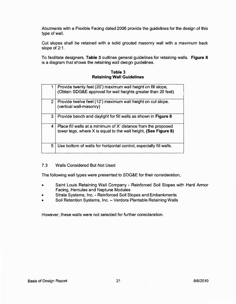
To facilitate designers, Table 3 outlines general guidelines for retaining walls. Figure 8is a diagram that shows the retaining wall design guidelines.
Table 3Retaining Wall Guidelines
1 Provide twenty feet (20') maximum wall height on fill slope,(Obtain SDG&E approval for wall heights greater than 20 feet)
2 Provide twelve feet (12') maximum wall height on cut slope.(vertical wall-masonry)
3 Provide bench and daylight for fill walls as shown in Figure 8
4 Place fill walls at a minimum of X' distance from the proposedtower legs, where X is equal to the wall height, (See Figure 8)
5 Use bottom of walls for horizontal control, especially fill walls.
7.3 Walls Considered But Not Used
The following wall types were presented to SDG&E for their consideration,
• Saint Louis Retaining Wall Company - Reinforced Soil Slopes with Hard ArmorFacing, Hercules and Neptune Modules
• Strata Systems, Inc. - Reinforced Soil Slopes and Embankments• Soil Retention Systems, Inc. - Verdora Plantable Retaining Walls
However, these walls were not selected for further consideration.
Basis of Design Report 21 8/6/2010

2' MIN.
rWALL EMBEDMENT INTOEXISTING GROUND
2"--MIN. DISTANCE =HEIGHT OF WALL
SCALE: 1-=1' Woo. REV.
SUNRISE POWER l.N(
= 11-·_---------=-7·...,;M::.:.:IN:..:,:·-------_·1
I.. B=::::::::mca
• ~ SanDiego,CA92127-1624
I Tel: (656) 451-6100 Fax: (656) 451·2646 DRAIN 1mwww.us.bureauverttas.com CHtaCDl 1m
J _1m FIGURE 8I:L ---l~CAD~NO.::...-----:2>':2)--~~~----l..----=--=-::..:....:=--------'

8. QUALITY CHECK
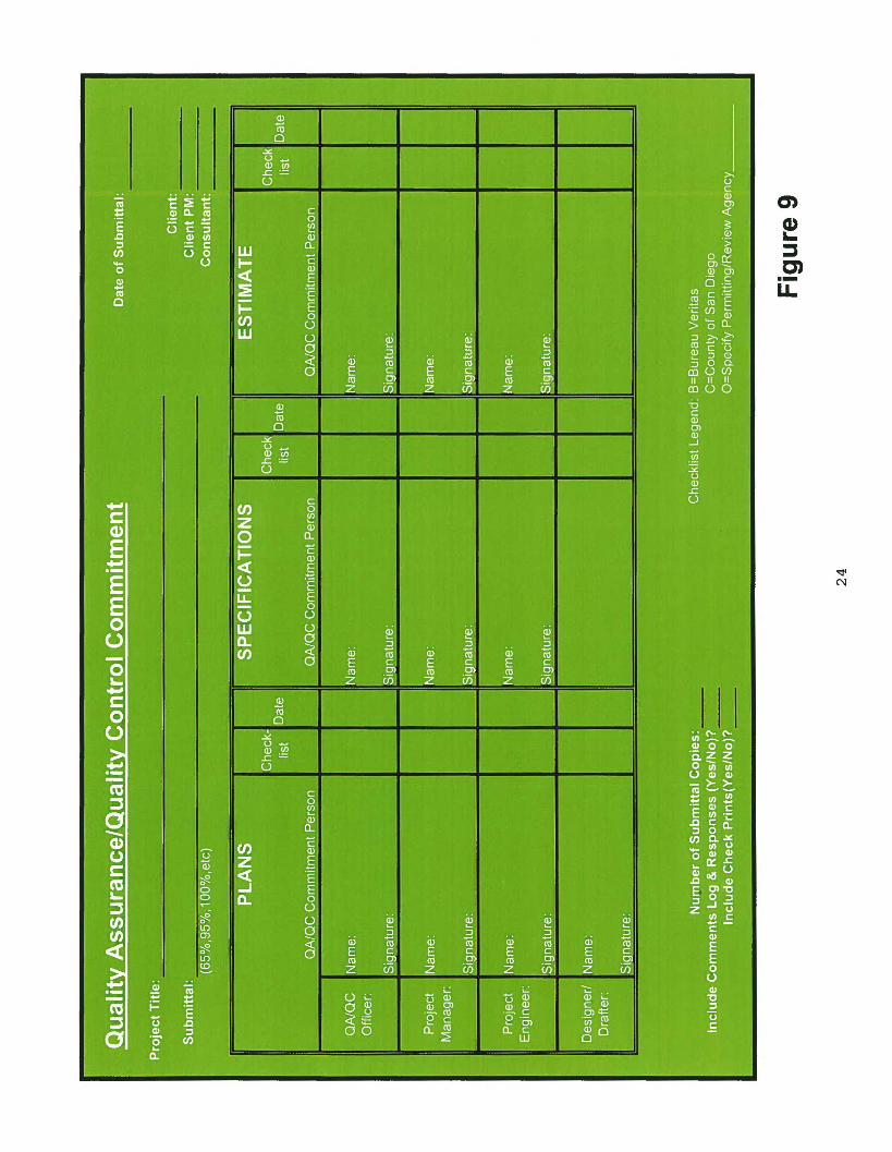
8.1 Quality Overview
All work shall be checked in accordance with the Bureau Veritas Quality Program. The"Green Sheet" (Figure 9) shall document the quality check for each submittal.
Plans shall be submitted at the 50%, 90%, and Final levels of completion. Each levelrequires a quality check.
Due to the project size and multiple offices performing work, the quality checks will betracked by the Quality Manager to ensure quality checks are performed and consistencyin work product to our client. Upon completion of a quality check, the checker shall notifythe Quality Manager.
8.2 Plan Check
The first line check is with designer. To assist the designer, a checklist is provided forthe designer's use and shown in Table 4.
8.3 Deviation from Standard
Deviations from SDG&E standards shall be submitted in writing to the Project Managerand SDG&E for approval. Use the form shown in Figure 10.
Basis of Design Report 23 8/6/2010
,• a')
!~C).-LL
.--
;°l~-...J
•
ll~ ·f
•.. :II.. 0
~
Ifffi •
~0 0 0
i;: 0 , 0
~
, . ,
.:' • r . i . ·0.•
0 I~~
~~
!op;;;
~
~ 0
~•
0
~~ i0 0
0 . 0
~
, . .~ . • f ~•;JJ
~ . ·;
0,
...J I
II I
I~~ IIf;;;:.F;L!::J ~.
0
I·
•0 0 .
~0 . 0
•. 0 . 0 ~ .
I ' r I'.
( • , •
~I t,· r )1lit.o •
t.· ~:~ ;j .!o
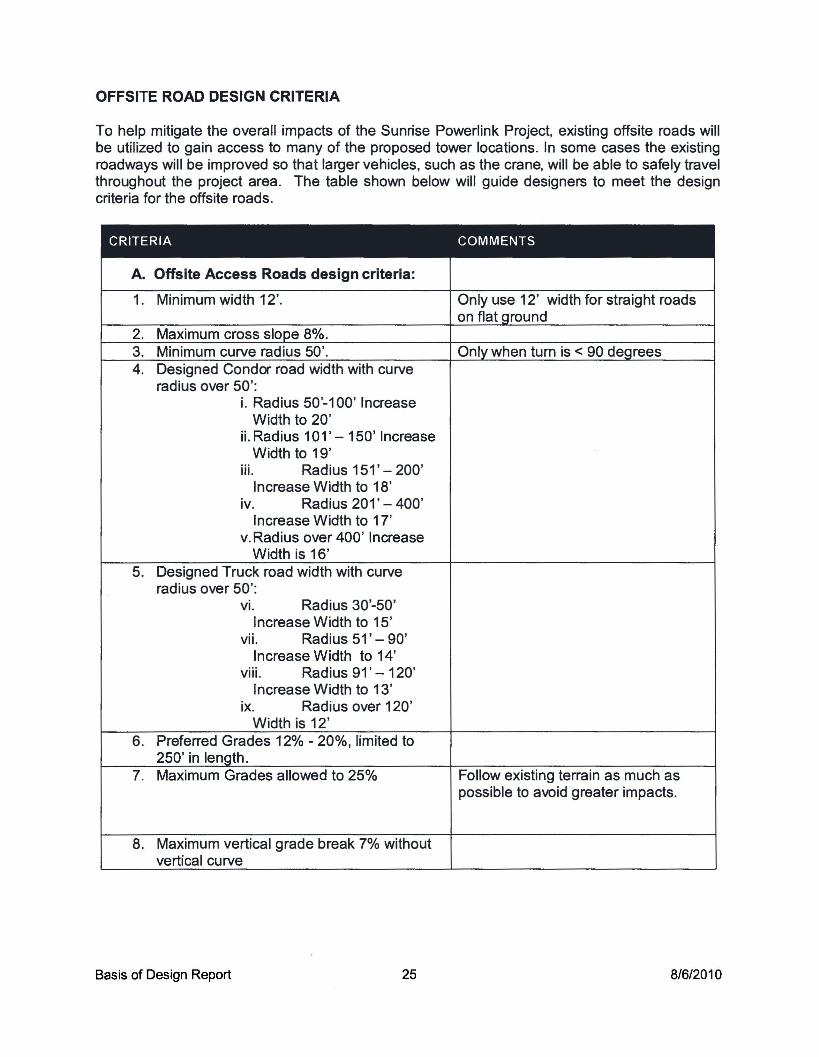
OFFSITE ROAD DESIGN CRITERIA
To help mitigate the overall impacts of the Sunrise Powerlink Project, existing offsite roads willbe utilized to gain access to many of the proposed tower locations. In some cases the existingroadways will be improved so that larger vehicles, such as the crane, will be able to safely travelthroughout the project area. The table shown below will guide designers to meet the designcriteria for the offsite roads.
CRITERIA COMMENTS
A. Offsite Access Roads design criteria:
1. Minimum width 12'. Only use 12' width for straight roadson flat Qround
2. Maximum cross slope 8%.3. Minimum curve radius 50'. Only when tum is < 90 degrees4. Designed Condor road width with curve
radius over 50':i. Radius 50'-100' Increase
Width to 20'ii. Radius 101' - 150' Increase
Width to 19'iii. Radius 151' - 200'
Increase Width to 18'iv. Radius 201' - 400'
Increase Width to 17'v. Radius over 400' Increase
Width is 16'5. Designed Truck road width with curve
radius over 50':vi. Radius 30'-50'
Increase Width to 15'vii. Radius 51' - 90'
Increase Width to 14'viii. Radius 91' - 120'
Increase Width to 13'ix. Radius over 120'
Width is 12'6. Preferred Grades 12% - 20%, limited to
250' in length.7. Maximum Grades allowed to 25% Follow existing terrain as much as
possible to avoid greater impacts.
8. Maximum vertical grade break 7% withoutvertical curve
Basis of Design Report 25 8/6/2010

CRITERIA COMMENTS
9. Water bar spacing requirements Do not drain over fill slopes unlessx. <5% -300' prefabricated down drains arexi. 5% -125' provided.xii. 10% -75'xiii. 15% - 60'xiv. 20% - 50'xv. 25% - 40'
10. Grades take precedence over drainage Minimized drainage crossingscrossinQ preferred.
11. Drainage design Culverts should be used instead of dipsections whenever possible
12. Energy dissipators Provide 5 feet x 5 feet rip rap pads atthe outlet of any concentrated flows.Place rip rap pads where thedischarge will not erode proposedgrading.
13. Down drains Provide pre-fabricated metal orconcrete down drains when conveyingwater down slopes.
14. Brow ditches Provide brow ditch above cut slopeswhen drainage area warrants it.
15. Impacted streams Impact to existing channel/streamsshould always be less than Y:z acre
16. Minimum cut slopes at 2:1 unless otherwise Contour grade slopes higher than 50specified by Geotechnical Engineer. Fill feetslopes typically at 1.5:1, minimum at 2: 1
17. Minimum cut slope in rock per GeotechnicalEngineer recommendations.
18. Fill slopes require keys when slope ofexistinQ terrain Is > 5: 1
19. Earthwork Balance earthwork at each sitewhenever possible; allow 10-20%additional cut material over fill materialquantity for shrinkage.Cut and fill sources and locationshould also be considered to minimizehauling.
20. Roadway Profiles Provide centerline stations on roadcenterlines.Use sections to show road centerline,road cross section, and pad crosssection. Show major features of site,Le. walls, cut slopes, fill slope,drainage.
Basis of Design Report 26 8/6/2010

INTRODUCTION
The Sunrise Powerlink Project consists of proposed access roads, pads, and towers that crossexisting streams, requiring hydrologic and hydraulic analysis to be performed at each streamcrossing being impacted by the project. Since the project is located in both the County of SanDiego and Imperial County an appropriate hydrologic methodology needed to be applied fordrainage crossings in each respective county as shown in more detail below. Dip sections andculverts have also been sized to safely convey the runoff across many of the proposed accessroad and pads. The methodology used to size each dip section and culvert in the project is alsoshown below.
HYDROLOGIC MODELING METHODOLOGY - COUNTY OF SAN DIEGO
The runoff calculation methodology utilized for hydrologic calculations conforms to commonlyaccepted practices utilized in the San Diego region as amended by the County of San Diego.The County's Hydrology Manual was used to determine flow rates within the project vicinity. ThefollOWing subsections describe the rationale behind each of the parameters used in the peakdischarge calculation using the rational method as well as the National Resources ConservationService (NRCS) hydrologic method. Supporting reference materials, including excerpts from theSan Diego County Hydrology Manual, dated June 2003, can be found in Appendix F.
Basin DelineationDrainage basin limits were obtained through the use of topographic mapping, conventional fieldsurveying, site inspection, and/or topographic maps obtained from the U.S. Geologic Survey(USGS).
Runoff CoefficientsThe rational method runoff coefficients used to determine the discharge for all contributing areasare based on the County's Hydrology Manual (refer to Tables 3-1 in Appendix F). A runoffcoefficient of 0.35 has been used for all of the drainage basins within the project area since theland use of the basins primarily consists of undisturbed natural terrain with varying amounts ofvegetation.
Runoff Curve NumbersThe NRCS method runoff curve numbers used to determine the discharge for the drainage areawas based on the County's Hydrology Manual (refer to Table 4-2 in Appendix F). The table usedto calculate the composite CN uses the worksheet headers shown in Table 4-9 of the County'sHydrology Manual which is shown in Appendix F. Once the composite CN has been determinedit will be adjusted based on the appropriate precipitation zone number (PZN) conditionaccording to the drainage basin's location within the County of San Diego (refer to Figure C-1and Appendix F).
Rational Method - Time of ConcentrationThe time of concentration (Tc) for the rational method was determined by calculating the traveltime for flow from the most remote point of the drainage basin to reach its outlet. A minimum of5-minutes was used for basins with calculated Tc's less than 5-minutes. The County of SanDiego's approach to calculate the time of concentration was used.
For rural or natural areas, the Tcwas calculated using the following equation (refer to Figure 3-4in Appendix F):
Basis of Design Report 27 8/6/2010
Where,
[3]0,385
Tc= l1.~L
Tc = Time of Concentration, hoursL = Length of drainage course, milesH = Difference in elevation from further most point of design, feet
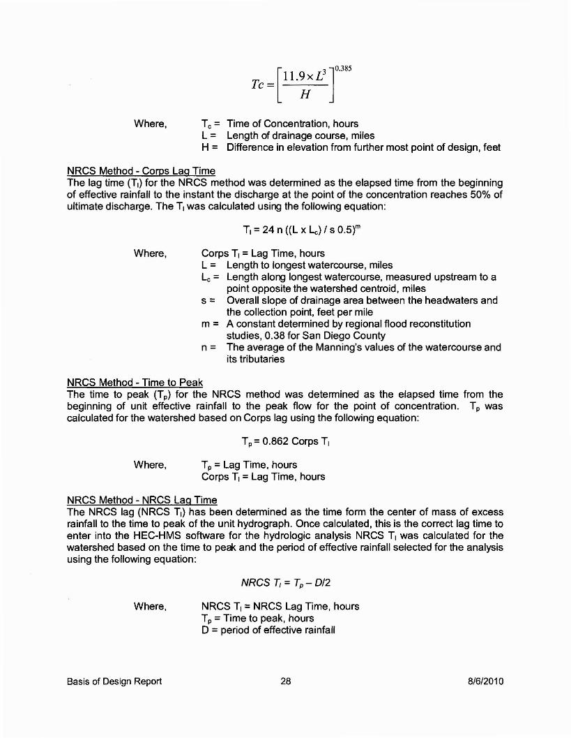
NRCS Method - Corps Lag TimeThe lag time (T1) for the NRCS method was determined as the elapsed time from the beginningof effective rainfall to the instant the discharge at the point of the concentration reaches 50% ofultimate discharge. The T1was calculated using the following equation:
T1= 24 n «L x Lc) / s 0.5}m
Where, Corps T1=Lag Time, hoursL = Length to longest watercourse, milesLc = Length along longest watercourse, measured upstream to a
point opposite the watershed centroid, miless = Overall slope of drainage area between the headwaters and
the collection point, feet per milem = A constant determined by regional flood reconstitution
studies, 0.38 for San Diego Countyn = The average of the Manning's values of the watercourse and
its tributaries
NRCS Method - Time to PeakThe time to peak (Tp) for the NRCS method was determined as the elapsed time from thebeginning of unit effective rainfall to the peak flow for the point of concentration. Tp wascalculated for the watershed based on Corps lag using the following equation:
Tp =0.862 Corps T,
Where, Tp =Lag Time, hoursCorps T, =Lag Time, hours
NRCS Method - NRCS Lag TimeThe NRCS lag (NRCS T1) has been determined as the time form the center of mass of excessrainfall to the time to peak of the unit hydrograph. Once calculated, this is the correct lag time toenter into the HEC-HMS software for the hydrologic analysis NRCS T1 was calculated for thewatershed based on the time to pea< and the period of effective rainfall selected for the analysisusing the following equation:
NRCS 7i =Tp - 0/2
Where,
Basis of Design Report
NRCS T1=NRCS Lag Time, hoursTp =Time to peak, hoursD = period of effective rainfall
28 8/6/2010
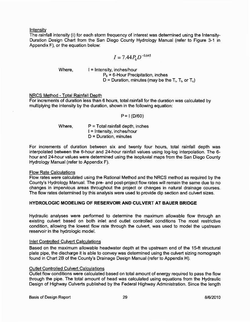
IntensityThe rainfall intensity (I) for each storm frequency of interest was determined using the IntensityDuration Design Chart from the San Diego County Hydrology Manual (refer to Figure 3-1 inAppendix F), or the equation below:
I = 7.44~D-o.645
Where, I =Intensity, inches/hourP6 =6-Hour Precipitation, inchesD =Duration, minutes (may be the Ti, Th or Tc)
NRCS Method - Total Rainfall DepthFor increments of duration less than 6 hours, total rainfall for the duration was calculated bymultiplying the intensity by the duration, shown in the following equation:
P= I (D/60)
Where, P =Total rainfall depth, inchesI =Intensity, inches/hourD =Duration, minutes
For increments of duration between six and twenty four hours, total rainfall depth wasinterpolated between the 6-hour and 24-hour rainfall values using log-log interpolation. The 6hour and 24-hour values were detenllined using the isopluvial maps from the San Diego CountyHydrology Manual (refer to Appendix F).
Flow Rate CalculationsFlow rates were calculated using the Rational Method and the NRCS method as required by theCounty's Hydrology Manual. The pre- and post-project flow rates will remain the same due to nochanges in impervious areas throughout the project or changes in natural drainage courses.The flow rates determined by this analysis were used to provide dip section and culvert sizes.
HYDROLOGIC MODELING OF RESERVOIR AND CULVERT AT BAUER BRIDGE
Hydraulic analyses were perfonlled to determine the maximum allowable flow through anexisting culvert based on both inlet and outlet controlled conditions The most restrictivecondition, allowing the lowest flow rate through the culvert, was used to model the upstreamreservoir in the hydrologic model.
Inlet Controlled Culvert Calculations
Based on the maximum allowable headwater depth at the upstream end of the 15-ft structuralplate pipe, the discharge it is able to convey was detenllined using the culvert sizing nomographfound in Chart 2B of the County's Drainage Design Manual (refer to Appendix H).
Outlet Controlled Culvert CalculationsOutlet flow conditions were calculated based on total amount of energy required to pass the flowthrough the pipe. The total amount of head was calculated using equations from the HydraulicDesign of Highway Culverts published by the Federal Highway Administration. Since the length
Basis of Design Report 29 8/6/2010

of the 15-ft pipe, 634-ft, falls outside the 500-ft maximum length shown in the culvert sizingnomograph found in Chart 7B of the County's Drainage Design Manual, the following equationswere used to determine the discharge based on the maximum allowable headwater depth.
Total Energy LossesThe total energy (Hl ) required to pass the flow through the culvert is made up the entrance loss(He), the friction losses through the pipe (Hf), and the exit loss (Ho). Hl was calculated using thefollowing equation:
Where, Hl =Total energy, feetHe = Entrance loss, feetHf =Friction losses, feetHo = Exit loss, feet
Entrance LossThe entrance loss (He) is a function of the velocity head in the barrel, and can be expressed asa coefficient times the velocity head as shown in the following equation:
Where, He = Entrance loss, feetKe =Entrance Loss CoefficientV =Velocity in the pipe, feetlsecondg =Acceleration due to gravity, 32.2 feetlsecond2
Friction LossThe friction loss (Hf) in the barrel is also a function of the velocity head. Based on Manning'sequation, the friction loss was calculated using the following equation:
Where, Hf = Friction loss, feetKu = 29 in English unitsn = Manning's roughness coefficient (Chart 7B in the San Diego
County Drainage Design ManualL =Length of culvert, feetR = Hydraulic Radius of the culvert when full (AlP), feetA =Cross-sectional area, feerP =Wetted perimeter, feetV = Velocity in the pipe, feetlsecondg =Acceleration due to gravity, feet/second/second
Basis of Design Report 30 8/6/2010
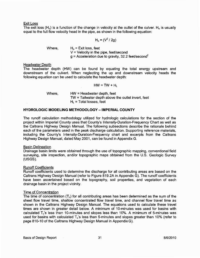
Exit LossThe exit loss (Ho) is a function of the change in velocity at the outlet of the culver. Ho is usuallyequal to the full flow velocity head in the pipe, as shown in the following equation:
Ho =(V2 /2g)
Where, Ho =Exit loss, feetV =Velocity in the pipe, feet/secondg = Acceleration due to gravity, 32.2 feetlsecond2
Headwater DepthThe headwater depth (HW) can be found by equating the total energy upstream anddownstream of the culvert. When neglecting the up and downstream velocity heads thefollowing equation can be used to calculate the headwater depth:
HW =TW+ HL
Where, HW =Headwater depth, feetTW = Tailwater depth above the outlet invert, feetHL =Totallosses, feet
HYDROLOGIC MODELING METHODOLOGY - IMPERIAL COUNTY
The runoff calculation methodology utilized for hydrologic calculations for the section of theproject within Imperial County uses that County's Intensity-Duration-Frequency Chart as well asthe Caltrans Highway Design Manual. The following subsections describe the rationale behindeach of the parameters used in the peak discharge calculation. Supporting reference materials,including the County's Intensity-Duration-Frequency chart and excerpts from the CaltransHighway Design Manual, dated May 2001, can be found in Appendix G.
Basin DelineationDrainage basin limits were obtained through the use of topographic mapping, conventional fieldsurveying, site inspection, and/or topographic maps obtained from the U.S. Geologic Survey(USGS).
Runoff CoefficientsRunoff coefficients used to determine the discharge for all contributing areas are based on theCaltrans Highway Design Manual (refer to Figure 819.2A in Appendix G). The runoff coefficientshave been ascertained based on the topography, soil properties, and vegetation of eachdrainage basin in the project vicinity.
Time of ConcentrationThe time of concentration (Tc) for all contributing areas has been determined as the sum of thesheet flow travel time, shallow concentrated flow travel time, and channel flow travel time asshown in the Caltrans Highway Design Manual. The equations used to calculate these traveltimes are shown in greater detail below. A minimum of 10-minutes was used for basins withcalculated Tc's less than 10-minutes and slopes less than 10%. A minimum of 5-minutes wasused for basins with calculated Tc's less than 5-minutes and slopes greater than 10% (refer topage 810-10 of the Caltrans Highway Design Manual in Appendix G).
Basis of Design Report 31 8/6/2010
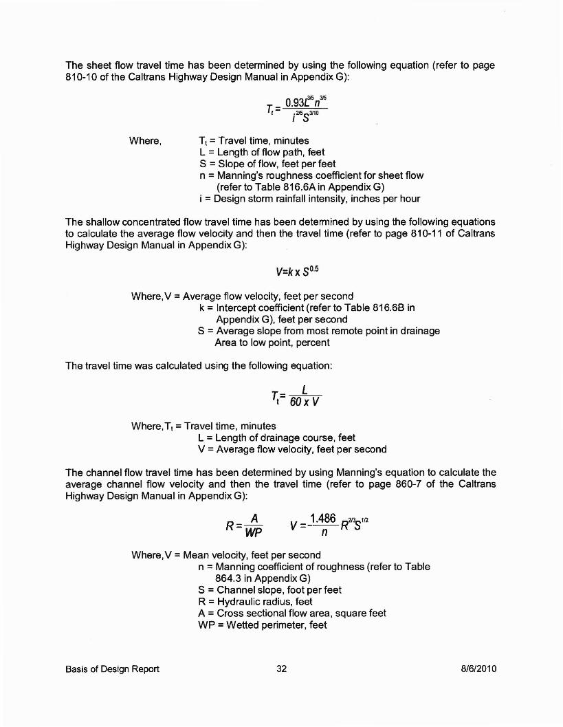
The sheet flow travel time has been determined by using the following equation (refer to page810-10 of the Caltrans Highway Design Manual in Appendix G):
Where, T1 =Travel time, minutesL =Length of flow path, feetS =Slope of flow, feet per feetn = Manning's roughness coefficient for sheet flow
(refer to Table 816.6A in Appendix G)i =Design storm rainfall intensity, inches per hour
The shallow concentrated flow travel time has been determined by using the following equationsto calculate the average flow velocity and then the travel time (refer to page 810-11 of CaltransHighway Design Manual in Appendix G):
V=kx 5°·5
Where, V =Average flow velocity, feet per secondk =Intercept coefficient (refer to Table 816.68 in
Appendix G), feet per secondS =Average slope from most remote point in drainage
Area to low point, percent
The travel time was calculated using the following equation:
T- Lt- 60 x V
Where,T1 =Travel time, minutesL =Length of drainage course, feetV =Average flow velocity, feet per second
The channel flow travel time has been determined by using Manning's equation to calculate theaverage channel flow velocity and then the travel time (refer to page 860-7 of the CaltransHighway Design Manual in Appendix G):
AR=Wp
Where, V =Mean velocity, feet per secondn =Manning coefficient of roughness (refer to Table
864.3 in Appendix G)S =Channel slope, foot per feetR =Hydraulic radius, feetA =Cross sectional flow area, square feetWP =Wetted perimeter, feet
Basis of Design Report 32 8/6/2010

The travel time was calculated using the following equation:
vrr=T
Where,Tt = Travel time, secondsV =Mean velocity, feet per secondL =Channel length, feet
IntensityThe rainfall intensity (I) for each storm frequency of interest was determined using the IntensityDuration-Frequency Chart from Imperial County (refer to Appendix G).
Flow Rate CalculationsFlow rates were calculated using the Rational Method as required by the Caltrans HighwayDesign Manual. The pre- and post-project flow rates will remain the same due to no changes inimpervious areas throughout the project or changes in natural drainage courses. The flow ratesdetermined by this analysis were used to provide dip section and culvert sizes.
GENERAL HYDRAULIC MODELING METHODOLOGY
Proposed drainage improvements are coordinated based on the results of the hydrologicanalysis described previously. Once 100-year peak discharge is determined, dip section andculvert sizing is performed.
Culvert DesignUsing Manning's Equation, culvert pipe diameters were determined given discharge, Manning'sn-value, and pipe slope. Based on information collected from the hydrologic modeling, the pipediameters were determined. An n-value of 0.013 was utilized for all corrugated metal (CMP) fullyasphalt lined pipes. The culvert sizing nomographs found in Figures 4-3 and 4-4 of the Countyof San Diego's Drainage Design Manual, located in Appendix H, were used to determine theheadwater depth of each culvert based on both inlet and outlet controlled conditions. Pipevelocities were determined using Bentley FlowMaster computer software, which utilizesManning's equation to determine the pipe velocities.
Dip Section DesignUsing Manning's Equation, dip section lengths were determined given discharge, Manning's nvalue, and longitudinal slopes along proposed roadways. An n-value of 0.033 was used for alldip sections. The normal depth, critical depth, and velocity of flow for each dip section has beendetermined using Bentley FlowMaster computer software to ensure that the runoff is safelyconveyed through each dip section (refer to SDG&E Detail Sheet DR-2 in Appendix H).
BRIDGE MODELING HYDRAULIC METHODOLOGY
The water surface at the bridge was determined using the HEC-RAS computer software. Userdefined cross sections were determined based on the ground topography and set at appropriatelocations in accordance with the HEC-RAS User's Manual (Hydraulic Reference Manual).
Basis of Design Report 33 8/6/2010
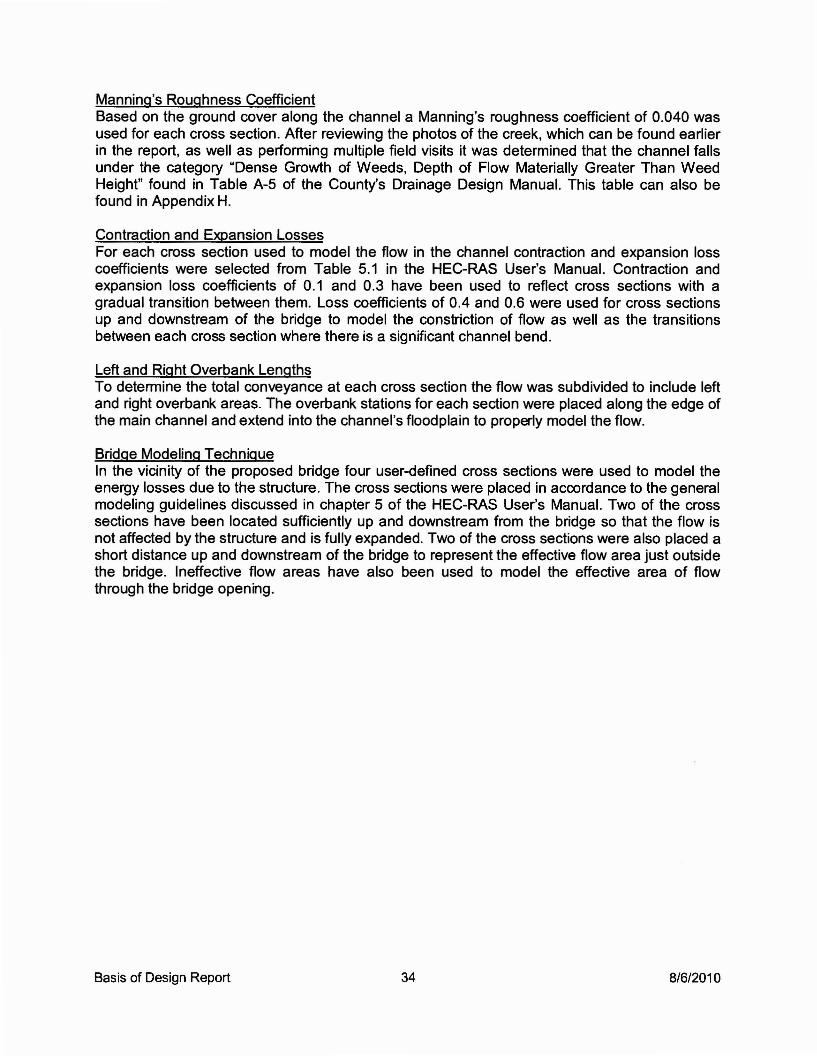
Manning's Roughness CoefficientBased on the ground cover along the channel a Manning's roughness coefficient of 0.040 wasused for each cross section. After reviewing the photos of the creek, which can be found earlierin the report, as well as performing multiple field visits it was determined that the channel fallsunder the category "Dense Growth of Weeds, Depth of Flow Materially Greater Than WeedHeight" found in Table A-5 of the County's Drainage Design Manual. This table can also befound in Appendix H.
Contraction and Expansion LossesFor each cross section used to model the flow in the channel contraction and expansion losscoefficients were selected from Table 5.1 in the HEC-RAS User's Manual. Contraction andexpansion loss coefficients of 0.1 and 0.3 have been used to reflect cross sections with agradual transition between them. Loss coefficients of 0.4 and 0.6 were used for cross sectionsup and downstream of the bridge to model the constriction of flow as well as the transitionsbetween each cross section where there is a significant channel bend.
Left and Right Overbank LengthsTo determine the total conveyance at each cross section the flow was subdivided to include leftand right overbank areas. The overbank stations for each section were placed along the edge ofthe main channel and extend into the channel's floodplain to properly model the flow.
Bridge Modeling TechniqueIn the vicinity of the proposed bridge four user-defined cross sections were used to model theenergy losses due to the structure. The cross sections were placed in accordance to the generalmodeling guidelines discussed in chapter 5 of the HEC-RAS User's Manual. Two of the crosssections have been located sufficiently up and downstream from the bridge so that the flow isnot affected by the structure and is fully expanded. Two of the cross sections were also placed ashort distance up and downstream of the bridge to represent the effective flow area just outsidethe bridge. Ineffective flow areas have also been used to model the effective area of flowthrough the bridge opening.
Basis of Design Report 34 8/6/2010

Table 4Sunrise Powerlink Plan Checklist
SEGMENT: BVNAJOB#: 16919 DESIGNER DATE: _
50% 90% Final CommentsCheck Check Check
I. ALL SHEETS ---A. Use standard SDG&E title block and update
each sheet appropriately.
B. Clearly designate between existingconditions and INOrk proposed.
C. Consistently use Sunrise CADD standards,labels & layers
D. Use drawing setting and drafting techniqueswhich allows for proper display in PDFformat, Le., "send to back" grid, "send tofront" text in profiles.
II. TYPICAL DETAILS -- -- -
A. Fill slopes and slope benching - slope,labels, minimax
B. Cut slopes - slope, labels, minimax
C. Pad berm - dimensions, min height
D. Retaining walls - geosynthetic, masonry, etc
E. Road section - min width, cross slope, labels
F. Dip section or water bar - width, spacing
G. Drainage ditch - depth, width, minimaxslope, concrete strength
H. Culverts - size, material, % min slope
I. Temporary erosion control (if required otherthan notes)
J. Energy dissipator - rock size, depth, area,minimax
Basis of Design Report 35 8/6/2010

K. Down drain - width, rebar, anchors,construct. notes
L. Pad drainage layout - flow arrows, swale,energy dissipator, down drain, max/mingrade
III. SITE PLAN --- --- ---A. Tower number
B. Earthwork quantities - cut & fill, difference,area of disturbance (pad, access road, &slopes)
C. Structure number, type, angle, height
D. Horizontal control and benchmarks
E. Vertical and horizontal scales on profiles andcross sections (same as site plan)
F. Contour elevations (existing & proposed -label major contours)
G. North Arrow and scale
H. Right-of-way/easements lines (Width ofeasements and Assessor Parcel Numbers(APN))
I. Joining and termination of/to existingroads/pads (feather grade)
J. Location of point data (number on table,coordinates & finish surface elevation,existing ground elevation, or flow lineelevation)
K. Location of sections (at locations that clarifydesign)
L. Section reference (Label sections A-A, B-B,C-C, etc., match direction ash shown inprofile)
M. Vertical curve location in profile view -Elevations shown (BVC, EVC, PI, K)
N. Road centerline stationing on plan
Basis of Design Report 36 8/6/2010

O. Berm and pad slope
P. Turnaround at road end or within 500' roadlength
Q. Culverts at low points/trapped drainage
R. Grading limits shown.
S. Label cutlfilliines.
T. Grade and flow line arrows shown on padand access roads.
U. Matchline and label sho'M1 to existing accessroads or other plan sheet
V. Flow line elevations
W. Label streams, dip sections, waterbars,ditches, and downdrains
X. Existing contours shown at 2' intervals andscreened to background; 50' beyondconstruction boundary.
Y. Riprap provided where drains discharge ontonatural ground.
Z. Retaining walls, drainage ditches, downdrains in plan view.
AA.TW / BW elevations along retaining walls onprofiles. (Note: BW is where wall joins pad ormeets existing ground)
BB.Karat symbol on slopes (cut is open karatand fill is solid karat)
III. EROSION CONTROL (NOTE: if required and --- --- ---cannot be covered by notes or details)
A. Provide appropriate facilities to eliminatesediment & debris.
B. Show all sediment control facilities:
1. Dikes shown
2. Fiber Rolls on slopes
Basis of Design Report 37 8/6/2010
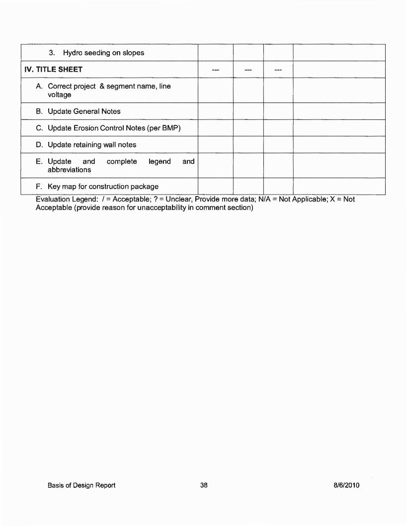
3. Hydro seeding on slopes
IV. TITLE SHEET -- --- ---
A. Correct project & segment name, linevoltage
B. Update General Notes
C. Update Erosion Control Notes (per BMP)
D. Update retaining wall notes
E. Update and complete legend andabbreviations
F. Key map for construction package
Evaluation Legend: / = Acceptable; ? = Unclear, Provide more data; N/A = Not Applicable; X = NotAcceptable (provide reason for unacceptability in comment section)
Basis of Design Report 38 8/6/2010

FIGURE 10· DEVIATION FROM STANDARD
Sunrise Powerlink230kV & SOOkV Access Roads & Maintenance Pads
DEVIATION FROM STANDARD
Date: _Line Segment _Location:-------1. Existing Conditions
Describe the existing conditions - grade, terrain, soil, access
2. Proposed Work and Non Standard Features
Describe work to be done - Tower, pole, access road, retaining wall, drainagefacility, etc. Describe the non-standard design element that requires the deviation.
3. Standard for Which the Deviation is Required
Specify the criteria and source.
4. Cost Impact
Show order of magnitude of cost to make design standard.
5. Justification for Requesting Exception
Be brief but thorough. Some possible reasons may include: high cost,environmental sensitivity, right-of-way limitations.
Approved:Bureau Veritas Date: _
SDG&E, Datt: _
Basis of Design Report 39 8/6/2010

Basis of Design Report
APPENDIX A
CADD S1ANDARDS
8/6/2010

BUREAU
SUNRISE POWERLINKPLAN PREPARATION
CADD STANDARDS
Prepared for:
San Diego Gas & Electric Company8316 Century Park, Bldg CP52G?San Diego, CA 92123-1548
Prepared by:
Bureau Veritas North America, Inc.11590 West Bernardo Court, Suite 100San Diego, CA 92717-1624
July 21, 2008

SUNRISE POWER LINK PLAN PREPARATIONComputer Aided Drafting & Design (CADD) Standardization
Table of Contents
A UTOCAD TEMPLATE (D W1) FILES 3
LDT PROJECT DIRECTORY and CADD FILE NAMES 4
Sample LDTProject Directory Names 4
Standard "DWG" Subdirectory Names 4
Sample CADD Drawing File Names ..•............••....•.........••....••...•............................................ 4
Sheet Drawing File Names 4
Xreference Plan Drawing File Names 5
Xreference Profile Drawing File Names 5
Sample LDT Alignment Names ....•.•.•.•..•.••.•••..•........•.•.....•....••......•..•....••...........••.••..••.••.....•... 5
Sample LDTSurface Names 5
Project CADD Symbols .•.......••..•..•........•......••.•...•....•..•.•...•...••....•..•........•..................•.••........•. 5
PAGE SETUPS and PLOTTING 6
AutoCAD Page Setups 6
AutoCAD Pen Tables ("CTB" Files) and Line Weights .•.••.•.••••••••••••.•.•••.••••••••••.•••••.•••.•••.•.•• 6
TEXT STyLES 6
LAYER NAMES......... 7
Sheet Drawing Layer Names .•..............••..•.•....•..•......•••...••......•.•.................•.•......................... 7
Sample Plan Drawing Layer Names 7
Sample Plan Drawing Layer Names (cont) ................•.....•..•................•........•.•.....••.•.....•....•• 7
Profde Drawing Layer Names •.•••••.••••.••.•.•••••.•••••••••••...••••••••••.•••••••••••.••••••••••..•••••••••.••••.••••••••• 8
Appendix "A" Project Symbols Library 14
Appendix "B" Civil-Struct.ctb Pen Weights Table Weights 15

AUTOCAD TEMPLATE (DWT) FILES
Below is a screen capture showing the LDT New Drawing dialogue box with the BVprofile current. When creating a new drawing, CADD Operators should select one of theappropriate "Drawing templates" from the field to automatically load the SDG&Estandard text styles, dimension styles, plotter/page setup and layer names & settings forthis project.
Important: CADD Operators should refrain from implementing any commands orroutines that "purge-all" unused layers, styles or linetypes without discriminating.
Note to CADD Operators Creating New Profile Drawings: Before creating a new"SDG&E profile" drawing, copy the file "P:\$SUPPORTlACADldwtISDG&Eprofile.djm" to the project's "dwg" directory and rename it "[new profile drawingname].djm"; click "OK" to overwrite the existing file.
x;
r.D'_N....LName: II
Project and Drawi'lg Location------,--------,---------.....,
Project Path: Ip:\16919 SDG&E SPL\CADD\ ::oJ Browse...
Project Name: I04A ::oJDrawing Path: I"""p-:\1-6....9-19-S-0-G-&...E-SP....L-\-CA-O.....O-\O-4A-\d-w-g\----3
Filter Project Lisl.. Project Detais... Create Projecl..
Preview-----------,
Cancel I Help:...---..:.--
Browse... I
OK
r Show sub-folders
Select Drawing template--------,
~ SPL Civil3d.dwl~SPL Plan.dwt~ SPL Profile.dwt::. SPL Sheet.dwt
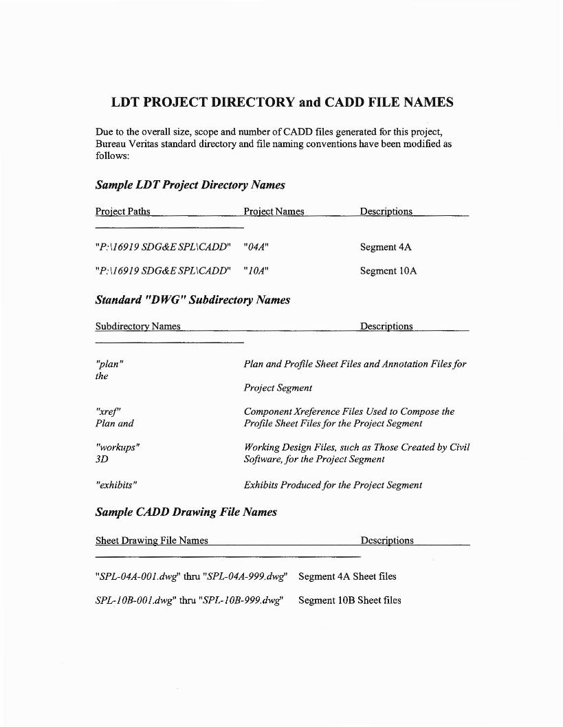
LDT PROJECT DIRECTORY and CADD FILE NAMES
Due to the overall size, scope and number ofCADD files generated for this project,Bureau Veritas standard directory and file naming conventions have been modified asfollows:
Sample LDTProject Directory Names
Project Paths Project Names
"P:116919 SDG&E SPLICADD" "04A"
"P:116919 SDG&E SPL ICADD" "lOA"
Standard "DWG" Subdirectory Names
Subdirectory Names
Descriptions
Segment4A
Segment lOA
Descriptions
"plan"the
"xref'Plan and
"workups"3D
"exhibits"
Plan and Profile Sheet Files and Annotation Files for
Project Segment
Component Xreference Files Used to Compose theProfile Sheet Files for the Project Segment
Working Design Files, such as Those Created by CivilSoftware, for the Project Segment
Exhibits Produced for the Project Segment
Sample CADD Drawing File Names
Sheet Drawing File Names Descriptions
"SPL-04A-OOl.dwg' thru "SPL-04A-999.dwg' Segment 4A Sheet files
SPL-lOB-OOl.dwg" thru "SPL-lOB-999.dwg' Segment lOB Sheet files
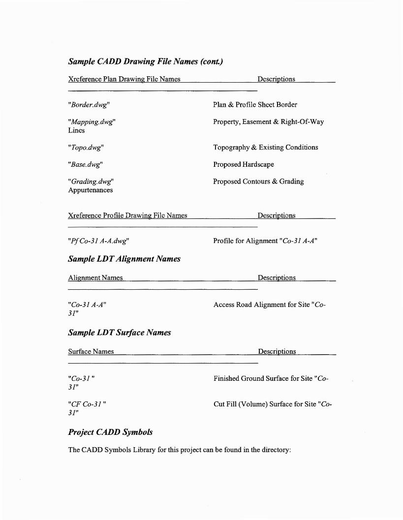
Sample CADD Drawing File Names (cont.)
Xreference Plan Drawing File Names Descriptions
"Border.dwg"
"Mapping.dwg"Lines
"Topo.dwg"
"Base.dwg"
"Grading. dwg'Appurtenances
Xreference Profile Drawing File Names
"PfCo-31 A-A.dwg"
Sample LDTAlignment Names
Alignment Names
"Co-31 A-A"31"
Sample LDT Surface Names
Surface Names
"Co-31 "31"
"CFCo-31 "31"
Project CADD Symbols
Plan & Profile Sheet Border
Property, Easement & Right-Of-Way
Topography & Existing Conditions
Proposed Hardscape
Proposed Contours & Grading
Descriptions
Profile for Alignment "Co-31 A-A"
Descriptions
Access Road Alignment for Site "Co-
Descriptions
Finished Ground Surface for Site "Co-
Cut Fill (Volume) Surface for Site "Co-
The CADD Symbols Library for this project can be found in the directory:

"P:I$SUPPORT\ACADIBLOCKSISPL Symbols Library"
A sheet plot of all the symbols in the library is attached as "Appendix 'A'" to thisdocument.
PAGE SETUPS and PLOTTING
AutoCAD Page Setups
Standard 24"x 36" plotter page setups, and the approximately half sized (11 "x 17")printer page setups, for the San Diego office load automatically when the AutoCADTemplate (dwt) drawings are used to create new drawing files.
AutoCAD Pen Tables ("CTB" Files) and Line Weights
The Client has instructed us to use the AutoCAD Pen Table (ctb) file "CIVILSTRUCT.ctb" when preparing and plotting the plan sheets for this project. This fileloads automatically with the aforementioned Page Setups. A table of sample line weightsis attached to this document and labeled "Appendix 'B"'.
TEXT STYLES
The following are the names of text styles (with their properties) that SDG&E hasinstructed us to use when preparing the plan sheets for this project. These text styles willload automatically when the AutoCAD Template (dwt) drawings are used to create newdrawing files.
Text Style Names and Appurtenant Information
Style Name Font File Plotted Height Application
SI simplex.shx 0.1" plan & profileannotations
ROMAND romand.shx 0.13" table headings;section titles
HM-LD hm-Id.shx 0.19" plan & profile titles

Note: All text styles shown above have a width factor of" I" and oblique angle of"OdO'O"". Title sheets, exhibits and other special drawings may use font files not listedabove.
LAYER NAMESLayers
Minimizing the number of layers and the simplification of layer naming in AutoCADdrawings is key to a successful project. Simplicity, without the loss ofutility, should bethe goal when deciding whether to, create a new layer or, use an existing layer already inthe drawing file.
Sheet Drawing Layer Names
Layer Name
$plan)
Text
Dim
Vport
Xref
Used for:
Designer's Notes and Construction Lines (not shown on
Annotation; Titles
Leader Lines
Viewport
Xreference Drawings
Sample Plan Drawing Layer Names
Layer Name
$plan)
Contour Major
Used for:
Designer's Notes and Construction Lines (not shown on
Major Contours
Sample Plan Drawing Layer Names (cont.)
Layer Name
Contour Minor
SlopeIndicators
Used for:
Minor Contours
Lines Delineating Tops and Toes of Slopes; Slope
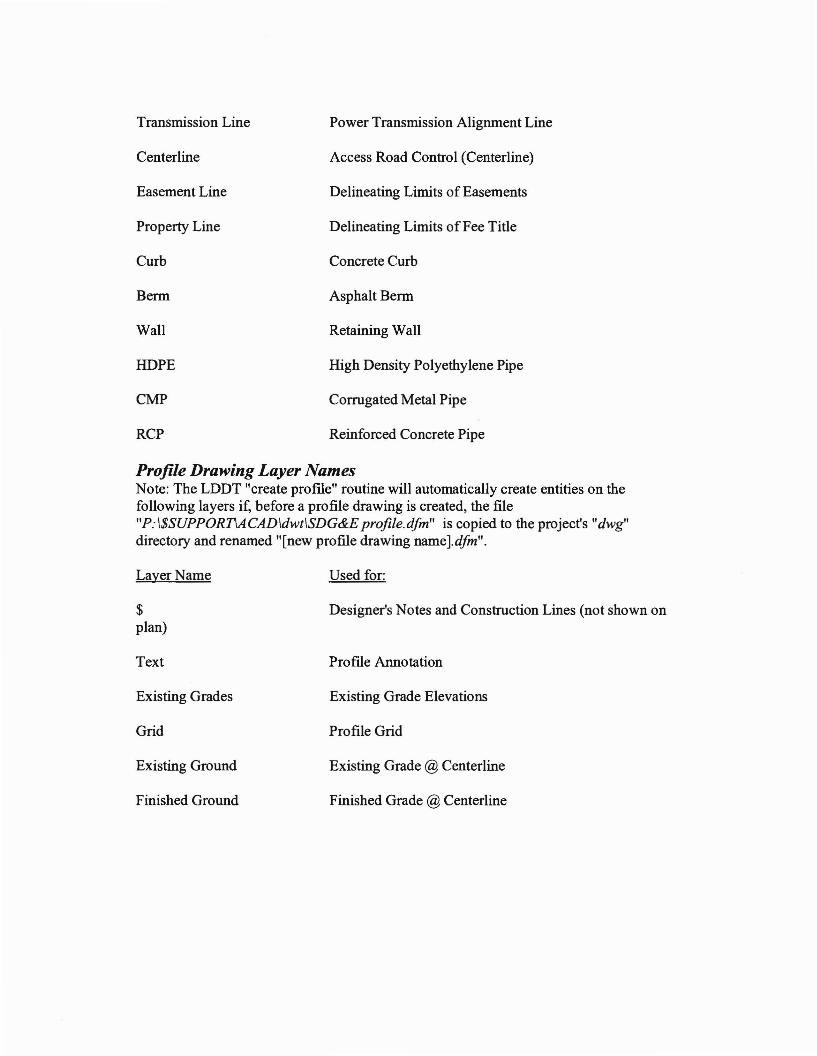
Transmission Line
Centerline
Easement Line
Property Line
Curb
Berm
Wall
HDPE
CMP
RCP
Power Transmission Alignment Line
Access Road Control (Centerline)
Delineating Limits of Easements
Delineating Limits ofFee Title
Concrete Curb
Asphalt Berm
Retaining Wall
High Density Polyethylene Pipe
Corrugated Metal Pipe
Reinforced Concrete Pipe
Profile Drawing Layer NamesNote: The LDDT "create profIle" routine will automatically create entities on thefollowing layers if, before a profile drawing is created, the fileliP: I$SUPPORTiACADldwtISDG&E profile.dfm" is copied to the project's "dwg"directory and renamed "[new profile drawing name].dfm".
Layer Name
$plan)
Text
Existing Grades
Grid
Existing Ground
Finished Ground
Used for:
Designer's Notes and Construction Lines (not shown on
Profile Annotation
Existing Grade Elevations
Profile Grid
Existing Grade @ Centerline
Finished Grade @ Centerline

Layers in the iibase.dwg" drawing
$ - This layer contains everything you do not want to plot such as construction lines,design notes, and 3D faces if you choose to use them.
o-This layer is automatically created by Land Desktop. There should be nothing on thislayer.
Centerline - The centerline for every access road is placed on this layer. It is correct thatlines drawn on this layer are yellow and continuous. Every road centerline should beplaced in the base drawing.
CMP - This layer is automatically created in any new drawing that is created with the"SPL Plan" template drawing. This layer has not been used yet in the project. Thereshould be nothing on this layer.
DCA_INFO - There should be nothing on this layer.
Defpoints - This layer is automatically created by Land Desktop. There should be nothingon this layer.
Down Drain - This layer is for the down drains coming offof the pads.
Easement Line - This layer indicates where SDG&E will be acquiring easements for theproject outside of their right of way. Up to this point in project SDG&E has no easementsso there should be nothing on this layer.
Fiber Roll - All fiber rolls should be drawn on this layer.
HOPE - This layer is automatically created in any new drawing that is created with the"SPL Plan" template drawing. This layer has not been used yet in the project. Thereshould be nothing on this layer.
Hydroseed - All outlines for hydroseed hatching should be drawn on this layer.
RCP - This layer is automatically created in any new drawing that is created with the"SPL Plan" template drawing. This layer has not been used yet in the project. Thereshould be nothing on this layer.
Rip Rap - All o~tlines for rip rap hatching as well as the hatching to indicate rip rapshould be drawn on this layer.
Transmission Line - This layer is for all proposed transmission lines.
Transmission Structure - This layer is for all proposed transmission poles and towers.

Wall - All retaining walls should be on this layer. The line work for a retaining wallshould first consist of three parallel lines drawn .5 units apart from each other as shownbelow:
The middle line will need to be a polyline so it can be changed into the thick, dashed linethat represents the wall. Through the properties dialogue box change the linetype ofthemiddle line to "HIDDEN2" and the global width to 1.00.
Xref - Nothing should be drawn on this layer.
Layers in the "grading.dwg" drawing
$ - This layer contains everything you do not want to plot such as construction lines,design notes, and 3D faces if you choose to use them.
a-This layer is automatically created by Land Desktop. There should be nothing on thislayer.
CMP - This layer is automatically created in any new drawing that is created with the"SPL Plan" template drawing. This layer has not been used yet in the project. Thereshould be nothing on this layer.
Contour Major - Proposed - All proposed major contours should be on this layer.
Contour Minor - Proposed - All proposed minor contours should be on this layer.
Daylight - All outside boundary lines where proposed grading meets the existing groundshould be on this layer and the interior boundary ofthe proposed grading around padsand proposed access roads should also be on this layer.
DCA_INFO - There should be nothing on this layer.
Defpoints - This layer is automatically created by Land Desktop. There should be nothingon this layer.
Fiber Roll - All fiber rolls should be drawn on this layer.
Flow Line - All flow lines should be drawn on this layer and they should all be located inthe grading file.
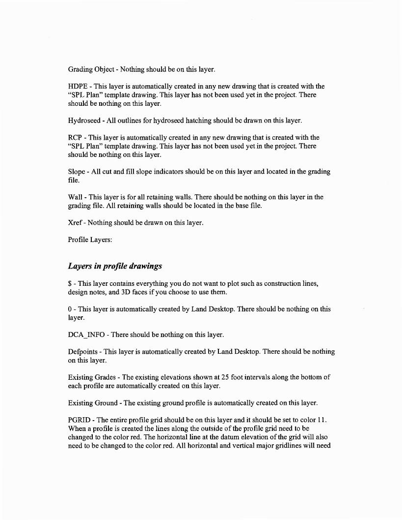
Grading Object - Nothing should be on this layer.
HDPE - This layer is automatically created in any new drawing that is created with the"SPL Plan" template drawing. This layer has not been used yet in the project. Thereshould be nothing on this layer.
Hydroseed - All outlines for hydroseed hatching should be drawn on this layer.
RCP - This layer is automatically created in any new drawing that is created with the"SPL Plan" template drawing. This layer has not been used yet in the project. Thereshould be nothing on this layer.
Slope - All cut and fill slope indicators should be on this layer and located in the gradingfile.
Wall - This layer is for all retaining walls. There should be nothing on this layer in thegrading file. All retaining walls should be located in the base file.
Xref - Nothing should be drawn on this layer.
Profile Layers:
Layers in profile drawings
$ - This layer contains everything you do not want to plot such as construction lines,design notes, and 3D faces if you choose to use them.
o-This layer is automatically created by Land Desktop. There should be nothing on thislayer.
DCA_INFO - There should be nothing on this layer.
Defpoints - This layer is automatically created by Land Desktop. There should be nothingon this layer.
Existing Grades - The existing elevations shown at 25 foot intervals along the bottom ofeach profile are automatically created on this layer.
Existing Ground - The existing ground profile is automatically created on this layer.
PGRID - The entire profile grid should be on this layer and it should be set to color II.When a profile is created the lines along the outside of the profile grid need to bechanged to the color red. The horizontal line at the datum elevation of the grid will alsoneed to be changed to the color red. All horizontal and vertical major gridlines will need
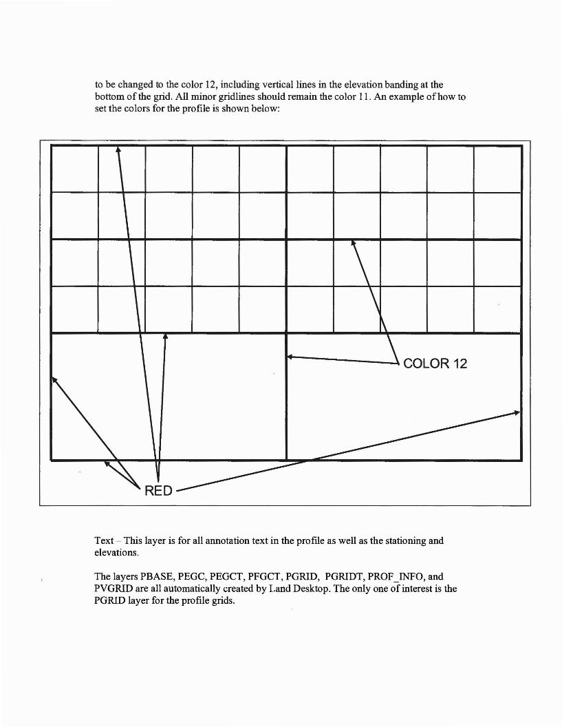
to be changed to the color 12, including vertical lines in the elevation banding at thebottom of the grid. All minor gridlines should remain the color 11. An example ofhow toset the colors for the profile is shown below:
4
\\~
~
\ COLOR 12-
----------~RED-------
Text - This layer is for all annotation text in the profIle as well as the stationing andelevations.
The layers PBASE, PEOC, PEOCT, PFOCT, PORID, PORIDT, PROF_INFO, andPVORID are all automatically created by Land Desktop. The only one of interest is thePORID layer for the profIle grids.

Layers in Ix or annotation drawings
$ - This layer contains everything you do not want to plot such as construction lines,design notes, and 3D faces if you choose to use them.
o-This layer is automatically created by Land Desktop. There should be nothing on thislayer.
CMP - This layer is automatically created in any new drawing that is created with the"SPL Plan" template drawing. This layer has not been used yet in the project. Thereshould be nothing on this layer.
Contour Major - Existing - There should be nothing on this layer.
Contour Minor - Existing - There should be nothing on this layer.
Contour Major - Proposed - There should be nothing on this layer.
Contour Minor - Proposed - There should be nothing on this layer.
DCA_INFO - There should be nothing on this layer.
Defpoints - This layer is automatically created by Land Desktop. There should be nothingon this layer.
Fiber Roll- There should be nothing on this layer.
HDPE - There should be nothing on this layer.
Hydroseed - There should be nothing on this layer.
RCP - There should be nothing on this layer.
Slope - There should be nothing on this layer.
Transmission Line - There should be nothing on this layer.
Transmission Structure - There should be nothing on this layer.
Wall- There should be nothing on this layer.
Xref - There should be nothing on this layer.

xLSection Indicator
Symbol=indicator section.dwg
---«
Cut Slope IndicatorSymbol=indicator cut slope.dwg
Fill Slope IndicatorSymbol=indicator fill slope.dwg
£MDt OIyDDCUT: .. tv.F'U: .. tv.
AIIEA: _ so. n.
Coordinate TableSymbol=table coordinate.dwg
North ArrowSymbol=label north.dwg
NOTE:
Co-xx HAS BEEN REMOVEDI-xx HAS BEEN REMOVED
NoteSymbol=label note.dwg
Structure Info TableSymbol=table coordinate.dwg
POLE x-xx PLANSCALE: I" = lClC'
Plan LobelSymbol=label plan.dwg
SECTION x-x
Section LobelSymbol=label section.dwg
Earthwork TableSymbol=table earthwork.dwg
POLE x-xx PROFILESCALE: I" = lClC'
Profile LobelSymbol=label profile.dwg
Coordinate Callout LobelSymbol=lobel coordinate callout.dw
BUREAU
VERITAS
11590 West Bemardo Court Suite 100San Diego. CA 92127-1624
Tel: (858) 451-6100 Fax: (858) 451-2846www.us.bureauveritas.com
SAN DIEGO GAS & ELECTRIC COMPANYSAN DIEGO. CAUFORNIA
SUNRISE POWER LINKSYMBOLS LIBRARY
APPENDIX "An
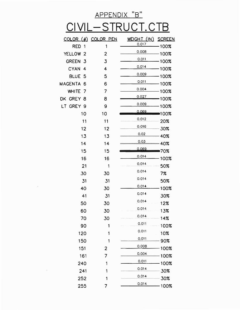
APPENDIX "B"
CI VI L- STRU CT. CTSCOLOR (N) COLOR PEN WEIGHT (IN) SCREEN
REO 1 10.017 100%
YELLOW 2 2 0.008 100%
GREEN 3 30.011 100%
CYAN 4 4 0.014 100%
BLUE 5 5 0.009 100%MAGENTA 6 6 0.011 100%
WHITE 7 7 0.004 100%OK GREY 8 8 0.027 100%
LT GREY 9 90.009 100%
10 10 0@9 100%11 11 0.012 20%
12 12 0.016 30%
13 13 0.02 40%14 14 0.03 40%
15 15 0099 70%
16 16 0.014 100%
21 10.014 50%
30 30 0.014 7%
31 31 0.014 50%
40 30 0.014 100%41 31 0.014 30%
50 30 0.014 12%
60 30 0.014 13%
70 30 0.014 -- 14%
90 10.011 100%
120 10.011 10%
150 10.011 90%
151 2 0.008 100%
161 7 0.004 100%
240 10.011 100%
241 10.014 30%
252 10.014 30%
255 7 0.014 100%
Basis of Design Report
APPENDIX B
CIVIL 3D GUIDELINES
8/6/2010
BUREAU
SUNRISE POWERLINKPLAN PREPARATION
Civil 3D Guidelines
Prepared for:
San Diego Gas & Electric Company8316 Century Park, Bldg CP52G?San Diego, CA 92123-1548
Prepared by:
Bureau Veritas North America, Inc.11590 West Bernardo Court, Suite 100San Diego, CA 92717-1624
March 17, 2009
Civil 3D Conventions
General:
• Create new drawing using the pre-set templates made for each segment.Templates are available at P:\$SUPPORT\ACAD\dwt c3d. Thesetemplates contain all the styles, corridors and settings needed for theproject.
• Use SDG&E File naming conventions per SUNRISE POWER LINKPLAN PREPARATION, Computer Aided Drafting & Design (CADD)Standardization
• Use workups folder for temporary, intermediate design, and recoverydrawings. Keep the design folder clean. Only design files which areXREFed (External Referenced) into the plan sheets should live in thisfolder.
• Place data short cuts in data short cut folder. Use default file name• XML files for SDG&E should be placed in an XML folder• When creating tables use the table style SPL-PNEZ. Tables are created
by clicking on the Points pull down menu and selecting "Add Tables". Theprimary table created for this project will include control points for the sitesuch as top of wall elevations, pad corners, begin of road centerlines etc.
Surface: (Also See Sites)
• When creating surfaces, place your initials and the date in the descriptionbox so that the designer and "age" of the surfaces can be identified. Thisis found in the dialogue box which appears when surfaces are created.
• Use SDG&E naming convention for the main surface (Le., 9C 215) whichcontains the pasted road and pad surfaces; and also for the cut fillsurface (CF 9C 215) which contains the cut fill lines for the main surface.
• For other surfaces use:o EX - for existing topographyo PAD - for pad grading onlyo Access A-A, Access B-B, etc.- for access roads
Profiles:
• Do not twist view in model space• Use SDG&E naming convention for profile• Use default profile view name• Use SPL Profile - for profile view style• Use SPL Band - for band set

Sites:
• Use only one site per design.• Use default site name.• Use default group name.
Corridors:
• Name corridors using the following format: Access 'section' such asAccess A-A, Access B-B etc.
Assembly:
• Use SPL 14 Road assembly which was provided by the template whenthe drawing was created.
• If you need to create additional assemblies, preface name with SPL, thenselected name (Le., SPL selected name).
XREFs:
• Bring in XREF drawings as an overlay with "relative path" not "full path"setting on the XREF layer.
Submittals:
• Submittals will be full size PDF format. Be sure the drawing order is asfollows:
o Existing features - sent to backo Proposed feature - bring to fronto Profile grids - sent to back
APPENDIX C
SDG&E CIVIUSTRUCTURAL ENGINEERING DESIGN & PROCEDURE
MANUAL FOR TRANSMISSION LINE ACCESS ROADS
Basis of Design Report 8/6/2010

Date: 5/18/07
.~~.. .'-.
SDG'...JEA~Sempra Energy'utility
SAN DIEGO GAS & ELECTRICCIVIUSTRUCTURAL ENGINEERING
DESIGN AND PROCEDURE MANUALFOR
TRANSMISSION LINE ACCESS ROADS
May 18, 2007
Prepared By: Con MarsalekCorinna l. MarsalekEngineer I, Civil/Structural Engineering
Reviewed By: ;:-1-, //1e?1"1<TIm MooreTeam Lead, Civil/Structural Engineering
Approved By: 0 C) Date: 7h ~ (; ?( ret Ball
anager, Transmission Construction and Maintenance
ApprovedBy5.~ 0",,": 1/.. S/oJSamuel J. arrisManager, CivillStructural Engineering

e.'
Section Content
Table of Contents
Page
1.0 Purpose _ 1
2.0 Reference Documents .
3.0 Inputs Required 2
4.0 Procedure and Coordination Requirements 2
4.1
4.2
4.3
4.4
4.51';'t
';.'~-)
4.6
4.7
4.8
Kickoff Meeting 3
Research .3
Reconnaissancc 4
50% Preliminary Design Submittal Requirements 5
90% Preliminary Design Submittal Requirements 5
Final Design Submittal Requirements 6
SpecificatioDS 6
Document Delivery 7
5.0 Design Criteria .7
5.1 Topographic Surveying, 8
5.2 Horizontal Alignment 8
5.3 Vertical Alignment 9
5.4 Grading Considerations l 0
5.5 Drainage Considcrations 10
5.6 Waterbars ll
6.0 General Drawings Requirements
6.1 General Notes 12
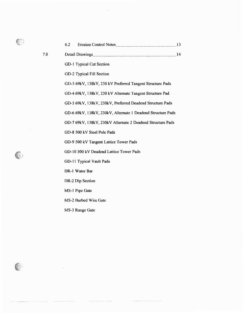
6.2 Erosion Control Notes 13
7.0 Detail Drawings 14
00-1 Typical Cut Seclion
GO-2 Typical Fill Section
OD-3 69kV, 138kV, 230 kV Preferred Tangent Structure Pads
GOA 69kV, 138kV, 230 kV Alternate Tangent Structure Pad
OD-5 69kV, 138kV, 230kV, Preferred Oeadend Structure Pads
OD-669kV, 138kV, 230kV, Alternate I Oeadend Structure Pads
OD-7 69kV, 138kV, 230kV Alternate 2 Oeadend Structure Pads
OD-8 500 kV Steel Pole Pads
OD-9 500 kV Tangent Lattice Tower Pads
GO-to 500 kV Deadend Lattice Tower Pads
GO-11 Typical Vault Pads
DR-] Water Bar
DR-2 Dip Section
MS-] Pipe Gate
MS-2 Barbed Wire Gate
MS-3 Range Gate
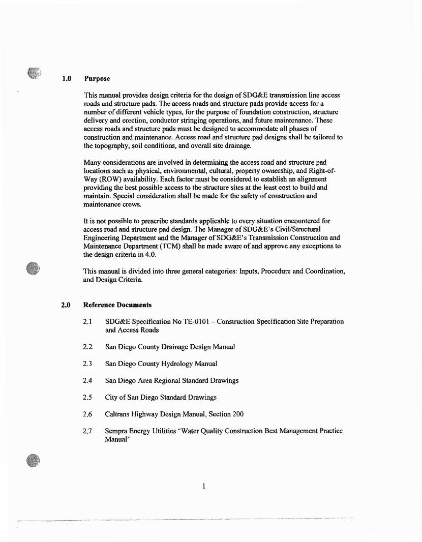
1.0 Purpose
This manual provides design criteria for the design ofSDG&E transmission line accessroads and structure pads. The access roads and structure pads provide access for anumber ofdifferent vehicle types, for the purpose of foundation construction, structuredelivery and erection, conductor stringing operations, and future maintenance. Theseaccess roads and structure pads must be designed to accommodate all phases ofconstruction and maintenance. Access road and structure pad designs shall be tailored tothe topography, soil conditions, and overall site drainage.
Many considerations are involved in determining the access road and structure padlocations such as physical, environmental, cultural, property ownership, and Right-ofWay (ROW) availability. Each factor must be considered to establish an alignmentproviding the best possible access to the structure sites at the least cost to build andmaintain. Special consideration shall be made for the safety of construction andmaintenance crews.
It is not possible to prescribe standards applicable to every situation encountered foraccess road and structure pad design. The Manager ofSDG&E's CiviVStructuralEngineering Department and the Manager ofSDG&E's Transmission Construction andMaintenance Department (TCM) shall be made aware of and approve any exceptions tothe design criteria in 4.0.
This manual is divided into three general categories: Inputs, Procedure and Coordination,and Design Criteria.
2.0 Reference Documents
2.1
2.2
2.3
2.4
2.5
2.6
2.7
SDG&E Specification No 'fE-OlOI - Constmction Specification Site Preparationand Access Roads
San Diego County Drainage Design Manual
San Diego County Hydrology Manual
San Diego Area Regional Standard Drawings
City of San Diego Standard Drawings
Caltrans Highway Design Manual, Section 200
Sempra Energy Utilities "Water Quality Construction Best Management PracticeManual"
------_..__......•. ", ~,. _._ " ~ __ _ _.._._...•_----.__.._---_._ ~ - _.._.._-_.-----'_.-..__ _ _ ,--_.' .._ .
~!' ')~ 2.8 California Regional Water Quality Control Board "Guidelines for Construction
Practices"
2.9 California State Water Resources Control Board's Construction Storm WaterGeneral NPDES Permit
2.10 Applicablc Municipal Ordinanccs (Counties, Cities, Special Districts)
3.0 Inputs Required
The following minimum inf<mnation is required to design access roads and structurepads. This infonnation will be provided by SDG&E to consultants pcrtolming this work.
3.1
3.2
3.3
3.4
;~') 3.5"'",.'
3.6
Coordinates of all structures including structure type (wood, steel, pole, tower,tangent, deadend, vault, vault size), height, and voltage level (see 4.2.1)
Available aerial photos and contours (sec 4.2.1)
Right of Entry permits (see 4.2.2)
Right of Way information (see 4.2.2)
Restrictions and limitations duc to environmental, archaeological, andpaleontological constraints (see 4.2.3)
Geotechnical information obtained by SDG&E at structure sites, including depthto groundwater, ifavailable
4.0 Procedure and Coordination Requirements
It is the responsibility of the SDG&E Project Manager to coordinate all responsibilitiesand project design activities between the involved parties. This is essential to avoidlocating roads or structure pads in sensitive areas, on property that is not available, or in amanner that is physically difficult to construct and/or use. Proper project coordinationwill keep the project design on track and avoid misunderstandings andmiscommunications that could rt.'Sult in inappropriate designs, project delays, costoverruns, and construction difficulties.
During the design process, the designer shall spend an ample amount of time in the fieldto become completely familiar with the terrain and existing conditions. Contact theSDG&E Project Manager assigned to the project to ensure permission, in the form of aRight-of-Entry (ROE) permit, is granted to access private property, and to ensuresensitive areas have been cleared by SDG&E Environmental Management for entry.
2

Outlined below is the design procedure to follow when developing a set of access roadand structure pad b1fading plans.
4.1 Kickoff Meeting
A project design kickolT meeting should be arranged by the SDG&E ProjectManager to discuss and define the project scope, establish design parameters andproject goals, and assign project responsibilities and action items. The proposedtransmission line and structure locations should be identified during or prior to thekickoff meeting.
4.2 Research
The following design input information shall be researched by appropriateSDG&E departments and made available to the designer. This information will beprovided by SDG&E to consultants performing this work.
4.2. I Transmission line location
• Coordinates and general information (see 3.1) of all structures fromTransmission Engineering and Design (l'E&D)
• Property owner maps and assessor parcel maps• Aerial photos and contour maps• USGS topographic maps for research purposes, if aerial photos and
contour maps are not available
4.2.2 Availability of Right-of-Way outside the transmission line Right-of-Wayprovided by SDG&E ROW agent
• Determination of whether prescriptive rights give SDG&E access toany roadway not covered by recorded easements.
• The attitude of property owners toward the project.• Determination of whether construction of access roads olltside the
transmission line easement is acceptable to the owner.• The degree ofdifficulty ofobtaining additional easements.
4.2.3 Environmental, Archaeological, and Paleontological provided bySDG&E's Environmental Management Department
An envirorunental report is typically started in the early stages of theproject. Therefore, preliminary road and structure pad locations need to beidentified using the constraints identified by the project environmentalgroup. The following items will be provided:
• Locations of sensitive biological or cultural areas
3
• Locations requiring reduced or minimal visibility from houses andhighways
• Locations of "no build" areas• Locations ofdrainage crossings
4.3 Reconnaissance
Site reconnaissance shall take place to familiarize the project team with theexisting conditions of the prospective sites and the surrounding areas. A site visitcan be performed by vehicle, helicopter, and/or foot after preliminary structurestaking is completed, ROE is obtained, and gencl""dl potential environmental issuesare identified. Representatives from the following shall attend the sitereconnaissance: Civil/Structural Engineering, Environmental Management, RealEstate and Land Services, TCM. TE&D, and consultants, if used. If the site visitis conducted a1\er researching available project information, feasible designscenarios can be pinpointed and unworkable design solutions eliminated.
The site visit also serves the purpose of verifying the accuracy and usefulness ofthe researched project information. During the course of the field visits, it may bedetermined that additional field data is required. This can be accomplished by theSDG&E Project Manager making a survey request and submitting it to theSDG&E Survey Department or submitting other data requests to applicabledepartments. If the design work is being performed by an outside consultant, theirin-house survey staffcould be utilized per the contract agreement. If additionalcontrol points or benchmarks are required, coordination with SDG&E's SurveyDepartment is required.
Site reconnaissance can provide information and design direction for thefollowing:
4.3.1 Identifying existing access that can be utilized to structure sites anddetermining additional access or modifications that may be required.
4.3.2 Terrain, gcotechnical~ and hydrological issues and constraints for accessroads and structure pads.
4.3.3 Environmental/archcologicallpalentological issues and constraints.
4.3.4 Construction issues due to the existing or required casements (A SDG&ERight-of-Way agents should be involved in property and easement issues).
4.3.5 Photographic information taken during the site visit can be used torhistorical records, required public hearings, and as a reference for designwork.
4

, ~·l
;''{4.4 50% Preliminary Design Submittal Requirements
4.4.1 Detennine the best possible scale for the appropriate level ofdetail. Thedrawings shall clearly depict the scope ofwork required including cut andfill slopes.
4.4.2 Using most recent survey data, plot structure locations and structurenumbers, transmission line ROW, property lines, and existing locations.USGS and SDG&E GIS can be used if aerial photography and contoursare not available in sufficient time.
4.4.3 [dentify which existing roads may be used for access. Identify anyimprovements required.
4.4.4 Identify limitation areas of special consideration (environmentallysensitive areas, cultural sites, and areas of no or limited access) if any.
4.4.5 Layout the proposed access roads and structure pads, including squarefootage of disturbance. Identify if it is not possible to keep within theboundary of the transmission line ROW while maintaining minimumdesign standards. Show locations ofproposed retaining walls and otherstructures.
4.4.6 Show locations and types of major water crossings such as dip sections,culverts. etc. Show preliminary access road drainage flow directionincluding type and location of flow control devices (waterbars and energydissipators, downdrains, diversionary structures, etc.).
4.4.7 Include notes on the Drawings to supplement the Specifications (see 4.7and 6.1.1)
4.4.8 Drawings and Specifications shall be submitted to the SDG&E ProjectManager to distribute to project team members for re,,;ew.
4.5 90% Preliminary Design Submittal Requirements
4.5.1 Revise the drawings to reflect any changes to the road and structure paddesigns based on input from all appropriate departments and otherconsultants.
4.5.2 Show profiles, sections, area ofdisturbance, grading quantities. northarrow, scales, and a horizontal control table for all roads and structurepads.
5
......................_.._ _ _ _._--_ --_.--_ __ - ..-._-_. ---

4.5.3 Show location and provide design calculations and detail drawings forculverts, drainage pipes, energy dissipators, retaining walls, stabilizedslopes, and other design features.
4.5.4 Show vicinity map, legend, and general and erosion control notes.
4.5.5 Show location and detail drawings tor waterbars (see Detail Drawing DR2), gates (see Detail Drawings MS-I - MS-J), and all other drainage andconstruction items.
4.5.6 Prepare preliminary co~1 estimate.
4.5.7 Drawings and Specifications (see 4.7 and 6.1.1) shall be submitted to theSDG&E Projcct Manager to distribute to pr~ject tcam members forreview.
4.6 Final Design Submittal Requirements
4.6.1 Revise the drawings and Specifications to reflect any changes to the roadand structure pad designs based on input from SDG&E and consultants.
4.6.2 Finali7.-C grading quantities and construction cost estimate. Care shall betaken to include costs associated \,ith overexcavation, bulking orshrinkage of soils, pumping, geotechnical investigation, geotechnicalmonitoring, construction surveying, construction management, drainagestructures, earth retaining structures etc.
4.6.3 List ofaccess roads structures and other construction strllctures and theirGIS location that require post-construction maintenance (culverts,retaining walls, rip rap, etc.).
4.6.4 Stamped final design drawings, detail drawings, specifications, and costestimates shall be submitted to SDG&E's Civil/Structural EngineeringManager and the Project Manager (See 4.8).
4.7 Specifications
If necessary prepare and submit construction specifications with 50%, 90%, andtinal submittals (sec 4.4, 4.5, 4.6, and 6.1.1). SDG&E Specifi.calion TE-OI01"Construction Specification - Site Preparation and Access Roads" shall beincluded by reference (see 6.1.1). TE-OIOI shall be supplemented by anyadditional or revised items as necessary to describe all materials and constructionrequirements not included in TE-O101.
6
4.8 Document Delivery
Upon completion ofthe fmal design, specifications, and cost estimate, documentsfor agency permitting and Contractor bidding shall be delivered to the SDG&EProject Manager in both electronic and hard copy formats.
4.8.1 Electronic files and format shall be as follows:
• All drawing files shall be in AutoCAD (2004 or newcr), LandDevelopment Desktop (LDD), and/or Civil 3D, as approved by theSDG&E CiviVStructurai Engineering Representative.
• All LDD and Civil 3D project mes shall include horizontal andvertical alignments, digital tcrrain tiles, poitits files, etc.
• All text document files shall be in Microsoft Word 2000 or ncwer.
• Spreadsheet documents shall be in Microsoft Excel 2000 or newer.
4.8.2 Typical hard copy deliverables include:
• Reproducible plans shall be on vellum
• Hardcopy sets per SDG&E Project Manager's request
• Geotechnical reports
• Hydrology studies
• Structural calculations
• Construction specifications
• Cost estimates
5.0 Design Criteria
Many ofSDG&E's transmission lines are located in rural areas, requiring construction ofaccess roads in natural, rolling, mountainous, rocky, or desert terrain.
SDG&E uses a number of different structures to support transmission lines (overhead andunderground). '[bey consist of, but are not limited to, wood poles, steel poles, H-framestructures, lattice towers, and underground vaults. Each type of structure requires afoundation ofnative soil, gravel backfill, cement slurry, or cast in place concrete. Eachfoundation is individually excavated either by hand or powered equipment; therefore the
7
----_._..---......-._----_.....----...---_.--..--.-.. ......-..__ . -~ .._ __.•.- _---"."." _--_ ---_._ -_ --_ __ .

access roads and structure pads must accommodate a wide variety of heavy constructionvehicles. Each type of structure also requires different maintenance methods; thereforedi flerent access road and structure pad requirements.
This section contains design criteria for the design of access roads and structure pads interms of horizontal alignment, vertical alignment, grading considerations, and drainagerequirements. Variance from these guidelines shall have approval ofSDG&E'sCivil/Structural Engineering Manager and the TCM Manager. Specific state, county,and/or city requirements for grading shall be researched. The more stringent requirementshall be followed.
5.J Topographic Surveying
Prior to any design work, a topographic survey shall be performed with two (2)foot contours. The limits of the topographic survey shall extend to at least 100feet beyond the limits of the transmission ROW. Extensions beyond 100 feet maybe necessary where geological or hydrological features potentially affect thedesign. For larger projects, where it may not be practical or cost etlectivc tosurvey from the ground, an aerial topography shall be tlown. Orthographic photosshall also be taken in conjunction with the aerial topography. All orthographicphotos shall have a minimwn resolution of 1 pixel equals 0.25 feet.
For critical work and areas where the aerial topography is inaccurate, a groundtopographic survey shall also be performt.>d. At this time Lidar surveyingtechnology shall not be used tor access road and structure pad design.
5.2 Horizontal Alignment
It is preferred to construct roads along the same route as the transmission linethereby increasing the accessibility to each tower, decreasing additional ROWcosts, and decreasing the total disturbed area. Typically the horizontal alignmentis established by the terrain and the location ofmajor drainages. In steep and hillyterrain the roads may meander in and out of the transmission ROW in order tocontorm to maximum vertical grades as outlined in 5.3. [faccess roads orstructure pads need to be located outside of the transmission ROW, additionaleasements requirements shall be addressed. The access roads and structure padsshall also be designed and located to minimize the major drainage and streamcrossings and the proximity to drainages and streams. It shall be brought to theattention ofTE&D if structures or structure pads are located in or ncar drainage orstrcam crossings. TE&D will detcrmine if the structure can be moved to avoid orminimize the impact to the drainage or stream crossing.
Roads shall have maximum cross slope of 4%. Structure pads shall have amaximum cross slope of 2%. Roads shall be sloped horizontally to affect sheetflow runoff to the downslope side away trom interior slope wall wheneverpractical.
8

Existing access roads shall be utilized wherever possible to reduce constructioncosts, unless other mitigation costs and/or environmental factors preclude theirusc. All curves shall have a radius of curvature of not less than 75 teet, measuredat the centerline of the usable road surface. The minimum usable width of allaccess roads shall be 14 feet and shall be increased on curves by the distanceshown in Table 5.2 in order to accommodate tracking by longer vehicles.
T bl 5 2 Add' . I R d W'd h Ra e .. ItlOna oa 1 t eqwrcmentsRadius ofCurvature Additional Road Width
75-100' 6'101-150' 5'151-200' 4'201-400' 3'Over 400' 2'
Dead-end stub roads over 500 feet in length shaH be provided with a Y-type orcircle type turnaround whenever possible. Turnarounds shall be located to avoidclose proximity to drainages and steep slopes whenever possible. When notpossible, additional consideration shall be given to pennanent erosion andsediment controls.
Structure pads shall be designed to prevent runoff directly towards a structure,onto a fill slope, or towards a retaining structure. Properly sized riprap energydissipators or other required stonn water control structures shall be specified atthe location the water exits the structure pad if necessary.
Structure pads shall be in accordance with attached drawings OD-4 through GD6. If it is impractical to meet these minimum requirements, the largest pads thatcan be practically constructed shall be designed. SDO&E's Civil StructuralEngineering Manager and TCM Manager will determine if such reduced sizes areacceptable. If construction ofan access road and structure pad is impractical, thesite may be designated as a helicopter construction site by SDG&E CivilStructural Engineering Manager and TCM Manager.
5.3 Vertical Alignment
The maximum grade tor continuous access road lengths is 12%.
Grades of 12% to 20% shall be limited to a length of250' maximum.
Where alternate routes for access roads allow similar access to structure pads, therouting that minimizes the percent grade and drainage crossings shall bepreferred. When percent grade is within acceptable limits, minimization ofdrainage crossings is then preterred.
9
-_._._~-,-------~-p"-_.,'--~-"",,,---------"'----''''~''-
Typically, vertical curves arc not necessary in the design and construction ofaccess roads. However, where grade breaks over 6% occur, the resulting profileshall be evaluated against intended vehicle use to ensure that high centering andtail dragging conditions do not exist.
Adequate stopping sight distance shall be provided at alt intersections with otherroadways, public or private. Site distance shall be based on roadwayclassification, use, and speed of vehicles on the intersecting roadway (applies tovertical and horizontal alignment). Comply with Caltrans Highway DesignManual, Section 200, tor adequate stopping sight distance.
Where access roads intersect paved city or country roads or highways, the designshall minimize vehicle tracking of mud or sediment onto the paved surface.
5.4 Grading Considerations
Grading requirements are given by reference to TE·OIOI and any supplementalrequirements (see 4.7 and 6.1.1)
Existing roads shall be utilized to the greatest extent possible to reduceconstruction costs and construction time. Whether grading new roads orretrofitting existing roads, profiles shall be designed to balance cut/fill earthworkwithin each roadway section whenever possible.
Cut slopes shall be minimum 2: I in soils (see Detail Drawing GD-l). lfthegeotechnical investigation shows solid rock, a minimum Y2: I cut slope shall bepermitted. Care shall be taken to specify solid rock slopes on the drawings. Fillslopes shall be n minimum 2: 1. Fill slopes shall require keys when the naturalslopes are steeper than 6 horizontal to 1 vertical (see Detail Drawing GD-2). Ageotechnical investigation shall be performed to determine the depth of the key.Applicable slope erosion and sediment control requirements shall be incorporatedinto the design when necessary. Designs shall accommodate vegetation of allslopes, except those designated as rock slopes.
Local grading ordinances shall be followed if stricter than tht:se requirements.
5.5 Drainage Considerations
The general principal of drainage design for access roads is that runotf shall beconveyed over, under, or along the roadway without rotting or causing erosion.There shall be no diversion from the historic runoff. Access road and structurepad designs shall consider minimi7.ation of channelized flow of stonn water andemphasize sheetflow runoff whenev(."( possible.
10
---_ . ....._._._-------_ --_ _---- -._ _._--- ~.._.---__--- ------

Where it is not possible to avoid major drainage or stream crossings or tominimize proximity to drainages Qr streams, additional permanent erosion andsedimentation controls shall be designed.
Applicable State Water Resources Control Board General Construction StonnWater Pennit and Municipal Storm Water Ordinance requirements shall beincorporated into the access road and structure pads slope designs. Theserequirements are concerning linear pre- and post-construction rlDlotTrequirements, and prohibitions or minimization ofconstruction hydromoditicationofdrainages and streams.
The San Diego County Hydrology Manual and the San Diego Count)' DrainageDesign Manual shall be used in detennining rainfall intensity, coefficient ofrunoff, pipe sizes, energy dissipator sizes, etc.
There are several accepted methods used to manage rainfall runoff including theconstruction ofdip sections (see Detail Drawing DR-2), culverts, downdrains,fords, geosynthetic materials, etc. Care shall be taken with each design tominimize impact to the drainage crossing. Performing work in crossings shall beavoided if possible due to the environmental permitting required. Designemphasis shall be placed on cost effective long term maintainability of the accessroads and structure pads. The San Diego Area Regional Standard Drawings andthe City of San Diego Standard Drawings shaH be utilized whenever possible.
5.6 Waterbars
If sheet flow offaccess roads is not practical, watcrbars shall be placed to preventthe buildup of runoff in a given length of roadway by conveying runoff to the sideof the roadway, through energy dissipating riprap at the road edge, and then into avegetated buffer area before entering a natural watercourse. Drainage flows fromwaterbars shall not be directed onto till slopes but onto natural, vegetated,undisturbed slopes or into brow ditches if necessary. Alternate methods may beimplemented where grainy, erosive soils make the required compaction difficultto obtain.
Each watcrbar shall have a continuous, finn berm of soil at least 6 inches abovethe nonnal road grade and parallel to the watcrbar cut, which is at lea..t 6 inchesbelow normal road grade (see Detail Drawing DR-I). Additionally, the ridge ofeach waterbar shall be maintained at an elevation at least 6 inches above theadjacent depression. All waterbars shall be open at the lower end to allow water todrain out easily. Energy dissipators shall be required at the open end of allwaterbars. The energy dissipator construction shall consist of rock, filter fabric,and in some cases an cnd sill. The exact requirements for the energy dissipatorsshall be determined on the basis of discharge velocity, volume, and slope ofterrain. All watcrbars shall be approximately 30 to 45 degrees to the transverse
II
____ _._•• •.....•............•.•._ .•__._•.••_._- .••__.••__••••••._'7"'

section of the road as shown in Detail DR-2. Waterhar spacing shall comply withTable 5.6
T bl 56 W b S Ra e .. ater ar ipacmg equrrementsAveraRe Road Grade (%) Maximum Waterhar Spacin2"
<5% 300 ft5% 125 ft.10% 75 ft.15% 60 ft.20% 50 ft._.25% 40 ft.
6.0 General Drawings Requirements
The following notes shall he included with all grading plans
6.1 General Notes
6.1.1 ••All work shall comply with Specification No. TE-O10I: ConstructionSpecification Site Preparation and Access Roads." If it is necessary torevise or add to TE~0101 to describe all materials and constructionrequirements not described in TE-OIOl, prepare a supplement(s) to TE0101 and revise this note to say: "All work shall comply withSpecification No. 'fE-OIOI: Construction Specification Site Preparationand Access Roads and the Supplements to TE-OIOl."
6.1.2 "Neither the owner nor the engineer of work will enforce safety measuresor regulations. The contractor shall design, construct, and maintain allsafety devices, including shoring. The contractor shall be responsible forconforming to aU local, state, and federal safety and health standards,laws, and regulations."
6.1.3 "Grdding shaJI be done within a tolerance of±0.1' of the grades andelevations shown on these plans and all slopes shall be constructed within±0.5' of the location shown on these plans. In no way shall the abovetolerances relieve the contractor of the responsibility of providing a finishsurface that shall not pond water."
6.1.4 "All areas to be graded shall be cleared and grubbed only within the areato be graded."
6.1.6 "The Contractor shall grade all excavated and filled surfaces to providepositive drainage and pre-vent ponding of water. The Contractor shallcontrol surface water to avoid damage to adjoining properties or to finishwork on the site. The Contractor shaH take remedial measures to prevent
12

6.1.6
6.1.7
erosion of freshly graded areas, and until such time as pennanent drainageand erosion control measures have been installed. After grading iscompleted and the Geotechnical Engineer has finished the observations ofthe work, no further excavation or filling shall be done, except under theobservation of the Geotechnical Engineer."
"Any quantities indicated on thl.'Se plans are engineer's estimates only andarc not to be used by contractor for bidding purposes."
"The Contractor shall verify existing conditions in the field and bringdiscrepancies to the attention of the SDG&E representative prior tostarting c-onstruction."
6.2 .:rosion Control Notes
6.2.1 "Tops of all fi II slopes to be diked to prevent water from flowing over thecrest. All roads and structure pads shall be constructed to prevent waterfrom causing erosion."
6.2.2 "It is the responsibility of the Contractor to hydroseed and install erosioncontrol blankets on all cut and till slopes. The seed mix will include nativeor drought tolerant plant species and will be specified by SDG&E."
6.2.3 "All cut and fill slopes shall be temporarily protected by continuouscertified weed~free rice wattles located at all locations where runoff fromexcavated or filled areas can occur, in accordance with the Sempra EnergyUtilities "Water Quality Construction Best Management PracticesManual." At a minimum, continuous fiber roils shall be placed along thetoe, top, face, and at grade breaks of exposed and erodible slopes tocomply with sheet flow requirements. Any extra clarification required canbe brought up in the pre-bid meeting and/or walk-down."
6.2.4 'The Contractor shall follow the Stonn Water Pollution Prevention Plan(SWPPP) in accordance with the California Water Resource ControlBoard General Construction Storm Water Permit and any local RegionalWater Quality Control Board (RWQCB) guidance or directives. Thecontractor is also responsible for implementing all required BMP's per theSWPPP, including, but not limited to, providing the necessary material,equipment, and trained personnel."
6.2.5 '·Hydroseeding slopes shall follow the recommendations of the projectbiologist as to the selection of species, seed specifications, mixture, timeof seeding, seeding method, and irrigation requirements."
6.2.6 "The Contractor shall provide the necessary material, equipment, andtrained personnel to provide the required vegetative cover and for the time
13
.J
7.0
periods as specified by the appropriate California Water Resource ControlBoard General Construction Storm Water Permit applicable to the projector projt.."Ct section and in effect at the time of construction.
Detail Drawings
The following drawings are provided as a general guideline.
14

EXIST. GRADE
---
PROPOSED SLOPE
-------_ - % SLOPE
SCARIFY 12" OF EXISTINGSURFACE AND RECOMPACTTO 90% RELATIVE DRYDENSITY
PREFERRED SECTION - SHEET FLOW
PROPOSED SLOPE
-SCARIFY 12" OF EXISTINGSURFACE AND RECOMPACTTO 90% RELATIVE DRYDENSITY
1--- --
ALTERNA TE SECTION
NOTES:
1. CUT SLOPES IN SOIL SHALL BE 2: 1 MAXIMUM UNLESS OTHERWISEAPPROVED BY SDG&E CIVIL/STRUCTURAL ENGINEERING MANAGER.
2. CUT SLOPES IN SOLID ROCK MAY 8E .12: 1 MAXIMUM.3. 4% MAXIMUM CROSS SLOPE FOR ROADS. 2% MAXIMUM CROSS
SLOPE FOR STRUCTURE PADS
TYPICAL CUT SECTIONS GD-1
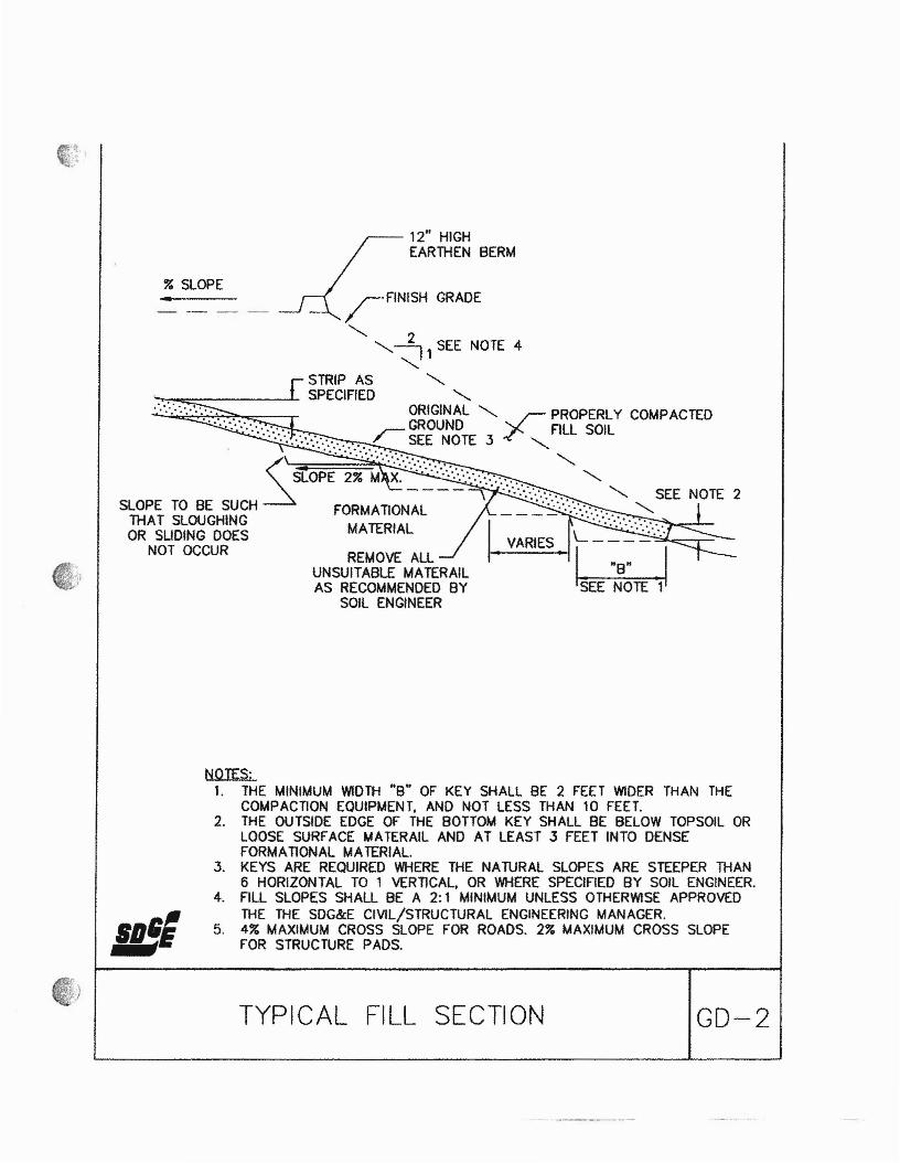
12" HIGHEARTHEN BERM
..% SLOPErFINISH GRADE
""-""-~ 1 SEE NOTE 4
""-""-
~-=::-- ...... SPECIFIED ""-.'..:.: ":'. . ORIGINAL ""- / PROPERLY COMPACTED
...................:.:.... '. '. ~ GROUND ..r '- FILL SOIL
. (\~;~:.'~~"~':~:'~~ ...:~~: ...:.. :. " " "~ - - - - "\ . ,'....:.:.: '" " SEE NOTE 2
SLOPE TO BE SUCH FORMATIONAL :.:........ "THAT SLOUGHING : c:-;."'>-::::....1-OR SLIDING DOES MATERIAL L _ ~.~. ".:-::"';,j.:'.o::--~:---
NOT OCCUR REMOVE ALL VARIES I. "B" .1UNSUITABLE MATERAIL . _ _ .AS RECOMMENDED BY SEE NOTE 1
SOIL ENGINEER
11J'~_rl!E
NOTES:1. THE MINIMUM WIDTH HS" OF KEY SHALL BE 2 FEET WIDER THAN THE
COMPACTION EOUIPMENT, AND NOT LESS THAN 10 FEET.2. THE OUTSIDE EDGE OF THE SOTTOM KEY SHALL 8E BELOW TOPSOIL OR
LOOSE SURFACE MATERAIL AND AT LEAST 3 fEET INTO DENSEfORMATIONAL MATERIAL.
3. KEYS ARE REQUIRED WHERE THE NAruRAL SLOPES ARE STEEPER THAN6 HORIZONTAL TO 1 VERTICAL, OR WHERE SPECifiED BY SOIL ENGINEER.
4. FILL SLOPES SHALL BE A 2: 1 MINIMUM UNLESS OTHERWISE APPROVEDTHE THE SDG&:E CIVIL/STRUCTURAL ENGINEERING MANAGER.
5. 4% MAXIMUM CROSS SLOPE FOR ROADS. 2% MAXIMUM CROSS SLOPEFOR STRUCTURE PADS.
TYPICAL FILL SECTION GD-2
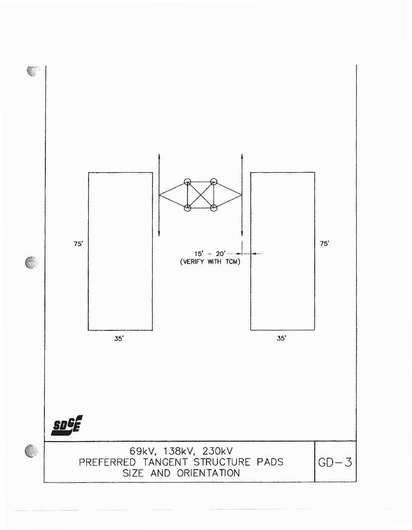
· ~.~
•. ~: r
')
75'
IS',
35'
I15' - 20' -_. --1-- -_...
(VERIFY WITH reM)
35'
75'
69kV, 138kV, 230kVPREFERRED TANGENT STRUCTURE PADS
SIZE AND ORIENTATIONGD-3

75'
50'
NOTE:FOR PREFERRED PAD SIZE AND ORIENTATION SEE GD-3
'.',.\ 69kV, 138kV, 230kV
ALTERNATE TANGENT STRUCTURE PADSIZE AND ORIENTATION
GD-4
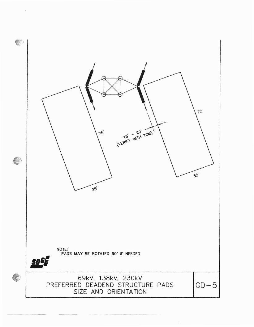
NOTE:PADS MAY BE ROTATED 90· If NEEDED
I lftl"_-.!E69kV, 138kV, 230kV
PREFERRED DEADEND STRUCTURE PADSSIZE AND ORIENTATION
GD-5

75'
/
THIS PAD MAYBE ROTATED90' IF NEEDED
i!II
15' - 20'-1--(VERIFY WI TH reM)
THIS PAD MAYBE ROTATED90' IF NEEDED
75'
S'll'~..--,"
35'
NOTES:1. THIS IS THE PREFERRED OPTION.2. PADS MAY BE ROTATED 90' IF NEEDED
35'
69kV, 138kV, 230kVALTERNATE 1 DEADEND STRUCTURE PADS GD-6
SIZE AND ORIENTATION
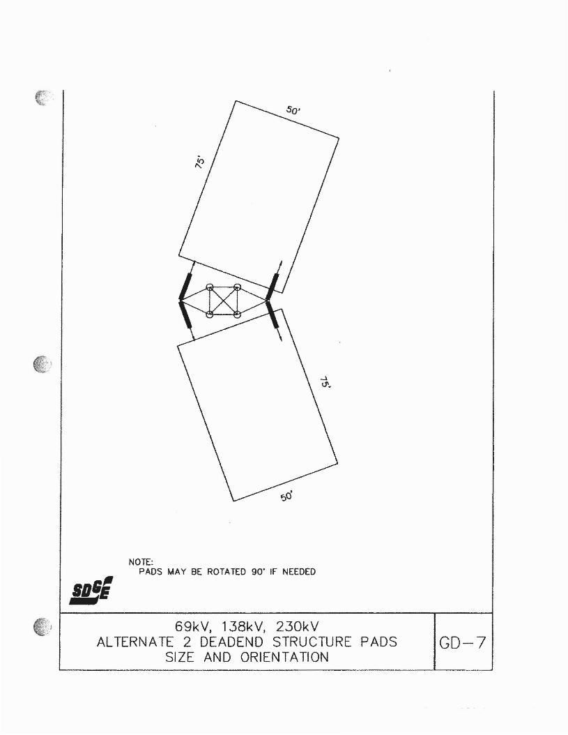
11('.'~
NOTE:PADS MAY BE ROTATED 90· IF NEEDED
jji"."69kV, 138kV, 230kV
ALTERNATE 2 DEADEND STRUCTURE PADSSIZE AND ORIENTATION
GD-7
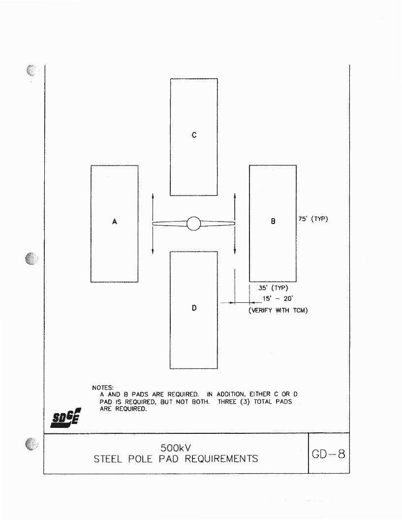
c
A 1 =0 1 8 75' (TYP)( ]
J Jft·,~.I:;. ~~,.;...
II 1~5' (TYP)I
.. I 15' - 20'
0 (VERIFY WITH rCM)
"'I''Y:'..'
NOTES:A AND B PADS ARE REQUIRED. IN ADDITION, EITHER C OR DPAD IS REQUIRED, BUT NOT BOTH. THREE (3) TOTAL PADSARE REQUIRED.
500kVSTEEL POLE PAD REQUIREMENTS GD-8

,.
~.
c o
A ~I I I
8 75'(TYP)
E F 11 35' (TYP)
-. --+--15' - 20'
(VERIFY WITH reM)
NOTE:A AND 8 PADS ARE REQUIRED. IN ADDITION, EITHER PAD C OR D OR EOR F IS REQUIRED. THREE (3) TOTAL PADS ARE REQUIRED.
500kVTANGENT LATTICE TOWER PAD
REQUIREMENTSGD-9

(It.'.....~
c o
A B 7S'(TYP)
E F
I ~5' (lYP)
--l-L: 15' - 20'(VERIFY WITH reM)
.'B_"
NOTES:A AND 8 PADS ARE REQUIRED. IN ADDITION, EITHER PAD C OR D, PLUSPAD E OR F ARE REQUIRED. FOUR (4) TOTAL PADS ARE REQUIRED.
500kVDEAD END LATTICE TOWER PAD
REQUIREMENTS0-10

50'1---- - ..----- -- -.-...
.....
Ill',
ACCESS ROAD~
V VAULT
--.iiIii~I
~I...... j
i
II
..-_----J __.__..t.
TYPICAL SECTION
TYPICAL VAULT SETTING PADSIZE AND ORIENTATION GD-11
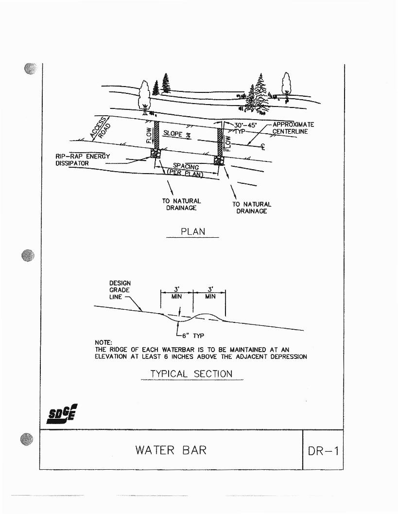
RIP-RAP ENERGYDISSIPATOR --
DESIGNGRADELINE
SPACING
\TO NATURAL
DRAINAGE
PLAN
\----\--TO NATURAL
DRAINAGE
NOTE:THE RIDGE OF EACH WATERBAR IS TO BE MAINTAINED AT ANELEVATION AT LEAST 6 INCHES ABOVE THE ADJACENT DEPRESSION
TYPICAL SECTION
.,/J_"
WATER BAR DR-1

------------
-----------PLAN
15' IJJN
EXlS"NGGRADE "-
- - __"L-_
BURY FABRIC ENOS /8-MJNIMUM~SlOE
,- CRUSHED AGGREGA TECAP 4- THICK
MA TCH EXIST GROUNDEACH SIDE
iILDiI'"t-- 12" MINUS ROCK, 18- THICK~--~a. OVER M/RAFJ 700X Ai TER FABRIC
SECTION A-A
EX/S"NGGRADE
,. DIP SEen: LENCIH ---j°,0 1 I
----~---- --------D ....,.
SECTION B-BAGGREGA TE AS NOlEDABOVE
IslftNOTE:THE MAX/MUlti WATER DEPTH, BASED ON A 10 YEAR FREQ(jENCY STORM,SHALL BE 10~ THE DEPTH (D) IN FEET MUL"PUED BY THE VELOCITY (V)IN FEET PER SECOND SHALL 8£ EQUAL TO SIX OR LEss. (OXV:=6)
DIP SECTION DR-2

4 1/2" 0.0.PIPE SLEEVE
14'
2 3/8" 0.0. SCHED 40PIPE FRAME
4" 0.0.GATE POST --..-I
4" 0.0.LATCH POST
3"
•tt')I~
R<0I
~.;Co ..t~
.oW
• .~.
€l 0:
...~ I~
NOTES1. FOOTINGS SHALL BE MINIMUM 3000 PSI CONCRETE
PIPE GATE MS-1
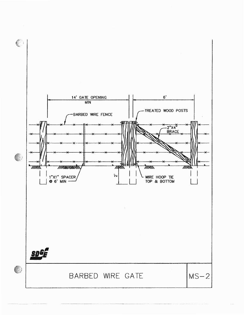
14' GATE OPENING 6'MIN
TREATED WOOD POSTS
I IU
WIRE HOOP TIETOP &: BOTTOM
BARBED WIRE FENCE
I 1 1"X'" SPACERU C 6' MIN
""BARBED WIRE GATE MS-2
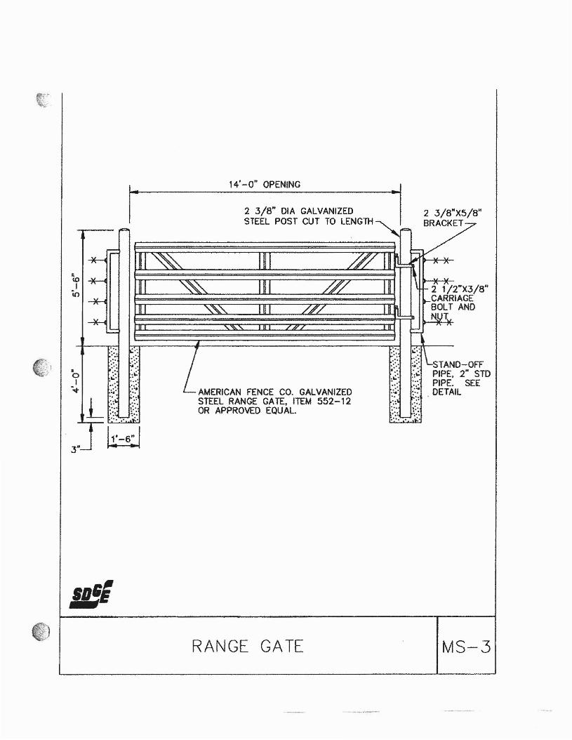
..coI
in
•oI-..,.
3"
14'-0" OPENING
2 3/8" DIA GALVANIZEDSTEEL POST CUT TO LENGTH
AMERICAN FENCE CO. GALVANIZEDSTEEL RANGE GATE. ITEM 552-12OR APPROVED EQUAL.
RANGE GATE
-.".,.. .:..:6. ~.:
.:~ ~.:.....
2 1/2"X3/8"CARRIAGEBOLT AND
T
STAND-OFFPIPE, 2" STDPIPE. SEEDETAIL
MS-3

Basis of Design Report
APPENDIX D
CONDOR MAINTENANCE VEHICLE
8/6/2010

TO
r' O
;
CALAVAR CORPORATION
\.
\
I
=3;0 x \00\ .Sb ,U&.,l;)..,NC,
••••••
~. iE·
.o.r,
93 It
140 ft
\I
/' -
I
II
I. ,
. -//ftm~5",
I . I ~
I 'I \CAlAVM AU. STEER \
83 FT lVRNNC DrAWETERF'ront Wheels- 28.5" Turnin9 AngleRcor Wh~ls- 11.2· Tl.Irning AngleWheelbose- 270 1/2 Inch
II
I·\
(
..-"---TOTAL. P.02
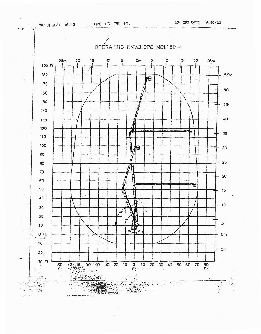
MAY-01-2e01 16:43 Tll'E I"FG. TRI<. MT. 254 399 0433 P. 02/03
, Jt ...' '.
/OPERA TING ENVELOPE MDl180-1
25m 20 15 10 5 Om 5 10 15 20 25m
30
50
S5m
25
20
15
10
5
Om
5m
t I J I I I I I IJ I J
, I I I I I
Vv re '",,-
/ '" -'-
/ i \/ II \ -'-
1 \ -'-
I /:... -'-
't;;2 --;
/,. --., il1 -f-
.. i 1=1~
. ~
1\ .-. .,. .. .'..
~. . /.- '. 'r ",'"!'-.'. --
\.
""wl,. y.0
\. / --. ,
K ~ jl'- /.. .. f'
"'- :-...... -"V
-I-
80
70
1.30
120
140
110
150
190 F
90
t60
100
170
160
40 :
20
30
60
50
Oft
10
20:•
....:"
.30 rt
.•.. ~~ :.:~ " \.
~~ rg.itl:~g~;;: ~~ ..~~ 30
.~:.:P·:~;~~~t.1~f1.:t~~;20 10 0 10 20 .30 40 50 SO 70 80
'~' n
.. :~:..
. '.'...:.,

2S4 399 0433 P. 133/103RtVlSlON
TIME MFG. TRK. MT.--
tr~ltr
(2701~{UJw
'1'-5' ~s-•••
• I")(%.$I) (.......) t'-CIIO}
sr...lt-ttL_I
;~.
'S-S'(r~
«."v,
... ~..;~:".
~o~~~~2)LlD21a) ~~s-12~1
FE6WRES/OPTlQNS .1. 1500 LoBS (680 KG) UNRESTRICTED CAPACITY2. INTERCHANGEABLE STEEL PLATFORM3. 180· PLATFORM ROTATION4. FRONT SWING OUT OUTRIGGERS5. RI:AR: DOuBLE: TELESCOPING OUTRIGGERS6. 24'" (61 CM) OUiRlGGER PENETRATION7. .360· CONTlNUOUS·ROTATlON•
.. 8. ~UMINUM'WHEELS.9. ALUMINUM"FENDERS
10, ;.36;,;X~.36~;·, oU~IGGER FLOATS11 ;:-:500KV.. ELECTRtCALL.Y' CERilF1ED
. ,....... (76~~~"OPTIbN.AV~LABLE)',2. OEClC'MOUNTED "ENGINE OPTION SHOWN.
~~~:\~~~~~1t$~{:' ,E:STlMATEO':wt:IGHTS: .FRONT - 45000"LBS.(204 OS KG)REAR - 50000 ,lBS:, (22678 KG)TOTAL - 95000 LaS (~POS6 KG)
..
Du.i'~~t;,eiL ~~ll.\~a..s "30 Mlj ::p=-........~, o....-.-~ ~~
G:t~......k SL.e'f6... ~ ~\' 'e:>~ ~c:.1pa. \"~ '-s. 0:.
REV•
C•' - 0l"" -;:'f-": ,·cw ,,/5.!W....-
. ~' CKCIU,,·:_:. ~-;.' , .. '. . ...• -. :.8.. ?~ ...~~ ....,.:_:..':.:~ ._-:"':':~ EJZOI "0.. -
~~ NO'Im:
~ 1/16 :ow:; ~~ @.}NlCU5 • ,. ;g •.03 .~~~~...;z @ r:::J,r;s% ~ ..otO r.:n=-l\.t=-----C-O-N-O-O-R-M..;.-.O-O-El..-·'-8-0---\-----;
~..-s-~ =3 12 X S TORQUE BOX CHASSIS
OTAL P.03
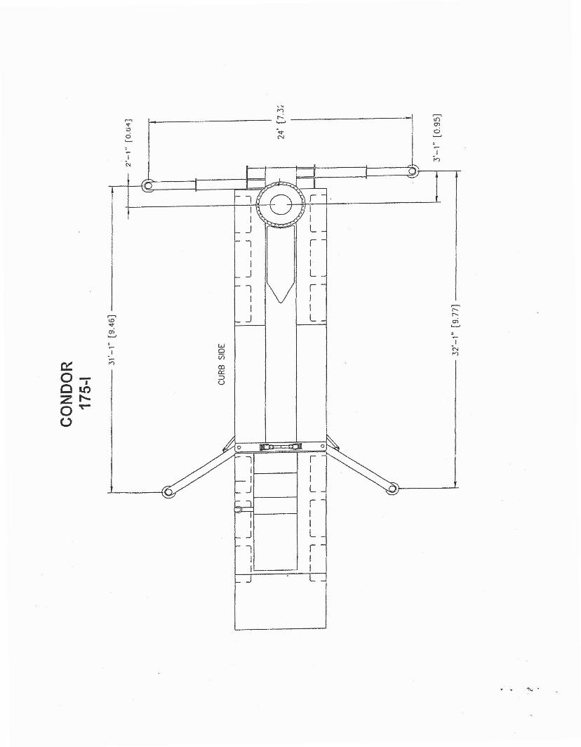
~ 0
IIIL
rI
I IJ L
l rI II I
J L
,~
n,....., r-.: .--.v '--'
U"l
toen
0-<:t C
....... N .........
:,
~
~
II
Nn
.----.<.D<:tC1l......,
~W
I 0
~;;)
ViCD
0a:::- :::>
C • <..)
10Z I"-0 ~
U
"'- .

.'
22'-e I 2"
'-
'- "
CONDORCONDOR MODEL 180-1
12 x 8 TORQUE BOX CHASSIS
FEATURES/OPTIONS
1. 1500 LBS (680 KG) UNRESTRICTED CAPACITY2. INTERCHANGEABLE STEEL PLATFORM3, 180' PLATFORM ROTATION4. FRONT SWING OUT OUTRIGGERS5. REAR DOUBLE TELESCOPING OUTRIGGERS6. 24" (61 CM) OUTRIGGER PENETRATION7. 360' CONTINUOUS ROTATION.8. ALUMINUM WHEELS.9. ALUMINUM FENDERS10. 36" x 36" OUTRIGGER FLOATS11. 500kV ELECTRICALLY CERTIFIED
(765KV OPTION AVAILABLE)12. DECK MOUNTED ENGINE OPTION SHOWN.
ESTIMATED WEIGHTS
FRONT - 45,000 LBS (20,408 KG)REAR - 50,000 LBS (22,678 KG)TOTAL - 95,000 LBS (43,086 KG)
'- "
'- "

~.
I ..~~
CDI
~

APPENDIX E
DRAFT SUNRISE POWERLINK EIRIEIS MITIGATIONDESIGN STANDARDS ACCESS ROADS
Basis of Design Report 8/6/2010

Draft Sunrise PowerlinkEIR/EIS Mitigation Design Standards
Access Roads
Introduction
The following standards have been derived from the Sunrise PowerlinkEIR/EIS keyed on the southern route and focus on measures which willdirect the design of temporary and permanent access roads tostrL!ctures, substations and any other ancillary or related actions (e.g.reconductors) associated with the project. These standards arerequirements and should be adhered to unless explicitly provided forin the measure itself. In certain cases, because of the requirementseither specified in the measure or due to subsequent permits orrequirements and the delays associated with them, it will always bebetter to comply with the avoidance standard than to impact asensitive feature. In this case, even if the standard allows formitigation, the design standard has been kept as absolute. Impacts tosensitive features should be limited to those areas where siteconditions, engineering or operations and maintenance constraintsprovide no other choice but to impact the sensitive feature. The fulltext of the mitigation measures from where these standards arederived is included as Attachment Two. It should be noted that someof these measures were written to cover other facilities or activitiesother than access road design but they are included in their entirety toprOVide context. Furthermore, in all cases, these mitigation measuresas interpreted by the CPUC and BLM during their plan review andapproval process always override the standards outlined below. Thestandards are only a guide to assist in complying with the mitigationmeasures.
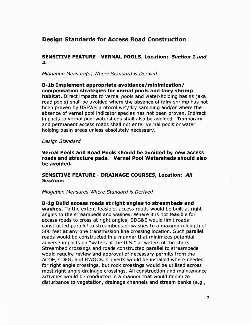
Design Standards for Access Road Construction
SENSITIVE FEATURE - VERNAL POOLS, Location: Section 1 and2.
Mitigation Measure(s) Where Standard is Derived
B-1b Implement appropriate avoidance/minimization/compensation strategies for vernal pools and fairy shrimphabitat. Direct impacts to vernal pools and water-holding basins (akaroad pools) shall be avoided where the absence of fairy shrimp has notbeen proven by USFWS protocol wet/dry sampling and/or where theabsence of vernal pool indicator species has not been proven. Indirectimpacts to vernal pool watersheds shall also be avoided. Temporaryand permanent access roads shall not enter vernal pools or waterholding basin areas unless absolutely necessary.
Design Standard
Vernal Pools and Road Pools should be avoided by new accessroads and structure pads. Vernal Pool Watersheds should alsobe avoided.
SENSITIVE FEATURE - DRAINAGE COURSES, Location: AllSections
Mitigation Measures Where Standard is Derived
B-1g Build access roads at right angles to streambeds andwashes. To the extent feasible, access roads would be built at rightangles to the streambeds and washes. Where it is not feasible foraccess roads to cross at right angles, SDG&E would limit roadsconstructed parallel to streambeds or washes to a maximum length of500 feet at anyone transmission line crossing location. Such parallelroads would be constructed in a manner that minimizes potentialadverse impacts on "waters of the U.S." or waters of the state.Streambed crossings and roads constructed parallel to streambedswould require review and approval of necessary permits from theACOE, CDFG, and RWQCB. Culverts would be installed where neededfor right angle crossings, but rock crossings would be utilized acrossmost right angle drainage crossings. All construction and maintenanceactivities would be conducted in a manner that would minimizedisturbance to vegetation, drainage channels and stream banks (e.g.,
2

structures would not be located within a stream channel, constructionactivities would- avoid sensitive features). Prior to construction instreambeds and washes, SDG&E would perform a pre-activity survey,or more as appropriate, to determine the presence or absence ofendangered riparian species. However, this survey would not replacethe need for SDG&E to perform detailed on-the-ground surveys asotherwise required by the BIO-APM-1. [BIO-APM-5].
B-li Restrict the construction of access and spur roads. Exceptwhen not feasible due to physical or safety constraints, all projectvehicle movement would be restricted to existing access roads andaccess roads constructed as a part of the project and determined andmarked by SDG&E in advance for the contractor, contractor-acquiredaccesses, or public roads. New access road construction for theproject would be allowed year-round. However, when feasible, everyeffort would be made to avoid constructing roads during the nestingseason. When it is not feasible to keep vehicles on existing accessroads or to avoid constructing new access roads during the nesting,breeding, or flight season, SDG&E would perform a site survey, ormore as appropriate, in the area where the work is to occur. Thissurvey would be performed to determine presence or absence ofendangered nesting birds, or other endangered species in the workarea. SDG&E would submit results of this survey to the USFWS andCDFG and consult on reasonable mitigation measures to avoid orminimize for potential impacts, prior to vehicle use off existing accessroads or the construction of new access roads. However, this surveywould not replace the need for SDG&E to perform detailed on-theground surveys otherwise required by BIOAPM- 1. Parking or drivingunderneath oak trees is not allowed in order to protect root structures.In addition to regular watering to control fugitive dust created duringclearing, grading, earth-moving, excavation, and other constructionactivities which could interfere with plant photosynthesis, a 15 milesper hour speed limit shall be observed on dirt access roads to reducedust and allow reptiles and small mammals to disperse. [BIO-APM-3]All new access roads or spur roads constructed as part of the projectthat are not reqUired as permanent access for future projectmaintenance and operation would be permanently closed. Whererequired, roads would be permanently closed using the most effectivefeasible and least environmentally damaging methods appropriate tothat area with the concurrence of the underlying landowner and thegovernmental agency having jurisdiction (e.g., stockpiling andreplacing topsoil or rock replacement). This would limit new orimproved accessibility into the area. Mowing of vegetation can be aneffective method for protecting the vegetative understory while at the
3
same time creating access to the work area. Mowing should be usedwhen permanent access is not required since, with time, total revegetation is expected. If mowing is in response to a permanentaccess need, but the alternative of grading is undesirable because ofdownstream siltation potential, it should be recognized that periodicmowing would be necessary to maintain permanent access. Theproject biological construction monitor shall conduct checks on mowingprocedures to ensure that mowing for temporary or permanent accessroads is limited to a 14-foot-wide area on straight portions of the roadand a 16- to 20-foot-wide area at turns, and that the mowing height isno less than 4 inches from finished grade. [BIO-APM-17]
H-ld Avoid watercourses to the maximum extent possible. Tothe extent feasible, structures shall be placed so as to avoid sensitivefeatures such as watercourses, or to allow conductors to clearly spanthe features, within limits of safety and standard structure design.[WQ-APM-2]
H-li Construction routes to avoid and minimize disturbance tostream channels. To the extent feasible, where the construction ofaccess roads would disturb sensitive features such as streambeds, theroute of the access road would be adjusted to avoid such impacts.Whenever practicable, construction and maintenance traffic would useexisting roads or cross-country access routes (including the ROW)which avoid impacts to the sensitive feature. To minimize grounddisturbance, construction traffic routes will be clearly marked withtemporary markers such as easily visible flagging. Construction routes,or other means of avoidance, should be approved by the appropriateagency or landowner before use. Where it is not feasible for accessroads to avoid streambed crossings, such crossings would be built atright angles to the streambeds whenever feasible. Where suchcrossings cannot be made at right angles, SDG&E would limit roadsconstructed parallel to streambeds to a maximum length of 500 feet atanyone transmission line crossing location. Such parallel roads wouldbe constructed in such a manner that minimizes potential adverseimpacts on waters of the U.S. or waters of the state. Streambedcrossings or roads constructed parallel to streambeds would requirereview and approval of necessary permits from the ACOE, CDFG, andSWRCB/RWQCB. [WQ-APM-15]
G-lc Avoid new disturbance, erosion, and degradation. Projectconstruction activities will be designed and implemented to avoid orminimize new disturbance, erosion on manufactured slopes, and offsite degradation from accelerated sedimentation. Maintenance of cut
4
and fill slopes created by project construction activities would consistprimarily of erosion repair. Where revegetation is necessary toimprove the success of erosion control, planting or seeding with nativeseed mix would be done on slopes. [GEO-APM-S]
G-le Minimize road construction. Any temporary roads developedfor the project would be removed, recontoured, and revegetatedfollowing construction except where the USFS authorizes continueduse of the roads for transmission line maintenance, eliminating longterm impacts from temporary roads.
Design Standards
Use existing access roads and spur roads to access structures.Where additional access is required to reach the structure pad,existing access and spur roads should be extended to reach thestructure pad as a first priority, as long as no drainage courseand/or wetland feature is impacted. If extension of the roadoff of an existing road will result in an impact to a drainagecourse or wetland feature, then the priority will be to avoid thedrainage course or wetland feature even if a new access orspur road is necessary. If an access road potentially impacts asignificant cultural feature to avoid a drainage course, then thedesign should avoid the significant cultural feature first andminimize impacts to the drainage course to the greatest extentfeasible. If an access road impacts a wetland while avoiding asignificant cultural feature, then a priority will be establishedon a case by case basis.
New access roads should be designed to cross drainages atright angles, as perpendicular as possible at the point ofcrossing to reduce the crossing length to the shortest amountpracticable, where avoidance is not possible.
Access roads should not parallel anyone drainage course formore than 500 feet for anyone transmission line crossing suchthat for drainage courses the toe of slope would not be locatedcloser than 50 feet from the drainage course centerline and forwetlands the toe of the slope would not be closer than 100 feetfrom from the wetlands centerline (based on the City of SanDiego Environmentally Sensitive Lands Ordinance).
No access road fill slopes shall encroach into any drainagecourses.
5
Temporary access roads shall be removed, recontoured, andrevegetated following construction except where the USFSauthorizes continued use of the roads for transm ission linemaintenance.
Access roads that should cross drainage courses should beculverted and designed with appropriate short- and long-termBMP's or should be spanned with a bridge or equivalentstructure with headwalls and fill located outside of thedrainage course as delineated by the wetlands biologist. Theuse of culvert or bridge or equivalent bridge-like crossings willbe determined on a case by case basis. In general, drainagecourses that have perennial water should be crossed with abridge or equivalent structure. Intermittent drainage coursesshould be traversed with a culvert crossing if flow duration,flood volumes and velocities and local soil conditions, includingscour potential, indicate a long-term maintenance and BMPbenefit or comparative costs between culvert and dip crossingapproaches reach similar levels. For ephemeral drainagecourses and desert washes, rock or dip crossings can beutilized, however, culvert crossings should be considered on acase by case basis with input from the wetland biologist,hydrologic and soil conditions assessment and actual siteconditions.
SENSITIVE FEATURE - DESIGNATED ENDANGERED SPECIESCRITICAL HABITAT, Location: 6, 7, 88, BC, 98, 9C, 1.0A, and1.08
Mitigation Measures Where Standard is Derived
B-2c Avoid sensitive features. In areas designated as sensitive bySDG&E or the resource agencies, to the extent feasible structures andaccess roads would be designed to minimize impacts to sensitivefeatures. These areas of sensitive features include but are not limitedto high-value wildlife habitats, sensitive vegetation communities, andhigh value plant habitats, and/or to allow conductors to clearly spanthe features, within limits of standard structure design. If the sensitivefeatures cannot be completely avoided, structures and access roadswould be placed to minimize the disturbance to the extent feasible.
6

Design Standard
For structures located in Designated Critical Habitat wherethere is no existing road to fully access structures, SDG&E mayuse helicopter construction techniques to avoid or mimimizethe construction of new access and spur roads. There are noexceptions in these areas unless there are overriding physical,equipment or safety issues that can be demonstrated to theCPUC and underlying Land Managing Entity requiring fullvehicle access for construction or long-term operations,maintenance and repair.
SENSITIVE FEATURE - SENSTIVE PLANT SPECIES, Location: AllSections
Mitigation Measures Where Standard is Derived
B-2c Avoid sensitive features. In areas designated as sensitive bySDG&E or the resource agencies, to the extent feasible structures andaccess roads would be designed to minimize impacts to sensitivefeatures. These areas of sensitive features include but are not limitedto high-value wildlife habitats, sensitive vegetation communities, andhigh value plant habitats, and/or to allow conductors to clearly spanthe features, within limits of standard structure design. If the sensitivefeatures cannot be completely avoided, structures and access roadswould be p'laced to minimize the disturbance to the extent feasible.
Design Standards
Use existing access roads and spur roads to access structures.Where additional access is required to reach the structure pad,existing access and spur roads should be extended to reach thestructure pad as a first priority, as long as no known sensitiveplant population is impacted. If extension of the road off of anexisting road will result in an impact to a known sensitive plantpopulation, then the priority will be to avoid the knownsensitive plant population even if a new access or spur road isnecessary. If an access road potentially impacts a significantcultural feature to avoid a known sensitive plant population,then the design should avoid the significant cultural featurefirst and minimize impacts to the known sensitive plantpopulation to the greatest extent feasible. If an access roadimpacts a known rare, endangered or threatened plant
7

population while avoiding a significant cultural feature, then apriority will be established on a case by case basis.
As an alternative to the above, if there remains potentialimpacts to a known sensitive plant population after allavoidance or minimization, then relocation of the sensitiveplant population to be im pacted may be pursued on a case bycase basis in consultation with the USFWS, CDFG andappropriate agency Land Management Entity.
For all known sensitive plant populations including nativetrees, a 20-foot buffer around the mapped plant populationshould also be accounted for in avoidance to the greatestextent feasible unless the creation of the buffer results in animpact to another sensitive feature as outlined above.
SENSITIVE FEATURE - NATIVE TREES, Location: All Sections
Mitigation Measures Where Standard is Derived
B-la Tree Mitigation. Mitigation for loss of native trees or native treetrimming shall be provided by (1) acquiring and preserving habitatwithin which the trees occur and/or (2)restoring (i.e., planting) treeson land that would not be subject to vegetation clearing (either in theapplicant's ROWand/or on land acquired and preserved). Any land tobe used for this mitigation shall be approved by the CPUC, BLM, StateParks (for ABDSP restoration), USDA Forest Service (for alternativeswith restoration on National Forest lands), and the Wildlife Agencies.For habitat acquisition and preservation, the mitigation ratios shallfollow those in Table D.2-7 for the Proposed Project (see Impacts toVegetation Communities and Required Mitigation tables in alternativessections for the alternatives). For example, removal of coast live oaktrees (that occur in coast live oak woodland) shall require mitigation ata 3: 1 ratio based on the permanent impact to the summed acreage ofall individual coast live oak trees impacted. Therefore, if the totalacreage of all individual coast live oak trees in coast live oak woodlandimpacted is 10 acres, then 30 acres of coast live oak woodland shall beacquired and preserved. For all trimmed native trees, the ratio shall be1: 1. For restoration (planting trees), these gUidelines, based onrecommendations from the CDFG, shall be followed. Native trees thatare removed shall be replaced in-kind as follows.
Trees less than five inches diameter at breast height (DBH) shall bereplaced at 3: 1
Trees between five and 12 inches DBH shall be replaced at 5: 1
8
Trees between 12 and 36 inches shall be replaced at 10: 1Trees greater than 36 inches shall be replaced at 20: 1
Native trees that are trimmed shall be replaced in-kind as follows.Trees less than 12 inches DBH shall be replaced at 2: 1Trees greater than 12 inches DBH shall be replaced at 5: 1
All restoration shall be maintained and monitored for a minimum of 10years. The restoration shall be directed according to a HabitatRestoration Plan approved by the CPUC, BLM, State Parks (for ABDSPrestoration), USDA Forest Service (for National Forest landrestoration), and the Wildlife Agencies.
Design Standards
Existing trees should be protected in place wherever possibleto best preserve the health and well-being of the tree. Aminimum 20' tree protection buffer should be provided aroundeach tree trunk. The Project Biologist shall determine ifadditional measures are required to protect trees based onspecies, size and local conditions. Where construction shouldoccur within the buffer area, or within 50' of existing treesprotect the tree to the extent possible by installation oftemporary fencing to surround the maximum buffer areaavailable before the start of any construction operations.Vehicle use, parking, stockpiling of materials or soil is notallowed in the tree protection areas.
Where an impact to native trees cannot be avoided, thenreplanting at the ratios specified under mitigation measure Bla, Native Trees, shall be located in areas appropriate for theircontinued health and vigor with final approval by the CPUC andBLM and wildlife agencies with priority given to locations thatalso provide screening and blending of new access road cut andfill slopes as long as all short- and long-term clearancerequirements are met, including clearances for operations,maintenance and repair vehicles and equipment.
9

Pruning of existing native trees shall be avoided wherepossible. Where pruning of existing trees to remain is requiredfor access or construction, the following levels of pruning maybe required:1. For removal of small branches more than 50% of thedistance from crown to dripline, and less than 10% of the treecanopy volume the tree may be pruned as needed.2. For all other pruning, the tree shall be pruned by skilled treeworkers under the direction of a Certified Arborist. All workshall be done to promote the health, survival and naturalappearance of the tree, with the goal of leaving the tree in asnatural appearing condition as possible. Selective pruningmethods shall be used, severing branches at crotches, and notleaving branch stubs. Topping of trees will not be permitted.3. Where removal of tree roots is required for grading,trenching or other reasons, all top and root pruning work shallbe done prior to the clearing, grubbing, grading or otheroperations that may damage the roots. Construction work shallbe performed to minimize the amount of root removal required.Roots required to be removed shall be severed cleanly prior toripping or trenching. Tunnel under roots for trenches insteadof cutting the roots. After root pruning, prune the tree canopyto compensate for root removals. If 20% of roots are removed,a similar percentage of the canopy shall be removed bythinning.4. Where more than 50% of the tree canopy volume isrequired to be removed, one tree of the same species shall beplanted for every 5 feet of vertical height of the tree.
SENSITVE FEATURE - FIELD OBSERVATIONS PRIOR TO ORDURING CONSTRUCTION, Location: All Sections
Mitigation Measures Where Standard is Derived
B-2c Avoid sensitive features. In areas designated as sensitive bySDG&E or the resource agencies, to the extent feasible structures andaccess roads would be designed to minimize impacts to sensitivefeatures. These areas of sensitive features include but are not limitedto high-value wildlife habitats, sensitive vegetation communities, andhigh value plant habitats, and/or to allow conductors to clearly spanthe features, within limits of standard structure design. If the sensitivefeatures cannot be completely avoided, structures and access roadswould be placed to minimize the disturbance to the extent feasible.
10

B-la Provide restoration/compensation for affected sensitivevegetation communities. Any impacts associated with unauthorizedactivity (e.g., exceeding approved construction footprints) shall bemitigated at as: 1 ratio (5.5: 1 in FTHL MA). Restoration of theunauthorized impacts shall be credited at a 1: 1 ratio (i.e., mitigated byin-place habitat restoration); the remaining 4: 1 (or 4.5: 1 in FTHL MA)shall be acquired off site.
Design Standard
Sensitive features that may not have been known during designmay be found during pre-construction surveys or during actualconstruction activity. Any field redesign of access roads shouldbe documented and quantified and routed as directed by theSDG&E Compliance Manager, environmental monitors, CPUCand the Agency Land Managing Entity. Prior to actualconstruction of the rerouted access road, an estimation ofimpact should be completed and compared to the impact of theprevious access road design.
SENSITIVE FEATURE - VISUAL RESOURCES, Location: Sections6, 7, 88, 8C, 98, 9C,JOA, and J08
Mitigation Measures Where Standard is Derived
V-2a Reduce in-line views of land scars. Construct access or spurroads at appropriate angles from the originating, primary travelfacilities to minimize extended, in-line views of newly graded terrain.Contour grading should be used where possible to better blend gradedsurfaces with existing terrain. SDG&E shall submit final constructionplans demonstrating compliance with this measure to the CPUC andBLM, as well as the Forest Service and Anza-Borrego Desert State Park(as appropriate), for review and approval at least 60 days prior to thestart of construction.
V-2b Reduce visual contrast from unnatural vegetation lines. Inthose areas where views of land ~cars are unavoidable, the boundariesof disturbed areas shall be aggressively revegetated to create a lessdistinct and more natural-appearing line to reduce visual contrast.Furthermore, all graded roads and areas not required for on-goingoperation, maintenance, or access shall be returned to pre-
11

construction conditions. In those cases where potential public access isopened by construction routes, SDG&E shall create barriers or fencesto prevent public access and patrol construction routes to preventvandalized access and litter clean-up until all vegetation removedreturns to its pre-project state. SDG&E shall submit final constructionand restoration plans demonstrating compliance with this measure tothe BLM and CPUC, as well as Forest Service and Anza-Borrego DesertState Park (as appropriate), for review and approval at least 60 daysprior to the start of construction.
V-2c Reduce color contrast of land scars on non-Forest lands.For non-USFS-administered land areas where views of land scars fromsensitive public viewing locations are unavoidable, disturbed soils shallbe treated with Eonite or similar treatments to reduce the visualcontrast created by the lighter-colored disturbed soils with the darkervegetated surroundings (Eonite and Permeon are commerciallyavailable chemical treatments that "age" or oxidize rock and are usedspecifically for coloring concrete or rock surfaces to tone down glareand contrast and simulate naturally occurring desert varnish). SDG&Ewill consult with the Authorized Officer (as determined by the CPUCand BLM as appropriate) on a site-by-site basis for the use of Eonite.SDG&E shall submit final construction and restoration plansdemonstrating compliance with this measure to the BLM and CPUC, aswell as Anza-Borrego Desert State Park (as appropriate), for reviewand approval at least 60 days prior to the start of construction.
V-2d Construction by helicopter. In those areas where long-termland-scarring and vegetation clearance impacts would be visible tosensitive public viewing locations, or where construction would occuron slopes over 15 percent, SDG&E will consult with the AuthorizedOfficer and appropriate land management agency, on a site-by-sitebasis regarding the use of helicopter construction techniques and theprohibition of access and spur roads. Agency consultations should beconducted and approvals received at least 120 days prior to the startof construction.
V-2e Minimize vegetation removal. Only the minimum amount ofvegetation necessary for the construction of structures and facilitieswill be removed. Topsoil located in areas containing sensitive habitatshall be conserved during excavation and reused as cover on disturbedareas to facilitate re-growth of vegetation. Topsoil located in developedor disturbed areas is excluded from this APM. [BIO-APM-23]
12
V-2f Reduce land scarring and vegetation clearance impacts onUSFS-administered lands. Vegetation within the right of way andground clearing at the foot of each tower and between towers will belimited to the clearing necessary to comply with electrical safety andfire clearance requirements. Mitigation will be incorporated to reducethe total visual impact of all vegetation clearing performed for thepower line (USFS Scenery Conservation Plan)
V-45a Prepare and implement Scenery Conservation Plan.Within one year after license issuance, or prior to any grounddisturbing activities, the Licensee shall file with the Commission aScenery Conservation Plan that is approved by the Forest Service. Thepurpose of this Scenery Conservation Plan is to identify specific actionsthat will minimize the project's visible disturbance to the naturallyestablished scenery and to establish final direction to best achieve thespirit and intent of the Scenic Integrity Objectives of the ClevelandNational Forest Land and Resource Management Plan. To achieve thegreatest consistency with the Scenic Integrity Objectives, the projectshall detail and integrate the following design recommendations intothe Scenery Conservation Plan:
Roads. No new access or spur roads, or improvementsreconstruction/expansion) to existing roads are to be constructed inthe following areas: (1) where ground slopes exceed 15%, or (2) onForest lands subject to a HIGH Scenic Integrity Objective (510) wherethe new access or spur road would be visible from primary travel(paved) roads or the Pacific Crest National Scenic Trail, regardless ofground slope. Existing roads needing reconstruction/expansion onother areas of the forest shall be configured to minimize the creationof cut/fill slopes. Where such slopes are created, they shall beimmediately treated to minimize their level of scenery disturbance.These treatments may include construction of structural elementsdesigned to blend with the adjacent natural scenery, or revegetationwith native species.
Design Standards
In Sections lOA and lOB and other areas where interveningtopography between the existing primary access road and thestructure average 15% or less in slope, design of access roadsshall not allow an uninterrupted linear view down the accessroad. This may be accomplished by providing periodic turns tobreak the directional view. For ease of access, roads may meetthe adjoining public road at 90 degrees, with a straight section
13
for 150 feet before curving away from 90 degrees to prevent alinear view down the road. Exceptions to this are wherecompliance with this standard creates an impact to a drainagecourse, significant cultural resource or other sensitive featurethat cannot be avoided.
For USFS congressional boundary lands, areas located within1000 feet of existing recreational trails, areas located withinCounty or City parks, BLM ACEC areas or areas otherwisedesignated as high value recreation or scenic areas in the FinalEIR/EIS, cut and fill slopes for access roads shall not exceed 50feet in vertical height as measured from the toe of the cut/fillslope to the top of the cut/fill slope (vertical projecteddistance).
For lands within the congressional boundaries of the ClevelandNational Forest, no new access or spur roads, or improvements(reconstruction/ expansion) to existing roads are to beconstructed in the following areas: (1) where ground slopesexceed 150/0, or (2) on Forest lands subject to a HIGH ScenicIntegrity Objective (510) where the new access or spur roadwould be visible from primary travel (paved) roads or thePacific Crest National Scenic Trail, regardless of ground slope.For structures located in these areas where there is no existingroad to fully access structures, SDG&E should use helicopterconstruction techniques to prohibit the construction of accessand spur roads. There are no exceptions in these areas unlessthere are overriding physical, equipment or safety issues thatcan be demonstrated to the CPUC and USFS requiring fullvehicle access for construction or long-term operations,maintenance and repair.
For all other areas, cut and fill slopes for access roads greaterthan 50 feet in vertical height shall be avoided to the greatestextent feasible. Where cut and fill slopes exceed 50 feet theslope shall be contour graded with variable slopes ranging from1:1 to 4:1 depending on geologic and soil condition constraints.Exceptions to the variable slope requirement are wherecompliance with this standard creates an impact to a drainagecourse, significant cultural resource or other sensitive featurethat cannot be avoided from the creation of a greater area ofhorizontal disturbance.
14

In non-USFS congressional boundary lands, if cut and fill slopesgreater than 50 feet cannot be avoided in access road design,and creates an impact to a drainage course, cultural resourceor other sensitive feature, retaining walls shall be used as analternative method of avoidance. Construct retaining walls ofmaterials and colors that minimize the visual impact of the wallstructure based on the views of the wall. Avoid retaining wallswith long, straight runs when exposed to view. Avoid acuteangles in walls, in favor of walls that curve to match existingconditions. Consider construction impacts, and select the walltype allowing the least disturbance to existing soils andvegetation. Acceptable options for walls include plantablesegmental retaining walls, or sculpted and colored rockconcrete surfacing that match the shapes, textures and colorsof surrounding rock outcrops. Provide plantable areas in frontof walls to permit establishment of vegetation to help obscurethe walls and create a transition to the natural landscape.
Use existing access roads and spur roads to access structures.Where additional access is required to reach the structure pad,existing access and spur roads should be extended to reach thestructure pad as a first priority, as long as no recreationaltrails, areas located within County or City parks, BLM ACECareas or areas otherwise designated as high value recreation orscenic areas in the Final EIR/EIS are impacted by theextension. For structures located in these areas where there isno existing road to fully access structures, SDG8&.E should usehelicopter construction techniques to prohibit the constructionof access and spur roads. There are no exceptions in theseareas unless there are overriding physical, equipment or safetyissues that can be demonstrated to the CPUC and underlyingLand Managing Entity requiring full vehicle access forconstruction or long-term operations, maintenance and repair.
SENSITIVE FEATURE - CULTURAL RESOURCES, Location: AllSections
Mitigation Measures Where Standard is Derived
C-lb Avoid and protect potentially significant resources. Whereoperationally feasible, regardless of cost, potentially register-eligibleresources shall be protected from direct project impacts by projectredesign; complete avoidance of impacts to such resources shall bethe preferred protection strategy. On the basis of preliminary National
15
Register of Historic Places (NRHP) eligibility assessments (MitigationMeasure C-la) or previous determinations of resource eligibility, theBLM and CPUC, in consultation with the SHPO, may require therelocation of the line, ancillary facilities, or temporary facilities or workareas, if any, where relocation would avoid or reduce damage tocultural resource values. Where the BLM and CPUC decide thatpotentially NRHP- and/or CRHR-eligible cultural resources cannot beprotected from direct impacts by project redesign, the Applicant shallundertake additional studies to evaluate the resources' NRHP- and/orCRHR-eligibility and to recommend further mitigative treatment. Thenature and extent of this evaluation shall be determined by the BLM inconsultation with the CPUC and the SHPO and shall be based uponfinal project engineering specifications. Evaluations will be based onsurface remains, subsurface testing, archival and ethnographicresources, and in the framework of the historic context and importantresearch questions of the project area. Results of those evaluationstudies and recommendations for mitigation of project effects shall beincorporated into a Historic Properties Treatment Plan consistent withMitigation Measure C-lc (Develop and implement Historic PropertiesTreatment Plan).
All potentially NRHP- and/or CRHR-eligible resources (as determinedby the BLM and CPUC, in consultation with the SHPO) that will not beaffected by direct impacts, but are within 50 feet of direct impactareas, will be designated as Environmentally Sensitive Areas (ESAs) toensure that construction activities do not encroach on site peripheries.Protective fencing, or other markers (after approval by CPUC/BLM),shall be erected and maintained to protect ESAs from inadvertenttrespass for the duration of construction in the vicinity. ESAs shall notbe identified specifically as cultural resources. A monitoring programshall be developed as part of a Historic Properties Treatment Plan andimplemented by the Applicant to ensure the effectiveness of ESAprotection (as detailed in Mitigation Measure C-le).
Design Standard
Potentially NRHP- and/or CRHR-eligible cultural resources shallbe avoided. Avoidance can be achieved in any of the followingmeans, either individually or in combination:
1. Access road and structure relocation placed outside of thedefined boundaries of the cultural resource.
16

2. Capping with gravel, soil or plates, on a case by case basiswith input and guidance from CPUC, BLM, SHPO (includingthe PA and HRTP) and the project archaeologist.
3. Surface recovery of artifacts where temporary accessroads and spur roads can be placed without grading orsoil disturbance.
Traditional Cultural Properties or current or potential HistoricDistricts that contain or could contain human remains shall beavoided.
Use existing access roads and spur roads to access structures.Where additional access is required to reach the structure pad,existing access and spur roads should be extended to reach thestructure pad as a first priority.
SENSITIVE FEATURE - UNIQUE GEOLOGIC FEATURE, Location:Sections lOA and B
Mitigation Measures Where Standard is Derived
G-2a Protect desert pavement. Grading for new access roads orwork areas in areas covered by desert pavement shall be avoided orminimized. If avoidance of these areas is not possible, the desertpavement surface shall be protected from damage or disturbance fromconstruction vehicles by use of temporary mats placed on the groundsurface. A plan for identification and avoidance or protection ofsensitive desert pavement shall be prepared and submitted to theCPUC and BLM for review and approval at least 60 days prior to startof construction. The plan shall define how protective measures willprevent destruction of desert pavement.
Design Standard
Access road and structure relocation outside of the definedboundaries desert pavement. Exceptions to this are wherecompliance with this standard creates an impact to a drainagecourse, cultural resource or other sensitive feature that cannotbe avoided.
Design of facilities, construction and operations shall beperformed in a manner to protect desert pavement to thefullest extent possible. Since any vehicle use, grading, orpedestrian use will damage desert pavement, desert pavement
17
shall be protected by restricting all construction activity,vehicle use, pedestrian activity and any other activity that mayaffect the pavement, to the defined route by use of temporaryfencing to protect all desert pavement not directly in theestablished route.
18
ATTACHMENT ONE - GLOSSARY
ACEC: Area of Critical Environmental Concern is designated by theBLM due to a significant biological, cultural, historic otherwise sensitiveenvironmental feature. These are afforded high levels of protection bythe BLM.
APM: Applicant Proposed Measures are proposed by SDG&E in theProponent's Environmental Assessment (PEA), part of the projectapplication to the CPUC. The measures are incorporated into theproject description by SDG&E to address potential environmentaleffects of the project. In all cases, the CPUC and BLM, when theyprepared the EIR/EIS augmented or otherwise replaced thesemeasures with their own, more stringent mitigation measures.
BLM: Bureau of Land Management. The lead agency granting right ofway for the Sunrise Powerlink in BLM administered lands in the desertand portions of eastern San Diego County. They are co-lead agencieswith the CPUC for the preparation of the Environmental ImpactReport/Environmental Impact Statement.
CPUC: California Public Utilities Commission: Lead state agencygranting SDG&E a Certificate of Public Convenience and Necessity,essentially a permit and co lead agency with the BLM for thepreparation of the Environmental Impact Report/Environmental ImpactStatement.
Contour grading: A grading design technique using varying sloperatios, and undulating slope faces to promote a more naturalappearance and continuity with the shapes of adjacent landforms. Techniques include creating smooth transitions between slopefaces and adjacent grades, rounding slopes and avoiding orminimizing continuous flat slope faces, angular transitions and gradebreaks.
Drainage Course: Any feature that carries or could carry eitherpermanently or temporarily, regardless of duration or the presence ofwater or the feature's size, location or the presence of vegetation.
Ephemeral Drainage Course: Drainage course containing runningwater only seasonally and not necessarily every year.
19

Existing Access Road: A paved, gravel or dirt road that can currentlyaccommodate and be traversed by a four-wheel drive vehicle withoutimprovements.
Historic Districts: A series of cultural features that may beindividually distinct but due to location and the nature of the featuresassociated with them are related significantly enough to render themas being considered one site.
HRTP: Historic Resources Treatment Plan. Prepared as part of theProgrammatic Agreement which is a document that outlines how theBLM will mitigation for potential impacts to cultural and historicresources as required by Section 106 of the Historic ResourcesProtection Act.
Intermittent Drainage Course: Drainage course containing wateronly in certain segments fed by springs or ground water and dry forlong distances between.
Land Managing Entity: Underlying owner or manager of a parcel ofland, either a private entity or an agency.
Land Scar: A visible disturbance to the soil surface or vegetationwhich contrasts to existing appearance of the land. This may be agraded cut or fill slope, road, or facility pad, erosion, or damageresulting from construction, vehicular use or other activity.
NRHP- and/or CRHR-eligible cultural resources: Cultural orhistoric resources that qualify or could qualify as National Register ofHistoric Places and California Register of Historic Resources based oncriteria set forth to determine their designation by state and federallaws.
New Access Road: A road traversing lands with no previousdisturbance where vegetation and other natural features appear tohave not been disturbed by human activities.
PA: Programmatic Agreement which is a document that outlines howthe BLM will take into account the potential impacts to cultural andhistoric resources as required by Section 106 of the Historic ResourcesProtection Act.
Perennial Drainage Course: Drainage course that flows year-round.
20

Sensitive Feature: Any feature that is considered to have significantbiological, cultural, historic, aesthetic, visual or recreational value asoutlined in the EIR/EIS.
SHPO: The State Historic Preservation Office is the Agency which isresponsible for compliance with state and federal historic and culturalresource protection laws.
Significant Cultural Feature: Any feature that has been mappedpreviously by others, or as part of the Sunrise Powerlinkenvironmental process or that is found in the field by professionalcultural resource monitors or archeologists, that they and/or the CPUC,BLM, or SHPO indicates as significant and have a high priority foravoidance of impact or disturbance.
Traditional Cultural Properties: A property or a place that iseligible for inclusion on the National Register of Historic Places becauseof its association with cultural practices and beliefs that are (1) rootedin the history of a community, and (2) are important to maintainingthe continuity of that community's traditional beliefs and practices.
USFS congressional boundary: Boundary of the Cleveland NationalForest as set forth by Congress when the forest was established, assubsequently amended, which can include both federally owned andprivate lands.
Vernal Pool/Road Pool: Shallow depression that holds waterseasonally underlain by specific soil types and located in uniquetopography that sustain sensitive features including rare andendangered plants and animals. For the purposes of these standards,vernal pool/road pool is considered the same feature.
Wetland: Drainage feature that has vegetation, soil and hydrologiccharacteristics that indicate a long-term presence of surface andsubsurface water either permanently or intermittently.
21

APPENDIX F
COUNTY OF SAN DIEGO HYDROLOGIC REFERENCE MATERIAL
Basis of Design Report 8/6/2010
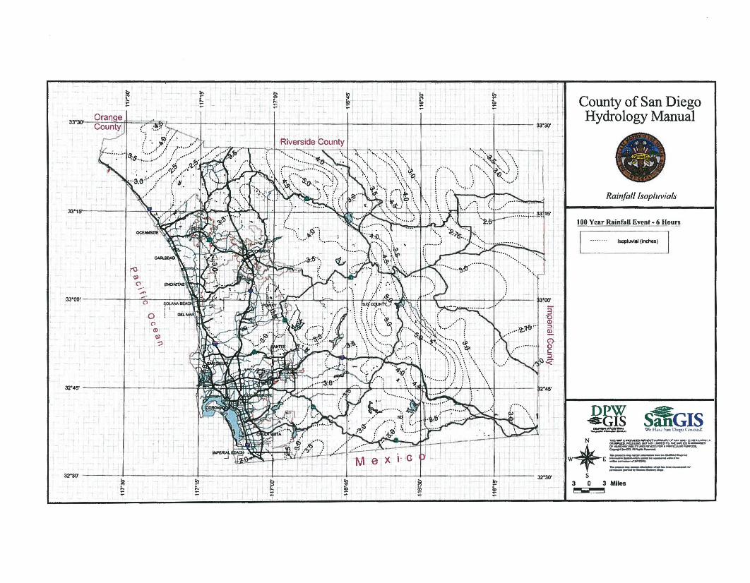
S1liGISWe Hol' .. "'"-an tllq)l (.m.(,,~
DPW'-eGIS~..:==....
Rainjalllsopiuvials
Isopluvllll flllChes)
County of San DiegoHydrology Manual
100 Year Rainfall Event - 6 Hours
IN 'Ita_OrJtlMDal'lllfMOUl'l/JJIIIINIIIlIfrOF_"OuJ.-III ....... :l1O
'~ _.-um.~wtHOllMl:tOrl).tMf~CD ...--.si OJ~,",IfC)IIIICSS"ll'l.-naJlM~
! ~t-en. .......I ...__ ~"......
" E =--='111--:::.:- -..__... _-..e-t_11 S -...-..-- ......
303Mlles1"""- ;
~ : 1 -. r" l
~ I in - 0 In1::: 1:;·1 1" r1..' ... - .. ~
'" ~:: ;:: ;::, .. - ;:~ :: . I()r::lnnl'l I I
,I I
II II
33"'
'33·'5' I ~, 'b#'.=>~,"" ~ 'r9i :/.., I ~:" :,U. X"~il :;::/( :.. I\ j,: \; In::'" i. :'1"" .L
o"(l)
(l)':)
1
~
Ol
"...'-"l
33·00 I ...· i ~"r ll.)~~i l~ I': ~ ;' '~~$":Lf L I ! I ..I ('\ ~. I I . • " •• ! I \ ~; _:: ••~~••, '.' "0 it I· ._••• ~. __ .___ l ...<
32'45' I '.,.
32·30' I I I I , . I 32~
~ 10 8' l 10 I ~~ ~
I~
~~1t>
;: I ;: I l - t ;!I,
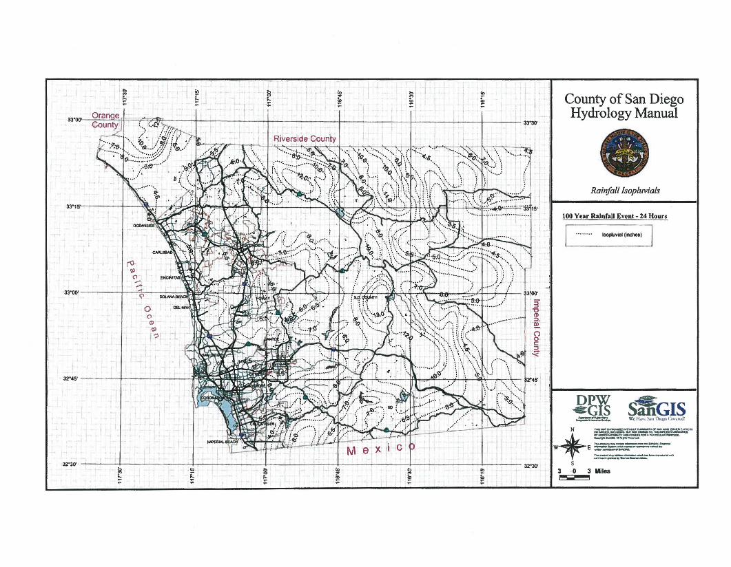
~
S1IiGISw.: H.,...... ""'" I'>..l)') Ctn",u,J!
Rainfall lsop/uvia/s
DPW-eGIS.:::::-~=-
County ofSan DiegoHydrology Manual
100 Year Rainfall Event - 24 Hours
I '""",uvial (inchea) I
N ~....,.."'O'CItDWfnClUf~O'MftQllCllrftt«lll....-
~l»""-'O'IC:U.C:.lQ~"OI"l.-.mTO.IIolI..-utD...--.ut1'~..nOllUlIQIII"_~...-az.~""".IIiIo,.-..-
~I E ==-:=.==-..:::=~1lK_~ --"""'-'"
-.-.....- .....S
303Miles~
-t
L-.
~
~~I
~I'"•!!!~
I'8I-l=
~~
.'-
lb
£r .
33'3lr VI C1I1St: rt= $?c' I I \- .. I I I I I I_~nllnh/ 1. k,,~~ I i 33'30"
..? ,"'~~:::Y~o' I'• i
....\.~~~-<~:1-/ I~I/-D,/o.:~:::::::;::::~.'~.} .
. '.•~:6'''''..:,ti,.....
33'15' I ~.\J ?:~l\i ';,'- "f!h .I: 1-"'" i:xIAi ,h":',: '.' :.'...~_.> J\;\1," ..£1": :i,l ··:'::Fi:::~.e _: ... l ..,
32'45' I m
ro~
('1........'33'00: I ....· ~ ~"t1' qkJ;l':'h'l~~' l "''''''''' l 'I": I no" ·,'It ", :l""'~' lli '..-1 ·,iC? ~"""'''''''.''6~~ .••~I.I~''~1 =t::- ... ._ .... ..a-••! J :1K,<J: 1..I.? :e. }I -'
o1('1~
~)-:)1
32'30- . I I I , I 32'30'~ ~ 8 I I' t '" !; I , , '"~ ~ ~
.;L !!! ~:;: T ,

, I , I
P8 1 1.5 2 2.5 3 3.S 4 I U 5 5.5TaDuration I I I I I I I I I I I I
5 2.63 3.95 5.27 a.59 7.90 9.22 10.541'1.88~17~ 15.817 2.12 3.18 4.24 5.30 a.38 7.42 8.48 9.54 10.80 11.68 12.72
10 1.68 2.53 3.37 4.21 5.05 5.90 8.74 7.58 8.42 9.27 10.1115 1.30 1.95 2.59 3.24 3.89 4.54 5.19 5.84 8.49 7.13 7.78210 1.08 1.62 2.15 2.69 3.23 3.n 4.31 4.85 5.39 5.93 8.4625 0.93 1.40 1.87 2.33 2.80 3.27 3.73 4.20 4.87 5.13 5.8030 0.83 1.24 1.66 2.07 2.49 2.90 3.32 3.73 4.15 4.56 4.9840 0.69 1.03 1.38 1.72 2.07 2.41 2.76 3.10 3.45 3.79 4.1350 0.80 0.90 1.19 1.49 1.79 2.09 2.39 2.69 2.98 3.28 3.58
• 0.53 0.• 1.08 1.33 1.59 1.88 2.12 2.39 2.85 2.92 3.1810 0.41 0.81 0.82 1.02 1.23 1.43 1.63 1.84 2.04 2.25 2.45
1210 0.34 0.51 0.66 0.85 1.02 1.19 '1.38 1.53 1.70 -'tv 2.04no 0.29 0.44 0.59 0.73 0.88 1.03 1.18 1.32 1.47 1.62 1.761. 0.28 0.39 0.52 0.65 0.78 0.91 1.04 1.18 1.31 1.441 1.57240 0.22 0.33 0.43 0.54 0.85 0.76 0.87 0.98 1.08 1.19 1.30300 0.19 0.29 0.38 0.47 0.58 0.68 0.75 0.85 0.94 1.031 1.13380 0.17 0.25 0.33 0.42 0.50 0.68 0.87 0.76 0.84 0.921 1.00
~~
Note: This chart replaces the Intensity-Duration-Frequencycurves used since 1965.
Directions for Application:(1) From precipitation maps determine ahr and 24 hr amounts
for the selected frequency. These maps are included In theCounty Hydrology Manual (10. 50. and 100 yr maps includedIn the Design and Procedure Manual).
(2) Adjust ahr precipitation (if necessary) so that it Is within
the range of 45% to 65% of the 24 hr precipitation (notappllcaple to Desert).
(3) Plot 6 hr precipitation on the right side of the chart.
(4) Draw a line through the point parallel to the plotted lines.
(5) This line is the intensity-duration curve for the locationbeing analyzed.
Application Fonn:
(a) Selected frequency __year. Pl'l
(b) P6 =__ In., P24 =-_.r = %(2)24
(c) Adjusted P6(2) = __ in.
(d) tx = __ min.
(e) I = __ in./hr.
1.5
2.0
1.0
2.5
t{J
~-..
60i5:5 i5.0 ::>
4.55'
4.0 ~3.5.!!!.
3.0
3 4 5 6Hours
2
Intenslty-Duratlon Design Chart· Template
40 50
Duration
20 30Minutes
15
I-~ .... ..... i'o.i'o. .... ..... ....
~ .... ..... .... ....~ .......... .....~ , ~ .... EQUATION
'!oo.. i"-. ..... i"'i ~ I = 7.44 Pa0-0·645I ,.....
i'o.i'o.I = Intensity (in/hr)
~ ..... ~ ~ Pa = 6-Hour Precipitation (in)) ..... ... ~~ '~
o = Duration (min)
I 'I-.. ....."~.....
.....~ I- ".....!oo.. I'~I
""",i"-.~ i'o.'..... I.. I'~ ",,'I.. ,
""i'ol'
I'.....
, " ..... 1'i
I..i ,,
"" i'o~,
!
I
0.3
0.2
0.5 6 7 8 910
0.4
2.0
3.0
4.0
5.0
10.09.0
8.07.0
6.0
J.e 1.0
~0.9
~0.8
.s,EO.
0.6
0.5

San Diego County Hydrology ManualDate: June 2003
Section:Page:
36 of 26
Table 3-1RUNOFF COEFFICIENTS FOR URBAN AREAS
Land Use Runoff Coefficient "C"
Soil Type
NRCS Elements Coun Elements %IMPER. A B C D
Undisturbed Natural Terrain (Natural) Permanent Open Space 0* 0.20 0.25 0.30 0.35
Low Density Residential (LDR) Residential, 1.0 DU/A or less 10 0.27 0.32 0.36 0.41
Low Density Residential (LDR) Residential, 2.0 DUiA or less 20 0.34 0.38 0.42 0.46
Low Density Residential (LDR) Residential, 2.9 DU/A or less 25 0.38 0.41 0.45 0.49
Medium Density Residential (MDR) Residential, 4.3 DU/A or less 30 0.41 0.45 0.48 0.52
Medium Density Residential (MDR) Residential, 7.3 DU/A or less 40 0.48 0.51 0.54 0.57
Medium Density Residential (MDR) Residential, 10.9 DU/A or less 45 0.52 0.54 0.57 0.60
Medium Density Residential (MDR) Residential, 14.5 DU/A or less 50 0.55 0.58 0.60 0.63
High Density Residential (HDR) Residential, 24.0 DU/A or less 65 0.66 0.67 0.69 0.71
High Density Residential (HDR) Residential, 43.0 DU/A or less 80 0.76 0.77 0.78 0.79
CommerciallIndustrial (N. Com) Neighborhood Commercial 80 0.76 0.77 0.78 0.79
CommerciaUIndustrial (G. Com) General Commercial 85 0.80 0.80 0.81 0.82
CommerciallIndustrial (D.P. Com) Office Professional/Commercial 90 0.83 0.84 0.84 0.85
CommerciallIndustrial (Limited 1.) Limited Industrial 90 0.83 0.84 0.84 0.85
CommerciallIndustrial (General J.) General Industrial 95 0.87 0.87 0.87 0.87
*The values associated with 0% impervious may be used for direct calculation of the runoff coefficient as described in Section 3.1.2 (representing the pervious runoffcoefficient, Cp" for the soil type), or for areas that will remain undisturbed in perpetuity. Justification must be given that the area will remain natural forever (e.g., the areais located in Cleveland National Forest).DU/A =dwelling units per acreNRCS = National Resources Conservation Service
3-6
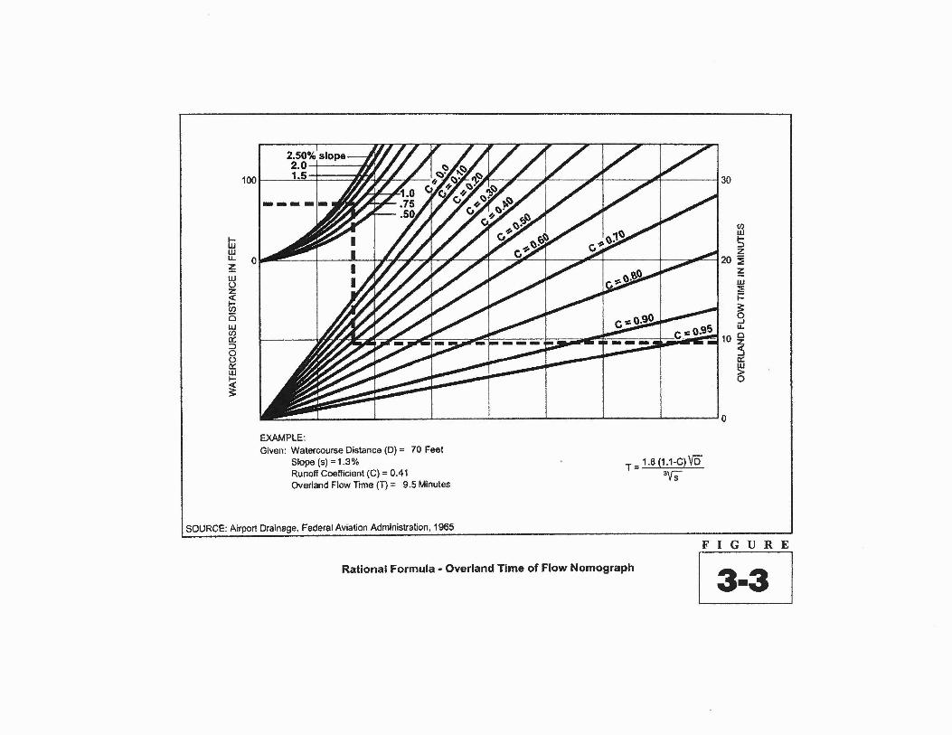
Iiiwu.~w(,)zgow~::Jo~WI-
~
~ / § /1 :A" 130
(J)
~
I- I ! 1///7f/ A :Y 1:7'1 I ~20 i~w:Ei=s:o-Iu..
~ ~"----=i 0____ - ~10 ~
a::
~
~ I , , I I I I '0
EXAMPLE:Given: Watercourse Distance (D) = 70 Feet
Slope (5) =1.3%Runoff Coefficient (C) = 0.41Overland Flow Time (T) = 9.5 Minutes
SOURCE: Airport Drainage. Federal Aviation Administration, 1965
T = 1.6 (1.1-C) Vi)31fS
Rational Formula - Overland Time of Flow Nomograph
FIGURE
13-3 I

5
3
2
4
3
TcHours Minutes
300
LMllee Feet
4OO(l 20, 183000 16
0.5,, 14
2000,
12,1800 ,1600 , 101400 ,
91200 8
7
6
5
4
400
EQUATION
e~~3t·385
Time of concentration (houl!i)= Watercourse Distance (miles)= Change in elevation along
effective slope line (See Figure 3-5)(feet)
Te
TcL
~E
2000
3000
5000
4000
200
JOO
100
20
10
30
1000900800
'10060},
SOD',400 ,
,~,~~
~1l,,, , ,,,,'1,
~E
Feet
200
~E L Tc
SOURCE: California Division of Highways (1941) and Kirpich (1940)
Nomograph for Determination ofTIme of Concentration (Tc) or Travel Time (Tt) for Natural Watersheds
FIGURE
~

San Diego County Hydrology Manual Section: 4Date: June 2003 Page: 80f60
Table 4-1RAINFALL DEPTH-AREA ADJUSTMENT DATA POINTS
Watershed Rainfall Depth-Area Adjustment for DurationArea
(square miles) 3G-Minute I-Hour 3-Hour 6-Hour 24-Hour
0 1.000 1.000 1.000 1.000 1.000
5 0.942 0.970 0.980 0.985 0.990
10 0.900 0.947 0.970 0.980 0.985
20 0.834 0.900 0.952 0.963 0.975
30 0.768 0.858 0.932 0.950 0.964
40 0.730 0.830 0.915 0.940 0.958
50 0.692 0.800 0.900 0.928 0.952
60 0.663 0.778 0.883 0.920 0.948
70 0.645 0.760 0.872 0.912 0.945
80 0.630 0.746 0.862 0.904 0.942
90 0.620 0.735 0.853 0.896 0.938
100 0.610 0.722 0.845 0.890 0.935
125 0.588 0.700 0.830 0.878 0.930
150 0.572 0.685 0.818 0.865 0.925
175 0.572 0.672 0.808 0.858 0.922
200 0.572 0.666 0.798 0.851 0.918
225 0.572 0.660 0.790 0.845 0.915
250 0.572 0.655 0.787 0.842 0.914
300 0.572 0.652 0.782 0.838 0.912
350 0.572 0.652 0.780 0.830 0.910
400 0.572 0.652 0.780 0.828 0.908
4-8
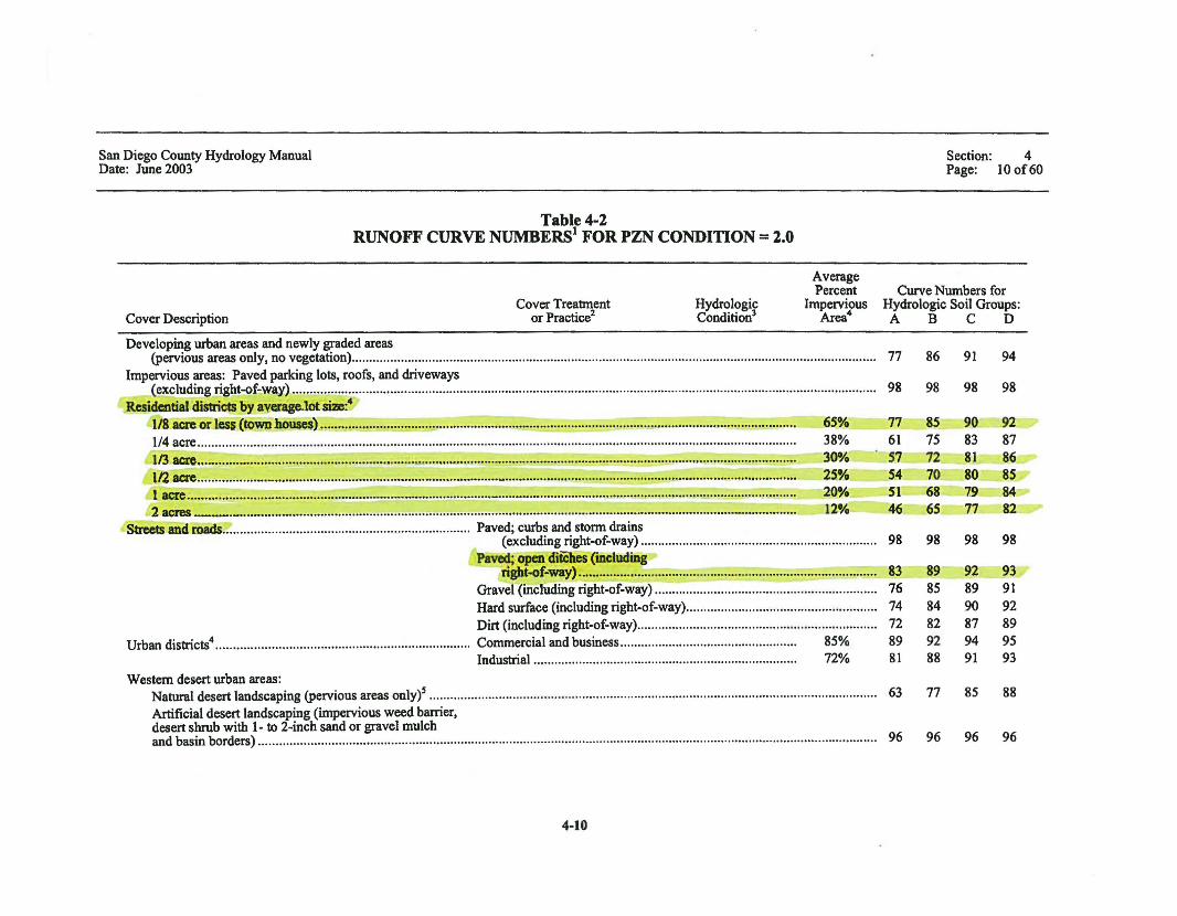
San Diego County Hydrology ManualDate: June 2003
Table 4-2RUNOFF CURVE NUMBERS1 FOR PZN CONDITION = 2.0
Section: 4Page: 10 of60
Cover DescriptionCover Treatment
or Practice2HydrologicCondition3
AveragePercent
ImperviousArea4
Curve Numbers forHydrologic Soil Groups:ABC D
65%38%30%Zi%20%12%
Developing urban areas and newly graded areas(pervious areas only, no vegetation) ..
Impervious areas: Paved parking lots, roofs, and driveways(excluding right-of-way) .
Residential districts by a¥erage.1ot size:4
1/8 8Cre"or less (townhousc$) ., .1/4 acre .113 acre ·.."'" , ~.~
112"acre _ : ..1acre •••.._ · - ..•._ , ..2 acres __ _ = .= '"
Streets and roads................ Paved; curbs and storm drains(excluding right-of-way) ..
Paved; open ditches (mcludingright-of-way) :.::;.:.'~=.~ .
Gravel (including right-of-way) ..Hard surface (including right-of-way) .Dirt (including right-of·way) .
Urban districts4 Commercial and business................................................... 85%Industrial 72%
Western desert urban areas:Natural desert landscaping (pervious areas onlyi ..Artificial desert landscaping (impervious weed barrier,desert shrub with 1· to 2-inch sand or gravel mulchand basin borders) .
4-10
77 86 91 94
98 98 98 98
77 85 90 _9261 75 83 8757 72 81 86SA 70 80 85SI 68 79 8446 65 77 82
98 98 98 98
83 89 92 9376 85 89 9174 84 90 9272 82 87 8989 92 94 9581 88 91 93
63 77 85 88
96 96 96 96

San Diego County Hydrology ManualDate: June 2003
Table 4-2 ~CoDtiDued)
RUNOFF CURVE NUMBERS FOR PZN CONDITION = 2.0
Section: 4Page: 12 of60
Small grain , Straight row Poor .Good .
Contoured Poor .Good ,
Vineyards6 Disked .Annual grass or legume cover Poor ..
Fair ..Good .
Annual grass (Dryland pasture) Poor .Fair .Good ..
Barren ..Meadow Poor ..
Fair .Good ..
Open.space Oawns, parks,.golfcourses, cemeteries, etc:)1 Grass cover <50% Poor ..Grass cover 50% to 75% -:.... Fair ..Grass cover >75% Good .
Pasture or range land............ Poor ..Fair .Good .
Perennial grass............................. Poor ..Fair ..Good .
Cover DescriptionCover Trea1ment
or Practice2HydrologicCondition3
AveragePercent
ImperviousArea4
Curve Numbers forHydrologic Soil Groups:A B C D
65 76 84 8863 75 83 8763 74 82 8561 73 81 8476 85 90 9265 78 85 8950 69 79 8438 61 74 8067 78 86 8950 69 79 8438 61 74 8078 86 91 9363 77 85 8851 70 80 8430 58 72 7868 79 86 8949 69 79 8439 61 74 8068 79 86 8949 69 79 8439 61 74 8067 79 86 8950 69 79 8438 61 74 80
4-12
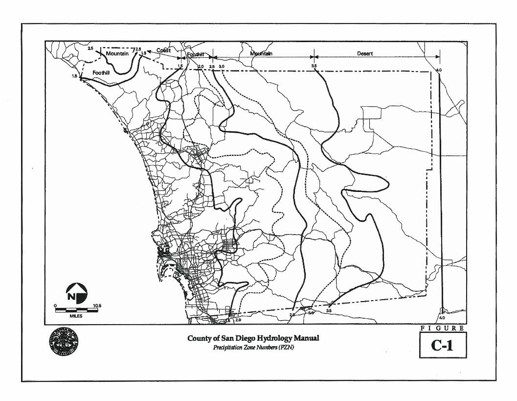
Q10.60
!iMILES
• Countyof San Diego Hydrology ManualPrecipitation Zone Numbers (PZN)
Desert
-----------------,
-------
FI GURE
~

APPENDIX G
COUNTY OF IMPERIAL HYDROLOGIC REFERENCE MATERIAL
Basis of Design Report 8/6/2010
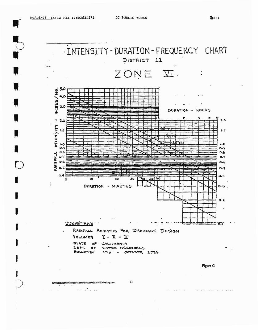
I.S
\.0
0.'0.&O.iO.b
0.5
o.~ .
o:r
5' ~.O
~004
CHAR1..'-
~.
Ie PUBLIC WORKS
ZONE
c..o-I..\ rQl\Nl Faw.ll\~~ R.'E:S(>l:lRC:S:~
i'"JS OCTo\!)"e:f\ .1.OJj.~
$'r"'~!! ofJ)EPT. ()Pflu L.~.:E"t·1N .
RPlIHFPlI-L. f\NF\\..YS'~ Fb" 'DR.""~AG£ Di:.~lGN
\'OUJM~~ 1: - 'Ii. - 11r
""""'--
· I .. .1)URJIlTI 0 1'1 - HOUR~
1 z. 3 .It
. .. . ·I I I........ ......
I'..-- I r-....t ."'" """ ......-.;:: I ........ .... "Il I
I.
. I . . . I. I •~ ..
-
.5 lO,
20 ~ ~!Q I sol 400 I ...... ......... .....
· NJ ~ I"t>Ufl,I\"ilOrt - M\NUTli.S
1".. ..... ......,.........~ ....
........~
~
1'"..%,!i~--·t>A1·
. _.. .. .. . -...... .. ...• ..- ... - .. - "
. INTEN5I1Y -DURATION - FREQUENC.i'D IST~\CT 11
1 ~.¢,...t 1.·$
.1Il.%Wt% 1·0- O.~
-J 0.6.~ C.i~~ c.o(.
~ e.g
0.4
14:13 FAX 17803521272Q4I16/Q4
I
I
I
I
I
--~
, ---,~.
ww
-~
r)
I
F'1£Ul'e C
I')I .
11

I
I
04/16/04 1~:12 FAX 1;803521272
~.' i;- -
~ ..
..
IC Pti~LIC WORKS
Cto I
io
,.. .~ .
o
~003
=
:
~~ .
.. .•2.... " ":".'

810-10July 1,2008
mGHWAY DESIGN MANUAL
816.6 Time of Concentration (Tc) andTravel Time (Tt)
Time of concentration is defined as the timerequired for storm runoff to travel from thehydraulically most remote point of the drainagebasin to the point of interest.
An assumption made in some of the hydrologicmethods for estimating peak discharge, such as theRational and NRCS Methods (Index 819.2), is thatmaximum flow results when rainfall of uniformintensity falls over the entire watershed area andthe duration of that rainfall is equal to the time ofconcentration. Time of concentration (Tc) istypically the cumulative sum of three travel times,including:
• Sheet flow
• Shallow concentrated flow
• Channel flow
For all-paved watersheds (e.g., parking lots,roadway travel lanes and shoulders, etc.) it is notnecessary to calculate a separate shallowconcentrated flow travel time segment. Such flowswill typically transition directly from sheet flow tochannel flow or be intercepted at inlets with eitherno, or inconsequential lengths of, shallowconcentrated flow.
In many cases a minimum time of concentrationwill have to be assumed as extremely short traveltimes will lead to calculated rainfall intensities thatare overly conservative for design purposes. Forall-paved areas it is recommended that a minimumtime of concentration of 5 minutes be used. Forrural or undeveloped areas, it is recommended thata minimum Tc of 10 minutes be used for mostsituations. However, for slopes steeper thanI V: I OH, or where there is limited opportunity forsurface storage, aTe of 5 minutes should beassumed.
Designers should be aware that maximum runoffestimates are not always obtained using rainfallintensities determined by the time of concentrationfor the total area. Peak runoff estimates may beobtained by applying higher rainfall intensitiesfrom storms of short duration over a portion of thewatershed.
(1) Sheet flow travel time. Sheet flow is flow ofuniform depth over plane surfaces and usuallyoccurs for some distance after rain falls on theground. The maximum flow depth is usuallyless than 0.8 inches - 1.2 inches. For unpavedareas, sheet flow normally exists for a distanceless than 80 feet- 100 feet. An upper limit of300 feet is recommended for paved areas.
A common method to estimate the travel timeof sheet flow is based on kinematic wavetheory and uses the Kinematic Wave Equation:
T =O.93L3/5n3/5t i 2I5S3/10
where
Tt = travel time in minutes.
L = Length of flow path in feet.
S = Slope of flow in feet per feet.
n = Manning's roughness coefficientfor sheet flow (see Table 816.6A).
i = Design storm rainfall intensity ininches per hour.
If Tt is used (as part of Tc) to determine theintensity of the design storm from the IOFcurves, application of the Kinematic WaveEquation becomes an iterative process: anassumed value of Tt is used to determine i fromthe IDF curve; then the equation is used tocalculate a new value of Tt which in tum yieldsan updated i. The process is repeated until thecalculated Tl is the same in two successiveiterations.
To eliminate the iterations, use the followingsimplified form of the Manning's kinematicsolution:
T =0.42L4/5n4/5t P 1/2 215
2 S
where P2 is the 2-year, 24-hour rainfall depth ininches (ref. NOAA Atlas 2, Volume XI or useeither of the following web site addresses;http://www.wrcc.dri.edu/pcpnfreq.html or,http://www.nws.noaa.gov/oh/hdsc/noaaatlas2.htm).
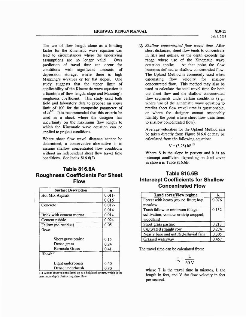
HIGHWAY DESIGN MANUAL 810-11July 1,2008
The use of flow length alone as a limitingfactor for the Kinematic wave equation canlead to circumstances where the underlyingassumptions are no longer valid. Overprediction of travel time can occur forconditions with significant amounts ofdepression storage, where there is highManning's n-values or for flat slopes. Onestudy suggests that the upper limit ofapplicability of the Kinematic wave equation isa function of flow length, slope and Manning'sroughness coefficient. This study used bothfield and laboratory data to propose an upperlimit of 100 for the composite parameter ofnL/s ll2
. It is recommended that this criteria beused as a check where the designer hasuncertainty on the maximum flow length towhich the Kinematic wave equation can beapplied to project conditions.
Where sheet flow travel distance cannot bedetermined, a conservative alternative is toassume shallow concentrated flow conditionswithout an independent sheet flow travel timeconditions. See Index 816.6(2).
Table 816.6ARoughness Coefficients For Sheet
Flow
Surface Description nHot Mix Asphalt 0.011-
0.016Concrete 0.012-
0.014Brick with cement mortar 0.014Cement rubble 0.024Fallow (no residue) 0.05Grass
Short grass prairie 0.15Dense grass 0.24Bermuda Grass 0.41
Woods(l)
Light underbrush 0.40Dense underbrush 0.80
(I) Woods coverts considered up to a helghtof30 nun, which IS themaximum depth obstructing sheet flow.
(2) Shallow concentrated flow travel time. Aftershort distances, sheet flow tends to concentratein rills and gullies, or the depth exceeds therange where use of the Kinematic waveequation applies. At that point the flowbecomes defined as shallow concentrated flow.The Upland Method is commonly used whencalculating flow velocity for shallowconcentrated flow. This method may also beused to calculate the total travel time for boththe sheet flow and the shallow concentratedflow segments under certain conditions (e.g.,where use of the Kinematic wave equation topredict sheet flow travel time is questionable,or where the designer cannot reasonablyidentify the point where sheet flow transitionsto shallow concentrated flow).
Average velocities for the Upland Method canbe taken directly from Figure 816.6 or may becalculated from the following equation:
V = (3.28) kS I12
Where S is the slope in percent and k is anintercept coefficient depending on land coveras shown in Table 816.6B.
Table 816.68Intercept Coefficients for Shallow
Concentrated Flow
Land cover/Flow reltime kForest with heavy ground litter; hay 0.076meadowTrash fallow or minimum tillage 0.152cultivation; contour or strip cropped;woodlandShort grass pasture 0.213Cultivated straight row 0.274Nearly bare and untilled-alluvial fans 0.305Grassed waterway 0.457
The travel time can be calculated from:
T=~t 60V
where Tt is the travel time in -minutes, L thelength in feet, and V the flow velocity in feetper second

810-16September 1, 2006
mGHWAY DESIGN MANUAL
such as transposing a hydrograph from anotherhydrologically homogeneous watershed. Thestream hydraulic method, and upland methodare described in HOS No.2. These, and othermethods, are adequate for use with RationalMethods for estimating peak discharge and willprovide results that are acceptable to form thebasis for design of highway drainage facilities.
It is clearly evident upon examination of theassumptions and parameters which form thebasis of the equation that much care andjudgment must be applied with the use ofRational Methods to obtain reasonable results.
• The runoff coefficient "c" in theequation represents the percent of waterwhich will run off the ground surfaceduring the storm. The remainingamount of precipitation is lost toinfiltration, transpiration, evaporationand depression storage.
Values of "c" may be determined for undeveloped areas from Figure 819.2A byconsidering the four characteristics of: relief,soil infiltration, vegetal cover, and surfacestorage.
Some typical values of "C" for developed areasare given in Table 819.2B. Should the basincontain varying amounts of different cover, aweighted runoff coefficient for the entire basincan be determined as:
• To properly satisfy the assumption that theentire drainage area contributes to the flow;the rainfall intensity, (i) in the equationexpressed in inches per hour, requires thatthe storm duration and the time ofconcentration (tc) be equal. Therefore, thefirst step in estimating (i) is to estimate (te).Methods for determining time ofconcentration are discussed under Index816.6.
• Once the time of concentration, (te), isestimated, the rainfall intensity, (i),
corresponding to a storm of equal duration,may be obtained from available sourcessuch as intensity-duration-frequency (IOF)curves. See Index 815.3(3) for furtherinformation on IOF curves.
The runoff coefficients given in Figure 819.2Aand Table 819.2B are applicable for storms ofup to 5 or 10 year frequencies. Less frequent,higher intensity storms usually requiremodification of the coefficient becauseinfiltration, detention, and other losses have aproportiona lly smaller effect on the total runoffvolume. The adjustment of the rational methodfor use with major storms can be made bymultiplying the coefficient by a frequencyfactor, C(t). Values of C(t) are given below.Under no circumstances should the product ofC(t) times C exceed 1.0.
Frequency (yrs) C(t)
25 1.1
50 1.2
100 1.25
(2) Regional Analysis Methods. Regional analysismethods utilize records for streams or drainageareas in the vicinity of the stream underconsideration which would have similarcharacteristics to develop peak dischargeestimates. These methods provide techniquesfor estimating annual peak stream discharge atany site, gaged or ungaged, for probability ofrecurrence from 50 percent (2 years) to Ipercent (100 years). Application of thesemethods is convenient, but the procedure issubject to some limitations.
Regional Flood Frequency equationsdeveloped by the U.S. Geological Survey foruse in California are given in Figures 819.2Cand 819.20. These equations are based onregional regression analysis of data from streamgauging stations. The equations in Figure819.2C were derived from data gathered andanalyzed through the mid-I 970's, while theregions covered by Figure 819.20 are reflectiveof a more recent (1994) study of theSouthwestern U.S. Nomographs and completeinformation on use and development of thismethod may be found in "Magnitude andFrequency of Floods in California" published in
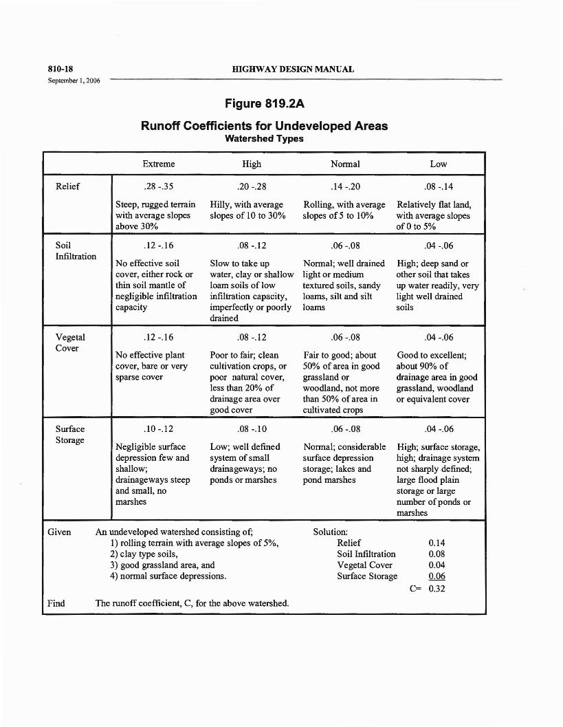
810-18September I, 2006
mGHWAY DESIGN MANUAL
Figure 819.2A
Runoff Coefficients for Undeveloped AreasWatershed Types
Extreme High Nonnal Low
Relief .28 -.35 .20 -.28 .14-.20 .08 -.14
Steep, rugged terrain Hilly, with average Rolling, with average Relatively flat land,with average slopes slopes of 10 to 30% slopes of 5 to 10% with average slopesabove 30% of 0 to 5%
Soil .12 -.16 .08 -.12 .06 -.08 .04 -.06Infiltration
No effective soil Slow to take up Nonnal; well drained High; deep sand orcover, either rock or water, clay or shallow light or medium other soil that takesthin soil mantle of loam soils of low textured soils, sandy up water readily, verynegligible infiltration infiltration capacity, loams, silt and silt light well drainedcapacity imperfectly or poorly loams soils
drained
Vegetal .12-.16 .08 -.12 .06 -.08 .04 -.06Cover
No effective plant Poor to fair; clean Fair to good; about Good to excellent;cover, bare or very cultivation crops, or 50% of area in good about 90% ofsparse cover poor natural cover, grassland or drainage area in good
less than 20% of woodland, not more grassland, woodlanddrainage area over than 50% of area in or equivalent covergood cover cultivated crops
Surface .10 -.12 .08 -.10 .06 -.08 .04 -.06Storage
Negligible surface Low; well defined Nonnal; considerable High; surface storage,depression few and system of small surface depression high; drainage systemshallow; drainageways; no storage; lakes and not sharply defined;drainageways steep ponds or marshes pond marshes large flood plainand small, no storage or largemarshes number of ponds or
marshes
Given An undeveloped watershed consisting of; Solution:1) rolling terrain with average slopes of 5%, Relief 0.142) clay type soils, Soil Infiltration 0.083) good grassland area, and Vegetal Cover 0.044) nonnal surface depressions. Surface Storage 0.06
C= 0.32
Find The runoff coefficient, C, for the above watershed.

HIGHWAY DESIGN MANUAL 860-7September 1, 2006
(4) Manning's Equation. Several equations havebeen empirically derived for computing theaverage flow velocity within an open channel.One such equation is the Manning Equation.Assuming unifonn and turbulent flowconditions, the mean flow velocity in an openchannel can be computed as:
V = 1.486 R 213S112
n
For the non-pressure, full flow condition, thegeometric properties and conveyance of achannel section can be computed. Then for agiven channel slope the discharge capacity canbe easily detennined.
Table 864.3A
Average Values for Manning'sRoughness Coefficient (n)
NOTES:For additional values ofn, see "Introduction toHighway Hydraulics", Hydraulic Design SeriesNo.4, FHWA Table 14.
(6) Critical Flow. A useful concept in hydraulicanalysis is that of "specific energy". Thespecific energy at a given section is defined asthe total energy, or total head, of the flowingwater with respect to the channel bottom. For achannel of small slope;
Where V :: Mean velocity, in feetper second
n = Manning coefficient ofroughness
S = Channel slope, in foot perfeet
R = Hydraulic Radius, in feet=AIWP
Where A = Cross sectional flow area, insquare feet
WP = Wetted perimeter, in feet
Commonly accepted values for Manning'sroughne ss coefficient, n, based on materialsand workmanship required in the StandardSpecifications, are provided in Table 864.3A.The tabulated values take into accountdeterioration of the channel lining surface,distortion of the grade line due to unequalsettlement, construction joints and nonnalsurface irregularities. These average valuesshould be modified to satisfy any foreseeableabnonnal conditions.
Direct solutions for Manning's equation formany channels of trapezoidal, rectangular, andcircular cross sections can be found in FHWA'sHydraulic Design Series No.3, "Design Chartsfor Open Channel Flow".
(5) Conveyance Equation. Often it is convenientto group the properties peculiar to the crosssection into one tenn called the conveyancefactor, K. The conveyance factor, as expressedby the Manning's equation, is equal to:
Type of Channel
Unlined Channels:Clay LoamSandGravelRock
Lined Channels:
Portland Cement ConcreteAir Blown Mortar (troweled)Air Blown Mortar (untroweled)Air Blown Mortar (roughened)Asphalt ConcreteSacked Concrete
Pavement and Gutters:
Portland Cement ConcreteAsphalt Concrete
Depressed Medians:
Earth (without growth)Earth (with growth)Gravel
n value
0.023
0.020
0.030
0.040
0.014
0.012
0.016
0.025
0.018
0.025
0.015
0.016
0.040
0.050
0.055

Basis of Design Report
APPENDIX H
HYDRAULIC REFERENCE MATERIAL
8/6/2010
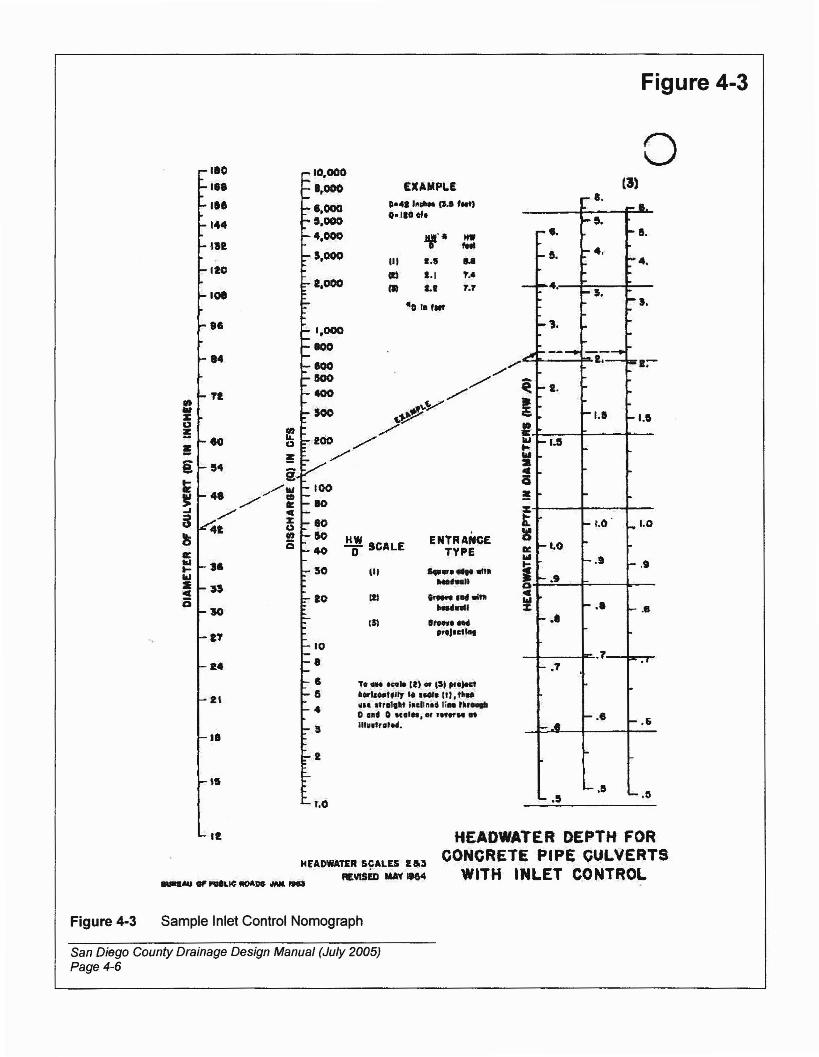
Figure 4-3
o(3)
a
.5
...._Il
.... 5.r- •• -I.
~5.I- 4.·
-4•
- -4..... 5.
-I•
-,.""r-
"".,A ---- ---I.--1;-
~ - t. r-
I ~I.I -1.1,.w -1.5...wS..a!!zt -1.0· 1- 1•0lC~
~I.O I-!AI ..... 9
i... ,.
- .9a
=~ roo ••z - ..~ ..
.7~ .7
~T
~_.-.e -.6
- .15~.~'-
ENtRANCETYPE............,._ ..
"- tllNHnU
.tHY....""1&1·""
Te _ ~.. It) 01 tSI .,e)eel
'''''''lfi" ...~elll.~~.. ,"'1,.. I••llnd Ii••""-o I" 0 Me'..... In"M etm..t,o'.M.
III
W: SCALE
1/1
r.O
24
JI
110
I'. £l(AMPL£
II' D-•• 1ft.... ~.5 ftlt)
14400110flf.
112 If'· HW,...110
III I., ...CI) 1.1 t .•
101(I) I., f.f
..~ l'lllt
.e
"l
2T
2'
1ftTt..,
Z
"!: to!i 54 i~ 4. //twJ / CD~ ./" =8 ott li!5 lit
Ea:IIIt-III
~·0
It
HfADWA1U S~ALES U~3
REVISED MAY If64
HEADWATER DEPTH FORCONCRETE PIPE C~LVERTS
WITH INLET CONTROL
Figure 4-3 Sample Inlet Control Nomograph
San Diego County Drainage Design Manual (July 2005)Page 4-6

Figure 4-4
.4
.5
.6
20
••... .. I.....9:--. • .0
/~.-.
r"r _ .... qo- .,.+ _,~,_",II HW ........... _,.... io .. fftl9' ..-...
~ t .... s.- ~SU~() OU1\,(T CULvfAl nQIIlN~ f'ULL
;"........, ...../.p <~ t-
Il! Z..~ 1&1
~ ... '".-- '( ~......'" .p
",~ J
- '--t.~~~--# ~ - 1:z:.. --~ a~~ ". •IlJ ..
:z:
5
~aO5
# 8-e.• ()D '.0 10..,.
1: 2000
...• III
1000Z •.. :;ill..
800 120
.00 108
500 ,.400 84
300 12
••..00 eo.,... ,..
~
i! • - ..~..III... % .",,'
0 1000 ......... ~ ..~.. .1g./Z
CIJ ~0J.-- -II:C 0 n% -u &0 II:Vt 130 W
:10 t-Id so
4\02cis 27
'0 14
10 21
I'10 15
•6 -12
5
..HEAD FOR
CONCRETE. P'PE CULVERTSFLOWING FULL
n -0.012
Figure 4-4 Sample Outlet Control Nomograph
San Diego County Drainage Design Manual (July 2005)Page 4-7
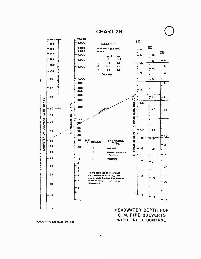
.5
o(2)
(I)
,...,... 8.
(3)~I.
I- 5. r- ••
'I.
... D.fo ... 4.
... 3. ... 4 .
... 3.- 3.
- 2.------.... - 2. ... 2•~ --~ ~I.&
e(/) i- 1.1 ~I.Ilit:
""~WSoil(
0at% -1.0 -1.0~~ -1.0wQ I- •• - .. - -lit:
""~ ....t; ..... r- .•QCw
-l:-:!-%
i- .7 - .7
'- .7
- .. I- .6
I- .1
'- .1:1..... 5
'-
ENTRANCETYPE
III",•• t...d",,,,I. ,'.p.".,.clln.
HEADWATER DEPTH FORC. M. PIPE CULVERTSWITH INLET CONTROL
('I
lit
121
To no teot. (2) "' (I) "oj..,U,i••Il1.II, f ••,,1, (I). Ill."
... 'fr.'," inclln.' II". ",..."D ••' 0 ICOI." .. , ...... II!lInt ,.11•.
.!:r! SCALEo
I
CHART 2810,000
8,000 EXAMPLE6,000 D· 51 Inc',. 11.0 IMtl5,000 0'" cre4,000
!JI- It-3,000 I'M')
(II I.' I .•
2,000 III 1.1 '.1III I.r •••
·0 ill I••t
1,000
800
20
600500
400
1.0
10
8
6II
4
3
IIOT118
156
144
132 ••120
d
l!!4
101 ...~...
I' ~lo-U;:).,
84....411
(/)721w
:z:II'lf,)
~ ...eo f,)
~ ~
§ '4 §.... Wlit: ~w 48 ~> oil(..J %-:l
/~f,)42... / Q0./lit:
I&J36...
w::II ncis
30•U
ell 27III:«Iellz 244...411
21
18
IS
1 12
BUIlEAU O~ PU8LIC ROAOS ,/AN. I"~
C-6
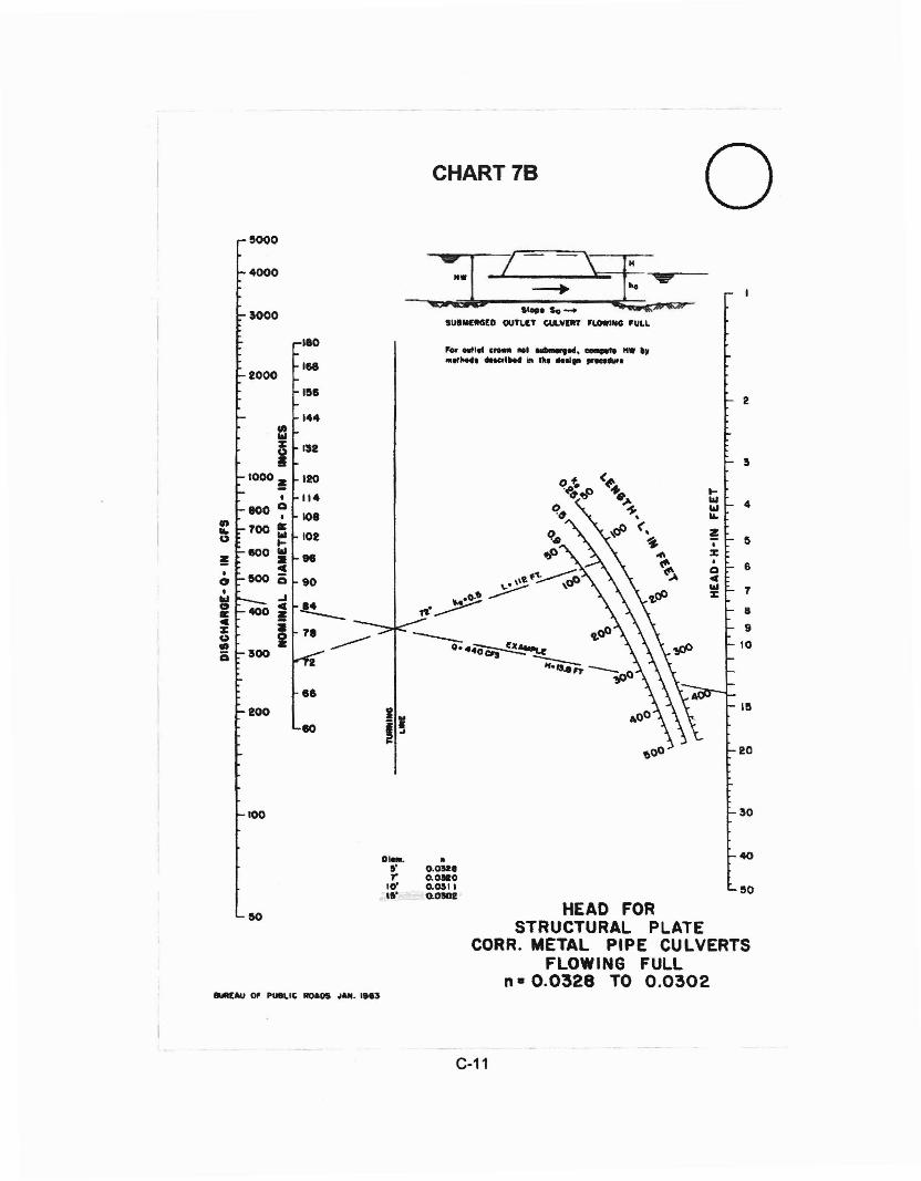
100 30
0-. •" 0.052'r 0.0.0
10' O.OSI\Ill' Q.D!CII
40
50
HEAD FORSTRUCTURAL PLATE
CORR. METAL PIPE CULVERTSFLOWING FULL
n· 0.0328 TO 0.0302
C-11
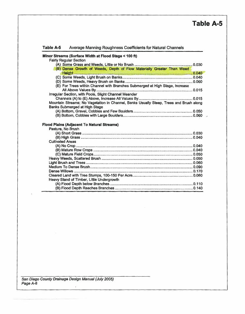
TableA·5 Average Manning Roughness Coefficients for Natural Channels
Table A-5
Minor Streams (Surface Width at Flood Stage < 100 tt)Fairly Regular Section
(A) Some Grass and Weeds, Little or No Brush 0.030(B) Dense Growth of Weeds, Depth of Flow Materially Greater Than Weed
Height 0.040(C) Some Weeds, Light Brush on Banks 0.040(D) Some Weeds, Heavy Brush on Banks 0.060(E) For Trees within Channel with Branches Submerged at High Stage, Increase
All Above Values By 0.015Irregular Section, with Pools, Slight Channel Meander
Channels (A) to (E) Above, Increase All Values By 0.015Mountain Streams; No Vegetation in Channel, Banks Usually Steep, Trees and Brush alongBanks Submerged at High Stage
(A) Bottom, Gravel, Cobbles and Few Boulders 0.050(B) Bottom, Cobbles with Large Boulders 0.060 ,
Flood Plains (Adjacent To Natural Streams)Pasture, No Brush
(A) Short Grass 0.030(B) High Grass 0.040
Cultivated Areas(A) No Crop 0.040(B) Mature Row Crops 0.040(C) Mature Field Crops 0.050
Heavy Weeds, Scattered Brush 0.050Ught Brush and Trees 0.060Medium To Dense Brush 0.090Dense Willows 0.170Cleared Land with Tree Stumps, 100-150 Per Acre 0.060Heavy Stand of Timber, Little Undergrowth
(A) Flood Depth below Branches 0.11 0(B) Flood Depth Reaches Branches 0.140
San Diego County Drainage Design Manual (July 2005)PageA-6
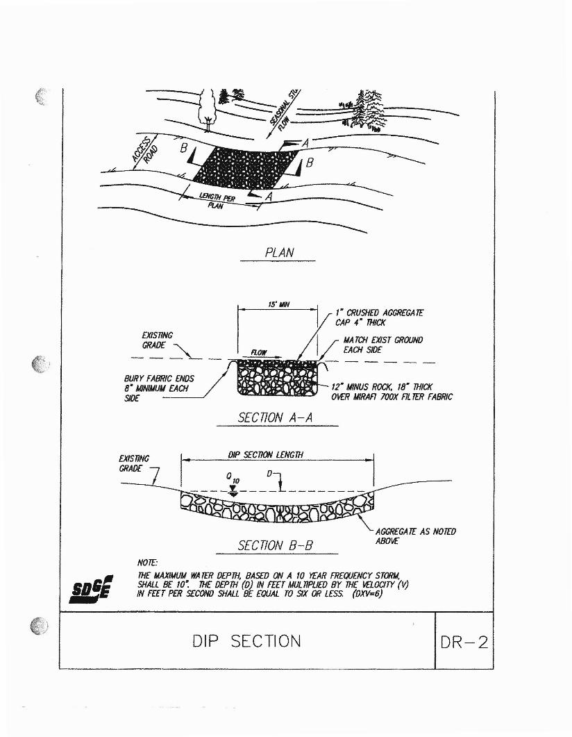
---------
PLAN
EXISTINGGRADE "-
----"--BURYFA8R~C£NOS8- MlNlUUM EACHSlO£
15' IIIN,- CRUSHEO AGGREGA TECAP 4- THICK
UA TCH EXIST GROUNDEACH SIO£
12" MINUS ROCK. 18- THICKO'rf:R UIRAA lOOX AL TER FABRIC
SECTION A-A
SECTION B-BAGGREGATE AS NOTEDABOVE
... 010
01----y---- --------D ......
I DIP SECTION LENGI1IEXISTINGGRADE
IIJ';NOTE:THE UAXIMUIJ WA fER DEPTH, BASED ON A 10 YEAR FREQUENCY STORM.SHALL BE 10~ THE DEPTH (0) IN FEET MULTIPliED BY THE VELOCITY (V)IN FEET PER S£COND SHALL 8£ EOUAL TO SIX OR LESS. (OXV=6)
DIP SECTION DR-2
Related Documents