Basis of Design Report March 2018 Basis of Design Report Belmont Bridge Replacement Project VDOT Project: 0020-104-101-UPC #75878 Draft – March 28, 2018 PREPARED FOR PREPARED BY

Welcome message from author
This document is posted to help you gain knowledge. Please leave a comment to let me know what you think about it! Share it to your friends and learn new things together.
Transcript

Basis of Design Report March 2018
Basis of Design Report
Belmont Bridge Replacement Project
VDOT Project: 0020-104-101-UPC #75878
Draft – March 28, 2018
PREPARED FOR
PREPARED BY

DRAFT – Date and time if needed
Basis of Design Report March 2018
Belmont Bridge 1-1
Revision Record
Revision Issue Date Pages Affected Description of Revisions
1 03/28/18
1-4,2-5,3-6,3-7,3-8,3-
10,3-11,4-12,5-13,5-
14,5-16
Comments from Jeanette Janiczek and Amanda
Poncy.

DRAFT – Date and time if needed
Basis of Design Report March 2018
Belmont Bridge 1-2
Table of Contents
Chapter 1 Introduction...................................................................................................................................... 1-4
1.1 Project Area ............................................................................................................................................. 1-5
Chapter 2 Existing Conditions .......................................................................................................................... 2-5
Chapter 3 Proposed Roadway Design Criteria ................................................................................................. 3-6
3.2 Design Vehicles ....................................................................................................................................... 3-8
3.3 Horizontal Alignment ............................................................................................................................. 3-10
3.4 Vertical Alignment ................................................................................................................................. 3-10
3.5 Typical Sections ..................................................................................................................................... 3-11
3.6 Superelevation ...................................................................................................................................... 3-12
3.7 Design Waivers and Exceptions ........................................................................................................... 3-12
Chapter 4 Drainage and Stormwater Management Strategy ........................................................................ 4-12
Chapter 5 Ancillary Design Considerations .................................................................................................... 5-13
5.1 ADA Compliance .................................................................................................................................... 5-13
5.2 Traffic Studies Design Integration ........................................................................................................ 5-13
5.3 Maintenance of Traffic .......................................................................................................................... 5-13
5.4 Pedestrian/Bicycle Accommodations .................................................................................................. 5-15
5.5 Bridge Design ........................................................................................................................................ 5-16

DRAFT – Date and time if needed
Basis of Design Report March 2018
Belmont Bridge 1-3
Figures
Figure 1.1: Overall Project Area ............................................................................................................................... 1-5
Figure 3.1: Typical Section – North of Belmont Bridge (Looking North on 9th St.) ............................................ 3-10
Figure 3.2: Typical Section – North of Belmont Bridge (Looking North on 9th St.) ............................................ 3-11
Figure 3.3: Typical Section – South of Belmont Bridge (Looking North on 9th St.) ............................................ 3-12
Figure 5.1: MOT Concept – Conceptual Maintenance of Traffic Concept for 9th Street.................................... 5-15
Figure 5.1: Typical Section – Belmont Bridge over Buckingham Branch Railroad, Water Street and Old Avon
Street ....................................................................................................................................................................... 5-16
Tables
Table 3.1: Design Criteria ......................................................................................................................................... 3-7
Table 3.2: Design Criteria: Project-Wide Standards ............................................................................................... 3-8

DRAFT – Date and time if needed
Basis of Design Report March 2018
Belmont Bridge 1-4
CHAPTER 1 INTRODUCTION
This report is the basis of design (BOD) for the engineering elements of the Belmont Bridge Replacement
Project. This report has been prepared based on project planning meetings, data collection, and input from the
project stakeholders gathered during the public engagement process. The BOD serves as a record to document
design criteria and project decisions made during the design development process that affect the development
of the Belmont Bridge replacement.
Field survey, utility survey, a traffic study, conceptual structural analysis, steering committee and technical
committee meetings, stakeholder groups and public input supported the development of the BOD for the
project.
The Belmont Bridge in Charlottesville, Virginia is scheduled for replacement as part of VDOT Project 0020-104-
101, UPC 75878. The vision for the Belmont Bridge is to provide a community connection for bikes,
pedestrians, buses, and cars between the surrounding neighborhoods and the City’s downtown/urban core.
The project limits are from the intersection of Avon Street, 9th Street, Garrett Street and Levy Avenue to the
intersection of 9th Street and Levy Avenue to the intersection of 9th Street and East Market Street.
This report provides the proposed roadway and structural design parameters based on applicable local, state,
and federal guidelines, standards, and requirements for the corridor.

DRAFT – Date and time if needed
Basis of Design Report March 2018
Belmont Bridge 2-5
1.1 Project Area
Figure 1.1: Overall Project Area
CHAPTER 2 EXISTING CONDITIONS
The existing conditions were documented through field and utility survey and compiled from various data
sources. Field survey mapping for the entire project corridor was developed by H&B Survey and Mapping, LLC
in January 2017. Underground utility mapping was performed by Accumark in February 2017. General
information outside of the project area was gathered from City of Charlottesville GIS databases. A vertical and
horizontal datum of NAVD ’88 and horizontal coordinate system of NAD ’83 have been set as the datum for the
project.

DRAFT – Date and time if needed
Basis of Design Report March 2018
Belmont Bridge 3-6
CHAPTER 3 PROPOSED ROADWAY DESIGN CRITERIA
Roadway and structural design of general travel lanes, bridges and other geometric roadway features within
the right-of-way will follow this established set of design criteria. These criteria are a collection of design
standards and/or guidance from local, state, and national sources. The American Association of State Highway
and Transportation Officials (AASHTO) is the national body that has developed design standards and guidance
for transportation infrastructure through practice, policy testing, research, and experience. This project will be
designed in accordance with the manuals below:
City of Charlottesville
The current edition of the City of Charlottesville’s City Standards and Design Manual
The current edition of the City of Charlottesville’s Streets that Work Guidelines
VDOT
The current revision to the 2016 Edition of the VDOT Road and Bridge Standards
The current revision to the, the current edition of the VDOT Survey Manual
The current edition of the VDOT Drainage Manual
The current edition of VDOT Hydraulic Design Advisories
The current edition of the 2013 Virginia Stormwater Handbook
The current edition of the 1992 Virginia Erosion and Sediment Control Handbook
The current edition of the VDOT Urban Construction Initiative Program Administrative Guide
The current edition of the VDOT Locally Administrated Projects Manual
The current edition of the VDOT Traffic Operations and Safety Analysis Manual (TOSAM)
AASHTO
The 2011 edition of the American Association of State Highway & Transportation Officials (AASHTO) Policy
on the Geometric Design of Highways and Streets (AASHTO Green Book)
The current edition of the AASHTO LRFD Bridge Design Specifications
The current edition of the 2012 AASHTO Guide for the Development of Bicycle Facilities
The current edition of the 2004 AASHTO Guide for the Planning, Design and Operation of Pedestrian
Facilities
NACTO
The current edition of the NACTO Urban Street Design Guide
The current edition of the NACTO Urban Bikeway Design Guide
FHWA
The current edition of the 2009 Manual on Uniform Traffic Control Devices (MUTCD)
Department of Justice
The 2010 ADA Standards for Accessible Design
United States Access Board
Proposed Right-of-Way Guidelines (PROWAG)
The map in Section 1.1 shows the project area. All streets within the City of Charlottesville are owned and
maintained by the City. The following tables outline which standards will be utilized for each street within the
project are. All the roadway segments with work beyond the curb return within the project limits are included in
the table to outline governing criteria in case additional modifications are needed.

DRAFT – Date and time if needed
Basis of Design Report March 2018
Belmont Bridge 3-7
Table 3.1: Design Criteria
Street Segment 9th Street
(Route 20)
Old Avon Street and
South Street Water Street
From: Levy Avenue South Street Transit Center
To: E. Market Street Old Avon Cul de
Sac
Water Street Trail
Project Limits
Design Criteria Source
Design Speed VDOT Road Design Manual
(RDM) Appendix A-4
25 mph 25 mph 25 mph
Posted Speed 25 mph 25 mph 25 mph
Location VDOT 2005 Functional
Classification Map Urban Urban Urban
Functional
Class
VDOT 2014 Functional
Classification Map Minor Arterial Local Street Major Collector
Geometric
Standard VDOT RDM Appendix A GS-6 GS-8 GS-7
STW Typology
City of Charlottesville
Streets that Work
Guidelines
Downtown Downtown Downtown
Curb/Curb &
Gutter
Standard
City of Charlottesville City
Standards and Design
Manual
CG-2/CG-6/
RT-1/SW-2
CG-2/CG-6/
RT-1/SW-2 CG-2/CG-6
Min. Horizontal
Radius (ft)
2011 AASHTO Greenbook
Table 3-8, RDM Page A-16,
A-17
154 feet 154 feet 154 feet
Inter. Section
Sight Distance
SDL/SDR (ft)
RDM, Page F-40 280/280 280/280 280/280
Stopping Sight
Distance RDM Page A-16, A-17 200 200 200
Min. Crest K
Value
2011 AASHTO Greenbook,
Table 3-34 12 12 12
Min. Sag K
Value
2011 AASHTO Greenbook,
Table 3-36 26 26 26
Superelevation
Standard RDM Page A-16, A-17
Urban Low Speed
(ULS) – Normal
Crown
Urban Low Speed
(ULS) – Normal
Crown
Urban Low Speed
(ULS) – Normal
Crown
Max. Grade
RDM Page A-16, A-17;
2011 AASHTO Greenbook,
Table 7-4, Table 6-8
City Standards & Design
Manual Page 24
9% 10% 10%
Min. Bridge
Vertical
Clearance over
Roads (ft)
VDOT Structure and Bridge
Manual Part 2, Chapter 6,
File No. 06.02-8, 06.02-10
16.5 14.5 14.5

DRAFT – Date and time if needed
Basis of Design Report March 2018
Belmont Bridge 3-8
Min. Bridge
Vertical
Clearance over
Railroads (ft)
VDOT Structure and Bridge
Manual Part 2, Chapter 6,
File No. 06.06-1
23 feet 23 feet 23 feet
Min. Horizontal
Offset from CL
of nearest rail
to Face of Pier
VDOT Structure and Bridge
Manual Part 2, Chapter 6,
File No. 06.06-1
18 feet Min (with
Crash Wall) or 25
feet with no Crash
Wall
18 feet Min (with
Crash Wall) or 25’
with no Crash Wall
18 feet Min (with
Crash Wall) or 25
feet with no Crash
Wall
Maximum
Gutter Spread
(ft)
VDM, Page 9-3 ½ Driving Lane + Gutter Width (Maximum 10 feet)
Minimum
Storm Pipe
Slope
VDM, Page 9-5 0.20%
Storm Pipe
Design Year VDM, Page 9-3, Table 9-2 10 Year
Design Vehicle WB-67 WB-40 WB-67
3.2 Design Vehicles
Due to width of Old Avon and South Street a WB40 is the largest vehicle that would be able to maneuver both
in the existing and proposed condition. In both the existing and proposed condition the WB-40 must track into
oncoming lanes to navigate the turns from one side street to another.
Table 3.2: Design Criteria: Project-Wide Standards
Design Criteria Source Project-Wide Standard
Min. Width of Parallel Parking
Lanes Streets that Work page 81 8.0 feet
Min. Vertical Clearance to
Signs, Adjacent to Sidewalk VDOT RDM Appendix A-174 7.0 feet to Bottom of Sign
Min. Vertical Clearance to
Signs, Adjacent to Bike Lanes
Guide for the Development
of Bicycle Facilities page 5-4 4.0 feet to Bottom of Sign
Min. Width of In Road Bike
Lane
Wo C&G/W C&G
(ft)
Guide for the Development
of Bicycle Facilities, Section
4.6.4, page 4-15
5 feet

DRAFT – Date and time if needed
Basis of Design Report March 2018
Belmont Bridge 3-9
Min. Width of Sidewalk Buffer
Strip (ft) Streets that Work page 46
3 to 6 feet Soil volume minimums: small trees
= 250 ft3; medium trees = 400 ft3;
large trees = 400 ft3 (700 ft3
preferred)
Min. Width of Sidewalk Streets that Work page 46 6 feet (Clear)
Min. Width of Shared Use
Path (ft)
Guide for the Development of Bicycle Facilities, Section 5.2.1, page 5-3
8
Min Width of Shared Use Path
Shoulder (ft)
Guide for the Development
of Bicycle Facilities, Section
5.2.1, page 5-5
3
Max. Grade of Sidewalk VDOT RDM Appendix A-161
5.0% or longitudinal slope of
adjacent street, whichever is
greater
Max. Grade of Sidewalk
Ramps VDOT RDM Appendix A-152 12:1 (8.3%)
Max. Cross-slope of Sidewalk VDOT RDM Appendix A-152 48:1 (2.0%)
Min Turn Lane Taper VDOT RDM Appendix F page
F-55
100 Single
150 Dual
Min. Turn Lane Storage VDOT RDM Appendix page F-
55 100 feet*
Clear Zone (ft) VDOT RDM Appendix A
page A-27 16 to 18
Min. Width of Pedestrian
“Refuge”
AASHTO Greenbook 4-64 –
4-66 6.0 feet median width
Min. Lateral Offset to
Obstructions VDOT RDM Appendix A-29
1.5 feet from Curb Face
3.0 feet at Intersections
Min. Lane Shift VDOT RDM Appendix A-10 L = W x S2 / 60
* To be determined by traffic analysis, 100' is minimum
The design vehicle will be analyzed for turning movements at all intersections along the corridor. AutoTURN® is
the CAD-based program that can graphically show the full apron and turning path of a bus, truck, or other
DRAFT – Date and time if needed
Basis of Design Report March 2018
Belmont Bridge 3-10
design vehicle when making different turning movements. Critical turning movements along the corridor will be
identified by the project team and the City of Charlottesville to ensure the design vehicle can make turns from
modified, improved or created intersections within the project area without unacceptable encroachment onto
adjacent lanes or running over curbs, median, or sidewalk.
Portions of the existing surface parking lot and parallel parking along Old Avon Street are proposed to be
removed with this project. Impacts, remediation and replacement concepts for parking within the project was
studied with the development of the conceptual design and the design concept will show proposed parking
provisions within the project area as plans are developed.
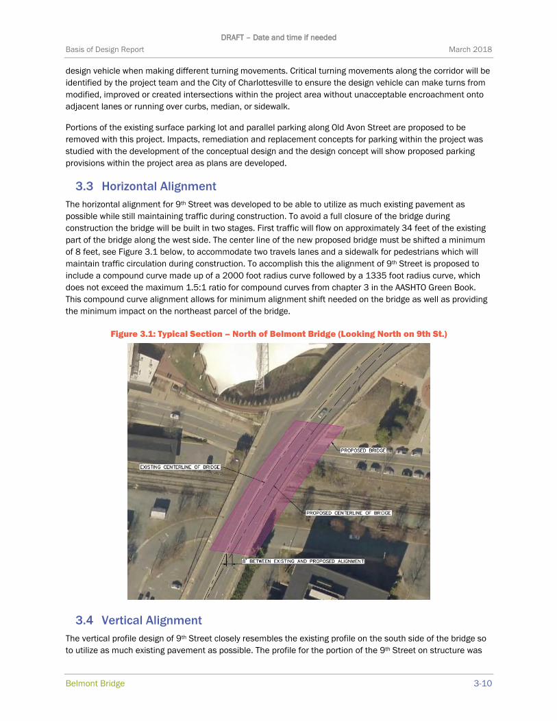
3.3 Horizontal Alignment
The horizontal alignment for 9th Street was developed to be able to utilize as much existing pavement as
possible while still maintaining traffic during construction. To avoid a full closure of the bridge during
construction the bridge will be built in two stages. First traffic will flow on approximately 34 feet of the existing
part of the bridge along the west side. The center line of the new proposed bridge must be shifted a minimum
of 8 feet, see Figure 3.1 below, to accommodate two travels lanes and a sidewalk for pedestrians which will
maintain traffic circulation during construction. To accomplish this the alignment of 9th Street is proposed to
include a compound curve made up of a 2000 foot radius curve followed by a 1335 foot radius curve, which
does not exceed the maximum 1.5:1 ratio for compound curves from chapter 3 in the AASHTO Green Book.
This compound curve alignment allows for minimum alignment shift needed on the bridge as well as providing
the minimum impact on the northeast parcel of the bridge.
Figure 3.1: Typical Section – North of Belmont Bridge (Looking North on 9th St.)
3.4 Vertical Alignment
The vertical profile design of 9th Street closely resembles the existing profile on the south side of the bridge so
to utilize as much existing pavement as possible. The profile for the portion of the 9th Street on structure was

DRAFT – Date and time if needed
Basis of Design Report March 2018
Belmont Bridge 3-11
developed to maintain a minimum vertical clearance of 23 feet between the top of the highest rail of the
Buckingham Branch Railroad and the bottom of the bridge. Currently 4 feet and 9 inches bridge structure
depth is assumed plus an allowance for 2% cross slope for 31 feet from centerline to edge to bridge which
adds an additional .62 feet or a total structure depth of 5.37 feet. At Water Street and Avon Street the profile
must provide a minimum vertical clearance of 14.5 feet; however, given the proximity of both roadways to the
Buckingham Branch Railroad more than the minimum vertical clearance will be provided over both roadways.
On the north side of the bridge the proposed centerline and crown location is shifted east of the existing crown.
The proposed profile will allow for extension of the existing southbound cross slope (approximately 2%) to shift
the crown location to the proposed centerline. This approach will allow for much of the existing pavement and
the existing retaining wall(s) behind the Pavilion to remain and/or be adjusted with milling and overlay. This
approach minimizes the cost of replacement asphalt and simplified maintenance of traffic on the north side of
the proposed bridge replacement.
3.5 Typical Sections
Typical sections were created for the areas both north and south of Belmont bridge based on the constraints of
the design criteria above, to minimize right of way impacts, maintain/enhance pedestrian and bike
accessibility, and supported by the traffic study. On the north side of the Belmont bridge there are four 11 feet
lanes; one northbound through, one northbound left, one northbound right, and one southbound lane through
lane. In addition, there is a 7 foot bike lane heading in each direction. There is a 3 foot MS-1 median between
the southbound through lane and the southbound bike lane. The northbound bike lane is located between the
northbound through and northbound right turn lanes. Figure 3 shows the typical section. Additionally, there is a
10 foot sidewalk heading on the back of the curb in either direction.
Figure 3.2 shows the proposed typical section North of Belmont Bridge.
Figure 3.2: Typical Section – North of Belmont Bridge (Looking North on 9th St.)
The typical section on the south side of the Belmont bridge consists of three 11 feet lanes; one southbound
shared through/right turn lane, one southbound left, and one northbound through. There is a 6 foot median on
the centerline that divides the southbound left and northbound through lanes. 7 foot Bike lanes, which are
separated from vehicle traffic by a 3 foot MS-1 median, are located next to the curb in each direction. In both
directions, there is a 10 foot sidewalk which is contained by a 6 foot greenspace on the traffic side and a
retaining wall on the opposite side. The typical section for south of the bridge is shown in Figure 3.3 below. The
southbound left turn lane is utilized to reduce the delay on the southbound through motion at the 9th Street
and Levy Street intersection.

DRAFT – Date and time if needed
Basis of Design Report March 2018
Belmont Bridge 4-12
Figure 3.3: Typical Section – South of Belmont Bridge (Looking North on 9th St.)
3.6 Superelevation
All streets within the project limits are urban streets with posted speed limits of 25 mph; therefore, the streets
are to utilize normal crown superelevation in accordance with TC5.11 Urban Low Speed (ULS).
3.7 Design Waivers and Exceptions
Because all streets improved within this project are maintained by the City of Charlottesville, no design waivers
for elements that do not meet the requirements of the Virginia Department of Transportation but exceed
AASHTO standards require a design waiver to be submitted. However, the project is required to either fully
comply with AASHTO standards or obtain a Design Exception that must be approved by both the City and VDOT.
Based on a review of the current design, Kimley-Horn anticipates no need for design exceptions on this project.
CHAPTER 4 DRAINAGE AND STORMWATER MANAGEMENT
STRATEGY
This project is “grandfathered” under Part IIC technical criteria rather than being required to meet the “new”
Part IIB criteria. VODT IIM 195.9 allows for a project to be grandfathered if it was partially (or wholly) funded
prior to July 1, 2012. The Belmont Bridge project had funding shown in the 2013 Six Year Improvement Plan.
To maintain this grandfathered status, construction activities must begin prior to July 1, 2019. Therefore, the
minimum requirement for this project could be to meet Part IIC “old” technical criteria that include the
Performance/ Technology-Based methodology for determining compliance with water quality requirements and
MS-19 criteria for determining compliance with stream channel flooding and erosion requirements. However,
the City of Charlottesville has determined that the project will comply with Part IIB criteria to meet the City’s
Goal 3 to support A Beautiful and Sustainable Natural and Built Environment and limit construction revisions if
construction does not start prior to July 1, 2019. Existing conditions relating to feasibility, effectiveness and
cost were evaluated to determine the current stormwater management plan is to construction two onsite
BMP’s (likely Level II Biofiltration) within the limits of the Old Avon Street plaza and purchase nutrient credits
for the remaining water quality credits required for the project.
Water quantity requirements are to be met by reducing the quantity of stormwater run-off by conversion of
impervious surface to pervious surface, regrading or underground detention.

DRAFT – Date and time if needed
Basis of Design Report March 2018
Belmont Bridge 5-13
CHAPTER 5 ANCILLARY DESIGN CONSIDERATIONS
Other guidelines and factors will influence the design of the Belmont bridge replacement. The following
sections briefly describe a few of them and how they will affect the roadway and bridge design.
5.1 ADA Compliance
The project will comply with federal and state Americans with Disabilities Act (ADA) requirements. VDOT
guidance includes the Americans with Disabilities Act Compliance document (TE-377.0) and IIM-LD-55.16
(Guidelines for the Placement of Curb Ramps and Pedestrian Access Routes) dated July 15, 2014, which
pertain specifically to curb ramps and pedestrian access routes. Curb ramps will conform to VDOT Road and
Bridge Standards CG-12 Types A, B, or C (see VDOT Road and Design Manual, Appendix A, Section A-5). The
project’s compliance with ADA requirements is summarized in a memorandum entitled ‘Belmont Bridge
Replacement Project ADA Requirements’ dated October 20, 2017. PROWAG, while not formally adopted, will
be used to evaluate and design for future compliance with upcoming ADA requirements/guidance.
5.2 Traffic Studies Design Integration
This basis of design report is one of numerous studies/reports being completed for the Belmont Bridge
replacement project. For additional information on traffic analyses and traffic operations please see the report
entitled ‘Belmont Bridge Traffic Report’.
5.3 Maintenance of Traffic
All maintenance of traffic plans will comply with the latest editions of the Manual on Uniform Traffic Control
Devices (MUTCD), Virginia Work Area Protection Manual (VWAPM), and local City of Charlottesville
requirements. Traffic control measures will need to meet location specific characteristics for this high density,
urban environment with close intersection spacing and posted speed limits of 25 MPH. Typical types of traffic
control applications found in the VWAPM related to this project include the following:
Work Beyond the Shoulder Operation (TTC-1.1)
Mobile or Short Duration Shoulder Operation (TTC-2.0)
Stationary Operation on Shoulder (TTC-4.1)
Shoulder Closure Operation with Barrier (TTC-6.1)
Shoulder Closure with Barrier and Lane Shift Operation (TTC 7.0)
Short Duration Operation on a Multi-Lane Roadway (TTC-15.1)
Outside Lane Closure Operation on a Four-Lane Roadway (TTC-16.1)
Inside Lane Closure Operation on a Four-Lane Roadway (TTC-17.1)
Lane Closure on a Two-Lane Roadway Using Flaggers (TTC-23.0)
Lane Closure Operation – Near Side of an Intersection (TTC-26.1)
Lane Closure Operation – Far Side of an Intersection (TTC-27.1)
Lane Closure Operation in an Intersection (TTC-28.1)
Turn Lane Closure Operation (TTC-29.1)
Flagging Operation at a Signalized Intersection (TTC-30.1)
Sidewalk Closure and Bypass Sidewalk Operation (TTC-35.0)
Crosswalk Closure and Pedestrian Detour Operation (TTC-36.1)
In addition, Charlottesville’s Pedestrian Accessibility in the Public Way During Construction must be followed
during construction. Any construction that impacts a public street or sidewalk should consider the following:
Advanced warning and guidance signs
DRAFT – Date and time if needed
Basis of Design Report March 2018
Belmont Bridge 5-14
Adequate illumination and reflectors
Use of temporary walkways
Channeling and barricading to separate pedestrians from traffic
Adequate barricading to prevent visually impaired pedestrians from entering work zones
Wheelchair accessible alternate pedestrian circulation routes with appropriate signage
During development of the conceptual design, the decision was made to maintain two-way traffic on 9th Street
at all times through construction. This design decision was made with input from the City and the project’s
Steering Committee. This decision required the conceptual design to accommodate staged construction of the
proposed bridge replacement, which will construct the bridge in two stages. Please see the description in
Section 3.1 Horizontal Alignment for the impact of this decision on the proposed horizontal alignment. The
proposed bridge design was developed to provide a minimum of 28.5’ of proposed bridge constructed in Stage
1. Further, to simplify staging the demolition of the existing bridge is proposed along the existing joint at the
bridge’s centerline. Lastly, the existing Belmont Bridge provides one of the only convenient pedestrian
connections over the Buckingham Branch Railroad in this area of the City, so one pedestrian sidewalk is
proposed to be maintained at all times.

DRAFT – Date and time if needed
Basis of Design Report March 2018
Belmont Bridge 5-15
Figure 5.1: MOT Concept – Conceptual Maintenance of Traffic Concept for 9th Street
5.4 Pedestrian/Bicycle Accommodations
The project will comply with guidelines published by the National Associations of City Transportation Officials
(NACTO) entitled Urban Bikeway Design Guide and Urban Street Design Guide for pedestrian and bicycle
accommodations. The conceptual design was developed with significant input from the public, City Staff and

DRAFT – Date and time if needed
Basis of Design Report March 2018
Belmont Bridge 5-16
the City’s Bicycle and Pedestrian Advisory Committee. The conceptual design as proposed will enhance the
following bicycle and pedestrian accommodations with the following measures:
Separated bicycle lanes from north of the intersection with Levy Avenue to the north end of the
replacement bridge (both northbound and southbound on 9th Street/Avon Street).
Northbound separated bicycle lane from north end of the replacement bridge to the south side of the
intersection with E. Market Street.
Southbound Buffered bicycle lane from the north end of the replacement bridge to the south side of the
intersection with E. Market Street.
10 foot wide sidewalks from the intersection with Levy Avenue to the intersection with E. Market Street
(both northbound and southbound on 9th Street/Avon Street).
Signalized pedestrian crossings of 9th Street and side streets at signalized intersections with Levy Avenue
and E. Market Street.
A new pedestrian passageway below 9th Street from the east to the west of 9th Street in the vicinity of the
Graves Street and Monticello Avenue intersection.
Extension of the existing pedestrian passageway below 9th Street into the Pavilion.
Stair towers from 9th Street to the adjacent street network in the Southwest quadrant (to Old Avon Street),
in the Northwest quadrant (to Water Street west) and Northeast quadrant (to Water Street east).
Connection to the proposed Water Street Trail east of the replacement bridge.
Pedestrian Plaza with closure of Old Avon Street at Levy Avenue which simplified pedestrian crossings and
improves signal timing for pedestrians at Levy Avenue/Avon Street.
5.5 Bridge Design
The Kimley-Horn team will develop bridge plans that detail substructure, superstructure and foundation
designs for the bridge depicted in the concept drawings. Please see the Stage 1 bridge report for the Belmont
Bridge Replacement project (for details. However, basic design components for the replacement bridge are as
follows:
Three spans over Old Avon Street, Buckingham Branch Railroad and Water Street
Total Bridge Length of approximately 235.89’
Proposed Typical Section as shown below:
Figure 5.2: Typical Section – Belmont Bridge over Buckingham Branch Railroad, Water Street and
Old Avon Street
Related Documents


