Welcome message from author
This document is posted to help you gain knowledge. Please leave a comment to let me know what you think about it! Share it to your friends and learn new things together.
Transcript

Introduction Classification Working of Two stroke Working of Four stroke Power cycles Valve timing diagram IC engine combustion Working of simple carburetor M.P.F.I. system Lubricant additives and their
advantages
INDEX
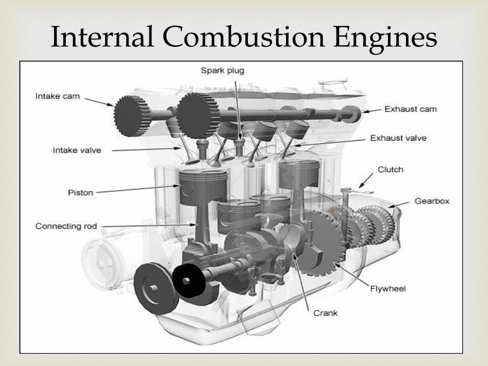
Internal Combustion Engines

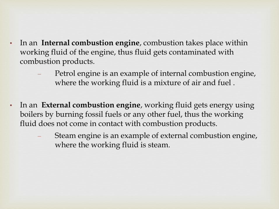
• In an Internal combustion engine, combustion takes place within working fluid of the engine, thus fluid gets contaminated with combustion products.
– Petrol engine is an example of internal combustion engine, where the working fluid is a mixture of air and fuel .
• In an External combustion engine, working fluid gets energy using boilers by burning fossil fuels or any other fuel, thus the working fluid does not come in contact with combustion products.
– Steam engine is an example of external combustion engine, where the working fluid is steam.
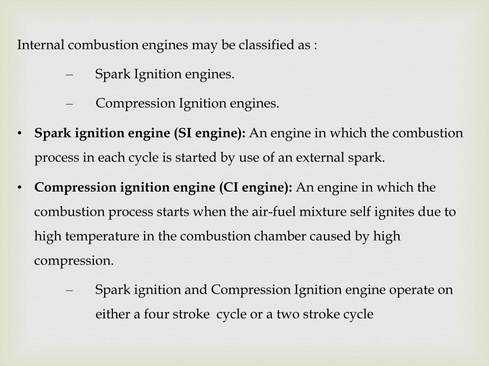
Internal combustion engines may be classified as :
– Spark Ignition engines.
– Compression Ignition engines.
• Spark ignition engine (SI engine): An engine in which the combustion
process in each cycle is started by use of an external spark.
• Compression ignition engine (CI engine): An engine in which the
combustion process starts when the air-fuel mixture self ignites due to
high temperature in the combustion chamber caused by high
compression.
– Spark ignition and Compression Ignition engine operate on
either a four stroke cycle or a two stroke cycle
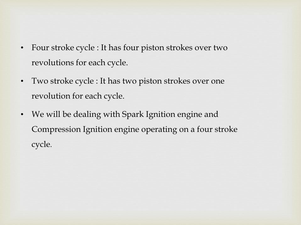
• Four stroke cycle : It has four piston strokes over two
revolutions for each cycle.
• Two stroke cycle : It has two piston strokes over one
revolution for each cycle.
• We will be dealing with Spark Ignition engine and
Compression Ignition engine operating on a four stroke
cycle.
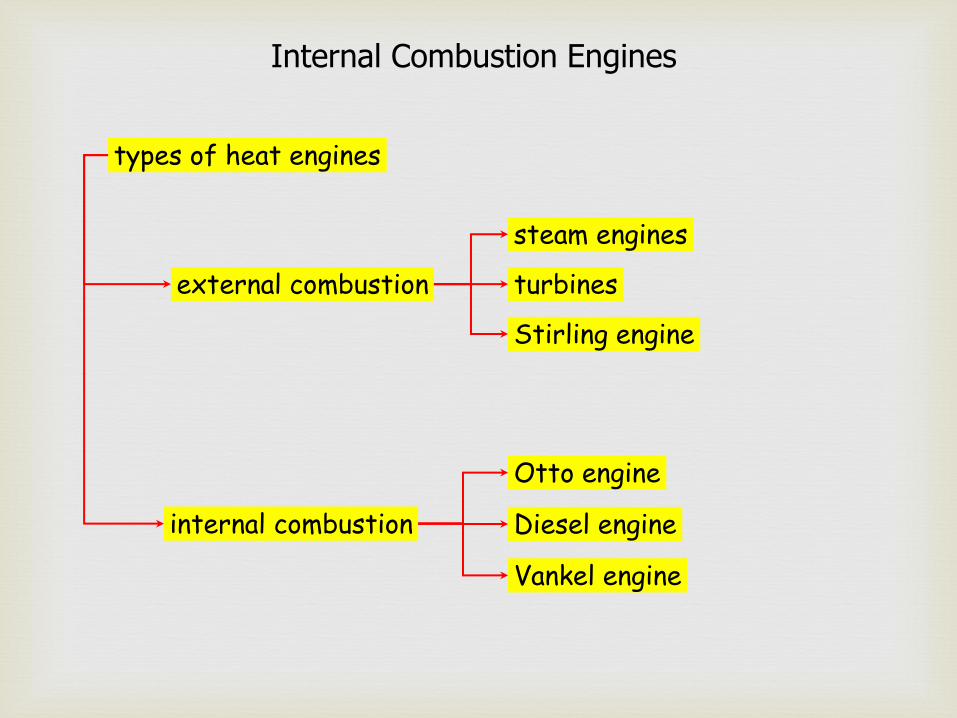
Internal Combustion Engines
types of heat engines
external combustion
internal combustion
steam engines
turbines
Stirling engine
Otto engine
Diesel engine
Vankel engine

Applications of I.C. Engines
The internal combustion engine is an engine in which the
combustion of fuel-oxidizer mixture occurs in a confined space
applied in: automotive rail transportation power generation ships aviation garden appliances
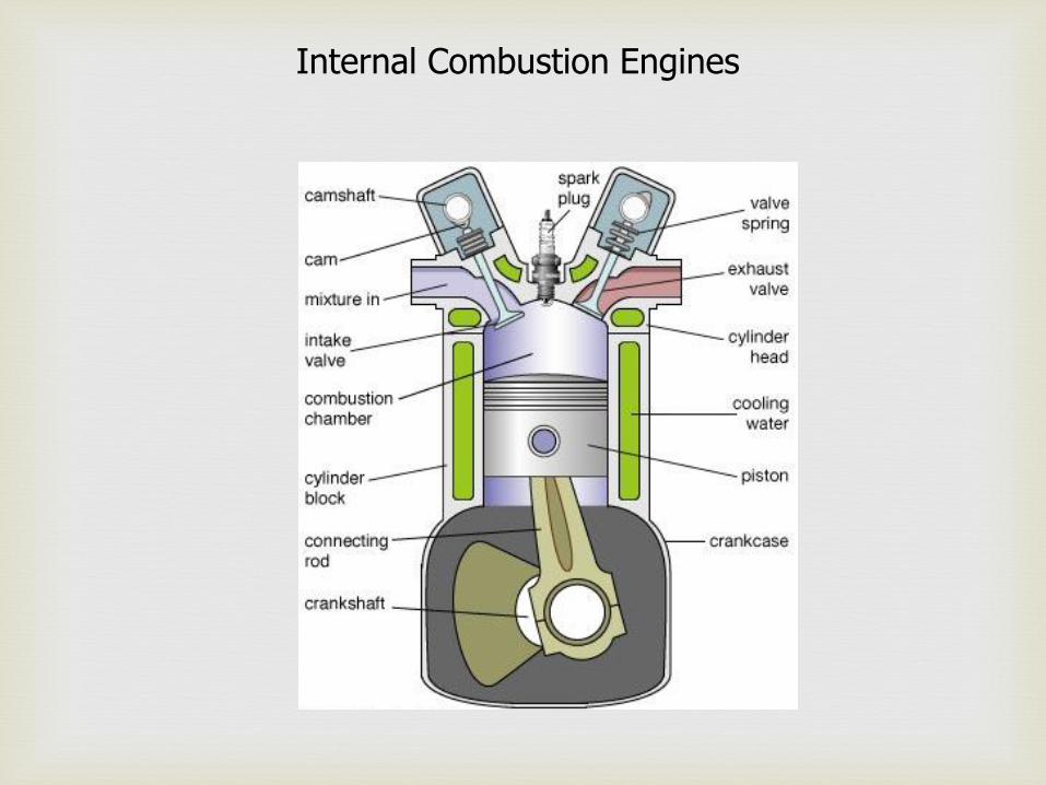
Internal Combustion Engines

Internal Combustion Engines – two stroke -
1. Power / Exhaust 2. Intake / Compression
a. ignition b. piston moves downward
compressing fuel-air mixture in the crankcase
c. exhaust port opens
a. inlet port opens b. compressed fuel-air mixture
rushes into the cylinder c. piston upward movement
provides further compression
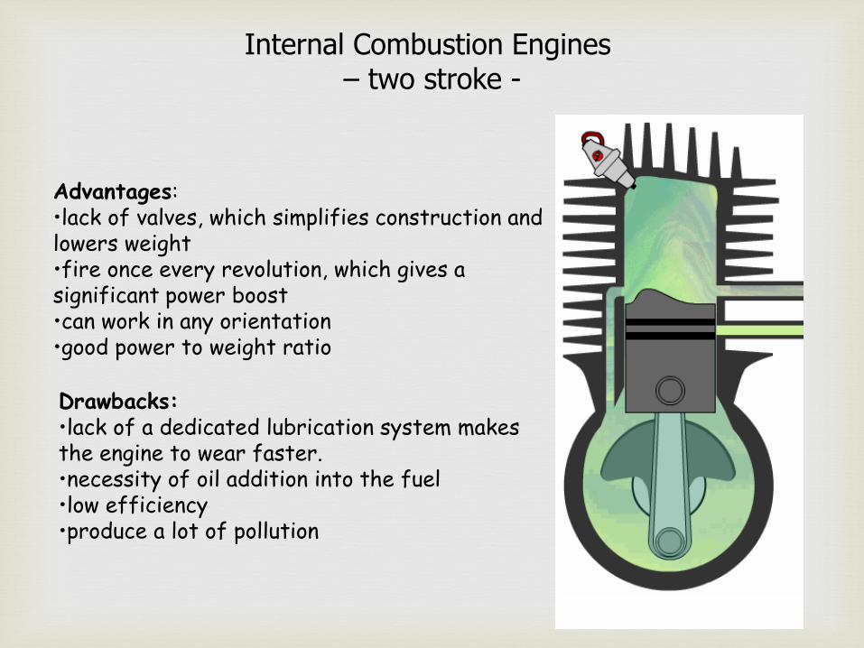
Internal Combustion Engines – two stroke -
Advantages: •lack of valves, which simplifies construction and lowers weight •fire once every revolution, which gives a significant power boost •can work in any orientation •good power to weight ratio
Drawbacks: •lack of a dedicated lubrication system makes the engine to wear faster. •necessity of oil addition into the fuel •low efficiency •produce a lot of pollution

Internal Combustion Engines – four stroke -
starting position
a. piston starts moving down b. intake valve opens c. air-fuel mixture gets in
1. intake
a. piston moves up b. both valves closed c. air-fuel mixture gets compressed
2. compression

Internal Combustion Engines – four stroke -
ignition
a. air-fuel mixture explodes driving the piston down
3. power
a. piston moves up b. exhaust valve opens c. exhaust leaves the cylinder
4. exhaust

Internal Combustion Engines – four stroke -
Advantages: •dedicated lubrication system makes to engine more wear resistant •better efficiency that 2-stroke engine •no oil in the fuel – less pollution
Drawbacks: •complicated constriction •should work in horizontal position due to lubrication

Internal Combustion Engines – Diesel -
air intake
compression
fuel injection
combustion
exhaust
exhaust /intake
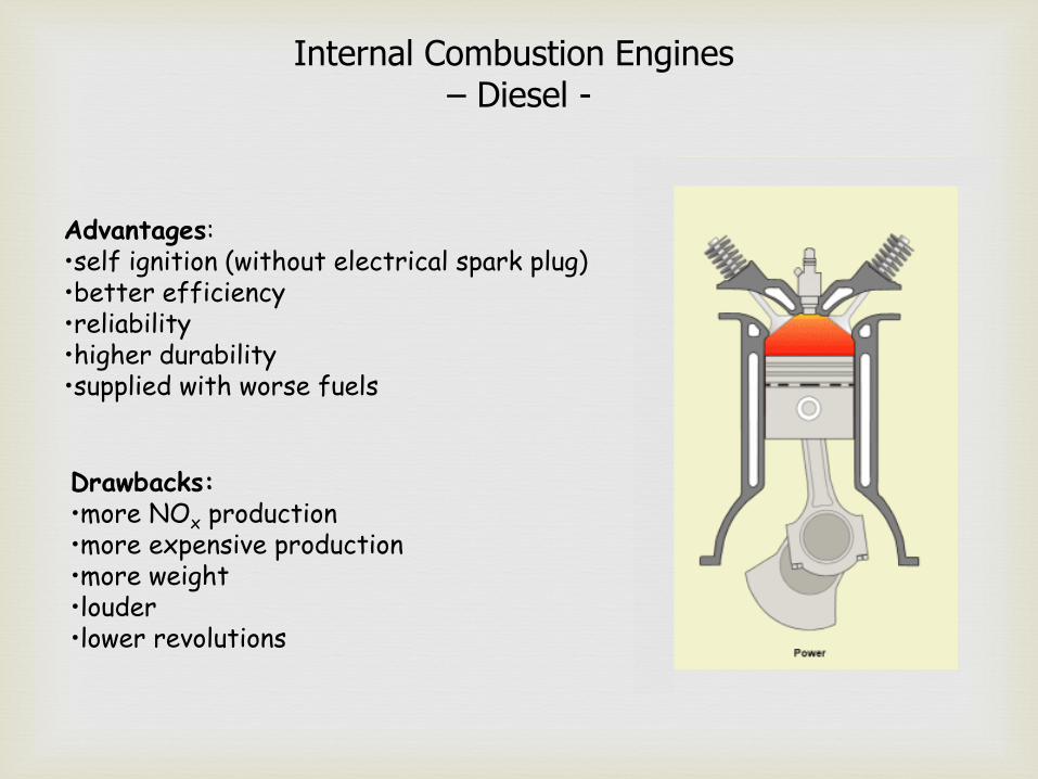
Internal Combustion Engines – Diesel -
Advantages: •self ignition (without electrical spark plug) •better efficiency •reliability •higher durability •supplied with worse fuels
Drawbacks: •more NOx production •more expensive production •more weight •louder •lower revolutions
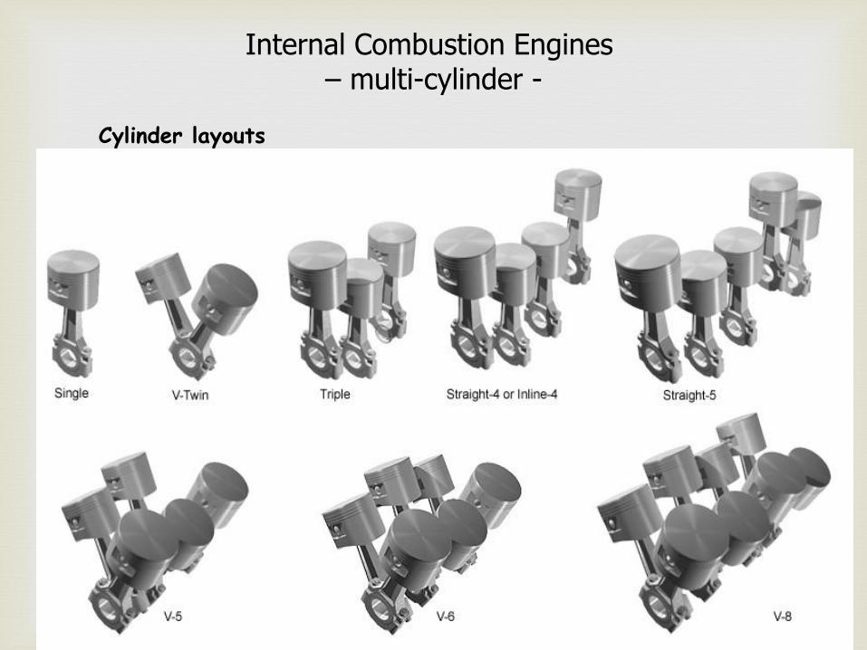
Internal Combustion Engines – multi-cylinder -
Cylinder layouts
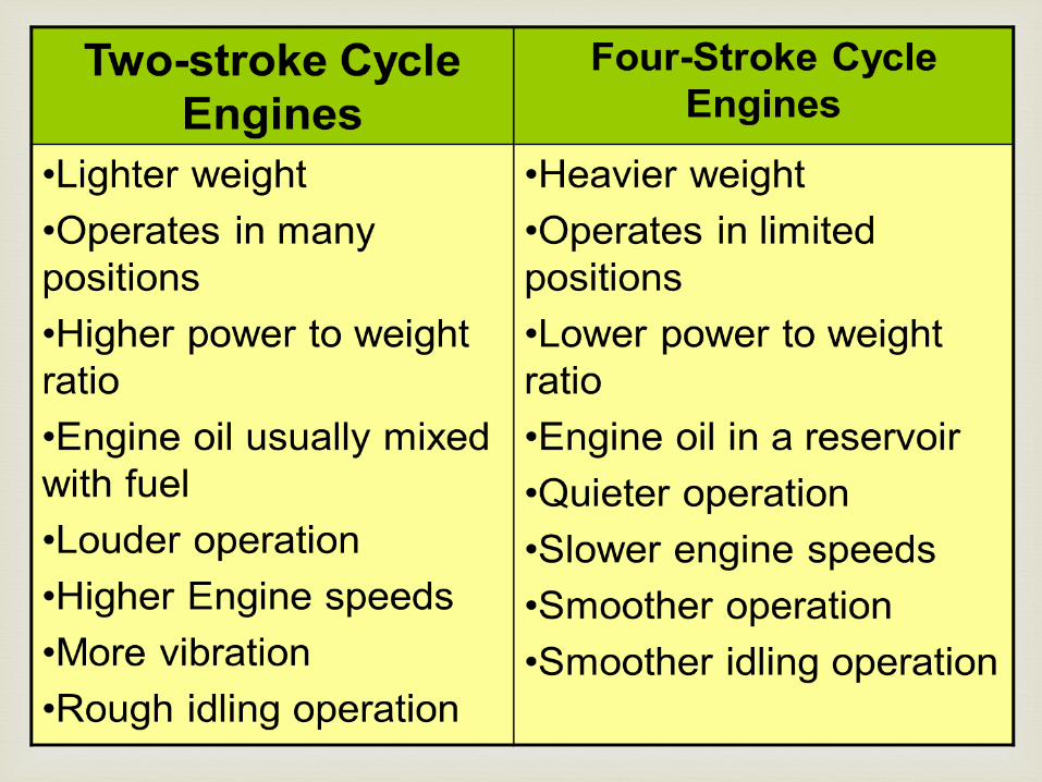
Characteristics of two- and four-stroke engines
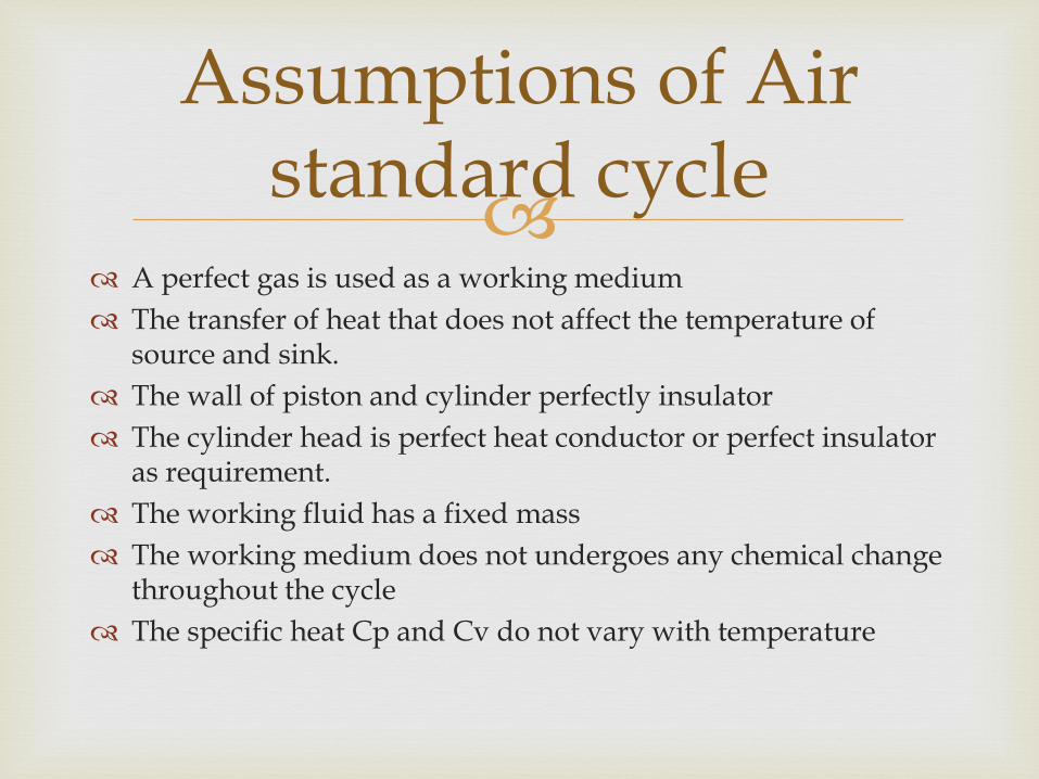
A perfect gas is used as a working medium
The transfer of heat that does not affect the temperature of source and sink.
The wall of piston and cylinder perfectly insulator
The cylinder head is perfect heat conductor or perfect insulator as requirement.
The working fluid has a fixed mass
The working medium does not undergoes any chemical change throughout the cycle
The specific heat Cp and Cv do not vary with temperature
Assumptions of Air standard cycle

Power Cycles
The air standard Otto Cycle is an ideal cycle that approximates a spark-ignition internal combustion engine. It assumes that the heat addition occurs instantaneously while the piston is at TDC.
a) Otto cycle

Process
(1-2) Isentropic Compression
Compression from ν1 => v2
↓ ↓ BDC(β=180º ) TDC (θ=0º)
(2-3) Constant Volume heat input: QH
•While at TDC: umin
•Ignition of fuel (chemical reaction takes place)
(3-4) Isentropic Expansion
•Power is delivered while s = const.
(4-1) Constant volume heat rejection process
a) Otto cycle

b) Diesel cycle
Process 1-2: Isentropic compression Process 2-3: Constant pressure heat addition Process 3-4: Isentropic expansion Process 4-1: Constant volume heat rejection
P-V Diagram T-S Diagram
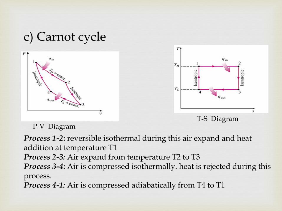
c) Carnot cycle
Process 1-2: reversible isothermal during this air expand and heat addition at temperature T1 Process 2-3: Air expand from temperature T2 to T3 Process 3-4: Air is compressed isothermally. heat is rejected during this process. Process 4-1: Air is compressed adiabatically from T4 to T1
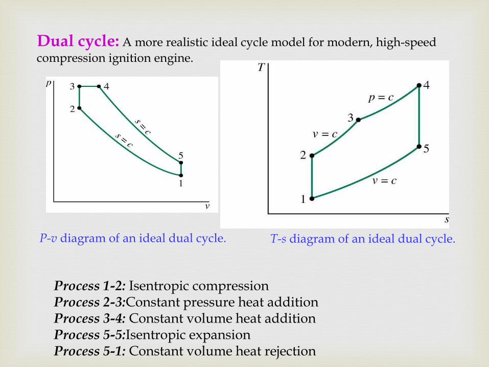
P-v diagram of an ideal dual cycle.
Dual cycle: A more realistic ideal cycle model for modern, high-speed
compression ignition engine.
T-s diagram of an ideal dual cycle.
Process 1-2: Isentropic compression Process 2-3:Constant pressure heat addition Process 3-4: Constant volume heat addition Process 5-5:Isentropic expansion Process 5-1: Constant volume heat rejection
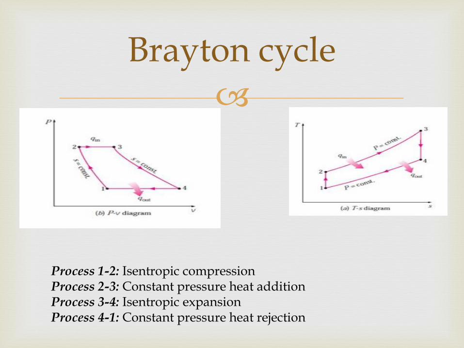
Brayton cycle
Process 1-2: Isentropic compression Process 2-3: Constant pressure heat addition Process 3-4: Isentropic expansion Process 4-1: Constant pressure heat rejection

Valve Timing diagram for 4-s SI & CI
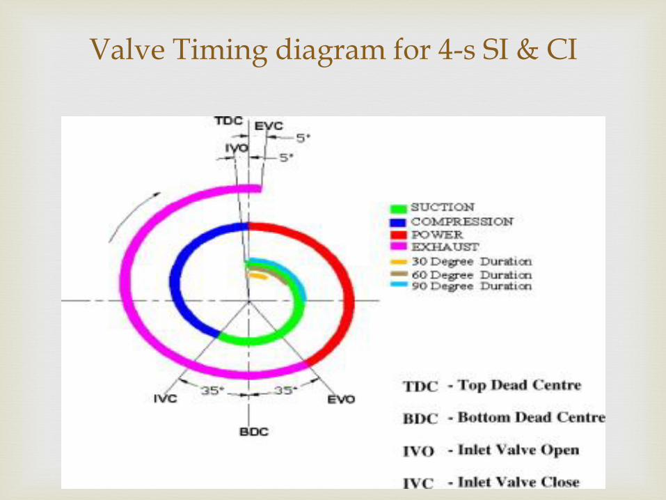
Valve Timing diagram for 4-s SI & CI
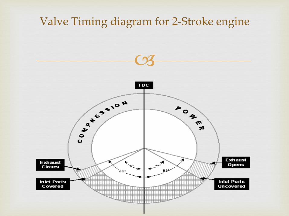
Valve Timing diagram for 2-Stroke engine
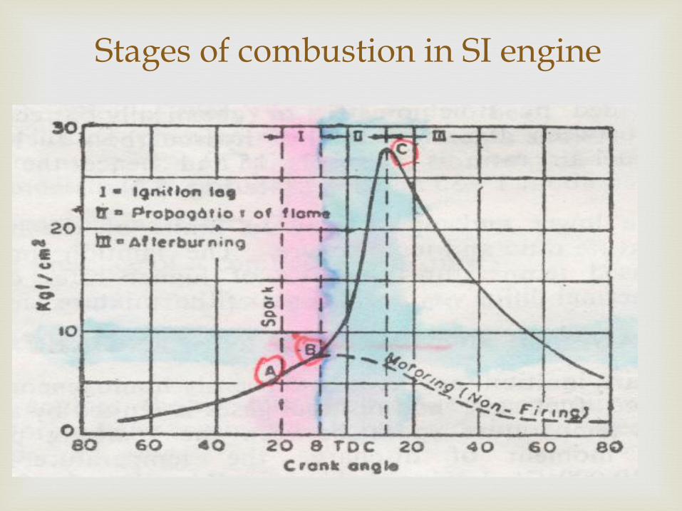
Stages of combustion in SI engine
Ignition Lag It is related with growth and development of a left propagating flame. Flame Propagation During this the sudden pressure and temperature rise. The heat released rate is depend on turbulence intensity and reaction rate of charge. After Burning This is instant at which the pressure is reached on the indicator diagram. The velocity of flame decreases so combustion rate decreases. Since the expansion stroke start before this stage.
Stages of combustion in SI engine

32
In Cylinder Measurements
This graph shows the fuel injection flow rate, net heat release rate and
cylinder pressure for a direct injection CI engine.
Start of injection
Start of combustion
End of injection
33
Combustion in CI Engine The combustion process proceeds by the following stages:
Ignition delay (ab) - fuel is injected directly into the cylinder towards the end of
the compression stroke. The liquid fuel atomizes into small drops and
penetrates into the combustion chamber. The fuel vaporizes and mixes with
the high-temperature high-pressure air.
Premixed combustion phase (bc) – combustion of the fuel which has mixed
with the air to within the flammability limits (air at high-temperature and high-
pressure) during the ignition delay period occurs rapidly in a few crank angles.
Mixing controlled combustion phase (cd) – after premixed gas consumed, the
burning rate is controlled by the rate at which mixture becomes available for
burning. The rate of burning is controlled in this phase primarily by the fuel-air
mixing process.
Late combustion phase (de) – heat release may proceed at a lower rate well
into the expansion stroke (no additional fuel injected during this phase).
Combustion of any unburned liquid fuel and soot is responsible for this.

34
Four Stages of Combustion in CI Engines
Start of
injection
End of
injecction
-10 TC -20 10 20 30
It is the process of clearing or sweeping out the exhaust
gases from the combustion chamber of the cylinder.
It is necessary that cylinder should not have any burnt gases because they mixed with the fresh incoming charge and reduce its strength.
Power will loss if the fresh charge is diluted by the exhaust gases.
The scavenging is necessary only in two stroke engines since piston does not help for clearing the burned gas from the cylinder.
Scavenging

Cross flow scavenging
Full loop or back flow scavenging
Uniform flow scavenging
Types of scavenging
In SI engine the combustion during the normal
working is initiated by a electric spark.
The spark is timed to occur at a definite point just before the end of the compression stroke.
The ignition of the charge should not occurs before the spark is introduced in the cylinder, if the ignition start due to any other reasons when the piston is still doing its compression stroke is called as pre-ignition
Pre- Ignition
High compression ratio
Overheated spark plug point
Incandescent carbon deposit on cylinder wall.
Overheated exhaust valve
It may occur due to faulty timing of spark production.
Pre-ignition occurs due to following reasons

Reduce useful work per cycle
Increase heat losses from engine
Reduction in the thermal efficiency
Subjected the engine components to excessive pressure
Effects of Pre-ignition

It is the indication of abnormal combustion in the
engine cylinder, in normal combustion of SI engine the spark is produce just before the end of compression .
In abnormal combustion after the combustion produced, there is rise of temperature and pressure due to the combustion of the ignited fuel which leads to propagate the flame to the remote part of the cylinder & the charge present in the remote part reaches to critical temperature
Detonation

Noise
Mechanical damage
Increase heat transfer
Pre-ignition
Decrease in power out put
Effects of detonation
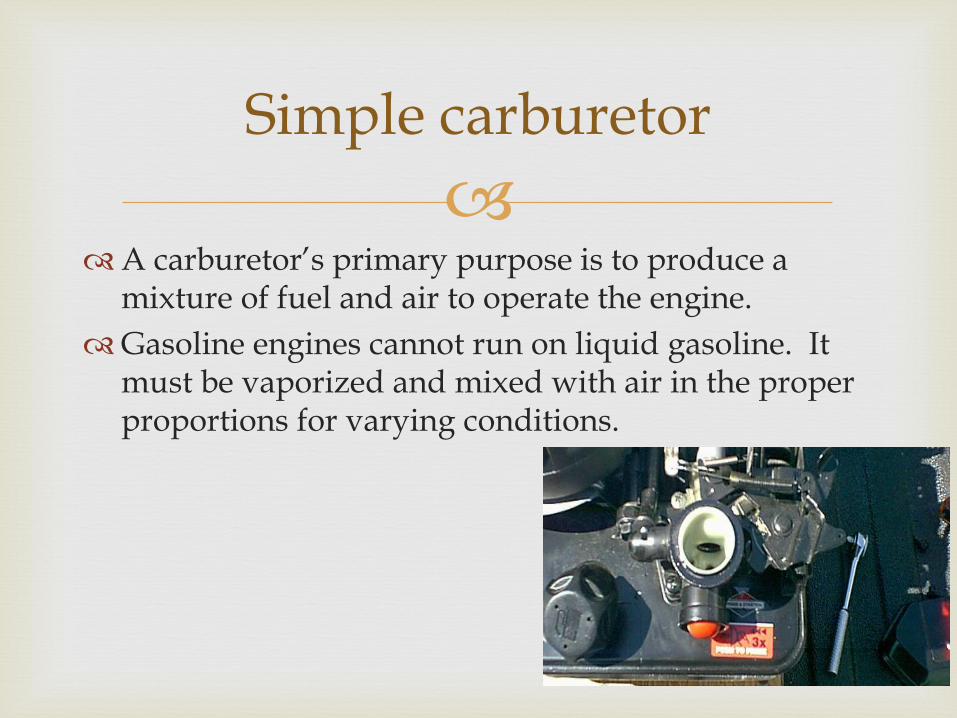
A carburetor’s primary purpose is to produce a
mixture of fuel and air to operate the engine.
Gasoline engines cannot run on liquid gasoline. It must be vaporized and mixed with air in the proper proportions for varying conditions.
Simple carburetor

The carburetor must create an air fuel mixture that is
correct for different circumstances such as:
Cold or hot starting
Idling
Part throttle
Acceleration
High speed operation
Carburetors work on the principle of air pressure differences. When discussing pressure differences we will talk about
Carburetion

How does it work?
Air enters the top of the carburetor and is mixed with liquid fuel.
This increase in velocity reduces pressure causing
fuel to be drawn into the air stream.
Particles of fuel are vaporized by air rushing through the venturi.
The air fuel mixture is forced into the intake manifold by atmospheric pressure and burned in the combustion chamber of the engine.
A venturi is a restriction in an air passage that increases air speed or velocity.
How does it work?
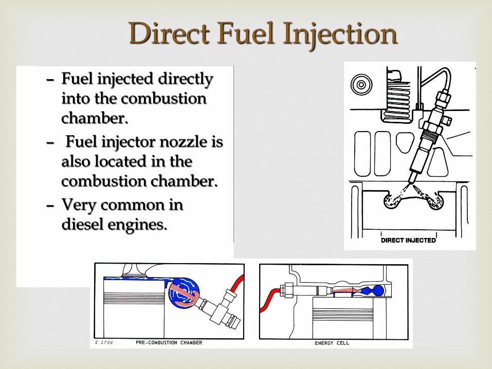
Direct Fuel Injection
– Fuel injected directly into the combustion chamber.
– Fuel injector nozzle is also located in the combustion chamber.
– Very common in diesel engines.

Throttle Body Fuel Injection
– Injectors are located in the throttle body.
– Throttle body is the intake cavity or intake manifold.
– The Carburetor is removed from the intake manifold and simply replaced by a fuel injection system.

Multi-Port (Point) Fuel Injection
– Uses one injector located: • At the mouth of the intake
valve -or-
• At the mouth of an individual intake port that is connected to only one intake valve.
– Much more efficient
– Chrysler began this in the late 70’s, Ford mid 80’s, Chevy Vortex
Related Documents