Welcome message from author
This document is posted to help you gain knowledge. Please leave a comment to let me know what you think about it! Share it to your friends and learn new things together.
Transcript

Basic Welding Inspection for
Field Inspectors
Class Agenda
What is Welding?
Video Presentation – The Welding Process
Types of Welding You Will Encounter
Weld Specification Review
Welding Inspection
Hands-on Session
Course Objectives
To familiarize inspection personnel with basic welding and inspection requirements for welded structures.
To review and discuss VDOT specifications and the American Welding Society Welding Code.
To demonstrate welding and inspection processes.
To make sure you know how to get assistance with welding /inspection problems.
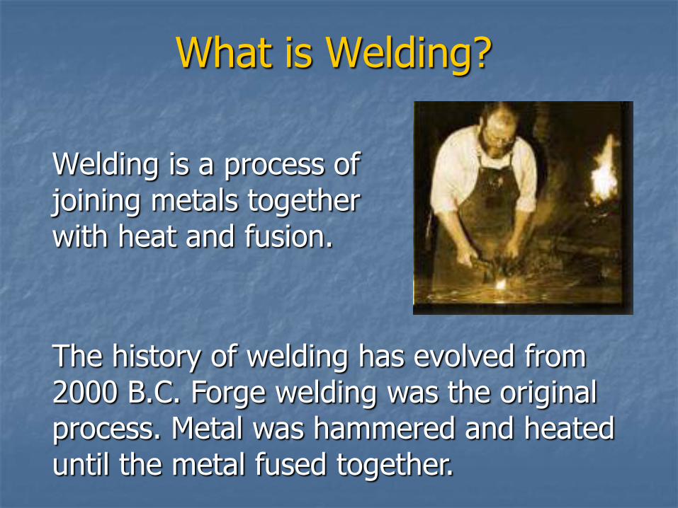
What is Welding?
Welding is a process of joining metals together with heat and fusion.
The history of welding has evolved from 2000 B.C. Forge welding was the original process. Metal was hammered and heated until the metal fused together.
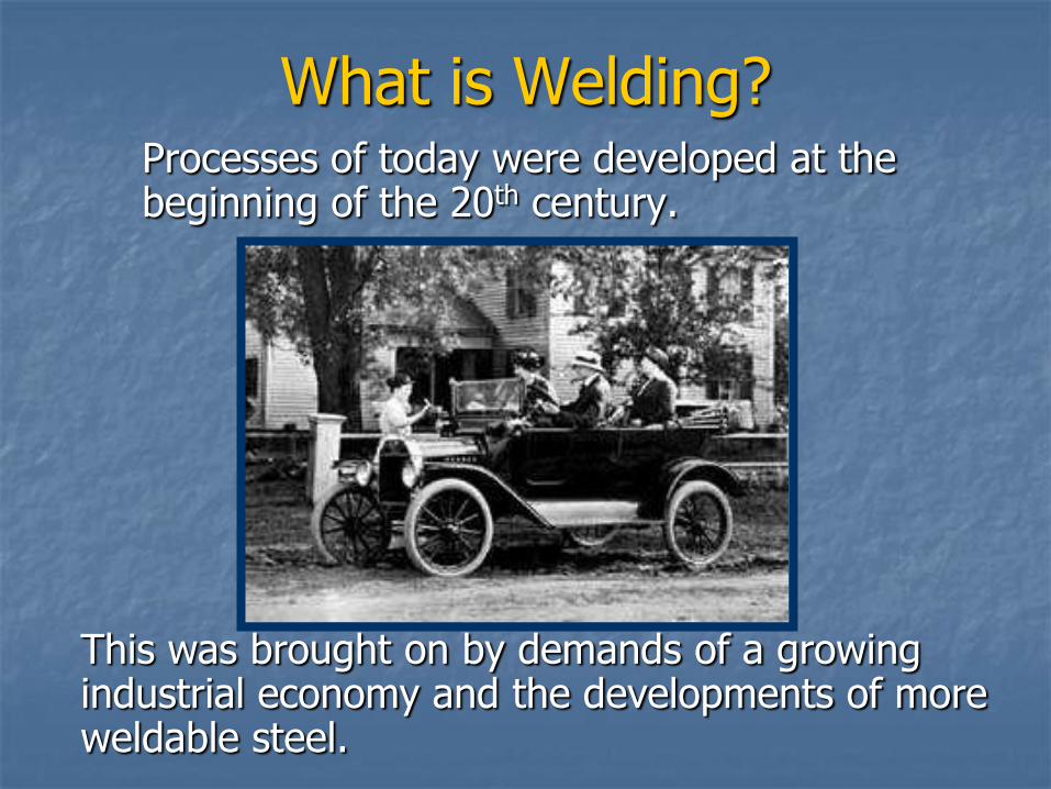
Processes of today were developed at the beginning of the 20th century.
What is Welding?
This was brought on by demands of a growing industrial economy and the developments of more weldable steel.
What is Welding?
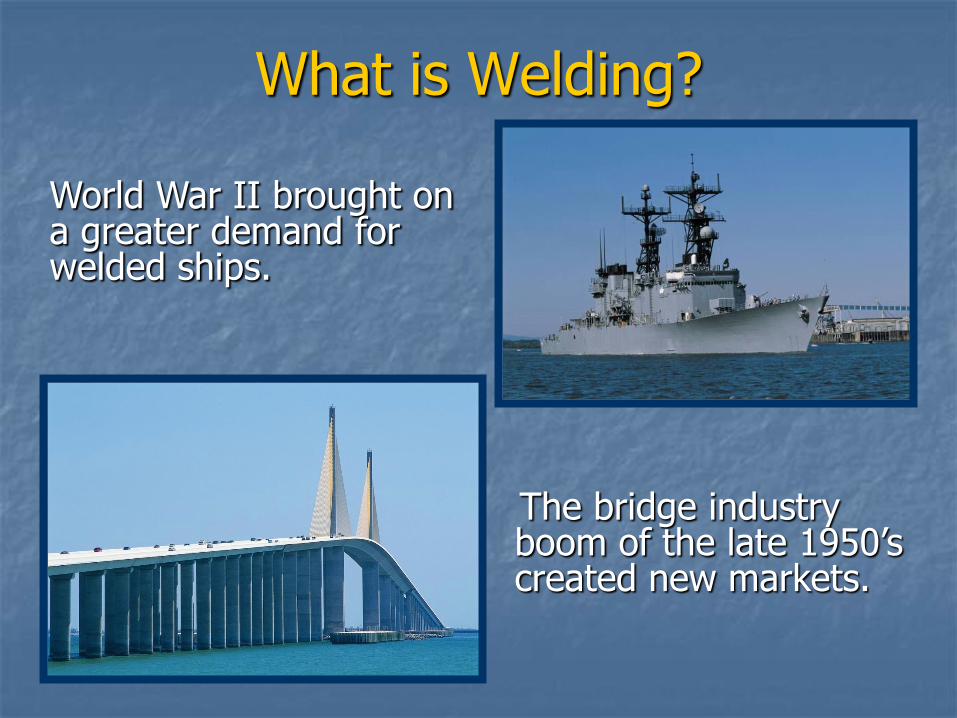
World War II brought on a greater demand for welded ships.
The bridge industry boom of the late 1950’s created new markets.
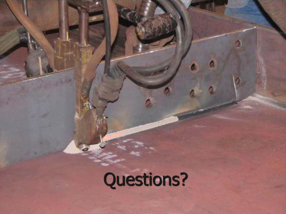
Questions?
Types of Welding You Will Encounter
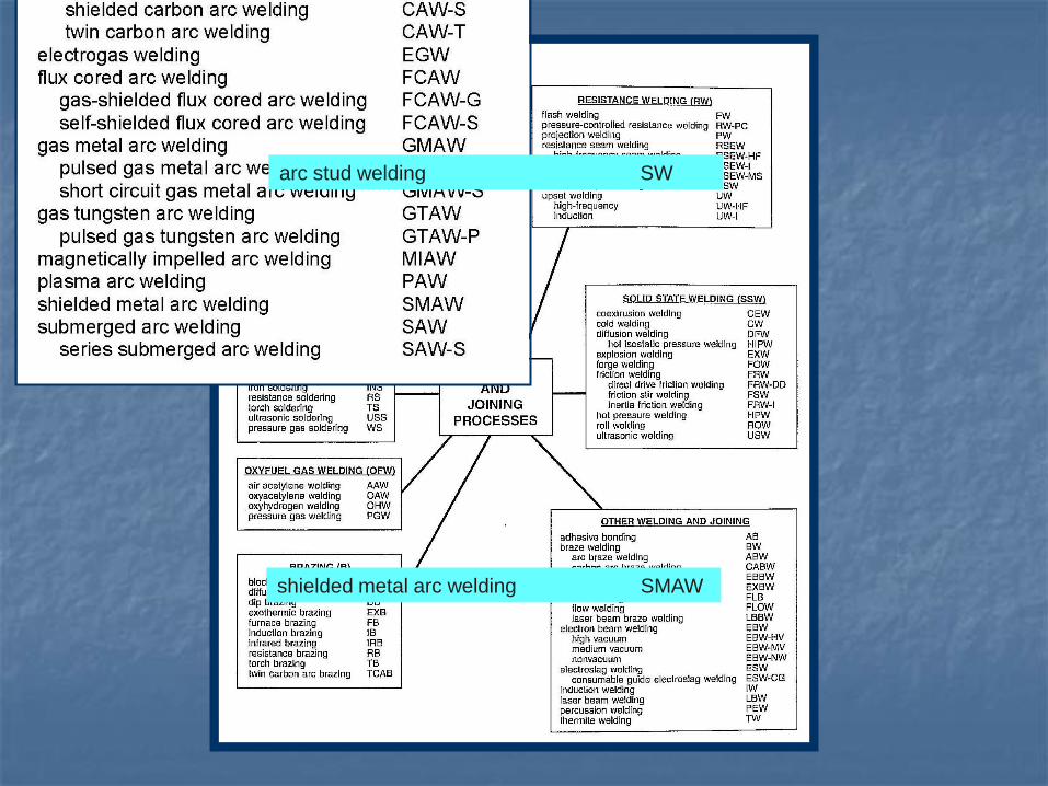
shielded metal arc welding SMAW
arc stud welding SW
Common Field Welding Applications
Stay in place forms
Sole plates on concrete girders
Sole plates on steel girders
Pot bearings
H-Pile and pipe pile splices
Soldier piles for retaining walls
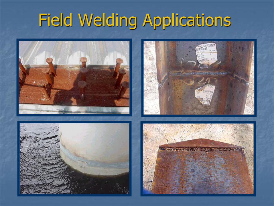
Field Welding Applications
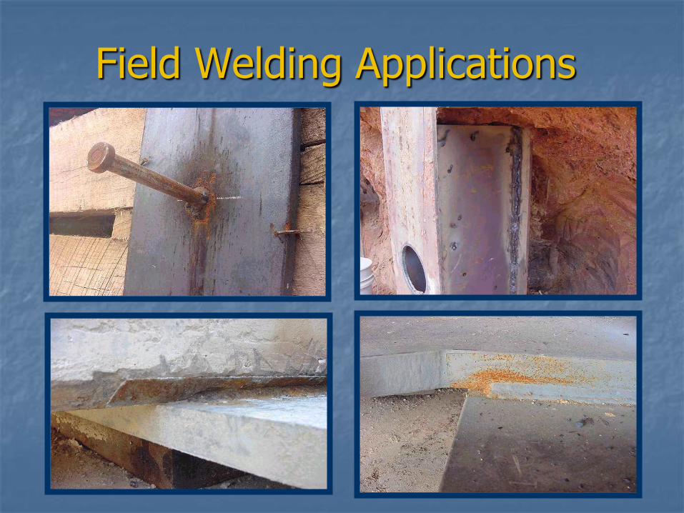
Field Welding Applications
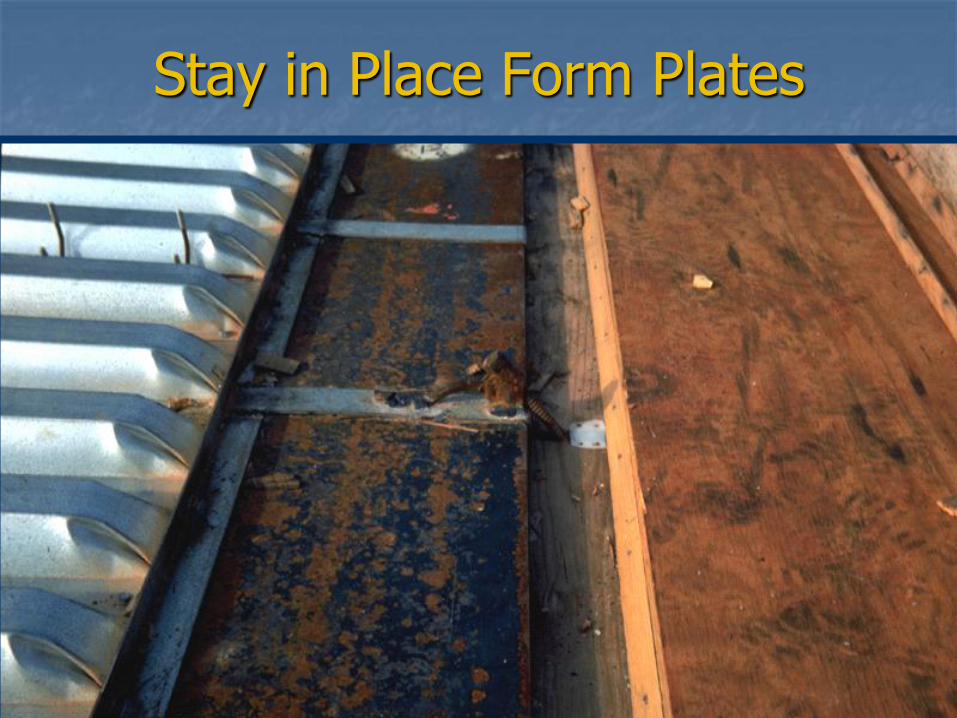
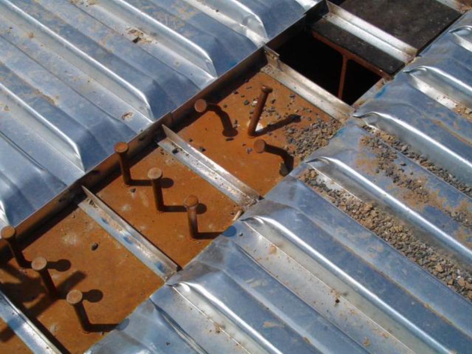
Stay in Place Form Plates
Stay In Place Forms Welding Considerations
VDOT Road & Bridge Specifications 404.03
Devices for supporting forms of any type shall not be welded to steel beams or girders unless specified on the plans.
Preheat requirements also apply to SIP welds.
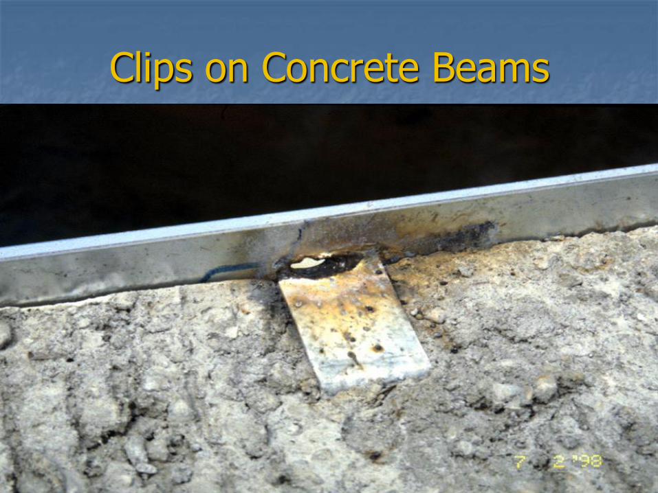
Clips on Concrete Beams
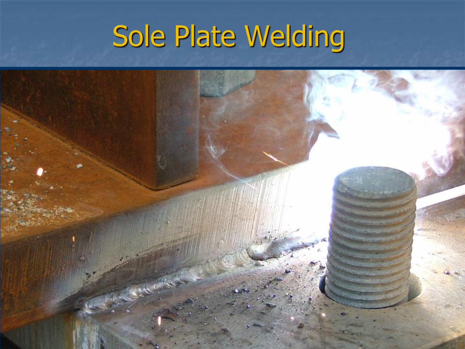
Sole Plate Welding
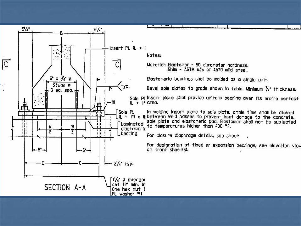
Sole Plate & Bearing Plate Welding
The maximum temperature for welds on bearing plates with elastomeric pads bonded to them or pot bearings is 400
oF.
Alternate welding from one side of the bearing plate to another when making multiple passes to keep the temperature of the bearing plate from exceeding the maximum allowed.
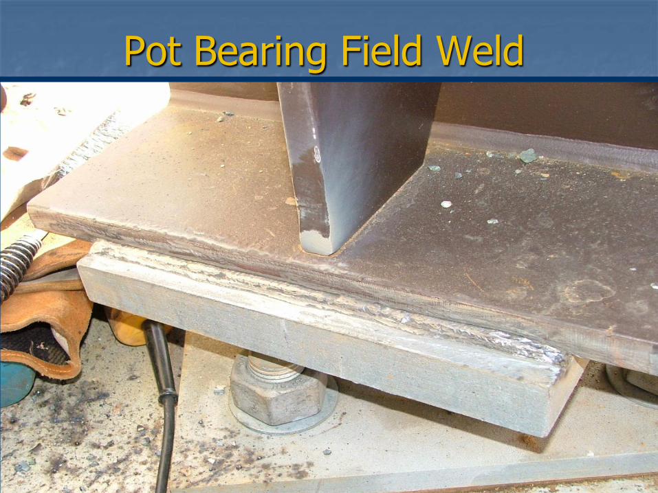
Pot Bearing Field Weld
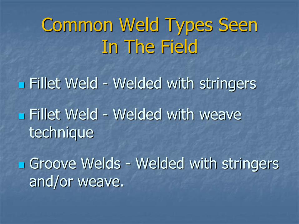
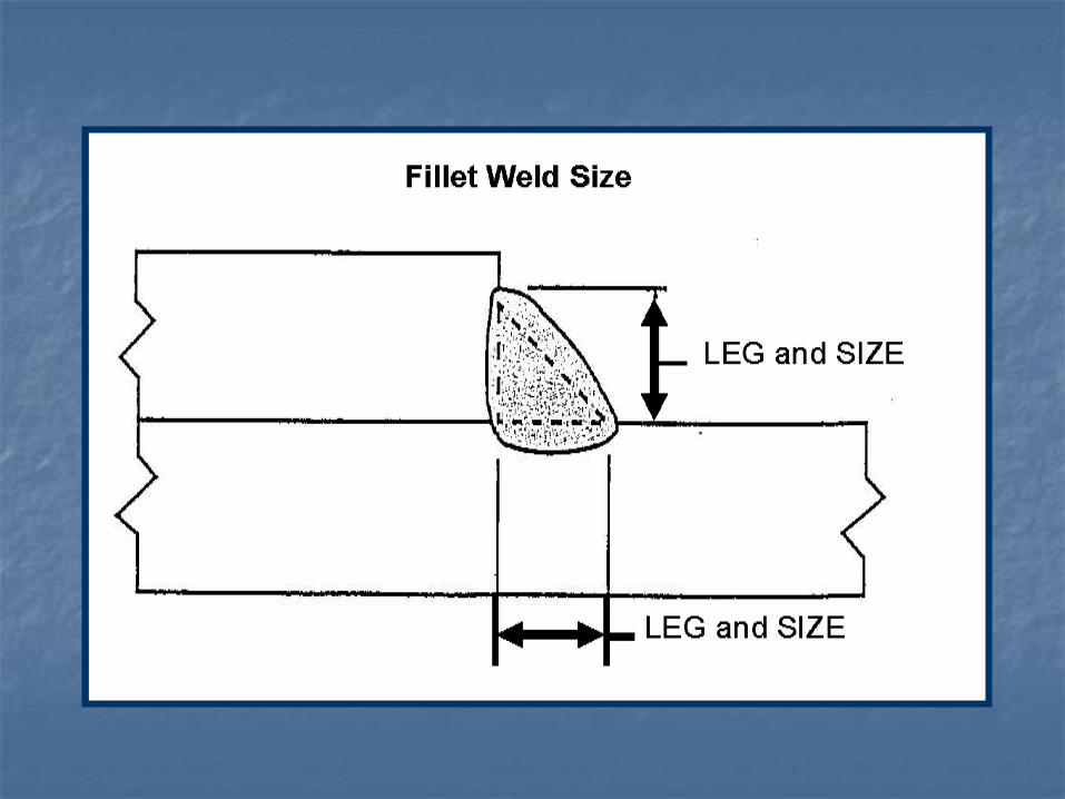
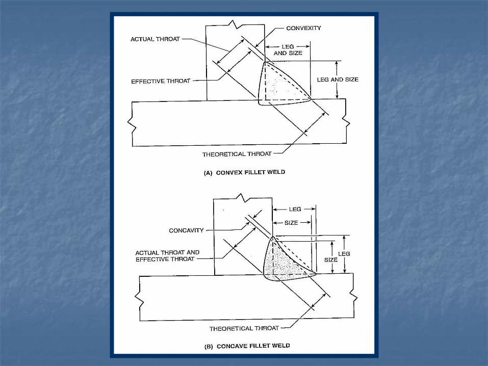
Common Weld Types Seen In The Field
Fillet Weld - Welded with stringers
Fillet Weld - Welded with weave technique
Groove Welds - Welded with stringers and/or weave.
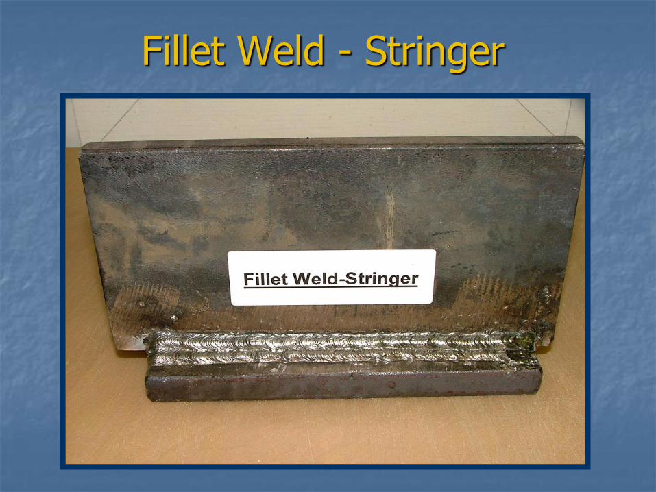
Fillet Weld - Stringer
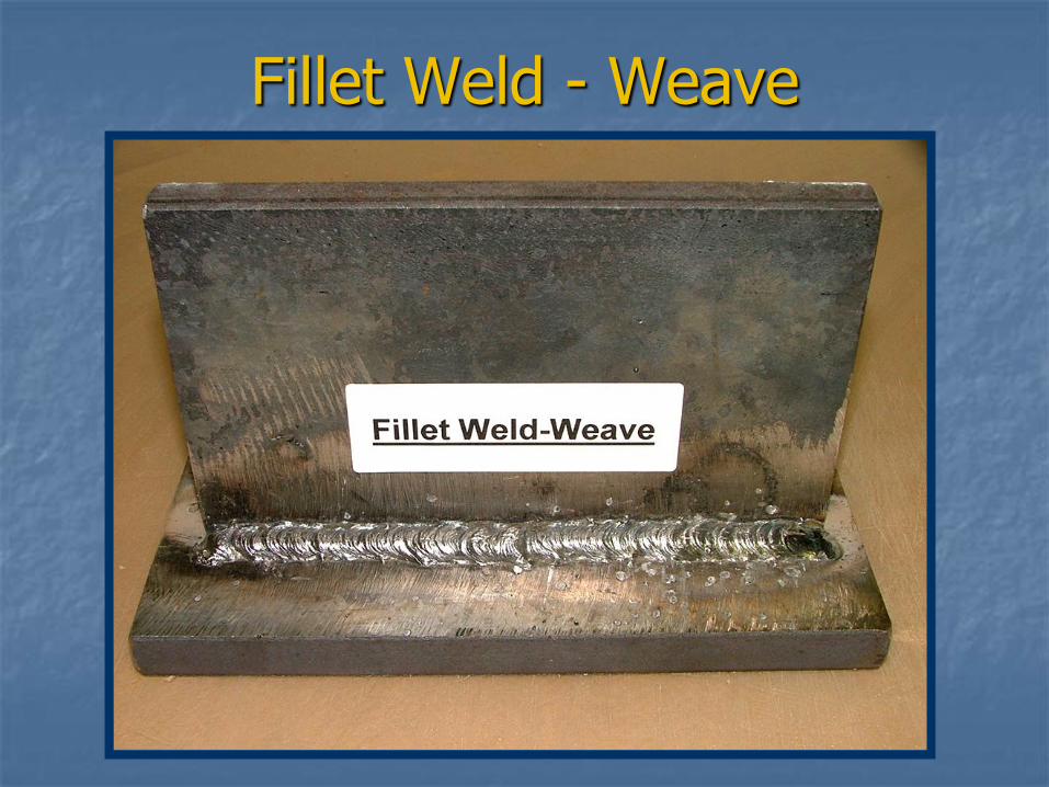
Fillet Weld - Weave
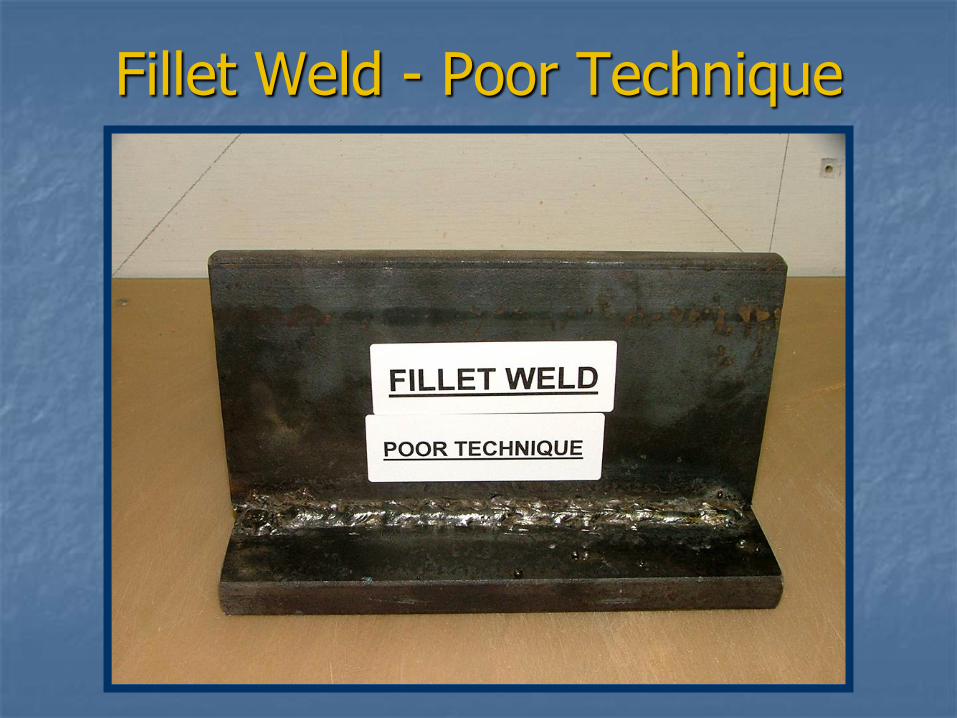
Fillet Weld - Poor Technique
QUESTIONS?
WELD SPECIFICATION REVIEW
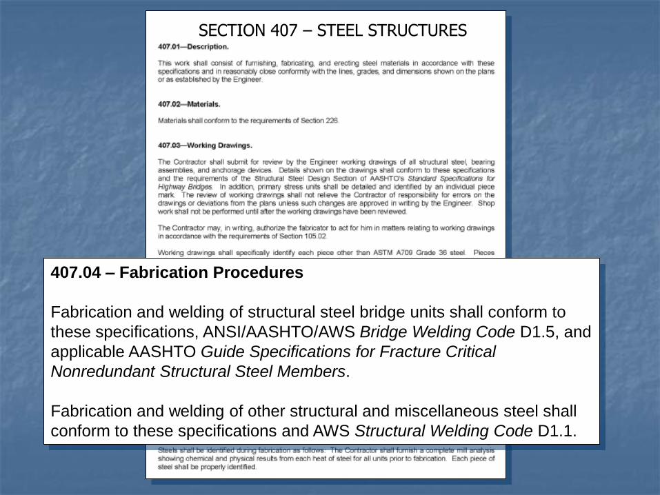
SECTION 407 – STEEL STRUCTURES
407.04 – Fabrication Procedures
Fabrication and welding of structural steel bridge units shall conform to
these specifications, ANSI/AASHTO/AWS Bridge Welding Code D1.5, and
applicable AASHTO Guide Specifications for Fracture Critical
Nonredundant Structural Steel Members.
Fabrication and welding of other structural and miscellaneous steel shall
conform to these specifications and AWS Structural Welding Code D1.1.
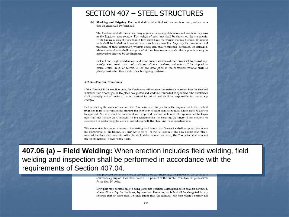
SECTION 407 – STEEL STRUCTURES
407.06 (a) – Field Welding: When erection includes field welding, field
welding and inspection shall be performed in accordance with the
requirements of Section 407.04.
AWS BRIDGE WELDING CODE
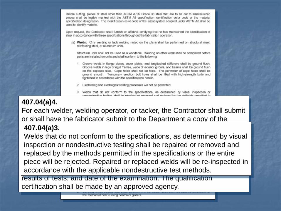
407.04(a)4.
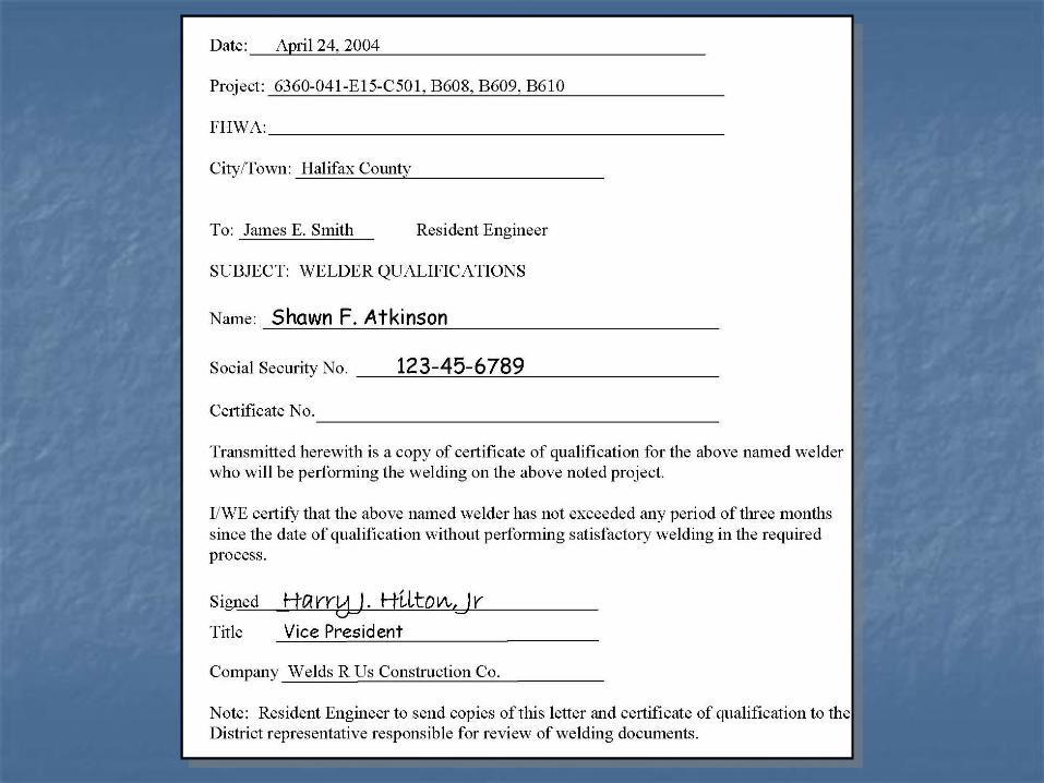
For each welder, welding operator, or tacker, the Contractor shall submit
or shall have the fabricator submit to the Department a copy of the
certificate of qualification and a certificate stating that the welder, welder
operator, or tacker has not exceeded any period of 3 months since the
date of qualification without performing satisfactory welding in the
required process. The qualification certification shall state the name of
the welder, operator, or tacker; name and title of the person who
conducted the examination; kind of specimens; position of welds;
results of tests; and date of the examination. The qualification
certification shall be made by an approved agency.
407.04(a)3.
Welds that do not conform to the specifications, as determined by visual
inspection or nondestructive testing shall be repaired or removed and
replaced by the methods permitted in the specifications or the entire
piece will be rejected. Repaired or replaced welds will be re-inspected in
accordance with the applicable nondestructive test methods.
Welder Certification
All field welders must be certified to weld on VDOT projects.
Record of each welder’s certification can be found in VDOT database.
If welder is not in database, information needs to be submitted for review.
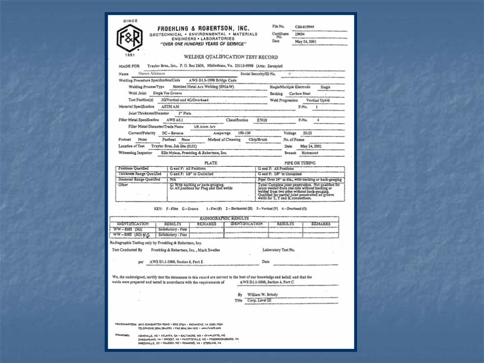
Shawn Atkinson
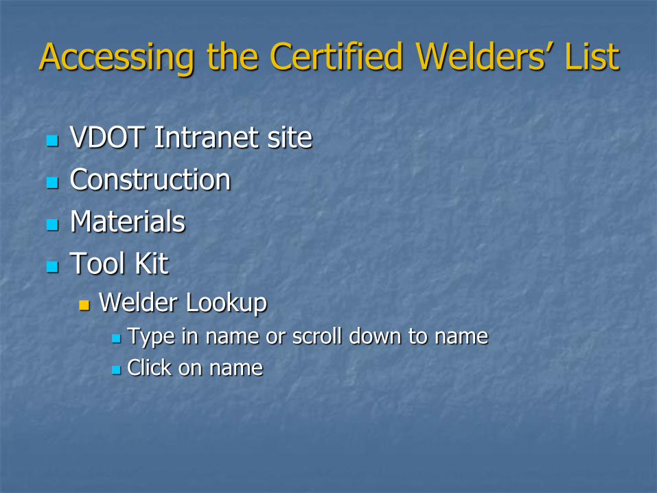
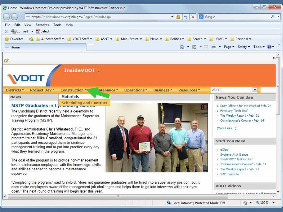
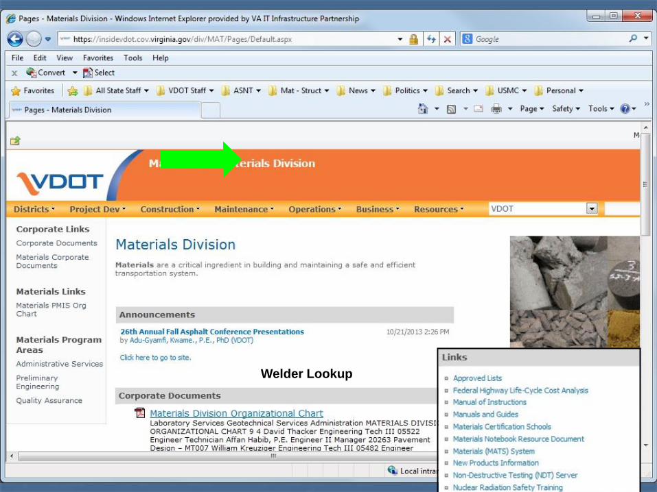
Accessing the Certified Welders’ List
VDOT Intranet site
Construction
Materials
Tool Kit
Welder Lookup
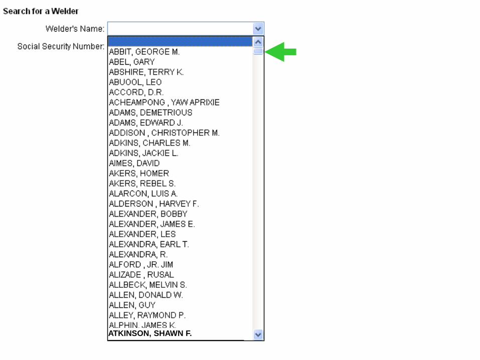
Type in name or scroll down to name
Click on name
Welder Lookup
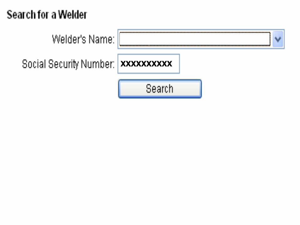
XXXXXXXXXX
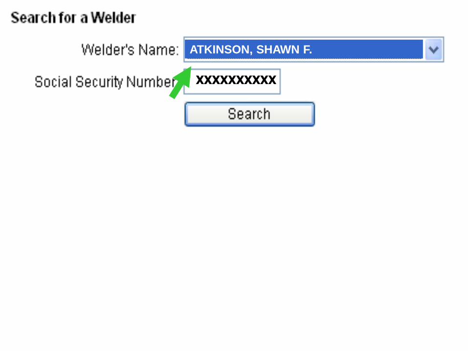
ATKINSON, SHAWN F.
XXXXXXXXXX
ATKINSON, SHAWN F.
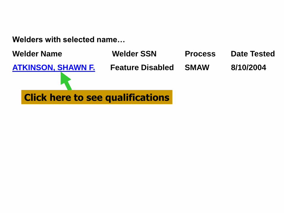
Welders with selected name…
Welder Name Welder SSN Process Date Tested
ATKINSON, SHAWN F. Feature Disabled SMAW 8/10/2004
Click here to see qualifications
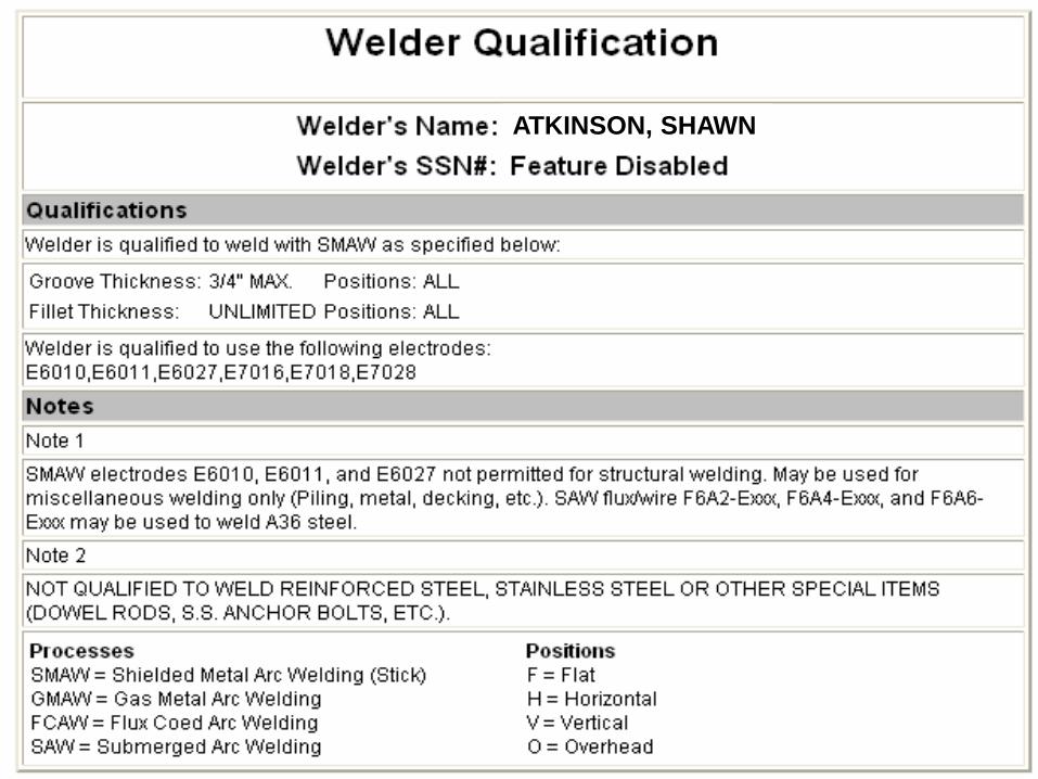
ATKINSON, SHAWN
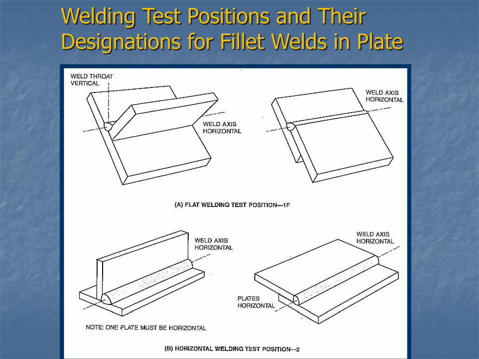
Welding Test Positions and Their Designations for Fillet Welds in Plate
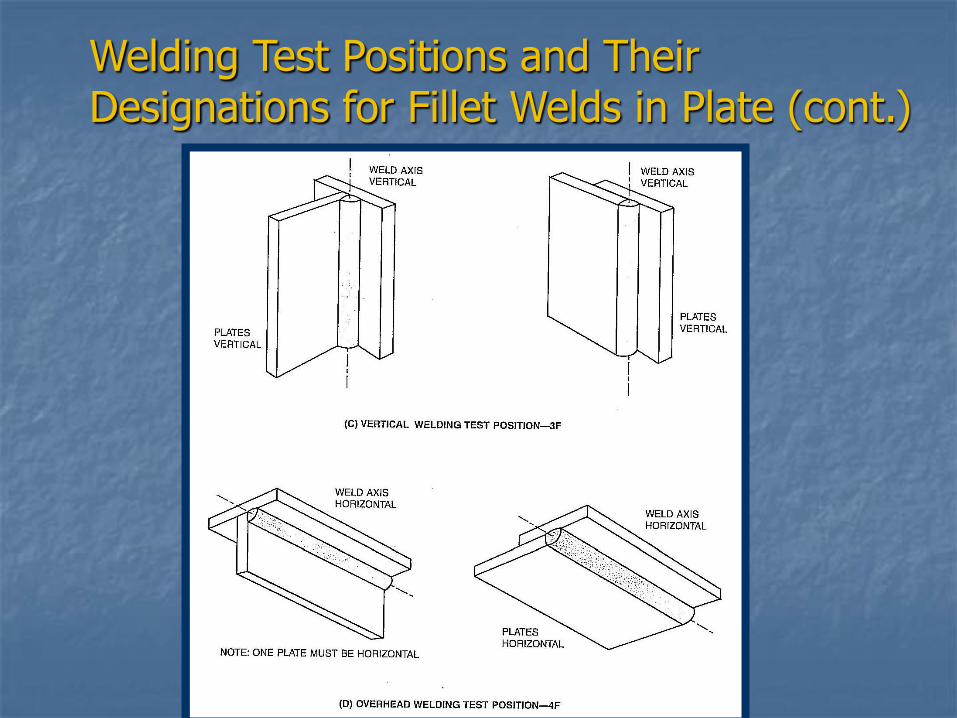
Welding Test Positions and Their Designations for Fillet Welds in Plate (cont.)
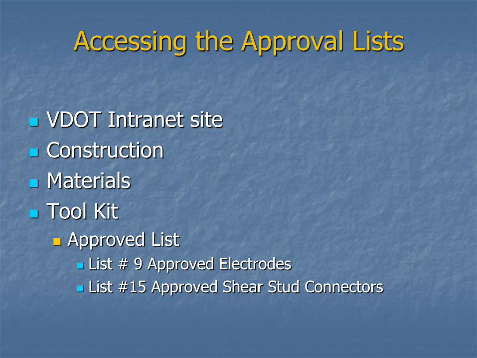
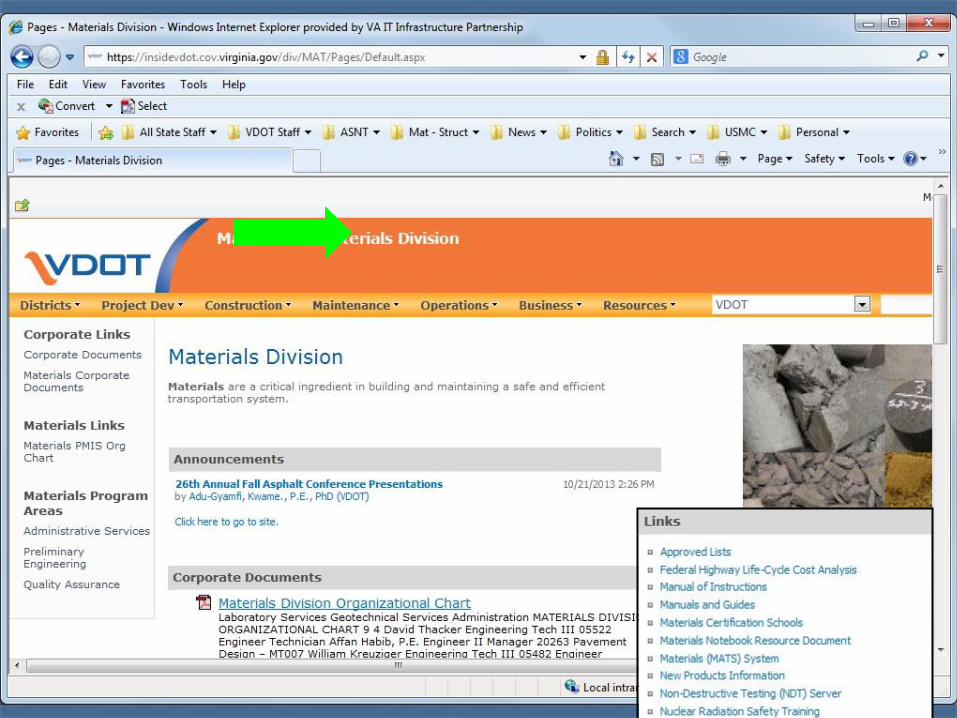
Accessing the Approval Lists
VDOT Intranet site
Construction
Materials
Tool Kit
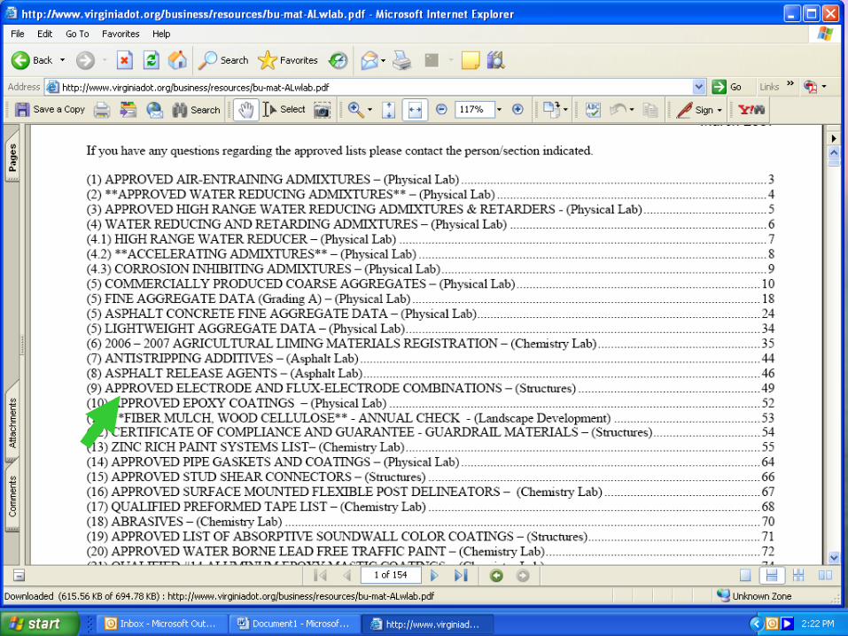
Approved List
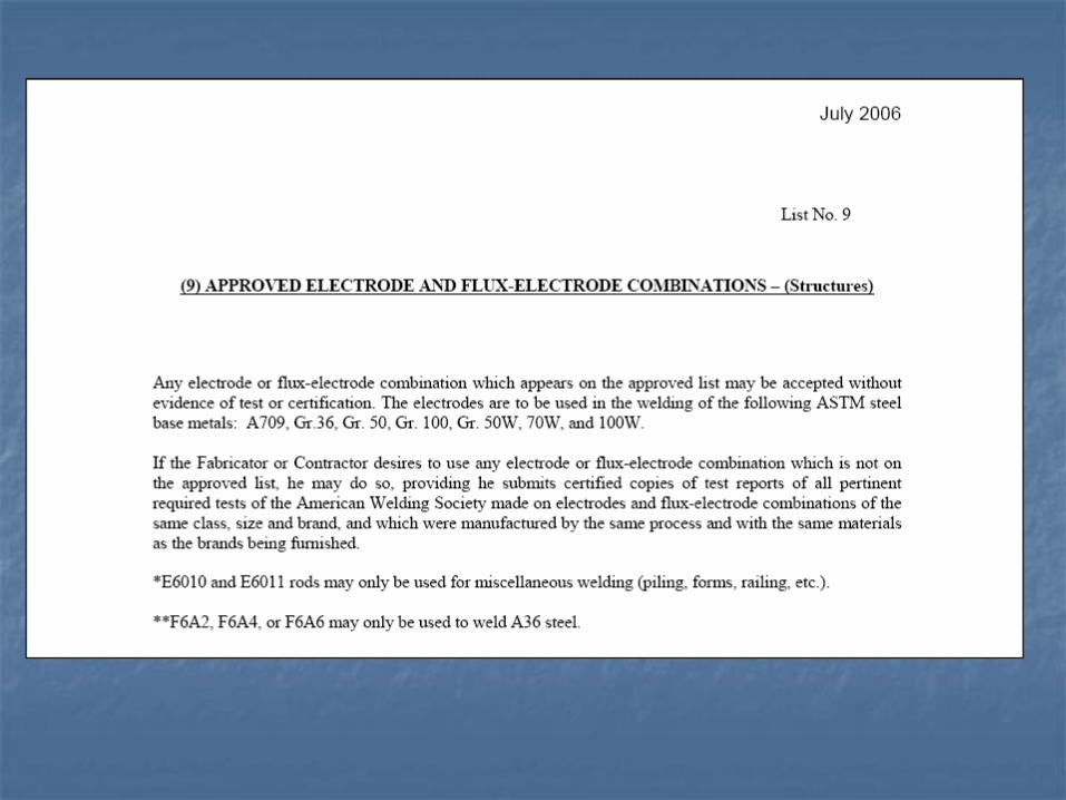
List # 9 Approved Electrodes
List #15 Approved Shear Stud Connectors

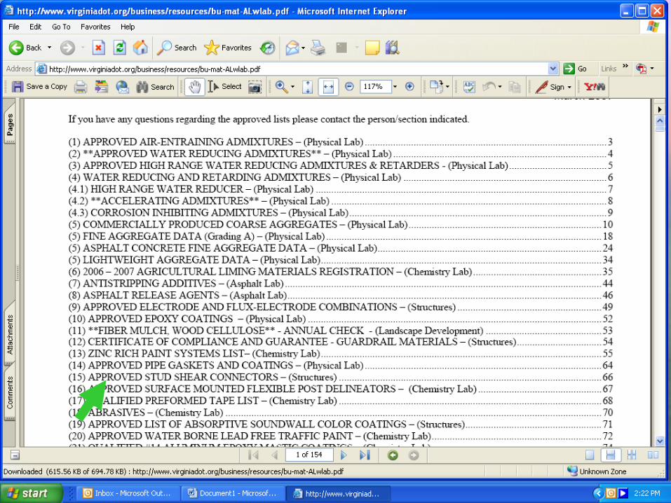
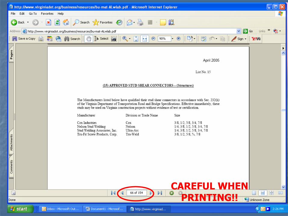
CAREFUL WHEN PRINTING!!
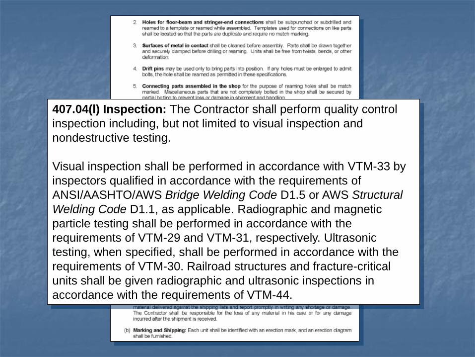
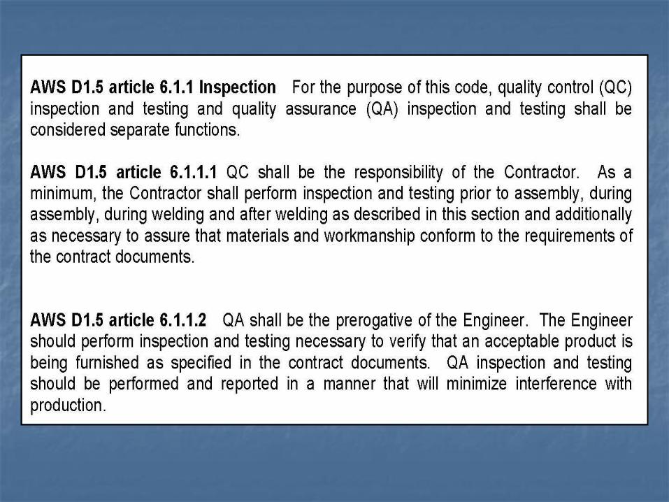
407.04(l) Inspection: The Contractor shall perform quality control
inspection including, but not limited to visual inspection and
nondestructive testing.
Visual inspection shall be performed in accordance with VTM-33 by
inspectors qualified in accordance with the requirements of
ANSI/AASHTO/AWS Bridge Welding Code D1.5 or AWS Structural
Welding Code D1.1, as applicable. Radiographic and magnetic
particle testing shall be performed in accordance with the
requirements of VTM-29 and VTM-31, respectively. Ultrasonic
testing, when specified, shall be performed in accordance with the
requirements of VTM-30. Railroad structures and fracture-critical
units shall be given radiographic and ultrasonic inspections in
accordance with the requirements of VTM-44.
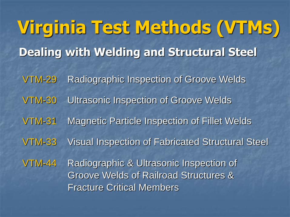
Virginia Test Methods (VTMs)
Dealing with Welding and Structural Steel
VTM-29 Radiographic Inspection of Groove Welds
VTM-30 Ultrasonic Inspection of Groove Welds
VTM-31 Magnetic Particle Inspection of Fillet Welds
VTM-33 Visual Inspection of Fabricated Structural Steel
VTM-44 Radiographic & Ultrasonic Inspection of
Groove Welds of Railroad Structures &
Fracture Critical Members
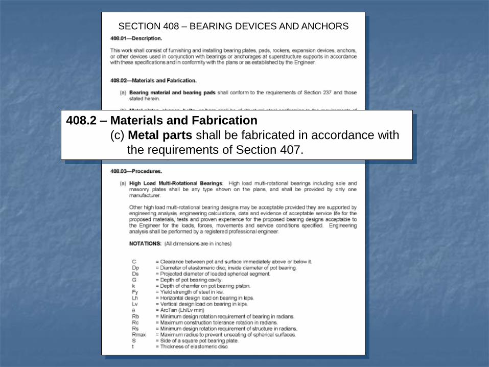
SECTION 408 – BEARING DEVICES AND ANCHORS
408.2 – Materials and Fabrication
(c) Metal parts shall be fabricated in accordance with
the requirements of Section 407.
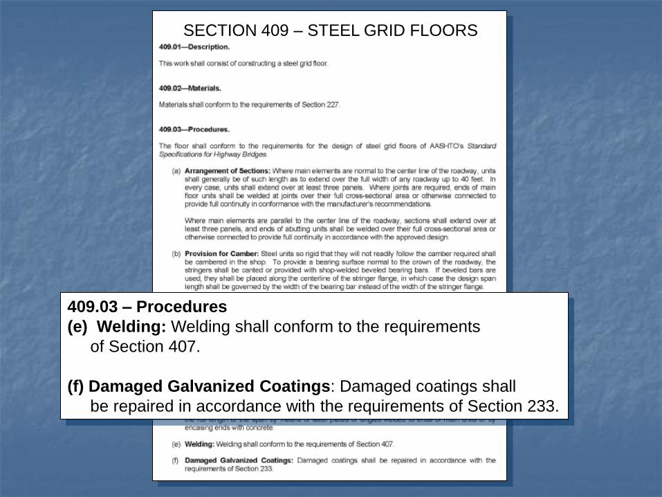
409.03 – Procedures
(e) Welding: Welding shall conform to the requirements
of Section 407.
(f) Damaged Galvanized Coatings: Damaged coatings shall
be repaired in accordance with the requirements of Section 233.
SECTION 409 – STEEL GRID FLOORS
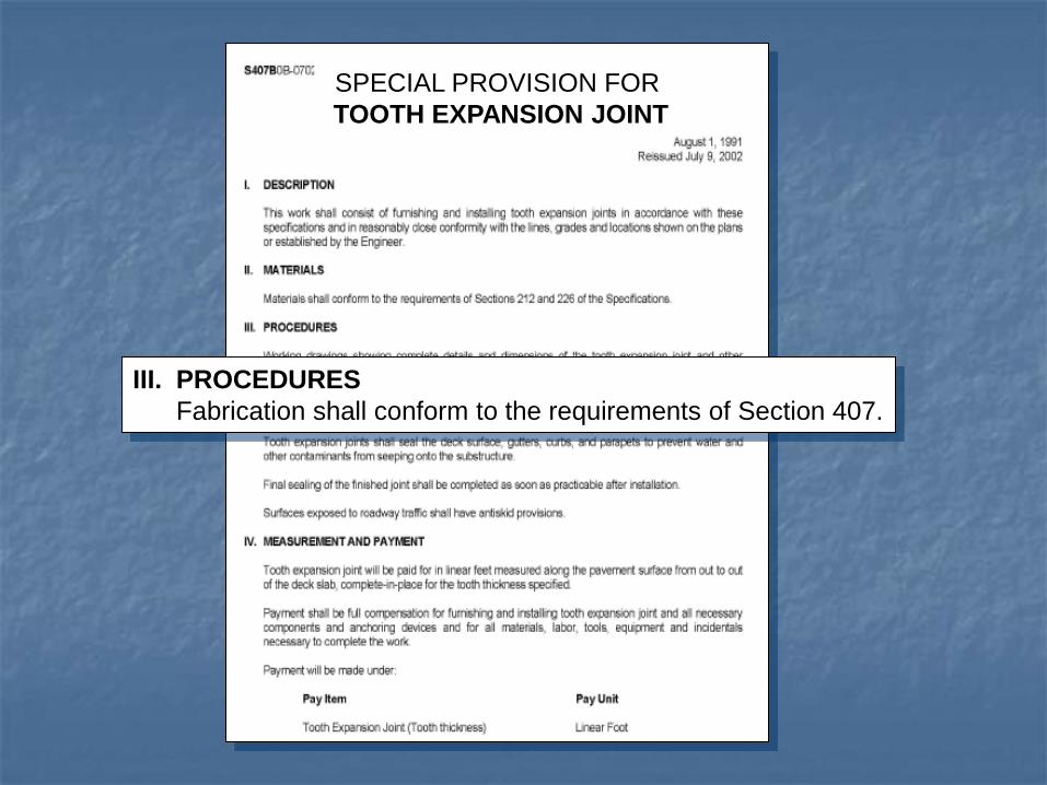
III. PROCEDURES
Fabrication shall conform to the requirements of Section 407.
SPECIAL PROVISION FOR
TOOTH EXPANSION JOINT
AASHTO/AWS D1.5 2002
Section 6 – Inspection
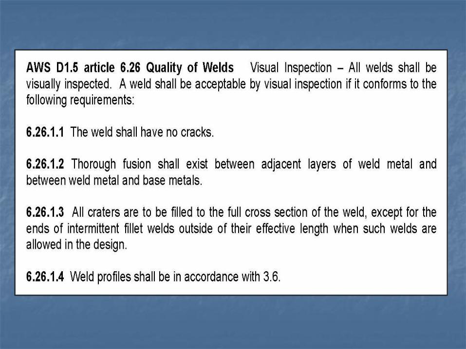
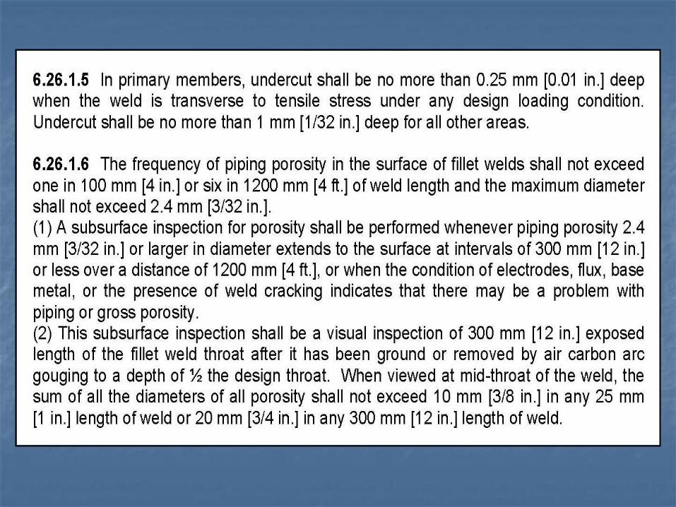
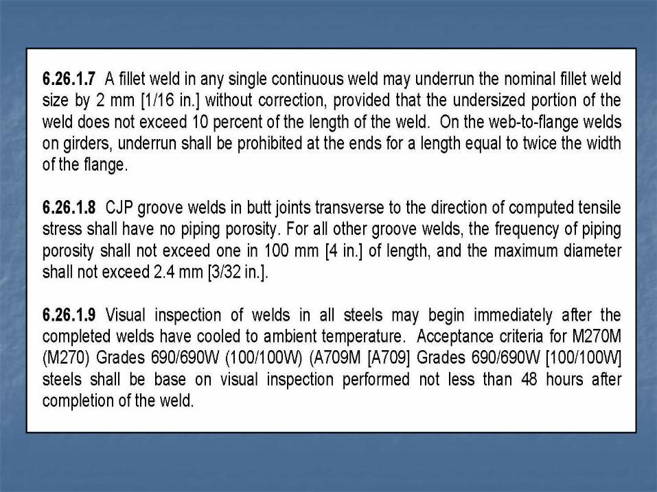
Section 6.26 - Quality of welds
Section 6.26.1 - Visual Inspection
All welds shall be visually inspected.
Commentary
- 20° C (0° F)
Questions?

Welding Inspection
Purpose of Inspection
Insure that only certified people are welding on VDOT projects.
Make sure the specifications are followed.
Insure that all welds are complete.
Design of the structure assumes complete and quality welds.
Insure that field welds are only made when called for on the plans or when authorized by the Engineer.
Verify welds are free of injurious defects.
Minimum Welding Equipment
Welding machine with cables
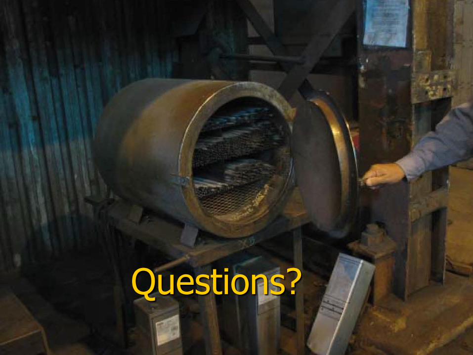
Drying oven(“hot box”) for storing electrodes
Torch with oxygen and fuel for preheating
Slag hammer, wire brush, portable grinder
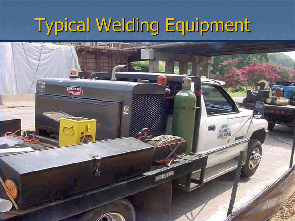
Typical Welding Equipment
Field Use of Burning Torches
To be used only with the Engineer’s permission.
Only to be used with a mechanical guide. (At least use a metal bar clamped to the workpiece for guiding cuts.)
Not for use in making holes.
Air carbon arc is the preferred process for removal of welds.
Proper Electrode Storage
Electrodes exposed to the atmosphere upon removal from drying or storage ovens or hermetically sealed containers shall be used within the time limit shown in Table 4.7.
The welder should take out only as many electrodes from the “hot box” as can be used in a short period of time.
Do not allow use of electrodes that are or have been wet, even with redrying.
Improper Electrode Storage
Cans of electrodes laying out in the open.
Electrodes in a welder’s “sweaty” back pocket.
Electrodes laying on the ground.
Electrodes stored in an unplugged “hot box” or with the temperature set too low.
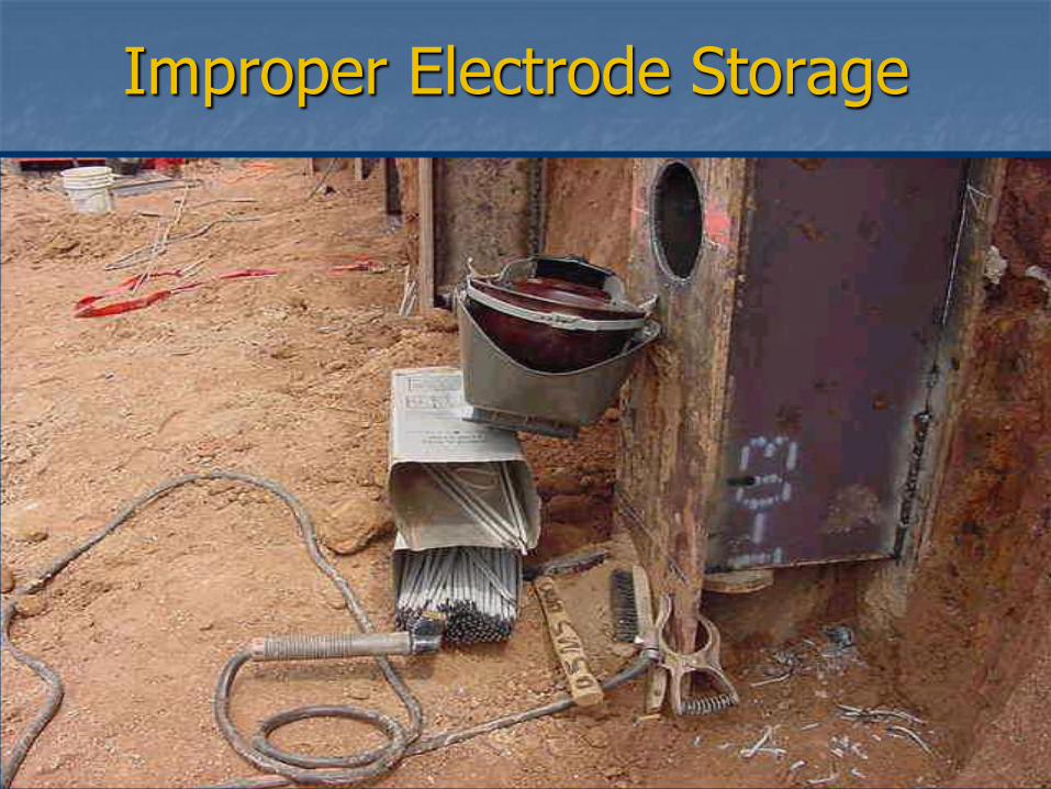
Improper Electrode Storage
Safety Hazards Specific to Welding
The electric arc gives off ultraviolet and infrared radiation that can cause severe sunburn type injuries which could lead to blindness, therefore: DO NOT WATCH THE ARC!!!
Both welding and grinding produce sparks. Always wear eye protection around welding and grinding. Keep flammable materials away from the welding area.
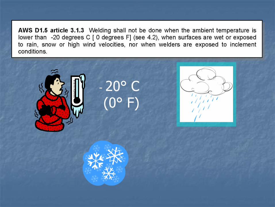
Weather Conditions
Do not allow welding when it is misting, raining, snowing, sleeting or when the steel is wet.
Do not allow the hot welds to be quenched with water. It is not allowable to blow
compressed air on heated areas > 600 oF
Do not allow welding when the air temperature is below 0
oF.
Verify minimum preheat.
Preparation Of Base Metal
Remove all foreign material prior to welding by grinding or wire brushing as necessary.
The area to be welded should look shiny with no rust, paint, oil, or grease.
Preheat as necessary, minimum 50 oF.
Dry off water and dew. See Table 4.4
Joint to be welded must be beveled if required by the contract drawings, and have correct dimensions.
Weld Symbols Special symbols are used on a drawing to specify where welds are to
be located, the type of joint to be used, as well as the size and amount of weld metal to be deposited in the joint. These symbols have been standardized by the American Welding Society (AWS). You will come into contact with these symbols anytime you do a welding job from a set of blueprints. You need to have a working knowledge of the basic weld symbols and the standard location of all the elements of a welding symbol.
A standard welding symbol consists of a reference line, an arrow, and a tail. The reference line becomes the foundation of the welding symbol. It is used to apply weld symbols, dimensions, and other data to the weld. The arrow simply connects the reference line to the joint or area to be welded. The direction of the arrow has no bearing on the significance of the reference line. The tail of the welding symbol is used only when necessary to include a specification, process, or other reference information.
Weld Symbols - The term weld symbol refers to the symbol for a specific type of weld. As discussed earlier, fillet, groove, surfacing, plug, and slot are all types of welds. Basic weld symbols are shown in figure 3-44.
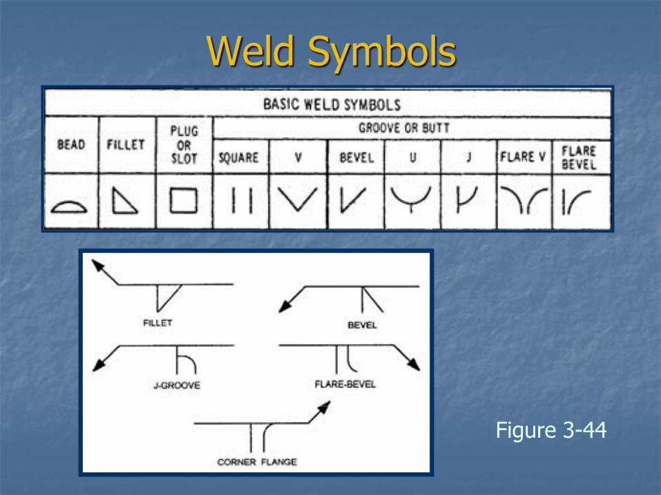
Weld Symbols
Figure 3-44
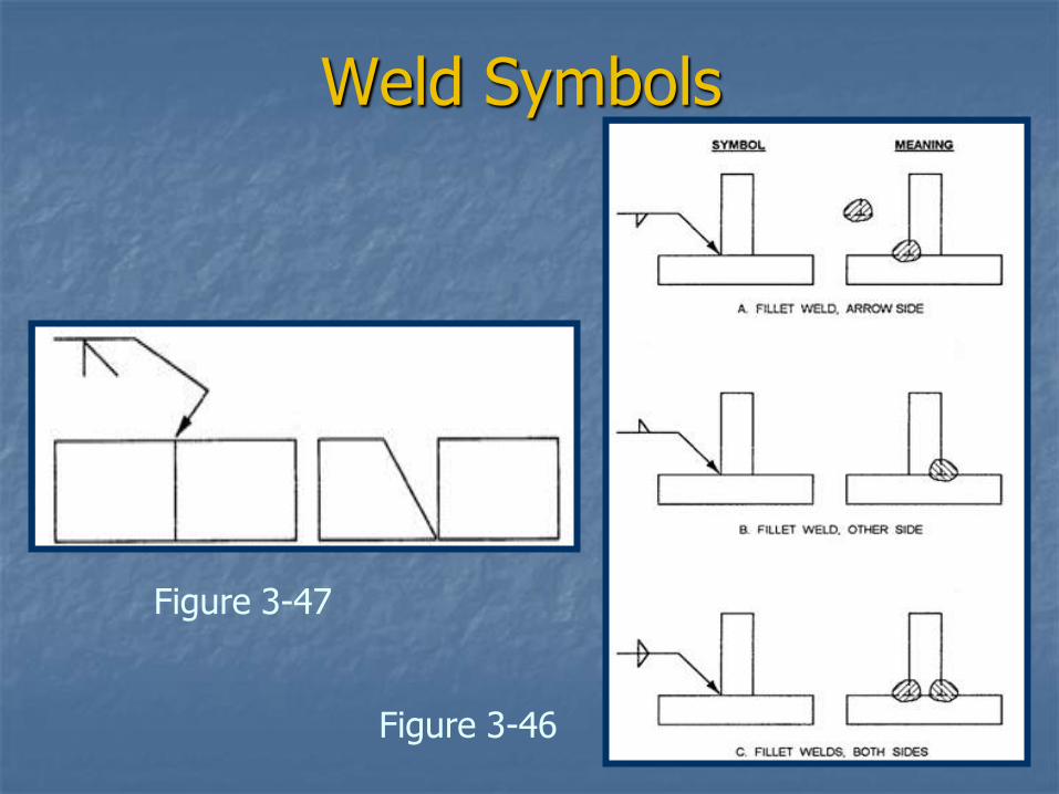
Weld Symbols
Figure 3-47
Figure 3-46
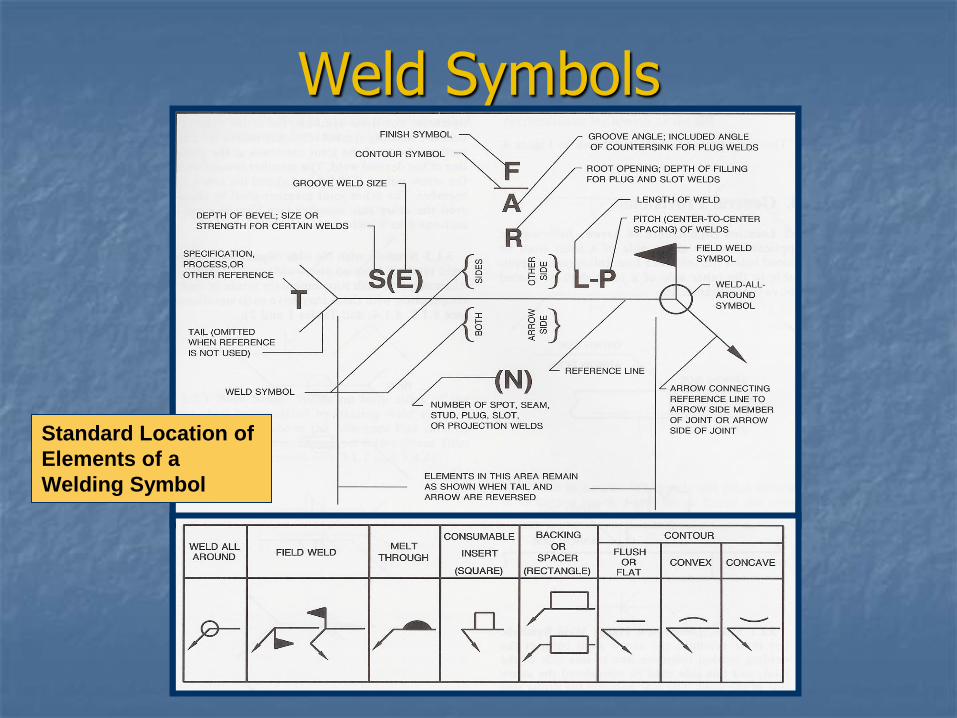
Weld Symbols
Standard Location of
Elements of a
Welding Symbol

Fillet Weld - Stringer
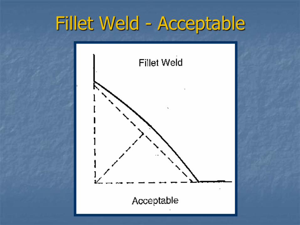
Fillet Weld - Acceptable
Common Weld Discontinuities
Undercut
Porosity
Overlap
Cracks
Crater Cracks
Underfill
Arc Strikes
Unfilled Crater
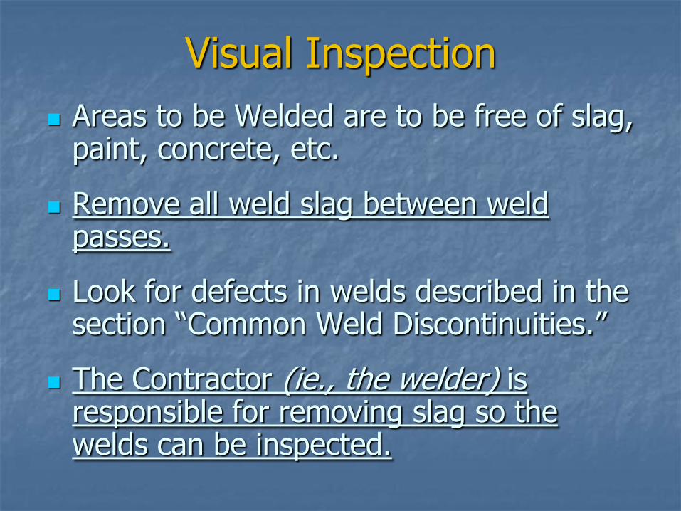
Visual Inspection
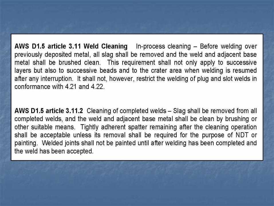
Areas to be Welded are to be free of slag, paint, concrete, etc.
Remove all weld slag between weld passes.
Look for defects in welds described in the section “Common Weld Discontinuities.”
The Contractor (ie., the welder) is responsible for removing slag so the welds can be inspected.
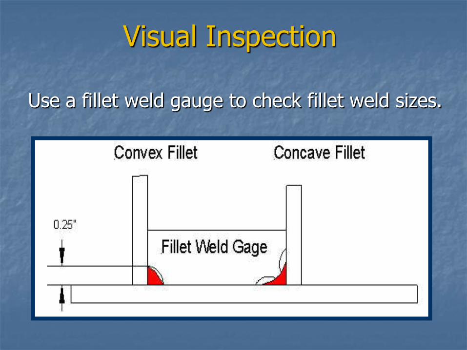
Visual Inspection
Use a fillet weld gauge to check fillet weld sizes.
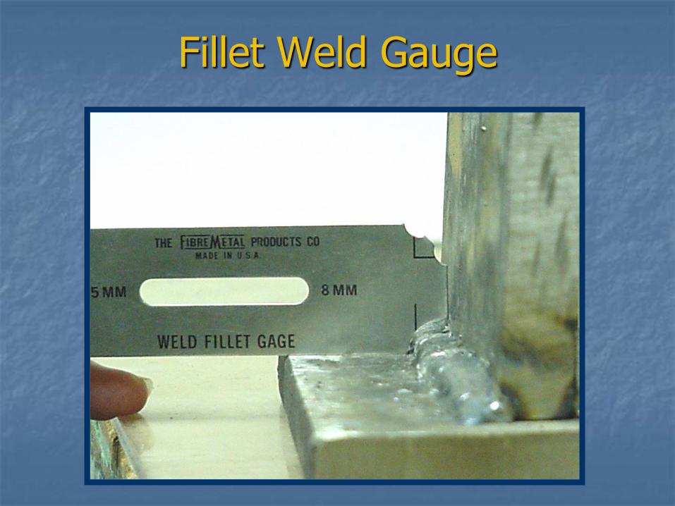
Fillet Weld Gauge
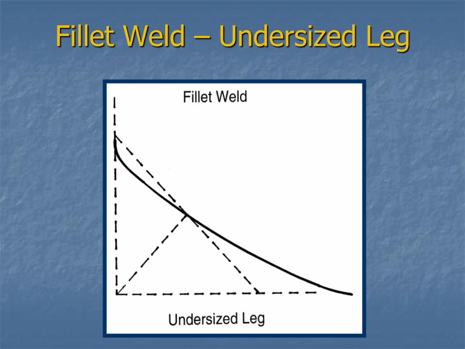
Fillet Weld – Undersized Leg
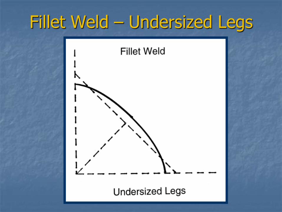
Fillet Weld – Undersized Legs
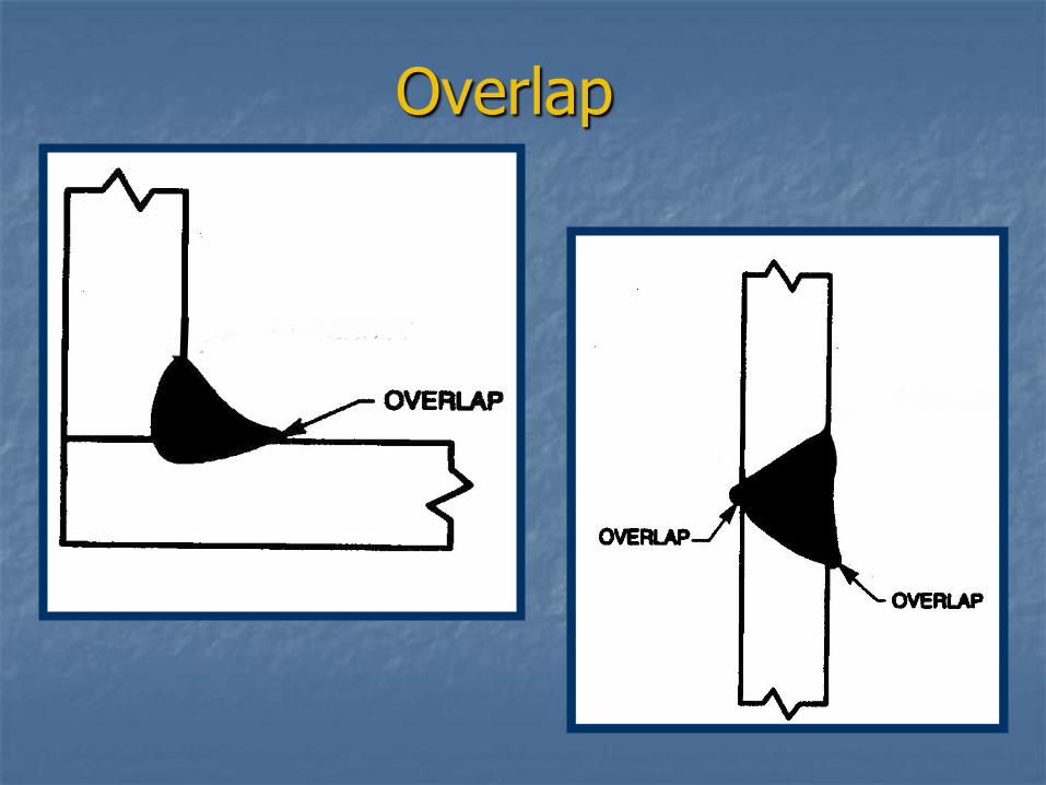
Overlap
Overlap is a condition where the weld metal does not fuse with the base metal and the solidified weld metal laps over the base metal to form a sharp notch. The sharp notch that formed can cause cracking.
Overlap
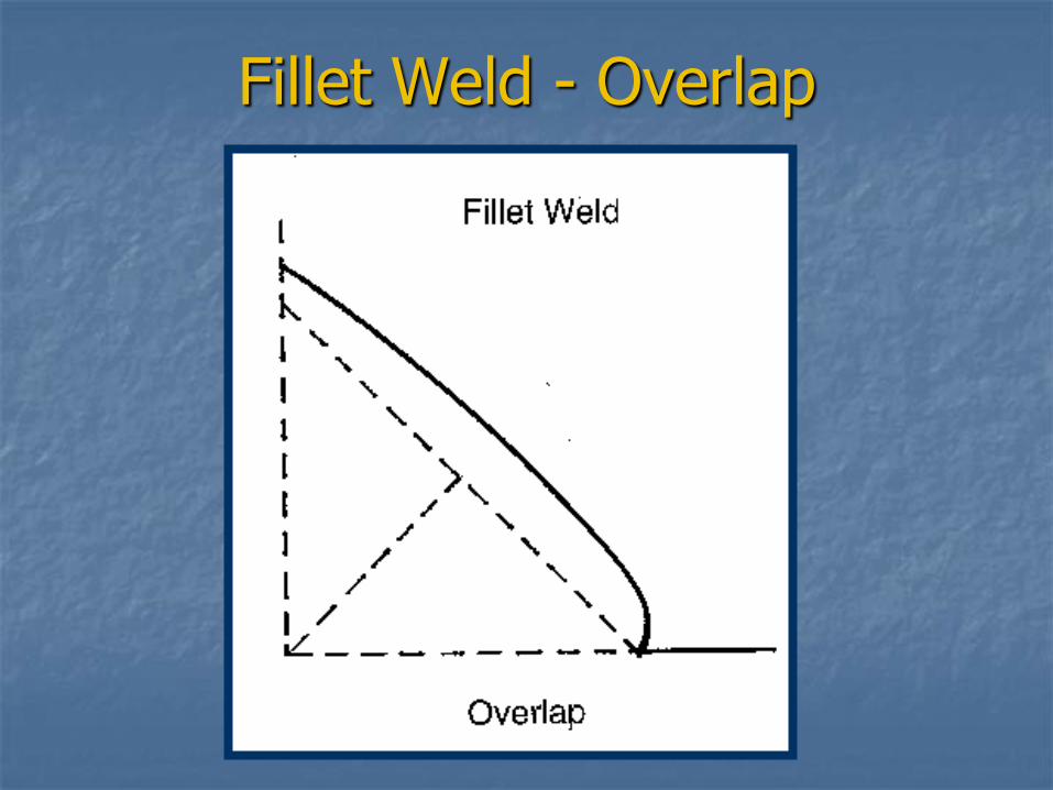
Fillet Weld - Overlap
Undercut
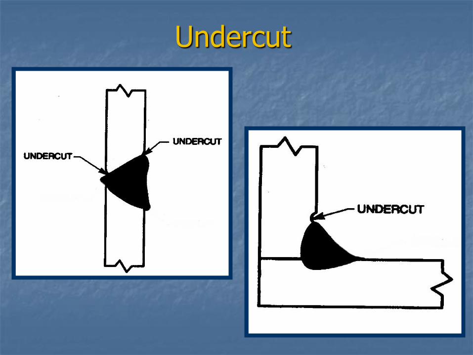
Undercut is caused when the welding arc melts the base metal, but the melting electrode does not fill the area of melted base metal.
This creates a sharp notch where cracks could occur. Undercut also decreases the strength of the joint.
Undercut
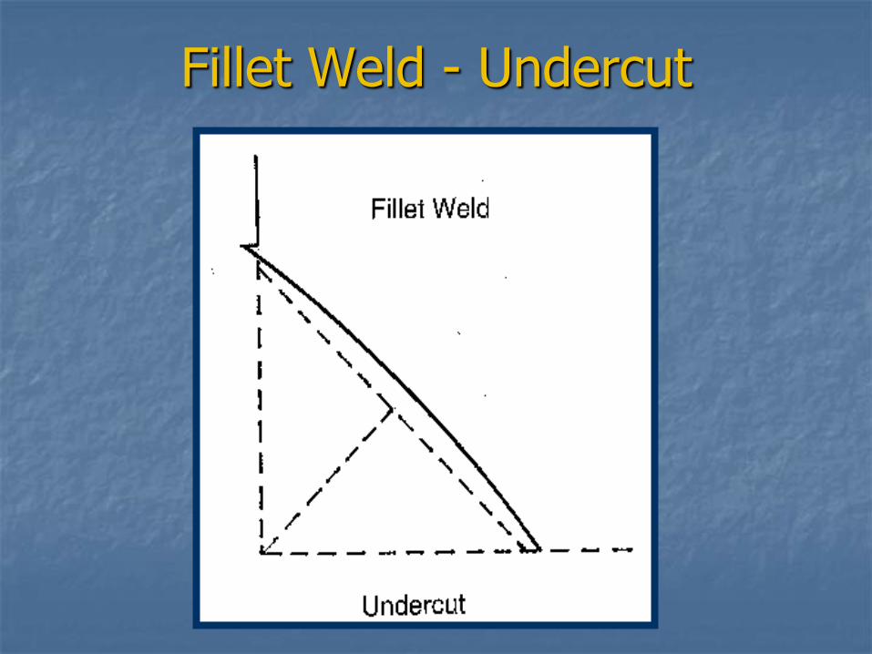
Fillet Weld - Undercut
Porosity
Porosity is caused when gas pockets are trapped in the solidified weld metal. They can be in the form of holes that are open to the surface of the weld or they may remain internal and not be visible without performing nondestructive testing. Porosity can weaken welds and can cause cracking.
One of the major causes of porosity is moisture on the steel or in the welding electrodes. This is why it is so critical that we require electrodes to be held in drying ovens and we require base metal to be preheated.
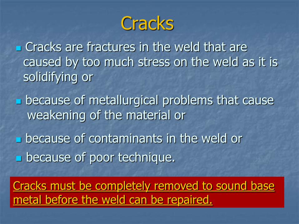
Cracks Cracks are fractures in the weld that are caused by too much stress on the weld as it is solidifying or
because of metallurgical problems that cause weakening of the material or
because of contaminants in the weld or
because of poor technique.
Cracks must be completely removed to sound base metal before the weld can be repaired.
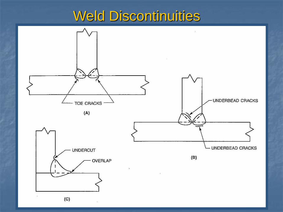
Weld Discontinuities
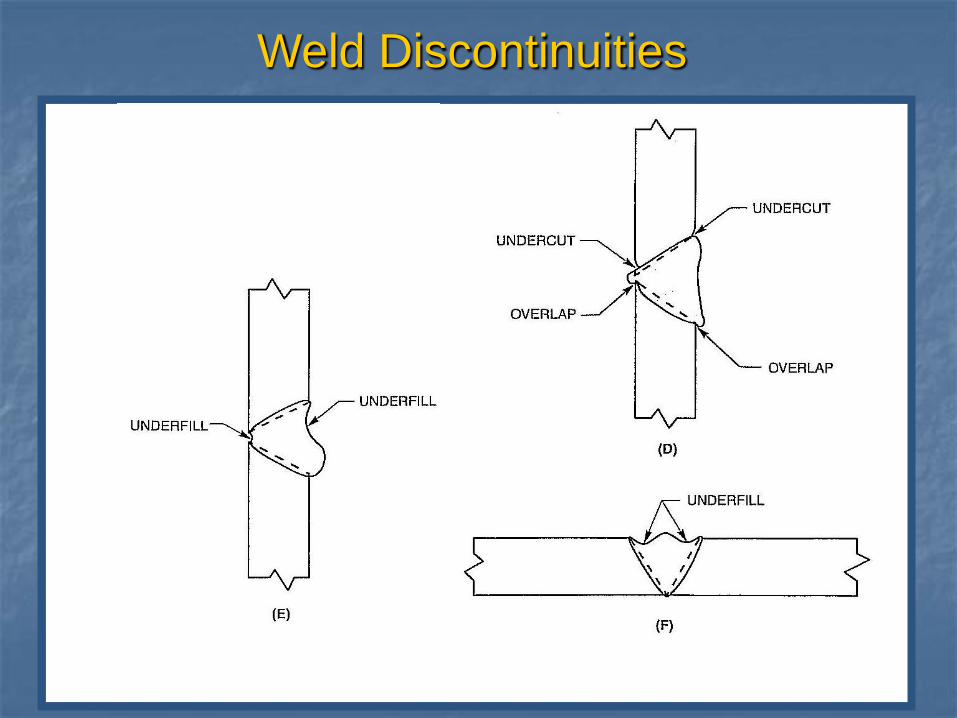
Weld Discontinuities
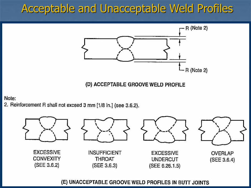
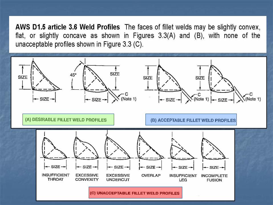
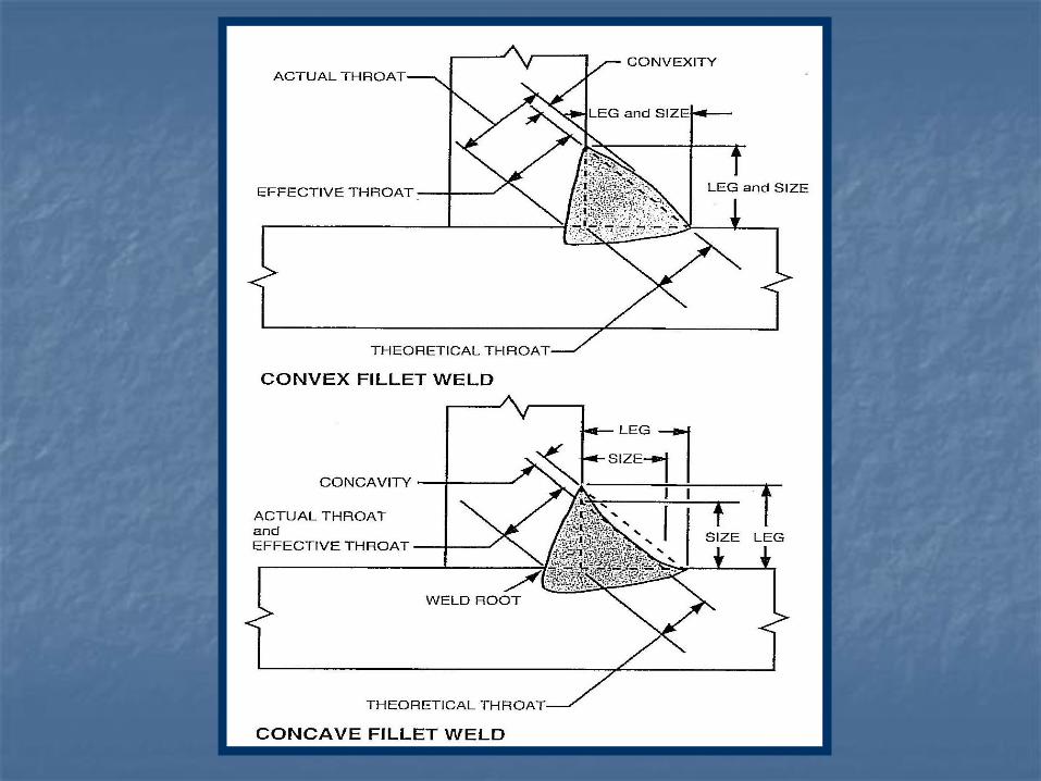
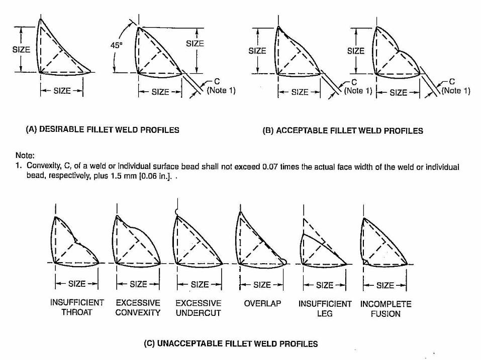
Acceptable and Unacceptable Weld Profiles
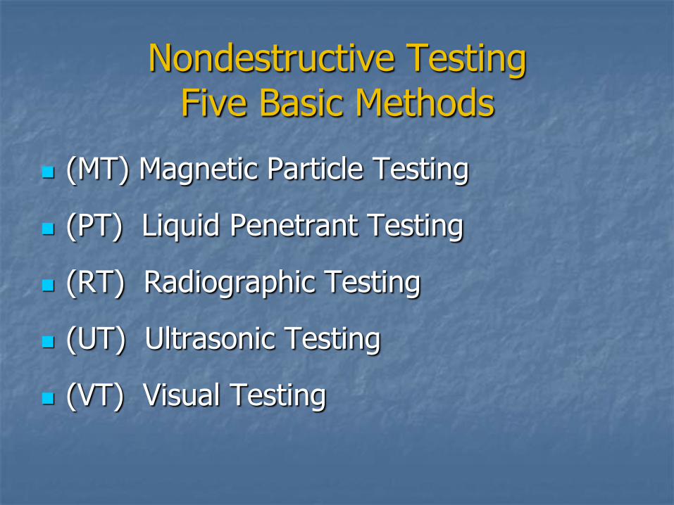
Nondestructive Testing Five Basic Methods
(MT) Magnetic Particle Testing
(PT) Liquid Penetrant Testing
(RT) Radiographic Testing
(UT) Ultrasonic Testing
(VT) Visual Testing
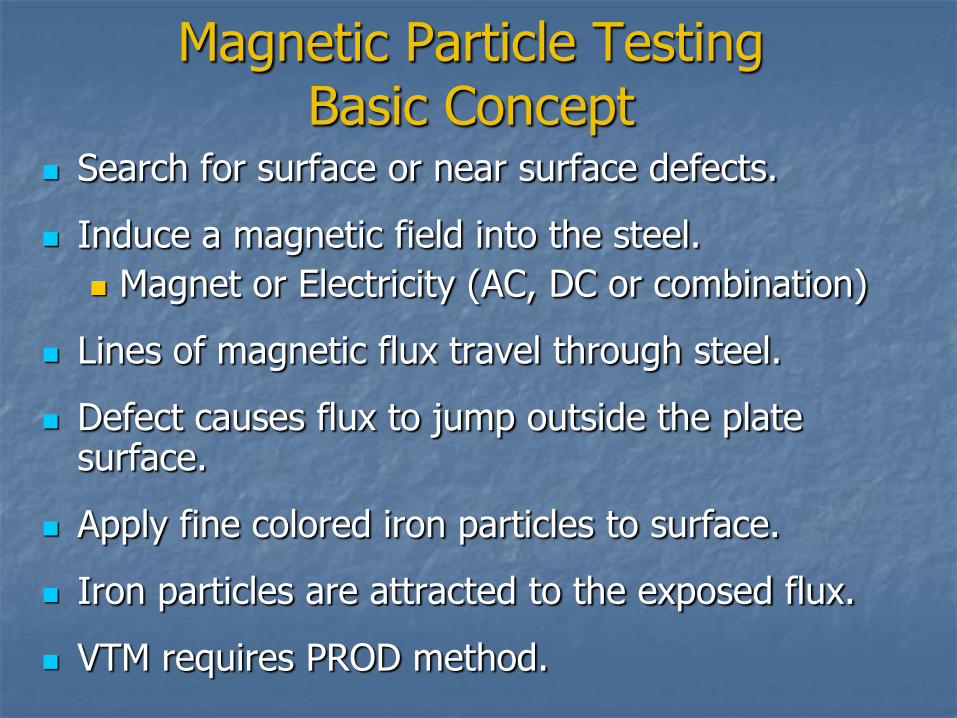
Magnetic Particle Testing Basic Concept
Search for surface or near surface defects.
Induce a magnetic field into the steel.
Magnet or Electricity (AC, DC or combination)
Lines of magnetic flux travel through steel.
Defect causes flux to jump outside the plate surface.
Apply fine colored iron particles to surface.
Iron particles are attracted to the exposed flux.
VTM requires PROD method.
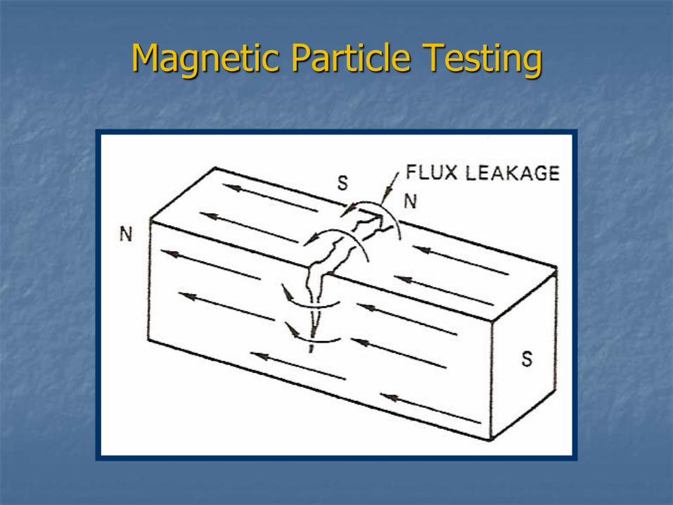
Magnetic Particle Testing
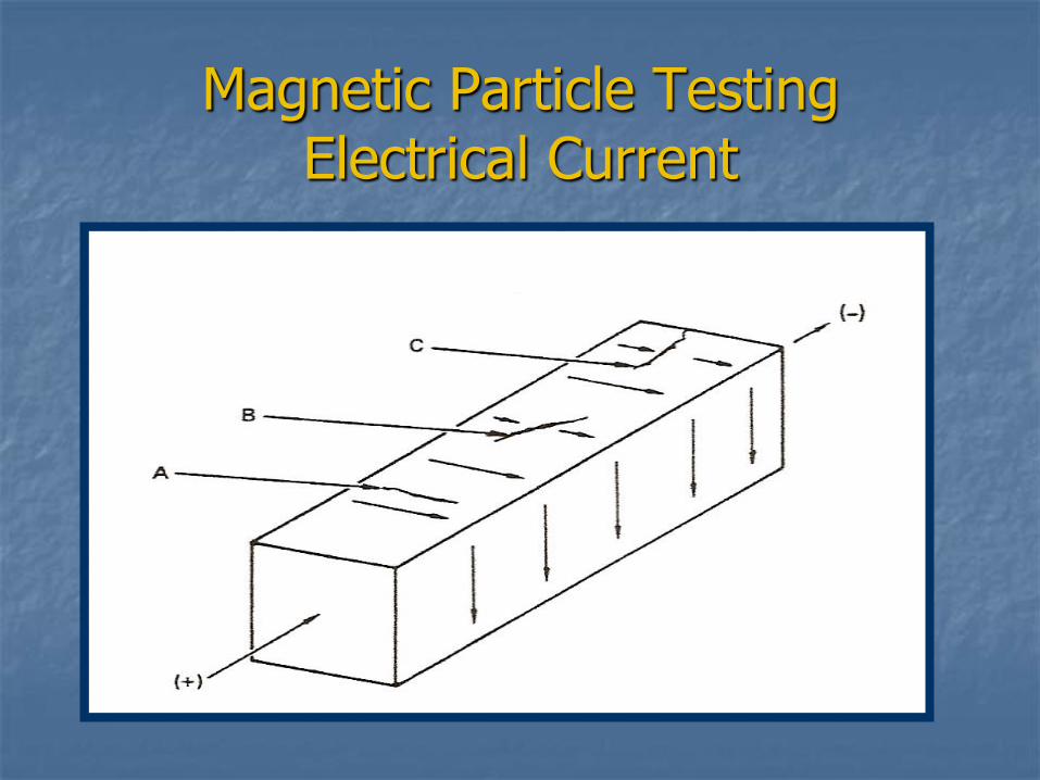
Magnetic Particle Testing Electrical Current
Magnetic Particle Testing Advantages
Fast
Portable
Inexpensive
Consumables
Testing Equipment
Easy to Learn
Minimal experience
Clean
Safe
Magnetic Particle Testing Disadvantages
Surface or near surface defects
Carbon Steel (ferromagnetic)
Linear indications
No permanent record
Liquid Penetrant Testing Basic Concept
Search for surface defects.
Apply penetrating oil (red) to the surface.
Capillary action pulls penetrant into defects.
Clean penetrant from the surface without
removing it from the defect.
Apply a white powder to the surface to act as a
blotter.
Red dots or lines will appear to indicate the
location of defects.
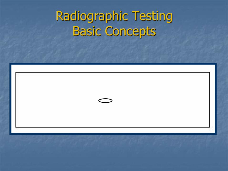
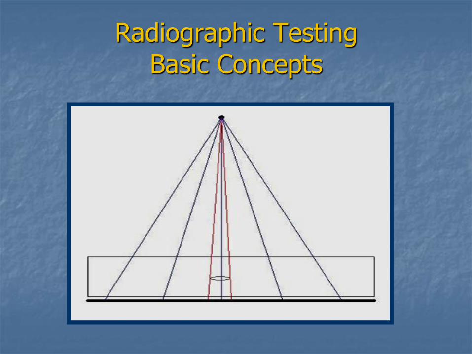
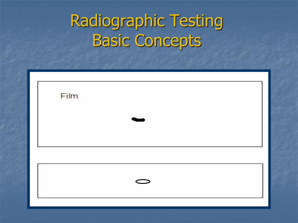
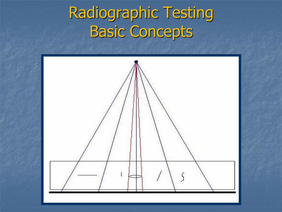
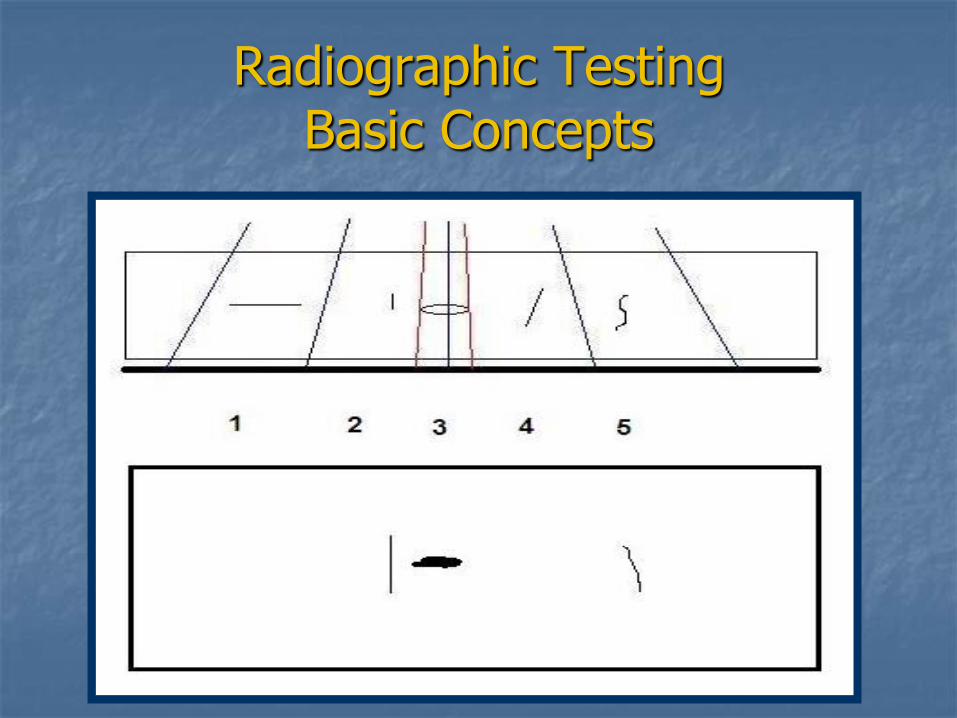
Radiographic Testing Basic Concept
Search for surface or subsurface defects.
X-rays or gamma rays are directed at the plate.
Rays are shielded by the plate but some make it to the other side.
The rays that make it are detected by the film.
Film is developed and read.
Radiographic Testing Basic Concepts
Radiographic Testing Basic Concepts
Radiographic Testing Basic Concepts
Radiographic Testing Basic Concepts
Radiographic Testing Basic Concepts
Radiographic Testing Advantages
Generally Portable
Surface and subsurface capabilities
Sensitive to certain defects
Permanent record
Clean
Carbon, stainless, aluminum
Radiographic Testing Disadvantages
Expensive
equipment, consumables, training, time, maintenance, regulations
Usually an overnight process
Dangerous
technicians and surrounding personnel
2-man crew
Defect orientation is critical
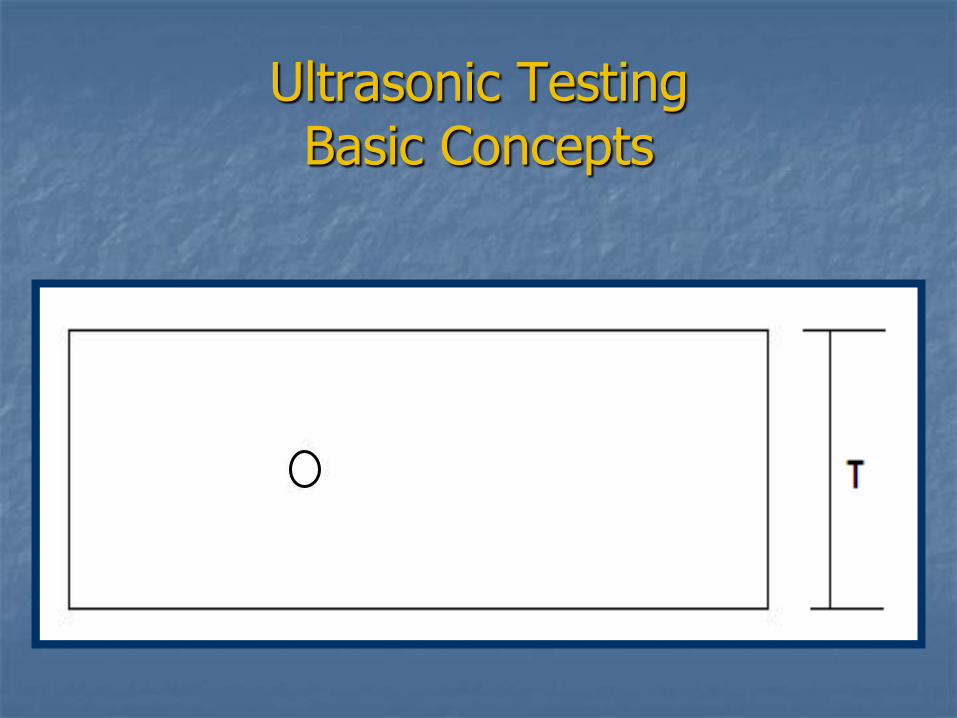
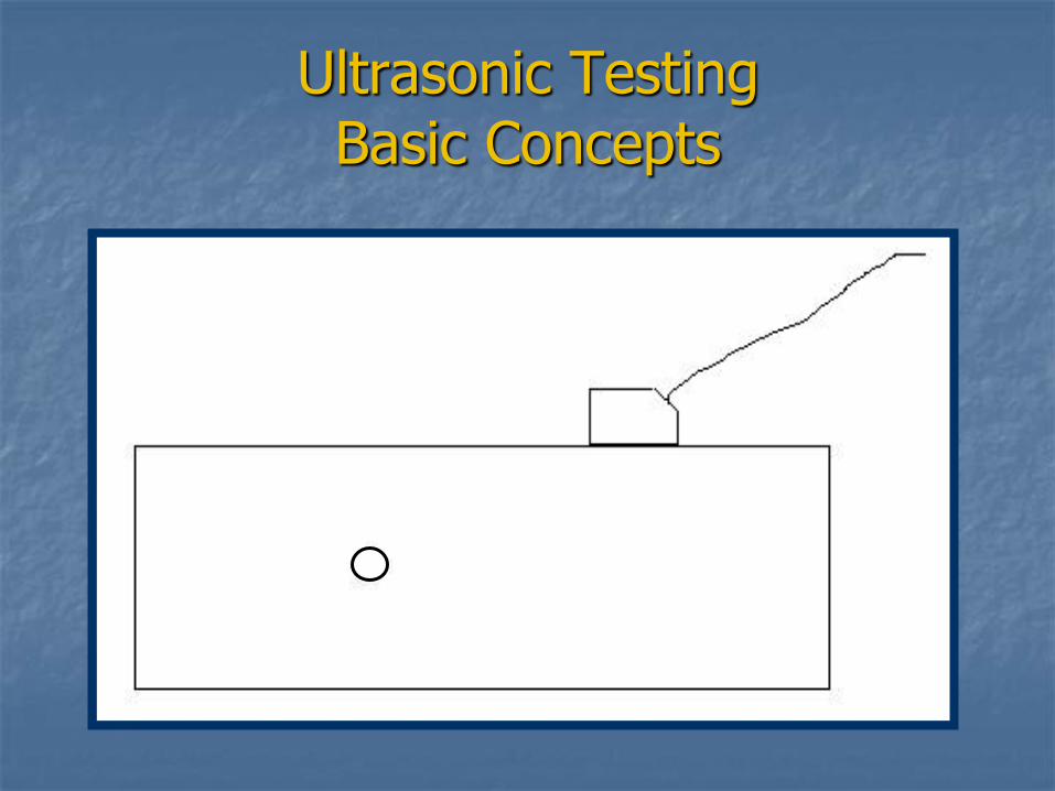
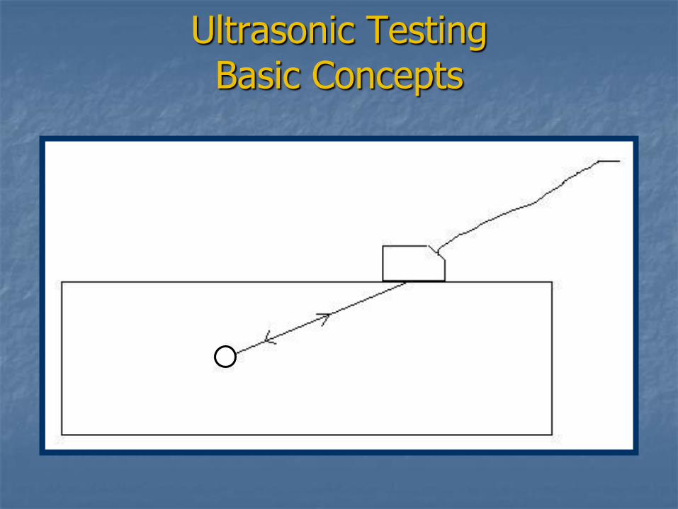
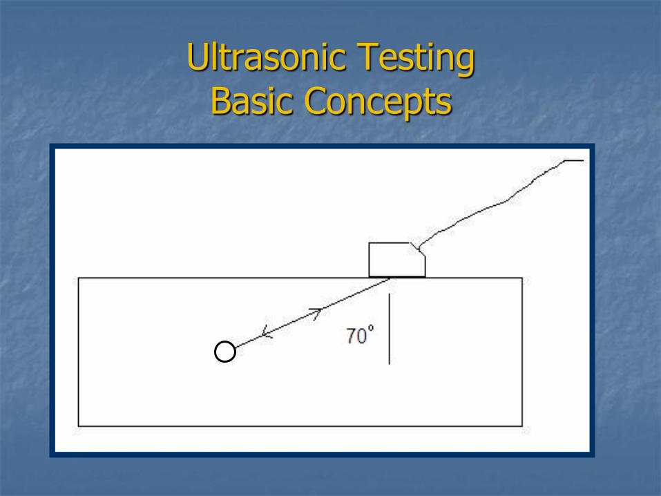
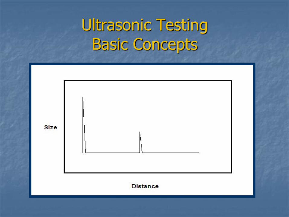
Ultrasonic Testing Basic Concept
Search for surface or subsurface defects.
Sound waves are directed into the steel via a transducer (piezoelectric) at known speed and direction.
Defect causes sound reflection back to the transducer.
The time for the sound to leave and return to the transducer is calculated.
Technician / machine can convert this into a size, depth and specific location.
Ultrasonic Testing Basic Concepts
Ultrasonic Testing Basic Concepts
Ultrasonic Testing Basic Concepts
Ultrasonic Testing Basic Concepts
Ultrasonic Testing Basic Concepts
Ultrasonic Testing Advantages
Fast (reasonably)
Portable
Inexpensive Consumables
Testing equipment ($20K)
Clean
Safe
Carbon, Stainless
Ultrasonic Testing Disadvantages
High degree of training & experience
Technician dependent
No permanent record
Defect orientation is critical
Nondestructive Testing Summary
No NDT method is “best”.
Use methods in combination.
UT and RT are often not interchangeable.
Defect understanding
location, shape, material
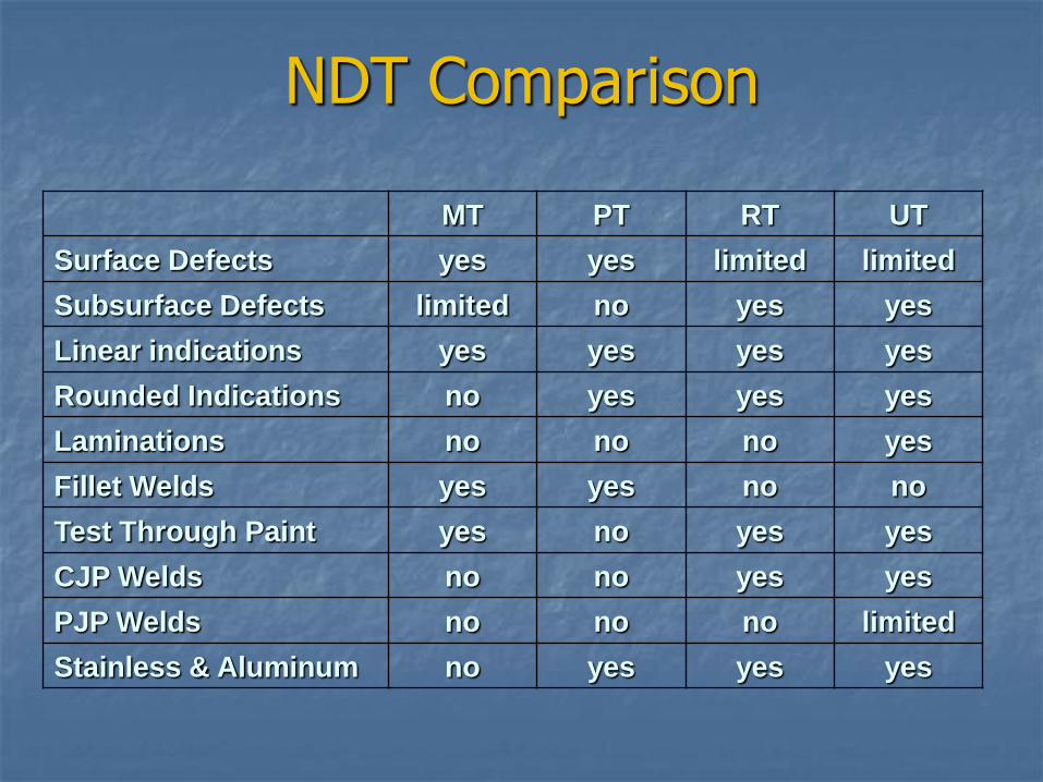
NDT Comparison
MT PT RT UT
Surface Defects yes yes limited limited
Subsurface Defects limited no yes yes
Linear indications yes yes yes yes
Rounded Indications no yes yes yes
Laminations no no no yes
Fillet Welds yes yes no no
Test Through Paint yes no yes yes
CJP Welds no no yes yes
PJP Welds no no no limited
Stainless & Aluminum no yes yes yes
What to Look For
Welder certifications
Proper equipment
Correct electrodes and storage
Preparation of base metal
Correct weld size & shape
Discontinuities
All welds are complete
Review
Make sure welders are certified before welding starts. Check Identification verify in VDOT database.
Use proper welding equipment.
Use the correct electrodes and store them properly.
Properly prepare the base metal before welding.
Visually inspect for size, shape, quality, completeness.
Follow safety rules.
Acknowledgments
Debra Casper – VDOT Training Section NCDOT – Materials & Testing Division HRV Conformance Verification, Inc.
Questions
Related Documents