Division of Measurement Standards Training Training for the Weights and Measures Official S S e e v v e e n n Basic Weighing and Measuring Principles

Welcome message from author
This document is posted to help you gain knowledge. Please leave a comment to let me know what you think about it! Share it to your friends and learn new things together.
Transcript
Division of Measurement Standards Tr
aini
ng
Training for the Weights and Measures Official
SSeevveenn
Basic Weighing and Measuring
Principles
MODULE 7 - BASIC WEIGHING AND MEASURING PRINCIPLES Module 1 - Introduction to Weights and Measures Module 2 - Laws and Regulations Module 3 - Enforcement Procedures Module 4 - Legal Action Module 5 - Legal Metrology Module 6 - Field Standards and Test Equipment Module 8 - Device Type Evaluation Module 9 - Weighing Devices Module 10 - Measuring Devices Module 11 - Weighmaster Enforcement Module 12 - Petroleum Products Module 13 - Quantity Control Module 14 - Service Agencies and Agents
TRAINING FOR THE WEIGHTS AND MEASURES OFFICIAL
CURRICULUM
Module Team Gary Castro—Team Leader John Cline Dennis Gorman Aimee Harris Charlie Nelson Dan Reiswig Editing Team Dennis Johannes David Lazier Roger Macey Production Team Carol Allen Angie Averitt
It is impossible to list the names of the many people who contributed
to the development of this course. However, gratitude is extended to
the following groups whose dedication and commitment made this
training module a reality.
Developing a training program for weights and measures officials is
a challenging and ambitious project. It requires time, dedication,
and expertise from many individuals.
Acknowledgment
Module Seven Basic Weighing and Measuring Principles
Tabl
e of
Con
tent
s Introduction/Objectives .............................................................................. 1
SEGMENT 1 1. Weighing Principles ........................................................................... 2 2. Self-Evaluation Questions ................................................................. 6 SEGMENT 2 1. Lever Principles ................................................................................. 7 2. Types of Levers ................................................................................. 9 3. Self-Evaluation Questions ................................................................ 17 SEGMENT 3 1. Strain Gauge Technology ................................................................ 18 2. Types of Load Cells .......................................................................... 19 3. Weighing Indicators ......................................................................... 21 4. Self-Evaluation Questions ............................................................... 22 SEGMENT 4 1. Measuring Principles ....................................................................... 23 2. Self-Evaluation Questions ............................................................... 24 SEGMENT 5 1. Flow Meters ...................................................................................... 25 2. Other Metering Considerations ....................................................... 33 3. Self-Evaluation Questions ............................................................... 35 Glossary .................................................................................................... 36 Bibliography and References ................................................................... 37 Self-Evaluation Answers .......................................................................... 38 Feedback ................................................................................................... 39
Training Module 7 Introduction
1 (2002)
IInnttrroodduuccttiioonn
WWeellccoommee ttoo “Basic Weighing and Measuring Principles”. This is the seventh module in the series “Training for the Weights and Measures Official”. It will introduce you to the physics and mechanics applied to weighing and measuring devices. Basic information on testing procedures will also be considered. At the end of each segment in this module you will find a series of self-evaluation questions to test your knowledge. Although you are not required to complete the self-evaluation, we encourage you to take a few minutes to read the questions before moving on to the next segment. Answers are provided at the end of the module. If you are unsure of a response, reread the training material and it will give you the information you need.
MMoodduullee OObbjjeeccttiivveess When you have completed this module you will:
Be aware of the history and the importance of a standard system of weighing and measuring principles.
Understand basic lever principles and their application to scale construction.
Be acquainted with strain gauge technology and its application to load cell construction.
Be able to identify and understand the different kinds of non-automatic and automatic weight indicators.
Have a basic understanding of liquid and gas measuring principles.
Be able to describe different types of flow meters and their recommended applications for the measurement of flow.
Training Module 7 Segment 1
2 (2002)
WWeeiigghhiinngg PPrriinncciipplleess WW
Commerce would not have progressed beyond the barter system without the invention of a system of weights and measures. And, as a result, weighing and measuring machines and devices became a necessity.
Commerce would not have progressed beyond the barter system without the invention of a system of weights and measures. And, as a result, weighing and measuring machines and devices became a necessity. A scale or weighing instrument is an appliance for comparison of weights or of forces. They are a basic tool of commerce and industry. The equal arm balance is perhaps the most widely recognized type of weighing device.
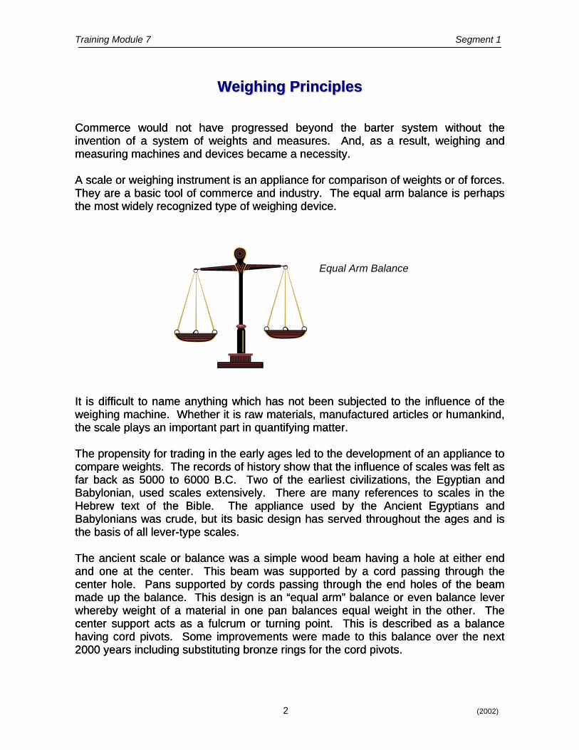
A scale or weighing instrument is an appliance for comparison of weights or of forces. They are a basic tool of commerce and industry. The equal arm balance is perhaps the most widely recognized type of weighing device.
It is difficult to name anything which has not been subjected to the influence of the weighing machine. Whether it is raw materials, manufactured articles or humankind, the scale plays an important part in quantifying matter.
It is difficult to name anything which has not been subjected to the influence of the weighing machine. Whether it is raw materials, manufactured articles or humankind, the scale plays an important part in quantifying matter. The propensity for trading in the early ages led to the development of an appliance to compare weights. The records of history show that the influence of scales was felt as far back as 5000 to 6000 B.C. Two of the earliest civilizations, the Egyptian and Babylonian, used scales extensively. There are many references to scales in the Hebrew text of the Bible. The appliance used by the Ancient Egyptians and Babylonians was crude, but its basic design has served throughout the ages and is the basis of all lever-type scales.
The propensity for trading in the early ages led to the development of an appliance to compare weights. The records of history show that the influence of scales was felt as far back as 5000 to 6000 B.C. Two of the earliest civilizations, the Egyptian and Babylonian, used scales extensively. There are many references to scales in the Hebrew text of the Bible. The appliance used by the Ancient Egyptians and Babylonians was crude, but its basic design has served throughout the ages and is the basis of all lever-type scales. The ancient scale or balance was a simple wood beam having a hole at either end and one at the center. This beam was supported by a cord passing through the center hole. Pans supported by cords passing through the end holes of the beam made up the balance. This design is an “equal arm” balance or even balance lever whereby weight of a material in one pan balances equal weight in the other. The center support acts as a fulcrum or turning point. This is described as a balance having cord pivots. Some improvements were made to this balance over the next 2000 years including substituting bronze rings for the cord pivots.
The ancient scale or balance was a simple wood beam having a hole at either end and one at the center. This beam was supported by a cord passing through the center hole. Pans supported by cords passing through the end holes of the beam made up the balance. This design is an “equal arm” balance or even balance lever whereby weight of a material in one pan balances equal weight in the other. The center support acts as a fulcrum or turning point. This is described as a balance having cord pivots. Some improvements were made to this balance over the next 2000 years including substituting bronze rings for the cord pivots.
eeiigghhiinngg PPrriinncciipplleess
Equal Arm Balance
Training Module 7 Segment 1
3 (2002)
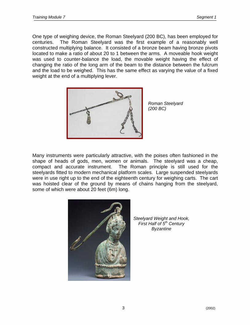
One type of weighing device, the Roman Steelyard (200 BC), has been employed for centuries. The Roman Steelyard was the first example of a reasonably well constructed multiplying balance. It consisted of a bronze beam having bronze pivots located to make a ratio of about 20 to 1 between the arms. A moveable hook weight was used to counter-balance the load, the movable weight having the effect of changing the ratio of the long arm of the beam to the distance between the fulcrum and the load to be weighed. This has the same effect as varying the value of a fixed weight at the end of a multiplying lever.
Roman Steelyard (200 BC)
Many instruments were particularly attractive, with the poises often fashioned in the shape of heads of gods, men, women or animals. The steelyard was a cheap, compact and accurate instrument. The Roman principle is still used for the steelyards fitted to modern mechanical platform scales. Large suspended steelyards were in use right up to the end of the eighteenth century for weighing carts. The cart was hoisted clear of the ground by means of chains hanging from the steelyard, some of which were about 20 feet (6m) long.
Steelyard Weight and Hook, First Half of 5th Century
Byzantine
Training Module 7 Segment 1
4 (2002)
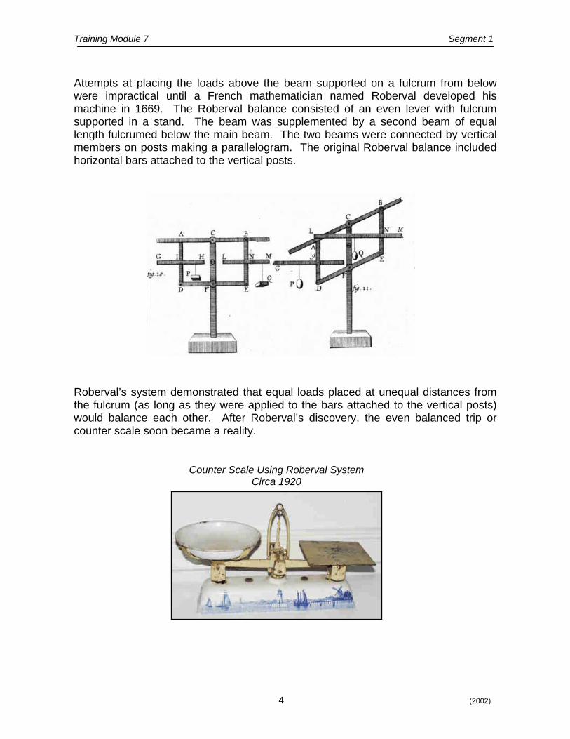
Attempts at placing the loads above the beam supported on a fulcrum from below were impractical until a French mathematician named Roberval developed his machine in 1669. The Roberval balance consisted of an even lever with fulcrum supported in a stand. The beam was supplemented by a second beam of equal length fulcrumed below the main beam. The two beams were connected by vertical members on posts making a parallelogram. The original Roberval balance included horizontal bars attached to the vertical posts. Roberval’s system demonstrated that equal loads placed at unequal distances from the fulcrum (as long as they were applied to the bars attached to the vertical posts) would balance each other. After Roberval’s discovery, the even balanced trip or counter scale soon became a reality.
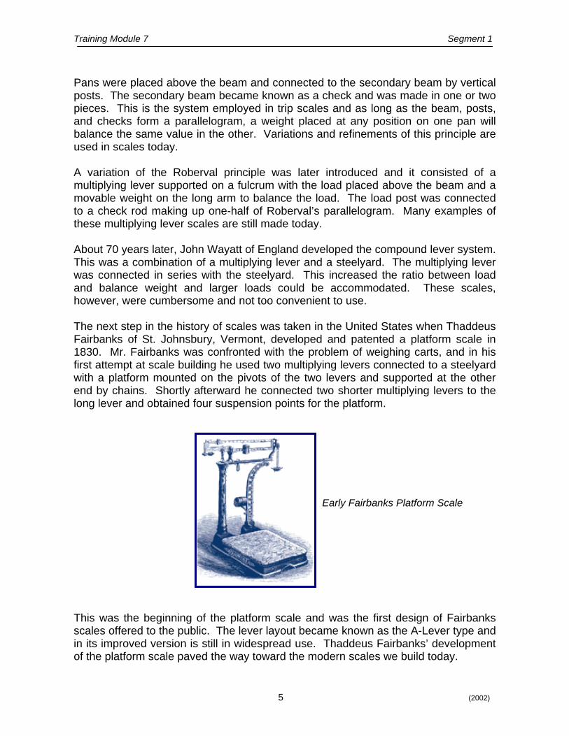
Counter Scale Using Roberval SystemCirca 1920
Training Module 7 Segment 1
5 (2002)
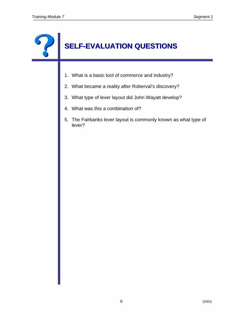
Pans were placed above the beam and connected to the secondary beam by vertical posts. The secondary beam became known as a check and was made in one or two pieces. This is the system employed in trip scales and as long as the beam, posts, and checks form a parallelogram, a weight placed at any position on one pan will balance the same value in the other. Variations and refinements of this principle are used in scales today. A variation of the Roberval principle was later introduced and it consisted of a multiplying lever supported on a fulcrum with the load placed above the beam and a movable weight on the long arm to balance the load. The load post was connected to a check rod making up one-half of Roberval’s parallelogram. Many examples of these multiplying lever scales are still made today. About 70 years later, John Wayatt of England developed the compound lever system. This was a combination of a multiplying lever and a steelyard. The multiplying lever was connected in series with the steelyard. This increased the ratio between load and balance weight and larger loads could be accommodated. These scales, however, were cumbersome and not too convenient to use. The next step in the history of scales was taken in the United States when Thaddeus Fairbanks of St. Johnsbury, Vermont, developed and patented a platform scale in 1830. Mr. Fairbanks was confronted with the problem of weighing carts, and in his first attempt at scale building he used two multiplying levers connected to a steelyard with a platform mounted on the pivots of the two levers and supported at the other end by chains. Shortly afterward he connected two shorter multiplying levers to the long lever and obtained four suspension points for the platform.
Early Fairbanks Platform Scale
This was the beginning of the platform scale and was the first design of Fairbanks scales offered to the public. The lever layout became known as the A-Lever type and in its improved version is still in widespread use. Thaddeus Fairbanks’ development of the platform scale paved the way toward the modern scales we build today.
Training Module 7 Segment 1
6 (2002)
SSEELLFF--EEVVAALLUUAATTIIOONN QQUUEESSTTIIOONNSS SSEELLFF--EEVVAALLUUAATTIIOONN QQUUEESSTTIIOONNSS
1. What is a basic tool of commerce and industry? 2. What became a reality after Roberval’s discovery? 3. What type of lever layout did John Wayatt develop? 4. What was this a combination of? 5. The Fairbanks lever layout is commonly known as what type of
lever?
Training Module 7 Segment 2
7 (2002)
LLeevveerr PPrriinncciipplleess
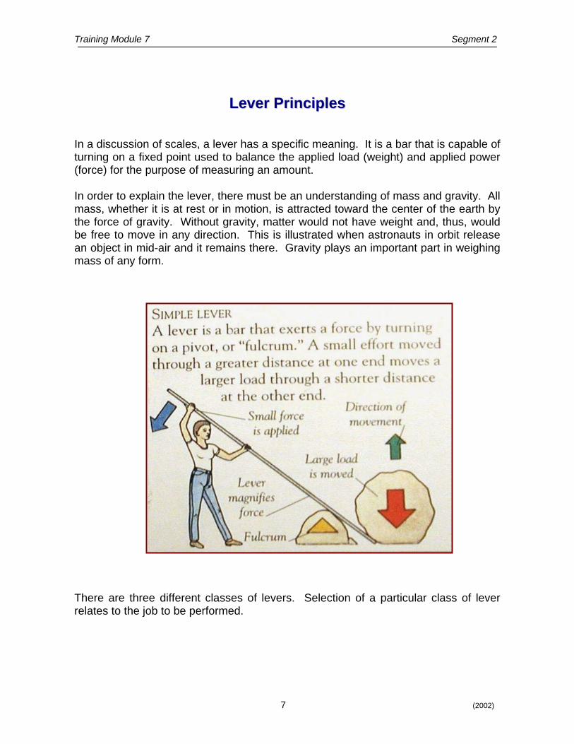
In a discussion of scales, a lever has a specific meaning. It is a bar that is capable of turning on a fixed point used to balance the applied load (weight) and applied power (force) for the purpose of measuring an amount. In order to explain the lever, there must be an understanding of mass and gravity. All mass, whether it is at rest or in motion, is attracted toward the center of the earth by the force of gravity. Without gravity, matter would not have weight and, thus, would be free to move in any direction. This is illustrated when astronauts in orbit release an object in mid-air and it remains there. Gravity plays an important part in weighing mass of any form.
There are three different classes of levers. Selection of a particular class of lever relates to the job to be performed.
Training Module 7 Segment 2
8 (2002)
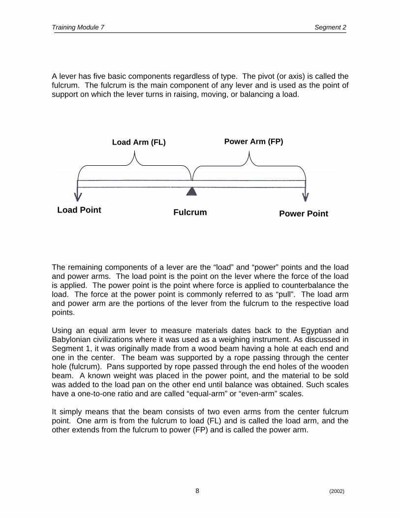
A lever has five basic components regardless of type. The pivot (or axis) is called the fulcrum. The fulcrum is the main component of any lever and is used as the point of support on which the lever turns in raising, moving, or balancing a load.
Load Arm (FL) Power Arm (FP)
Load Point Fulcrum Power Point
The remaining components of a lever are the “load” and “power” points and the load and power arms. The load point is the point on the lever where the force of the load is applied. The power point is the point where force is applied to counterbalance the load. The force at the power point is commonly referred to as “pull”. The load arm and power arm are the portions of the lever from the fulcrum to the respective load points. Using an equal arm lever to measure materials dates back to the Egyptian and Babylonian civilizations where it was used as a weighing instrument. As discussed in Segment 1, it was originally made from a wood beam having a hole at each end and one in the center. The beam was supported by a rope passing through the center hole (fulcrum). Pans supported by rope passed through the end holes of the wooden beam. A known weight was placed in the power point, and the material to be sold was added to the load pan on the other end until balance was obtained. Such scales have a one-to-one ratio and are called “equal-arm” or “even-arm” scales. It simply means that the beam consists of two even arms from the center fulcrum point. One arm is from the fulcrum to load (FL) and is called the load arm, and the other extends from the fulcrum to power (FP) and is called the power arm.
Training Module 7 Segment 2
9 (2002)
Load Point
Power Point Fulcrum
TTyyppeess ooff LLeevveerrss
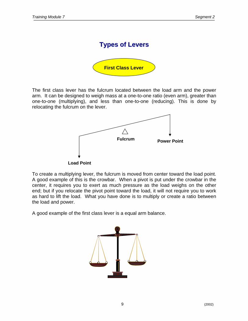
First Class Lever The first class lever has the fulcrum located between the load arm and the power arm. It can be designed to weigh mass at a one-to-one ratio (even arm), greater than one-to-one (multiplying), and less than one-to-one (reducing). This is done by relocating the fulcrum on the lever. To create a multiplying lever, the fulcrum is moved from center toward the load point. A good example of this is the crowbar. When a pivot is put under the crowbar in the center, it requires you to exert as much pressure as the load weighs on the other end; but if you relocate the pivot point toward the load, it will not require you to work as hard to lift the load. What you have done is to multiply or create a ratio between the load and power. A good example of the first class lever is a equal arm balance.

Training Module 7 Segment 2
10 (2002)
To Determine Ratio of First Class Lever
R = Ratio FP = Distance between the fulcrum and the power points FL = Distance between the fulcrum and the load points
FL
FP R
If you divide the crowbar into three equal parts and place one end under the load and place the pivot at the 1/3 mark, you have established a ratio of two to one. To illustrate, let us assume your load weighs 100 pounds and the crowbar is nine feet long from tip to tip.
When you place the fulcrum pivot under the 1/3 mark, you now have a FL that is three feet long and a FP that is six feet long. You can see that the FP is twice as long as the FL.
To determine the ratio or multiple of the crowbar lever, you must divide the length of the FL into the length of FP: three feet goes into six feet twice, so you have a ratio of two to one.
You can now lift the 100 pound load with only 50 pounds of pressure applied at the power point of the crowbar.
Note that the motion required on the power arm is twice that which results on the load arm. When the fulcrum is moved from center toward the power point, it will act as a reducing lever and will require more power or pull to balance the load than the force of the load itself. The formula to figure the ratio remains the same for the first class multiplying lever and the first class reducing lever. In this case the motion on the power arm is only half the motion on the load arm. Each first class lever, whether it is the even-arm, multiplying or reducing, has a function and is applied to a scale according to its design. The important thing to remember about the first class lever is that the fulcrum pivot is always located or set somewhere between the load and power pivots.
Training Module 7 Segment 2
11 (2002)
Load Point
Power Point Fulcrum
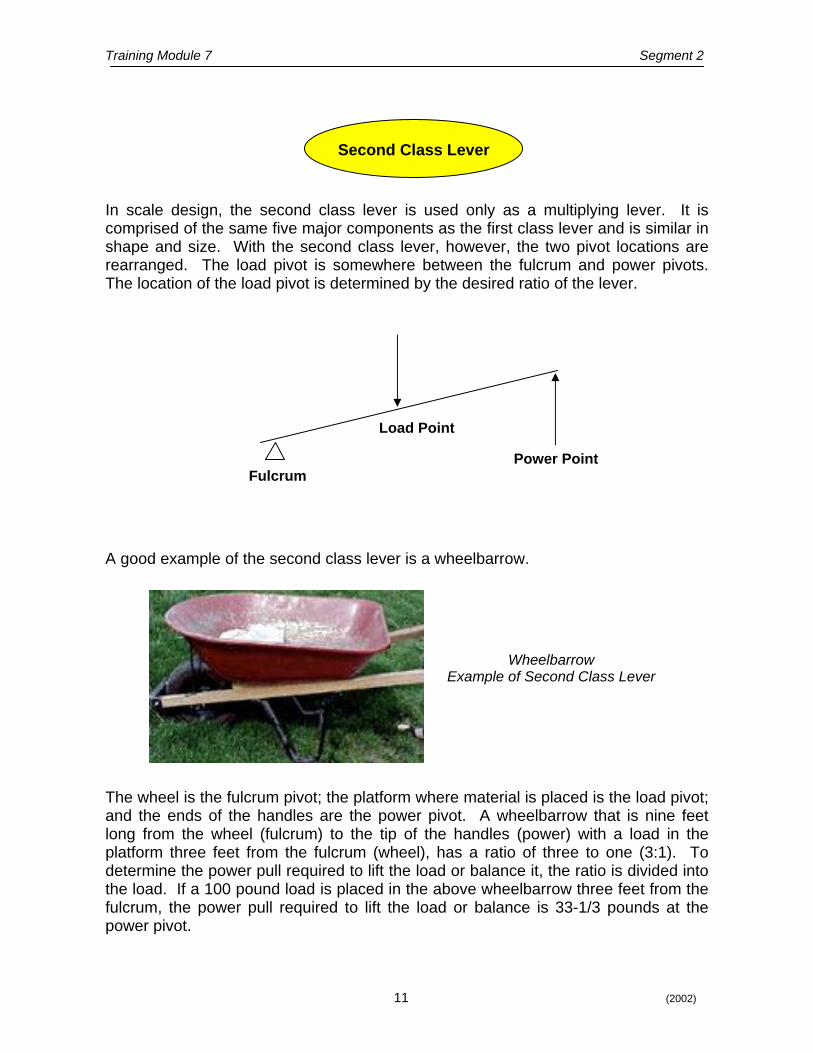
In scale design, the second class lever is used only as a multiplying lever. It is comprised of the same five major components as the first class lever and is similar in shape and size. With the second class lever, however, the two pivot locations are rearranged. The load pivot is somewhere between the fulcrum and power pivots. The location of the load pivot is determined by the desired ratio of the lever. A good example of the second class lever is a wheelbarrow.
Wheelbarrow Example of Second Class Lever
Second Class Lever
The wheel is the fulcrum pivot; the platform where material is placed is the load pivot; and the ends of the handles are the power pivot. A wheelbarrow that is nine feet long from the wheel (fulcrum) to the tip of the handles (power) with a load in the platform three feet from the fulcrum (wheel), has a ratio of three to one (3:1). To determine the power pull required to lift the load or balance it, the ratio is divided into the load. If a 100 pound load is placed in the above wheelbarrow three feet from the fulcrum, the power pull required to lift the load or balance is 33-1/3 pounds at the power pivot.
Training Module 7 Segment 2
12 (2002)
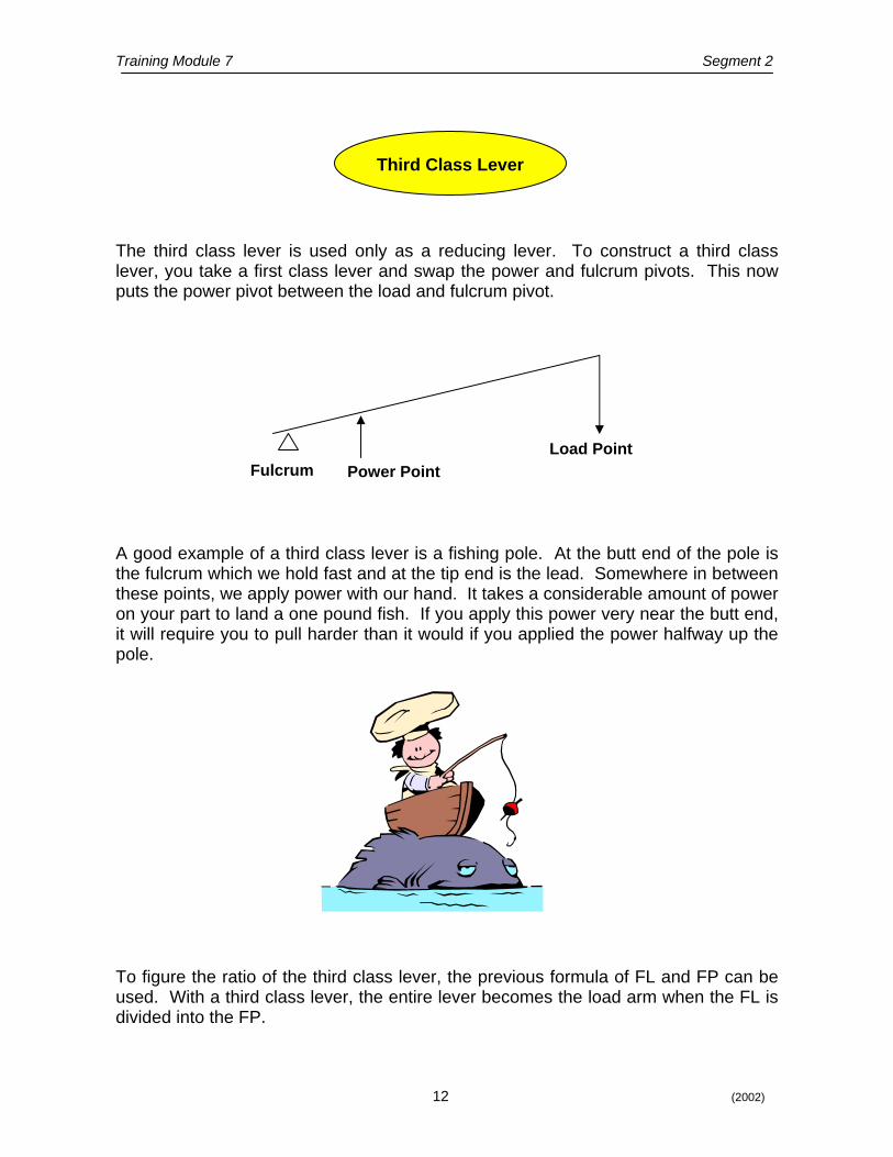
Third Class Lever The third class lever is used only as a reducing lever. To construct a third class lever, you take a first class lever and swap the power and fulcrum pivots. This now puts the power pivot between the load and fulcrum pivot.
Fulcrum Load Point
Power Point
A good example of a third class lever is a fishing pole. At the butt end of the pole is the fulcrum which we hold fast and at the tip end is the lead. Somewhere in between these points, we apply power with our hand. It takes a considerable amount of power on your part to land a one pound fish. If you apply this power very near the butt end, it will require you to pull harder than it would if you applied the power halfway up the pole. To figure the ratio of the third class lever, the previous formula of FL and FP can be used. With a third class lever, the entire lever becomes the load arm when the FL is divided into the FP.
Training Module 7 Segment 2
13 (2002)
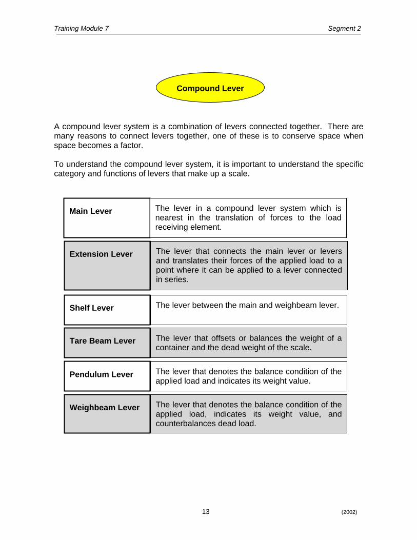
Compound Lever A compound lever system is a combination of levers connected together. There are many reasons to connect levers together, one of these is to conserve space when space becomes a factor. To understand the compound lever system, it is important to understand the specific category and functions of levers that make up a scale.
Main Lever The lever in a compound lever system which is nearest in the translation of forces to the load receiving element.
Weighbeam Lever The lever that denotes the balance condition of the applied load, indicates its weight value, and counterbalances dead load.
Pendulum Lever The lever that denotes the balance condition of the applied load and indicates its weight value.
Extension Lever The lever that connects the main lever or levers and translates their forces of the applied load to a point where it can be applied to a lever connected in series.
Shelf Lever
The lever between the main and weighbeam lever.
Tare Beam Lever
The lever that offsets or balances the weight of a container and the dead weight of the scale.
Training Module 7 Segment 2
14 (2002)
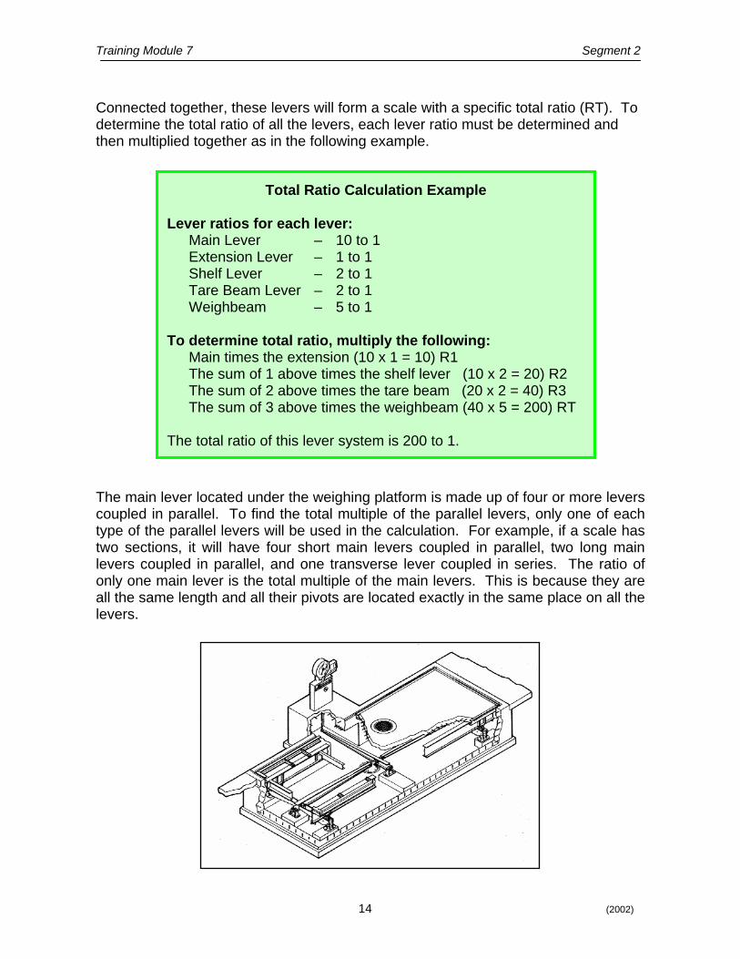
Connected together, these levers will form a scale with a specific total ratio (RT). To determine the total ratio of all the levers, each lever ratio must be determined and then multiplied together as in the following example.
Total Ratio Calculation Example
Lever ratios for each lever: Main Lever – 10 to 1 Extension Lever – 1 to 1 Shelf Lever – 2 to 1 Tare Beam Lever – 2 to 1 Weighbeam – 5 to 1
To determine total ratio, multiply the following:
Main times the extension (10 x 1 = 10) R1 The sum of 1 above times the shelf lever (10 x 2 = 20) R2 The sum of 2 above times the tare beam (20 x 2 = 40) R3 The sum of 3 above times the weighbeam (40 x 5 = 200) RT
The total ratio of this lever system is 200 to 1.
The main lever located under the weighing platform is made up of four or more levers coupled in parallel. To find the total multiple of the parallel levers, only one of each type of the parallel levers will be used in the calculation. For example, if a scale has two sections, it will have four short main levers coupled in parallel, two long main levers coupled in parallel, and one transverse lever coupled in series. The ratio of only one main lever is the total multiple of the main levers. This is because they are all the same length and all their pivots are located exactly in the same place on all the levers.

Training Module 7 Segment 2 The total ratio of any lever system is the combined ratios of all the levers coupled in series by multiplying them together.
Weighbeams
Sensitivity requirement of a non-automatic indicating device, such as a weighbeam, is the amount of weight that, when placed on the scale platform, will cause the beam to move from a balanced condition to the top of the trig loop. This determines the sensitivity of a scale at both zero load on the platform and at the test load.
Weighbeams are generally supplemented with an auxiliary indicator. This will speed up the reading of the balanced weight. Full Capacity Beam - The beam is supported by the fulcrum pivot (FP) on the
beam stand. The scale lever system is connected to the weighbeam at the load pivot (LP). The power for a weighbeam are the major and minor poises. The beam is balanced when all the poises are indicating zero and the tip of the beam is in the center of the trig loop. A balance ball is provided to facilitate this. When a load is placed on the platform, the beam will go to the top of the trig loop. The beam may be rebalanced by moving the major poise toward the tip of the beam until the tip starts to come down. The beam can be fine balanced by moving the minor poise toward the tip.
Weighbeam With Poise
The weighbeam of a scale is the final lever in its system. It is the indicating element. In most cases it is a first class lever.
15 (2002)
Training Module 7 Segment 2
16 (2002)
The poise run of a beam is the distance a poise weight travels from zero to full capacity position. The distance between the fulcrum pivot and the zero graduation has no bearing on the ratio of the poise run. This distance only affects the empty balance of the scale. The poise run is a power arm with a variable ratio. As the poise is moved along, the various positions represent various ratios or multiples. The poise at zero position is balanced with the rest of the scale structure. Equilibrium is established. As soon as it is moved away from the zero position, it becomes one of the power factors of the scale.
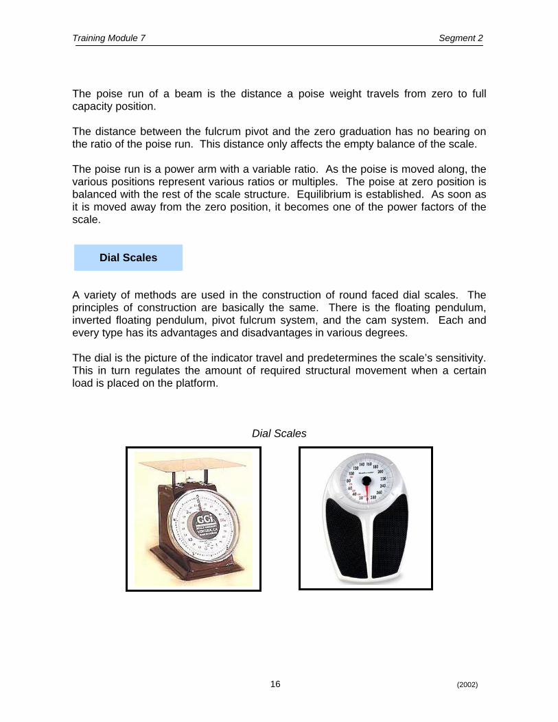
Dial Scales
A variety of methods are used in the construction of round faced dial scales. The principles of construction are basically the same. There is the floating pendulum, inverted floating pendulum, pivot fulcrum system, and the cam system. Each and every type has its advantages and disadvantages in various degrees. The dial is the picture of the indicator travel and predetermines the scale’s sensitivity. This in turn regulates the amount of required structural movement when a certain load is placed on the platform.
Dial Scales
Training Module 7 Segment 2
17 (2002)
SSEELLFF--EEVVAALLUUAATTIIOONN QQUUEESSTTIIOONNSS SSEELLFF--EEVVAALLUUAATTIIOONN QQUUEESSTTIIOONNSS
1. Regardless of type, the lever has this many basic components? 2. What is the main component of any lever? 3. The wheelbarrow is a good example of which class of lever?
4. What is the purpose of a balance ball on a weighbeam?
Training Module 7 Segment 3
18 (2002)
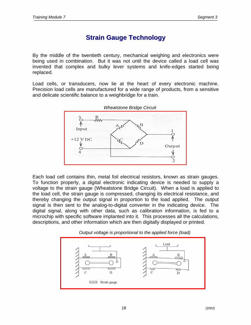
Wheatstone Bridge Circuit
Output voltage is proportional to the applied force (load)
SSttrraaiinn GGaauuggee TTeecchhnnoollooggyy
By the middle of the twentieth century, mechanical weighing and electronics were being used in combination. But it was not until the device called a load cell was invented that complex and bulky lever systems and knife-edges started being replaced. Load cells, or transducers, now lie at the heart of every electronic machine. Precision load cells are manufactured for a wide range of products, from a sensitive and delicate scientific balance to a weighbridge for a train.
Each load cell contains thin, metal foil electrical resistors, known as strain gauges. To function properly, a digital electronic indicating device is needed to supply a voltage to the strain gauge (Wheatstone Bridge Circuit). When a load is applied to the load cell, the strain gauge is compressed, changing its electrical resistance, and thereby changing the output signal in proportion to the load applied. The output signal is then sent to the analog-to-digital converter in the indicating device. The digital signal, along with other data, such as calibration information, is fed to a microchip with specific software implanted into it. This processes all the calculations, descriptions, and other information which are then digitally displayed or printed.

Training Module 7 Segment 3
19 (2002)
Strain gauge technology is emerging as the dominant way of converting force into a digital value which can be refined as a digital output signal for display purposes, printing, batching and weight processing.
TTyyppeess ooff LLooaadd CCeellllss
Traditional Canister Cell
S-Beam Cell
Bending Beam Cell
Training Module 7 Segment 3
20 (2002)
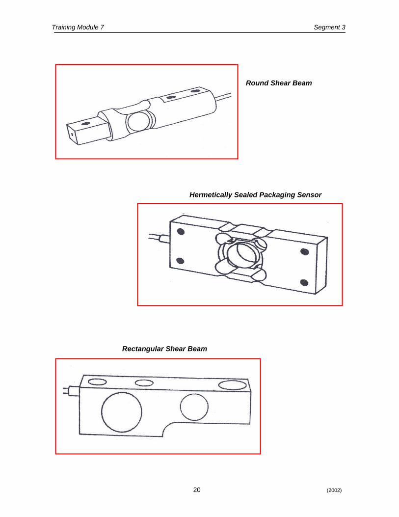
Round Shear Beam
Hermetically Sealed Packaging Sensor
Rectangular Shear Beam
Training Module 7 Segment 3
21 (2002)
WWeeiigghhiinngg IInnddiiccaattoorrss
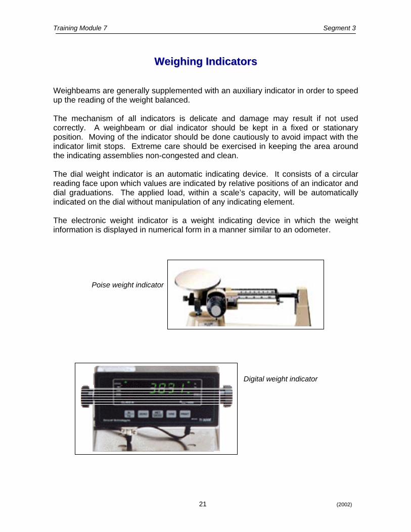
Weighbeams are generally supplemented with an auxiliary indicator in order to speed up the reading of the weight balanced. The mechanism of all indicators is delicate and damage may result if not used correctly. A weighbeam or dial indicator should be kept in a fixed or stationary position. Moving of the indicator should be done cautiously to avoid impact with the indicator limit stops. Extreme care should be exercised in keeping the area around the indicating assemblies non-congested and clean. The dial weight indicator is an automatic indicating device. It consists of a circular reading face upon which values are indicated by relative positions of an indicator and dial graduations. The applied load, within a scale’s capacity, will be automatically indicated on the dial without manipulation of any indicating element. The electronic weight indicator is a weight indicating device in which the weight information is displayed in numerical form in a manner similar to an odometer.
Digital weight indicator
Poise weight indicator
Training Module 7 Segment 3
22 (2002)
SSEELLFF--EEVVAALLUUAATTIIOONN QQUUEESSTTIIOONNSS SSEELLFF--EEVVAALLUUAATTIIOONN QQUUEESSTTIIOONNSS
1. What device is now being used to replace levers in weighing
elements? 2. What is the main component of a load cell? 3. With a load cell, what is the relationship of the output signal to
the load applied?
Training Module 7 Segment 4
23 (2002)
MMeeaassuurriinngg PPrriinncciipplleess
History The United States method of measuring volume is based on an Ancient Egyptian measure, a 12th century British measure, and a custom of doubling each measure to find the next. Some measures were dropped along the way and are no longer in use. There are two official sets of volume measures in the United Sates: wet and dry, with the gallon as the basic unit of liquid measure. Ancient Egyptian liquid measures, from large to small, were: ro, hin, hekat, khar, and cubic cubit (0.14 cubic metre [37 U.S. gallons]).
Gallon - The British imperial gallon is the volume of 10 pounds of pure water at 62°F and is equal to 277.42 cubic inches. A U.S. gallon is 231 cubic inches. Liquid Capacity - The British units of liquid capacity are thus about 20% larger than the corresponding U.S. units. Fluid Ounce - The U.S. fluid ounce is 1/16 of a U.S. pint. The British unit is 1/20 of an imperial pint and is thus slightly smaller than the U.S. fluid ounce.
Properties of Liquid and Gases Since liquids have a definite volume but no fixed shape, they will flow and take the shape of their container. Liquid particles are more loosely bound than particles in solid materials and will move more easily over short distances. Gases have no fixed volume or shape and will expand to fill their container. Gas particles are widely spaced. The bonds between the particles are very weak and the particles move freely. Types of Measuring Devices Measuring devices in use today are designed to move product as quickly and accurately as possible without compromising basic units of measure. There are many factors involved when attempting to measure liquids and gases accurately, such as atmospheric pressure, temperature, and amount of volume to measure; however, we will limit our discussion to the measuring principles of devices commonly used today.

Training Module 7 Segment 4
24 (2002)
SSEELLFF--EEVVAALLUUAATTIIOONN QQUUEESSTTIIOONNSS SSEELLFF--EEVVAALLUUAATTIIOONN QQUUEESSTTIIOONNSS
1. What shape will liquid take when poured into a container and
why? 2. Why do gases expand to fill their container?
Training Module 7 Segment 5
25 (2002)
FFllooww MMeetteerrss
gauge the trength of flow.
outlines the
11, and in the late 1960’s the first vortex shedding eters appeared on the market.
momentum of the stream prevents it from smoothly recombining downstream of the
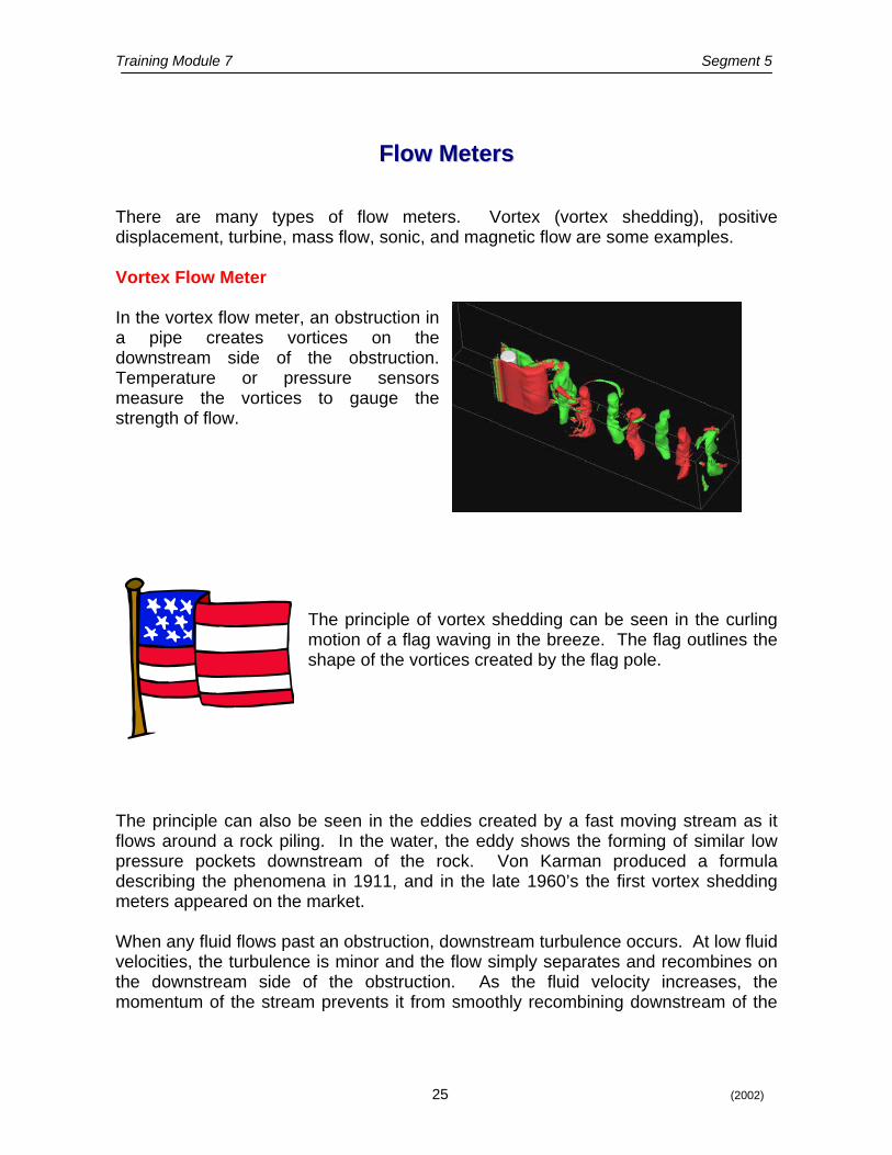
There are many types of flow meters. Vortex (vortex shedding), positive displacement, turbine, mass flow, sonic, and magnetic flow are some examples. Vortex Flow Meter In the vortex flow meter, an obstruction in a pipe creates vortices on the downstream side of the obstruction. Temperature or pressure sensors measure the vortices tos
The principle of vortex shedding can be seen in the curling motion of a flag waving in the breeze. The flagshape of the vortices created by the flag pole.
The principle can also be seen in the eddies created by a fast moving stream as it flows around a rock piling. In the water, the eddy shows the forming of similar low pressure pockets downstream of the rock. Von Karman produced a formula describing the phenomena in 19m When any fluid flows past an obstruction, downstream turbulence occurs. At low fluid velocities, the turbulence is minor and the flow simply separates and recombines on the downstream side of the obstruction. As the fluid velocity increases, the
Training Module 7 Segment 5
26 (2002)
obstruction. This creates a low pressure region on the back side of the obstruction, resulting in an inward flow of the fluid. As the velocity increases, this effect is heightened with an increasing low pressure pocket causing the fluid to be pulled backwards in a swirling motion (vortex). As this occurs it relieves the low pressure pocket, leaving the swirl free to drift downstream. As this swirl separates it leaves a low pressure pocket on the opposite side of the obstruction, which causes the action to repeat, but this time the swirl is released from the opposite side. The result is a series of swirls coming from opposite sides of the obstruction. To put this into commonly used terminology, the swirls are “vortices”, being “shed” from a “bluff body” (also known as the “shedder bar” or “shedder strut”). The center of the vortex path is called the “Von Karman Street”. The frequency of the vortices is directly proportional to the fluid velocity and is essentially linear. A drop off occurs at low fluid velocities, which may be linearized using electronics.
When to use the Vortex Meter (basic rules)
1. Gases need to be dense enough to allow the development of a
strong enough pressure pulse to allow the pulse to be distinguished against background pipe noise. Helium and hydrogen are problem gases.
2. Fluids which have high viscosities may not allow the vortex to
form properly. 3. The meter is best on gases and fluids. This meter is excellent
for dirty gases which can foul turbine meter bearings. 4. Consider this meter design for liquids, gases and steam. 5. As long as your fluid is within the limits of usage, the meter is
not affected by changes in viscosity and density.
Training Module 7 Segment 5
27 (2002)
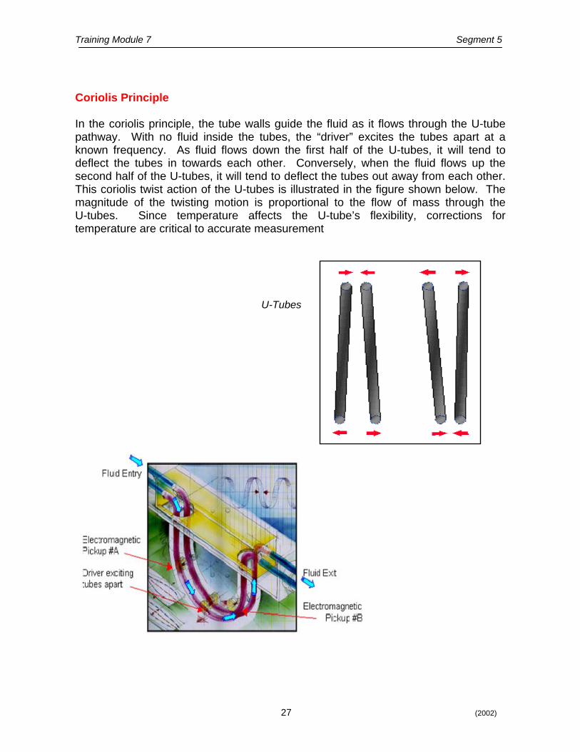
Coriolis Principle In the coriolis principle, the tube walls guide the fluid as it flows through the U-tube pathway. With no fluid inside the tubes, the “driver” excites the tubes apart at a known frequency. As fluid flows down the first half of the U-tubes, it will tend to deflect the tubes in towards each other. Conversely, when the fluid flows up the second half of the U-tubes, it will tend to deflect the tubes out away from each other. This coriolis twist action of the U-tubes is illustrated in the figure shown below. The magnitude of the twisting motion is proportional to the flow of mass through the U-tubes. Since temperature affects the U-tube’s flexibility, corrections for temperature are critical to accurate measurement
U-Tubes
Training Module 7 Segment 5
28 (2002)
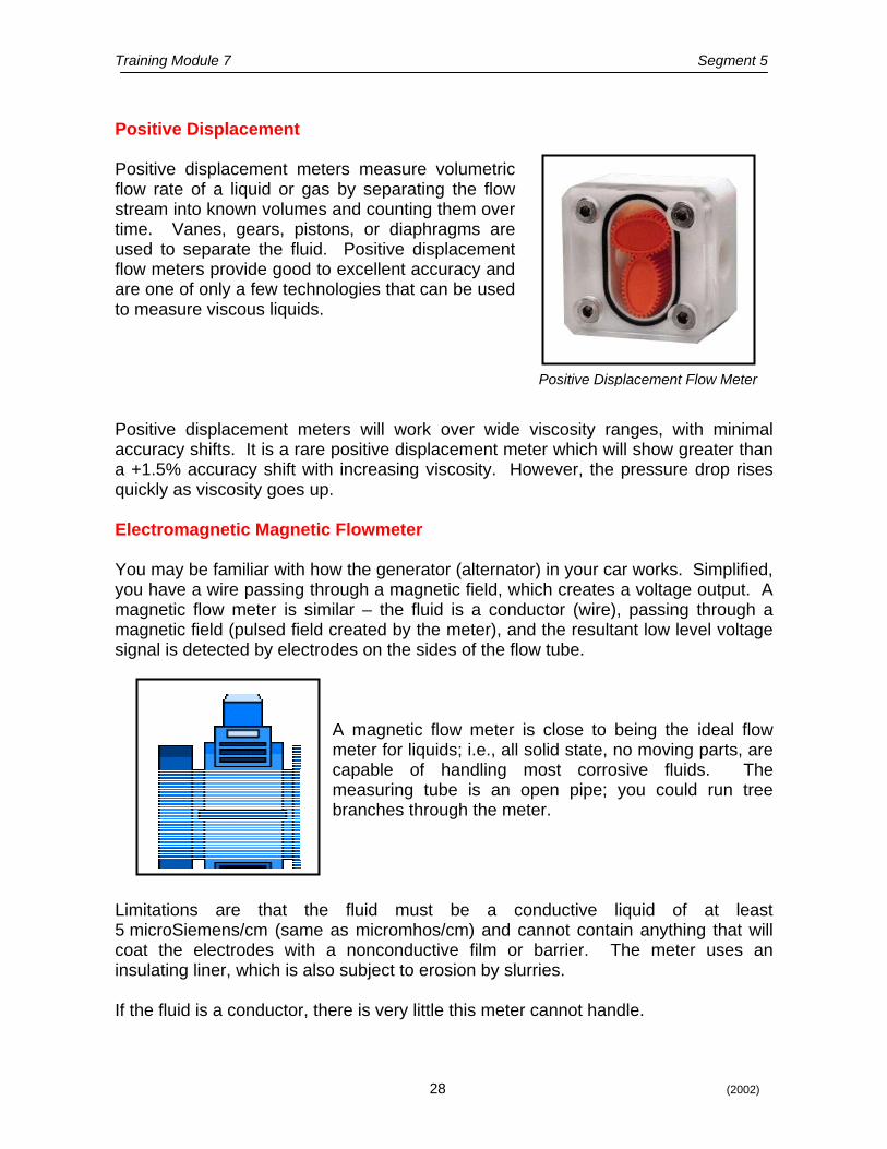
Positive Displacement Positive displacement meters measure volumetric flow rate of a liquid or gas by separating the flow stream into known volumes and counting them over time. Vanes, gears, pistons, or diaphragms are used to separate the fluid. Positive displacement flow meters provide good to excellent accuracy and are one of only a few technologies that can be used to measure viscous liquids.
Positive Displacement Flow Meter Positive displacement meters will work over wide viscosity ranges, with minimal accuracy shifts. It is a rare positive displacement meter which will show greater than a +1.5% accuracy shift with increasing viscosity. However, the pressure drop rises quickly as viscosity goes up. Electromagnetic Magnetic Flowmeter You may be familiar with how the generator (alternator) in your car works. Simplified, you have a wire passing through a magnetic field, which creates a voltage output. A magnetic flow meter is similar – the fluid is a conductor (wire), passing through a magnetic field (pulsed field created by the meter), and the resultant low level voltage signal is detected by electrodes on the sides of the flow tube.
A magnetic flow meter is close to being the ideal flow meter for liquids; i.e., all solid state, no moving parts, are capable of handling most corrosive fluids. The measuring tube is an open pipe; you could run tree branches through the meter.
Limitations are that the fluid must be a conductive liquid of at least 5 microSiemens/cm (same as micromhos/cm) and cannot contain anything that will coat the electrodes with a nonconductive film or barrier. The meter uses an insulating liner, which is also subject to erosion by slurries. If the fluid is a conductor, there is very little this meter cannot handle.

Training Module 7 Segment 5
29 (2002)
Differential Pressure Metering This differential pressure element actually forces flow into a smaller diameter section of pipe, then measures the pressure differences between the unrestricted flow and the restricted flow.
Venturi Tube Other differential pressure meters use an orifice plate which helps measure flow through differences in pressure from the upstream side to the downstream side of a partially obstructed pipe. The plate offers a precisely measured obstruction that narrows the pipe and forces the flowing substance to constrict. Pressure sensing cells or pressure transducers allow the comparison of the pressure on the upstream (unobstructed) side and the downstream (constricted) side.
Orifice Plate
Training Module 7 Segment 5
30 (2002)
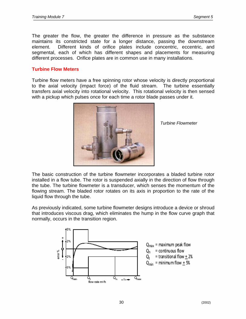
The greater the flow, the greater the difference in pressure as the substance maintains its constricted state for a longer distance, passing the downstream element. Different kinds of orifice plates include concentric, eccentric, and segmental, each of which has different shapes and placements for measuring different processes. Orifice plates are in common use in many installations. Turbine Flow Meters Turbine flow meters have a free spinning rotor whose velocity is directly proportional to the axial velocity (impact force) of the fluid stream. The turbine essentially transfers axial velocity into rotational velocity. This rotational velocity is then sensed with a pickup which pulses once for each time a rotor blade passes under it.
Turbine Flowmeter
The basic construction of the turbine flowmeter incorporates a bladed turbine rotor installed in a flow tube. The rotor is suspended axially in the direction of flow through the tube. The turbine flowmeter is a transducer, which senses the momentum of the flowing stream. The bladed rotor rotates on its axis in proportion to the rate of the liquid flow through the tube. As previously indicated, some turbine flowmeter designs introduce a device or shroud that introduces viscous drag, which eliminates the hump in the flow curve graph that normally, occurs in the transition region.
Training Module 7 Segment 5
31 (2002)
While linearity is affected by viscosity, repeatability is not.
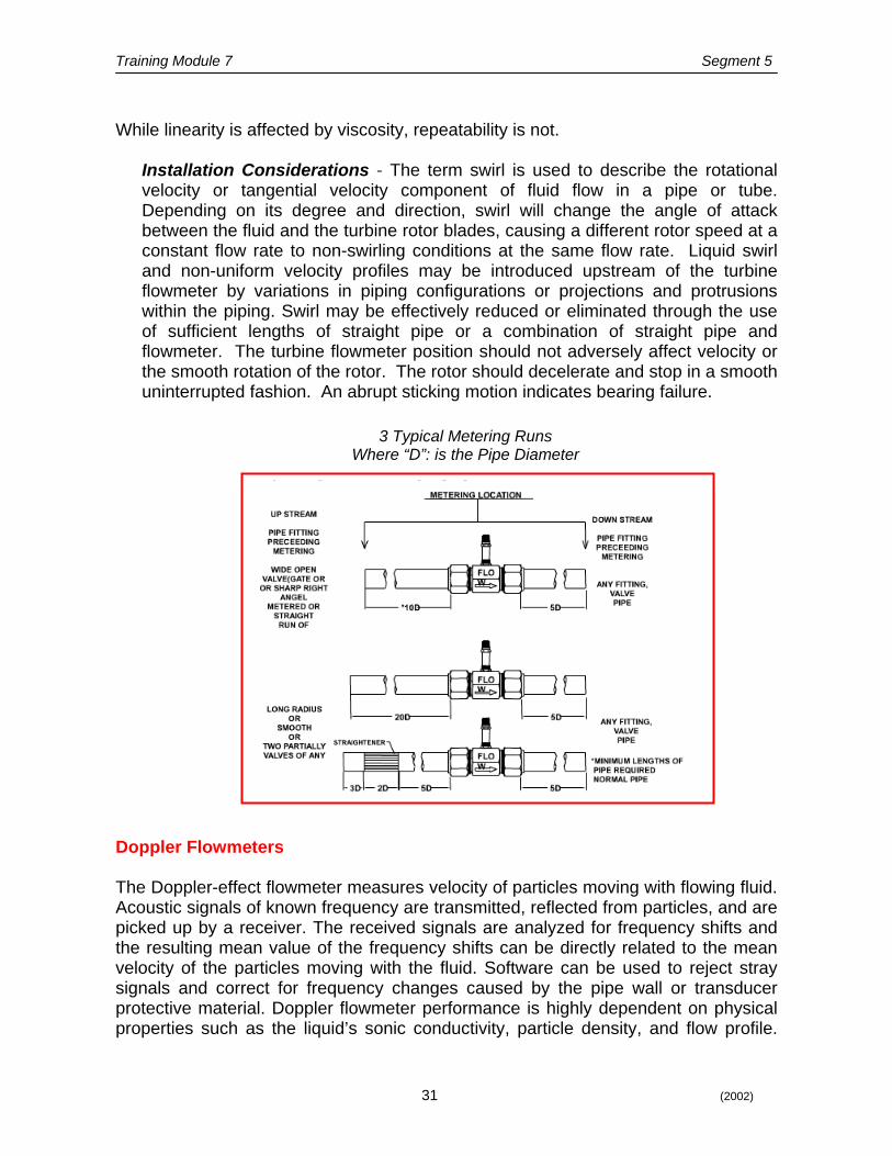
Installation Considerations - The term swirl is used to describe the rotational velocity or tangential velocity component of fluid flow in a pipe or tube. Depending on its degree and direction, swirl will change the angle of attack between the fluid and the turbine rotor blades, causing a different rotor speed at a constant flow rate to non-swirling conditions at the same flow rate. Liquid swirl and non-uniform velocity profiles may be introduced upstream of the turbine flowmeter by variations in piping configurations or projections and protrusions within the piping. Swirl may be effectively reduced or eliminated through the use of sufficient lengths of straight pipe or a combination of straight pipe and flowmeter. The turbine flowmeter position should not adversely affect velocity or the smooth rotation of the rotor. The rotor should decelerate and stop in a smooth uninterrupted fashion. An abrupt sticking motion indicates bearing failure.
3 Typical Metering Runs
Where “D”: is the Pipe Diameter
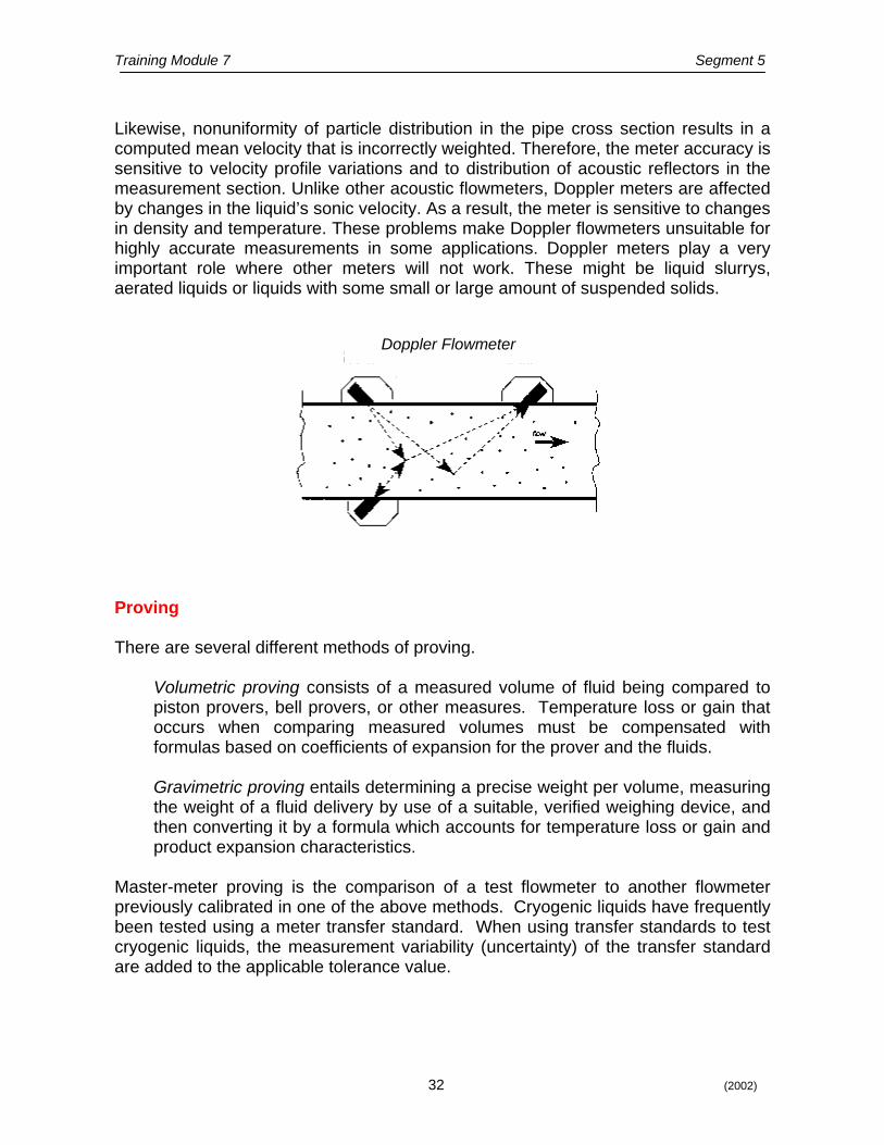
Doppler Flowmeters The Doppler-effect flowmeter measures velocity of particles moving with flowing fluid. Acoustic signals of known frequency are transmitted, reflected from particles, and are picked up by a receiver. The received signals are analyzed for frequency shifts and the resulting mean value of the frequency shifts can be directly related to the mean velocity of the particles moving with the fluid. Software can be used to reject stray signals and correct for frequency changes caused by the pipe wall or transducer protective material. Doppler flowmeter performance is highly dependent on physical properties such as the liquid’s sonic conductivity, particle density, and flow profile.
Training Module 7 Segment 5
32 (2002)
Likewise, nonuniformity of particle distribution in the pipe cross section results in a computed mean velocity that is incorrectly weighted. Therefore, the meter accuracy is sensitive to velocity profile variations and to distribution of acoustic reflectors in the measurement section. Unlike other acoustic flowmeters, Doppler meters are affected by changes in the liquid’s sonic velocity. As a result, the meter is sensitive to changes in density and temperature. These problems make Doppler flowmeters unsuitable for highly accurate measurements in some applications. Doppler meters play a very important role where other meters will not work. These might be liquid slurrys, aerated liquids or liquids with some small or large amount of suspended solids.
Doppler Flowmeter
Proving There are several different methods of proving.
Volumetric proving consists of a measured volume of fluid being compared to piston provers, bell provers, or other measures. Temperature loss or gain that occurs when comparing measured volumes must be compensated with formulas based on coefficients of expansion for the prover and the fluids. Gravimetric proving entails determining a precise weight per volume, measuring the weight of a fluid delivery by use of a suitable, verified weighing device, and then converting it by a formula which accounts for temperature loss or gain and product expansion characteristics.
Master-meter proving is the comparison of a test flowmeter to another flowmeter previously calibrated in one of the above methods. Cryogenic liquids have frequently been tested using a meter transfer standard. When using transfer standards to test cryogenic liquids, the measurement variability (uncertainty) of the transfer standard are added to the applicable tolerance value.
Training Module 7 Segment 5
33 (2002)
OOtthheerr MMeetteerriinngg CCoonnssiiddeerraattiioonnss
Cavitation
Cavitation in a liquid flowmeter will take place when the local pressures fall close to or below the vapor pressure of the liquid product. The formation of bubbles and their collapse or local vaporization of product as it passes over the rotor blade surface or when it enters or exits the measuring chamber or the pump, can cause erratic behavior in turbine and positive displacement flowmeters. It may also lead to excessive wear due to over speeding.
Viscosity
Viscosity, a resistance to flow, can complicate measurement with many meter types. Meter flow ranges can be adversely affected and performance can shift when viscosity changes occur. This is often a problem when using a single point calibrated meter to measure liquids of widely varying viscosity. Generally turbine meters are effected much more than positive displacement meters.
Air Elimination
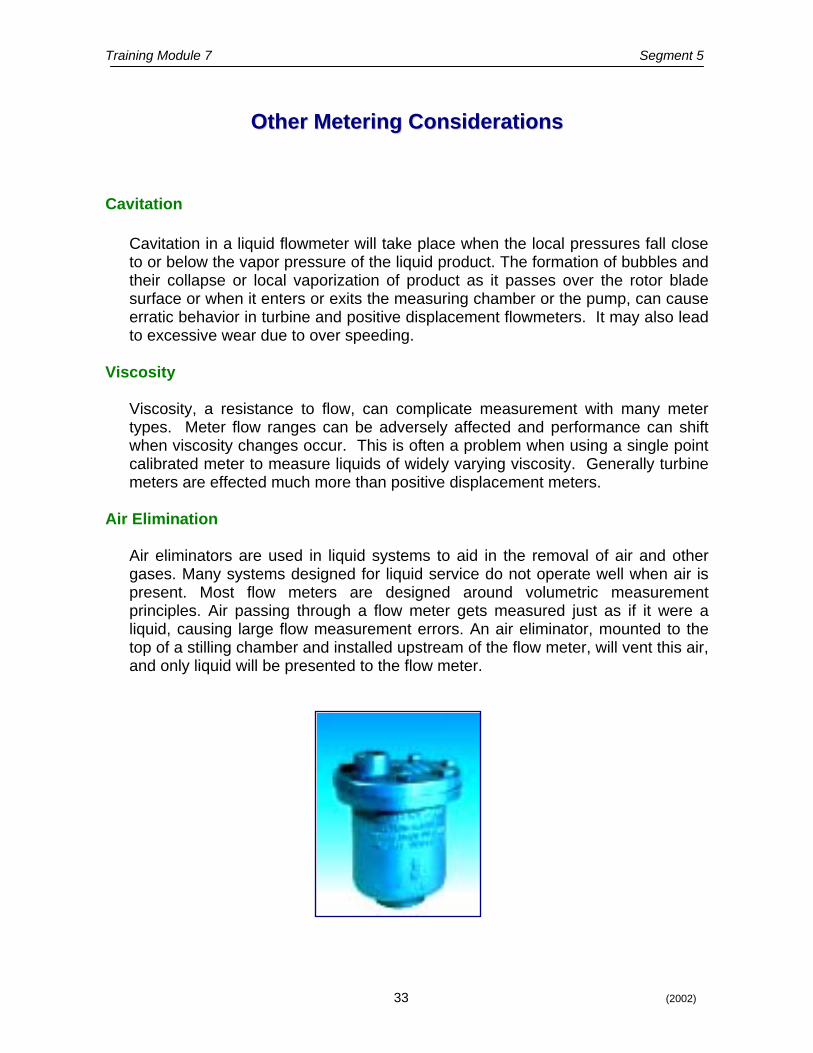
Air eliminators are used in liquid systems to aid in the removal of air and other gases. Many systems designed for liquid service do not operate well when air is present. Most flow meters are designed around volumetric measurement principles. Air passing through a flow meter gets measured just as if it were a liquid, causing large flow measurement errors. An air eliminator, mounted to the top of a stilling chamber and installed upstream of the flow meter, will vent this air, and only liquid will be presented to the flow meter.
Training Module 7 Segment 5
34 (2002)
Flow Straighteners and Conditioners
Flow straighteners and conditioners can smooth out turbulent and transitional flows and help meters measure more accurately. Turbine meters frequently require such flow conditioning to perform correctly.
Temperature Effects
Temperature effects volume of both liquids and gases to the extent that corrections must be considered when the temperature of the product during metering is different from the temperature when the prover volume is being read. Even minor temperature changes of a gas result in the necessity to make volume corrections. Many products such as bulk petroleum products are sold based upon standard temperatures so that the metered volume must be either automatically or manually corrected back to the volume at standard temperature.
Altitude Corrections for Gases
Products in a vapor state expand noticeably as atmospheric pressure decreases. Since changes in elevation effect the pressure exerted by the earth’s atmosphere, corrections for these pressure variations are necessary to achieve accurate measurement of vaporized hydrocarbons such as natural gas or propane.
Training Module 7 Segment 5
35 (2002)
SSEELLFF--EEVVAALLUUAATTIIOONN QQUUEESSTTIIOONNSS SSEELLFF--EEVVAALLUUAATTIIOONN QQUUEESSTTIIOONNSS
1. What effect does a stream of fast moving water around an
obstacle create? 2. What type of meter uses this principle? 3. What two properties does the Coriolis Principle utilize for
measuring flow? 4. What type of meter works best over a wide range of viscosities
with few accuracy shifts? 5. What will take place with a turbine flowmeter when the local
pressure falls? Resulting in what? 6. What other methods of measuring liquid are available?
Training Module 7 Glossary
36 (2002)
GLOSSARY
A LISTING OF TERMINOLOGY AND ACRONYMS MOST COMMONLY USED BY WEIGHTS AND MEASURES OFFICIALS.
Beam – The indicating device of a lever scale. Bell Prover – A calibrated cylindrical metal tank of the annular type with a scale thereon that, in the downward travel in a surrounding tank containing a sealing medium, displaces air through the meter being proved or calibrated. Cryogenic Liquid – Fluids whose normal boiling point is below 120 kelvin (-243°F) Fulcrum – A pivot point for a lever. Lever – A tool that transfers a force, equally, with reduction or with multiplication. Load Cell – A device which produces an output signal proportional to the applied weight or force.
Poise – A movable weight that counterbalances the load on a scale. At the point of equal balance the weight indicated by the position of the poise on the beam. Poise Run – The distance the poise travels on a beam from zero to full capacity position. Scale – A device for weighing, comparing and determining a weight or mass.
Transfer Standard – A measurement system designed for use in proving and testing cryogenic liquid measuring devices.
Training Module 7
37 (2002)
BBIIBBLLIIOOGGRRAAPPHHYY AANNDD RREEFFEERREENNCCEESS BBIIBBLLIIOOGGRRAAPPHHYY AANNDD RREEFFEERREENNCCEESS
Scaleman’s Handbook of Metrology, National Scaleman’s Association
Training Module 7
38 (2002)
SSEELLFF--EEVVAALLUUAATTIIOONN AANNSSWWEERRSS SSEELLFF--EEVVAALLUUAATTIIOONN AANNSSWWEERRSS
Segment 1 1. The scale and/or weighing instrument 2. The even balanced trip or center scale 3. A-lever 4. A multiplying lever and a steelyard 5. The A-Lever type Segment 2 1. 5 2. Fulcrum 3. Second class 4. To balance the beam at zero Segment 3 1. The load cell 2. The strain gauge (Wheatstone bridge) 3. The output signal is proportional to the load applied Segment 4 1. Takes the shape of the container because liquid particles are
more loosely bound than other particles and will move short distances.
2. The bonds between gas particles are weak Segment 5 1. An eddy current 2. The Vortex flow meter 3. Vibration and frequency 4. The positive displacement meter 5. Cavitation. Erratic behavior in the turbine flowmeter 6. Volumetric (prover) and gravimetric (weighing)
Training Module 7
39 (2002)
We would appreciate your taking a few moments to complete our training evaluation feedback form. We welcome your comments and any suggestions you might have regarding Training Module 7. You may E-mail your response to us at [email protected] or mail to Division of Measurement Standards at 6790 Florin Perkins Road, Suite 100, Sacramento CA 95828-1812.
1. Did this module fulfill your expectations? 2. What did you like/dislike about this module? 3. What areas would you like to see improved? 4. What specific changes, if any, would you recommend? 5. How could this module be better organized to make it easier to follow and learn
from? 6. Was this module too basic or too advanced for someone with an entry level
background in weights and measures? 7. Additional comments or suggestions.
TTrraaiinniinngg MMoodduullee 77 FFeeeeddbbaacckk
Related Documents