Nokia — Proprietary and confidential. Use pursuant to applicable agreements. 7450 ETHERNET SERVICE SWITCH 7750 SERVICE ROUTER 7950 EXTENSIBLE ROUTING SYSTEM VIRTUALIZED SERVICE ROUTER BASIC SYSTEM CONFIGURATION GUIDE RELEASE 19.5.R1 3HE 15079 AAAA TQZZA 01 Issue: 01 May 2019 BASIC SYSTEM CONFIGURATION GUIDE RELEASE 19.5.R1

Welcome message from author
This document is posted to help you gain knowledge. Please leave a comment to let me know what you think about it! Share it to your friends and learn new things together.
Transcript
Nokia — Proprietary and confidential.Use pursuant to applicable agreements.
7450 ETHERNET SERVICE SWITCH7750 SERVICE ROUTER7950 EXTENSIBLE ROUTING SYSTEMVIRTUALIZED SERVICE ROUTER
BASIC SYSTEM CONFIGURATION GUIDE RELEASE 19.5.R1
3HE 15079 AAAA TQZZA 01
Issue: 01
May 2019
BASIC SYSTEM CONFIGURATION GUIDE RELEASE 19.5.R1

2
BASIC SYSTEM CONFIGURATION GUIDERELEASE 19.5.R1
3HE 15079 AAAA TQZZA 01 Issue: 01
Nokia is a registered trademark of Nokia Corporation. Other products and company names mentioned herein may be trademarks or tradenames of their respective owners.
The information presented is subject to change without notice. No responsibility is assumed for inaccuracies contained herein.
© 2019 Nokia.
Contains proprietary/trade secret information which is the property of Nokia and must not be made available to, or copied or used by anyone outside Nokia without its written authorization. Not to be used or disclosed except in accordance with applicable agreements.
BASIC SYSTEM CONFIGURATION GUIDE RELEASE 19.5.R1
Issue: 01 3HE 15079 AAAA TQZZA 01 3
Table of Contents
1 Getting Started................................................................................91.1 About This Guide.........................................................................................91.2 Router System Configuration Process ......................................................11
2 CLI Usage ......................................................................................132.1 CLI Structure .............................................................................................132.2 Navigating in the CLI .................................................................................142.2.1 CLI Contexts..............................................................................................142.2.2 Basic CLI Commands................................................................................152.2.3 CLI Environment Commands ....................................................................172.2.4 CLI Monitor Commands.............................................................................182.3 Getting Help in the CLI ..............................................................................202.4 The CLI Command Prompt........................................................................232.5 Displaying Configuration Contexts ............................................................242.6 EXEC Files ................................................................................................252.7 CLI Script Control ......................................................................................262.8 Entering CLI Commands ...........................................................................272.8.1 Command Completion...............................................................................272.8.2 Unordered and Unnamed Parameters ......................................................272.8.3 Editing Keystrokes.....................................................................................282.8.4 Absolute Paths ..........................................................................................292.8.5 History .......................................................................................................302.8.6 Entering Numerical Ranges.......................................................................312.8.7 Pipe/Match.................................................................................................322.8.8 Pipe/Count.................................................................................................362.8.9 Range Operator Support of Regular Expression Match ............................372.8.9.1 Regular Expression Symbols in a Regular Expression Match
Operation...................................................................................................382.8.10 Redirection ................................................................................................402.9 VI Editor.....................................................................................................412.9.1 Summary of vi Commands ........................................................................412.9.2 Using the vi Commands ............................................................................422.9.3 EX Commands ..........................................................................................472.10 Configuration Rollback ..............................................................................492.10.1 Feature Behavior .......................................................................................502.10.2 Rollback and SNMP ..................................................................................562.10.3 Rescue Configuration ................................................................................572.10.4 Operational Guidelines ..............................................................................572.11 Transactional Configuration.......................................................................602.11.1 Basic Operation .........................................................................................602.11.2 Transactions and Rollback .......................................................................622.11.3 Authorization..............................................................................................632.12 Basic CLI Command Reference ................................................................652.12.1 Command Hierarchies...............................................................................652.12.1.1 Global Commands.....................................................................................65
4
BASIC SYSTEM CONFIGURATION GUIDERELEASE 19.5.R1
3HE 15079 AAAA TQZZA 01 Issue: 01
2.12.1.2 Monitor Commands ...................................................................................662.12.1.3 Environment Commands...........................................................................682.12.1.4 Candidate Commands...............................................................................682.12.1.5 Rollback Commands .................................................................................692.12.2 Command Descriptions .............................................................................702.12.2.1 Global Commands.....................................................................................702.12.2.2 Monitor CLI Commands.............................................................................902.12.2.3 CLI Environment Commands ..................................................................1602.12.2.4 Candidate Commands.............................................................................1652.12.2.5 Rollback Commands ...............................................................................1742.12.2.6 Show Commands ....................................................................................180
3 File System Management...........................................................1833.1 The File System.......................................................................................1833.1.1 Compact Flash Devices...........................................................................1833.1.2 URLs........................................................................................................1843.1.3 Wildcards.................................................................................................1853.2 File Management Tasks ..........................................................................1873.2.1 Modifying File Attributes .........................................................................1873.2.2 Creating Directories.................................................................................1883.2.3 Copying Files...........................................................................................1883.2.4 Moving Files ............................................................................................1893.2.5 Deleting Files and Removing Directories ................................................1893.2.6 Displaying Directory and File Information................................................1903.2.7 Repairing the File System .......................................................................1913.3 File Command Reference........................................................................1933.3.1 Command Hierarchy................................................................................1933.3.1.1 File Commands .......................................................................................1933.3.2 Command Descriptions ...........................................................................1933.3.2.1 File System Commands ..........................................................................1933.3.2.2 File Commands .......................................................................................195
4 Boot Options ...............................................................................2094.1 System Initialization.................................................................................2094.1.1 Configuration and Image Loading ...........................................................2124.1.1.1 Persistence..............................................................................................2144.1.1.2 Lawful Intercept .......................................................................................2144.1.1.3 FIPS-140-2 Mode ....................................................................................2154.1.1.4 System Profiles........................................................................................2164.2 Initial System Startup Process Flow ........................................................2194.3 Configuration Notes.................................................................................2204.4 Configuring Boot Options File with CLI....................................................2214.4.1 BOF Configuration Overview...................................................................2214.4.2 Basic BOF Configuration .........................................................................2214.4.3 Common Configuration Tasks .................................................................2224.4.3.1 Searching for the BOF.............................................................................2224.4.3.2 Accessing the CLI....................................................................................2244.4.4 Configuring BOF Parameters ..................................................................2254.5 Service Management Tasks ....................................................................226
BASIC SYSTEM CONFIGURATION GUIDE RELEASE 19.5.R1
Issue: 01 3HE 15079 AAAA TQZZA 01 5
4.5.1 System Administration Commands .........................................................2264.5.1.1 Viewing the Current Configuration...........................................................2264.5.1.2 Modifying and Saving a Configuration.....................................................2274.5.1.3 Deleting Bof Parameters .........................................................................2284.5.1.4 Saving a Configuration to a Different Filename.......................................2294.5.1.5 Rebooting ................................................................................................2294.6 BOF Configuration Command Reference................................................2314.6.1 Command Hierarchies.............................................................................2314.6.1.1 Configuration Commands........................................................................2314.6.2 Command Descriptions ...........................................................................2324.6.2.1 File Management Commands .................................................................2324.6.2.2 BOF Processing Control..........................................................................2334.6.2.3 Console Port Configuration .....................................................................2344.6.2.4 Image and Configuration Management ...................................................2344.6.2.5 Management Ethernet Configuration.......................................................2404.6.2.6 DNS Configuration Commands ...............................................................2454.7 BOF Show Command Reference ............................................................2494.7.1 Command Hierarchies.............................................................................2494.7.2 Command Descriptions ...........................................................................2494.7.2.1 BOF Show Commands............................................................................249
5 Debug Commands ......................................................................255
6 Tools Commands........................................................................257
7 System Management .................................................................2597.1 System Management Parameters ...........................................................2597.1.1 System Information..................................................................................2597.1.1.1 System Name..........................................................................................2597.1.1.2 System Contact .......................................................................................2597.1.1.3 System Location ......................................................................................2607.1.1.4 System Coordinates ................................................................................2607.1.1.5 Naming Objects .......................................................................................2607.1.1.6 Common Language Location Identifier....................................................2617.1.1.7 DNS Security Extensions ........................................................................2617.1.2 System Time ...........................................................................................2617.1.2.1 Time Zones..............................................................................................2617.1.2.2 Network Time Protocol (NTP)..................................................................2637.1.2.3 SNTP Time Synchronization ...................................................................2657.1.2.4 CRON......................................................................................................2667.2 High Availability .......................................................................................2677.2.1 HA Features ............................................................................................2677.2.1.1 Redundancy ............................................................................................2687.2.1.2 Nonstop Forwarding ................................................................................2707.2.1.3 Nonstop Routing (NSR)...........................................................................2717.2.1.4 CPM Switchover ......................................................................................2727.2.1.5 Synchronization .......................................................................................2727.3 Synchronization and Redundancy...........................................................2747.3.1 Active and Standby Designations............................................................275
6
BASIC SYSTEM CONFIGURATION GUIDERELEASE 19.5.R1
3HE 15079 AAAA TQZZA 01 Issue: 01
7.3.2 When the Active CPM Goes Offline ........................................................2757.3.3 OOB Management Ethernet Port Redundancy .......................................2767.3.4 Persistence..............................................................................................2777.3.4.1 Dynamic Data Persistency (DDP) Access Optimization for DHCP
Leases .....................................................................................................2787.4 Network Synchronization.........................................................................2807.4.1 Central Synchronization Sub-System......................................................2817.4.2 7950 XRS-40 Extension Chassis Central Clocks ....................................2857.4.3 Synchronization Status Messages (SSM) ...............................................2857.4.3.1 DS1 Signals.............................................................................................2857.4.3.2 E1 Signals ...............................................................................................2867.4.3.3 SONET/SDH Signals...............................................................................2867.4.3.4 DS3/E3 ....................................................................................................2867.4.4 Synchronous Ethernet .............................................................................2867.4.5 Clock Source Quality Level Definitions....................................................2877.4.6 Advanced G.781 Features.......................................................................2907.4.7 IEEE 1588v2 PTP....................................................................................2907.4.7.1 PTP Clock Synchronization .....................................................................2977.4.7.2 Performance Considerations ...................................................................2987.4.7.3 PTP Capabilities ......................................................................................2997.4.7.4 PTP Ordinary Slave Clock For Frequency ..............................................3007.4.7.5 PTP Ordinary Master Clock For Frequency ............................................3017.4.7.6 PTP Boundary Clock for Frequency and Time........................................3037.4.7.7 PTP Clock Redundancy ..........................................................................3047.4.7.8 PTP Time for System Time and OAM Time ............................................3047.4.7.9 PTP within Routing Instances..................................................................3047.5 System-Wide ATM Parameters ...............................................................3057.6 QinQ Network Interface Support .............................................................3067.7 Link Layer Discovery Protocol (LLDP).....................................................3077.8 IP Hashing as an LSR .............................................................................3107.9 Satellites ..................................................................................................3117.9.1 Ethernet Satellites ...................................................................................3117.9.2 TDM Satellites .........................................................................................3127.9.3 Software Repositories for Satellites.........................................................3137.9.4 Satellite Software Upgrade Overview......................................................3147.9.5 100GE Client Ports..................................................................................3157.9.6 Satellite Configuration ............................................................................3167.9.6.1 Satellite Client Port ID Formats ...............................................................3167.9.6.2 Local Forwarding .....................................................................................3177.9.6.3 Port Template ..........................................................................................3197.9.6.4 10GE Client Ports ...................................................................................3197.9.6.5 10GE Uplinks on the 64x10GE+4x100GE Satellite.................................3197.9.6.6 Satellite Uplink Resiliency .......................................................................3217.10 Auto-Provisioning ....................................................................................3237.10.1 Auto-provisioning limits............................................................................3247.10.2 Auto-provisioning Process.......................................................................3257.10.3 Auto-provisioning DHCP Rules ...............................................................3267.10.4 Auto-provisioning Failure ........................................................................3277.11 Administrative Tasks ...............................................................................328
BASIC SYSTEM CONFIGURATION GUIDE RELEASE 19.5.R1
Issue: 01 3HE 15079 AAAA TQZZA 01 7
7.11.1 Saving Configurations .............................................................................3287.11.2 Specifying Post-Boot Configuration Files ................................................3287.11.3 Network Timing........................................................................................3287.11.4 Power Supplies........................................................................................3297.11.5 Automatic Synchronization ......................................................................3297.11.5.1 Boot-Env Option ......................................................................................3307.11.5.2 Config Option...........................................................................................3307.11.6 Manual Synchronization ..........................................................................3307.11.6.1 Forcing a Switchover ...............................................................................3317.12 System Router Instances ........................................................................3327.13 System Configuration Process Overview ................................................3347.14 Configuration Notes.................................................................................3357.14.1 General....................................................................................................3357.15 Configuring System Management with CLI .............................................3377.15.1 Saving Configurations .............................................................................3377.15.2 Basic System Configuration ....................................................................3387.15.3 Common Configuration Tasks .................................................................3387.15.3.1 System Information..................................................................................3397.15.3.2 Configuring Synchronization and Redundancy .......................................3527.15.3.3 Configuring Multi-Chassis Redundancy for LAG.....................................3547.15.3.4 Configuring Power Supply Parameters ...................................................3567.15.3.5 Configuring ATM System Parameters .....................................................3577.15.3.6 Configuring Backup Copies .....................................................................3587.15.3.7 Post-Boot Configuration Extension Files .................................................3597.15.4 System Timing.........................................................................................3617.15.4.1 Edit Mode ................................................................................................3617.15.4.2 Configuring Timing References ...............................................................3627.15.4.3 Using the Revert Command ....................................................................3627.15.4.4 Other Editing Commands ........................................................................3637.15.4.5 Forcing a Specific Reference ..................................................................3647.15.5 Configuring System Monitoring Thresholds.............................................3647.15.5.1 Creating Events .......................................................................................3647.15.5.2 System Alarm Contact Inputs ..................................................................3667.15.6 Configuring LLDP ....................................................................................3677.16 System Command Reference ................................................................3697.16.1 Command Hierarchies.............................................................................3697.16.1.1 Configuration Commands........................................................................3697.16.1.2 System Information Commands ..............................................................3697.16.1.3 Satellite Commands ................................................................................3717.16.1.4 System Alarm Contact Input Commands ................................................3727.16.1.5 System Threshold Alarm Commands......................................................3727.16.1.6 System Bluetooth Commands .................................................................3737.16.1.7 Persistence Commands ..........................................................................3737.16.1.8 PTP Commands ......................................................................................3747.16.1.9 System Time Commands ........................................................................3757.16.1.10 Cron Commands .....................................................................................3767.16.1.11 Script Control Commands .......................................................................3777.16.1.12 System Synchronization Commands.......................................................3777.16.1.13 System Administration (Admin) Commands............................................378
8
BASIC SYSTEM CONFIGURATION GUIDERELEASE 19.5.R1
3HE 15079 AAAA TQZZA 01 Issue: 01
7.16.1.14 High Availability (Redundancy) Commands ............................................3797.16.1.15 LLDP System Commands .......................................................................3817.16.1.16 LLDP Ethernet Port Commands ..............................................................3817.16.1.17 System Router Instance Commands.......................................................3827.16.2 System Command Reference .................................................................3827.16.2.1 Generic Commands.................................................................................3827.16.2.2 System Information Commands ..............................................................3837.16.2.3 System Alarm Contact Input Commands ................................................4127.16.2.4 System Threshold Alarm Commands......................................................4157.16.2.5 System Bluetooth Commands .................................................................4337.16.2.6 Persistence Commands ..........................................................................4367.16.2.7 PTP Commands ......................................................................................4407.16.2.8 Date and Time Commands......................................................................4517.16.2.9 Network Time Protocol Commands.........................................................4527.16.2.10 Cron Commands .....................................................................................4657.16.2.11 Script Control Commands .......................................................................4717.16.2.12 System Synchronization Configuration Commands ................................4757.16.2.13 System Administration Commands .........................................................4857.16.2.14 Redundancy Commands.........................................................................4967.16.2.15 LLDP System Commands .......................................................................5177.16.2.16 LLDP Ethernet Port Commands ..............................................................5197.16.2.17 System Router Instance Commands.......................................................5227.17 Show, Clear, Debug, and Tools Command Reference ...........................5257.17.1 Command Hierarchies.............................................................................5257.17.1.1 Show Commands ....................................................................................5257.17.1.2 Clear Commands.....................................................................................5267.17.1.3 Debug Commands...................................................................................5277.17.1.4 Tools Commands ....................................................................................5277.17.2 Command Descriptions ...........................................................................5297.17.2.1 Show Commands ....................................................................................5297.17.2.2 Debug Commands...................................................................................6257.17.2.3 Tools Commands ....................................................................................6287.17.2.4 Clear Commands.....................................................................................648
8 Standards and Protocol Support ..............................................659
BASIC SYSTEM CONFIGURATION GUIDE RELEASE 19.5.R1
Getting Started
Issue: 01 3HE 15079 AAAA TQZZA 01 9
1 Getting Started
1.1 About This Guide
This guide describes system concepts and provides configuration explanations and examples to configure SR OS boot option file (BOF), file system and system management functions. Also provided are concepts and descriptions of the Command Line Interface (CLI) syntax and command usage.
This guide is organized into functional chapters and provides concepts and descriptions of the implementation flow, as well as Command Line Interface (CLI) syntax and command usage.
The topics and commands described in this document apply to the:
• 7450 ESS
• 7750 SR
• 7950 XRS
• VSR
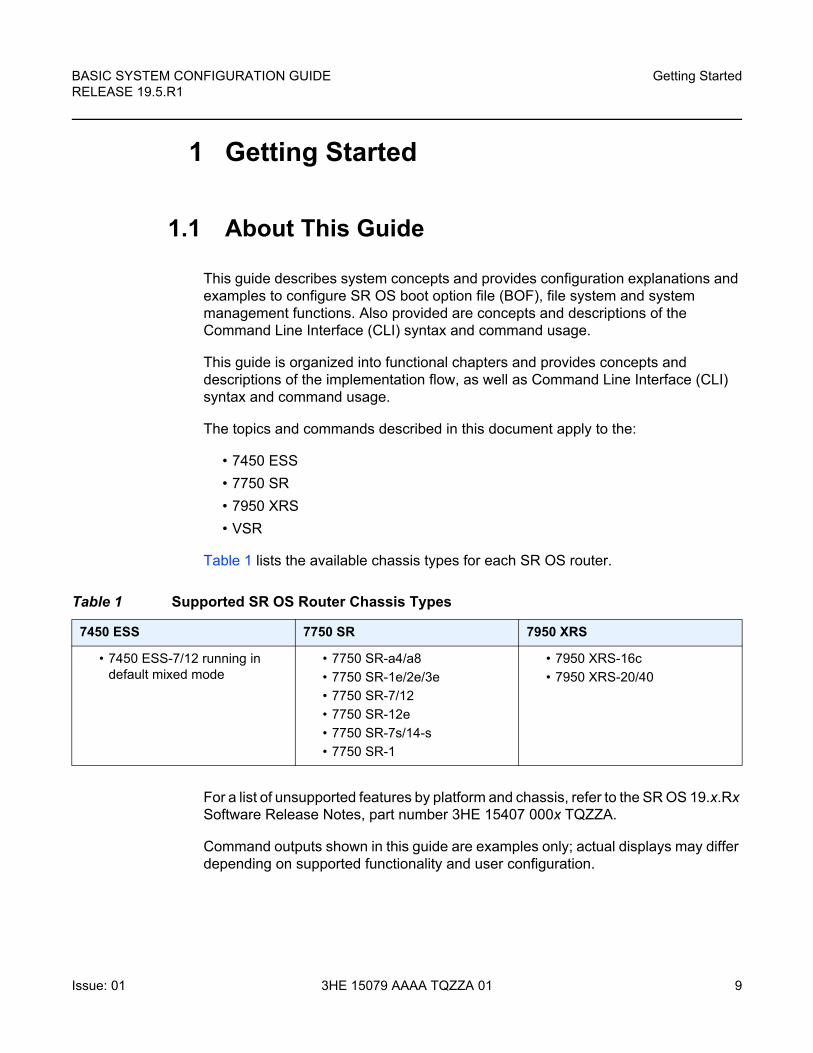
Table 1 lists the available chassis types for each SR OS router.
For a list of unsupported features by platform and chassis, refer to the SR OS 19.x.Rx Software Release Notes, part number 3HE 15407 000x TQZZA.
Command outputs shown in this guide are examples only; actual displays may differ depending on supported functionality and user configuration.
Table 1 Supported SR OS Router Chassis Types
7450 ESS 7750 SR 7950 XRS
• 7450 ESS-7/12 running in default mixed mode
• 7750 SR-a4/a8
• 7750 SR-1e/2e/3e
• 7750 SR-7/12
• 7750 SR-12e
• 7750 SR-7s/14-s
• 7750 SR-1
• 7950 XRS-16c
• 7950 XRS-20/40

Getting Started
10
BASIC SYSTEM CONFIGURATION GUIDERELEASE 19.5.R1
3HE 15079 AAAA TQZZA 01 Issue: 01
Note: This guide generically covers Release 19.x.Rx content and may contain some content that will be released in later maintenance loads. Refer to the SR OS 19.x.Rx Software Release Notes, part number 3HE 15407 000x TQZZA, for information about features supported in each load of the Release 19.x.Rx software.
BASIC SYSTEM CONFIGURATION GUIDE RELEASE 19.5.R1
Getting Started
Issue: 01 3HE 15079 AAAA TQZZA 01 11
1.2 Router System Configuration Process
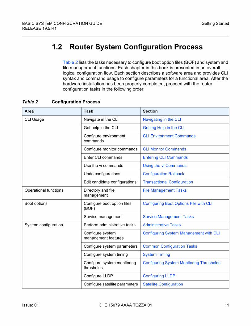
Table 2 lists the tasks necessary to configure boot option files (BOF) and system and file management functions. Each chapter in this book is presented in an overall logical configuration flow. Each section describes a software area and provides CLI syntax and command usage to configure parameters for a functional area. After the hardware installation has been properly completed, proceed with the router configuration tasks in the following order:
Table 2 Configuration Process
Area Task Section
CLI Usage Navigate in the CLI Navigating in the CLI
Get help in the CLI Getting Help in the CLI
Configure environment commands
CLI Environment Commands
Configure monitor commands CLI Monitor Commands
Enter CLI commands Entering CLI Commands
Use the vi commands Using the vi Commands
Undo configurations Configuration Rollback
Edit candidate configurations Transactional Configuration
Operational functions Directory and file management
File Management Tasks
Boot options Configure boot option files (BOF)
Configuring Boot Options File with CLI
Service management Service Management Tasks
System configuration Perform administrative tasks Administrative Tasks
Configure system management features
Configuring System Management with CLI
Configure system parameters Common Configuration Tasks
Configure system timing System Timing
Configure system monitoring thresholds
Configuring System Monitoring Thresholds
Configure LLDP Configuring LLDP
Configure satellite parameters Satellite Configuration

Getting Started
12
BASIC SYSTEM CONFIGURATION GUIDERELEASE 19.5.R1
3HE 15079 AAAA TQZZA 01 Issue: 01
BASIC SYSTEM CONFIGURATION GUIDE RELEASE 19.5.R1
CLI Usage
Issue: 01 3HE 15079 AAAA TQZZA 01 13
2 CLI Usage
2.1 CLI Structure
SR OS CLI is a command-driven interface accessible through the console, Telnet and secure shell (SSH). The CLI can be used for the configuration and management of routers.
The SR OS CLI command tree is a hierarchical inverted tree. At the highest level is the ROOT level. Below this level are other tree levels with the major command groups; for example, configuration commands and show commands are levels below ROOT.
The CLI is organized so related commands with the same scope are at the same level or in the same context. Sublevels or subcontexts have related commands with a more refined scope.
Note: The CLI engine used to execute scripts is the primary CLI engine configured with configure>system>management-interface>cli>cli-engine {classic-cli | md-cli} [{classic-cli | md-cli}...(up to 2 max)].
CLI Usage
14
BASIC SYSTEM CONFIGURATION GUIDERELEASE 19.5.R1
3HE 15079 AAAA TQZZA 01 Issue: 01
2.2 Navigating in the CLI
The command outputs in the following sections are examples only; actual displays may differ depending on supported functionality and user configuration.
2.2.1 CLI Contexts
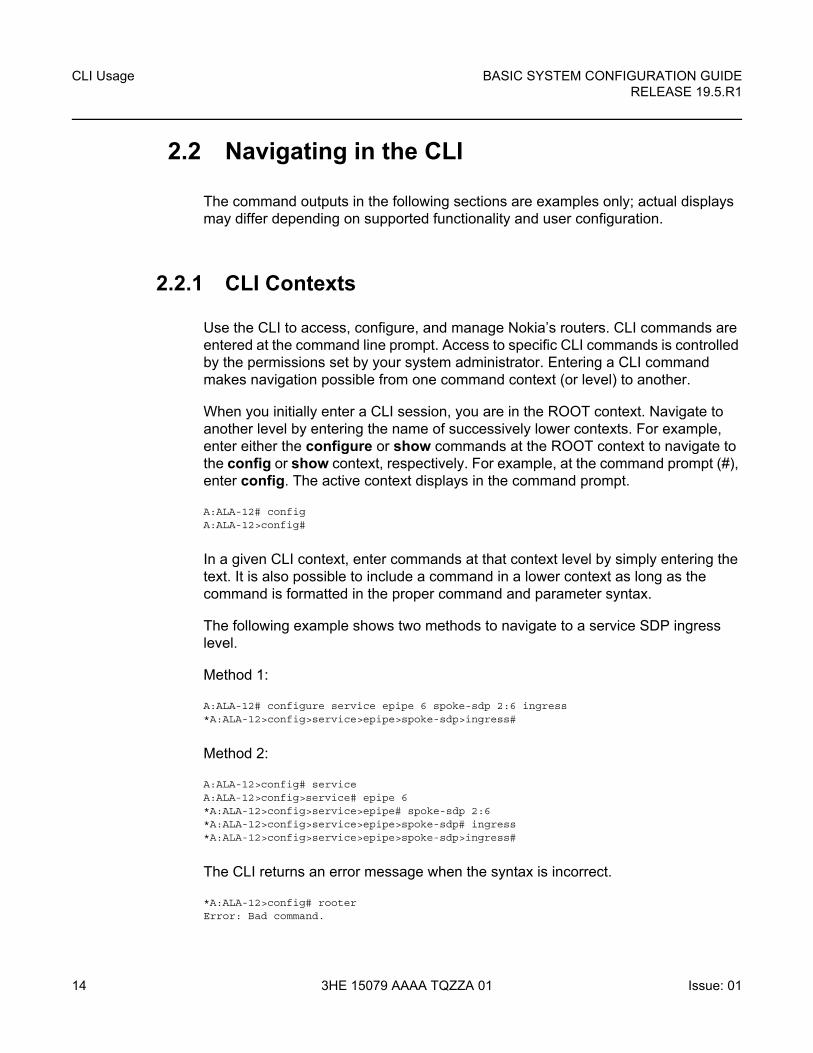
Use the CLI to access, configure, and manage Nokia’s routers. CLI commands are entered at the command line prompt. Access to specific CLI commands is controlled by the permissions set by your system administrator. Entering a CLI command makes navigation possible from one command context (or level) to another.
When you initially enter a CLI session, you are in the ROOT context. Navigate to another level by entering the name of successively lower contexts. For example, enter either the configure or show commands at the ROOT context to navigate to the config or show context, respectively. For example, at the command prompt (#), enter config. The active context displays in the command prompt.
A:ALA-12# configA:ALA-12>config#
In a given CLI context, enter commands at that context level by simply entering the text. It is also possible to include a command in a lower context as long as the command is formatted in the proper command and parameter syntax.
The following example shows two methods to navigate to a service SDP ingress level.
Method 1:
A:ALA-12# configure service epipe 6 spoke-sdp 2:6 ingress*A:ALA-12>config>service>epipe>spoke-sdp>ingress#
Method 2:
A:ALA-12>config# serviceA:ALA-12>config>service# epipe 6*A:ALA-12>config>service>epipe# spoke-sdp 2:6*A:ALA-12>config>service>epipe>spoke-sdp# ingress*A:ALA-12>config>service>epipe>spoke-sdp>ingress#
The CLI returns an error message when the syntax is incorrect.
*A:ALA-12>config# rooterError: Bad command.
BASIC SYSTEM CONFIGURATION GUIDE RELEASE 19.5.R1
CLI Usage
Issue: 01 3HE 15079 AAAA TQZZA 01 15
2.2.2 Basic CLI Commands
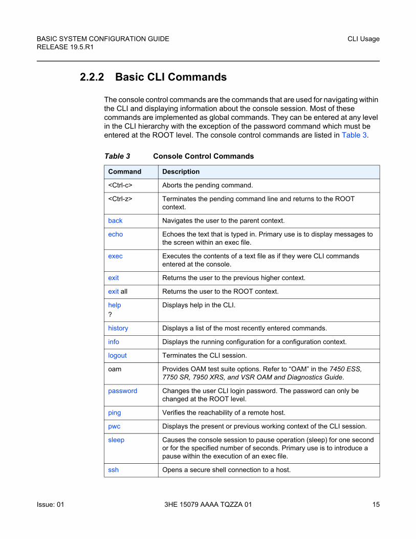
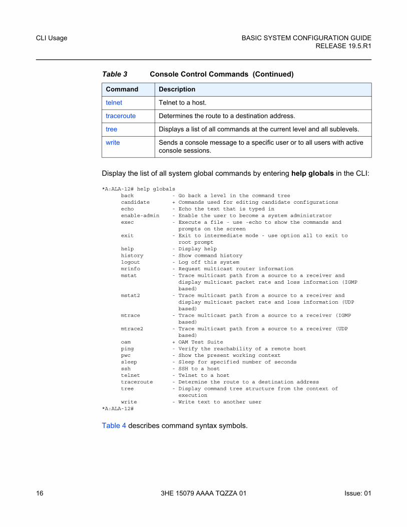
The console control commands are the commands that are used for navigating within the CLI and displaying information about the console session. Most of these commands are implemented as global commands. They can be entered at any level in the CLI hierarchy with the exception of the password command which must be entered at the ROOT level. The console control commands are listed in Table 3.
Table 3 Console Control Commands
Command Description
<Ctrl-c> Aborts the pending command.
<Ctrl-z> Terminates the pending command line and returns to the ROOT context.
back Navigates the user to the parent context.
echo Echoes the text that is typed in. Primary use is to display messages to the screen within an exec file.
exec Executes the contents of a text file as if they were CLI commands entered at the console.
exit Returns the user to the previous higher context.
exit all Returns the user to the ROOT context.
help
?
Displays help in the CLI.
history Displays a list of the most recently entered commands.
info Displays the running configuration for a configuration context.
logout Terminates the CLI session.
oam Provides OAM test suite options. Refer to “OAM” in the 7450 ESS, 7750 SR, 7950 XRS, and VSR OAM and Diagnostics Guide.
password Changes the user CLI login password. The password can only be changed at the ROOT level.
ping Verifies the reachability of a remote host.
pwc Displays the present or previous working context of the CLI session.
sleep Causes the console session to pause operation (sleep) for one second or for the specified number of seconds. Primary use is to introduce a pause within the execution of an exec file.
ssh Opens a secure shell connection to a host.
CLI Usage
16
BASIC SYSTEM CONFIGURATION GUIDERELEASE 19.5.R1
3HE 15079 AAAA TQZZA 01 Issue: 01
Display the list of all system global commands by entering help globals in the CLI:
*A:ALA-12# help globalsback - Go back a level in the command treecandidate + Commands used for editing candidate configurationsecho - Echo the text that is typed inenable-admin - Enable the user to become a system administratorexec - Execute a file - use -echo to show the commands and
prompts on the screenexit - Exit to intermediate mode - use option all to exit to
root prompthelp - Display helphistory - Show command historylogout - Log off this systemmrinfo - Request multicast router informationmstat - Trace multicast path from a source to a receiver and
display multicast packet rate and loss information (IGMPbased)
mstat2 - Trace multicast path from a source to a receiver anddisplay multicast packet rate and loss information (UDPbased)
mtrace - Trace multicast path from a source to a receiver (IGMPbased)
mtrace2 - Trace multicast path from a source to a receiver (UDPbased)
oam + OAM Test Suiteping - Verify the reachability of a remote hostpwc - Show the present working contextsleep - Sleep for specified number of secondsssh - SSH to a hosttelnet - Telnet to a hosttraceroute - Determine the route to a destination addresstree - Display command tree structure from the context of
executionwrite - Write text to another user
*A:ALA-12#
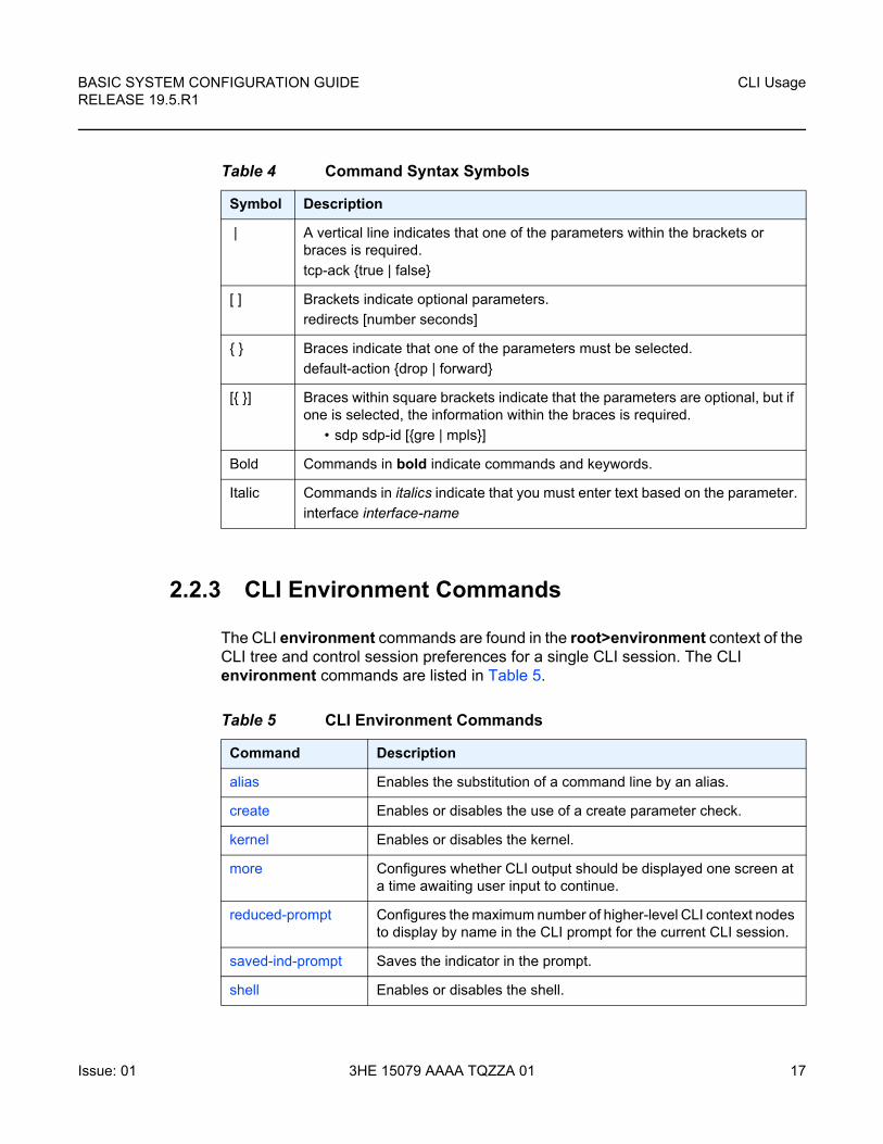
Table 4 describes command syntax symbols.
telnet Telnet to a host.
traceroute Determines the route to a destination address.
tree Displays a list of all commands at the current level and all sublevels.
write Sends a console message to a specific user or to all users with active console sessions.
Table 3 Console Control Commands (Continued)
Command Description
BASIC SYSTEM CONFIGURATION GUIDE RELEASE 19.5.R1
CLI Usage
Issue: 01 3HE 15079 AAAA TQZZA 01 17
2.2.3 CLI Environment Commands
The CLI environment commands are found in the root>environment context of the CLI tree and control session preferences for a single CLI session. The CLI environment commands are listed in Table 5.
Table 4 Command Syntax Symbols
Symbol Description
| A vertical line indicates that one of the parameters within the brackets or braces is required.
tcp-ack {true | false}
[ ] Brackets indicate optional parameters.
redirects [number seconds]
{ } Braces indicate that one of the parameters must be selected.
default-action {drop | forward}
[{ }] Braces within square brackets indicate that the parameters are optional, but if one is selected, the information within the braces is required.
• sdp sdp-id [{gre | mpls}]
Bold Commands in bold indicate commands and keywords.
Italic Commands in italics indicate that you must enter text based on the parameter.
interface interface-name
Table 5 CLI Environment Commands
Command Description
alias Enables the substitution of a command line by an alias.
create Enables or disables the use of a create parameter check.
kernel Enables or disables the kernel.
more Configures whether CLI output should be displayed one screen at a time awaiting user input to continue.
reduced-prompt Configures the maximum number of higher-level CLI context nodes to display by name in the CLI prompt for the current CLI session.
saved-ind-prompt Saves the indicator in the prompt.
shell Enables or disables the shell.
CLI Usage
18
BASIC SYSTEM CONFIGURATION GUIDERELEASE 19.5.R1
3HE 15079 AAAA TQZZA 01 Issue: 01
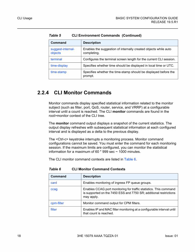
2.2.4 CLI Monitor Commands
Monitor commands display specified statistical information related to the monitor subject (such as filter, port, QoS, router, service, and VRRP) at a configurable interval until a count is reached. The CLI monitor commands are found in the root>monitor context of the CLI tree.
The monitor command output displays a snapshot of the current statistics. The output display refreshes with subsequent statistical information at each configured interval and is displayed as a delta to the previous display.
The <Ctrl-c> keystroke interrupts a monitoring process. Monitor command configurations cannot be saved. You must enter the command for each monitoring session. If the maximum limits are configured, you can monitor the statistical information for a maximum of 60 * 999 sec ~ 1000 minutes.
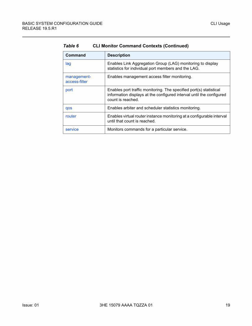
The CLI monitor command contexts are listed in Table 6.
suggest-internal-objects
Enables the suggestion of internally created objects while auto completing.
terminal Configures the terminal screen length for the current CLI session.
time-display Specifies whether time should be displayed in local time or UTC.
time-stamp Specifies whether the time-stamp should be displayed before the prompt.
Table 5 CLI Environment Commands (Continued)
Command Description
Table 6 CLI Monitor Command Contexts
Command Description
card Enables monitoring of ingress FP queue groups.
ccag Enables CCAG port monitoring for traffic statistics. This command is supported on the 7450 ESS and 7750 SR; additional restrictions may apply.
cpm-filter Monitor command output for CPM filters.
filter Enables IP and MAC filter monitoring at a configurable interval until that count is reached.
BASIC SYSTEM CONFIGURATION GUIDE RELEASE 19.5.R1
CLI Usage
Issue: 01 3HE 15079 AAAA TQZZA 01 19
lag Enables Link Aggregation Group (LAG) monitoring to display statistics for individual port members and the LAG.
management-access-filter
Enables management access filter monitoring.
port Enables port traffic monitoring. The specified port(s) statistical information displays at the configured interval until the configured count is reached.
qos Enables arbiter and scheduler statistics monitoring.
router Enables virtual router instance monitoring at a configurable interval until that count is reached.
service Monitors commands for a particular service.
Table 6 CLI Monitor Command Contexts (Continued)
Command Description
CLI Usage
20
BASIC SYSTEM CONFIGURATION GUIDERELEASE 19.5.R1
3HE 15079 AAAA TQZZA 01 Issue: 01
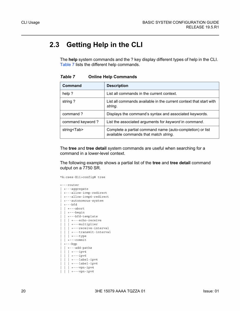
2.3 Getting Help in the CLI
The help system commands and the ? key display different types of help in the CLI. Table 7 lists the different help commands.
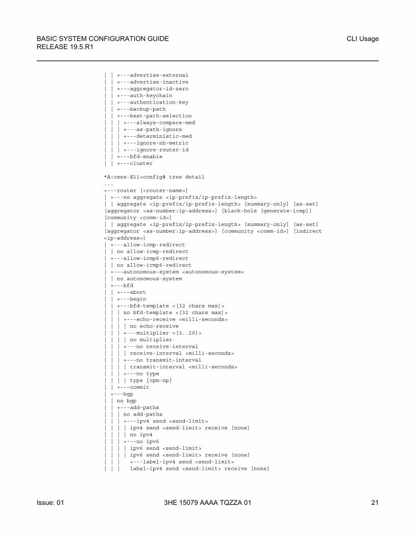
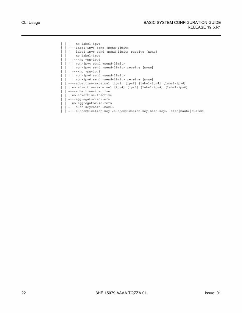
The tree and tree detail system commands are useful when searching for a command in a lower-level context.
The following example shows a partial list of the tree and tree detail command output on a 7750 SR.
*A:cses-E11>config# tree
+---router| +---aggregate| +---allow-icmp-redirect| +---allow-icmp6-redirect| +---autonomous-system| +---bfd| | +---abort| | +---begin| | +---bfd-template| | | +---echo-receive| | | +---multiplier| | | +---receive-interval| | | +---transmit-interval| | | +---type| | +---commit| +---bgp| | +---add-paths| | | +---ipv4| | | +---ipv6| | | +---label-ipv4| | | +---label-ipv6| | | +---vpn-ipv4| | | +---vpn-ipv6
Table 7 Online Help Commands
Command Description
help ? List all commands in the current context.
string ? List all commands available in the current context that start with string.
command ? Displays the command’s syntax and associated keywords.
command keyword ? List the associated arguments for keyword in command.
string<Tab> Complete a partial command name (auto-completion) or list available commands that match string.
BASIC SYSTEM CONFIGURATION GUIDE RELEASE 19.5.R1
CLI Usage
Issue: 01 3HE 15079 AAAA TQZZA 01 21
| | +---advertise-external| | +---advertise-inactive| | +---aggregator-id-zero| | +---auth-keychain| | +---authentication-key| | +---backup-path| | +---best-path-selection| | | +---always-compare-med| | | +---as-path-ignore| | | +---deterministic-med| | | +---ignore-nh-metric| | | +---ignore-router-id| | +---bfd-enable| | +---cluster
*A:cses-E11>config# tree detail...+---router [<router-name>]| +---no aggregate <ip-prefix/ip-prefix-length>| | aggregate <ip-prefix/ip-prefix-length> [summary-only] [as-set][aggregator <as-number:ip-address>] [black-hole [generate-icmp]][community <comm-id>]| | aggregate <ip-prefix/ip-prefix-length> [summary-only] [as-set][aggregator <as-number:ip-address>] [community <comm-id>] [indirect<ip-address>]| +---allow-icmp-redirect| | no allow-icmp-redirect| +---allow-icmp6-redirect| | no allow-icmp6-redirect| +---autonomous-system <autonomous-system>| | no autonomous-system| +---bfd| | +---abort| | +---begin| | +---bfd-template <[32 chars max]>| | | no bfd-template <[32 chars max]>| | | +---echo-receive <milli-seconds>| | | | no echo-receive| | | +---multiplier <[3..20]>| | | | no multiplier| | | +---no receive-interval| | | | receive-interval <milli-seconds>| | | +---no transmit-interval| | | | transmit-interval <milli-seconds>| | | +---no type| | | | type {cpm-np}| | +---commit| +---bgp| | no bgp| | +---add-paths| | | no add-paths| | | +---ipv4 send <send-limit>| | | | ipv4 send <send-limit> receive [none]| | | | no ipv4| | | +---no ipv6| | | | ipv6 send <send-limit>| | | | ipv6 send <send-limit> receive [none]| | | +---label-ipv4 send <send-limit>| | | label-ipv4 send <send-limit> receive [none]
CLI Usage
22
BASIC SYSTEM CONFIGURATION GUIDERELEASE 19.5.R1
3HE 15079 AAAA TQZZA 01 Issue: 01
| | | no label-ipv4| | +---label-ipv6 send <send-limit>| | | label-ipv6 send <send-limit> receive [none]| | | no label-ipv6| | | +---no vpn-ipv4| | | | vpn-ipv4 send <send-limit>| | | | vpn-ipv4 send <send-limit> receive [none]| | | +---no vpn-ipv6| | | | vpn-ipv6 send <send-limit>| | | | vpn-ipv6 send <send-limit> receive [none]| | +---advertise-external [ipv4] [ipv6] [label-ipv4] [label-ipv6]| | | no advertise-external [ipv4] [ipv6] [label-ipv4] [label-ipv6]| | +---advertise-inactive| | | no advertise-inactive| | +---aggregator-id-zero| | | no aggregator-id-zero| | +---auth-keychain <name>| | +---authentication-key <authentication-key|hash-key> [hash|hash2|custom]
BASIC SYSTEM CONFIGURATION GUIDE RELEASE 19.5.R1
CLI Usage
Issue: 01 3HE 15079 AAAA TQZZA 01 23
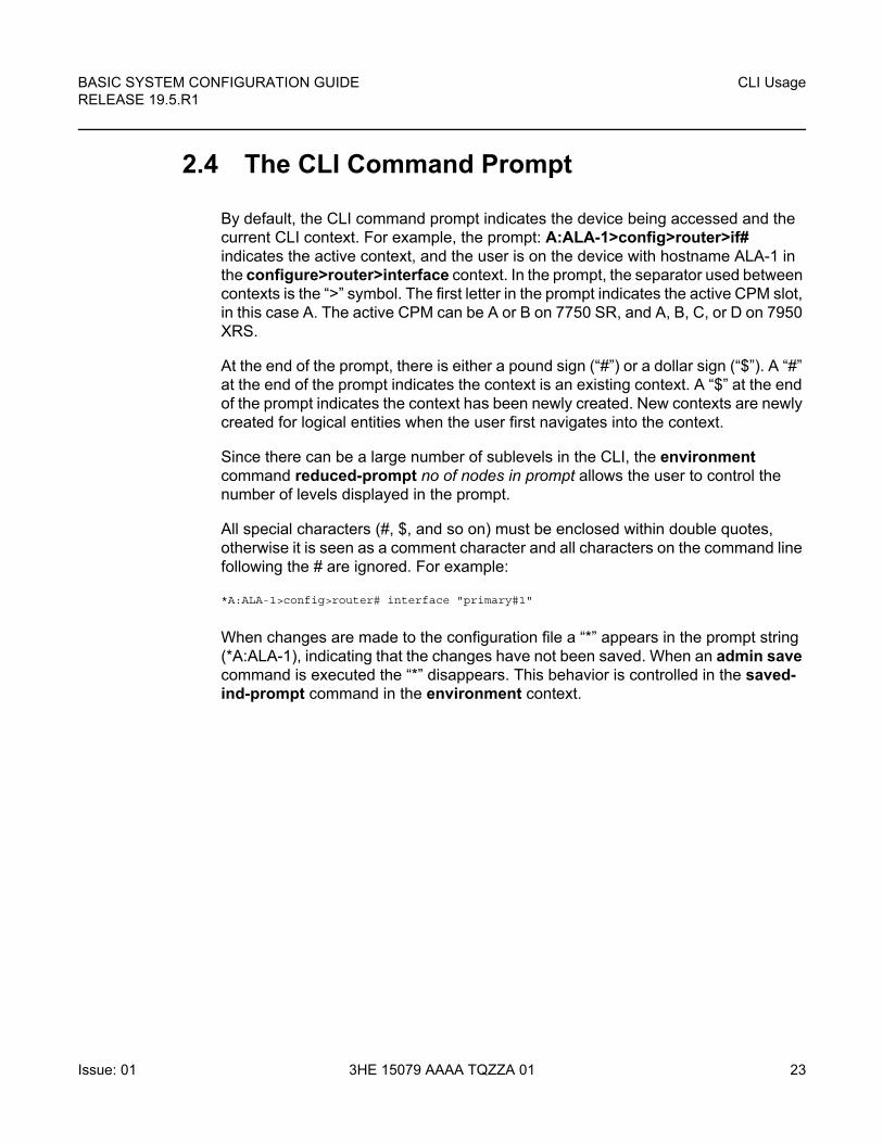
2.4 The CLI Command Prompt
By default, the CLI command prompt indicates the device being accessed and the current CLI context. For example, the prompt: A:ALA-1>config>router>if# indicates the active context, and the user is on the device with hostname ALA-1 in the configure>router>interface context. In the prompt, the separator used between contexts is the “>” symbol. The first letter in the prompt indicates the active CPM slot, in this case A. The active CPM can be A or B on 7750 SR, and A, B, C, or D on 7950 XRS.
At the end of the prompt, there is either a pound sign (“#”) or a dollar sign (“$”). A “#” at the end of the prompt indicates the context is an existing context. A “$” at the end of the prompt indicates the context has been newly created. New contexts are newly created for logical entities when the user first navigates into the context.
Since there can be a large number of sublevels in the CLI, the environment command reduced-prompt no of nodes in prompt allows the user to control the number of levels displayed in the prompt.
All special characters (#, $, and so on) must be enclosed within double quotes, otherwise it is seen as a comment character and all characters on the command line following the # are ignored. For example:
*A:ALA-1>config>router# interface "primary#1"
When changes are made to the configuration file a “*” appears in the prompt string (*A:ALA-1), indicating that the changes have not been saved. When an admin save command is executed the “*” disappears. This behavior is controlled in the saved-ind-prompt command in the environment context.
CLI Usage
24
BASIC SYSTEM CONFIGURATION GUIDERELEASE 19.5.R1
3HE 15079 AAAA TQZZA 01 Issue: 01
2.5 Displaying Configuration Contexts
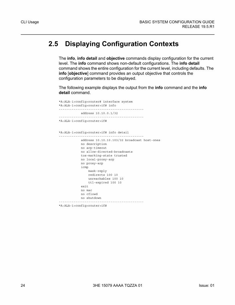
The info, info detail and objective commands display configuration for the current level. The info command shows non-default configurations. The info detail command shows the entire configuration for the current level, including defaults. The info [objective] command provides an output objective that controls the configuration parameters to be displayed.
The following example displays the output from the info command and the info detail command.
*A:ALA-1>config>router# interface system*A:ALA-1>config>router>if# info----------------------------------------------
address 10.10.0.1/32----------------------------------------------*A:ALA-1>config>router>if#
*A:ALA-1>config>router>if# info detail----------------------------------------------
address 10.10.10.103/32 broadcast host-onesno descriptionno arp-timeoutno allow-directed-broadcaststos-marking-state trustedno local-proxy-arpno proxy-arpicmp
mask-replyredirects 100 10unreachables 100 10ttl-expired 100 10
exitno macno cflowdno shutdown
----------------------------------------------*A:ALA-1>config>router>if#
BASIC SYSTEM CONFIGURATION GUIDE RELEASE 19.5.R1
CLI Usage
Issue: 01 3HE 15079 AAAA TQZZA 01 25
2.6 EXEC Files
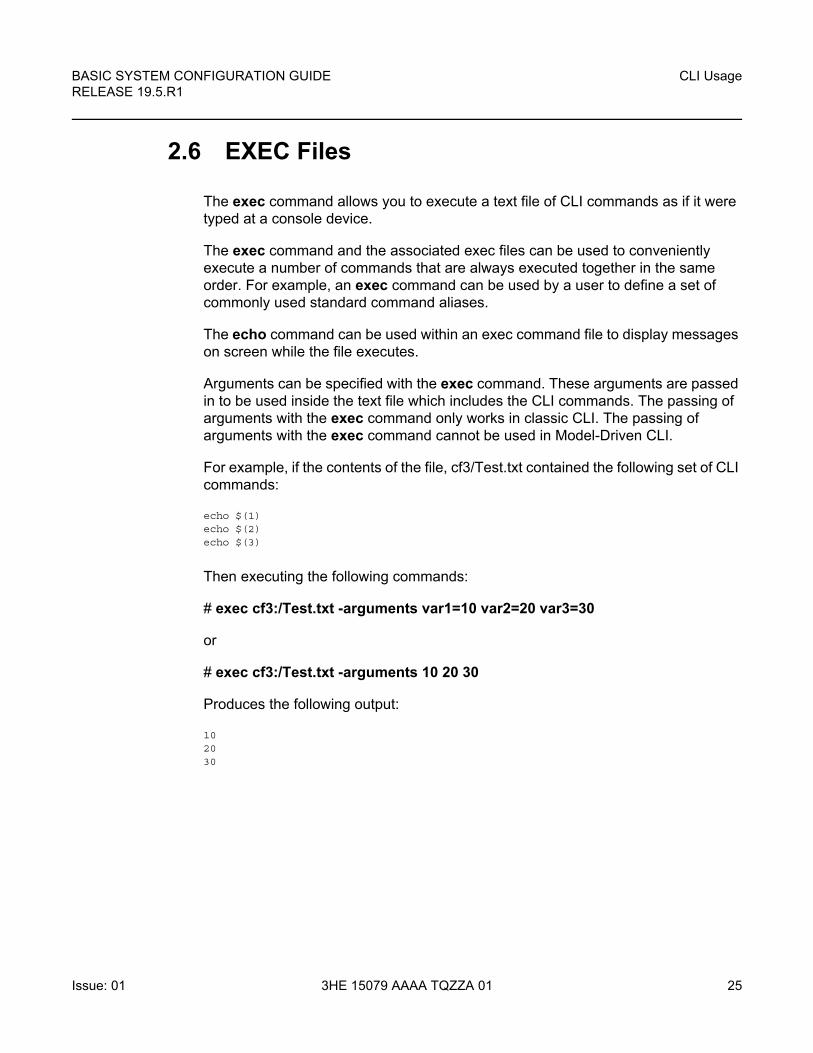
The exec command allows you to execute a text file of CLI commands as if it were typed at a console device.
The exec command and the associated exec files can be used to conveniently execute a number of commands that are always executed together in the same order. For example, an exec command can be used by a user to define a set of commonly used standard command aliases.
The echo command can be used within an exec command file to display messages on screen while the file executes.
Arguments can be specified with the exec command. These arguments are passed in to be used inside the text file which includes the CLI commands. The passing of arguments with the exec command only works in classic CLI. The passing of arguments with the exec command cannot be used in Model-Driven CLI.
For example, if the contents of the file, cf3/Test.txt contained the following set of CLI commands:
echo $(1)echo $(2)echo $(3)
Then executing the following commands:
# exec cf3:/Test.txt -arguments var1=10 var2=20 var3=30
or
# exec cf3:/Test.txt -arguments 10 20 30
Produces the following output:
102030
CLI Usage
26
BASIC SYSTEM CONFIGURATION GUIDERELEASE 19.5.R1
3HE 15079 AAAA TQZZA 01 Issue: 01
2.7 CLI Script Control
The SR OS provides centralized script management for CLI scripts that are used by CRON and the Event Handling System (EHS). A set of script policies and script objects can be configured to control the following items and more:
• where scripts are located (local compact flash, remote FTP server)
• where to store the output of the results
• how long to keep historical script result records
• how long a script may run
If the scripts are located on local compact flash devices, then the user must ensure that the scripts are on the compact flash devices of both CPMs so that operation of EHS continues as expected if a CPM switchover occurs.
A single script can be executing at one time. A table (SNMP smRunTable in the DISMAN-SCRIPT-MIB) is used as both an input queue of scripts waiting to be executed as well as for storage of records for completed scripts. If the input queue is full, then the script request is discarded.
BASIC SYSTEM CONFIGURATION GUIDE RELEASE 19.5.R1
CLI Usage
Issue: 01 3HE 15079 AAAA TQZZA 01 27
2.8 Entering CLI Commands
The command outputs in the following sections are examples only; actual displays may differ depending on supported functionality and user configuration.
2.8.1 Command Completion
The CLI supports both command abbreviation and command completion. If the keystrokes entered are enough to match a valid command, the CLI displays the remainder of the command syntax when the <Tab> key or space bar is pressed. When typing a command, the <Tab> key or space bar invokes auto-completion. If the keystrokes entered are definite, auto-completion completes the command. If the letters are not sufficient to identify a specific command, pressing the <Tab> key or space bar displays commands matching the letters entered.
System commands are available in all CLI context levels.
2.8.2 Unordered and Unnamed Parameters
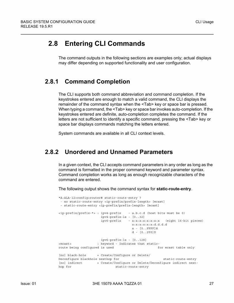
In a given context, the CLI accepts command parameters in any order as long as the command is formatted in the proper command keyword and parameter syntax. Command completion works as long as enough recognizable characters of the command are entered.
The following output shows the command syntax for static-route-entry.
*A:ALA-12>config>router# static-route-entry ?- no static-route-entry <ip-prefix/prefix-length> [mcast]- static-route-entry <ip-prefix/prefix-length> [mcast]
<ip-prefix/prefix-*> : ipv4-prefix - a.b.c.d (host bits must be 0)ipv4-prefix-le - [0..32]ipv6-prefix - x:x:x:x:x:x:x:x (eight 16-bit pieces)
x:x:x:x:x:x:d.d.d.dx - [0..FFFF]Hd - [0..255]D
ipv6-prefix-le - [0..128]<mcast> : keyword - Indicates that static-route being configured is used for mcast table only
[no] black-hole + Create/Configure or Delete/Deconfigure blackhole nexthop for static-route-entry[no] indirect + Create/Configure or Delete/Deconfigure indirect next-hop for static-route-entry
CLI Usage
28
BASIC SYSTEM CONFIGURATION GUIDERELEASE 19.5.R1
3HE 15079 AAAA TQZZA 01 Issue: 01
[no] next-hop + Create/Configure or Delete/Deconfigure next-hop for static-route-entry
Some SR OS CLI commands have multiple unnamed parameters. For example, the subrate csu-mode rate-step command has both a csu-mode parameter and a rate-step parameter that do not have leading keywords. SR OS uses a best-match algorithm to select which parts of the user input are intended to be used for each unnamed parameter. This best-match algorithm depends on the specific command.
In some cases, it is not possible for the algorithm to be 100% accurate, and the SR OS may assign a value to an unintended parameter when two unnamed parameters have similar constraints and syntax. For example, the environment alias alias-name alias-command-name command may reverse the alias-name and alias-command-name parameters if the first parameter entered is larger than 80 characters.
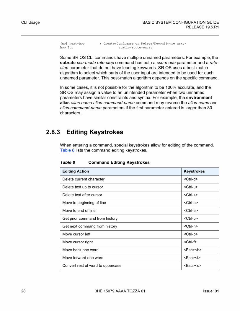
2.8.3 Editing Keystrokes
When entering a command, special keystrokes allow for editing of the command. Table 8 lists the command editing keystrokes.
Table 8 Command Editing Keystrokes
Editing Action Keystrokes
Delete current character <Ctrl-d>
Delete text up to cursor <Ctrl-u>
Delete text after cursor <Ctrl-k>
Move to beginning of line <Ctrl-a>
Move to end of line <Ctrl-e>
Get prior command from history <Ctrl-p>
Get next command from history <Ctrl-n>
Move cursor left <Ctrl-b>
Move cursor right <Ctrl-f>
Move back one word <Esc><b>
Move forward one word <Esc><f>
Convert rest of word to uppercase <Esc><c>
BASIC SYSTEM CONFIGURATION GUIDE RELEASE 19.5.R1
CLI Usage
Issue: 01 3HE 15079 AAAA TQZZA 01 29
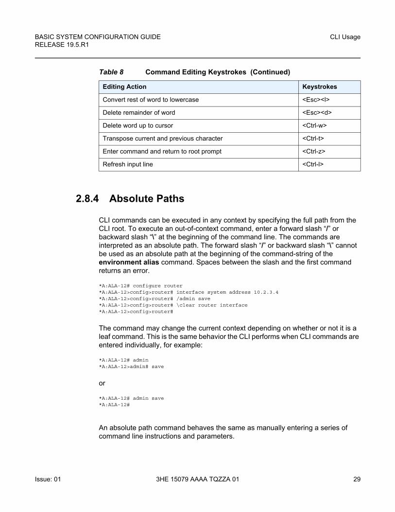
2.8.4 Absolute Paths
CLI commands can be executed in any context by specifying the full path from the CLI root. To execute an out-of-context command, enter a forward slash “/” or backward slash “\” at the beginning of the command line. The commands are interpreted as an absolute path. The forward slash “/” or backward slash “\” cannot be used as an absolute path at the beginning of the command-string of the environment alias command. Spaces between the slash and the first command returns an error.
*A:ALA-12# configure router*A:ALA-12>config>router# interface system address 10.2.3.4*A:ALA-12>config>router# /admin save*A:ALA-12>config>router# \clear router interface*A:ALA-12>config>router#
The command may change the current context depending on whether or not it is a leaf command. This is the same behavior the CLI performs when CLI commands are entered individually, for example:
*A:ALA-12# admin*A:ALA-12>admin# save
or
*A:ALA-12# admin save*A:ALA-12#
An absolute path command behaves the same as manually entering a series of command line instructions and parameters.
Convert rest of word to lowercase <Esc><l>
Delete remainder of word <Esc><d>
Delete word up to cursor <Ctrl-w>
Transpose current and previous character <Ctrl-t>
Enter command and return to root prompt <Ctrl-z>
Refresh input line <Ctrl-l>
Table 8 Command Editing Keystrokes (Continued)
Editing Action Keystrokes
CLI Usage
30
BASIC SYSTEM CONFIGURATION GUIDERELEASE 19.5.R1
3HE 15079 AAAA TQZZA 01 Issue: 01
For example, beginning in an IES context service ID 4 (IES 4):
config>service>ies> /clear card 1
behaves the same as the following series of commands:
config>service>ies>exit allclear card 1configure service ies 4 (returns you to your starting point)config>service>ies
If the command takes you to a different context, the following occurs:
config>service>ies>/configure service vpls 5 create
becomes:
config>service>ies>exit allconfigure service vpls 5 createconfig>service>vpls>
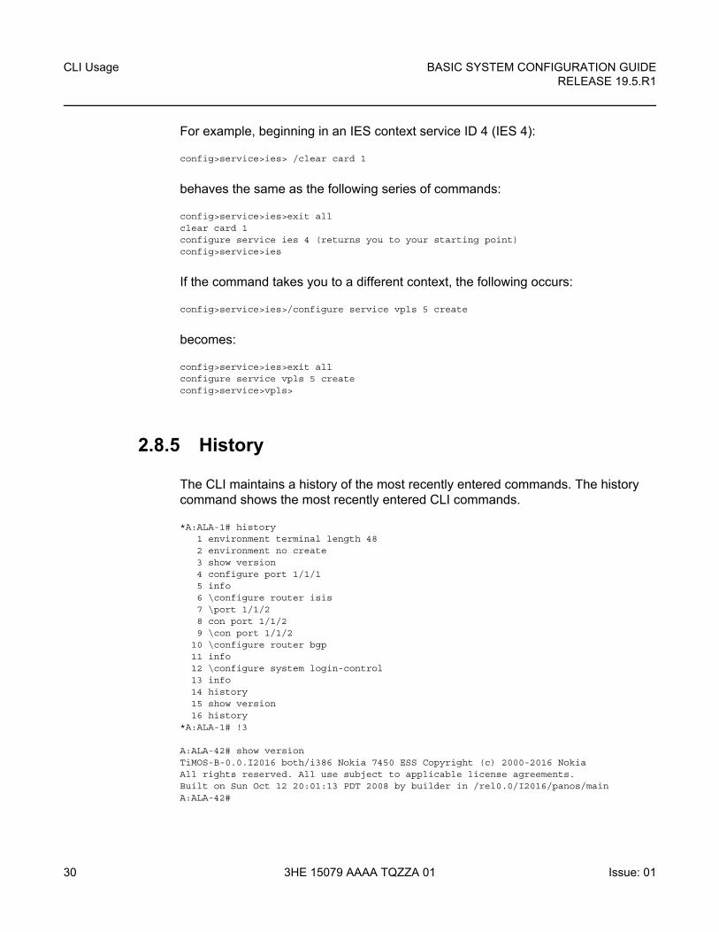
2.8.5 History
The CLI maintains a history of the most recently entered commands. The history command shows the most recently entered CLI commands.
*A:ALA-1# history1 environment terminal length 482 environment no create3 show version4 configure port 1/1/15 info6 \configure router isis7 \port 1/1/28 con port 1/1/29 \con port 1/1/2
10 \configure router bgp11 info12 \configure system login-control13 info14 history15 show version16 history
*A:ALA-1# !3
A:ALA-42# show versionTiMOS-B-0.0.I2016 both/i386 Nokia 7450 ESS Copyright (c) 2000-2016 NokiaAll rights reserved. All use subject to applicable license agreements.Built on Sun Oct 12 20:01:13 PDT 2008 by builder in /rel0.0/I2016/panos/mainA:ALA-42#
BASIC SYSTEM CONFIGURATION GUIDE RELEASE 19.5.R1
CLI Usage
Issue: 01 3HE 15079 AAAA TQZZA 01 31
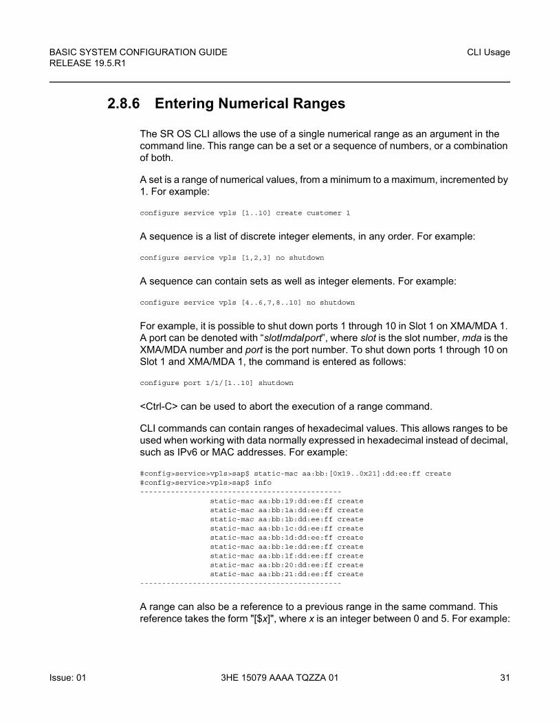
2.8.6 Entering Numerical Ranges
The SR OS CLI allows the use of a single numerical range as an argument in the command line. This range can be a set or a sequence of numbers, or a combination of both.
A set is a range of numerical values, from a minimum to a maximum, incremented by 1. For example:
configure service vpls [1..10] create customer 1
A sequence is a list of discrete integer elements, in any order. For example:
configure service vpls [1,2,3] no shutdown
A sequence can contain sets as well as integer elements. For example:
configure service vpls [4..6,7,8..10] no shutdown
For example, it is possible to shut down ports 1 through 10 in Slot 1 on XMA/MDA 1. A port can be denoted with “slot/mda/port”, where slot is the slot number, mda is the XMA/MDA number and port is the port number. To shut down ports 1 through 10 on Slot 1 and XMA/MDA 1, the command is entered as follows:
configure port 1/1/[1..10] shutdown
<Ctrl-C> can be used to abort the execution of a range command.
CLI commands can contain ranges of hexadecimal values. This allows ranges to be used when working with data normally expressed in hexadecimal instead of decimal, such as IPv6 or MAC addresses. For example:
#config>service>vpls>sap$ static-mac aa:bb:[0x19..0x21]:dd:ee:ff create#config>service>vpls>sap$ info----------------------------------------------
static-mac aa:bb:19:dd:ee:ff createstatic-mac aa:bb:1a:dd:ee:ff createstatic-mac aa:bb:1b:dd:ee:ff createstatic-mac aa:bb:1c:dd:ee:ff createstatic-mac aa:bb:1d:dd:ee:ff createstatic-mac aa:bb:1e:dd:ee:ff createstatic-mac aa:bb:1f:dd:ee:ff createstatic-mac aa:bb:20:dd:ee:ff createstatic-mac aa:bb:21:dd:ee:ff create
----------------------------------------------
A range can also be a reference to a previous range in the same command. This reference takes the form "[$x]", where x is an integer between 0 and 5. For example:
CLI Usage
32
BASIC SYSTEM CONFIGURATION GUIDERELEASE 19.5.R1
3HE 15079 AAAA TQZZA 01 Issue: 01
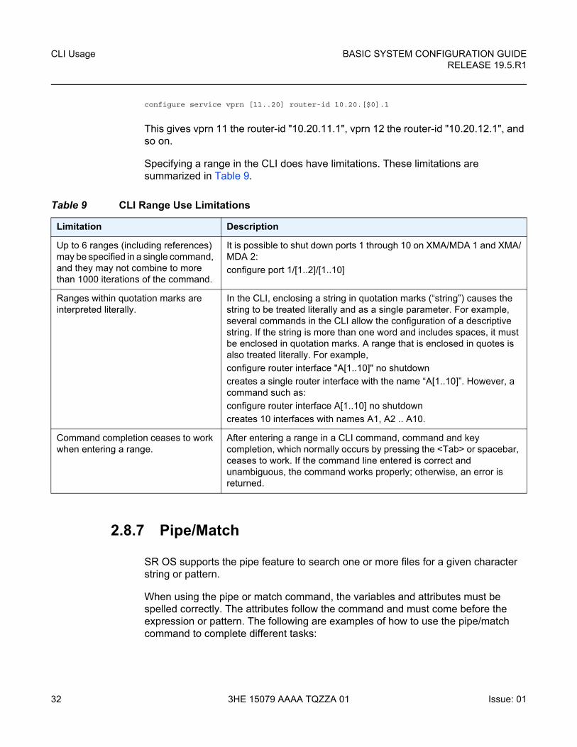
configure service vprn [11..20] router-id 10.20.[$0].1
This gives vprn 11 the router-id "10.20.11.1", vprn 12 the router-id "10.20.12.1", and so on.
Specifying a range in the CLI does have limitations. These limitations are summarized in Table 9.
2.8.7 Pipe/Match
SR OS supports the pipe feature to search one or more files for a given character string or pattern.
When using the pipe or match command, the variables and attributes must be spelled correctly. The attributes follow the command and must come before the expression or pattern. The following are examples of how to use the pipe/match command to complete different tasks:
Table 9 CLI Range Use Limitations
Limitation Description
Up to 6 ranges (including references) may be specified in a single command, and they may not combine to more than 1000 iterations of the command.
It is possible to shut down ports 1 through 10 on XMA/MDA 1 and XMA/MDA 2:
configure port 1/[1..2]/[1..10]
Ranges within quotation marks are interpreted literally.
In the CLI, enclosing a string in quotation marks (“string”) causes the string to be treated literally and as a single parameter. For example, several commands in the CLI allow the configuration of a descriptive string. If the string is more than one word and includes spaces, it must be enclosed in quotation marks. A range that is enclosed in quotes is also treated literally. For example,
configure router interface "A[1..10]" no shutdown
creates a single router interface with the name “A[1..10]”. However, a command such as:
configure router interface A[1..10] no shutdown
creates 10 interfaces with names A1, A2 .. A10.
Command completion ceases to work when entering a range.
After entering a range in a CLI command, command and key completion, which normally occurs by pressing the <Tab> or spacebar, ceases to work. If the command line entered is correct and unambiguous, the command works properly; otherwise, an error is returned.
BASIC SYSTEM CONFIGURATION GUIDE RELEASE 19.5.R1
CLI Usage
Issue: 01 3HE 15079 AAAA TQZZA 01 33
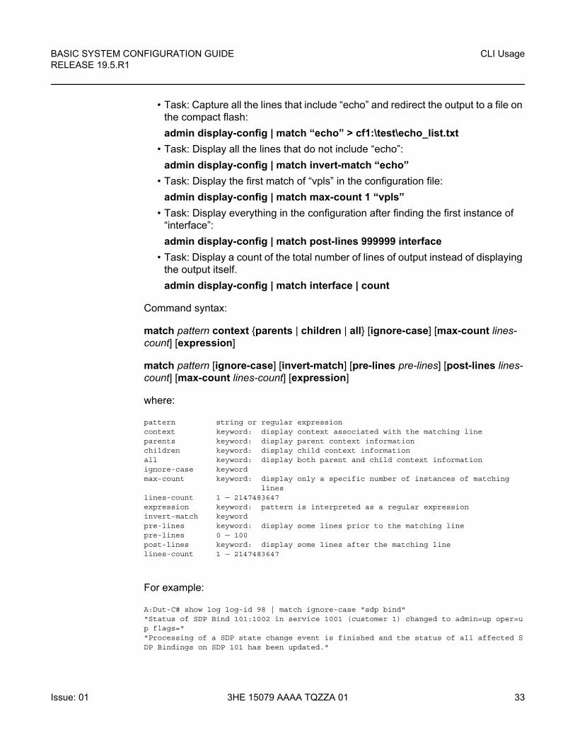
• Task: Capture all the lines that include “echo” and redirect the output to a file on the compact flash:
admin display-config | match “echo” > cf1:\test\echo_list.txt
• Task: Display all the lines that do not include “echo”:
admin display-config | match invert-match “echo”
• Task: Display the first match of “vpls” in the configuration file:
admin display-config | match max-count 1 “vpls”
• Task: Display everything in the configuration after finding the first instance of “interface”:
admin display-config | match post-lines 999999 interface
• Task: Display a count of the total number of lines of output instead of displaying the output itself.
admin display-config | match interface | count
Command syntax:
match pattern context {parents | children | all} [ignore-case] [max-count lines-count] [expression]
match pattern [ignore-case] [invert-match] [pre-lines pre-lines] [post-lines lines-count] [max-count lines-count] [expression]
where:
pattern string or regular expressioncontext keyword: display context associated with the matching lineparents keyword: display parent context informationchildren keyword: display child context informationall keyword: display both parent and child context informationignore-case keywordmax-count keyword: display only a specific number of instances of matching
lineslines-count 1 — 2147483647expression keyword: pattern is interpreted as a regular expressioninvert-match keywordpre-lines keyword: display some lines prior to the matching linepre-lines 0 — 100post-lines keyword: display some lines after the matching linelines-count 1 — 2147483647
For example:
A:Dut-C# show log log-id 98 | match ignore-case "sdp bind""Status of SDP Bind 101:1002 in service 1001 (customer 1) changed to admin=up oper=up flags=""Processing of a SDP state change event is finished and the status of all affected SDP Bindings on SDP 101 has been updated."
CLI Usage
34
BASIC SYSTEM CONFIGURATION GUIDERELEASE 19.5.R1
3HE 15079 AAAA TQZZA 01 Issue: 01
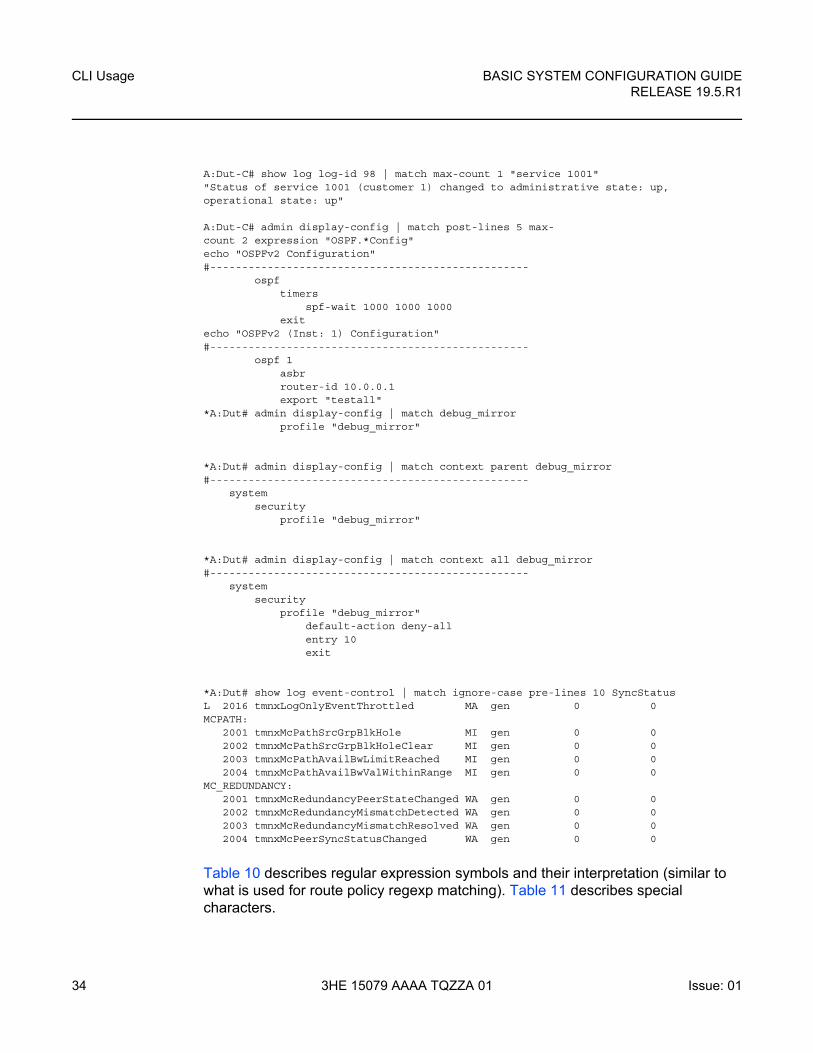
A:Dut-C# show log log-id 98 | match max-count 1 "service 1001""Status of service 1001 (customer 1) changed to administrative state: up,operational state: up"
A:Dut-C# admin display-config | match post-lines 5 max-count 2 expression "OSPF.*Config"echo "OSPFv2 Configuration"#--------------------------------------------------
ospftimers
spf-wait 1000 1000 1000exit
echo "OSPFv2 (Inst: 1) Configuration"#--------------------------------------------------
ospf 1asbrrouter-id 10.0.0.1export "testall"
*A:Dut# admin display-config | match debug_mirrorprofile "debug_mirror"
*A:Dut# admin display-config | match context parent debug_mirror#--------------------------------------------------
systemsecurity
profile "debug_mirror"
*A:Dut# admin display-config | match context all debug_mirror#--------------------------------------------------
systemsecurity
profile "debug_mirror"default-action deny-allentry 10exit
*A:Dut# show log event-control | match ignore-case pre-lines 10 SyncStatusL 2016 tmnxLogOnlyEventThrottled MA gen 0 0MCPATH:
2001 tmnxMcPathSrcGrpBlkHole MI gen 0 02002 tmnxMcPathSrcGrpBlkHoleClear MI gen 0 02003 tmnxMcPathAvailBwLimitReached MI gen 0 02004 tmnxMcPathAvailBwValWithinRange MI gen 0 0
MC_REDUNDANCY:2001 tmnxMcRedundancyPeerStateChanged WA gen 0 02002 tmnxMcRedundancyMismatchDetected WA gen 0 02003 tmnxMcRedundancyMismatchResolved WA gen 0 02004 tmnxMcPeerSyncStatusChanged WA gen 0 0
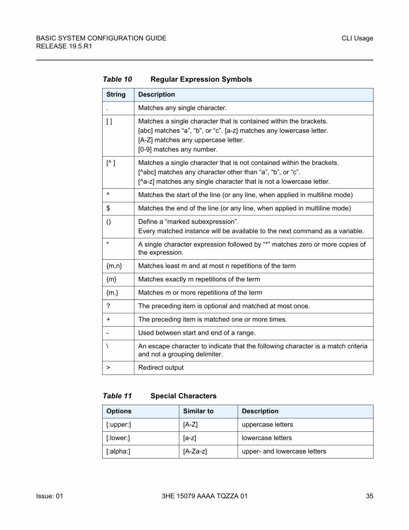
Table 10 describes regular expression symbols and their interpretation (similar to what is used for route policy regexp matching). Table 11 describes special characters.
BASIC SYSTEM CONFIGURATION GUIDE RELEASE 19.5.R1
CLI Usage
Issue: 01 3HE 15079 AAAA TQZZA 01 35
Table 10 Regular Expression Symbols
String Description
. Matches any single character.
[ ] Matches a single character that is contained within the brackets.
[abc] matches “a”, “b”, or “c”. [a-z] matches any lowercase letter.
[A-Z] matches any uppercase letter.
[0-9] matches any number.
[^ ] Matches a single character that is not contained within the brackets.
[^abc] matches any character other than “a”, “b”, or “c”.
[^a-z] matches any single character that is not a lowercase letter.
^ Matches the start of the line (or any line, when applied in multiline mode)
$ Matches the end of the line (or any line, when applied in multiline mode)
() Define a “marked subexpression”.
Every matched instance will be available to the next command as a variable.
* A single character expression followed by “*” matches zero or more copies of the expression.
{m,n} Matches least m and at most n repetitions of the term
{m} Matches exactly m repetitions of the term
{m,} Matches m or more repetitions of the term
? The preceding item is optional and matched at most once.
+ The preceding item is matched one or more times.
- Used between start and end of a range.
\ An escape character to indicate that the following character is a match criteria and not a grouping delimiter.
> Redirect output
Table 11 Special Characters
Options Similar to Description
[:upper:] [A-Z] uppercase letters
[:lower:] [a-z] lowercase letters
[:alpha:] [A-Za-z] upper- and lowercase letters
CLI Usage
36
BASIC SYSTEM CONFIGURATION GUIDERELEASE 19.5.R1
3HE 15079 AAAA TQZZA 01 Issue: 01
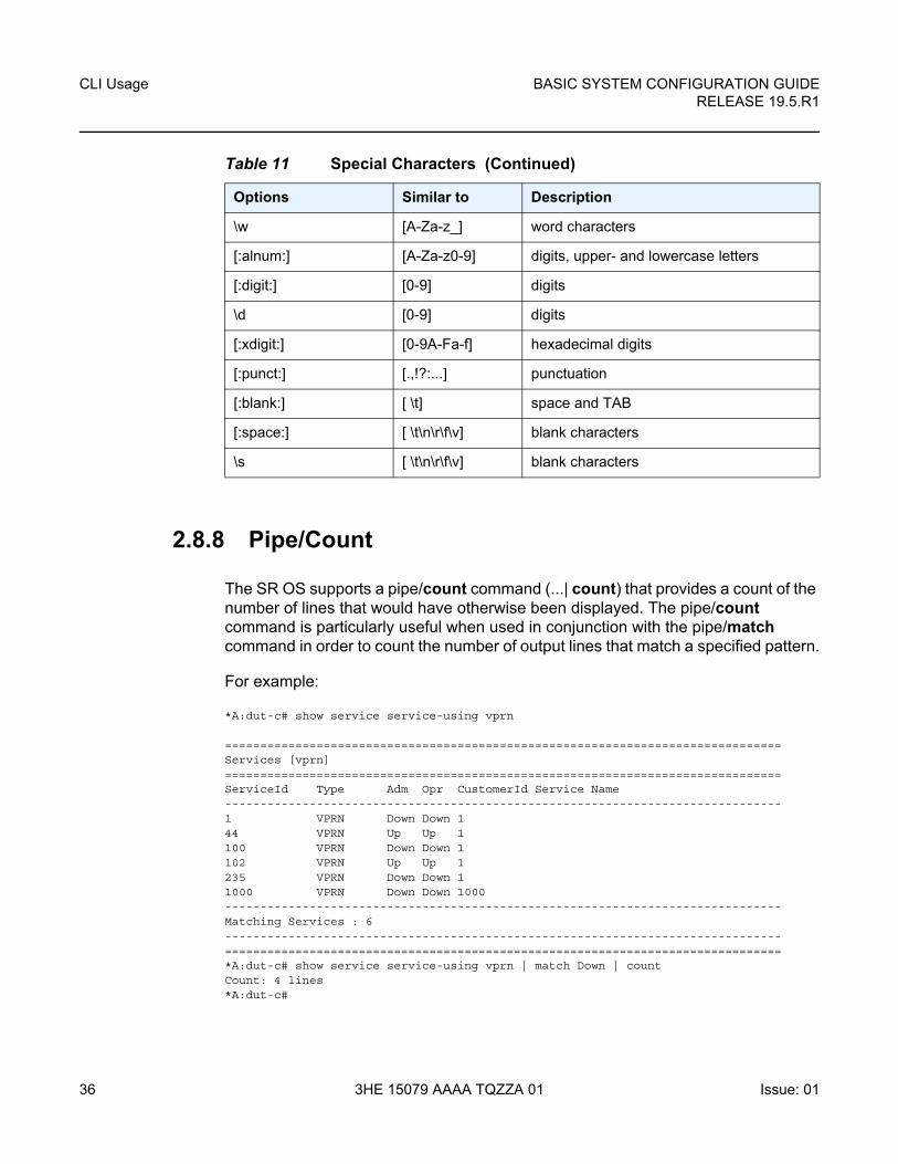
2.8.8 Pipe/Count
The SR OS supports a pipe/count command (...| count) that provides a count of the number of lines that would have otherwise been displayed. The pipe/count command is particularly useful when used in conjunction with the pipe/match command in order to count the number of output lines that match a specified pattern.
For example:
*A:dut-c# show service service-using vprn
===============================================================================Services [vprn]===============================================================================ServiceId Type Adm Opr CustomerId Service Name-------------------------------------------------------------------------------1 VPRN Down Down 144 VPRN Up Up 1100 VPRN Down Down 1102 VPRN Up Up 1235 VPRN Down Down 11000 VPRN Down Down 1000-------------------------------------------------------------------------------Matching Services : 6-------------------------------------------------------------------------------===============================================================================*A:dut-c# show service service-using vprn | match Down | countCount: 4 lines*A:dut-c#
\w [A-Za-z_] word characters
[:alnum:] [A-Za-z0-9] digits, upper- and lowercase letters
[:digit:] [0-9] digits
\d [0-9] digits
[:xdigit:] [0-9A-Fa-f] hexadecimal digits
[:punct:] [.,!?:...] punctuation
[:blank:] [ \t] space and TAB
[:space:] [ \t\n\r\f\v] blank characters
\s [ \t\n\r\f\v] blank characters
Table 11 Special Characters (Continued)
Options Similar to Description
BASIC SYSTEM CONFIGURATION GUIDE RELEASE 19.5.R1
CLI Usage
Issue: 01 3HE 15079 AAAA TQZZA 01 37
2.8.9 Range Operator Support of Regular Expression Match
The user can include a regular expression inside the range operator, of any clear, config, show, or tools CLI command. The beginning and ending of the regular expression must be delimited with the forward slash "/" symbol.
SR OS performs the following steps:
• auto-completes the command to get all the possible names
• performs a match of the regular expression against all the names
• executes the command for the names for which the match was successful
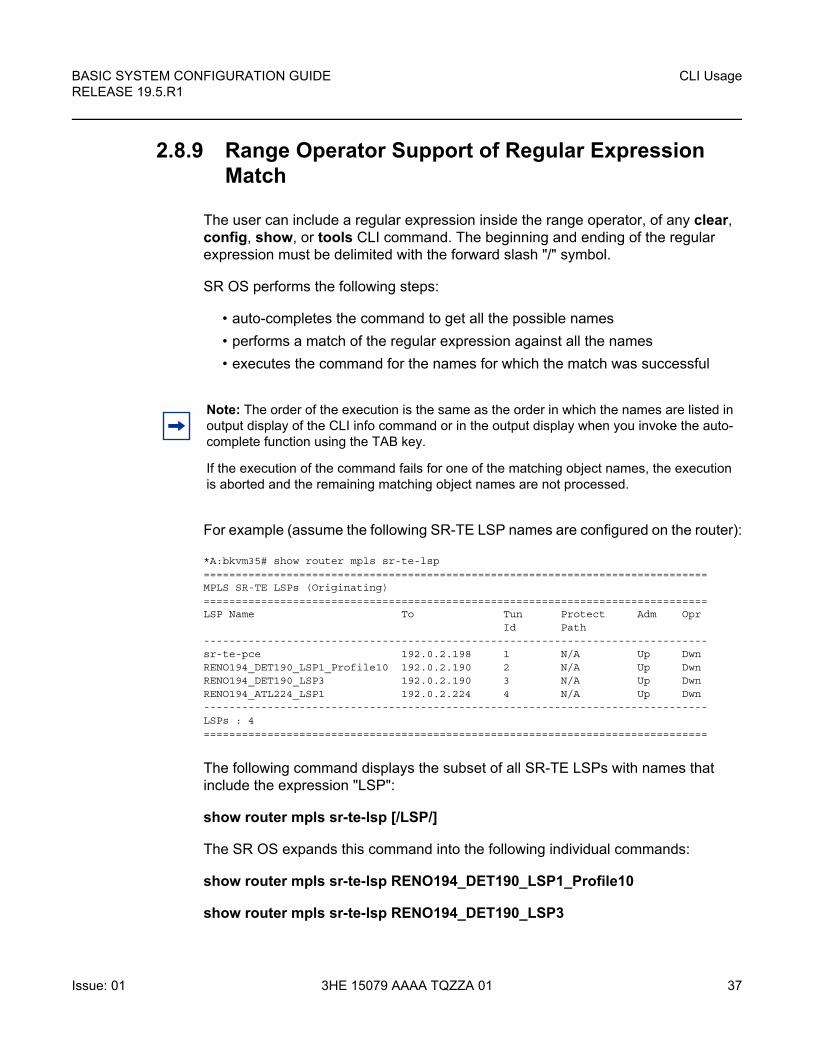
For example (assume the following SR-TE LSP names are configured on the router):
*A:bkvm35# show router mpls sr-te-lsp===============================================================================MPLS SR-TE LSPs (Originating)===============================================================================LSP Name To Tun Protect Adm Opr
Id Path-------------------------------------------------------------------------------sr-te-pce 192.0.2.198 1 N/A Up DwnRENO194_DET190_LSP1_Profile10 192.0.2.190 2 N/A Up DwnRENO194_DET190_LSP3 192.0.2.190 3 N/A Up DwnRENO194_ATL224_LSP1 192.0.2.224 4 N/A Up Dwn-------------------------------------------------------------------------------LSPs : 4===============================================================================
The following command displays the subset of all SR-TE LSPs with names that include the expression "LSP":
show router mpls sr-te-lsp [/LSP/]
The SR OS expands this command into the following individual commands:
show router mpls sr-te-lsp RENO194_DET190_LSP1_Profile10
show router mpls sr-te-lsp RENO194_DET190_LSP3
Note: The order of the execution is the same as the order in which the names are listed in output display of the CLI info command or in the output display when you invoke the auto-complete function using the TAB key.
If the execution of the command fails for one of the matching object names, the execution is aborted and the remaining matching object names are not processed.
CLI Usage
38
BASIC SYSTEM CONFIGURATION GUIDERELEASE 19.5.R1
3HE 15079 AAAA TQZZA 01 Issue: 01
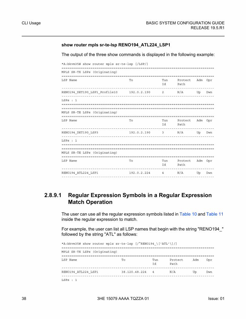
show router mpls sr-te-lsp RENO194_ATL224_LSP1
The output of the three show commands is displayed in the following example:
*A:bkvm35# show router mpls sr-te-lsp [/LSP/]===============================================================================MPLS SR-TE LSPs (Originating)===============================================================================LSP Name To Tun Protect Adm Opr
Id Path-------------------------------------------------------------------------------RENO194_DET190_LSP1_Profile10 192.0.2.190 2 N/A Up Dwn-------------------------------------------------------------------------------LSPs : 1==============================================================================================================================================================MPLS SR-TE LSPs (Originating)===============================================================================LSP Name To Tun Protect Adm Opr
Id Path-------------------------------------------------------------------------------RENO194_DET190_LSP3 192.0.2.190 3 N/A Up Dwn-------------------------------------------------------------------------------LSPs : 1==============================================================================================================================================================MPLS SR-TE LSPs (Originating)===============================================================================LSP Name To Tun Protect Adm Opr
Id Path-------------------------------------------------------------------------------RENO194_ATL224_LSP1 192.0.2.224 4 N/A Up Dwn-------------------------------------------------------------------------------
2.8.9.1 Regular Expression Symbols in a Regular Expression Match Operation
The user can use all the regular expression symbols listed in Table 10 and Table 11 inside the regular expression to match.
For example, the user can list all LSP names that begin with the string "RENO194_" followed by the string "ATL" as follows:
*A:bkvm35# show router mpls sr-te-lsp [/^RENO194_\['ATL'\]/]===============================================================================MPLS SR-TE LSPs (Originating)===============================================================================LSP Name To Tun Protect Adm Opr
Id Path-------------------------------------------------------------------------------RENO194_ATL224_LSP1 38.120.48.224 4 N/A Up Dwn-------------------------------------------------------------------------------LSPs : 1
BASIC SYSTEM CONFIGURATION GUIDE RELEASE 19.5.R1
CLI Usage
Issue: 01 3HE 15079 AAAA TQZZA 01 39
===============================================================================
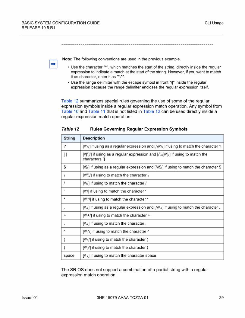
Table 12 summarizes special rules governing the use of some of the regular expression symbols inside a regular expression match operation. Any symbol from Table 10 and Table 11 that is not listed in Table 12 can be used directly inside a regular expression match operation.
The SR OS does not support a combination of a partial string with a regular expression match operation.
Note: The following conventions are used in the previous example.
• Use the character "^", which matches the start of the string, directly inside the regular expression to indicate a match at the start of the string. However, if you want to match it as character, enter it as "\\^".
• Use the range delimiter with the escape symbol in front "\[" inside the regular expression because the range delimiter encloses the regular expression itself.
Table 12 Rules Governing Regular Expression Symbols
String Description
? [/\?/] if using as a regular expression and [/\\\?/] if using to match the character ?
[ ] [/\[\]/] if using as a regular expression and [/\\\[\\\]/] if using to match the characters []
$ [/$/] if using as a regular expression and [/\\$/] if using to match the character $
\ [/\\\\/] if using to match the character \
/ [/\//] if using to match the character /
‘ [/\'/] if using to match the character '
* [/\\*/] if using to match the character *
. [/\./] if using as a regular expression and [/\\\./] if using to match the character .
+ [/\\+/] if using to match the character +
, [/\,/] if using to match the character ,
^ [/\\^/] if using to match the character ^
( [/\\(/] if using to match the character (
) [/\\)/] if using to match the character )
space [/\ /] if using to match the character space
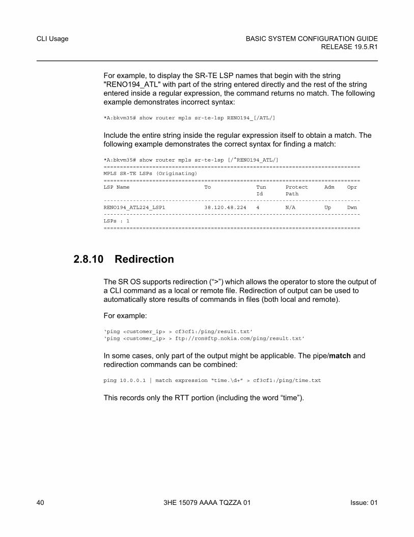
CLI Usage
40
BASIC SYSTEM CONFIGURATION GUIDERELEASE 19.5.R1
3HE 15079 AAAA TQZZA 01 Issue: 01
For example, to display the SR-TE LSP names that begin with the string "RENO194_ATL" with part of the string entered directly and the rest of the string entered inside a regular expression, the command returns no match. The following example demonstrates incorrect syntax:
*A:bkvm35# show router mpls sr-te-lsp RENO194_[/ATL/]
Include the entire string inside the regular expression itself to obtain a match. The following example demonstrates the correct syntax for finding a match:
*A:bkvm35# show router mpls sr-te-lsp [/^RENO194_ATL/]===============================================================================MPLS SR-TE LSPs (Originating)===============================================================================LSP Name To Tun Protect Adm Opr
Id Path-------------------------------------------------------------------------------RENO194_ATL224_LSP1 38.120.48.224 4 N/A Up Dwn-------------------------------------------------------------------------------LSPs : 1===============================================================================
2.8.10 Redirection
The SR OS supports redirection (“>”) which allows the operator to store the output of a CLI command as a local or remote file. Redirection of output can be used to automatically store results of commands in files (both local and remote).
For example:
‘ping <customer_ip> > cf3cf1:/ping/result.txt’‘ping <customer_ip> > ftp://[email protected]/ping/result.txt’
In some cases, only part of the output might be applicable. The pipe/match and redirection commands can be combined:
ping 10.0.0.1 | match expression “time.\d+” > cf3cf1:/ping/time.txt
This records only the RTT portion (including the word “time”).
BASIC SYSTEM CONFIGURATION GUIDE RELEASE 19.5.R1
CLI Usage
Issue: 01 3HE 15079 AAAA TQZZA 01 41
2.9 VI Editor
The “vi”sual editor (vi) is a file editor that can edit any ASCII file. This includes configuration, exec files, BOF, and any other ASCII file on the system.
VT100 terminal mode is supported. However, if a different terminal mode is configured, there is no noticeable negative effect.
When a configuration file is changed, a validation check is executed to see if the user is allowed to view or perform configuration changes. When a user modifies the configuration file using the vi editor, these checks do not occur. Because of this, the vi editor is only available to a user with administrator privileges. Should others require access to the vi editor, their profile must be modified to allow the access. Access permission for the file directory where the file resides must be performed before a user can open, read, or write a file processing command. If a user does not have permission to access the directory, the operation is denied.
When opening a file, a resource check verifies that sufficient resources are available to process the file. If there are insufficient resources, the operation is denied and the operator is informed of that event.
Multiple sessions are allowed and are limited only by the memory resources available on the node.
2.9.1 Summary of vi Commands
The vi editor operates in two modes:
• Command mode — This mode causes actions to be taken on the file.
In this mode, each character entered is a command that does something to the text file being edited; a character typed in the command mode may even cause the vi editor to enter the insert mode.
• Insert mode — Entered text is inserted into the file.
In the insert mode, every character typed is added to the text in the file. Pressing ESC turns off the insert mode.
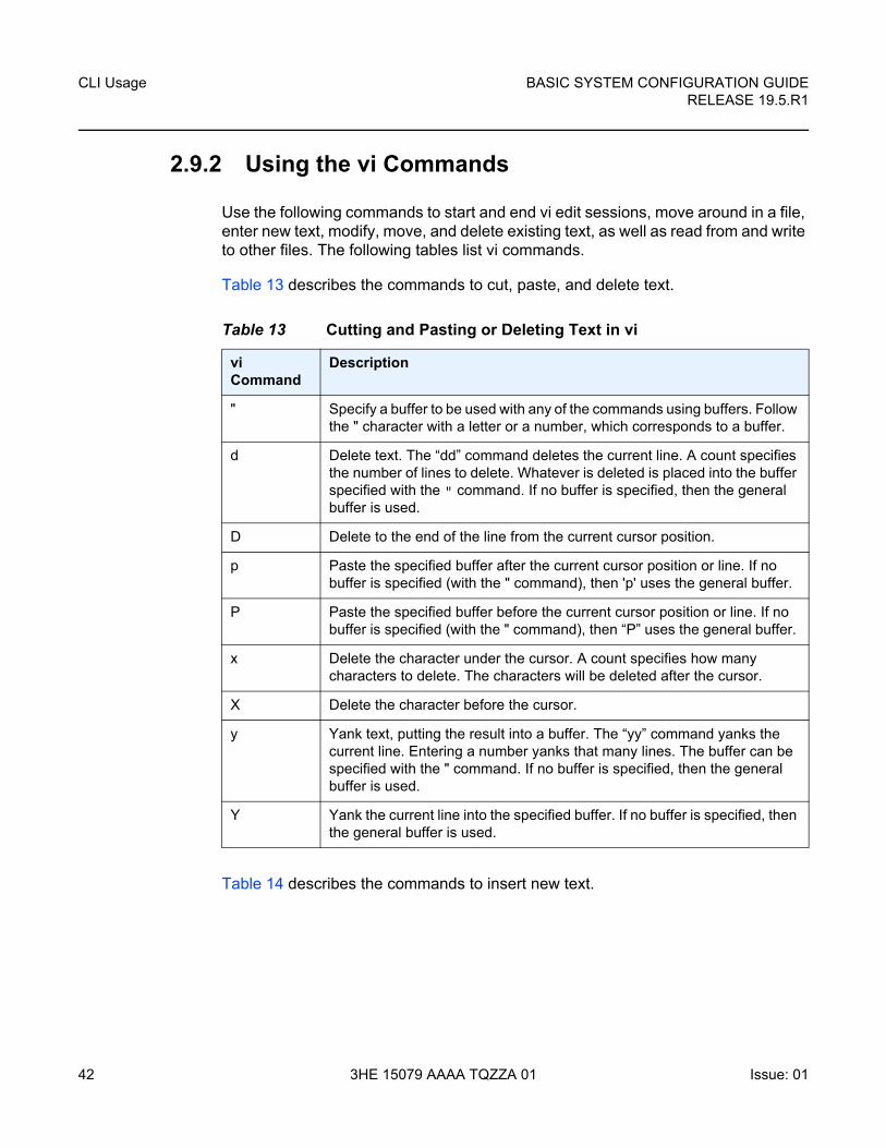
CLI Usage
42
BASIC SYSTEM CONFIGURATION GUIDERELEASE 19.5.R1
3HE 15079 AAAA TQZZA 01 Issue: 01
2.9.2 Using the vi Commands
Use the following commands to start and end vi edit sessions, move around in a file, enter new text, modify, move, and delete existing text, as well as read from and write to other files. The following tables list vi commands.
Table 13 describes the commands to cut, paste, and delete text.
Table 14 describes the commands to insert new text.
Table 13 Cutting and Pasting or Deleting Text in vi
vi Command
Description
" Specify a buffer to be used with any of the commands using buffers. Follow the " character with a letter or a number, which corresponds to a buffer.
d Delete text. The “dd” command deletes the current line. A count specifies the number of lines to delete. Whatever is deleted is placed into the buffer specified with the " command. If no buffer is specified, then the general buffer is used.
D Delete to the end of the line from the current cursor position.
p Paste the specified buffer after the current cursor position or line. If no buffer is specified (with the " command), then 'p' uses the general buffer.
P Paste the specified buffer before the current cursor position or line. If no buffer is specified (with the " command), then “P” uses the general buffer.
x Delete the character under the cursor. A count specifies how many characters to delete. The characters will be deleted after the cursor.
X Delete the character before the cursor.
y Yank text, putting the result into a buffer. The “yy” command yanks the current line. Entering a number yanks that many lines. The buffer can be specified with the " command. If no buffer is specified, then the general buffer is used.
Y Yank the current line into the specified buffer. If no buffer is specified, then the general buffer is used.
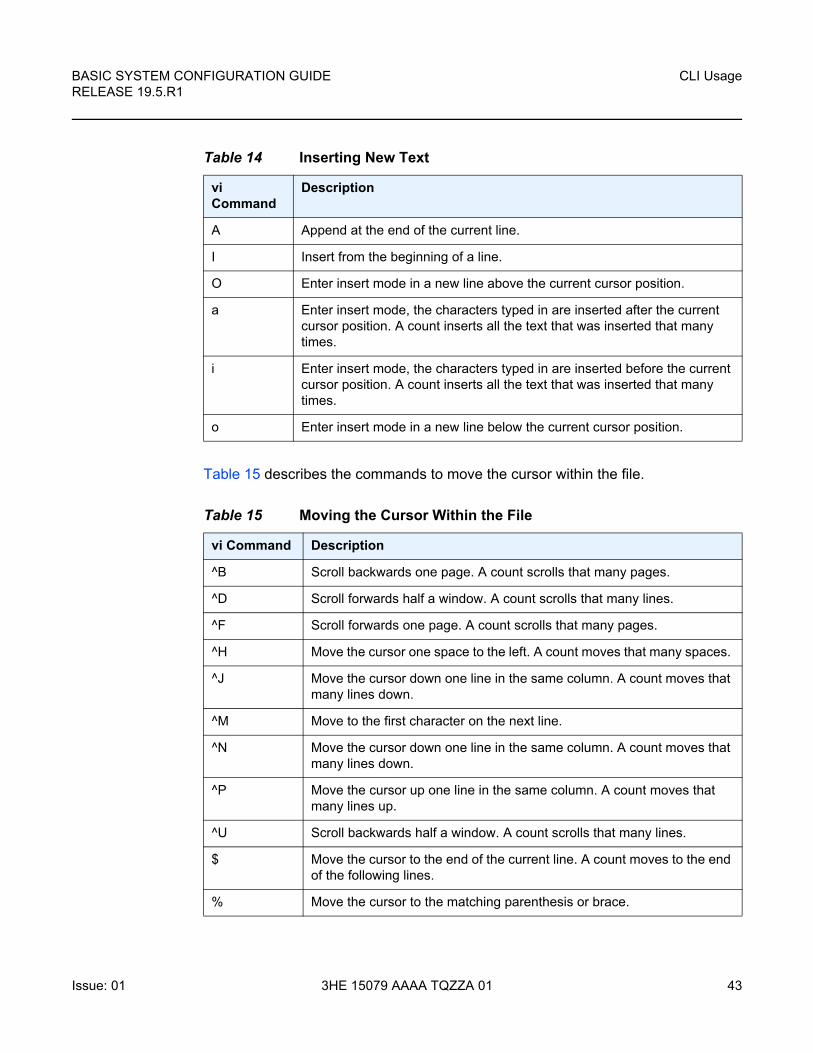
BASIC SYSTEM CONFIGURATION GUIDE RELEASE 19.5.R1
CLI Usage
Issue: 01 3HE 15079 AAAA TQZZA 01 43
Table 15 describes the commands to move the cursor within the file.
Table 14 Inserting New Text
vi Command
Description
A Append at the end of the current line.
I Insert from the beginning of a line.
O Enter insert mode in a new line above the current cursor position.
a Enter insert mode, the characters typed in are inserted after the current cursor position. A count inserts all the text that was inserted that many times.
i Enter insert mode, the characters typed in are inserted before the current cursor position. A count inserts all the text that was inserted that many times.
o Enter insert mode in a new line below the current cursor position.
Table 15 Moving the Cursor Within the File
vi Command Description
^B Scroll backwards one page. A count scrolls that many pages.
^D Scroll forwards half a window. A count scrolls that many lines.
^F Scroll forwards one page. A count scrolls that many pages.
^H Move the cursor one space to the left. A count moves that many spaces.
^J Move the cursor down one line in the same column. A count moves that many lines down.
^M Move to the first character on the next line.
^N Move the cursor down one line in the same column. A count moves that many lines down.
^P Move the cursor up one line in the same column. A count moves that many lines up.
^U Scroll backwards half a window. A count scrolls that many lines.
$ Move the cursor to the end of the current line. A count moves to the end of the following lines.
% Move the cursor to the matching parenthesis or brace.

CLI Usage
44
BASIC SYSTEM CONFIGURATION GUIDERELEASE 19.5.R1
3HE 15079 AAAA TQZZA 01 Issue: 01
^ Move the cursor to the first non-whitespace character.
( Move the cursor to the beginning of a sentence.
) Move the cursor to the beginning of the next sentence.
{ Move the cursor to the preceding paragraph.
} Move the cursor to the next paragraph.
| Move the cursor to the column specified by the count.
+ Move the cursor to the first non-whitespace character in the next line.
- Move the cursor to the first non-whitespace character in the previous line.
_ Move the cursor to the first non-whitespace character in the current line.
0 Move the cursor to the first column of the current line.
B Move the cursor back one word, skipping over punctuation.
E Move forward to the end of a word, skipping over punctuation.
G Go to the line number specified as the count. If no count is given, then go to the end of the file.
H Move the cursor to the first non-whitespace character on the top of the screen.
L Move the cursor to the first non-whitespace character on the bottom of the screen.
M Move the cursor to the first non-whitespace character on the middle of the screen.
W Move forward to the beginning of a word, skipping over punctuation.
b Move the cursor back one word. If the cursor is in the middle of a word, move the cursor to the first character of that word.
e Move the cursor forward one word. If the cursor is in the middle of a word, move the cursor to the last character of that word.
h Move the cursor one character position to the left.
j Move the cursor down one line.
k Move the cursor up one line.
l Move the cursor one character position to the right.
Table 15 Moving the Cursor Within the File (Continued)
vi Command Description
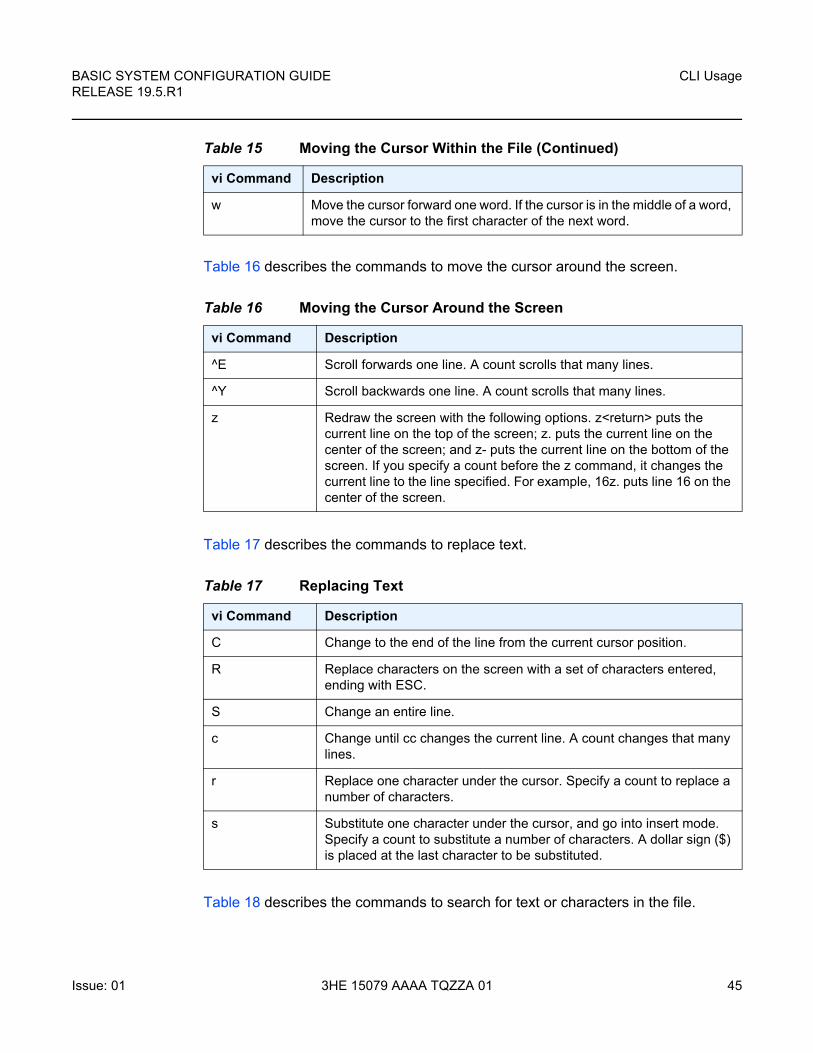
BASIC SYSTEM CONFIGURATION GUIDE RELEASE 19.5.R1
CLI Usage
Issue: 01 3HE 15079 AAAA TQZZA 01 45
Table 16 describes the commands to move the cursor around the screen.
Table 17 describes the commands to replace text.
Table 18 describes the commands to search for text or characters in the file.
w Move the cursor forward one word. If the cursor is in the middle of a word, move the cursor to the first character of the next word.
Table 16 Moving the Cursor Around the Screen
vi Command Description
^E Scroll forwards one line. A count scrolls that many lines.
^Y Scroll backwards one line. A count scrolls that many lines.
z Redraw the screen with the following options. z<return> puts the current line on the top of the screen; z. puts the current line on the center of the screen; and z- puts the current line on the bottom of the screen. If you specify a count before the z command, it changes the current line to the line specified. For example, 16z. puts line 16 on the center of the screen.
Table 17 Replacing Text
vi Command Description
C Change to the end of the line from the current cursor position.
R Replace characters on the screen with a set of characters entered, ending with ESC.
S Change an entire line.
c Change until cc changes the current line. A count changes that many lines.
r Replace one character under the cursor. Specify a count to replace a number of characters.
s Substitute one character under the cursor, and go into insert mode. Specify a count to substitute a number of characters. A dollar sign ($) is placed at the last character to be substituted.
Table 15 Moving the Cursor Within the File (Continued)
vi Command Description
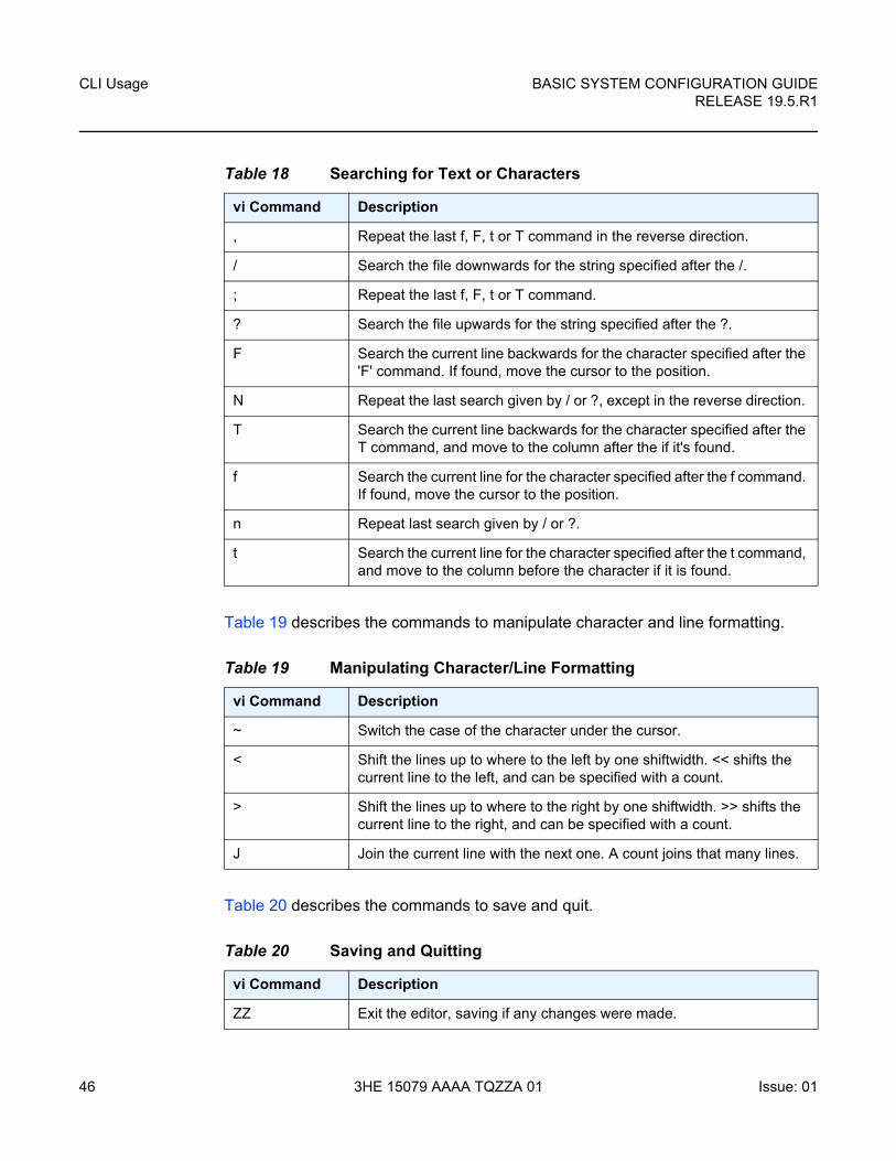
CLI Usage
46
BASIC SYSTEM CONFIGURATION GUIDERELEASE 19.5.R1
3HE 15079 AAAA TQZZA 01 Issue: 01
Table 19 describes the commands to manipulate character and line formatting.
Table 20 describes the commands to save and quit.
Table 18 Searching for Text or Characters
vi Command Description
, Repeat the last f, F, t or T command in the reverse direction.
/ Search the file downwards for the string specified after the /.
; Repeat the last f, F, t or T command.
? Search the file upwards for the string specified after the ?.
F Search the current line backwards for the character specified after the 'F' command. If found, move the cursor to the position.
N Repeat the last search given by / or ?, except in the reverse direction.
T Search the current line backwards for the character specified after the T command, and move to the column after the if it's found.
f Search the current line for the character specified after the f command. If found, move the cursor to the position.
n Repeat last search given by / or ?.
t Search the current line for the character specified after the t command, and move to the column before the character if it is found.
Table 19 Manipulating Character/Line Formatting
vi Command Description
~ Switch the case of the character under the cursor.
< Shift the lines up to where to the left by one shiftwidth. << shifts the current line to the left, and can be specified with a count.
> Shift the lines up to where to the right by one shiftwidth. >> shifts the current line to the right, and can be specified with a count.
J Join the current line with the next one. A count joins that many lines.
Table 20 Saving and Quitting
vi Command Description
ZZ Exit the editor, saving if any changes were made.
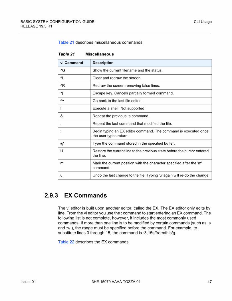
BASIC SYSTEM CONFIGURATION GUIDE RELEASE 19.5.R1
CLI Usage
Issue: 01 3HE 15079 AAAA TQZZA 01 47
Table 21 describes miscellaneous commands.
2.9.3 EX Commands
The vi editor is built upon another editor, called the EX. The EX editor only edits by line. From the vi editor you use the : command to start entering an EX command. The following list is not complete, however, it includes the most commonly used commands. If more than one line is to be modified by certain commands (such as :s and :w ), the range must be specified before the command. For example, to substitute lines 3 through 15, the command is :3,15s/from/this/g.
Table 22 describes the EX commands.
Table 21 Miscellaneous
vi Command Description
^G Show the current filename and the status.
^L Clear and redraw the screen.
^R Redraw the screen removing false lines.
^[ Escape key. Cancels partially formed command.
^^ Go back to the last file edited.
! Execute a shell. Not supported
& Repeat the previous :s command.
. Repeat the last command that modified the file.
: Begin typing an EX editor command. The command is executed once the user types return.
@ Type the command stored in the specified buffer.
U Restore the current line to the previous state before the cursor entered the line.
m Mark the current position with the character specified after the 'm' command.
u Undo the last change to the file. Typing 'u' again will re-do the change.

CLI Usage
48
BASIC SYSTEM CONFIGURATION GUIDERELEASE 19.5.R1
3HE 15079 AAAA TQZZA 01 Issue: 01
Table 22 EX commands
vi Command Description
:ab string strings Abbreviation. If a word is typed in vi corresponding to string1, the editor automatically inserts the corresponding words. For example, the abbreviation :ab usa United States of America would insert the words, United States of America whenever the word usa is typed in.
:map keys new_seq
Mapping. This lets you map a key or a sequence of keys to another key or a sequence of keys.
:q Quit vi. If there have been changes made, the editor issues a warning message.
:q! Quit vi without saving changes.
:s/pattern/to_pattern/options
Substitute. This substitutes the specified pattern with the string in the to_pattern. Without options, it only substitutes the first occurrence of the pattern. If a 'g' is specified, then all occurrences are substituted.
:set [all] Sets some customizing options to vi and EX. The :set all command gives all the possible options.
:una string Removes the abbreviation previously defined by :ab.
:unm keys Removes the remove mapping defined by :map.
:vi filename Starts editing a new file. If changes have not been saved, the editor displays a warning.
:w Write out the current file.
:w filename Write the buffer to the filename specified.
:w >> filename Append the contents of the buffer to the filename.
:wq Write the buffer and quit.
BASIC SYSTEM CONFIGURATION GUIDE RELEASE 19.5.R1
CLI Usage
Issue: 01 3HE 15079 AAAA TQZZA 01 49
2.10 Configuration Rollback
The Configuration Rollback feature provides the ability to undo configuration and reverts back to previous router configuration states while minimizing impacts to services.
This feature gives the operator better control and visibility over the router configurations and reduces operational risk while increasing flexibility and providing powerful recovery options.
Configuration Rollback is useful in cases where configuration changes are made but the operator later decides not to keep the changes (for example, experimentation or when problems are identified in the configuration during actual network operation).
The advantages of this feature include the following:
• Changes made to router configuration are performed with minimal impact on services being provided by the SR by not being required to reboot the router.
• No impact in areas of configuration that did not change.
With the rollback feature, the operator can smoothly revert to previous configurations.
Configuration parameters that changed (or items that changed configuration have dependencies on) are first removed (revert to default), and the previous values are then restored (can be briefly service impacting in changed areas).
A history of changes is preserved (checkpoint IDs) that allows rollback to different points, as well as examination of changes made, as shown in Figure 1.
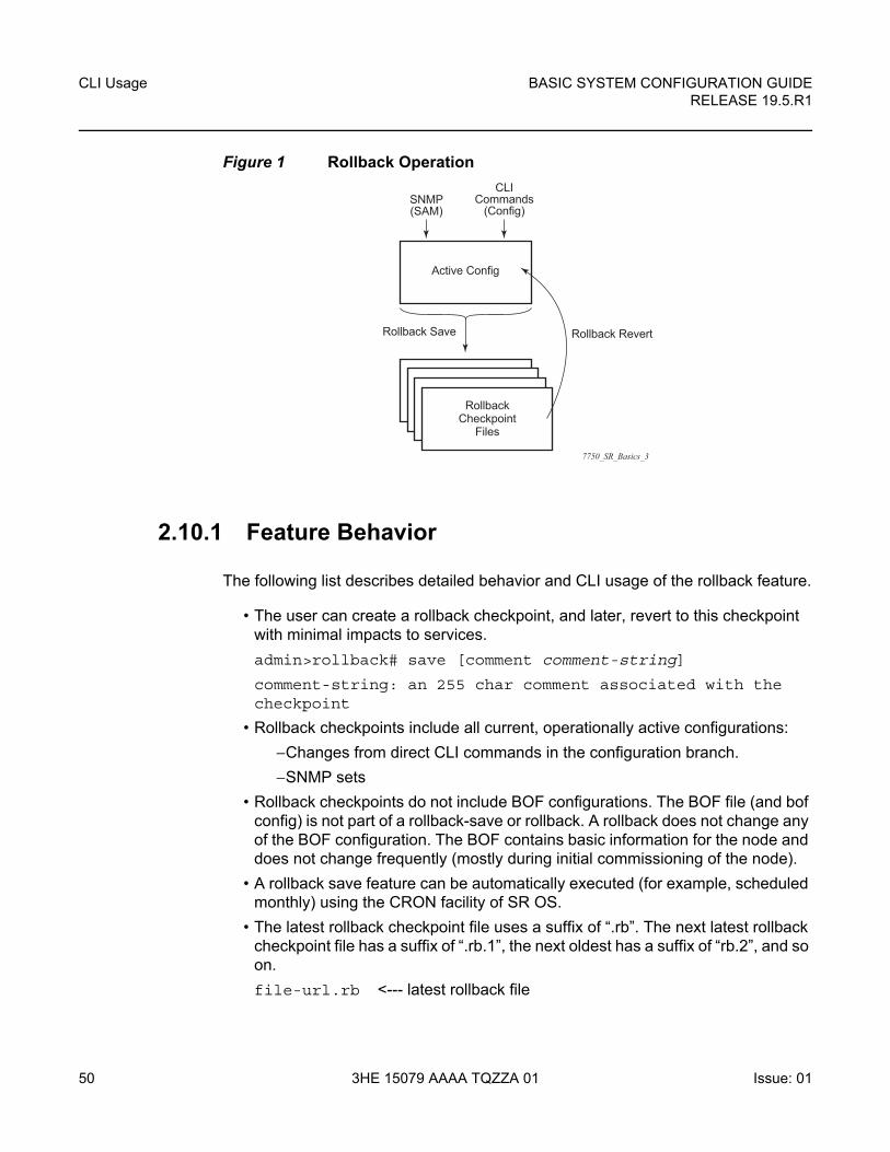
CLI Usage
50
BASIC SYSTEM CONFIGURATION GUIDERELEASE 19.5.R1
3HE 15079 AAAA TQZZA 01 Issue: 01
Figure 1 Rollback Operation
2.10.1 Feature Behavior
The following list describes detailed behavior and CLI usage of the rollback feature.
• The user can create a rollback checkpoint, and later, revert to this checkpoint with minimal impacts to services.
admin>rollback# save [comment comment-string]
comment-string: an 255 char comment associated with the checkpoint
• Rollback checkpoints include all current, operationally active configurations:
−Changes from direct CLI commands in the configuration branch.
−SNMP sets
• Rollback checkpoints do not include BOF configurations. The BOF file (and bof config) is not part of a rollback-save or rollback. A rollback does not change any of the BOF configuration. The BOF contains basic information for the node and does not change frequently (mostly during initial commissioning of the node).
• A rollback save feature can be automatically executed (for example, scheduled monthly) using the CRON facility of SR OS.
• The latest rollback checkpoint file uses a suffix of “.rb”. The next latest rollback checkpoint file has a suffix of “.rb.1”, the next oldest has a suffix of “rb.2”, and so on.
file-url.rb <--- latest rollback file
7750_SR_Basics_3
SNMP(SAM)
CLICommands
(Config)
Rollback RevertRollback Save
Active Config
RollbackCheckpoint
Files
BASIC SYSTEM CONFIGURATION GUIDE RELEASE 19.5.R1
CLI Usage
Issue: 01 3HE 15079 AAAA TQZZA 01 51
file-url.rb.1
…
file-url.rb.9 <--- oldest rollback file
• When a rollback save is executed, the system shifts the file suffix of all the previous checkpoints by 1 (new id = old id + 1). If there are already as many checkpoint files as the maximum number supported then the last checkpoint file is deleted.
• The maximum number of rollback checkpoints is configurable and defaults to 10 (“latest” and 1 through 9, where checkpoint file 9 is deleted during the next rollback-save).
• The location and name of the rollback checkpoint files is configurable to be local (on compact flash) or remote. The file-url must not contain a suffix (just a path/directory + filename). The suffix for rollback checkpoint files is .rb and is automatically appended to rollback checkpoint files.
config>system>rollback# rollback-location file-url
• There is no default rollback-location. If one is not specified (or it is cleared using no rollback-location) and a rollback save is attempted, the rollback save fails and returns an error message.
• The entire set of rollback checkpoint files can be copied from the active CPM CF to the standby CPM CF. This synchronization is done via the following command:
admin>redundancy# rollback-sync
• The operator can enable an automatic synchronization of rollback checkpoint files between the active CPM and standby CPM. When this automatic synchronization is enabled, a rollback save causes the new checkpoint file to be saved to both the active and standby. The suffixes of the old checkpoint files on both active and standby CPMs are incremented.
The automatic sync only causes the new checkpoint file to be copied to both CFs (the other 9 checkpoints are not automatically copied from active to standby but that can be done manually with admin redundancy rollback-sync).
config>redundancy# [no] rollback-sync
• config>redundancy>synchronize {boot-env | config} and admin>redundancy>synchronize {boot-env | config} do not apply to rollback checkpoint files. These commands do not manually or automatically sync rollback checkpoint files. The dedicated rollback-sync commands must be used to synchronize rollback checkpoint files.
• Rollback files can be deleted using a dedicated rollback checkpoint deletion command.
admin>rollback# delete {latest-rb | checkpoint-id}
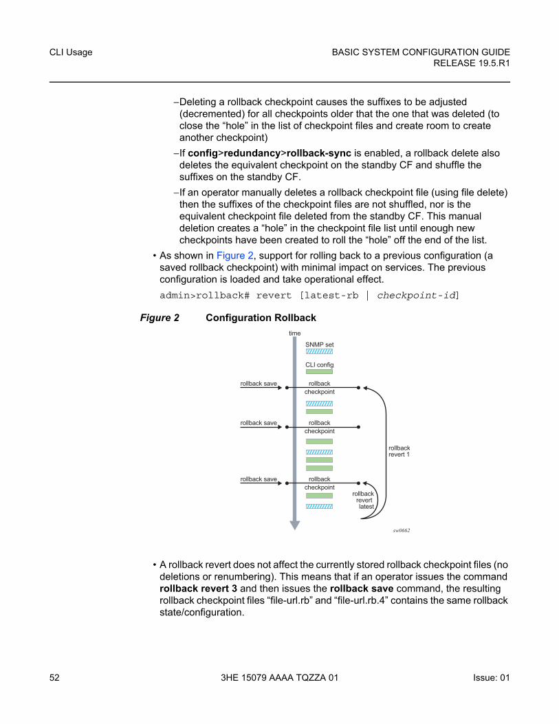
CLI Usage
52
BASIC SYSTEM CONFIGURATION GUIDERELEASE 19.5.R1
3HE 15079 AAAA TQZZA 01 Issue: 01
−Deleting a rollback checkpoint causes the suffixes to be adjusted (decremented) for all checkpoints older that the one that was deleted (to close the “hole” in the list of checkpoint files and create room to create another checkpoint)
−If config>redundancy>rollback-sync is enabled, a rollback delete also deletes the equivalent checkpoint on the standby CF and shuffle the suffixes on the standby CF.
−If an operator manually deletes a rollback checkpoint file (using file delete) then the suffixes of the checkpoint files are not shuffled, nor is the equivalent checkpoint file deleted from the standby CF. This manual deletion creates a “hole” in the checkpoint file list until enough new checkpoints have been created to roll the “hole” off the end of the list.
• As shown in Figure 2, support for rolling back to a previous configuration (a saved rollback checkpoint) with minimal impact on services. The previous configuration is loaded and take operational effect.
admin>rollback# revert [latest-rb | checkpoint-id]
Figure 2 Configuration Rollback
• A rollback revert does not affect the currently stored rollback checkpoint files (no deletions or renumbering). This means that if an operator issues the command rollback revert 3 and then issues the rollback save command, the resulting rollback checkpoint files “file-url.rb” and “file-url.rb.4” contains the same rollback state/configuration.
sw0662
SNMP set
CLI config
rollbackcheckpoint
rollbackrollback save
rollbackrevert 1
rollbackrevert latest
rollback save
time
rollback save
checkpoint
rollbackcheckpoint
BASIC SYSTEM CONFIGURATION GUIDE RELEASE 19.5.R1
CLI Usage
Issue: 01 3HE 15079 AAAA TQZZA 01 53
• The boot-good-exec or bad-exec are not automatically executed after a rollback.
• Impacts to the running services are minimized during a rollback:
−no impact in areas of configuration that did not change
−configuration parameters that changed (or items that changed config have dependencies on) are first removed (revert to default) and the previous values are then restored (can be briefly service impacting in changed areas). Some examples are the following:
• If the currently active configuration contains configure port 5/1/1 dwdm tdcm dispersion -1000 and the rollback checkpoint contains configure port 5/1/1 dwdm tdcm dispersion -1010, then the operational dispersion transitions from -1000, to 0 and then back to -1010 for port 5/1/1, which causes a traffic interruption.
• Changing the neighbor of an MC-APS port starts with neighbor 1, then be configured as no neighbor, and then configured with neighbor 2. Moving through the no neighbor intermediate state requires the working and protect circuits to be torn down and rebuilt. This impacts the 7450 ESS and 7750 SR.
• A rollback undoes any SNMP sets or direct CLI configuration commands that occurred since the last checkpoint creation.
• During the period when a node is processing a rollback revert, both CLI commands (from other users) and SNMP commands continue to be processed. The only commands that are blocked during a rollback revert are other rollback commands including revert, save, and compare (only one rollback command can be executing at a time in one node).
• Commands are available to view and compare the various rollback checkpoints to current operating and candidate configurations.
• Rollback checkpoint files are not guaranteed to be in any particular format. They are not interchangeable with normal configuration files or executable scripts. A normal configuration file (from an admin save) cannot be renamed as a rollback checkpoint and then referenced for a rollback revert operation. Only rollback checkpoint files generated with rollback save can be used to rollback revert.
• If a hardware change is made after a rollback save, then:
−a rollback can be executed as long as the hardware change was an addition of hardware to the node (for example, added a new card or IOM into a previously empty slot).
−a rollback is not guaranteed to work if hardware was removed or changed (for example, XCM/IOM was removed, or XMA/MDA was swapped for a different XMA/MDA type).
• Rollback across a change to the following parameters is not supported:
−chassis-mode
CLI Usage
54
BASIC SYSTEM CONFIGURATION GUIDERELEASE 19.5.R1
3HE 15079 AAAA TQZZA 01 Issue: 01
−mixed-mode
−the SR | SS capability of a card (configure card capability sr | ess)
−configure isa application-assurance-group minimum-isa-generation
• Rollback is supported even after an admin reboot is performed (or the primary configuration in the BOF is changed and an admin reboot is performed). Admin reboot does not “break the chain” for rollback.
• Lawful Intercept configuration under the config>li branch is not affected by a rollback or rescue. LI configuration is not saved in the rollback checkpoint or rescue file, and a rollback revert does not affect any configuration under the config>li branch.
• Any configuration or state change performed under the debug branch of CLI is not saved in the rollback checkpoint file or impacted by a rollback.
• Rollbacks to a checkpoint created in a more recent release is not supported (for example, node running in 9.0r5 cannot rollback to a checkpoint created in 9.0r7).
• The following list captures some side effects and specific behaviors of a rollback revert. Some of these side effects are not related purely to configuration (that is, in the CLI configuration branch) and may have interactions with tools commands, RADIUS, and so on.
−SAA jobs that are running when a rollback revert is initiated, and need configuration changes due to the rollback, are stopped. If the SAA job is a continuous type, then it is restarted as part of the rollback revert after the configuration changes have been applied (just as if the operator had typed no shutdown for the continuous SAA job). Non-continuous SAA jobs that were modified by the rollback would need to be manually restarted if they need to be run again.
−If max-nbr-mac-addr is reduced as part of the revert and the number of MAC addresses in the forwarding database is greater than the max-nbr-mac-addr, then the rollback is aborted (before any actions are taken) and an informative error message is provided. The operator must take actions to remove the MAC addresses if they wish to proceed with the rollback.
−If active subscribers or subscriber hosts or DHCP lease states are present, some associated configuration changes may be blocked (just as those same changes would be blocked if an operator tried to make them via CLI – trying to delete an SLA profile being used by active subscriber hosts, or trying to change a NAT policy in a subscriber profile). If certain configuration changes associated with the hosts or lease states are required as part of the rollback but those changes are blocked, then for each blocked configuration item, a warning is printed, that particular configuration item is not changed and the rollback continues. This is supported on the 7450 ESS and 7750 SR.
BASIC SYSTEM CONFIGURATION GUIDE RELEASE 19.5.R1
CLI Usage
Issue: 01 3HE 15079 AAAA TQZZA 01 55
−After multi-chassis peer shutdown or configuration changes have occurred that affect the contents of the distributed database (for example, sync tag creation or deletion), further configuration changes related to that peer may be temporarily refused. The duration of the temporary configuration freeze depends on the size of the distributed database. A rollback attempting to make those refused configuration changes fails and an error message is provided to the CLI user.
−If a force-switchover command (for example, tools perform service id 1 endpoint "x" force-switchover spoke-sdp-fec 1) has been applied to a spoke-sdp-fec of a dynamic multi-segment pseudo wire, and a rollback revert needs to change the admin state of the spoke-sdp-fec (for example, to modify spoke-sdp-fec parameters that may be dependent on the admin state), then the rollback revert automatically removes the force-switchover and the node reverts to whatever is the best spoke-sdp in the redundant set.
−Rollback impacts the configuration state of the router, and as with normal operator CLI or SNMP configuration changes, additional actions or steps may need to occur before certain configuration changes take operational effect. Some examples include:
• Configuration changes that require a shutdown and then no-shutdown to be done by an operator in order to take operational effect also need this manual shut/no-shut to be performed by the operator in order to take operational effect after a rollback if the rollback changes those configuration items. Some examples include:
• Changes to Autonomous System or Confederation value require a BGP shut and no shut command.
• Changes to VPRN Max-routes require a shut/no-shut on the VPRN service.
• Changes to OSPF or ISIS export-limit require a shut/no-shut on OSPF or ISIS.
• Configuration changes to an MSAP policy that normally require a tools perform subscriber-mgmt eval-msap command to take operational effect on subscribers that are already active. Rollback changes the MSAP policy configuration, but if it is required to have the configuration changes applied to the active subscribers, then the operator must run the eval-msap tools command.
−Any uncommitted changes (for example, the begin command was entered, some changes made, but the commit command was never entered) in the following areas are lost or cleared when a rollback revert is initiated:
• config>app-assure>group policy
• config>router>policy-options
• config>system>sync-if-timing
CLI Usage
56
BASIC SYSTEM CONFIGURATION GUIDERELEASE 19.5.R1
3HE 15079 AAAA TQZZA 01 Issue: 01
• Some card and mda commands require a reboot, remove or rebuild of an entire card or XMA/MDA. When these commands need to be executed as part of a rollback, the impacted cards and MDAs are listed in a warning and the operator is prompted with a single y/n prompt to decide whether to proceed. This prompting will not occur for a rollback initiated via SNMP, or if the operator uses the now keyword with the rollback revert command. Some examples of card and mda commands that may cause a prompt are:
−configure>card>card-type
−configure>card>named-pool-mode (7450 ESS and 7750 SR)
−configure>card>mda
−configure>card>mda>mda-type
• Although the use of the CTRL-C key combination is not recommended during a rollback revert, it is supported (via CLI or SNMP). Interrupting a rollback revert may leave the router in a state that is not necessarily something between the old active configuration and the rollback checkpoint, as the rollback processing may have been in the middle of tearing things down or rebuilding configurations. A strong warning is issued in this case to indicate that the operator must examine the configuration and potentially issue another rollback revert to return to a known (and coherent) configuration.
• An HA CPM switchover during a rollback revert causes the rollback operation to abort. The newly active CPM has an indeterminate configuration. When an HA switchover occurs during a rollback (or within a few seconds of a rollback completing), the operator is advised to repeat the rollback revert operation to the same checkpoint.
• A rollback revert operation does not check authorization of each command that is applied during the revert. Permission to execute the revert operation (authorization for the “admin rollback revert command itself) should only be given to users who are allowed to initiate a rollback revert. It is generally advised to only allow system administrators access to the file system where the rollback files are stored so that they cannot be manually edited.
2.10.2 Rollback and SNMP
The SR OS has SNMP support for rollback status and control. See the TIMETRA-SYSTEM-MIB for details (for example, items such as tmnxSysRollbackStarted).
When the router is doing a rollback revert, SNMP managers see a tmnxSysRollbackStarted trap, then a rapid set of “config change” traps, and then finally, the tmnxSysRollbackStatusChange trap.
BASIC SYSTEM CONFIGURATION GUIDE RELEASE 19.5.R1
CLI Usage
Issue: 01 3HE 15079 AAAA TQZZA 01 57
During the period when a router is processing a rollback revert, both CLI commands (from other users) and SNMP commands continue to be processed.
2.10.3 Rescue Configuration
A special rescue configuration checkpoint can be created that an operator can revert to at any time. The rescue configuration has its own keyword (rescue) and does not use the same rolling suffix indices as the normal rollback checkpoints. This allows the operator to easily return to the rescue configuration state without having to consider a checkpoint index, and ensures that the rescue checkpoint is always available (and does not roll off the bottom of the list of checkpoints).
The operator should define a basic rescue configuration that is known to work and give correct management access to the node.
The location and filename of the rescue file are configurable. The SR OS appends an “.rc” suffix to the specified rescue filename.
2.10.4 Operational Guidelines
The following points offer some operational guidance on the usage of rollback.
• The admin save and admin rollback save commands should be performed periodically:
• The admin save command can be used to backup a complete configuration file that can be used during router reboot, with the following considerations:
−used with a reboot as a last resort
−performed after any major hardware changes or major service changes
−performed after any software upgrade
• The admin rollback save command can be used to create a rollback checkpoint as follows:
−to be used for intermediate checkpoints that can be recovered with minimal impacts to services
−to be performed each time that a moderate amount of configuration changes have been made
−to be performed after any hardware changes
−to be performed after any software upgrade
−to be scheduled with CRON (for example, once every one or two weeks)
CLI Usage
58
BASIC SYSTEM CONFIGURATION GUIDERELEASE 19.5.R1
3HE 15079 AAAA TQZZA 01 Issue: 01
• A new admin rollback save rescue must be created when hardware is changed.
• Rollback checkpoint files are not editable, or compatible or interchangeable with configuration files (generated with admin save).
• The repeated use of the admin rollback save, admin rollback delete, and admin rollback revert commands over the course of weeks or months is not recommended without also executing an occasional admin save. In a serious situation, use one of the saved configurations as the primary configuration for an admin reboot.
• For a software upgrade, it is recommended to create a Rollback Checkpoint (admin rollback save), in addition to saving the configuration (admin save), after an upgrade has been performed and the system is operating as expected. This ensures a good checkpoint that is fully compatible with the new release is available at a point shortly after the upgrade.
• An operator could create a set of rollback checkpoints to support busy or quiet days or weekends or weekdays and use CRON to shift between them.
• It is beneficial to create a rollback checkpoint before a rollback revert is initiated (especially if significant configuration changes have been applied since the last checkpoint was created). If the rollback is especially significant (a lot of major changes), it is also a good practice to perform an admin save in case a full reboot is required to recover from an issue.
• A rollback failure may occur in some limited cases where the node needs a long time to complete one of the resulting configuration changes. If a rollback (for example, rollback revert 5) fails during execution, it should be attempted again. The second attempt typically completes the remaining configuration changes required to fully revert to the desired checkpoint.
• When a new backup CPM is commissioned, the user executes the admin redundancy rollback-sync command to copy the entire set of rollback files from the active CPM CF to the new standby CPM CF. If the operator wants the system to automatically copy new rollback checkpoints to both CFs whenever a new checkpoint is created, then the configure redundancy rollback-sync should be configured.
• An HA CPM switchover during a rollback revert causes the rollback operation to abort. The newly active CPM has an indeterminate configuration. A log event is created in this case to warn the operator. When an HA switchover occurs during a rollback (or within a few seconds of a rollback completing), the operator is advised to repeat the rollback revert operation to the same checkpoint.
• A rollback checkpoint stores the rollback location and the local- and remote-max-checkpoint values, and it is possible that a rollback revert operation can change those values. If an operator changes the local- or remote-max-checkpoint values, it is recommended to delete all the existing checkpoints to prevent a subsequent rollback revert from changing the maximum values to any of the previous values..

BASIC SYSTEM CONFIGURATION GUIDE RELEASE 19.5.R1
CLI Usage
Issue: 01 3HE 15079 AAAA TQZZA 01 59
• If a warning prompt (y/n) is displayed when a rollback revert is initiated, it is highly suggested to respond no to the warning prompt the first time, save a rollback checkpoint before attempting this rollback revert, execute the revert again, and respond yes. If the rollback encounters problems, then a revert to the saved checkpoint can be used to return to the initial configuration state.
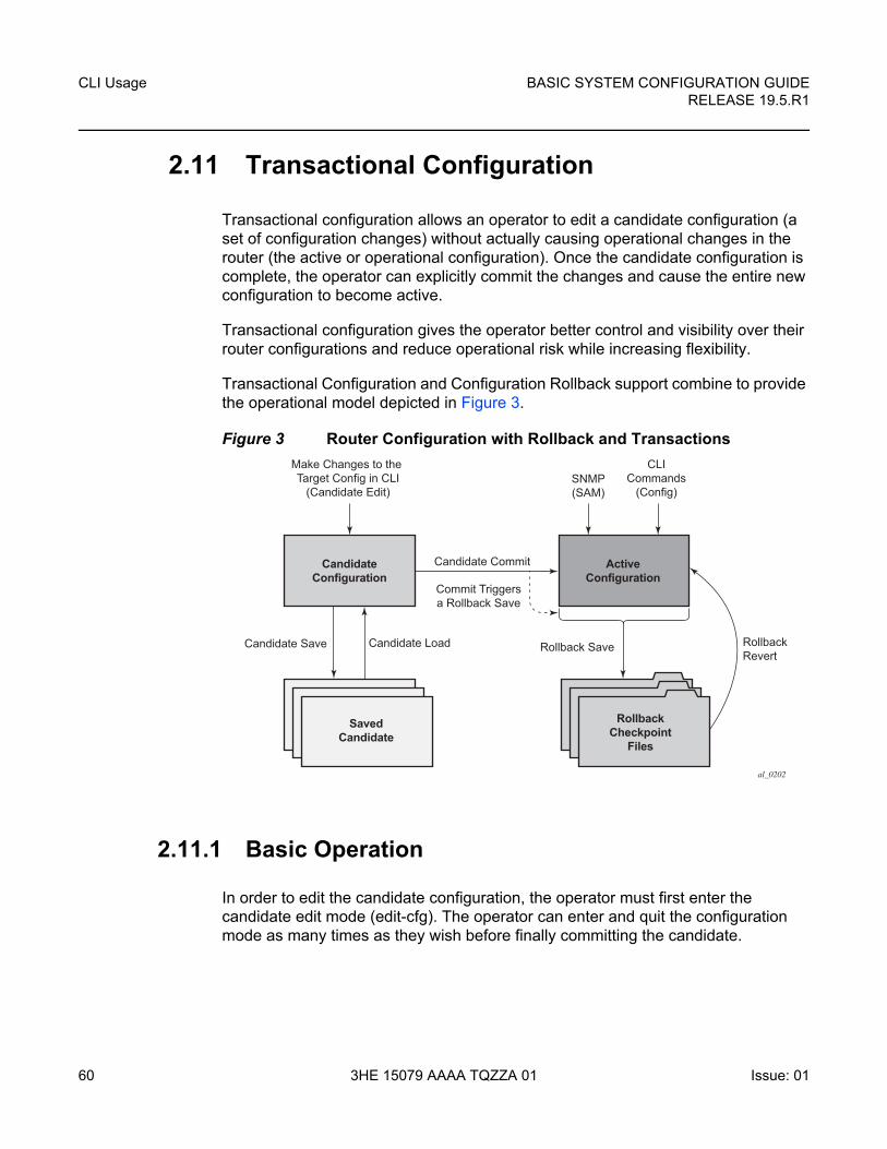
CLI Usage
60
BASIC SYSTEM CONFIGURATION GUIDERELEASE 19.5.R1
3HE 15079 AAAA TQZZA 01 Issue: 01
2.11 Transactional Configuration
Transactional configuration allows an operator to edit a candidate configuration (a set of configuration changes) without actually causing operational changes in the router (the active or operational configuration). Once the candidate configuration is complete, the operator can explicitly commit the changes and cause the entire new configuration to become active.
Transactional configuration gives the operator better control and visibility over their router configurations and reduce operational risk while increasing flexibility.
Transactional Configuration and Configuration Rollback support combine to provide the operational model depicted in Figure 3.
Figure 3 Router Configuration with Rollback and Transactions
2.11.1 Basic Operation
In order to edit the candidate configuration, the operator must first enter the candidate edit mode (edit-cfg). The operator can enter and quit the configuration mode as many times as they wish before finally committing the candidate.
Make Changes to the Target Config in CLI
(Candidate Edit)
Candidate Commit
Commit Triggersa Rollback Save
Candidate Save Rollback Save RollbackRevert
CLICommands
(Config)SNMP(SAM)
CandidateConfiguration
ActiveConfiguration
SavedCandidate
RollbackCheckpoint
Files
al_0202
Candidate Load
BASIC SYSTEM CONFIGURATION GUIDE RELEASE 19.5.R1
CLI Usage
Issue: 01 3HE 15079 AAAA TQZZA 01 61
In edit-cfg mode, the operator builds a set of candidate configuration changes using the same CLI tree as the standard (line-by-line non-transactional) configuration. Tab completion and keyword syntax checking is available.
Just as there is a single operational active configuration that can be modified simultaneously by multiple users in the SR OS, there is also a single global candidate configuration instance. All users make changes in the same global candidate configuration and a commit operation by any user commits the changes made by all users.
Users have the ability to exclusively create a candidate configuration by blocking other users (and sessions of the same user) from entering edit-cfg mode.
If a commit operation is successful, then all of the candidate changes takes operational effect and the candidate is cleared. If there is an error in the processing of the commit, or a ‘commit confirmed’ is not confirmed and an auto-revert occurs, then the router returns to a configuration state with none of the candidate changes applied. The operator can then continue editing the candidate and try a commit later.
All commands in the candidate configuration must be in the correct order for a commit to be successful. Configuration that depends on other candidate objects must be placed after those objects in the candidate. A set of candidate editing commands (copy, insert, and so on) are available to correct and reorder the candidate configuration.
The edit-cfg mode is primarily intended for building a candidate configuration while navigating the configure branch of CLI. Many CLI commands in branches other than configure are supported while in edit-cfg mode, but access to some CLI branches and command are blocked including:
• exec command
• enable-admin command
• enable-dynamic-services-config command
• admin branch
• bof branch
• debug branch
• tools branch
The candidate configuration can be saved to a file and subsequently loaded into a candidate configuration. A saved candidate is similar to, but not the same as an SR OS configuration file generated with an admin save command. The saved candidate cannot be used in general as a configuration file and may not exec without failures.
CLI Usage
62
BASIC SYSTEM CONFIGURATION GUIDERELEASE 19.5.R1
3HE 15079 AAAA TQZZA 01 Issue: 01
There is no SNMP access to the candidate configuration and no SNMP management of candidates, although any configuration changes done via a transaction are reported via the standard SR OS SNMP change traps and basic candidate status information is available via SNMP.
Failure of a commit may be due to one or more of several reasons including:
• Misordering: The candidate configuration has changes that are not in the correct order (an object is referred to before it is actually created).
• Invalid options and combinations: Although many syntax errors are eliminated during the candidate editing process, the candidate configuration may contain combinations of configuration and options that are not valid and are rejected when the SR OS attempts to have them take operational effect.
• Out of resources: The application of the candidate may exhaust various system resources, such as queue resources.
Error messages that help the operator to take necessary actions to correct the candidate are provided for commit failures.
Standard line-by-line (immediate operational effect upon pressing Enter) non-transactional CLI and SNMP commands are not blocked during the creation or editing of a candidate or the processing of a commit. These commands take immediate effect as normal.
2.11.2 Transactions and Rollback
By default, the SR OS automatically creates a new rollback checkpoint after a commit operation. The rollback checkpoint includes the new configuration changes made by the commit. An optional no-checkpoint keyword can be used to avoid the auto-creation of a rollback checkpoint after a commit. If the commit fails, then no new rollback checkpoint is created.
When the commit confirmed option is used then a rollback checkpoint is created after the processing of the commit and exists whether the commit is automatically reverted or not.
Transactional configuration relies on the rollback mechanism to operate. Any commands and configurations that are not supported in a rollback revert are also not supported in edit-cfg mode; for example, changes to chassis-mode.
BASIC SYSTEM CONFIGURATION GUIDE RELEASE 19.5.R1
CLI Usage
Issue: 01 3HE 15079 AAAA TQZZA 01 63
2.11.3 Authorization
Authorization works transparently in edit-cfg mode and no unique or new local profile or TACACS+ permissions rules are required (other than allowing access to the candidate branch). For example: if an operator has permissions to access the configure filter context, then they automatically also have access to the configure filter context when in edit-cfg mode.
The candidate load and save operations (if the operator’s profile allows access to these commands) loads and saves only those items that the user is authorized to access.
The candidate view only displays the items that the user is authorized to access.
The various candidate editing commands (such as adding lines, removing lines, delete, and so on) only allow operations on items that the user is authorized to access.
The candidate commit and discard operations (along with admin rollback revert) operate on the entire candidate and impact all items (authorization does not apply).

CLI Usage
64
BASIC SYSTEM CONFIGURATION GUIDERELEASE 19.5.R1
3HE 15079 AAAA TQZZA 01 Issue: 01
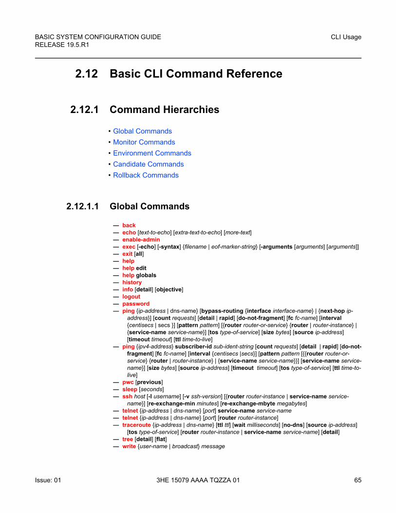
BASIC SYSTEM CONFIGURATION GUIDE RELEASE 19.5.R1
CLI Usage
Issue: 01 3HE 15079 AAAA TQZZA 01 65
2.12 Basic CLI Command Reference
2.12.1 Command Hierarchies
• Global Commands
• Monitor Commands
• Environment Commands
• Candidate Commands
• Rollback Commands
2.12.1.1 Global Commands
— back— echo [text-to-echo] [extra-text-to-echo] [more-text] — enable-admin— exec [-echo] [-syntax] {filename | eof-marker-string} [-arguments [arguments] [arguments]]— exit [all]— help— help edit— help globals— history— info [detail] [objective]— logout— password — ping {ip-address | dns-name} [bypass-routing {interface interface-name} | {next-hop ip-
address}] [count requests] [detail | rapid] [do-not-fragment] [fc fc-name] [interval {centisecs | secs }] [pattern pattern] [{router router-or-service} {router | router-instance} | {service-name service-name}] [tos type-of-service] [size bytes] [source ip-address] [timeout timeout] [ttl time-to-live]
— ping {ipv4-address} subscriber-id sub-ident-string [count requests] [detail | rapid] [do-not-fragment] [fc fc-name] [interval {centisecs |secs}] [pattern pattern [{{router router-or-service} {router | router-instance} | {service-name service-name}}] [service-name service-name}] [size bytes] [source ip-address] [timeout timeout] [tos type-of-service] [ttl time-to-live]
— pwc [previous]— sleep [seconds]— ssh host [-l username] [-v ssh-version] [{router router-instance | service-name service-
name}] [re-exchange-min minutes] [re-exchange-mbyte megabytes]— telnet {ip-address | dns-name} [port] service-name service-name— telnet {ip-address | dns-name} [port] [router router-instance] — traceroute {ip-address | dns-name} [ttl ttl] [wait milliseconds] [no-dns] [source ip-address]
[tos type-of-service] [router router-instance | service-name service-name] [detail]— tree [detail] [flat]— write {user-name | broadcast} message
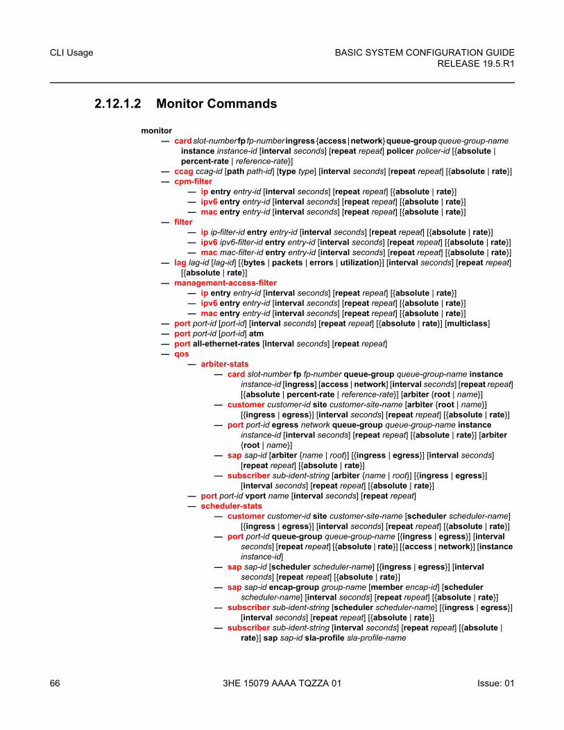
CLI Usage
66
BASIC SYSTEM CONFIGURATION GUIDERELEASE 19.5.R1
3HE 15079 AAAA TQZZA 01 Issue: 01
2.12.1.2 Monitor Commands
monitor— card slot-number fp fp-number ingress {access | network} queue-group queue-group-name
instance instance-id [interval seconds] [repeat repeat] policer policer-id [{absolute | percent-rate | reference-rate}]
— ccag ccag-id [path path-id] [type type] [interval seconds] [repeat repeat] [{absolute | rate}]— cpm-filter
— ip entry entry-id [interval seconds] [repeat repeat] [{absolute | rate}]— ipv6 entry entry-id [interval seconds] [repeat repeat] [{absolute | rate}]— mac entry entry-id [interval seconds] [repeat repeat] [{absolute | rate}]
— filter— ip ip-filter-id entry entry-id [interval seconds] [repeat repeat] [{absolute | rate}]— ipv6 ipv6-filter-id entry entry-id [interval seconds] [repeat repeat] [{absolute | rate}]— mac mac-filter-id entry entry-id [interval seconds] [repeat repeat] [{absolute | rate}]
— lag lag-id [lag-id] [{bytes | packets | errors | utilization}] [interval seconds] [repeat repeat] [{absolute | rate}]
— management-access-filter— ip entry entry-id [interval seconds] [repeat repeat] [{absolute | rate}]— ipv6 entry entry-id [interval seconds] [repeat repeat] [{absolute | rate}]— mac entry entry-id [interval seconds] [repeat repeat] [{absolute | rate}]
— port port-id [port-id] [interval seconds] [repeat repeat] [{absolute | rate}] [multiclass]— port port-id [port-id] atm — port all-ethernet-rates [interval seconds] [repeat repeat] — qos
— arbiter-stats— card slot-number fp fp-number queue-group queue-group-name instance
instance-id [ingress] [access | network] [interval seconds] [repeat repeat] [{absolute | percent-rate | reference-rate}] [arbiter {root | name}]
— customer customer-id site customer-site-name [arbiter {root | name}] [{ingress | egress}] [interval seconds] [repeat repeat] [{absolute | rate}]
— port port-id egress network queue-group queue-group-name instance instance-id [interval seconds] [repeat repeat] [{absolute | rate}] [arbiter {root | name}]
— sap sap-id [arbiter {name | root}] [{ingress | egress}] [interval seconds] [repeat repeat] [{absolute | rate}]
— subscriber sub-ident-string [arbiter {name | root}] [{ingress | egress}] [interval seconds] [repeat repeat] [{absolute | rate}]
— port port-id vport name [interval seconds] [repeat repeat]— scheduler-stats
— customer customer-id site customer-site-name [scheduler scheduler-name] [{ingress | egress}] [interval seconds] [repeat repeat] [{absolute | rate}]
— port port-id queue-group queue-group-name [{ingress | egress}] [interval seconds] [repeat repeat] [{absolute | rate}] [{access | network}] [instance instance-id]
— sap sap-id [scheduler scheduler-name] [{ingress | egress}] [interval seconds] [repeat repeat] [{absolute | rate}]
— sap sap-id encap-group group-name [member encap-id] [scheduler scheduler-name] [interval seconds] [repeat repeat] [{absolute | rate}]
— subscriber sub-ident-string [scheduler scheduler-name] [{ingress | egress}] [interval seconds] [repeat repeat] [{absolute | rate}]
— subscriber sub-ident-string [interval seconds] [repeat repeat] [{absolute | rate}] sap sap-id sla-profile sla-profile-name
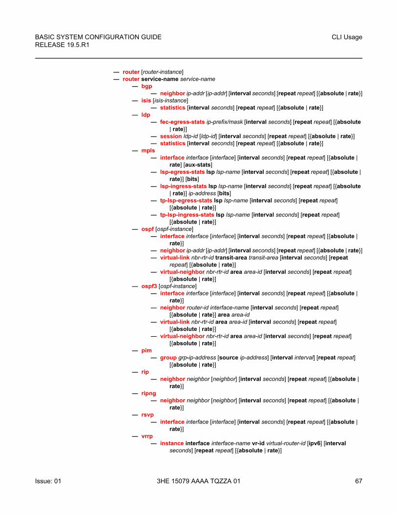
BASIC SYSTEM CONFIGURATION GUIDE RELEASE 19.5.R1
CLI Usage
Issue: 01 3HE 15079 AAAA TQZZA 01 67
— router [router-instance] — router service-name service-name
— bgp— neighbor ip-addr [ip-addr] [interval seconds] [repeat repeat] [{absolute | rate}]
— isis [isis-instance]— statistics [interval seconds] [repeat repeat] [{absolute | rate}]
— ldp — fec-egress-stats ip-prefix/mask [interval seconds] [repeat repeat] [{absolute
| rate}] — session ldp-id [ldp-id] [interval seconds] [repeat repeat] [{absolute | rate}] — statistics [interval seconds] [repeat repeat] [{absolute | rate}]
— mpls— interface interface [interface] [interval seconds] [repeat repeat] [{absolute |
rate] [aux-stats]— lsp-egress-stats lsp lsp-name [interval seconds] [repeat repeat] [{absolute |
rate}] [bits]— lsp-ingress-stats lsp lsp-name [interval seconds] [repeat repeat] [{absolute
| rate}] ip-address [bits]— tp-lsp-egress-stats lsp lsp-name [interval seconds] [repeat repeat]
[{absolute | rate}]— tp-lsp-ingress-stats lsp lsp-name [interval seconds] [repeat repeat]
[{absolute | rate}]— ospf [ospf-instance]
— interface interface [interface] [interval seconds] [repeat repeat] [{absolute | rate}]
— neighbor ip-addr [ip-addr] [interval seconds] [repeat repeat] [{absolute | rate}]— virtual-link nbr-rtr-id transit-area transit-area [interval seconds] [repeat
repeat] [{absolute | rate}]— virtual-neighbor nbr-rtr-id area area-id [interval seconds] [repeat repeat]
[{absolute | rate}]— ospf3 [ospf-instance]
— interface interface [interface] [interval seconds] [repeat repeat] [{absolute | rate}]
— neighbor router-id interface-name [interval seconds] [repeat repeat] [{absolute | rate}] area area-id
— virtual-link nbr-rtr-id area area-id [interval seconds] [repeat repeat] [{absolute | rate}]
— virtual-neighbor nbr-rtr-id area area-id [interval seconds] [repeat repeat] [{absolute | rate}]
— pim— group grp-ip-address [source ip-address] [interval interval] [repeat repeat]
[{absolute | rate}]— rip
— neighbor neighbor [neighbor] [interval seconds] [repeat repeat] [{absolute | rate}]
— ripng— neighbor neighbor [neighbor] [interval seconds] [repeat repeat] [{absolute |
rate}]— rsvp
— interface interface [interface] [interval seconds] [repeat repeat] [{absolute | rate}]
— vrrp— instance interface interface-name vr-id virtual-router-id [ipv6] [interval
seconds] [repeat repeat] [{absolute | rate}]
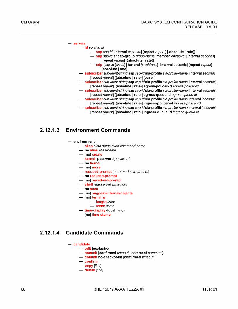
CLI Usage
68
BASIC SYSTEM CONFIGURATION GUIDERELEASE 19.5.R1
3HE 15079 AAAA TQZZA 01 Issue: 01
— service— id service-id
— sap sap-id [interval seconds] [repeat repeat] [{absolute | rate}]— sap sap-id encap-group group-name [member encap-id] [interval seconds]
[repeat repeat] [{absolute | rate}]— sdp {sdp-id [:vc-id] | far-end ip-address} [interval seconds] [repeat repeat]
[absolute | rate]— subscriber sub-ident-string sap sap-id sla-profile sla-profile-name [interval seconds]
[repeat repeat] [{absolute | rate}] [base]— subscriber sub-ident-string sap sap-id sla-profile sla-profile-name [interval seconds]
[repeat repeat] [{absolute | rate}] egress-policer-id egress-policer-id— subscriber sub-ident-string sap sap-id sla-profile sla-profile-name [interval seconds]
[repeat repeat] [{absolute | rate}] egress-queue-id egress-queue-id— subscriber sub-ident-string sap sap-id sla-profile sla-profile-name interval [seconds]
[repeat repeat] [{absolute | rate}] ingress-policer-id ingress-policer-id— subscriber sub-ident-string sap sap-id sla-profile sla-profile-name interval [seconds]
[repeat repeat] [{absolute | rate}] ingress-queue-id ingress-queue-id
2.12.1.3 Environment Commands
— environment— alias alias-name alias-command-name— no alias alias-name— [no] create— kernel -password password— no kernel — [no] more— reduced-prompt [no-of-nodes-in-prompt]— no reduced-prompt— [no] saved-ind-prompt— shell -password password— no shell— [no] suggest-internal-objects— [no] terminal
— length lines— width width
— time-display {local | utc}— [no] time-stamp
2.12.1.4 Candidate Commands
— candidate — edit [exclusive]— commit [confirmed timeout] [comment comment]— commit no-checkpoint [confirmed timeout]— confirm— copy [line]— delete [line]
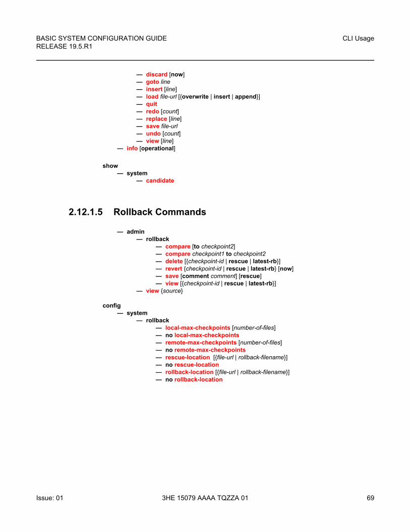
BASIC SYSTEM CONFIGURATION GUIDE RELEASE 19.5.R1
CLI Usage
Issue: 01 3HE 15079 AAAA TQZZA 01 69
— discard [now]— goto line— insert [line]— load file-url [{overwrite | insert | append}] — quit— redo [count]— replace [line]— save file-url — undo [count]— view [line]
— info [operational]
show— system
— candidate
2.12.1.5 Rollback Commands
— admin— rollback
— compare [to checkpoint2]— compare checkpoint1 to checkpoint2— delete [{checkpoint-id | rescue | latest-rb}]— revert {checkpoint-id | rescue | latest-rb} [now]— save [comment comment] [rescue] — view [{checkpoint-id | rescue | latest-rb}]
— view {source}
config— system
— rollback— local-max-checkpoints [number-of-files]— no local-max-checkpoints— remote-max-checkpoints [number-of-files]— no remote-max-checkpoints — rescue-location [{file-url | rollback-filename}]— no rescue-location— rollback-location [{file-url | rollback-filename}]— no rollback-location
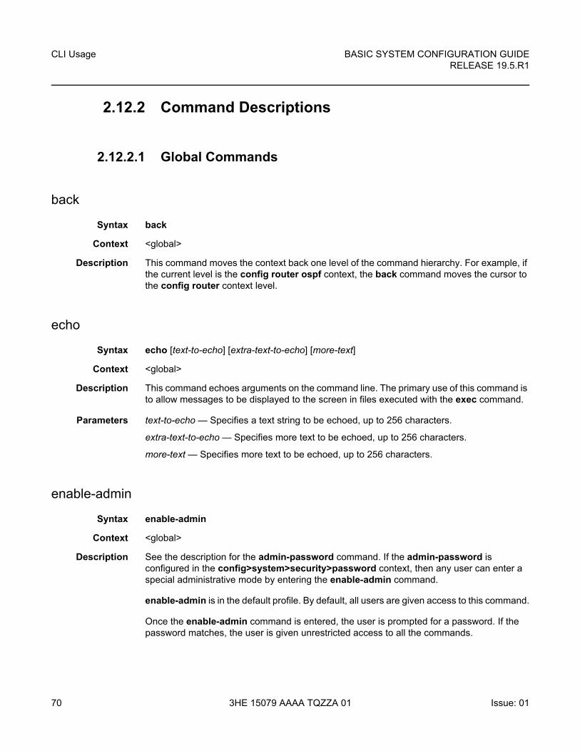
CLI Usage
70
BASIC SYSTEM CONFIGURATION GUIDERELEASE 19.5.R1
3HE 15079 AAAA TQZZA 01 Issue: 01
2.12.2 Command Descriptions
2.12.2.1 Global Commands
back
Syntax back
Context <global>
Description This command moves the context back one level of the command hierarchy. For example, if the current level is the config router ospf context, the back command moves the cursor to the config router context level.
echo
Syntax echo [text-to-echo] [extra-text-to-echo] [more-text]
Context <global>
Description This command echoes arguments on the command line. The primary use of this command is to allow messages to be displayed to the screen in files executed with the exec command.
Parameters text-to-echo — Specifies a text string to be echoed, up to 256 characters.
extra-text-to-echo — Specifies more text to be echoed, up to 256 characters.
more-text — Specifies more text to be echoed, up to 256 characters.
enable-admin
Syntax enable-admin
Context <global>
Description See the description for the admin-password command. If the admin-password is configured in the config>system>security>password context, then any user can enter a special administrative mode by entering the enable-admin command.
enable-admin is in the default profile. By default, all users are given access to this command.
Once the enable-admin command is entered, the user is prompted for a password. If the password matches, the user is given unrestricted access to all the commands.
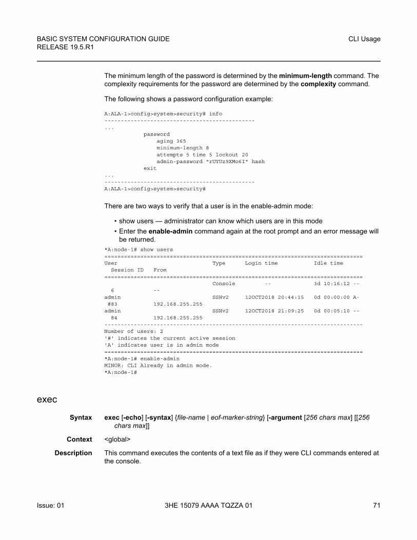
BASIC SYSTEM CONFIGURATION GUIDE RELEASE 19.5.R1
CLI Usage
Issue: 01 3HE 15079 AAAA TQZZA 01 71
The minimum length of the password is determined by the minimum-length command. The complexity requirements for the password are determined by the complexity command.
The following shows a password configuration example:
A:ALA-1>config>system>security# info----------------------------------------------...
passwordaging 365minimum-length 8attempts 5 time 5 lockout 20admin-password "rUYUz9XMo6I" hash
exit...----------------------------------------------A:ALA-1>config>system>security#
There are two ways to verify that a user is in the enable-admin mode:
• show users — administrator can know which users are in this mode
• Enter the enable-admin command again at the root prompt and an error message will be returned.
*A:node-1# show users===============================================================================User Type Login time Idle time
Session ID From===============================================================================
Console -- 3d 10:16:12 --6 --
admin SSHv2 12OCT2018 20:44:15 0d 00:00:00 A-#83 192.168.255.255
admin SSHv2 12OCT2018 21:09:25 0d 00:05:10 --84 192.168.255.255
-------------------------------------------------------------------------------Number of users: 2'#' indicates the current active session'A' indicates user is in admin mode===============================================================================*A:node-1# enable-adminMINOR: CLI Already in admin mode.*A:node-1#
exec
Syntax exec [-echo] [-syntax] {file-name | eof-marker-string} [-argument [256 chars max] [[256 chars max]]
Context <global>
Description This command executes the contents of a text file as if they were CLI commands entered at the console.
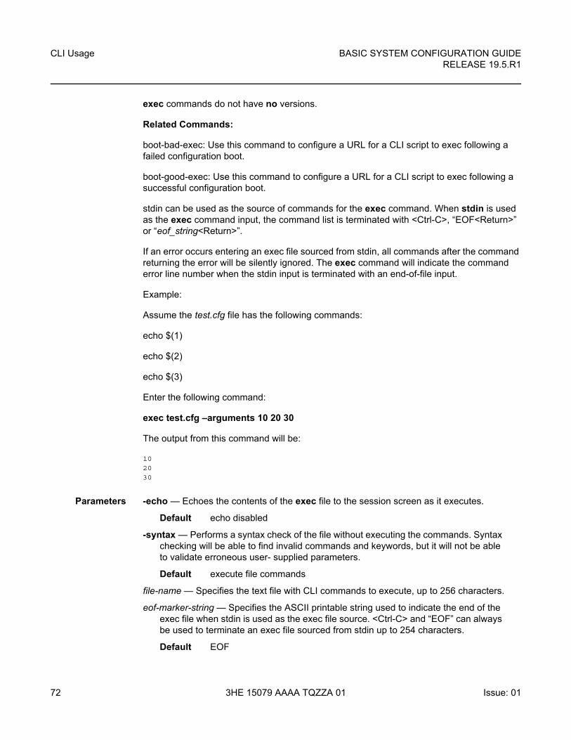
CLI Usage
72
BASIC SYSTEM CONFIGURATION GUIDERELEASE 19.5.R1
3HE 15079 AAAA TQZZA 01 Issue: 01
exec commands do not have no versions.
Related Commands:
boot-bad-exec: Use this command to configure a URL for a CLI script to exec following a failed configuration boot.
boot-good-exec: Use this command to configure a URL for a CLI script to exec following a successful configuration boot.
stdin can be used as the source of commands for the exec command. When stdin is used as the exec command input, the command list is terminated with <Ctrl-C>, “EOF<Return>” or “eof_string<Return>”.
If an error occurs entering an exec file sourced from stdin, all commands after the command returning the error will be silently ignored. The exec command will indicate the command error line number when the stdin input is terminated with an end-of-file input.
Example:
Assume the test.cfg file has the following commands:
echo $(1)
echo $(2)
echo $(3)
Enter the following command:
exec test.cfg –arguments 10 20 30
The output from this command will be:
102030
Parameters -echo — Echoes the contents of the exec file to the session screen as it executes.
Default echo disabled
-syntax — Performs a syntax check of the file without executing the commands. Syntax checking will be able to find invalid commands and keywords, but it will not be able to validate erroneous user- supplied parameters.
Default execute file commands
file-name — Specifies the text file with CLI commands to execute, up to 256 characters.
eof-marker-string — Specifies the ASCII printable string used to indicate the end of the exec file when stdin is used as the exec file source. <Ctrl-C> and “EOF” can always be used to terminate an exec file sourced from stdin up to 254 characters.
Default EOF
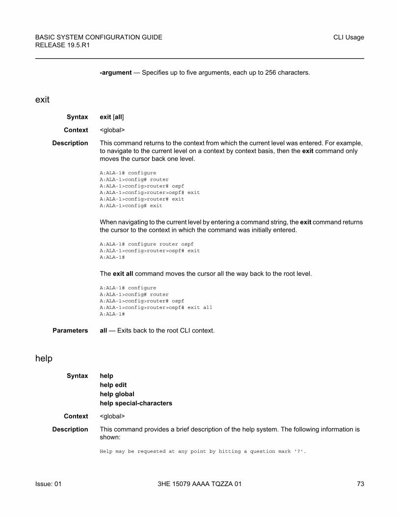
BASIC SYSTEM CONFIGURATION GUIDE RELEASE 19.5.R1
CLI Usage
Issue: 01 3HE 15079 AAAA TQZZA 01 73
-argument — Specifies up to five arguments, each up to 256 characters.
exit
Syntax exit [all]
Context <global>
Description This command returns to the context from which the current level was entered. For example, to navigate to the current level on a context by context basis, then the exit command only moves the cursor back one level.
A:ALA-1# configureA:ALA-1>config# routerA:ALA-1>config>router# ospfA:ALA-1>config>router>ospf# exitA:ALA-1>config>router# exitA:ALA-1>config# exit
When navigating to the current level by entering a command string, the exit command returns the cursor to the context in which the command was initially entered.
A:ALA-1# configure router ospfA:ALA-1>config>router>ospf# exitA:ALA-1#
The exit all command moves the cursor all the way back to the root level.
A:ALA-1# configureA:ALA-1>config# routerA:ALA-1>config>router# ospfA:ALA-1>config>router>ospf# exit allA:ALA-1#
Parameters all — Exits back to the root CLI context.
help
Syntax help
help edit
help global
help special-characters
Context <global>
Description This command provides a brief description of the help system. The following information is shown:
Help may be requested at any point by hitting a question mark '?'.
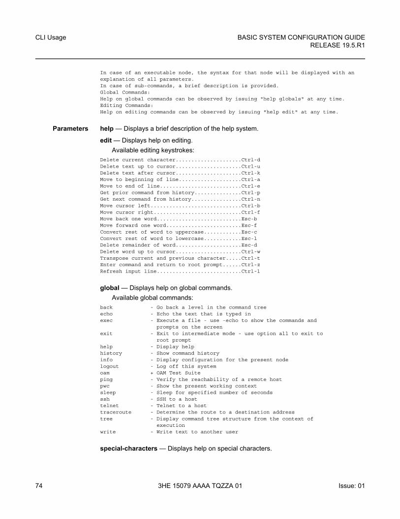
CLI Usage
74
BASIC SYSTEM CONFIGURATION GUIDERELEASE 19.5.R1
3HE 15079 AAAA TQZZA 01 Issue: 01
In case of an executable node, the syntax for that node will be displayed with anexplanation of all parameters.In case of sub-commands, a brief description is provided.Global Commands:Help on global commands can be observed by issuing "help globals" at any time.Editing Commands:Help on editing commands can be observed by issuing "help edit" at any time.
Parameters help — Displays a brief description of the help system.
edit — Displays help on editing.
Available editing keystrokes:Delete current character.....................Ctrl-dDelete text up to cursor.....................Ctrl-uDelete text after cursor.....................Ctrl-kMove to beginning of line....................Ctrl-aMove to end of line..........................Ctrl-eGet prior command from history...............Ctrl-pGet next command from history................Ctrl-nMove cursor left.............................Ctrl-bMove cursor right............................Ctrl-fMove back one word...........................Esc-bMove forward one word........................Esc-fConvert rest of word to uppercase............Esc-cConvert rest of word to lowercase............Esc-lDelete remainder of word.....................Esc-dDelete word up to cursor.....................Ctrl-wTranspose current and previous character.....Ctrl-tEnter command and return to root prompt......Ctrl-zRefresh input line...........................Ctrl-l
global — Displays help on global commands.
Available global commands:back - Go back a level in the command treeecho - Echo the text that is typed inexec - Execute a file - use -echo to show the commands and
prompts on the screenexit - Exit to intermediate mode - use option all to exit to
root prompthelp - Display helphistory - Show command historyinfo - Display configuration for the present nodelogout - Log off this systemoam + OAM Test Suiteping - Verify the reachability of a remote hostpwc - Show the present working contextsleep - Sleep for specified number of secondsssh - SSH to a hosttelnet - Telnet to a hosttraceroute - Determine the route to a destination addresstree - Display command tree structure from the context of
executionwrite - Write text to another user
special-characters — Displays help on special characters.
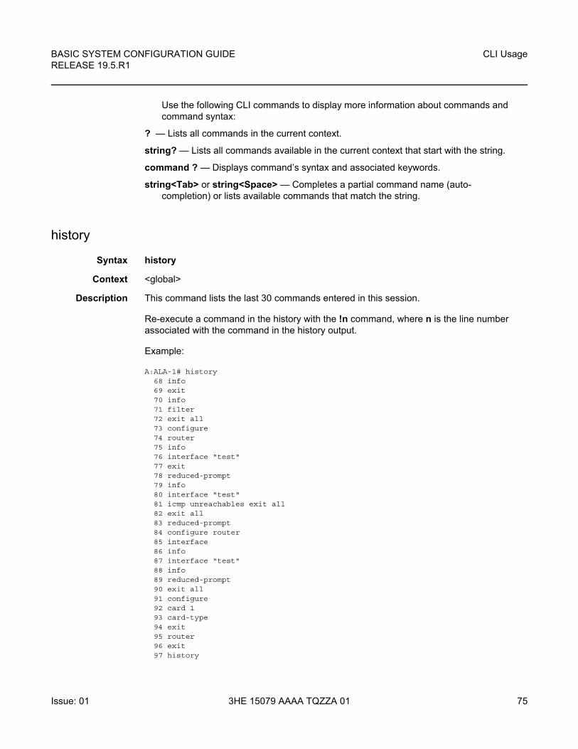
BASIC SYSTEM CONFIGURATION GUIDE RELEASE 19.5.R1
CLI Usage
Issue: 01 3HE 15079 AAAA TQZZA 01 75
Use the following CLI commands to display more information about commands and command syntax:
? — Lists all commands in the current context.
string? — Lists all commands available in the current context that start with the string.
command ? — Displays command’s syntax and associated keywords.
string<Tab> or string<Space> — Completes a partial command name (auto-completion) or lists available commands that match the string.
history
Syntax history
Context <global>
Description This command lists the last 30 commands entered in this session.
Re-execute a command in the history with the !n command, where n is the line number associated with the command in the history output.
Example:
A:ALA-1# history68 info69 exit70 info71 filter72 exit all73 configure74 router75 info76 interface "test"77 exit78 reduced-prompt79 info80 interface "test"81 icmp unreachables exit all82 exit all83 reduced-prompt84 configure router85 interface86 info87 interface "test"88 info89 reduced-prompt90 exit all91 configure92 card 193 card-type94 exit95 router96 exit97 history
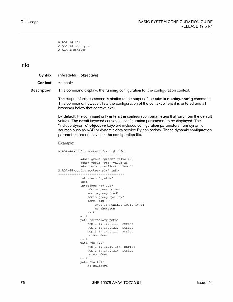
CLI Usage
76
BASIC SYSTEM CONFIGURATION GUIDERELEASE 19.5.R1
3HE 15079 AAAA TQZZA 01 Issue: 01
A:ALA-1# !91A:ALA-1# configureA:ALA-1>config#
info
Syntax info [detail] [objective]
Context <global>
Description This command displays the running configuration for the configuration context.
The output of this command is similar to the output of the admin display-config command. This command, however, lists the configuration of the context where it is entered and all branches below that context level.
By default, the command only enters the configuration parameters that vary from the default values. The detail keyword causes all configuration parameters to be displayed. The “include-dynamic” objective keyword includes configuration parameters from dynamic sources such as VSD or dynamic data service Python scripts. These dynamic configuration parameters are not saved in the configuration file.
Example:
A:ALA-48>config>router>if-attr# info------------------------------------
admin-group "green" value 15admin-group "red" value 25admin-group "yellow" value 20
A:ALA-48>config>router>mpls# info------------------------------------
interface "system"exitinterface "to-104"
admin-group "green"admin-group "red"admin-group "yellow"label-map 35
swap 36 nexthop 10.10.10.91no shutdown
exitexitpath "secondary-path"
hop 1 10.10.0.111 stricthop 2 10.10.0.222 stricthop 3 10.10.0.123 strictno shutdown
exitpath "to-NYC"
hop 1 10.10.10.104 stricthop 2 10.10.0.210 strictno shutdown
exitpath "to-104"
no shutdown
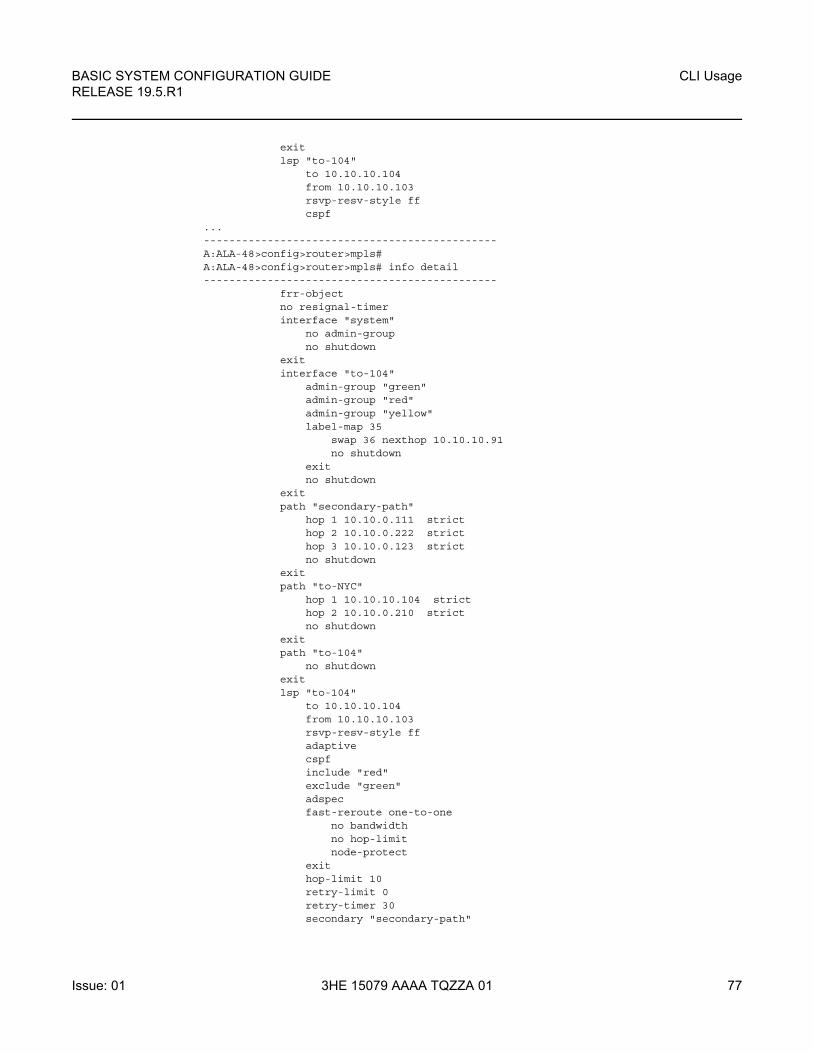
BASIC SYSTEM CONFIGURATION GUIDE RELEASE 19.5.R1
CLI Usage
Issue: 01 3HE 15079 AAAA TQZZA 01 77
exitlsp "to-104"
to 10.10.10.104from 10.10.10.103rsvp-resv-style ffcspf
...----------------------------------------------A:ALA-48>config>router>mpls#A:ALA-48>config>router>mpls# info detail----------------------------------------------
frr-objectno resignal-timerinterface "system"
no admin-groupno shutdown
exitinterface "to-104"
admin-group "green"admin-group "red"admin-group "yellow"label-map 35
swap 36 nexthop 10.10.10.91no shutdown
exitno shutdown
exitpath "secondary-path"
hop 1 10.10.0.111 stricthop 2 10.10.0.222 stricthop 3 10.10.0.123 strictno shutdown
exitpath "to-NYC"
hop 1 10.10.10.104 stricthop 2 10.10.0.210 strictno shutdown
exitpath "to-104"
no shutdownexitlsp "to-104"
to 10.10.10.104from 10.10.10.103rsvp-resv-style ffadaptivecspfinclude "red"exclude "green"adspecfast-reroute one-to-one
no bandwidthno hop-limitnode-protect
exithop-limit 10retry-limit 0retry-timer 30secondary "secondary-path"
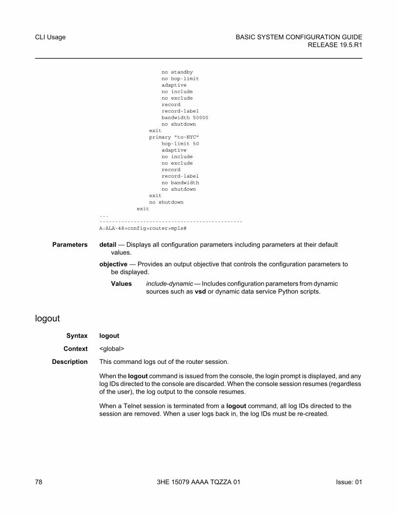
CLI Usage
78
BASIC SYSTEM CONFIGURATION GUIDERELEASE 19.5.R1
3HE 15079 AAAA TQZZA 01 Issue: 01
no standbyno hop-limitadaptiveno includeno excluderecordrecord-labelbandwidth 50000no shutdown
exitprimary "to-NYC"
hop-limit 50adaptiveno includeno excluderecordrecord-labelno bandwidthno shutdown
exitno shutdown
exit...----------------------------------------------A:ALA-48>config>router>mpls#
Parameters detail — Displays all configuration parameters including parameters at their default values.
objective — Provides an output objective that controls the configuration parameters to be displayed.
Values include-dynamic — Includes configuration parameters from dynamic sources such as vsd or dynamic data service Python scripts.
logout
Syntax logout
Context <global>
Description This command logs out of the router session.
When the logout command is issued from the console, the login prompt is displayed, and any log IDs directed to the console are discarded. When the console session resumes (regardless of the user), the log output to the console resumes.
When a Telnet session is terminated from a logout command, all log IDs directed to the session are removed. When a user logs back in, the log IDs must be re-created.
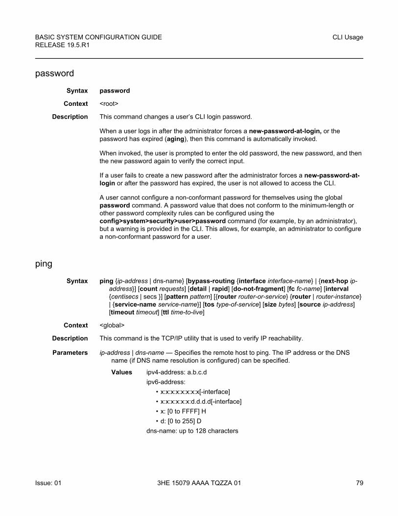
BASIC SYSTEM CONFIGURATION GUIDE RELEASE 19.5.R1
CLI Usage
Issue: 01 3HE 15079 AAAA TQZZA 01 79
password
Syntax password
Context <root>
Description This command changes a user’s CLI login password.
When a user logs in after the administrator forces a new-password-at-login, or the password has expired (aging), then this command is automatically invoked.
When invoked, the user is prompted to enter the old password, the new password, and then the new password again to verify the correct input.
If a user fails to create a new password after the administrator forces a new-password-at-login or after the password has expired, the user is not allowed to access the CLI.
A user cannot configure a non-conformant password for themselves using the global password command. A password value that does not conform to the minimum-length or other password complexity rules can be configured using the config>system>security>user>password command (for example, by an administrator), but a warning is provided in the CLI. This allows, for example, an administrator to configure a non-conformant password for a user.
ping
Syntax ping {ip-address | dns-name} [bypass-routing {interface interface-name} | {next-hop ip-address}] [count requests] [detail | rapid] [do-not-fragment] [fc fc-name] [interval {centisecs | secs }] [pattern pattern] [{router router-or-service} {router | router-instance} | {service-name service-name}] [tos type-of-service] [size bytes] [source ip-address] [timeout timeout] [ttl time-to-live]
Context <global>
Description This command is the TCP/IP utility that is used to verify IP reachability.
Parameters ip-address | dns-name — Specifies the remote host to ping. The IP address or the DNS name (if DNS name resolution is configured) can be specified.
Values ipv4-address: a.b.c.d
ipv6-address:
• x:x:x:x:x:x:x:x[-interface]
• x:x:x:x:x:x:d.d.d.d[-interface]
• x: [0 to FFFF] H
• d: [0 to 255] D
dns-name: up to 128 characters
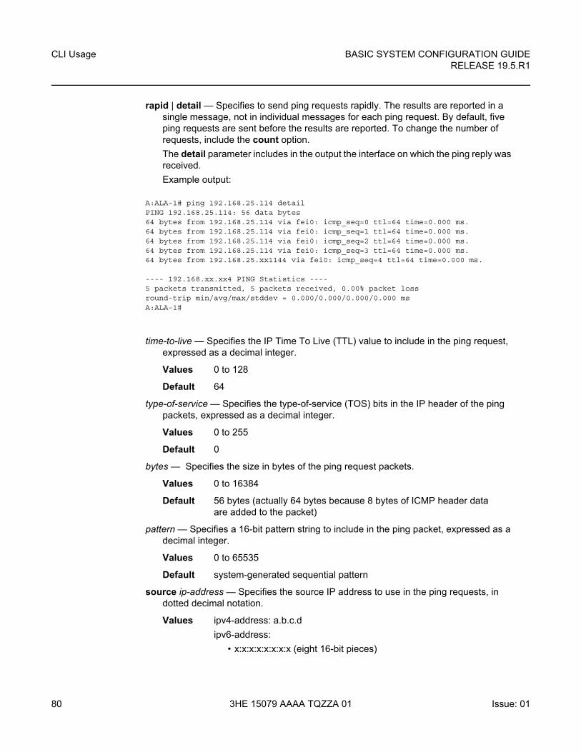
CLI Usage
80
BASIC SYSTEM CONFIGURATION GUIDERELEASE 19.5.R1
3HE 15079 AAAA TQZZA 01 Issue: 01
rapid | detail — Specifies to send ping requests rapidly. The results are reported in a single message, not in individual messages for each ping request. By default, five ping requests are sent before the results are reported. To change the number of requests, include the count option.
The detail parameter includes in the output the interface on which the ping reply was received.
Example output:
A:ALA-1# ping 192.168.25.114 detailPING 192.168.25.114: 56 data bytes64 bytes from 192.168.25.114 via fei0: icmp_seq=0 ttl=64 time=0.000 ms.64 bytes from 192.168.25.114 via fei0: icmp_seq=1 ttl=64 time=0.000 ms.64 bytes from 192.168.25.114 via fei0: icmp_seq=2 ttl=64 time=0.000 ms.64 bytes from 192.168.25.114 via fei0: icmp_seq=3 ttl=64 time=0.000 ms.64 bytes from 192.168.25.xx1144 via fei0: icmp_seq=4 ttl=64 time=0.000 ms.
---- 192.168.xx.xx4 PING Statistics ----5 packets transmitted, 5 packets received, 0.00% packet lossround-trip min/avg/max/stddev = 0.000/0.000/0.000/0.000 msA:ALA-1#
time-to-live — Specifies the IP Time To Live (TTL) value to include in the ping request, expressed as a decimal integer.
Values 0 to 128
Default 64
type-of-service — Specifies the type-of-service (TOS) bits in the IP header of the ping packets, expressed as a decimal integer.
Values 0 to 255
Default 0
bytes — Specifies the size in bytes of the ping request packets.
Values 0 to 16384
Default 56 bytes (actually 64 bytes because 8 bytes of ICMP header data are added to the packet)
pattern — Specifies a 16-bit pattern string to include in the ping packet, expressed as a decimal integer.
Values 0 to 65535
Default system-generated sequential pattern
source ip-address — Specifies the source IP address to use in the ping requests, in dotted decimal notation.
Values ipv4-address: a.b.c.d
ipv6-address:
• x:x:x:x:x:x:x:x (eight 16-bit pieces)

BASIC SYSTEM CONFIGURATION GUIDE RELEASE 19.5.R1
CLI Usage
Issue: 01 3HE 15079 AAAA TQZZA 01 81
• x:x:x:x:x:x:d.d.d.d
• x: [0 to FFFF] H
• d: [0 to 255] D
Default The IP address of the egress IP interface.
centisecs | secs — The interval between consecutive ping requests, expressed as a decimal integer.
Values 1 to 10000 seconds; if “rapid” is selected, 1 to 10000 centiseconds
Default 1 second; if “rapid” is selected, 1 centisecond
next-hop ip-address — Disregards the routing table and will send this packet to the specified next hop address. This address must be on an adjacent router that is attached to a subnet that is common between this and the next-hop router.
Values ipv4-address: a.b.c.d
ipv6-address:
• x:x:x:x:x:x:x:x (eight 16-bit pieces)
• x:x:x:x:x:x:d.d.d.d
• x: [0 to FFFF] H
• d: [0 to 255] D
Default Per the routing table.
interface-name — Specifies the interface name. 32 characters maximum.
bypass-routing — Sends the ping request to a host on a directly attached network bypassing the routing table. The host must be on a directly attached network or an error is returned.
requests — Specifies the number of ping requests to send to the remote host, expressed as a decimal integer.
Values 1 to 10000
Default 5
do-not-fragment — Specifies that the request frame should not be fragmented. This option is particularly useful in combination with the size parameter for maximum MTU determination (does not apply to ICMPv6).
router-instance — Specifies the router name, CPM router instance, or service ID.
Values
Default Base
router-instance: router name or service-id
router-name “Base” | “management” | cpm-vr-name | “vpls-management”
cpm-vr-name up to 32 characters
vprn-service-id 1 to 2147483647
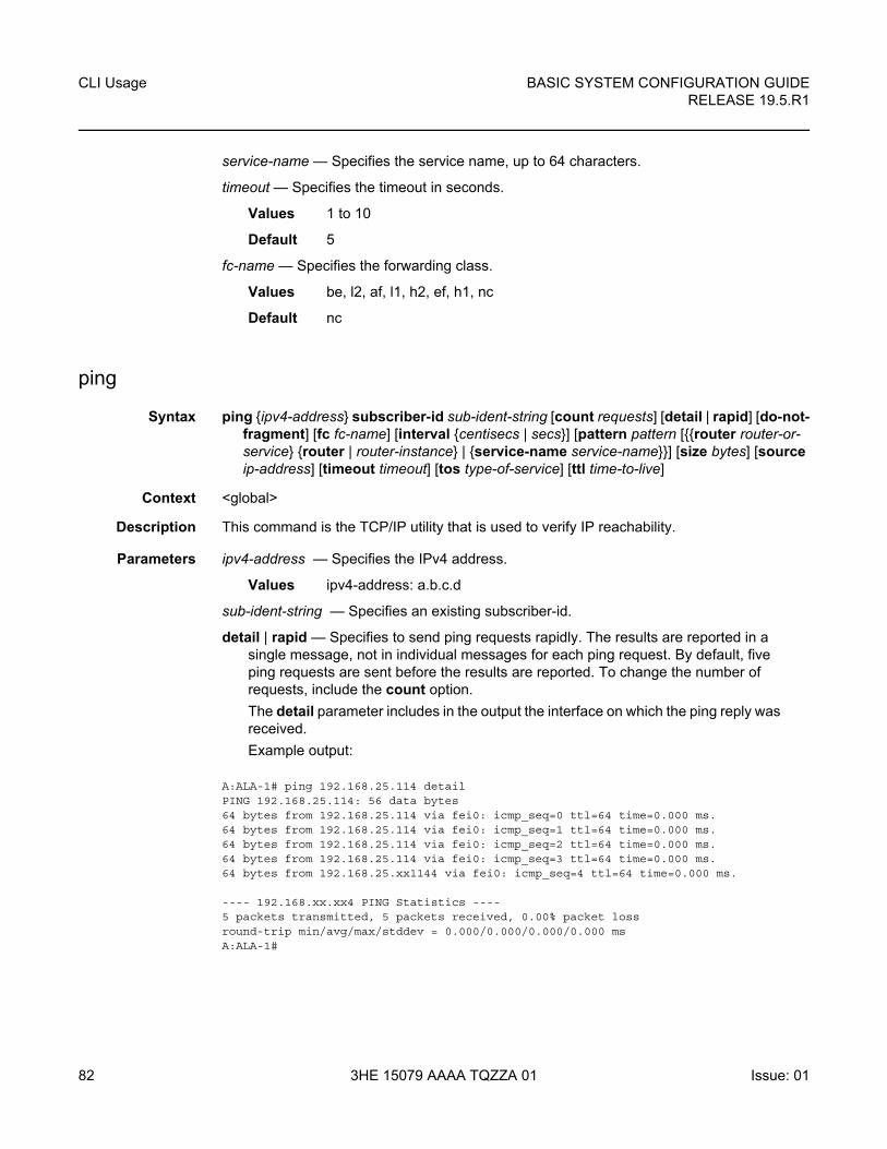
CLI Usage
82
BASIC SYSTEM CONFIGURATION GUIDERELEASE 19.5.R1
3HE 15079 AAAA TQZZA 01 Issue: 01
service-name — Specifies the service name, up to 64 characters.
timeout — Specifies the timeout in seconds.
Values 1 to 10
Default 5
fc-name — Specifies the forwarding class.
Values be, l2, af, l1, h2, ef, h1, nc
Default nc
ping
Syntax ping {ipv4-address} subscriber-id sub-ident-string [count requests] [detail | rapid] [do-not-fragment] [fc fc-name] [interval {centisecs | secs}] [pattern pattern [{{router router-or-service} {router | router-instance} | {service-name service-name}}] [size bytes] [source ip-address] [timeout timeout] [tos type-of-service] [ttl time-to-live]
Context <global>
Description This command is the TCP/IP utility that is used to verify IP reachability.
Parameters ipv4-address — Specifies the IPv4 address.
Values ipv4-address: a.b.c.d
sub-ident-string — Specifies an existing subscriber-id.
detail | rapid — Specifies to send ping requests rapidly. The results are reported in a single message, not in individual messages for each ping request. By default, five ping requests are sent before the results are reported. To change the number of requests, include the count option.
The detail parameter includes in the output the interface on which the ping reply was received.
Example output:
A:ALA-1# ping 192.168.25.114 detailPING 192.168.25.114: 56 data bytes64 bytes from 192.168.25.114 via fei0: icmp_seq=0 ttl=64 time=0.000 ms.64 bytes from 192.168.25.114 via fei0: icmp_seq=1 ttl=64 time=0.000 ms.64 bytes from 192.168.25.114 via fei0: icmp_seq=2 ttl=64 time=0.000 ms.64 bytes from 192.168.25.114 via fei0: icmp_seq=3 ttl=64 time=0.000 ms.64 bytes from 192.168.25.xx1144 via fei0: icmp_seq=4 ttl=64 time=0.000 ms.
---- 192.168.xx.xx4 PING Statistics ----5 packets transmitted, 5 packets received, 0.00% packet lossround-trip min/avg/max/stddev = 0.000/0.000/0.000/0.000 msA:ALA-1#
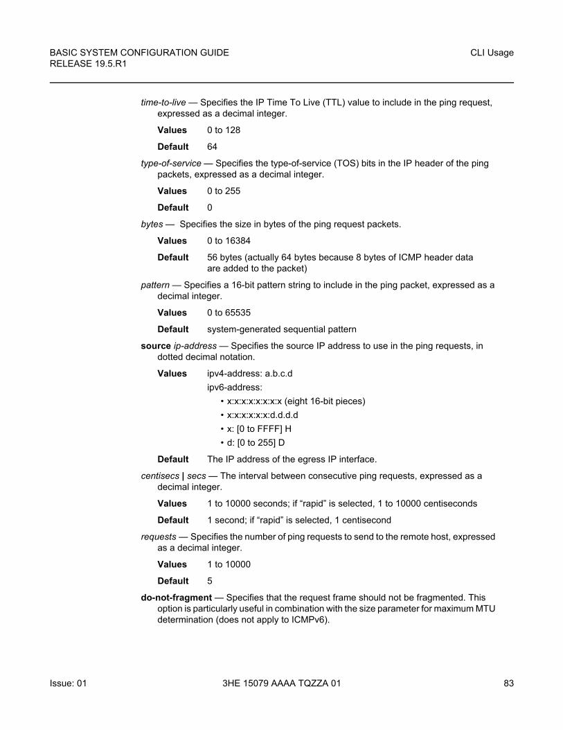
BASIC SYSTEM CONFIGURATION GUIDE RELEASE 19.5.R1
CLI Usage
Issue: 01 3HE 15079 AAAA TQZZA 01 83
time-to-live — Specifies the IP Time To Live (TTL) value to include in the ping request, expressed as a decimal integer.
Values 0 to 128
Default 64
type-of-service — Specifies the type-of-service (TOS) bits in the IP header of the ping packets, expressed as a decimal integer.
Values 0 to 255
Default 0
bytes — Specifies the size in bytes of the ping request packets.
Values 0 to 16384
Default 56 bytes (actually 64 bytes because 8 bytes of ICMP header data are added to the packet)
pattern — Specifies a 16-bit pattern string to include in the ping packet, expressed as a decimal integer.
Values 0 to 65535
Default system-generated sequential pattern
source ip-address — Specifies the source IP address to use in the ping requests, in dotted decimal notation.
Values ipv4-address: a.b.c.d
ipv6-address:
• x:x:x:x:x:x:x:x (eight 16-bit pieces)
• x:x:x:x:x:x:d.d.d.d
• x: [0 to FFFF] H
• d: [0 to 255] D
Default The IP address of the egress IP interface.
centisecs | secs — The interval between consecutive ping requests, expressed as a decimal integer.
Values 1 to 10000 seconds; if “rapid” is selected, 1 to 10000 centiseconds
Default 1 second; if “rapid” is selected, 1 centisecond
requests — Specifies the number of ping requests to send to the remote host, expressed as a decimal integer.
Values 1 to 10000
Default 5
do-not-fragment — Specifies that the request frame should not be fragmented. This option is particularly useful in combination with the size parameter for maximum MTU determination (does not apply to ICMPv6).
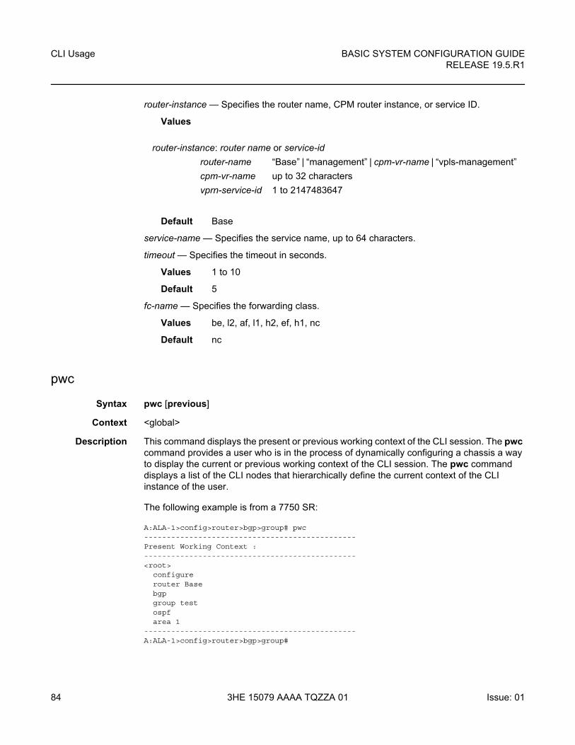
CLI Usage
84
BASIC SYSTEM CONFIGURATION GUIDERELEASE 19.5.R1
3HE 15079 AAAA TQZZA 01 Issue: 01
router-instance — Specifies the router name, CPM router instance, or service ID.
Values
Default Base
service-name — Specifies the service name, up to 64 characters.
timeout — Specifies the timeout in seconds.
Values 1 to 10
Default 5
fc-name — Specifies the forwarding class.
Values be, l2, af, l1, h2, ef, h1, nc
Default nc
pwc
Syntax pwc [previous]
Context <global>
Description This command displays the present or previous working context of the CLI session. The pwc command provides a user who is in the process of dynamically configuring a chassis a way to display the current or previous working context of the CLI session. The pwc command displays a list of the CLI nodes that hierarchically define the current context of the CLI instance of the user.
The following example is from a 7750 SR:
A:ALA-1>config>router>bgp>group# pwc-----------------------------------------------Present Working Context :-----------------------------------------------<root>
configurerouter Basebgpgroup testospfarea 1
-----------------------------------------------A:ALA-1>config>router>bgp>group#
router-instance: router name or service-id
router-name “Base” | “management” | cpm-vr-name | “vpls-management”
cpm-vr-name up to 32 characters
vprn-service-id 1 to 2147483647
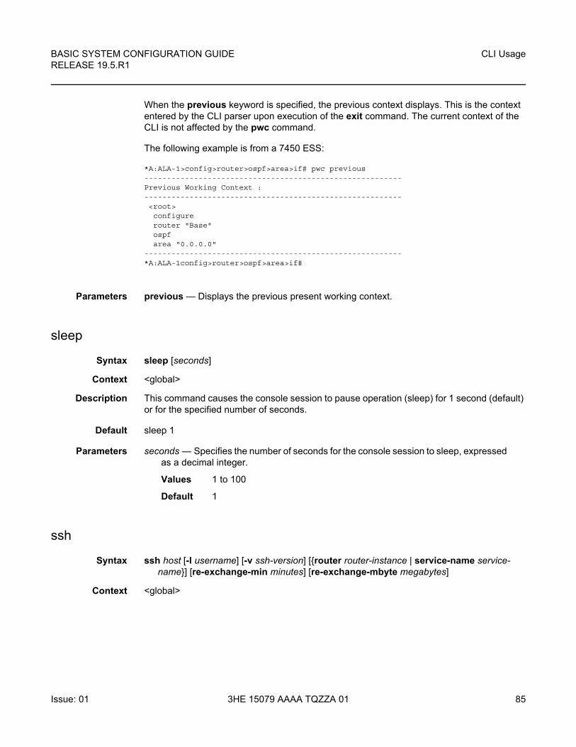
BASIC SYSTEM CONFIGURATION GUIDE RELEASE 19.5.R1
CLI Usage
Issue: 01 3HE 15079 AAAA TQZZA 01 85
When the previous keyword is specified, the previous context displays. This is the context entered by the CLI parser upon execution of the exit command. The current context of the CLI is not affected by the pwc command.
The following example is from a 7450 ESS:
*A:ALA-1>config>router>ospf>area>if# pwc previous---------------------------------------------------------Previous Working Context :---------------------------------------------------------<root>configurerouter "Base"ospfarea "0.0.0.0"
---------------------------------------------------------*A:ALA-1config>router>ospf>area>if#
Parameters previous — Displays the previous present working context.
sleep
Syntax sleep [seconds]
Context <global>
Description This command causes the console session to pause operation (sleep) for 1 second (default) or for the specified number of seconds.
Default sleep 1
Parameters seconds — Specifies the number of seconds for the console session to sleep, expressed as a decimal integer.
Values 1 to 100
Default 1
ssh
Syntax ssh host [-l username] [-v ssh-version] [{router router-instance | service-name service-name}] [re-exchange-min minutes] [re-exchange-mbyte megabytes]
Context <global>
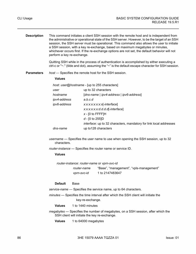
CLI Usage
86
BASIC SYSTEM CONFIGURATION GUIDERELEASE 19.5.R1
3HE 15079 AAAA TQZZA 01 Issue: 01
Description This command initiates a client SSH session with the remote host and is independent from the administrative or operational state of the SSH server. However, to be the target of an SSH session, the SSH server must be operational. This command also allows the user to initiate a SSH session, with a key re-exchange, based on maximum megabytes or minutes, whichever occurs first. If the re-exchange options are not set, the default behavior will not perform a key re-exchange.
Quitting SSH while in the process of authentication is accomplished by either executing a ctrl-c or "~." (tilde and dot), assuming the “~” is the default escape character for SSH session.
Parameters host — Specifies the remote host for the SSH session.
Values
username — Specifies the user name to use when opening the SSH session, up to 32 characters.
router-instance — Specifies the router name or service ID.
Values
Default Base
service-name — Specifies the service name, up to 64 characters.
minutes — Specifies the time interval after which the SSH client will initiate the
key-re-exchange.
Values 1 to 1440 minutes
megabytes — Specifies the number of megabytes, on a SSH session, after which the SSH client will initiate the key re-exchange.
Values 1 to 64000 megabytes
host: user@hostname - [up to 255 characters]
user up to 32 characters
hostname [dns-name | ipv4-address | ipv6-address]
ipv4-address a.b.c.d
ipv6-address x:x:x:x:x:x:x:x[-interface]
x:x:x:x:x:x:d.d.d.d[-interface]
x - [0 to FFFF]H
d - [0 to 255]D
interface: up to 32 characters, mandatory for link local addresses
dns-name up to128 characters
router-instance: router-name or vprn-svc-id
router-name “Base”, “management”, “vpls-management”
vprn-svc-id 1 to 2147483647
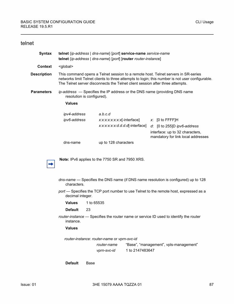
BASIC SYSTEM CONFIGURATION GUIDE RELEASE 19.5.R1
CLI Usage
Issue: 01 3HE 15079 AAAA TQZZA 01 87
telnet
Syntax telnet {ip-address | dns-name} [port] service-name service-name
telnet {ip-address | dns-name} [port] [router router-instance]
Context <global>
Description This command opens a Telnet session to a remote host. Telnet servers in SR-series networks limit Telnet clients to three attempts to login; this number is not user configurable. The Telnet server disconnects the Telnet client session after three attempts.
Parameters ip-address — Specifies the IP address or the DNS name (providing DNS name resolution is configured).
Values
dns-name — Specifies the DNS name (if DNS name resolution is configured) up to 128 characters.
port — Specifies the TCP port number to use Telnet to the remote host, expressed as a decimal integer.
Values 1 to 65535
Default 23
router-instance — Specifies the router name or service ID used to identify the router instance.
Values
Default Base
ipv4-address a.b.c.d
ipv6-address x:x:x:x:x:x:x:x[-interface]
x:x:x:x:x:x:d.d.d.d[-interface]
x: [0 to FFFF]H
d: [0 to 255]D ipv6-address
interface: up to 32 characters, mandatory for link local addresses
dns-name up to 128 characters
Note: IPv6 applies to the 7750 SR and 7950 XRS.
router-instance: router-name or vprn-svc-id
router-name “Base”, “management”, vpls-management”
vprn-svc-id 1 to 2147483647
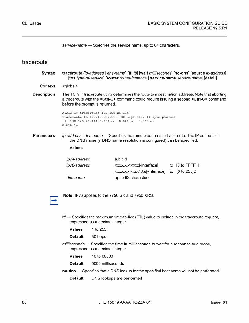
CLI Usage
88
BASIC SYSTEM CONFIGURATION GUIDERELEASE 19.5.R1
3HE 15079 AAAA TQZZA 01 Issue: 01
service-name — Specifies the service name, up to 64 characters.
traceroute
Syntax traceroute {ip-address | dns-name} [ttl ttl] [wait milliseconds] [no-dns] [source ip-address] [tos type-of-service] [router router-instance | service-name service-name] [detail]
Context <global>
Description The TCP/IP traceroute utility determines the route to a destination address. Note that aborting a traceroute with the <Ctrl-C> command could require issuing a second <Ctrl-C> command before the prompt is returned.
A:ALA-1# traceroute 192.168.25.114traceroute to 192.168.25.114, 30 hops max, 40 byte packets1 192.168.25.114 0.000 ms 0.000 ms 0.000 ms
A:ALA-1#
Parameters ip-address | dns-name — Specifies the remote address to traceroute. The IP address or the DNS name (if DNS name resolution is configured) can be specified.
Values
ttl — Specifies the maximum time-to-live (TTL) value to include in the traceroute request, expressed as a decimal integer.
Values 1 to 255
Default 30 hops
milliseconds — Specifies the time in milliseconds to wait for a response to a probe, expressed as a decimal integer.
Values 10 to 60000
Default 5000 milliseconds
no-dns — Specifies that a DNS lookup for the specified host name will not be performed.
Default DNS lookups are performed
ipv4-address a.b.c.d
ipv6-address x:x:x:x:x:x:x:x[-interface]
x:x:x:x:x:x:d.d.d.d[-interface]
x: [0 to FFFF]H
d: [0 to 255]D
dns-name up to 63 characters
Note: IPv6 applies to the 7750 SR and 7950 XRS.
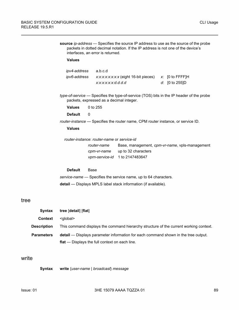
BASIC SYSTEM CONFIGURATION GUIDE RELEASE 19.5.R1
CLI Usage
Issue: 01 3HE 15079 AAAA TQZZA 01 89
source ip-address — Specifies the source IP address to use as the source of the probe packets in dotted decimal notation. If the IP address is not one of the device’s interfaces, an error is returned.
Values
type-of-service — Specifies the type-of-service (TOS) bits in the IP header of the probe packets, expressed as a decimal integer.
Values 0 to 255
Default 0
router-instance — Specifies the router name, CPM router instance, or service ID.
Values
Default Base
service-name — Specifies the service name, up to 64 characters.
detail — Displays MPLS label stack information (if available).
tree
Syntax tree [detail] [flat]
Context <global>
Description This command displays the command hierarchy structure of the current working context.
Parameters detail — Displays parameter information for each command shown in the tree output.
flat — Displays the full context on each line.
write
Syntax write {user-name | broadcast} message
ipv4-address a.b.c.d
ipv6-address x:x:x:x:x:x:x:x (eight 16-bit pieces)
x:x:x:x:x:x:d.d.d.d
x: [0 to FFFF]H
d: [0 to 255]D
router-instance: router-name or service-id
router-name Base, management, cpm-vr-name, vpls-management
cpm-vr-name up to 32 characters
vprn-service-id 1 to 2147483647

CLI Usage
90
BASIC SYSTEM CONFIGURATION GUIDERELEASE 19.5.R1
3HE 15079 AAAA TQZZA 01 Issue: 01
Context <global>
Description This command sends a console message to a specific user or to all users with active console sessions.
Parameters user-name — Specifies the name of a user, up to 32 characters, with an active console session to which to send a console message.
Values any valid CLI username
broadcast — Sends the message-string to all users logged into the router.
message — Specifies the message string to send. Allowed values are any string, up to 256 characters, composed of printable, 7-bit ASCII characters. If the string contains special characters (#, $, spaces, and so on), the entire string must be enclosed within double quotes.
2.12.2.2 Monitor CLI Commands
card
Syntax card slot-number fp fp-number ingress {access | network} queue-group queue-group-name instance instance-id [interval seconds] [repeat repeat] policer policer-id [absolute | percent-rate | reference-rate]
Context monitor
Description This command monitors policer statistics in an ingress FP queue group.
Parameters slot-number — Specifies the slot number associated with the queue group, expressed as an integer.
Values 1 to 10
fp-number — Specifies the FP number associated with the queue group, expressed as an integer.
Values 1 to 8
ingress — Displays policer statistics applied on the ingress FP.
access — Displays policer statistics on the FP access.
network — Displays policer statistics on the FP network.
queue-group-name — Specifies the name of the queue group up, to 32 characters.
instance-id — Specifies the identification of a specific instance of the queue-group.
Values 1 to 65535

BASIC SYSTEM CONFIGURATION GUIDE RELEASE 19.5.R1
CLI Usage
Issue: 01 3HE 15079 AAAA TQZZA 01 91
repeat — Configures how many times the command is repeated.
Values 1 to 999
Default 10
policer-id — Specifies the policer ID; must exist within the queue-group template applied to the ingress context of the forwarding plane.
Values 1 to 32
absolute — Displays Raw statistics, without processing. No calculations are performed on the delta or rate statistics.
percent-rate — Displays rate-per-second for each statistic based on the reference rate of 10G.
Values 1 to 999
Default 10
reference-rate — Displays rate-per-second for each statistic as a percentage based on the reference rate specified.
Values 100M, 1G, 10G, 40G, 100G, 400G
Default 10G
ccag
Syntax ccag ccag-id [path path-id] [type type] [interval seconds] [repeat repeat] [absolute | rate]
Context monitor
Description Displays monitor command output of traffic statistics for Cross Connect Aggregation Groups (CCAGs) ports.
Parameters ccag-id — Specifies the CCAG instance to monitor.
Values 1 to 8
path-id — Specifies the CCA path nodal context where the CCA path bandwidth, buffer and accounting parameters are maintained. The path context must be specified with either the a or b keyword specifying the CCA path context to be entered.
Values a, b
type — Specifies cross connect type.
Values sap-sap, sap-net, net-sap
seconds — Configures the interval for each display in seconds.
Values 3 to 60
Default 10 seconds
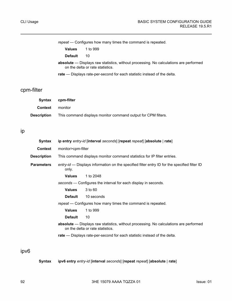
CLI Usage
92
BASIC SYSTEM CONFIGURATION GUIDERELEASE 19.5.R1
3HE 15079 AAAA TQZZA 01 Issue: 01
repeat — Configures how many times the command is repeated.
Values 1 to 999
Default 10
absolute — Displays raw statistics, without processing. No calculations are performed on the delta or rate statistics.
rate — Displays rate-per-second for each statistic instead of the delta.
cpm-filter
Syntax cpm-filter
Context monitor
Description This command displays monitor command output for CPM filters.
ip
Syntax ip entry entry-id [interval seconds] [repeat repeat] [absolute | rate]
Context monitor>cpm-filter
Description This command displays monitor command statistics for IP filter entries.
Parameters entry-id — Displays information on the specified filter entry ID for the specified filter ID only.
Values 1 to 2048
seconds — Configures the interval for each display in seconds.
Values 3 to 60
Default 10 seconds
repeat — Configures how many times the command is repeated.
Values 1 to 999
Default 10
absolute — Displays raw statistics, without processing. No calculations are performed on the delta or rate statistics.
rate — Displays rate-per-second for each statistic instead of the delta.
ipv6
Syntax ipv6 entry entry-id [interval seconds] [repeat repeat] [absolute | rate]
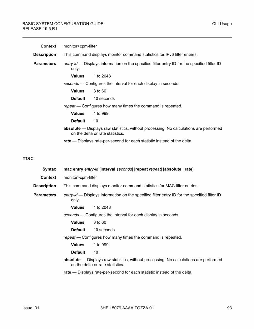
BASIC SYSTEM CONFIGURATION GUIDE RELEASE 19.5.R1
CLI Usage
Issue: 01 3HE 15079 AAAA TQZZA 01 93
Context monitor>cpm-filter
Description This command displays monitor command statistics for IPv6 filter entries.
Parameters entry-id — Displays information on the specified filter entry ID for the specified filter ID only.
Values 1 to 2048
seconds — Configures the interval for each display in seconds.
Values 3 to 60
Default 10 seconds
repeat — Configures how many times the command is repeated.
Values 1 to 999
Default 10
absolute — Displays raw statistics, without processing. No calculations are performed on the delta or rate statistics.
rate — Displays rate-per-second for each statistic instead of the delta.
mac
Syntax mac entry entry-id [interval seconds] [repeat repeat] [absolute | rate]
Context monitor>cpm-filter
Description This command displays monitor command statistics for MAC filter entries.
Parameters entry-id — Displays information on the specified filter entry ID for the specified filter ID only.
Values 1 to 2048
seconds — Configures the interval for each display in seconds.
Values 3 to 60
Default 10 seconds
repeat — Configures how many times the command is repeated.
Values 1 to 999
Default 10
absolute — Displays raw statistics, without processing. No calculations are performed on the delta or rate statistics.
rate — Displays rate-per-second for each statistic instead of the delta.
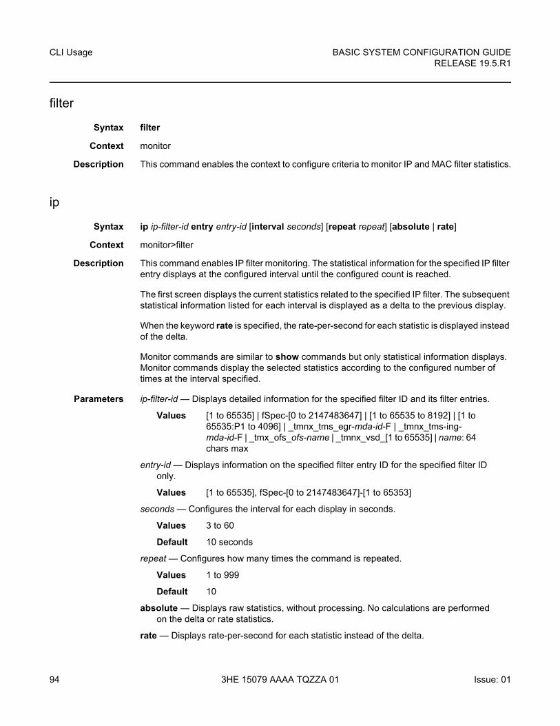
CLI Usage
94
BASIC SYSTEM CONFIGURATION GUIDERELEASE 19.5.R1
3HE 15079 AAAA TQZZA 01 Issue: 01
filter
Syntax filter
Context monitor
Description This command enables the context to configure criteria to monitor IP and MAC filter statistics.
ip
Syntax ip ip-filter-id entry entry-id [interval seconds] [repeat repeat] [absolute | rate]
Context monitor>filter
Description This command enables IP filter monitoring. The statistical information for the specified IP filter entry displays at the configured interval until the configured count is reached.
The first screen displays the current statistics related to the specified IP filter. The subsequent statistical information listed for each interval is displayed as a delta to the previous display.
When the keyword rate is specified, the rate-per-second for each statistic is displayed instead of the delta.
Monitor commands are similar to show commands but only statistical information displays. Monitor commands display the selected statistics according to the configured number of times at the interval specified.
Parameters ip-filter-id — Displays detailed information for the specified filter ID and its filter entries.
Values [1 to 65535] | fSpec-[0 to 2147483647] | [1 to 65535 to 8192] | [1 to 65535:P1 to 4096] | _tmnx_tms_egr-mda-id-F | _tmnx_tms-ing-mda-id-F | _tmx_ofs_ofs-name | _tmnx_vsd_[1 to 65535] | name: 64 chars max
entry-id — Displays information on the specified filter entry ID for the specified filter ID only.
Values [1 to 65535], fSpec-[0 to 2147483647]-[1 to 65353]
seconds — Configures the interval for each display in seconds.
Values 3 to 60
Default 10 seconds
repeat — Configures how many times the command is repeated.
Values 1 to 999
Default 10
absolute — Displays raw statistics, without processing. No calculations are performed on the delta or rate statistics.
rate — Displays rate-per-second for each statistic instead of the delta.
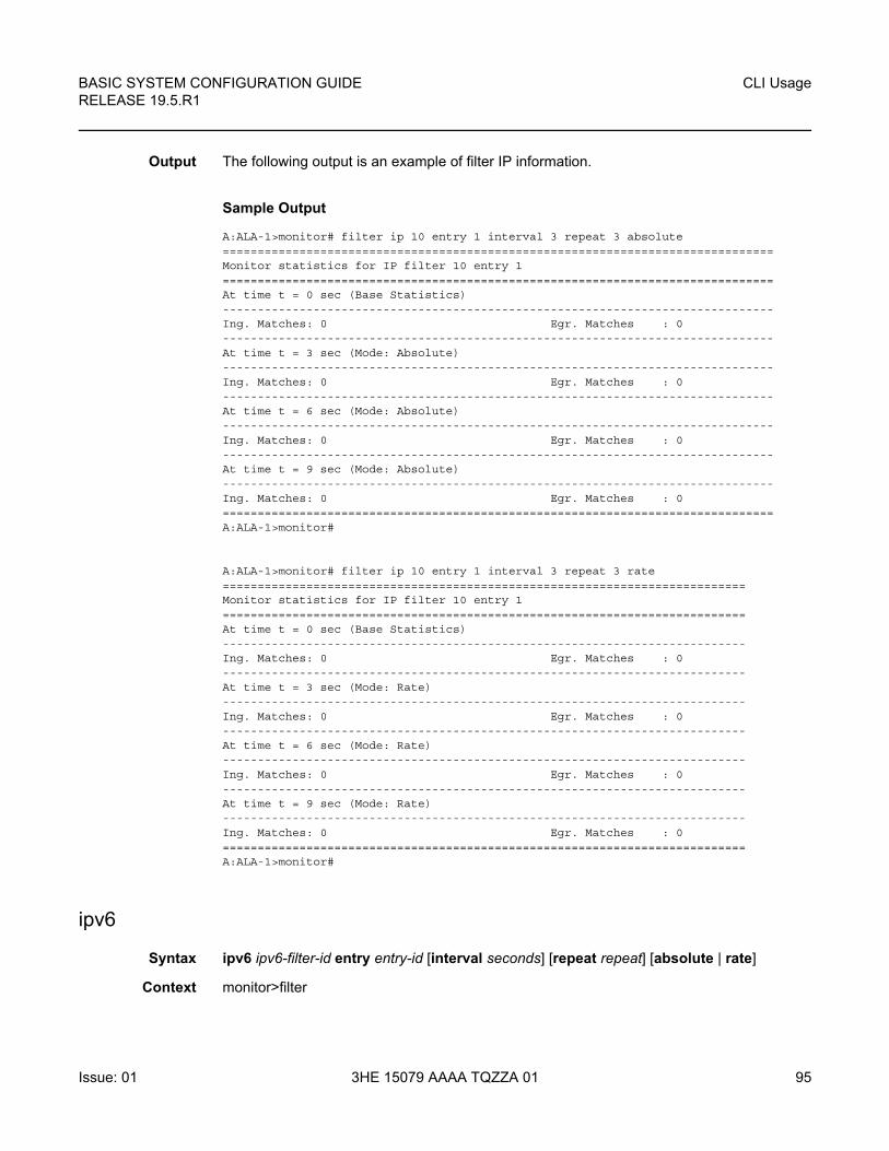
BASIC SYSTEM CONFIGURATION GUIDE RELEASE 19.5.R1
CLI Usage
Issue: 01 3HE 15079 AAAA TQZZA 01 95
Output The following output is an example of filter IP information.
Sample Output
A:ALA-1>monitor# filter ip 10 entry 1 interval 3 repeat 3 absolute===============================================================================Monitor statistics for IP filter 10 entry 1===============================================================================At time t = 0 sec (Base Statistics)-------------------------------------------------------------------------------Ing. Matches: 0 Egr. Matches : 0-------------------------------------------------------------------------------At time t = 3 sec (Mode: Absolute)-------------------------------------------------------------------------------Ing. Matches: 0 Egr. Matches : 0-------------------------------------------------------------------------------At time t = 6 sec (Mode: Absolute)-------------------------------------------------------------------------------Ing. Matches: 0 Egr. Matches : 0-------------------------------------------------------------------------------At time t = 9 sec (Mode: Absolute)-------------------------------------------------------------------------------Ing. Matches: 0 Egr. Matches : 0===============================================================================A:ALA-1>monitor#
A:ALA-1>monitor# filter ip 10 entry 1 interval 3 repeat 3 rate===========================================================================Monitor statistics for IP filter 10 entry 1===========================================================================At time t = 0 sec (Base Statistics)---------------------------------------------------------------------------Ing. Matches: 0 Egr. Matches : 0---------------------------------------------------------------------------At time t = 3 sec (Mode: Rate)---------------------------------------------------------------------------Ing. Matches: 0 Egr. Matches : 0---------------------------------------------------------------------------At time t = 6 sec (Mode: Rate)---------------------------------------------------------------------------Ing. Matches: 0 Egr. Matches : 0---------------------------------------------------------------------------At time t = 9 sec (Mode: Rate)---------------------------------------------------------------------------Ing. Matches: 0 Egr. Matches : 0===========================================================================A:ALA-1>monitor#
ipv6
Syntax ipv6 ipv6-filter-id entry entry-id [interval seconds] [repeat repeat] [absolute | rate]
Context monitor>filter
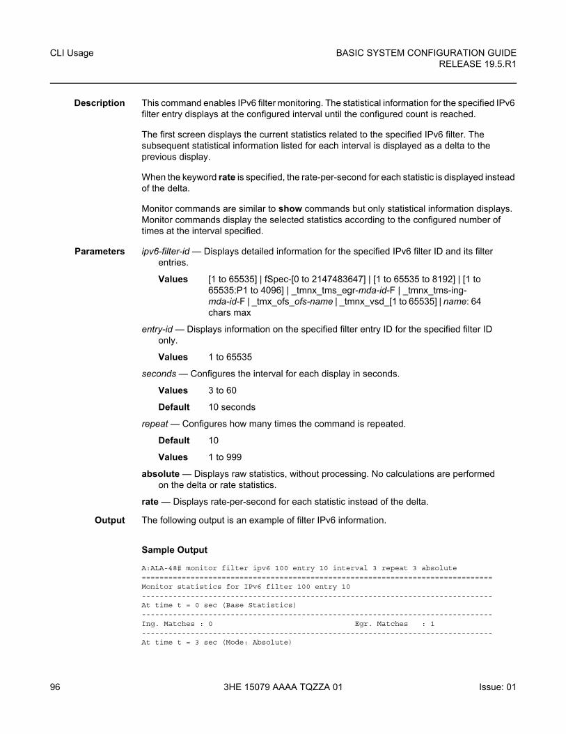
CLI Usage
96
BASIC SYSTEM CONFIGURATION GUIDERELEASE 19.5.R1
3HE 15079 AAAA TQZZA 01 Issue: 01
Description This command enables IPv6 filter monitoring. The statistical information for the specified IPv6 filter entry displays at the configured interval until the configured count is reached.
The first screen displays the current statistics related to the specified IPv6 filter. The subsequent statistical information listed for each interval is displayed as a delta to the previous display.
When the keyword rate is specified, the rate-per-second for each statistic is displayed instead of the delta.
Monitor commands are similar to show commands but only statistical information displays. Monitor commands display the selected statistics according to the configured number of times at the interval specified.
Parameters ipv6-filter-id — Displays detailed information for the specified IPv6 filter ID and its filter entries.
Values [1 to 65535] | fSpec-[0 to 2147483647] | [1 to 65535 to 8192] | [1 to 65535:P1 to 4096] | _tmnx_tms_egr-mda-id-F | _tmnx_tms-ing-mda-id-F | _tmx_ofs_ofs-name | _tmnx_vsd_[1 to 65535] | name: 64 chars max
entry-id — Displays information on the specified filter entry ID for the specified filter ID only.
Values 1 to 65535
seconds — Configures the interval for each display in seconds.
Values 3 to 60
Default 10 seconds
repeat — Configures how many times the command is repeated.
Default 10
Values 1 to 999
absolute — Displays raw statistics, without processing. No calculations are performed on the delta or rate statistics.
rate — Displays rate-per-second for each statistic instead of the delta.
Output The following output is an example of filter IPv6 information.
Sample Output
A:ALA-48# monitor filter ipv6 100 entry 10 interval 3 repeat 3 absolute===============================================================================Monitor statistics for IPv6 filter 100 entry 10-------------------------------------------------------------------------------At time t = 0 sec (Base Statistics)-------------------------------------------------------------------------------Ing. Matches : 0 Egr. Matches : 1-------------------------------------------------------------------------------At time t = 3 sec (Mode: Absolute)
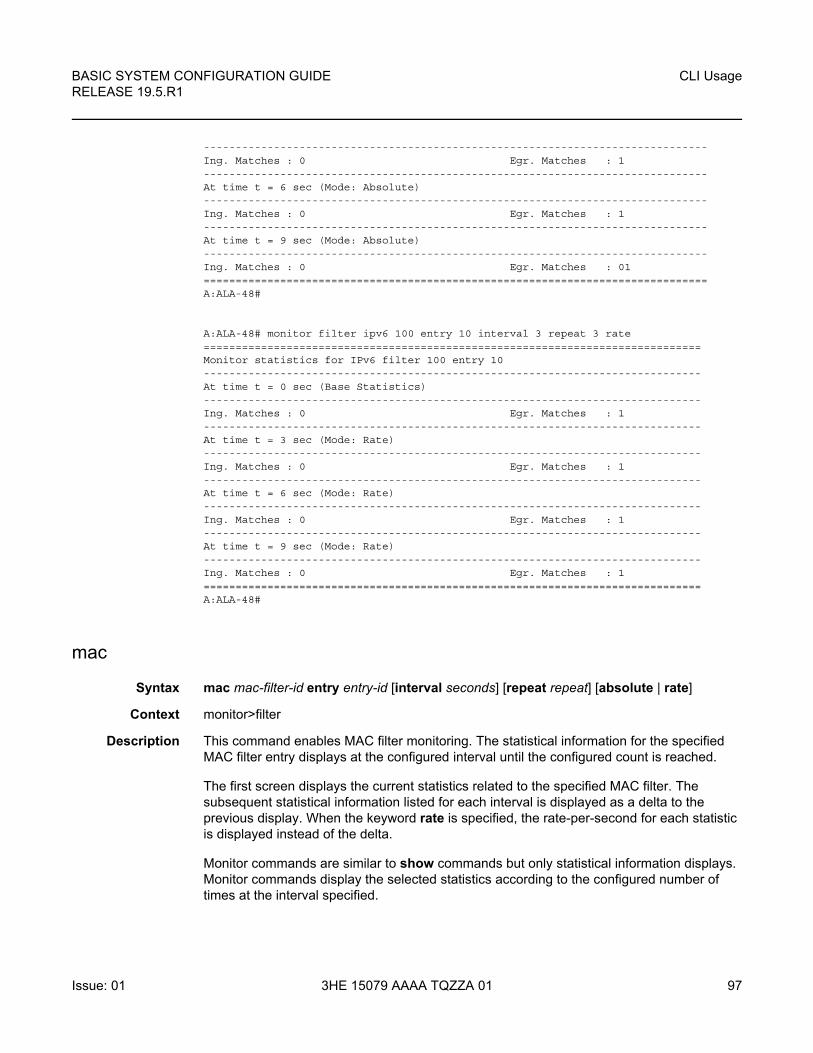
BASIC SYSTEM CONFIGURATION GUIDE RELEASE 19.5.R1
CLI Usage
Issue: 01 3HE 15079 AAAA TQZZA 01 97
-------------------------------------------------------------------------------Ing. Matches : 0 Egr. Matches : 1-------------------------------------------------------------------------------At time t = 6 sec (Mode: Absolute)-------------------------------------------------------------------------------Ing. Matches : 0 Egr. Matches : 1-------------------------------------------------------------------------------At time t = 9 sec (Mode: Absolute)-------------------------------------------------------------------------------Ing. Matches : 0 Egr. Matches : 01===============================================================================A:ALA-48#
A:ALA-48# monitor filter ipv6 100 entry 10 interval 3 repeat 3 rate==============================================================================Monitor statistics for IPv6 filter 100 entry 10------------------------------------------------------------------------------At time t = 0 sec (Base Statistics)------------------------------------------------------------------------------Ing. Matches : 0 Egr. Matches : 1------------------------------------------------------------------------------At time t = 3 sec (Mode: Rate)------------------------------------------------------------------------------Ing. Matches : 0 Egr. Matches : 1------------------------------------------------------------------------------At time t = 6 sec (Mode: Rate)------------------------------------------------------------------------------Ing. Matches : 0 Egr. Matches : 1------------------------------------------------------------------------------At time t = 9 sec (Mode: Rate)------------------------------------------------------------------------------Ing. Matches : 0 Egr. Matches : 1==============================================================================A:ALA-48#
mac
Syntax mac mac-filter-id entry entry-id [interval seconds] [repeat repeat] [absolute | rate]
Context monitor>filter
Description This command enables MAC filter monitoring. The statistical information for the specified MAC filter entry displays at the configured interval until the configured count is reached.
The first screen displays the current statistics related to the specified MAC filter. The subsequent statistical information listed for each interval is displayed as a delta to the previous display. When the keyword rate is specified, the rate-per-second for each statistic is displayed instead of the delta.
Monitor commands are similar to show commands but only statistical information displays. Monitor commands display the selected statistics according to the configured number of times at the interval specified.
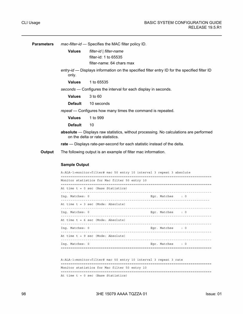
CLI Usage
98
BASIC SYSTEM CONFIGURATION GUIDERELEASE 19.5.R1
3HE 15079 AAAA TQZZA 01 Issue: 01
Parameters mac-filter-id — Specifies the MAC filter policy ID.
Values filter-id | filter-name
filter-id: 1 to 65535
filter-name: 64 chars max
entry-id — Displays information on the specified filter entry ID for the specified filter ID only.
Values 1 to 65535
seconds — Configures the interval for each display in seconds.
Values 3 to 60
Default 10 seconds
repeat — Configures how many times the command is repeated.
Values 1 to 999
Default 10
absolute — Displays raw statistics, without processing. No calculations are performed on the delta or rate statistics.
rate — Displays rate-per-second for each statistic instead of the delta.
Output The following output is an example of filter mac information.
Sample Output
A:ALA-1>monitor>filter# mac 50 entry 10 interval 3 repeat 3 absolute===============================================================================Monitor statistics for Mac filter 50 entry 10===============================================================================At time t = 0 sec (Base Statistics)-------------------------------------------------------------------------------Ing. Matches: 0 Egr. Matches : 0------------------------------------------------------------------------------At time t = 3 sec (Mode: Absolute)-------------------------------------------------------------------------------Ing. Matches: 0 Egr. Matches : 0-------------------------------------------------------------------------------At time t = 6 sec (Mode: Absolute)-------------------------------------------------------------------------------Ing. Matches: 0 Egr. Matches : 0-------------------------------------------------------------------------------At time t = 9 sec (Mode: Absolute)-------------------------------------------------------------------------------Ing. Matches: 0 Egr. Matches : 0===============================================================================
A:ALA-1>monitor>filter# mac 50 entry 10 interval 3 repeat 3 rate===============================================================================Monitor statistics for Mac filter 50 entry 10===============================================================================At time t = 0 sec (Base Statistics)
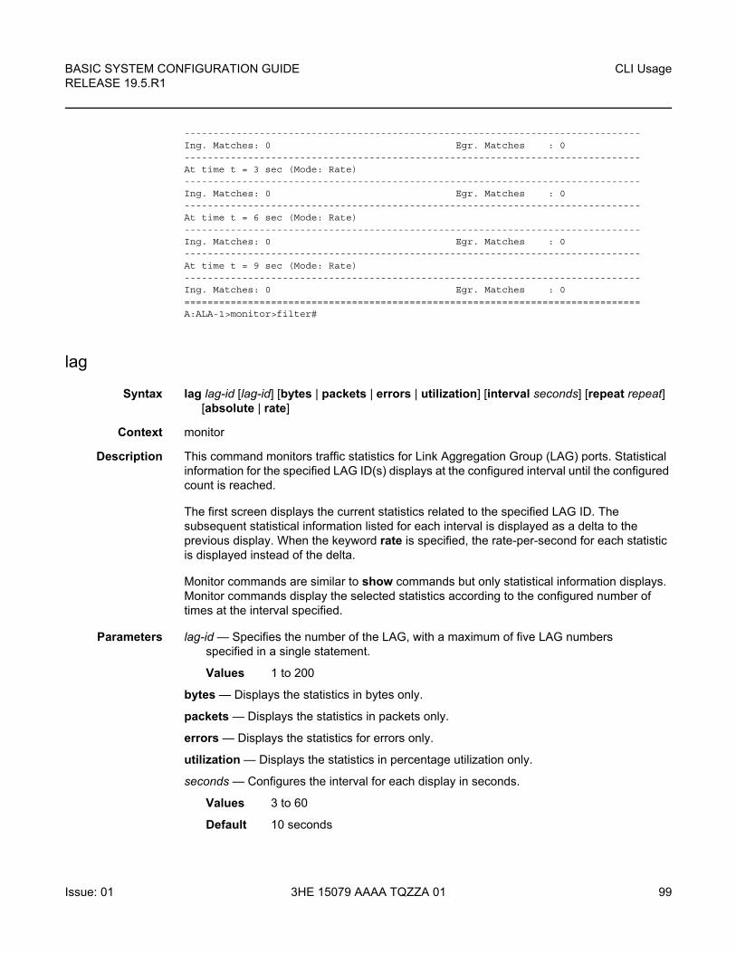
BASIC SYSTEM CONFIGURATION GUIDE RELEASE 19.5.R1
CLI Usage
Issue: 01 3HE 15079 AAAA TQZZA 01 99
-------------------------------------------------------------------------------Ing. Matches: 0 Egr. Matches : 0-------------------------------------------------------------------------------At time t = 3 sec (Mode: Rate)-------------------------------------------------------------------------------Ing. Matches: 0 Egr. Matches : 0-------------------------------------------------------------------------------At time t = 6 sec (Mode: Rate)-------------------------------------------------------------------------------Ing. Matches: 0 Egr. Matches : 0-------------------------------------------------------------------------------At time t = 9 sec (Mode: Rate)-------------------------------------------------------------------------------Ing. Matches: 0 Egr. Matches : 0===============================================================================A:ALA-1>monitor>filter#
lag
Syntax lag lag-id [lag-id] [bytes | packets | errors | utilization] [interval seconds] [repeat repeat] [absolute | rate]
Context monitor
Description This command monitors traffic statistics for Link Aggregation Group (LAG) ports. Statistical information for the specified LAG ID(s) displays at the configured interval until the configured count is reached.
The first screen displays the current statistics related to the specified LAG ID. The subsequent statistical information listed for each interval is displayed as a delta to the previous display. When the keyword rate is specified, the rate-per-second for each statistic is displayed instead of the delta.
Monitor commands are similar to show commands but only statistical information displays. Monitor commands display the selected statistics according to the configured number of times at the interval specified.
Parameters lag-id — Specifies the number of the LAG, with a maximum of five LAG numbers specified in a single statement.
Values 1 to 200
bytes — Displays the statistics in bytes only.
packets — Displays the statistics in packets only.
errors — Displays the statistics for errors only.
utilization — Displays the statistics in percentage utilization only.
seconds — Configures the interval for each display in seconds.
Values 3 to 60
Default 10 seconds
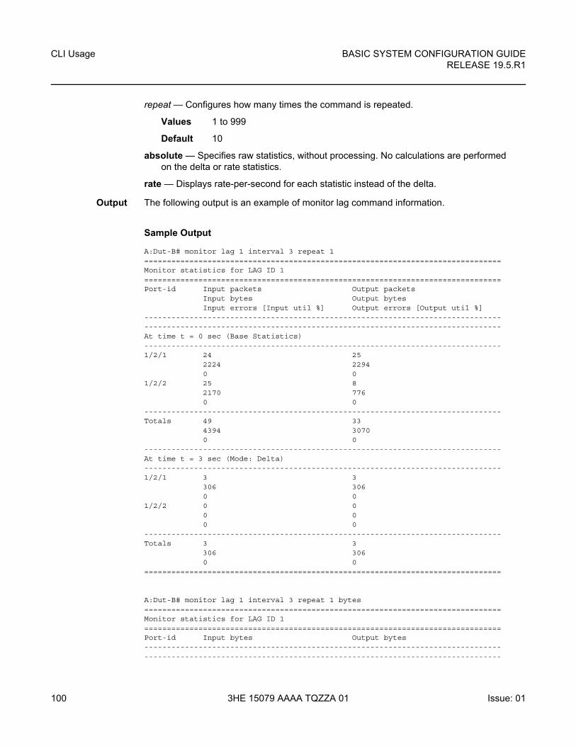
CLI Usage
100
BASIC SYSTEM CONFIGURATION GUIDERELEASE 19.5.R1
3HE 15079 AAAA TQZZA 01 Issue: 01
repeat — Configures how many times the command is repeated.
Values 1 to 999
Default 10
absolute — Specifies raw statistics, without processing. No calculations are performed on the delta or rate statistics.
rate — Displays rate-per-second for each statistic instead of the delta.
Output The following output is an example of monitor lag command information.
Sample Output
A:Dut-B# monitor lag 1 interval 3 repeat 1===============================================================================Monitor statistics for LAG ID 1===============================================================================Port-id Input packets Output packets
Input bytes Output bytesInput errors [Input util %] Output errors [Output util %]
--------------------------------------------------------------------------------------------------------------------------------------------------------------At time t = 0 sec (Base Statistics)-------------------------------------------------------------------------------1/2/1 24 25
2224 22940 0
1/2/2 25 82170 7760 0
-------------------------------------------------------------------------------Totals 49 33
4394 30700 0
-------------------------------------------------------------------------------At time t = 3 sec (Mode: Delta)-------------------------------------------------------------------------------1/2/1 3 3
306 3060 0
1/2/2 0 00 00 0
-------------------------------------------------------------------------------Totals 3 3
306 3060 0
===============================================================================
A:Dut-B# monitor lag 1 interval 3 repeat 1 bytes===============================================================================Monitor statistics for LAG ID 1===============================================================================Port-id Input bytes Output bytes--------------------------------------------------------------------------------------------------------------------------------------------------------------
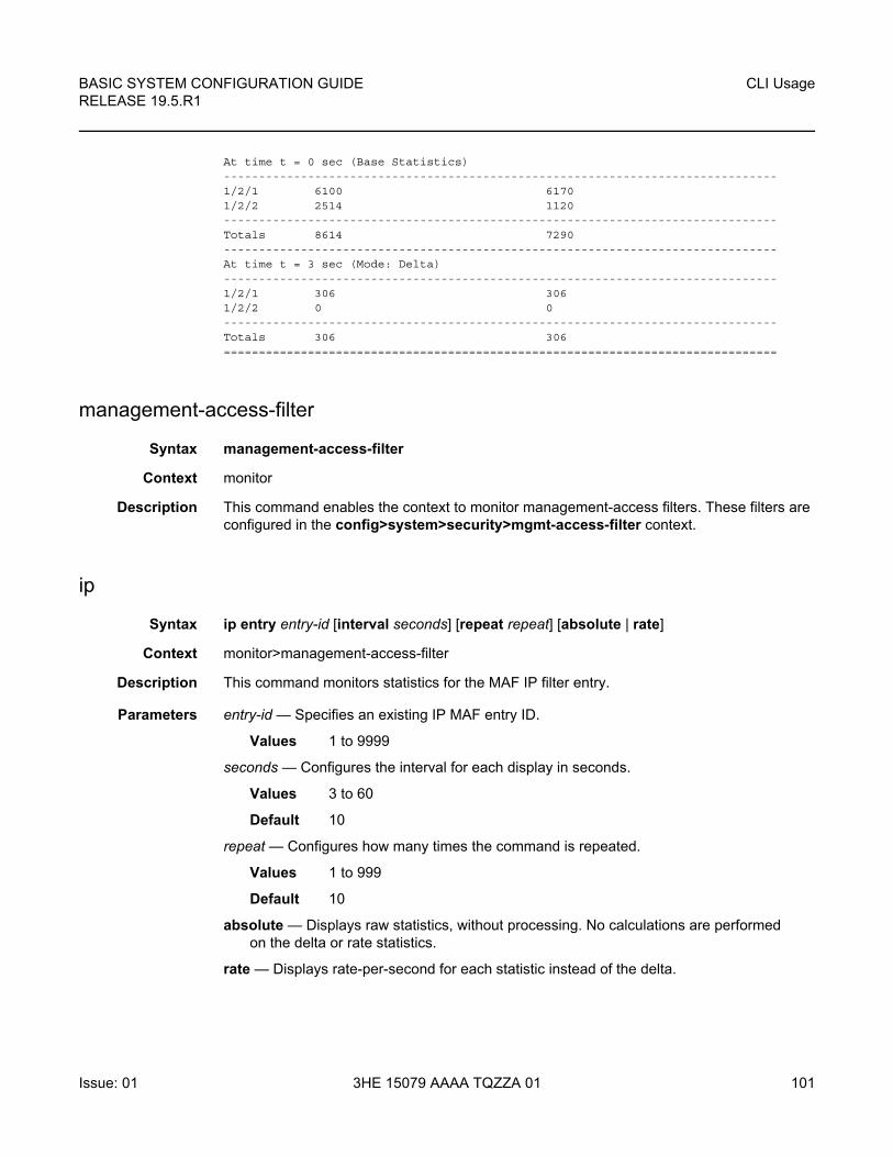
BASIC SYSTEM CONFIGURATION GUIDE RELEASE 19.5.R1
CLI Usage
Issue: 01 3HE 15079 AAAA TQZZA 01 101
At time t = 0 sec (Base Statistics)-------------------------------------------------------------------------------1/2/1 6100 61701/2/2 2514 1120-------------------------------------------------------------------------------Totals 8614 7290-------------------------------------------------------------------------------At time t = 3 sec (Mode: Delta)-------------------------------------------------------------------------------1/2/1 306 3061/2/2 0 0-------------------------------------------------------------------------------Totals 306 306===============================================================================
management-access-filter
Syntax management-access-filter
Context monitor
Description This command enables the context to monitor management-access filters. These filters are configured in the config>system>security>mgmt-access-filter context.
ip
Syntax ip entry entry-id [interval seconds] [repeat repeat] [absolute | rate]
Context monitor>management-access-filter
Description This command monitors statistics for the MAF IP filter entry.
Parameters entry-id — Specifies an existing IP MAF entry ID.
Values 1 to 9999
seconds — Configures the interval for each display in seconds.
Values 3 to 60
Default 10
repeat — Configures how many times the command is repeated.
Values 1 to 999
Default 10
absolute — Displays raw statistics, without processing. No calculations are performed on the delta or rate statistics.
rate — Displays rate-per-second for each statistic instead of the delta.
CLI Usage
102
BASIC SYSTEM CONFIGURATION GUIDERELEASE 19.5.R1
3HE 15079 AAAA TQZZA 01 Issue: 01
ipv6
Syntax ipv6 entry-id [interval seconds] [repeat repeat] [absolute | rate]
Context monitor>management-access-filter
Description This command monitors statistics for the MAF IPv6 filter entry.
Parameters entry-id — Specifies an existing IP MAF entry ID.
Values 1 to 9999
interval seconds — Configures the interval for each display in seconds.
Values 3 to 60
Default 10
repeat — Configures how many times the command is repeated.
Values 1 to 999
Default 10
absolute — Displays raw statistics, without processing. No calculations are performed on the delta or rate statistics.
rate — Displays rate-per-second for each statistic instead of the delta.
mac
Syntax mac entry-id [interval seconds] [repeat repeat] [absolute | rate]
Context monitor>management-access-filter
Description This command monitors statistics for the MAF MAC filter entry.
Parameters entry-id — Specifies an existing IP MAF entry ID.
Values 1 to 9999
seconds — Configures the interval for each display in seconds.
Values 3 to 60
Default 10
repeat — Configures how many times the command is repeated.
Values 1 to 999
Default 10
absolute — Displays raw statistics, without processing. No calculations are performed on the delta or rate statistics.
rate — Displays rate-per-second for each statistic instead of the delta.
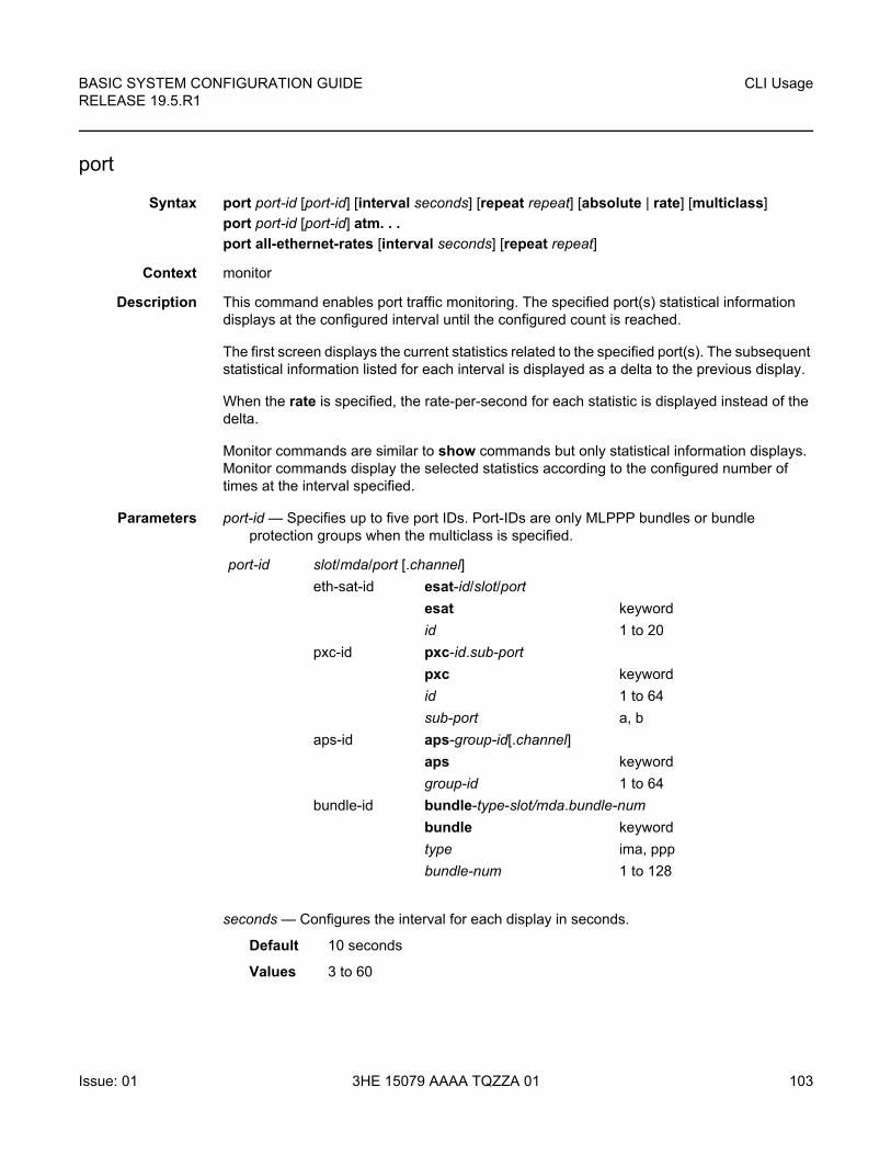
BASIC SYSTEM CONFIGURATION GUIDE RELEASE 19.5.R1
CLI Usage
Issue: 01 3HE 15079 AAAA TQZZA 01 103
port
Syntax port port-id [port-id] [interval seconds] [repeat repeat] [absolute | rate] [multiclass]
port port-id [port-id] atm. . .
port all-ethernet-rates [interval seconds] [repeat repeat]
Context monitor
Description This command enables port traffic monitoring. The specified port(s) statistical information displays at the configured interval until the configured count is reached.
The first screen displays the current statistics related to the specified port(s). The subsequent statistical information listed for each interval is displayed as a delta to the previous display.
When the rate is specified, the rate-per-second for each statistic is displayed instead of the delta.
Monitor commands are similar to show commands but only statistical information displays. Monitor commands display the selected statistics according to the configured number of times at the interval specified.
Parameters port-id — Specifies up to five port IDs. Port-IDs are only MLPPP bundles or bundle protection groups when the multiclass is specified.
seconds — Configures the interval for each display in seconds.
Default 10 seconds
Values 3 to 60
port-id slot/mda/port [.channel]
eth-sat-id esat-id/slot/port
esat keyword
id 1 to 20
pxc-id pxc-id.sub-port
pxc keyword
id 1 to 64
sub-port a, b
aps-id aps-group-id[.channel]
aps keyword
group-id 1 to 64
bundle-id bundle-type-slot/mda.bundle-num
bundle keyword
type ima, ppp
bundle-num 1 to 128
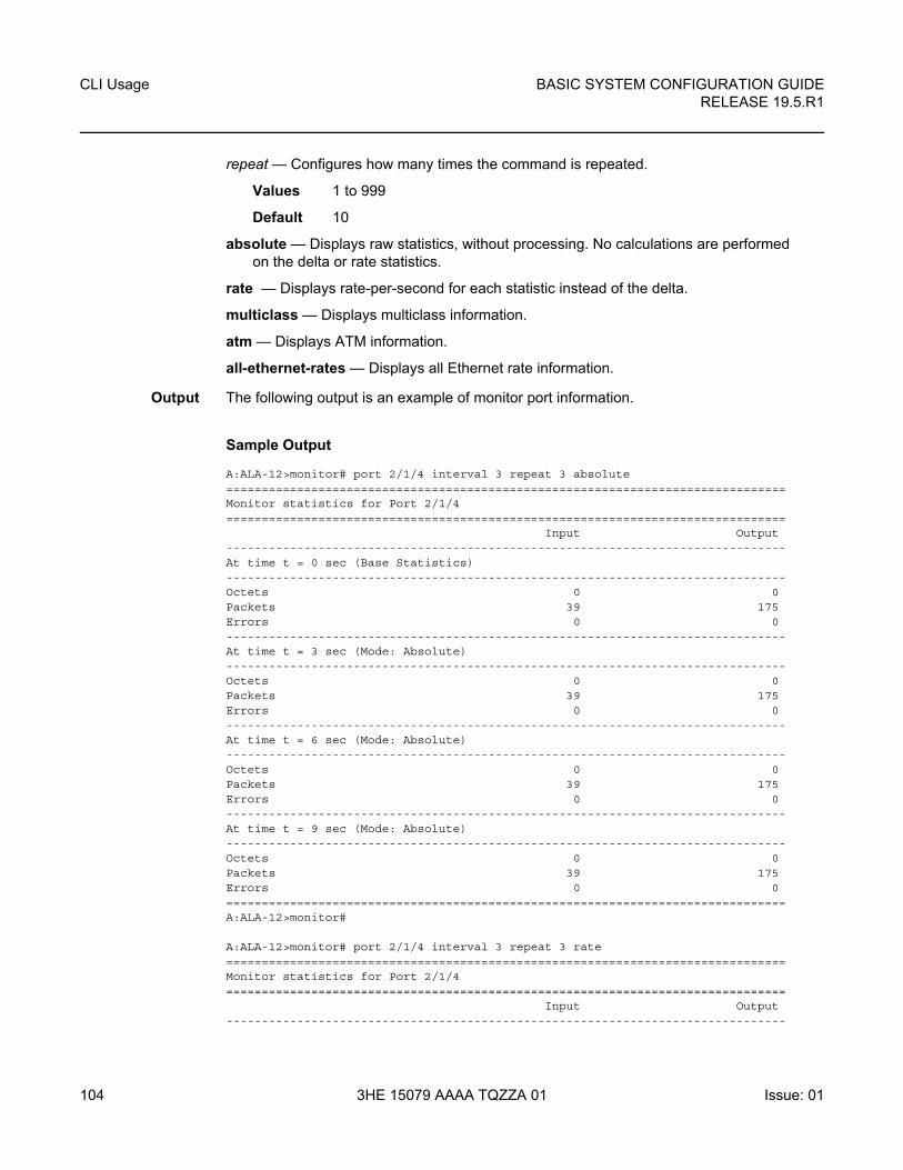
CLI Usage
104
BASIC SYSTEM CONFIGURATION GUIDERELEASE 19.5.R1
3HE 15079 AAAA TQZZA 01 Issue: 01
repeat — Configures how many times the command is repeated.
Values 1 to 999
Default 10
absolute — Displays raw statistics, without processing. No calculations are performed on the delta or rate statistics.
rate — Displays rate-per-second for each statistic instead of the delta.
multiclass — Displays multiclass information.
atm — Displays ATM information.
all-ethernet-rates — Displays all Ethernet rate information.
Output The following output is an example of monitor port information.
Sample Output
A:ALA-12>monitor# port 2/1/4 interval 3 repeat 3 absolute===============================================================================Monitor statistics for Port 2/1/4===============================================================================
Input Output-------------------------------------------------------------------------------At time t = 0 sec (Base Statistics)-------------------------------------------------------------------------------Octets 0 0Packets 39 175Errors 0 0-------------------------------------------------------------------------------At time t = 3 sec (Mode: Absolute)-------------------------------------------------------------------------------Octets 0 0Packets 39 175Errors 0 0-------------------------------------------------------------------------------At time t = 6 sec (Mode: Absolute)-------------------------------------------------------------------------------Octets 0 0Packets 39 175Errors 0 0-------------------------------------------------------------------------------At time t = 9 sec (Mode: Absolute)-------------------------------------------------------------------------------Octets 0 0Packets 39 175Errors 0 0===============================================================================A:ALA-12>monitor#
A:ALA-12>monitor# port 2/1/4 interval 3 repeat 3 rate===============================================================================Monitor statistics for Port 2/1/4===============================================================================
Input Output-------------------------------------------------------------------------------
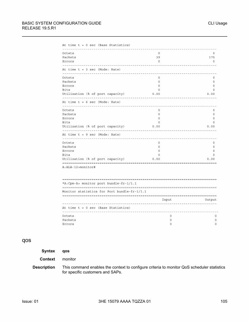
BASIC SYSTEM CONFIGURATION GUIDE RELEASE 19.5.R1
CLI Usage
Issue: 01 3HE 15079 AAAA TQZZA 01 105
At time t = 0 sec (Base Statistics)-------------------------------------------------------------------------------Octets 0 0Packets 39 175Errors 0 0-------------------------------------------------------------------------------At time t = 3 sec (Mode: Rate)-------------------------------------------------------------------------------Octets 0 0Packets 0 0Errors 0 0Bits 0 0Utilization (% of port capacity) 0.00 0.00-------------------------------------------------------------------------------At time t = 6 sec (Mode: Rate)-------------------------------------------------------------------------------Octets 0 0Packets 0 0Errors 0 0Bits 0 0Utilization (% of port capacity) 0.00 0.00-------------------------------------------------------------------------------At time t = 9 sec (Mode: Rate)-------------------------------------------------------------------------------Octets 0 0Packets 0 0Errors 0 0Bits 0 0Utilization (% of port capacity) 0.00 0.00===============================================================================A:ALA-12>monitor#
===============================================================================*A:Cpm-A> monitor port bundle-fr-1/1.1===============================================================================Monitor statistics for Port bundle-fr-1/1.1===============================================================================
Input Output-------------------------------------------------------------------------------At time t = 0 sec (Base Statistics)--------------------------------------------------------------------------------Octets 0 0Packets 0 0Errors 0 0
qos
Syntax qos
Context monitor
Description This command enables the context to configure criteria to monitor QoS scheduler statistics for specific customers and SAPs.
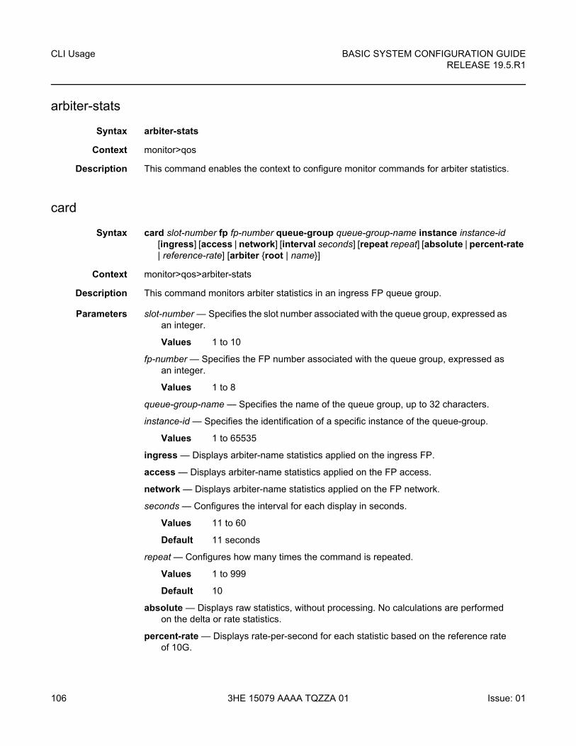
CLI Usage
106
BASIC SYSTEM CONFIGURATION GUIDERELEASE 19.5.R1
3HE 15079 AAAA TQZZA 01 Issue: 01
arbiter-stats
Syntax arbiter-stats
Context monitor>qos
Description This command enables the context to configure monitor commands for arbiter statistics.
card
Syntax card slot-number fp fp-number queue-group queue-group-name instance instance-id [ingress] [access | network] [interval seconds] [repeat repeat] [absolute | percent-rate | reference-rate] [arbiter {root | name}]
Context monitor>qos>arbiter-stats
Description This command monitors arbiter statistics in an ingress FP queue group.
Parameters slot-number — Specifies the slot number associated with the queue group, expressed as an integer.
Values 1 to 10
fp-number — Specifies the FP number associated with the queue group, expressed as an integer.
Values 1 to 8
queue-group-name — Specifies the name of the queue group, up to 32 characters.
instance-id — Specifies the identification of a specific instance of the queue-group.
Values 1 to 65535
ingress — Displays arbiter-name statistics applied on the ingress FP.
access — Displays arbiter-name statistics applied on the FP access.
network — Displays arbiter-name statistics applied on the FP network.
seconds — Configures the interval for each display in seconds.
Values 11 to 60
Default 11 seconds
repeat — Configures how many times the command is repeated.
Values 1 to 999
Default 10
absolute — Displays raw statistics, without processing. No calculations are performed on the delta or rate statistics.
percent-rate — Displays rate-per-second for each statistic based on the reference rate of 10G.
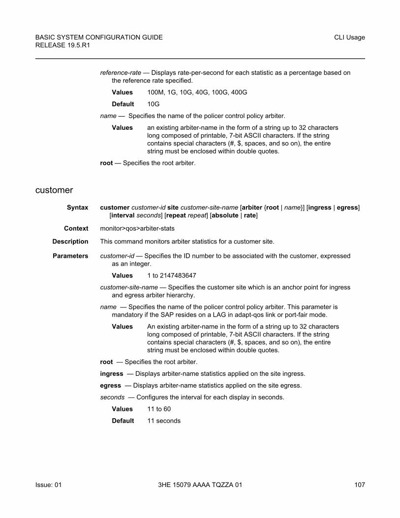
BASIC SYSTEM CONFIGURATION GUIDE RELEASE 19.5.R1
CLI Usage
Issue: 01 3HE 15079 AAAA TQZZA 01 107
reference-rate — Displays rate-per-second for each statistic as a percentage based on the reference rate specified.
Values 100M, 1G, 10G, 40G, 100G, 400G
Default 10G
name — Specifies the name of the policer control policy arbiter.
Values an existing arbiter-name in the form of a string up to 32 characters long composed of printable, 7-bit ASCII characters. If the string contains special characters (#, $, spaces, and so on), the entire string must be enclosed within double quotes.
root — Specifies the root arbiter.
customer
Syntax customer customer-id site customer-site-name [arbiter {root | name}] [ingress | egress] [interval seconds] [repeat repeat] [absolute | rate]
Context monitor>qos>arbiter-stats
Description This command monitors arbiter statistics for a customer site.
Parameters customer-id — Specifies the ID number to be associated with the customer, expressed as an integer.
Values 1 to 2147483647
customer-site-name — Specifies the customer site which is an anchor point for ingress and egress arbiter hierarchy.
name — Specifies the name of the policer control policy arbiter. This parameter is mandatory if the SAP resides on a LAG in adapt-qos link or port-fair mode.
Values An existing arbiter-name in the form of a string up to 32 characters long composed of printable, 7-bit ASCII characters. If the string contains special characters (#, $, spaces, and so on), the entire string must be enclosed within double quotes.
root — Specifies the root arbiter.
ingress — Displays arbiter-name statistics applied on the site ingress.
egress — Displays arbiter-name statistics applied on the site egress.
seconds — Configures the interval for each display in seconds.
Values 11 to 60
Default 11 seconds
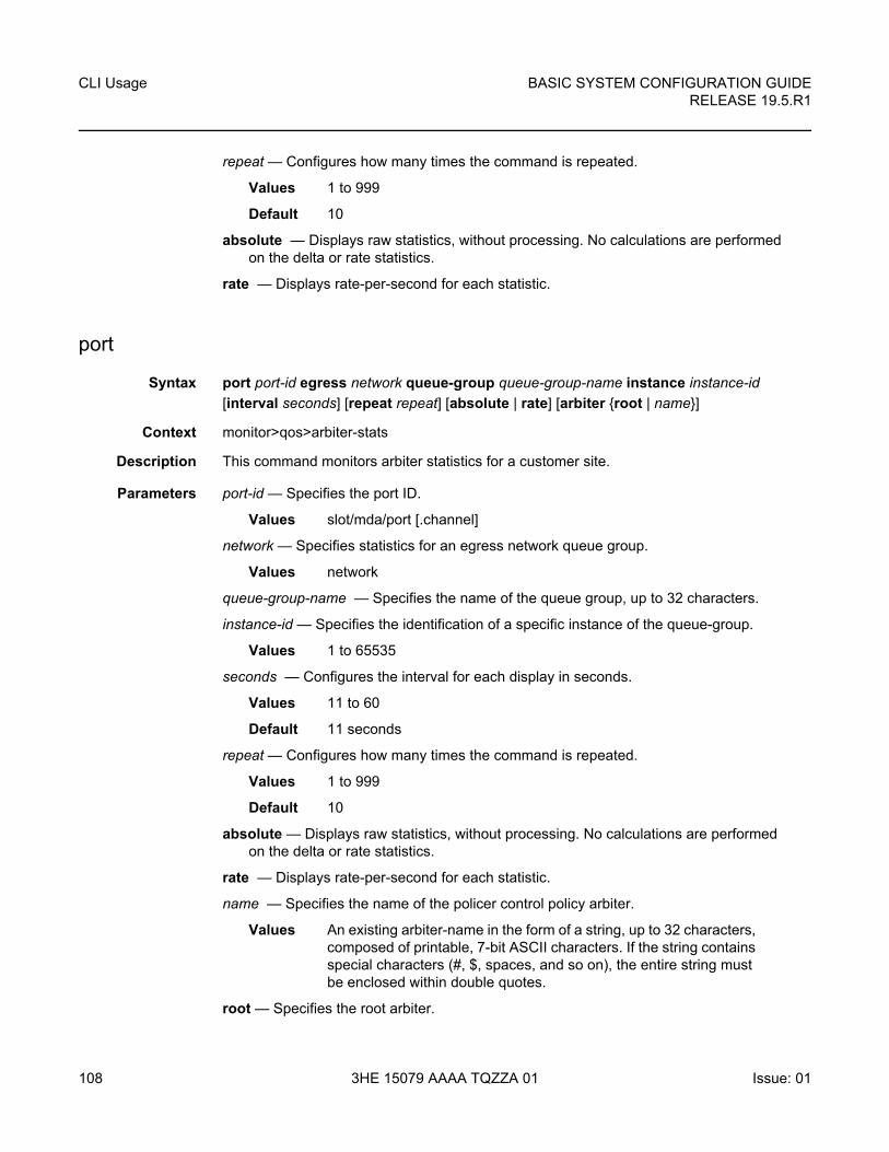
CLI Usage
108
BASIC SYSTEM CONFIGURATION GUIDERELEASE 19.5.R1
3HE 15079 AAAA TQZZA 01 Issue: 01
repeat — Configures how many times the command is repeated.
Values 1 to 999
Default 10
absolute — Displays raw statistics, without processing. No calculations are performed on the delta or rate statistics.
rate — Displays rate-per-second for each statistic.
port
Syntax port port-id egress network queue-group queue-group-name instance instance-id
[interval seconds] [repeat repeat] [absolute | rate] [arbiter {root | name}]
Context monitor>qos>arbiter-stats
Description This command monitors arbiter statistics for a customer site.
Parameters port-id — Specifies the port ID.
Values slot/mda/port [.channel]
network — Specifies statistics for an egress network queue group.
Values network
queue-group-name — Specifies the name of the queue group, up to 32 characters.
instance-id — Specifies the identification of a specific instance of the queue-group.
Values 1 to 65535
seconds — Configures the interval for each display in seconds.
Values 11 to 60
Default 11 seconds
repeat — Configures how many times the command is repeated.
Values 1 to 999
Default 10
absolute — Displays raw statistics, without processing. No calculations are performed on the delta or rate statistics.
rate — Displays rate-per-second for each statistic.
name — Specifies the name of the policer control policy arbiter.
Values An existing arbiter-name in the form of a string, up to 32 characters, composed of printable, 7-bit ASCII characters. If the string contains special characters (#, $, spaces, and so on), the entire string must be enclosed within double quotes.
root — Specifies the root arbiter.
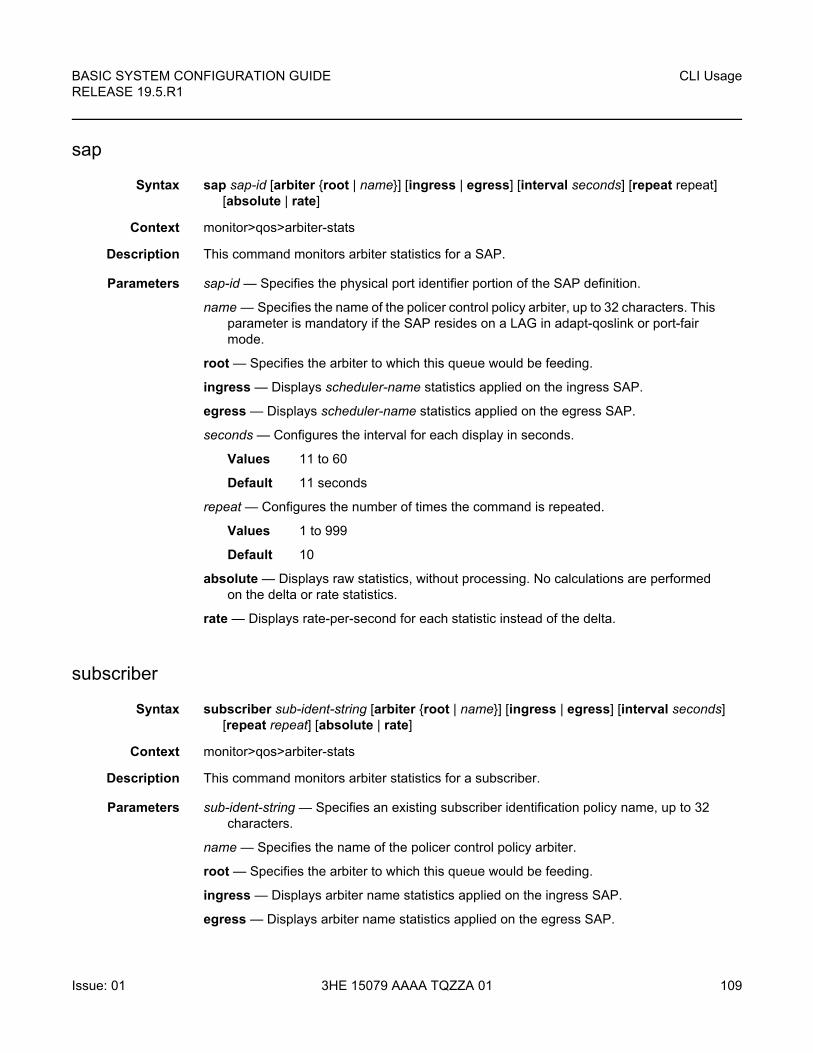
BASIC SYSTEM CONFIGURATION GUIDE RELEASE 19.5.R1
CLI Usage
Issue: 01 3HE 15079 AAAA TQZZA 01 109
sap
Syntax sap sap-id [arbiter {root | name}] [ingress | egress] [interval seconds] [repeat repeat] [absolute | rate]
Context monitor>qos>arbiter-stats
Description This command monitors arbiter statistics for a SAP.
Parameters sap-id — Specifies the physical port identifier portion of the SAP definition.
name — Specifies the name of the policer control policy arbiter, up to 32 characters. This parameter is mandatory if the SAP resides on a LAG in adapt-qoslink or port-fair mode.
root — Specifies the arbiter to which this queue would be feeding.
ingress — Displays scheduler-name statistics applied on the ingress SAP.
egress — Displays scheduler-name statistics applied on the egress SAP.
seconds — Configures the interval for each display in seconds.
Values 11 to 60
Default 11 seconds
repeat — Configures the number of times the command is repeated.
Values 1 to 999
Default 10
absolute — Displays raw statistics, without processing. No calculations are performed on the delta or rate statistics.
rate — Displays rate-per-second for each statistic instead of the delta.
subscriber
Syntax subscriber sub-ident-string [arbiter {root | name}] [ingress | egress] [interval seconds] [repeat repeat] [absolute | rate]
Context monitor>qos>arbiter-stats
Description This command monitors arbiter statistics for a subscriber.
Parameters sub-ident-string — Specifies an existing subscriber identification policy name, up to 32 characters.
name — Specifies the name of the policer control policy arbiter.
root — Specifies the arbiter to which this queue would be feeding.
ingress — Displays arbiter name statistics applied on the ingress SAP.
egress — Displays arbiter name statistics applied on the egress SAP.
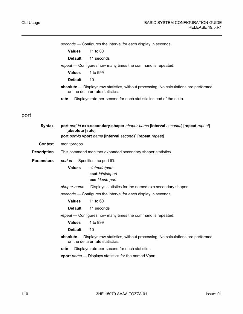
CLI Usage
110
BASIC SYSTEM CONFIGURATION GUIDERELEASE 19.5.R1
3HE 15079 AAAA TQZZA 01 Issue: 01
seconds — Configures the interval for each display in seconds.
Values 11 to 60
Default 11 seconds
repeat — Configures how many times the command is repeated.
Values 1 to 999
Default 10
absolute — Displays raw statistics, without processing. No calculations are performed on the delta or rate statistics.
rate — Displays rate-per-second for each statistic instead of the delta.
port
Syntax port port-id exp-secondary-shaper shaper-name [interval seconds] [repeat repeat] [absolute | rate]
port port-id vport name [interval seconds] [repeat repeat]
Context monitor>qos
Description This command monitors expanded secondary shaper statistics.
Parameters port-id — Specifies the port ID.
Values slot/mda/port
esat-id/slot/port
pxc-id.sub-port
shaper-name — Displays statistics for the named exp secondary shaper.
seconds — Configures the interval for each display in seconds.
Values 11 to 60
Default 11 seconds
repeat — Configures how many times the command is repeated.
Values 1 to 999
Default 10
absolute — Displays raw statistics, without processing. No calculations are performed on the delta or rate statistics.
rate — Displays rate-per-second for each statistic.
vport name — Displays statistics for the named Vport..
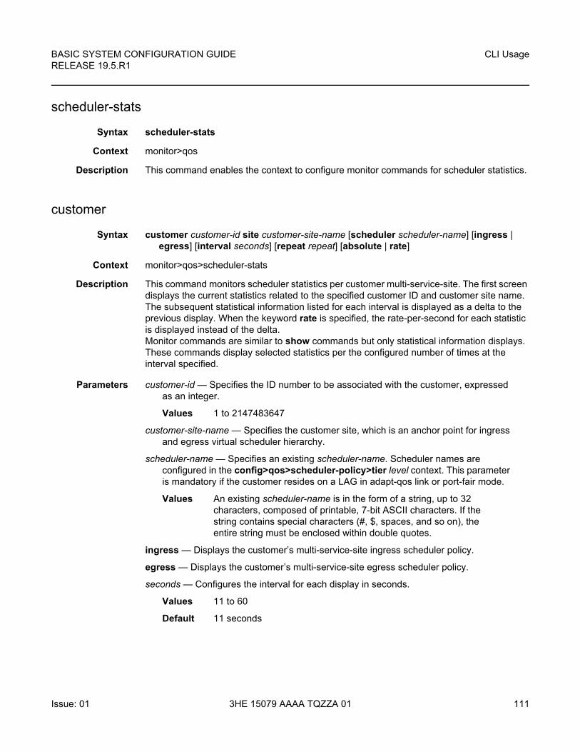
BASIC SYSTEM CONFIGURATION GUIDE RELEASE 19.5.R1
CLI Usage
Issue: 01 3HE 15079 AAAA TQZZA 01 111
scheduler-stats
Syntax scheduler-stats
Context monitor>qos
Description This command enables the context to configure monitor commands for scheduler statistics.
customer
Syntax customer customer-id site customer-site-name [scheduler scheduler-name] [ingress | egress] [interval seconds] [repeat repeat] [absolute | rate]
Context monitor>qos>scheduler-stats
Description This command monitors scheduler statistics per customer multi-service-site. The first screen displays the current statistics related to the specified customer ID and customer site name. The subsequent statistical information listed for each interval is displayed as a delta to the previous display. When the keyword rate is specified, the rate-per-second for each statistic is displayed instead of the delta. Monitor commands are similar to show commands but only statistical information displays. These commands display selected statistics per the configured number of times at the interval specified.
Parameters customer-id — Specifies the ID number to be associated with the customer, expressed as an integer.
Values 1 to 2147483647
customer-site-name — Specifies the customer site, which is an anchor point for ingress and egress virtual scheduler hierarchy.
scheduler-name — Specifies an existing scheduler-name. Scheduler names are configured in the config>qos>scheduler-policy>tier level context. This parameter is mandatory if the customer resides on a LAG in adapt-qos link or port-fair mode.
Values An existing scheduler-name is in the form of a string, up to 32 characters, composed of printable, 7-bit ASCII characters. If the string contains special characters (#, $, spaces, and so on), the entire string must be enclosed within double quotes.
ingress — Displays the customer’s multi-service-site ingress scheduler policy.
egress — Displays the customer’s multi-service-site egress scheduler policy.
seconds — Configures the interval for each display in seconds.
Values 11 to 60
Default 11 seconds
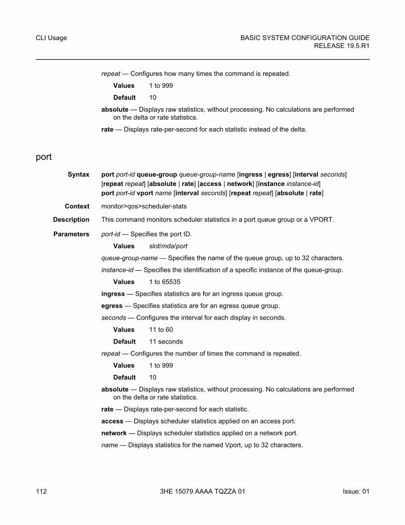
CLI Usage
112
BASIC SYSTEM CONFIGURATION GUIDERELEASE 19.5.R1
3HE 15079 AAAA TQZZA 01 Issue: 01
repeat — Configures how many times the command is repeated.
Values 1 to 999
Default 10
absolute — Displays raw statistics, without processing. No calculations are performed on the delta or rate statistics.
rate — Displays rate-per-second for each statistic instead of the delta.
port
Syntax port port-id queue-group queue-group-name [ingress | egress] [interval seconds]
[repeat repeat] [absolute | rate] [access | network] [instance instance-id]
port port-id vport name [interval seconds] [repeat repeat] [absolute | rate]
Context monitor>qos>scheduler-stats
Description This command monitors scheduler statistics in a port queue group or a VPORT.
Parameters port-id — Specifies the port ID.
Values slot/mda/port
queue-group-name — Specifies the name of the queue group, up to 32 characters.
instance-id — Specifies the identification of a specific instance of the queue-group.
Values 1 to 65535
ingress — Specifies statistics are for an ingress queue group.
egress — Specifies statistics are for an egress queue group.
seconds — Configures the interval for each display in seconds.
Values 11 to 60
Default 11 seconds
repeat — Configures the number of times the command is repeated.
Values 1 to 999
Default 10
absolute — Displays raw statistics, without processing. No calculations are performed on the delta or rate statistics.
rate — Displays rate-per-second for each statistic.
access — Displays scheduler statistics applied on an access port.
network — Displays scheduler statistics applied on a network port.
name — Displays statistics for the named Vport, up to 32 characters.
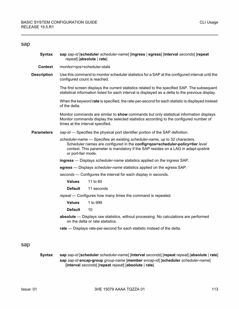
BASIC SYSTEM CONFIGURATION GUIDE RELEASE 19.5.R1
CLI Usage
Issue: 01 3HE 15079 AAAA TQZZA 01 113
sap
Syntax sap sap-id [scheduler scheduler-name] [ingress | egress] [interval seconds] [repeat repeat] [absolute | rate]
Context monitor>qos>scheduler-stats
Description Use this command to monitor scheduler statistics for a SAP at the configured interval until the configured count is reached.
The first screen displays the current statistics related to the specified SAP. The subsequent statistical information listed for each interval is displayed as a delta to the previous display.
When the keyword rate is specified, the rate-per-second for each statistic is displayed instead of the delta.
Monitor commands are similar to show commands but only statistical information displays. Monitor commands display the selected statistics according to the configured number of times at the interval specified.
Parameters sap-id — Specifies the physical port identifier portion of the SAP definition.
scheduler-name — Specifies an existing scheduler-name, up to 32 characters. Scheduler names are configured in the config>qos>scheduler-policy>tier level context. This parameter is mandatory if the SAP resides on a LAG in adapt-qoslink or port-fair mode.
ingress — Displays scheduler-name statistics applied on the ingress SAP.
egress — Displays scheduler-name statistics applied on the egress SAP.
seconds — Configures the interval for each display in seconds.
Values 11 to 60
Default 11 seconds
repeat — Configures how many times the command is repeated.
Values 1 to 999
Default 10
absolute — Displays raw statistics, without processing. No calculations are performed on the delta or rate statistics.
rate — Displays rate-per-second for each statistic instead of the delta.
sap
Syntax sap sap-id [scheduler scheduler-name] [interval seconds] [repeat repeat] [absolute | rate]
sap sap-id encap-group group-name [member encap-id] [scheduler scheduler-name] [interval seconds] [repeat repeat] [absolute | rate]
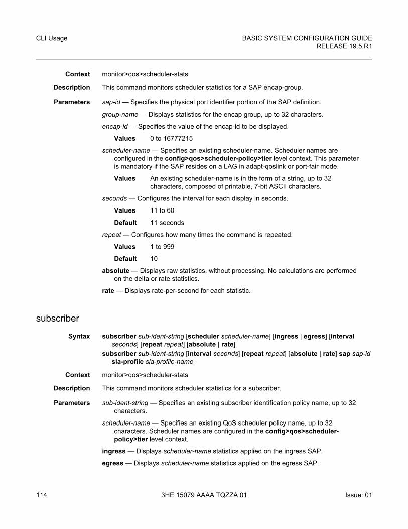
CLI Usage
114
BASIC SYSTEM CONFIGURATION GUIDERELEASE 19.5.R1
3HE 15079 AAAA TQZZA 01 Issue: 01
Context monitor>qos>scheduler-stats
Description This command monitors scheduler statistics for a SAP encap-group.
Parameters sap-id — Specifies the physical port identifier portion of the SAP definition.
group-name — Displays statistics for the encap group, up to 32 characters.
encap-id — Specifies the value of the encap-id to be displayed.
Values 0 to 16777215
scheduler-name — Specifies an existing scheduler-name. Scheduler names are configured in the config>qos>scheduler-policy>tier level context. This parameter is mandatory if the SAP resides on a LAG in adapt-qoslink or port-fair mode.
Values An existing scheduler-name is in the form of a string, up to 32 characters, composed of printable, 7-bit ASCII characters.
seconds — Configures the interval for each display in seconds.
Values 11 to 60
Default 11 seconds
repeat — Configures how many times the command is repeated.
Values 1 to 999
Default 10
absolute — Displays raw statistics, without processing. No calculations are performed on the delta or rate statistics.
rate — Displays rate-per-second for each statistic.
subscriber
Syntax subscriber sub-ident-string [scheduler scheduler-name] [ingress | egress] [interval seconds] [repeat repeat] [absolute | rate]
subscriber sub-ident-string [interval seconds] [repeat repeat] [absolute | rate] sap sap-id sla-profile sla-profile-name
Context monitor>qos>scheduler-stats
Description This command monitors scheduler statistics for a subscriber.
Parameters sub-ident-string — Specifies an existing subscriber identification policy name, up to 32 characters.
scheduler-name — Specifies an existing QoS scheduler policy name, up to 32 characters. Scheduler names are configured in the config>qos>scheduler-policy>tier level context.
ingress — Displays scheduler-name statistics applied on the ingress SAP.
egress — Displays scheduler-name statistics applied on the egress SAP.
BASIC SYSTEM CONFIGURATION GUIDE RELEASE 19.5.R1
CLI Usage
Issue: 01 3HE 15079 AAAA TQZZA 01 115
seconds — Configures the interval for each display in seconds.
Values 11 to 60
Default 11 seconds
repeat — Configures how many times the command is repeated.
Values 1 to 999
Default 10
absolute — Displays raw statistics, without processing. No calculations are performed on the delta or rate statistics.
rate — Displays rate-per-second for each statistic instead of the delta.
sap-id — Specifies the physical port identifier portion of the SAP definition.
sla-profile-name — Specifies the SLA profile belonging to the subscriber host, up to 32 characters.
router
Syntax router [router-instance]
router service-name service name
Context monitor
Description This command enables the context to configure criteria to monitor statistical information for a variety of routing protocols.
Parameters router-instance — Specifies the router name or service ID.
Values
Default Base
service-name — Specifies the service name used to identify the router instance. The name can be up to 64 characters long.
bgp
Syntax bgp
Context monitor>router
Description This command monitors commands for the BGP instance.
router-name: Base, management, cpm-vr-name, vpls-management
vprn-service-id: 1 to 2147483647
cpm-vr-name up to 32 characters
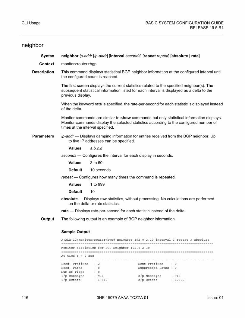
CLI Usage
116
BASIC SYSTEM CONFIGURATION GUIDERELEASE 19.5.R1
3HE 15079 AAAA TQZZA 01 Issue: 01
neighbor
Syntax neighbor ip-addr [ip-addr] [interval seconds] [repeat repeat] [absolute | rate]
Context monitor>router>bgp
Description This command displays statistical BGP neighbor information at the configured interval until the configured count is reached.
The first screen displays the current statistics related to the specified neighbor(s). The subsequent statistical information listed for each interval is displayed as a delta to the previous display.
When the keyword rate is specified, the rate-per-second for each statistic is displayed instead of the delta.
Monitor commands are similar to show commands but only statistical information displays. Monitor commands display the selected statistics according to the configured number of times at the interval specified.
Parameters ip-addr — Displays damping information for entries received from the BGP neighbor. Up to five IP addresses can be specified.
Values a.b.c.d
seconds — Configures the interval for each display in seconds.
Values 3 to 60
Default 10 seconds
repeat — Configures how many times the command is repeated.
Values 1 to 999
Default 10
absolute — Displays raw statistics, without processing. No calculations are performed on the delta or rate statistics.
rate — Displays rate-per-second for each statistic instead of the delta.
Output The following output is an example of BGP neighbor information.
Sample Output
A:ALA-12>monitor>router>bgp# neighbor 192.0.2.10 interval 3 repeat 3 absolute===============================================================================Monitor statistics for BGP Neighbor 192.0.2.10===============================================================================At time t = 0 sec-------------------------------------------------------------------------------Recd. Prefixes : 2 Sent Prefixes : 0Recd. Paths : 0 Suppressed Paths : 0Num of Flaps : 0i/p Messages : 916 o/p Messages : 916i/p Octets : 17510 o/p Octets : 17386
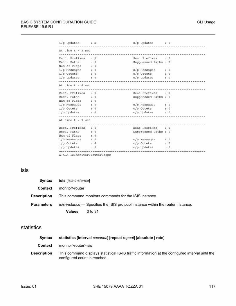
BASIC SYSTEM CONFIGURATION GUIDE RELEASE 19.5.R1
CLI Usage
Issue: 01 3HE 15079 AAAA TQZZA 01 117
i/p Updates : 2 o/p Updates : 0-------------------------------------------------------------------------------At time t = 3 sec-------------------------------------------------------------------------------Recd. Prefixes : 0 Sent Prefixes : 0Recd. Paths : 0 Suppressed Paths : 0Num of Flaps : 0i/p Messages : 0 o/p Messages : 0i/p Octets : 0 o/p Octets : 0i/p Updates : 0 o/p Updates : 0-------------------------------------------------------------------------------At time t = 6 sec-------------------------------------------------------------------------------Recd. Prefixes : 0 Sent Prefixes : 0Recd. Paths : 0 Suppressed Paths : 0Num of Flaps : 0i/p Messages : 0 o/p Messages : 0i/p Octets : 0 o/p Octets : 0i/p Updates : 0 o/p Updates : 0-------------------------------------------------------------------------------At time t = 9 sec-------------------------------------------------------------------------------Recd. Prefixes : 0 Sent Prefixes : 0Recd. Paths : 0 Suppressed Paths : 0Num of Flaps : 0i/p Messages : 0 o/p Messages : 0i/p Octets : 6 o/p Octets : 0i/p Updates : 0 o/p Updates : 0===============================================================================A:ALA-12>monitor>router>bgp#
isis
Syntax isis [isis-instance]
Context monitor>router
Description This command monitors commands for the ISIS instance.
Parameters isis-instance — Specifies the ISIS protocol instance within the router instance.
Values 0 to 31
statistics
Syntax statistics [interval seconds] [repeat repeat] [absolute | rate]
Context monitor>router>isis
Description This command displays statistical IS-IS traffic information at the configured interval until the configured count is reached.
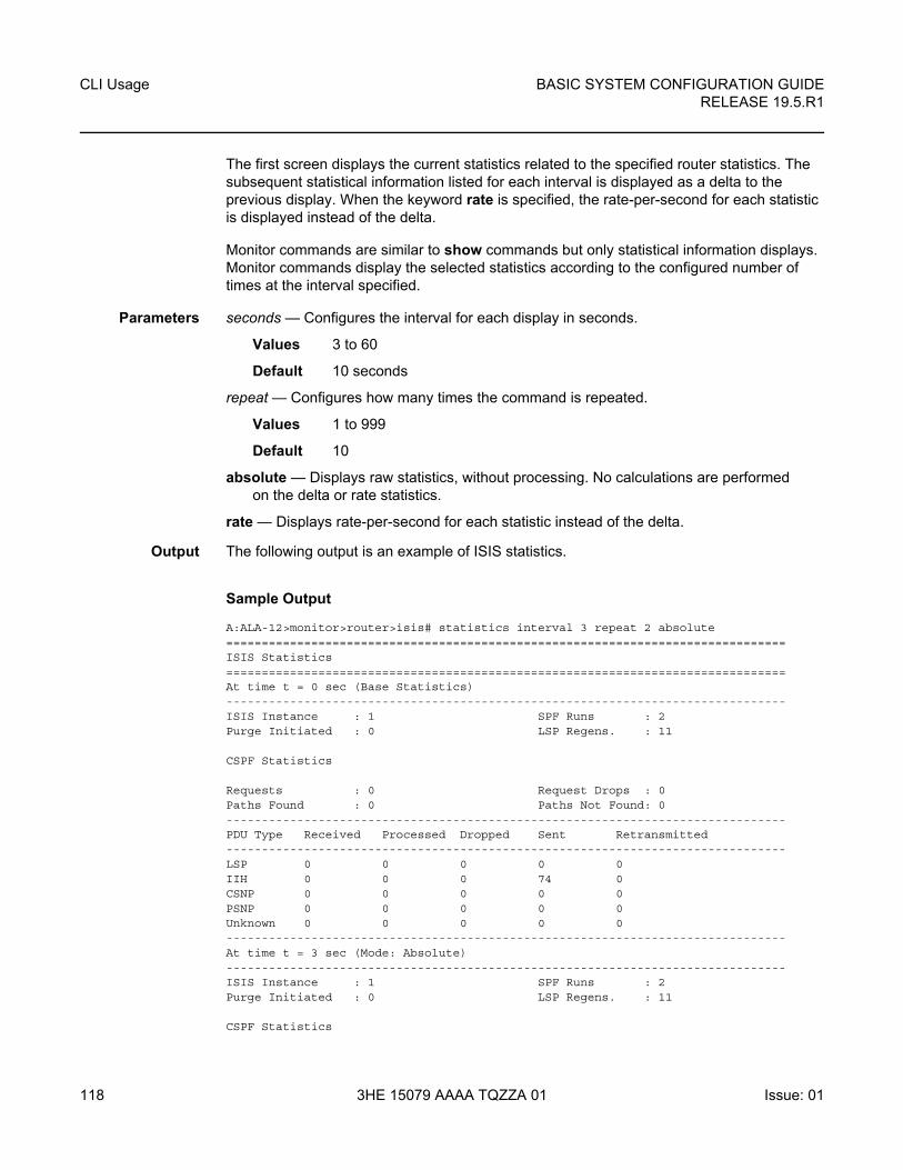
CLI Usage
118
BASIC SYSTEM CONFIGURATION GUIDERELEASE 19.5.R1
3HE 15079 AAAA TQZZA 01 Issue: 01
The first screen displays the current statistics related to the specified router statistics. The subsequent statistical information listed for each interval is displayed as a delta to the previous display. When the keyword rate is specified, the rate-per-second for each statistic is displayed instead of the delta.
Monitor commands are similar to show commands but only statistical information displays. Monitor commands display the selected statistics according to the configured number of times at the interval specified.
Parameters seconds — Configures the interval for each display in seconds.
Values 3 to 60
Default 10 seconds
repeat — Configures how many times the command is repeated.
Values 1 to 999
Default 10
absolute — Displays raw statistics, without processing. No calculations are performed on the delta or rate statistics.
rate — Displays rate-per-second for each statistic instead of the delta.
Output The following output is an example of ISIS statistics.
Sample Output
A:ALA-12>monitor>router>isis# statistics interval 3 repeat 2 absolute===============================================================================ISIS Statistics===============================================================================At time t = 0 sec (Base Statistics)-------------------------------------------------------------------------------ISIS Instance : 1 SPF Runs : 2Purge Initiated : 0 LSP Regens. : 11
CSPF Statistics
Requests : 0 Request Drops : 0Paths Found : 0 Paths Not Found: 0-------------------------------------------------------------------------------PDU Type Received Processed Dropped Sent Retransmitted-------------------------------------------------------------------------------LSP 0 0 0 0 0IIH 0 0 0 74 0CSNP 0 0 0 0 0PSNP 0 0 0 0 0Unknown 0 0 0 0 0-------------------------------------------------------------------------------At time t = 3 sec (Mode: Absolute)-------------------------------------------------------------------------------ISIS Instance : 1 SPF Runs : 2Purge Initiated : 0 LSP Regens. : 11
CSPF Statistics
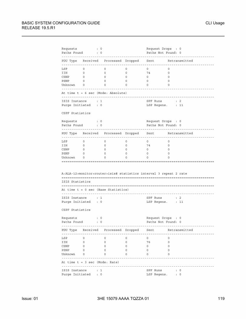
BASIC SYSTEM CONFIGURATION GUIDE RELEASE 19.5.R1
CLI Usage
Issue: 01 3HE 15079 AAAA TQZZA 01 119
Requests : 0 Request Drops : 0Paths Found : 0 Paths Not Found: 0-------------------------------------------------------------------------------PDU Type Received Processed Dropped Sent Retransmitted-------------------------------------------------------------------------------LSP 0 0 0 0 0IIH 0 0 0 74 0CSNP 0 0 0 0 0PSNP 0 0 0 0 0Unknown 0 0 0 0 0-------------------------------------------------------------------------------At time t = 6 sec (Mode: Absolute)-------------------------------------------------------------------------------ISIS Instance : 1 SPF Runs : 2Purge Initiated : 0 LSP Regens. : 11
CSPF Statistics
Requests : 0 Request Drops : 0Paths Found : 0 Paths Not Found: 0-------------------------------------------------------------------------------PDU Type Received Processed Dropped Sent Retransmitted-------------------------------------------------------------------------------LSP 0 0 0 0 0IIH 0 0 0 74 0CSNP 0 0 0 0 0PSNP 0 0 0 0 0Unknown 0 0 0 0 0===============================================================================
A:ALA-12>monitor>router>isis# statistics interval 3 repeat 2 rate===============================================================================ISIS Statistics===============================================================================At time t = 0 sec (Base Statistics)-------------------------------------------------------------------------------ISIS Instance : 1 SPF Runs : 2Purge Initiated : 0 LSP Regens. : 11
CSPF Statistics
Requests : 0 Request Drops : 0Paths Found : 0 Paths Not Found: 0-------------------------------------------------------------------------------PDU Type Received Processed Dropped Sent Retransmitted-------------------------------------------------------------------------------LSP 0 0 0 0 0IIH 0 0 0 76 0CSNP 0 0 0 0 0PSNP 0 0 0 0 0Unknown 0 0 0 0 0-------------------------------------------------------------------------------At time t = 3 sec (Mode: Rate)-------------------------------------------------------------------------------ISIS Instance : 1 SPF Runs : 0Purge Initiated : 0 LSP Regens. : 0
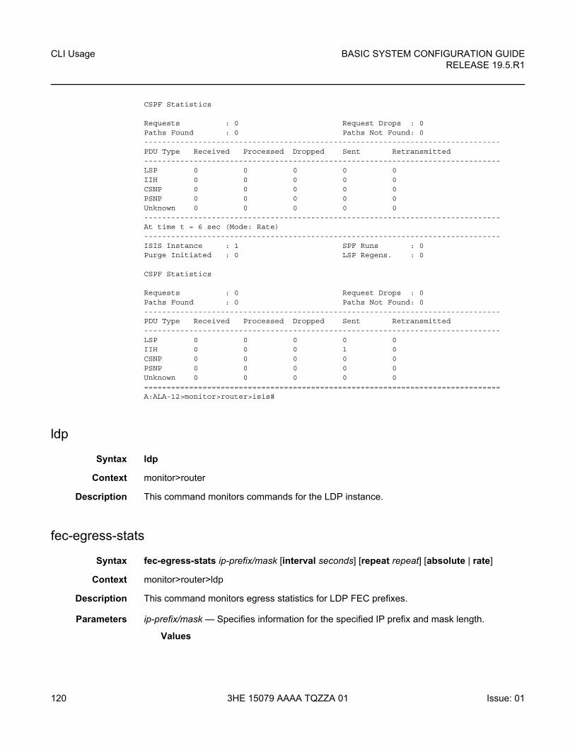
CLI Usage
120
BASIC SYSTEM CONFIGURATION GUIDERELEASE 19.5.R1
3HE 15079 AAAA TQZZA 01 Issue: 01
CSPF Statistics
Requests : 0 Request Drops : 0Paths Found : 0 Paths Not Found: 0-------------------------------------------------------------------------------PDU Type Received Processed Dropped Sent Retransmitted-------------------------------------------------------------------------------LSP 0 0 0 0 0IIH 0 0 0 0 0CSNP 0 0 0 0 0PSNP 0 0 0 0 0Unknown 0 0 0 0 0-------------------------------------------------------------------------------At time t = 6 sec (Mode: Rate)-------------------------------------------------------------------------------ISIS Instance : 1 SPF Runs : 0Purge Initiated : 0 LSP Regens. : 0
CSPF Statistics
Requests : 0 Request Drops : 0Paths Found : 0 Paths Not Found: 0-------------------------------------------------------------------------------PDU Type Received Processed Dropped Sent Retransmitted-------------------------------------------------------------------------------LSP 0 0 0 0 0IIH 0 0 0 1 0CSNP 0 0 0 0 0PSNP 0 0 0 0 0Unknown 0 0 0 0 0===============================================================================A:ALA-12>monitor>router>isis#
ldp
Syntax ldp
Context monitor>router
Description This command monitors commands for the LDP instance.
fec-egress-stats
Syntax fec-egress-stats ip-prefix/mask [interval seconds] [repeat repeat] [absolute | rate]
Context monitor>router>ldp
Description This command monitors egress statistics for LDP FEC prefixes.
Parameters ip-prefix/mask — Specifies information for the specified IP prefix and mask length.
Values
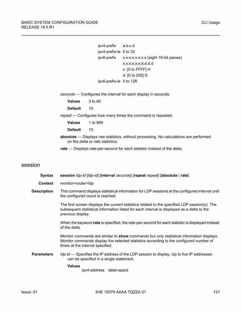
BASIC SYSTEM CONFIGURATION GUIDE RELEASE 19.5.R1
CLI Usage
Issue: 01 3HE 15079 AAAA TQZZA 01 121
seconds — Configures the interval for each display in seconds.
Values 3 to 60
Default 10
repeat — Configures how many times the command is repeated.
Values 1 to 999
Default 10
absolute — Displays raw statistics, without processing. No calculations are performed on the delta or rate statistics.
rate — Displays rate-per-second for each statistic instead of the delta.
session
Syntax session ldp-id [ldp-id] [interval seconds] [repeat repeat] [absolute | rate]
Context monitor>router>ldp
Description This command displays statistical information for LDP sessions at the configured interval until the configured count is reached.
The first screen displays the current statistics related to the specified LDP session(s). The subsequent statistical information listed for each interval is displayed as a delta to the previous display.
When the keyword rate is specified, the rate-per-second for each statistic is displayed instead of the delta.
Monitor commands are similar to show commands but only statistical information displays. Monitor commands display the selected statistics according to the configured number of times at the interval specified.
Parameters ldp-id — Specifies the IP address of the LDP session to display. Up to five IP addresses can be specified in a single statement.
Values
ipv4-prefix a.b.c.d
ipv4-prefix-le 0 to 32
ipv6-prefix x:x:x:x:x:x:x:x (eight 16-bit pieces)
x:x:x:x:x:x:d.d.d.d
x: [0 to FFFF] H
d: [0 to 255] D
ipv6-prefix-le 0 to 128
ipv4-address label-space
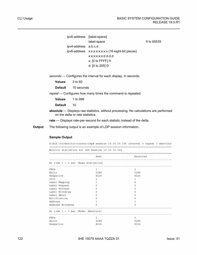
CLI Usage
122
BASIC SYSTEM CONFIGURATION GUIDERELEASE 19.5.R1
3HE 15079 AAAA TQZZA 01 Issue: 01
seconds — Configures the interval for each display, in seconds.
Values 3 to 60
Default 10 seconds
repeat — Configures how many times the command is repeated.
Values 1 to 999
Default 10
absolute — Displays raw statistics, without processing. No calculations are performed on the delta or rate statistics.
rate — Displays rate-per-second for each statistic instead of the delta.
Output The following output is an example of LDP session information.
Sample Output
A:ALA-103>monitor>router>ldp# session 10.10.10.104 interval 3 repeat 3 absolute===============================================================================Monitor statistics for LDP Session 10.10.10.104===============================================================================
Sent Received-------------------------------------------------------------------------------At time t = 0 sec (Base Statistics)-------------------------------------------------------------------------------FECs 1 2Hello 5288 5289Keepalive 8225 8225Init 1 1Label Mapping 1 4Label Request 0 0Label Release 0 0Label Withdraw 0 0Label Abort 0 0Notification 0 0Address 1 1Address Withdraw 0 0-------------------------------------------------------------------------------At time t = 3 sec (Mode: Absolute)-------------------------------------------------------------------------------FECs 1 2Hello 5288 5289Keepalive 8226 8226
ipv6-address [label-space]
label-space 0 to 65535
ipv4-address a.b.c.d
ipv6-address x:x:x:x:x:x:x:x (16 eight-bit pieces)
x:x:x:x:x:x:d.d.d.d
x: [0 to FFFF] H
d: [0 to 255] D
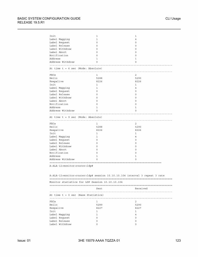
BASIC SYSTEM CONFIGURATION GUIDE RELEASE 19.5.R1
CLI Usage
Issue: 01 3HE 15079 AAAA TQZZA 01 123
Init 1 1Label Mapping 1 4Label Request 0 0Label Release 0 0Label Withdraw 0 0Label Abort 0 0Notification 0 0Address 1 1Address Withdraw 0 0-------------------------------------------------------------------------------At time t = 6 sec (Mode: Absolute)-------------------------------------------------------------------------------FECs 1 2Hello 5288 5290Keepalive 8226 8226Init 1 1Label Mapping 1 4Label Request 0 0Label Release 0 0Label Withdraw 0 0Label Abort 0 0Notification 0 0Address 1 1Address Withdraw 0 0-------------------------------------------------------------------------------At time t = 9 sec (Mode: Absolute)-------------------------------------------------------------------------------FECs 1 2Hello 5288 5290Keepalive 8226 8226Init 1 1Label Mapping 1 4Label Request 0 0Label Release 0 0Label Withdraw 0 0Label Abort 0 0Notification 0 0Address 1 1Address Withdraw 0 0========================================================================A:ALA-12>monitor>router>ldp#
A:ALA-12>monitor>router>ldp# session 10.10.10.104 interval 3 repeat 3 rate===============================================================================Monitor statistics for LDP Session 10.10.10.104===============================================================================
Sent Received-------------------------------------------------------------------------------At time t = 0 sec (Base Statistics)-------------------------------------------------------------------------------FECs 1 2Hello 5289 5290Keepalive 8227 8227Init 1 1Label Mapping 1 4Label Request 0 0Label Release 0 0Label Withdraw 0 0
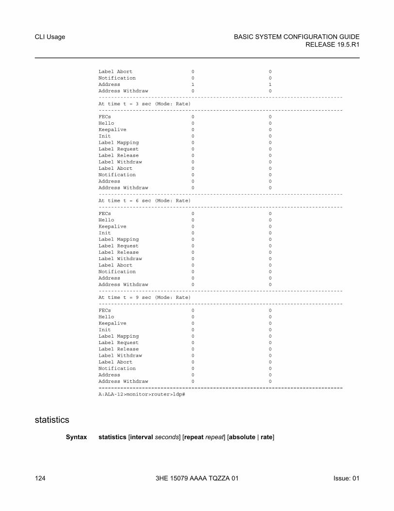
CLI Usage
124
BASIC SYSTEM CONFIGURATION GUIDERELEASE 19.5.R1
3HE 15079 AAAA TQZZA 01 Issue: 01
Label Abort 0 0Notification 0 0Address 1 1Address Withdraw 0 0-------------------------------------------------------------------------------At time t = 3 sec (Mode: Rate)-------------------------------------------------------------------------------FECs 0 0Hello 0 0Keepalive 0 0Init 0 0Label Mapping 0 0Label Request 0 0Label Release 0 0Label Withdraw 0 0Label Abort 0 0Notification 0 0Address 0 0Address Withdraw 0 0-------------------------------------------------------------------------------At time t = 6 sec (Mode: Rate)-------------------------------------------------------------------------------FECs 0 0Hello 0 0Keepalive 0 0Init 0 0Label Mapping 0 0Label Request 0 0Label Release 0 0Label Withdraw 0 0Label Abort 0 0Notification 0 0Address 0 0Address Withdraw 0 0-------------------------------------------------------------------------------At time t = 9 sec (Mode: Rate)-------------------------------------------------------------------------------FECs 0 0Hello 0 0Keepalive 0 0Init 0 0Label Mapping 0 0Label Request 0 0Label Release 0 0Label Withdraw 0 0Label Abort 0 0Notification 0 0Address 0 0Address Withdraw 0 0===============================================================================A:ALA-12>monitor>router>ldp#
statistics
Syntax statistics [interval seconds] [repeat repeat] [absolute | rate]
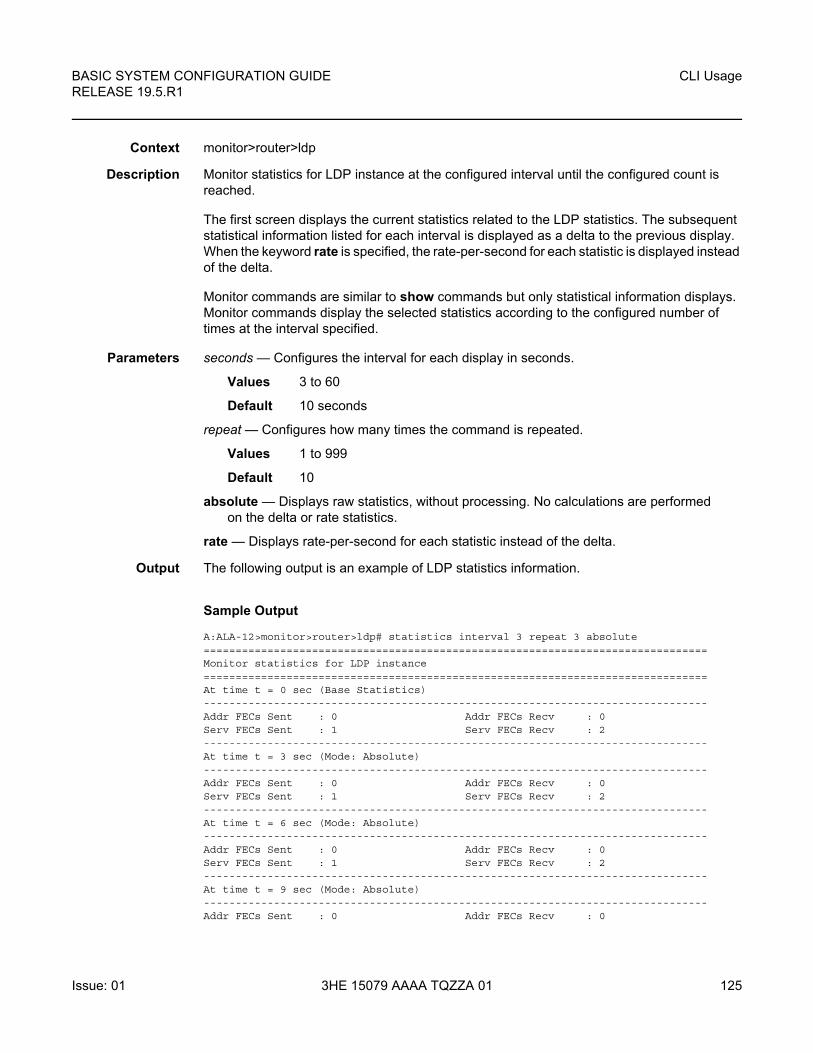
BASIC SYSTEM CONFIGURATION GUIDE RELEASE 19.5.R1
CLI Usage
Issue: 01 3HE 15079 AAAA TQZZA 01 125
Context monitor>router>ldp
Description Monitor statistics for LDP instance at the configured interval until the configured count is reached.
The first screen displays the current statistics related to the LDP statistics. The subsequent statistical information listed for each interval is displayed as a delta to the previous display. When the keyword rate is specified, the rate-per-second for each statistic is displayed instead of the delta.
Monitor commands are similar to show commands but only statistical information displays. Monitor commands display the selected statistics according to the configured number of times at the interval specified.
Parameters seconds — Configures the interval for each display in seconds.
Values 3 to 60
Default 10 seconds
repeat — Configures how many times the command is repeated.
Values 1 to 999
Default 10
absolute — Displays raw statistics, without processing. No calculations are performed on the delta or rate statistics.
rate — Displays rate-per-second for each statistic instead of the delta.
Output The following output is an example of LDP statistics information.
Sample Output
A:ALA-12>monitor>router>ldp# statistics interval 3 repeat 3 absolute===============================================================================Monitor statistics for LDP instance===============================================================================At time t = 0 sec (Base Statistics)-------------------------------------------------------------------------------Addr FECs Sent : 0 Addr FECs Recv : 0Serv FECs Sent : 1 Serv FECs Recv : 2-------------------------------------------------------------------------------At time t = 3 sec (Mode: Absolute)-------------------------------------------------------------------------------Addr FECs Sent : 0 Addr FECs Recv : 0Serv FECs Sent : 1 Serv FECs Recv : 2-------------------------------------------------------------------------------At time t = 6 sec (Mode: Absolute)-------------------------------------------------------------------------------Addr FECs Sent : 0 Addr FECs Recv : 0Serv FECs Sent : 1 Serv FECs Recv : 2-------------------------------------------------------------------------------At time t = 9 sec (Mode: Absolute)-------------------------------------------------------------------------------Addr FECs Sent : 0 Addr FECs Recv : 0
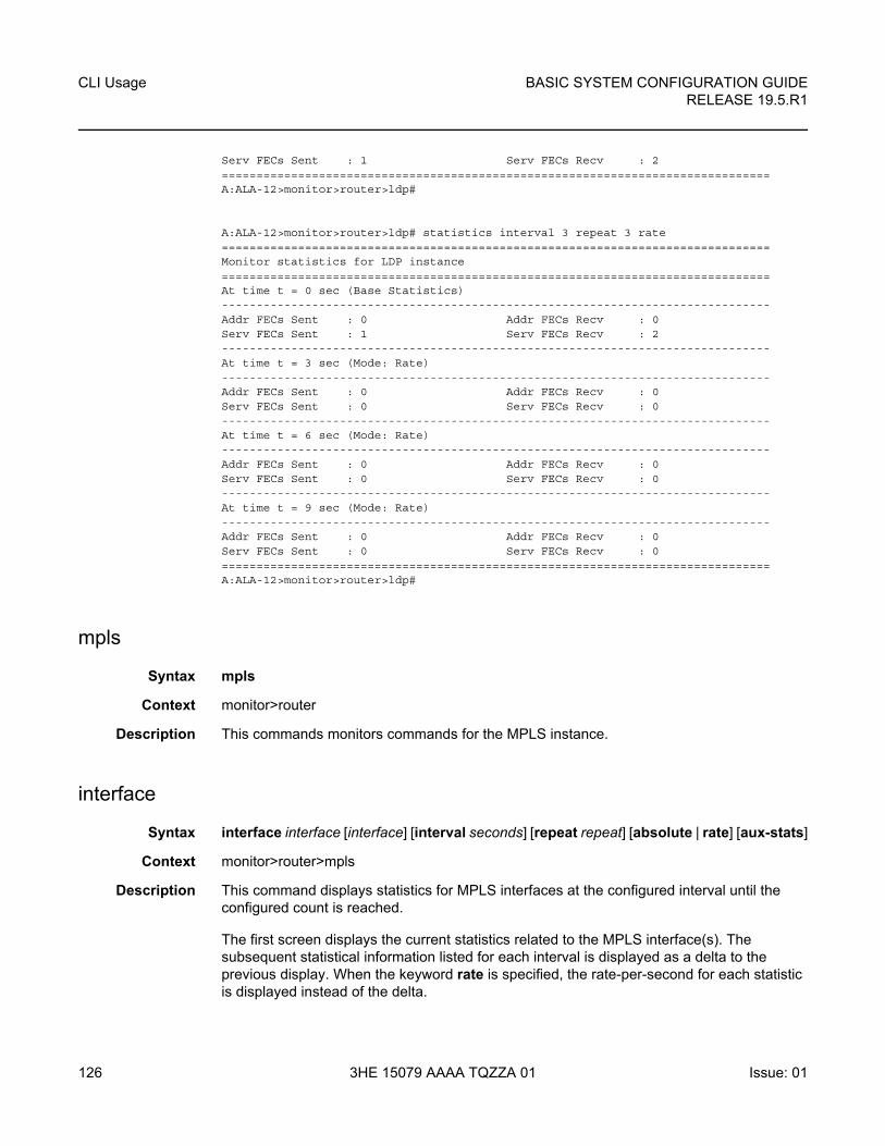
CLI Usage
126
BASIC SYSTEM CONFIGURATION GUIDERELEASE 19.5.R1
3HE 15079 AAAA TQZZA 01 Issue: 01
Serv FECs Sent : 1 Serv FECs Recv : 2===============================================================================A:ALA-12>monitor>router>ldp#
A:ALA-12>monitor>router>ldp# statistics interval 3 repeat 3 rate===============================================================================Monitor statistics for LDP instance===============================================================================At time t = 0 sec (Base Statistics)-------------------------------------------------------------------------------Addr FECs Sent : 0 Addr FECs Recv : 0Serv FECs Sent : 1 Serv FECs Recv : 2-------------------------------------------------------------------------------At time t = 3 sec (Mode: Rate)-------------------------------------------------------------------------------Addr FECs Sent : 0 Addr FECs Recv : 0Serv FECs Sent : 0 Serv FECs Recv : 0-------------------------------------------------------------------------------At time t = 6 sec (Mode: Rate)-------------------------------------------------------------------------------Addr FECs Sent : 0 Addr FECs Recv : 0Serv FECs Sent : 0 Serv FECs Recv : 0-------------------------------------------------------------------------------At time t = 9 sec (Mode: Rate)-------------------------------------------------------------------------------Addr FECs Sent : 0 Addr FECs Recv : 0Serv FECs Sent : 0 Serv FECs Recv : 0===============================================================================A:ALA-12>monitor>router>ldp#
mpls
Syntax mpls
Context monitor>router
Description This commands monitors commands for the MPLS instance.
interface
Syntax interface interface [interface] [interval seconds] [repeat repeat] [absolute | rate] [aux-stats]
Context monitor>router>mpls
Description This command displays statistics for MPLS interfaces at the configured interval until the configured count is reached.
The first screen displays the current statistics related to the MPLS interface(s). The subsequent statistical information listed for each interval is displayed as a delta to the previous display. When the keyword rate is specified, the rate-per-second for each statistic is displayed instead of the delta.
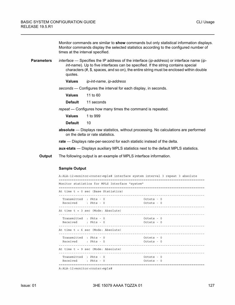
BASIC SYSTEM CONFIGURATION GUIDE RELEASE 19.5.R1
CLI Usage
Issue: 01 3HE 15079 AAAA TQZZA 01 127
Monitor commands are similar to show commands but only statistical information displays. Monitor commands display the selected statistics according to the configured number of times at the interval specified.
Parameters interface — Specifies the IP address of the interface (ip-address) or interface name (ip-int-name). Up to five interfaces can be specified. If the string contains special characters (#, $, spaces, and so on), the entire string must be enclosed within double quotes.
Values ip-int-name, ip-address
seconds — Configures the interval for each display, in seconds.
Values 11 to 60
Default 11 seconds
repeat — Configures how many times the command is repeated.
Values 1 to 999
Default 10
absolute — Displays raw statistics, without processing. No calculations are performed on the delta or rate statistics.
rate — Displays rate-per-second for each statistic instead of the delta.
aux-stats — Displays auxiliary MPLS statistics next to the default MPLS statistics.
Output The following output is an example of MPLS interface information.
Sample Output
A:ALA-12>monitor>router>mpls# interface system interval 3 repeat 3 absolute===============================================================================Monitor statistics for MPLS Interface "system"===============================================================================At time t = 0 sec (Base Statistics)-------------------------------------------------------------------------------
Transmitted : Pkts - 0 Octets - 0Received : Pkts - 0 Octets - 0
-------------------------------------------------------------------------------At time t = 3 sec (Mode: Absolute)-------------------------------------------------------------------------------
Transmitted : Pkts - 0 Octets - 0Received : Pkts - 0 Octets - 0
-------------------------------------------------------------------------------At time t = 6 sec (Mode: Absolute)-------------------------------------------------------------------------------
Transmitted : Pkts - 0 Octets - 0Received : Pkts - 0 Octets - 0
-------------------------------------------------------------------------------At time t = 9 sec (Mode: Absolute)-------------------------------------------------------------------------------
Transmitted : Pkts - 0 Octets - 0Received : Pkts - 0 Octets - 0
===============================================================================A:ALA-12>monitor>router>mpls#
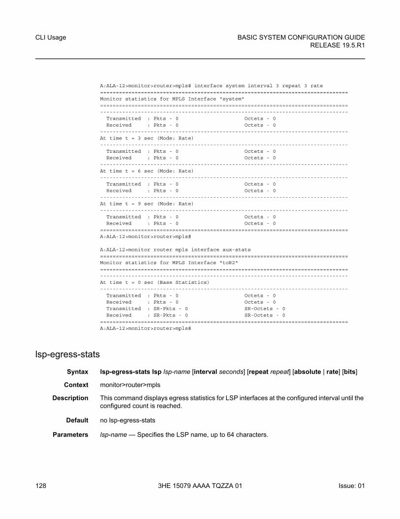
CLI Usage
128
BASIC SYSTEM CONFIGURATION GUIDERELEASE 19.5.R1
3HE 15079 AAAA TQZZA 01 Issue: 01
A:ALA-12>monitor>router>mpls# interface system interval 3 repeat 3 rate===============================================================================Monitor statistics for MPLS Interface "system"===============================================================================-------------------------------------------------------------------------------
Transmitted : Pkts - 0 Octets - 0Received : Pkts - 0 Octets - 0
-------------------------------------------------------------------------------At time t = 3 sec (Mode: Rate)-------------------------------------------------------------------------------
Transmitted : Pkts - 0 Octets - 0Received : Pkts - 0 Octets - 0
-------------------------------------------------------------------------------At time t = 6 sec (Mode: Rate)-------------------------------------------------------------------------------
Transmitted : Pkts - 0 Octets - 0Received : Pkts - 0 Octets - 0
-------------------------------------------------------------------------------At time t = 9 sec (Mode: Rate)-------------------------------------------------------------------------------
Transmitted : Pkts - 0 Octets - 0Received : Pkts - 0 Octets - 0
===============================================================================A:ALA-12>monitor>router>mpls#
A:ALA-12>monitor router mpls interface aux-stats===============================================================================Monitor statistics for MPLS Interface "toR2"===============================================================================-------------------------------------------------------------------------------At time t = 0 sec (Base Statistics)-------------------------------------------------------------------------------
Transmitted : Pkts - 0 Octets - 0Received : Pkts - 0 Octets - 0Transmitted : SR-Pkts - 0 SR-Octets - 0Received : SR-Pkts - 0 SR-Octets - 0
===============================================================================A:ALA-12>monitor>router>mpls#
lsp-egress-stats
Syntax lsp-egress-stats lsp lsp-name [interval seconds] [repeat repeat] [absolute | rate] [bits]
Context monitor>router>mpls
Description This command displays egress statistics for LSP interfaces at the configured interval until the configured count is reached.
Default no lsp-egress-stats
Parameters lsp-name — Specifies the LSP name, up to 64 characters.
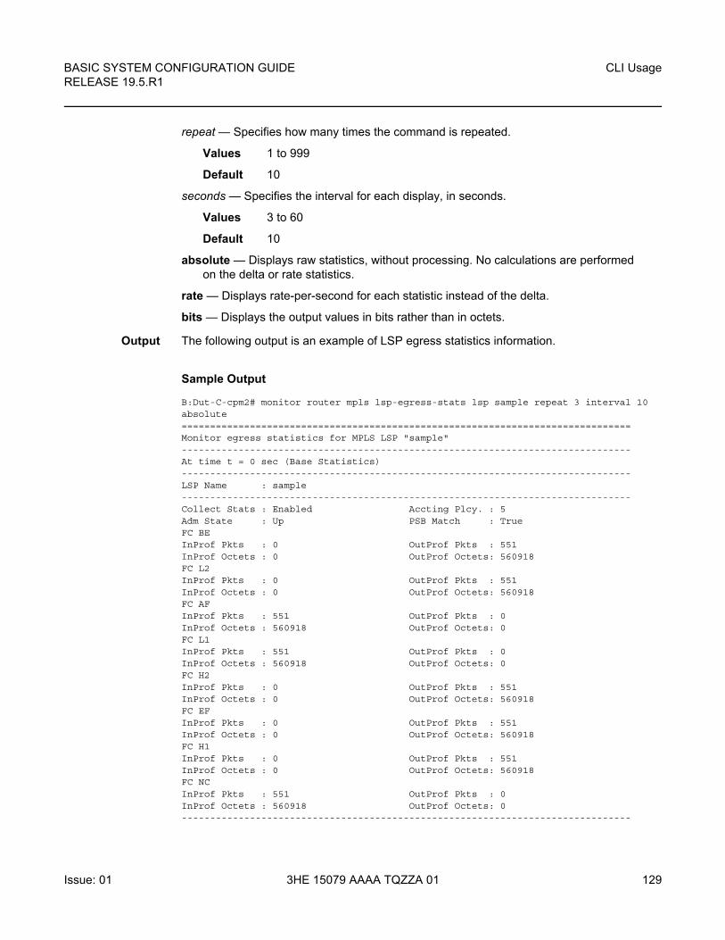
BASIC SYSTEM CONFIGURATION GUIDE RELEASE 19.5.R1
CLI Usage
Issue: 01 3HE 15079 AAAA TQZZA 01 129
repeat — Specifies how many times the command is repeated.
Values 1 to 999
Default 10
seconds — Specifies the interval for each display, in seconds.
Values 3 to 60
Default 10
absolute — Displays raw statistics, without processing. No calculations are performed on the delta or rate statistics.
rate — Displays rate-per-second for each statistic instead of the delta.
bits — Displays the output values in bits rather than in octets.
Output The following output is an example of LSP egress statistics information.
Sample Output
B:Dut-C-cpm2# monitor router mpls lsp-egress-stats lsp sample repeat 3 interval 10absolute===============================================================================Monitor egress statistics for MPLS LSP "sample"-------------------------------------------------------------------------------At time t = 0 sec (Base Statistics)-------------------------------------------------------------------------------LSP Name : sample-------------------------------------------------------------------------------Collect Stats : Enabled Accting Plcy. : 5Adm State : Up PSB Match : TrueFC BEInProf Pkts : 0 OutProf Pkts : 551InProf Octets : 0 OutProf Octets: 560918FC L2InProf Pkts : 0 OutProf Pkts : 551InProf Octets : 0 OutProf Octets: 560918FC AFInProf Pkts : 551 OutProf Pkts : 0InProf Octets : 560918 OutProf Octets: 0FC L1InProf Pkts : 551 OutProf Pkts : 0InProf Octets : 560918 OutProf Octets: 0FC H2InProf Pkts : 0 OutProf Pkts : 551InProf Octets : 0 OutProf Octets: 560918FC EFInProf Pkts : 0 OutProf Pkts : 551InProf Octets : 0 OutProf Octets: 560918FC H1InProf Pkts : 0 OutProf Pkts : 551InProf Octets : 0 OutProf Octets: 560918FC NCInProf Pkts : 551 OutProf Pkts : 0InProf Octets : 560918 OutProf Octets: 0-------------------------------------------------------------------------------
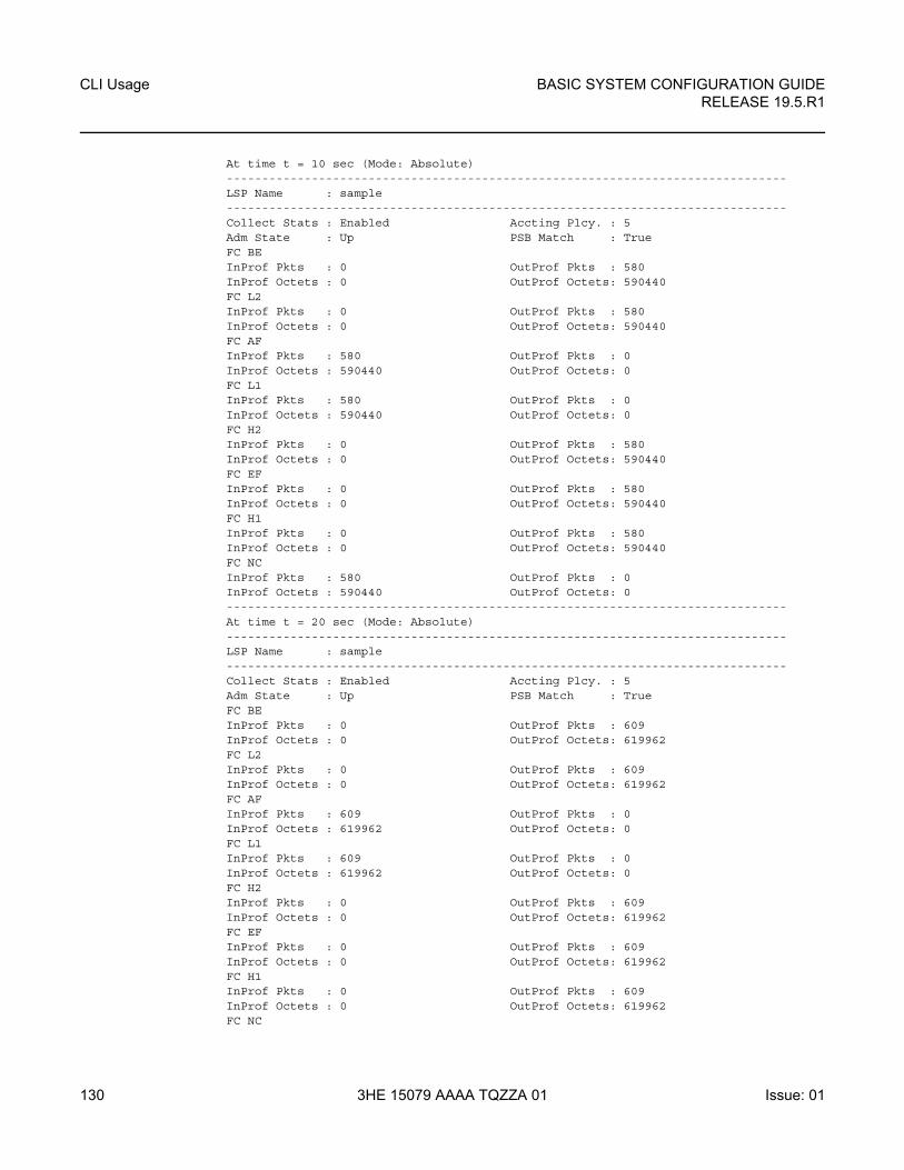
CLI Usage
130
BASIC SYSTEM CONFIGURATION GUIDERELEASE 19.5.R1
3HE 15079 AAAA TQZZA 01 Issue: 01
At time t = 10 sec (Mode: Absolute)-------------------------------------------------------------------------------LSP Name : sample-------------------------------------------------------------------------------Collect Stats : Enabled Accting Plcy. : 5Adm State : Up PSB Match : TrueFC BEInProf Pkts : 0 OutProf Pkts : 580InProf Octets : 0 OutProf Octets: 590440FC L2InProf Pkts : 0 OutProf Pkts : 580InProf Octets : 0 OutProf Octets: 590440FC AFInProf Pkts : 580 OutProf Pkts : 0InProf Octets : 590440 OutProf Octets: 0FC L1InProf Pkts : 580 OutProf Pkts : 0InProf Octets : 590440 OutProf Octets: 0FC H2InProf Pkts : 0 OutProf Pkts : 580InProf Octets : 0 OutProf Octets: 590440FC EFInProf Pkts : 0 OutProf Pkts : 580InProf Octets : 0 OutProf Octets: 590440FC H1InProf Pkts : 0 OutProf Pkts : 580InProf Octets : 0 OutProf Octets: 590440FC NCInProf Pkts : 580 OutProf Pkts : 0InProf Octets : 590440 OutProf Octets: 0-------------------------------------------------------------------------------At time t = 20 sec (Mode: Absolute)-------------------------------------------------------------------------------LSP Name : sample-------------------------------------------------------------------------------Collect Stats : Enabled Accting Plcy. : 5Adm State : Up PSB Match : TrueFC BEInProf Pkts : 0 OutProf Pkts : 609InProf Octets : 0 OutProf Octets: 619962FC L2InProf Pkts : 0 OutProf Pkts : 609InProf Octets : 0 OutProf Octets: 619962FC AFInProf Pkts : 609 OutProf Pkts : 0InProf Octets : 619962 OutProf Octets: 0FC L1InProf Pkts : 609 OutProf Pkts : 0InProf Octets : 619962 OutProf Octets: 0FC H2InProf Pkts : 0 OutProf Pkts : 609InProf Octets : 0 OutProf Octets: 619962FC EFInProf Pkts : 0 OutProf Pkts : 609InProf Octets : 0 OutProf Octets: 619962FC H1InProf Pkts : 0 OutProf Pkts : 609InProf Octets : 0 OutProf Octets: 619962FC NC
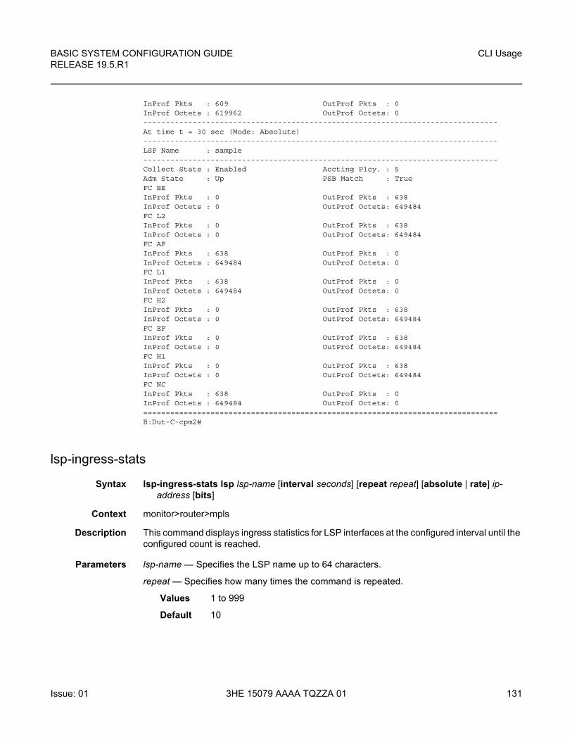
BASIC SYSTEM CONFIGURATION GUIDE RELEASE 19.5.R1
CLI Usage
Issue: 01 3HE 15079 AAAA TQZZA 01 131
InProf Pkts : 609 OutProf Pkts : 0InProf Octets : 619962 OutProf Octets: 0-------------------------------------------------------------------------------At time t = 30 sec (Mode: Absolute)-------------------------------------------------------------------------------LSP Name : sample-------------------------------------------------------------------------------Collect Stats : Enabled Accting Plcy. : 5Adm State : Up PSB Match : TrueFC BEInProf Pkts : 0 OutProf Pkts : 638InProf Octets : 0 OutProf Octets: 649484FC L2InProf Pkts : 0 OutProf Pkts : 638InProf Octets : 0 OutProf Octets: 649484FC AFInProf Pkts : 638 OutProf Pkts : 0InProf Octets : 649484 OutProf Octets: 0FC L1InProf Pkts : 638 OutProf Pkts : 0InProf Octets : 649484 OutProf Octets: 0FC H2InProf Pkts : 0 OutProf Pkts : 638InProf Octets : 0 OutProf Octets: 649484FC EFInProf Pkts : 0 OutProf Pkts : 638InProf Octets : 0 OutProf Octets: 649484FC H1InProf Pkts : 0 OutProf Pkts : 638InProf Octets : 0 OutProf Octets: 649484FC NCInProf Pkts : 638 OutProf Pkts : 0InProf Octets : 649484 OutProf Octets: 0===============================================================================B:Dut-C-cpm2#
lsp-ingress-stats
Syntax lsp-ingress-stats lsp lsp-name [interval seconds] [repeat repeat] [absolute | rate] ip-address [bits]
Context monitor>router>mpls
Description This command displays ingress statistics for LSP interfaces at the configured interval until the configured count is reached.
Parameters lsp-name — Specifies the LSP name up to 64 characters.
repeat — Specifies how many times the command is repeated.
Values 1 to 999
Default 10
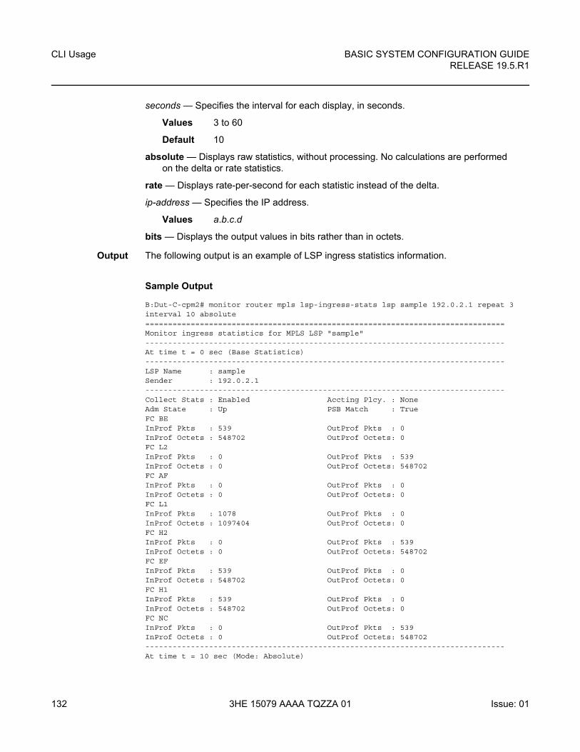
CLI Usage
132
BASIC SYSTEM CONFIGURATION GUIDERELEASE 19.5.R1
3HE 15079 AAAA TQZZA 01 Issue: 01
seconds — Specifies the interval for each display, in seconds.
Values 3 to 60
Default 10
absolute — Displays raw statistics, without processing. No calculations are performed on the delta or rate statistics.
rate — Displays rate-per-second for each statistic instead of the delta.
ip-address — Specifies the IP address.
Values a.b.c.d
bits — Displays the output values in bits rather than in octets.
Output The following output is an example of LSP ingress statistics information.
Sample Output
B:Dut-C-cpm2# monitor router mpls lsp-ingress-stats lsp sample 192.0.2.1 repeat 3interval 10 absolute===============================================================================Monitor ingress statistics for MPLS LSP "sample"-------------------------------------------------------------------------------At time t = 0 sec (Base Statistics)-------------------------------------------------------------------------------LSP Name : sampleSender : 192.0.2.1-------------------------------------------------------------------------------Collect Stats : Enabled Accting Plcy. : NoneAdm State : Up PSB Match : TrueFC BEInProf Pkts : 539 OutProf Pkts : 0InProf Octets : 548702 OutProf Octets: 0FC L2InProf Pkts : 0 OutProf Pkts : 539InProf Octets : 0 OutProf Octets: 548702FC AFInProf Pkts : 0 OutProf Pkts : 0InProf Octets : 0 OutProf Octets: 0FC L1InProf Pkts : 1078 OutProf Pkts : 0InProf Octets : 1097404 OutProf Octets: 0FC H2InProf Pkts : 0 OutProf Pkts : 539InProf Octets : 0 OutProf Octets: 548702FC EFInProf Pkts : 539 OutProf Pkts : 0InProf Octets : 548702 OutProf Octets: 0FC H1InProf Pkts : 539 OutProf Pkts : 0InProf Octets : 548702 OutProf Octets: 0FC NCInProf Pkts : 0 OutProf Pkts : 539InProf Octets : 0 OutProf Octets: 548702-------------------------------------------------------------------------------At time t = 10 sec (Mode: Absolute)
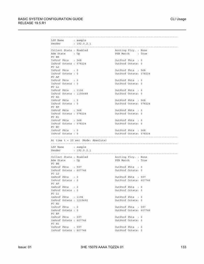
BASIC SYSTEM CONFIGURATION GUIDE RELEASE 19.5.R1
CLI Usage
Issue: 01 3HE 15079 AAAA TQZZA 01 133
-------------------------------------------------------------------------------LSP Name : sampleSender : 192.0.2.1-------------------------------------------------------------------------------Collect Stats : Enabled Accting Plcy. : NoneAdm State : Up PSB Match : TrueFC BEInProf Pkts : 568 OutProf Pkts : 0InProf Octets : 578224 OutProf Octets: 0FC L2InProf Pkts : 0 OutProf Pkts : 568InProf Octets : 0 OutProf Octets: 578224FC AFInProf Pkts : 0 OutProf Pkts : 0InProf Octets : 0 OutProf Octets: 0FC L1InProf Pkts : 1136 OutProf Pkts : 0InProf Octets : 1156448 OutProf Octets: 0FC H2InProf Pkts : 0 OutProf Pkts : 568InProf Octets : 0 OutProf Octets: 578224FC EFInProf Pkts : 568 OutProf Pkts : 0InProf Octets : 578224 OutProf Octets: 0FC H1InProf Pkts : 568 OutProf Pkts : 0InProf Octets : 578224 OutProf Octets: 0FC NCInProf Pkts : 0 OutProf Pkts : 568InProf Octets : 0 OutProf Octets: 578224-------------------------------------------------------------------------------At time t = 20 sec (Mode: Absolute)-------------------------------------------------------------------------------LSP Name : sampleSender : 192.0.2.1-------------------------------------------------------------------------------Collect Stats : Enabled Accting Plcy. : NoneAdm State : Up PSB Match : TrueFC BEInProf Pkts : 597 OutProf Pkts : 0InProf Octets : 607746 OutProf Octets: 0FC L2InProf Pkts : 0 OutProf Pkts : 597InProf Octets : 0 OutProf Octets: 607746FC AFInProf Pkts : 0 OutProf Pkts : 0InProf Octets : 0 OutProf Octets: 0FC L1InProf Pkts : 1194 OutProf Pkts : 0InProf Octets : 1215492 OutProf Octets: 0FC H2InProf Pkts : 0 OutProf Pkts : 597InProf Octets : 0 OutProf Octets: 607746FC EFInProf Pkts : 597 OutProf Pkts : 0InProf Octets : 607746 OutProf Octets: 0FC H1InProf Pkts : 597 OutProf Pkts : 0InProf Octets : 607746 OutProf Octets: 0
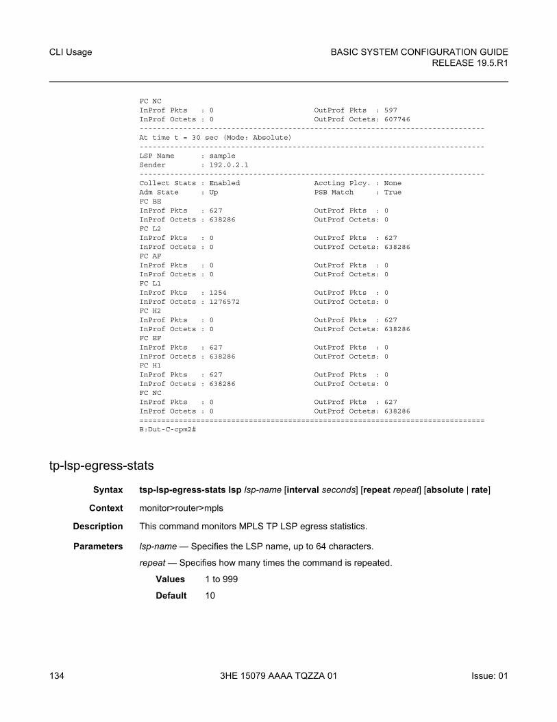
CLI Usage
134
BASIC SYSTEM CONFIGURATION GUIDERELEASE 19.5.R1
3HE 15079 AAAA TQZZA 01 Issue: 01
FC NCInProf Pkts : 0 OutProf Pkts : 597InProf Octets : 0 OutProf Octets: 607746-------------------------------------------------------------------------------At time t = 30 sec (Mode: Absolute)-------------------------------------------------------------------------------LSP Name : sampleSender : 192.0.2.1-------------------------------------------------------------------------------Collect Stats : Enabled Accting Plcy. : NoneAdm State : Up PSB Match : TrueFC BEInProf Pkts : 627 OutProf Pkts : 0InProf Octets : 638286 OutProf Octets: 0FC L2InProf Pkts : 0 OutProf Pkts : 627InProf Octets : 0 OutProf Octets: 638286FC AFInProf Pkts : 0 OutProf Pkts : 0InProf Octets : 0 OutProf Octets: 0FC L1InProf Pkts : 1254 OutProf Pkts : 0InProf Octets : 1276572 OutProf Octets: 0FC H2InProf Pkts : 0 OutProf Pkts : 627InProf Octets : 0 OutProf Octets: 638286FC EFInProf Pkts : 627 OutProf Pkts : 0InProf Octets : 638286 OutProf Octets: 0FC H1InProf Pkts : 627 OutProf Pkts : 0InProf Octets : 638286 OutProf Octets: 0FC NCInProf Pkts : 0 OutProf Pkts : 627InProf Octets : 0 OutProf Octets: 638286===============================================================================B:Dut-C-cpm2#
tp-lsp-egress-stats
Syntax tsp-lsp-egress-stats lsp lsp-name [interval seconds] [repeat repeat] [absolute | rate]
Context monitor>router>mpls
Description This command monitors MPLS TP LSP egress statistics.
Parameters lsp-name — Specifies the LSP name, up to 64 characters.
repeat — Specifies how many times the command is repeated.
Values 1 to 999
Default 10
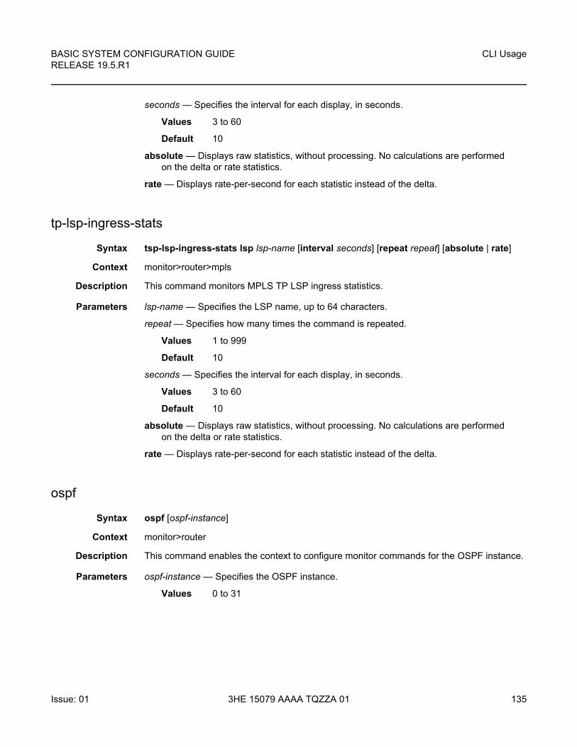
BASIC SYSTEM CONFIGURATION GUIDE RELEASE 19.5.R1
CLI Usage
Issue: 01 3HE 15079 AAAA TQZZA 01 135
seconds — Specifies the interval for each display, in seconds.
Values 3 to 60
Default 10
absolute — Displays raw statistics, without processing. No calculations are performed on the delta or rate statistics.
rate — Displays rate-per-second for each statistic instead of the delta.
tp-lsp-ingress-stats
Syntax tsp-lsp-ingress-stats lsp lsp-name [interval seconds] [repeat repeat] [absolute | rate]
Context monitor>router>mpls
Description This command monitors MPLS TP LSP ingress statistics.
Parameters lsp-name — Specifies the LSP name, up to 64 characters.
repeat — Specifies how many times the command is repeated.
Values 1 to 999
Default 10
seconds — Specifies the interval for each display, in seconds.
Values 3 to 60
Default 10
absolute — Displays raw statistics, without processing. No calculations are performed on the delta or rate statistics.
rate — Displays rate-per-second for each statistic instead of the delta.
ospf
Syntax ospf [ospf-instance]
Context monitor>router
Description This command enables the context to configure monitor commands for the OSPF instance.
Parameters ospf-instance — Specifies the OSPF instance.
Values 0 to 31
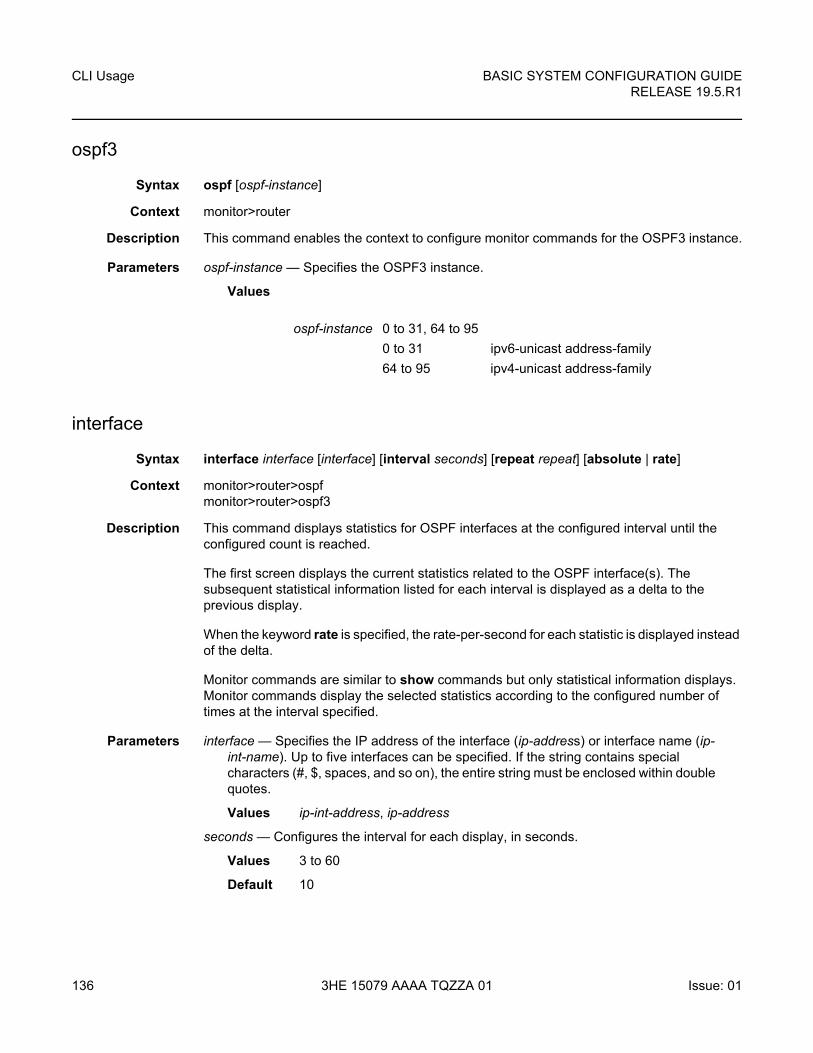
CLI Usage
136
BASIC SYSTEM CONFIGURATION GUIDERELEASE 19.5.R1
3HE 15079 AAAA TQZZA 01 Issue: 01
ospf3
Syntax ospf [ospf-instance]
Context monitor>router
Description This command enables the context to configure monitor commands for the OSPF3 instance.
Parameters ospf-instance — Specifies the OSPF3 instance.
Values
interface
Syntax interface interface [interface] [interval seconds] [repeat repeat] [absolute | rate]
Context monitor>router>ospfmonitor>router>ospf3
Description This command displays statistics for OSPF interfaces at the configured interval until the configured count is reached.
The first screen displays the current statistics related to the OSPF interface(s). The subsequent statistical information listed for each interval is displayed as a delta to the previous display.
When the keyword rate is specified, the rate-per-second for each statistic is displayed instead of the delta.
Monitor commands are similar to show commands but only statistical information displays. Monitor commands display the selected statistics according to the configured number of times at the interval specified.
Parameters interface — Specifies the IP address of the interface (ip-address) or interface name (ip-int-name). Up to five interfaces can be specified. If the string contains special characters (#, $, spaces, and so on), the entire string must be enclosed within double quotes.
Values ip-int-address, ip-address
seconds — Configures the interval for each display, in seconds.
Values 3 to 60
Default 10
ospf-instance 0 to 31, 64 to 95
0 to 31 ipv6-unicast address-family
64 to 95 ipv4-unicast address-family
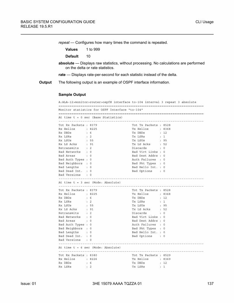
BASIC SYSTEM CONFIGURATION GUIDE RELEASE 19.5.R1
CLI Usage
Issue: 01 3HE 15079 AAAA TQZZA 01 137
repeat — Configures how many times the command is repeated.
Values 1 to 999
Default 10
absolute — Displays raw statistics, without processing. No calculations are performed on the delta or rate statistics.
rate — Displays rate-per-second for each statistic instead of the delta.
Output The following output is an example of OSPF interface information.
Sample Output
A:ALA-12>monitor>router>ospf# interface to-104 interval 3 repeat 3 absolute===============================================================================Monitor statistics for OSPF Interface "to-104"===============================================================================At time t = 0 sec (Base Statistics)-------------------------------------------------------------------------------Tot Rx Packets : 8379 Tot Tx Packets : 8528Rx Hellos : 8225 Tx Hellos : 8368Rx DBDs : 6 Tx DBDs : 12Rx LSRs : 2 Tx LSRs : 1Rx LSUs : 55 Tx LSUs : 95Rx LS Acks : 91 Tx LS Acks : 52Retransmits : 2 Discards : 0Bad Networks : 0 Bad Virt Links : 0Bad Areas : 0 Bad Dest Addrs : 0Bad Auth Types : 0 Auth Failures : 0Bad Neighbors : 0 Bad Pkt Types : 0Bad Lengths : 0 Bad Hello Int. : 0Bad Dead Int. : 0 Bad Options : 0Bad Versions : 0-------------------------------------------------------------------------------At time t = 3 sec (Mode: Absolute)-------------------------------------------------------------------------------Tot Rx Packets : 8379 Tot Tx Packets : 8528Rx Hellos : 8225 Tx Hellos : 8368Rx DBDs : 6 Tx DBDs : 12Rx LSRs : 2 Tx LSRs : 1Rx LSUs : 55 Tx LSUs : 95Rx LS Acks : 91 Tx LS Acks : 52Retransmits : 2 Discards : 0Bad Networks : 0 Bad Virt Links : 0Bad Areas : 0 Bad Dest Addrs : 0Bad Auth Types : 0 Auth Failures : 0Bad Neighbors : 0 Bad Pkt Types : 0Bad Lengths : 0 Bad Hello Int. : 0Bad Dead Int. : 0 Bad Options : 0Bad Versions : 0-------------------------------------------------------------------------------At time t = 6 sec (Mode: Absolute)-------------------------------------------------------------------------------Tot Rx Packets : 8380 Tot Tx Packets : 8529Rx Hellos : 8226 Tx Hellos : 8369Rx DBDs : 6 Tx DBDs : 12Rx LSRs : 2 Tx LSRs : 1
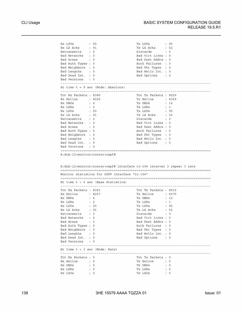
CLI Usage
138
BASIC SYSTEM CONFIGURATION GUIDERELEASE 19.5.R1
3HE 15079 AAAA TQZZA 01 Issue: 01
Rx LSUs : 55 Tx LSUs : 95Rx LS Acks : 91 Tx LS Acks : 52Retransmits : 2 Discards : 0Bad Networks : 0 Bad Virt Links : 0Bad Areas : 0 Bad Dest Addrs : 0Bad Auth Types : 0 Auth Failures : 0Bad Neighbors : 0 Bad Pkt Types : 0Bad Lengths : 0 Bad Hello Int. : 0Bad Dead Int. : 0 Bad Options : 0Bad Versions : 0-------------------------------------------------------------------------------At time t = 9 sec (Mode: Absolute)-------------------------------------------------------------------------------Tot Rx Packets : 8380 Tot Tx Packets : 8529Rx Hellos : 8226 Tx Hellos : 8369Rx DBDs : 6 Tx DBDs : 12Rx LSRs : 2 Tx LSRs : 1Rx LSUs : 55 Tx LSUs : 95Rx LS Acks : 91 Tx LS Acks : 52Retransmits : 2 Discards : 0Bad Networks : 0 Bad Virt Links : 0Bad Areas : 0 Bad Dest Addrs : 0Bad Auth Types : 0 Auth Failures : 0Bad Neighbors : 0 Bad Pkt Types : 0Bad Lengths : 0 Bad Hello Int. : 0Bad Dead Int. : 0 Bad Options : 0Bad Versions : 0===============================================================================A:ALA-12>monitor>router>ospf#
A:ALA-12>monitor>router>ospf# interface to-104 interval 3 repeat 3 rate===============================================================================Monitor statistics for OSPF Interface "to-104"===============================================================================At time t = 0 sec (Base Statistics)-------------------------------------------------------------------------------Tot Rx Packets : 8381 Tot Tx Packets : 8530Rx Hellos : 8227 Tx Hellos : 8370Rx DBDs : 6 Tx DBDs : 12Rx LSRs : 2 Tx LSRs : 1Rx LSUs : 55 Tx LSUs : 95Rx LS Acks : 91 Tx LS Acks : 52Retransmits : 2 Discards : 0Bad Networks : 0 Bad Virt Links : 0Bad Areas : 0 Bad Dest Addrs : 0Bad Auth Types : 0 Auth Failures : 0Bad Neighbors : 0 Bad Pkt Types : 0Bad Lengths : 0 Bad Hello Int. : 0Bad Dead Int. : 0 Bad Options : 0Bad Versions : 0-------------------------------------------------------------------------------At time t = 3 sec (Mode: Rate)-------------------------------------------------------------------------------Tot Rx Packets : 0 Tot Tx Packets : 0Rx Hellos : 0 Tx Hellos : 0Rx DBDs : 0 Tx DBDs : 0Rx LSRs : 0 Tx LSRs : 0Rx LSUs : 0 Tx LSUs : 0
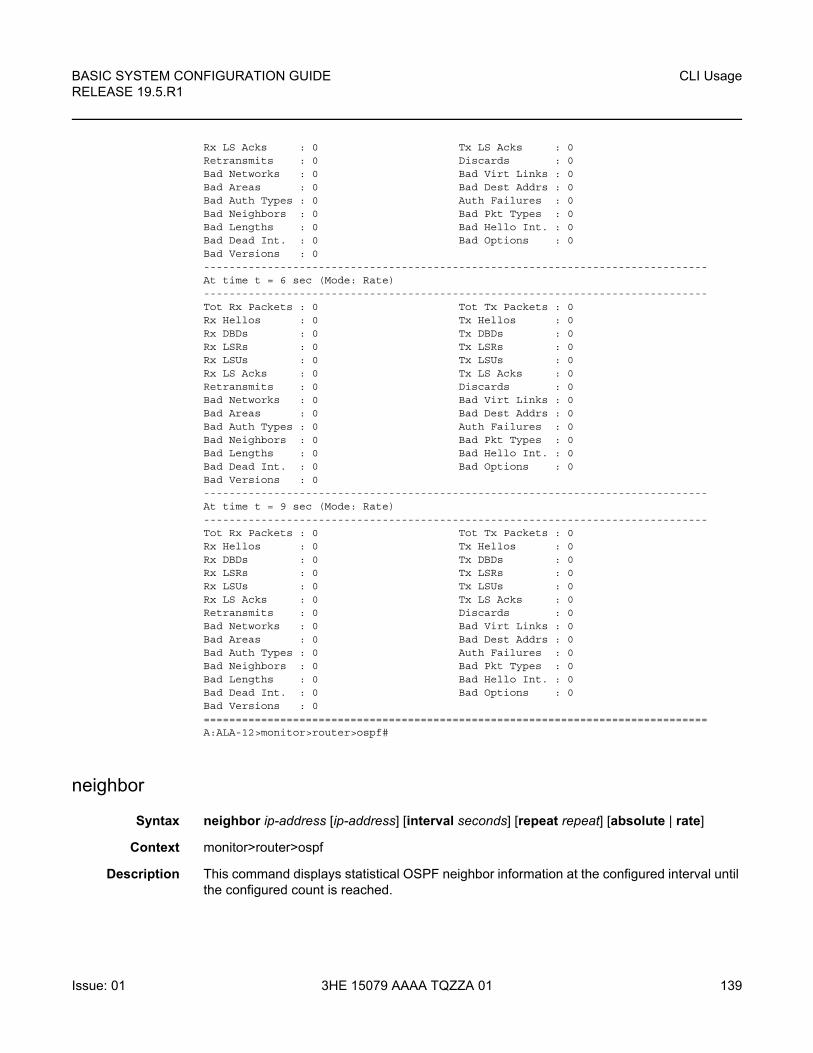
BASIC SYSTEM CONFIGURATION GUIDE RELEASE 19.5.R1
CLI Usage
Issue: 01 3HE 15079 AAAA TQZZA 01 139
Rx LS Acks : 0 Tx LS Acks : 0Retransmits : 0 Discards : 0Bad Networks : 0 Bad Virt Links : 0Bad Areas : 0 Bad Dest Addrs : 0Bad Auth Types : 0 Auth Failures : 0Bad Neighbors : 0 Bad Pkt Types : 0Bad Lengths : 0 Bad Hello Int. : 0Bad Dead Int. : 0 Bad Options : 0Bad Versions : 0-------------------------------------------------------------------------------At time t = 6 sec (Mode: Rate)-------------------------------------------------------------------------------Tot Rx Packets : 0 Tot Tx Packets : 0Rx Hellos : 0 Tx Hellos : 0Rx DBDs : 0 Tx DBDs : 0Rx LSRs : 0 Tx LSRs : 0Rx LSUs : 0 Tx LSUs : 0Rx LS Acks : 0 Tx LS Acks : 0Retransmits : 0 Discards : 0Bad Networks : 0 Bad Virt Links : 0Bad Areas : 0 Bad Dest Addrs : 0Bad Auth Types : 0 Auth Failures : 0Bad Neighbors : 0 Bad Pkt Types : 0Bad Lengths : 0 Bad Hello Int. : 0Bad Dead Int. : 0 Bad Options : 0Bad Versions : 0-------------------------------------------------------------------------------At time t = 9 sec (Mode: Rate)-------------------------------------------------------------------------------Tot Rx Packets : 0 Tot Tx Packets : 0Rx Hellos : 0 Tx Hellos : 0Rx DBDs : 0 Tx DBDs : 0Rx LSRs : 0 Tx LSRs : 0Rx LSUs : 0 Tx LSUs : 0Rx LS Acks : 0 Tx LS Acks : 0Retransmits : 0 Discards : 0Bad Networks : 0 Bad Virt Links : 0Bad Areas : 0 Bad Dest Addrs : 0Bad Auth Types : 0 Auth Failures : 0Bad Neighbors : 0 Bad Pkt Types : 0Bad Lengths : 0 Bad Hello Int. : 0Bad Dead Int. : 0 Bad Options : 0Bad Versions : 0===============================================================================A:ALA-12>monitor>router>ospf#
neighbor
Syntax neighbor ip-address [ip-address] [interval seconds] [repeat repeat] [absolute | rate]
Context monitor>router>ospf
Description This command displays statistical OSPF neighbor information at the configured interval until the configured count is reached.
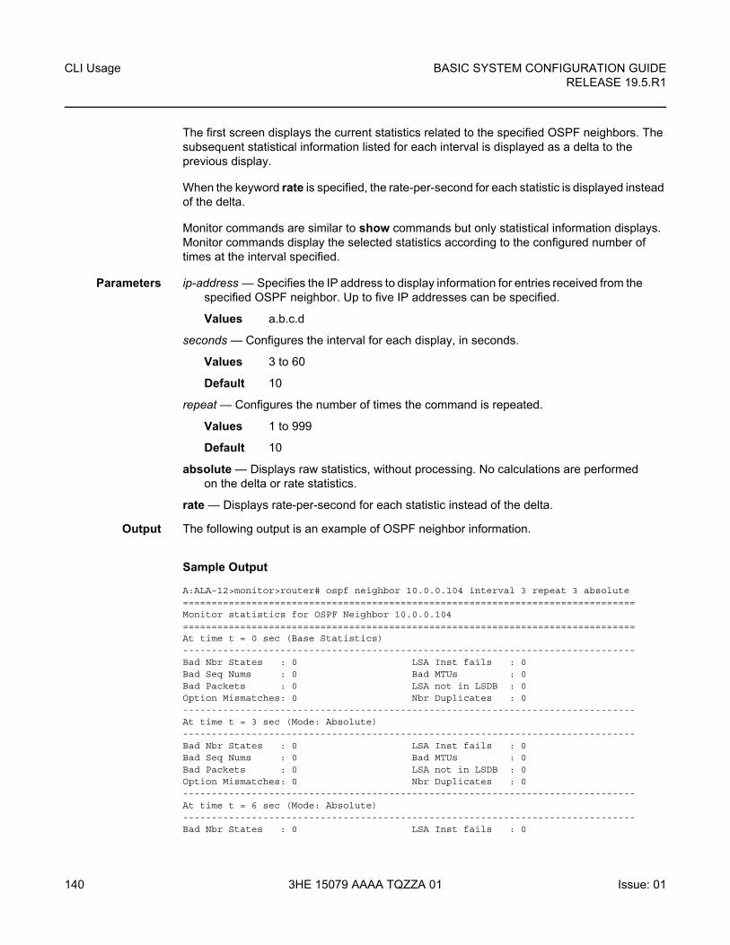
CLI Usage
140
BASIC SYSTEM CONFIGURATION GUIDERELEASE 19.5.R1
3HE 15079 AAAA TQZZA 01 Issue: 01
The first screen displays the current statistics related to the specified OSPF neighbors. The subsequent statistical information listed for each interval is displayed as a delta to the previous display.
When the keyword rate is specified, the rate-per-second for each statistic is displayed instead of the delta.
Monitor commands are similar to show commands but only statistical information displays. Monitor commands display the selected statistics according to the configured number of times at the interval specified.
Parameters ip-address — Specifies the IP address to display information for entries received from the specified OSPF neighbor. Up to five IP addresses can be specified.
Values a.b.c.d
seconds — Configures the interval for each display, in seconds.
Values 3 to 60
Default 10
repeat — Configures the number of times the command is repeated.
Values 1 to 999
Default 10
absolute — Displays raw statistics, without processing. No calculations are performed on the delta or rate statistics.
rate — Displays rate-per-second for each statistic instead of the delta.
Output The following output is an example of OSPF neighbor information.
Sample Output
A:ALA-12>monitor>router# ospf neighbor 10.0.0.104 interval 3 repeat 3 absolute===============================================================================Monitor statistics for OSPF Neighbor 10.0.0.104===============================================================================At time t = 0 sec (Base Statistics)-------------------------------------------------------------------------------Bad Nbr States : 0 LSA Inst fails : 0Bad Seq Nums : 0 Bad MTUs : 0Bad Packets : 0 LSA not in LSDB : 0Option Mismatches: 0 Nbr Duplicates : 0-------------------------------------------------------------------------------At time t = 3 sec (Mode: Absolute)-------------------------------------------------------------------------------Bad Nbr States : 0 LSA Inst fails : 0Bad Seq Nums : 0 Bad MTUs : 0Bad Packets : 0 LSA not in LSDB : 0Option Mismatches: 0 Nbr Duplicates : 0-------------------------------------------------------------------------------At time t = 6 sec (Mode: Absolute)-------------------------------------------------------------------------------Bad Nbr States : 0 LSA Inst fails : 0
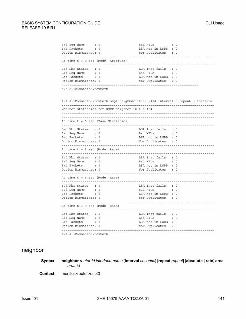
BASIC SYSTEM CONFIGURATION GUIDE RELEASE 19.5.R1
CLI Usage
Issue: 01 3HE 15079 AAAA TQZZA 01 141
Bad Seq Nums : 0 Bad MTUs : 0Bad Packets : 0 LSA not in LSDB : 0Option Mismatches: 0 Nbr Duplicates : 0-------------------------------------------------------------------------------At time t = 9 sec (Mode: Absolute)-------------------------------------------------------------------------------Bad Nbr States : 0 LSA Inst fails : 0Bad Seq Nums : 0 Bad MTUs : 0Bad Packets : 0 LSA not in LSDB : 0Option Mismatches: 0 Nbr Duplicates : 0=======================================================================A:ALA-12>monitor>router#
A:ALA-12>monitor>router# ospf neighbor 10.0.0.104 interval 3 repeat 3 absolute===============================================================================Monitor statistics for OSPF Neighbor 10.0.0.104===============================================================================-------------------------------------------------------------------------------At time t = 0 sec (Base Statistics)-------------------------------------------------------------------------------Bad Nbr States : 0 LSA Inst fails : 0Bad Seq Nums : 0 Bad MTUs : 0Bad Packets : 0 LSA not in LSDB : 0Option Mismatches: 0 Nbr Duplicates : 0-------------------------------------------------------------------------------At time t = 3 sec (Mode: Rate)-------------------------------------------------------------------------------Bad Nbr States : 0 LSA Inst fails : 0Bad Seq Nums : 0 Bad MTUs : 0Bad Packets : 0 LSA not in LSDB : 0Option Mismatches: 0 Nbr Duplicates : 0-------------------------------------------------------------------------------At time t = 6 sec (Mode: Rate)-------------------------------------------------------------------------------Bad Nbr States : 0 LSA Inst fails : 0Bad Seq Nums : 0 Bad MTUs : 0Bad Packets : 0 LSA not in LSDB : 0Option Mismatches: 0 Nbr Duplicates : 0-------------------------------------------------------------------------------At time t = 9 sec (Mode: Rate)-------------------------------------------------------------------------------Bad Nbr States : 0 LSA Inst fails : 0Bad Seq Nums : 0 Bad MTUs : 0Bad Packets : 0 LSA not in LSDB : 0Option Mismatches: 0 Nbr Duplicates : 0===============================================================================A:ALA-12>monitor>router#
neighbor
Syntax neighbor router-id interface-name [interval seconds] [repeat repeat] [absolute | rate] area area-id
Context monitor>router>ospf3
CLI Usage
142
BASIC SYSTEM CONFIGURATION GUIDERELEASE 19.5.R1
3HE 15079 AAAA TQZZA 01 Issue: 01
Description This command displays statistical OSPF3 neighbor information at the configured interval until the configured count is reached.
The first screen displays the current statistics related to the specified OSPF3 neighbor(s). The subsequent statistical information listed for each interval is displayed as a delta to the previous display.
When the keyword rate is specified, the rate-per-second for each statistic is displayed instead of the delta.
Monitor commands are similar to show commands but only statistical information displays. Monitor commands display the selected statistics according to the configured number of times at the interval specified.
Parameters router-id — Specifies the IP address.
Values a.b.c.d
interface-name — Specifies the interface name, up to 32 characters.
seconds — Configures the interval for each display, in seconds.
Values 3 to 60
Default 10
repeat — Configures the number of times the command is repeated.
Values 1 to 999
Default 10
absolute — Displays raw statistics, without processing. No calculations are performed on the delta or rate statistics.
rate — Displays rate-per-second for each statistic instead of the delta.
area-id — Specifies the OSPF area, up to 256 characters.
virtual-link
Syntax virtual-link nbr-rtr-id area area-id [interval seconds] [repeat repeat] [absolute | rate]
Context monitor>router>ospfmonitor>router>ospf3
Description This command displays statistical OSPF virtual link information at the configured interval until the configured count is reached.
The first screen displays the current statistics related to the specified neighbor(s). The subsequent statistical information listed for each interval is displayed as a delta to the previous display.
When the keyword rate is specified, the rate-per-second for each statistic is displayed instead of the delta.
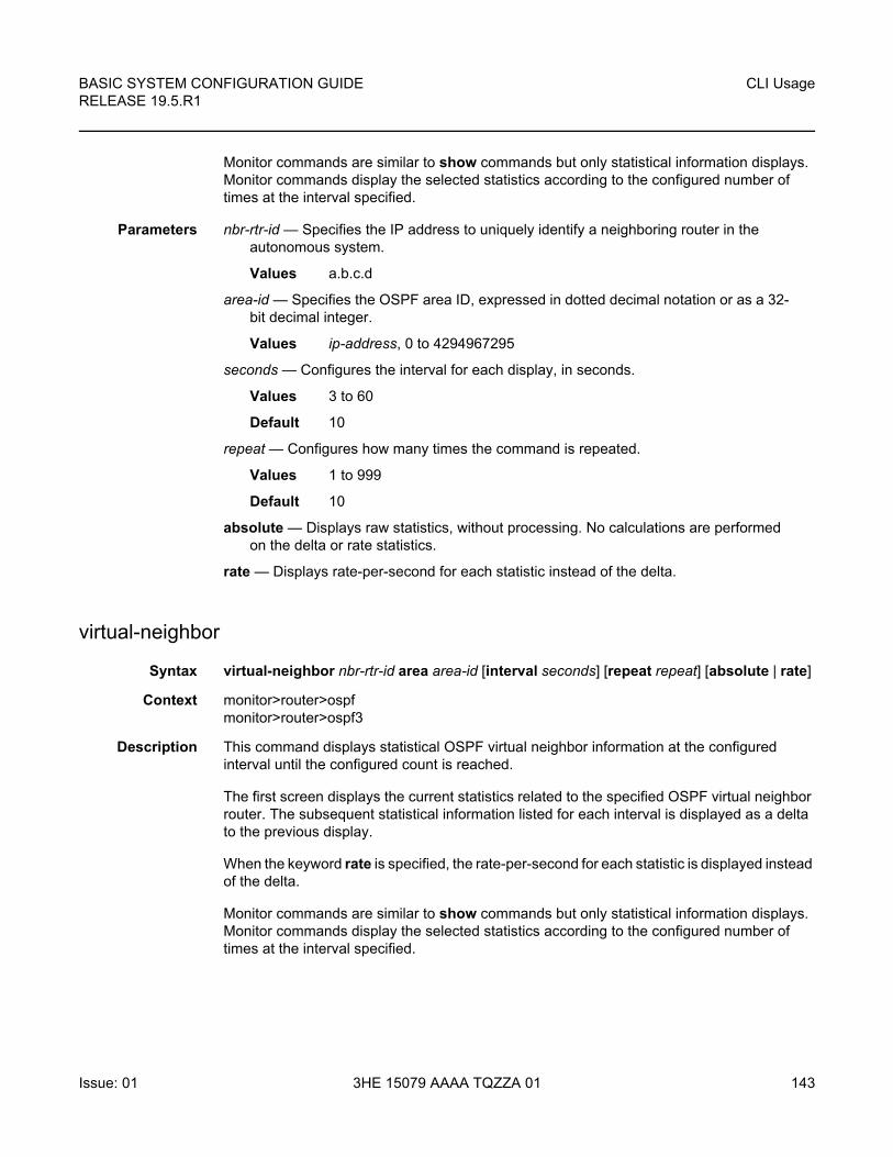
BASIC SYSTEM CONFIGURATION GUIDE RELEASE 19.5.R1
CLI Usage
Issue: 01 3HE 15079 AAAA TQZZA 01 143
Monitor commands are similar to show commands but only statistical information displays. Monitor commands display the selected statistics according to the configured number of times at the interval specified.
Parameters nbr-rtr-id — Specifies the IP address to uniquely identify a neighboring router in the autonomous system.
Values a.b.c.d
area-id — Specifies the OSPF area ID, expressed in dotted decimal notation or as a 32-bit decimal integer.
Values ip-address, 0 to 4294967295
seconds — Configures the interval for each display, in seconds.
Values 3 to 60
Default 10
repeat — Configures how many times the command is repeated.
Values 1 to 999
Default 10
absolute — Displays raw statistics, without processing. No calculations are performed on the delta or rate statistics.
rate — Displays rate-per-second for each statistic instead of the delta.
virtual-neighbor
Syntax virtual-neighbor nbr-rtr-id area area-id [interval seconds] [repeat repeat] [absolute | rate]
Context monitor>router>ospfmonitor>router>ospf3
Description This command displays statistical OSPF virtual neighbor information at the configured interval until the configured count is reached.
The first screen displays the current statistics related to the specified OSPF virtual neighbor router. The subsequent statistical information listed for each interval is displayed as a delta to the previous display.
When the keyword rate is specified, the rate-per-second for each statistic is displayed instead of the delta.
Monitor commands are similar to show commands but only statistical information displays. Monitor commands display the selected statistics according to the configured number of times at the interval specified.
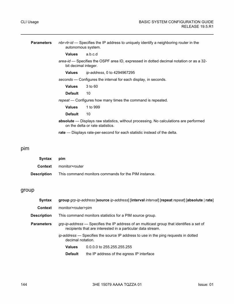
CLI Usage
144
BASIC SYSTEM CONFIGURATION GUIDERELEASE 19.5.R1
3HE 15079 AAAA TQZZA 01 Issue: 01
Parameters nbr-rtr-id — Specifies the IP address to uniquely identify a neighboring router in the autonomous system.
Values a.b.c.d
area-id — Specifies the OSPF area ID, expressed in dotted decimal notation or as a 32-bit decimal integer.
Values ip-address, 0 to 4294967295
seconds — Configures the interval for each display, in seconds.
Values 3 to 60
Default 10
repeat — Configures how many times the command is repeated.
Values 1 to 999
Default 10
absolute — Displays raw statistics, without processing. No calculations are performed on the delta or rate statistics.
rate — Displays rate-per-second for each statistic instead of the delta.
pim
Syntax pim
Context monitor>router
Description This command monitors commands for the PIM instance.
group
Syntax group grp-ip-address [source ip-address] [interval interval] [repeat repeat] [absolute | rate]
Context monitor>router>pim
Description This command monitors statistics for a PIM source group.
Parameters grp-ip-address — Specifies the IP address of an multicast group that identifies a set of recipients that are interested in a particular data stream.
ip-address — Specifies the source IP address to use in the ping requests in dotted decimal notation.
Values 0.0.0.0 to 255.255.255.255
Default the IP address of the egress IP interface
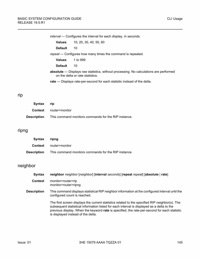
BASIC SYSTEM CONFIGURATION GUIDE RELEASE 19.5.R1
CLI Usage
Issue: 01 3HE 15079 AAAA TQZZA 01 145
interval — Configures the interval for each display, in seconds.
Values 10, 20, 30, 40, 50, 60
Default 10
repeat — Configures how many times the command is repeated.
Values 1 to 999
Default 10
absolute — Displays raw statistics, without processing. No calculations are performed on the delta or rate statistics.
rate — Displays rate-per-second for each statistic instead of the delta.
rip
Syntax rip
Context router>monitor
Description This command monitors commands for the RIP instance.
ripng
Syntax ripng
Context router>monitor
Description This command monitors commands for the RIP instance.
neighbor
Syntax neighbor neighbor [neighbor] [interval seconds] [repeat repeat] [absolute | rate]
Context monitor>router>ripmonitor>router>ripng
Description This command displays statistical RIP neighbor information at the configured interval until the configured count is reached.
The first screen displays the current statistics related to the specified RIP neighbor(s). The subsequent statistical information listed for each interval is displayed as a delta to the previous display. When the keyword rate is specified, the rate-per-second for each statistic is displayed instead of the delta.
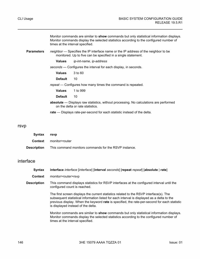
CLI Usage
146
BASIC SYSTEM CONFIGURATION GUIDERELEASE 19.5.R1
3HE 15079 AAAA TQZZA 01 Issue: 01
Monitor commands are similar to show commands but only statistical information displays. Monitor commands display the selected statistics according to the configured number of times at the interval specified.
Parameters neighbor — Specifies the IP interface name or the IP address of the neighbor to be monitored. Up to five can be specified in a single statement.
Values ip-int-name, ip-address
seconds — Configures the interval for each display, in seconds.
Values 3 to 60
Default 10
repeat — Configures how many times the command is repeated.
Values 1 to 999
Default 10
absolute — Displays raw statistics, without processing. No calculations are performed on the delta or rate statistics.
rate — Displays rate-per-second for each statistic instead of the delta.
rsvp
Syntax rsvp
Context monitor>router
Description This command monitors commands for the RSVP instance.
interface
Syntax interface interface [interface] [interval seconds] [repeat repeat] [absolute | rate]
Context monitor>router>rsvp
Description This command displays statistics for RSVP interfaces at the configured interval until the configured count is reached.
The first screen displays the current statistics related to the RSVP interface(s). The subsequent statistical information listed for each interval is displayed as a delta to the previous display. When the keyword rate is specified, the rate-per-second for each statistic is displayed instead of the delta.
Monitor commands are similar to show commands but only statistical information displays. Monitor commands display the selected statistics according to the configured number of times at the interval specified.
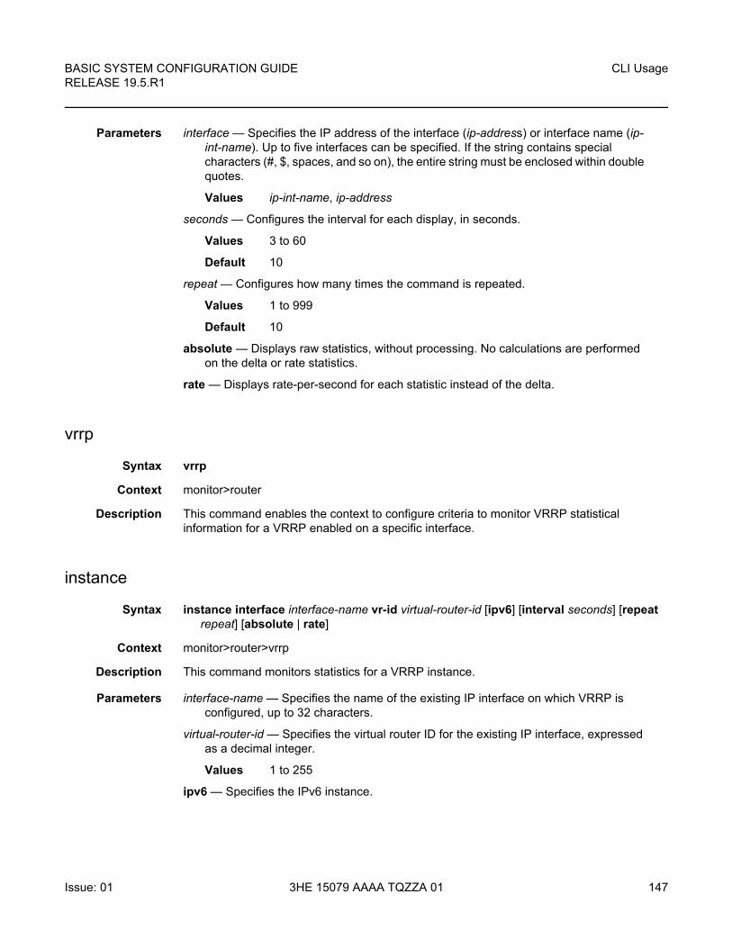
BASIC SYSTEM CONFIGURATION GUIDE RELEASE 19.5.R1
CLI Usage
Issue: 01 3HE 15079 AAAA TQZZA 01 147
Parameters interface — Specifies the IP address of the interface (ip-address) or interface name (ip-int-name). Up to five interfaces can be specified. If the string contains special characters (#, $, spaces, and so on), the entire string must be enclosed within double quotes.
Values ip-int-name, ip-address
seconds — Configures the interval for each display, in seconds.
Values 3 to 60
Default 10
repeat — Configures how many times the command is repeated.
Values 1 to 999
Default 10
absolute — Displays raw statistics, without processing. No calculations are performed on the delta or rate statistics.
rate — Displays rate-per-second for each statistic instead of the delta.
vrrp
Syntax vrrp
Context monitor>router
Description This command enables the context to configure criteria to monitor VRRP statistical information for a VRRP enabled on a specific interface.
instance
Syntax instance interface interface-name vr-id virtual-router-id [ipv6] [interval seconds] [repeat repeat] [absolute | rate]
Context monitor>router>vrrp
Description This command monitors statistics for a VRRP instance.
Parameters interface-name — Specifies the name of the existing IP interface on which VRRP is configured, up to 32 characters.
virtual-router-id — Specifies the virtual router ID for the existing IP interface, expressed as a decimal integer.
Values 1 to 255
ipv6 — Specifies the IPv6 instance.
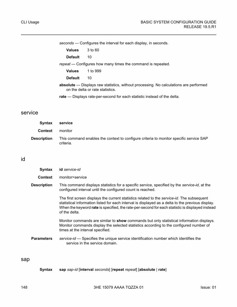
CLI Usage
148
BASIC SYSTEM CONFIGURATION GUIDERELEASE 19.5.R1
3HE 15079 AAAA TQZZA 01 Issue: 01
seconds — Configures the interval for each display, in seconds.
Values 3 to 60
Default 10
repeat — Configures how many times the command is repeated.
Values 1 to 999
Default 10
absolute — Displays raw statistics, without processing. No calculations are performed on the delta or rate statistics.
rate — Displays rate-per-second for each statistic instead of the delta.
service
Syntax service
Context monitor
Description This command enables the context to configure criteria to monitor specific service SAP criteria.
id
Syntax id service-id
Context monitor>service
Description This command displays statistics for a specific service, specified by the service-id, at the configured interval until the configured count is reached.
The first screen displays the current statistics related to the service-id. The subsequent statistical information listed for each interval is displayed as a delta to the previous display. When the keyword rate is specified, the rate-per-second for each statistic is displayed instead of the delta.
Monitor commands are similar to show commands but only statistical information displays. Monitor commands display the selected statistics according to the configured number of times at the interval specified.
Parameters service-id — Specifies the unique service identification number which identifies the service in the service domain.
sap
Syntax sap sap-id [interval seconds] [repeat repeat] [absolute | rate]
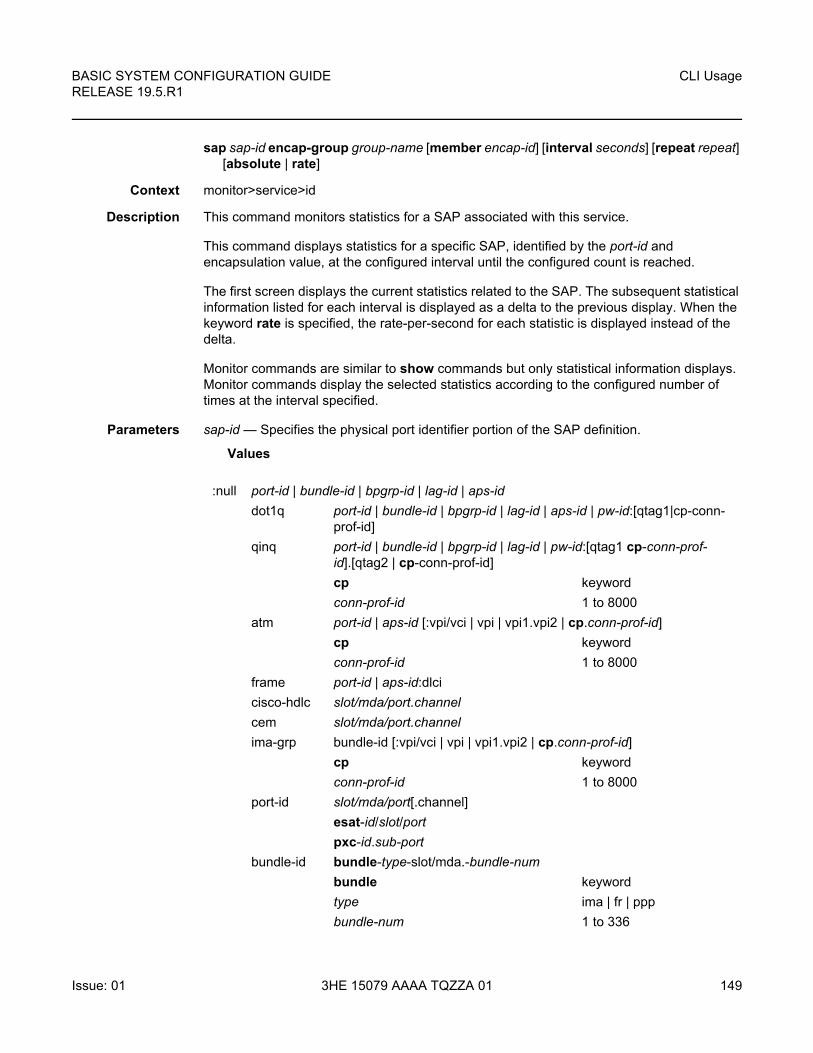
BASIC SYSTEM CONFIGURATION GUIDE RELEASE 19.5.R1
CLI Usage
Issue: 01 3HE 15079 AAAA TQZZA 01 149
sap sap-id encap-group group-name [member encap-id] [interval seconds] [repeat repeat] [absolute | rate]
Context monitor>service>id
Description This command monitors statistics for a SAP associated with this service.
This command displays statistics for a specific SAP, identified by the port-id and encapsulation value, at the configured interval until the configured count is reached.
The first screen displays the current statistics related to the SAP. The subsequent statistical information listed for each interval is displayed as a delta to the previous display. When the keyword rate is specified, the rate-per-second for each statistic is displayed instead of the delta.
Monitor commands are similar to show commands but only statistical information displays. Monitor commands display the selected statistics according to the configured number of times at the interval specified.
Parameters sap-id — Specifies the physical port identifier portion of the SAP definition.
Values
:null port-id | bundle-id | bpgrp-id | lag-id | aps-id
dot1q port-id | bundle-id | bpgrp-id | lag-id | aps-id | pw-id:[qtag1|cp-conn-prof-id]
qinq port-id | bundle-id | bpgrp-id | lag-id | pw-id:[qtag1 cp-conn-prof-id].[qtag2 | cp-conn-prof-id]
cp keyword
conn-prof-id 1 to 8000
atm port-id | aps-id [:vpi/vci | vpi | vpi1.vpi2 | cp.conn-prof-id]
cp keyword
conn-prof-id 1 to 8000
frame port-id | aps-id:dlci
cisco-hdlc slot/mda/port.channel
cem slot/mda/port.channel
ima-grp bundle-id [:vpi/vci | vpi | vpi1.vpi2 | cp.conn-prof-id]
cp keyword
conn-prof-id 1 to 8000
port-id slot/mda/port[.channel]
esat-id/slot/port
pxc-id.sub-port
bundle-id bundle-type-slot/mda.-bundle-num
bundle keyword
type ima | fr | ppp
bundle-num 1 to 336
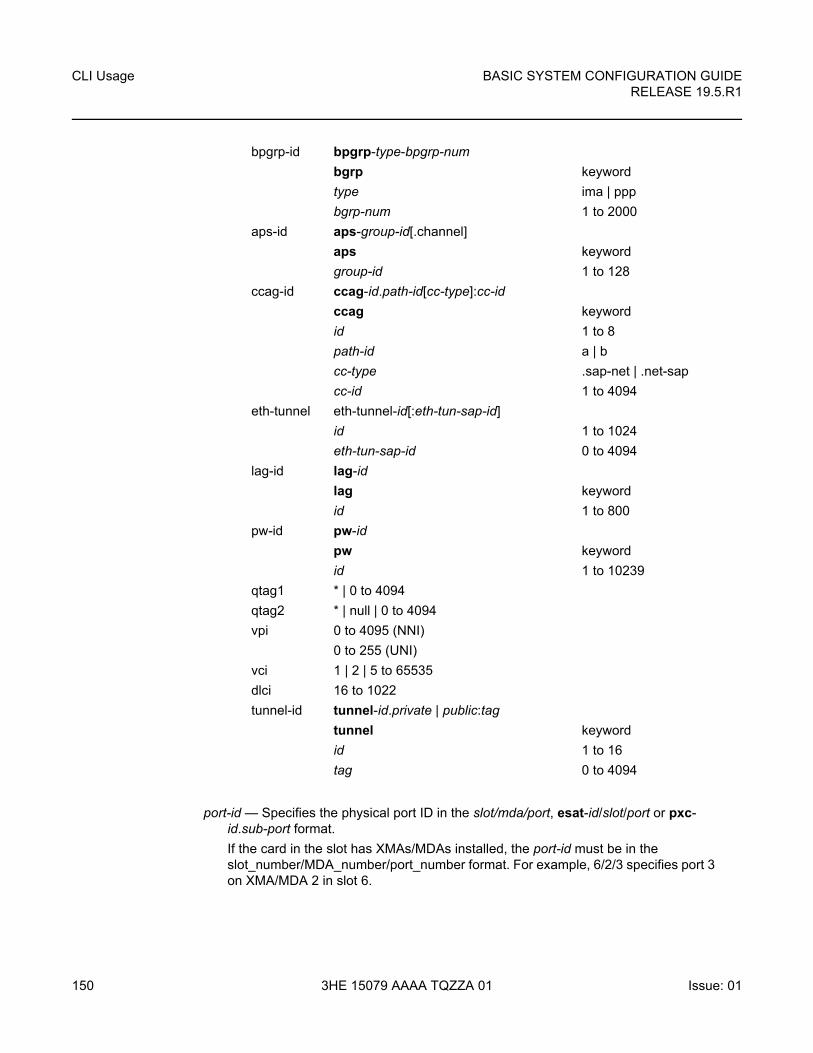
CLI Usage
150
BASIC SYSTEM CONFIGURATION GUIDERELEASE 19.5.R1
3HE 15079 AAAA TQZZA 01 Issue: 01
port-id — Specifies the physical port ID in the slot/mda/port, esat-id/slot/port or pxc-id.sub-port format.
If the card in the slot has XMAs/MDAs installed, the port-id must be in the slot_number/MDA_number/port_number format. For example, 6/2/3 specifies port 3 on XMA/MDA 2 in slot 6.
bpgrp-id bpgrp-type-bpgrp-num
bgrp keyword
type ima | ppp
bgrp-num 1 to 2000
aps-id aps-group-id[.channel]
aps keyword
group-id 1 to 128
ccag-id ccag-id.path-id[cc-type]:cc-id
ccag keyword
id 1 to 8
path-id a | b
cc-type .sap-net | .net-sap
cc-id 1 to 4094
eth-tunnel eth-tunnel-id[:eth-tun-sap-id]
id 1 to 1024
eth-tun-sap-id 0 to 4094
lag-id lag-id
lag keyword
id 1 to 800
pw-id pw-id
pw keyword
id 1 to 10239
qtag1 * | 0 to 4094
qtag2 * | null | 0 to 4094
vpi 0 to 4095 (NNI)
0 to 255 (UNI)
vci 1 | 2 | 5 to 65535
dlci 16 to 1022
tunnel-id tunnel-id.private | public:tag
tunnel keyword
id 1 to 16
tag 0 to 4094
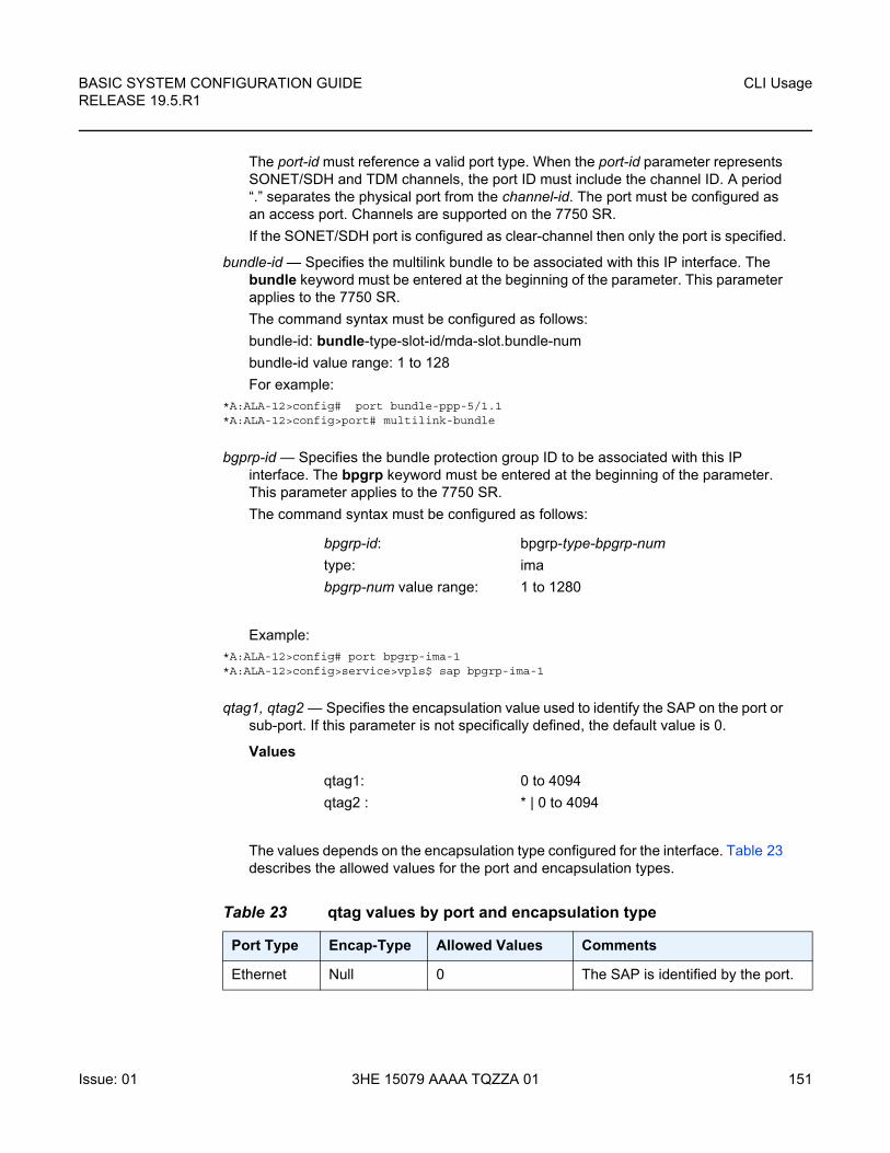
BASIC SYSTEM CONFIGURATION GUIDE RELEASE 19.5.R1
CLI Usage
Issue: 01 3HE 15079 AAAA TQZZA 01 151
The port-id must reference a valid port type. When the port-id parameter represents SONET/SDH and TDM channels, the port ID must include the channel ID. A period “.” separates the physical port from the channel-id. The port must be configured as an access port. Channels are supported on the 7750 SR.
If the SONET/SDH port is configured as clear-channel then only the port is specified.
bundle-id — Specifies the multilink bundle to be associated with this IP interface. The bundle keyword must be entered at the beginning of the parameter. This parameter applies to the 7750 SR.
The command syntax must be configured as follows:
bundle-id: bundle-type-slot-id/mda-slot.bundle-num
bundle-id value range: 1 to 128
For example:*A:ALA-12>config# port bundle-ppp-5/1.1*A:ALA-12>config>port# multilink-bundle
bgprp-id — Specifies the bundle protection group ID to be associated with this IP interface. The bpgrp keyword must be entered at the beginning of the parameter. This parameter applies to the 7750 SR.
The command syntax must be configured as follows:
Example:*A:ALA-12>config# port bpgrp-ima-1*A:ALA-12>config>service>vpls$ sap bpgrp-ima-1
qtag1, qtag2 — Specifies the encapsulation value used to identify the SAP on the port or sub-port. If this parameter is not specifically defined, the default value is 0.
Values
The values depends on the encapsulation type configured for the interface. Table 23 describes the allowed values for the port and encapsulation types.
bpgrp-id: bpgrp-type-bpgrp-num
type: ima
bpgrp-num value range: 1 to 1280
qtag1: 0 to 4094
qtag2 : * | 0 to 4094
Table 23 qtag values by port and encapsulation type
Port Type Encap-Type Allowed Values Comments
Ethernet Null 0 The SAP is identified by the port.
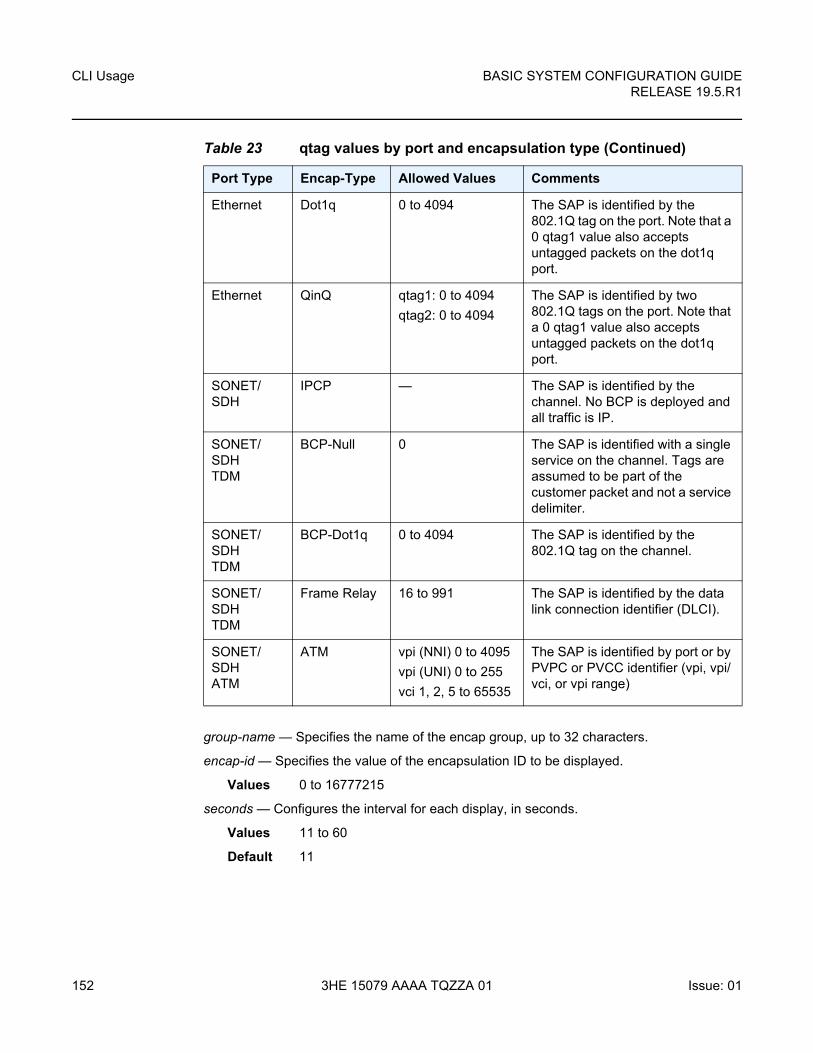
CLI Usage
152
BASIC SYSTEM CONFIGURATION GUIDERELEASE 19.5.R1
3HE 15079 AAAA TQZZA 01 Issue: 01
group-name — Specifies the name of the encap group, up to 32 characters.
encap-id — Specifies the value of the encapsulation ID to be displayed.
Values 0 to 16777215
seconds — Configures the interval for each display, in seconds.
Values 11 to 60
Default 11
Ethernet Dot1q 0 to 4094 The SAP is identified by the 802.1Q tag on the port. Note that a 0 qtag1 value also accepts untagged packets on the dot1q port.
Ethernet QinQ qtag1: 0 to 4094
qtag2: 0 to 4094
The SAP is identified by two 802.1Q tags on the port. Note that a 0 qtag1 value also accepts untagged packets on the dot1q port.
SONET/SDH
IPCP — The SAP is identified by the channel. No BCP is deployed and all traffic is IP.
SONET/SDHTDM
BCP-Null 0 The SAP is identified with a single service on the channel. Tags are assumed to be part of the customer packet and not a service delimiter.
SONET/SDH TDM
BCP-Dot1q 0 to 4094 The SAP is identified by the 802.1Q tag on the channel.
SONET/SDHTDM
Frame Relay 16 to 991 The SAP is identified by the data link connection identifier (DLCI).
SONET/SDHATM
ATM vpi (NNI) 0 to 4095
vpi (UNI) 0 to 255
vci 1, 2, 5 to 65535
The SAP is identified by port or by PVPC or PVCC identifier (vpi, vpi/vci, or vpi range)
Table 23 qtag values by port and encapsulation type (Continued)
Port Type Encap-Type Allowed Values Comments
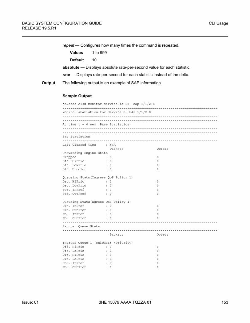
BASIC SYSTEM CONFIGURATION GUIDE RELEASE 19.5.R1
CLI Usage
Issue: 01 3HE 15079 AAAA TQZZA 01 153
repeat — Configures how many times the command is repeated.
Values 1 to 999
Default 10
absolute — Displays absolute rate-per-second value for each statistic.
rate — Displays rate-per-second for each statistic instead of the delta.
Output The following output is an example of SAP information.
Sample Output
*A:cses-A13# monitor service id 88 sap 1/1/2:0===============================================================================Monitor statistics for Service 88 SAP 1/1/2:0===============================================================================-------------------------------------------------------------------------------At time t = 0 sec (Base Statistics)--------------------------------------------------------------------------------------------------------------------------------------------------------------Sap Statistics-------------------------------------------------------------------------------Last Cleared Time : N/A
Packets OctetsForwarding Engine StatsDropped : 0 0Off. HiPrio : 0 0Off. LowPrio : 0 0Off. Uncolor : 0 0
Queueing Stats(Ingress QoS Policy 1)Dro. HiPrio : 0 0Dro. LowPrio : 0 0For. InProf : 0 0For. OutProf : 0 0
Queueing Stats(Egress QoS Policy 1)Dro. InProf : 0 0Dro. OutProf : 0 0For. InProf : 0 0For. OutProf : 0 0-------------------------------------------------------------------------------Sap per Queue Stats-------------------------------------------------------------------------------
Packets Octets
Ingress Queue 1 (Unicast) (Priority)Off. HiPrio : 0 0Off. LoPrio : 0 0Dro. HiPrio : 0 0Dro. LoPrio : 0 0For. InProf : 0 0For. OutProf : 0 0
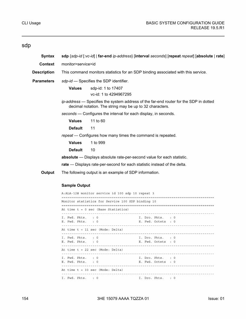
CLI Usage
154
BASIC SYSTEM CONFIGURATION GUIDERELEASE 19.5.R1
3HE 15079 AAAA TQZZA 01 Issue: 01
sdp
Syntax sdp {sdp-id [:vc-id] | far-end ip-address} [interval seconds] [repeat repeat] [absolute | rate]
Context monitor>service>id
Description This command monitors statistics for an SDP binding associated with this service.
Parameters sdp-id — Specifies the SDP identifier.
Values sdp-id: 1 to 17407
vc-id: 1 to 4294967295
ip-address — Specifies the system address of the far-end router for the SDP in dotted decimal notation. The string may be up to 32 characters.
seconds — Configures the interval for each display, in seconds.
Values 11 to 60
Default 11
repeat — Configures how many times the command is repeated.
Values 1 to 999
Default 10
absolute — Displays absolute rate-per-second value for each statistic.
rate — Displays rate-per-second for each statistic instead of the delta.
Output The following output is an example of SDP information.
Sample Output
A:ALA-12# monitor service id 100 sdp 10 repeat 3===============================================================================Monitor statistics for Service 100 SDP binding 10===============================================================================At time t = 0 sec (Base Statistics)-------------------------------------------------------------------------------I. Fwd. Pkts. : 0 I. Dro. Pkts. : 0E. Fwd. Pkts. : 0 E. Fwd. Octets : 0-------------------------------------------------------------------------------At time t = 11 sec (Mode: Delta)-------------------------------------------------------------------------------I. Fwd. Pkts. : 0 I. Dro. Pkts. : 0E. Fwd. Pkts. : 0 E. Fwd. Octets : 0-------------------------------------------------------------------------------At time t = 22 sec (Mode: Delta)-------------------------------------------------------------------------------I. Fwd. Pkts. : 0 I. Dro. Pkts. : 0E. Fwd. Pkts. : 0 E. Fwd. Octets : 0-------------------------------------------------------------------------------At time t = 33 sec (Mode: Delta)-------------------------------------------------------------------------------I. Fwd. Pkts. : 0 I. Dro. Pkts. : 0
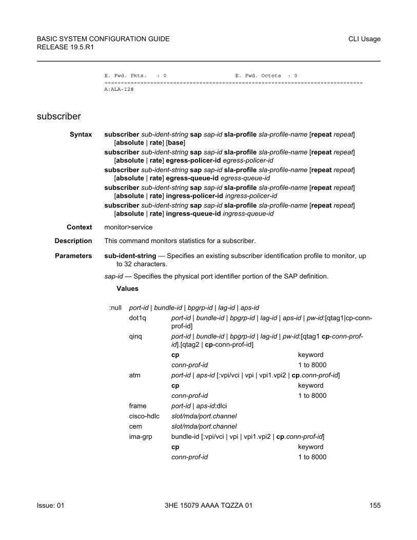
BASIC SYSTEM CONFIGURATION GUIDE RELEASE 19.5.R1
CLI Usage
Issue: 01 3HE 15079 AAAA TQZZA 01 155
E. Fwd. Pkts. : 0 E. Fwd. Octets : 0===============================================================================A:ALA-12#
subscriber
Syntax subscriber sub-ident-string sap sap-id sla-profile sla-profile-name [repeat repeat] [absolute | rate] [base]
subscriber sub-ident-string sap sap-id sla-profile sla-profile-name [repeat repeat] [absolute | rate] egress-policer-id egress-policer-id
subscriber sub-ident-string sap sap-id sla-profile sla-profile-name [repeat repeat] [absolute | rate] egress-queue-id egress-queue-id
subscriber sub-ident-string sap sap-id sla-profile sla-profile-name [repeat repeat] [absolute | rate] ingress-policer-id ingress-policer-id
subscriber sub-ident-string sap sap-id sla-profile sla-profile-name [repeat repeat] [absolute | rate] ingress-queue-id ingress-queue-id
Context monitor>service
Description This command monitors statistics for a subscriber.
Parameters sub-ident-string — Specifies an existing subscriber identification profile to monitor, up to 32 characters.
sap-id — Specifies the physical port identifier portion of the SAP definition.
Values
:null port-id | bundle-id | bpgrp-id | lag-id | aps-id
dot1q port-id | bundle-id | bpgrp-id | lag-id | aps-id | pw-id:[qtag1|cp-conn-prof-id]
qinq port-id | bundle-id | bpgrp-id | lag-id | pw-id:[qtag1 cp-conn-prof-id].[qtag2 | cp-conn-prof-id]
cp keyword
conn-prof-id 1 to 8000
atm port-id | aps-id [:vpi/vci | vpi | vpi1.vpi2 | cp.conn-prof-id]
cp keyword
conn-prof-id 1 to 8000
frame port-id | aps-id:dlci
cisco-hdlc slot/mda/port.channel
cem slot/mda/port.channel
ima-grp bundle-id [:vpi/vci | vpi | vpi1.vpi2 | cp.conn-prof-id]
cp keyword
conn-prof-id 1 to 8000
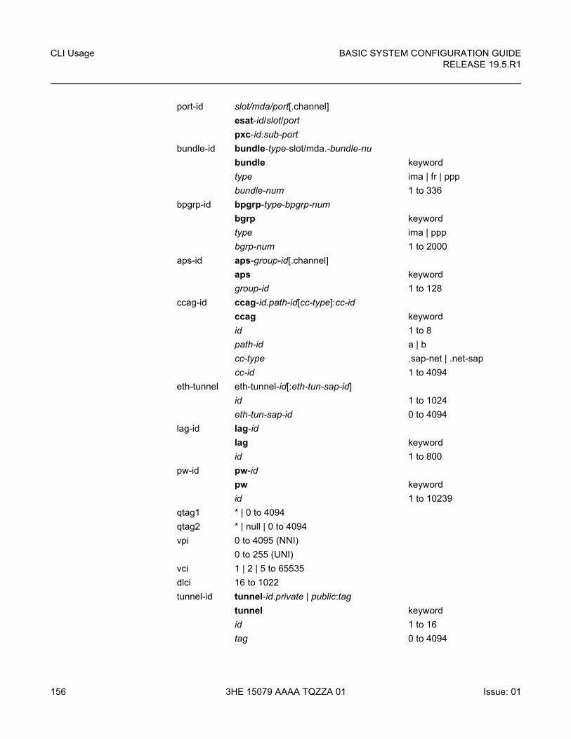
CLI Usage
156
BASIC SYSTEM CONFIGURATION GUIDERELEASE 19.5.R1
3HE 15079 AAAA TQZZA 01 Issue: 01
port-id slot/mda/port[.channel]
esat-id/slot/port
pxc-id.sub-port
bundle-id bundle-type-slot/mda.-bundle-nu
bundle keyword
type ima | fr | ppp
bundle-num 1 to 336
bpgrp-id bpgrp-type-bpgrp-num
bgrp keyword
type ima | ppp
bgrp-num 1 to 2000
aps-id aps-group-id[.channel]
aps keyword
group-id 1 to 128
ccag-id ccag-id.path-id[cc-type]:cc-id
ccag keyword
id 1 to 8
path-id a | b
cc-type .sap-net | .net-sap
cc-id 1 to 4094
eth-tunnel eth-tunnel-id[:eth-tun-sap-id]
id 1 to 1024
eth-tun-sap-id 0 to 4094
lag-id lag-id
lag keyword
id 1 to 800
pw-id pw-id
pw keyword
id 1 to 10239
qtag1 * | 0 to 4094
qtag2 * | null | 0 to 4094
vpi 0 to 4095 (NNI)
0 to 255 (UNI)
vci 1 | 2 | 5 to 65535
dlci 16 to 1022
tunnel-id tunnel-id.private | public:tag
tunnel keyword
id 1 to 16
tag 0 to 4094
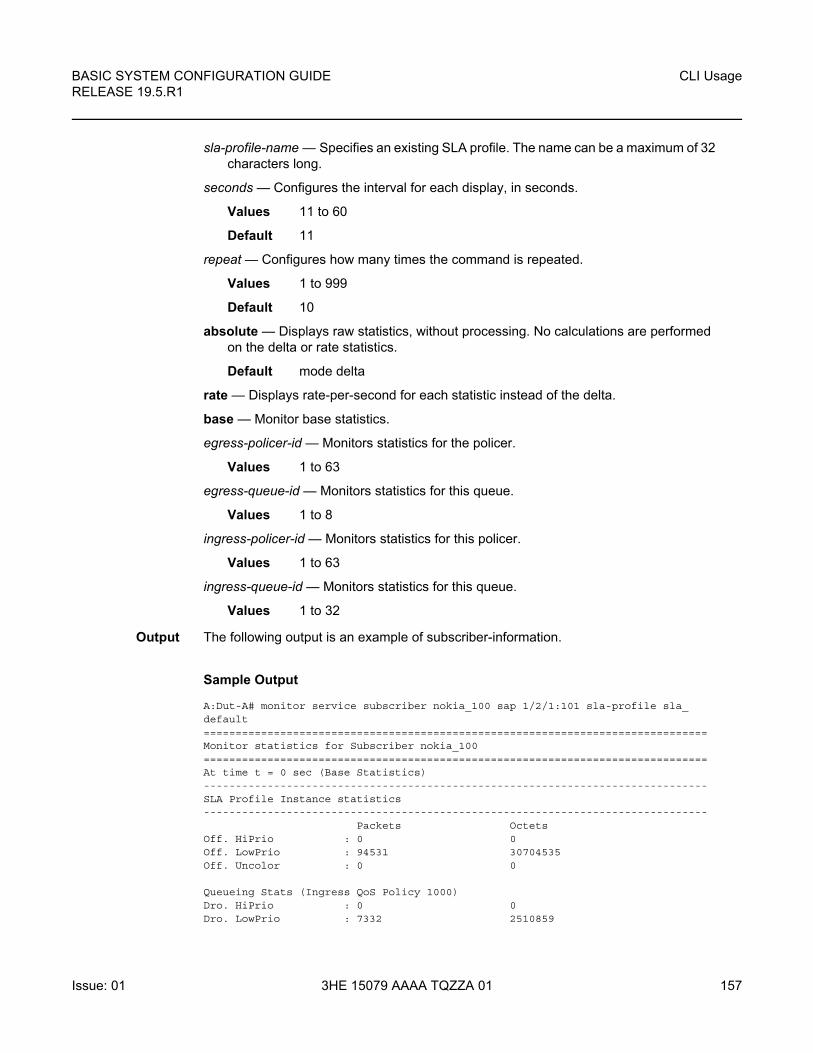
BASIC SYSTEM CONFIGURATION GUIDE RELEASE 19.5.R1
CLI Usage
Issue: 01 3HE 15079 AAAA TQZZA 01 157
sla-profile-name — Specifies an existing SLA profile. The name can be a maximum of 32 characters long.
seconds — Configures the interval for each display, in seconds.
Values 11 to 60
Default 11
repeat — Configures how many times the command is repeated.
Values 1 to 999
Default 10
absolute — Displays raw statistics, without processing. No calculations are performed on the delta or rate statistics.
Default mode delta
rate — Displays rate-per-second for each statistic instead of the delta.
base — Monitor base statistics.
egress-policer-id — Monitors statistics for the policer.
Values 1 to 63
egress-queue-id — Monitors statistics for this queue.
Values 1 to 8
ingress-policer-id — Monitors statistics for this policer.
Values 1 to 63
ingress-queue-id — Monitors statistics for this queue.
Values 1 to 32
Output The following output is an example of subscriber-information.
Sample Output
A:Dut-A# monitor service subscriber nokia_100 sap 1/2/1:101 sla-profile sla_default===============================================================================Monitor statistics for Subscriber nokia_100===============================================================================At time t = 0 sec (Base Statistics)-------------------------------------------------------------------------------SLA Profile Instance statistics-------------------------------------------------------------------------------
Packets OctetsOff. HiPrio : 0 0Off. LowPrio : 94531 30704535Off. Uncolor : 0 0
Queueing Stats (Ingress QoS Policy 1000)Dro. HiPrio : 0 0Dro. LowPrio : 7332 2510859
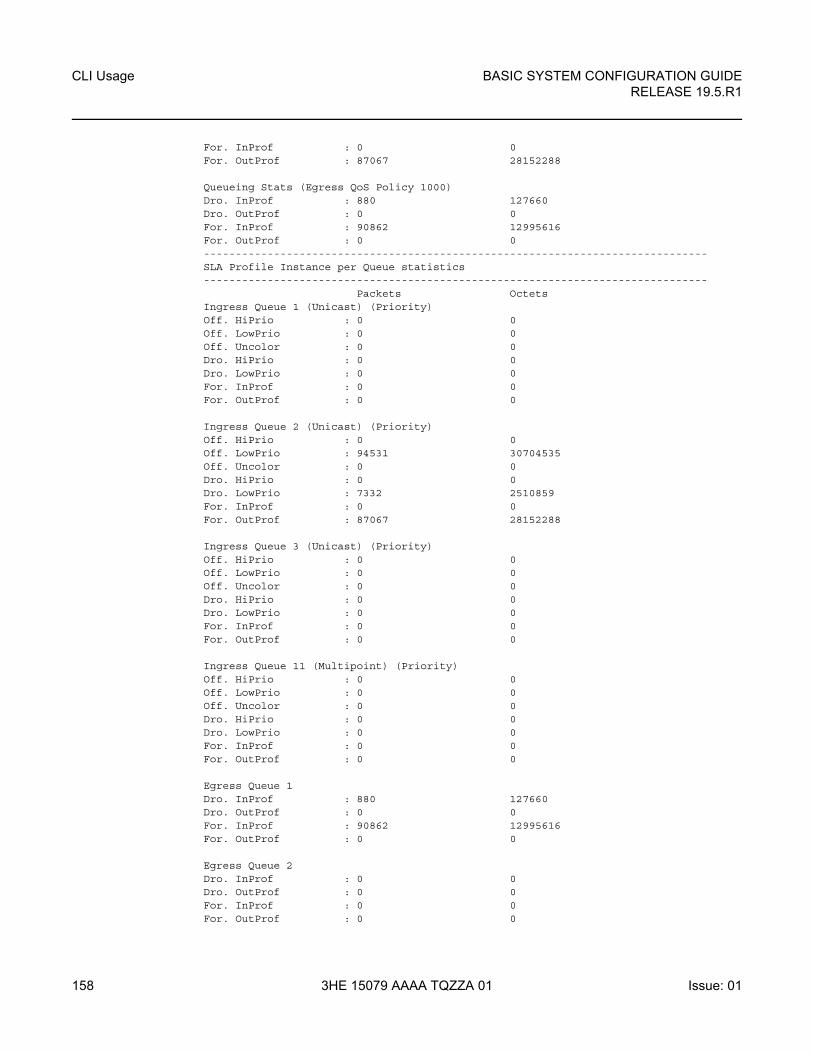
CLI Usage
158
BASIC SYSTEM CONFIGURATION GUIDERELEASE 19.5.R1
3HE 15079 AAAA TQZZA 01 Issue: 01
For. InProf : 0 0For. OutProf : 87067 28152288
Queueing Stats (Egress QoS Policy 1000)Dro. InProf : 880 127660Dro. OutProf : 0 0For. InProf : 90862 12995616For. OutProf : 0 0-------------------------------------------------------------------------------SLA Profile Instance per Queue statistics-------------------------------------------------------------------------------
Packets OctetsIngress Queue 1 (Unicast) (Priority)Off. HiPrio : 0 0Off. LowPrio : 0 0Off. Uncolor : 0 0Dro. HiPrio : 0 0Dro. LowPrio : 0 0For. InProf : 0 0For. OutProf : 0 0
Ingress Queue 2 (Unicast) (Priority)Off. HiPrio : 0 0Off. LowPrio : 94531 30704535Off. Uncolor : 0 0Dro. HiPrio : 0 0Dro. LowPrio : 7332 2510859For. InProf : 0 0For. OutProf : 87067 28152288
Ingress Queue 3 (Unicast) (Priority)Off. HiPrio : 0 0Off. LowPrio : 0 0Off. Uncolor : 0 0Dro. HiPrio : 0 0Dro. LowPrio : 0 0For. InProf : 0 0For. OutProf : 0 0
Ingress Queue 11 (Multipoint) (Priority)Off. HiPrio : 0 0Off. LowPrio : 0 0Off. Uncolor : 0 0Dro. HiPrio : 0 0Dro. LowPrio : 0 0For. InProf : 0 0For. OutProf : 0 0
Egress Queue 1Dro. InProf : 880 127660Dro. OutProf : 0 0For. InProf : 90862 12995616For. OutProf : 0 0
Egress Queue 2Dro. InProf : 0 0Dro. OutProf : 0 0For. InProf : 0 0For. OutProf : 0 0
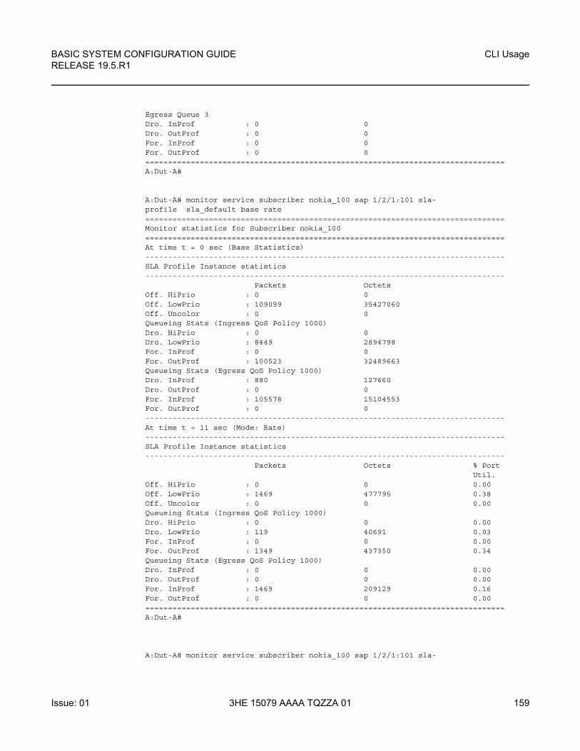
BASIC SYSTEM CONFIGURATION GUIDE RELEASE 19.5.R1
CLI Usage
Issue: 01 3HE 15079 AAAA TQZZA 01 159
Egress Queue 3Dro. InProf : 0 0Dro. OutProf : 0 0For. InProf : 0 0For. OutProf : 0 0===============================================================================A:Dut-A#
A:Dut-A# monitor service subscriber nokia_100 sap 1/2/1:101 sla-profile sla_default base rate===============================================================================Monitor statistics for Subscriber nokia_100===============================================================================At time t = 0 sec (Base Statistics)-------------------------------------------------------------------------------SLA Profile Instance statistics-------------------------------------------------------------------------------
Packets OctetsOff. HiPrio : 0 0Off. LowPrio : 109099 35427060Off. Uncolor : 0 0Queueing Stats (Ingress QoS Policy 1000)Dro. HiPrio : 0 0Dro. LowPrio : 8449 2894798For. InProf : 0 0For. OutProf : 100523 32489663Queueing Stats (Egress QoS Policy 1000)Dro. InProf : 880 127660Dro. OutProf : 0 0For. InProf : 105578 15104553For. OutProf : 0 0-------------------------------------------------------------------------------At time t = 11 sec (Mode: Rate)-------------------------------------------------------------------------------SLA Profile Instance statistics-------------------------------------------------------------------------------
Packets Octets % PortUtil.
Off. HiPrio : 0 0 0.00Off. LowPrio : 1469 477795 0.38Off. Uncolor : 0 0 0.00Queueing Stats (Ingress QoS Policy 1000)Dro. HiPrio : 0 0 0.00Dro. LowPrio : 119 40691 0.03For. InProf : 0 0 0.00For. OutProf : 1349 437350 0.34Queueing Stats (Egress QoS Policy 1000)Dro. InProf : 0 0 0.00Dro. OutProf : 0 0 0.00For. InProf : 1469 209129 0.16For. OutProf : 0 0 0.00===============================================================================A:Dut-A#
A:Dut-A# monitor service subscriber nokia_100 sap 1/2/1:101 sla-
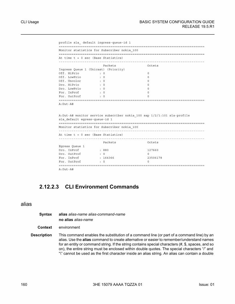
CLI Usage
160
BASIC SYSTEM CONFIGURATION GUIDERELEASE 19.5.R1
3HE 15079 AAAA TQZZA 01 Issue: 01
profile sla_ default ingress-queue-id 1===============================================================================Monitor statistics for Subscriber nokia_100===============================================================================At time t = 0 sec (Base Statistics)-------------------------------------------------------------------------------
Packets OctetsIngress Queue 1 (Unicast) (Priority)Off. HiPrio : 0 0Off. LowPrio : 0 0Off. Uncolor : 0 0Dro. HiPrio : 0 0Dro. LowPrio : 0 0For. InProf : 0 0For. OutProf : 0 0===============================================================================A:Dut-A#
A:Dut-A# monitor service subscriber nokia_100 sap 1/2/1:101 sla-profilesla_default egress-queue-id 1===============================================================================Monitor statistics for Subscriber nokia_100-------------------------------------------------------------------------------At time t = 0 sec (Base Statistics)-------------------------------------------------------------------------------
Packets OctetsEgress Queue 1Dro. InProf : 880 127660Dro. OutProf : 0 0For. InProf : 164366 23506178For. OutProf : 0 0===============================================================================A:Dut-A#
2.12.2.3 CLI Environment Commands
alias
Syntax alias alias-name alias-command-name
no alias alias-name
Context environment
Description This command enables the substitution of a command line (or part of a command line) by an alias. Use the alias command to create alternative or easier to remember/understand names for an entity or command string. If the string contains special characters (#, $, spaces, and so on), the entire string must be enclosed within double quotes. The special characters “/” and “\” cannot be used as the first character inside an alias string. An alias can contain a double
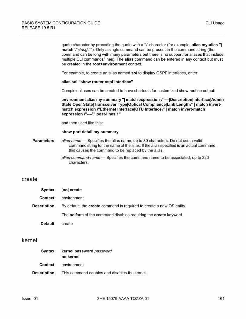
BASIC SYSTEM CONFIGURATION GUIDE RELEASE 19.5.R1
CLI Usage
Issue: 01 3HE 15079 AAAA TQZZA 01 161
quote character by preceding the quote with a “\” character (for example, alias my-alias "| match \"string\""). Only a single command can be present in the command string (the command can be long with many parameters but there is no support for aliases that include multiple CLI commands/lines). The alias command can be entered in any context but must be created in the root>environment context.
For example, to create an alias named soi to display OSPF interfaces, enter:
alias soi “show router ospf interface”
Complex aliases can be created to have shortcuts for customized show routine output:
environment alias my-summary "| match expression \"----|Description|Interface|Admin State|Oper State|Transceiver Type|Optical Compliance|Link Length\" | match invert-match expression \"Ethernet Interface|OTU Interface\" | match invert-match expression \"----\" post-lines 1"
and then used like this:
show port detail my-summary
Parameters alias-name — Specifies the alias name, up to 80 characters. Do not use a valid command string for the name of the alias. If the alias specified is an actual command, this causes the command to be replaced by the alias.
alias-command-name — Specifies the command name to be associated, up to 320 characters.
create
Syntax [no] create
Context environment
Description By default, the create command is required to create a new OS entity.
The no form of the command disables requiring the create keyword.
Default create
kernel
Syntax kernel password password
no kernel
Context environment
Description This command enables and disables the kernel.
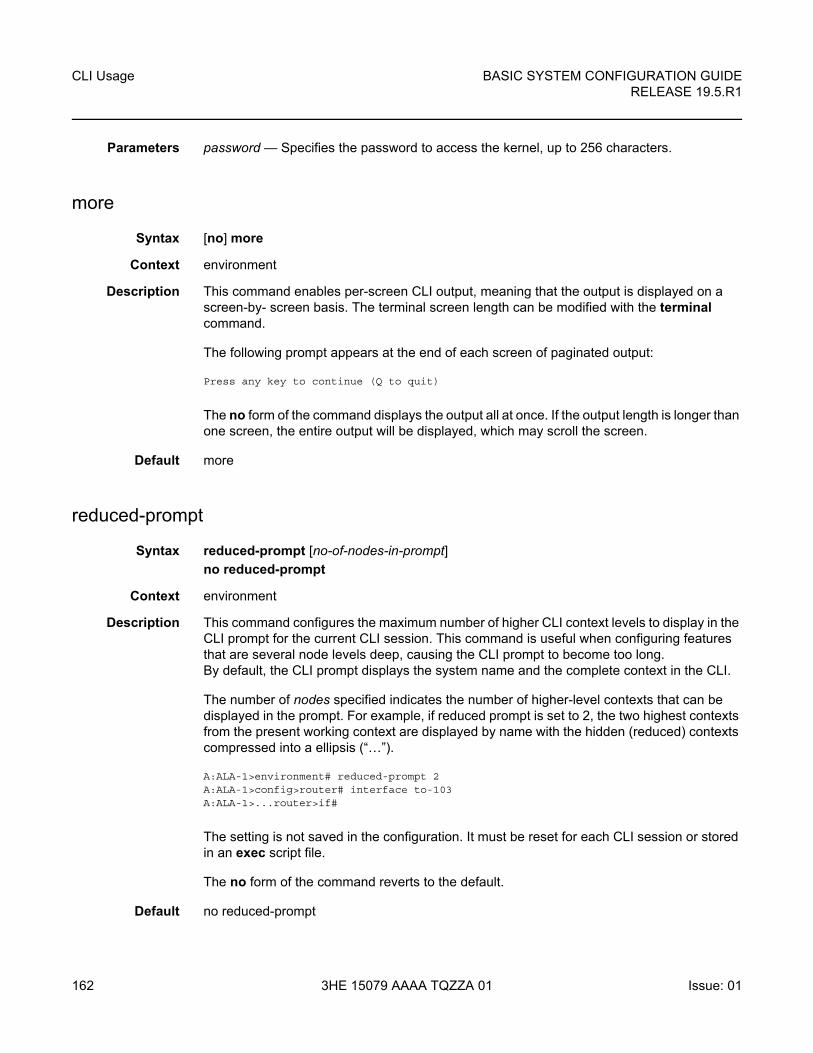
CLI Usage
162
BASIC SYSTEM CONFIGURATION GUIDERELEASE 19.5.R1
3HE 15079 AAAA TQZZA 01 Issue: 01
Parameters password — Specifies the password to access the kernel, up to 256 characters.
more
Syntax [no] more
Context environment
Description This command enables per-screen CLI output, meaning that the output is displayed on a screen-by- screen basis. The terminal screen length can be modified with the terminal command.
The following prompt appears at the end of each screen of paginated output:
Press any key to continue (Q to quit)
The no form of the command displays the output all at once. If the output length is longer than one screen, the entire output will be displayed, which may scroll the screen.
Default more
reduced-prompt
Syntax reduced-prompt [no-of-nodes-in-prompt]
no reduced-prompt
Context environment
Description This command configures the maximum number of higher CLI context levels to display in the CLI prompt for the current CLI session. This command is useful when configuring features that are several node levels deep, causing the CLI prompt to become too long. By default, the CLI prompt displays the system name and the complete context in the CLI.
The number of nodes specified indicates the number of higher-level contexts that can be displayed in the prompt. For example, if reduced prompt is set to 2, the two highest contexts from the present working context are displayed by name with the hidden (reduced) contexts compressed into a ellipsis (“…”).
A:ALA-1>environment# reduced-prompt 2A:ALA-1>config>router# interface to-103A:ALA-1>...router>if#
The setting is not saved in the configuration. It must be reset for each CLI session or stored in an exec script file.
The no form of the command reverts to the default.
Default no reduced-prompt

BASIC SYSTEM CONFIGURATION GUIDE RELEASE 19.5.R1
CLI Usage
Issue: 01 3HE 15079 AAAA TQZZA 01 163
Parameters no-of-nodes-in-prompt — Specifies the maximum number of higher-level nodes displayed by name in the prompt, expressed as a decimal integer.
Values 0 to 15
Default 2
saved-ind-prompt
Syntax [no] saved-ind-prompt
Context environment
Description This command enables saved indicator in the prompt. When changes are made to the configuration file a “*” appears in the prompt string indicating that the changes have not been saved. When an admin save command is executed the “*” disappears.
*A:ALA-48# admin saveWriting file to ftp://192.0.2.43/./sim48/sim48-config.cfgSaving configuration .... Completed.A:ALA-48#
shell
Syntax shell -password password
no shell
Context environment
Description This command enables and disables the shell.
Parameters password — Specifies the password to enter the shell, up to 256 characters.
suggest-internal-objects
Syntax [no] suggest-internal-objects
Context environment
Description This command enables suggesting of internally created objects while auto completing.
The no form of the command disables the command.
terminal
Syntax terminal

CLI Usage
164
BASIC SYSTEM CONFIGURATION GUIDERELEASE 19.5.R1
3HE 15079 AAAA TQZZA 01 Issue: 01
no terminal
Context environment
Description This command enables the context to configure the terminal screen length for the current CLI session.
length
Syntax length lines
Context environment>terminal
Description This command sets the number of lines on a screen.
Parameters lines — Specifies the number of lines for the terminal screen length, expressed as a decimal integer.
Values 1 to 512
Default 24 — terminal dimensions are set to 24 lines long by 80 characters wide
width
Syntax width width
Context environment>terminal
Description This command determines display terminal width.
Default width 80
Parameters width — Sets the width of the display terminal.
Values 1 to 512
time-display
Syntax time-display {local | utc}
Context environment
Description This command displays time stamps in the CLI session based on local time or Coordinated Universal Time (UTC).
The system keeps time internally in UTC and is capable of displaying the time in either UTC or local time based on the time zone configured.
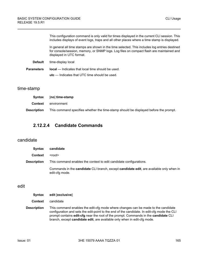
BASIC SYSTEM CONFIGURATION GUIDE RELEASE 19.5.R1
CLI Usage
Issue: 01 3HE 15079 AAAA TQZZA 01 165
This configuration command is only valid for times displayed in the current CLI session. This includes displays of event logs, traps and all other places where a time stamp is displayed.
In general all time stamps are shown in the time selected. This includes log entries destined for console/session, memory, or SNMP logs. Log files on compact flash are maintained and displayed in UTC format.
Default time-display local
Parameters local — Indicates that local time should be used.
utc — Indicates that UTC time should be used.
time-stamp
Syntax [no] time-stamp
Context environment
Description This command specifies whether the time-stamp should be displayed before the prompt.
2.12.2.4 Candidate Commands
candidate
Syntax candidate
Context <root>
Description This command enables the context to edit candidate configurations.
Commands in the candidate CLI branch, except candidate edit, are available only when in edit-cfg mode.
edit
Syntax edit [exclusive]
Context candidate
Description This command enables the edit-cfg mode where changes can be made to the candidate configuration and sets the edit-point to the end of the candidate. In edit-cfg mode the CLI prompt contains edit-cfg near the root of the prompt. Commands in the candidate CLI branch, except candidate edit, are available only when in edit-cfg mode.
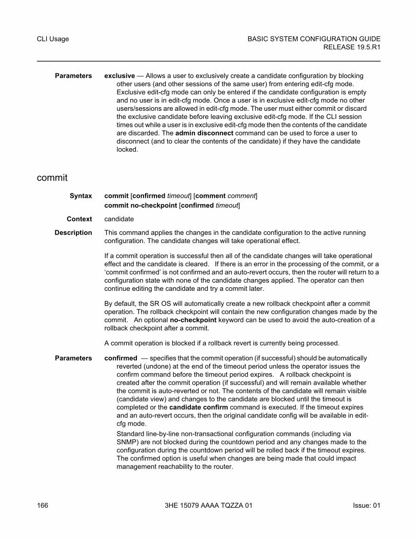
CLI Usage
166
BASIC SYSTEM CONFIGURATION GUIDERELEASE 19.5.R1
3HE 15079 AAAA TQZZA 01 Issue: 01
Parameters exclusive — Allows a user to exclusively create a candidate configuration by blocking other users (and other sessions of the same user) from entering edit-cfg mode. Exclusive edit-cfg mode can only be entered if the candidate configuration is empty and no user is in edit-cfg mode. Once a user is in exclusive edit-cfg mode no other users/sessions are allowed in edit-cfg mode. The user must either commit or discard the exclusive candidate before leaving exclusive edit-cfg mode. If the CLI session times out while a user is in exclusive edit-cfg mode then the contents of the candidate are discarded. The admin disconnect command can be used to force a user to disconnect (and to clear the contents of the candidate) if they have the candidate locked.
commit
Syntax commit [confirmed timeout] [comment comment]
commit no-checkpoint [confirmed timeout]
Context candidate
Description This command applies the changes in the candidate configuration to the active running configuration. The candidate changes will take operational effect.
If a commit operation is successful then all of the candidate changes will take operational effect and the candidate is cleared. If there is an error in the processing of the commit, or a ‘commit confirmed’ is not confirmed and an auto-revert occurs, then the router will return to a configuration state with none of the candidate changes applied. The operator can then continue editing the candidate and try a commit later.
By default, the SR OS will automatically create a new rollback checkpoint after a commit operation. The rollback checkpoint will contain the new configuration changes made by the commit. An optional no-checkpoint keyword can be used to avoid the auto-creation of a rollback checkpoint after a commit.
A commit operation is blocked if a rollback revert is currently being processed.
Parameters confirmed — specifies that the commit operation (if successful) should be automatically reverted (undone) at the end of the timeout period unless the operator issues the confirm command before the timeout period expires. A rollback checkpoint is created after the commit operation (if successful) and will remain available whether the commit is auto-reverted or not. The contents of the candidate will remain visible (candidate view) and changes to the candidate are blocked until the timeout is completed or the candidate confirm command is executed. If the timeout expires and an auto-revert occurs, then the original candidate config will be available in edit-cfg mode.
Standard line-by-line non-transactional configuration commands (including via SNMP) are not blocked during the countdown period and any changes made to the configuration during the countdown period will be rolled back if the timeout expires. The confirmed option is useful when changes are being made that could impact management reachability to the router.
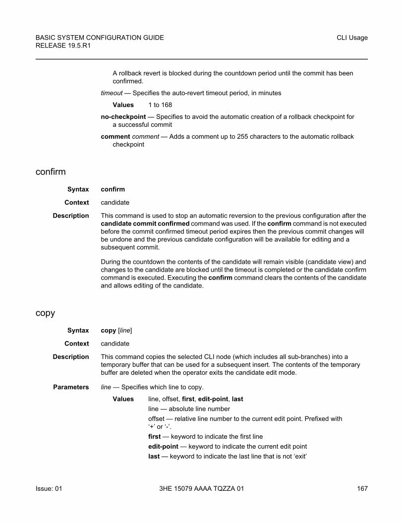
BASIC SYSTEM CONFIGURATION GUIDE RELEASE 19.5.R1
CLI Usage
Issue: 01 3HE 15079 AAAA TQZZA 01 167
A rollback revert is blocked during the countdown period until the commit has been confirmed.
timeout — Specifies the auto-revert timeout period, in minutes
Values 1 to 168
no-checkpoint — Specifies to avoid the automatic creation of a rollback checkpoint for a successful commit
comment comment — Adds a comment up to 255 characters to the automatic rollback checkpoint
confirm
Syntax confirm
Context candidate
Description This command is used to stop an automatic reversion to the previous configuration after the candidate commit confirmed command was used. If the confirm command is not executed before the commit confirmed timeout period expires then the previous commit changes will be undone and the previous candidate configuration will be available for editing and a subsequent commit.
During the countdown the contents of the candidate will remain visible (candidate view) and changes to the candidate are blocked until the timeout is completed or the candidate confirm command is executed. Executing the confirm command clears the contents of the candidate and allows editing of the candidate.
copy
Syntax copy [line]
Context candidate
Description This command copies the selected CLI node (which includes all sub-branches) into a temporary buffer that can be used for a subsequent insert. The contents of the temporary buffer are deleted when the operator exits the candidate edit mode.
Parameters line — Specifies which line to copy.
Values line, offset, first, edit-point, last
line — absolute line number
offset — relative line number to the current edit point. Prefixed with ‘+’ or ‘-’.
first — keyword to indicate the first line
edit-point — keyword to indicate the current edit point
last — keyword to indicate the last line that is not ‘exit’
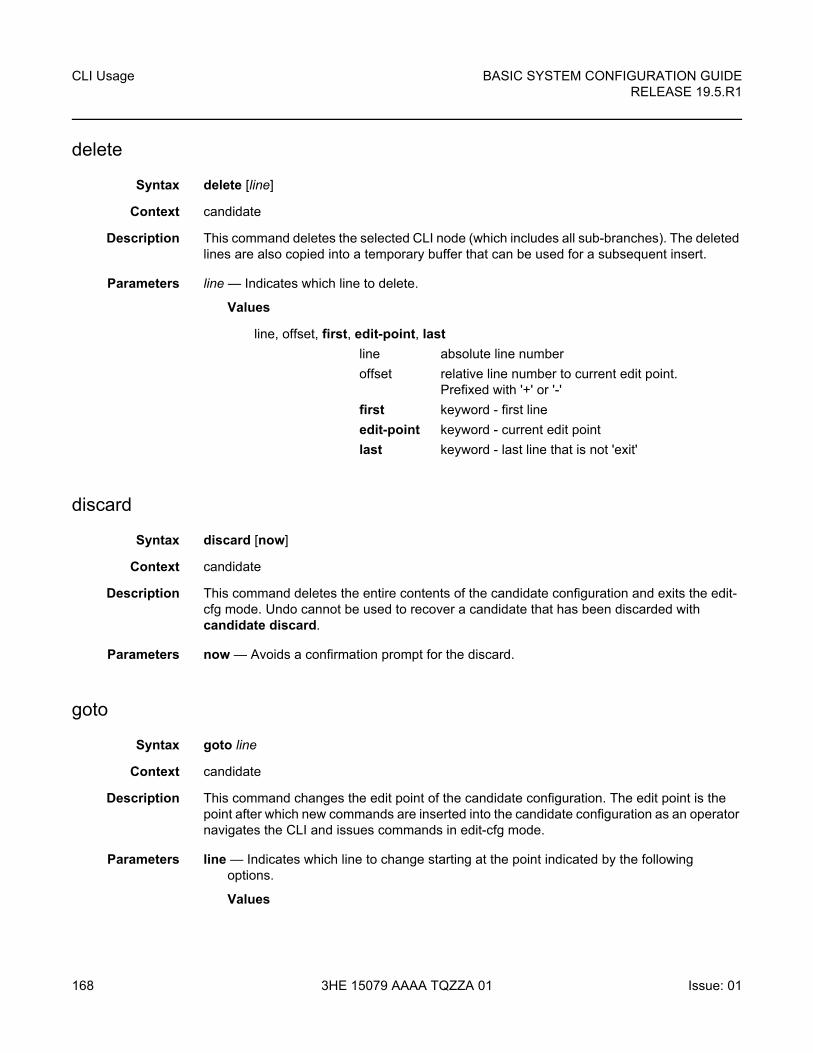
CLI Usage
168
BASIC SYSTEM CONFIGURATION GUIDERELEASE 19.5.R1
3HE 15079 AAAA TQZZA 01 Issue: 01
delete
Syntax delete [line]
Context candidate
Description This command deletes the selected CLI node (which includes all sub-branches). The deleted lines are also copied into a temporary buffer that can be used for a subsequent insert.
Parameters line — Indicates which line to delete.
Values
discard
Syntax discard [now]
Context candidate
Description This command deletes the entire contents of the candidate configuration and exits the edit-cfg mode. Undo cannot be used to recover a candidate that has been discarded with candidate discard.
Parameters now — Avoids a confirmation prompt for the discard.
goto
Syntax goto line
Context candidate
Description This command changes the edit point of the candidate configuration. The edit point is the point after which new commands are inserted into the candidate configuration as an operator navigates the CLI and issues commands in edit-cfg mode.
Parameters line — Indicates which line to change starting at the point indicated by the following options.
Values
line, offset, first, edit-point, last
line absolute line number
offset relative line number to current edit point. Prefixed with '+' or '-'
first keyword - first line
edit-point keyword - current edit point
last keyword - last line that is not 'exit'
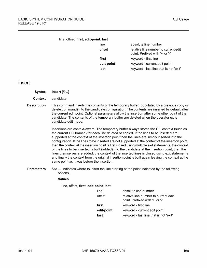
BASIC SYSTEM CONFIGURATION GUIDE RELEASE 19.5.R1
CLI Usage
Issue: 01 3HE 15079 AAAA TQZZA 01 169
insert
Syntax insert [line]
Context candidate
Description This command inserts the contents of the temporary buffer (populated by a previous copy or delete command) into the candidate configuration. The contents are inserted by default after the current edit point. Optional parameters allow the insertion after some other point of the candidate. The contents of the temporary buffer are deleted when the operator exits candidate edit mode.
Insertions are context-aware. The temporary buffer always stores the CLI context (such as the current CLI branch) for each line deleted or copied. If the lines to be inserted are supported at the context of the insertion point then the lines are simply inserted into the configuration. If the lines to be inserted are not supported at the context of the insertion point, then the context at the insertion point is first closed using multiple exit statements, the context of the lines to be inserted is built (added) into the candidate at the insertion point, then the lines themselves are added, the context of the inserted lines is closed using exit statements and finally the context from the original insertion point is built again leaving the context at the same point as it was before the insertion.
Parameters line — Indicates where to insert the line starting at the point indicated by the following options.
Values
line, offset, first, edit-point, last
line absolute line number
offset relative line number to current edit point. Prefixed with '+' or '-'
first keyword - first line
edit-point keyword - current edit point
last keyword - last line that is not 'exit'
line, offset, first, edit-point, last
line absolute line number
offset relative line number to current edit point. Prefixed with '+' or '-'
first keyword - first line
edit-point keyword - current edit point
last keyword - last line that is not 'exit'
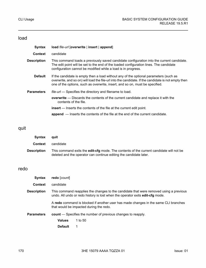
CLI Usage
170
BASIC SYSTEM CONFIGURATION GUIDERELEASE 19.5.R1
3HE 15079 AAAA TQZZA 01 Issue: 01
load
Syntax load file-url [overwrite | insert | append]
Context candidate
Description This command loads a previously saved candidate configuration into the current candidate. The edit point will be set to the end of the loaded configuration lines. The candidate configuration cannot be modified while a load is in progress.
Default If the candidate is empty then a load without any of the optional parameters (such as overwrite, and so on) will load the file-url into the candidate. If the candidate is not empty then one of the options, such as overwrite, insert, and so on, must be specified.
Parameters file-url — Specifies the directory and filename to load.
overwrite — Discards the contents of the current candidate and replace it with the contents of the file.
insert — Inserts the contents of the file at the current edit point.
append — Inserts the contents of the file at the end of the current candidate.
quit
Syntax quit
Context candidate
Description This command exits the edit-cfg mode. The contents of the current candidate will not be deleted and the operator can continue editing the candidate later.
redo
Syntax redo [count]
Context candidate
Description This command reapplies the changes to the candidate that were removed using a previous undo. All undo or redo history is lost when the operator exits edit-cfg mode.
A redo command is blocked if another user has made changes in the same CLI branches that would be impacted during the redo.
Parameters count — Specifies the number of previous changes to reapply.
Values 1 to 50
Default 1
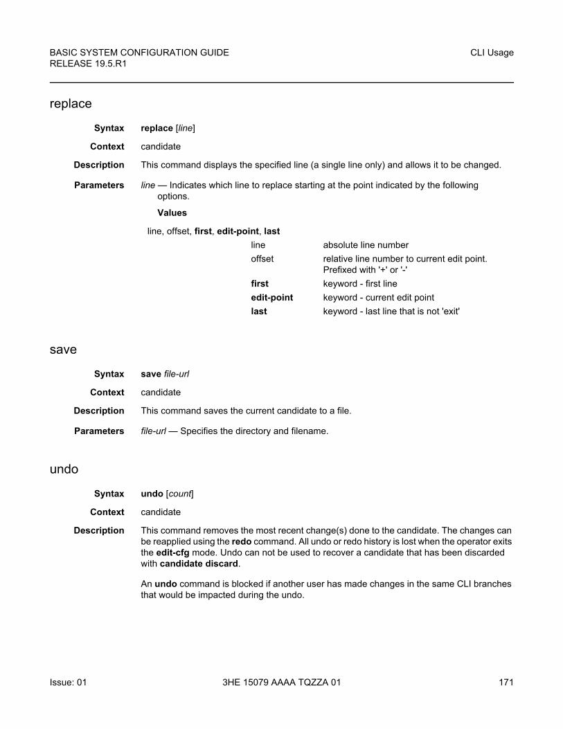
BASIC SYSTEM CONFIGURATION GUIDE RELEASE 19.5.R1
CLI Usage
Issue: 01 3HE 15079 AAAA TQZZA 01 171
replace
Syntax replace [line]
Context candidate
Description This command displays the specified line (a single line only) and allows it to be changed.
Parameters line — Indicates which line to replace starting at the point indicated by the following options.
Values
save
Syntax save file-url
Context candidate
Description This command saves the current candidate to a file.
Parameters file-url — Specifies the directory and filename.
undo
Syntax undo [count]
Context candidate
Description This command removes the most recent change(s) done to the candidate. The changes can be reapplied using the redo command. All undo or redo history is lost when the operator exits the edit-cfg mode. Undo can not be used to recover a candidate that has been discarded with candidate discard.
An undo command is blocked if another user has made changes in the same CLI branches that would be impacted during the undo.
line, offset, first, edit-point, last
line absolute line number
offset relative line number to current edit point. Prefixed with '+' or '-'
first keyword - first line
edit-point keyword - current edit point
last keyword - last line that is not 'exit'
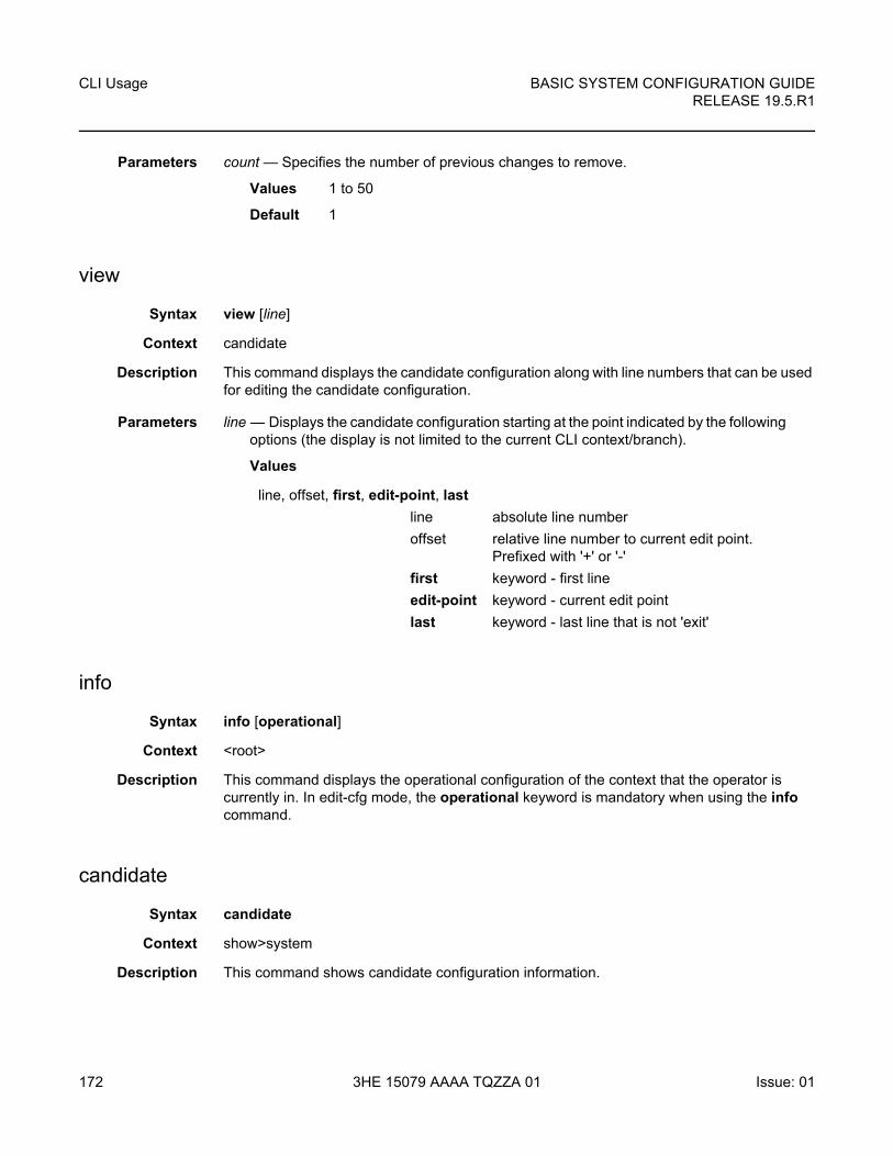
CLI Usage
172
BASIC SYSTEM CONFIGURATION GUIDERELEASE 19.5.R1
3HE 15079 AAAA TQZZA 01 Issue: 01
Parameters count — Specifies the number of previous changes to remove.
Values 1 to 50
Default 1
view
Syntax view [line]
Context candidate
Description This command displays the candidate configuration along with line numbers that can be used for editing the candidate configuration.
Parameters line — Displays the candidate configuration starting at the point indicated by the following options (the display is not limited to the current CLI context/branch).
Values
info
Syntax info [operational]
Context <root>
Description This command displays the operational configuration of the context that the operator is currently in. In edit-cfg mode, the operational keyword is mandatory when using the info command.
candidate
Syntax candidate
Context show>system
Description This command shows candidate configuration information.
line, offset, first, edit-point, last
line absolute line number
offset relative line number to current edit point. Prefixed with '+' or '-'
first keyword - first line
edit-point keyword - current edit point
last keyword - last line that is not 'exit'
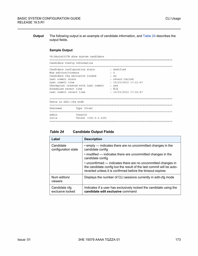
BASIC SYSTEM CONFIGURATION GUIDE RELEASE 19.5.R1
CLI Usage
Issue: 01 3HE 15079 AAAA TQZZA 01 173
Output The following output is an example of candidate information, and Table 24 describes the output fields.
Sample Output
*A:bksim3107# show system candidate===============================================================================Candidate Config Information===============================================================================Candidate configuration state : modifiedNum editors/viewers : 0Candidate cfg exclusive locked : noLast commit state : revert-failedLast commit time : 10/23/2012 17:21:47Checkpoint created with last commit : yesScheduled revert time : N/ALast commit revert time : 10/23/2012 17:22:47
===============================================================================Users in edit-cfg mode===============================================================================Username Type (from)===============================================================================admin ConsoleJoris Telnet (192.0.2.239)===============================================================================
Table 24 Candidate Output Fields
Label Description
Candidate configuration state
• empty — indicates there are no uncommitted changes in the candidate config
• modified — indicates there are uncommitted changes in the candidate config
• unconfirmed — indicates there are no uncommitted changes in the candidate config but the result of the last commit will be auto-reverted unless it is confirmed before the timeout expires
Num editors/viewers
Displays the number of CLI sessions currently in edit-cfg mode
Candidate cfg exclusive locked
Indicates if a user has exclusively locked the candidate using the candidate edit exclusive command
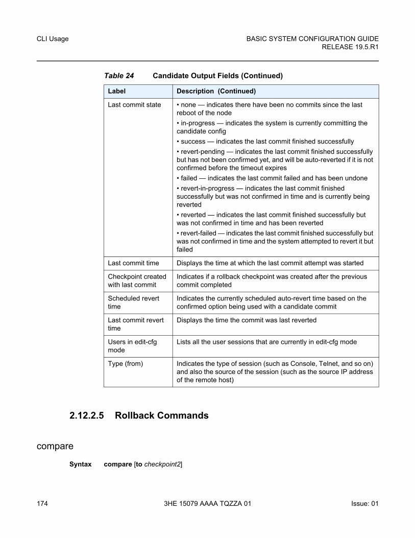
CLI Usage
174
BASIC SYSTEM CONFIGURATION GUIDERELEASE 19.5.R1
3HE 15079 AAAA TQZZA 01 Issue: 01
2.12.2.5 Rollback Commands
compare
Syntax compare [to checkpoint2]
Last commit state • none — indicates there have been no commits since the last reboot of the node
• in-progress — indicates the system is currently committing the candidate config
• success — indicates the last commit finished successfully
• revert-pending — indicates the last commit finished successfully but has not been confirmed yet, and will be auto-reverted if it is not confirmed before the timeout expires
• failed — indicates the last commit failed and has been undone
• revert-in-progress — indicates the last commit finished successfully but was not confirmed in time and is currently being reverted
• reverted — indicates the last commit finished successfully but was not confirmed in time and has been reverted
• revert-failed — indicates the last commit finished successfully but was not confirmed in time and the system attempted to revert it but failed
Last commit time Displays the time at which the last commit attempt was started
Checkpoint created with last commit
Indicates if a rollback checkpoint was created after the previous commit completed
Scheduled revert time
Indicates the currently scheduled auto-revert time based on the confirmed option being used with a candidate commit
Last commit revert time
Displays the time the commit was last reverted
Users in edit-cfg mode
Lists all the user sessions that are currently in edit-cfg mode
Type (from) Indicates the type of session (such as Console, Telnet, and so on) and also the source of the session (such as the source IP address of the remote host)
Table 24 Candidate Output Fields (Continued)
Label Description (Continued)
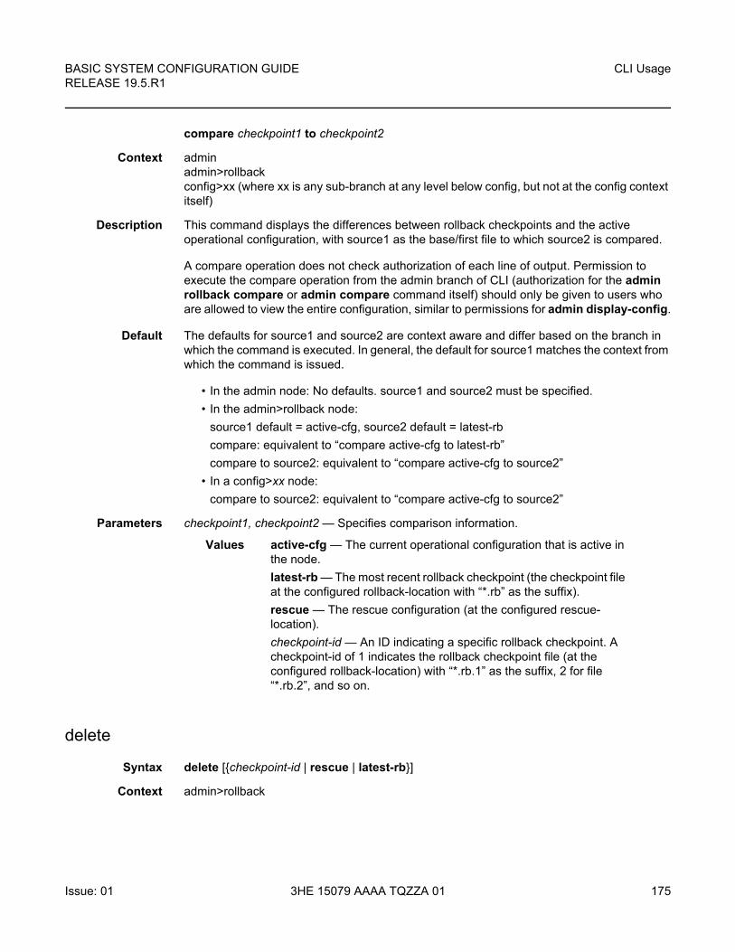
BASIC SYSTEM CONFIGURATION GUIDE RELEASE 19.5.R1
CLI Usage
Issue: 01 3HE 15079 AAAA TQZZA 01 175
compare checkpoint1 to checkpoint2
Context admin admin>rollbackconfig>xx (where xx is any sub-branch at any level below config, but not at the config context itself)
Description This command displays the differences between rollback checkpoints and the active operational configuration, with source1 as the base/first file to which source2 is compared.
A compare operation does not check authorization of each line of output. Permission to execute the compare operation from the admin branch of CLI (authorization for the admin rollback compare or admin compare command itself) should only be given to users who are allowed to view the entire configuration, similar to permissions for admin display-config.
Default The defaults for source1 and source2 are context aware and differ based on the branch in which the command is executed. In general, the default for source1 matches the context from which the command is issued.
• In the admin node: No defaults. source1 and source2 must be specified.
• In the admin>rollback node:
source1 default = active-cfg, source2 default = latest-rb
compare: equivalent to “compare active-cfg to latest-rb”
compare to source2: equivalent to “compare active-cfg to source2”
• In a config>xx node:
compare to source2: equivalent to “compare active-cfg to source2”
Parameters checkpoint1, checkpoint2 — Specifies comparison information.
Values active-cfg — The current operational configuration that is active in the node.
latest-rb — The most recent rollback checkpoint (the checkpoint file at the configured rollback-location with “*.rb” as the suffix).
rescue — The rescue configuration (at the configured rescue-location).
checkpoint-id — An ID indicating a specific rollback checkpoint. A checkpoint-id of 1 indicates the rollback checkpoint file (at the configured rollback-location) with “*.rb.1” as the suffix, 2 for file “*.rb.2”, and so on.
delete
Syntax delete [{checkpoint-id | rescue | latest-rb}]
Context admin>rollback
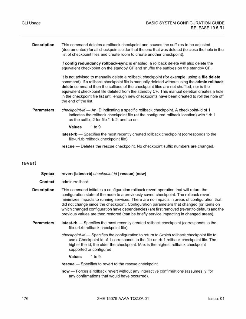
CLI Usage
176
BASIC SYSTEM CONFIGURATION GUIDERELEASE 19.5.R1
3HE 15079 AAAA TQZZA 01 Issue: 01
Description This command deletes a rollback checkpoint and causes the suffixes to be adjusted (decremented) for all checkpoints older that the one that was deleted (to close the hole in the list of checkpoint files and create room to create another checkpoint).
If config redundancy rollback-sync is enabled, a rollback delete will also delete the equivalent checkpoint on the standby CF and shuffle the suffixes on the standby CF.
It is not advised to manually delete a rollback checkpoint (for example, using a file delete command). If a rollback checkpoint file is manually deleted without using the admin rollback delete command then the suffixes of the checkpoint files are not shuffled, nor is the equivalent checkpoint file deleted from the standby CF. This manual deletion creates a hole in the checkpoint file list until enough new checkpoints have been created to roll the hole off the end of the list.
Parameters checkpoint-id — An ID indicating a specific rollback checkpoint. A checkpoint-id of 1 indicates the rollback checkpoint file (at the configured rollback location) with *.rb.1 as the suffix, 2 for file *.rb.2, and so on.
Values 1 to 9
latest-rb — Specifies the most recently created rollback checkpoint (corresponds to the file-url.rb rollback checkpoint file).
rescue — Deletes the rescue checkpoint. No checkpoint suffix numbers are changed.
revert
Syntax revert {latest-rb| checkpoint-id | rescue} [now]
Context admin>rollback
Description This command initiates a configuration rollback revert operation that will return the configuration state of the node to a previously saved checkpoint. The rollback revert minimizes impacts to running services. There are no impacts in areas of configuration that did not change since the checkpoint. Configuration parameters that changed (or items on which changed configuration have dependencies) are first removed (revert to default) and the previous values are then restored (can be briefly service impacting in changed areas).
Parameters latest-rb — Specifies the most recently created rollback checkpoint (corresponds to the file-url.rb rollback checkpoint file).
checkpoint-id — Specifies the configuration to return to (which rollback checkpoint file to use). Checkpoint-id of 1 corresponds to the file-url.rb.1 rollback checkpoint file. The higher the id, the older the checkpoint. Max is the highest rollback checkpoint supported or configured.
Values 1 to 9
rescue — Specifies to revert to the rescue checkpoint.
now — Forces a rollback revert without any interactive confirmations (assumes ‘y’ for any confirmations that would have occurred).
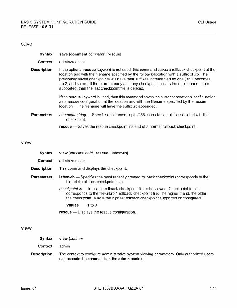
BASIC SYSTEM CONFIGURATION GUIDE RELEASE 19.5.R1
CLI Usage
Issue: 01 3HE 15079 AAAA TQZZA 01 177
save
Syntax save [comment comment] [rescue]
Context admin>rollback
Description If the optional rescue keyword is not used, this command saves a rollback checkpoint at the location and with the filename specified by the rollback-location with a suffix of .rb. The previously saved checkpoints will have their suffixes incremented by one (.rb.1 becomes .rb.2, and so on). If there are already as many checkpoint files as the maximum number supported, then the last checkpoint file is deleted.
If the rescue keyword is used, then this command saves the current operational configuration as a rescue configuration at the location and with the filename specified by the rescue location. The filename will have the suffix .rc appended.
Parameters comment-string — Specifies a comment, up to 255 characters, that is associated with the checkpoint.
rescue — Saves the rescue checkpoint instead of a normal rollback checkpoint.
view
Syntax view [checkpoint-id | rescue | latest-rb]
Context admin>rollback
Description This command displays the checkpoint.
Parameters latest-rb — Specifies the most recently created rollback checkpoint (corresponds to the file-url.rb rollback checkpoint file).
checkpoint-id — Indicates rollback checkpoint file to be viewed. Checkpoint-id of 1 corresponds to the file-url.rb.1 rollback checkpoint file. The higher the id, the older the checkpoint. Max is the highest rollback checkpoint supported or configured.
Values 1 to 9
rescue — Displays the rescue configuration.
view
Syntax view {source}
Context admin
Description The context to configure administrative system viewing parameters. Only authorized users can execute the commands in the admin context.
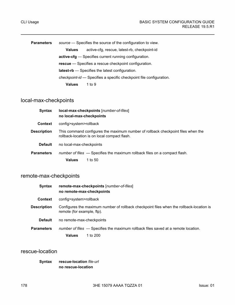
CLI Usage
178
BASIC SYSTEM CONFIGURATION GUIDERELEASE 19.5.R1
3HE 15079 AAAA TQZZA 01 Issue: 01
Parameters source — Specifies the source of the configuration to view.
Values active-cfg, rescue, latest-rb, checkpoint-id
active-cfg — Specifies current running configuration.
rescue — Specifies a rescue checkpoint configuration.
latest-rb — Specifies the latest configuration.
checkpoint-id — Specifies a specific checkpoint file configuration.
Values 1 to 9
local-max-checkpoints
Syntax local-max-checkpoints [number-of-files]
no local-max-checkpoints
Context config>system>rollback
Description This command configures the maximum number of rollback checkpoint files when the rollback-location is on local compact flash.
Default no local-max-checkpoints
Parameters number of files — Specifies the maximum rollback files on a compact flash.
Values 1 to 50
remote-max-checkpoints
Syntax remote-max-checkpoints [number-of-files]
no remote-max-checkpoints
Context config>system>rollback
Description Configures the maximum number of rollback checkpoint files when the rollback-location is remote (for example, ftp).
Default no remote-max-checkpoints
Parameters number of files — Specifies the maximum rollback files saved at a remote location.
Values 1 to 200
rescue-location
Syntax rescue-location file-url
no rescue-location
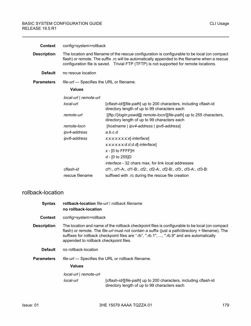
BASIC SYSTEM CONFIGURATION GUIDE RELEASE 19.5.R1
CLI Usage
Issue: 01 3HE 15079 AAAA TQZZA 01 179
Context config>system>rollback
Description The location and filename of the rescue configuration is configurable to be local (on compact flash) or remote. The suffix .rc will be automatically appended to the filename when a rescue configuration file is saved. Trivial FTP (TFTP) is not supported for remote locations.
Default no rescue location
Parameters file-url — Specifies the URL or filename.
Values
rollback-location
Syntax rollback-location file-url / rollback filename
no rollback-location
Context config>system>rollback
Description The location and name of the rollback checkpoint files is configurable to be local (on compact flash) or remote. The file-url must not contain a suffix (just a path/directory + filename). The suffixes for rollback checkpoint files are “.rb”, ".rb.1", ..., ".rb.9" and are automatically appended to rollback checkpoint files.
Default no rollback-location
Parameters file-url — Specifies the URL or rollback filename.
Values
local-url | remote-url
local-url [cflash-id/][file-path] up to 200 characters, including cflash-id directory length of up to 99 characters each
remote-url [{ftp://}login:pswd@ remote-locn/][file-path] up to 255 characters, directory length of up to 99 characters each
remote-locn [hostname | ipv4-address | ipv6-address]
ipv4-address a.b.c.d
ipv6-address x:x:x:x:x:x:x:x[-interface]
x:x:x:x:x:x:d.d.d.d[-interface]
x - [0 to FFFF]H
d - [0 to 255]D
interface - 32 chars max, for link local addresses
cflash-id cf1:, cf1-A:, cf1-B:, cf2:, cf2-A:, cf2-B:, cf3:, cf3-A:, cf3-B:
rescue filename suffixed with .rc during the rescue file creation
local-url | remote-url
local-url [cflash-id/][file-path] up to 200 characters, including cflash-id directory length of up to 99 characters each
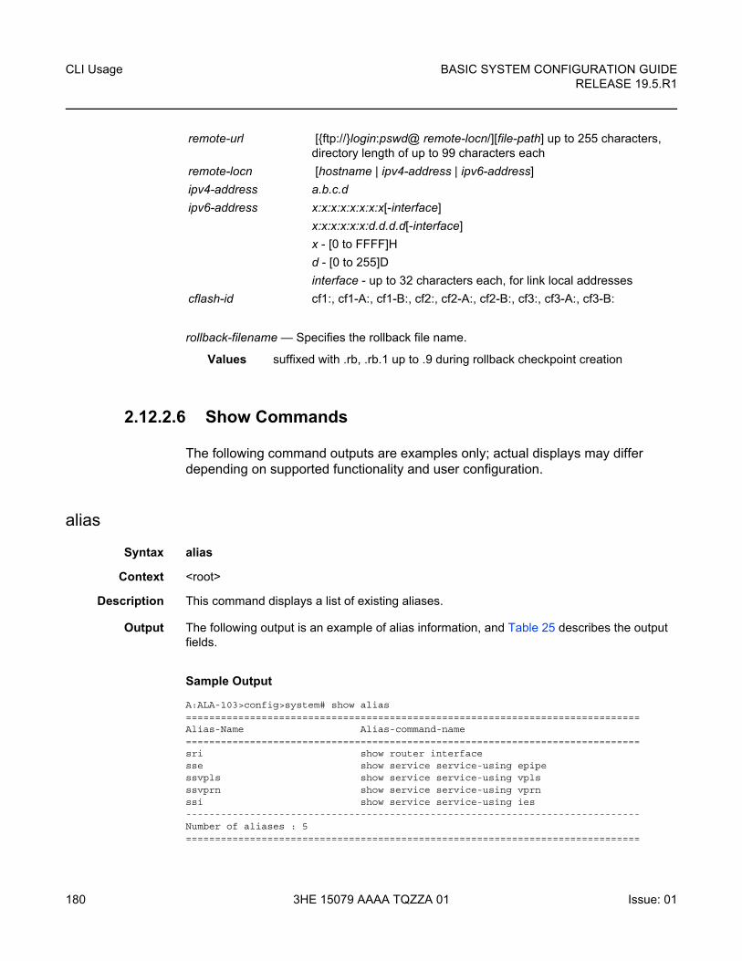
CLI Usage
180
BASIC SYSTEM CONFIGURATION GUIDERELEASE 19.5.R1
3HE 15079 AAAA TQZZA 01 Issue: 01
rollback-filename — Specifies the rollback file name.
Values suffixed with .rb, .rb.1 up to .9 during rollback checkpoint creation
2.12.2.6 Show Commands
The following command outputs are examples only; actual displays may differ depending on supported functionality and user configuration.
alias
Syntax alias
Context <root>
Description This command displays a list of existing aliases.
Output The following output is an example of alias information, and Table 25 describes the output fields.
Sample Output
A:ALA-103>config>system# show alias==============================================================================Alias-Name Alias-command-name==============================================================================sri show router interfacesse show service service-using epipessvpls show service service-using vplsssvprn show service service-using vprnssi show service service-using ies------------------------------------------------------------------------------Number of aliases : 5==============================================================================
remote-url [{ftp://}login:pswd@ remote-locn/][file-path] up to 255 characters, directory length of up to 99 characters each
remote-locn [hostname | ipv4-address | ipv6-address]
ipv4-address a.b.c.d
ipv6-address x:x:x:x:x:x:x:x[-interface]
x:x:x:x:x:x:d.d.d.d[-interface]
x - [0 to FFFF]H
d - [0 to 255]D
interface - up to 32 characters each, for link local addresses
cflash-id cf1:, cf1-A:, cf1-B:, cf2:, cf2-A:, cf2-B:, cf3:, cf3-A:, cf3-B:
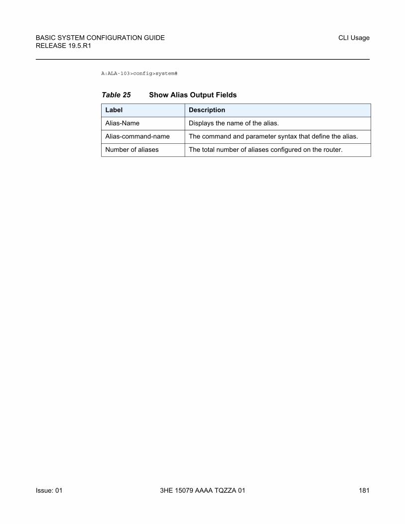
BASIC SYSTEM CONFIGURATION GUIDE RELEASE 19.5.R1
CLI Usage
Issue: 01 3HE 15079 AAAA TQZZA 01 181
A:ALA-103>config>system#
Table 25 Show Alias Output Fields
Label Description
Alias-Name Displays the name of the alias.
Alias-command-name The command and parameter syntax that define the alias.
Number of aliases The total number of aliases configured on the router.

CLI Usage
182
BASIC SYSTEM CONFIGURATION GUIDERELEASE 19.5.R1
3HE 15079 AAAA TQZZA 01 Issue: 01
BASIC SYSTEM CONFIGURATION GUIDE RELEASE 19.5.R1
File System Management
Issue: 01 3HE 15079 AAAA TQZZA 01 183
3 File System Management
3.1 The File System
The SR OS file system is used to store files used and generated by the system, for example, image files, configuration files, logging files and accounting files.
The file commands allow you to copy, create, move, and delete files and directories, navigate to a different directory, display file or directory contents and the image version.
Although some of the storage devices on routers are not actually compact flash devices (for example, cf1: on the 7950 XRS is an internal SSD), we refer to all storage devices as compact flash.
3.1.1 Compact Flash Devices
The file system is based on a DoS file system (with an optional Reliance file system). In the 7750 SR and 7450 ESS, each control processor can have up to three compact flash devices numbered one through three. In the 7950 XRS, each CCM has an SSD and up to two compact flash devices. The names for these devices are:
• cf1:
• cf2:
• cf3:
The above device names are relative device names as they refer to the devices local to the control processor with the current console session. As in the DoS file system, the colon (“:”) at the end of the name indicates it is a device.
The three compact flash devices on the 7450 ESS and 7750 SR OS are removable and have an administrative state (shutdown/no shutdown).
The cf2: and cf3: compact flash devices on the 7950 XRS routers are removable and have an administrative state (shutdown/no shutdown). cf1: is an internal SSD.
Note: To prevent corrupting open files in the file system, you should only remove a compact flash that is administratively shutdown. The SR OS gracefully closes any open files on the device, so it can be safely removed.
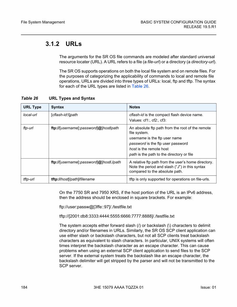
File System Management
184
BASIC SYSTEM CONFIGURATION GUIDERELEASE 19.5.R1
3HE 15079 AAAA TQZZA 01 Issue: 01
3.1.2 URLs
The arguments for the SR OS file commands are modeled after standard universal resource locater (URL). A URL refers to a file (a file-url) or a directory (a directory-url).
The SR OS supports operations on both the local file system and on remote files. For the purposes of categorizing the applicability of commands to local and remote file operations, URLs are divided into three types of URLs: local, ftp and tftp. The syntax for each of the URL types are listed in Table 26.
On the 7750 SR and 7950 XRS, if the host portion of the URL is an IPv6 address, then the address should be enclosed in square brackets. For example:
ftp://user:passw@[3ffe::97]/./testfile.txt
tftp://[2001:db8:3333:4444:5555:6666:7777:8888]/./testfile.txt
The system accepts either forward slash (/) or backslash (\) characters to delimit directory and/or filenames in URLs. Similarly, the SR OS SCP client application can use either slash or backslash characters, but not all SCP clients treat backslash characters as equivalent to slash characters. In particular, UNIX systems will often times interpret the backslash character as an escape character. This can cause problems when using an external SCP client application to send files to the SCP server. If the external system treats the backslash like an escape character, the backslash delimiter will get stripped by the parser and will not be transmitted to the SCP server.
Table 26 URL Types and Syntax
URL Type Syntax Notes
local-url [cflash-id:\]path cflash-id is the compact flash device name.
Values: cf1:, cf2:, cf3:
ftp-url ftp://[username[:password]@]host/path An absolute ftp path from the root of the remote file system.
username is the ftp user name
password is the ftp user password
host is the remote host
path is the path to the directory or file
ftp://[username[:password]@]host/./path A relative ftp path from the user’s home directory. Note the period and slash (“./”) in this syntax compared to the absolute path.
tftp-url tftp://host[/path]/filename tftp is only supported for operations on file-urls.
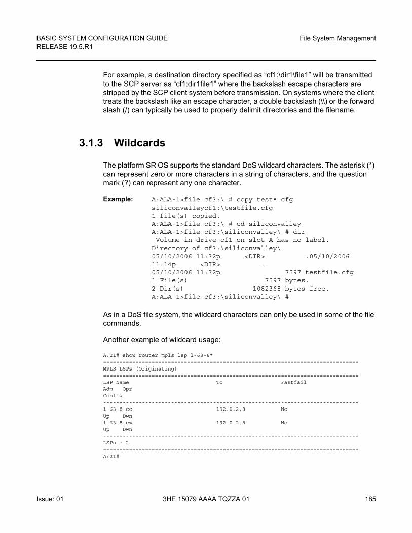
BASIC SYSTEM CONFIGURATION GUIDE RELEASE 19.5.R1
File System Management
Issue: 01 3HE 15079 AAAA TQZZA 01 185
For example, a destination directory specified as “cf1:\dir1\file1” will be transmitted to the SCP server as “cf1:dir1file1” where the backslash escape characters are stripped by the SCP client system before transmission. On systems where the client treats the backslash like an escape character, a double backslash (\\) or the forward slash (/) can typically be used to properly delimit directories and the filename.
3.1.3 Wildcards
The platform SR OS supports the standard DoS wildcard characters. The asterisk (*) can represent zero or more characters in a string of characters, and the question mark (?) can represent any one character.
Example: A:ALA-1>file cf3:\ # copy test*.cfgsiliconvalleycf1:\testfile.cfg1 file(s) copied.A:ALA-1>file cf3:\ # cd siliconvalleyA:ALA-1>file cf3:\siliconvalley\ # dir Volume in drive cf1 on slot A has no label.Directory of cf3:\siliconvalley\05/10/2006 11:32p <DIR> .05/10/200611:14p <DIR> ..05/10/2006 11:32p 7597 testfile.cfg1 File(s) 7597 bytes.2 Dir(s) 1082368 bytes free.A:ALA-1>file cf3:\siliconvalley\ #
As in a DoS file system, the wildcard characters can only be used in some of the file commands.
Another example of wildcard usage:
A:21# show router mpls lsp l-63-8*===============================================================================MPLS LSPs (Originating)===============================================================================LSP Name To FastfailAdm OprConfig-------------------------------------------------------------------------------l-63-8-cc 192.0.2.8 NoUp Dwnl-63-8-cw 192.0.2.8 NoUp Dwn-------------------------------------------------------------------------------LSPs : 2===============================================================================A:21#
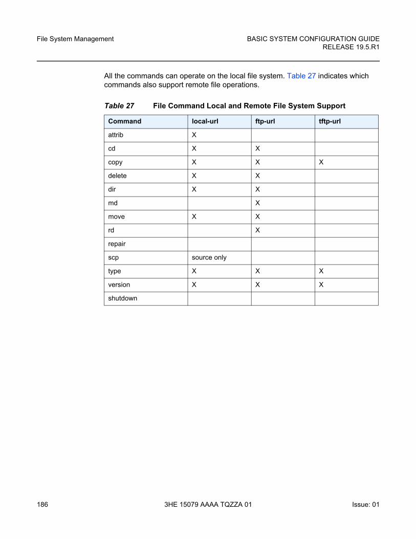
File System Management
186
BASIC SYSTEM CONFIGURATION GUIDERELEASE 19.5.R1
3HE 15079 AAAA TQZZA 01 Issue: 01
All the commands can operate on the local file system. Table 27 indicates which commands also support remote file operations.
Table 27 File Command Local and Remote File System Support
Command local-url ftp-url tftp-url
attrib X
cd X X
copy X X X
delete X X
dir X X
md X
move X X
rd X
repair
scp source only
type X X X
version X X X
shutdown
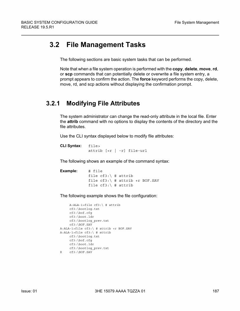
BASIC SYSTEM CONFIGURATION GUIDE RELEASE 19.5.R1
File System Management
Issue: 01 3HE 15079 AAAA TQZZA 01 187
3.2 File Management Tasks
The following sections are basic system tasks that can be performed.
Note that when a file system operation is performed with the copy, delete, move, rd, or scp commands that can potentially delete or overwrite a file system entry, a prompt appears to confirm the action. The force keyword performs the copy, delete, move, rd, and scp actions without displaying the confirmation prompt.
3.2.1 Modifying File Attributes
The system administrator can change the read-only attribute in the local file. Enter the attrib command with no options to display the contents of the directory and the file attributes.
Use the CLI syntax displayed below to modify file attributes:
CLI Syntax: file> attrib [+r | -r] file-url
The following shows an example of the command syntax:
Example: # filefile cf3:\ # attrib file cf3:\ # attrib +r BOF.SAVfile cf3:\ # attrib
The following example shows the file configuration:
A:ALA-1>file cf3:\ # attribcf3:\bootlog.txtcf3:\bof.cfgcf3:\boot.ldrcf3:\bootlog_prev.txtcf3:\BOF.SAV
A:ALA-1>file cf3:\ # attrib +r BOF.SAVA:ALA-1>file cf3:\ # attrib
cf3:\bootlog.txtcf3:\bof.cfgcf3:\boot.ldrcf3:\bootlog_prev.txt
R cf3:\BOF.SAV
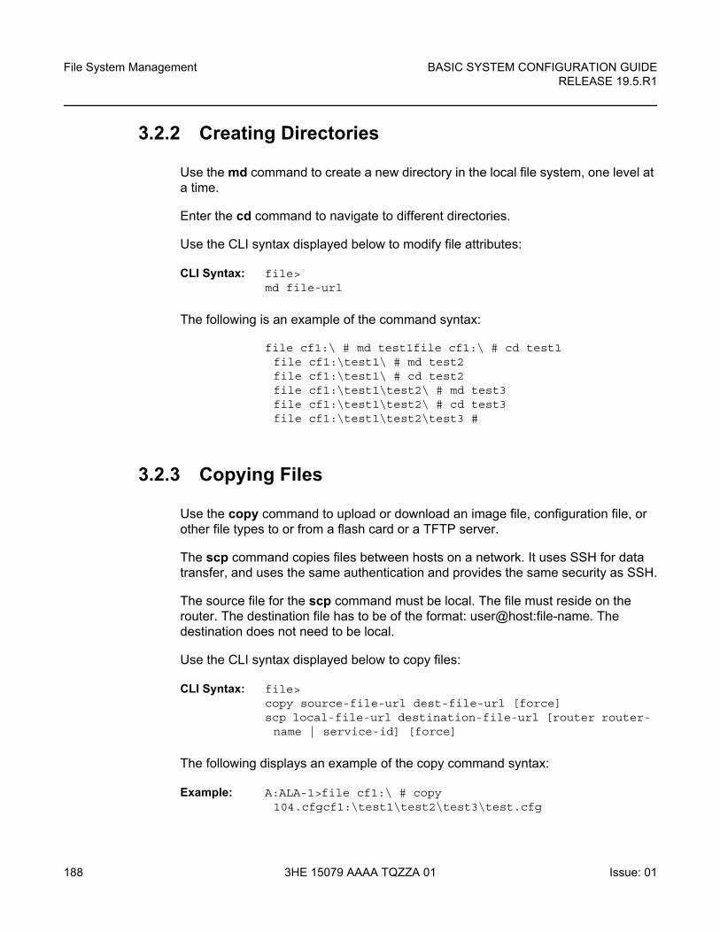
File System Management
188
BASIC SYSTEM CONFIGURATION GUIDERELEASE 19.5.R1
3HE 15079 AAAA TQZZA 01 Issue: 01
3.2.2 Creating Directories
Use the md command to create a new directory in the local file system, one level at a time.
Enter the cd command to navigate to different directories.
Use the CLI syntax displayed below to modify file attributes:
CLI Syntax: file> md file-url
The following is an example of the command syntax:
file cf1:\ # md test1file cf1:\ # cd test1file cf1:\test1\ # md test2file cf1:\test1\ # cd test2file cf1:\test1\test2\ # md test3file cf1:\test1\test2\ # cd test3file cf1:\test1\test2\test3 #
3.2.3 Copying Files
Use the copy command to upload or download an image file, configuration file, or other file types to or from a flash card or a TFTP server.
The scp command copies files between hosts on a network. It uses SSH for data transfer, and uses the same authentication and provides the same security as SSH.
The source file for the scp command must be local. The file must reside on the router. The destination file has to be of the format: user@host:file-name. The destination does not need to be local.
Use the CLI syntax displayed below to copy files:
CLI Syntax: file> copy source-file-url dest-file-url [force]scp local-file-url destination-file-url [router router- name | service-id] [force]
The following displays an example of the copy command syntax:
Example: A:ALA-1>file cf1:\ # copy 104.cfgcf1:\test1\test2\test3\test.cfg
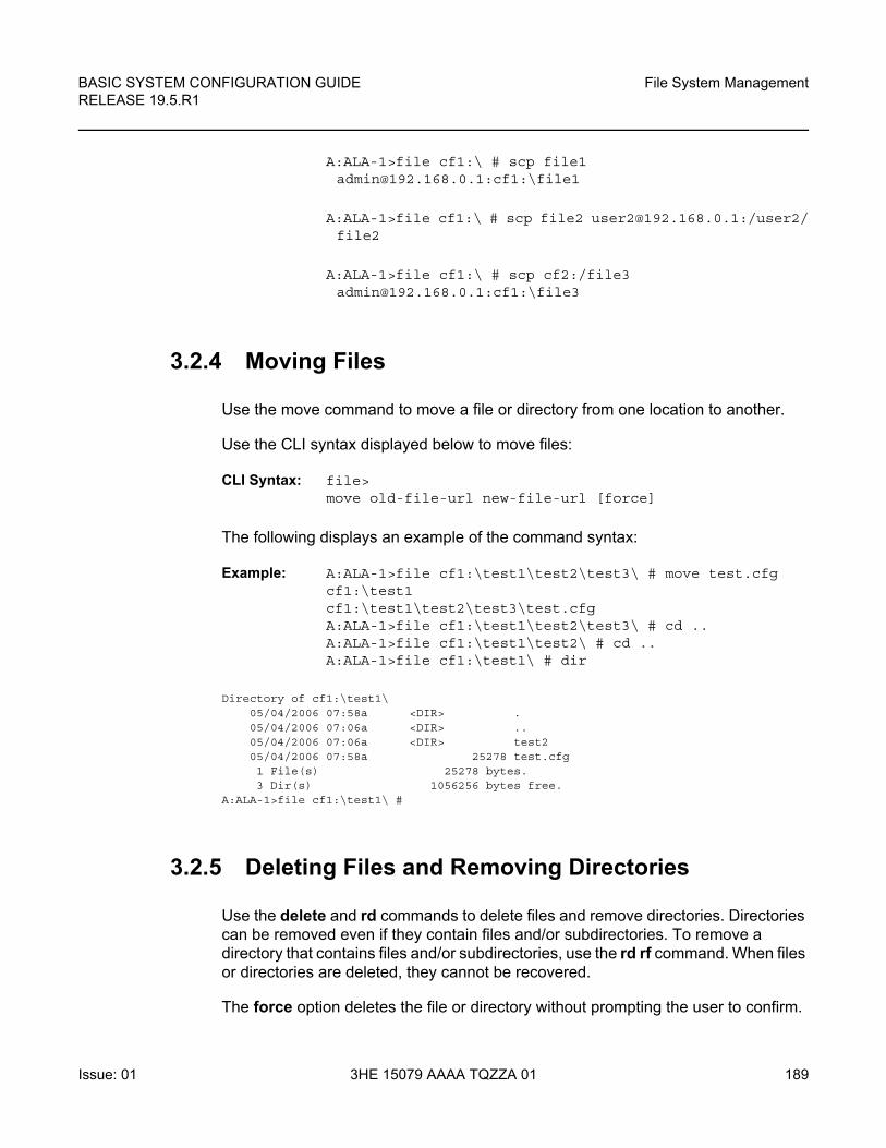
BASIC SYSTEM CONFIGURATION GUIDE RELEASE 19.5.R1
File System Management
Issue: 01 3HE 15079 AAAA TQZZA 01 189
A:ALA-1>file cf1:\ # scp file1 [email protected]:cf1:\file1
A:ALA-1>file cf1:\ # scp file2 [email protected]:/user2/file2
A:ALA-1>file cf1:\ # scp cf2:/file3 [email protected]:cf1:\file3
3.2.4 Moving Files
Use the move command to move a file or directory from one location to another.
Use the CLI syntax displayed below to move files:
CLI Syntax: file> move old-file-url new-file-url [force]
The following displays an example of the command syntax:
Example: A:ALA-1>file cf1:\test1\test2\test3\ # move test.cfgcf1:\test1cf1:\test1\test2\test3\test.cfgA:ALA-1>file cf1:\test1\test2\test3\ # cd ..A:ALA-1>file cf1:\test1\test2\ # cd ..A:ALA-1>file cf1:\test1\ # dir
Directory of cf1:\test1\05/04/2006 07:58a <DIR> .05/04/2006 07:06a <DIR> ..05/04/2006 07:06a <DIR> test205/04/2006 07:58a 25278 test.cfg1 File(s) 25278 bytes.3 Dir(s) 1056256 bytes free.
A:ALA-1>file cf1:\test1\ #
3.2.5 Deleting Files and Removing Directories
Use the delete and rd commands to delete files and remove directories. Directories can be removed even if they contain files and/or subdirectories. To remove a directory that contains files and/or subdirectories, use the rd rf command. When files or directories are deleted, they cannot be recovered.
The force option deletes the file or directory without prompting the user to confirm.
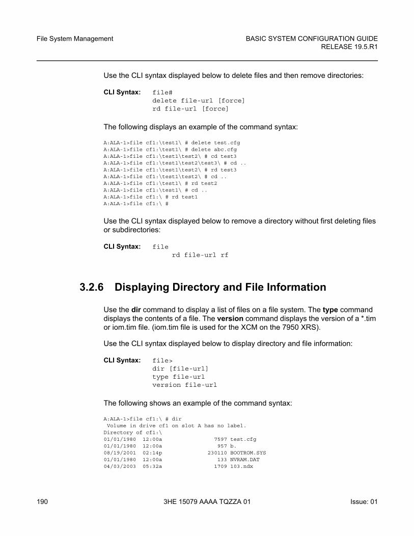
File System Management
190
BASIC SYSTEM CONFIGURATION GUIDERELEASE 19.5.R1
3HE 15079 AAAA TQZZA 01 Issue: 01
Use the CLI syntax displayed below to delete files and then remove directories:
CLI Syntax: file# delete file-url [force]rd file-url [force]
The following displays an example of the command syntax:
A:ALA-1>file cf1:\test1\ # delete test.cfgA:ALA-1>file cf1:\test1\ # delete abc.cfgA:ALA-1>file cf1:\test1\test2\ # cd test3A:ALA-1>file cf1:\test1\test2\test3\ # cd ..A:ALA-1>file cf1:\test1\test2\ # rd test3A:ALA-1>file cf1:\test1\test2\ # cd ..A:ALA-1>file cf1:\test1\ # rd test2A:ALA-1>file cf1:\test1\ # cd ..A:ALA-1>file cf1:\ # rd test1A:ALA-1>file cf1:\ #
Use the CLI syntax displayed below to remove a directory without first deleting files or subdirectories:
CLI Syntax: filerd file-url rf
3.2.6 Displaying Directory and File Information
Use the dir command to display a list of files on a file system. The type command displays the contents of a file. The version command displays the version of a *.tim or iom.tim file. (iom.tim file is used for the XCM on the 7950 XRS).
Use the CLI syntax displayed below to display directory and file information:
CLI Syntax: file> dir [file-url]type file-urlversion file-url
The following shows an example of the command syntax:
A:ALA-1>file cf1:\ # dirVolume in drive cf1 on slot A has no label.
Directory of cf1:\01/01/1980 12:00a 7597 test.cfg01/01/1980 12:00a 957 b.08/19/2001 02:14p 230110 BOOTROM.SYS01/01/1980 12:00a 133 NVRAM.DAT04/03/2003 05:32a 1709 103.ndx
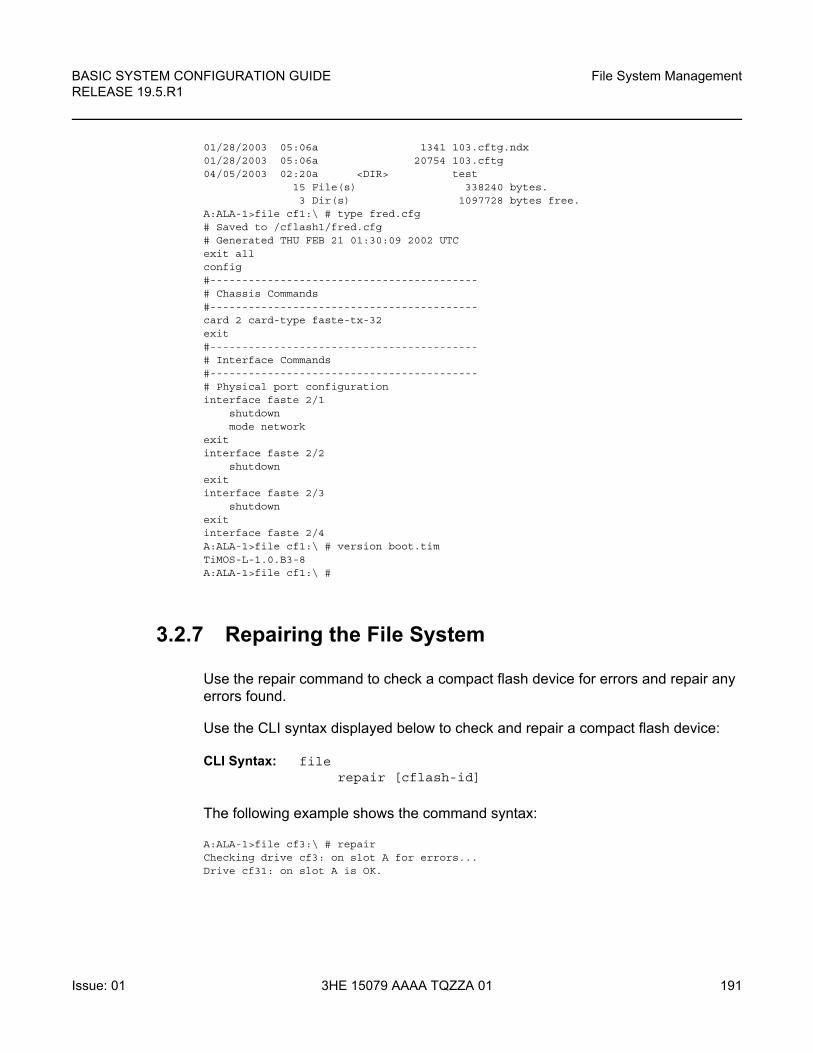
BASIC SYSTEM CONFIGURATION GUIDE RELEASE 19.5.R1
File System Management
Issue: 01 3HE 15079 AAAA TQZZA 01 191
01/28/2003 05:06a 1341 103.cftg.ndx01/28/2003 05:06a 20754 103.cftg04/05/2003 02:20a <DIR> test
15 File(s) 338240 bytes.3 Dir(s) 1097728 bytes free.
A:ALA-1>file cf1:\ # type fred.cfg# Saved to /cflash1/fred.cfg# Generated THU FEB 21 01:30:09 2002 UTCexit allconfig#------------------------------------------# Chassis Commands#------------------------------------------card 2 card-type faste-tx-32exit#------------------------------------------# Interface Commands#------------------------------------------# Physical port configurationinterface faste 2/1
shutdownmode network
exitinterface faste 2/2
shutdownexitinterface faste 2/3
shutdownexitinterface faste 2/4A:ALA-1>file cf1:\ # version boot.timTiMOS-L-1.0.B3-8A:ALA-1>file cf1:\ #
3.2.7 Repairing the File System
Use the repair command to check a compact flash device for errors and repair any errors found.
Use the CLI syntax displayed below to check and repair a compact flash device:
CLI Syntax: filerepair [cflash-id]
The following example shows the command syntax:
A:ALA-1>file cf3:\ # repairChecking drive cf3: on slot A for errors...Drive cf31: on slot A is OK.

File System Management
192
BASIC SYSTEM CONFIGURATION GUIDERELEASE 19.5.R1
3HE 15079 AAAA TQZZA 01 Issue: 01
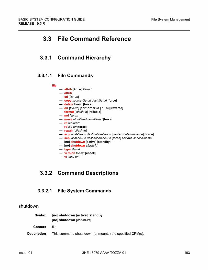
BASIC SYSTEM CONFIGURATION GUIDE RELEASE 19.5.R1
File System Management
Issue: 01 3HE 15079 AAAA TQZZA 01 193
3.3 File Command Reference
3.3.1 Command Hierarchy
3.3.1.1 File Commands
file — attrib [+r | -r] file-url— attrib— cd [file-url]— copy source-file-url dest-file-url [force]— delete file-url [force]— dir [file-url] [sort-order {d | n | s}] [reverse]— format [cflash-id] [reliable]— md file-url— move old-file-url new-file-url [force]— rd file-url rf— rd file-url [force]— repair [cflash-id]— scp local-file-url destination-file-url [router router-instance] [force]— scp local-file-url destination-file-url [force] service service-name— [no] shutdown [active] [standby]— [no] shutdown cflash-id— type file-url— version file-url [check]— vi local-url
3.3.2 Command Descriptions
3.3.2.1 File System Commands
shutdown
Syntax [no] shutdown [active] [standby]
[no] shutdown [cflash-id]
Context file
Description This command shuts down (unmounts) the specified CPM(s).
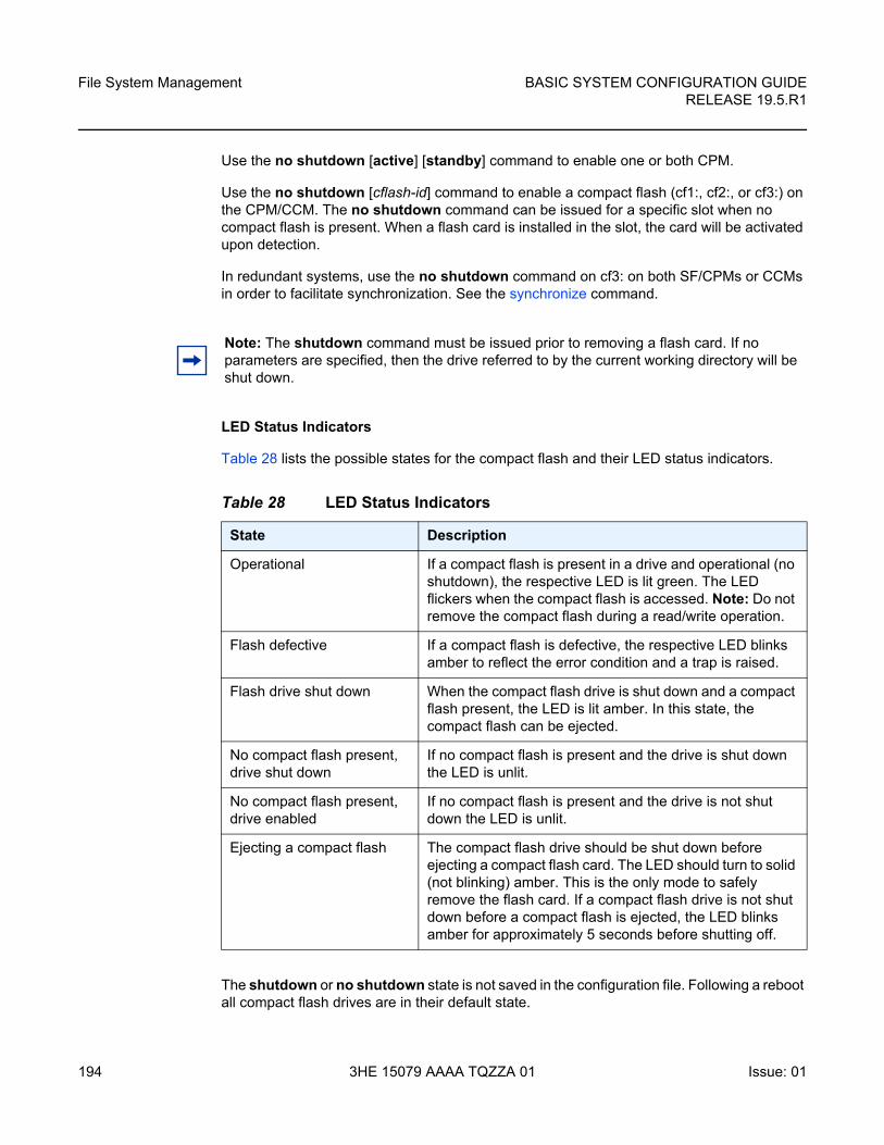
File System Management
194
BASIC SYSTEM CONFIGURATION GUIDERELEASE 19.5.R1
3HE 15079 AAAA TQZZA 01 Issue: 01
Use the no shutdown [active] [standby] command to enable one or both CPM.
Use the no shutdown [cflash-id] command to enable a compact flash (cf1:, cf2:, or cf3:) on the CPM/CCM. The no shutdown command can be issued for a specific slot when no compact flash is present. When a flash card is installed in the slot, the card will be activated upon detection.
In redundant systems, use the no shutdown command on cf3: on both SF/CPMs or CCMs in order to facilitate synchronization. See the synchronize command.
LED Status Indicators
Table 28 lists the possible states for the compact flash and their LED status indicators.
The shutdown or no shutdown state is not saved in the configuration file. Following a reboot all compact flash drives are in their default state.
Note: The shutdown command must be issued prior to removing a flash card. If no parameters are specified, then the drive referred to by the current working directory will be shut down.
Table 28 LED Status Indicators
State Description
Operational If a compact flash is present in a drive and operational (no shutdown), the respective LED is lit green. The LED flickers when the compact flash is accessed. Note: Do not remove the compact flash during a read/write operation.
Flash defective If a compact flash is defective, the respective LED blinks amber to reflect the error condition and a trap is raised.
Flash drive shut down When the compact flash drive is shut down and a compact flash present, the LED is lit amber. In this state, the compact flash can be ejected.
No compact flash present, drive shut down
If no compact flash is present and the drive is shut down the LED is unlit.
No compact flash present, drive enabled
If no compact flash is present and the drive is not shut down the LED is unlit.
Ejecting a compact flash The compact flash drive should be shut down before ejecting a compact flash card. The LED should turn to solid (not blinking) amber. This is the only mode to safely remove the flash card. If a compact flash drive is not shut down before a compact flash is ejected, the LED blinks amber for approximately 5 seconds before shutting off.
BASIC SYSTEM CONFIGURATION GUIDE RELEASE 19.5.R1
File System Management
Issue: 01 3HE 15079 AAAA TQZZA 01 195
Default no shutdown
Parameters cflash-id — Specifies the compact flash slot ID to be shut down or enabled. If cflash-id is specified, the drive is shut down or enabled. If no cflash-id is specified, the drive referred to by the current working directory is assumed. If a slot number is not specified, then the active CPM is assumed.
Values cf1:, cf1-A:, cf1-B:, cf2:, cf2-A:, cf2-B:, cf3:, cf3-A:, cf3-B:
Default the current compact flash device
active — Specifies that all drives on the active CPM are shutdown or enabled.
standby — Specifies that all drives on the standby CPM are shutdown or enabled.
When both active and standby keywords are specified, then all drives on both CPM are shutdown.
3.3.2.2 File Commands
file
Syntax file
Context root
Description Specifies the context to enter and perform file system operations. When entering the file context, the prompt changes to reflect the present working directory. Navigating the file system with the cd .. command results in a changed prompt.
The exit all command leaves the file system/file operation context and returns to the <root> CLI context. The state of the present working directory is maintained for the CLI session. Entering the file command returns the cursor to the working directory where the exit command was issued.
attrib
Syntax attrib [+r | -r] file-url
attrib
Context file
Description This command sets or clears/resets the read-only attribute for a file in the local file system. To list all files and their current attributes enter attrib or attrib x where x is either the filename or a wildcard (*).
File System Management
196
BASIC SYSTEM CONFIGURATION GUIDERELEASE 19.5.R1
3HE 15079 AAAA TQZZA 01 Issue: 01
When an attrib command is entered to list a specific file or all files in a directory, the file’s attributes are displayed with or without an “R” preceding the filename. The “R” implies that the +r is set and that the file is read-only. Files without the “R” designation implies that the -r is set and that the file is read-write-all. For example:
ALA-1>file cf3:\ # attribcf3:\bootlog.txtcf3:\bof.cfgcf3:\boot.ldrcf3:\sr1.cfgcf3:\testcf3:\bootlog_prev.txtcf3:\BOF.SAV
Parameters file-url — Specifies the URL for the local file.
Values
+r — Sets the read-only attribute on the specified file.
-r — Clears/resets the read-only attribute on the specified file.
cd
Syntax cd [file-url]
Context file
Description This command displays or changes the current working directory in the local file system.
Parameters file-url — Specifies the file URL.
Values
local-url [cflash-id/][file-path] up to 200 characters, including cflash-id directory length 99 chars max each
remote-url [{ftp:// | tftp://}login:pswd@remote-locn/][file-path]
up to 247 characters
directory length up to 199 characters
remote-locn [hostname | ipv4-address | [ipv6-address]]
ipv4-address a.b.c.d
ipv6-address x:x:x:x:x:x:x:x[-interface]
x:x:x:x:x:x:d.d.d.d[-interface]
x - [0 to FFFF]H
d - [0 to 255]D
interface - up to 32 characters, for link local addresses 255
cflash-id cf1:, cf1-A:, cf1-B:, cf2:, cf2-A:, cf2-B:, cf3:, cf3-A:, cf3-B:
BASIC SYSTEM CONFIGURATION GUIDE RELEASE 19.5.R1
File System Management
Issue: 01 3HE 15079 AAAA TQZZA 01 197
If no file-url is entered, the current working directory is displayed.
.. — signifies the parent directory. This can be used in place of an actual directory name in a directory-url.
directory-url — Specifies the destination directory.
copy
Syntax copy source-file-url dest-file-url [force]
Context file
Description This command copies a file or all files in a directory from a source URL to a destination URL. At least one of the specified URLs should be a local URL. The optional wildcard (*) can be used to copy multiple files that share a common (partial) prefix and/or (partial) suffix.
When a file is copied to a destination with the same file name, the original file is overwritten by the new file specified in the operation. The following prompt appears if the destination file already exists:
“Overwrite destination file (y/n)?”
For example:
To copy a file named srcfile in a directory called test on cf2 in slot B to a file called destfile in a directory called production on cf1 in slot A, the syntax is:
sr1>file cf2:\ # copy cf2-B/test/srcfile cf1-A/production/destfile
local-url [cflash-id/][file-path] up to 200 characters, including cflash-id directory length 99 chars max each
remote-url [{ftp:// | tftp://}login:pswd@remote-locn/][file-path]
up to 247 characters
directory length up to 199 characters
remote-locn [hostname | ipv4-address | [ipv6-address]]
ipv4-address a.b.c.d
ipv6-address x:x:x:x:x:x:x:x[-interface]
x:x:x:x:x:x:d.d.d.d[-interface]
x - [0 to FFFF]H
d - [0 to 255]D
interface - up to 32 characters, for link local addresses 255
cflash-id cf1:, cf1-A:, cf1-B:, cf2:, cf2-A:, cf2-B:, cf3:, cf3-A:, cf3-B:
File System Management
198
BASIC SYSTEM CONFIGURATION GUIDERELEASE 19.5.R1
3HE 15079 AAAA TQZZA 01 Issue: 01
To FTP a file named 121201.cfg in directory mydir stored on cf1 in slot A to a network FTP server with IP address 192.0.2.79 in a directory called backup with a destination file name of 121201.cfg, the FTP syntax is:
copy cf1-A/mydir/121201.cfg 192.0.2.79/backup/121201.cfg
Parameters source-file-url — Specifies the location of the source file or directory to be copied.
Values
dest-file-url — Specifies the destination of the copied file or directory.
force — Specifies to force an immediate copy of the specified file(s). Executes the command without displaying a user prompt message.
delete
Syntax delete file-url [force]
Context file
Description This command deletes the specified file.
The optional wildcard (*) can be used to delete multiple files that share a common (partial) prefix and/or (partial) suffix. When the wildcard is entered, the following prompt displays for each file that matches the wildcard:
“Delete file <filename> (y/n)?”
Parameters file-url — Specifies the file name to delete.
Values
local-url [cflash-id/][file-path] up to 200 characters, including cflash-id directory length 99 chars max each
remote-url [{ftp:// | tftp://}login:pswd@remote-locn/][file-path]
up to 247 characters
directory length up to 199 characters
remote-locn [hostname | ipv4-address | [ipv6-address]]
ipv4-address a.b.c.d
ipv6-address x:x:x:x:x:x:x:x[-interface]
x:x:x:x:x:x:d.d.d.d[-interface]
x - [0 to FFFF]H
d - [0 to 255]D
interface - up to 32 characters, for link local addresses 255
cflash-id cf1:, cf1-A:, cf1-B:, cf2:, cf2-A:, cf2-B:, cf3:, cf3-A:, cf3-B:
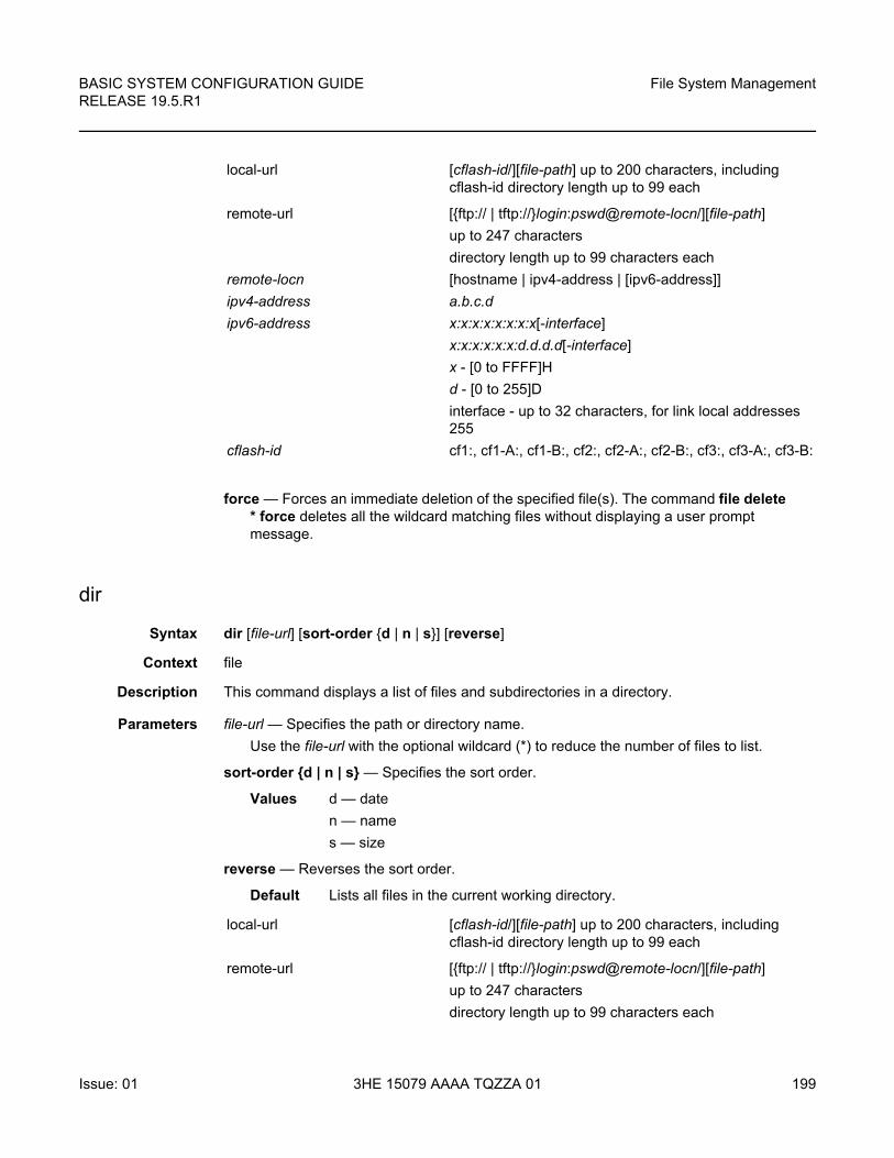
BASIC SYSTEM CONFIGURATION GUIDE RELEASE 19.5.R1
File System Management
Issue: 01 3HE 15079 AAAA TQZZA 01 199
force — Forces an immediate deletion of the specified file(s). The command file delete * force deletes all the wildcard matching files without displaying a user prompt message.
dir
Syntax dir [file-url] [sort-order {d | n | s}] [reverse]
Context file
Description This command displays a list of files and subdirectories in a directory.
Parameters file-url — Specifies the path or directory name.
Use the file-url with the optional wildcard (*) to reduce the number of files to list.
sort-order {d | n | s} — Specifies the sort order.
Values d — date
n — name
s — size
reverse — Reverses the sort order.
Default Lists all files in the current working directory.
local-url [cflash-id/][file-path] up to 200 characters, including cflash-id directory length up to 99 each
remote-url [{ftp:// | tftp://}login:pswd@remote-locn/][file-path]
up to 247 characters
directory length up to 99 characters each
remote-locn [hostname | ipv4-address | [ipv6-address]]
ipv4-address a.b.c.d
ipv6-address x:x:x:x:x:x:x:x[-interface]
x:x:x:x:x:x:d.d.d.d[-interface]
x - [0 to FFFF]H
d - [0 to 255]D
interface - up to 32 characters, for link local addresses 255
cflash-id cf1:, cf1-A:, cf1-B:, cf2:, cf2-A:, cf2-B:, cf3:, cf3-A:, cf3-B:
local-url [cflash-id/][file-path] up to 200 characters, including cflash-id directory length up to 99 each
remote-url [{ftp:// | tftp://}login:pswd@remote-locn/][file-path]
up to 247 characters
directory length up to 99 characters each
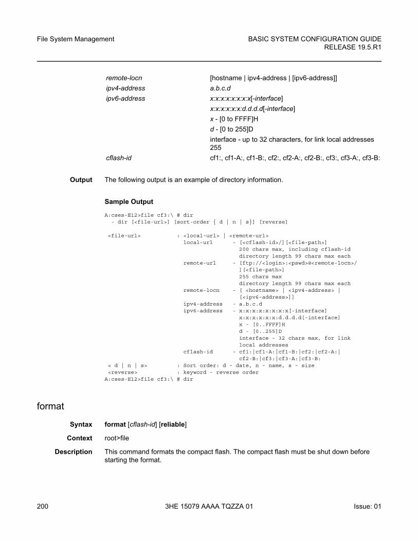
File System Management
200
BASIC SYSTEM CONFIGURATION GUIDERELEASE 19.5.R1
3HE 15079 AAAA TQZZA 01 Issue: 01
Output The following output is an example of directory information.
Sample Output
A:cses-E12>file cf3:\ # dir- dir [<file-url>] [sort-order { d | n | s}] [reverse]
<file-url> : <local-url> | <remote-url>local-url - [<cflash-id>/][<file-path>]
200 chars max, including cflash-iddirectory length 99 chars max each
remote-url - [ftp://<login>:<pswd>@<remote-locn>/][<file-path>]255 chars maxdirectory length 99 chars max each
remote-locn - [ <hostname> | <ipv4-address> |[<ipv6-address>]]
ipv4-address - a.b.c.dipv6-address - x:x:x:x:x:x:x:x[-interface]
x:x:x:x:x:x:d.d.d.d[-interface]x - [0..FFFF]Hd - [0..255]Dinterface - 32 chars max, for linklocal addresses
cflash-id - cf1:|cf1-A:|cf1-B:|cf2:|cf2-A:|cf2-B:|cf3:|cf3-A:|cf3-B:
< d | n | s> : Sort order: d - date, n - name, s - size<reverse> : keyword - reverse order
A:cses-E12>file cf3:\ # dir
format
Syntax format [cflash-id] [reliable]
Context root>file
Description This command formats the compact flash. The compact flash must be shut down before starting the format.
remote-locn [hostname | ipv4-address | [ipv6-address]]
ipv4-address a.b.c.d
ipv6-address x:x:x:x:x:x:x:x[-interface]
x:x:x:x:x:x:d.d.d.d[-interface]
x - [0 to FFFF]H
d - [0 to 255]D
interface - up to 32 characters, for link local addresses 255
cflash-id cf1:, cf1-A:, cf1-B:, cf2:, cf2-A:, cf2-B:, cf3:, cf3-A:, cf3-B:
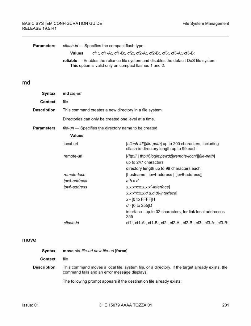
BASIC SYSTEM CONFIGURATION GUIDE RELEASE 19.5.R1
File System Management
Issue: 01 3HE 15079 AAAA TQZZA 01 201
Parameters cflash-id — Specifies the compact flash type.
Values cf1:, cf1-A:, cf1-B:, cf2:, cf2-A:, cf2-B:, cf3:, cf3-A:, cf3-B:
reliable — Enables the reliance file system and disables the default DoS file system. This option is valid only on compact flashes 1 and 2.
md
Syntax md file-url
Context file
Description This command creates a new directory in a file system.
Directories can only be created one level at a time.
Parameters file-url — Specifies the directory name to be created.
Values
move
Syntax move old-file-url new-file-url [force]
Context file
Description This command moves a local file, system file, or a directory. If the target already exists, the command fails and an error message displays.
The following prompt appears if the destination file already exists:
local-url [cflash-id/][file-path] up to 200 characters, including cflash-id directory length up to 99 each
remote-url [{ftp:// | tftp://}login:pswd@remote-locn/][file-path]
up to 247 characters
directory length up to 99 characters each
remote-locn [hostname | ipv4-address | [ipv6-address]]
ipv4-address a.b.c.d
ipv6-address x:x:x:x:x:x:x:x[-interface]
x:x:x:x:x:x:d.d.d.d[-interface]
x - [0 to FFFF]H
d - [0 to 255]D
interface - up to 32 characters, for link local addresses 255
cflash-id cf1:, cf1-A:, cf1-B:, cf2:, cf2-A:, cf2-B:, cf3:, cf3-A:, cf3-B:
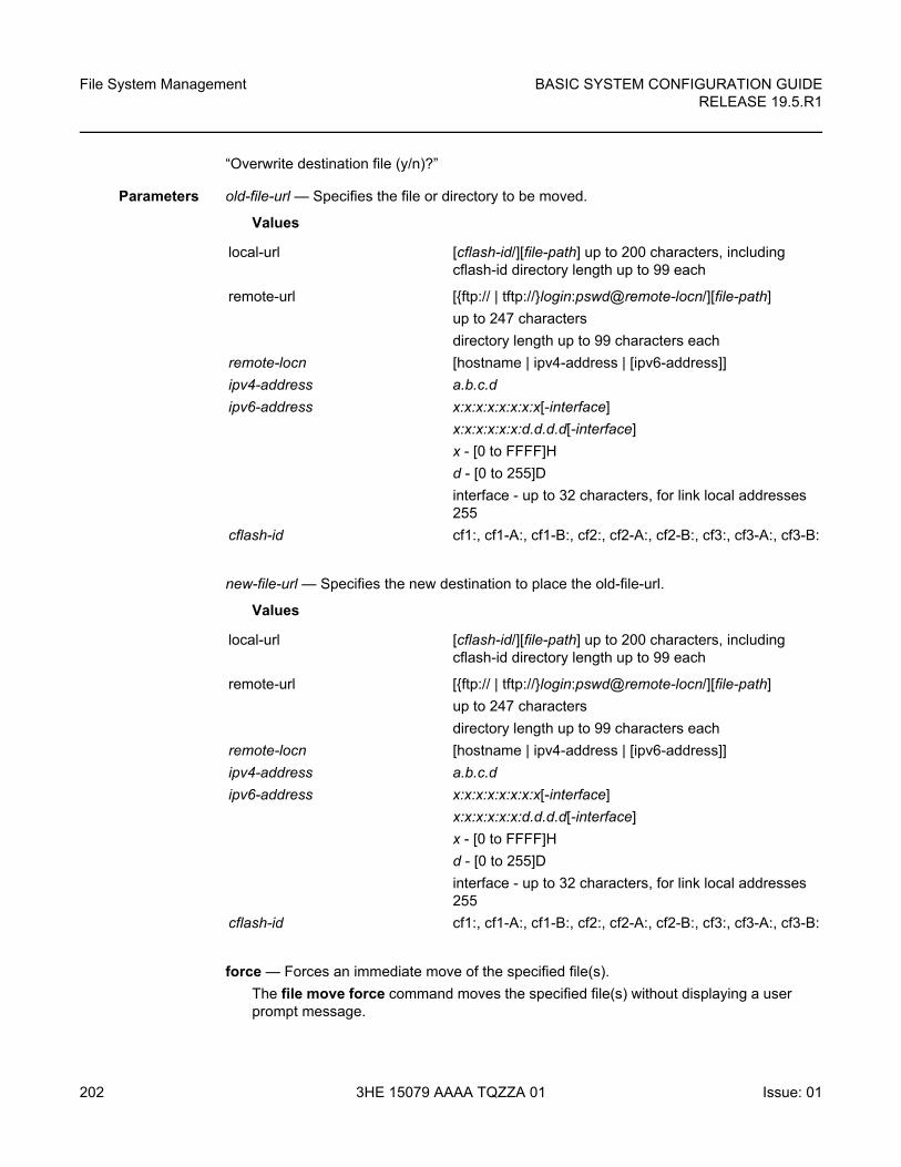
File System Management
202
BASIC SYSTEM CONFIGURATION GUIDERELEASE 19.5.R1
3HE 15079 AAAA TQZZA 01 Issue: 01
“Overwrite destination file (y/n)?”
Parameters old-file-url — Specifies the file or directory to be moved.
Values
new-file-url — Specifies the new destination to place the old-file-url.
Values
force — Forces an immediate move of the specified file(s).
The file move force command moves the specified file(s) without displaying a user prompt message.
local-url [cflash-id/][file-path] up to 200 characters, including cflash-id directory length up to 99 each
remote-url [{ftp:// | tftp://}login:pswd@remote-locn/][file-path]
up to 247 characters
directory length up to 99 characters each
remote-locn [hostname | ipv4-address | [ipv6-address]]
ipv4-address a.b.c.d
ipv6-address x:x:x:x:x:x:x:x[-interface]
x:x:x:x:x:x:d.d.d.d[-interface]
x - [0 to FFFF]H
d - [0 to 255]D
interface - up to 32 characters, for link local addresses 255
cflash-id cf1:, cf1-A:, cf1-B:, cf2:, cf2-A:, cf2-B:, cf3:, cf3-A:, cf3-B:
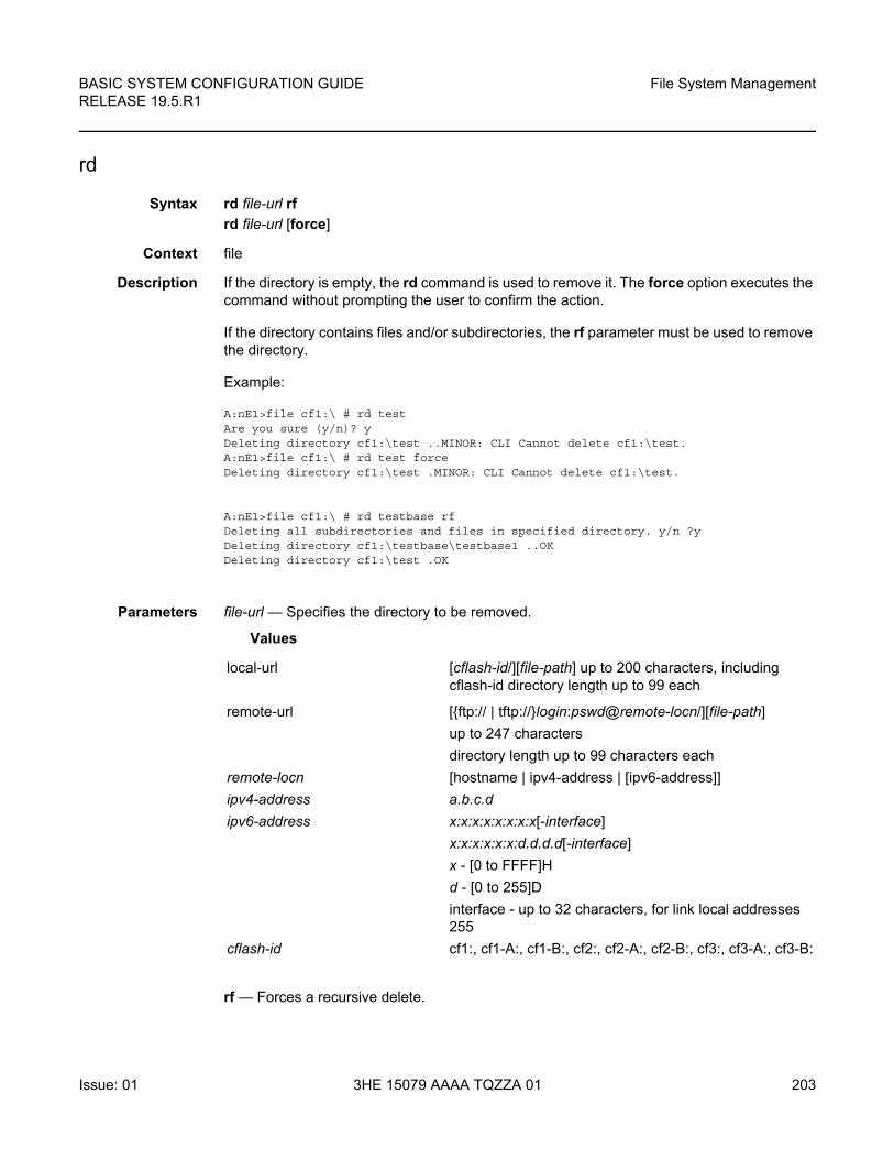
BASIC SYSTEM CONFIGURATION GUIDE RELEASE 19.5.R1
File System Management
Issue: 01 3HE 15079 AAAA TQZZA 01 203
rd
Syntax rd file-url rf
rd file-url [force]
Context file
Description If the directory is empty, the rd command is used to remove it. The force option executes the command without prompting the user to confirm the action.
If the directory contains files and/or subdirectories, the rf parameter must be used to remove the directory.
Example:
A:nE1>file cf1:\ # rd testAre you sure (y/n)? yDeleting directory cf1:\test ..MINOR: CLI Cannot delete cf1:\test.A:nE1>file cf1:\ # rd test forceDeleting directory cf1:\test .MINOR: CLI Cannot delete cf1:\test.
A:nE1>file cf1:\ # rd testbase rfDeleting all subdirectories and files in specified directory. y/n ?yDeleting directory cf1:\testbase\testbase1 ..OKDeleting directory cf1:\test .OK
Parameters file-url — Specifies the directory to be removed.
Values
rf — Forces a recursive delete.
local-url [cflash-id/][file-path] up to 200 characters, including cflash-id directory length up to 99 each
remote-url [{ftp:// | tftp://}login:pswd@remote-locn/][file-path]
up to 247 characters
directory length up to 99 characters each
remote-locn [hostname | ipv4-address | [ipv6-address]]
ipv4-address a.b.c.d
ipv6-address x:x:x:x:x:x:x:x[-interface]
x:x:x:x:x:x:d.d.d.d[-interface]
x - [0 to FFFF]H
d - [0 to 255]D
interface - up to 32 characters, for link local addresses 255
cflash-id cf1:, cf1-A:, cf1-B:, cf2:, cf2-A:, cf2-B:, cf3:, cf3-A:, cf3-B:
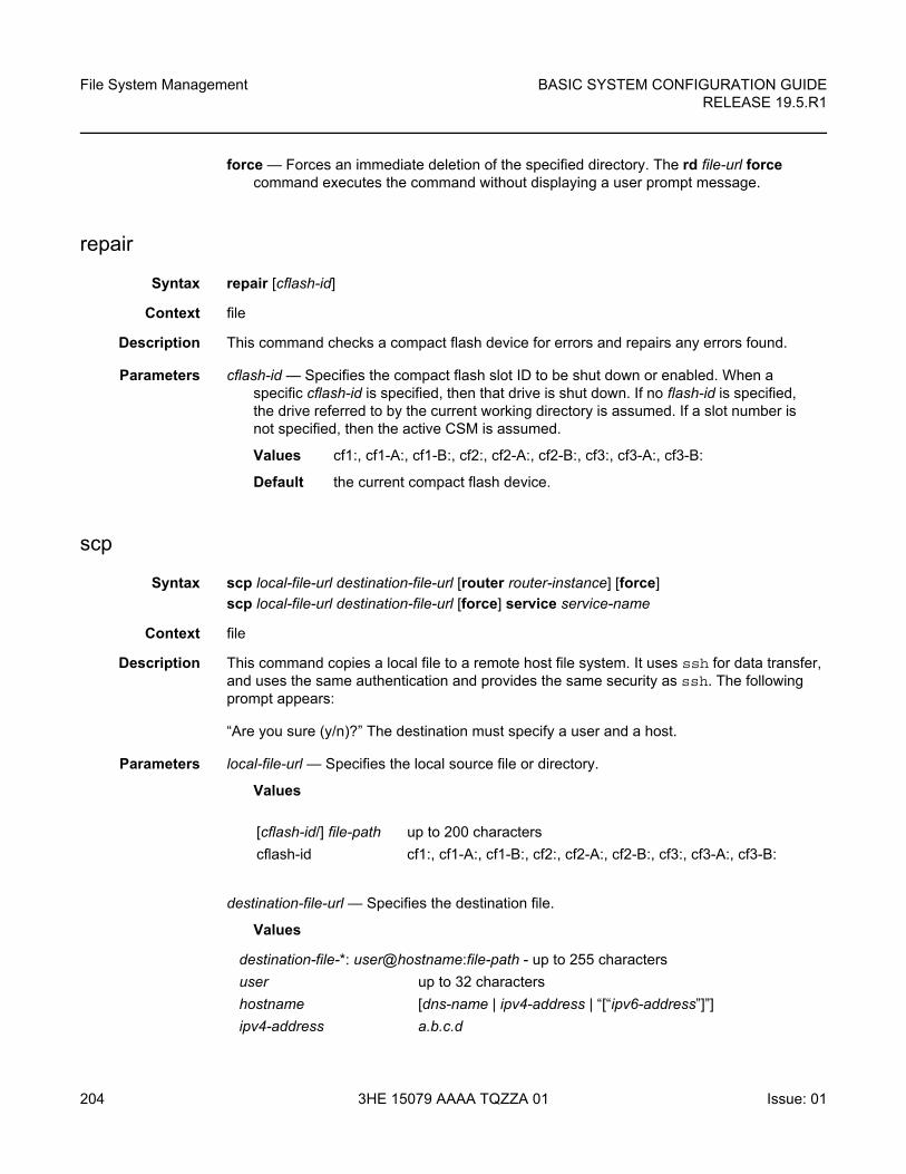
File System Management
204
BASIC SYSTEM CONFIGURATION GUIDERELEASE 19.5.R1
3HE 15079 AAAA TQZZA 01 Issue: 01
force — Forces an immediate deletion of the specified directory. The rd file-url force command executes the command without displaying a user prompt message.
repair
Syntax repair [cflash-id]
Context file
Description This command checks a compact flash device for errors and repairs any errors found.
Parameters cflash-id — Specifies the compact flash slot ID to be shut down or enabled. When a specific cflash-id is specified, then that drive is shut down. If no flash-id is specified, the drive referred to by the current working directory is assumed. If a slot number is not specified, then the active CSM is assumed.
Values cf1:, cf1-A:, cf1-B:, cf2:, cf2-A:, cf2-B:, cf3:, cf3-A:, cf3-B:
Default the current compact flash device.
scp
Syntax scp local-file-url destination-file-url [router router-instance] [force]
scp local-file-url destination-file-url [force] service service-name
Context file
Description This command copies a local file to a remote host file system. It uses ssh for data transfer, and uses the same authentication and provides the same security as ssh. The following prompt appears:
“Are you sure (y/n)?” The destination must specify a user and a host.
Parameters local-file-url — Specifies the local source file or directory.
Values
destination-file-url — Specifies the destination file.
Values
[cflash-id/] file-path up to 200 characters
cflash-id cf1:, cf1-A:, cf1-B:, cf2:, cf2-A:, cf2-B:, cf3:, cf3-A:, cf3-B:
destination-file-*: user@hostname:file-path - up to 255 characters
user up to 32 characters
hostname [dns-name | ipv4-address | “[“ipv6-address”]”]
ipv4-address a.b.c.d
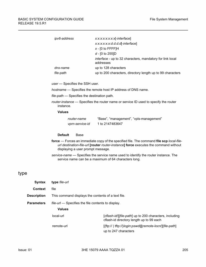
BASIC SYSTEM CONFIGURATION GUIDE RELEASE 19.5.R1
File System Management
Issue: 01 3HE 15079 AAAA TQZZA 01 205
user — Specifies the SSH user.
hostname — Specifies the remote host IP address of DNS name.
file-path — Specifies the destination path.
router-instance — Specifies the router name or service ID used to specify the router instance.
Values
Default Base
force — Forces an immediate copy of the specified file. The command file scp local-file-url destination-file-url [router router-instance] force executes the command without displaying a user prompt message.
service-name — Specifies the service name used to identify the router instance. The service name can be a maximum of 64 characters long.
type
Syntax type file-url
Context file
Description This command displays the contents of a text file.
Parameters file-url — Specifies the file contents to display.
Values
ipv6-address x:x:x:x:x:x:x:x[-interface]
x:x:x:x:x:x:d.d.d.d[-interface]
x - [0 to FFFF]H
d - [0 to 255]D
interface - up to 32 characters, mandatory for link local addresses
dns-name up to 128 characters
file-path up to 200 characters, directory length up to 99 characters
router-name “Base”, “management”, “vpls-management”
vprn-service-id 1 to 2147483647
local-url [cflash-id/][file-path] up to 200 characters, including cflash-id directory length up to 99 each
remote-url [{ftp:// | tftp://}login:pswd@remote-locn/][file-path]
up to 247 characters
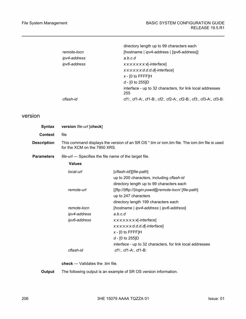
File System Management
206
BASIC SYSTEM CONFIGURATION GUIDERELEASE 19.5.R1
3HE 15079 AAAA TQZZA 01 Issue: 01
version
Syntax version file-url [check]
Context file
Description This command displays the version of an SR OS *.tim or iom.tim file. The iom.tim file is used for the XCM on the 7950 XRS.
Parameters file-url — Specifies the file name of the target file.
Values
check — Validates the .tim file.
Output The following output is an example of SR OS version information.
directory length up to 99 characters each
remote-locn [hostname | ipv4-address | [ipv6-address]]
ipv4-address a.b.c.d
ipv6-address x:x:x:x:x:x:x:x[-interface]
x:x:x:x:x:x:d.d.d.d[-interface]
x - [0 to FFFF]H
d - [0 to 255]D
interface - up to 32 characters, for link local addresses 255
cflash-id cf1:, cf1-A:, cf1-B:, cf2:, cf2-A:, cf2-B:, cf3:, cf3-A:, cf3-B:
local-url [cflash-id/][file-path]
up to 200 characters, including cflash-id
directory length up to 99 characters each
remote-url [{ftp://|tftp://}login:pswd@remote-locn/ [file-path]
up to 247 characters
directory length 199 characters each
remote-locn [hostname | ipv4-address | ipv6-address]
ipv4-address a.b.c.d
ipv6-address x:x:x:x:x:x:x:x[-interface]
x:x:x:x:x:x:d.d.d.d[-interface]
x - [0 to FFFF]H
d - [0 to 255]D
interface - up to 32 characters, for link local addresses
cflash-id cf1:, cf1-A:, cf1-B:
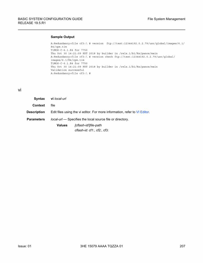
BASIC SYSTEM CONFIGURATION GUIDE RELEASE 19.5.R1
File System Management
Issue: 01 3HE 15079 AAAA TQZZA 01 207
Sample Output
A:Redundancy>file cf3:\ # version ftp://test:[email protected]/usr/global/images/6.1/R4/cpm.timTiMOS-C-6.1.R4 for 7750Thu Oct 30 14:21:09 PDT 2018 by builder in /relx.1/b1/Rx/panos/mainA:Redundancy>file cf3:\ # version check ftp://test:[email protected]/usr/global/images/6.1/R4/cpm.timTiMOS-C-6.1.R4 for 7750Thu Oct 30 14:21:09 PDT 2018 by builder in /relx.1/b1/Rx/panos/mainValidation successfulA:Redundancy>file cf3:\ #
vi
Syntax vi local-url
Context file
Description Edit files using the vi editor. For more information, refer to VI Editor.
Parameters local-url — Specifies the local source file or directory.
Values [cflash-id/]file-path
cflash-id: cf1:, cf2:, cf3:

File System Management
208
BASIC SYSTEM CONFIGURATION GUIDERELEASE 19.5.R1
3HE 15079 AAAA TQZZA 01 Issue: 01

BASIC SYSTEM CONFIGURATION GUIDE RELEASE 19.5.R1
Boot Options
Issue: 01 3HE 15079 AAAA TQZZA 01 209
4 Boot Options
4.1 System Initialization
The primary copy of SR OS software is located on a compact flash card. The removable media is shipped with each router and contains a copy of the OS image.
Starting a router begins with hardware initialization (a reset or power cycle). By default, the system searches Compact Flash Slot #3 (cf3) for the boot.ldr file (also known as the bootstrap file). The boot.ldr file is the image that reads and executes the system initialization commands configured in the boot option file (BOF). The default value to initially search for the boot.ldr file on cf3 cannot be modified.
The following is an example of a console display output when the boot.ldr file cannot be located on cf3.
...(memory test messages)(serial number information)Searching for boot.ldr on local drives:No disk in cf3No disk in cf3No disk in cf3Error - file boot.ldr not found on any drivePlease insert CF containing boot.ldr. Rebooting in 5 seconds.
When the bootstrap image is loaded, the BOF is read to obtain the location of the image and configuration files. The BOF must be located on the same compact flash drive as the boot.ldr file.
Figure 4 displays the system initialization sequence. In the figure, “A” refers to Figure 5, and “B” refers to the list of files on the compact flash.
Note:
• The modules contain three slots for removable compact flash cards. The drives are named Compact Flash Slot #1 (cf1), Compact Flash Slot #2 (cf2), and Compact Flash Slot #3 (cf3). Configurations and executable images can be stored on flash cards or an FTP file location.
• The flash card containing the bootstrap and boot option files must be installed in Compact Flash Slot #3 (cf3).
• You must have a console connection.
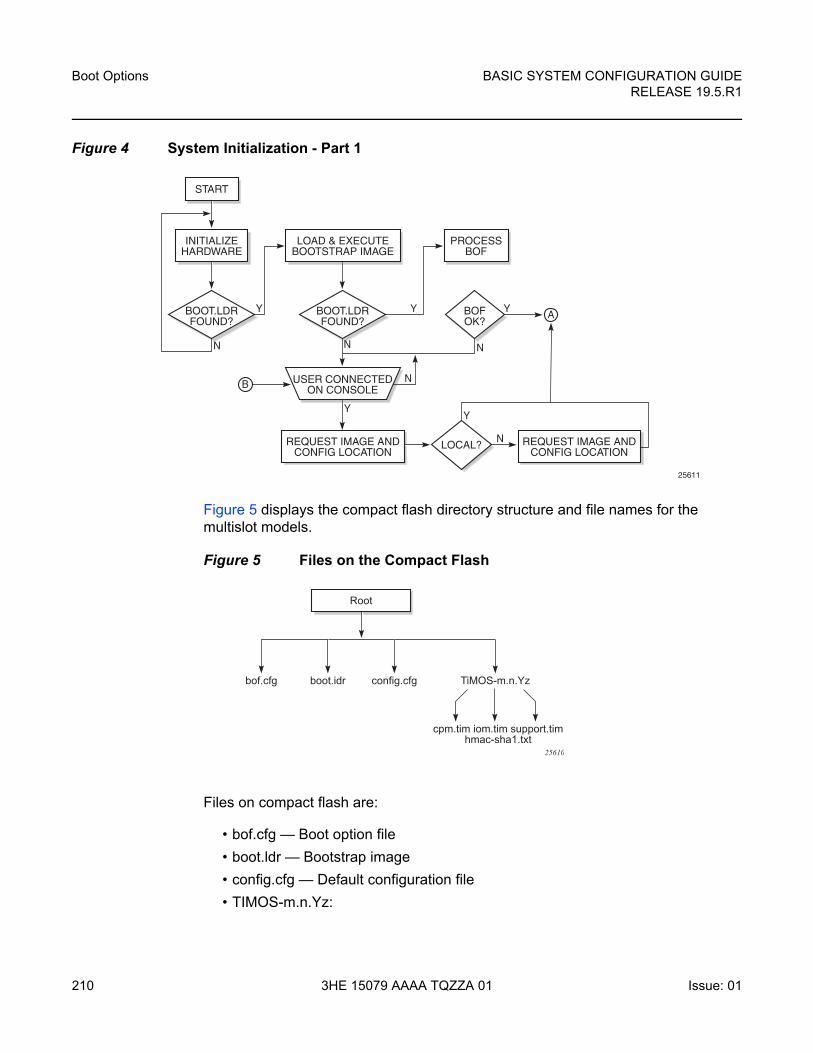
Boot Options
210
BASIC SYSTEM CONFIGURATION GUIDERELEASE 19.5.R1
3HE 15079 AAAA TQZZA 01 Issue: 01
Figure 4 System Initialization - Part 1
Figure 5 displays the compact flash directory structure and file names for the multislot models.
Figure 5 Files on the Compact Flash
Files on compact flash are:
• bof.cfg — Boot option file
• boot.ldr — Bootstrap image
• config.cfg — Default configuration file
• TIMOS-m.n.Yz:
25611
START
INITIALIZEHARDWARE
LOAD & EXECUTEBOOTSTRAP IMAGE
REQUEST IMAGE ANDCONFIG LOCATION
BOOT.LDRFOUND?
PROCESSBOF
BOOT.LDRFOUND?
LOCAL?
USER CONNECTEDON CONSOLE
BOFOK?
REQUEST IMAGE ANDCONFIG LOCATION
A
B
N
Y Y Y
N
N
N
YY
N
Root
bof.cfg boot.idr config.cfg TiMOS-m.n.Yz
cpm.tim iom.tim support.timhmac-sha1.txt
25610
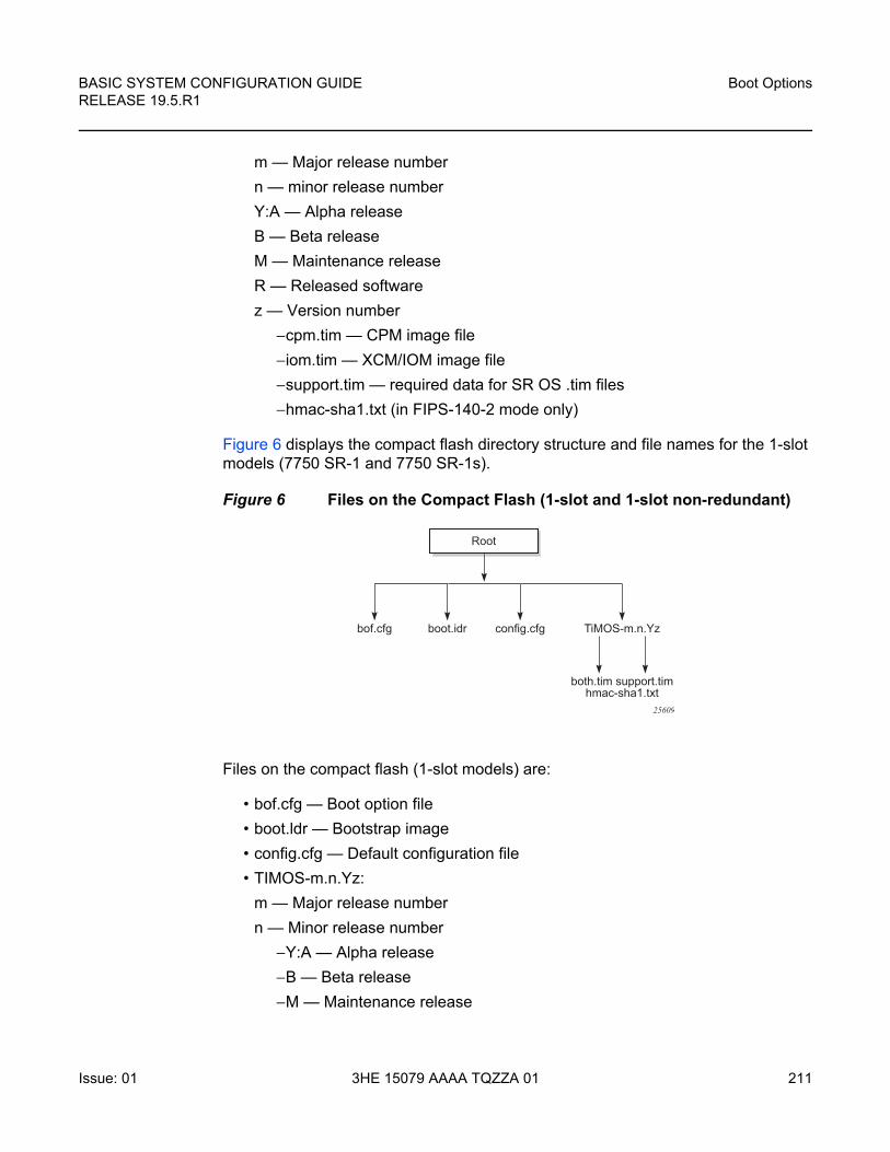
BASIC SYSTEM CONFIGURATION GUIDE RELEASE 19.5.R1
Boot Options
Issue: 01 3HE 15079 AAAA TQZZA 01 211
m — Major release number
n — minor release number
Y:A — Alpha release
B — Beta release
M — Maintenance release
R — Released software
z — Version number
−cpm.tim — CPM image file
−iom.tim — XCM/IOM image file
−support.tim — required data for SR OS .tim files
−hmac-sha1.txt (in FIPS-140-2 mode only)
Figure 6 displays the compact flash directory structure and file names for the 1-slot models (7750 SR-1 and 7750 SR-1s).
Figure 6 Files on the Compact Flash (1-slot and 1-slot non-redundant)
Files on the compact flash (1-slot models) are:
• bof.cfg — Boot option file
• boot.ldr — Bootstrap image
• config.cfg — Default configuration file
• TIMOS-m.n.Yz:
m — Major release number
n — Minor release number
−Y:A — Alpha release
−B — Beta release
−M — Maintenance release
Root
bof.cfg boot.idr config.cfg TiMOS-m.n.Yz
both.tim support.timhmac-sha1.txt
25609
Boot Options
212
BASIC SYSTEM CONFIGURATION GUIDERELEASE 19.5.R1
3HE 15079 AAAA TQZZA 01 Issue: 01
−R — Released software
z — Version number
−both.tim — CPM and IOM image file
−support.tim — required data for SR OS .tim files
−hmac-sha1.txt (in FIPS-140-2 mode only)
The 7750 SR includes a boot option for running the node in a FIPS-140-2 mode. This mode limits the use of cryptographic algorithms on the CPM to only those that are in accordance with the FIPS-140-2 certifications associated with the 7750 SR.
4.1.1 Configuration and Image Loading
When the system executes the boot.ldr file, the initialization parameters from the BOF are processed. Three locations can be configured for the system to search for the files that contains the runtime image. The locations can be local or remote. The first location searched is the primary image location. If not found, the secondary image location is searched, and lastly, the tertiary image location is searched.
If the BOF cannot be found or loaded, then the system enters a console message dialog session prompting the user to enter alternate file locations and file names.
The boot.ldr can be interrupted during the boot sequence by pressing any key on the CPM console port. The operator must then type sros and press ENTER within 30 seconds or the boot.ldr continues to try to boot the system. This key sequence ensures that noise or misconfiguration does not inadvertently interrupt the boot sequence. If the operator types sros and presses ENTER within 30 seconds, they are brought to a console message dialog session prompting the user to enter file locations and other boot information.
When the runtime image is successfully loaded, control is passed from the bootstrap loader to the image. The runtime image first attempts to read the license file if one has been included in the bof. If a license file is found, it is activated. If there are any issues with the activation, a log event is raised but the startup processing continues with the reading of the configuration file. The runtime image next attempts to locate the configuration file as configured in the BOF. Like the runtime image, three locations can be configured for the system to search for the configuration file. The locations can be local or remote. The first location searched is the primary configuration location. If not found, the secondary configuration location is searched, and lastly, the tertiary configuration location is searched. The configuration file includes chassis, card, MDA, and port configurations, as well as system, routing, and service configurations.
Figure 7 displays the boot sequence.
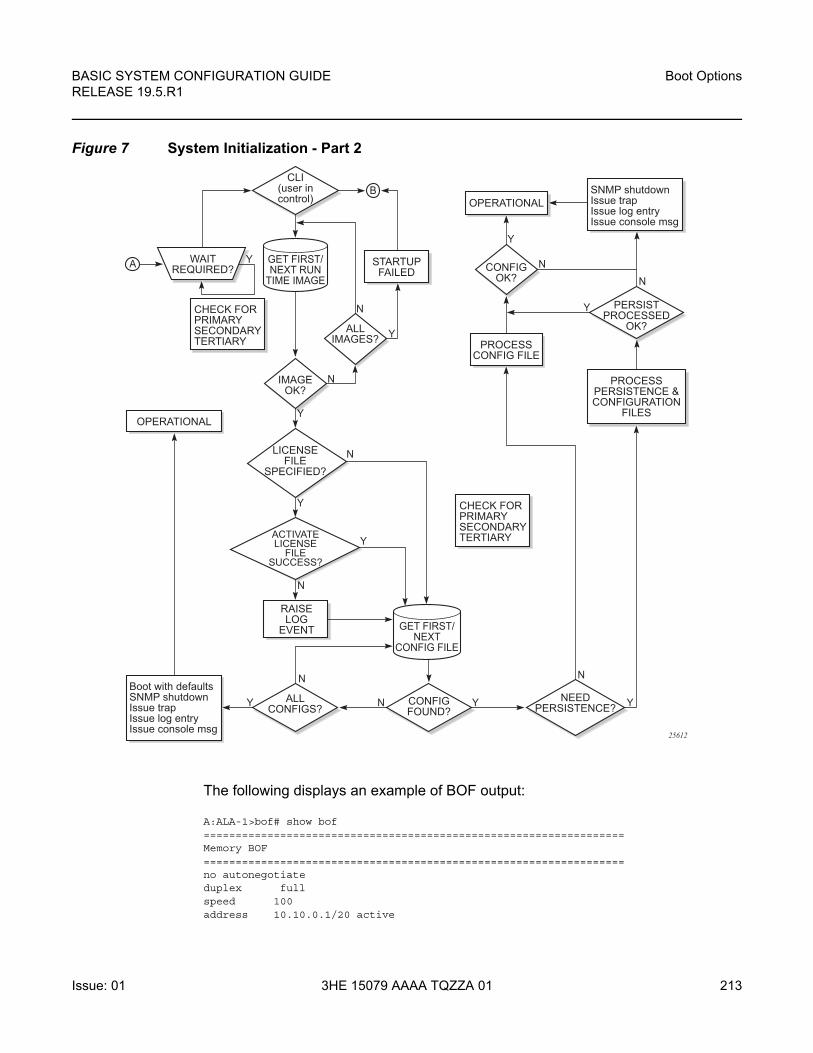
BASIC SYSTEM CONFIGURATION GUIDE RELEASE 19.5.R1
Boot Options
Issue: 01 3HE 15079 AAAA TQZZA 01 213
Figure 7 System Initialization - Part 2
The following displays an example of BOF output:
A:ALA-1>bof# show bof==================================================================Memory BOF==================================================================no autonegotiateduplex fullspeed 100address 10.10.0.1/20 active
OPERATIONAL
CHECK FORPRIMARYSECONDARYTERTIARY
CHECK FORPRIMARYSECONDARYTERTIARY
OPERATIONAL
PERSISTPROCESSED
OK?
CLI(user incontrol)
WAITREQUIRED?A
B SNMP shutdownIssue trapIssue log entryIssue console msg
CONFIGOK?
STARTUPFAILED
ALLIMAGES?
IMAGEOK?
LICENSEFILE
SPECIFIED?
ACTIVATELICENSE
FILESUCCESS?
GET FIRST/NEXT RUN
TIME IMAGE
GET FIRST/NEXT
CONFIG FILE
PROCESSPERSISTENCE &CONFIGURATION
FILES
PROCESSCONFIG FILE
CONFIGFOUND?
NEEDPERSISTENCE?
ALLCONFIGS?
Boot with defaultsSNMP shutdownIssue trapIssue log entryIssue console msg
Y
Y
Y
Y
RAISELOG
EVENT
N
N
N
N
N
N
Y
N
N
N
Y Y
Y
Y
Y
25612
Boot Options
214
BASIC SYSTEM CONFIGURATION GUIDERELEASE 19.5.R1
3HE 15079 AAAA TQZZA 01 Issue: 01
wait 3primary-image cf3:\both.timprimary-config cf3:\test123.cfgprimary-dns 192.168.10.20persist ondns-domain test.nokia.com==================================================================A:ALA-1>bof#
4.1.1.1 Persistence
Optionally, the BOF persist parameter can specify whether the system should preserve system indexes when a save command is executed. During a subsequent boot, the index file is read along with the configuration file. As a result, a number of system indexes are preserved between reboots, including the interface index, LSP IDs, path IDs, etc. If persistence is not required and the configuration file is successfully processed, then the system becomes operational. If persist is required, then a matching x.ndx file must be located and successfully processed before the system can become operational. Matching files (configuration and index files) must have the same filename prefix such as test123.cfg and test123.ndx and are created at the same time when a save command is executed. Note that the persistence option must be enabled to deploy the Network Management System (NMS). The default is off.
Traps, logs, and console messages are generated if problems occur and SNMP shuts down for all SNMP gets and sets, however, traps are issued.
4.1.1.2 Lawful Intercept
Lawful Intercept (LI) describes a process to intercept telecommunications by which law enforcement authorities can unobtrusively monitor voice and data communications to combat crime and terrorism with higher security standards of lawful intercept capabilities in accordance with local law and after following due process and receiving proper authorization from competent authorities. The interception capabilities are sought by various telecommunications providers.
As lawful interception is subject to national regulation, requirements vary from one country to another. This implementation satisfies most national standard’s requirements. LI is configurable for all service types.
BASIC SYSTEM CONFIGURATION GUIDE RELEASE 19.5.R1
Boot Options
Issue: 01 3HE 15079 AAAA TQZZA 01 215
4.1.1.3 FIPS-140-2 Mode
The 7750 SR includes a configurable parameter in the bof.cfg file to make the node run in FIPS-140-2 mode. When the node boots in FIPS-140-2 mode, the following behaviors are enabled on the node:
• The node performs an HMAC-SHA1 integrity test on the software images .tim files.
• The node limits the use of encryption and authentication algorithms to only those allowed for the associated FIPS-140-2 certification of the 7750-SR.
• Cryptographic module startup tests are executed on the CPM when the node boots to ensure the associated approved FIPS-140-2 algorithms are operating correctly.
• Cryptographic module conditional tests are executed when required during normal operation of associated when using FIPS-140-2 approved algorithms.
• When configuring user-defined encryption or authentication keys, the CLI prompts for the key to be re-entered. If the re-entered key does not match the original, the CLI command is canceled. This affects several protocols and applications.
To support FIPS-140-2, an HMAC-SHA-1 integrity check is performed to verify the integrity of the software images. The following file is included in the TIMOS-m.n.Yz software bundle containing the hmac-sha-1 signature:
• hmac-sha1.txt
During the loading of the cpm.tim or both.tim, a HMAC-SHA-1 check is performed to ensure that the calculated HMAC-SHA-1 of the loaded image matches that stored in the hmac-sha1.txt file.
The HMAC-SHA-1 check is performed on the data loaded from the .tim file. Note that when configuring the primary-image, secondary-image and tertiary-image, the hmac-sha1.txt file must exist in the same directory as the .tim files. If the load has been verified correctly from the HMAC-SHA-1 integrity check, the load continues to startup as normal. If the load is not verified by the HMAC-SHA-1 integrity check, the image load fails.
After the HMAC-SHA-1 integrity check passes, the nodes continues its normal startup sequence including reading the config.cfg file and loading the configuration. The config.cfg file used to boot the node in FIPS-140-2 mode must not contain any configuration that is not supported in FIPS-140-2 mode. If such configuration is present in the config.cfg file when the node boots, the node loads the config.cfg file until the location of the offending configuration and then halt the configuration at that point. Upon a failure to load the config.cfg file, a failure message is printed on the console.
Boot Options
216
BASIC SYSTEM CONFIGURATION GUIDERELEASE 19.5.R1
3HE 15079 AAAA TQZZA 01 Issue: 01
Enabling FIPS-140-2 restricts the ability to configure and use cryptographic algorithms and functions that are not FIPS approved. FIPS-140-2 impacts the ability to configure SSH, SNMP and certificates. Refer to the 7450 ESS, 7750 SR, 7950 XRS, and VSR System Management Guide for details of FIPS-140-2 related items.
In addition, signature algorithms of the following combinations only are approved for FIPS:
• FIPS-140 Approved - Digital Signature Standard (DSS)
−DSA
−RSA
−ECDSA
• FIPS-140 Approved - Secured Hash Standard (SHS)
−SHA-1
−SHA-224
−SHA-256
−SHA-384
−SHA-512
Any other combination is not supported in FIPS mode. Using other FIPS signature algorithms in certificates affecting IPSec can cause tunnels to fail. Restrictions to cryptographic algorithms are listed in the 7450 ESS, 7750 SR, 7950 XRS, and VSR System Management Guide.
4.1.1.4 System Profiles
System profiles provide flexibility when using FP4-based line cards by supporting different system capabilities. The system profile is defined in the BOF and is used by the system when it is next rebooted. Contact your Nokia representative for system profile information.
The following system profiles are supported:
• Profile none
This profile represents the existing system capabilities and allows FP3- and FP4-based hardware to co-exist within a system. This profile is indicated by the omission of the system-profile parameter in the BOF.
• Profile A
BASIC SYSTEM CONFIGURATION GUIDE RELEASE 19.5.R1
Boot Options
Issue: 01 3HE 15079 AAAA TQZZA 01 217
This profile is primarily targeted at subscriber services and Layer 2 and 3 VPN business services and is defined by configuring the BOF system-profile parameter to profile-a.
• Profile B
This profile is primarily targeted at infrastructure routing, core, peering, and DC-GW applications.
System profile profile-a and profile-b support only FP4-based line cards. Provisioning FP2- or FP3-based line cards is prohibited when the system profile is set to profile-a or profile-b. If FP2- or FP3-based card types are present in the boot configuration when using these profiles, the boot sequence aborts the loading of the configuration file when it encounters their configuration.
When changing between system profiles, it is mandatory to remove all configuration commands for features that are not supported in the target system profile before rebooting the system, otherwise the reboot fails at the unsupported configuration command on startup.
On 7750 SR-1 and 7750 SR-s systems, the following conditions apply:
• The BOF system-profile parameter should be configured to either profile-a or profile-b.
• If the system-profile parameter is omitted from the BOF, system profile profile-a is used by the system.
• If the BOF system-profile parameter is configured to an invalid value, it is ignored and system profile profile-a is used by the system.
On 7750 SR-12e and 7950 XRS-20/20e systems, the following conditions apply:
• The default system profile is none when the system-profile parameter is omitted from the BOF.
• The BOF system-profile parameter can be configured to either profile-a or profile-b, in which case only FP4-based line cards are supported.
• If the BOF system-profile parameter is configured to an invalid value, it is ignored and system profile none is used by the system.
On all other systems, the following conditions apply:
• These systems must use profile none (the existing system capabilities). As a result, the system-profile parameter must not be configured in the BOF.
Boot Options
218
BASIC SYSTEM CONFIGURATION GUIDERELEASE 19.5.R1
3HE 15079 AAAA TQZZA 01 Issue: 01
• If the system-profile parameter is configured to profile-a or profile-b in the BOF, the system boots, allowing access using the console and CPM management interface, but FP2-based and FP3-based line cards cannot be provisioned; if these card types are present in the boot configuration, the boot sequence aborts loading the configuration file when it encounters their configuration. This issue can be corrected by removing the system-profile parameter from the BOF and rebooting the system.
• If the BOF system-profile parameter is configured to an invalid value, it is ignored and profile none is used by the system.
If a system has two CPMs, and the standby CPM boots with a different system-profile parameter than is used on the active CPM, the active CPM reboot the standby CPM and keep it in a down state. To correct the situation, the BOF can be reconfigured on the standby CPM to match the one configured on the active CPM, and then reboot the system. Alternatively, automatic BOF synchronization can be enabled to keep both CPMs in sync using the following command:
configure redundancy synchronize boot-env
When performing a minor or major ISSU software upgrade on dual CPM systems, it is important that the system profile in the BOF on both the active and standby CPM is the same and has a value supported on the pre-upgrade software release. If the standby CPM happened to have a system profile which is only supported in the post-upgrade release, the active CPM reboots the standby and keeps it down due to a system profile mis-match.
The BOF system profile can be displayed as follows:
*A:PE-1# show bof | match system-profile system-profile profile-a*A:PE-1#
The BOF system profile used by the system when it booted can be seen in the boot messages (using the show boot-messages command), which display the BOF read when rebooting.
The system profile in use on the system can be displayed as follows:
*A:PE-1# show chassis | match "System Profile" System Profile : none*A:PE-1#
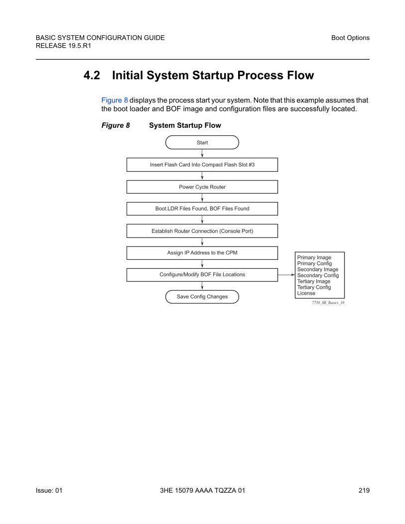
BASIC SYSTEM CONFIGURATION GUIDE RELEASE 19.5.R1
Boot Options
Issue: 01 3HE 15079 AAAA TQZZA 01 219
4.2 Initial System Startup Process Flow
Figure 8 displays the process start your system. Note that this example assumes that the boot loader and BOF image and configuration files are successfully located.
Figure 8 System Startup Flow
7750_SR_Basics_10
Start
Insert Flash Card Into Compact Flash Slot #3
Power Cycle Router
Boot.LDR Files Found, BOF Files Found
Establish Router Connection (Console Port)
Assign IP Address to the CPMPrimary ImagePrimary ConfigSecondary ImageSecondary ConfigTertiary ImageTertiary ConfigLicense
Configure/Modify BOF File Locations
Save Config Changes
Boot Options
220
BASIC SYSTEM CONFIGURATION GUIDERELEASE 19.5.R1
3HE 15079 AAAA TQZZA 01 Issue: 01
4.3 Configuration Notes
This section describes BOF configuration caveats.
• For router initialization, the compact flash card must be installed in the Compact Flash #3 slot.
• The loading sequence is based on the order in which it is placed in the configuration file. It is loaded as it is read in at boot time.
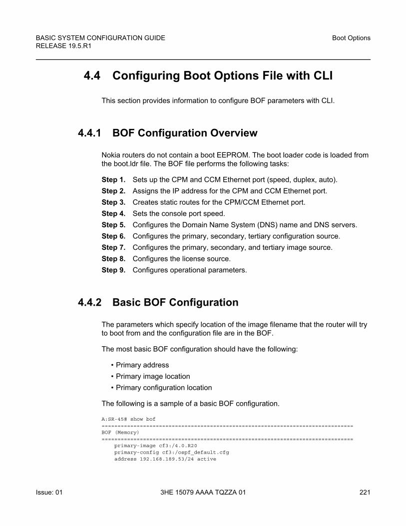
BASIC SYSTEM CONFIGURATION GUIDE RELEASE 19.5.R1
Boot Options
Issue: 01 3HE 15079 AAAA TQZZA 01 221
4.4 Configuring Boot Options File with CLI
This section provides information to configure BOF parameters with CLI.
4.4.1 BOF Configuration Overview
Nokia routers do not contain a boot EEPROM. The boot loader code is loaded from the boot.ldr file. The BOF file performs the following tasks:
Step 1. Sets up the CPM and CCM Ethernet port (speed, duplex, auto).
Step 2. Assigns the IP address for the CPM and CCM Ethernet port.
Step 3. Creates static routes for the CPM/CCM Ethernet port.
Step 4. Sets the console port speed.
Step 5. Configures the Domain Name System (DNS) name and DNS servers.
Step 6. Configures the primary, secondary, tertiary configuration source.
Step 7. Configures the primary, secondary, and tertiary image source.
Step 8. Configures the license source.
Step 9. Configures operational parameters.
4.4.2 Basic BOF Configuration
The parameters which specify location of the image filename that the router will try to boot from and the configuration file are in the BOF.
The most basic BOF configuration should have the following:
• Primary address
• Primary image location
• Primary configuration location
The following is a sample of a basic BOF configuration.
A:SR-45# show bof===============================================================================BOF (Memory)===============================================================================
primary-image cf3:/4.0.R20primary-config cf3:/ospf_default.cfgaddress 192.168.189.53/24 active
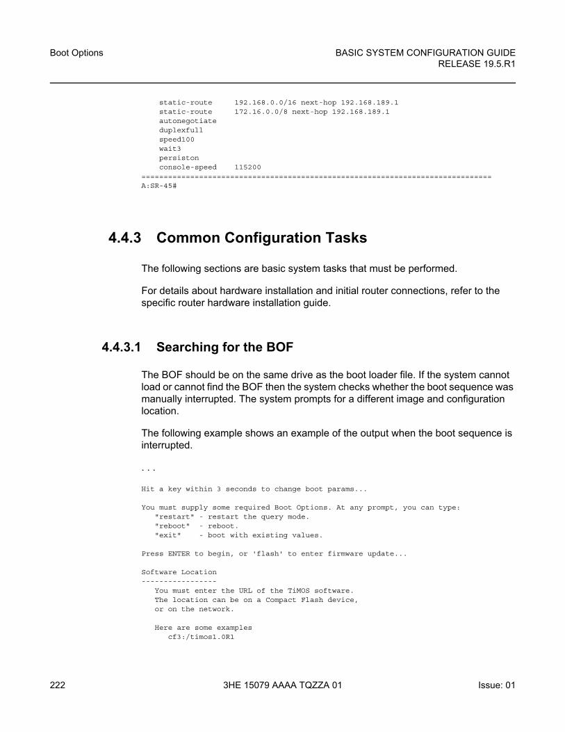
Boot Options
222
BASIC SYSTEM CONFIGURATION GUIDERELEASE 19.5.R1
3HE 15079 AAAA TQZZA 01 Issue: 01
static-route 192.168.0.0/16 next-hop 192.168.189.1static-route 172.16.0.0/8 next-hop 192.168.189.1autonegotiateduplexfullspeed100wait3persistonconsole-speed 115200
===============================================================================A:SR-45#
4.4.3 Common Configuration Tasks
The following sections are basic system tasks that must be performed.
For details about hardware installation and initial router connections, refer to the specific router hardware installation guide.
4.4.3.1 Searching for the BOF
The BOF should be on the same drive as the boot loader file. If the system cannot load or cannot find the BOF then the system checks whether the boot sequence was manually interrupted. The system prompts for a different image and configuration location.
The following example shows an example of the output when the boot sequence is interrupted.
. . .
Hit a key within 3 seconds to change boot params...
You must supply some required Boot Options. At any prompt, you can type:"restart" - restart the query mode."reboot" - reboot."exit" - boot with existing values.
Press ENTER to begin, or 'flash' to enter firmware update...
Software Location-----------------
You must enter the URL of the TiMOS software.The location can be on a Compact Flash device,or on the network.
Here are some examplescf3:/timos1.0R1
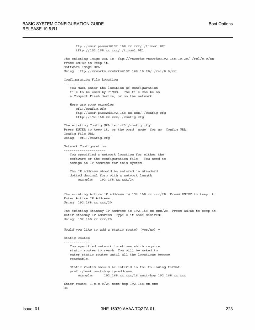
BASIC SYSTEM CONFIGURATION GUIDE RELEASE 19.5.R1
Boot Options
Issue: 01 3HE 15079 AAAA TQZZA 01 223
ftp://user:[email protected]/./timos1.0R1tftp://192.168.xx.xxx/./timos1.0R1
The existing Image URL is 'ftp://vxworks:[email protected]/./rel/0.0/xx'Press ENTER to keep it.Software Image URL:Using: 'ftp://vxworks:[email protected]/./rel/0.0/xx'
Configuration File Location---------------------------
You must enter the location of configurationfile to be used by TiMOS. The file can be ona Compact Flash device, or on the network.
Here are some examplescf1:/config.cfgftp://user:[email protected]/./config.cfgtftp://192.168.xx.xxx/./config.cfg
The existing Config URL is 'cf3:/config.cfg'Press ENTER to keep it, or the word 'none' for no Config URL.Config File URL:Using: 'cf3:/config.cfg'
Network Configuration---------------------
You specified a network location for either thesoftware or the configuration file. You need toassign an IP address for this system.
The IP address should be entered in standarddotted decimal form with a network length.
example: 192.168.xx.xxx/24
The existing Active IP address is 192.168.xx.xxx/20. Press ENTER to keep it.Enter Active IP Address:Using: 192.168.xx.xxx/20
The existing Standby IP address is 192.168.xx.xxx/20. Press ENTER to keep it.Enter Standby IP Address (Type 0 if none desired):Using: 192.168.xx.xxx/20
Would you like to add a static route? (yes/no) y
Static Routes-------------
You specified network locations which requirestatic routes to reach. You will be asked toenter static routes until all the locations becomereachable.
Static routes should be entered in the following format:prefix/mask next-hop ip-address
example: 192.168.xx.xxx/16 next-hop 192.168.xx.xxx
Enter route: 1.x.x.0/24 next-hop 192.168.xx.xxxOK
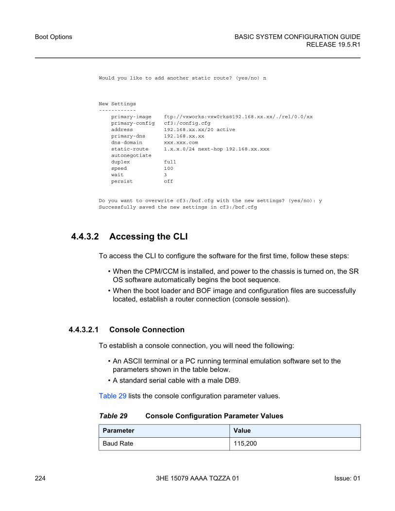
Boot Options
224
BASIC SYSTEM CONFIGURATION GUIDERELEASE 19.5.R1
3HE 15079 AAAA TQZZA 01 Issue: 01
Would you like to add another static route? (yes/no) n
New Settings------------
primary-image ftp://vxworks:[email protected]/./rel/0.0/xxprimary-config cf3:/config.cfgaddress 192.168.xx.xx/20 activeprimary-dns 192.168.xx.xxdns-domain xxx.xxx.comstatic-route 1.x.x.0/24 next-hop 192.168.xx.xxxautonegotiateduplex fullspeed 100wait 3persist off
Do you want to overwrite cf3:/bof.cfg with the new settings? (yes/no): ySuccessfully saved the new settings in cf3:/bof.cfg
4.4.3.2 Accessing the CLI
To access the CLI to configure the software for the first time, follow these steps:
• When the CPM/CCM is installed, and power to the chassis is turned on, the SR OS software automatically begins the boot sequence.
• When the boot loader and BOF image and configuration files are successfully located, establish a router connection (console session).
4.4.3.2.1 Console Connection
To establish a console connection, you will need the following:
• An ASCII terminal or a PC running terminal emulation software set to the parameters shown in the table below.
• A standard serial cable with a male DB9.
Table 29 lists the console configuration parameter values.
Table 29 Console Configuration Parameter Values
Parameter Value
Baud Rate 115,200
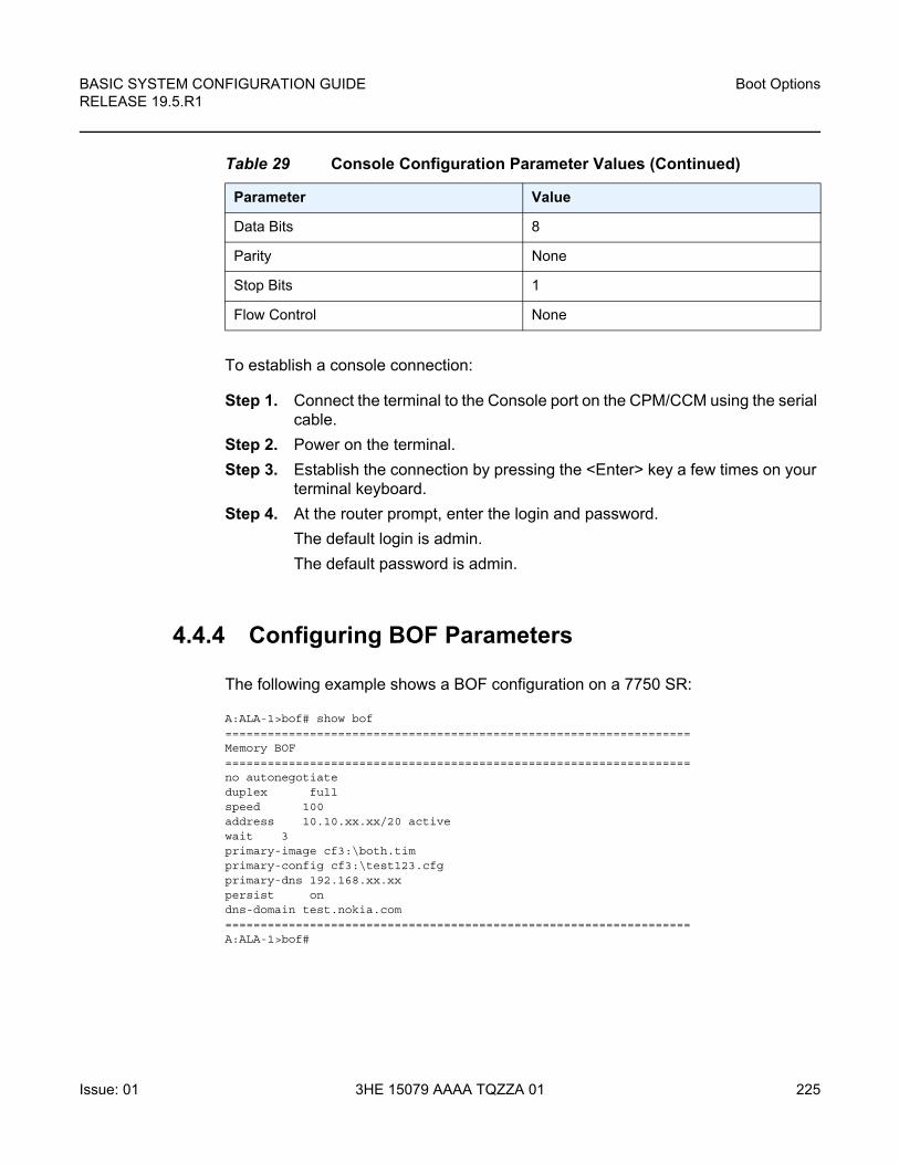
BASIC SYSTEM CONFIGURATION GUIDE RELEASE 19.5.R1
Boot Options
Issue: 01 3HE 15079 AAAA TQZZA 01 225
To establish a console connection:
Step 1. Connect the terminal to the Console port on the CPM/CCM using the serial cable.
Step 2. Power on the terminal.
Step 3. Establish the connection by pressing the <Enter> key a few times on your terminal keyboard.
Step 4. At the router prompt, enter the login and password.
The default login is admin.
The default password is admin.
4.4.4 Configuring BOF Parameters
The following example shows a BOF configuration on a 7750 SR:
A:ALA-1>bof# show bof==================================================================Memory BOF==================================================================no autonegotiateduplex fullspeed 100address 10.10.xx.xx/20 activewait 3primary-image cf3:\both.timprimary-config cf3:\test123.cfgprimary-dns 192.168.xx.xxpersist ondns-domain test.nokia.com==================================================================A:ALA-1>bof#
Data Bits 8
Parity None
Stop Bits 1
Flow Control None
Table 29 Console Configuration Parameter Values (Continued)
Parameter Value
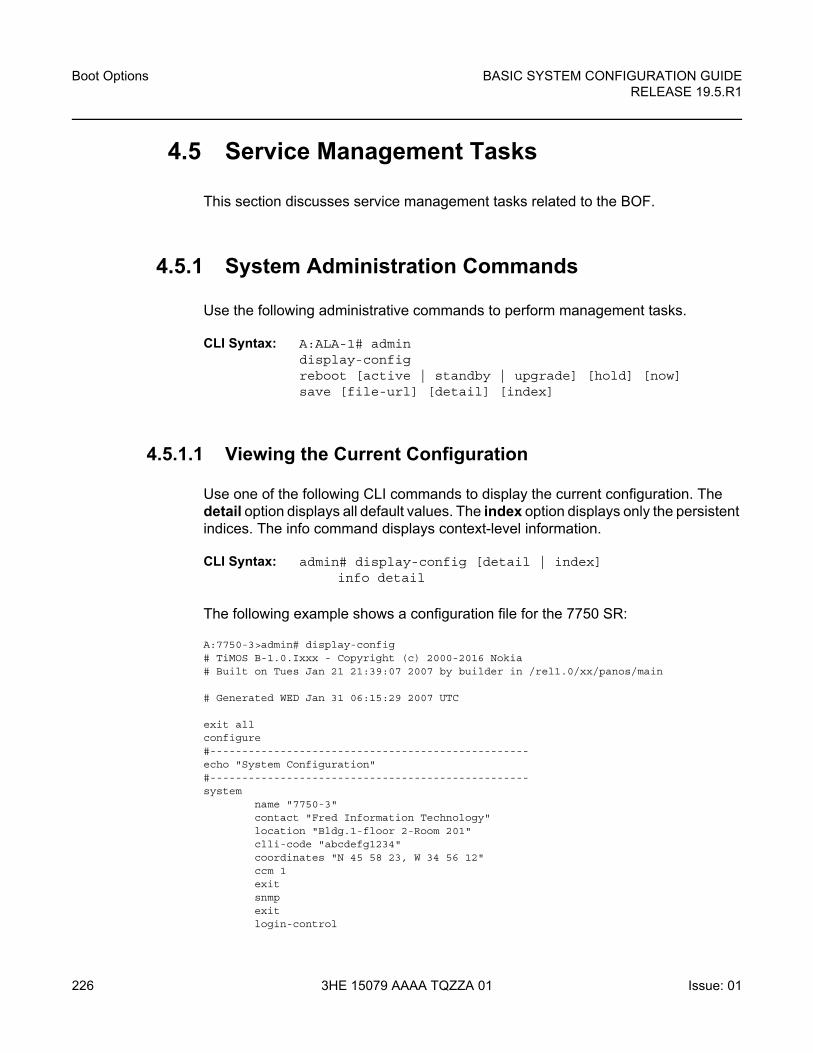
Boot Options
226
BASIC SYSTEM CONFIGURATION GUIDERELEASE 19.5.R1
3HE 15079 AAAA TQZZA 01 Issue: 01
4.5 Service Management Tasks
This section discusses service management tasks related to the BOF.
4.5.1 System Administration Commands
Use the following administrative commands to perform management tasks.
CLI Syntax: A:ALA-1# admindisplay-configreboot [active | standby | upgrade] [hold] [now]save [file-url] [detail] [index]
4.5.1.1 Viewing the Current Configuration
Use one of the following CLI commands to display the current configuration. The detail option displays all default values. The index option displays only the persistent indices. The info command displays context-level information.
CLI Syntax: admin# display-config [detail | index]info detail
The following example shows a configuration file for the 7750 SR:
A:7750-3>admin# display-config# TiMOS B-1.0.Ixxx - Copyright (c) 2000-2016 Nokia# Built on Tues Jan 21 21:39:07 2007 by builder in /rel1.0/xx/panos/main
# Generated WED Jan 31 06:15:29 2007 UTC
exit allconfigure#--------------------------------------------------echo "System Configuration"#--------------------------------------------------system
name "7750-3"contact "Fred Information Technology"location "Bldg.1-floor 2-Room 201"clli-code "abcdefg1234"coordinates "N 45 58 23, W 34 56 12"ccm 1exitsnmpexitlogin-control
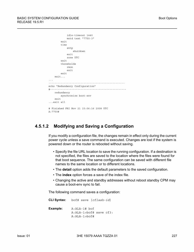
BASIC SYSTEM CONFIGURATION GUIDE RELEASE 19.5.R1
Boot Options
Issue: 01 3HE 15079 AAAA TQZZA 01 227
idle-timeout 1440motd text "7750-3"
exittime
sntpshutdown
exitzone UTC
exitthresholds
rmonexit
exitexit...
...--------------------------------------------------echo "Redundancy Configuration"#--------------------------------------------------
redundancysynchronize boot-env
exit...exit all
# Finished FRI Nov 21 15:06:16 2008 UTCA:7750#
4.5.1.2 Modifying and Saving a Configuration
If you modify a configuration file, the changes remain in effect only during the current power cycle unless a save command is executed. Changes are lost if the system is powered down or the router is rebooted without saving.
• Specify the file URL location to save the running configuration. If a destination is not specified, the files are saved to the location where the files were found for that boot sequence. The same configuration can be saved with different file names to the same location or to different locations.
• The detail option adds the default parameters to the saved configuration.
• The index option forces a save of the index file.
• Changing the active and standby addresses without reboot standby CPM may cause a boot-env sync to fail.
The following command saves a configuration:
CLI Syntax: bof# save [cflash-id]
Example: A:ALA-1# bofA:ALA-1>bof# save cf3:A:ALA-1>bof#
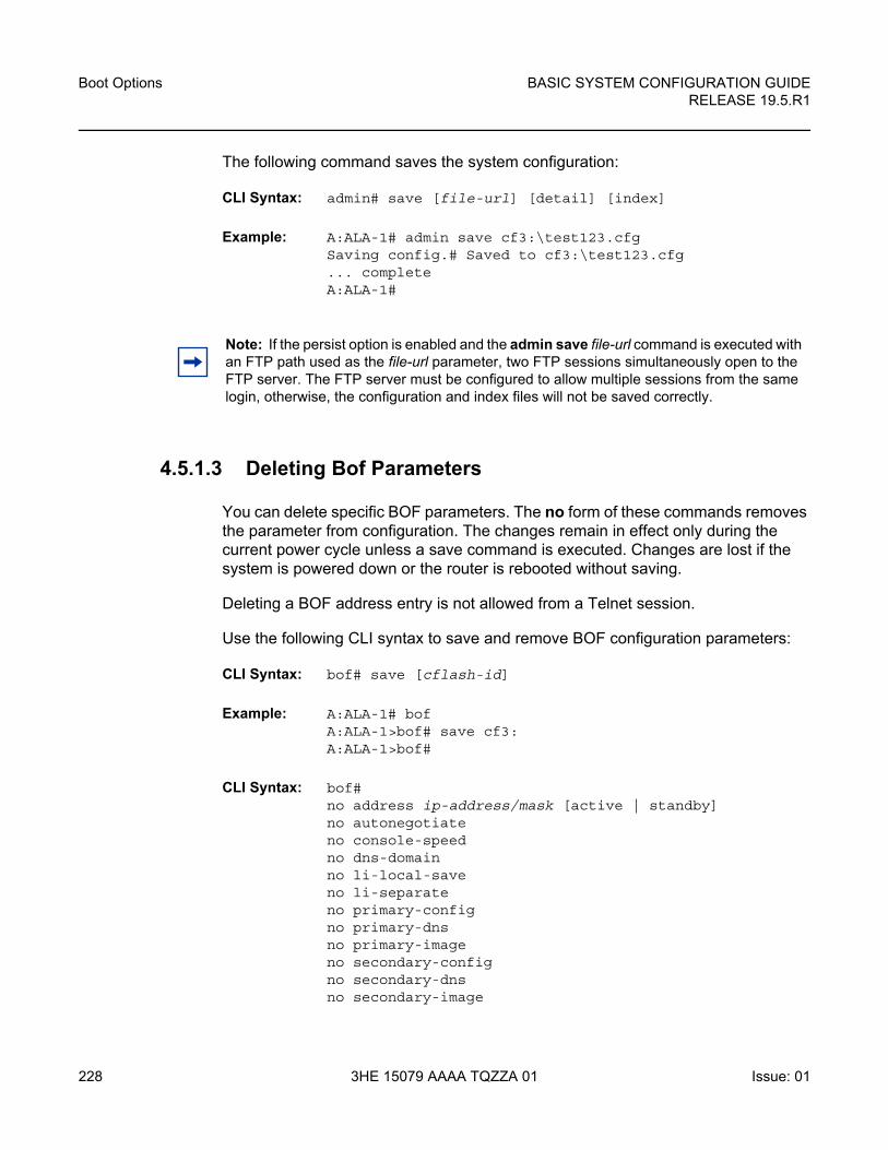
Boot Options
228
BASIC SYSTEM CONFIGURATION GUIDERELEASE 19.5.R1
3HE 15079 AAAA TQZZA 01 Issue: 01
The following command saves the system configuration:
CLI Syntax: admin# save [file-url] [detail] [index]
Example: A:ALA-1# admin save cf3:\test123.cfgSaving config.# Saved to cf3:\test123.cfg... completeA:ALA-1#
4.5.1.3 Deleting Bof Parameters
You can delete specific BOF parameters. The no form of these commands removes the parameter from configuration. The changes remain in effect only during the current power cycle unless a save command is executed. Changes are lost if the system is powered down or the router is rebooted without saving.
Deleting a BOF address entry is not allowed from a Telnet session.
Use the following CLI syntax to save and remove BOF configuration parameters:
CLI Syntax: bof# save [cflash-id]
Example: A:ALA-1# bofA:ALA-1>bof# save cf3:A:ALA-1>bof#
CLI Syntax: bof# no address ip-address/mask [active | standby]no autonegotiateno console-speedno dns-domainno li-local-saveno li-separateno primary-config no primary-dnsno primary-image no secondary-config no secondary-dnsno secondary-image
Note: If the persist option is enabled and the admin save file-url command is executed with an FTP path used as the file-url parameter, two FTP sessions simultaneously open to the FTP server. The FTP server must be configured to allow multiple sessions from the same login, otherwise, the configuration and index files will not be saved correctly.
BASIC SYSTEM CONFIGURATION GUIDE RELEASE 19.5.R1
Boot Options
Issue: 01 3HE 15079 AAAA TQZZA 01 229
no static-route ip-address/mask next-hop ip-addressno system-profile no tertiary-config no tertiary-dnsno tertiary-image
4.5.1.4 Saving a Configuration to a Different Filename
Save the current configuration with a unique filename to have additional backup copies and to edit parameters with a text editor. You can save your current configuration to an ASCII file.
Use the following CLI syntax to save a configuration to a different location:
CLI Syntax: admin# save [file-url] [detail] [index]
Example: A:ALA-1>admin# save cf3:\testABC.cfgSaving config.# Saved to cf3:\testABC.cfg... completeA:ALA-1#
4.5.1.5 Rebooting
When an admin>reboot command is issued, routers with redundant CPM are rebooted as well as the XMAs, XCMs, and IOMs. Changes are lost unless the configuration is saved. Use the admin>save file-url command to save the current configuration. If no command line options are specified, the user is prompted to confirm the reboot operation.
Use the following CLI syntax to reboot:
CLI Syntax: admin# reboot [active | standby | upgrade] [hold] [now]
Example: A:ALA-1>admin# reboot A:DutA>admin# reboot Are you sure you want to reboot (y/n)? y Resetting...OKAlcatel 7xxx Boot ROM. Copyright 2000-2007 Alcatel-Lucent.
All rights reserved. All use is subject to applicable license agreements.....

Boot Options
230
BASIC SYSTEM CONFIGURATION GUIDERELEASE 19.5.R1
3HE 15079 AAAA TQZZA 01 Issue: 01
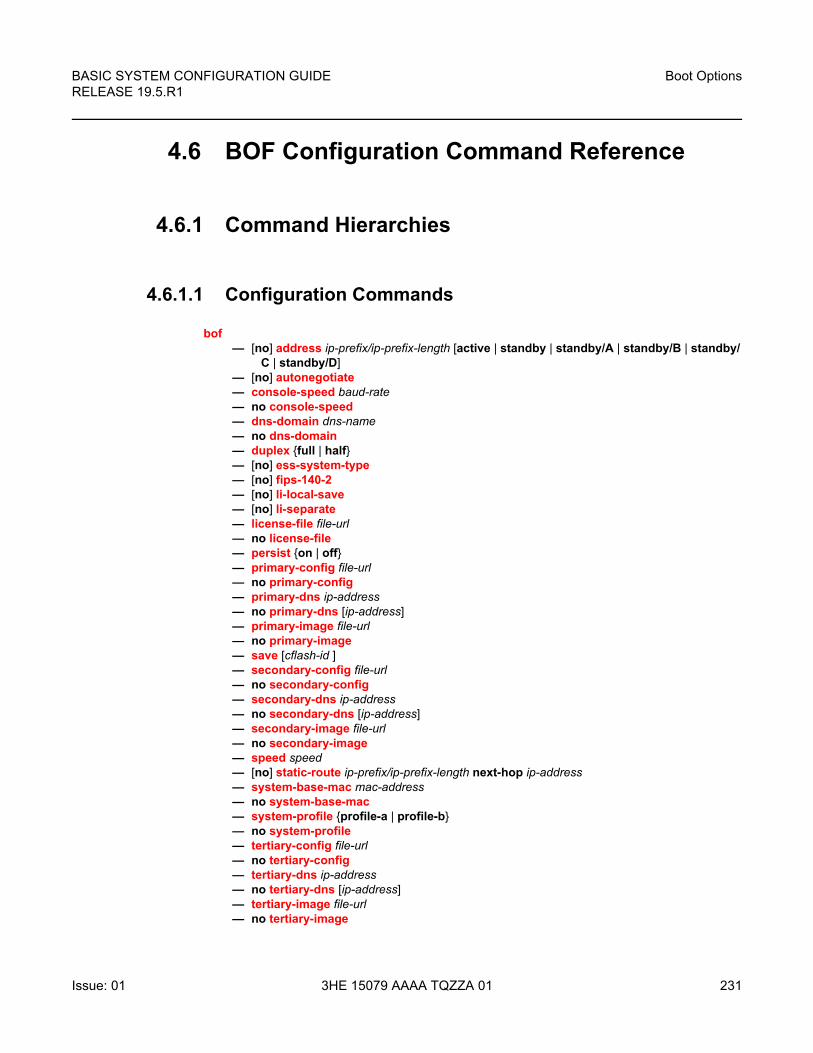
BASIC SYSTEM CONFIGURATION GUIDE RELEASE 19.5.R1
Boot Options
Issue: 01 3HE 15079 AAAA TQZZA 01 231
4.6 BOF Configuration Command Reference
4.6.1 Command Hierarchies
4.6.1.1 Configuration Commands
bof— [no] address ip-prefix/ip-prefix-length [active | standby | standby/A | standby/B | standby/
C | standby/D]— [no] autonegotiate— console-speed baud-rate— no console-speed— dns-domain dns-name — no dns-domain— duplex {full | half}— [no] ess-system-type— [no] fips-140-2— [no] li-local-save— [no] li-separate— license-file file-url— no license-file— persist {on | off}— primary-config file-url — no primary-config— primary-dns ip-address— no primary-dns [ip-address]— primary-image file-url — no primary-image— save [cflash-id ]— secondary-config file-url — no secondary-config— secondary-dns ip-address— no secondary-dns [ip-address]— secondary-image file-url — no secondary-image— speed speed— [no] static-route ip-prefix/ip-prefix-length next-hop ip-address— system-base-mac mac-address— no system-base-mac — system-profile {profile-a | profile-b}— no system-profile— tertiary-config file-url — no tertiary-config— tertiary-dns ip-address— no tertiary-dns [ip-address]— tertiary-image file-url — no tertiary-image
Boot Options
232
BASIC SYSTEM CONFIGURATION GUIDERELEASE 19.5.R1
3HE 15079 AAAA TQZZA 01 Issue: 01
— wait seconds
4.6.2 Command Descriptions
4.6.2.1 File Management Commands
bof
Syntax bof
Context <root>
Description This command creates or edits the boot option file (BOF) for the specified local storage device.
A BOF file specifies where the system searches for runtime images, configuration files, and other operational parameters during system initialization.
BOF parameters can be modified. Changes can be saved to a specified compact flash. The BOF must be located in the root directory of either an internal or external compact flash local to the system and have the mandatory filename of bof.cfg.
When modifications are made to in-memory parameters that are currently in use or operating, the changes are effective immediately. For example, if the IP address of the management port is changed, the change takes place immediately.
Only one entry of the BOF configuration command statement can be saved once the statement has been found to be syntactically correct.
When opening an existing BOF that is not the BOF used in the most recent boot, a message is issued notifying the user that the parameters will not affect the operation of the node.
No default boot option file exists. The router boots with the factory default boot sequence and options.
save
Syntax save [cflash-id]
Context bof
Description This command uses the boot option parameters currently in memory and writes them from the boot option file to the specified compact flash.
BASIC SYSTEM CONFIGURATION GUIDE RELEASE 19.5.R1
Boot Options
Issue: 01 3HE 15079 AAAA TQZZA 01 233
The BOF must be located in the root directory of the internal or external compact flash drives local to the system and have the mandatory filename of bof.cfg.
If a location is not specified, the BOF is saved to the default compact flash drive (cf3:) on the active CPM (typically the CPM in slot A, but the CPM in slot B could also be acting as the active CPM). The slot name is not case-sensitive. You can use upper or lowercase “A” or “B”.
Command usage:
• bof save — saves the BOF to the default drive (cf3:) on the active CPM (either in slot A or B)
• bof save cf3: — saves the BOF to cf3: on the active CPM (either in slot A or B)
To save the BOF to a compact flash drive on the standby CPM (for example, the redundant (standby) CPM is installed in slot B), specify -A or -B option.
Command usage:
• bof save cf3-A: — saves the BOF to cf3: on CPM in slot A whether it is active or standby
• bof save cf3-B: — saves the BOF to cf3: on CPM in slot B whether it is active or standby
The slot name is not case-sensitive. You can use upper or lowercase “A” or “B”.
The bof save and show bof commands allow you to save to or read from the compact flash of the standby CPM. Use the show card command to determine the active and standby CPM (A or B).
Default Saves must be explicitly executed. The BOF is saved to cf3: if a location is not specified.
Parameters flash-id — Specifies the compact flash ID where the bof.cfg is to be saved.
Values cf1:, cf1-A:, cf1-B:, cf2:, cf2-A:, cf2-B:, cf3:, cf3-A:, cf3-B:
Default cf3:
4.6.2.2 BOF Processing Control
wait
Syntax wait seconds
Context bof
Description This command configures a pause, in seconds, at the start of the boot process which allows system initialization to be interrupted at the console.
When system initialization is interrupted the operator is allowed to manually override the parameters defined in the boot option file (BOF).
Boot Options
234
BASIC SYSTEM CONFIGURATION GUIDERELEASE 19.5.R1
3HE 15079 AAAA TQZZA 01 Issue: 01
Only one wait command can be defined in the BOF.
Default wait 3
Parameters seconds — Specifies the time to pause at the start of the boot process, in seconds.
Values 1 to10
4.6.2.3 Console Port Configuration
console-speed
Syntax console-speed baud-rate
no console-speed
Context bof
Description This command configures the console port baud rate.
When this command is issued while editing the BOF file used for the most recent boot, both the BOF file and the active configuration are changed immediately.
The no form of this command reverts to the default value.
Default console-speed 115200
Parameters baud-rate — Specifies the console port baud rate, expressed as a decimal integer.
Values 9600, 19200, 38400, 57600, 115200
4.6.2.4 Image and Configuration Management
persist
Syntax persist {on | off}
Context bof
Description This command specifies whether the system will preserve system indexes when a save command is executed. During a subsequent boot, the index file is read along with the configuration file. As a result, a number of system indexes are preserved between reboots, including the interface index, LSP IDs, path IDs, and so on. This reduces resynchronizations of the Network Management System (NMS) with the affected network element.
BASIC SYSTEM CONFIGURATION GUIDE RELEASE 19.5.R1
Boot Options
Issue: 01 3HE 15079 AAAA TQZZA 01 235
In the event that persist is on and the reboot with the appropriate index file fails, SNMP is operationally shut down to prevent the management system from accessing and possibly synchronizing with a partially booted or incomplete network element. To enable SNMP access, enter the config>system>snmp>no shutdown command.
If persist is enabled and the admin save url command is executed with an FTP path used as the url parameter, two FTP sessions simultaneously open to the FTP server. The FTP server must be configured to allow multiple sessions from the same login, otherwise, the configuration and index files will not be saved correctly.
Default persist off
Parameters on — Enables the system index saves between reboots.
off — Disables the system index saves between reboots.
primary-config
Syntax primary-config file-url
no primary-config
Context bof
Description This command specifies the name and location of the primary configuration file.
The system attempts to use the configuration specified in primary-config. If the specified file cannot be located, the system automatically attempts to obtain the configuration from the location specified in secondary-config and then the tertiary-config.
If an error in the configuration file is encountered, the boot process aborts.
The no form of this command removes the primary-config configuration.
Parameters file-url — Specifies the primary configuration file location, expressed as a file URL.
Values
Note:
• Persistency files (.ndx) are saved on the same disk as the configuration files and the image files.
• When an operator sets the location for the persistency file, the system will check to ensure that the disk has enough free space. If this there is not enough free space, the persistency will not become active and a trap will be generated. Then, it is up to the operator to free adequate disk space. In the meantime, the system will perform a space availability check every 30 seconds. As soon as the space is available the persistency will become active on the next (30 second) check.
file-url {local-url | remote-url} (up to 180 characters)
Boot Options
236
BASIC SYSTEM CONFIGURATION GUIDERELEASE 19.5.R1
3HE 15079 AAAA TQZZA 01 Issue: 01
primary-image
Syntax primary-image file-url
no primary image
Context bof
Description This command specifies the primary directory location for runtime image file loading.
The system attempts to load all runtime image files configured in the primary-image first. If this fails, the system attempts to load the runtime images from the location configured in the secondary-image. If the secondary image load fails, the tertiary image specified in tertiary-image is used.
All runtime image files (*.tim files) must be located in the same directory.
The no form of this command removes the primary-image configuration.
Parameters file-url — Specifies the file-url can be either local (this CPM) or a remote FTP server.
Values
system-base-mac
Syntax system-base-mac mac-address
no system-base-mac
Context bof
Description This command is used to specify the base MAC address for a VSR-based system. The specified MAC address is used as the first MAC address by the system to assign MAC addresses to individual interfaces.
It is strongly recommended that a unique base MAC address is assigned to each VSR instance with a minimum gap of 1024 between base addresses to avoid a MAC address overlap.
The no form of this command removes the configured system base MAC address.
local-url [cflash-id/][file-path]
remote-url [{ftp://|tftp://} login:pswd@remote-locn/][file-path]
cflash-id cf1:, cf1-A:, cf1-B:, cf2:, cf2-A:, cf2-B:, cf3:, cf3-A:, cf3-B:
file-url {local-url | remote-url} (up to 180 characters)
local-url [cflash-id/][file-path]
remote-url [{ftp://|tftp://} login:pswd@remote-locn/][file-path]
cflash-id cf1:, cf1-A:, cf1-B:, cf2:, cf2-A:, cf2-B:, cf3:, cf3-A:, cf3-B:
BASIC SYSTEM CONFIGURATION GUIDE RELEASE 19.5.R1
Boot Options
Issue: 01 3HE 15079 AAAA TQZZA 01 237
Default no system-base-mac
Parameters mac-address — Specifies the MAC address.
Values xx:xx:xx:xx:xx:xx or xx-xx-xx-xx-xx-xx
system-profile
Syntax system-profile {profile-a | profile-b}
no system-profile
Context bof
Description This command configures the system profile in the BOF.
System profile none represents the existing system capabilities and allows FP3- and FP4-based hardware to co-exist within a system. This is indicated by the omission of the system-profile parameter in the BOF, except on 7750 SR-1 systems.
System profile profile-a is primarily targeted at subscriber services and layer 2 and 3 VPN business services.
System profile profile-b is primarily targeted at infrastructure routing, core, peering, and DC-GW applications.
System profile profile-a and profile-b are supported on 7950 XRS-20/20e, 7750 SR-1 and 7750 SR-12e systems, and support only FP4-based line cards.
The system profile on 7750 SR-1 systems should be set to profile-a. It is set by default to profile-a when the system-profile parameter is omitted from the BOF, or configured to an invalid value.
On 7950 XRS-20/20e and 7750 SR-12e systems, default system profile is none.
On all other systems, the system-profile parameter must not be configured in the BOF which sets the system profile to none.
The no form of this command removes the system-profile parameter from the BOF.
Default none
Parameters profile-a — Specifies that the system profile is for subscriber services and Layer 2 and 3 VPN business services.
profile-b — Specifies that the system profile is primarily targeted at infrastructure routing, core, peering, and DC-GW applications.
Boot Options
238
BASIC SYSTEM CONFIGURATION GUIDERELEASE 19.5.R1
3HE 15079 AAAA TQZZA 01 Issue: 01
secondary-config
Syntax secondary-config file-url
no secondary-config
Context bof
Description This command specifies the name and location of the secondary configuration file.
The system attempts to use the configuration as specified in secondary-config if the primary config cannot be located. If the secondary-config file cannot be located, the system attempts to obtain the configuration from the location specified in the tertiary-config.
Note that if an error in the configuration file is encountered, the boot process aborts.
The no form of this command removes the secondary-config configuration.
Parameters file-url — Specifies the secondary configuration file location, expressed as a file URL.
Values
secondary-image
Syntax secondary-image file-url
no secondary-image
Context bof
Description This command specifies the secondary directory location for runtime image file loading.
The system attempts to load all runtime image files configured in the primary-image first. If this fails, the system attempts to load the runtime images from the location configured in the secondary-image. If the secondary image load fails, the tertiary image specified in tertiary-image is used.
All runtime image files (*.tim files) must be located in the same directory.
The no form of this command removes the secondary-image configuration.
Parameters file-url — Specifies the file URL; can be either local (this CPM) or a remote FTP server.
Values
file-url [local-url | remote-url] (up to 180 characters)
local-url [cflash-id/][file-path]
remote-url [{ftp://|tftp://} login:pswd@remote-locn/][file-path]
cflash-id cf1:, cf1-A:, cf1-B:, cf2:, cf2-A:, cf2-B:, cf3:, cf3-A:, cf3-B:
file-url {local-url | remote-url} (up to 180 characters)
local-url [cflash-id/][file-path]
BASIC SYSTEM CONFIGURATION GUIDE RELEASE 19.5.R1
Boot Options
Issue: 01 3HE 15079 AAAA TQZZA 01 239
tertiary-config
Syntax tertiary-config file-url
no tertiary-config
Context bof
Description This command specifies the name and location of the tertiary configuration file.
The system attempts to use the configuration specified in tertiary-config if both the primary and secondary config files cannot be located. If this file cannot be located, the system boots with the factory default configuration.
Note that if an error in the configuration file is encountered, the boot process aborts.
The no form of this command removes the tertiary-config configuration.
Parameters file-url — Specifies the tertiary configuration file location, expressed as a file URL.
Values
tertiary-image
Syntax tertiary-image file-url
no tertiary-image
Context bof
Description This command specifies the tertiary directory location for runtime image file loading.
The system attempts to load all runtime image files configured in the primary-image first. If this fails, the system attempts to load the runtime images from the location configured in the secondary-image. If the secondary image load fails, the tertiary image specified in tertiary-image is used.
All runtime image files (*.tim files) must be located in the same directory.
The no form of this command removes the tertiary-image configuration.
remote-url [{ftp://|tftp://} login:pswd@remote-locn/][file-path]
cflash-id cf1:, cf1-A:, cf1-B:, cf2:, cf2-A:, cf2-B:, cf3:, cf3-A:, cf3-B:
file-url {local-url | remote-url} (up to 180 characters)
local-url [cflash-id/][file-path]
remote-url [{ftp://|tftp://} login:pswd@remote-locn/][file-path]
cflash-id cf1:, cf1-A:, cf1-B:, cf2:, cf2-A:, cf2-B:, cf3:, cf3-A:, cf3-B:
Boot Options
240
BASIC SYSTEM CONFIGURATION GUIDERELEASE 19.5.R1
3HE 15079 AAAA TQZZA 01 Issue: 01
Parameters file-url — Specifies the file URL; can be either local (this CPM) or a remote FTP server.
Values
4.6.2.5 Management Ethernet Configuration
address
Syntax [no] address ip-prefix/ip-prefix-length [active | standby | standby/A | standby/B | standby/C | standby/D]
Context bof
Description This command assigns an IP address to the management Ethernet port on a CPM. This applies during the boot loader and the running image.
On all systems except the 7950 XRS-40, an address must be assigned with the active keyword and for systems with a redundant CPM an additional address may be assigned with the standby keyword. The active address is used by the active CPM whether its CPM A or CPM B and the standby address, if specified, is used by the standby CPM whether its CPM B or CPM A.
For the 7950 XRS-40, if the extension chassis shall boot from local compact flash then an active and standby address should be defined for use by the master chassis as defined above.
For the 7950 XRS-40, if the extension chassis shall boot from remote URL, then it is required to assign addresses to the management Ethernet ports for CPM C and CPM D. In this case, the BOF should be updated to have addresses defined using the standby/A, standby/B, standby/C, and standby/D keywords in addition to an address using the active keyword. With these keywords, CPM A shall always use the address defined using the standby/A address when CPM A is running as the standby CPM. Similarly, CPM B shall always use the address defined using the standby/B address when CPM B is running as the standby CPM. The active CPM of CPM A and CPM B shall use the address defined using the active keyword.
Deleting a BOF address entry is not allowed from a remote session.
Note that changing the active and standby addresses without reboot standby CPM may cause a boot-env sync to fail.
The no form of this command deletes the IP address from the CPM Ethernet port.
file-url {local-url | remote-url} (up to 180 characters)
local-url [cflash-id/][file-path]
remote-url [{ftp://|tftp://} login:pswd@remote-locn/][file-path]
cflash-id cf1:, cf1-A:, cf1-B:, cf2:, cf2-A:, cf2-B:, cf3:, cf3-A:, cf3-B:
BASIC SYSTEM CONFIGURATION GUIDE RELEASE 19.5.R1
Boot Options
Issue: 01 3HE 15079 AAAA TQZZA 01 241
Parameters ip-prefix/ip-prefix-length — Specifies the destination address of the aggregate route in dotted decimal notation.
Values
active | standby | standby/A | standby/B | standby/C | standby/D — specifies which CPM Ethernet address is being configured
Default active
autonegotiate
Syntax [no] autonegotiate
Context bof
Description This command enables speed and duplex autonegotiation on the management Ethernet port in the running configuration and the Boot Option File (BOF).
When autonegotiation is enabled, the link attempts to automatically negotiate the link speed and duplex parameters. If autonegotiation is enabled, then the configured duplex and speed parameters are ignored.
The no form of this command disables the autonegotiate feature on this port.
duplex
Syntax duplex {full | half}
Context bof
ipv4-prefix a.b.c.d (host bits must be 0)
ipv4-prefix-length 0 to 32
ipv6-prefix x:x:x:x:x:x:x:x (eight 16-bit pieces)
x:x:x:x:x:x:d.d.d.d
x: [0 to FFFF]H
d: [0 to 255]D
ipv6-prefix-length 0 to128
Note: IPv6 is applicable to the 7750 SR and 7950 XRS only.
Boot Options
242
BASIC SYSTEM CONFIGURATION GUIDERELEASE 19.5.R1
3HE 15079 AAAA TQZZA 01 Issue: 01
Description This command configures the duplex mode of the CPM management Ethernet port when autonegotiation is disabled in the running configuration and the Boot Option File (BOF). If the port is configured to autonegotiate this parameter will be ignored.
Parameters full — Sets the link to full duplex mode.
half — Sets the link to half duplex mode.
ess-system-type
Syntax [no] ess-system-type
Context bof
Description This command allows a new RoHS compliant 7750 SR-12 or 7750 SR-7 chassis to operate as an 7450 ESS-12 or 7450 ESS-7 system.
After entering this command, the system must be rebooted for the change to take effect.
If the RoHS compliant 7750 SR-12 or 7750 SR-7 chassis is operating as an 7450 ESS system, it can operate with either the 7750 SR or 7450 ESS CPM (subject to SR OS support) but both should always be the same type.
In addition, the system can operate with supported 7450 ESS IOMs, MDAs, and IMMs with Layer 2 VPN service licenses. In this mode only 7450 ESS functionality is supported.
The system can also operate in mixed-mode, in which case a mixture of 7750 SR and 7450 ESS IOMs, MDAs, and IMMs are supported, as well as 7450 ESS and 7750 SR functionality. This is subject to all existing requirements and limitations for the mixed-mode feature.
The no form of this command disables this mode of operation and returns the system to a 7750 SR chassis type operation on the next reboot.
Default no ess-system-type
fips-140-2
Syntax [no] fips-140-2
Context bof
Description This command is used to configure the node in FIPS-140-2 mode. Before using this command, the operator must ensure that no current configuration exists in the config file that is not supported in FIPS-140-2 mode. Failing to remove unsupported configuration will result in the node being unable to boot up. The node must be rebooted after executing this command in order for the node to begin operating in FIPS-140-2 mode.
BASIC SYSTEM CONFIGURATION GUIDE RELEASE 19.5.R1
Boot Options
Issue: 01 3HE 15079 AAAA TQZZA 01 243
li-local-save
Syntax [no] li-local-save
Context bof
Description This command enables the lawful intercept (LI) configuration to be saved locally.
li-separate
Syntax [no] li-separate
Context bof
Description This command enables separate access to lawful intercept (LI) information.
license-file
Syntax license-file file-url
no license-file
Context bof
Description This command configures the license location and file name.
The no form of this command removes the file URL from the configuration.
Parameters file-url — Specifies the file-url.
Values
speed
Syntax speed speed
Context bof
Description This command configures the speed for the CPM management Ethernet port when autonegotiation is disabled in the running configuration and the Boot Option File (BOF).
If the port is configured to autonegotiate, this parameter is ignored.
file-url {local-url | remote-url} (up to 180 characters)
local-url [cflash-id/][file-path]
remote-url [{ftp://|tftp://} login:pswd@remote-locn/][file-path]
cflash-id cf1:, cf1-A:, cf1-B:, cf2:, cf2-A:, cf2-B:, cf3:, cf3-A:, cf3-B:

Boot Options
244
BASIC SYSTEM CONFIGURATION GUIDERELEASE 19.5.R1
3HE 15079 AAAA TQZZA 01 Issue: 01
Default speed 100
Parameters speed — Sets the link speed, in Mb/s.
Values 10, 100
static-route
Syntax [no] static-route ip-prefix/ip-prefix-length next-hop ip-address
Context bof
Description This command creates a static route entry for the CPM management Ethernet port in the running configuration and the Boot Option File (BOF).
This command allows manual configuration of static routing table entries. These static routes are only used by traffic generated by the CPM Ethernet port. To reduce configuration, manual address aggregation should be applied where possible.
A static default (0.0.0.0/0 or ::/0) route cannot be configured on the CPM Ethernet port. A maximum of 10 static routes can be configured on the CPM port.
The no form of this command deletes the static route.
Default no static-route
Parameters ip-prefix/ip-prefix-length — Specifies the destination address of the static route in dotted decimal notation.
Values
ip-prefix/ip-prefix-length ipv4-prefix a.b.c.d (host bits must be 0)
ipv4-prefix-le 0 to 32
ipv6-prefix x:x:x:x:x:x:x:x (eight 16-bit pieces)
x:x:x:x:x:x:d.d.d.d
x: [0 to FFFF]H
d: [0to 255]D
ipv6-prefix-le 0 to128
ip-address ipv4-address a.b.c.d
ipv6-address x:x:x:x:x:x:x:x (eight 16-bit pieces)
x:x:x:x:x:x:d.d.d.d
x: [0 to FFFF]H
d: [0 to 255]D
BASIC SYSTEM CONFIGURATION GUIDE RELEASE 19.5.R1
Boot Options
Issue: 01 3HE 15079 AAAA TQZZA 01 245
mask — Specifies the subnet mask, expressed as an integer or in dotted decimal notation.
Values 1 to 32 (mask length), 128.0.0.0 to255.255.255.255 (dotted decimal)
ip-address — Specifies the next hop IP address used to reach the destination.
4.6.2.6 DNS Configuration Commands
dns-domain
Syntax dns-domain dns-name
no dns-domain
Context bof
Description This command configures the domain name used when performing DNS address resolution. This is a required parameter if DNS address resolution is required. Only a single domain name can be configured. If multiple domain statements are configured, the last one encountered is used.
The no form of this command removes the domain name from the configuration.
Default no dns-domain
Parameters dns-name — Specifies the DNS domain name, up to 178 characters.
primary-dns
Syntax primary-dns ip-address
no primary-dns [ip-address]
Context bof
Description This command configures the primary DNS server used for DNS name resolution. DNS name resolution can be used when executing ping, traceroute, and service-ping, and also when defining file URLs. DNS name resolution is not supported when DNS names are embedded in configuration files.
The no form of this command removes the primary DNS server from the configuration.
Note: IPv6 is applicable to the 7750 SR and 7950 XRS only.
Boot Options
246
BASIC SYSTEM CONFIGURATION GUIDERELEASE 19.5.R1
3HE 15079 AAAA TQZZA 01 Issue: 01
Default no primary-dns
Parameters ip-address — Specifies the IP or IPv6 address of the primary DNS server.
Values
secondary-dns
Syntax secondary-dns ip-address
no secondary-dns [ip-address]
Context bof
Description This command configures the secondary DNS server for DNS name resolution. The secondary DNS server is used only if the primary DNS server does not respond.
DNS name resolution can be used when executing ping, traceroute, and service-ping, and also when defining file URLs. DNS name resolution is not supported when DNS names are embedded in configuration files.
The no form of this command removes the secondary DNS server from the configuration.
Default no secondary-dns
Parameters ip-address — Specifies the IP or IPv6 address of the secondary DNS server.
Values
ipv4-address a.b.c.d
ipv6-address x:x:x:x:x:x:x:x[-interface]
x:x:x:x:x:x:d.d.d.d[-interface]
x: [0 to FFFF]H
d: [0 to 255]D
interface 32 chars max, for link local addresses
Note: IPv6 is applicable to the 7750 SR and 7950 XRS only.
ipv4-address a.b.c.d
ipv6-address x:x:x:x:x:x:x:x[-interface]
x:x:x:x:x:x:d.d.d.d[-interface]
x: [0 to FFFF]H
d: [0 to 255]D
interface up to 32 characters for link local addresses
BASIC SYSTEM CONFIGURATION GUIDE RELEASE 19.5.R1
Boot Options
Issue: 01 3HE 15079 AAAA TQZZA 01 247
tertiary-dns
Syntax tertiary-dns ip-address
no tertiary-dns [ip-address]
Context bof
Description This command configures the tertiary DNS server for DNS name resolution. The tertiary DNS server is used only if the primary DNS server and the secondary DNS server do not respond.
DNS name resolution can be used when executing ping, traceroute, and service-ping, and also when defining file URLs. DNS name resolution is not supported when DNS names are embedded in configuration files.
The no form of this command removes the tertiary DNS server from the configuration.
Default no tertiary-dns
Parameters ip-address — Specifies the IP or IPv6 address of the tertiary DNS server.
Values
Note: IPv6 is applicable to the 7750 SR and 7950 XRS only.
ipv4-address a.b.c.d
ipv6-address x:x:x:x:x:x:x:x[-interface]
x:x:x:x:x:x:d.d.d.d[-interface]
x: [0 to FFFF]H
d: [0 to 255]D
interface 32 chars max, for link local addresses
Note: IPv6 is applicable to the 7750 SR and 7950 XRS only.

Boot Options
248
BASIC SYSTEM CONFIGURATION GUIDERELEASE 19.5.R1
3HE 15079 AAAA TQZZA 01 Issue: 01
BASIC SYSTEM CONFIGURATION GUIDE RELEASE 19.5.R1
Boot Options
Issue: 01 3HE 15079 AAAA TQZZA 01 249
4.7 BOF Show Command Reference
4.7.1 Command Hierarchies
show— bof [cflash-id | booted] — boot-messages
4.7.2 Command Descriptions
4.7.2.1 BOF Show Commands
The command outputs in the following sections are examples only; actual displays may differ depending on supported functionality and user configuration.
bof
Syntax bof [cflash-id | booted]
Context show
Description This command displays the Boot Option File (BOF) executed on last system boot or on the specified device.
If no device is specified, the BOF used in the last system boot displays. If the BOF has been modified since the system boot, a message displays.
Parameters cflash-id — Displays the cflash directory name. The slot name is not case-sensitive. Use upper or lowercase “A” or “B” for the slot name.
Values cf1:, cf1-A:, cf1-B:, cf2:, cf2-A:, cf2-B:, cf3:, cf3-A:, cf3-B:
booted — displays the boot option file used to boot the system.
Output The following output is an example of BOF, and Table 30 describes the output fields.
Sample Output
A:ALA-1# show bof cf3:=====================================================================BOF on cf3:=====================================================================
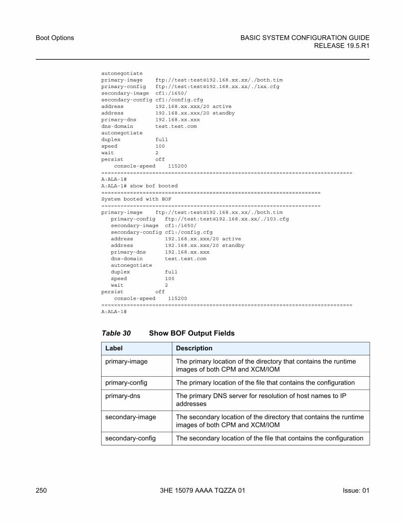
Boot Options
250
BASIC SYSTEM CONFIGURATION GUIDERELEASE 19.5.R1
3HE 15079 AAAA TQZZA 01 Issue: 01
autonegotiateprimary-image ftp://test:[email protected]/./both.timprimary-config ftp://test:[email protected]/./1xx.cfgsecondary-image cf1:/i650/secondary-config cf1:/config.cfgaddress 192.168.xx.xxx/20 activeaddress 192.168.xx.xxx/20 standbyprimary-dns 192.168.xx.xxxdns-domain test.test.comautonegotiateduplex fullspeed 100wait 2persist off
console-speed 115200===============================================================================A:ALA-1#A:ALA-1# show bof booted=====================================================================System booted with BOF=====================================================================primary-image ftp://test:[email protected]/./both.tim
primary-config ftp://test:[email protected]/./103.cfgsecondary-image cf1:/i650/secondary-config cf1:/config.cfgaddress 192.168.xx.xxx/20 activeaddress 192.168.xx.xxx/20 standbyprimary-dns 192.168.xx.xxxdns-domain test.test.comautonegotiateduplex fullspeed 100wait 2
persist offconsole-speed 115200
===============================================================================A:ALA-1#
Table 30 Show BOF Output Fields
Label Description
primary-image The primary location of the directory that contains the runtime images of both CPM and XCM/IOM
primary-config The primary location of the file that contains the configuration
primary-dns The primary DNS server for resolution of host names to IP addresses
secondary-image The secondary location of the directory that contains the runtime images of both CPM and XCM/IOM
secondary-config The secondary location of the file that contains the configuration
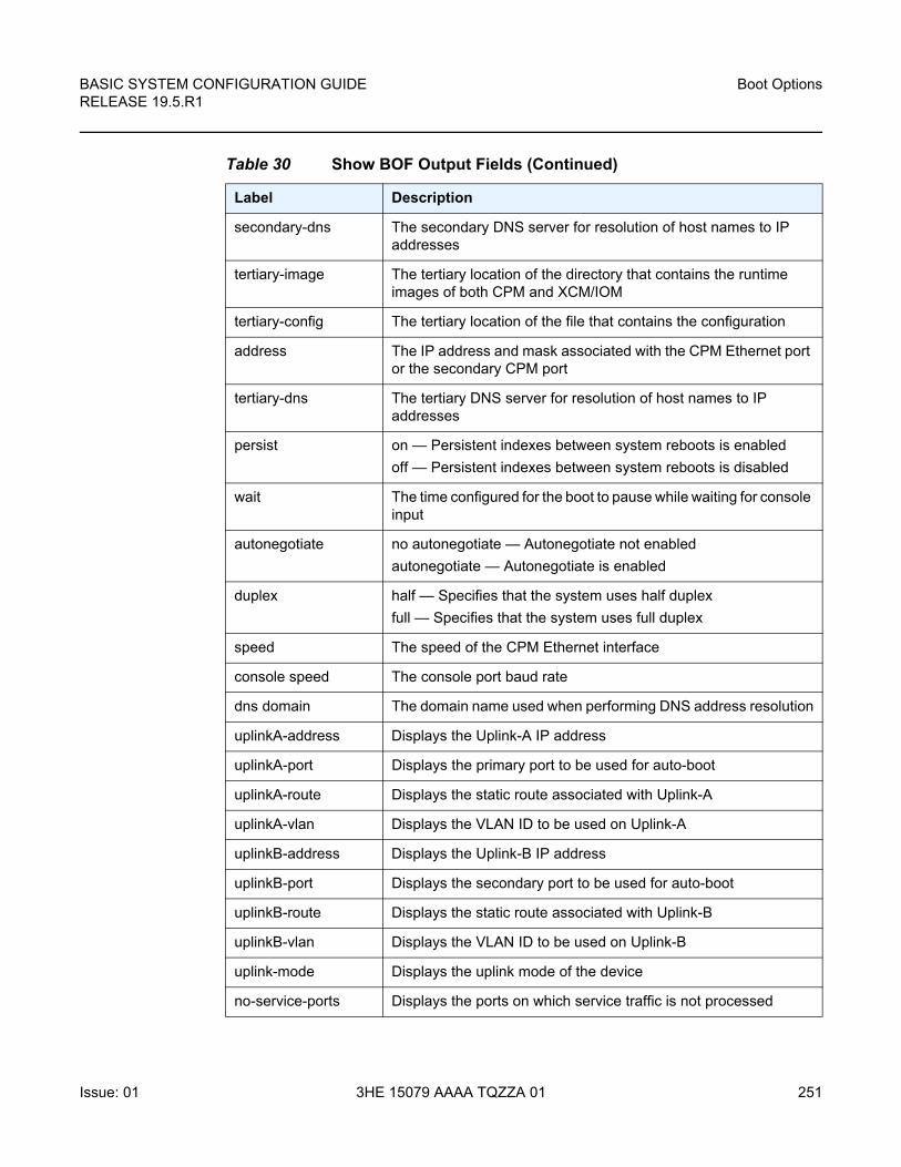
BASIC SYSTEM CONFIGURATION GUIDE RELEASE 19.5.R1
Boot Options
Issue: 01 3HE 15079 AAAA TQZZA 01 251
secondary-dns The secondary DNS server for resolution of host names to IP addresses
tertiary-image The tertiary location of the directory that contains the runtime images of both CPM and XCM/IOM
tertiary-config The tertiary location of the file that contains the configuration
address The IP address and mask associated with the CPM Ethernet port or the secondary CPM port
tertiary-dns The tertiary DNS server for resolution of host names to IP addresses
persist on — Persistent indexes between system reboots is enabled
off — Persistent indexes between system reboots is disabled
wait The time configured for the boot to pause while waiting for console input
autonegotiate no autonegotiate — Autonegotiate not enabled
autonegotiate — Autonegotiate is enabled
duplex half — Specifies that the system uses half duplex
full — Specifies that the system uses full duplex
speed The speed of the CPM Ethernet interface
console speed The console port baud rate
dns domain The domain name used when performing DNS address resolution
uplinkA-address Displays the Uplink-A IP address
uplinkA-port Displays the primary port to be used for auto-boot
uplinkA-route Displays the static route associated with Uplink-A
uplinkA-vlan Displays the VLAN ID to be used on Uplink-A
uplinkB-address Displays the Uplink-B IP address
uplinkB-port Displays the secondary port to be used for auto-boot
uplinkB-route Displays the static route associated with Uplink-B
uplinkB-vlan Displays the VLAN ID to be used on Uplink-B
uplink-mode Displays the uplink mode of the device
no-service-ports Displays the ports on which service traffic is not processed
Table 30 Show BOF Output Fields (Continued)
Label Description
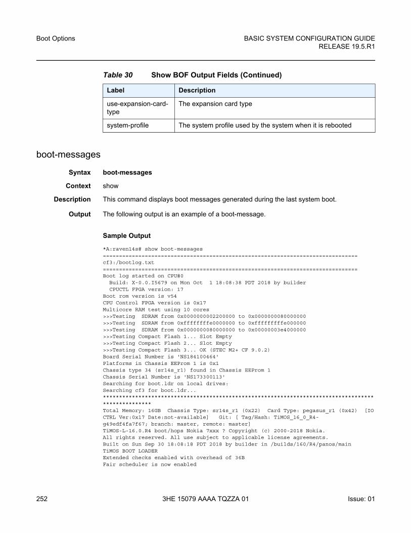
Boot Options
252
BASIC SYSTEM CONFIGURATION GUIDERELEASE 19.5.R1
3HE 15079 AAAA TQZZA 01 Issue: 01
boot-messages
Syntax boot-messages
Context show
Description This command displays boot messages generated during the last system boot.
Output The following output is an example of a boot-message.
Sample Output
*A:raven14s# show boot-messages===============================================================================cf3:/bootlog.txt===============================================================================Boot log started on CPU#0
Build: X-0.0.I5679 on Mon Oct 1 18:08:38 PDT 2018 by builderCPUCTL FPGA version: 17
Boot rom version is v54CPU Control FPGA version is 0x17Multicore RAM test using 10 cores>>>Testing SDRAM from 0x0000000002200000 to 0x0000000080000000>>>Testing SDRAM from 0xffffffffe0000000 to 0xfffffffffe000000>>>Testing SDRAM from 0x0000000080000000 to 0x00000003e4000000>>>Testing Compact Flash 1... Slot Empty>>>Testing Compact Flash 2... Slot Empty>>>Testing Compact Flash 3... OK (STEC M2+ CF 9.0.2)Board Serial Number is 'NS184100464'Platforms in Chassis EEProm 1 is 0x1Chassis type 34 (sr14s_r1) found in Chassis EEProm 1Chassis Serial Number is 'NS173300113'Searching for boot.ldr on local drives:Searching cf3 for boot.ldr...***************************************************************************************************Total Memory: 16GB Chassis Type: sr14s_r1 (0x22) Card Type: pegasus_r1 (0x42) [IOCTRL Ver:0x17 Date:not-available] Git: [ Tag/Hash: TiMOS_16_0_R4-g49edf4fa7f67; branch: master, remote: master]TiMOS-L-16.0.R4 boot/hops Nokia 7xxx ? Copyright (c) 2000-2018 Nokia.All rights reserved. All use subject to applicable license agreements.Built on Sun Sep 30 18:08:18 PDT 2018 by builder in /builds/160/R4/panos/mainTiMOS BOOT LOADERExtended checks enabled with overhead of 36BFair scheduler is now enabled
use-expansion-card-type
The expansion card type
system-profile The system profile used by the system when it is rebooted
Table 30 Show BOF Output Fields (Continued)
Label Description

BASIC SYSTEM CONFIGURATION GUIDE RELEASE 19.5.R1
Boot Options
Issue: 01 3HE 15079 AAAA TQZZA 01 253
Time from clock is TUE NOV 17 15:12:04 2020 UTCSwitching serial output to sync mode... doneLooking for cf3:/bof.cfg ... OK, readingContents of Boot Options File on cf3:

Boot Options
254
BASIC SYSTEM CONFIGURATION GUIDERELEASE 19.5.R1
3HE 15079 AAAA TQZZA 01 Issue: 01
BASIC SYSTEM CONFIGURATION GUIDE RELEASE 19.5.R1
Debug Commands
Issue: 01 3HE 15079 AAAA TQZZA 01 255
5 Debug Commands
The debug commands enable detailed debug information for various protocols.
Debug output is generally seen by configuring a log with from debug-trace and then viewing the output of the log.
The currently enabled debug can be seen using the show debug command.
Debug configuration is not persistent across CPM switchovers nor router reboots. The admin debug-save command can be used to save the debug configuration. The resulting file could then be exec'ed later as needed.
Individual debug commands are described in the various User Guides where the associated protocols and features are also described. For example, the debug service id arp-host command is described in the 7450 ESS, 7750 SR, 7950 XRS, and VSR Layer 3 Services Guide: IES and VPRN.

Debug Commands
256
BASIC SYSTEM CONFIGURATION GUIDERELEASE 19.5.R1
3HE 15079 AAAA TQZZA 01 Issue: 01
BASIC SYSTEM CONFIGURATION GUIDE RELEASE 19.5.R1
Tools Commands
Issue: 01 3HE 15079 AAAA TQZZA 01 257
6 Tools Commands
The tools commands provide two primary functions:
• dump
• perform
The tools dump commands are used to provide additional detailed and enhanced information about various aspects of the router.
The tools perform commands provide the ability to trigger a variety of actions in the router such as a card power cycle (tools perform card power-cycle), APS switchovers, and so on.
Individual tools commands are described in the various User Guides where the associated protocols and features are also described. For example, the tools dump log subscriptions command is described in the 7450 ESS, 7750 SR, 7950 XRS, and VSR System Management Guide.

Tools Commands
258
BASIC SYSTEM CONFIGURATION GUIDERELEASE 19.5.R1
3HE 15079 AAAA TQZZA 01 Issue: 01
BASIC SYSTEM CONFIGURATION GUIDE RELEASE 19.5.R1
System Management
Issue: 01 3HE 15079 AAAA TQZZA 01 259
7 System Management
7.1 System Management Parameters
System management commands allow you to configure basic system management functions such as the system name, the router’s location and coordinates, and Common Language Location Identifier (CLLI) code as well as time zones, Network Time Protocol (NTP), Simple Network Time Protocol (SNTP) properties, CRON and synchronization properties.
On SR OS routers, it is possible to query the DNS server for IPv6 addresses. By default, the DNS names are queried for A-records only (address-preference is IPv4-only). If the address-preference is set to IPv6 first, the DNS server is queried for AAAA-records first, and if there is no successful reply, then A-records.
7.1.1 System Information
This section describes system information components.
7.1.1.1 System Name
The system name is the MIB II (RFC 1907, Management Information Base for Version 2 of the Simple Network Management Protocol (SNMPv2)) sysName object. By convention, this text string is the node’s fully-qualified domain name. The system name can be any ASCII-printable text string of up to 64 characters.
7.1.1.2 System Contact
The system contact is the MIB II sysContact object. By convention, this text string is a textual identification of the contact person for this managed node, together with information on how to contact this person. The system contact can be any ASCII-printable text string of up to 80 characters.
System Management
260
BASIC SYSTEM CONFIGURATION GUIDERELEASE 19.5.R1
3HE 15079 AAAA TQZZA 01 Issue: 01
7.1.1.3 System Location
The system location is the MIB II sysLocation object which is a text string conventionally used to describe the node’s physical location, for example, “Bldg MV-11, 1st Floor, Room 101”. The system location can be any ASCII-printable text string of up to 80 characters.
7.1.1.4 System Coordinates
The system coordinates is the Nokia Chassis MIB tmnxChassisCoordinates object. This text string indicates the Global Positioning System (GPS) coordinates of the location of the chassis.
Two-dimensional GPS positioning offers latitude and longitude information as a four dimensional vector:
<direction, hours, minutes, seconds>
where direction is one of the four basic values: N, S, W, E, hours ranges from 0 to 180 (for latitude) and 0 to 90 for longitude, and minutes and seconds range from 0 to 60.
<W, 122, 56, 89> is an example of longitude and <N, 85, 66, 43> is an example of latitude.
System coordinates can be expressed in different notations, examples include:
• N 45 58 23, W 34 56 12
• N37 37' 00 latitude, W122 22' 00 longitude
• N36*39.246', W121*40.121
The system coordinates can be any ASCII-printable text string up to 80 characters.
7.1.1.5 Naming Objects
Do not configure named objects with a name that starts with “_tmnx_”, or with “_” in general.
BASIC SYSTEM CONFIGURATION GUIDE RELEASE 19.5.R1
System Management
Issue: 01 3HE 15079 AAAA TQZZA 01 261
7.1.1.6 Common Language Location Identifier
A CLLI code string for the device is an 11-character standardized geographic identifier that uniquely identifies the geographic location of places and certain functional categories of equipment unique to the telecommunications industry. The CLLI code is stored in the Nokia Chassis MIB tmnxChassisCLLICode object.
The CLLI code can be any ASCII-printable text string of up to 11 characters.
7.1.1.7 DNS Security Extensions
DNS Security (DNSSEC) Extensions are now implemented in the SR OS, allowing operators to configure DNS behavior of the router to evaluate whether the Authenticated Data bit was set in the response received from the recursive name server and to trust the response, or ignore it.
7.1.2 System Time
SR-series routers are equipped with a real-time system clock for time keeping purposes. When set, the system clock always operates on Coordinated Universal Time (UTC), but the SR-series routers OS software has options for local time translation as well as system clock synchronization.
7.1.2.1 Time Zones
Setting a time zone in SR OS allows for times to be displayed in the local time rather than in UTC. SR OS has both user-defined and system-defined time zones.
A user-defined time zone has a user-assigned name of up to four printable ASCII characters in length and is unique from the system-defined time zones. For user-defined time zones, the offset from UTC is configured as well as any summer time adjustment for the time zone.
SR OS includes multiple commands to control the presentation of times in either UTC or local time zone format. For a CLI session, the environment variable time-display may be set to indicate UTC or local time zone. This setting only affects time strings shown during that specific CLI session. In addition, a global setting of config>system>time>prefer-local-time can be used to control time strings for objects with larger scope that a single CLI session, including the following:
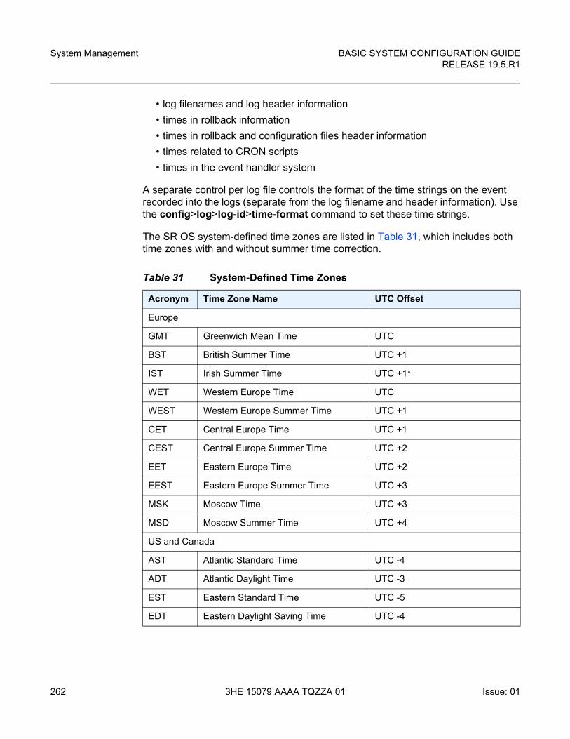
System Management
262
BASIC SYSTEM CONFIGURATION GUIDERELEASE 19.5.R1
3HE 15079 AAAA TQZZA 01 Issue: 01
• log filenames and log header information
• times in rollback information
• times in rollback and configuration files header information
• times related to CRON scripts
• times in the event handler system
A separate control per log file controls the format of the time strings on the event recorded into the logs (separate from the log filename and header information). Use the config>log>log-id>time-format command to set these time strings.
The SR OS system-defined time zones are listed in Table 31, which includes both time zones with and without summer time correction.
Table 31 System-Defined Time Zones
Acronym Time Zone Name UTC Offset
Europe
GMT Greenwich Mean Time UTC
BST British Summer Time UTC +1
IST Irish Summer Time UTC +1*
WET Western Europe Time UTC
WEST Western Europe Summer Time UTC +1
CET Central Europe Time UTC +1
CEST Central Europe Summer Time UTC +2
EET Eastern Europe Time UTC +2
EEST Eastern Europe Summer Time UTC +3
MSK Moscow Time UTC +3
MSD Moscow Summer Time UTC +4
US and Canada
AST Atlantic Standard Time UTC -4
ADT Atlantic Daylight Time UTC -3
EST Eastern Standard Time UTC -5
EDT Eastern Daylight Saving Time UTC -4
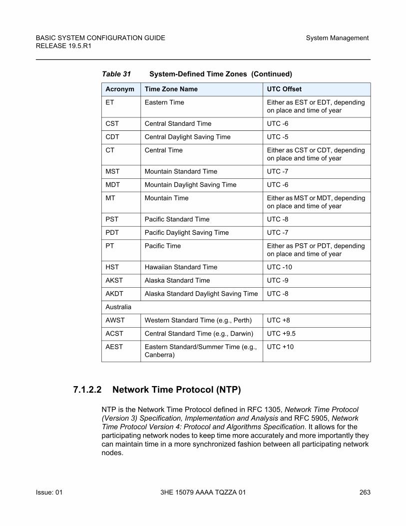
BASIC SYSTEM CONFIGURATION GUIDE RELEASE 19.5.R1
System Management
Issue: 01 3HE 15079 AAAA TQZZA 01 263
7.1.2.2 Network Time Protocol (NTP)
NTP is the Network Time Protocol defined in RFC 1305, Network Time Protocol (Version 3) Specification, Implementation and Analysis and RFC 5905, Network Time Protocol Version 4: Protocol and Algorithms Specification. It allows for the participating network nodes to keep time more accurately and more importantly they can maintain time in a more synchronized fashion between all participating network nodes.
ET Eastern Time Either as EST or EDT, depending on place and time of year
CST Central Standard Time UTC -6
CDT Central Daylight Saving Time UTC -5
CT Central Time Either as CST or CDT, depending on place and time of year
MST Mountain Standard Time UTC -7
MDT Mountain Daylight Saving Time UTC -6
MT Mountain Time Either as MST or MDT, depending on place and time of year
PST Pacific Standard Time UTC -8
PDT Pacific Daylight Saving Time UTC -7
PT Pacific Time Either as PST or PDT, depending on place and time of year
HST Hawaiian Standard Time UTC -10
AKST Alaska Standard Time UTC -9
AKDT Alaska Standard Daylight Saving Time UTC -8
Australia
AWST Western Standard Time (e.g., Perth) UTC +8
ACST Central Standard Time (e.g., Darwin) UTC +9.5
AEST Eastern Standard/Summer Time (e.g., Canberra)
UTC +10
Table 31 System-Defined Time Zones (Continued)
Acronym Time Zone Name UTC Offset
System Management
264
BASIC SYSTEM CONFIGURATION GUIDERELEASE 19.5.R1
3HE 15079 AAAA TQZZA 01 Issue: 01
NTP uses stratum levels to define the number of hops from a reference clock. The reference clock is considered to be a stratum-0 device that is assumed to be accurate with little or no delay. Stratum-0 servers cannot be used in a network. However, they can be directly connected to devices that operate as stratum-1 servers. A stratum-1 server is an NTP server with a directly-connected device that provides Coordinated Universal Time (UTC), such as a GPS or atomic clock.
The higher stratum levels are separated from the stratum-1 server over a network path, thus, a stratum-2 server receives its time over a network link from a stratum-1 server. A stratum-3 server receives its time over a network link from a stratum-2 server.
SR OS routers normally operate as a stratum-2 or higher device. The router relies on an external stratum-1 server to source accurate time into the network. However, SR OS also allows for the use of the local PTP recovered time to be sourced into NTP. In this latter case, the local PTP source appears as a stratum-0 server and SR OS advertises itself as a stratum-1 server. Activation of the PTP source into NTP may impact the network NTP topology because the SR OS router is promoted to stratum 1.
SR OS router runs a single NTP clock which then operates NTP message exchanges with external NTP clocks. Exchanges can be made with external NTP clients, servers, and peers. These exchanges can be through the base, management, or VPRN routing instances.
NTP operates associations between clocks as either client or server, symmetric active and symmetric passive, or broadcast modes. These modes of operation are applied according to which elements are configured on the router. To run server mode, the operator must enable NTP server mode for the base and each desired VPRN routing instance. To run client mode, the operator must configure external servers. If both the local router and remote router are configured with each other as peers, then the router operates in symmetric active mode. If only one side of the association has peering configured, then the modes are symmetric passive. To operate using broadcast mode, interfaces must be configured to transmit as broadcast servers or receive as broadcast clients.
NTP server operation for both unicast and broadcast communication within a VPRN is configured within the VPRN (refer to the NTP Within a VPRN Service section in 7450 ESS, 7750 SR, 7950 XRS, and VSR Layer 3 Services Guide: IES and VPRN).
The following NTP elements are supported:
• Server mode — In this mode, the node advertises the ability to act as a clock source for other network elements. The node, by default, transmits NTP packets in NTP version 4 mode.
BASIC SYSTEM CONFIGURATION GUIDE RELEASE 19.5.R1
System Management
Issue: 01 3HE 15079 AAAA TQZZA 01 265
• Authentication keys — Authentication keys implement increased security support in carrier and other networks. Both DES and MD5 authentication are supported, as well as multiple keys.
• Operation in symmetric active mode — This capability requires that NTP be synchronized with a specific node that is considered more trustworthy or accurate than other nodes carrying NTP in the system. This mode requires that a specific peer is set.
• Server and peer addressing using IPv6 — Both external servers and external peers may be defined using IPv6 or IPv4 addresses. Other features (such as multicast, broadcast) use IPv4 addressing only.
• Broadcast or multicast modes — When operating in these modes, the node receives or sends using either a multicast (default 224.0.1.1) or a broadcast address. Multicast is supported only on the CPM MGMT port.
• Alert when NTP server is not available — When none of the configured servers are reachable on the node, the system reverts to manual timekeeping and issues a critical alarm. When a server becomes available, a trap is issued indicating that standard operation has resumed.
• NTP and SNTP — If both NTP and SNTP are enabled on the node, then SNTP transitions to an operationally down state. If NTP is removed from the configuration or shut down, then SNTP resumes an operationally up state.
• Gradual clock adjustment — As several applications (such as Service Assurance Agent (SAA)) can use the clock, and if determined that a major (128 ms or more) adjustment needs to be performed, the adjustment is performed by programmatically stepping the clock. If a minor (less than 128 ms) adjustment must be performed, then the adjustment is performed by either speeding up or slowing down the clock.
• In order to avoid the generation of too many events/trap the NTP module rates limit the generation of events/traps to three per second. At that point a single trap is generated that indicates that event/trap squashing is taking place.
7.1.2.3 SNTP Time Synchronization
For synchronizing the system clock with outside time sources, the SR OS includes a Simple Network Time Protocol (SNTP) client. As defined in RFC 2030, SNTP Version 4 is an adaptation of the Network Time Protocol (NTP). SNTP typically provides time accuracy within 100 milliseconds of the time source. SNTP can only receive the time from NTP servers; it cannot be used to provide time services to other systems. SNTP is a compact, client-only version of NTP. SNTP does not authenticate traffic.
System Management
266
BASIC SYSTEM CONFIGURATION GUIDERELEASE 19.5.R1
3HE 15079 AAAA TQZZA 01 Issue: 01
SNTP can be configured in both unicast client modes (point-to-point) and broadcast client modes (point-to-multipoint). SNTP should be used only at the extremities of the synchronization subnet. SNTP clients should operate only at the highest stratum (leaves) of the subnet and in configurations where no NTP or SNTP client is dependent on another SNTP client for synchronization. SNTP time servers should operate only at the root (stratum 1) of the subnet and then only in configurations where no other source of synchronization other than a reliable radio clock is available. External servers may only be specified using IPv4 addresses.
In the SR OS, the SNTP client can be configured for either broadcast or unicast client mode.
7.1.2.4 CRON
The CRON feature supports periodic and date and time-based scheduling in SR OS. CRON can be used, for example, to schedule Service Assurance Agent (SAA) functions. CRON functionality includes the ability to specify scripts that need to be run, when they are scheduled, including one-time only functionality (one-shot), interval and calendar functions. Scheduled reboots, peer turn ups, service assurance agent tests and more can all be scheduled with CRON, as well as OAM events, such as connectivity checks, or troubleshooting runs.
CRON supports the schedule element. The schedule function configures the type of schedule to run, including one-time only (one-shot), periodic, or calendar-based runs. All runs are determined by month, day of month or weekday, hour, minute, and interval (seconds).
BASIC SYSTEM CONFIGURATION GUIDE RELEASE 19.5.R1
System Management
Issue: 01 3HE 15079 AAAA TQZZA 01 267
7.2 High Availability
This section discusses the high availability (HA) routing options and features available to service providers that help diminish vulnerability at the network or service provider edge and alleviate the effect of a lengthy outage on IP networks.
High availability is an important feature in service provider routing systems. High availability is gaining momentum due to the unprecedented growth of IP services and applications in service provider networks driven by the demand from the enterprise and residential communities. Downtime can be very costly, and, in addition to lost revenue, customer information and business-critical communications can be lost. High availability is the combination of continuous uptime over long periods (Mean Time Between Failures (MTBF)) and the speed at which failover or recovery occurs (Mean Time To Repair (MTTR)).
The popularity of high availability routing is evident at the network or service provider edge where thousands of connections are hosted and rerouting options around a failed piece of equipment can often be limiting. Or, a single access link exists to a customer because of additional costs for redundant links. As service providers converge business-critical services such as real-time voice (VoIP), video, and VPN applications over their IP networks, high availability becomes much more stringent compared to the requirements for best-effort data. Network and service availability become critical aspects when offering advanced IP services which dictates that IP routers that are used to construct the foundations of these networks be resilient to component and software outages.
For high availability configuration information, see Synchronization and Redundancy.
7.2.1 HA Features
As more and more critical commercial applications move onto the IP/MPLS networks, providing high availability services becomes increasingly important. This section describes high availability features for routers. Most of these features only apply to routers with two Control Processor Modules (CPM).
System Management
268
BASIC SYSTEM CONFIGURATION GUIDERELEASE 19.5.R1
3HE 15079 AAAA TQZZA 01 Issue: 01
7.2.1.1 Redundancy
The redundancy features enable the duplication of data elements and software functionality to maintain service continuation in case of outages or component failure.
Refer to the 7450 ESS, 7750 SR, and VSR Multiservice Integrated Service Adapter Guide for information about redundancy for the Integrated Service Adapter (ISA).
7.2.1.1.1 Software Redundancy
Software outages are challenging even when baseline hardware redundancy is in place. There should be a balance to provide high availability routing otherwise router problems typically propagate not only throughout the service provider network, but also externally to other connected networks possibly belonging to other service providers. This could affect customers on a broad scale. Presently, there are several software availability features that contribute to the percentage of time that a router is available to process and forward traffic.
To fully appreciate high availability you should realize that all routing protocols specify minimum time intervals in which the peer device must receive an acknowledgment before it disconnects the session.
• OSPF default session timeout is approximately 40 seconds. The timeout intervals are configurable.
• BGP default session timeout is approximately 120 seconds. The timeout intervals are configurable for the 7750 SR and 7950 XRS only.
Therefore, router software has to recover faster than the specified time interval to maintain up time.
7.2.1.1.2 Configuration Redundancy
Features configured on the active device CPM are saved on the standby CPM as well. When the active device CPM fails, these features are brought up on the standby device CPM that takes over the mastership.
Even with modern modular and stable software, the failure of route processor hardware or software can cause the router to reboot or cause other service impacting events. In the best circumstances, failure leads to the initialization of a redundant route processor, which hosts the standby software configuration, to become the active processor. The following options are available.
BASIC SYSTEM CONFIGURATION GUIDE RELEASE 19.5.R1
System Management
Issue: 01 3HE 15079 AAAA TQZZA 01 269
• Warm standby — The router image and configuration is already loaded on the standby route processor. However, the standby could still take a few minutes to become effective since it must first re-initialize connections by bringing up Layer 2 connections and Layer 3 routing protocols and then rebuild routing tables.
• Hot standby — The router image, configuration, and network state is already loaded on the standby and it receives continual updates from the active route processor and the swapover is immediate. However, hot standby affects conventional router performance as more frequent synchronization increases consumption of system resources. Nokia’s newer generation service routers address this issue because they already have extra processing built into the system.
7.2.1.1.3 Component Redundancy
Component redundancy is critical to reduce MTTR for the system and primarily consists of the following router features:
• Dual route processor modules — For a highly available architecture, redundant Control Processor Modules (CPM) are essential. The route processing functions of the CPM calculate the most efficient route to an Internet destination and communicate the best path information to peer routers. Rapid information synchronization between the primary and secondary CPMs is crucial to minimize recovery time.
• Switch fabric (SFM) redundancy — Failure of a single switch fabric card with little to no loss of traffic.
• Redundant line cards — LAG, ECMP and other techniques to spread traffic over multiple line cards so that a failure of one line card does not impact the services being delivered.
• Redundant power supply — A power module can be removed without impact on traffic.
• Redundant fan — Failure of a fan module without impacting traffic.
• Hot swap — Components in a live system can be replaced or become active without taking the system down or affecting traffic flow to/from other modules.
Router hardware architecture plays a key role in the availability of the system. The principle router architecture styles are centralized and distributed. In these architectures, both active and standby route processors, I/O modules (IOMs) (also called line cards), fans, and power supplies maintain a low MTTR for the routing system.
System Management
270
BASIC SYSTEM CONFIGURATION GUIDERELEASE 19.5.R1
3HE 15079 AAAA TQZZA 01 Issue: 01
However, in a centralized architecture, packet processing and forwarding is performed in a central shared route processor and the individual line cards are relatively simple. The cards rely solely on the route processor for routing and forwarding intelligence and, should the centralized route processor fail, there is greater impact to the system overall, as all routing and packet forwarding stops.
In a distributed system, the packet forwarding functionality is situated on each line card. Distributing the forwarding engines off the central route processor and positioning one on each line card lowers the impact of route processor failure as the line cards can continue to forward traffic during an outage.
The distributed system is better suited to enable the convergence of business critical services such as real-time voice (VoIP), Video, and VPN applications over IP networks with superior performance and scalability. The centralized architecture can be prone to performance bottleneck issues and limits service offerings through poor scalability which may lead to customer and service SLA violations.
7.2.1.1.4 Service Redundancy
All service-related statistics are kept during a switchover. Services, SDPs, and SAPs remains up with a minimum loss of forwarded traffic during a CPM switchover.
7.2.1.1.5 Accounting Configuration Redundancy
When there is a switchover and the standby CPM becomes active, the accounting servers are checked and if they are administratively up and capable of coming online (media present, and so on), the standby is brought online and new accounting files are created at that point. Users must manually copy the accounting records from the failed CPM.
7.2.1.2 Nonstop Forwarding
In a control plane failure or a forced switchover event, the router continues to forward packets using the existing stale forwarding information. Nonstop forwarding requires clean control plane and data plane separation. Usually the forwarding information is distributed to the IOMs, XCMs and XMAs.
BASIC SYSTEM CONFIGURATION GUIDE RELEASE 19.5.R1
System Management
Issue: 01 3HE 15079 AAAA TQZZA 01 271
Nonstop forwarding is used to notify peer routers to continue forwarding and receiving packets, even if the route processor (control plane) is not working or is in a switch-over state. Nonstop forwarding requires clean control plane and data plane separation and usually the forwarding information is distributed to the line cards. This method of availability has both advantages and disadvantages. Nonstop forwarding continues to forward packets using the existing stale forwarding information during a failure. This may cause routing loops and black holes, and also requires that surrounding routers adhere to separate extension standards for each protocol. Every router vendor must support protocol extensions for interoperability.
7.2.1.3 Nonstop Routing (NSR)
With NSR on the SR-series router devices, routing neighbors are unaware of a routing process fault. If a fault occurs, a reliable and deterministic activity switch to the inactive control complex occurs such that routing topology and reachability are not affected, even in the presence of routing updates. NSR achieves high availability through parallelization by maintaining up to date routing state information, at all times, on the standby route processor. This capability is achieved independently of protocols or protocol extensions, providing a more robust solution than graceful restart protocols between network routers.
The NSR implementation on the SR-series routers supports all routing protocols. NSR makes it possible to keep the existing sessions (BGP, LDP, OSPF, etc.) during a CPM switchover, including support for MPLS signaling protocols. Peers do not see any change.
Protocol extensions are not required. There are no interoperability issues and there is no need to define protocol extensions for every protocol. Unlike nonstop forwarding and graceful restart, the forwarding information in NSR is always up to date, which eliminates possible blackholes or forwarding loops.
Traditionally, addressing high availability issues have been patched through non-stop forwarding solutions. With the implementation of NSR, these limitations are overcome by delivering an intelligent hitless failover solution. This enables a carrier-class foundation for transparent networks, required to support business IP services backed by stringent SLAs. This level of high availability poses a major issue for conventional routers whose architectural design limits or prevents them from implementing NSR.
System Management
272
BASIC SYSTEM CONFIGURATION GUIDERELEASE 19.5.R1
3HE 15079 AAAA TQZZA 01 Issue: 01
7.2.1.4 CPM Switchover
During a switchover, system control and routing protocol execution are transferred from the active to the standby CPM.
An automatic switchover may occur under the following conditions:
• A fault condition that causes the active CPM to crash or reboot.
• The active CPM is declared down (not responding).
• Online removal of the active CPM.
A manual switchover can occur under the following conditions:
• To force a switchover from an active CPM to a standby, use the admin redundancy force-switchover command. You can configure a batch file that executes after failover by using the config system switchover-exec CLI command.
7.2.1.5 Synchronization
Synchronization between the CPMs includes the following:
• Configuration and boot-env Synchronization
• State Database Synchronization
7.2.1.5.1 Configuration and boot-env Synchronization
Configuration and boot-env synchronization are supported in admin>redundancy> synchronize and config>redundancy>synchronize contexts.
7.2.1.5.2 State Database Synchronization
If a new standby CPM is inserted into the system, it synchronizes with the active CPM upon a successful boot process.
If the standby CPM is rebooted, it synchronizes with the active CPM upon a successful boot process.
When configuration or state changes occur, an incremental synchronization is conducted from the active CPM to the standby CPM.
BASIC SYSTEM CONFIGURATION GUIDE RELEASE 19.5.R1
System Management
Issue: 01 3HE 15079 AAAA TQZZA 01 273
If the synchronization fails, the standby does not reboot automatically. The show redundancy synchronization command displays synchronization output information.
If the active and standby are not synchronized for some reason, users can manually synchronize the standby CPM by rebooting the standby by issuing the admin reboot standby command on the active or the standby CPM.
System Management
274
BASIC SYSTEM CONFIGURATION GUIDERELEASE 19.5.R1
3HE 15079 AAAA TQZZA 01 Issue: 01
7.3 Synchronization and Redundancy
SR-series routers supporting redundancy use a 1:1 redundancy scheme. Redundancy methods facilitate system synchronization between the active and standby Control Processor Modules (CPMs) so they maintain identical operational parameters to prevent inconsistencies in the event of a CPM failure.
When automatic system synchronization is enabled for an entity, any save or delete file operations configured on the primary, secondary or tertiary choices on the active CPM file system are mirrored in the standby CPM file system.
Although software configurations and images can be copied or downloaded from remote locations, synchronization can only occur locally between compact flash drives (cf1:, cf2:, and cf3:).
Synchronization can occur either:
• Automatically — Automatic synchronization is disabled by default. To enable automatic synchronization, the config>redundancy>synchronization command must be specified with either the boot-env parameter or the config parameter.
When the boot-env parameter is specified, the BOF, boot.ldr, config, and image files are automatically synchronized. When the config parameter is specified, only the config files are automatically synchronized.
Automatic synchronization also occurs whenever the BOF is modified and when an admin>save command is entered with no filename specified.
• Manually — To execute synchronization manually, the admin>redundancy> synchronization command must be entered with the boot-env parameter or the config parameter.
When the boot-env parameter is specified, the BOF, boot.ldr, config, and image files are synchronized. When the config parameter is specified, only the config files are synchronized.
The following shows the output displayed during a manual synchronization of configuration files.
A:ALA-12>admin>redundancy# synchronize configSyncing configuration......
Syncing configuration.....Completed.A:ALA-12#
BASIC SYSTEM CONFIGURATION GUIDE RELEASE 19.5.R1
System Management
Issue: 01 3HE 15079 AAAA TQZZA 01 275
7.3.1 Active and Standby Designations
Typically, the first Switch Fabric (SF)/CPM card installed in a redundant SR-series router chassis assumes the role as active, regardless of being inserted in Slot A or B. The next CPM installed in the same chassis then assumes the role as the standby CPM. If two CPM are inserted simultaneously (or almost simultaneously) and are booting at the same time, then preference is given to the CPM installed in Slot A.
If only one CPM is installed in a redundant router device, then it becomes the active CPM regardless of the slot it is installed in.
The active and standby designations can be visually determined by LEDs on the CPM/CCM faceplate. Refer to the appropriate platform Installation Guide for LED indicator details.
The following output shows that the CPM installed in Slot A is acting as the active CPM and the CPM installed in Slot B is acting as the standby.
The following is an example of the 7950 XRS output:
*A:7950 XRS-20# show card===============================================================================Card Summary===============================================================================Slot Provisioned Type Admin Operational Comments
Equipped Type (if different) State State-------------------------------------------------------------------------------1 xcm-x20 up provisionedA cpm-x20 up up/activeB cpm-x20 up up/standby===============================================================================
The following console message displays when a CPM boots, sees an active CPM, and becomes the standby CPM:
...Slot A contains the Active CPMThis CPM (Slot B) is the Standby CPM
7.3.2 When the Active CPM Goes Offline
When an active CPM goes offline (due to reboot, removal, or failure), the standby CPM takes control without rebooting or initializing itself. It is assumed that the CPMs are synchronized, therefore, there is no delay in operability. When the CPM that went offline boots and then comes back online, it becomes the standby CPM.
When the standby CPM comes online, the following output is shown:
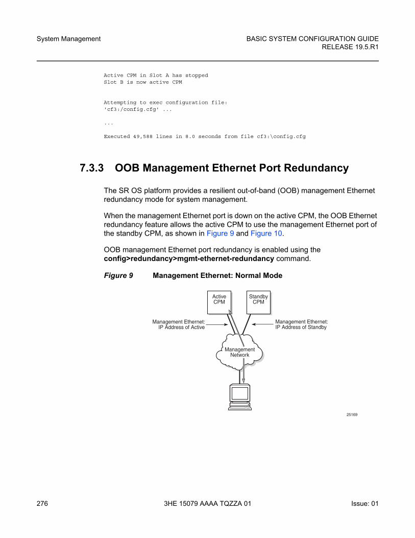
System Management
276
BASIC SYSTEM CONFIGURATION GUIDERELEASE 19.5.R1
3HE 15079 AAAA TQZZA 01 Issue: 01
Active CPM in Slot A has stoppedSlot B is now active CPM
Attempting to exec configuration file:'cf3:/config.cfg' ...
...
Executed 49,588 lines in 8.0 seconds from file cf3:\config.cfg
7.3.3 OOB Management Ethernet Port Redundancy
The SR OS platform provides a resilient out-of-band (OOB) management Ethernet redundancy mode for system management.
When the management Ethernet port is down on the active CPM, the OOB Ethernet redundancy feature allows the active CPM to use the management Ethernet port of the standby CPM, as shown in Figure 9 and Figure 10.
OOB management Ethernet port redundancy is enabled using the config>redundancy>mgmt-ethernet-redundancy command.
Figure 9 Management Ethernet: Normal Mode
ActiveCPM
StandbyCPM
Management Ethernet:IP Address of Active
Management Ethernet:IP Address of Standby
25169
ManagementNetwork
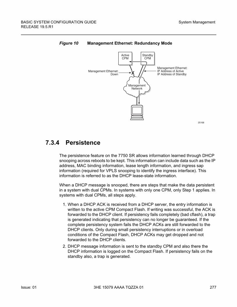
BASIC SYSTEM CONFIGURATION GUIDE RELEASE 19.5.R1
System Management
Issue: 01 3HE 15079 AAAA TQZZA 01 277
Figure 10 Management Ethernet: Redundancy Mode
7.3.4 Persistence
The persistence feature on the 7750 SR allows information learned through DHCP snooping across reboots to be kept. This information can include data such as the IP address, MAC binding information, lease length information, and ingress sap information (required for VPLS snooping to identify the ingress interface). This information is referred to as the DHCP lease-state information.
When a DHCP message is snooped, there are steps that make the data persistent in a system with dual CPMs. In systems with only one CPM, only Step 1 applies. In systems with dual CPMs, all steps apply.
1. When a DHCP ACK is received from a DHCP server, the entry information is written to the active CPM Compact Flash. If writing was successful, the ACK is forwarded to the DHCP client. If persistency fails completely (bad cflash), a trap is generated indicating that persistency can no longer be guaranteed. If the complete persistency system fails the DHCP ACKs are still forwarded to the DHCP clients. Only during small persistency interruptions or in overload conditions of the Compact Flash, DHCP ACKs may get dropped and not forwarded to the DHCP clients.
2. DHCP message information is sent to the standby CPM and also there the DHCP information is logged on the Compact Flash. If persistency fails on the standby also, a trap is generated.
ActiveCPM
StandbyCPM
X
ManagementNetwork
Management Ethernet:Down
Management Ethernet:IP Address of ActiveIP Address of Standby
25168
System Management
278
BASIC SYSTEM CONFIGURATION GUIDERELEASE 19.5.R1
3HE 15079 AAAA TQZZA 01 Issue: 01
7.3.4.1 Dynamic Data Persistency (DDP) Access Optimization for DHCP Leases
A high rate of DHCP renewals can create a load on the compact flash file system when subscriber management and/or DHCP server persistence is enabled. To optimize the access to the Dynamic Data Persistency (DDP) files on the compact flash, a lease-time threshold can be specified that controls the eligibility of a DHCP lease for persistency updates when no other data other than the lease expiry time is to be updated.
configuresystem
persistencesubscriber-mgmt
location cf2:exitdhcp-server
location cf2:exitoptions
dhcp-leasetime-threshold [days <days>] [hrs <hours>][min <minutes>] [sec <seconds>]
exitexit
exit
When the offered lease time of the DHCP lease is less than the configured threshold, the lease is flagged to skip persistency updates and is installed with its full lease time upon a persistency recovery after a reboot.
The dhcp-leasetime-threshold command controls persistency updates for:
• DHCPv4 and DHCPv6 leases for a DHCP relay or proxy (enabled with persistence subscriber-mgmt)
• DHCPv4 leases for DHCP snooping in a VPLS service (enabled with persistence subscriber-mgmt)
• DHCPv4 and DHCPv6 leases for a DHCP server (enabled with persistence dhcp-server)
To check if a DHCP relay or proxy lease is flagged to skip persistency updates, use the tools dump persistence submgt record record-key CLI command. When flagged to skip persistency updates, the persistency record output includes “Skip Persistency Updates: true”.

BASIC SYSTEM CONFIGURATION GUIDE RELEASE 19.5.R1
System Management
Issue: 01 3HE 15079 AAAA TQZZA 01 279
To check if a DHCP server lease is flagged to skip persistency updates, use the tools dump persistence dhcp-server record record-key CLI command. When flagged to skip persistency updates, the persistency record output includes “lease mode : LT” (LT = Lease Time) and a “lease time : …” field. When not flagged to skip persistency updates, the persistency record output includes “lease mode : ET” (ET = Expiry Time) and an “expires : …” field.
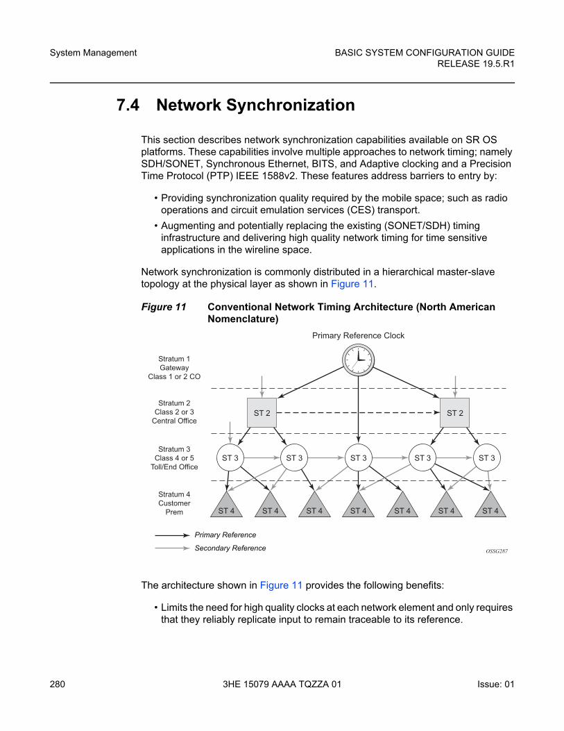
System Management
280
BASIC SYSTEM CONFIGURATION GUIDERELEASE 19.5.R1
3HE 15079 AAAA TQZZA 01 Issue: 01
7.4 Network Synchronization
This section describes network synchronization capabilities available on SR OS platforms. These capabilities involve multiple approaches to network timing; namely SDH/SONET, Synchronous Ethernet, BITS, and Adaptive clocking and a Precision Time Protocol (PTP) IEEE 1588v2. These features address barriers to entry by:
• Providing synchronization quality required by the mobile space; such as radio operations and circuit emulation services (CES) transport.
• Augmenting and potentially replacing the existing (SONET/SDH) timing infrastructure and delivering high quality network timing for time sensitive applications in the wireline space.
Network synchronization is commonly distributed in a hierarchical master-slave topology at the physical layer as shown in Figure 11.
Figure 11 Conventional Network Timing Architecture (North American Nomenclature)
The architecture shown in Figure 11 provides the following benefits:
• Limits the need for high quality clocks at each network element and only requires that they reliably replicate input to remain traceable to its reference.
OSSG287
ST 2
ST 3 ST 3 ST 3 ST 3 ST 3
ST 2
Primary Reference Clock
Stratum 1Gateway
Class 1 or 2 CO
ST 4 ST 4 ST 4ST 4 ST 4 ST 4 ST 4
Stratum 2Class 2 or 3
Central Office
Stratum 3Class 4 or 5
Toll/End Office
Stratum 4Customer
Prem
Primary Reference
Secondary Reference
BASIC SYSTEM CONFIGURATION GUIDE RELEASE 19.5.R1
System Management
Issue: 01 3HE 15079 AAAA TQZZA 01 281
• Uses reliable physical media to provide transport of the timing signal; it doesn't consume any bandwidth and requires limited additional processing.
The synchronization network is designed so a clock always receives timing from a clock of equal or higher stratum or quality level. This ensures that if an upstream clock has a fault condition (for example, loses its reference and enters a holdover or free-run state) and begins to drift in frequency, the downstream clock is able to follow it. For greater reliability and robustness, most offices and nodes have at least two synchronization references that can be selected in priority order (such as primary and secondary).
Further levels of resiliency can be provided by designing a capability in the node clock that operates within prescribed network performance specifications without any reference for a specified time-frame. A clock operating in this mode is said to hold the last known state over (or holdover) until the reference lock is once again achieved. Each level in the timing hierarchy is associated with minimum levels of network performance.
Each synchronization capable port can be independently configured to transmit data using the node reference timing or loop timing. In addition, some TDM channels can use adaptive timing.
Transmission of a reference clock through a chain of Ethernet equipment requires that all equipment supports Synchronous Ethernet. A single piece of equipment that is not capable of performing Synchronous Ethernet breaks the chain. Ethernet frames still get through but downstream devices should not use the recovered line timing as it is be traceable to an acceptable stratum source.
7.4.1 Central Synchronization Sub-System
The timing subsystem for the platforms has a central clock located on the CPM (motherboard). The timing subsystem performs many of the duties of the network element clock as defined by Telcordia (GR-1244-CORE) and ITU-T G.781.
The system can select from up to three (7950 XRS) or four (7450 ESS and 7750 SR) timing inputs to train the local oscillator. The priority order of these references must be specified. This is a simple ordered list of inputs: {bits, ref1, ref2, ptp}. The CPM clock output shall have the ability to drive the clocking for all line cards in the system. The routers support selection of the node reference using Quality Level (QL) indications. See Figure 12 for a description of the synchronization selection process for the CPM clock.
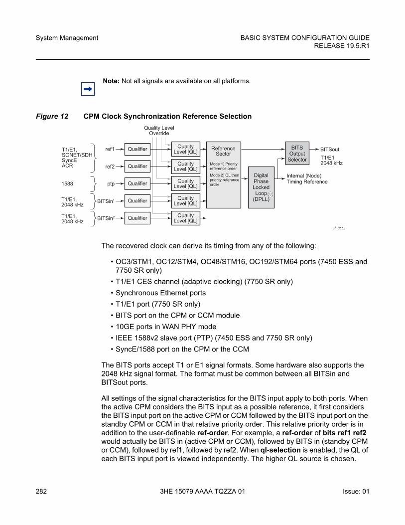
System Management
282
BASIC SYSTEM CONFIGURATION GUIDERELEASE 19.5.R1
3HE 15079 AAAA TQZZA 01 Issue: 01
Figure 12 CPM Clock Synchronization Reference Selection
The recovered clock can derive its timing from any of the following:
• OC3/STM1, OC12/STM4, OC48/STM16, OC192/STM64 ports (7450 ESS and 7750 SR only)
• T1/E1 CES channel (adaptive clocking) (7750 SR only)
• Synchronous Ethernet ports
• T1/E1 port (7750 SR only)
• BITS port on the CPM or CCM module
• 10GE ports in WAN PHY mode
• IEEE 1588v2 slave port (PTP) (7450 ESS and 7750 SR only)
• SyncE/1588 port on the CPM or the CCM
The BITS ports accept T1 or E1 signal formats. Some hardware also supports the 2048 kHz signal format. The format must be common between all BITSin and BITSout ports.
All settings of the signal characteristics for the BITS input apply to both ports. When the active CPM considers the BITS input as a possible reference, it first considers the BITS input port on the active CPM or CCM followed by the BITS input port on the standby CPM or CCM in that relative priority order. This relative priority order is in addition to the user-definable ref-order. For example, a ref-order of bits ref1 ref2 would actually be BITS in (active CPM or CCM), followed by BITS in (standby CPM or CCM), followed by ref1, followed by ref2. When ql-selection is enabled, the QL of each BITS input port is viewed independently. The higher QL source is chosen.
Note: Not all signals are available on all platforms.
al_0553
Qualifierref1T1/E1,SONET/SDHSyncEACR
1588
T1/E1,2048 kHz
T1/E1,2048 kHz
ref2
ptp
BITSin1
BITSin2
QualityLevel [QL]
Quality LevelOverride
ReferenceSector
DigitalPhaseLockedLoop
(DPLL)
BITSOutput
Selector
Internal (Node)Timing Reference
BITSoutT1/E12048 kHzQualifier Quality
Level [QL]
Qualifier QualityLevel [QL]
Qualifier QualityLevel [QL]
Qualifier QualityLevel [QL]
Mode 1) Priorityreference order
Mode 2) QL thenpriority reference order
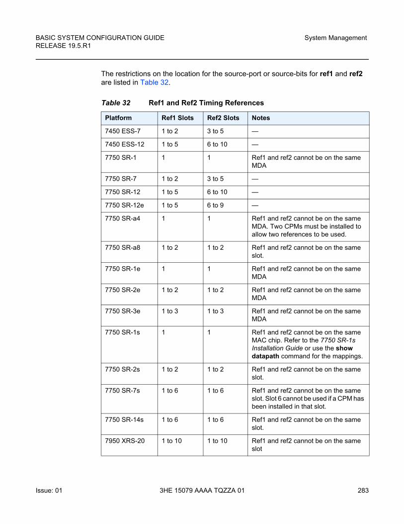
BASIC SYSTEM CONFIGURATION GUIDE RELEASE 19.5.R1
System Management
Issue: 01 3HE 15079 AAAA TQZZA 01 283
The restrictions on the location for the source-port or source-bits for ref1 and ref2 are listed in Table 32.
Table 32 Ref1 and Ref2 Timing References
Platform Ref1 Slots Ref2 Slots Notes
7450 ESS-7 1 to 2 3 to 5 —
7450 ESS-12 1 to 5 6 to 10 —
7750 SR-1 1 1 Ref1 and ref2 cannot be on the same MDA
7750 SR-7 1 to 2 3 to 5 —
7750 SR-12 1 to 5 6 to 10 —
7750 SR-12e 1 to 5 6 to 9 —
7750 SR-a4 1 1 Ref1 and ref2 cannot be on the same MDA. Two CPMs must be installed to allow two references to be used.
7750 SR-a8 1 to 2 1 to 2 Ref1 and ref2 cannot be on the same slot.
7750 SR-1e 1 1 Ref1 and ref2 cannot be on the same MDA
7750 SR-2e 1 to 2 1 to 2 Ref1 and ref2 cannot be on the same MDA
7750 SR-3e 1 to 3 1 to 3 Ref1 and ref2 cannot be on the same MDA
7750 SR-1s 1 1 Ref1 and ref2 cannot be on the same MAC chip. Refer to the 7750 SR-1s Installation Guide or use the show datapath command for the mappings.
7750 SR-2s 1 to 2 1 to 2 Ref1 and ref2 cannot be on the same slot.
7750 SR-7s 1 to 6 1 to 6 Ref1 and ref2 cannot be on the same slot. Slot 6 cannot be used if a CPM has been installed in that slot.
7750 SR-14s 1 to 6 1 to 6 Ref1 and ref2 cannot be on the same slot.
7950 XRS-20 1 to 10 1 to 10 Ref1 and ref2 cannot be on the same slot
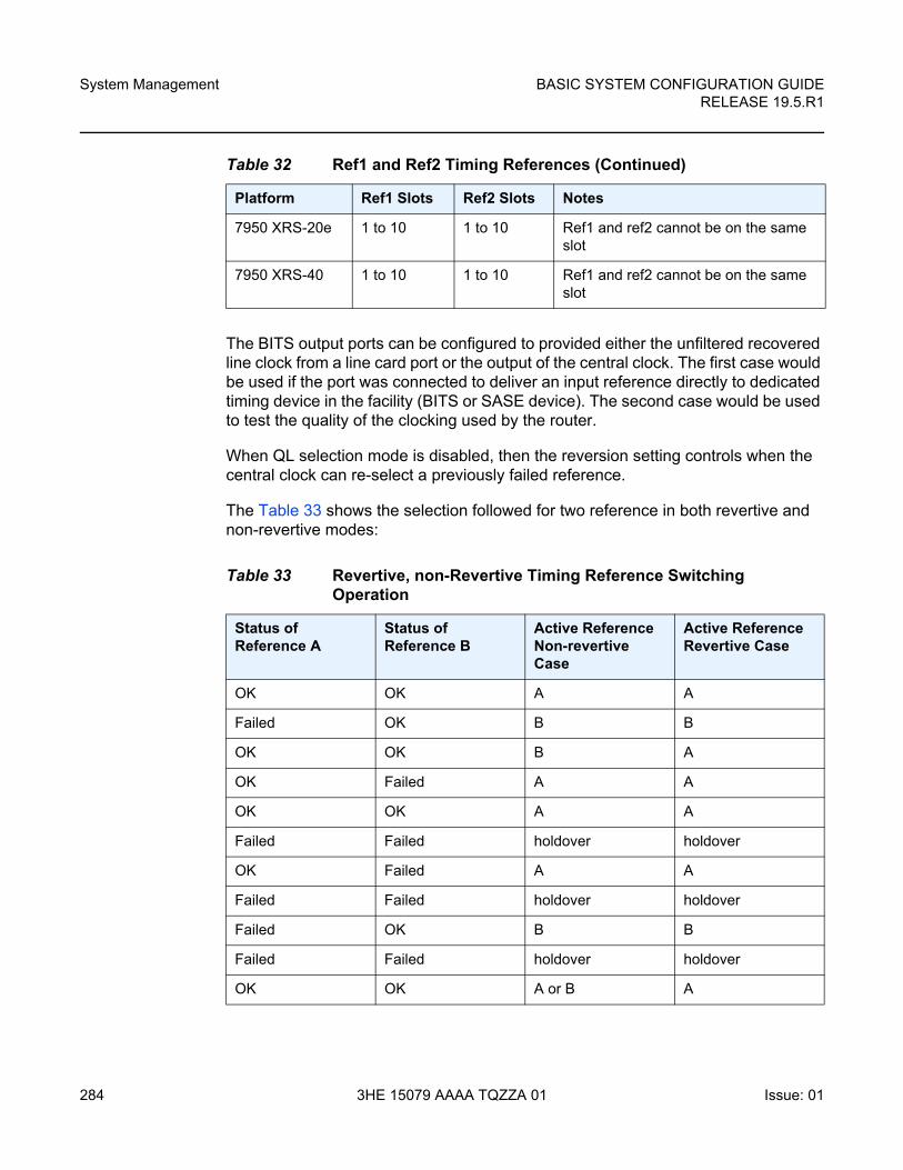
System Management
284
BASIC SYSTEM CONFIGURATION GUIDERELEASE 19.5.R1
3HE 15079 AAAA TQZZA 01 Issue: 01
The BITS output ports can be configured to provided either the unfiltered recovered line clock from a line card port or the output of the central clock. The first case would be used if the port was connected to deliver an input reference directly to dedicated timing device in the facility (BITS or SASE device). The second case would be used to test the quality of the clocking used by the router.
When QL selection mode is disabled, then the reversion setting controls when the central clock can re-select a previously failed reference.
The Table 33 shows the selection followed for two reference in both revertive and non-revertive modes:
7950 XRS-20e 1 to 10 1 to 10 Ref1 and ref2 cannot be on the same slot
7950 XRS-40 1 to 10 1 to 10 Ref1 and ref2 cannot be on the same slot
Table 33 Revertive, non-Revertive Timing Reference Switching Operation
Status of Reference A
Status of Reference B
Active Reference Non-revertive Case
Active Reference Revertive Case
OK OK A A
Failed OK B B
OK OK B A
OK Failed A A
OK OK A A
Failed Failed holdover holdover
OK Failed A A
Failed Failed holdover holdover
Failed OK B B
Failed Failed holdover holdover
OK OK A or B A
Table 32 Ref1 and Ref2 Timing References (Continued)
Platform Ref1 Slots Ref2 Slots Notes
BASIC SYSTEM CONFIGURATION GUIDE RELEASE 19.5.R1
System Management
Issue: 01 3HE 15079 AAAA TQZZA 01 285
7.4.2 7950 XRS-40 Extension Chassis Central Clocks
The central clock architecture described above applies to each chassis of the 7950 XRS-40. There is a central clock located on each of the CPMs present in the extension chassis. However, there is no configuration for the central clocks on the CPMs of the extension chassis. The central clocks only use the BITS input ports of the extension chassis for their input reference. It is assumed that the quality of the reference provided into the BITS input ports of the extension chassis CPMs is equal to the quality of the Master chassis central clocks. Refer to the Installation Guide for appropriate physical cabling to support this architecture.
7.4.3 Synchronization Status Messages (SSM)
SSM provides a mechanism to allow the synchronization distribution network to both determine the quality level of the clock sourcing a given synchronization trail and to allow a network element to select the best of multiple input synchronization trails. Synchronization Status messages have been defined for various transport protocols including SONET/SDH, T1/E1, and Synchronous Ethernet, for interaction with office clocks, such as BITS or SSUs and embedded network element clocks.
SSM allows equipment to autonomously provision and reconfigure (by reference switching) their synchronization references, while helping to avoid the creation of timing loops. These messages are particularly useful to allow synchronization reconfigurations when timing is distributed in both directions around a ring.
The following sections provide details about the SSM message functionality for different signal types. These functions apply to all platforms that support the given signal type.
7.4.3.1 DS1 Signals
DS1 signals can carry an indication of the quality level of the source generating the timing information using the SSM transported within the 1544 Kbit/s signal's Extended Super Frame (ESF) Data Link (DL) as specified in Recommendation G.704. No such provision is extended to SF formatted DS1 signals.
The format of the data link messages in ESF frame format is "0xxx xxx0 1111 1111", transmitted rightmost bit first. The six bits denoted "xxx xxx" contain the actual message; some of these messages are reserved for synchronization messaging. It takes 32 frames (such as 4 ms) to transmit all 16 bits of a complete DL.
System Management
286
BASIC SYSTEM CONFIGURATION GUIDERELEASE 19.5.R1
3HE 15079 AAAA TQZZA 01 Issue: 01
7.4.3.2 E1 Signals
E1 signals can carry an indication of the quality level of the source generating the timing information using the SSM as specified in Recommendation G.704.
One of the Sa4 to Sa8 bits, (the actual Sa bit is for operator selection), is allocated for Synchronization Status Messages. To prevent ambiguities in pattern recognition, it is necessary to align the first bit (San1) with frame 1 of a G.704 E1 multi-frame.
The numbering of the San (n = 4, 5, 6, 7, 8) bits. A San bit is organized as a 4-bit nibble San1 to San4. San1 is the most significant bit; San4 is the least significant bit.
The message set in San1 to San4 is a copy of the set defined in SDH bits 5 to 8 of byte S1.
7.4.3.3 SONET/SDH Signals
The SSM of SDH and SONET interfaces is carried in the S1 byte of the frame overhead. Each frame contains the four bit value of the QL.
7.4.3.4 DS3/E3
DS3/E3 signals are not required to be synchronous. However, it is acceptable for their clocking to be generated from a synchronization source. The 7750 SR and the 7450 ESS permit E3/DS3 physical ports to be specified as a central clock input reference.
DS3/E3 signals do not support an SSM channel. QL-override should be used for these ports if ql-selection is enabled
7.4.4 Synchronous Ethernet
Traditionally, Ethernet-based networks employ the physical layer transmitter clock to be derived from an inexpensive +/-100ppm crystal oscillator and the receiver locks onto it. There is no need for long term frequency stability because the data is packetized and can be buffered. For the same reason there is no need for consistency between the frequencies of different links. However, you can derive the physical layer transmitter clock from a high quality frequency reference by replacing the crystal with a frequency source traceable to a primary reference clock. This would
BASIC SYSTEM CONFIGURATION GUIDE RELEASE 19.5.R1
System Management
Issue: 01 3HE 15079 AAAA TQZZA 01 287
not affect the operation of any of the Ethernet layers, for which this change would be transparent. The receiver at the far end of the link would lock onto the physical layer clock of the received signal, and thus itself gain access to a highly accurate and stable frequency reference. Then, in a manner analogous to conventional hierarchical master-slave network synchronization, this receiver could lock the transmission clock of its other ports to this frequency reference and a fully time synchronous network could be established.
The advantage of using Synchronous Ethernet, compared with methods that rely on sending timing information in packets over an unclocked physical layer, is that it is not influenced by impairments introduced by the higher levels of the networking technology (packet loss, packet delay variation). Hence, the frequency accuracy and stability may be expected to exceed those of networks with unsynchronized physical layers.
Synchronous Ethernet allows operators to gracefully integrate existing systems and future deployments into conventional industry-standard synchronization hierarchy. The concept behind synchronous Ethernet is analogous to SONET/SDH system timing capabilities. It allows the operator to select any (optical) Ethernet port as a candidate timing reference. The recovered timing from this port is then used to time the system (for example, the CPM locks to this provisioned reference selection). The operator then could ensure that any of system output would be locked to a stable traceable frequency source.
If the port is a fixed copper Ethernet port and in 1000BASE-T mode of operation, there is a dependency on the 802.3 link timing for the Synchronous Ethernet functionality (refer to ITU-T G.8262). The 802.3 link Master-Slave timing states must align with the desired direction of Synchronous Ethernet timing flow. When a fixed copper Ethernet port is specified as an input reference for the node or when it is removed as an input reference for the node, an 802.3 link auto-negotiation is triggered to ensure the link timing aligns properly.
The SSM of Synchronous Ethernet uses an Ethernet OAM PDU that uses the slow protocol subtype. For a complete description of the format and processing, refer to ITU-T G.8264.
7.4.5 Clock Source Quality Level Definitions
The following clock source quality levels have been identified for the purpose of tracking network timing flow. These levels make up all of the defined network deployment options given in Recommendation G.803 and G.781. The Option I network is a network developed on the original European SDH model; whereas, the Option II network is a network developed on the North American SONET model.
System Management
288
BASIC SYSTEM CONFIGURATION GUIDERELEASE 19.5.R1
3HE 15079 AAAA TQZZA 01 Issue: 01
In addition to the QL values received over SSM of an interface, the standards also define additional codes for internal use. These include the following:
• QL INVx is generated internally by the system if and when an unallocated SSM value is received, where x represents the binary value of this SSM. All of these independent values are assigned as the singled value of QL-INVALID.
• QL FAILED is generated internally by the system if and when the terminated network synchronization distribution trail is in the signal fail state.
There is also an internal quality level of QL-UNKNOWN. This is used to differentiate from a received QL-STU code but is equivalent for the purposes of QL selection.
Table 34 lists the synchronization message coding and source priorities for SSM received.
Table 34 Synchronization Message Coding and Source Priorities — SSM Received
SSM value received on port
SDH interface SyncE interface in SDH mode
SONET InterfaceSyncE interface in SONET mode
E1 interface T1 interface (ESF) Internal Relative Quality Level
0010 (prc) 0001 (prs) 0010 (prc) 00000100 11111111 (prs) 1 - Best quality
0000 (stu) 00001000 11111111 (stu) 2
0111 (st2) 00001100 11111111 (ST2) 3
0100 (ssua) 0100 (tnc) 0100 (ssua) 01111000 11111111 (TNC) 4
1101 (st3e) 01111100 11111111 (ST3E)
5
1000 (ssub) 1000 (ssub) 6
1010 (st3/eec2) 00010000 11111111 (ST3) 7
1011 (sec/eec1) 1011 (sec) 8 - Lowest quality qualified in QL-enabled mode
1100 (smc) 00100010 11111111 (smc) 9
00101000 11111111 (st4) 10
1110 (pno) 01000000 11111111 (pno) 11
1111 (dnu) 1111 (dus) 1111 (dnu) 00110000 11111111 (dus) 12
Any other Any other Any other N/A 13- QL_INVALID
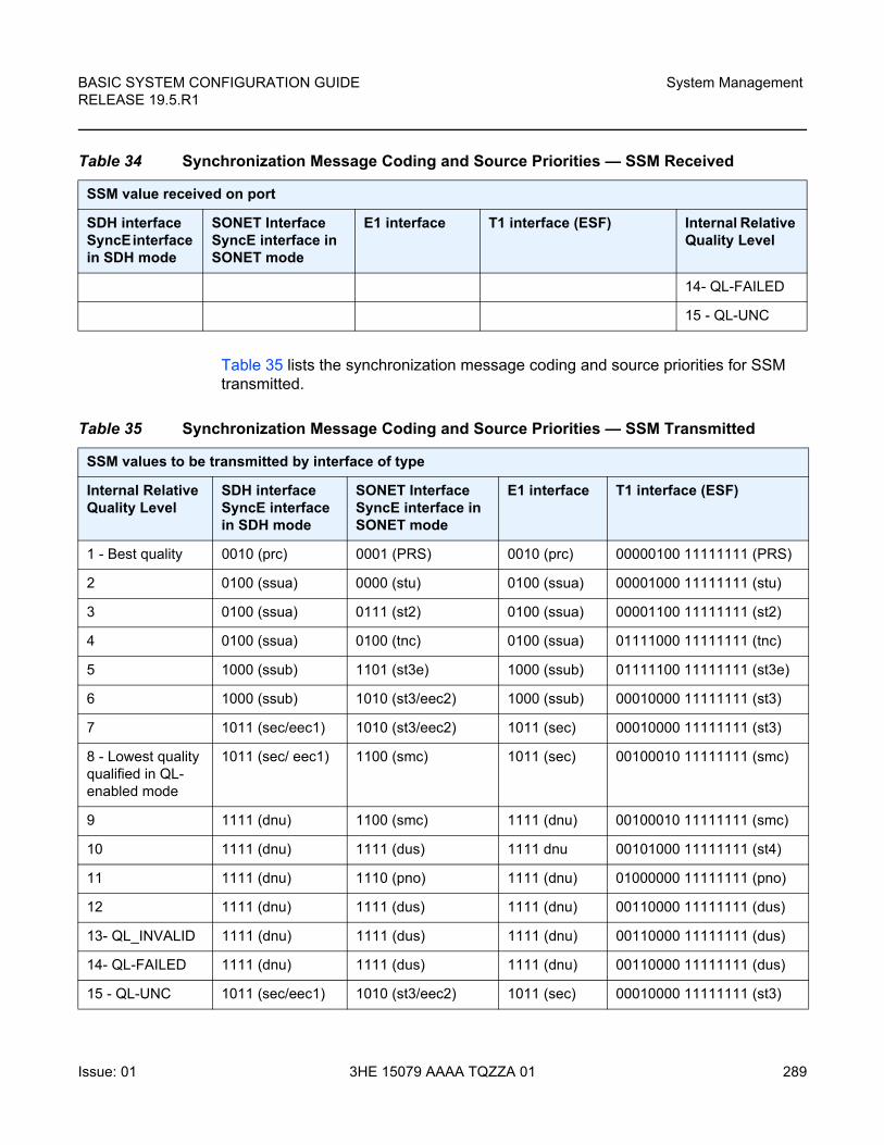
BASIC SYSTEM CONFIGURATION GUIDE RELEASE 19.5.R1
System Management
Issue: 01 3HE 15079 AAAA TQZZA 01 289
Table 35 lists the synchronization message coding and source priorities for SSM transmitted.
14- QL-FAILED
15 - QL-UNC
Table 34 Synchronization Message Coding and Source Priorities — SSM Received
SSM value received on port
SDH interface SyncE interface in SDH mode
SONET InterfaceSyncE interface in SONET mode
E1 interface T1 interface (ESF) Internal Relative Quality Level
Table 35 Synchronization Message Coding and Source Priorities — SSM Transmitted
SSM values to be transmitted by interface of type
Internal Relative Quality Level
SDH interface SyncE interface in SDH mode
SONET InterfaceSyncE interface in SONET mode
E1 interface T1 interface (ESF)
1 - Best quality 0010 (prc) 0001 (PRS) 0010 (prc) 00000100 11111111 (PRS)
2 0100 (ssua) 0000 (stu) 0100 (ssua) 00001000 11111111 (stu)
3 0100 (ssua) 0111 (st2) 0100 (ssua) 00001100 11111111 (st2)
4 0100 (ssua) 0100 (tnc) 0100 (ssua) 01111000 11111111 (tnc)
5 1000 (ssub) 1101 (st3e) 1000 (ssub) 01111100 11111111 (st3e)
6 1000 (ssub) 1010 (st3/eec2) 1000 (ssub) 00010000 11111111 (st3)
7 1011 (sec/eec1) 1010 (st3/eec2) 1011 (sec) 00010000 11111111 (st3)
8 - Lowest quality qualified in QL-enabled mode
1011 (sec/ eec1) 1100 (smc) 1011 (sec) 00100010 11111111 (smc)
9 1111 (dnu) 1100 (smc) 1111 (dnu) 00100010 11111111 (smc)
10 1111 (dnu) 1111 (dus) 1111 dnu 00101000 11111111 (st4)
11 1111 (dnu) 1110 (pno) 1111 (dnu) 01000000 11111111 (pno)
12 1111 (dnu) 1111 (dus) 1111 (dnu) 00110000 11111111 (dus)
13- QL_INVALID 1111 (dnu) 1111 (dus) 1111 (dnu) 00110000 11111111 (dus)
14- QL-FAILED 1111 (dnu) 1111 (dus) 1111 (dnu) 00110000 11111111 (dus)
15 - QL-UNC 1011 (sec/eec1) 1010 (st3/eec2) 1011 (sec) 00010000 11111111 (st3)
System Management
290
BASIC SYSTEM CONFIGURATION GUIDERELEASE 19.5.R1
3HE 15079 AAAA TQZZA 01 Issue: 01
7.4.6 Advanced G.781 Features
The central clock of the node supports several advanced features of the G.781 standard. These include the specification of a minimum acceptable QL value for the input references, the specification of a minimum acceptable QL value for the BITS output port, the ability to squelch the BITS output signal, and the specification of a Wait To Restore timer for input references. These features allow for more options in the management of the synchronization topology.
7.4.7 IEEE 1588v2 PTP
Precision Time Protocol (PTP) is a timing-over-packet protocol defined in the IEEE 1588v2 standard 1588 PTP 2008. Support for PTP is dependent on both platform and software release; see the SR OS 19.x.Rx Software Release Notes for applicability.
PTP may be deployed as an alternative timing-over-packet option to ACR. PTP provides the capability to synchronize network elements to a Stratum-1 clock or primary reference clock (PRC) traceable frequency source over a network that may or may not be PTP-aware. PTP has several advantages over ACR. It is a standards-based protocol, has lower bandwidth requirements, can transport both frequency and time, and can potentially provide better performance.
The PTP functionality has dependencies on hardware components in the applicable platform. Refer to the SR OS 19.x.Rx Software Release Notes for details.
Support is provided for an ordinary clock in slave or master mode or a boundary clock. When configured as an ordinary clock master, PTP can only be used for the distribution of a frequency reference, not a time reference. The boundary clock and ordinary clock slave can be used for both frequency and time distribution.
The ordinary clock master, ordinary clock slave, and boundary clock communicate with neighboring IEEE 1588v2 clocks. These neighbor clocks can be ordinary clock masters, ordinary clock slaves, or boundary clocks. The communication can be based on either unicast IPv4 sessions transported through IP interfaces or multicast Ethernet transported through Ethernet ports.
Note: When the internal Quality level is in the range of 9 through 14, the output codes shown in Table 35, only appear if QL selection is disabled. If ql-selection is enabled, then all of these internal states are changed to internal state 15 (Holdover) and the ssm value generated reflects the holdover quality of the internal clock.
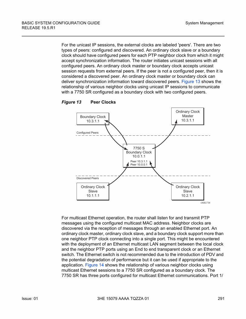
BASIC SYSTEM CONFIGURATION GUIDE RELEASE 19.5.R1
System Management
Issue: 01 3HE 15079 AAAA TQZZA 01 291
For the unicast IP sessions, the external clocks are labeled 'peers'. There are two types of peers: configured and discovered. An ordinary clock slave or a boundary clock should have configured peers for each PTP neighbor clock from which it might accept synchronization information. The router initiates unicast sessions with all configured peers. An ordinary clock master or boundary clock accepts unicast session requests from external peers. If the peer is not a configured peer, then it is considered a discovered peer. An ordinary clock master or boundary clock can deliver synchronization information toward discovered peers. Figure 13 shows the relationship of various neighbor clocks using unicast IP sessions to communicate with a 7750 SR configured as a boundary clock with two configured peers.
Figure 13 Peer Clocks
For multicast Ethernet operation, the router shall listen for and transmit PTP messages using the configured multicast MAC address. Neighbor clocks are discovered via the reception of messages through an enabled Ethernet port. An ordinary clock master, ordinary clock slave, and a boundary clock support more than one neighbor PTP clock connecting into a single port. This might be encountered with the deployment of an Ethernet multicast LAN segment between the local clock and the neighbor PTP ports using an End to end transparent clock or an Ethernet switch. The Ethernet switch is not recommended due to the introduction of PDV and the potential degradation of performance but it can be used if appropriate to the application. Figure 14 shows the relationship of various neighbor clocks using multicast Ethernet sessions to a 7750 SR configured as a boundary clock. The 7750 SR has three ports configured for multicast Ethernet communications. Port 1/
Boundary Clock10.3.1.1
Ordinary ClockSlave
10.1.1.1
Ordinary ClockMaster
10.3.1.1
Ordinary ClockSlave
10.2.1.1
7750 SBoundary Clock
10.0.1.1Peer 10.3.1.1Peer 10.0.0.1
Configured Peers
Discovered Peers
OSSG736
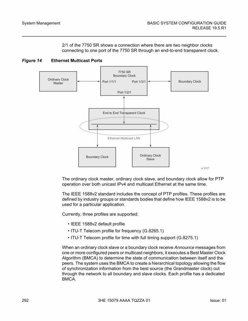
System Management
292
BASIC SYSTEM CONFIGURATION GUIDERELEASE 19.5.R1
3HE 15079 AAAA TQZZA 01 Issue: 01
2/1 of the 7750 SR shows a connection where there are two neighbor clocks connecting to one port of the 7750 SR through an end-to-end transparent clock.
Figure 14 Ethernet Multicast Ports
The ordinary clock master, ordinary clock slave, and boundary clock allow for PTP operation over both unicast IPv4 and multicast Ethernet at the same time.
The IEEE 1588v2 standard includes the concept of PTP profiles. These profiles are defined by industry groups or standards bodies that define how IEEE 1588v2 is to be used for a particular application.
Currently, three profiles are supported:
• IEEE 1588v2 default profile
• ITU-T Telecom profile for frequency (G.8265.1)
• ITU-T Telecom profile for time with full timing support (G.8275.1)
When an ordinary clock slave or a boundary clock receive Announce messages from one or more configured peers or multicast neighbors, it executes a Best Master Clock Algorithm (BMCA) to determine the state of communication between itself and the peers. The system uses the BMCA to create a hierarchical topology allowing the flow of synchronization information from the best source (the Grandmaster clock) out through the network to all boundary and slave clocks. Each profile has a dedicated BMCA.
al_0527
7750 SRBoundary Clock
Port 1/2/1
Port 1/1/1 Port 1/3/1
Boundary Clock
Boundary Clock
Ordinary ClockSlave
Ethernet Multicast LAN
Ordinary ClockMaster
End to End Transparent Clock
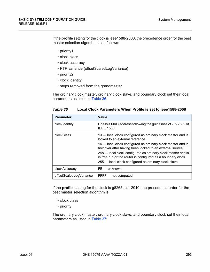
BASIC SYSTEM CONFIGURATION GUIDE RELEASE 19.5.R1
System Management
Issue: 01 3HE 15079 AAAA TQZZA 01 293
If the profile setting for the clock is ieee1588-2008, the precedence order for the best master selection algorithm is as follows:
• priority1
• clock class
• clock accuracy
• PTP variance (offsetScaledLogVariance)
• priority2
• clock identity
• steps removed from the grandmaster
The ordinary clock master, ordinary clock slave, and boundary clock set their local parameters as listed in Table 36:
If the profile setting for the clock is g8265dot1-2010, the precedence order for the best master selection algorithm is:
• clock class
• priority
The ordinary clock master, ordinary clock slave, and boundary clock set their local parameters as listed in Table 37:
Table 36 Local Clock Parameters When Profile is set to ieee1588-2008
Parameter Value
clockIdentity Chassis MAC address following the guidelines of 7.5.2.2.2 of IEEE 1588
clockClass 13 — local clock configured as ordinary clock master and is locked to an external reference
14 — local clock configured as ordinary clock master and in holdover after having been locked to an external source
248 — local clock configured as ordinary clock master and is in free run or the router is configured as a boundary clock
255 — local clock configured as ordinary clock slave
clockAccuracy FE — unknown
offsetScaledLogVariance FFFF — not computed
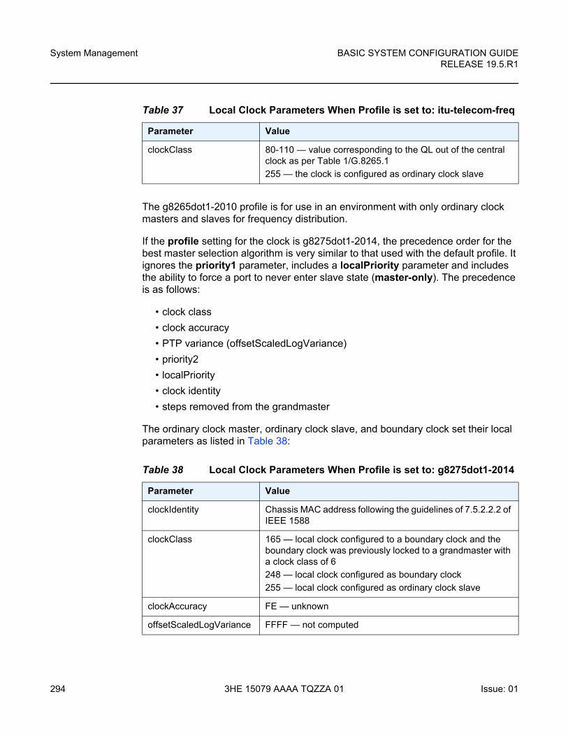
System Management
294
BASIC SYSTEM CONFIGURATION GUIDERELEASE 19.5.R1
3HE 15079 AAAA TQZZA 01 Issue: 01
The g8265dot1-2010 profile is for use in an environment with only ordinary clock masters and slaves for frequency distribution.
If the profile setting for the clock is g8275dot1-2014, the precedence order for the best master selection algorithm is very similar to that used with the default profile. It ignores the priority1 parameter, includes a localPriority parameter and includes the ability to force a port to never enter slave state (master-only). The precedence is as follows:
• clock class
• clock accuracy
• PTP variance (offsetScaledLogVariance)
• priority2
• localPriority
• clock identity
• steps removed from the grandmaster
The ordinary clock master, ordinary clock slave, and boundary clock set their local parameters as listed in Table 38:
Table 37 Local Clock Parameters When Profile is set to: itu-telecom-freq
Parameter Value
clockClass 80-110 — value corresponding to the QL out of the central clock as per Table 1/G.8265.1
255 — the clock is configured as ordinary clock slave
Table 38 Local Clock Parameters When Profile is set to: g8275dot1-2014
Parameter Value
clockIdentity Chassis MAC address following the guidelines of 7.5.2.2.2 of IEEE 1588
clockClass 165 — local clock configured to a boundary clock and the boundary clock was previously locked to a grandmaster with a clock class of 6
248 — local clock configured as boundary clock
255 — local clock configured as ordinary clock slave
clockAccuracy FE — unknown
offsetScaledLogVariance FFFF — not computed
BASIC SYSTEM CONFIGURATION GUIDE RELEASE 19.5.R1
System Management
Issue: 01 3HE 15079 AAAA TQZZA 01 295
There is a limit on the number of external PTP clocks to which the ordinary clock slave or boundary clock requests unicast service (# configured peers) and also a limit to the number of external PTP clocks to which the ordinary clock master or boundary clock grants unicast service (# discovered peers). An association where the boundary clock has a symmetric relationship with another boundary clock (in other words, they both have the other as a configured peer) consumes a request and a grant unicast service in each router.
The number of configured Ethernet ports is not restricted.
There are limits to the maximum transmitted and received event message rates supported in the router. Each unicast IP service established consumes a portion of one of the unicast message limits. Once either limit is reached, additional unicast service requests are refused by sending a grant response with zero in the duration field.
Refer to the scaling guide for the appropriate release for the specific unicast message limits related to PTP.
Multicast messages are not considered when validating the unicast message limit. When multicast messaging on Ethernet ports is enabled, the PTP load needs to be monitored to ensure the load does not exceed the capabilities. There are several commands that can be used for this monitoring:
• The show system cpu command identifies the load of the PTP software process. If the capacity usage reaches 100%, the PTP software process on the router is at its limit of transmitting and/or receiving PTP packets.
Because the user cannot control the amount of PTP messages being received over the Ethernet ports, the statistics commands can be used to identify the source of the message load:
• show system ptp statistics has aggregate packet rates
• show system ptp port and show system ptp port port-id [detail] display received packet rates
Figure 15 shows the unicast negotiation procedure performed between a slave and a peer clock that is selected to be the master clock. The slave clock requests Announce messages from all peer clocks but only request Sync and Delay_Resp messages from the clock selected to be the master clock.
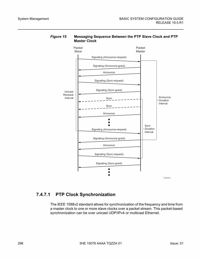
System Management
296
BASIC SYSTEM CONFIGURATION GUIDERELEASE 19.5.R1
3HE 15079 AAAA TQZZA 01 Issue: 01
Figure 15 Messaging Sequence Between the PTP Slave Clock and PTP Master Clock
7.4.7.1 PTP Clock Synchronization
The IEEE 1588v2 standard allows for synchronization of the frequency and time from a master clock to one or more slave clocks over a packet stream. This packet-based synchronization can be over unicast UDP/IPv4 or multicast Ethernet.
OSSG666
AnnounceDurationInterval
SyncDurationInterval
Signaling (Announce-grant)
Signaling (Announce-grant)
Signaling (Sync-grant)
Signaling (Sync-grant)
Sync
Sync
Announce
Announce
Announce
Signaling (Announce-request)
Signaling (Sync-request)
Signaling (Sync-request)
Signaling (Announce-request)
PacketMaster
PacketSlave
UnicastRenewal
Interval
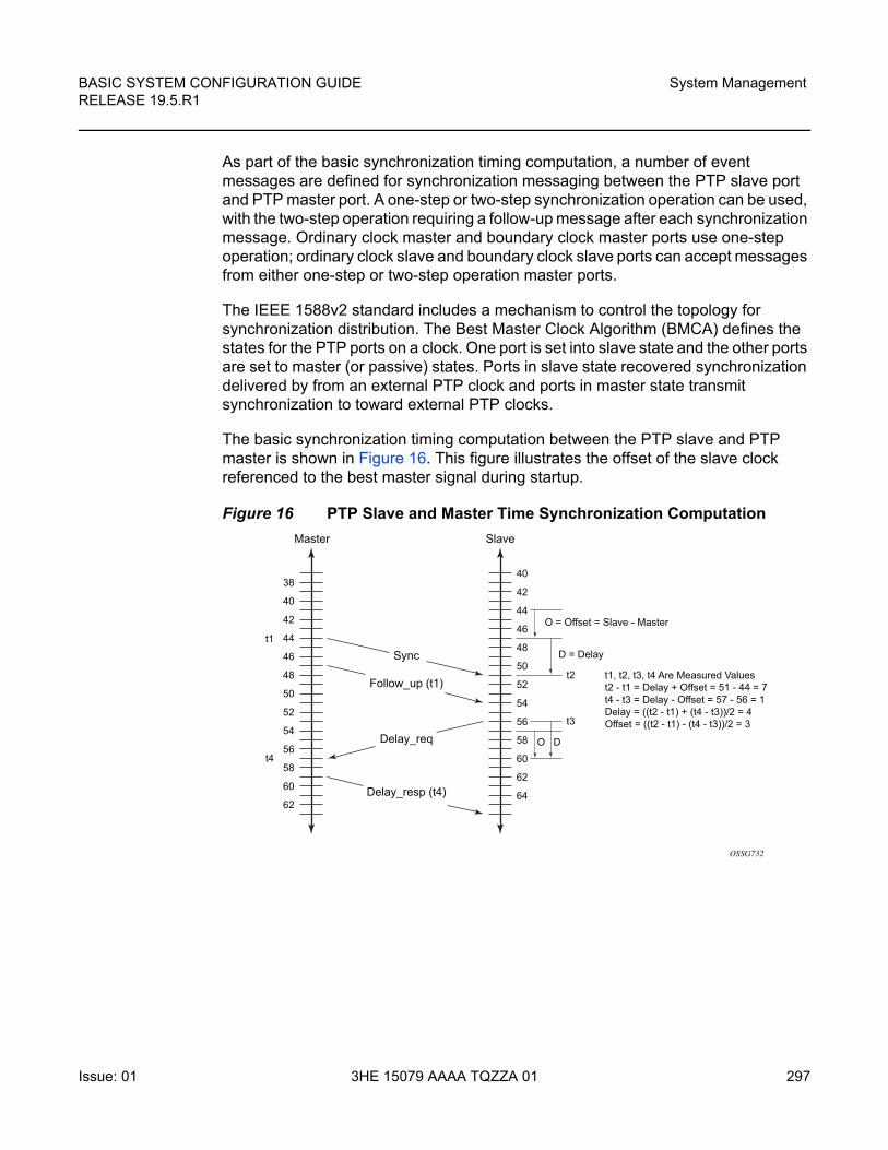
BASIC SYSTEM CONFIGURATION GUIDE RELEASE 19.5.R1
System Management
Issue: 01 3HE 15079 AAAA TQZZA 01 297
As part of the basic synchronization timing computation, a number of event messages are defined for synchronization messaging between the PTP slave port and PTP master port. A one-step or two-step synchronization operation can be used, with the two-step operation requiring a follow-up message after each synchronization message. Ordinary clock master and boundary clock master ports use one-step operation; ordinary clock slave and boundary clock slave ports can accept messages from either one-step or two-step operation master ports.
The IEEE 1588v2 standard includes a mechanism to control the topology for synchronization distribution. The Best Master Clock Algorithm (BMCA) defines the states for the PTP ports on a clock. One port is set into slave state and the other ports are set to master (or passive) states. Ports in slave state recovered synchronization delivered by from an external PTP clock and ports in master state transmit synchronization to toward external PTP clocks.
The basic synchronization timing computation between the PTP slave and PTP master is shown in Figure 16. This figure illustrates the offset of the slave clock referenced to the best master signal during startup.
Figure 16 PTP Slave and Master Time Synchronization Computation
Master Slave
Sync
Follow_up (t1)
Delay_req
Delay_resp (t4)
38
40
42
44
46
48
50
52
54
56
58
60
62
40
42
44
46
48
50
52
54
56
58
60
62
64
O = Offset = Slave - Master
t1, t2, t3, t4 Are Measured Valuest2 - t1 = Delay + Offset = 51 - 44 = 7t4 - t3 = Delay - Offset = 57 - 56 = 1Delay = ((t2 - t1) + (t4 - t3))/2 = 4Offset = ((t2 - t1) - (t4 - t3))/2 = 3
D = Delayt1
t4
t2
O D
OSSG732
t3
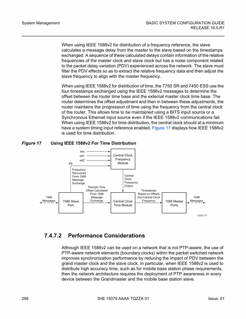
System Management
298
BASIC SYSTEM CONFIGURATION GUIDERELEASE 19.5.R1
3HE 15079 AAAA TQZZA 01 Issue: 01
When using IEEE 1588v2 for distribution of a frequency reference, the slave calculates a message delay from the master to the slave based on the timestamps exchanged. A sequence of these calculated delays contain information of the relative frequencies of the master clock and slave clock but has a noise component related to the packet delay variation (PDV) experienced across the network. The slave must filter the PDV effects so as to extract the relative frequency data and then adjust the slave frequency to align with the master frequency.
When using IEEE 1588v2 for distribution of time, the 7750 SR and 7450 ESS use the four timestamps exchanged using the IEEE 1588v2 messages to determine the offset between the router time base and the external master clock time base. The router determines the offset adjustment and then in between these adjustments, the router maintains the progression of time using the frequency from the central clock of the router. This allows time to be maintained using a BITS input source or a Synchronous Ethernet input source even if the IEEE 1588v2 communications fail. When using IEEE 1588v2 for time distribution, the central clock should at a minimum have a system timing input reference enabled. Figure 17 displays how IEEE 1588v2 is used for time distribution.
Figure 17 Using IEEE 1588v2 For Time Distribution
7.4.7.2 Performance Considerations
Although IEEE 1588v2 can be used on a network that is not PTP-aware, the use of PTP-aware network elements (boundary clocks) within the packet switched network improves synchronization performance by reducing the impact of PDV between the grand master clock and the slave clock. In particular, when IEEE 1588v2 is used to distribute high accuracy time, such as for mobile base station phase requirements, then the network architecture requires the deployment of PTP awareness in every device between the Grandmaster and the mobile base station slave.
Central ClockFrequency
Module
bitsref1ref2
ptp
FrequencyRecoveredFrom 1588MessageExchange
Periodic TimeOffset Calculated
From 1588MessageExchange
TimestampsBased on OffsetsAnd Central Clock
Frequency1588
Messages1588
Messages
CentralClockFrequencyOutput
Central ClockTime Module
1588 SlavePort
1588 MasterPorts
OSSG733
BASIC SYSTEM CONFIGURATION GUIDE RELEASE 19.5.R1
System Management
Issue: 01 3HE 15079 AAAA TQZZA 01 299
In addition, performance is also improved by the removal of any PDV caused by internal queuing within the boundary clock or slave clock. This is accomplished with hardware that is capable of detecting and time stamping the IEEE 1588v2 packets at the Ethernet interface. This capability is referred to as port-based time stamping.
7.4.7.2.1 Port-Based Timestamping of PTP Messages
For optimal performance, the 1588 packets should be time-stamped at the ingress and egress. This avoids any possible PDV that might be introduced between the port and the CPM. The ability to timestamp in the interface hardware is provided on a subset of the IMM and MDA assemblies of the routers. Refer to the SR OS 19.x.Rx Software Release Notes for the complete list.
In order for this to operate, the CPM, IOM, IMM, and MDAs must be running firmware that supports this capability. The CPM firmware upgrade occurs automatically when the CPM card software is updated. Since upgrading of IOM, IMM, and MDA firmware is service impacting, this upgrade is not performed automatically on a soft reset of the MDA. The IOM/IMM firmware is upgraded when the IOM/IMM card is hard reset. The MDA firmware is programmed during system initialization, when the MDA is inserted, or when the MDA is hard reset via a clear mda or clear card command. However, when an MDA is soft reset via either a clear card soft command or during a major ISSU, the MDA firmware is not updated.
Port-based timestamping of 1588 packets cannot be used at the same time for Ethernet encapsulation and IP encapsulation on a given port. This means that PTP cannot be configured on an Ethernet port if ptp-hw-assist is already configured on a L3 interface associated with that port. Similarly, ptp-hw-assist cannot be configured on a L3 interface if its associated port is already configured as a PTP port.
7.4.7.3 PTP Capabilities
For each PTP message type to be exchanged between the router and an external 1588 clock, a Unicast Session must be established using the Unicast Negotiation procedures. The router allows configuration of the message rate to be requested from external 1588 clocks. The router also supports a range of message rates that it grants to requests received from the external 1588 clocks.
Table 39 describes the ranges for both the rates that the router can request and grant.
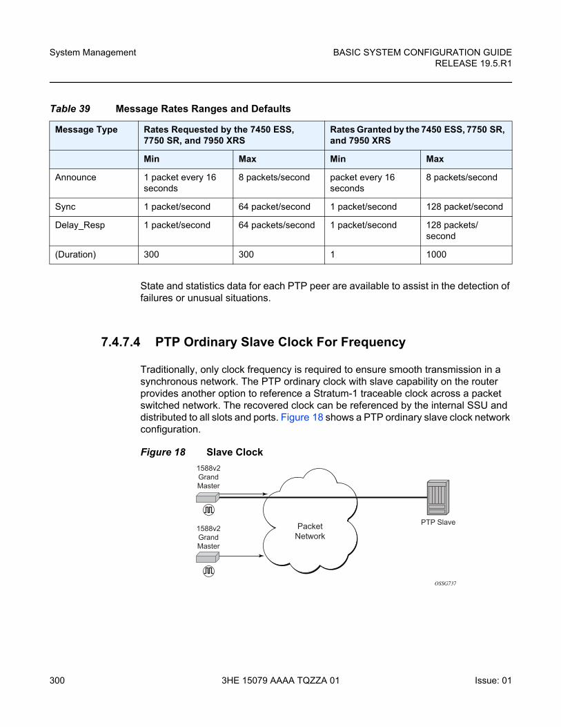
System Management
300
BASIC SYSTEM CONFIGURATION GUIDERELEASE 19.5.R1
3HE 15079 AAAA TQZZA 01 Issue: 01
State and statistics data for each PTP peer are available to assist in the detection of failures or unusual situations.
7.4.7.4 PTP Ordinary Slave Clock For Frequency
Traditionally, only clock frequency is required to ensure smooth transmission in a synchronous network. The PTP ordinary clock with slave capability on the router provides another option to reference a Stratum-1 traceable clock across a packet switched network. The recovered clock can be referenced by the internal SSU and distributed to all slots and ports. Figure 18 shows a PTP ordinary slave clock network configuration.
Figure 18 Slave Clock
Table 39 Message Rates Ranges and Defaults
Message Type Rates Requested by the 7450 ESS, 7750 SR, and 7950 XRS
Rates Granted by the 7450 ESS, 7750 SR, and 7950 XRS
Min Max Min Max
Announce 1 packet every 16 seconds
8 packets/second packet every 16 seconds
8 packets/second
Sync 1 packet/second 64 packet/second 1 packet/second 128 packet/second
Delay_Resp 1 packet/second 64 packets/second 1 packet/second 128 packets/second
(Duration) 300 300 1 1000
PacketNetwork
1588v2GrandMaster
PTP Slave1588v2GrandMaster
OSSG737
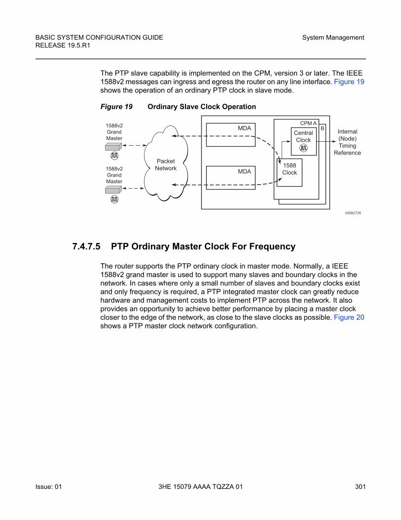
BASIC SYSTEM CONFIGURATION GUIDE RELEASE 19.5.R1
System Management
Issue: 01 3HE 15079 AAAA TQZZA 01 301
The PTP slave capability is implemented on the CPM, version 3 or later. The IEEE 1588v2 messages can ingress and egress the router on any line interface. Figure 19 shows the operation of an ordinary PTP clock in slave mode.
Figure 19 Ordinary Slave Clock Operation
7.4.7.5 PTP Ordinary Master Clock For Frequency
The router supports the PTP ordinary clock in master mode. Normally, a IEEE 1588v2 grand master is used to support many slaves and boundary clocks in the network. In cases where only a small number of slaves and boundary clocks exist and only frequency is required, a PTP integrated master clock can greatly reduce hardware and management costs to implement PTP across the network. It also provides an opportunity to achieve better performance by placing a master clock closer to the edge of the network, as close to the slave clocks as possible. Figure 20 shows a PTP master clock network configuration.
PacketNetwork
MDACentralClock
1588Clock
Internal(Node)Timing
Reference
MDA
1588v2GrandMaster
CPM AB
1588v2GrandMaster
OSSG738
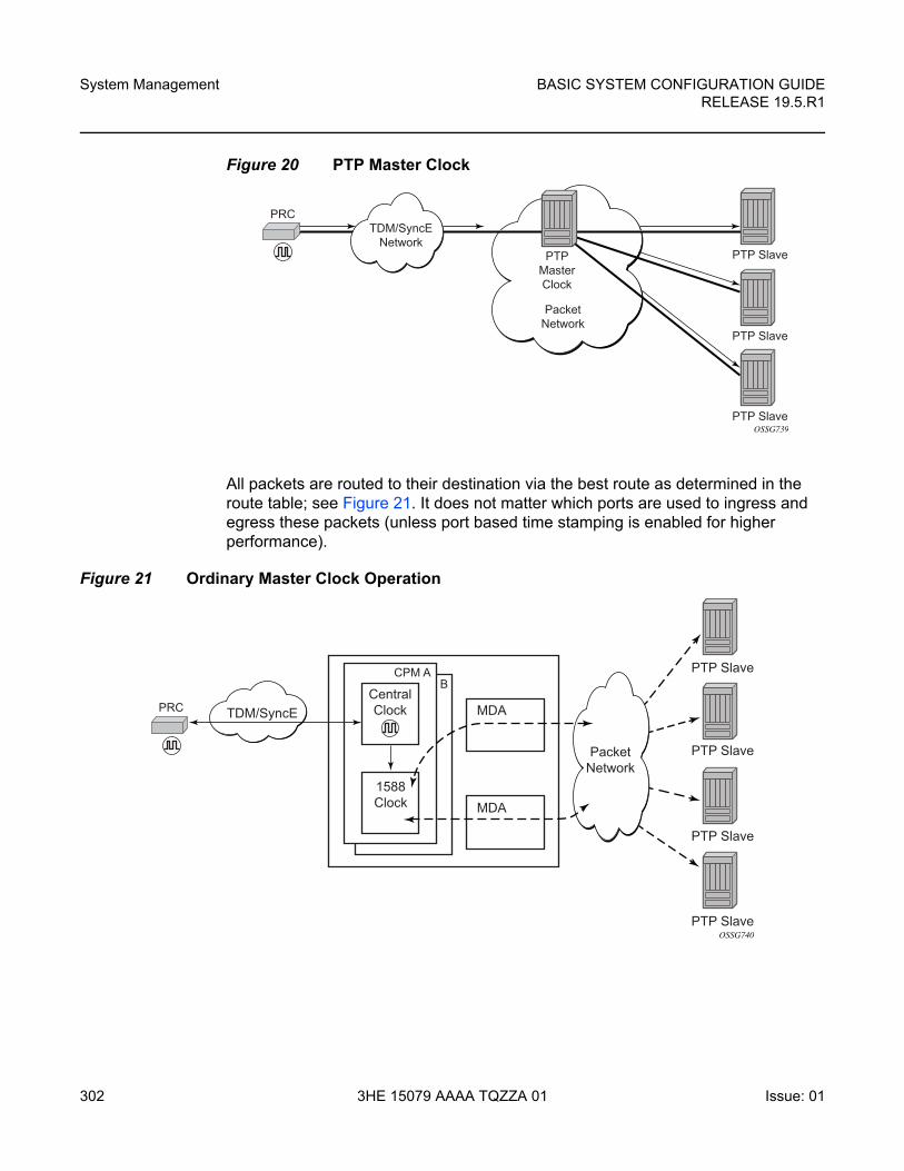
System Management
302
BASIC SYSTEM CONFIGURATION GUIDERELEASE 19.5.R1
3HE 15079 AAAA TQZZA 01 Issue: 01
Figure 20 PTP Master Clock
All packets are routed to their destination via the best route as determined in the route table; see Figure 21. It does not matter which ports are used to ingress and egress these packets (unless port based time stamping is enabled for higher performance).
Figure 21 Ordinary Master Clock Operation
PacketNetwork
TDM/SyncENetwork
PRC
PTP Slave
PTP Slave
PTP Slave
PTPMasterClock
OSSG739
TDM/SyncE MDACentralClock
1588Clock
PTP Slave
PTP Slave
PTP Slave
PTP Slave
MDA
PRC
CPM AB
OSSG740
PacketNetwork
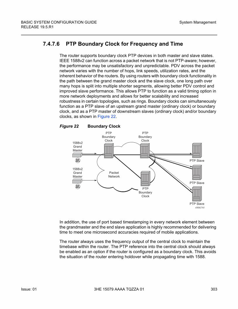
BASIC SYSTEM CONFIGURATION GUIDE RELEASE 19.5.R1
System Management
Issue: 01 3HE 15079 AAAA TQZZA 01 303
7.4.7.6 PTP Boundary Clock for Frequency and Time
The router supports boundary clock PTP devices in both master and slave states. IEEE 1588v2 can function across a packet network that is not PTP-aware; however, the performance may be unsatisfactory and unpredictable. PDV across the packet network varies with the number of hops, link speeds, utilization rates, and the inherent behavior of the routers. By using routers with boundary clock functionality in the path between the grand master clock and the slave clock, one long path over many hops is split into multiple shorter segments, allowing better PDV control and improved slave performance. This allows PTP to function as a valid timing option in more network deployments and allows for better scalability and increased robustness in certain topologies, such as rings. Boundary clocks can simultaneously function as a PTP slave of an upstream grand master (ordinary clock) or boundary clock, and as a PTP master of downstream slaves (ordinary clock) and/or boundary clocks, as shown in Figure 22.
Figure 22 Boundary Clock
In addition, the use of port based timestamping in every network element between the grandmaster and the end slave application is highly recommended for delivering time to meet one microsecond accuracies required of mobile applications.
The router always uses the frequency output of the central clock to maintain the timebase within the router. The PTP reference into the central clock should always be enabled as an option if the router is configured as a boundary clock. This avoids the situation of the router entering holdover while propagating time with 1588.
PacketNetwork
1588v2GrandMaster
PTP Slave
PTP Slave
PTP Slave
PTPBoundary
Clock
PTPBoundary
Clock
PTPBoundary
Clock
OSSG741
1588v2GrandMaster
System Management
304
BASIC SYSTEM CONFIGURATION GUIDERELEASE 19.5.R1
3HE 15079 AAAA TQZZA 01 Issue: 01
7.4.7.7 PTP Clock Redundancy
The PTP module in the router exists on the CPM. The PTP module on the standby CPM is kept synchronized to the PTP module on the active CPM. All sessions with external PTP peers are maintained over a CPM switchover.
7.4.7.8 PTP Time for System Time and OAM Time
PTP has the potential to provide much more accurate time into the router than can be obtained with NTP. This PTP recovered time can be made available for system time and OAM packet time stamping to improve the accuracies of logged events and OAM delay measurements. The mechanism to activate PTP as the source for these internal time bases is to allocate PTP as a local server into NTP. This permits the NTP time recovery to use PTP as a source for time and then distribute it within the router to system time and the OAM process. This activation also affects the operation of the NTP server within the SR OS. The PTP server appears as NTP stratum 0 server and therefore the SR OS advertises itself as an NTP Stratum 1 server to external peers and clients. This activation may impact the NTP topology.
7.4.7.9 PTP within Routing Instances
In addition to Base routing and IES services, PTP messaging is supported within VPRN services on the 7750 SR and 7950 XRS platforms. The 7450 ESS supports PTP in the Base routing instance. PTP messaging is not supported through the management router instance. Only one PTP clock exists within the router and it is shared by all routing instances that have access. Only one routing instance may have configured peers and only this routing context can receive the time or frequency reference into the router (contain a PTP port in Slave state). The dynamic peers are shared across all routing instances; if it is desired to control the number of dynamic peers that can be consumed by a given routing instance then this must be configured for that routing instance.
BASIC SYSTEM CONFIGURATION GUIDE RELEASE 19.5.R1
System Management
Issue: 01 3HE 15079 AAAA TQZZA 01 305
7.5 System-Wide ATM Parameters
On the 7750 SR, the ATM ping OAM loopback feature can be enabled on an ATM SAP for a period of time configured through the interval and the send-count parameters. When the ATM SAP terminates on IES or VPRN services, a failure of the loopback state machine does not bring down the Layer 3 interface. Only receiving AIS/RDI OAM cells or entering the AIS/RDI state brings down the Layer 3 interface.
The ATM ping OAM loopback feature can also be enabled on a continuous basis on an ATM SAP terminating on IES or VPRN services. When the loopback state machine fails, the Layer 3 interface is brought down.
The ATM OAM loopback parameters must first be enabled and configured in the config>system>atm>oam context, and then enabled in the IES or VPRN service interface SAP atm oam context.
Refer to the 7450 ESS, 7750 SR, 7950 XRS, and VSR Layer 3 Services Guide: IES and VPRN for further information.
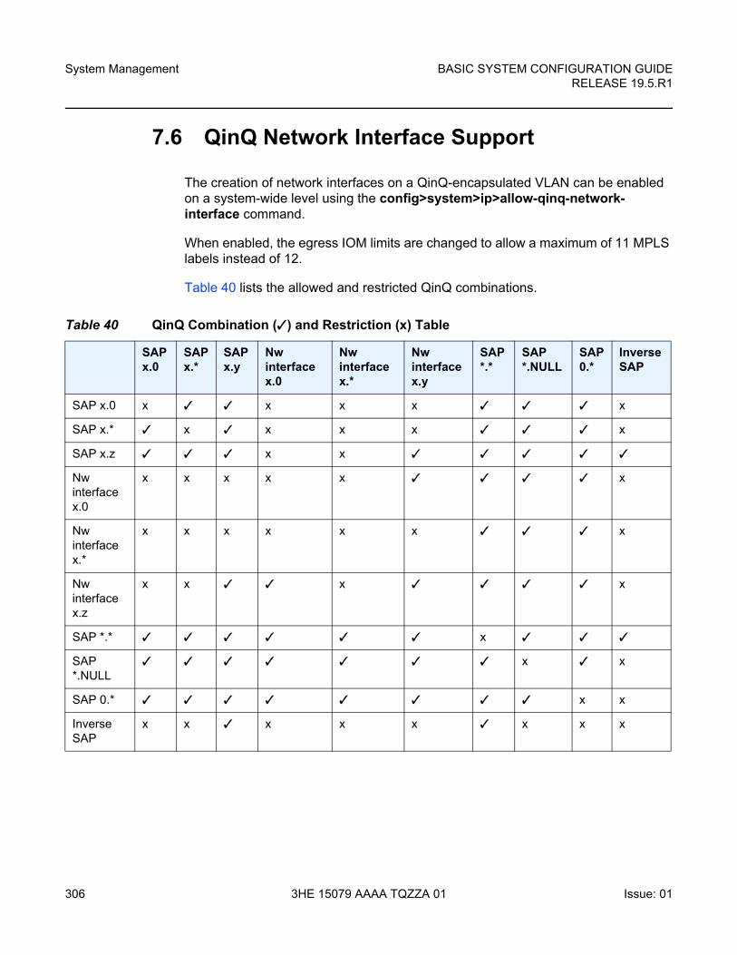
System Management
306
BASIC SYSTEM CONFIGURATION GUIDERELEASE 19.5.R1
3HE 15079 AAAA TQZZA 01 Issue: 01
7.6 QinQ Network Interface Support
The creation of network interfaces on a QinQ-encapsulated VLAN can be enabled on a system-wide level using the config>system>ip>allow-qinq-network-interface command.
When enabled, the egress IOM limits are changed to allow a maximum of 11 MPLS labels instead of 12.
Table 40 lists the allowed and restricted QinQ combinations.
Table 40 QinQ Combination (✓) and Restriction (x) Table
SAP x.0
SAP x.*
SAP x.y
Nw interface x.0
Nw interface x.*
Nw interface x.y
SAP *.*
SAP *.NULL
SAP 0.*
Inverse SAP
SAP x.0 x ✓ ✓ x x x ✓ ✓ ✓ x
SAP x.* ✓ x ✓ x x x ✓ ✓ ✓ x
SAP x.z ✓ ✓ ✓ x x ✓ ✓ ✓ ✓ ✓
Nw interface x.0
x x x x x ✓ ✓ ✓ ✓ x
Nw interface x.*
x x x x x x ✓ ✓ ✓ x
Nw interface x.z
x x ✓ ✓ x ✓ ✓ ✓ ✓ x
SAP *.* ✓ ✓ ✓ ✓ ✓ ✓ x ✓ ✓ ✓
SAP *.NULL
✓ ✓ ✓ ✓ ✓ ✓ ✓ x ✓ x
SAP 0.* ✓ ✓ ✓ ✓ ✓ ✓ ✓ ✓ x x
Inverse SAP
x x ✓ x x x ✓ x x x
BASIC SYSTEM CONFIGURATION GUIDE RELEASE 19.5.R1
System Management
Issue: 01 3HE 15079 AAAA TQZZA 01 307
7.7 Link Layer Discovery Protocol (LLDP)
The IEEE 802.1ab Link Layer Discovery Protocol (LLDP) is a unidirectional protocol that uses the MAC layer to transmit specific information related to the capabilities and status of the local device. Separately from the transmit direction, the LLDP agent can also receive the same kind of information for a remote device which is stored in the related MIBs.
LLDP itself does not contain a mechanism for soliciting specific information from other LLDP agents, nor does it provide a specific means of confirming the receipt of information. LLDP allows the transmitter and the receiver to be separately enabled, making it possible to configure an implementation so the local LLDP agent can either transmit only or receive only, or can transmit and receive LLDP information.
The information fields in each LLDP frame are contained in a LLDP Data Unit (LLDPDU) as a sequence of variable length information elements, that each include type, length, and value fields (known as TLVs), where:
• Type identifies what kind of information is being sent.
• Length indicates the length of the information string in octets.
• Value is the actual information that needs to be sent (for example, a binary bit map or an alphanumeric string that can contain one or more fields).
Each LLDPDU contains four mandatory TLVs and can contain optional TLVs as selected by network management:
• Chassis ID TLV
• Port ID TLV
• Time To Live TLV
• Zero or more optional TLVs, as allowed by the maximum size of the LLDPDU
• End Of LLDPDU TLV
The chassis ID and the port ID values are concatenated to form a logical identifier that is used by the recipient to identify the sending LLDP agent/port. Both the chassis ID and port ID values can be defined in a number of convenient forms. Once selected however, the chassis ID/port ID value combination remains the same as long as the particular port remains operable.
A non-zero value in the TTL field of the time-to-live TLV tells the receiving LLDP agent how long all information pertaining to this LLDPDU’s identifier is valid so that all the associated information can later be automatically discarded by the receiving LLDP agent if the sender fails to update it in a timely manner. A zero value indicates that any information pertaining to this LLDPDU’s identifier is to be discarded immediately.
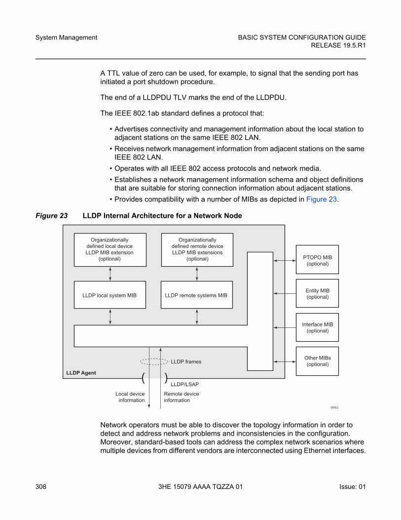
System Management
308
BASIC SYSTEM CONFIGURATION GUIDERELEASE 19.5.R1
3HE 15079 AAAA TQZZA 01 Issue: 01
A TTL value of zero can be used, for example, to signal that the sending port has initiated a port shutdown procedure.
The end of a LLDPDU TLV marks the end of the LLDPDU.
The IEEE 802.1ab standard defines a protocol that:
• Advertises connectivity and management information about the local station to adjacent stations on the same IEEE 802 LAN.
• Receives network management information from adjacent stations on the same IEEE 802 LAN.
• Operates with all IEEE 802 access protocols and network media.
• Establishes a network management information schema and object definitions that are suitable for storing connection information about adjacent stations.
• Provides compatibility with a number of MIBs as depicted in Figure 23.
Figure 23 LLDP Internal Architecture for a Network Node
Network operators must be able to discover the topology information in order to detect and address network problems and inconsistencies in the configuration. Moreover, standard-based tools can address the complex network scenarios where multiple devices from different vendors are interconnected using Ethernet interfaces.
0981
LLDP local system MIB
Organizationallydefined local deviceLLDP MIB extension
(optional)
Organizationallydefined remote deviceLLDP MIB extensions
(optional)
LLDP remote systems MIB
PTOPO MIB(optional)
Entity MIB(optional)
Interface MIB(optional)
Other MIBs(optional)LLDP frames
LLDP Agent
LLDP/LSAP
Remote deviceinformation
Local deviceinformation
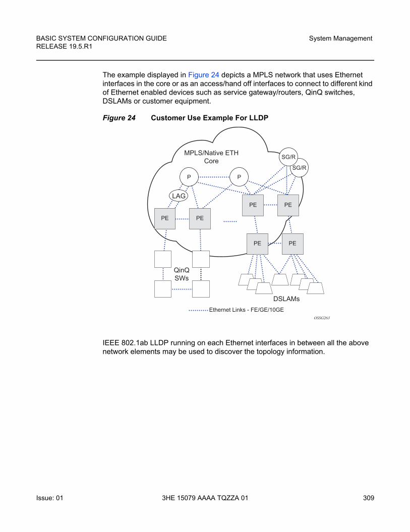
BASIC SYSTEM CONFIGURATION GUIDE RELEASE 19.5.R1
System Management
Issue: 01 3HE 15079 AAAA TQZZA 01 309
The example displayed in Figure 24 depicts a MPLS network that uses Ethernet interfaces in the core or as an access/hand off interfaces to connect to different kind of Ethernet enabled devices such as service gateway/routers, QinQ switches, DSLAMs or customer equipment.
Figure 24 Customer Use Example For LLDP
IEEE 802.1ab LLDP running on each Ethernet interfaces in between all the above network elements may be used to discover the topology information.
OSSG263
Ethernet Links - FE/GE/10GE
MPLS/Native ETHCore
LAG
QinQSWs
DSLAMs
P
PE PE
PE PE
PE PE
PSG/R
SG/R
System Management
310
BASIC SYSTEM CONFIGURATION GUIDERELEASE 19.5.R1
3HE 15079 AAAA TQZZA 01 Issue: 01
7.8 IP Hashing as an LSR
It is now possible to include IP header in the hash routine at an LSR for the purpose of spraying labeled-IPv4 and labeled-IPv6 packets over multiple equal cost paths in ECMP in an LDP LSP and/or over multiple links of a LAG group in all types of LSPs.
A couple of configurable options are supported. The first option is referred to as the Label-IP Hash option and is designated in the CLI as lbl-ip. When enabled, the hash algorithm parses down the label stack and once it hits the bottom of the stack, it checks the next nibble. If the nibble value is four or six then it assumes it is an IPv4 or IPv6 packet. The result of the hash of the label stack, along with the incoming port and system IP address, is fed into another hash along with source and destination address fields in the IP packet’s header. The second option is referred to as IP-only hash and is enabled in CLI by entering the iponly keyword. It operates the same way as the Label-IP Hash method except the hash is performed exclusively on the source and destination address fields in the IP packet header. This method supports both IPv4 and IPv6 payload and operates on packets received on an IP interface on an IOM3-XP/IMM port only.
By default, MPLS packet hashing at an LSR is based on the whole label stack, along with the incoming port and system IP address. This method is referred to as Label-Only Hash option and is enabled in CLI by entering the lbl-only keyword.
The lbl-only, lbl-ip and ip-only hashing options can be configured system-wide and can also be overridden on a per-IP-interface basis.
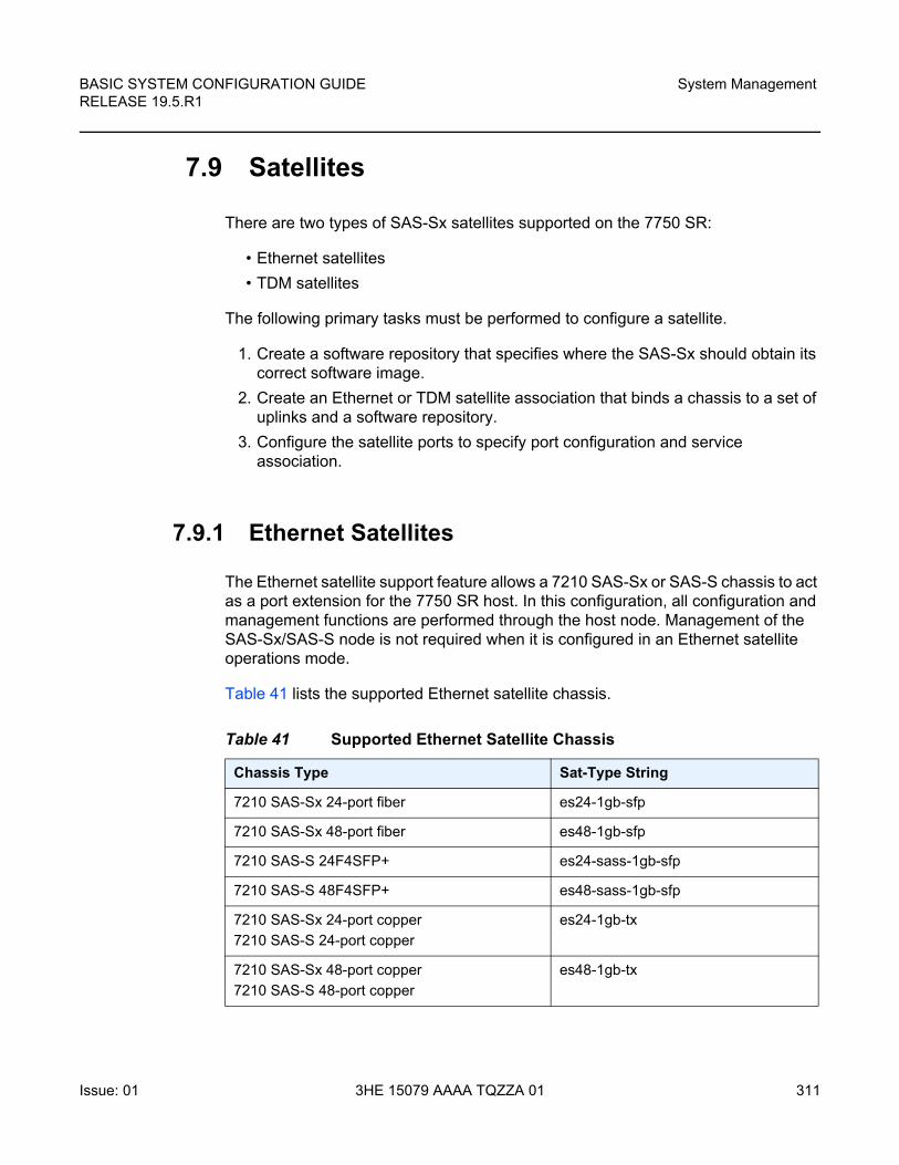
BASIC SYSTEM CONFIGURATION GUIDE RELEASE 19.5.R1
System Management
Issue: 01 3HE 15079 AAAA TQZZA 01 311
7.9 Satellites
There are two types of SAS-Sx satellites supported on the 7750 SR:
• Ethernet satellites
• TDM satellites
The following primary tasks must be performed to configure a satellite.
1. Create a software repository that specifies where the SAS-Sx should obtain its correct software image.
2. Create an Ethernet or TDM satellite association that binds a chassis to a set of uplinks and a software repository.
3. Configure the satellite ports to specify port configuration and service association.
7.9.1 Ethernet Satellites
The Ethernet satellite support feature allows a 7210 SAS-Sx or SAS-S chassis to act as a port extension for the 7750 SR host. In this configuration, all configuration and management functions are performed through the host node. Management of the SAS-Sx/SAS-S node is not required when it is configured in an Ethernet satellite operations mode.
Table 41 lists the supported Ethernet satellite chassis.
Table 41 Supported Ethernet Satellite Chassis
Chassis Type Sat-Type String
7210 SAS-Sx 24-port fiber es24-1gb-sfp
7210 SAS-Sx 48-port fiber es48-1gb-sfp
7210 SAS-S 24F4SFP+ es24-sass-1gb-sfp
7210 SAS-S 48F4SFP+ es48-sass-1gb-sfp
7210 SAS-Sx 24-port copper
7210 SAS-S 24-port copper
es24-1gb-tx
7210 SAS-Sx 48-port copper
7210 SAS-S 48-port copper
es48-1gb-tx
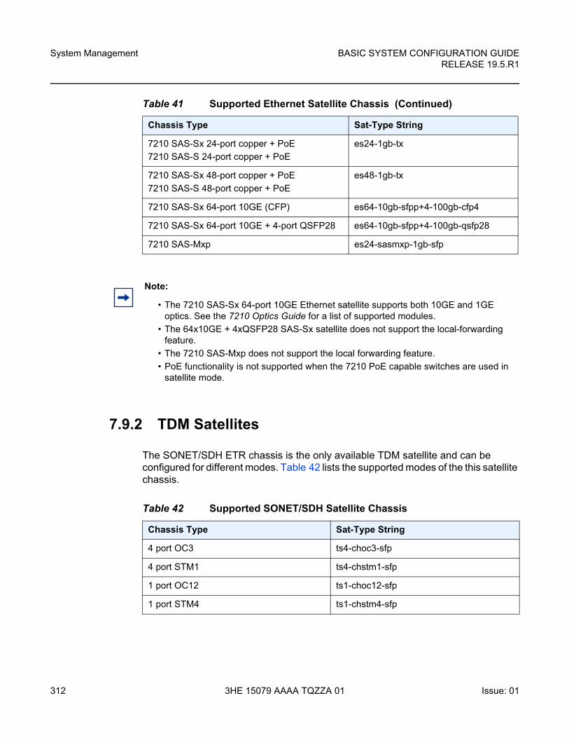
System Management
312
BASIC SYSTEM CONFIGURATION GUIDERELEASE 19.5.R1
3HE 15079 AAAA TQZZA 01 Issue: 01
7.9.2 TDM Satellites
The SONET/SDH ETR chassis is the only available TDM satellite and can be configured for different modes. Table 42 lists the supported modes of the this satellite chassis.
7210 SAS-Sx 24-port copper + PoE
7210 SAS-S 24-port copper + PoE
es24-1gb-tx
7210 SAS-Sx 48-port copper + PoE
7210 SAS-S 48-port copper + PoE
es48-1gb-tx
7210 SAS-Sx 64-port 10GE (CFP) es64-10gb-sfpp+4-100gb-cfp4
7210 SAS-Sx 64-port 10GE + 4-port QSFP28 es64-10gb-sfpp+4-100gb-qsfp28
7210 SAS-Mxp es24-sasmxp-1gb-sfp
Table 41 Supported Ethernet Satellite Chassis (Continued)
Chassis Type Sat-Type String
Note:
• The 7210 SAS-Sx 64-port 10GE Ethernet satellite supports both 10GE and 1GE optics. See the 7210 Optics Guide for a list of supported modules.
• The 64x10GE + 4xQSFP28 SAS-Sx satellite does not support the local-forwarding feature.
• The 7210 SAS-Mxp does not support the local forwarding feature.
• PoE functionality is not supported when the 7210 PoE capable switches are used in satellite mode.
Table 42 Supported SONET/SDH Satellite Chassis
Chassis Type Sat-Type String
4 port OC3 ts4-choc3-sfp
4 port STM1 ts4-chstm1-sfp
1 port OC12 ts1-choc12-sfp
1 port STM4 ts1-chstm4-sfp
BASIC SYSTEM CONFIGURATION GUIDE RELEASE 19.5.R1
System Management
Issue: 01 3HE 15079 AAAA TQZZA 01 313
The default type on a supplied TDM satellite is ts4-choc3-sfp. Updating to another type initiates a reboot of the satellite.
The TDM satellite provides CEM functionalities supported on the 7750 SR OC3/OC12 CES MDAs. The satellite is built using the same architecture as the 7705 SAR-8 adapter cards and is designed to transport existing TDM services including:
• Cpipe service of DS1/E1 channels within SONET/SDH in structure-agnostic mode (SATOP) as described in RFC4553
• MEF8 service of DS1/E1 channels within SONET/SDH in structure-agnostic mode
The following types of synchronization are supported:
• DS1/E1 channels can be independently loop-timed, node-timed, or differentially-timed
• OC3/STM1/OC12/STM4 ports can be node-timed
To provide a stable frequency from the host to the SONET/SDH satellite, ensure that the host's clock is referenced to a suitable timing source (for example, BITS) and configure Synchronous Ethernet from the host's Ethernet port connecting to the satellite. Copper Ethernet SFPs are not supported because they do not support Synchronous Ethernet.
The TDM satellite is entirely managed through a 7750 SR host system, such as 7750 SR, 7750 SR-a, or 7750 SR-e. As a satellite, no new IP address needs to be assigned. Services on the satellite are provisioned on the host in the same manner as any ports in a native MDA. The TDM satellite connects to the SR host using a Gigabit Ethernet link, thereby not occupying valuable slots space in the host system. APS is supported across satellites connecting to a single host.
7.9.3 Software Repositories for Satellites
The software repositories define the locations from where the host can obtain software for subcomponents including Ethernet satellites. The software repository is also used to upgrade an existing subcomponent by changing the location of the image to be served to the remote device. The software repositories are not used for management of the host router software, which is managed using the standard procedures described in the SR OS 19.x.Rx Software Release Notes.
System Management
314
BASIC SYSTEM CONFIGURATION GUIDERELEASE 19.5.R1
3HE 15079 AAAA TQZZA 01 Issue: 01
Each software repository supports up to three locations to search for the software. A location may be a URL or a directory on a compact flash. When an upgrade operation is initiated, each of the three locations is checked in sequence to locate the required software. The upgrade operation fails if the software is not located in any of the configured locations. The satellite booting operation also fails if the software cannot be located.
At least one software repository must be configured to support a satellite connected to the local host by using the config>system>software-repository CLI tree, as follows.
1. Create a software repository using a unique repository name.
2. Specify the primary location for the SAS-Sx image.
3. Optionally, specify a secondary or tertiary image location and a description.
7.9.4 Satellite Software Upgrade Overview
The process to change or upgrade the satellite software consists of the following steps.
1. Copy the new satellite software images to a local compact flash card. It is recommended that the new image files be placed in a different directory.
Although you can store the satellite software on a remote server and use a URL to reference the remote location, it is recommended that the primary image location is locally accessible.
2. Create a new software repository using a new name and at least a primary-location for the 7210 SAS-Sx image.
3. Modify the satellite configuration such that the software-repository parameter references the newly created software repository.
Use the following CLI context:
config>system>satellite>eth-sat sat-id
or
config>system>satellite>tdm-sat sat-id
4. Reboot the satellite to load the new software.
Depending on whether a firmware update is needed, perform one of the following steps to reboot the satellite.
Caution: Software for TDM satellites and Ethernet satellites should be stored in separate software repositories. There is one file that has the same name for both types of software, that is overwritten if they are placed in the same repository.
BASIC SYSTEM CONFIGURATION GUIDE RELEASE 19.5.R1
System Management
Issue: 01 3HE 15079 AAAA TQZZA 01 315
a. A satellite firmware update is not required.
i. The satellite loads the new software the next time it reboots.
ii. You can reset the satellite with the following administrative command, if required.
admin satellite eth-sat sat-id reboot [now]
or
admin satellite tdm-sat sat-id reboot [now]
b. A satellite firmware update is required.
i. To continue the upgrade to the 7210 firmware image, enter one of the following commands and allow it to execute completely:
admin satellite eth-sat sat-id sync-boot-env
or
admin satellite tdm-sat sat-id sync-boot-env
ii. Reboot the satellite again using the upgrade keyword to update the firmware image.
The upgrade keyword causes the 7210 SAS-Sx to upgrade the included firmware images. This process takes longer than a normal reboot.
admin satellite eth-sat sat-id reboot upgrade now
or
admin satellite tdm-sat sat-id reboot upgrade now
7.9.5 100GE Client Ports
Ports 67 and 68 on the 64x10GE + 4x100GE satellites (sat-type es64-10gb-sfpp+4-100gb-cfp4) can be reassigned as client ports instead of uplinks. This provides the flexibility to offer 100GE services from these satellite chassis. These two 100GE ports can be reconfigured as client ports using the port-template configuration commands. The port template must be configured before port topology bindings are configured as well as before SAPs, interfaces, or services can be applied to the associated satellite ports.
This feature is not supported on the es64-10gb-sfpp+4-100gb-qsfp28 satellite.
System Management
316
BASIC SYSTEM CONFIGURATION GUIDERELEASE 19.5.R1
3HE 15079 AAAA TQZZA 01 Issue: 01
7.9.6 Satellite Configuration
After creating the software repositories, configure the satellite. The satellite configuration is required to create a satellite binding to a satellite ID, and to provide additional information that uniquely identifies the satellite chassis, chassis type, and the software repository to be used to boot the remote satellite.
The following parameters can be specified for a satellite.
• mac-address — The satellite chassis MAC address must be specified. This is used to bind a specific chassis to the associated satellite ID. (The local host router boots only satellites with configured MAC addresses.) This parameter is mandatory.
• sat-type — The satellite chassis type must be specified and must match the chassis type that the satellite advertises during the boot process. This parameter is mandatory.
• software-repository— A preconfigured software repository must be specified in the satellite configuration. This defines the location of the software image to boot the associated 7210 SAS-Sx. This parameter is mandatory.
• no shutdown — By default, a new satellite is in a shutdown state; use the no shutdown command to bring the satellite online. This parameter is mandatory.
• description — Use this command to configure a description string associated with the satellite. This parameter is optional.
• sync-e — Use this command to enable the sync-e option. This parameter is only available for an Ethernet satellite. This parameter is optional.
7.9.6.1 Satellite Client Port ID Formats
Use the following format to reference Ethernet satellite client ports:
port esat- sat-id/slotNum/portNum
where:
• sat-id is between 1 and 20
• slotNum is always 1
• portNum is between 1 and 64
Use the following format to reference Ethernet satellite uplink port:
port esat- sat-id/1/uplink-id
BASIC SYSTEM CONFIGURATION GUIDE RELEASE 19.5.R1
System Management
Issue: 01 3HE 15079 AAAA TQZZA 01 317
where:
• sat-id is between 1 and 20
• uplink-id is between u1 and u4
Use the following format to reference TDM satellite client ports:
port tsat- sat-id/slotNum/portNum.channel
where:
• sat-id is between 1 and 20
• slotNum is always 1
• portNum is between 1 and 4
Use the following format to reference TDM satellite uplink port:
port tsat- sat-id/1/u1
where:
• sat-id is between 1 and 20
7.9.6.2 Local Forwarding
The local forwarding capability allows traffic to be forwarded between two client satellite ports without going through the SR host, which allows for optimal forwarding by preserving uplink bandwidth.
• Locally forwarded traffic is identified based on the ingress VLAN tag.
• The outer VLAN tag used to identify the traffic to be locally forwarded can be different at the two bypass endpoints. In that case, as traffic is forwarded from the ingress to the egress, the outer VLAN tag is modified.
• The bypass paths are bidirectional, so only a single local-forwarding path needs to be defined to allow for traffic flow in both directions.
Figure 25 shows an example of local forwarding.
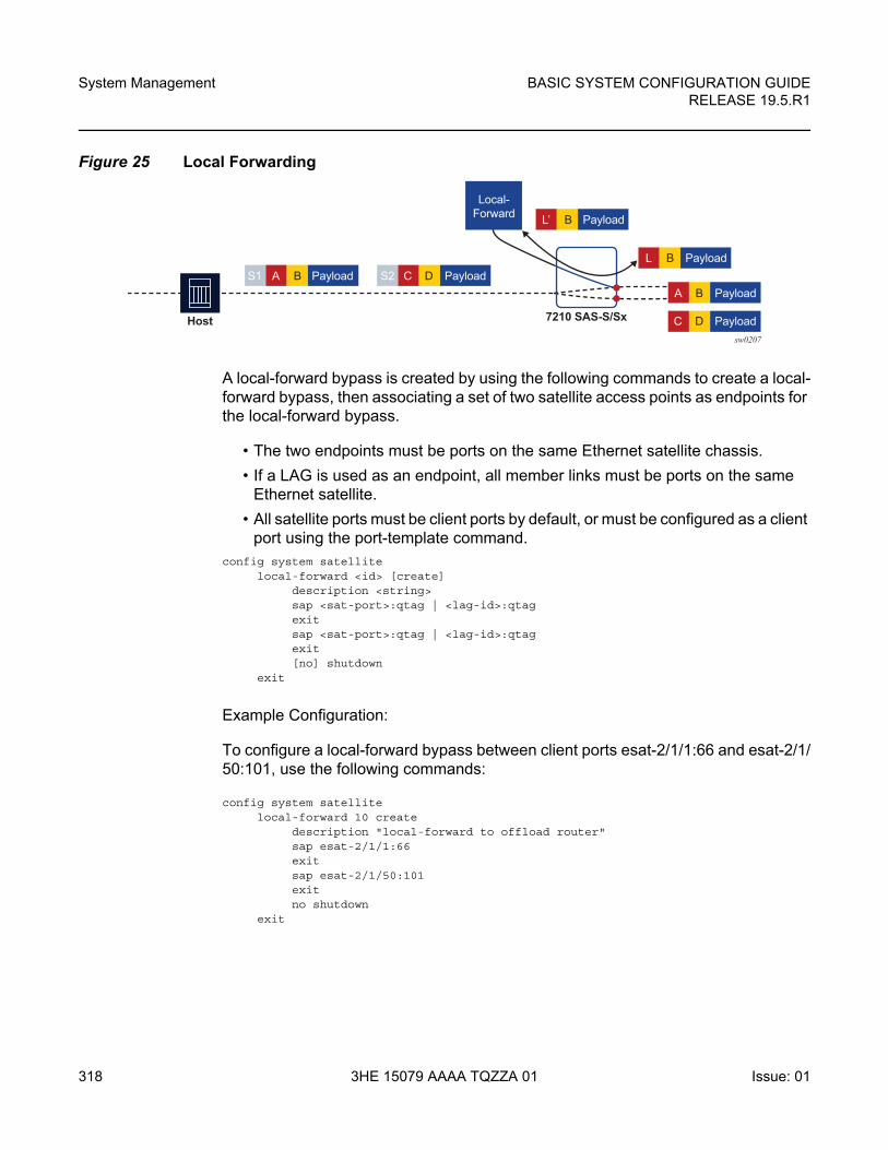
System Management
318
BASIC SYSTEM CONFIGURATION GUIDERELEASE 19.5.R1
3HE 15079 AAAA TQZZA 01 Issue: 01
Figure 25 Local Forwarding
A local-forward bypass is created by using the following commands to create a local-forward bypass, then associating a set of two satellite access points as endpoints for the local-forward bypass.
• The two endpoints must be ports on the same Ethernet satellite chassis.
• If a LAG is used as an endpoint, all member links must be ports on the same Ethernet satellite.
• All satellite ports must be client ports by default, or must be configured as a client port using the port-template command.
config system satellitelocal-forward <id> [create]
description <string>sap <sat-port>:qtag | <lag-id>:qtagexitsap <sat-port>:qtag | <lag-id>:qtagexit[no] shutdown
exit
Example Configuration:
To configure a local-forward bypass between client ports esat-2/1/1:66 and esat-2/1/50:101, use the following commands:
config system satellitelocal-forward 10 create
description "local-forward to offload router"sap esat-2/1/1:66exitsap esat-2/1/50:101exitno shutdown
exit
sw0207
Host
S1 A B Payload S2 C D Payload
L’ B Payload
Local-Forward
L B Payload
A B Payload
C D Payload7210 SAS-S/Sx
BASIC SYSTEM CONFIGURATION GUIDE RELEASE 19.5.R1
System Management
Issue: 01 3HE 15079 AAAA TQZZA 01 319
7.9.6.3 Port Template
The port-template command hierarchy allows the creation of a satellite template that reconfigures the port role and uplink association for one or more satellite ports. This template can then be applied to one or more Ethernet satellite instances, in which case those satellites inherit the specified port role and uplink associations.
The port template is necessary when reconfiguring a satellite uplink as a client port for use as part of a local-forward bypass path.
configuresystem
satellite[no] port-template <template-name> sat-type <sat-type> [create]
port <port-id>role {none | uplink | client | system-default}uplink {<port-id> | system-default | none}
exit[no] description <string>[no] shutdown
7.9.6.4 10GE Client Ports
Ports 51 and 52 on the 48xGE + 4x10GE satellite chassis can be reassigned as client ports instead of uplink ports. This provides the flexibility to offer 10GE services from these satellite chassis. These two 10GE ports can be reconfigured as client ports using the port-template configuration commands described above. The port template configuration must be done before SAPs, interfaces, or services can be applied to the associated satellite ports.
7.9.6.5 10GE Uplinks on the 64x10GE+4x100GE Satellite
On the 7210 SAS-Sx 64x10GE + 4x100GE (es64-10gb-sfpp+4-100gb-cfp4) satellite, selected 10GE ports can be reconfigured and used as the satellite uplinks to the host router running SR OS.
Up to 16 10GE interfaces can be used as the uplinks for the associated satellite. A new satellite template that configures the desired 10GE interfaces as uplinks must be created. In addition, use the port template port-template to specify the uplink association between the remaining client ports and configured uplinks.

System Management
320
BASIC SYSTEM CONFIGURATION GUIDERELEASE 19.5.R1
3HE 15079 AAAA TQZZA 01 Issue: 01
Apply the new template to the desired satellite using the config>system>satellite>eth-sat sat-id>sat-type sat-type>port-template template-name command, where the template-name is the name configured in the port-template context.
This feature requires the 7210 SAS-Sx to be running at least Release 9.0.R10 or later.
The following restrictions apply:
• The 10GE ports used as satellite uplinks must start at port 1 and be sequential, up to the maximum of 16 10GE uplinks.
• When 10GE ports are used as uplinks, the 4x100GE port are not available for use and should be configured as role none.
The following is an example configuration:
config>systemsatellite
port-template "10gUp" sat-type "es64-10gb-sfpp+4-100gb-cfp4" createport 1/1/1
role uplinkuplink none
exitport 1/1/2
role uplinkuplink none
exitport 1/1/3
role uplinkuplink none
exitport 1/1/4
role uplinkuplink none
exit...port 1/1/9
uplink 1/1/1exitport 1/1/10...port 1/1/16
uplink 1/1/2exit...port 1/1/65
role noneexitport 1/1/66
role noneexit...no shutdown
exit
BASIC SYSTEM CONFIGURATION GUIDE RELEASE 19.5.R1
System Management
Issue: 01 3HE 15079 AAAA TQZZA 01 321
eth-sat 20 createmac-address d0:99:d5:96:ee:41sat-type "es64-10gb-sfpp+4-100gb-cfp4" port-template "10gUp"software-repository "rep1"no shutdown
exitexit
exit
7.9.6.6 Satellite Uplink Resiliency
An option in the port-map configuration allows a secondary uplink to be assigned to enable uplink resiliency. A secondary uplink is used to carry the traffic associated with the client port if the primary uplink becomes unavailable. If traffic is switched to the secondary uplink, once the primary uplink becomes available, traffic is reverted to the primary as soon as possible.
The configuration of a secondary uplink is performed on a per-client port basis using the port-map command.
config>system>sat>eth-sat>port-map client-port-id primary primary-uplink-port-id [secondary secondary-uplink-port-id]
config>system>sat>eth-sat>port-map client-port-id system-default
To configure a secondary uplink, after the primary uplink is specified, the secondary keyword should be included, followed by the intended uplink to be used as the secondary uplink.
For example,
config>system>satellite>eth-sat 1port-map esat-1/1/2 primary esat-1/1/u1 secondary esat-1/1/u3
• If there are no SAPs or interfaces bound to a client port, then any change can be made to the uplinks
• If a SAP or interface is bound to a client port, or the client port is member of a LAG or ETH tunnel, then only one uplink change per configuration command is allowed (see below)
• The primary cannot be changed directly, this requires multiple steps.
1. swap primary and secondary
2. remove secondary
3. add new secondary
4. perform a second swap of primary and secondary

System Management
322
BASIC SYSTEM CONFIGURATION GUIDERELEASE 19.5.R1
3HE 15079 AAAA TQZZA 01 Issue: 01
The following are basic actions allowed with a single command:
• add or delete secondary uplink
• swap primary and secondary
• add a secondary uplink and swap secondary with primary
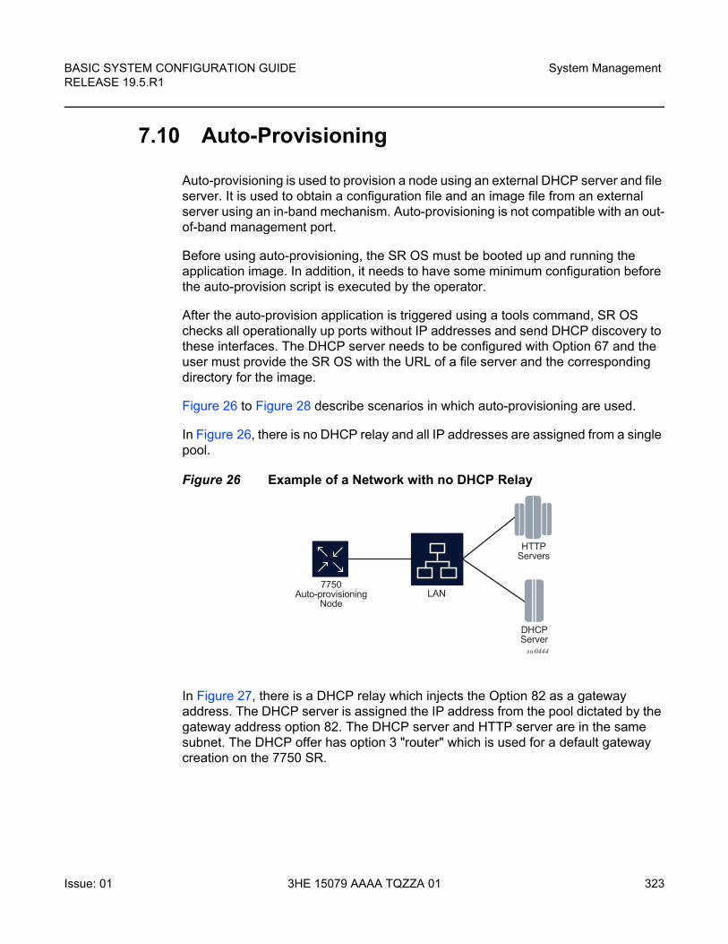
BASIC SYSTEM CONFIGURATION GUIDE RELEASE 19.5.R1
System Management
Issue: 01 3HE 15079 AAAA TQZZA 01 323
7.10 Auto-Provisioning
Auto-provisioning is used to provision a node using an external DHCP server and file server. It is used to obtain a configuration file and an image file from an external server using an in-band mechanism. Auto-provisioning is not compatible with an out-of-band management port.
Before using auto-provisioning, the SR OS must be booted up and running the application image. In addition, it needs to have some minimum configuration before the auto-provision script is executed by the operator.
After the auto-provision application is triggered using a tools command, SR OS checks all operationally up ports without IP addresses and send DHCP discovery to these interfaces. The DHCP server needs to be configured with Option 67 and the user must provide the SR OS with the URL of a file server and the corresponding directory for the image.
Figure 26 to Figure 28 describe scenarios in which auto-provisioning are used.
In Figure 26, there is no DHCP relay and all IP addresses are assigned from a single pool.
Figure 26 Example of a Network with no DHCP Relay
In Figure 27, there is a DHCP relay which injects the Option 82 as a gateway address. The DHCP server is assigned the IP address from the pool dictated by the gateway address option 82. The DHCP server and HTTP server are in the same subnet. The DHCP offer has option 3 "router" which is used for a default gateway creation on the 7750 SR.
sw0444
LAN
HTTPServers
DHCPServer
7750Auto-provisioning
Node
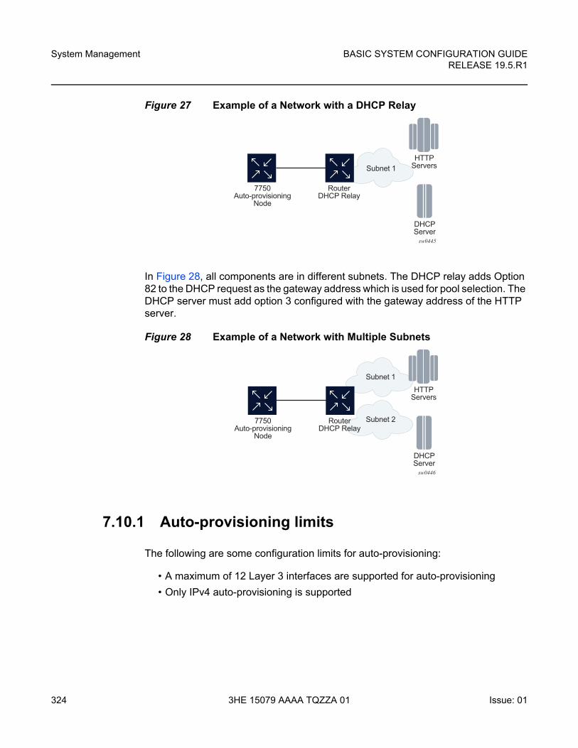
System Management
324
BASIC SYSTEM CONFIGURATION GUIDERELEASE 19.5.R1
3HE 15079 AAAA TQZZA 01 Issue: 01
Figure 27 Example of a Network with a DHCP Relay
In Figure 28, all components are in different subnets. The DHCP relay adds Option 82 to the DHCP request as the gateway address which is used for pool selection. The DHCP server must add option 3 configured with the gateway address of the HTTP server.
Figure 28 Example of a Network with Multiple Subnets
7.10.1 Auto-provisioning limits
The following are some configuration limits for auto-provisioning:
• A maximum of 12 Layer 3 interfaces are supported for auto-provisioning
• Only IPv4 auto-provisioning is supported
sw0445
HTTPServersSubnet 1
DHCPServer
7750Auto-provisioning
Node
RouterDHCP Relay
sw0446
HTTPServers
Subnet 1
Subnet 2
DHCPServer
7750Auto-provisioning
Node
RouterDHCP Relay
BASIC SYSTEM CONFIGURATION GUIDE RELEASE 19.5.R1
System Management
Issue: 01 3HE 15079 AAAA TQZZA 01 325
• It is highly recommended to only have a basic card, MDA, port, and interface configuration as described in this document and no additional static routes or IGP or BGP protocols when performing auto-provisioning because auto-provisioning installs default static routes that may be affected by any extra routing configuration.
• A maximum of 255 characters is supported for the remote URL (200 character maximum for the filepath, the rest for the main URL consisting of the protocol, login credentials, and host IP). A maximum of 200 characters is supported for the local URL. The local file or folder name must not exceed 99 characters.
• The maximum number of file pairs for each image/config record is 10.
7.10.2 Auto-provisioning Process
1. The auto-provisioning process starts by going through interfaces with a port configuration and no IP address (IPv4 or IPv6) one by one.
2. The first interface that matches triggers the DHCP client process. See Auto-provisioning DHCP Rules.
3. A static route is automatically configured with the default gateway received by DHCP offer (option 3 "Router" in DHCP offer).
4. Option 67 points to the location of a provisioning file. This is a URL in HTTP format.
5. The node downloads this provisioning file and places it on compact flash or RAM (configurable). The URL is in IP format and there is no need for DNS.
6. The node uses the primary-image/cfg-download parameters of the provisioning file to download the image and config file and places them at the destination dictated by the provisioning file. Only compact flash is supported.
If the primary-image/cfg-download server times out, two more redundant servers can be configured using secondary and tertiary options.
a. The node goes through the config file primary, secondary, and tertiary server first.
b. Then the node goes through the image primary, secondary, and tertiary server.
c. If the node fails to download the image or config, then the auto-provisioning process considers this interface unusable and moves to the next interface. The auto-provisioning also informs the DHCP task of the failure so DHCP releases the IP and sends a DHCP release.
7. The node loads the bof part of the provisioning file into the bof and save the bof. The bof must point to compact flash.
System Management
326
BASIC SYSTEM CONFIGURATION GUIDERELEASE 19.5.R1
3HE 15079 AAAA TQZZA 01 Issue: 01
8. The user can force a reboot after successful execution or choose to clear the force reboot option and reboot the node manually.
9. After the reboot, the node boots from compact flash and comes back up with an operational bof.cfg
10. Any further image or config updates are done using a console.
7.10.3 Auto-provisioning DHCP Rules
The following are the DHCP rules in the auto-provisioning stage:
1. First, auto-provisioning walks through the interfaces with a configured port, where the port is in operational status up, one by one.
2. It sends a DHCP request to the first configured interface with a port up and no IP address configured.
a. If, on this interface, multiple DHCP offers arrives, only the first offer is sent to the auto-provisioning task and the other offers are ignored. This could occur if the node is on a LAN and multiple DHCP servers are connected to the interface.
b. The DHCP client has an exponential retry mechanism. If the DHCP offer does not arrive from the server, the client resends a DHCP request at 2, 4, 8, 32 and 64 s, with 64 s being the maximum timeout, If the 64 s timeout interval is reached, the DHCP client keeps retrying every 64 s. The user can configure a timeout value. If no DHCP offer has arrived by this timeout value, the auto-provisioning process moves to the next interface.
c. If the DHCP offer arrives on the port and the DHCP client task does not acknowledge the DHCP offer, for any reason, it disables the DHCP client and remove the IP from the port.
d. If the DHCP offer arrives on the port and the DHCP client acknowledges the offer, it sends the information to auto-provisioning. If auto-provisioning does not like the offer, because there is no option 67, option 67 is malformed, or for any other reason listed in Auto-provisioning Failure, the auto-provisioning process deconfigures the DHCP client and the DHCP client sends a DHCP release, and unassigns the IP address.
e. In case of failure, detailed information is displayed by the auto-provisioning process and the process moves to the next port that is up and does not have an IP address.
3. If auto-provisioning is successful using the offer and its option then the provisioning file download starts through HTTP.
The auto-provisioning command is CLI blocking. All information about the auto-provisioning process is displayed on the CLI and logged.
BASIC SYSTEM CONFIGURATION GUIDE RELEASE 19.5.R1
System Management
Issue: 01 3HE 15079 AAAA TQZZA 01 327
7.10.4 Auto-provisioning Failure
Auto-provisioning fails for the following reasons:
• There is no Option 67.
• The Option 67 format is not acceptable to auto-provisioning.
• The format is a URL or DNS is not supported.
• There is a failure in the download provisioning file or the server is not reachable.
• There is failure in the download of the image or config file using the provisioning file information, for example, the server is not available, the wrong directory is listed, or the wrong credentials are given.
• The image or config fails to copy to the compact flash.
• The image or config fails to sync to the inactive CPM.
• The BOF does not point to the compact flash, for example, it is pointing to the network.
If the auto-provisioning procedure on this interface fails, then auto-provisioning:
1. Displays all information on the blocked CLI and in the log, explaining the failure in detail
2. Updates the DHCP task so the DHCP task can take the appropriate actions to release the IP address on the interface. This is done by sending a DHCP release for the DHCP ack received from the server.
3. Goes to the next interface with port up and no IP address.
4. If no other interface with port up is found, the auto-provisioning task stops and a failure error is displayed on the CLI and in the log.
System Management
328
BASIC SYSTEM CONFIGURATION GUIDERELEASE 19.5.R1
3HE 15079 AAAA TQZZA 01 Issue: 01
7.11 Administrative Tasks
This section contains information to perform administrative tasks.
7.11.1 Saving Configurations
Whenever configuration changes are made, the modified configuration must be saved so they are not lost when the system is rebooted.
Configuration files are saved by executing explicit command syntax which includes the file URL location to save the configuration file as well as options to save both default and non-default configuration parameters. Boot option file (BOF) parameters specify where the system should search for configuration and image files as well as other operational parameters during system initialization.
For more information about boot option files, refer to the Boot Options section.
7.11.2 Specifying Post-Boot Configuration Files
Two post-boot configuration extension files are supported and are triggered when either a successful or failed boot configuration file is processed. The boot-bad-exec and boot-good-exec commands specify URLs for the CLI scripts to be run following the completion of the boot-up configuration. A URL must be specified or no action is taken.
For example, after a configuration file is successfully loaded, the specified URL can contain a nearly identical configuration file with certain commands enabled or disabled, or particular parameters specified and according to the script which loads that file.
7.11.3 Network Timing
In Time Domain Multiplexed (TDM)-based networks (for example, SONET or SDH circuit- switched networks), the concept of network timing is used to prevent over-run or under-run issues where circuits are groomed (rebundled) and switched. Hardware exists in each node that takes a common clock derived from an internal oscillator, a specific receive interface, or special BITS interface and provides it to each synchronous interface in the system. Usually, each synchronous interface is allowed
BASIC SYSTEM CONFIGURATION GUIDE RELEASE 19.5.R1
System Management
Issue: 01 3HE 15079 AAAA TQZZA 01 329
to choose between using the chassis-provided clock or the clocking recovered from the received signal on the interface. The clocking is used to drive the transmit side of the interface. The appropriate configuration at each node which defines how interface clocking is handled must be considered when designing a network that has a centralized timing source so each interface is operating in a synchronous manner.
The effect of timing on a network is dependent on the nature of the type of traffic carried on the network. With bit-wise synchronous traffic (traditional circuit-based voice or video), non-synchronous transmissions cause a loss of information in the streams affecting performance. With packet-based traffic, the applications expect and handle jitter and latency inherent to packet-based networks. When a packet-based network is used to carry voice or video traffic, the applications use data compression and elasticity buffering to compensate for jitter and latency. The network itself relies on appropriate Quality of Service (QoS) definitions and network provisioning to further minimize the jitter and latency the application may experience.
7.11.4 Power Supplies
SR OS supports a power-supply command to configure the type and number of power supplies present in the chassis. The operational status of a power source is always displayed by the LEDs on the Control Processor/Switch Fabric Module (CP/SFM) front panel, but the power supply information must be explicitly configured in order for a power supply alarm to be generated if a power source becomes operationally disabled.
7.11.5 Automatic Synchronization
Use the CLI syntax displayed below to configure synchronization components relating to active-to-standby CPM switchover. In redundant systems, synchronization ensures that the active and standby CPMs have identical operational parameters, including the active configuration, CPM, XCM, and IOM images in the event of a failure or reset of the active CPM.
The force-switchover command forces a switchover to the standby CPM card.
To enable automatic synchronization, either the boot-env parameter or the config parameter must be specified. The synchronization occurs when the admin save or bof save commands are executed.
System Management
330
BASIC SYSTEM CONFIGURATION GUIDERELEASE 19.5.R1
3HE 15079 AAAA TQZZA 01 Issue: 01
When the boot-env parameter of the synchronize command is specified, the bof.cfg, primary/secondary/tertiary configuration files (.cfg and .ndx), li, and ssh files are automatically synchronized. When the config parameter is specified, only the configuration files are automatically synchronized.
Synchronization also occurs whenever the BOF is modified and when an admin>save command is entered with no filename specified.
7.11.5.1 Boot-Env Option
The boot-env option enables a synchronization of all the files used in system initialization.
When configuring the system to perform this synchronization, the following occurs:
1. The BOF used during system initialization is copied to the same compact flash on the standby CPM (in redundant systems). The synchronization parameters on the standby CPM are preserved.
2. The primary, secondary, and tertiary images, (provided they are locally stored on the active CPM) are copied to the same compact flash on the standby CPM.
3. The primary, secondary, and tertiary configuration files, (provided they are locally stored on the active CPM) are copied to the same compact flash on the standby CPM.
7.11.5.2 Config Option
The config option synchronizes configuration files by copying the files specified in the active CPM BOF file to the same compact flash on the standby CPM.
Both image files (CPM and IOM) on the 7450 ESS must be located in the same directory. Failure to locate and synchronize both images causes an error to be generated.
7.11.6 Manual Synchronization
The admin redundancy synchronize command performs manual CPM synchronizations. The boot-env parameter synchronizes the BOF, image, and configuration files in redundant systems. The config parameter synchronizes only the configuration files in redundant systems.
BASIC SYSTEM CONFIGURATION GUIDE RELEASE 19.5.R1
System Management
Issue: 01 3HE 15079 AAAA TQZZA 01 331
7.11.6.1 Forcing a Switchover
The force-switchover now command forces an immediate switchover to the standby CPM card.
If the active and standby are not synchronized for some reason, users can manually synchronize the standby CPM by rebooting the standby by issuing the admin reboot standby command on the active or the standby CPM.
System Management
332
BASIC SYSTEM CONFIGURATION GUIDERELEASE 19.5.R1
3HE 15079 AAAA TQZZA 01 Issue: 01
7.12 System Router Instances
SR OS supports multiple Layer 3 router instances. These instances have their own IP addressing spaces and parameters. Router instances are isolated from each other.
The following are the different types of router instances in SR OS:
• Base
All SR OS routers have the Base router instance: the system created default router instance used to forward user IP traffic among router line card ports. Router interfaces (that is, network interfaces configured under configure router [Base]) and IES services and interfaces exist in the Base router instance. The Base router instance is identified in SNMP as vRtrType = baseRouter (1) and has a vRtrID of 1.
• VPRN instances
Another type of router instance is the set of operator configured VPRN services. Each VPRN service has a unique router instance. For more information about VPRN services and their associated router instances, refer to the 7450 ESS, 7750 SR, 7950 XRS, and VSR Layer 3 Services Guide: IES and VPRN. VPRN router instances are identified in SNMP as vRtrType = vprn (2), and the vRtrID is dynamically allocated.
• Special system router instances
SR OS routers also support the following special router instances:
−management
The management router instance is a system created router instance that is used for management of the router. The management router instance is bound to CPM/CCM ports A/1 and B/1. This is a CPM router instance which cannot be renamed or deleted by an operator. The management router instance is identified in SNMP as vRtrType = vr(3), and the vRtrID is 4095.
−vpls-management
The vpls-management router instance is used for management of VPLS services. It is identified in SNMP as vRtrType = vr(3), and the vRtrID is 4094.
−User created CPM router instances
BASIC SYSTEM CONFIGURATION GUIDE RELEASE 19.5.R1
System Management
Issue: 01 3HE 15079 AAAA TQZZA 01 333
User created CPM router instances are user defined router instances that are mainly used with ethernet ports on the CPM/CCM cards: CPM router instances only use CPM/CCM ethernet ports as interfaces. CPM router instances have a user-defined name and are the only types of non-VPRN router instances that can be created by the user. User created CPM router instances are identified in SNMP as vRtrType = vr(3), and the vRtrID is dynamically allocated.
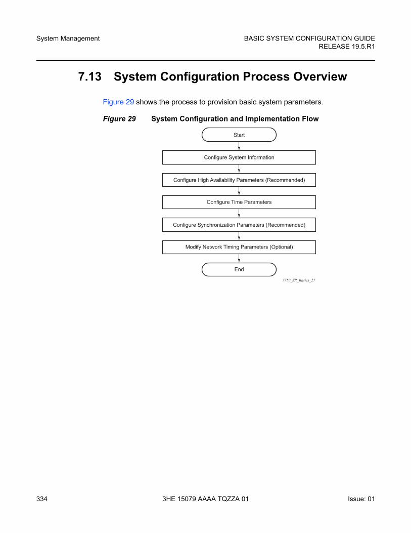
System Management
334
BASIC SYSTEM CONFIGURATION GUIDERELEASE 19.5.R1
3HE 15079 AAAA TQZZA 01 Issue: 01
7.13 System Configuration Process Overview
Figure 29 shows the process to provision basic system parameters.
Figure 29 System Configuration and Implementation Flow
7750_SR_Basics_27
Start
Configure System Information
Configure High Availability Parameters (Recommended)
Configure Time Parameters
Configure Synchronization Parameters (Recommended)
Modify Network Timing Parameters (Optional)
End
BASIC SYSTEM CONFIGURATION GUIDE RELEASE 19.5.R1
System Management
Issue: 01 3HE 15079 AAAA TQZZA 01 335
7.14 Configuration Notes
This section describes system configuration caveats.
7.14.1 General
The system must be properly initialized and the boot loader and BOF files successfully executed in order to access the CLI.

System Management
336
BASIC SYSTEM CONFIGURATION GUIDERELEASE 19.5.R1
3HE 15079 AAAA TQZZA 01 Issue: 01
BASIC SYSTEM CONFIGURATION GUIDE RELEASE 19.5.R1
System Management
Issue: 01 3HE 15079 AAAA TQZZA 01 337
7.15 Configuring System Management with CLI
This section provides information about configuring system management features with CLI.
7.15.1 Saving Configurations
Whenever configuration changes are made, the modified configuration must be saved so the changes will not be lost when the system is rebooted. The system uses the configuration and image files, as well as other operational parameters necessary for system initialization, according to the locations specified in the boot option file (BOF) parameters. For more information about boot option files, see Boot Options.
Configuration files are saved by executing implicit or explicit command syntax.
• An explicit save writes the configuration to the location specified in the save command syntax (the file-url option).
• An implicit save writes the configuration to the file specified in the primary configuration location.
If the file-url option is not specified in the save command syntax, the system attempts to save the current configuration to the current BOF primary configuration source. If the primary configuration source (path and filename) changed since the last boot, the new configuration source is used.
The save command includes an option to save both default and non-default configuration parameters (the detail option).
The index option specifies that the system preserves system indexes when a save command is executed, regardless of the persistent status in the BOF file. During a subsequent boot, the index file is read along with the configuration file. As a result, a number of system indexes are preserved between reboots, including the interface index, LSP IDs, path IDs, and so on. This reduces resynchronizations of the Network Management System (NMS) with the affected network element.
If the save attempt fails at the destination, an error occurs and is logged. The system does not try to save the file to the secondary or tertiary configuration sources unless the path and filename are explicitly named with the save command.
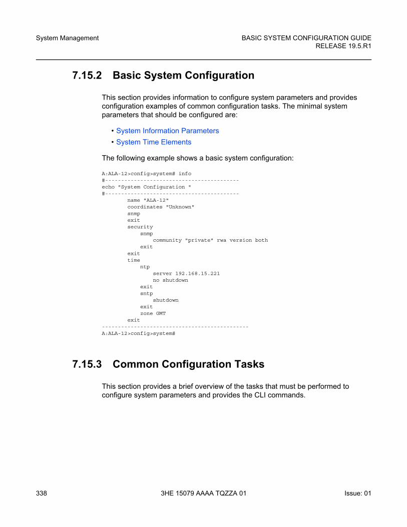
System Management
338
BASIC SYSTEM CONFIGURATION GUIDERELEASE 19.5.R1
3HE 15079 AAAA TQZZA 01 Issue: 01
7.15.2 Basic System Configuration
This section provides information to configure system parameters and provides configuration examples of common configuration tasks. The minimal system parameters that should be configured are:
• System Information Parameters
• System Time Elements
The following example shows a basic system configuration:
A:ALA-12>config>system# info#------------------------------------------echo "System Configuration "#------------------------------------------
name "ALA-12"coordinates "Unknown"snmpexitsecurity
snmpcommunity "private" rwa version both
exitexittime
ntpserver 192.168.15.221no shutdown
exitsntp
shutdownexitzone GMT
exit----------------------------------------------A:ALA-12>config>system#
7.15.3 Common Configuration Tasks
This section provides a brief overview of the tasks that must be performed to configure system parameters and provides the CLI commands.
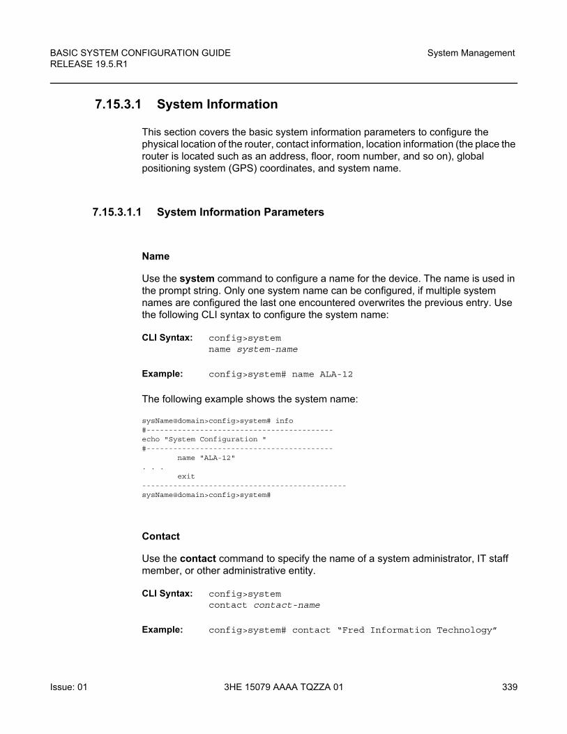
BASIC SYSTEM CONFIGURATION GUIDE RELEASE 19.5.R1
System Management
Issue: 01 3HE 15079 AAAA TQZZA 01 339
7.15.3.1 System Information
This section covers the basic system information parameters to configure the physical location of the router, contact information, location information (the place the router is located such as an address, floor, room number, and so on), global positioning system (GPS) coordinates, and system name.
7.15.3.1.1 System Information Parameters
Name
Use the system command to configure a name for the device. The name is used in the prompt string. Only one system name can be configured, if multiple system names are configured the last one encountered overwrites the previous entry. Use the following CLI syntax to configure the system name:
CLI Syntax: config>systemname system-name
Example: config>system# name ALA-12
The following example shows the system name:
sysName@domain>config>system# info#------------------------------------------echo "System Configuration "#------------------------------------------
name "ALA-12". . .
exit----------------------------------------------sysName@domain>config>system#
Contact
Use the contact command to specify the name of a system administrator, IT staff member, or other administrative entity.
CLI Syntax: config>systemcontact contact-name
Example: config>system# contact “Fred Information Technology”
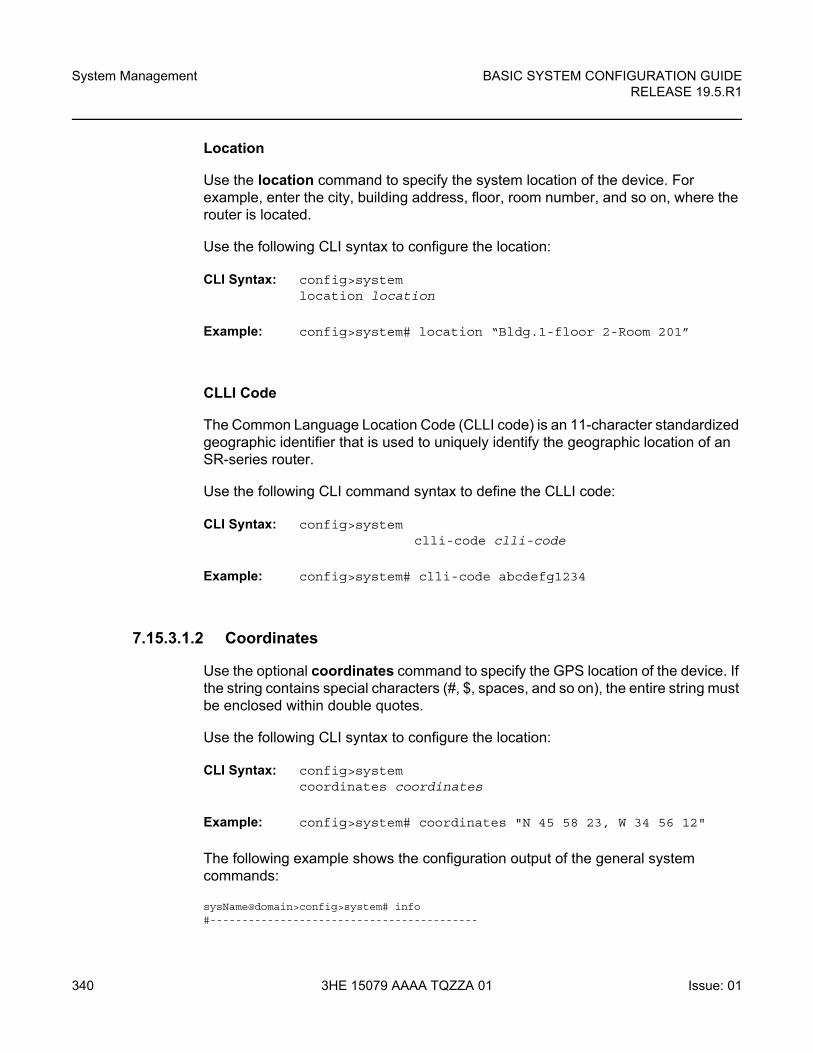
System Management
340
BASIC SYSTEM CONFIGURATION GUIDERELEASE 19.5.R1
3HE 15079 AAAA TQZZA 01 Issue: 01
Location
Use the location command to specify the system location of the device. For example, enter the city, building address, floor, room number, and so on, where the router is located.
Use the following CLI syntax to configure the location:
CLI Syntax: config>systemlocation location
Example: config>system# location “Bldg.1-floor 2-Room 201”
CLLI Code
The Common Language Location Code (CLLI code) is an 11-character standardized geographic identifier that is used to uniquely identify the geographic location of an SR-series router.
Use the following CLI command syntax to define the CLLI code:
CLI Syntax: config>systemclli-code clli-code
Example: config>system# clli-code abcdefg1234
7.15.3.1.2 Coordinates
Use the optional coordinates command to specify the GPS location of the device. If the string contains special characters (#, $, spaces, and so on), the entire string must be enclosed within double quotes.
Use the following CLI syntax to configure the location:
CLI Syntax: config>systemcoordinates coordinates
Example: config>system# coordinates "N 45 58 23, W 34 56 12"
The following example shows the configuration output of the general system commands:
sysName@domain>config>system# info#------------------------------------------
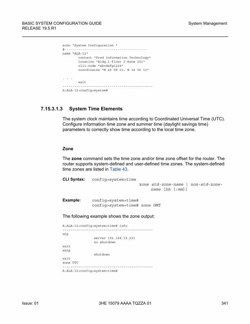
BASIC SYSTEM CONFIGURATION GUIDE RELEASE 19.5.R1
System Management
Issue: 01 3HE 15079 AAAA TQZZA 01 341
echo "System Configuration "#------------------------------------------name "ALA-12"
contact "Fred Information Technology"location "Bldg.1-floor 2-Room 201"clli-code "abcdefg1234"coordinates "N 45 58 23, W 34 56 12"
. . .exit
----------------------------------------------A:ALA-12>config>system#
7.15.3.1.3 System Time Elements
The system clock maintains time according to Coordinated Universal Time (UTC). Configure information time zone and summer time (daylight savings time) parameters to correctly show time according to the local time zone.
Zone
The zone command sets the time zone and/or time zone offset for the router. The router supports system-defined and user-defined time zones. The system-defined time zones are listed in Table 43.
CLI Syntax: config>system>timezone std-zone-name | non-std-zone-
name [hh [:mm]]
Example: config>system>time# config>system>time# zone GMT
The following example shows the zone output:
A:ALA-12>config>system>time# info----------------------------------------------ntp
server 192.168.15.221no shutdown
exitsntp
shutdownexitzone UTC----------------------------------------------A:ALA-12>config>system>time#
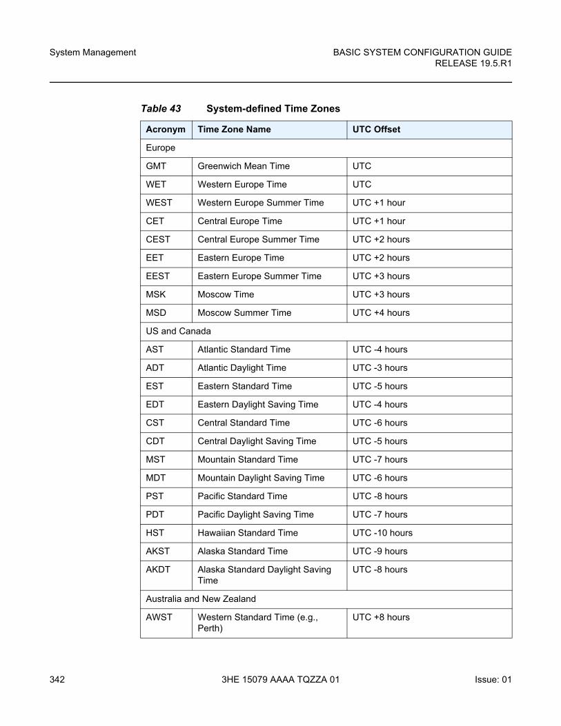
System Management
342
BASIC SYSTEM CONFIGURATION GUIDERELEASE 19.5.R1
3HE 15079 AAAA TQZZA 01 Issue: 01
Table 43 System-defined Time Zones
Acronym Time Zone Name UTC Offset
Europe
GMT Greenwich Mean Time UTC
WET Western Europe Time UTC
WEST Western Europe Summer Time UTC +1 hour
CET Central Europe Time UTC +1 hour
CEST Central Europe Summer Time UTC +2 hours
EET Eastern Europe Time UTC +2 hours
EEST Eastern Europe Summer Time UTC +3 hours
MSK Moscow Time UTC +3 hours
MSD Moscow Summer Time UTC +4 hours
US and Canada
AST Atlantic Standard Time UTC -4 hours
ADT Atlantic Daylight Time UTC -3 hours
EST Eastern Standard Time UTC -5 hours
EDT Eastern Daylight Saving Time UTC -4 hours
CST Central Standard Time UTC -6 hours
CDT Central Daylight Saving Time UTC -5 hours
MST Mountain Standard Time UTC -7 hours
MDT Mountain Daylight Saving Time UTC -6 hours
PST Pacific Standard Time UTC -8 hours
PDT Pacific Daylight Saving Time UTC -7 hours
HST Hawaiian Standard Time UTC -10 hours
AKST Alaska Standard Time UTC -9 hours
AKDT Alaska Standard Daylight Saving Time
UTC -8 hours
Australia and New Zealand
AWST Western Standard Time (e.g., Perth)
UTC +8 hours
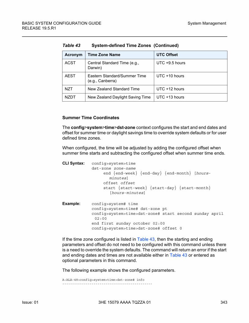
BASIC SYSTEM CONFIGURATION GUIDE RELEASE 19.5.R1
System Management
Issue: 01 3HE 15079 AAAA TQZZA 01 343
Summer Time Coordinates
The config>system>time>dst-zone context configures the start and end dates and offset for summer time or daylight savings time to override system defaults or for user defined time zones.
When configured, the time will be adjusted by adding the configured offset when summer time starts and subtracting the configured offset when summer time ends.
CLI Syntax: config>system>timedst-zone zone-name
end {end-week} {end-day} {end-month} [hours-minutes]
offset offsetstart {start-week} {start-day} {start-month}
[hours-minutes]
Example: config>system# timeconfig>system>time# dst-zone ptconfig>system>time>dst-zone# start second sunday april 02:00
end first sunday october 02:00config>system>time>dst-zone# offset 0
If the time zone configured is listed in Table 43, then the starting and ending parameters and offset do not need to be configured with this command unless there is a need to override the system defaults. The command will return an error if the start and ending dates and times are not available either in Table 43 or entered as optional parameters in this command.
The following example shows the configured parameters.
A:ALA-48>config>system>time>dst-zone# info----------------------------------------------
ACST Central Standard Time (e.g., Darwin)
UTC +9.5 hours
AEST Eastern Standard/Summer Time (e.g., Canberra)
UTC +10 hours
NZT New Zealand Standard Time UTC +12 hours
NZDT New Zealand Daylight Saving Time UTC +13 hours
Table 43 System-defined Time Zones (Continued)
Acronym Time Zone Name UTC Offset
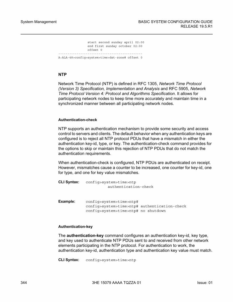
System Management
344
BASIC SYSTEM CONFIGURATION GUIDERELEASE 19.5.R1
3HE 15079 AAAA TQZZA 01 Issue: 01
start second sunday april 02:00end first sunday october 02:00offset 0
----------------------------------------------A:ALA-48>config>system>time>dst-zone# offset 0
NTP
Network Time Protocol (NTP) is defined in RFC 1305, Network Time Protocol (Version 3) Specification, Implementation and Analysis and RFC 5905, Network Time Protocol Version 4: Protocol and Algorithms Specification. It allows for participating network nodes to keep time more accurately and maintain time in a synchronized manner between all participating network nodes.
Authentication-check
NTP supports an authentication mechanism to provide some security and access control to servers and clients. The default behavior when any authentication keys are configured is to reject all NTP protocol PDUs that have a mismatch in either the authentication key-id, type, or key. The authentication-check command provides for the options to skip or maintain this rejection of NTP PDUs that do not match the authentication requirements.
When authentication-check is configured, NTP PDUs are authenticated on receipt. However, mismatches cause a counter to be increased, one counter for key-id, one for type, and one for key value mismatches.
CLI Syntax: config>system>time>ntpauthentication-check
Example: config>system>time>ntp# config>system>time>ntp# authentication-checkconfig>system>time>ntp# no shutdown
Authentication-key
The authentication-key command configures an authentication key-id, key type, and key used to authenticate NTP PDUs sent to and received from other network elements participating in the NTP protocol. For authentication to work, the authentication key-id, authentication type and authentication key value must match.
CLI Syntax: config>system>time>ntp
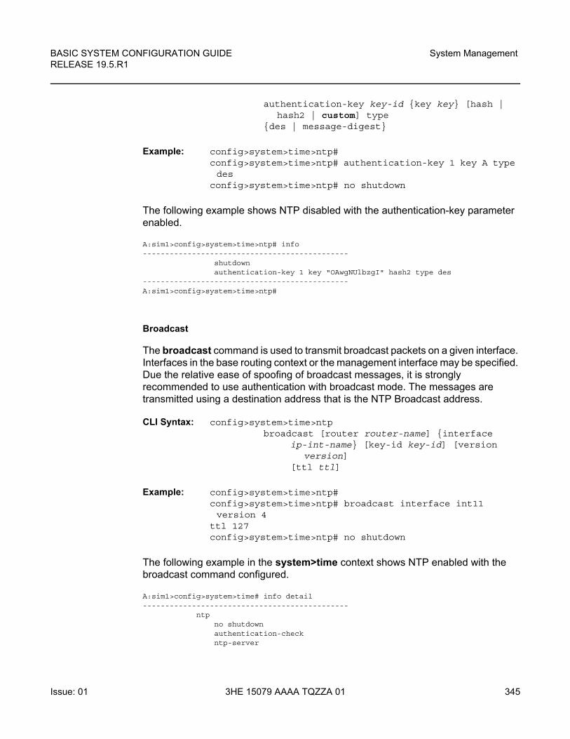
BASIC SYSTEM CONFIGURATION GUIDE RELEASE 19.5.R1
System Management
Issue: 01 3HE 15079 AAAA TQZZA 01 345
authentication-key key-id {key key} [hash | hash2 | custom] type
{des | message-digest}
Example: config>system>time>ntp# config>system>time>ntp# authentication-key 1 key A type des
config>system>time>ntp# no shutdown
The following example shows NTP disabled with the authentication-key parameter enabled.
A:sim1>config>system>time>ntp# info----------------------------------------------
shutdownauthentication-key 1 key "OAwgNUlbzgI" hash2 type des
----------------------------------------------A:sim1>config>system>time>ntp#
Broadcast
The broadcast command is used to transmit broadcast packets on a given interface. Interfaces in the base routing context or the management interface may be specified. Due the relative ease of spoofing of broadcast messages, it is strongly recommended to use authentication with broadcast mode. The messages are transmitted using a destination address that is the NTP Broadcast address.
CLI Syntax: config>system>time>ntpbroadcast [router router-name] {interface
ip-int-name} [key-id key-id] [version version]
[ttl ttl]
Example: config>system>time>ntp# config>system>time>ntp# broadcast interface int11 version 4
ttl 127config>system>time>ntp# no shutdown
The following example in the system>time context shows NTP enabled with the broadcast command configured.
A:sim1>config>system>time# info detail----------------------------------------------
ntpno shutdownauthentication-checkntp-server
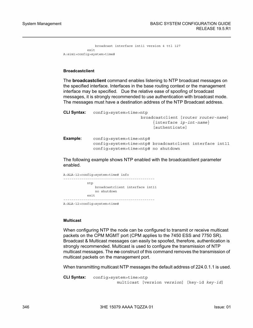
System Management
346
BASIC SYSTEM CONFIGURATION GUIDERELEASE 19.5.R1
3HE 15079 AAAA TQZZA 01 Issue: 01
broadcast interface int11 version 4 ttl 127exit
A:sim1>config>system>time#
Broadcastclient
The broadcastclient command enables listening to NTP broadcast messages on the specified interface. Interfaces in the base routing context or the management interface may be specified. Due the relative ease of spoofing of broadcast messages, it is strongly recommended to use authentication with broadcast mode. The messages must have a destination address of the NTP Broadcast address.
CLI Syntax: config>system>time>ntpbroadcastclient [router router-name]
{interface ip-int-name} [authenticate]
Example: config>system>time>ntp# config>system>time>ntp# broadcastclient interface int11config>system>time>ntp# no shutdown
The following example shows NTP enabled with the broadcastclient parameter enabled.
A:ALA-12>config>system>time# info----------------------------------------------
ntpbroadcastclient interface int11no shutdown
exit----------------------------------------------A:ALA-12>config>system>time#
Multicast
When configuring NTP the node can be configured to transmit or receive multicast packets on the CPM MGMT port (CPM applies to the 7450 ESS and 7750 SR). Broadcast & Multicast messages can easily be spoofed, therefore, authentication is strongly recommended. Multicast is used to configure the transmission of NTP multicast messages. The no construct of this command removes the transmission of multicast packets on the management port.
When transmitting multicast NTP messages the default address of 224.0.1.1 is used.
CLI Syntax: config>system>time>ntpmulticast [version version] [key-id key-id]

BASIC SYSTEM CONFIGURATION GUIDE RELEASE 19.5.R1
System Management
Issue: 01 3HE 15079 AAAA TQZZA 01 347
Example: config>system>time>ntp# config>system>time>ntp# multicastconfig>system>time>ntp# no shutdown
The following example shows NTP enabled with the multicast command configured.
A:ALA-12>config>system>time# info----------------------------------------------
server 192.168.15.221multicastno shutdown
----------------------------------------------A:ALA-12>config>system>time#
Multicastclient
The multicastclient command is used to configure an address to receive multicast NTP messages on the CPM MGMT port (7450 ESS and 7750 SR). Broadcast & Multicast messages can easily be spoofed, therefore, authentication is strongly recommended. The no construct of this command removes the multicast client. If multicastclient is not configured, all NTP multicast traffic will be ignored.
CLI Syntax: config>system>time>ntpmulticastclient [authenticate]
Example: config>system>time>ntp# config>system>time>ntp# multicastclient authenticateconfig>system>time>ntp# no shutdown
The following example shows NTP enabled with the multicastclient command configured.
A:ALA-12>config>system>time# info----------------------------------------------
server 192.168.15.221multicastclientno shutdown
----------------------------------------------A:ALA-12>config>system>time##
NTP-Server
The ntp-server command configures the node to assume the role of an NTP server. Unless the server command is used this node will function as an NTP client only and will not distribute the time to downstream network elements. If authentication is specified in this command, the NTP server requires client packets to be authenticated based on the key received in the client request.
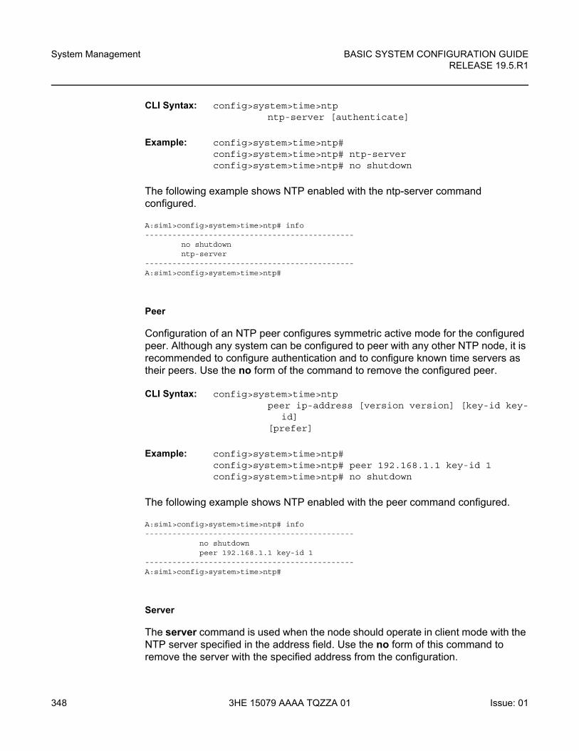
System Management
348
BASIC SYSTEM CONFIGURATION GUIDERELEASE 19.5.R1
3HE 15079 AAAA TQZZA 01 Issue: 01
CLI Syntax: config>system>time>ntpntp-server [authenticate]
Example: config>system>time>ntp# config>system>time>ntp# ntp-serverconfig>system>time>ntp# no shutdown
The following example shows NTP enabled with the ntp-server command configured.
A:sim1>config>system>time>ntp# info----------------------------------------------
no shutdownntp-server
----------------------------------------------A:sim1>config>system>time>ntp#
Peer
Configuration of an NTP peer configures symmetric active mode for the configured peer. Although any system can be configured to peer with any other NTP node, it is recommended to configure authentication and to configure known time servers as their peers. Use the no form of the command to remove the configured peer.
CLI Syntax: config>system>time>ntppeer ip-address [version version] [key-id key-
id] [prefer]
Example: config>system>time>ntp# config>system>time>ntp# peer 192.168.1.1 key-id 1config>system>time>ntp# no shutdown
The following example shows NTP enabled with the peer command configured.
A:sim1>config>system>time>ntp# info----------------------------------------------
no shutdownpeer 192.168.1.1 key-id 1
----------------------------------------------A:sim1>config>system>time>ntp#
Server
The server command is used when the node should operate in client mode with the NTP server specified in the address field. Use the no form of this command to remove the server with the specified address from the configuration.
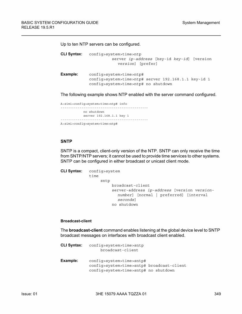
BASIC SYSTEM CONFIGURATION GUIDE RELEASE 19.5.R1
System Management
Issue: 01 3HE 15079 AAAA TQZZA 01 349
Up to ten NTP servers can be configured.
CLI Syntax: config>system>time>ntpserver ip-address [key-id key-id] [version
version] [prefer]
Example: config>system>time>ntp# config>system>time>ntp# server 192.168.1.1 key-id 1config>system>time>ntp# no shutdown
The following example shows NTP enabled with the server command configured.
A:sim1>config>system>time>ntp# info----------------------------------------------
no shutdownserver 192.168.1.1 key 1
----------------------------------------------A:sim1>config>system>time>ntp#
SNTP
SNTP is a compact, client-only version of the NTP. SNTP can only receive the time from SNTP/NTP servers; it cannot be used to provide time services to other systems. SNTP can be configured in either broadcast or unicast client mode.
CLI Syntax: config>systemtime
sntpbroadcast-client server-address ip-address [version version-
number] [normal | preferred] [interval seconds]
no shutdown
Broadcast-client
The broadcast-client command enables listening at the global device level to SNTP broadcast messages on interfaces with broadcast client enabled.
CLI Syntax: config>system>time>sntpbroadcast-client
Example: config>system>time>sntp# config>system>time>sntp# broadcast-clientconfig>system>time>sntp# no shutdown
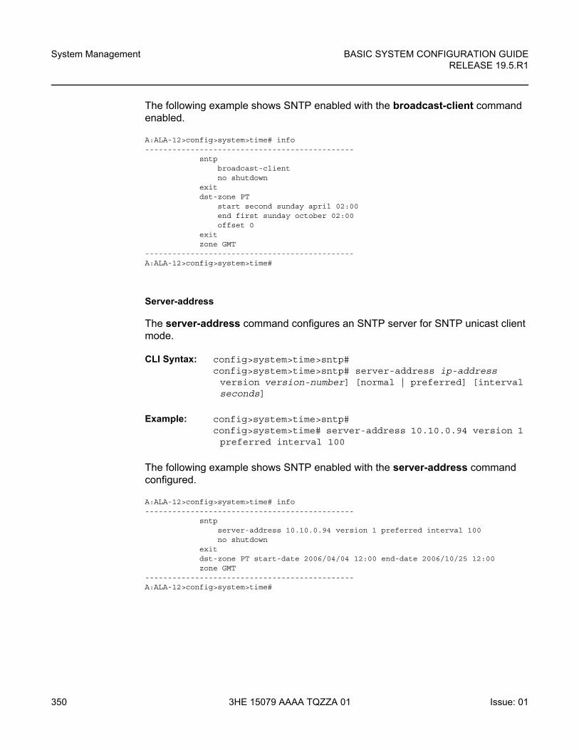
System Management
350
BASIC SYSTEM CONFIGURATION GUIDERELEASE 19.5.R1
3HE 15079 AAAA TQZZA 01 Issue: 01
The following example shows SNTP enabled with the broadcast-client command enabled.
A:ALA-12>config>system>time# info----------------------------------------------
sntpbroadcast-clientno shutdown
exitdst-zone PT
start second sunday april 02:00end first sunday october 02:00offset 0
exitzone GMT
----------------------------------------------A:ALA-12>config>system>time#
Server-address
The server-address command configures an SNTP server for SNTP unicast client mode.
CLI Syntax: config>system>time>sntp#config>system>time>sntp# server-address ip-address version version-number] [normal | preferred] [interval seconds]
Example: config>system>time>sntp#config>system>time# server-address 10.10.0.94 version 1 preferred interval 100
The following example shows SNTP enabled with the server-address command configured.
A:ALA-12>config>system>time# info----------------------------------------------
sntpserver-address 10.10.0.94 version 1 preferred interval 100no shutdown
exitdst-zone PT start-date 2006/04/04 12:00 end-date 2006/10/25 12:00zone GMT
----------------------------------------------A:ALA-12>config>system>time#
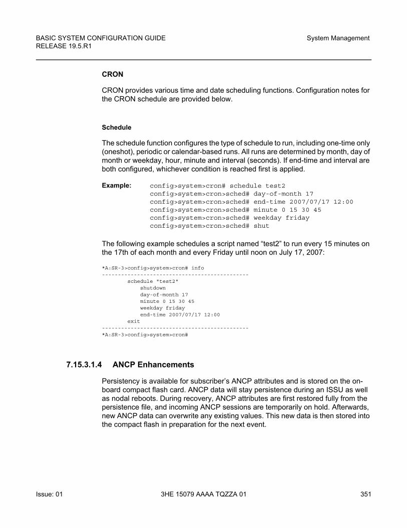
BASIC SYSTEM CONFIGURATION GUIDE RELEASE 19.5.R1
System Management
Issue: 01 3HE 15079 AAAA TQZZA 01 351
CRON
CRON provides various time and date scheduling functions. Configuration notes for the CRON schedule are provided below.
Schedule
The schedule function configures the type of schedule to run, including one-time only (oneshot), periodic or calendar-based runs. All runs are determined by month, day of month or weekday, hour, minute and interval (seconds). If end-time and interval are both configured, whichever condition is reached first is applied.
Example: config>system>cron# schedule test2config>system>cron>sched# day-of-month 17config>system>cron>sched# end-time 2007/07/17 12:00config>system>cron>sched# minute 0 15 30 45config>system>cron>sched# weekday fridayconfig>system>cron>sched# shut
The following example schedules a script named “test2” to run every 15 minutes on the 17th of each month and every Friday until noon on July 17, 2007:
*A:SR-3>config>system>cron# info----------------------------------------------
schedule "test2"shutdownday-of-month 17minute 0 15 30 45weekday fridayend-time 2007/07/17 12:00
exit----------------------------------------------*A:SR-3>config>system>cron#
7.15.3.1.4 ANCP Enhancements
Persistency is available for subscriber’s ANCP attributes and is stored on the on-board compact flash card. ANCP data will stay persistence during an ISSU as well as nodal reboots. During recovery, ANCP attributes are first restored fully from the persistence file, and incoming ANCP sessions are temporarily on hold. Afterwards, new ANCP data can overwrite any existing values. This new data is then stored into the compact flash in preparation for the next event.
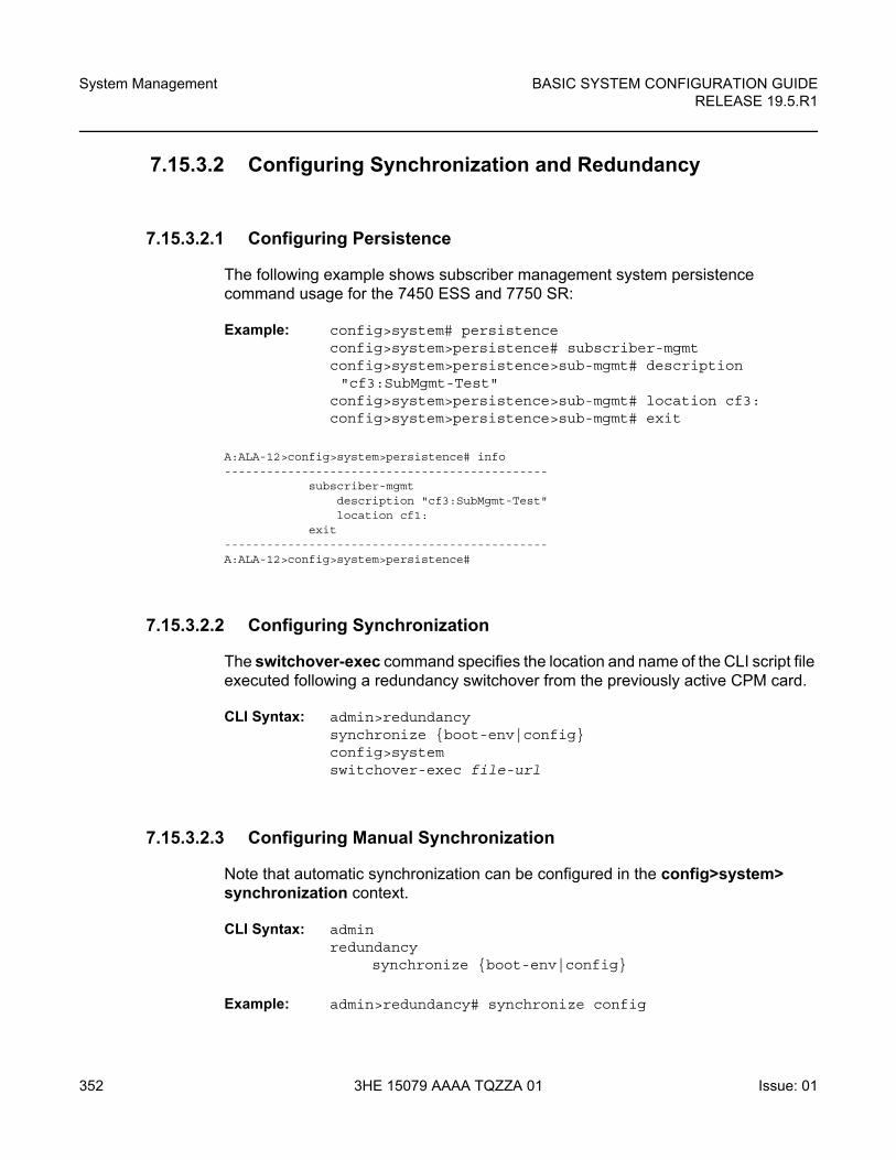
System Management
352
BASIC SYSTEM CONFIGURATION GUIDERELEASE 19.5.R1
3HE 15079 AAAA TQZZA 01 Issue: 01
7.15.3.2 Configuring Synchronization and Redundancy
7.15.3.2.1 Configuring Persistence
The following example shows subscriber management system persistence command usage for the 7450 ESS and 7750 SR:
Example: config>system# persistenceconfig>system>persistence# subscriber-mgmtconfig>system>persistence>sub-mgmt# description "cf3:SubMgmt-Test"
config>system>persistence>sub-mgmt# location cf3:config>system>persistence>sub-mgmt# exit
A:ALA-12>config>system>persistence# info----------------------------------------------
subscriber-mgmtdescription "cf3:SubMgmt-Test"location cf1:
exit----------------------------------------------A:ALA-12>config>system>persistence#
7.15.3.2.2 Configuring Synchronization
The switchover-exec command specifies the location and name of the CLI script file executed following a redundancy switchover from the previously active CPM card.
CLI Syntax: admin>redundancysynchronize {boot-env|config}config>systemswitchover-exec file-url
7.15.3.2.3 Configuring Manual Synchronization
Note that automatic synchronization can be configured in the config>system> synchronization context.
CLI Syntax: adminredundancy
synchronize {boot-env|config}
Example: admin>redundancy# synchronize config
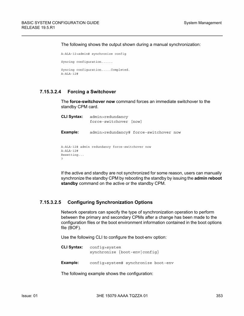
BASIC SYSTEM CONFIGURATION GUIDE RELEASE 19.5.R1
System Management
Issue: 01 3HE 15079 AAAA TQZZA 01 353
The following shows the output shown during a manual synchronization:
A:ALA-12>admin# synchronize config
Syncing configuration......
Syncing configuration.....Completed.A:ALA-12#
7.15.3.2.4 Forcing a Switchover
The force-switchover now command forces an immediate switchover to the standby CPM card.
CLI Syntax: admin>redundancyforce-switchover [now]
Example: admin>redundancy# force-switchover now
A:ALA-12# admin redundancy force-switchover nowA:ALA-12#Resetting...?
If the active and standby are not synchronized for some reason, users can manually synchronize the standby CPM by rebooting the standby by issuing the admin reboot standby command on the active or the standby CPM.
7.15.3.2.5 Configuring Synchronization Options
Network operators can specify the type of synchronization operation to perform between the primary and secondary CPMs after a change has been made to the configuration files or the boot environment information contained in the boot options file (BOF).
Use the following CLI to configure the boot-env option:
CLI Syntax: config>systemsynchronize {boot-env|config}
Example: config>system# synchronize boot-env
The following example shows the configuration:
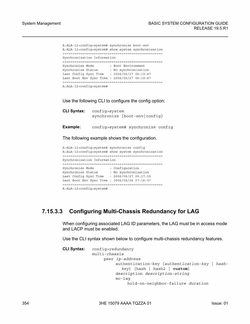
System Management
354
BASIC SYSTEM CONFIGURATION GUIDERELEASE 19.5.R1
3HE 15079 AAAA TQZZA 01 Issue: 01
A:ALA-12>config>system# synchronize boot-envA:ALA-12>config>system# show system synchronization===================================================Synchronization Information===================================================Synchronize Mode : Boot EnvironmentSynchronize Status : No synchronizationLast Config Sync Time : 2006/06/27 06:19:47Last Boot Env Sync Time : 2006/06/27 06:19:47===================================================A:ALA-12>config>system#
Use the following CLI to configure the config option:
CLI Syntax: config>systemsynchronize {boot-env|config}
Example: config>system# synchronize config
The following example shows the configuration.
A:ALA-12>config>system# synchronize configA:ALA-12>config>system# show system synchronization===================================================Synchronization Information===================================================Synchronize Mode : ConfigurationSynchronize Status : No synchronizationLast Config Sync Time : 2006/06/27 09:17:15Last Boot Env Sync Time : 2006/06/24 07:16:37===================================================A:ALA-12>config>system#
7.15.3.3 Configuring Multi-Chassis Redundancy for LAG
When configuring associated LAG ID parameters, the LAG must be in access mode and LACP must be enabled.
Use the CLI syntax shown below to configure multi-chassis redundancy features.
CLI Syntax: config>redundancymulti-chassis
peer ip-addressauthentication-key [authentication-key | hash-
key] [hash | hash2 | custom]description description-stringmc-lag
hold-on-neighbor-failure duration
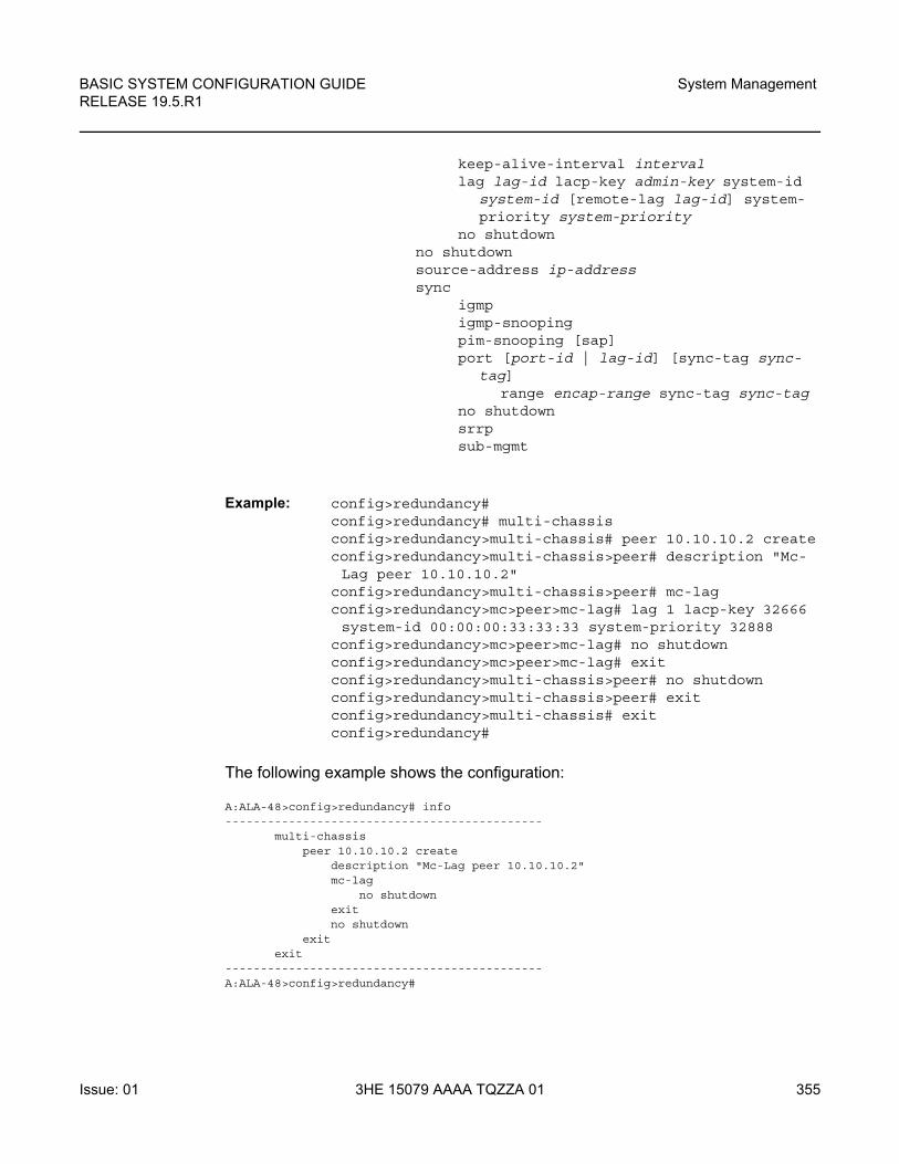
BASIC SYSTEM CONFIGURATION GUIDE RELEASE 19.5.R1
System Management
Issue: 01 3HE 15079 AAAA TQZZA 01 355
keep-alive-interval intervallag lag-id lacp-key admin-key system-id
system-id [remote-lag lag-id] system-priority system-priority
no shutdownno shutdownsource-address ip-addresssync
igmpigmp-snoopingpim-snooping [sap]port [port-id | lag-id] [sync-tag sync-
tag]range encap-range sync-tag sync-tag
no shutdownsrrpsub-mgmt
Example: config>redundancy# config>redundancy# multi-chassisconfig>redundancy>multi-chassis# peer 10.10.10.2 createconfig>redundancy>multi-chassis>peer# description "Mc-Lag peer 10.10.10.2"
config>redundancy>multi-chassis>peer# mc-lagconfig>redundancy>mc>peer>mc-lag# lag 1 lacp-key 32666 system-id 00:00:00:33:33:33 system-priority 32888
config>redundancy>mc>peer>mc-lag# no shutdownconfig>redundancy>mc>peer>mc-lag# exitconfig>redundancy>multi-chassis>peer# no shutdownconfig>redundancy>multi-chassis>peer# exitconfig>redundancy>multi-chassis# exitconfig>redundancy#
The following example shows the configuration:
A:ALA-48>config>redundancy# info---------------------------------------------
multi-chassispeer 10.10.10.2 create
description "Mc-Lag peer 10.10.10.2"mc-lag
no shutdownexitno shutdown
exitexit
---------------------------------------------A:ALA-48>config>redundancy#
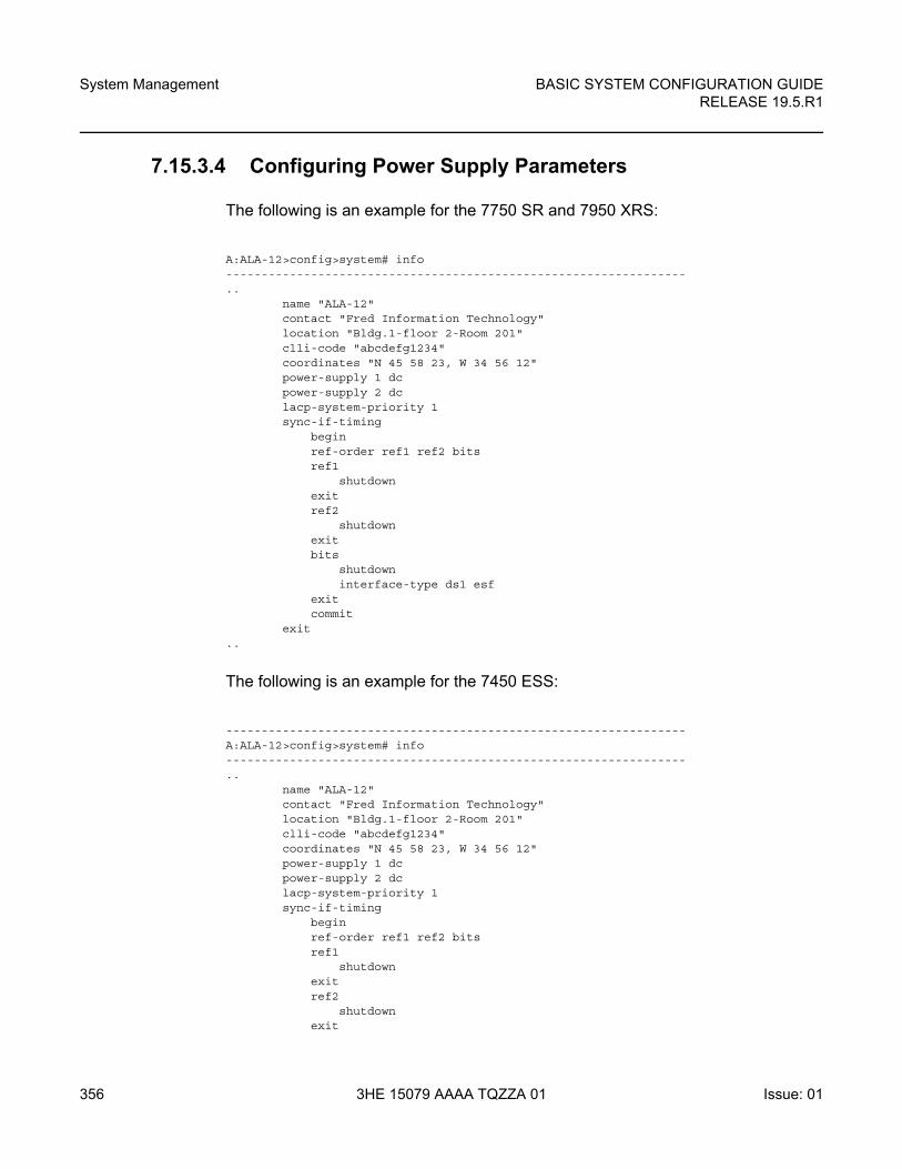
System Management
356
BASIC SYSTEM CONFIGURATION GUIDERELEASE 19.5.R1
3HE 15079 AAAA TQZZA 01 Issue: 01
7.15.3.4 Configuring Power Supply Parameters
The following is an example for the 7750 SR and 7950 XRS:
A:ALA-12>config>system# info-----------------------------------------------------------------..
name "ALA-12"contact "Fred Information Technology"location "Bldg.1-floor 2-Room 201"clli-code "abcdefg1234"coordinates "N 45 58 23, W 34 56 12"power-supply 1 dcpower-supply 2 dclacp-system-priority 1sync-if-timing
beginref-order ref1 ref2 bitsref1
shutdownexitref2
shutdownexitbits
shutdowninterface-type ds1 esf
exitcommit
exit..
The following is an example for the 7450 ESS:
-----------------------------------------------------------------A:ALA-12>config>system# info-----------------------------------------------------------------..
name "ALA-12"contact "Fred Information Technology"location "Bldg.1-floor 2-Room 201"clli-code "abcdefg1234"coordinates "N 45 58 23, W 34 56 12"power-supply 1 dcpower-supply 2 dclacp-system-priority 1sync-if-timing
beginref-order ref1 ref2 bitsref1
shutdownexitref2
shutdownexit
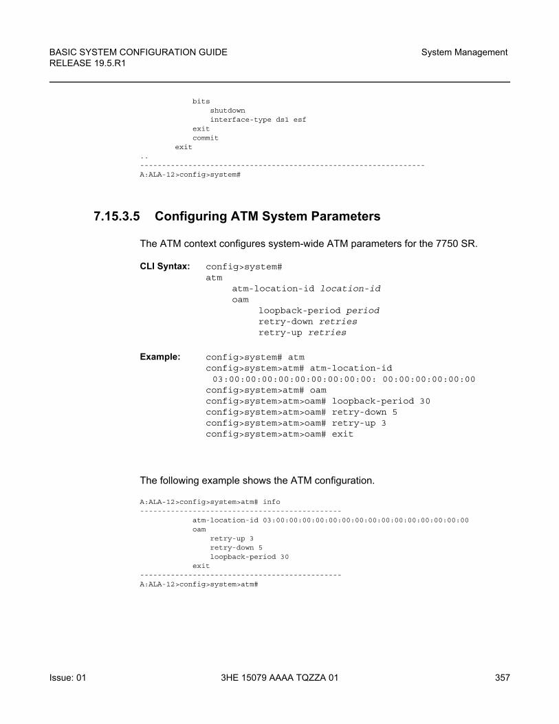
BASIC SYSTEM CONFIGURATION GUIDE RELEASE 19.5.R1
System Management
Issue: 01 3HE 15079 AAAA TQZZA 01 357
bitsshutdowninterface-type ds1 esf
exitcommit
exit..-----------------------------------------------------------------A:ALA-12>config>system#
7.15.3.5 Configuring ATM System Parameters
The ATM context configures system-wide ATM parameters for the 7750 SR.
CLI Syntax: config>system#atm
atm-location-id location-idoam
loopback-period periodretry-down retriesretry-up retries
Example: config>system# atmconfig>system>atm# atm-location-id 03:00:00:00:00:00:00:00:00:00: 00:00:00:00:00:00
config>system>atm# oamconfig>system>atm>oam# loopback-period 30config>system>atm>oam# retry-down 5config>system>atm>oam# retry-up 3config>system>atm>oam# exit
The following example shows the ATM configuration.
A:ALA-12>config>system>atm# info----------------------------------------------
atm-location-id 03:00:00:00:00:00:00:00:00:00:00:00:00:00:00:00oam
retry-up 3retry-down 5loopback-period 30
exit----------------------------------------------A:ALA-12>config>system>atm#
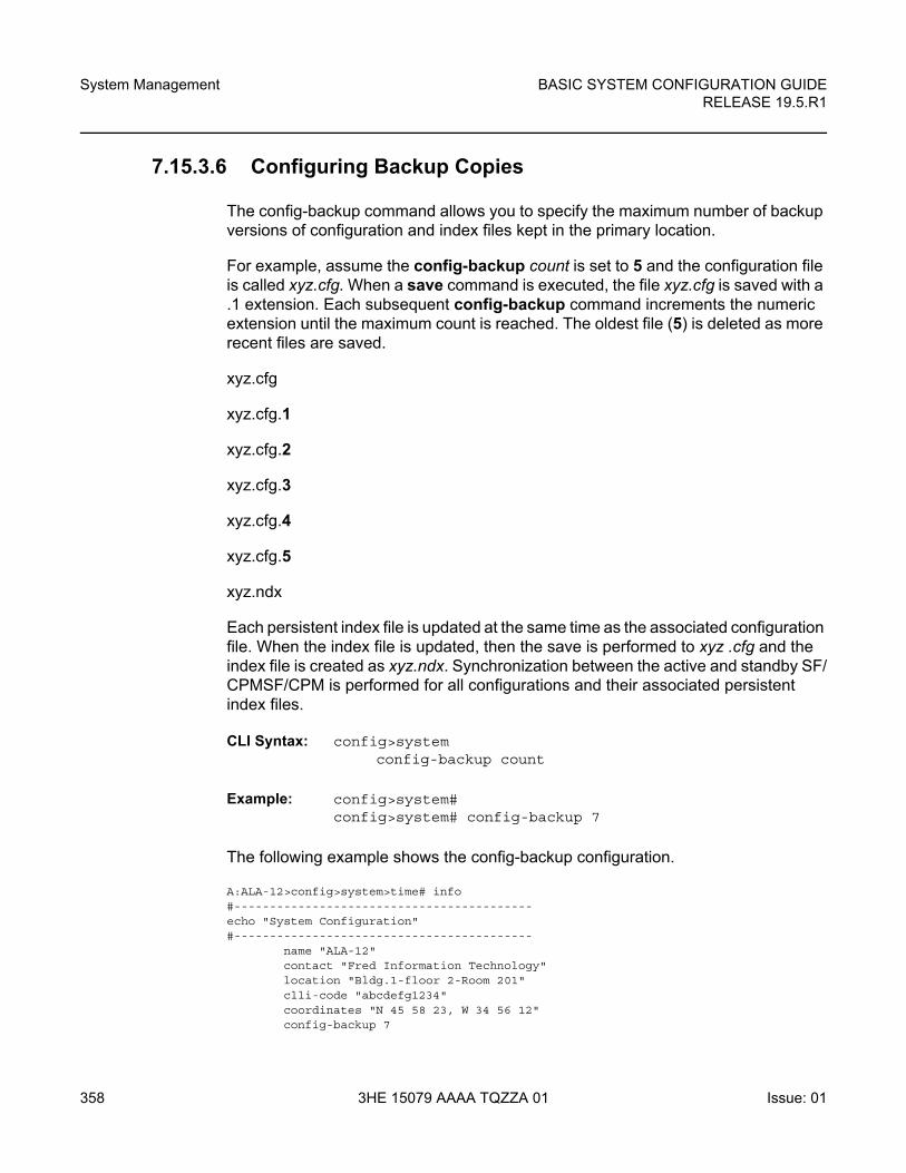
System Management
358
BASIC SYSTEM CONFIGURATION GUIDERELEASE 19.5.R1
3HE 15079 AAAA TQZZA 01 Issue: 01
7.15.3.6 Configuring Backup Copies
The config-backup command allows you to specify the maximum number of backup versions of configuration and index files kept in the primary location.
For example, assume the config-backup count is set to 5 and the configuration file is called xyz.cfg. When a save command is executed, the file xyz.cfg is saved with a .1 extension. Each subsequent config-backup command increments the numeric extension until the maximum count is reached. The oldest file (5) is deleted as more recent files are saved.
xyz.cfg
xyz.cfg.1
xyz.cfg.2
xyz.cfg.3
xyz.cfg.4
xyz.cfg.5
xyz.ndx
Each persistent index file is updated at the same time as the associated configuration file. When the index file is updated, then the save is performed to xyz .cfg and the index file is created as xyz.ndx. Synchronization between the active and standby SF/CPMSF/CPM is performed for all configurations and their associated persistent index files.
CLI Syntax: config>systemconfig-backup count
Example: config>system#config>system# config-backup 7
The following example shows the config-backup configuration.
A:ALA-12>config>system>time# info#------------------------------------------echo "System Configuration"#------------------------------------------
name "ALA-12"contact "Fred Information Technology"location "Bldg.1-floor 2-Room 201"clli-code "abcdefg1234"coordinates "N 45 58 23, W 34 56 12"config-backup 7
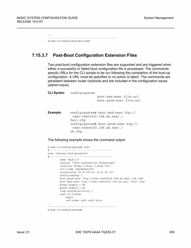
BASIC SYSTEM CONFIGURATION GUIDE RELEASE 19.5.R1
System Management
Issue: 01 3HE 15079 AAAA TQZZA 01 359
...----------------------------------------------A:ALA-12>config>system>time#
7.15.3.7 Post-Boot Configuration Extension Files
Two post-boot configuration extension files are supported and are triggered when either a successful or failed boot configuration file is processed. The commands specify URLs for the CLI scripts to be run following the completion of the boot-up configuration. A URL must be specified or no action is taken. The commands are persistent between router (re)boots and are included in the configuration saves (admin>save).
CLI Syntax: config>system boot-bad-exec file-urlboot-good-exec file-url
Example: config>system# boot-bad-exec ftp://test:[email protected]/./
fail.cfgconfig>system# boot-good-exec ftp://test:[email protected]/./
ok.cfg
The following example shows the command output:
A:ALA-12>config>system# info#------------------------------------------echo "System Configuration"#------------------------------------------
name "ALA-12"contact "Fred Information Technology"location "Bldg.1-floor 2-Room 201"clli-code "abcdefg1234"coordinates "N 45 58 23, W 34 56 12"config-backup 7boot-good-exec "ftp://test:[email protected]/./ok.cfg"boot-bad-exec "ftp://test:[email protected]/./fail.cfg"power-supply 1 dcpower-supply 2 dclacp-system-priority 1sync-if-timing
beginref-order ref1 ref2 bits
..----------------------------------------------A:ALA-12>config>system#
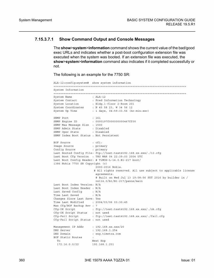
System Management
360
BASIC SYSTEM CONFIGURATION GUIDERELEASE 19.5.R1
3HE 15079 AAAA TQZZA 01 Issue: 01
7.15.3.7.1 Show Command Output and Console Messages
The show>system>information command shows the current value of the bad/good exec URLs and indicates whether a post-boot configuration extension file was executed when the system was booted. If an extension file was executed, the show>system>information command also indicates if it completed successfully or not.
The following is an example for the 7750 SR:
ALA-12>config>system# show system information===============================================================================System Information===============================================================================System Name : ALA-12System Contact : Fred Information TechnologySystem Location : Bldg.1-floor 2-Room 201System Coordinates : N 45 58 23, W 34 56 12System Up Time : 1 days, 04:59:33.56 (hr:min:sec)
SNMP Port : 161SNMP Engine ID : 0000197f000000000467ff00SNMP Max Message Size : 1500SNMP Admin State : DisabledSNMP Oper State : DisabledSNMP Index Boot Status : Not Persistent
BOF Source : cf1:Image Source : primaryConfig Source : primaryLast Booted Config File: ftp://test:[email protected]/./12.cfgLast Boot Cfg Version : THU MAR 04 22:39:03 2004 UTCLast Boot Config Header: # TiMOS-L-14.0.B1-217 boot/i386 Nokia 7750 SR Copyright (c)
2000-2016 Nokia.# All rights reserved. All use subject to applicable licenseagreements.# Built on Wed Jul 13 19:08:56 PDT 2016 by builder in /rel14.0/b1/B1-217/panos/main
Last Boot Index Version: N/ALast Boot Index Header : N/ALast Saved Config : N/ATime Last Saved : N/AChanges Since Last Save: YesTime Last Modified : 2004/03/06 03:30:45Max Cfg/BOF Backup Rev : 7Cfg-OK Script : ftp://test:[email protected]/./ok.cfgCfg-OK Script Status : not usedCfg-Fail Script : ftp://test:[email protected]/./fail.cfgCfg-Fail Script Status : not used
Management IP Addr : 192.168.xx.xxx/20DNS Server : 192.168.1.254DNS Domain : eng.timetra.comBOF Static Routes :
To Next Hop172.16.0.0/22 192.168.1.251
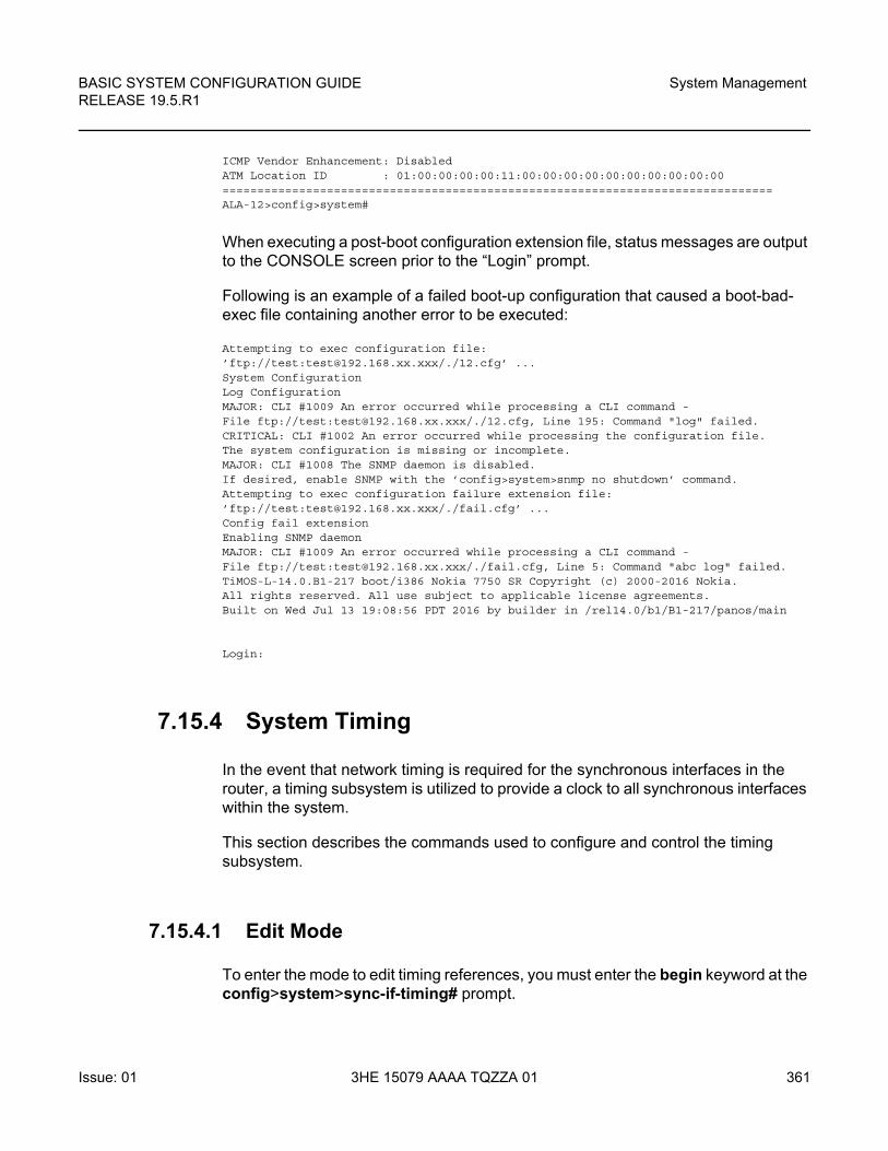
BASIC SYSTEM CONFIGURATION GUIDE RELEASE 19.5.R1
System Management
Issue: 01 3HE 15079 AAAA TQZZA 01 361
ICMP Vendor Enhancement: DisabledATM Location ID : 01:00:00:00:00:11:00:00:00:00:00:00:00:00:00:00===============================================================================ALA-12>config>system#
When executing a post-boot configuration extension file, status messages are output to the CONSOLE screen prior to the “Login” prompt.
Following is an example of a failed boot-up configuration that caused a boot-bad-exec file containing another error to be executed:
Attempting to exec configuration file:’ftp://test:[email protected]/./12.cfg’ ...System ConfigurationLog ConfigurationMAJOR: CLI #1009 An error occurred while processing a CLI command -File ftp://test:[email protected]/./12.cfg, Line 195: Command "log" failed.CRITICAL: CLI #1002 An error occurred while processing the configuration file.The system configuration is missing or incomplete.MAJOR: CLI #1008 The SNMP daemon is disabled.If desired, enable SNMP with the ’config>system>snmp no shutdown’ command.Attempting to exec configuration failure extension file:’ftp://test:[email protected]/./fail.cfg’ ...Config fail extensionEnabling SNMP daemonMAJOR: CLI #1009 An error occurred while processing a CLI command -File ftp://test:[email protected]/./fail.cfg, Line 5: Command "abc log" failed.TiMOS-L-14.0.B1-217 boot/i386 Nokia 7750 SR Copyright (c) 2000-2016 Nokia.All rights reserved. All use subject to applicable license agreements.Built on Wed Jul 13 19:08:56 PDT 2016 by builder in /rel14.0/b1/B1-217/panos/main
Login:
7.15.4 System Timing
In the event that network timing is required for the synchronous interfaces in the router, a timing subsystem is utilized to provide a clock to all synchronous interfaces within the system.
This section describes the commands used to configure and control the timing subsystem.
7.15.4.1 Edit Mode
To enter the mode to edit timing references, you must enter the begin keyword at the config>system>sync-if-timing# prompt.
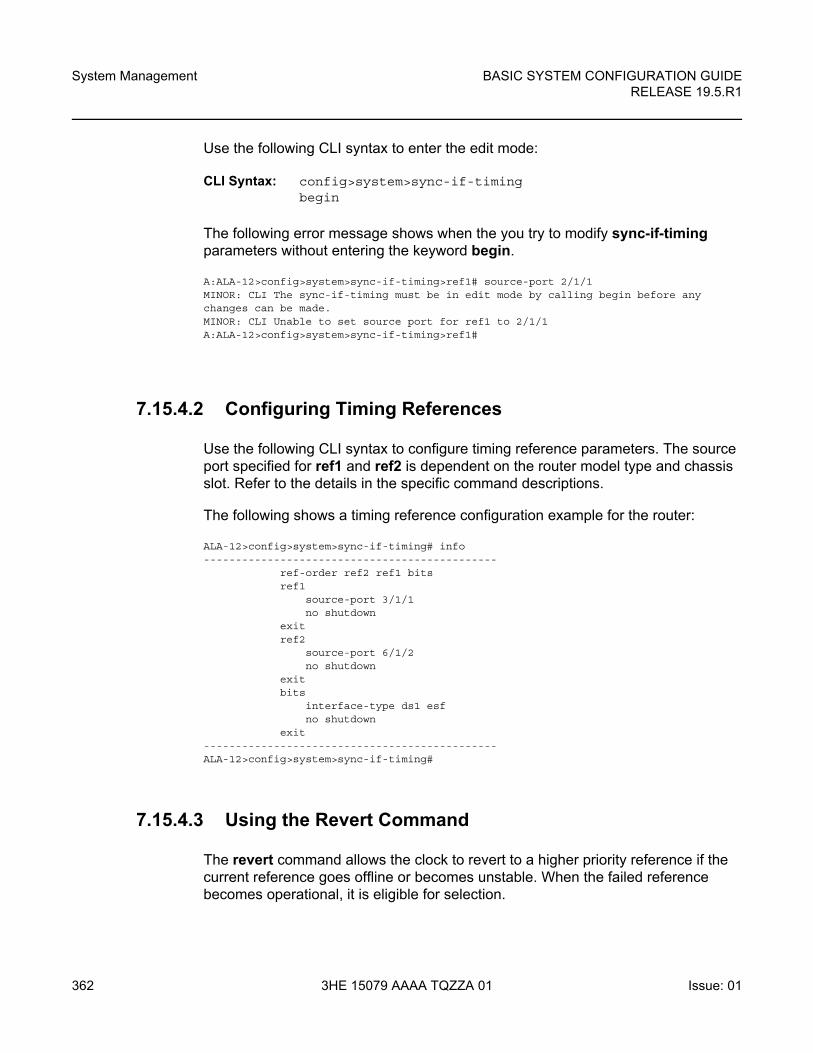
System Management
362
BASIC SYSTEM CONFIGURATION GUIDERELEASE 19.5.R1
3HE 15079 AAAA TQZZA 01 Issue: 01
Use the following CLI syntax to enter the edit mode:
CLI Syntax: config>system>sync-if-timingbegin
The following error message shows when the you try to modify sync-if-timing parameters without entering the keyword begin.
A:ALA-12>config>system>sync-if-timing>ref1# source-port 2/1/1MINOR: CLI The sync-if-timing must be in edit mode by calling begin before anychanges can be made.MINOR: CLI Unable to set source port for ref1 to 2/1/1A:ALA-12>config>system>sync-if-timing>ref1#
7.15.4.2 Configuring Timing References
Use the following CLI syntax to configure timing reference parameters. The source port specified for ref1 and ref2 is dependent on the router model type and chassis slot. Refer to the details in the specific command descriptions.
The following shows a timing reference configuration example for the router:
ALA-12>config>system>sync-if-timing# info----------------------------------------------
ref-order ref2 ref1 bitsref1
source-port 3/1/1no shutdown
exitref2
source-port 6/1/2no shutdown
exitbits
interface-type ds1 esfno shutdown
exit----------------------------------------------ALA-12>config>system>sync-if-timing#
7.15.4.3 Using the Revert Command
The revert command allows the clock to revert to a higher priority reference if the current reference goes offline or becomes unstable. When the failed reference becomes operational, it is eligible for selection.
BASIC SYSTEM CONFIGURATION GUIDE RELEASE 19.5.R1
System Management
Issue: 01 3HE 15079 AAAA TQZZA 01 363
When mode is non-revertive, a failed clock source is not selected again. If a node would enter holdover due to the references being in previous failed state, then the node will select one of the previously failed references rather than going into holdover.
CLI Syntax: config>system>sync-if-timing revert
If the current reference goes offline or becomes unstable the revert command allows the clock to revert to a higher-priority reference.
When revertive switching enabled a valid timing reference of the highest priority is used. If a reference with a higher priority becomes valid, a reference switch over to that reference is initiated. If a failure on the current reference occurs, the next highest reference takes over.
If non-revertive switching is enabled, the valid active reference always remains selected even if a higher priority reference becomes available. If the active reference becomes invalid, a reference switch over to a valid reference with the highest priority is initiated. The failed reference is eligible for selection once it becomes operational.
CLI Syntax: config>system>sync-if-timingno revert
7.15.4.4 Other Editing Commands
Other editing commands include:
• commit — This command saves changes made to the timing references during a session. Modifications are not persistent across system boots unless this command is entered.
• abort — This command discards changes that have been made to the timing references during a session.
CLI Syntax: config>system>sync-if-timing abortcommit
System Management
364
BASIC SYSTEM CONFIGURATION GUIDERELEASE 19.5.R1
3HE 15079 AAAA TQZZA 01 Issue: 01
7.15.4.5 Forcing a Specific Reference
The debug sync-if-timing force-reference command should only be used to test and debug problems. Network synchronization problems may appear if network elements are left with this manual override setting. Once the system timing reference input has been forced, it may be cleared using the no force-reference command.
You can force the CPM clock to use a specific input reference using the force-reference command.
When the command is executed, the CPM clock on the active CPM immediately switches its input reference to that specified by the command. If the specified input is not available (shutdown), or in a disqualified state, the CPM clock shall use the next qualified input reference based on the selection rules.
This command also affects the BITS output port. If the BITS output port selection is set to line-reference and the reference being forced is not the BITS input port, then the system uses the forced reference to generate the signal out the BITS output port. If the BITS output port selection is set to internal-clock, then the system uses the output of the CPM clock to generate the signal for the BITS output port.
On a CPM activity switch, the force command is cleared and normal reference selection is determined.
Debug configurations are not saved between reboots.
CLI Syntax: debug>sync-if-timingforce-reference {ref1 | ref2 | bits}
debug>sync-if-timing# force-reference
7.15.5 Configuring System Monitoring Thresholds
7.15.5.1 Creating Events
The event command controls the generation and notification of threshold crossing events configured with the alarm command. When a threshold crossing event is triggered, the rmon event configuration optionally specifies whether an entry in the RMON-MIB log table be created to record the occurrence of the event. It can also specify whether an SNMP notification (trap) be generated for the event. There are two notifications for threshold crossing events, a rising alarm and a falling alarm.ping-address
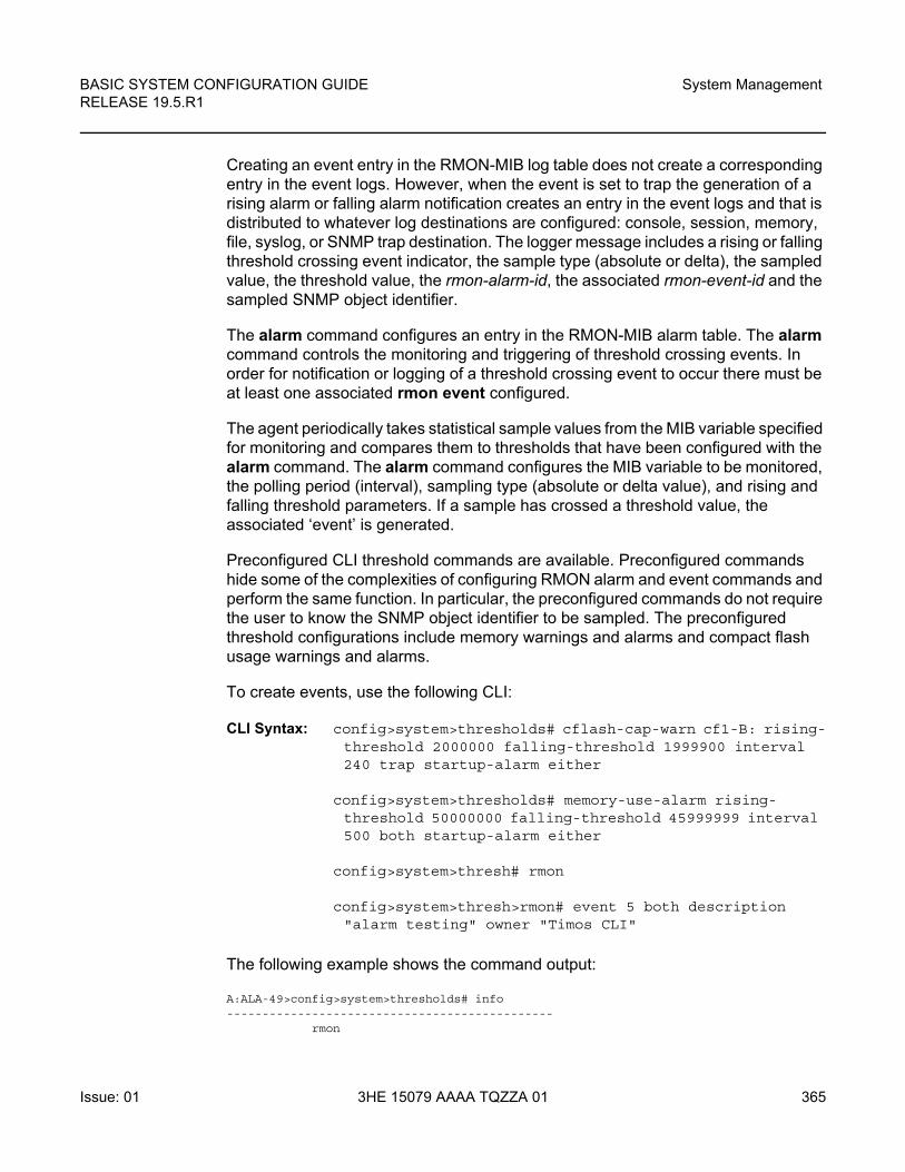
BASIC SYSTEM CONFIGURATION GUIDE RELEASE 19.5.R1
System Management
Issue: 01 3HE 15079 AAAA TQZZA 01 365
Creating an event entry in the RMON-MIB log table does not create a corresponding entry in the event logs. However, when the event is set to trap the generation of a rising alarm or falling alarm notification creates an entry in the event logs and that is distributed to whatever log destinations are configured: console, session, memory, file, syslog, or SNMP trap destination. The logger message includes a rising or falling threshold crossing event indicator, the sample type (absolute or delta), the sampled value, the threshold value, the rmon-alarm-id, the associated rmon-event-id and the sampled SNMP object identifier.
The alarm command configures an entry in the RMON-MIB alarm table. The alarm command controls the monitoring and triggering of threshold crossing events. In order for notification or logging of a threshold crossing event to occur there must be at least one associated rmon event configured.
The agent periodically takes statistical sample values from the MIB variable specified for monitoring and compares them to thresholds that have been configured with the alarm command. The alarm command configures the MIB variable to be monitored, the polling period (interval), sampling type (absolute or delta value), and rising and falling threshold parameters. If a sample has crossed a threshold value, the associated ‘event’ is generated.
Preconfigured CLI threshold commands are available. Preconfigured commands hide some of the complexities of configuring RMON alarm and event commands and perform the same function. In particular, the preconfigured commands do not require the user to know the SNMP object identifier to be sampled. The preconfigured threshold configurations include memory warnings and alarms and compact flash usage warnings and alarms.
To create events, use the following CLI:
CLI Syntax: config>system>thresholds# cflash-cap-warn cf1-B: rising-threshold 2000000 falling-threshold 1999900 interval 240 trap startup-alarm either
config>system>thresholds# memory-use-alarm rising-threshold 50000000 falling-threshold 45999999 interval 500 both startup-alarm either
config>system>thresh# rmon
config>system>thresh>rmon# event 5 both description "alarm testing" owner "Timos CLI"
The following example shows the command output:
A:ALA-49>config>system>thresholds# info----------------------------------------------
rmon
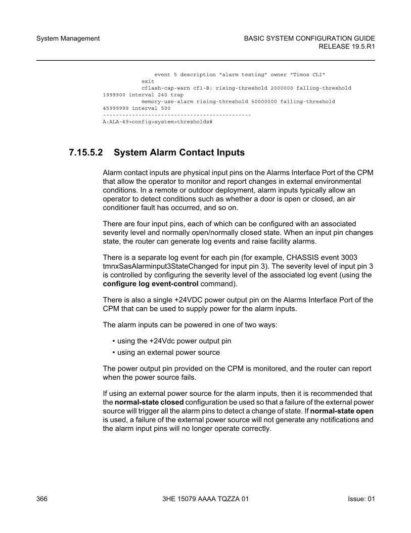
System Management
366
BASIC SYSTEM CONFIGURATION GUIDERELEASE 19.5.R1
3HE 15079 AAAA TQZZA 01 Issue: 01
event 5 description "alarm testing" owner "Timos CLI"exitcflash-cap-warn cf1-B: rising-threshold 2000000 falling-threshold
1999900 interval 240 trapmemory-use-alarm rising-threshold 50000000 falling-threshold
45999999 interval 500----------------------------------------------A:ALA-49>config>system>thresholds#
7.15.5.2 System Alarm Contact Inputs
Alarm contact inputs are physical input pins on the Alarms Interface Port of the CPM that allow the operator to monitor and report changes in external environmental conditions. In a remote or outdoor deployment, alarm inputs typically allow an operator to detect conditions such as whether a door is open or closed, an air conditioner fault has occurred, and so on.
There are four input pins, each of which can be configured with an associated severity level and normally open/normally closed state. When an input pin changes state, the router can generate log events and raise facility alarms.
There is a separate log event for each pin (for example, CHASSIS event 3003 tmnxSasAlarminput3StateChanged for input pin 3). The severity level of input pin 3 is controlled by configuring the severity level of the associated log event (using the configure log event-control command).
There is also a single +24VDC power output pin on the Alarms Interface Port of the CPM that can be used to supply power for the alarm inputs.
The alarm inputs can be powered in one of two ways:
• using the +24Vdc power output pin
• using an external power source
The power output pin provided on the CPM is monitored, and the router can report when the power source fails.
If using an external power source for the alarm inputs, then it is recommended that the normal-state closed configuration be used so that a failure of the external power source will trigger all the alarm pins to detect a change of state. If normal-state open is used, a failure of the external power source will not generate any notifications and the alarm input pins will no longer operate correctly.
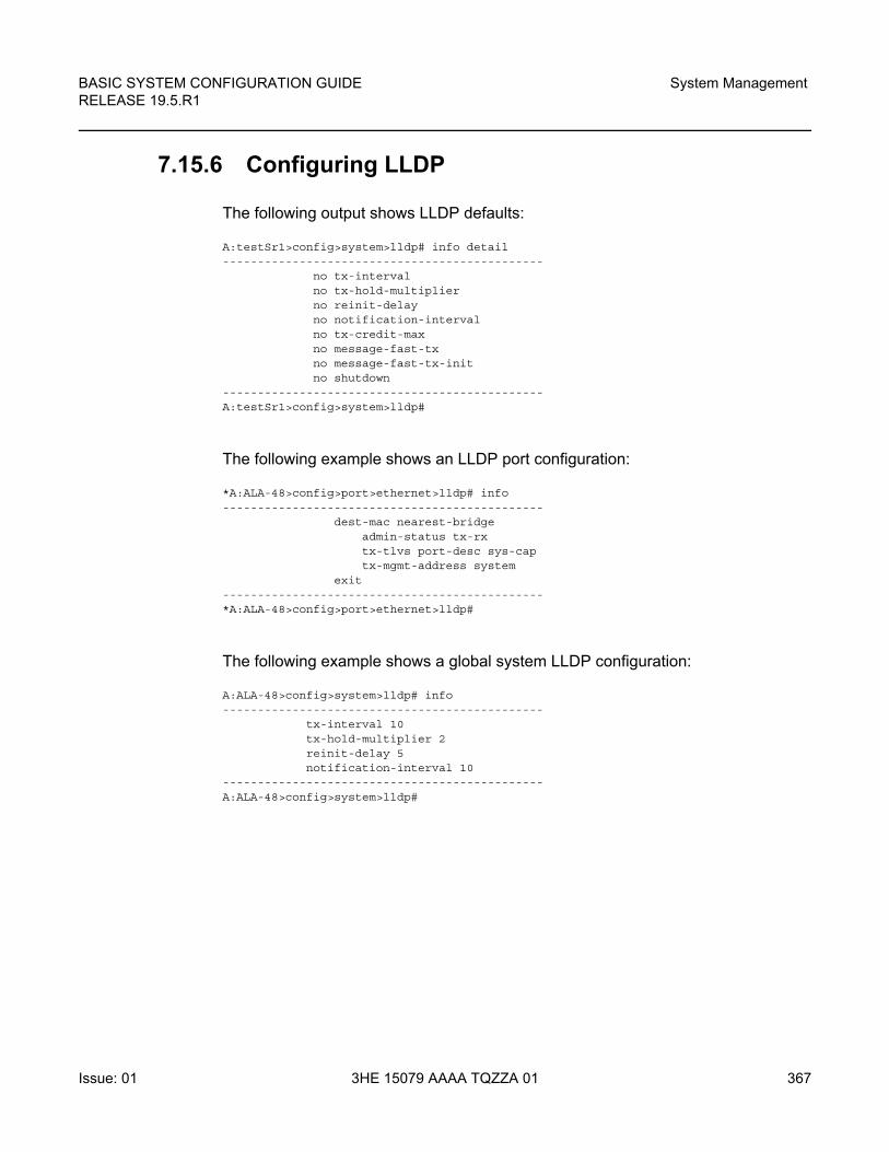
BASIC SYSTEM CONFIGURATION GUIDE RELEASE 19.5.R1
System Management
Issue: 01 3HE 15079 AAAA TQZZA 01 367
7.15.6 Configuring LLDP
The following output shows LLDP defaults:
A:testSr1>config>system>lldp# info detail----------------------------------------------
no tx-intervalno tx-hold-multiplierno reinit-delayno notification-intervalno tx-credit-maxno message-fast-txno message-fast-tx-initno shutdown
----------------------------------------------A:testSr1>config>system>lldp#
The following example shows an LLDP port configuration:
*A:ALA-48>config>port>ethernet>lldp# info----------------------------------------------
dest-mac nearest-bridgeadmin-status tx-rxtx-tlvs port-desc sys-captx-mgmt-address system
exit----------------------------------------------*A:ALA-48>config>port>ethernet>lldp#
The following example shows a global system LLDP configuration:
A:ALA-48>config>system>lldp# info----------------------------------------------
tx-interval 10tx-hold-multiplier 2reinit-delay 5notification-interval 10
----------------------------------------------A:ALA-48>config>system>lldp#

System Management
368
BASIC SYSTEM CONFIGURATION GUIDERELEASE 19.5.R1
3HE 15079 AAAA TQZZA 01 Issue: 01
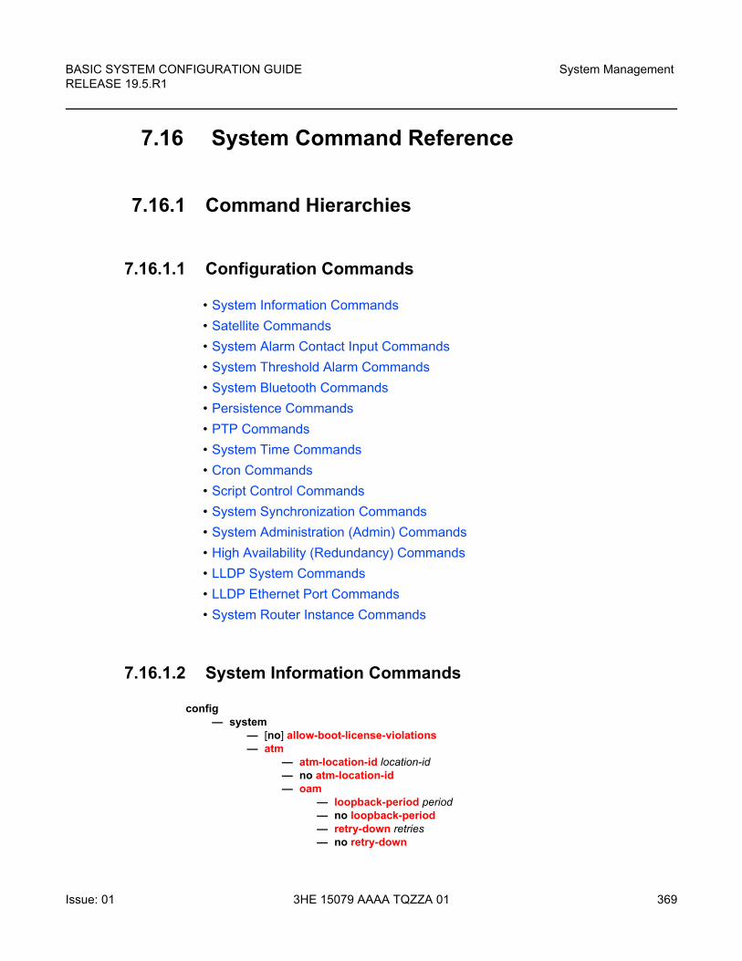
BASIC SYSTEM CONFIGURATION GUIDE RELEASE 19.5.R1
System Management
Issue: 01 3HE 15079 AAAA TQZZA 01 369
7.16 System Command Reference
7.16.1 Command Hierarchies
7.16.1.1 Configuration Commands
• System Information Commands
• Satellite Commands
• System Alarm Contact Input Commands
• System Threshold Alarm Commands
• System Bluetooth Commands
• Persistence Commands
• PTP Commands
• System Time Commands
• Cron Commands
• Script Control Commands
• System Synchronization Commands
• System Administration (Admin) Commands
• High Availability (Redundancy) Commands
• LLDP System Commands
• LLDP Ethernet Port Commands
• System Router Instance Commands
7.16.1.2 System Information Commands
config— system
— [no] allow-boot-license-violations — atm
— atm-location-id location-id— no atm-location-id— oam
— loopback-period period— no loopback-period— retry-down retries— no retry-down
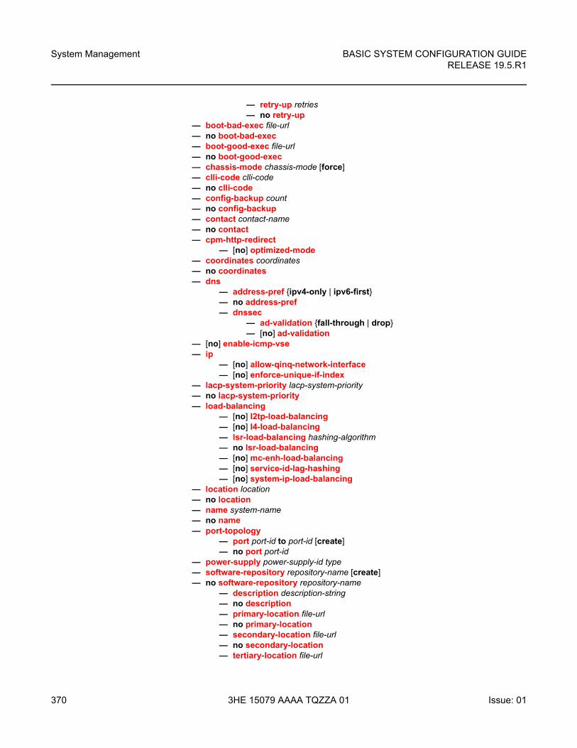
System Management
370
BASIC SYSTEM CONFIGURATION GUIDERELEASE 19.5.R1
3HE 15079 AAAA TQZZA 01 Issue: 01
— retry-up retries— no retry-up
— boot-bad-exec file-url— no boot-bad-exec — boot-good-exec file-url— no boot-good-exec— chassis-mode chassis-mode [force]— clli-code clli-code— no clli-code — config-backup count— no config-backup— contact contact-name— no contact— cpm-http-redirect
— [no] optimized-mode— coordinates coordinates— no coordinates— dns
— address-pref {ipv4-only | ipv6-first}— no address-pref— dnssec
— ad-validation {fall-through | drop}— [no] ad-validation
— [no] enable-icmp-vse— ip
— [no] allow-qinq-network-interface— [no] enforce-unique-if-index
— lacp-system-priority lacp-system-priority— no lacp-system-priority— load-balancing
— [no] l2tp-load-balancing — [no] l4-load-balancing— lsr-load-balancing hashing-algorithm— no lsr-load-balancing— [no] mc-enh-load-balancing— [no] service-id-lag-hashing— [no] system-ip-load-balancing
— location location— no location— name system-name— no name— port-topology
— port port-id to port-id [create]— no port port-id
— power-supply power-supply-id type— software-repository repository-name [create]— no software-repository repository-name
— description description-string— no description — primary-location file-url — no primary-location — secondary-location file-url — no secondary-location — tertiary-location file-url
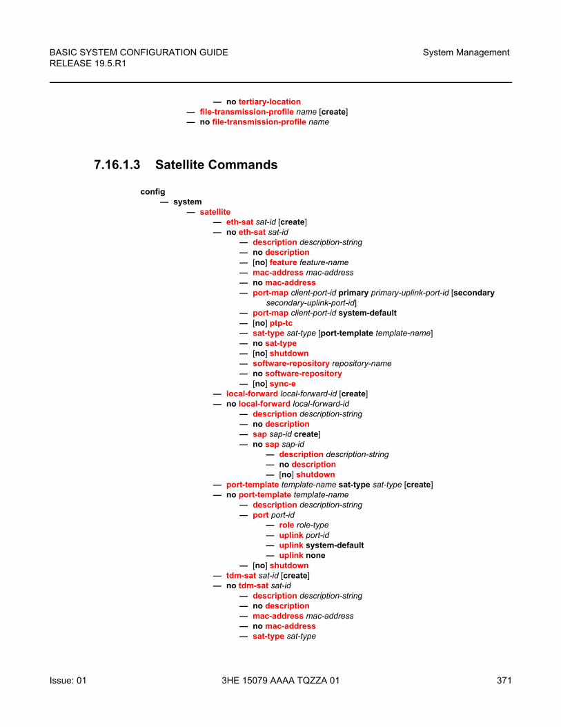
BASIC SYSTEM CONFIGURATION GUIDE RELEASE 19.5.R1
System Management
Issue: 01 3HE 15079 AAAA TQZZA 01 371
— no tertiary-location — file-transmission-profile name [create]— no file-transmission-profile name
7.16.1.3 Satellite Commands
config— system
— satellite — eth-sat sat-id [create]— no eth-sat sat-id
— description description-string— no description — [no] feature feature-name— mac-address mac-address— no mac-address— port-map client-port-id primary primary-uplink-port-id [secondary
secondary-uplink-port-id] — port-map client-port-id system-default— [no] ptp-tc— sat-type sat-type [port-template template-name]— no sat-type— [no] shutdown — software-repository repository-name— no software-repository — [no] sync-e
— local-forward local-forward-id [create]— no local-forward local-forward-id
— description description-string— no description — sap sap-id create]— no sap sap-id
— description description-string— no description — [no] shutdown
— port-template template-name sat-type sat-type [create]— no port-template template-name
— description description-string— port port-id
— role role-type— uplink port-id— uplink system-default— uplink none
— [no] shutdown — tdm-sat sat-id [create]— no tdm-sat sat-id
— description description-string— no description — mac-address mac-address— no mac-address— sat-type sat-type
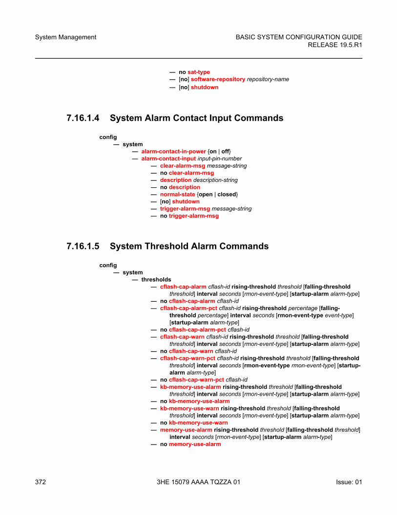
System Management
372
BASIC SYSTEM CONFIGURATION GUIDERELEASE 19.5.R1
3HE 15079 AAAA TQZZA 01 Issue: 01
— no sat-type— [no] software-repository repository-name— [no] shutdown
7.16.1.4 System Alarm Contact Input Commands
config— system
— alarm-contact-in-power {on | off}— alarm-contact-input input-pin-number
— clear-alarm-msg message-string— no clear-alarm-msg— description description-string— no description— normal-state {open | closed}— [no] shutdown— trigger-alarm-msg message-string— no trigger-alarm-msg
7.16.1.5 System Threshold Alarm Commands
config— system
— thresholds— cflash-cap-alarm cflash-id rising-threshold threshold [falling-threshold
threshold] interval seconds [rmon-event-type] [startup-alarm alarm-type]— no cflash-cap-alarm cflash-id— cflash-cap-alarm-pct cflash-id rising-threshold percentage [falling-
threshold percentage] interval seconds [rmon-event-type event-type] [startup-alarm alarm-type]
— no cflash-cap-alarm-pct cflash-id— cflash-cap-warn cflash-id rising-threshold threshold [falling-threshold
threshold] interval seconds [rmon-event-type] [startup-alarm alarm-type]— no cflash-cap-warn cflash-id — cflash-cap-warn-pct cflash-id rising-threshold threshold [falling-threshold
threshold] interval seconds [rmon-event-type rmon-event-type] [startup-alarm alarm-type]
— no cflash-cap-warn-pct cflash-id — kb-memory-use-alarm rising-threshold threshold [falling-threshold
threshold] interval seconds [rmon-event-type] [startup-alarm alarm-type]— no kb-memory-use-alarm— kb-memory-use-warn rising-threshold threshold [falling-threshold
threshold] interval seconds [rmon-event-type] [startup-alarm alarm-type]— no kb-memory-use-warn— memory-use-alarm rising-threshold threshold [falling-threshold threshold]
interval seconds [rmon-event-type] [startup-alarm alarm-type]— no memory-use-alarm
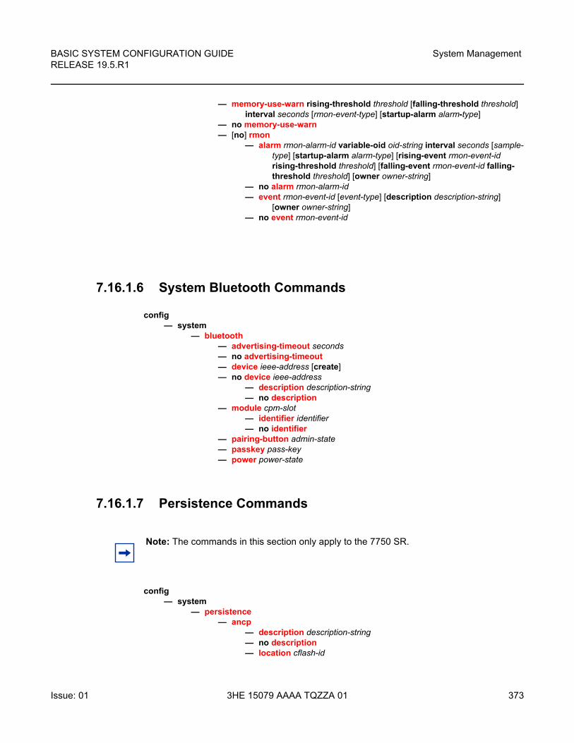
BASIC SYSTEM CONFIGURATION GUIDE RELEASE 19.5.R1
System Management
Issue: 01 3HE 15079 AAAA TQZZA 01 373
— memory-use-warn rising-threshold threshold [falling-threshold threshold] interval seconds [rmon-event-type] [startup-alarm alarm-type]
— no memory-use-warn— [no] rmon
— alarm rmon-alarm-id variable-oid oid-string interval seconds [sample-type] [startup-alarm alarm-type] [rising-event rmon-event-id rising-threshold threshold] [falling-event rmon-event-id falling-threshold threshold] [owner owner-string]
— no alarm rmon-alarm-id— event rmon-event-id [event-type] [description description-string]
[owner owner-string]— no event rmon-event-id
7.16.1.6 System Bluetooth Commands
config— system
— bluetooth— advertising-timeout seconds — no advertising-timeout — device ieee-address [create]— no device ieee-address
— description description-string — no description
— module cpm-slot — identifier identifier— no identifier
— pairing-button admin-state— passkey pass-key— power power-state
7.16.1.7 Persistence Commands
config— system
— persistence— ancp
— description description-string— no description— location cflash-id
Note: The commands in this section only apply to the 7750 SR.
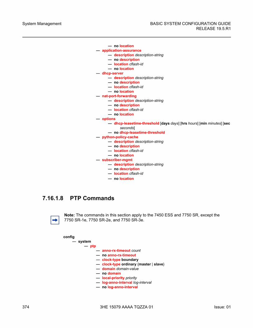
System Management
374
BASIC SYSTEM CONFIGURATION GUIDERELEASE 19.5.R1
3HE 15079 AAAA TQZZA 01 Issue: 01
— no location— application-assurance
— description description-string— no description— location cflash-id— no location
— dhcp-server— description description-string— no description— location cflash-id— no location
— nat-port-forwarding— description description-string— no description— location cflash-id— no location
— options— dhcp-leasetime-threshold [days days] [hrs hours] [min minutes] [sec
seconds]— no dhcp-leasetime-threshold
— python-policy-cache— description description-string— no description— location cflash-id— no location
— subscriber-mgmt— description description-string— no description— location cflash-id— no location
7.16.1.8 PTP Commands
config— system
— ptp— anno-rx-timeout count— no anno-rx-timeout— clock-type boundary— clock-type ordinary {master | slave}— domain domain-value— no domain— local-priority priority— log-anno-interval log-interval— no log-anno-interval
Note: The commands in this section apply to the 7450 ESS and 7750 SR, except the 7750 SR-1e, 7750 SR-2e, and 7750 SR-3e.
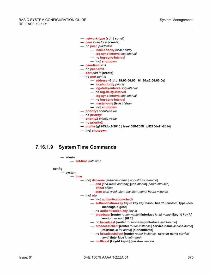
BASIC SYSTEM CONFIGURATION GUIDE RELEASE 19.5.R1
System Management
Issue: 01 3HE 15079 AAAA TQZZA 01 375
— network-type {sdh | sonet}— peer ip-address [create]— no peer ip-address
— local-priority local-priority— log-sync-interval log-interval— no log-sync-interval— [no] shutdown
— peer-limit limit— no peer-limit— port port-id [create]— no port port-id
— address {01:1b:19:00:00:00 | 01:80:c2:00:00:0e}— local-priority priority— log-delay-interval log-interval— no log-delay-interval— log-sync-interval log-interval— no log-sync-interval— master-only {true | false}— [no] shutdown
— priority1 priority-value— no priority1— priority2 priority-value— no priority2— profile {g8265dot1-2010 | ieee1588-2008 | g8275dot1-2014}— [no] shutdown
7.16.1.9 System Time Commands
— admin— set-time date time
config— system
— time— [no] dst-zone {std-zone-name | non-std-zone-name}
— end [end-week end-day] [end-month] [hours-minutes]— offset offset— start start-week start-day start-month hours-minutes
— [no] ntp— [no] authentication-check— authentication-key key-id key key [hash | hash2 | custom] type {des
| message-digest} — no authentication-key key-id— broadcast [router router-name] {interface ip-int-name} [key-id key-id]
[version version] [ttl ttl]— no broadcast [router router-name] {interface ip-int-name}— broadcastclient [router router-instance | service-name service-name]
{interface ip-int-name} [authenticate]— no broadcastclient [router router-instance | service-name service-
name] {interface ip-int-name}— multicast [key-id key-id] [version version]
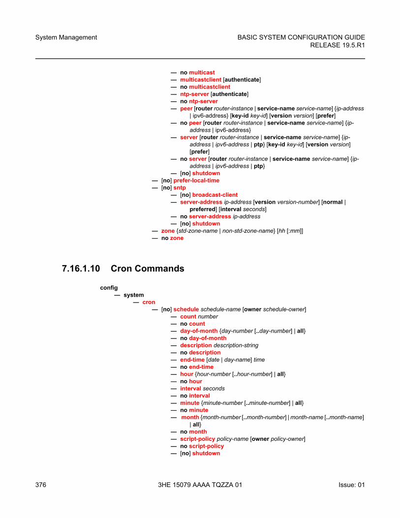
System Management
376
BASIC SYSTEM CONFIGURATION GUIDERELEASE 19.5.R1
3HE 15079 AAAA TQZZA 01 Issue: 01
— no multicast— multicastclient [authenticate]— no multicastclient— ntp-server [authenticate]— no ntp-server— peer [router router-instance | service-name service-name] {ip-address
| ipv6-address} [key-id key-id] [version version] [prefer]— no peer [router router-instance | service-name service-name] {ip-
address | ipv6-address}— server [router router-instance | service-name service-name] {ip-
address | ipv6-address | ptp} [key-id key-id] [version version] [prefer]
— no server [router router-instance | service-name service-name] {ip-address | ipv6-address | ptp}
— [no] shutdown— [no] prefer-local-time— [no] sntp
— [no] broadcast-client— server-address ip-address [version version-number] [normal |
preferred] [interval seconds]— no server-address ip-address— [no] shutdown
— zone {std-zone-name | non-std-zone-name} [hh [:mm]] — no zone
7.16.1.10 Cron Commands
config— system
— cron— [no] schedule schedule-name [owner schedule-owner]
— count number— no count— day-of-month {day-number [..day-number] | all}— no day-of-month— description description-string — no description— end-time [date | day-name] time— no end-time — hour {hour-number [..hour-number] | all} — no hour— interval seconds— no interval— minute {minute-number [..minute-number] | all} — no minute— month {month-number [..month-number] | month-name [..month-name]
| all}— no month— script-policy policy-name [owner policy-owner]— no script-policy— [no] shutdown
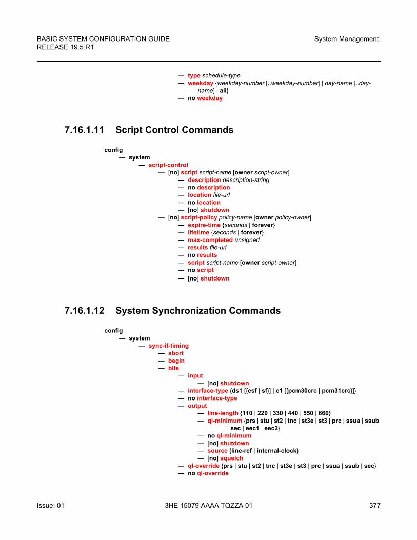
BASIC SYSTEM CONFIGURATION GUIDE RELEASE 19.5.R1
System Management
Issue: 01 3HE 15079 AAAA TQZZA 01 377
— type schedule-type— weekday {weekday-number [..weekday-number] | day-name [..day-
name] | all}— no weekday
7.16.1.11 Script Control Commands
config— system
— script-control— [no] script script-name [owner script-owner]
— description description-string— no description— location file-url— no location— [no] shutdown
— [no] script-policy policy-name [owner policy-owner]— expire-time {seconds | forever}— lifetime {seconds | forever}— max-completed unsigned— results file-url— no results— script script-name [owner script-owner]— no script— [no] shutdown
7.16.1.12 System Synchronization Commands
config— system
— sync-if-timing— abort— begin— bits
— input— [no] shutdown
— interface-type {ds1 [{esf | sf}] | e1 [{pcm30crc | pcm31crc}]}— no interface-type— output
— line-length {110 | 220 | 330 | 440 | 550 | 660}— ql-minimum {prs | stu | st2 | tnc | st3e | st3 | prc | ssua | ssub
| sec | eec1 | eec2}— no ql-minimum — [no] shutdown— source {line-ref | internal-clock}— [no] squelch
— ql-override {prs | stu | st2 | tnc | st3e | st3 | prc | ssua | ssub | sec}— no ql-override
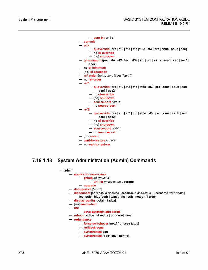
System Management
378
BASIC SYSTEM CONFIGURATION GUIDERELEASE 19.5.R1
3HE 15079 AAAA TQZZA 01 Issue: 01
— ssm-bit sa-bit— commit— ptp
— ql-override {prs | stu | st2 | tnc |st3e | st3 | prc | ssua | ssub | sec}— no ql-override— [no] shutdown
— ql-minimum {prs | stu | st2 | tnc | st3e | st3 | prc | ssua | ssub | sec | eec1 | eec2}
— no ql-minimum — [no] ql-selection— ref-order first second [third [fourth]]— no ref-order— ref1
— ql-override {prs | stu | st2 | tnc | st3e | st3 | prc | ssua | ssub | sec | eec1 | eec2}
— no ql-override— [no] shutdown— source-port port-id— no source-port
— ref2— ql-override {prs | stu | st2 | tnc | st3e | st3 | prc | ssua | ssub | sec |
eec1 | eec2}— no ql-override— [no] shutdown— source-port port-id— no source-port
— [no] revert— wait-to-restore minutes— no wait-to-restore
7.16.1.13 System Administration (Admin) Commands
— admin— application-assurance
— group aa-group-id— url-list url-list-name upgrade
— upgrade— debug-save [file-url]— disconnect [address ip-address | session-id session-id | username user-name |
{console | bluetooth | telnet | ftp | ssh | netconf | grpc}]— display-config [detail | index]— [no] enable-tech— nat
— save-deterministic-script— reboot [active | standby | upgrade] [now] — redundancy
— force-switchover [now] [ignore-status]— rollback-sync— synchronize cert— synchronize {boot-env | config}
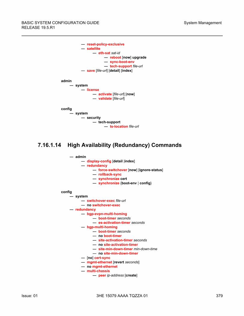
BASIC SYSTEM CONFIGURATION GUIDE RELEASE 19.5.R1
System Management
Issue: 01 3HE 15079 AAAA TQZZA 01 379
— reset-policy-exclusive— satellite
— eth-sat sat-id — reboot [now] upgrade— sync-boot-env — tech-support file-url
— save [file-url] [detail] [index]
admin— system
— license— activate [file-url] [now]— validate [file-url]
config— system
— security— tech-support
— ts-location file-url
7.16.1.14 High Availability (Redundancy) Commands
— admin— display-config [detail |index]— redundancy
— force-switchover [now] [ignore-status]— rollback-sync— synchronize cert— synchronize {boot-env | config}
config— system
— switchover-exec file-url— no switchover-exec
— redundancy— bgp-evpn-multi-homing
— boot-timer seconds— es-activation-timer seconds
— bgp-multi-homing— boot-timer seconds— no boot-timer— site-activation-timer seconds— no site-activation-timer— site-min-down-timer min-down-time— no site-min-down-timer
— [no] cert-sync— mgmt-ethernet [revert seconds]— no mgmt-ethernet— multi-chassis
— peer ip-address [create]
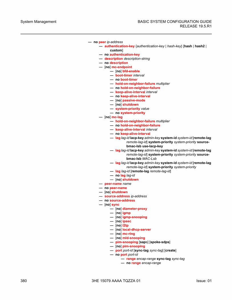
System Management
380
BASIC SYSTEM CONFIGURATION GUIDERELEASE 19.5.R1
3HE 15079 AAAA TQZZA 01 Issue: 01
— no peer ip-address— authentication-key {authentication-key | hash-key} [hash | hash2 |
custom]— no authentication-key— description description-string— no description— [no] mc-endpoint
— [no] bfd-enable— boot-timer interval— no boot-timer— hold-on-neighbor-failure multiplier— no hold-on-neighbor-failure— keep-alive-interval interval— no keep-alive-interval— [no] passive-mode— [no] shutdown— system-priority value— no system-priority
— [no] mc-lag— hold-on-neighbor-failure multiplier— no hold-on-neighbor-failure— keep-alive-interval interval— no keep-alive-interval— lag lag-id lacp-key admin-key system-id system-id [remote-lag
remote-lag-id] system-priority system-priority source-bmac-lsb use-lacp-key
— lag lag-id lacp-key admin-key system-id system-id [remote-lag remote-lag-id] system-priority system-priority source-bmac-lsb MAC-Lsb
— lag lag-id lacp-key admin-key system-id system-id [remote-lag remote-lag-id] system-priority system-priority
— lag lag-id [remote-lag remote-lag-id]— no lag lag-id— [no] shutdown
— peer-name name— no peer-name— [no] shutdown— source-address ip-address— no source-address— [no] sync
— [no] diameter-proxy— [no] igmp— [no] igmp-snooping— [no] ipsec— [no] l2tp— [no] local-dhcp-server— [no] mc-ring— [no] mld-snooping— pim-snooping [saps] [spoke-sdps]— [no] pim-snooping— port port-id [sync-tag sync-tag] [create] — no port port-id
— range encap-range sync-tag sync-tag — no range encap-range
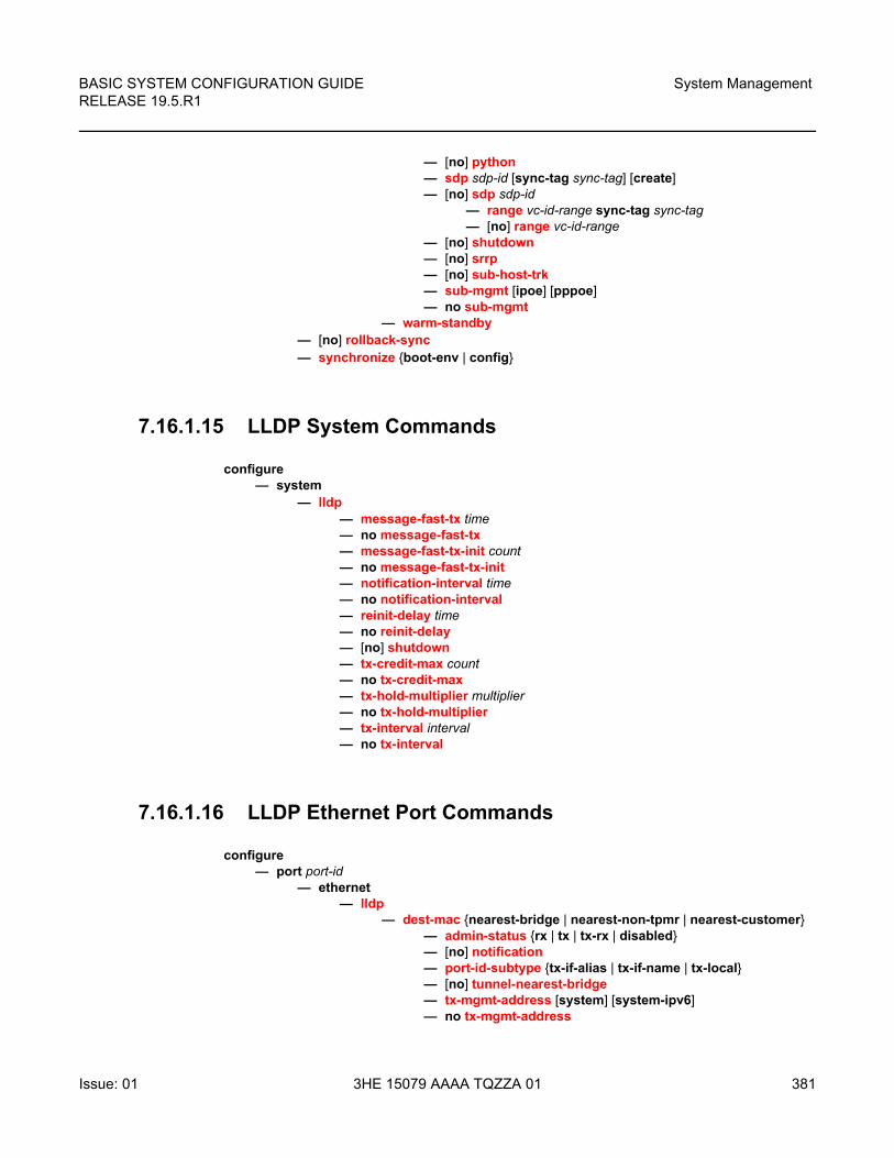
BASIC SYSTEM CONFIGURATION GUIDE RELEASE 19.5.R1
System Management
Issue: 01 3HE 15079 AAAA TQZZA 01 381
— [no] python— sdp sdp-id [sync-tag sync-tag] [create]— [no] sdp sdp-id
— range vc-id-range sync-tag sync-tag— [no] range vc-id-range
— [no] shutdown— [no] srrp— [no] sub-host-trk — sub-mgmt [ipoe] [pppoe]— no sub-mgmt
— warm-standby— [no] rollback-sync— synchronize {boot-env | config}
7.16.1.15 LLDP System Commands
configure— system
— lldp— message-fast-tx time— no message-fast-tx— message-fast-tx-init count— no message-fast-tx-init— notification-interval time— no notification-interval— reinit-delay time— no reinit-delay— [no] shutdown— tx-credit-max count— no tx-credit-max— tx-hold-multiplier multiplier— no tx-hold-multiplier— tx-interval interval— no tx-interval
7.16.1.16 LLDP Ethernet Port Commands
configure— port port-id
— ethernet— lldp
— dest-mac {nearest-bridge | nearest-non-tpmr | nearest-customer}— admin-status {rx | tx | tx-rx | disabled}— [no] notification— port-id-subtype {tx-if-alias | tx-if-name | tx-local}— [no] tunnel-nearest-bridge— tx-mgmt-address [system] [system-ipv6]— no tx-mgmt-address
System Management
382
BASIC SYSTEM CONFIGURATION GUIDERELEASE 19.5.R1
3HE 15079 AAAA TQZZA 01 Issue: 01
— tx-tlvs [port-desc] [sys-name] [sys-desc] [sys-cap]— no tx-tlvs
7.16.1.17 System Router Instance Commands
config— router [router-instance] [create]— no router [router-instance]
7.16.2 System Command Reference
7.16.2.1 Generic Commands
shutdown
Syntax [no] shutdown
Context config>system>cron>schedconfig>system>satellite>local-forward>sapconfig>system>satellite>port-templateconfig>system>time>ntpconfig>system>time>sntpconfig>system>script-control>script-policyconfig>system>script-control>scriptconfig>system>synceconfig>system>sync-if-timing>ref1config>system>sync-if-timing>ref2config>system>sync-if-timing>ptpconfig>system>sync-if-timing>bits>inputconfig>system>sync-if-timing>bits>outputconfig>system>persistence>app-assureconfig>system>persistence>dhcp-serverconfig>system>persistence>nat-port-forwardconfig>system>persistence>python-policy-cacheconfig>system>persistence>subscriber-mgmtconfig>redundancy>multi-chassis>peerconfig>redundancy>multi-chassis>peer>mc-lagconfig>redundancy>multi-chassis>peer>syncconfig>redundancy>mc>peer>mcr>node>cvconfig>system>lldpconfig>redundancy>multi-chassis>peer>mc-ep
BASIC SYSTEM CONFIGURATION GUIDE RELEASE 19.5.R1
System Management
Issue: 01 3HE 15079 AAAA TQZZA 01 383
Description This command administratively disables the entity. When disabled, an entity does not change, reset, or remove any configuration settings or statistics.
The operational state of the entity is disabled as well as the operational state of any entities contained within. Many objects must be shut down before they may be deleted.
The no form of this command places the entity into an administratively enabled state.
Default shutdown
description
Syntax description description-string
no description
Context config>redundancy>multi-chassis>peerconfig>system>cron>schedconfig>system>persistence>ancpconfig>system>persistence>app-assureconfig>system>persistence>dhcp-serverconfig>system>persistence>nat-fwdconfig>system>persistence>python-policy-cacheconfig>system>persistence>sub-mgmtconfig>system>script-control>script
Description This command creates a text description stored in the configuration file for a configuration context.
The description command associates a text string with a configuration context to help identify the content in the configuration file.
The no form of this command removes the string from the configuration.
Default no description
Parameters string — Specifies the description character string. Allowed values are any string up to 80 characters long composed of printable, 7-bit ASCII characters. If the string contains special characters (#, $, spaces, and so on), the entire string must be enclosed within double quotes.
7.16.2.2 System Information Commands
allow-boot-license-violations
Syntax [no] allow-boot-license-violations
System Management
384
BASIC SYSTEM CONFIGURATION GUIDERELEASE 19.5.R1
3HE 15079 AAAA TQZZA 01 Issue: 01
Context config>system
Description This command configures whether the system should allow successful execution of the boot-up configuration file when it contains license violations. When enabled, the system will not error on any configuration that causes a license violation and as a result permits the system to come into service. However, if violations are detected, the system will reboot after one hour if the violations are not fixed.
atm
Syntax atm
Context config>system
Description This command enables the context to configure system-wide ATM parameters.
atm-location-id
Syntax atm-location-id location-id
no atm-location-id
Context config>system>atm
Description This command indicates the location ID for ATM OAM.
Refer to the 7450 ESS, 7750 SR, 7950 XRS, and VSR Services Overview Guide for information about ATM QoS policies and ATM-related service parameters.
Default no atm-location-id
Parameters location-id — Specifies the 16 octets that identifies the system loopback location ID as required by the ATM OAM Loopback capability. This textual convention is defined in ITU-T standard I.610. The loopback location ID should be entered in the following format: xx:xx:xx:xx:xx:xx:xx:xx:xx:xx:xx:xx:xx:xx:xx:xx.
Invalid values include a location ID where the first octet is: 00, FF, 6A Acceptable location-ids include values where the first octet is: 01, 03 Other values are not accepted.
oam
Syntax oam
Context config>system>atm
Description This command configures system-wide ATM parameters.
BASIC SYSTEM CONFIGURATION GUIDE RELEASE 19.5.R1
System Management
Issue: 01 3HE 15079 AAAA TQZZA 01 385
loopback-period
Syntax loopback-period period
no loopback-period
Context config>system>atm>oam
Description This command specifies the number of seconds between periodic loopback attempts on an ATM endpoint that has periodic loopback enabled.
Default no loopback-period
Parameters period — Specifies the time, in seconds, between periodic loopback attempts.
Values 1 to 40
Default 10
retry-down
Syntax retry-down retries
no retry-down
Context config>system>atm>oam
Description This command specifies the number of OAM loopback attempts that must fail after the periodic attempt before the endpoint will transition to AIS-LOC state.
The retry values are configured on a system wide basis and are affective on the next period cycle of any ATM VC SAP using periodic-loopback, if changed. The timeout for receiving a loopback response from the remote peer and declaring the loopack failed is 1 second and is not configurable.
Default no retry-down
Parameters retries — Specifies the number of failed loopback attempts before an ATM VC goes down.
Values 0 to 10 (A zero value means that the endpoint will transition to AIS-LOC state immediately if the periodic loopback attempt fails.)
Default 4
retry-up
Syntax retry-up retries
no retry-up
Context config>system>atm>oam
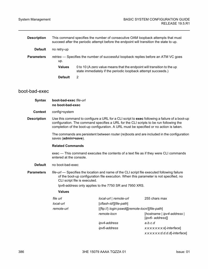
System Management
386
BASIC SYSTEM CONFIGURATION GUIDERELEASE 19.5.R1
3HE 15079 AAAA TQZZA 01 Issue: 01
Description This command specifies the number of consecutive OAM loopback attempts that must succeed after the periodic attempt before the endpoint will transition the state to up.
Default no retry-up
Parameters retries — Specifies the number of successful loopback replies before an ATM VC goes up.
Values 0 to 10 (A zero value means that the endpoint will transition to the up state immediately if the periodic loopback attempt succeeds.)
Default 2
boot-bad-exec
Syntax boot-bad-exec file-url
no boot-bad-exec
Context config>system
Description Use this command to configure a URL for a CLI script to exec following a failure of a boot-up configuration. The command specifies a URL for the CLI scripts to be run following the completion of the boot-up configuration. A URL must be specified or no action is taken.
The commands are persistent between router (re)boots and are included in the configuration saves (admin>save).
Related Commands
exec — This command executes the contents of a text file as if they were CLI commands entered at the console.
Default no boot-bad-exec
Parameters file-url — Specifies the location and name of the CLI script file executed following failure of the boot-up configuration file execution. When this parameter is not specified, no CLI script file is executed.
Ipv6-address only applies to the 7750 SR and 7950 XRS.
Values
file url local-url | remote-url 255 chars max
local-url [cflash-id/][file-path]
remote-url [{ftp://} login:pswd@remote-locn/][file-path]
remote-locn [hostname | ipv4-address | [ipv6- address]]
ipv4-address a.b.c.d
ipv6-address x:x:x:x:x:x:x:x[-interface]
x:x:x:x:x:x:d.d.d.d[-interface]
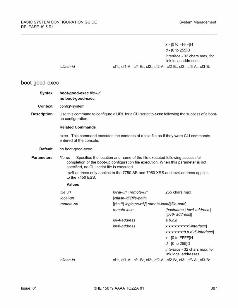
BASIC SYSTEM CONFIGURATION GUIDE RELEASE 19.5.R1
System Management
Issue: 01 3HE 15079 AAAA TQZZA 01 387
boot-good-exec
Syntax boot-good-exec file-url
no boot-good-exec
Context config>system
Description Use this command to configure a URL for a CLI script to exec following the success of a boot-up configuration.
Related Commands
exec - This command executes the contents of a text file as if they were CLI commands entered at the console.
Default no boot-good-exec
Parameters file-url — Specifies the location and name of the file executed following successful completion of the boot-up configuration file execution. When this parameter is not specified, no CLI script file is executed.
Ipv6-address only applies to the 7750 SR and 7950 XRS and ipv4-address applies to the 7450 ESS.
Values
x - [0 to FFFF]H
d - [0 to 255]D
interface - 32 chars max, for link local addresses
cflash-id cf1:, cf1-A:, cf1-B:, cf2:, cf2-A:, cf2-B:, cf3:, cf3-A:, cf3-B:
file url local-url | remote-url 255 chars max
local-url [cflash-id/][file-path]
remote-url [{ftp://} login:pswd@remote-locn/][file-path]
remote-locn [hostname | ipv4-address | [ipv6- address]]
ipv4-address a.b.c.d
ipv6-address x:x:x:x:x:x:x:x[-interface]
x:x:x:x:x:x:d.d.d.d[-interface]
x - [0 to FFFF]H
d - [0 to 255]D
interface - 32 chars max, for link local addresses
cflash-id cf1:, cf1-A:, cf1-B:, cf2:, cf2-A:, cf2-B:, cf3:, cf3-A:, cf3-B:
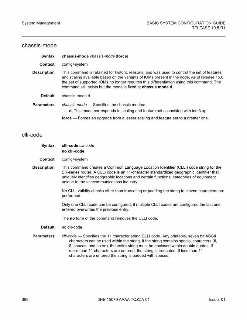
System Management
388
BASIC SYSTEM CONFIGURATION GUIDERELEASE 19.5.R1
3HE 15079 AAAA TQZZA 01 Issue: 01
chassis-mode
Syntax chassis-mode chassis-mode [force]
Context config>system
Description This command is retained for historic reasons, and was used to control the set of features and scaling available based on the variants of IOMs present in the node. As of release 15.0, the set of supported IOMs no longer requires this differentiation using this command. The command still exists but the mode is fixed at chassis mode d.
Default chassis-mode d
Parameters chassis-mode — Specifies the chassis modes:
d: This mode corresponds to scaling and feature set associated with iom3-xp.
force — Forces an upgrade from a lesser scaling and feature set to a greater one.
clli-code
Syntax clli-code clli-code
no clli-code
Context config>system
Description This command creates a Common Language Location Identifier (CLLI) code string for the SR-series router. A CLLI code is an 11-character standardized geographic identifier that uniquely identifies geographic locations and certain functional categories of equipment unique to the telecommunications industry.
No CLLI validity checks other than truncating or padding the string to eleven characters are performed.
Only one CLLI code can be configured, if multiple CLLI codes are configured the last one entered overwrites the previous entry.
The no form of the command removes the CLLI code.
Default no clli-code
Parameters clli-code — Specifies the 11 character string CLLI code. Any printable, seven bit ASCII characters can be used within the string. If the string contains special characters (#, $, spaces, and so on), the entire string must be enclosed within double quotes. If more than 11 characters are entered, the string is truncated. If less than 11 characters are entered the string is padded with spaces.
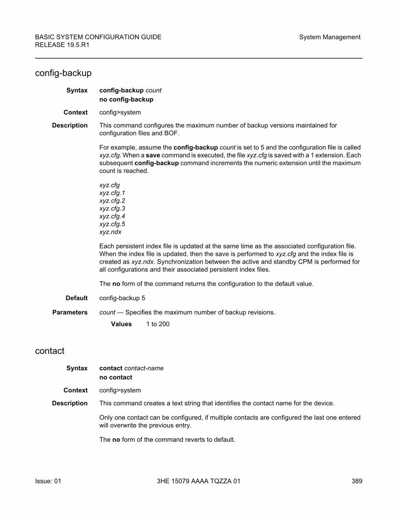
BASIC SYSTEM CONFIGURATION GUIDE RELEASE 19.5.R1
System Management
Issue: 01 3HE 15079 AAAA TQZZA 01 389
config-backup
Syntax config-backup count
no config-backup
Context config>system
Description This command configures the maximum number of backup versions maintained for configuration files and BOF.
For example, assume the config-backup count is set to 5 and the configuration file is called xyz.cfg. When a save command is executed, the file xyz.cfg is saved with a 1 extension. Each subsequent config-backup command increments the numeric extension until the maximum count is reached.
xyz.cfgxyz.cfg.1xyz.cfg.2xyz.cfg.3xyz.cfg.4xyz.cfg.5xyz.ndx
Each persistent index file is updated at the same time as the associated configuration file. When the index file is updated, then the save is performed to xyz.cfg and the index file is created as xyz.ndx. Synchronization between the active and standby CPM is performed for all configurations and their associated persistent index files.
The no form of the command returns the configuration to the default value.
Default config-backup 5
Parameters count — Specifies the maximum number of backup revisions.
Values 1 to 200
contact
Syntax contact contact-name
no contact
Context config>system
Description This command creates a text string that identifies the contact name for the device.
Only one contact can be configured, if multiple contacts are configured the last one entered will overwrite the previous entry.
The no form of the command reverts to default.
System Management
390
BASIC SYSTEM CONFIGURATION GUIDERELEASE 19.5.R1
3HE 15079 AAAA TQZZA 01 Issue: 01
Default no contact
Parameters contact-name — Specifies the contact name character string. The string can be up to 80 characters long. Any printable, seven-bit ASCII characters can be used within the string. If the string contains special characters (#, $, spaces, and so on), the entire string must be enclosed within double quotes.
cpm-http-redirect
Syntax cpm-http-redirect
Context config>system
Description This command enables the context to configure cpm-http-redirect settings for enabling or disabling the optimized-mode.
optimized-mode
Syntax [no] optimized-mode
Context config>system>cpm-http-redirect
Description This command enables the cpm-http-redirect optimized-mode. The optimized-mode improves the scale of HTTP redirect sessions supported system wide.
Default optimized-mode
coordinates
Syntax coordinates coordinates
no coordinates
Context config>system
Description This command creates a text string that identifies the system coordinates for the device location. For example, the command coordinates “37.390 -122.0550" is read as latitude 37.390 north and longitude 122.0550 west.
Only one set of coordinates can be configured. If multiple coordinates are configured, the last one entered overwrites the previous entry.
The no form of the command reverts to the default value.
BASIC SYSTEM CONFIGURATION GUIDE RELEASE 19.5.R1
System Management
Issue: 01 3HE 15079 AAAA TQZZA 01 391
Parameters coordinates — Specifies the coordinates describing the device location character string. The string may be up to 80 characters long. Any printable, seven-bit ASCII characters can be used within the string. If the string contains special characters (#, $, spaces, and so on), the entire string must be enclosed within double quotes. If the coordinates are subsequently used by an algorithm that locates the exact position of this node then the string must match the requirements of the algorithm.
dns
Syntax dns
Context config>system
Description This command configures DNS settings.
address-pref
Syntax address-pref {ipv4-only | ipv6-first}
no address-pref
Context config>system>dns
Description This command configures the DNS address resolving order preference. By default DNS names are queried for A-records only (address-preference is IPv4-only).
If the address-preference is set to IPv6-first, the DNS server will be queried for AAAA-records (IPv6) first and if a successful replied is not received, then the DNS server is queried for A-records. IPv6 applies only to the 7750 SR and 7950 XRS.
Default address-pref ipv4-only
dnssec
Syntax dnssec
Context config>system>dns
Description This command configures system Domain Name System Security Extensions (DNSSEC) settings.
ad-validation
Syntax ad-validation {fall-through | drop}
no ad-validation
System Management
392
BASIC SYSTEM CONFIGURATION GUIDERELEASE 19.5.R1
3HE 15079 AAAA TQZZA 01 Issue: 01
Context config>system>dns>dnssec
Description This command enables validation of the presence of the AD-bit in responses from the DNS servers, and reports a warning to the SECURITY log if DNSSEC validation was not possible.
This command requires either the fall-through or drop parameters be configured. When the fall-through parameter is supplied, the system will allow DNS responses that do not pass DNSSEC validation to be accepted and logged. When the drop parameter is specified, the system will reject and log DNS responses that do not pass DNSSEC validation and the resolution will appear to fail.
Default no ad-validation
Parameters fall-through — Specifies that the DNSSEC validator should allow non-DNSSEC responses to fall-through to permit resolution in case of validation failure.
drop — Specifies that the DNSSEC validator should drop non-DNSSEC responses in case of validation failure.
enable-icmp-vse
Syntax [no] enable-icmp-vse
Context config>system
Description This command enables vendor specific extensions to ICMP.
Default no enable-icmp-vse
ip
Syntax ip
Context config>system
Description This command configures system-wide IP router parameters.
allow-qinq-network-interface
Syntax [no] allow-qinq-network-interface
Context config>system>ip
Description This command is a system-wide option that allows the creation of network interfaces on a QinQ encapsulated VLAN.
When enabled, the maximum number of allowed MPLS labels is reduced by 1 to allow for the additional VLAN tag at egress processing.
BASIC SYSTEM CONFIGURATION GUIDE RELEASE 19.5.R1
System Management
Issue: 01 3HE 15079 AAAA TQZZA 01 393
The no form of this command reverts the option to the default value, which is to not allow network interfaces on QinQ encapsulated VLANs.
Default no allow-qinq-network-interface
enforce-unique-if-index
Syntax [no] enforce-unique-if-index
Context config>system>ip
Description This command enables the options to force the creation of IP interface indexes so that they are globally unique across all routing contexts. In addition, the command ensures that any interface created using SNMP also has a system-wide unique IP interface index.
If this command is issued but the system has previously existing interface indexes that conflict, the command will be rejected until all the conflicts are removed. Pre-existing persistency tables should also be removed before enabling this system option.
The no form of the command disables this option and returns the system to the default behavior.
Default no enforce-unique-if-index
lacp-system-priority
Syntax lacp-system-priority lacp-system-priority
no lacp-system-priority
Context config>system
Description This command configures the Link Aggregation Control Protocol (LACP) system priority on aggregated Ethernet interfaces. LACP allows the operator to aggregate multiple physical interfaces to form one logical interface.
Default lacp-system-priority 32768
Parameters lacp-system-priority — Specifies the LACP system priority.
Values 1 to 65535
load-balancing
Syntax load-balancing
Context config>system
System Management
394
BASIC SYSTEM CONFIGURATION GUIDERELEASE 19.5.R1
3HE 15079 AAAA TQZZA 01 Issue: 01
Description This command enables the load-balancing context to configure the interface per-flow load balancing options that will apply to traffic entering this interface and egressing over a LAG/ECMP on system-egress. This is a per interface setting. For load-balancing options that can also be enabled on the system level, the options enabled on the interface level overwrite system level configurations.
l2tp-load-balancing
Syntax [no] l2tp-load-balancing
Context config>system>load-balancing
Description This command enables the inclusion of the L2TPv2 session ID into the load-balancing hash algorithm to induce more variation and better load distribution over available links and next-hops.
The no form of this command disables the inclusion of the session-id.
l4-load-balancing
Syntax [no] l4-load-balancing
Context config>system>load-balancing
Description This command configures system-wide Layer 4 load balancing. The configuration at the system level can enable or disable load balancing based on Layer 4 fields. If enabled, the Layer 4 source and destination port fields will be included in hashing calculation for TCP/UDP packets.
The hashing algorithm addresses finer spraying granularity where many hosts are connected to the network.
To address more efficient traffic distribution between network links (forming a LAG group), a hashing algorithm extension takes into account L4 information (that is, src/dst L4-protocol port).
The hashing index can be calculated according to the following algorithm:
If [(TCP or UDP traffic) & enabled] hash (TCP/UDP ports, IP addresses)
else if (IP traffic) hash (IP addresses)
else hash (MAC addresses)
endif
BASIC SYSTEM CONFIGURATION GUIDE RELEASE 19.5.R1
System Management
Issue: 01 3HE 15079 AAAA TQZZA 01 395
This algorithm will be used in all cases where IP information in per-packet hashing is included (refer to “LAG and ECMP Hashing” in the 7450 ESS, 7750 SR, 7950 XRS, and VSR Interface Configuration Guide). However, the Layer 4 information (TCP/UDP ports) will not be used for fragmented packets.
Default no l4-load-balancing
lsr-load-balancing
Syntax lsr-load-balancing hashing-algorithm
no lsr-load-balancing
Context config>system>load-balancing
Description This command configures system-wide LSR load balancing. Hashing can be enabled on the label stack and/or IP header at an LSR for spraying labeled IP packets over multiple equal cost paths and/or over multiple links of a LAG group.
The LSR hash routine operates on the label stack and the IP header if a packet is IPv4. An LSR will consider a packet to be IPv4 if the first nibble following the bottom of the label stack is 4. The hash on label and IPv4 and IPv6 headers can be enabled or disabled at the system level or incoming network IP interface level.
Default no lsr-load-balancing
Parameters lbl-only — Specifies that only the label is used in the hashing algorithm
lbl-ip — Specifies that the IP header is included in the hashing algorithm
ip-only — Specifies that the IP header is used exclusively in the hashing algorithm
eth-encap-ip — Specifies that the hash algorithm parses down the label stack (up to 3 labels supported) and once it hits the bottom, the stack assumes Ethernet II non-tagged header follows. At the expected Ethertype offset location, the algorithm checks whether the value present is IPv4/v6 (0x0800 or 0x86DD). If the check passes, the hash algorithm checks the first nibble at the expected IP header location for IPv4/IPv6 (0x0100/0x0110). If the secondary check passes, the hash is performed using IP SA/DA fields in the expected IP header; if any of the checks fail, the label-stack hash is performed.
lbl-ip-l4-teid — Specifies that this hashing algorithm hashes based on label, IP header, Layer 4 header and GTP header (TEID) in order. The algorithm uses all the supported headers that are found in the header fragment of incoming traffic.
mc-enh-load-balancing
Syntax [no] mc-enh-load-balancing
Context config>system>load-balancing
System Management
396
BASIC SYSTEM CONFIGURATION GUIDERELEASE 19.5.R1
3HE 15079 AAAA TQZZA 01 Issue: 01
Description This command enables enhanced egress multicast load balancing behavior for Layer 3 multicast. When enabled, the router will spray the multicast traffic using as hash inputs from the packet based on lsr-load-balancing, l4-load-balancing and system-ip-load-balancing configurations. That is, an ingress LER or IP PE will spray traffic based on the IP hash criteria: SA/DA + optional Layer 4 port + optional system IP egress LER or LSR - will spray traffic based on label or IP hash criteria outlined above or both based on configuration of lsr-load-balancing, l4-load-balancing, and system-ip-load-balancing.
The no form of the command preserves the default behavior for per flow hashing of multicast traffic.
Default no mc-enh-load-balancing
service-id-lag-hashing
Syntax [no] service-id-lag-hashing
Context config>system>load-balancing
Description This command enables enhanced VLL LAG service ID hashing. This command improves the LAG spraying of VLL service packets and is applied only when both ECMP and LAG hashing are performed by the same router. By default, the ECMP interface and LAG link for all packets on the VLL service are selected based on a direct modulo operation of the service ID. This command enhances distribution and hashes the service ID prior to the LAG link modulo operation when an ECMP link modulo operation is performed.
The no form of the command preserves the default behavior of VLL LAG service ID hashing.
Default no service-id-lag-hashing
system-ip-load-balancing
Syntax [no] system-ip-load-balancing
Context config>system>load-balancing
Description This command enables the use of the system IP address in the ECMP hash algorithm to add a per system variable. This can help guard against cases where multiple routers, in series, will end up hashing traffic to the same ECMP/LAG path.
This command is set at a system wide basis, however if certain IOMs do not support the new load-balancing algorithm, they will continue to use the default algorithm. By default, the IPv4 system IP address is used in the hash algorithm. When no IPv4 system IP address is configured, the IPv6 system IP address, when configured, is used in the hash algorithm.
The no form of the command resets the system wide algorithm to default.
Default no system-ip-load-balancing
BASIC SYSTEM CONFIGURATION GUIDE RELEASE 19.5.R1
System Management
Issue: 01 3HE 15079 AAAA TQZZA 01 397
location
Syntax location location
no location
Context config>system
Description This command creates a text string that identifies the system location for the device.
Only one location can be configured. If multiple locations are configured, the last one entered overwrites the previous entry.
The no form of the command reverts to the default value.
Parameters location — Specifies the location as a character string. The string may be up to 80 characters. Any printable, seven-bit ASCII characters can be used within the string. If the string contains special characters (#, $, spaces, and so on), the entire string must be enclosed within double quotes.
name
Syntax name system-name
no name
Context config>system
Description This command creates a system name string for the device.
For example, system-name parameter ALA-1 for the name command configures the device name as ALA-1.
ABC>config>system# name "ALA-1"ALA-1>config>system#
Only one system name can be configured. If multiple system names are configured, the last one encountered overwrites the previous entry.
The no form of the command reverts to the default value.
Default no name
Parameters system-name — Specifies the system name as a character string. The string may be up to 64 characters. Any printable, seven-bit ASCII characters can be used within the string. If the string contains special characters (#, $, spaces, and so on), the entire string must be enclosed within double quotes.
System Management
398
BASIC SYSTEM CONFIGURATION GUIDERELEASE 19.5.R1
3HE 15079 AAAA TQZZA 01 Issue: 01
switchover-exec
Syntax switchover-exec file-url
no switchover-exec
Context config>system
Description This command specifies the location and name of the CLI script file executed following a redundancy switchover from the previously active CPM card. A switchover can happen because of a fatal failure or by manual action.
The CLI script file can contain commands for environment settings, debug (excluding mirroring settings), and other commands not maintained by the configuration redundancy.
The following commands are not supported in the switchover-exec file: clear, configure, candidate, oam, tools, oam, ping, traceroute, mstat, mtrace and mrinfo.
When the file-url parameter is not specified, no CLI script file is executed.
Default no switch-over-exec
Parameters file-url — Specifies the location and name of the CLI script file.
Values
port-topology
Syntax port-topology
Context config>system
Description This parameter creates or edits the context to configure intra-node port connections.
local-url | remote-url
local-url [cflash-id/][file-path] 200 chars max, including cflash-id
directory length 99 chars max each
remote-url [{ftp:// | tftp://}login:pswd@remote-locn/][file-path]
243 chars max
directory length 99 chars max each
remote-locn [hostname | ipv4-address | ipv6-address]
ipv4-address a.b.c.d
ipv6-address x:x:x:x:x:x:x:x[-interface]
x:x:x:x:x:x:d.d.d.d[-interface]
x - [0 to FFFF]H
d - [0 to 255]D
interface - 32 chars max, for link local addresses
cflash-id cf1:, cf1-A:, cf1-B:, cf2:, cf2-A:, cf2-B:, cf3:, cf3-A:, cf3-B:
BASIC SYSTEM CONFIGURATION GUIDE RELEASE 19.5.R1
System Management
Issue: 01 3HE 15079 AAAA TQZZA 01 399
Default disabled
port
Syntax port port-id to port-id [create]
no port port-id
Context config>system>port-topology
Description This command is used for satellites. It identifies to the SR OS that there is an internal connection between two ports.
Permitted pairings of the two ports are:
For satellites, this command configures the binding between a host port ID and the satellite uplink from the satellite chassis. The port topology can be configured with the host connected to a satellite uplink or the satellite uplink port connected to the specified host port. Both configurations are supported, as shown in the following examples:
*A:Dut-A# configure system port-topology port esat-1/1/u4 to 1/2/2 create*A:Dut-A# configure system port-topology no port esat-1/1/u4*A:Dut-A# configure system port-topology port 1/2/2 to esat-1/1/u4 create*A:Dut-A# configure system port-topology no port 1/2/2
The no form of the command removes the internal connection.
Default no port port-id
Parameters port-id — Specifies one port of an internal port connection. These ports can be router ports or Ethernet satellite uplink ports. Acceptable pairings are defined in the command description.
Values
First port Second port
Router port Satellite uplink port
Satellite uplink port Router port
port-id (Router port)
slot/mda/port
slot The slot number of the card in the chassis. The maximum slot number is platform dependent. Refer to the hardware installation guides for more information.
mda [1 to 2]
port [1 to 160] (depending on the MDA type)
System Management
400
BASIC SYSTEM CONFIGURATION GUIDERELEASE 19.5.R1
3HE 15079 AAAA TQZZA 01 Issue: 01
create — Specifies the keyword required to create the binding between the two ports.
power-supply
Syntax power-supply power-supply-id type
Context config>system
Description This command configures information about the type of power supply used for each power feed connection on the router chassis. The information is used to populate queries made using the show>chassis detail and show>chassis power-supply commands.
Parameters power-supply-id — Specifies the power feed connection.
Values 1, 2
type — Specifies the type of power source that is connected to the power feed connection.
Values dc — Specifies that a single DC power source is connected to the power feed connector.
ac single — Specifies that a single AC power source is connected to the power feed connector.
ac multiple — Specifies that multiple AC power sources are connected to the power feed connector.
default — Reverts the configured information to the default power source type for the chassis.
none — Specifies that no power source is connected to the power feed connector.
satellite
Syntax satellite
Context config>system
(Ethernet satellite uplink port)
esat-id/slot/uport
esat keyword
id [1 to 20]
slot [1]
u keyword for up-link port
port [1 to 4]
BASIC SYSTEM CONFIGURATION GUIDE RELEASE 19.5.R1
System Management
Issue: 01 3HE 15079 AAAA TQZZA 01 401
Description This command enables the satellite configuration context. Within the satellite context, the administrator can specify the configuration details for a satellite chassis that is hosted by the associated local system.
eth-sat
Syntax eth-sat sat-id [create]
no eth-sat sat-id
Context config>system>satellite
Description This command enables the specified Ethernet satellite configuration context.
The no form of the command deletes the specified Ethernet satellite.
Parameters sat-id — Specifies the satellite ID for the associated Ethernet satellite.
Values 1 to 20
create — Creates a new Ethernet satellite context.
feature
Syntax [no] feature feature-name
Context config>system>satellite>eth-sat
Description This command enables specific satellite functionality that may have specific satellite requirements, such as software version.
The no form of this command disables the specific satellite functionality.
Parameters feature-name — Specifies the functionality to enable.
Values local-forward
Values transparent-clock-eth
local-forward
Syntax local-forward local-forward-id [create]
no local-forward local-forward-id
Context config>system>satellite
Description This command creates a local-forward instance.
A local-forward instance creates a traffic bypass within the Ethernet satellite, which allows traffic to be forwarded between satellite client ports.
System Management
402
BASIC SYSTEM CONFIGURATION GUIDERELEASE 19.5.R1
3HE 15079 AAAA TQZZA 01 Issue: 01
The no form of this command deletes the specified local-forward instance.
Parameters local-forward-id — Specifies the ID number for the local-forward instance.
Values 1 to 10240
create — Creates a new local-forward instance.
sap
Syntax sap sap-id [create]
no sap sap-id
Context config>system>satellite>local-forward
Description This command configures a Service Access Point (SAP) used in satellite local forward instances defined in the system.
The no form of this command removes the satellite access point from the local-forward instance.
Parameters eth-sat-id — Specifies the satellite access point in the local-forward instance in the esat-id/slot/port format.
Values
lag-id — Specifies the LAG identifier, expressed as an integer,
Values
qtag1 — Specifies the qtag value.
Values 1 to 4094
port-template
Syntax port-template template-name sat-type sat-type [create]
no port-template template-name
Context config>system>satellite
Description This command creates a new port template context to define the port usage for a specific satellite type. A port template is specific to the specified satellite type. Port templates must be configured separately using different template names for each different satellite chassis type.
esat keyword
id 1 to 20
lag keyword
id 1 to 800
BASIC SYSTEM CONFIGURATION GUIDE RELEASE 19.5.R1
System Management
Issue: 01 3HE 15079 AAAA TQZZA 01 403
The no form of this command deletes the specified port template.
Parameters template-name — Specifies the name for the associated port template. This value must be unique in the network.
sat-type — Specifies the type of satellite chassis associated with the port-template.
Values es24-1gb-sfp, es24-1gb-tx, es24-sass-1gb-sfp, es48-1gb-sfp, es48-1gb-tx, es48-sass-1gb-sfp, es64-10gb-sfpp+4-100gb-cfp4, es24-sasmxp-1gb-sfp
create — Creates a new port template.
port
Syntax port port-id
Context config>system>satellite>port-template
Description This command specifies the satellite port to be reconfigured.
The no form of this command deletes the specified port configuration.
Parameters port-id — Specifies the satellite physical port ID. This must use the format slot/mda/port. Currently, all satellites have a single slot and a single MDA, so these values will always be 1. For example, port 10 would be specified as 1/1/10.
role
Syntax role role-type
Context config>system>satellite>port-template>port
Description This command configures the role that the associated port is to take on.
Parameters none — Clears the role association for the associated port.
uplink — Specifies that the associated satellite port is assigned the role of an uplink port.
client — Specifies that the associated satellite port is assigned the role of a satellite client port.
system-default — Specifies that the associated satellite port is returned to the system default.
uplink
Syntax uplink port-id
uplink system-default
System Management
404
BASIC SYSTEM CONFIGURATION GUIDERELEASE 19.5.R1
3HE 15079 AAAA TQZZA 01 Issue: 01
uplink none
Context config>system>satellite>port-template>port
Description This command configures the uplink association to be used for the associated satellite port.
Parameters port-id — Specifies the satellite physical port ID. This must use the format slot/mda/port. All satellites have a single slot and a single MDA, so these values will always be 1. For example, port 10 would be specified as 1/1/10.
system-default — Specifies that the uplink association is returned to the system default.
none — Clears the uplink association.
tdm-sat
Syntax tdm-sat sat-id [create]
no tdm-sat sat-id
Context config>system>satellite
Description This command enters the specified TDM satellite configuration context.
The no form of the command deletes the specified TDM satellite.
Parameters sat-id — Specifies the satellite ID for the associated TDM satellite.
Values 1 to 20
create — The keyword used to create a new TDM satellite context. The create keyword requirement can be enabled/disabled in the environment>create context.
description
Syntax description description-string
no description
Context config>system>satellite>eth-satconfig>system>satellite>local-forwardconfig>system>satellite>local-forward>sapconfig>system>satellite>port-templateconfig>system>satellite>tdm-sat
Description This command defines a description string for the associated satellite.
The no form of the command deletes the associated description string.
Default no description
Parameters description-string — Specifies the satellite description, up to 80 characters.
BASIC SYSTEM CONFIGURATION GUIDE RELEASE 19.5.R1
System Management
Issue: 01 3HE 15079 AAAA TQZZA 01 405
mac-address
Syntax mac-address mac-address
no mac-address
Context config>system>satellite>eth-satconfig>system>satellite>tdm-sat
Description This command configures the MAC address for the associated satellite chassis. This MAC address is used to validate the identity of an satellite that attempts to associate with the local host.
The no form of the command deletes the MAC address for the associated satellite.
Parameters mac-address — Specifies the MAC address of the associated satellite chassis; do not use a broadcast or multicast MAC. Enter the MAC address in either of the following formats: xx:xx:xx:xx:xx:xx or xx-xx-xx-xx-xx-xx.
port-map
Syntax port-map client-port-id primary primary-uplink-port-id [secondary secondary-uplink-port-id]
port-map client-port-id system-default
Context config>system>satellite>eth-sat
Description This command configures the mapping between a satellite client port and its associated uplink. This command allows both a primary and an optional secondary uplink to be configured.
If a secondary uplink is configured, it is used to forward traffic if the primary uplink is down for any reason.
Before an uplink can be used as either a primary or secondary uplink, it must be configured using the port-topology configuration command.
To return the uplink association to its default the port-map client-port-id system-default command should be used.
Parameters client-port-id — Specifies the satellite client port associated with the port mapping, in the format esat-id/slot/port.
primary-uplink-port-id — Specifies the primary satellite uplink to be associated with the associate client port, in the format esat-id/slot/uport where id is 1 to 20.
secondary-uplink-port-id — Specifies the secondary satellite uplink to be associated with the associate client port, in the format esat-id/slot/uport where id is 1 to 20.
system-default — Specifies to set the port map to the system default.
System Management
406
BASIC SYSTEM CONFIGURATION GUIDERELEASE 19.5.R1
3HE 15079 AAAA TQZZA 01 Issue: 01
ptp-tc
Syntax [no] ptp-tc
Context config>system>satellite>eth-sat
Description This command enables the ethernet satellite IEEE1588 transparent clock function. This provides increased accuracy on the PTP event messages transiting the satellite. When a IEEE1588 event message transits the ethernet satellite, the correction field of the message is updated with the residence time of that message. This is used in PTP time calculations. The ethernet satellite shall perform the transparent clock function on PTP messages with Ethernet and UDP/IP encapsulation. All ports of the satellite are enabled for this capability with the one setting. This feature must be enabled to allow the assignment of one of the satellite’s client ports as a PTP port under config>system>ptp>port. Only PTP using Ethernet encapsulation is supported from the host.
To enable this command, the satellite must have first been configured to support the feature using the config>system>satellite>eth-sat>feature transparent-clock-eth and must have been enabled for synchronous ethernet with config>system>satellite>eth-sat>sync-e.
All host ports connecting to this satellite must support 1588 port-based timestamping.
The no version of this command disables the specific satellite functionality.
Default no ptp-tc
BASIC SYSTEM CONFIGURATION GUIDE RELEASE 19.5.R1
System Management
Issue: 01 3HE 15079 AAAA TQZZA 01 407
sat-type
Syntax sat-type sat-type [port-template template-name]
no sat-type
Context config>system>satellite>eth-satconfig>system>satellite>tdm-sat
Description This command configures the type of satellite variant for the associated satellite chassis.
The no form of the command deletes the sat-type configuration.
Default no sat-type
Parameters sat-type — Specifies the satellite type. Configuration of the following variants is supported:
es24-1gb-sfp — Specifies the 24xGE (SFP) + 4x10GE Ethernet satellite.
es48-1gb-sfp — Specifies the 48xGE (SFP) + 4x10GE Ethernet satellite.
es24-sass-1gb-sfp — Specifies the SAS-S 24xGE (SFP) + 4x10GE Ethernet satellite.
es48-sass-1gb-sfp — Specifies the SAS-S 48xGE (SFP) + 4x10GE Ethernet satellite.
es24-1gb-tx — Specifies the 24xGE (copper) + 4x10GE Ethernet satellite.
es48-1gb-tx — Specifies the 48xGE (copper) + 4x10GE Ethernet satellite.
es24-1gb-tx — Specifies the 24-port copper + PoE Ethernet satellite.
es48-1gb-tx — Specifies the 48-port copper + PoE Ethernet satellite.
es64-10gb-sfpp+4-100gb-cfp4 — Specifies the 64x10GE + 4x100GE Ethernet satellite.
es64-10gb-sfpp+4-100gb-qsfp28 — Specifies the 64x10GE + 4xQSFP28 Ethernet satellite.
es24-sasmxp-1gb-sfp — Specifies the 7210 SAS-Mxp as an ethernet satellite.
ts4-choc3-sfp — Specifies the 4-port OC3 TDM satellite.
ts4-chstm1-sfp — Specifies the 4-port STM1 TDM satellite.
ts1-choc12-sfp — Specifies the 1-port OC12 TDM satellite.
ts1-chstm4-sfp — Specifies the 1-port STM4 TDM satellite.
template-name — Specifies the name for the associated port template.
shutdown
Syntax [no] shutdown
Context config>system>satellite>eth-satconfig>system>satellite>tdm-sat
System Management
408
BASIC SYSTEM CONFIGURATION GUIDERELEASE 19.5.R1
3HE 15079 AAAA TQZZA 01 Issue: 01
Description This command disables the associated satellite.
If the associated satellite is active, the satellite will not be reset but all satellite client ports will be shut down.
If the satellite is not active but attempts to associate with the host, the satellite chassis will be brought up according to the satellite configuration but all client ports will be shut down.
The no form of this command removes the shutdown state and all client ports on active satellites will be brought back up.
Default shutdown
software-repository
Syntax software-repository repository-name
no software-repository
Context config>system>satellite>eth-satconfig>system>satellite>tdm-sat
Description This command binds the specified software repository to the associated satellite. The software repository is used to locate and serve the correct software image to the satellite at boot time.
The configured software repository is only used when the satellite boots. Changing the software repository for an active satellite does not have an effect until the next time a satellite boots.
A satellite cannot be booted if there is no software repository defined for it.
The no form of the command removes the software repository.
Default no software-repository
Parameters repository-name — Specifies a string, up to 32 characters, that uniquely identifies the software repository.
sync-e
Syntax [no] sync-e
Context config>system>satellite>eth-sat
Description This command enables the Ethernet satellite for synchronous Ethernet operation so that the transmit timing of the satellite access ports use the frequency of the host router’s central clock.
BASIC SYSTEM CONFIGURATION GUIDE RELEASE 19.5.R1
System Management
Issue: 01 3HE 15079 AAAA TQZZA 01 409
To enable this functionality, both host ports on the router that connect to the U1 and U2 ports of the satellite must be synchronous Ethernet-capable ports.
When the Ethernet satellite is configured for synchronous Ethernet, ESMC frames are enabled on the host ports. The SSM code-type used between the host and the satellite should be manually configured on the host ports to match the code-type desired on the satellite client ports. The code-type setting on the host ports does not restrict the code-type used on the satellite client ports, as those may be configured on an individual port basis.
software-repository
Syntax software-repository repository-name [create]
no software-repository repository-name
Context config>system
Description This command creates or deletes an instance of a software repository. The instance is identified by a repository name.
A software repository is used to obtain files to upgrade software on certain subsystems of the router (for example, Ethernet satellites).
Up to three locations can be specified within a software repository for the router to access files in the repository. The router will first attempt to access the file at the primary location. If the primary location is not configured or the files are not found at the primary location, then the router will attempt to access the files at the secondary location. If the secondary location is not configured or the files are not found at the secondary location, then the router will attempt to access the files at the tertiary location. If the tertiary location is not configured or the files are not found at the tertiary location, then the software repository access will fail.
The no form of the command removes the software repository.
Parameters repository-name — Specifies a string, up to 32 characters, that uniquely identifies the software repository.
create — Specifies the keyword required when the software-repository context is first created. Once the context is created, it can be accessed without the create keyword.
description
Syntax description description-string
no description
Context config>system>software-repository
Description This command defines a description string for the software repository.
The no form of the command deletes the associated description string.
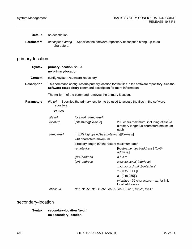
System Management
410
BASIC SYSTEM CONFIGURATION GUIDERELEASE 19.5.R1
3HE 15079 AAAA TQZZA 01 Issue: 01
Default no description
Parameters description-string — Specifies the software repository description string, up to 80 characters.
primary-location
Syntax primary-location file-url
no primary-location
Context config>system>software-repository
Description This command configures the primary location for the files in the software repository. See the software-respository command description for more information.
The no form of the command removes the primary location.
Parameters file-url — Specifies the primary location to be used to access the files in the software repository.
Values
secondary-location
Syntax secondary-location file-url
no secondary-location
file url local-url | remote-url
local-url [cflash-id/][file-path] 200 chars maximum, including cflash-id directory length 99 characters maximum each
remote-url [{ftp://} login:pswd@remote-locn/][file-path]
243 characters maximum
directory length 99 characters maximum each
remote-locn [hostname | ipv4-address | [ipv6- address]]
ipv4-address a.b.c.d
ipv6-address x:x:x:x:x:x:x:x[-interface]
x:x:x:x:x:x:d.d.d.d[-interface]
x - [0 to FFFF]H
d - [0 to 255]D
interface - 32 characters max, for link local addresses
cflash-id cf1:, cf1-A:, cf1-B:, cf2:, cf2-A:, cf2-B:, cf3:, cf3-A:, cf3-B:
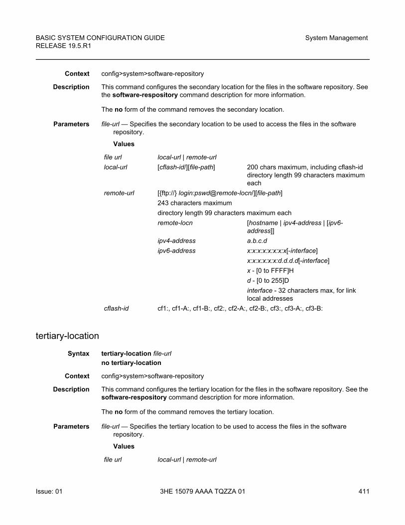
BASIC SYSTEM CONFIGURATION GUIDE RELEASE 19.5.R1
System Management
Issue: 01 3HE 15079 AAAA TQZZA 01 411
Context config>system>software-repository
Description This command configures the secondary location for the files in the software repository. See the software-respository command description for more information.
The no form of the command removes the secondary location.
Parameters file-url — Specifies the secondary location to be used to access the files in the software repository.
Values
tertiary-location
Syntax tertiary-location file-url
no tertiary-location
Context config>system>software-repository
Description This command configures the tertiary location for the files in the software repository. See the software-respository command description for more information.
The no form of the command removes the tertiary location.
Parameters file-url — Specifies the tertiary location to be used to access the files in the software repository.
Values
file url local-url | remote-url
local-url [cflash-id/][file-path] 200 chars maximum, including cflash-id directory length 99 characters maximum each
remote-url [{ftp://} login:pswd@remote-locn/][file-path]
243 characters maximum
directory length 99 characters maximum each
remote-locn [hostname | ipv4-address | [ipv6- address]]
ipv4-address a.b.c.d
ipv6-address x:x:x:x:x:x:x:x[-interface]
x:x:x:x:x:x:d.d.d.d[-interface]
x - [0 to FFFF]H
d - [0 to 255]D
interface - 32 characters max, for link local addresses
cflash-id cf1:, cf1-A:, cf1-B:, cf2:, cf2-A:, cf2-B:, cf3:, cf3-A:, cf3-B:
file url local-url | remote-url
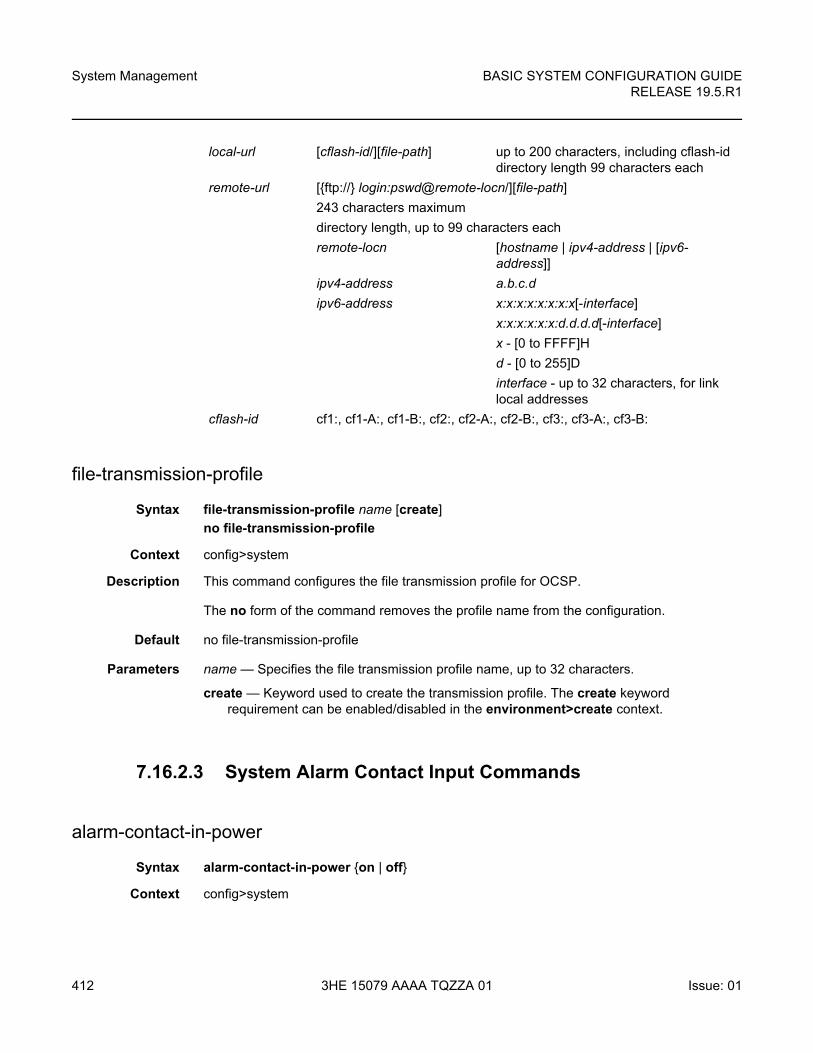
System Management
412
BASIC SYSTEM CONFIGURATION GUIDERELEASE 19.5.R1
3HE 15079 AAAA TQZZA 01 Issue: 01
file-transmission-profile
Syntax file-transmission-profile name [create]
no file-transmission-profile
Context config>system
Description This command configures the file transmission profile for OCSP.
The no form of the command removes the profile name from the configuration.
Default no file-transmission-profile
Parameters name — Specifies the file transmission profile name, up to 32 characters.
create — Keyword used to create the transmission profile. The create keyword requirement can be enabled/disabled in the environment>create context.
7.16.2.3 System Alarm Contact Input Commands
alarm-contact-in-power
Syntax alarm-contact-in-power {on | off}
Context config>system
local-url [cflash-id/][file-path] up to 200 characters, including cflash-id directory length 99 characters each
remote-url [{ftp://} login:pswd@remote-locn/][file-path]
243 characters maximum
directory length, up to 99 characters each
remote-locn [hostname | ipv4-address | [ipv6- address]]
ipv4-address a.b.c.d
ipv6-address x:x:x:x:x:x:x:x[-interface]
x:x:x:x:x:x:d.d.d.d[-interface]
x - [0 to FFFF]H
d - [0 to 255]D
interface - up to 32 characters, for link local addresses
cflash-id cf1:, cf1-A:, cf1-B:, cf2:, cf2-A:, cf2-B:, cf3:, cf3-A:, cf3-B:
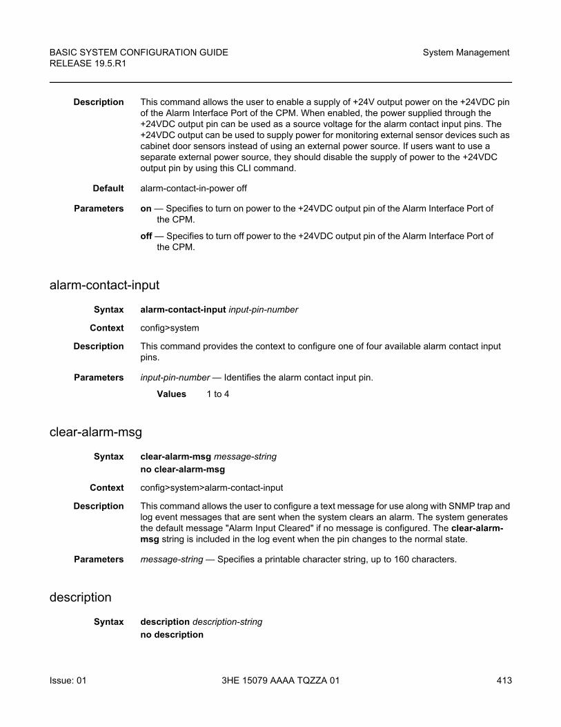
BASIC SYSTEM CONFIGURATION GUIDE RELEASE 19.5.R1
System Management
Issue: 01 3HE 15079 AAAA TQZZA 01 413
Description This command allows the user to enable a supply of +24V output power on the +24VDC pin of the Alarm Interface Port of the CPM. When enabled, the power supplied through the +24VDC output pin can be used as a source voltage for the alarm contact input pins. The +24VDC output can be used to supply power for monitoring external sensor devices such as cabinet door sensors instead of using an external power source. If users want to use a separate external power source, they should disable the supply of power to the +24VDC output pin by using this CLI command.
Default alarm-contact-in-power off
Parameters on — Specifies to turn on power to the +24VDC output pin of the Alarm Interface Port of the CPM.
off — Specifies to turn off power to the +24VDC output pin of the Alarm Interface Port of the CPM.
alarm-contact-input
Syntax alarm-contact-input input-pin-number
Context config>system
Description This command provides the context to configure one of four available alarm contact input pins.
Parameters input-pin-number — Identifies the alarm contact input pin.
Values 1 to 4
clear-alarm-msg
Syntax clear-alarm-msg message-string
no clear-alarm-msg
Context config>system>alarm-contact-input
Description This command allows the user to configure a text message for use along with SNMP trap and log event messages that are sent when the system clears an alarm. The system generates the default message "Alarm Input Cleared" if no message is configured. The clear-alarm-msg string is included in the log event when the pin changes to the normal state.
Parameters message-string — Specifies a printable character string, up to 160 characters.
description
Syntax description description-string
no description
System Management
414
BASIC SYSTEM CONFIGURATION GUIDERELEASE 19.5.R1
3HE 15079 AAAA TQZZA 01 Issue: 01
Context config>system>alarm-contact-input
Description This command describes an alarm contact input pin. The description provides an indication of the usage or attribute of the pin. It is stored in the CLI configuration file and helps the user in identifying the purpose of the pin. The description is included in the log event when the pin changes state (the string “Pin x” is used in the log events if no description is configured).
Parameters description-string — Specifies a printable character string, up to 80 characters.
normal-state
Syntax normal-state {open | closed}
Context config>system>alarm-contact-input
Description This command configures the normal state to be associated with the alarm contact input. When the system detects a transition from the normal state, an alarm is generated. The alarm is cleared when the system detects a transition back to the normal state.
Configure the normal state as closed if an external power source is used to power the inputs.
Default normal-state open
Parameters open — Specifies that the normal state is identified as open. When the system detects a transition to the closed state, an alarm is generated. The alarm is cleared when the system detects a transition back to the open state.
closed — Specifies that the normal state is identified as closed. When the system detects a transition to the open state, an alarm is generated. The alarm is cleared when the system detects a transition back to the closed state.
shutdown
Syntax [no] shutdown
Context config>system>alarm-contact-input
Description This command stops tracking the state changes associated with the alarm contact input. The system does not generate or clear the alarms for the alarm contact input, but if an alarm is generated, the system clears the alarm when the shutdown command is executed. The no form of the command starts tracking the state changes associated with the alarm contact input.
Default shutdown
BASIC SYSTEM CONFIGURATION GUIDE RELEASE 19.5.R1
System Management
Issue: 01 3HE 15079 AAAA TQZZA 01 415
trigger-alarm-msg
Syntax trigger-alarm-msg message-string
no trigger-alarm-msg
Context config>system>alarm-contact-input
Description This command allows the user to configure a text message for use along with SNMP trap and log event messages that are sent when the system generates an alarm. The system generates the default message "Alarm Input Triggered" if no message is configured. The trigger-alarm-msg string is included in the log event when the pin changes from the normal state.
Parameters message-string — Specifies a printable character string, up to 160 characters.
7.16.2.4 System Threshold Alarm Commands
thresholds
Syntax thresholds
Context config>system
Description This command enables the context to configure monitoring thresholds.
cflash-cap-alarm
Syntax cflash-cap-alarm cflash-id rising-threshold threshold [falling-threshold threshold] interval seconds [rmon-event-type] [startup-alarm alarm-type]
no cflash-cap-alarm cflash-id
Context config>system>thresholds
Description This command enables capacity monitoring of the compact flash specified in this command. The severity level is alarm. Both a rising and falling threshold can be specified.
The no form of this command removes the configured compact flash threshold alarm.
Parameters cflash-id — Specifies the name of the cflash device to be monitored.
Values cf1:, cf1-A:, cf1-B:, cf2:, cf2-A:, cf2-B:, cf3:, cf3-A:, cf3-B:
System Management
416
BASIC SYSTEM CONFIGURATION GUIDERELEASE 19.5.R1
3HE 15079 AAAA TQZZA 01 Issue: 01
rising-threshold threshold — Specifies a threshold for the sampled statistic. When the current sampled value is greater than or equal to this threshold, and the value at the last sampling interval was less than this threshold, a single threshold crossing event will be generated. A single threshold crossing event will also be generated if the first sample taken is greater than or equal to this threshold and the associated startup-alarm is equal to rising or either.
After a rising threshold crossing event is generated, another such event will not be generated until the sampled value falls below this threshold and reaches less than or equal to the falling-threshold value.
The threshold value represents units of 512 bytes.
Values -2147483648 to 2147483647
Default 0
falling-threshold threshold — Specifies a threshold for the sampled statistic. When the current sampled value is less than or equal to this threshold, and the value at the last sampling interval was greater than this threshold, a single threshold crossing event will be generated. A single threshold crossing event will also be generated if the first sample taken is less than or equal to this threshold and the associated startup-alarm is equal to falling or either.
After a falling threshold crossing event is generated, another such event will not be generated until the sampled value rises above this threshold and reaches greater than or equal to the rising-threshold value.
The threshold value represents units of 512 bytes.
Values -2147483648 to 2147483647
Default 0
seconds — Specifies the polling period, in seconds, over which the data is sampled and compared with the rising and falling thresholds.
Values 1 to 2147483647
rmon-event-type — Specifies the type of notification action to be taken when this event occurs.
Values log — An entry is made in the RMON-MIB log table for each event occurrence. This does not create a TiMOS logger entry. The RMON-MIB log table entries can be viewed using the show>system>thresholds CLI command.
trap — A TiMOS logger event is generated. The TiMOS logger utility then distributes the notification of this event to its configured log destinations, which may be CONSOLE, telnet session, memory log, cflash file, syslog, or SNMP trap destinations logs.
both — Both an entry in the RMON-MIB logTable and a TiMOS logger event are generated.
none — No action is taken.
Default both
alarm-type — Specifies the alarm that may be sent when this alarm is first created
BASIC SYSTEM CONFIGURATION GUIDE RELEASE 19.5.R1
System Management
Issue: 01 3HE 15079 AAAA TQZZA 01 417
If the first sample is greater than or equal to the rising threshold value and startup-alarm is equal to rising or either, a single rising threshold crossing event is generated.
If the first sample is less than or equal to the falling threshold value and startup-alarm is equal to falling or either, a single falling threshold crossing event is generated.
Values rising, falling, either
Default either
Configuration example
cflash-cap-alarm cf1-A: rising-threshold 50000000 falling-threshold 49999900interval 120 rmon-event-type both start-alarm rising
cflash-cap-alarm-pct
Syntax cflash-cap-alarm-pct cflash-id rising-threshold percentage [falling-threshold percentage] interval seconds [rmon-event-type event-type] [startup-alarm alarm-type]
no cflash-cap-alarm-pct cflash-id
Context config>system>thresholds
Description This command enables capacity monitoring of the compact flash specified in this command. The usage is monitored as a percentage of the capacity of the compact flash. The severity level is alarm. Both a rising and falling threshold can be specified.
The no form of this command removes the configured compact flash threshold alarm.
Parameters cflash-id — Specifies the name of the cflash device to be monitored.
Values cf1:, cf1-A:, cf1-B:, cf2:, cf2-A:, cf2-B:, cf3:, cf3-A:, cf3-B:
rising-threshold percentage — Specifies a threshold for the sampled statistic. When the current sampled value is greater than or equal to this threshold, and the value at the last sampling interval was less than this threshold, a single threshold crossing event will be generated. A single threshold crossing event will also be generated if the first sample taken is greater than or equal to this threshold and the associated startup-alarm is equal to rising or either.
After a rising threshold crossing event is generated, another such event will not be generated until the sampled value falls below this threshold and reaches less than or equal to the falling-threshold value.
The threshold value is the percentage of used space versus capacity for the specified compact flash.
Values 0 to 100
Default 0
System Management
418
BASIC SYSTEM CONFIGURATION GUIDERELEASE 19.5.R1
3HE 15079 AAAA TQZZA 01 Issue: 01
falling-threshold percentage — Specifies a threshold for the sampled statistic. When the current sampled value is less than or equal to this threshold, and the value at the last sampling interval was greater than this threshold, a single threshold crossing event will be generated. A single threshold crossing event will also be generated if the first sample taken is less than or equal to this threshold and the associated startup-alarm is equal to falling or either.
After a falling threshold crossing event is generated, another such event will not be generated until the sampled value rises above this threshold and reaches greater than or equal to the rising-threshold value.
The threshold value is the percentage of used space versus capacity for the specified compact flash.
Values 0 to 100
Default 0
seconds — Specifies the polling period, in seconds, over which the data is sampled and compared with the rising and falling thresholds.
Values 1 to 2147483647
event-type — Specifies the type of notification action to be taken when this event occurs.
Values log — An entry is made in the RMON-MIB log table for each event occurrence. This does not create a TiMOS logger entry. The RMON-MIB log table entries can be viewed using the show>system>thresholds CLI command.
trap — A TiMOS logger event is generated. The TiMOS logger utility then distributes the notification of this event to its configured log destinations, which may be CONSOLE, telnet session, memory log, cflash file, syslog, or SNMP trap destinations logs.
both — Both an entry in the RMON-MIB logTable and a TiMOS logger event are generated.
none — No action is taken.
Default both
alarm-type — Specifies the alarm that may be sent when this alarm is first created.
If the first sample is greater than or equal to the rising threshold value and startup-alarm is equal to rising or either, a single rising threshold crossing event is generated.
If the first sample is less than or equal to the falling threshold value and startup-alarm is equal to falling or either, a single falling threshold crossing event is generated.
Values rising, falling, either
Default either
Configuration examplecflash-cap-alarm-pct cf1-A: rising-threshold 70 falling-
BASIC SYSTEM CONFIGURATION GUIDE RELEASE 19.5.R1
System Management
Issue: 01 3HE 15079 AAAA TQZZA 01 419
threshold 60 interval 120 rmon-event-type both start-alarm rising
cflash-cap-warn
Syntax cflash-cap-warn cflash-id rising-threshold threshold [falling-threshold threshold] interval seconds [rmon-event-type] [startup-alarm alarm-type]
no cflash-cap-warn cflash-id
Context config>system>thresholds
Description This command enables capacity monitoring of the compact flash specified in this command.
The severity level is warning. Both a rising and falling threshold can be specified. The no form of this command removes the configured compact flash threshold warning.
Parameters cflash-id — Specifies that the cflash-id specifies the name of the cflash device to be monitored.
Values cf1:, cf1-A:, cf1-B:, cf2:, cf2-A:, cf2-B:, cf3:, cf3-A:, cf3-B:
rising-threshold threshold — Specifies a threshold for the sampled statistic. When the current sampled value is greater than or equal to this threshold, and the value at the last sampling interval was less than this threshold, a single threshold crossing event will be generated. A single threshold crossing event will also be generated if the first sample taken is greater than or equal to this threshold and the associated startup-alarm is equal to rising or either.
After a rising threshold crossing event is generated, another such event will not be generated until the sampled value falls below this threshold and reaches less than or equal to the falling-threshold value.
The threshold value represents units of 512 bytes.
Values -2147483648 to 2147483647
Default 0
falling-threshold threshold — Specifies a threshold for the sampled statistic. When the current sampled value is less than or equal to this threshold, and the value at the last sampling interval was greater than this threshold, a single threshold crossing event will be generated. A single threshold crossing event will also be generated if the first sample taken is less than or equal to this threshold and the associated startup-alarm is equal to falling or either.
After a falling threshold crossing event is generated, another such event will not be generated until the sampled value rises above this threshold and reaches greater than or equal to the rising-threshold value.
The threshold value represents units of 512 bytes.
Values -2147483648 to 2147483647
Default 0
System Management
420
BASIC SYSTEM CONFIGURATION GUIDERELEASE 19.5.R1
3HE 15079 AAAA TQZZA 01 Issue: 01
seconds — Specifies the polling period over which the data is sampled and compared with the rising and falling thresholds.
Values 1 to 2147483647
rmon-event-type — Specifies the type of notification action to be taken when this event occurs.
Values log — An entry is made in the RMON-MIB log table for each event occurrence. This does not create a TiMOS logger entry. The RMON-MIB log table entries can be viewed using the show>system>thresholds CLI command.
trap — A TiMOS logger event is generated. The TiMOS logger utility then distributes the notification of this event to its configured log destinations, which may be CONSOLE, telnet session, memory log, cflash file, syslog, or SNMP trap destinations logs.
both — Both an entry in the RMON-MIB logTable and a TiMOS logger event are generated.
none — No action is taken.
Default both
alarm-type — Specifies the alarm that may be sent when this alarm is first created. If the first sample is greater than or equal to the rising threshold value and startup-alarm is equal to rising or either, a single rising threshold crossing event is generated.
If the first sample is less than or equal to the falling threshold value and startup-alarm is equal to falling or either, a single falling threshold crossing event is generated.
Values rising, falling, either
Default either
Configuration examplecflash-cap-warn cf1-B: rising-threshold 2000000 falling-threshold 1999900interval 240 rmon-event-type trap start-alarm either
cflash-cap-warn-pct
Syntax cflash-cap-warn-pct cflash-id rising-threshold percentage [falling-threshold percentage] interval seconds [rmon-event-type event-type] [startup-alarm alarm-type]
no cflash-cap-warn-pct cflash-id
Context config>system>thresholds
Description This command enables capacity monitoring of the compact flash specified in this command. The usage is monitored as a percentage of the capacity of the compact flash.
The severity level is warning. Both a rising and falling threshold can be specified. The no form of this command removes the configured compact flash threshold warning.
BASIC SYSTEM CONFIGURATION GUIDE RELEASE 19.5.R1
System Management
Issue: 01 3HE 15079 AAAA TQZZA 01 421
Parameters cflash-id — Specifies that the cflash-id specifies the name of the cflash device to be monitored.
Values cf1:, cf1-A:, cf1-B:, cf2:, cf2-A:, cf2-B:, cf3:, cf3-A:, cf3-B:
rising-threshold percentage — Specifies a threshold for the sampled statistic. When the current sampled value is greater than or equal to this threshold, and the value at the last sampling interval was less than this threshold, a single threshold crossing event will be generated. A single threshold crossing event will also be generated if the first sample taken is greater than or equal to this threshold and the associated startup-alarm is equal to rising or either.
After a rising threshold crossing event is generated, another such event will not be generated until the sampled value falls below this threshold and reaches less than or equal to the falling-threshold value.
The threshold value is the percentage of used space versus capacity for the specified compact flash.
Values 0 to 100
Default 0
falling-threshold percentage — Specifies a threshold for the sampled statistic. When the current sampled value is less than or equal to this threshold, and the value at the last sampling interval was greater than this threshold, a single threshold crossing event will be generated. A single threshold crossing event will also be generated if the first sample taken is less than or equal to this threshold and the associated startup-alarm is equal to falling or either.
After a falling threshold crossing event is generated, another such event will not be generated until the sampled value rises above this threshold and reaches greater than or equal to the rising-threshold value.
The threshold value is the percentage of used space versus capacity for the specified compact flash.
Values 0 to 100
Default 0
seconds — Specifies the polling period over which the data is sampled and compared with the rising and falling thresholds.
Values 1 to 2147483647
event-type — Specifies the type of notification action to be taken when this event occurs.
Values log — An entry is made in the RMON-MIB log table for each event occurrence. This does not create a TiMOS logger entry. The RMON-MIB log table entries can be viewed using the show>system>thresholds CLI command.
trap — A TiMOS logger event is generated. The TiMOS logger utility then distributes the notification of this event to its configured log destinations, which may be CONSOLE, telnet session, memory log, cflash file, syslog, or SNMP trap destinations logs.
System Management
422
BASIC SYSTEM CONFIGURATION GUIDERELEASE 19.5.R1
3HE 15079 AAAA TQZZA 01 Issue: 01
both —Both an entry in the RMON-MIB logTable and a TiMOS logger event are generated.
none — No action is taken.
Default both
alarm-type — Specifies the alarm that may be sent when this alarm is first created. If the first sample is greater than or equal to the rising threshold value and startup-alarm is equal to rising or either, a single rising threshold crossing event is generated.
If the first sample is less than or equal to the falling threshold value and startup-alarm is equal to falling or either, a single falling threshold crossing event is generated.
Values rising, falling, either
Default either
Configuration example
cflash-cap-warn-pct cf1-B: rising-threshold 70 falling-threshold 60interval 240 rmon-event-type trap start-alarm either
kb-memory-use-alarm
Syntax kb-memory-use-alarm rising-threshold threshold [falling-threshold threshold] interval seconds [rmon-event-type] [startup-alarm alarm-type]
no kb-memory-use-warn
Context config>system>thresholds
Description This command configures memory use, in kilobytes, alarm thresholds.
The no form of the command removes the parameters from the configuration.
Parameters rising-threshold threshold — Specifies a threshold for the sampled statistic. When the current sampled value is greater than or equal to this threshold, and the value at the last sampling interval was less than this threshold, a single threshold crossing event will be generated. A single threshold crossing event will also be generated if the first sample taken is greater than or equal to this threshold and the associated startup-alarm is equal to rising or either.
After a rising threshold crossing event is generated, another such event will not be generated until the sampled value falls below this threshold and reaches less than or equal the falling-threshold value.
The threshold value represents units of kilobytes.
Values -2147483648 to 2147483647
Default 0
BASIC SYSTEM CONFIGURATION GUIDE RELEASE 19.5.R1
System Management
Issue: 01 3HE 15079 AAAA TQZZA 01 423
falling-threshold threshold — Specifies a threshold for the sampled statistic. When the current sampled value is less than or equal to this threshold, and the value at the last sampling interval was greater than this threshold, a single threshold crossing event will be generated. A single threshold crossing event will also be generated if the first sample taken is less than or equal to this threshold and the associated startup-alarm is equal to falling or either.
After a falling threshold crossing event is generated, another such event will not be generated until the sampled value rises above this threshold and reaches greater than or equal the rising-threshold value.
The threshold value represents units of kilobytes.
Values -2147483648 to 2147483647
Default 0
seconds — Specifies the polling period over which the data is sampled and compared with the rising and falling thresholds.
Values 1 to 2147483647
rmon-event-type — Specifies the type of notification action to be taken when this event occurs.
Values log — In the case of log, an entry is made in the RMON-MIB log table for each event occurrence. This does not create a TiMOS logger entry. The RMON-MIB log table entries can be viewed using the show>system>thresholds CLI command.
trap — A TiMOS logger event is generated. The TiMOS logger utility then distributes the notification of this event to its configured log destinations which may be CONSOLE, telnet session, memory log, cflash file, syslog, or SNMP trap destinations logs.
both — Both an entry in the RMON-MIB logTable and a TiMOS logger event are generated.
none — No action is taken.
Default both
startup-alarm alarm-type — Specifies the alarm that may be sent when this alarm is first created. If the first sample is greater than or equal to the rising threshold value and startup-alarm is equal to rising or either, then a single rising threshold crossing event is generated. If the first sample is less than or equal to the falling threshold value and startup-alarm is equal to falling or either, a single falling threshold crossing event is generated.
Values rising, falling, either
Default either
kb-memory-use-warn
Syntax kb-memory-use-warn rising-threshold threshold [falling-threshold threshold] interval
System Management
424
BASIC SYSTEM CONFIGURATION GUIDERELEASE 19.5.R1
3HE 15079 AAAA TQZZA 01 Issue: 01
seconds [rmon-event-type] [startup-alarm alarm-type]
no kb-memory-use-warn
Context config>system>thresholds
Description This command configures memory usage, in kilobytes, for warning thresholds
Parameters rising-threshold threshold — Specifies a threshold for the sampled statistic. When the current sampled value is greater than or equal to this threshold, and the value at the last sampling interval was less than this threshold, a single threshold crossing event will be generated. A single threshold crossing event will also be generated if the first sample taken is greater than or equal to this threshold and the associated startup-alarm is equal to rising or either.
After a rising threshold crossing event is generated, another such event will not be generated until the sampled value falls below this threshold and reaches less than or equal the falling-threshold value.
The threshold value represents units of kilobytes.
Values -2147483648 to 2147483647
Default 0
falling-threshold threshold — Specifies a threshold for the sampled statistic. When the current sampled value is less than or equal to this threshold, and the value at the last sampling interval was greater than this threshold, a single threshold crossing event will be generated. A single threshold crossing event will also be generated if the first sample taken is less than or equal to this threshold and the associated startup-alarm is equal to falling or either.
After a falling threshold crossing event is generated, another such event will not be generated until the sampled value rises above this threshold and reaches greater than or equal the rising-threshold value.
The threshold value represents units of kilobytes.
Values -2147483648 to 2147483647
Default 0
seconds — Specifies the polling period over which the data is sampled and compared with the rising and falling thresholds.
Values 1 to 2147483647
rmon-event-type — Specifies the type of notification action to be taken when this event occurs.
Values log — An entry is made in the RMON-MIB log table for each event occurrence. This does not create a TiMOS logger entry. The RMON-MIB log table entries can be viewed using the show>system>thresholds CLI command.
trap — A TiMOS logger event is generated. The TiMOS logger utility then distributes the notification of this event to its configured log destinations which may be CONSOLE, telnet session, memory log, cflash file, syslog, or SNMP trap destinations logs.
BASIC SYSTEM CONFIGURATION GUIDE RELEASE 19.5.R1
System Management
Issue: 01 3HE 15079 AAAA TQZZA 01 425
both — Both an entry in the RMON-MIB logTable and a TiMOS logger event are generated.
none — No action is taken.
Default both
alarm-type — Specifies the alarm that may be sent when this alarm is first created. If the first sample is greater than or equal to the rising threshold value and startup-alarm is equal to rising or either, then a single rising threshold crossing event is generated. If the first sample is less than or equal to the falling threshold value and startup-alarm is equal to falling or either, a single falling threshold crossing event is generated.
Values rising, falling, either
Default either
memory-use-alarm
Syntax memory-use-alarm rising-threshold threshold [falling-threshold threshold] interval seconds [rmon-event-type] [startup-alarm alarm-type]
no memory-use-alarm
Context config>system>thresholds
Description The memory thresholds are based on monitoring the TIMETRA-SYSTEM-MIB sgiMemoryUsed object. This object contains the amount of memory currently used by the system. The severity level is Alarm. The absolute sample type method is used.
The no form of this command removes the configured memory threshold warning.
Parameters rising-threshold threshold — Specifies a threshold for the sampled statistic. When the current sampled value is greater than or equal to this threshold, and the value at the last sampling interval was less than this threshold, a single threshold crossing event will be generated. A single threshold crossing event will also be generated if the first sample taken is greater than or equal to this threshold and the associated startup-alarm is equal to rising or either.
After a rising threshold crossing event is generated, another such event will not be generated until the sampled value falls below this threshold and reaches less than or equal the falling-threshold value.
The threshold value represents units in bytes.
Values -2147483648 to 2147483647
Default 0
falling-threshold threshold — Specifies a threshold for the sampled statistic. When the current sampled value is less than or equal to this threshold, and the value at the last sampling interval was greater than this threshold, a single threshold crossing event will be generated. A single threshold crossing event will also be generated if the first sample taken is less than or equal to this threshold and the associated startup-alarm is equal to falling or either.
System Management
426
BASIC SYSTEM CONFIGURATION GUIDERELEASE 19.5.R1
3HE 15079 AAAA TQZZA 01 Issue: 01
After a falling threshold crossing event is generated, another such event will not be generated until the sampled value rises above this threshold and reaches greater than or equal the rising-threshold value.
The threshold value represents units in bytes.
Values -2147483648 to 2147483647
Default 0
seconds — Specifies the polling period over which the data is sampled and compared with the rising and falling thresholds.
The threshold value represents units in bytes.
Values 1 to 2147483647
rmon-event-type — Specifies the type of notification action to be taken when this event occurs.
Values log — An entry is made in the RMON-MIB log table for each event occurrence. This does not create an OS logger entry. The RMON-MIB log table entries can be viewed using the CLI command.
trap — A TiMOS logger event is generated. The TiMOS logger utility then distributes the notification of this event to its configured log destinations which may be CONSOLE, telnet session, memory log, cflash file, syslog, or SNMP trap destinations logs.
both — Both an entry in the RMON-MIB logTable and a TiMOS logger event are generated.
none — No action is taken.
Default both
alarm-type — Specifies the alarm that may be sent when this alarm is first created. If the first sample is greater than or equal to the rising threshold value and startup-alarm is equal to rising or either, then a single rising threshold crossing event is generated. If the first sample is less than or equal to the falling threshold value and startup-alarm is equal to falling or either, a single falling threshold crossing event is generated.
Values rising, falling, either
Default either
Configuration examplememory-use-alarm rising-threshold 50000000 falling-threshold 45999999interval 500 rmon-event-type both start-alarm either
memory-use-warn
Syntax memory-use-warn rising-threshold threshold [falling-threshold threshold] interval seconds [rmon-event-type] [startup-alarm alarm-type]
no memory-use-warn
BASIC SYSTEM CONFIGURATION GUIDE RELEASE 19.5.R1
System Management
Issue: 01 3HE 15079 AAAA TQZZA 01 427
Context config>system>thresholds
Description The memory thresholds are based on monitoring MemoryUsed object. This object contains the amount of memory currently used by the system. The severity level is Alarm.
The absolute sample type method is used.
The no form of this command removes the configured compact flash threshold warning.
Parameters rising-threshold threshold — Specifies a threshold for the sampled statistic. When the current sampled value is greater than or equal to this threshold, and the value at the last sampling interval was less than this threshold, a single threshold crossing event will be generated. A single threshold crossing event will also be generated if the first sample taken is greater than or equal to this threshold and the associated startup-alarm is equal to rising or either.
After a rising threshold crossing event is generated, another such event will not be generated until the sampled value falls below this threshold and reaches less than or equal the falling-threshold value.
The threshold value represents units in bytes.
Values -2147483648 to 2147483647
Default 0
falling-threshold threshold — Specifies a threshold for the sampled statistic. When the current sampled value is less than or equal to this threshold, and the value at the last sampling interval was greater than this threshold, a single threshold crossing event will be generated. A single threshold crossing event will also be generated if the first sample taken is less than or equal to this threshold and the associated startup-alarm is equal to falling or either.
After a falling threshold crossing event is generated, another such event will not be generated until the sampled value rises above this threshold and reaches greater than or equal the rising-threshold value.
The threshold value represents units in bytes.
Values -2147483648 to 2147483647
Default 0
seconds — Specifies the polling period over which the data is sampled and compared with the rising and falling thresholds.
Values 1 to 2147483647
rmon-event-type — Specifies the type of notification action to be taken when this event occurs.
Values log — An entry is made in the RMON-MIB log table for each event occurrence.
This does not create a TiMOS logger entry. The RMON-MIB log table entries can be viewed using the show>system>thresholds CLI command.
System Management
428
BASIC SYSTEM CONFIGURATION GUIDERELEASE 19.5.R1
3HE 15079 AAAA TQZZA 01 Issue: 01
trap — A TiMOS logger event is generated. The TiMOS logger utility then distributes the notification of this event to its configured log destinations which may be CONSOLE, telnet session, memory log, cflash file, syslog, or SNMP trap destinations logs.
both — Both an entry in the RMON-MIB logTable and a TiMOS logger event are generated.
none — No action is taken.
Default both
startup-alarm alarm-type — Specifies the alarm that may be sent when this alarm is first created. If the first sample is greater than or equal to the rising threshold value and startup-alarm is equal to rising or either, then a single rising threshold crossing event is generated. If the first sample is less than or equal to the falling threshold value and startup-alarm is equal to falling or either, a single falling threshold crossing event is generated.
Default either
Values rising, falling, either
Configuration examplememory-use-warn rising-threshold 500000 falling-threshold 400000 interval 800 rmon-event-type log start-alarm falling
rmon
Syntax rmon
Context config>system>thresholds
Description This command creates the context to configure generic RMON alarms and events.
Generic RMON alarms can be created on any SNMP object-ID that is valid for RMON monitoring (for example, an integer-based datatype).
The configuration of an event controls the generation and notification of threshold crossing events configured with the alarm command.
alarm
Syntax alarm rmon-alarm-id variable-oid oid-string interval seconds [sample-type] [startup-alarm alarm-type] [rising-event rmon-event-id rising-threshold threshold] [falling-event rmon-event-id falling-threshold threshold] [owner owner-string]
no alarm rmon-alarm-id
Context config>system>thresholds>rmon
BASIC SYSTEM CONFIGURATION GUIDE RELEASE 19.5.R1
System Management
Issue: 01 3HE 15079 AAAA TQZZA 01 429
Description The alarm command configures an entry in the RMON-MIB alarmTable. The alarm command controls the monitoring and triggering of threshold crossing events. In order for notification or logging of a threshold crossing event to occur there must be at least one associated rmon>event configured.
The agent periodically takes statistical sample values from the MIB variable specified for monitoring and compares them to thresholds that have been configured with the alarm command. The alarm command configures the MIB variable to be monitored, the polling period (interval), sampling type (absolute or delta value), and rising and falling threshold parameters. If a sample has crossed a threshold value, the associated event is generated.
Use the no form of this command to remove an rmon-alarm-id from the configuration.
Parameters rmon-alarm-id — Specifies a numerical identifier for the alarm being configured. The number of alarms that can be created is limited to 1200.
Values 1 to 65535
Default none
oid-string — Specifies the SNMP object identifier of the particular variable to be sampled. Only SNMP variables that resolve to an ASN.1 primitive type of integer (integer, Integer32, Counter32, Counter64, Gauge, or TimeTicks) may be sampled. The oid-string, up to 255 characters, may be expressed using either the dotted string notation or as object name plus dotted instance identifier. For example, "1.3.6.1.2.1.2.2.1.10.184582144" or "ifInOctets.184582144".
Default none
seconds — Specifies the polling period over which the data is sampled and compared with the rising and falling thresholds. When setting this interval value, care should be taken in the case of ’delta’ type sampling - the interval should be set short enough that the sampled variable is very unlikely to increase or decrease by more than 2147483647 - 1 during a single sampling interval. Care should also be taken not to set the interval value too low to avoid creating unnecessary processing overhead.
Values 1 to 2147483647
Default none
sample-type — Specifies the method of sampling the selected variable and calculating the value to be compared against the thresholds.
Values absolute — Specifies that the value of the selected variable will be compared directly with the thresholds at the end of the sampling interval.
delta — Specifies that the value of the selected variable at the last sample will be subtracted from the current value, and the difference compared with the thresholds.
Default absolute
alarm-type — Specifies the alarm that may be sent when this alarm is first created.
System Management
430
BASIC SYSTEM CONFIGURATION GUIDERELEASE 19.5.R1
3HE 15079 AAAA TQZZA 01 Issue: 01
If the first sample is greater than or equal to the rising threshold value and startup-alarm is equal to rising or either, then a single rising threshold crossing event is generated.
If the first sample is less than or equal to the falling threshold value and startup-alarm is equal to falling or either, a single falling threshold crossing event is generated.
Values rising, falling, either
Default either
rising-event rmon-event-id — Specifies the identifier of the rmon>event that specifies the action to be taken when a rising threshold crossing event occurs.
If there is no corresponding event configured for the specified rmon-event-id, then no association exists and no action is taken.
If the rising-event rmon-event-id has a value of zero (0), no associated event exists.
If a rising-event rmon-event-id is configured, the CLI requires a rising-threshold to also be configured.
Values 0 to 65535
Default 0
rising-threshold threshold — Specifies a threshold for the sampled statistic. When the current sampled value is greater than or equal to this threshold, and the value at the last sampling interval was less than this threshold, a single threshold crossing event will be generated. A single threshold crossing event will also be generated if the first sample taken is greater than or equal to this threshold and the associated startup-alarm is equal to rising or either.
After a rising threshold crossing event is generated, another such event will not be generated until the sampled value falls below this threshold and reaches less than or equal the falling-threshold value.
Values -2147483648 to 2147483647
Default 0
falling-event rmon-event-id — Specifies the identifier of the rmon>event that specifies the action to be taken when a falling threshold crossing event occurs. If there is no corresponding event configured for the specified rmon-event-id, then no association exists and no action is taken. If the falling-event has a value of zero (0), no associated event exists.
If a falling-event is configured, the CLI requires a falling-threshold to also be configured.
Values 0 to 65535
Default 0
BASIC SYSTEM CONFIGURATION GUIDE RELEASE 19.5.R1
System Management
Issue: 01 3HE 15079 AAAA TQZZA 01 431
falling-threshold threshold — Specifies a threshold for the sampled statistic. When the current sampled value is less than or equal to this threshold, and the value at the last sampling interval was greater than this threshold, a single threshold crossing event will be generated. A single threshold crossing event will also be generated if the first sample taken is less than or equal to this threshold and the associated startup-alarm is equal to falling or either.
After a falling threshold crossing event is generated, another such event will not be generated until the sampled value rises above this threshold and reaches greater than or equal the rising-threshold value.
Values -2147483648 to 2147483647
Default 0
owner-string — Specifies the owner string; the owner identifies the creator of this alarm. It defaults to "TiMOS CLI". This parameter is defined primarily to allow entries that have been created in the RMON-MIB alarmTable by remote SNMP managers to be saved and reloaded in a CLI configuration file. The owner will not normally be configured by CLI users and can be a maximum of 80 characters long.
Default TiMOS CLI
Configuration example
alarm 3 variable-oid ifInOctets.184582144 interval 20 sample-type deltastart-alarm either rising-event 5 rising-threshold 10000 falling-event 5falling-threshold 9000 owner "TiMOS CLI"
event
Syntax event rmon-event-id [event-type] [description description-string] [owner owner-string]
no event rmon-event-id
Context config>system>thresholds>rmon
Description The event command configures an entry in the RMON-MIB event table. The event command controls the generation and notification of threshold crossing events configured with the alarm command. When a threshold crossing event is triggered, the rmon>event configuration optionally specifies if an entry in the RMON-MIB log table should be created to record the occurrence of the event. It may also specify that an SNMP notification (trap) should be generated for the event. The RMON-MIB defines two notifications for threshold crossing events: Rising Alarm and Falling Alarm.
Creating an event entry in the RMON-MIB log table does not create a corresponding entry in the TiMOS event logs. However, when the event-type is set to trap, the generation of a Rising Alarm or Falling Alarm notification creates an entry in the TiMOS event logs and that is distributed to whatever TiMOS log destinations are configured: CONSOLE, session, memory, file, syslog, or SNMP trap destination.
System Management
432
BASIC SYSTEM CONFIGURATION GUIDERELEASE 19.5.R1
3HE 15079 AAAA TQZZA 01 Issue: 01
The TiMOS logger message includes a rising or falling threshold crossing event indicator, the sample type (absolute or delta), the sampled value, the threshold value, the RMON-alarm-id, the associated RMON-event-id and the sampled SNMP object identifier.
Use the no form of this command to remove an rmon-event-id from the configuration.
Parameters rmon-event-id — Specifies an identifier for this event.
Values 1 to 65535
rmon-event-type — Specifies the type of notification action to be taken when this event occurs.
Values log — An entry is made in the RMON-MIB log table for each event occurrence.
This does not create a TiMOS logger entry. The RMON-MIB log table entries can be viewed using the show>system>thresholds CLI command.
trap — A TiMOS logger event is generated. The TiMOS logger utility then distributes the notification of this event to its configured log destinations which may be CONSOLE, telnet session, memory log, cflash file, syslog, or SNMP trap destinations logs.
both — Both an entry in the RMON-MIB logTable and a TiMOS logger event are generated.
none — No action is taken.
Default both
description-string — Specifies a user configurable string that can be used to identify the purpose of this event. This is an optional parameter and can be up to 80 characters long. If the string contains special characters (#, $, spaces, and so on), the entire string must be enclosed within double quotes.
owner-string — Specifies the owner string; the owner identifies the creator of this alarm. It defaults to "TiMOS CLI". This parameter is defined primarily to allow entries that have been created in the RMON-MIB alarmTable by remote SNMP managers to be saved and reloaded in a CLI configuration file. The owner will not normally be configured by CLI users and can be up 80 characters long.
Default TiMOS CLI
Configuration example:event 5 rmon-event-type both description "alarm testing" owner "TiMOS CLI"
BASIC SYSTEM CONFIGURATION GUIDE RELEASE 19.5.R1
System Management
Issue: 01 3HE 15079 AAAA TQZZA 01 433
7.16.2.5 System Bluetooth Commands
bluetooth
Syntax bluethooth
Context config>system
Description This command enables the context for configuring Bluetooth console attributes.
advertising-timeout
Syntax advertising-timeout seconds
no advertising-timeout
Context config>system>bluetooth
Description When the power is enabled, this timer controls the amount of time the Bluetooth device will advertise that is ready to pair. If an external device does not complete the pairing within this time, then the pairing must be re-initiated.
The no form of this command disables the timeout.
Default advertising-timeout 30
Parameters seconds — Specifies the paring timeout interval.
Values 30 to 3600
device
Syntax device ieee-address [create]
no device ieee-address
Context config>system>bluetooth
Description This command is used to add and remove devices from the Bluetooth whitelist or to enter the context to configure the MAC. The router only accepts pairing requests with devices that are in the whitelist. The devices are identified through their IEEE 802 MAC addresses. There can be up to six devices defined in the whitelist.
The create keyword must be used to add a new device.
The no form of this command removes the indicated device from the whitelist.
System Management
434
BASIC SYSTEM CONFIGURATION GUIDERELEASE 19.5.R1
3HE 15079 AAAA TQZZA 01 Issue: 01
Parameters ieee-address — Specifies the MAC address of the external Bluetooth device.
Values 6-byte unicast MAC address (xx:xx:xx:xx:xx:xx or xx-xx-xx-xx-xx-xx)
description
Syntax description description-string
no description
Context config>system>bluetooth>device
Description This command creates a text description for a configuration context to help identify the content in the configuration file.
The no form of this command removes any description string from the context.
Default no description
Parameters description-string — Specifies the description character string, up to 80 characters, composed of printable, 7-bit ASCII characters. If the string contains special characters (#, $, spaces, and so on), the entire string must be enclosed within double quotes.
module
Syntax module cpm-slot
Context config>system>bluetooth
Description This command enters the context to define Bluetooth parameters for the specific CPM slot.
Parameters cpm-slot — Specifies the CPM slot.
Values {A | B | C | D}
identifier
Syntax identifier identifier
no identifier
Context config>system>bluetooth>module
Description This command defines an identifier string to be used to advertise the Bluetooth module during pairing operations.
If there is no identifier specified by the user, the default is derived from the platform type, the CPM slot, and the serial number of the chassis.
BASIC SYSTEM CONFIGURATION GUIDE RELEASE 19.5.R1
System Management
Issue: 01 3HE 15079 AAAA TQZZA 01 435
For example, a device with a platform field of 7750, SR-12 chassis, and a CPM serial number of NS23456 would have a Bluetooth identifier of "7750-SR-12-CPM-A-NS23456." for the CPM in slot A.
The no form of the command resets the identifier back to the default.
Parameters identifier — Specifies string, up to 32 characters, using the values in the range 0-9, a-z, or A-Z.
pairing-button
Syntax pairing-button admin-state
Context config>system>bluetooth
Description This command is used to allow or block the function of the pairing button. This can be used to block the accidental triggering of a pairing operation while there is already a paired device.
The actual behavior of the Bluetooth pairing is dependent on both this command and the power command.
If normal operation is to use the pairing button on the router and on the external device to initiate the Bluetooth connection, then set:
config>system>bluetooth>power enabled-manual
config>system>bluetooth>pairing-button enable
If normal operation is to only require the pairing to be initiated by the external device, then set:
config>system>bluetooth>power enabled-automatic
config>system>bluetooth>pairing-button disable
If normal operation is to not allow the local operator to connect without permission from the central management location, then set:
config>system>bluetooth>power enabled-manual
config>system>bluetooth>pairing-button disable
Then when a connection is desired, the central management station must change the configuration to one of the two options shown above for the time the local operator is connecting. The central management station can change the setting back to block local access after the operations is complete.
Default pairing-button disable
Parameters admin-state — Specifies the administrative state.
Values enable — pairing button can trigger a pairing operation
System Management
436
BASIC SYSTEM CONFIGURATION GUIDERELEASE 19.5.R1
3HE 15079 AAAA TQZZA 01 Issue: 01
disable — pairing button does not trigger a pairing operation
passkey
Syntax passkey passkey
Context config>system>bluetooth
Description This command is used to define the Bluetooth pass key that is used during paring. This passkey must match in both devices attempting the pairing operation.
Default passkey 123456
Parameters passkey — Must be six digits.
Values 000000 to 999999
power
Syntax power power-state
Context config>system>bluetooth
Description This command sets the operating mode of the Bluetooth module. This can be powered off or powered on but requires the pairing button to initiate the pairing operation, or powered on and continuously pairing.
The pairing-button setting also impacts how pairing operations work.
Default power off
Parameters power-state — Specifies the power state.
Values off — Bluetooth radio disabled
enabled-manual — Bluetooth enabled (pairing requires the use of the pairing button)
enabled-automatic — Bluetooth is enabled and continuously attempts to pair whenever it is not actively paired to a device
7.16.2.6 Persistence Commands
persistence
Syntax persistence
BASIC SYSTEM CONFIGURATION GUIDE RELEASE 19.5.R1
System Management
Issue: 01 3HE 15079 AAAA TQZZA 01 437
Context config>system
Description This command enables the context to configure persistence parameters on the system.
The persistence feature enables state on information learned through DHCP snooping across reboots to be retained. This information includes data such as the IP address and MAC binding information, lease-length information, and ingress sap information (required for VPLS snooping to identify the ingress interface).
If persistence is enabled when there are no DHCP relay or snooping commands enabled, it will simply create an empty file.
Default persistence
ancp
Syntax ancp
Context config>system>persistence
Description This command configures ANCP persistence parameters.
application-assurance
Syntax application-assurance
Context config>system>persistence
Description This command configures application assurance persistence parameters.
dhcp-server
Syntax dhcp-server
Context config>system>persistence
Description This command configures DHCP server persistence parameters.
nat-port-forwarding
Syntax nat-port-forwarding
Context config>system>persistence
Description This command configures NAT port forwarding persistence parameters.
System Management
438
BASIC SYSTEM CONFIGURATION GUIDERELEASE 19.5.R1
3HE 15079 AAAA TQZZA 01 Issue: 01
options
Syntax options
Context config>system>persistence
Description This command enables the CLI context to configure persistence options parameters.
dhcp-leasetime-threshold
Syntax dhcp-leasetime-threshold [days days] [hrs hours] [min minutes] [sec seconds]
no dhcp-leasetime-threshold
Context config>system>persistence>options
Description This command configures Dynamic Data Persistence (DDP) compact flash access optimization for DHCP leases.
The DHCP lease-time threshold controls the eligibility of a DHCP lease for persistency updates when no data other than the lease expiry time is to be updated. When the offered lease time of the DHCP lease is less than the configured threshold, the lease is flagged to skip persistency updates and will be installed with its full lease time upon a persistency recovery after a reboot.
The dhcp-leasetime-threshold command controls persistency updates for DHCPv4 and DHCPv6 leases for a DHCP relay or proxy and DHCPv4 leases for DHCP snooping (enabled with subscriber-mgmt) and a DHCP server (enabled with dhcp-server).
The no form of the command disables the DHCP lease time threshold.
Default no dhcp-leasetime-threshold
Parameters days — Specifies the threshold in days.
Values 0 to 7305
hours — Specifies the threshold in hours.
Values 0 to 23
minutes — Specifies the threshold in minutes.
Values 0 to 59
seconds — Specifies the threshold in seconds.
Values 0 to 59
python-policy-cache
Syntax python-policy-cache
BASIC SYSTEM CONFIGURATION GUIDE RELEASE 19.5.R1
System Management
Issue: 01 3HE 15079 AAAA TQZZA 01 439
Context config>system>persistence
Description This command configures Python policy cache persistency parameters.
subscriber-mgmt
Syntax subscriber-mgmt
Context config>system>persistence
Description This command configures subscriber management persistence parameters.
location
Syntax location cflash-id
no location
Context config>system>persistence>ancpconfig>system>persistence>app-assureconfig>system>persistence>dhcp-serverconfig>system>persistence>nat-fwdconfig>system>persistence>pythonconfig>system>persistence>subscriber-mgmt
Description This command instructs the system where to write the persistency files for the corresponding application. Each application creates two files on the flash card, one with suffix .i<version>, referencing an index file, and the other with suffix .0<version>, where <version> is a 2-digit number reflecting the file version. These versions are not related to the SROS release running on the node. The <version> can remain the same over two major releases, for example, when no format change is made to the persistency file. On boot, the system scans the file systems looking for the corresponding persistency files, and the load begins.
For example, in the subscriber management context, the location specifies the flash device on a CPM card where the data for handling subscriber management persistency is stored.
The no form of this command returns the system to the default. If there is a change in file location while persistence is running, a new file will be written on the new flash, and then the old file will be removed.
Default no location
Parameters cflash-id — Specifies the compact flash device name.
Values cf1:, cf2:, cf3:
System Management
440
BASIC SYSTEM CONFIGURATION GUIDERELEASE 19.5.R1
3HE 15079 AAAA TQZZA 01 Issue: 01
7.16.2.7 PTP Commands
ptp
Syntax ptp
Context config>system
Description This command enables the context to configure parameters for IEEE 1588-2008, Precision Time Protocol.
This command is only available on the control assemblies that support 1588.
anno-rx-timeout
Syntax anno-rx-timeout count
no anno-rx-timeout
Context config>system>ptp
Description This command configures the announceReceiptTimeout value for all peer associations. This defines the number of Announce message intervals that must expire with no received Announce messages before declaring an ANNOUNCE_RECIPT_TIMEOUT event.
The announce-rx-timeout cannot be changed unless PTP is shut down.
Default anno-rx-timeout 3
Parameters count — Specifies the announce packet interval, in log form.
Values 2 to 10
Default 3
clock-type
Syntax clock-type boundary
clock-type ordinary {master | slave}
Context config>system>ptp
Description This command configures the type of clock. The clock type can only be changed when PTP is shutdown.
BASIC SYSTEM CONFIGURATION GUIDE RELEASE 19.5.R1
System Management
Issue: 01 3HE 15079 AAAA TQZZA 01 441
The clock type cannot be changed to ordinary master if the PTP reference is no shutdown. In addition, the clock type cannot be changed to ordinary master if there are peers configured. The clock type is restricted based on the profile. See the profile command description for the details of the restrictions.
Default clock-type ordinary slave
Parameters boundary — Specifies that the system is a boundary clock, which may be anywhere in the master-slave clock hierarchy. It can obtain timing from a master clock, and provide timing to multiple slave clocks concurrently.
ordinary master — Specifies that the system is a grandmaster clock in the master-slave hierarchy. The system provides timing to multiple slave clocks in the network.
ordinary slave — Specifies that the system is always a slave clock in the master-slave hierarchy. The system derives its timing from one or more master clocks in the network.
domain
Syntax domain domain
no domain
Context config>system>ptp
Description This command configures the PTP domain.
The no form of the command reverts to the default configuration. The default value is dependent upon the configured profile, as detailed below.
Note some profiles may require a domain number in a restricted range. It is up to the operator to ensure the value aligns with what is expected within the profile.
Domain cannot be changed unless PTP is shutdown. If the PTP profile is changed, the domain is changed to the default domain for the new PTP profile.
Default domain 0 — profile ieee1588-2008
domain 4 — profile g8265dot1-2010
domain 24 — profile g8275dot1-2014
Parameters domain — Specifies the PTP domain.
Values 0 to 255 for ieee1588-2008
0 to 255 for g8265dot1-2010
24 to 43 for g8275dot1-2014
System Management
442
BASIC SYSTEM CONFIGURATION GUIDERELEASE 19.5.R1
3HE 15079 AAAA TQZZA 01 Issue: 01
local-priority
Syntax local-priority priority
Context config>system>ptpconfig>system>ptp>peerconfig>system>ptp>port
Description This command configures the local priority used to choose between PTP masters in the best master clock algorithm (BMCA). This setting is relevant when the profile is set to either g8265dot1-2010 or g8275dot1-2014. The parameter is ignored when any other profile is selected.
The value 1 is the highest priority and 255 is the lowest priority. The priority of a peer cannot be configured if the PTP profile is ieee1588-2008.
For g8265dot1-2010, this parameter configures the priority used to choose between master clocks with the same quality (refer to G.8265.1 for more details).
For g8275dot1-2014, this parameter sets the value of the localPriority associated with the Announce messages received from the external clocks (ptp>peer or ptp>port), or the local clock (PTP). Refer to G.8275.1 for detailed information.
Default local-priority 128
Parameters priority — Specifies the value of the local priority.
Values 1 to 255
log-anno-interval
Syntax log-anno-interval log-interval
no log-anno-interval
Context config>system>ptp
Description This command configures the announce message interval used for both unicast and multicast messages.
For unicast messages, it defines the announce message interval that is requested during unicast negotiation to any peer. This controls the announce message rate sent from remote peers to the local node. It does not affect the announce message rate that may be sent from the local node to remote peers. Remote peers may request an announce message rate anywhere within the acceptable grant range.
For multicast messages, used on PTP Ethernet ports, this configures the message interval used for Announce messages transmitted by the local node.
This value also defines the interval between executions of the BMCA within the node.
BASIC SYSTEM CONFIGURATION GUIDE RELEASE 19.5.R1
System Management
Issue: 01 3HE 15079 AAAA TQZZA 01 443
The announce-interval cannot be changed unless the PTP is shut down.
Default log-anno-interval 1 (1 packet every 2 seconds) for ieee1588-2008
log-anno-interval 1 (1 packet every 2 seconds) for g8265dot1-2010
log-anno-interval -3 (8 packets per second) for g8275dot1-2014
Parameters log-interval — Specifies the announce packet interval, in log form.
Values -3 to 4
network-type
Syntax network-type {sdh | sonet}
Context config>system>ptp
Description This command configures the codeset to be used for the encoding of QL values into PTP clockClass values when the profile is configured for G.8265.1. The codeset is defined in Table 1/G.8265.1. This setting only applies to the range of values observed in the clockClass values transmitted out of the node in Announce messages. The router will support the reception of any valid value in Table 1/G.8265.1
Default network-type sdh
Parameters sdh — Specifies the values used on a G.781 Option 1 compliant network.
sonet — Specifies the values used on a G.781 Option 2 compliant network.
peer
Syntax peer ip-address [create]
no peer ip-address
Context config>system>ptp
Description This command configures a remote PTP peer. It provides the context to configure parameters for the remote PTP peer.
Up to 20 remote PTP peers may be configured.
The no form of the command deletes the specified peer. The specific address being deleted must be included.
Note: In order to minimize BMCA driven reconfigurations, the IEEE recommends that the announce-interval should be consistent across the entire 1588 network.
System Management
444
BASIC SYSTEM CONFIGURATION GUIDERELEASE 19.5.R1
3HE 15079 AAAA TQZZA 01 Issue: 01
If the clock-type is ordinary slave or boundary, and PTP is no shutdown, the last peer cannot be deleted. This prevents the user from having PTP enabled without any peer configured and enabled.
Peers are created within the routing instance associated with the context of this command. All configured PTP peers must use the same routing instance.
Parameters ip-address — Specifies the IP address of the remote peer.
create — Creates the remote PTP peer.
Values ipv4 address: a.b.c.d.
log-sync-interval
Syntax log-sync-interval log-interval
no log-sync-interval
Context config>system>ptp>peer
Description This command configures the message interval used for unicast event messages. It defines the message interval for both Sync and Delay_Resp messages that are requested during unicast negotiation to the specific peer. This controls the Sync and Delay_Resp message rate sent from remote peers to the local node. It does not affect the Sync or Delay_Resp packet rate that may be sent from the local node to remote peers. Remote peers may request a Sync or Delay_Resp packet rate anywhere within the acceptable grant range.
The log-sync-interval cannot be changed unless the peer is shutdown.
Default log-sync-interval -6 (64 packets per second) for 1588-2008
log-sync-interval -6 (64 packets per second) for g8265dot1-2010
log-sync-interval -4 (16 packets per second) for g8275dot1-2014
Parameters log-interval — Specifies the sync message interval, in log form.
Values -6 to 0
shutdown
Syntax [no] shutdown
Context config>system>ptp>peer
Description This command disables or enables a specific PTP peer. Shutting down a peer sends cancel unicast negotiation messages on any established unicast sessions. When shutdown, all received packets from the peer are ignored.
BASIC SYSTEM CONFIGURATION GUIDE RELEASE 19.5.R1
System Management
Issue: 01 3HE 15079 AAAA TQZZA 01 445
If the clock-type is ordinary slave or boundary, and PTP is no shutdown, the last enabled peer cannot be shutdown. This prevents the user from having PTP enabled without any peer configured & enabled
Default no shutdown
peer-limit
Syntax peer-limit limit
no peer-limit
Context config>system>ptp
Description This command specifies an upper limit to the number of discovered peers permitted within the routing instance. This can be used to ensure that a routing instance does not consume all the possible discovered peers and blocking discovered peers in other routing instances.
If it is desired to reserve a fixed number of discovered peers per router instance, then all router instances supporting PTP should have values specified with this command and the sum of all the peer-limit values must not exceed the maximum number of discovered peers supported by the system.
If the user attempts to specify a peer-limit, and there are already more discovered peers in the routing instance than the new limit being specified, the configuration will not be accepted.
Default no peer-limit
Parameters limit — Specifies the maximum number of discovered peers allowed in the routing instance.
Values 0 to 512
Default 1 (The maximum number of discovered peers supported by the system.)
port
Syntax port port-id [create]
no port port-id
Context config>system>ptp
Description This command configures PTP over Ethernet on the physical port. The PTP process shall transmit and receive PTP messages through the port using Ethernet encapsulation (as opposed to UDP/IPv4 encapsulation).
The frames are transmitted with no VLAN tags even if the port is configured for dot1q or qinq modes for encap-type. In addition, the received frames from the external PTP clock must also be untagged.
System Management
446
BASIC SYSTEM CONFIGURATION GUIDERELEASE 19.5.R1
3HE 15079 AAAA TQZZA 01 Issue: 01
There are two reserved multicast addresses allocated for PTP messages (see Annex F IEEE Std 1588™-2008). Either address can be configured for the PTP messages sent through this port.
A PTP port may not be created if the PTP profile is set g8265dot1-2010.
If the port specified in the port-id supports 1588 port based timestamping, then a side effect of enabling PTP over Ethernet on the port shall be the enabling of Synchronous Ethernet on that port.
De-provisioning of the card or MDA containing the specified port is not permitted while the port is configured within PTP.
Changing the encapsulation or the port type of the Ethernet port is not permitted when PTP Ethernet Multicast operation is configured on the port.
To allocate an ethernet satellite client port as a PTP port, the ethernet satellite must first be enabled for the transparent clock function. For more information, see the ptp-tc command.
Parameters port-id — Specifies a specific physical port.
Values slot/mda/port
create — Creates the PTP port. This keyword is required when first creating the PTP port, if the system is configured to require it (enabled in the environment create command). Once the PTP port is created, it is possible to navigate into the context without the create keyword.
address
Syntax address {01:1b:19:00:00:00|01:80:c2:00:00:0e}
Context config>system>ptp>port
Description This command allows for the specification of the mac-address to be used for the destination MAC address of the transmitted ptp messages.
IEEE Std 1588-2008 Annex F defines two reserved addresses for 1588 messages. These are:
• 01-1B-19-00-00-00 — all except the peer delay mechanism messages
• 01-80-C2-00-00-0E — peer delay mechanism messages
Both addresses are supported for reception independent of the address configured by this command.
The no form of this command sets the address to the default address.
Default address 01-1B-19-00-00-00
BASIC SYSTEM CONFIGURATION GUIDE RELEASE 19.5.R1
System Management
Issue: 01 3HE 15079 AAAA TQZZA 01 447
log-delay-interval
Syntax log-delay-interval log-interval
no log-delay-interval
Context config>system>ptp>port
Description This command configures the minimum interval used for multicast Delay_Req messages. This parameter is applied on a per port basis. For ports in a slave state, it shall be the interval used, unless the parent port indicates a longer interval. For a port in master state, it shall be the interval advertised to external slave ports as the minimum acceptable interval for Delay_Req messages from those slave ports.
It is a requirement of the 1588 standard that a port in Slave state shall check the logMessageInterval field of received multicast Delay_Resp messages. If the value of the logMessageInterval field of those messages is greater than the value programmed locally for the generation of Delay_Req messages, then the Slave must change to use the greater value (i.e. longer interval) for the generation of Delay_Req messages. This requirement is supported in the router.
The parameter is only applicable to ports and not to peers.
Default log-delay-interval -6 for ieee1588-2008
log-delay-interval -6 for g8265dot1-2010
log-delay-interval -4 for g8275dot1-2014
Parameters log-interval — Specifies the Delay_Req message interval, in log form.
Values -6 to 0
Default -6
log-sync-interval
Syntax log-sync-interval log-interval
no log-sync-interval
Context config>system>ptp>port
Description This command configures the message interval used for transmission of multicast Sync messages.
For multicast messages used on PTP Ethernet ports, this configures the message interval used for Sync messages transmitted by the local node when the port is in Master state.
Default log-sync-interval -6 (64 packets per second) for ieee1588-2008 or
log-sync-interval -6 (64 packets per second) for g8265dot1-2010 or
System Management
448
BASIC SYSTEM CONFIGURATION GUIDERELEASE 19.5.R1
3HE 15079 AAAA TQZZA 01 Issue: 01
log-sync-interval -4 (16 packets per second) for g8275dot1-2014
Parameters log-interval — Specifies the message interval, in log form.
Values -6 to 0 (This corresponds to a maximum rate of 64 packets per second, and a minimum rate of 1 packet per second.)
Default -6
master-only
Syntax master-only {true | false}
Context config>system>ptp>port
Description This command is used to restrict the local port to never enter the slave state. Use the command to ensure that the 7750 SR never draws synchronization from the attached external device.
This parameter is only effective when the profile is set to g8275dot1-2014.
Default master-only true
Parameters true — Enables the master-only parameter of the PTP port.
false — Disables the master-only parameter of the PTP port.
shutdown
Syntax [no] shutdown
Context config>system>ptp>port
Description This command disables or enables a specific PTP port. When shutdown, all PTP Ethernet messages are dropped on the IOM They will not be counted in the PTP message statistics. No PTP packets are transmitted by the node toward this port.
If the clock-type is ordinary slave or boundary, and PTP is no shutdown, the last enabled port or peer cannot be shutdown. This prevents the user from having PTP enabled without any means to synchronize the local clock to a parent clock.
Default no shutdown
Note: The ITU-T G.8275.1 (07/2014) recommendation used the term 'notSlave' for this functionality; however, the IEEE has added this capability into the next edition of the 1588 standard using the term masterOnly. These are equivalent.
BASIC SYSTEM CONFIGURATION GUIDE RELEASE 19.5.R1
System Management
Issue: 01 3HE 15079 AAAA TQZZA 01 449
priority1
Syntax priority1 priority-value
no priority1
Context config>system>ptp
Description This command configures the priority1 value of the local clock. This parameter is only used when the profile is set to ieee1588-2008. This value is used by the Best Master Clock Algorithm to determine which clock should provide timing for the network.
This value is used for the value to advertise in the Announce messages and for the local clock value in data set comparisons.
The no form of the command reverts to the default configuration.
Default priority1 128
Parameters priority-value — Specifies the value of the priority1 field.
Values 0 to 255
priority2
Syntax priority2 priority-value
no priority2
Context config>system>ptp
Description This command configures the priority2 value of the local clock. This parameter is only used when the profile is set to ieee1588-2008 or g8275dot1-2014. The parameter is ignored when any other profile is selected.
This value is used by the Best Master Clock algorithm to determine which clock should provide timing for the network.
The no form of the command reverts to the default configuration.
Default priority2 128
Parameters priority-value — Specifies the value of the priority2 field.
Values 0 to 255
Note: This value is used for the value to advertise in the Announce messages and for local clock value in data set comparisons.
System Management
450
BASIC SYSTEM CONFIGURATION GUIDERELEASE 19.5.R1
3HE 15079 AAAA TQZZA 01 Issue: 01
profile
Syntax profile {g8265dot1-2010 | ieee1588-2008 | g8275dot1-2014}
Context config>system>ptp
Description This command configures the profile to be used for the internal PTP clock. It defines the Best Master Clock Algorithm (BMCA) behavior.
The profile cannot be changed unless PTP is shutdown.
When you change the profile, the domain changes to the default value for the new profile. The clock-type is restricted based on the profile. If the profile is ieee1588-2008, then the clock-type is not restricted. If the profile is g8265dot1-2010, then the clock type may only be ordinary slave or ordinary master; boundary clock is not allowed. If the profile is g8275dot1-2014, then the clock-type may only be boundary clock or ordinary slave; ordinary master is not allowed.
When you change the profile, if any of the command parameters are set to default for the original profile, then the parameter will be changed to the default for the new profile. This applies to the following:
• log-anno-interval set for the clock
• log-sync-interval set for a peer or a port
• log-delay-interval set for a port
If the parameter is set to a value other than the default for the original profile, then its value will remain unchanged
Default profile g8265dot1-2010
Parameters g8265dot1-2010 — Conforms to the ITU-T G.8265.1 specification.
ieee1588-2008 — Conforms to the 2008 version of the IEEE1588 standard.
g8275dot1-2014 — Conforms to the ITU-T G.8275.1 specification.
shutdown
Syntax [no] shutdown
Context config>system>ptp
Description This command disables or enables the PTP protocol. If PTP is disabled, the router will not transmit any PTP packets, and will ignore all received PTP packets. If the user attempts execute a no shutdown command on hardware that does not support PTP, an alarm will be raised to indicate limited capabilities.
When PTP is shutdown, the PTP slave port is not operational. It shall not be considered as a source for system timing.
BASIC SYSTEM CONFIGURATION GUIDE RELEASE 19.5.R1
System Management
Issue: 01 3HE 15079 AAAA TQZZA 01 451
On assemblies supporting a 1 PPS output interface, this command controls the presentation of a signal on that interface. When PTP is enabled, the 1 PPS port is enabled, and it generates a pulse whose rising edge represented the second rollover of the internal PTP time scale (that is, whenever the fractional second of the time is exactly zero). When PTP is disabled, no signal is presented on the 1 PPS interface.
Default shutdown
7.16.2.8 Date and Time Commands
set-time
Syntax set-time date time
Context admin
Description This command sets the local system time.
The time entered should be accurate for the time zone configured for the system. The system will convert the local time to UTC before saving to the system clock which is always set to UTC. This command does not take into account any daylight saving offset if defined.
If SNTP or NTP is enabled (no shutdown) then this command cannot be used.
Parameters date — Specifies the local date and time accurate to the minute in the YYYY/MM/DD format.
Values YYYY is the four-digit yearMM is the two-digit monthDD is the two-digit date
time — Specifies the time (accurate to the second) in the hh:mm[:ss] format. If no seconds value is entered, the seconds are reset to :00.
Values hh is the two-digit hour in 24 hour format (00=midnight, 12=noon)mm is the two-digit minute
Default 0
time
Syntax time
Context config>system
Description This command enables the context to configure the system time zone and time synchronization parameters.
System Management
452
BASIC SYSTEM CONFIGURATION GUIDERELEASE 19.5.R1
3HE 15079 AAAA TQZZA 01 Issue: 01
7.16.2.9 Network Time Protocol Commands
ntp
Syntax [no] ntp
Context config>system>time
Description This command enables the context to configure Network Time Protocol (NTP) and its operation. This protocol defines a method to accurately distribute and maintain time for network elements. Furthermore this capability allows for the synchronization of clocks between the various network elements. Use the no form of the command to stop the execution of NTP and remove its configuration.
Default ntp
prefer-local-time
Syntax [no] prefer-local-time
Context config>system>time
Description This command sets the preference to use local or UTC time in the system. This preference is applied to objects such as log file names, created and completed times reported in log files, and rollback times displayed in show routines.
The no form of this command indicates preference for UTC time.
Default no prefer-local-time
Note: The format used for the date-time strings may change when the prefer-local-time option is enabled. For example, when enabled, all date-time strings include a suffix of three to five characters that indicates the timezone used for the presentation. This suffix may not be present if the option in not enabled.
Note: The time format for timestamps on log events is controlled on a per-log basis using the config>log>log-id>time-format {utc | local} CLI command and not via prefer-local-time. Also an operator may force the timezone used for show outputs during a CLI session using an environment variable in the environment>time-display {utc | local} command.
BASIC SYSTEM CONFIGURATION GUIDE RELEASE 19.5.R1
System Management
Issue: 01 3HE 15079 AAAA TQZZA 01 453
authentication-check
Syntax [no] authentication-check
Context config>system>time>ntp
Description This command provides the option to skip the rejection of NTP PDUs that do not match the authentication key-id, type or key requirements. The default behavior when authentication is configured is to reject all NTP protocol PDUs that have a mismatch in either the authentication key-id, type or key.
When authentication-check is enabled, NTP PDUs are authenticated on receipt. However, mismatches cause a counter to be increased, one counter for type and one for key-id, one for type, value mismatches. These counters are visible in a show command.
The no form of this command allows authentication mismatches to be accepted; the counters however are maintained.
Default authentication-check
authentication-key
Syntax authentication-key key-id key key [hash | hash2 | custom] type {des | message-digest}
no authentication-key key-id
Context config>system>time>ntp
Description This command sets the authentication key-id, type and key used to authenticate NTP PDUs sent to or received by other network elements participating in the NTP protocol. For authentication to work, the authentication key-id, type and key value must match.
The no form of the command removes the authentication key.
Parameters key-id — Configures the authentication key-id that will be used by the node when transmitting or receiving Network Time Protocol packets
Entering the authentication-key command with a key-id value that matches an existing configuration key will result in overriding the existing entry.
Recipients of the NTP packets must have the same authentication key-id, type, and key value in order to use the data transmitted by this node. This is an optional parameter.
Values 1 to 255
Default None
key — Specifies the authentication key associated with the configured key-id, the value configured in this parameter is the actual value used by other network elements to authenticate the NTP packet.
System Management
454
BASIC SYSTEM CONFIGURATION GUIDERELEASE 19.5.R1
3HE 15079 AAAA TQZZA 01 Issue: 01
The key can be any combination of ASCII characters up to 32 characters for message-digest (md5) or 8 characters for des (length limits are unencrypted lengths). If spaces are used in the string, enclose the entire string in quotation marks (“.”).
hash — Specifies the key is entered in an encrypted form. If the hash or hash2 parameter is not used, the key is assumed to be in an unencrypted, clear text form. For security, all keys are stored in encrypted form in the configuration file with the hash or hash2 parameter specified
hash2 — Specifies the key is entered in a more complex encrypted form that involves more variables than the key value alone, meaning that the hash2 encrypted variable cannot be copied and pasted. If the hash or hash2 parameter is not used, the key is assumed to be in an unencrypted, clear text form. For security, all keys are stored in encrypted form in the configuration file with the hash or hash2 parameter specified.
custom — Specifies the custom encryption to management interface.
type — Determines if DES or message-digest authentication is used.
This is a required parameter; either DES or message-digest must be configured.
des — Specifies that DES authentication is used for this key. The des option is not permitted in FIPS-140-2 mode.
message-digest — Specifies that MD5 authentication in accordance with RFC 2104 is used for this key.
broadcast
Syntax broadcast [router router-name] {interface ip-int-name} [key-id key-id] [version version] [ttl ttl]
no broadcast [router router-name] {interface ip-int-name}
Context config>system>time>ntp
Description This command configures the node to transmit NTP packets on a given interface. Broadcast and multicast messages can easily be spoofed, thus, authentication is strongly recommended.
The no form of this command removes the address from the configuration.
Parameters router-name — Specifies the router name used to transmit NTP packets. Base is the default. Select management to use the management port (Ethernet port on the CPM). Note that broadcast server capability can also be enabled on an interface within a VPRN context. Refer to “NTP Within a VPRN Service” in the 7450 ESS, 7750 SR, 7950 XRS, and VSR Layer 3 Services Guide: IES and VPRN for more information.
Values Base | Management
Default Base
BASIC SYSTEM CONFIGURATION GUIDE RELEASE 19.5.R1
System Management
Issue: 01 3HE 15079 AAAA TQZZA 01 455
ip-int-name — Specifies the local interface on which to transmit NTP broadcast packets, up to 32 characters. If the string contains special characters (#, $, spaces, and so on), the entire string must be enclosed within double quotes.
key-id — Identifies the configured authentication key and authentication type used by this node to receive and transmit NTP packets to and from an NTP server and peers. If an NTP packet is received by this node both authentication key and authentication type must be valid otherwise the packet will be rejected and an event or trap generated.
Values 1 to 255
Default none
version — Specifies the NTP version number that is generated by this node. This parameter does not need to be configured when in client mode in which case all versions will be accepted.
Values 2 to 4
Default 4
ttl — Specifies the IP Time To Live (TTL) value.
Values 1 to 255
Default none
broadcastclient
Syntax broadcastclient [router router-instance | service-name service-name] {interface ip-int-name} [authenticate]
no broadcastclient [router router-instance | service-name service-name] {interface ip-int-name}
Context config>system>time>ntp
Description When configuring NTP, the node can be configured to receive broadcast packets on a specified subnet. This command configures a specific interface to listen for broadcast NTP messages. The interface may exist within a VPRN service.
Broadcast and multicast messages can easily be spoofed, so authentication is strongly recommended. If broadcast is not configured, then any received NTP broadcast traffic will be ignored. Use the show command to view the state of the configuration.
The no form of this command removes the interface from the configuration.
Parameters router-instance — Specifies the routing context that contains the interface in the form of router-name or service-id.
Values router-name — Base | Management
service-id — 1 to 2147483647
Default Base
System Management
456
BASIC SYSTEM CONFIGURATION GUIDERELEASE 19.5.R1
3HE 15079 AAAA TQZZA 01 Issue: 01
service name — Specifies the service name for the VPRN. The name can be up to 64 characters in length. Note that CPM routing instances are not supported.
ip-int-name — Specifies the VPRN interface on which to receive NTP broadcast packets. If the string contains special characters (such as #, $, or spaces) the entire string must be enclosed within double quotes.
authenticate — Specifies whether or not to require authentication of NTP PDUs. When enabled, NTP PDUs are authenticated upon receipt.
multicast
Syntax multicast [key-id key-id] [version version]
no multicast
Context config>system>time>ntp
Description This command configures NTP the node to transmit multicast packets on the CPM/CCM MGMT port. Broadcast and multicast messages can easily be spoofed; authentication is strongly recommended.
The no form of this command removes the multicast address from the configuration.
Parameters key-id — Specifies the configured authentication key and authentication type used by this version to transmit NTP packets. If this command is omitted from the configuration, packets are sent unencrypted.
Values 1 to 255
Default None
version — Specifies the NTP version number that is generated by this node. This parameter does not need to be configured when in client mode in which case all three versions are accepted.
Values 2 to 4
Default 4
multicastclient
Syntax multicastclient [authenticate]
no multicastclient
Context config>system>time>ntp
Description This command configures the node to receive multicast NTP messages on the CPM MGMT port. If multicastclient is not configured, received NTP multicast traffic will be ignored. Use the show command to view the state of the configuration.
BASIC SYSTEM CONFIGURATION GUIDE RELEASE 19.5.R1
System Management
Issue: 01 3HE 15079 AAAA TQZZA 01 457
The no construct of this message removes the multicast client for the specified interface from the configuration.
Parameters authenticate — Specifies to make authentication a requirement (optional). If authentication is required, the authentication key-id received must have been configured in the authentication-key command, and that key-id type and key value must also match.
ntp-server
Syntax ntp-server [authenticate]
no ntp-server
Context config>system>time>ntp
Description This command configures the node to assume the role of an NTP server. Unless the server command is used, this node will function as an NTP client only and will not distribute the time to downstream network elements.
Default no ntp-server
Parameters authenticate — Specifies to make authentication a requirement (optional). If authentication is required, the authentication key-id received in a message must have been configured in the authentication-key command, and that key-id type and key value must also match.
The authentication key from the received messages will be used for the transmitted messages.
peer
Syntax peer [router router-instance | service-name service-name] {ip-address | ipv6-address} [key-id key-id] [version version] [prefer]
no peer [router router-instance | service-name service-name] {ip-address | ipv6-address}
Context config>system>time>ntp
Description This command configures symmetric active mode for an NTP peer. It is recommended to configure authentication and to only configure known time servers as peers. Peers may exist within a VPRN service.
The no form of the command removes the configured peer.
Note: For symmetric peering to operate correctly with a peer accessible through a VPRN, local NTP server functionality must be enabled within the VPRN using the config>service>vprn>ntp command.
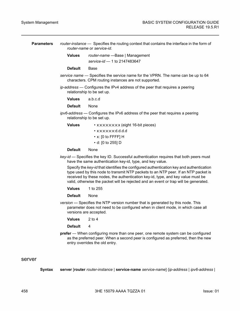
System Management
458
BASIC SYSTEM CONFIGURATION GUIDERELEASE 19.5.R1
3HE 15079 AAAA TQZZA 01 Issue: 01
Parameters router-instance — Specifies the routing context that contains the interface in the form of router-name or service-id.
Values router-name —Base | Management
service-id — 1 to 2147483647
Default Base
service name — Specifies the service name for the VPRN. The name can be up to 64 characters. CPM routing instances are not supported.
ip-address — Configures the IPv4 address of the peer that requires a peering relationship to be set up.
Values a.b.c.d
Default None
ipv6-address — Configures the IPv6 address of the peer that requires a peering relationship to be set up.
Values • x:x:x:x:x:x:x:x (eight 16-bit pieces)
• x:x:x:x:x:x:d.d.d.d
• x: [0 to FFFF] H
• d: [0 to 255] D
Default None
key-id — Specifies the key ID. Successful authentication requires that both peers must have the same authentication key-id, type, and key value.
Specify the key-id that identifies the configured authentication key and authentication type used by this node to transmit NTP packets to an NTP peer. If an NTP packet is received by these nodes, the authentication key-id, type, and key value must be valid, otherwise the packet will be rejected and an event or trap will be generated.
Values 1 to 255
Default None
version — Specifies the NTP version number that is generated by this node. This parameter does not need to be configured when in client mode, in which case all versions are accepted.
Values 2 to 4
Default 4
prefer — When configuring more than one peer, one remote system can be configured as the preferred peer. When a second peer is configured as preferred, then the new entry overrides the old entry.
server
Syntax server [router router-instance | service-name service-name] {ip-address | ipv6-address |
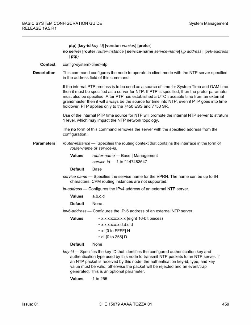
BASIC SYSTEM CONFIGURATION GUIDE RELEASE 19.5.R1
System Management
Issue: 01 3HE 15079 AAAA TQZZA 01 459
ptp} [key-id key-id] [version version] [prefer]
no server [router router-instance | service-name service-name] {ip address | ipv6-address | ptp}
Context config>system>time>ntp
Description This command configures the node to operate in client mode with the NTP server specified in the address field of this command.
If the internal PTP process is to be used as a source of time for System Time and OAM time then it must be specified as a server for NTP. If PTP is specified, then the prefer parameter must also be specified. After PTP has established a UTC traceable time from an external grandmaster then it will always be the source for time into NTP, even if PTP goes into time holdover. PTP applies only to the 7450 ESS and 7750 SR.
Use of the internal PTP time source for NTP will promote the internal NTP server to stratum 1 level, which may impact the NTP network topology.
The no form of this command removes the server with the specified address from the configuration.
Parameters router-instance — Specifies the routing context that contains the interface in the form of router-name or service-id.
Values router-name — Base | Management
service-id — 1 to 2147483647
Default Base
service name — Specifies the service name for the VPRN. The name can be up to 64 characters. CPM routing instances are not supported.
ip-address — Configures the IPv4 address of an external NTP server.
Values a.b.c.d
Default None
ipv6-address — Configures the IPv6 address of an external NTP server.
Values • x:x:x:x:x:x:x:x (eight 16-bit pieces)
• x:x:x:x:x:x:d.d.d.d
• x: [0 to FFFF] H
• d: [0 to 255] D
Default None
key-id — Specifies the key ID that identifies the configured authentication key and authentication type used by this node to transmit NTP packets to an NTP server. If an NTP packet is received by this node, the authentication key-id, type, and key value must be valid, otherwise the packet will be rejected and an event/trap generated. This is an optional parameter.
Values 1 to 255
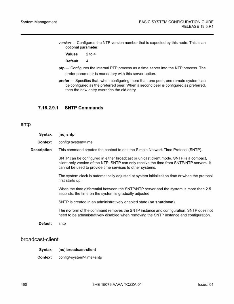
System Management
460
BASIC SYSTEM CONFIGURATION GUIDERELEASE 19.5.R1
3HE 15079 AAAA TQZZA 01 Issue: 01
version — Configures the NTP version number that is expected by this node. This is an optional parameter.
Values 2 to 4
Default 4
ptp — Configures the internal PTP process as a time server into the NTP process. The
prefer parameter is mandatory with this server option.
prefer — Specifies that, when configuring more than one peer, one remote system can be configured as the preferred peer. When a second peer is configured as preferred, then the new entry overrides the old entry.
7.16.2.9.1 SNTP Commands
sntp
Syntax [no] sntp
Context config>system>time
Description This command creates the context to edit the Simple Network Time Protocol (SNTP).
SNTP can be configured in either broadcast or unicast client mode. SNTP is a compact, client-only version of the NTP. SNTP can only receive the time from SNTP/NTP servers. It cannot be used to provide time services to other systems.
The system clock is automatically adjusted at system initialization time or when the protocol first starts up.
When the time differential between the SNTP/NTP server and the system is more than 2.5 seconds, the time on the system is gradually adjusted.
SNTP is created in an administratively enabled state (no shutdown).
The no form of the command removes the SNTP instance and configuration. SNTP does not need to be administratively disabled when removing the SNTP instance and configuration.
Default sntp
broadcast-client
Syntax [no] broadcast-client
Context config>system>time>sntp
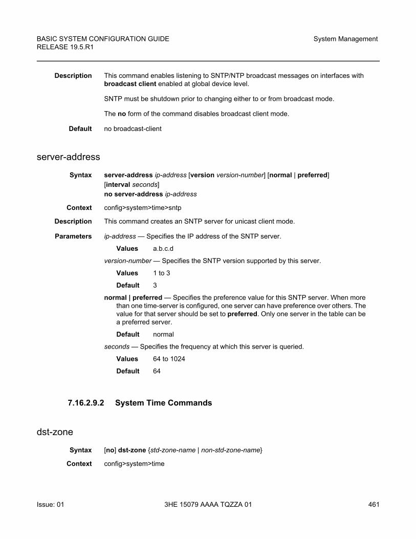
BASIC SYSTEM CONFIGURATION GUIDE RELEASE 19.5.R1
System Management
Issue: 01 3HE 15079 AAAA TQZZA 01 461
Description This command enables listening to SNTP/NTP broadcast messages on interfaces with broadcast client enabled at global device level.
SNTP must be shutdown prior to changing either to or from broadcast mode.
The no form of the command disables broadcast client mode.
Default no broadcast-client
server-address
Syntax server-address ip-address [version version-number] [normal | preferred]
[interval seconds]
no server-address ip-address
Context config>system>time>sntp
Description This command creates an SNTP server for unicast client mode.
Parameters ip-address — Specifies the IP address of the SNTP server.
Values a.b.c.d
version-number — Specifies the SNTP version supported by this server.
Values 1 to 3
Default 3
normal | preferred — Specifies the preference value for this SNTP server. When more than one time-server is configured, one server can have preference over others. The value for that server should be set to preferred. Only one server in the table can be a preferred server.
Default normal
seconds — Specifies the frequency at which this server is queried.
Values 64 to 1024
Default 64
7.16.2.9.2 System Time Commands
dst-zone
Syntax [no] dst-zone {std-zone-name | non-std-zone-name}
Context config>system>time
System Management
462
BASIC SYSTEM CONFIGURATION GUIDERELEASE 19.5.R1
3HE 15079 AAAA TQZZA 01 Issue: 01
Description This command configures the start and end dates and offset for summer time or daylight savings time to override system defaults or for user defined time zones.
When configured, the time is adjusted by adding the configured offset when summer time starts and subtracting the configured offset when summer time ends.
If the time zone configured is listed in the Time Zones section, then the starting and ending parameters and offset do not need to be configured with this command unless it is necessary to override the system defaults. The command returns an error if the start and ending dates and times are not available either the Time Zones section on or entered as optional parameters in this command.
Up to five summer time zones may be configured, for example, for five successive years or for five different time zones. Configuring a sixth entry will return an error message. If no summer (daylight savings) time is supplied, it is assumed no summer time adjustment is required.
The no form of the command removes a configured summer (daylight savings) time entry.
Parameters std-zone-name — Specifies the standard time zone name. The standard name must be a system-defined zone in the Time Zones section. For zone names in the table that have an implicit summer time setting, for example MDT for Mountain Daylight Saving Time, the remaining start-date, end-date and offset parameters need to be provided unless it is necessary to override the system defaults for the time zone.
Values ADT, NDT, AKDT, CDT, CEST, EDT, EEST, MDT, NZDT, PDT, WEST
non-std-zone-name — Specifies the non-standard time zone name. Create a user-defined name created using the zone. The name can be a maximum of 5 characters in length.
end
Syntax end end-week end-day end-month hours-minutes
Context config>system>time>dst-zone
Description This command configures start of summer time settings.
Default end first sunday january 00:00
Parameters end-week — Specifies the starting week of the month when the summer time ends.
Values first, second, third, fourth, last
Default first
end-day — Specifies the starting day of the week when the summer time ends.
Values sunday, monday, tuesday, wednesday, thursday, friday, saturday
Default sunday
BASIC SYSTEM CONFIGURATION GUIDE RELEASE 19.5.R1
System Management
Issue: 01 3HE 15079 AAAA TQZZA 01 463
end-month — Specifies the starting month of the year when the summer time takes effect.
Values january, february, march, april, may, june, july, august, september, october, november, december
Default january
hours-minutes — Specifies the time at which the summer time ends, in hh:mm format.
Values hours: 00 to 23
minutes: 00 to 59
Default 00:00
offset
Syntax offset offset
Context config>system>time>dst-zone
Description This command specifies the number of minutes that will be added to the time when summer time takes effect. The same number of minutes will be subtracted from the time when the summer time ends.
Default offset 60
Parameters offset — Specifies the number of minutes added to the time at the beginning of summer time and subtracted at the end of summer time, expressed as an integer.
Values 0 to 60
Default 60
start
Syntax start start-week start-day start-month hours-minutes
Context config>system>time>dst-zone
Description This command configures start of summer time settings.
Default start first sunday january 00:00
Parameters start-week — Specifies the starting week of the month when the summer time takes effect.
Values first, second, third, fourth, last
Default first
System Management
464
BASIC SYSTEM CONFIGURATION GUIDERELEASE 19.5.R1
3HE 15079 AAAA TQZZA 01 Issue: 01
start-day — Specifies the starting day of the week when the summer time takes effect.
Values sunday, monday, tuesday, wednesday, thursday, friday, saturday
Default sunday
start-month — Specifies the starting month of the year when the summer time takes effect.
Values january, february, march, april, may, june, july, august, september, october, november, december
Default january
hours-minutes — Specifies the time at which the summer time takes effect, in hh:mm format.
Values hours: 00 to 23
minutes: 00 to 59
Default 00:00
zone
Syntax zone {std-zone-name | non-std-zone-name} [hh [:mm]]
no zone
Context config>system>time
Description This command sets the time zone and/or time zone offset for the device.
The SR-series router OS supports system-defined and user-defined time zones. The system-defined time zones are listed in the Time Zones section.
For user-defined time zones, the zone and the UTC offset must be specified.
The no form of the command reverts to the default of Coordinated Universal Time (UTC). If the time zone in use was a user-defined time zone, the time zone will be deleted. If a dst-zone command has been configured that references the zone, the summer commands must be deleted before the zone can be reset to UTC.
Default zone UTC 00
Parameters std-zone-name — Specifies the standard time zone name. The standard name must be a system-defined zone in the Time Zones section. For zone names in the table that have an implicit summer time setting, for example MDT for Mountain Daylight Saving Time, the remaining start-date, end-date and offset parameters need to be provided unless it is necessary to override the system defaults for the time zone.
BASIC SYSTEM CONFIGURATION GUIDE RELEASE 19.5.R1
System Management
Issue: 01 3HE 15079 AAAA TQZZA 01 465
For system-defined time zones, a different offset cannot be specified. If a new time zone is needed with a different offset, the user must create a new time zone. Note that some system-defined time zones have implicit summer time settings which causes the switchover to summer time to occur automatically; configuring the dst-zone parameter is not required.
A user-defined time zone name is case-sensitive and can be up to 5 characters in length.
Values A user-defined value can be up to 4 characters or one of the following values:GMT, WET, CET, EET, EEST, MSK, MSD, AST, NST, EST, CST, MST, PST, HST, AKST, AWST, ACST, AEST, NZST, UTC
non-std-zone-name — Specifies the non-standard time zone name. The name can be up to 5 characters.
hh [:mm] — Specifies the hours and minutes offset from UTC time, expressed as integers. Some time zones do not have an offset that is an integral number of hours. In these instances, the minutes-offset must be specified. For example, the time zone in Pirlanngimpi, Australia UTC + 9.5 hours.
Values hours: -11 to 12minutes: 0 to 59
Default hours: 0minutes: 0
7.16.2.10 Cron Commands
cron
Syntax cron
Context config
Description This command creates the context to create scripts, script parameters and schedules which support the Service Assurance Agent (SAA) functions.
CRON features are saved to the configuration file on both primary and backup control modules. If a control module switchover occurs, CRON events are restored when the new configuration is loaded. If a control module switchover occurs during the execution of a cron script, the failover behavior will be determined by the contents of the script.
schedule
Syntax [no] schedule schedule-name [owner schedule-owner]
System Management
466
BASIC SYSTEM CONFIGURATION GUIDERELEASE 19.5.R1
3HE 15079 AAAA TQZZA 01 Issue: 01
Context config>system>cron
Description This command configures the type of schedule to run, including one-time only (oneshot), periodic or calendar-based runs. All runs are determined by month, day of month or weekday, hour, minute and interval (seconds).
The no form of the command removes the context from the configuration.
Parameters schedule-name — Specifies the name of the schedule. The name can be up to 32 characters.
schedule-owner — Specifies the owner name of the schedule. The name can be up to 32 characters.
Default TiMOS CLI
count
Syntax count number
no count
Context config>system>cron>sched
Description This command configures the total number of times a CRON “interval” schedule is run. For example, if the interval is set to 600 and the count is set to 4, the schedule runs 4 times at 600 second intervals.
Default no count
Parameters number — Specifies the number of times the schedule is run.
Values 1 to 65535
Default 65535
day-of-month
Syntax day-of-month {day-number [..day-number] all}
no day-of-month
Context config>system>cron>sched
Description This command specifies which days of the month that the schedule will occur. Multiple days of the month can be specified. When multiple days are configured, each of them will cause the schedule to trigger. If a day-of-month is configured without configuring month, weekday, hour, and minute, the event will not execute.
Using the weekday command as well as the day-of-month command will cause the script to run twice. For example, consider that today is Monday January 1. If Tuesday January 5 is configured, the script will run on Tuesday (tomorrow) as well as January 5 (Friday).
BASIC SYSTEM CONFIGURATION GUIDE RELEASE 19.5.R1
System Management
Issue: 01 3HE 15079 AAAA TQZZA 01 467
The no form of this command removes the specified day-of-month from the list.
Default no day-of-month
Parameters day-number — Specifies the positive integers specify the day of the month counting from the first of the month. The negative integers specify the day of the month counting from the last day of the month. For example, configuring day-of-month -5, 5 in a month that has 31 days will specify the schedule to occur on the 27th and 5th of that month.
Integer values must map to a valid day for the month in question. For example, February 30 is not a valid date.
Values 1 to 31, -31 to -1 (maximum 62 day-numbers)
all — Specifies all days of the month.
end-time
Syntax end-time [date | day-name] time
no end-time
Context config>system>cron>sched
Description This command is used concurrently with type periodic or calendar. Using the type of periodic, end-time determines at which interval the schedule will end. Using the type of calendar, end-time determines on which date the schedule will end.
When no end-time is specified, the schedule runs forever.
Default no end-time
Parameters date — Specifies the date to schedule a command.
Values YYYY:MM:DD in year:month:day number format
day-name — Specifies the day of the week to schedule a command.
Values sunday, monday, tuesday, wednesday, thursday, friday, saturday
time — Specifies the time of day to schedule a command.
Values hh:mm
hour
Syntax hour hour-number [..hour-number] | all}
no hour
Context config>system>cron>sched
System Management
468
BASIC SYSTEM CONFIGURATION GUIDERELEASE 19.5.R1
3HE 15079 AAAA TQZZA 01 Issue: 01
Description This command specifies which hour to schedule a command. Multiple hours of the day can be specified. When multiple hours are configured, each of them will cause the schedule to trigger. Day-of-month or weekday must also be specified. All days of the month or weekdays can be specified. If an hour is configured without configuring month, weekday, day-of-month, and minute, the event will not execute.
The no form of this command removes the specified hour from the configuration.
Default no hour
Parameters hour-number — Specifies the hour to schedule a command.
Values 0 to 23 (maximum 24 hour-numbers)
all — Specifies all hours.
interval
Syntax interval seconds
no interval
Context config>system>cron>sched
Description This command specifies the interval between runs of an event.
Default no interval
Parameters seconds — Specifies the interval, in seconds, between runs of an event.
Values 30 to 42949672
minute
Syntax minute {minute-number [..minute-number] | all}
no minute
Context config>system>cron>sched
Description This command specifies the minute to schedule a command. Multiple minutes of the hour can be specified. When multiple minutes are configured, each of them will cause the schedule to occur. If a minute is configured, but no hour or day is configured, the event will not execute. If a minute is configured without configuring the month, weekday, day-of-month, and minute, the event will not execute.
The no form of this command removes the specified minute from the configuration.
Default no minute
BASIC SYSTEM CONFIGURATION GUIDE RELEASE 19.5.R1
System Management
Issue: 01 3HE 15079 AAAA TQZZA 01 469
Parameters minute-number — Specifies the minute to schedule a command.
Values 0 to 59 (maximum 60 minute-numbers)
all — Specifies all minutes.
month
Syntax month {month-number [..month-number] | month-name [..month-name] | all}
no month
Context config>system>cron>sched
Description This command specifies the month when the event should be executed. Multiple months can be specified. When multiple months are configured, each of them will cause the schedule to trigger. If a month is configured without configuring the month, weekday, day-of-month, and minute, the event will not execute.
The no form of this command removes the specified month from the configuration.
Default no month
Parameters month-number — Specifies a month number.
Values 1 to 12 (maximum 12 month-numbers)
month-name — Specifies a month by name.
Values january, february, march, april, may, june, july, august, september, october, november, december (maximum 12 month names)
all — Specifies all months.
script-policy
Syntax script-policy policy-name [owner policy-owner]
no script-policy
Context config>system>cron>schedule
Description This command is used to configure the CLI script policy.
Parameters policy-name — Specifies the name of the policy. Can be up to 32 characters.
policy-owner — Specifies the name of the policy owner. Can be up to 32 characters.
The owner is an arbitrary name and not necessarily a user name. Commands in the scripts are not authorized against the owner. The configure system security cli-script authorization x cli-user command determines the user context against which commands in the scripts are authorized.
Default “TiMOS CLI”
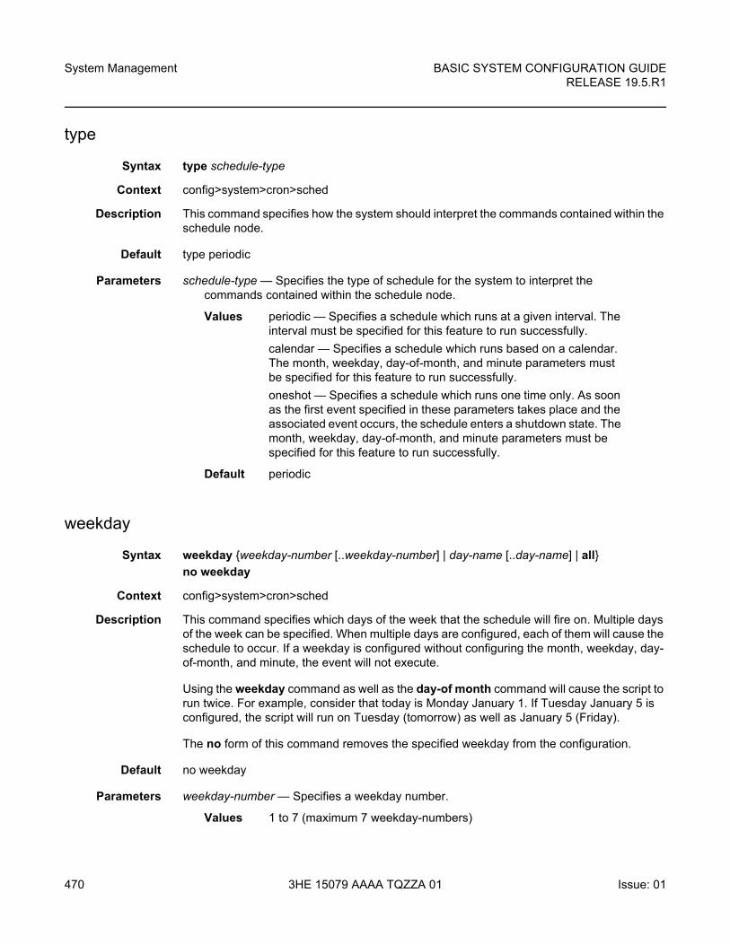
System Management
470
BASIC SYSTEM CONFIGURATION GUIDERELEASE 19.5.R1
3HE 15079 AAAA TQZZA 01 Issue: 01
type
Syntax type schedule-type
Context config>system>cron>sched
Description This command specifies how the system should interpret the commands contained within the schedule node.
Default type periodic
Parameters schedule-type — Specifies the type of schedule for the system to interpret the commands contained within the schedule node.
Values periodic — Specifies a schedule which runs at a given interval. The interval must be specified for this feature to run successfully.
calendar — Specifies a schedule which runs based on a calendar. The month, weekday, day-of-month, and minute parameters must be specified for this feature to run successfully.
oneshot — Specifies a schedule which runs one time only. As soon as the first event specified in these parameters takes place and the associated event occurs, the schedule enters a shutdown state. The month, weekday, day-of-month, and minute parameters must be specified for this feature to run successfully.
Default periodic
weekday
Syntax weekday {weekday-number [..weekday-number] | day-name [..day-name] | all}
no weekday
Context config>system>cron>sched
Description This command specifies which days of the week that the schedule will fire on. Multiple days of the week can be specified. When multiple days are configured, each of them will cause the schedule to occur. If a weekday is configured without configuring the month, weekday, day-of-month, and minute, the event will not execute.
Using the weekday command as well as the day-of month command will cause the script to run twice. For example, consider that today is Monday January 1. If Tuesday January 5 is configured, the script will run on Tuesday (tomorrow) as well as January 5 (Friday).
The no form of this command removes the specified weekday from the configuration.
Default no weekday
Parameters weekday-number — Specifies a weekday number.
Values 1 to 7 (maximum 7 weekday-numbers)
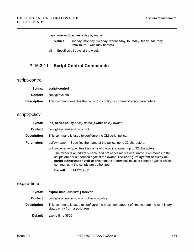
BASIC SYSTEM CONFIGURATION GUIDE RELEASE 19.5.R1
System Management
Issue: 01 3HE 15079 AAAA TQZZA 01 471
day-name — Specifies a day by name.
Values sunday, monday, tuesday, wednesday, thursday, friday, saturday (maximum 7 weekday names)
all — Specifies all days of the week.
7.16.2.11 Script Control Commands
script-control
Syntax script-control
Context config>system
Description This command enables the context to configure command script parameters.
script-policy
Syntax [no] script-policy policy-name [owner policy-owner]
Context config>system>script-control
Description This command is used to configure the CLI script policy.
Parameters policy-name — Specifies the name of the policy, up to 32 characters.
policy-owner — Specifies the name of the policy owner, up to 32 characters.
The owner is an arbitrary name and not necessarily a user name. Commands in the scripts are not authorized against the owner. The configure system security cli-script authorization x cli-user command determines the user context against which commands in the scripts are authorized.
Default “TiMOS CLI”
expire-time
Syntax expire-time {seconds | forever}
Context config>system>script-control>script-policy
Description This command is used to configure the maximum amount of time to keep the run history status entry from a script run.
Default expire-time 3600
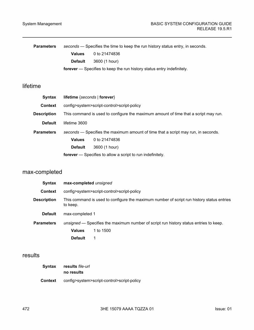
System Management
472
BASIC SYSTEM CONFIGURATION GUIDERELEASE 19.5.R1
3HE 15079 AAAA TQZZA 01 Issue: 01
Parameters seconds — Specifies the time to keep the run history status entry, in seconds.
Values 0 to 21474836
Default 3600 (1 hour)
forever — Specifies to keep the run history status entry indefinitely.
lifetime
Syntax lifetime {seconds | forever}
Context config>system>script-control>script-policy
Description This command is used to configure the maximum amount of time that a script may run.
Default lifetime 3600
Parameters seconds — Specifies the maximum amount of time that a script may run, in seconds.
Values 0 to 21474836
Default 3600 (1 hour)
forever — Specifies to allow a script to run indefinitely.
max-completed
Syntax max-completed unsigned
Context config>system>script-control>script-policy
Description This command is used to configure the maximum number of script run history status entries to keep.
Default max-completed 1
Parameters unsigned — Specifies the maximum number of script run history status entries to keep.
Values 1 to 1500
Default 1
results
Syntax results file-url
no results
Context config>system>script-control>script-policy
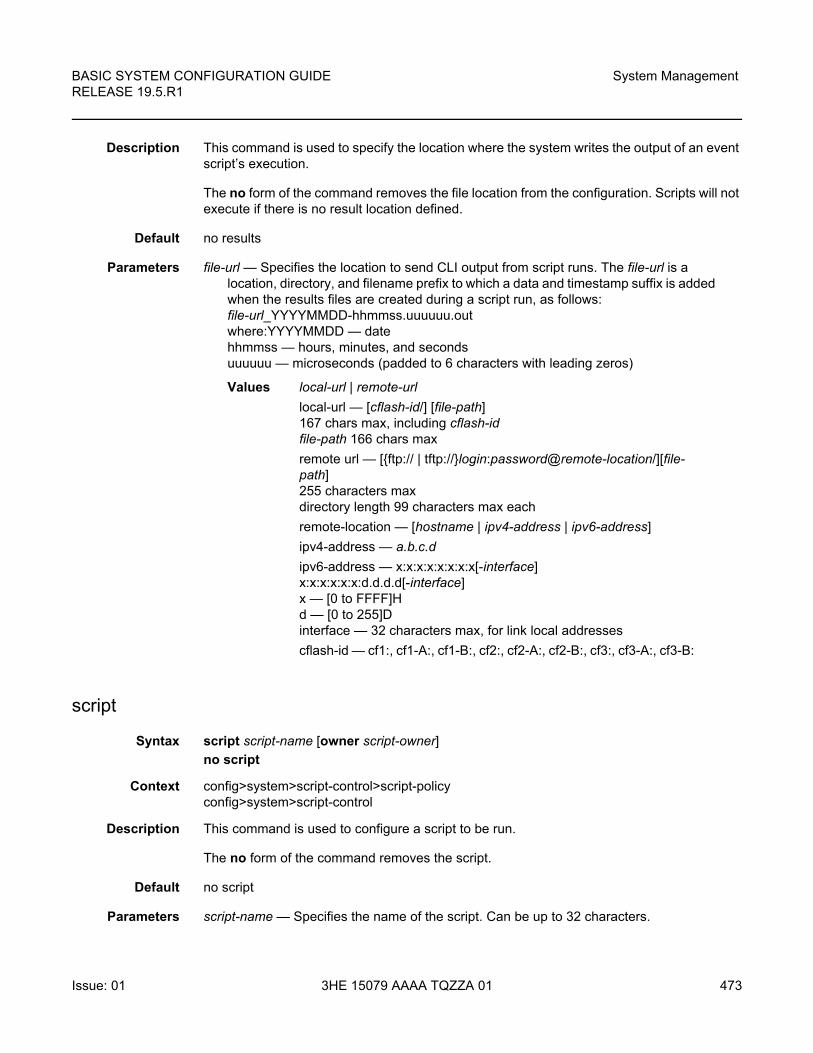
BASIC SYSTEM CONFIGURATION GUIDE RELEASE 19.5.R1
System Management
Issue: 01 3HE 15079 AAAA TQZZA 01 473
Description This command is used to specify the location where the system writes the output of an event script’s execution.
The no form of the command removes the file location from the configuration. Scripts will not execute if there is no result location defined.
Default no results
Parameters file-url — Specifies the location to send CLI output from script runs. The file-url is a location, directory, and filename prefix to which a data and timestamp suffix is added when the results files are created during a script run, as follows:file-url_YYYYMMDD-hhmmss.uuuuuu.outwhere:YYYYMMDD — datehhmmss — hours, minutes, and secondsuuuuuu — microseconds (padded to 6 characters with leading zeros)
Values local-url | remote-url
local-url — [cflash-id/] [file-path]167 chars max, including cflash-idfile-path 166 chars max
remote url — [{ftp:// | tftp://}login:password@remote-location/][file-path]255 characters maxdirectory length 99 characters max each
remote-location — [hostname | ipv4-address | ipv6-address]
ipv4-address — a.b.c.d
ipv6-address — x:x:x:x:x:x:x:x[-interface]x:x:x:x:x:x:d.d.d.d[-interface]x — [0 to FFFF]Hd — [0 to 255]Dinterface — 32 characters max, for link local addresses
cflash-id — cf1:, cf1-A:, cf1-B:, cf2:, cf2-A:, cf2-B:, cf3:, cf3-A:, cf3-B:
script
Syntax script script-name [owner script-owner]
no script
Context config>system>script-control>script-policyconfig>system>script-control
Description This command is used to configure a script to be run.
The no form of the command removes the script.
Default no script
Parameters script-name — Specifies the name of the script. Can be up to 32 characters.
System Management
474
BASIC SYSTEM CONFIGURATION GUIDERELEASE 19.5.R1
3HE 15079 AAAA TQZZA 01 Issue: 01
script-owner — Specifies the name of the script owner. Can be up to 32 characters.
The owner is an arbitrary name and not necessarily a user name. Commands in the scripts are not authorized against the owner. The configure system security cli-script authorization x cli-user command determines the user context against which commands in the scripts are authorized.
Default “TiMOS CLI”
location
Syntax location file-url
no location
Context config>system>script-control>script
Description This command is used to identify the location of a script to be scheduled.
The no form of the command removes the location.
Default no location
Parameters file-url — Specifies the location to search for scripts.
Values local-url | remote-url
local-url — [cflash-id/] [file-path]200 chars max, including cflash-iddirectory length 99 characters max each
remote url — [{ftp:// | tftp://}login:password@remote-location/][file-path]255 characters maxdirectory length 99 characters max each
remote-location — [hostname | ipv4-address | ipv6-address]
ipv4-address — a.b.c.d
ipv6-address — x:x:x:x:x:x:x:x[-interface]x:x:x:x:x:x:d.d.d.d[-interface]x — [0 to FFFF]Hd — [0 to 255]Dinterface — 32 characters max, for link local addresses
cflash-id — cf1:, cf1-A:, cf1-B:, cf2:, cf2-A:, cf2-B:, cf3:, cf3-A:, cf3-B:
BASIC SYSTEM CONFIGURATION GUIDE RELEASE 19.5.R1
System Management
Issue: 01 3HE 15079 AAAA TQZZA 01 475
7.16.2.12 System Synchronization Configuration Commands
sync-if-timing
Syntax sync-if-timing
Context config>system
Description This command creates or edits the context to create or modify timing reference parameters.
abort
Syntax abort
Context config>system>sync-if-timing
Description This command is required to discard changes that have been made to the synchronous interface timing configuration during a session.
begin
Syntax begin
Context config>system>sync-if-timing
Description This command is required in order to enter the mode to create or edit the system synchronous interface timing configuration.
bits
Syntax bits
Context config>system>sync-if-timing
Description This command enables the context to configure parameters for the Building Integrated Timing Supply (BITS). The settings specified under this context apply to both the BITS input and BITS output ports.
The bits command subtree is only available on the 7450 ESS-7, 7450 ESS-12, 7750 SR-7, 7750 SR-12, 7750 SR-12e, 7950 XRS-20, 7950 XRS-40, 7750 SR-a4, 7750 SR-a8, 7750 SR-1e, 7750 SR-2e, and 7750 SR-3e.
System Management
476
BASIC SYSTEM CONFIGURATION GUIDERELEASE 19.5.R1
3HE 15079 AAAA TQZZA 01 Issue: 01
input
Syntax input
Context config>system>sync-if-timing>bits
Description This command provides a context to enable or disable the external BITS timing reference inputs to the central clock of the router. In redundant systems with BITS ports, there are two possible BITS-in interfaces, one for each CPM or CCM.
interface-type
Syntax interface-type {ds1 [{esf | sf}] | e1 [{pcm30crc | pcm31crc}]}
no interface-type
Context config>system>sync-if-timing>bits
Description This command configures the Building Integrated Timing Source (BITS) timing reference.
The no form of the command reverts to the default configuration.
Default interface-type ds1 esf
Parameters ds1 esf — Specifies Extended Super Frame (ESF). This is a framing type used on DS1 circuits that consists of 24 192-bit frames, The 193rd bit provides timing and other functions.
ds1 sf — Specifies Super Frame (SF), also called D4 framing. This is a common framing type used on DS1 circuits. SF consists of 12 192-bit frames. The 193rd bit provides error checking and other functions. ESF supersedes SF.
e1 pcm30crc — Specifies the pulse code modulation (PCM) type. PCM30CRC uses PCM to separate the signal into 30 user channels with CRC protection.
e1 pcm31crc — Specifies the pulse code modulation (PCM) type. PCM31CRC uses PCM to separate the signal into 31 user channels with CRC protection.
output
Syntax output
Context config>system>sync-if-timing>bits
Description This command provides a context to configure and enable or disable the external BITS timing reference output to the central clock of the router. On redundant systems, there are two possible BITS-out interfaces, one for each CPM or CCM.
BASIC SYSTEM CONFIGURATION GUIDE RELEASE 19.5.R1
System Management
Issue: 01 3HE 15079 AAAA TQZZA 01 477
line-length
Syntax line-length {110 | 220 | 330 | 440 | 550 | 660}
Context config>system>sync-if-timing>bits>output
Description This command configures the line-length parameter of the BITS output, This is the distance in feet between the network element and the office clock (BITS/SSU). There are two possible BITS-out interfaces, one for each CPM. They are configured together, but they are displayed separately in the show command. This command is only applicable when the interface-type is DS1.
Default line-length 110
Parameters 110 — Specifies that the distance is from 0 to 110 feet.
220 — Specifies that the distance is from 110 to 220 feet.
330 — Specifies that the distance is from 220 to 330 feet.
440 — Specifies that the distance is from 330 to 440 feet.
550 — Specifies that the distance is from 440 to 550 feet.
660 — Specifies that the distance is from 550 to 660 feet.
ql-minimum
Syntax ql-minimum {prs | stu | st2 | tnc | st3e | st3 | prc | ssua | ssub | sec | eec1 | eec2}
no ql-minimum
Context config>system>sync-if-timing>bits>output
Description This command configures the minimum acceptable QL value that a signal must have in order to be selected for the BITSout port. This ensures that the signal has traceability to a source with at least this quality level so that attached equipment can function properly.
The no form of this command disables this check.
Default no ql-minimum
Parameters prs — Specifies the SONET Primary Reference Source.
stu — Specifies the SONET Synchronous Traceability Unknown.
st2 — Specifies the SONET Stratum 2.
tnc — Specifies the SONET Transit Node Clock.
st3e — Specifies the SONET Stratum 3E.
st3 — Specifies the SONET Stratum 3.
prc — Specifies the SDH Primary Reference Clock.
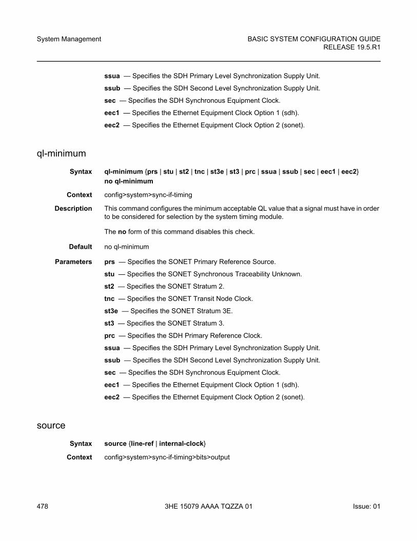
System Management
478
BASIC SYSTEM CONFIGURATION GUIDERELEASE 19.5.R1
3HE 15079 AAAA TQZZA 01 Issue: 01
ssua — Specifies the SDH Primary Level Synchronization Supply Unit.
ssub — Specifies the SDH Second Level Synchronization Supply Unit.
sec — Specifies the SDH Synchronous Equipment Clock.
eec1 — Specifies the Ethernet Equipment Clock Option 1 (sdh).
eec2 — Specifies the Ethernet Equipment Clock Option 2 (sonet).
ql-minimum
Syntax ql-minimum {prs | stu | st2 | tnc | st3e | st3 | prc | ssua | ssub | sec | eec1 | eec2}
no ql-minimum
Context config>system>sync-if-timing
Description This command configures the minimum acceptable QL value that a signal must have in order to be considered for selection by the system timing module.
The no form of this command disables this check.
Default no ql-minimum
Parameters prs — Specifies the SONET Primary Reference Source.
stu — Specifies the SONET Synchronous Traceability Unknown.
st2 — Specifies the SONET Stratum 2.
tnc — Specifies the SONET Transit Node Clock.
st3e — Specifies the SONET Stratum 3E.
st3 — Specifies the SONET Stratum 3.
prc — Specifies the SDH Primary Reference Clock.
ssua — Specifies the SDH Primary Level Synchronization Supply Unit.
ssub — Specifies the SDH Second Level Synchronization Supply Unit.
sec — Specifies the SDH Synchronous Equipment Clock.
eec1 — Specifies the Ethernet Equipment Clock Option 1 (sdh).
eec2 — Specifies the Ethernet Equipment Clock Option 2 (sonet).
source
Syntax source {line-ref | internal-clock}
Context config>system>sync-if-timing>bits>output
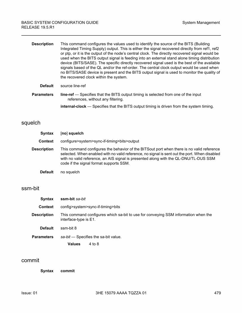
BASIC SYSTEM CONFIGURATION GUIDE RELEASE 19.5.R1
System Management
Issue: 01 3HE 15079 AAAA TQZZA 01 479
Description This command configures the values used to identify the source of the BITS (Building Integrated Timing Supply) output. This is either the signal recovered directly from ref1, ref2 or ptp, or it is the output of the node’s central clock. The directly recovered signal would be used when the BITS output signal is feeding into an external stand alone timing distribution device (BITS/SASE). The specific directly recovered signal used is the best of the available signals based of the QL and/or the ref-order. The central clock output would be used when no BITS/SASE device is present and the BITS output signal is used to monitor the quality of the recovered clock within the system.
Default source line-ref
Parameters line-ref — Specifies that the BITS output timing is selected from one of the input references, without any filtering.
internal-clock — Specifies that the BITS output timing is driven from the system timing.
squelch
Syntax [no] squelch
Context configure>system>sync-if-timing>bits>output
Description This command configures the behavior of the BITSout port when there is no valid reference selected. When enabled with no valid reference, no signal is sent out the port. When disabled with no valid reference, an AIS signal is presented along with the QL-DNU/TL-DUS SSM code if the signal format supports SSM.
Default no squelch
ssm-bit
Syntax ssm-bit sa-bit
Context config>system>sync-if-timing>bits
Description This command configures which sa-bit to use for conveying SSM information when the interface-type is E1.
Default ssm-bit 8
Parameters sa-bit — Specifies the sa-bit value.
Values 4 to 8
commit
Syntax commit

System Management
480
BASIC SYSTEM CONFIGURATION GUIDERELEASE 19.5.R1
3HE 15079 AAAA TQZZA 01 Issue: 01
Context config>system>sync-if-timing
Description This command saves changes made to the system synchronous interface timing configuration.
ref-order
Syntax ref-order first second [third [fourth]]
no ref-order
Context config>system>sync-if-timing
Description The synchronous equipment timing subsystem can lock to different timing reference inputs, those specified in the ref1, ref2, bits, and ptp command configuration. This command organizes the priority order of the timing references.
If a reference source is disabled, then the clock from the next reference source as defined by ref-order is used. If all reference sources are disabled, then clocking is derived from a local oscillator.
If a sync-if-timing reference is linked to a source port that is operationally down, the port is no longer qualified as a valid reference.
For 7450 ESS and 7750 SR systems with two SF/CPM modules, the system distinguishes between the BITS inputs on the active and standby CPMs. The active CPM will use its BITS input port providing that port is qualified. If the local port is not qualified, then the active CPM will use the BITS input port from the standby CPM as the next priority reference. For example, the normal ref-order of bits ref1 ref2 will actually be bits (active CPM), followed by bits (standby CPM), followed by ref1, followed by ref2.
For 7950 XRS systems with two SF/CPMs and two CCMs, the system distinguishes between the BITS inputs on the CCMs associated with the active and standby CPMs. The active CPM will use the BITS input port on the associated CCM, provided that the port is qualified. If the local port is not qualified, then the active CPM will use the BITS input port from the CCM associated with the standby CPM as the next priority reference. For example, the normal ref-order of bits ref1 ref2 will actually be bits (active CCM), followed by bits (standby CCM), followed by ref1, followed by ref2.
The no form of the command resets the reference order to the default values.
Default bits ref1 ref2 ptp (7750 SR and 7450 ESS)
bits ref1 ref2 (7950 XRS)
Parameters first — Specifies the first timing reference to use in the reference order sequence.
Values ref1, ref2, bits, ptp
second — Specifies the second timing reference to use in the reference order sequence.
Values ref1, ref2, bits, ptp
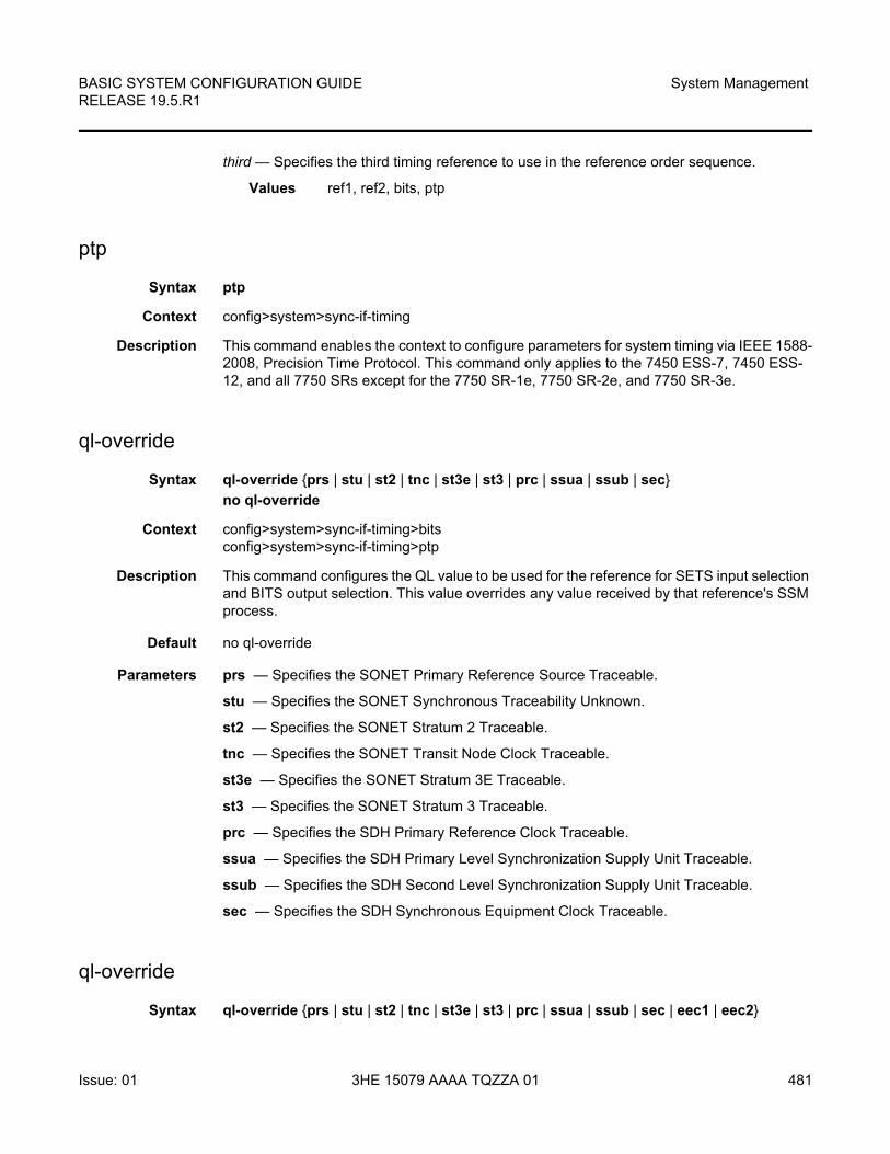
BASIC SYSTEM CONFIGURATION GUIDE RELEASE 19.5.R1
System Management
Issue: 01 3HE 15079 AAAA TQZZA 01 481
third — Specifies the third timing reference to use in the reference order sequence.
Values ref1, ref2, bits, ptp
ptp
Syntax ptp
Context config>system>sync-if-timing
Description This command enables the context to configure parameters for system timing via IEEE 1588-2008, Precision Time Protocol. This command only applies to the 7450 ESS-7, 7450 ESS-12, and all 7750 SRs except for the 7750 SR-1e, 7750 SR-2e, and 7750 SR-3e.
ql-override
Syntax ql-override {prs | stu | st2 | tnc | st3e | st3 | prc | ssua | ssub | sec}
no ql-override
Context config>system>sync-if-timing>bitsconfig>system>sync-if-timing>ptp
Description This command configures the QL value to be used for the reference for SETS input selection and BITS output selection. This value overrides any value received by that reference's SSM process.
Default no ql-override
Parameters prs — Specifies the SONET Primary Reference Source Traceable.
stu — Specifies the SONET Synchronous Traceability Unknown.
st2 — Specifies the SONET Stratum 2 Traceable.
tnc — Specifies the SONET Transit Node Clock Traceable.
st3e — Specifies the SONET Stratum 3E Traceable.
st3 — Specifies the SONET Stratum 3 Traceable.
prc — Specifies the SDH Primary Reference Clock Traceable.
ssua — Specifies the SDH Primary Level Synchronization Supply Unit Traceable.
ssub — Specifies the SDH Second Level Synchronization Supply Unit Traceable.
sec — Specifies the SDH Synchronous Equipment Clock Traceable.
ql-override
Syntax ql-override {prs | stu | st2 | tnc | st3e | st3 | prc | ssua | ssub | sec | eec1 | eec2}
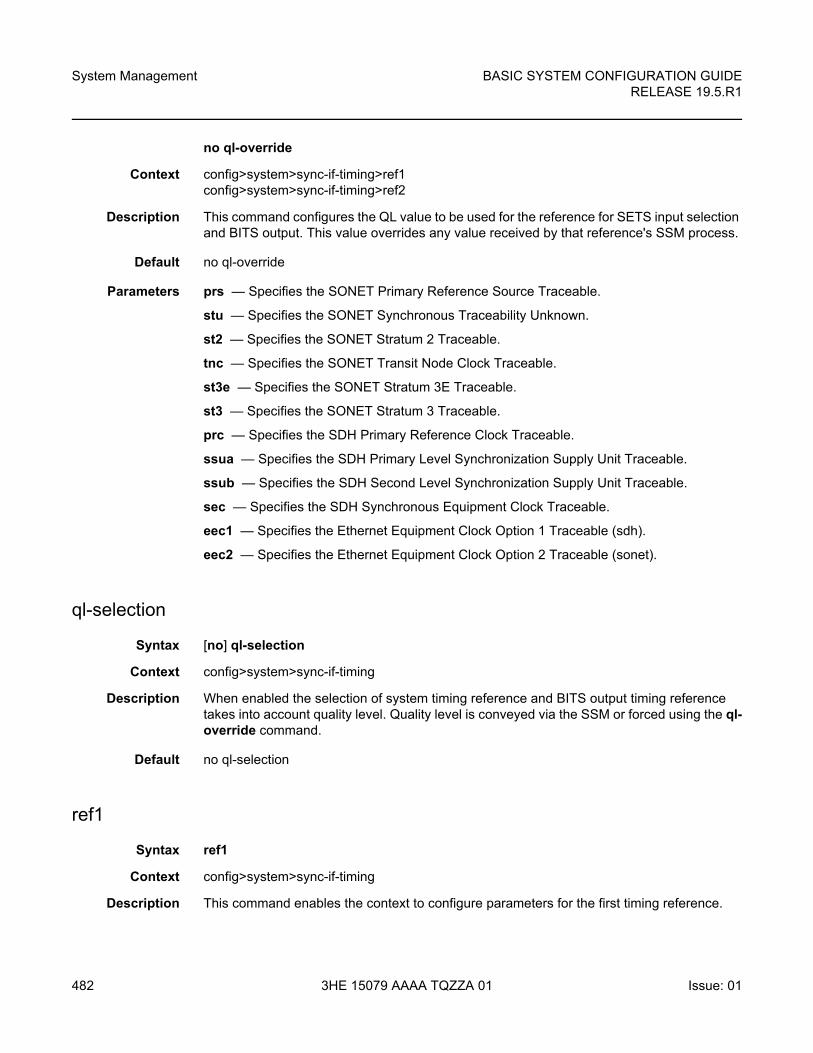
System Management
482
BASIC SYSTEM CONFIGURATION GUIDERELEASE 19.5.R1
3HE 15079 AAAA TQZZA 01 Issue: 01
no ql-override
Context config>system>sync-if-timing>ref1 config>system>sync-if-timing>ref2
Description This command configures the QL value to be used for the reference for SETS input selection and BITS output. This value overrides any value received by that reference's SSM process.
Default no ql-override
Parameters prs — Specifies the SONET Primary Reference Source Traceable.
stu — Specifies the SONET Synchronous Traceability Unknown.
st2 — Specifies the SONET Stratum 2 Traceable.
tnc — Specifies the SONET Transit Node Clock Traceable.
st3e — Specifies the SONET Stratum 3E Traceable.
st3 — Specifies the SONET Stratum 3 Traceable.
prc — Specifies the SDH Primary Reference Clock Traceable.
ssua — Specifies the SDH Primary Level Synchronization Supply Unit Traceable.
ssub — Specifies the SDH Second Level Synchronization Supply Unit Traceable.
sec — Specifies the SDH Synchronous Equipment Clock Traceable.
eec1 — Specifies the Ethernet Equipment Clock Option 1 Traceable (sdh).
eec2 — Specifies the Ethernet Equipment Clock Option 2 Traceable (sonet).
ql-selection
Syntax [no] ql-selection
Context config>system>sync-if-timing
Description When enabled the selection of system timing reference and BITS output timing reference takes into account quality level. Quality level is conveyed via the SSM or forced using the ql-override command.
Default no ql-selection
ref1
Syntax ref1
Context config>system>sync-if-timing
Description This command enables the context to configure parameters for the first timing reference.
BASIC SYSTEM CONFIGURATION GUIDE RELEASE 19.5.R1
System Management
Issue: 01 3HE 15079 AAAA TQZZA 01 483
The restrictions on the location for the source port or source bits for ref1 and ref2 are listed in Ref1 and Ref2 Timing References.
bits-interface-type
Syntax bits-interface-type {ds1 [{esf | sf}] | e1 [{pcm30crc | pcm31crc}
no bits-interface-type
Context config>system>sync-if-timing>ref1config>system>sync-if-timing>ref2
Description This command configures the interface type of the BITS timing reference.
The no form of the command reverts to the default configuration
Parameters ds1 esf — Specifies Extended Super Frame (ESF). This is a framing type used on DS1 circuits that consists of 24 192-bit frames, The 193rd bit provides timing and other functions.
ds1 sf — Specifies Super Frame (SF), also called D4 framing. This is a common framing type used on DS1 circuits. SF consists of 12 192-bit frames. The 193rd bit provides error checking and other functions. ESF supersedes SF.
e1 pcm30crc — Specifies the pulse code modulation (PCM) type. PCM30CRC uses PCM to separate the signal into 30 user channels with CRC protection.
e1 pcm31crc — Specifies the pulse code modulation (PCM) type. PCM31CRC uses PCM to separate the signal into 31 user channels with CRC protection.
source-port
Syntax source-port port-id
no source-port
Context config>system>sync-if-timing>ref1config>system>sync-if-timing>ref2
Description This command configures the source port for timing reference ref1 or ref2. If the port is unavailable or the link is down, then the reference sources are re-evaluated according to the reference order configured in the ref-order command.
In addition to physical port on the 7750 SR, T1 or E1 channels on a channelized OC3/OC12/STM1/STM4 Circuit Emulation Service port can be specified if they are using adaptive timing.
There are restrictions on the source-port location for ref1 and ref2 based on platform. Refer to the description of the ref1 command for details.
Default no source-port
System Management
484
BASIC SYSTEM CONFIGURATION GUIDERELEASE 19.5.R1
3HE 15079 AAAA TQZZA 01 Issue: 01
Parameters port-id — Identifies the physical port in the slot/mda/port, esat-id/slot/port, or pxc-id.sub-port format.
Values slot/mda/port [.channel]
ref2
Syntax ref2
Context config>system>sync-if-timing
Description This command enables the context to configure parameters for the second timing reference. There are restrictions on the source-port and source-bits locations for ref2 based on the platform. The restrictions on the location for the source-port or source-bits for ref1 and ref2 are listed in Revertive, non-Revertive Timing Reference Switching Operation.
revert
Syntax [no] revert
Context config>system>sync-if-timing
Description This command allows the clock to revert to a higher priority reference if the current reference goes offline or becomes unstable. When the failed reference becomes operational, it is eligible for selection. When the mode is non-revertive, a failed clock source is not selected again.
Default no revert
wait-to-restore
Syntax wait-to-restore minutes
no wait-to-restore
Context config>system>sync-if-timing
Description This command configures the time for the Wait to Restore timer. A previously failed input reference must be valid for the time specified before it is used for either the BITSout or the central clock input reference.
The no form of this command disables the timer.
Default no wait-to-restore
Parameters minutes — Specifies a value representing the number of minutes for the wait to restore timeout.
Values 1 to 12
BASIC SYSTEM CONFIGURATION GUIDE RELEASE 19.5.R1
System Management
Issue: 01 3HE 15079 AAAA TQZZA 01 485
7.16.2.13 System Administration Commands
admin
Syntax admin
Context <root>
Description The context to configure administrative system commands. Only authorized users can execute the commands in the admin context.
application-assurance
Syntax application-assurance
Context admin
Description This command enables the context to perform application-assurance operations.
group
Syntax group aa-group-id
Context admin>application-assurance
Description This command enables the context to perform a group-specific upgrade.
Parameters aa-group-id — Specifies an AA ISA group ID.
Values 1 to 255
url-list
Syntax url-list url-list-name upgrade
Context admin>application-assurance>group
Description This command upgrades the URL list.
Parameters url-list-name — Specifies the application assurance URL list, up to 32 characters.
upgrade
Syntax upgrade
System Management
486
BASIC SYSTEM CONFIGURATION GUIDERELEASE 19.5.R1
3HE 15079 AAAA TQZZA 01 Issue: 01
Context admin>app-assure
Description This command loads a new protocol list from the isa-aa.tim file into the CPM.
This command requires an ISA-AA reboot.
debug-save
Syntax debug-save [file-url]
Context admin
Description This command saves existing debug configuration (configuration done under the debug branch of CLI). Debug configurations are not saved by the admin save command and not preserved across a node reboot or CPM switchover. The debug-save command makes the debug configuration available for the operator to execute after a reboot by using the exec command or after a CPM switchover by using the switchover-exec command, if desired.
Parameters file-url — Specifies the file URL location to save the debug configuration. If no file-url is specified then the debug configuration is saved at the same location as the standard configuration file (bof>primary-config/bof>secondary-config/bof>tertiary-config) with the same file name as the standard configuration file but with a .dbg suffix.
Values
Note: IPv6-address applies only to 7750 SR and 7950 XRS.
file url local-url | remote-url: 255 chars max
local-url [cflash-id/][file-path] 200 chars max, including cflash-id file-path 199 chars max
remote-url [{ftp:// | tftp://}login:pswd@remote-locn/][file-path]
255 chars max
directory length 99 chars max each
remote-locn {hostname | ipv4-address | [ipv6-address]}
ipv4-address a.b.c.d
ipv6-address x:x:x:x:x:x:x:x[-interface]
x:x:x:x:x:x:d.d.d.d[-interface]
x - [0 to FFFF]H
d - [0 to 255]D
interface - 32 chars max, for link local addresses 255
cflash-id cf1:, cf1-A:, cf1-B:, cf2:, cf2-A:, cf2-B:, cf3:, cf3-A:, cf3-B:
BASIC SYSTEM CONFIGURATION GUIDE RELEASE 19.5.R1
System Management
Issue: 01 3HE 15079 AAAA TQZZA 01 487
disconnect
Syntax disconnect [address ip-address | session-id session-id | username user-name | {console | bluetooth | telnet | ftp | ssh | netconf | grpc}]
Context admin
Description This command disconnects a user from a session.
Issuing the disconnect command without any parameters will disconnect the session in which the command was executed.
If any of the session type options (for example, console, bluetooth, telnet, FTP, SSH) are specified, then only the respective sessions are affected.
If no session type options are specified, then all sessions from the IP address or from the specified user are disconnected.
Any task that the user is executing is terminated. FTP files accessed by the user will not be removed.
A major severity security log event is created specifying what was terminated and by whom.
Parameters ip-address — Specifies the IP address to disconnect, specified in dotted decimal notation.
Values
session-id — The model-driven session ID. Can be obtained using the show system management-interface datastore-locks [detail] command.
user-name — Specifies the name of the user. The name can be up to 32 characters.
console — Disconnects the console session.
bluetooth — Disconnects the bluetooth session.
telnet — Disconnects the Telnet session.
ftp — Disconnects the FTP session.
Note: IPv6 is supported on the 7750 SR and 7950 XRS.
ipv4-address a.b.c.d
ipv6-address x:x:x:x:x:x:x:x (eight 16-bit pieces)
x:x:x:x:x:x:d.d.d.d
x - [0 to FFFF]H
d - [0 to 255]D
System Management
488
BASIC SYSTEM CONFIGURATION GUIDERELEASE 19.5.R1
3HE 15079 AAAA TQZZA 01 Issue: 01
ssh — Disconnects the SSH session.
netconf — Disconnects the NETCONF session.
grpc — Disconnects the GRPC session.
display-config
Syntax display-config [detail | index]
Context admin
Description This command displays the system’s running configuration.
By default, only non-default settings are displayed.
Specifying the detail option displays all default and non-default configuration parameters.
Parameters detail — Displays default and non-default configuration parameters.
index — Displays only persistent-indices.
enable-tech
Syntax [no] enable-tech
Context admin
Description This command enables the shell and kernel commands.
nat
Syntax nat
Context admin
Description This command performs NAT operations.
save-deterministic-script
Syntax save-deterministic-script
Note: This command should only be used with authorized direction from the Nokia Technical Assistance Center (TAC).
BASIC SYSTEM CONFIGURATION GUIDE RELEASE 19.5.R1
System Management
Issue: 01 3HE 15079 AAAA TQZZA 01 489
Context admin>nat
Description This command saves the script that calculates deterministic NAT map entries.
reboot
Syntax reboot [active | standby | upgrade] [now]
Context admin
Description This command reboots the router or one CPM and can also be used to force an upgrade of the system boot ROMs.
If no options are specified, the user is prompted to confirm the reboot operation. Answering yes (y) will result in both CPMs and all IOMs rebooting.
ALA-1>admin# rebootAre you sure you want to reboot (y/n)?
Parameters active — Reboots the active CPM.
Default active
standby — Reboots the standby CPM.
Default active
upgrade — Forces card firmware to be upgraded during chassis reboot. Normally, the SR-series router OS automatically performs firmware upgrades on CPMs and XCM/IOM cards without the need for the upgrade keyword. The automatic upgrade must be enabled in the SR OS7 Command Line Interface (CLI) when rebooting the system.
When the upgrade keyword is specified, a chassis flag is set for the BOOT Loader (boot.ldr) and on the subsequent boot of the OS on the chassis, firmware images on CPMs, XCMs, or IOMs will be upgraded automatically.
Any CPMs, XCMs, or IOMs that are installed in the chassis will be upgraded automatically. For example, if a card is inserted with down revision firmware as a result of a card hot swap with the latest OS version running, the firmware on the card will be automatically upgraded before the card is brought online.
If the card firmware is upgraded automatically, a chassis cardUpgraded (event 2032) log event is generated. The corresponding SNMP trap for this log event is tmnxEqCardFirmwareUpgraded.
During any firmware upgrade, automatic or manual, it is imperative that during the upgrade procedure:
• Power must not be switched off or interrupted.
• The system must not be reset.
• No cards are inserted or removed.
Any of the above conditions may render cards inoperable requiring a return of the card for resolution.
System Management
490
BASIC SYSTEM CONFIGURATION GUIDERELEASE 19.5.R1
3HE 15079 AAAA TQZZA 01 Issue: 01
The time required to upgrade the firmware on the cards in the chassis depends on the number of cards to be upgraded. The progress of a firmware upgrade can be monitored at the console.
now — Forces a reboot of the router immediately without an interactive confirmation.
reset-policy-exclusive
Syntax reset-policy-exclusive
Context admin
Description This command allows an authorized administrator to reset the exclusive policy editing lock. This will reset the lock flag and end the policy editing session in progress, discarding any policy edits.
save
Syntax save [file-url] [detail] [index]
Context admin
Description This command saves the running configuration to a configuration file. For example:
A:ALA-1>admin# save ftp://test:[email protected]/./100.cfgSaving configuration .........Completed.
An admin save operation initiated by a user is aborted if another user initiates another admin save from another session.
By default, the running configuration is saved to the primary configuration file.
Parameters file-url — Specifies the file URL location to save the configuration file.
Values
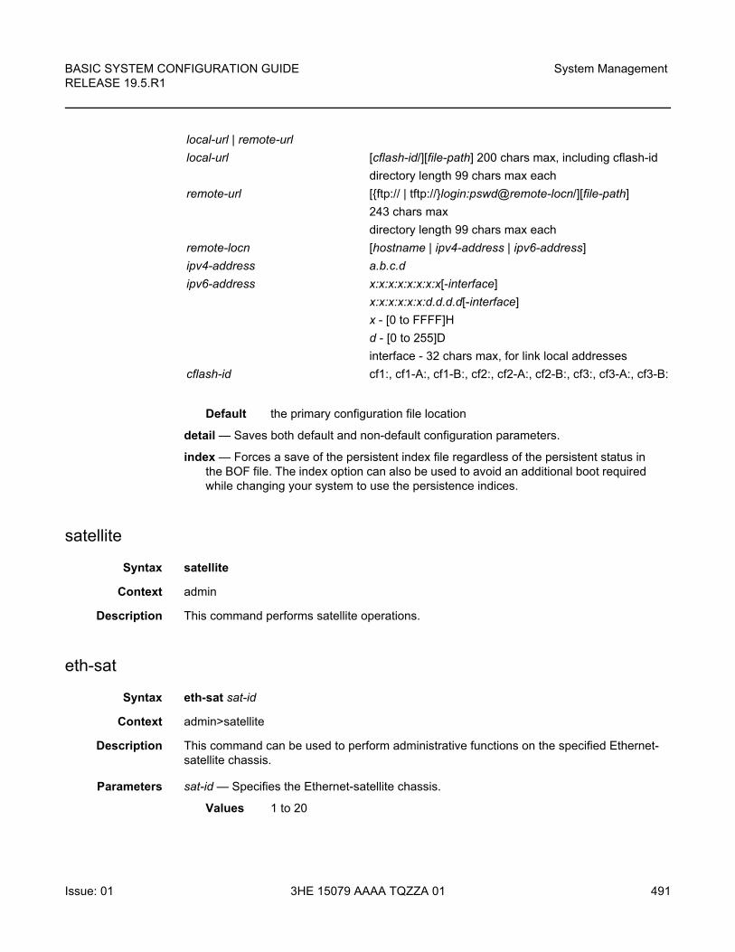
BASIC SYSTEM CONFIGURATION GUIDE RELEASE 19.5.R1
System Management
Issue: 01 3HE 15079 AAAA TQZZA 01 491
Default the primary configuration file location
detail — Saves both default and non-default configuration parameters.
index — Forces a save of the persistent index file regardless of the persistent status in the BOF file. The index option can also be used to avoid an additional boot required while changing your system to use the persistence indices.
satellite
Syntax satellite
Context admin
Description This command performs satellite operations.
eth-sat
Syntax eth-sat sat-id
Context admin>satellite
Description This command can be used to perform administrative functions on the specified Ethernet-satellite chassis.
Parameters sat-id — Specifies the Ethernet-satellite chassis.
Values 1 to 20
local-url | remote-url
local-url [cflash-id/][file-path] 200 chars max, including cflash-id
directory length 99 chars max each
remote-url [{ftp:// | tftp://}login:pswd@remote-locn/][file-path]
243 chars max
directory length 99 chars max each
remote-locn [hostname | ipv4-address | ipv6-address]
ipv4-address a.b.c.d
ipv6-address x:x:x:x:x:x:x:x[-interface]
x:x:x:x:x:x:d.d.d.d[-interface]
x - [0 to FFFF]H
d - [0 to 255]D
interface - 32 chars max, for link local addresses
cflash-id cf1:, cf1-A:, cf1-B:, cf2:, cf2-A:, cf2-B:, cf3:, cf3-A:, cf3-B:
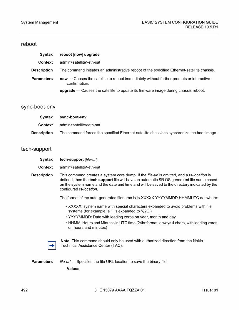
System Management
492
BASIC SYSTEM CONFIGURATION GUIDERELEASE 19.5.R1
3HE 15079 AAAA TQZZA 01 Issue: 01
reboot
Syntax reboot [now] upgrade
Context admin>satellite>eth-sat
Description The command initiates an administrative reboot of the specified Ethernet-satellite chassis.
Parameters now — Causes the satellite to reboot immediately without further prompts or interactive confirmation.
upgrade — Causes the satellite to update its firmware image during chassis reboot.
sync-boot-env
Syntax sync-boot-env
Context admin>satellite>eth-sat
Description The command forces the specified Ethernet-satellite chassis to synchronize the boot image.
tech-support
Syntax tech-support [file-url]
Context admin>satellite>eth-sat
Description This command creates a system core dump. If the file-url is omitted, and a ts-location is defined, then the tech support file will have an automatic SR OS generated file name based on the system name and the date and time and will be saved to the directory indicated by the configured ts-location.
The format of the auto-generated filename is ts-XXXXX.YYYYMMDD.HHMMUTC.dat where:
• XXXXX: system name with special characters expanded to avoid problems with file systems (for example, a '.' is expanded to %2E.)
• YYYYMMDD: Date with leading zeros on year, month and day
• HHMM: Hours and Minutes in UTC time (24hr format, always 4 chars, with leading zeros on hours and minutes)
Parameters file-url — Specifies the file URL location to save the binary file.
Values
Note: This command should only be used with authorized direction from the Nokia Technical Assistance Center (TAC).
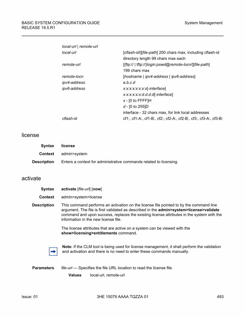
BASIC SYSTEM CONFIGURATION GUIDE RELEASE 19.5.R1
System Management
Issue: 01 3HE 15079 AAAA TQZZA 01 493
license
Syntax license
Context admin>system
Description Enters a context for administrative commands related to licensing.
activate
Syntax activate [file-url] [now]
Context admin>system>license
Description This command performs an activation on the license file pointed to by the command line argument. The file is first validated as described in the admin>system>license>validate command and upon success, replaces the existing license attributes in the system with the information in the new license file.
The license attributes that are active on a system can be viewed with the show>licensing>entitlements command.
Parameters file-url — Specifies the file URL location to read the license file.
Values local-url, remote-url
local-url | remote-url
local-url [cflash-id/][file-path] 200 chars max, including cflash-id
directory length 99 chars max each
remote-url [{ftp:// | tftp://}login:pswd@remote-locn/][file-path]
199 chars max
remote-locn [hostname | ipv4-address | ipv6-address]
ipv4-address a.b.c.d
ipv6-address x:x:x:x:x:x:x:x[-interface]
x:x:x:x:x:x:d.d.d.d[-interface]
x - [0 to FFFF]H
d - [0 to 255]D
interface - 32 chars max, for link local addresses
cflash-id cf1:, cf1-A:, cf1-B:, cf2:, cf2-A:, cf2-B:, cf3:, cf3-A:, cf3-B:
Note: If the CLM tool is being used for license management, it shall perform the validation and activation and there is no need to enter these commands manually.
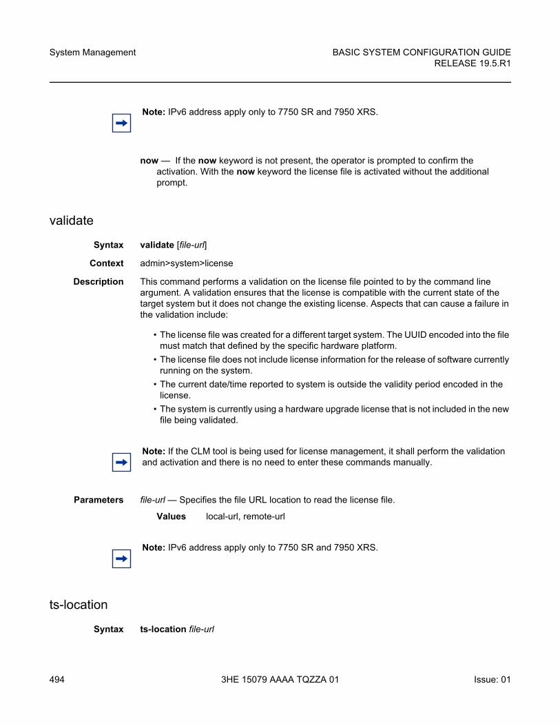
System Management
494
BASIC SYSTEM CONFIGURATION GUIDERELEASE 19.5.R1
3HE 15079 AAAA TQZZA 01 Issue: 01
now — If the now keyword is not present, the operator is prompted to confirm the activation. With the now keyword the license file is activated without the additional prompt.
validate
Syntax validate [file-url]
Context admin>system>license
Description This command performs a validation on the license file pointed to by the command line argument. A validation ensures that the license is compatible with the current state of the target system but it does not change the existing license. Aspects that can cause a failure in the validation include:
• The license file was created for a different target system. The UUID encoded into the file must match that defined by the specific hardware platform.
• The license file does not include license information for the release of software currently running on the system.
• The current date/time reported to system is outside the validity period encoded in the license.
• The system is currently using a hardware upgrade license that is not included in the new file being validated.
Parameters file-url — Specifies the file URL location to read the license file.
Values local-url, remote-url
ts-location
Syntax ts-location file-url
Note: IPv6 address apply only to 7750 SR and 7950 XRS.
Note: If the CLM tool is being used for license management, it shall perform the validation and activation and there is no need to enter these commands manually.
Note: IPv6 address apply only to 7750 SR and 7950 XRS.
BASIC SYSTEM CONFIGURATION GUIDE RELEASE 19.5.R1
System Management
Issue: 01 3HE 15079 AAAA TQZZA 01 495
no ts-location
Context config>system>security>tech-support
Description The ts-location command is used (along with an automatic system generated file name) when no file-url parameter is provided for the admin tech-support command. If no ts-location is defined then the operator must provide a file-url with the admin tech-support command itself.
The directory specified for the ts-location is not auto-created by SR OS. The operator must ensure that it exists.
See the admin tech-support command for more details about the system generated file name.
Default no ts-location
Parameters file-url — Specifies the destination directory for auto-named tech-support files (when no file-url is specified with the admin tech-support command). The file-url for the ts-location must be a directory (no filename or extension). The root directory (for example, cf1:\) is blocked for local compact flash destinations. A sub-directory (for example, cf2:\tech-support) must be used if local cf is the location.
Values
view
Syntax view {bootup-cfg | active-cfg | candidate-cfg | latest-rb| checkpoint-id | rescue}
Context <root>
local-url | remote-url
local-url [cflash-id/][file-path] 200 chars max, including cflash-id
directory length 99 chars max each
remote-url [ftp://login:pswd@remote-locn/][file-path]
247 chars max
directory length 99 chars max each
remote-locn [hostname | ipv4-address | "["ipv6-address"]" ]
ipv4-address a.b.c.d
ipv6-address x:x:x:x:x:x:x:x[-interface]
x:x:x:x:x:x:d.d.d.d[-interface]
x - [0 to FFFF]H
d - [0 to 255]D
interface - 32 chars max, for link local addresses
cflash-id cf1:, cf1-A:, cf1-B:, cf2:, cf2-A:, cf2-B:, cf3:, cf3-A:, cf3-B:
System Management
496
BASIC SYSTEM CONFIGURATION GUIDERELEASE 19.5.R1
3HE 15079 AAAA TQZZA 01 Issue: 01
Description The context to configure administrative system viewing parameters. Only authorized users can execute the commands in the admin context.
Parameters bootup-cfg — Specifies the bootup configuration.
active-cfg — Specifies current running configuration.
candidate-cfg — Specifies candidate configuration.
latest-rb — Specifies the latest configuration.
checkpoint-id — Specifies a specific checkpoint file configuration.
Values 1 to 9
rescue — Specifies a rescue checkpoint configuration.
7.16.2.14 Redundancy Commands
redundancy
Syntax redundancy
Context adminconfig
Description This command enters the context to allow the user to perform redundancy operations.
cert-sync
Syntax [no] cert-sync
Context admin>redundancyconfigure>redundancy
Description This command automatically synchronizes the certificate/CRL/key when importing or generating (for the key). Also if a new CF card is inserted into slot3 into the backup CPM, the system will sync the whole system-pki directory from the active CPM.
Default enabled
force-switchover
Syntax force-switchover [now] [ignore-status]
Context admin>redundancy
BASIC SYSTEM CONFIGURATION GUIDE RELEASE 19.5.R1
System Management
Issue: 01 3HE 15079 AAAA TQZZA 01 497
Description This command forces a switchover to the standby CPM card. The primary CPM reloads its software image and becomes the secondary CPM.
Parameters now — Forces the switchover to the redundant CPM card immediately.
ignore-status — Forces a switchover despite any diagnostics or conditions on the standby. For the 7950 XRS, this is true even if the standby cannot reach the extension CPMs on the extension chassis of an XRS-40 via its local CPM interconnect ports).
rollback-sync
Syntax rollback-sync
Context admin>redundancy
Description This command copies the entire set of rollback checkpoint files from the active CPM CF to the standby CPM CF.
synchronize
Syntax synchronize cert
synchronize {boot-env | config}
Context admin>redundancy
Description This command performs a synchronization of the standby CPM’s images and/or configuration files to the active CPM. Either the boot-env or config parameter must be specified.
In the admin>redundancy context, this command performs a manually triggered standby CPM synchronization. When the standby CPM takes over operation following a failure or reset of the active CPM, it is important to ensure that the active and standby CPM have identical operational parameters. This includes the saved configuration, CPM, XCM, and IOM images.
The active CPM ensures that the active configuration is maintained on the standby CPM. However, to ensure smooth operation under all circumstances, runtime images and system initialization configurations must also be automatically synchronized between the active and standby CPM. If synchronization fails, alarms and log messages that indicate the type of error that caused the failure of the synchronization operation are generated. When the error condition ceases to exist, the alarm is cleared.
Only files stored on the router are synchronized. If a configuration file or image is stored in a location other than on a local compact flash, the file is not synchronized (for example, storing a configuration file on an FTP server).
The no form of the command removes the parameter from the configuration.
Default no synchronize
System Management
498
BASIC SYSTEM CONFIGURATION GUIDERELEASE 19.5.R1
3HE 15079 AAAA TQZZA 01 Issue: 01
Parameters cert — Synchronizes the imported certificate/key/CRL files to the standby CPM.
boot-env — Synchronizes all files required for the boot process (loader, BOF, images, and config).
config — Synchronizes only the primary, secondary, and tertiary configuration files.
mgmt-ethernet
Syntax mgmt-ethernet [revert seconds]
no mgmt-ethernet
Context config>redundancy
Description If the management Ethernet port on the active CPM goes down, this command allows the active CPM to be configured to use the management Ethernet port of the standby CPM.
The revert option allows the administrator to control when to revert back to the management Ethernet port of the primary CPM once it comes up again.
The no form of the command disables redundancy, so that connectivity to the active CPM is lost if its Ethernet port goes down.
This feature is not supported on the 7750 SR-a, 7750-e, and the VSR platforms.
Default no mgmt-ethernet
Parameters seconds — Specifies the duration to wait (in seconds) before reverting back to the primary CPM’s management Ethernet port.
Values 1 to 300
multi-chassis
Syntax multi-chassis
Context config>redundancy
Description This command enables the context to configure multi-chassis parameters.
bgp-multi-homing
Syntax bgp-multi-homing
Context config>redundancy
Description This command configures BGP multi-homing parameters.
BASIC SYSTEM CONFIGURATION GUIDE RELEASE 19.5.R1
System Management
Issue: 01 3HE 15079 AAAA TQZZA 01 499
boot-timer
Syntax boot-timer seconds
no boot-timer
Context config>redundancy>bgp-multi-homing
Description This command configures the time the service manager waits after a node reboot before running the DF election algorithm. The boot-timer value should be configured to allow for the BGP sessions to come up and for the NLRI information to be refreshed or exchanged.
The no form of the command reverts the default.
Default no boot-timer
Parameters seconds — Specifies the BGP multi-homing boot-timer in seconds.
Values 0 to 600
site-activation-timer
Syntax site-activation-timer seconds
no site-activation-timer
Context config>redundancy>bgp-multi-homing
Description This command defines the amount of time the service manager will keep the local sites in standby status, waiting for BGP updates from remote PEs before running the DF election algorithm to decide whether the site should be unblocked. The timer is started when one of the following events occurs if the site is operationally up:
• Manual site activation using the no shutdown command at site-id level or at member object(s) level (SAP(s) or PW(s))
• Site activation after a failure
Default no site-activation-timer
Parameters seconds — Specifies the standby status in seconds.
Values 0 to 100
Default 2
site-min-down-timer
Syntax site-min-down-timer seconds
no site-min-down-timer
Context config>redundancy>bgp-multi-homing
System Management
500
BASIC SYSTEM CONFIGURATION GUIDERELEASE 19.5.R1
3HE 15079 AAAA TQZZA 01 Issue: 01
Description This command configures the BGP multi-homing site minimum down time. When set to a non-zero value, if the site goes operationally down it will remain operationally down for at least the length of time configured for the site-min-down-timer, regardless of whether other state changes would have caused it to go operationally up. This timer is restarted every time that the site transitions from up to down.
The above operation is optimized in the following circumstances:
• If the site goes down on the designated forwarder but there are no BGP multi-homing peers with the same site in an UP state, then the site-min-down-timer is not started and is not used.
• If the site goes down on the designated forwarder but there are no active BGP multi-homing peers, then the site-min-down-timer is not started and is not used.
• If the site-min-down-timer is active and a BGP multi-homing update is received from the designated forwarder indicating its site has gone down, the site-min-down-timer is immediately terminated and this PE becomes the designated forwarder if the BGP multi-homing algorithm determines it should be the designated forwarder.
The no form of the command reverts to default value.
Default no site-min-down-timer
Parameters seconds — Specifies the time, in seconds, that a BGP multi-homing site remains operationally down after a transition from up to down.
Values 1 to 100
Default 0
bgp-evpn-multi-homing
Syntax bgp-evpn-multi-homing
Context config>redundancy
Description This command configures BGP EVPN multi-homing parameters.
boot-timer
Syntax boot-timer seconds
no boot-timer
Context config>redundancy>bgp-evpn-multi-homing
Description This command configures the time the service manager waits after a node reboot before running the DF election algorithm. The boot-timer value should be configured to allow for the BGP sessions to come up and for the NLRI information to be refreshed/exchanged.
The no form of the command reverts the default.
BASIC SYSTEM CONFIGURATION GUIDE RELEASE 19.5.R1
System Management
Issue: 01 3HE 15079 AAAA TQZZA 01 501
Default no boot-timer
Parameters seconds — Specifies the BGP multi-homing boot-timer in seconds.
Values 1 to 600
Default 10
es-activation-timer
Syntax es-activation-timer seconds
Context config>redundancy>bgp-evpn-multi-homing
Description This command defines the amount of time the service manager will keep the local sites in standby status, waiting for BGP updates from remote PEs before running the DF election algorithm to decide whether the site should be unblocked. The timer is started when one of the following events occurs if the site is operationally up:
• Manual site activation using the no shutdown command at site-id level or at member object(s) level (SAP(s) or PW(s))
• Site activation after a failure
Parameters seconds — Specifies the standby status in seconds.
Values 0 to 100
Default 3
rollback-sync
Syntax [no] rollback-sync
Context config>redundancy
Description The operator can enable automatic synchronization of rollback checkpoint files between the active CPM and standby CPM. When this automatic synchronization is enabled, a rollback save will cause the new checkpoint file to be saved on both the active and standby CPMs. The suffixes of the old checkpoint files on both active and standby CPMs are incremented. Note that automatic sync only causes the one new checkpoint file to be copied to both CFs (the other 9 checkpoints are not automatically copied from active to standby but that can be done manually with admin red rollback-sync).
Automatic synchronization of rollback checkpoint files across CPMs is only performed if the rollback-location is configured as a local file-url (for example, "cf3:/rollback-files/rollback). Synchronization is not done if the rollback-location is remote.
System Management
502
BASIC SYSTEM CONFIGURATION GUIDERELEASE 19.5.R1
3HE 15079 AAAA TQZZA 01 Issue: 01
The config red sync {boot-env | config} and admin red sync {boot-env | config} do not apply to rollback checkpoint files. These commands do not manually or automatically sync rollback checkpoint files. The dedicated rollback-sync commands must be used to sync rollback checkpoint files.
Default no rollback-sync
synchronize
Syntax synchronize {boot-env | config}
Context config>redundancy
Description This command performs a synchronization of the standby CPMs images and/or config files to the active CPM. Either the boot-env or config parameter must be specified.In the config>redundancy context, this command performs an automatically triggered standby CPM synchronization. When the standby CPM takes over operation following a failure or reset of the active CPM, it is important to ensure that the active and standby CPMs have identical operational parameters. This includes the saved configuration, CPM, XCM, and IOM images.
The active CPM ensures that the active configuration is maintained on the standby CPM. However, to ensure smooth operation under all circumstances, runtime images and system initialization configurations must also be automatically synchronized between the active and standby CPM.
If synchronization fails, alarms and log messages that indicate the type of error that caused the failure of the synchronization operation are generated. When the error condition ceases to exist, the alarm is cleared.
Only files stored on the router are synchronized. If a configuration file or image is stored in a location other than on a local compact flash, the file is not synchronized (for example, storing a configuration file on an FTP server).
Default no synchronize
Parameters boot-env — Synchronizes all files required for the boot process (loader, BOF, images, and config).
config — Synchronizes only the primary, secondary, and tertiary configuration files.
Default config
BASIC SYSTEM CONFIGURATION GUIDE RELEASE 19.5.R1
System Management
Issue: 01 3HE 15079 AAAA TQZZA 01 503
7.16.2.14.1 Peer Commands
peer
Syntax peer ip-address [create]
no peer ip-address
Context config>redundancy>multi-chassis
Description This command configures a multi-chassis redundancy peer.
Parameters ip-address — Specifies a peer IP address. Multicast addresses are not allowed.
Values ipv4-address: a.b.c.d
ipv6-address:
• x:x:x:x:x:x:x:x (eight 16-bit pieces)
• x:x:x:x:x:x:d.d.d.d
• x: [0 to FFFF] H
• d: [0 to 255] D
authentication-key
Syntax authentication-key {authentication-key | hash-key} [hash | hash2 | custom]
no authentication-key
Context config>redundancy>multi-chassis>peer
Description This command configures the authentication key used between this node and the multi-chassis peer. The authentication key can be any combination of letters or numbers. The no form of the command removes the authentication key.
Default no authentication-key
Parameters authentication-key — Specifies the authentication key. Allowed values are any string up to 20 characters long composed of printable, 7-bit ASCII characters. If the string contains special characters (#, $, spaces, and so on), the entire string must be enclosed within double quotes.
hash-key — Specifies the hash key. The key can be any combination of ASCII characters up to 33 (hash1-key) or 55 (hash2-key) characters in length (encrypted). If spaces are used in the string, enclose the entire string in quotation marks (“ ”).
hash — Specifies the key is entered in an encrypted form. If the hash or hash2 parameter is not used, the key is assumed to be in an unencrypted, clear text form. For security, all keys are stored in encrypted form in the configuration file with the hash or hash2 parameter specified
System Management
504
BASIC SYSTEM CONFIGURATION GUIDERELEASE 19.5.R1
3HE 15079 AAAA TQZZA 01 Issue: 01
hash2 — Specifies the key is entered in a more complex encrypted form that involves more variables than the key value alone, meaning that the hash2 encrypted variable cannot be copied and pasted. If the hash or hash2 parameter is not used, the key is assumed to be in an unencrypted, clear text form. For security, all keys are stored in encrypted form in the configuration file with the hash or hash2 parameter specified.
custom — Specifies the custom encryption to management interface.
diameter-proxy
Syntax [no] diameter-proxy
Context config>redundancy>multi-chassis>peer>sync
Description This command synchronizes diameter proxy.
Default no diameter-proxy
igmp
Syntax [no] igmp
Context config>redundancy>multi-chassis>peer>sync
Description This command specifies whether IGMP protocol information should be synchronized with the multi-chassis peer.
Default no igmp
igmp-snooping
Syntax [no] igmp-snooping
Context config>redundancy>multi-chassis>peer>sync
Description This command specifies whether IGMP snooping information should be synchronized with the multi-chassis peer.
Default no igmp-snooping
ipsec
Syntax [no] ipsec
Context config>redundancy>multi-chassis>peer>sync
BASIC SYSTEM CONFIGURATION GUIDE RELEASE 19.5.R1
System Management
Issue: 01 3HE 15079 AAAA TQZZA 01 505
Description This command synchronizes IPsec information.
Default no ipsec
l2tp
Syntax [no] l2tp
Context config>redundancy>multi-chassis>peer>sync
Description This command synchronizes L2TP.
Default no l2tp
local-dhcp-server
Syntax [no] local-dhcp-server
Context config>redundancy>multi-chassis>peer>sync
Description This command synchronizes DHCP server information.
Default no local-dhcp-server
mc-ring
Syntax [no] mc-ring
Context config>redundancy>multi-chassis>peer>sync
Description This command synchronizes multi-chassis ring information.
Default no mc-ring
mld-snooping
Syntax [no] mld-snooping
Context config>redundancy>multi-chassis>peer>sync
Description This command is not supported. It is not blocked for backwards-compatibility reasons but has no effect on the system if configured.
Default no mld-snooping
System Management
506
BASIC SYSTEM CONFIGURATION GUIDERELEASE 19.5.R1
3HE 15079 AAAA TQZZA 01 Issue: 01
peer-name
Syntax peer-name name
no peer-name
Context config>redundancy>multi-chassis>peer
Description This command specifies a peer name.
Default no peer-name
Parameters name — Specifies the string, up to 32 characters long, consisting of any printable, seven-bit ASCII characters can be used within the string. If the string contains special characters (#, $, spaces, and so on), the entire string must be enclosed within double quotes.
pim-snooping
Syntax pim-snooping [saps] [spoke-sdps]
no pim-snooping
Context config>redundancy>multi-chassis>peer>sync
Description This command specifies whether PIM snooping for IPv4 information should be synchronized with the multi-chassis peer. Entering only pim-snooping (without any parameter) results in the synchronization being applicable only to SAPs.
Default no pim-snooping
Parameters saps — Specifies that SAPs are to be synchronized with the multi-chassis peer relating to sync-tags configured on ports. This is the default when no parameters are included.
spoke-sdps — Specifies that spoke SDPs are to be synchronized with the multi-chassis
peer according to the synchronization tags configured on spoke SDPs.
port
Syntax port port-id [sync-tag sync-tag] [create]
no port port-id]
Context config>redundancy>multi-chassis>peer>sync
Description This command specifies the port to be synchronized with the multi-chassis peer and a synchronization tag to be used while synchronizing this port with the multi-chassis peer.
Parameters port-id — Specifies the port to be synchronized with the multi-chassis peer.
Values
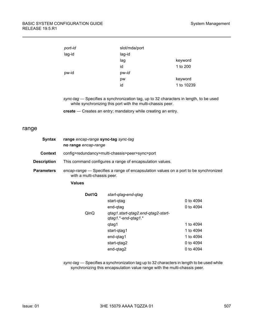
BASIC SYSTEM CONFIGURATION GUIDE RELEASE 19.5.R1
System Management
Issue: 01 3HE 15079 AAAA TQZZA 01 507
sync-tag — Specifies a synchronization tag, up to 32 characters in length, to be used while synchronizing this port with the multi-chassis peer.
create — Creates an entry; mandatory while creating an entry.
range
Syntax range encap-range sync-tag sync-tag
no range encap-range
Context config>redundancy>multi-chassis>peer>sync>port
Description This command configures a range of encapsulation values.
Parameters encap-range — Specifies a range of encapsulation values on a port to be synchronized with a multi-chassis peer.
Values
sync-tag — Specifies a synchronization tag up to 32 characters in length to be used while synchronizing this encapsulation value range with the multi-chassis peer.
port-id slot/mda/port
lag-id lag-id
lag keyword
id 1 to 200
pw-id pw-id
pw keyword
id 1 to 10239
Dot1Q start-qtag-end-qtag
start-qtag 0 to 4094
end-qtag 0 to 4094
QinQ qtag1.start-qtag2.end-qtag2-start-qtag1.*-end-qtag1.*
qtag1 1 to 4094
start-qtag1 1 to 4094
end-qtag1 1 to 4094
start-qtag2 0 to 4094
end-qtag2 0 to 4094
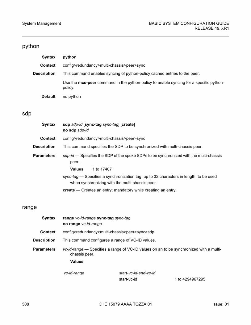
System Management
508
BASIC SYSTEM CONFIGURATION GUIDERELEASE 19.5.R1
3HE 15079 AAAA TQZZA 01 Issue: 01
python
Syntax python
Context config>redundancy>multi-chassis>peer>sync
Description This command enables syncing of python-policy cached entries to the peer.
Use the mcs-peer command in the python-policy to enable syncing for a specific python-policy.
Default no python
sdp
Syntax sdp sdp-id [sync-tag sync-tag] [create]
no sdp sdp-id
Context config>redundancy>multi-chassis>peer>sync
Description This command specifies the SDP to be synchronized with multi-chassis peer.
Parameters sdp-id — Specifies the SDP of the spoke SDPs to be synchronized with the multi-chassis
peer.
Values 1 to 17407
sync-tag — Specifies a synchronization tag, up to 32 characters in length, to be used
when synchronizing with the multi-chassis peer.
create — Creates an entry; mandatory while creating an entry.
range
Syntax range vc-id-range sync-tag sync-tag
no range vc-id-range
Context config>redundancy>multi-chassis>peer>sync>sdp
Description This command configures a range of VC-ID values.
Parameters vc-id-range — Specifies a range of VC-ID values on an to be synchronized with a multi-chassis peer.
Values
vc-id-range start-vc-id-end-vc-id
start-vc-id 1 to 4294967295
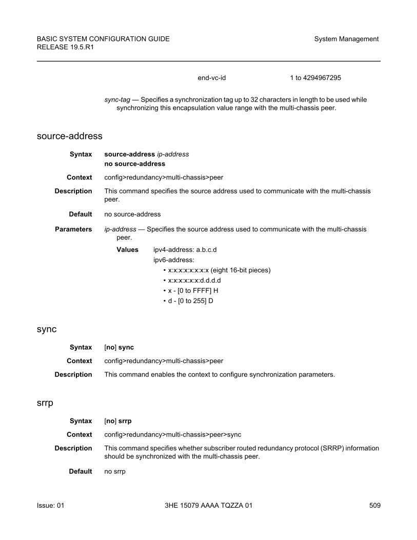
BASIC SYSTEM CONFIGURATION GUIDE RELEASE 19.5.R1
System Management
Issue: 01 3HE 15079 AAAA TQZZA 01 509
sync-tag — Specifies a synchronization tag up to 32 characters in length to be used while synchronizing this encapsulation value range with the multi-chassis peer.
source-address
Syntax source-address ip-address
no source-address
Context config>redundancy>multi-chassis>peer
Description This command specifies the source address used to communicate with the multi-chassis peer.
Default no source-address
Parameters ip-address — Specifies the source address used to communicate with the multi-chassis peer.
Values ipv4-address: a.b.c.d
ipv6-address:
• x:x:x:x:x:x:x:x (eight 16-bit pieces)
• x:x:x:x:x:x:d.d.d.d
• x - [0 to FFFF] H
• d - [0 to 255] D
sync
Syntax [no] sync
Context config>redundancy>multi-chassis>peer
Description This command enables the context to configure synchronization parameters.
srrp
Syntax [no] srrp
Context config>redundancy>multi-chassis>peer>sync
Description This command specifies whether subscriber routed redundancy protocol (SRRP) information should be synchronized with the multi-chassis peer.
Default no srrp
end-vc-id 1 to 4294967295
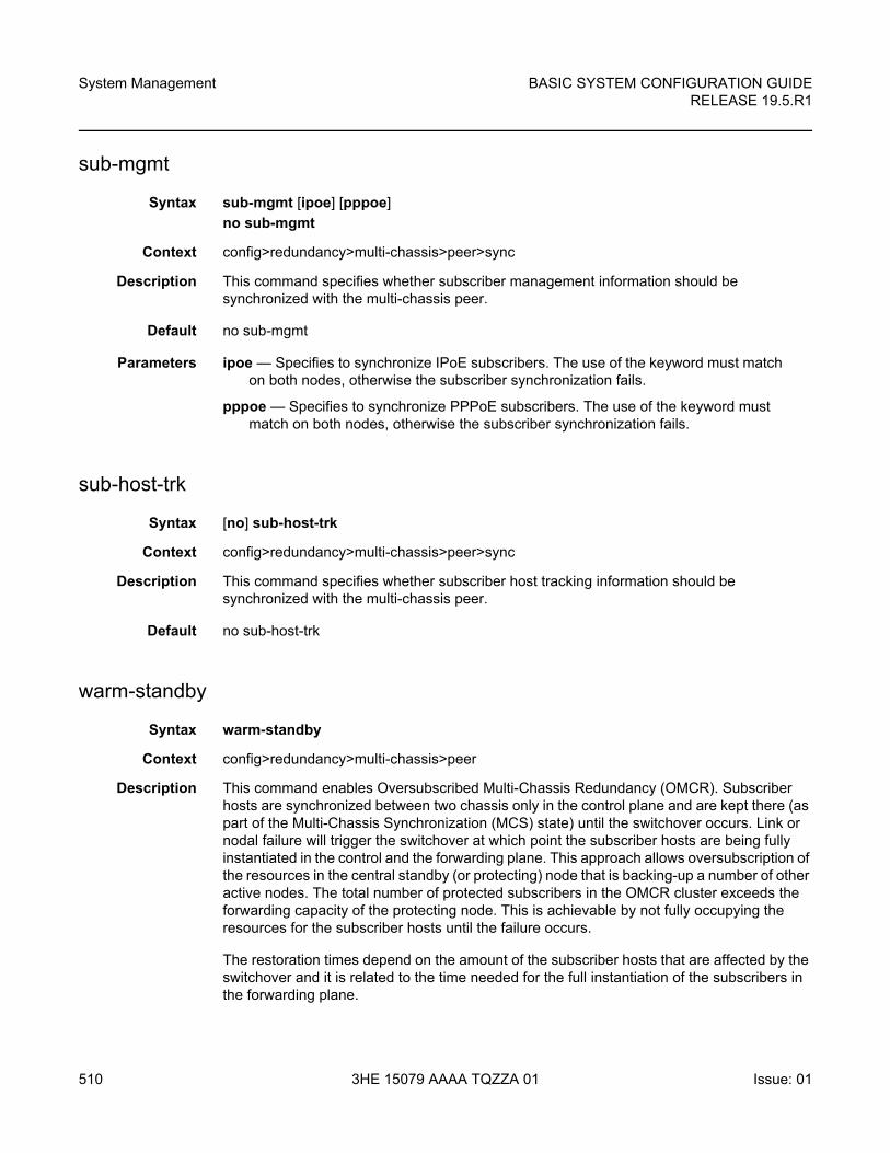
System Management
510
BASIC SYSTEM CONFIGURATION GUIDERELEASE 19.5.R1
3HE 15079 AAAA TQZZA 01 Issue: 01
sub-mgmt
Syntax sub-mgmt [ipoe] [pppoe]
no sub-mgmt
Context config>redundancy>multi-chassis>peer>sync
Description This command specifies whether subscriber management information should be synchronized with the multi-chassis peer.
Default no sub-mgmt
Parameters ipoe — Specifies to synchronize IPoE subscribers. The use of the keyword must match on both nodes, otherwise the subscriber synchronization fails.
pppoe — Specifies to synchronize PPPoE subscribers. The use of the keyword must match on both nodes, otherwise the subscriber synchronization fails.
sub-host-trk
Syntax [no] sub-host-trk
Context config>redundancy>multi-chassis>peer>sync
Description This command specifies whether subscriber host tracking information should be synchronized with the multi-chassis peer.
Default no sub-host-trk
warm-standby
Syntax warm-standby
Context config>redundancy>multi-chassis>peer
Description This command enables Oversubscribed Multi-Chassis Redundancy (OMCR). Subscriber hosts are synchronized between two chassis only in the control plane and are kept there (as part of the Multi-Chassis Synchronization (MCS) state) until the switchover occurs. Link or nodal failure will trigger the switchover at which point the subscriber hosts are being fully instantiated in the control and the forwarding plane. This approach allows oversubscription of the resources in the central standby (or protecting) node that is backing-up a number of other active nodes. The total number of protected subscribers in the OMCR cluster exceeds the forwarding capacity of the protecting node. This is achievable by not fully occupying the resources for the subscriber hosts until the failure occurs.
The restoration times depend on the amount of the subscriber hosts that are affected by the switchover and it is related to the time needed for the full instantiation of the subscribers in the forwarding plane.
BASIC SYSTEM CONFIGURATION GUIDE RELEASE 19.5.R1
System Management
Issue: 01 3HE 15079 AAAA TQZZA 01 511
Although this command is configured on a peer level, the warm-standby property is a nodal characteristic. In other words, mixing of N:1 and 1:1 (hot standby) mode in the central standby node is not supported. Consequently all peers on the central standby node must be configured for warm-standby (N:1), or all peers must be configured for hot-standby (1:1) by omitting the warm-standby keyword from the configuration.
The peer of the central-backup node is not aware of the redundancy model supported. In in other words, the peer of the central-backup node does not know whether it peers with a warm-standby peer or host-standby-peer. All nodes participating in this protection model must run SR OS 12.0 or higher.
This command applies only to the 7450 ESS and 7750 SR.
Default no warm-standby
7.16.2.14.2 Multi-Chassis Endpoint Commands
mc-endpoint
Syntax [no] mc-endpoint
Context config>redundancy>multi-chassis>peer
Description This command specifies that the endpoint is multi-chassis. This value should be the same on both MC-EP peers for the pseudowires that must be part of the same group.
The no form of this command removes the endpoint from the MC-EP. Single chassis behavior applies.
Default no mc-endpoint
bfd-enable
Syntax [no] bfd-enable
Context config>redundancy>multi-chassis>peer>mc-epconfig>router>rsvpconfig>router>bgpconfig>router>bgp>groupconfig>router>bgp>group>neighborconfig>redundancy>multi-chassis>peer>mc-ep
System Management
512
BASIC SYSTEM CONFIGURATION GUIDERELEASE 19.5.R1
3HE 15079 AAAA TQZZA 01 Issue: 01
Description This command enables the use of bi-directional forwarding (BFD) to control the state of the associated protocol interface. By enabling BFD on a given protocol interface, the state of the protocol interface is tied to the state of the BFD session between the local node and the remote node. The parameters used for the BFD are set via the BFD command under the IP interface.
The no form of this command disables BFD.
Default no bfd-enable
boot-timer
Syntax boot-timer interval
no boot-timer
Context config>redundancy>multi-chassis>peer>mc-ep
Description This command configures the boot timer interval. This command applies only when the node reboots. It specifies the time the MC-EP protocol keeps trying to establish a connection before assuming a failure of the remote peer. This is different from the keep-alives mechanism which is used just after the peer-peer communication was established. After this time interval passed all the mc-endpoints configured under services will revert to single chassis behavior, activating the best local PW.
The no form of this command sets the interval to default.
Default no boot-timer
Parameters interval — Specifies the boot timer interval.
Values 1 to 600
hold-on-neighbor-failure
Syntax hold-on-neighbor-failure multiplier
no hold-on-neighbor-failure
Context config>redundancy>multi-chassis>peer>mc-ep
Description This command specifies the number of keep-alive intervals that the local node will wait for packets from the MC-EP peer before assuming failure. After this time interval passed the all the mc-endpoints configured under services will revert to single chassis behavior, activating the best local pseudowire.
The no form of this command sets the multiplier to default value.
Default no hold-on-neighbor-failure
BASIC SYSTEM CONFIGURATION GUIDE RELEASE 19.5.R1
System Management
Issue: 01 3HE 15079 AAAA TQZZA 01 513
Parameters multiplier — Specifies the hold time applied on neighbor failure.
Values 2 to 25
keep-alive-interval
Syntax keep-alive-interval interval
no keep-alive-interval
Context config>redundancy>multi-chassis>peer>mc-ep
Description This command sets the interval at which keep-alive messages are exchanged between two systems participating in MC-EP when bfd is not enabled or is down. These fast keep-alive messages are used to determine remote-node failure and the interval is set in deci-seconds.
The no form of this command sets the interval to default value
Default no keep-alive-interval
Parameters interval — Specifies the time interval expressed in deciseconds.
Values 5 to 500 (tenths of a second)
passive-mode
Syntax [no] passive-mode
Context config>redundancy>multi-chassis>peer>mc-ep
Description This command configures the passive mode behavior for the MC-EP protocol. When in passive mode the MC-EP pair will be dormant until two of the pseudowires in a MC-EP will be signaled as active by the remote PEs, being assumed that the remote pair is configured with regular MC-EP. As soon as more than one pseudowire is active, dormant MC-EP pair will activate. It will use the regular exchange to select the best pseudowire between the active ones and it will block the Rx and Tx directions of the other pseudowires.
The no form of this command will disable the passive mode behavior.
Default no passive-mode
system-priority
Syntax system-priority value
no system-priority
Context config>redundancy>multi-chassis>peer>mc-ep
System Management
514
BASIC SYSTEM CONFIGURATION GUIDERELEASE 19.5.R1
3HE 15079 AAAA TQZZA 01 Issue: 01
Description This command allows the operator to set the system priority. The peer configured with the lowest value is chosen to be the master. If system-priority are equal then the one with the highest system-id (chassis MAC address) is chosen as the master.
The no form of this command sets the system priority to default.
Default no system-priority
Parameters value — Specifies the priority assigned to the local MC-EP peer.
Values 1 to 255
7.16.2.14.3 MC-LAG Commands
mc-lag
Syntax [no] mc-lag
Context config>redundancy>multi-chassis>peer>mc-lag
Description This command enables the context to configure multi-chassis LAG operations and related parameters.
The no form of this command administratively disables multi-chassis LAG. MC-LAG can only be issued only when mc-lag is shutdown.
Default no mc-lag
hold-on-neighbor-failure
Syntax hold-on-neighbor-failure multiplier
no hold-on-neighbor-failure
Context config>redundancy>multi-chassis>peer>mc-lag
Description This command specifies the interval that the standby node will wait for packets from the active node before assuming a redundant-neighbor node failure. This delay in switch-over operation is required to accommodate different factors influencing node failure detection rate, such as IGP convergence, or HA switch-over times and to prevent the standby node to take action prematurely.
The no form of this command sets this parameter to default value.
Default hold-on-neighbor-failure 3
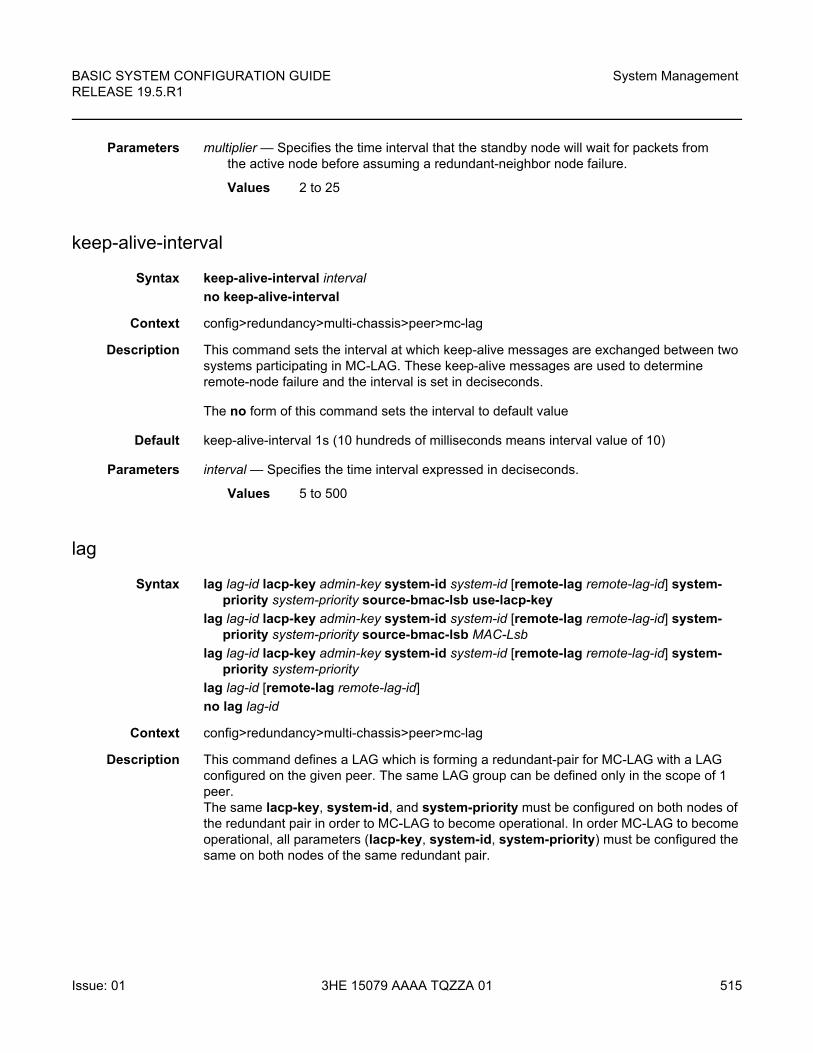
BASIC SYSTEM CONFIGURATION GUIDE RELEASE 19.5.R1
System Management
Issue: 01 3HE 15079 AAAA TQZZA 01 515
Parameters multiplier — Specifies the time interval that the standby node will wait for packets from the active node before assuming a redundant-neighbor node failure.
Values 2 to 25
keep-alive-interval
Syntax keep-alive-interval interval
no keep-alive-interval
Context config>redundancy>multi-chassis>peer>mc-lag
Description This command sets the interval at which keep-alive messages are exchanged between two systems participating in MC-LAG. These keep-alive messages are used to determine remote-node failure and the interval is set in deciseconds.
The no form of this command sets the interval to default value
Default keep-alive-interval 1s (10 hundreds of milliseconds means interval value of 10)
Parameters interval — Specifies the time interval expressed in deciseconds.
Values 5 to 500
lag
Syntax lag lag-id lacp-key admin-key system-id system-id [remote-lag remote-lag-id] system-priority system-priority source-bmac-lsb use-lacp-key
lag lag-id lacp-key admin-key system-id system-id [remote-lag remote-lag-id] system-priority system-priority source-bmac-lsb MAC-Lsb
lag lag-id lacp-key admin-key system-id system-id [remote-lag remote-lag-id] system-priority system-priority
lag lag-id [remote-lag remote-lag-id]
no lag lag-id
Context config>redundancy>multi-chassis>peer>mc-lag
Description This command defines a LAG which is forming a redundant-pair for MC-LAG with a LAG configured on the given peer. The same LAG group can be defined only in the scope of 1 peer. The same lacp-key, system-id, and system-priority must be configured on both nodes of the redundant pair in order to MC-LAG to become operational. In order MC-LAG to become operational, all parameters (lacp-key, system-id, system-priority) must be configured the same on both nodes of the same redundant pair.
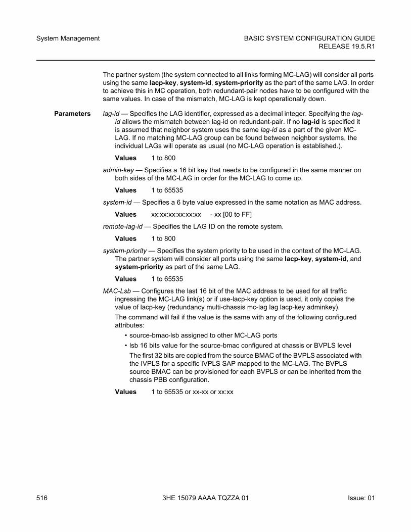
System Management
516
BASIC SYSTEM CONFIGURATION GUIDERELEASE 19.5.R1
3HE 15079 AAAA TQZZA 01 Issue: 01
The partner system (the system connected to all links forming MC-LAG) will consider all ports using the same lacp-key, system-id, system-priority as the part of the same LAG. In order to achieve this in MC operation, both redundant-pair nodes have to be configured with the same values. In case of the mismatch, MC-LAG is kept operationally down.
Parameters lag-id — Specifies the LAG identifier, expressed as a decimal integer. Specifying the lag-id allows the mismatch between lag-id on redundant-pair. If no lag-id is specified it is assumed that neighbor system uses the same lag-id as a part of the given MC-LAG. If no matching MC-LAG group can be found between neighbor systems, the individual LAGs will operate as usual (no MC-LAG operation is established.).
Values 1 to 800
admin-key — Specifies a 16 bit key that needs to be configured in the same manner on both sides of the MC-LAG in order for the MC-LAG to come up.
Values 1 to 65535
system-id — Specifies a 6 byte value expressed in the same notation as MAC address.
Values xx:xx:xx:xx:xx:xx - xx [00 to FF]
remote-lag-id — Specifies the LAG ID on the remote system.
Values 1 to 800
system-priority — Specifies the system priority to be used in the context of the MC-LAG. The partner system will consider all ports using the same lacp-key, system-id, and system-priority as part of the same LAG.
Values 1 to 65535
MAC-Lsb — Configures the last 16 bit of the MAC address to be used for all traffic ingressing the MC-LAG link(s) or if use-lacp-key option is used, it only copies the value of lacp-key (redundancy multi-chassis mc-lag lag lacp-key adminkey).
The command will fail if the value is the same with any of the following configured attributes:
• source-bmac-lsb assigned to other MC-LAG ports
• lsb 16 bits value for the source-bmac configured at chassis or BVPLS level
The first 32 bits are copied from the source BMAC of the BVPLS associated with the IVPLS for a specific IVPLS SAP mapped to the MC-LAG. The BVPLS source BMAC can be provisioned for each BVPLS or can be inherited from the chassis PBB configuration.
Values 1 to 65535 or xx-xx or xx:xx
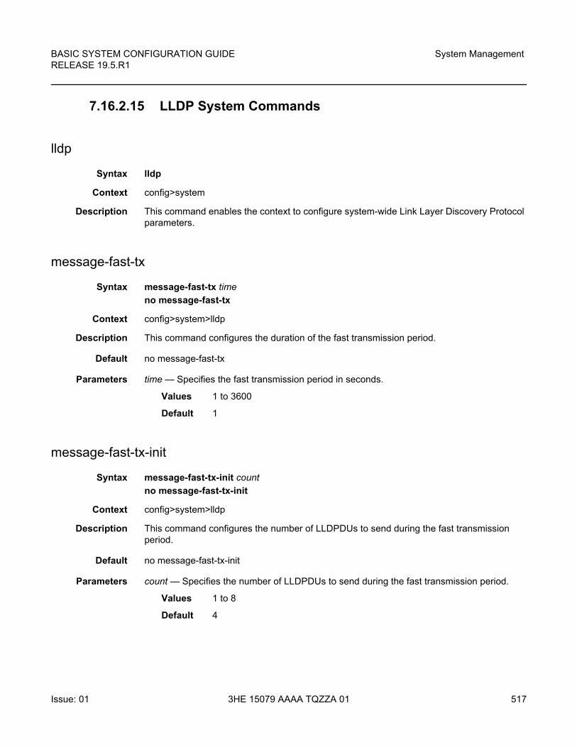
BASIC SYSTEM CONFIGURATION GUIDE RELEASE 19.5.R1
System Management
Issue: 01 3HE 15079 AAAA TQZZA 01 517
7.16.2.15 LLDP System Commands
lldp
Syntax lldp
Context config>system
Description This command enables the context to configure system-wide Link Layer Discovery Protocol parameters.
message-fast-tx
Syntax message-fast-tx time
no message-fast-tx
Context config>system>lldp
Description This command configures the duration of the fast transmission period.
Default no message-fast-tx
Parameters time — Specifies the fast transmission period in seconds.
Values 1 to 3600
Default 1
message-fast-tx-init
Syntax message-fast-tx-init count
no message-fast-tx-init
Context config>system>lldp
Description This command configures the number of LLDPDUs to send during the fast transmission period.
Default no message-fast-tx-init
Parameters count — Specifies the number of LLDPDUs to send during the fast transmission period.
Values 1 to 8
Default 4
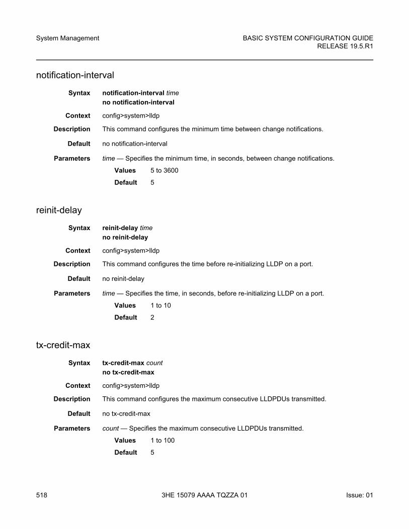
System Management
518
BASIC SYSTEM CONFIGURATION GUIDERELEASE 19.5.R1
3HE 15079 AAAA TQZZA 01 Issue: 01
notification-interval
Syntax notification-interval time
no notification-interval
Context config>system>lldp
Description This command configures the minimum time between change notifications.
Default no notification-interval
Parameters time — Specifies the minimum time, in seconds, between change notifications.
Values 5 to 3600
Default 5
reinit-delay
Syntax reinit-delay time
no reinit-delay
Context config>system>lldp
Description This command configures the time before re-initializing LLDP on a port.
Default no reinit-delay
Parameters time — Specifies the time, in seconds, before re-initializing LLDP on a port.
Values 1 to 10
Default 2
tx-credit-max
Syntax tx-credit-max count
no tx-credit-max
Context config>system>lldp
Description This command configures the maximum consecutive LLDPDUs transmitted.
Default no tx-credit-max
Parameters count — Specifies the maximum consecutive LLDPDUs transmitted.
Values 1 to 100
Default 5
BASIC SYSTEM CONFIGURATION GUIDE RELEASE 19.5.R1
System Management
Issue: 01 3HE 15079 AAAA TQZZA 01 519
tx-hold-multiplier
Syntax tx-hold-multiplier multiplier
no tx-hold-multiplier
Context config>system>lldp
Description This command configures the multiplier of the tx-interval.
Default no tx-hold-multiplier
Parameters multiplier — Specifies the multiplier of the tx-interval.
Values 2 to 10
Default 4
tx-interval
Syntax tx-interval interval
no tx-interval
Context config>system>lldp
Description This command configures the LLDP transmit interval time.
Default no tx-interval
Parameters interval — Specifies the LLDP transmit interval time.
Values 5 to 32768
Default 30
7.16.2.16 LLDP Ethernet Port Commands
lldp
Syntax lldp
Context config>port>ethernet
Description This command enables the context to configure Link Layer Discovery Protocol (LLDP) parameters on the specified port.
System Management
520
BASIC SYSTEM CONFIGURATION GUIDERELEASE 19.5.R1
3HE 15079 AAAA TQZZA 01 Issue: 01
dest-mac
Syntax dest-mac {nearest-bridge | nearest-non-tpmr | nearest-customer}
Context config>port>ethernet>lldp
Description This command configures destination MAC address parameters.
Default dest-mac nearest-bridge
Parameters nearest-bridge — Specifies to use the nearest bridge.
nearest-non-tpmr — Specifies to use the nearest non-Two-Port MAC Relay (TPMR).
nearest-customer — Specifies to use the nearest customer.
admin-status
Syntax admin-status {rx | tx | tx-rx | disabled}
Context config>port>ethernet>lldp>dstmac
Description This command specifies the administratively desired status of the local LLDP agent.
Default admin-status disabled
Parameters rx — Specifies the LLDP agent will receive, but will not transmit LLDP frames on this port.
tx — Specifies that the LLDP agent will transmit LLDP frames on this port and will not store any information about the remote systems connected.
tx-rx — Specifies that the LLDP agent will transmit and receive LLDP frames on this port.
disabled — Specifies that the LLDP agent will not transmit or receive LLDP frames on this port. If there is remote systems information which is received on this port and stored in other tables, before the port's admin status becomes disabled, then the information will naturally age out.
notification
Syntax [no] notification
Context config>port>ethernet>lldp>dstmac
Description This command enables LLDP notifications.
The no form of the command disables LLDP notifications.
Default no notification
BASIC SYSTEM CONFIGURATION GUIDE RELEASE 19.5.R1
System Management
Issue: 01 3HE 15079 AAAA TQZZA 01 521
port-id-subtype
Syntax pot-id-subtype {tx-if-alias | tx-if-name | tx-local}
Context config>port>ethernet>lldp>dstmac
Description This command configures the encoding of the port identifier TLVs transmitted to the peer.
Default port-id-subtype tx-local
Parameters tx-if-alias — (1) Transmits the ifAlias IF-MIB string.
tx-if-name — (5) Transmits the ifName IF-MIB string.
tx-local — (7) Transmits the interface ifIndex value.
tunnel-nearest-bridge
Syntax [no] tunnel-nearest-bridge
Context config>port>ethernet>lldp>dest-mac
Description The command allows LLDP packets received on the port with the destination address of the nearest bridge to be tunneled without being intercepted on the local port. The dest-mac nearest-bridge must be disable for tunneling to occur. This is applicable to NULL SAP Epipe and VPLS services only.
Default no tunnel-nearest-bridge
tx-mgmt-address
Syntax tx-mgmt-address [system] [system-ipv6]
no tx-mgmt-address
Context config>port>ethernet>lldp>dstmac
Description This command specifies which management address to transmit.
The no form of the command resets value to the default.
Default no tx-mgmt-address
Parameters system — Specifies to use the system IP address. The system address will only be transmitted once it has been configured if this parameter is specified.
system-ipv6 — Specifies to use the system IPv6 address. The system address will only be transmitted once it has been configured if this parameter is specified.
System Management
522
BASIC SYSTEM CONFIGURATION GUIDERELEASE 19.5.R1
3HE 15079 AAAA TQZZA 01 Issue: 01
tx-tlvs
Syntax tx-tlvs [port-desc] [sys-name] [sys-desc] [sys-cap]
no tx-tlvs
Context config>port>ethernet>lldp>dstmac
Description This command specifies which LLDP TLVs to transmit.
The no form of the command resets the value to the default.
Default no tx-tlvs
Parameters port-desc — Indicates that the LLDP agent should transmit port description TLVs.
sys-name — Indicates that the LLDP agent should transmit system name TLVs.
sys-desc — Indicates that the LLDP agent should transmit system description TLVs.
sys-cap — Indicates that the LLDP agent should transmit system capabilities TLVs.
7.16.2.17 System Router Instance Commands
router
Syntax router [router-instance] [create]
no router [router-instance]
Context config
Description This command enables the context in which to configure router parameters including interfaces, route policies and protocols. This command is also used to create CPM router instances.
For CPM router instances, this command enters or creates a user-created CPM router instance. A CPM router instance is not a VPRN router instance. VPRN router instances are configured under configure service vprn. CPM router instances are the only type of non-VPRN router instances that can be created by a user, and have a user-defined name. CPM router instances only use CPM/CCM ethernet ports as interfaces.
Parameters router-instance — Specifies the router name or CPM router instance.
Values

BASIC SYSTEM CONFIGURATION GUIDE RELEASE 19.5.R1
System Management
Issue: 01 3HE 15079 AAAA TQZZA 01 523
Default Base
create — Keyword used to create the router instance.
router-instance: router name
router-name Base | management | cpm-vr-name
cpm-vr-name up to 32 characters

System Management
524
BASIC SYSTEM CONFIGURATION GUIDERELEASE 19.5.R1
3HE 15079 AAAA TQZZA 01 Issue: 01
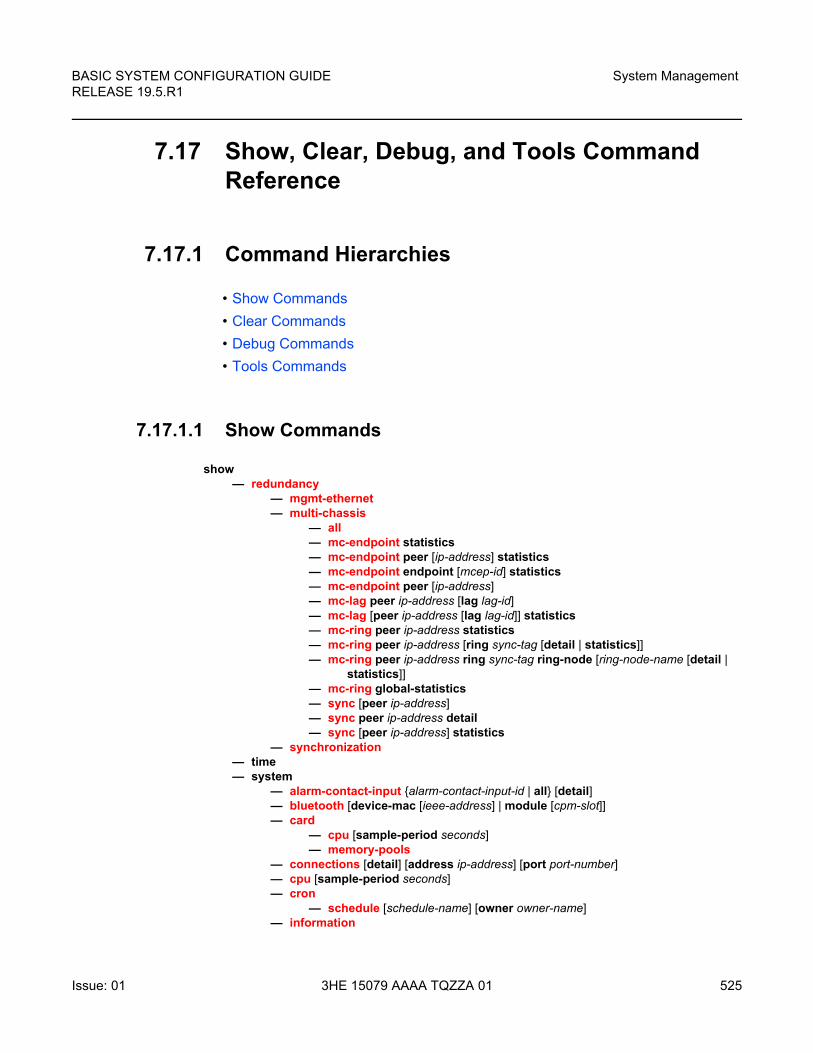
BASIC SYSTEM CONFIGURATION GUIDE RELEASE 19.5.R1
System Management
Issue: 01 3HE 15079 AAAA TQZZA 01 525
7.17 Show, Clear, Debug, and Tools Command Reference
7.17.1 Command Hierarchies
• Show Commands
• Clear Commands
• Debug Commands
• Tools Commands
7.17.1.1 Show Commands
show— redundancy
— mgmt-ethernet— multi-chassis
— all — mc-endpoint statistics— mc-endpoint peer [ip-address] statistics— mc-endpoint endpoint [mcep-id] statistics— mc-endpoint peer [ip-address]— mc-lag peer ip-address [lag lag-id]— mc-lag [peer ip-address [lag lag-id]] statistics— mc-ring peer ip-address statistics— mc-ring peer ip-address [ring sync-tag [detail | statistics]]— mc-ring peer ip-address ring sync-tag ring-node [ring-node-name [detail |
statistics]]— mc-ring global-statistics— sync [peer ip-address]— sync peer ip-address detail— sync [peer ip-address] statistics
— synchronization— time— system
— alarm-contact-input {alarm-contact-input-id | all} [detail]— bluetooth [device-mac [ieee-address] | module [cpm-slot]]— card
— cpu [sample-period seconds]— memory-pools
— connections [detail] [address ip-address] [port port-number] — cpu [sample-period seconds] — cron
— schedule [schedule-name] [owner owner-name]— information
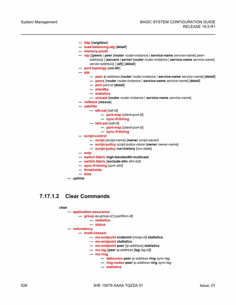
System Management
526
BASIC SYSTEM CONFIGURATION GUIDERELEASE 19.5.R1
3HE 15079 AAAA TQZZA 01 Issue: 01
— lldp [neighbor]— load-balancing-alg [detail]— memory-pools— ntp [{peers | peer [router router-instance | service-name service-name] peer-
address} | {servers | server [router router-instance | service-name service-name] server-address} | [all]] [detail]
— port-topology [uni-dir]— ptp
— peer ip-address [router router-instance | service-name service-name] [detail]— peers [router router-instance | service-name service-name] [detail]— port port-id [detail]— standby — statistics — unicast [router router-instance | service-name service-name]
— rollback [rescue]— satellite
— eth-sat [sat-id]— port-map [client-port-id]— sync-if-timing
— tdm-sat [sat-id]— port-map [client-port-id]— sync-if-timing
— script-control— script [script-name] [owner script-owner]— script-policy script-policy-name [owner owner-name]— script-policy run-history [run-state]
— sntp— switch-fabric high-bandwidth-multicast— switch-fabric [exclude-sfm sfm-list]— sync-if-timing [cpm-slot]— thresholds— time
— uptime
7.17.1.2 Clear Commands
clear— application-assurance
— group aa-group-id [:partition-id]— statistics — status
— redundancy — multi-chassis
— mc-endpoint endpoint [mcep-id] statistics— mc-endpoint statistics— mc-endpoint peer [ip-address] statistics— mc-lag [peer ip-address [lag lag-id]]— mc-ring
— debounce peer ip-address ring sync-tag— ring-nodes peer ip-address ring sync-tag— statistics
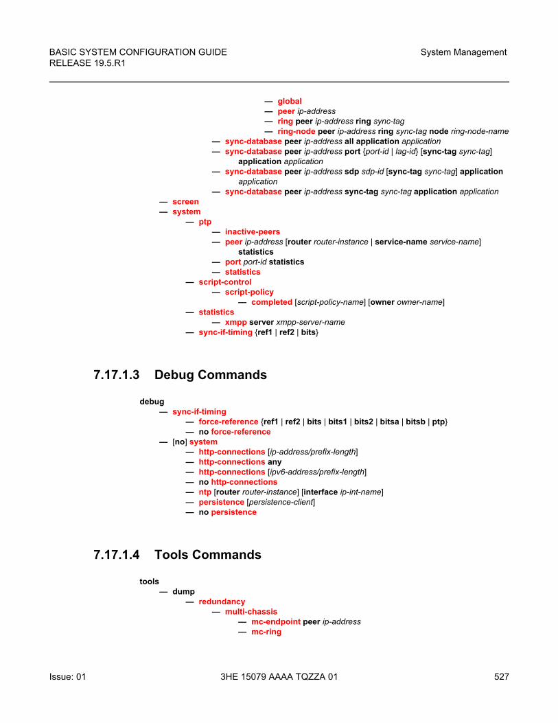
BASIC SYSTEM CONFIGURATION GUIDE RELEASE 19.5.R1
System Management
Issue: 01 3HE 15079 AAAA TQZZA 01 527
— global— peer ip-address— ring peer ip-address ring sync-tag— ring-node peer ip-address ring sync-tag node ring-node-name
— sync-database peer ip-address all application application— sync-database peer ip-address port {port-id | lag-id} [sync-tag sync-tag]
application application— sync-database peer ip-address sdp sdp-id [sync-tag sync-tag] application
application— sync-database peer ip-address sync-tag sync-tag application application
— screen — system
— ptp— inactive-peers— peer ip-address [router router-instance | service-name service-name]
statistics— port port-id statistics— statistics
— script-control— script-policy
— completed [script-policy-name] [owner owner-name]— statistics
— xmpp server xmpp-server-name— sync-if-timing {ref1 | ref2 | bits}
7.17.1.3 Debug Commands
debug— sync-if-timing
— force-reference {ref1 | ref2 | bits | bits1 | bits2 | bitsa | bitsb | ptp}— no force-reference
— [no] system— http-connections [ip-address/prefix-length]— http-connections any— http-connections [ipv6-address/prefix-length]— no http-connections— ntp [router router-instance] [interface ip-int-name]— persistence [persistence-client]— no persistence
7.17.1.4 Tools Commands
tools— dump
— redundancy— multi-chassis
— mc-endpoint peer ip-address— mc-ring
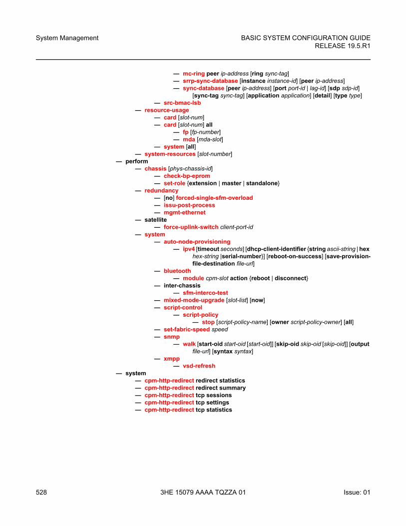
System Management
528
BASIC SYSTEM CONFIGURATION GUIDERELEASE 19.5.R1
3HE 15079 AAAA TQZZA 01 Issue: 01
— mc-ring peer ip-address [ring sync-tag]— srrp-sync-database [instance instance-id] [peer ip-address]— sync-database [peer ip-address] [port port-id | lag-id] [sdp sdp-id]
[sync-tag sync-tag] [application application] [detail] [type type]— src-bmac-lsb
— resource-usage— card [slot-num]— card [slot-num] all
— fp [fp-number]— mda [mda-slot]
— system [all]— system-resources [slot-number]
— perform— chassis [phys-chassis-id]
— check-bp-eprom — set-role {extension | master | standalone}
— redundancy— [no] forced-single-sfm-overload— issu-post-process— mgmt-ethernet
— satellite— force-uplink-switch client-port-id
— system— auto-node-provisioning
— ipv4 [timeout seconds] [dhcp-client-identifier {string ascii-string | hex hex-string |serial-number}] [reboot-on-success] [save-provision-file-destination file-url]
— bluetooth— module cpm-slot action {reboot | disconnect}
— inter-chassis — sfm-interco-test
— mixed-mode-upgrade [slot-list] [now]— script-control
— script-policy— stop [script-policy-name] [owner script-policy-owner] [all]
— set-fabric-speed speed— snmp
— walk [start-oid start-oid [start-oid]] [skip-oid skip-oid [skip-oid]] [output file-url] [syntax syntax]
— xmpp — vsd-refresh
— system— cpm-http-redirect redirect statistics— cpm-http-redirect redirect summary— cpm-http-redirect tcp sessions — cpm-http-redirect tcp settings — cpm-http-redirect tcp statistics
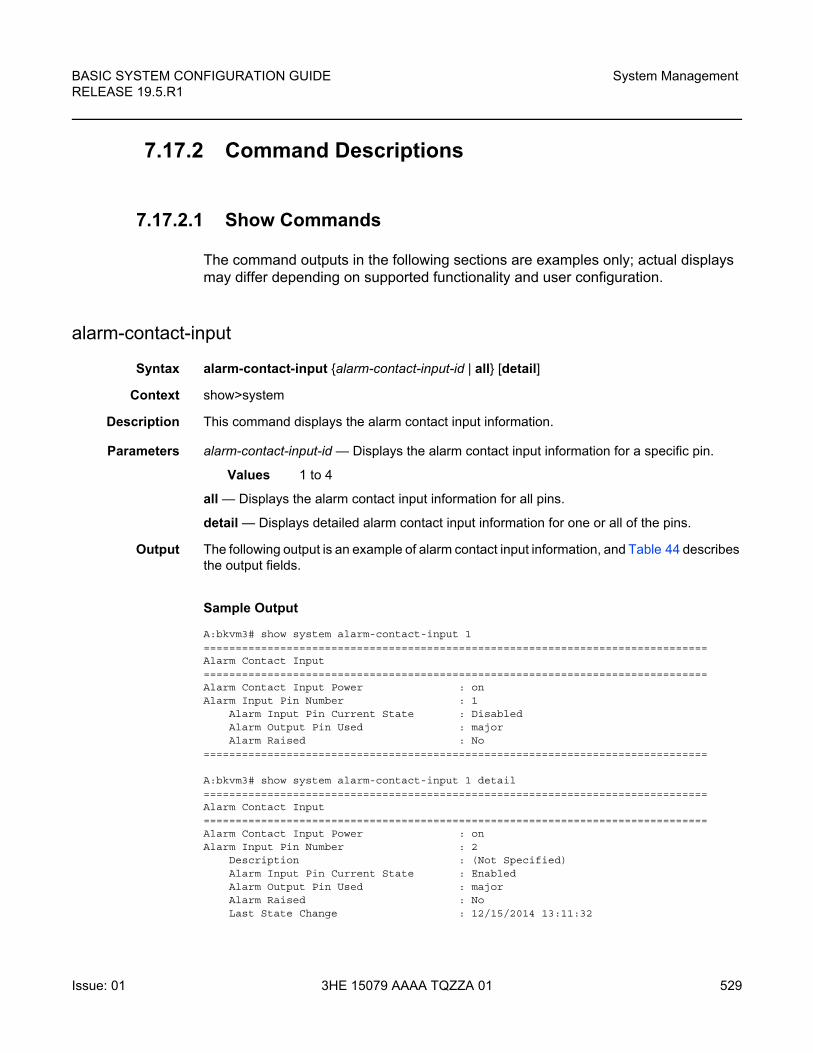
BASIC SYSTEM CONFIGURATION GUIDE RELEASE 19.5.R1
System Management
Issue: 01 3HE 15079 AAAA TQZZA 01 529
7.17.2 Command Descriptions
7.17.2.1 Show Commands
The command outputs in the following sections are examples only; actual displays may differ depending on supported functionality and user configuration.
alarm-contact-input
Syntax alarm-contact-input {alarm-contact-input-id | all} [detail]
Context show>system
Description This command displays the alarm contact input information.
Parameters alarm-contact-input-id — Displays the alarm contact input information for a specific pin.
Values 1 to 4
all — Displays the alarm contact input information for all pins.
detail — Displays detailed alarm contact input information for one or all of the pins.
Output The following output is an example of alarm contact input information, and Table 44 describes the output fields.
Sample Output
A:bkvm3# show system alarm-contact-input 1===============================================================================Alarm Contact Input===============================================================================Alarm Contact Input Power : onAlarm Input Pin Number : 1
Alarm Input Pin Current State : DisabledAlarm Output Pin Used : majorAlarm Raised : No
===============================================================================
A:bkvm3# show system alarm-contact-input 1 detail===============================================================================Alarm Contact Input===============================================================================Alarm Contact Input Power : onAlarm Input Pin Number : 2
Description : (Not Specified)Alarm Input Pin Current State : EnabledAlarm Output Pin Used : majorAlarm Raised : NoLast State Change : 12/15/2014 13:11:32
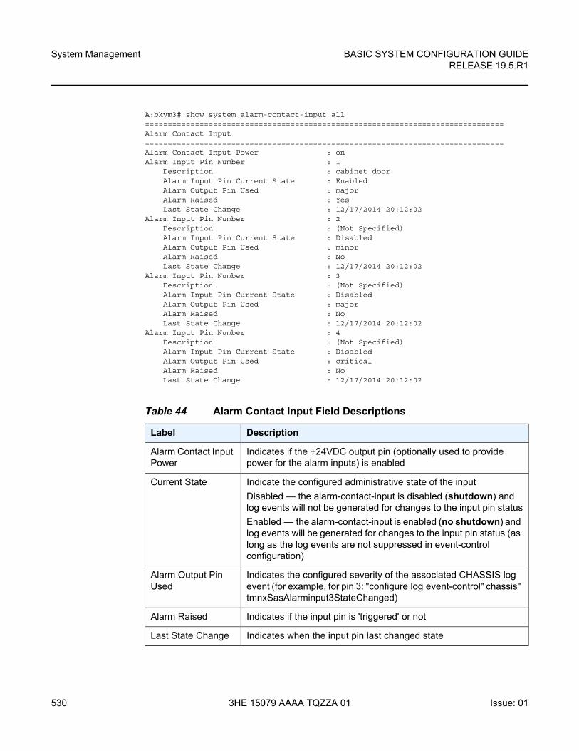
System Management
530
BASIC SYSTEM CONFIGURATION GUIDERELEASE 19.5.R1
3HE 15079 AAAA TQZZA 01 Issue: 01
A:bkvm3# show system alarm-contact-input all===============================================================================Alarm Contact Input===============================================================================Alarm Contact Input Power : onAlarm Input Pin Number : 1
Description : cabinet doorAlarm Input Pin Current State : EnabledAlarm Output Pin Used : majorAlarm Raised : YesLast State Change : 12/17/2014 20:12:02
Alarm Input Pin Number : 2Description : (Not Specified)Alarm Input Pin Current State : DisabledAlarm Output Pin Used : minorAlarm Raised : NoLast State Change : 12/17/2014 20:12:02
Alarm Input Pin Number : 3Description : (Not Specified)Alarm Input Pin Current State : DisabledAlarm Output Pin Used : majorAlarm Raised : NoLast State Change : 12/17/2014 20:12:02
Alarm Input Pin Number : 4Description : (Not Specified)Alarm Input Pin Current State : DisabledAlarm Output Pin Used : criticalAlarm Raised : NoLast State Change : 12/17/2014 20:12:02
Table 44 Alarm Contact Input Field Descriptions
Label Description
Alarm Contact Input Power
Indicates if the +24VDC output pin (optionally used to provide power for the alarm inputs) is enabled
Current State Indicate the configured administrative state of the input
Disabled — the alarm-contact-input is disabled (shutdown) and log events will not be generated for changes to the input pin status
Enabled — the alarm-contact-input is enabled (no shutdown) and log events will be generated for changes to the input pin status (as long as the log events are not suppressed in event-control configuration)
Alarm Output Pin Used
Indicates the configured severity of the associated CHASSIS log event (for example, for pin 3: "configure log event-control" chassis" tmnxSasAlarminput3StateChanged)
Alarm Raised Indicates if the input pin is 'triggered' or not
Last State Change Indicates when the input pin last changed state
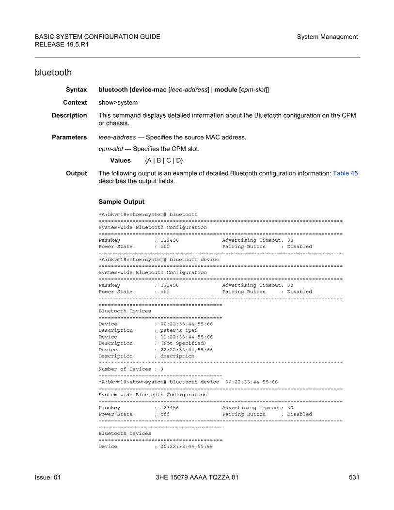
BASIC SYSTEM CONFIGURATION GUIDE RELEASE 19.5.R1
System Management
Issue: 01 3HE 15079 AAAA TQZZA 01 531
bluetooth
Syntax bluetooth [device-mac [ieee-address] | module [cpm-slot]]
Context show>system
Description This command displays detailed information about the Bluetooth configuration on the CPM or chassis.
Parameters ieee-address — Specifies the source MAC address.
cpm-slot — Specifies the CPM slot.
Values {A | B | C | D}
Output The following output is an example of detailed Bluetooth configuration information; Table 45 describes the output fields.
Sample Output
*A:bkvm18>show>system# bluetooth===============================================================================System-wide Bluetooth Configuration===============================================================================Passkey : 123456 Advertising Timeout: 30Power State : off Pairing Button : Disabled===============================================================================*A:bkvm18>show>system# bluetooth device===============================================================================System-wide Bluetooth Configuration===============================================================================Passkey : 123456 Advertising Timeout: 30Power State : off Pairing Button : Disabled=======================================================================================================================Bluetooth Devices========================================Device : 00:22:33:44:55:66Description : peter's ipadDevice : 11:22:33:44:55:66Description : (Not Specified)Device : 22:22:33:44:55:66Description : description-------------------------------------------------------------------------------Number of Devices : 3========================================*A:bkvm18>show>system# bluetooth device 00:22:33:44:55:66===============================================================================System-wide Bluetooth Configuration===============================================================================Passkey : 123456 Advertising Timeout: 30Power State : off Pairing Button : Disabled=======================================================================================================================Bluetooth Devices========================================Device : 00:22:33:44:55:66
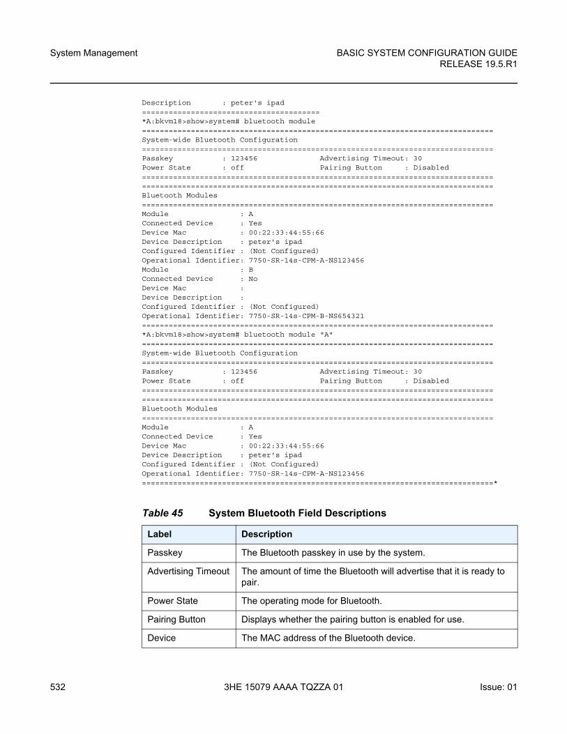
System Management
532
BASIC SYSTEM CONFIGURATION GUIDERELEASE 19.5.R1
3HE 15079 AAAA TQZZA 01 Issue: 01
Description : peter's ipad========================================*A:bkvm18>show>system# bluetooth module===============================================================================System-wide Bluetooth Configuration===============================================================================Passkey : 123456 Advertising Timeout: 30Power State : off Pairing Button : Disabled==============================================================================================================================================================Bluetooth Modules===============================================================================Module : AConnected Device : YesDevice Mac : 00:22:33:44:55:66Device Description : peter's ipadConfigured Identifier : (Not Configured)Operational Identifier: 7750-SR-14s-CPM-A-NS123456Module : BConnected Device : NoDevice Mac :Device Description :Configured Identifier : (Not Configured)Operational Identifier: 7750-SR-14s-CPM-B-NS654321===============================================================================*A:bkvm18>show>system# bluetooth module "A"===============================================================================System-wide Bluetooth Configuration===============================================================================Passkey : 123456 Advertising Timeout: 30Power State : off Pairing Button : Disabled==============================================================================================================================================================Bluetooth Modules===============================================================================Module : AConnected Device : YesDevice Mac : 00:22:33:44:55:66Device Description : peter's ipadConfigured Identifier : (Not Configured)Operational Identifier: 7750-SR-14s-CPM-A-NS123456===============================================================================*
Table 45 System Bluetooth Field Descriptions
Label Description
Passkey The Bluetooth passkey in use by the system.
Advertising Timeout The amount of time the Bluetooth will advertise that it is ready to pair.
Power State The operating mode for Bluetooth.
Pairing Button Displays whether the pairing button is enabled for use.
Device The MAC address of the Bluetooth device.
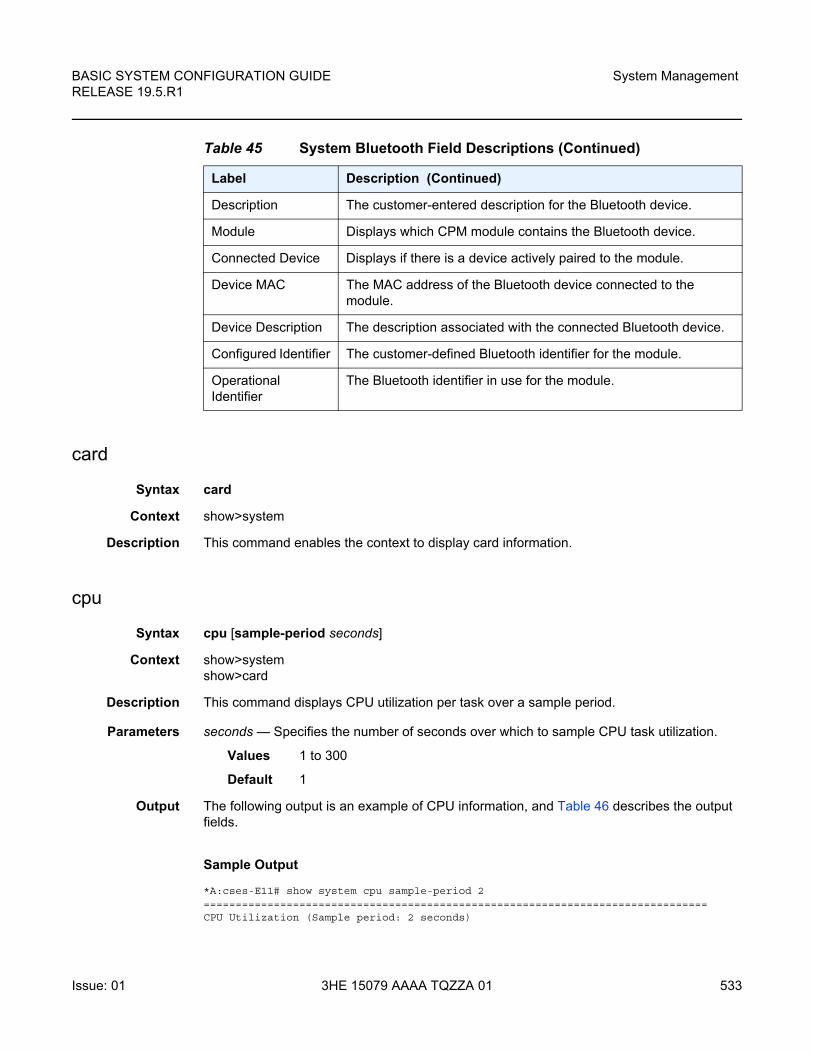
BASIC SYSTEM CONFIGURATION GUIDE RELEASE 19.5.R1
System Management
Issue: 01 3HE 15079 AAAA TQZZA 01 533
card
Syntax card
Context show>system
Description This command enables the context to display card information.
cpu
Syntax cpu [sample-period seconds]
Context show>systemshow>card
Description This command displays CPU utilization per task over a sample period.
Parameters seconds — Specifies the number of seconds over which to sample CPU task utilization.
Values 1 to 300
Default 1
Output The following output is an example of CPU information, and Table 46 describes the output fields.
Sample Output
*A:cses-E11# show system cpu sample-period 2===============================================================================CPU Utilization (Sample period: 2 seconds)
Description The customer-entered description for the Bluetooth device.
Module Displays which CPM module contains the Bluetooth device.
Connected Device Displays if there is a device actively paired to the module.
Device MAC The MAC address of the Bluetooth device connected to the module.
Device Description The description associated with the connected Bluetooth device.
Configured Identifier The customer-defined Bluetooth identifier for the module.
Operational Identifier
The Bluetooth identifier in use for the module.
Table 45 System Bluetooth Field Descriptions (Continued)
Label Description (Continued)
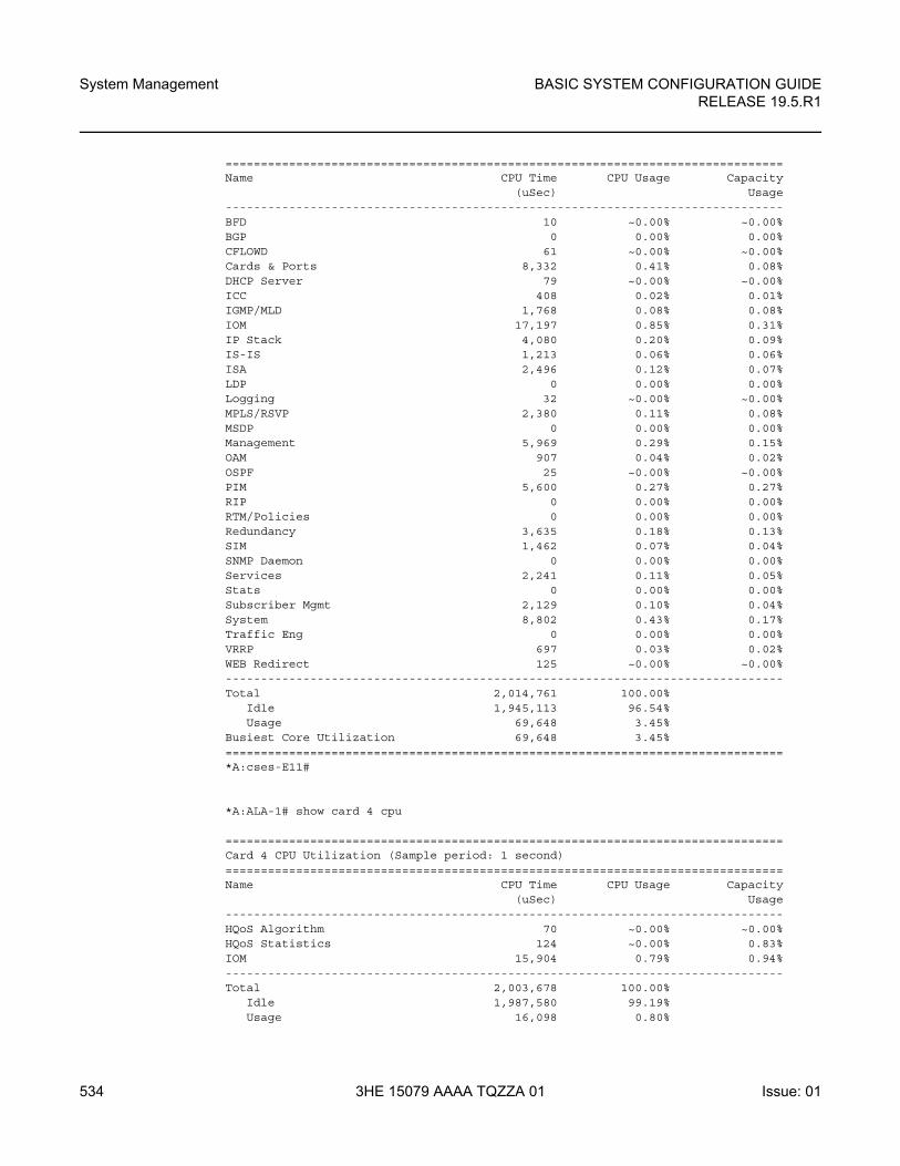
System Management
534
BASIC SYSTEM CONFIGURATION GUIDERELEASE 19.5.R1
3HE 15079 AAAA TQZZA 01 Issue: 01
===============================================================================Name CPU Time CPU Usage Capacity
(uSec) Usage-------------------------------------------------------------------------------BFD 10 ~0.00% ~0.00%BGP 0 0.00% 0.00%CFLOWD 61 ~0.00% ~0.00%Cards & Ports 8,332 0.41% 0.08%DHCP Server 79 ~0.00% ~0.00%ICC 408 0.02% 0.01%IGMP/MLD 1,768 0.08% 0.08%IOM 17,197 0.85% 0.31%IP Stack 4,080 0.20% 0.09%IS-IS 1,213 0.06% 0.06%ISA 2,496 0.12% 0.07%LDP 0 0.00% 0.00%Logging 32 ~0.00% ~0.00%MPLS/RSVP 2,380 0.11% 0.08%MSDP 0 0.00% 0.00%Management 5,969 0.29% 0.15%OAM 907 0.04% 0.02%OSPF 25 ~0.00% ~0.00%PIM 5,600 0.27% 0.27%RIP 0 0.00% 0.00%RTM/Policies 0 0.00% 0.00%Redundancy 3,635 0.18% 0.13%SIM 1,462 0.07% 0.04%SNMP Daemon 0 0.00% 0.00%Services 2,241 0.11% 0.05%Stats 0 0.00% 0.00%Subscriber Mgmt 2,129 0.10% 0.04%System 8,802 0.43% 0.17%Traffic Eng 0 0.00% 0.00%VRRP 697 0.03% 0.02%WEB Redirect 125 ~0.00% ~0.00%-------------------------------------------------------------------------------Total 2,014,761 100.00%
Idle 1,945,113 96.54%Usage 69,648 3.45%
Busiest Core Utilization 69,648 3.45%===============================================================================*A:cses-E11#
*A:ALA-1# show card 4 cpu
===============================================================================Card 4 CPU Utilization (Sample period: 1 second)===============================================================================Name CPU Time CPU Usage Capacity
(uSec) Usage-------------------------------------------------------------------------------HQoS Algorithm 70 ~0.00% ~0.00%HQoS Statistics 124 ~0.00% 0.83%IOM 15,904 0.79% 0.94%-------------------------------------------------------------------------------Total 2,003,678 100.00%
Idle 1,987,580 99.19%Usage 16,098 0.80%
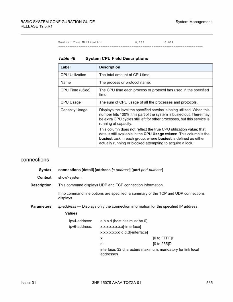
BASIC SYSTEM CONFIGURATION GUIDE RELEASE 19.5.R1
System Management
Issue: 01 3HE 15079 AAAA TQZZA 01 535
Busiest Core Utilization 8,192 0.81%===============================================================================
connections
Syntax connections [detail] [address ip-address] [port port-number]
Context show>system
Description This command displays UDP and TCP connection information.
If no command line options are specified, a summary of the TCP and UDP connections displays.
Parameters ip-address — Displays only the connection information for the specified IP address.
Values
Table 46 System CPU Field Descriptions
Label Description
CPU Utilization The total amount of CPU time.
Name The process or protocol name.
CPU Time (uSec) The CPU time each process or protocol has used in the specified time.
CPU Usage The sum of CPU usage of all the processes and protocols.
Capacity Usage Displays the level the specified service is being utilized. When this number hits 100%, this part of the system is busied out. There may be extra CPU cycles still left for other processes, but this service is running at capacity.
This column does not reflect the true CPU utilization value; that data is still available in the CPU Usage column. This column is the busiest task in each group, where busiest is defined as either actually running or blocked attempting to acquire a lock.
ipv4-address: a.b.c.d (host bits must be 0)
ipv6-address: x:x:x:x:x:x:x:x[-interface]
x:x:x:x:x:x:d.d.d.d[-interface]
x: [0 to FFFF]H
d: [0 to 255]D
interface: 32 characters maximum, mandatory for link local addresses
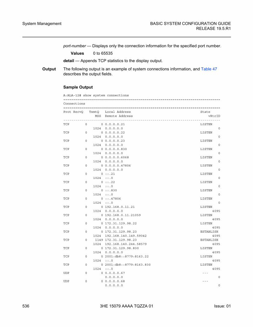
System Management
536
BASIC SYSTEM CONFIGURATION GUIDERELEASE 19.5.R1
3HE 15079 AAAA TQZZA 01 Issue: 01
port-number — Displays only the connection information for the specified port number.
Values 0 to 65535
detail — Appends TCP statistics to the display output.
Output The following output is an example of system connections information, and Table 47 describes the output fields.
Sample Output
A:ALA-12# show system connections===============================================================================Connections===============================================================================Prot RecvQ TxmtQ Local Address State
MSS Remote Address vRtrID-------------------------------------------------------------------------------TCP 0 0 0.0.0.0.21 LISTEN
1024 0.0.0.0.0 0TCP 0 0 0.0.0.0.22 LISTEN
1024 0.0.0.0.0 0TCP 0 0 0.0.0.0.23 LISTEN
1024 0.0.0.0.0 0TCP 0 0 0.0.0.0.830 LISTEN
1024 0.0.0.0.0 0TCP 0 0 0.0.0.0.6068 LISTEN
1024 0.0.0.0.0 0TCP 0 0 0.0.0.0.47806 LISTEN
1024 0.0.0.0.0 0TCP 0 0 ::.21 LISTEN
1024 ::.0 0TCP 0 0 ::.22 LISTEN
1024 ::.0 0TCP 0 0 ::.830 LISTEN
1024 ::.0 0TCP 0 0 ::.47806 LISTEN
1024 ::.0 0TCP 0 0 192.168.0.11.21 LISTEN
1024 0.0.0.0.0 4095TCP 0 0 192.168.0.11.21059 LISTEN
1024 0.0.0.0.0 4095TCP 0 0 172.31.129.98.22 LISTEN
1024 0.0.0.0.0 4095TCP 0 0 172.31.129.98.23 ESTABLISH
1024 192.168.140.149.59042 4095TCP 0 1149 172.31.129.98.23 ESTABLISH
1024 192.168.140.244.58579 4095TCP 0 0 172.31.129.98.830 LISTEN
1024 0.0.0.0.0 4095TCP 0 0 2001:db8::8779:8163.22 LISTEN
1024 ::.0 4095TCP 0 0 2001:db8::8779:8163.830 LISTEN
1024 ::.0 4095UDP 0 0 0.0.0.0.67 ---
0.0.0.0.0 0UDP 0 0 0.0.0.0.68 ---
0.0.0.0.0 0
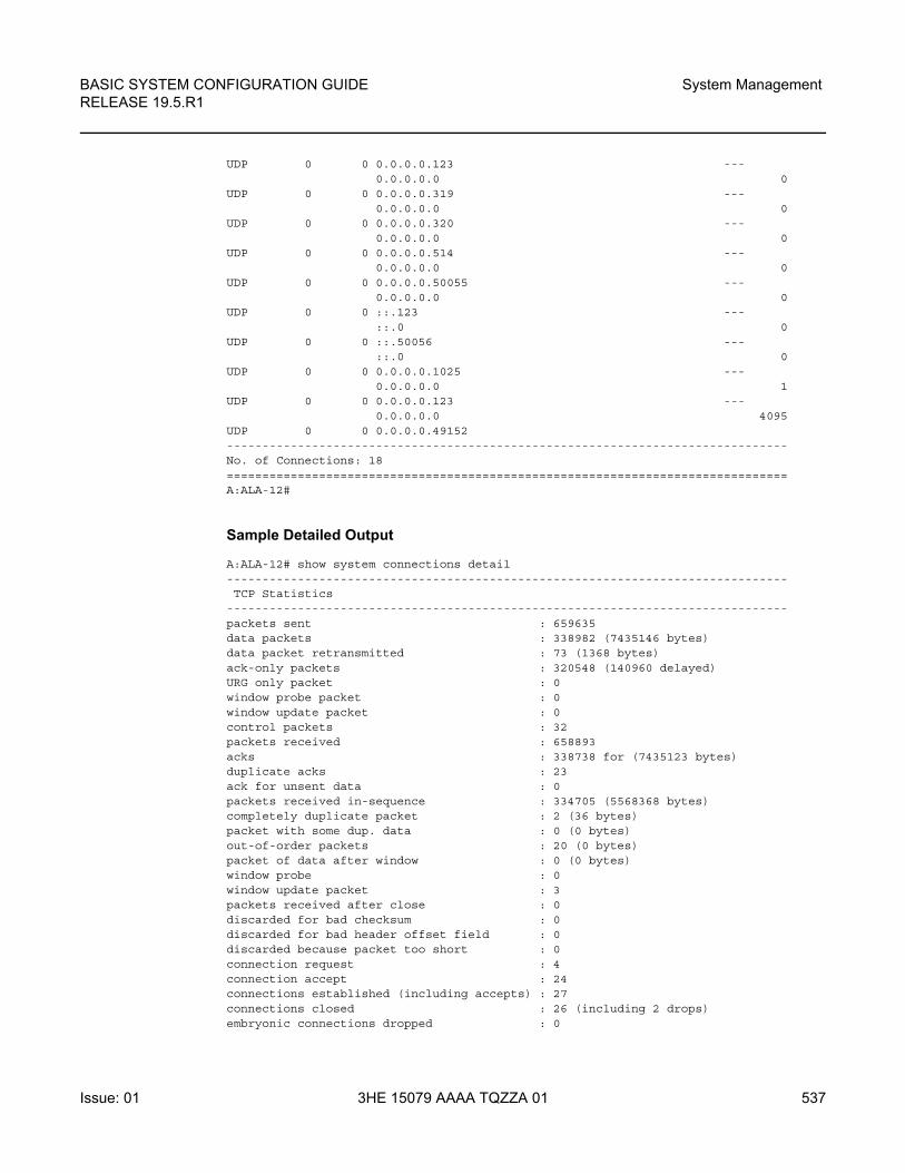
BASIC SYSTEM CONFIGURATION GUIDE RELEASE 19.5.R1
System Management
Issue: 01 3HE 15079 AAAA TQZZA 01 537
UDP 0 0 0.0.0.0.123 ---0.0.0.0.0 0
UDP 0 0 0.0.0.0.319 ---0.0.0.0.0 0
UDP 0 0 0.0.0.0.320 ---0.0.0.0.0 0
UDP 0 0 0.0.0.0.514 ---0.0.0.0.0 0
UDP 0 0 0.0.0.0.50055 ---0.0.0.0.0 0
UDP 0 0 ::.123 ---::.0 0
UDP 0 0 ::.50056 ---::.0 0
UDP 0 0 0.0.0.0.1025 ---0.0.0.0.0 1
UDP 0 0 0.0.0.0.123 ---0.0.0.0.0 4095
UDP 0 0 0.0.0.0.49152-------------------------------------------------------------------------------No. of Connections: 18===============================================================================A:ALA-12#
Sample Detailed Output
A:ALA-12# show system connections detail-------------------------------------------------------------------------------TCP Statistics
-------------------------------------------------------------------------------packets sent : 659635data packets : 338982 (7435146 bytes)data packet retransmitted : 73 (1368 bytes)ack-only packets : 320548 (140960 delayed)URG only packet : 0window probe packet : 0window update packet : 0control packets : 32packets received : 658893acks : 338738 for (7435123 bytes)duplicate acks : 23ack for unsent data : 0packets received in-sequence : 334705 (5568368 bytes)completely duplicate packet : 2 (36 bytes)packet with some dup. data : 0 (0 bytes)out-of-order packets : 20 (0 bytes)packet of data after window : 0 (0 bytes)window probe : 0window update packet : 3packets received after close : 0discarded for bad checksum : 0discarded for bad header offset field : 0discarded because packet too short : 0connection request : 4connection accept : 24connections established (including accepts) : 27connections closed : 26 (including 2 drops)embryonic connections dropped : 0
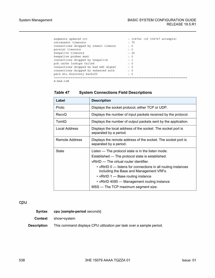
System Management
538
BASIC SYSTEM CONFIGURATION GUIDERELEASE 19.5.R1
3HE 15079 AAAA TQZZA 01 Issue: 01
segments updated rtt : 338742 (of 338747 attempts)retransmit timeouts : 75connections dropped by rexmit timeout : 0persist timeouts : 0keepalive timeouts : 26keepalive probes sent : 0connections dropped by keepalive : 1pcb cache lookups failed : 0connections dropped by bad md5 digest : 0connections dropped by enhanced auth : 0path mtu discovery backoff : 0===============================================================================A:ALA-12#
cpu
Syntax cpu [sample-period seconds]
Context show>system
Description This command displays CPU utilization per task over a sample period.
Table 47 System Connections Field Descriptions
Label Description
Proto Displays the socket protocol, either TCP or UDP.
RecvQ Displays the number of input packets received by the protocol.
TxmtQ Displays the number of output packets sent by the application.
Local Address Displays the local address of the socket. The socket port is separated by a period.
Remote Address Displays the remote address of the socket. The socket port is separated by a period.
State Listen — The protocol state is in the listen mode.
Established — The protocol state is established.
vRtrID — The virtual router identifier.
• vRtrID 0 — listens for connections in all routing instances including the Base and Management VRFs.
• vRtrID 1 — Base routing instance
• vRtrID 4095 — Management routing instance
MSS — The TCP maximum segment size.
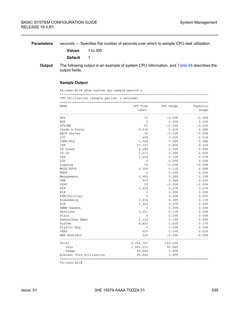
BASIC SYSTEM CONFIGURATION GUIDE RELEASE 19.5.R1
System Management
Issue: 01 3HE 15079 AAAA TQZZA 01 539
Parameters seconds — Specifies the number of seconds over which to sample CPU task utilization.
Values 1 to 300
Default 1
Output The following output is an example of system CPU information, and Table 48 describes the output fields.
Sample Output
*A:cses-E11# show system cpu sample-period 2===============================================================================CPU Utilization (Sample period: 2 seconds)===============================================================================Name CPU Time CPU Usage Capacity
(uSec) Usage-------------------------------------------------------------------------------BFD 10 ~0.00% ~0.00%BGP 0 0.00% 0.00%CFLOWD 61 ~0.00% ~0.00%Cards & Ports 8,332 0.41% 0.08%DHCP Server 79 ~0.00% ~0.00%ICC 408 0.02% 0.01%IGMP/MLD 1,768 0.08% 0.08%IOM 17,197 0.85% 0.31%IP Stack 4,080 0.20% 0.09%IS-IS 1,213 0.06% 0.06%ISA 2,496 0.12% 0.07%LDP 0 0.00% 0.00%Logging 32 ~0.00% ~0.00%MPLS/RSVP 2,380 0.11% 0.08%MSDP 0 0.00% 0.00%Management 5,969 0.29% 0.15%OAM 907 0.04% 0.02%OSPF 25 ~0.00% ~0.00%PIM 5,600 0.27% 0.27%RIP 0 0.00% 0.00%RTM/Policies 0 0.00% 0.00%Redundancy 3,635 0.18% 0.13%SIM 1,462 0.07% 0.04%SNMP Daemon 0 0.00% 0.00%Services 2,241 0.11% 0.05%Stats 0 0.00% 0.00%Subscriber Mgmt 2,129 0.10% 0.04%System 8,802 0.43% 0.17%Traffic Eng 0 0.00% 0.00%VRRP 697 0.03% 0.02%WEB Redirect 125 ~0.00% ~0.00%-------------------------------------------------------------------------------Total 2,014,761 100.00%
Idle 1,945,113 96.54%Usage 69,648 3.45%
Busiest Core Utilization 69,648 3.45%===============================================================================*A:cses-E11#
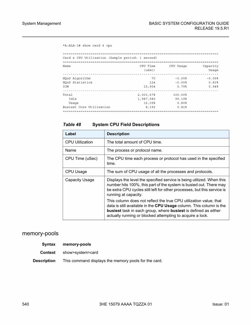
System Management
540
BASIC SYSTEM CONFIGURATION GUIDERELEASE 19.5.R1
3HE 15079 AAAA TQZZA 01 Issue: 01
*A:ALA-1# show card 4 cpu
===============================================================================Card 4 CPU Utilization (Sample period: 1 second)===============================================================================Name CPU Time CPU Usage Capacity
(uSec) Usage-------------------------------------------------------------------------------HQoS Algorithm 70 ~0.00% ~0.00%HQoS Statistics 124 ~0.00% 0.83%IOM 15,904 0.79% 0.94%-------------------------------------------------------------------------------Total 2,003,678 100.00%
Idle 1,987,580 99.19%Usage 16,098 0.80%
Busiest Core Utilization 8,192 0.81%===============================================================================
memory-pools
Syntax memory-pools
Context show>system>card
Description This command displays the memory pools for the card.
Table 48 System CPU Field Descriptions
Label Description
CPU Utilization The total amount of CPU time.
Name The process or protocol name.
CPU Time (uSec) The CPU time each process or protocol has used in the specified time.
CPU Usage The sum of CPU usage of all the processes and protocols.
Capacity Usage Displays the level the specified service is being utilized. When this number hits 100%, this part of the system is busied out. There may be extra CPU cycles still left for other processes, but this service is running at capacity.
This column does not reflect the true CPU utilization value; that data is still available in the CPU Usage column. This column is the busiest task in each group, where busiest is defined as either actually running or blocked attempting to acquire a lock.
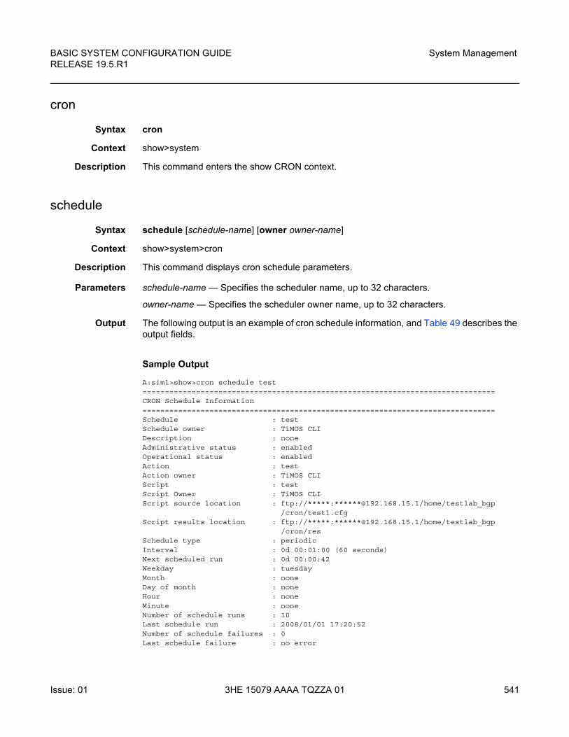
BASIC SYSTEM CONFIGURATION GUIDE RELEASE 19.5.R1
System Management
Issue: 01 3HE 15079 AAAA TQZZA 01 541
cron
Syntax cron
Context show>system
Description This command enters the show CRON context.
schedule
Syntax schedule [schedule-name] [owner owner-name]
Context show>system>cron
Description This command displays cron schedule parameters.
Parameters schedule-name — Specifies the scheduler name, up to 32 characters.
owner-name — Specifies the scheduler owner name, up to 32 characters.
Output The following output is an example of cron schedule information, and Table 49 describes the output fields.
Sample Output
A:sim1>show>cron schedule test===============================================================================CRON Schedule Information===============================================================================Schedule : testSchedule owner : TiMOS CLIDescription : noneAdministrative status : enabledOperational status : enabledAction : testAction owner : TiMOS CLIScript : testScript Owner : TiMOS CLIScript source location : ftp://*****:******@192.168.15.1/home/testlab_bgp
/cron/test1.cfgScript results location : ftp://*****:******@192.168.15.1/home/testlab_bgp
/cron/resSchedule type : periodicInterval : 0d 00:01:00 (60 seconds)Next scheduled run : 0d 00:00:42Weekday : tuesdayMonth : noneDay of month : noneHour : noneMinute : noneNumber of schedule runs : 10Last schedule run : 2008/01/01 17:20:52Number of schedule failures : 0Last schedule failure : no error
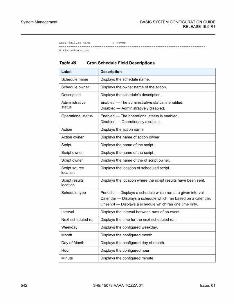
System Management
542
BASIC SYSTEM CONFIGURATION GUIDERELEASE 19.5.R1
3HE 15079 AAAA TQZZA 01 Issue: 01
Last failure time : never===============================================================================A:sim1>show>cron
Table 49 Cron Schedule Field Descriptions
Label Description
Schedule name Displays the schedule name.
Schedule owner Displays the owner name of the action.
Description Displays the schedule’s description.
Administrative status
Enabled — The administrative status is enabled.
Disabled — Administratively disabled.
Operational status Enabled — The operational status is enabled.
Disabled — Operationally disabled.
Action Displays the action name
Action owner Displays the name of action owner.
Script Displays the name of the script.
Script owner Displays the name of the script.
Script owner Displays the name of the of script owner.
Script source location
Displays the location of scheduled script.
Script results location
Displays the location where the script results have been sent.
Schedule type Periodic — Displays a schedule which ran at a given interval.
Calendar — Displays a schedule which ran based on a calendar.
Oneshot — Displays a schedule which ran one time only.
Interval Displays the interval between runs of an event.
Next scheduled run Displays the time for the next scheduled run.
Weekday Displays the configured weekday.
Month Displays the configured month.
Day of Month Displays the configured day of month.
Hour Displays the configured hour.
Minute Displays the configured minute.
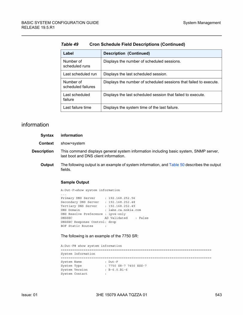
BASIC SYSTEM CONFIGURATION GUIDE RELEASE 19.5.R1
System Management
Issue: 01 3HE 15079 AAAA TQZZA 01 543
information
Syntax information
Context show>system
Description This command displays general system information including basic system, SNMP server, last boot and DNS client information.
Output The following output is an example of system information, and Table 50 describes the output fields.
Sample Output
A:Dut-F>show system information...Primary DNS Server : 192.168.252.56Secondary DNS Server : 192.168.252.48Tertiary DNS Server : 192.168.252.49DNS Domain : labs.ca.nokia.comDNS Resolve Preference : ipv4-onlyDNSSEC AD Validated : FalseDNSSEC Response Control: dropBOF Static Routes :
The following is an example of the 7750 SR:
A:Dut-F# show system information===============================================================================System Information===============================================================================System Name : Dut-FSystem Type : 7750 SR-7 7450 ESS-7System Version : B-6.0.B1-6System Contact :
Number of scheduled runs
Displays the number of scheduled sessions.
Last scheduled run Displays the last scheduled session.
Number of scheduled failures
Displays the number of scheduled sessions that failed to execute.
Last scheduled failure
Displays the last scheduled session that failed to execute.
Last failure time Displays the system time of the last failure.
Table 49 Cron Schedule Field Descriptions (Continued)
Label Description (Continued)
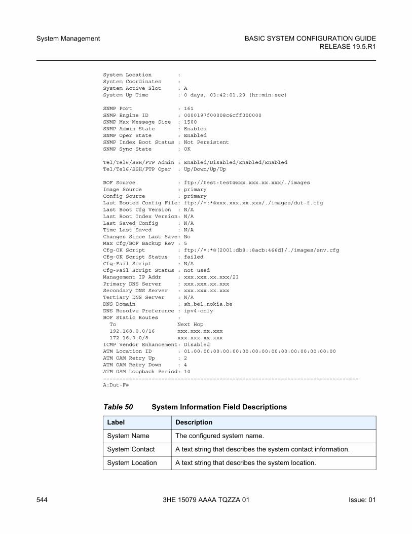
System Management
544
BASIC SYSTEM CONFIGURATION GUIDERELEASE 19.5.R1
3HE 15079 AAAA TQZZA 01 Issue: 01
System Location :System Coordinates :System Active Slot : ASystem Up Time : 0 days, 03:42:01.29 (hr:min:sec)
SNMP Port : 161SNMP Engine ID : 0000197f00008c6cff000000SNMP Max Message Size : 1500SNMP Admin State : EnabledSNMP Oper State : EnabledSNMP Index Boot Status : Not PersistentSNMP Sync State : OK
Tel/Tel6/SSH/FTP Admin : Enabled/Disabled/Enabled/EnabledTel/Tel6/SSH/FTP Oper : Up/Down/Up/Up
BOF Source : ftp://test:[email protected]/./imagesImage Source : primaryConfig Source : primaryLast Booted Config File: ftp://*:*@xxx.xxx.xx.xxx/./images/dut-f.cfgLast Boot Cfg Version : N/ALast Boot Index Version: N/ALast Saved Config : N/ATime Last Saved : N/AChanges Since Last Save: NoMax Cfg/BOF Backup Rev : 5Cfg-OK Script : ftp://*:*@[2001:db8::8acb:466d]/./images/env.cfgCfg-OK Script Status : failedCfg-Fail Script : N/ACfg-Fail Script Status : not usedManagement IP Addr : xxx.xxx.xx.xxx/23Primary DNS Server : xxx.xxx.xx.xxxSecondary DNS Server : xxx.xxx.xx.xxxTertiary DNS Server : N/ADNS Domain : sh.bel.nokia.beDNS Resolve Preference : ipv4-onlyBOF Static Routes :
To Next Hop192.168.0.0/16 xxx.xxx.xx.xxx172.16.0.0/8 xxx.xxx.xx.xxx
ICMP Vendor Enhancement: DisabledATM Location ID : 01:00:00:00:00:00:00:00:00:00:00:00:00:00:00:00ATM OAM Retry Up : 2ATM OAM Retry Down : 4ATM OAM Loopback Period: 10===============================================================================A:Dut-F#
Table 50 System Information Field Descriptions
Label Description
System Name The configured system name.
System Contact A text string that describes the system contact information.
System Location A text string that describes the system location.
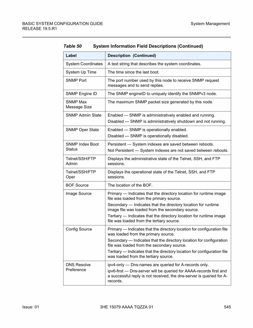
BASIC SYSTEM CONFIGURATION GUIDE RELEASE 19.5.R1
System Management
Issue: 01 3HE 15079 AAAA TQZZA 01 545
System Coordinates A text string that describes the system coordinates.
System Up Time The time since the last boot.
SNMP Port The port number used by this node to receive SNMP request messages and to send replies.
SNMP Engine ID The SNMP engineID to uniquely identify the SNMPv3 node.
SNMP Max Message Size
The maximum SNMP packet size generated by this node.
SNMP Admin State Enabled — SNMP is administratively enabled and running.
Disabled — SNMP is administratively shutdown and not running.
SNMP Oper State Enabled — SNMP is operationally enabled.
Disabled — SNMP is operationally disabled.
SNMP Index Boot Status
Persistent — System indexes are saved between reboots.
Not Persistent — System indexes are not saved between reboots.
Telnet/SSH/FTP Admin
Displays the administrative state of the Telnet, SSH, and FTP sessions.
Telnet/SSH/FTP Oper
Displays the operational state of the Telnet, SSH, and FTP sessions.
BOF Source The location of the BOF.
Image Source Primary — Indicates that the directory location for runtime image file was loaded from the primary source.
Secondary — Indicates that the directory location for runtime image file was loaded from the secondary source.
Tertiary — Indicates that the directory location for runtime image file was loaded from the tertiary source.
Config Source Primary — Indicates that the directory location for configuration file was loaded from the primary source.
Secondary — Indicates that the directory location for configuration file was loaded from the secondary source.
Tertiary — Indicates that the directory location for configuration file was loaded from the tertiary source.
DNS Resolve Preference
ipv4-only — Dns-names are queried for A-records only.
ipv6-first — Dns-server will be queried for AAAA-records first and a successful reply is not received, the dns-server is queried for A-records.
Table 50 System Information Field Descriptions (Continued)
Label Description (Continued)
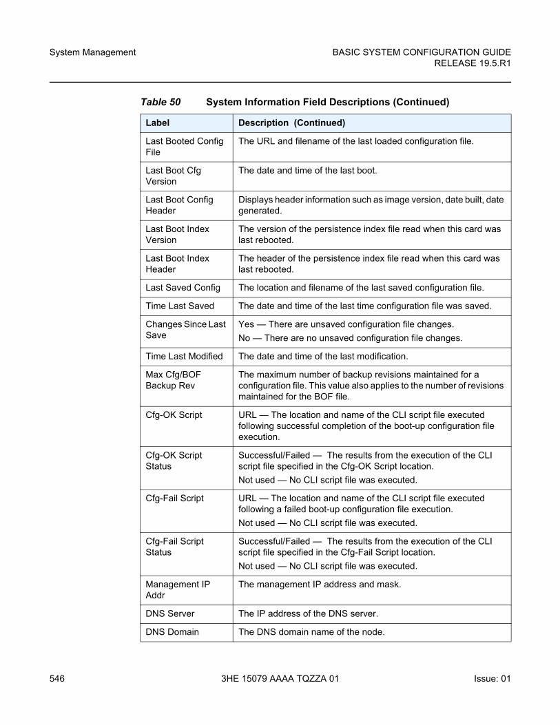
System Management
546
BASIC SYSTEM CONFIGURATION GUIDERELEASE 19.5.R1
3HE 15079 AAAA TQZZA 01 Issue: 01
Last Booted Config File
The URL and filename of the last loaded configuration file.
Last Boot Cfg Version
The date and time of the last boot.
Last Boot Config Header
Displays header information such as image version, date built, date generated.
Last Boot Index Version
The version of the persistence index file read when this card was last rebooted.
Last Boot Index Header
The header of the persistence index file read when this card was last rebooted.
Last Saved Config The location and filename of the last saved configuration file.
Time Last Saved The date and time of the last time configuration file was saved.
Changes Since Last Save
Yes — There are unsaved configuration file changes.
No — There are no unsaved configuration file changes.
Time Last Modified The date and time of the last modification.
Max Cfg/BOF Backup Rev
The maximum number of backup revisions maintained for a configuration file. This value also applies to the number of revisions maintained for the BOF file.
Cfg-OK Script URL — The location and name of the CLI script file executed following successful completion of the boot-up configuration file execution.
Cfg-OK Script Status
Successful/Failed — The results from the execution of the CLI script file specified in the Cfg-OK Script location.
Not used — No CLI script file was executed.
Cfg-Fail Script URL — The location and name of the CLI script file executed following a failed boot-up configuration file execution.
Not used — No CLI script file was executed.
Cfg-Fail Script Status
Successful/Failed — The results from the execution of the CLI script file specified in the Cfg-Fail Script location.
Not used — No CLI script file was executed.
Management IP Addr
The management IP address and mask.
DNS Server The IP address of the DNS server.
DNS Domain The DNS domain name of the node.
Table 50 System Information Field Descriptions (Continued)
Label Description (Continued)
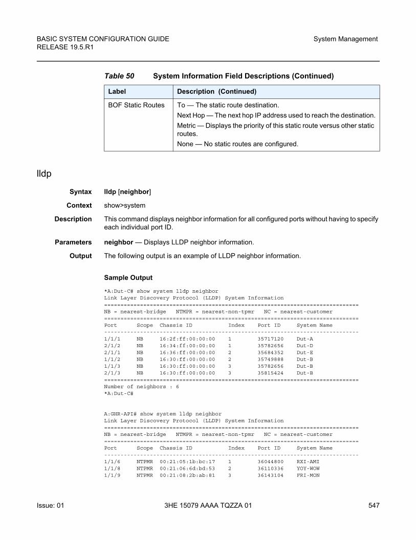
BASIC SYSTEM CONFIGURATION GUIDE RELEASE 19.5.R1
System Management
Issue: 01 3HE 15079 AAAA TQZZA 01 547
lldp
Syntax lldp [neighbor]
Context show>system
Description This command displays neighbor information for all configured ports without having to specify each individual port ID.
Parameters neighbor — Displays LLDP neighbor information.
Output The following output is an example of LLDP neighbor information.
Sample Output
*A:Dut-C# show system lldp neighborLink Layer Discovery Protocol (LLDP) System Information==============================================================================NB = nearest-bridge NTMPR = nearest-non-tpmr NC = nearest-customer==============================================================================Port Scope Chassis ID Index Port ID System Name------------------------------------------------------------------------------1/1/1 NB 16:2f:ff:00:00:00 1 35717120 Dut-A2/1/2 NB 16:34:ff:00:00:00 1 35782656 Dut-D2/1/1 NB 16:36:ff:00:00:00 2 35684352 Dut-E1/1/2 NB 16:30:ff:00:00:00 2 35749888 Dut-B1/1/3 NB 16:30:ff:00:00:00 3 35782656 Dut-B2/1/3 NB 16:30:ff:00:00:00 3 35815424 Dut-B==============================================================================Number of neighbors : 6*A:Dut-C#
A:GHR-API# show system lldp neighborLink Layer Discovery Protocol (LLDP) System Information==============================================================================NB = nearest-bridge NTMPR = nearest-non-tpmr NC = nearest-customer==============================================================================Port Scope Chassis ID Index Port ID System Name------------------------------------------------------------------------------1/1/6 NTPMR 00:21:05:1b:bc:17 1 36044800 RXI-AMI1/1/8 NTPMR 00:21:06:6d:bd:53 2 36110336 YOY-WOW1/1/9 NTPMR 00:21:08:2b:ab:81 3 36143104 FRI-MON
BOF Static Routes To — The static route destination.
Next Hop — The next hop IP address used to reach the destination.
Metric — Displays the priority of this static route versus other static routes.
None — No static routes are configured.
Table 50 System Information Field Descriptions (Continued)
Label Description (Continued)
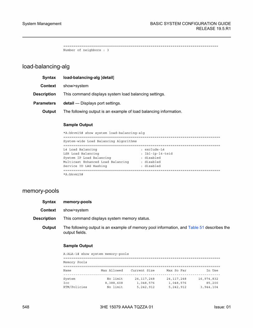
System Management
548
BASIC SYSTEM CONFIGURATION GUIDERELEASE 19.5.R1
3HE 15079 AAAA TQZZA 01 Issue: 01
==============================================================================Number of neighbors : 3
load-balancing-alg
Syntax load-balancing-alg [detail]
Context show>system
Description This command displays system load balancing settings.
Parameters detail — Displays port settings.
Output The following output is an example of load balancing information.
Sample Output
*A:bkvm15# show system load-balancing-alg===============================================================================System-wide Load Balancing Algorithms===============================================================================L4 Load Balancing : exclude-L4LSR Load Balancing : lbl-ip-l4-teidSystem IP Load Balancing : disabledMulticast Enhanced Load Balancing : disabledService ID LAG Hashing : disabled===============================================================================*A:bkvm15#
memory-pools
Syntax memory-pools
Context show>system
Description This command displays system memory status.
Output The following output is an example of memory pool information, and Table 51 describes the output fields.
Sample Output
A:ALA-1# show system memory-pools===============================================================================Memory Pools===============================================================================Name Max Allowed Current Size Max So Far In Use-------------------------------------------------------------------------------System No limit 24,117,248 24,117,248 16,974,832Icc 8,388,608 1,048,576 1,048,576 85,200RTM/Policies No limit 5,242,912 5,242,912 3,944,104
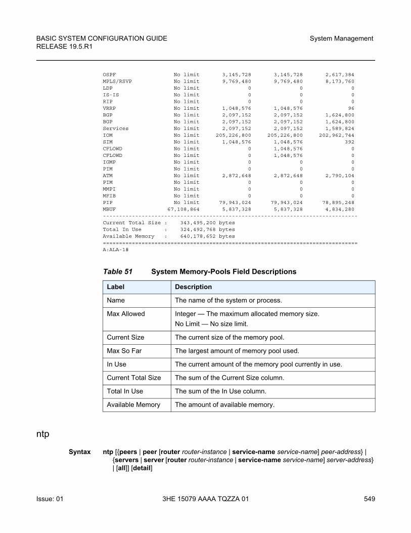
BASIC SYSTEM CONFIGURATION GUIDE RELEASE 19.5.R1
System Management
Issue: 01 3HE 15079 AAAA TQZZA 01 549
OSPF No limit 3,145,728 3,145,728 2,617,384MPLS/RSVP No limit 9,769,480 9,769,480 8,173,760LDP No limit 0 0 0IS-IS No limit 0 0 0RIP No limit 0 0 0VRRP No limit 1,048,576 1,048,576 96BGP No limit 2,097,152 2,097,152 1,624,800BGP No limit 2,097,152 2,097,152 1,624,800Services No limit 2,097,152 2,097,152 1,589,824IOM No limit 205,226,800 205,226,800 202,962,744SIM No limit 1,048,576 1,048,576 392CFLOWD No limit 0 1,048,576 0CFLOWD No limit 0 1,048,576 0IGMP No limit 0 0 0PIM No limit 0 0 0ATM No limit 2,872,648 2,872,648 2,790,104PIM No limit 0 0 0MMPI No limit 0 0 0MFIB No limit 0 0 0PIP No limit 79,943,024 79,943,024 78,895,248MBUF 67,108,864 5,837,328 5,837,328 4,834,280-------------------------------------------------------------------------------Current Total Size : 343,495,200 bytesTotal In Use : 324,492,768 bytesAvailable Memory : 640,178,652 bytes===============================================================================A:ALA-1#
ntp
Syntax ntp [{peers | peer [router router-instance | service-name service-name] peer-address} | {servers | server [router router-instance | service-name service-name] server-address} | [all]] [detail]
Table 51 System Memory-Pools Field Descriptions
Label Description
Name The name of the system or process.
Max Allowed Integer — The maximum allocated memory size.
No Limit — No size limit.
Current Size The current size of the memory pool.
Max So Far The largest amount of memory pool used.
In Use The current amount of the memory pool currently in use.
Current Total Size The sum of the Current Size column.
Total In Use The sum of the In Use column.
Available Memory The amount of available memory.
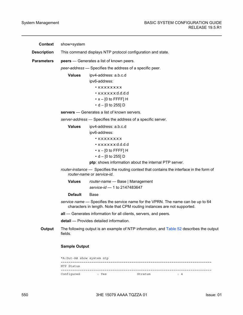
System Management
550
BASIC SYSTEM CONFIGURATION GUIDERELEASE 19.5.R1
3HE 15079 AAAA TQZZA 01 Issue: 01
Context show>system
Description This command displays NTP protocol configuration and state.
Parameters peers — Generates a list of known peers.
peer-address — Specifies the address of a specific peer.
Values ipv4-address: a.b.c.d
ipv6-address:
• x:x:x:x:x:x:x:x
• x:x:x:x:x:x:d.d.d.d
• x – [0 to FFFF] H
• d – [0 to 255] D
servers — Generates a list of known servers.
server-address — Specifies the address of a specific server.
Values ipv4-address: a.b.c.d
ipv6-address:
• x:x:x:x:x:x:x:x
• x:x:x:x:x:x:d.d.d.d
• x – [0 to FFFF] H
• d – [0 to 255] D
ptp: shows information about the internal PTP server.
router-instance — Specifies the routing context that contains the interface in the form of router-name or service-id.
Values router-name — Base | Management
service-id — 1 to 2147483647
Default Base
service name — Specifies the service name for the VPRN. The name can be up to 64 characters in length. Note that CPM routing instances are not supported.
all — Generates information for all clients, servers, and peers.
detail — Provides detailed information.
Output The following output is an example of NTP information, and Table 52 describes the output fields.
Sample Output
*A:Dut-A# show system ntp===============================================================================NTP Status===============================================================================Configured : Yes Stratum : 4
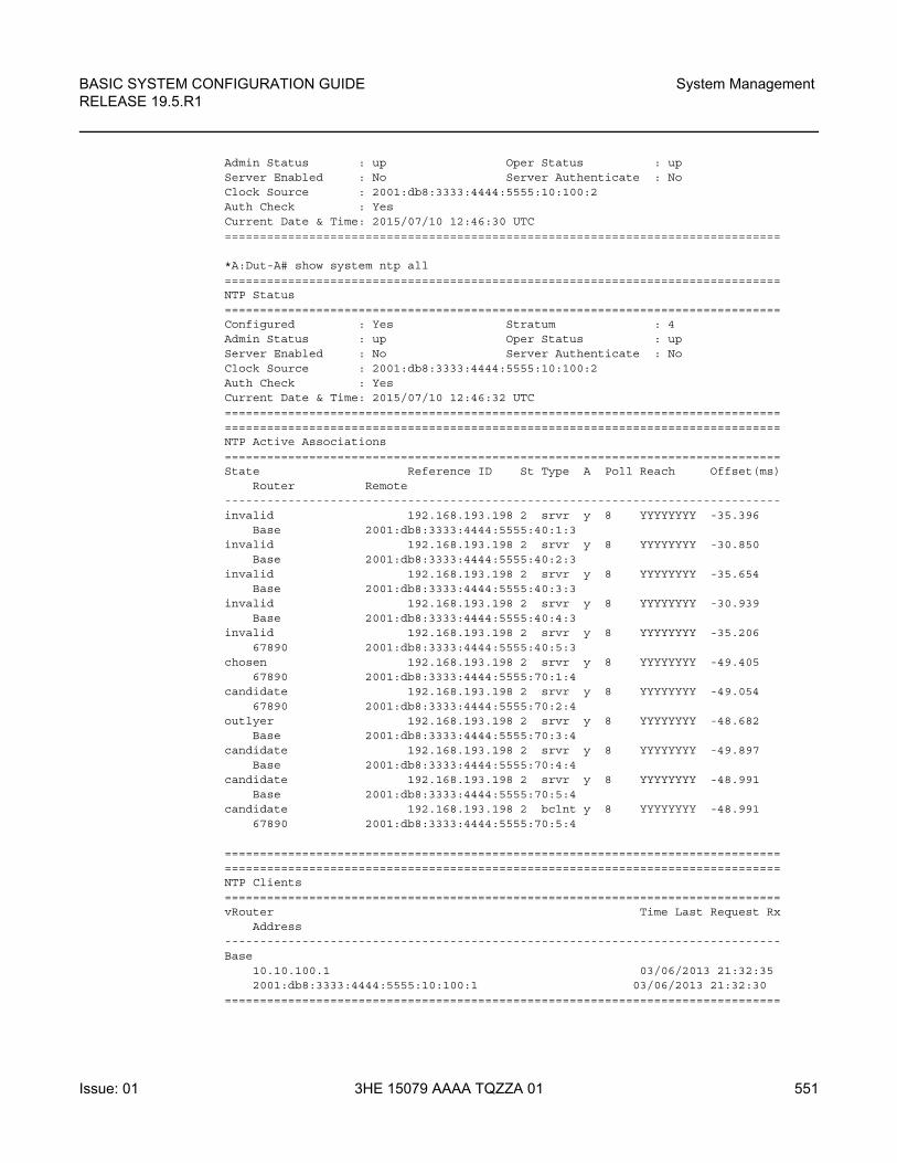
BASIC SYSTEM CONFIGURATION GUIDE RELEASE 19.5.R1
System Management
Issue: 01 3HE 15079 AAAA TQZZA 01 551
Admin Status : up Oper Status : upServer Enabled : No Server Authenticate : NoClock Source : 2001:db8:3333:4444:5555:10:100:2Auth Check : YesCurrent Date & Time: 2015/07/10 12:46:30 UTC===============================================================================
*A:Dut-A# show system ntp all===============================================================================NTP Status===============================================================================Configured : Yes Stratum : 4Admin Status : up Oper Status : upServer Enabled : No Server Authenticate : NoClock Source : 2001:db8:3333:4444:5555:10:100:2Auth Check : YesCurrent Date & Time: 2015/07/10 12:46:32 UTC==============================================================================================================================================================NTP Active Associations===============================================================================State Reference ID St Type A Poll Reach Offset(ms)
Router Remote-------------------------------------------------------------------------------invalid 192.168.193.198 2 srvr y 8 YYYYYYYY -35.396
Base 2001:db8:3333:4444:5555:40:1:3invalid 192.168.193.198 2 srvr y 8 YYYYYYYY -30.850
Base 2001:db8:3333:4444:5555:40:2:3invalid 192.168.193.198 2 srvr y 8 YYYYYYYY -35.654
Base 2001:db8:3333:4444:5555:40:3:3invalid 192.168.193.198 2 srvr y 8 YYYYYYYY -30.939
Base 2001:db8:3333:4444:5555:40:4:3invalid 192.168.193.198 2 srvr y 8 YYYYYYYY -35.206
67890 2001:db8:3333:4444:5555:40:5:3chosen 192.168.193.198 2 srvr y 8 YYYYYYYY -49.405
67890 2001:db8:3333:4444:5555:70:1:4candidate 192.168.193.198 2 srvr y 8 YYYYYYYY -49.054
67890 2001:db8:3333:4444:5555:70:2:4outlyer 192.168.193.198 2 srvr y 8 YYYYYYYY -48.682
Base 2001:db8:3333:4444:5555:70:3:4candidate 192.168.193.198 2 srvr y 8 YYYYYYYY -49.897
Base 2001:db8:3333:4444:5555:70:4:4candidate 192.168.193.198 2 srvr y 8 YYYYYYYY -48.991
Base 2001:db8:3333:4444:5555:70:5:4candidate 192.168.193.198 2 bclnt y 8 YYYYYYYY -48.991
67890 2001:db8:3333:4444:5555:70:5:4
==============================================================================================================================================================NTP Clients===============================================================================vRouter Time Last Request Rx
Address-------------------------------------------------------------------------------Base
10.10.100.1 03/06/2013 21:32:352001:db8:3333:4444:5555:10:100:1 03/06/2013 21:32:30
===============================================================================
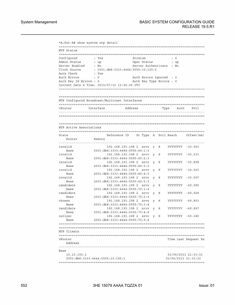
System Management
552
BASIC SYSTEM CONFIGURATION GUIDERELEASE 19.5.R1
3HE 15079 AAAA TQZZA 01 Issue: 01
*A:Dut-A# show system ntp detail===============================================================================NTP Status===============================================================================Configured : Yes Stratum : 4Admin Status : up Oper Status : upServer Enabled : No Server Authenticate : NoClock Source : 2001:db8:3333:4444:5555:10:100:2Auth Check : YesAuth Errors : 0 Auth Errors Ignored : 0Auth Key Id Errors : 0 Auth Key Type Errors : 0Current Date & Time: 2015/07/10 12:46:34 UTC===============================================================================
===============================================================================NTP Configured Broadcast/Multicast Interfaces===============================================================================vRouter Interface Address Type Auth Poll-------------------------------------------------------------------------------===============================================================================
===============================================================================NTP Active Associations===============================================================================State Reference ID St Type A Poll Reach Offset(ms)
Router Remote-------------------------------------------------------------------------------invalid 192.168.193.198 2 srvr y 8 YYYYYYYY -30.563
Base 2001:db8:3333:4444:5555:40:1:3invalid 192.168.193.198 2 srvr y 8 YYYYYYYY -35.233
Base 2001:db8:3333:4444:5555:40:2:3invalid 192.168.193.198 2 srvr y 8 YYYYYYYY -35.808
Base 2001:db8:3333:4444:5555:40:3:3invalid 192.168.193.198 2 srvr y 8 YYYYYYYY -34.563
Base 2001:db8:3333:4444:5555:40:4:3invalid 192.168.193.198 2 srvr y 8 YYYYYYYY -35.507
Base 2001:db8:3333:4444:5555:40:5:3candidate 192.168.193.198 2 srvr y 8 YYYYYYYY -49.990
Base 2001:db8:3333:4444:5555:70:1:4candidate 192.168.193.198 2 srvr y 8 YYYYYYYY -49.926
Base 2001:db8:3333:4444:5555:70:2:4chosen 192.168.193.198 2 srvr y 8 YYYYYYYY -49.803
Base 2001:db8:3333:4444:5555:70:3:4candidate 192.168.193.198 2 srvr y 8 YYYYYYYY -49.897
Base 2001:db8:3333:4444:5555:70:4:4outlyer 192.168.193.198 2 srvr y 8 YYYYYYYY -50.180
Base 2001:db8:3333:4444:5555:70:5:4==============================================================================================================================================================NTP Clients===============================================================================vRouter Time Last Request Rx
Address-------------------------------------------------------------------------------Base
10.10.100.1 03/06/2013 21:33:312001:db8:3333:4444:5555:10:100:1 03/06/2013 21:33:32
===============================================================================
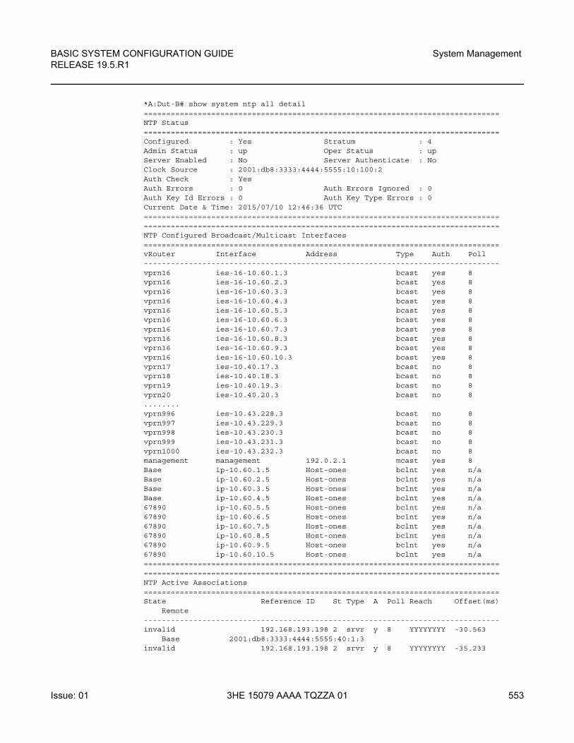
BASIC SYSTEM CONFIGURATION GUIDE RELEASE 19.5.R1
System Management
Issue: 01 3HE 15079 AAAA TQZZA 01 553
*A:Dut-B# show system ntp all detail===============================================================================NTP Status===============================================================================Configured : Yes Stratum : 4Admin Status : up Oper Status : upServer Enabled : No Server Authenticate : NoClock Source : 2001:db8:3333:4444:5555:10:100:2Auth Check : YesAuth Errors : 0 Auth Errors Ignored : 0Auth Key Id Errors : 0 Auth Key Type Errors : 0Current Date & Time: 2015/07/10 12:46:36 UTC==============================================================================================================================================================NTP Configured Broadcast/Multicast Interfaces===============================================================================vRouter Interface Address Type Auth Poll-------------------------------------------------------------------------------vprn16 ies-16-10.60.1.3 bcast yes 8vprn16 ies-16-10.60.2.3 bcast yes 8vprn16 ies-16-10.60.3.3 bcast yes 8vprn16 ies-16-10.60.4.3 bcast yes 8vprn16 ies-16-10.60.5.3 bcast yes 8vprn16 ies-16-10.60.6.3 bcast yes 8vprn16 ies-16-10.60.7.3 bcast yes 8vprn16 ies-16-10.60.8.3 bcast yes 8vprn16 ies-16-10.60.9.3 bcast yes 8vprn16 ies-16-10.60.10.3 bcast yes 8vprn17 ies-10.40.17.3 bcast no 8vprn18 ies-10.40.18.3 bcast no 8vprn19 ies-10.40.19.3 bcast no 8vprn20 ies-10.40.20.3 bcast no 8........vprn996 ies-10.43.228.3 bcast no 8vprn997 ies-10.43.229.3 bcast no 8vprn998 ies-10.43.230.3 bcast no 8vprn999 ies-10.43.231.3 bcast no 8vprn1000 ies-10.43.232.3 bcast no 8management management 192.0.2.1 mcast yes 8Base ip-10.60.1.5 Host-ones bclnt yes n/aBase ip-10.60.2.5 Host-ones bclnt yes n/aBase ip-10.60.3.5 Host-ones bclnt yes n/aBase ip-10.60.4.5 Host-ones bclnt yes n/a67890 ip-10.60.5.5 Host-ones bclnt yes n/a67890 ip-10.60.6.5 Host-ones bclnt yes n/a67890 ip-10.60.7.5 Host-ones bclnt yes n/a67890 ip-10.60.8.5 Host-ones bclnt yes n/a67890 ip-10.60.9.5 Host-ones bclnt yes n/a67890 ip-10.60.10.5 Host-ones bclnt yes n/a==============================================================================================================================================================NTP Active Associations===============================================================================State Reference ID St Type A Poll Reach Offset(ms)
Remote-------------------------------------------------------------------------------invalid 192.168.193.198 2 srvr y 8 YYYYYYYY -30.563
Base 2001:db8:3333:4444:5555:40:1:3invalid 192.168.193.198 2 srvr y 8 YYYYYYYY -35.233
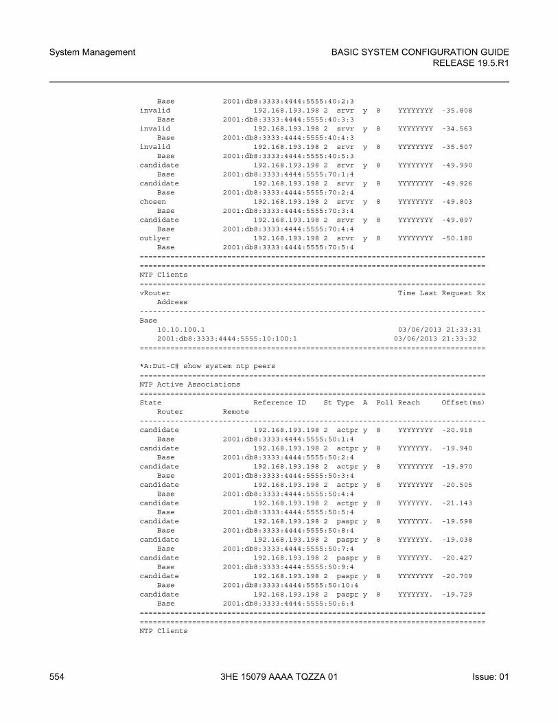
System Management
554
BASIC SYSTEM CONFIGURATION GUIDERELEASE 19.5.R1
3HE 15079 AAAA TQZZA 01 Issue: 01
Base 2001:db8:3333:4444:5555:40:2:3invalid 192.168.193.198 2 srvr y 8 YYYYYYYY -35.808
Base 2001:db8:3333:4444:5555:40:3:3invalid 192.168.193.198 2 srvr y 8 YYYYYYYY -34.563
Base 2001:db8:3333:4444:5555:40:4:3invalid 192.168.193.198 2 srvr y 8 YYYYYYYY -35.507
Base 2001:db8:3333:4444:5555:40:5:3candidate 192.168.193.198 2 srvr y 8 YYYYYYYY -49.990
Base 2001:db8:3333:4444:5555:70:1:4candidate 192.168.193.198 2 srvr y 8 YYYYYYYY -49.926
Base 2001:db8:3333:4444:5555:70:2:4chosen 192.168.193.198 2 srvr y 8 YYYYYYYY -49.803
Base 2001:db8:3333:4444:5555:70:3:4candidate 192.168.193.198 2 srvr y 8 YYYYYYYY -49.897
Base 2001:db8:3333:4444:5555:70:4:4outlyer 192.168.193.198 2 srvr y 8 YYYYYYYY -50.180
Base 2001:db8:3333:4444:5555:70:5:4==============================================================================================================================================================NTP Clients===============================================================================vRouter Time Last Request Rx
Address-------------------------------------------------------------------------------Base
10.10.100.1 03/06/2013 21:33:312001:db8:3333:4444:5555:10:100:1 03/06/2013 21:33:32
===============================================================================
*A:Dut-C# show system ntp peers===============================================================================NTP Active Associations===============================================================================State Reference ID St Type A Poll Reach Offset(ms)
Router Remote-------------------------------------------------------------------------------candidate 192.168.193.198 2 actpr y 8 YYYYYYYY -20.918
Base 2001:db8:3333:4444:5555:50:1:4candidate 192.168.193.198 2 actpr y 8 YYYYYYY. -19.940
Base 2001:db8:3333:4444:5555:50:2:4candidate 192.168.193.198 2 actpr y 8 YYYYYYYY -19.970
Base 2001:db8:3333:4444:5555:50:3:4candidate 192.168.193.198 2 actpr y 8 YYYYYYYY -20.505
Base 2001:db8:3333:4444:5555:50:4:4candidate 192.168.193.198 2 actpr y 8 YYYYYYY. -21.143
Base 2001:db8:3333:4444:5555:50:5:4candidate 192.168.193.198 2 paspr y 8 YYYYYYY. -19.598
Base 2001:db8:3333:4444:5555:50:8:4candidate 192.168.193.198 2 paspr y 8 YYYYYYY. -19.038
Base 2001:db8:3333:4444:5555:50:7:4candidate 192.168.193.198 2 paspr y 8 YYYYYYY. -20.427
Base 2001:db8:3333:4444:5555:50:9:4candidate 192.168.193.198 2 paspr y 8 YYYYYYYY -20.709
Base 2001:db8:3333:4444:5555:50:10:4candidate 192.168.193.198 2 paspr y 8 YYYYYYY. -19.729
Base 2001:db8:3333:4444:5555:50:6:4==============================================================================================================================================================NTP Clients
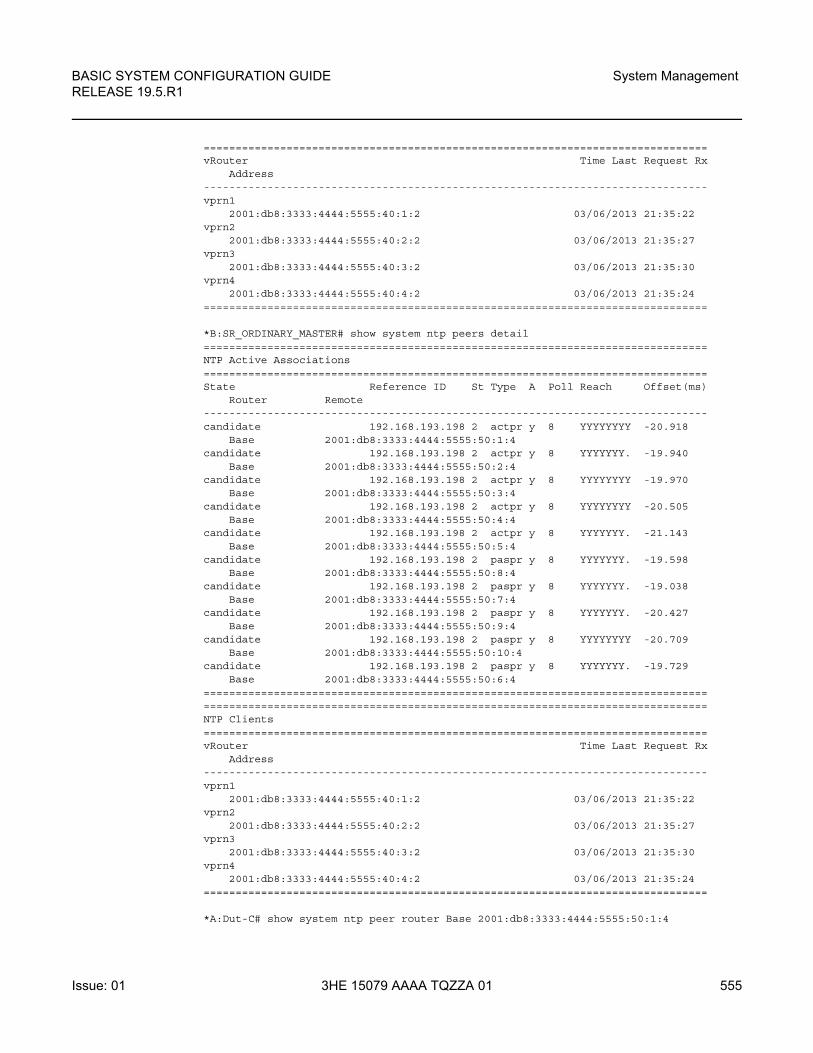
BASIC SYSTEM CONFIGURATION GUIDE RELEASE 19.5.R1
System Management
Issue: 01 3HE 15079 AAAA TQZZA 01 555
===============================================================================vRouter Time Last Request Rx
Address-------------------------------------------------------------------------------vprn1
2001:db8:3333:4444:5555:40:1:2 03/06/2013 21:35:22vprn2
2001:db8:3333:4444:5555:40:2:2 03/06/2013 21:35:27vprn3
2001:db8:3333:4444:5555:40:3:2 03/06/2013 21:35:30vprn4
2001:db8:3333:4444:5555:40:4:2 03/06/2013 21:35:24===============================================================================
*B:SR_ORDINARY_MASTER# show system ntp peers detail===============================================================================NTP Active Associations===============================================================================State Reference ID St Type A Poll Reach Offset(ms)
Router Remote-------------------------------------------------------------------------------candidate 192.168.193.198 2 actpr y 8 YYYYYYYY -20.918
Base 2001:db8:3333:4444:5555:50:1:4candidate 192.168.193.198 2 actpr y 8 YYYYYYY. -19.940
Base 2001:db8:3333:4444:5555:50:2:4candidate 192.168.193.198 2 actpr y 8 YYYYYYYY -19.970
Base 2001:db8:3333:4444:5555:50:3:4candidate 192.168.193.198 2 actpr y 8 YYYYYYYY -20.505
Base 2001:db8:3333:4444:5555:50:4:4candidate 192.168.193.198 2 actpr y 8 YYYYYYY. -21.143
Base 2001:db8:3333:4444:5555:50:5:4candidate 192.168.193.198 2 paspr y 8 YYYYYYY. -19.598
Base 2001:db8:3333:4444:5555:50:8:4candidate 192.168.193.198 2 paspr y 8 YYYYYYY. -19.038
Base 2001:db8:3333:4444:5555:50:7:4candidate 192.168.193.198 2 paspr y 8 YYYYYYY. -20.427
Base 2001:db8:3333:4444:5555:50:9:4candidate 192.168.193.198 2 paspr y 8 YYYYYYYY -20.709
Base 2001:db8:3333:4444:5555:50:10:4candidate 192.168.193.198 2 paspr y 8 YYYYYYY. -19.729
Base 2001:db8:3333:4444:5555:50:6:4==============================================================================================================================================================NTP Clients===============================================================================vRouter Time Last Request Rx
Address-------------------------------------------------------------------------------vprn1
2001:db8:3333:4444:5555:40:1:2 03/06/2013 21:35:22vprn2
2001:db8:3333:4444:5555:40:2:2 03/06/2013 21:35:27vprn3
2001:db8:3333:4444:5555:40:3:2 03/06/2013 21:35:30vprn4
2001:db8:3333:4444:5555:40:4:2 03/06/2013 21:35:24===============================================================================
*A:Dut-C# show system ntp peer router Base 2001:db8:3333:4444:5555:50:1:4
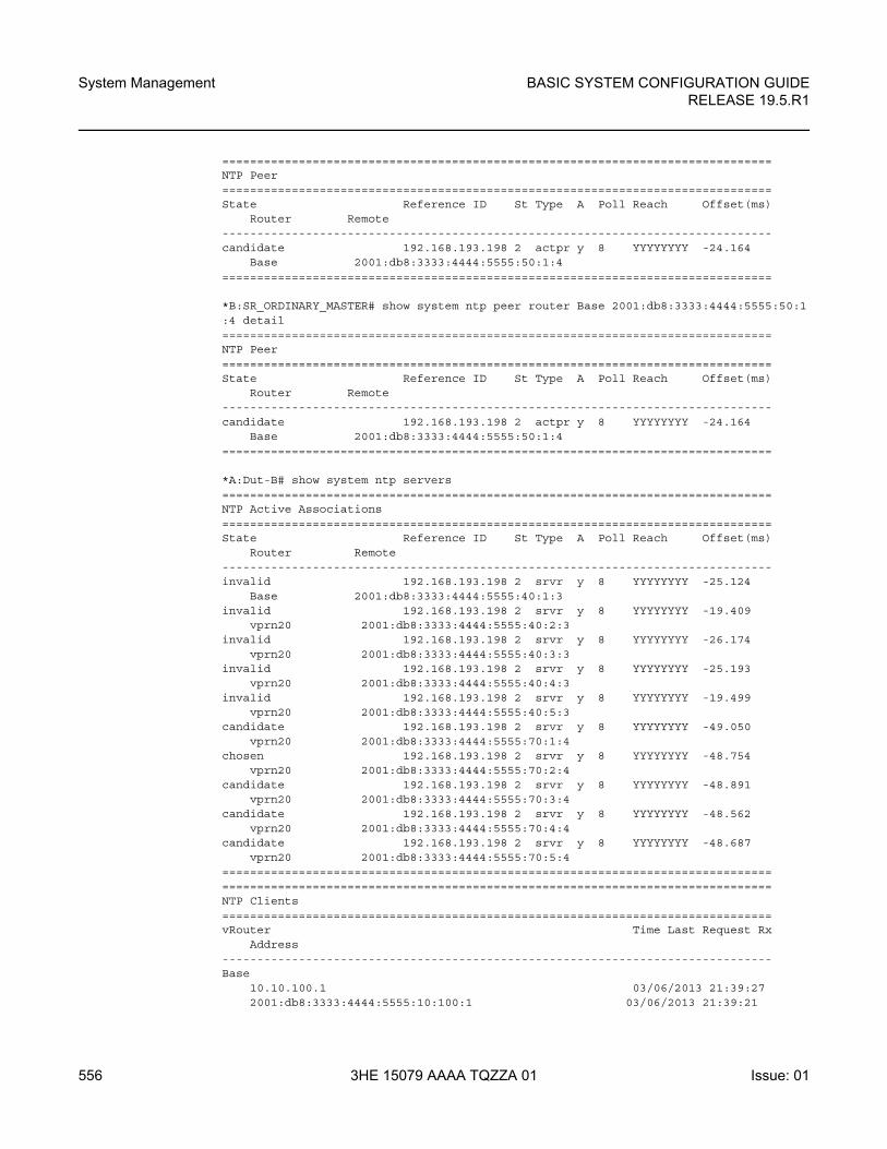
System Management
556
BASIC SYSTEM CONFIGURATION GUIDERELEASE 19.5.R1
3HE 15079 AAAA TQZZA 01 Issue: 01
===============================================================================NTP Peer===============================================================================State Reference ID St Type A Poll Reach Offset(ms)
Router Remote-------------------------------------------------------------------------------candidate 192.168.193.198 2 actpr y 8 YYYYYYYY -24.164
Base 2001:db8:3333:4444:5555:50:1:4===============================================================================
*B:SR_ORDINARY_MASTER# show system ntp peer router Base 2001:db8:3333:4444:5555:50:1:4 detail===============================================================================NTP Peer===============================================================================State Reference ID St Type A Poll Reach Offset(ms)
Router Remote-------------------------------------------------------------------------------candidate 192.168.193.198 2 actpr y 8 YYYYYYYY -24.164
Base 2001:db8:3333:4444:5555:50:1:4===============================================================================
*A:Dut-B# show system ntp servers===============================================================================NTP Active Associations===============================================================================State Reference ID St Type A Poll Reach Offset(ms)
Router Remote-------------------------------------------------------------------------------invalid 192.168.193.198 2 srvr y 8 YYYYYYYY -25.124
Base 2001:db8:3333:4444:5555:40:1:3invalid 192.168.193.198 2 srvr y 8 YYYYYYYY -19.409
vprn20 2001:db8:3333:4444:5555:40:2:3invalid 192.168.193.198 2 srvr y 8 YYYYYYYY -26.174
vprn20 2001:db8:3333:4444:5555:40:3:3invalid 192.168.193.198 2 srvr y 8 YYYYYYYY -25.193
vprn20 2001:db8:3333:4444:5555:40:4:3invalid 192.168.193.198 2 srvr y 8 YYYYYYYY -19.499
vprn20 2001:db8:3333:4444:5555:40:5:3candidate 192.168.193.198 2 srvr y 8 YYYYYYYY -49.050
vprn20 2001:db8:3333:4444:5555:70:1:4chosen 192.168.193.198 2 srvr y 8 YYYYYYYY -48.754
vprn20 2001:db8:3333:4444:5555:70:2:4candidate 192.168.193.198 2 srvr y 8 YYYYYYYY -48.891
vprn20 2001:db8:3333:4444:5555:70:3:4candidate 192.168.193.198 2 srvr y 8 YYYYYYYY -48.562
vprn20 2001:db8:3333:4444:5555:70:4:4candidate 192.168.193.198 2 srvr y 8 YYYYYYYY -48.687
vprn20 2001:db8:3333:4444:5555:70:5:4==============================================================================================================================================================NTP Clients===============================================================================vRouter Time Last Request Rx
Address-------------------------------------------------------------------------------Base
10.10.100.1 03/06/2013 21:39:272001:db8:3333:4444:5555:10:100:1 03/06/2013 21:39:21
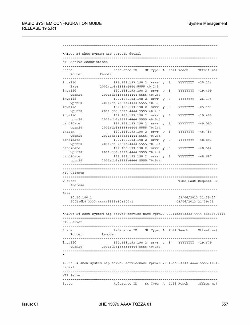
BASIC SYSTEM CONFIGURATION GUIDE RELEASE 19.5.R1
System Management
Issue: 01 3HE 15079 AAAA TQZZA 01 557
===============================================================================
*A:Dut-B# show system ntp servers detail===============================================================================NTP Active Associations===============================================================================State Reference ID St Type A Poll Reach Offset(ms)
Router Remote-------------------------------------------------------------------------------invalid 192.168.193.198 2 srvr y 8 YYYYYYYY -25.124
Base 2001:db8:3333:4444:5555:40:1:3invalid 192.168.193.198 2 srvr y 8 YYYYYYYY -19.409
vprn20 2001:db8:3333:4444:5555:40:2:3invalid 192.168.193.198 2 srvr y 8 YYYYYYYY -26.174
vprn20 2001:db8:3333:4444:5555:40:3:3invalid 192.168.193.198 2 srvr y 8 YYYYYYYY -25.193
vprn20 2001:db8:3333:4444:5555:40:4:3invalid 192.168.193.198 2 srvr y 8 YYYYYYYY -19.499
vprn20 2001:db8:3333:4444:5555:40:5:3candidate 192.168.193.198 2 srvr y 8 YYYYYYYY -49.050
vprn20 2001:db8:3333:4444:5555:70:1:4chosen 192.168.193.198 2 srvr y 8 YYYYYYYY -48.754
vprn20 2001:db8:3333:4444:5555:70:2:4candidate 192.168.193.198 2 srvr y 8 YYYYYYYY -48.891
vprn20 2001:db8:3333:4444:5555:70:3:4candidate 192.168.193.198 2 srvr y 8 YYYYYYYY -48.562
vprn20 2001:db8:3333:4444:5555:70:4:4candidate 192.168.193.198 2 srvr y 8 YYYYYYYY -48.687
vprn20 2001:db8:3333:4444:5555:70:5:4==============================================================================================================================================================NTP Clients===============================================================================vRouter Time Last Request Rx
Address-------------------------------------------------------------------------------Base
10.10.100.1 03/06/2013 21:39:272001:db8:3333:4444:5555:10:100:1 03/06/2013 21:39:21
===============================================================================
*A:Dut-B# show system ntp server service-name vprn20 2001:db8:3333:4444:5555:40:1:3===============================================================================NTP Server===============================================================================State Reference ID St Type A Poll Reach Offset(ms)
Router Remote-------------------------------------------------------------------------------invalid 192.168.193.198 2 srvr y 8 YYYYYYYY -19.679
vprn20 2001:db8:3333:4444:5555:40:1:3===============================================================================*
A:Dut B# show system ntp server servicename vprn20 2001:db8:3333:4444:5555:40:1:3detail===============================================================================NTP Server===============================================================================State Reference ID St Type A Poll Reach Offset(ms)
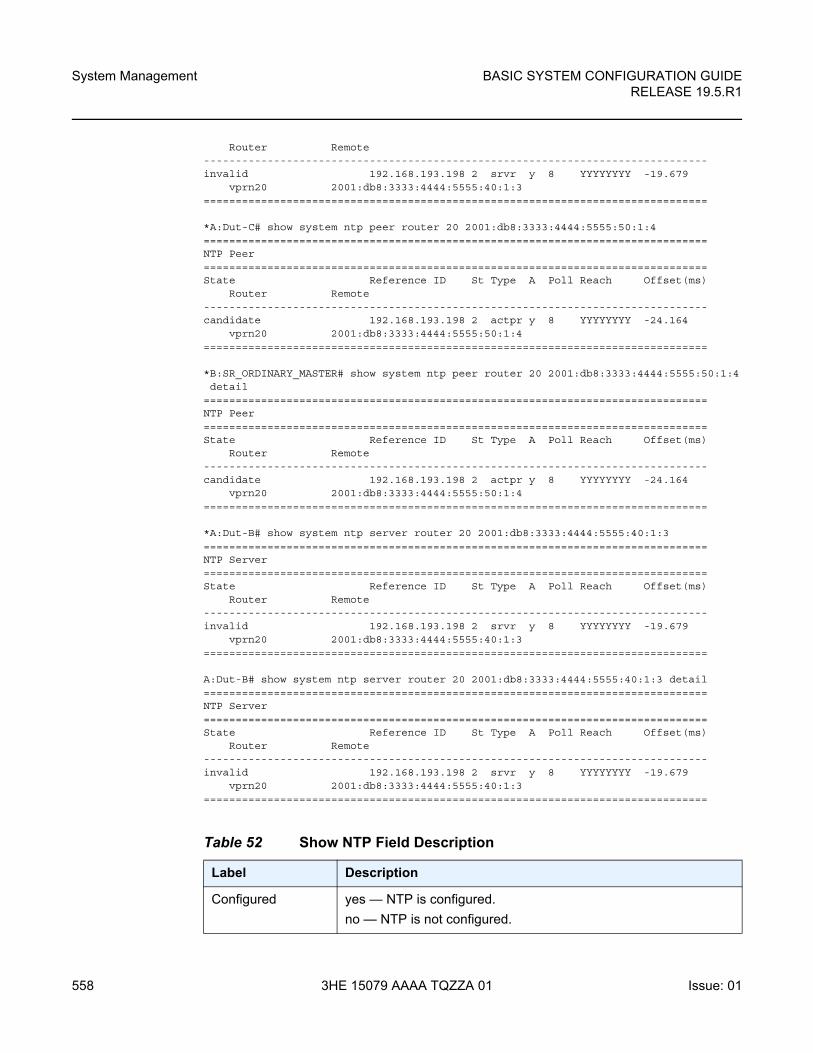
System Management
558
BASIC SYSTEM CONFIGURATION GUIDERELEASE 19.5.R1
3HE 15079 AAAA TQZZA 01 Issue: 01
Router Remote-------------------------------------------------------------------------------invalid 192.168.193.198 2 srvr y 8 YYYYYYYY -19.679
vprn20 2001:db8:3333:4444:5555:40:1:3===============================================================================
*A:Dut-C# show system ntp peer router 20 2001:db8:3333:4444:5555:50:1:4===============================================================================NTP Peer===============================================================================State Reference ID St Type A Poll Reach Offset(ms)
Router Remote-------------------------------------------------------------------------------candidate 192.168.193.198 2 actpr y 8 YYYYYYYY -24.164
vprn20 2001:db8:3333:4444:5555:50:1:4===============================================================================
*B:SR_ORDINARY_MASTER# show system ntp peer router 20 2001:db8:3333:4444:5555:50:1:4detail
===============================================================================NTP Peer===============================================================================State Reference ID St Type A Poll Reach Offset(ms)
Router Remote-------------------------------------------------------------------------------candidate 192.168.193.198 2 actpr y 8 YYYYYYYY -24.164
vprn20 2001:db8:3333:4444:5555:50:1:4===============================================================================
*A:Dut-B# show system ntp server router 20 2001:db8:3333:4444:5555:40:1:3===============================================================================NTP Server===============================================================================State Reference ID St Type A Poll Reach Offset(ms)
Router Remote-------------------------------------------------------------------------------invalid 192.168.193.198 2 srvr y 8 YYYYYYYY -19.679
vprn20 2001:db8:3333:4444:5555:40:1:3===============================================================================
A:Dut-B# show system ntp server router 20 2001:db8:3333:4444:5555:40:1:3 detail===============================================================================NTP Server===============================================================================State Reference ID St Type A Poll Reach Offset(ms)
Router Remote-------------------------------------------------------------------------------invalid 192.168.193.198 2 srvr y 8 YYYYYYYY -19.679
vprn20 2001:db8:3333:4444:5555:40:1:3===============================================================================
Table 52 Show NTP Field Description
Label Description
Configured yes — NTP is configured.
no — NTP is not configured.
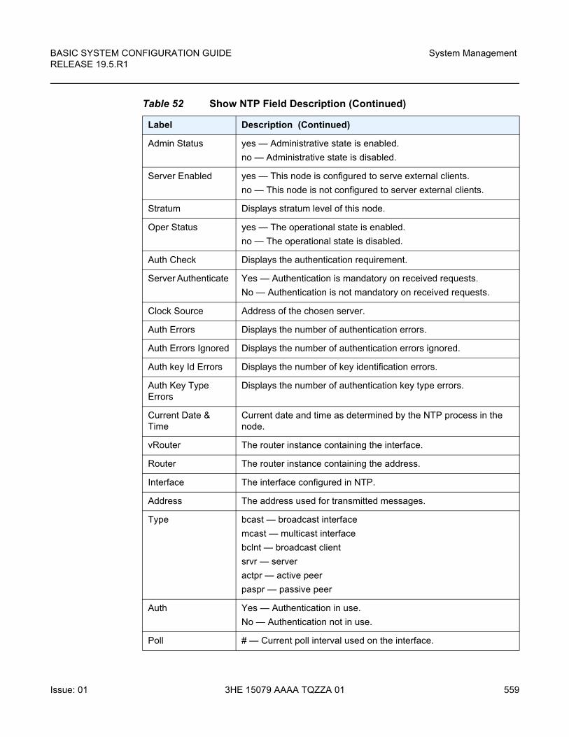
BASIC SYSTEM CONFIGURATION GUIDE RELEASE 19.5.R1
System Management
Issue: 01 3HE 15079 AAAA TQZZA 01 559
Admin Status yes — Administrative state is enabled.
no — Administrative state is disabled.
Server Enabled yes — This node is configured to serve external clients.
no — This node is not configured to server external clients.
Stratum Displays stratum level of this node.
Oper Status yes — The operational state is enabled.
no — The operational state is disabled.
Auth Check Displays the authentication requirement.
Server Authenticate Yes — Authentication is mandatory on received requests.
No — Authentication is not mandatory on received requests.
Clock Source Address of the chosen server.
Auth Errors Displays the number of authentication errors.
Auth Errors Ignored Displays the number of authentication errors ignored.
Auth key Id Errors Displays the number of key identification errors.
Auth Key Type Errors
Displays the number of authentication key type errors.
Current Date & Time
Current date and time as determined by the NTP process in the node.
vRouter The router instance containing the interface.
Router The router instance containing the address.
Interface The interface configured in NTP.
Address The address used for transmitted messages.
Type bcast — broadcast interface
mcast — multicast interface
bclnt — broadcast client
srvr — server
actpr — active peer
paspr — passive peer
Auth Yes — Authentication in use.
No — Authentication not in use.
Poll # — Current poll interval used on the interface.
Table 52 Show NTP Field Description (Continued)
Label Description (Continued)
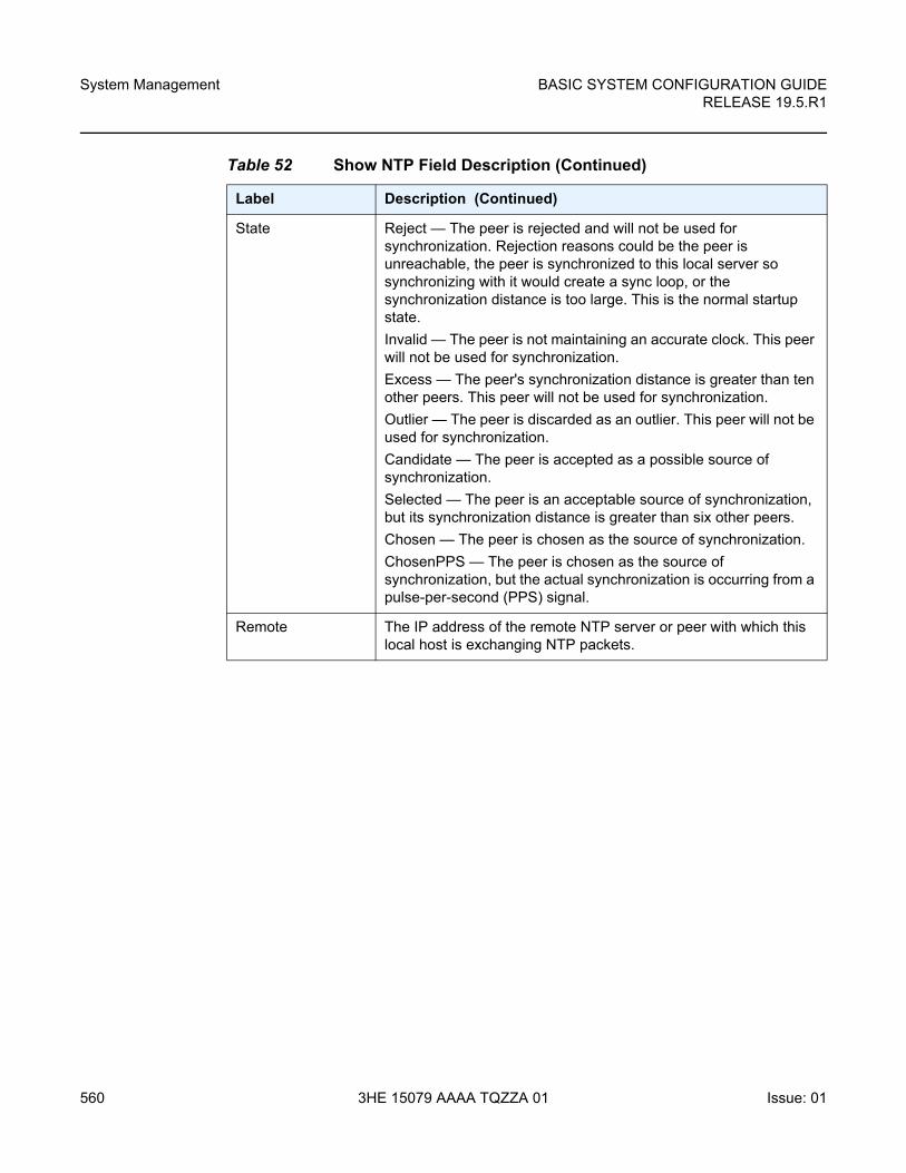
System Management
560
BASIC SYSTEM CONFIGURATION GUIDERELEASE 19.5.R1
3HE 15079 AAAA TQZZA 01 Issue: 01
State Reject — The peer is rejected and will not be used for synchronization. Rejection reasons could be the peer is unreachable, the peer is synchronized to this local server so synchronizing with it would create a sync loop, or the synchronization distance is too large. This is the normal startup state.
Invalid — The peer is not maintaining an accurate clock. This peer will not be used for synchronization.
Excess — The peer's synchronization distance is greater than ten other peers. This peer will not be used for synchronization.
Outlier — The peer is discarded as an outlier. This peer will not be used for synchronization.
Candidate — The peer is accepted as a possible source of synchronization.
Selected — The peer is an acceptable source of synchronization, but its synchronization distance is greater than six other peers.
Chosen — The peer is chosen as the source of synchronization.
ChosenPPS — The peer is chosen as the source of synchronization, but the actual synchronization is occurring from a pulse-per-second (PPS) signal.
Remote The IP address of the remote NTP server or peer with which this local host is exchanging NTP packets.
Table 52 Show NTP Field Description (Continued)
Label Description (Continued)
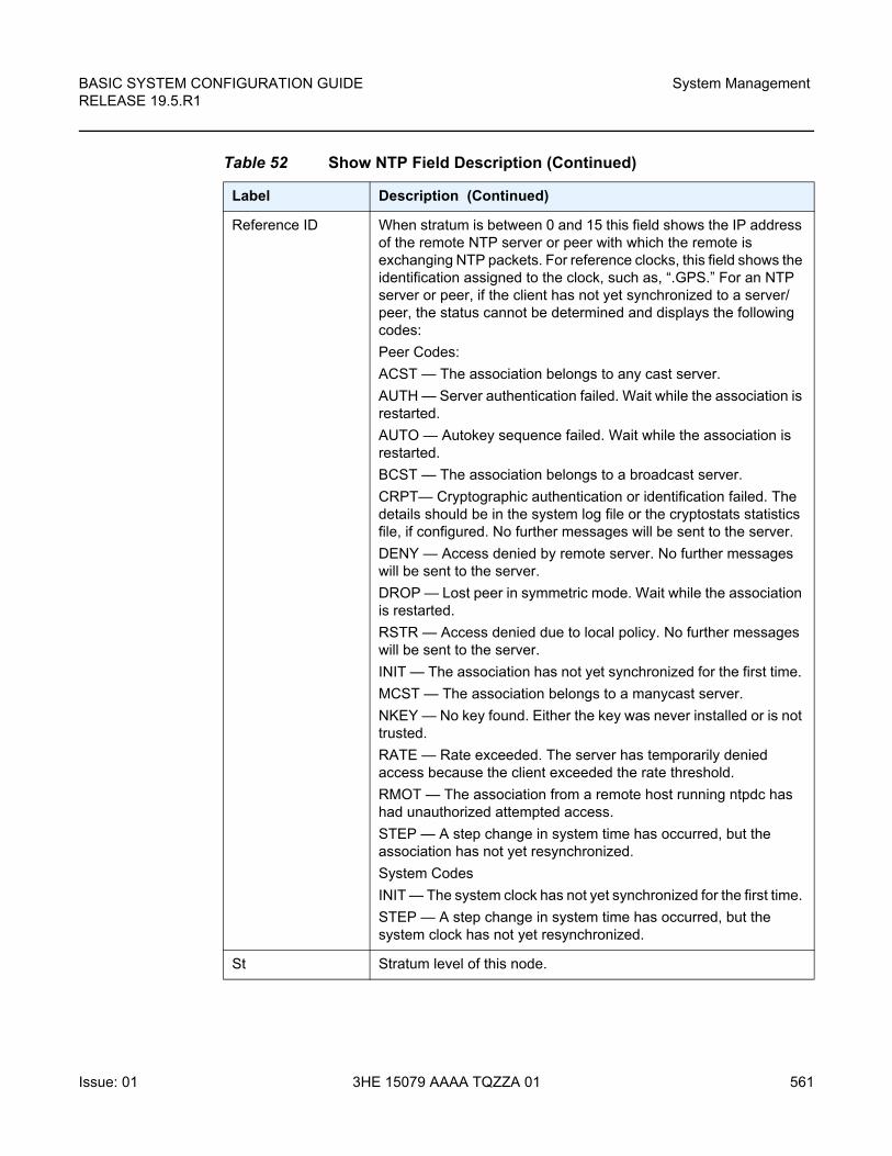
BASIC SYSTEM CONFIGURATION GUIDE RELEASE 19.5.R1
System Management
Issue: 01 3HE 15079 AAAA TQZZA 01 561
Reference ID When stratum is between 0 and 15 this field shows the IP address of the remote NTP server or peer with which the remote is exchanging NTP packets. For reference clocks, this field shows the identification assigned to the clock, such as, “.GPS.” For an NTP server or peer, if the client has not yet synchronized to a server/peer, the status cannot be determined and displays the following codes:
Peer Codes:
ACST — The association belongs to any cast server.
AUTH — Server authentication failed. Wait while the association is restarted.
AUTO — Autokey sequence failed. Wait while the association is restarted.
BCST — The association belongs to a broadcast server.
CRPT— Cryptographic authentication or identification failed. The details should be in the system log file or the cryptostats statistics file, if configured. No further messages will be sent to the server.
DENY — Access denied by remote server. No further messages will be sent to the server.
DROP — Lost peer in symmetric mode. Wait while the association is restarted.
RSTR — Access denied due to local policy. No further messages will be sent to the server.
INIT — The association has not yet synchronized for the first time.
MCST — The association belongs to a manycast server.
NKEY — No key found. Either the key was never installed or is not trusted.
RATE — Rate exceeded. The server has temporarily denied access because the client exceeded the rate threshold.
RMOT — The association from a remote host running ntpdc has had unauthorized attempted access.
STEP — A step change in system time has occurred, but the association has not yet resynchronized.
System Codes
INIT — The system clock has not yet synchronized for the first time.
STEP — A step change in system time has occurred, but the system clock has not yet resynchronized.
St Stratum level of this node.
Table 52 Show NTP Field Description (Continued)
Label Description (Continued)
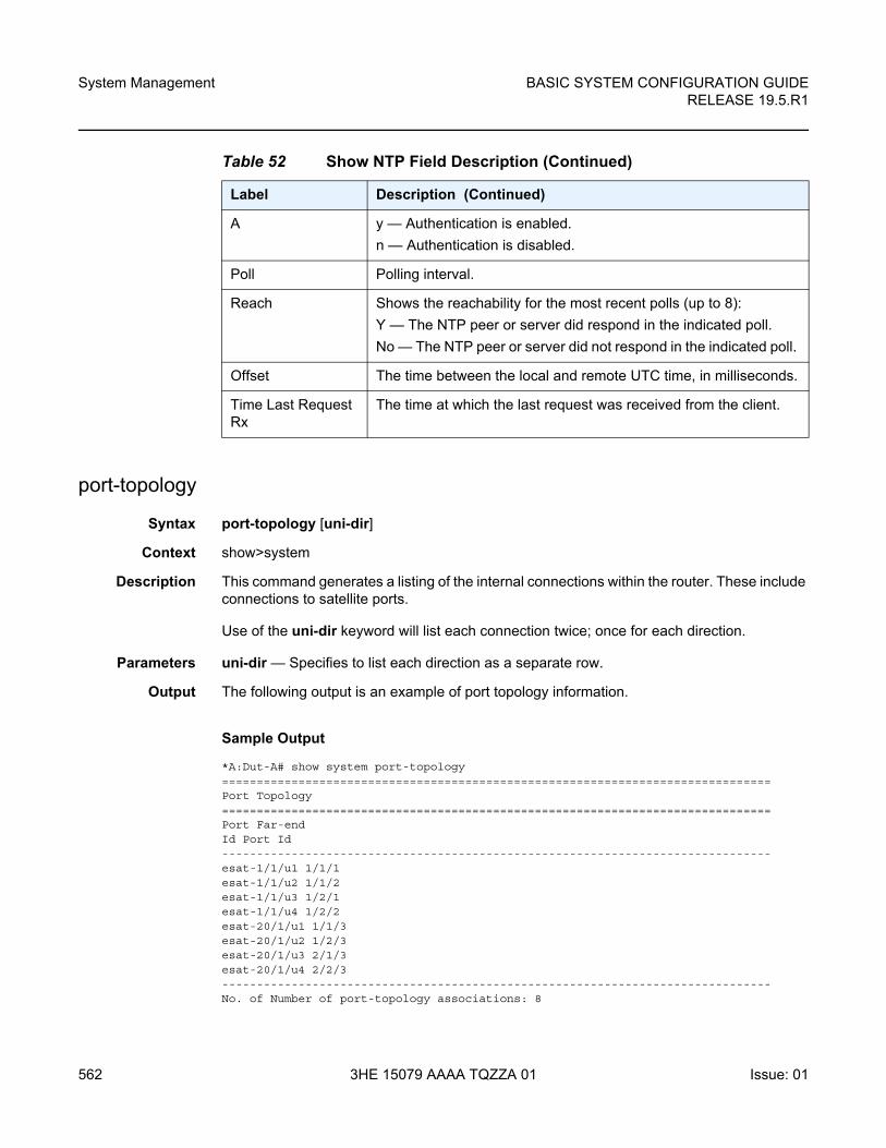
System Management
562
BASIC SYSTEM CONFIGURATION GUIDERELEASE 19.5.R1
3HE 15079 AAAA TQZZA 01 Issue: 01
port-topology
Syntax port-topology [uni-dir]
Context show>system
Description This command generates a listing of the internal connections within the router. These include connections to satellite ports.
Use of the uni-dir keyword will list each connection twice; once for each direction.
Parameters uni-dir — Specifies to list each direction as a separate row.
Output The following output is an example of port topology information.
Sample Output
*A:Dut-A# show system port-topology===============================================================================Port Topology===============================================================================Port Far-endId Port Id-------------------------------------------------------------------------------esat-1/1/u1 1/1/1esat-1/1/u2 1/1/2esat-1/1/u3 1/2/1esat-1/1/u4 1/2/2esat-20/1/u1 1/1/3esat-20/1/u2 1/2/3esat-20/1/u3 2/1/3esat-20/1/u4 2/2/3-------------------------------------------------------------------------------No. of Number of port-topology associations: 8
A y — Authentication is enabled.
n — Authentication is disabled.
Poll Polling interval.
Reach Shows the reachability for the most recent polls (up to 8):
Y — The NTP peer or server did respond in the indicated poll.
No — The NTP peer or server did not respond in the indicated poll.
Offset The time between the local and remote UTC time, in milliseconds.
Time Last Request Rx
The time at which the last request was received from the client.
Table 52 Show NTP Field Description (Continued)
Label Description (Continued)
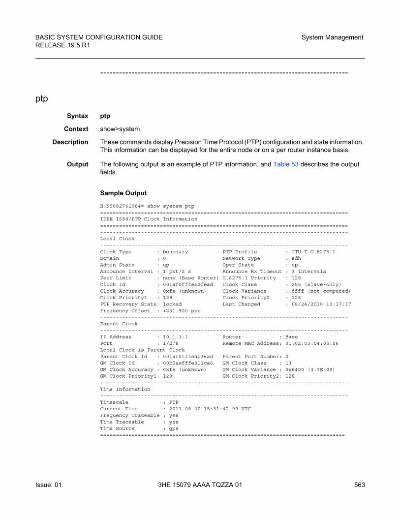
BASIC SYSTEM CONFIGURATION GUIDE RELEASE 19.5.R1
System Management
Issue: 01 3HE 15079 AAAA TQZZA 01 563
===============================================================================
ptp
Syntax ptp
Context show>system
Description These commands display Precision Time Protocol (PTP) configuration and state information. This information can be displayed for the entire node or on a per router instance basis.
Output The following output is an example of PTP information, and Table 53 describes the output fields.
Sample Output
B:NS082761964# show system ptp===============================================================================IEEE 1588/PTP Clock Information===============================================================================-------------------------------------------------------------------------------Local Clock-------------------------------------------------------------------------------Clock Type : boundary PTP Profile : ITU-T G.8275.1Domain : 0 Network Type : sdhAdmin State : up Oper State : upAnnounce Interval : 1 pkt/2 s Announce Rx Timeout : 3 intervalsPeer Limit : none (Base Router) G.8275.1 Priority : 128Clock Id : 001af0fffeb2fead Clock Class : 255 (slave-only)Clock Accuracy : 0xfe (unknown) Clock Variance : ffff (not computed)Clock Priority1 : 128 Clock Priority2 : 128PTP Recovery State: locked Last Changed : 08/24/2010 13:17:37Frequency Offset : +231.920 ppb-------------------------------------------------------------------------------Parent Clock-------------------------------------------------------------------------------IP Address : 10.1.1.1 Router : BasePort : 1/2/8 Remote MAC Address: 01:02:03:04:05:06Local Clock is Parent ClockParent Clock Id : 001af0fffeab36ad Parent Port Number: 2GM Clock Id : 00b0aefffe011ca6 GM Clock Class : 13GM Clock Accuracy : 0xfe (unknown) GM Clock Variance : 0x6400 (3.7E-09)GM Clock Priority1: 128 GM Clock Priority2: 128-------------------------------------------------------------------------------Time Information-------------------------------------------------------------------------------Timescale : PTPCurrent Time : 2011-08-30 15:31:42.99 UTCFrequency Traceable : yesTime Traceable : yesTime Source : gps==============================================================================
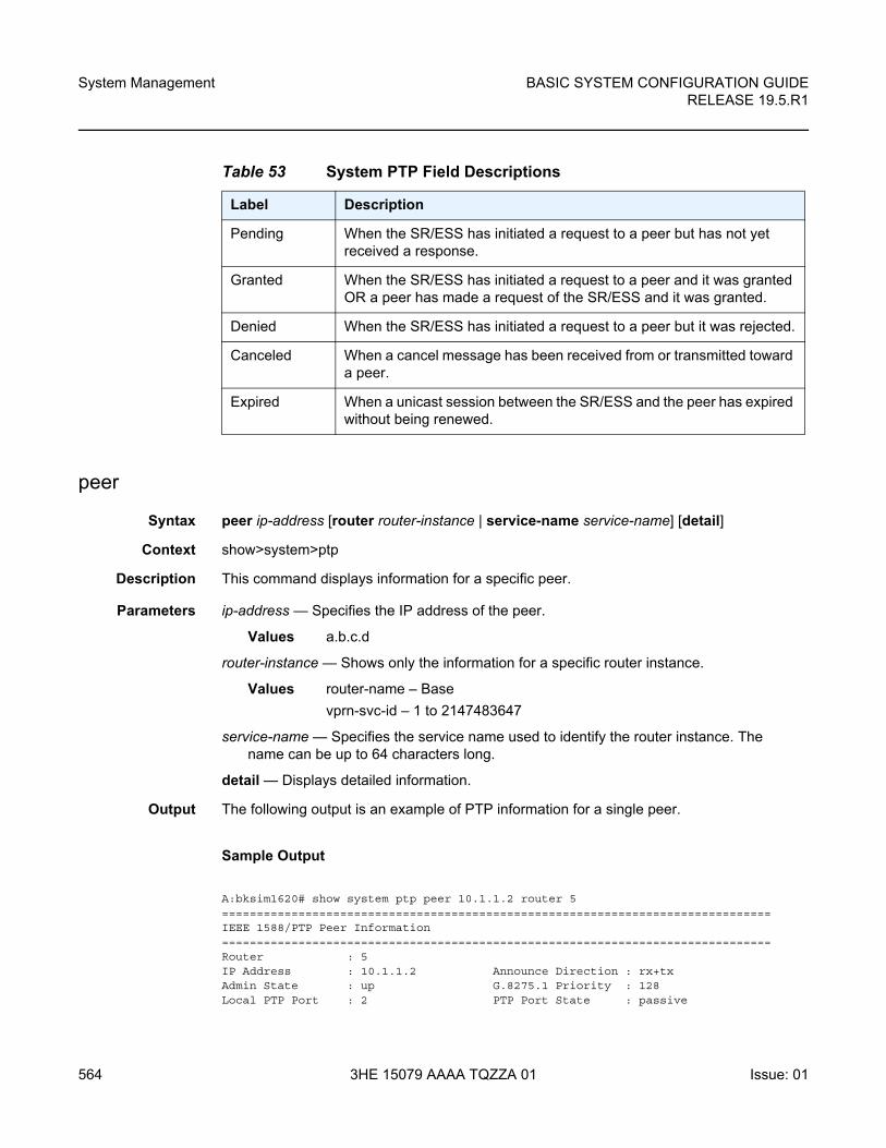
System Management
564
BASIC SYSTEM CONFIGURATION GUIDERELEASE 19.5.R1
3HE 15079 AAAA TQZZA 01 Issue: 01
peer
Syntax peer ip-address [router router-instance | service-name service-name] [detail]
Context show>system>ptp
Description This command displays information for a specific peer.
Parameters ip-address — Specifies the IP address of the peer.
Values a.b.c.d
router-instance — Shows only the information for a specific router instance.
Values router-name – Base
vprn-svc-id – 1 to 2147483647
service-name — Specifies the service name used to identify the router instance. The name can be up to 64 characters long.
detail — Displays detailed information.
Output The following output is an example of PTP information for a single peer.
Sample Output
A:bksim1620# show system ptp peer 10.1.1.2 router 5===============================================================================IEEE 1588/PTP Peer Information===============================================================================Router : 5IP Address : 10.1.1.2 Announce Direction : rx+txAdmin State : up G.8275.1 Priority : 128Local PTP Port : 2 PTP Port State : passive
Table 53 System PTP Field Descriptions
Label Description
Pending When the SR/ESS has initiated a request to a peer but has not yet received a response.
Granted When the SR/ESS has initiated a request to a peer and it was granted OR a peer has made a request of the SR/ESS and it was granted.
Denied When the SR/ESS has initiated a request to a peer but it was rejected.
Canceled When a cancel message has been received from or transmitted toward a peer.
Expired When a unicast session between the SR/ESS and the peer has expired without being renewed.
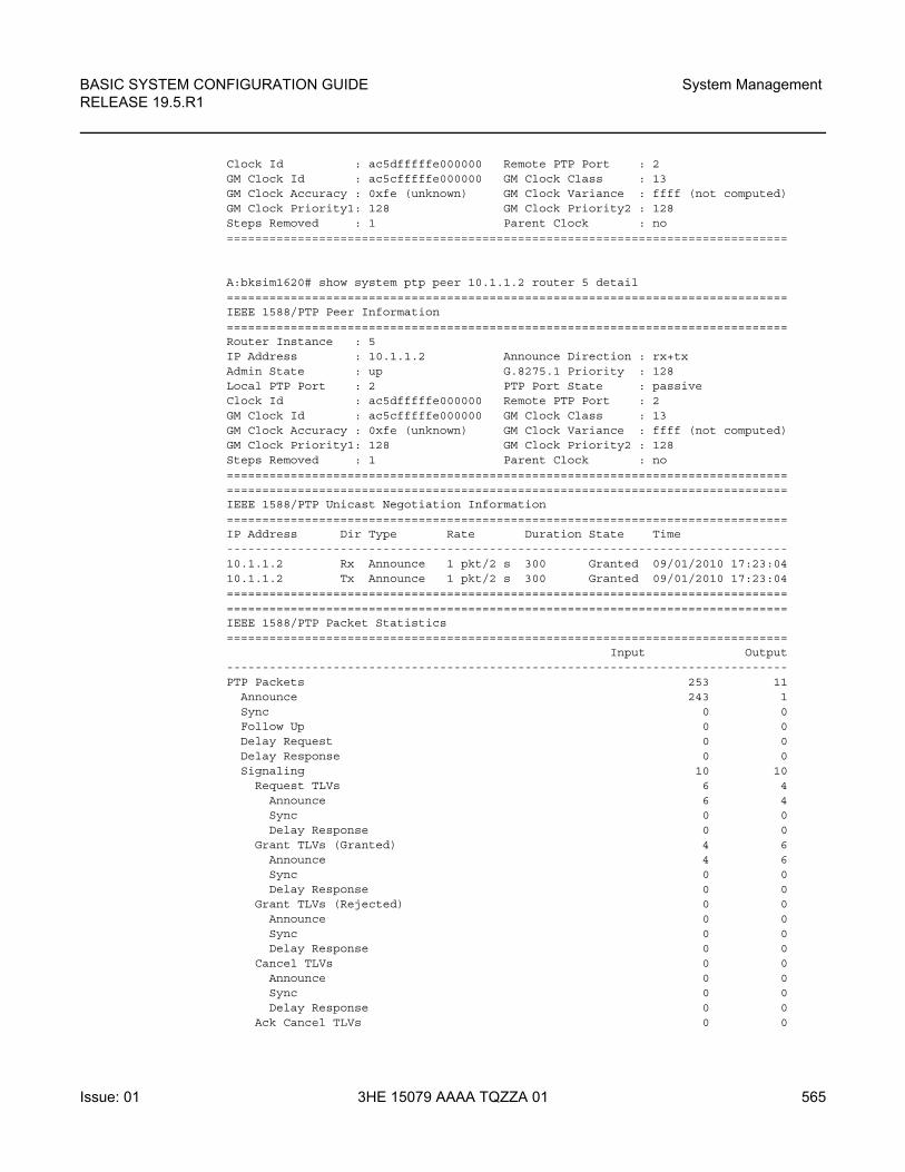
BASIC SYSTEM CONFIGURATION GUIDE RELEASE 19.5.R1
System Management
Issue: 01 3HE 15079 AAAA TQZZA 01 565
Clock Id : ac5dfffffe000000 Remote PTP Port : 2GM Clock Id : ac5cfffffe000000 GM Clock Class : 13GM Clock Accuracy : 0xfe (unknown) GM Clock Variance : ffff (not computed)GM Clock Priority1: 128 GM Clock Priority2 : 128Steps Removed : 1 Parent Clock : no===============================================================================
A:bksim1620# show system ptp peer 10.1.1.2 router 5 detail===============================================================================IEEE 1588/PTP Peer Information===============================================================================Router Instance : 5IP Address : 10.1.1.2 Announce Direction : rx+txAdmin State : up G.8275.1 Priority : 128Local PTP Port : 2 PTP Port State : passiveClock Id : ac5dfffffe000000 Remote PTP Port : 2GM Clock Id : ac5cfffffe000000 GM Clock Class : 13GM Clock Accuracy : 0xfe (unknown) GM Clock Variance : ffff (not computed)GM Clock Priority1: 128 GM Clock Priority2 : 128Steps Removed : 1 Parent Clock : no==============================================================================================================================================================IEEE 1588/PTP Unicast Negotiation Information===============================================================================IP Address Dir Type Rate Duration State Time-------------------------------------------------------------------------------10.1.1.2 Rx Announce 1 pkt/2 s 300 Granted 09/01/2010 17:23:0410.1.1.2 Tx Announce 1 pkt/2 s 300 Granted 09/01/2010 17:23:04==============================================================================================================================================================IEEE 1588/PTP Packet Statistics===============================================================================
Input Output-------------------------------------------------------------------------------PTP Packets 253 11
Announce 243 1Sync 0 0Follow Up 0 0Delay Request 0 0Delay Response 0 0Signaling 10 10
Request TLVs 6 4Announce 6 4Sync 0 0Delay Response 0 0
Grant TLVs (Granted) 4 6Announce 4 6Sync 0 0Delay Response 0 0
Grant TLVs (Rejected) 0 0Announce 0 0Sync 0 0Delay Response 0 0
Cancel TLVs 0 0Announce 0 0Sync 0 0Delay Response 0 0
Ack Cancel TLVs 0 0
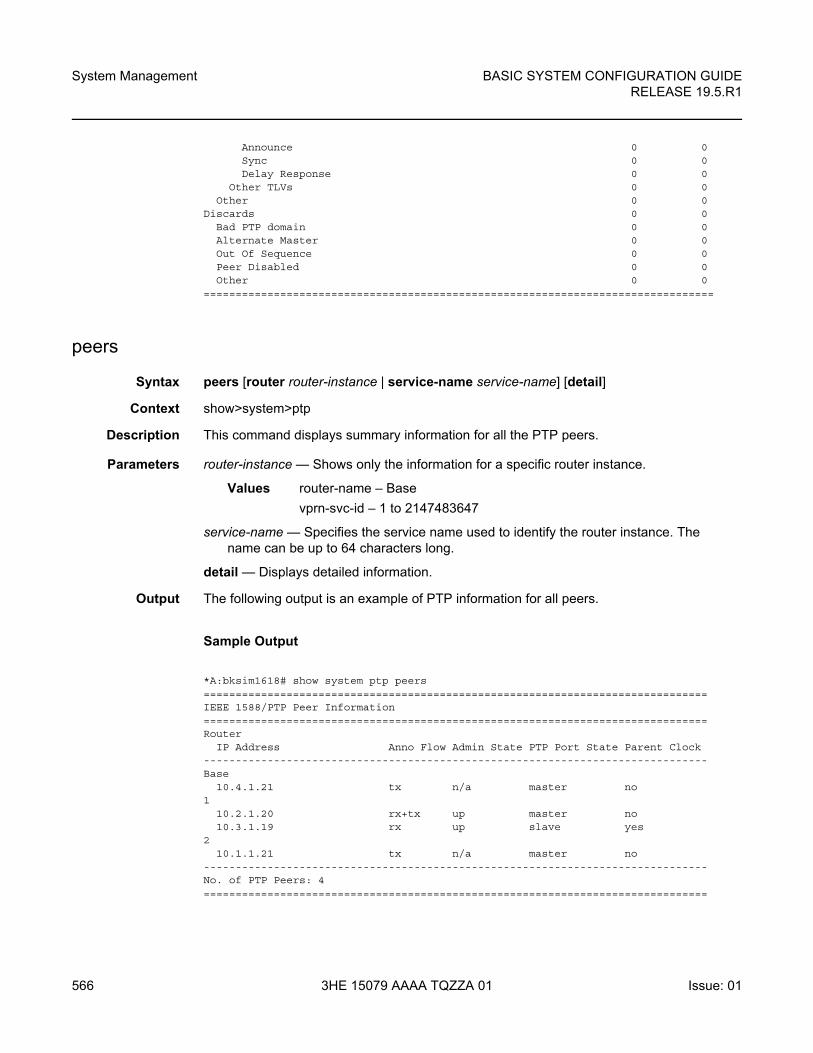
System Management
566
BASIC SYSTEM CONFIGURATION GUIDERELEASE 19.5.R1
3HE 15079 AAAA TQZZA 01 Issue: 01
Announce 0 0Sync 0 0Delay Response 0 0
Other TLVs 0 0Other 0 0
Discards 0 0Bad PTP domain 0 0Alternate Master 0 0Out Of Sequence 0 0Peer Disabled 0 0Other 0 0
================================================================================
peers
Syntax peers [router router-instance | service-name service-name] [detail]
Context show>system>ptp
Description This command displays summary information for all the PTP peers.
Parameters router-instance — Shows only the information for a specific router instance.
Values router-name – Base
vprn-svc-id – 1 to 2147483647
service-name — Specifies the service name used to identify the router instance. The name can be up to 64 characters long.
detail — Displays detailed information.
Output The following output is an example of PTP information for all peers.
Sample Output
*A:bksim1618# show system ptp peers===============================================================================IEEE 1588/PTP Peer Information===============================================================================Router
IP Address Anno Flow Admin State PTP Port State Parent Clock-------------------------------------------------------------------------------Base
10.4.1.21 tx n/a master no1
10.2.1.20 rx+tx up master no10.3.1.19 rx up slave yes
210.1.1.21 tx n/a master no
-------------------------------------------------------------------------------No. of PTP Peers: 4===============================================================================
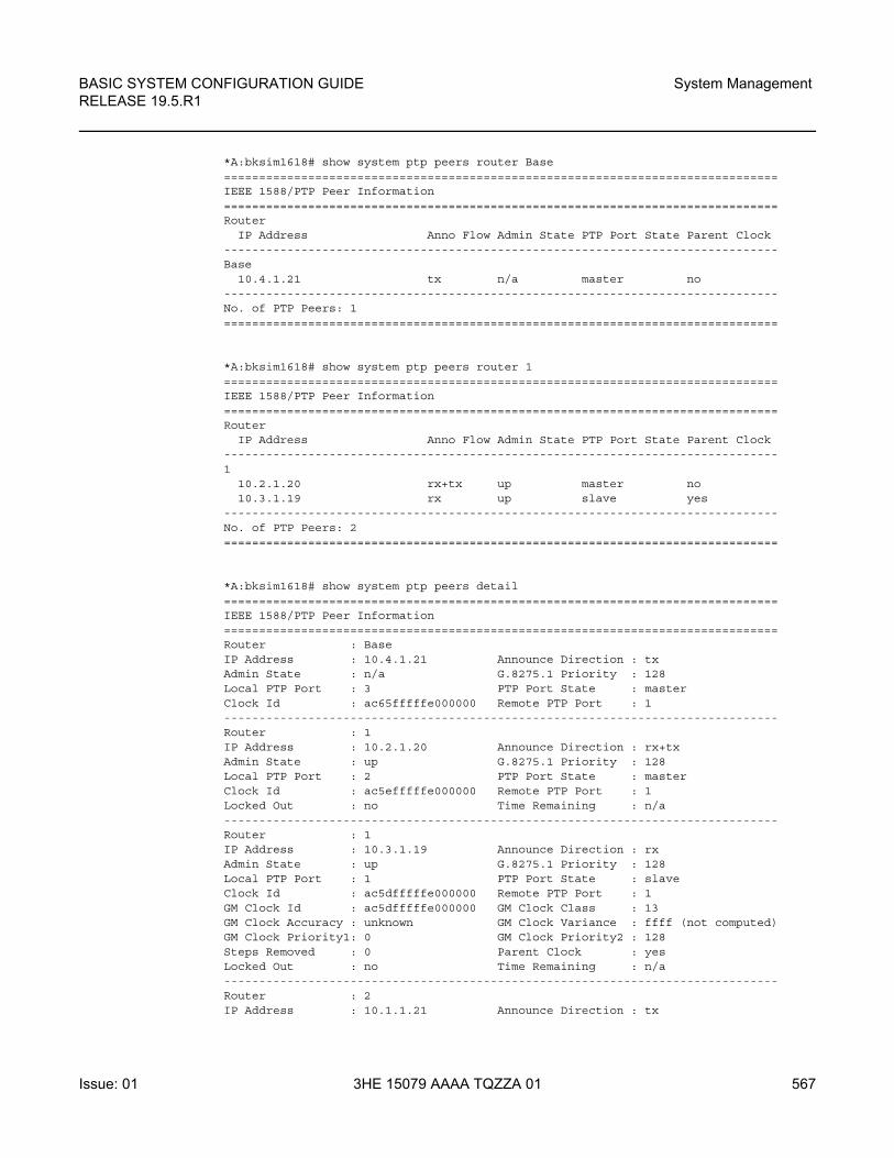
BASIC SYSTEM CONFIGURATION GUIDE RELEASE 19.5.R1
System Management
Issue: 01 3HE 15079 AAAA TQZZA 01 567
*A:bksim1618# show system ptp peers router Base===============================================================================IEEE 1588/PTP Peer Information===============================================================================Router
IP Address Anno Flow Admin State PTP Port State Parent Clock-------------------------------------------------------------------------------Base
10.4.1.21 tx n/a master no-------------------------------------------------------------------------------No. of PTP Peers: 1===============================================================================
*A:bksim1618# show system ptp peers router 1===============================================================================IEEE 1588/PTP Peer Information===============================================================================Router
IP Address Anno Flow Admin State PTP Port State Parent Clock-------------------------------------------------------------------------------1
10.2.1.20 rx+tx up master no10.3.1.19 rx up slave yes
-------------------------------------------------------------------------------No. of PTP Peers: 2===============================================================================
*A:bksim1618# show system ptp peers detail===============================================================================IEEE 1588/PTP Peer Information===============================================================================Router : BaseIP Address : 10.4.1.21 Announce Direction : txAdmin State : n/a G.8275.1 Priority : 128Local PTP Port : 3 PTP Port State : masterClock Id : ac65fffffe000000 Remote PTP Port : 1-------------------------------------------------------------------------------Router : 1IP Address : 10.2.1.20 Announce Direction : rx+txAdmin State : up G.8275.1 Priority : 128Local PTP Port : 2 PTP Port State : masterClock Id : ac5efffffe000000 Remote PTP Port : 1Locked Out : no Time Remaining : n/a-------------------------------------------------------------------------------Router : 1IP Address : 10.3.1.19 Announce Direction : rxAdmin State : up G.8275.1 Priority : 128Local PTP Port : 1 PTP Port State : slaveClock Id : ac5dfffffe000000 Remote PTP Port : 1GM Clock Id : ac5dfffffe000000 GM Clock Class : 13GM Clock Accuracy : unknown GM Clock Variance : ffff (not computed)GM Clock Priority1: 0 GM Clock Priority2 : 128Steps Removed : 0 Parent Clock : yesLocked Out : no Time Remaining : n/a-------------------------------------------------------------------------------Router : 2IP Address : 10.1.1.21 Announce Direction : tx
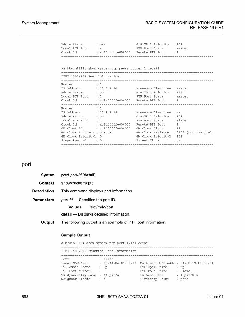
System Management
568
BASIC SYSTEM CONFIGURATION GUIDERELEASE 19.5.R1
3HE 15079 AAAA TQZZA 01 Issue: 01
Admin State : n/a G.8275.1 Priority : 128Local PTP Port : 4 PTP Port State : masterClock Id : ac65fffffe000000 Remote PTP Port : 1===============================================================================
*A:bksim1618# show system ptp peers router 1 detail===============================================================================IEEE 1588/PTP Peer Information===============================================================================Router : 1IP Address : 10.2.1.20 Announce Direction : rx+txAdmin State : up G.8275.1 Priority : 128Local PTP Port : 2 PTP Port State : masterClock Id : ac5efffffe000000 Remote PTP Port : 1-------------------------------------------------------------------------------Router : 1IP Address : 10.3.1.19 Announce Direction : rxAdmin State : up G.8275.1 Priority : 128Local PTP Port : 1 PTP Port State : slaveClock Id : ac5dfffffe000000 Remote PTP Port : 1GM Clock Id : ac5dfffffe000000 GM Clock Class : 13GM Clock Accuracy : unknown GM Clock Variance : ffff (not computed)GM Clock Priority1: 0 GM Clock Priority2 : 128Steps Removed : 0 Parent Clock : yes===============================================================================
port
Syntax port port-id [detail]
Context show>system>ptp
Description This command displays port information.
Parameters port-id — Specifies the port ID.
Values slot/mda/port
detail — Displays detailed information.
Output The following output is an example of PTP port information.
Sample Output
A:bksim1618# show system ptp port 1/1/1 detail===============================================================================IEEE 1588/PTP Ethernet Port Information===============================================================================Port : 1/1/2Local MAC Addr : 02:43:BA:01:00:03 Multicast MAC Addr : 01:1b:19:00:00:00PTP Admin State : up PTP Oper State : upPTP Port Number : 3 PTP Port State : SlaveTx Sync/Delay Rate : 64 pkt/s Tx Anno Rate : 1 pkt/2 sNeighbor Clocks : 4 Timestamp Point : port
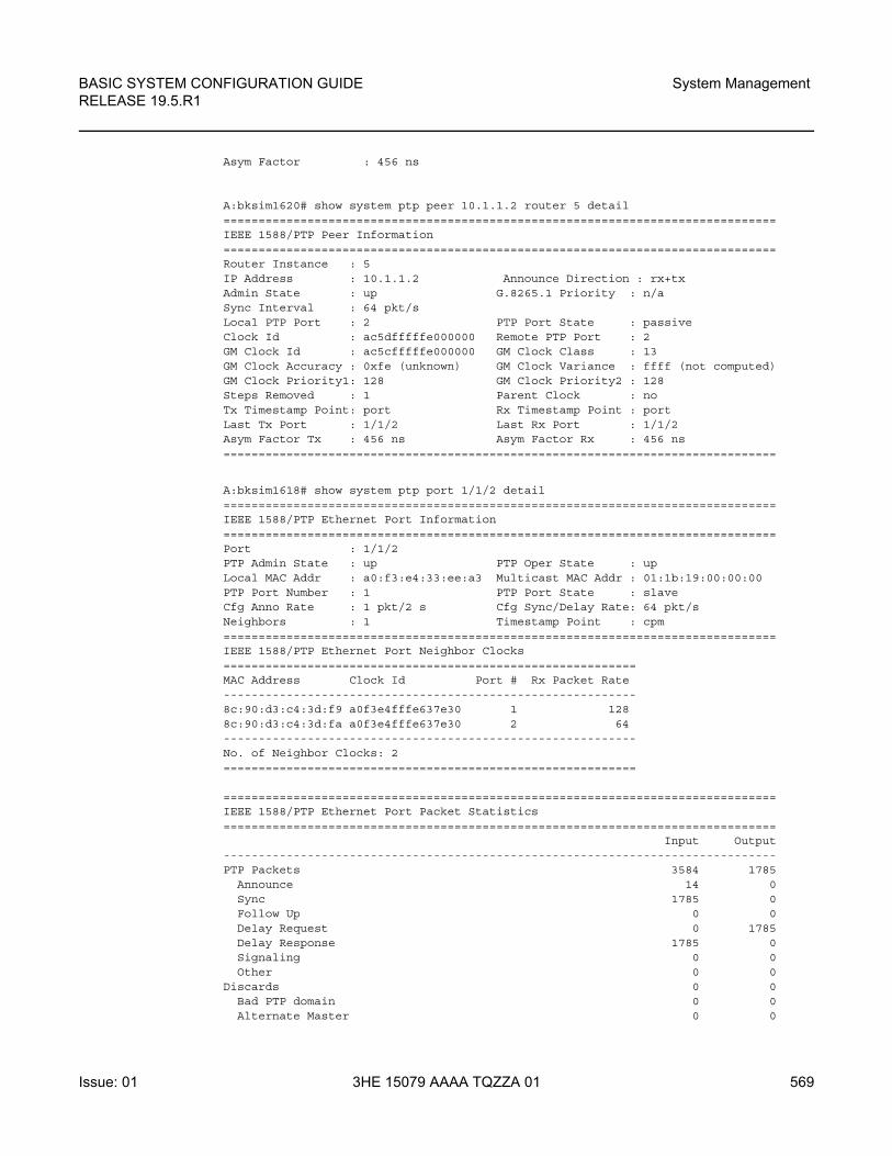
BASIC SYSTEM CONFIGURATION GUIDE RELEASE 19.5.R1
System Management
Issue: 01 3HE 15079 AAAA TQZZA 01 569
Asym Factor : 456 ns
A:bksim1620# show system ptp peer 10.1.1.2 router 5 detail===============================================================================IEEE 1588/PTP Peer Information===============================================================================Router Instance : 5IP Address : 10.1.1.2 Announce Direction : rx+txAdmin State : up G.8265.1 Priority : n/aSync Interval : 64 pkt/sLocal PTP Port : 2 PTP Port State : passiveClock Id : ac5dfffffe000000 Remote PTP Port : 2GM Clock Id : ac5cfffffe000000 GM Clock Class : 13GM Clock Accuracy : 0xfe (unknown) GM Clock Variance : ffff (not computed)GM Clock Priority1: 128 GM Clock Priority2 : 128Steps Removed : 1 Parent Clock : noTx Timestamp Point: port Rx Timestamp Point : portLast Tx Port : 1/1/2 Last Rx Port : 1/1/2Asym Factor Tx : 456 ns Asym Factor Rx : 456 ns===============================================================================
A:bksim1618# show system ptp port 1/1/2 detail===============================================================================IEEE 1588/PTP Ethernet Port Information===============================================================================Port : 1/1/2PTP Admin State : up PTP Oper State : upLocal MAC Addr : a0:f3:e4:33:ee:a3 Multicast MAC Addr : 01:1b:19:00:00:00PTP Port Number : 1 PTP Port State : slaveCfg Anno Rate : 1 pkt/2 s Cfg Sync/Delay Rate: 64 pkt/sNeighbors : 1 Timestamp Point : cpm===============================================================================IEEE 1588/PTP Ethernet Port Neighbor Clocks===========================================================MAC Address Clock Id Port # Rx Packet Rate-----------------------------------------------------------8c:90:d3:c4:3d:f9 a0f3e4fffe637e30 1 1288c:90:d3:c4:3d:fa a0f3e4fffe637e30 2 64-----------------------------------------------------------No. of Neighbor Clocks: 2===========================================================
===============================================================================IEEE 1588/PTP Ethernet Port Packet Statistics===============================================================================
Input Output-------------------------------------------------------------------------------PTP Packets 3584 1785
Announce 14 0Sync 1785 0Follow Up 0 0Delay Request 0 1785Delay Response 1785 0Signaling 0 0Other 0 0
Discards 0 0Bad PTP domain 0 0Alternate Master 0 0
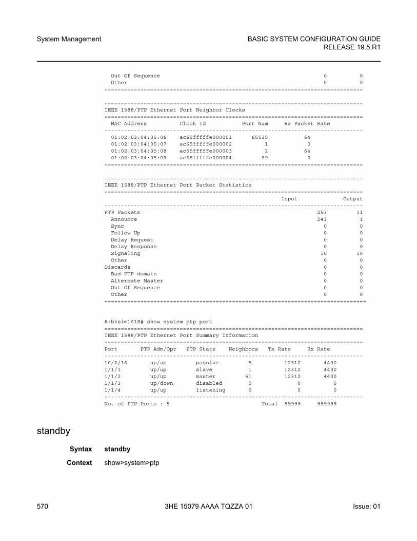
System Management
570
BASIC SYSTEM CONFIGURATION GUIDERELEASE 19.5.R1
3HE 15079 AAAA TQZZA 01 Issue: 01
Out Of Sequence 0 0Other 0 0
===============================================================================
===============================================================================IEEE 1588/PTP Ethernet Port Neighbor Clocks===============================================================================
MAC Address Clock Id Port Num Rx Packet Rate-------------------------------------------------------------------------------
01:02:03:04:05:06 ac65fffffe000001 65535 6401:02:03:04:05:07 ac65fffffe000002 1 001:02:03:04:05:08 ac65fffffe000003 2 6401:02:03:04:05:09 ac65fffffe000004 99 0
===============================================================================
===============================================================================IEEE 1588/PTP Ethernet Port Packet Statistics===============================================================================
Input Output-------------------------------------------------------------------------------PTP Packets 253 11
Announce 243 1Sync 0 0Follow Up 0 0Delay Request 0 0Delay Response 0 0Signaling 10 10Other 0 0
Discards 0 0Bad PTP domain 0 0Alternate Master 0 0Out Of Sequence 0 0Other 0 0
================================================================================
A:bksim1618# show system ptp port===============================================================================IEEE 1588/PTP Ethernet Port Summary Information===============================================================================Port PTP Adm/Opr PTP State Neighbors Tx Rate Rx Rate-------------------------------------------------------------------------------10/2/16 up/up passive 5 12312 44001/1/1 up/up slave 1 12312 44001/1/2 up/up master 61 12312 44001/1/3 up/down disabled 0 0 01/1/4 up/up listening 0 0 0-------------------------------------------------------------------------------No. of PTP Ports : 5 Total 99999 999999
standby
Syntax standby
Context show>system>ptp
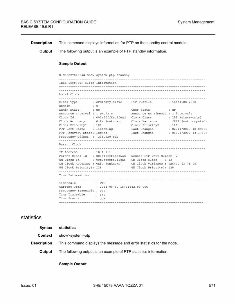
BASIC SYSTEM CONFIGURATION GUIDE RELEASE 19.5.R1
System Management
Issue: 01 3HE 15079 AAAA TQZZA 01 571
Description This command displays information for PTP on the standby control module.
Output The following output is an example of PTP standby information.
Sample Output
B:NS082761964# show system ptp standby===============================================================================IEEE 1588/PTP Clock Information===============================================================================-------------------------------------------------------------------------------Local Clock-------------------------------------------------------------------------------Clock Type : ordinary,slave PTP Profile : ieee1588-2008Domain : 0Admin State : up Oper State : upAnnounce Interval : 1 pkt/2 s Announce Rx Timeout : 3 intervalsClock Id : 001af0fffeb2fead Clock Class : 255 (slave-only)Clock Accuracy : 0xfe (unknown) Clock Variance : ffff (not computed)Clock Priority1 : 128 Clock Priority2 : 128PTP Port State : listening Last Changed : 02/11/2013 18:09:58PTP Recovery State: locked Last Changed : 08/24/2010 13:17:37Frequency Offset : +231.920 ppb-------------------------------------------------------------------------------Parent Clock-------------------------------------------------------------------------------IP Address : 10.1.1.1Parent Clock Id : 001af0fffeab36ad Remote PTP Port Number: 2GM Clock Id : 00b0aefffe011ca6 GM Clock Class : 13GM Clock Accuracy : 0xfe (unknown) GM Clock Variance : 0x6400 (3.7E-09)GM Clock Priority1: 128 GM Clock Priority2: 128-------------------------------------------------------------------------------Time Information-------------------------------------------------------------------------------Timescale : PTPCurrent Time : 2011-08-30 15:31:42.99 UTCFrequency Traceable : yesTime Traceable : yesTime Source : gps==============================================================================
statistics
Syntax statistics
Context show>system>ptp
Description This command displays the message and error statistics for the node.
Output The following output is an example of PTP statistics information.
Sample Output
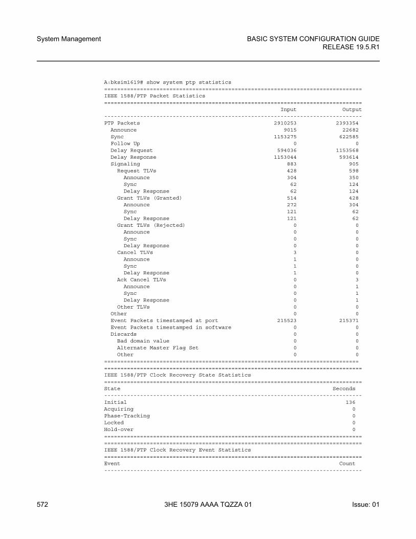
System Management
572
BASIC SYSTEM CONFIGURATION GUIDERELEASE 19.5.R1
3HE 15079 AAAA TQZZA 01 Issue: 01
A:bksim1619# show system ptp statistics===============================================================================IEEE 1588/PTP Packet Statistics===============================================================================
Input Output-------------------------------------------------------------------------------PTP Packets 2910253 2393354
Announce 9015 22682Sync 1153275 622585Follow Up 0 0Delay Request 594036 1153568Delay Response 1153044 593614Signaling 883 905
Request TLVs 428 598Announce 304 350Sync 62 124Delay Response 62 124
Grant TLVs (Granted) 514 428Announce 272 304Sync 121 62Delay Response 121 62
Grant TLVs (Rejected) 0 0Announce 0 0Sync 0 0Delay Response 0 0
Cancel TLVs 3 0Announce 1 0Sync 1 0Delay Response 1 0
Ack Cancel TLVs 0 3Announce 0 1Sync 0 1Delay Response 0 1
Other TLVs 0 0Other 0 0Event Packets timestamped at port 215523 215371Event Packets timestamped in software 0 0Discards 0 0
Bad domain value 0 0Alternate Master Flag Set 0 0Other 0 0
=============================================================================================================================================================IEEE 1588/PTP Clock Recovery State Statistics===============================================================================State Seconds-------------------------------------------------------------------------------Initial 136Acquiring 0Phase-Tracking 0Locked 0Hold-over 0==============================================================================================================================================================IEEE 1588/PTP Clock Recovery Event Statistics===============================================================================Event Count-------------------------------------------------------------------------------
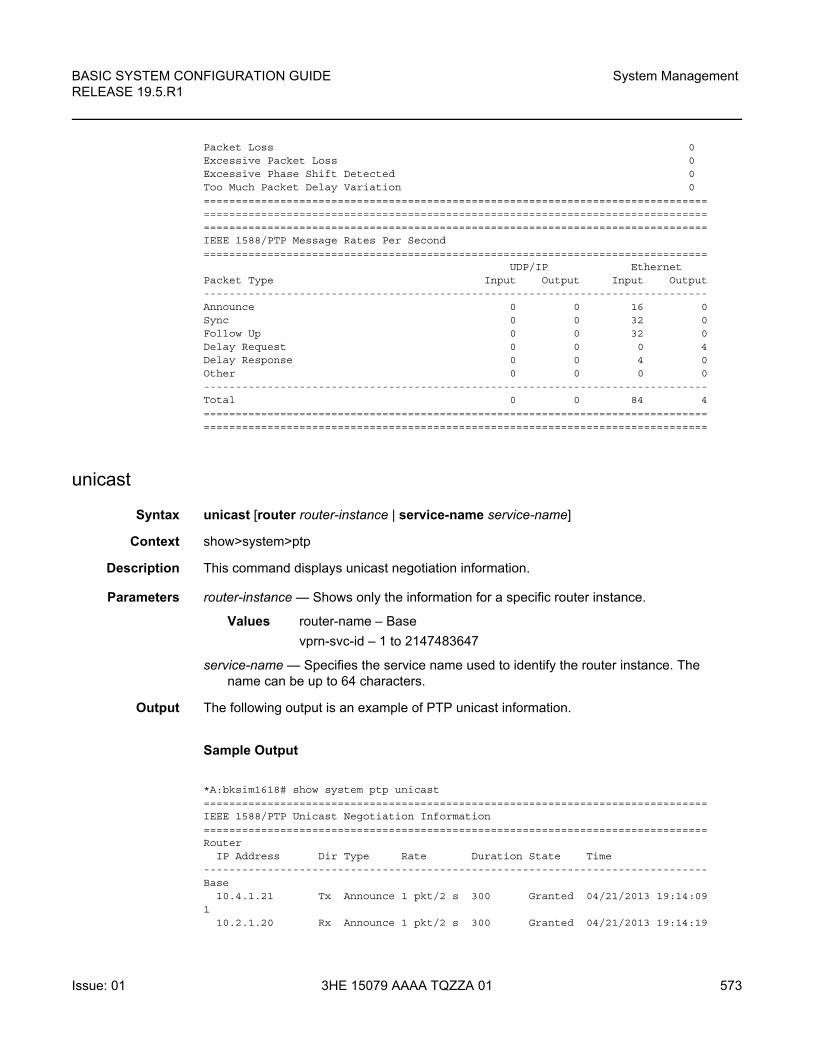
BASIC SYSTEM CONFIGURATION GUIDE RELEASE 19.5.R1
System Management
Issue: 01 3HE 15079 AAAA TQZZA 01 573
Packet Loss 0Excessive Packet Loss 0Excessive Phase Shift Detected 0Too Much Packet Delay Variation 0=============================================================================================================================================================================================================================================IEEE 1588/PTP Message Rates Per Second===============================================================================
UDP/IP EthernetPacket Type Input Output Input Output-------------------------------------------------------------------------------Announce 0 0 16 0Sync 0 0 32 0Follow Up 0 0 32 0Delay Request 0 0 0 4Delay Response 0 0 4 0Other 0 0 0 0-------------------------------------------------------------------------------Total 0 0 84 4==============================================================================================================================================================
unicast
Syntax unicast [router router-instance | service-name service-name]
Context show>system>ptp
Description This command displays unicast negotiation information.
Parameters router-instance — Shows only the information for a specific router instance.
Values router-name – Base
vprn-svc-id – 1 to 2147483647
service-name — Specifies the service name used to identify the router instance. The name can be up to 64 characters.
Output The following output is an example of PTP unicast information.
Sample Output
*A:bksim1618# show system ptp unicast===============================================================================IEEE 1588/PTP Unicast Negotiation Information===============================================================================Router
IP Address Dir Type Rate Duration State Time-------------------------------------------------------------------------------Base
10.4.1.21 Tx Announce 1 pkt/2 s 300 Granted 04/21/2013 19:14:091
10.2.1.20 Rx Announce 1 pkt/2 s 300 Granted 04/21/2013 19:14:19
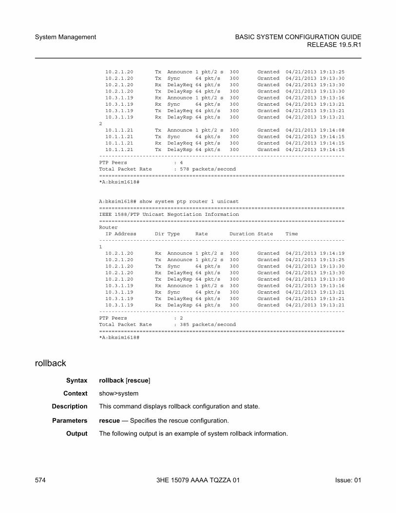
System Management
574
BASIC SYSTEM CONFIGURATION GUIDERELEASE 19.5.R1
3HE 15079 AAAA TQZZA 01 Issue: 01
10.2.1.20 Tx Announce 1 pkt/2 s 300 Granted 04/21/2013 19:13:2510.2.1.20 Tx Sync 64 pkt/s 300 Granted 04/21/2013 19:13:3010.2.1.20 Rx DelayReq 64 pkt/s 300 Granted 04/21/2013 19:13:3010.2.1.20 Tx DelayRsp 64 pkt/s 300 Granted 04/21/2013 19:13:3010.3.1.19 Rx Announce 1 pkt/2 s 300 Granted 04/21/2013 19:13:1610.3.1.19 Rx Sync 64 pkt/s 300 Granted 04/21/2013 19:13:2110.3.1.19 Tx DelayReq 64 pkt/s 300 Granted 04/21/2013 19:13:2110.3.1.19 Rx DelayRsp 64 pkt/s 300 Granted 04/21/2013 19:13:21
210.1.1.21 Tx Announce 1 pkt/2 s 300 Granted 04/21/2013 19:14:0810.1.1.21 Tx Sync 64 pkt/s 300 Granted 04/21/2013 19:14:1510.1.1.21 Rx DelayReq 64 pkt/s 300 Granted 04/21/2013 19:14:1510.1.1.21 Tx DelayRsp 64 pkt/s 300 Granted 04/21/2013 19:14:15
-------------------------------------------------------------------------------PTP Peers : 4Total Packet Rate : 578 packets/second===============================================================================*A:bksim1618#
A:bksim1618# show system ptp router 1 unicast===============================================================================IEEE 1588/PTP Unicast Negotiation Information===============================================================================Router
IP Address Dir Type Rate Duration State Time-------------------------------------------------------------------------------1
10.2.1.20 Rx Announce 1 pkt/2 s 300 Granted 04/21/2013 19:14:1910.2.1.20 Tx Announce 1 pkt/2 s 300 Granted 04/21/2013 19:13:2510.2.1.20 Tx Sync 64 pkt/s 300 Granted 04/21/2013 19:13:3010.2.1.20 Rx DelayReq 64 pkt/s 300 Granted 04/21/2013 19:13:3010.2.1.20 Tx DelayRsp 64 pkt/s 300 Granted 04/21/2013 19:13:3010.3.1.19 Rx Announce 1 pkt/2 s 300 Granted 04/21/2013 19:13:1610.3.1.19 Rx Sync 64 pkt/s 300 Granted 04/21/2013 19:13:2110.3.1.19 Tx DelayReq 64 pkt/s 300 Granted 04/21/2013 19:13:2110.3.1.19 Rx DelayRsp 64 pkt/s 300 Granted 04/21/2013 19:13:21
-------------------------------------------------------------------------------PTP Peers : 2Total Packet Rate : 385 packets/second===============================================================================*A:bksim1618#
rollback
Syntax rollback [rescue]
Context show>system
Description This command displays rollback configuration and state.
Parameters rescue — Specifies the rescue configuration.
Output The following output is an example of system rollback information.
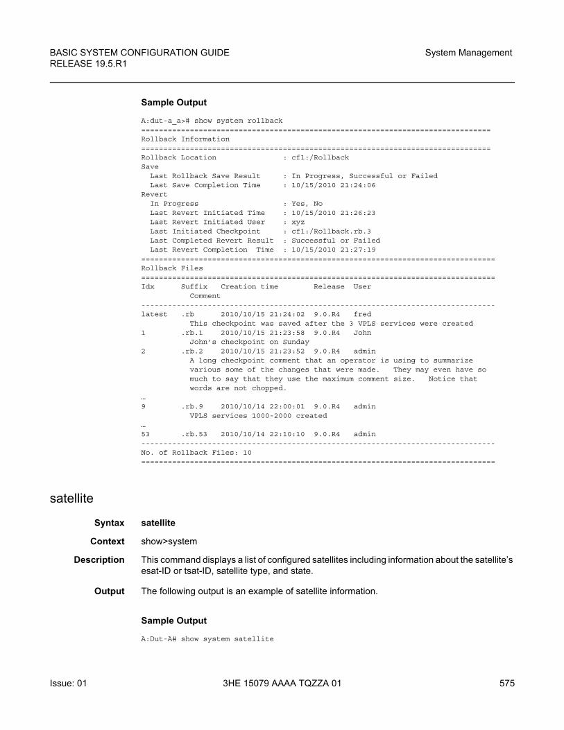
BASIC SYSTEM CONFIGURATION GUIDE RELEASE 19.5.R1
System Management
Issue: 01 3HE 15079 AAAA TQZZA 01 575
Sample Output
A:dut-a_a># show system rollback===============================================================================Rollback Information===============================================================================Rollback Location : cf1:/RollbackSave
Last Rollback Save Result : In Progress, Successful or FailedLast Save Completion Time : 10/15/2010 21:24:06
RevertIn Progress : Yes, NoLast Revert Initiated Time : 10/15/2010 21:26:23Last Revert Initiated User : xyzLast Initiated Checkpoint : cf1:/Rollback.rb.3Last Completed Revert Result : Successful or FailedLast Revert Completion Time : 10/15/2010 21:27:19
================================================================================Rollback Files================================================================================Idx Suffix Creation time Release User
Comment--------------------------------------------------------------------------------latest .rb 2010/10/15 21:24:02 9.0.R4 fred
This checkpoint was saved after the 3 VPLS services were created1 .rb.1 2010/10/15 21:23:58 9.0.R4 John
John’s checkpoint on Sunday2 .rb.2 2010/10/15 21:23:52 9.0.R4 admin
A long checkpoint comment that an operator is using to summarizevarious some of the changes that were made. They may even have somuch to say that they use the maximum comment size. Notice thatwords are not chopped.
…9 .rb.9 2010/10/14 22:00:01 9.0.R4 admin
VPLS services 1000-2000 created…53 .rb.53 2010/10/14 22:10:10 9.0.R4 admin--------------------------------------------------------------------------------No. of Rollback Files: 10================================================================================
satellite
Syntax satellite
Context show>system
Description This command displays a list of configured satellites including information about the satellite’s esat-ID or tsat-ID, satellite type, and state.
Output The following output is an example of satellite information.
Sample Output
A:Dut-A# show system satellite
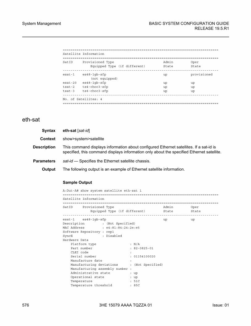
System Management
576
BASIC SYSTEM CONFIGURATION GUIDERELEASE 19.5.R1
3HE 15079 AAAA TQZZA 01 Issue: 01
===============================================================================Satellite Information===============================================================================SatID Provisioned Type Admin Oper
Equipped Type (if different) State State-------------------------------------------------------------------------------esat-1 es48-1gb-sfp up provisioned
(not equipped)esat-20 es48-1gb-sfp up uptsat-2 ts4-choc3-sfp up uptsat-3 ts4-choc3-sfp up up-------------------------------------------------------------------------------No. of Satellites: 4===============================================================================
eth-sat
Syntax eth-sat [sat-id]
Context show>system>satellite
Description This command displays information about configured Ethernet satellites. If a sat-id is specified, this command displays information only about the specified Ethernet satellite.
Parameters sat-id — Specifies the Ethernet satellite chassis.
Output The following output is an example of Ethernet satellite information.
Sample Output
A:Dut-A# show system satellite eth-sat 1===============================================================================Satellite Information===============================================================================SatID Provisioned Type Admin Oper
Equipped Type (if different) State State-------------------------------------------------------------------------------esat-1 es48-1gb-sfp up upDescription : (Not Specified)MAC Address : e4:81:84:24:2e:e5Software Repository : rep1SyncE : DisabledHardware Data
Platform type : N/APart number : 82-0825-01CLEI code :Serial number : 01154100020Manufacture date :Manufacturing deviations : (Not Specified)Manufacturing assembly number :Administrative state : upOperational state : upTemperature : 51CTemperature threshold : 85C
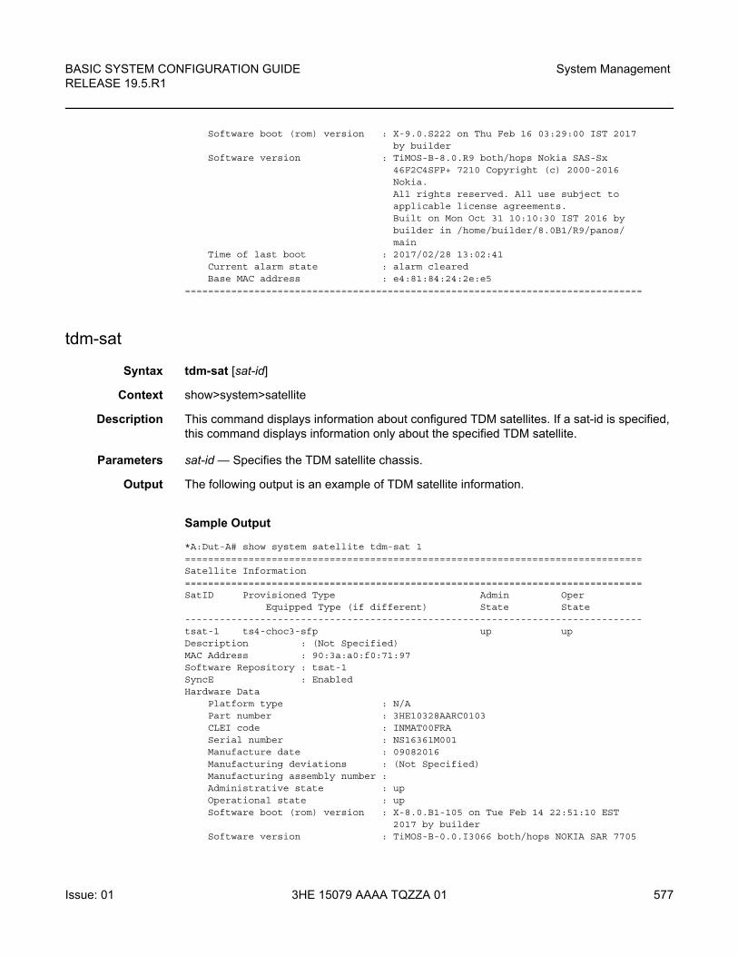
BASIC SYSTEM CONFIGURATION GUIDE RELEASE 19.5.R1
System Management
Issue: 01 3HE 15079 AAAA TQZZA 01 577
Software boot (rom) version : X-9.0.S222 on Thu Feb 16 03:29:00 IST 2017by builder
Software version : TiMOS-B-8.0.R9 both/hops Nokia SAS-Sx46F2C4SFP+ 7210 Copyright (c) 2000-2016Nokia.All rights reserved. All use subject toapplicable license agreements.Built on Mon Oct 31 10:10:30 IST 2016 bybuilder in /home/builder/8.0B1/R9/panos/main
Time of last boot : 2017/02/28 13:02:41Current alarm state : alarm clearedBase MAC address : e4:81:84:24:2e:e5
===============================================================================
tdm-sat
Syntax tdm-sat [sat-id]
Context show>system>satellite
Description This command displays information about configured TDM satellites. If a sat-id is specified, this command displays information only about the specified TDM satellite.
Parameters sat-id — Specifies the TDM satellite chassis.
Output The following output is an example of TDM satellite information.
Sample Output
*A:Dut-A# show system satellite tdm-sat 1===============================================================================Satellite Information===============================================================================SatID Provisioned Type Admin Oper
Equipped Type (if different) State State-------------------------------------------------------------------------------tsat-1 ts4-choc3-sfp up upDescription : (Not Specified)MAC Address : 90:3a:a0:f0:71:97Software Repository : tsat-1SyncE : EnabledHardware Data
Platform type : N/APart number : 3HE10328AARC0103CLEI code : INMAT00FRASerial number : NS16361M001Manufacture date : 09082016Manufacturing deviations : (Not Specified)Manufacturing assembly number :Administrative state : upOperational state : upSoftware boot (rom) version : X-8.0.B1-105 on Tue Feb 14 22:51:10 EST
2017 by builderSoftware version : TiMOS-B-0.0.I3066 both/hops NOKIA SAR 7705
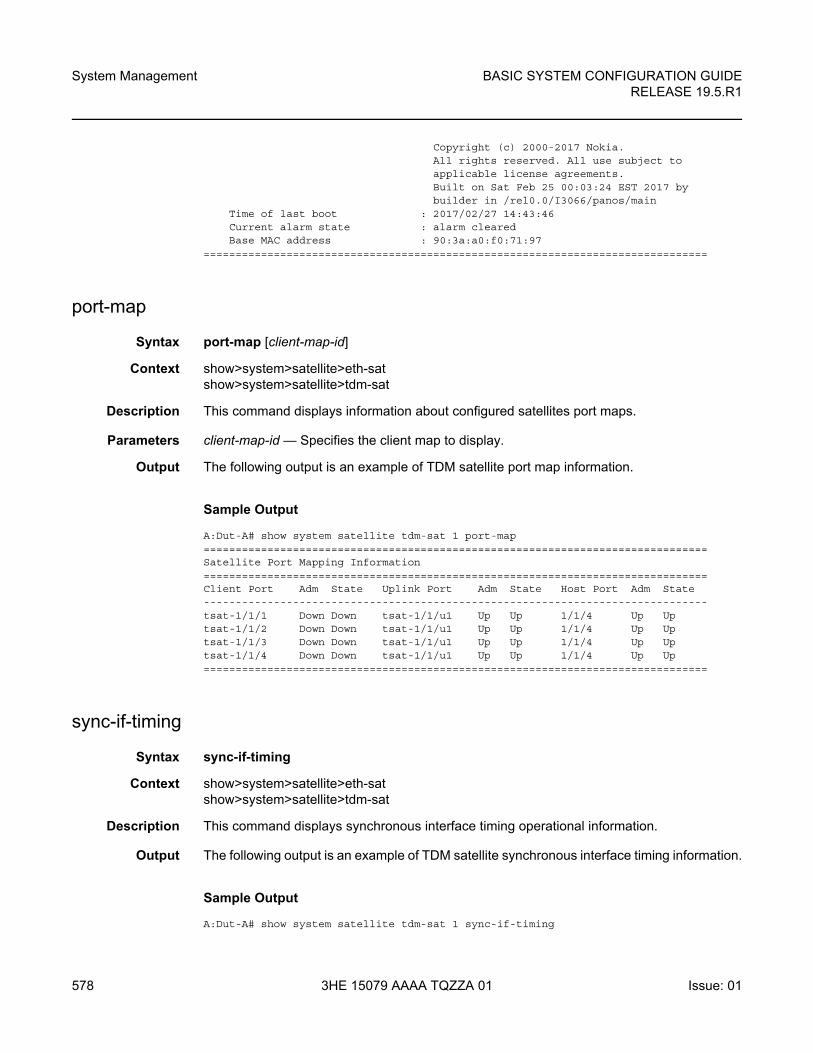
System Management
578
BASIC SYSTEM CONFIGURATION GUIDERELEASE 19.5.R1
3HE 15079 AAAA TQZZA 01 Issue: 01
Copyright (c) 2000-2017 Nokia.All rights reserved. All use subject toapplicable license agreements.Built on Sat Feb 25 00:03:24 EST 2017 bybuilder in /rel0.0/I3066/panos/main
Time of last boot : 2017/02/27 14:43:46Current alarm state : alarm clearedBase MAC address : 90:3a:a0:f0:71:97
===============================================================================
port-map
Syntax port-map [client-map-id]
Context show>system>satellite>eth-satshow>system>satellite>tdm-sat
Description This command displays information about configured satellites port maps.
Parameters client-map-id — Specifies the client map to display.
Output The following output is an example of TDM satellite port map information.
Sample Output
A:Dut-A# show system satellite tdm-sat 1 port-map===============================================================================Satellite Port Mapping Information===============================================================================Client Port Adm State Uplink Port Adm State Host Port Adm State-------------------------------------------------------------------------------tsat-1/1/1 Down Down tsat-1/1/u1 Up Up 1/1/4 Up Uptsat-1/1/2 Down Down tsat-1/1/u1 Up Up 1/1/4 Up Uptsat-1/1/3 Down Down tsat-1/1/u1 Up Up 1/1/4 Up Uptsat-1/1/4 Down Down tsat-1/1/u1 Up Up 1/1/4 Up Up===============================================================================
sync-if-timing
Syntax sync-if-timing
Context show>system>satellite>eth-satshow>system>satellite>tdm-sat
Description This command displays synchronous interface timing operational information.
Output The following output is an example of TDM satellite synchronous interface timing information.
Sample Output
A:Dut-A# show system satellite tdm-sat 1 sync-if-timing
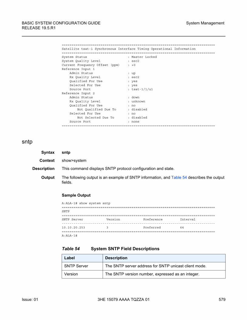
BASIC SYSTEM CONFIGURATION GUIDE RELEASE 19.5.R1
System Management
Issue: 01 3HE 15079 AAAA TQZZA 01 579
===============================================================================Satellite tsat-1 Synchronous Interface Timing Operational Information===============================================================================System Status : Master LockedSystem Quality Level : eec2Current Frequency Offset (ppm) : +0Reference Input 1
Admin Status : upRx Quality Level : eec2Qualified For Use : yesSelected For Use : yesSource Port : tsat-1/1/u1
Reference Input 2Admin Status : downRx Quality Level : unknownQualified For Use : no
Not Qualified Due To : disabledSelected For Use : no
Not Selected Due To : disabledSource Port : none
===============================================================================
sntp
Syntax sntp
Context show>system
Description This command displays SNTP protocol configuration and state.
Output The following output is an example of SNTP information, and Table 54 describes the output fields.
Sample Output
A:ALA-1# show system sntp===============================================================================SNTP===============================================================================SNTP Server Version Preference Interval-------------------------------------------------------------------------------10.10.20.253 3 Preferred 64===============================================================================A:ALA-1#
Table 54 System SNTP Field Descriptions
Label Description
SNTP Server The SNTP server address for SNTP unicast client mode.
Version The SNTP version number, expressed as an integer.
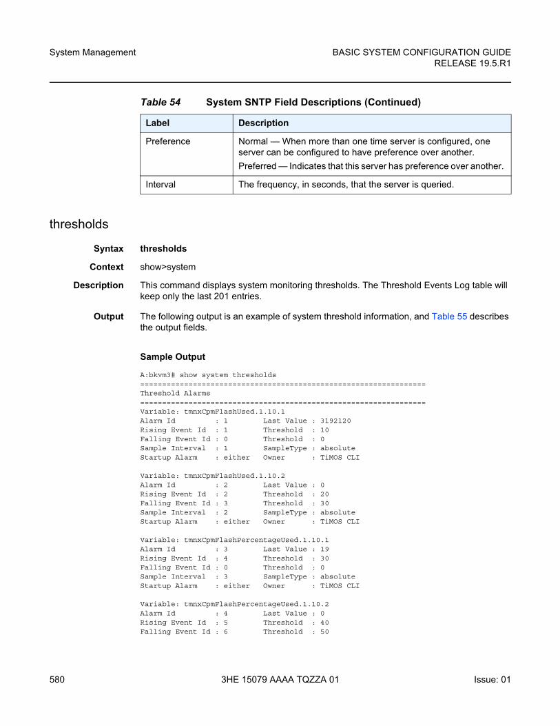
System Management
580
BASIC SYSTEM CONFIGURATION GUIDERELEASE 19.5.R1
3HE 15079 AAAA TQZZA 01 Issue: 01
thresholds
Syntax thresholds
Context show>system
Description This command displays system monitoring thresholds. The Threshold Events Log table will keep only the last 201 entries.
Output The following output is an example of system threshold information, and Table 55 describes the output fields.
Sample Output
A:bkvm3# show system thresholds=================================================================Threshold Alarms=================================================================Variable: tmnxCpmFlashUsed.1.10.1Alarm Id : 1 Last Value : 3192120Rising Event Id : 1 Threshold : 10Falling Event Id : 0 Threshold : 0Sample Interval : 1 SampleType : absoluteStartup Alarm : either Owner : TiMOS CLI
Variable: tmnxCpmFlashUsed.1.10.2Alarm Id : 2 Last Value : 0Rising Event Id : 2 Threshold : 20Falling Event Id : 3 Threshold : 30Sample Interval : 2 SampleType : absoluteStartup Alarm : either Owner : TiMOS CLI
Variable: tmnxCpmFlashPercentageUsed.1.10.1Alarm Id : 3 Last Value : 19Rising Event Id : 4 Threshold : 30Falling Event Id : 0 Threshold : 0Sample Interval : 3 SampleType : absoluteStartup Alarm : either Owner : TiMOS CLI
Variable: tmnxCpmFlashPercentageUsed.1.10.2Alarm Id : 4 Last Value : 0Rising Event Id : 5 Threshold : 40Falling Event Id : 6 Threshold : 50
Preference Normal — When more than one time server is configured, one server can be configured to have preference over another.
Preferred — Indicates that this server has preference over another.
Interval The frequency, in seconds, that the server is queried.
Table 54 System SNTP Field Descriptions (Continued)
Label Description
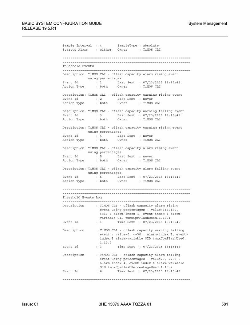
BASIC SYSTEM CONFIGURATION GUIDE RELEASE 19.5.R1
System Management
Issue: 01 3HE 15079 AAAA TQZZA 01 581
Sample Interval : 4 SampleType : absoluteStartup Alarm : either Owner : TiMOS CLI
==================================================================================================================================Threshold Events=================================================================Description: TiMOS CLI - cflash capacity alarm rising event
using percentagesEvent Id : 1 Last Sent : 07/23/2015 18:15:46Action Type : both Owner : TiMOS CLI
Description: TiMOS CLI - cflash capacity warning rising eventEvent Id : 2 Last Sent : neverAction Type : both Owner : TiMOS CLI
Description: TiMOS CLI - cflash capacity warning falling eventEvent Id : 3 Last Sent : 07/23/2015 18:15:46Action Type : both Owner : TiMOS CLI
Description: TiMOS CLI - cflash capacity warning rising eventusing percentages
Event Id : 4 Last Sent : neverAction Type : both Owner : TiMOS CLI
Description: TiMOS CLI - cflash capacity alarm rising eventusing percentages
Event Id : 5 Last Sent : neverAction Type : both Owner : TiMOS CLI
Description: TiMOS CLI - cflash capacity alarm falling eventusing percentages
Event Id : 6 Last Sent : 07/23/2015 18:15:46Action Type : both Owner : TiMOS CLI
==================================================================================================================================Threshold Events Log=================================================================Description : TiMOS CLI - cflash capacity alarm rising
event using percentages : value=3192120,>=10 : alarm-index 1, event-index 1 alarm-variable OID tmnxCpmFlashUsed.1.10.1
Event Id : 1 Time Sent : 07/23/2015 18:15:46
Description : TiMOS CLI - cflash capacity warning fallingevent : value=0, <=30 : alarm-index 2, event-index 3 alarm-variable OID tmnxCpmFlashUsed.1.10.2
Event Id : 3 Time Sent : 07/23/2015 18:15:46
Description : TiMOS CLI - cflash capacity alarm fallingevent using percentages : value=0, <=50 :alarm-index 4, event-index 6 alarm-variableOID tmnxCpmFlashPercentageUsed.1.10.2
Event Id : 6 Time Sent : 07/23/2015 18:15:46
=================================================================
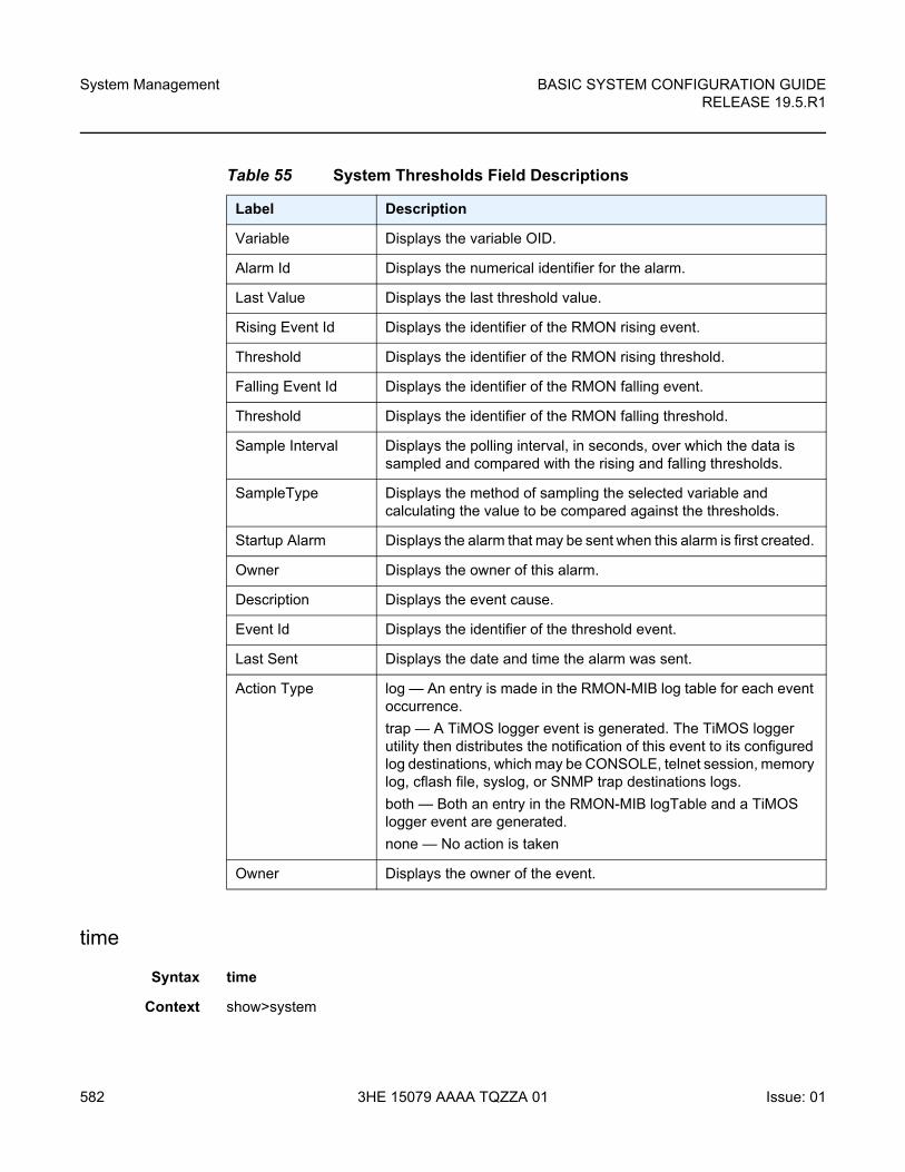
System Management
582
BASIC SYSTEM CONFIGURATION GUIDERELEASE 19.5.R1
3HE 15079 AAAA TQZZA 01 Issue: 01
time
Syntax time
Context show>system
Table 55 System Thresholds Field Descriptions
Label Description
Variable Displays the variable OID.
Alarm Id Displays the numerical identifier for the alarm.
Last Value Displays the last threshold value.
Rising Event Id Displays the identifier of the RMON rising event.
Threshold Displays the identifier of the RMON rising threshold.
Falling Event Id Displays the identifier of the RMON falling event.
Threshold Displays the identifier of the RMON falling threshold.
Sample Interval Displays the polling interval, in seconds, over which the data is sampled and compared with the rising and falling thresholds.
SampleType Displays the method of sampling the selected variable and calculating the value to be compared against the thresholds.
Startup Alarm Displays the alarm that may be sent when this alarm is first created.
Owner Displays the owner of this alarm.
Description Displays the event cause.
Event Id Displays the identifier of the threshold event.
Last Sent Displays the date and time the alarm was sent.
Action Type log — An entry is made in the RMON-MIB log table for each event occurrence.
trap — A TiMOS logger event is generated. The TiMOS logger utility then distributes the notification of this event to its configured log destinations, which may be CONSOLE, telnet session, memory log, cflash file, syslog, or SNMP trap destinations logs.
both — Both an entry in the RMON-MIB logTable and a TiMOS logger event are generated.
none — No action is taken
Owner Displays the owner of the event.
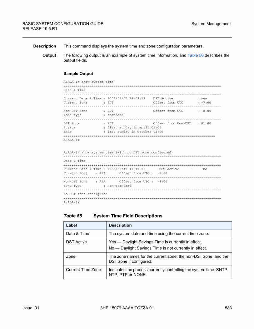
BASIC SYSTEM CONFIGURATION GUIDE RELEASE 19.5.R1
System Management
Issue: 01 3HE 15079 AAAA TQZZA 01 583
Description This command displays the system time and zone configuration parameters.
Output The following output is an example of system time information, and Table 56 describes the output fields.
Sample Output
A:ALA-1# show system time===============================================================================Date & Time===============================================================================Current Date & Time : 2006/05/05 23:03:13 DST Active : yesCurrent Zone : PDT Offset from UTC : -7:00-------------------------------------------------------------------------------Non-DST Zone : PST Offset from UTC : -8:00Zone type : standard-------------------------------------------------------------------------------DST Zone : PDT Offset from Non-DST : 01:00Starts : first sunday in april 02:00Ends : last sunday in october 02:00============================================================================A:ALA-1#
A:ALA-1# show system time (with no DST zone configured)===============================================================================Date & Time===============================================================================Current Date & Time : 2006/05/12 11:12:05 DST Active : noCurrent Zone : APA Offset from UTC : -8:00-------------------------------------------------------------------------------Non-DST Zone : APA Offset from UTC : -8:00Zone Type : non-standard-------------------------------------------------------------------------------No DST zone configured===============================================================================A:ALA-1#
Table 56 System Time Field Descriptions
Label Description
Date & Time The system date and time using the current time zone.
DST Active Yes — Daylight Savings Time is currently in effect.
No — Daylight Savings Time is not currently in effect.
Zone The zone names for the current zone, the non-DST zone, and the DST zone if configured.
Current Time Zone Indicates the process currently controlling the system time. SNTP, NTP, PTP or NONE.
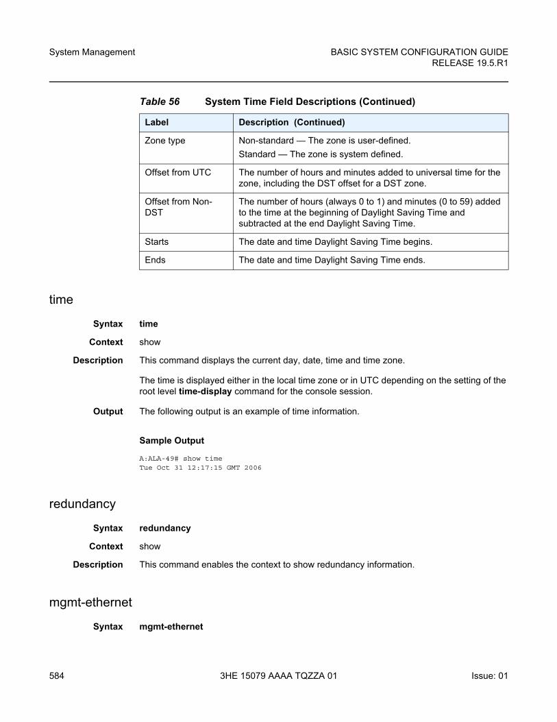
System Management
584
BASIC SYSTEM CONFIGURATION GUIDERELEASE 19.5.R1
3HE 15079 AAAA TQZZA 01 Issue: 01
time
Syntax time
Context show
Description This command displays the current day, date, time and time zone.
The time is displayed either in the local time zone or in UTC depending on the setting of the root level time-display command for the console session.
Output The following output is an example of time information.
Sample Output
A:ALA-49# show timeTue Oct 31 12:17:15 GMT 2006
redundancy
Syntax redundancy
Context show
Description This command enables the context to show redundancy information.
mgmt-ethernet
Syntax mgmt-ethernet
Zone type Non-standard — The zone is user-defined.
Standard — The zone is system defined.
Offset from UTC The number of hours and minutes added to universal time for the zone, including the DST offset for a DST zone.
Offset from Non-DST
The number of hours (always 0 to 1) and minutes (0 to 59) added to the time at the beginning of Daylight Saving Time and subtracted at the end Daylight Saving Time.
Starts The date and time Daylight Saving Time begins.
Ends The date and time Daylight Saving Time ends.
Table 56 System Time Field Descriptions (Continued)
Label Description (Continued)
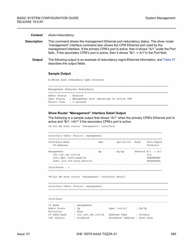
BASIC SYSTEM CONFIGURATION GUIDE RELEASE 19.5.R1
System Management
Issue: 01 3HE 15079 AAAA TQZZA 01 585
Context show>redundancy
Description This command shows the management Ethernet port redundancy status. The show router “management” interface command also shows the CPM Ethernet port used by the management interface. If the primary CPM’s port is active, then it shows “A/1” under the Port field,. If the secondary CPM’s port is active, then it shows “B/1 -> A/1”in the Port field.
Output The following output is an example of redundancy mgmt-Ethernet information, and Table 57 describes the output fields.
Sample Output
A:SR12# show redundancy mgmt-ethernet
===============================================================================Management Ethernet Redundancy===============================================================================Admin Status : EnabledOper Status : Management port operating on active CPMRevert Time : 5 seconds===============================================================================
Show Router “Management” Interface Detail Output
The following is a sample output that shows “A/1” when the primary CPM’s Ethernet port is active and “B/1 ->A/1” if the secondary CPM’s port is active.*B:Dut-A# show router "management" interface
===========================================================================Interface Table (Router: management)===========================================================================Interface-Name Adm Opr(v4/v6) Mode Port/SapId
IP-Address PfxState---------------------------------------------------------------------------management Up Up/Up Network B/1 -> A/1
192.168.186.219/24 n/a2001:db8::8a78:badb/96 PREFERREDfe80::221:5ff:fece:df49/64 PREFERRED
---------------------------------------------------------------------------Interfaces : 1===========================================================================
*B:Dut-A# show router "management" interface detail
===============================================================================Interface Table (Router: management)===============================================================================
-------------------------------------------------------------------------------Interface-------------------------------------------------------------------------------If Name : managementAdmin State : Up Oper (v4/v6) : Up/UpProtocols : NoneIP Addr/mask : 192.168.186.219/24 Address Type : PrimaryIGP Inhibit : Disabled Broadcast Address : Host-ones
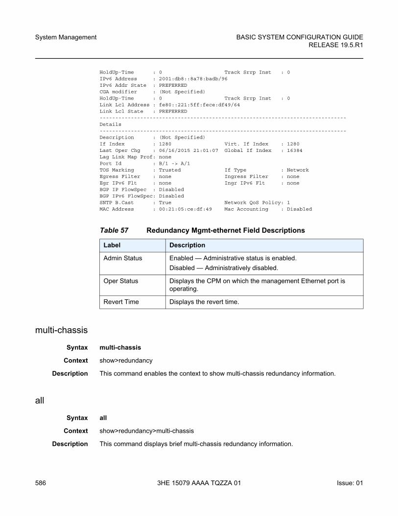
System Management
586
BASIC SYSTEM CONFIGURATION GUIDERELEASE 19.5.R1
3HE 15079 AAAA TQZZA 01 Issue: 01
HoldUp-Time : 0 Track Srrp Inst : 0IPv6 Address : 2001:db8::8a78:badb/96IPv6 Addr State : PREFERREDCGA modifier : (Not Specified)HoldUp-Time : 0 Track Srrp Inst : 0Link Lcl Address : fe80::221:5ff:fece:df49/64Link Lcl State : PREFERRED-------------------------------------------------------------------------------Details-------------------------------------------------------------------------------Description : (Not Specified)If Index : 1280 Virt. If Index : 1280Last Oper Chg : 06/16/2015 21:01:07 Global If Index : 16384Lag Link Map Prof: nonePort Id : B/1 -> A/1TOS Marking : Trusted If Type : NetworkEgress Filter : none Ingress Filter : noneEgr IPv6 Flt : none Ingr IPv6 Flt : noneBGP IP FlowSpec : DisabledBGP IPv6 FlowSpec: DisabledSNTP B.Cast : True Network QoS Policy: 1MAC Address : 00:21:05:ce:df:49 Mac Accounting : Disabled
multi-chassis
Syntax multi-chassis
Context show>redundancy
Description This command enables the context to show multi-chassis redundancy information.
all
Syntax all
Context show>redundancy>multi-chassis
Description This command displays brief multi-chassis redundancy information.
Table 57 Redundancy Mgmt-ethernet Field Descriptions
Label Description
Admin Status Enabled — Administrative status is enabled.
Disabled — Administratively disabled.
Oper Status Displays the CPM on which the management Ethernet port is operating.
Revert Time Displays the revert time.
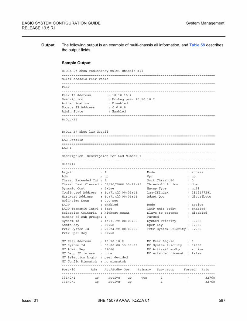
BASIC SYSTEM CONFIGURATION GUIDE RELEASE 19.5.R1
System Management
Issue: 01 3HE 15079 AAAA TQZZA 01 587
Output The following output is an example of multi-chassis all information, and Table 58 describes the output fields.
Sample Output
B:Dut-B# show redundancy multi-chassis all===============================================================================Multi-chassis Peer Table===============================================================================Peer-------------------------------------------------------------------------------Peer IP Address : 10.10.10.2Description : Mc-Lag peer 10.10.10.2Authentication : DisabledSource IP Address : 0.0.0.0Admin State : Enabled===============================================================================B:Dut-B#
B:Dut-B# show lag detail===============================================================================LAG Details===============================================================================LAG 1-------------------------------------------------------------------------------Description: Description For LAG Number 1-------------------------------------------------------------------------------Details-------------------------------------------------------------------------------Lag-id : 1 Mode : accessAdm : up Opr : upThres. Exceeded Cnt : 9 Port Threshold : 0Thres. Last Cleared : 05/20/2006 00:12:35 Threshold Action : downDynamic Cost : false Encap Type : nullConfigured Address : 1c:71:ff:00:01:41 Lag-IfIndex : 1342177281Hardware Address : 1c:71:ff:00:01:41 Adapt Qos : distributeHold-time Down : 0.0 secLACP : enabled Mode : activeLACP Transmit Intvl : fast LACP xmit stdby : enabledSelection Criteria : highest-count Slave-to-partner : disabledNumber of sub-groups: 1 Forced : -System Id : 1c:71:ff:00:00:00 System Priority : 32768Admin Key : 32768 Oper Key : 32666Prtr System Id : 20:f4:ff:00:00:00 Prtr System Priority : 32768Prtr Oper Key : 32768
MC Peer Address : 10.10.10.2 MC Peer Lag-id : 1MC System Id : 00:00:00:33:33:33 MC System Priority : 32888MC Admin Key : 32666 MC Active/Standby : activeMC Lacp ID in use : true MC extended timeout : falseMC Selection Logic : peer decidedMC Config Mismatch : no mismatch-------------------------------------------------------------------------------Port-id Adm Act/Stdby Opr Primary Sub-group Forced Prio-------------------------------------------------------------------------------331/2/1 up active up yes 1 - 32768331/2/2 up active up 1 - 32768
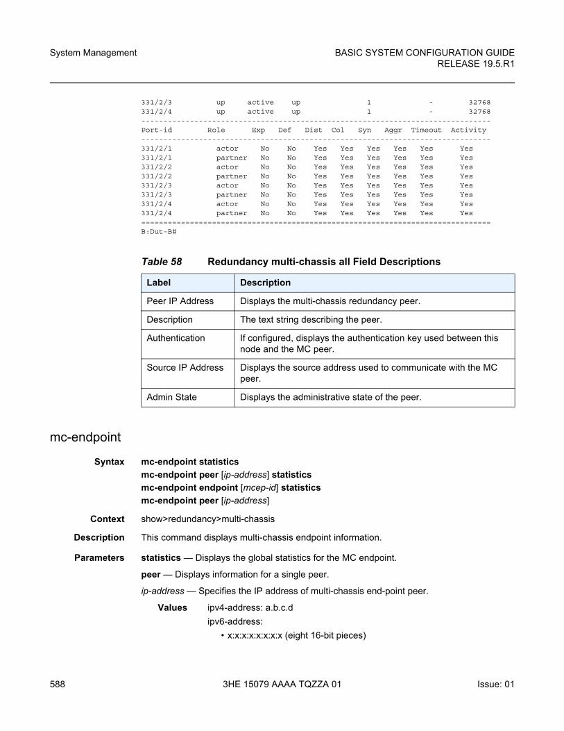
System Management
588
BASIC SYSTEM CONFIGURATION GUIDERELEASE 19.5.R1
3HE 15079 AAAA TQZZA 01 Issue: 01
331/2/3 up active up 1 - 32768331/2/4 up active up 1 - 32768-------------------------------------------------------------------------------Port-id Role Exp Def Dist Col Syn Aggr Timeout Activity-------------------------------------------------------------------------------331/2/1 actor No No Yes Yes Yes Yes Yes Yes331/2/1 partner No No Yes Yes Yes Yes Yes Yes331/2/2 actor No No Yes Yes Yes Yes Yes Yes331/2/2 partner No No Yes Yes Yes Yes Yes Yes331/2/3 actor No No Yes Yes Yes Yes Yes Yes331/2/3 partner No No Yes Yes Yes Yes Yes Yes331/2/4 actor No No Yes Yes Yes Yes Yes Yes331/2/4 partner No No Yes Yes Yes Yes Yes Yes===============================================================================B:Dut-B#
mc-endpoint
Syntax mc-endpoint statistics
mc-endpoint peer [ip-address] statistics
mc-endpoint endpoint [mcep-id] statistics
mc-endpoint peer [ip-address]
Context show>redundancy>multi-chassis
Description This command displays multi-chassis endpoint information.
Parameters statistics — Displays the global statistics for the MC endpoint.
peer — Displays information for a single peer.
ip-address — Specifies the IP address of multi-chassis end-point peer.
Values ipv4-address: a.b.c.d
ipv6-address:
• x:x:x:x:x:x:x:x (eight 16-bit pieces)
Table 58 Redundancy multi-chassis all Field Descriptions
Label Description
Peer IP Address Displays the multi-chassis redundancy peer.
Description The text string describing the peer.
Authentication If configured, displays the authentication key used between this node and the MC peer.
Source IP Address Displays the source address used to communicate with the MC peer.
Admin State Displays the administrative state of the peer.
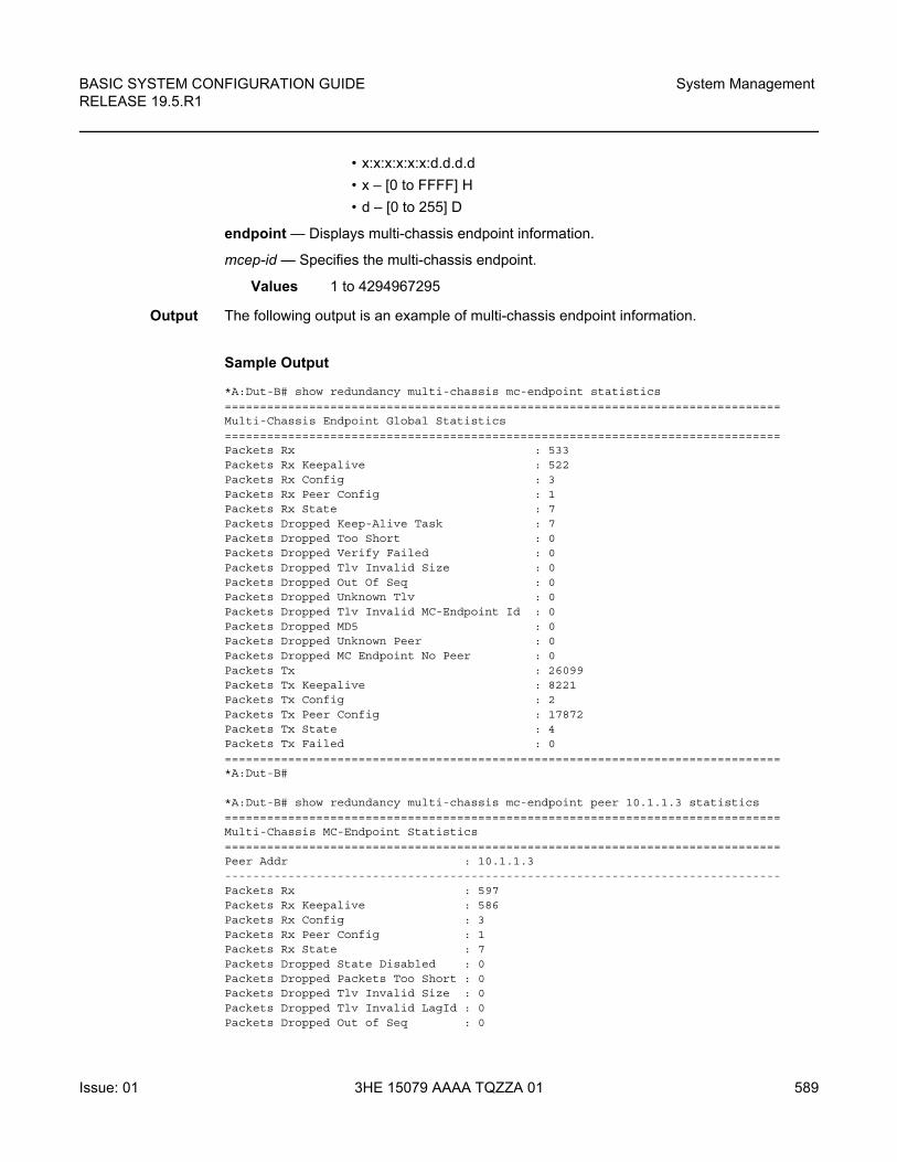
BASIC SYSTEM CONFIGURATION GUIDE RELEASE 19.5.R1
System Management
Issue: 01 3HE 15079 AAAA TQZZA 01 589
• x:x:x:x:x:x:d.d.d.d
• x – [0 to FFFF] H
• d – [0 to 255] D
endpoint — Displays multi-chassis endpoint information.
mcep-id — Specifies the multi-chassis endpoint.
Values 1 to 4294967295
Output The following output is an example of multi-chassis endpoint information.
Sample Output
*A:Dut-B# show redundancy multi-chassis mc-endpoint statistics===============================================================================Multi-Chassis Endpoint Global Statistics===============================================================================Packets Rx : 533Packets Rx Keepalive : 522Packets Rx Config : 3Packets Rx Peer Config : 1Packets Rx State : 7Packets Dropped Keep-Alive Task : 7Packets Dropped Too Short : 0Packets Dropped Verify Failed : 0Packets Dropped Tlv Invalid Size : 0Packets Dropped Out Of Seq : 0Packets Dropped Unknown Tlv : 0Packets Dropped Tlv Invalid MC-Endpoint Id : 0Packets Dropped MD5 : 0Packets Dropped Unknown Peer : 0Packets Dropped MC Endpoint No Peer : 0Packets Tx : 26099Packets Tx Keepalive : 8221Packets Tx Config : 2Packets Tx Peer Config : 17872Packets Tx State : 4Packets Tx Failed : 0===============================================================================*A:Dut-B#
*A:Dut-B# show redundancy multi-chassis mc-endpoint peer 10.1.1.3 statistics===============================================================================Multi-Chassis MC-Endpoint Statistics===============================================================================Peer Addr : 10.1.1.3-------------------------------------------------------------------------------Packets Rx : 597Packets Rx Keepalive : 586Packets Rx Config : 3Packets Rx Peer Config : 1Packets Rx State : 7Packets Dropped State Disabled : 0Packets Dropped Packets Too Short : 0Packets Dropped Tlv Invalid Size : 0Packets Dropped Tlv Invalid LagId : 0Packets Dropped Out of Seq : 0
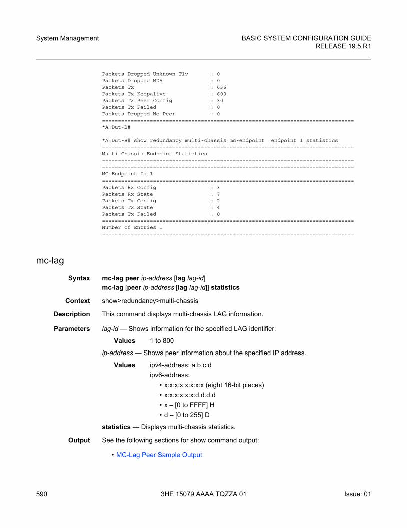
System Management
590
BASIC SYSTEM CONFIGURATION GUIDERELEASE 19.5.R1
3HE 15079 AAAA TQZZA 01 Issue: 01
Packets Dropped Unknown Tlv : 0Packets Dropped MD5 : 0Packets Tx : 636Packets Tx Keepalive : 600Packets Tx Peer Config : 30Packets Tx Failed : 0Packets Dropped No Peer : 0===============================================================================*A:Dut-B#
*A:Dut-B# show redundancy multi-chassis mc-endpoint endpoint 1 statistics===============================================================================Multi-Chassis Endpoint Statistics==============================================================================================================================================================MC-Endpoint Id 1===============================================================================Packets Rx Config : 3Packets Rx State : 7Packets Tx Config : 2Packets Tx State : 4Packets Tx Failed : 0===============================================================================Number of Entries 1===============================================================================
mc-lag
Syntax mc-lag peer ip-address [lag lag-id]
mc-lag [peer ip-address [lag lag-id]] statistics
Context show>redundancy>multi-chassis
Description This command displays multi-chassis LAG information.
Parameters lag-id — Shows information for the specified LAG identifier.
Values 1 to 800
ip-address — Shows peer information about the specified IP address.
Values ipv4-address: a.b.c.d
ipv6-address:
• x:x:x:x:x:x:x:x (eight 16-bit pieces)
• x:x:x:x:x:x:d.d.d.d
• x – [0 to FFFF] H
• d – [0 to 255] D
statistics — Displays multi-chassis statistics.
Output See the following sections for show command output:
• MC-Lag Peer Sample Output
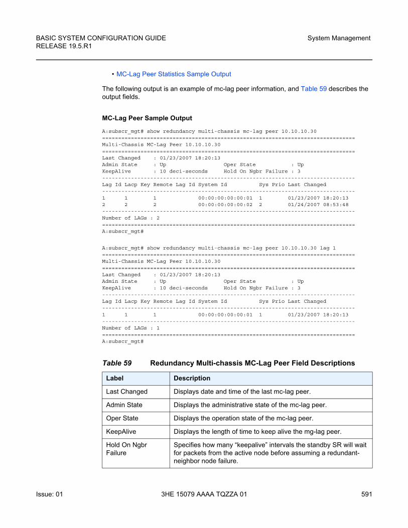
BASIC SYSTEM CONFIGURATION GUIDE RELEASE 19.5.R1
System Management
Issue: 01 3HE 15079 AAAA TQZZA 01 591
• MC-Lag Peer Statistics Sample Output
The following output is an example of mc-lag peer information, and Table 59 describes the output fields.
MC-Lag Peer Sample Output
A:subscr_mgt# show redundancy multi-chassis mc-lag peer 10.10.10.30===============================================================================Multi-Chassis MC-Lag Peer 10.10.10.30===============================================================================Last Changed : 01/23/2007 18:20:13Admin State : Up Oper State : UpKeepAlive : 10 deci-seconds Hold On Ngbr Failure : 3-------------------------------------------------------------------------------Lag Id Lacp Key Remote Lag Id System Id Sys Prio Last Changed-------------------------------------------------------------------------------1 1 1 00:00:00:00:00:01 1 01/23/2007 18:20:132 2 2 00:00:00:00:00:02 2 01/24/2007 08:53:48-------------------------------------------------------------------------------Number of LAGs : 2===============================================================================A:subscr_mgt#
A:subscr_mgt# show redundancy multi-chassis mc-lag peer 10.10.10.30 lag 1===============================================================================Multi-Chassis MC-Lag Peer 10.10.10.30===============================================================================Last Changed : 01/23/2007 18:20:13Admin State : Up Oper State : UpKeepAlive : 10 deci-seconds Hold On Ngbr Failure : 3-------------------------------------------------------------------------------Lag Id Lacp Key Remote Lag Id System Id Sys Prio Last Changed-------------------------------------------------------------------------------1 1 1 00:00:00:00:00:01 1 01/23/2007 18:20:13-------------------------------------------------------------------------------Number of LAGs : 1===============================================================================A:subscr_mgt#
Table 59 Redundancy Multi-chassis MC-Lag Peer Field Descriptions
Label Description
Last Changed Displays date and time of the last mc-lag peer.
Admin State Displays the administrative state of the mc-lag peer.
Oper State Displays the operation state of the mc-lag peer.
KeepAlive Displays the length of time to keep alive the mg-lag peer.
Hold On Ngbr Failure
Specifies how many “keepalive” intervals the standby SR will wait for packets from the active node before assuming a redundant-neighbor node failure.
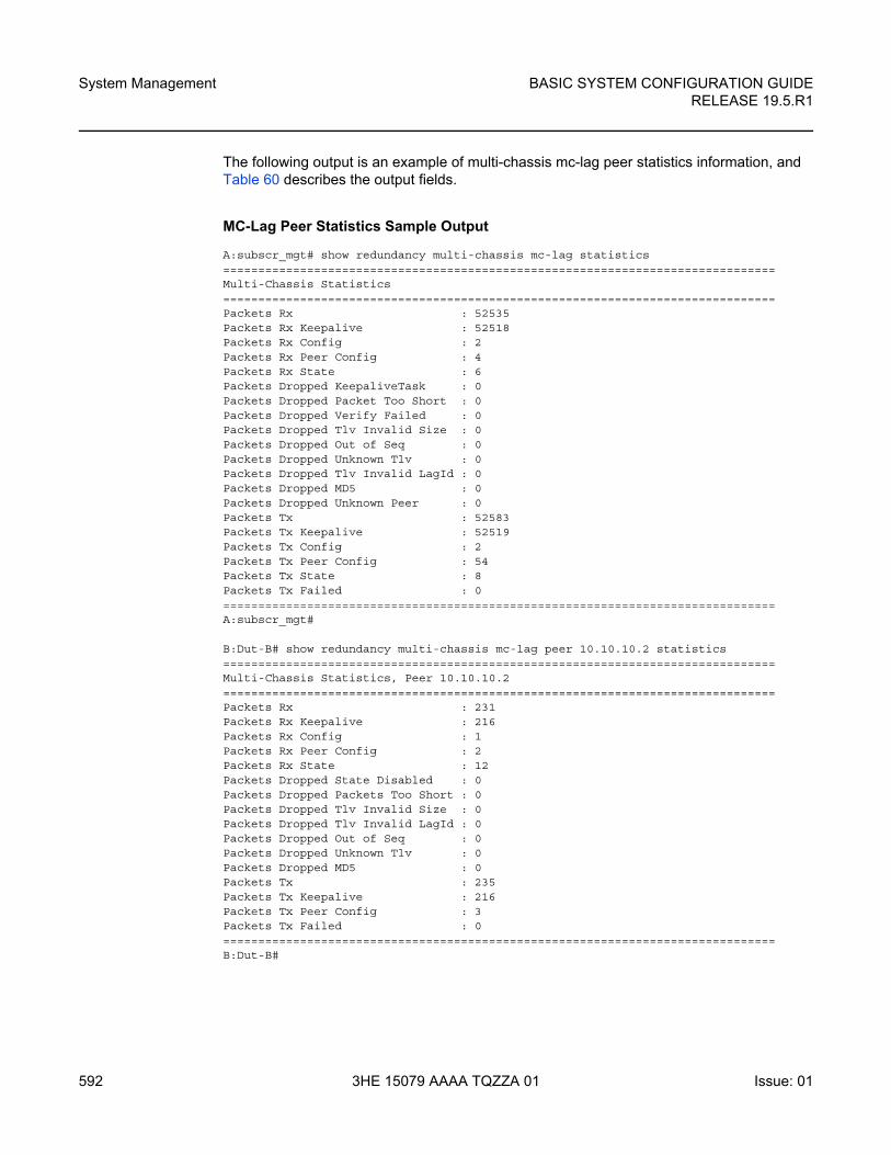
System Management
592
BASIC SYSTEM CONFIGURATION GUIDERELEASE 19.5.R1
3HE 15079 AAAA TQZZA 01 Issue: 01
The following output is an example of multi-chassis mc-lag peer statistics information, and Table 60 describes the output fields.
MC-Lag Peer Statistics Sample Output
A:subscr_mgt# show redundancy multi-chassis mc-lag statistics===============================================================================Multi-Chassis Statistics===============================================================================Packets Rx : 52535Packets Rx Keepalive : 52518Packets Rx Config : 2Packets Rx Peer Config : 4Packets Rx State : 6Packets Dropped KeepaliveTask : 0Packets Dropped Packet Too Short : 0Packets Dropped Verify Failed : 0Packets Dropped Tlv Invalid Size : 0Packets Dropped Out of Seq : 0Packets Dropped Unknown Tlv : 0Packets Dropped Tlv Invalid LagId : 0Packets Dropped MD5 : 0Packets Dropped Unknown Peer : 0Packets Tx : 52583Packets Tx Keepalive : 52519Packets Tx Config : 2Packets Tx Peer Config : 54Packets Tx State : 8Packets Tx Failed : 0===============================================================================A:subscr_mgt#
B:Dut-B# show redundancy multi-chassis mc-lag peer 10.10.10.2 statistics===============================================================================Multi-Chassis Statistics, Peer 10.10.10.2===============================================================================Packets Rx : 231Packets Rx Keepalive : 216Packets Rx Config : 1Packets Rx Peer Config : 2Packets Rx State : 12Packets Dropped State Disabled : 0Packets Dropped Packets Too Short : 0Packets Dropped Tlv Invalid Size : 0Packets Dropped Tlv Invalid LagId : 0Packets Dropped Out of Seq : 0Packets Dropped Unknown Tlv : 0Packets Dropped MD5 : 0Packets Tx : 235Packets Tx Keepalive : 216Packets Tx Peer Config : 3Packets Tx Failed : 0===============================================================================B:Dut-B#
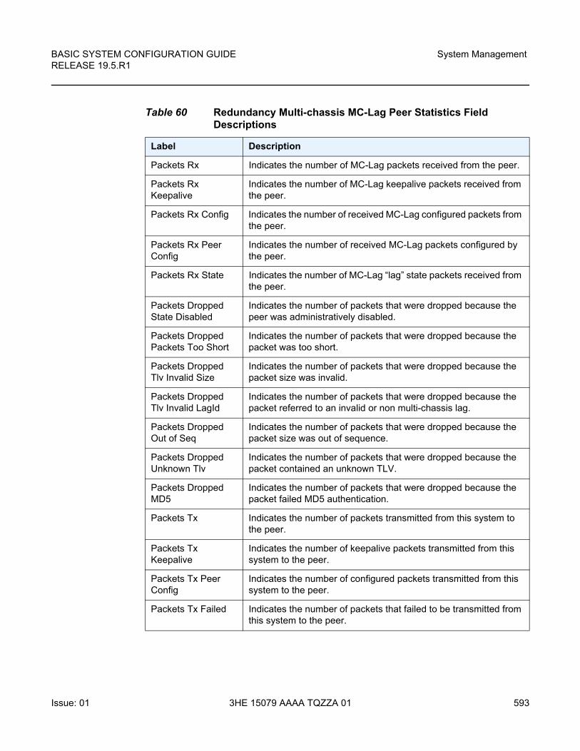
BASIC SYSTEM CONFIGURATION GUIDE RELEASE 19.5.R1
System Management
Issue: 01 3HE 15079 AAAA TQZZA 01 593
Table 60 Redundancy Multi-chassis MC-Lag Peer Statistics Field Descriptions
Label Description
Packets Rx Indicates the number of MC-Lag packets received from the peer.
Packets Rx Keepalive
Indicates the number of MC-Lag keepalive packets received from the peer.
Packets Rx Config Indicates the number of received MC-Lag configured packets from the peer.
Packets Rx Peer Config
Indicates the number of received MC-Lag packets configured by the peer.
Packets Rx State Indicates the number of MC-Lag “lag” state packets received from the peer.
Packets Dropped State Disabled
Indicates the number of packets that were dropped because the peer was administratively disabled.
Packets Dropped Packets Too Short
Indicates the number of packets that were dropped because the packet was too short.
Packets Dropped Tlv Invalid Size
Indicates the number of packets that were dropped because the packet size was invalid.
Packets Dropped Tlv Invalid LagId
Indicates the number of packets that were dropped because the packet referred to an invalid or non multi-chassis lag.
Packets Dropped Out of Seq
Indicates the number of packets that were dropped because the packet size was out of sequence.
Packets Dropped Unknown Tlv
Indicates the number of packets that were dropped because the packet contained an unknown TLV.
Packets Dropped MD5
Indicates the number of packets that were dropped because the packet failed MD5 authentication.
Packets Tx Indicates the number of packets transmitted from this system to the peer.
Packets Tx Keepalive
Indicates the number of keepalive packets transmitted from this system to the peer.
Packets Tx Peer Config
Indicates the number of configured packets transmitted from this system to the peer.
Packets Tx Failed Indicates the number of packets that failed to be transmitted from this system to the peer.
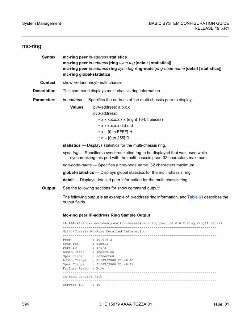
System Management
594
BASIC SYSTEM CONFIGURATION GUIDERELEASE 19.5.R1
3HE 15079 AAAA TQZZA 01 Issue: 01
mc-ring
Syntax mc-ring peer ip-address statistics
mc-ring peer ip-address [ring sync-tag [detail | statistics]]
mc-ring peer ip-address ring sync-tag ring-node [ring-node-name [detail | statistics]]
mc-ring global-statistics
Context show>redundancy>multi-chassis
Description This command displays multi-chassis ring information.
Parameters ip-address — Specifies the address of the multi-chassis peer to display.
Values ipv4-address: a.b.c.d
ipv6-address:
• x:x:x:x:x:x:x:x (eight 16-bit pieces)
• x:x:x:x:x:x:d.d.d.d
• x – [0 to FFFF] H
• d – [0 to 255] D
statistics — Displays statistics for the multi-chassis ring.
sync-tag — Specifies a synchronization tag to be displayed that was used while synchronizing this port with the multi-chassis peer. 32 characters maximum.
ring-node-name — Specifies a ring-node name. 32 characters maximum.
global-statistics — Displays global statistics for the multi-chassis ring.
detail — Displays detailed peer information for the multi-chassis ring.
Output See the following sections for show command output:
The following output is an example of ip-address ring information, and Table 61 describes the output fields.
Mc-ring peer IP-address Ring Sample Output
*A:ALA-48>show>redundancy>multi-chassis# mc-ring peer 10.0.0.2 ring ring11 detail==============================================================================Multi-Chassis MC-Ring Detailed Information==============================================================================Peer : 10.0.0.2Sync Tag : ring11Port ID : 1/1/3Admin State : inServiceOper State : connectedAdmin Change : 01/07/2008 21:40:07Oper Change : 01/07/2008 21:40:24Failure Reason : None------------------------------------------------------------------------------In Band Control Path------------------------------------------------------------------------------Service ID : 10
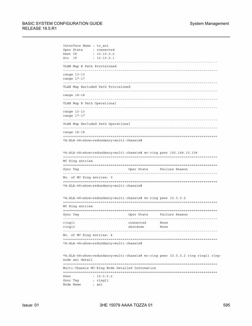
BASIC SYSTEM CONFIGURATION GUIDE RELEASE 19.5.R1
System Management
Issue: 01 3HE 15079 AAAA TQZZA 01 595
Interface Name : to_an1Oper State : connectedDest IP : 10.10.0.2Src IP : 10.10.0.1------------------------------------------------------------------------------VLAN Map B Path Provisioned------------------------------------------------------------------------------range 13-13range 17-17------------------------------------------------------------------------------VLAN Map Excluded Path Provisioned------------------------------------------------------------------------------range 18-18------------------------------------------------------------------------------VLAN Map B Path Operational------------------------------------------------------------------------------range 13-13range 17-17------------------------------------------------------------------------------VLAN Map Excluded Path Operational------------------------------------------------------------------------------range 18-18==============================================================================*A:ALA-48>show>redundancy>multi-chassis#
*A:ALA-48>show>redundancy>multi-chassis# mc-ring peer 192.168.10.104==============================================================================MC Ring entries==============================================================================Sync Tag Oper State Failure Reason------------------------------------------------------------------------------No. of MC Ring entries: 0==============================================================================*A:ALA-48>show>redundancy>multi-chassis#
*A:ALA-48>show>redundancy>multi-chassis# mc-ring peer 10.0.0.2==============================================================================MC Ring entries==============================================================================Sync Tag Oper State Failure Reason------------------------------------------------------------------------------ring11 connected Nonering12 shutdown None------------------------------------------------------------------------------No. of MC Ring entries: 4==============================================================================*A:ALA-48>show>redundancy>multi-chassis#
*A:ALA-48>show>redundancy>multi-chassis# mc-ring peer 10.0.0.2 ring ring11 ring-node an1 detail==============================================================================Multi-Chassis MC-Ring Node Detailed Information==============================================================================Peer : 10.0.0.2Sync Tag : ring11Node Name : an1
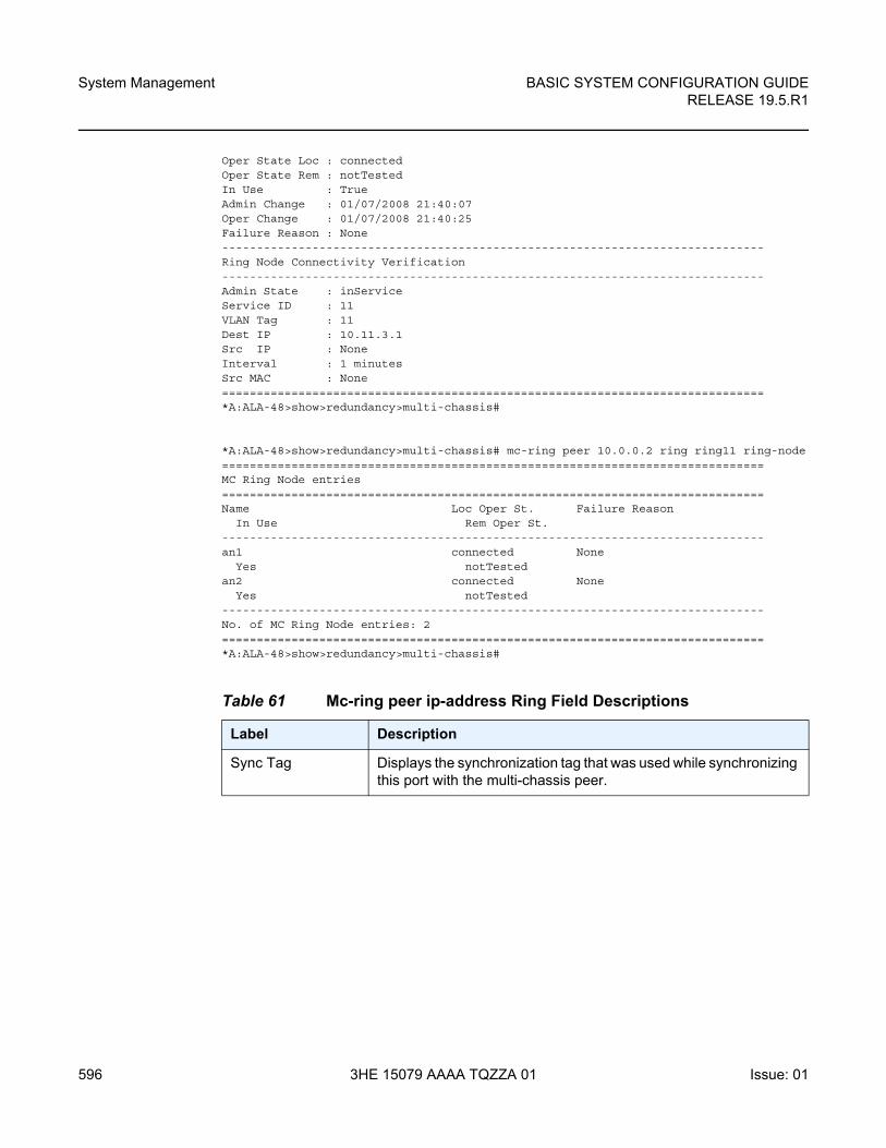
System Management
596
BASIC SYSTEM CONFIGURATION GUIDERELEASE 19.5.R1
3HE 15079 AAAA TQZZA 01 Issue: 01
Oper State Loc : connectedOper State Rem : notTestedIn Use : TrueAdmin Change : 01/07/2008 21:40:07Oper Change : 01/07/2008 21:40:25Failure Reason : None------------------------------------------------------------------------------Ring Node Connectivity Verification------------------------------------------------------------------------------Admin State : inServiceService ID : 11VLAN Tag : 11Dest IP : 10.11.3.1Src IP : NoneInterval : 1 minutesSrc MAC : None==============================================================================*A:ALA-48>show>redundancy>multi-chassis#
*A:ALA-48>show>redundancy>multi-chassis# mc-ring peer 10.0.0.2 ring ring11 ring-node==============================================================================MC Ring Node entries==============================================================================Name Loc Oper St. Failure Reason
In Use Rem Oper St.------------------------------------------------------------------------------an1 connected None
Yes notTestedan2 connected None
Yes notTested------------------------------------------------------------------------------No. of MC Ring Node entries: 2==============================================================================*A:ALA-48>show>redundancy>multi-chassis#
Table 61 Mc-ring peer ip-address Ring Field Descriptions
Label Description
Sync Tag Displays the synchronization tag that was used while synchronizing this port with the multi-chassis peer.
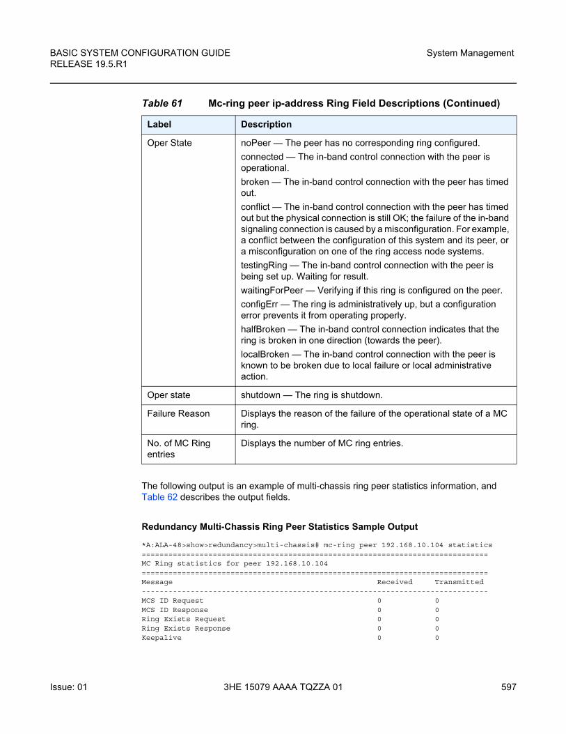
BASIC SYSTEM CONFIGURATION GUIDE RELEASE 19.5.R1
System Management
Issue: 01 3HE 15079 AAAA TQZZA 01 597
The following output is an example of multi-chassis ring peer statistics information, and Table 62 describes the output fields.
Redundancy Multi-Chassis Ring Peer Statistics Sample Output
*A:ALA-48>show>redundancy>multi-chassis# mc-ring peer 192.168.10.104 statistics==============================================================================MC Ring statistics for peer 192.168.10.104==============================================================================Message Received Transmitted------------------------------------------------------------------------------MCS ID Request 0 0MCS ID Response 0 0Ring Exists Request 0 0Ring Exists Response 0 0Keepalive 0 0
Oper State noPeer — The peer has no corresponding ring configured.
connected — The in-band control connection with the peer is operational.
broken — The in-band control connection with the peer has timed out.
conflict — The in-band control connection with the peer has timed out but the physical connection is still OK; the failure of the in-band signaling connection is caused by a misconfiguration. For example, a conflict between the configuration of this system and its peer, or a misconfiguration on one of the ring access node systems.
testingRing — The in-band control connection with the peer is being set up. Waiting for result.
waitingForPeer — Verifying if this ring is configured on the peer.
configErr — The ring is administratively up, but a configuration error prevents it from operating properly.
halfBroken — The in-band control connection indicates that the ring is broken in one direction (towards the peer).
localBroken — The in-band control connection with the peer is known to be broken due to local failure or local administrative action.
Oper state shutdown — The ring is shutdown.
Failure Reason Displays the reason of the failure of the operational state of a MC ring.
No. of MC Ring entries
Displays the number of MC ring entries.
Table 61 Mc-ring peer ip-address Ring Field Descriptions (Continued)
Label Description
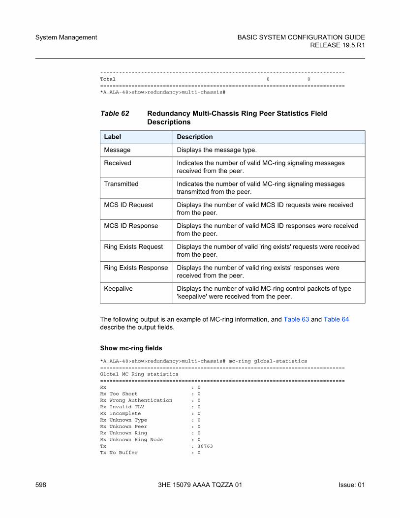
System Management
598
BASIC SYSTEM CONFIGURATION GUIDERELEASE 19.5.R1
3HE 15079 AAAA TQZZA 01 Issue: 01
------------------------------------------------------------------------------Total 0 0==============================================================================*A:ALA-48>show>redundancy>multi-chassis#
The following output is an example of MC-ring information, and Table 63 and Table 64 describe the output fields.
Show mc-ring fields
*A:ALA-48>show>redundancy>multi-chassis# mc-ring global-statistics==============================================================================Global MC Ring statistics==============================================================================Rx : 0Rx Too Short : 0Rx Wrong Authentication : 0Rx Invalid TLV : 0Rx Incomplete : 0Rx Unknown Type : 0Rx Unknown Peer : 0Rx Unknown Ring : 0Rx Unknown Ring Node : 0Tx : 36763Tx No Buffer : 0
Table 62 Redundancy Multi-Chassis Ring Peer Statistics Field Descriptions
Label Description
Message Displays the message type.
Received Indicates the number of valid MC-ring signaling messages received from the peer.
Transmitted Indicates the number of valid MC-ring signaling messages transmitted from the peer.
MCS ID Request Displays the number of valid MCS ID requests were received from the peer.
MCS ID Response Displays the number of valid MCS ID responses were received from the peer.
Ring Exists Request Displays the number of valid 'ring exists' requests were received from the peer.
Ring Exists Response Displays the number of valid ring exists' responses were received from the peer.
Keepalive Displays the number of valid MC-ring control packets of type 'keepalive' were received from the peer.
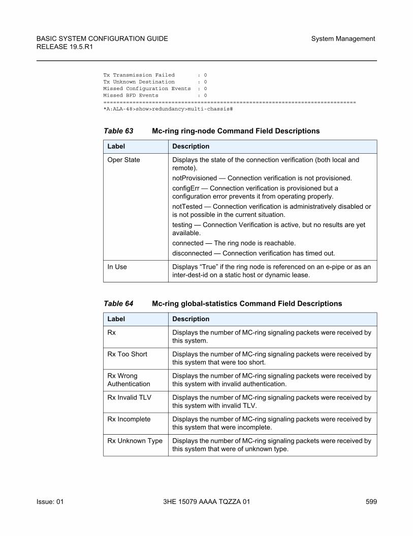
BASIC SYSTEM CONFIGURATION GUIDE RELEASE 19.5.R1
System Management
Issue: 01 3HE 15079 AAAA TQZZA 01 599
Tx Transmission Failed : 0Tx Unknown Destination : 0Missed Configuration Events : 0Missed BFD Events : 0==============================================================================*A:ALA-48>show>redundancy>multi-chassis#
Table 63 Mc-ring ring-node Command Field Descriptions
Label Description
Oper State Displays the state of the connection verification (both local and remote).
notProvisioned — Connection verification is not provisioned.
configErr — Connection verification is provisioned but a configuration error prevents it from operating properly.
notTested — Connection verification is administratively disabled or is not possible in the current situation.
testing — Connection Verification is active, but no results are yet available.
connected — The ring node is reachable.
disconnected — Connection verification has timed out.
In Use Displays “True” if the ring node is referenced on an e-pipe or as an inter-dest-id on a static host or dynamic lease.
Table 64 Mc-ring global-statistics Command Field Descriptions
Label Description
Rx Displays the number of MC-ring signaling packets were received by this system.
Rx Too Short Displays the number of MC-ring signaling packets were received by this system that were too short.
Rx Wrong Authentication
Displays the number of MC-ring signaling packets were received by this system with invalid authentication.
Rx Invalid TLV Displays the number of MC-ring signaling packets were received by this system with invalid TLV.
Rx Incomplete Displays the number of MC-ring signaling packets were received by this system that were incomplete.
Rx Unknown Type Displays the number of MC-ring signaling packets were received by this system that were of unknown type.
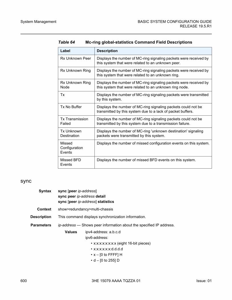
System Management
600
BASIC SYSTEM CONFIGURATION GUIDERELEASE 19.5.R1
3HE 15079 AAAA TQZZA 01 Issue: 01
sync
Syntax sync [peer ip-address]
sync peer ip-address detail
sync [peer ip-address] statistics
Context show>redundancy>multi-chassis
Description This command displays synchronization information.
Parameters ip-address — Shows peer information about the specified IP address.
Values ipv4-address: a.b.c.d
ipv6-address:
• x:x:x:x:x:x:x:x (eight 16-bit pieces)
• x:x:x:x:x:x:d.d.d.d
• x – [0 to FFFF] H
• d – [0 to 255] D
Rx Unknown Peer Displays the number of MC-ring signaling packets were received by this system that were related to an unknown peer.
Rx Unknown Ring Displays the number of MC-ring signaling packets were received by this system that were related to an unknown ring.
Rx Unknown Ring Node
Displays the number of MC-ring signaling packets were received by this system that were related to an unknown ring node.
Tx Displays the number of MC-ring signaling packets were transmitted by this system.
Tx No Buffer Displays the number of MC-ring signaling packets could not be transmitted by this system due to a lack of packet buffers.
Tx Transmission Failed
Displays the number of MC-ring signaling packets could not be transmitted by this system due to a transmission failure.
Tx Unknown Destination
Displays the number of MC-ring 'unknown destination' signaling packets were transmitted by this system.
Missed Configuration Events
Displays the number of missed configuration events on this system.
Missed BFD Events
Displays the number of missed BFD events on this system.
Table 64 Mc-ring global-statistics Command Field Descriptions
Label Description
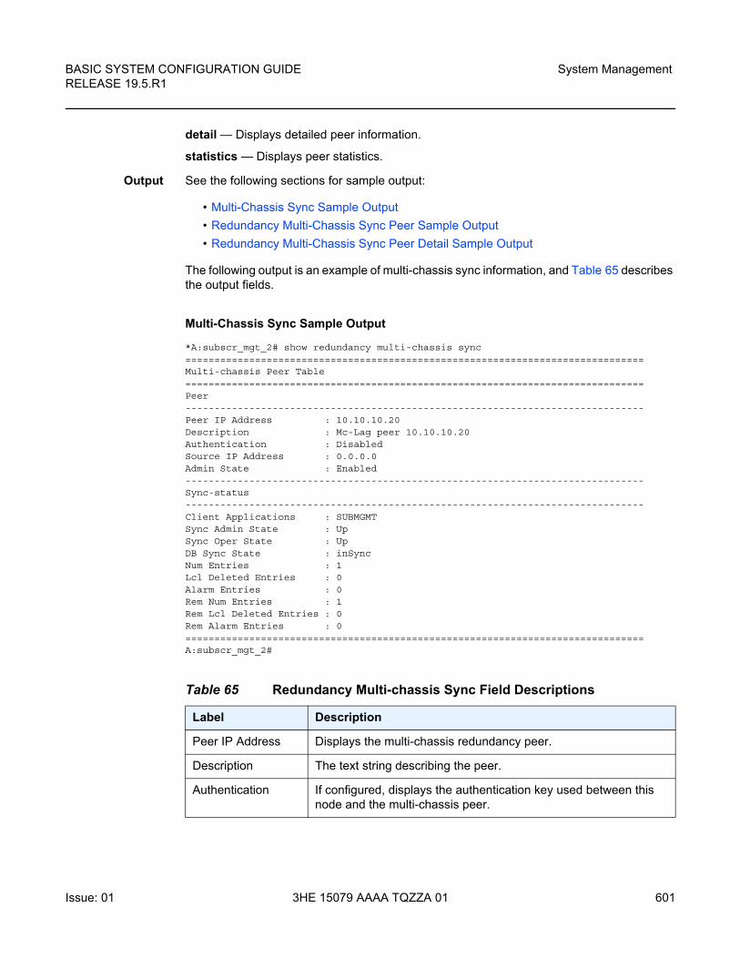
BASIC SYSTEM CONFIGURATION GUIDE RELEASE 19.5.R1
System Management
Issue: 01 3HE 15079 AAAA TQZZA 01 601
detail — Displays detailed peer information.
statistics — Displays peer statistics.
Output See the following sections for sample output:
• Multi-Chassis Sync Sample Output
• Redundancy Multi-Chassis Sync Peer Sample Output
• Redundancy Multi-Chassis Sync Peer Detail Sample Output
The following output is an example of multi-chassis sync information, and Table 65 describes the output fields.
Multi-Chassis Sync Sample Output
*A:subscr_mgt_2# show redundancy multi-chassis sync===============================================================================Multi-chassis Peer Table===============================================================================Peer-------------------------------------------------------------------------------Peer IP Address : 10.10.10.20Description : Mc-Lag peer 10.10.10.20Authentication : DisabledSource IP Address : 0.0.0.0Admin State : Enabled-------------------------------------------------------------------------------Sync-status-------------------------------------------------------------------------------Client Applications : SUBMGMTSync Admin State : UpSync Oper State : UpDB Sync State : inSyncNum Entries : 1Lcl Deleted Entries : 0Alarm Entries : 0Rem Num Entries : 1Rem Lcl Deleted Entries : 0Rem Alarm Entries : 0===============================================================================A:subscr_mgt_2#
Table 65 Redundancy Multi-chassis Sync Field Descriptions
Label Description
Peer IP Address Displays the multi-chassis redundancy peer.
Description The text string describing the peer.
Authentication If configured, displays the authentication key used between this node and the multi-chassis peer.
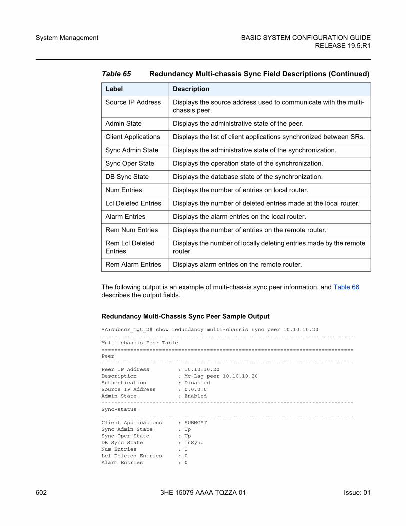
System Management
602
BASIC SYSTEM CONFIGURATION GUIDERELEASE 19.5.R1
3HE 15079 AAAA TQZZA 01 Issue: 01
The following output is an example of multi-chassis sync peer information, and Table 66 describes the output fields.
Redundancy Multi-Chassis Sync Peer Sample Output
*A:subscr_mgt_2# show redundancy multi-chassis sync peer 10.10.10.20===============================================================================Multi-chassis Peer Table===============================================================================Peer-------------------------------------------------------------------------------Peer IP Address : 10.10.10.20Description : Mc-Lag peer 10.10.10.20Authentication : DisabledSource IP Address : 0.0.0.0Admin State : Enabled-------------------------------------------------------------------------------Sync-status-------------------------------------------------------------------------------Client Applications : SUBMGMTSync Admin State : UpSync Oper State : UpDB Sync State : inSyncNum Entries : 1Lcl Deleted Entries : 0Alarm Entries : 0
Source IP Address Displays the source address used to communicate with the multi-chassis peer.
Admin State Displays the administrative state of the peer.
Client Applications Displays the list of client applications synchronized between SRs.
Sync Admin State Displays the administrative state of the synchronization.
Sync Oper State Displays the operation state of the synchronization.
DB Sync State Displays the database state of the synchronization.
Num Entries Displays the number of entries on local router.
Lcl Deleted Entries Displays the number of deleted entries made at the local router.
Alarm Entries Displays the alarm entries on the local router.
Rem Num Entries Displays the number of entries on the remote router.
Rem Lcl Deleted Entries
Displays the number of locally deleting entries made by the remote router.
Rem Alarm Entries Displays alarm entries on the remote router.
Table 65 Redundancy Multi-chassis Sync Field Descriptions (Continued)
Label Description
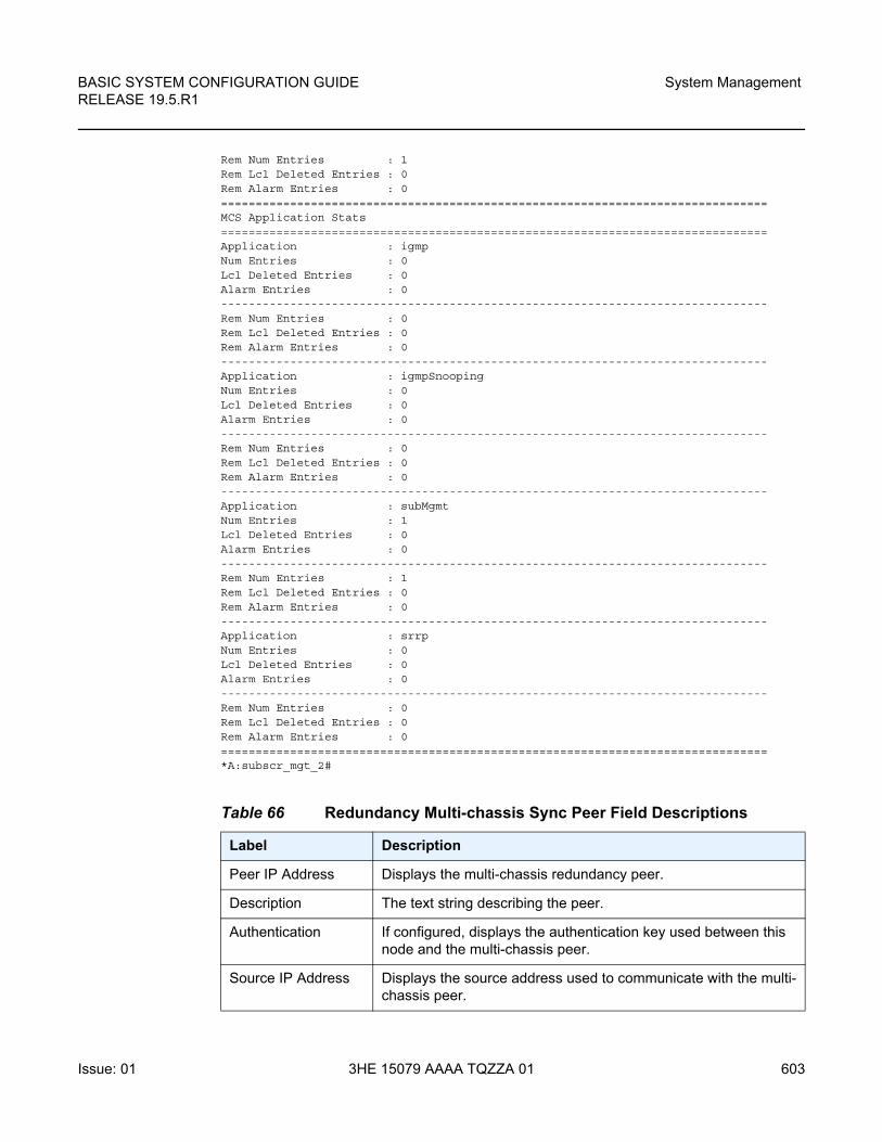
BASIC SYSTEM CONFIGURATION GUIDE RELEASE 19.5.R1
System Management
Issue: 01 3HE 15079 AAAA TQZZA 01 603
Rem Num Entries : 1Rem Lcl Deleted Entries : 0Rem Alarm Entries : 0===============================================================================MCS Application Stats===============================================================================Application : igmpNum Entries : 0Lcl Deleted Entries : 0Alarm Entries : 0-------------------------------------------------------------------------------Rem Num Entries : 0Rem Lcl Deleted Entries : 0Rem Alarm Entries : 0-------------------------------------------------------------------------------Application : igmpSnoopingNum Entries : 0Lcl Deleted Entries : 0Alarm Entries : 0-------------------------------------------------------------------------------Rem Num Entries : 0Rem Lcl Deleted Entries : 0Rem Alarm Entries : 0-------------------------------------------------------------------------------Application : subMgmtNum Entries : 1Lcl Deleted Entries : 0Alarm Entries : 0-------------------------------------------------------------------------------Rem Num Entries : 1Rem Lcl Deleted Entries : 0Rem Alarm Entries : 0-------------------------------------------------------------------------------Application : srrpNum Entries : 0Lcl Deleted Entries : 0Alarm Entries : 0-------------------------------------------------------------------------------Rem Num Entries : 0Rem Lcl Deleted Entries : 0Rem Alarm Entries : 0===============================================================================*A:subscr_mgt_2#
Table 66 Redundancy Multi-chassis Sync Peer Field Descriptions
Label Description
Peer IP Address Displays the multi-chassis redundancy peer.
Description The text string describing the peer.
Authentication If configured, displays the authentication key used between this node and the multi-chassis peer.
Source IP Address Displays the source address used to communicate with the multi-chassis peer.
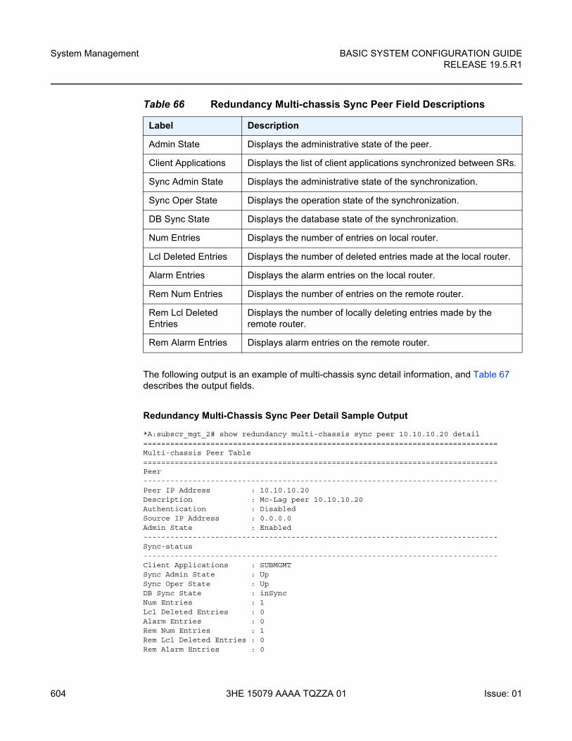
System Management
604
BASIC SYSTEM CONFIGURATION GUIDERELEASE 19.5.R1
3HE 15079 AAAA TQZZA 01 Issue: 01
The following output is an example of multi-chassis sync detail information, and Table 67 describes the output fields.
Redundancy Multi-Chassis Sync Peer Detail Sample Output
*A:subscr_mgt_2# show redundancy multi-chassis sync peer 10.10.10.20 detail===============================================================================Multi-chassis Peer Table===============================================================================Peer-------------------------------------------------------------------------------Peer IP Address : 10.10.10.20Description : Mc-Lag peer 10.10.10.20Authentication : DisabledSource IP Address : 0.0.0.0Admin State : Enabled-------------------------------------------------------------------------------Sync-status-------------------------------------------------------------------------------Client Applications : SUBMGMTSync Admin State : UpSync Oper State : UpDB Sync State : inSyncNum Entries : 1Lcl Deleted Entries : 0Alarm Entries : 0Rem Num Entries : 1Rem Lcl Deleted Entries : 0Rem Alarm Entries : 0
Admin State Displays the administrative state of the peer.
Client Applications Displays the list of client applications synchronized between SRs.
Sync Admin State Displays the administrative state of the synchronization.
Sync Oper State Displays the operation state of the synchronization.
DB Sync State Displays the database state of the synchronization.
Num Entries Displays the number of entries on local router.
Lcl Deleted Entries Displays the number of deleted entries made at the local router.
Alarm Entries Displays the alarm entries on the local router.
Rem Num Entries Displays the number of entries on the remote router.
Rem Lcl Deleted Entries
Displays the number of locally deleting entries made by the remote router.
Rem Alarm Entries Displays alarm entries on the remote router.
Table 66 Redundancy Multi-chassis Sync Peer Field Descriptions
Label Description
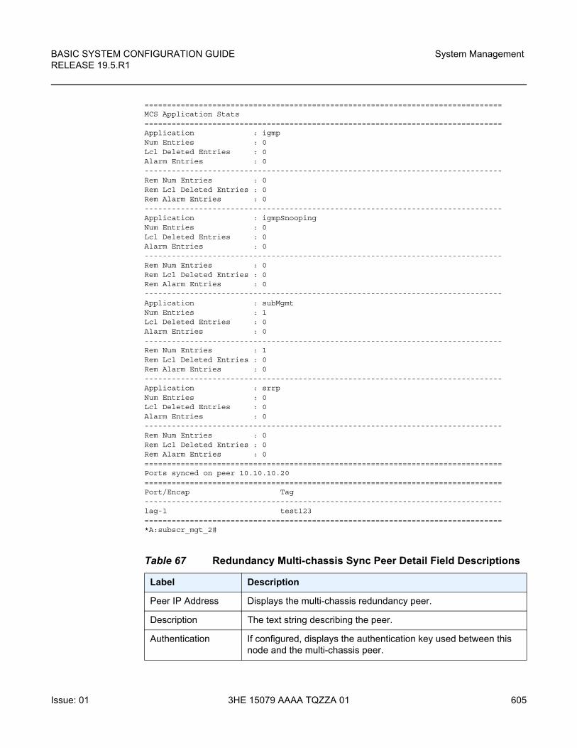
BASIC SYSTEM CONFIGURATION GUIDE RELEASE 19.5.R1
System Management
Issue: 01 3HE 15079 AAAA TQZZA 01 605
===============================================================================MCS Application Stats===============================================================================Application : igmpNum Entries : 0Lcl Deleted Entries : 0Alarm Entries : 0-------------------------------------------------------------------------------Rem Num Entries : 0Rem Lcl Deleted Entries : 0Rem Alarm Entries : 0-------------------------------------------------------------------------------Application : igmpSnoopingNum Entries : 0Lcl Deleted Entries : 0Alarm Entries : 0-------------------------------------------------------------------------------Rem Num Entries : 0Rem Lcl Deleted Entries : 0Rem Alarm Entries : 0-------------------------------------------------------------------------------Application : subMgmtNum Entries : 1Lcl Deleted Entries : 0Alarm Entries : 0-------------------------------------------------------------------------------Rem Num Entries : 1Rem Lcl Deleted Entries : 0Rem Alarm Entries : 0-------------------------------------------------------------------------------Application : srrpNum Entries : 0Lcl Deleted Entries : 0Alarm Entries : 0-------------------------------------------------------------------------------Rem Num Entries : 0Rem Lcl Deleted Entries : 0Rem Alarm Entries : 0===============================================================================Ports synced on peer 10.10.10.20===============================================================================Port/Encap Tag-------------------------------------------------------------------------------lag-1 test123===============================================================================*A:subscr_mgt_2#
Table 67 Redundancy Multi-chassis Sync Peer Detail Field Descriptions
Label Description
Peer IP Address Displays the multi-chassis redundancy peer.
Description The text string describing the peer.
Authentication If configured, displays the authentication key used between this node and the multi-chassis peer.
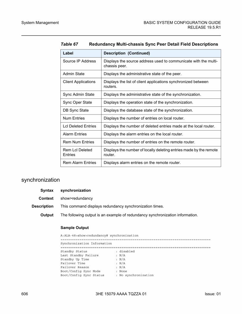
System Management
606
BASIC SYSTEM CONFIGURATION GUIDERELEASE 19.5.R1
3HE 15079 AAAA TQZZA 01 Issue: 01
synchronization
Syntax synchronization
Context show>redundancy
Description This command displays redundancy synchronization times.
Output The following output is an example of redundancy synchronization information.
Sample Output
A:ALA-48>show>redundancy# synchronization===============================================================================Synchronization Information===============================================================================Standby Status : disabledLast Standby Failure : N/AStandby Up Time : N/AFailover Time : N/AFailover Reason : N/ABoot/Config Sync Mode : NoneBoot/Config Sync Status : No synchronization
Source IP Address Displays the source address used to communicate with the multi-chassis peer.
Admin State Displays the administrative state of the peer.
Client Applications Displays the list of client applications synchronized between routers.
Sync Admin State Displays the administrative state of the synchronization.
Sync Oper State Displays the operation state of the synchronization.
DB Sync State Displays the database state of the synchronization.
Num Entries Displays the number of entries on local router.
Lcl Deleted Entries Displays the number of deleted entries made at the local router.
Alarm Entries Displays the alarm entries on the local router.
Rem Num Entries Displays the number of entries on the remote router.
Rem Lcl Deleted Entries
Displays the number of locally deleting entries made by the remote router.
Rem Alarm Entries Displays alarm entries on the remote router.
Table 67 Redundancy Multi-chassis Sync Peer Detail Field Descriptions
Label Description (Continued)
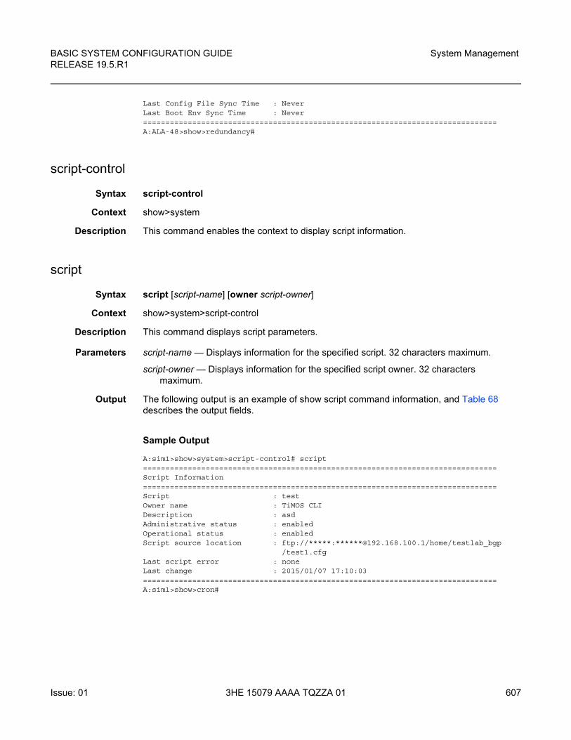
BASIC SYSTEM CONFIGURATION GUIDE RELEASE 19.5.R1
System Management
Issue: 01 3HE 15079 AAAA TQZZA 01 607
Last Config File Sync Time : NeverLast Boot Env Sync Time : Never===============================================================================A:ALA-48>show>redundancy#
script-control
Syntax script-control
Context show>system
Description This command enables the context to display script information.
script
Syntax script [script-name] [owner script-owner]
Context show>system>script-control
Description This command displays script parameters.
Parameters script-name — Displays information for the specified script. 32 characters maximum.
script-owner — Displays information for the specified script owner. 32 characters maximum.
Output The following output is an example of show script command information, and Table 68 describes the output fields.
Sample Output
A:sim1>show>system>script-control# script===============================================================================Script Information===============================================================================Script : testOwner name : TiMOS CLIDescription : asdAdministrative status : enabledOperational status : enabledScript source location : ftp://*****:******@192.168.100.1/home/testlab_bgp
/test1.cfgLast script error : noneLast change : 2015/01/07 17:10:03===============================================================================A:sim1>show>cron#
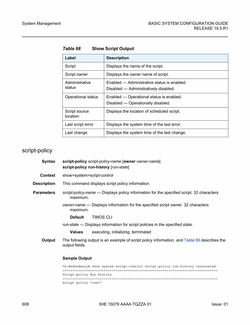
System Management
608
BASIC SYSTEM CONFIGURATION GUIDERELEASE 19.5.R1
3HE 15079 AAAA TQZZA 01 Issue: 01
script-policy
Syntax script-policy script-policy-name [owner owner-name]
script-policy run-history [run-state]
Context show>system>script-control
Description This command displays script policy information.
Parameters script-policy-name — Displays policy information for the specified script. 32 characters maximum.
owner-name — Displays information for the specified script owner. 32 characters maximum.
Default TiMOS CLI
run-state — Displays information for script policies in the specified state.
Values executing, initializing, terminated
Output The following output is an example of script policy information, and Table 69 describes the output fields.
Sample Output
*A:Redundancy# show system script-control script-policy run-history terminated===============================================================================Script-policy Run History===============================================================================Script policy "test"
Table 68 Show Script Output
Label Description
Script Displays the name of the script.
Script owner Displays the owner name of script.
Administrative status
Enabled — Administrative status is enabled.
Disabled — Administratively disabled.
Operational status Enabled — Operational status is enabled.
Disabled — Operationally disabled.
Script source location
Displays the location of scheduled script.
Last script error Displays the system time of the last error.
Last change Displays the system time of the last change.
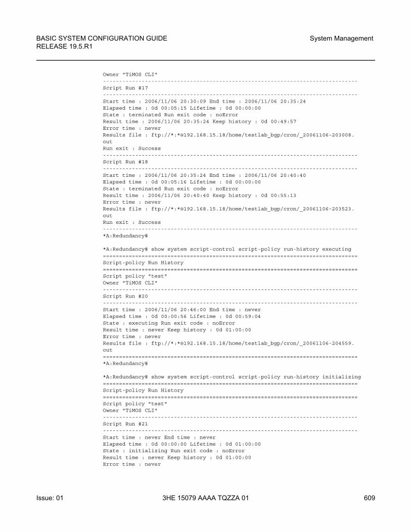
BASIC SYSTEM CONFIGURATION GUIDE RELEASE 19.5.R1
System Management
Issue: 01 3HE 15079 AAAA TQZZA 01 609
Owner "TiMOS CLI"-------------------------------------------------------------------------------Script Run #17-------------------------------------------------------------------------------Start time : 2006/11/06 20:30:09 End time : 2006/11/06 20:35:24Elapsed time : 0d 00:05:15 Lifetime : 0d 00:00:00State : terminated Run exit code : noErrorResult time : 2006/11/06 20:35:24 Keep history : 0d 00:49:57Error time : neverResults file : ftp://*:*@192.168.15.18/home/testlab_bgp/cron/_20061106-203008.outRun exit : Success-------------------------------------------------------------------------------Script Run #18-------------------------------------------------------------------------------Start time : 2006/11/06 20:35:24 End time : 2006/11/06 20:40:40Elapsed time : 0d 00:05:16 Lifetime : 0d 00:00:00State : terminated Run exit code : noErrorResult time : 2006/11/06 20:40:40 Keep history : 0d 00:55:13Error time : neverResults file : ftp://*:*@192.168.15.18/home/testlab_bgp/cron/_20061106-203523.outRun exit : Success-------------------------------------------------------------------------------*A:Redundancy#
*A:Redundancy# show system script-control script-policy run-history executing===============================================================================Script-policy Run History===============================================================================Script policy "test"Owner "TiMOS CLI"-------------------------------------------------------------------------------Script Run #20-------------------------------------------------------------------------------Start time : 2006/11/06 20:46:00 End time : neverElapsed time : 0d 00:00:56 Lifetime : 0d 00:59:04State : executing Run exit code : noErrorResult time : never Keep history : 0d 01:00:00Error time : neverResults file : ftp://*:*@192.168.15.18/home/testlab_bgp/cron/_20061106-204559.out===============================================================================*A:Redundancy#
*A:Redundancy# show system script-control script-policy run-history initializing===============================================================================Script-policy Run History===============================================================================Script policy "test"Owner "TiMOS CLI"-------------------------------------------------------------------------------Script Run #21-------------------------------------------------------------------------------Start time : never End time : neverElapsed time : 0d 00:00:00 Lifetime : 0d 01:00:00State : initializing Run exit code : noErrorResult time : never Keep history : 0d 01:00:00Error time : never
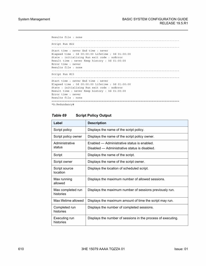
System Management
610
BASIC SYSTEM CONFIGURATION GUIDERELEASE 19.5.R1
3HE 15079 AAAA TQZZA 01 Issue: 01
Results file : none-------------------------------------------------------------------------------Script Run #22-------------------------------------------------------------------------------Start time : never End time : neverElapsed time : 0d 00:00:00 Lifetime : 0d 01:00:00State : initializing Run exit code : noErrorResult time : never Keep history : 0d 01:00:00Error time : neverResults file : none-------------------------------------------------------------------------------Script Run #23-------------------------------------------------------------------------------Start time : never End time : neverElapsed time : 0d 00:00:00 Lifetime : 0d 01:00:00State : initializing Run exit code : noErrorResult time : never Keep history : 0d 01:00:00Error time : neverResults file : none===============================================================================*A:Redundancy#
Table 69 Script Policy Output
Label Description
Script policy Displays the name of the script policy.
Script policy owner Displays the name of the script policy owner.
Administrative status
Enabled — Administrative status is enabled.
Disabled — Administrative status is disabled.
Script Displays the name of the script.
Script owner Displays the name of the script owner.
Script source location
Displays the location of scheduled script.
Max running allowed
Displays the maximum number of allowed sessions.
Max completed run histories
Displays the maximum number of sessions previously run.
Max lifetime allowed Displays the maximum amount of time the script may run.
Completed run histories
Displays the number of completed sessions.
Executing run histories
Displays the number of sessions in the process of executing.
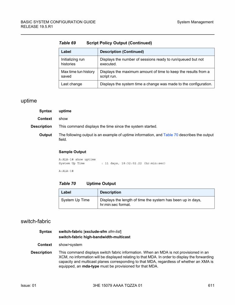
BASIC SYSTEM CONFIGURATION GUIDE RELEASE 19.5.R1
System Management
Issue: 01 3HE 15079 AAAA TQZZA 01 611
uptime
Syntax uptime
Context show
Description This command displays the time since the system started.
Output The following output is an example of uptime information, and Table 70 describes the output field.
Sample Output
A:ALA-1# show uptimeSystem Up Time : 11 days, 18:32:02.22 (hr:min:sec)
A:ALA-1#
switch-fabric
Syntax switch-fabric [exclude-sfm sfm-list]
switch-fabric high-bandwidth-multicast
Context show>system
Description This command displays switch fabric information. When an MDA is not provisioned in an XCM, no information will be displayed relating to that MDA. In order to display the forwarding capacity and multicast planes corresponding to that MDA, regardless of whether an XMA is equipped, an mda-type must be provisioned for that MDA.
Initializing run histories
Displays the number of sessions ready to run/queued but not executed.
Max time tun history saved
Displays the maximum amount of time to keep the results from a script run.
Last change Displays the system time a change was made to the configuration.
Table 69 Script Policy Output (Continued)
Label Description (Continued)
Table 70 Uptime Output
Label Description
System Up Time Displays the length of time the system has been up in days, hr:min:sec format.
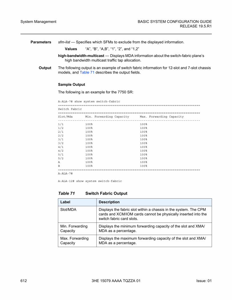
System Management
612
BASIC SYSTEM CONFIGURATION GUIDERELEASE 19.5.R1
3HE 15079 AAAA TQZZA 01 Issue: 01
Parameters sfm-list — Specifies which SFMs to exclude from the displayed information.
Values “A”, “B”, “A,B”, “1”, “2”, and “1,2”
high-bandwidth-multicast — Displays MDA information about the switch-fabric plane’s high bandwidth multicast traffic tap allocation.
Output The following output is an example of switch fabric information for 12-slot and 7-slot chassis models, and Table 71 describes the output fields.
Sample Output
The following is an example for the 7750 SR:
A:ALA-7# show system switch-fabric==============================================================================Switch Fabric==============================================================================Slot/Mda Min. Forwarding Capacity Max. Forwarding Capacity------------------------------------------------------------------------------1/1 100% 100%1/2 100% 100%2/1 100% 100%2/2 100% 100%3/1 100% 100%3/2 100% 100%4/1 100% 100%4/2 100% 100%5/1 100% 100%5/2 100% 100%A 100% 100%B 100% 100%==============================================================================A:ALA-7#
A:ALA-12# show system switch-fabric
Table 71 Switch Fabric Output
Label Description
Slot/MDA Displays the fabric slot within a chassis in the system. The CPM cards and XCM/IOM cards cannot be physically inserted into the switch fabric card slots.
Min. Forwarding Capacity
Displays the minimum forwarding capacity of the slot and XMA/MDA as a percentage.
Max. Forwarding Capacity
Displays the maximum forwarding capacity of the slot and XMA/MDA as a percentage.
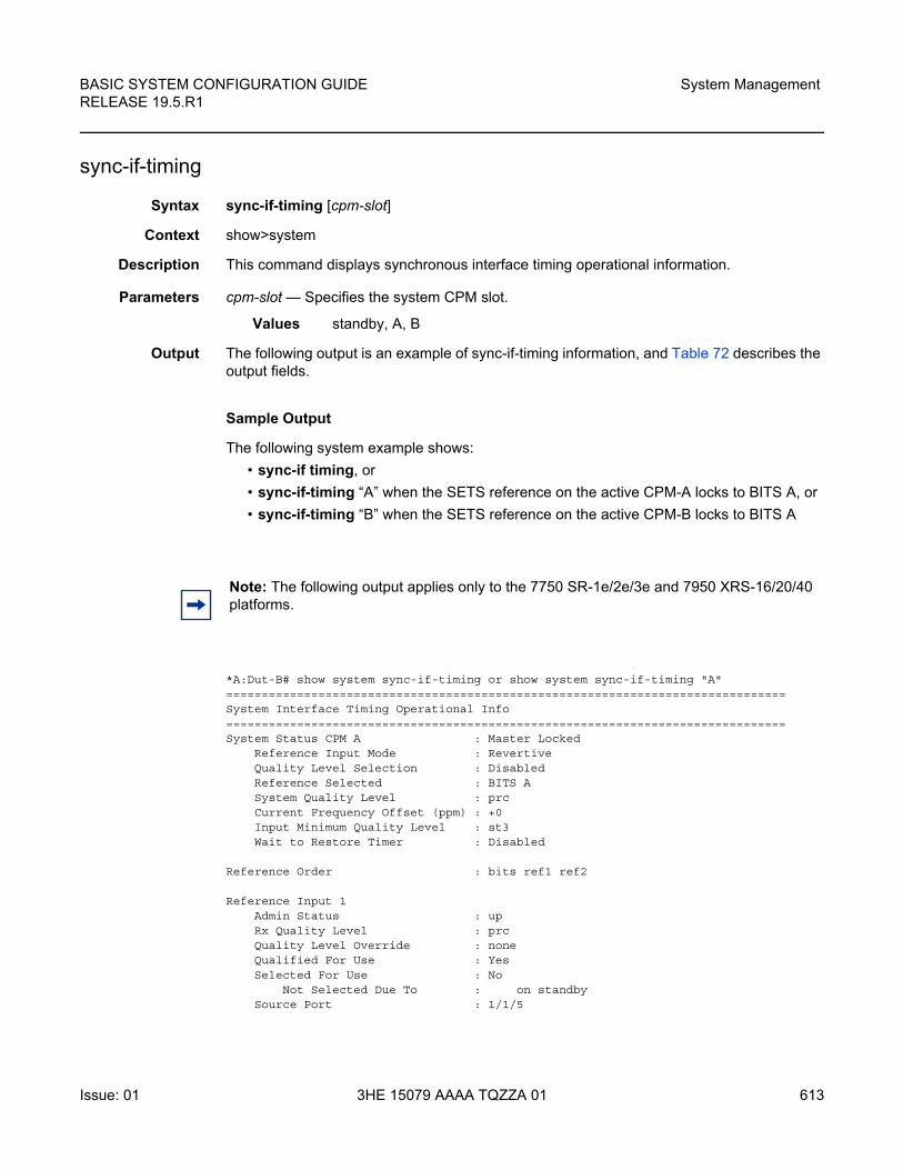
BASIC SYSTEM CONFIGURATION GUIDE RELEASE 19.5.R1
System Management
Issue: 01 3HE 15079 AAAA TQZZA 01 613
sync-if-timing
Syntax sync-if-timing [cpm-slot]
Context show>system
Description This command displays synchronous interface timing operational information.
Parameters cpm-slot — Specifies the system CPM slot.
Values standby, A, B
Output The following output is an example of sync-if-timing information, and Table 72 describes the output fields.
Sample Output
The following system example shows:
• sync-if timing, or
• sync-if-timing “A” when the SETS reference on the active CPM-A locks to BITS A, or
• sync-if-timing “B” when the SETS reference on the active CPM-B locks to BITS A
*A:Dut-B# show system sync-if-timing or show system sync-if-timing "A"===============================================================================System Interface Timing Operational Info===============================================================================System Status CPM A : Master Locked
Reference Input Mode : RevertiveQuality Level Selection : DisabledReference Selected : BITS ASystem Quality Level : prcCurrent Frequency Offset (ppm) : +0Input Minimum Quality Level : st3Wait to Restore Timer : Disabled
Reference Order : bits ref1 ref2
Reference Input 1Admin Status : upRx Quality Level : prcQuality Level Override : noneQualified For Use : YesSelected For Use : No
Not Selected Due To : on standbySource Port : 1/1/5
Note: The following output applies only to the 7750 SR-1e/2e/3e and 7950 XRS-16/20/40 platforms.
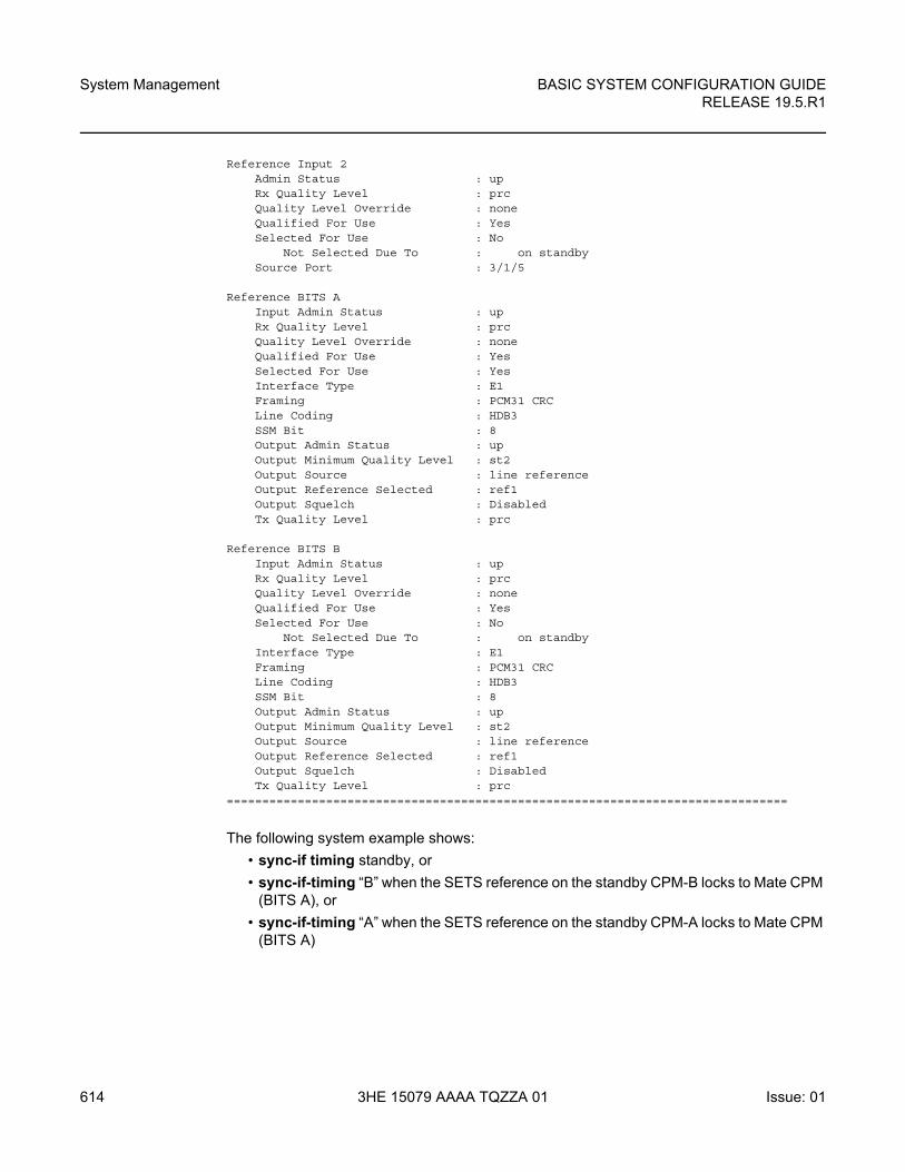
System Management
614
BASIC SYSTEM CONFIGURATION GUIDERELEASE 19.5.R1
3HE 15079 AAAA TQZZA 01 Issue: 01
Reference Input 2Admin Status : upRx Quality Level : prcQuality Level Override : noneQualified For Use : YesSelected For Use : No
Not Selected Due To : on standbySource Port : 3/1/5
Reference BITS AInput Admin Status : upRx Quality Level : prcQuality Level Override : noneQualified For Use : YesSelected For Use : YesInterface Type : E1Framing : PCM31 CRCLine Coding : HDB3SSM Bit : 8Output Admin Status : upOutput Minimum Quality Level : st2Output Source : line referenceOutput Reference Selected : ref1Output Squelch : DisabledTx Quality Level : prc
Reference BITS BInput Admin Status : upRx Quality Level : prcQuality Level Override : noneQualified For Use : YesSelected For Use : No
Not Selected Due To : on standbyInterface Type : E1Framing : PCM31 CRCLine Coding : HDB3SSM Bit : 8Output Admin Status : upOutput Minimum Quality Level : st2Output Source : line referenceOutput Reference Selected : ref1Output Squelch : DisabledTx Quality Level : prc
===============================================================================
The following system example shows:
• sync-if timing standby, or
• sync-if-timing “B” when the SETS reference on the standby CPM-B locks to Mate CPM (BITS A), or
• sync-if-timing “A” when the SETS reference on the standby CPM-A locks to Mate CPM (BITS A)
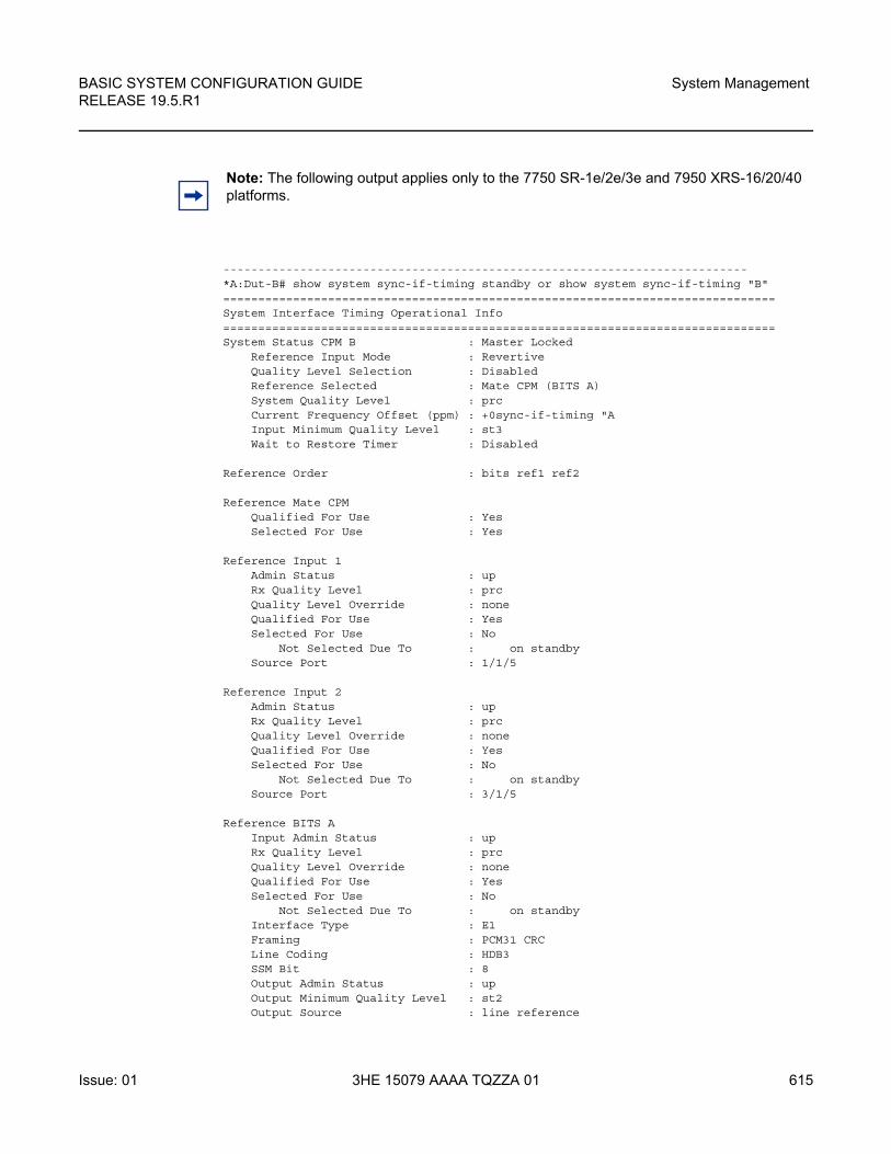
BASIC SYSTEM CONFIGURATION GUIDE RELEASE 19.5.R1
System Management
Issue: 01 3HE 15079 AAAA TQZZA 01 615
---------------------------------------------------------------------------*A:Dut-B# show system sync-if-timing standby or show system sync-if-timing "B"===============================================================================System Interface Timing Operational Info===============================================================================System Status CPM B : Master Locked
Reference Input Mode : RevertiveQuality Level Selection : DisabledReference Selected : Mate CPM (BITS A)System Quality Level : prcCurrent Frequency Offset (ppm) : +0sync-if-timing "AInput Minimum Quality Level : st3Wait to Restore Timer : Disabled
Reference Order : bits ref1 ref2
Reference Mate CPMQualified For Use : YesSelected For Use : Yes
Reference Input 1Admin Status : upRx Quality Level : prcQuality Level Override : noneQualified For Use : YesSelected For Use : No
Not Selected Due To : on standbySource Port : 1/1/5
Reference Input 2Admin Status : upRx Quality Level : prcQuality Level Override : noneQualified For Use : YesSelected For Use : No
Not Selected Due To : on standbySource Port : 3/1/5
Reference BITS AInput Admin Status : upRx Quality Level : prcQuality Level Override : noneQualified For Use : YesSelected For Use : No
Not Selected Due To : on standbyInterface Type : E1Framing : PCM31 CRCLine Coding : HDB3SSM Bit : 8Output Admin Status : upOutput Minimum Quality Level : st2Output Source : line reference
Note: The following output applies only to the 7750 SR-1e/2e/3e and 7950 XRS-16/20/40 platforms.
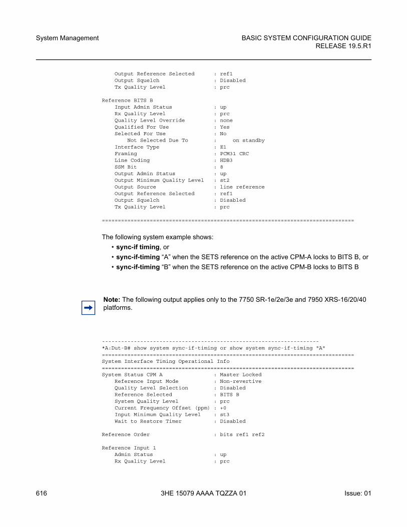
System Management
616
BASIC SYSTEM CONFIGURATION GUIDERELEASE 19.5.R1
3HE 15079 AAAA TQZZA 01 Issue: 01
Output Reference Selected : ref1Output Squelch : DisabledTx Quality Level : prc
Reference BITS BInput Admin Status : upRx Quality Level : prcQuality Level Override : noneQualified For Use : YesSelected For Use : No
Not Selected Due To : on standbyInterface Type : E1Framing : PCM31 CRCLine Coding : HDB3SSM Bit : 8Output Admin Status : upOutput Minimum Quality Level : st2Output Source : line referenceOutput Reference Selected : ref1Output Squelch : DisabledTx Quality Level : prc
===============================================================================
The following system example shows:
• sync-if timing, or
• sync-if-timing “A” when the SETS reference on the active CPM-A locks to BITS B, or
• sync-if-timing “B” when the SETS reference on the active CPM-B locks to BITS B
--------------------------------------------------------------------*A:Dut-B# show system sync-if-timing or show system sync-if-timing "A"===============================================================================System Interface Timing Operational Info===============================================================================System Status CPM A : Master Locked
Reference Input Mode : Non-revertiveQuality Level Selection : DisabledReference Selected : BITS BSystem Quality Level : prcCurrent Frequency Offset (ppm) : +0Input Minimum Quality Level : st3Wait to Restore Timer : Disabled
Reference Order : bits ref1 ref2
Reference Input 1Admin Status : upRx Quality Level : prc
Note: The following output applies only to the 7750 SR-1e/2e/3e and 7950 XRS-16/20/40 platforms.
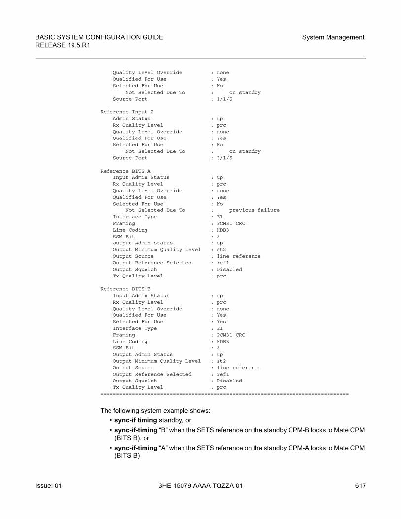
BASIC SYSTEM CONFIGURATION GUIDE RELEASE 19.5.R1
System Management
Issue: 01 3HE 15079 AAAA TQZZA 01 617
Quality Level Override : noneQualified For Use : YesSelected For Use : No
Not Selected Due To : on standbySource Port : 1/1/5
Reference Input 2Admin Status : upRx Quality Level : prcQuality Level Override : noneQualified For Use : YesSelected For Use : No
Not Selected Due To : on standbySource Port : 3/1/5
Reference BITS AInput Admin Status : upRx Quality Level : prcQuality Level Override : noneQualified For Use : YesSelected For Use : No
Not Selected Due To : previous failureInterface Type : E1Framing : PCM31 CRCLine Coding : HDB3SSM Bit : 8Output Admin Status : upOutput Minimum Quality Level : st2Output Source : line referenceOutput Reference Selected : ref1Output Squelch : DisabledTx Quality Level : prc
Reference BITS BInput Admin Status : upRx Quality Level : prcQuality Level Override : noneQualified For Use : YesSelected For Use : YesInterface Type : E1Framing : PCM31 CRCLine Coding : HDB3SSM Bit : 8Output Admin Status : upOutput Minimum Quality Level : st2Output Source : line referenceOutput Reference Selected : ref1Output Squelch : DisabledTx Quality Level : prc
===============================================================================
The following system example shows:
• sync-if timing standby, or
• sync-if-timing “B” when the SETS reference on the standby CPM-B locks to Mate CPM (BITS B), or
• sync-if-timing “A” when the SETS reference on the standby CPM-A locks to Mate CPM (BITS B)
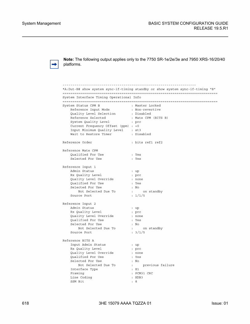
System Management
618
BASIC SYSTEM CONFIGURATION GUIDERELEASE 19.5.R1
3HE 15079 AAAA TQZZA 01 Issue: 01
--------------------------------------------------------------------*A:Dut-B# show system sync-if-timing standby or show system sync-if-timing "B"===============================================================================System Interface Timing Operational Info===============================================================================System Status CPM B : Master Locked
Reference Input Mode : Non-revertiveQuality Level Selection : DisabledReference Selected : Mate CPM (BITS B)System Quality Level : prcCurrent Frequency Offset (ppm) : +0Input Minimum Quality Level : st3Wait to Restore Timer : Disabled
Reference Order : bits ref1 ref2
Reference Mate CPMQualified For Use : YesSelected For Use : Yes
Reference Input 1Admin Status : upRx Quality Level : prcQuality Level Override : noneQualified For Use : YesSelected For Use : No
Not Selected Due To : on standbySource Port : 1/1/5
Reference Input 2Admin Status : upRx Quality Level : prcQuality Level Override : noneQualified For Use : YesSelected For Use : No
Not Selected Due To : on standbySource Port : 3/1/5
Reference BITS AInput Admin Status : upRx Quality Level : prcQuality Level Override : noneQualified For Use : YesSelected For Use : No
Not Selected Due To : previous failureInterface Type : E1Framing : PCM31 CRCLine Coding : HDB3SSM Bit : 8
Note: The following output applies only to the 7750 SR-1e/2e/3e and 7950 XRS-16/20/40 platforms.
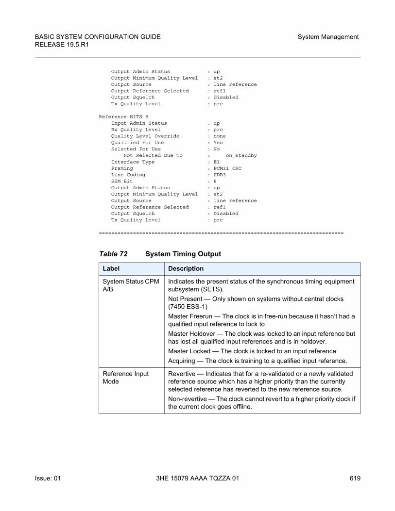
BASIC SYSTEM CONFIGURATION GUIDE RELEASE 19.5.R1
System Management
Issue: 01 3HE 15079 AAAA TQZZA 01 619
Output Admin Status : upOutput Minimum Quality Level : st2Output Source : line referenceOutput Reference Selected : ref1Output Squelch : DisabledTx Quality Level : prc
Reference BITS BInput Admin Status : upRx Quality Level : prcQuality Level Override : noneQualified For Use : YesSelected For Use : No
Not Selected Due To : on standbyInterface Type : E1Framing : PCM31 CRCLine Coding : HDB3SSM Bit : 8Output Admin Status : upOutput Minimum Quality Level : st2Output Source : line referenceOutput Reference Selected : ref1Output Squelch : DisabledTx Quality Level : prc
===============================================================================
Table 72 System Timing Output
Label Description
System Status CPM A/B
Indicates the present status of the synchronous timing equipment subsystem (SETS).
Not Present — Only shown on systems without central clocks (7450 ESS-1)
Master Freerun — The clock is in free-run because it hasn’t had a qualified input reference to lock to
Master Holdover — The clock was locked to an input reference but has lost all qualified input references and is in holdover.
Master Locked — The clock is locked to an input reference
Acquiring — The clock is training to a qualified input reference.
Reference Input Mode
Revertive — Indicates that for a re-validated or a newly validated reference source which has a higher priority than the currently selected reference has reverted to the new reference source.
Non-revertive — The clock cannot revert to a higher priority clock if the current clock goes offline.
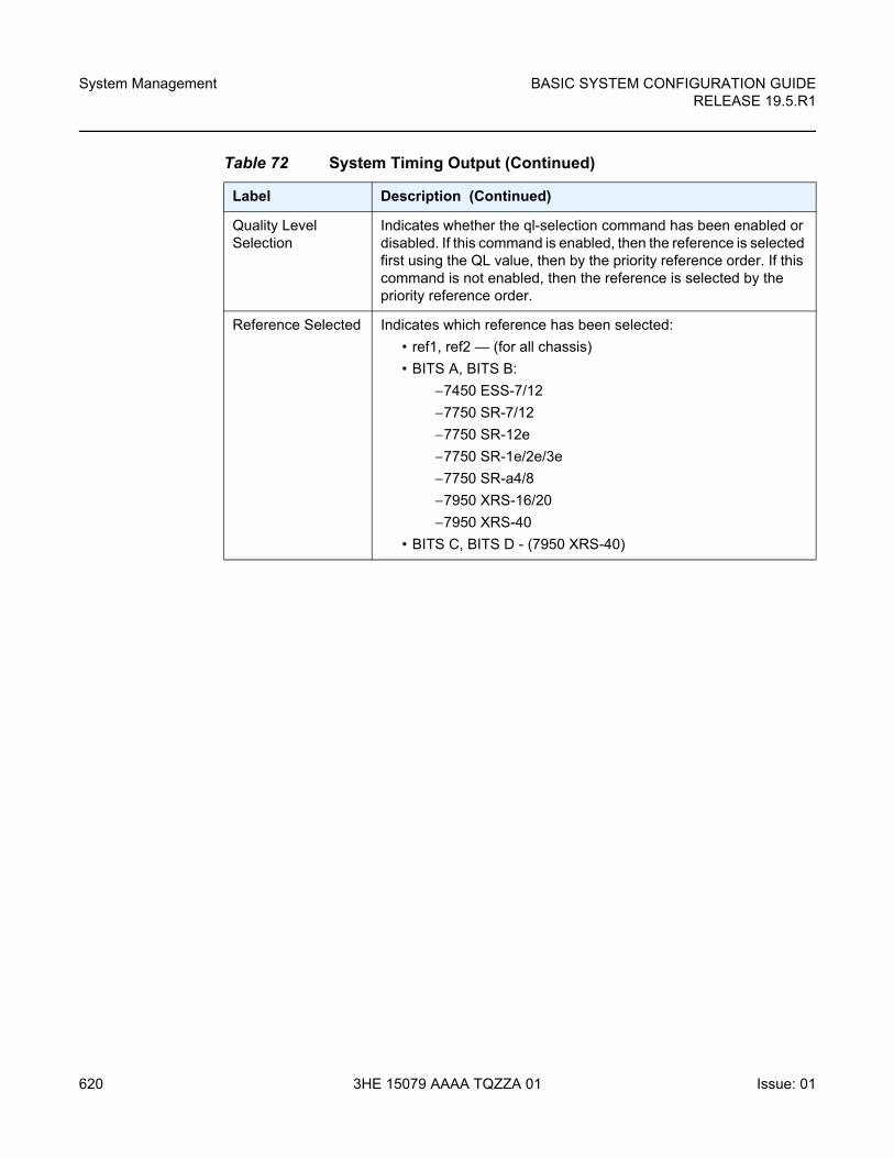
System Management
620
BASIC SYSTEM CONFIGURATION GUIDERELEASE 19.5.R1
3HE 15079 AAAA TQZZA 01 Issue: 01
Quality Level Selection
Indicates whether the ql-selection command has been enabled or disabled. If this command is enabled, then the reference is selected first using the QL value, then by the priority reference order. If this command is not enabled, then the reference is selected by the priority reference order.
Reference Selected Indicates which reference has been selected:
• ref1, ref2 — (for all chassis)
• BITS A, BITS B:
−7450 ESS-7/12
−7750 SR-7/12
−7750 SR-12e
−7750 SR-1e/2e/3e
−7750 SR-a4/8
−7950 XRS-16/20
−7950 XRS-40
• BITS C, BITS D - (7950 XRS-40)
Table 72 System Timing Output (Continued)
Label Description (Continued)
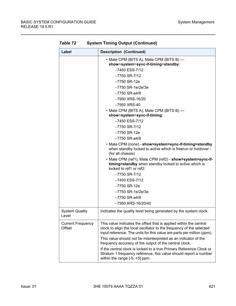
BASIC SYSTEM CONFIGURATION GUIDE RELEASE 19.5.R1
System Management
Issue: 01 3HE 15079 AAAA TQZZA 01 621
• Mate CPM (BITS A), Mate CPM (BITS B) — show>system>sync-if-timing>standby:
−7450 ESS-7/12
−7750 SR-7/12
−7750 SR-12e
−7750 SR-1e/2e/3e
−7750 SR-a4/8
−7950 XRS-16/20
−7950 XRS-40
• Mate CPM (BITS A), Mate CPM (BITS B) — show>system>sync-if-timing:
−7450 ESS-7/12
−7750 SR-7/12
−7750 SR-12e
−7750 SR-a4/8
• Mate CPM (none) - show>system>sync-if-timing>standby when standby locked to active which is freerun or holdover - (for all chassis)
• Mate CPM (ref1), Mate CPM (ref2) - show>system>sync-if-timing>standby when standby locked to active which is locked to ref1 or ref2:
−7750 SR-7/12
−7450 ESS-7/12
−7750 SR-12e
−7750 SR-1e/2e/3e
−7750 SR-a4/8
−7950 XRS-16/20/40
System Quality Level
Indicates the quality level being generated by the system clock.
Current Frequency Offset
This value indicates the offset that is applied within the central clock to align the local oscillator to the frequency of the selected input reference. The units for this value are parts per million (ppm).
This value should not be misinterpreted as an indicator of the frequency accuracy of the output of the central clock.
If the central clock is locked to a true Primary Reference Clock or Stratum 1 frequency reference, this value should report a number within the range [-5, +5] ppm.
Table 72 System Timing Output (Continued)
Label Description (Continued)
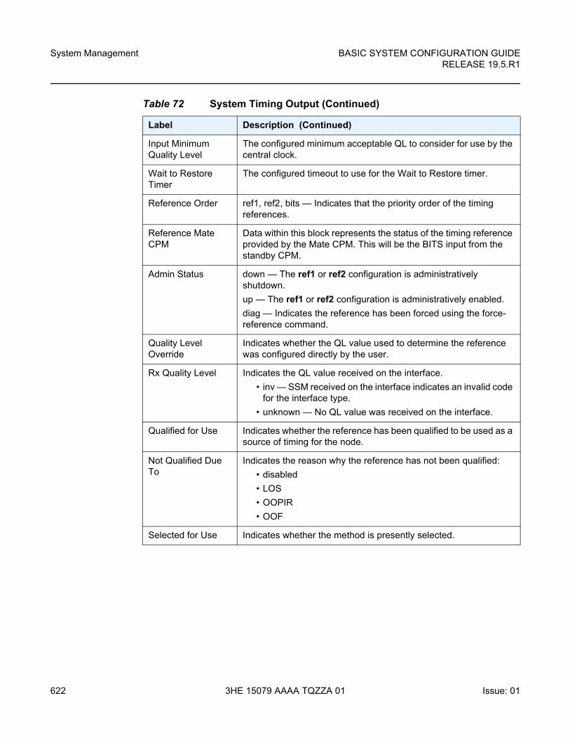
System Management
622
BASIC SYSTEM CONFIGURATION GUIDERELEASE 19.5.R1
3HE 15079 AAAA TQZZA 01 Issue: 01
Input Minimum Quality Level
The configured minimum acceptable QL to consider for use by the central clock.
Wait to Restore Timer
The configured timeout to use for the Wait to Restore timer.
Reference Order ref1, ref2, bits — Indicates that the priority order of the timing references.
Reference Mate CPM
Data within this block represents the status of the timing reference provided by the Mate CPM. This will be the BITS input from the standby CPM.
Admin Status down — The ref1 or ref2 configuration is administratively shutdown.
up — The ref1 or ref2 configuration is administratively enabled.
diag — Indicates the reference has been forced using the force-reference command.
Quality Level Override
Indicates whether the QL value used to determine the reference was configured directly by the user.
Rx Quality Level Indicates the QL value received on the interface.
• inv — SSM received on the interface indicates an invalid code for the interface type.
• unknown — No QL value was received on the interface.
Qualified for Use Indicates whether the reference has been qualified to be used as a source of timing for the node.
Not Qualified Due To
Indicates the reason why the reference has not been qualified:
• disabled
• LOS
• OOPIR
• OOF
Selected for Use Indicates whether the method is presently selected.
Table 72 System Timing Output (Continued)
Label Description (Continued)
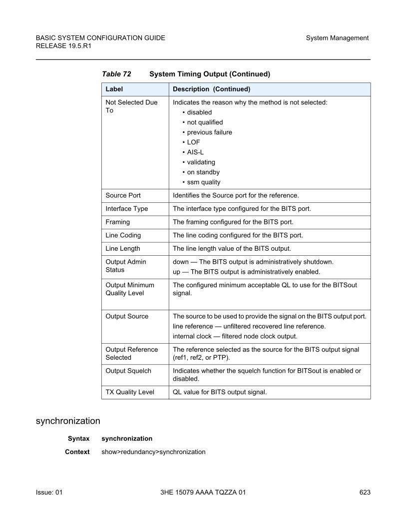
BASIC SYSTEM CONFIGURATION GUIDE RELEASE 19.5.R1
System Management
Issue: 01 3HE 15079 AAAA TQZZA 01 623
synchronization
Syntax synchronization
Context show>redundancy>synchronization
Not Selected Due To
Indicates the reason why the method is not selected:
• disabled
• not qualified
• previous failure
• LOF
• AIS-L
• validating
• on standby
• ssm quality
Source Port Identifies the Source port for the reference.
Interface Type The interface type configured for the BITS port.
Framing The framing configured for the BITS port.
Line Coding The line coding configured for the BITS port.
Line Length The line length value of the BITS output.
Output Admin Status
down — The BITS output is administratively shutdown.
up — The BITS output is administratively enabled.
Output Minimum Quality Level
The configured minimum acceptable QL to use for the BITSout signal.
Output Source The source to be used to provide the signal on the BITS output port.
line reference — unfiltered recovered line reference.
internal clock — filtered node clock output.
Output Reference Selected
The reference selected as the source for the BITS output signal (ref1, ref2, or PTP).
Output Squelch Indicates whether the squelch function for BITSout is enabled or disabled.
TX Quality Level QL value for BITS output signal.
Table 72 System Timing Output (Continued)
Label Description (Continued)
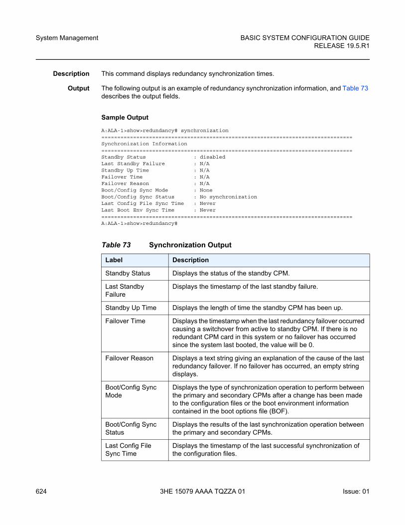
System Management
624
BASIC SYSTEM CONFIGURATION GUIDERELEASE 19.5.R1
3HE 15079 AAAA TQZZA 01 Issue: 01
Description This command displays redundancy synchronization times.
Output The following output is an example of redundancy synchronization information, and Table 73 describes the output fields.
Sample Output
A:ALA-1>show>redundancy# synchronization===============================================================================Synchronization Information===============================================================================Standby Status : disabledLast Standby Failure : N/AStandby Up Time : N/AFailover Time : N/AFailover Reason : N/ABoot/Config Sync Mode : NoneBoot/Config Sync Status : No synchronizationLast Config File Sync Time : NeverLast Boot Env Sync Time : Never===============================================================================A:ALA-1>show>redundancy#
Table 73 Synchronization Output
Label Description
Standby Status Displays the status of the standby CPM.
Last Standby Failure
Displays the timestamp of the last standby failure.
Standby Up Time Displays the length of time the standby CPM has been up.
Failover Time Displays the timestamp when the last redundancy failover occurred causing a switchover from active to standby CPM. If there is no redundant CPM card in this system or no failover has occurred since the system last booted, the value will be 0.
Failover Reason Displays a text string giving an explanation of the cause of the last redundancy failover. If no failover has occurred, an empty string displays.
Boot/Config Sync Mode
Displays the type of synchronization operation to perform between the primary and secondary CPMs after a change has been made to the configuration files or the boot environment information contained in the boot options file (BOF).
Boot/Config Sync Status
Displays the results of the last synchronization operation between the primary and secondary CPMs.
Last Config File Sync Time
Displays the timestamp of the last successful synchronization of the configuration files.
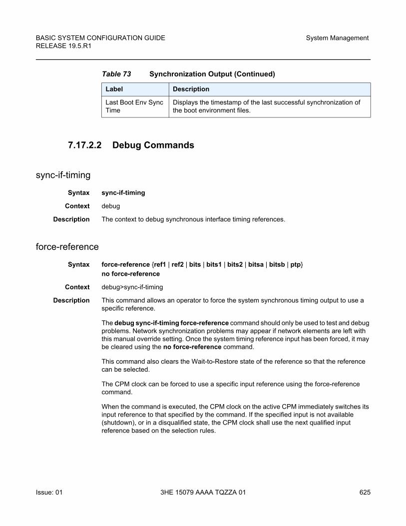
BASIC SYSTEM CONFIGURATION GUIDE RELEASE 19.5.R1
System Management
Issue: 01 3HE 15079 AAAA TQZZA 01 625
7.17.2.2 Debug Commands
sync-if-timing
Syntax sync-if-timing
Context debug
Description The context to debug synchronous interface timing references.
force-reference
Syntax force-reference {ref1 | ref2 | bits | bits1 | bits2 | bitsa | bitsb | ptp}
no force-reference
Context debug>sync-if-timing
Description This command allows an operator to force the system synchronous timing output to use a specific reference.
The debug sync-if-timing force-reference command should only be used to test and debug problems. Network synchronization problems may appear if network elements are left with this manual override setting. Once the system timing reference input has been forced, it may be cleared using the no force-reference command.
This command also clears the Wait-to-Restore state of the reference so that the reference can be selected.
The CPM clock can be forced to use a specific input reference using the force-reference command.
When the command is executed, the CPM clock on the active CPM immediately switches its input reference to that specified by the command. If the specified input is not available (shutdown), or in a disqualified state, the CPM clock shall use the next qualified input reference based on the selection rules.
Last Boot Env Sync Time
Displays the timestamp of the last successful synchronization of the boot environment files.
Table 73 Synchronization Output (Continued)
Label Description
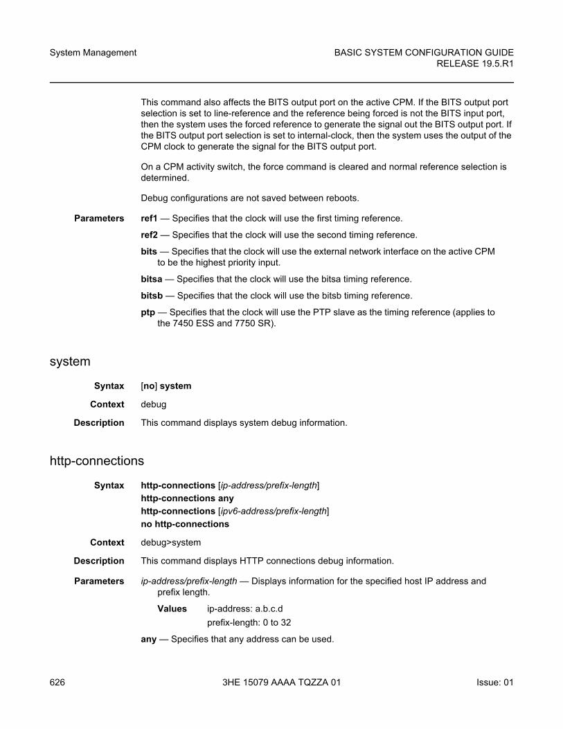
System Management
626
BASIC SYSTEM CONFIGURATION GUIDERELEASE 19.5.R1
3HE 15079 AAAA TQZZA 01 Issue: 01
This command also affects the BITS output port on the active CPM. If the BITS output port selection is set to line-reference and the reference being forced is not the BITS input port, then the system uses the forced reference to generate the signal out the BITS output port. If the BITS output port selection is set to internal-clock, then the system uses the output of the CPM clock to generate the signal for the BITS output port.
On a CPM activity switch, the force command is cleared and normal reference selection is determined.
Debug configurations are not saved between reboots.
Parameters ref1 — Specifies that the clock will use the first timing reference.
ref2 — Specifies that the clock will use the second timing reference.
bits — Specifies that the clock will use the external network interface on the active CPM to be the highest priority input.
bitsa — Specifies that the clock will use the bitsa timing reference.
bitsb — Specifies that the clock will use the bitsb timing reference.
ptp — Specifies that the clock will use the PTP slave as the timing reference (applies to the 7450 ESS and 7750 SR).
system
Syntax [no] system
Context debug
Description This command displays system debug information.
http-connections
Syntax http-connections [ip-address/prefix-length]
http-connections any
http-connections [ipv6-address/prefix-length]
no http-connections
Context debug>system
Description This command displays HTTP connections debug information.
Parameters ip-address/prefix-length — Displays information for the specified host IP address and prefix length.
Values ip-address: a.b.c.d
prefix-length: 0 to 32
any — Specifies that any address can be used.
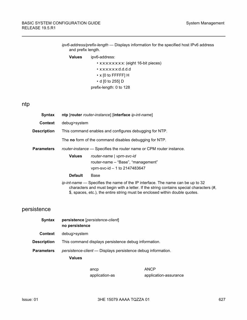
BASIC SYSTEM CONFIGURATION GUIDE RELEASE 19.5.R1
System Management
Issue: 01 3HE 15079 AAAA TQZZA 01 627
ipv6-address/prefix-length — Displays information for the specified host IPv6 address and prefix length.
Values ipv6-address:
• x:x:x:x:x:x:x:x: (eight 16-bit pieces)
• x:x:x:x:x:x:d.d.d.d
• x [0 to FFFFF] H
• d [0 to 255] D
prefix-length: 0 to 128
ntp
Syntax ntp [router router-instance] [interface ip-int-name]
Context debug>system
Description This command enables and configures debugging for NTP.
The no form of the command disables debugging for NTP.
Parameters router-instance — Specifies the router name or CPM router instance.
Values router-name | vprn-svc-id
router-name – “Base”, “management”
vprn-svc-id – 1 to 2147483647
Default Base
ip-int-name — Specifies the name of the IP interface. The name can be up to 32 characters and must begin with a letter. If the string contains special characters (#, $, spaces, etc.), the entire string must be enclosed within double quotes.
persistence
Syntax persistence [persistence-client]
no persistence
Context debug>system
Description This command displays persistence debug information.
Parameters persistence-client — Displays persistence debug information.
Values
ancp ANCP
application-as application-assurance
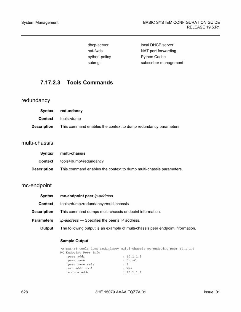
System Management
628
BASIC SYSTEM CONFIGURATION GUIDERELEASE 19.5.R1
3HE 15079 AAAA TQZZA 01 Issue: 01
7.17.2.3 Tools Commands
redundancy
Syntax redundancy
Context tools>dump
Description This command enables the context to dump redundancy parameters.
multi-chassis
Syntax multi-chassis
Context tools>dump>redundancy
Description This command enables the context to dump multi-chassis parameters.
mc-endpoint
Syntax mc-endpoint peer ip-address
Context tools>dump>redundancy>multi-chassis
Description This command dumps multi-chassis endpoint information.
Parameters ip-address — Specifies the peer’s IP address.
Output The following output is an example of multi-chassis peer endpoint information.
Sample Output
*A:Dut-B# tools dump redundancy multi-chassis mc-endpoint peer 10.1.1.3MC Endpoint Peer Info
peer addr : 10.1.1.3peer name : Dut-Cpeer name refs : 1src addr conf : Yessource addr : 10.1.1.2
dhcp-server local DHCP server
nat-fwds NAT port forwarding
python-policy Python Cache
submgt subscriber management
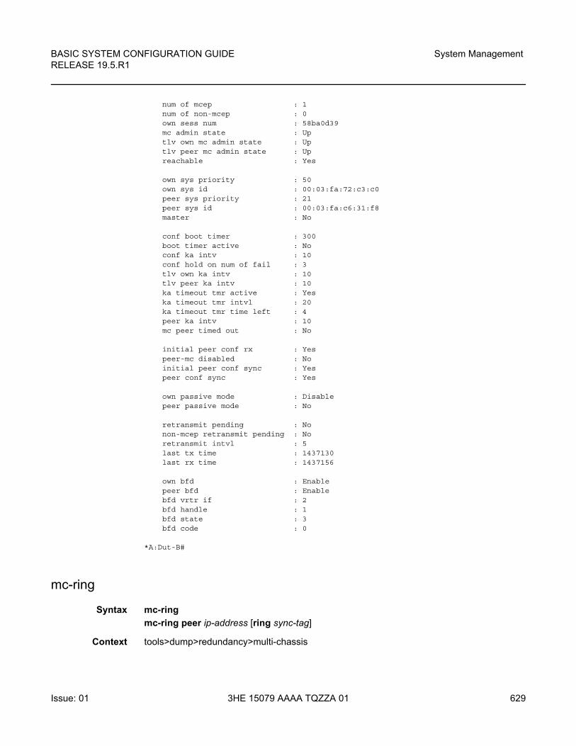
BASIC SYSTEM CONFIGURATION GUIDE RELEASE 19.5.R1
System Management
Issue: 01 3HE 15079 AAAA TQZZA 01 629
num of mcep : 1num of non-mcep : 0own sess num : 58ba0d39mc admin state : Uptlv own mc admin state : Uptlv peer mc admin state : Upreachable : Yes
own sys priority : 50own sys id : 00:03:fa:72:c3:c0peer sys priority : 21peer sys id : 00:03:fa:c6:31:f8master : No
conf boot timer : 300boot timer active : Noconf ka intv : 10conf hold on num of fail : 3tlv own ka intv : 10tlv peer ka intv : 10ka timeout tmr active : Yeska timeout tmr intvl : 20ka timeout tmr time left : 4peer ka intv : 10mc peer timed out : No
initial peer conf rx : Yespeer-mc disabled : Noinitial peer conf sync : Yespeer conf sync : Yes
own passive mode : Disablepeer passive mode : No
retransmit pending : Nonon-mcep retransmit pending : Noretransmit intvl : 5last tx time : 1437130last rx time : 1437156
own bfd : Enablepeer bfd : Enablebfd vrtr if : 2bfd handle : 1bfd state : 3bfd code : 0
*A:Dut-B#
mc-ring
Syntax mc-ring
mc-ring peer ip-address [ring sync-tag]
Context tools>dump>redundancy>multi-chassis
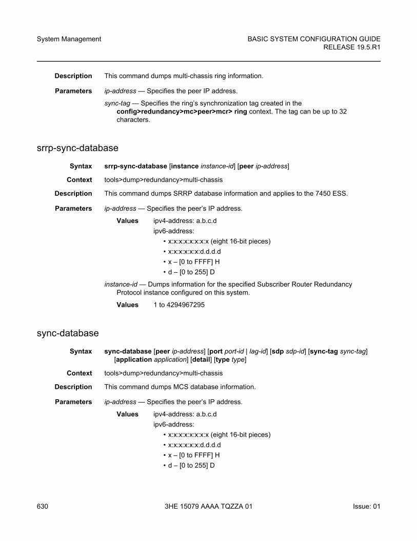
System Management
630
BASIC SYSTEM CONFIGURATION GUIDERELEASE 19.5.R1
3HE 15079 AAAA TQZZA 01 Issue: 01
Description This command dumps multi-chassis ring information.
Parameters ip-address — Specifies the peer IP address.
sync-tag — Specifies the ring’s synchronization tag created in the config>redundancy>mc>peer>mcr> ring context. The tag can be up to 32 characters.
srrp-sync-database
Syntax srrp-sync-database [instance instance-id] [peer ip-address]
Context tools>dump>redundancy>multi-chassis
Description This command dumps SRRP database information and applies to the 7450 ESS.
Parameters ip-address — Specifies the peer’s IP address.
Values ipv4-address: a.b.c.d
ipv6-address:
• x:x:x:x:x:x:x:x (eight 16-bit pieces)
• x:x:x:x:x:x:d.d.d.d
• x – [0 to FFFF] H
• d – [0 to 255] D
instance-id — Dumps information for the specified Subscriber Router Redundancy Protocol instance configured on this system.
Values 1 to 4294967295
sync-database
Syntax sync-database [peer ip-address] [port port-id | lag-id] [sdp sdp-id] [sync-tag sync-tag] [application application] [detail] [type type]
Context tools>dump>redundancy>multi-chassis
Description This command dumps MCS database information.
Parameters ip-address — Specifies the peer’s IP address.
Values ipv4-address: a.b.c.d
ipv6-address:
• x:x:x:x:x:x:x:x (eight 16-bit pieces)
• x:x:x:x:x:x:d.d.d.d
• x – [0 to FFFF] H
• d – [0 to 255] D
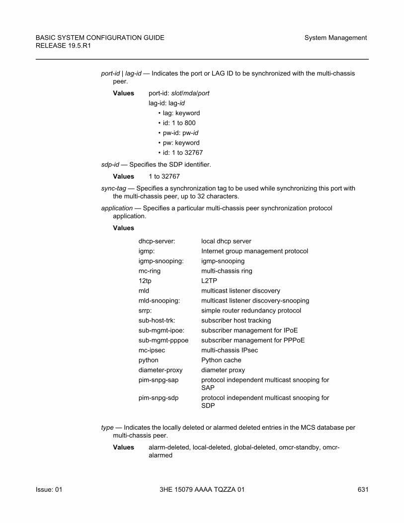
BASIC SYSTEM CONFIGURATION GUIDE RELEASE 19.5.R1
System Management
Issue: 01 3HE 15079 AAAA TQZZA 01 631
port-id | lag-id — Indicates the port or LAG ID to be synchronized with the multi-chassis peer.
Values port-id: slot/mda/port
lag-id: lag-id
• lag: keyword
• id: 1 to 800
• pw-id: pw-id
• pw: keyword
• id: 1 to 32767
sdp-id — Specifies the SDP identifier.
Values 1 to 32767
sync-tag — Specifies a synchronization tag to be used while synchronizing this port with the multi-chassis peer, up to 32 characters.
application — Specifies a particular multi-chassis peer synchronization protocol application.
Values
type — Indicates the locally deleted or alarmed deleted entries in the MCS database per multi-chassis peer.
Values alarm-deleted, local-deleted, global-deleted, omcr-standby, omcr-alarmed
dhcp-server: local dhcp server
igmp: Internet group management protocol
igmp-snooping: igmp-snooping
mc-ring multi-chassis ring
12tp L2TP
mld multicast listener discovery
mld-snooping: multicast listener discovery-snooping
srrp: simple router redundancy protocol
sub-host-trk: subscriber host tracking
sub-mgmt-ipoe: subscriber management for IPoE
sub-mgmt-pppoe subscriber management for PPPoE
mc-ipsec multi-chassis IPsec
python Python cache
diameter-proxy diameter proxy
pim-snpg-sap protocol independent multicast snooping for SAP
pim-snpg-sdp protocol independent multicast snooping for SDP
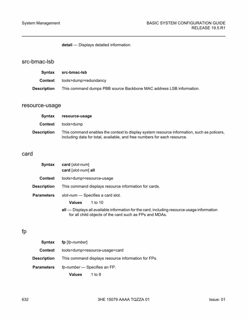
System Management
632
BASIC SYSTEM CONFIGURATION GUIDERELEASE 19.5.R1
3HE 15079 AAAA TQZZA 01 Issue: 01
detail — Displays detailed information.
src-bmac-lsb
Syntax src-bmac-lsb
Context tools>dump>redundancy
Description This command dumps PBB source Backbone MAC address LSB information.
resource-usage
Syntax resource-usage
Context tools>dump
Description This command enables the context to display system resource information, such as policers, including data for total, available, and free numbers for each resource.
card
Syntax card [slot-num]
card [slot-num] all
Context tools>dump>resource-usage
Description This command displays resource information for cards.
Parameters slot-num — Specifies a card slot.
Values 1 to 10
all — Displays all available information for the card, including resource usage information for all child objects of the card such as FPs and MDAs.
fp
Syntax fp [fp-number]
Context tools>dump>resource-usage>card
Description This command displays resource information for FPs.
Parameters fp-number — Specifies an FP.
Values 1 to 8
BASIC SYSTEM CONFIGURATION GUIDE RELEASE 19.5.R1
System Management
Issue: 01 3HE 15079 AAAA TQZZA 01 633
mda
Syntax mda [mda-slot]
Context tools>dump>resource-usage>card
Description This command displays resource information for MDAs.
Parameters mda-slot — Specifies an MDA slot.
Values 1 to 2
system
Syntax system [all]
Context tools>dump>resource-usage
Description This command displays resource information for resources that are managed at the system level.
Parameters all — Displays all system resource usage information, as well as resource usage information for all cards, FPs, and MDAs in the system.
system-resources
Syntax system-resources [slot-number]
Context tools>dump
Description The system-resources command has been deprecated and replaced by the tools>dump>resource-usage command. The system-resources command continues to be supported, but it is recommended to use the resource-usage command instead.
This command displays system resource information.
Parameters slot-number — Specifies a specific slot to view system resources information.
Values 1 to 10
chassis
Syntax chassis [phys-chassis-id]
Context tools>perform
Description The following command performs chassis maintenance operations.
System Management
634
BASIC SYSTEM CONFIGURATION GUIDERELEASE 19.5.R1
3HE 15079 AAAA TQZZA 01 Issue: 01
Parameters phys-chassis-id — The identifier of the physical chassis for the tools perform context.
Values 1
check-bp-eprom
Syntax check-bp-eprom
Context tools>perform>chassis
Description This command checks the chassis BP EPROM. The function reads the EPROM and is corrected with one of the following:
• for each SEEP that is found to be acceptable or can be corrected:
“BP eprom X: ok” with X = seep number
• for each SEEP that is found to be unacceptable and cannot be corrected:
“BP eprom X: not ok”
set-role
Syntax set-role {extension | master | standalone}
Context tools>perform>chassis
Description This command sets the role of the 7950 XRS chassis from which the command is invoked.
• When run on a standalone chassis this will update the EEPROM on the (one) Chassis backplane.
• Master and Extension chassis are blocked if any SFMs are configured as type sfm-x20 (must be sfm-x20-b). The following message displays:
• When the extension option is specified, the chassis will immediately reboot as part of the command. The following warning and prompt will be provided:
WARNING: You are about to provision the chassis as an XRS-40 Extension chassis.This chassis will immediately reboot after the command is executed. No CLI shell isavailable directly on an Extension chassis. An Extension chassis will not completelyboot up unless it is properly cabled to and controlled by an XRS-40 Master
chassis. Do you wish to proceed (yes/no) ?
• When the master option is specified, the chassis will immediately reboot as part of the command. The Operational mode is not changed until a reboot is performed. The following warning and prompt will be provided:
WARNING: You are about to provision the chassis as an XRS-40 Master chassis. This chassis will immediately reboot after the command isexecute
Do you wish to proceed (yes/no) ?
BASIC SYSTEM CONFIGURATION GUIDE RELEASE 19.5.R1
System Management
Issue: 01 3HE 15079 AAAA TQZZA 01 635
• When the master or extension options are specified and the chassis has any SFM slots with a configured type of sfm-x20, then the command will fail with the following message:
Configured sfm-type of sfm-x20 is not compatible with XRS-40 mode operation.
If you want to change the role of the chassis anyways, you can deconfigure the SFMs and then change the role.
redundancy
Syntax redundancy
Context tools>perform
Description This command enables the context to display redundancy information.
forced-single-sfm-overload
Syntax [no] forced-single-sfm-overload
Context tools>perform>redundancy
Description This command forces the single-sfm-overload state on or off.
issu-post-process
Syntax issu-post-process
Context tools>perform>redundancy
Description This command allows requests for new LSPs.
mgmt-ethernet
Syntax mgmt-ethernet
Context tools>perform>redundancy
Description This command triggers redundancy mode, just as if the management Ethernet port of the primary CPM has gone down. The router will revert if the management Ethernet port of the primary CPM has been up for the revert duration.
System Management
636
BASIC SYSTEM CONFIGURATION GUIDERELEASE 19.5.R1
3HE 15079 AAAA TQZZA 01 Issue: 01
force-uplink-switch
Syntax force-uplink-switch client-port-id
Context tools>perform>satellite
Description This command forces traffic associated with the specified satellite client port to be switched away from the current uplink depending on which uplink is currently active.
Parameters client-port-id — Specifies the satellite client port associated with the port mapping, in the format esat-id/slot/port force.
mixed-mode-upgrade
Syntax mixed-mode-upgrade [slot-list] [now]
Context tools>perform>system
Description This command initiates the upgrade process to enable mixed-mode in a 7450 ESS-7 or ESS-12.
Executing this command will (as one action), enable the system state of mixed-mode and enable SR capabilities on the IOMs or IMMs located in the slots specified in the slot list. This will result in rebooting of the IOMs and IMMs located in the specified slots.
If any of the slots contain 7450 ESS IOMs, this command will fail.
This command can only be used to enable the mixed-mode state. It can not be used to reverse the state.
Parameters slot-list — Specifies a list of slots to be upgraded to 7750 IOM/IMM functionality. This parameter is required to modify the mode in which the IOM/IMMs function and will require a reboot of the IOM/IMMs in the designated slot.
now — Forces the command to be executed immediately without further question (optional). If this keyword is not present, then the user will be presented with a question to ensure they understand that as a result of this command, the associated slots will be reset immediately to enable mixed mode.
system
Syntax system
Context tools>perform
Description This command is a tool for controlling the system.
BASIC SYSTEM CONFIGURATION GUIDE RELEASE 19.5.R1
System Management
Issue: 01 3HE 15079 AAAA TQZZA 01 637
auto-node-provisioning
Syntax auto-node-provisioning
Context tools>perform>system
Description This command initiates auto-provisioning of the node on all ports that are operationally up but do not have an IP address.
bluetooth
Syntax bluetooth
Context tools>perform>system
Description This command enters the context for tools commands related to the Bluetooth interface.
module
Syntax module cpm-slot action {reboot | disconnect}
Context tools>perform>system>bluetooth
Description This command performs reboots or disconnects on the Bluetooth module on the specified CPM.
Parameters cpm-slot — Specifies the CPM slot
Values {A | B | C | D}
reboot — triggers a reboot of the Bluetooth subsystem on the module.
disconnect — forces a disconnect of any active Bluetooth session.
ipv4
Syntax ipv4 [timeout seconds] [dhcp-client-identifier {string ascii-string | hex hex-string | serial-number}] [reboot-on-success] [save-provision-file-destination file-url]
Context tools>perform>system>auto-node-provisioning
Description This command initiates the IPv4 auto-provisioning of the node on all the ports that have an operationally up port but no IP address.
System Management
638
BASIC SYSTEM CONFIGURATION GUIDERELEASE 19.5.R1
3HE 15079 AAAA TQZZA 01 Issue: 01
Parameters seconds — DHCP request timeout period, before the system tries the next interface. Within this timeout, the DHCP client tries to retransmit the DHCP request with randomized exponential backoff (RFC 2131). This randomized exponential backoff begins at 2 s and goes to 64 s (2,4,8,32,64,64,64,64). After 64 seconds, the system will retry every 64 s.
Values 1 to 65535 seconds
Default 10
ascii-string — DHCP client identifier in ASCII format, up to 127 characters long.
hex-string — DHCP client identifier in hexadecimal format, up to 254 hexadecimal nibbles long.
Values 0x0 to 0xFFFFFFFF
file-url — The file URL as a local-url. The local file or folder name should not exceed 99 characters).
sfm-interco-test
Syntax sfm-interco-test [sfm x]
Context tools>perform>system>inter-chassis>
Description Use this command to run inter-chassis SFM loopback tests for the 7950 XRS.
Run on an out-of-service standalone chassis that will later become the Extension chassis of an XRS-40 system. The out of service chassis (Chassis 1 – future Master chassis) must be connected by means of SFM interconnect links (cable bundles) before this test is run. This test operates without requiring any XCMs in either chassis, but they can be present.
The test should not be initiated from Chassis 1.
The following conditions must be satisfied for the test to be permitted:
• The system must be in standalone mode; error message:The test can only be performed on a standalone system
• The system must have only XRS-40 compatible SFMs provisioned; error message:The chassis can not have SFMs with a configured type of sfm-x20s-bwhen performing the test
• All provisioned SFMs must be operational; error message:
local-url [cflash-id/][file-path]
cflash-id cf1:, cf1-A:, cf1-B:, cf2:, cf2-A:, cf2-B:, cf3:, cf3-A:, cf3-B:
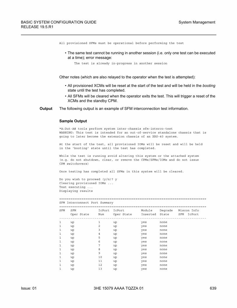
BASIC SYSTEM CONFIGURATION GUIDE RELEASE 19.5.R1
System Management
Issue: 01 3HE 15079 AAAA TQZZA 01 639
All provisioned SFMs must be operational before performing the test
• The same test cannot be running in another session (i.e. only one test can be executed at a time); error message:
The test is already in-progress in another session
Other notes (which are also relayed to the operator when the test is attempted):
• All provisioned XCMs will be reset at the start of the test and will be held in the booting state until the test has completed.
• All SFMs will be cleared when the operator exits the test. This will trigger a reset of the XCMs and the standby CPM.
Output The following output is an example of SFM interconnection test information.
Sample Output
*A:Dut-A# tools perform system inter-chassis sfm-interco-testWARNING: This test is intended for an out-of-service standalone chassis that isgoing to later become the extension chassis of an XRS-40 system.
At the start of the test, all provisioned IOMs will be reset and will be heldin the 'booting' state until the test has completed.
While the test is running avoid altering this system or the attached system(e.g. do not shutdown, clear, or remove the CPMs/SFMs/IOMs and do not issueCPM switchovers)
Once testing has completed all SFMs in this system will be cleared.
Do you wish to proceed (y/n)? yClearing provisioned IOMs ...Test executing ...Displaying results
===============================================================================SFM Interconnect Port Summary===============================================================================SFM SFM IcPort IcPort Module Degrade Miscon Info
Oper State Num Oper State Inserted State SFM IcPort-------------------------------------------------------------------------------1 up 1 up yes none1 up 2 up yes none1 up 3 up yes none1 up 4 up yes none1 up 5 up yes none1 up 6 up yes none1 up 7 up yes none1 up 8 up yes none1 up 9 up yes none1 up 10 up yes none1 up 11 up yes none1 up 12 up yes none1 up 13 up yes none
System Management
640
BASIC SYSTEM CONFIGURATION GUIDERELEASE 19.5.R1
3HE 15079 AAAA TQZZA 01 Issue: 01
1 up 14 up yes none2 up 1 up yes none2 up 2 up yes none2 up 3 up yes none2 up 4 up yes none2 up 5 up yes none2 up 6 up yes none2 up 7 up yes none2 up 8 up yes none2 up 9 up yes none2 up 10 up yes none2 up 11 up yes none2 up 12 up yes none2 up 13 up yes none2 up 14 up yes none3 up 1 up yes none3 up 2 up yes none3 up 3 up yes none3 up 4 up yes none3 up 5 up yes none3 up 6 up yes none3 up 7 up yes none3 up 8 up yes none3 up 9 up yes none3 up 10 up yes none3 up 11 up yes none3 up 12 up yes none3 up 13 up yes none3 up 14 up yes none4 up 1 up yes none4 up 2 up yes none4 up 3 up yes none4 up 4 up yes none4 up 5 up yes none4 up 6 up yes none4 up 7 up yes none4 up 8 up yes none4 up 9 up yes none4 up 10 up yes none4 up 11 up yes none4 up 12 up yes none4 up 13 up yes none4 up 14 up yes none5 up 1 up yes none5 up 2 up yes none5 up 3 up yes none5 up 4 up yes none5 up 5 up yes none5 up 6 up yes none5 up 7 up yes none5 up 8 up yes none5 up 9 up yes none5 up 10 up yes none5 up 11 up yes none5 up 12 up yes none5 up 13 up yes none5 up 14 up yes none6 up 1 up yes none6 up 2 up yes none
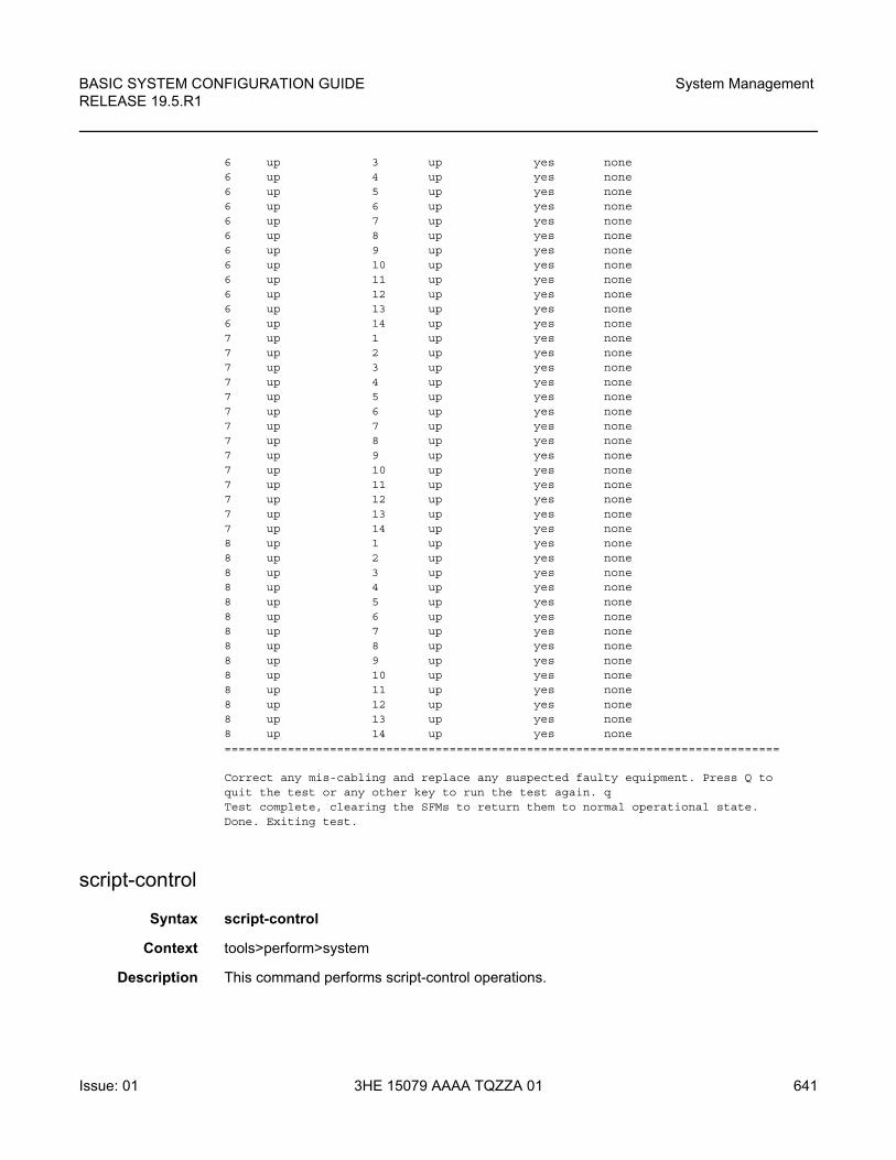
BASIC SYSTEM CONFIGURATION GUIDE RELEASE 19.5.R1
System Management
Issue: 01 3HE 15079 AAAA TQZZA 01 641
6 up 3 up yes none6 up 4 up yes none6 up 5 up yes none6 up 6 up yes none6 up 7 up yes none6 up 8 up yes none6 up 9 up yes none6 up 10 up yes none6 up 11 up yes none6 up 12 up yes none6 up 13 up yes none6 up 14 up yes none7 up 1 up yes none7 up 2 up yes none7 up 3 up yes none7 up 4 up yes none7 up 5 up yes none7 up 6 up yes none7 up 7 up yes none7 up 8 up yes none7 up 9 up yes none7 up 10 up yes none7 up 11 up yes none7 up 12 up yes none7 up 13 up yes none7 up 14 up yes none8 up 1 up yes none8 up 2 up yes none8 up 3 up yes none8 up 4 up yes none8 up 5 up yes none8 up 6 up yes none8 up 7 up yes none8 up 8 up yes none8 up 9 up yes none8 up 10 up yes none8 up 11 up yes none8 up 12 up yes none8 up 13 up yes none8 up 14 up yes none===============================================================================
Correct any mis-cabling and replace any suspected faulty equipment. Press Q toquit the test or any other key to run the test again. qTest complete, clearing the SFMs to return them to normal operational state.Done. Exiting test.
script-control
Syntax script-control
Context tools>perform>system
Description This command performs script-control operations.
System Management
642
BASIC SYSTEM CONFIGURATION GUIDERELEASE 19.5.R1
3HE 15079 AAAA TQZZA 01 Issue: 01
script-policy
Syntax script-policy
Context tools>perform>system>script-control
Description This command performs script-policy operations.
stop
Syntax stop [script-policy-name] [owner script-policy-owner] [all]
Context tools>perform>system>script-control>script-policy
Description This command stops the execution of scripts.
Parameters script-policy-name — Specifies to only stop scripts with the specified script-policy, up to 32 characters.
script-policy-owner — Specifies to only stop scripts that are associated with script-policies with the specified owner, up to 32 characters.
Default TiMOS CLI
all — Specifies to stop all running scripts.
set-fabric-speed
Syntax set-fabric-speed speed
Context tools>perform>system
Description This command sets fabric speed for the 7750 SR-7/12/12e, 7450 ESS-7/12 or 7950 XRS-20/20e. With the introduction of the T3 and T4 generations of fabric switching, this command is necessary to define the mode of operation of the system.
Default set-fabric-speed fabric-speed-a (for the 7750 SR and 7450 ESS systems)
set-fabric-speed none (for the 7950 XRS systems)
Parameters speed — Specifies the system fabric-speed.
Values fabric-speed-a — The 7750 SR-7/12/12e and 7450 ESS-7/12 chassis default is fabric-speed-a when initially deployed. The chassis operates as: 100 Gb/s per slot for ESS/SR-7/12 and 200 Gb/s per slot for SR-12e. This permits a mixture of FP2 and FP3-based cards to co-exist.
BASIC SYSTEM CONFIGURATION GUIDE RELEASE 19.5.R1
System Management
Issue: 01 3HE 15079 AAAA TQZZA 01 643
fabric-speed-b — Enables the 7750 SR-7/12 and 7450 ESS-7/12 to operate at up to 200 Gb/s, and the 7750 SR-12e to operate up to 400 Gb/s. All cards in the system are required to be T3-based (FP3 IMM, IOM3-XP-C, or newer). The system does not support any FP2-based cards when the chassis is set to fabric-speed-b.
Note: For the 7750 SR-7/12 and 7450 ESS-7/12, the chassis must have a manufacturing date of 2008 or later (show chassis detail).
none — The 7950 XRS-20/20e chassis defaults to none when initially deployed. This permits the operation of FP3-based cards only.
fabric-speed-c — Enables the 7950 XRS-20/20e to use both FP3-based and FP4-based cards. This speed is mandatory if FP4 cards are used.
snmp
Syntax snmp
Context tools>perform>system
Description This command displays SNMP information.
walk
Syntax walk [start-oid start-oid [start-oid]] [skip-oid skip-oid [skip-oid]] [output file-url] [syntax syntax]
Context tools>perform>system>snmp
Description This command performs SNMP MIB walk.
Parameters start-oid — Specifies the starting SNMP MIB object identifier for the MIB walk, up to 256 characters, and up to twenty MIB objects can be specified in a single statement.
Default 1.3
skip-oid — Specifies the MIB object identifier to be skipped during MIB walk, up to 256 characters, and up to twenty MIB objects can be specified in a single statement.
file-url — Specifies the URL for the local file.
Values file-url: local-url | remote-url
local-url: [cflash-id/] [file-path] 200 characters max, including cflash-id directory length 99 characters max each
remote-url: [{ftp:// | tftp://}login:pswd@remote-locn/] [filepath]
remote-locn: [hostname | ipv4-address | ipv6-address]
ipv4-address: a.b.c.d
System Management
644
BASIC SYSTEM CONFIGURATION GUIDERELEASE 19.5.R1
3HE 15079 AAAA TQZZA 01 Issue: 01
ipv6-address:
• x:x:x:x:x:x:x:x [-interface]
• x:x:x:x:x:x:d.d.d.d [-interface]
• x – [0 to FFFFF] H
• d – [0 to 255] D
• interface: 32 characters max, for link local addresses
cflash-id: cf1: | cf1-A: | cf1-B: | cf2: | cf2-A: | cf2-B: | cf3: | cf3-A: | cf3-B:
syntax — Specifies the syntax for the addresses.
Values hexString, inetAddress
xmpp
Syntax xmpp
Context tools>perform>system
Description This command displays XMPP information.
vsd-refresh
Syntax vsd-refresh
Context tools>perform>system>xmpp
Description This command performs VSD refresh operations.
cpm-http-redirect
Syntax cpm-http-redirect redirect statistics
Context tools>dump>system
Description This command displays system level statistics for all redirected TCP sessions in optimized-mode. These include the following:
• Close requests to TCP: TCP layer requested to send a FIN
• Abort requests to TCP: error in the received packet and the TCP layer needs to send a RST
• Data requests to TCP: number of redirects sent to the TCP layer
• Connections deleted: number of connections closed without a successful redirect performed
• HTTP GET parse errors: formatting error in the HTTP request
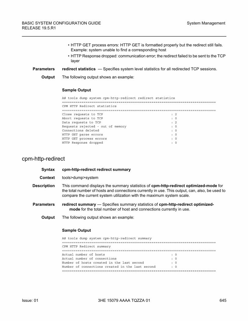
BASIC SYSTEM CONFIGURATION GUIDE RELEASE 19.5.R1
System Management
Issue: 01 3HE 15079 AAAA TQZZA 01 645
• HTTP GET process errors: HTTP GET is formatted properly but the redirect still fails. Example: system unable to find a corresponding host
• HTTP Response dropped: communication error; the redirect failed to be sent to the TCP layer
Parameters redirect statistics — Specifies system level statistics for all redirected TCP sessions.
Output The following output shows an example:
Sample Output
A# tools dump system cpm-http-redirect redirect statistics===============================================================================CPM HTTP Redirect statistics===============================================================================Close requests to TCP : 2Abort requests to TCP : 0Data requests to TCP : 2Requests rejected - out of memory : 0Connections deleted : 0HTTP GET parse errors : 0HTTP GET process errors : 0HTTP Response dropped : 0
cpm-http-redirect
Syntax cpm-http-redirect redirect summary
Context tools>dump>system
Description This command displays the summary statistics of cpm-http-redirect optimized-mode for the total number of hosts and connections currently in use. This output, can, also, be used to compare the current system utilization with the maximum system scale.
Parameters redirect summary — Specifies summary statistics of cpm-http-redirect optimized-mode for the total number of host and connections currently in use.
Output The following output shows an example:
Sample Output
A# tools dump system cpm-http-redirect summary===============================================================================CPM HTTP Redirect summary===============================================================================Actual number of hosts : 0Actual number of connections : 0Number of hosts created in the last second : 0Number of connections created in the last second : 0===============================================================================
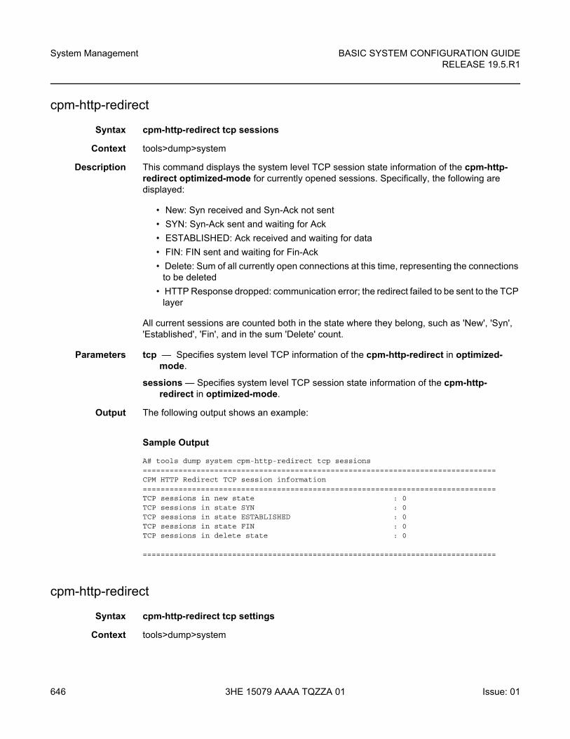
System Management
646
BASIC SYSTEM CONFIGURATION GUIDERELEASE 19.5.R1
3HE 15079 AAAA TQZZA 01 Issue: 01
cpm-http-redirect
Syntax cpm-http-redirect tcp sessions
Context tools>dump>system
Description This command displays the system level TCP session state information of the cpm-http-redirect optimized-mode for currently opened sessions. Specifically, the following are displayed:
• New: Syn received and Syn-Ack not sent
• SYN: Syn-Ack sent and waiting for Ack
• ESTABLISHED: Ack received and waiting for data
• FIN: FIN sent and waiting for Fin-Ack
• Delete: Sum of all currently open connections at this time, representing the connections to be deleted
• HTTP Response dropped: communication error; the redirect failed to be sent to the TCP layer
All current sessions are counted both in the state where they belong, such as 'New', 'Syn', 'Established', 'Fin', and in the sum 'Delete' count.
Parameters tcp — Specifies system level TCP information of the cpm-http-redirect in optimized-mode.
sessions — Specifies system level TCP session state information of the cpm-http-redirect in optimized-mode.
Output The following output shows an example:
Sample Output
A# tools dump system cpm-http-redirect tcp sessions===============================================================================CPM HTTP Redirect TCP session information===============================================================================TCP sessions in new state : 0TCP sessions in state SYN : 0TCP sessions in state ESTABLISHED : 0TCP sessions in state FIN : 0TCP sessions in delete state : 0
===============================================================================
cpm-http-redirect
Syntax cpm-http-redirect tcp settings
Context tools>dump>system
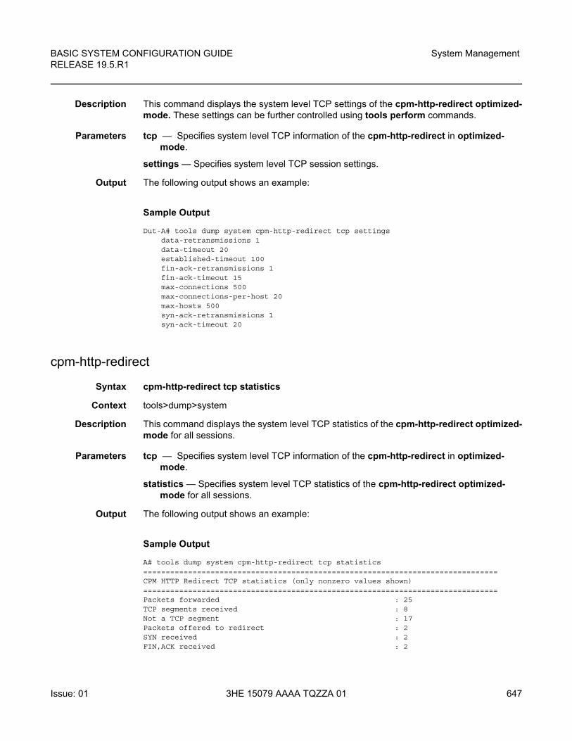
BASIC SYSTEM CONFIGURATION GUIDE RELEASE 19.5.R1
System Management
Issue: 01 3HE 15079 AAAA TQZZA 01 647
Description This command displays the system level TCP settings of the cpm-http-redirect optimized-mode. These settings can be further controlled using tools perform commands.
Parameters tcp — Specifies system level TCP information of the cpm-http-redirect in optimized-mode.
settings — Specifies system level TCP session settings.
Output The following output shows an example:
Sample Output
Dut-A# tools dump system cpm-http-redirect tcp settingsdata-retransmissions 1data-timeout 20established-timeout 100fin-ack-retransmissions 1fin-ack-timeout 15max-connections 500max-connections-per-host 20max-hosts 500syn-ack-retransmissions 1syn-ack-timeout 20
cpm-http-redirect
Syntax cpm-http-redirect tcp statistics
Context tools>dump>system
Description This command displays the system level TCP statistics of the cpm-http-redirect optimized-mode for all sessions.
Parameters tcp — Specifies system level TCP information of the cpm-http-redirect in optimized-mode.
statistics — Specifies system level TCP statistics of the cpm-http-redirect optimized-mode for all sessions.
Output The following output shows an example:
Sample Output
A# tools dump system cpm-http-redirect tcp statistics===============================================================================CPM HTTP Redirect TCP statistics (only nonzero values shown)===============================================================================Packets forwarded : 25TCP segments received : 8Not a TCP segment : 17Packets offered to redirect : 2SYN received : 2FIN,ACK received : 2
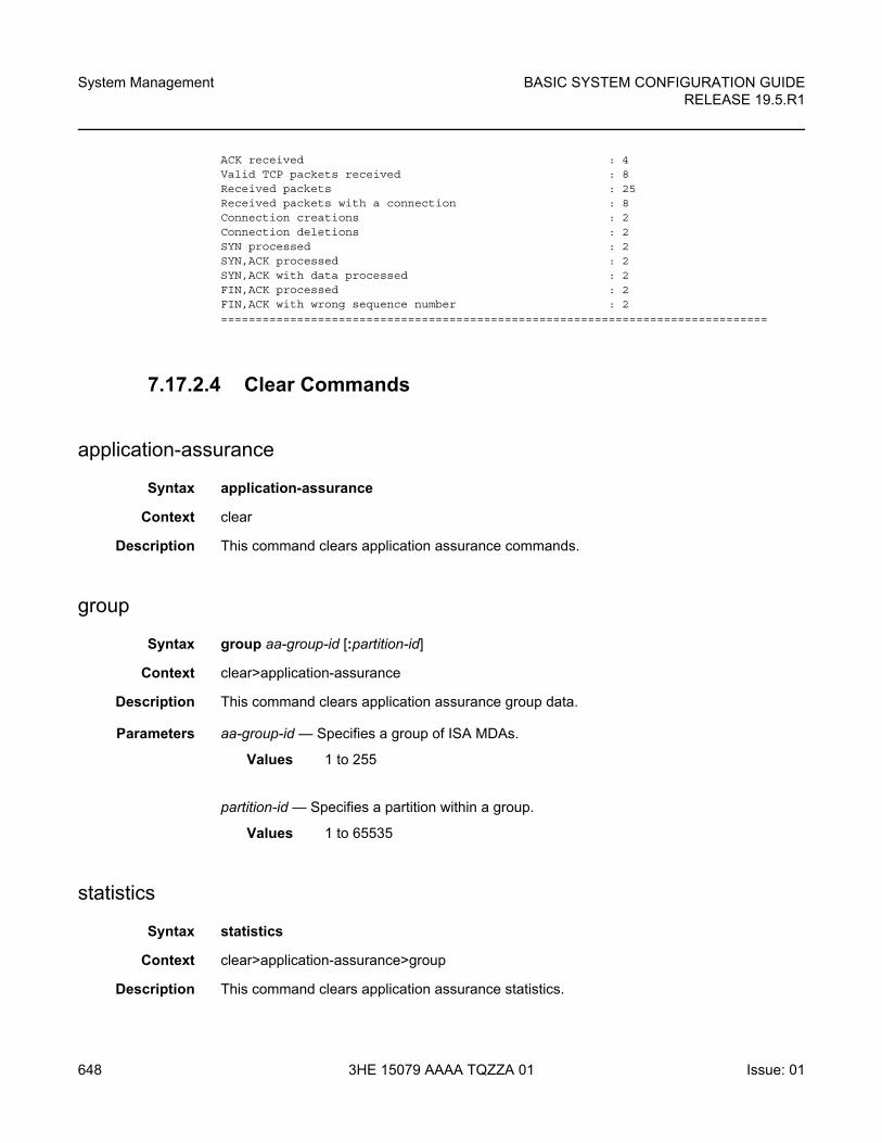
System Management
648
BASIC SYSTEM CONFIGURATION GUIDERELEASE 19.5.R1
3HE 15079 AAAA TQZZA 01 Issue: 01
ACK received : 4Valid TCP packets received : 8Received packets : 25Received packets with a connection : 8Connection creations : 2Connection deletions : 2SYN processed : 2SYN,ACK processed : 2SYN,ACK with data processed : 2FIN,ACK processed : 2FIN,ACK with wrong sequence number : 2===============================================================================
7.17.2.4 Clear Commands
application-assurance
Syntax application-assurance
Context clear
Description This command clears application assurance commands.
group
Syntax group aa-group-id [:partition-id]
Context clear>application-assurance
Description This command clears application assurance group data.
Parameters aa-group-id — Specifies a group of ISA MDAs.
Values 1 to 255
partition-id — Specifies a partition within a group.
Values 1 to 65535
statistics
Syntax statistics
Context clear>application-assurance>group
Description This command clears application assurance statistics.
BASIC SYSTEM CONFIGURATION GUIDE RELEASE 19.5.R1
System Management
Issue: 01 3HE 15079 AAAA TQZZA 01 649
status
Syntax status
Context clear>application-assurance>group
Description This command clears application assurance system statistics.
redundancy
Syntax redundancy
Context clear
Description This command enables the context to clear redundancy parameters.
multi-chassis
Syntax multi-chassis
Context clear>redundancy
Description This command enables the context to clear multi-chassis parameters.
mc-endpoint
Syntax mc-endpoint endpoint [mcep-id] statistics
mc-endpoint statistics
mc-endpoint peer [ip-address] statistics
Context clear>redundancy>multi-chassis
Description This command clears multi-chassis endpoint statistics.
Parameters mcep-id — Clears information for the specified multi-chassis endpoint ID.
Values 1 to 4294967295
ip-address — Clears information for the specified peer IP address.
Values ipv4-address: a.b.c.d
ipv6-address:
• x:x:x:x:x:x:x:x (eight 16-bit pieces)
• x:x:x:x:x:x:d.d.d.d
• x – [0 to FFFF] H
• d – [0 to 255] D
System Management
650
BASIC SYSTEM CONFIGURATION GUIDERELEASE 19.5.R1
3HE 15079 AAAA TQZZA 01 Issue: 01
statistics — Clears statistics for this multi-chassis endpoint.
mc-lag
Syntax mc-lag [peer ip-address [lag lag-id]]
Context clear>redundancy>multi-chassis
Description This command clears multi-chassis Link Aggregation Group (LAG) information.
Parameters ip-address — Clears the specified address of the multi-chassis peer.
Values ipv4-address: a.b.c.d
ipv6-address:
• x:x:x:x:x:x:x:x (eight 16-bit pieces)
• x:x:x:x:x:x:d.d.d.d
• x – [0 to FFFF] H
• d – [0 to 255] D
lag-id — Clears the specified LAG on this system.
Values 1 to 200
mc-ring
Syntax mc-ring
Context clear>redundancy>multi-chassis
Description This command clears multi-chassis ring data.
debounce
Syntax debounce peer ip-address ring sync-tag
Context clear>redundancy>multi-chassis
Description This command clears multi-chassis ring operational state debounce history.
Parameters ip-address — Clears debounce history for the specified IP address.
Values ipv4-address: a.b.c.d
ipv6-address:
• x:x:x:x:x:x:x:x (eight 16-bit pieces)
• x:x:x:x:x:x:d.d.d.d
• x – [0 to FFFF] H
BASIC SYSTEM CONFIGURATION GUIDE RELEASE 19.5.R1
System Management
Issue: 01 3HE 15079 AAAA TQZZA 01 651
• d – [0 to 255] D
sync-tag — Clears debounce history for the specified sync tag.
ring-nodes
Syntax ring-nodes peer ip-address ring sync-tag
Context clear>redundancy>multi-chassis>mcr
Description This command clears multi-chassis ring unreferenced ring nodes.
Parameters ip-address — Clears ring statistics for the specified IP address.
Values ipv4-address: a.b.c.d
ipv6-address:
• x:x:x:x:x:x:x:x (eight 16-bit pieces)
• x:x:x:x:x:x:d.d.d.d
• x – [0 to FFFF] H
• d – [0 to 255] D
sync-tag — Clears ring statistics for the specified sync tag.
statistics
Syntax statistics
Context clear>redundancy>multi-chassis>mc-ring
Description This command clears multi-chassis ring
global
Syntax global
Context clear>redundancy>multi-chassis>mc-ring>statistics
Description This command clears multi-chassis ring global statistics.
peer
Syntax peer ip-address
Context clear>redundancy>multi-chassis>mc-ring>statistics
Description This command clears multi-chassis ring peer statistics.
System Management
652
BASIC SYSTEM CONFIGURATION GUIDERELEASE 19.5.R1
3HE 15079 AAAA TQZZA 01 Issue: 01
Parameters ip-address — Clears ring peer statistics for the specified IP address.
Values ipv4-address: a.b.c.d
ipv6-address:
• x:x:x:x:x:x:x:x (eight 16-bit pieces)
• x:x:x:x:x:x:d.d.d.d
• x – [0 to FFFF] H
• d – [0 to 255] D
ring
Syntax ring peer ip-address ring sync-tag
Context clear>redundancy>multi-chassis>mc-ring>statistics
Description This command clears multi-chassis ring statistics.
Parameters ip-address — Clears ring statistics for the specified IP address.
Values ipv4-address: a.b.c.d
ipv6-address:
• x:x:x:x:x:x:x:x (eight 16-bit pieces)
• x:x:x:x:x:x:d.d.d.d
• x – [0 to FFFF] H
• d – [0 to 255] D
sync-tag — Clears ring statistics for the specified sync tag. 32 characters maximum.
ring-node
Syntax ring-node peer ip-address ring sync-tag node ring-node-name
Context clear>redundancy>multi-chassis>mc-ring>statistics
Description This command clears multi-chassis ring statistics.
Parameters ip-address — Clears ring-node peer statistics for the specified IP address.
Values ipv4-address: a.b.c.d
ipv6-address:
• x:x:x:x:x:x:x:x (eight 16-bit pieces)
• x:x:x:x:x:x:d.d.d.d
• x – [0 to FFFF] H
• d – [0 to 255] D
BASIC SYSTEM CONFIGURATION GUIDE RELEASE 19.5.R1
System Management
Issue: 01 3HE 15079 AAAA TQZZA 01 653
sync-tag — Clears ring-node peer statistics for the specified synchronization tag. The tag can be up to 32 characters.
ring-node-name — Clears ring-node peer statistics for the specified ring node name. The ring node name can be up to 32 characters.
sync-database
Syntax sync-database peer ip-address all application application
sync-database peer ip-address port {port-id | lag-id} [sync-tag sync-tag] application application
sync-database peer ip-address sdp sdp-id [sync-tag sync-tag] application application
sync-database peer ip-address sync-tag sync-tag application application
Context clear>redundancy>multi-chassis
Description This command clears multi-chassis sync database information.
Parameters ip-address — Clears the specified address of the multi-chassis peer.
Values ipv4-address: a.b.c.d
ipv6-address:
• x:x:x:x:x:x:x:x (eight 16-bit pieces)
• x:x:x:x:x:x:d.d.d.d
• x – [0 to FFFF] H
• d – [0 to 255] D
port-id — Clears the specified port ID of the multi-chassis peer.
Values slot/mda/port
lag-id — Clears the specified Link Aggregation Group (LAG) on this system.
Values lag-lag-id
all — Clears all ports and synchronization tags.
sync-tag — Clears the synchronization tag used while synchronizing this port with the multi-chassis peer. The synchronization tag can be up to 32 characters.
sdp-id — Specifies the SDP identifier.
Values 1 to 32767
application — Clears the specified application information that was synchronized with the multi-chassis peer.
Values The following are values for the 7750 SR and 7950 XRS:
System Management
654
BASIC SYSTEM CONFIGURATION GUIDERELEASE 19.5.R1
3HE 15079 AAAA TQZZA 01 Issue: 01
Values The following are values for the 7450 ESS:
screen
Syntax screen
Context clear
Description This command allows an operator to clear the Telnet or console screen.
system
Syntax system
Context clear
Description This command allows an operator to clear system information.
ptp
Syntax ptp
Context clear>system
all: All supported applications
dhcp-server: local dhcp server
igmp: internet group management protocol
igmp-snooping: igmp-snooping
mc-ring: multi-chassis ring
mld-snooping: multicast listener discovery-snooping
srrp: simple router redundancy protocol
sub-host-trk subscriber host tracking
sub-mgmt: subscriber management
all All supported applications
igmp-snooping igmp-snooping
mc-ring multi-chassis ring
mld-snooping multicast listener discovery-snooping
sub-host-trk subscriber host tracking
sub-mgmt subscriber management
BASIC SYSTEM CONFIGURATION GUIDE RELEASE 19.5.R1
System Management
Issue: 01 3HE 15079 AAAA TQZZA 01 655
Description This command enables the context to clear Precision Timing Protocol (PTP) information.
inactive-peers
Syntax inactive-peers
Context clear>system>ptp
Description This command clears inactive peer information.
peer
Syntax peer ip-address [router router-instance | service name service-name] statistics
Context clear>system>ptp
Description This command clears PTP peer information.
Parameters ip-address — Clears information specific to the address of the PTP 1588 peer.
Values a.b.c.d
router-instance — Clears information that is specific to a virtual router instance. The router instance can be up to 32 characters.
service-name — Clears information that is specific to a service name. The service name can be up to 64 characters.
statistics — Clears statistics information of the specified IP address.
port
Syntax port port-id statistics
Context clear>system>ptp
Description This command clears PTP port information.
Parameters port-id — Clears the specified port ID.
Values slot/mda/port
statistics — Clears statistics information of the specified port ID.
statistics
Syntax statistics
System Management
656
BASIC SYSTEM CONFIGURATION GUIDERELEASE 19.5.R1
3HE 15079 AAAA TQZZA 01 Issue: 01
Context clear>system>ptp
Description This command clears all PTP statistics.
script-control
Syntax script-control
Context clear>system
Description This command enables the context to clear script information.
script-policy
Syntax script-policy
Context clear>system>script-control
Description This command enables the context to clear script policy information.
completed
Syntax completed [script-policy-name] [owner owner-name]
Context clear>system>script-control>script-policy
Description This command clears completed script run history entries.
Parameters script-policy-name — Specifies to only clear history entries for the specified script-policy. 32 characters maximum.
owner-name — Specifies to only clear history entries for script-policies with the specified owner. 32 characters maximum.
Default TiMOS CLI
statistics
Syntax statistics
Context clear>system
Description This command clears system specific statistics.
BASIC SYSTEM CONFIGURATION GUIDE RELEASE 19.5.R1
System Management
Issue: 01 3HE 15079 AAAA TQZZA 01 657
xmpp
Syntax xmpp server xmpp-server-name
Context clear>system>statistics
Description This command clears XMPP server statistics.
Parameters xmpp-server-name — Specifies the XMPP server, up to 32 characters in length.
sync-if-timing
Syntax sync-if-timing {ref1 | ref2 | bits}
Context clear>system
Description This command allows an operator to individually clear (re-enable) a previously failed reference. As long as the reference is one of the valid options, this command is always executed. An inherent behavior enables the revertive mode which causes a re-evaluation of all available references.
This command also clears the Wait-to-Restore state of the reference so that it can be selected.
Parameters ref1 — Clears the first timing reference.
ref2 — Clears the second timing reference.
bits — Clears the bits timing reference.
trace
Syntax trace
Context clear
Description This command clears commands for traces.

System Management
658
BASIC SYSTEM CONFIGURATION GUIDERELEASE 19.5.R1
3HE 15079 AAAA TQZZA 01 Issue: 01
BASIC SYSTEM CONFIGURATION GUIDE RELEASE 19.5.R1
Standards and Protocol Support
Issue: 01 3HE 15079 AAAA TQZZA 01 659
8 Standards and Protocol Support
Access Node Control Protocol (ANCP)
draft-ietf-ancp-protocol-02, Protocol for Access Node Control Mechanism in Broadband Networks
RFC 5851, Framework and Requirements for an Access Node Control Mechanism in Broadband Multi-Service Networks
Application Assurance (AA)
3GPP Release 12 (ADC rules over Gx interfaces)
RFC 3507, Internet Content Adaptation Protocol (ICAP)
Asynchronous Transfer Mode (ATM)
AF-ILMI-0065.000, Integrated Local Management Interface (ILMI) Version 4.0
AF-PHY-0086.001, Inverse Multiplexing for ATM (IMA) Specification Version 1.1
AF-TM-0121.000, Traffic Management Specification Version 4.1
AF-TM-0150.00, Addendum to Traffic Management v4.1 optional minimum desired cell rate indication for UBR
GR-1113-CORE, Asynchronous Transfer Mode (ATM) and ATM Adaptation Layer (AAL) Protocols Generic Requirements, Issue 1
GR-1248-CORE, Generic Requirements for Operations of ATM Network Elements (NEs), Issue 3
ITU-T I.432.1, B-ISDN user-network interface - Physical layer specification: General characteristics (02/99)
ITU-T I.610, B-ISDN operation and maintenance principles and functions (11/95)
RFC 1626, Default IP MTU for use over ATM AAL5
RFC 2684, Multiprotocol Encapsulation over ATM Adaptation Layer 5
Bidirectional Forwarding Detection (BFD)
RFC 5880, Bidirectional Forwarding Detection (BFD)
RFC 5881, Bidirectional Forwarding Detection (BFD) IPv4 and IPv6 (Single Hop)
RFC 5883, Bidirectional Forwarding Detection (BFD) for Multihop Paths
Note: The information presented is subject to change without notice.
Nokia assumes no responsibility for inaccuracies contained herein.
Standards and Protocol Support
660
BASIC SYSTEM CONFIGURATION GUIDERELEASE 19.5.R1
3HE 15079 AAAA TQZZA 01 Issue: 01
RFC 7130, Bidirectional Forwarding Detection (BFD) on Link Aggregation Group (LAG) Interfaces
Border Gateway Protocol (BGP)
draft-hares-idr-update-attrib-low-bits-fix-01, Update Attribute Flag Low Bits Clarification
draft-ietf-idr-add-paths-guidelines-08, Best Practices for Advertisement of Multiple Paths in IBGP
draft-ietf-idr-best-external-03, Advertisement of the best external route in BGP
draft-ietf-idr-bgp-flowspec-oid-03, Revised Validation Procedure for BGP Flow Specifications
draft-ietf-idr-bgp-gr-notification-01, Notification Message support for BGP Graceful Restart
draft-ietf-idr-bgp-optimal-route-reflection-10, BGP Optimal Route Reflection (BGP-ORR)
draft-ietf-idr-error-handling-03, Revised Error Handling for BGP UPDATE Messages
draft-ietf-idr-flowspec-interfaceset-03, Applying BGP flowspec rules on a specific interface set
draft-ietf-idr-flowspec-path-redirect-05, Flowspec Indirection-id Redirect (localised ID)
draft-ietf-idr-flowspec-redirect-ip-02, BGP Flow-Spec Redirect to IP Action
draft-ietf-idr-link-bandwidth-03, BGP Link Bandwidth Extended Community
draft-ietf-sidr-origin-validation-signaling-04, BGP Prefix Origin Validation State Extended Community
draft-uttaro-idr-bgp-persistence-03, Support for Long-lived BGP Graceful Restart
RFC 1772, Application of the Border Gateway Protocol in the Internet
RFC 1997, BGP Communities Attribute
RFC 2385, Protection of BGP Sessions via the TCP MD5 Signature Option
RFC 2439, BGP Route Flap Damping
RFC 2545, Use of BGP-4 Multiprotocol Extensions for IPv6 Inter-Domain Routing
RFC 2858, Multiprotocol Extensions for BGP-4
RFC 2918, Route Refresh Capability for BGP-4
RFC 3107, Carrying Label Information in BGP-4
RFC 3392, Capabilities Advertisement with BGP-4
RFC 4271, A Border Gateway Protocol 4 (BGP-4)
RFC 4360, BGP Extended Communities Attribute
RFC 4364, BGP/MPLS IP Virtual Private Networks (VPNs)
RFC 4456, BGP Route Reflection: An Alternative to Full Mesh Internal BGP (IBGP)
BASIC SYSTEM CONFIGURATION GUIDE RELEASE 19.5.R1
Standards and Protocol Support
Issue: 01 3HE 15079 AAAA TQZZA 01 661
RFC 4486, Subcodes for BGP Cease Notification Message
RFC 4659, BGP-MPLS IP Virtual Private Network (VPN) Extension for IPv6 VPN
RFC 4684, Constrained Route Distribution for Border Gateway Protocol/MultiProtocol Label Switching (BGP/MPLS) Internet Protocol (IP) Virtual Private Networks (VPNs)
RFC 4724, Graceful Restart Mechanism for BGP (helper mode)
RFC 4760, Multiprotocol Extensions for BGP-4
RFC 4798, Connecting IPv6 Islands over IPv4 MPLS Using IPv6 Provider Edge Routers (6PE)
RFC 4893, BGP Support for Four-octet AS Number Space
RFC 5004, Avoid BGP Best Path Transitions from One External to Another
RFC 5065, Autonomous System Confederations for BGP
RFC 5291, Outbound Route Filtering Capability for BGP-4
RFC 5396, Textual Representation of Autonomous System (AS) Numbers (asplain)
RFC 5549, Advertising IPv4 Network Layer Reachability Information with an IPv6 Next Hop
RFC 5575, Dissemination of Flow Specification Rules
RFC 5668, 4-Octet AS Specific BGP Extended Community
RFC 6286, Autonomous-System-Wide Unique BGP Identifier for BGP-4
RFC 6810, The Resource Public Key Infrastructure (RPKI) to Router Protocol
RFC 6811, Prefix Origin Validation
RFC 6996, Autonomous System (AS) Reservation for Private Use
RFC 7311, The Accumulated IGP Metric Attribute for BGP
RFC 7607, Codification of AS 0 Processing
RFC 7674, Clarification of the Flowspec Redirect Extended Community
RFC 7752, North-Bound Distribution of Link-State and Traffic Engineering (TE) Information Using BGP
RFC 7854, BGP Monitoring Protocol (BMP)
RFC 7911, Advertisement of Multiple Paths in BGP
RFC 7999, BLACKHOLE Community
RFC 8092, BGP Large Communities Attribute
RFC 8212, Default External BGP (EBGP) Route Propagation Behavior without Policies
Circuit Emulation
RFC 4553, Structure-Agnostic Time Division Multiplexing (TDM) over Packet (SAToP)
Standards and Protocol Support
662
BASIC SYSTEM CONFIGURATION GUIDERELEASE 19.5.R1
3HE 15079 AAAA TQZZA 01 Issue: 01
RFC 5086, Structure-Aware Time Division Multiplexed (TDM) Circuit Emulation Service over Packet Switched Network (CESoPSN)
RFC 5287, Control Protocol Extensions for the Setup of Time-Division Multiplexing (TDM) Pseudowires in MPLS Networks
Ethernet
IEEE 802.1AB, Station and Media Access Control Connectivity Discovery
IEEE 802.1ad, Provider Bridges
IEEE 802.1ag, Connectivity Fault Management
IEEE 802.1ah, Provider Backbone Bridges
IEEE 802.1ak, Multiple Registration Protocol
IEEE 802.1aq, Shortest Path Bridging
IEEE 802.1ax, Link Aggregation
IEEE 802.1D, MAC Bridges
IEEE 802.1p, Traffic Class Expediting
IEEE 802.1Q, Virtual LANs
IEEE 802.1s, Multiple Spanning Trees
IEEE 802.1w, Rapid Reconfiguration of Spanning Tree
IEEE 802.1X, Port Based Network Access Control
IEEE 802.3ab, 1000BASE-T
IEEE 802.3ac, VLAN Tag
IEEE 802.3ad, Link Aggregation
IEEE 802.3ae, 10 Gb/s Ethernet
IEEE 802.3ah, Ethernet in the First Mile
IEEE 802.3ba, 40 Gb/s and 100 Gb/s Ethernet
IEEE 802.3i, Ethernet
IEEE 802.3u, Fast Ethernet
IEEE 802.3x, Ethernet Flow Control
IEEE 802.3z, Gigabit Ethernet
ITU-T G.8031/Y.1342, Ethernet Linear Protection Switching
ITU-T G.8032/Y.1344, Ethernet Ring Protection Switching
ITU-T Y.1731, OAM functions and mechanisms for Ethernet based networks
Ethernet VPN (EVPN)
draft-ietf-bess-evpn-ac-df-01, AC-Influenced Designated Forwarder Election for EVPN
draft-ietf-bess-evpn-pref-df-01, Preference-based EVPN DF Election
BASIC SYSTEM CONFIGURATION GUIDE RELEASE 19.5.R1
Standards and Protocol Support
Issue: 01 3HE 15079 AAAA TQZZA 01 663
draft-ietf-bess-evpn-prefix-advertisement-11, IP Prefix Advertisement in EVPN
draft-ietf-bess-evpn-proxy-arp-nd-04, Operational Aspects of Proxy-ARP/ND in EVPN Networks
draft-ietf-bess-evpn-vpls-seamless-integ-03, (PBB-)EVPN Seamless Integration with (PBB-)VPLS
draft-snr-bess-pbb-evpn-isid-cmacflush-01, PBB-EVPN ISID-based CMAC-Flush
RFC 7432, BGP MPLS-Based Ethernet VPN
RFC 7623, Provider Backbone Bridging Combined with Ethernet VPN (PBB-EVPN)
RFC 8214, Virtual Private Wire Service Support in Ethernet VPN
RFC 8317, Ethernet-Tree (E-Tree) Support in Ethernet VPN (EVPN) an Provider Backbone Bridging EVPN (PBB-EVPN)
RFC 8365, A Network Virtualization Overlay Solution Using Ethernet VPN (EVPN)
Frame Relay
ANSI T1.617 Annex D, DSS1 - Signalling Specification For Frame Relay Bearer Service
FRF.1.2, PVC User-to-Network Interface (UNI) Implementation Agreement
FRF.12, Frame Relay Fragmentation Implementation Agreement
FRF.16.1, Multilink Frame Relay UNI/NNI Implementation Agreement
FRF.5, Frame Relay/ATM PVC Network Interworking Implementation
FRF2.2, PVC Network-to-Network Interface (NNI) Implementation Agreement
ITU-T Q.933 Annex A, Additional procedures for Permanent Virtual Connection (PVC) status management
Generalized Multiprotocol Label Switching (GMPLS)
draft-ietf-ccamp-rsvp-te-srlg-collect-04, RSVP-TE Extensions for Collecting SRLG Information
RFC 3471, Generalized Multi-Protocol Label Switching (GMPLS) Signaling Functional Description
RFC 3473, Generalized Multi-Protocol Label Switching (GMPLS) Signaling Resource ReserVation Protocol-Traffic Engineering (RSVP-TE) Extensions
RFC 4204, Link Management Protocol (LMP)
RFC 4208, Generalized Multiprotocol Label Switching (GMPLS) User-Network Interface (UNI): Resource ReserVation Protocol-Traffic Engineering (RSVP-TE) Support for the Overlay Model
RFC 4872, RSVP-TE Extensions in Support of End-to-End Generalized Multi-Protocol Label Switching (GMPLS) Recovery
Standards and Protocol Support
664
BASIC SYSTEM CONFIGURATION GUIDERELEASE 19.5.R1
3HE 15079 AAAA TQZZA 01 Issue: 01
RFC 5063, Extensions to GMPLS Resource Reservation Protocol (RSVP) Graceful Restart (helper mode)
gRPC Remote Procedure Calls (gRPC)
gnmi.proto, gRPC Network Management Interface (gNMI), version 0.4.0
gRPC Network Management Interface (gNMI), Capabilities, Get, Set, Subscribe (ONCE, SAMPLE, ON_CHANGE)
Intermediate System to Intermediate System (IS-IS)
draft-ietf-isis-mi-02, IS-IS Multi-Instance
draft-kaplan-isis-ext-eth-02, Extended Ethernet Frame Size Support
ISO/IEC 10589:2002, Second Edition, Nov. 2002, Intermediate system to Intermediate system intra-domain routeing information exchange protocol for use in conjunction with the protocol for providing the connectionless-mode Network Service (ISO 8473)
RFC 1195, Use of OSI IS-IS for Routing in TCP/IP and Dual Environments
RFC 2973, IS-IS Mesh Groups
RFC 3359, Reserved Type, Length and Value (TLV) Codepoints in Intermediate System to Intermediate System
RFC 3719, Recommendations for Interoperable Networks using Intermediate System to Intermediate System (IS-IS)
RFC 3787, Recommendations for Interoperable IP Networks using Intermediate System to Intermediate System (IS-IS)
RFC 4971, Intermediate System to Intermediate System (IS-IS) Extensions for Advertising Router Information
RFC 5120, M-ISIS: Multi Topology (MT) Routing in IS-IS
RFC 5130, A Policy Control Mechanism in IS-IS Using Administrative Tags
RFC 5301, Dynamic Hostname Exchange Mechanism for IS-IS
RFC 5302, Domain-wide Prefix Distribution with Two-Level IS-IS
RFC 5303, Three-Way Handshake for IS-IS Point-to-Point Adjacencies
RFC 5304, IS-IS Cryptographic Authentication
RFC 5305, IS-IS Extensions for Traffic Engineering TE
RFC 5306, Restart Signaling for IS-IS (helper mode)
RFC 5307, IS-IS Extensions in Support of Generalized Multi-Protocol Label Switching (GMPLS)
RFC 5308, Routing IPv6 with IS-IS
RFC 5309, Point-to-Point Operation over LAN in Link State Routing Protocols
RFC 5310, IS-IS Generic Cryptographic Authentication
BASIC SYSTEM CONFIGURATION GUIDE RELEASE 19.5.R1
Standards and Protocol Support
Issue: 01 3HE 15079 AAAA TQZZA 01 665
RFC 6213, IS-IS BFD-Enabled TLV
RFC 6232, Purge Originator Identification TLV for IS-IS
RFC 6233, IS-IS Registry Extension for Purges
RFC 6329, IS-IS Extensions Supporting IEEE 802.1aq Shortest Path Bridging
RFC 7775, IS-IS Route Preference for Extended IP and IPv6 Reachability
RFC 7794, IS-IS Prefix Attributes for Extended IPv4 and IPv6 Reachability
RFC 8202, IS-IS Multi-Instance (single topology)
Internet Protocol (IP) — Fast Reroute
draft-ietf-rtgwg-lfa-manageability-08, Operational management of Loop Free Alternates
RFC 5286, Basic Specification for IP Fast Reroute: Loop-Free Alternates
RFC 7431, Multicast-Only Fast Reroute
RFC 7490, Remote Loop-Free Alternate (LFA) Fast Reroute (FRR)
Internet Protocol (IP) — General
draft-grant-tacacs-02, The TACACS+ Protocol
RFC 768, User Datagram Protocol
RFC 793, Transmission Control Protocol
RFC 854, Telnet Protocol Specifications
RFC 1350, The TFTP Protocol (revision 2)
RFC 2347, TFTP Option Extension
RFC 2348, TFTP Blocksize Option
RFC 2349, TFTP Timeout Interval and Transfer Size Options
RFC 2428, FTP Extensions for IPv6 and NATs
RFC 2784, Generic Routing Encapsulation (GRE)
RFC 2890, Key and Sequence Number Extensions to GRE
RFC 4250, The Secure Shell (SSH) Protocol Assigned Numbers
RFC 4251, The Secure Shell (SSH) Protocol Architecture
RFC 4252, The Secure Shell (SSH) Authentication Protocol (publickey, password)
RFC 4253, The Secure Shell (SSH) Transport Layer Protocol
RFC 4254, The Secure Shell (SSH) Connection Protocol
RFC 4632, Classless Inter-domain Routing (CIDR): The Internet Address Assignment and Aggregation Plan
RFC 5082, The Generalized TTL Security Mechanism (GTSM)
RFC 5656, Elliptic Curve Algorithm Integration in the Secure Shell Transport Layer (ECDSA)
Standards and Protocol Support
666
BASIC SYSTEM CONFIGURATION GUIDERELEASE 19.5.R1
3HE 15079 AAAA TQZZA 01 Issue: 01
RFC 5925, The TCP Authentication Option
RFC 5926, Cryptographic Algorithms for the TCP Authentication Option (TCP-AO)
RFC 6398, IP Router Alert Considerations and Usage (MLD)
RFC 6528, Defending against Sequence Number Attacks
Internet Protocol (IP) — Multicast
cisco-ipmulticast/pim-autorp-spec01, Auto-RP: Automatic discovery of Group-to-RP mappings for IP multicast (version 1)
draft-dolganow-bess-mvpn-expl-track-01, Explicit Tracking with Wild Card Routes in Multicast VPN
draft-ietf-bier-mvpn-11, Multicast VPN Using BIER
draft-ietf-idmr-traceroute-ipm-07, A "traceroute" facility for IP Multicast
draft-ietf-l2vpn-vpls-pim-snooping-07, Protocol Independent Multicast (PIM) over Virtual Private LAN Service (VPLS)
RFC 1112, Host Extensions for IP Multicasting
RFC 2236, Internet Group Management Protocol, Version 2
RFC 2365, Administratively Scoped IP Multicast
RFC 2375, IPv6 Multicast Address Assignments
RFC 2710, Multicast Listener Discovery (MLD) for IPv6
RFC 3306, Unicast-Prefix-based IPv6 Multicast Addresses
RFC 3376, Internet Group Management Protocol, Version 3
RFC 3446, Anycast Rendevous Point (RP) mechanism using Protocol Independent Multicast (PIM) and Multicast Source Discovery Protocol (MSDP)
RFC 3590, Source Address Selection for the Multicast Listener Discovery (MLD) Protocol
RFC 3618, Multicast Source Discovery Protocol (MSDP)
RFC 3810, Multicast Listener Discovery Version 2 (MLDv2) for IPv6
RFC 3956, Embedding the Rendezvous Point (RP) Address in an IPv6 Multicast Address
RFC 3973, Protocol Independent Multicast - Dense Mode (PIM-DM): Protocol Specification (Revised) (auto-RP groups)
RFC 4541, Considerations for Internet Group Management Protocol (IGMP) and Multicast Listener Discovery (MLD) Snooping Switches
RFC 4604, Using Internet Group Management Protocol Version 3 (IGMPv3) and Multicast Listener Discovery Protocol Version 2 (MLDv2) for Source-Specific Multicast
RFC 4607, Source-Specific Multicast for IP
RFC 4608, Source-Specific Protocol Independent Multicast in 232/8
BASIC SYSTEM CONFIGURATION GUIDE RELEASE 19.5.R1
Standards and Protocol Support
Issue: 01 3HE 15079 AAAA TQZZA 01 667
RFC 4610, Anycast-RP Using Protocol Independent Multicast (PIM)
RFC 4611, Multicast Source Discovery Protocol (MSDP) Deployment Scenarios
RFC 5059, Bootstrap Router (BSR) Mechanism for Protocol Independent Multicast (PIM)
RFC 5186, Internet Group Management Protocol Version 3 (IGMPv3) / Multicast Listener Discovery Version 2 (MLDv2) and Multicast Routing Protocol Interaction
RFC 5384, The Protocol Independent Multicast (PIM) Join Attribute Format
RFC 5496, The Reverse Path Forwarding (RPF) Vector TLV
RFC 6037, Cisco Systems' Solution for Multicast in MPLS/BGP IP VPNs
RFC 6512, Using Multipoint LDP When the Backbone Has No Route to the Root
RFC 6513, Multicast in MPLS/BGP IP VPNs
RFC 6514, BGP Encodings and Procedures for Multicast in MPLS/IP VPNs
RFC 6515, IPv4 and IPv6 Infrastructure Addresses in BGP Updates for Multicast VPNs
RFC 6516, IPv6 Multicast VPN (MVPN) Support Using PIM Control Plane and Selective Provider Multicast Service Interface (S-PMSI) Join Messages
RFC 6625, Wildcards in Multicast VPN Auto-Discover Routes
RFC 6826, Multipoint LDP In-Band Signaling for Point-to-Multipoint and Multipoint-to-Multipoint Label Switched Path
RFC 7246, Multipoint Label Distribution Protocol In-Band Signaling in a Virtual Routing and Forwarding (VRF) Table Context
RFC 7385, IANA Registry for P-Multicast Service Interface (PMSI) Tunnel Type Code Points
RFC 7716, Global Table Multicast with BGP Multicast VPN (BGP-MVPN) Procedures
RFC 7761, Protocol Independent Multicast - Sparse Mode (PIM-SM): Protocol Specification (Revised)
RFC 8279, Multicast Using Bit Index Explicit Replication (BIER)
RFC 8296, Encapsulation for Bit Index Explicit Replication (BIER) in MPLS and Non-MPLS Networks (MPLS encapsulation)
RFC 8401, Bit Index Explicit Replication (BIER) Support via IS-IS
RFC 8487, Mtrace Version 2: Traceroute Facility for IP Multicast
Internet Protocol (IP) — Version 4
RFC 791, Internet Protocol
RFC 792, Internet Control Message Protocol
RFC 826, An Ethernet Address Resolution Protocol
RFC 951, Bootstrap Protocol (BOOTP)
Standards and Protocol Support
668
BASIC SYSTEM CONFIGURATION GUIDERELEASE 19.5.R1
3HE 15079 AAAA TQZZA 01 Issue: 01
RFC 1034, Domain Names - Concepts and Facilities
RFC 1035, Domain Names - Implementation and Specification
RFC 1191, Path MTU Discovery (router specification)
RFC 1519, Classless Inter-Domain Routing (CIDR): an Address Assignment and Aggregation Strategy
RFC 1534, Interoperation between DHCP and BOOTP
RFC 1542, Clarifications and Extensions for the Bootstrap Protocol
RFC 1812, Requirements for IPv4 Routers
RFC 1918, Address Allocation for Private Internets
RFC 2003, IP Encapsulation within IP
RFC 2131, Dynamic Host Configuration Protocol
RFC 2132, DHCP Options and BOOTP Vendor Extensions
RFC 2401, Security Architecture for Internet Protocol
RFC 3021, Using 31-Bit Prefixes on IPv4 Point-to-Point Links
RFC 3046, DHCP Relay Agent Information Option (Option 82)
RFC 3768, Virtual Router Redundancy Protocol (VRRP)
RFC 4884, Extended ICMP to Support Multi-Part Messages (ICMPv4 and ICMPv6 Time Exceeded)
Internet Protocol (IP) — Version 6
RFC 2464, Transmission of IPv6 Packets over Ethernet Networks
RFC 2529, Transmission of IPv6 over IPv4 Domains without Explicit Tunnels
RFC 3122, Extensions to IPv6 Neighbor Discovery for Inverse Discovery Specification
RFC 3315, Dynamic Host Configuration Protocol for IPv6 (DHCPv6)
RFC 3587, IPv6 Global Unicast Address Format
RFC 3596, DNS Extensions to Support IP version 6
RFC 3633, IPv6 Prefix Options for Dynamic Host Configuration Protocol (DHCP) version 6
RFC 3646, DNS Configuration options for Dynamic Host Configuration Protocol for IPv6 (DHCPv6)
RFC 3736, Stateless Dynamic Host Configuration Protocol (DHCP) Service for IPv6
RFC 3971, SEcure Neighbor Discovery (SEND)
RFC 3972, Cryptographically Generated Addresses (CGA)
RFC 4007, IPv6 Scoped Address Architecture
RFC 4193, Unique Local IPv6 Unicast Addresses
RFC 4291, Internet Protocol Version 6 (IPv6) Addressing Architecture
BASIC SYSTEM CONFIGURATION GUIDE RELEASE 19.5.R1
Standards and Protocol Support
Issue: 01 3HE 15079 AAAA TQZZA 01 669
RFC 4443, Internet Control Message Protocol (ICMPv6) for the Internet Protocol Version 6 (IPv6) Specification
RFC 4861, Neighbor Discovery for IP version 6 (IPv6)
RFC 4862, IPv6 Stateless Address Autoconfiguration (router functions)
RFC 4890, Recommendations for Filtering ICMPv6 Messages in Firewalls
RFC 4941, Privacy Extensions for Stateless Address Autoconfiguration in IPv6
RFC 5007, DHCPv6 Leasequery
RFC 5095, Deprecation of Type 0 Routing Headers in IPv6
RFC 5722, Handling of Overlapping IPv6 Fragments
RFC 5798, Virtual Router Redundancy Protocol (VRRP) Version 3 for IPv4 and IPv6 (IPv6)
RFC 5952, A Recommendation for IPv6 Address Text Representation
RFC 6092, Recommended Simple Security Capabilities in Customer Premises Equipment (CPE) for Providing Residential IPv6 Internet Service (Internet Control and Management, Upper-Layer Transport Protocols, UDP Filters, IPsec and Internet Key Exchange (IKE), TCP Filters)
RFC 6106, IPv6 Router Advertisement Options for DNS Configuration
RFC 6164, Using 127-Bit IPv6 Prefixes on Inter-Router Links
RFC 8021, Generation of IPv6 Atomic Fragments Considered Harmful
RFC 8200, Internet Protocol, Version 6 (IPv6) Specification
RFC 8201, Path MTU Discovery for IP version 6
Internet Protocol Security (IPsec)
draft-ietf-ipsec-isakmp-mode-cfg-05, The ISAKMP Configuration Method
draft-ietf-ipsec-isakmp-xauth-06, Extended Authentication within ISAKMP/Oakley (XAUTH)
RFC 2401, Security Architecture for the Internet Protocol
RFC 2403, The Use of HMAC-MD5-96 within ESP and AH
RFC 2404, The Use of HMAC-SHA-1-96 within ESP and AH
RFC 2405, The ESP DES-CBC Cipher Algorithm With Explicit IV
RFC 2406, IP Encapsulating Security Payload (ESP)
RFC 2407, IPsec Domain of Interpretation for ISAKMP (IPsec DoI)
RFC 2408, Internet Security Association and Key Management Protocol (ISAKMP)
RFC 2409, The Internet Key Exchange (IKE)
RFC 2410, The NULL Encryption Algorithm and Its Use With IPsec
RFC 3526, More Modular Exponential (MODP) Diffie-Hellman group for Internet Key Exchange (IKE)
RFC 3566, The AES-XCBC-MAC-96 Algorithm and Its Use With IPsec
Standards and Protocol Support
670
BASIC SYSTEM CONFIGURATION GUIDERELEASE 19.5.R1
3HE 15079 AAAA TQZZA 01 Issue: 01
RFC 3602, The AES-CBC Cipher Algorithm and Its Use with IPsec
RFC 3706, A Traffic-Based Method of Detecting Dead Internet Key Exchange (IKE) Peers
RFC 3947, Negotiation of NAT-Traversal in the IKE
RFC 3948, UDP Encapsulation of IPsec ESP Packets
RFC 4106, The Use of Galois/Counter Mode (GCM) in IPsec ESP
RFC 4210, Internet X.509 Public Key Infrastructure Certificate Management Protocol (CMP)
RFC 4211, Internet X.509 Public Key Infrastructure Certificate Request Message Format (CRMF)
RFC 4301, Security Architecture for the Internet Protocol
RFC 4303, IP Encapsulating Security Payload
RFC 4307, Cryptographic Algorithms for Use in the Internet Key Exchange Version 2 (IKEv2)
RFC 4308, Cryptographic Suites for IPsec
RFC 4434, The AES-XCBC-PRF-128 Algorithm for the Internet Key Exchange Protocol (IKE)
RFC 4543, The Use of Galois Message Authentication Code (GMAC) in IPsec ESP and AH
RFC 4868, Using HMAC-SHA-256, HMAC-SHA-384, and HMAC-SHA-512 with IPSec
RFC 4945, The Internet IP Security PKI Profile of IKEv1/ISAKMP, IKEv2 and PKIX
RFC 5019, The Lightweight Online Certificate Status Protocol (OCSP) Profile for High-Volume Environments
RFC 5280, Internet X.509 Public Key Infrastructure Certificate and Certificate Revocation List (CRL) Profile
RFC 5282, Using Authenticated Encryption Algorithms with the Encrypted Payload of the IKEv2 Protocol
RFC 5903, ECP Groups for IKE and IKEv2
RFC 5998, An Extension for EAP-Only Authentication in IKEv2
RFC 6379, Suite B Cryptographic Suites for IPsec
RFC 6380, Suite B Profile for Internet Protocol Security (IPsec)
RFC 6712, Internet X.509 Public Key Infrastructure -- HTTP Transfer for the Certificate Management Protocol (CMP)
RFC 6960, X.509 Internet Public Key Infrastructure Online Certificate Status Protocol - OCSP
RFC 7296, Internet Key Exchange Protocol Version 2 (IKEv2)
RFC 7321, Cryptographic Algorithm Implementation Requirements and Usage Guidance for Encapsulating Security Payload (ESP) and Authentication Header (AH)
BASIC SYSTEM CONFIGURATION GUIDE RELEASE 19.5.R1
Standards and Protocol Support
Issue: 01 3HE 15079 AAAA TQZZA 01 671
RFC 7383, Internet Key Exchange Protocol Version 2 (IKEv2) Message Fragmentation
RFC 7427, Signature Authentication in the Internet Key Exchange Version 2 (IKEv2)
RFC 7468, Textual Encodings of PKIX, PKCS, and CMS Structures
Label Distribution Protocol (LDP)
draft-pdutta-mpls-ldp-adj-capability-00, LDP Adjacency Capabilities
draft-pdutta-mpls-ldp-v2-00, LDP Version 2
draft-pdutta-mpls-mldp-up-redundancy-00, Upstream LSR Redundancy for Multi-point LDP Tunnels
draft-pdutta-mpls-multi-ldp-instance-00, Multiple LDP Instances
draft-pdutta-mpls-tldp-hello-reduce-04, Targeted LDP Hello Reduction
RFC 3037, LDP Applicability
RFC 3478, Graceful Restart Mechanism for Label Distribution Protocol (helper mode)
RFC 5036, LDP Specification
RFC 5283, LDP Extension for Inter-Area Label Switched Paths (LSPs)
RFC 5443, LDP IGP Synchronization
RFC 5561, LDP Capabilities
RFC 5919, Signaling LDP Label Advertisement Completion
RFC 6388, Label Distribution Protocol Extensions for Point-to-Multipoint and Multipoint-to-Multipoint Label Switched Paths
RFC 6512, Using Multipoint LDP When the Backbone Has No Route to the Root
RFC 6826, Multipoint LDP in-band signaling for Point-to-Multipoint and Multipoint-to-Multipoint Label Switched Paths
RFC 7032, LDP Downstream-on-Demand in Seamless MPLS
RFC 7473, Controlling State Advertisements of Non-negotiated LDP Applications
RFC 7552, Updates to LDP for IPv6
Layer Two Tunneling Protocol (L2TP) Network Server (LNS)
draft-mammoliti-l2tp-accessline-avp-04, Layer 2 Tunneling Protocol (L2TP) Access Line Information Attribute Value Pair (AVP) Extensions
RFC 2661, Layer Two Tunneling Protocol "L2TP"
RFC 2809, Implementation of L2TP Compulsory Tunneling via RADIUS
RFC 3438, Layer Two Tunneling Protocol (L2TP) Internet Assigned Numbers: Internet Assigned Numbers Authority (IANA) Considerations Update
RFC 3931, Layer Two Tunneling Protocol - Version 3 (L2TPv3)
Standards and Protocol Support
672
BASIC SYSTEM CONFIGURATION GUIDERELEASE 19.5.R1
3HE 15079 AAAA TQZZA 01 Issue: 01
RFC 4719, Transport of Ethernet Frames over Layer 2 Tunneling Protocol Version 3 (L2TPv3)
RFC 4951, Fail Over Extensions for Layer 2 Tunneling Protocol (L2TP) "failover"
Management
draft-ieft-snmpv3-update-mib-05, Management Information Base (MIB) for the Simple Network Management Protocol (SNMP)
draft-ietf-isis-wg-mib-06, Management Information Base for Intermediate System to Intermediate System (IS-IS)
draft-ietf-mboned-msdp-mib-01, Multicast Source Discovery protocol MIB
draft-ietf-mpls-ldp-mib-07, Definitions of Managed Objects for the Multiprotocol Label Switching, Label Distribution Protocol (LDP)
draft-ietf-mpls-lsr-mib-06, Multiprotocol Label Switching (MPLS) Label Switching Router (LSR) Management Information Base Using SMIv2
draft-ietf-mpls-te-mib-04, Multiprotocol Label Switching (MPLS) Traffic Engineering Management Information Base
draft-ietf-ospf-mib-update-08, OSPF Version 2 Management Information Base
draft-ietf-vrrp-unified-mib-06, Definitions of Managed Objects for the VRRP over IPv4 and IPv6 (IPv6)
ianaaddressfamilynumbers-mib, IANA-ADDRESS-FAMILY-NUMBERS-MIB
ianagmplstc-mib, IANA-GMPLS-TC-MIB
ianaiftype-mib, IANAifType-MIB
ianaiprouteprotocol-mib, IANA-RTPROTO-MIB
IEEE8021-CFM-MIB, IEEE P802.1ag(TM) CFM MIB
IEEE8021-PAE-MIB, IEEE 802.1X MIB
IEEE8023-LAG-MIB, IEEE 802.3ad MIB
LLDP-MIB, IEEE P802.1AB(TM) LLDP MIB
openconfig-bgp.yang version 3.0.1, BGP Module
openconfig-bgp-common.yang version 3.0.1, BGP Common Module
openconfig-bgp-common-multiprotocol.yang version 3.0.1, BGP Common Multiprotocol Module
openconfig-bgp-common-structure.yang version 3.0.1, BGP Common Structure Module
openconfig-bgp-global.yang version 3.0.1, BGP Global Module
openconfig-bgp-neighbor.yang version 3.0.1, BGP Neighbor Module
openconfig-bgp-peer-group.yang version 3.0.1, BGP Peer Group Module
openconfig-bgp-policy.yang version 4.0.1, BGP Policy Module
openconfig-if-aggregate.yang version 2.0.0, Interfaces Aggregated Model
BASIC SYSTEM CONFIGURATION GUIDE RELEASE 19.5.R1
Standards and Protocol Support
Issue: 01 3HE 15079 AAAA TQZZA 01 673
openconfig-if-ethernet.yang version 2.0.0, Interfaces Ethernet Model
openconfig-if-ip.yang version 2.0.0, Interfaces IP Module
openconfig-if-ip-ext.yang version 2.0.0, Interfaces IP Extensions Module
openconfig-interfaces.yang version 2.0.0, Interfaces Module
openconfig-isis.yang version 0.3.0, IS-IS Module
openconfig-isis-lsp.yang version 0.3.0, IS-IS LSP Module
openconfig-isis-routing.yang version 0.3.0, IS-IS Routing Module
openconfig-lacp.yang version 1.1.0, LACP Module
openconfig-lldp.yang version 0.1.0, LLDP Module
openconfig-local-routing.yang version 1.0.1, Local Routing Module
openconfig-network-instance.yang version 0.8.0, Network Instance Module
openconfig-routing-policy.yang version 3.0.0, Routing Policy Module
openconfig-vlan.yang version 2.0.0, VLAN Module
RFC 1157, A Simple Network Management Protocol (SNMP)
RFC 1212, Concise MIB Definitions
RFC 1213, Management Information Base for Network Management of TCP/IP-based Internets: MIB-II
RFC 1215, A Convention for Defining Traps for use with the SNMP
RFC 1724, RIP Version 2 MIB Extension
RFC 1901, Introduction to Community-based SNMPv2
RFC 2021, Remote Network Monitoring Management Information Base Version 2 using SMIv2
RFC 2115, Management Information Base for Frame Relay DTEs Using SMIv2
RFC 2206, RSVP Management Information Base using SMIv2
RFC 2213, Integrated Services Management Information Base using SMIv2
RFC 2494, Definitions of Managed Objects for the DS0 and DS0 Bundle Interface Type
RFC 2514, Definitions of Textual Conventions and OBJECT-IDENTITIES for ATM Management
RFC 2515, Definitions of Managed Objects for ATM Management
RFC 2570, SNMP Version 3 Framework
RFC 2571, An Architecture for Describing SNMP Management Frameworks
RFC 2572, Message Processing and Dispatching for the Simple Network Management Protocol (SNMP)
RFC 2573, SNMP Applications
RFC 2574, User-based Security Model (USM) for version 3 of the Simple Network Management Protocol (SNMPv3)
Standards and Protocol Support
674
BASIC SYSTEM CONFIGURATION GUIDERELEASE 19.5.R1
3HE 15079 AAAA TQZZA 01 Issue: 01
RFC 2575, View-based Access Control Model (VACM) for the Simple Network Management Protocol (SNMP)
RFC 2578, Structure of Management Information Version 2 (SMIv2)
RFC 2579, Textual Conventions for SMIv2
RFC 2580, Conformance Statements for SMIv2
RFC 2787, Definitions of Managed Objects for the Virtual Router Redundancy Protocol
RFC 2819, Remote Network Monitoring Management Information Base
RFC 2856, Textual Conventions for Additional High Capacity Data Types
RFC 2863, The Interfaces Group MIB
RFC 2864, The Inverted Stack Table Extension to the Interfaces Group MIB
RFC 2933, Internet Group Management Protocol MIB
RFC 3014, Notification Log MIB
RFC 3164, The BSD syslog Protocol
RFC 3165, Definitions of Managed Objects for the Delegation of Management Scripts
RFC 3231, Definitions of Managed Objects for Scheduling Management Operations
RFC 3273, Remote Network Monitoring Management Information Base for High Capacity Networks
RFC 3416. Version 2 of the Protocol Operations for the Simple Network Management Protocol (SNMP)
RFC 3417, Transport Mappings for the Simple Network Management Protocol (SNMP) (SNMP over UDP over IPv4)
RFC 3419, Textual Conventions for Transport Addresses
RFC 3498, Definitions of Managed Objects for Synchronous Optical Network (SONET) Linear Automatic Protection Switching (APS) Architectures
RFC 3584, Coexistence between Version 1, Version 2, and Version 3 of the Internet-standard Network Management Framework
RFC 3592, Definitions of Managed Objects for the Synchronous Optical Network/Synchronous Digital Hierarchy (SONET/SDH) Interface Type
RFC 3593, Textual Conventions for MIB Modules Using Performance History Based on 15 Minute Intervals
RFC 3635, Definitions of Managed Objects for the Ethernet-like Interface Types
RFC 3637, Definitions of Managed Objects for the Ethernet WAN Interface Sublayer
RFC 3826, The Advanced Encryption Standard (AES) Cipher Algorithm in the SNMP User-based Security Model
RFC 3877, Alarm Management Information Base (MIB)
RFC 3895, Definitions of Managed Objects for the DS1, E1, DS2, and E2 Interface Types
BASIC SYSTEM CONFIGURATION GUIDE RELEASE 19.5.R1
Standards and Protocol Support
Issue: 01 3HE 15079 AAAA TQZZA 01 675
RFC 3896, Definitions of Managed Objects for the DS3/E3 Interface Type
RFC 4001, Textual Conventions for Internet Network Addresses
RFC 4022, Management Information Base for the Transmission Control Protocol (TCP)
RFC 4113, Management Information Base for the User Datagram Protocol (UDP)
RFC 4220, Traffic Engineering Link Management Information Base
RFC 4273, Definitions of Managed Objects for BGP-4
RFC 4292, IP Forwarding Table MIB
RFC 4293, Management Information Base for the Internet Protocol (IP)
RFC 4379, Detecting Multi-Protocol Label Switched (MPLS) Data Plane Failures
RFC 4511, Lightweight Directory Access Protocol (LDAP): The Protocol
RFC 4513, Lightweight Directory Access Protocol (LDAP): Authentication Methods and Security Mechanisms (TLS)
RFC 4631, Link Management Protocol (LMP) Management Information Base (MIB)
RFC 4878, Definitions and Managed Objects for Operations, Administration, and Maintenance (OAM) Functions on Ethernet-Like Interfaces
RFC 5101, Specification of the IP Flow Information Export (IPFIX) Protocol for the Exchange of IP Traffic Flow Information
RFC 5102, Information Model for IP Flow Information Export
RFC 5246, The Transport Layer Security (TLS) Protocol Version 1.2 (TLS client, RSA public key)
RFC 6374, Packet Loss and Delay Measurement for MPLS Networks (Delay Measurement, Channel Type 0x000C)
RFC 6424, Mechanism for Performing Label Switched Path Ping (LSP Ping) over MPLS Tunnels
RFC 6425, Detecting Data Plane Failures in Point-to-Multipoint Multiprotocol Label Switching (MPLS) - Extensions to LSP Ping
RFC 6991, Common YANG Data Types
RFC 7420, Path Computation Element Communication Protocol (PCEP) Management Information Base (MIB) Module
RFC 7876, UDP Return Path for Packet Loss and Delay Measurement for MPLS Networks (Delay Measurement)
RFC 7950, The YANG 1.1 Data Modeling Language
SFLOW-MIB, sFlow MIB Version 1.3 (Draft 5)
Multiprotocol Label Switching — Transport Profile (MPLS-TP)
RFC 5586, MPLS Generic Associated Channel
RFC 5921, A Framework for MPLS in Transport Networks
Standards and Protocol Support
676
BASIC SYSTEM CONFIGURATION GUIDERELEASE 19.5.R1
3HE 15079 AAAA TQZZA 01 Issue: 01
RFC 5960, MPLS Transport Profile Data Plane Architecture
RFC 6370, MPLS Transport Profile (MPLS-TP) Identifiers
RFC 6378, MPLS Transport Profile (MPLS-TP) Linear Protection
RFC 6426, MPLS On-Demand Connectivity and Route Tracing
RFC 6427, MPLS Fault Management Operations, Administration, and Maintenance (OAM)
RFC 6428, Proactive Connectivity Verification, Continuity Check and Remote Defect indication for MPLS Transport Profile
RFC 6478, Pseudowire Status for Static Pseudowires
RFC 7213, MPLS Transport Profile (MPLS-TP) Next-Hop Ethernet Addressing
Multiprotocol Label Switching (MPLS)
draft-ietf-teas-sr-rsvp-coexistence-rec-02, Recommendations for RSVP-TE and Segment Routing LSP co-existence
RFC 3031, Multiprotocol Label Switching Architecture
RFC 3032, MPLS Label Stack Encoding
RFC 3443, Time To Live (TTL) Processing in Multi-Protocol Label Switching (MPLS) Networks
RFC 4023, Encapsulating MPLS in IP or Generic Routing Encapsulation (GRE)
RFC 4182, Removing a Restriction on the use of MPLS Explicit NULL
RFC 5332, MPLS Multicast Encapsulations
RFC 5884, Bidirectional Forwarding Detection (BFD) for MPLS Label Switched Paths (LSPs)
RFC 6790, The Use of Entropy Labels in MPLS Forwarding
RFC 7510, Encapsulating MPLS in UDP
Network Address Translation (NAT)
draft-ietf-behave-address-format-10, IPv6 Addressing of IPv4/IPv6 Translators
draft-ietf-behave-v6v4-xlate-23, IP/ICMP Translation Algorithm
draft-miles-behave-l2nat-00, Layer2-Aware NAT
draft-nishitani-cgn-02, Common Functions of Large Scale NAT (LSN)
RFC 4787, Network Address Translation (NAT) Behavioral Requirements for Unicast UDP
RFC 5382, NAT Behavioral Requirements for TCP
RFC 5508, NAT Behavioral Requirements for ICMP
RFC 6146, Stateful NAT64: Network Address and Protocol Translation from IPv6 Clients to IPv4 Servers
BASIC SYSTEM CONFIGURATION GUIDE RELEASE 19.5.R1
Standards and Protocol Support
Issue: 01 3HE 15079 AAAA TQZZA 01 677
RFC 6333, Dual-Stack Lite Broadband Deployments Following IPv4 Exhaustion
RFC 6334, Dynamic Host Configuration Protocol for IPv6 (DHCPv6) Option for Dual-Stack Lite
RFC 6887, Port Control Protocol (PCP)
RFC 6888, Common Requirements For Carrier-Grade NATs (CGNs)
RFC 7915, IP/ICMP Translation Algorithm
Network Configuration Protocol (NETCONF)
RFC 5277, NETCONF Event Notifications
RFC 6022, YANG Module for NETCONF Monitoring
RFC 6241, Network Configuration Protocol (NETCONF)
RFC 6242, Using the NETCONF Protocol over Secure Shell (SSH)
RFC 6243, With-defaults Capability for NETCONF
RFC 7895, YANG Module Library
Open Shortest Path First (OSPF)
draft-ietf-ospf-ospfv3-lsa-extend-13, OSPFv3 LSA Extendibility
RFC 1586, Guidelines for Running OSPF Over Frame Relay Networks
RFC 1765, OSPF Database Overflow
RFC 2328, OSPF Version 2
RFC 3101, The OSPF Not-So-Stubby Area (NSSA) Option
RFC 3509, Alternative Implementations of OSPF Area Border Routers
RFC 3623, Graceful OSPF Restart Graceful OSPF Restart (helper mode)
RFC 3630, Traffic Engineering (TE) Extensions to OSPF Version 2
RFC 4203, OSPF Extensions in Support of Generalized Multi-Protocol Label Switching (GMPLS)
RFC 4222, Prioritized Treatment of Specific OSPF Version 2 Packets and Congestion Avoidance
RFC 4552, Authentication/Confidentiality for OSPFv3
RFC 4576, Using a Link State Advertisement (LSA) Options Bit to Prevent Looping in BGP/MPLS IP Virtual Private Networks (VPNs)
RFC 4577, OSPF as the Provider/Customer Edge Protocol for BGP/MPLS IP Virtual Private Networks (VPNs)
RFC 5185, OSPF Multi-Area Adjacency
RFC 5187, OSPFv3 Graceful Restart (helper mode)
RFC 5243, OSPF Database Exchange Summary List Optimization
RFC 5250, The OSPF Opaque LSA Option
Standards and Protocol Support
678
BASIC SYSTEM CONFIGURATION GUIDERELEASE 19.5.R1
3HE 15079 AAAA TQZZA 01 Issue: 01
RFC 5309, Point-to-Point Operation over LAN in Link State Routing Protocols
RFC 5340, OSPF for IPv6
RFC 5709, OSPFv2 HMAC-SHA Cryptographic Authentication
RFC 5838, Support of Address Families in OSPFv3
RFC 6987, OSPF Stub Router Advertisement
RFC 7684, OSPFv2 Prefix/Link Attribute Advertisement
RFC 7770, Extensions to OSPF for Advertising Optional Router Capabilities
OpenFlow
TS-007, OpenFlow Switch Specification Version 1.3.1 (OpenFlow-hybrid switches)
Path Computation Element Protocol (PCEP)
draft-alvarez-pce-path-profiles-04, PCE Path Profiles
draft-ietf-pce-segment-routing-08, PCEP Extensions for Segment Routing
draft-ietf-pce-stateful-pce-14, PCEP Extensions for Stateful PCE
RFC 5440, Path Computation Element (PCE) Communication Protocol (PCEP)
Point-to-Point Protocol (PPP)
RFC 1332, The PPP Internet Protocol Control Protocol (IPCP)
RFC 1377, The PPP OSI Network Layer Control Protocol (OSINLCP)
RFC 1661, The Point-to-Point Protocol (PPP)
RFC 1662, PPP in HDLC-like Framing
RFC 1877, PPP Internet Protocol Control Protocol Extensions for Name Server Addresses
RFC 1989, PPP Link Quality Monitoring
RFC 1990, The PPP Multilink Protocol (MP)
RFC 1994, PPP Challenge Handshake Authentication Protocol (CHAP)
RFC 2153, PPP Vendor Extensions
RFC 2516, A Method for Transmitting PPP Over Ethernet (PPPoE)
RFC 2615, PPP over SONET/SDH
RFC 2686, The Multi-Class Extension to Multi-Link PPP
RFC 2878, PPP Bridging Control Protocol (BCP)
RFC 4638, Accommodating a Maximum Transit Unit/Maximum Receive Unit (MTU/MRU) Greater Than 1492 in the Point-to-Point Protocol over Ethernet (PPPoE)
RFC 5072, IP Version 6 over PPP
BASIC SYSTEM CONFIGURATION GUIDE RELEASE 19.5.R1
Standards and Protocol Support
Issue: 01 3HE 15079 AAAA TQZZA 01 679
Policy Management and Credit Control
3GPP TS 29.212 Release 11, Policy and Charging Control (PCC); Reference points (Gx support as it applies to wireline environment (BNG))
RFC 3588, Diameter Base Protocol
RFC 4006, Diameter Credit-Control Application
Pseudowire
draft-ietf-l2vpn-vpws-iw-oam-04, OAM Procedures for VPWS Interworking
MFA Forum 12.0.0, Multiservice Interworking - Ethernet over MPLS
MFA Forum 13.0.0, Fault Management for Multiservice Interworking v1.0
MFA Forum 16.0.0, Multiservice Interworking - IP over MPLS
MFA Forum 9.0.0, The Use of Virtual trunks for ATM/MPLS Control Plane Interworking
RFC 3916, Requirements for Pseudo-Wire Emulation Edge-to-Edge (PWE3)
RFC 3985, Pseudo Wire Emulation Edge-to-Edge (PWE3)
RFC 4385, Pseudo Wire Emulation Edge-to-Edge (PWE3) Control Word for Use over an MPLS PSN
RFC 4446, IANA Allocations for Pseudowire Edge to Edge Emulation (PWE3)
RFC 4447, Pseudowire Setup and Maintenance Using the Label Distribution Protocol (LDP)
RFC 4448, Encapsulation Methods for Transport of Ethernet over MPLS Networks
RFC 4619, Encapsulation Methods for Transport of Frame Relay over Multiprotocol Label Switching (MPLS) Networks
RFC 4717, Encapsulation Methods for Transport Asynchronous Transfer Mode (ATM) over MPLS Networks
RFC 4816, Pseudowire Emulation Edge-to-Edge (PWE3) Asynchronous Transfer Mode (ATM) Transparent Cell Transport Service
RFC 5085, Pseudowire Virtual Circuit Connectivity Verification (VCCV): A Control Channel for Pseudowires
RFC 5659, An Architecture for Multi-Segment Pseudowire Emulation Edge-to-Edge
RFC 5885, Bidirectional Forwarding Detection (BFD) for the Pseudowire Virtual Circuit Connectivity Verification (VCCV)
RFC 6073, Segmented Pseudowire
RFC 6310, Pseudowire (PW) Operations, Administration, and Maintenance (OAM) Message Mapping
RFC 6391, Flow-Aware Transport of Pseudowires over an MPLS Packet Switched Network
Standards and Protocol Support
680
BASIC SYSTEM CONFIGURATION GUIDERELEASE 19.5.R1
3HE 15079 AAAA TQZZA 01 Issue: 01
RFC 6575, Address Resolution Protocol (ARP) Mediation for IP Interworking of Layer 2 VPNs
RFC 6718, Pseudowire Redundancy
RFC 6829, Label Switched Path (LSP) Ping for Pseudowire Forwarding Equivalence Classes (FECs) Advertised over IPv6
RFC 6870, Pseudowire Preferential Forwarding Status bit
RFC 7023, MPLS and Ethernet Operations, Administration, and Maintenance (OAM) Interworking
RFC 7267, Dynamic Placement of Multi-Segment Pseudowires
Quality of Service (QoS)
RFC 2430, A Provider Architecture for Differentiated Services and Traffic Engineering (PASTE)
RFC 2474, Definition of the Differentiated Services Field (DS Field) in the IPv4 and IPv6 Headers
RFC 2598, An Expedited Forwarding PHB
RFC 3140, Per Hop Behavior Identification Codes
RFC 3260, New Terminology and Clarifications for Diffserv
Remote Authentication Dial In User Service (RADIUS)
RFC 2865, Remote Authentication Dial In User Service (RADIUS)
RFC 2866, RADIUS Accounting
RFC 2867, RADIUS Accounting Modifications for Tunnel Protocol Support
RFC 2868, RADIUS Attributes for Tunnel Protocol Support
RFC 2869, RADIUS Extensions
RFC 3162, RADIUS and IPv6
RFC 4818, RADIUS Delegated-IPv6-Prefix Attribute
RFC 5176, Dynamic Authorization Extensions to RADIUS
RFC 6911, RADIUS attributes for IPv6 Access Networks
RFC 6929, Remote Authentication Dial-In User Service (RADIUS) Protocol Extensions
Resource Reservation Protocol — Traffic Engineering (RSVP-TE)
draft-newton-mpls-te-dynamic-overbooking-00, A Diffserv-TE Implementation Model to dynamically change booking factors during failure events
RFC 2702, Requirements for Traffic Engineering over MPLS
BASIC SYSTEM CONFIGURATION GUIDE RELEASE 19.5.R1
Standards and Protocol Support
Issue: 01 3HE 15079 AAAA TQZZA 01 681
RFC 2747, RSVP Cryptographic Authentication
RFC 2961, RSVP Refresh Overhead Reduction Extensions
RFC 3097, RSVP Cryptographic Authentication -- Updated Message Type Value
RFC 3209, RSVP-TE: Extensions to RSVP for LSP Tunnels
RFC 3473, Generalized Multi-Protocol Label Switching (GMPLS) Signaling Resource ReserVation Protocol-Traffic Engineering (RSVP-TE) Extensions (IF_ID RSVP_HOP object with unnumbered interfaces and RSVP-TE graceful restart helper procedures)
RFC 3477, Signalling Unnumbered Links in Resource ReSerVation Protocol - Traffic Engineering (RSVP-TE)
RFC 3564, Requirements for Support of Differentiated Services-aware MPLS Traffic Engineering
RFC 3906, Calculating Interior Gateway Protocol (IGP) Routes Over Traffic Engineering Tunnels
RFC 4090, Fast Reroute Extensions to RSVP-TE for LSP Tunnels
RFC 4124, Protocol Extensions for Support of Diffserv-aware MPLS Traffic Engineering
RFC 4125, Maximum Allocation Bandwidth Constraints Model for Diffserv-aware MPLS Traffic Engineering
RFC 4127, Russian Dolls Bandwidth Constraints Model for Diffserv-aware MPLS Traffic Engineering
RFC 4561, Definition of a Record Route Object (RRO) Node-Id Sub-Object
RFC 4875, Extensions to Resource Reservation Protocol - Traffic Engineering (RSVP-TE) for Point-to-Multipoint TE Label Switched Paths (LSPs)
RFC 4950, ICMP Extensions for Multiprotocol Label Switching
RFC 5151, Inter-Domain MPLS and GMPLS Traffic Engineering -- Resource Reservation Protocol-Traffic Engineering (RSVP-TE) Extensions
RFC 5712, MPLS Traffic Engineering Soft Preemption
RFC 5817, Graceful Shutdown in MPLS and Generalized MPLS Traffic Engineering Networks
Routing Information Protocol (RIP)
RFC 1058, Routing Information Protocol
RFC 2080, RIPng for IPv6
RFC 2082, RIP-2 MD5 Authentication
RFC 2453, RIP Version 2
Standards and Protocol Support
682
BASIC SYSTEM CONFIGURATION GUIDERELEASE 19.5.R1
3HE 15079 AAAA TQZZA 01 Issue: 01
Segment Routing (SR)
draft-filsfils-spring-segment-routing-policy-05, Segment Routing Policy for Traffic Engineering
draft-francois-rtgwg-segment-routing-ti-lfa-04, Topology Independent Fast Reroute using Segment Routing
draft-gredler-idr-bgp-ls-segment-routing-ext-03, BGP Link-State extensions for Segment Routing
draft-ietf-idr-segment-routing-te-policy-02, Advertising Segment Routing Policies in BGP
draft-ietf-isis-segment-routing-extensions-04, IS-IS Extensions for Segment Routing
draft-ietf-mpls-spring-lsp-ping-02, Label Switched Path (LSP) Ping/Trace for Segment Routing Networks Using MPLS Dataplane
draft-ietf-ospf-segment-routing-extensions-04, OSPF Extensions for Segment Routing
draft-ietf-spring-conflict-resolution-05, Segment Routing MPLS Conflict Resolution
draft-ietf-spring-segment-routing-ldp-interop-09, Segment Routing interworking with LDP
Synchronous Optical Networking (SONET)/Synchronous Digital Hierarchy (SDH)
ANSI T1.105.03, Jitter Network Interfaces
ANSI T1.105.06, Physical Layer Specifications
ANSI T1.105.09, Network Timing and Synchronization
ITU-T G.703, Physical/electrical characteristics of hierarchical digital interfaces
ITU-T G.707, Network node interface for the synchronous digital hierarchy (SDH)
ITU-T G.813, Timing characteristics of SDH equipment slave clocks (SEC)
ITU-T G.823, The control of jitter and wander within digital networks which are based on the 2048 kbit/s hierarchy
ITU-T G.824, The control of jitter and wander within digital networks which are based on the 1544 kbit/s hierarchy
ITU-T G.825, The control of jitter and wander within digital networks which are based on the synchronous digital hierarchy (SDH)
ITU-T G.841, Types and Characteristics of SDH Networks Protection Architecture, issued in October 1998 and as augmented by Corrigendum 1, issued in July 2002
ITU-T G.957, Optical interfaces for equipments and systems relating to the synchronous digital hierarchy
BASIC SYSTEM CONFIGURATION GUIDE RELEASE 19.5.R1
Standards and Protocol Support
Issue: 01 3HE 15079 AAAA TQZZA 01 683
Time Division Multiplexing (TDM)
ANSI T1.403, DS1 Metallic Interface Specification
ANSI T1.404, DS3 Metallic Interface Specification
Timing
GR-1244-CORE, Clocks for the Synchronized Network: Common Generic Criteria, Issue 3, May 2005
GR-253-CORE, SONET Transport Systems: Common Generic Criteria. Issue 3, September 2000
IEEE 1588-2008, IEEE Standard for a Precision Clock Synchronization Protocol for Networked Measurement and Control Systems
ITU-T G.781, Synchronization layer functions, issued 09/2008
ITU-T G.813, Timing characteristics of SDH equipment slave clocks (SEC), issued 03/2003
ITU-T G.8261, Timing and synchronization aspects in packet networks, issued 04/2008
ITU-T G.8262, Timing characteristics of synchronous Ethernet equipment slave clock (EEC), issued 08/2007
ITU-T G.8264, Distribution of timing information through packet networks, issued 10/2008
ITU-T G.8265.1, Precision time protocol telecom profile for frequency synchronization, issued 10/2010
ITU-T G.8275.1, Precision time protocol telecom profile for phase/time synchronization with full timing support from the network, issued 07/2014
RFC 5905, Network Time Protocol Version 4: Protocol and Algorithms Specification
Two-Way Active Measurement Protocol (TWAMP)
RFC 5357, A Two-Way Active Measurement Protocol (TWAMP) (server, unauthenticated mode)
RFC 5938, Individual Session Control Feature for the Two-Way Active Measurement Protocol (TWAMP)
RFC 6038, Two-Way Active Measurement Protocol (TWAMP) Reflect Octets and Symmetrical Size Features
Virtual Private LAN Service (VPLS)
RFC 4761, Virtual Private LAN Service (VPLS) Using BGP for Auto-Discovery and Signaling
Standards and Protocol Support
684
BASIC SYSTEM CONFIGURATION GUIDERELEASE 19.5.R1
3HE 15079 AAAA TQZZA 01 Issue: 01
RFC 4762, Virtual Private LAN Service (VPLS) Using Label Distribution Protocol (LDP) Signaling
RFC 5501, Requirements for Multicast Support in Virtual Private LAN Services
RFC 6074, Provisioning, Auto-Discovery, and Signaling in Layer 2 Virtual Private Networks (L2VPNs)
RFC 7041, Extensions to the Virtual Private LAN Service (VPLS) Provider Edge (PE) Model for Provider Backbone Bridging
RFC 7117, Multicast in Virtual Private LAN Service (VPLS)
Voice and Video
DVB BlueBook A86, Transport of MPEG-2 TS Based DVB Services over IP Based Networks
ETSI TS 101 329-5 Annex E, QoS Measurement for VoIP - Method for determining an Equipment Impairment Factor using Passive Monitoring
ITU-T G.1020 Appendix I, Performance Parameter Definitions for Quality of Speech and other Voiceband Applications Utilizing IP Networks - Mean Absolute Packet Delay Variation & Markov Models
ITU-T G.107, The E Model - A computational model for use in planning
ITU-T P.564, Conformance testing for voice over IP transmission quality assessment models
RFC 3550 Appendix A.8, RTP: A Transport Protocol for Real-Time Applications (estimating the interarrival jitter)
RFC 4585, Extended RTP Profile for Real-time Transport Control Protocol (RTCP)-Based Feedback (RTP/AVPF)
RFC 4588, RTP Retransmission Payload Format
Wireless Local Area Network (WLAN) Gateway
3GPP TS 23.402, Architecture enhancements for non-3GPP accesses (S2a roaming based on GPRS)

Customer Document and Product Support
Customer DocumentationCustomer Documentation Welcome Page
Technical SupportProduct Support Portal
Documentation FeedbackCustomer Documentation Feedback

© 2019 Nokia.3HE 15079 AAAA TQZZA 01
Related Documents